

Page 1
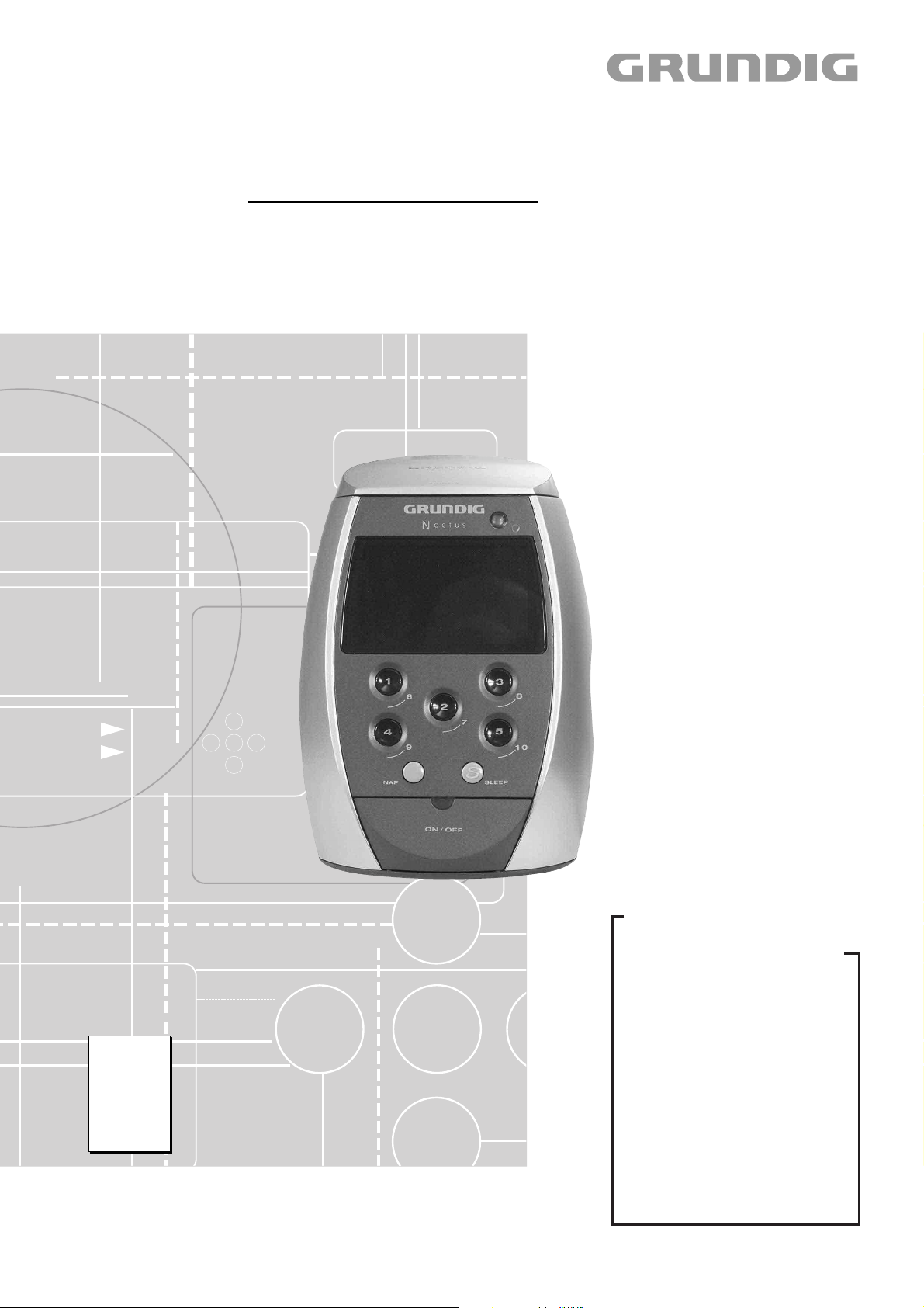
Audio Service Manual
NOCTUS
SC 9100 DCF RDS
GKM0150
Zusätzlich erforderliche Unterlagen für den Komplettservice
Additionally required Service Documents for the Complete Service
Service
Manual
Sicherheit
Safety
Materialnr./Part No.
720108000000
Materialnummer/Part Number 720107718500
Änderungen vorbehalten/Subject to alteration • Printed in Germany
E-BS-SA18 1101 • 8002/8012, 8005/8015, 8006/8016
http://www.grundig.com
Grundig Service
Hotline Deutschland…
Technik:
TV
TV
SAT
VCR/LiveCam
HiFi/Audio
Car Audio
Telekommunikation
Planatron
Ersatzteil-Verkauf: Mo.-Fr. 8.00-19.00 Uhr
Kundendienst/Werkstätten:
gebührenpflichtig
(8.00-22.00 Uhr)
…Mo.-Fr. 8.00-18.00 Uhr
0180/52318-41
0180/52318-49
0180/52318-48
0180/52318-42
0180/52318-43
0180/52318-44
0180/52318-45
Fax:
Telefon: 0180/52318-40
Telefon:
Fax:
0180/52318-51
0180/52318-99
0180/52318-50Fax:
Mo.-Fr. 8.00-18.00 Uhr
0180/52318-52
0180/52318-46
Page 2

Allgemeiner Teil / General Section NOCTUS - SC 9100 DCF RDS
Es gelten die Vorschriften und Sicherheitshinweise gemäß dem Service Manual "Sicherheit",
Materialnummer 720108000000, sowie zusätzlich die eventuell abweichenden, landesspezifischen Vorschriften!
Inhaltsverzeichnis
Seite
Allgemeiner Teil ............................. 1 - 2 … 1 - 7
Messgeräte / Messmittel ............................................................ 1 - 2
Technische Daten ...................................................................... 1 - 3
Servicehinweise ......................................................................... 1 - 3
Bedienhinweise .......................................................................... 1 - 4
Ausbauhinweise ......................................................................... 1 - 6
Abgleichvorschriften .................................. 2 - 1
Tuner .......................................................................................... 2 - 1
75kHz-Oszillator ......................................................................... 2 - 1
4,332MHz-Oszillator .................................................................. 2 - 1
Platinenabbildungen
und Schaltpläne ........................... 3 - 1 … 3 - 11
Blockschaltplan .......................................................................... 3 - 1
Verdrahtungsplan ....................................................................... 3 - 2
Schaltpläne:
Hauptschaltplan ..................................................................... 3 - 4
Record-Platte ....................................................................... 3 - 10
Melody-Platte ....................................................................... 3 - 10
DCF-Platte ........................................................................... 3 - 11
Platinenabbildungen:
Display-Platte ......................................................................... 3 - 6
LED-Platten ............................................................................ 3 - 6
Power-Platte ........................................................................... 3 - 7
LED-Platte .............................................................................. 3 - 7
Key-Platte ............................................................................... 3 - 8
Volume-Platte ......................................................................... 3 - 8
Radio-Platte ........................................................................... 3 - 9
IC-Blockschaltpläne ................................................................... 3-11
The regulations and safety instructions shall be
valid as provided by the "Safety" Service Manual,
part number 720108000000, as well as the respective national deviations!
Table of Contents
Page
General Section .............................. 1 - 2 … 1 - 7
Measuring Instruments / Equipment .......................................... 1 - 2
Technical Data ........................................................................... 1 - 3
Service Hints .............................................................................. 1 - 3
Operating Hints .......................................................................... 1 - 5
Disassembly Instructions ........................................................... 1 - 6
Adjustment Procedures.............................. 2 - 2
Tuner .......................................................................................... 2 - 2
75kHz Oscillator ......................................................................... 2 - 2
4.332MHz Oscillator ................................................................... 2 - 2
Layout of PCBs
and Circuit Diagrams ................... 3 - 1 … 3 - 11
Block Diagram ............................................................................ 3 - 1
Wiring Diagram .......................................................................... 3 - 2
Circuit Diagrams:
Main Circuit Diagram .............................................................. 3 - 4
Record PCB ......................................................................... 3 - 10
Melody PCB ......................................................................... 3 - 10
DCF PCB ............................................................................. 3 - 11
Layout of the PCBs:
Display PCB ........................................................................... 3 - 6
LED PCB ................................................................................ 3 - 6
Powe PCB .............................................................................. 3 - 7
LED PCB ................................................................................ 3 - 7
Key PCB ................................................................................. 3 - 8
Volume PCB ........................................................................... 3 - 8
Radio PCB ............................................................................. 3 - 9
IC Block Diagrams ..................................................................... 3-11
Explosionszeichnung und
Ersatzteilliste .................................. 4 - 1 … 4 - 2
Allgemeiner Teil
Messgeräte/Messmittel
Frequenzzähler Mess-Sender
Oszilloskop Digitalvoltmeter
Beachten Sie bitte das GRUNDIG Messtechnik-Programm, das Sie
unter folgender Adresse erhalten:
GRUNDIG AG Geschäftsbereich Instruments
Test- und Mess-Systeme
Würzburger Str. 150
D 90766 Fürth/Bay
Tel. 0911/703-4540
Fax 0911/703-4130
eMail: instruments@grundig.com
Internet: http://www.grundig-instruments.de
Internet: http://www.grundig-instruments.com
Exploded View and
Spare Parts List .............................. 4 - 1 … 4 - 2
General Section
Measuring Instruments/Equipment
Frequency counter Signal generator
Oscilloscope Digital voltmeter
Please note the GRUNDIG Catalog "Test and Measuring Equipment"
obtainable from:
1 - 2 GRUNDIG Service
Page 3
NOCTUS - SC 9100 DCF RDS Allgemeiner Teil / General Section
Technische Daten
Spannungsversorgung: ..............................................230V, 50/60Hz
Maximale Leistungsaufnahme ..................................................... 4W
Standby Leistungsaufnahme .................................................... 1,2W
Ausgangsleistung: ............................. DIN 45324, 10% THD 700mW
Wellenbereich: ................................................. FM 87,5 ...108,0MHz
Abmessungen: ................................... B x H x T 120 x 185 x 120mm
Gewicht: .................................................................................... 990g
Servicehinweise
Vor Öffnen des Gehäuses Netzstecker ziehen.
Leitungsverlegung
Bevor Sie die Leitungen und insbesondere die Masseleitungen lösen,
muss die Leitungsverlegung zu den einzelnen Baugruppen beachtet
werden.
Nach erfolgter Reparatur ist es notwendig, die Leitungsführung wieder
in den werkseitigen Zustand zu versetzen um eventuell spätere
Ausfälle oder Störungen zu vermeiden.
Speicher für Sender und Weckzeiten
Die Speicherung wird durch einen Gold-Cap ca. 24 Stunden aufrecht
erhalten.
Technical Data
Power supply: ............................................................ 230V, 50/60Hz
Maximum power consumption ..................................................... 4W
Standby power consumption ..................................................... 1.2W
Output: .............................................. DIN 45324, 10% THD 700mW
Frequency band: ............................................. FM 87.5 ... 108.0MHz
Dimensions: ...................................... W x H x L 120 x 185 x 120mm
Weight: ...................................................................................... 990g
Service Hints
Disconnect the mains plug before opening the set.
Wiring
Before disconnecting any leads and especially the earth connecting
leads observe the way they are routed to the individual assemblies.
On completion of the repairs the leads must be laid out as originally
fitted at the factory to avoid later failures or disturbances.
Preset and Alarm Times Memory
The memory will be secured by a gold-cap for about 24 hours.
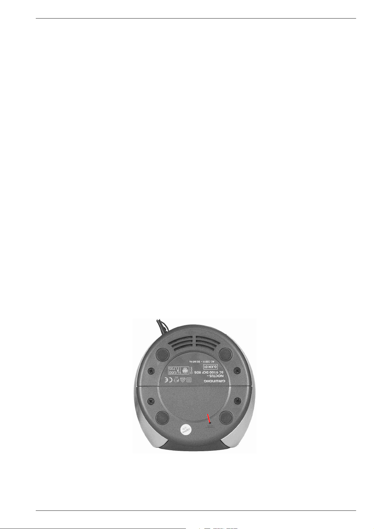
Reset (alle Einstellungen löschen)
Wenn die Bedienelektronik Ihres Gerätes blockiert sein sollte (zum
Beispiel durch statische Aufladungen von Teppichböden oder aufgrund
von Gewittern) kann das Gerät in seinen Auslieferzustand zurückgesetzt werden:
Mit spitzem Gegenstand – zum Beispiel einer aufgebogenen Büroklammer– »RESET« drücken.
Uhrzeit, Wochentag, Weckzeiten, Programmeinstellungen und Sprachaufzeichnungen sind gelöscht.
Reset (Deleting all settings)
If the electronic system of your device becomes blocked (as the result
of static electricity from the floor carpet or storms, for example), the
device can be reset to its original condition:
Press »RESET« (at the base of the casing) with a sharp object.
The settings for time, day of the week, alarm times, program settings
and voice recordings are now deleted.
Reset
GRUNDIG Service 1 - 3
Page 4
1 - 4 GRUNDIG Service
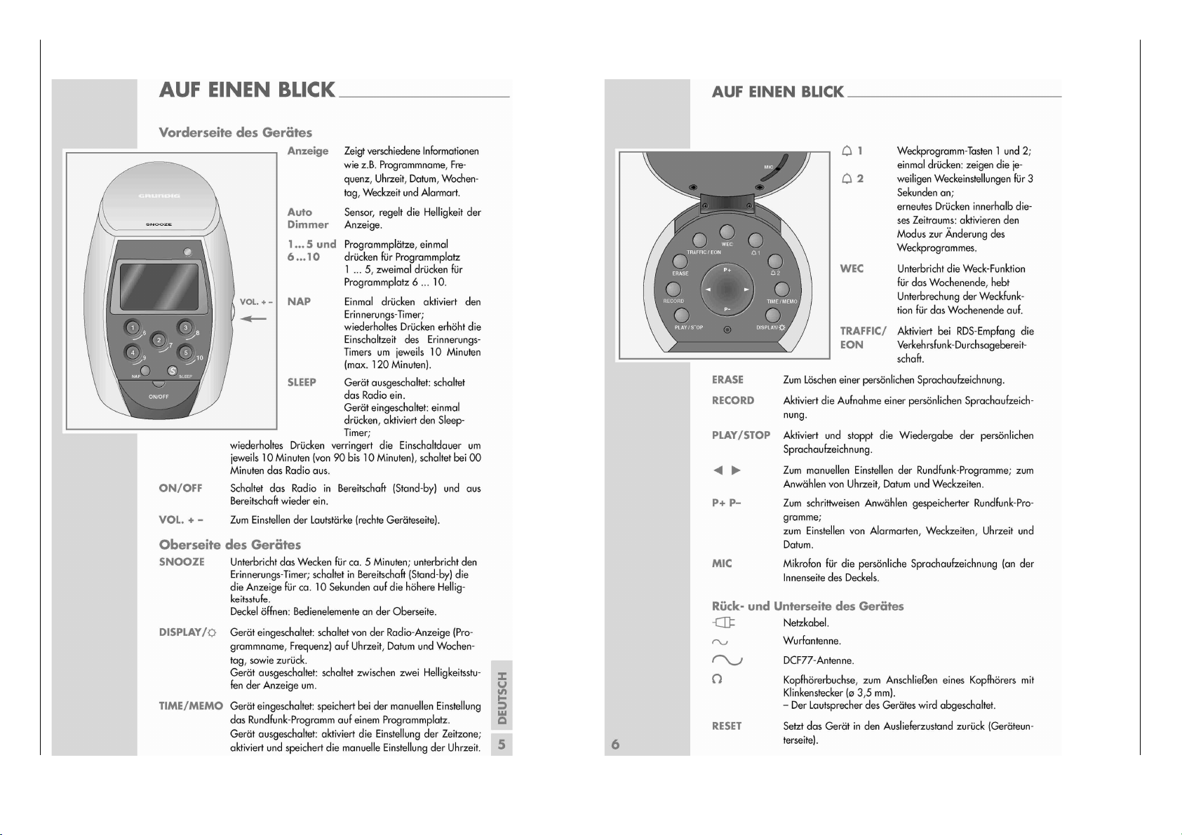
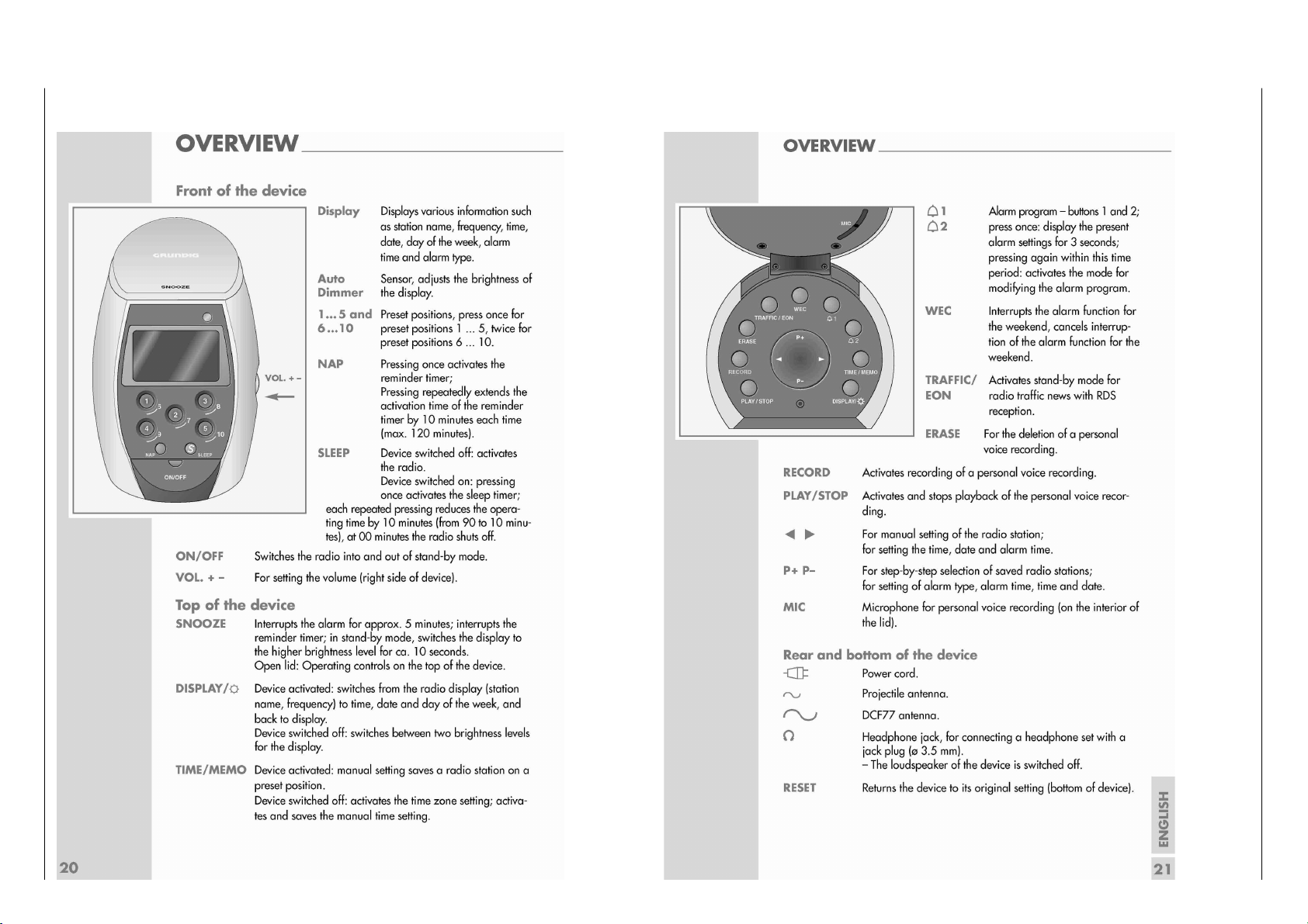
Bedienhinweise
Dieses Kapitel enthält Auszüge aus der Bedienungsanleitung.
Weitergehende Informationen entnehmen Sie bitte der gerätespezifischen Bedienungsanleitung, deren Materialnummer Sie in der ent
Allgemeiner Teil / General Section NOCTUS - SC 9100 DCF RDS
sprechenden Ersatzteilliste finden.
Page 5
GRUNDIG Service 1 - 5
Operating Hints
This chapter contains excerpts from the operating instructions.
For further particulars please refer to the appropriate user instructions the part number of which is indicated in the relevant
NOCTUS - SC 9100 DCF RDS Allgemeiner Teil / General Section
spare parts list.
Page 6
Allgemeiner Teil / General Section NOCTUS - SC 9100 DCF RDS
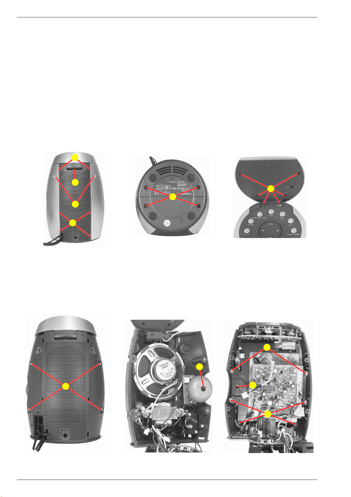
Ausbauhinweise
Bevor Sie Leitungen lösen, muss die Leitungsverlegung beachtet
werden. Nach erfolgter Reparatur ist es notwendig, die Leitungsführung in den werkseitigen Zustand zu versetzen.
1. Seitenblenden
- 2 Schrauben A (Fig. 1) herausdrehen.
- 4 Schrauben B (Fig. 2) herausdrehen.
- Seitenblenden an den Punkten C (Fig. 1) ausrasten und zur Seite
abnehmen.
2. Deckel/Mikrofon
- 6 Schrauben D (Fig. 3) herausdrehen.
- Deckeloberteil an Punkt E (Fig. 1) ausrasten.
- Achtung! Kurzes Mikrofonkabel!
- Beim Einbau darauf achten, dass das Mikrofonkabel nicht eingeklemmt wird (Aussparung im Deckeloberteil!).
C
E
A
Disassembly Instructions
Before disconnecting any leads observe the way they are routed.
On completion of the repairs the leads must be laid out as
originally fitted at the factory.
1. Side Covers
- Undo 2 screws A (Fig. 1).
- Undo 4 screws B (Fig. 2).
- Disengage the side covers at points C (Fig. 1) and remove
sidewards.
2. Lid/Microphone
- Undo 6 screws D (Fig. 3).
- Disengage the lid top at point E (Fig. 1).
- Attention! Short microphone wire!
- When reassembling take care not to squeeze the microphone wire
(cutout in the lid top!).
D
B
C
Fig. 1
3. Gerät öffnen
- Seitenblenden abnehmen (Punkt 1).
- 4 Schrauben F (Fig. 4) herausdrehen.
- Gehäuse vorsichtig öffnen.
- Bei Bedarf Steckverbindungen lösen und FM-Antennenleitung ablöten.
- Beim Zusammenbau darauf achten, dass der Lautstärkeregler G
(Fig. 5) in seine Führung H (Fig. 6) an der Frontseite eingreift.
Fig. 2
F
Fig. 3
3. Open the unit
- Remove the side covers (point 1).
- Undo 4 screws F (Fig. 4).
- Carefully open the cabinet.
- When necessary unplug the connections and unsolder the FM
aerial.
- When reassembling take care that the volume control knob G
(Fig. 5) engages with its guide H (Fig. 6) at the front part.
I
G
H
I
Fig. 4 Fig. 5 Fig. 6
1 - 6 GRUNDIG Service
Page 7

NOCTUS - SC 9100 DCF RDS Allgemeiner Teil / General Section
4. Leiterplatten-Träger
- Gerät öffnen (Punkt 3).
- 6 Schrauben I (Fig. 6) herausdrehen.
- Träger mit den Leiterplatten aus dem Gehäusevorderteil herausnehmen.
5. Display-Platte
- Leiterplattenträger ausbauen (Punkt 4).
- 6 Schrauben K (Fig. 7) herausdrehen.
- Bei Bedarf Steckverbindungen lösen.
6. FM-Platte
- Gerät öffnen (Punkt 3).
- 4 Schrauben L (Fig. 8) herausdrehen.
- Masseleitung M (Fig. 8) ablöten.
- Bei Bedarf Steckverbindungen lösen.
K
4. PCB Support
- Open the unit (point 3).
- Undo 6 screws I (Fig. 6).
- Remove the support together with the cabinet front.
5. Display PCB
- Remove the PCB support (point 4).
- Undo 6 screws K (Fig. 7).
- When necessary unplug the connections.
6. FM PCB
- Open the unit (point 3).
- Undo 4 screws L (Fig. 8).
- Unsolder ground wire M (Fig. 8).
- When necessary unplug the connections.
M
L
Fig. 7
7. Bedienplatte
- Gerät öffnen (Punkt 3).
- 6 Schrauben N (Fig. 9) herausdrehen.
8. NF-Platte
- Leiterplattenträger ausbauen (Punkt 4).
- 2 Schrauben O (Fig. 10) herausdrehen.
N
Fig. 8
7. Operating PCB
- Open the unit (point 3).
- Undo 6 screws N (Fig. 9).
8. AF PCB
- Remove the PCB support (point 4).
- Undo 2 screws O (Fig. 10).
O
Fig. 9 Fig. 10
GRUNDIG Service 1 - 7
Page 8

Abgleichvorschriften / Adjustment Procedures NOCTUS - SC 9100 DCF RDS
Abgleichvorschriften
Tuner
Messgeräte: Mess-Sender, Oszilloskop, Digital-Voltmeter
Abgleich Vorbereitung Abgleichvorgang
FM-Oszillator
FM-Vorkreis
87,5MHz;
Digital-Voltmeter an Messpunkt TP3.
Mess-Sender an Antennen-Eingang ANT1
Ue <; f
Oszilloskop an Lautsprecher.
= 1kHz;
mod
Mit L2 auf 1,70V ± 0,05V abgleichen (verbiegen).
Wechselweise mit L1 (verbiegen) bei 90MHz und mit TC1
bei 106MHz auf NF-Maximum abgleichen.
75kHz-Oszillator
Messgeräte: Frequenzzähler
Abgleich Vorbereitung Abgleichvorgang
75kHz-Oszillator Frequenzzähler an Messpunkt TP4. Mit TC2 auf 75kHz ± 10Hz abgleichen.
4,332MHz-Oszillator
Messgeräte: Frequenzzähler
Abgleich Vorbereitung Abgleichvorgang
4,332MHz-Oszillator Frequenzzähler an Messpunkt TP6. Mit TC3 auf 4,332MHz ± 10Hz abgleichen.
Radio-Platte Display-Platte
2 - 1 GRUNDIG Service
Page 9

NOCTUS - SC 9100 DCF RDS Abgleichvorschriften / Adjustment Procedures
Adjustment Procedure
Tuner
Test equipment: Signal Generator, Oscilloscope, Digital Voltmeter
Adjustment Preparation Adjustment Procedure
FM Oscillator
FM Band Pass
87.5MHz;
Digital Voltmeter to testpoint TP3.
Signal Generator to aerial input ANT1
Ue <; f
Oscilloscope to Loudspeaker.
= 1kHz;
mod
Adjust (bend) with L2 for 1.70V ± 0.05V.
Adjust alternating with L1 (bend) at 90MHz and with TC1
at 106MHz to AF Maximum.
75kHz Oscillator
Test equipment: Frequency Counter
Adjustment Preparation Adjustment Procedure
75kHz Oscillator Frequenzy Counter to testpoint TP4. Adjust with TC2 for 75kHz ± 10Hz.
4.332MHz-Oscillator
Test equipment: Frequency Counter
Adjustment Preparation Adjustment Procedure
4.332MHz Oscillator Frequenzy Counter to testpoint TP6. Adjust with TC3 for 4.332MHz ± 10Hz.
Radio PCB Display PCB
GRUNDIG Service 2 - 2
Page 10

3 - 1 GRUNDIG Service
Blockschaltplan / Block Diagram
Platinenabbildungen und Schaltpläne / Layout of PCBs and Circuit Diagrams
Platinenabbildungen und Schaltpläne / Layout of PCBs and Circuit Diagrams NOCTUS - SC 9100 DCF RDS
Page 11

Verdrahtungsplan / Wiring
Platinenabbildungen und Schaltpläne / Layout of PCBs and Circuit Diagrams Platinenabbildungen und Schaltpläne / Layout of PCBs and Circuit DiagramsNOCTUS - SC 9100 DCF RDS NOCTUS - SC 9100 DCF RDS
GRUNDIG Service GRUNDIG Service
3 - 33 - 2
Page 12

Platinenabbildungen und Schaltpläne / Layout of PCBs and Circuit Diagrams Platinenabbildungen und Schaltpläne / Layout of PCBs and Circuit Diagrams NOCTUS - SC 9100 DCF RDSNOCTUS - SC 9100 DCF RDS
Hauptschaltplan / Main Circuit Diagram
zu/to P208
Seite/Page 3-10
zu/to P206
Seite/Page 3-11
zu/to P201
Seite/Page 3-10
3 - 4 3 - 5
GRUNDIG Service GRUNDIG Service
Bei den in den Schaltplänen angegebenen Messwerten handelt es sich um
Näherungswerte!
The measured values given in the circuit diagrams are approximates!
Page 13

Display-Platte / Display PCB
Platinenabbildungen und Schaltpläne / Layout of PCBs and Circuit DiagramsNOCTUS - SC 9100 DCF RDS
LED-Platten / LED PCBs
GRUNDIG Service 3 - 6
Page 14

Platinenabbildungen und Schaltpläne / Layout of PCBs and Circuit Diagrams NOCTUS - SC 9100 DCF RDS
Power-Platte / Power PCB
LED-Platte / LED PCB
3 - 7 GRUNDIG Service
Page 15

Key-Platte / Key PCB
Platinenabbildungen und Schaltpläne / Layout of PCBs and Circuit DiagramsNOCTUS - SC 9100 DCF RDS
Volume-Platte / Volume PCB
GRUNDIG Service 3 - 8
Page 16

Platinenabbildungen und Schaltpläne / Layout of PCBs and Circuit Diagrams NOCTUS - SC 9100 DCF RDS
Radio-Platte / Radio PCB
3 - 9 GRUNDIG Service
Page 17

Record-Platte / Record PCB
Platinenabbildungen und Schaltpläne / Layout of PCBs and Circuit DiagramsNOCTUS - SC 9100 DCF RDS
Melody-Platte / Melody PCB
zu/to P9
Seite/Page 3-4
zu/to P7
Seite/Page 3-4
GRUNDIG Service 3 - 10
Page 18

Platinenabbildungen und Schaltpläne / Layout of PCBs and Circuit Diagrams NOCTUS - SC 9100 DCF RDS
DCF-Platte / DCF PCB
IC5 - TC 9260 P
zu/to P5
Seite/Page 3-4
IC9 - BU 1924 F
IC9 - SAA 6579
IC6 - BU 2614
IC4 - KA 2201
3 - 11 GRUNDIG Service
Page 19

GRUNDIG Service 4 - 1
Explosionszeichnungen und Ersatzteilliste / Exploded Views and Spare Parts List
Explosionszeichnungen und Ersatzteilliste / Exploded Views and Spare Parts ListNOCTUS - SC 9100 DCF RDS
1
Page 20

4 - 2 GRUNDIG Service
Ersatzteilliste
Spare Parts List
10 / 2001
POS. NR. ABB. MATERIAL-NR. ANZ. BEZEICHNUNG DESCRIPTION
POS. NO. FIG. PART NUMBER QTY.
0001.000 1 759550464100 LINSE DISPLAY LENS DISPLAY
0002.000 1 759550462900 GEHAEUSEVORDERTEIL FRONT CABINET
0003.000 1 759550463600 KNOPF EIN/AUS KNOB ON/OFF
0005.000 1 759550464400 LINSE KNOPF EIN/AUS LENS KNOB ON/OFF
0006.000 1 759550462500 2 FEDER KNOPF EIN/AUS SPRING KNOB ON/AUS
0007.000 1 759550464300 LINSE DIMMER LENS DIMMER
0009.000 1 759550463800 KNOPF SCHLUMMER KNOB NAP/SLEEP
0013.000 1 759550463900 5 KNOPF VORBELEGUNG KNOB PRESET
0015.000 1 759550464000 HALTER KNOPF VORBELEGUNG HOLDER KNOB PRESET
0023.000S1 759550462400 TRAFO MIT NETZKABEL TO-V6 TRANSFORMER WITH POWERCABEL
0024.000 1 759550462300 LAUTSPRECHER 8OHM1-3W SPEAKER 8OHM1-3W
0026.000 1 759550463000 GEHAEUSERUECKTEIL CABINET BACK
0029.000 1 759550462800 4 FUSS GUMMI 10X1,6MM FOOT RUBBER 10X1,6MM
0031.000 1 759550464500 KNOPF LAUTSTAERKE KNOB VOLUME
0033.000 1 759550461800 REGLER XRE0121PVB20FINA1- REGLER XRE0121PVB20FINA1-
0035.000 1 759550464600 GEHAEUSE ANTENNE CABINET ANTENNA
0036.000 1 759550465100 DCF PLATTE IC4225 DCF BOARD IC4225
0041.000 1 759550460900 DISPLAY UTN-H309EN1W DISPLAY UTN-H309EN1W
0042.000 1 759550462700 DIFFUSER PLATTE 70X44MM DIFFUSER PLATE 70X44MM
0043.000 1 759550464800 KONTAKTGUMMI B CONTACTRUBBER B
0044.000 1 759550464700 KONTAKTGUMMI A CONTACTRUBBER A
0045.000 1 759550464200 REFLECTOR REFLECTOR
0061.000 1 759550461900 KOPFHOERERBUCHSE 3,5MM ST EAR PHONE SOCKET 3,5MM ST
0062.000 1 759550464900 RECORD PLATTE ISD1420 RECORD BOARD ISD1420
0063.000 1 759550465000 MELODY PLATTE AM8553 MELODY BOARD AM8553
0067.000 1 759550463200 ABDECKUNG RECHTS COVER RIGHT
0068.000 1 759550463100 ABDECKUNG LINKS COVER LEFT
0069.000 1 759550463300 ABDECKUNG OBEN COVER TOP
0070.000 1 759550462000 MICROPHON WM-034CY MICROPHON WM-034CY
0074.000 1 759550463400 BLENDE OBEN MASK TOP
0075.000 1 759550462600 KNOPF SCHLUMMER KNOB SNOOZE
0076.000 1 759550463700 KNOPF PROGRAMM/SUCHLAUF KNOB PROGRAM/SEARCH
0077.000 1 759550463500 KNOPFSATZ FUNKTION KNOB SET FUNCTION
ǵ
AUDIO
NOCTUS SC 9100 DCF RDS
MATERIAL-NR. / PART NO.: 759088105000
BESTELL-NR. / ORDER NO.: GKM0150 CHROME
d©
759088105000 NOCTUS SC9100DCF RDS NOCTUS SC9100DCF RDS
720114013500 BEDIENUNGSANLEITUNG OPRERATING INSTRUCTION
720107718500 SERVICE MANUAL D/GB SERVICE MANUAL D/GB
KEIN E-TEIL NO SPARE PART
D/GB/F/I/NL/DK/S/FIN/E/P D/GB/F/I/NL/DK/S/FIN/E/P
POS. NR. MATERIAL-NR. BEZEICHNUNG
POS. NO. PART NUMBER DESCRIPTION
C 00043 759540367100 ELKO 1000UF 10V
C 00059 845299864700 ELKO 1000UF 20% 25V RM5 C
C 00060 759550052400 ELKO 2200UF 25V 20% RM5
C 00078 759550462100 TRIMMER 30PF 7MM GRUEN
C 00085 759550462100 TRIMMER 30PF 7MM GRUEN
C 00094 759550462200 GOLD-CAP 100MF/5,5V
C 00099 759540367100 ELKO 1000UF 10V
CF 00001 759550071900 FILTER BAND PASS GFMB3
CF 00002 860282219000 CER.FIL.190 SFE 10,7 MS3A
CF 00003 860282219000 CER.FIL.190 SFE 10,7 MS3A
CF 00004 759550461500 CER- FILTER CDA10,7C1-A
CF 00005 759540659500 QUARZ 75KHZ *CDM700
CF 00006 838217043300 QUARZ #170 A/C 4,332MHZ
CF 00007 838216604100 QUARZ #166 4,194304MHZ
CF 00008 838200000300 QUARZ 32,768KHZ 2X6MM C-0
D 00001 830921500600 DIODE 1 N 4001 -GA
D 00002 830921500600 DIODE 1 N 4001 -GA
D 00003 830921500600 DIODE 1 N 4001 -GA
D 00004 830921500600 DIODE 1 N 4001 -GA
D 00005 830921504500 DIODE 1N4148 AV619 -GA
D 00006 830921500600 DIODE 1 N 4001 -GA
D 00007 830921500600 DIODE 1 N 4001 -GA
D 00008 759550461300 DIODE IN5817
D 00009 830921504500 DIODE 1N4148 AV619 -GA
D 00010 830921504500 DIODE 1N4148 AV619 -GA
D 00011 830921504500 DIODE 1N4148 AV619 -GA
D 00012 830921504500 DIODE 1N4148 AV619 -GA
D 00013 830921504500 DIODE 1N4148 AV619 -GA
D 00014 830921504500 DIODE 1N4148 AV619 -GA
D 00015 830921504500 DIODE 1N4148 AV619 -GA
D 00016 830921504500 DIODE 1N4148 AV619 -GA
D 00017 830921504500 DIODE 1N4148 AV619 -GA
D 00018 830921504500 DIODE 1N4148 AV619 -GA
D 00019 759550461200 LED-DIODE 5Y3SCY83 ORANGE
D 00020 759550461200 LED-DIODE 5Y3SCY83 ORANGE
D 00021 759550461100 LED-DIODE 3Y4SCC8 ORANGE
D 00022 759550461100 LED-DIODE 3Y4SCC8 ORANGE
D 00023 759550461000 LED-DIODE 5Y3HD-10 ORANGE
D 00024 830921504500 DIODE 1N4148 AV619 -GA
D 00025 830921504500 DIODE 1N4148 AV619 -GA
D 00027 759550461300 DIODE IN5817
IC 00001 759550460300 IC UPD16431AGC
IC 00002 759550460400 IC TA2132
IC 00003 759550460800 IC KA78L12
IC 00004 759550460500 IC KA2201
IC 00005 759550074700 IC TC9260P
IC 00006 759550460600 IC BU2614FS
IC 00007 759550460100 IC T0032(780024)
IC 00009 759550460700 IC BU1924F
K 00001 759550245900 TAKTSCHALTER EVQJAC04M HO
K 00002 759550245900 TAKTSCHALTER EVQJAC04M HO
K 00003 759550245900 TAKTSCHALTER EVQJAC04M HO
K 00004 759550461700 TAKTSCHALTER TSC063803-10
K 00005 759550245900 TAKTSCHALTER EVQJAC04M HO
K 00006 759550245900 TAKTSCHALTER EVQJAC04M HO
K 00007 759550245900 TAKTSCHALTER EVQJAC04M HO
K 00008 759550245900 TAKTSCHALTER EVQJAC04M HO
K 00009 759550245900 TAKTSCHALTER EVQJAC04M HO
K 00010 759550245900 TAKTSCHALTER EVQJAC04M HO
K 00011 759550245900 TAKTSCHALTER EVQJAC04M HO
K 00012 759550245900 TAKTSCHALTER EVQJAC04M HO
K 00013 759550245900 TAKTSCHALTER EVQJAC04M HO
POS. NR. MATERIAL-NR. BEZEICHNUNG
POS. NO. PART NUMBER DESCRIPTION
K 00014 759550245900 TAKTSCHALTER EVQJAC04M HO
K 00015 759550245900 TAKTSCHALTER EVQJAC04M HO
K 00016 759550245900 TAKTSCHALTER EVQJAC04M HO
K 00017 759550245900 TAKTSCHALTER EVQJAC04M HO
K 00018 759550245900 TAKTSCHALTER EVQJAC04M HO
K 00019 759550245900 TAKTSCHALTER EVQJAC04M HO
K 00020 759550245900 TAKTSCHALTER EVQJAC04M HO
K 00021 759550245900 TAKTSCHALTER EVQJAC04M HO
K 00022 759550245900 TAKTSCHALTER EVQJAC04M HO
K 00023 759550461600 TAKTSCHALTER TC-0010Z
LCD00001 759550460900 DISPLAY UTN-H309EN1W
Q 00001 759540642100 TRANSISTOR S 9014 C
Q 00002 759540642100 TRANSISTOR S 9014 C
Q 00003 759540642100 TRANSISTOR S 9014 C
Q 00004 759540642100 TRANSISTOR S 9014 C
Q 00005 759540642100 TRANSISTOR S 9014 C
Q 00006 759540642100 TRANSISTOR S 9014 C
Q 00007 759540472400 TRANSISTOR 9012H
Q 00008 759864110000 TRANS.9018 F 9018F
Q 00009 759864110000 TRANS.9018 F 9018F
Q 00010 759864110000 TRANS.9018 F 9018F
Q 00011 759540200900 TRANS. SS8550 C
Q 00013 759540642100 TRANSISTOR S 9014 C
Q 00014 759540642100 TRANSISTOR S 9014 C
Q 00015 759540200900 TRANS. SS8550 C
Q 00016 759540200900 TRANS. SS8550 C
Q 00017 759540472400 TRANSISTOR 9012H
Q 00019 759540642100 TRANSISTOR S 9014 C
Q 00020 759540642100 TRANSISTOR S 9014 C
Q 00219 759540642100 TRANSISTOR S 9014 C
Q 00220 759540642100 TRANSISTOR S 9014 C
TC 00001 759550462100 TRIMMER 30PF 7MM GRUEN
TD 00001 759550461400 CAP-DIODE SVC201-SPA
TD 00002 759550461400 CAP-DIODE SVC201-SPA
ZD 00001 830972007400 Z DIODE 7,5 B 0,5W
Explosionszeichnungen und Ersatzteilliste / Exploded Views and Spare Parts List NOCTUS - SC 9100 DCF RDS
ÄNDERUNGEN VORBEHALTEN / SUBJECT TO ALTERATION
Es gelten die Vorschriften und Sicherheitshinweise
gemäß dem Service Manual "Sicherheit", Mat.-Nummer 720108000000, sowie zusätzlich die eventuell abweichenden, landesspezifischen Vorschriften!
The regulations and safety instructions shall be valid
!
as provided by the "Safety" Service Manual, part
number 720108000000, as well as the respective
( ! )
national deviations.
ÄNDERUNGEN VORBEHALTEN / SUBJECT TO ALTERATION
 Loading...