

Page 1
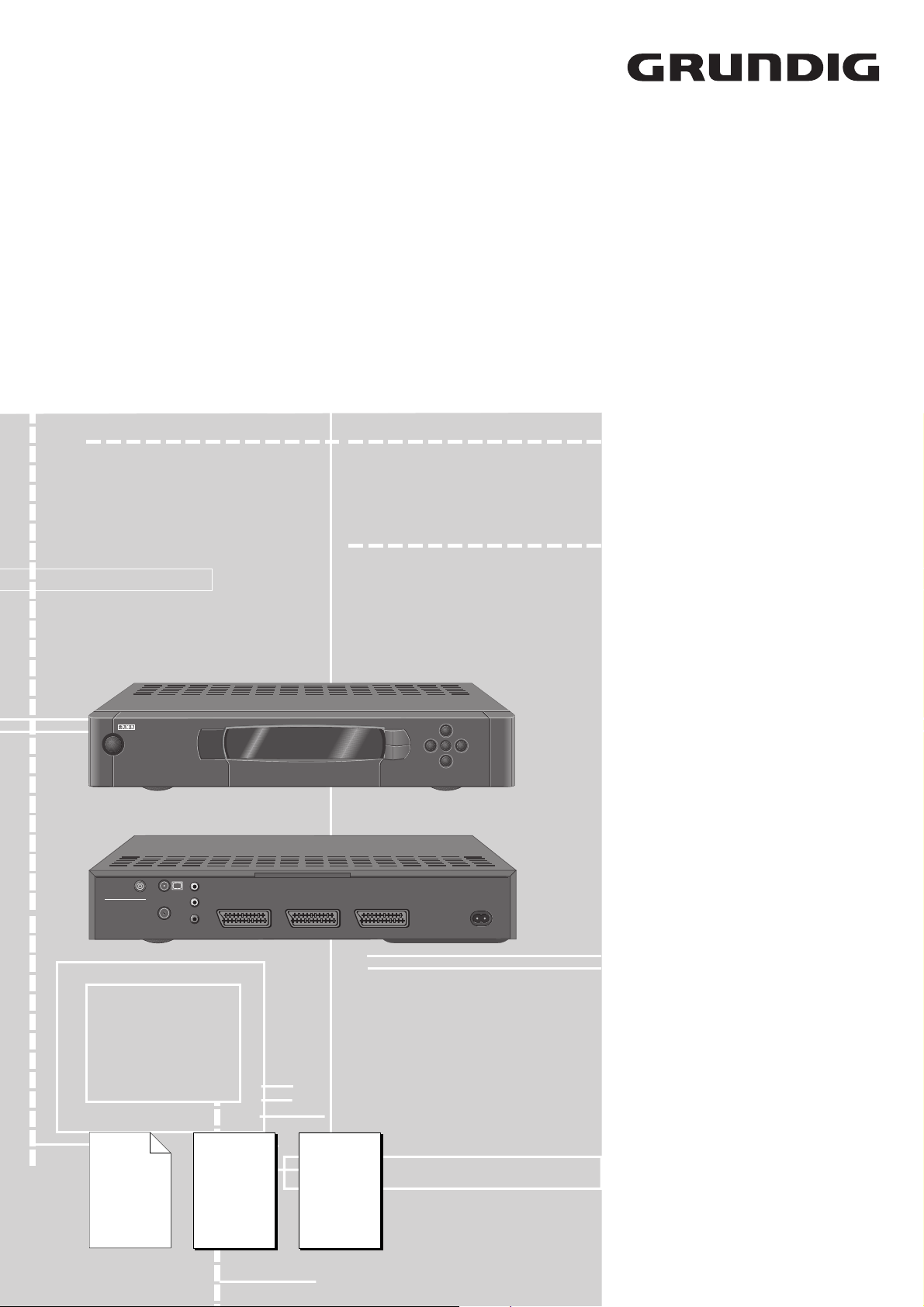
Service Manual
SAT
STR 611
POWER TIMER
8
INPUT-SAT
950-2150 MHz
14/18 V 350 mA
Ergänzung
Supplement
1
Sach-Nr./Part No.
72010 021 3100
1
TV
VIDEO
CONTROL
R
AUDIO OUT
L
Zusätzlich erforderliche
Unterlagen für den Komplettservice
Additionally required
Service Manuals for the Complete Service
Service
Manual
STR 622 TWIN
Sach-Nr./Part No.
72010-021.30
Sach-Nr./Part No.
Service
Manual
Sicherheit
Safety
72010-800.00
STR 611
À
+
6
EXIT
EURO AV VCREURO AV DECODEREURO AV TV
P
OK
4 3
-
P
220-240 V~
50-60 Hz
Btx * 32700 #
Sachnummer
Part Number 72010 021 3100
Änderungen vorbehalten
Subject to alteration
Printed in Germany
VK22/232 0798
Page 2

Allgemeiner Teil / General Section STR 611
Es gelten die Vorschriften und Sicherheitshinweise gemäß dem Service Manual "Sicherheit",
Sach-Nummer 72010-800.00, sowie zusätzlich
die eventuell abweichenden, landesspezifischen
Vorschriften!
D
Sicherheitshinweise zu Lithium-Batterien
Vorsicht bei Lithium-Batterien:
Bei falscher Handhabung (Überhitzung, Falschpolung oder Kurzschluß) der Lithium-Batterien besteht Explosionsgefahr!
Lithium-Batterien dürfen nur gegen Original-Ersatzteile (s. Ersatzteilliste) getauscht werden.
Die verbrauchten Lithium-Batterien entsorgen Sie bitte fachgerecht.
Für diese Geräte gilt das Service Manual STR 622 TWIN.
Es entfällt der Schaltungsteil "Teilschaltplan VCR".
Diese Ergänzung dokumentiert die unterschiedliche Bestückung des
Gerätes.
Grundlage für den Service sind:
– Sicherheitsvorschriften (Sach-Nr. 72010-800.00)
– Service Manual STR 622 TWIN (Sach-Nr. 72010-021.30)
– 1. Ergänzung STR 611 (Sach-Nr. 72010 021 3100)
Durch die EDV-Umstellung wurden die bisherigen 10-stelligen
Sachnummern auf 12-stellige geändert.
Beispiel: bisher: 29504-111.22
neu: 29504 111 2200
Während der Umstellphase können im Service Manual beide
Schreibweisen vorkommen.
The regulations and safety instructions shall be
valid as provided by the "Safety" Service Manual,
part number 72010-800.00, as well as the
respective national deviations.
GB
Safety Precautions for Lithium Batteries
Warning for lithium batteries:
Lithium batteries, if incorrectly used (excessive heat, wrong connection of terminals, short circuit) represent a danger of explosion!
Lithium batteries must be replaced only by original spare parts (see
Spare Parts List). Observe the appropriate disposal regulations for
exhausted lithium batteries.
For these TV sets the Service Manual STR 622 TWIN is applicable.
The circuit section "Part of the Circuit VCR" is omitted.
This Manual describes the differences in the components fitted to this
model.
Basic instructions for servicing are given in the:
– Safety Instructions (Part No. 72010-800.00)
– Service Manual STR 622 (Part No. 72010-021.30)
– 1st Supplement STR 611 (Part No.72010-021.31)
Due to the conversion of the EDP system, the previous 10-digit part
numbers were change to 12-digit numbers.
Example: previous: 29504-111.22
new: 29504 111 2200
During the conversion of the system, either form may be found in
the Service Manual.
Inhaltsverzeichnis
Seite
Allgemeiner Teil ................................... 1-1…1-6
Meßgeräte.................................................................................... 1-2
Technische Daten ....................................................................... .1-3
Modulübersicht............................................................................. 1-3
Bedienungsanleitung ................................................................... 1-4
Platinenabbildungen
und Schaltpläne ................................. 2-1…2-11
Oszillogramme ............................................................................. 2-1
Chassisplatte ............................................................................... 2-2
Gesamtschaltplan TV................................................................... 2-6
Bedieneinheit mit Anzeige ......................................................... 2-10
Ersatzteilliste ........................................ 3-1…3-2
Allgemeiner Teil
Meßgeräte
Regeltrenntrafo Oszilloskop
DC-Voltmeter Frequenzzähler
Beachten Sie bitte das Grundig Meßtechnik-Programm, das Sie unter
folgender Adresse erhalten:
Table of Contents
Page
General Section.................................... 1-1…1-9
Test Equipment............................................................................ 1-2
Technical Data ............................................................................. 1-3
Module List................................................................................... 1-3
Operating Instructions.................................................................. 1-7
Layout of the PCBs
and Circuit Diagrams ......................... 2-1…2-11
Oscillogrammes ........................................................................... 2-1
Chassis Board.............................................................................. 2-2
General Circuit Diagram TV......................................................... 2-6
Control Unit with Indication ........................................................ 2-10
Spare Parts List.................................... 3-1…3-2
General Section
Test Equipment
Variable isolating transformer Oscilloscope
DC Voltmeter Frequency counter
Please note the Grundig Catalog "Test and Measuring Equipment"
obtainable from:
Grundig Instruments
Test- und Meßsysteme GmbH
Würzburger Str. 150, D-90766 Fürth/Bay.
Tel. 0911/703-4118, Telefax 0911/703-4130
eMail: instruments@grundig.de
Internet: http://www.grundig-instruments.de
1 - 2 GRUNDIG Service
Grundig Instruments
Test- und Meßsysteme GmbH
Würzburger Str. 150, D-90766 Fürth/Bay.
Tel. 0911/703-4118, Telefax 0911/703-4130
eMail: instruments@grundig.de
Internet: http://www.grundig-instruments.de
Page 3
STR 611 Allgemeiner Teil / General Section
Bestell-Nr.
Order No.
G.AE 0851
Chassis
29305-201.53
Modulator 29502-025.45
Tuner 29504-201.88
Bedieneinheit
Control Unit
29305-206.08
29642-061.03
Technische Daten
Programmspeicherplätze .......................................... 250 TV / Radio
Eingangsfrequenzbereich ........................................ 950…2150MHz
SAT-ZF-Eingang ............................................................................. 1
ZF-Bandbreite ............. 27MHz mit 3-stufiger Threshold-Erweiterung
LNB-Power..................................................... 14 / 18V, max. 350mA
DiSEqC ...................................................................... Aus / Mini / 1.0
LNB-Schaltsignal .................................................................... 22kHz
LNB-Anpassung..... 4 auswählbare LO-Frequenzen, 1MHz-Schritte
Ton-Frequenzbereich................................................. 5,0…9,00MHz
Stereo ..................................................................... Panda Wegener
Ton-Bandbreite .......... 50 / 80 / 110 / 180 / 280 / 380 / 480 / 680kHz
Ton-Deemphasis umschaltbar ............................... 75µs / 50µs / J17
Videohub................................................................................ 4 stufig
Videopolarität ............................................................positiv / negativ
Anzeige ........................................................ 3x7-Segment + 3 LEDs
Timer ............................................................................................... 4
OSD-Menü ........................................................................... Englisch
Euro-AV-Buchsen ................................................ TV, VCR, Decoder
Modulator .....................................................................Kanal 21…60
Netzspannung ................................................................. 220…240V
Regelbereich ................................................................... 185…265V
Netzfrequenz...................................................................... 50 / 60Hz
Fernbedienung............................................................... TP 820 SAT
Abmessungen (BxHxT).................................. ca. 380 x 70 x 329mm
Gewicht ............................................................................... ca. 1,8kg
Leistungsaufnahme bei Vollast (mit LNC)............................ ca. 15W
Leistungsaufnahme in Standby................................................. < 2W
Technical Data
Programme memory locations .................................. 250 TV / Radio
Input frequency range .............................................. 950…2150MHz
SAT IF-input.................................................................................... 1
IF bandwidth .................... 27MHz with 3-stage Threshold extension
LNB power ..................................................... 14 / 18V, max. 350mA
DiSEqC ...................................................................... Out / Mini / 1.0
LNB switching signal ............................................................... 22kHz
LNB-Adaption.................... 4 variabel LO-Adjustments, 1MHz-steps
Sound frequency range.............................................. 5.0…9.00MHz
Stereo ..................................................................... Panda Wegener
Audio bandwidth ........ 50 / 80 / 110 / 180 / 280 / 380 / 480 / 680kHz
Sound de-emphasis, switchable ............................ 75µs / 50µs / J17
Video deviation ..................................................................... 4-stage
Video polarity ........................................................positive / negative
Display .......................................................... 3x7-segment + 3 LEDs
Timer ............................................................................................... 4
OSD menu .............................................................................English
Euro AV sockets ..................................................TV, VCR, Decoder
Modulator ................................................................. channel 21…60
Mains supply ................................................................... 220…240V
Control range .................................................................. 185…265V
Mains frequency................................................................. 50 / 60Hz
Remote control handset ................................................. TP 820 SAT
Dimensions (WxHxD)..................................... ca. 380 x 70 x 329mm
Weight................................................................................. ca. 1.8kg
Power consumption at full load (with LNC) .......................... ca. 15W
Power consumption in standby ................................................. < 2W
Modulübersicht / Module List
Fernbedienung / Remote Control
TP 820 SAT
GRUNDIG Service 1 - 3
Page 4
Allgemeiner Teil / General Section STR 611
1 - 4 GRUNDIG Service
Bedienhinweise Dieses Kapitel enthält Auszüge aus der Bedienungsanleitung. Weitergehende Informationen entnehmen Sie bitte der gerätespezifischen Bedienungsanleitung, deren
Sachnummer Sie in der entsprechenden Ersatzteilliste finden.
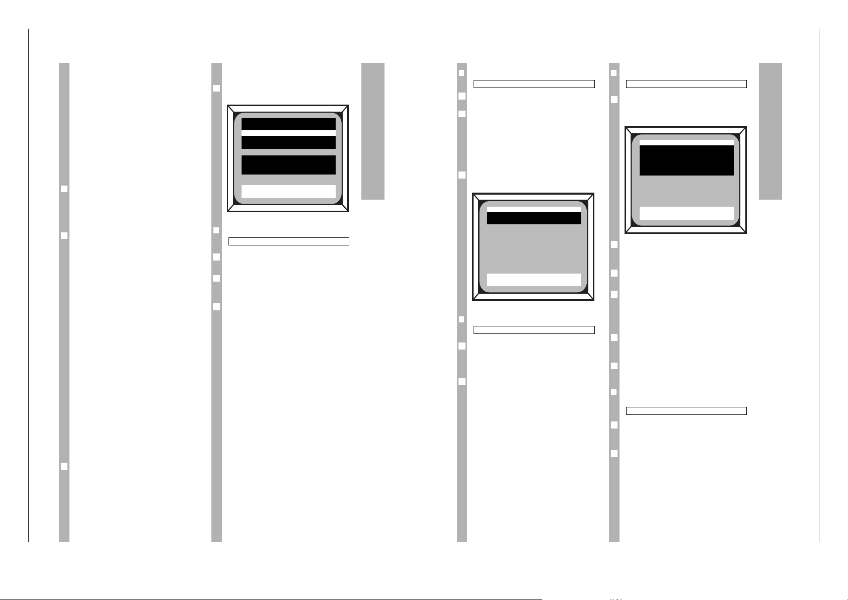
Die einzelnen Menüpunkte
Drücken Sie die Taste
.
MENUE der Fernbedienung.
– Das Hauptmenü erscheint.
❒
Programmplatz wählen
Die Programmwahl erfolgt mit den Tasten
xc
oder den Zifferntasten.
Mit der blauen Taste
g
RADIO können Sie die Anzei-
ge rechts oben zwischen »TV« und »Radio«
umschalten.
Wenn Sie »Radio« wählen und speichern, wird
nach dem Ausblenden der Menütafel der Bildschirm
dunkel geschaltet. Diese Funktion wird benötigt,
wenn Sie einen noch nicht vorprogrammierten
Radiosender nachprogrammieren wollen.
6
2
1
Programm : 007 TV
1
Das Menü
Allgemein
Der Receiver ist bereits auf die aktuellen Programme vieler Satelliten vorprogrammiert (siehe Programmtabelle).
Es kommen immer wieder neue Programme hinzu
oder Sendefrequenzen werden geändert.
In den folgenden Abschnitten wird erklärt, wie Sie
die dazu nötigen Korrekturen vornehmen können.
Einen aktuellen Stand der Sendefrequenzen können
Sie über Videotexttafel verschiedener Sender abfragen (z.B. SAT 1: Videotexttafel 675 oder 3SAT:
Videotexttafel 620). Sie können diese Sender im
Menü nachprogrammieren.
Anzeige am Receiver
Immer wenn eine Menütafel am Bildschirm eingeblendet wird (z.B. Hauptmenü, Timermenü),
erscheint in der Anzeige des Receivers »05d«
(Anzeige von ON SCREEN DISPLAY Informationen
am Bildschirm).
Da die Bedienung fast ausschließlich über wenige
Schlüsseltasten erfolgt, erhalten Sie nun eine kurze
Einführung in die Bedienphilosophie. Viele Erklärungen werden dadurch überflüssig.
Die wichtigsten Tastenfunktionen
im Menü
.
MENUE Zum Aufrufen des Menüs oder eines
Untermenüs. Im Stand-by Mode länger als
5 Sekunden gedrückt halten, das Sondermenü (System) wird aufgerufen.
]|
Mit diesen Tasten wird die weiße Zeilenmarkierung nach oben oder unten verschoben.
xc
Mit diesen Tasten kann ein Wert in der
gewählten Zeile geändert werden.
0…9 Direkte Zifferneingabe.
O
Die geänderten oder neu eingestellten
Werte werden gespeichert.
¢
TXT
EXIT Verlassen der aktuellen Menütafel. Evtl.
geänderte Werte werden durch Drücken
dieser Taste wieder zurückgesetzt, wenn
sie vorher nicht gespeichert wurden.
h
Bei störendem Bildhintergrund kann ein
grüner Bildhintergrund ein- oder ausgeblendet werden.
Tastenerklärung auf dem Bildschirm
In den beiden untersten Zeilen sind alle Tasten aufgeführt, die eine Funktion ausführen. Die möglichen
Tastenfunktionen sind von der jeweils gewählten
Menüzeile abhängig.
6
6
6
Programm : 1 A TV
Name : ARD_ _
Frequenz : 11494.0 MHz
Pol./Ant. : Hor. a / 0 kHz
Decoder : Automatik
LNB LO : 1 (9,750 GHz)
Kontrast : 3 (37)
Audio : 1 ( 7,02 St )
iu
op
0 . . 9 PERI
TXT = Abbruch OK = Speichern
❒
Decodereinstellung
Wählen Sie im Hauptmenü mit den Tasten
xc
die gewünschte Einstellung.
Folgende Decodereinstellungen sind möglich:
Automatik – sollten Sie bei Decodern mit Schalt-
spannungsausgabe einstellen (z.B.
Premiere), der Decoder schaltet sich
automatisch in den Signalweg.
Ein – sollten Sie bei Decodern ohne Schalt-
spannungsausgabe wählen.
Mit der Taste
.
MENUE gelangen Sie in ein Unter-
menü für weitere Decodereinstellungen.
❒
LNB-Oszillatorfrequenzen wählen
Mit den Tasten xcschalten Sie zwischen 4 vorgewählten LO-Frequenzen um (die jeweils zugehörige, eingestellte LO-Frequenz wird in Klammern
angezeigt).
Die vorgewählten LO-Frequenzen können Sie in
einem Untermenü ändern (siehe folgenden
Abschnitt).
2
1
LNB LO: 1 (9750)
2
6
1
Decoder : Automatik
❒
LNB-Oszillatorfrequenzen vorwählen
Um die vorgewählten LO-Frequenzen zu ändern
drücken Sie in der Zeile »LNB LO« des Hauptmenüs
die Taste
.
MENUE.
Die Frequenz der gewählten Zeile können Sie mit
den Zifferntasten direkt eingeben oder mit den
Tasten xcschrittweise ändern.
Mit den Tasten ]|gelangen Sie zur Einstellung
der anderen LO-Frequenzen.
Für Satelliten, die im 2,5 und 4 GHz Bereich senden,
werden LNBs verwendet, die ein „negatives” Bild
erzeugen. Durch die Menüeinstellung »neg«
erscheint auf dem TV-Bildschirm wieder das
gewohnte Bild.
LO-Frequenzen unter 7000 MHz wird automatisch
negative (»neg«) Videopolarität zugeordnet, höheren Frequenzen positive (»pos«).
Mit der roten Taste kkönnen Sie die Polarität
ändern.
❒
LNB-Spannungsversorgung ein-/
ausschalten
Um die LNB-Spannungsversorgung ein-/auszuschalten, drücken Sie in der Zeile »LNB LO« des
Hauptmenüs die Taste
.
MENUE.
Wählen Sie in der Zeile »LNB Spg.« mit den Tasten
xc
zwischen den Einstellungen »14/18 V« (ein)
und »Aus«.
2
1
LNB Spg. : 14/18 V
5
4
6
3
2
1
LO 1 : 9,750 GHz pos
Das Menü
DECODER
Norm : BB Pal
Signal : Video
iu
op
TXT = Abbruch OK = Speichern
LNB LO 1 : 9,750 GHz pos
LNB LO 2 : 9,750 GHz pos
LNB LO 3 : 10,600 GHz pos
LNB LO 4 : 11,475 GHz pos
LNB Spg : 14/18 Volt
iu
op
0 . . 9 rot = pos/neg
TXT = Abbruch OK = Speichern
Page 5
STR 611 Allgemeiner Teil / General Section
GRUNDIG Service 1 - 5
Bedeutung der Einstellungen in der Zeile »Pol/Ant.«
des Hauptmenüs.
ohne Bedeutung
H/V je nach Polarisation
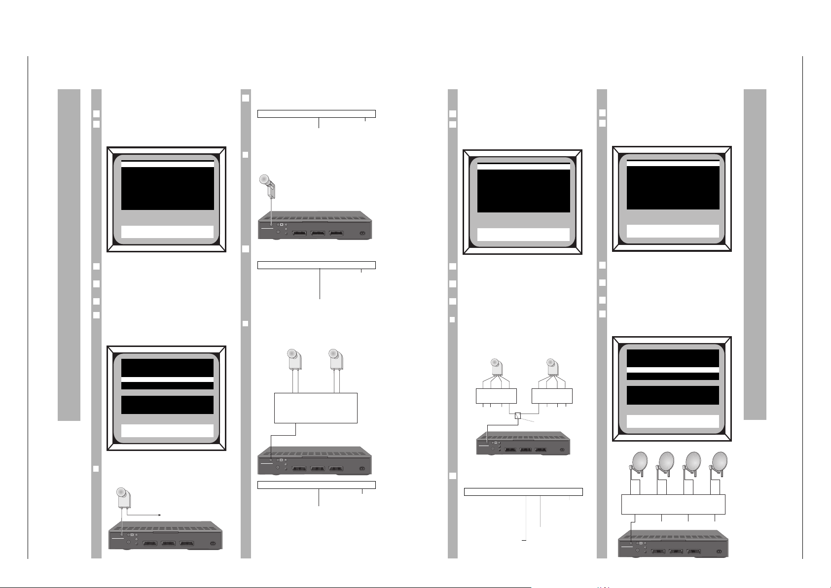
❒
Empfang zweier Frequenzbereiche eines
Satelliten mittels Universal LNB
Bedeutung der Einstellungen in der Zeile »Pol/Ant.«
des Hauptmenüs.
0 kHz: unterer
bzw. 22 kHz:
oberer *
Frequenzbereich
H/V je nach Polarisation
❒
Empfang eines Frequenzbereiches
zweier Satelliten mittels 22 kHz Schalter
und Dual LNBs
0 kHz: LNB 1,
22 kHz: LNB 2
H/V je nach Polarisation
Pol./Ant. : H / 0 kHz
Pol./Ant. : H / 0 kHz
6
Pol./Ant. : H / 0 kHz
6
STR00384
220-240 V~
50-60 Hz
EURO AV VCREURO AV DECODEREURO AV TV
AUDIO OUT
VIDEO
CONTROL
R
L
INPUT-SAT
950-2150 MHz
14/18 V 350 mA
TV
Universal LNB,
z.B. GRUNDIG LNC UNI 3
STR00384
220-240 V~
50-60 Hz
EURO AV VCREURO AV DECODEREURO AV TV
AUDIO OUT
VIDEO
CONTROL
R
L
INPUT-SAT
950-2150 MHz
14/18 V 350 mA
TV
Dual LNBs,
z.B. GRUNDIG
LNC DUAL 1
0 kHz 22 kHz
V/H: (14/18 V)
LNB-Wahl: 0/22 kHz
22 kHz Multischalter
z.B GRUNDIG SVT 5/4
System 1: universell
Drücken Sie die Taste b.
Rufen Sie das Sondermenü auf, dazu Taste
.
MENUE
5 Sekunden drücken.
– Das Sondermenü erscheint.
Wählen Sie mit den Tasten ]|die Zeile
»System«.
Wählen Sie mit den Tasten xcdie Einstellung
»Universell«.
Speichern Sie mit Taste O.
In Abhängigkeit der Systemwahl (im Sondermenü),
können in der Zeile »Ant/Pol« des Hauptmenüs die
Polarisation und Antennenauswahl eingestellt
werden.
❒
Empfang eines Frequenzbereiches eines
Satelliten mittels Twin LNB
6
5
4
3
2
1
Anwendungsbeispiele zur Polarisations-/Antennenauswahl
STR00384
220-240 V~
50-60 Hz
EURO AV VCREURO AV DECODEREURO AV TV
AUDIO OUT
VIDEO
CONTROL
R
L
INPUT-SAT
950-2150 MHz
14/18 V 350 mA
TV
Twin LNB,
z.B. GRUNDIG LNC 975/5 TG
Programm : 1 A TV
Name : ARD . .
Frequenz : 11494,0 MHz
Pol./Ant. : Hor. 0 kHz
Decoder : Automatik
LNB LO : 1 (9,750 GHz)
Kontrast : 3 (36)
Audio : 1 ( 7,02 St )
iu
op
TXT = Abbruch OK = Speichern
* Zur Zeit werden beim Astra-Satellitensystem im oberen Fre-
quenzbereich ausschließlich digitale Programme gesendet.
IR Ebene : SAT 1
Menü-Anz. : Ein
Security : . . . .
System : Universell
Modulator : C 38
Lautst. : 26
Software : Version …
iu
op
TXT = Abbruch OK = Speichern
System 2: Mini DiSEqC
Drücken Sie die Taste b.
Rufen Sie das Sondermenü auf, dazu Taste
.
MENUE
5 Sekunden drücken.
– Das Sondermenü erscheint.
Wählen Sie mit den Tasten ]|die Zeile
»System«.
Wählen Sie mit den Tasten xcdie Einstellung
»Mini DiSEqC«.
Speichern Sie mit Taste O.
❒
Empfang des unteren und oberen
Frequenzbereiches zweier Satelliten mittels ToneBurst-Schalter und Quattro LNBs
Bedeutung der Einstellungen in der Zeile »Pol/Ant.«
des Hauptmenüs.
0 kHz: unterer
bzw. 22 kHz:
oberer *
Frequenzbereich
a: LNB 1
H/V je nach Polarisation b: LNB 2
Pol./Ant. : H a / 0 kHz
6
5
4
3
2
1
Anwendungsbeispiele zur Polarisations-/Antennenauswahl
STR00384
220-240 V~
50-60 Hz
EURO AV VCREURO AV DECODEREURO AV TV
AUDIO OUT
VIDEO
CONTROL
R
L
INPUT-SAT
950-2150 MHz
14/18 V 350 mA
TV
ab
Quattro LNBs
z.B. GRUNDIG LNC UNI Q1
Mini DiSEqC-Schalter z.B.
GRUNDIG SWITCH UNI 1
12
0 kHz 22 kHz
22 kHz Multischalter
z.B. GRUNDIG SVT 5/4
0 kHz 22 kHz
22 kHz Multischalter
z.B. GRUNDIG SVT 5/4
VH VH VH VH
* Zur Zeit werden beim Astra-Satellitensystem im oberen Fre-
quenzbereich ausschließlich digitale Programme gesendet.
System 3: DiSEqC 1.0
Drücken Sie die Taste b.
Rufen Sie das Sondermenü auf, dazu Taste
.
MENUE
5 Sekunden drücken.
– Das Sondermenü erscheint.
Wählen Sie mit den Tasten ]|die Zeile
»System«.
Wählen Sie mit den Tasten xcdie Einstellung
»DiSEqC 1.0«.
Speichern Sie mit Taste O.
Durch die Systemauswahl DiSEqC 1.0 können bis
zu 8 Satelliten bzw. 16 Ebenen im Hauptmenü
angewählt werden.
6
5
4
3
2
1
IR Ebene : SAT 1
Menü-Anz. : Ein
Security : . . . .
System : Mini DiSEqC
Modulator : C 38
Lautst. : 26
Software : Version …
iu
op
TXT = Abbruch OK = Speichern
IR Ebene : SAT 1
Menü-Anz. : Ein
Security : . . . .
System : DiSEqC 1.0
Modulator : C 38
Lautst. : 26
Software : Version …
iu
op
TXT = Abbruch OK = Speichern
Programm : 1 A TV
Name : ARD_ _
Frequenz : 11494.0 MHz
Pol./Ant. : Hor. a1 Low
Decoder : Automatik
LNB LO : 1 (9,750 GHz)
Kontrast : 3 (37)
Audio : 1 ( 7,02 St )
iu
op
TXT = Abbruch OK = Speichern
STR00384
220-240 V~
50-60 Hz
EURO AV VCREURO AV DECODEREURO AV TV
AUDIO OUT
VIDEO
CONTROL
R
L
INPUT-SAT
950-2150 MHz
14/18 V 350 mA
TV
HVHVHVH V
8-fach Multischalter
z.B. Kathrein EXR 904
Page 6

Allgemeiner Teil / General Section STR 611
1 - 6 GRUNDIG Service
Mit der Taste
.
MENUE das Einstellmenü für die hin-
terlegten Motordaten aufrufen.
Wählen Sie mit den Tasten xcdie Satellitenpositionen 0 bis 31 an.
Wählen Sie mit den Tasten ]|die Zeile »Antenne drehen« an.
Mit den Tasten xcwird der V-SEC Motoreinheit
über 22 kHz Impulse der Drehbefehl Ost (x) oder
West (c) übermittelt.
Wählen Sie mit den Tasten ]|die Zeile
»Position« an und ändern mit den Tasten xcdie
Position.
– Jeder Satellit kann mit einer Positionsangabe hin-
terlegt werden.
Mit Taste Owerden die Positionsdaten im Receiver und die Motordaten in der Y-SEC Motoreinheit
abgespeichert.
Nähere Beschreibungen entnehmen Sie der Bedienungsanleitung Ihrer V-SEC Motoreinheit.
6
6
5
4
3
2
1
Anwendungsbeispiele zur Polarisations-/Antennenauswahl
System 4: V-SEC
Drücken Sie die Taste b.
Rufen Sie das Sondermenü auf, dazu Taste
.
MENUE
5 Sekunden drücken.
– Das Sondermenü erscheint.
Wählen Sie mit den Tasten ]|die Zeile
»System«.
Wählen Sie mit den Tasten xcdie Einstellung
»V-SEC«.
Speichern Sie mit Taste O.
Wird im Sondermenü das System »V-SEC« gewählt
kann im Hauptmenü zusätzlich die Satellitenposition für Variosat-Positioner eingestellt werden.
Es sind bis zu 31 Satellitenpositionen anwählbar.
Die Satellitenposition 0 ist zur Begrenzung des
Ost/West-Drehbereiches der Motoreinheit vorgesehen.
6
6
5
4
3
2
1
Programm : 1 A TV
Name : ARD_ _
Frequenz : 11494.0 MHz
Pol./Ant. : Hor. / 0 kHz
Decoder : Automatik
Satellit : 1 (19’Ost)
LNB LO : 1 (9,750 GHz)
Kontrast : 3 (37)
Audio : 1 ( 7,02 St )
iu
op
TXT = Abbruch OK = Speichern
Satellit : 1
Antenne drehen : – –
Position : 19’ Ost
/
iu
op
TXT = Zurück OK = Speichern
IR Ebene : SAT 1
Menü-Anz. : Ein
Security : . . . .
System : V-SEC
Modulator : C 38
Lautst. : 26
Software : Version …
iu
op
TXT = Abbruch OK = Speichern
Menü-Übersicht
Hauptmenü
Timermenü
Menü zur Bild- und Tonverbesserung (Threshold extension/DX)
Sondermenü
Programm : 1 TV
Name : ARD . .
Frequenz : 11494,0 MHZ
Pol./Ant : Hor. / a 0 kHz
Decoder : Ein
Satellit
1)
: 1 (19° Ost)
LNB LO : 1 (9,750 GHz)
Kontrast : 3 (37)
Audio : 1 (7,02 ST)
P 9 TV : RTL 2
P 8 TV : VOX
P 7 TV : PRO 7
P 6 TV : 3SAT
P 5 TV : N-TV
P 4 TV : SAT 1
P 3 TV : RTL
P 2 TV : ZDF
P 1 TV : ARD
LNB LO 1 : 09,750 GHz pos
LNB LO 2 : 09,750 GHz pos
LNB LO 3 : 10,600 GHz pos
LNB LO 4 : 11,475 GHz pos
LNB Spg. : 14/18 Volt
Kontrast 1 : 16
Kontrast 2 : 22
Kontrast 3 : 37
Kontrast 4 : 16
Audio Nr. : 1
Audio L : 7,02 MHz
Audio R : 7,20 MHz
Mode : Stereo
Deemphasis : Panda
Audio BW : 110 kHz
e
Threshold : Aus
Audio BW : Normal
e
Timer 1 : Ein
Programm : 1 ARD
Datum : 24.12.96
Start : 21:00
Stop : 22:15
IR Ebene : SAT 1
Menü-Anz. : EIN
Security : . . . .
System : universell
Modulator : C 38
Lautst. : 26
Software : Version …
e
Timer 1 : Aus
Timer 2 : Aus
Timer 3 : Aus
Timer 4 : Aus
Datum : 24.12.96
Uhrzeit : 18:46
.
MENUE
®DX
h
.
MENUE
.
MENUE
.
MENUE
.
MENUE
.
MENUE
Decoder
Norm : FBAS
Signal : Video + Audio
.
MENUE
1)
nur bei V-SEC
Page 7

STR 611 Allgemeiner Teil / General Section
GRUNDIG Service 1 - 7
Operating Hints This chapter contains excerpts from the operating instructions. For further particulars please refer to the appropriate user instructions the part number of which is indicated in the
relevant spare parts list.
The Menu Items
Press the
.
MENUE key on the remote control unit.
– The main menu is displayed.
❒
Selecting programme positions
Use the
xc
keys or the numeric keys to select
the desired programme position.
Use the blue
g
RADIO key to switch between the
“TV” and “Radio” option in the top right corner.
If you select and save the “Radio” option, the
screen is switched blue when exiting the menu.
Select this option if you wish to programme a radio
station which is not yet preprogrammed.
6
2
1
Programm : 007 TV
1
The On-Screen Menu Guide
General
The receiver is already preprogrammed to the current stations of many satellites (see Station table).
New stations arrive again and again and station
frequencies are changed.
The following sections describe how to make the
required corrections.
You can find the current station frequencies on the
teletext pages of certain stations (e.g. SAT 1: teletext page 675, or 3SAT: teletext page 620) or in a
current satellite magazine. Stations can be reprogrammed via the menu.
Display on the receiver
Every time a menu is displayed on the picture
screen (e.g. main menu or timer menu), “05d”
(= ON SCREEN DISPLAY of information) appears in
the receiver’s display.
As only a few keys ar required for navigating in the
menus, a brief description of the menu philosophy
will suffice for using the menus.
Important Key Functions for the
Menus
.
MENUE Displays the main menu or a sub-menu.
Pressing the key for more than 5 s in
stand-by mode calls up the special menu
(system).
]|
Moves the white cursor bar up or down.
xc
Change values in the selected line.
0…9 Direct entry of digits.
O
Saves the changed or newly set values.
¢
TXT
EXIT Exits the current menu. Changed values
which have not been saved are restored.
h
Switches on and off the green picture
screen background.
On-screen key explanations
All keys performing a function are shown in the two
bottom menu lines. The possible key functions
depend on the menu line selected.
6
6
6
Programm : 1 A TV
Name : ARD_ _
Frequenz : 11494.0 MHz
Pol./Ant. : Hor. a / 0 kHz
Decoder : Automatik
LNB LO : 1 (9,750 GHz)
Kontrast : 3 (37)
Audio : 1 ( 7,02 St )
iu
op
0 . . 9 PERI
TXT = Abbruch OK = Speichern
❒
Decoder settings
Use the xckeys to select the desired setting in
the main menu.
The following decoder settings are possible:
Automatik – Select this option for decoders which
supply a switching voltage (e.g. Première); the decoder then is automatically switched into the signal path.
Ein (On) – Select this option for decoders without
switching voltage generation.
Press the
.
MENUE key to display a submenu for
further decoder settings.
❒
Selecting LNB oscillator frequencies
Use the xckeys to select between 4 preset LO
frequencies (the assigned LO frequency is shown
between brackets).
It is possible to change the preset LO frequencies in
a submenu (see following section).
2
1
LNB LO: 1 (9750)
2
6
1
Decoder : Automatik
❒
Preselecting LNB oscillator frequencies
To change the preselected LO frequencies, press
the
.
MENUE key when in the “LNB LO” line of the
main menu.
Enter the frequency directly with the numeric keys
or change it step by step with the xckeys.
Use the ]|keys to go to the other LO frequency
settings.
For satellites broadcasting in the 2.5 and 4 GHz
range, LNB’s are used which produce a “negative”
picture. In this case, select the “neg” menu option
to get a “normal” picture on the screen.
A negative (“neg”) video polarity is automatically
asssigned to LO frequencies below 7000 MHz
and a positive (“pos”) video polarity to higher
frequencies.
You can change the polarity by pressing the red
k
key.
❒
LNB power supply on/off
In order to change the LNB power supply setting,
press the
.
MENUE key when in the “LNB LO” line of
the main menu.
Use the xckeys when in the “LNB Spg.” menu
line to select between “14/18 Volt” (on) and “Aus”
(off).
2
1
LNB Spg. : 14/18 V
5
4
6
3
2
1
LO 1 : 9,750 GHz pos
The On-Screen Menu Guide
DECODER
Norm : BB Pal
Signal : Video
iu
op
TXT = Abbruch OK = Speichern
LNB LO 1 : 9,750 GHz pos
LNB LO 2 : 9,750 GHz pos
LNB LO 3 : 10,600 GHz pos
LNB LO 4 : 11,475 GHz pos
LNB Spg : 14/18 Volt
iu
op
0 . . 9 rot = pos/neg
TXT = Abbruch OK = Speichern
Page 8

Allgemeiner Teil / General Section STR 611
1 - 8 GRUNDIG Service
Meaning of the settings in the “Pol/Ant.” line of the
main menu.
no meaning
H/V acc. to polarization
❒
Reception of two frequency ranges of one
satellite with one universal LNB
Meaning of the settings in the “Pol/Ant.” line of the
main menu.
0 kHz: low
or 22 kHz:
high*
frequency range
H/V acc. to polarization
❒
Reception of one frequency range of two
satellites with a 22 kHz switch and Dual
LNBs
0 kHz: LNB 1,
22 kHz: LNB 2
H/V acc. to polarization
Pol./Ant. : H / 0 kHz
Pol./Ant. : H / 0 kHz
6
Pol./Ant. : H / 0 kHz
6
STR00384
220-240 V~
50-60 Hz
EURO AV VCREURO AV DECODEREURO AV TV
AUDIO OUT
VIDEO
CONTROL
R
L
INPUT-SAT
950-2150 MHz
14/18 V 350 mA
TV
Universal LNB,
e.g. GRUNDIG LNC UNI 3
STR00384
220-240 V~
50-60 Hz
EURO AV VCREURO AV DECODEREURO AV TV
AUDIO OUT
VIDEO
CONTROL
R
L
INPUT-SAT
950-2150 MHz
14/18 V 350 mA
TV
Dual LNBs,
e.g. GRUNDIG
LNC DUAL 1
0 kHz 22 kHz
V/H: (14/18 V)
LNB selection: 0/22 kHz
22 kHz multiswitch,
e.g. GRUNDIG SVT 5/4
12
System 1: universal
Press the bkey.
Press the
.
MENUE key for more than 5 seconds to
display the special menu.
– The special menu appears.
Use the ]|keys to select the “System” menu
line.
Use the
xc
keys to select the “Universell”
setting.
Save with the Okey.
It is possible to select the polarization and aerial
selection in the “Ant/Pol” line of the main menu as a
function of the system selected.
❒
Reception of one frequency range of one
satellite with a Twin LNB
6
5
4
3
2
1
Examples to Polarization/Aerial Selection
STR00384
220-240 V~
50-60 Hz
EURO AV VCREURO AV DECODEREURO AV TV
AUDIO OUT
VIDEO
CONTROL
R
L
INPUT-SAT
950-2150 MHz
14/18 V 350 mA
TV
Twin LNB,
e.g. GRUNDIG LNC 975/5 TG
VH VH
Programm : 1 A TV
Name : ARD . .
Frequenz : 11494,0 MHz
Pol./Ant. : Hor. 0 kHz
Decoder : Automatik
LNB LO : 1 (9,750 GHz)
Kontrast : 3 (36)
Audio : 1 ( 7,02 St )
iu
op
TXT = Abbruch OK = Speichern
* At the moment, only digital programmes are broadcast in the
high frequency range of the Astra satellite system.
IR Ebene : SAT 1
Menü-Anz. : Ein
Security : . . . .
System : Universell
Modulator : C 38
Lautst. : 26
Software : Version …
iu
op
TXT = Abbruch OK = Speichern
System 2: Mini DiSEqC
Press the bkey.
Press the
.
MENUE key for more than 5 seconds to
display the special menu.
– The special menu appears.
Use the ]|keys to select the “System” menu
line.
Use the xckeys to select the “Mini DiSEqC”
setting.
Save with the Okey.
❒
Reception of the low and high frequency
range of two satellites with a ToneBurst
switch and Quattro LNBs
Meaning of the settings in the “Pol/Ant.” line of the
main menu.
0 kHz: low
or 22 kHz:
high*
frequency range
a: LNB 1
H/V acc. to polarization b: LNB 2
Pol./Ant. : H a / 0 kHz
6
5
4
3
2
1
Examples to Polarization/Aerial Selection
STR00384
220-240 V~
50-60 Hz
EURO AV VCREURO AV DECODEREURO AV TV
AUDIO OUT
VIDEO
CONTROL
R
L
INPUT-SAT
950-2150 MHz
14/18 V 350 mA
TV
ab
Quattro LNBs
e.g. GRUNDIG LNC UNI Q1
Mini DiSEqC switch, e.g.
GRUNDIG SWITCH UNI 1
12
0 kHz 22 kHz
22 kHz multi-switch,
e.g. GRUNDIG SVT 5/4
0 kHz 22 kHz
22 kHz multi-switch,
e.g. GRUNDIG SVT 5/4
VH VH VH VH
* At the moment, only digital programmes are broadcast in the
high frequency range of the Astra satellite system.
System 3: DiSEqC 1.0
Press the bkey.
Press the
.
MENUE key for more than 5 seconds to
display the special menu.
– The special menu appears.
Use the ]|keys to select the “System” menu
line.
Use the xckeys to select the “DiSEqC 1.0”
setting.
Save with the Okey.
With the DiSEqC 1.0 system selection, up to 8
satellites or 16 polarizations can be selected in the
main menu.
6
5
4
3
2
1
IR Ebene : SAT 1
Menü-Anz. : Ein
Security : . . . .
System : Mini DiSEqC
Modulator : C 38
Lautst. : 26
Software : Version …
iu
op
TXT = Abbruch OK = Speichern
IR Ebene : SAT 1
Menü-Anz. : Ein
Security : . . . .
System : DiSEqC 1.0
Modulator : C 38
Lautst. : 26
Software : Version …
iu
op
TXT = Abbruch OK = Speichern
Programm : 1 A TV
Name : ARD_ _
Frequenz : 11494.0 MHz
Pol./Ant. : Hor. a1 Low
Decoder : Automatik
LNB LO : 1 (9,750 GHz)
Kontrast : 3 (37)
Audio : 1 ( 7,02 St )
iu
op
TXT = Abbruch OK = Speichern
STR00384
220-240 V~
50-60 Hz
EURO AV VCREURO AV DECODEREURO AV TV
AUDIO OUT
VIDEO
CONTROL
R
L
INPUT-SAT
950-2150 MHz
14/18 V 350 mA
TV
HVHVHVH V
8-fold multi-switch
e.g. Kathrein EXR 904
Page 9

STR 611 Platinenabbildungen und Schaltpläne / Layout of the PCBs and Circuit Diagrams
0V
1 1V/cm, 100ns/cm
0V
0V
0V
2
CS OSD
SCL
SDA
5V/cm, 20ms/cm
500mV/cm, 20ms/cm (SDA)
Use the
.
MENUE
key to display the setting menu for
the stored motor data.
Use the
xc
keys to select the satellite positions
0 to 31.
Use the ]|keys to select the “Antenne drehen”
(rotate aerial) menu line.
Use the
xc
keys to send the rotate command
East (
x
) or West (
c
) via 22 kHz impulses to the
V-SEC motor unit.
Use the ]|keys to select the “Position” menu
line then use the
xc
keys to change the
position.
– A position can be stored for every satellite.
Use the
O
key to store the position data in the
receiver and the motor data in the Y-SEC motor
unit.
For more information refer to the user manual of
the V-SEC motor unit.
6
6
5
4
3
2
1
Examples to Polarization/Aerial Selection
System 4: V-SEC
Press the
b
key.
Press the
.
MENUE
key for more than 5 seconds to
display the special menu.
– The special menu appears.
Use the ]|keys to select the “System” menu
line.
Use the
xc
keys to select the “V-SEC” setting.
Save with the
O
key.
If the “V-SEC” system is selected in the special
menu, the satellite position for a Variosat Positioner
can additionally be selected in the main menu.
Up to 31 satellite positions can be selected.
The satellite position 0 is provided for limiting the
east/west action range of the motor unit.
6
6
5
4
3
2
1
Programm : 1 A TV
Name : ARD_ _
Frequenz : 11494.0 MHz
Pol./Ant. : Hor. / 0 kHz
Decoder : Automatik
Satellit : 1 (19’Ost)
LNB LO : 1 (9,750 GHz)
Kontrast : 3 (37)
Audio : 1 ( 7,02 St )
iu
op
TXT = Abbruch OK = Speichern
Satellit : 1
Antenne drehen : – –
Position : 19’ Ost
/
iuopTXT = Zurück OK = Speichern
IR Ebene : SAT 1
Menü-Anz. : Ein
Security : . . . .
System : V-SEC
Modulator : C 38
Lautst. : 26
Software : Version …
iuopTXT = Abbruch OK = Speichern
Menu Overview
Main menu
Timer menu
Menu for picture and sound improvement (Threshold extension/DX)
Special menu
Programm : 1 TV
Name : ARD . .
Frequenz : 11494,0 MHZ
Pol./Ant : Hor. / a 0 kHz
Decoder : Ein
Satellit
1)
: 1 (19° Ost)
LNB LO : 1 (9,750 GHz)
Kontrast : 3 (37)
Audio : 1 (7,02 ST)
P 9 TV : RTL 2
P 8 TV : VOX
P 7 TV : PRO 7
P 6 TV : 3SAT
P 5 TV : N-TV
P 4 TV : SAT 1
P 3 TV : RTL
P 2 TV : ZDF
P 1 TV : ARD
LNB LO 1 : 09,750 GHz pos
LNB LO 2 : 09,750 GHz pos
LNB LO 3 : 10,600 GHz pos
LNB LO 4 : 11,475 GHz pos
LNB Spg. : 14/18 Volt
Kontrast 1 : 16
Kontrast 2 : 22
Kontrast 3 : 37
Kontrast 4 : 16
Audio Nr. : 1
Audio L : 7,02 MHz
Audio R : 7,20 MHz
Mode : Stereo
Deemphasis : Panda
Audio BW : 110 kHz
e
Threshold : Aus
Audio BW : Normal
e
Timer 1 : Ein
Programm : 1 ARD
Datum : 24.12.96
Start : 21:00
Stop : 22:15
IR Ebene : SAT 1
Menü-Anz. : EIN
Security : . . . .
System : universell
Modulator : C 38
Lautst. : 26
Software : Version …
e
Timer 1 : Aus
Timer 2 : Aus
Timer 3 : Aus
Timer 4 : Aus
Datum : 24.12.96
Uhrzeit : 18:46
.
MENUE
®
DX
h
.
MENUE
.
MENUE
.
MENUE
.
MENUE
.
MENUE
Decoder
Norm : FBAS
Signal : Video + Audio
.
MENUE
1)
only with V-SEC
STR 611 Allgemeiner Teil / General Section
STR 611 Platinenabbildungen und Schaltpläne / Layout of the PCBs and Circuit Diagrams
Platinenabbildungen und Schaltpläne / Layout of the PCBs and Circuit Diagrams
Oszillogramme / Oscillogrammes
0V
3 2V/cm, 2ms/cm
IR-Signal
5
0V
5A
5
2V/cm, 20ms/cm
5A
1V/cm, 20ms/cm
0V
6 2V/cm, 20µs/cm
0V
0V
7 1V/cm, 25ns/cm
4 1V/cm, 20µs/cm
8
2V/cm, 10ms/cm
8A
1V/cm, 10ms/cm
0V
10
0V
10A
0V
GRUNDIG Service
1 - 9
9 1V/cm, 20ns/cm
0V
10 1V/cm, 20µs/cm
0V
Chassisplatte / Chassis Board
Koordinaten für die Bauteile der Lötseite (Unterseite)
Coordinates of the components on the solder side (bottom side)
Bestückungskoordinaten der Bauteile
- Die Koordinaten X und Y sind sowohl als metrische Koordinaten
für die Originalplatine in Millimeter, als auch als absolute Koordinaten für die vergrößerten Abbildungen der Platinen verwendbar.
Pos.-Nr./ Koordinaten/
Pos. No. Coordinates
CC1003 47 124
CC1004 32 85
CC1006 43 100
CC1013 64 43
CC1014 78 50
CC1016 81 50
CC1017 77 41
CC1019 90 44
CC1021 255 43
CC1025 245 60
CC1026 237 80
CC1029 236 86
CC1030 223 82
CC1036 255 57
CC1037 252 56
CC1038 242 45
CC1039 236 35
CC1041 227 44
CC1042 222 44
CC1044 239 45
CC1046 214 63
XY
GRUNDIG Service
Pos.-Nr./ Koordinaten/
Pos. No. Coordinates
CC1047 241 38
CC1051 247 56
CC1052 244 56
CC1053 258 49
CC1054 222 64
CC1056 239 56
CC1057 236 56
CC1059 231 56
CC1061 215 56
CC1062 236 70
CC1072 218 77
CC1073 210 81
CC1074 207 80
CC1076 210 61
CC1077 210 64
CC1078 209 37
CC1079 210 41
CC1081 205 45
CC1083 210 55
CC1086 210 58
CC1108 60 119
XY
Pos.-Nr./ Koordinaten/
Pos. No. Coordinates
CC1110 52 51
CC1113 54 46
CC1114 66 49
CC1145 25 26
CC1201 214 105
CC1203 213 110
CC1211 209 108
CC1213 204 113
CC1221 269 110
CC1223 264 109
CC1231 261 94
CC1233 259 109
CC1262 153 110
CC1264 148 110
CC1331 127 75
CC1333 100 79
CC1334 110 82
CC1335 104 81
CC1336 116 89
CC1337 108 77
CC1338 103 54
XY
0V
0V
11 2V/cm, 10µs/cm
12 100V/cm, 20µs/cm
Assembly coordinates of the components
- The X and Y coordinates can be used as both metric coordinates
in mm for the original circuit board and absolute coordinates for the
enlarged diagrams of the circuit boards.
Pos.-Nr./ Koordinaten/
Pos. No. Coordinates
CC1339 115 84
CC1345 107 55
CC1346 112 55
CC1354 98 89
CC1356 92 87
CC1401 109 4
CC1402 97 4
CC1403 94 10
CC1404 90 12
CC1407 102 8
CC1410 75 102
CC1411 85 108
CC1412 70 95
CC1415 60 110
CC1454 250 103
CC1456 261 103
CC1457 278 112
CC1458 293 123
CC1460 300 110
CC1649 289 74
CC1650 289 77
XY
Pos.-Nr./ Koordinaten/
Pos. No. Coordinates
CC1654 301 45
CC1656 278 40
CC1662 287 53
CC1707 211 9
CC1712 221 11
CC1718 284 19
CC1727 334 14
CC1762 315 15
CC1768 299 67
CC2003 22 123
CC2004 21 84
CC2006 26 93
CC2009 25 47
CC2013 18 38
CC2014 35 49
CC2016 38 48
CC2017 34 43
CC2019 41 38
CC2021 183 41
CC2025 173 60
CC2026 168 81
XY
Pos.-Nr./ Koordinaten/
Pos. No. Coordinates
CC2029 167 85
CC2030 154 80
CC2036 185 59
CC2037 182 55
CC2038 171 43
CC2039 162 35
CC2041 159 42
CC2042 154 42
CC2044 168 43
CC2046 144 62
CC2047 168 32
CC2051 179 56
CC2052 174 55
CC2053 180 70
CC2054 147 60
CC2056 168 55
CC2057 165 55
CC2059 160 54
CC2061 143 56
CC2062 166 69
CC2072 144 77
XY
2 - 1
Page 10

Platinenabbildungen und Schaltpläne / Layout of the PCBs and Circuit Diagrams STR 611
Chassisplatte / Chassis Board
Lötseite / Solder side
Platinenabbildungen und Schaltpläne / Layout of the PCBs and Circuit Diagrams STR 611
Y
130
120
110
100
90
80
70
60
50
40
30
20
10
CR1455
CR1759
CR1650
EB
CR1662
CR1672
CC1718
CR1653
CIC1450
CR1647
CR1646
CC1650
CR1663
CR1460
CC1662
CC1649
CC1458
CR1443
CD1732
CR1731
CR1458
CR1459
CC1460
CC1768
CD1731
31
CD1735
CC1654
CR1763
CR1762
CD1736
CC1762
CR1755
CR1754
CD1726
CR1766
CR1726
CC1727
CC2110
CR1818
CR2018
CR2010
CR2001
CR2004
CR2016
CC2113
CC2004
CR2013
CC2013
CT2013
EB
CIC1140
CC2003
CC2006
CC1145
CR2014
CR2015
CC2009
CR2009
CR2005
CIC1120
CR1010
CR2006
CC1004
CR1823
CC2014
CR2017
CR1824
CR1001
CR1006
CC2017
CC2019
CR1004
CT2012
CC2016
CC1006
EB
CR1812
CC1003
CR1005
CR2012
CR1813
CR1800
CR1018
CR1814
CC1110
CR1806
CC1415
CR1016
CC1113
CC1108
CR1267
CR1013
CT1105
CR1108
CR1821
CR1807
CT1013
CR1265
EB
CR1413
CR1403
CR1266
CIC1330
CC1013
CR1811
EB
CD2043
CR1102
CR1402
CR1014
CR1808
CT1101
CT1405
CR1105
CR1106
CC1410
CC1412
CC1114
CR1009
CR1107
EB
CR1015
CR1820
CD2042
EB
CR1414
CR1411
CR1101
EB
CR1417
CIC1401
CR1416
CC1014
CR1017
CC1017
CT1400
CIC1400
CT1012
CR1401
CT1406
CR1419
CR1412
EB
EB
CR1410
CR1012
CC1016
CC1404
CR1409
CT1407
CR1418
CR1816
CC1356
CC1019
CC1411
CR1415
CR1356
EB
CR1817
CR1822
CC1403
CR1354
CD1344
CC1333
CC1402
CR1275
CC1354
CR1819
CR1344
CR1815
CR1128
CR1359
CT1365
CT1350
EB
CC1335
CC1337
CR1343
CC1338
CR1131
CC1407
CR1342
CR1404
CR1273
CC1334
CC1345
CT1260
EB
CC1401
CR1358
CR1270
CR1338
CR1333
CIC1331
CC1346
CR1337
EB
CR1334
CR1809
CR1268
CR1276
CT1270
CC1339
CR1810
CR1269
EB
CR1336
CC1336
CT1277
CC1331
CR2045
CR1280
CR1279
CT1254
CR1278
EB
CR1331
CR2077
CR2076
CC2076
CC2086
CR2086
CR2083
CR2049
EB
EB
CT1276
CC2081
CT2078
CR1251
CR1277
EB
CR1252
CR2048
CC2074
EB
CT1250
CR1254
CC2073
CR2074
CC2077
CC2083
CR2081
CC2078
CR1262
CR1263
CR1255
CC1262
CC1264
CR2033
CC2079
CR2078
CR2073
CR2079
CT2073
EB
CR2072
CC2046
CC2061
CR2071
CR2061
CR2039
CC2072
CC2054
CD2041
CT2071
CR2087
CR2054
CR2042
CC2030
CD2053
CD2039
CR2046
CR2047
EB
CC2042
CD2054
CR2059
CR2041
29306-101.51/4LS(08)
CC2059
CC2041
CD2038
CR2029
CR2026
CC2062
CR2057
CC2039
CD2056
CC2057
CR2044
CC2044
CR1211
CR1300
CC2029
CC2026
CR2056
CC2056
CR2027
CR2025
CC2047
CR1205
CR2028
CR2058
CT1210
CC2025
CC2052
CC2038
CR2062
CR2051
CR2052
CR1209
EB
CR2037
CR1204
CC2053
CR2036
CC2037
CR1208
CC2021
CC2036
31
CR1049
CR1216
CD1216
CR1180
CC1081
CR1667
CR1215
CC1086
CR1086
CR1076
CR1668
CR1212
CR1083
CC1213
CR1077
EB
CT1078
CT1665
CR1045
CC1074
EB
CR1201
CC1211
CC1077
CR1081
CC1078
CR1213
CR1074
CC1083
CC1079
CT1640
CC1707
CC1201
CC1073
CR1073
CC1076
CR1641
CR1203
CR1033
CC1046
CR1079
CR1078
CR1072
CR1087
CC1061
CR1071
CR1702
CC1203
CT1073
EB
CR1054
CR1061
CD1041
CR1710
CR1703
EB
CR1302
CT1071
EB
CC1030
CC1072
CC1054
CD1053 CD1054
CR1046
CR1042
CC1042
CR1041
CD1039
CT1710
CC1712
CT1715
EB
CR1712
CR1231
CR1246
CC1041
CD1246
CR1040
CR1059
CR1039
EB
CR1707
CR1715
CR1029
CD1056
CC1059
CT1650
CT1230
31
CR1026
CD1038
CR1713
CR1225
CC1062
CR1056
CR1057
CR1044
CC1039
CR1711
CC1029
CC1057
EB
CR1229
CC1026
CC1044
CR1708
CR1709
EB
CR1227
CC1056
CC1047
CR1283
CT1280
CR1025
CR1670
CR1028
CR1027
CC1038
CR1290
CR1282
CC1025
CC1052
CT1281
EB
EB
CR1284
CR1052
CC1051
CC1454
CR1051
CR1058
CR1228
CT1736
CR1450
CR1037
CC1037
CC1021
CR1281
CR1062
CC1036
CR1036
CC1053
CR1736
EB
CR1245
CC1233
CR1753
CR1770
CR1233
CC1223
CC1456
CC1231
CR1644
CR1673
CT1737
CR1756
CT1675
CR1223
CC1221
CR1648
CR1678
CR1752
CR1221
CT1733
CR1758
EB
EB
CR1454
CR1232
CT1645
CR1674
CC1656
CC1457
CR1649
CR1645
0
0 10 20 30 40 50 60 70 80 90 100 110 120 130 140 150 160 170 180 190 200 210 220 230 240 250 260 270 280 290 300 310 320 330 340 350 360
X
Pos.-Nr./ Koordinaten/
Pos. No. Coordinates
CC2073 137 77
CC2074 134 76
CC2076 139 60
CC2077 139 63
CC2078 136 37
CC2079 136 45
CC2081 132 45
CC2083 139 54
CC2086 139 57
CC2110 12 52
CC2113 15 47
CD1038 231 38
CD1039 226 36
CD1041 226 40
CD1053 222 60
CD1054 229 60
CD1056 233 64
CD1216 193 109
CD1246 230 100
CD1344 101 75
CD1726 329 28
CD1731 297 18
CD1732 299 29
CD1735 300 77
CD1736 306 29
CD2038 159 36
CD2039 154 34
CD2041 153 38
XY
2 - 2
5 4325 1091
Pos.-Nr./ Koordinaten/
Pos. No. Coordinates
CD2042 74 118
CD2043 67 119
CD2053 152 59
CD2054 158 59
CD2056 163 60
CIC1120 31 19
CIC1140 23 7
CIC1330 65 71
CIC1331 114 69
CIC1400 77 86
CIC1401 77 18
CIC1450 288 112
CO1 184 87
CO3 187 88
CO4 190 79
CO5 188 88
CR1001 41 123
CR1004 40 84
CR1005 46 101
CR1006 40 100
CR1009 65 46
CR1010 32 94
CR1012 82 57
CR1013 59 46
CR1014 67 54
CR1015 67 52
XY
CR1016 56 53
Pos.-Nr./ Koordinaten/
Pos. No. Coordinates
CR1017 77 44
CR1018 51 54
CR1025 242 59
CR1026 235 80
CR1027 240 80
CR1028 243 90
CR1029 234 86
CR1033 215 90
CR1036 255 55
CR1037 251 59
CR1039 231 34
CR1040 228 86
CR1041 224 44
CR1042 219 44
CR1044 232 44
CR1045 209 85
CR1046 222 56
CR1049 199 40
CR1051 249 56
CR1052 250 62
CR1054 218 60
CR1056 236 61
CR1057 234 56
CR1058 247 44
CR1059 228 56
CR1061 217 56
CR1062 256 77
CR1071 216 47
CR1072 216 77
XY
Pos.-Nr./ Koordinaten/
Pos. No. Coordinates
CR1073 213 77
CR1074 210 77
CR1076 206 61
CR1077 206 64
CR1078 211 37
CR1079 211 47
CR1081 209 48
CR1083 205 55
CR1086 205 58
CR1087 216 71
CR1101 75 113
CR1102 63 117
CR1105 75 108
CR1106 75 105
CR1107 68 124
CR1108 61 115
CR1128 97 11
CR1131 101 15
CR1180 203 48
CR1201 207 113
CR1203 213 113
CR1204 181 102
CR1205 175 98
CR1208 183 107
CR1209 180 113
CR1211 169 118
CR1212 202 113
CR1213 210 113
CR1215 198 114
XY
Pos.-Nr./ Koordinaten/
Pos. No. Coordinates
XY
CR1216 195 113
CR1221 272 113
CR1223 269 114
CR1225 234 113
CR1227 238 102
CR1228 249 108
CR1229 238 113
CR1231 228 119
CR1232 274 102
CR1233 263 114
CR1245 259 114
CR1246 229 104
CR1251 132 109
CR1252 134 113
CR1254 134 102
CR1255 138 114
CR1262 152 113
CR1263 146 114
CR1265 63 82
CR1266 68 77
CR1267 59 84
CR1268 118 107
CR1269 119 111
CR1270 115 98
CR1273 112 98
CR1275 99 114
CR1276 122 102
CR1277 128 94
Pos.-Nr./ Koordinaten/
Pos. No. Coordinates
CR1278 127 102
CR1279 125 110
CR1280 124 113
CR1281 255 114
CR1282 244 113
CR1283 241 113
CR1284 245 102
CR1290 251 126
CR1300 167 114
CR1302 225 117
CR1331 127 69
CR1333 112 78
CR1334 114 78
CR1336 120 93
CR1337 115 93
CR1338 113 85
CR1342 104 68
CR1343 102 71
CR1344 99 71
CR1354 95 84
CR1356 94 88
CR1358 111 90
CR1359 108 92
CR1401 80 106
CR1402 67 82
CR1403 65 88
CR1404 100 18
CR1409 86 114
XY
GRUNDIG Service
Pos.-Nr./ Koordinaten/
Pos. No. Coordinates
CR1410 85 78
CR1411 74 79
CR1412 79 93
CR1413 64 94
CR1414 70 81
CR1415 91 67
CR1416 76 77
CR1417 74 75
CR1418 87 75
CR1419 79 95
CR1443 293 120
CR1450 253 103
CR1454 277 108
CR1455 286 120
CR1458 298 114
CR1459 297 110
CR1460 289 123
CR1641 212 17
CR1644 270 51
CR1645 279 54
CR1646 285 64
CR1647 285 69
CR1648 275 54
CR1649 279 74
CR1650 285 76
CR1653 285 45
CR1662 285 55
CR1663 286 59
CR1667 199 16
XY
2 - 3
Pos.-Nr./ Koordinaten/
Pos. No. Coordinates
XY
CR1668 203 20
CR1670 239 18
CR1672 283 51
CR1673 267 38
CR1674 278 49
CR1678 271 38
CR1702 218 8
CR1703 218 18
CR1707 231 13
CR1708 235 14
CR1709 235 7
CR1710 218 20
CR1711 231 11
CR1712 222 6
CR1713 232 7
CR1715 229 7
CR1726 340 28
CR1731 297 13
CR1736 257 16
CR1752 272 9
CR1753 260 10
CR1754 320 4
CR1755 318 9
CR1756 269 57
CR1758 271 68
CR1759 281 69
CR1762 310 11
CR1763 307 18
Pos.-Nr./ Koordinaten/
Pos. No. Coordinates
CR1766 347 36
CR1770 266 72
CR1800 49 101
CR1806 51 7
CR1807 60 7
CR1808 65 13
CR1809 118 47
CR1810 120 32
CR1811 63 7
CR1812 43 7
CR1813 45 7
CR1814 48 7
CR1815 97 22
CR1816 92 26
CR1817 92 23
CR1818 12 73
CR1819 98 26
CR1820 70 7
CR1821 60 107
CR1822 98 15
CR1823 31 28
CR1824 34 28
CR2001 20 123
CR2004 18 72
CR2005 29 96
CR2006 29 92
CR2009 24 44
CR2010 13 94
XY
Für die tatsächliche Bauteilbestückung ist das Schaltbild maßgebend!
The circuit diagram is relevant for the actual component assembly!
Pos.-Nr./ Koordinaten/
Pos. No. Coordinates
CR2012 44 54
CR2013 21 47
CR2014 28 54
CR2015 29 51
CR2016 17 53
CR2017 34 40
CR2018 12 55
CR2025 171 56
CR2026 165 81
CR2027 171 83
CR2028 174 88
CR2029 164 85
CR2033 146 86
CR2036 182 59
CR2037 179 59
CR2039 146 40
CR2041 156 42
CR2042 151 42
CR2044 163 43
CR2045 124 40
CR2046 152 55
CR2047 157 84
CR2048 134 81
CR2049 128 41
CR2051 176 55
CR2052 177 62
CR2054 150 55
CR2056 167 59
CR2057 163 55
XY
Pos.-Nr./ Koordinaten/
Pos. No. Coordinates
XY
CR2058 169 37
CR2059 158 54
CR2061 147 54
CR2062 175 79
CR2071 145 46
CR2072 142 75
CR2073 139 75
CR2074 137 73
CR2076 134 60
CR2077 134 63
CR2078 136 41
CR2079 141 46
CR2081 137 47
CR2083 135 54
CR2086 135 57
CR2087 148 71
CT1012 78 58
CT1013 61 51
CT1071 222 86
CT1073 215 83
CT1078 205 39
CT1101 69 113
CT1105 62 123
CT1210 177 106
CT1230 237 107
CT1250 137 109
CT1254 128 114
CT1260 112 104
Pos.-Nr./ Koordinaten/
Pos. No. Coordinates
CT1270 119 98
CT1276 126 97
CT1277 127 106
CT1280 244 107
CT1281 249 113
CT1350 99 84
CT1365 106 87
CT1400 75 97
CT1405 68 88
CT1406 80 77
CT1407 89 81
CT1640 217 13
CT1645 279 58
CT1650 232 18
CT1665 206 16
CT1675 271 42
CT1710 225 19
CT1715 225 10
CT1733 273 74
CT1736 255 11
CT1737 270 62
CT2012 40 57
CT2013 22 52
CT2071 151 84
CT2073 141 80
CT2078 132 38
XY
GRUNDIG Service
Page 11

STR 611 Platinenabbildungen und Schaltpläne / Layout of the PCBs and Circuit Diagrams
Chassisplatte / Chassis Board
Bestückungsseite / Components side
STR 611 Platinenabbildungen und Schaltpläne / Layout of the PCBs and Circuit Diagrams
C1701
3
1
4
2
C1700
D1703
D1704
C1714
C1718
D17001
C1713
D1700
D1722
D1723
13467
Keine Netztrennung
C1726
IC1725
C
S
D
TR1700
OK1736
12
BU1700
L1700
C1712
46
SI1736
SI1701
C1711
13
Durchlaufrichtung
T1A
C1717
C1716
C1732
10 18
D1762
T1,6A
D1736
RAK
SI1734
T1A
C1767
D1737
D1731
C1731
C1720
C1721
C1730
L1768
C1735
7 8A
121
VCR
8A
85A
C1231
C1204
C1224
IC1650
C1222
D1650
C1234
C1232
C1028
L1650
C1228
C1202
F1029
C1063
V-Masse
C1064
1 3
28
C1769
C1737
C1058
11
7
L1047
12
6
1
5
+12V
A-Masse
2
3
4
C1034
C1033
1 3
IC1655
+5V
D1658
+5V/D
L1718
L1021
C1022
L1658
C1725
C1048
10
9
8
C1719
+5V/D
76
121
C1212
C1214
DEC
C2214
C1211
85A
121
C1261
C1263
C1220
C1221
C2212
C1208
C2211
C2028
F2029
C2064
V-Masse
1
28
C2063
C1332
1
IC1100
5629
C2022
L2021
+5V
C1043
POWER
LNC-VCR
SAT-Receiver STR622
C2005
D2659
C2058
+12V
L2047
C2048
M-Masse
D2660
C2034
A-Masse
+33V
POWER
LNC-TV
C1005
5629
C2033
D1659
29306-101.51/4B(09)
TV
C1336
IC2100
D1660
C1333
C2043
M-Masse
C1272
C1339
L1333
Q1345
SCL
C1268
C1351
31
IC1402
C1342
C1409
L1016
L1019
Q1402
C1284
SDA
C1400
L1014
C1287
C1283
L1017
CHINCH
L1286
C1011
C1405
L1287
MODULATOR
C1004
C1286
L1116
1 11
SAT-TUNER1
111
1
C1002
+5V
L2016
SAT-TUNER2
111
P8
C2002
1
L1002
C2004
L2014
L2002
P7
L2116
L2017
C1023
DP
L2019
Q1121
C2011
-
BATT1
++
130
120
110
100
90
111
80
70
60
50
C2023
40
30
20
10
0
Y
Chassisplatte / Chassis Board
Koordinaten für die Bauteile der Bestückungsseite (Oberseite)
Coordinates of the components on the components side (top side)
Pos.-Nr./ Koordinaten/
Pos. No. Coordinates
BATT1 18 17
D1723 343 55
C1004 66 57
C1023 48 46
C1028 243 87
C1202 212 102
C1204 218 107
C1211 169 111
C1212 205 105
C1214 198 103
C1220 140 102
C1221 155 102
C1222 272 102
C1224 265 103
C1231 223 117
C1232 259 92
C1234 258 103
C1261 158 110
XY
Pos.-Nr./ Koordinaten/
Pos. No. Coordinates
C1263 147 103
C1272 114 111
C1284 88 70
C1287 71 106
C1332 125 75
C1333 121 59
C1339 119 81
C1342 97 72
C1351 92 80
C1400 80 106
C1405 67 8
C1409 89 107
C1721 294 39
C1725 266 14
C1737 267 62
C2004 32 59
C2023 11 46
C2028 173 85
C2211 165 105
XY
Pos.-Nr./ Koordinaten/
Pos. No. Coordinates
C2212 187 98
C2214 188 104
C1005 144 17
C1011 63 40
C1022 252 43
C1033 213 38
C1034 221 38
C1043 200 40
C1048 243 36
C1058 244 44
C1735 292 5
C2005 180 14
C2011 14 38
C2022 178 40
C2033 141 38
C2034 148 37
C2043 125 40
C2048 165 32
C2058 172 36
C1063 227 77
XY
Pos.-Nr./ Koordinaten/
Pos. No. Coordinates
C1064 237 77
C1283 75 69
C1286 53 67
C1719 277 6
C1726 353 37
C2063 156 77
C2064 166 77
C1002 42 69
C2002 23 70
C1208 173 101
C1228 228 109
C1268 96 115
C1720 303 7
C1732 303 44
C1767 298 64
C1769 278 62
C1731 293 13
C1717 319 72
C1336 124 89
C1718 345 64
XY
Pos.-Nr./ Koordinaten/
Pos. No. Coordinates
C1730 294 29
C1700 338 84
C1701 339 107
C1711 322 86
C1712 326 86
C1713 353 62
C1714 351 69
C1716 317 59
OK1736 325 11
Q1402 92 12
D1658 276 40
D1659 137 22
D1660 133 22
D1700 330 72
D1703 346 78
D1704 346 74
D2659 173 19
D2660 168 19
XY
Pos.-Nr./ Koordinaten/
Pos. No. Coordinates
D17001 334 72
D1650 270 81
D1736 308 29
D1737 304 29
D1762 307 13
D1731 296 21
D1722 335 59
SI1701 315 96
F1029 227 94
F2029 157 91
IC1402 104 11
L1718 278 15
L1768 295 79
L1700 338 95
L1002 35 67
L1014 78 53
L1016 86 52
XY
Pos.-Nr./ Koordinaten/
Pos. No. Coordinates
L1017 75 47
L1019 83 44
L1021 262 41
L1047 235 44
L1116 56 46
L1286 60 68
L1287 66 106
L1333 110 82
L1650 256 81
L1658 262 30
L2002 24 62
L2014 36 52
L2016 42 46
L2017 32 47
L2019 37 40
L2021 186 41
L2047 165 43
L2116 18 47
IC1650 283 77
XY
Pos.-Nr./ Koordinaten/
Pos. No. Coordinates
IC1655 283 46
Q1121 30 11
Q1345 110 59
IC1100 230 59
IC2100 159 58
SI1734 297 89
SI1736 314 6
IC1725 346 30
DEC 193 124
TV 132 124
VCR 253 124
CHINCH 76 112
BU1700 343 121
TR1700 323 35
XY
Für die tatsächliche Bauteilbestückung ist das Schaltbild maßgebend!
The circuit diagram is relevant for the actual component assembly!
0102030405060708090100110120130140150160170180190200210220230240250260270280290300310320330340350360
X
GRUNDIG Service
2 - 4
GRUNDIG Service
2 - 5
Page 12

Platinenabbildungen und Schaltpläne / Layout of the PCBs and Circuit Diagrams STR 611
CR1028
C
33
6
C
,
6
3
Gesamtschaltplan / General Circuit Diagram
Platinenabbildungen und Schaltpläne / Layout of the PCBs and Circuit Diagrams STR 611
36
M
+5V/D
16
CR1822
10k
+5V/D
+5V/D
CR1823
10k
CR1824
10k
FRONTMODUL
SEITE / PAGE 2 -11
DP
1
65432
+5V/D
T2T4T5
T3
T1
IR
SDA
4MHz
REMOTE
CHINCH
M
SCL
CT1101
BC858B
CR1101
100
+5V/D
10k
CR1105
CR1102
4,7k
LED
CR1106
CD2042
LS4148
DATA
4,7k
CD2043
LS4148
!
SI1701
T1A
2
1
BU1700
220
-
240V ~
PRIMAERMASSE / NICHT NETZGETRENNTES SCHALTUNGSTEIL
PRIMARY CHASSIS, NOTE / CIRCUT NOT MAINS ISOLATED
MASSE PRIMAIRE / CIRCUIT NON ISOLE DU SECTEUR
P
MASSA PRIMARIO / CIRCUITO NON SEPAR., DALLA RETE
MASA PRIMARIA / SECTOUR DE COM. NO SEP. DE LA RED
F
C1701
0,1u/MKP/250V_AC
L1700
F
C1700
0,1u/MKP/250V_AC
SDA_UHR
T1
K
C1730
SI1734
T1A
PB0
PB1
PB2
T2T4T5
T3
D1731
BYV27/200
270p/1KV
M
CD1732
BYG22B
CD1735
BYG22B
M
D1736
BYS21-45
0,1u
CC1762
4,7k
CR1763
M
SCL_UHR
+5V/D
CC1407
M
47n
C1405
M
+
47u/16V
M
58 17 18 20 8 9 10 11 12 57 30 34 35
VSS
VRL
VRH
PB5
PB6
SCL
22u/63V
PB7
SDA
CR1731
3,3k
AFC
U
PD0/AN0
TV
AFC
U
CD1731
VDD
VCR
CIC1401
68HC05BQB32
PB3
PB4
AV
OUT2
U
+
C1731
M
IC1650
32
LM317M
1
+
CR1649
470u/35V
CT1645
BC848B
470p
C1767
STPS340S
CC1718
+
CD1736
CR1648
470u/35V
470p
CR1762
L1768
C1720
4,7k
6,8k/1%
3,3k/1%
M
47u
n.V.
+
C1732
M
CC1768
D1737
BYS21-45
SI1736
T1,6A
CR1755
68
CC1403
M
39p
1M
CR1128
4MHz
Q1402
PA2
+5V/D
CR1819
REMOTE
M
CR1726
4,7/SI
P
C1726
10
OK1736
CNY17
C1721
M
CC1404
PA3
10k
+5V/D
CR1815
CT1105
BC848B
+
C1717
P
+
47u/25V
180p
82p
1
OS2
PA4
PA5
10k
TV
AV
RGB
OUT3
U
U
CC1108
6,8n
M
F
C1716
P
D1722
47u/385V
D1723
321
D1762
+5V/D
PA6
+5V/D
CR1817
+5V/D
CR1816
2,2n/400V
BZT03D200
BYT54M
CD1726
654
TL431
M
CR1404
CS
C1718
P
LS4148
CC1727
Ref
0
NC
PA7
+5V/D
+5V
10k
CR1809
10k
CR1810
10k
OSD
M
3
K
1n
1
6
7
100n
CR1754
39
34567 252645 46 55 56
NCNCNCNCNCNCNC
CR1806
10k
CR1807
10k
10k
CR1812
10k
CR1813
10k
CR1814
10k
11
13
12
14
TR1700
8140-601-540
16
17
18
M
CC1402
28 29 27
NC
NC
NC
NC
NC
NC
IRQ
31 32 33 44 43 42 41 40 39 38 37 54 53 52 51 50 49 48 47 24 23 22 21 19
987
10
PLMA
OS1
PLMB
PA0
PA1
11
M
B
B
MOD
14/18
22kHz
U
U
U
OUT
CR1108
+5V/D
10k
10k
CR1107
M
C1712
C1711
K
K
1n
D17001
1N4007
D1704
1N4007
C1713
K
K
1n
1n
12
D
S
+
47u/16V
CR1766
P
C
1n
D1700
1N4007
D1703
1N4007
C1714
IC1725
TOP201
RDI
PD1/AN1
AV
IN2
U
BZX84C33V
470u/35V
RESET
12
IC1402
MC33164MC33164
3
M
TDO
SCLK
PD2/AN2
AV
IN1
U
+
C1735
MM
C1769
MMM
L1718
47u
VPP1
TCMP2
TCMP1
PD3/AN3
EXO
SYNC
47u/50V
CC1650
CC1649
+
1k
PD4/AN4
+33V
47n
M
12n
M
470u/16V
PC0
PD5/AN5
PD6/AN6
PD7/AN7
15 14 13 2 1 64 63 62 61 60 59
CR1820
10k
CR1811
10k
CR1808
10k
BY
LNC
STAND
REMOTE
U
U
32
LM317M
0,1u
CC1654
M
D1650
1N4002
270/1%
CR1650
CR1647
3,6k/1%
390/1%
CR1646
M
STR611
CT1733
SI4947
100k
CR1759
CR1770
+
C1719
CR1752
220u/25V
MMM
+5V/D
PC1
OFF
100k
CR1131
RESETPC2/ECLK
A
14/18
U
IC1655
1
CR1672
CR1674
M
C1725
100k
CC1401
A
22kHZ
U
6,8k/1%
3,3k/1%
CT1675
BC848B
CR1758
CT1733
SI4947
+
4,7u/63v
+33V
+
+5V
10n
M
TCAP1
TCAP2
PC3
PC4
PC5
PC6
PC7
M
BATT1
3
IR
OUT
DATA
LED
IR-OUT
A
14/18
14/18
POWER
POWER
LNC_TV
LNC_VCR
U
U
2,2u
L1658
D1658
1N4002
47n
CC1656
CC1662
270/1%
CR1653
M
12n
M
CR1662
CR1663
3,6k/1%
390/1%
STR611
L1650
2,2u
M
CR1678
10k
STR611
CR1645
10k
+12V
C1737
+
4,7u/100V
CT1737
BC848B
10k
CR1756
10k
+
M
4321
CIC1120
MK41T56
M
5
6
B
CR1673
10k
CR1644
10k
STR611
32,768kHz
Q1121
TIMER
8765
+5V/D
+5V/D
CC1145
0,1u
VCC
SDA
CIC1140
M24C64MW6
SCL
A0 A1 A2 VSS
+5V/D
+5V/D
CC1707
22n
CT1665
BC848B
M
$D0
8
4
$A0
TEST
CR1703
CR1702
4321
M
1,6k/2%
560
M
M
7
CR1712
CC1712
M
1000u/6,3V
P8
M
1u/100V
M
CT1710
BC858B
1,6k/2%
CR1713
22n
CT1640
BC848B
C1002
M
2
3
1
CC1004
100n
C1004
CR1710
CT1715
BC858B
560
+
+
3,3k
CR1715
3,3k
CR1004
TV
AFC
U
M
L1002
1
M
+5V
CT1736
CR1753
BC848B
4,7k
CR1736
10k
M
+5V/D
470
CR1005
CR1006
M
100k
100n
10u
33k
CR1707
4,7k
CR1711
4,7k
M
CC1006
89
SAT-TUNER1
29504-201.88
$C0
67
SCL
SDA
TV
VCR
22kHz
22kHz
CT1012
M
CR1010
BFS20
CT1013
BY
STAND
U
4,7k
1k
5
CR1014
CR1016
47u/16V
BC848B
100
CR1015
22p
560
CR1018
CC1110
100n
+
C1023
M
220
CC1114
3,3
45
12
13
14
15
1011
CR1001
M
2,2k
CC1003
M
100n
22u/50V
POWER
LNC_TV
LNC
OFF
U
CR1708
10k
CR1709
10k
+
C1005
11
+5V
+5V
CT1650
BC848B
D1659
1N4002
1N4002
D1660
22kHz
U
CR1670
+5V
STR611
CR1641
10k
CR1667
V
10k
Net-
connection
CO1
10k
+5V
CR1668
M
Nicht bei STR 611 bestückt! / Not fitted in STR 611!
M
L1116
5,6u
CC1113
22p
CR1013
3,3k
M
470
CR1012
CC1014
+12V
100p
L1014
47u/16V
+
C1011
100n
CC1013
560
CR1009
MM
+5V
4,7/SI
CR1331
100n
CC1331
VV
CC1016
L1016
5,6u
22p
47u
+5V
+5V_OSD
+
C1332
47u/25V
L1019
22u
CC1017
2
MMM
SDA
L1021
C1034
100p
CR1017
47u
100n
SCL
+
C1033
220u/10V
220u/10V
AL
AR
V
A
10n
2,4V
CC1019
1k
5,6u
L1017
MM
5A
2,5V
4,9V
+
C1022
CC1021
220u/25V
MM
CS
OSD
8
CS
10
SCLK
9
SIN
30
VDD1
17
VDD2
1
VSS
22
VSS
V
4,7V
+
C1333
1u/100V
V
CC1335
RST
15
CC1036
2,6V
23
20
36
xx
V
1,5n
CR1036
FM
IN
B-BAND-IN
V DD
5V
I/O
29 303132
6
22kHz
U
VSYNCOUT
VCOOUT
2,4V
CC1333
VV
CR1037
36k
CC1037
33
J17R
L1333
5,6u
30p
CC1334
4,7k
8,2n
CC1038
4,3V
M
+5V_OSD
HSYNCOUT
VCOIN
2,4V
24p
CR1039
AR
CC1039
100n
AR
42 4756
AGC R
A GND R
SDA
4,7V
SDA
3.58/4.43
SO 30
FC
2,9V
xx
CC1337
V
CC1338
4,7V
SCL
NTSC/PAL
CR1333
V
82k
22p
SCLHAXTL
3,9V
7
1k
100p
4MHz
1k
22n
CR1041
2,4V
DET R
35
CR1025
CC1025
525/625
AMPOUT
25262728
3V
120
180k
CR1334
LS4148
LS4148
LS4148
10k
V
C1336
V GND
V
V
11121314
SECAM
CIC13
LC747
F
1u
CD1041
CD1039
CD1038
CR1027
47u/16V
V
V
CC1345
CC1041
VIDEEM1
2,5V
1,5k
17
2,4V
247
XTALIN1
C
119
+
p
2 - 6
GRUNDIG Service
2 - 7
GRUNDIG Service
Page 13

STR 611 Platinenabbildungen und Schaltpläne / Layout of the PCBs and Circuit Diagrams
CR1334
STR 611 Platinenabbildungen und Schaltpläne / Layout of the PCBs and Circuit Diagrams
10k
V
LS4148
LS4148
LS4148
V GND
V
CD1041
CD1039
CD1038
CR1027
47u/16V
V
CC1041
VIDEEM1
2,5V
1,5k
1819
+
CR1042
15p
2,4V
100p
CC1026
5,1k
CR1026
C1028
CR1028
U75 R
27k
3,8V
CC1029
CC1042
2,7n
ARARAR
xx
10u
+
560k
CR1049
5V
CPUMP R
UNCL DEEM
15 16
8
1k
15p
CR1029
C1043
VIDEEM2
CR1044
1,3V
AMPLK R
CC1044
100n
GND 5V
37
M
IN OUT
23 22 21 20 19 18 17 16 15 14 13
+12V
LS4148
AL
4,3V
26
AGC L
100n
AL
A GND L
CR1054
CC1054
82k
22p
4,7k
1,5n
CR1052
CC1051
47u
100n
2,4V
A
A
V REF
100n
CC1047
C1048
220u/25V
L1047
+
A 12V
+12V/1
2,6V
CR1051
36k
CC1052
34
J17L
8,2n
CC1053
560k
AR
CR1046
CC1046
51 52
PK OUT R
CR1056
2,4V
DET L
180k
LS4148
LS4148
CD1056
CD1054
CC1056
CD1053
CR1057
15p
2,5V
U75 L
27k
CC1057
CR1058
2,7n
xx
10u
5V
+
C1058
3839 40 414344 454648 49
CPUMP L
CR1059
1,4V
AMPLK L
560k
ALALAL
CC1059
IC1100
STV0056A
TV
$06
PK IN R
24k
220n
+12V/1
3,1-3,6V
FC R
123 4
43k
CR1077
CR1076
1,5n
CC1076
CC1077
AR AR
10k
CR1045
AL
LEVEL L
1,6V
53 54 55
CR1079
10k
1,2M
100n
10k
CR1078
CC1078
390p
1,8n
CC1079
CT1078
BC857B
PK IN L
2,4V
CR1081
CC1081
AL
24k
10k
+12V/1
F1029
F202004
GND
+12V/4
V
CLAMP IN
I REF
2,3V
50
CR1071
A
CC1072
390p
47k/1%
LEVEL R
1,6V
CR1073
CR1072
10k
CC1073
10k
CT1073
BC857B
2,4V
CR1074
1,8n
CC1074
3,5V
13
8A
8,2n
CC1030
12
CR1033
CT1071
BC858B
AR
1k
V
V
1k
CR1040
9865124
11
AR
220n
100n
CR1083
CC1083
CR1061
3-3,6V
PK OUT L
43k
AL AL
CR1180
3,6V
1,5n
560k
CC1061
FC L
AL
CR1086
CC1086
100n
1,2M
V
V
V
100n
100n
CC1062
C1063
220u/16V
C1064
220u/16V
+33V
470
CR1800
CR1821
+5V/D
BC848
+12V
CT1400
BC848
CR1415
CR1416
CR1417
+12V
3,3
C1284
+
47u/16V
330
470
M
LINKS
RECHTS
+12V
CR1413
CR1414
CHINCH
CHINCH
CR1403
47k
1k
M
1k
+5V
M
M
A
220u/16V
+
C1283
CR1402
47k
CR1266
15k
CR1265
VIDEO
10u
L1287
C1287
M
+
100u/16V
M
2
3
1
18k
+12V
CIC1330
-
+
CR1267
100
M
SDA
+12V
CR1062
10
+12V/4
M
CC1410
470p
+
+
17
V 12V
S1 VID RTN
4,7V
S2 RTN R
4,8V
S1 VID OUT
3,2V
4,7V
2122
S2 RTN L
VOL R
678
2,7V
11
S2 VID RTN
S3 VID RTN
S3 VID OUT
4,8V
VOL L
10
S2 VID
OUT
S2 OUT L
S2 OUT R
S3 RTN L
S3 RTN R
S3 OUT L
S3 OUT R
9
3,2V
12
5V
14
4,9V
24
4,7V
25
4,7V
5
2,7V
3,3V
27
5V
28
4,8V
+
100u/10V
+
4,7u/63V
C1211
C1212
4,7u/63V
+
C1214
+
100u/10V
4,7u/63V
C1231
+
C1234
4,7u/63V
+
C1232
12
13
M
2
CR1410
0
CR1412
0
CC1412
0,1u
+12V
CIC1400
HEF4053
STR611
CR1411
16
0
CR1419
10k
1
5
47
CR1087
3
876
V_TV
IN
OUT
OUT
AR_TV
AL_TV
MOD
OUT
VIDEO
OUT
AR_DEC
OUT
AL_DEC
OUT
V_DEC
V_DEC
IN
AR_DECINAL_DEC
AR_VCR
IN
IN
IN
OUT
OUT
OUT
V_VCR
V_VCR
AL_VCR
AL_VCR
AR_VCR
M
STR611
10u/50V
14
11
15
10
4
9
M
+
AUDIO
C1400
CR1401
CC1411
M
470p
470
10u/50V
CT1407
BC848B
+
C1409
AUDIO
CT1406
BC848
CR1418
MOD
U
CR1409
470
CT1405
10k
M
100k
CC1415
M
100n
89
MODULATOR
29502-025.45
67
M
+5V
10u
L1286
C1286
+
M
330u/10V
45
12
13
14
15
1011
M
SCL
V
SECAM
C1336
1u
V
CC1345
17,734MHz
2,4V
235611
XTALIN1
CIC1331
LC74763
F
CC1336
33p
Q1345
CR1336
6,8k
6,8n
V
CC1346
2,4V
XTALOUT1
AMPIN
2,9V
AV
OUT
EXO
SYNC
1k
CR1342
C1342
V
+
0,47u
2,7k
47k
CR1344
CR1343
MOD
VIDEO
V_TV
OUT
OUT
AR_TV
33p
LL4148
SEPC
2,7V
29
SYNCDET
SYNCIN
4,7V
CD1344
C1339
+
1u
CVOUT
CVCR
1920212324
CVIN
220p
16
18
V
CR1338
220
CC1339
10
+5V_OSD
CC1354
V
100n
5,6k
CR1354
CT1350
+5V_OSD
1k
V
CT1365
BC848B
CR1358
220k
V
BC848B
CR1359
C1351
+
1u/63V
CR1356
V
5,1k
100n
CC1356
V
9
XTALIN2
XTALOUT2
PDOUT
2,4V
1,5k
CR1337
AL_TV
OUT
OUT
AR_DEC
AL_DEC
V_DEC
OUT
+12V
10
CR1205
C1208
+
V
CT1210
BC848B
CC1201
10
470p
470p
CR1268
CC1262
CR1208
CC1203
AA
C1268
+
470u/16V
CR1269
470
V
CR1263
CR1262
470p
470u/16V
CR1209
1k
V
CR1201
470
CR1203
470
470p
75
470
470
V
75
V
MB
MG
MR
V
V
V
MB
MG
MR
CR1273
100
C1263
+
4,7u/63V
C1261
+
4,7u/63V
4,7u/63V
4,7u/63V
+12V
C1202
+
C1204
+
CR1204
100
CR1275
CT1260
BC848B
CC1264
IN
V_DEC
100
CR1300
CR1211
V
75
DEC
21
20
19
18
17
15
13
11
9
7
5
3
1
TV
21
19
17
15
13
11
9
7
5
3
1
V
16
14
V
12
10
8
6
4
2
A
470
CR1212
470
CR1213
20
18
16
14
12
10
8
6
4
2
V
V
xx
CR1290
A
IN
AL_DECINAR_DEC
470p
CC1213
CC1211
CR1215
10k
470p
AA
+12V
CT1277
BC848B
CR1280
47
1k
CR1279
V
+12V
CT1250
BC858B
470
CR1255
OUT
AR_VCR
CR1216
VV
CR1251
10k
IN1
OUT
OUT
V_VCR
AL_VCR
U
100
CT1230
BC848B
C1224
+
4,7u/63V
C1222
+
4,7u/63V
CR1227
+12V
CR1228
CR1225
10
1k
V
CC1221
C1228
+
470u/16V
470p
CR1229
75
CC1223
AA
V
V
V
CR1223
470
CR1221
470
470p
IN
V_VCR
VCR
100
21
19
17
15
13
11
CR1302
CR1231
20
18
75
16
14
12
10
9
8
7
5
3
1
470
6
A
4
CR1233
470
2
CR1232
IN
IN
AR_VCR
AL_VCR
V
V
470p
CC1233
CC1231
AA
V
CC1458
BZX84C4V7
8,2k
CD1216
CR1277
CR1278
1k
CT1276
CR1459
V
1,2M
CR1454
xx
xx
1M
V
xx
xx
2,2k
150p
CR1450
CC1454
CT1270
BC848B
CC1456
33n
xx
+12V
2,2k
CR1276
BC858B
330
V
V
CR1458
CC1460
CR1443
+5V
6,8k
2,2n
V
820k
CR1460
xx
xx
100k
CR1455
xx
+5V
xx
0,1u
xx
V
CR1252
CT1254
BC848B
82k
V
6,8k
V
470p
xx
3,3n
xx
V
CC1457
10k
CR1245
CR1246
+12V
CR1281
470
20 19 18 17 16 15 14 13 12 11
AV
U
8,2k
CD1246
V
V
CIC1450
SDA5642
IN2
$21
xx
CT1280
BC848B
BZX84C4V7
CR1282
10k
CT1281
BC858B
n.V.
CR1283
+12V
AV
OUT2
U
CR1284
82k
10
987654321
V
CR1254
AA
AV
TV
RGB
OUT3
SDA
SCL
U
U
10k
V
V
10k
CR1270
4,7k
130298
GRUNDIG Service
2 - 8
GRUNDIG Service
2 - 9
Page 14

Platinenabbildungen und Schaltpläne / Layout of the PCBs and Circuit Diagrams STR 611
29306-106.04/2L(04)
08
C1807
C1804
C1810
DP1801
DP1802
DP1812
DP1805
DP1800
D1812
D1805
D1813
112
13 24
IC1801
112
13 24
IC1811
112
13 24
IC1812
P1
EXIT
P2
OK
P4
P3
MENU
STAND-BY
1 11
DP
13
IC1800
29306-106.04/4B (02)
29306-106.04/2L(04)
08
CBR002
CC1812
DP1811
CC1806
CC1801
CC1811
CR1808
CR1804
CR1811
CR1818
CR1817
CR1805
CR1810
CR1806
CR1813
CR1816
CBR005
CBR006
CBR007
CBR008
CBR009
CBR010
CBR011
CBR012
CBR013
CBR014
CBR003
CBR001
CC1802
CC1813
CBR015
29306-106.04/4LS(03)
0
0
10
20
30
40
50
60
10 20 30 40 50 60 70 80 90 100 110 120 130 140 150 160 170 180 190 200 210 220 230 240 250 260
Y
X
Bedieneinheit mit Anzeige / Control Unit with Indication
Koordinaten für die Bauteile der Lötseite (Unterseite)
Coordinates of the components on the solder side (bottom side)
Bestückungskoordinaten der Bauteile
- Die Koordinaten X und Y sind sowohl als metrische Koordinaten
für die Originalplatine in Millimeter, als auch als absolute Koordinaten für die vergrößerten Abbildungen der Platinen verwendbar.
Assembly coordinates of the components
- The X and Y coordinates can be used as both metric coordinates
in mm for the original circuit board and absolute coordinates for the
enlarged diagrams of the circuit boards.
Pos.-Nr./ Koordinaten/
Pos. No. Coordinates
CBR01 188 36
CBR02 187 43
CBR03 142 41
CBR04 120 30
CBR05 191 50
CBR06 136 24
CBR07 199 50
CBR08 156 34
CBR09 185 24
CBR10 214 48
CBR11 167 24
CBR12 72 35
CBR13 182 24
CBR14 63 41
CBR15 121 48
CC1801 156 24
CC1802 158 24
XY
Pos.-Nr./ Koordinaten/
Pos. No. Coordinates
CC1806 216 27
CC1811 116 24
CC1812 192 24
XY
CC1813 119 24
CR1804 214 40
CR1805 213 26
CR1806 214 44
CR1808 219 27
CR1810 116 45
CR1811 102 34
CR1813 239 48
CR1814 90 20
CR1816 56 25
CR1817 63 25
CR1818 59 25
Lötseite / Solder side
Platinenabbildungen und Schaltpläne / Layout of the PCBs and Circuit Diagrams STR 611
Bestückungsseite / Components side
Für die tatsächliche Bauteilbestückung ist das Schaltbild maßgebend!
The circuit diagram is relevant for the actual component assembly!
EH
10
A
9
B
7542
+5V
H Z
DP1801
TDSG3151
83
PC
6
DP
TV
RADIO
D1813
CR1813
TLHY4605
0
1
G
ED
FC
10
A
9
B
7542
PC
DP1802
*
83
6
DP
1
G
ED
FC
PC
10
A
9
B
7542
DP1811
*
83
6
DP
1
G
ED
FC
*
TV
D1812
*
CR1811
PC
10
A
9
B
7542
E
DP1812
*
83
6
DP
1
G
ED
FC
P1
STAND
BY
STAND-BY
P2
EXIT
EXIT
MENU
MENU
+5V +5V
VCR TV
Z
10
A
9
B
7542
DP1800
TDSG3151
83
PC
6
DP
1
G
ED
FC
10
A
9
B
7542
PC
DP1805
TDSG3151
83
6
DP
G
ED
FC
VCR
D1805
0
TLSH5100
CR1805
1
OK
P3 P4
8910 11121314 15
IC1812
DATA OUT
CURR
16
UAA2022
7
BEDIENEINHEIT MIT ANZEIGE STR 622 TWIN 29305-206.04
CONTROL UNIT WITH INDICATION
UNITE DE COMMANDE AVEC INDICATION
UNITA’ DI COMANDO CON INDICAZIONE
UNODAD DE MANDO CON INDICACION
STR 611 29305-206.08
2 - 10
123456
2324
17
CLK
19 202122
DATA IN
VDR
18
CC1812
+5V
0,1u
DATA OUT
8910 11121314 15
CURR
16
CC1802
2,2n
CC1806
4,7k
CR1808
+5V
0,1u
IC1801
UAA2022
+
C1807
220u/16V
7
0,1u
8910 11121314 15
DATA OUT
CURR
16
IC1811
CC1813
0,1u
CR1814
*
*
123456
2324
DATA IN
CLK
19 202122
VDR
17
18
+5V
CC1801
Für die tatsächliche Bauteilbestückung ist die Tabelle maßgebend!
The Table is relevant for the actual component assembly!
DP1802*
STR 611
STR 622
GRUNDIG Service
2 - 11
TLSH5100UAA202200,1uTDSG3151 TDSG3151 TDSG3151
123456
2324
VDR
DATA IN
7
CLK
19 202122
CR1814DP1812D1812IC1811DP1811CR1811CC1811
0
17
18
+5V
CC1811
*
+5V
IC1800
TFMS5300
1
10k
CR1816
IR
+5V
10k
+5V
CR1817
22k
3
CR1806
270
2
CR1804
+
C1804
4,7u/63V
+5V
+5V
+5V
OK
10k
CR1818
+
C1810
47u/10V
MP1
1
CR1810
11
T5
10
T4
9
T3
8
T2
7
T1
6
LED
5
IR
4
+5V
3
SDA
SEITE / PAGE 2 - 6 (FRONTMODUL)
2
SCL
1
DP
170698
GRUNDIG Service
Page 15

GRUNDIG Service 3 - 1
1
Ersatzteilliste
Spare Parts List
6 / 98
POS. NR. ABB. SACHNUMMER ANZ. BEZEICHNUNG DESCRIPTION
POS. NO. FIG. PART NUMBER QTY.
0100.000 29504 201 8800 TUNER SAT (OFW 27MHZ) STEHEND TUNER SAT (OFW 27MHZ) STANDING
0200.000 29502 025 4500 PLL-MODULATOR PLL-MODULATOR
S 27400 220 9700 BATTERIE LITHIUM 3V BATTERY LITHIUM 3V
0268.000
1080.000 29303 119 0400 3
1300.000 29303 168 3500 CINCH-BUCHSE 3-FACH CINCH SOCKET 3 FOLD
2300.000
S 27511 474 0000 NETZ EINBAUGERAETESTECKER APPLIANCE COUPLER
2440.000 29303 156 2000 FOLIE WAERMELEITEND IC1655 FOIL HEAT CONDUCTING IC1655
2470.000 29303 153 1600 MONTAGECLIP IC1655 MOUNTING CLIP IC1655
2700.000
S 09621 113 0200 2 SICHERUNGSHALTER SI1701 FUSE HOLDER SI1701
POS. NR. SACHNUMMER BEZEICHNUNG
POS. NO. PART NUMBER DESCRIPTION
C 1002 84529 670 2100 ELKO AMMO5 1000UF 6,3V
C 1700
S 85117 938 1800 FOKO MKP336.2 0,1UF 275V
C 1701
S 85117 938 1800 FOKO MKP336.2 0,1UF 275V
C 1711 86500 811 2500 HV-KERKO 1000PF 20% 1000V
C 1712 86500 811 2500 HV-KERKO 1000PF 20% 1000V
C 1713 86500 811 2500 HV-KERKO 1000PF 20% 1000V
C 1714 86500 811 2500 HV-KERKO 1000PF 20% 1000V
C 1716
S 86600 982 3800 SI-KERKO B-SS 2200PF 400V
C 1718 86500 811 2500 HV-KERKO 1000PF 20% 1000V
C 1730 86500 811 1100 HV-KERKO 270PF 20% 2000V
CD 1038 83250 041 4800 SMD DIODE LS 4148
CD 1039 83250 041 4800 SMD DIODE LS 4148
CD 1041 83250 041 4800 SMD DIODE LS 4148
CD 1053 83250 041 4800 SMD DIODE LS 4148
CD 1054 83250 041 4800 SMD DIODE LS 4148
CD 1056 83250 041 4800 SMD DIODE LS 4148
CD 1216 83093 840 4700 SMD-Z DIODE BZX 84 C
CD 1246 83093 840 4700 SMD-Z DIODE BZX 84 C
CD 1344 83250 041 4800 SMD DIODE LS 4148
CD 1726 83250 041 4800 SMD DIODE LS 4148
CD 1731 83253 843 3000 SMD Z-DIODE BZX84C33
CD 1732 83253 280 2200 SMD DIODE BYG22B
CD 1735 83253 280 2200 SMD DIODE BYG22B
CD 2042 83250 041 4800 SMD DIODE LS 4148
CD 2043 83250 041 4800 SMD DIODE LS 4148
CD 2062 83094 135 4500 SMD KAP-DIODE BB545E
CIC 1120 83057 530 4100 SMD IC MKI41T56S00 A
CIC 1140 83059 600 6500 SMD IC M24C64MN6-TR/
CIC 1330 83057 603 5800 SMD IC LM358M NSC/TI
CIC 1331 83057 657 6300 SMD I55C LC74763M-9602
CIC 1401 83056 855 3900 IC ZC 85576 FU
CIC 2050 83058 487 2200 SMD IC TDA8722T PHI
Btx *32700#
d©
EURO-AV BUCHSENLEISTE 21-POL SCHWARZ
POS. NR. SACHNUMMER BEZEICHNUNG
POS. NO. PART NUMBER DESCRIPTION
CR 1331
CR 1726
CT 1012 83010 048 4800 SMD-TRANS.BC 848 B
CT 1013 83011 850 2000 SMD-TRANS BFS20
CT 1071 83010 038 5800 SMD-TRANS.BC 858 B
CT 1073 83010 048 5700 SMD-TRANS.BC 857 B
CT 1078 83010 048 5700 SMD-TRANS.BC 857 B
CT 1101 83010 038 5800 SMD-TRANS.BC 858 B
CT 1105 83010 048 4800 SMD-TRANS.BC 848 B
CT 1210 83010 048 4800 SMD-TRANS.BC 848 B
CT 1230 83010 048 4800 SMD-TRANS.BC 848 B
CT 1250 83010 038 5800 SMD-TRANS.BC 858 B
CT 1254 83010 048 4800 SMD-TRANS.BC 848 B
CT 1260 83010 048 4800 SMD-TRANS.BC 848 B
CT 1270 83010 048 4800 SMD-TRANS.BC 848 B
CT 1276 83010 038 5800 SMD-TRANS.BC 858 B
CT 1277 83010 048 4800 SMD-TRANS.BC 848 B
CT 1280 83010 048 4800 SMD-TRANS.BC 848 B
CT 1281 83010 038 5800 SMD-TRANS.BC 858 B
CT 1350 83010 048 4800 SMD-TRANS.BC 848 B
CT 1365 83010 048 4800 SMD-TRANS.BC 848 B
CT 1400 83010 048 4800 SMD-TRANS.BC 848 B
CT 1405 83010 048 4800 SMD-TRANS.BC 848 B
CT 1406 83010 048 4800 SMD-TRANS.BC 848 B
CT 1650 83010 048 4800 SMD-TRANS.BC 848 B
CT 1665 83010 048 4800 SMD-TRANS.BC 848 B
CT 1675 83010 048 4800 SMD-TRANS.BC 848 B
CT 1710 83010 038 5800 SMD-TRANS.BC 858 B
CT 1733 83017 094 4700 SMD TRANS SI4947DYT1
CT 1736 83010 048 4800 SMD-TRANS.BC 848 B
CT 1737 83010 048 4800 SMD-TRANS.BC 848 B
CT 2005 83011 770 6700 SMD TRANS BFP67
CT 2060 83010 048 4700 SMD-TRANS.BC 847 B
ÄNDERUNGEN VORBEHALTEN / SUBJECT TO ALTERATION
EURO-AV SOCKET STRIP 21 PLS BLACK
S87063 200 1700 SMD R SI 1206 4,7 OHM 5%
S87063 200 1700 SMD R SI 1206 4,7 OHM 5%
CHASSIS SAT
SACH-NR. / PART NO.: 29305 201 5300
SAT
POS. NR. SACHNUMMER BEZEICHNUNG
POS. NO. PART NUMBER DESCRIPTION
D 1658 83092 150 2000 DIODE 1 N 4004 -GA
D 1659 83092 150 2000 DIODE 1 N 4004 -GA
D 1660 83092 150 2000 DIODE 1 N 4004 -GA
D 1700 83092 151 2700 DIODE 1 N 4007 -GA
D 1701 83092 151 2700 DIODE 1 N 4007 -GA
D 1703 83092 151 2700 DIODE 1 N 4007 -GA
D 1704 83092 151 2700 DIODE 1 N 4007 -GA
D 1722 83096 822 4000 Z-DIODE BZW03D240
D 1723 83095 168 5400 DIODE BYT 54 M
D 1731 83095 162 7200 DIODE BYV27/200 PHI/
D 1736 83095 180 2300 DIODE BYV10-40 PHI/
D 1737 83095 180 2300 DIODE BYV10-40 PHI/
D 1762 83054 404 3100 IC TL431CLPRP MOT AV
F 1029 81406 023 1900 FILTER 5X5 #319 4FAC
F 2068 81405 351 7300 SPULE 7X7 #173 O.FAR/COIL
IC 1100 83051 250 5600 IC STV0056A
IC 1402 83052 100 6500 IC MC33164P-5RP AV33
IC 1655 83052 043 1500 IC LM317MT
IC 1725 83054 592 0100 IC TOP201
L 1002 81405 232 4900 DR ST 0411-GRP 10UH
L 1014 81405 264 5600 DR 0309 5,6UH 5%
L 1016 81405 264 5900 DR 0309 47UH 5%
L 1017 81405 264 5600 DR 0309 5,6UH 5%
L 1019 81405 260 2300 DR 0309 22UH 5%
L 1021 81405 227 2100 DR ST 0411 47UH 5%
L 1047 81405 227 2100 DR ST 0411 47UH 5%
L 1116 81405 264 5600 DR 0309 5,6UH 5%
L 1286 81405 232 4900 DR ST 0411-GRP 10UH
L 1287 81405 232 4900 DR ST 0411-GRP 10UH
L 1333 81405 264 5600 DR 0309 5,6UH 5%
L 1658 81405 227 0400 DR 0411 2,2UH 5%
L 1700
S 29500 823 9700 FUNKENTSTOERDROSSEL/
L 1718 81405 254 5500 SIEBDR.-GR 47UH LHLC
L 1768 81405 254 5500 SIEBDR.-GR 47UH LHLC
L 2002 09241 125 0700 HF-SPULE/COIL
L 2006 09241 248 0700 HF-SPULE/COIL
L 2020 81419 146 0000 BALUN UEBERTRAGER/
S83060 000 1200 OPTOKOPPLER CNY17F1
OK 1736
Q 1121 83822 007 9700
Q 1345 83823 351 7900 QUARZ 17,734475MHZ
Q 1402 83821 620 4100 QUARZ 4 MHZ LNG8-638
Q 2061 83821 620 4000 QUARZ 4 MHZ LNG8-592
SI 1701
S 83156 170 0400 SI 5X20 T1A L 250V
SI 1734
S 83156 182 0000 LOET-SI.-GR 1 A/T
SI 1736
S 83156 190 2800 LOET-SI.-GR 1,6 A/T
S 81406 015 4000 TRAFO SPERRWANDLER/
TR 1700
Es gelten die Vorschriften und Sicherheitshinweise
gemäß dem Service Manual "Sicherheit", Sach-Nummer 72010 800 0000, sowie zusätzlich die eventuell
abweichenden, landesspezifischen Vorschriften!
Btx *32700#
INTERFERENCE SUPPRESSION
COIL
BALUN TRANSFORMER
SCHWINGQUARZ 32,768KHZ12pF
B.O.-TYPE CONVERTER
TRANSFORMER
POS. NR. SACHNUMMER BEZEICHNUNG
POS. NO. PART NUMBER DESCRIPTION
The regulations and safety instructions shall be valid
!
as provided by the "Safety" Service Manual, part
number 72010 800 0000, as well as the respective
( ! )
national deviations.
ÄNDERUNGEN VORBEHALTEN / SUBJECT TO ALTERATION
STR 611 Ersatzteilliste / Spare Parts List
Page 16

Änderungen vorbehalten Printed in Germany Service Manual Sach-Nr. / Part No. 72010 021 3100
Subject to alteration VK 22/232 0798 8002/8012, 8003/8013
Ersatzteilliste
Spare Parts List
Ersatzteilliste / Spare Parts List STR 611
1
SAT
6 / 98
SACH-NR. / PART NO.: 92175 001 5100
POS. NR. ABB. SACHNUMMER ANZ. BEZEICHNUNG DESCRIPTION
POS. NO. FIG. PART NUMBER QTY.
0200.000 29502 215 0100 GEH-OBERTEIL CABINET UPPER PART
0220.000 29502 224 2100 GEH-UNTERTEIL DRUCK KPL CABINET LOWER PART PRINT CPL
0269.000 29628 824 0100 FOLIE ISOLIERUNG 20X20MM FOIL INSULATION 20X20MM
0270.000 29622 833 0100 4 GUMMIFUSS RUBBER FOOT
1300.000 29305 206 0800 BEDIENEINHEIT M.ANZEIGE CONTROL UNIT W.INDICATOR
1310.000 29703 357 0100 8 TASTSCHALTER BEDIENEINHEIT KEY SWITCH CONTROL UNIT
2100.000
2400.000 29642 061 0300 TELEPILOT TP 820 SAT REMOTE CONTROL TP 820 SAT
POS. NR. SACHNUMMERBEZEICHNUNG
POS. NO. PART NUMBERDESCRIPTION
D 1805 83099 214 9000 LE DIODE TLSH 5100
D 1813 83099 446 2500 LE-DIODE TLHY4605
DP 1800 83099 311 0400 LED DISPLAY HD 1105G
DP 1801 83099 311 0400 LED DISPLAY HD 1105G
DP 1805 83099 311 0400 LED DISPLAY HD 1105G
IC 1800 83053 675 3000 IC TFMS5300 STEHEND/
IC 1801 83052 022 4200 IC UAA2022 MOT
IC 1812 83052 022 4200 IC UAA2022 MOT
92175 001 5100 STR 611 SCHWARZ STR 611 BLACK
S 82909 913 1600 NETZKABEL KPL MIT ENTSTOERDROSSEL POWER CABLE WITH INTERFERENCE CHOKE
29305 201 5300 X CHASSIS-SAT STR 611 CHASSIS SAT STR 611
21750 941 0100 BEDIENUNGSANLEITUNG OPERATING INSTRUCTIONS
72010 021 3000 SERVICEMANUAL D/GB SERVICEMANUAL D/GB
72010 021 3100 SERVICEMANUAL D/GB 1. ERGAENZUNG SERVICEMANUAL D/GB 1ST SUPPLEMENT
BESTELL-NR. / ORDER NO.: G.AE 0851
d©
KEIN E-TEIL NO SPARE PART
X = SIEHE GESONDERTE E-LISTE X = SEE SEPARATE PARTS LIST
POS. NR. SACHNUMMERBEZEICHNUNG
POS. NO. PART NUMBERDESCRIPTION
STR 611
SCHWARZ/BLACK
Es gelten die Vorschriften und Sicherheitshinweise
gemäß dem Service Manual "Sicherheit", Sach-Nummer 72010 800 0000, sowie zusätzlich die eventuell
abweichenden, landesspezifischen Vorschriften!
Btx *32700#
The regulations and safety instructions shall be valid
!
as provided by the "Safety" Service Manual, part
number 72010 800 0000, as well as the respective
( ! )
national deviations.
ÄNDERUNGEN VORBEHALTEN / SUBJECT TO ALTERATION
 Loading...