

Page 1
Service
Manual
RCD 400
Sach-Nr./Part No.
72010-747.05
Zusätzlich erforderliche Unterlagen
für den
Komplettservice:
Additionally
required Service
Manuals for the
Complete Service:
Service
Manual
Sicherheit
Safety
Sach-Nr./Part No.
72010-800.00
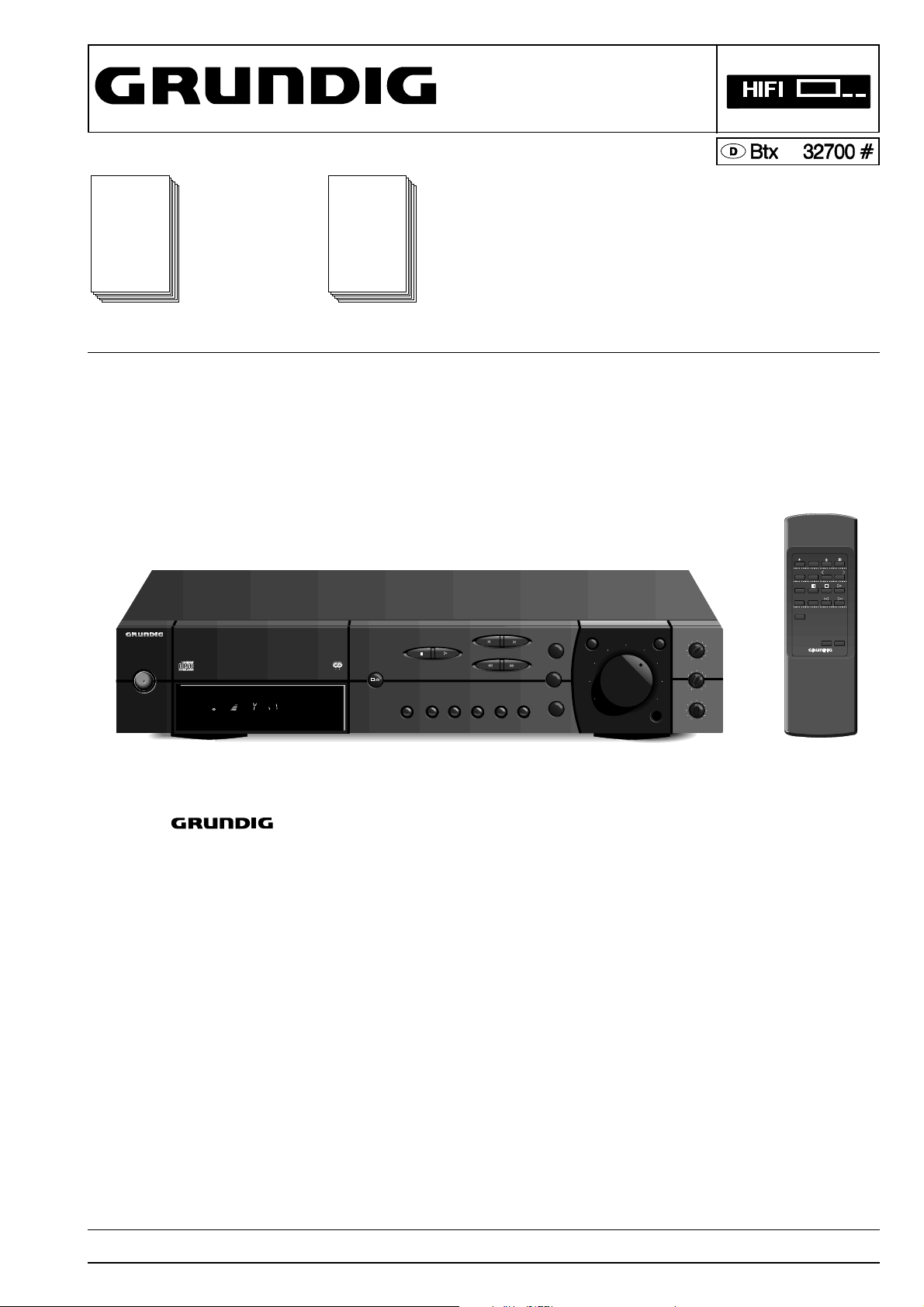
SERVICE MANUAL
*
RCD 400
POWER IO
POWER IO
HIFI CD RECEIVER
RCD 400
ANTENNA
TUNED
59 8A EPA 3
PAUSE
PLAY
PAUSE
PLAY
STOP
STOP
R D S
OPEN/
CLOSE
CLOSE
OPEN/
SHUFFLE
INFO
SHUFFLE
INFO
MONO
MONO
REPEAT
REPEAT
ANT/CABLE
ANT/CABLE
EDIT
EDIT
SKIP/STATION
SKIP/STATION
SEARCH/TUNING
SEARCH/TUNING
CANCEL
CANCEL
MEMORY
MEMORY
TUNER BAND
TUNER BAND
CD
CD
TAPE/AUX
TAPE/AUX
DEFEAT
DEFEAT
RCD 400 (9.79805-8151 / G.LF 1751)
IR-Geber / IR Remote Control (75954-032.17)
VOLUME
VOLUME
LOUDNESS
LOUDNESS
HEADPHONES
HEADPHONES
-
-
-
-
L
TREBLE
TREBLE
BASS
BASS
BALANCE
BALANCE
SLEEP
PTY
TUNER STATION
CD
DISC–+
TAPE
-
VOLUME
+
+
+
+
+
RRL
RC 400
Änderungen vorbehalten Printed in Germany Service Manual Sach-Nr.
Subject to alteration VK 232 0296 Service Manual Part No. 72010-747.05
Page 2

Allgemeiner Teil / General Section RCD 400
Es gelten die Vorschriften und Sicherheitshinweise gemäß dem Service Manual "Sicherheit",
Sach-Nummer 72010-800.00, sowie zusätzlich
die eventuell abweichenden, landesspezifischen
Vorschriften!
D
Inhaltsverzeichnis
Seite
Allgemeiner Teil...............................1 - 2...1 - 16
Meßgeräte / Meßmittel .................................................................. 1 - 2
Technische Daten ......................................................................... 1 - 3
Bedienhinweise............................................................................. 1 - 4
Ausbauhinweise .......................................................................... 1 - 13
Abgleichvorschriften ......................... 2 - 1...2 - 3
Platinenabbildungen
und Schaltpläne ...............................3 - 1...3 - 21
Display .......................................................................................... 3 - 1
Verdrahtungsplan.......................................................................... 3 - 2
Detailschaltpläne:
CD .......................................................................................... 3 - 4
Tuner .................................................................................... 3 - 10
Hauptplatte, Kopfhörerplatte, Display- und Tastenplatte,
Netzteilplatte, Klangreglerplatte, Lautstärkeplatte ................ 3 - 13
Druckplattenabbildungen:
CD (IC-Block-Diagramme TDA1313T, SAA6579T)................ 3 - 6
Tuner ...................................................................................... 3 - 8
Hauptplatte (IC-Block-Diagramme TDA7294, LC7821) ....... 3 - 16
Kopfhörerplatte, Display- und Tastenplatten, Netzteilplatte,
Klangreglerplatte, Lautstärkeplatte....................................... 3 - 19
The regulations and safety instructions shall be
valid as provided by the "Safety" Service Manual,
part number 72010-800.00, as well as the
respective national deviations.
Table of Contents
GB
Page
General Section ................................1 - 2...1 - 16
Test Equipment / Aids ................................................................... 1 - 2
Specifications ................................................................................ 1 - 3
Operating Hints ............................................................................. 1 - 8
Disassembly Instructions ............................................................ 1 - 13
Adjustment Procedures.....................2 - 1...2 - 3
Layout of the PCBs
and Circuit Diagrams...................... 3 - 1...3 - 21
Display .......................................................................................... 3 - 1
Wiring Diagram ............................................................................. 3 - 2
Circuit Diagrams:
CD .......................................................................................... 3 - 4
Tuner .................................................................................... 3 - 10
Main Board, Headphone Board, Display and Key Board,
Mains Board, Volume Board ................................................ 3 - 13
Layout of PCBs:
CD (IC Block Diagrams TDA1313T, SAA6579T) ................... 3 - 6
Tuner ...................................................................................... 3 - 8
Main Board (IC Block Diagrams TDA7294, LC7821) ........... 3 - 16
Headphone Board, Display and Key Boards, Mains Board,
Volume Board....................................................................... 3 - 19
Ersatzteilliste und
Explosionszeichnungen .....................4 - 1...4 - 6
Explosionszeichnung RCD 400 .................................................... 4 - 1
Explosionszeichnung CD-Laufwerk .............................................. 4 - 3
Ersatzteiliste.................................................................................. 4 - 4
Allgemeiner Teil
Meßgeräte / Meßmittel
Digitalvoltmeter, Wobbler, Meßsender, Stereokoder, Tongenerator,
Oszilloskop, NF-Voltmeter, Klirrfaktormeßgerät
Beachten Sie bitte das GRUNDIG Meßtechnik-Programm, das Sie unter
folgender Adresse erhalten:
GRUNDIG electronics GmbH
Würzburger Str. 150
D-90766 Fürth/Bay.
Tel. 0911/703-0
Telefax 0911/703-4479
Spare Parts List and
Exploded Views..................................4 - 1...4 - 6
Exploded View RCD 400 .............................................................. 4 - 1
Exploded View CD Drive Mechanism ........................................... 4 - 3
Spare Parts List ............................................................................ 4 - 4
General Section
Test Equipment / Aids
Digital voltmeter, Sweep generator, Test generator, Stereo coder, AF
generator, Oscilloscope, AF voltmeter, Distortion meter
Please note the Grundig Catalog "Test and Measuring Equipment"
obtainable from:
GRUNDIG electronics GmbH
Würzburger Str. 150
D-90766 Fürth/Bay.
Tel. 0911/703-0
Telefax 0911/703-4479
1 - 2 GRUNDIG Service
Page 3

RCD 400 Allgemeiner Teil / General Section
Technische Daten
Verstärker
Ausgangsleistung (DIN45500)
Musikleistung (4Ω) ............................................................ 2 x 50W
Sinusleistung (4Ω, 0,7% Klirrfaktor, 1kHz) ....................... 2 x 30W
Eingangsempfindlichkeit / Impedanz
Line IN .................................................................... 180mV / 47kΩ
Klirrfaktor
Sinusleistung -1dB, 8Ω, 1kHz ............................................ ≤0,01%
Geräuschspannungsabstand .............................................. ≥94dB
Tuner
Empfindlichkeit
Mono (S/N = 26 dB) ............................................................≤1,1µV
Stereo (S/N = 46 dB) ............................................................. 35µV
Wellenbereiche
FM.................................................................. 87,50 ... 108,00MHz
MW ....................................................................... 528 ... 1605kHz
CD
Linearität Frequenzgang ±0,1dB ............................. 20 ... 20000Hz
Signal- / Rauschspannungsabstand ..................................... 90dB
Klirrfaktor (1kHz, 0dB)......................................................... ≤0,01%
Dynamikbereich .................................................................... ≥88dB
Allgemeines
Spannungsversorgung
Betriebsspannung ................................................................ 230V~
Frequenz........................................................................... 50/60Hz
max. Leistungsaufnahme...................................................... 150W
Leistungsaufnahme in Standby .............................................. ≤6W
Abmessungen
B x H x T ................................................. 435 x 75 (+12) x 300mm
Gewicht .................................................................................. 5,3kg
Specifications
Amplifier
Output power (DIN45500)
Music (4Ω) ........................................................................ 2 x 50W
Nominal (4Ω, 0.7% distortion, 1kHz) ................................ 2 x 30W
Input sensitivity / impedance
Line IN .................................................................... 180mV / 47kΩ
Distortion
Nominal power -1dB, 8Ω, 1kHz ......................................... ≤0.01%
Signal-to-noise ratio ............................................................. ≥94dB
Tuner
Sensitivity
Mono (S/N = 26 dB) ............................................................≤1.1µV
Stereo (S/N = 46 dB) ............................................................. 35µV
Wave ranges
FM.................................................................. 87.50 ... 108.00MHz
MW ....................................................................... 528 ... 1605kHz
CD
Frequency ranges ±0.1dB........................................ 20 ... 20000Hz
Signal-to-noise ratio ............................................................... 90dB
Distortion (1kHz, 0dB) ......................................................... ≤0.01%
Dynamic range ...................................................................... ≥88dB
General
Power supply
Voltage................................................................................. 230V~
Frequency ......................................................................... 50/60Hz
max Power consumption ...................................................... 150W
Standby power consumption .................................................. ≤6W
Dimensions
W x H x D................................................ 435 x 75 (+12) x 300mm
Weight....................................................................................5.3kg
Notizen / Notes
GRUNDIG Service 1 - 3
Page 4
Allgemeiner Teil / General Section RCD 400
1 - 4 GRUNDIG Service
D D
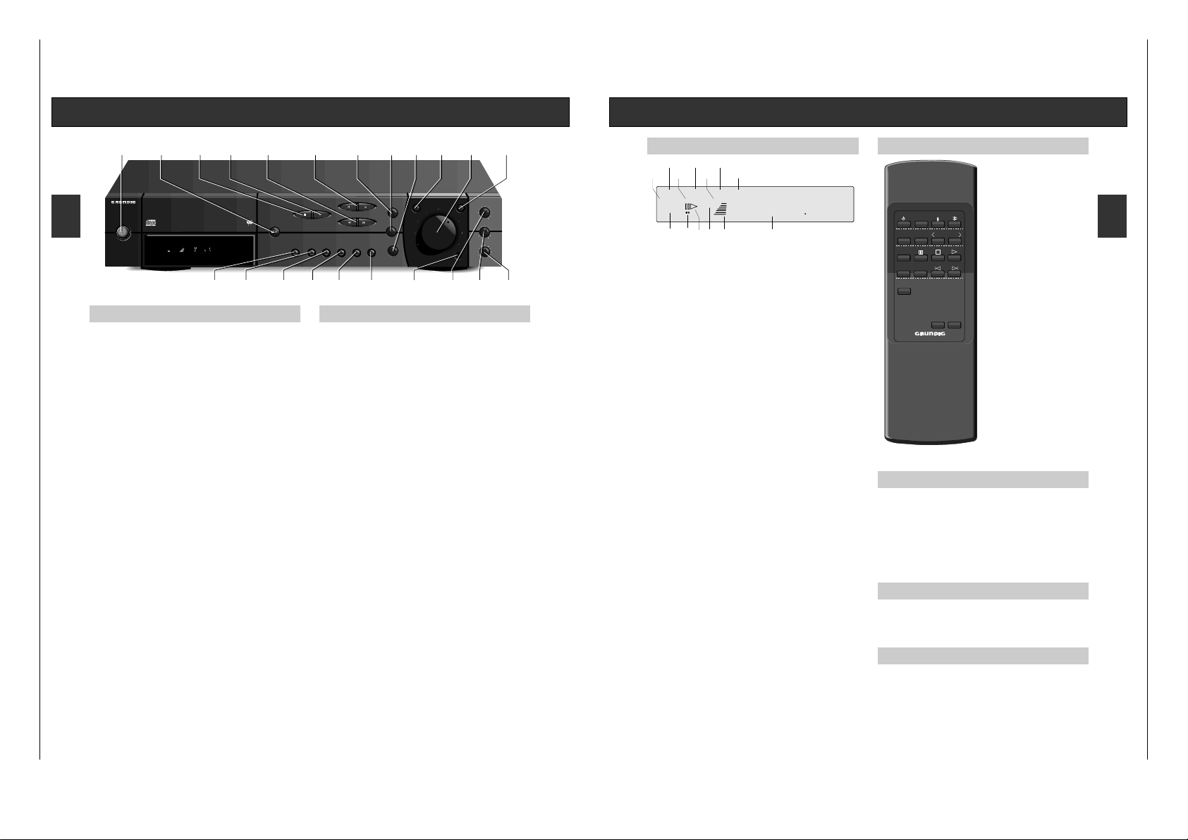
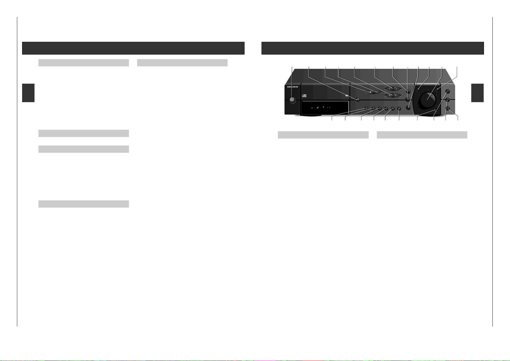
Bedienungselemente
Vorderseite des CD-Receivers
POWER Mit dieser Taste wird das Gerät ein- oder auf Bereitschaft
geschaltet
.
9 STOP/ Mit dieser Taste beenden Sie alle Funktionen und
öffnen
.?
OPEN/CLOSE
und schließen Sie die CD-Schublade
close the CD
compartment.
PAUSE ; Mit dieser Taste unterbrechen Sie die Wiedergabe kurzzeitig
(PAUSE), ohne daß Geräteeinstellungen verändert werden.
PLAY B Diese Taste wird zum Starten oder erneuten Starten der
Wiedergabe verwendet.
SEARCH / TUNING Q R
CD-Betrieb: Mit dieser Taste starten Sie den Suchlauf rückwärts Q
oder vorwärts R.
TUNER-Betrieb:
Mit diesen Tasten starten Sie den Sendersuchlauf (AUTO
TUNING)
oder schalten die Frequenz in die gewünschte Rich-
tung Schritt für Schritt (MANUAL TUNING) weiter.
SKIP / STATION O P
CD-Betrieb:
Mit dieser Taste springen Sie in der Titelreihenfolge
vorwärts
oder rückwärts.
TUNER-Betrieb: Mit diesen Tasten schalten Sie die Speicherplätze in der
jeweiligen Richtung durch.
WAHL DES GERÄTES
TUNER BAND Mit dieser Taste schalten Sie zyklisch zwischen den
Bändern (Wellenbereichen) FM (UKW), und MW um.
CD Mit dieser Taste wird auf CD-Player geschaltet.
TAPE/AUX Mit dieser Taste wird TAPE/AUX gewählt.
DEFEAT Mit dieser Taste werden der HÖHEN- und TIEFEN-Regler
umgangen.
VOLUME Mit diesem Einsteller passen Sie die Lautstärke an.
LOUDNESS
Mit diesem Schalter können Sie den Ton bei geringen Lautstärken dem Hörempfinden des menschlichen Ohres
anpassen.
BALANCE Hiermit beeinflussen Sie die Verteilung des Klanges
zwischen linkem und rechtem Kanal.
BASS Hiermit beeinflussen Sie den unteren Frequenzbereich.
TREBLE Hiermit beeinflussen Sie den oberen Frequenzbereich.
HEADPHONES Hier können Sie einen handelsüblichen Stereo-kopfhörer
mit 6,3 mm-Klinkenstecker anschließen. Die Lautstärke
stellen Sie mit dem Drehknopf VOLUME ein.
Die angeschlossenen Lautsprecher werden abgeschaltet,
wenn Sie den Klinkenstecker einstecken. Ziehen Sie den
Stecker, werden die Lautsprecher wieder eingeschaltet.
MEMORY
CD-Betrieb: Hiermit rufen Sie den Programmier-Modus auf oder
speichern einzelne Tracks.
TUNER-Betrieb: Diese Taste speichert einen eingestellten Sender auf den
jeweils niedrigsten, freien Speicherplatz.
CANCEL
CD-Betrieb: Hiermit löschen Sie einzelne Titel (Tracks) aus Ihrem
Programm oder löschen Sie das ganze Programm.
TUNER-Betrieb: Mit dieser Taste löschen Sie einzelne Speicherplätze oder
den gesamten Speicherinhalt (länger als 10 Sekunden
gedrückt halten).
EDIT
CD-Betrieb: Mit dieser Taste passen Sie die Spielzeit der CD an die
verwendete Aufnahme-Cassette an.
TUNER-Betrieb: Mit dieser Taste wählen Sie den Eingabemodus an, um
einen Sendernamen zu vergeben.
STANDBY-Betrieb: Mit dieser Taste werden Timer- und Uhreinstellung
ermöglicht.
REPEAT / ANT/CABLE
CD-Betrieb: REPEAT Mit dieser Taste schalten Sie die Wiederholung
der CD oder des Programmes ein und aus.
TUNER-Betrieb: ANT/CABLE - Mit dieser Taste wird der FM-
Antennenabschwächer eingeschaltet, mit dem Störungen
vermieden werden, wenn der Tuner an ein Breitbandkabel
angeschlossen ist und das Empfangssignal zu stark ist.
SHUFFLE / MONO
CD-Betrieb: SHUFFLEMit dieser Taste schalten Sie die zufällige
Reihenfolge der Wiedergabe der Titel ein und aus.
TUNER-Betrieb: MONO Mit dieser Taste schalten Sie auf MONO-Empfang
um, wenn z. B. der Stereo-Empfang durch Rauschen
gestört ist.
INFO
CD-Betrieb: Hiermit kan zwischen die angezeigten Informationen
umgeschaltet werden.
TUNER-Betrieb: Mit dieser Taste wird auf der Anzeige zwischen
Sendername (RDS) (oder einem anderen von Ihnen
gegebenen Namen), RADIOTEXT und Senderfrequenz
hin- und hergeschaltet.
Beide Betriebsarten: Durch längeres Drücken dieser Taste wird der Timer ein-
und ausgeschaltet.
HIFI CD RECEIVER
RCD 400
R D S
POWER IO
POWER IO
POWER
DEFEAT
PAUSE
PAUSE
PLAY
PLAY
REPEAT
REPEAT
SHUFFLE
SHUFFLE
INFO
INFO
STOP
STOP
OPEN/
CLOSE
OPEN/
CLOSE
SKIP/STATION
SKIP/STATION
SEARCH/TUNING
SEARCH/TUNING
MEMORY
MEMORY
CANCEL
CANCEL
EDIT
EDIT
TAPE/AUX
TAPE/AUX
CD
CD
TUNER BAND
TUNER BAND
DEFEAT
DEFEAT
VOLUME
VOLUME
LOUDNESS
LOUDNESS
HEADPHONES
HEADPHONES
TREBLE
TREBLE
BASS
BASS
BALANCE
BALANCE
RRL
L
+
+
+
+
-
-
-
-
ANT/CABLE
ANT/CABLE
MONO
MONO
HEADPHONES
LOUDNESS
STOP
OPEN/CLOSE
PAUSE ; PLAY B
SKIP/STATION
O P
SEARCH/TUNING
Q R VOLUME
INFO
SHUFFLE
MONO
REPEAT
ANT/CABLE
EDIT CANCEL MEMORY TREBLE BASS BALANCE
TUNER BAND CD TAPE/AUX
59 8A EPA 3
TUNED
ANTENNA
d 5
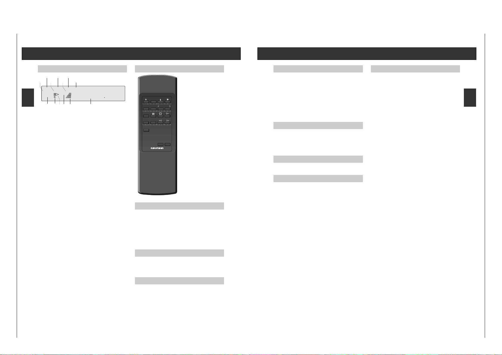
Display Fernbedienung
Display
1 STATION NUMBER Siebensegment-Anzeige
Hier wird die Nummer des Speicherplatzes (1bis 59) ein- oder zweistellig
dargestellt.
2
) – Der Tuner empfängt FM-Stereosendungen.
3 ;B – Der CD-Player ist in Wiedergabe- oder Pausenbetrieb.
4 TUNED – Das Gerät ist optimal auf einen Sender eingestellt.
5 Signalstärke-Anzeige – Je mehr Striche im Display erscheinen, desto
stärker empfangen Sie den eingestellten Sender.
6 Achtstellige 14 Segment-Anzeige – Für Frequenzen in MHz (FM)
oder kHz (MW), Sendername (RDS), Radiotext, selbstvergebene Namen
oder den gewählten Programmtyp.
7 PROGRAM – Der CD-Player ist programmierbereit.
8 SHUFFLE – Der CD-Player spielt Titel in zufälliger Reihenfolge.
9 ANTENNA – Leuchtet auf, wenn der Antennenabschwächer nicht
eingeschaltet ist.
0 REPEAT – Der CD-Player wiederholt die CD in der vorgegebenen
Reihenfolge.
! CABLE – Leuchtet auf, wenn bei Breitbandkabelempfang der Antennen-
abschwächer mit Taste ANTENNA/CABLE eingeschaltet ist.
@ REMAIN – Leuchtet, wenn die Anzeige der Restspielzeit der CD
eingeschaltet ist.
# TOTAL – Leuchtet, wenn die Anzeige der Gesamtspielzeit der CD
eingeschaltet ist.
Fernbedienung
Batteriewechsel
Läßt die Reichweite Ihres
Fernbedienung nach oder lassen sich
einzelne Funktionen nicht mehr
ausführen, sollten Sie die Batterien
auswechseln.
Verwendeter Batterietyp 2x Micro 1,5
Volt LR06, Größe AA. Öffnen Sie zum
Batteriewechsel den Deckel des
Batteriefaches auf der Rückseite des
Gebers. Achten Sie auf die richtige
Polung der Batterien (Markierung im
Batteriefach beachten).
Umwelthinweis: Denken Sie beim
Batteriewechsel daran: Batterien sind
Sondermüll.
ALLGEMEINES
y Taste – Mit dieser Taste schalten Sie das Gerät in STANDBY.
SLEEP – Mit dieser Taste wird die Sleep-Timer-Funktion eingeschaltet.
6 Taste– Mit dieser Taste werden die Anzeigearten des gewählten Gerätes
eingeschaltet.
a Taste– Mit dieser Taste schalten Sie das Gerät stumm.
VOLUME +/– – Mit diesen Tasten steuern Sie die Lautstärke des Verstärkers.
TAPE – Diese Taste dient zur Anwahl des Eingangs TAPE (Cassette deck).
TUNER
TUNER – Diese Taste dient zur Anwahl des Radios (Tuner).
PTY – Diese Taste schaltet das Gerät in den Programmartmodus.
STATION 1 2 – Mit dieser Tasten wählen Sie die Speicherplätze.
CD
CD – Diese Taste dient zur Anwahl des CD-Spielers.
; – Hiermit schalten Sie den CD-Spieler auf PAUSE.
9 – Hiermit beenden Sie die Wiedergabe des CD-Spielers..
B – Hiermit starten Sie die CD-Wiedergabe.
– DISC + – Diese Taste wird nur bei einem CD-Wechsler genutzt.
O P – Hiermit aktivieren Sie die Funktion Titelsprung vor- oder rückwärts.
PROGRAM
ANTENNA
########
MHz
1
2
0@
#9!
6
kHz
88
SHUFFLE
REPEAT REMAIN
TOTAL
CABLE
TUNED
54
7
8
3
d 6
Bedienhinweise
Hinweis: Dieses Kapitel enthält Auszüge aus der Bedienungsanleitung. Weitergehende Informationen
entnehmen Sie bitte der gerätespezifischen Bedienungsanleitung, deren Sachnummer Sie in
der entsprechenden Ersatzteilliste finden.
SLEEP
PTY
TUNER STATION
CD
DISC–+
TAPE
RC 400
-
VOLUME
+
Page 5

RCD 400 Allgemeiner Teil / General Section
GRUNDIG Service 1 - 5
D D
d 7
Radio
Einschalten
• Wählen Sie den Tuner durch Drücken der Taste TUNER BAND.
– Schalten Sie Ihr Gerät nach dem Auspacken zum ersten Mal ein, wählt das
Gerät ‘FM’, das Display zeigt 87,50 MHz. Die Empfangsart STEREO
) ist
gewählt.
– Ihr Gerät ist mit der Funktion ‘LAST STATION MEMORY’ ausgestattet. Dies
bedeutet, Ihr Gerät meldet sich nach dem Einschalten mit der Station wieder,
die Sie vor dem Ausschalten eingestellt hatten.
Wellenbereichswahl
• Wählen Sie den gewünschten Wellenbereich (FM oder MW), indem Sie die
Fortschalt-Taste TUNER BAND drücken. Jedes Betätigen der Taste schaltet
zum nächsten Wellenbereich weiter in der Reihenfolge: FM - MW - FM.
– Das Display informiert Sie über den eingestellten Bereich.
Antennenanpassung
Empfangen Sie Ihre Sender über das Breitbandkabel einer öffentlichen oder
privaten Betreiber-Gesellschaft, kann es vorkommen, daß an Ihrer AntennenDose ein sehr hoher Pegel anliegt, der zu Störungen führen kann.
• Drücken Sie deshalb die Taste ANT/CABLE, um den Eingangsabschwächer
einzuschalten. Im Display erscheint ‘CABLE’. Dadurch wird die
Empfindlichkeit des Antenneneinganges herabgesetzt und Störungen durch
zu hohe Pegel vermieden. Diese Einstellung wird automatisch abgespeichert.
FM (UKW)-Empfangsart MONO/STEREO
Im Normalfall ist Ihr Gerät in Stereo-Bereitschaft. Sobald ein empfangswürdiges
Stereo-Signal registriert wird, leuchtet im Display '
)' auf. Ist der Stereo-
Empfang gestört, erlischt das Zeichen
). Störgeräusche, etc. werden
unterdrückt.
Ist der Stereo-Fernempfang gestört, können Sie Ihr Gerät auf MONO-Empfang
schalten.
• In diesen Fällen drücken Sie die Taste MONO
– Das Zeichen
) erlischt im Display.
Die MUTING-Funktion ist bei MONO immer ausgeschaltet, so daß Sie auch
sehr schwache Sender einstellen können.
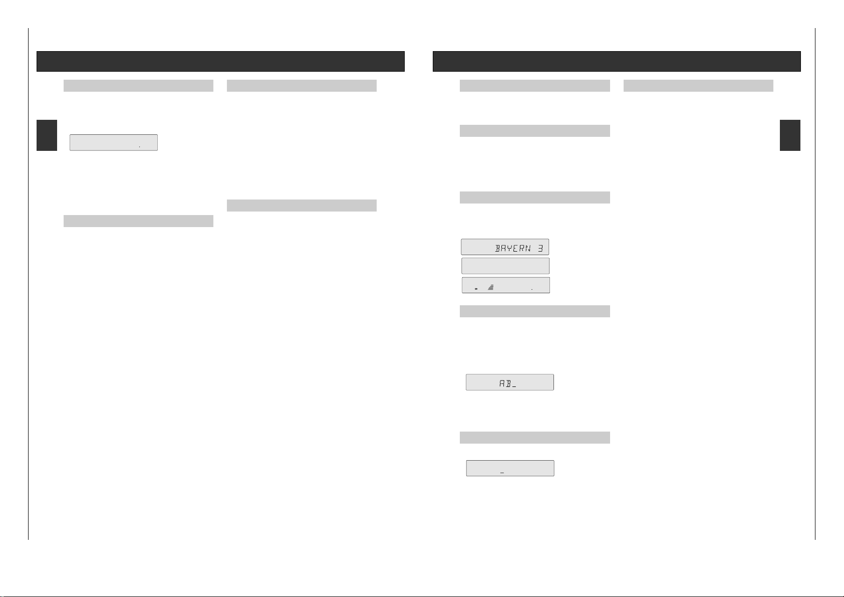
RDS (Radio Data System)
Das Radio ist ein RDS-Gerät.
RDS (Radio Data System) steht für eine neue Ära des Rundfunkempfanges, die
demHörer/Benutzer zunächst mehr Komfort und besseren Empfang beschert,
langfristig aber auch völlig neue Informationsmöglickeiten eröffnet.
RDS-Geräte erkennen den eingestellten Sender (wenn er RDS-Signale
aussendet) und zeigen den Namen des Programmes in der achtstelligen
Anzeige an (z. B. BAYERN 3, SDR 3).
Haben Sie einen RDS-Sender eingestellt, wird nach kurzer Zeit der Sendername
angezeigt.
Für weitere Informationen lesen Sie bitte Seite 10.
Automatischer Sendersuche
• Um die Funktion ‘SUCHLAUF’ (AUTO TUNING) aufzurufen, betätigen Sie die
Tasten TUNING Q oder R, bis die Frequenzanzeige ‘zu laufen’
beginnt. Lassen Sie dann die Taste los.
– Der Suchlauf stoppt, sobald er einen Sender mit ausreichender Empfangs-
stärke gefunden hat. Auf der Anzeige leuchtet TUNED.
– Jedesmal, wenn Sie den Suchlauf starten, schaltet das Gerät auf STEREO.
– Eine Anzeige informiert Sie zudem über die Feldstärke. Je mehr Striche im
Display erscheinen, desto stärker wird der Sender empfangen.
– Die Frequenz des empfangenen Senders wird in MHz (FM) oder kHz (MW)
angezeigt.
– Stoppt der Suchlauf, überprüft die Funktion 'AUTO COMPARE', ob diese
Frequenz schon im Senderspeicher abgelegt ist. Ist dies der Fall, wird der
Speicherplatz links und, falls Sie einen solchen vergeben haben, der Name
des Senders, angezeigt.
– Stationen, die mit geringer Feldstärke empfangen werden, können vom
Suchlauf übersprungen werden. Diese können mittels Handabstimmung
eingestellt werden.
• Bei Bedarf können Sie den Suchlauf auch unterbrechen, indem Sie die
Tasten TUNING QRerneut drücken.
Manuelle Sendersuche (Handabstimmung)
• Tippen Sie die Tasten TUNING Q oder R kurz an, um in die entsprechende Richtung in Einzelschritten (FM: 25 kHz; MW: 1 kHz) abzustimmen.
• Halten Sie die Taste gedrückt, können Sie größere Frequenzbereiche im
'Schnelldurchgang' abtasten. Lassen Sie die Tasten los, so wird auf automatischen Suchlauf umgeschalten. Während dieser Sendersuche ist die
Wiedergabe stummgeschaltet.
• Tippen Sie eine der Tasten TUNING QRkurz an, wird wieder auf
manuelle Sendersuche umgeschalten.
– Wie bei der automatischen Einstellung zeigen TUNED und die Zahl der
leuchtenden Striche die Empfangsqualität an.
– Auch hier überprüft die Funktion 'AUTO COMPARE', ob diese Frequenz
schon im Senderspeicher abgelegt ist.
Funktion 'LAST STATION MEMORY'
LAST STATION MEMORY bedeutet, das Gerät merkt sich die jeweils zuletzt
eingestellte Station. Mit dieser Funktion läßt sich sicherstellen, daß der Sender
der vor dem Ausschalten eingestellt war nach dem Einschalten wieder zu hören
ist.
ANTENNA
FM 10530
MHz
TUNED
ANTENNA
FM 10530
MHz
4
TUNED
d 8
Verstärker
Ein- und Ausschalten
Schalten Sie Ihr Gerät ein, indem Sie den Netzschalter POWER betätigen. Die
Betriebsanzeige, eine LED in der Mitte des Einschalt-Knopfes, informiert Sie
über den Schaltzustand:
gedrückt: EIN
ausgerastet: AUS.
Bei Einschalten des CD-Receivers ist das zuletzt gewählte Gerät aktiv.
Ist der CD-Receiver auf Aktivmodus geschaltet (wie weiter unten beschrieben),
leuchtet die Leuchtdiode in der Power-Taste.
Unmittelbar nach dem Einschalten ist der Receiver für ca. 3 Sekunden
stummgeschaltet, um störende Einschaltgeräusche zu unterdrücken.
Durch erneutes Drücken der Taste POWER wird das Gerät auf Bereitschaft
geschaltet.
Stand by-Betrieb
Das Gerät kann mit der Taste y auf der Fernbedienung oder der Taste POWER
auf Bereitschaft geschaltet werden.
In der Anzeige erscheint die Uhrzeit.
Wollen Sie die Anlage wieder einschalten, drücken Sie eine der Eingangs-
wahltasten am Gerät oder eine der Eingangswahltasten der Fernbedienung oder
der Taste POWER.
Wahl der Programmquellen
Drücken Sie die entsprechende Taste am Gerät oder auf der Fernbedienung, um
eine Programmquelle anzuwählen.
Automatische Wahl des Gerätes
Ist das Gerät eingeschaltet, schaltet es automatisch auf den CD-Player, wenn
die Taste B des CD-Players gedrückt wird.
Klangeinstellung
VOLUME Sie regulierenen die Lautstärke mit dem Einsteller VOLUME.
Sie können diese Funktion aber auch über die Fernbedienung, Tasten VOLUME +/–, ausführen.
MUTING Drücken Sie auf der Fernbedienung die Taste a, können Sie
die Lautstärke stumm schalten, um z. B. ein Telefongespräch
entgegen zunehmen.
Nehmen Sie während dieser Zeit Tonband-Aufnahmen vor,
beeinträchtigt die Funktion MUTING Ihre Aufnahme nicht, da
nur die Lautsprecher abgeschaltet werden.
Das Klicken, welches Sie hören, wenn Sie die Taste a betätigen, rührt von den Relais her, welche die Lautsprecher-Ausgänge stummschalten.
Drücken Sie die Taste a erneut, beenden Sie die Funktion
MUTING.
MUTING wird auch aufgehoben, wenn Sie die Taste VOLUME
+ oder eine der Eingangswahltasten drücken.
BASS, TREBLE Mit den Einstellern BASS und TREBLE können Sie das
Klangbild in den Höhen und Bässen individuell verändern.
Somit können Sie Unregelmäßigkeiten in der Akustik des
Abhörraumes kompensieren, die von Reflexionen an glatten
Wänden oder Dämpfung durch Textilien verursacht werden.
LOUDNESS Betätigen Sie den Schalter LOUDNESS, werden die tiefen
und hohen Frequenzen so angehoben, daß das Klangbild
auch bei leiser Wiedergabe immer ausgeglichen bleibt.
Dies geschieht in Abhängigkeit von der Stellung des Lautstärke-Einstellers. Dabei wird der Klang dem menschlichen
Gehör angepaßt, dessen Klang-Empfinden von der Lautstärke
abhängt.
Haben Sie sehr baßstarke Lautsprecherboxen angeschlossen,
sollten Sie die Funktion LOUDNESS ausschalten, um eine
lineare Wiedergabe zu erreichen. So korrigieren Sie eine
übermäßige Betonung der tiefen Frequenzen.
DEFEAT Betätigen Sie den Schalter DEFEAT, schalten Sie den Einfluß
der Klangeinsteller aus, ohne deren Einstellung zu verändern.
Diese Funktion umgeht den Signalausgang durch Bass- und
Treble-Regler und stellt sicher, daß der Originalklang mit der
höchsten Qualität wiedergegeben wird.
BALANCE Für Stereo-Wiedergabe ist es wichtig, daß von beiden Stereo-
Lautsprechern im Mittel eine gleichmäßige Schallabstrahlung erfolgt.
Das ‘akustische Gleichgewicht’ kann durch eine
unsymmetrische Anordnung der Sitzgruppe, des Hörortes,
verschoben werden. Dadurch kann der Stereo-Eindruck
verfälscht werden.
Mit dem Einsteller BALANCE können Sie in solchen Fällen
einen Ausgleich schaffen.
Page 6
Allgemeiner Teil / General Section RCD 400
1 - 6 GRUNDIG Service
D D
d 9
Radio
Festsenderspeicher (STATION MEMORY)
Sie haben 59 Speicherplätze zur Verfügung.
• Stimmen Sie den Sender, den Sie speichern wollen, per Suchlauf oder
manuell ab.
• Drücken Sie die Taste MEMORY.
– Der gefundene Sender wird auf den nächsten freien Speicherplatz gelegt.
– Die Software des Tuners überprüft jetzt den Stationsspeicher nach freien
Speicherplätzen. Sind alle Plätze belegt, zeigt das Display für ca. 1,5 Sekunden ‘MEM FULL’.
– Es ist nicht möglich, eine Frequenz auf zwei Speicherplätzen abzulegen. Die
gewählte Station wird auf dem jeweils niedrigsten freien Speicherplatz
abgelegt. Sie müssen also keine Speicherplatz-nummer eingeben.
– Die Einstellungen MONO/STEREO und ANTENNA/CABLE werden bei jedem
Wechsel automatisch gespeichert.
Stationen speichern
• Wollen Sie eine gewählte Station speichern, drücken Sie die Taste
MEMORY.
– Die erste gespeicherte Station erhält die Speicherplatznummer 1, die nächste
Station die Nummer 2 und so fort.
• Möchten Sie eine bereits gespeicherte Station ‘verschieben’, d.h. auf einen
anderen Speicherplatz legen, drücken Sie MEMORY.
– Die Station wird immer auf den ersten freien Speicherplatz gelegt.
• Drücken Sie die Taste erneut, wird der nächste freie Platz belegt.
• Halten Sie die Taste gedrückt, werden die Speicherplätze der Reihe nach
durchgetastet. Der bisherige Speicherplatz wird automatisch gelöscht.
Beispiel:
Ihr Lieblingssender soll von Speicherplatznummer '6' auf Speicherplatznummer
'1' abgelegt werden.
• Wählen Sie Speicherplatznummer '1'.
• Drücken Sie die Taste CANCEL einmal.
– Speicherplatz '1' ist jetzt gelöscht.
Sie können auch die Taste MEMORY drücken, um den auf Position ‘1’
gespeicherten Sender auf die nächst freie Position zu verschieben.
• Wählen Sie jetzt Platz '6' an, Ihren Lieblingssender, danach die Taste
MEMORY.
Jetzt ist Ihr Sender auf Speicherplatz '1' abgelegt.
Aufrufen eines Senderspeichers
• Möchten Sie einen Senderspeicher (Speicherplatz) aufrufen, betätigen Sie
die Tasten STATION OP. Die gespeicherten Stationen werden in
aufsteigender oder fallender Reihenfolge aufgerufen.
Die Speicherplätze können auch über die Fernbedienung angewählt werden.
• Wählen Sie den Tuner durch Drücken der Taste TUNER.
• Drücken Sie die Tasten 1 STATION 2.
– Im Display erscheint die ausgewählte Speicherstelle, und das Gerät stellt
sich automatisch auf diesen Sender ein.
– Es ist nicht möglich, einen Speicherplatz aufzurufen, dem noch kein Sender
zugeordnet wurde.
Beispiel:
Speicherplatz '6' trägt keinen Sender.
Wenn Sie auf Speicherplatz 5 stehen und drücken einmal STATION P ,
springt das Gerät automatisch vor auf Nummer 7 (vorausgesetzt dieser
Speicherplatz wurde bereits belegt).
Speicherplatz löschen
• Wollen Sie einen belegten Speicherplatz wieder löschen, freimachen, rufen
Sie zuerst seine Nummer auf.
• Drücken Sie die Tasten STATION OPsolange in die entsprechende
Richtung, bis Sie den Speicherplatz, den Sie freimachen wollen, ausgewählt
haben, oder wählen Sie den Speicherplatz über die Tastatur der Fernbedienung - mit den Tasten STATION 12.
• Drücken Sie die Taste CANCEL.
– Der Speicherplatz ist gelöscht, die Speicherplatznummer erlischt im Display.
• Möchten Sie alle Speicherplätze löschen, z.B. nach einem Umzug, halten Sie
die Taste CANCEL für 5 Sekunden gedrückt.
– Im Display erscheint für kurze Zeit 'ERASE ?'.
• Halten Sie die Taste noch für 5 weitere Sekunden gedrückt, bis das Display
die Frequenz '87,5 MHz' zeigt
– Alle Senderspeicher sind gelöscht.
• Drücken Sie jetzt eine der Tasten STATION OP, so erscheint im Display
'FREE'.
• Wenn Sie die Taste CANCEL loslassen, bevor diese fünf Sekunden
verstrichen sind, wird die Löschfunktion nicht ausgeführt.
ANTENNA
FM 10420
MHz
8
d 10
Radio
RDS (Radio Data System)
Ihr Gerät ist in der Lage, RDS-Informationen, die mit dem Sendersignal
ausgestrahlt werden, zu empfangen und auszuwerten. Der Programmname wird
im Display angezeigt und automatisch in den Programmspeicher übernommen.
Schon vorhandene Namen werden überschrieben.
RADIOTEXT
Einige RDS-Sender strahlen die Information RADIOTEXT aus. Dies sind Zusatzinformationen zu Sender und Programm. RADIOTEXT erscheint als Laufschrift
im Display. Da RADIOTEXT vom Sender Zeichen für Zeichen übertragen wird,
kann es einige Zeit dauern, bis der Text vollständig empfangen worden ist.
• Sie rufen RADIOTEXT auf, indem Sie die Taste INFO so oft drücken, bis die
Laufschrift des RADIOTEXTES zu sehen ist.
– Wird kein RADIOTEXT übertragen, erscheint wieder die Frequenz.
Umschalten der Anzeige
• Drücken Sie die Taste INFO, wechselt die Anzeige zwischen Stationsnamen
(RDS oder eigen vergeben), RDS-Zeit, RADIOTEXT (bei RDS-Sendern) und
Frequenz.
– Bei Anzeige des Stationsnamens wird links daneben nur die Speicherplatz-
nummer angezeigt.
Sendernamen vergeben
Empfangen Sie Sender, die den RDS-Code nicht ausstrahlen, können Sie jeder
Station einen Namen Ihrer Wahl geben.
• Drücken Sie die Taste EDIT.
• Mit den Tasten TUNING QRkönnen Sie die Eingabemarke, den
Cursor, in die jeweilige Richtung bewegen. Ihnen stehen insgesamt 8
Eingabestellen zur Verfügung.
• Mit den Tasten STATION OPlaufen Sie vorwärts oder rückwärts durch
das Alphabet, das Leerzeichen und die Zahlen von 0 - 9.
• Wollen Sie die Eingabe beenden, den Eingabemodus verlassen und
abspeichern, drücken Sie die Taste EDIT oder MEMORY.
Anmerkung:
Versuchen Sie, einem Sender, der RDS-Codes ausstrahlt, einen
Namen Ihrer Wahl zu geben, informiert Sie das Display mit der Anzeige RDS-DATA über die Eingabesperre.
Löschen eines Namens
• Drücken Sie im Eingabemodus die Taste CANCEL, wird der bisherige Name
gelöscht und die Einfügemarke springt an die erste Position.
Programmart-Kennung (PTY)
RDS bietet Ihnen die Möglichkeit, FM-Sender nach Programmarten auszuwählen.
Dazu sind 16 Programmarten definiert.
• Mit den Tasten PTY können Sie die Programmarten aufrufen. Mit den Tasten
STATION 12können andere Arten gewählt werden.
– Das Display zeigt für kurze Zeit die Programm-art und danach den Namen der
Station, die diese Programmart-Kennung überträgt.
– Wird die aktuelle Kennung von keiner Station übertragen, zeigt das Display für
kurze Zeit: 'NONE' ('KEINE').
Was ist unter Programmart zu verstehen?
NEWS = Nachrichtendienste
Sendungen, die meist kurzgefaßt über aktuelle Ereignisse und Äußerungen von
öffentlichem Interesse informieren. Außerdem: Wetter und Verkehrsberichterstattung.
AFFAIRS = Politik und Zeitgeschehen
Sendungen zur Ergänzung oder Vertiefung von Nachrichten, z.B. Berichte und
Kommentare, Informationsmagazine. Aber auch ausführlichere Darstellungen von
Zusammenhängen, z.B. Dokumentationen und Diskussionen. Außerdem:
Übertragungen von Bundestags- und Landtagsdebatten o.ä.
INFO = Spezielle Wortprogramme
Sendungen zur Orientierungshilfe in unterschiedlichen Lebensbereichen, z.B. Verbrauchermagazine, Gesundheitsratgeber, Reisetips, besondere Wetterdienste.
Aber auch Sendungen für einzelne Zielgruppen, z.B. für Landwirte, Kinder,
ausländische Arbeitnehmer.
SPORT = Sport
Sportsendungen aller Art.
EDUCATE = Lernen und Weiterbildung
Sendungen mit pädagogischem Ansatz, die zum Erwerb oder zur Erweiterung von
Kenntnissen aus verschiedenen Wissensgebieten einladen; z.B. Schulfunk,
Funkkolleg, Sprachkurse.
DRAMA = Hörspiel und Literatur
Hörspielsendungen aller Art, z.B. auch Kriminalhörspiel und Science-fiction;
Lesungen aus literarischen Werken.
CULTURE = Kultur, Kirche und Gesellschaft
Sendungen, die sich darstellend, erläuternd oder wertend mit Themen aus dem
genannten Bereich befassen; z.B. Theater-, Film- u. Buchbesprechungen,
literarische Hörfolgen, Beiträge zum Schul- und Bildungswesen, Kirchenfunk;
auch Andachten und Gottesdienste.
SCIENCE = Wissenschaft
Sendungen, die sich mit Methoden und Ergebnissen auf dem Gebiet der Geistesund Naturwissenschaften und mit dem Fragen der Technik auseinandersetzen.
VARIETY = Unterhaltendes Wort
Sendungen, die vor allem Kurzweil bieten wollen, z.B. Talk Shows, Quiz- und Ratespiele, Kabarettistisches, Sketche, Plaudereien etc., oft in Verbindung mit Musik.
POP M. = Popmusik
Sendungen mit populären Hits und modernen Schlägern, deutsch und
international.
ROCK M. = Rockmusik
Sendungen mit internationaler Musik der jüngeren Generation, oft stark
rhythmusbetont.
EASY M. = Unterhaltungsmusik
Sendungen mit leichter Musik aller Art, z.B. Volksmusik, Tanzmusik, Musical und
Operette.
LIGHT-M. = Leichte klassische Musik
Sendungen mit eingängiger Klassik; Musik, oft kleinere Formen oder
Werkausschnitte, z.B. Ouvertüren, Opernarien usw.
CLASSICS = Ernste klassische Musik
Sendungen mit anspruchsvolleren Werken, z.B. Symphonik, Kammermusik, große
Oper.
MUSIC = Spezielle Musikprogramme
Musiksendungen, die sich den vorgenannten Programmarten nicht zuordnen
lassen, z.B. Folklore, Jazz, experimentelle Musik.
7
7
ANTENNA
FM 10530
MHz
4
TUNED
ARD-RADI
4
Page 7
RCD 400 Allgemeiner Teil / General Section
GRUNDIG Service 1 - 7
D D
d 12
CD
Programm-Betrieb
Jede CD läßt sich in der Reihenfolge der Titel programmieren.
Die Reihenfolge der Programmplätze bestimmt die Reihenfolge beim
Abspielen. Jeder Titel läßt sich mehrfach speichern. Die Zeitanzeige informiert
Sie über die aktuelle Gesamtzeit des Programmes.
Es gibt zwei Möglichkeiten, eine Titelreihenfolge nach Ihren Wünschen zu
erstellen. Sie können ein Programm im STOP-Betrieb oder im PLAY-Betrieb
eingeben.
Sie können max. 30 Titel programmieren.
Programmieren im STOP-Betrieb
• Legen Sie eine CD ein und schließen Sie die Schublade.
– Das Inhaltsverzeichnis der CD wird eingelesen. Im Display wird die
Gesamtspielzeit und die Anzahl der Tracks angezeigt.
• Drücken Sie Taste MEMORY. Jetzt haben Sie den PROGRAM-Modus angewählt.
– Das Display zeigt links PROGRAM und die Gesamt-Spielzeit des
Programmes..
• Wählen Sie mit den Tasten O und P das erste Stück an, das Sie in Ihr
Programm aufnehmen wollen.
– Die Track-Nummer blinkt.
– Das Display zeigt Ihnen die Zeit an, welche die Gesamtzeit Ihres Programms
sein wird, wenn Sie den ausgewählten Titel abspeichern. Auf diese Weise
können Sie sehr einfach nach Titeln suchen, die innerhalb einer gewünschten Gesamtzeit Ihr Programm darstellen (z. B. für Aufnahmezwecke).
• Drücken Sie die Taste MEMORY, wird das Stück in Ihr Programm übernommen.
– Die Track-Nummer links blinkt nicht mehr.
• Wählen Sie den nächsten Titel, den Sie Ihrem Programm hinzufügen
möchten. Speichern Sie mit Taste MEMORY.
– Die Spieldauer-Anzeige wird aktualisiert.
• Sie beenden das Programmieren, wenn Sie die Taste 9 drücken.
Programmieren im PLAY-Betrieb
Sie können ein Programm auch erstellen, während Sie eine CD wiedergeben.
• Drücken Sie die Taste MEMORY.
– Die Zahl des gerade laufenden Titels blinkt, und in der Anzeige erscheint die
Zeit. Dabei handelt es sich um die Gesamtzeit des Programmes, wenn der
gewählte Titel gespeichert wird.
• Möchten Sie diesen Titel in Ihr Programm übernehmen, drücken Sie die
Taste MEMORY erneut Die Titelnummer blinkt nicht mehr.
• Möchten Sie einen anderen als den aktuellen Titel in Ihr Programm aufnehmen, wählen Sie den gewünschten Titel mit den Tasten O oder P aus.
• Speichern Sie den Titel mit Taste MEMORY.
• Sie beenden das Programmieren, wenn Sie die Taste 9 drücken.
Wiedergeben des Programmes
• Drücken Sie die Taste B (PLAY), beginnt die Wiedergabe Ihres
Programmes.
– Sie können alle Funktionen des Wiedergabebetriebes ausführen.
Ändern des Programmes
Sie können ein Programm nachträglich verändern, Sie können weitere Titel
hinzufügen oder löschen.
• Soll ein weiterer Titel ergänzt werden, MEMORY drücken und den
gewünschten Titel wählen, indem O P auf der Fernbedienung gedrückt
wird. Die betreffende Titelnummer leuchtet.
• Mit der Taste MEMORY fügen Sie den Titel in das Programm ein.
• Möchten Sie einen Titel löschen, wählen Sie den Titel an und drücken
anschließend die Taste CANCEL.
– Die Spielzeitanzeige wird laufend aktualisiert.
Löschen des Programmes
• Sie löschen das gesamte Programm, indem Sie im STOP-Modus die Taste
CANCEL drücken.
• Öffnen Sie die Schublade (Taste ?) oder schalten das Gerät aus, wird das
Programm ebenfalls gelöscht.
Funktion EDIT
Mit dieser Funktion informieren Sie den CD-Spieler über die verwendete
Cassettengröße.
• Drücken Sie die Taste EDIT, rufen Sie der Reihe nach die Angaben C 46, C
60, C 90, C 100, C 110, C 120 auf.
• Wählen Sie die entsprechende Spieldauer der Cassette.
– Nach kurzer Zeit zeigt Ihnen das Gerät die Gesamtspieldauer und welche Titel
auf die Seite A überspielt werden.
• Starten Sie die Funktion CD COPY am Cassettendeck.
– Die Seite A wird bespielt. Danach zeigt das Display die Verteilung der Titel
für Seite B.
• Diese Funktion können Sie auch in Verbindung mit einem von Ihnen erstellten Programm ausführen.
PROGRAM
420
1
TOTAL
PROGRAM
420
1
TOTAL
PROGRAM
000
TOTAL
d 11
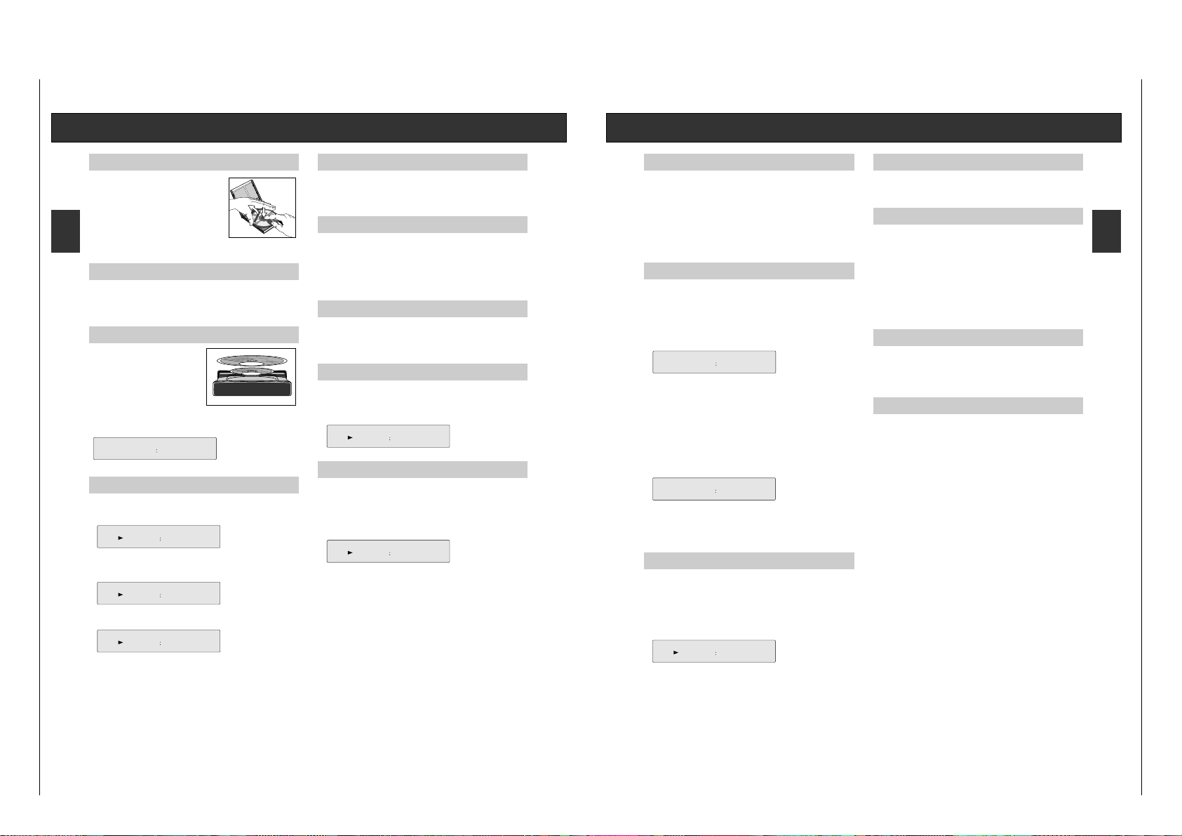
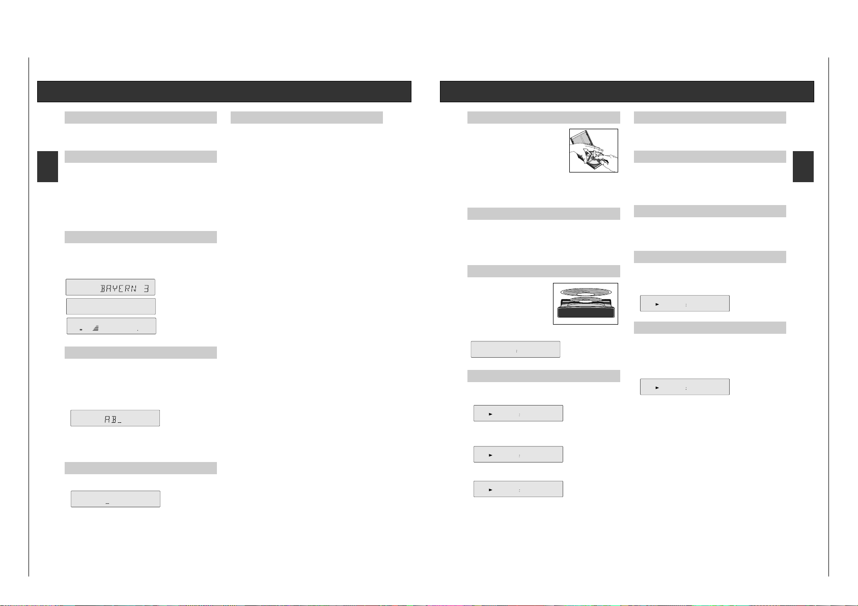
CD
Allgemeines
Um die Disc aus ihrem Gehäuse zu nehmen, fassen
Sie sie mit dem Zeigefinger in der Mitte und dem
Daumen am Rand an. Berühren Sie die Spielseite
der Disc nicht mit den Fingern. Bewahren Sie die
Discs in ihren Gehäusen auf. Legen Sie die Disc mit
dem Etikett nach oben in das Gehäuse und drücken
Sie leicht auf die Etikettenoberfläche.
Die CDs niemals längere Zeit direkter Sonneneinstrahlung aussetzen oder in
der Nähe einer Wärmequelle z.B. einem Heizkörper aufstellen.
Einschalten
• Durch Drücken der Taste CD wird der CD-Player eingeschaltet.
– Haben Sie keine CD eingelegt, zeigt das Display für kurze Zeit: ‘NO DISC’,
danach ‘–:––’.
– Nach dem Einschalten ist das Gerät immer im STOP-Modus.
CD einlegen
Mit ? öffnen Sie die Disc-Schublade.
Legen Sie eine CD so ein, daß die bedruckte
Seite (Labelseite) nach oben zeigt.
Legen Sie CD-Singles (8 cm) in die Vertiefung der Schublade und drücken Sie ?
erneut. Die Schublade fährt ein.
Sie können die Schublade auch manuell
zuschieben. Nachdem die Schublade eingefahren ist, liest das Gerät das
Inhaltsverzeichnis der CD. Dort sind Informationen über Titelanzahl, Spieldauer,
etc. gespeichert. Diese werden im Display angezeigt.
Abspielen einer CD
• Drücken Sie die Taste B auf dem Gerät (oder auf dem Ferngeber) um die
Wiedergabe zu starten. Das Display zeigt die Nummer des aktuellen Titels
(Track), sowie die abgelaufene Spieldauer (relative Spielzeit) an.
Sie können sich im Display noch weitere Informationen zeigen lassen.
• Nach Drücken der Taste INFO auf dem Gerät oder der Taste
6 auf der
Fernbedienung wird die Restspielzeit der CD angezeigt ‘REMAIN’.
• Nochmaliges Drücken zeigt die Gesamtspieldauer und die Gesamtzahl der
Titel (Track) an.
• Drücken Sie die Taste B erneut, wird das aktuelle Stück wiederholt.
• Wollen Sie die Wiedergabe unterbrechen, ohne daß Geräteinstellungen
verändert werden, drücken Sie die Taste ;
– Auf der Anzeige leuchtet das Zeichen ;
•
Während die Wiedergabe unterbrochen ist, können Sie mit den Tasten O P
zu einem anderen Stück springen oder mit den Tasten QReine
bestimmte Passage suchen.
• Wollen Sie mit der Wiedergabe fortfahren, drücken Sie die Taste ; oder die
Taste B erneut.
• Um die Wiedergabe zu beenden, drücken Sie die Taste 9 (STOP).
Umschalten der Anzeigen
• Durch Betätigen der Taste INFO auf dem Gerät oder der Taste 6 auf der
Fernbedienung können in der Anzeige verschiedene Informationen
aufgerufen werden.
– Die Anzeigen ändern sich je nach Betriebsart.
Titelsprung (TRACK NEXT/PREVIOUS)
• Drücken Sie die Taste SKIP P, so wird an den Anfang des nächsten
Stückes in der Titelreihenfolge gesprungen (NEXT); Mit der Taste SKIP O
an den Beginn des vorherigen Stückes (PREVIOUS).
• Betätigen Sie die Taste aus STOP heraus, können Sie gezielt ein bestimmtes
Stück anwählen.
– Die Wiedergabe beginnt sofort.
Schneller Suchlauf SEARCH
• Mit den Tasten SEARCH Q oder R starten Sie den schnellen
Suchlauf (SEARCH) in die entsprechende Richtung.
– Während des Suchlaufes können Sie mithören.
– Nach ca. 5 Sekunden wird das Gerät stummgeschaltet.
Wiederholfunktion REPEAT
Sie können sich die CD (oder Ihr Programm) mehrfach hintereinander anhören.
• Drücken Sie die Taste REPEAT, schalten Sie die Wiederholfunktion ein,
nochmaliges Drücken schaltet die Funktion wieder aus.
– Das Display informiert Sie über die gewählte Funktion.
Zufalls-Wiedergabe SHUFFLE
• Drücken Sie die Taste SHUFFLE, so starten Sie die Wiedergabe der CD in
zufälliger Reihenfolge. Die Auswahl der Reihenfolge übernimmt ein Zufallsgenerator.
– Alle Bedienfunktionen bleiben, wie bei normaler Wiedergabe, erhalten.
– Ein Tracksprung wird allerdings auch vom Zufallsgenerator gesteuert.
– Das Display informiert Sie über die gewählte Funktion.
• Die Funktion wird beendet, wenn Sie die Taste 9, ? oder SHUFFLE
drücken, in diesem Fall werden die nachfolgenden Stücke in gewohnter
Reihenfolge wiedergegeben oder die Wiedergabe wird beendet.
– Die Wiedergabe in zufälliger Reihenfolge (Shuffle) ist nicht möglich, solange
Sie ein Programm abspielen.
142
5
REPEAT
SHUFFLE
027
4
REPEAT
4611
12
TOTAL
4432
1
REMAIN
016
1
4611
12
TOTAL
12 cm
8 cm
6
.
O
Y
E
M
I C
A
N
T
O
(
H
e
a
r
M
y
V
o
ic
e
)
7
. D
O
N
'T
W
A
N
N
A
L
O
S
E
Y
O
U
8
.
G
E
T
O
N
Y
O
U
R
F
E
E
T
9
.
Y
O
U
R
L
O
V
E
IS
B
E
D
F
O
R
M
E
1
0
.
C
U
T
S
B
O
T
H
W
A
Y
S
1
1
.
O
Y
E
M
I
C
A
N
T
O
(
S
p
a
n
i
s
h
V
e
r
s
i
o
n
)
1
2
.
S
I
V
O
Y
A
P
E
R
D
E
R
T
E
E
P
C
4
6
5
1
4
5
2
BIEM
/STEMRA
S
T
E
R
E
O
A
ll rig
h
ts
o
f th
e
p
ro
d
u
c
e
r a
n
d
o
f th
e
o
w
n
e
r o
f th
e
re
c
o
rd
e
d
w
o
rk re
s
e
rv
e
d
. U
n
a
u
th
o
ris
e
d
c
o
p
y
in
g
,
p
u
b
lic
p
e
rfo
rm
a
n
c
e
, b
ro
a
d
c
a
s
tin
g
, h
irin
g
o
r re
n
ta
l o
f th
is
re
c
o
rd
in
g
p
ro
h
ib
ite
d
. M
a
d
e
in
A
u
s
tria
1
.
A
Y
,
A
Y
,
I
2
. H
E
R
E
W
E
A
R
E
3
.
S
A
Y
4
.
T
H
IN
K
A
B
O
U
T
Y
O
U
N
O
W
5
.
N
O
T
H
I
N
' N
E
W
C
O
M
P
A
C
T
D
I
G
I
T
A
L
A
U
D
I
O
1
2
Page 8
Allgemeiner Teil / General Section RCD 400
1 - 8 GRUNDIG Service
D GB
d 13
Uhr und Timer
Uhreinstellung
Das Gerät verfügt über eine eingebaute Uhr (24 Stunden).
• Mit der Taste POWER Bereitschaftsmodus wählen.
• Zweimal EDIT drücken. In der Anzeige erscheint CLOCK.
– In der Anzeige beginnt die Zeit zu blinken.
• Zum Einstellen der Zeit die Tasten Q SEARCH/TUNING R drücken.
Mit jedem kurzen Tastendruck wird die angezeigte Zahl um 1 erhöht. Durch
Niederhalten der Taste wird die Einstellung im Schnellverfahren
vorgenommen.
• Zum Speichern der Einstellung MEMORY drücken.
• Soll der Uhreinstellungsmodus ohne geänderte Einstellung verlassen
werden, erneut EDIT drücken.
Anmerkung:
Bei Stromausfall wird die Zeit gespeichert. Kehrt der Strom
wieder, läuft die Uhr ab der gespeicherten Zeit weiter.
Timer-Funktion
Stellen Sie vor dem Einstellen des Timers sicher, daß die Uhr richtig gestellt ist.
Ein- und Ausschalten des Timers
Der Timer kann in jeder Betriebsart (selbst bei Bereitschaft) ein- oder
ausgeschaltet werden.
• Der Timer kann durch längeres Drücken der Taste INFO ein- oder
ausgeschaltet werden.
– Ist der Timer eingeschaltet, wird eine Sekunde lang ‘TIMER ON’ angezeigt.
Anschließend erscheinen in der Anzeige wieder die ursprünglichen Angaben.
Die Leuchtdiode in der POWER-Taste beginnt zu blinken.
– Ist der Timer ausgeschaltet (erneutes längeres Drücken der INFO-Taste), wird
eine Sekunde lang ‘TIMER OFF’ angezeigt. Anschließend kehren in der
Anzeige die ursprünglichen Angaben wieder.
Timereinstellung
• Mit der Taste POWER auf Bereitschaft schalten.
• Einmal EDIT drücken. In der Anzeige erscheint kurz ‘TIMER’.
– Die Anfangszeit beginnt zu blinken, z. B. ‘02:30 ON’.
• Zum Einstellen der Anfangszeit die Tasten Q SEARCH/TUNING R
drücken. Mit jedem kurzen Tastendruck wird die angezeigte Zahl um 1
erhöht. Durch Niederhalten der Taste wird die Einstellung im
Schnellverfahren vorgenommen.
• Zum Einstellen der Endzeit SKIP/STATION P drücken.
• Mit den Tasten Q SEARCH/TUNING R die Endzeit einstellen.
• Zum Speichern der Timereinstellung MEMORY drücken.
– Sobald der Timer eingeschaltet ist, beginnt die Leuchtdiode in der Taste
POWER zu blinken.
– Das Gerät beginnt mit jener Funktion, die eingestellt war, bevor das Gerät auf
Bereitschaft geschaltet wurde (dasselbe Geräteteil, derselbe Radiosender
oder dieselbe Titelnummer der CD).
– War das Gerät bereits eingeschaltet, als der Timer gestellt wurde, läuft die
gewählte Funktion weiter und das Gerät schaltet sich bei der eingestellten
Endzeit ab.
– Nach dem Timerverfahren wird das Gerät auf Bereitschaft geschaltet und die
Leuchtdiode in der Taste POWER hört auf zu blinken.
Funktion SLEEP (auf der Fernbedienung)
Mit Hilfe der Sleep-Funktion (Einschlafautomatik) kann das Gerät nach Ablauf
einer bestimmten Zeit automatisch abgeschaltet werden.
Damit können Sie zum Einschlafen Musik hören. Sie brauchen dann das Gerät
nicht in Bereitschaft zu schalten, da dies automatisch geschieht. Die Taste
SLEEP befindet sich auf der Fernbedienung.
Drücken Sie einmal auf die Taste SLEEP.
• Einmal die Taste SLEEP drücken.
– In der Anzeige erscheint ‘SLEEP 60’.
– Nach einer Sekunde wird das Gerät eingeschaltet, und nach 60 Minuten
schaltet es sich automatisch auf Bereitschaft.
• Wird die SLEEP-Taste innerhalb einer Sekunde erneut gedrückt, kann eine
andere Sleep-Zeit gewählt werden: 60 –> 40 –> 30 –> 20 –> 10 –> 5 –> 0
– Während der Sleep-Funktion erscheint in der Anzeige ‘SLEEP’.
Hinweise:
• Während die Sleep-Funktion aktiviert ist, kann durch Drücken der Taste
SLEEP die Einschlafzeit auf 60 Minuten zurückgestellt werden.
• Die SLEEP-Einstellung kann gelöscht werden, indem Sie das Gerät in
Bereitschaft schalten (mit der Taste y auf der Fernbedienung) oder wenn Sie
die Taste SLEEP drücken bis in der Anzeige ‘SLEEP 0’ erscheint.
Front of the CD RECEIVER
POWER This button is used for switching the receiver on and to
standby.
9 STOP/ This button is used to end all functions and to open and
?
OPEN/CLOSE
close the CD compartment.
PAUSE ; This button is used to briefly interrupt CD playback
(PAUSE), without changing the unit settings.
PLAY B This button is used to start or restart CD playback.
SEARCH / TUNING Q R
In CD mode: These buttons are used to start backward Q or
forward R search.
In TUNER mode: You use these buttons to start the station search (AUTO
TUNING) or to advance the frequency step by step
(MANUAL TUNING).
SKIP / STATION O P
In CD mode: These buttons are used to skip to the previous or next
tracks.
In TUNER mode: These buttons are used to scroll through the station
memory in the direction indicated by the arrows.
SOURCE SELECTION
TUNER BAND This button is used to select the tuner and to switch to the
FM and MW bands.
CD This button is used to select the source CD.
TAPE/AUX This button is used to select the TAPE/AUX input.
DEFEAT This switch is used to bypass the BASS and TREBLE
controls
VOLUME This control is used for adjusting the volume.
LOUDNESS This switch is used during playback to adapt the volume
level to individual hearing sensitivity.
BALANCE This control is used to adjust the sound balance
between the left and right channels
BASS This is to adjust the bass tones.
TREBLE This is to adjust the high tones.
HEADPHONES This socket is for connecting standard stereo head-
phones with a 6.3 mm jack.
Volume is adjusted with the rotary VOLUME knob.
The receiver´s speaker outputs are automatically
switched off when the headphone jack is inserted, and
are automatically switched on again when it is removed.
MEMORY
In CD mode: This is used to call up the programming mode or to save
individual tracks.
In TUNER mode: This button stores a set station at the lowest respective
memory location.
CANCEL
In CD mode: This button is used to omit individual tracks from the
programme or to delete the complete programme.
In TUNER mode: This button is used to delete individual memory locations
or, if desired, the entire memory contents (by keeping the
button depressed for longer than 10 seconds).
EDIT
In TUNER mode: This button is used for selecting the station name input
mode.
In CD mode: This button is used to adjust the CD playing time to the
length of the cassette you are recording to.
In STANDBY mode: This button is used to call up the timer and clock
adjusting mode
REPEAT / ANT/CABLE
In CD mode: REPEATThis button is used to turn the repeat function
on and off.
In TUNER mode: ANT/CABLEThis button is used to switch on the FM
antenna attenuator for reducing radio disturbance if your
tuner is connected to broadband cable and the reception
signal is too strong.
SHUFFLE / MONO
In CD mode: SHUFFLE This button is used to turn the shuffle function
on and off, which mixes up the track order.
In TUNER mode: MONOYou use this button for selecting mono reception
if, for example, stereo reception exhibits too much
disturbing noise.
INFO
In CD mode:
This is used to change the information shown in the
display.
In TUNER mode: This button is used for switching the display between the
station name (RDS), or another name you assign,
RADIOTEXT and station frequency.
In any mode Pressing this button longer switches the timer on and off.
© 16
Operating elements
HIFI CD RECEIVER
RCD 400
R D S
POWER IO
POWER IO
POWER
DEFEAT
PAUSE
PAUSE
PLAY
PLAY
REPEAT
REPEAT
SHUFFLE
SHUFFLE
INFO
INFO
STOP
STOP
OPEN/
CLOSE
OPEN/
CLOSE
SKIP/STATION
SKIP/STATION
SEARCH/TUNING
SEARCH/TUNING
MEMORY
MEMORY
CANCEL
CANCEL
EDIT
EDIT
TAPE/AUX
TAPE/AUX
CD
CD
TUNER BAND
TUNER BAND
DEFEAT
DEFEAT
VOLUME
VOLUME
LOUDNESS
LOUDNESS
HEADPHONES
HEADPHONES
TREBLE
TREBLE
BASS
BASS
BALANCE
BALANCE
RRL
L
+
+
+
+
-
-
-
-
ANT/CABLE
ANT/CABLE
MONO
MONO
HEADPHONES
LOUDNESS
STOP
OPEN/CLOSE
PAUSE ; PLAY B
SKIP/STATION
O P
SEARCH/TUNING
Q R VOLUME
INFO
SHUFFLE
MONO
REPEAT
ANT/CABLE
EDIT CANCEL MEMORY TREBLE BASS BALANCE
TUNER BAND CD TAPE/AUX
59 8A EPA 3
TUNED
ANTENNA
Operating Hints
Note: This chapter contains excerpts from the operating instructions. For further particulars please refer
to the appropriate user instructions the part number of which is indicated in the relevant spare
parts list.
Page 9
RCD 400 Allgemeiner Teil / General Section
GRUNDIG Service 1 - 9
GB GB
Display Remote Control
Display
1 STATION NUMBER seven-segment display
This shows the number of the selected memory location (1 to 59 as either
one or two digits
2
) – This indicates that the tuner is receiving FM stereo broadcasts
3 ;B – This indicates that the CD is in playback or in pause mode.
4 TUNED – This indicates that the unit is optimally tuned to a station
5 Signal strength – The more dashes you can see, the stronger the
reception of the station you have tuned to.
6 14-segment display – for frequencies in MHz (FM) or kHz (MW),
(RDS) station name, radio text, names you have assigned or the selected
programme type.
7 PROGRAM – This indicates that the CD is in programme mode.
8 SHUFFLE – This indicates that the CD is playing tracks in random order.
9 ANTENNA – comes on when the antenna attenuator is not switched on.
0 REPEAT – This indicates that the CD is in repeat mode.
! CABLE – comes on during broadband cable reception if the antenna
attenuator is switched on with the ANTENNA/CABLE button.
@ REMAIN – This lights up when the remaining time indication for the CD
player is selected.
# TOTAL – This lights up when the total time indication for the CD player is
selected.
Remote Control
Changing the batteries
If the range of your infrared remote
control seems to decrease, or if
certain individual functions can no
longer be carried out, you should
replace the batteries.
Two 1.5 Volt LR06 size AA are
required. To change the batteries,
open the compartment on the back of
the remote control. Ensure that the
batteries are inserted properly (note
the markings in the compartment).
And in the interest of the
environment: Remember that batteries
must always be disposed of properly.
GENERAL
y – This button is used to switch the unit to STANDBY.
SLEEP – this button is used to call up the sleep timer function.
6 – This button is used to toggle the display modes of the active source.
a – This button is used for muting the speakers.
VOLUME +/– – These buttons are used for controlling the volume of the
receiver.
TAPE – This button is used for selecting the TAPE input.
TUNER
TUNER – ThIs button is used for selecting the tuner (radio)
PTY – This buttons are used to select the programme type.
STATION 1 2 – These buttons are used for selecting stations
CD
CD – This button is used for selecting the CD player.
; – This button is used to switch the CD player to PAUSE.
9 – This button is used to switch the CD player to STOP.
B – This button is used to start playback of the CD player
– DISC + – This button is only used for a CD changer.
O P – These buttons are used to select next or previous tracks on a CD.
PROGRAM
ANTENNA
########
MHz
1
2
0@
#9!
6
kHz
88
SHUFFLE
REPEAT REMAIN
TOTAL
CABLE
TUNED
54
7
8
3
© 17
Amplifier part
Switching on and off
When you want to switch your receiver on, press the POWER button. The red
LED in the middle of the button indicates that the unit is on.
button depressed: POWER ON
button not depressed: STANDBY
The receiver will be activated and the last selected source will be selected.
When the receiver is switched to active mode (as described below), the LED in
the power knob lights up.
The receiver is muted for approximately 3 seconds when it is turned on in order
to suppress disturbing initial signal noise.
To switch the receiver to stand-by press the POWER button again.
Stand By
You can switch the system to STAND BY with the y button on the remote
control or with the POWER button.
The display shows the clock time.
When you want to switch your system on again, simply press one of the input
selection buttons on the unit or on the remote control or the POWER button.
Source Selection
To select a listening source, press either the corresponding button on the unit
or the corresponding button on the remote control.
Automatic Source Selection
When the receiver is switched on, the receiver automatically switches to the CD
input as soon as you press the CD player B button.
Sound control
VOLUME The volume can be adjusted with the rotary VOLUMEknob.
The volume can also be controlled via the remote control
with the VOLUME +/– buttons.
MUTING The volume can be completely muted by pressing the a
button on the remote control.
This is useful, for example, if you want to take a telephone
call and do not want to be distracted by music, news, etc.,
from your system.
If the muting function is used when recording a tape, this
has no effect on the subsequent recording volume level as
only the speakers are muted.
The click you hear when you press the a button comes from
the relay which mutes the speakers.
The MUTING function can be deactivated by pressing the a
button again or by pressing the VOLUME + button on the
remote control or any one of the input selection buttons.
BASS, TREBLE The BASS and TREBLE controllers can be used to
individually adjust the higher and lower frequencies from the
sound of your speakers. In this way, you can compensate for
surrounding acoustic irregularities which may be caused, for
example, by sound reflection behaviour on walls with
relatively large, empty surface areas, or ‘damping’ caused
by furniture or other objects.
LOUDNESS Pressing the LOUDNESS button slightly accentuates the
lower and higher frequencies which renders a more balanced
overall sound during quieter passages.
Its effectiveness depends in turn on the setting of the volume
knob. The sound is thus optimally adapted to human hearing
sensitivity, which is also dependent on the respective
volume.
If you have connected speakers which exhibit a great deal of
bass, LOUDNESS should always remain off to achieve a
more linear acoustic pattern. In this way, you compensate for
excessive emphasis of the lower frequencies.
DEFEAT The DEFEAT switch can be used to deactivate the bass and
treble control without changing the respective settings.
This function merely bypasses the signal path through the
bass and treble controls ensuring that the original sound is
reproduced with the highest fidelity.
BALANCE For effective stereo playback, it is important that the sound
emanates equally from both speakers.
Acoustic equalibrium can be distorted by furniture groups or
the listener´s position in a room, thus distorting the
impression of stereo sound.
The BALANCE controller can compensate for such
distortions.
© 18
SLEEP
PTY
TUNER STATION
CD
DISC–+
TAPE
RC 400
-
VOLUME
+
Page 10

Allgemeiner Teil / General Section RCD 400
1 - 10 GRUNDIG Service
GB GB
Radio
Switching on
• Select the radio input by pressing the TUNER BAND button.
– The first time you switch your unit on, it automatically switches to 'FM', and
the display indicates 87,50 MHz. STEREO
) is also selected.
– Your unit is provided with the function 'LAST STATION MEMORY', which
means that the station that was playing when the set was switched off will be
selected again when the radio is switched back on.
Selecting the wave band
• Select the desired wave band (FM or MW) by pressing the TUNER BAND
button. Pressing this button switches to the next wave band in the following
order: FM - MW - FM.
– The display shows the selected band.
Adapting the antenna
If you receive broadcasts via broad band cable of a public or private cable
service, there may be high signal inputs at your antenna terminal, which may in
turn cause reception disturbances.
• If this is the case, press the ANT/CABLE button to switch on the input
attenuator ‘CABLE’ appears on the display. This reduces the antenna input
sensitivity, thus reducing disturbances. This setting is automatically stored.
FM reception MONO/STEREO
Normally, your unit is in stereo reception mode, which means that as soon as a
stereo signal of sufficient strength is detected, '
)' appears in the display. If
stereo reception is disturbed, '
)' disappears. In this way, disturbing
background noise is suppressed.
If noise-free stereo reception is not possible, you can switch your unit to MONO
reception.
• In this case, press MONO.
–'
)' will disappear from the display.
The MUTING function is always switched off for MONO reception, allowing
the unit to receive even very weak broadcast signals.
RDS Radio Data System
Your tuner is an RDS tuner.
RDS (Radio Data System) stands for a new generation of radios that provides
the listener/user with more comfort and better reception in the short term, but
also opens up completely new information options for the future.
RDS-equipped receivers identify the tuned station (if it transmits 'RDS signals')
and indicate the name of the programme in the 8-place display (e.g. BAYERN 3,
SDR 3).
If you are tuned to an RDS station, the name of the station will be indicated after
a short time.
For more information, please see page 21.
Automatic station search
• To activate automatic station search (AUTO TUNING), press TUNING Q
or R until the frequency display begins 'to run'; then release the button.
– The search stops as soon as a station with sufficient reception quality is
found and tuned to precisely. The display shows TUNED.
– Every time you begin a search, the unit automatically switches to STEREO.
– A graph in the display indicates the field strength: the more illuminated
dashes you see, the stronger the reception.
–
The frequency of the received station is indicated in kHz (MW) or MHz (FM).
– If the search stops, the 'AUTO COMPARE' function first verifies whether the
station which has been found is already stored in the station memory. If this
is the case, the memory location of the station is displayed, as well as the
name of the station, if it already exists.
– Stations which are received with a weak field strength may be skipped.
These can be tuned to manually.
•
If desired, you can also interrupt the search by pressing TUNING QR.
Manual station search (manual tuning)
• Briefly press the TUNINGQor R button to tune in the corresponding
direction in individual steps (FM: 25kHz; MW: 1 kHz).
• If you keep the button depressed, you can rapidly scan large frequency
ranges. When you release the button, AUTO TUNING is automatically
switched to. Muting is active during AUTO TUNING.
• If you briefly press one of the TUNING
Q
R buttons, manual tuning
is automatically switched to.
– Just as with automatic tuning , the TUNED flag and the number of
illuminated dashes indicate the reception quality.
– The 'AUTO COMPARE' function also verifies whether the found frequency is
already stored.
'LAST STATION MEMORY'
LAST STATION MEMORY means that the unit 'remembers' the last station that
was tuned to. This function ensures that the station which was selected before
the radio was switched off is automatically selected again when your radio is
switched back on.
ANTENNA
FM 10530
MHz
TUNED
ANTENNA
FM 10530
MHz
4
TUNED
© 19
Radio
Station memory
59 memory locations are available for storing stations.
•
Tune to the station you want to store with the station search function or manually.
• Press MEMORY.
– The station is stored at the next available memory location.
– The tuner software first checks the station memory for available memory
locations. If all the locations are occupied,’MEM FULL’ appears on the
display for approx. 1.5 seconds.
– Assigning a station frequency to two different memory locations is not
possible. The selected station is stored at the lowest available memory
location, meaning that you need not enter a number for memory locations.
– Every time the settings STEREO/MONO and ANTENNA/CABLEare changed,
they are automatically stored.
Storing stations
• If you want to store a station, press MEMORY.
– The first station which is stored is assigned to memory location 1, the
second station to memory location 2 and so on.
• If you want to move a stored station to another memory location, press
MEMORY.
– The station is always assigned to the first available memory location.
• Pressing the button again assigns a station to the next available memory
location.
• If you keep the button depressed, the memory locations are scanned one
after the other, deleting the previously assigned memory location.
Example:
You want to move your favourite station from memory location '6' to memory
location '1'.
• Select memory location '1'.
• Press CANCEL once.
– This deletes, or clears, memory location '1'.
You can also press MEMORY to move the station on location '1' to the next
available free memory location.
• Now select position '6', your favourite station, and then press MEMORY.
Your station is now stored on memory location '1'.
Calling up a stored station
• When you want to call up a stored station, press STATION OP. The
stations are called up in ascending or descending order.
Stations can also be selected via the system remote control:
• Select the radio input by pressing the TUNER button.
• Press the 1 STATION 2 buttons.
– The display shows the selected memory location number, and the unit
switches to this memory location.
– It is not possible to select a memory location which has not (yet) been
assigned to a station.
Example:
Memory location 6 is not assigned to a station.
If you are situated at memory location number 5 and press once STATION
P the unit will jump to memory location 7 (provided this location has been
assigned to a station).
Deleting a memory location
• If you want to delete a memory location to which a station is assigned, first
call up its number.
• Press STATION OPuntil you reach the station you want to delete.
You may also use the STATION 12buttons on the remote control.
• Press CANCEL.
– The memory location is deleted, and the memory location number does not
light up on the display anymore.
• Hold CANCEL down for 5 seconds if you want to delete all the memory
locations, for example after you move to another location.
– 'ERASE ?' appears briefly on the display.
• Keep the button depressed for an additional 5 seconds until the display
shows '87,5 MHz'.
– The station memory is deleted.
• If you now press one of the STATION OPbuttons, 'FREE' is shown on
the display.
• If you release the CANCEL button before these 5 seconds have elapsed, the
erase function is not carried out.
ANTENNA
FM 10420
MHz
8
© 20
Page 11
RCD 400 Allgemeiner Teil / General Section
GRUNDIG Service 1 - 11
GB GB
Radio
RDS Radio Data System
Your unit is capable of receiving and evaluating RDS information which is broadcasted along with the normal broadcast signal. The channel name is displayed and
automatically stored in the unit´s memory, overwriting names previously stored.
RADIOTEXT
Some RDS stations broadcast RADIOTEXT, which is additional information on
the
station and programme being broadcast. RADIOTEXT information appears
as ‘running’ text in the display. RADIOTEXT is transmitted character-bycharacter by the radio station. As a result of that it may take some time until the
entire text has been completely received.
• RADIOTEXT is called up by pressing the INFO several times until the
running text of the RADIOTEXT signal can be seen.
– If a station does not broadcast RADIOTEXT, the unit switches automatically
to the frequency indication.
Switching displays
• Pressing INFO briefly switches the display (when available) between station
name (RDS or one you have entered), RADIOTEXT (with RDS stations), and
frequency.
– When the station name is displayed, only the memory location number is
displayed to the left of the name.
Assigning station names
Stations which do not transmit the RDS code can be assigned any name of your
choice.
• Press EDIT.
– With TUNING
Q
R , you can move the cursor in the desired
direction. You can enter up to eight characters.
– With STATION OP, you can move forward and backward through the
alphabet, the numbers 0-9 and to the space key.
• When you are ready to conclude an input and exit the input mode to store a
name, press EDIT or MEMORY.
Note:
If you attempt to assign a name to a station which transmits the RDS code,
RDS-DATA appears in the display, indicating that a name cannot be assigned.
Deleting a name
• If you press CANCEL when the input mode is selected, the previous name is
deleted and the cursor jumps to the first (left) position.
Programme type PTY (on the remote control)
RDS allows you to select FM stations according to programme type. There are
16 programme categories.
• By using the PTY button on the remote control, you can call up the actual
programme type. Other types can be selected with the STATION 1 2 buttons.
– The display briefly shows the programme type and then the name of the
stations that broadcast this programme type.
– If there are no stations broadcasting a given programme type, the display
briefly shows: 'NONE'.
What is meant by programme types?
NEWS = News service
Programmes that usually give brief reports on current events and statements
that are of public interest. Also: weather and traffic reports.
AFFAIRS = Politics and current events
Programmes that supplement or give more extensive information on the news,
e.g. reports and commentary, news magazine. These programmes also offer
detailed accounts on related issues, e.g. documentation and discussions. Also:
broadcasts of political and similar events.
INFO = Special informative reports
Programmes that offer helpful information, e.g. consumer magazine, health tips,
travel tips, special weather service. In addition, there are also programmes for
individual target groups, e.g. for farmers, children, foreign employees.
SPORT = Sports
All types of sports programmes.
EDUCATE = Learning and continuation of education
Educational programmes for those who wish to gain or further their knowledge
of different fields; e.g. schools' radio, educational radio broadcasts, foreign
language courses.
DRAMA = Radio plays, literature
All types of radio plays, e.g. radio thrillers and science fiction programmes;
readings from literary works.
CULTURE = Culture, church and society
Programmes that offer reports, commentaries or evaluations on topics from the
above-mentioned areas; e.g. discussions on theater, films and books, literary
radio series, reports on the school and educational system, church radio; also
prayers and church services.
SCIENCE
Programmes that deal with methods and findings from the world of science, as
well as with issues from the field of technology.
VARIETY
Programmes that mostly offer light entertainment, e.g. talk shows, quiz shows
and guessing games, cabaret shows, sketches, chat shows etc., often featuring
music.
POP M. = Pop music
Programmes with popular and modern hits from home and abroad.
ROCK M. = Rock music
Programmes with international music of the younger generation, often with a
heavy emphasis on rhythm.
EASY M. = Light music
Programmes with light music of all types, e.g. folk music, dance music,
musicals and operettes.
LIGHT-M. = Light classical music
Programmes with popular classical music; music, often abbreviated works of
excerpts of works, e.g. overtures, arias, etc.
CLASSICS = Serious classical music
Programmes with more serious works, e.g. symphonies, chamber music, fulllength operas.
MUSIC = Special music programmes
Music programmes that cannot be assigned to one of the above mentioned
programme types, e.g. folklore, jazz, experimental music.
7
7
ANTENNA
FM 10530
MHz
4
TUNED
ARD-RADI
4
© 21
CD
General information
To remove a CD from its case, hold it on its
outside edge with the index finger and thumb.
Do not touch the surface of a CD with your fingers.
Always store a CD in its case when it is not being
used.
Place a CD in its case with the label facing up and
press down lightly.
Do not leave CD's for any length of time in direct sunlight or other places where
high temperatures may occur, such as in the vicinity of heating apparaturs. Do
not expose the CD's to humidity or rain.
Switching on
• Select the CD player by pressing the CD button.
– If you have not inserted a CD, ‘NO DISC’ appears briefly in the display, and
then ‘–:– –’.
– After the unit has been switched on, it is always in the STOP mode.
Inserting a CD
Open the CD compartment by pressing ?
Insert the CD so that the printed side of the
disc is facing up. Place CD singles (8 cm)
in the depression in the compartment.
Press ? again. The compartment closes.
The CD compartment can also be closed by
hand. After the compartment has closed, the
unit reads the contents of the CD. Information on the number of tracks, playing
length, etc. are recorded there. This information is shown in the display.
CD playback
• Press B on the unit (or on the remote control) to start playback. The display
shows the number of the track being played as well as the elapsed playing
time (relative playing time).
The display can also show you additional information.
• Press INFO on the unit or
6 on the remote control and the display shows you
the CD´s remaining playing time, ‘REMAIN’.
• If you press this button once more, the display shows the total playing time
and the total number of tracks.
• If you press B again, the running track will be restarted (REPLAY function).
• If you want to stop playback without changing the unit settings, press ;.
– The ; indicator on the display lights up.
• While playback is interrupted, you can press O P to skip to another track,
or press Q or R to search for a certain passage.
• If you want to continue with playback, press ; or B once more.
• To stop playback, press 9 (STOP).
Changing the display
• You can call up various information in the display by pressing the INFO
button on the unit or the
6 button on the remote control.
– The displays changes according to the operating mode.
Skip function (TRACK NEXT/PREVIOUS)
• By pressing SKIP P you can skip to the beginning of the next track in the
track sequence (NEXT), and by pressing SKIP O you can skip to the
beginning of the preceding track (PREVIOUS).
• While in STOP mode you can choose a certain track.
– Playback begins immediately.
Fast search (SEARCH)
• By pressing SEARCH Q or R , you activate the fast search in the
corresponding direction.
– During the search procedure you can listen to the tracks.
– After approx. 5 seconds the unit ´s mute function is activated.
REPEAT function
The repeat function allows you to repeat the entire CD (or your programme).
• By pressing the REPEAT button, you activate the repeat function; by
pressing the button again you deactivate the repeat function.
– The display shows you the function you have chosen.
SHUFFLE function
• By pressing SHUFFLE you activate the shuffle function which mixes up the
order of the CD tracks. A random number generator selects the order of the
tracks to be played.
– All operating functions continue to function as during normal playback.
– The random number generator also controls the skip function.
– The display shows the function you have selected.
• The function is deactivated by pressing SHUFFLE or 9?; in this case the
remaining tracks are played in their normal order or playback is stopped.
– The shuffle function is also possible during playback of a programme.
142
5
REPEAT
SHUFFLE
027
4
REPEAT
4611
12
TOTAL
4432
1
REMAIN
016
1
4611
12
TOTAL
12 cm
8 cm
© 22
2
,
g
in
y
p
tria
s
o
u
c
d
A
1
.
A
e
Y
in
,
A
2
ris
Y
e
.
H
,
I
E
o
d
R
E
3
a
W
.
th
S
E
A
u
Y
A
4
R
a
. M
.
E
T
H
n
d
IN
5
K
.
A
N
ite
B
O
. U
O
T
H
U
d
ib
I
T
N
Y
'
e
N
h
O
E
U
W
N
rv
ro
O
e
W
s
p
g
1
re
in
rk
rd
o
o
c
w
d
re
e
is
rd
o
f th
c
l o
re
e
ta
n
f th
r re
r o
o
e
g
n
w
irin
o
e
, h
g
f th
tin
o
s
d
a
n
c
d
r a
a
e
ro
c
u
, b
d
e
ro
c
n
p
a
e
rm
f th
rfo
o
6
.
e
O
ts
Y
E
h
7
p
M
.
I
D
C
O
A
N
lic
N
'T
8
T
.
G
O
b
W
ll rig
(
E
A
H
u
T
N
e
9
A
O
N
a
.
r
A
p
N
Y
M
Y
O
L
y
O
O
U
S
R
U
V
1
E
0
L
R
o
.
Y
ic
C
O
F
e
O
E
V
U
)
U
E
E
T
1
T
S
IS
1
B
.
B
O
O
Y
E
T
E
D
1
H
F
2
M
W
.
O
S
I
C
A
R
I
V
Y
A
M
S
N
O
E
T
Y
O
A
(
P
S
p
E
a
R
n
D
is
E
h
R
V
T
E
e
r
s
i
o
n
)
E
P
C
4
6
5
BIEM
1
4
5
/STEMRA
2
S
T
E
R
E
O
C
O
M
P
A
C
T
D
I
G
I
T
A
L
A
U
D
I
O
Page 12

Allgemeiner Teil / General Section RCD 400
1 - 12 GRUNDIG Service
GB GB
CD
Programming
You can programme your own track sequence for each CD.
The order of the programmed tracks determines the order in which they are
played. Each track can be stored as often as you like. The time display shows
you the total playing time of the programme.
There are two methods of programming the desired track sequence. You can
enter a programme in the STOP mode or in the PLAY mode.
You can store a sequence of up to 30 tracks.
Programming in STOP mode
• Insert a CD and close the compartment.
– The CD player reads the contents of the CD. The display shows the total
playing time and the number of tracks.
• Press MEMORY to select the PROGRAM mode.
– At the left, the display shows PROGRAM and the total playing time of
programme.
• Select the first track you want to programme with O and P.
– The track number flashes.
– The display shows the time which will be the total time of your programme
when you store the selected track. In this way you can easily search for tracks
which fill in your program to a desired total time (e.g. for recording purposes).
• By pressing MEMORY, the track is stored in your programme.
– The track number at the left stops flashing.
• Choose the next track you wish to include in your programme and press
MEMORY to save it.
–
The playing time display is updated.
• You can leave the programme mode by pressing the 9 button.
Programming in PLAY mode
You can also enter a programme while a CD is playing.
• Press MEMORY.
– The number of the current track flashes and the display shows the time which
will be the total time of your programme when you store the selected track.
• If you wish to add this track to your programme, press MEMORY again.
– The track number stops blinking.
• If you wish to add a track to your programme other than the one currently
being played, press the O or P button.
• Save your selection by pressing MEMORY.
• You can leave the programme mode by pressing the 9 button.
Programme playback
• To play the programme you have created, press B (PLAY).
– All functions of the playback mode continue to function.
Changing the programme
It is possible to change the programme you have created; you can add
additional tracks or delete tracks from your programme.
• If you wish to add an additional track, press MEMORY and select the
desired track by pressing OPon the keypad of your remote control. The
corresponding track number blinks.
• Use MEMORY to add the track to your programme.
• If you wish to delete a track you can do so by selecting the track and then
pressing CANCEL.
– The playing time display is continuously updated.
Deleting the programme
• To delete the entire programme, press CANCEL while in the STOP mode.
•
Opening the compartment (?) or shutting off the unit also deletes the programme.
EDIT function
This function notifies the CD player as to the playing time of a cassette tape.
• Press the EDIT button to call up the entries C 46, C 60, C 90, C100, C 110,
C 120 one after another.
• Select the corresponding playing time of the cassette.
– After a brief pause the unit will show you the total playing time and which
tracks will be recorded onto the A side of the cassette.
• Start the CD COPY function on the cassette deck.
– It starts to record on side A. When it is finished, the display shows the tracks
that will be recorded onto the B side.
• This function can also be used to record a programme that you have saved.
PROGRAM
420
1
TOTAL
PROGRAM
420
1
TOTAL
PROGRAM
000
TOTAL
© 23
The Clock and Timer
Setting the clock
Your unit has a 24 hour clock.
• Select STANDBY mode with the POWER button.
• Press the EDIT button two times. CLOCK appears on the display
– The time starts flashing in the display.
• To set the time, press the Q SEARCH/TUNING R buttons. Each
short pressure of the buttons increases the displayed number by one.
Holding the button down increases the setting at high speed.
• Press the MEMORY button to store the setting.
• If you wish to leave the clock setting mode without changing the settings,
press the EDIT button again.
Note:
In case of a power breakdown, the actual clock time is stored in the
memory. When power returns the clock start running again from the stored time
onwards.
The timer function
Before setting the timer, ensure that the correct clock time is set.
Switching the timer on and off.
The timer can be switched on or off in any mode of the set, even in standby
mode.
• You can activate and deactivate the timer with a long pressure on the INFO
button.
– If the timer is switched on, the display shows ‘TIMER ON’ during 1 second
and then returns to showing the original information. The LED in the POWER
button starts blinking.
– If the timer is switched off (another long pressure on the INFO button), the
display shows ‘TIMER OFF’ during 1 second and then returns to showing
the original information.
Setting the timer
• Select STANDBY mode with the POWER button.
• Press the EDIT button once. The display shows briefly TIMER.
– The start time starts flashing in the display.
e.g. ‘02:30 ON ‘
• To set the start time, press the Q SEARCH/TUNING R buttons. Each
short pressure of the buttons increases the displayed number by one.
Holding the button down increases the setting at high speed.
• Press the SKIP/STATION P button to prepare for setting the stop time.
• Adjust the stop time with the Q SEARCH/TUNING R buttons.
• Press the MEMORY button to store the timer setting.
– As soon as the timer is activated, the LED in the POWER button will start
flashing.
– The set will start with the same function that was active before the set was
switched to standby (same source, same tuner station or same track number
of the CD).
– If the set was already switched on when the timer is activated, the actual
function continues and the set switches off at the set stop time.
– After the timer procedure the set will be switched to standby and the LED in
the POWER button will stop flashing.
The SLEEP function (on the remote control)
Your unit is provided with a sleep function which switches the unit off after a set
time has elapsed.
This allows you, for example, to fall asleep to music. You don't need to switch
the unit to standby as this happens automatically when the time you set has
elapsed.
The SLEEP button is on the remote control.
• Press the SLEEP button once.
–'SLEEP 60' appears on the display.
– After one second the set will be switched on and after 60 minutes the unit
will automatically switch to standby.
• If you press the SLEEP button again within one second you can select the
other sleep times: 60 –> 40 –> 30 –> 20 –> 10 –> 5 –> 0.
– During the sleep function the SLEEPindication will be shown on the display.
Note:
• While the sleep function is still active, you can reset the sleep time to 60
minutes by pressing the SLEEP button.
• Deactivate the SLEEP setting by switching the unit to standby (with the y
button on the remote control) or by pressing the SLEEP button until
'SLEEP 0' appears.
© 24
Page 13

RCD 400 Allgemeiner Teil / General Section
Ausbauhinweise
1. Gehäuseoberteil
- 6 Schrauben am Gehäuseoberteil herausschrauben.
- Deckel abnehmen.
2. Tunerplatte
- 2 Schrauben A (Fig. 1) herausschrauben.
- 4 Schrauben B (Fig. 2) herausschrauben.
- Steckverbindungen lösen.
A
C
C
Fig. 1
3. Verstärkerplatte
- 2 Schrauben C (Fig. 1) herausschrauben.
- 2 Schrauben D (Fig. 3) herausschrauben.
- Die Tunerplatte (Punkt 2) zusammen mit dem Halter ausbauen.
- 3 Schrauben E (Fig. 1) herausschrauben.
- 6 Schrauben F (Fig. 4) herausschrauben.
E
Disassembly Instructions
1. Cabinet Top
- Undo 6 screws at the cabinet top.
- Remove cover.
2. Tuner PCB
- Undo 2 screws A (Fig. 1).
- Undo 4 screws B (Fig. 2).
- Disconnect the plug-in connectors.
1
Fig. 2
3. Amplifier PCB
- Undo 2 screws C (Fig. 1).
- Undo 2 screws D (Fig. 3).
- Remove the Tuner PCB (para 2) together with the holder.
- Undo 3 screws E (Fig. 1).
- Undo 6 screws F (Fig. 4).
B
2
2
D
1
Fig. 3
4. Frontblende
- CD-Schublade öffnen und CD-Fachblende nach oben abziehen.
- Die seitlichen Rastungen G (Fig. 5) ausrasten.
- Steckverbinder lösen (Fig. 5).
2
FF
1
Fig. 4
4. Front
- Open the CD tray and pull up the tray cover to the top.
- Disengage the catches G (Fig. 5) at the sides.
- Disconnect the plug-in connections (Fig. 5).
2
1
3
2
1
2
1
GG
Fig. 5
GRUNDIG Service 1 - 13
Page 14

Allgemeiner Teil / General Section RCD 400
5. Lautstärkereglerplatte
- Lautstärkeknopf abziehen.
- Mutter H (Fig. 6) abschrauben.
- Steckverbinder lösen.
6. Klangreglerplatte
- Frontblende lösen (Punkt 4).
- Schraube I (Fig. 7) herausschrauben.
7. Kopfhörerbuchsenplatte
- Frontblende lösen (Punkt 4).
- Schraube K (Fig. 7) herausschrauben.
8. Bedienplatte "Defeat/Loudness"
- Frontblende lösen (Punkt 4).
- Rastnasen L (Fig. 7) ausrasten.
9. Hauptbedienplatte
- Frontblende lösen (Punkt 4).
- 8 Schrauben M (Fig. 7) herausschrauben.
10. Bedienplatte "Power"
- Frontblende lösen (Punkt 4).
- 2 Schrauben N (Fig. 7) herausschrauben.
LIM NM
Fig. 6
H
5. Volume Control PCB
- Pull off the volume control knob.
- Unscrew nut H (Fig. 6).
- Disconnect the plug-in connections.
6. Tone Control PCB
- Loosen the front (para 4).
- Undo screw I (Fig. 7).
7. Headphone socket PCB
- Loosen the front (para 4).
- Undo screw K (Fig. 7).
8. Operating PCB "Defeat/Loudness"
- Loosen the front (para 4).
- Disengage the catches L (Fig. 7).
9. Main Operating PCB
- Loosen the front (para 4).
- Undo 8 screws M (Fig. 7).
10. Operating PCB "Power"
- Loosen the front (para 4).
- Undo 2 screws N (Fig. 7).
K
Fig. 7
11. Netztrafo
- Der Netztrafo ist mit 4 Schrauben am Gehäuseboden festgeschraubt.
12. Netzanschlußplatte
- Die Netzanschlußplatte ist mit 2 Schrauben am Gehäuseboden
festgeschraubt.
13. CD-Teil
- Schublade öffnen und CD-Fachblende nach oben abnehmen.
- Rastung O (Fig. 8) ausrasten und Schublade nach vorne aus dem
Gerät ziehen.
- 3 Schrauben P (Fig. 9) herausschrauben.
Fig. 8 Fig. 9
11. Mains Transformer
- The mains transformer is mounted with 4 screws at the bottom.
12. Mains Connection PCB
- The mains connection PCB is mounted with 2 screws at the bottom.
13. CD Part
- Open the disc tray and remove the disc tray cover to the top.
- Disengage catch O (Fig. 8) and pull the tray out of the set.
- Undo 3 screws P (Fig. 9).
O
P
1 - 14 GRUNDIG Service
Page 15

RCD 400 Allgemeiner Teil / General Section
14. CD-Leiterplatte
- Die 3 Schrauben Q herausschrauben (Fig.10).
- Die Leiterplatte vorsichtig vom Laufwerk abheben und den Flexprint
R (Fig.11) abziehen.
- Vor dem Öffnen des Flexprint-Steckers eine Büroklammer über
die Flexprint-Leitung schieben. Beim Herausziehen der
Flexprint-Leitung diese dann nach unten über die Kontakte
schieben (MOS-Bauteile)!
Fig. 10 Fig. 11
Q
14. Removing the CD PCB
- Unscrew the 3 screws Q (Fig.10).
- Carefully lift off the PCB from the drive and disconnect the flexprint
connector R (Fig.11).
- Before opening the flexprint connector, put a paper clip on the
flexprint. When pulling out the flexprint, push the paper clip
over the contacts (MOS components)!
R
15. Zerlegen des CD-Laufwerks (Fig. 12 - 15)
- Das CD-Laufwerk ausbauen und Leiterplatte abnehmen
(s. Punkt 13-14).
- Den Schlitten nach rechts hochschieben (Fig. 12 und 13).
- Der Schlitten kann jetzt an der rechten Seite angehoben und danach
ausgehängt werden (Fig. 14 und 15).
- Beim Wiedereinsetzen auf richtigen Sitz in den Führungen S
(Fig. 12) achten.
Fig. 12 Fig. 13
15. Disassembling the CD Drive (Fig. 12 - 15)
- Remove the CD Drive and the PCB (see Para 13-14).
- Move the sled to the right (Fig. 12 and 13).
- The sled can now be lifted on the right side an can be removed
- Take care of the guide rail S (Fig. 12) when fitting the sled.
S
S
S
S
Fig. 14 Fig. 15
(Fig. 14 and 15).
GRUNDIG Service 1 - 15
Page 16

Allgemeiner Teil / General Section RCD 400
16. Ausbau des Antriebsriemens (Fig. 16 und 17)
- CD-Laufwerk ausbauen (Punkt 12).
- Mit einem kleinen Schraubendreher die Abdeckung T abheben.
- Der Riemen U kann jetzt abgenommen werden.
17. Ausbau des Motors (Fig. 17)
- Den Antriebsriemen ausbauen (Punkt 15).
- Die beiden Schrauben V herausschrauben.
- Den Motor nach unten herausnehmen.
Fig. 16 Fig. 17
16. Removing the Drive Belt (Fig. 16 and 17)
- Remove the CD drive (para 12).
- Unhinge the cover T with a small screw driver.
- The belt U can now be removed.
17. Removing the Motor (Fig. 17)
- Remove the drive belt (para 15).
- Unscrew the 2 screws V.
- Take away the motor.
T
U
V
Notizen / Notes
1 - 16 GRUNDIG Service
Page 17

RCD 400 Abgleichvorschriften / Adjustment Procedures
D
Abgleichvorschriften
Meßgeräte:
Wobbler, Meßsender, Stereokoder, Tongenerator, Oszilloskop, Digitalvoltmeter, NF-Voltmeter, Klirrfaktormeßgerät
Hinweis:
Das Frontend ist ein komplett abgeglichener Baustein. Nur das ZF-Filter muß dem ZF-Verstärker angeglichen werden (1). Die Abstimmspannungen
des Frontends haben folgende Größen:
87,5MHz = typ. 1,6V min. 1,3V
108MHz = typ. 8,0V max. 9V
Abgleich Vorbereitung Abgleichprozedur
1. ZF-Filter
2. Demodulator
3. FeldstärkeAnzeige
4. Suchlauf
5. Stereo-Übersprechdämpfung
6. Nachbarkanalfilter
7. 38-kHz-Filter
FM, 98MHz.
Wobbler 98MHz an Antennebuchse. Pegel ca. 100µV /
75Ω.
Oszilloskop an Meßpunkt B.
FM, 98MHz
Meßsender 98MHz an Antennenbuchse. Pegel ca. 100µV
/ 75Ω, ∆f = ±40kHz.
Klirrfaktormeßgerät an NF-Ausgang.
FM, 98MHz.
Meßsender 98MHz U
buchse. Digitalvoltmeter an Meßpunkt F.
= 300µV / 75Ω an Antennen-
HF
FM, 98MHz.
Meßsender 98MHz U
buchse. Digitalvoltmeter an Meßpunkt G.
= 100µV / 75Ω an Antennen-
HF
FM
Stereokoder linker Kanal moduliert an Antennenbuchse.
NF-Voltmeter an NF-Ausgang rechter Kanal.
FM
Tongenerator mit 114kHz, ca. 100mV an den Eingang von
F2 D (Pin 2).
NF-Voltmeter an den Ausgang von F2
DD
D (Pin 4).
DD
FM
Meßsender an Antennenbuchse; FM, f
NF-Voltmeter an den NF-Ausgang.
= 38kHz.
mod
Mit F1 a auf Maximum und Symmetrie einstellen.
Mit F7 i K
einstellen (typ. 0,12%, max. 0,2%).
min
Mit R119 F 1,5V + 0,05V einstellen.
Mit R123 S 1,2V + 0,05V einstellen.
Mit R69 C Minimum einstellen.
Danach rechten Kanal modulieren und linken NF-Ausgang kontrollieren.
Mit F2 D Minimum einstellen.
Mit F9 J (linker Kanal) und F11 K (rechter Kanal) Mini-
mum einstellen.
8. 19-kHz-Filter
9. MW-Oszillator
10. MW-Vorkreis
Meßsender an Antennenbuchse; FM, f
NF-Voltmeter an den NF-Ausgang.
= 19kHz.
mod
MW, 531kHz
Digitalvoltmeter an Meßpunkt E.
MW
Meßsender über 120-150µH parallel zur Rahmenantenne;
AM, UHF = 3µV, m = 30%, f
NF-Voltmeter an den NF-Ausgang.
= 1kHz.
mod
Mit F9 G (linker Kanal) und F11 H (rechter Kanal)
Minimum einstellen.
Mit L18 VI1,1V einstellen.
Mit C3IVund F6
VII
bei 1449kHz und mit L1
III
bei
558kHz Maximum einstellen. Abgleich wechselseitig wie-
derholen, mit 1449kHz beenden.
GRUNDIG Service
2 - 1
Page 18

Ableichvorschriften / Alignment Procedure
RCD 400
GB
Adjustment Procedures
Test Equipment:
Sweep generator, Test generator, Stereo coder, AF generator, Oscilloscope, Digital voltmeter, AF voltmeter, Distortion meter
Note:
The frontend is a completely preadjusted module. Only the IF filter must be adjusted to the IF amplifier (1). The values of the tuning voltages are:
87.5MHz = typ. 1.6V min 1.3V
108MHz = typ. 8.0V max 9V
Adjustment Preperation Adjustment Procedure
1. IF Filter
2. Demodulator
3. Field strength
indication
4. Station search
5. Stereo Crosstalk
6. Adjacent channel
filter
7. 38 kHz Filter
FM, 98MHz.
Sweep generator 98MHz to aerial socket. Level approx.
100µV / 75Ω.
Oscilloscope to testpoint B.
FM, 98MHz
Test generator 98MHz to aerial socket. Level approx.
100µV / 75Ω, ∆f = ±40kHz.
Distortion meter to AF output.
FM, 98MHz.
Test generator 98MHz, U
Digital voltmeter to testpoint F.
= 300µV / 75Ω to aerial socket.
RF
FM, 98MHz.
Test generator 98MHz, U
Digital voltmeter to testpoint G.
= 100µV / 75Ω to aerial socket.
RF
FM
Stereocoder, left channel modulated, to aerial socket.
AF voltmeter to AF output, right channel.
FM
AF generator 114kHz, approx. 100mV to the input of F2 D
(Pin 2).
AF voltmeter to the output of F2
DD
D (Pin 4).
DD
FM
Test generator to aerial socket; FM, f
AF voltmeter to AF output.
= 38kHz.
mod
Adjust F1 a to maximum and symmetry.
Adjust F7 i to K
(typ. 0.12%, max. 0.2%).
min
Adjust R119 F to 1.5 V + 0.05V.
Adjust R123 S to 1.2V + 0.05V.
Adjust R69 C to minimum.
Control the left AF output with modulated right channel.
Adjust F2 D to minimum.
Adjust F9 J (left channel) and F11 K (right channel) to
minimum.
8. 19 kHz Filter
9. MW Oscillator
10. MW RF Circuits
Test generator to aerial socket; FM, f
AF voltmeter to AF output.
= 19kHz.
mod
MW, 531kHz
Digital voltmeter to testpoint E.
MW
Test generator via 120-150µH parallel to frame aerial; AM,
URF = 3µV, m = 30%, f
AF voltmeter to AF output.
= 1kHz.
mod
Adjust F9 G (left channel) and F11 H (right channel) to
minimum.
Adjust L18 VIto 1.1V.
Adjust C3 IV and F6
VII
at 1449kHz and L1
III
558kHz to maximum. Repeat the adjustment reciprocally,
end with 1449kHz.
at
2 - 2 GRUNDIG Service
Page 19

RCD 400 Abgleichvorschriften / Adjustment Procedures
Abgleichlageplan / Alignment Scheme
120-150µH
LK
RK
L1
R69
4
III
IV
C3
C
L18
VI
F7
F2
i
R114
IC3
C
1
B
R74
D
E
R67
a
F1
H
K
F11 F9
G
J
D
2
R123 R119
S
F
G F
Tabelle für ZF-Programmierung / Table for IF-Programming
0 = Brücke geöffnet / 0 = Bridge opened
1 = Brücke geschlossen / 1 = Bridge closed
ZF (MHz) B3 B2 B1 B0 ZF/IF Filter ZF/IF Filter
IF (MHz) Kennbuchstabe Farbe
Ident. letter Colour
10,6000 0 0 0 0
10,6125 0 0 0 1
10,6250 0 0 1 0
10,6375 0 0 1 1
10,6500 0 1 0 0 D schwarz/black
10,6625 0 1 0 1
10,6750 0 1 1 0 B blau/blue
10,6875 0 1 1 1
10,7000 1 0 0 0 A rot/red
10,7125 1 0 0 1
10,7250 1 0 1 0 C orange
10,7375 1 0 1 1
10,7500 1 1 0 0 E weiß/white
10,7625 1 1 0 1
10,7750 1 1 1 0
10,7875 1 1 1 1
F6
VII
BR2
BR3
A
BR0
BR1
Beim Austausch eines der ZF-Filter achten Sie darauf,
daß nur Filter mit gleicher Kennfarbe bestückt sind.
When replacing one of the ceramic resonators, take care
that the colour codes of all resonators are the same.
GRUNDIG Service
2 - 3
Page 20

Platinenabbildungen und Schaltpläne / Layout of the PCBs and Circuit Diagrams
Platinenabbildungen und Schaltpläne / Layout of the PCBs and Circuit Diagrams
Display
RCD 400
SHUFFLE
PROGRAM
f1
e1
88
a2
a1
b2
b1
f2
g2
g1
c2
c1
e2
d2
d1
REPEAT A B REMAIN
ANTENNA
CABLE
TUNED
TOTAL
g
f
e
d
c
b
########
a
1 2 3 4 5 6 7
10G 9G 8G 7G 6G 5G 4G 3G 2G 1G
a
h
k
f
m
e
n
PIN CONNECTION
PIN NO.
CONNECTION
b
j
g
c
p
r
d
SHUFFLE
PROGRAM
88
REPEAT A B REMAIN
ANTENNA
TUNED
CABLE
1 2 3 4 5 6 7
TOTAL
########
kHz
MHz
0987654321
P
P
P
P
P
P
P
P
NPFF
1
1
1
1
8
1
7
6
5
4
P
1
1
1
1
3
2
1
0P9P8P7P6P5P4P3P2P1NX
NXNXN
1
0G9G8G7G6G5G4G3G2G1
X
P
G
F --- Filament NP --- No pin NX --- No extended nG --- Grid
kHz
MHz
381
383736353433323130292827262524232221201918171615141312111
FFN
ANODE CONNECTION
10G
P1
SHUFFLE
P2
PROGRAM
P3
P4
P5
P6
P7
P8
P9
P10
P11
P12
P13
P14
P15
P16
a1
b1
f1
g1
c1
e1
d1
a2
b2
f2
g2
c2
e2
d2
P17
P18
9G 8G
REPEAT
A
B
REMAIN
ANTENNA
CABLE
TUNED
7G 6G 5G 4G 3G 2G 1G
TOTAL
a
b
f
k
j
h
m
g
g
n
f
p
e
d
b
r
c
c
e
d
1
a
b
f
k
j
h
m
g
n
p
r
c
e
d
a
23456
a
b
f
k
j
h
m
g
n
p
r
c
e
d
a
b
f
k
j
h
m
g
n
p
r
c
e
d
a
b
f
k
j
h
m
g
n
p
r
c
e
d
a
b
f
k
j
h
m
g
n
p
r
c
e
d
a
b
f
k
j
h
m
g
n
p
r
c
e
d
7
a
b
f
k
j
h
m
g
n
p
r
c
e
d
kHz
MHz
3 - 1 GRUNDIG Service
Page 21

Platinenabbildungen und Schaltpläne / Layout of the PCBs and Circuit Diagrams Platinenabbildungen und Schaltpläne / Layout of the PCBs and Circuit Diagrams
RCD 400RCD 400
Verdrahtungsplan / Wiring Diagram
2
L201
2
F201
T800mA
1
P1C
1
FC101
IC03
1
IC01
1
IC07
CDL
GND
CDR
RAB
SIDA
SIC
SILD
Standby
GND
+10V
1
IC02
1
1
IC04
IC05
P2C
1
IC06
SPEAKERS
LEFT RIGHT
TAPE
IN OUT
AM ANT. FM ANT.
L
F11
R
1A
L1
F9
R69
FE
L18
F2
F7
IC201
1
11
IC303
IC304
1
IC203
CN304
BU303
1
CT302
BU302
FC301
IC301
3
CN303
1
IC3
F6
CN502
CT202
C203
IC302
1
C207
1
IC502
RL301
FC302
1
1
CT301
1
IC306
1
1
IC2
1
1
IC501
1
IC202
FC201
1
4
2A
1
R119R123
IC1
1
1
WT503
WT502WT501
20 40
CT201
121
1
4 10 3 4 2 2 10
FC506
1
FC540
IC5
4A
1
5
(2)
5
11
2
1
6
Flexprint
4
S520
1
CN305
Flexprint
Flexprint
FC302A
BU304
M1
TRAFO
Lasereinheit
Laser Unit
S504
S503
S502
S507
40
S511
21
20
S512
S515
S513
1
DP501
S501
1
S516
S505
S506
S514
S519
S518
2
S517
1
FC540
M2
VR301
1
CN301
VR302 VR304
VR303
41
CT303
CT304
S509 S508
3 - 33 - 2 GRUNDIG ServiceGRUNDIG Service
Page 22

Platinenabbildungen und Schaltpläne / Layout of the PCBs and Circuit Diagrams Platinenabbildungen und Schaltpläne / Layout of the PCBs and Circuit Diagrams
RCD 400
Schaltbild – CD / Circuit Diagram – CD
+5V
R101
P1C
7
C101
22n
9
10
12
11
8
TO CD DRIVE MECHANISM
6
+1V
+1V
+1V
C105
5
+5.3V
FOC+
3
+4.8V
FOC-
2
+5.1V
RAD+
1
+5.1V
RAD-
4
P2C
+5V
+5.1V
+4.3V
+4.8V
+5.4V
SLEDGESLEDGE+
MOTMOT+
HOME
6
5
4
3
2
1
TO CD DRIVE MECHANISM
+4.3V
22n
+10.5V
CD+B
+
C102
33U/50V
15
21
22
24
19
23
20
16
ca. 200mV
ca. 100mV
18 17 8
NC
eff
eff
R116
1
4.7
TDA1302T
451.0264.00
uP
AMP
I/IV
6 AMP
A1-A6
AND
6 LP
FILTERS
100K
R104
+4.7V
IC01
LP
+
A4A3A2A1
16
13
IC04
TDA7073A
451.0268.00
12
9
10 14 5
0.1
C122
12
9
IC05
TDA7073A
13
16
10 14
1n
1314
+
LDON
M
12
R102
9
1K
C124
220P
R124
10K
4
R125
3
10K
1
R127
6
2
5
7
+1.8V+1.3V
R129
1n5
C130
C106
+2.5V
2
+
C111
1
-
+
-
+10.4V
+2.5V
+2.5V
6
C112
7
+
C117
47u/50v
5
+2.5V
6
+
1n
C118
7
-
+
-
+2.5V
+2.5V
2
1n
C119
1
+2.5V
M
560P
C131
ca. 7mV
1n
1n
0.1
C116
R117
R118
10K
10KR126
10KR128
10K
R111
R112
430
390
eff
C107
2n2
430
430
ca. 1.5V
220P
C125
47n
C134
C120
10u/50v
ss
C103
4U7/50V
220P
C126
220P
C129
+
C114
R119
+2.3V
220P
C128
R113
12K
C113
47n
R121
4.7
C133
+5V
+
R103
22K
C108
47P
R115
12K
C115
47n
1K
47n
C104
M
0.1
C109
U1
D1
5
D2
6
D3
7
A/D
D4
9
R1
10
R2
11
VRL
8
220P
LDON
C127
2
FO
23
12KR114
RA
22
47n
OUTPUT STAGE
SL
24
28 20 21 15 14 3 12
+
0.1
M
33U/16V
R132
R133
12K
C136
+5V
12K
R120
1K
C135
11
IC03
SAA7345GB
451.0266.00
12
24
HFIN
8
ISLICE
7
HFREF
9
IREF
10
C110
22n
13
XR
XTAL
OSCILLATOR
CL DIVIDER
VREF
GENERATOR
PREPROCESSING
CLCL
CONTROL
FUNCTION
IC02
TDA1301T
451.0199.00
VSSAVSSDVDD1VDD2
0.1
M
C137
PLL
FRONT-
END
R105
CL
24K
XIN
CONTROL PART
uP INTERFACE
0.1
M
C138
CORRECTOR
PLL
DIGITAL
19
16
1
27
26
25
FLAGS
ERROR
EFM
DEMODULATOR
+
C139
33U/16V
R139
4.7
SRAM
RAM
ADDRESSER
DOBM
2
DATA
19
WCLK
20
SCLK
21
15441614131727323130284232233435363738394041424365
+5V
R163
4.7
0.1
M
M
C165
+
C166
0.1
4U7/50
R191
4.7
+5V
VOLTAGE MEASURED RELATIVE TO GND ON PLAY.
PROCCESSOR
MOTOR
CONTROL
MOTO2
MOTO1
AUDIO
Q-CHANNEL
CRC CHECK
Q-CHANNEL
REGISTER
MICROPROCESSOR
INTERFACE
CL
DA
RAB
CL16
R161
100
16.9344MHZ
C162
10P
R146
TIMING
CRIN
R162
100K
KR162
C163
10P
CROUT
EBU
INTER-
FACE
SERIAL
DATA
INTER-
FACE
C164
470
CD+B
+5V
10K
10KR141
10KR142
10KR147
R145
R143 10K
+5V
+10.5V
+5V
C142
0.1
C199
C198
M
+5V
+3.3V
C196
1n
0.1
1n
+
C197
22U/50V
CDL
GND
CDR
RAB
SIDA
SICL
SILD
STBYCD
GND
CD+B
10
2
SI/LSI
15
WS
BCK
16
4/8FSSEL
3
1
LRSEL/RSI
VDD
14 13 5 12 6 11 7
M
+
C191
33U/50V
IC06
OUT
MC7805CT
REF
M
C192
0.1
VSSD
VSSO
33U/50V
IN
C141
VSSA
C193
0.1
IC07
TDA1313T
451.0265.00
VDDO
+
M
M
10
LIN
VDDA
C194
+
C140
0.1
330u/16v
LOUT
VREF
ROUT
RIN
R192
4.7
+2.5V
9
4
+2.5V
8
Bei den in den Schaltplänen angegebenen Meßwerten
handelt es sich um Näherungswerte!
The measured values given in the circuit diagrams are
approximates!
RCD 400
FC101
9
8
7
6
5
4
TO MAIN BOARD WT503
3
2
1
3 - 4 GRUNDIG Service
3 - 5 GRUNDIG Service
Page 23

Platinenabbildungen und Schaltpläne / Layout of the PCBs and Circuit Diagrams Platinenabbildungen und Schaltpläne / Layout of the PCBs and Circuit Diagrams
Platinenabbildungen – CD / Layout of the PCBs – CD
Ansicht von der Lötseite / View of solder side Ansicht von der Bestückungsseite / View of components
C140
+10V
GND
STANDBY
SILD
SICL
SIDA
RAB
CDR
GND
CDL
SLESLE+
MOT-
MOT+
HOME
GND
+
FC101
P2C
C141
+
M
IC06
C197
+
1
C196
J22
J3
J4
R191
R192
IC05
16
C199
1
M
+
M
M
+
C119
J5
J6
C118
M
1
+
C122
C117
R116
R115
16
C193
C194
C192
C191
R117
1
J1
C198
1
IC07
R118
C115
M
C102
R104
J7
C116
M
J2
C113
C142
J8
C101
J9
+
C105
C106
1
R114
J10
C114
12
13
J11
R112
C112
C111
R113
1
16
R111
IC04
C136
+
IC01
1
24
P1C
M
R120
R119
C120
R126
R125
R124
J21
C131
09-03-95
C166
C107
C133
C134
R129
R127
+
C162
C163
KR162
R162
C164
C130
R163
C103
R102
C104
C124
C125
C126
C127
C128
C129
R128
M
R101
M
R132
IC02
C138
+
M
12
R133
R161
1
14
R105
J19
C139
P/N:530.0283.00
C109
R103
C108
C110
1
J12
23
J15
28
J17
J16
15
J18
+
RCD 400RCD 400
C140
P/N:530.0283.00
09-03-95
C142
M
C141
+
+
M
1
J2
J8
J7
C113
C198
C102
C193
C192
R104
16
IC07
C194
C191
R118
M
C116
J1
1
C115
IC06
C197
+
M
M
+
R117
C122
C117
R115
+
M
C119
C118
FC101
1
C196
+10V
GND
STANDBY
SILD
J22
J3
SICL
SIDA
RAB
C199
R191
J4
R192
IC05
1
16
J5
J6
M
+
R116
CDR
GND
CDL
P2C
SLE-
SLE+
MOTMOT+
HOME
1
GND
C103
R102
C104
M
IC02
C124
C125
C126
C127
C128
C129
R128
C138
M
R163
C162
C163
KR162
R162
C164
R127
+
R129
C166
C133
C134
C130
C107
R126
R125
R124
J21
C131
R120
R119
C120
IC01
C136
1
24
P1C
M
IC04
+
R111
16
1
C112
C111
R113
J11
R112
J9
+
C101
12
13
C105
C106
1
J10
C114
R114
R101
C108
C110
+
M
12
C109
R103
R147
C165
M
1
R147
M
C165
1
J12
1
IC03
IC03
C137
C135
J14
J20
34
R132
23
R133
R161
J15
1
28
J17
J16
M
14
J18
15
R105
J19
+
+
C139
34
J13
J13
J14
R146
R145
R141
R142
R143
C137
M
R146
R145
R141
R142
R143
J20
C135
+
R121
R139
R121
R139
TDA 1313 / TDA 1313 T
Pin
1
2
3
4
5
6
7
8
9
10
11
12
13
14
15
16
Symbol
LRSEL/RSI
SI/LSI
4/8FSSEL
V
REF
V
SSO
V
DDO
RIN
ROUT
LOUT
LIN
V
DDA
V
SSA
V
SSD
V
DDD
WS
BCK
Description
left/right select; right serial input
serial input; left serial input
4/8 oversampling select
reference voltage output
operational amplifier ground
operational amplifier supply voltage
right analog input
right analog output
left analog output
left analog input
analog supply voltage
analog ground
digital ground
digital supply voltage
word select
bit clock input
LOUT
4/8FSSEL
BCK
LRSEL/RIS
SI/LSI
WS
LIN
10
R1
4 kΩ
9
-
+
OP1
V
REF
3
16
1
2
15
LEFT INPUT REGISTER
LEFT OUTPUT REGISTER
LEFT BIT SWITSCHES
11-BIT
PASSIVE
DIVIDER
CONTROL
AND
TIMING
13
V
SSD
CALIBRATED
1 CALIBRATED
14
V
DDD
32 (5-BIT)
CURRENT
SOURCES
SPARE
SOURCE
V
SSO
RIGHT INPUT REGISTER
RIGHT OUTPUT REGISTER
RIGHT BIT SWITHES
32 (5-BIT)
CALIBRATED
CURRENT
SOURCES
1 CALIBRATED
SPARE
SOURCE
TDA 1313
TDA 1313 T
65
V
DDO
SSA
11-BIT
PASSIVE
DIVIDER
REF.
SOURCE
V
1112
VV
DDA
4 kΩ
REF
7
RIN
R2
8
+
OP2
ROUT
V
4
REF
12345678
DIFFERENTIAL
DECODER
DEVIDER
ANTI
ALIASING
FILTER
QUALITY-
BIT
GENERATOR
BIPHASE
SYMBOL
DECODER
CLOCK
REGENERATION
AND SYNC
COSTAS LOOP
VARIABLE AND
FIXED DIVIDER
OSZILLATOR
VP1
REFERENZ
VOLTAGE
57KHZ
BANDPASS
(8th ORDER)
SAA6579T
CLOCKED
COMPARATOR
SCOUTCINVSSAVDDAMUXVREFRDDAQUAL
RECONSTRUK.
FILTER
TESTLOGIC AND
OUTPUT
SELEKTOR SWITCH
16 12131415 91011
RDCL T57 OSCO OSCI VDDD VSSD TEST TSTLD
3 - 73 - 6 GRUNDIG ServiceGRUNDIG Service
Page 24

Platinenabbildungen und Schaltpläne / Layout of the PCBs and Circuit Diagrams Platinenabbildungen und Schaltpläne / Layout of the PCBs and Circuit Diagrams
RCD 400
Platinenabbildungen – Tuner / Layout of the PCBs – Tuner
Ansicht von der Lötseite / View of solder side Ansicht von der Bestückungsseite / View of components
RCD 400
BR101
R84
CE
R127
D43
BR106
R132
R128
BR120
Q2
11
4A
BR154
BR155
S
R119R123
BR108
BR107
BR109
R25
C17
D19
C102
R116
C106
R91
R103
R101
C57
C54
R106
BR122
F
Q1
C23
C92
R115
BR152
3A
1
2A
IC5
1
BR103
BR149
D39
L21
C109
MODEL:R120/220 PCB:TUNER BD
R121
BR121
C75
+
R93
CEB
BR102
R126
C107
Q3
+
C68
C112
C99
C113
C108
D29
C63
IC2
+
C114
BR104
R129
BR147
R71
+
BR100
BR105
T24
+
+
C62
R88
C59
C76
C77
R131
R86
C84
+
R96
D27
R95
R83
R82
+
R85
R81
C66
C74
T22
CE
CE
R99
T21
BR133
+
BR131
BR132
D28
R98
T19
CE
+
BR134
R97
RK
22
F11
D41
K
H
D42
66
C115
R109
R
CH.2POL
+
C55
R87
C78
C89
R111
R112
C58
CE
J
G
1
C105
2
31
D
64
F2
C56
+
C111
+
C64
T18
R94
C7
C6
F9
D9M
LK
L1
C15
C14
R108
R21
1A
BR139
R19
B-TER.
L
BR123
R118
R122
6
R118A
T23
R124
R125
R69
D9
C3
2
T1
BR135
R1
530.0269.00
4A*
C25
BR119
+
C97
BR150
C104
+
C103
CE
1
BR130
BR153
BR137
BR136
R15
BR143
R13
31
CE
III
4
BR144
CE
BR111
BR110
1
C32
3
R24
C94
i
6
D6
BR151
C8
T3
R14
R28
R27
R26
R104
4
R16
R35
BR112
IC1
C88
R102
+
+
C98
R105
R113
F7
C96
F8
BR129
R117
BR138
C9
C4
CE
R2
BR113
C83
F6
C86
IC3
R107
BR124
C85
R89
R133
C11
D7
T2
R34
C82
C95
L2
L6
12
D14
D17
D15
D16
R58
BR114
BR115 BR116
R42
L16
VII
3
R90
BR118
+
BR125
BR126
BR127
1
R114
C91
R134
L18
C93
T17
CE
R78
BR145
BR157
R17
L5
C13
R9
C5
R12
BR3
R51
R43
D24
2
C81
L19
F4
1
F5
BR158
CE
3
1
6
L17
D5
R6
L10
BR142
ANT-TER
C70
4
VI
D4
R8A
R75
T25
5A
+
C79
C69
1
R8
1
C71
BR0
BR1BR2
R52
CE
T8
R46
CE
D25
CE
T13
BR117
R77
R67
R76
R72
T16
CE
F4A
BR128
R74
R23
C72
C67
CE
BR146
T15
C73
C65
D8
C10
C1A
R5
C1
+
C53
R73
R68
D2
R57
T6
R63
1
D23
D1
R45
T7
C61
F3
R22
BR141
L3
R10
FE
D12
C45
C51
L7
R7
CE
+
8
7
6
5
3
1
D3
BR140
C39
CE
R55
R62
T12
R49
C60
C2
USR4
BR148
R65
a
F1
R18
D11
C12
R60
530.269.00
R11
C45
C39
R60
CE
BR148
R55
R62
T12
CE
R65
R49
C60
+
530.269.00
C51
8
a
7
F1
R11
R18
D11
C12
USR4
BR140
6
5
3
1
FE
L7
D12
D3
R7
C2
R45
T7
C61
R10
R57
T6
R63
C53
1
F3
BR128
R22
R23
D23
C67
R68
BR146
T15
C73
BR141
L3
D1
BR0
+
C72
R67
R73
D2
BR1 BR2
R52
CE
R46
CE
CE
BR117
R77
R76
R72
T16
C65
D8
C1A
T8
T13
C79
CE
C71
C1
R74
CE
C10
R5
D25
1
F4A
T25
+
5A
C69
1
4
R8A
R8
R51
BR114
BR115BR116
R43
C70
L19
R75
F4
VI
6
L17
D4
BR142
BR3
D15
D16
R58
R42
L16
D24
2
VII
3
R90
C81
BR118
BR127
1
F5
R114
BR158
R134
CE
L18
T17
CE
3
1
R78
BR145
BR157
L5
D5
R6
R12
L10
ANT-TER
D17
C82
C95
+
BR126
C91
C93
R17
C5
D14
C83
12
F6
C86
IC3
BR125
1
R107
BR124
C85
BR129
R133
C11
C13
R9
L2
T2
L6
R34
BR113
IC1
R113
R89
BR138
D7
+
C96
C9
C4
R35
R28
BR112
R27
R26
C88
C98
R105
R104
F7
F8
R117
CE
R2
BR111
BR110
R102
+
C94
4
R16
D6
R24
C32
C97
3
i
6
BR153
BR137
BR136
R15
BR151
C8
T3
R14
4A*
1
+
1
BR143
R13
CE
F
R119 R123
Q1
C17
C23
C25
D19
BR119
R91
C92
R103
R101
R106
R115
BR150
BR123
+
C104
R118
C103
CE
R118A
T23
R122
R124
BR130
R125
R69
BR135
D9
C3
2
31
III
4
6
T1
CE
BR144
R1
11
4A
D43
S
BR154
BR155
R25
BR107
BR109
BR108
BR106
R132
C102
R116
C106
Q2
C57
BR122
C54
C59
C105
F2
1
C55
2
31
D
64
C56
+
C111
+
C64
T18
R94
C7
C6
L1
D9M
C15
J
F9
LK
G
C14
R21
R108
1A
R19
L
BR139
C113
CEB
+
BR101
BR100
C112
C114
R84
T24
R128
CE
+
BR147
R127
BR120
+
C62
BR104
BR105
C108
D29
R71
C63
R129
C99
+
BR102
BR103
R126
Q3
R121
BR121
C68
BR149
C107
+
IC2
R83
R82
R81
C66
R87
+
T19
R98
CE
T22
CE
R99
BR131
BR132
CE
T21
C78
C58
D28
C89
+
BR134
CE
R97
22
K
H
66
R111
R112
C115
R109
R
CH.2POL
530.0269.00
BR152
IC5
L21
+
R93
+
R85
BR133
RK
F11
D41
3A
1
2A
1
D39
C109
C75
R88
C76
R86
MODEL:R120/220 PCB:TUNER BD
C74
+
C77
C84
+
R96
D27
R95
R131
D42
Für die tatsächliche Bauteilbestückung ist das Schaltbild maßgebend!
The circuit diagram is relevant for the actual component assembly!
3 - 8 GRUNDIG Service
FM AMFMAM
FM
3 - 9 GRUNDIG Service
Page 25

Schaltbild – Tuner / Circuit Diagram – Tuner
22N
2
2U2/25V
G
N
RCD 400RCD 400
Platinenabbildungen und Schaltpläne / Layout of the PCBs and Circuit DiagramsPlatinenabbildungen und Schaltpläne / Layout of the PCBs and Circuit Diagrams
56K
R132
K
C7
4.7N
ANT/CABLE
R134
2.2K
R133
33K
FM
T25
BC548B
R22
+FM 12V
GND
R23
6K8
+12V
ANT
GND
GND
6K8
VT
1
2
4
3
5
6
FM: 1.6V - 8.0V
MW: 1.1V - 8.0V max. 9V
VT
C16
22P
K
L8
K
C18
0U22
C19
K
15P
K
R29
C21
100K
K
C22
FM-FRONT END
D13
18P
0U22
L9
C24
0...5P
R31
A
T9
R59
R61
R64
100R
C46
C47
1K...2K2
F1
180K...680K
K
2...4
K
22P
C48
R66
a
K
0U22
330R
C49
K
15P
T14
100K
T4
BF998
R36
L11
0...100R
L12
K
C29
C31
K
0U22
100R
R37
5...10P
D18
R38
33K
C33
R39
R41
C36
K
5P
D21
K
0...5
C34
33K
T5
R44
2K7
10K
K
47P
D22
C35
L13
R47
K
L14
C41
K
C37
820K...1.5M
R48
100R
C38
K
2P
L15
0...5P
K
220P
22P
C42
K
1P
C43
R56
470R
10K
R53
T11
K
8P
C44
K
27P
10K
R54
C27
K
K
33K
C26
10K
R32
8P
K
R33
4...10P
K
C28
220P
7
IFOUT
L16
8
330N
OSCOUT
R67
100R
FM-OSZ
+12V
R75
330R
1K2
R72
D23
R73
SVC321
3.1V
560R
C67
10V
3.8V
K
F3
E
R74
100K
F
C61
0U33
VT
R76
R77
4P7
C71
47P
C72
390P
T16
BF240
4R7
330R
K
K
VI
C69
F4
K
22N
B
L19
39MH
L18
C79
10U/50V
C81
22N
F6
VII
13
+
K
1
342
+MW
76
14
AM-IF
910
FM-IF
118
C82
100P
C83
100P
AM-RF
12
20
K
11
2.8V
2.5V
K
10
21
4V
REF
2
4V
K
C85
IF-ENA
AM
VT
AM-RF
DA-OUT
C3
D9
SVC321SP
4.5-20P
IV
R15
10K
K
C8
0U1
10N
K
C9
III
L1
1
4
2
6
3
CE
CL
DA-IN
FM-OSZ
AM-OSZ
+5V
R24
10K
R25
100K
R26
100K
R27
100K
R28
100K
K
2.6V
C17
36P
Q1
7.2MHZ
2.3V
18
19
IC1
LC7217
CE
DA-IN
C23
K
36P
2.5V
REFERENZ
DIVIDER
12 BIT
PROGRAMMABLE
DIVIDER
1/2
1/16, 1/17 4BIT
SHIFT REDISTER LATCH
1N4151
DA-OUT
CL
6
D14
1N4151
D15
D16
1N4151
D17
1N4151
COUNTERSWALLOW
C25
F
0U1
VDD
PHASE
DETECTOR
+5V
4.6V
R34
LC7217
UNIVERSAL
COUNTER
8717141312111095432
R35
100K
21
22
16
15
23
100K
20241
B0
B1
B2
B3
AM-IF
FM-IF
IF-ENA
VCO-STOP
C39
F
0U47
1N4151
D19
R45
2K2
2SK30AY1
R42
10K
DG
S
T7
2K2
R55
R49
470R
T8
BC328-25
R52
47K
10K
R51
0.24V
Bei den in den Schaltplänen angegebenen Meßwerten
handelt es sich um Näherungswerte!
The measured values given in the circuit diagrams are
approximates!
VT
2K2
R65
R57
8K2
C45
F
1N
BC328-25
R58
R63
47K
10K
R62
4K7
T12
BC548C
T13
+12V
C51
+MW
+FM
+
22N
K
C53
C111
150P
FM-MPX
R124
22U/25V
C
4.7K
AM-AF
K
C54
F2
+12V
F
C57
IC2
LA3401
47N
C55
K
47N
C56
K
27P
42
1/3
D
Q2
0U1
1.8V
VOLT
REG
OSC
SYMMETRICAL
REACTANCE
CIRCUIT
FF FF
MUTING
FM AM CHANGE
1 2345 6 7 89
C58
+
4U7/25V
C62
2U2/100V
+
C63
CSB456
+
0U47
PHASE
COMPARATOR
F
1N5
C59
C
FF
38KHZ
+
C64
R69
5K6
R71
VCO STOP
FF
19KHZ
DECODER
10U/25V
100K
R81
270K
C66
180P
90
VCO-STOP
C68
+
1U/63V
PILOT DET
FF
19KHZ
K
R82
0
330K
R83
MUTE
1K5
R84
5V2.8V6.2V4V2.8V4.7V
MUTING CONTROL
FM AM CHANGE OVER
3.2V5.5V3.2V3.2V5.5V3.2V3.2V3.2V 3.2V
R85
270K
C74
K
180P
330K
1U/50V
141516171819202122
VCC O
MUTIN
C76
C75
+
+
3 - 113 - 10 GRUNDIG ServiceGRUNDIG Service
Page 26

A
RCD 400
11
10
21
REF
C85
2.5V
RF
K
22N
I F I F
BUFFER BUFFER
OSC
OSC
BUFFER
4V4V
C86
+
10U/50V
K
C88
AM-OSZ
10N
i
F7
4
K
3
C96
K
53214131820
10K
16171914242322
Q.D.
C95
+
C97
1U/100V
+
22N
R104
3K6
POST
AMP
IC3
LA1266
LED
DRIVER
1U/100V
K
22N
C93K22N
C91
2.5V 2.5V 2.5V 12V 12V 12V
FM - IF
DETAM-ZFMIX
NARROW
S-METER
R101
K
C92
220R
22N
AGC
S-METER
1.5V1.5V3.2V
R102
R103
10K
+
C94
2U2/100V
6
1
R105
R106
10K
Platinenabbildungen und Schaltpläne / Layout of the PCBs and Circuit Diagrams
IC5
GL7812
13
2
CE
DA-IN
CL
C113
STEREO
DA-OUT
F
76
47K
+12V
LA1266
12
9
15
8
R107
K
C98
3.3V
4V
1.5V
22N
100K
R113
R114
F
R115
1U/100V
R119
4K7
+
C104
1K
6K2
C
D
C105
100K
K
C103
10N
AM-AF
C
R123
150P
100K
+12V
S
R118A
1.8K
R118
1.8K
G
F
+
C112
3.4V
F
C114
220U/16V
+12V
2.7V
R125
0U1
T23
BC548B
1.2K
FM-MPX
+5V
0U33
+19V
MUTE
MUTE
DATAOUT
SEARCHLV
FIELDSTG
STEREO
1N4151
ANT/CABLE
4
3
2
1
CE
CL
DATA-IN
D43
RDS.CLK
RDS.DATA
2A
TO MAIN BOARD FC201
4A
11
10
9
8
7
6
5
4
TO MAIN BOARD FC506
3
2
1
STEREO
C75
+
+
LAMP
DRIVER
TRIGGER
STEREO
SWITCH
R88
2U2/25V
LA3401
MUTING
OUTPUT
4K7
R86
3K3
R87
3K3
121314
1U/50V
5V 5V
ONTROL
NGE OVER
VCC ON
MUTING
3.2V
8 9 10 11
C76
R91
C77
4U7/50V
+
C78
+
4U7/50V
4K7
R116
10K
+5V
L21
22U
D29
1N4148
C
C102
RDS DEMODULATOR
VCC
VCC
GND
GND
GND
GND
100N
9 10 11 6 13 14
J
2
KH
2
C99
C
560P
2.5V
IC4 SAA6579T
IC BLOCK DIAGRAM
PAGE 3 - 7
124
124
2.5V 2.5V
IC4
SAA6579T
XIN
C
C107
F9
6
891
F11
6
891
C108
FM.MPX
+
2.2U/100V
2.5V
3478125
CLK
16
FM MPX
DATA
2
XOUT
Q3
2.2K
R121
4M332
C
C109
82P
L CH.
1A
TO MAIN BOARD FC301
47P
G
R CH.
VOLTAGE MEASURED RELATIVE TO GND ON FM.
3 - 12GRUNDIG Service
Page 27

Platinenabbildungen und Schaltpläne / Layout of the PCBs and Circuit Diagrams
Schaltbild / Circuit Diagram:
-Hauptplatte / Main Board -Klangreglerplatte / Tone Control Board
-Kopfhörerplatte / Headphone Board -Display- und Tastenplatte / Display and Key Board
-Netzteilplatte / Mains Board -Lautstärkeplatte / Volume Board
RCD 400
AUX-IN-L
BU302A
AUX-OUT-L
AUX-OUT-R
BU302B
AUX-IN-R
FC301
TO TUNER BD.
R373
10K
C353
220P
C359
IC306
4U7
3
R363
CDL
+
+2.5V
R367
18K
2K2
R305
R306
2K2
R301
R303
R304
R302
+
+3.7V
1
18K
2K2
2K2
2K2
2K2
C351
330P
MAIN BORD
C302
100P
R375
1K
C361
47P
LM833
R369
-
2
+2.5V
R365
10K
C303
47P
C304
47P
CD-IN-L
4K7
C301
100P
T301
BC338
TU-IN-L
TU-IN-R
R370
C354
220P
C352
R377
330P
FC540.
1
C509
2
TO MAIN BD.
VOLUME BD.
C305
47P
0V
16
VSS
0V
1K
-12V
CD-IN-R
R376
1K
C360
+
4U7
+3.7V
7
+11V
LM833
C355
U1
-
48
6
C356
+2.5V
U1
R366
10K
+5V
R559
220K
C362
47P
-11V
+12V
R560
D509
3V9
T515
BC558B
1K
R558
100K
R374
10K
4K7
IC306
+
5
+2.5V
R368
18K
R364
18K
CDR
-
0V0V
T514
BC548B
T302
BC338
+
C357
100U
R372
220
+
C358
100U
M
+
0V0V
47K
R371
220
R556
VR301
TU-IN-L
TU-IN-R
R555
47K
R378
1K
CD-IN-L
0V0V
LCOM1 L6L5
L4L3L2L1
RCOM1
CD-IN-R
CDMUTE
+12V
-12V
C307
560P
R307
33K
0V0V
0V0V
R308
33K
C308
560P
T501
BC328
432
CN502
TO CD MECHANISM
2425 20232627282930
R528
470
R6R5R4R3R2R1
C309
0V0V
U47
C310
U47
10K
R311
R312
1
R309
1K
IC301
LC7821
1K
+
C502
33U
CT302
R310
T503
BC338
0V0V
LCOM2
RCOM2
10K
T502
BC328
0V0V
CT302
+5V
R529
470
C503
33U
T504
BC338
STBYCD
CDL
CDR
987654321
10
VOLUME BD.
CN305
0V0V
2122
50KA
CN305
VR301
VOLUME BD.
+5V
R554
10K
+
R527
1K5
R526 1K5
SICL
SILD
SIDA
TO CD MAIN BD.
U1
12345 8 1167 9 10
C306
47P
R557
10K
M
M
VR301
50KA
VUP
C
U1C504
RAB
0V0V
LCOM3L8L7
RCOM3R8R7
+5V
R530
22K
8
7
CLK
VEE
12 17
C314
U1
CT501
M
33P
+10.5V
CD+B
WT503
C
EEPROM
IC502
X24C04
CE
141315
CECL
VDD
RES
S
-12V
TRAYIN
TRAY+
TRAY-
CR501
6.5536MHZ
C311
+
4U7
DATA
+12V
19
DI
R128
12K
18
+12V
C
C348
U1
+
C312
4U7
65
4321
82
81
79
78
77
76
75
36
37
C511
M
82P
VUP
+5V
STOP/OPEN
R512
10K
VUP
R523
10K
R503
1K
S501
R513
1K
S511
SHUFFLE
R504
820
S502
PLAY
R514
820
S512
REPEAT
R505
910
S503
PAUSE
R515
910
S513
CANCEL
R506
1K2
S504
SKIPREV
R516
1K2
S514
MEMORY
R507
1K2
S505
SKIPFWD
R517
1K2
S515
EDIT
R518
S516
INFO
1K8
R508
1K8
S506
SER.FWD
R519
1K8
S517
TAPE
SER.REV
R509
1K8
S507
R520
2K7
S518
CD
R510
2K7
S508
TONE
TUNER
R521
3K3
S519
R511
3K3
S509
LOUDNESS
R522
3K9
S520
ON/OFF
DISPLAY-KEY BOARD
3 - 13 GRUNDIG Service
Page 28

Platinenabbildungen und Schaltpläne / Layout of the PCBs and Circuit Diagrams Platinenabbildungen und Schaltpläne / Layout of the PCBs and Circuit Diagrams
RCD 400
TONE CONTROL BD.
R337
C311
+
4U7
+12V
19
C
R128
C313
12K
18
C312
4U7
4
C511
M
82P
U1
+12V
C
C348
U1
+
8382
81
79
78
77
76
75
36
37 44 43 42 414569 68 67 66 65 55565961 606263 50 49 48 47 46 34 3374 73 72 71 70
WT501
R313
1K
R315
220K
C318
R318
10K
47U
R314
1K
R316
220K
R533
47K
4
3
4
3
REPEAT AB
ANTENNA
RCOUT
5
5
+5V
R532
47K
RCIN
6
6
TUNED
7
7
REMAIN
CABLE
8
8
R534
47K
T505
BC548B
R536
18K
9
9
+5V
CDMUTE
76
2101
2101
654
SHUFFLE TOTAL
PROGRAM
3K3
R333
8K2
47U
C317
R317
R535
47K
10K
+
C316
33P
-12V
+5V
0V
C
C315
33P
0V
+
R319
0V
5
C
0V
6
R326
220
C324
100U
T506
BC558B
114
IC302
3
+
2
-
220K
C
C319
C320
C
IC302
+
-
48
-11V
+
NJM4560D
56P
56P
R320
220K
NJM4560D
+
+5V
C505
1U
RESET
+11V
C323
100U
+5V
1
7
R537
10K
+
0V
0V
R325
220
T507
BC548
R322
10K
C506
22U
R538
3K3
R321
+
C322
10U
10K
R323
1K
+5V
+12V
C321
10U
+
+
R539
47K
R324
1K
D503
1N4148
GND
CT301
+5V
5
4
3
2
1
L501
22UH
CN301
L.CH
5
L.BACK
4
3
R.BACK
2
R.CH
1
VUP
+5V
+
GND
C507
47U
+10.5V
CD+B
R327
3K3
VR304
100K
BAL.
R328
3K3
R541
T509
BC548B
1K
R329
220
C325
4N7
VR302
100KW
TREBLE
R330
220
VR302
100KW
TREBLE
R544
T508
BC517
47K
C
C
R331
820
C
C
R542
10K
C327
22N
C326
4N7
C328
22N
R332
820
R543
1K
R345
R334
8K2
R381
2K7
3K3
R346
3K3
R382
2K7
9725 80 84 8593
R335
R336
IC501
KS88C7132
64
15
14
13
12
11
13
12
11
16171819202122232425262728293031323334353637383940
16171819202122232425262728293031323334353637383940
15
14
343332313029282726 35212019181716151413121110987
7651432
kHZ
MHZ
87 303132 8889
58
VUP
+5V
D504
5V1
VUP
1
47
2
R525
38
37
9
F1F1F2
47
R524
D501
LED
+5V
RC501
-28.9V
-VEE
C501
22U
4K7
4K7
WT502
STDBY
+5V
R545
29
R501
47
+
R339
91K
C329
C
33N
BASS
VR303
100KW
C
C331
U15
R338
3K3
R340
91K
C330
C
33N
VR303
100KW
C332
C
U15
+12V
SPKR
PWRMUTE
+5V
+5V
4K7
R502
R341
560
R343
1K8
BASS
PWR_DOWN
+5V
13234261740 539915735101298 20
VOLM+
VOLM-
120
15
21
22
23
28
27
24
16
18
19
R342
560
R344
1K8
1N4148
CT303/304
RDS-DATA
RDS.CLK
ANT/CABLE
MUTETUNER
SEARCH-LV
DATA-IN
CLK
DATA
CE
D505
1N4148
1
2
3
4
STEREO
FIELD-STG
D507
CN303
1
2
1
2
CN304
R550
SPKR
10K
BC328
R379
100K
STDBY
PWRMUTE
C334
1U
+
R348
22K
CLK
CE
DATA
R546
1K2
R548
T510
R552
1K
R553
1K
T512
BC338
2
TO VOLUME BD.
+
C333
1U
C336
100U
22K
1
VUP
T511
+
R350
1K2
R549
R551
10K
BC328
T513
BC338
FC540
100U
R349
47K
10K
C335
R351
1K
+
22K
R547
FC506
1
2
3
4
5
6
7
8
9
10
11
2
0V
0V
3
R347
22K
4
1 9 10 7 13 8 15
C339
+
C337
47U
+5V
+5V
+
C338
1U
1 9 10 7 13 8 15
4
0V
3
R352
0V
2
1K
PWR_DOWN
-28.9V
-VEE
T202
BC640
R209
680
D211
30V
A
TO TUNER BD.
FC201
4
B
3
2
1
TO TUNER BD.
+5V
D506
1N4148
D508
1N4148
U1
C340
A
U1
+12V
R353
22K
C
C
R354
22K
T201
BC548B
+5V
R207
47K
R208
+23V (+17V)
-25V (-18V)
-12V
+16.7V (+14V)
IC303
TDA7294
C341
U1
+23V (+17V)
C342
U1
TDA7294
IC304
+16.7V (+14V)
+5V
27K
+
+
C210
U1
+5V
C
C206
C207
6
14
-25V (-18V)
C
R358
47K
14
6
1N4002
1N4002
C205
+
220U50V
OUT IN
C
C215
U1
+
C343
22U
0V
R355
B
R356
0V
C344
22U
+
R206A
47K
D209
D210
T630mA
+23V (+17V)
C212
U1
C
47K
47K
R206
F203
IC201
7812
GND
2
OUT IN
C
OUT IN
1
+
47K
1N4002
D208
1N4002
1N5401
1N5401
IC203
79M12
GND
R357
120K
T303
BC548
C204
D207
D203
D204
C209
IC202
C347
100U
U47
31
U1
7805
GND
3
+
R205
47K
F2
C
2
2
C214
RCD 400
+12V
BU303A
L.CH
T304
BC548
D301
D302
1N4148
1N4148
T305
BC517
RL301A
RL301B
FC302
1
2
3
4
5
6
7
8
9
10
C371
1N
C
FC302A
1
2
3
4
5
6
7
8
9
10
R359
270
R360
270
HEADPHONE BOARD
C
C372
1N
C345
C346
SPK = 4 OHM
BU304
5
4
BU303B
2
3
7
8
1
SPK = 4 OHM
R.CH
1N
1N
FOR MODEL:RCD261 ONLY
DescriptionLocation no:
RES.150 ohm 2WR359/360
RES. 18K ohm 1/6WR345/346
(....) = RCD 261 ONLY
POWER TRANSFORMER
P/N:445.0090.00 =RCD 400
(P/N:445.0099.00 =RCD 261)
D205
R204
4R7
D201
1N5401
D202
1N5401
R202
10
D206
1N4002
1N4002
F202
T160mA
R203
4R7
3.8V~
C202
U1
C
C203
C
U1
CT201
CT202
28V~
18V~
(13.5V~)
18V~
(13.5V~)
T130DEG.C
F201
T800mA
2
L201
MAINS-FILTER
341
MAINS BOARD
JK106
AC 230V 50/60HZ
31
C
C211
U22
Bei den in den Schaltplänen angegebenen Meßwerten
C
U1
handelt es sich um Näherungswerte!
The measured values given in the circuit diagrams are
approximates!
3 - 14 GRUNDIG Service
3 - 15 GRUNDIG Service
Page 29

RCD 400
Platinenabbildungen und Schaltpläne / Layout of the PCBs and Circuit Diagrams
Platinenabbildungen – Hauptplatte / Layout of the PCBs – Main Board
Für die tatsächliche Bauteilbestückung ist das Schaltbild maßgebend!
The circuit diagram is relevant for the actual component assembly!
Ansicht von der Lötseite / View of solder side
R350
R349
C372 C371
+
C335
R351
R347
J66
2
4
6
8
10
12
14
+
J67
+
+
J68
2
4
6
8
10
12
14
+
+
1
3
5
7
9
11
1315
C343
1
3
5
7
9
11
1315
C344
C337
C338
R352
R348
IC303
J65
C336
IC304
R353
R354
J69
C339
+
+
C340
C333
CN303
C341
J60
J61
J62
J63
CN304
C334
C342
C207
D203
D204
+
J56
1
C215
1
IC201
C210
J85
J82
J78
J80
J81
J84
J83
J79
C209
J77
J76
IC203
C214
+
J72
J73
R202
F203
T630mA
C213
J71
J53
RL301
J44
J50
J46
J49
J47
J48
C202
CT202
C203
IC502
J64
C504
85
R530
C206
J59
D202
R203
T201
R355
D205
C347
R204
D206
C204
+
R205
R206A
R206
EC
R357
R379
R207
+
D201
+
J55
J54
R356
J42
J86
J43
J87
D302
R554
14
R529
T502
CE
R528
CE
T501
J9
41
TP1
CT501
C505
J19
J18
J34
J58
J17
1
R358
J20
EC
EC
T304
T303
D301
J21
FC302
10 1
C502
+
CN502
+
C503
R527
T504
EC
EC
J2
R526
J4
T503
J22
J23
J10
100
130
IC501
31
C511
CR501
+
+
J16
IC202
J57
EC
T305
4
1
J45
R543
R544
T508
R541
EC
J1
1
J3
J5
J6
J7
J8
81
8051
50
C507
T507
EC
R538
D503
+
R539
R537
C506
F202
C212
C211
J24
FC201
J25
R546
R547
R542
J11
J14
L501
T160mA
D209
J27
J26
C205
T202
J12
EC
J13
D207
2
20
22
40
EB
R209
111
T509
D208
+
R208
D210
D211
1
WT501
19
21
WT502
39
CT201
WT503
10
RL
BU301
BU303
BU302
R301
J105
R304
CE
C370
C305
C306
R302
C303
R303
C304
R536
C302
R533
R534
C301
R535
T506
R305
FC301
R306
R311
IC301
1
J101
J104
J103
J102
T505
R312
EC
R532
C307
C308
R307
R308
J88
R309
R310
C310 C309
J89
C314
C348
J90
J91
J92
J93
15
16
J100
J97
C313
+
J98
J99
C312
R380
C311
+
J94
J96
CT302
J95
C323
R323
+
R318
+
R325
R321
C318
R317
R322
C317
R319
R324
R320
+
85
C320
C319
C316
R326
C315
R314
R313
41
C324
+
+
R316
J41
+
IC302
15
R315
C321
C322
CT301
R377
R559
J40
J39
CE
T515
R375
T301
C361
R378
T302
J37
J38
C362
R372
R560
C359
R558
+
R365
R373
R369
C351
EC
IC306
85
EC
C352
C360
R376
R374
R370
+
R371
R367
41
J33
D509
R363
C353
R366
J32
+
R368
R557
EC
J51
R549
R551
C358
+
M
C356
D506
M
D508
C354
J36
R364
J28
J29
J30
J31
T514
R556
T511
CE
R552
CE
EC
1
T513
FC540
J35
R555
2
T512
FC506
EC
R548
R550
D505
T510
R553
D507
3 - 16GRUNDIG Service
Page 30

RCD 400
Ansicht von der Bestückungsseite / View of components
R554
CN502
+
+
T504
41
CE
EC
EC
T501
T503
CE
J22
J23
J10
100 31
T502
41
130
TP1
C511
CT501
+
C505
J19
J18
J34
J58
J17
IC202
1
R529
CT202
R528
J9
IC502
85
R530
J59
C204
R205
R206A
R206
R357
EC
R379
J64
D206
+
C504
R204
R207
R350
R349
R203
D205
T201
C202
C203
C347
WT503
10
WT501
WT502
CT201
T509
1
19
21
39
D210
D208
R544
EC
R542
R541
J3
2
20
22
J11
J13
40
J12
J14
L501
T160mA
D207
D209
J5
J6
J7
J8
T507
R539
R537
F202
1
80 51
R543
+
C506
81 50
EC
C507
J1
R538
EC
T508
R527
R526
J4
D503
C502
C503
J2
IC501
CR501
+
J16
C206
D202
D201
J55
J54
Platinenabbildungen und Schaltpläne / Layout of the PCBs and Circuit Diagrams
+
C335
R351
R347
C207
J56
J60
J61
J62
J63
C333
CN303
C341
CN304
C334
C342
+
C340
C339
+
J69
R353
R354
R352
R348
J65
C336
J66
C343
C337
C338
J68
C344
13579111315
2 4 6 8 10 12 14
IC303
+
J67
+
+
+
13579111315
2 4 6 8 10 12 14
IC304
+
D203
D204
+
+
D211
FC506
R555
R548
R550
D505
T510
R553
D507
EC
T512
C205
+
EB
R208
R209
T202
C212
J24
C211
FC201
J25
J27
J26
111
T514
R556
T511
R552
CE
1
2
FC540
R546
J28
J29
J30
J31
R557
EC
J51
C358
R549
R551
CE
C356
D506
D508
EC
T513
J36
J35
R547
+
M
M
C354
J57
1
J45
J33
J32
D509
R363
C353
41
+
R366
R368
R364
EC
EC
T305
T303
J21
4
R371
R372
R558
R365
+
R369
R367
EC
85
EC
C352
R370
+
C360
+
J20
R358
EC
T304
D301
110
D302
FC302
J41
R559
R560
J40
J39
CE
R315
T515
C359
R373
C361
R375
C321
CT301
C351
C322
R377
IC306
T301
R378
T302
J37
J38
C362
R376
R374
R355
R356
C324
+
J42
J86
J87
R326
C315
C319
J44
J43
C317
+
R313
+
51
IC302
+
R316
R319
41
R324
85
R320
C320
R314
C316
RL301
J47
R317
R322
J48
R325
R321
J49
R318
C318
+
R202
J50
R323
+
J46
J95
C323
J96
J94
CT302
+
T630mA
F203
J53
C311
+
C213
C312
IC203
1
C214
C215
1
IC201
+
J72
J71
J73
J90
J88
R309
J89
J91
J92
J93
C314
J98
15
J97
J100
J99
16
C348
C313
R310
C209
R380
C310C309
R307
R308
J76
C307
C308
J77
IC301
1
R312
C210
J78
J81
J101
R532
R311
T505
J80
J102
J79
J103
J82
EC
J83
R305
FC301
J104
R306
R535
T506
R533
R534
J84
C301
R536
C305
C306
R302
C303
R303
C304
C302
J85
C372C371
RL
BU303
BU302
R301
J105
R304
C370
CE
BU301
3 - 17GRUNDIG Service
Page 31

RCD 400
Platinenabbildungen und Schaltpläne / Layout of the PCBs and Circuit Diagrams
IN –
IN +
IN + MUTE
/SUR
MUTE
STBY
LCOM1
LCOM2
LCOM3
V
V
V
RES
L1
L2
L3
L4
L5
L6
L7
L8
DD
SS
EE
+ Ua
7
+ Ua (POWER)
13
TDA 7294
2
3
4
10
MUTE
STAND-BY
5
1
1
2
3
4
5
6
7
8
9
10
11
19
16
12
18
17
S
–
+
THERMAL
SHUT DOWN
8
– UaSTBY GND
LEVEL SHIFTER
SHIFT REGISTER
LC 7821
LATCH
PROTECTION
15
– Ua (POWER)
8/C
CONTROL
14
6
30
29
28
27
26
25
24
23
22
21
20
14
15
13
OUT
BOOTSTRAP
R1
R2
R3
R4
RCOM1
R5
R6
RCOM2
R7
R8
RCOM3
DI
CL
CE
GRUNDIG Service
3 - 18
Page 32

Platinenabbildungen und Schaltpläne / Layout of the PCBs and Circuit Diagrams Platinenabbildungen und Schaltpläne / Layout of the PCBs and Circuit Diagrams
RCD 400
Platinenabbildungen / Layout of the PCBs: -Klangreglerplatte / Tone Control Board -Kopfhörerplatte / Headphone Board
-Lautstärkeplatte / Volume Board -Display- und Tastenplatten / Display and Key Boards
-Netzteilplatte / Mains Board
RCD 400
Display- und Tastenplatten / Display and Key Boards
Ansicht von der Bestückungsseite / View of components
S509
3K3
XX
R502
S520
330
D501
ON/OFF
1
Ansicht von der Lötseite / View of solder side
S505
R508
R519
R517
R516
1K2
R509
1K8
S513
R507
1K2
1K8
1K2
CANCEL
R520
R521
3K9
R522
2K7
3K3
S519
TUNER
S517
TAPE
S518
CD
2K7
R510
SKIPFWD
S506
SER.FWD
S514
MEMORY
1K8
LOUDNESS
R523
10K
10K
1K8
S515
R511
S504
SKIPREV
S507
SER.REV
40 21
R512
R518
R515
910
EDIT
S502
S512
REPEAT
PLAY
20 1
R514
820
SHUFFLE
S508
RC501
S511
R506
1K2
TONE
DP501
INFO
S503
S516
STOP
5V1
D504
R525
47
R524
47
R501
R513
1K
1K
R503
47
+
C501
R505
910
820
R504
22U
S501
OPEN
S501
OPEN
C501
Netzteilplatte / Mains Board
Ansicht von der Bestückungsseite
View of components
R509
S513
1K8
R519
R517
R508
R516
1K2
S505
SKIPFWD
S506
1K8
SER.FWD
S514
MEMORY
R510
S518
CD
S519
L201
TUNER
2K7
3K9
R522
3K3
R521
F201
T800mA
S517
R520
2K7
TAPE
Ansicht von der Lötseite
View of solder side
D501
XX
S520
ON/OFF
1
R502
330
L201
F201
T800mA
S504
R523
10K
10K
1K8
S515
R507
1K2
CANCEL
LOUDNESS
1K8
1K2
SKIPREV
201
R514
820
PLAY
S502
S512
REPEAT
R515
910
SER.REV
3K3
R511
S507
4021
R512
R518
EDIT
S509
S503
R506
1K2
R505
910
820
R504
R513
1K
1K
R503
R524
47
R525
47
STOP
D504
5V1
S516
S511
INFO
R501
47
22U
+
TONE
SHUFFLE
S508
RC501
DP501
3 - 19 GRUNDIG Service
3 - 20 GRUNDIG Service
Page 33

Platinenabbildungen und Schaltpläne / Layout of the PCBs and Circuit Diagrams
Klangreglerplatte / Tone Control Board
RCD 400
Ansicht von der Bestückungsseite / View of components
TREBLE
BASS
BALANCE
VR302
C326
C328
C327
R339
91K
VR303
R342
R341
VR304
C325
22N
22N
4K7
2K7
2K7
560
560
R335
4N7
4N7
R382
U15
U15
R381
C329
33N
C331
R329
220
3K3
R337
R330
220
R332
820
820
R331
3K3
R336
R340
R338
91K
4K7
C330
33N
C332
R344
1K8
1K8
R343
R346
3K3
3K3
R345
8K2
R328
3K3
R333
8K2
4
3
2
1
R334
3K3
5
CN301
1
R327
CT304
CT303
Kopfhörerplatte / Headphone Board
Ansicht von der Bestückungsseite
View of components
FC302A
110
Ansicht von der Lötseite / View of solder side
R340
91K
R381
R336
C331
R382
4K7
U15
C325
4N7
4N7
C326
2K7
2K7
C328
22N
C327
22N
C329
R335
R339
91K
4K7
VR303
33N
U15
R342
560
560
R341
VR304
CN301
CT304
CT303
5
1
R327
3K3
R334
4
3
2
1
R333
8K2
3K3
8K2
R328
R331
R338
R332
R346
3K3
3K3
R345
R330
3K3
R329
220
3K3
R337
220
820
820
C330
R344
R343
33N
C332
1K8
1K8
TREBLE
BASS
BALANCE
270
270
R360
R359
C346
1N
C345
1N
BU304
32
874
5
1
Ansicht von der Lötseite
View of solder side
FC302A
110
R360
R359
270
270
C346
1N
C345
1N
BU304
23
Lautstärkeplatte / Volume Board
Ansicht von der Bestückungsseite
View of components
CN305
FC540
21
C509
U1
M1
12345678
50KA
VR301
M2
Ansicht von der Lötseite
View of solder side
CN305
FC540
12
C509
U1
VR301
M2
M1
1234567 8
50KA
547
8
1
3 - 21 GRUNDIG Service
Page 34

RCD 400 Ersatzteilliste und Explosionszeichnungen / Spare Parts List and Exploded Views
Ersatzteilliste und Explosionszeichnungen / Spare Parts List and Exploded Views
RCD 400 Ersatzteilliste und Explosionszeichnungen / Spare Parts List and Exploded Views
Explosionszeichnung RCD 400 / Exploded View RCD 400
1
GRUNDIG Service
4 - 1 4 - 2
GRUNDIG Service
Page 35

Ersatzteilliste und Explosionszeichnungen / Spare Parts List and Exploded Views RCD 400
POS. NR.
ABB.
SACHNUMMER ANZ.
POS. NO.
FIG.
PART NUMBER QUA.
BEZEICHNUNG
DESCRIPTION
D
GB
Explosionszeichnung CD-Laufwerk / Exploded View CD Drive Mechanism
Ersatzteilliste und Explosionszeichnungen / Spare Parts List and Exploded Views RCD 400
Ersatzteilliste
2
Spare Parts List
D
Btx * 32700
#
10 / 95 RCD 400
SACH-NR. / PART NO.: 9.79805-8151
BESTELL-NR. / ORDER NO.: G.LF 1751
A003.000 1 09667-035.01 4 KLEMMSTUECK CLAMP PART
A005.000 1 75954-010.01 4 FUSS FOOT
A006.000 1 75954-010.02 4 FILZ FELT
A008.000 1 S 75954-032.10 NETZTRAFO POWER TRANSFORMER
A009.000 1 S 75954-015.73 NETZKABEL POWER CABLE
A012.000 1 75952-030.50 CD-LAUFWERK KPL. CD DRIVE MECHANISM
A015.000 1 75953-028.02 FILTERFOLIE FILTER FOIL
A016.000 1 75954-032.01 NETZTASTE POWER KEY
A017.000 1 75954-032.02 NETZTASTE LINSE POWER KEY
A018.000 1 75954-032.03 LINSE DISPLAY LENS
A019.000 1 75954-032.04 3 KNOPF KNOB
A020.000 1 75954-032.05 BLENDE FRONT MASK
A036.000 1 75954-032.06 SCHUBLADE CD DRAWER
A038.000 1 75954-032.08 KNOPF VOLUME KNOB
A045.000 75954-010.37 KOPFHOERERBUCHSE EAR PHONE SOCKET
A048.000 75954-032.17 FERNBEDIENUNG REMOTE CONTROL
CD-LAUFWERK KPL. CD DRIVE MECHANISM
B002.000 2 75952-030.51 SCHUBLADE DRAWER
B005.000 2 75952-030.52 ZAHNRAD GEAR WHEEL
B006.000 2 75953-800.49 DAEMPFUNG DAMPING
B009.000 2 75953-800.49 DAEMPFUNG DAMPING
B010.000 2 75952-030.05 SCHALTER SWITCH
B011.000 2 75952-030.57 MOTOR KPL.M.PULLY MOTOR
B014.000 2 75952-030.53 ZAHNRAD GEAR WHEEL
B015.000 2 75952-030.54 ZAHNRAD GEAR WHEEL
B018.000 2 75952-030.56 RIEMEN BELT
B020.000 2 S 75952-030.55 LASEREINHEIT LASER UNIT
B040.000 2 75952-030.95 DAEMPFUNG DAMPING
B041.000 2 75952-030.95 DAEMPFUNG DAMPING
72010-747.00 BEDIENUNGSANLEITUNG INSTRUCTION MANULA
72010-747.05 SERVICE MANUAL SERVECE MANUAL
4 - 3 4 - 4
GRUNDIG Service
ÄNDERUNGEN VORBEHALTEN SUBJECT TO ALTERATION
GRUNDIG Service
Page 36

RCD 400 Ersatzteilliste und Explosionszeichnungen / Spare Parts List and Exploded Views
POS. NR.
POS. NO.
SACHNUMMER
PART NUMBER
BEZEICHNUNG
DESCRIPTION
302 75954-032.13 BUCHSE CINCH2X2 RJ1073-02
303 75954-032.12 BUCHSE LAUTSPR.CJ9020-080
C 206 75954-010.26 ELKO 4700UF 35V 20%
C 207 75954-010.26 ELKO 4700UF 35V 20%
CR 501 75954-032.11 QUARZ 6,5536 MHZ
CT 501 75954-010.14 TRIMMER 4,5/20 PF
D 201 S 75954-010.32 DIODE 1 N 5401
D 202 S 75954-010.32 DIODE 1 N 5401
D 203 S 75954-010.32 DIODE 1 N 5401
D 204 S 75954-010.32 DIODE 1 N 5401
D 205 S 75952-030.44 SI-DIODE IN 4002
D 206 S 75952-030.44 SI-DIODE IN 4002
D 207 75952-030.44 SI-DIODE IN 4002
D 208 75952-030.44 SI-DIODE IN 4002
D 209 75952-030.44 SI-DIODE IN 4002
D 210 75952-030.44 SI-DIODE IN 4002
D 211 8309-707-034 Z DIODE ZPD 30 3% ITT
D 301 75952-030.43 SI-DIODE 1 N 4148
D 302 75952-030.43 SI-DIODE 1 N 4148
D 501 75954-015.03 LE DIODE TLR 124 ROT
D 503 75952-030.43 SI-DIODE 1 N 4148
D 504 75952-030.48 Z DIODE 5,1 C D035 0,5W
D 505 75952-030.43 SI-DIODE 1 N 4148
D 506 75952-030.43 SI-DIODE 1 N 4148
D 507 75952-030.43 SI-DIODE 1 N 4148
D 508 75952-030.43 SI-DIODE 1 N 4148
D 509 75952-030.46 Z DIODE 3,9 V 500MW
DP 1 75954-032.73 Display SVA-10SS04
F 201 S 8315-616-205 LOET-SI.-GR 800 MA/T
F 202 S 8315-609-026 LOET-SI.-GR 160 MA/T
F 203 S 8315-615-027 LOET-SI.-GR 630 MA/T
IC 1 75954-012.19 IC TDA 1302 T
IC 2 75952-030.27 IC TDA 1301 T
IC 3 75953-701.03 IC SAA 7345 GP / M5
IC 4 75953-701.75 IC TDA 7073 A / N2
IC 5 75953-701.75 IC TDA 7073 A / N2
IC 6 75954-012.21 IC GL 7805 GRLTR TO-220
IC 7 75954-012.26 IC TDA 1313 T
IC 201 S 75954-015.02 IC NJM 7812 A
IC 202 S 75952-030.26 IC MC 7805 CT
IC 203 S 75954-010.29 IC LM 79 M 12
IC 301 8305-262-821 IC LC 7821 SANYO
IC 302 75952-030.45 IC NJM 4560 D JRC
IC 303 75954-010.31 IC TDA 7294
IC 304 75954-010.31 IC TDA 7294
IC 306 75952-030.45 IC NJM 4560 D JRC
IC 501 75954-032.16 IC KS88C7132
IC 502 75954-010.39 IC X 24 C 04 P EPROM
POS. NR.
POS. NO.
SACHNUMMER
PART NUMBER
BEZEICHNUNG
DESCRIPTION
R 101 S 75952-030.92 SI.-WIDERST.4,7 1/4W ERD
R 116 S 75954-012.14 SI.-WIDERST.1,0
R 121 S 75952-030.92 SI.-WIDERST.4,7 1/4W ERD
R 139 S 75952-030.92 SI.-WIDERST.4,7 1/4W ERD
R 163 S 75952-030.92 SI.-WIDERST.4,7 1/4W ERD
R 191 S 75952-030.92 SI.-WIDERST.4,7 1/4W ERD
R 192 S 75952-030.92 SI.-WIDERST.4,7 1/4W ERD
R 202 S 8700-229-025 KSW NB 0207 10 OHM 5%
R 203 S 75987-542.14 KSW SI 0207 4,7 OHM 5% AX
R 204 S 75987-542.14 KSW SI 0207 4,7 OHM 5% AX
R 359 S 8705-260-074 MOW 0617 / 270 OHM 2W
R 360 S 8705-260-074 MOW 0617 / 270 OHM 2W
RC 501 75954-010.41 IR EMPFAENGER
RL 301 S 75954-032.14 RELEY JW2AHN-DC 12V
S 501 75952-030.08 TAKTSCHALTER
S 511 75952-030.08 TAKTSCHALTER
S 520 75952-030.07 TAKTSCHALTER
T 201 75952-030.39 TRANS.BC 548 B
T 202 75952-030.76 TRANS.PNP BC 640
T 301 75952-030.41 TRANS.BC 338-25
T 302 75952-030.41 TRANS.BC 338-25
T 303 75952-030.39 TRANS.BC 548 B
T 304 75952-030.39 TRANS.BC 548 B
T 305 8302-200-517 TRANS.BC 517 TID/SIE
T 501 8303-272-328 TRANS.BC 328-25
T 502 8303-272-328 TRANS.BC 328-25
T 503 75952-030.41 TRANS.BC 338-25
T 504 75952-030.41 TRANS.BC 338-25
T 505 75952-030.39 TRANS.BC 548 B
T 506 75952-030.38 TRANS.BC 558 B
T 507 75952-030.39 TRANS.BC 548 B
T 508 8302-200-517 TRANS.BC 517 TID/SIE
T 509 75952-030.39 TRANS.BC 548 B
T 510 8303-272-328 TRANS.BC 328-25
T 511 8303-272-328 TRANS.BC 328-25
T 512 75952-030.41 TRANS.BC 338-25
T 513 75952-030.41 TRANS.BC 338-25
T 514 75952-030.39 TRANS.BC 548 B
T 515 75952-030.38 TRANS.BC 558 B
VR 301 75954-010.40 POTI.100 KOHM / LAUTST.
VR 302 75954-010.24 POTI 100 KOHM
VR 303 75954-010.24 POTI 100 KOHM
VR 304 75954-010.23 POTI 100 KOHM BALANCE
KR 162 75951-004.26 QUARZ 16,934 MHZ
L 201 S 75952-030.62 AC-FILTER
L 501 75954-010.44 SPULE 22UH +-10%
ÄNDERUNGEN VORBEHALTEN SUBJECT TO ALTERATION
GRUNDIG Service 4 - 5
Page 37

Ersatzteilliste und Explosionszeichnungen / Spare Parts List and Exploded Views RCD 400
POS. NR.
POS. NO.
C 3 75954-010.14 TRIMMER 4,5/20 PF
D 9 75954-010.18 DIODE SVC 321
D 14 75952-030.43 SI-DIODE 1 N 4148
D 15 75952-030.43 SI-DIODE 1 N 4148
D 16 75952-030.43 SI-DIODE 1 N 4148
D 17 75952-030.43 SI-DIODE 1 N 4148
D 19 75952-030.43 SI-DIODE 1 N 4148
D 23 75954-010.18 DIODE SVC 321
D 29 75952-030.43 SI-DIODE 1 N 4148
F 2 19202-705.12 FILTER (NACHBARKANAL)
F 3 75954-015.39 FILTER 10,7MHZ
F 4 75954-015.39 FILTER 10,7MHZ
F 6 75954-010.17 FILTER
F 7 75954-015.44 SPULE FM DEM 7X7
F 9 75954-015.40 FILTER LPF-V20
F 11 75954-015.40 FILTER LPF-V20
SACHNUMMER
PART NUMBER
75954-010.20 TUNER
75954-010.19 ANTENNENBUCHSE
BEZEICHNUNG
DESCRIPTION
TUNER
POS. NR.
POS. NO.
T 7 8302-638-030 TRANS.2 SK 30 A-TM-Y1
T 8 75952-030.38 TRANS.BC 558 B
T 12 8302-200-254 BC 548B/C SIE/VAL/TFK/ITT
T 13 75952-030.38 TRANS.BC 558 B
T 16 75952-030.75 TRANS.BF 240
T 22 75952-030.39 TRANS.BC 548 B
T 25 75952-030.39 TRANS.BC 548 B
SACHNUMMER
PART NUMBER
BEZEICHNUNG
DESCRIPTION
IC 1 8305-262-218 IC LC 7218 SANYO
IC 2 8305-260-340 IC LA 3401 SANYO
IC 3 8305-260-166 IC LA 1266 SANYO
IC 4 75954-015.47 IC SAA 6579T
IC 5 S 75954-015.02 IC NJM 7812 A
L 1 75954-029.22 SPULE MW ANT 19202-702.12
L 16 75954-010.21 DR.AX 0,33UH 10%
L 18 75954-015.42 SPULE MW OSC
L 19 75954-015.46 SPULE 39MH 5%
L 21 75954-010.44 SPULE 22UH +-10%
Q 1 75954-012.02 QUARZ 7,2 MHZ
Q 2 75954-010.16 CER.RESONATOR
Q 3 75954-012.03 QUARZ 4,33 MHZ
R 69 75954-010.12 ESTR. 100 KOHM
R 119 75954-010.12 ESTR. 100 KOHM
R 123 75954-010.12 ESTR. 100 KOHM
Es gelten die Vorschriften und Sicherheitshinweise gemäß dem Service Manual "Sicherheit",
Sach-Nummer 72010-800.00, sowie zusätzlich
die eventuell abweichenden, landesspezifischen
Vorschriften!
( )
The regulations and safety instructions shall be
valid as provided by the "Safety" Service Manual,
part number 72010-800.00, as well as the
respective national deviations.
Änderungen vorbehalten Printed in Germany Service Manual Sach-Nr.
Subject to alteration VK 232 0296 Service Manual Part No. 72010-747.05
 Loading...