

Page 1
HiFi Service Manual
RCD 2000
G.LK 0150
Zusätzlich erforderliche Unterlagen für den Komplettservice
Additionally required Service Documents for the Complete Service
Service
Manual
Sicherheit
Safety
Materialnr./Part No.
72010 800 0000
Materialnummer/Part Number 72010 760 6000
Änderungen vorbehalten/Subject to alteration • Printed in Germany
E-BS 36 0500 • 8002/8012, 8005/8015, 8006/8016
http://www.grundig.com
Grundig Service
Hotline Deutschland...
Technik:
TV
TV
SAT
VCR/LiveCam
HiFi/Audio
Car Audio
Telekommunikation
Planatron
Ersatzteil-Verkauf: ...Mo.-Fr. 8.00-19.00 Uhr
(8.00-22.00 Uhr)
...Mo.-Fr. 8.00-18.00 Uhr
0180/52318-41
0180/52318-49
0180/52318-48
0180/52318-42
0180/52318-43
0180/52318-44
Fax:
Telefon:
Fax:
0180/52318-45
0180/52318-51
0180/52318-99
0180/52318-40
0180/52318-50
Page 2

Allgemeiner Teil / General Section RCD 2000
Es gelten die Vorschriften und Sicherheitshinweise
gemäß dem Service Manual "Sicherheit", Materialnummer 72010 800 0000, sowie zusätzlich die eventuell abweichenden, landesspezifischen Vorschriften!
Inhaltsverzeichnis
Seite
Allgemeiner Teil .......................... 1 - 2 … 1 - 13
Messgeräte / Messmittel ........................................................... 1 - 2
Servicehinweis .......................................................................... 1 - 3
Technische Daten ..................................................................... 1 - 3
Ausbauhinweise........................................................................ 1 - 4
Bedienheinweise....................................................................... 1 - 7
Abgleichvorschriften .................... 2 - 1 … 2 - 2
Schaltpläne und
Druckplattenabbildungen........... 3 - 1 … 3 - 27
Verdrahtungsplan...................................................................... 3 - 1
Schaltpläne
CD-Control-Platte.................................................................. 3 - 4
CD-Servo-Platte .................................................................... 3 - 8
NF-Platte ............................................................................. 3 - 14
Tuner-Platte ........................................................................ 3 - 16
Display-Platte ...................................................................... 3 - 20
Tasten-Platten ..................................................................... 3 - 22
Netzteil ................................................................................ 3 - 25
Druckplattenabbildungen
CD-Control-Platte.................................................................. 3 - 6
CD-Servo-Platte .................................................................. 3 - 12
NF-Platte ............................................................................. 3 - 13
Tuner-Platte ........................................................................ 3 - 18
Display-Platte ...................................................................... 3 - 19
Tasten-Platten ..................................................................... 3 - 23
Netzanschluß-Platte............................................................ 3 - 25
Display .................................................................................... 3 - 26
IC-Innenbeschaltungen........................................................... 3 - 27
The regulations and safety instructions shall be valid
as provided by the "Safety" Service Manual, part
number 72010 800 0000, as well as the respective
national deviations.
Table of Contents
Page
General Section........................... 1 - 2 … 1 - 19
Test equipment / aids................................................................ 1 - 2
Service Hint............................................................................... 1 - 3
Technical Data .......................................................................... 1 - 3
Disassembly Instructions .......................................................... 1 - 4
Operating Hints ....................................................................... 1 - 13
Adjustment Procedures................ 2 - 1 … 2 - 2
Circuit Diagrams and
Layout of PCBs ........................... 3 - 1 … 3 - 27
Wiring Diagram ......................................................................... 3 - 1
Circuit Diagrams
CD Control Board.................................................................. 3 - 4
CD Servo Board .................................................................... 3 - 8
AF Board ............................................................................. 3 - 14
Tuner Board ........................................................................ 3 - 16
Display Board...................................................................... 3 - 20
Switch Boards ..................................................................... 3 - 22
Power Supply ...................................................................... 3 - 25
Layout of PCBs
CD Control Board.................................................................. 3 - 6
CD Servo Board .................................................................. 3 - 12
AF Board ............................................................................. 3 - 13
Tuner Board ........................................................................ 3 - 18
Display Board...................................................................... 3 - 19
Switch Boards ..................................................................... 3 - 23
Mains Connection Board ..................................................... 3 - 25
Display .................................................................................... 3 - 26
IC Block Diagrams .................................................................. 3 - 27
Explosionszeichnungen
und Ersatzteilliste ......................... 4 - 1 … 4 - 6
Allgemeiner Teil
Messgeräte / Messmittel
Mess-/Wobbelsender Oszilloskop
Digital-Voltmeter NF-Voltmeter
Klirrfaktor-Messgerät
Beachten Sie bitte das GRUNDIG Messtechnik-Programm, das Sie
unter folgender Adresse erhalten:
GRUNDIG Instruments
Test- und Messsysteme GmbH
Würzburger Str. 150
D 90766 Fürth/Bay
Tel. 0911/703-4118
Fax 0911/703-4130
eMail: instruments@grundig.de;
Internet: http://www.grundig-instruments.de
Exploded Views and
Spare Parts List............................. 4 - 1 … 4 - 6
General Section
Test Equipment / Aids
Standard/sweep generator Oscilloscope
Digital voltmeter AF voltmeter
Distortion meter
Please note the Grundig Catalog "Test and Measuring Equipment"
obtainable from:
1 - 2 GRUNDIG Service
Page 3

RCD 2000 Allgemeiner Teil / General Section
Servicehinweis
Die Daten- und Analog-Funkmodule dürfen nur durch autorisierte
Fachbetriebe repariert werden und müssen daher im Defektfall
komplett getauscht werden.
Leitungsverlegung
Bevor Sie die Leitungen und insbesondere die Masseleitungen lösen,
muss die Leitungsverlegung zu den einzelnen Baugruppen beachtet
werden.
Nach erfolgter Reparatur ist es notwendig, die Leitungsführung wieder
in den werkseitigen Zustand zu versetzen um evtl. spätere Ausfälle
oder Störungen zu vermeiden.
Technische Daten
Verstärker
Frequenzbereich .................................................... 10Hz … 100kHz
Signal-Rausch-Abstand (gew.) ............................................ >100dB
Nom.-1dB, 8Ω, 1kHz .............................................................. 0,01%
Tuner
Empfindlichkeit
Mono (S/N=26dB) ................................................................. 1µV
Stereo (S/N=46dB).............................................................. 25µV
FM (25kHz Schrittweite)......................................... 87,5 … 108MHz
Klirrfaktor................................................................................ <0,5%
Frequenzbereich (±3dB) .......................................... 10Hz … 15kHz
Signal-Rausch-Abstand ......................................................... >74dB
CD-Player
Frequenzgang ....................................................................... ca.1dB
Klirrfaktor (IEC gew.)............................................................ <0,01%
Stereo Übersprechen (20Hz … 20kHz) ................................... >85B
Intermodulation ...................................................................... <0,1%
Dynamikbereich ................................................................... >100dB
Signal-Rausch-Abstand (gew.) ............................................ >100dB
Phasenlinearität ....................................................................... +0,5°
Ausgangsspannung .................................................................. 2,0V
Stromversorgung
Netzspannung ........................................................................ 230V~
Netzfrequenz..................................................................... 50 / 60Hz
Leistungsaufnahme................................................................... 20W
Leistungsaufnahme bei Standby............................................... <2W
Anschlüsse
Line in ................................................................................ 2 x cinch
FM-Antenne ...................................................................... 75Ω coax
Tonband ein / aus............................................................... 4 x cinch
Kopfhörer ................................................................... 6,3mm stereo
Line out .............................................................................. 2 x cinch
Pre-Amp out ..........................................................500mV / 2 x cinch
Digital out (nur CD) .......................................................... 1 x Toslink
HF-Übertragung
Frequenz der Audio-Übertragung ........................... 863 … 865MHz
Frequenz der Daten-Übertragung ........................... 868 … 870MHz
Max. Sendeleistung ............................................................. <10mW
Übersprechdämpfung ............................................................ >70dB
Klirrfaktor................................................................................ <0,4%
Signal-Rausch-Abstand (gew.) ................................................ 90dB
Frequenzbereich ...................................................... 40Hz … 20kHz
Service Hint
The Data and Analog RF Modules are allowed to be repaired only
by authorized dealers and are to be exchanged completely in case
of any defect.
Wiring
Before disconnecting any leads and especially the earth connecting
leads observe the way they are routed to the individual assemblies.
On completion of the repairs the leads must be laid out as originally
fitted at the factory to avoid later failures or disturbances.
Technical Data
Amplifier
Frequency response .............................................. 10Hz … 100kHz
Signal-to-noise ratio (wtd.) ................................................... >100dB
Nom.-1dB, 8Ω, 1kHz .............................................................. 0.01%
Tuner
Sensitivity
Mono (S/N=26dB) ................................................................. 1µV
Stereo (S/N=46dB).............................................................. 25µV
FM (25kHz steps)................................................... 87.5 … 108MHz
Distortion ................................................................................ <0.5%
Frequency response (±3dB) .................................... 10Hz … 15kHz
Signal-to-noise ratio ............................................................... >74dB
CD-Player
Frequency response ............................................................ abt.1dB
Distortion (IEC wtd.) ............................................................. <0.01%
Stereo crosstalk (20Hz … 20kHz).......................................... >85dB
Intermodulation ...................................................................... <0.1%
Dynamic range ..................................................................... >100dB
Signal-to-noise ratio (wtd.) ................................................... >100dB
Phase linearity ......................................................................... +0.5°
Fixed output .............................................................................. 2.0V
Power supply
Mains voltage ......................................................................... 230V~
Mains frequency................................................................ 50 / 60Hz
Power consumption .................................................................. 20W
Standby power consumption..................................................... <2W
Connection
Line in ................................................................................ 2 x cinch
FM antenna ....................................................................... 75Ω coax
Tape in / out ....................................................................... 4 x cinch
Headphones............................................................... 6.3mm stereo
Line out .............................................................................. 2 x cinch
Preamp out ........................................................... 500mV / 2 x cinch
Digital out (CD only) ......................................................... 1 x Toslink
RF-transmission
Frequency for audio transmission ........................... 863 … 865MHz
Frequency for data transmission............................. 868 … 870MHz
Max. radiated power ............................................................ <10mW
Crosstalk ................................................................................ >70dB
Distortion ................................................................................ <0.4%
Signal-to-noise ratio (A wtd.) .................................................... 90dB
Frequency response ................................................ 40Hz … 20kHz
GRUNDIG Service 1 - 3
Page 4
Allgemeiner Teil / General Section RCD 2000
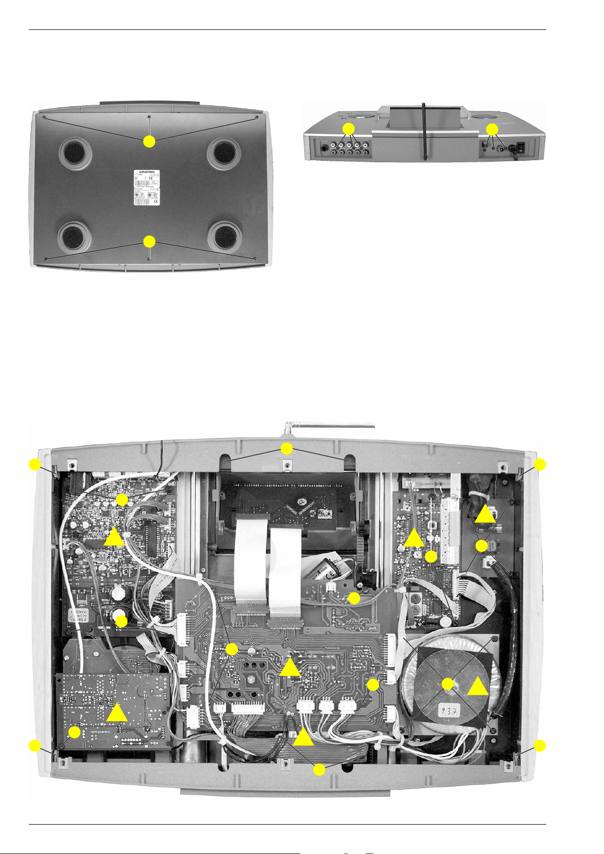
Ausbauhinweise
1. Boden entfernen
- Die 6 Schrauben A (Fig. 1) herausschrauben und den Boden
abnehmen.
A
A
Fig. 1
2. CD-Control-Platte a ausbauen
- Boden entfernen (Pkt. 1).
- 3 Schrauben D und Schraube E herausschrauben und CDControl-Platte herausnehmen (Fig. 3).
- Kabelbinder und Steckverbinder nach Bedarf öffnen.
3. NF-Platte b ausbauen
- Boden entfernen (Pkt. 1).
- 3 Schrauben B (Fig. 2) und 4 Schrauben F (Fig. 3) herausschrauben und NF-Platte herausnehmen.
- Kabelbinder und Steckverbinder nach Bedarf öffnen.
Disassembly Instructions
1. Removing the bottom
- Undo 6 screws A (Fig. 1) and remove the bottom.
B
Fig. 2
2. Removing the CD Control Board a
- Remove bottom (para 1).
- Undo 3 screws D and screw E and remove the CD Control Board
(Fig. 3).
- Open cable supports and connectors if necessary.
3. Removing the AF Board b
- Remove bottom (para 1).
- Undo 3 screws B (Fig. 2) and 4 screws F (Fig. 3) and remove the
AF Board.
- Open cable supports and connectors if necessary.
C
X
V
H
F
b
F
d
D
W
a
e
E
D
c
G
J
X
g
K
f
V
I
Fig. 3
1 - 4 GRUNDIG Service
Page 5
RCD 2000 Allgemeiner Teil / General Section
4. Tuner-Platte c ausbauen
- Boden entfernen (Pkt. 1).
- 2 Schrauben G herausschrauben und Tuner-Platte herausnehmen
(Fig. 3).
- Kabelbinder und Steckverbinder nach Bedarf öffnen.
5. Audio Funk-Modul d ausbauen
- Boden entfernen (Pkt. 1).
- Schraube H herausschrauben und Funkmodul herausnehmen
(Fig. 3).
- Kabelbinder und Steckverbinder nach Bedarf öffnen.
6. Daten Funk-Modul e ausbauen
- Boden entfernen (Pkt. 1).
- 2 Schrauben I herausschrauben und Funkmodul herausnehmen
(Fig. 3 / Fig. 6).
- Kabelbinder und Steckverbinder nach Bedarf öffnen.
7. Netztrafo f ausbauen
- Boden entfernen (Pkt. 1).
- 4 Schrauben J herausschrauben und Netztrafo herausnehmen
(Fig. 3).
- Kabelbinder und Steckverbinder nach Bedarf öffnen.
8. Netzanschluss-Platte g ausbauen
- Boden entfernen (Pkt. 1).
- 4 Schrauben K herausschrauben und Netzanschluss-Platte herausnehmen (Fig. 3).
- Kabelbinder und Steckverbinder nach Bedarf öffnen.
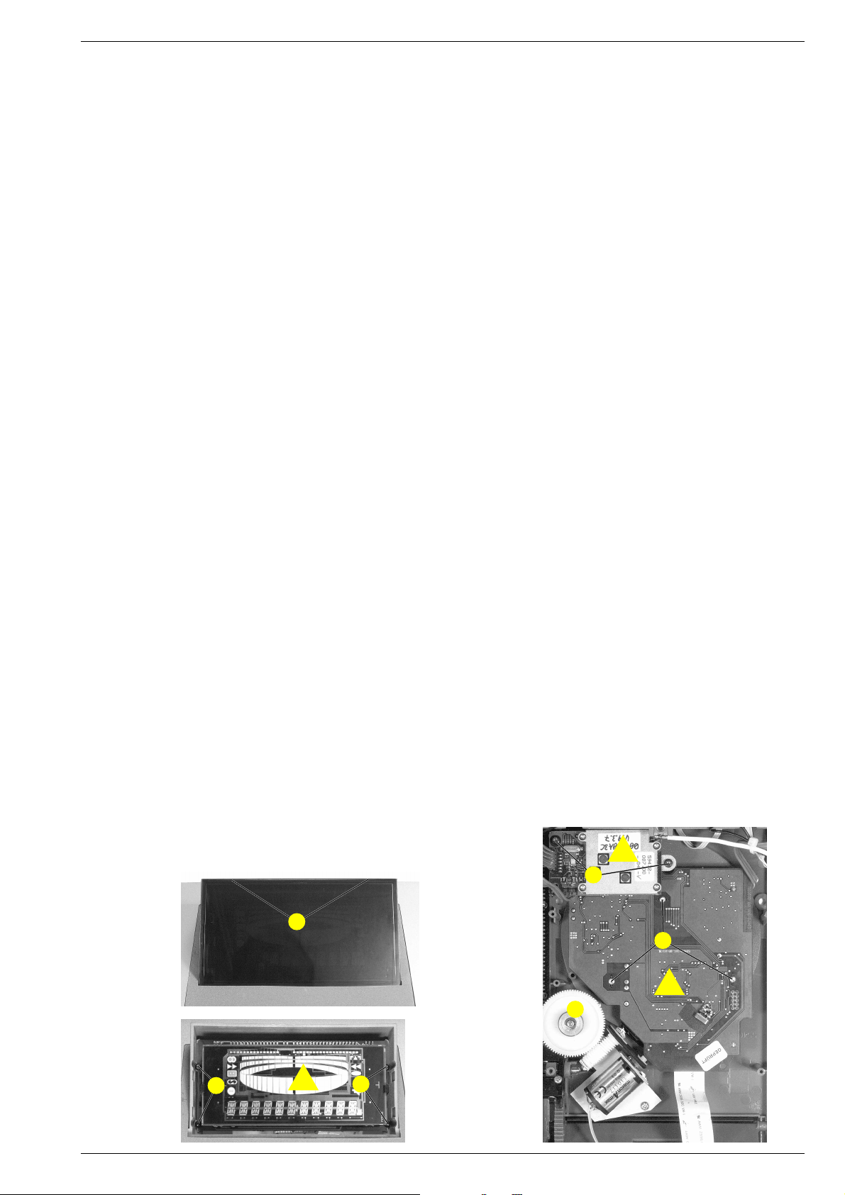
9. Display-Platte h ausbauen
- Boden entfernen (Pkt. 1).
- 2 Rastnasen L ausrasten und Displayabdeckung abnehmen
(Fig. 4).
- 4 Schrauben M herausschrauben und Display-Platte herausnehmen (Fig. 5).
- Kabelbinder und Steckverbinder nach Bedarf öffnen.
10. CD-Laufwerk und CD-Servo-Platte i ausbauen
- CD-Control-Platte (Pkt. 2) und Daten Funk-Modul (Pkt. 6) ausbauen.
- 3 Schrauben N herausschrauben und CD-Logik-Platte zusammen
mit dem CD-Laufwerk herausnehmen (Fig. 6).
- Kabelbinder und Steckverbinder nach Bedarf öffnen.
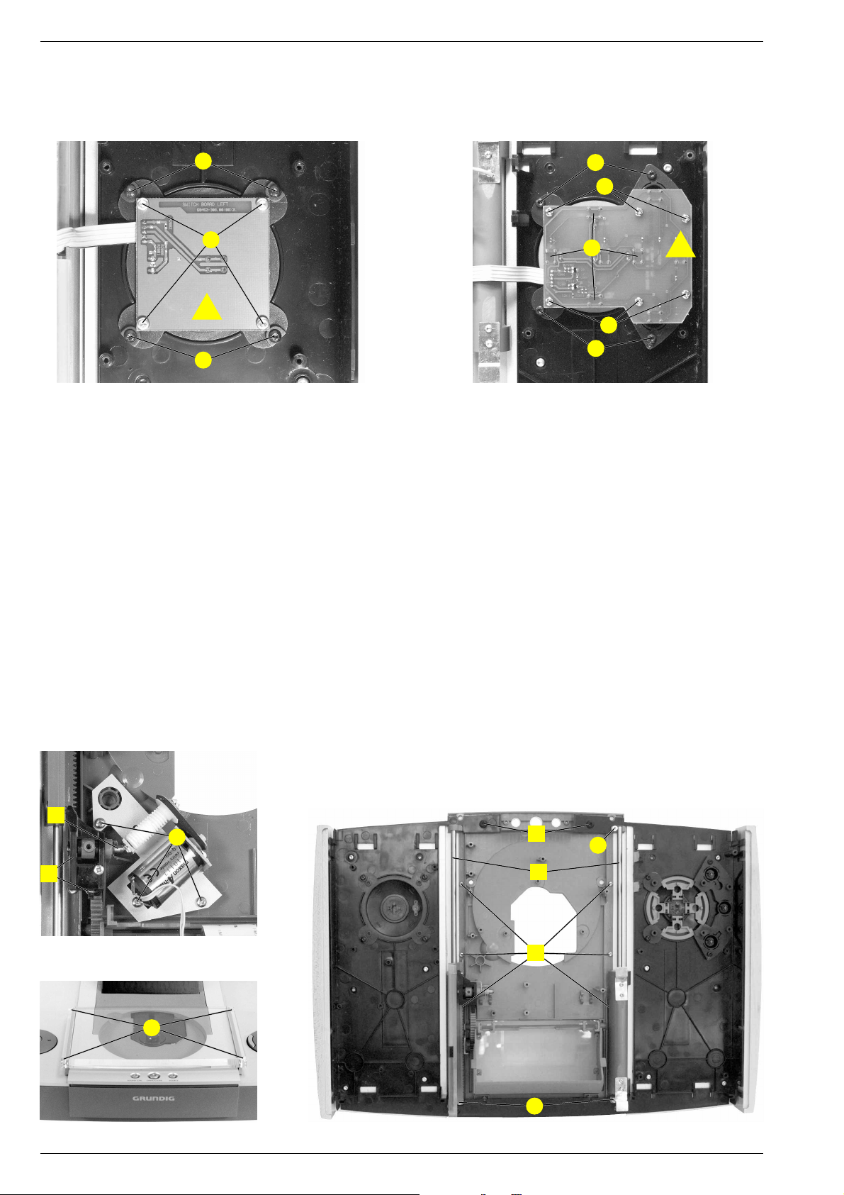
11. Tastenplatte links j ausbauen
- Netztrafo ausbauen (Pkt. 7).
- 4 Schrauben O herausschrauben und Tastenplatte herausnehmen
(Fig. 7).
- Kabelbinder und Steckverbinder nach Bedarf öffnen.
12. Tastenplatte rechts k ausbauen
- Audio Funk-Modul ausbauen (Pkt. 5).
- 6 Schrauben P herausschrauben und Tastenplatte herausnehmen
(Fig. 8).
- Achtung: Unter den 4 Tasten Q befinden sich Federn!
- Kabelbinder und Steckverbinder nach Bedarf öffnen.
13. Linke Tasten ausbauen
- Tastenplatte links ausbauen (Pkt. 11).
- 4 Schrauben R herausschrauben und Tasten herausnehmen
(Fig. 7).
4. Removing the Tuner Board c
- Remove bottom (para 1).
- Undo 2 screws G and remove the Tuner Board (Fig. 3).
- Open cable supports and connectors if necessary.
5. Removing the Audio RF Module d
- Remove bottom (para 1).
- Undo screw H and remove the Audio RF Module (Fig. 3).
- Open cable supports and connectors if necessary.
6. Removing the Data RF Module e
- Remove bottom (para 1).
- Undo 2 screws I and remove the Data RF Module (Fig. 3 / Fig. 6).
- Open cable supports and connectors if necessary.
7. Removing the Mains Transformer f
- Remove bottom (para 1).
- Undo 4 screws J remove the Mains Transformer (Fig. 3).
- Open cable supports and connectors if necessary.
8. Removing the Mains Con Board g
- Remove bottom (para 1).
- Undo 4 screws K and remove the Mains Con Board.
- Open cable supports and connectors if necessary.
9. Removing the Display Board h
- Remove bottom (para 1).
- Undo 2 catches L and remove the Display cover (Fig. 4).
- Undo 4 screws M and remove the Display Board (Fig. 5).
- Open cable supports and connectors if necessary.
10. Removing the CD Drive and the CD Servo Board i
- Remove CD Control Board (para 1) and Data RF Module (para 6).
- Undo 3 screws N and remove the CD Servo Board together with the
CD Drive (Fig. 6).
- Open cable supports and connectors if necessary.
11. Removing the Switch Board left j
- Remove the Mains Transformer (para 7).
- Undo 4 screws O and remove the Switch Board (Fig. 7).
- Open cable supports and connectors if necessary.
12. Removing the Switch Board right k
- Remove the Audio RF Module (para 5).
- Undo 6 screws P and remove the Switch Board (Fig. 8).
- Attention on the 4 springs below the buttons Q.
- Open cable supports and connectors if necessary.
13. Removing the left buttons
- Remove the Switch Board left (para 11).
- Undo 4 screws R and remove the buttons (Fig. 7).
e
I
L
N
i
Fig. 4
M
Fig. 5 Fig. 6
GRUNDIG Service 1 - 5
h
M
T
Page 6
Allgemeiner Teil / General Section RCD 2000
14. Rechte Tasten ausbauen
- Tastenplatte rechts ausbauen (Pkt. 12).
- 4 Schrauben S herausschrauben und Tasten herausnehmen
(Fig. 8).
R
O
j
R
15. CD Mechanik zerlegen
- CD Laufwerk ausbauen (Pkt. 10).
- NF-Platte ausbauen (Pkt. 3).
- Zahnradantrieb T (Fig. 6) nach oben herausziehen.
- 3 Schrauben U herausschrauben und Motoreinheit abnehmen
(Fig. 9).
- 2 Rastnasen V ausrasten und vordere Abdeckung abziehen
(Fig. 3).
- 3 Schrauben C (Fig. 2) und 2 Schrauben W (Fig. 3) herausschrauben, 2 Rastnasen X (Fig. 3) ausrasten und hintere Abdeckung
abziehen.
- 4 Schrauben Y herausschrauben und CD-Abdeckung abnehmen
(Fig. 10).
- 3 Schrauben Z herausschrauben und die 2 Achsen A herausnehmen (Fig. 11).
- Achse B herausziehen und die Zahnräder C herausnehmen
(Fig. 9).
- 2 Schrauben D und 6 Schrauben E herausschrauben und die CDBodenplatte herausnehmen (Fig. 11).
14. Removing the right buttons
- Remove the Switch Board right (para 12).
- Undo 4 screws S and remove the buttons (Fig. 8).
S
P
Q
k
P
S
Fig. 8Fig. 7
15. Disassembling the CD mechanism
- Remove the CD Drive (para 10).
- Remove the AF Board (para 3).
- Pull out the gear drive T (Fig. 6).
- Undo 3 screws U and take out the motor unit (Fig. 9).
- Undo 2 catches V and pull out the front cover (Fig. 3).
- Undo 3 screws C (Fig. 2) and 2 screws W (Fig. 3), undo 2
catches X (Fig. 3) and pull out the rear cover.
- Undo 4 screws Y and remove the CD cover (Fig. 10).
- Undo 3 screws Z and remove the 2 shafts A (Fig. 11).
- Pull out shaft B and take off the gear wheels C (Fig. 9).
- Undo 2 screws D and 6 screws E and take out the CD bottom plate
(Fig. 11).
B
U
C
Fig. 9
D
Z
A
E
Y
Z
Fig. 10 Fig. 11
1 - 6 GRUNDIG Service
Page 7
GRUNDIG Service 1 - 7
RCD 2000 Allgemeiner Teil / General Section
Bedienhinweise Dieses Kapitel enthält Auszüge aus der Bedienungsanleitung. Weitergehende Informationen entnehmen Sie bitte der
gerätespezifischen Bedienungsanleitung, deren Materialnummer Sie in der entsprechenden Ersatzteilliste finden.
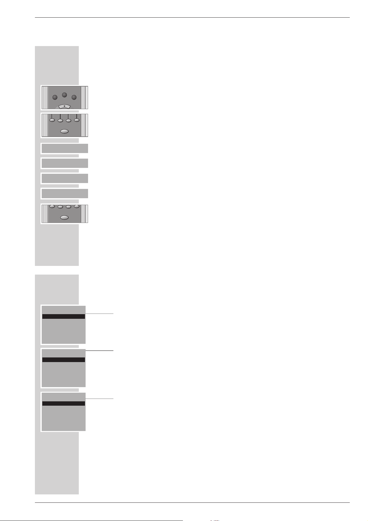
AUF EINEN BLICK
______________________________________________________________________
Die Benutzerführung der Fernbedienung
Die Fernbedienung Ihrer HiFi-Anlage ist mit einer Benutzerführung ausgestattet.
Viele Erklärungen für Bedienung und Einstellungen sind in Menüs enthalten.
Schalten Sie die Anzeige mit einer beliebigen Taste (zum Beispiel »OK«) ein.
Die Hauptmenüs wählen Sie mit den Tasten »SOURCE«, »SOUND« oder
»CONTROL«.
Zum Anwählen der gewünschten Menüpunkte und zum Speichern oder Löschen
von Funktionen verwenden Sie die Tastenreihe »
«« «« «« ««
« unter der
Menüanzeige, die jeweilige Funktion der Tasten – abhängig vom Betriebszustand – wird in der untersten Zeile des Menüs gezeigt.
Anzeige Taste Funktion
BACK »BACK« schaltet ein Menü zurück,
p o
»
p o
« wählt eine Menüzeile oder eine Funktion,
–+ »–+« verändert Einstellungen,
MENU »MENU« ruft das Tuner- oder CD-Menü auf,
INFO »INFO« ruft Informationen auf,
CLR » CLR« löscht im CD-Betrieb das Musik-Programm
DEL » DEL« löscht im CD-Betrieb einzelne Titel aus dem
Musik-Programm,
löscht im Tuner-Betrieb Programmplätze,
MEMO »MEMO« speichert Einstellungen.
Mit Taste »OK« bestätigen Sie die gewählte Funktion.
Hinweis:
Um die Batterien zu schonen, schaltet die Anzeige der Fernbedienung nach
kurzer Zeit ab, wenn keine Funktion gewählt wurde.
Durch Drücken der Taste »OK« der Fernbedienung schalten Sie die Anzeige wieder ein. Dieser Tastendruck löst keine Funktion aus.
SOURCE CONTROL
SOUND
BACK po
CLR DEL MEMO
-
+
MENU INFO
AUF EINEN BLICK
______________________________________________________________________
Die Hauptmenüs der Benutzerführung
Das Menü »SOURCE«:
»TUNER« = Tuner-Betrieb,
»CD« = CD-Betrieb,
»TAPE« = Betrieb mit einem externen Tape-Deck,
»AUX« = Betrieb mit einem externen Gerät, zum Beispiel einem Fern-
sehgerät.
Das Menü »SOUND«:
»SELECT ROOM« = Lautsprecherpaar gezielt anwählen (wenn
mehrere Lautsprecherpaare in Betrieb sind),
»TONE CONTROL« = Bässe, Höhen und Balance einstellen,
»SOUND MODE« = Klangeinstellungen wählen,
»LOUDNES« = Loudness-Funktion ein-/aus,
»EDIT USER PRESET« = persönliche Klangvoreinstellung program-
mieren.
Das Menü »CONTROL«:
»SELECT ROOM« = Lautsprecherpaar gezielt anwählen (wenn
mehrere Lautsprecherpaare in Betrieb sind),
»SPEAKERS« = Lautsprecher ein-/ausschalten,
»SLEEP« = TIMER-Funktion anwählen,
»AUDIO CHANNEL« = Sende-/Empfangskanal wählen,
»INSTALL« = Lautsprecherboxen und Fernbedienungen
installieren.
Die Funktionen der einzelnen Menüs werden anhand von Beispielen in dieser
Bedienungsanleitung erklärt.
CONTROL
SELECT ROOM
SPEAKERS
SLEEP
po
SOURCE
TUNER
CD
TAPE
po
SOUND
SELECT ROOM
TONE CONTROL
SOUND MODE
BACK po
OK
OK
Page 8
1 - 8 GRUNDIG Service
Allgemeiner Teil / General Section RCD 2000
ANSCHLIESSEN UND VORBEREITEN
_____________________________________
Lautsprecher anschließen und installieren
Die Audiosignale von der HiFi-Anlage zu den Lautsprechern werden per Funk
übertragen. Lautsprecherkabel sind nicht notwendig.
Sie können bis zu 6 Lautsprecherpaare an der HiFi-Anlage betreiben.
Die Sendereichweite von der HiFi-Anlage zu den Lautsprechern beträgt in
Gebäuden maximal 15 m. Decken oder Wände reduzieren die Reichweite,
besonders wenn sie aus Stahlbeton sind.
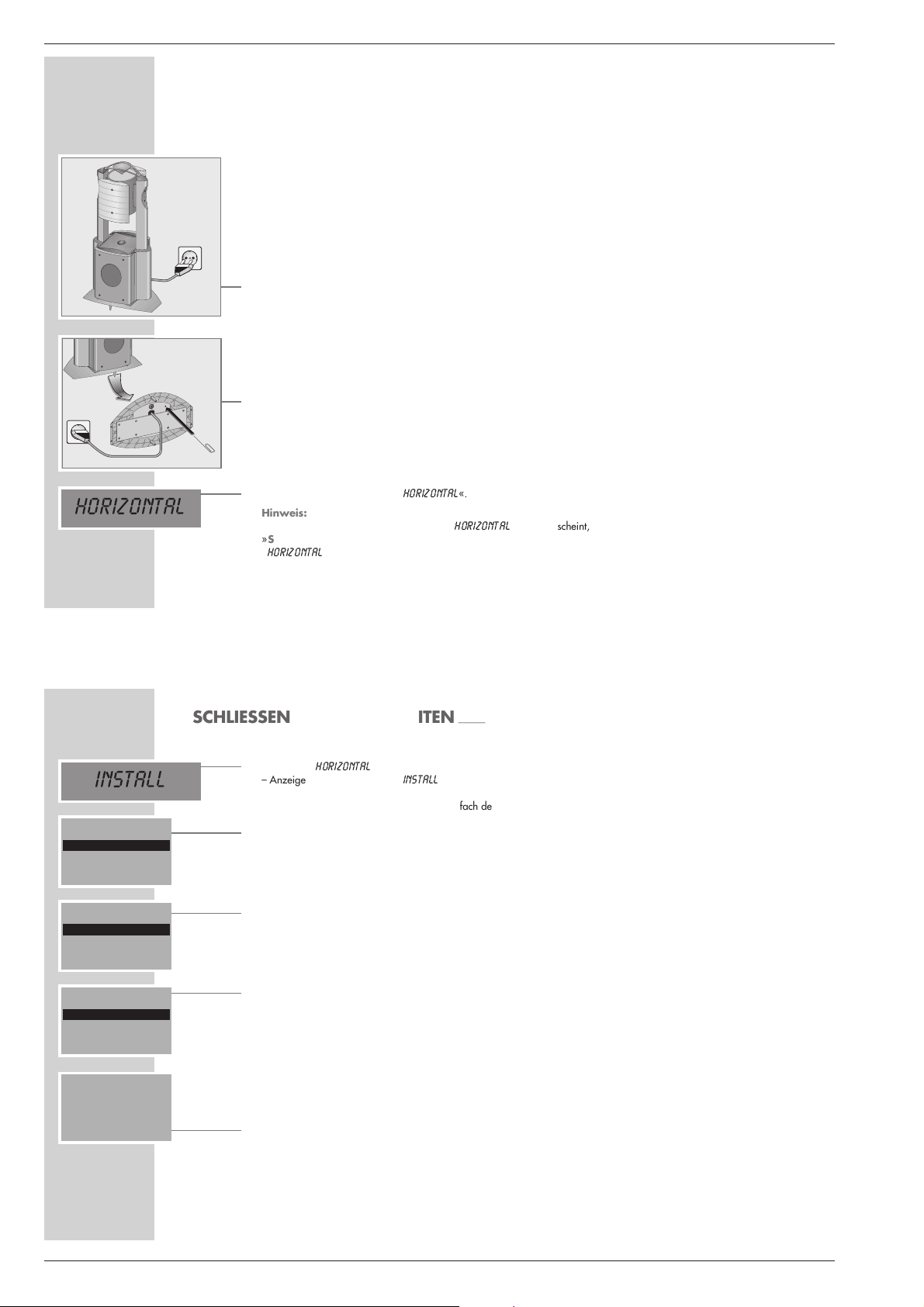
Lautsprecher an das Stromnetz anschließen
1 Stecker der Netzkabel in die Steckdose stecken.
Erstes Lautsprecherpaar installieren
1 Linken Lautsprecher des ersten Lautsprecherpaares mit »POWER« einschal-
ten, danach rechten Lautsprecher des ersten Lautsprecherpaares einschalten.
– Die Anzeigen in den Tasten »POWER« blinken grün/orange, dies bedeu-
tet, die Lautsprecher sind vorbereitet für die Installation.
Hinweis:
Wenn die Anzeigen nicht blinken, Taste »RESET« am Gehäuseboden des
Lautsprechers drücken, zum Beispiel mit einer Büroklammer.
2 Beide Lautsprecher wieder ausschalten.
3 HiFi-Anlage mit »OI« einschalten.
– Anzeige an der HiFi-Anlage: »
HORIZONTAL
«.
Hinweis:
Wenn in der Anzeige der HiFi-Anlage »
HORIZONTAL
« nicht erscheint,
»SOUND MODE« an der HiFi-Anlage drücken und gedrückt halten, bis
»
HORIZONTAL
« erscheint.
HORIZONTAL
1
POWER
ANSCHLIESSEN UND VORBEREITEN
_____________________________________
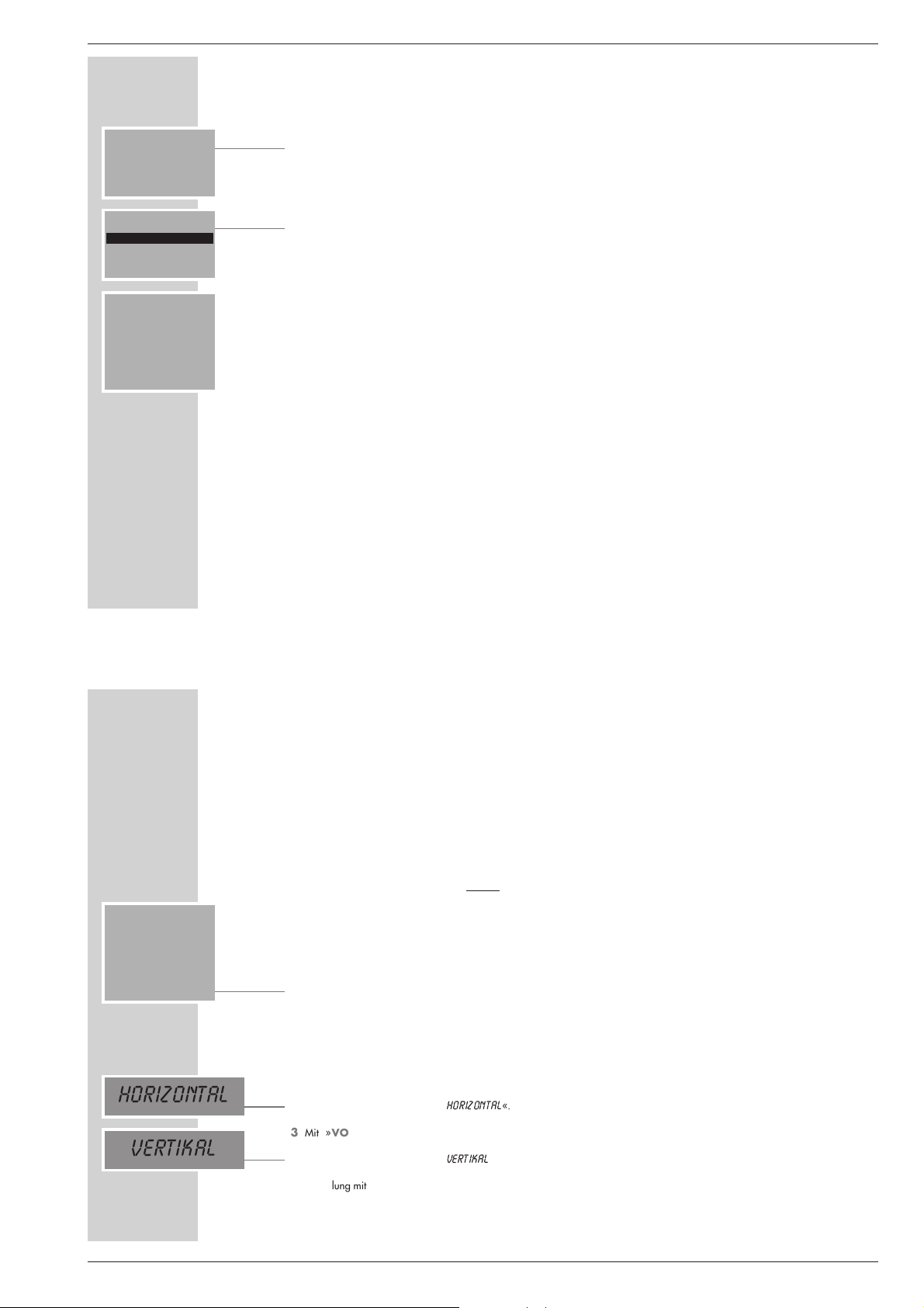
4 Einstellung »
HORIZONTAL
« mit »4« an der HiFi-Anlage bestätigen.
– Anzeige an der HiFi-Anlage: »
INSTALL
«.
5 Die beiliegenden drei Batterien in das Batteriefach der Fernbedienung einle-
gen, dabei Polung beachten.
– Nach dem Einlegen der Batterien erscheint in der Anzeige der Fernbedie-
nung »INSTALL ALL SETS ON RCD«, die Fernbedienung hat die
HiFi-Anlage „erkannt”.
6 Linken Lautsprecher des ersten Lautsprecherpaares mit »POWER« wieder
einschalten.
– Die Anzeige in der Taste »POWER « leuchtet orange, in der Anzeige der
Fernbedienung erscheint: »RCD LS1 «. Die Fernbedienung und die HiFiAnlage haben den linken Lautsprecher „erkannt”.
7 Rechten Lautsprecher des ersten Lautsprecherpaares mit »POWER« wieder
einschalten.
– Die Anzeige in der Taste »POWER « leuchtet orange, in der Anzeige der
Fernbedienung erscheint: »RCD LS1 LS 2«. Die Fernbedienung und die
HiFi-Anlage haben den rechten Lautsprecher „erkannt”.
Hilfe:
Erscheint die Meldung »ALL SETS ON RCD LS1 LS 2 « nicht, muß
die HiFi-Anlage in den Auslieferzustand zurückgesetzt werden, siehe Kapitel
„INFORMATIONEN” auf Seite 56. Danach Einstellung ab Pkt. 1 wiederholen.
8 Einstellung mit »OK« bestätigen.
– Anzeige der Fernbedienung: »SELECT LEFT LS AND PRESS
OK
«, die Anzeige in der Taste »POWER« des linken Lautsprechers blinkt
orange, die Anzeige in der Taste »POWER« des rechten Lautsprechers
leuchtet orange.
Hinweis:
Wenn der linke Lautsprecher als rechter Lautsprecher definiert werden soll,
einmal »+« drücken, die Anzeige in der Taste »POWER « des rechten Lautsprechers blinkt orange.
INSTALL
ALL SETS ON
RCD
INSTALL
ALL SETS ON
RCD LS1
INSTALL
SELECT LEFT LS
AND PRESS OK
INSTALL
ALL SETS ON
RCD LS1 LS 2
INSTALL
Page 9
GRUNDIG Service 1 - 9
RCD 2000 Allgemeiner Teil / General Section
ANSCHLIESSEN UND VORBEREITEN
_____________________________________
9 Einstellung mit »OK« bestätigen.
– Anzeige der Fernbedienung: »CONFIRM RIGHT LS WITH OK«, die
Anzeige in der Taste »POWER« des linken Lautsprechers leuchtet orange,
die Anzeige in der Taste »POWER« des rechten Lautsprechers blinkt
orange.
10
Einstellung mit »OK« bestätigen.
– Anzeige der Fernbedienung: » READY«, beide Anzeigen in den Tasten
»POWER « der Lautsprecher leuchten orange.
11
Einstellung mit »OK« bestätigen.
– Anzeige der Fernbedienung: »TUNER 87.50 MHz«.
– Beide Lautsprecher werden automatisch eingeschaltet, die Anzeigen in den
Tasten »POWER« leuchten grün.
Hinweis:
Werden die Lautsprecher nicht automatisch eingeschaltet, Lautsprecher mit
»VOLUME xx« einschalten.
INSTALL
READY
INSTALL
CONFIRM RIGHT LS
WITH OK
TUNER
87.50 MHz
MENU INFO MEMO
SONDEREINSTELLUNGEN
________________________________________________________
Sende-/Empfangskanal der HiFi-Anlage und der
Lautsprecher verändern
Sollte es bei der Tonübertragung zu Störungen kommen – dies kann der Fall
sein, wenn ein anderes Gerät auf der gleichen Sendefrequenz sendet – kann
der Sende-/Empfangskanal verändert werden.
Es stehen 7 Einstellungen zur Verfügung. Bei der Erstinstallation ist automatisch
der Kanal 1 gewählt.
1 HiFi-Anlage und nur Lautsprecher im Raum 1 einschalten.
2 »CONTROL« an der Fernbedienung drücken.
3 Im Menü »CONTROL« die Zeile »AUDIO CHANNEL« mit » A« oder
»S« anwählen und mit »OK« bestätigen.
– Der eingestellte Kanal erscheint in der Anzeige der Fernbedienung.
4 Neuen Kanal (von 2 bis 7) mit »– « oder » +« anwählen.
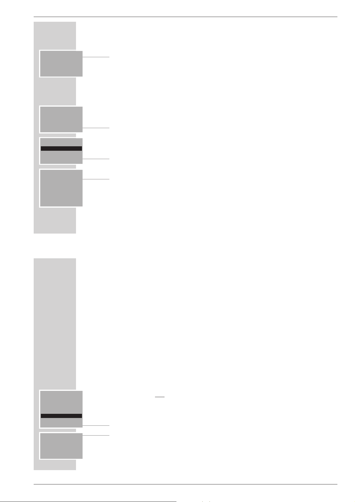
HiFi-Anlage auf den „vertikalen” Betrieb umschalten
1 HiFi-Anlage mit »OI« ausschalten.
2 »VOLUME +« an der HiFi-Anlage drücken und gedrückt halten und dabei
HiFi-Anlage mit »OI« einschalten.
– Anzeige an der HiFi-Anlage: »
HORIZONTAL
«.
3 Mit »VOLUME +« an der HiFi-Anlage die Betriebslage auf vertikal
umschalten.
– Anzeige an der HiFi-Anlage: »
VERTIKAL
«.
4 Einstellung mit »
4
« an der HiFi-Anlage bestätigen.
5 CD-Fach mit »OPEN/CLOSE« an der HiFi-Anlage öffnen und wieder
schließen.
AUDIO CHANNEL
CHANNEL: 3
BACK +
-
HORIZONTAL
VERTIKAL
Page 10

1 - 10 GRUNDIG Service
Allgemeiner Teil / General Section RCD 2000
SONDEREINSTELLUNGEN
________________________________________________________
Lautsprecher im Raum 1 auf „Kabel-Betrieb”
schalten
Möchten Sie die Lautsprecher im Raum 1 nicht über Funk betreiben sondern mittels NF-Kabel an die HiFi-Anlage anschließen, bieten wir Ihnen diese Möglichkeit.
Hinweis:
Bevor Sie diese Einstellung durchführen, müssen die Lautsprecher mit Cinchkabel an der HiFi-Anlage angeschlossen und die Installation (siehe Seite 16)
muss durchgeführt sein.
1 HiFi-Anlage und alle Lautsprecher einschalten.
2 »CONTROL« an der Fernbedienung drücken.
3 Im Menü »CONTROL« die Zeile »AUDIO CHANNEL« mit »A« oder
»S« anwählen und mit »OK« bestätigen.
– Anzeige: »ROOM 1: RF«.
4 Lautsprecher mit »LINK« auf Kabel-Betrieb umstellen.
– Die Anzeige wechselt auf »ROOM 1: LINE«.
Hinweis:
Wollen Sie die Lautsprecher wieder über Funk betreiben, wiederholen Sie
die Einstellung, die Anzeige wechselt auf »
ROOM 1: RF«
AUDIO CHANNEL
CHANNEL: 3
ROOM 1: RF
BACK LINK +
-
AUDIO CHANNEL
CHANNEL: 3
ROOM 1: LINE
BACK LINK +
-
MEHRRAUM-BETRIEB
_____________________________________________
Besonderheiten des Mehrraum-Betriebes
Sie können bis zu fünf zusätzliche Lautsprecherpaare – auf mehrere Räume verteilt – mit der HiFi-Anlage betreiben.
Damit Sie nicht immer die Fernbedienung von Raum zu Raum tragen müssen,
wenn Sie die Lautstärke und Klangeinstellung für die einzelnen Lautsprecherpaare individuell einstellen, können Sie mehrere Fernbedienungen benutzen,
um die HiFi-Anlage und die Lautsprecherpaare zu bedienen.
Zweites Lautsprecherpaar und weitere installieren
1 »CONTROL« an der Fernbedienung drücken.
– Das Menü »CONTROL« erscheint.
2 Im Menü »CONTROL« die Zeile »INSTALL« mit »A« anwählen und mit
»OK« bestätigen.
– Das Menü »INSTALL« erscheint.
3 Im Menü »INSTALL« die Zeile »SPEAKERS« mit »OK« bestätigen.
4 Linken Lautsprecher des zweiten Lautsprecherpaares mit »POWER« ein-
schalten.
– Anzeige der Fernbedienung: »LS1«, die Anzeige in der Taste
»POWER « leuchtet orange, die Fernbedienung und die HiFi-Anlage
haben den linken Lautsprecher „erkannt”.
5 Rechten Lautsprecher des zweiten Lautsprecherpaares mit »POWER« ein-
schalten.
– Anzeige der Fernbedienung: »LS1 LS 2«, die Anzeige in der Taste
»POWER « leuchtet orange, die Fernbedienung und die HiFi-Anlage
haben den rechten Lautsprecher „erkannt”.
CONTROL
AUDIO CHANNEL
INSTALL
INSTALL 1
SPEAKERS
REPLACE SPEAKERS
INSTALL 1
ALL SPEAKERS ON
LS1
INSTALL 1
ALL SPEAKERS ON
LS1 LS 2
Page 11
GRUNDIG Service 1 - 11
RCD 2000 Allgemeiner Teil / General Section
6 Einstellung mit »OK« bestätigen.
– Anzeige der Fernbedienung: »SELECT LEFT LS AND PRESS OK«,
die Anzeige in der Taste »POWER« des linken Lautsprechers blinkt orange, die Anzeige in der Taste »POWER« des rechten Lautsprechers leuchtet orange.
Hinweise:
Wenn der linke Lautsprecher als rechter Lautsprecher definiert werden soll,
einmal »+« drücken, die Anzeige in der Taste »POWER « des gewählten
Lautsprechers blinkt orange.
Ab dem zweiten Lautsprecherpaar erscheint in der Anzeige der Fernbedienung zusätzlich die Nummer des Raumes, dessen Lautsprecherpaar Sie mit
der Fernbedienung bedienen können.
7 Einstellung mit »OK« bestätigen.
– Anzeige der Fernbedienung: »CONFIRM RIGHT LS WITH OK«, die
Anzeige in der Taste »POWER« des linken Lautsprechers leuchtet orange,
die Anzeige in der Taste »POWER« des rechten Lautsprechers blinkt
orange.
8 Einstellung mit »OK« bestätigen.
– Anzeige der Fernbedienung: » READY«, beide Anzeigen in den Tasten
»POWER « der Lautsprecher leuchten orange.
9 Einstellung mit »OK« bestätigen.
– Anzeige der Fernbedienung: »TUNER 87.50 MHz«.
– Beide Lautsprecher werden automatisch eingeschaltet, die Anzeigen in den
Tasten »POWER« leuchten grün.
Hinweis:
Werden die Lautsprecher nicht automatisch eingeschaltet, die Lautsprecher
mit dem Menü der Fernbedienung einschalten, siehe nächstes Kapitel.
MEHRRAUM-BETRIEB
________________________________________________________________
INSTALL 1
SELECT LEFT LS
AND PRESS OK
INSTALL 1
READY
INSTALL 1
CONFIRM RIGHT LS
WITH OK
TUNER
87.50 MHz
MENU INFO MEMO
MEHRRAUM-BETRIEB
________________________________________________________________
Lautsprecherpaar einschalten
1 »CONTROL« an der Fernbedienung drücken.
2 Im Menü »CONTROL« die Zeile »SELECT ROOM« mit »A« anwählen
und mit »OK« bestätigen.
3 Im Menü »SELECT ROOM« die Zeile » ROOM 2« mit »A« oder »S«
wählen und mit »OK« bestätigen.
4 Lautsprecher mit »
yy
VOLUME xx« einschalten.
Zweite und weitere Fernbedienungen installieren
Wenn Sie an Ihrer HiFi-Anlage mehrere Lautsprecherpaare betreiben, können
Sie auch eine zweite und weitere Fernbedienungen installieren. Damit können
Sie Lautsprecherpaare, die in einem anderen Raum stehen – unabhängig von
der HiFi-Anlage – mit dieser Fernbedienung bedienen.
1 HiFi-Anlage und alle Lautsprecher einschalten.
2 »CONTROL« an der ersten Fernbedienung drücken.
– Das Menü »CONTROL« erscheint.
3 Im Menü »CONTROL« die Zeile »INSTALL« mit »A« anwählen und mit
»OK« bestätigen.
4 Im Menü »INSTALL« die Zeile »RC« mit »A« anwählen und mit »OK«
bestätigen.
– Anzeige der Fernbedienung: »INSERT BATTERIES IN THE NEW
RC.
«.
5 Drei Batterien (3 x 1,5 V Alkaline, Typ Mignon LR6/AA/AM3) in das Batte-
riefach der zweiten Fernbedienung einlegen, dabei Polung beachten.
– Die zweite Fernbedienung ist betriebsbereit.
INSTALL 1
SPEAKERS
REPLACE SPEAKERS
RC
BACK po
INSTALL 1
INSERT BATTERIES
IN THE NEW RC.
Page 12

1 - 12 GRUNDIG Service
Allgemeiner Teil / General Section RCD 2000
MEHRRAUM-BETRIEB
________________________________________________________________
Neuen Lautsprecher auf „altem” Platz anmelden
Wenn Sie Lautsprecherpaare, die an der HiFi-Anlage angemeldet sind, austauschen wollen, muß das neue Lautsprecherpaar wieder angemeldet werden.
1 »CONTROL« an der Fernbedienung drücken.
– Das Menü »CONTROL« erscheint.
2 Im Menü »CONTROL« die Zeile »INSTALL« mit »A« oder »S«
anwählen und mit »OK« bestätigen.
3 Im Menü »INSTALL« die Zeile »REPLACE SPEAKER« mit »A« oder
»S« anwählen und mit »OK« bestätigen.
4
Mit
»+« oder »–« Raum anwählen, dessen Lautsprecher „ausgetauscht”
werden soll, und mit »OK« bestätigen.
5 Linken Lautsprecher des Lautsprecherpaares mit »POWER« einschalten.
– Anzeige der Fernbedienung: »RCD LS1«, die Anzeige in der Taste
»POWER « leuchtet orange, die Fernbedienung und die HiFi-Anlage
haben den linken Lautsprecher „erkannt”.
6 Rechten Lautsprecher des Lautsprecherpaares mit »POWER« einschalten.
– Anzeige der Fernbedienung: »RCD LS1 LS 2«, die Anzeige in der Taste
»POWER « leuchtet orange, die Fernbedienung und die HiFi-Anlage
haben den rechten Lautsprecher „erkannt”.
Hilfe:
Erscheint die Meldung »ALL SETS ON RCD LS1 LS 2 « nicht, Einstellung ab Pkt. 1 wiederholen.
REPLACE SPEAKERS
SELECT ROOM: 1
BACK +
-
INSTALL
SPEAKERS
REPLACE SPEAKERS
RC
BACK po
MEHRRAUM-BETRIEB
________________________________________________________________
7 Einstellung mit »OK« bestätigen.
– Anzeige der Fernbedienung: »SELECT LEFT LS AND PRESS OK«,
die Anzeige in der Taste »POWER« des linken Lautsprechers blinkt orange, die Anzeige in der Taste »POWER« des rechten Lautsprechers leuchtet orange.
8 Einstellung mit »OK« bestätigen.
– Anzeige der Fernbedienung: »CONFIRM RIGHT LS WITH OK«.
Hinweis:
Wenn der linke Lautsprecher als rechter Lautsprecher definiert werden soll,
einmal »+« drücken, der gewählte Lautsprecher blinkt orange.
Fernbedienung auf einen anderen Raum umschalten
1 »CONTROL« an der Fernbedienung drücken.
– Das Menü »CONTROL« erscheint.
2 Im Menü »CONTROL« die Zeile »SELECT ROOM« mit »A« oder »S«
anwählen und mit »OK« bestätigen.
– Das Menü »SELECT ROOM« erscheint.
3 Im Menü »SELECT ROOM« die Lautsprecher des gewünschten Raumes mit
»– « oder »+« anwählen.
Hinweis:
Mit »BACK« kann zum Hauptmenü zurückgeschaltet werden.
Es können nur die Räume angewählt werden, in denen auch Lautsprecher
angemeldet sind.
Lautstärke und Klangänderungen für einen Raum werden in den Lautsprecherboxen gespeichert.
CONTROL
SELECT ROOM
SPEAKERS
SLEEP
po
SELECT ROOM 1
ROOM 2
BACK ê +
Page 13

GRUNDIG Service 1 - 13
RCD 2000 Allgemeiner Teil / General Section
Operating Hints This chapter contains excerpts from the operating instructions. For further particulars please refer to the appropriate
user instructions the part number of which is indicated in the relevant spare parts list.
INFORMATIONEN
_____________________________________________________________________
Komponenten in den Auslieferzustand zurücksetzen
HiFi-Anlage zurücksetzen
1 HiFi-Anlage mit »OI« einschalten.
2 »SOURCE« an der HiFi-Anlage so lange drücken, bis »
HORIZONTAL
« in
der Anzeige erscheint.
3 HiFi-Anlage mit »OI« ausschalten.
Fernbedienung zurücksetzen
1 »CONTROL« an der Fernbedienung drücken.
2 Im Menü »CONTROL« die Zeile »INSTALL« mit »A« oder »S«
anwählen und mit »OK« bestätigen.
3 Im Menü »INSTALL« die Zeile »ALL NEW« mit »A« anwählen und mit
»OK« bestätigen.
4 Batterien entfernen und wieder einsetzen.
Lautsprecherboxen zurücksetzen
1 Lautsprecher mit den »POWER« Tasten einschalten.
2 Taste »RESET« am Gehäuseboden der Lautsprecher drücken, zum Beispiel
mit einer Büroklammer.
– Die Anzeigen in den Tasten »POWER« blinken grün/orange.
INSTALL 1
ALL NEW
HORIZONTAL
CONTROL
AUDIO CHANNEL
INSTALL
OVERVIEW
__________________________________________________________________________________
The remote control menu system
Your HiFi system’s remote control unit is equipped with a menu system.
The menus contain a wide range of information on setting up and operating the
system.
Press any button (for example »OK«) to activate the display.
Press the »SOURCE«, » SOUND« or »CONTROL« button to select one of the
main menus.
To select the required menu command and save or delete settings, use the »
««
«« «« ««
« buttons below the menu display. The current function of each button
is shown above it in the bottom line of the display.
Display Button Function
BACK »BACK« Returns to the previous menu
p o
»
p o
« Selects a menu item or function
–+ »–+« Alters settings
MENU »MENU« Opens the Tuner or CD menu
INFO »INFO« Calls up information
CLR » CLR« Deletes the track memory in CD mode
DEL » DEL« Deletes individual tracks from the memory in CD
mode
Deletes preset stations in Tuner mode
MEMO »MEMO« Stores settings
The »OK« button activates the selected function.
Note:
In order to prolong the life of the batteries, the remote control display switches off after a short while if no function is selected.
Press the »OK« button on the remote control to switch the display back on
again. This does not activate any functions.
BACK po
CLR DEL MEMO
-
+
MENU INFO
SOUND
SOURCE CONTROL
OK
OK
Page 14

1 - 14 GRUNDIG Service
Allgemeiner Teil / General Section RCD 2000
OVERVIEW
__________________________________________________________________________________
The main remote control menus
The »SOURCE« menu:
»TUNER« = Tuner mode
»CD« = CD mode
»TAPE« = External tape deck operation
»AUX« = Operation with an external device such as a television.
The »SOUND« menu:
»SELECT ROOM« = Selects a particular pair of loudspeakers (if
several pairs are used)
»TONE CONTROL« = Adjusts the bass, treble and balance levels
»SOUND MODE« = Selects sound settings
»LOUDNES« = Activates and deactivates the Loudness function
»EDIT USER PRESET« = Programs custom sound settings
The »CONTROL« menu:
»SELECT ROOM« = Selects a particular pair of loudspeakers
(if several pairs are used)
»SPEAKERS« = Switches loudspeakers on and off
»SLEEP« = Selects the Timer function
»AUDIO CHANNEL« = Selects the communication channel
»INSTALL« = Installs loudspeakers and remote controls.
These menus are explained in detail in this manual with the aid of a number of
examples.
CONTROL
SELECT ROOM
SPEAKERS
SLEEP
po
SOURCE
TUNER
CD
TAPE
po
SOUND
SELECT ROOM
TONE CONTROL
SOUND MODE
BACK po
CONNECTION AND PREPARATION
_______________________________________
Connecting and installing the loudspeakers
The HiFi transmits audio signals by radio to the loudspeakers. Speaker cables
are not necessary.
You can operate up to six pairs of loudspeakers with the HiFi system.
The maximum transmission range from the HiFi to the loudspeakers is 15 m.
Walls and ceilings reduce the range, especially if they are made of reinforced
concrete.
Connecting the loudspeakers to the mains supply
1 Plug the mains cable into the socket.
Installing the first pair of loudspeakers
1 Press »POWER« to switch on the left loudspeaker of the first pair, then
switch on the right loudspeaker of the first pair.
– The indicators in the »POWER« buttons flash green and orange, which
means that the loudspeakers are ready for installation.
Note:
If the indicators do not flash, press the »RESET« button on the bottom of the
loudspeaker case with an implement such as a paper clip.
2 Switch both loudspeakers off again.
3 Switch on the HiFi by pressing the »OI« switch.
– The HiFi display reads: »
HORIZONTAL
«.
Note:
If »
HORIZONTAL
« does not appear on the HiFi display, press »SOUND
MODE« on the HiFi and hold it down until the word »
HORIZONTAL
«
appears.
HORIZONTAL
POWER
1
Page 15

GRUNDIG Service 1 - 15
RCD 2000 Allgemeiner Teil / General Section
CONNECTION AND PREPARATION
_______________________________________
4 Confirm the »
HORIZONTAL
« setting by pressing the »4« button on the
HiFi.
– The HiFi display reads: »
INSTALL
«.
5 Insert the three batteries supplied into the remote control battery compart-
ment, making sure the polarity is correct.
– When you insert the batteries the remote control display reads
»INSTALL ALL SETS ON RCD«, indicating that the remote control has detected the HiFi system.
6 Switch on the left loudspeaker of the first pair using the »POWER« button.
– The orange indicator in the »POWER« button lights up and the remote
control display reads: »RCD LS1 «. The remote control and the HiFi have
detected the left loudspeaker.
7 Switch on the right loudspeaker of the first pair using the »POWER« but-
ton.
– The orange indicator in the »POWER« button lights up and the remote
control display reads: »RCD LS1 LS 2«. The remote control and the
HiFi have detected the right loudspeaker.
Hint:
If you do not see the message »ALL SETS ON RCD LS1 LS 2 «, you
must reset the HiFi to its original state – see the ”INFORMATION” section on
Page 56. Then repeat the set-up procedure from Step 1.
8 Press »OK« to confirm the setting.
– The remote control display reads: »SELECT LEFT LS AND PRESS
OK
«, the orange indicator in the »POWER « button on the left loud-
speaker flashes and the orange indicator in the »POWER « button on the
right loudspeaker lights up continuously.
Note:
If you want to use the left loudspeaker as a right loudspeaker, press »+«
once. The orange indicator in the »POWER « button on the right loudspeaker flashes.
INSTALL
ALL SETS ON
RCD
INSTALL
ALL SETS ON
RCD LS1
INSTALL
SELECT LEFT LS
AND PRESS OK
INSTALL
ALL SETS ON
RCD LS1 LS 2
INSTALL
CONNECTION AND PREPARATION
_______________________________________
9 Press »OK« to confirm the setting.
– The remote control display reads: »CONFIRM RIGHT LS WITH OK«,
the orange indicator in the »POWER « button on the left loudspeaker
lights up continuously and the orange indicator in the »POWER « button
on the right loudspeaker flashes.
10
Press »OK« to confirm the setting.
– The remote control display reads: »READY«, the orange indicators in both
»POWER « buttons on the loudspeakers light continuously.
11
Press »OK« to confirm the setting.
– The remote control display reads: »TUNER 87.50 MHz«.
– Both loudspeakers are switched on automatically and the green indicators
in the »POWER « buttons light up continuously.
Note:
If the loudspeakers are not switched on automatically, switch them on
manually by pressing »VOLUME xx«.
INSTALL
READY
INSTALL
CONFIRM RIGHT LS
WITH OK
TUNER
87.50 MHz
MENU INFO MEMO
Page 16

1 - 16 GRUNDIG Service
Allgemeiner Teil / General Section RCD 2000
SPECIAL SETTINGS
____________________________________________________________________
Changing the communication channel of the HiFi
and the loudspeakers
If interference occurs during sound transmission, which can happen if another
device is using the same frequency, you can change the communication channel.
Seven channels are available. When you first set up the system Channel 1 is selected by default.
1 Switch on the HiFi and the loudspeakers in Room 1 only.
2 Press the »CONTROL« button on the remote control.
3 From the »CONTROL« menu, select the »AUDIO CHANNEL« item by
pressing »A« or »S« and then »OK« to confirm.
– The selected channel appears in the remote control display.
4 Select the new channel (from 2 to 7) by pressing »– « or » +«.
Switching the HiFi system to Vertical mode
1 Switch off the HiFi by pressing the »OI« button.
2 Press »VOLUME +« on the HiFi and keep it pressed while you switch the
HiFi on again with the »OI« button.
– The HiFi display reads: »
HORIZONTAL
«.
3 Press »VOLUME +« on the HiFi to switch the system to Vertical operating
mode.
– The HiFi display reads: »
VERTIKAL
«.
4 Confirm the setting by pressing »
4
« on the HiFi.
5 Press the »OPEN/CLOSE« button on the HiFi to open the CD compartment
and then close it again.
AUDIO CHANNEL
CHANNEL: 3
ROOM 1: RF
BACK LINK +
-
HORIZONTAL
VERTIKAL
SPECIAL SETTINGS
____________________________________________________________________
Switching the loudspeakers in Room 1 to Cable
mode
This option is available in case you do not want to use radio signals for the loudspeakers in Room 1, but rather to connect them to the HiFi using LF cables.
Note:
Before you implement this setting the loudspeakers must first be connected to
the HiFi using cinch cables and installed (see Page 16).
1 Switch on the HiFi and all the loudspeakers.
2 Press the »CONTROL« button on the remote control.
3 From the »CONTROL« menu, select the »AUDIO CHANNEL« item by
pressing »A« or »S« and then »OK« to confirm.
– Display: »ROOM 1: RF«.
4 Select »LINK« to switch the loudspeakers to Cable mode.
– The display changes to »ROOM 1: LINE«.
Note:
If you change the loudspeakers back to wireless operation, repeat the setting. The display changes back to »
ROOM 1: RF«
AUDIO CHANNEL
CHANNEL: 3
ROOM 1: RF
BACK LINK +
-
AUDIO CHANNEL
CHANNEL: 3
ROOM 1: LINE
BACK LINK +
-
Page 17

GRUNDIG Service 1 - 17
RCD 2000 Allgemeiner Teil / General Section
MULTIPLE ROOM OPERATION
_____________________
Special features of multiple room mode
You can operate up to five additional pairs of loudspeakers – distributed in different rooms – with the HiFi system.
If you do not want to carry the remote control from room to room in order to set
the volume and tone for the individual pairs of loudspeakers, you have the option of using more than one remote control unit to operate the HiFi and the loudspeakers.
Installing additional pairs of loudspeakers
1 Press the »CONTROL« button on the remote control.
– The »CONTROL« menu appears.
2 From the »CONTROL« menu, select the »INSTALL« item by pressing
»A« and then »OK« to confirm.
– The »INSTALL« menu appears.
3 In the »INSTALL« menu select »SPEAKERS« by pressing »OK«.
4 Switch on the left loudspeaker of the second pair using the »POWER« but-
ton.
– The remote control display reads: »LS1« and the orange indicator in the
»POWER « button lights up, which means that the remote control and the
HiFi have detected the left loudspeaker.
5 Switch on the right loudspeaker of the second pair using the »POWER«
button.
– The remote control display reads: »LS1 LS 2« and the orange indicator
in the »POWER « button lights up, which means that the remote control
and the HiFi have detected the right loudspeaker.
CONTROL
AUDIO CHANNEL
INSTALL
INSTALL 1
SPEAKERS
REPLACE SPEAKERS
INSTALL 1
ALL SPEAKERS ON
LS1
INSTALL 1
ALL SPEAKERS ON
LS1 LS 2
6 Press »OK« to confirm the setting.
– The remote control display reads: »SELECT LEFT LS AND PRESS
OK
«, the orange indicator in the »POWER « button on the left loudspea-
ker flashes and the orange indicator in the »POWER « button on the right
loudspeaker lights up continuously.
Note:
If you want to use the left loudspeaker as a right loudspeaker, press »+«
once. The orange indicator on the selected loudspeaker flashes.
From the second pair of loudspeakers onwards, the remote control display
also shows the number of the room containing the pair of loudspeakers you
can operate with it.
7 Press »OK« to confirm the setting.
– The remote control display reads: »CONFIRM RIGHT LS WITH OK«,
the orange indicator in the »POWER « button on the left loudspeaker
lights up continuously and the orange indicator in the »POWER « button
on the right loudspeaker flashes.
8 Press »OK« to confirm the setting.
– The remote control display reads: »READY«, the orange indicators in both
»POWER « buttons on the loudspeakers light continuously.
9 Press »OK« to confirm the setting.
– The remote control display reads: »TUNER 87.50 MHz«.
– Both loudspeakers are switched on automatically and the green indicators
in the »POWER « buttons light up continuously.
Note:
If the loudspeakers are not switched on automatically, switch them on using
the remote control menu as described in the next section.
MULTIPLE ROOM OPERATION
________________________________________________
INSTALL 1
SELECT LEFT LS
AND PRESS OK
INSTALL 1
READY
INSTALL 1
CONFIRM RIGHT LS
WITH OK
TUNER
87.50 MHz
MENU INFO MEMO
Page 18

1 - 18 GRUNDIG Service
Allgemeiner Teil / General Section RCD 2000
MULTIPLE ROOM OPERATION
________________________________________________
Switching on a pair of loudspeakers
1 Press the »CONTROL« button on the remote control.
2 From the »CONTROL« menu, select the »SELECT ROOM« item by pres-
sing »A« and then »OK« to confirm.
3 From the »SELECT ROOM« menu, select the » ROOM 2« item by pressing
»A« or »S« and then »OK« to confirm.
4 Switch on the loudspeakers using the »
yy
VOLUME xx« button.
Installing additional remote contols
If you are using several pairs of loudspeakers you can also install additional
remote control units. These enable you to operate pairs of loudspeakers in different rooms, regardless of where the HiFi is located.
1 Switch on the HiFi and all the loudspeakers.
2 Press the »CONTROL« button on the first remote control.
– The »CONTROL« menu appears.
3 From the »CONTROL« menu, select the »INSTALL« item by pressing
»A« and then »OK« to confirm.
4 From the »INSTALL« menu, select the »RC« item by pressing »A« and
then »OK« to confirm.
– The remote control display reads: »INSERT BATTERIES IN THE
NEW RC.
«.
5 Insert three batteries (3 x 1.5 V alkaline, LR6/AA/AM3) in the battery com-
partment of the second remote control, making sure that the polarity is correct.
– The second remote control is now ready for operation.
INSTALL 1
SPEAKERS
REPLACE SPEAKERS
RC
BACK po
INSTALL 1
INSERT BATTERIES
IN THE NEW RC.
MULTIPLE ROOM OPERATION
________________________________________________
Replacing loudspeakers on the HiFi
If you replace a pair of loudspeakers, you must install the new pair on the
HiFi system in the same manner.
1 Press the »CONTROL« button on the remote control.
– The »CONTROL« menu appears.
2 From the »CONTROL« menu, select the »INSTALL« item by pressing
»A« or »S« and then »OK« to confirm.
3 From the »INSTALL« menu, select the »REPLACE SPEAKER« item by
pressing »A« or »S« and then »OK« to confirm.
4
Press
»+« or »–« to select the room containing the pair of loudspeakers
which were replaced, and then press »OK« to confirm.
5 Switch on the left loudspeaker of the new pair using the »POWER« button.
– The remote control display reads: »RCD LS1« and the orange indicator
in the »POWER « lights up, which means that the remote control and the
HiFi have detected the left loudspeaker.
6 Switch on the right loudspeaker of the new pair using the »POWER« but-
ton.
– The remote control display reads: »RCD LS1 LS 2« and the orange
indicator in the »POWER « lights up, which means that the remote control
and the HiFi have detected the right loudspeaker.
Hint:
If the message »ALL SETS ON RCD LS1 LS 2 « does not appear,
repeat the process from Step 1 onwards.
REPLACE SPEAKERS
SELECT ROOM: 1
BACK +
-
INSTALL
SPEAKERS
REPLACE SPEAKERS
RC
BACK po
Page 19

GRUNDIG Service 1 - 19
RCD 2000 Allgemeiner Teil / General Section
MULTIPLE ROOM OPERATION
________________________________________________
7 Press »OK« to confirm the setting.
– The remote control display reads: »SELECT LEFT LS AND PRESS
OK
«, the orange indicator in the »POWER « button on the left loud-
speaker flashes and the orange indicator in the »POWER « button on the
right loudspeaker lights up continuously.
8 Press »OK« to confirm the setting.
– The remote control display reads: »CONFIRM RIGHT LS WITH OK«.
Note:
If you want to use the left loudspeaker as a right loudspeaker, press »+«
once. The orange indicator on the selected loudspeaker flashes.
Switching the remote control to another room
1 Press the »CONTROL« button on the remote control.
– The »CONTROL« menu appears.
2 From the »CONTROL« menu, select the »SELECT ROOM« item by pres-
sing »A« or »S« and then »OK« to confirm.
– The »SELECT ROOM« menu appears.
3 From the »SELECT ROOM« menu, select the loudspeakers in the required
room using »– « or »+«.
Note:
Select »BACK« to return to the main menu.
You can only select rooms in which loudspeakers are configured.
Changes to the volume and tone for individual rooms are saved in the loudspeakers themselves.
CONTROL
SELECT ROOM
SPEAKERS
SLEEP
po
SELECT ROOM 1
ROOM 2
BACK ê +
INFORMATION
__________________________________________________________________________
Resetting components to the original state
Resetting the HiFi system
1 Switch on the HiFi by pressing the »OI« switch.
2 Keep pressing »SOURCE« on the HiFi until the word »
HORIZONTAL
«
appears in the display.
3 Switch off the HiFi by pressing the »OI« button.
Resetting the remote control
1 Press the »CONTROL« button on the remote control.
2 From the »CONTROL« menu select the »INSTALL« item by pressing
»A« or »S« and then »OK« to confirm.
3 From the »INSTALL« menu, select the »ALL NEW« item by pressing
»A« and then »OK« to confirm.
4 Remove and replace the batteries.
Resetting the loudspeakers
1 Switch on the loudspeakers using the »POWER« buttons.
2 Press the »RESET« button on the bottom of the casing using an implement
such as a paper clip.
– The indicators in the »POWER « buttons flash green and orange.
INSTALL 1
ALL NEW
HORIZONTAL
CONTROL
AUDIO CHANNEL
INSTALL
Page 20

Abgleichvorschriften / Adjustment Procedures RCD 2000
Abgleichvorschriften
Tuner
Messgeräte: Mess-/Wobbelsender, Oszilloskop, Digital-Voltmeter, NF-Voltmeter, Klirrfaktor-Messgerät
Hinweis: Das Frontend ist ein komplett abgeglichener Baustein. Nur das ZF-Filter muß dem ZF-Verstärker angeglichen werden (1).
Die Abstimmspannungen des Frontends haben folgende Größen: 87,5MHz = typ. 1,6V min 1,3V; 108MHz = typ. 8,0V max 9V
Abgleich Vorbereitung Abgleichvorgang
1. ZF-Filter
Wobbelsender an Antennenbuchse.
Mittenfrequenz 98MHz.
∆f = ±100kHz; UHF = 100µV / 75Ω.
Oszilloskop an MP1.
2. Demodulator
Messsender 98MHz an Antennenbuchse.
UHF = 1mV / 75Ω, f
Klirrfaktor-Messgerät an MP2.
3. Suchlauf
4. 38-kHz-Filter
Messsender 98MHz an Antennenbuchse.
U
= 15µV / 75Ω.
HF
Digitalvoltmeter an MP5.
Messsender an Antennenbuchse.
UHF = 1mV / 75Ω, f
NF-Voltmeter an MP2 (linker Kanal) bzw. MP3 (rechter
Kanal).
5. 19-kHz-Filter
Messsender an Antennenbuchse.
UHF = 1mV / 75Ω, f
NF-Voltmeter an MP2 (linker Kanal) bzw. MP3 (rechter
Kanal).
Adjustment Procedures
= 1kHz, Hub = 40kHz.
mod
= 38kHz, Hub = 40kHz.
mod
= 19kHz, Hub = 40kHz.
mod
Mit A auf Maximum und Symmetrie
einstellen.
Mit F141 B auf minimalen Klirrfaktor einstellen.
Mit P141 S 0,65V ± 0,05V einstellen.
Mit F171 I (linker Kanal) und F172 K (rechter Kanal)
Minimum einstellen.
Mit F171 G (linker Kanal) und F172 H (rechter Kanal)
Minimum einstellen.
Tuner
Test Equipment: Standard/sweep generator, Oscilloscope, Digital voltmeter, AF voltmeter, Distortion meter
Note: The frontend is a completely preadjusted module. Only the IF filter must be adjusted to the IF amplifier (1).
The values of the tuning voltages are as follows: 87.5MHz = typ. 1.6V min 1.3V; 108MHz = typ. 8.0V max 9V
Adjustment Preparation Adjustment Procedure
1. IF Filter
2. Demodulator
3. Station search
4. 38 kHz Filter
5. 19 kHz Filter
Sweep generator to aerial socket.
center frequency 98MHz.
∆f = ±100kHz; URF = 100µV / 75Ω.
Oscilloscope to MP1.
Test generator 98MHz to aerial socket.
URF = 1mV / 75Ω, f
Distortion meter to MP2.
= 1kHz, Dev. = 40kHz.
mod
Test generator 98MHz to aerial socket.
U
= 15µV / 75Ω.
RF
Digitalvoltmeter to MP5.
Test generator to aerial socket.
URF = 1mV / 75Ω, f
AF voltmeter to MP2 (left channel) resp. MP3 (right
= 38kHz, Dev. = 40kHz.
mod
channel).
Test generator to aerial socket.
URF = 1mV / 75Ω, f
AF voltmeter to MP2 (left channel) resp. MP3 (right
= 19kHz, Dev. = 40kHz.
mod
channel).
Adjust A to maximum and
symmetry.
Adjust F141 B to minimum distortion.
Adjust P141 S to 0.65 ± 0.05V.
Adjust F171 I (left channel) and F172 K (right channel)
to minimum.
Adjust F171 G (left channel) and F172 H (right channel)
to minimum.
2 - 1 GRUNDIG Service
Page 21

RCD 2000 Abgleichvorschriften / Adjustment Procedures
P142
F171
F141
Frontend
FE100
F172
P141
ST171
1
117
ST101
ST102
F101
F102
IC140
A
B
S
IG
KH
MP2
MP3
MP1
MP5
Abgleichlageplan / Alignment Layout
Beim Austausch eines der ZF-Filter (F101, F102) achten Sie darauf, dass nur
Filter mit gleicher Kennfarbe bestückt sind.
When replacing one of the ceramic resonators (F101, F102), take care that
the colour codes of all resonators are the same.
ZF (MHz)
IF (MHz)
10.6500 D schwarz / black
10.6750 B blau / blue
10.7000 A rot / red
10.7250 C orange
10.7500 E weiß / white
ZF / IF Filter
Kennbuchstabe
Ident. letter
ZF / IF Filter
Farbe / Colour
GRUNDIG Service 2 - 2
Page 22

Schaltpläne und Druckplattenabbildungen / Circuit Diagrams and Layout of PCBs RCD 2000
Schaltpläne und Druckplattenabbbildungen / Circuit Diagrams and Layout of PCBs
Verdrahtungsplan / Wiring Diagram
PREAMP OUT LINE OUT TAPE OUT TAPE IN AUX IN
P240 P230
P700
NF-PLATTE
AF BOARD
P280
1
864MHZ TRANSM
P220
P200
3
3
TUNER-IN CD-IN
P210
12
TASTEN-PLATTE RECHTS
SWITCH BOARD RIGHT
TO/FROM CD CONTROL
1
P201
+
+
TO/FROM CD CONTROL
P930
45
3
STDBY
GNDR
KEY0
+5VR
+
15
P2010
+
+++
3 - 1 GRUNDIG Service
Page 23

RCD 2000 Schaltpläne und Druckplattenabbildungen / Circuit Diagrams and Layout of PCBs RCD 2000 Schaltpläne und Druckplattenabbildungen / Circuit Diagrams and Layout of PCBs
4948474443424140393837363534333231302827252423222120191817161514131211
DISPLAY-PLATTE
DISPLAY BOARD
1
12
12 1
P3014
NF-BOARD
5
P3010
SWITCH
RIGHT
51
P3011
51
4
TX
JST
P911
NF-BOARD
1
P3009
SWITCH
FRONT
JST
JST
P3002
SERVO
31
P3007
HF REMOTE
JST
DIS300
9876321
10
1
P3020
CD
1
JST
P3001
SERVO
CD-CONTROL-BOARD
CD CONTROL BOARD
121
MOTOR
3
2 1
P3013
MOTOR
1
TRAFO TRAFO TRAFO
GN-GN-BN-BN
P900P920 P910
OR-SW-OR
WS-WS-BL-BL
P1609
LICHTLEITER-BUCHSEN-PLATTE
J2020
P2020
JST
P1670
1
1
3
3
CD-SERVO-PLATTE
CD SERVO BOARD
1
OPTICAL OUTPUT BOARD
J2030
J2031J2032
1
TUNER-PLATTE
TUNER BOARD
3
ST171
1
A1A2
1
ST101 ST102
1
P1608
11
P3004
FM TUNER
111
4
TASTEN-PLATTE LINKS
MAINS
SWITCH BOARD LEFT
41
P3005
TUN SUP
P3008
SWITCH
LEFT
51
5
12
P2000
LED2
1
GNDL
LED1
KEY1_L
5
KEYX_L
MAINS CON BOARD
NETZ-ANSCHLUSS-PLATTE
P03
4
3
TASTEN-PLATTE VORNE
SWITCH BOARD FRONT
3
13
P2001
+5VF
KEY1_F
KEYX_F
5
3
AUDIO-FUNK-MODUL
AUDIO RF MODULE
4
TRAFO
1
DATEN-FUNK-MODUL
1
DATA RF MODULE
11
11 12
GRUNDIG Service GRUNDIG Service3 - 2 3 - 3
Page 24

Schaltpläne und Druckplattenabbildungen / Circuit Diagrams and Layout of PCBs RCD 2000 Schaltpläne und Druckplattenabbildungen / Circuit Diagrams and Layout of PCBs RCD 2000
P3008
1
2
3
4
5
6K8
R3103
10K R3105
P3014
1
2
3
4
5
6
7
8
9
10
11
12
150K R3104
6K8R3101
+
470U/63V
C902
P3007
1
2
3
4
5
6
7
8
9
10
11
12
100N/63V
C900
ADJUST
OUT IN
LM337T
IC900
1
23
100N/63V
C901
T315mA-L
SI900
~
~
+
DF04S
GL900
1
2
3
4
10K
R900
220R
R902
12K
R901
+
10U/50V
C903
P3001
123456789
101112131415161718192021222324
25
P3002
123456789
101112131415161718192021222324
25
10K R3106
1N4004
D900
1N4004
D922
ZPD4V7
D901
P3020
1
213456789
10
11
12
13
14
15
16
17
18
R3012
120R
BC848B
T3002
1
2
3
5K6
R3002
LL4148
D3002
4K7
R3001
1K
R3004
~
~
+
-
DF02S
GL920
1
2
3
4
22K
R922
LL4148
D920
47k
R923
18K
R925
0R
R924
+
U47/50V
C926
R3011
120R
180R
LL4148
D921
470R
R921
+
4700U/25V
C922
3
2
1
GND
OUT IN
L78M05CDT
IC920
100n/63V
C923
100n
C924
T1A-L
SI920
22n
C921
22n
C920
470R
R920
10K
R3005
1M
R3683
BD434
T3014
S3683
SPVF24
P3010
12345
LL4148
D3003
BD433
T3012
BD434
T3013
BC858B
T3001
BD433
T3011
220K
R3403
BC848B
T3401
BC848B
T920
10K
R3201
47K
R3202
BC848B
T3202
BC848B
T3402
47K
R3402
10K
R3401
1N
C3401
BC848B
T3201
220K
R3203
1N
C3301
10K
R3301
47K
R3302
BC848B
T3302
BC848B
T3301
220K
R3303
6K8
R3102
123
4
P3005
4
3
2
1
P920
P3013
1
2
P3004
1
2
3
4
5
6
7
8
9
10
11
12
P3009
1
2
3
P3011
1
2
3
4
5
REM-ON
REM-ON
WAKEUP
SCLK
SCLK
+5V
+5V
+5V
+5V
+5V
+5V
+5V
+5V
+5V
+5V
SIN
SIN
LED1
LED1
SOUT
SOUT
LDC
LDC
TX-PD
TX-PD
SRDY
SRDY
RDC
RDC
TXD
TXD
+
2200U/25V
C925
+12V
+12V
+12V
+12V
FIL1
FIL1
RDS-DATA
RDS-DATA
MUTE
MUTE
-VEE
+15V
FIL2
FIL2
STEREO
STEREO
CD-ON
CD-ON
HP-MUTE
HP-MUTE
FIELDSTG
FIELDSTG
A-CE
A-CE
A-HP-IN
A-HP-IN
KEYIN
SEARCH
SEARCH
12VTX
KEY0
KEY0
TRAYMOT-
TRAY-IN
RDS-CLK
RDS-CLK
LED2
LED2
KEY1
KEY1
KEY1
FM-DATA-OUT
FM-DATA-OUT
CLOCK
CLOCK
CLOCK
CLOCK
CLOCK
PD
PD
DATA
DATA
DATA
DATA
DATA
RTS
TRAYMOT+
RXD
CTS
CTS
FM-CE
FM-CE
STDBY
STDBY
STDBY
to
AUDIO RF MODULE
24.01.00
to ST101
TUNER BOARD
to P302 DISPLAY BOARD to P1670 CD LOGIC BOARDto P301 DISPLAY BOARD
to MOTOR POWER
TRANSFORMER
POWER
TRANSFORMER
POWER
TRANSFORMER
DS-2Y-S-DC12V
REL3001
1
2
3
45
6
7
8
4
3
2
1
P910
65432
1
P911
LL4148
D3031
LL4148
D3032
BC848B
T3031
47K
R3032
2K2
R3031
3
2
1
P900
DS-2Y-S-DC12V
REL3002
1
2
3
4
5
6
7
8
+12V
+12V
+15V
12VTX
STDBY
to P930 AF BOARDto P2010
SWITCH BOARD RIGHT
to P2001
SWITCH BOARD FRONT
to P2000
SWITCH BOARD LEFT to
DATA RF MODULE
to ST102 TUNER BOARD to P201 AF BOARD
10V~
36V~
2V~
2V~
17V~
17V~
1K
R3003
+
470U/50V
C3001
LL4148
D3000
ZPD3V9
D3001
R3013
180R
R3014
LL4148
D3013
LL4148
D3014
LL4148
D3011
LL4148
D3012
T200mA-L
SI3001
-32V
-52V
Alle Spannungsangaben sind Näherungswerte
All voltage levels are approximates
CD-Control-Platte / CD Control Board
3 - 15
Seite / page
Seite / page
3 - 20
Seite / page
3 - 20
3 - 17
Seite / page
3 - 22
Seite / page
3 - 22
Seite / page
Seite / page
3 - 4 3 - 5
3 - 23
Seite / page
3 - 17
GRUNDIG Service GRUNDIG Service
Seite / page
Seite / page
3 - 11
3 - 15
3 - 27
Seite / page
3 - 27
Seite / page
3 - 27
Seite / page
Page 25

RCD 2000 Schaltpläne und Druckplattenabbildungen / Circuit Diagrams and Layout of PCBs RCD 2000 Schaltpläne und Druckplattenabbildungen / Circuit Diagrams and Layout of PCBs
+
C902
IC900
SI900
1
S3683
SI920
BE
T3012
BE
T3013
+
C925
R3013
REL3001REL3002
BE
T3011
R3014
SI3001
BE
T3014
+
C3001
R3011
R3012
+
C922
59452-328.00 (07)4B
T200mA-L
T315mA-L
T1A-L
CD Control RCD2000
5 1
P3008
121
P3014
-+
C903
JST
1
P3002
D900
C900C901
C923
~~
-+
GL920
IC920
2 1
P3013
121
P3007
4 1
P3005
R900
R902
R901
R3002
R3001
R3004
R3005
R3683
R3032
R3031
51
P3011
12 1
P3004
P920
T3001
JST
1
P3020
P911
T3002
T920
T3031
D3002
D920
D921
D3003
D3031D3032
C926
R3303
P910
P900
R3102
R3302
R3301
C3301
R3203
C3401
R3401
R3402
~~
-+
GL900
D922
R3202
R3201
D3014
R3403
R3106
R3101
R3104
R3105
R3103
T3301
T3302
T3201
T3402
T3202
T3401
D3013 D3011
D3012
31
P3009
51
P3010
R920
C920
C921
C924
R921
R924
R925
R923
R922
D901
JST
1
P3001
D3000
R3003
D3001
59452-328.00 (07)4L
GN-BN
OR-SW-OR
WS-BL
NF-BOARD
NF-BOARD
TX
RIGHT
SWITCH
FRONT
SWITCH
HF REMOTE
TRAFO TRAFO
TRAFO
SWITCH LEFT
TUN SUP
FM TUNER
SERVO
SERVO
MOTOR
CD
CD Control RCD2000
1301201101009080706050403020100
190
180
170
160
150
140
130
120
110
100
90
80
70
60
50
40
30
20
10
0
X
Y
CD-Control-Platte / CD Control Board
Bestückungsseite / Component Side
3 - 6 3 - 7
GRUNDIG Service GRUNDIG Service
CD-Control-Platte / CD Control Board
Lötseite / Solder Side
Bauteil /
Component
XY
C900 57 104
C901 57 98
C903 62 65
C920 87 107
C921 87 100
C923 83 80
C924 88 80
C926 87 112
C3301 71 49
C3401 82 51
D900 68 84
D901 87 138
D920 82 120
D921 82 117
D922 95 88
D3000 125 49
D3001 123 43
D3002 57 161
D3003 66 162
D3011 38 135
D3012 17 152
D3013 31 135
D3014 17 145
D3031 75 160
D3032 75 152
GL900 63 102
GL920 81 102
P900 106 129
P910 106 147
P911 11 8
P920 106 111
P3001 39 94
P3002 27 65
P3004 40 183
P3005 63 183
P3007 110 63
P3008 115 183
P3009 110 38
P3010 77 8
P3011 120 17
P3013 8 133
P3014 43 8
P3020 8 78
R900 67 91
R901 69 91
R902 60 77
R920 87 119
R921 87 117
R922 82 113
R923 90 114
R924 90 118
R925 90 110
R3001 57 153
R3002 79 168
R3003 127 43
R3004 61 158
R3005 61 166
R3031 61 153
R3032 63 153
R3101 68 47
R3102 84 53
R3103 86 53
R3104 72 47
R3105 89 52
R3106 89 54
R3201 63 44
R3202 63 32
R3203 57 32
R3301 68 49
R3302 69 35
R3303 67 35
R3401 79 51
R3402 83 47
R3403 83 44
R3683 8 117
T920 93 112
T3001 74 169
T3002 62 163
T3031 67 153
T3201 61 40
T3202 61 35
T3301 69 44
T3302 69 40
T3401 76 48
T3402 76 43
Page 26

Schaltpläne und Druckplattenabbildungen / Circuit Diagrams and Layout of PCBs RCD 2000 Schaltpläne und Druckplattenabbildungen / Circuit Diagrams and Layout of PCBs RCD 2000
1
2
3
4
5
6
7
8
9
10
11
12
13
14
15
16
1
2
3
4
5
6
7
8
9
10
11
12
13
14
151617
181920
21
222324
25
262728
29
30
31
32
33
34
35
363738
39
40
41
42
43
44
45
464748
49
50
515253
54
55
56
57
58
59
60
61
62
63
64
1
2
3
4
5
6
7
8
9
10
11
12
13
14
15
16
17
18
1
2
3
4
5 6
7
8
910 11 12
13
14
15
16
1
2
3
4
5
6
7
8
9
10
11
12
13
14
15
16
1
2
3
4
1
2
3
4
5
6
7
8
9
10
11
12
13
14
15
16
1
2
C1654
C1653
R1655
IC1603
IC1601
C1655
C1652
P1601
C1651
C1656
R1656
R1651
C1646
C1643
C1644
C1645
R1645
R1644
R1643
C1626C1623
C1624C1621
R1625R1622
R1626 R1624
R1623 R1621
C1627
R1627
C1662
R1662
C1660
R1661
R1669
R1668
R1667
R1671
IC1602
R1603
C1618
R1612
R1613
R1611R1617
R1615
R1616
R1614
C1611
C1615 C1617
IC1604
R1648R1649
C1649
C1647
C1648
R1618
Q1601
C1642
C1641
R1641
R1642
C1663
R1663
R1639
R1638
C1636
R1636
C1632
R1633
T1601
R1632
R1634
R1635
R1631
T1604
C1601
R1601R1602
P1603
IC1605
C1708
R1607
R1608
R1604
R1605
C1688
C1681
C1683
C1682
R1682
R1683
C1686
C1685
C1684
C1689
C1690
C1687
R1676
C1675
C1676
C1671
R1637
R1665 R1664
R1666
R1672
R1659
R1658
T1603
T1602
R1679R1678
R1657
R1660
C1658
C1657
C1701
C1702
R1701
R1702
C1704
C1703
R1708
R1706
R1707
C1650
T1605
P1602
I-i
I-i
I+i
I+i
OUT-
OUT-
OUT+
OUT+
VP
IN-
IN-
IN+
IN+
NC NC NC NC NC
+
+
-
-
NC
Processor
Audio
Detect
Peak
Demodulator
EFM
SRAM
Processor
Subcode
RAM
Addresser
RCK
SUB
SFSY
SBSY
Timing
Interface
Microcontroller
Decoder
STATUS
V5
V4
V3
V2
V1
Interface
Versatile Pins
Kill
Kill
/RESET
CL4
CL11
CL16
CROUT
CRIN
SELPLL
TEST3
TEST2
TEST1
Test
Digital PLL
Frontend
Iref
ISLICE
HFREF
HFIN
Interface
Microcontroller
SILD
RAB
SDA
SCL
Vref
Generator
VRH
ADC
R2
R1
VRL
D1
D2
D3
D4
IrefT
Ctrl. Function
Part
Control
Pre-Processing
stages
Output
Control
Motor
Corrector
Error
Flags
Interface
EBU
Interface
Data
Serial
EF
DATA
WCLK
SCLK
DOBM
C2FAIL
CFLG
MOTO2
MOTO1
LDON
SL
FO
RA
VDDDc3
VDDDp2
VDDDp1
VSSD4
VSSD3
VSSD2
VSSD1
VDDA2
VDDA1
VSSA3
VSSA2
VSSA1
+
+
put
out
swsw
put
out
left rgt
curr.sinks
calibr.
curr.sources curr.sources
16(4Bit) cal. 16(4Bit) cal.
16(4Bit)
VSSA
VDDA
VDDO
VSSO
Ref. Source
FILTCL
VOL VOR
FILTCR
Vref
++
--
NC
VSSD
VDDD
Data EncoderData Encoder
interpolator
linear
halfband
7th order
FIR Filter
Noise Shaper Noise Shaper
2nd order 2nd order
(Sample and hold) (Sample and hold)
6 * oversampling 6 * oversampling
Test
Timing
and
Ctrl.
BCK
WS
DATA
+
I-i
I-i
I+i
I+i
OUT-
OUT-
OUT+
OUT+
VP
IN-
IN-
IN+
IN+
NC NC NC NC NC
+
+
-
-
+
I-i
I-i
I+i
I+i
OUT-
OUT-
OUT+
OUT+
VP
IN-
IN-
IN+
IN+
NC NC NC NC NC
+
+
-
-
+
+
+
+
+
+
+
220p/5%/16V
220p/5%/16V
10k
TDA7073A/AT
SAA7378GP
220p/5%/16V
220p/5%/16V
220p/5%/16V
220p/5%/16V
10k
270k
1n/5%/16V
47p/5%/16V
22n/5%/16V
100n/5%/16V
1k
22k
150k
560p1.8n
5.6n10n
1.2k1.2k
6.8k 27k
6.8k 22k
47U/16V
3.3R
47U/16V
10R
10N/16V
C1661
10N/16V
47R
0R
R1698
10K
0R
0R
47R
TDA1549T
3.3R
47U/16V
100k
100k
56k6.8k
1k1k1k
100n
220n 10n
TDA7073A/AT
1k1k
47U/16V
100N/16V
100N/16V
10k
8.4672MHz
27p/NP0
27p/NP0
100K
330R
10n
220R
R1675
47k
R1697
100K
220R
220R
47p/5%/16V
220R
2.7p/0p25
10k
BC848B
T1699
BC848B
10k
100R
10k
10k
BC848B
10n
C1608
2.2U/16V
C1607
2.2U/16V
100R220R
TDA7073A/AT
47U/16V
6.2k
6.2k
100k
100k
22n
22n
1n/5%/16V
1n/5%/16V
470R
470R
22U/16V
4.7U/16V
4.7U/16V
22n
100U/16V
22n
47k
1.5n/5%/16V
220p/16V
220R
10k 10k
22k
100R
10k
10k
BC848B
BC858B
1k1k
10k
10k
1.5N/5%/16V
560p/5%/16V
4.7U/16V
4.7U/16V
100R
33R
10N/16V
10N/16V
3.3R
1k
1k
22N
BC848B
TO PICKUP UNIT
LO
LD
HG
LS
TO PICKUP UNIT
RFE
FOCUS
LDON
(D5)
(D3)
UREF
UREF
UREF
UREF
HOME
TT+
SL+
SLIDE
RADIAL
TURNTABLE+
TURNTABLE-
R+
RF+
F-
SL-
TT-
SBSY
CD-RESET
CL4
SFSY
SUB
RCK
SICL
SILD
VDD
VDD
VDD
VDD
VDD
VDD
TRAYTRAY+
+5V-CD
+CD
+SERVO
SR
+5V-CD
+5V-CD
CD-MUTE
(D1)
(D4)
DTA
(D2)
GNDA GNDA
GNDA
GNDA
GNDA GNDAGNDA
1.5n/5%/16V
GNDAGNDA
GNDA GNDA
+SERVO
+SERVO
+CD
+5V-CD
TRAYMOT-
TRAYMOT+
EBU
ANOUT-R
ANOUT-L
+5V-CD
CD-Servo-Platte / CD Servo Board
3 - 8 3 - 9
GRUNDIG Service GRUNDIG Service
Page 27

RCD 2000 Schaltpläne und Druckplattenabbildungen / Circuit Diagrams and Layout of PCBs RCD 2000 Schaltpläne und Druckplattenabbildungen / Circuit Diagrams and Layout of PCBs
optical out
TOTX178
ANOUT-R
ANOUT-L
EBU
+5VLOG
Fiber optic con.
P1608
EBU
+5V-CD
+5VLOG
22k
22k
22k
R610
R611
R609
1M
R683
KEYIN
27P
C621
X601
4.19M
1M
27P
C620
P2020
EBU
1
1
2
2
3
GNDB
+5VB
3
GNDB
C2020
100n
LICHTLEITER-BUCHSEN-PLATTE
OPTICAL OUTPUT BOARD
R1696
J2020
GND
Vcc
In
123
GNDB
K
RCK
SUB
SBSY
SFSY
CL4
TRAY-
TRAY+
CD-MUTE
CD-RESET
DTA
SILD
SICL
+5V-CD
+CD
+SERVO
SR
TRAYMOT+
TRAYMOT-
R672
470R
R674
470R
47R
R677
R676
R671
1
EXCK
2
470R
R673
470R
R675
470R
SBSO
IC605
3
SCOR
4
WFCK
5
MCK
6
XMODE
78
LC89170M
VDD
DQSY
SRDT
SCLK
SW2
SW1
TEST
14
13
DQSY
12
SRDT
11
SCLKT
10
9
C610
100n
1
+
C601
100n/63V
R1694
C600
5.6k
R1693
47U/16V
T1696
BC848B
R1692
R678
470R
IC601
L7805CD2T
SN
GND
D604
T1695
BSP60
1k
10k
470R
OUTIN
2
1N4001
R1691
R679
10k
220R
SRDY
47
P70/TI00/TO0
P51/A9
22k
R663
45
46
P02/INTP2
P03/INTP3/ADTRG
P52/A10
P53/A11
A10
A11
22k
R664
A12
PD
44
P01/INTP1
P54/A12
22k
DQSY
43
P00/INTP0
P55/A13
+5VLOG
R665
+5VLOG
TRAY-
CD-RESET
470R
1N4001
3
100n
C602
R602
5.6k
T602
BC848B
D605
T601
BSP60
R604
+
47U
C603
1k
R605
TRAY+
SICL
SILD
D602
LL4148
10k
22k
R670
DTA
RD
WR
LE
D0
D1
D2
D3
D4
D5
D6
D7
48
TO50
P71/TI01
P52/TI50
49
P73/TI51/TO51
50
P74/PCL
51
P75/BUZ
52
P64/_RD
53
P65/_WR
54
P66/_WAIT
55
P67/ASTB
56
P40/AD0
57
P41/AD1
58
P42/AD2
59
P43/AD3
60
P44/AD4
61
P45/AD5
62
P46/AD6
63
P47/AD7
64
P50/A8
123456789
A9
A8
+5VLOG+CD
C605
100n
+5V-CD
D603
LL4148
R662
4.7k
R601
R1695
VPP
38
39
40
41
42
X1
X2
IC
VSS1
XT1
IC602
UPD78002XGC-xxx-AB8
P57/A15
P56/A14
VDD0
VSS0
P30
10111213141516
22k
R600
37
XT2
P31
CD-MUTE
R666
22K
SRDT
22k
35
36
_RESET
P32
WR
RD
R667
+5VLOG
+5VLOG
34
AVDD
P33
D3
D4
D5
D6
D7
CE
A10
RD
A11
A9
A8
WR
22k
AVREF
P34/SI31
R637
22k
R638
22k
33
P10/ANI0
P11/ANI1
P12/ANI2
P13/ANI3
P14/ANI4
P15/ANI5
P16/ANI6
P17/ANI7
P25/ASCK0
P24/TxD0
P23/RxD0
P22/_SCK30
P21/SO30
P20/SI30
P36/_SCK31
P35/SO31
+5VLOG
O3
O4
16
O5
17
O6
18
O7
19
CE
20
21
OE
22
A11
23
A9
24
A8
25
NC
26
27
Vcc
28
A10
PGM
AVSS
VDD1
32
31
30
29
28
27
26
25
24
23
22
21
20
19
18
17
SCLKT
UL6264A
RAM
IC604
C607
100n
22k
R620
22k
R621
22k
R623
22k
R625
22k
R627
TRAY-OUT
TRAY-IN
100n
C609
SCLK
SOUT
SIN
Vss
A12
Vpp
O2
O1
O0
A0
A1
A2
A3
A4
A5
A6
A7
22k
R622
22k
R624
22k
R626
+5VLOG
100n
C611
1415
13
12
11
10
9
8
7
6
5
4
3
2
1
A12
+5VLOG
R646
D2
D1
D0
A0
A1
A2
A3
A4
A5
A6
A7
R647
R630
+5VLOG
100k
RESET
T630
BC848B
220N
C630
R631
R632
100k
10K
D630
LL4148
22N
C631
JP600
_RESET
R658
22k
22k
R659
SOUT
SCLK
SRDY
R660
22k
ST666
12
34
56
78
910
90131-0125
Target Connector
Flash Master
22k
22k
22k
22k
R648
22k
R649
R650
R652
22k
22k
R653
R651
+5VLOG
0R
R633
for
100n
22k
C608
1
OE
2
D0
3
IC603
D1
4
D2
5
D3
6
LATCH
D4
7
D5
8
D6
9
D7
74HCT573M
10 11
+5VLOG
22k
VPP
22k
R655
R656
22k
22k
R657
R654
20
Vcc
19
Q0
18
Q1
17
Q2
16
Q3
15
Q4
14
Q5
13
Q6
12
Q7
LE
LE
R668
+5VLOG
22k
R669
ANOUT-R
GNDA
ANOUT-L
3
2
1
P1609
to P200
AF Board
Seite / page
3 - 14
+5VLOG
22k
22k
R615
22k
R614
R613
R612
22k
SIN
PD
TRAYMOT-
KEYIN
TRAYMOT+
18
17
16
15
14
13
12
11
10
9
8
7
6
5
4
3
2
1
Seite / page
to P3020 CD Control Board
P1670
3 - 5
22k
R661
TRAY-IN
TRAY-OUT
CD-ON
+CD
22k
LE
GRUNDIG Service GRUNDIG Service
3 - 10 3 - 11
27.04.00
Page 28

Schaltpläne und Druckplattenabbildungen / Circuit Diagrams and Layout of PCBs RCD 2000 Schaltpläne und Druckplattenabbildungen / Circuit Diagrams and Layout of PCBs RCD 2000
IC951
P200
SI931
-+
C360
C257
T294
P280
R360
T370
IC250
3016
15
1
IC240
R298
28 15
141
IC270
D372
D370
T702
D371
D362
D360
D363
D361
D364
D365
D366
D367
D373
R3010
-+
C371
-+
C370
-+
C260
-+
C290
-+
C367
-+
C261
-+
C366
-+
C275
-+
C291
-+
C277
-+
C278
-+
C276
-+
C250
-+
C251
-+
C361
-+
C700
-+
C701
-+
C262
-+
C263
-+
C293
-+
C292
-+
C252
-+
C271
-+
C253
-+
C272
P220
+
C932
+
C933
T700
T371
T701
IC930
R375
R376
R378
R379
R713
R711
R709
R377
R374
R362
R364
R372
R240
R243
R241
R242
R370
R369
R211
R210
R231
R230
R260
R221R220
R262
R263
R287
R288
R265
R264
R252
R253
R255
R254
R200
R291
R363
R295
R261
R371
R293
R366
R290
R294
R365
R367
R368
R373
R201
C706
R705
R703
R702
R706
R704
R707
R710
R708
R273
R250
R274
R270
R271
R272
R251
R299
C705
C702
C240C241
C242
C211
C210
C231
C230
C221C220
C287
C288
C265
C264
C255C254
C295
C364
C294
R297
C365
C200
C201
C703
C704
C707
C279
R296
C284
C280
C282
C270
C227
T291
T292
P240
C936
C937
P210
P230
-+
C232
C363
SI930
IC370
R701
R700
R361
IC260
IC290
IC360
IC700
P201
C362
R715
R714
C952
C285
-+
C233
C256
R292
C297
C267
C266
C296
IC931
C951
C930
C935
C934
C931
T293
R300
R301
T261
T262
R268
R267
P930
R716
C713
R286
C229
C228
R285
T288
R302
C302
R303
C303
R304
R305
P700
R3011
C3010
C3011
R3013
R3012
C283
C281
C286
~~
-+
BR930
T287
59472-304.00 (05)4B
T400mA-L
T400mA-L
TUNER-IN
CD-IN
TO/FROM CD CONTROL
TO/FROM CD CONTROL
864MHZ TRANSM
PREAMP OUT
LINE OUT
TAPE OUT TAPE IN
AUX IN
1009080706050403020100
150
140
130
120
110
100
90
80
70
60
50
40
30
20
10
0
X
Y
CD-Servo-Platte / CD Servo Board
Bestückungsseite / Component Side
130
P1670
120
-+
C1708
110
IC1605
100
90
80
70
60
50
40
30
R1641
C1650
C1648
Q1601
20
10
0
R1624
R1671
R1672
C1671
Y
X
Bauteil /
Component
XY
C600 90 107
C601 98 111
C602 103 96
C603 88 111
C605 83 99
C607 53 74
C608 53 85
C609 88 63
C610 48 7
C611 98 85
C620 84 89
C621 84 92
C630 98 88
C631 95 87
C1601 32 44
C1607 65 108
C1608 69 98
C1641
C1642
JST
C1702
C1644
R1642
R1648
R1611
R1621
P1608
C1611 93 42
C1615 89 39
C1617 96 39
C1618 103 32
C1621 42 54
C1623 42 57
C1624 42 49
C1626 42 46
C1627 29 61
C1632 41 34
C1636 31 18
C1641 7 30
C1642 8 30
C1643 12 36
C1644 12 35
C1645 16 36
C1646 15 41
C1647 25 46
C1648 8 46
C1649 103 39
R1701
C1645
R1645
C1703
PICKUP
P1601
C1646
-+
R1643
C1643
C1661
R1661
R1651
C1651
C1652
R1660
C1657
R1644
R673
C1658
C1655
C1656
R1698
R674
R1659
C1654
IC1601
R671
R1655
C1653 R1656
1
R672
C1650 8 47
C1651 19 36
C1652 21 37
C1653 27 37
C1654 25 37
C1655 24 37
C1656 22 37
C1657 18 41
C1658 19 41
C1660 31 10
C1661 11 19
C1662 40 26
C1663 31 25
C1671 10 14
C1675 95 10
C1676 95 13
C1681 73 6
C1682 91 10
C1683 91 11
C1684 93 5
R1708
R1658
R1657
C1647
R1669
R1667
C1701
IC1603
C1601
T1601
-+
C1704
T1699
R675
R1637
C1660
C1636
C1627
-+
R1668
R1627
R1649
C1623
R1623
C1621
R1622
R1625
C1624
R1626
C1626
R1601
R1633
C1632
R1631
R1634
C1662
-+
IC605
R678
R679
C1685 93 16
C1686 84 17
C1687 83 22
C1688 73 12
C1689 75 12
C1690 74 17
C1701 30 39
C1702 8 40
C1703 10 28
C1704 28 34
C1708 60 118
D602 108 59
D603 108 56
D604 86 104
D605 88 97
D630 94 89
IC601 96 102
IC602 86 74
IC603 62 82
IC604 64 67
R646
C608
R666
R667
R637
R668
C607
R1663
R1638
R1639
C1663
R1636
R677
C610
R648
R647
R649
R1632
R1635
R1702
P1603
R650
IC604
R661
R669
R1602
R1662
R1618
R609
R610
R611
R676
IC605 41 9
IC1601 21 24
IC1602 82 8
IC1603 34 52
IC1604 92 32
IC1605 56 101
JP600 92 85
P1601 16 53
P1602 104 48
P1603 45 18
P1608 11 9
P1609 110 11
P1670 76 120
Q1601 3 29
R600 92 87
R601 109 54
R602 103 63
R604 107 63
Lichtleiter-Buchsen-Platte / Optical Output Board
Bestückungsseite / Component Side
JST
C1607
R1707
R1706
R1607
R1608
R1605
R1604
R655
R656
R657
R658
R659
R660
T1605
C1681
C1608
R653
R651
R652
R638
R683
R670
IC603
R654
T1695
R1694
T1696
R1692
R1691
C1690
C1688
C1689
R605 109 61
R609 52 11
R610 52 10
R611 52 8
R612 95 64
R613 97 64
R614 98 64
R615 81 97
R620 101 87
R621 100 85
R622 100 83
R623 100 82
R624 100 80
R625 99 78
R626 98 77
R627 97 75
R630 95 85
R631 98 93
R632 96 93
R633 101 78
1
C603
C600
D604
C605
D605
R615
C621
R1696
C620
R1695
JP600
IC602
R665
R664
R663
R662
R1612
R1614
R1693
C1615
IC1604
R1697
C1687
C1686
-+
-+
IC1602
J2020
C2020
P2020
13
C601
-+
T630
X601
R600
C609
R1603
R1613
R1615
T1602
C1685
R630
C1611
C1617
-+
R632
C631
R627
R613
R612
R631
C611
T601
R1616
R1617
-+
R633
R626
R614
P1602
D630
C630
ST666
R602
R1666
T1604
T1603
C1676
R1676
-+
C1675
R1678
C1684
R637 53 80
R638 69 91
R646 56 91
R647 58 91
R648 59 91
R649 61 91
R650 62 91
R651 64 91
R652 66 91
R653 67 91
R654 70 57
R655 68 57
R656 66 57
R657 64 57
R658 63 57
R659 61 57
R660 59 57
R661 58 57
R662 78 57
R663 80 57
R1675
J2030
BR2000 BR2001
J2031J2032
59452-314.00(02)4B
IC601
C602
R620
R621
R622
R623
R624
R625
Target cable
T602
R604
R605
D602
D603
R601
-+
C1649
-+
C1618
R1664
R1665
R1679
P1609
31
R1683
C1683
C1682
R1682
R664 82 57
R665 84 57
R666 53 83
R667 53 81
R668 53 76
R669 56 57
R670 80 85
R671 22 10
R672 23 10
R673 18 10
R674 20 10
R675 34 12
R676 52 7
R677 48 11
R678 48 10
R679 48 8
R683 80 87
R1601 40 39
R1602 35 39
R1603 95 50
RCD2000
R1604 64 94
R1605 64 95
R1607 64 99
R1608 64 97
R1611 5 16
R1612 87 42
R1613 88 42
R1614 85 42
R1615 90 42
R1616 95 42
R1617 97 42
R1618 34 32
R1621 4 16
R1622 42 52
R1623 42 56
R1624 2 16
R1625 42 51
R1626 42 47
R1627 37 67
R1631 41 33
R1632 34 36
R1633 41 36
R1634 42 31
R1635 34 35
R1636 35 19
R1637 31 21
R1638 34 22
R1639 34 20
R1641 8 27
R1642 8 25
R1643 12 38
R1644 16 34
R1645 15 36
R1648 7 16
R1649 42 59
R1651 18 36
R1655 24 41
R1656 22 41
R1657 25 41
R1658 27 41
R1659 21 41
R1660 16 41
R1661 9 19
R1662 36 32
R1663 33 24
1201101009080706050403020100
OUTPUT
R1664 99 18
R1665 101 17
R1666 101 21
R1667 27 10
R1668 25 10
R1669 29 10
R1671 10 16
R1672 10 15
R1675 95 8
R1676 95 11
R1678 98 5
R1679 97 17
R1682 91 8
R1683 91 13
R1691 76 37
R1692 76 38
R1693 79 42
R1694 79 43
R1695 85 86
R1696 84 91
R1697 74 28
R1698 21 47
R1701 10 32
R1702 33 32
R1706 64 103
R1707 64 105
R1708 37 81
T601 102 58
T602 110 64
T630 93 93
T1601 38 39
T1602 98 22
T1603 98 8
T1604 98 13
T1605 38 35
T1695 81 48
T1696 76 41
T1699 34 27
X601 88 90
59472-306.00 (05)4B
OPTICAL
GRUNDIG Service GRUNDIG Service3 - 12 3 - 13
NF-Platte / AF Board
Bestückungsseite / Component Side
Bauteil /
Component
XY
BR930 81 25
C200 88 112
C201 86 106
C210 88 102
C211 88 96
C220 75 124
C221 80 124
C227 84 131
C228 70 134
C229 43 134
C230 86 125
C231 94 133
C232 45 91
C233 49 87
C240 87 80
C241 87 72
C242 78 69
C250 63 100
C251 68 100
C252 60 116
C253 68 116
C254 60 125
C255 65 125
C256 72 107
C257 59 102
C260 49 100
C261 54 100
C262 46 116
C263 53 116
C264 47 125
C265 52 125
C266 45 102
C267 59 109
C270 21 71
C271 16 74
C272 8 65
C275 28 101
C276 5 105
C277 29 70
C278 40 91
C279 22 67
C280 22 69
C281 31 89
C282 27 91
C283 35 89
C284 33 89
C285 36 71
C286 33 71
C287 11 74
C288 18 81
C290 35 99
C291 41 99
C292 31 116
C293 39 116
C294 32 125
C295 38 125
C296 32 105
C297 42 111
C302 31 109
C303 43 108
C360 36 59
C361 28 60
C362 58 85
C363 53 82
C364 63 73
C365 52 74
C366 65 67
C367 49 65
C370 71 62
C371 46 58
C700 10 97
C701 21 97
C702 22 117
C703 19 110
C704 9 110
C705 9 117
C706 12 122
C707 19 122
C713 7 135
C930 90 22
C931 90 29
C932 54 38
C933 54 19
C934 44 32
C935 44 25
C936 33 37
C937 37 25
C951 27 35
C952 10 39
C3010 26 67
C3011 39 71
D360 65 80
D361 63 87
D362 68 86
D363 68 80
D364 43 78
D365 43 72
D366 47 72
D367 47 78
D370 71 67
D371 43 63
D372 64 61
D373 52 58
IC240 79 84
IC250 65 107
IC260 52 107
IC270 29 80
IC290 38 107
IC360 58 74
IC370 58 67
IC700 15 115
IC930 39 37
IC931 37 15
IC951 18 36
P200 94 110
P201 95 68
P210 94 98
P220 91 147
P230 70 147
P240 42 147
P280 6 80
P700 19 141
P930 94 24
R200 88 114
R201 88 108
R210 88 100
R211 88 94
R220 75 127
R221 80 127
R230 86 127
R231 98 133
R240 87 76
R241 91 86
R242 96 86
R243 93 86
R250 59 105
R251 72 105
R252 60 122
R253 65 122
R254 60 127
R255 65 127
R260 46 105
R261 59 107
R262 47 122
R263 52 122
R264 47 127
R265 53 127
R267 55 134
R268 51 132
R270 16 65
R271 87 63
R272 87 56
R273 30 93
R274 35 93
R285 9 71
R286 16 84
R287 11 78
R288 12 82
R290 31 107
R291 40 103
R292 32 122
R293 38 122
R294 29 123
R295 41 123
R296 30 131
R297 37 131
R298 24 120
R299 43 131
R300 24 122
R301 43 133
R302 32 109
R303 45 108
R304 28 109
R305 47 108
R360 18 61
R361 18 57
R362 61 79
R363 51 77
R364 61 82
R365 51 80
R366 66 76
R367 66 73
R368 49 74
R369 51 71
R370 68 73
R371 44 68
R372 70 69
R373 44 65
R374 59 61
R375 54 61
R376 81 63
R377 59 57
R378 77 60
R379 41 57
R700 11 88
R701 11 91
R702 22 114
R703 22 110
R704 24 117
R705 4 110
R706 8 114
R707 7 117
R708 19 120
R709 13 105
R710 12 120
R711 22 105
R713 4 133
R714 19 108
R715 9 108
R716 4 136
R3010 37 67
R3011 34 67
R3012 39 67
R3013 30 67
SI930 77 14
SI931 77 36
T261 56 130
T262 47 130
T287 4 72
T288 12 85
T291 40 127
T292 31 127
T293 38 133
T294 31 133
T370 80 60
T371 56 57
T700 10 105
T701 19 105
T702 7 123
Page 29

RCD 2000 Schaltpläne und Druckplattenabbildungen / Circuit Diagrams and Layout of PCBs RCD 2000 Schaltpläne und Druckplattenabbildungen / Circuit Diagrams and Layout of PCBs
NF-Platte / AF Board
3 - 11
to P1609
Seite / page
Seite / page
P200
CD SERVO BOARD
3 - 17
to ST171
TUNER BOARD
P210
P280
AUDIO RF MODULE
to
P220
R
AUX
IN
L
R
TAPE
IN
L
P230
R
TAPE
OUT
L
R
LINE
OUT
L
P240
R
PREAMP
OUT
L
P240
P230
MUTE
4K7
R716
L78M12CDT
OUT IN
3
C936
C937
3
OUT IN
L7912ACD2T
R711
2K2
BC848B
R709
2K2
1k
R272
T702
BC858B
100k
R713
100N
C713
IC930
1
GND
2
1
GND
2
IC931
R700
10R
R701
10R
+
C700
T701
T700
BC848B
Alle Spannungsangaben sind Näherungswerte
All voltage levels are approximates
+
BR930
DF02S
C934
C932
C933
+
+
2200U/25V
2200U/25V
~
100n/63V
100n/63V
C935
HEADPHONE AMPLIFIER
C701
100k
100k
6
5
3
2
0V
0V
0V
0V
C702
56p
R704
27k
8
-
IC700
NJM4556D
+
4
+
NJM4556D
IC700
-
C705
56p
R707
27k
100U/25V
100U/25V
R702
100p
100p
R706
+
2K7
C703
C704
2K7
R714
R715
~
IC951
L78M12CDT
OUTIN
GND
SI930
T400mA-L
C930
C931
SI931
T400mA-L
4N7
C706
2
4N7
C707
3
100n
C952
+12V
+12V
17V~
17V~
+15V
1
8
7
3
2
A_DATA
A_CL
A_CE
HP-PLUG-SW
HP-MUTE
LDC
RDC
SCL
SDA
+5V
28.03.00
6
5
4
3
2
1
P930
P700
3 - 5
to P 911
Seite / page
CD CONTROL BOARD
HEADPHONES
P201
1
2
3
4
5
6
7
8
9
10
11
12
3 - 4
Seite / page
to P3014 CD CONTROL BOARD
1
C951
100n/63V
100n/63V
-
100n/63V
0V
7
1
0V
R708
150R
R710
150R
1k
R230
1k
R231
T262
BC848B
R220
R221
C228
47p
47p
T287
BC848B
2K2
1k
1k
10N
C254
C255
T294
BC848B
T293
BC848B
1k
R200
1k
R201
1k
R210
1k
R211
R285
47p
47p
47p
47p
47k
47k
T261
BC848B
R265
2K2
R300
2K2
R301
R296
R297
C230
C231
C220
C221
10U/25V
R252
R253
10U/25V
R264
1k
1k
1k
C252
C253
2K2
R267
2K2
R268
1k
47p
47p
T288
BC848B
2K2
+
+
MUTE
47p
C200
47p
C210
R286
0V
0V
47p
47p
MUTE
BC848B
T291
T292
C201
C211
1
7
47k
C264
47k
C265
BC848B
1k
R294
1k
R295
100N
C257
100N
C256
MUTE
10U/25V
C262
R262
R263
10U/25V
C263
2K2
R299
2K2
R298
47p
47p
IC250
LM833
LM833
IC250
+
+
4
8
C294
C295
47k
47k
-
+
+
-
2
3
-12V
5
6
+12V
0V
1
100N
C266
7
0V
C267
100N
10U/25V
C292
R292
R293
C293
10U/25V
1k
R288
1k
R287
47p
C288
+
C250
IC260
LM833
4
LM833
IC260
8
0V
0V
-
+
+
-
C297
100N
1U/50V
R251
2
3
5
6
1
100N
C296
7
+
+12V
C302
27K
10K
C251
100k
0V
-12V
0V
47p
1U/50V
R250
27K
IC290
LM833
LM833
IC290
8
100k
1U/50V
R261
47p
R302
-
+
4
+
-
R303
C303
R305
0V
0V
+
+
3
2
1
3
2
1
3
2
1
1
2
3
4
10N
C227
7
6
5
4
1k
7
R254
3
2
1k
1
R255
7
6
5
4
C229
7
10N
3
2
1
CD-IN-R
CD-IN-L
AUX-IN-L
TAPE-OUT-L
TAPE-IN-L
TUNER-IN-R
TUNER-IN-L
47p
C287
TAPE-OUT-R
+
C261
+
C260
1U/50V
100k
R260
100k
R304
2
0V
10K
0V
3
-12V
5
0V
0V
6
+12V
0V 0V 0V 0V 0V 0V 0V 0V 0V 0V 0V 12V 12V 0V 0V
29
30
R2
R1
IC240
L2
L1
1
2
0V 0V 0V 0V 0V 0V 0V 0V 0V
AUX-IN-R
TAPE-IN-R
C300
+
2.2U/50V
C289
+
2.2U/50V
100N
C362
+
C290
1U/50V
C291
R291
100k
100N
R290
+
1U/50V
100k
28
R3
L3
3
2.2U/50V
NF-HF-R
4V5
NF-HF-L
4V5
C363
NF-R
17
7
R362
R363
C232
27
4
+
NF-L
R4
L4
220k
220k
NF-L
R364
R365
26
RCOM1
LCOM1
5
4V5 4V5 4V5
4V5
4V5 4V5
+
C233
2.2U/50V
LL4148
1K8
LL4148
1K8
LL4148
LL4148
25
R5
L5
6
R-NF
PRE-OUT-R
PRE-OUT-L
D360
D363
LL4148
D362
D361
LL4148
0V
0V
0V
0V
D367
D364
LL4148
D365
D366
LL4148
24
R6
L6
7
2
3
5
6
23
RCOM2
LCOM2
8
4V5 4V5
2325131415
4V5 4V5
R366
120K
C364
27p
R367
120k
-
IC360
LM833
+
4
+
LM833
IC360
-
8
R368
120k
C365
27p
R369
120K
22
MUTE
+12V
19
20
21
R8
R7
L8
L7
10
0V 0V -12V 0V 5V 5V
TDA7313
0V6
1
7
0V6
IC270
11
100n
C242
53222491011
1.8n/5%
R370
R371
RCOM3
LCOM3
-12V
100U/16V
22U/25V
4V5
C279
10U/16V
1k
10U/16V
1k
VDD
VEE
12
22n
C270
+
C271
+
C272
4V5
1.8n/5%
+
C361
C366
+
C367
+
R240
18
RES
LATCH
LEVEL SHIFTER
CE
13
R2411kR242
A_CE
4V5
C2801UC281
R273
+
100U/25V
100U/25V
10k
R372
10k
R373
C240
100n
12k
C241
100n
17
S
SHIFT REGISTER
CONTROL
DI
14
1k
A_DATA
R270
330R
9V
21
U
4V5
47N
12k
R360
10R
R361
10R
C360
D370
LL4148
D371
LL4148
C275
+
4.7U/50V
C282
1U
C276
+
4.7U/50V
+12V
0V
2
0V
3
5
0V
6
0V
LC7821
CL VSS
15 16
R243
A_CL
4V5
R274
1k
47N
C283
-12V
-
IC370
LM393D
+
+
LM393D
IC370
-
12k
4
8
+12V
4V5
R-NF-HP
330N
C284
L-NF-HP
R3010
1
7
0V
26
I 2 C
4V5
0V
R374
R375
C285
220R
812191821204
330N
R3011
+
C370
D372
LL4148
4.7k
4.7k
D373
LL4148
10U/16V
4V5
C286
220R
10U/16V
+
C371
5V
28
27
16
6
C3010
R3013
5V
4V5
4V5
22N/5%
3k3
R378
R376
R377
R379
C3011
R3012
4.7k
BC848B
T370
220R
220R
T371
BC848B
4.7k
22N/5%
C277
3k3
2.2U/50V
+
C278
+
2.2U/50V
+12V
-12V
MUTE
R703
R705
R271
100n
100n
-12V
+12V
1K
1K
1k
GRUNDIG Service GRUNDIG Service3 - 14 3 - 15
Page 30

Schaltpläne und Druckplattenabbildungen / Circuit Diagrams and Layout of PCBs RCD 2000 Schaltpläne und Druckplattenabbildungen / Circuit Diagrams and Layout of PCBs RCD 2000
Tuner-Platte / Tuner Board
LICHTLEITER-BUCHSEN-PLATTE
OPTICAL OUTPUT BOARD
FM-Antenne
J2030
FM-ANT
12
FM-GND
R104
22K
C101
4N7
R103
ANT/CABLE
C121
39P
Q120
C122
7.2MHz
39P
J2032 J2031
A1
A2
D1
BAV102
FM-ANT
D2
BAV102
1
2
4
R102
33K
2K2
T101
BC848B
R100
6K8
R101
3
6K8
5
6
100N
C100
+10V
FM-OSZ
VT
FM-IF
MO/ST
IF-ENA
+5V
+10V
LL4148
R124
17
0V
0V
47K
R123
15
16
0V
0V
0V
0V
101112 13
PLL SYNTHESIZER
47K
+5V
100N
C123
18
19
20
21
22
23
24
0V
0V
2V5
5V
0V
2V2
123456789
+5V
10K
R132
Alle Spannungsangaben sind Näherungswerte
All voltage levels are approximates
0V
5V
2V5
0V5
LC7218MIC120
0V
0V
0V
5V
D126
+5V
14
0V
0V
0V
5V
AND IF COUNTER
R126
100K
R127
100K
R128
100K
R129
47K
R133
2K2
CL
DATA-IN
CE
DATA-OUT
FE100
FM-FRONT END
+10V
C135
LOOP-FILTER
100N
C133
F
470N
2K2
R137
T131
2SK30AY1
R134
R136
C134
8K2
1N
470R
R138
4K7
T132
BC848C
VT
R139
4K7
MO/ST
+10V
FM-IF
IF-ENA
A
7
8
STEREO
+5V
100K
R146
C140
4U7/35V
47K
R189
C141
47N
47U/16V
+
C142
6
R142
4K7
C143
100N
7
+10V
F141
13
B
C144
R149
C146
+
U47/50V
C148
+
1U/50V
R143
10K
R148
6K2
1N
C147
+
1U/50V
6K2
+
R141
100R
L101
330N
S
R106
1
100R
FM-OSZ
F101
FIELDSTG
SEARCH-LV
100KP142
100KP141
MP5
C149
22N
1
3V6
9V5
3V6
3V6
0V
5V
10V
10V
1V4
4V3
0V
0V
9V
5V8
IC140
LA1837M
1V7
3V2
3V6
0V7
3V6
0V
0V5
3V7
2V9
3V4
3V4
4V3
4V3
4V3
4V3
2
3
4
5
6
7
8
9
10
11
12
13
14
15 16
STEREO DECODER
WITH FM-IF
2
30
29
28
27
26
25
24
23
22
21
20
19
18
17
R108
3
R107
FM-IF-IN
R160
+10V
1K2
560R
R150
6K2
47N
3K3
C160
C170
+
4U7/35V
C154
1N5/5%
C153
1N5/5%
C150
47N
R109
R111
R112
100N
C103
330R
T102
BF840
4R7
330R
C102
+10V
C188
+
33U/10V
C158
+
10U/16V
+
C156
+
10U/16V
C151
F102
1
22N
T151
BC848B
C157
680P/5%
C180
10U/16V
2
R153
OPT.
3
18K
+
MP1
FM-IF-IN
FM-MPX
R156
1K2
MPX-BUFFER
C152
10U/16V
R161
LEFT
RIGHT
R162
470K
1K
MUTE
D161
1U/50V
R171
3K3
R172
3K3
LL4148
+
C161
R166
R164
R163
100K
100K
100K
MUTING
T161
BC848B
+10V
10U/16V
+10V
R167
LL4148
+
C113
D162 150R
C162
+
OPT.
T162
BC858B
R168
2K2
R169
2K2
C171
+
4U7/35V
C172
+
4U7/35V
C112
100N
T163
BC848B
T164
BC848B
D111
LL4148
+5V
L181
C187
IC110
R121
OUT IN
300R/1%
LM317
ADJUST
R122
2K2/1%
+
10U/16V
DATA-OUT
CE
C111
C114
+UIN
CL
100N/63V
SEARCH-LV
DATA-IN
FM-MPX
22UH
RDS DEMODULATOR
C181
560P
2V5
2V5
876 543
15
2V0
5V
R188
C186
2V5
SAA6579TIC180
2V5
R184
Q181
4M332
100N
5124
2
3
197
5124
2
3
197
C182
F171
8
F172
8
6
6
47P
GI
HK
C183
3K3
R173
MPX-FILTER
3K3
R176
+5V
STEREO
FIELDSTG
4K7
+
330P
C184
2V5
1614139101112
2K2
82P
R174
100R
R177
100R
470/16V
MUTE
2U2/50V
2V4
2
1
2V5
MP2
MP3
+
C117
RDS-CLK
RDS-DATA
R186
10K
R187
100N
C116
CE
DATA-OUT
CL
DATA-IN
SEARCH-LV
FIELDSTG
STEREO
MUTE
RDS-CLK
RDS-DATA
10K
OUT_L
OUT_R
21.09.99
4
3
2
1
ST101
11
10
9
8
7
6
5
4
3
2
1
ST102
ST171
1
2
3
to P3005
to P3004
to P210
3 - 4
Seite / page
CD CONTROL BOARD
3 - 4
Seite / page
CD CONTROL BOARD
NF BOARD
3 - 14
Seite / page
GRUNDIG Service GRUNDIG Service3 - 16 3 - 17
Page 31

RCD 2000 Schaltpläne und Druckplattenabbildungen / Circuit Diagrams and Layout of PCBs
Tuner-Platte / Tuner Board
Bestückungsseite / Component Side
120
110
100
90
80
70
60
50
40
30
20
10
F172
R164
R163
T164
R169
C172
C156
Bauteil /
Component
XY
A01 16 3
A02 21 3
BU100 45 6
C100 23 45
C101 4 44
C102 28 52
C103 28 48
C111 22 112
C112 26 112
C113 24 108
C114 36 115
C116 10 106
C117 14 113
C121 22 85
C122 17 85
C123 27 78
C133 41 85
C134 39 72
C135 39 74
C140 38 48
C141 33 37
C142 28 40
C143 33 32
C144 27 72
C146 32 24
C147 38 19
C148 32 19
C149 39 44
C150 48 46
C151 51 24
C152 55 24
C153 46 23
C154 46 21
C156 55 31
C157 49 33
C158 53 37
C160 50 40
C161 53 80
C162 46 62
C170 53 43
C171 52 62
C172 57 62
C180 52 33
C181 16 93
C182 29 101
C183 29 104
C184 11 99
C186 13 93
C187 29 97
C188 53 50
D01 24 12
D02 27 12
D111 32 115
D126 31 64
D161 46 78
D162 46 72
F101 28 60
F102 33 44
F141 27 30
F171 41 98
F172 52 98
FE100 14 36
IC110 26 115
IC120 19 76
IC140 42 33
IC180 20 100
L101 20 67
L181 22 93
P141 39 55
P142 39 63
Q120 19 89
Q181 32 103
R100 4 27
R101 4 30
R102 4 41
R103 4 47
R104 4 50
R106 24 55
R107 25 52
R108 25 51
R109 25 49
R111 27 55
R112 28 50
R121 29 112
R122 33 111
R123 26 64
R124 27 76
R126 10 71
R127 10 73
R128 10 75
R129 10 77
R132 10 69
R133 27 82
R134 43 75
R136 39 70
R137 39 76
R138 39 68
R139 43 68
R141 33 30
R142 33 28
R143 27 74
R146 10 83
R148 37 22
R149 43 43
R150 46 46
R153 47 55
R156 44 49
R160 48 42
R161 51 84
R162 50 82
R163 53 75
R164 55 75
R166 49 79
R167 48 82
R168 49 68
R169 53 71
R171 51 57
R172 56 57
R173 44 110
R174 41 110
R176 47 110
R177 50 110
R184 29 107
R186 12 93
R187 9 93
R188 47 48
R189 33 35
ST101 4 103
ST102 4 81
ST171 44 115
T101 3 34
T102 31 56
T131 41 79
T132 43 72
T151 47 52
T161 50 76
T162 49 71
T163 52 67
T164 56 71
ST101
R102 R103C101 R104
T101
R101
FE100
R100
C117
R187
ST102
C116
C184
R186
R146
R129
R128
R126
R132
IC180
C186
Q120
IC120
R127
-+
L101
A1
C181
C111
C113
A2
IC110
231
C112
R184C182 C183
L181
C121 C122
R133
C144
R123
F101
R111
R106
R107
R109
R112
C103
R108
C100
-+
C142
F141
C146
C148
D2
D1
D111
C114
ST171
R121
C187
Q181
R174R177
R122
F171
C133
RDS/FM-Tuner
C123
T131
R124
59472-310.00(02)4B
T102
C102
R142
P142
P141
F102
C141
C143
R137
C135
C134
T132
R136
R138
C149
IC140
R148
R143
D126
R189
R141
BU100
R173
R176
R166
R167
D161
R134
DS
R139
D162
-+
C162
T151
R156
R188
C140
R150
R149
C160
C157
C153
C154
C147
R162
T162
R168
R153
C150
R160
C180
R161
C171
R171
-+
C161
T161
T163
R172
C188
C170
C158
C152 C151
0
Y
X
GRUNDIG Service 3 - 18
6050403020100
Page 32

Schaltpläne und Druckplattenabbildungen / Circuit Diagrams and Layout of PCBs RCD 2000
Display-Platte / Display Board
Bestückungsseite / Component Side
60
DIS300
50
494847
444342414039383736353433323130282725242322212019181716151413121110
987
6
321
40
30
20
10
0
Y
X
Bauteil /
Component
XY
C300 34 20
C301 35 16
C304 13 5
C305 24 5
C306 19 10
DH301
R303
C306
C304
-+
C307 22 20
C308 31 22
C309 32 23
C310 51 33
C311 49 33
C312 23 9
C340 85 15
R327
R326
R325
R328
R329
R330
R331
R332
C308
C307
R302
R301
-+
D300 27 11
DH300 110 25
DH301 10 25
DIS300 60 51
IC340 76 15
C309
C300
T301
D300
C312
L300
R335
C305
R336
C301
X301
L300 32 26
L301 50 30
R301 23 15
R302 20 16
R303 20 12
R304 56 46
R304A 58 46
R318
T311
C311
L301
R317
R314
R315
T310
R305 54 46
R305A 52 46
R306 84 46
R307 86 46
R308 88 46
R309 90 46
R310 92 46
R305
R305A
C310
R304
R304A
R333
R334
R311 94 46
R312 96 46
R313 98 46
R314 48 20
R315 48 17
R317 45 20
R318 44 17
R325 25 36
DISPLAY PCB RCD2000
59472-308.00 (05)4B
R306
R311
R310
R309
R308
R307
02/05/2000
IC340
R341
C340
R340
R326 27 40
R327 27 42
R328 22 34
R329 22 32
R330 22 30
R331 22 28
R332 22 26
R333 64 12
R334 64 10
R335 36 20
R336 34 23
R340 83 15
R341 81 15
T301 23 12
R312
R313
DH300
T310 48 14
T311 44 14
X301 39 17
1201101009080706050403020100
Display-Platte / Display Board
Lötseite / Solder Side
1
IC300
JST
1
JST
3 - 19 GRUNDIG Service
Page 33

RCD 2000 Schaltpläne und Druckplattenabbildungen / Circuit Diagrams and Layout of PCBs RCD 2000 Schaltpläne und Druckplattenabbildungen / Circuit Diagrams and Layout of PCBs
Display-Platte / Display Board
10UH
L301
FIL2
-VEE
FIL1
123456789
P302
PD
+5V
101112131415161718192021222324
C311
100N
C310
100N
A-CE
HP-MUTE
A-HP-IN
LDC
RDC
SCL
SDA
SCL
SDA
TX-PD
+5V
CD-ON
8
100N
C340
1
SCLK
SRDY
25
SOUT
123456789
P301
R341
R340
7
2
SIN
22K
22K
6
X24C04IC340
3
45
RXD
TXD
CTS
RTS
TRX-ON
VCC
5V
47K
R315
T310
BC858B
R314
4K7
VCC
5V
47K
R318
R317
ID-SETUP
WAKEUP
KEY0
KEY1
LED1
LED1
BC858B
LED2
LED2
T311
STDBY
RDS-DATA
MUTE
RDS-CLK
4K7
STEREO
FIELDSTG
SEARCH
101112131415161718192021222324
to P3001 CD CONTROL BOARDto P3002 CD CONTROL BOARD
DATA
LE2
CLOCK
FM-DTA-IN
LE1
FM-CE
25
SRDY
CD-ON
TXD
RXD
SCLK
CLOCK
SIN
SOUT
HP-MUTE
A-CE
A-HP-IN
STDBY
STEREO
DATA
SEARCH
LDC
RDC
SCL
SDA
PD
LE1
LE2
CTS
RDS-DATA
MUTE
RDS-CLK
RTS
TRX-ON
ID-SETUP
WAKEUP
TX-PD
FM-CE
FM-DTA-IN
KEY1
KEY0
+5V
R307
47K
R309
47K
R311
47K
R313
47K
FIL1
FIL2
R306
47K
R308
47K
R310
47K
R312
47K
63
64
65
66
67
68
69
70
71
72
73
74
75
76
77
78
79
80
FLD0
P57
P21/FLD1
P20/BUZ02
/SRDY2
SCLK22
P56/SCLK21
P55/TxD
P54/RxD
P53/SCLK12
P52/SCLK11
P51/SOUT1
P50/SIN1
AVss
VREF
P65/SSTB1/AN11
P64/INT4/SBUSY1/AN10
P63/AN9
P62/_SRDY1/AN8
P77/AN7
P76/AN6
P74/AN4
P75/AN5
123456789
62
P22/FLD2
P73/AN3
R334
10K
61
P23/FLD3
P72/AN2
60
P24/FLD4
P71/AN1
59
58
P25/FLD5
P70/AN0
1
2
3
REC
47
DIS300
FV719GN
48
49
52
53
P03/FLD11
P02/FLD10
IC300
M38B57MC
P90/XCIN
P91/XCOUT
R335
1M
3.68MHz
X301
18P
13
14
51
P05/FLD13
P04/FLD12
XIN
Vss
XIN
50
XOUT
R336
C300
49
P06/FLD14
XOUT
VCC
220R
18P
48
P07/FLD15
P10/FLD16
P46/T3OUT
Vcc
47
P11/FLD17
P45/T1OUT
C309
21201918171615
54
55
56
57
P27/FLD7
P26/FLD6
P01/FLD09
P00/FLD08
/RESET
P47/INT2
P60/CNTR1
P61/CNTR0/CNTR2
101112131415161718192021222324
/RESET
R333
10K
C301
46
P12/FLD18
P44/PWM1
100N
45
L300
10UH
44
P13/FLD19
P14/FLD20
P42/INT3
P43/BUZ01
43
C308
42
P15/FLD21
P16/FLD22
P40/INT0
P41/INT1
100N
41
P17
P30/FLD24
P31/FLD25
P32/FLD26
P33/FLD27
P34/FLD28
P35/FLD29
P36/FLD30
P37/FLD31
P80/FLD32
P81/FLD33
P82/FLD34
P83/FLD35
P84/FLD36
P85/RTP0
P86/RTP1
P87/PWM0
FLD23
FLD39
FLD37
FLD38
C306
Vee
R328
100K
R329
100K
R330
100K
R331
100K
R332
100K
kHz
MHz
444342414039383736353433323123226789101112
R302
100N
27
28
40
39
38
37
36
35
34
33
32
31
30
29
28
27
26
25
VCC
T301
BC848B
-VEE
100K
+5V
R303
R304A
6K8
R304
6K8
R301
10K
100K
R305
6K8
R305A
6K8
C307
D300
R325
100K
R326
100K
R327
100K
220N
LL4148
C306
5V
100N
-VEE
47U/6V3
+5V
+
+
C304
C305
47U/6V3
02.05.00
Seite / page
3 - 4
GRUNDIG Service GRUNDIG Service
Seite / page
3 - 4
3 - 20 3 - 21
Page 34

Schaltpläne und Druckplattenabbildungen / Circuit Diagrams and Layout of PCBs RCD 2000 Schaltpläne und Druckplattenabbildungen / Circuit Diagrams and Layout of PCBs RCD 2000
R2002
R2000
R2001
13
P2001
K2004
K2002
K2003
+5VF
KEYX_F
KEY1_F
SOUND CTRL
OP/CL
59452-306.00 (01)4B
SOURCE
SWITCH BOARD FRONT
RCD2000
R2005
R2004 R2003
Tastenplatten / Switch Boards Tastenplatte links / Switch Board left
Bestückungsseite / Component Side
SWITCH BOARD RIGHT
Tastenplatte rechts
<PAUSE> <STOP>
D2014
L-53LGD
GNDR
R2018
2K7
2V35 2V68 2V96
K2018
PREV
K2017
STOP
L-53LGD
R2017
1K8
D2013
KEYLIGHT
L-53LGD
K2016
PLAY
D2012
R2016
1K8
R2010
<NEXT><PLAY><PREV>
120R
R2010A
L-53LGD
D2011
L-53LGD
D2010
120R
R2006
100K
10K
R2007
GNDR GNDR
R2015
1K2
3V35 3V64 3V97 4V754V25
K2015
NEXT
KEY0
GNDRSTDBY
K2014
DOWN
+5VR
R2014
1K2
K2013
MUTE
R2013
910R
T2011
BC848B
K2012
UP
R2008
1K
R2012
820R
T2010
BC858B
K2011
PAUSE
+5VR
R2009
100K
+5VR
R2011
1K
RCD2000
SWITCH BOARD LEFT
59452-308.00 (01) 4B
K2001
ON/OFF
P2000
GNDL
LED1
LED2
KEY1_L
15
KEYX_L
GREEN
D2000
RED
Tastenplatte links / Switch Board left
Lötseite / Solder Side
SWITCH BOARD LEFT
Tastenplatte links
GNDL
GREEN RED
D2000
ON/OFF-STDBY
390R
390R
R2000
R2001
LED
R2002
1K2
1
2
3
P2010
to P3010
CD CONTROL BOARD
Seite / page
3 - 4
4
5
Alle Spannungsangaben sind Näherungswerte
All voltage levels are approximates
SWITCH BOARD FRONT
Tastenplatte front
R2003
910R
R2004
820R
R2005
1K
Tastenplatte front / Switch Board front
Bestückungsseite / Component Side
+5VF
Tastenplatte front / Switch Board front
Lötseite / Solder Side
ON/OFF
LED1
LED2
K2001
P2000
GNDL
KEY1_L
1
2
to P3008
CD CONTROL BOARD
KEYX_L
3
4
5
Seite / page
3 - 4
2V983V64 4V26 4V58
K2002
SOUNDCTRL
K2003
OP/CL
KEYX_F
1
P2001
to P3009
CD CONTROL BOARD
Seite / page
3 - 4
+5VF
KEY1_F
2
3
K2004
SOURCE
17.09.99
GRUNDIG Service GRUNDIG Service3 - 22 3 - 23
Page 35

RCD 2000 Schaltpläne und Druckplattenabbildungen / Circuit Diagrams and Layout of PCBs
Tastenplatte rechts / Switch Board right
Bestückungsseite / Component Side
15
PREV
DOWN
K2014
STOP
K2017
+
D2011
K2018
+
STDBY
+
+
PLAY
K2016
NEXT
K2015
D2014
D2012
D2010
RCD2000
SWITCH BOARD RIGHT
59452-310.00 (01) 4B
KEY0
GNDR
D2013
+5VR
P2010
+
PAUSE
K2011
UP
K2012
MUTE
K2013
Tastenplatte rechts / Switch Board right
Lötseite / Solder Side
R2018
R2006
R2009
R2011
T2010
R2010
R2010A
R2008
R2007
T2011
R2017
R2016
R2015
R2012
R2014R2013
GRUNDIG Service 3 - 24
Page 36

Schaltpläne und Druckplattenabbildungen / Circuit Diagrams and Layout of PCBs RCD 2000
21.09.99
to P910
CD CONTROL
to P900
CD CONTROL
to P920
CD CONTROL
SI01
P03
F01
MAINS
2
1
1
23
4
1
2
BL
PTR2BNPTR1
T315mA-L
102° C
Netz-Anschluss-Platte
MAINS CON BOARD
16.5V~
16.5V~
1.9V~
1.9V~
35.7V~
9.8V~
MAINS SWITCH
Th.sw.
POWER TRANSFORMER
50-60Hz
230V AC
MAINS
Netzteil / Power Supply
Seite / page
3 - 5
Seite / page
3 - 5
Seite / page
3 - 5
Netz-Anschluss-Platte /
Mains Connection Board
Bestückungsseite / Component Side
MAINS CON BOARD
NETZANSCHLUSSPLATTE
MAINS
T315mA-L
SI01
F01
P03
59452-312.00 (03)4B
3 - 25 GRUNDIG Service
Page 37

RCD 2000 Schaltpläne und Druckplattenabbildungen / Circuit Diagrams and Layout of PCBs RCD 2000 Schaltpläne und Druckplattenabbildungen / Circuit Diagrams and Layout of PCBs
REFERENCE
DIVIDER
PHASE DETECTOR
CHARGE PUMP
SWALLOW COUNTER
1/16, 1/17 4BIT
12 BIT PROGRAMMABLE
DIVIDER
SHIFT REGISTER
LATCH
UNIVERSAL
COUNTER
1
2
22
16
15
20
23
5
4
3
2
18
19
24
1
121110
9
13 14 17
7 8
21
6
PD2
HCTR
LCTR
V
DD
Vss
PD1
DO
CL
DI
CE
AMIN
FMIN
XOUT
XIN
OUT3OUT2OUT1
OUT0
OUT4 OUT5 OUT6 IN0 IN1
SYC
VP1
CLOCK
REGENERATION
AND SYNC
OSZILLATOR
DEVIDER
TESTLOGIC AND
OUTPUT
SELEKTOR SWITCH
QUALITY-
BIT
GENERATOR
COSTAS LOOP
VARIABLE AND
FIXED DIVIDER
CLOCKED
COMPARATOR
BIPHASE
SYMBOL
DECODER
ANTI
ALIASING
FILTER
57KHZ
BANDPASS
(8th ORDER)
RECONSTRUK.
FILTER
REFERENZ
VOLTAGE
DIFFERENTIAL
DECODER
RDCL T57 OSCO OSCI VDDD VSSD TEST TSTLD
SCOUTCINVSSAVDDAMUXVREFRDDAQUAL
16 12131415 91011
12345678
START
STOP
LOGIC
CONTROL
LOGIC
SLAVE ADDRESS
REGISTER
+COMPARATOR
WORD
ADDRESS
COUNTER
D
OUT
ACK
YDEC
DATA REGISTER
E PROM
32 X 128
2
XDEC
H.V. GENERATION
TIMING
& CONTROL
START CYCLE
LOAD INC
__
R/W
PIN
CK
88
D
OUT
(1) A
(2) A
(3) A
(6) SCL
(5) SDA
(7) TEST
(4) V
(8) V
ss
cc
2
1
0
Display
49 1
rec
ANODE CONNECTION
P1
P2
P3
P4
P5
P6
P7
P8
P9
P10
P11
P12
P13
P14
P15
P16
P17
P18
14G
rec
S2
S3
S9
S10
-
-
13G, 12G
B1
B2
B3
B4
B5
B6
B7
B8
B9
B10
B11
B12
B13
B14
B15
B16
B17
B18
11G ~ 7G
a
b
f
k
j
h
m
g
n
p
r
c
e
d
-
-
-
6G
a
b
f
k
j
h
m
g
n
p
r
co
c
e
d
-
-
-
5G
PIN-No.. Connection
1 ............. F1
IC-Innenbeschaltungen / IC Block Diagrams
2 ............. F1
3 ............. F1
4 ............ N.P.
IC120 (LC7218M)
5 ............ N.P.
6 ............ P18
7 ............ P17
8 ............ P16
9 ............ P15
10 ........... P14
11 ........... P13
12 ........... P12
13 ........... P11
14 ........... P10
15 ............ P9
16 ............ P8
17 ............ P7
18 ............ P6
kHz
MHz
19 ............ P5
20 ............ P4
21 ............ P3
22 ............ P2
23 ............ P1
24 ........... N.C.
25 ............ I.C.
26 ........... N.P.
4G
a
b
f
k
j
h
m
g
n
p
r
c
e
d
-
-
-
a
b
f
k
j
h
m
g
n
p
r
Dp
c
e
d
-
-
-
3G, 2G
a
b
f
k
j
h
m
g
n
p
r
c
e
d
-
-
-
1G
a
b
f
k
j
h
m
g
n
p
r
c
e
d
kHz
MHz
-
27 ........... G.d.
28 ........... G.d.
29 ........... N.P.
30 ............ I.C.
31 ............ 1G
32 ............ 2G
33 ............ 3G
34 ............ 4G
35 ............ 5G
36 ............ 6G
37 ............ 7G
38 ............ 8G
39 ............ 9G
40 ........... 10G
41 ........... 11G
42 ........... 12G
43 ........... 13G
44 ........... 14G
45 ........... N.P.
46 ........... N.P.
47 ............ F2
48 ............ F2
49 ............ F2
F1, F2 : Filament
N.P. : No Pin
N.C. : No Connection
1G … 14G : Grid
IC180 (SAA6579T)IC340 (X24C04)
I.C. : Internal Connection
G.d. : Diffusion Grid
14G 13G 12G 14G
B6
S1
B10
B11
S3S2
S4
B9
B14
S5
S6
rec
GRUNDIG Service GRUNDIG Service3 - 26 3 - 27
11G 10G 9G 8G 7G 6G 5G 4G 3G 2G 1G
B15
B16
B17
B13
B8
B2B3B4B5
B18
B12
B5B4B3B2
B10
B6
B11
S8
IC140 (LA1837M)
S7
B1
B1
B7
B7
B8
B9
B14
B12
B13
S10S9
S11
S12
B15
B16
B18
co
a
h
j
b
f
kk
g
mm
n
r
c
e
p
d
B17
S13
Dp
kHz
MHz
Page 38

Explosionszeichnungen und Ersatzteilliste / Exploded Views and Spare Parts List RCD 2000 Explosionszeichnungen und Ersatzteilliste / Exploded Views and Spare Parts List RCD 2000
Explosionszeichnungen und Ersatzteilliste / Exploded Views and Spare Parts List
1
GRUNDIG Service GRUNDIG Service4 - 1 4 - 2
Page 39

RCD 2000 Explosionszeichnungen und Ersatzteilliste / Exploded Views and Spare Parts List
44
41
42
40
30
31
32
35
38
33
34
20
21
22
22
25
26
27
28
600
25
36
46
43
39
37
2
GRUNDIG Service 4 - 3
Page 40

Explosionszeichnungen und Ersatzteilliste / Exploded Views and Spare Parts List RCD 2000
1
Ersatzteilliste
Spare Parts List
5 / 2000
ERSETZT AUSGABE 12/99
SUBSTITUTE EDITION 12/99
POS. NR. ABB. MATERIAL-NR. ANZ. BEZEICHNUNG DESCRIPTION
POS. NO. FIG. PART NUMBER QTY.
95540 110 5000 RCD 2000 RCD 2000
0001.000 1 55401 201 0109 OBERTEIL UPPER PART
0002.000 1 55401 152 0106 SCHALTEREINHEIT START KPL SWITCH UNIT START CPL
0003.000 1 55401 153 0100 SCHALTEREINHEIT NETZ KPL SWITCH UNIT POWER CPL
0004.000 1 55401 301 0100 FLUEGEL RECHTS WING RHS
0005.000 1 55401 300 0100 FLUEGEL LINKS WING LHS
0006.000 1 55401 200 0107 GEHAEUSE FRONT CABINET FRONT
0007.000 1 55401 202 0100 RUECKWAND REAR PANEL
0008.000S1 81340 201 0800 WIPPSCHALTER SNAP-IN SDDJ ROCKER SWITCH SNAP-IN SDDJ
0009.000 1 81261 251 0600 KLINKENB.6,3 STEREO JACK SOCKET 6.3 STEREO
0010.000 1 81261 252 4000 CINCH-BUCHSE 2-FACH YKC21 CINCH SOCKET 2 FOLD YKC21
0011.000 1 81261 252 1500 2 CINCH-BUCHSE 4-FACH YKC21 CINCH SOCKET 4 FOLD YKC21
0012.000 1 55401 500 0100 2 SEITENWAND SIDE PANEL
0013.000 1 55401 217 0000 4 VERSCHLUSS SEITENWAND SEAL SID PANEL
0015.000S1 59430 060 0100 TRAFO TRANSFORMER
0016.000 1 55401 154 0100 4 FUSS BODEN KPL MONT. FOOT BOTTOM CPL MOUNT.
0017.000 59752 069 0000 4 ANTI-RUTSCH FILZ ANTI SLIP FELT
0018.000S1 82909 913 6600 NETZKABEL GWN9.29 POWER CABLE GWN9.29
0019.000 1 09666 451 0000 ZUGENTLASTUNG NETZKABEL PULL-RELIEF POWER CABLE
0020.000 2 59726 016 0000 LAUFWERK CD VAM 2103 DRIVE MECHANISM CD VAM 2103
0021.000 2 55401 511 0000 3 GUMMILAGER F.CD-LFW RUBBER BEARING F.CD DRIVE
0022.000 2 55401 240 0000 3 AUFNAHME CD-LFW HOLDER CD DRIVE
0025.000 2 55401 403 0000 DRUCKFEDER CD CONTROL PRESSURE SPRING CD CONTROL
0026.000 2 55401 404 0000 DRUCKFEDER CD EJECT PRESSURE SPRING CD EJECT
0027.000 2 55401 232 0100 KNOPF CD EJECT KNOB CD EJECT
0028.000 2 55401 231 0100 KNOPF CD CONTROL KNOB CD CONTROL
0029.000 55360 263 0100 2 HALTER DISPLAY HOLDER DISPLAY
0030.000 2 55401 205 0000 FENSTER DISPLAY WINDOW DISPLAY
0031.000 2 55401 508 0000 FOLIE FILTER FOIL FILTER
0032.000 2 55401 204 0100 GEHAEUSE DISPLAY CABINET DISPLAY
0033.000 2 59720 100 2400 MOTOR SER.NR.N2732 MOTOR SER.NR.N2732
0034.000 2 55401 219 0000 SCHNECKE WORMGEAR
0035.000 2 55401 815 0000 DAEMPFUNG TIF110 ELPAC DAMPER TIF110 ELPAC
0036.000 2 55401 157 0000 KUPPLUNG KPL. CLUTCH CPL
0037.000 2 55401 243 0000 WEICHE CROSS OVER NETWORK
0038.000 2 55401 406 0000 ZUGFEDER NOCKENZAHNRAD TENSION SPRING CAM GEAR WHEEL
0039.000 2 55401 220 0000 NOCKENZAHNRAD 1 CAM GEAR WHEEL 1
0040.000 2 55401 210 0000 FUEHRUNG 1 CD GUIDE 1 CD
0041.000 2 55401 208 0000 FENSTER CD WINDOW CD
0042.000 2 55401 211 0000 FUEHRUNG 2 CD GUIDE 2 CD
0043.000 2 55401 213 0000 2 GLEITLAGER FUEHRUNG 2 IGUS SLIDING GUIDE 2 IGUS
0044.000 2 55401 304 0100 ZIERTEIL CD ORNAMENTAL PART CD
0045.000S 09621 113 0200 12 SICHERUNGSHALTER FUSE HOLDER
0046.000 55404 504 0000 ANTRIEBSRIEMEN DRIVE BELT
0047.000 1 81261 252 9300 KOAX-BUCHSE LP AJ-2021 J COAX BUCHSE PCB AJ-2021
0048.000 2 82901 761 7800 GLASFASER LP-VERBINDER FIBER OPTIC TRANSMITTING
0050.000 1 55401 813 0000 ANTENNE ANTENNA
0500.000 1 59472 002 0000 LP SENDER 864MHZ BEST.KPL PCB TRANSMITTER 864MHZ AS
0600.000 2 59472 029 0000 LP DATENFUNKMODUL BEST.KPL PCB DATA FUNK MOD.ASSY.CPL
d©
KEIN E-TEIL NO SAPRE PART
MATERIAL-NR. / PART NO.: 95540 110 5000
BESTELL-NR. / ORDER NO.: G.LK 01-50 ALU+MAPLE
HIFI/AUDIO
RCD 2000
55401 941 0200 BEDIENUNGSANLEITUNG D/I OPERATING INSTRUCTIONS D/I
55401 941 0800 BEDIENUNGSANLEITUNG F/NL OPERATING INSTRUCTIONS F/NL
55401 941 1100 BEDIENUNGSANLEITUNG GB/FIN OPERATING INSTRUCTIONS GB/FIN
55401 941 1400 BEDIENUNGSANLEITUNG S/DK OPERATING INSTRUCTIONS S/DK
55401 941 1900 BEDIENUNGSANLEITUNG E/P OPERATING INSTRUCTIONS E/P
72010 760 6000 SERVICE MANUAL D/GB SERVICE MANUAL D/GB
ÄNDERUNGEN VORBEHALTEN / SUBJECT TO ALTERATION
4 - 4 GRUNDIG Service
Page 41

RCD 2000 Explosionszeichnungen und Ersatzteilliste / Exploded Views and Spare Parts List
POS. NR. MATERIAL-NR. BEZEICHNUNG
POS. NO. PART NUMBER DESCRIPTION
BR 00900 83080 100 0400 SMD GLR DF04S
BR 00920 83080 100 0200 SMD GLR DF02S
BR 00930 83080 100 0200 SMD GLR DF02S
C 00922 84526 689 8600 ELKO 4700UF 25V VR 16X31,
C 00925 84529 961 5000 ELKO 2200UF 20% 25V CB
C 00932 84529 961 5000 ELKO 2200UF 20% 25V CB
C 00933 84529 961 5000 ELKO 2200UF 20% 25V CB
D 00001 83253 131 0200 MELF DIODE BAV102
D 00002 83253 131 0200 MELF DIODE BAV102
D 00111 83250 041 4800 SMD DIODE LS 4148
D 00126 83250 041 4800 SMD DIODE LS 4148
D 00161 83250 041 4800 SMD DIODE LS 4148
D 00162 83250 041 4800 SMD DIODE LS 4148
D 00300 83250 041 4800 SMD DIODE LS 4148
D 00360 83250 041 4800 SMD DIODE LS 4148
D 00361 83250 041 4800 SMD DIODE LS 4148
D 00362 83250 041 4800 SMD DIODE LS 4148
D 00363 83250 041 4800 SMD DIODE LS 4148
D 00364 83250 041 4800 SMD DIODE LS 4148
D 00365 83250 041 4800 SMD DIODE LS 4148
D 00366 83250 041 4800 SMD DIODE LS 4148
D 00367 83250 041 4800 SMD DIODE LS 4148
D 00370 83250 041 4800 SMD DIODE LS 4148
D 00371 83250 041 4800 SMD DIODE LS 4148
D 00372 83250 041 4800 SMD DIODE LS 4148
D 00373 83250 041 4800 SMD DIODE LS 4148
D 00602 83250 041 4800 SMD DIODE LS 4148
D 00603 83250 041 4800 SMD DIODE LS 4148
D 00604 83301 101 0000 MELF DIODE BYM10-1000 GI
D 00605 83301 101 0000 MELF DIODE BYM10-1000 GI
D 00630 83250 041 4800 SMD DIODE LS 4148
D 00900 83300 040 0400 MELF DIODE LL4004
D 00901 83093 840 4700 SMD-Z DIODE BZX 84 C4V7
D 00920 83250 041 4800 SMD DIODE LS 4148
D 00921 83250 041 4800 SMD DIODE LS 4148
D 00922 83300 040 0400 MELF DIODE LL4004
D 03000 83250 041 4800 SMD DIODE LS 4148
D 03001 83253 840 3900 SMD Z-DIODE BZX84C3V9
D 03002 83250 041 4800 SMD DIODE LS 4148
D 03003 83250 041 4800 SMD DIODE LS 4148
D 03011 83250 041 4800 SMD DIODE LS 4148
D 03012 83250 041 4800 SMD DIODE LS 4148
D 03013 83250 041 4800 SMD DIODE LS 4148
D 03014 83250 041 4800 SMD DIODE LS 4148
D 03031 83250 041 4800 SMD DIODE LS 4148
D 03032 83250 041 4800 SMD DIODE LS 4148
DP 00300 55401 803 0000 DISPLAY FV719GN FUTABA
F 00001 81406 011 7700 AC FILTER 3A/250V
F 00101 86028 220 7000 KERFIL #70/Z 10,7MHZ
F 00102 86028 220 7000 KERFIL #70/Z 10,7MHZ
F 00141 81411 114 5000 FILTER 7X7 #450 10,7MHZ
F 00171 81419 100 6200 FILTER 10X10 #62 2FACH FA
F 00172 81419 100 6200 FILTER 10X10 #62 2FACH FA
FE 00100 59420 348 0000 FRONTEND MODEL FE 415-G11
IC 00110 83052 043 1700 IC LM317T NSC/MOT/SGS
IC 00120 83057 657 1800 SMD IC LC7218M
IC 00140 83057 571 3700 SMD IC LA1837M
IC 00180 83058 265 7900 SMD IC SAA6579T PHI
IC 00240 83052 628 2100 IC LC7821 SANYO
IC 00250 83057 598 3300 SMD IC LM833D
IC 00260 83057 598 3300 SMD IC LM833D
IC 00270 83058 473 1300 SMD IC TDA7313D-013TR
IC 00290 83057 598 3300 SMD IC LM833D
IC 00300 83057 524 5000 SMD IC M38B59EFFP MIT
IC 00340 83059 600 2200 SMD IC X24C04S8-2,7C7000
POS. NR. MATERIAL-NR. BEZEICHNUNG
POS. NO. PART NUMBER DESCRIPTION
IC 00360 83057 598 3300 SMD IC LM833D
IC 00370 83057 593 9400 SMD IC LM393D
IC 00601 83057 647 0600 SMD IC L7805CD2T MOT
IC 00602 83058 788 2000 SMD IC UPD78002XGC-AB8
IC 00603 83057 735 7300 SMD IC 74HCT573M
IC 00604 83048 462 6400 SMD IC UL6264A
IC 00605 83057 658 7000 SMD IC LC89170M SYO
IC 00700 83058 074 5600 SMD IC NJM4556D
IC 00900 83052 043 3700 IC LM337T
IC 00920 83051 005 0500 IC 78M05UC FAI/PHI/MOT/NS
IC 00930 83057 647 1200 SMD IC L78M12CDT
IC 00931 83057 647 1300 SMD IC L7912ACD2T
IC 00951 83057 647 1200 SMD IC L78M12CDT
IC 01601 83058 273 7800 SMD IC SAA7378GP PHI
IC 01602 83058 415 4900 SMD IC TDA1549T PHI
IC 01603 83058 470 7300 SMD IC TDA7073A/AT
IC 01604 83058 470 7300 SMD IC TDA7073A/AT
IC 01605 83058 470 7300 SMD IC TDA7073A/AT
L 00101 81405 264 8000 SMD DR 1206 0,33UH 20%
L 00181 81405 264 6700 SMD DR 1206 22UH 10%
L 00301 81405 274 7400 SMD DR 0603 10UH 20%
Q 00120 83821 900 7200 QUARZ 7,2 MHZ Q 190/A
Q 00181 83821 704 3300 QUARZ #170 A/C 4,332MHZ
Q 00301 83790 260 3600 SMD QUARZ #26 3,6864MHZ
Q 00601 86023 310 8800 CER.RES.88/11 CST 4.19 MG
Q 01601 83822 060 8400 QUARZ #206 8,4672MHZ 30PF
R 00141 87920 021 6400 ESTR.S6 100 KOHM LIN
R 00360 S 87011 180 2500 KSW SI B 10 OHM 5%
R 00361 S 87011 180 2500 KSW SI B 10 OHM 5%
R 00700 S 87011 180 2500 KSW SI B 10 OHM 5%
R 00701 S 87011 180 2500 KSW SI B 10 OHM 5%
R 01603 S 87011 210 1300 KSW SI B 3,3 OHM 5%
R 01627 S 87011 210 1300 KSW SI B 3,3 OHM 5%
R 01708 S 87011 210 1300 KSW SI B 3,3 OHM 5%
RL 03001 83120 031 3800 RELAIS DS2Y-S-12V MAT
RL 03002 83120 031 3800 RELAIS DS2Y-S-12V MAT
S 03683 81340 202 1000 MIKROSCHALTER SPVF24 ALP
SI 00001S 83156 120 0200 SI 5X20 T315MA L 250V
SI 00900S 83156 120 0200 SI 5X20 T315MA L 250V
SI 00920S 83156 170 0400 SI 5X20 T1A L 250V
SI 00930S 83156 130 0400 SI 5X20 T400MA L 250V
SI 00931S 83156 130 0400 SI 5X20 T400MA L 250V
SI 03001S 83156 100 0200 SI 5X20 T200MA L 250V
T 00101 83010 048 4800 SMD TRANS BC848B/ BC847B
T 00102 83011 308 4000 SMD TRANS BF840
T 00131 83026 380 3000 TRANS.2 SK 30 A-TM-Y1 GEG
T 00132 83010 068 4800 SMD TRANS BC848C/ BC847C
T 00151 83010 048 4800 SMD TRANS BC848B/ BC847B
T 00161 83010 048 4800 SMD TRANS BC848B/ BC847B
T 00162 83010 038 5800 SMD TRANS BC858B/ BC857B
T 00163 83010 048 4800 SMD TRANS BC848B/ BC847B
T 00164 83010 048 4800 SMD TRANS BC848B/ BC847B
T 00261 83010 048 4800 SMD TRANS BC848B/ BC847B
T 00262 83010 048 4800 SMD TRANS BC848B/ BC847B
T 00291 83010 048 4800 SMD TRANS BC848B/ BC847B
T 00292 83010 048 4800 SMD TRANS BC848B/ BC847B
T 00293 83010 048 4800 SMD TRANS BC848B/ BC847B
T 00294 83010 048 4800 SMD TRANS BC848B/ BC847B
T 00310 83010 038 5800 SMD TRANS BC858B/ BC857B
T 00311 83010 038 5800 SMD TRANS BC858B/ BC857B
T 00370 83010 048 4800 SMD TRANS BC848B/ BC847B
T 00371 83010 048 4800 SMD TRANS BC848B/ BC847B
T 00601 83011 900 6000 SMD TRANS BSP60
T 00602 83010 048 4800 SMD TRANS BC848B/ BC847B
ÄNDERUNGEN VORBEHALTEN / SUBJECT TO ALTERATION
GRUNDIG Service 4 - 5
Page 42

Explosionszeichnungen und Ersatzteilliste / Exploded Views and Spare Parts List RCD 2000
POS. NR. MATERIAL-NR. BEZEICHNUNG
POS. NO. PART NUMBER DESCRIPTION
T 00630 83010 048 4800 SMD TRANS BC848B/ BC847B
T 00700 83010 048 4800 SMD TRANS BC848B/ BC847B
T 00701 83010 048 4800 SMD TRANS BC848B/ BC847B
T 00702 83010 038 5800 SMD TRANS BC858B/ BC857B
T 00920 83010 048 4800 SMD TRANS BC848B/ BC847B
T 01601 83010 048 4800 SMD TRANS BC848B/ BC847B
T 01602 83010 038 5800 SMD TRANS BC858B/ BC857B
T 01603 83010 048 4800 SMD TRANS BC848B/ BC847B
T 01604 83010 048 4800 SMD TRANS BC848B/ BC847B
T 01605 83010 048 4800 SMD TRANS BC848B/ BC847B
T 03001 83010 038 5800 SMD TRANS BC858B/ BC857B
T 03002 83010 048 4800 SMD TRANS BC848B/ BC847B
T 03011 83022 124 3300 TRANS.BD 433 WW. GD 361 9
T 03012 83022 124 3300 TRANS.BD 433 WW. GD 361 9
T 03013 83022 104 3400 TRANS BD434
T 03014 83022 104 3400 TRANS BD434
T 03031 83010 048 4800 SMD TRANS BC848B/ BC847B
T 03201 83010 048 4800 SMD TRANS BC848B/ BC847B
T 03202 83010 048 4800 SMD TRANS BC848B/ BC847B
T 03301 83010 048 4800 SMD TRANS BC848B/ BC847B
T 03302 83010 048 4800 SMD TRANS BC848B/ BC847B
T 03401 83010 048 4800 SMD TRANS BC848B/ BC847B
T 03402 83010 048 4800 SMD TRANS BC848B/ BC847B
POS. NR. MATERIAL-NR. BEZEICHNUNG
POS. NO. PART NUMBER DESCRIPTION
Es gelten die Vorschriften und Sicherheitshinweise
gemäß dem Service Manual "Sicherheit", Mat.-Nummer 72010 800 0000, sowie zusätzlich die eventuell
abweichenden, landesspezifischen Vorschriften!
4 - 6 GRUNDIG Service
( ! )
The regulations and safety instructions shall be valid
!
as provided by the "Safety" Service Manual, part
number 72010 800 0000, as well as the respective
national deviations.
ÄNDERUNGEN VORBEHALTEN / SUBJECT TO ALTERATION
 Loading...