

Page 1

D
Montageanleitung
Modul PIP 3a (mit PIP-Tuner), Bestellnummer G.AF 6500
für TV-Chassis Digi Basic++
bestehend aus: PIP-Baustein 29504 106 5500
Antennenweiche 29620 013 0100
EPROM IC 27C040-150NS für Multi-Geräte 19798-318.XX
EPROM IC 27C040-150NS für PAL-Geräte 19798-323.XX
Einbaumaterial
Montage:
- Über die Menüführung können Sie die Geräte-Software-Version abrufen, in dem Sie mit der Taste "
"DIALOG CENTER" –> OK aufrufen. Durch Drücken der Taste "AUX" wird die Software-Version (19798-318.XX für
Multigeräte bzw. 19798-323.XX für PAL-Geräte) eingeblendet. Sofern diese Software-Version < -318.30 für Multigeräte
bzw. < -323.10 für PAL-Geräte ist, muß das EPROM IC80060 auf der Chassis-Platte gegen das jeweils beigepackte
EPROM mit der neuen Software-Version getauscht werden.
- Netzstecker ziehen und Gerät öffnen.
- Beigepackte Antennenweiche auf den PIP-Tuner aufsetzen und die 2-pol. grüne Leitung mit dem roten Steckerunterteil
"ST +12" des PIP-Bausteins verbinden.
- Bausteinhalter aushängen und PIP-Baustein auf die vorgesehene Steckerleiste "ST-PI1" des Signalchassis stecken.
Bei schon nachgerüstetem VGA-Modul 9-pol. Steckerleitung ST-PI2A aus der Chassisplatte herausziehen und auf den
Steckerunterteil ST-PI2A auf dem PIP-Modul stecken.
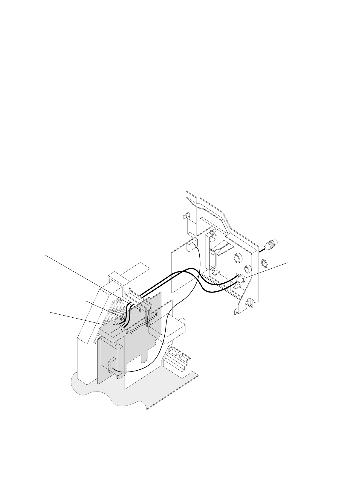
- Bausteinhalter wieder einrasten, die Führungen halten das PIP-Modul und den Signalbaustein (Abb. Pos A).
- Schwarzes Kabel mit Antennenstecker durch das vorgestanzte Langloch in der Abdeckung (Abb. Pos. B) schieben und
auf den Tuner des Signalbausteins stecken.
- Schwarzes Kabel mit Antennenbuchse durch das Langloch in der Abdeckung (Abb. Pos. B) schieben und mit der
Kontermutter auf der Abdeckplatte befestigen (das bereits durchgesteckte Steckerkabel seitlich im Langloch verlegen).
- Geräterückwand aufsetzen, Gerät anschließen und einschalten.
- Über den Menüpunkt "GR/OEM PIP29504-106" mit der Taste "
–> "OK" –> "Für den Fachhandel" –> "OK" –> Kennzahl "8500" aufrufen.
- Menüpunkt "GR/OEM PIP29504-106" auf "XXX .55" stellen.
- Die PIP-Taste ruft das PIP-Bild auf. Über die Menüführung können Sie die PIP-Position und PIP-Größe verändern.
- Für den PIP-Abgleich die Fernbedientaste "PIP" gedrückt halten und das Gerät mit dem Netzschalter einschalten. Mit den
Tasten
begrenzt wird. Einstellung mit der Taste "OK" speichern.
ǵǶǷǸ die vertikale und horizontale PIP-Position so einstellen, daß das Kleinbild nicht vom Bildschirmrand
Ǻ" das Menü "DIALOG CENTER" –> OK –> "SERVICE"
Ǻ" das Menü
GB
Fitting Instructions
Module PIP 3a (with PIP Tuner), Order Number G.AF 6500
for Digi Basic++ TV Chassis
consisting of: PIP Module 29504 106 5500
Antenna Splitter 29620 013 0100
EPROM IC 27C040-150NS for multi-system TV receivers 19798-318.XX
EPROM IC 27C040-150NS for PAL TV receivers 19798-323.XX
Fitting material
Assembly:
- The software version of the TV receiver can be called up via the menu guide by pressing the "
"DIALOG CENTER" –> OK. By pressing the "AUX" button, the software version (19798-318.XX for multi-system TV
receivers or 19798-323.XX for PAL models) is shown. If the software version is < -318.30 for multi-system models or
< -323.10 for PAL models, the EPROM IC80060 on the chassis board is to be replaced by the EPROM with the new software
included in the delivery.
- Disconnect the mains plug and open the TV receiver.
- Insert the Antenna Splitter included in the delivery into the PIP Tuner and connect the 2-core green lead with the red
connector base "ST +12" on the PIP Module.
Änderungen vorbehalten / Subject to alteration • 72010 020 1701 • 1099 • E-BS 38
Ǻ" button to enter the
Page 2
- Detach the module holder and plug the PIP Module into the multipoint connector "ST-PI1" provided for it on the Signal
Chassis.
If the TV receiver is already retrofitted with a VGA Module pull out the 9-pin plug cord ST-PI2A from the chassis board and
plug it into the connector base ST-PI2A on the PIP Module.
- Re-insert the module holder. Guides are provided to hold the PIP Module and the Signal Module in position (Fig. Pos. A).
- Lead the black cable with the antenna plug through the pre-punched elongated hole in the cover (Fig. Pos. B) and plug it
into the tuner of the Signal Module.
- Pass the black cable with the antenna socket through the pre-punched elongated hole in the cover (Fig. Pos. B) and fasten
it with the counternut to the cover (with the black cable with the plug being located in the elongated part of the hole).
- Refit the rear of the cabinet, connect the TV receiver and switch it on.
- Call up the menu option "GR/OEM PIP29504-106" by pressing button "
Ǻ" and following the menu guide "DIALOG CENTER"
–> "OK" –> "SERVICE" –> "OK" –> "For authorised dealer" –> "OK" –> code number "8500".
- In menu option "GR/OEM PIP29504-106" select "XXX .55".
- The PIP function can be called up by pressing the PIP button. The PIP position and size can be changed with the help of
the menu.
- For adjusting the PIP, press and hold the "PIP" button on the remote control handset and switch the TV receiver on with
the mains switch. With the
ǵǶǷǸ buttons shift the PIP in the vertical and horizontal direction so that the it does not border
on the edge of the screen. Store with "OK".
Abbildung
Figure
A
Antennenweiche /
Antenna Splitter
ST +12
ST-P
I2A
PIP Mod.
ST-PI1
Signal Mod.
ST-PI2A
VGA Mod.
B
 Loading...