

Grundig CUC 2103 H, LEEMAXX 55 T 55-4104 M-HOT-CL Service Manual [en, de]
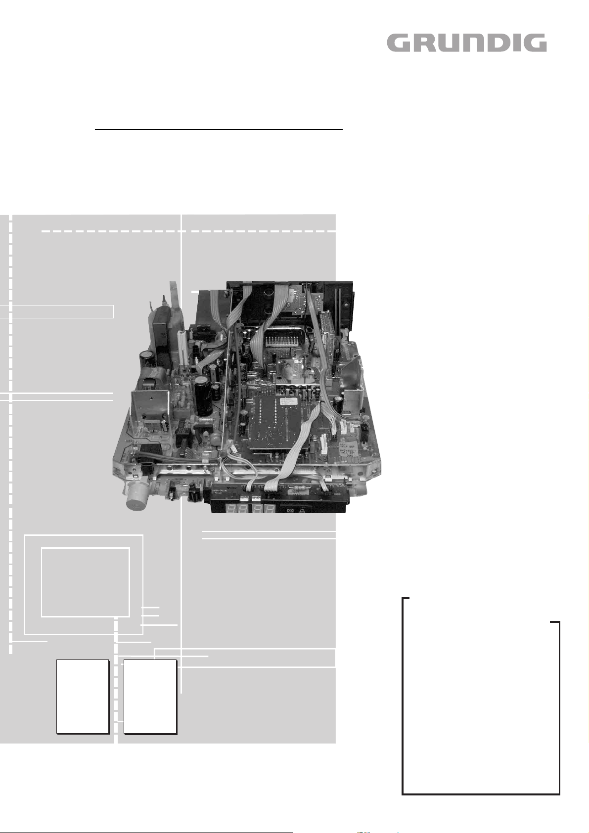
TV Service Manual
CUC 2103 H
LEEMAXX 55
T 55-4104 M/HOT/CL
GCM9300 (VNM / VNA)
Zusätzlich erforderliche Unterlagen für den Komplettservice
Additionally required Service Documents for the Complete Service
Service
Manual
Sicherheit
Safety
Materialnr./Part No.
720108000000
Materialnummer/Part Number 720100436000
Änderungen vorbehalten/Subject to alteration • Printed in Germany IP
H-S 45 0202
http://www.grundig.com
Service
Training
CUC 2100
Materialnr./Part No.
Ķ 720103503200
ķ 720103503300
Grundig Service
Hotline Deutschland…
Technik:
TV
TV
SAT
VCR/LiveCam
HiFi/Audio
Car Audio
Telekommunikation
Planatron
Ersatzteil-Verkauf: Mo.-Fr. 8.00-19.00 Uhr
Kundendienst/Werkstätten:
gebührenpflichtig
(8.00-22.00 Uhr)
…Mo.-Fr. 8.00-18.00 Uhr
0180/52318-41
0180/52318-49
0180/52318-48
0180/52318-42
0180/52318-43
0180/52318-44
0180/52318-45
Fax:
Telefon: 0180/52318-40
Telefon:
Fax:
0180/52318-51
0180/52318-99
0180/52318-50Fax:
Mo.-Fr. 8.00-18.00 Uhr
0180/52318-52
0180/52318-46

Allgemeiner Teil / General Section CUC 2103 H
Es gelten die Vorschriften und Sicherheitshinweise
gemäß dem Service Manual "Sicherheit", Materialnummer 720108000000, sowie zusätzlich die eventuell abweichenden, landesspezifischen Vorschriften!
D
Inhaltsverzeichnis
Seite
Allgemeiner Teil ................................. 1-3…1-13
Messgeräte .................................................................................. 1-3
Allgemeine Hinweise .................................................................... 1-3
Modulübersicht ............................................................................. 1-4
Technische Daten ........................................................................ 1-4
Sicherheits- / Service Hinweise ................................................... 1-5
Schaltplansymbole ....................................................................... 1-6
Bedienhinweise ......................................................................... 1-10
Konfigurieren der Fernbedienung .............................................. 1-10
Service- und Sonderfunktionen .................................................. 1-12
Abgleich ................................................ 2-1…2-2
The regulations and safety instructions shall be valid
as provided by the "Safety" Service Manual, part
number 720108000000, as well as the respective
national deviations.
GB
Table of Contents
Page
General Section .................................. 1-3…1-14
Test Equipment ............................................................................ 1-3
General Notes .............................................................................. 1-3
Module List ................................................................................... 1-4
Technical Data ............................................................................. 1-4
Safety Advices / Service Notes .................................................... 1-5
Circuit Diagram Symbols ............................................................. 1-6
Operating Hints .......................................................................... 1-11
Setup of Remote Control ........................................................... 1-11
Service and Special Functions................................................... 1-13
Alignment.............................................. 2-3…2-4
Platinenabbildungen
und Schaltpläne ................................. 3-1…3-32
Chassisplatte ............................................................................... 3-1
Oszillogramme (Chassis) ............................................................. 3-7
Chassisplatte (vergrößert) ........................................................... 3-9
Teilschaltplan Netzteil ................................................................ 3-13
Teilschaltplan Ablenkung ........................................................... 3-15
Teilschaltplan Prozessor ............................................................ 3-17
Teilschaltplan Tuner ................................................................... 3-19
Teilschaltplan Video ................................................................... 3-21
Teilschaltplan Audio ................................................................... 3-23
Bildrohrplatte .............................................................................. 3-25
Prozessor-Platte ........................................................................ 3-27
LS Buchsenplatte ....................................................................... 3-30
Uhr-Modul kpl. ............................................................................ 3-31
Ersatzteillisten ...................................... 4-1…4-8
Layout of the PCBs
and Circuit Diagrams ......................... 3-1…3-32
Chassis Board .............................................................................. 3-1
Oscillograms (Chassis) ................................................................ 3-7
Chassis Board (Enlarged) ............................................................ 3-9
Circuit Diagram Mains Section................................................... 3-13
Circuit Diagram Deflection Section ............................................ 3-15
Circuit Diagram Processor Section ............................................ 3-17
Circuit Diagram Tuner Section ................................................... 3-19
Circuit Diagram Video Section ................................................... 3-21
Circuit Diagram Audio Section ................................................... 3-23
CRT Panel ................................................................................. 3-25
Processing Board ....................................................................... 3-27
LS Socket Board ........................................................................ 3-30
Clock Module compl. .................................................................. 3-31
Spare Parts Lists .................................. 4-1…4-8
1 - 2 GRUNDIG Service
CUC 2103 H Allgemeiner Teil / General Section
Allgemeiner Teil
Messgeräte
Beachten Sie bitte das Grundig Messtechnik-Programm, das Sie unter
folgender Adresse erhalten:
Geschäftsbereich Instruments
Test- und Mess-Systeme
Würzburger Str. 150
D-90766 Fürth
Tel.: 0911 / 703-4540
Fax: 0911 / 703-4130
eMail: instruments@grundig.com
Internet: http://www.grundig-instruments.de
Allgemeine Hinweise
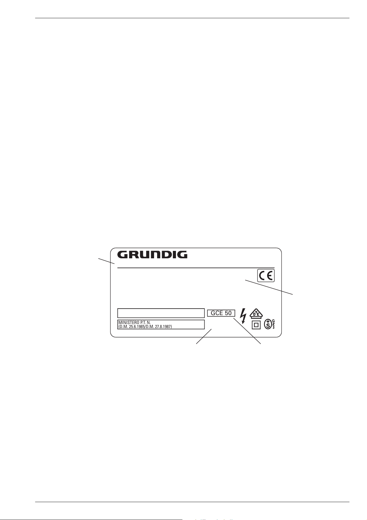
Typenschild des Gerätes
Zusätzlich zum Gerätetyp und der Chassisbezeichnung enthält das
Gerätetypenschild eine sogenannte "Version number" z.B. VNA. Diese Kennzeichnung gibt Aufschluß über den technischen/mechanischen Fertigungsstand.
Für die Bestellung von Ersatzteilen sind deshalb folgende Angaben
unbedingt erforderlich:
- Gerätetype (z.B. "T 51-731 text")
- Chassis-Bezeichnung (z.B. "CUC 7303")
- Version number (z.B. "VNA")
- Materialnummer des Ersatzteils
General Section
Test Equipment
Please note the Grundig Catalog "Test and Measuring Equipment"
obtainable from:
Grundig AG
General Notes
Type Label on the Set
In addition to the type of the TV set and the designation of the chassis,
a so-called "Version number", e.g. VNA, is printed on the type label.
This identification gives information on the technical/mechanical state
of production.
Do not fail to give the following particulars when ordering spare parts:
- type of TV set (e.g. "T 51-731 text")
- name of chassis (e.g. "CUC 7303")
- version number (e.g. "VNA")
- part number spare part
Gerätetype
Type of product
Wegen Veränderung des Schwerpunktes beim Abnehmen der
Rückwand bzw. Ausbau des Chassis oder Entfernen eines eventuell vorhandenen Standfußes ist das Gerät gegen Kippen zu
sichern.
Vor dem Öffnen des Gehäuses zuerst den Netzstecker ziehen!
Leitungsverlegung
Bevor Sie die Leitungen und insbesondere die Masseleitungen lösen,
muss die Leitungsverlegung zu den einzelnen Baugruppen wie z.B.
Chassis, Netzschalterplatte, Bedieneinheit, Bildrohrplatte, Ablenkeinheit, Lautsprecher usw. beachtet werden.
Nach erfolgter Reparatur ist es notwendig, die Leitungsführung wieder
in den werkseitigen Zustand zu versetzen um evtl. spätere Ausfälle
oder Störungen zu vermeiden.
Netzkabel
Diese Geräte dürfen nur mit dem Original-Netzanschlusskabel mit
integrierter Entstördrossel betrieben werden. Dieses Netzkabel verhindert Störungen aus dem Netz und ist Bestandteil der Gerätezulassung. Im Ersatzfall bestellen Sie bitte ausschließlich das Netzkabel laut Ersatzteilliste.
T 51-731 text
220-240V~ 50/60Hz 55W
EIGENSICHERE KATHODENSTRAHLRÖHRE NACH ANLAGE III
DER RÖNTGENVERORDNUNG.
BESCHLEUNIGUNGSSPANNUNG MAX. 25kV, 1.0mA.
TUBOS DE RADIACIÓN CATÓDICA AUTOLIMITADA, SEGÚN ANEXO III DE LA NORMATIVA
RADIOLÓGICA. TENSIÓN DE ACELERACIÓN MÁX. 25kV, 1.0mA.
ATENCION! NO ABRIR SIN ANTES DESCONECTAR LA TENSION DE RED.
STACCARE LA SPINA DI RETE PRIMA DI TOGLIERE IL PANNELLO POSTERIORE.
PROTEGGERE L'APPARECCHIO DALL'UMIDITA`. ATTENZIONE ALTA TENSIONE 25kV, 1.0mA.
MINISTERO P.T. N.
(D.M. 25.6.1985/D.M. 27.8.1987)
MADE IN AUSTRIA FABRICANTE: GRUNDIG AG, WIEN
Chassis-Bezeichnung
Chassis designation
VNA
Version number
GCE 50
CUC 7303
Because of the change of the centre of gravity when removing the
rear panel, the chassis or an existing stand, it is necessary to
protect the set from tipping.
Before opening the cabinet disconnect the mains plug!
Wiring
Before disconnecting any leads and especially the earth connecting
leads observe the way they are routed to the individual assemblies like
the chassis, mains switch panel, keyboard control panel, picture tube
panel, deflection unit, loudspeaker and so on.
On completion of the repairs the leads must be laid out as originally
fitted at the factory to avoid later failures or disturbances.
Mains Cable
The TV receiver must only be operated with an original mains connecting
cable with an interference suppressor choke integrated in the mains
plug.This mains cable prevents interference from the mains supply and
is part of the product approval. For replacement please order exclusively
the mains connecting cable specified in the spare parts list.
25kV
Bestellnummer ohne Farbkennzeichnung
Order number without colour code
GRUNDIG Service 1 - 3
Allgemeiner Teil / General Section CUC 2103 H
Modulübersicht
Module List
Bestell-Nr.
Order No.
Chassis-Nr.
Chassis No.
PLL Tuner
Prozessor-Modul
Processing Board
Bildrohrplatte
CRT Panel
LS-Buchsenplatte
LS Socket Board
Uhr-Modul kpl.
Clock Module comp.
TP 800 Hcl
Technische Daten / Technical Data
Bildröhre / Picture Tube
Sichtbares Bild
Visible picture
Bildröhre
CRT
Ablenkwinkel
Deflection angle
Bildwechselfrequenz
Vertical frequency
Elektronik / Electronic
Programmspeicherplätze
Programme positions
Materialnummer
Part Number
295043010100
295045010100
293052193300
293051223800
293051605700
295010880200
296420615600
LEEMAXX 55 T 55-4104 M/HOT/CL
Optionally Thomson, Samsung
LEEMAXX 55
T 55-4104 M/HOT/CL
CUC 2103 H
GCM9300 GCM9300
297040125100
297040125200
297040125300
295043010100 295045010100
(VNM/VNA)
CUC 2103 H
51cm
55cm (21"), Black Line D,
Philips 27,5KV small neck
90°
50Hz
99 TV + 1 AV
LEEMAXX 55
T 55-4104 M/HOT/CL
(VNM)
(VNA)
CUC 2103 H
297040127300
297040127400
297040127500
••
••
••
••
••
Tuner
TV-Standard B/G, I, D/K/K`, L/L´
Farbsysteme
Color systems
Videotext
Teletext
Musikleistung
Music power
Anschlüsse Rückwand / Connections Rear Panel
Euro AV 1 (schwarz/black)
Lautsprecherbuchse
Loudspeaker socket
Netzteil / Mains Stage
Netzspannung (Regelbereich)
Mains voltage (variable)
Netzfrequenz
Mains frequency
Leistungsaufnahme
Power consumption
Standby ca. 5W
PLL Frequenz Synthesizer Tuning UHF/VHF,
PLL frequency synthesizer tuning UHF/VHF,
1 x DIN parallel zum Lautsprecher (min. 8Ω)
1 x DIN parallel to Loudspeaker (min. 8Ω)
globale Pinbelegung
global pinning
PAL, SECAM, NTSC 4.43MHz,
via AV: 3.58MHz
7-Seiten-TOP/FLOF-text
7-pages-TOP/FLOF-text
8W
FBAS Ein-/Ausgang, S-Video-Eingang,
RGB Eingang
CCVS in-/output, S-Video input,
RGB input
230V ±15%
50 / 60Hz
ca. 60W
1 - 4 GRUNDIG Service

CUC 2103 H Allgemeiner Teil / General Section
Sicherheits-Hinweise
Die in den Fernsehgeräten auftretende Röntgenstrahlung entspricht
den Bestimmungen der Physikalisch-Technischen Bundesanstalt
vom 8. Januar 1987.
Die Hochspannung für die Bildröhre und die damit auftretende
Röntgenstrahlung ist abhängig von der exakten Einstellung der
Netzteilspannung +A.
Nach jeder Reparatur im Netzteil oder in der Horizontalablenkung ist
die Hochspannung zu messen und gegebenenfalls einzustellen.
Schutzschaltungen im Gerät dürfen nur kurzzeitig außer Betrieb
gesetzt werden, um Folgeschäden am Chassis oder an der Bildröhre zu vermeiden.
Beim Austausch der Bildröhre dürfen nur die in den Ersatzteillisten
vorgeschriebenen Typen verwendet werden.
D
Servicehinweise
Chassisausbau
Bevor Sie die Chassis-Verbindungsleitungen lösen, muss die Leitungsverlegung zu den einzelnen Baugruppen wie Netzschalterplatte, Bedieneinheit, Bildrohrplatte, Ablenkeinheit oder Lautsprecher beachtet werden.
Nach erfolgter Reparatur ist es notwendig, die Leitungsführung wieder
in den werkseitigen Zustand zu versetzen, um eventuell spätere
Ausfälle oder Störungen zu vermeiden.
Safety Advices
The X-radiation developing in the sets conforms to the X-radiation
Regulations (January 8, 1987), issued by the Physikalisch-Technische Bundesanstalt (federal physiotechnical institution).
The high tension for the picture tube and thus the developing Xradiation depends on the precise adjustment of the +A power
supply.
After every repair of the power supply unit or the horizontal deflection
stage it is imperative that the EHT for the picture tube is checked and
re-adjusted if necessary.
To avoid consequential damages to the chassis or the picture tube
the integrated protective circuits are allowed to be put out of
operation only for a short time.
When replacing the picture tube use only the types specified in the
spare parts lists.
Cable dereseau
Ces appareils ne peuvent être utilisés qu ' avec un cable de connecion
original de réseau avec bobine antiparasite intégré dans la fiche de
secteur. Ce câble de réseau empêche des perturbations de réseau et
est partie de l'autorisation d'appareil. Si nécessaire commandez
uniquement le cable de réseau selon la liste de pièces détachées.
Netzkabel
Diese Geräte dürfen nur mit dem Original-Netzanschlusskabel mit
integrierter Entstördrossel betrieben werden. Dieses Netzkabel verhindert Störungen aus dem Netz und ist Bestandteil der Gerätezulassung. Im Ersatzfall bestellen Sie bitte ausschließlich das Netzkabel laut Ersatzteilliste.
GB
Service Notes
Disassembly of the chassis
Before disconnecting the chassis connecting leads observe the way
they are routed to the individual assemblies like the mains switch
panel, keyboard control panel, picture tube panel, deflection unit or
loudspeaker.
On completion of the repairs the leads must be laid out as originally
fitted at the factory to avoid later failures or disturbances.
Mains cable
The TV receiver must only be operated with an original mains connecting
cable with an interference suppressor choke integrated in the mains
plug.This mains cable prevents interference from the mains supply and
is part of the product approval. For replacement please order exclusively
the mains connecting cable specified in the spare parts list.
F
Information pour la maintenance
Dèmontage de chassis
Avant de défaire les connecteurs du châssis princip, il y a lieu de
repérer auparavant les liaisons correspondant à chaque platine comme
par exemple le C.I. Inter secteur, le C.I. Commande, le C.I. Tube, le
bloc déviation ou les haut-parleurs.
A la fin de l'intervention, les connexions doivent être remises dans leur
position d'origine afin d'éviter par après d'éventuelles défaillances ou
perturbations.
I
Nota di servizio
Smontaggio del telaio
Prima di sfilare i cavi di collegamneto col telaio è necessario osservare
la disposizione originaria degli stessi verso le singole parti come la
piastra alimentazione, l'unità comandi, la piastra cinescopio, il giogo o
l'altoparlante.
Dopo la riparazione è necessario che gli ancoraggi e le guide
garantiscano la disposizione dei cavi analogamente a quella data in
fabrica e ciò per evitare disturbi o danni nel tempo.
Cavo rete
Gli apperechi devono essere messi in funzioni solo con il cavo originale
il colle gamento di rete e la sua spina di rete deve essere munita di una
bombina d´induttanza. In causa di sostituzione ordinate solo il cavo di
alimentatore che corrésponde alla lista degli accessori.
E
Nota de servicio
Desmontaje del chassis
Antes de desconectar las conecciones del Chassis hay que observar
la dirección de dichas conecciones a los distintos grupos de construcción
como la placa de conmutación de red, unidad de control, placa del
zócalo del tubo de imagen, unidad de deflección o altavoces.
Después de haber realizado la reparación y para evitar fallos o
pertubaciones posteriores es necesario reponer las conecciones tal
como fueron instaladas originalmente en fabrica.
Cable de red
El aparato solo se puede usar con el cable de red original con choque
antiparásito integrado en el enchufe de red. Este cable de red evita
perturbaciones de la red y es parte de la autorización del aparato. En
caso necesario puede pedir el cable de red según lista de piezas de
repuestos.
GRUNDIG Service 1 - 5

Allgemeiner Teil / General Section CUC 2103 H
+
-
REF
A-AM
ABK
AUDIO
AUDIO-L
AUDIO-R
AUDIO
MAC
AUDIO
L-MAC
AUDIO
R-MAC
AUDIO
SUB
AUDIO
TV
AUDIO
VCR
A-ZF 1
A-ZF 2
B EXT
BB
B EXT
B
OSD
B PIP
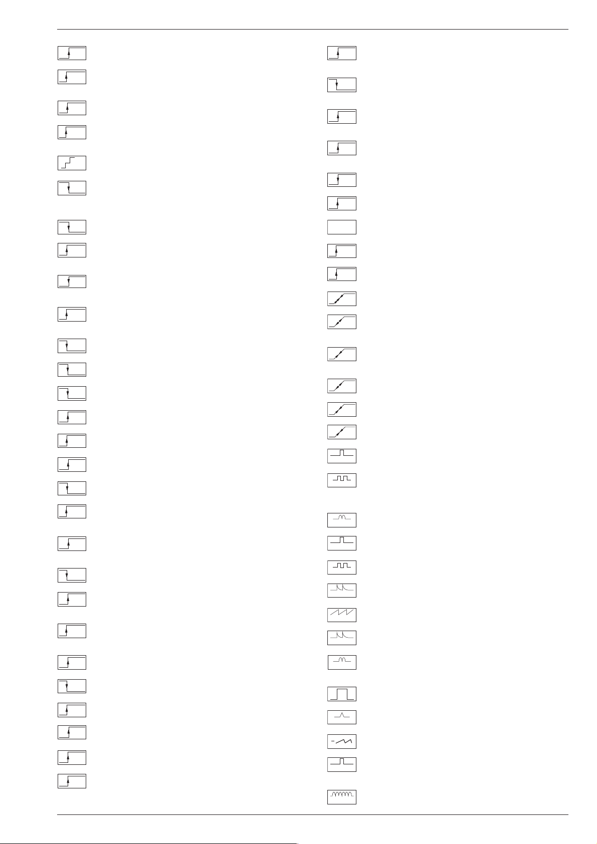
Schaltplansymbole
D
Simboli sullo schema
I
Feinabst. + / Fine tuning + / Réglage fine + / Sint. fine + / Sint. fina +
Feinabst. - / Fine tuning - / Réglage fine - / Sint. fine - / Sint. fina -
Lautstärke / Volume / Volume / Volume sonore / Volumen
Referenz Lautstärke / Volume ref. volt. / Tens. de réf. vol. sonore /
Tens di rif. volume / Tens. ref. volumen
Balance / Balance / Balance / Balanciam. / Balance
Suchlauf / Self seek / Recherche autom. / Sint. autom. / Sintonia
automatica
Farbton / Tint / Teinte / Tinta / Tinte
Helligkeit / Brightness / Luminosité / Luminosita / Brillo
Kontrast / Contrast / Contraste / Contrasto / Contraste
Farbkontrast / Colour contrast / Contraste des coleurs / Contrasto
colore / Contraste de color
Schutzschaltung / Protection circuit / Circuit de sécurité / Circuito di
protezione / Circuito de protección
Audio AM
(Burst Key): Burstaustastimpuls / Burst blanking pulse / Impulsion de
suppress. de burst / Imp. di soppress. del burst / Imp. supresion burst
Ton-Signal / Audio signal / Signal audio / Segnale audio / Señal audio
Ton-Signal links / Audio signal left / Signal audio gauche / Segnale
audio sinistra / Señal audio izquierda
Ton-Signal rechts / Audio signal right / Signal audio droit / Segnale
audio destra / Señal audio derecha
Tonsignal D2 Mac / Audio signal D2MAC / Signal audio D2MAC /
Segnale audio D2MAC / Señal de sonido D2MAC /
Tonsignal links D2 Mac / Audio signal left D2MAC / Signal audio
gauche D2MAC / Segnale audio sinistro D2MAC / Señal de sonido
izquirdo D2MAC
Tonsignal rechts D2 MAC / Audio signal right D2MAC / Signal audio
droit D2MAC / Segnale audio destro D2MAC / Señal de sonido
derecho D2MAC /
Audio Tieftöner / Audio sub woofer / Audio haut-parleur pour les
frequences basses / Audio toni bassi / Audio sonido bajo
Audio-Signal FS Gerät / Audio signal TV set / Signal audio
téléviseur / Segnale audio TV / Señal audio TV
Tonsignal VCR Gerät / Audio signal VCR unit / Signal audio
magnetoscope / Segnale audio VCR / Señal audio VCR
Audio ZF 1 / Audio IF 1 / Audio FI 1 / Audio FI 1 / Audio FI 1
Audio ZF 2 / Audio IF 2 / Audio FI 2 / Audio FI 2 / Audio FI 2
Blau-Signal / Blue signal / Signal bleu / Segnale blu / Señal azul
Basisband / Baseband / Bande de base / Banda base / Banda base
Blau-Signal extern / Signal blue external /Signal bleu externe /
Segnale blu esterno / Señal azul externa
OSD-Einblendung blau / OSD blue / Eblouissement OSD bleu /
Visualizzazione OSD blu / Visualisacione OSD azul
Blau-Signal PIP / PIP Blue signal / Signal bleu PIP / Segnale blu
PIP / Señal azul PIP
GB
Circuit Diagram Symbols
F
Simbolos en los esquemas
E
Blau - Signal - 50Hz vert.,15625Hz hor. / Blue signal - 50Hz vert.,
B/50
15625Hz hor. / Signal bleu - 50Hz vert., 15625Hz hor. / Segnale bleu
- 50Hz vert., 15625Hz hor. / Señal azul - 50Hz vert., 15625Hz hor.
B/100
B-Y 50
B-Y 100
CENTER
CINCH
AUDIO L
CINCH
AUDIO R
CHROMA
CHROMA
CS 100
DATA
ENABLE
ENABLE
ENABLE
EURO-AV
AUDIO-L
EURO-AV
AUDIO-R
EURO-AV
VIDEO
Blau-Signal -100Hz vert., 31250Hz hor. / Blue signal -100Hz vert.,
31250Hz hor. / Signal bleu -100Hz vert., 31250Hz hor. / Segnale blu
-100Hz vert., 31250Hz hor. / Señal azul -100Hz vert., 31250Hz hor.
B-Y -Signal - 50Hz vert., 15625Hz hor. / B-Y -Signal - 50Hz vert.,
15625Hz hor. / Signal B-Y - 50Hz vert., 15625Hz hor. / Segnale BY - 50Hz vert., 15625Hz hor. / Señal B-Y - 50Hz vert., 15625Hz hor.
B-Y -Signal - 100Hz vert., 31250Hz hor. / B-Y -Signal - 100Hz vert.,
31250Hz hor. / Signal B-Y - 100Hz vert., 31250Hz hor. / Segnale BY - 100Hz vert., 31250Hz hor. / Señal B-Y - 100Hz vert., 31250Hz hor.
Kanalwahl / Channel selection / Sélection de canaux / Selez.
C
canale / Seleccion canal
Mittelpunkt-Lautsprecher / Center loudspeaker / Haut-parleur de
centre / Alto parlante punto centrale / Altavoz del centro
CHIP
Chip Adresse / Chip adress / Chip direction / Indiri. del chip /
ADR
Direccion chip
Ton-Signal Cinch links / Audio signal cinch left / Signal audio cinch
gauche / Segnale audio cinch sinistra / Señal audio cinch izquierda
Ton-Signal Cinch rechts / Audio signal cinch right / Signal audio
cinch droit / Segnale audio cinch destra / Señal audio cinch derecha
Chroma Signal / Chroma signal / Signal dégree / Croma segnale /
Señal croma
Chroma S-VHS-Signal / Chroma S-VHS-Signal / Signal dégree de
S-VHS
S-VHS / Croma segnale S-VHS / Señal croma S-VHS
Clock
CLK
Clock 1
CL 1
Clock 2
CL 2
Composite Sync. Imp. für VT / Composite sync pulse for TT / Imp. de
CSY
sync. vidéo-composite pour TXT / Imp. hor. para Video Comp.
Kombiniertes Hor./vert. Sync. Signal 31250Hz/100Hz (Composite
Sync.) / Combined hor./vert. sync signal 31250Hz/100Hz (Composite Sync) / Signal synchr. hor./vert. combiné 31250Hz/100Hz
(Synchr. composité) / Segnale sincr. orizz./vert. 31250Hz/100Hz
(Sincr. Composito) / Señal combinada sincr. hor./vert. 31250/100Hz
(Sincr. compuesto)
Daten / Data / Données / Dati / Datos
Verzögerungsleitung / Delay line / Ligne à retard / Linea di ritardo /
DL
Linea de retardo
Freigabe / Enable / Autorisation / Consenso / Habilitacion
ENA
ENA
Freigabe ZF / IF Enable / Validation FI / Consenso FI / Autorizacón FI
ZF
Freigabe FT / Finetuning enable / Autorisation Réglage fin / Abilitaz.
FT
Sintonia fine / Habilitacion Sintoinia fina
Freigabe LED / LED enable / Autorisation LED / Abilitaz. LED /
LED
Habilitacion LED
Freigabe Ton / Sound enable / Autorisation son / Abilitaz. audio /
TON
Habilitacion sonido
Audio-Signal EURO-AV links / Audio signal EURO-AV left / Signal
audio EURO-AV gauche / Segnale audio EURO-AV sinistra / Señal
audio izquierda EURO-AV
Audio-Signal EURO-AV rechts / Signal audio EURO-AV right /
Signal audio EURO-AV droit / Segnale audio EURO-AV destra /
Señal audio derecha EURO-AV
Video-Signal EURO-AV / Video signal EURO-AV / Signal video
EURO-AV / Segnale video EURO-AV / Señal video EURO-AV
Farb-Signal / Chroma signal / Signal chroma / Segnale chroma /
F
Señal croma
Symboles schéma
1 - 6 GRUNDIG Service

CUC 2103 H Allgemeiner Teil / General Section
FBAS
FBAS
CINCH
FBAS
MAC
FBAS
TON
FBAS
TXT
FBAS
TEXT
FBAS
SYNC.
FBAS
S-VHS
F
H
FRM
FT
F
U
F
V
FBAS-Signal / CCVS signal / Signal vidéo composite / Segnale video
composito / señal video compuesta
FBAS-Signal-Cinch Buchse / CCVS signal-cinch socket / FBASprise à cinch / FBAS-presa cinch / FBAS-cinch
FBAS-D2 MAC / D2MAC CCVS signal / Signal vidéo compositeD2MAC / FBAS-D2MAC / FBAS-D2MAC
Basisband / Baseband / Bande de base / Banda base / Banda base
FBAS-Videotext / CCVS videotext / Signal vidéo compositeTélétexte / FBAS-Televideo / FBAS-Teletexto
FBAS Sync. Signal / CCVS sync signal / Signal sync. vidéo col.
comp. / Segnal sincr. video col. comp. / Señal sincr. video
compuesta
FBAS Signal S-VHS / CCVS signal S-VHS / Signal vidéo col. comp. SVHS / Segnal video col. comp. S-VHS / Señal video compuesta S-VHS
Hochspg. / EHT voltage / Haute tens. / Alta tens. / MAT
Rahmensignal / Frame signal / Signal d'encadrement / Segnale
cornice / Señal de marco
Feinabstimmung / Fine tuning / Reglage fin / Sint. fine / Sint. fina
FU-Signal / FU-signal / Signal FU / Segnale FU / Senal FU
FV-Signal / FV-signal / Signal FV / Segnale FV / Senal FV
ICL
IR
IM
CLOCK
IM
IDENT
IM
RESET
IR CLK
IR DATA
IR
VIDEO
KB
KH
AUDIO-L
KH
AUDIO-R
L
I2C Bus -Clock
Infrarot-Signal / Signal infrared / Signal infra-rouge / Segnale
infrarosso / Señal infrarojo.
I2C Bus -Clock
I2C Bus -Kennung / I2C-Bus Identification / Identification I2C-Bus /
2
Ident. I
C-Bus, Identification I2C-Bus
I2C Bus -Reset
Infrarot Clock / Infrared clock / Signal I.R. horloge / Clock segnale
R.I. / Clock infrarojos
Infrarot Signal / Infrared signal / Signal I.R. / Segnale infrarosso /
Data infrarrojos
Infrarot Signal Video / Infrared signal video / Signal I.R. video /
Segnale infrarosso video / Data infrarrojos video
Keyboard
Tonsignal Kopfhörer links / Audio signal headphone left / Signal
audio gauche de casque / Segnale audio sinistra cuffia / Señal audio
izquierda auriculares
Tonsignal Kopfhörer rechts / Audio signal headphone right / Signal
audio droit de casque / Segnale audio sinistra cuffia / Señal audio
derecha auriculares
Lautstärke / Volume / Volume / Volume sonore / Volumen
G
G
OSD
G PIP
G EXT
G/50
G/100
GND - H
HA
HDR
HC
H
SYNC
HFB
HS
I2S CL
I2S TER
I2S IN
I2S WS
I BEAM
Grün-Signal / Green signal / Signal green external / Signal vert /
Segnale verde / Señal verde
OSD-Einblendung grün / OSD green / Eblouissement OSD vert /
Visualizzazione OSD verde / Visualisacione OSD verde
Grün-Signal PIP / Green signal PIP / Signal green PIP/ Signal vert
PIP / Segnale verde PIP / Señal verde PIP
Grün-Signal extern / Green signal vertical / Signal vert externe /
Segnale verde esterno / Señal verde externa
Grün-Signal - 50Hz vert.,15625Hz hor. / Green signal - 50Hz vert.,
15625Hz hor. / Signal vert - 50Hz vert., 15625Hz hor. / Segnale
verde - 50Hz vert., 15625Hz hor. / Señal verde -50Hz vert., 15625Hz hor.
Grün-Signal -100Hz vert., 31250Hz hor. / Green signal -100Hz vert.,
31250Hz hor. / Signal vert -100Hz vert., 31250Hz hor. / Segnale
verde -100Hz vert., 31250Hz hor. / Señal verde -100Hz vert.,
31250Hz hor.
Nullpunkt Heizung / Ground filament / Point neutre-Chauffage /
Punto zero-Filamento / Punto medio filamento
Horiz. Sync. Impuls / Horiz. Sync pulse / Impulsion synchro. horiz. /
Impulso sincro orizzontale / Impulso de sinc. horiz.
Horiz. Ansteuerimpuls / Horiz. drive pulse / Impulsion de commande
horiz. / Impulso comando orizzontale / Impulso de control horiz.
Horiz. Klemmimpuls / Horiz. clamp pulse / Impulsion de serrage
horiz. / Impulso comando orizzontale / Impulso de garras horiz.
Horizontaler Sync-Impuls / Horizontal Sync impuls / Sync impuls
horizontale / Sinc impulso orrizontale / Impulso sync horizontal
Horiz. Rückschlagimpuls / Horiz. flyback / Impulsion de retour
horiz. / Impulso rotorno orizzontale / Impulso de retroceso horiz.
Hor. Sync. Implus für VT / Hor. sync pulse for TT / Imp. de sync. hor. pour
TXT / Imp. sincr. orizz. per Televideo / Imp. hor. para Video Comp.
Digitale Datensignale / Digtital data signals / Signal donneé digital /
Segnali dati digitali / Señal datos digital
Digitale Datensignale / Digtital data signals / Signal donneé digital /
Segnali dati digitali / Señal datos digital
Digitale Datensignale / Digtital data signals / Signal donneé digital /
Segnali dati digitali / Señal datos digital
Digitale Datensignale / Digtital data signals / Signal donneé digital /
Segnali dati digitali / Señal datos digital
Strahlstrom / Current beam / Current rayon / Corrante del irradire /
Corriente de haz
LED
M
MEGA
LOGIC
MODE
NIC CLK
NORM
OWA
P
P/C
PIP
P1
R
REMOTE
R
OSD
R PIP
R EXT
R-Y 50
R-Y 100
Leuchtdiode / Light emitting diode / Diode lumineuse / Diodo
luminoso / Diodo luminescente
Speicher Taste / Memory button / Touche mémoire / Tasto di
memoria / Puls. memoria
Megalogic Daten / Megalogic data / Megalogic dates / Dati
Megalogic / Megalogic datas
Modus / Mode / Mode / Modo / Modo
NICAM Clock / Clock NICAM / Horloge NICAM / Clock NICAM /
Clock NICAM
Norm Taste / TV standard select button / touche de norme / Tasto
norma / Puls. de norma
Ost-West Ansteuerimpuls / East-west drive impuls / Impulsion de
commande Est-Ouest / Impulso comando Est-Ovest / Impulso de
control Este-Oeste
Programm / Program / Programme / Programma /Programa
Programm-Kanalwahl / Program channel selection / Progr. sélection
de canaux / Progr. selez.canale / Progr. selec. canal
Bild im Bild / Picture in picture / Image dans l'image / PIP / Imagen
en la imagen
Progr. Taste / Progr. button / Touche Progr. / Tasto Progr. / Puls.
Progr.
Rot-Signal / Red signal / Signal rouge / Segnale rosso / Señal rojo
Fernbedienung / Remote control / Telecommande / Telecomando /
Mando a distancia
OSD-Einblendung rot / OSD red / Eblouissement OSD rouge /
Visualizzazione OSD rosso / Visualisacione OSD rojo
Rot-Signal PIP / Red signal PIP / Signal rouge PIP / Segnale rosso
PIP / Señal rojo PIP
Rot-Signal extern / Signal red external / Signal rouge externe /
Segnale rosso esterno / Señal rojo externa
R-Y -Signal - 50Hz vert., 15625Hz hor. / R-Y -Signal - 50Hz vert.,
15625Hz hor. / Signal R-Y - 50Hz vert., 15625Hz hor. / Segnale RY - 50Hz vert., 15625Hz hor. / Señal R-Y - 50Hz vert., 15625Hz hor.
R-Y -Signal - 100Hz vert., 31250Hz hor. / R-Y -Signal - 100Hz vert.,
31250Hz hor. / Signal R-Y - 100Hz vert., 31250Hz hor. / Segnale
R-Y - 100Hz vert., 31250Hz hor. / Señal R-Y - 100Hz vert., 31250Hz hor.
GRUNDIG Service 1 - 7

Allgemeiner Teil / General Section CUC 2103 H
S
SB
SCL
SCL 100
SDA
SHIFT
VIDEO
SHIFT
TEXT
SS
SSB
SSC
SSC
PIP
SSC 100
SSC 50
SUR-
ROUND
SYNC
SYNC.
BTX
SYNC.
VT
SW
TE
T1
T2
TT
U
FOC
U
G1
U
H
U
G2
VA
VB
VCL
VDR
Sonderkanal / Special channel / Canal special / Canale speciale /
Canal especial
Strahlstrombegrenzung / Beam current lim. / Lim. cour. de faisceau /
Lim. corr. di raggio / Corriente media de haz
I2C-Bus Clock
Schneller I2C-Bus Clock / I2C-Bus clock high speed / I2C-Bus grande
2
vitesse / I
I2C-Bus Daten / I2C-Bus data / I2C-Bus données / I2C-Bus dati /
2
I
Dynamische vert. Versch. 25Hz, aktiv bei Video u. Mix Betrieb /
Dynam. vert. shift 25Hz, active on video and mix operation / Decal
dynam. de l'image 25Hz, actif sur video et fonction. mixte / Spostam.
vert. dinam. 25Hz, attivo con video e. funzionam. misto / Desplaz.
dinamico vert. 25Hz, activo con video Y funciones mixtas
Dynamische vert. Versch. 25Hz, aktiv bei Standbild u. VT / Dyn. vert.
shift 25Hz, active on freeze-frame and Teletext / Decal dynam. de
l'image 25Hz, actif sur arret immage et Vidéotext (Antiope) / Spostam.
vert. dinam. 25Hz, attivo con fermo immag. e Televideo / Desplaz.
dinamico vert. 25Hz, activo con imagen parada Y Videotexto
Schutzschaltung / Protection circuit / Cablage protecteur / Pot. de
prot. / Circuito de proteccion
Spitzenstrahlstrombegrenzung / Peak beam current limiting / Lim.
de faisceau crete / Lim. corr. catod. di pico / Corrente pico de haz
Supersandcastle
Supersandcastle PIP
Supersandcastle 100Hz vert., 31250Hz hor.
Supersandcastle 50Hz vert., 15625Hz hor.
Surround
Sync.-Signal / Sync.-Signal / Signal sync / Segnale sync. / Señal de sync.
Sync. BTX / Viewdata Sync / Sync. Télétext / Sincr. Videotel / Sincr.
Videotexto
Sync. VT / Sync. Teletext / Sync Vidéotexte / Sincr. Televideo / Sincr.
Videotexto
Schwarzwert / Black level / Niveau du noir / Livello del nero / Nivel de negro
TEXT-Freigabe / TEXT enable / Autorisation TEXTE / Abilitaz.
TELEVIDEO / Habilatation TEXTE
Bei Zweiton, Ton 1 / On two channel sound, sound 1 / Pour double
son, son 1 / In bicanale, audio 1 / En dual, sonido 1
Bei Zweiton, Ton 2 / On two channel sound, sound 2 / Pour double
son, son 2 / In bicanale, audio 2 / En dual, sonido 2
Tieftöner / Woofer / Haut-parleur pour les frequences basses / Toni
bassi / Sonido bajo
Fokusspg. / Focussing volt. / Tens. de focalis. / Tens di focalizz. /
Tens focalizacion
Spg. Gitter G 1 / Volt. grid G1 / Tens grille G 1 / Tens. griglia G1 / Tens.
rejillas G 1
Hochspannung / High voltage / Haute tension / EAT / Alte tension
Schirmgitter Spg. / Screen-grid volt. / Tens. de grille - écran / Tens.di
griglia schermo / Tens. de rejilla
Vertikaler Ansteuerimpuls / Vert. drive pulse / Impulsion de commande
verticale / Impulso di comando verticale / Impulso de control vertical
VCR - Clock
Freigabe Anzeigebaustein / Display enable / Autorisation pour module
indicateur / Modulo indicazione / Habilitacion modulo indicacion
C-Bus veloce / Clock del I2C-Bus de alta velocida
C-Bus datos
VG
VIDEO
VT DATA
VT SCL
VT SDA
V SYNC
Y
Y 50
Y 100
ZF
AFC
U
AV
U
B1
U
B2
U
U
BA
U
BTX
U
C-AV
U
DATA
DATA
U
EXT
DATA
U
OSD
U
DEEM
DS
U
EURO-
U
AV
EU-AV
U
CINCH
U
FBAS
U
HIFI
HIFI
U
MUTE
Vert. Gegenkopplung / Vert. feedback / Contre-reaction verticale /
Controreazione vert. / Aliment. neg. vert.
Video Signal / Video signal / Signal vidéo / Segnale video / Señal video
Videotext Daten / Teletext data / Données Teletexte / Linea dati
Televideo / Data Teletexto
Videotext Clock / Teletext clock / Signal horloge Vidéotext / Clock
Televideo / Clock Teletexto
I2C Bus: VT Daten / Teletext data / Données Vidéotext / Dati
Televideo / Data Teletexto
Vertikaler Sync-Impuls / Vertical Sync impuls / Sync impuls vertical
/ Sinc impulso vertical / Impulso sync vertical
Y-Signal / Y Signal / Signal Y /Segnale Y / Señal Y
Y -Signal - 50Hz vert., 15625Hz hor. / Y -Signal - 50Hz vert., 15625Hz
hor. / Signal Y - 50Hz vert., 15625Hz hor. / Segnale
Y - 50Hz vert., 15625Hz hor. / Señal Y - 50Hz vert., 15625Hz hor.
Y - Signal - 100Hz vert., 31250Hz hor. / Y -Signal - 100Hz vert.,
31250Hz hor. / Signal Y - 100Hz vert., 31250Hz hor. / Segnale
Y - 100Hz vert., 31250Hz hor. / Señal Y - 100Hz vert., 31250Hz hor
Zwischenfrequenz / IF / FI / FI / FI
Schaltspg. AFC / AFC switching volt. / Tens. de commut. AFC/ Tens.
di commut. AFC / Tens. conmut. CAF
Schaltspg. AV / Switching volt. AV / Tens. de commut. AV / Tens. di
commut. AV / Tens. conmut. AV
Schaltspg. Band 1 / Switching volt. band 1 / Tens. de commut.
bande 1 / Tens. di commut. banda 1 / Tens. conmut. de banda 1
Schaltspg. Band 3/ / Switching volt. band 3 / Tens. de commut.
bande 3 / Tens. di commut. banda 3 / Tens. conmut. de banda 3
Schaltspg. Bildamplitude / Switching voltage vertical amplitude /
Tension de coupure amplitude dìmage / Tensione di commutaz.
ampiezza d'imagine / Tension de conm. amplitude de imagen di
commut. PAL / Tens. conmut. PAL
Schaltspg. BTX / Switching volt. BTX (Viewdata) / Tens. commut.
Télétext / Tens. commut. VIDEOTEL / Tens. conmut. Teletexto
Schaltspg. Camera Wiederg. über Camera-AV Eingang / Switching
volt. cam. playback via Camera-AV input / Tens de commut pour lec.
de camera par l'entree Camera-AV / Tens.de commut. in riproduz.
camera tramite ingresso Camera-AV / Tens. de serv. reprod. camera
a traves de la entrada Camera-AV
Schaltspg. Datenbetr. / Switching volt. data mode / Tens. de commut. fonct. données / Tens. di commut. dati / Tens conmut. datos
Schaltspg. U Data extern / Switching volt Data ext. / Tension de
commutation U Data externe / Tens. di commutazione U-Data
esterno / Tensión de conmutatón externa U
Schaltspg. für Bildschirm-Einblendung / Switching volt. for On
Screen Display / Tens. commut. pour eblouissement On Screen
Display / Tens. commut. per di visualizzazione On Screen Display /
Tens. conmut. para On Screen Display
Schaltspg. Deemphasis / Switching volt. deemphasis / Tens. commut. desaccent. / Tens. commut. deenfasi / Tens. conmut. deenfasis
Schaltspg. Dolby-Surround / Switching volt. Dolby-Surround / Tens.
commut. Dolby-Surround / Tens. commut. di Dolby-Surround / Tens.
de conmut. Dolby-Surround
Schaltspg. EURO-AV / Switching volt. EURO-AV / Tens. de commut.
EURO-AV / Tens. di commut. EURO-AV / Tens. conmut. EURO-AV
Schaltspg. EURO-AV-Cinch-Buchse / Switching volt. EURO-AVCinch socket / Tens. commut. prisa Scart - Cinch / Tens. commut.
presa Scart -Cinch / Tens. conm. EURO-AV - Cinch
Schaltspannung für Video-Ausgang EURO-AV Buchse / Switch.
voltage for video output EURO-AV socket / Tension de commut.
pour sortie vidéo EURO-AV / Tension commut. per presa d'uscita
video EURO-AV / Tension de conmut. para salida EURO-AV
Schaltspg. HIFI / Switching voltage HIFI / Tens. de commut. HIFI /
Tens di commut. HIFI / Tens. conmut. HIFI
Stummschaltung HiFi / Muting volt. HiFi / Commutation de silence
HiFi / Silenzametno HiFi / Muting HiFi
1 - 8 GRUNDIG Service
CUC 2103 H Allgemeiner Teil / General Section
U
U
U
U
U
50/60Hz
U
U
U
U
U
U
U
U
U
U
U
U
U
U
U
U
U
U
U
U
U
U
U
HUB
Schaltspg. HUB / Switching volt. deviation / Tens. commut.
déviation / Tens. commut. deviazione / Tens. conmut. deviacion
IDENT
Schaltspg. Signalkennung AV 3 / Switching volt. signal identification
AV 3 / Tens de commut.identification de signal AV3 / Tens. commut.
identificazione segnale / Tens. conmut. identifi. segñal AV3
KH
Stummschaltung Kopfhörer / Muting volt. headphone / Commutation
MUTE
de silence casque / Silenzamento cuffia / Muting auriculares
KLEMM
Gleichspannung für SAT-Basissignal / DC for SAT basic signal /
Tens. continue pour SAT base signal / Tens continua per segnale
SAT base / Tens. continua para segñal SAT base
KOIN
Schaltspg. Koinz. / Switching volt. coinc. / Tens de commut. coinc. /
Tens di commut. coinc. / Tens. conmut. coinc.
KOIN
Schaltspg. Koinz. mit Videoquelle verknüpft / Coinc. switching volt.
VQ
linked with video source / Signal de coincid. combiné avec source
video / Tens. di commut. a coinc. combinata con sorg video segñal
de coincidencia combinada con video
LED
Schaltspg. LED / Switching volt. LED / Tens de commut. LED / Tens.
commut. LED / Conmut. LED
Leucht-
Schaltspg. Leuchtpunktunterdrückung / Switching volt. beam spot
punkt
suppression / Tens. de commut. suppress. du spot lumineux / Tens.
soppr. punto luminoso / Tens. de conmut. filtro supresor del punto luz
LNC
Schaltspg. LNC "Aus" / Switching volt. LNC "OFF" / Tens. de
OFF
commut. LNC "OFF" / Tensione di commut. "Spento" LNC / Tension
LNC "OFF"
MAC
Schaltspg. D2MAC / Switching volt. D2MAC / Tension de
commutation D2MAC / Tens. di commutazione D2MAC / Tensión de
conmutación D2MAC
MUTE
Stummschaltung / Muting / Silencieux / Silenziamento /Muting
NF 1
Schaltspg. NF 1 / Switching volt. AF 1 / Tension commut. BF 1 / Tens.
commut BF 1 / Tens. conm. BF 1
NF 2
Schaltspg. NF 2 / Switching volt. AF 2 / Tension commut. BF 2 / Tens.
commut BF 2 / Tens. conm. BF 2
NIC
Schaltspg. NICAM / Switching volt. NICAM / Tens. de commut.
NICAM / Tens. commut. NICAM / Tens. de conmut. NICAM
NORM
Schaltspg. Norm / Switching volt. Norm / Tens. de commut.
standard / Tens. di commut. Norma / Tens. conmut. Norma
PAL
Schaltspg. PAL / Switching volt. PAL / Tens. de commut. PAL / Tens.
di commut. PAL / Tens conmut. PAL
POL.
Schaltspg. Polarität / Switching volt. polarity / Tension commut.
polarite / Tens. commut. polarita / Tens. conmut polarizacion
POWER
Schaltspg. Ökoschalter / Switching volt. eco switch / Tens. de
OFF
commut. interr. eco. / Tens. commut. interr. ecologico / Tens.
conmut. interr. ecol.
PV
Schaltspg. Panorama View / Switching volt. Panorama View / Tens.
de commut. Panorama View / Tens. commut. Panorama View /
Tens. conmut. Panorama View
RESET
Schaltspg. Reset / Switching volt. Reset / Tens. commut. Reset /
Tens. commut. Reset / Tens. conmut. Reset
RGB
Schaltspg. RGB1 - RGB2 / Switching volt. RGB1 - RGB2 / Tens. de
commut. RGB1 - RGB2 / Tens. di commut. RGB1 - RGB2 / Tens.
conmut. RGB1 - RGB2
SCHUTZ
Schaltspg.-Schutzfunktion / Switching volt.-protective func. / Tens
de commut.-sécurité / Tens. di commut.-funz di protez. / Tens.
conmut.-proteccion
SEC
Schaltspg. SECAM / Switching volt. SECAM / Tens. de commut.
SECAM / Tens. di commut. SECAM / Tens. conm. SECAM
STBY
Schaltspg. Standby / Switching volt. Standby / Tens. commut.
Veille / Tens. commut. Standby / Tens. conmut. Standby
S-VHS
Schaltspg. S-VHS / Switching volt. S-VHS / Tens.de commut.
S-VHS / Tens. de commut. S-VHS / Tens. de conmut. S-VHS
TON
Schaltspg. Ton 1-2 / Switching volt. sound 1-2 / Tens. commut. audio
1/2
1-2 / Tens. commut. son 1-2 / Tens. conmut. son 1-2
UHF
Schaltspg. UHF / UHF switching volt. / Tens. de commut. UHF / Tens
di commut. UHF / Tens. conmut. UHF
VHF
Schaltspg. VHF / VHF switching volt. / Tens. de commut. VHF / Tens
di commut. VHF / Tens. conmut. VHF
VQ
U
U
WISCH
W/N
U
I / III
U
14V
U
22kHz
U
0/3/6/9V
4.5MHz
U
50/60
U
Hz
U
AFC
U
AFC
SAT
U
AGC
U
RE
U
TUN.
U
τ
HOR.
HOR.2FH
VERT.
VERT.
VER.2FV
VERT.
VERT.
VERT. 100
VERT. 100
REF.
PULSE
O/W
Schaltspg. Videoquelle / Switching volt. video source / Tens. de
commut. source video / Tens. di commut. sorg. video / Tens conmut.
video
Schaltspg. Wischerkontakt / Schwitching voltage temp. contact /
Tens. de commut. contact fugitif / Tens. commut. contatto temporaneo / Contacto supresor tens. de conmut.
Schaltspg. ZF breit - schmal / IF switching volt. wide - narrow / Tens.
commut. FI large - etroit / Tens. commut. FI larga - stretta / Tens. FI
ancho - estrecho
Schaltspg. Bandwahl / Band sel. switching volt. / Tens. de commut.
select. bande / Tens. di commut. selez. banda / Tens. conmut. selec.
banda
14V Schaltspg. / 14V switching volt. / Tens. commut. 14V / Tens.
commut. 14V / Tens. de conm. 14V
22kHz Schaltspg. / 22kHz switching volt. / Tens. commut. 22kHz /
Tens. commut. 22kHz / Tens. de conm. 22kHz
0/3/6/9V Schaltspg. / 0/3/6/9V switching volt. / Tens. commut.
0/3/6/9V / Tens. commut. 0/3/6/9V / Tens. de conm. 0/3/6/9V
Schaltspg. 4,5MHz / Switching volt. 4.5MHz / Tens. de commut.
4,5MHz / Tens. di commut. 4,5MHz / Tens conmut. 4,5MHz
Schaltspg. 50-60Hz / Switching volt. 50-60Hz / tens. de commut.
50-60Hz / Tens. di commut. 50-60Hz / Tens. conmut. 50-60Hz
Regelspg. AFC / AFC contr. volt. / Tens. de regul. AFC / Tens. di
contr. AFC / Tens. regul. CAF
Regelspg. AFC Satellitentuner / AFC contr. volt. SAT tuner / Tens.
de regul. AFC tuner SAT / Tens. di contr. AFC Tuner SAT / Tens.
regul. CAF Tuner SAT
Feldstärkeabhängige Spg. / Fieldstrength-depent volt. / Contr. automatique de gain / Tens. dipent. intens. campo / Contr. autom. de gain
tens. CAG
Regelspg. / Contr. volt. / Tens. de regul. / Tens. di contr. / Tens regul.
Abstimmspg. Tuner / Tuning volt. tuner / Tens. d'accord tuner / Tens.
di sintonia tuner / Tens. sintonia tuner
Regelspg. Verzög. / Delayed contr. volt. / Tens. de regul. retardee /
Tens. regul. retardada
Horizontale Ansteuerung / Horiz. drive / Synchr. lignes / Pilotaggio
orizz. / Exitación horiz.
31250Hz Ansteuerimp. für Zeilenendstufe / 31250Hz Triggering
pulse for horiz. output / 31250Hz commande pour l'étage final
lignes / Imp. Pilotaggio di 31250Hz per stadio finale di riga / Impulso
de exitación 31250Hz para paso final de lineas
Vert. Parabel / Vert. parabolic signal / Signal parabolique vert. /
Segnale parab. vert. / Senal parabolica vert.
Vert. Tastimpuls / Vert. Gating pulse / Imp. trame / Imp. a cadenza
vert. / Imp. cuadro
Vert. Tastimpuls 100Hz / Vert. Gating pulse 100Hz / Imp. trame
100Hz / Imp. a cadenza vert. 100Hz / Imp. cuadro 100Hz
Vert. Sägezahn / Vert. saw tooth / Signal dent de scie / Dente di sega
vert. / Dientede sierra vert.
Vert. Tastimpuls / Vert. Gating pulse / Imp. trame / Imp. a cadenza
vert. / Imp. cuadro
Vert Sägezahn 100Hz / Vert saw tooth 100Hz / Signal dent de scie
100Hz / Dente di sega vert. 100Hz / Dientede sierra vert. 100Hz
Vert. Parabel 100Hz / Vert. parabolic 100Hz signal / Signal parabolique 100Hz vert. / Segnale parab. vert. 100Hz / Senal parabolica
vert. 100Hz
Tastimpuls / Gating pulse / Impuls de declenchement / Impulso a
cadenza / Imp. puerta
Ref. Impuls hor. / Reference impulse hor. / Imp. de refer.hor. / Imp.
di rifer. hor. / Imp. refer. horiz.
Klemmung Ein-Aus / Clamping On-Off / Clampage Marche-Arrêt /
Clamping Ins.-Disins. / Clamping Enc.-Apag.
Pulse für Polarotor / Pulses for Polar-Rotor / Impulsions Rotor de
Polariastion / Impulsi per Rotore Polarizzazione / Impulsos dara
Polarrotor
O-W Amplitude / E-W amplitude / Amplitude E-O / Ampiezza E-O /
Amplitud E-O
GRUNDIG Service 1 - 9
Allgemeiner Teil / General Section CUC 2103 H
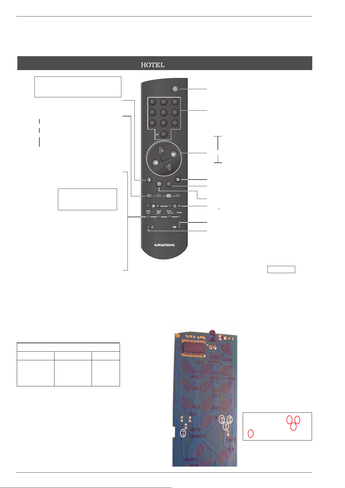
BEDIENUNGSANLEITUNG
A
– TV-Gerät einschalten
(Bereitschaft/Stand-by)
1
– AV
0
TV-Programme und AV-Plätze wählen
Einschalten aus Bereitschaft
Videotext-Seitenwahl
P p
– Menüzeilen anwählen
TV-Programme schrittweise wählen
Mit
P
aus Bereitschaft einstellen
G
– Ändern und aktivieren verschiedener
funktionen (z.B. Programmleiste)
FE
– Funktionen aus Menü wählen
Lautsärke leiser/lauter
›
ĭ
– Ton ein-/ausschalten
›
TXT
– Von TV- auf Videotext-Betrieb und
zurück schalten
›
Ȅ
– Ändert die Display-Helligkeit
∑
i
– Ändert die Farbstärke
∑
v
– Ändert die Helligkeit
›
o
– Bild-Menü aufrufen/beenden
› z – Zappfunktion
Mit z das Programm das im Moment
gesehen wird speichern. Es kann
dann mit
P p
zu einen anderen
Programm gezappt werden. Mit z
zum gespeicherten Programm
zurück. Mit
h
Funktion beenden.
ǵ
h
– Ruft Dialog Center auf
(mit
h
und G).
›
rot – Viedeotext - 1 Seite
›
grün – Viedeotext + 1 Seite
›
gelb – Seitenstopp bei Mehrfachseiten.
Bildschirmhinweise beachten.
›
blau – Wartezeit überbrücken (schaltet auf
TV-Programm zurück bis gesuchte
Seite angezeigt wird).
Bildschirmhinweise beachten.
›
Z
– Weckzeit (Alarm), mit Zifferntasten
1
– AV
0 gewünschte Weckzeit vier-
stellig eingeben.
Mit ›
Z
Weckalarm aktivieren.
›
U
– Alarm beenden und Weckzeit
löschen
›
I
– Weckzeit (Alarm) nach jeweils 10
Minuten nochmals nachwecken.
›
O
– Sleep-Timer wird eingeblendet.
Mit
P p
die gewünschte Ausschaltzeit eingeben (max. 99 Min.).
Bildschirmhinweise beachten.
Solange die Weckzeit (Alarm)
nicht mit
U
gelöscht wird, wird
täglich zur gleichen eingestellten
Zeit der Weckalarm ausgelöst.
Sicherheitshinweise
siehe Innenseite
21970-941.0600
INFORMATION!
Nach einschalten des TV-Gerätes (auch in Stand-by) wird die Uhrzeit
eingeblendet. Zur Uhrzeitaktualisierung muss auf den ersten 3
Programmplätzen ein Lokalsender liegen.
Erscheint das Glockensymbol ist der Wecker aktiv.
Bedienhinweise: Dieses Kapitel enthält Auszüge aus der Bedienungsanleitung. Weitergehende Informationen entnehmen Sie
bitte der gerätespezifischen Bedienungsanleitung, deren Materialnummer Sie in der entsprechenden
Ersatzteilliste finden.
ON/OFF
1
2
3
654
987
0
P
OK
P
TXT
TXT
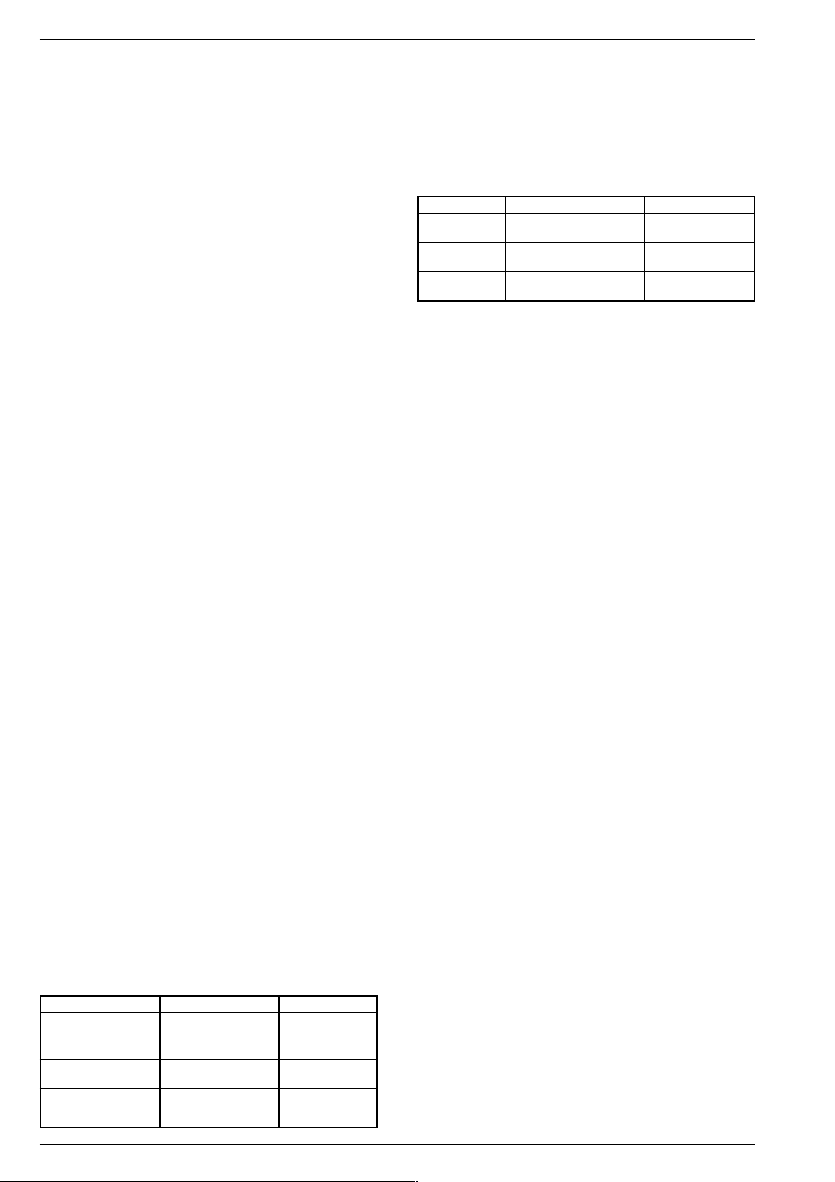
Tele Pilot 800 Hcl
Konfigurieren der Fernbedienung
Die Fernbedienebenen 1, 2, 3 und 4 werden durch Schließen der
Lötbrücken ausgewählt.
TP-Ebene / Level Brücke / Jumper SW-Level
1 - 10 GRUNDIG Service
Tele-Pilot 800 Hcl
1*) 1*) 0*)
221
332
443
1*) Standard ab Werk
Setup ex factory
PCB/Lötpunkte TP 800 Hcl
1
2
4
3
CUC 2103 H Allgemeiner Teil / General Section
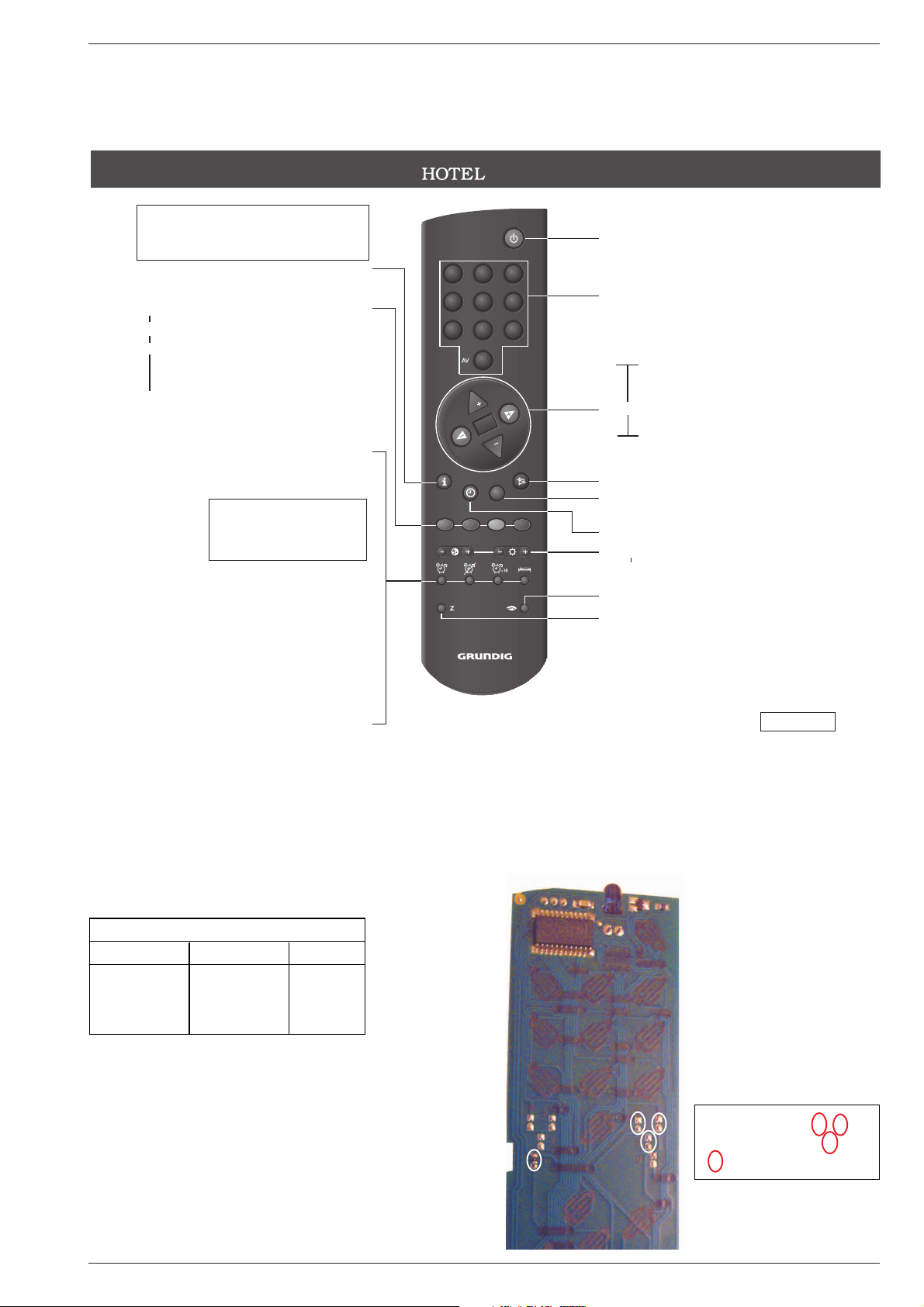
OPERATING INSTRUCTIONS
A
– Switches on the television (standby)
1
– AV
0
For selecting TV channels and AV
positions
Switches on from standby
Teletext page selection
P p
– Selects menu lines
Selects TV channels one by one
Adjust from standby with
P
.
G
– Adjusts and activates different func-
tions (e.g. channel bar)
FE
– Selects functions from menu
Volume quieter/louder
›
ĭ
– Switches sound on/off
›
TXT
– Switches from TV to teletext mode
and back
›
Ȅ
– Adjusts the display brightness
∑
i
– Adjusts the colour
∑
v
– Adjusts the brightness
›
o
– Calls up/exits the picture menu
› z – Surf function
Save the channel that is being viewed
at the moment with z.
P p
can
then be used to surf to a different
channel. Back to the stored channel
with z. End the function with
h
.
ǵ
h
– Calls up Dialog Center
(with
h
and G).
›
red – Teletext – 1 page
›
green – Teletext + 1 page
›
yellow – Page stop for multiple pages.
Observe information on the
screen.
›
blue – Bypasses the waiting period (swit-
ches back to TV programme until
the page searched for is displayed).
Observe information on the screen.
›
Z
– Alarm time; enter the desired four-
digit alarm time with number buttons 1
– AV
0.
Activate the alarm with ›
Z
.
›
U
– Ends the alarm and deletes the
alarm time.
›
I
– Alarm goes off again after
ten minutes.
›
O
– Sleep Timer is displayed.
Enter the desired Switch-off time
(max. 99 min.) with
P p
.
Observe information on the
screen.
As long as the alarm time has
not been deleted with
U
, the
alarm goes off everyday at the
same set time.
See inside for notes on safety
21970-941.0600
INFORMATION!
The time is displayed after switching on the television (also in standby).
A local TV station must be on one of the first three channel positions in
order to set the current time.
If the bell symbol appears the alarm clock is active.
Operating Hints: This chapter contains excerpts from the operating instructions. For further particulars please refer to the
appropriate user instructions the part number of which is indicated in the relevant spare parts list.
ON/OFF
1
2
3
654
987
0
P
OK
P
TXT
TXT
Tele Pilot 800 Hcl
Setup of Remote Control
The remote control levels 1, 2, 3 and 4 are selected by closing the
respective solder bridges.
TP-Ebene / Level Brücke / Jumper SW-Level
GRUNDIG Service 1 - 11
Tele-Pilot 800 Hcl
1*) 1*) 0*)
221
332
443
1*) Standard ab Werk
Setup ex factory
PCB/Solder points TP 800 Hcl
1
2
4
3
Allgemeiner Teil / General Section CUC 2103 H
Service- und Sonderfunktionen
1. Einschaltfunktionen
1.1 ATS-Reset (Automatic Tuning System)
Netzschalter "EIN" mit gedrückter Fernbedientaste "L+" –> Sprachauswahl –> OK.
Das Automatische Sendersuchsystem stoppt bei jedem empfangswürdigen Sender (AFC und Koinzidenz) und speichert automatisch die
entsprechenden Senderdaten mit dem jeweiligen Standard (die Speicherung findet unmittelbar im CIC82501 NVM statt). Danach wird der
Suchlauf fortgesetzt.
Tastendruck "TXT" bricht den ATS-Lauf ab.
1.2 Mittelwerte / Notdatensatz laden (ROM-Daten)
Fernbedientaste "P-" gedrückt halten und das Gerät mit dem Netzschalter einschalten. Dadurch wird z. B. nach Austausch des CIC82501
(NVM) das Gerät mit dem Notdatensatz gestartet.
Mit diesem Vorgang werden die Grund-Daten aus dem ROM des
Prozessors IC81500 in den NVM CIC82501 kopiert:
CIC82501: (gerätespezifische Daten, über das Dialog Center einstellbar)
- Farb- und Ton-Normen
- Decodereinstellungen
- Umkehrpunkt
- OSD Position
- ATS-Reset
- Hotel-Mode on/off
- AGC und AFC
- Analogwerte (Lautstärke, Helligkeit usw.)
- Bildschärfe
- Security on/off
- Geometrieabgleich
- Programmdaten (Kanal- und Feinabstimmung, Senderkennung)
Danach über das Dialog Center die persönlichen Werte, Bildgeometrie
eingeben.
1.3 Programmsperre (Kindersicherung) dauerhaft aufheben
Die Zahl "7038" hebt die Sperre dauerhaft auf.
1.4 EPROM-Versionsnummer
Mit Taste "Ǻ" das Menü "Dialog Center" aufrufen. Drücken der Taste "Z"
zeigt die Versionsnummer des EPROMs an.
1.5 Einschalten mit dem zuletzt gesehenen Programm
Der beim Ausschalten eingestellte Programmplatz wird beim Einschalten mit Taste "P+/P-" wieder aufgerufen (Last station memory).
2. Sonderfunktionen im Dialog Center
2.1 Tonskala
Mit Taste "Ǻ" die Dialogzeile "Tonskala" über "Dialog Center" –>
"Sonderfunktionen" aufrufen.
In Stellung "aus" wird die Tonskala nicht in das Bild eingeblendet.
2.2 Automatische Lautstärkeregelung (optional)
Mit Taste "Ǻ" die Dialogzeile "Autom. Lautst." über "Dialog Center" –>
"Sonderfunktionen" aufrufen. In Stellung "ein" wird bei großen Senderhüben die Lautstärke automatisch an den normalen Hub angepasst.
2.3 Programmplatzbezogene Decoder-Einstellung
Mit Taste "Ǻ" die Dialogzeile "Decoder Pxx" über "Dialog Center"
–> "Sonderfunktionen" aufrufen. Mit den Tasten ǷǸ können Sie
programmplatzbezogen für verschlüsselte Sendungen einen analogen oder digitalen Decoder auf interne oder externe Umschaltung
stellen.
Einstellungen des Decoders: "aus", "ON1", "ON2", "ON3".
Bedeutung der Decoderstellungen:
Ton Bild
Decoder "aus" intern intern
Decoder "ON1" extern Analog extern
Ton autom. intern Nicam-Ton
Decoder "ON2" extern Analog extern
alle Töne extern Nicam-Ton
Decoder "ON3" intern Analog extern
alle Töne intern Nicam-Ton
Die unterschiedlichen Einstellmöglichkeiten der Decoderfunktion stellen immer den richtigen Signalweg für das Audiosignal sicher.
Die drei möglichen Scramble-Verfahren:
Betriebsart:
Bild Ton Menü-Anzeige
1. Bild Analogton verschlüsselt Analog ext. bzw. ON1
verschlüsselt Nicamton unverschlüsselt Nicam intern
2. Bild Analogton verschlüsselt Analog ext. bzw. ON2
verschlüsselt Nicamton verschlüsselt Nicam extern
3. Bild Analogton unverschlüsselt Analog int. bzw. ON3
verschlüsselt Nicamton unverschlüsselt Nicam intern
Das Verfahren 1 ist für Kanal + Betrieb.
Das Verfahren 2 und 3 wird z. B. in England verwendet.
Bildsignalweg
Da das Bild generell verschlüsselt ist, muss nur die Decoder-Schaltspannung für die Videoumschaltung angelegt werden.
Audiosignalweg
Fall 1:
Decoder nicht stereotauglich, deswegen Nicamton unverschlüsselt.
Der Decoder schaltet den Audioweg in Abhängigkeit des NicamDecoders zwischen intern und extern um.
Fall 2:
Decoder stereotauglich für verschlüsselten Analog- und Nicamton.
Deswegen wird auf Externbetrieb umgeschaltet (Regelfall).
Fall 3:
Ton wird generell nur intern verbunden (keine Beschaltung am
Audiozweig der Euro-AV-Buchse).
3. Bild-Einstellungen
Grundeinstellung
Mit der Taste "Auge" das Bild-Menü aufrufen. Über die Menüführung
ist die Regulierung von Helligkeit, Farbe, Krontrast, Schärfe, Perfect
Clear und Tint (nur bei NTSC-Quellen) möglich.
Die Analogwerte für Kontrast, Bildschärfe und Tint werden beim
Verlassen des Menüs automatisch gespeichert.
4. Offene Service-Einstellungen
4.1 Maximale Programmnummer (Umkehrpunkt):
Programmnummer aufrufen, ab der die Programmplätze gesperrt
werden sollen. Mit Taste "Ǻ" die Dialogzeile "Manuelle Abstimmung"
über das "Dialog Center" aufrufen. Über die Menüführung in der
Dialogzeile Kanal "00" einstellen. Mit "OK" bestätigen und Menü
beenden. Danach können im Programm-Mode mit den Tasten "P+/P-"
nur Programme, die niedriger als der mit "00" belegte Programmplatz
sind, fortgeschaltet werden.
4.2 Farb-Zwangsumschaltung
Mit Taste "Ǻ" die Dialogzeile "Farbe" über "Dialog Center" –> "Service"
aufrufen. Mit den Tasten ǷǸ können Sie in schlechter Empfangslage
programmplatzbezogen die automatische Farbumschaltung
zwangsweise auf "PAL", "SECAM" oder "NTSC" einstellen.
4.3 IR-Dataprogrammer
Mit Taste "Ǻ" die Dialogzeile "IDP2 HP" über "Dialog Center" –>
"Service" aufrufen.
Mit der Taste "OK" können mit dem IR-Dataprogrammer 2 max. 99
Programmplätze mit Daten für Kanal, Norm, Peri, 6-stellige Sendereinblendung, Finetuning-Mitte und Lautstärke-Offset "0" abgespeichert
werden.
Der Programmer überträgt nur Kanäle und die 6-stelligen Senderkennzeichen mit Finetuning Mitte und Lautstärke-Offset "0".
4.4 Werksauslieferwerte
Mit Taste "Ǻ" die Dialogzeile "Werksauslieferwerte" über "Dialog Center" –> "Service" aufrufen.
Mit der FB-Taste "OK" werden die Werksauslieferwerte (NVM) aufgerufen und gespeichert.
1 - 12 GRUNDIG Service

CUC 2103 H Allgemeiner Teil / General Section
5. Service-Einstellungen für den Fachhandel
5.1 Service-Menü
Mit Taste "Ǻ" das Service Menü über "Dialog Center" –> "Service" –>
Service Code aufrufen.
Nach Eingabe der Codezahl "8500" kann der Fachhändler den Geräteabgleich laut Menüführung durchführen für:
- Geometry
- White adjustment
- AGC
- AFC 38,9MHz
- OSD horizontal
- OSD vertical
- Hotel
- OEM
- Remote cont.
- IR-system
Abgleich: Seite 2-1
5.2 OSD-Lage
Mit Taste "Ǻ" die Dialogzeile "OSD" über "Dialog Center" –> "Service"
–> Service Code "8500" aufrufen.
Mit den Tasten ǷǸ können Sie die horizontale, oder vertikale Lage
des Einblend-Menüs verschieben und "with mem" sichern.
5.3 Hotel-Mode
5.3.1 Hotel-Mode aktivieren
Mit Taste "Ǻ" die Dialogzeile "Hotel" über "Dialog Center"
–> "Service" –> Service Code "8500" aufrufen.
Bei aktiviertem "Hotel-Mode" ist:
- der Aufruf des "Dialog Center" mit der Taste "Ǻ" nicht mehr möglich.
- die zuletzt eingestellte Lautstärke die maximale Lautstärke die
gespeichert wird.
5.3.2 Hotel-Mode ausschalten
Taste "Ǻ" der Fernbedienung gedrückt halten und das Gerät mit dem
Netzschalter einschalten. Im Menü "Service" Hotel-Mode wieder ausschalten.
5.4 OEM
Mit Taste "Ǻ" die Dialogzeile "OEM" über "Dialog Center" –> "Service"
–> Service Code "8500" aufrufen.
Farbumstellung der Menüs.
Für Grundig Menü Standardeinstellung: OEM "off".
5.5 Remote Control
Mit Taste "Ǻ" die Dialogzeile "Remote cont." über "Dialog Center" –>
"Service" –> Service Code "8500" aufrufen.
Einstellung für TP 800 Hcl / TP 800 H auf "1".
5.6 IR-system
Mit Taste "Ǻ" die Dialogzeile "IR-system" über "Dialog Center" –>
"Service" –> Service Code "8500" aufrufen.
Bei Mehrgerätebetrieb die Fernbedienebene "0", "1", "2" oder "3"
einstellen (siehe Seite1-10).
5.7 Leuchtstärke LED Betriebsanzeige
Mit Taste "Ǻ" die Dialogzeile "End" über "Dialog Center" –> "Service"
–> Service Code "8500" aufrufen.
Mit den Fernbedientasten "rot" minus und "grün" plus wird die
Leuchtstärke der LED im Betriebszustand eingestellt.
Mit den Fernbedientasten "gelb" minus und "blau" plus wird die
Leuchtstärke der LED in Standby eingestellt.
6. Schutzschaltungen deaktivieren
- Horizontal- und Vertikal-Schutzschaltung:
Basis und Emitter des CT50055 verbinden.
- Horizontal- Schutzschaltung:
Basis und Kollektor des CT57113 verbinden.
- Vertikal- Schutzschaltung: C50052 kurzschließen.
Achtung: Nach beendeter Reparatur Schutzschaltungen unbedingt
aktivieren.
Service and Special Functions
1. Switching-on Options
1.1 ATS Reset (Automatic Tuning System)
Press the power "ON" button while pressing button "L+" on the
Remote Control –> Language selection –> OK.
The ATS system stops at every station of acceptable reception quality
(AFC and coincidence) and stores the station data and the respective
standard automatically (data is stored immediately in the
CIC82501 NVM). The system then continues searching.
Pressing the "TXT" button stops the ATS function.
1.2 Loading the Average Values / Emergency Data Set (ROM Data)
Press and hold the "P-" button on the Remote Control and switch on
with the mains button. After replacement of CIC82501 (NVM) for
example, the TV set is started with the emergency data set.
In doing so, the basic data is read out from the ROM of processor
IC81500 and loaded into the NVM CIC82501:
CIC82501: (data specific to the TV can be set via the Dialog Center):
- chroma and audio standards
- decoder settings
- reversing point
- OSD position
- ATS reset
- Hotel Mode on/off
- AGC and AFC
- analog values (volume, brightness etc.)
- picture sharpness
- security on/off
- geometry adjustment
- programme data (channel finetuning, station ident)
Subsequently enter your personal values, picture geometry via the
Dialog Center.
1.3 Cancelling the Parental Lock Continuously
To cancel the parental lock enter the number 7038.
1.4 EPROM Version Number
Press button "Ǻ" to call up the "Dialog Center". Button "Z" shows the
version number of the EPROM.
1.5 Switching on with the Last Viewed Programme.
The channel position which has been selected when switching off is
recovered when switching on again (last station memory).
2. Special Functions in the Dialog Center
2.1 Sound Scale
Reach the "Sound scale" menu via "Dialog Center" –> "Special functions"
by pressing button "Ǻ". When selecting "off" the scales indicating the
analog values do not appear.
2.2 Automatic Volume Control (option)
Reach the "Volume Limiter" dialog via "Dialog Center" –>
"Special functions" by pressing button "Ǻ". The volume of stations with
large deviation is adjusted to normal deviation when selecting "on".
2.3 Decoder Settings for Individual Programme Positions
By pressing button "Ǻ" call up the "Decoder Pxx" dialog via "Dialog
Center" –> "Special functions". With the ǷǸ buttons it is possible to
set an analog or digital decoder to be switched over internally or
externally on a per-programme basis for scrambled stations.
Possible decoder settings are: "Manual", "off", "ON1", "ON2", "ON3".
Meaning of the decoder settings:
Sound Picture
Decoder "off" internal internal
Decoder "ON1" external Analog external
Sound autom. internal Nicam
Decoder "ON2" external Analog external
all sounds external Nicam
Decoder "ON3" internal Analog external
all sounds internal Nicam
The different possibilities of setting the decoder function ensure that
the audio signal path is always switched correctly.
GRUNDIG Service 1 - 13

Allgemeiner Teil / General Section CUC 2103 H
The three possible scrambling methods are:
Operating Mode:
Picture Sound Menu Display
1. Scrambled Analog scrambled Analog ext. or ON1
Nicam not scrambled Nicam internal
2. Scrambled Analog scrambled Analog ext. or ON2
Nicam scrambled Nicam external
3. Scrambled Analog not scrambled Analog int. or ON3
Nicam not scrambled Nicam internal
Method 1 is for Channel+ operation.
Methods 2 and 3 are used for example in Great Britain.
Video Signal Path
Due to the fact that the video signal is generally scrambled it is only
necessary to apply the decoder video signal switching voltage.
Audio Signal Path
Case 1:
The decoder is not stereo capable. Therefore the Nicam sound is not
scrambled. The decoder changes the audio path in dependence of the
Nicam decoder between internal and external.
Case 2:
The decoder is stereo capable for scrambled analog and Nicam sound.
Therefore the decoder is switched over to external operation (usual
case).
Case 3:
The sound is generally connected only internally (no connection to the
audio path of the EURO AV socket).
3. Picture Settings
Basic Adjustment
Call up the picture settings menu with the button "eye". Via the menu
guide it is possible to change the Brightness, Color, Contrast, Sharpness, Perfect Clear and Tint (only NTSC sources).
The analog values for Contrast, Picture Sharpness and Tint are stored
automatically when leaving the menu.
4. Open Service Settings
4.1 Maximum Programme Number (reversing point)
Call up the programme number which is to be the highest selectable
programme position. With button "Ǻ" select the dialog line "Manual
tuning" via the "Dialog Center". Following the menu guide, enter "00"
in the dialog line channel. Confirm with "OK" and terminate the menu.
After this setting only those programme positions can be selected with
the "P+/P-" buttons in Programme Mode which are lower than the "00"
position.
4.2 Forced Chroma Switching
Call up the dialog line "Color" via "Dialog Center" –> "Service" with
button "Ǻ". With the buttons ǷǸ it is possible to force the automatic
chroma standard switching function into "PAL", "SECAM" or "NTSC"
on a per-programme basis under poor reception conditions.
4.3 IR Data Programmer
Call up the dialog line "IDP2 HP" via "Dialog Center" –> "Service" with
button "Ǻ".
Using the "OK" button, it is possible to store up to 99 programme
positions with data for channel, TV standard, Peri, 6-position station
name, centre fine tuning, and "0" volume offset, with the help of the IR
data programmer 2.
The Programmer transfers only the 6-position station name with centre
fine tuning and "0" volume offset.
4.4 Factory Settings
Press the "Ǻ" button to select the "Preset" dialog line via "Dialog Center"
–> "Service".
Use the "OK" button on the remote control to call up the factory settings
(NVM) and to store them.
5. Service Setting for the Dealer
5.1 Service Menu
Call up the Service Menu with button "Ǻ" via "Dialog Center"
–> "Service" –> Service Code .
Having entered the code number "8500" the dealer can change the
following settings under menu guide:
- Geometry
- White adjustment
- AGC
- AFC
- OSD horizontal
- OSD vertical
- Hotel
- OEM
- Remote cont.
- IR-system
Alignment: page 2-3
5.2 OSD Position
Call up the dialog line "OSD" with button "Ǻ" via "Dialog Center"
–> "Service" –> Service Code "8500".
With the ǷǸ buttons it is possible to shift the on screen display in the
horizontal or vertical direction and to store this position "with mem.".
5.3 Hotel Mode
5.3.1 Activating the Hotel Mode
Call up the dialog line "Hotel" with button "Ǻ" via "Dialog Center"
–> "Service" –> Service Code "8500".
With activated "Hotel Mode":
- it is no longer possible to call up the "Dialog Center" menu with button
"Ǻ".
- the last volume setting is stored as the maximum level possible.
5.3.2 Deactivating the Hotel Mode
Depress and hold button "Ǻ" on the remote control handset while
switching the TV set on with the mains switch. Under the "Service"
menu switch the Hotel Mode off.
5.4 OEM
Call up the dialog line "OEM" with button "Ǻ" via "Dialog Center" –>
"Service" –> Service Code "8500".
Colour change of the menus.
Standard setting for Grundig menu: OEM "off".
5.5 Remote Control
Call up the dialog line "Remote cont." with button "Ǻ" via "Dialog Center"
–> "Service" –> Service Code "8500".
For TP 800 Hcl / TP 800 H set to "1".
5.6 IR-system
Call up the dialog line "IR-system" with button "Ǻ" via "Dialog Center"
–> "Service" –> Service Code "8500".
For operating several sets set the remote control level to "0", "1", "2"
or "3" (see page 1-11).
5.7 Luminosity of the Operating Mode LED
Call up the dialog line "End" with button "Ǻ" via "Dialog Center" –>
"Service" –> Service Code "8500".
Use the "red" minus and "green" plus buttons on the remote control to
adjust the LED luminosity in normal operating mode.
Use the "yellow" minus and "blue" plus buttons on the remote control
to adjust the LED luminosity in standby mode.
6. Deactivating the Protection Circuit
- Horizontal and vertical protection circuit:
connect the basis and emitter at CT50055.
- Horizontal protection circuit:
connect the basis and collector at CT57113.
- Vertical protection circuit: to short out C50052.
Attention: When the repair is completed, it is absolutely necessary to
activate the overlaod protection circuits.
1 - 14 GRUNDIG Service
 Loading...