

Page 1
TV Service Manual
Service
Manual
Service
Manual
2. Ergänzung / Supplement 2
NUR FÜR INTERNEN GEBRAUCH
FOR INTERNAL USE ONLY
Chassis LH
Lenaro 19
LCD 49-7710 BS GBF4500
Zusätzlich erforderliche Unterlagen für den Komplettservice
Additionally required Service Documents for the Complete Service
Chassis LH
Materialnr./Part No.
720100526000
Materialnummer / Part Number 720100526200
Änderungen vorbehalten / Subject to alteration
TCC 0407 HH • Prepared in Germany
http://www.grundig.com
Sicherheit
Materialnr./Part No.
720108000001
Safety
Page 2
GRUNDIG Service Chassis LH
Es gelten die Vorschriften und Sicherheitshinweise
gemäß dem Service Manual "Sicherheit", Materialnummer 720108000001, sowie zusätzlich die eventuell abweichenden, landesspezifischen Vorschriften!
Inhaltsverzeichnis
Seite
Allgemeiner Teil ...........................................2…6
Allgemeine Hinweise ........................................................................2
Technische Daten.............................................................................3
Service- und Sonderfunktionen ........................................................5
Platinenabbildungen
und Schaltpläne .........................................7…29
Chassis X1P190R-3:
– Spannungsversorgung
– IN/OUT, VCT-IF ............................................................................
– VGA-Eingang und RGB-Umschalter
– Audio-Umschalter .......................................................................
– Audio-Verstärker .........................................................................
– Audio-Subwoofer ........................................................................
– Scaler
– Tuner ..........................................................................................
– Inverter Interface (14"-20") .........................................................
– Leiterplatte X1P.190R-3 .............................................................
Bedienplatte QX6.191 ....................................................................29
IR-/Netzschalterplatte ZV5.192 ......................................................29
..........................................................................................15
..................................................................7
...........................................10
12
13
14
17
17
18
The regulations and safety instructions shall be
valid as provided by the "Safety" Service Manual, part number 720108000001, as well as the
respective national deviations.
Table of Contents
Page
General Section ...........................................2…6
General Notes ..................................................................................2
Technical Data..................................................................................3
Service and Special Functions .........................................................5
Layout of the PCBs
and Circuit Diagrams ................................7…29
Chassis X1P190R-3:
– Power Supply
8
– IN/OUT, VCT-IF ............................................................................
– VGA Input and RGB Switches ....................................................
– Audio Switches ...........................................................................
– Audio Amplifier
– Audio Subwoofer ........................................................................
– Scaler
– Tuner ..........................................................................................
– Inverter Interface (14"-20") .........................................................
– PCB X1P.190R-3 ........................................................................
Control Board QX6.191 ..................................................................29
IR/Power Switch Board ZV5.192 ....................................................29
................................................................................7
8
10
12
...........................................................................13
14
..........................................................................................15
17
17
18
Ersatzteillisten ................................................ 30
Allgemeiner Teil
Einführung
In dieser Service-Manual-Ergänzung sind die Chassisplattenvariante
X1P.190R-3, sowie eine Gerätevariante, die mit dem Chassis LH
ausgestattet ist, dokumentiert.
Hinweis:
Grundlage für den Service sind folgende Service Manuals:
– Service Manual Sicherheit, Materialnummer 720108000001
– Service Manual Chassis LH, Materialnummer 720100526000
Allgemeine Hinweise
Vor dem Öffnen des Gehäuses den Netzstecker ziehen!
Achtung: ESD-Vorschriften beachten
Leitungsverlegung
Bevor Sie die Leitungen und insbesondere die Masseleitungen lösen,
muss die Leitungsverlegung zu den einzelnen Baugruppen beachtet
werden.
Nach erfolgter Reparatur ist es notwendig, die Leitungsführung wieder
in den werkseitigen Zustand zu versetzen um evtl. spätere Ausfälle
oder Störungen zu vermeiden.
Durchführen von Messungen
Bei Messungen mit dem Oszilloskop an Halbleitern sollten Sie nur Tastköpfe mit 10:1 - Teiler verwenden. Außerdem ist zu beachten, dass
nach vorheriger Messung mit AC-Kopplung der Koppelkondensator
des Oszilloskops aufgeladen sein kann. Durch die Entladung über
das Messobjekt können Bauteile beschädigt werden.
Messwerte und Oszillogramme
Bei den in den Schaltplänen und Oszillogrammen angegebenen
Messwerten handelt es sich um Näherungswerte!
Spare Parts Lists ............................................ 30
General Section
Introduction
This Supplement of Service Manual describes chassis variant
X1P.190R-3 as well as a set fitted with this chassis LH.
Note:
Basic instructions for servicing are given in following Service Manuals:
– Service Manual Safety, Part Number 720108000001
– Service Manual Chassis LH, Part Number 720100526000
General Notes
Before opening the cabinet disconnect the mains plug!
Attention: Observe the ESD safety regulations
Wiring
Before disconnecting any leads and especially the earth connecting
leads observe the way they are routed to the individual assemblies.
On completion of the repairs the leads must be laid out as originally
fitted at the factory to avoid later failures or disturbances.
Carrying out Measurements
When making measurements on semi-conductors with an oscilloscope,
ensure that the test probe is set to 10:1 dividing factor. If the previous
measurement was made on AC input, please note that the coupling
capacitor in the oscilloscope will be charged. Discharge via the item
being checked can damage the components.
Measured Values and Oscillograms
The measured values given in the circuit diagrams and oscillograms
are approximates!
2
Page 3
Chassis LHGRUNDIG Service
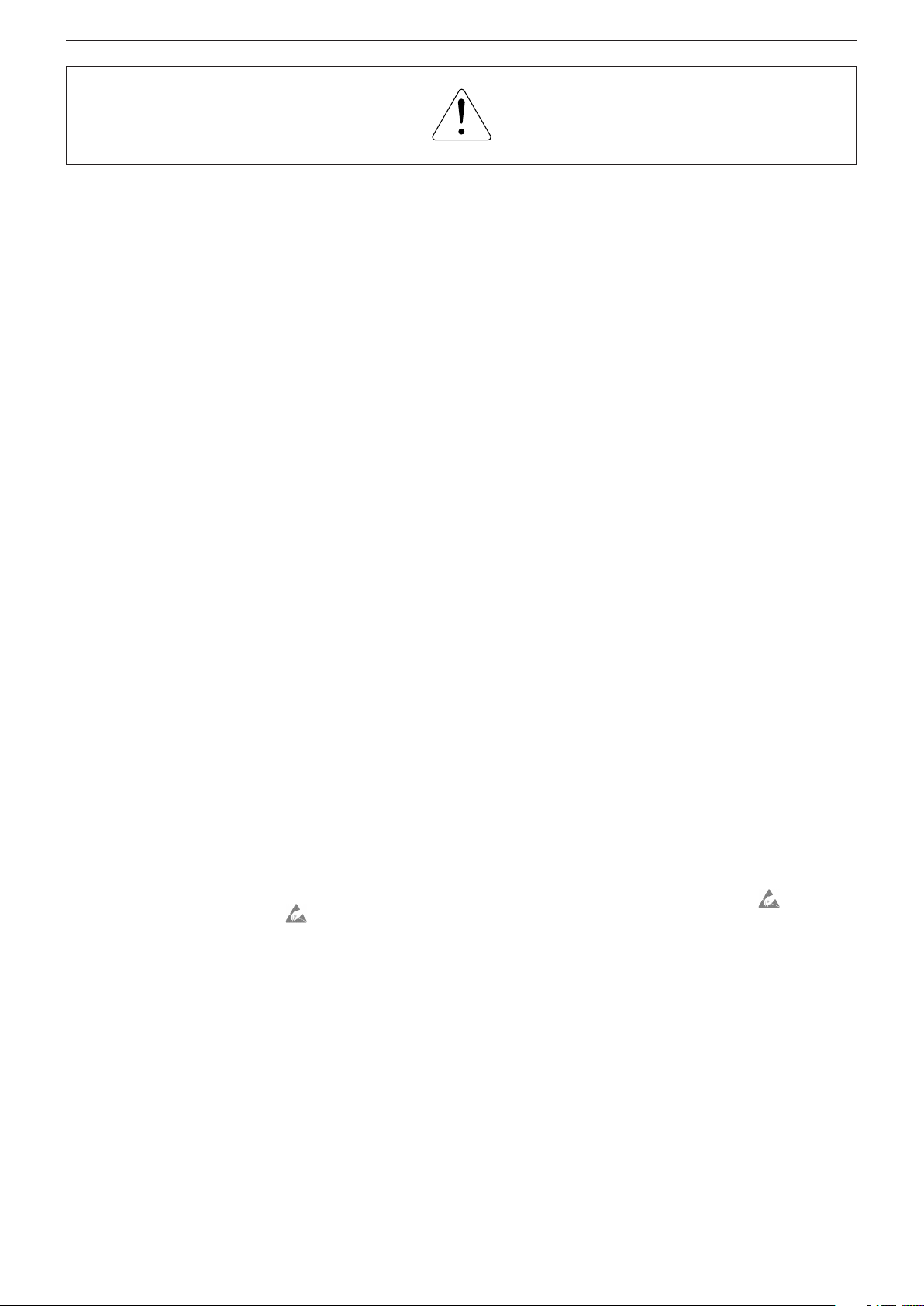
Displayvarianten
Je nach Verfügbarkeit werden Displays verschiedener Hersteller eingebaut. Dies führt zu unterschiedlichen Chassis-Bestückungen, sowie
zu Änderungen in der Software. Bei
Ersatzteilbestellungen und Software-Updates achten Sie bitte auf
das eingebaute Display, sowie auf
den "Product Code". Angaben dazu
finden Sie auf der Geräterückseite.
Sollte in der Ersatzteilliste Ihr "Product Code" oder Ihre Displayvariante nicht aufgeführt sein, können Sie
eine aktualisierte Version auf dem
GRUNDIG Service-Portal "http://
service.grundig.de" finden.
Überprüfen Sie vor Austausch der
Hauptplatte, ob die Aufkleber der
Platinen identisch sind.
Display Variants
Depending on availability displays
of different manufacturer are built
in. This results in different chassis
mountings as well as a different
software. On spare parts orders as
well as software updates take care
of the fitted display as well as of the
"Product Code". Therefore you can
find information on the labels on the
rear side. If your "Product Code" or
display variant is not mentioned in
the spare parts list please have
look for a current version at the
GRUNDIG Service-Portal "http://
service.grundig.de".
Before changing the main board
please check whether the labels on
the boards are identical.
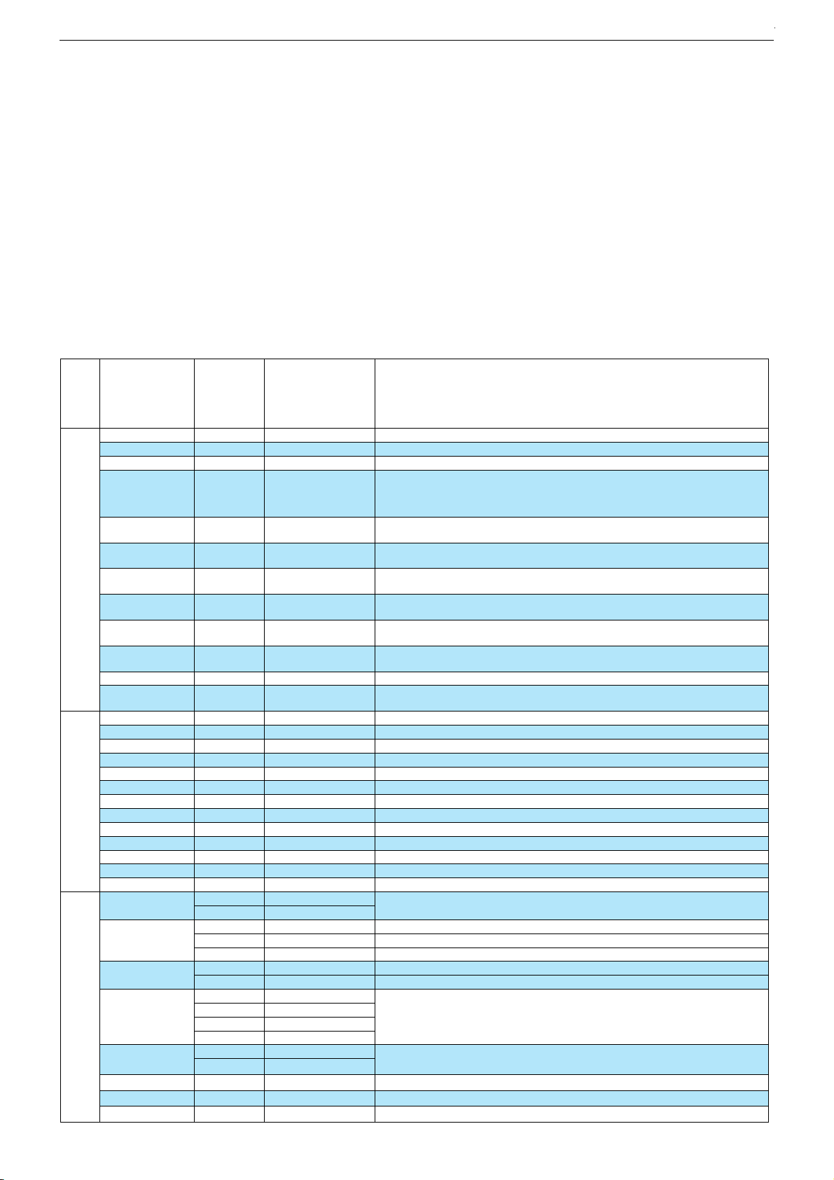
Technische Daten / Technical Data
Order No.
Develop. order No.
Destination
Approbations
IM-Languages
Remote control
EAN
Color
DISPLAY
Panel
16:9 wide-screen format
Response time
Brightness
Contrast ratio
Viewing angle ca.
Physical display resolution max. pixel
PICTURE
Reference Plus
Motion Adaptive Deinterlacing
Line Flicker Reduction
Digital Color Transition Improv. (DCTI)
Digital Combfilter
Digital Luminance Transition Improv. (DLTI)
Picture Noise Reduction (DNR)
CCS (Clear Color Screen)
Preset picture modes
Aspect ratios (Format switching)
Blackline detection
PIP
Multifold Tuner scan (Mosaic Picture)
PAT: Split screen (PICTURE + TEXT)
Lenaro 19 LCD 49-7710 BS
G.BF 45-00
CYC
CH, I, E,PL, H, CIS
CE, I, ME67
D, F, I, E, PL, H
TP 160 C
40 13833-60885 1
silver/black
19" / 49cm Active Matrix TFT-LC-Display
140° vertical / 160° horizontal
\
6ms
300cd/m2
700:1
XGA 1280 x 1024
\
\
\
\
[
\
\
\
user, natural, rich, soft
Auto (WSS), 4:3 / 16:9
\
\
\
\
3
Page 4
Chassis LHGRUNDIG Service
PAP: Double Window
P2AT: Double Window + TXT
POP: PICTURE on PICTURE
Picture freezing
Zoom with point function
Auto 16:9 selection via Scart
Sharpness control
Blue Background
CHASSIS
TV-Chassis
Progressive
Tuner
µ-Processor
Keyboard
ELECTRONIC
Stand by indicator
EPG (Electronic Programme Guide)
Easy Dialog
Megalogic
Manual & autom. labeling of prog.
Programmable off timer
Programmable on timer
Intelligent channel search (Zapping funct.)
Programme Edit
Intelligent Programme Switch
Auto switch off
Programme memory TV/AV (opt.)
Teletext/Fasttext/Toptext
Teletext options
Childlock
Menue languages OSD
Service mode
Hotel mode
TUNING
Autom. Tuning System with country selection
Frequency Based Auto Search
Automatic Micro-search
Automatic Programming
Manual fine tuning
Direct channel selection
Direct frequency selection
PAL/SECAM/BG/DK/I/L'/L
NTSC-Playback via Scart (3,58/4,43)
Cable TV / Hyperband (S1-S41)
AUDIO
Mono/Stereo/Nicam
AV Stereo
Loudspeaker
Virtual Dolby
Magic Fidelity Sound System
Matched Sound Delay (Lip synchronous)
Subwoofer
Dynamic Bass
DSP (Digital Sound Processor)
Balance Adjustment
AVL (Audio Volume Level)
PIP listening via Headphone.jack
Equalizer
Space Sound Effect
Audio mode
Audio amplifier
POWER SUPPLY / CABINET
Power voltage
Power switch
Integrated supply
Plug-in AC adaptor
Power consumption
Cabinet (WxHxD, cm) / Weight
FRONT PANEL CONNECTIONS
Headphones
Cinch-AV socket
S-Video
REAR PANEL CONNECTIONS
Euro-AV-Socket AV1
Euro-AV Socket AV2
Euro-AV Socket AV3
S-Video
Camera-AV
Wireless
YUV input / progressive
PC-input
PC-Audio in
DVI
HDMI
HD ready including HDCP
Headphones
Audio out
Antenna for terrestrial reception
DC-connector
Power supply plug
(PICTURE + PICTURE)
Lenaro 19 LCD 49-7710 BS
PLL frequency synthesizer tuning
6 keys: menue, ± for programme, ± for volume, AV/TV
22 languages, D, GB, F, I, E, P, NL, HR, RUS, GR, DK, S, FIN, N, TR, PL, CZ, SK, SLO, H, RO, BG
Simple hotel mode possible via service adjustment
cinema, music, sport, speech, user
2 x 5 / 10W (nominal/music)
53,5 x 47,6 x 9,5cm (19,6cm with stand) / ca. 7,5kg
3x Cinch - Video in, Audio in L/R (side)
CVBS in-/output, RGB input
1 x Coaxial-socket for TV-tuner-in, according to DIN 45325
\
\
\
\
\
[
[
[
LH
\
VCT-I
blue LED
\
\
\
[
[
[
[
[
\
\
99 / 5
[
/ [ /
\
10 pages
[
[
full automatic sorting
[
[
\
[
[
\
[
[
[
[
/ [ /
[
[
2 wide band lateral
\
\
\
\
\
\
[
\
\
5 Band
[
100 - 240V, 50/60Hz
[
[
\
ca. 45W, standby < 2W
[
, (side)
Hosiden (side)
CVBS in-/output
\
\
\
\
\
Multisync XGA
\
\
\
\
\
2 x Cinch
\
[
4
Page 5
AMIRA 17GRUNDIG Service
g
g
y
p
g
g
g
y p
p
)
Chassis LHGRUNDIG Service
Service- und Sonderfunktionen
Tastenfunktionen
i
OK
P+/P–
ǸǸ
ǸǸ
TXT
Service-Mode aktivieren
– Taste "
– Zahlenfolge "8500" eingeben. Auf dem Bildschirm wird das
– Service Menüs "ADJUSTMENTS" und "SELECTIONS" mit der
Service-Mode beenden
– Taste "
1. Grundeinstellwerte
Die Grundeinstellwerte im Service Mode sind in der Tabelle enthalten.
Aufrufen des Dialog Centers
Aufrufen der Service Menüs
Menü-Zeile (Menüpunkt) wählen
/ Ƿ Wert ändern
Beenden des Service Mode
i
" (INFO-Menü) drücken.
Service Menü "OPTIONS" und der Softwarestand angezeigt.
OK
Tast e "
Service
Menü
Menu
OK
" nacheinander aufrufen.
TXT
" drücken.
Menüpunkt
Point of Menu
P+ / P–
SCART 2
FAV
SVHS
HOTEL MODE
STBY RECALL
RECALL LAST AV
MSP CARRIER MUTE
OPTIONS
WSS RF
AUTO AV 16:9
FIRST ATS
BACKLIGHT POL
FACTORY MODE
WHITE R
WHITE G
WHITE B
BRI
CON
COL
PRESCALE FM
PRESCALE NICAM
PRESCALE SCART
ADJUSTMENTS
HOTEL VOLUME
AGC
FACTORY RESET
SW DOWNLOAD
TUNER TYPE
TELETEXT
TIMER MODE
MSP CLIP
SELECTIONS
SWAP/ZAPP
DOLBY VIRTUAL
LTI
CTI
Einstellung
Adjustment
Ǹ
/
Ƿ
SS_TECC2949
TH_CTF554X
FAST&TOP
FAST
NO TEXT
OFF TIMER
SLEEP TIMER
REDUCE VOL
REDUCE TONE
COMPROMISE
DYNAMIC
ZAPP
SWAP
Lenaro 19
LCD 49-7710 BS
ON
ON
ON
OFF
OFF
OFF
ON
ON
ON
OFF
POS
OFF
148
135
122
130
158
128
19
40
16
30
8 AGC-Abgleich / AGC adjustment
X FAST-Text
X Fester Ausschaltzeitpunkt / Fixed switch off timer
X
X
OFF
OFF
OFF
Scart 2 Buchse / Socket
Front-AV-Buchsen / Sockets
S-VHS-Buchse / Socket
Das Menü "SUCHEN / ABSTIMMUNG" ist nicht mehr aufrufbar. Die maximale Lautstärke ist be-
grenzt (siehe Service-Menü "ADJUSTMENTS" – "HOTEL VOLUME").
The "SETUP" Menu is not accessible. The maximum adjustable volume value is limited (see service menu "ADJUSTMENTS" – "HOTEL VOLUME").
OFF: Netz-Ein –> Standby / Power on –> standby
ON: Netz-Ein –> Pro
OFF: Netz-Ein –> Programm 1 / Power on –> Programme 1
ON: Netz-Ein –> zuletzt
Bei schlechtem Eingangs-Signal mutet der Sound-Prozessor MSP.
The Sound Processor MSP will mute the sound automaticall
Automatische Bild-Formatumschaltung auf 16:9 bei Empfang des "WSS"-Signales.
Automatic
Schaltspannung an Pin 8 der AV-Buchse schaltet automatisch auf das Bild-Format 16:9.
Volta
Beim nächsten Einschalten startet das Gerät mit ATS-Suchlauf.
Switchin
Intensität der Hinter
Service-Mode ist mit der Taste "SCAN" direkt aufrufbar.
Service mode was accessible b
Weißabgleich – Rot / White adjustment – red
Weißabgleich – Grün / White adjustment – green
Weißabgleich – Blau / White adjustment – blue
Grundeinstellwert für Helligkeit / Basic setting value for Brightness
Grundeinstellwert für Kontrast / Basic setting value for Contrast
Grundeinstellwert für Farbe / Basic setting value for Color
Grundlautstärke für FM-Ton / Basic setting value for FM sound
Grundlautstärke für NICAM-Ton / Basic setting value for NICAM sound
Grundlautstärke für SCART-Ton / Basic setting value for SCART sound
Maximale Lautstärke im Hotel-Mode / Hotel mode – volume maximum
Grundwerte werden geladen / Loading basic values
Software Download
Eingebauten Tuner wählen
Select used tuner
FAST & TOP-Text
Ausschaltzeit
MSP Sound-Optionen / Sound options MSP
Service and Special Functions
Functions of the buttons
i
OK
P+/P–
ǸǸ
ǸǸ
TXT
Calling up the Service Mode
– Press button "
– Enter the code number "8500". The Service Menu "OPTIONS"
– Step by step call up the Service Menu "ADJUSTMENTS" and
Exit the Service Mode
– Press button "
1. Basic Settings
The table shows all basic specific settings in the service mode.
icture format switching to 16:9 during "WSS" signal reception.
e at pin 8 of AV socket, picture format is switching to 16:9.
the unit on next time the ATS programming search starts automatically.
unkt in 15…120 Minuten / sleep timer (15…120 minutes
Call up the Dialog Center
Call up the Service Menus
Call up the dialogue line (point of menu)
/ Ƿ Changing the settings
Exit the Service Mode
i
" (INFO Menu).
and the software version number are shown on the screen.
OK
"SELECTIONS" with the button "
TXT
".
Hinweis
Hint
ramm 1 / Programme 1
esehenes AV-Programm / Power on –> last used AV programme
rundbeleuchtung / Intensity of backlight
ressing button "SCAN".
" .
if the signal quality is bad.
1 - 5
5
Page 6

AMIRA 17GRUNDIG Service
Chassis LHGRUNDIG Service
2. Austausch der Hauptplatte oder des U201
Nach dem Austausch der Hauptplatte oder des U201 sind Grundeinstellwerte im Service Mode entsprechend der Tabelle einzustellen.
3. Software-Versionsnummer
Die Software-Versionsnummer wird oben im Service-Menü angezeigt, z.B.:
L5CGNA_V1.43 - 01.11.2006
SLH20G-AU14715-T 43 -S 2
VCTI V 8 1
PVCS V 43
4. Programmsuchlauf
i
– Tast e "
– "SUCHEN / ABSTIMMUNG" mit den Tasten
" (INFO-Menü) drücken.
P+ / P–
anwählen
und mit der Taste "OK" bestätigen.
– "PROGRAMMSUCHLAUF" mit den Tasten
P+ / P–
anwählen und
mit der Taste "OK" bestätigen.
– Gewünschtes Land mit den Tasten
P+ / P–
, Ǹ / Ƿ auswählen und
mit der Taste "OK" bestätigen.
– Mit Taste "
OK
" Suchlauf starten.
Das automatische Sendersuchsystem stoppt bei jedem empfangswürdigen Sender (AFC und Koinzidenz) und speichert automatisch die entsprechenden Senderdaten mit dem jeweiligen
Standard. Danach wird der Suchlauf fortgesetzt.
Zum Abbrechen des Suchlaufes die blaue Taste drücken.
2. Change of the Main Board or U201
After changing the Main Board or U201 all basic settings in the service mode must be done according to the table.
3. Software Version Number
The software version number is shown on the upper part of the service menu, e.g.:
L5CGNA_V1.43 - 01.11.2006
SLH20G-AU14715-T 43 -S 2
VCTI V 8 1
PVCS V 43
4. Programme Search
i
– Press button "
– Select "SETUP" with the buttons
" (INFO Menu).
P+ / P–
and confirm with button
"OK".
– Select "STATION SEARCH" with the buttons
P+ / P–
and confirm
with button "OK".
P+ / P–
– Select the required Country with the buttons
, Ǹ / Ƿ and
confirm with button "OK".
– Start search with button "
OK
".
The autoprogrammes system stops at every station of acceptable
reception quality (AFC and coincidence) and stores the station
data and the respective standard automatically. The system then
continues searching.
Pressing the blue button stops the programme search.
1 - 6
6
Page 7
POWER
12V
3.3uH
L600
C602
100N
GND
C638
22N
GND
C600
100N
C601
100N
GND
GND
GND
R600
10K
GND
GND
C626
10N
D608
MBRS130LTR
R605
100R
C628
1000U16V
C603
100N
3.3uH
L601
C629
1000U16V
C604
100N
C625
10N
C636
1N5
GND
GND
GND
GND GND GND
TUNER_SU
10uH
L603
R603
10K
J600
0R
J601
0R
J602
0R
R602
10K
Q600
BC848B
C618
100N
GND
GND
5V_STBY
3V3_STBY
12V
C609
100N
C610
100N
C630
100U16V
C639
470U16V
IN
3
1
OUT
2
ADJ
U601 LM1117 3V3
5V_STBY
3V3_STBY
GND
GND
GNDGND
GND
S1
1
G1
2
S2
3
G2
4
D1
8
D1
7
D2
6
D2
5
U604
SI9933ADY
C622
100N
GND
2k
R604
C617
100N
GND
GND
5V
C621
100N
C615
100N
C616
100N
C631
100U16V
IN
3
1
OUT
2
ADJ
U603 LM1117 1V8
5V_STBY
1V8_STBY
GND
GND GND
GND GND
C632
100U16V
C619
100N
C633
100U16V
C620
100N
12V
8V
GND
GND
GND
GND
C623
100N
C624
100N
C634
100U16V
5V
3V3
GND
GND GNDGND GND
C635
100U16V
1K
R607
REGULATORS
PANELPWR
PNL_EN
STBY
5V_STBY
IN
3
2
OUT
1
GND
U605
MC78L08CP
12V INV_POW
4.7uH
L605
IN
3
1
OUT
2
ADJ
U606 LM1117 3V3
R601
18K
R608
56K
L609
22uH - CDRH104R
TP274
STBY2
STBY2
Significant for 26"-27"-30" chassis
4.7uH
L602
12V AMP_POW
GND
9
BS
1
VIN
2
OUT
3
GND
4
FB
5
COMP
6
EN
7
SS
8
U600
MP1593
GND
GND
3.3V_W
GND
C641
100N
C640
100U16V
GND
GND
C643
100N
C642
100U16V
GND GND
5V_W
3.3V_W
5V_LIPS
S1
1
G1
2
S2
3
G2
4
D1
8
D1
7
D2
6
D2
5
U602
SI9933ADY
Q602
BC848
R611
5.6k
R612
5.6K
R614
680R
5V_STBY
12V
C646
100N
J603
0R
C644
100nF
2k
R609
GND
C645
100nF
GND
5V_W
R610
1k
3
0
1
2
IN
OUT
OUT
GND
U610
NCP1086D2T-33R4G
1
2
3
4
CON610
J604
0R
FIT J603 & J604 if wireless
STBY
33V
L607
47uH
L606
47uH
Q604
BC848B
C611
10U/10V
C612
4N7 / 50V
C613
100N
C607
220pF / 50V
C614
4N7 / 50V
C608
33N / 50V
R619
22R 1/16W
R616
3K 1/16W
47R
R617
Q_Base
Q_Base
GND
1 2
3
D600
BAV99L
5V_STBY
L604
Ferrite Bead
GND
R620
470R
GND
DO NOT FIT DC-DC BLOCK, IF 20" LIPS USED
DC-DC BLOCK
*10uH option
C637
470U25V
GND
C685
47U25V
POWER INPUT FOR 14-20
1
2
S600
option
from JP204
Inverter
Interface
from JP204
Inverter
Interface
3V3
from JP204
Inverter Interface
MOLCON2
S601
CONN-POWER
GND
12V INPUT
F600
FUSE 5A
12V
12V_IN
J688
0R
L688
10uH
C627
470U25V
GND
C688
100N
GND
option
option
1
1
30
31
º
⁄
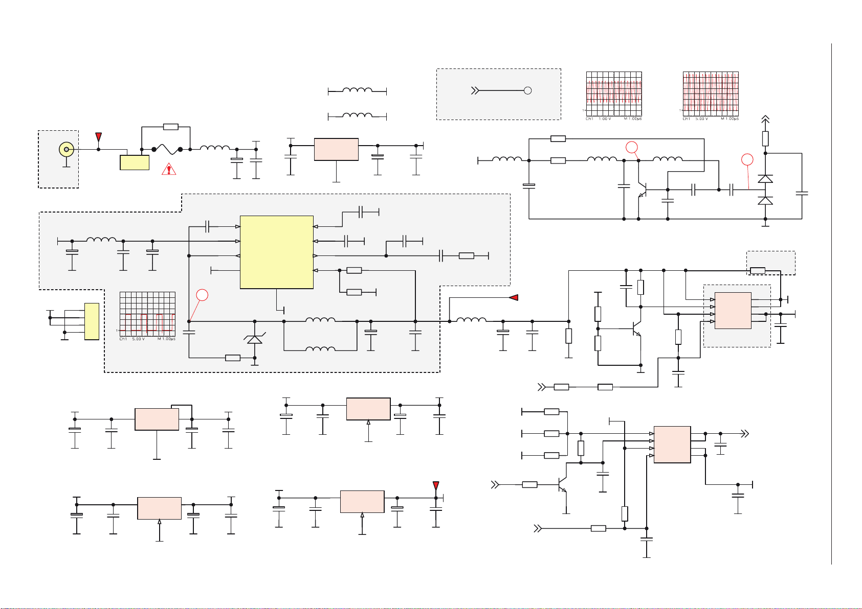
Schaltpläne und Platinenabbildungen / Circuit Diagrams and Layout of the PCBs
Spannungsversorgung / Power Supply - X1P.190
GRUNDIG Service Chassis LH
7
Page 8
GRUNDIG Service Chassis LH
VDD1V8D
1V8_STBY
1V8_STBY
VDD1V8FE
3V3_STBY
VDD3V3FE
3V3_STBY
VDD3V3IO
3V3
3V3
VDD3V3D
VDD3V3BE
5V
VDD5VFE
5V
VDD5VIF
5V
VDD5VBE
3V3
VDD3V3DAC
C411
3.3U50V
L300
10uH
L301
10uH
L310
10uH
L302
10uH
L303
10uH
L304
10uH
L306
10uH
L305
10uH
L307
10uH
L308
10uH
C341
10U25V
C300
100N
C337
470P
GND
C342
10U25V
C301
100N
C371
1N
GND
C344
10U25V
C338
470P
GND
C345
10U25V
C303
100N
GND
GND
GND
GND
GND
GND
C346
10U25V
C304
100N
C348
10U25V
C339
470P
C305
100N
C350
10U25V
C306
100N
C354
10U25V
C307
100N
C358
10U25V
C340
470P
GND
R345
100R
R346
100R
C334
22U50V
C333
22U50V
C378
1N
C380
1N
C379
1N
C381
1N
GND
GND
GND
GND
AOUT1L
AOUT1R
C377
1N
R354
470R
C418
330P
C399
220N
C376
1N
R353
470R
C417
330P
C398
220N
GND
GND
GND
GND
R2N
I
A
AIN2L
C332
100N
C402
100N
GND
R373
75R
GND
GND
R371
75R
R372
75R
GND
GND
SVHS_C
SVHS_Y
GND
C329
100N
RCA_CVBS
C383
1N
R356
470R
C420
330P
C401
220N
C382
1N
R355
470R
C419
330P
C400
220N
GND
GND
GND GND
GND
C421
1N
C422
1N
C403
220N
C404
220N
RCA_LEFT
RCA_RIGHT
SC2_I_L
SC2_I_R
AOUT2R
GND
GND
5V
VDD5VAUD
L311
10uH
GND
C314
100N
C360
10U25V
175mA
225mA
48mA
11mA
95mA
25mA
65mA
18mA
26mA
150mA
12V
12V-A
C359
10U25V
GND
C311
100N
C312
100N
L316
10uH
125mA
Q314
BC337-16
R383
220R
J316
0R
C384
47U16V
GND
D302
BZX84C12 SOT23
GND
D303
SOD80
This circuit is used for 15V panels.
Otherwise the jumper is mounted.
R363
75R
R374
180R
R375
150R
R351
470R
R300
10K
R361
18K
Q303
BC858B
Q307
BC848
5V
GND
GND
C343
10U25V
VOUT1
C323
100N
R364
75R
R376
180R
R377
150R
R352
470R
R301
10K
R362
18K
Q304
BC858B
Q308
BC848
5V
GND
GND
C324
100N
C347
10U25V
VOUT2
R365
75R
R367
75R
R368
75R
R369
75R
C318
100N
C319
100N
C320
100N
BIN
GIN
RIN
GND
GND
GND
GND
R323
10K
R322
10K
Q309
BC848
VDD3V3D
GND
C321
100N
GND
FBLIN
J306
0R
FBLIN
SC1_FBL
Optional
L317
10uH
L319
10uH
C386
47P
C387
47P
GND
GND
Close to VCTi
Close to VCTi
L323
10uH
L324
10uH
1
2
3
4
5
6
7
JP300
MOLCON7
Option for Side AV
SVHS_C_AV
SVHS_Y_AV
GND
CVBS_AV
RIGHT_AV
GND
LEFT_AV
CVBS_AV
LEFT_AV
RIGHT_AV
SC1_FBL
SC1_CVBS_OUT
SC1_RED
SC1_GREEN
SC1_BLUE
SC1_IN_L
SC1_IN_R
SC1_OUT_L
SC1_OUT_R
SC2_CVBS_OUT
SC2_IN_L
SC2_IN_R
J312
J308
J311
GND
GND
GND
GND
GND
GND
2341
4
3
2
1
Gnd
0
J307
CONN-DIN4
GND
1K
R423
1K
R424
C470
470P
C471
470P
SVHS_Y_AV
SVHS_C_AV
AO_R
1
AIN_R
2
AO_LM
3
AGND
4
B_GND
5
AIN_L
6
B
7
SWTCH
8
G_GND
9
CLKOUT
10
G
11
DATA
12
R_GND
13
D_GND
14
R
15
BLNK
16
V_GND
17
BL_GND
18
VOUT
19
VIN
20
SHIELD
21
S301
SCART1
AO_R
1
AIN_R
2
AO_LM
3
AGND
4
B_GND
5
AIN_L
6
B
7
SWTCH
8
G_GND
9
CLKOUT
10
G
11
DATA
12
R_GND
13
D_GND
14
R
15
BLNK
16
V_GND
17
BL_GND
18
VOUT
19
VIN
20
SHIELD
21
S303
SCART2
GND
GND
GND
R324
3K3
GND
GND
GND
GND
GND
GND
R366
75R
GND
GND
GND
GND
GND
GND
GND
GND
GND
R370
75R
GND
R333
3K3
GND
R386
10K
R387
10K
DATA
CLKOUT
SC1_PIN8
SC2_PIN8
SC1_CVBS_IN
SC1_CVBS_OUT
SC1_FBL
SC1_RED
SC1_GREEN
SC2_CVBS_IN
SC1_BLUE
SC1_IN_R
SC1_IN_L
SC1_OUT_R
SC1_OUT_L
SC2_CVBS_OUT
SC2_IN_L
SC2_IN_R
SC2_OUT_L
SC2_OUT_R
SCART INTERFACE
2
power on (trigger: +12V)
2
switch on with RC
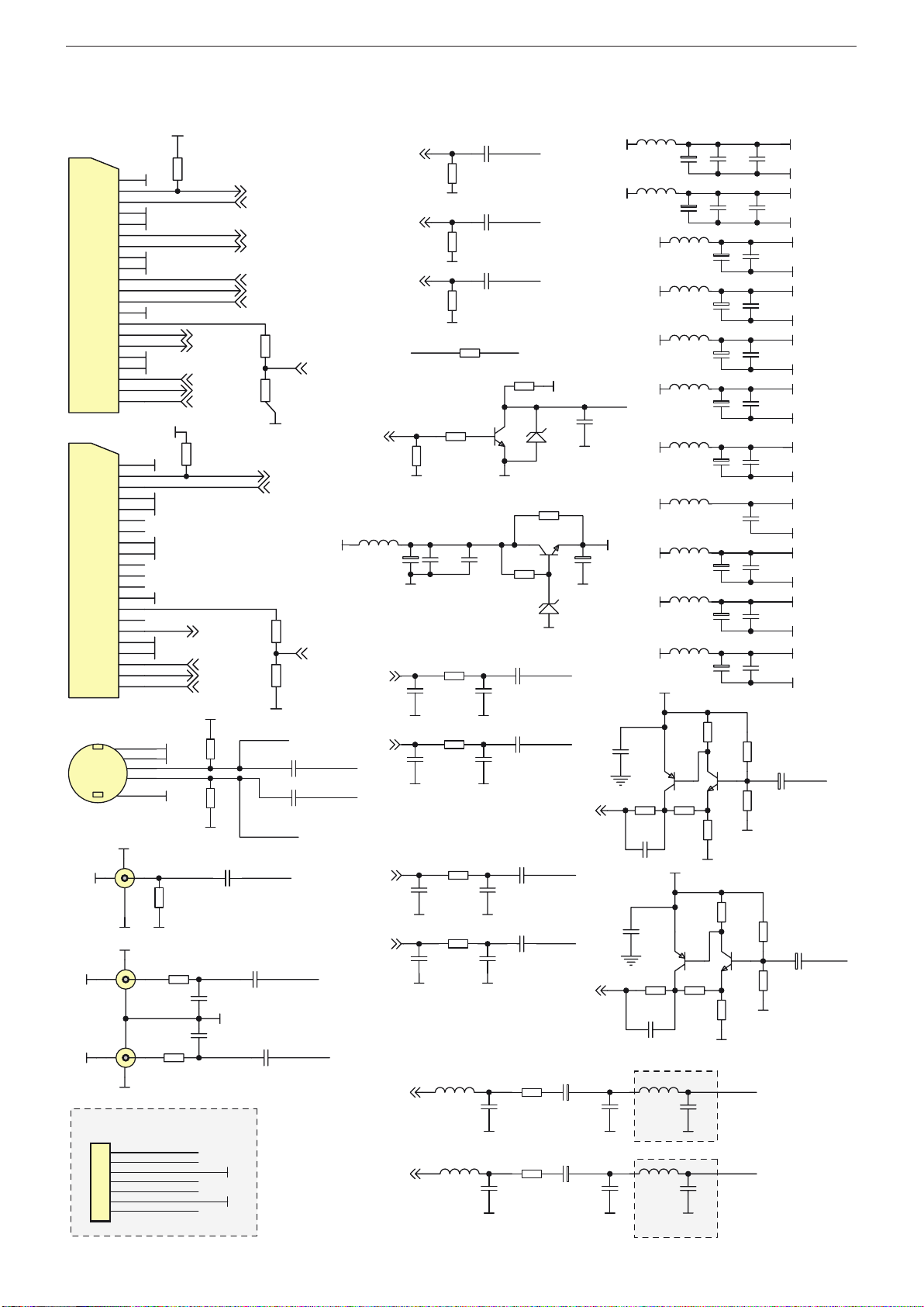
IN/OUT, VCT-IF - X1P.190
8
Page 9
GND
1
VSUP8.0AU
2
VREFAU
3
SPEAKERL
4
SPEAKERR
5
AOUT1L
6
AOUT1R
7
AIN3L/AOUT2L
8
AIN3R/AOUT2R
9
AIN2L
10
AIN2R
11
AIN1L
12
SIF/AIN1R
13
TAGC
14
VREFIF
15
IFIN-
16
IFIN+
17
RESETQ
18
VSUP5.0FE
19
VSUP5.0IF
20
VSUP3.3DIG
21
GND
22
GND
23
VSUP1.8DIG
24
XTAL1
25
XTAL2
26
P22
27
P23
28
VIN11
29
VIN10
30
VIN9
31
VIN8
32
VIN7
33
VIN6
34
VIN5
35
VIN4
36
VIN3
37
VIN2
38
VIN1
39
VOUT1
40
VOUT2
41
VOUT3
42
VSUP1.8FE
43
GND
44
GND
45
VSUP3.3VFE
46
P10
47
P11
48
P12
49
P13
50
P14
51
P15
52
P16
53
P17
54
P20
55
P21
56
SCL
57
SDA
58
VPROT
59
HOUT
60
HFLB
61
SAFETY
62
GNDDAC
63
VSUP3.3DAC
64
VSUP3.3IO
65
GND
66
GND
67
VSUP3.3BE
68
XREF
69
VRD
70
BOUT
71
GOUT
72
ROUT
73
SVMOUT
74
BIN
75
GIN
76
RIN
77
FBIN
78
GNDM
79
SENSE
80
RSW1
81
RSW2
82
EW
83
VERT-
84
VERT+
85
TEST/SUBW
86
VSUP5.0BE
87
GND
88
U303
VCT-IF PSSDIP88(2)
C308
100N
C411
3.3U50V
1K
R358
GND
GND
Y300
20.25MHz
C413
22P
C414
22P
GND
GND
GND
GND
GND
GND
GND
GND
GND
VDD1V8D
VDD1V8FE
VDD3V3FE
VDD3V3IO
VDD3V3D
VDD3V3BE
VDD5VFE
VDD5VIF
VDD5VBE
8V
VDD3V3DAC
C310
100N
GND
VCT-IF
AOUT1R
AOUT1L
AIN2L
AIN2R
SPEAKERL
SPEAKERR
RIN
GIN
BIN
SVHS_C
SVHS_Y
RCA_CVBS
FBLIN
AIN1L
AIN1R
AOUT2L
AOUT2R
VOUT1
VOUT2
C444
47U16V
C392
1N
C393
1N
R402
330R
1K
R360
Q306
BC858B
R336
3K3
C442
47U16V
R400
330R
C389
1N
GND
GND
GND
GND
8V
GND
AOUT2L
C443
47U16V
C390
1N
C391
1N
R401
330R
1K
R359
Q305
BC858B
R335
3K3
C441
47U16V
R399
330R
C388
1N
GND
GNDGND
GND
8V
GND
AOUT2R
GND
UART_RX
UART_RX
C313
100N
C412
4.7U50V
GND
GND
VDD5VBE
GND
GND
GND
GND
GND
GND
GND
GND
GND
GND
GND
GND
VCT-IF AND PERIPHERALS
SDA3V3
SCL3V3
UART_TX
R337
3K3
R338
3K3
3V3_STBY
UART_TX
UART_RX
HS_VCT
VS_VCT
RESETQ
BLUE
GREEN
RED
BLUE_VCT
GREEN_VCT
RED_VCT
SUBWOOFER
Q201
2N7002
Q200
2N7002
R233
3K3
R234
3K3
R202
10K
R203
10K
J224
0R
J225
0R
3V3_STBY
5V_STBY
SCL3V3
SDA3V3SDA5V
SCL5V
SPEAKERL
SPEAKERR
C316
100N
C322
100N
C356
10U25V
C309
100N
GND
GND
GND
Q311
BC858ALT1
Q310
BC848
8V
GND
C327
100N
R325
22R
R329
2K7
12
3
D301
BAV99L
R326
33R
C335
560P
BLUE
R330
150R
VDD5VBE
VDD5VBE
R347
270R
GND
Q312
BC858ALT1
R327
33R
C336
560P
GREEN
R331
150R
VDD5VBE
R348
270R
GND
Q313
BC858ALT1
R328
33R
C363
560P
RED
R332
150R
VDD5VBE
R357
270R
GND
J3140R
J315
0R
J3050R
GND
C385
47U16V
GND
IFIN+
IFIN-
AGC
L309
8.2uH
L318
10uH
L321
10uH
A connector for the
Light Sensor option.
L314 Ferrite Bead
L315
Ferrite Bead
1
2
S304
SC1_CVBS_IN
SC2_CVBS_IN
SC2_OUT_L
SC2_OUT_R
3
4
1
2
J310
3
4
1
2
J309
GND
GND
GND
GND
SAFETY
C423
33P
GND
75R
R433
75R
R432
C473 100N
C472 100N
W_SVIDEO_C_OUT
W_SVIDEO_Y_OUT
C689
22N
GND
6k8
R422
VDD5VFE
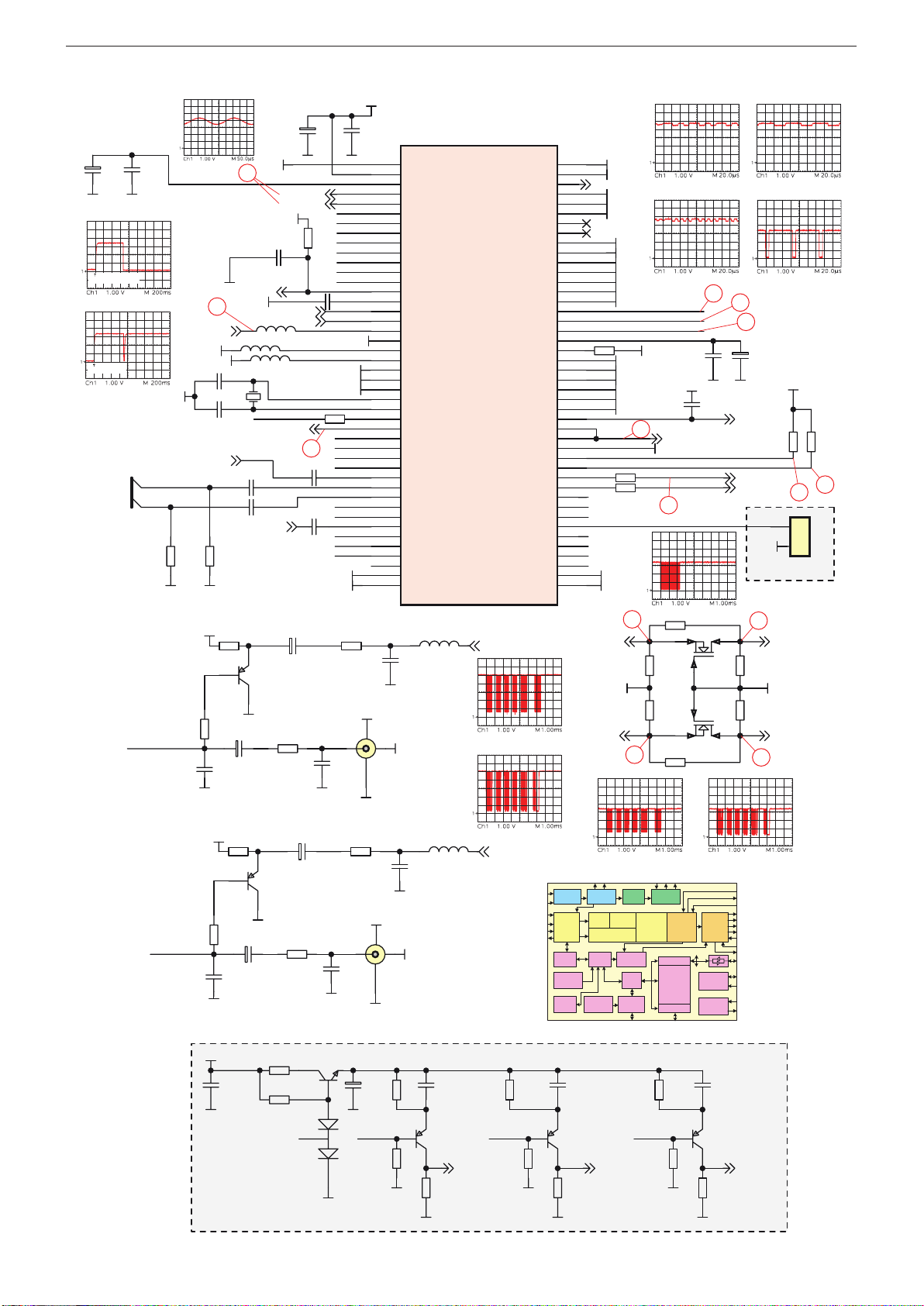
XTAL1
IF
Frontend
Slicer
Video
Backend
IF
Processor
Sound
Demod.
Audio
Processor
Display
Generator
Bus
Arbiter
20k BX
RAM
256kB
ProgROM
Clock
Generator
Reset &
TestLogic
I2C
24kB
CharROM
TEST
RESETQ
XTAL2
I2C
Pxy
CVBS in
IFIN-
IFIN+
T
A
G
C
S
IF
YCrCb in
CVBS out
RGB in
A
OU
T
S
P
E
A
K
E
R
RGB out
SVM
RGB in
SENSE
RSW
VERT
EW
HOUT
PROT
HFLB
Panorama
Scaler
Display
&
Deflection
Processor
Timer
CRT/PWM
ADC/UART
Watchdog
RTC
I/O-Ports
Memory
Interface
ADB, DB, PSENQ,
PSWEQ, WRQ, RDQ
CPU
8051
A
IN
Video
Frontend
Color
Decoder
Component
Interface
Comb
Filter
26
2
10
11
12
13
9
6
5
7
5
3
4
6
2
power on (trigger: +12V)
#
9
7
4
3
5 6
!
@
2
switch on with RC
§
GRUNDIG Service Chassis LH
IN/OUT, VCT-IF - X1P.190
9
Page 10

VGA - Eingang und RGB-Umschalter / VGA Input and RGB Switches - X1P.190
GND
1 2
3
D404
BAV99L
1 2
3
D402
BAV99L
GND
GND
GND
A0
1
A1
2
A2
3
VSS4SDA
5
SCL
6
WP
7
VCC
8
U400
HT24LC02
1N4148
D400
5V_STBY
5V
5V
C446
100N
GND
R420
47K
R421
47K
1
2
3
4
5
6
7
8
9
10
11
12
13
14
15
1617
P400
DB15HF
R412
100R
R413
100R
GND
1 2
3
D405
BAV99L
1 2
3
D401
BAV99L
1 2
3
D403
BAV99L
J402
0R
J401
0R
J400
0R
J406
0R
J403
0R
R417
75R
R415
75R
R416
75R
GND
GND
5V
RED_DSUB RED_SW
GND
5V
GND
GREEN_SWGREEN_DSUB
GND
5V
GND
BLUE_DSUB BLUE_SW
R403
10K
VS_DSUB
HS_DSUB
HS_SW
VS_SW
EDID
VGA
DDC_SDA_VGA
DDC_SCL_VGA
GND
J407
0R
J404
0R
J409
0R
J408
0R
J405
0R
DS_SV
DS_S
H
RED_SD RED_SW
GREEN_SD GREEN_SW
BLUE_SD BLUE_SW
1
2
3
4
5
6
7
8
9
10
11
12
13
14
15
S400
GND
AUDIO_R_SD
AUDIO_L_SD
BLUE_SD
GREEN_SD
RED_SD
HS_SD
VS_SD
AUDIO_R_SD
AUDIO_L_SD
UART_TX
UART_RX
Optional MCR Socket
5V_STBY
3V3_STBY
R677
75R
R678
75R
R679
75R
GND
J677
0R
J6780R
J679
0R
3V3_STBY
L400
10uH
3V3_RGB
C448
100N
GND
C464
10U25V
GND
C449
100N
C450
100N
C451
100N
GND
GND GND
C452
100N
C453
100N
C454
100N
C455
100N
GND
GND GND GND
Optional for 2nd RGB
switch.
10
GRUNDIG Service Chassis LH
Page 11

GRUNDIG Service Chassis LH
R408
47R
R406
47R
R410
47R
C462
10N
R414
470R
C460
10N
C459
10N
C457
10N
R418
75R
R419
75R
R404
10K
R405
10K
GND
GND
C465
22P
C466
22P
GND
GND
R407
47R
R409
47R
R411
47R
GND
C458
10N
C461
10N
C463
10N
VDD
1
YA
2
GND
3
VDD
4
YB
5
YC
6
GND
7
YD
8
VDD
9
GND
10
YE
11
SEL
12
E1
13
E0
14
D1
15
C1
16
D0
17
C0
18
VDD
19
GND
20
B1
21
B0
22
A1
23
A0
24
U401
PI3V512
VDD
1
YA
2
GND
3
VDD
4
YB
5
YC
6
GND
7
YD
8
VDD
9
GND
10
YE
11
SEL
12
E1
13
E0
14
D1
15
C1
16
D0
17
C0
18
VDD
19
GND
20
B1
21
B0
22
A1
23
A0
24
U402
PI3V512
GND
3V3_RGB
GND
GND
GND
RED_SD
RED_DSUB
GREEN_SD
GREEN_DSUB
BLUE_SD
BLUE_DSUB
HS_SD
HS_DSUB
VS_SD
VS_DSUB
C447
100N
GND
VS_SW
3V3_RGB
3V3_RGB
3V3_RGB
HS_SW
BLUE_SW
GREEN_SW
RED_SW
C456
100N
GND
RED_SW
GREEN_SW
BLUE_SW
HS_SW
VS_SW
GND
GND
GND
GND
3V3_RGB
3V3_RGB
3V3_RGB
3V3_RGB
VS_G
HS_G
BLUE_G
GREEN_G
RED_G
VS_VCT
HS_VCT
VS_G
HS_G
BLUE_G
GREEN_G
RED_G
TO GENESIS
RGB SWITCHES
2nd RGB Switch
VS_VCT
HS_VCT
BLUE_VCT
GREEN_VCT
RED_VCT
S1_MAIN_SW
PC_SD_SW
HS_PC
HS_PC
VS_PC
VS_PC
RED-
RED+
GREEN-
GREEN+
SOG_MCSS
BLUE+
BLUE-
BLUE+
BLUE-
SOG_MCSS
GREEN+
GREEN-
RED+
RED-
L401
3.3uH
R425
75R
C467
330P
GND
L402
3.3uH
R426
75R
C468
330P
GND
L403
3.3uH
R427
75R
C469
330P
GND
PI3V512
SEL
2
5
6
8
11
12
OUT_A
OUT_B
OUT_C
OUT_D
OUT_E
24
23
22
21
18
17
16
15
14
13
A0
A1
B0
B1
C0
D0
C1
D1
E0
E1
18
17
16
15
14
*
&
^
%
$
VGA - Eingang und RGB-Umschalter / VGA Input and RGB Switches - X1P.190
11
Page 12

2Y1
1
2Y0
2
3Y1
3
3Z
4
3Y0
5
E6VEE7GND
8
S3
9
S2
10
S1
11
1Y0
12
1Y1
13
1Z
14
2Z
15
VCC
16
U301
CD4053
GNDGNDGND
12V-A
C349
10U25V
C352
10U25V
R305
10K
R303
10K
12V-A
GND
R307
10K
R306
10K
12V-A
GND
GND
GND
R309
10K
R308
10K
12V-A
GND
R312
10K
R311
10K
12V-A
GND
C355
10U25V
C357
10U25V
C353
10U25V
C351
10U25V
R339
100R
R340
100R
R310
10K
12V-A
Q300
BC848B
GND
MR_R
MR_L
J302
0R
J303
0R
MR_L
MR_R
RCA_LEFT
2Y1
1
2Y0
2
3Y1
3
3Z
4
3Y0
5
E6VEE7GND
8
S3
9
S2
10
S1
11
1Y0
12
1Y1
13
1Z
14
2Z
15
VCC
16
U302
CD4053
GND
GND
GND
12V-A
C361
10U25V
C364
10U25V
R314
10K
R313
10K
12V-A
GND
MR_R
R316
10K
R315
10K
12V-A
GND
GND
GND
R318
10K
R317
10K
12V-A
GND
R321
10K
R320
10K
12V-A
GND
C366
10U25V
C367
10U25V
MR_L
R319
10K
12V-A
Q301
BC848B
GND
SC2_I_L
Optional
R382
4K7
R384
4K7
RCA_S2_S
C325
100N
C326
100N
GND
GND
SC2_I_R
RCA_RIGHT
RCA_LEFT
AUDIO_L_SD
AUDIO_R_SD
Optional
MEMCRD_RCA_S
J300
0R
J301
0R
MR_R
MR_L
AIN1R
AIN1L
AUDIO SWITCHES
C365
10U25V
C362
10U25V
R343
100R
R344
100R
AIN1L
AIN1R
VEE
7
X0
X1
13
X
14
Y0
2
Y1
1
Y
15
VSS
8
Z
4
Z1
3
Z0
INHIBIT
6
VDD
16
A
11
B
10
C
9
U310
MC14053
GND
12V-A
R430
10K
12V-A
Q315
BC848B
R429
4K7
GND
Wireless_Aud_SW_Ctrl
Wireless_I2C_SCL
Wireless_I2C_SDA
W_IR_VIN
W_AUDIO_R_OUT
W_AUDIO_L_OUT
W_SVIDEO_C_OUT
W_SVIDEO_Y_OUT
1
2
3
4
5
6
7
8
9
10
11
12
13
14
15
16
17
18
19
20
21
22
23
24
25
26
CON311
24-pin FPC Connector
GND
1
2
3
4
5
6
7
8
9
10
11
12
13
14
15
16
17
18
19
20
21
22
CON310
20-pin FPC Connector
J398
0R
J399
0R
Aud_Direct_R
Aud_Direct_L
AIN1R_bfr
AIN1L_bfr
Aud_Direct_R
Aud_Direct_L
AIN1L_bfr
AIN1R_bfr
12
5
W_AUDIO_L_OUT
W_AUDIO_R_OUT
R436
10k/ 1/16W
R434
10k / 1/16W
R435
10k / 1/16W
R437
10k / 1/16W
GND
12V-A
12V-A
GND
Audio - Umschalter / Switches - X1P.190
GRUNDIG Service Chassis LH
12
Page 13

GRUNDIG Service Chassis LH
C503
100N
5V
C523
470N
C524
470N
C532
1UF25V
AUVDD
053516
L504
22UH
053516
L505
22UH
C518
22N
C516
22N
C520
22N
C504
100N
C517
22N
C519
22N
R504
100R
R503
100R
C513
22N
C511
22N
C515
22N
C502
100N
C512
22N
C514
22N
R502
100R
R501
100R
053516
L502
22UH
053516
L503
22UH
L500
BK1608HM601
12V
C500
100N
C501
100N
C507
100U50V
C508
100U50V
C521
470N
C522
470N
C525
470N
C526
470N
C530
100P
C531
100P
1
2
3
4
S500
MOLCON4
SPEAKERL
SPEAKERR
AMP_EN
AMP_EN
AUVDD
5V
J500 0R
J501 0R
J502 0R
J503 0R
5V
5V
GND
GND
GND
GND
GND
GND
GND
GND
GND
GND
GND
GND
GND
GND
GND
GNDGND
GND
GND
GND
AUDIO AMP
PGND1PGND
2
VDD3VDD
4
CIN
5
CIP
6
CHOLD
7
NC
8
INL-
9
INL+
10
SHDN
11
SS
12
AGND
13
REG
14
INR-
15
INR+
16
GAIN1
17
GAIN2
18
FS1
19
FS2
20
VDD21VDD
22
PGND23PGND
24
OUTR-
25
OUTR-
26
OUTR+
27
OUTR+
28
OUTL-
29
OUTL-
30
OUTL+
31
OUTL+
32
GND
0
U501
MAX9704
GND
MAX9704
INL+10
1 2 3 4 21 22 23 24
9
19
11
17
18
12
13 AGND
14
6
5
20
INL-
FS1
FS2
G1
G2
SS
REG
MODULATOR
OSCILLATOR
CHARGE PUMP
C1P
C1N
GAIN
CONTROL
SHUTDOWN
CONTROL
SHDN
H-BRIDGE
OUTL+
OUTL+
OUTL-
OUTL-
32
31
30
29
PGND VDDVDDPGND
CHOLD
7
INR+
15
16
INR-
MODULATOR
H-BRIDGE
OUTR+
OUTR+
OUTR-
OUTR-
28
27
26
25
26
26
27
27
28
§ ≥ •
C406
2N2
GND
R381
4K7
C407
2N2
C408
2N2
C397
220N
GND GND
C368
100U16V
C369
100U16V
C372
1N
C373
1N
GND
GND
1
2
3
S300
GND
GND
OUTA
1
INA(NEG)
2
INA(POS)
3
VSS
4
INB(POS)
5
INB(NEG)
6
OUTB
7
VDD
8
U300
TDA1308
GND
C315
100N
VDD5VAUD
C302
100N
GND
VDD5VAUD
R302
10K
R304
10K
C370
100U16V
GND
GND
C394
1N5
R378
5K6
C395
1N5
R379
5K6
R380
4K7
C405
2N2
C396
220N
GND
SPEAKERL
SPEAKERR
HEADPHONE
Audio - Verstärker / Amplifier - X1P.190
13
Page 14

SUBWOOFER
NC
1
PIN1
2
NIN1
3
AGND1
4
NC
5
EN1
6
NIN2
7
PIN2
8
AGND2
9
EN2
10
NC
11
BS2
12
VPP2
13
SW2
14
PGND2
15
NC
16
BS1
17
VPP1
18
SW1
19
PGND1
20
U500
MP7731
L501
BK1608HM601
C535
1UF25V
C536
1UF25V
D502
BZX84C6V2
D503
BZX84C6V2
D501
IMBD4148
D500
IMBD4148
R507
20K
R508
20K
SUBVCC
C509
1000U25V
C510
1000U25V
R510
10R
SUBVCC
R511
10R
C539
390P
C540
390P
D504
MBRS130LTR
D505
MBRS130LTR
10uH
L506
10uH
L507
C527
470N
C529
470N
C537
15P
C538
15P
R505
150K
R506
150K
C528
470N
C534
1UF25V
C533
1UF25V
R509
180K
R500
10K
SUBWOOFER
AMP_EN
C506
2N2
C505
2N2
1
2
S501
MOLCON2
GND
GND
GND
GND
R513
100K %1
R512
100K %1
C541
CAP4.7U50V
GND
GND
SUBVCC
REF
REF
REF
AMP_POW
GND
GND
GND
GND
GND
GND GND
GND
GND
Audio - Subwoofer - X1P.190
GRUNDIG Service Chassis LH
14
Page 15

GRUNDIG Service Chassis LH
Y200
14.318MHz
C251
5PF
C252
5PF
ROM_ADDR0
ROM_ADDR1
ROM_ADDR2
ROM_ADDR3
ROM_ADDR4
ROM_ADDR5
ROM_ADDR6
ROM_ADDR7
ROM_ADDR8
ROM_ADDR9
ROM_ADDR10
ROM_ADDR11
ROM_ADDR12
ROM_ADDR13
ROM_ADDR14
ROM_ADDR15
ROM_ADDR16
ROM_ADDR17
R204
10K
R205
10K
R206
10K
R207
10K
R208
10K
R209
10K
R210
10K
R211
10K
R213
10K
R214
10K
R215
10K
R216
10K
R217
10K
R219
10K
R220
10K
R222
10K
R224
10K
ROM_ADDR0
ROM_ADDR1
ROM_ADDR2
ROM_ADDR3
ROM_ADDR4
ROM_ADDR5
ROM_ADDR6
ROM_ADDR7
ROM_ADDR8
ROM_ADDR9
ROM_ADDR10
ROM_ADDR11
ROM_ADDR12
ROM_ADDR13
ROM_ADDR14
ROM_ADDR15
ROM_ADDR16
R225
10K
ROM_ADDR17
3V3AVDD
3V3DVDD
1V8AVDD
1V8CVDD
3V3DVDD
CE
1
SO
2
WP
3
VSS
4
VCC
8
HOLD
7
SCK
6
SI
5
U203
25VF040
R231
10K
3V3DVDD
ROMCS
ROMWE
ROMWOE
ROM_ADDR15
ROMCS
3V3DVDD
R230
10K
C242
100N
GND
ROM_ADDR16
ROM_ADDR17
R227
10K
R228
10K
R229
10K
3V3DVDD
250R%1
R237
3V3AVDD
3V3AVDD
3V3_STBY
C247
22U50V
C212
100N
L200
10uH
3V3AVDD
C200
100N
C201
100N
C202
100N
C203
100N
C204
100N
C205
100N
C206
100N
C207
100N
C208
100N
C209
100N
C210
100N
C211
100N
C243
220P
3V3_STBY
C248
22U50V
C222
100N
L201
10uH
3V3DVDD
C213
100N
C214
100N
C215
100N
C216
100N
C217
100N
C218
100N
C219
100N
C220
100N
C221
100N
1V8_STBY
C249
22U50V
C232
100N
L202
10uH
1V8CVDD
C223
100N
C224
100N
C225
100N
C226
100N
C227
100N
C228
100N
C229
100N
C230
100N
C231
100N
C244
220P
1V8_STBY
C250
22U50V
C238
100N
L203
10uH
1V8AVDD
C233
100N
C234
100N
C235
100N
C236
100N
C237
100N
C245
220P
C246
220P
5V_STBY
GM2221
1
2
3
4
S202
MTA100_4
5V_STBY
R201
10K
R200
10K
GND
GND
GND
GND
GND
GND
GND
GND
SCALER
BOOTSTRAP CONFIGURATION
SPI FLASH
C253
10N
GND
UART_TX
UART_RX
DDC_SCL_VGA
DDC_SDA_VGA
UART_TX
UART_RX
DDC_SCL_VGA
DDC_SDA_VGA
RESETQ
RESETQ
BLUE+
BLUE-
SOG_MCSS
GREEN+
GREEN-
RED+
REDHS_PC
VS_PC
Q206
2N7002
Q205
2N7002
CLKOUT
DATA
5V_STBY
5V_STBY
R242
10K
R244
10K
J231
0R
SC_UPDT_CTR
SC_UPDT_CTR
SC_UPDT_CTR
SCL5V
SDA5V
5V_STBY
R243
10K
5V_STBY
R245
10K
C256
220N
GND
Should be close to VCT-IF
R24710K R248
GND GND
SW201
1
2
3
4
5
6
7
8
JP202
MOLCON8
1
2
3
4
5
6
7
JP203
MOLCON7
J2340RJ233
100R
3V3_STBY
GND
GND
LED1
IR
1K
R258
3V3_STBY
KEYBOARD
GND GND
LED2
KEYBOARD I/F
R256
10K
R255
100R
R246
10K
Q207
BC848B
GND
J227
0R
3V3_STBY
IR
IR_INV
Q302
BC848B
R398
27K
R334
10K
GND
MUTE
AMP_EN
5V
J232
0R
Optional
R260 10K
3V3_STBY
R265
10K
GND
GND
1 2
3
D201
BAV99L
1 2
3
D200
BAV99L
R273
10K
GND
3V3
5V
ROM_DATA3
1
ROM_DATA2
2
ROM_DATA1
3
ROM_DATA0
4
ROM_OEn
5
ROM_WEn
6
ROM_CSn
7
CVDD_1.8
9
VCO_LV/RESERVED
AVDD_LV_E_3.3
11
AVSS_LV_E
12
AVSS_LV_E
23
AVDD_LV_E_3.3
24
AVSS_LV
25
AVDD_lv_3.3
26
AVDD_LV_O_3.3
27
AVSS_LV_O
28
AVSS_LV_O
39
AVDD_LV_O_3.3
40
CVDD_1.8
41
RVDD_3.3
50
N/C52N/C53N/C
54
STI_TM2/RESERVED
HOST_SDA/UART_DO
72
RVDD_3.3
73
CVDD_1.8
75
HOST_SCL/UART_DI
71
DDC_SCL_VGA
77
DDC_SDA_VGA
78
DDC_SCL_DVI
79
DDC_SDA_DVI
80
CVDD_1.8
86
RVDD_3.3
95
CVDD_1.8
96
GPIO16/VDATA7
102
GPIO17/VDATA6
103
N/C
104
GPIO18/VDATA5
106
GPIO19/VDATA4
107
GPIO20/VDATA3
108
GPIO21/VDATA2
109
GPIO22/VDATA1
110
GPIO23/VDATA0
111
VCLK
112
AVDD_IMB_3.3
113
REXT
114
AGND_IMB
115
VDD_RX2_1.8
116
AGND_RX2
117
RX2+
118
RX2-
119
AVDD_RX2_3.3
120
VDD_RX1_1.8
121
AGND_RX1
122
RX1+
123
RX1-
124
AVDD_RX1_3.3
125
VDD_RX0_1.8
126
AGND_RX0
127
RX0+
128
RX0-
129
AVDD_RX0_3.3
130
AGND_RXC
131
RXC+
132
RXC-
133
AVDD_RXC_3.3
134
VBUFC_DVI/RESERVED
GND_RXPLL
136
VDD_RXPLL_1.8
137
CLKOUT/RESERVED
138
CVDD_1.8
139
AVDD_BLUE_3.3
141
BLUE+
142
BLUE-
143
AGND_BLUE
144
AVDD_GREEN_3.3
145
SOG_MCSS
146
GREEN+
147
GREEN-
148
AGND_GREEN
149
AVDD_RED_3.3
150
RED+
151
RED-
152
AGND_RED
153
AVDD_ADC_3.3
154
ADC_TEST/RESERVED
155
AGND_ADC
156
VDD_ADC_1.8
164
VDD_RPLL_1.8
166
RESERVED/VBUFC_RPLL
AGND_RPLL
168
XTAL
169
TCLK
170
AVDD_RPLL_3.3
171
LBADC_VDD_3.3
172
LBADC_GND
177
RESETn
178
CVDD_1.8
179
HSYNC/CSYNC
181
VSYNC
182
ROM_ADDR17
183
ROM_ADDR16
184
ROM_ADDR15
185
ROM_ADDR14
186
ROM_ADDR13
187
ROM_ADDR12
188
ROM_ADDR11
189
RVDD_3.3
190
ROM_ADDR10
192
ROM_ADDR9
193
ROM_ADDR8
194
ROM_ADDR7
195
ROM_ADDR6
196
ROM_ADDR5
197
ROM_ADDR4
198
ROM_ADDR3
199
ROM_ADDR2
200
ROM_ADDR1
201
ROM_ADDR0
202
ROM_DATA7
203
ROM_DATA6
204
RVDD_3.3
205
ROM_DATA5
207
ROM_DATA4
208
U200
GM2221_1
*DO NOT FIT R247
Wireless_Aud_SW_Ctrl
* FIT R260
R431
1k2
W_IR_VIN
1K5
R431
X1P.190R-2
10k / 1/16W
W_IR_VIN
Q432
BC848B
GND
C259
10NF
7
2
18
17 16
14
15
GM5221
GM2221
GPIO
Analog
RGB
Triple
ADC&PLL
X86
Micro-controller
External
ROM I/F
Image Capture /
Measurement
XTAL
Clock
Generation
On-chip
RAM
/ ROM
Ultra-
Reliable
DVI Rx
HDCP
DVI
(only
GM5221)
OSD
Controller
NVRAM
Display
Timing
Control
Test
Pattern
Generator
BT 656
2 X
LVDS
Tx
3 X General-
Purpose ADC
4 X
PWM
Intelligent Image Processing™
Zoom / Shrink Filter
with edge enhancement
uv
Y
Digital Color Adjustments
Reset CCT
422 to 444
Conversion
High-light Window
Color Look-up-Table
ACC
Luma
Shaping
ACM-II
Chroma
Adjust
Histogram
Color Space Conversion
DDC2Bi
Schmitt
Trigger
DDC2Bi
Resetn
Serial
Master
GPIO
Parallel or Serial
EEPROM
Keyp
ad Sensing
Temp Sensor
RGB/YUV Color Space Conversion
7
2
power on (trigger: +12V)
2
switch on with RC
$
%
^
&
*
¡
™
£
only for LVDS interface
≤
only for LVDS interface
∞
only for LVDS interface
Scaler - X1P.190
15
Page 16

GRUNDIG Service Chassis LH
1V8AVDD
1V8CVDD
R232
47R
CLK
GM2221
GND
GND
R235
100R
R236
100R
VCC
8
WP
7
SCL
6
SDA
5
A0
1
A1
2
A2
3
GND
4
U201
24LC16
GND
3V3_STBY
C239
100N
NVRAM
PNL_EN
S1_MAIN_SW
PC_SD_SW
LED1
LED2
MEMCRD_RCA_S
RCA_S2_S
SCL3V3
SDA3V3
GND
1
2
3
4
S204
MOLCON4
SCL3V3
SDA3V3
5V
GND
R24710K R248
10K
R249 10K
R251
10K
R252
10K
GND GND
GND GND
GND
R253
4K7
R254
4K7
3V3_STBY
R257
100R
STBY
IR_INV
KEYBOARD
MUTE
SC1_PIN8
SC2_PIN8
RESETQ
Optional
J235
0R
R260 10K
3V3_STBY
R26110K
3V3_STBY
3V3_STBY
3V3_STBY
R262 10K
R264
10K
BKL_EN
BRT_ADJ
PANELCTRL
DE
HS
VS
J238
0R
SAFETY
J237
0R
SAFETY
C257
22P
GND
C258
22P
GND
STBY2
R274
4K7
R276
4K7
Q208
BC848
R277
4K7
J236
0R
3V3_STBY
GND
C258_A
22P
GND
C257_A
22P
GND
1
2
3
4
5
6
7
8
9
V1
VIDA
1
2
3
4
5
6
7
8
9
V2
VIDA
1
2
3
4
5
6
7
8
9
V3
VIDA
1
2
3
4
5
6
7
8
9
V4
VIDA
GND
GND
GND
GND
CRVSS
8
CVDD_1.8
9
VCO_LV/RESERVED
10
CH3P_LV_E/ER0
13
CH3N_LV_E/ER1
14
CLKP_LV_E/ER2
15
CLKN_LV_E/ER3
16
CH2P_LV_E/ER4
17
CH2N_LV_E/ER5
18
CH1P_LV_E/ER6
19
CH1N_LV_E/ER7
20
CH0P_LV_E/EG0
21
CH0N_LV_E/EG1
22
CH3P_LV_O/EG2
29
CH3N_LV_O/EG3
30
CLKP_LV_O/EG4
31
CLKN_LV_O/EG5
32
CH2P_LV_O/EG6
33
CH2N_LV_O/EG7
34
CH1P_LV_O/EB0
35
CH1N_LV_O/EB1
36
CH0P_LV_O/EB2
37
CH0N_LV_O/EB3
38
CVDD_1.8
41
CVSS
42
EB4
43
EB5
44
EB6
45
EB7
46
DEN
47
DHS
48
DVS
49
CRVSS
51
N/C52N/C53N/C
54
DCLK
55
OR0/JTAG_RESET
56
OR1/RESERVED
57
OR2/RESERVED
58
OR3/RESERVED
59
OR4/RESERVED
60
OR5/RESERVED
61
OR6/RESERVED
62
OR7/RESERVED
63
OG0/JTAG_TDO
64
OG1/RESERVED
65
OG5/JTAG_TDI
66
PPWR
67
PBIAS
68
GPIO15
69
STI_TM2/RESERVED
70
CRVSS
74
CVDD_1.8
75
CRVSS
76
GPIO0
81
GPIO1
82
GPIO2
83
GPIO3
84
GPIO4
85
GPIO5
88
GPIO6
89
GPIO7/IRQin
90
GPIO8/IRQout
91
GPIO9/SCL
92
GPIO10/SDA
93
CVDD_1.8
86
CRVSS
87
CRVSS
94
CVDD_1.8
96
CRVSS
97
GPIO11/PWM0
98
GPIO12/PWM1
99
GPIO13/PWM2
100
GPIO14/PWM3
101
N/C
104
N/C
105
VDD_RX2_1.8
116
VDD_RX1_1.8
121
VDD_RX0_1.8
126
VBUFC_DVI/RESERVED
135
VDD_RXPLL_1.8
137
CVDD_1.8
139
CRVSS
140
N/C
157
N/C
158
N/C
159
N/C
160
N/C
161
N/C
162
GND_ADC
163
VDD_ADC_1.8
164
GND_RPLL
165
VDD_RPLL_1.8
166
RESERVED/VBUFC_RPLL
167
LBADC_IN1
173
LBADC_IN2
174
LBADC_IN3
175
LBADC_RETURN
176
CVDD_1.8
179
CRVSS
180
CRVSS
191
CRVSS
206
U200
GM2221_1
*DO NOT FIT R247
Wireless_Aud_SW_Ctrl
*DO NOT FIT R248
Wireless_I2C_SCL
* FIT R260
*DO NOT FIT R249
Wireless_I2C_SDA
R250
10K
GND
R263
10K
3V3_STBY
*FIT R262*FIT R261
1
2
3
4
5
6
7
8
9
10
11
12
13
14
15
16
17
18
19
20
S201
20 PIN LVDS
GND
GND
GND
GND
GND
GND
GND
RG200
RG47R
RG201
RG47R
RG202
RG47R
RG203
RG47R
RG204
RG47R
ER0
ER1
ER2
ER3
ER4
ER5
ER6
ER7
EG0
EG1
EG2
EG3
EG4
EG5
EG6
EG7
EB0
EB1
EB2
EB3
PANELCTRL
PANELCTRL
VS
HS
DE
DE
HS
VS
PANELPWR
PANELPWR
PANELPWR
PIN29
PIN30
PIN31
PIN32
PIN33
PIN34
PIN35
PIN36
PIN37
PIN38
1
2
3
4
5 6
7
8
9 10
11 12
13
14
15 16
17 18
19 20
21 22
23 24
25
26
27 28
29 30
31 32
33 34
35 36
37 38
39 40
JP200
HEADER2X20
RWPLENAPRWPLENAP
ER0
ER1
ER2
ER3
ER4ER5
ER6
ER7
EG0EG1
EG2EG3
EG4EG5
EG6
EG7
EB0EB1
EB2EB3
EB4
EB5
EB6EB7
DE
HS
VS
CLK
GND
3V3 3V3
5V 5V
EB4
EB5
EB6
EB7
RG205
RG47R
PIN43
PIN44
PIN45
PIN46
LVDS INTERFACE
J210
0R
J211
0R
J212
0R
J213
0R
J214
0R
J215
0R
J216
0R
J217
0R
J218
0R
J219
0R
J220
0R
J221
0R
J222
0R
J223
0R
PIN29
PIN30
PIN31
PIN32
PIN33
PIN34
PIN35
PIN36
PIN37
PIN38
J201
0R
J200
0R
J202
0R
J203
0R
J204
0R
J205
0R
J206
0R
J207
0R
J208
0R
J209
0R
TXE_3P
TXE_3N
TXCLKEP
TXCLKEN
TXE_2P
TXE_2N
TXE_1P
TXE_1N
TXE_0P
TXE_0N
GND
GND
GND
GND
GND
GND
GND
EB0
EB1
EB2
EB3
EG0
EG1
EG2
EG3
EG4
EG5
EG6
EG7
ER0
ER1
ER2
ER3
ER4
ER5
ER6
ER7
PANELPWR
C690
1000U16V
GND
1
2
3
4
5
6
7
8
9
10
11
12
13
14
15
16
17
18
19
20
21
22
23
24
25
26
27
28
29
30
0
S200
PCB X1P.190R-2
GND
22 21 20
19
6
5
2
24
2523
GM5221
GM2221
LVDS
Panel I/F
X86
Micro-controller
External
ROM I/F
On-chip
RAM
/ ROM
OSD
Controller
Display
Timing
Control
2 X
LVDS
Tx
3 X General-
Purpose ADC
4 X
PWM
Back-light
Audio
Intelligent Image Processing™
Zoom / Shrink Filter
with edge enhancement
uv
Y
Digital Color Adjustments
High-light Window
Color Look-up-Table
ACC
Luma
Shaping
ACM-II
Chroma
Adjust
Histogram
Color Space Conversion
Parallel or Serial
EEPROM
Keyp
ad Sensing
Temp Sensor
RGB/YUV Color Space Conversion
2
power on (trigger: +12V)
2
switch on with RC
5
6
(
)
¡
™
£
only for LVDS interface
≤
only for LVDS interface
∞
only for LVDS interface
Scaler - X1P.190
16
Page 17

GRUNDIG Service Chassis LH
J318
0R
J317
0R
L313 1uH
X6966D
1
2
3
4
5
SAW300
IF1
IF2
GND
330nF
C330
GND
33V
R341
100R
R342
100R
J304
0R
GND
TUNERS
J313
0R
D300
GND
33V
33V
C409
CAP100U50V
IFIN-
IFIN+
AGC
SDA5V
SCL5V
GND
5V
L312
coilrad10
C410
100U10V
C317
100N
GNDGND
R388
56R
GND
AGC
1
TU
2
AS
3
SCL
4
SDA
5
UB
6
VCC+5V
7
NC
8
VT
9
IF2
10
IF1
11
GND
12
GND
13
GND
14
GND
15
TU351
CTF5540
AGC
1
TU
2
ADD
3
SCL
4
SDA
5
NC
6
VCC+5V
7
NC/ADC
8
VST
9
IF2/NC
10
IF1
11
GND
12
GND
13
GND
14
GND
15
TU300
ENV57K##08G3F
AGC
1
TU
2
AS
3
SCL
4
SDA
5
NC
6
VCC+5V
7
NC/ADC
8
VST
9
NC
10
IF1
11
GND
12
GND
13
GND
14
GND
15
TU301
DTQS441IH241C
GND GND GND
GND
5k6
R699
47k
R698
L698
10uH
100R
R700
100k
R696
8
4
3
8
4 3
1
2
3
4
5
6
7
8
9
10
11
12
S203
MOLCON12
1
2
3
4
5
6
7
JP201
MOLCON7
GND
4.7uH
L205
C255
1000U16V
C254
22U50V
C241
100N
R238
470R
R212
10K
1K
R239
Q202
BC848B
GND
5V
GND
GND
J226
0R
R223
10K
R226
10K
1K
R241
1K
R240
J228
0R
Q203
BC848B
Q204
BC848B
GND
5V
5V
GND
INV_POW
BKL_EN
BRT_ADJ
INVERTER INTERFACE FOR 14-20
1
2
3
4
5
6
7
JP204
LIPS_PWR
J230
0R
J229
0R
12V_IN
GND
to S600
Power Switch
5V_LIPS
to L601
Power Supply
3V3
to Power Supply
option
Tuner - X1P.190
Inverter Interface (14"-20") - X1P.190
17
Page 18

Chassisplatte / Chassis Board - X1P.190R-3
18
Sicht auf Bestückungsseite / View on Component Side
GRUNDIG Service Chassis LH
Page 19

GRUNDIG Service Chassis LH
Chassisplatte / Chassis Board - X1P.190R-3
Sicht auf Bestückungsseite / View on Component Side
19
Page 20

GRUNDIG Service Chassis LH
Chassisplatte / Chassis Board - X1P.190R-3
Sicht auf Bestückungsseite / View on Component Side
20
Page 21

Chassisplatte / Chassis Board - X1P.190R-3
21
Sicht auf Lötseite / View on Solder Side
GRUNDIG Service Chassis LH
Page 22

GRUNDIG Service Chassis LH
Chassisplatte / Chassis Board - X1P.190R-3
Sicht auf Lötseite / View on Solder Side
22
Page 23

GRUNDIG Service Chassis LH
Chassisplatte / Chassis Board - X1P.190R-3
Sicht auf Lötseite / View on Solder Side
23
Page 24

GRUNDIG Service Chassis LH
Koordinaten für die Bauteile der Chassisplatte X1P.190R-3 (* Bauteile der Lötseite)
Coordinates of the Components of Chassis Board X1P.190R-3 (* components of Solder Side)
Pos.-Nr./ Koordinaten/
Pos. No. Coordinates
X Y
C200 136 99
C201 137 95
C202 140 99
C203 143 99
C204 153 95
C205 161 99
C206 151 95
C207 131 91
C208 142 95
C209 158 89
C210 155 95
C211 161 101
C212 134 99
C213 120 127
C214 120 125
C215 161 139
C216 113 107
C217 120 117
C218 120 123
C219 153 138
C220 174 149
C221 120 119
C222 159 139
C223 105 129
C224 113 104
C225 117 116
C226 117 118
C227 168 99
C228 138 87
C229 119 130
C230 161 143
C231 107 129
C232 113 122
C233 134 91
C234 135 95
C235 164 101
C236 164 99
C237 139 95
C238 138 99
C239 120 116
C241 55 155
C242 163 143
C243 156 89
C244 114 122
C245 136 87
C246 136 91
C247 152 90
C248 166 150
C249 165 134
C250 143 90
C251 164 103
C252 161 103
C253 109 123
C254 62 157
C255 35 149
C256 107 123
C257 90 105
C257_A* 91 106
C258 91 108
C258_A* 91 109
C259 178 163
C300 83 73
C301 103 73
C302 41 145
C303 83 107
C304 80 73
C305 88 51
C306 80 70
C307 73 106
C308 51 84
C309 53 75
C310 72 72
C311 33 98
C312 30 98
C313 77 107
C314 56 138
C315 49 142
C316 42 130
C317 36 74
Pos.-Nr./ Koordinaten/
Pos. No. Coordinates
X Y
C318 18 133
C319 18 139
C320 21 139
C321 22 143
C322 56 104
C323 15 84
C324 19 91
C325 25 109
C326 82 41
C327 119 50
C329 101 73
C330 28 68
C332 86 13
C333 17 111
C334 28 123
C335 114 89
C336 114 67
C337 99 61
C338 109 107
C339 81 107
C340 86 107
C341 98 56
C342 107 57
C343 24 136
C344 96 119
C345 82 120
C346 85 60
C347 24 87
C348 78 113
C349 83 20
C350 75 54
C351 90 20
C352 84 46
C353 76 24
C354 74 120
C355 76 16
C356 57 69
C357 77 45
C358 86 113
C359 40 94
C360 61 136
C361 43 121
C362 36 121
C363 108 66
C364 22 116
C365 39 102
C366 24 97
C367 21 104
C368 37 133
C369 37 140
C370 61 142
C371 108 62
C372 30 129
C373 33 142
C376 14 131
C377 14 126
C378 18 124
C379 15 102
C380 15 119
C381 28 118
C382 15 75
C383 15 73
C384 49 97
C385 117 45
C386 19 100
C387 37 127
C388 18 67
C389 15 71
C390 69 74
C391 30 11
C392 67 74
C393 13 11
C394 44 132
C395 45 147
C396 52 132
C397 56 142
C398 18 130
C399 22 124
C400 19 79
Pos.-Nr./ Koordinaten/
Pos. No. Coordinates
X Y
C401 19 77
C402 88 13
C403 44 11
C404 58 11
C405 52 134
C406 47 134
C407 51 142
C408 53 138
C409 48 72
C410 38 69
C411 51 79
C412 68 113
C413 91 67
C414 91 71
C417 18 128
C418 22 126
C419 15 80
C420 19 75
C421 37 11
C422 51 11
C423 92 103
C441 24 71
C442 24 79
C443 30 93
C444 39 86
C446 153 9
C447 122 31
C448 136 34
C449 121 69
C450 125 71
C451 123 68
C452 122 34
C453 123 36
C454 136 25
C455 136 28
C456 126 89
C457 136 80
C458 136 78
C459 136 76
C460 136 74
C461 136 71
C462 136 69
C463 136 67
C464 119 23
C465 134 87
C466 134 84
C467 120 79
C468 120 76
C469 124 73
C470 14 154
C471 15 97
C472 176 160
C473 93 74
C500 87 145
C501 70 141
C502 68 160
C503 73 142
C504 85 161
C505 163 40
C506 166 36
C507 70 134
C508 82 133
C509 162 30
C510 181 30
C511 65 163
C512 69 164
C513 68 158
C514 71 160
C515 71 158
C516 82 159
C517 80 159
C518 85 159
C519 89 161
C520 89 159
C521 75 138
C522 77 133
C523 81 139
C524 78 137
C525 85 138
Pos.-Nr./ Koordinaten/
Pos. No. Coordinates
X Y
C526 88 138
C527 177 6
C528 161 6
C529 165 6
C530 75 130
C531 90 138
C532 72 140
C533 160 36
C534 156 40
C535 174 25
C536 169 25
C537 183 21
C538 159 21
C539 177 18
C540 170 18
C541 168 45
C600 180 80
C601 180 78
C602 167 78
C603 180 60
C604 185 41
C607 97 42
C608 99 41
C609 122 54
C610 137 64
C611 112 37
C612 100 46
C613 96 33
C614 97 40
C615 172 99
C616 166 84
C617 98 140
C618 95 128
C619 65 74
C620 53 73
C621 103 140
C622 103 129
C623 59 130
C624 71 106
C625 180 74
C626 166 70
C627 112 29
C628 174 53
C629 176 40
C630 133 44
C631 171 94
C632 161 82
C633 65 69
C634 68 125
C635 59 108
C636 180 76
C637 156 72
C638 170 80
C639 143 61
C640 176 131
C641 177 136
C642 184 131
C643 184 137
C644 176 152
C645 171 129
C646 176 156
C685 152 64
C688 116 33
C689 71 74
C690 113 129
CON310 168 165
CON311 169 165
CON610 181 141
D200 11 115
D201 11 103
D300 44 67
D301 114 54
D302 45 104
D303 18 142
D400 154 13
D401 125 19
D402 143 9
D403 129 19
Pos.-Nr./ Koordinaten/
Pos. No. Coordinates
X Y
D404 143 13
D405 133 19
D500 179 22
D501 164 22
D502 174 22
D503 169 22
D504 174 13
D505 168 13
D600 98 37
D608 165 74
F600 98 28
J200 151 138
J201 150 142
J202 149 138
J203 148 142
J204 146 138
J205 145 142
J206 144 138
J207 143 142
J208 142 138
J209 141 142
J210 140 138
J211 138 142
J212 137 138
J213 136 142
J214 135 138
J215 134 142
J216 133 138
J217 132 142
J218 130 138
J219 129 142
J220 128 138
J221 127 142
J222 126 138
J223 125 142
J224 119 61
J225 129 61
J226 57 155
J227 98 107
J228 55 151
J229 185 38
J230 63 163
J231 122 99
J232 107 126
J233 89 132
J234 90 135
J235 117 123
J236 121 89
J237 88 105
J238 88 108
J300 39 107
J301 35 90
J302 74 35
J303 82 25
J304 30 68
J305 110 107
J306 14 145
J307 87 5
J308 43 5
J309 29 5
J310 15 5
J311 57 5
J312 71 5
J313 80 67
J314 107 107
J315 114 99
J316 45 86
J317 70 67
J318 70 65
J398 165 155
J399 160 163
J400 129 28
J401 131 28
J402 133 28
J403 126 28
J404 142 28
J405 142 25
J406 124 28
Pos.-Nr./ Koordinaten/
Pos. No. Coordinates
X Y
J407 142 23
J408 142 19
J409 142 21
J500 91 155
J501 93 155
J502 89 155
J503 87 155
J600 95 134
J601 95 132
J602 95 130
J603 165 50
J604 176 147
J677 151 23
J678 151 20
J679 151 17
J688 105 27
JP200 105 147
JP201 31 159
JP202 83 125
JP203 84 125
JP204 185 63
JP300 153 34
L200 163 92
L201 171 151
L202 153 82
L203 138 91
L205 43 154
L300 103 65
L301 103 51
L302 91 119
L303 87 119
L304 90 54
L305 73 112
L306 90 49
L307 81 52
L308 69 119
L309 116 92
L310 91 112
L311 56 133
L312 41 77
L313 80 62
L314 81 55
L315 90 60
L316 45 82
L317 15 101
L318 15 66
L319 34 128
L321 15 69
L323 15 124
L324 15 121
L400 120 29
L401 117 79
L402 118 76
L403 121 73
L500 66 139
L501 156 45
L502 70 146
L503 68 153
L504 75 155
L505 83 154
L506 179 13
L507 163 12
L600 145 70
L601 182 47
L602 148 47
L603 173 68
L604 118 36
L605 27 144
L606 102 38
L607 106 37
L609 173 65
L688 111 20
L698 31 75
P400 124 11
Q200 122 64
Q201 126 64
24
Page 25

GRUNDIG Service Chassis LH
Koordinaten für die Bauteile der Chassisplatte X1P.190R-3 (* Bauteile der Lötseite)
Coordinates of the Components of Chassis Board X1P.190R-3 (* components of Solder Side)
Pos.-Nr./ Koordinaten/
Pos. No. Coordinates
X Y
Q202 58 151
Q203 52 155
Q204 52 150
Q205 11 107
Q206 11 111
Q207 97 111
Q208 121 86
Q300 87 28
Q301 36 114
Q302 101 111
Q303 19 155
Q304 14 92
Q305 31 82
Q306 31 88
Q307 23 153
Q308 19 87
Q309 19 146
Q310 114 59
Q311 117 85
Q312 114 72
Q313 107 72
Q314 48 91
Q315 167 159
Q432 180 159
Q600 105 134
Q602 171 159
Q604 97 47
R200 112 118
R201 104 125
R202 126 61
R203 130 64
R204 165 130
R205 160 129
R206 165 128
R207 160 127
R208 165 126
R209 160 125
R210 165 124
R211 160 123
R212 62 150
R213 165 122
R214 160 121
R215 165 121
R216 160 120
R217 165 119
R219 160 118
R220 165 117
R222 160 115
R223 49 155
R224 165 114
R225 160 113
R226 47 151
R227 166 139
R228 160 111
R229 160 131
R230 166 143
R231 164 139
R232 121 130
R233 123 61
R234 118 64
R235 120 111
R236 120 109
R237 133 95
R238 62 152
R239 58 147
R240 49 151
R241 55 147
R242 14 115
R243 15 117
R244 15 104
R245 15 106
R246 100 107
R247 123 96
R248 126 99
R249 127 95
R250 130 99
R251 129 95
R252 132 99
Pos.-Nr./ Koordinaten/
Pos. No. Coordinates
X Y
R253 120 114
R254 120 107
R255 102 107
R256 97 107
R257 113 116
R258 91 132
R260 124 92
R261 124 99
R262 125 95
R263 128 99
R264 129 91
R265 131 95
R273 121 92
R274 124 87
R276 120 89
R277 126 86
R300 22 149
R301 19 84
R302 49 138
R303 86 33
R304 51 138
R305 88 33
R306 88 37
R307 86 37
R308 75 31
R309 73 31
R310 82 27
R311 75 38
R312 73 38
R313 32 115
R314 32 113
R315 28 113
R316 28 115
R317 33 102
R318 33 100
R319 38 110
R320 29 102
R321 29 100
R322 23 146
R323 14 147
R324 18 136
R325 117 50
R326 115 89
R327 114 65
R328 107 68
R329 115 50
R330 117 89
R331 114 69
R332 101 70
R333 19 82
R334 103 107
R335 30 79
R336 31 85
R337 95 107
R338 93 107
R339 93 13
R340 74 33
R341 34 67
R342 32 67
R343 40 110
R344 35 98
R345 18 122
R346 18 119
R347 114 86
R348 114 62
R351 19 151
R352 15 88
R353 14 129
R354 18 126
R355 15 78
R356 19 72
R357 107 75
R358 79 107
R359 34 81
R360 35 85
R361 19 149
R362 15 86
R363 14 152
R364 15 95
Pos.-Nr./ Koordinaten/
Pos. No. Coordinates
X Y
R365 14 133
R366 14 156
R367 14 139
R368 13 142
R369 14 149
R370 15 99
R371 83 13
R372 90 13
R373 71 11
R374 20 158
R375 26 151
R376 19 93
R377 19 95
R378 44 134
R379 45 145
R380 49 134
R381 53 142
R382 87 25
R383 47 86
R384 39 115
R386 14 136
R387 15 82
R388 52 67
R398 101 115
R399 21 68
R400 19 70
R401 27 11
R402 15 11
R403 143 5
R404 131 87
R405 132 84
R406 133 80
R407 133 78
R408 133 74
R409 133 71
R410 133 69
R411 133 67
R412 149 5
R413 147 5
R414 133 76
R415 122 19
R416 131 22
R417 136 20
R418 129 85
R419 131 83
R420 153 5
R421 156 5
R422 71 70
R423 40 11
R424 54 11
R425 114 80
R426 115 75
R427 118 73
R429 167 155
R430 153 158
R431 180 156
R432 91 74
R433 176 161
R434 184 156
R435 184 154
R436 184 159
R437 184 157
R500 160 40
R501 67 164
R502 74 160
R503 77 160
R504 88 163
R505 181 21
R506 161 21
R507 172 18
R508 166 18
R509 163 36
R510 175 18
R511 168 18
R512 166 40
R513 170 40
R600 184 77
R601 179 71
R602 99 129
Pos.-Nr./ Koordinaten/
Pos. No. Coordinates
X Y
R603 108 135
R604 101 129
R605 163 70
R607 101 125
R608 180 71
R609 178 151
R610 174 154
R611 173 156
R612 169 155
R614 171 155
R616 97 43
R617 99 34
R619 105 45
R620 178 148
R677 153 23
R678 153 20
R679 153 17
R696 43 71
R698 30 70
R699 35 77
R700 33 70
RG200 138 154
RG201 134 154
RG202 146 154
RG203 142 154
RG204 127 148
RG205 123 148
S200 132 165
S201 145 149
S202 105 119
S203 50 161
S204 118 100
S300 31 135
S301 8 139
S303 8 80
S304 66 106
S400 146 29
S500 77 164
S501 171 5
S600 101 19
S601 104 8
SAW300 75 67
SW201 170 122
TU300 43 38
TU301 43 41
TU351 42 36
U200 139 118
U201 115 112
U203 170 142
U300 45 140
U301 80 34
U302 31 108
U303 83 90
U310 159 157
U400 149 11
U401 129 28
U402 126 79
U500 171 31
U501 79 145
U600 173 76
U601 130 54
U602 182 149
U603 180 96
U604 100 134
U605 61 75
U606 60 123
U610 180 121
Y200 162 107
Y300 86 70
25
Page 26

Chassisplatte / Chassis Board - X1P.190R-3
26
Sicht auf Bestückungsseite DC/GND-Layer / View on Component Side DC/GND Layer
GRUNDIG Service Chassis LH
Page 27

GRUNDIG Service Chassis LH
Chassisplatte / Chassis Board - X1P.190R-3
Sicht auf Bestückungsseite DC/GND-Layer / View on Component Side DC/GND Layer
27
Page 28

GRUNDIG Service Chassis LH
Chassisplatte / Chassis Board - X1P.190R-3
Sicht auf Bestückungsseite DC/GND-Layer / View on Component Side DC/GND-Layer
28
Page 29

GRUNDIG Service Chassis LH
S2
PROG-
S1
PROG+
S4
VOL-
S3
VOL+
S5
MENU
S6
TV/AV
1
2
CN2
MOLCON5
R5
180R
R3
330R
R7
470R
R6
1K
R9
3K9
C1
1nF
R9
10K
R10
10K
GND
C2
10uF/16V
1
2
3
4
5
6
7
P2
7 HEADER
GND
S
1
S
2
S
3
G
4
D
5
D
6
D
7
D
8
U1
FDS6675A
GND
GND
OUT
GND
Vs
GND
R1
150R
C1
10uF/10V
R2
150R
Out
1
GND
2
Vs
3
IR1
IR
R8
270R
R4
470R
D1
LED
GND
1
2
3
4
P3
1
2
3 6
5
4
SW1
SW-SPEA121800
D2
OPTION
4
3
2
1
D2
4
Bedienplatte / Control Board - QX6.191
Sicht auf Bestückungsseite / View on Component Side
Sicht auf Lötseite / View on Solder Side
IR-/Netzschalterplatte / IR/Power Switch Board - ZV5.192
Sicht auf Bestückungsseite / View on Component Side
Sicht auf Lötseite / View on Solder Side
29
Page 30

ǵ
GRUNDIG Service Chassis LH
ǵ
Ersatzteilliste
Spare Parts List
3 / 2007
POS. NR. ABB. MATERIAL-NR. ANZ. BEZEICHNUNG DESCRIPTION
POS. NO. FIG. PART NUMBER QTY.
GBF4500 LENARO 19 LCD 49-7710 BS LENARO 19 LCD 49-7710 BS
0001.000 759551343700 GEH.-VORDERTEIL SILBER FRONT CABINET SILVER
0002.000 759551344100 RUECKWAND SILBER BACK COVER SILVER
0003.000 759551344200 BUCHSENABDECKUNG SILBER JACK COVER SILVER
0007.000 759551202400 LAUTSPRECHER 8 OHM 5 W LOUDSPEAKER 8 OHM 5 W
0010.000 S 759551344000 LCD-DISPLAY LG-PH LM190E08-TLB LCD-DISPLAY LG-PH LM190E08-TLB
0015.000 S 759551255300 NETZSCHALTER SPEA121800 POWER SWITSCH SPEA121800
0016.000 759551255400 KNOPF NETZ SILBER KNOB POWER SILVER
0018.000 759551344800 KNOPF PROG/VOL SILBER KNOB PROG/VOL SILVER
30
0019.000 759551343900 FUSS SILBER FOOT SILVER
0021.000 759551344500 KABEL LVDS AU1 CABLE LVDS AU1
0025.000 S 275990196700 X LP-CHASSISMODUL LH CHASSISBOARD LH
0027.000 720117138900 FERNBEDIENUNG TP 160 C SILBER REMOTE CONTROL TP 160 C SILVER
0030.000 275990215400 LP-IR-EMPFANGSMODUL19.7 LC(ZV5192-1 RECEIVERBOARD 19.7 LC(ZV5192-1
0040.000 275990213400 LP-KOPFHOERERMODUL (8R9198-01) HEAD PHONE BOARD (8R9198-01)
0070.000 S 759551344900 NETZTEIL MODUL 12V/5V POWER MODULE12V/5V
0090.000 759551344300 POLSTER LINKS CUSHION LEFT
0091.000 759551344400 POLSTER RECHTS CUSHION RIGHT
0092.000 759551343800 KARTON CARTON
720117264000 BEDIENUNGSANLEITUNG D,F,I,E,PL,H INSTRUCTION MANUAL D,F,I,E,PL,H
720100526000 SERVICE MANUAL D/GB SERVICE MANUAL D/GB
720100526200 SERVICE MANUAL D/GB 2.ERGAENZUNG SERVICE MANUAL D/GB 2ND SUPPLEMENT
720108000001 SICHERHEITSMANUAL D/GB/E/F/I SAFETY SERVICE MANUAL D/GB/E/F/I
Es gelten die Vorschriften und Sicherheitshinweise
gemäß dem Service Manual "Sicherheit", Mat.-Nummer 720108000001, sowie zusätzlich die eventuell abweichenden, landesspezifischen Vorschriften!
NUR FÜR INTERNEN GEBRAUCH
FOR INTERNAL USE ONLY
LENARO 19 LCD 49-7710 BS
BESTELL-NR. / ORDER NO.: GBF4500 (CYC)
d©
PRODUKTCODE CYC PRODUCT CODE CYC
KEIN E-TEIL NO SPARE PART
Hinweis:
Sollte in dieser Ersatzteilliste Ihr "Product
Code" oder Ihre Display-Variante nicht
aufgeführt sein, finden Sie eine aktualisierte Version auf dem GRUNDIG Service-Portal "http://service.grundig.de".
X = SIEHE GESONDERTE E-LISTE X = SEE SEPARATE PARTS LIST
The regulations and safety instructions shall be valid
!
as provided by the "Safety" Service Manual, part
number 720108000001, as well as the respective
( ! )
national deviations.
ÄNDERUNGEN VORBEHALTEN / SUBJECT TO ALTERATION
Note:
If your "Product Code" or display variant is
not mentioned in the spare parts list, please
look for a current version at the GRUNDIG
service portal "http://service.grundig.de".
TV
Ersatzteilliste
Spare Parts List
3 / 2007
POS. NR. ABB. MATERIAL-NR. ANZ. BEZEICHNUNG DESCRIPTION
POS. NO. FIG. PART NUMBER QTY.
275990196700 LP-CHASSISMODUL LH CHASSISBOARD LH
POS. NR. MATERIAL-NR. BEZEICHNUNG
POS. NO. PART NUMBER DESCRIPTION
D 300 832538433000 SMD Z-DIODE BZX84C33
D 301 759530510400 DIODE BAV 99
D 302 832538412000 SMD Z-DIODE BZX84C12
D 400 759551241900 DIODE CHIP IMBD4148
D 401 759530510400 DIODE BAV 99
D 402 759530510400 DIODE BAV 99
D 403 759530510400 DIODE BAV 99
D 404 759530510400 DIODE BAV 99
D 405 759530510400 DIODE BAV 99
D 600 759530510400 DIODE BAV 99
L 200 759550451500 SPULE 10UH R0814
L 201 759872527500 SPULE 10UH+-20% 5152324
L 202 759550451500 SPULE 10UH R0814
L 203 759872527500 SPULE 10UH+-20% 5152324
L 300 759550451500 SPULE 10UH R0814
L 301 759550451500 SPULE 10UH R0814
L 302 759872527500 SPULE 10UH+-20% 5152324
L 303 759872527500 SPULE 10UH+-20% 5152324
L 304 759872527500 SPULE 10UH+-20% 5152324
L 305 759872527500 SPULE 10UH+-20% 5152324
L 306 759872527500 SPULE 10UH+-20% 5152324
L 307 759872527500 SPULE 10UH+-20% 5152324
L 308 759872527500 SPULE 10UH+-20% 5152324
L 309 759875214900 CHIP SPULE 8.2UH
L 310 759872527500 SPULE 10UH+-20% 5152324
L 311 759872527500 SPULE 10UH+-20% 5152324
L 316 759872527500 SPULE 10UH+-20% 5152324
L 317 759550975200 SPULE 10 UH
L 318 759550975200 SPULE 10 UH
L 319 759550975200 SPULE 10 UH
L 321 759550975200 SPULE 10 UH
L 323 759550975200 SPULE 10 UH
L 324 759550975200 SPULE 10 UH
L 400 759872527500 SPULE 10UH+-20% 5152324
L 606 814052632600 DR AX 0411-GA 47UH 5%
L 607 814052632600 DR AX 0411-GA 47UH 5%
L 688 759550451500 SPULE 10UH R0814
L 698 759550451500 SPULE 10UH R0814
P 400 759551313000 BUCHSE VGA B10B
Q 200 759550973400 TRANS 2N002
Q 201 759550973400 TRANS 2N002
Q 202 830100484800 SMD TRANS BC848B/ BC847B P
Es gelten die Vorschriften und Sicherheitshinweise
gemäß dem Service Manual "Sicherheit", Mat.-Nummer 720108000001, sowie zusätzlich die eventuell abweichenden, landesspezifischen Vorschriften!
NUR FÜR INTERNEN GEBRAUCH
FOR INTERNAL USE ONLY
LP-CHASSISMODUL LH
CHASSISBOARD LH
MATERIAL-NR. / PART NO.: 275990196700
d©
POS. NR. MATERIAL-NR. BEZEICHNUNG
POS. NO. PART NUMBER DESCRIPTION
Q 203 830100484800 SMD TRANS BC848B/ BC847B P
Q 204 830100484800 SMD TRANS BC848B/ BC847B P
Q 207 830100484800 SMD TRANS BC848B/ BC847B P
Q 301 830100484800 SMD TRANS BC848B/ BC847B P
Q 302 830100484800 SMD TRANS BC848B/ BC847B P
Q 303 830100685700 SMD-TRANS.BC 857 C
Q 304 830100685700 SMD-TRANS.BC 857 C
Q 305 830100685700 SMD-TRANS.BC 857 C
Q 306 830100685700 SMD-TRANS.BC 857 C
Q 307 830100484800 SMD TRANS BC848B/ BC847B P
Q 308 830100484800 SMD TRANS BC848B/ BC847B P
Q 310 830100484800 SMD TRANS BC848B/ BC847B P
Q 311 830100685700 SMD-TRANS.BC 857 C
Q 312 830100685700 SMD-TRANS.BC 857 C
Q 313 830100685700 SMD-TRANS.BC 857 C
Q 600 830100484800 SMD TRANS BC848B/ BC847B P
Q 602 830100484800 SMD TRANS BC848B/ BC847B P
Q 604 830100484800 SMD TRANS BC848B/ BC847B P
S 301 759550922900 EURO AV BUCHSE
S 303 759550922900 EURO AV BUCHSE
SAW 300 831900696700 OFWFIL X6966M100 SIE
SW 201 759551057800 TASTSCHALTER
TU 351 759551246900 TUNER CTF5547
U 200 759551141600 IC GM2221
U 201 759550519300 IC CHIP AT24C16AN 10SI TAPE
U 203 759551114100 IC M25P40
U 300 759551114300 IC TDA 1308T/N2 SO-G8
U 302 759550951600 IC MC14053BD
U 303 720086715900 SW/IC LC VCTI L5C_VCTI_T81
U 400 759550969800 IC M24C02-MNST6T
U 402 759551246700 IC CHIP PI3V512QWX (QSOP24)
U 501 759551242000 IC CHIP MAX9704 ST D-AUD AM
U 601 759551050800 IC NCP 1117 DT 33 RK
U 602 759550968600 TRANS FDS9933A
U 603 759551114600 IC NCP1117DT18RK
U 604 759550968600 TRANS FDS9933A
U 605 759550967700 IC LM78L08ACZ
U 606 759551050800 IC NCP 1117 DT 33 RK
Y 200 759880686100 QUARZ SMD 14.31818MHZ/30PF
Y 300 759550967300 QUARZ 20.25 MHZ HC49-U
The regulations and safety instructions shall be valid
!
as provided by the "Safety" Service Manual, part
number 720108000001, as well as the respective
( ! )
national deviations.
ÄNDERUNGEN VORBEHALTEN / SUBJECT TO ALTERATION
TV
 Loading...