

Page 1
LIVE CAM Service Manual
1. Ergänzung / Supplement 1
Livance LC 1000 VC
GMH9000
625
Zusätzlich erforderliche Unterlagen für den Komplettservice
Additionally required Service Documents for the Complete Service
Service
Manual
Livance
LC 1000 VC
Materialnr./Part No.
720105384000
Materialnummer/Part Number 720105384100
Änderungen vorbehalten/Subject to alteration • Printed in Germany
E-BS-SA14 0501
http://www.grundig.com
Service
Manual
Sicherheit
Safety
Materialnr./Part No.
720108000000
Service
Manual
CZ-Mechanik
CZ Mechanism
Materialnr./Part No.
720105382700
Grundig Service
Hotline Deutschland...
Technik:
TV
TV
SAT
VCR/LiveCam
HiFi/Audio
Car Audio
Telekommunikation
Planatron
Ersatzteil-Verkauf: ...Mo.-Fr. 8.00-19.00 Uhr
(8.00-22.00 Uhr)
...Mo.-Fr. 8.00-18.00 Uhr
Fax:
Telefon:
Fax:
0180/52318-41
0180/52318-49
0180/52318-48
0180/52318-42
0180/52318-43
0180/52318-44
0180/52318-45
0180/52318-51
0180/52318-99
0180/52318-40
0180/52318-50
Page 2
Allgemeiner Teil / General Section LC 1000 VC
Einführung
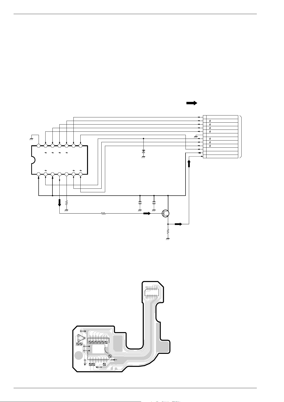
In dieser Service-Manual-Ergänzung ist der Schaltplan und die Platinenabbildung der CCD-Sensorplatte "VEP22304A" dokumentiert. Diese
ist kompatibel zu der CCD-Sensorplatte "VEP22295A" des BasisService-Manuals. Für die Ersatzteilbestellung ist die Materialnummer
759813790100 zu verwenden.
Hinweis:
Grundlage für den Service sind folgende Service Manuals:
– Service Manual Sicherheit,
Materialnummer 720108000000
– Service Manual,
Materialnummer 720105384000
Introduction
This Service Manual supplement documents the circuit diagram and
the printed circuit board of the CCD sensor board „VEP22304A“. This
is compatible to the CCD sensor board „VEP22295A“ of the basic
Service Manual. For ordering spare parts, please use the part number
759813790100.
Hinweis:
Grundlage für den Service sind folgende Service Manuals:
– Service Manual Sicherheit,
Materialnummer 720108000000
– Service Manual,
Materialnummer 720105384000
Schaltplan und Platinenabbildung / Circuit Diagram and Layout of the PCB
:VIDEO MAIN SIGNAL PATH
PS291
12
11
10
9
8
7
6
5
4
3
2
1
IC291
(CCD)
14 13 12 11 10
V4
V3
PW
OD
V2
R
VO
RD
98
V1
LG
PT
SUB
H1
H2
7654321
D291
02DZ16Y
PT
V1
V2
V3
V4
PW
R
H2
H1
SUB
15V
OUT
TO
CAMERA1
PP301
Page:23
R293
0
NOTE:THE MEASUREMENT MODE OF THE DC VOLTAGE ON THIS
DIAGRAM IS STOP MODE.
R292
Q291
CKZ2
C292
CKZ1
C295
R291
8
CKZ3
CKZ12
CKZ4
R291
56
10 14
CKZ9
CKZ11
CKZ10
IC291
CKZ6
CKZ5
R293
CKZ8
157
CKZ7
D291
C2951C292
0.1
156
PS291
14.9
Q291
11.7
7
1012
2SC2295
(AMP)
11.0
R292
1500
VEP22304A
0 - 2 GRUNDIG Service
 Loading...