

Page 1

Assembly Instructions
A
CLASS
KLASSE
Grundig SAT SystEms
Head-End Digital Modulator
HDM 2370 P CI
A
KLASSE
CLASS
GSS
Grundig SAT Systems GmbH
Beuthener Straße 43
English
Assembly Instructions
D-90471 Nuremberg
Phone: +49 (0) 911 / 703 8877
Fax: +49 (0) 911 / 703 9210
E-mail: info@gss.tv
Internet: http://www.gss.tv
Page 2

- 2 -
Contents
1 Safety regulations .....................................................................................................4
2 General information .................................................................................................4
2.1 Packing contents .......................................................................................4
2.2 Meaning of the symbols used .....................................................................5
2.3 Technical data ..........................................................................................5
2.4 Description ...............................................................................................6
2.5 Software query .........................................................................................7
3 Assembly .................................................................................................................7
3.1 Installing the cassette .................................................................................7
3.2 Installing the F terminals .............................................................................8
3.3 Connecting the cassette .............................................................................8
3.4 Retrofitting a CA module ............................................................................9
4 The control panel at a glance ..................................................................................10
4.1 Menu items ............................................................................................10
4.2 Control panel .........................................................................................10
5 Programming ......................................................................................................... 11
5.1 Preparation ............................................................................................11
5.2 Notes on the following programming procedure .........................................11
5.3 Programming procedure ..........................................................................12
5.3.1 Decoding 2 stations with one CA module (channel strip “B”) .............15
5.3.2 Time controlled switching ..............................................................16
5.4 Programming the cassette ........................................................................17
Selecting the cassette ...............................................................................17
5.4.1 Programming the main menu of the cassette ....................................18
Querying the software version .......................................................18
Selecting the channel strips “A”/“B” and ”a“/“b“ ...........................18
Setting time-controlled, alternative channels ....................................19
Decoding of two channels with one CA module ...............................19
Modulator operating mode ...........................................................19
Adjusting the output levels of the channel strips ...............................19
Setting the TV standard of the output signal ....................................20
Setting the output channel / output frequency ..................................20
Setting the fine-tuning ...................................................................21
Settings for TV stations..................................................................21
Setting the LNB oscillator frequency ...............................................21
Setting the input symbol rate .........................................................22
Configuring the CA module ..........................................................22
Setting the input frequency ............................................................22
Reception quality .........................................................................23
Channel selection ........................................................................24
Selecting the TV station sound .......................................................25
Setting the volume level ................................................................26
Setting the time zone and summer time ...........................................26
Saving settings ............................................................................27
- 2 -
Page 3

- 3 -
5.4.1.1 Adjusting the output levels of the channel strips ...................28
5.4.1.2 Settings for TV stations .....................................................29
Automatic picture format conversion ..................................29
Adjusting the picture format ..............................................30
Locking the regional window ............................................30
Switching teletext mode off/on .........................................31
Activating and entering teletext subtitle pages.....................31
Setting the teletext standard ..............................................32
Setting audio output ........................................................32
Setting the audio mode ....................................................33
5.4.1.3 Configuring the CA module ..............................................33
5.4.2 Decoding 2 stations with one CA module .......................................34
Selecting the channel strip ............................................................35
Modulator operating mode ...........................................................35
Setting the TV standard of the output signal ....................................35
Setting the output channel / output frequency .................................35
Setting the LNB oscillator frequency ...............................................35
Switching on decoding / Setting the input symbol rate .....................36
Switch off decoding .....................................................................37
5.4.3 Setting time-controlled, alternative channels ....................................38
Switching the timer on and off ......................................................38
Setting the switch-on time ............................................................38
Setting the switch-off time .............................................................39
Setting the days of the week .........................................................39
6 Channel and frequency tables .................................................................................40
- 3 -
Page 4

- 4 -
1 Safety regulations
Warning
• Assembly, installation and servicing should be carried out by authorised
electricians.
• Switch off the operating voltage of the system before beginning with assembly
or service work or pull out the mains plug.
• Do not perform installation and service work during thunderstorms.
• Install the system so it will not be able to vibrate…
- in a dust-free, dry environment
-
in such a manner that it is protected from moisture, fumes, splashing water and
dampness
- somewhere protected from direct sunlight
- not within the immediate vicinity of heat sources
- in an ambient temperature of -20 °C to +50 °C.
• Ensure that the head-end station is adequately ventilated.
Do not cover the ventilation slots.
• Beware of short circuits
• No liability is accepted for any damage caused by faulty connections or inappropriate handling.
• Observe the relevant standards, regulations and guidelines on the installation and
operation of antenna systems.
• Earth the
and VDE 0855 (earthed, equipotential bonding rail).
SAT receiver in accordance with DIN EN 50083-1 / EN 60728-11
Take action to prevent static discharge when working on the device.
2 General information
2.1 Packing contents
1 cassette HDM 2370 P CI
2 HF cables
1 CD (assembly instructions)
1 Brief assembly instructions
- 4 -
Page 5

- 5 -
2.2 Meaning of the symbols used
Important note
—> General note
• Performing works
2.3 Technical data
The devices meet the following EU directives:
2006/95/EC, 2004/108/EC
The product fulfils the guidelines and standards for CE labelling.
HF input
Frequency range: 950 … 2150 MHz
Level range: 60 dBµV … 80 dBµV
Input norm: QPSK
Symbol rate: 2 … 40 Msymb./s, SCPC/MCPC
FEC: automatic
HF output
Channels: C2 … C69 (incl. S2 … S41)
Frequency range: 48.25 MHz … 855.25 MHz
Standard: CCIR PAL B/G
PAL I (GB 6.0 FM)
Output level: typ. 95 dBµV
Output impedance: 75 Ω
Frequency detuning of the output signal:
±4.00 MHz in 62.5 kHz increments
MPEG decoding
MPEG 2: Main Level/Main Profile
Video output: 720 x 576 x 25 (Pixels x lines x Frames/sec)
Audio: 32 kHz, 44.1 kHz, 48 kHz
Picture format: options for letterbox, 16:9
Teletext capable: yes
VPS capable: yes (teletext, EIT)
- 5 -
Page 6

- 6 -
Connections
SAT inputs A and B: 2 F sockets
HF output (modulators): 1 IEC socket
Connection strip (10-pin): for supply voltages and control circuits
Socket RS 232: serial interface for software update
Conditional access: 2 channels can be decoded
2.4 Description
The twin transmodulator cassette is a QPSK-converter, which converts all stations modulated according to DVB-S1 standard and
lated cable signals.
The
cassette
has two digital SAT IF inputs and an HF output.
QPSK2 into two PAL-modu-
It is equipped with two channel strips (“A” and “B”). Each channel strip consists
of a digital tuner, a digital signal preparation unit and a modulator.
The channel strip “A” can decode encoded channels via a corresponding CA
module. Depending on the CA module and the smart card, two channels can be
decoded simultaneously with one CA module, with the second one supplied via
channel strip “B”. The control of the
cassette
takes place via the control unit of
the head-end station. By means of the “a” and “b” levels of the channel strips,
channel selection according to a timer is possible. The
are indicated by
channel switch over)
“Bx A / Bx a“ or “Bx B / Bx b” (“
in the control unit display.
Bx a
cassette
” / “
‘s channel strips
Bx b
” – time controlled
The prepared input signals reach the HF output collector of the head-end station
via the HF output socket. The common output level of the channel strips can be
set with the level regulator at the output collector of the head-end station.
When the head-end station is switched on, the two-line LC display briefly shows
the software version of the control unit.
To operate this cassette the software version of the control unit must be “V 37”
or higher. You can find the current operating software for the control unit and
the cassette, the software “BE-Flash”
and the current assembly instructions
website “www.gss.tv”.
The
cassette is
designed for use in the following head-end stations:
– STC 316
– STC 1200
– STR 19-8
on the
1
DVB-S – Digital Video Broadcasting - Satellite
2
QPSK – Quadrature Phase Shift Keying
- 6 -
Page 7
- 7 -
2.5 Software query
+24
BREITBA
Control unit
If necessary, you can activate the indication of the software version of the control unit manually:
• Press any two keys on the control unit of the head-end station simultaneously
until the display goes dark and
the software version, e.g. “
V 37
” appears.
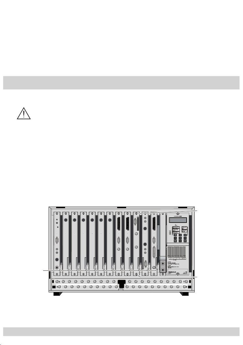
3 Assembly
3.1 Installing the cassette
Caution
– Ensure the head-end station is mounted so it will not be able to vibrate.
Avoid, for example, mounting the head-end station onto a lift shaft or any
other wall or floor construction that vibrates in a similar way.
– Before installing or changing a cassette unplug the power cable from the
mains power socket.
• Remove the fastening screws 1 of an unoccupied slot from the bracket of the
head-end station.
• Insert the cassette in this slot and push it into the housing.
• Align the cassette and apply slight pressure to connect it to the connections of
the board and the HF bus bar.
• Fasten the cassette with the 1 screws.
C101
L104
L100
L101
L103
C100
LNC-
+18V
ROT
GRUEN
+18V
Anschl.
INPUT OUTPUT OUTPUT INPUT
- 7 -
Page 8
- 8 -
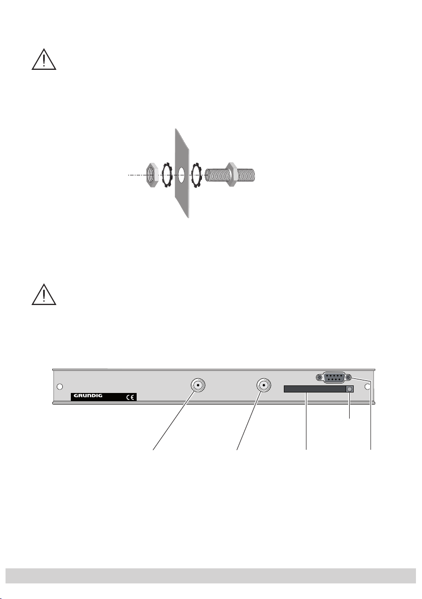
3.2 Installing the F terminals
To comply with the current EMC regulations, it is necessary to connect the
lines leading in and out of the head-end station using F terminals.
When mounting the cassette in an STR 19-8 head-end station which is in-
stalled in a 19" cabinet, make sure the connections leading in and out for
the 19" cabinet are made using F terminals.
• Insert the required number of F terminals in the openings provided in the
"
head-end station or in the 19
cabinet.
—> F terminals are not included in the scope of delivery.
Tighten the nut on the F terminal until the teeth on the lock washer have penetrated the exterior coating and a good connection is made between the
housing and F terminal.
3.3 Connecting the cassette
HF input "B"
HF input "A"
Plug the HF input cables into the HF input sockets “
•
(channel strip “A”) and “
•
Connect the head-end station to the mains power supply.
HF input B
- 8 -
” 1 (channel strip “B”).
Eject button
for CA module
Slot for
CA module
HF input A
RS 232
” 2
Page 9

- 9 -
Notes:
3 Slot for CA module
4 Eject button for CA module
5 Socket “RS 232”
The operating software of the
socket “RS 232” using a PC or notebook and the software “BE-Flash”. You
can find the current operating software on the website “www.gss.tv”.
3.4 Retrofitting a CA module
The cassette is equipped with a common interface. It allows you to connect
a CA module for various encryption systems and service providers. Encoded
channels can only be decoded with a CA module suitable for the encoding
system and the corresponding smart card. The smart card contains all the information for authorisation, decoding and subscription.
Caution
– Check with the distributor or manufacturer of the CA module to be
used to ensure that it is suitable for decoding 2 channels.
– The hardware and software of this cassette have been thoroughly pre-
pared and tested.
– Any changes made by program vendors to the structures in the program
data might impair or even prevent this function.
– When working with the CA module, please read the corresponding op-
erating manual from the respective provider.
cassette
can be updated via the 9-Pin D-DUB
• Insert the smart card into the CA module so that the chip on the smart card
faces the thicker side (top) of the CA module.
• Insert the CA module into the slot
module facing the top side of the cassette.
• Push the CA module without canting into the guide rails of the common interface slot and contact it to the common interface.
• To take out the CA module press the eject button
3 (s. chap. 3.3) with the top side of the CA
4.
- 9 -
Page 10
- 10 -
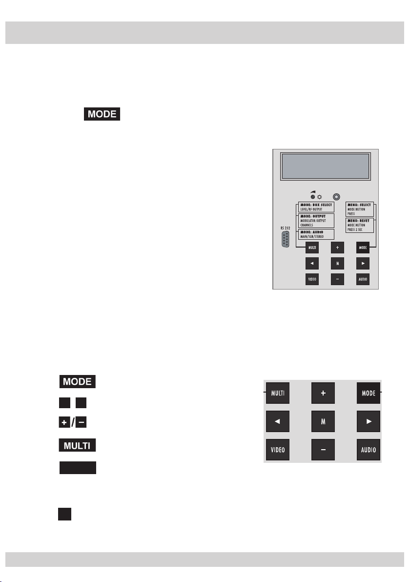
4 The control panel at a glance
4.1 Menu items
Program the
cassette
using the buttons on the control unit of the head-end station.
The two-line display of the control unit then shows the menus.
Use the key to select the following
main menu items:
–
Cassette
– Channel strip, software
– Modulator settings
BE–Remote V 37
please wait . . .
– TV standard
– Output channel / output frequency
– LNB oscillator frequency
– Input symbol rate
– Input frequency
– Channel selection
– TV station sound
– Volume
– Time zone and summer time
4.2 Control panel
The key pad on the head-end station is used to scroll through the menus and
menu items one at a time:
◀
/
selects sub-menus
VIDEO
“
scrolls forward through the menu
▶
select parameters in the menus.
set values, initiate actions
switches over between the
Setting the input frequency” and the
“Channel selection” menus.
M
saves all entries.
- 10 -
.
Page 11

- 11 -
5 Programming
5.1 Preparation
• Connect the test receiver to the HF output or the test output of the head-end
station.
• Set the output channel / output frequency of the
adjust the TV test receiver to this channel.
• Switch on the modulator if necessary.
• Balance the output levels of the channel strips “A” and “B” if the difference in
level is ≥ 1 dB (see chapter “Modulator settings”, page 19).
• Measure the output levels of the analogue
form output level using the appropriate level controls 2 (s. page 7).
5.2 Notes on the following programming procedure
– The parameters to be set are underlined (cursor).
– Connection C : Time-controlled channel selection
– Connection D : Decoding 2 stations with one CA module
cassette
cassettes
(see page 20) and
and tune them to a uni-
- 11 -
Page 12
- 12 -
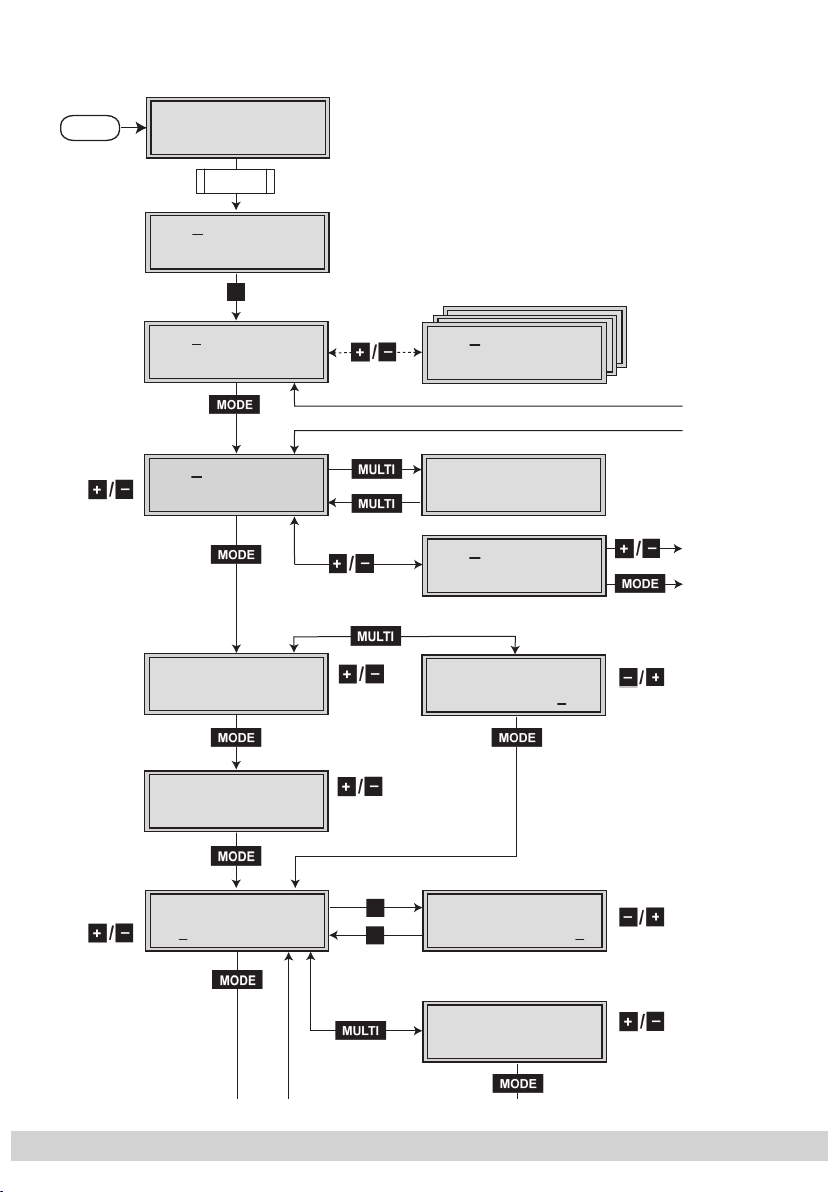
5.3 Programming procedure
Ein / On
A / B
BE–Remote
please wait …
t > 10 s
Bx 1A
C5-12,S3-24
Box 4
C2-69,S2-41
Bx 4A
Das Erste
Bx 4A
Modulator:
TWIN-SAT
+
QPSK-PAL
QPSK-PAL
V 37
C07
– – –
S21
OUTPUT:
on
on / off
Bx 1A
Böx 4
Bx 5A
C5-12,S3-24
C5-12,S3-24
BD3
Bx 4A
DVB-PAL B
Bx 4B
SAT.1
Bx 4A
HF-Level:
TWIN-SAT
DVBT-DVBT
VERSION:
QPSK-PAL
OUTPUT:
TWIN-SAT
C07
C07
C09
V.16
S09
0
0 … –7 dB
!
Page 14
Page 16
Page 15
Bx 4A
CCIR
5.5 FM
Bx 4A
S21
OUTPUT:
NORM:
CCIR 5.5 FM / GB 6.0 FM
▶
- 12 -
Bx 4A
S21 Fine
Bx 4A
Letter
▶
OUTPUT:
0
VIDEO-OUT:
–64 … +63
Letter / 16:9
Page 13

- 13 -
Bx 4A
Teletext:
OUTPUT:
on
on / off
Bx 4A
TXT-Page:
SUBTITLE:
150
Bx 4A
TXT-Norm:
SUBTITLE:
West
Bx 4A
Dual normal
AUDIO-OUT:
normal / swap
MPEG / VPS
West / East
Bx 4A
MPEG =>
AUDIO-OUT:
Audiomode
off / 150
100 … n
Bx 4A
PIDs:
SERVICE:
dynamic
dynamic / fixed
Bx 4A
Signaling:
WSS-OUT:
on
on / off
▶
◀
/
Bx 4A
f= 10600 MHz
LNB-FREQ:
"
▶
◀
/
Page 16
- 13 -
Page 14

- 14 -
Module Hauptmenü
–> Information
◀
Bx 4A
▶
/
SR= 27500
INPUT:
Bx 4A
Information
MENU 1/6
Smartkarte
Jugendschutz
Einstellungen
Zurück
Bitte wählen Sie mit OK
AlphaCrypt Light 1.01 (c) Mascom GmbH
TV-Bild
TV picture
◀
▶
/
◀
Bx 4A
▶
/
f= 11836 MHz
VIDEO
Bx 4A 01/10+
Das Erste
Bx 4A
01/02
Bx 4A
Volume:
Bx 4A
13:48:22 ?
FREQ-IN:
TV
AUDIO-IN:
“deu”
AUDIO-OUT:
0 dB
OFFSET:
+01 S
0
–24 … +6
–12 … +12
Bx 4A
0.0e - 8
Bx 4A
ARD
S / -
BER. C/N:
12.0 dB
PROVIDER:
Anzeige: Signalqualität
Display: Signal quality
#
Page 15
Page 12
M
- 14 -
Page 15

- 15 -
5.3.1 Decoding 2 stations with one CA module (channel strip “B”)
Page 12
!
on / off
◀
/
◀
/
▶
▶
Bx 4B
Modulator:
Bx 4B
CCIR
5.5 FM
Bx 4B
S09
Bx 4B
f = 10600 MHz
Bx 4B
SR= 22000
LNB-FREQ:
OUTPUT:
on
NORM:
OUTPUT:
INPUT:
Bx 4B
HF-Level:
CCIR 5.5 FM / GB 6.0 FM
▶
Bx 4B
S09 Fine
▶
* * )
Bx 4B
Data Tuner A
Bx 4B
* )
* ) Switches the decoding on or off
CI at LINE A
LNB-FREQ:
OUTPUT:
0
0 … –7 dB
–64 … +63
0
OUTPUT:
* * ) With activated decoding
INPUT:
▶
/
Bx 4B
f = 12544 MHz
◀
FREQ IN:
-0.3
Bx 4A
0.0e - 8
Bx 4B
Data Tuner A
BER. C/N:
#
12.0 dB
FREQ-IN:
#
Page 14
- 15 -
Page 16

- 16 -
5.3.2 Time controlled switching
Page 12
Bx 4a
Das Erste
Bx 4a
On Time
Bx 4a
Off Time
Bx 4a
Days
Page 13
QPSK-PAL
TIMER:
20:00
TIMER:
23:00
TIMER:
MTWTFSS
"
S21
on / –
◀
/
◀
Bx 4b
ZDF
◀
▶
/
▶
▶
/
QPSK-PAL
S09
- 16 -
Page 17

- 17 -
5.4 Programming the cassette
Ein / On
BE–Remote
please wait …
V 37
t > 10 s
Box 4
C2-69,S2-41
QPSK-PAL
– – –
Bx 1A
C5-12,S3-24
TWIN-SAT
C07
Bx 1A
C5-12,S3-24
TWIN-SAT
C07
Böx 4
C5-12,S3-24
TWIN-SAT
C07
Bx 5A
BD3
DVBT-DVBT
C09
+
—> Pressing the
button for longer than 2 seconds cancels the programming procedure. This takes you back to the program item “Selecting
the cassette” from any menu. Any entries that have not been saved are
reset to the previous settings.
M
—> Entries in the menus can be saved by pressing the
key. You are taken
back to the “Selecting the cassette” menu item.
• Switch on the head-end station
—> The display shows the software version (e.g. V 37)
—> The processor reads the
cassettes
‘ data
(approx. 10 seconds).
_
Selecting the cassette
• Select the
cassette
you want to program (e.g. Box 4) by
repeatedly pressing the button .
• By pressing the button, activate channel strip “A”.
- 17 -
Page 18

- 18 -
5.4.1 Programming the main menu of the cassette
Bx 4A
Das Erste
QPSK-PAL
S21
!
Bx 4A
DVB-PAL B
VERSION:
V.16
Bx 4B
SAT.1
QPSK-PAL
S09
A / B
!
Bx 4
S
L
S09
Bx 4A
Das Erste
QPSK-PAL
S21
!
Bx 4A
DVB-PAL B
VERSION:
V.16
Bx 4B
SAT.1
QPSK-PAL
S09
A / B
D
V
Querying the software version
B
AT.1
QPSK-PA
—> The display shows e.g. the menu “
“Bx” stands for
“4” for
slot
cassette
4
Bx 4
A QPSK-PAL”:
(box),
“A” for channel strip “A”
”QPSK-PAL” Type of cassette
”S21” Channel set
• Press the button.
—> The display shows e.g. the menu
Bx 4A VERSION:
DVB-PAL B V.16
”B” 2 programs can be simultaneously
decoded with this hardware (page 34).
”V.16” Software version
• To return to the main menu press the button
again.
Selecting the channel strips “A”/“B” and ”a“/“b“
VB-PAL B
- 18 -
ERSION
V.16
Page 19

- 19 -
• By pressing , select channel strip “A” / “B”
Bx 4A
Modulator:
OUTPUT:
on
Bx 4A
HF-Level:
OUTPUT:
0
0 … –7 dB
on / off
4A
l:
:
B
or “a” / “b”.
—> The capital letters “A” and “B” indicate the channel
strips of the main menu, the small letters ”a“ and ”b“
the channel strips of the time-controlled switching on
and off of channels
.
Setting time-controlled, alternative channels
• By pressing
, call up channel strip “B”.
• Press again:
—>
Call up timer “a”/ “ b” for time-controlled switch-
ing on and off of channels C (page 38).
Decoding of two channels with one CA module
• By pressing
, call up channel strip “B”.
• By pressing the but ton a ctiv at e t he d ec oding
of two channel with one CA module D (page 34).
• Press the button.
—> The “Modulator operating mode” –
“OUTPUT: Modulator” menu is activated.
Modulator operating mode
In this menu, you can switch the modulator off and on.
x
-Leve
•
By pressing , switch the modulator (output channel)
OUTPUT
“off” or “on”.
Adjusting the output levels of the channel strips
• Press the
button.
—> The menu “Adjusting the output levels of the
channel strips” – “OUTPUT: HF-Level” is acti-
vated
(chapter 5.4.1.1, page 28)
- 19 -
… –7 d
.
Page 20

- 20 -
• Press the button.
CCIR 5.5 FM / GB 6.0 FM
Bx 4A
CCIR
NORM:
5.5 FM
Bx 4A
S21
OUTPUT:
Bx 4A
S21 Fine
OUTPUT:
0
–64 … +63
Bx 4A
Letter
VIDEO-OUT:
Letter / 16:9
▶
▶
V
:
9
—> The “Setting the TV standard of the output signal” –
“NORM” menu is activated.
Setting the TV standard of the output signal
In this menu you can set the TV standard of the output
signal.
• Press to set the TV standard of the output signal.
• Press the button.
—> The “Setting the output channel / output frequency”
– “OUTPUT:” menu is activated.
Setting the output channel / output frequency
In this menu you can set the desired output channel (CCIR) or
dependent on the TV standard set, the output frequency.
IDEO-OUT
Letter
• By pressing
quency.
set the output channel / output fre-
- 20 -
etter / 16:
Page 21

- 21 -
Setting the fine-tuning
Bx 4A
f= 10600 MHz
LNB-FREQ:
"
Module Hauptmenü
▶
◀
/
Only change the fine-tuning in exceptional circumstances,
since once you change it, all connected television sets of the
cable system must be adjusted to match it by means of corresponding fine-tuning corrections.
• Press the
▶
button.
—> “FINE 0” appears in the display.
• Set the fine-tuning using the buttons.
• Press
◀
to return to the main menu.
Settings for TV stations
• Press the
button
—> The “Automatic picture format conversion” –
“VIDEO-OUT:” menu is activated
(chapter 5.4.1.2, page 29).
• Press the button.
—> The “Setting the LNB oscillator frequency” –
“
LNB-FREQ
:” menu is activated.
Setting the LNB oscillator frequency
Set the oscillator frequency of the LNB used in this menu.
◀
• Use
▶
to position the cursor under the digit of the
/
frequency displayed to be set.
• Press to enter the oscillator frequency of the LNB
used.
- 21 -
Page 22

- 22 -
• Press the button.
Bx 4A
SR= 27500
INPUT:
Bx 4A
Information
MENU 1/6
Module Hauptmenü
–> Information
Smartkarte
Jugendschutz
Einstellungen
Zurück
Bitte wählen Sie mit OK
AlphaCrypt Light 1.01 (c) Mascom GmbH
▶
◀
/
▶
◀
/
TV-Bild
TV picture
6
ü
–
n
e
z
n
tte wählen Sie
OK
H
/
d
—> The “Setting the input symbol rate” –
“INPUT: ”and e.g. “SR=27500” menu is activated.
Setting the input symbol rate
The symbol rates of the satellite transponders can be found in
the current channel table of the satellite operator, in various
satellite magazines and in the Internet.
odule Hauptmen
> Informatio
Smartkart
Jugendschut
Einstellunge
Zurück
i
AlphaCrypt Light 1.01 (c) Mascom Gmb
V-Bil
TV picture
mit
• Use
MENU 1/
Information
◀
▶
to position the cursor under the digit of the
/
symbol rate displayed to be set.
• Press
to enter the values of the symbol rate.
Configuring the CA module
• Press the
button
—> The “Configuring the CA module” – “MENU:”
menu is activated (chapter 5.4.1.3, page 33).
• Press the button.
—> The “Setting the input frequency” – “FREQ-IN:” menu
is activated.
Setting the input frequency
If three dots “ … “ appear in the second line of the display,
the cassette is in the “station search” mode. Please wait until
the process has finished.
Once the HF receiver has synchronised to the input signal,
any offset to the target frequency is displayed in MHz, e.g.
“– 1.8”.
If a question mark “?” appears in the second line of the display, there is no input signal present. Check the configuration
- 22 -
Page 23

- 23 -
of the antenna system and head-end station as well as the
VIDEO
Bx 4A
0.0e - 8
BER. C/N:
12.0 dB
#
Bx 4A
f= 11836 MHz
FREQ-IN:
0
▶
◀
/
p
Anzeige: Signalqualität
Display: Signal quality
:
A
VIDEO
Bx 4A
0.0e - 8
BER. C/N:
12.0 dB
#
Bx 4A
f= 11836 MHz
FREQ-IN:
0
▶
◀
/
Anzeige: Signalqualität
Display: Signal quality
V
4A
:
/
preceding settings of the cassette.
BER. C/N
• Use
.0e - 8
◀
▶
to position the cursor under the digit of the
/
12.0 dB
frequency displayed to be set.
• Press
to set the input frequency.
• After setting the input frequency set the frequency offset
shown in the display to less than 1 MHz using the
buttons.
• Press the button.
—> The “Reception quality” – “BER. C/N:” menu
is activated.
Reception quality
In this menu the reception quality (BER = Bit Error Rate) and
the signal to noise ratio (C/N) of the signal received is displayed (example):
”0.0e -8”: Bit Error Rate
”12.0 dB”: signal to noise ratio
x
f= 1183
IDEO
FREQ-IN
• To return to the main menu press the
button.
• Press the button.
—> The “Channel selection” – e.g. “Bx 4A 01/10+ TV”
menu is activated.
- 23 -
Page 24

- 24 -
Channel selection
Bx 4A 01/10+
Das Erste
TV
Bx 4A
ARD
PROVIDER:
#
As soon as the automatic station search has found all of the
TV or radio channels, the corresponding data appears in the
display of the head-end station.
Meaning of the terms displayed in this example:
“Bx 4A” Cassette 4, channel strip “A”.
“01/09” The 1st of 9 channels is displayed
“ + ”
means that the sound of the TV programme currently being shown is being broadcast in sev-
eral languages.
“TV” TV channel type
“
Das Erste
” Channel name
Further possible terms displayed:
“RA” Radio channel type
For radio stations, the back
ground of the screen
of the connected TV or test receiver is darkened.
A menu appears on the screen informing you
about the radio station currently selected, the
name of the broadcaster, the current time, the
title of the current programme along with what
time it started and finishes, as well as the title of
the following programme.
“ * ” The star means that the TV or radio station se-
lected is encoded. To enable the stations, the
CA module and the appropriate smart card of
the station provider are required.
—> If a service number (e.g. “131”) appears instead of
“TV” or “RA”, this indicates that an unnamed station
or an undefined data stream is being received.
- 24 -
Page 25

- 25 -
• To select the TV and radio stations of this broadcaster, use
TV
VIDEO
Bx 4A
f= 11836 MHz
FREQ-IN:
0
Bx 4A 01/10+
Das Erste
Bx 4A
01/02
AUDIO-IN:
“deu”
the buttons.
• By pressing , you can call up various station
information about the current TV or radio station in the
“PROVIDER:” menu. To return to the main menu press the
button again.
• By pressing the
VIDEO
button, you switch between the
“Setting the input frequency” and the “Channel selection”
menu.
• Press the button.
—> The “Selecting the TV station sound” – “AUDIO-IN:”
menu is activated.
Selecting the TV station sound
If two sound options in different languages or Dual sound
(“2ch”) are broadcast for a TV station, you can select the
desired audio stream from the transport stream in this menu.
• Press
• Press the button.
—> The “Setting the volume level” –
“AUDIO-OUT: Volume:” menu is activated.
to select the desired sound option.
- 25 -
Page 26

- 26 -
Setting the volume level
Bx 4A
Volume:
AUDIO-OUT:
0 dB
–24 … +6
Bx 4A
13:48:22 ?
OFFSET:
+01 S
–12 … +12
S / -
M
In this menu, you can balance unequal volume levels of TV
and radio stations in the various channel strips.
• Set the volume level to the same level as the levels of the
other output channels using the
buttons (+6 dB …
-24 dB), if necessary.
• Press the button.
—> The “Setting the time zone and summer time” –
“OFFSET:” menu is activated.
Setting the time zone and summer time
This setting is necessary for “Radio display” and time-controlled channel switching. The internal clock of the cassette
synchronises automatically to Greenwich Mean Time, longitude “0” (GMT). So that the programmes can be correctly
displayed, the time zone (offset) that your location is in relation to GMT should be entered.
“13:48:22 ?” Time (GMT)
The current time is displayed when the
question mark “?” disappears.
”+01” + 1 hour (offset to GMT) is set.
”S” Summer time support is switched on.
- 26 -
Page 27

- 27 -
Example:
Summertime support for the time zone of Germany (GMT +
1 hour) is in:
If “S” is switched on, one hour is added in addition to offset
(+01) during summer time.
• Press
to set the time zone you live in (offset from -12
hours to +12 hours).
• Press the button to switch summer time support
on (“S”) or off (“S” disappears).
Saving settings
• Press the
M
button.
—> Back to “Selecting the cassette” A (page 17).
—> The “new“ settings are saved permanently.
—> Going back to “Selecting the channel strips A/B and
a/b” B (page 18) via and selecting an-
other channel strip cancels all settings that have not
been saved.
- 27 -
Page 28

- 28 -
5.4.1.1 Adjusting the output levels of the channel strips
Bx 4A
Modulator:
OUTPUT:
on
Bx 4A
HF-Level:
OUTPUT:
0
0 … –7 dB
on / off
CCIR 5.5 FM / GB 6.0 FM
Bx 4A
CCIR
NORM:
5.5 FM
Bx 4A
S21
OUTPUT:
Bx 4A
S21 Fine
OUTPUT:
0
–64 … +63
▶
▶
M
:
e
:
–
3
In this menu you can set the output levels of the modulators of
the channel strips “A” and “B” to the same value.
Bx 4A
IR
5.5 FM
NORM
CIR 5.5 FM / GB 6.0 F
Bx 4A
S21 Fin
OUTPUT
0
64 … +6
• Measure and note down the output level of the channel
strip.
M
• Save the settings by pressing the
• Select the other channel strip
(page 18),
button.
measure and note
down its output level.
• Activate the
• By pressi
“OUTPUT: HF-Level” menu.
ng adjust the higher output level of one channel strip to the lower output level of the other channel strip
incrementally from “0
—>
To return to the “OUTPUT: Modulator:“ main menu,
” to “
–7” dB.
press the button.
• Press the button.
—> The “Setting the output channel/output frequency” –
“OUTPUT:” menu is activated (page 20).
- 28 -
Page 29

- 29 -
5.4.1.2 Settings for TV stations
Bx 4A
S21
OUTPUT:
Bx 4A
S21 Fine
OUTPUT:
0
–64 … +63
Bx 4A
Letter
VIDEO-OUT:
Letter / 16:9
▶
▶
e
:
–
3
The following settings “Automatic picture format conversion”,
“Teletext mode” and “Teletext subtitle page” are only relevant
for TV stations.
Automatic picture format conversion
TV programmes are transmitted in DVB Standard in picture
format 4:3 or 16:9. The
formats and prepares them automatically for all of the connected television sets (letterbox).
The “16:9” setting should only be selected if all of the television sets connected to the head-end station has the 16:9
format. The factory setting “Letter” should be retained in
normal circumstances, as 4:3 television sets are also supported in this case. The settings are only effective with TV
programmes with the picture format “16:9”.
– “Letter”: black bars at the top and bottom edge of the
– “16:9”: In the case of television sets with the picture
cassette
recognises these picture
screen
format 4:3, the picture content is vertically
“stretched” (e.g. faces appear longer).
OUTPUT:
S2
Bx 4A
S21 Fin
OUTPUT
0
64 … +6
• Press the buttons to select the desired picture format
“Letter” or “16:9”.
—> Pressing the button you return to the main
menu (Setting the output channel/output frequency)
(page 20).
• Press the button.
—> The “Adjusting the picture format” –
“WSS-OUT: Signaling:” menu is activated.
- 29 -
Page 30

- 30 -
Adjusting the picture format
Bx 4A
Signaling:
WSS-OUT:
on
on / off
Bx 4A
PIDs:
SERVICE:
dynamic
dynamic / fixed
If problems with the automatic picture format switchover (e.g.
4:3, 16:9, Letterbox) arise with the connected devices, you
can switch “off” the Wide-Screen-Signaling (WSS) in this
menu.
• Press to switch Wide-Screen-Signaling “on” or
“off”.
—> Pressing the button you return to the main
menu (Setting the output channel/output frequency)
(page 20).
• Press the button.
—> The “Locking the regional window” –
“SERVICE: PIDs:” menu is activated.
Locking the regional window
In this menu the dynamic switch over between the main
channel and the associated regional channels can be deactivated
.
• Press
(“
dynamic
to switch on the dynamic regional switch over
”) or off (“
fixed”).
—> Pressing the button you return to the main
menu (Setting the output channel/output frequency)
(page 20).
• Press the button.
—> The “Switching teletext mode off/on” –
“OUTPUT: Teletext:” menu is activated.
- 30 -
Page 31

- 31 -
Switching teletext mode off/on
Bx 4A
Tel ete xt:
OUTPUT:
on
on / off
Bx 4A
TXT-Page:
SUBTITLE:
150
off / 150
100 … n
▶
◀
/
In this menu you can define whether the teletext of the channel set is transmitted or not.
• By pressing
the teletext mode can be switched “on”
or “off”.
—> Pressing the button you return to the main
menu (Setting the output channel/output frequency)
(page 20).
• Press the button.
—> The “Activating and entering teletext subtitle pages”
– “SUBTITLE: TXT-Page:” menu is activated.
Activating and entering teletext subtitle pages
This menu allows subtitles transmitted in teletext to be displayed directly in the station.
• Press
to switch on (“150”) or off (“off”) the dis-
playing of teletext subtitles.
◀
• If necessary,
press
▶
to select the 100th, 10th and 1st
/
digit positions of the teletext subtitle page displayed and
enter the numbers of the teletext subtitle page wished with
the buttons.
• Press the button.
—> The “Setting the teletext standard” –
“SUBTITLE: TXT-Norm:” menu is activated.
- 31 -
Page 32

- 32 -
Setting the teletext standard
Bx 4A
TXT-Norm:
SUBTITLE:
West
West / East
Bx 4A
Dual normal
AUDIO-OUT:
normal / swap
In this menu you define the characters to display the languages. For the Western European languages set
“West”; for East-
ern European languages set “East”.
• Press to set teletext standard “West” or “East”.
• Press the button.
—> The “Setting audio output” –
“AUDIO-OUT: Dual …” menu is activated.
Setting audio output
In this menu you can swap the languages for TV channels
with dual tone.
• Press
“Dual swap”).
to swap languages (“Dual normal” /
—> Pressing the button you return to the main
menu (Setting the output channel/output frequency)
(page 20).
• Press the button.
—> The “Setting the audio mode“ –
“AUDIO-OUT:” and e.g. “MPEG => Audiomode”
menu is activated.
- 32 -
Page 33

- 33 -
Setting the audio mode
MPEG / VPS
Bx 4A
MPEG =>
AUDIO-OUT:
Audiomode
"
Bx 4A
SR= 27500
INPUT:
Bx 4A
Information
MENU 1/6
Module Hauptmenü
–> Information
Smartkarte
Jugendschutz
Einstellungen
Zurück
Bitte wählen Sie mit OK
AlphaCrypt Light 1.01 (c) Mascom GmbH
▶
◀
/
▶
◀
/
TV-Bild
TV picture
4A
:
/
In this menu you can define whether the Mono, Stereo or
Dual Tone signal from the MPEG data stream or the VPS Sig-
naling (if available) is to be used.
• Press
(“MPEG” / “VPS”).
• Press the button.
—> The “Setting the LNB oscillator frequency“ –
“LNB-FREQ:” menu is activated (page 21).
5.4.1.3 Configuring the CA module
This setting supports a menu, which is displayed on the television screen. This menu is dependent on the CA module
used. Please observe the operating instructions of the CA
module used.
x
SR= 2750
INPUT
• Press
• Activate menu item with
• Select the required function with the buttons.
• Save the settings with the M button.
—> To return to the “Setting the input symbol rate“ –
“INPUT:“ menu, press the button.
to switch over the data stream
to select the menu item on the screen.
▶
.
• Press the button.
—> The “Setting the input frequency” – “FREQ.-IN:”
menu is activated (page 22).
- 33 -
Page 34

- 34 -
5.4.2 Decoding 2 stations with one CA module
Bx 4B
S09
OUTPUT:
Bx 4B
f = 10600 MHz
LNB-FREQ:
Bx 4B
SR= 22000
INPUT:
▶
◀
/
Bx 4B
f = 12544 MHz
FREQ IN:
-0.3
▶
◀
/
▶
◀
/
* )
Bx 4B
CI at LINE A
INPUT:
Bx 4B
Data Tuner A
LNB-FREQ:
* * )
!
Bx 4B
Modulator:
OUTPUT:
on
Bx 4B
HF-Level:
OUTPUT:
0
0 … –7 dB
Bx 4B
CCIR
NORM:
5.5 FM
on / off
#
Bx 4B
Data Tuner A
FREQ-IN:
Bx 4B
S09 Fine
OUTPUT:
0
–64 … +63
▶
▶
Bx 4A
0.0e - 8
BER. C/N:
12.0 dB
#
CCIR 5.5 FM / GB 6.0 FM
B
:
!
:
:
:
R
:
FM
4B
e
:
–
3
M
4B
z
:
/
B
3
/
4A
:
B
– This feature is only possible via channel strip “B”.
– The settings not described below are the settings pertaining to channel
strip “A”.
on /
ff
Bx 4B
odulator
x 4B
I
5.5
Bx 4
S09
Bx
= 1060 MH
Bx 4
= 1254
OUTPUT:
NORM
CCIR 5.5 FM / GB 6.0 F
UTPUT
NB-FREQ
FREQ IN:
0.
HF-Level
Bx
S09 Fin
x
.0e - 8
OUTPUT
… –7 dB
UTPUT
64 … +6
ER. C/N
12.0 d
- 34 -
Page 35

- 35 -
Selecting the channel strip
Bx 4B
S09
OUTPUT:
* * )
Bx 4B
S09 Fine
OUTPUT:
0
–64 … +63
▶
▶
•
Select channel strip “B” (page 18).
Modulator operating mode
—> Setting see page 19
.
Setting the TV standard of the output signal
—> Setting see page 20
.
Setting the output channel / output frequency
—> Setting see page 20
Switch on decoding is switched on
decoding (see page 37, ”Switch off decoding”)
.
Setting the LNB oscillator frequency
The LNB oscillator frequency is not to be set if decoding is
activated.
• Press the
—> Setting see page 21
button.
.
- 35 -
Page 36

- 36 -
Bx 4B
f = 10600 MHz
LNB-FREQ:
Bx 4B
SR= 22000
INPUT:
▶
◀
/
▶
◀
/
* )
Bx 4B
CI at LINE A
INPUT:
Bx 4B
Data Tuner A
LNB-FREQ:
= 1060 MH
z
:
:
/
/
A
:
#
Bx 4B
Data Tuner A
FREQ-IN:
#
Bx 4A 01/10+
Das Erste
TV
Bx 4A
ARD
PROVIDER:
#
Switching on decoding / Setting the input symbol rate
The input symbol rate is not to be set if decoding is activated.
—> Setting the input symbol rate see page 22
NB-FREQ
NB-FREQ
Data Tuner
.
x 4B
SR= 2200
INPUT
• To switch on the decoding press the
button in the
”Setting the input symbol rate” menu.
—> The display shows “INPUT:” “CI at LINE A”.
The common interface of channel strip “A” is used for
the decoding.
• Press the button.
—>
The display shows “FREQ-IN: Data Tuner A” to indi-
cate that the input data of channel strip “A“ is used as
the output data for the modulator of channel strip “B”.
• Press the button.
—> Return to the main menu (”Channel selection” menu)
via connection F (page 24).
.
- 36 -
Page 37

- 37 -
Bx 4B
f = 10600 MHz
LNB-FREQ:
Bx 4B
SR= 22000
INPUT:
▶
◀
/
▶
◀
/
* )
Bx 4B
CI at LINE A
INPUT:
Bx 4B
Data Tuner A
LNB-FREQ:
= 1060 MH
z
:
/
Switch off decoding
NB-FREQ
• Press the
button.
—> The display shows “INPUT: and e.g. SR= 22000”.
Continue with “Setting the input symbol rate”
(page 22).
- 37 -
Page 38

- 38 -
5.4.3 Setting time-controlled, alternative channels
Bx 4a
Das Erste
QPSK-PAL
S21
Bx 4b
ZDF
QPSK-PAL
S09
4
9
Bx 4a
On Time
TIMER:
20:00
▶
◀
/
on / –
Channels can be switched on and off by means of a timer in
this menu. Here, for the set “On Time“, a switch over occurs
from channel strip “A“ (or “B“) to channel strip “a“ (or “b“);
for the “Off Time“, from channel strip “a“ (or “b“) to channel
strip “A“ (or “B“).)
Bx
QPSK-PAL
S0
• Press the
button.
—> The “Setting the switch-on time” –
“TIMER: On Time” menu is activated.
Switching the timer on and off
Setting the switch-on time
• Press to switch the timer on.
—> “On Time 20:00”, e.g., appears in the display.
—> To switch off the timer press .
“On Time —”, appears in the display.
◀
• Use
▶
to position the cursor under the digit (hours /
/
minutes) to be set.
• Press to set the desired switch-on time.
• Press the button.
—> The “Setting the switch-off time” –
“TIMER: Off Time” menu is activated.
—> “Off Time 23:00”, e.g., appears in the display.
- 38 -
Page 39

- 39 -
Setting the switch-off time
Bx 4a
Off Time
TIMER:
23:00
▶
◀
/
Bx 4a
Days
TIMER:
MTWTFSS
▶
◀
/
"
◀
• Use
▶
to position the cursor under the digit (hours /
/
minutes) to be set.
• Press to set the desired switch-off time.
• Press the button.
—> The “Setting the days of the week” –“TIMER: Days”
and e.g. “MTWTFSS” menu is activated.
Setting the days of the week
The letters “MTWTFSS“ mean:
M – Monday
T – Tuesday
W – Wednesday
T – Thursday
F – Friday
S – Saturday
S – Sunday
◀
• Use
▶
to position the cursor under the day to be set.
/
• Press to switch on or off ( – ) the day on which the
timer should and should not be active
(e.g. “TIMER: Days MTWTF – –”
—> Saturday and Sunday are switched off).
• Press the button.
—> Return to main menu E (page 21).
- 39 -
Page 40

6 Channel and frequency tables
CCIR – Band I/III (Frequency raster 7 MHz)
Kanal
Channel
Bildträgerfrequenz
C 2 48.25
C 3 55.25
C 4 62.25
S 2 112.25
S 3 119.25
S 4 126.25
]
Kanal
[MHz
Picture carrier frequency
Channel
S 5 133.25
S 6 140.25
S 7 147.25
S 8 154.25
S 9 161.25
S 10 168.25
]
Kanal
[MHz
Bildträgerfrequenz
Picture carrier frequency
Channel
C 5 175.25
C 6 182.25
C 7 189.25
C 8 196.25
C 9 203.25
C 10 210.25
]
[MHz
Bildträgerfrequenz
Picture carrier frequency
CCIR – Hyperband (Frequency raster 8 MHz)
]
Kanal
S 21 303.25 306.00
S 22 311.25 314.00
S 23 319.25 322.00
S 24 327.25 330.00
S 25 335.25 338.00
S 26 343.25 346.00
[MHz
Channel
Bildträgerfrequenz
Kanalmittenfrequenz
Picture carrier frequency
Channel centre frequency
]
Kanal
[MHz
S 27 351.25 354.00
S 28 359.25 362.00
S 29 367.25 370.00
S 30 375.25 378.00
S 31 383.25 386.00
S 32 391.25 394.00
]
[MHz
Channel
Bildträgerfrequenz
Kanalmittenfrequenz
Picture carrier frequency
]
Kanal
[MHz
Channel centre frequency
S 33 399.25 402.00
S 34 407.25 410.00
S 35 415.25 418.00
S 36 423.25 426.00
S 37 431.25 434.00
S 38 439.25 442.00
CCIR – Band IV/V (Frequency raster 8 MHz)
C 21 471.25 474.00
C 22 479.25 482.00
C 23 487.25 490.00
C 24 495.25 498.00
C 25 503.25 506.00
C 26 511.25 514.00
C 27 519.25 522.00
C 28 527.25 530.00
C 29 535.25 538.00
C 30 543.25 546.00
C 31 551.25 554.00
C 32 559.25 562.00
C 33 567.25 570.00
C 34 575.25 578.00
C 35 583.25 586.00
C 36 591.25 594.00
C 37 599.25 602.00
C 38 607.25 610.00
C 39 615.25 618.00
C 40 623.25 626.00
C 41 631.25 634.00
C 42 639.25 642.00
C 43 647.25 650.00
C 44 655.25 658.00
C 45 663.25 666.00
C 46 671.25 674.00
C 47 679.25 682.00
C 48 687.25 690.00
C 49 695.25 698.00
C 50 703.25 706.00
C 51 711.25 714.00
C 52 719.25 722.00
C 53 727.25 730.00
C 54 735.25 738.00
C 55 743.25 746.00
C 56 751.25 754.00
C 57 759.25 762.00
C 58 767.25 770.00
C 59 775.25 778.00
C 60 783.25 786.00
C 61 791.25 794.00
C 62 799.25 802.00
Kanal
Channel
Bildträgerfrequenz
C 11 217.25
C 12 224.25
S 11 231.25
S 12 238.25
S 13 245.25
S 14 252.25
]
Channel
[MHz
Bildträgerfrequenz
Kanalmittenfrequenz
Picture carrier frequency
]
Kanal
[MHz
Picture carrier frequency
]
[MHz
Channel centre frequency
Channel
Bildträgerfrequenz
Picture carrier frequency
S 15 259.25
S 16 266.25
S 17 273.25
S 18 280.25
S 19 287.25
S 20 294.25
]
Kanal
S 39 447.25 450.00
S 40 455.25 458.00
S 41 463.25 466.00
C 63 807.25 810.00
C 64 815.25 818.00
C 65 823.25 826.00
C 66 831.25 834.00
C 67 839.25 842.00
C 68 847.25 850.00
C 69 855.25 858.00
[MHz
Channel
Bildträgerfrequenz
Picture carrier frequency
]
[MHz
]
[MHz
Kanalmittenfrequenz
Channel centre frequency
Alterations reserved. Technical data E. & O.E. © GSS GmbH 02052008
 Loading...