

Page 1
Video Service Manual
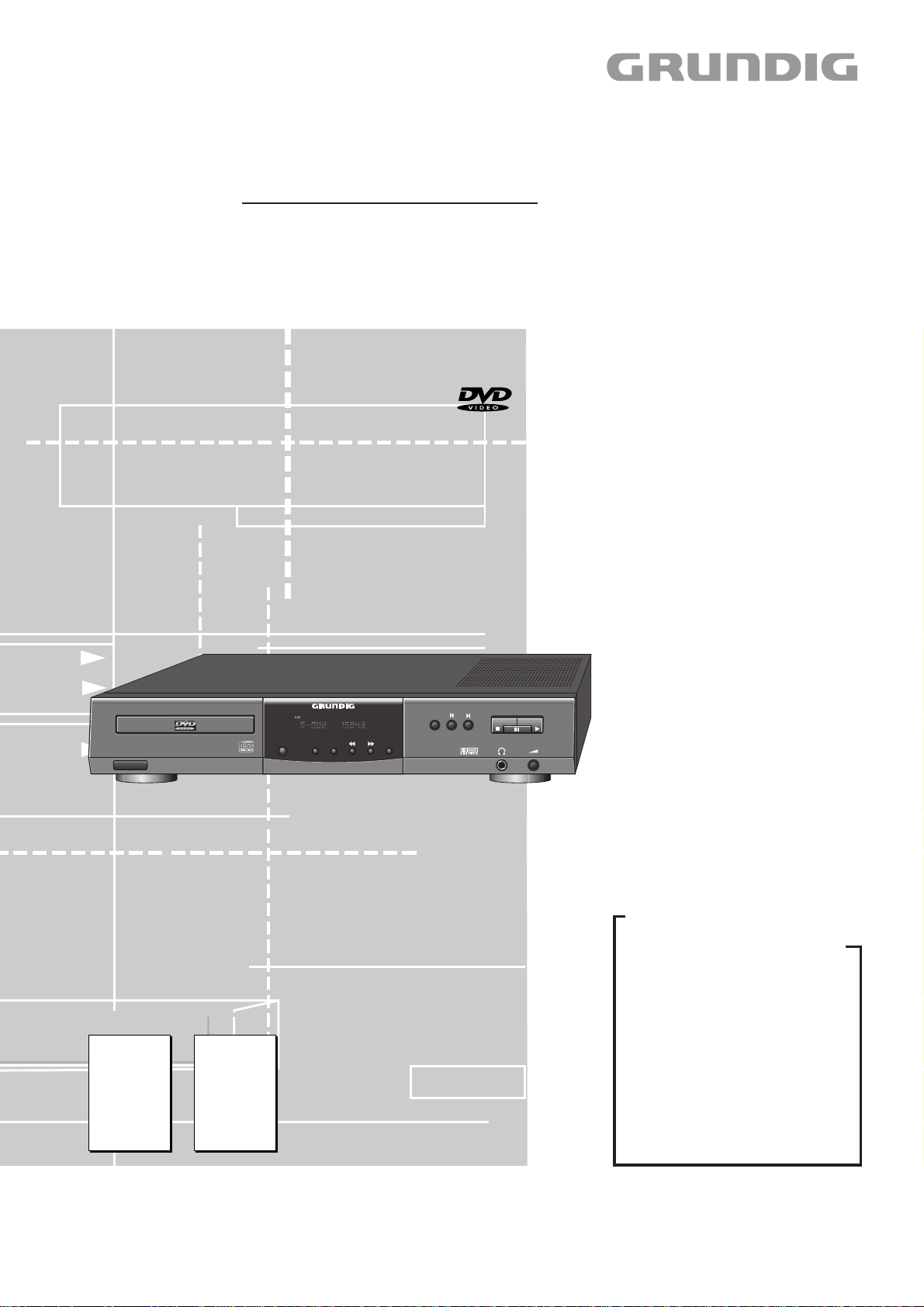
GDV 110
(G.MH 7700)
+
DVD / VIDEO-CD / CD-PLAYER
ON/OFF
Zusätzlich erforderliche Unterlagen für den Komplettservice
Additionally required Service Documents for the Complete Service
Service
Manual
GDV 100D/002
Materialnr./Part No.
72010 531 9600
Service
Manual
Sicherheit
Safety
Materialnr./Part No.
72010 800 0000
TITLE CHAPTER TIME
REPEAT TITLE
REPEAT
FTSSCANOPEN/CLOSE SHUFFLE
TruSurround
GDV 110
Grundig Service
Hotline Deutschland...
Technik:
TV
TV
SAT
VCR/LiveCam
HiFi/Audio
Car Audio
Telekommunikation
Planatron
Ersatzteil-Verkauf: ...Mo.-Fr. 8.00-19.00 Uhr
(8.00-22.00 Uhr)
...Mo.-Fr. 8.00-18.00 Uhr
0180/52318-41
0180/52318-49
0180/52318-48
0180/52318-42
0180/52318-43
0180/52318-44
0180/52318-45
Fax:
0180/52318-51
0180/52318-99
Telefon:
Fax:
0180/52318-40
0180/52318-50
Btx * 32700 # • Materialnummer/Part Number 72010 537 2000
Änderungen vorbehalten/Subject to alteration • Printed in Germany
E-BS 36 1099
http://www.grundig.de
Page 2
Allgemeiner Teil / General Section GDV 110
Es gelten die Vorschriften und Sicherheitshinweise
gemäß dem Service Manual "Sicherheit", Materialnummer 72010 800 0000, sowie zusätzlich die eventuell abweichenden, landesspezifischen Vorschriften!
Das Gerät GDV 110 entspricht dem Gerät GDV 100D/002 mit
folgenden Unterschieden:
- statt den Platinen "Digitalplatte" und "Laufwerk-Servoplatte"
nur eine Leiterplatte "Monoboard".
- neue Frontblende und CD-Fach Abdeckung.
- geänderte Software.
Mit diesem Service Manual erhalten Sie die Änderungen zum
Service Manual GDV 100D/002. Für den Komplettservice benötigen Sie zusätzlich das Service Manual GDV 100D/002, Materialnummer 72010 531 9600.
D
Inhaltsverzeichnis
Seite
Allgemeiner Teil .............................................. 2
Servicehinweise ............................................................................. 3
The regulations and safety instructions shall be valid
as provided by the "Safety" Service Manual, part
number 72010 800 0000, as well as the respective
national deviations.
The GDV 110 Player corresponds to model GDV 100D/002 with
the exception of the following:
- it is fitted with only one circuit board, the so-called
"Monoboard", instead of the "Digital Board" and the "Drive
Mechanism Servo Board".
- new front panel and CD compartment cover.
- modified software.
This Service Manual describes the changes with regard to the
Service Manual GDV 100D/002. To carry out complete repairs the
Service Manual GDV 100D/002, part number 72010 531 9600 is
additionally needed.
GB
Table of Contents
Page
General Section............................................... 2
Service Instructions........................................................................ 3
Service-Testprogramm ........................... 4…11
Automatischer Systemtest ............................................................. 4
Manueller Systemtest .................................................................... 4
PC-Systemtest ............................................................................... 8
Service-Testebenen..................................................................... 10
Fehlersuchanleitung Monoboard ................ 20
Explosionszeichnungen
und Ersatzteillisten ............................... 22…26
Explosionszeichnung Gerät ......................................................... 22
Ersatzteilliste Gerät ...................................................................... 23
Explosionszeichnung Laufwerk.................................................... 25
Ersatzteilliste Laufwerk ................................................................ 26
Service Test Programme ...................... 12…19
Automatic System Test ................................................................ 12
Manual System Test .................................................................... 12
PC System Test ........................................................................... 16
Service Test Levels...................................................................... 18
Test Instructions Monoboard....................... 21
Exploded Views and
Spare Parts Lists................................... 22…26
Exploded View Set....................................................................... 22
Spare Parts List Set ..................................................................... 23
Exploded View Drive Mechanism ................................................ 25
Spare Parts List Drive Mechanism............................................... 26
Allgemeiner Teil General Section
„Dolby“, „Dolby Pro Logic“, „AC 3“ ist gefertigt unter Lizenz von Dolby Laboratories
Licensing Corporation.
„Dolby“, „Dolby Pro Logic“, „AC 3“ und das Doppel-D-Symbol „g“ sind Warenzeichen der Dolby Laboratories Licensing Corporation. Copyright 1992 Dolby
Laboratories, Inc. Alle Rechte vorbehalten.
“Dolby“, “Dolby Pro Logic“, “AC 3” manufactured under license from Dolby
Laboratories Licensing Corporation.
“Dolby“, “Dolby Pro Logic“, “AC 3” and the double-D symbol “g” are trademarks of
the Dolby Laboratories Licensing Corporation. Copyright 1992 Dolby Laboratories,
Inc. All rights reserved.
2 GRUNDIG Service
Page 3
GDV 110 Allgemeiner Teil / General Section
Servicehinweise
Wiederherstellen der Gerätefunktion nach Austausch des
Monoboard oder Löschen des NVRAMs
• CD aus Gerät entnehmen, Schublade schließen und warten bis
Gerät "NO DISC" anzeigt.
• Auf der Fernbedienung die Taste PLAY Q drücken und die Zahlenfolge "274" eingeben.
Im Display erscheint: "– – – – – – – – – – –".
Auf der Fernbedienung folgende Zahlenfolge eingeben:
"002 001 000 140".
• Eingabe mit Taste PLAY Q bestätigen und warten, bis sich das
Gerät neu initialisiert.
Achtung:
Nur bei richtiger Zahlencode-Eingabe sind alle Gerätefunktionen
gewährleistet.
Wichtige Masseverbindungen!
Beim Zusammenbau des Gerätes ist darauf zu achten, daß die
Masseverbindungen zwischen den einzelnen Platinen und dem Rahmen sowie dem Laufwerk und dem Rahmen gewährleistet sind.
Durchführen von Messungen
Bei Messungen mit dem Oszilloskop an Halbleitern dürfen Sie nur
Tastköpfe mit 10:1 - Teiler verwenden. Außerdem ist zu beachten, daß
nach vorheriger Messung mit AC-Kopplung der Koppelkondensator
des Oszilloskops aufgeladen sein kann. Durch die Entladung über das
Meßobjekt können diese Bauteile beschädigt werden.
Service Instructions
Reactivation of the DVD-Player after exchanging the Monoboard
or resetting the NVRAM
• Remove CD from the DVD-Player, close the tray and wait until the
display shows "NO DISC"
• Press PLAY Q on the remote control and enter the numbers "274".
The diplay now shows "– – – – – – – – – – –".
Now enter the following numbers on the remote control:
"002 001 000 140".
• Press PLAY Q on the remote control to confirm the entry and wait
until the DVD-Player is initialized
Attention:
All functions will operate only if the code number has been entered
correctly.
Important: Chassis Connections!
When reassembling the machine it is essential to observe that the
chassis connections between the individual circuit boards and the
frame as well as between the Drive Mechanism and the frame are in
good order.
Carrying out Measurements
When making measurements on semi-conductors with an oscilloscope, ensure that the test probe is set to 10:1 dividing factor. Further,
please note that if the previous measurement is made on AC input, the
coupling capacitor in the oscilloscope will be charged. Discharge via
the item being checked can damage components.
Meßwerte und Oszillogramme
Bei den in den Schaltplänen und Oszillogrammen angegebenen
Meßwerten handelt es sich um Näherungswerte!
Präsentations-Mode
Die Bedienung des Gerätes ist nur noch über die Fernbedienung
möglich.
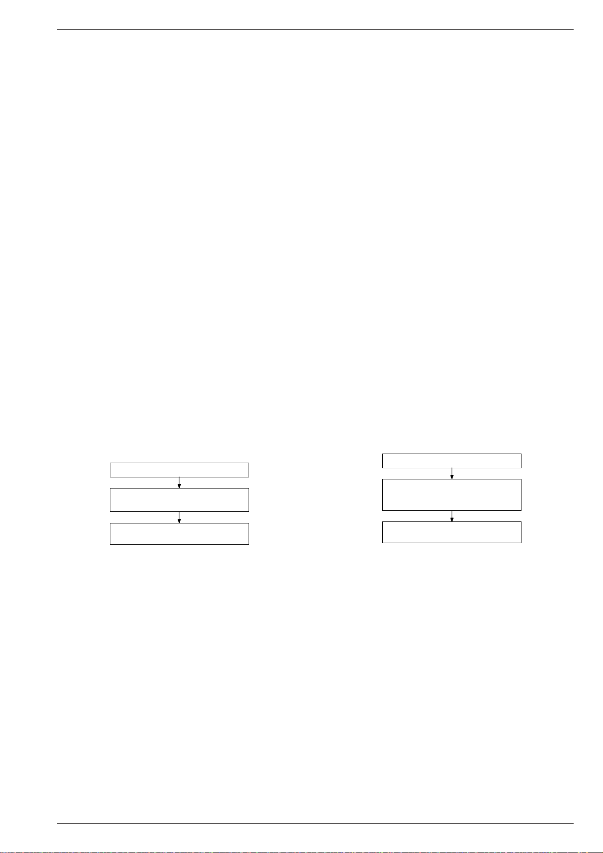
Gerät ausschalten
Tasten "PLAY" und "OPEN/CLOSE"
drücken beim Einschalten des Gerätes
Präsentations-Mode.
Ein- oder Ausgeschaltet
Measured Values and Oscillograms
The measured values given in the circuit diagrams and oscillograms
are approximates!
Presentation Mode
Local operation is not possible in this mode. Use the remote control instead.
Switch the Player off
Press and hold down the keys
"PLAY" und "OPEN/CLOSE"
and switch the Player on.
Presentation Mode
On or Off
GRUNDIG Service 3
Page 4
Servicetestprogramm GDV 110
Service-Testprogramm
D
Das Service-Testprogramm ist in 3 verschiedene Varianten unterteilt:
– Automatischer Systemtest
– Manueller Systemtest
– PC-Systemtest
Die Basis dieser Systemtests sind die Servicetestebenen, die über die
jeweiligen Tests automatisch durchgeführt werden oder manuell aufrufbar sind.
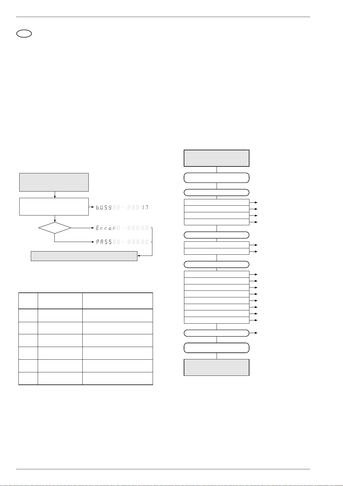
1. Automatischer Systemtest
Mit dem automatischen Systemtest ist eine Überprüfung der Hardware
des DVD-Player ohne zusätzliche Geräte möglich.
Während dem automatischen Systemtest werden die in der Tabelle
aufgeführten Servicetestebenen aufgerufen und durchgeführt. Bei
einem Gerätedefekt, Anzeige "Error", sind die einzelnen Servicetestebenen mit dem manuellen Systemtest oder dem PC-Systemtest
durchzuführen.
Hinweis: Beim automatischen Systemtest wird die A/V-MUX-Platte
nicht geprüft.
Aufruf des automatischen Systemtest mit Testübersicht
Zwei Tasten gleichzeitig drücken
<OPEN/CLOSE> + <PAUSE>
Netztaste EIN
Während des Tests zeigt das Display
die Anzahl der Ebenen,
die noch zu prüfen sind.
Gerät OK
JA
Automatischer Systemtest mit der Netztaste AUS beenden
Nummer
Display
Ebene Beschreibung
am
PapChksFl
6
PapDramWrR
5
Papl2cDisp
4
PapS2bEcho
3
NEIN
1 2 3 4 5 6 7 8 9 10 11 12 13 14 15 +--------------
1 2 3 4 5 6 7 8 9 10 11 12 13 14 15 +--------------
1 2 3 4 5 6 7 8 9 10 11 12 13 14 15 +--------------
Berechnen und Überprüfen der
Checksumme des FLASH-Speichers
Muster-Test aller Zellen im
DRAM
Test des I2C-Busses zum SlaveProzesser und Display
2
Test des I
C-Busses zum Laufwerk
D V D
V C D
D V D
V C D
D V D
V C D
2. Manueller Systemtest
Der manuelle Systemtest bietet die Möglichkeit, mit Hilfe der Tests
festzustellen, welche Module (Bedieneinheit, Monoboard oder Laufwerk) defekt sind. Des weiteren sind durch das Lesen des Fehlerprotokolls und der Fehlerbits alle Fehler feststellbar, die in letzter Zeit
bei Normalbetrieb des DVD-Players aufgetreten sind. Am Ende des
manuellen Systemtest wird ein Dauerlauftest durchgeführt (die Servicetestebenen des automatischen Systemtest werden in einer Endlosschleife wiederholt).
Zu diesem Test muß der DVD-Player an einem Fernsehgerät (PAL
oder Multisystem) angeschlossen sein, um das Ergebnis der verschiedenen Servicetestebenen prüfen zu können.
Damit die Ergebnisse bestimmter Servicetestebenen überprüft werden können, sieht der manuelle Systemtest einige interaktive Eingriffe
von seiten des Anwenders vor (z.B. Bestätigung eines Testbilds oder
Testtons). Bei einigen Ebenen (z.B. Ebenen, die die Laufwerksfunktionen testen) muß der DVD-Player geöffnet sein, damit eine
visuelle Kontrolle der beweglichen Teile möglich ist.
Es werden nur Tests im Rahmen der Servicetest-Software durchgeführt, da nur diese Fehler aufgedeckt werden können.
Aufruf des manuellen Systemtest mit Testübersicht
Zwei Tasten gleichzeitig drücken
<OPEN/CLOSE> + <STOP>
Netztaste EIN
Interaktiver Test
Bedieneinheit
Display-Test
LED-Test
Tastatur-Test
Fernbedienungs-Test
Digitalplatte
Bildtest 1
Tontest
Laufwerk
Version
Schubladen-Test
Schlitten-Test
Disk-Motor-Test
Fokus-Test
Radial-Test
Spursprung-Test
Schubladen-Test
Fehlerprotokoll & -Bits
Dauerlauftest
DispDisplay
DispLed
DispKeyb
DispRc
VideoColDencOn/Off
AudioSinOn
BeVer
BeTrayOut/In
BeSledgeOut/In
BeDiscMotorOn/Off
BeFocusOn/Off
BeRadialOn/Off
BeGroovesIn/Mid/Out
BeTrayOut/In
LogReadErr
LogReadbits
Papl2cNvram
2
CompSdramWrR
1
Test des I
Muster-Test aller Zellen im
SDRAM
2
C-Busses zum NVRAM
Test mit Netztaste
AUS beenden
2.1 Interaktiver Test
2.1.1 Bedieneinheit
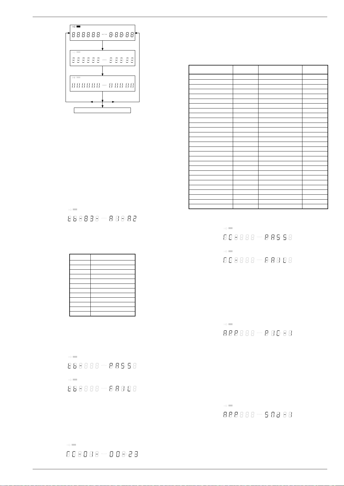
Display-Test
Servicetestebene: DispDisplay.
Bei diesem Test wird das Display wie in der folgenden Grafik dargestellt angesteuert. Die einzelnen Anzeigen können entweder durch
Drücken der Taste PLAY (Anzeige OK) oder Pause (Anzeige nicht OK)
fortgeschaltet werden. Dieser Test wird durchgeführt bis die Taste
NEXT gedrückt wird. Durch ein vorzeitiges Drücken der Taste NEXT
wird das Gesamtergebnis des manuellen Servicetestprogrammes
verfälscht.
4 GRUNDIG Service
Page 5
GDV 110 Servicetestprogramm
Fernbedientaste Code
Hexadezimal
STANDBY C
STOP 31
PLAY 2C
PLAY BACKWARD 2 d
PAUSE 30
STEP FORWARD F6
STEP BACKWARD F5
FORWARD 28
FORWARD 4x dF
FORWARD 8x E0
BACKWARD 29
BACKWARD 4x dE
BACKWARD 8x
dd
Fernbedientaste Code
Hexadezimal
SLOW 22
SLOW 2 d8
55
66
77
88
99
TOGGLE C8
ANGLE 85
AUDIO 4E
SUBTITLES 4 b
SUBTITLE ON/OFF E3
ROOT MENU 54
TITLE MENU 71
MENU d1
SETUP MENU 82
OSD ON/OFF F
SLOW BACKWARD 23
SLOW BACKWARD 2 db
NEXT 20
PREVIOUS 21
CURSOR UP 58
CURSOR DOWN 59
CURSOR LEFT 5A
CURSOR RIGHT 5b
OK 5C
00
11
22
33
44
RETURN 83
RESUME d7
SCAN 2A
SHUFFLE 1C
REPEAT 1D
A/B REPEAT 3D
TOGGLE SCART 43
OPEN/CLOSE 42
FTS FB
KARAOKE E4
OPTION FA
F T S
SHUFFLE
PAUSE SCAN A B-CHAPTER TITLE TRACK
CHAPTER
1 2 3 4 5 6 7 8 9 10 11 12 13 14 15 +--------------
PLAY drücken
F T S
SHUFFLE
CHAPTER
1 2 3 4 5 6 7 8 9 10 11 12 13 14 15 +--------------
PLAY drücken
F T S
SHUFFLE
CHAPTER
1 2 3 4 5 6 7 8 9 10 11 12 13 14 15 +--------------
PLAY drücken
wenn OK,
wenn OK,
wenn OK,
D V D
V C D
wenn Nicht OK,
PAUSE drücken
PAUSE SCAN A B-CHAPTER TITLE TRACK
D V D
V C D
wenn Nicht OK,
PAUSE drücken
PAUSE SCAN A B-CHAPTER TITLE TRACK
D V D
V C D
wenn Nicht OK,
PAUSE drücken
fortsetzen durch Drücken von NEXT
LED-Test
Servicetestebene: DispLed
Bei diesem Test muß die LED leuchten. Wenn die LED leuchtet, dann
PLAY drücken; andernfalls die Taste PAUSE drücken. Mit der Taste
NEXT kann auf den nächsten Test weitergeschaltet werden. Durch ein
vorzeitiges Drücken der Taste NEXT wird das Gesamtergebnis des
manuellen Servicetestprogrammes verfälscht.
Tastatur-Test
Servicetestebene: DispKeyb
Dazu müssen alle Tasten des Gerätes einmal gedrückt werden. Der
Code der jeweils gedrückten Taste erscheint am Gerätedisplay
(hexadezimalzahl). Die daran anschließende Zahl (hexadezimal) zeigt
an, wie oft die Taste betätigt wurde. Im Display sind immer die letzten
3 Codenummern der zuletzt gedrückten Tasten sichtbar (ab dem
Beginn des Tastatur-Test). Beispiel einer Anzeige während des Tests:
F T S
SHUFFLE
PAUSE SCAN A B-CHAPTER TITLE TRACK
CHAPTER
1 2 3 4 5 6 7 8 9 10 11 12 13 14 15 +--------------
D V D
V C D
tb: Tastaturtest
83: Taste BACKWARD 3 * gedrückt
A1: Taste FORWARD das 1. Mal gedrückt
A2: Taste FORWARD das 2. Mal gedrückt
Tasten ID Taste
0 PLAY
1 NEXT
2 PREVIOUS
3 PAUSE
4 STOP
5 REPEAT
6 FTS
7 SCAN
8 BACKWARD
9 OPEN / CLOSE
A FORWARD
b SHUFFLE
Taucht eine Taste mehr als einmal auf (wegen Hardwarefehler), wird
der Tastencode zweimal (oder öfter) angezeigt, wobei die zweite Zahl
um 1 erhöht wird. Zum Beenden des Tastaturtests die Taste NEXT
mindestens 1 Sekunde gedrückt halten. Durch ein vorzeitiges Beenden wird das Ergebnis verfälscht. Das Testergebnis erscheint auf dem
Gerätedisplay.
wenn OK:
wenn nicht OK:
Durch Drücken der Taste NEXT am Gerät kann zum nächsten Test
übergegangen werden.
Fernbedienungs-Test
Servicetestebene: DispRc
Dazu ist auf der Fernbedienung eine beliebige Taste einmal zu
drücken. Der Code der gedrückten Taste wird am Gerätedisplay als
Hexadezimalzahl gezeigt, solange die Taste gedrückt bleibt.
F T S
SHUFFLE
PAUSE SCAN A B-CHAPTER TITLE TRACK
CHAPTER
1 2 3 4 5 6 7 8 9 10 11 12 13 14 15 +--------------
F T S
SHUFFLE
CHAPTER
1 2 3 4 5 6 7 8 9 10 11 12 13 14 15 +--------------
D V D
V C D
PAUSE SCAN A B-CHAPTER TITLE TRACK
D V D
V C D
F T S
SHUFFLE
PAUSE SCAN A B-CHAPTER TITLE TRACK
CHAPTER
1 2 3 4 5 6 7 8 9 10 11 12 13 14 15 +--------------
D V D
V C D
GRUNDIG Service 5
REPEAT
REPEAT
REPEAT
REPEAT
REPEAT
REPEAT
REPEAT
TOTALTRACKTITLE
TOTALTRACKTITLE
TOTALTRACKTITLE
TOTALTRACKTITLE
TOTALTRACKTITLE
TOTALTRACKTITLE
TOTALTRACKTITLE
REM TRACK TIME
REM TRACK TIME
REM TRACK TIME
REM TRACK TIME
REM TRACK TIME
REM TRACK TIME
REM TRACK TIME
Der Fernbedientest kann durch Drücken der Taste NEXT am DVDPlayer beendet werden. Der Fernbedienungs-Test ist bestanden,
wenn vor dem Drücken der Taste NEXT ein Code angezeigt wurde.
Wird NEXT vor Betätigen einer Taste auf der Fernbedienung
gedrückt, entsteht ein Fehler im Fernbedientest. Die einzelnen
Tasten der Fernbedienung sind mit Hilfe der folgenden Tabelle
überprüfbar:
Nach Drücken der Taste NEXT erscheint das Ergebnis am Display des
DVD-Player:
wenn OK:
wenn nicht OK:
F T S
SHUFFLE
PAUSE SCAN A B-CHAPTER TITLE TRACK
CHAPTER
1 2 3 4 5 6 7 8 9 10 11 12 13 14 15 +--------------
F T S
SHUFFLE
PAUSE SCAN A B-CHAPTER TITLE TRACK
CHAPTER
1 2 3 4 5 6 7 8 9 10 11 12 13 14 15 +--------------
D V D
V C D
D V D
V C D
REPEAT
REPEAT
TOTALTRACKTITLE
TOTALTRACKTITLE
REM TRACK TIME
REM TRACK TIME
Mit der Taste NEXT auf der Gerätetastatur kann auf den nächsten Test
weitergeschaltet werden.
2.1.2 Monoboard
Bildtest 1
Servicetestebene: VideoColDencOn/Off
Beim Bildtest 1 wird ein Farbbalken-Testbild generiert. Im Display
erscheint:
F T S
SHUFFLE
PAUSE SCAN A B-CHAPTER TITLE TRACK
CHAPTER
1 2 3 4 5 6 7 8 9 10 11 12 13 14 15 +--------------
Durch Drücken der Taste PLAY wird bestätigt, daß das Bild sichtbar ist.
Durch Drücken der Taste PAUSE wird dem Gerät mitgeteilt, daß das
Bild nicht sichtbar oder gestört war.
Mit der Taste NEXT kann auf den nächsten Test weitergeschaltet
werden. Durch ein vorzeitiges Drücken der Taste NEXT wird das
Testergebnis verfälscht.
Tontest
Servicetestebene: AudioSinOn
Beim Tontest 2 wird ein sinusförmiger Ton erzeugt. Im Display erscheint:
F T S
SHUFFLE
PAUSE SCAN A B-CHAPTER TITLE TRACK
CHAPTER
1 2 3 4 5 6 7 8 9 10 11 12 13 14 15 +--------------
Zum Beenden des Tests die Taste STOP drücken.
Durch Drücken der Taste PLAY wird bestätigt, daß der Ton hörbar war.
Durch Drücken der Taste PAUSE wird dem Gerät mitgeteilt, daß der
Ton nicht hörbar oder gestört war.
Mit der Taste NEXT kann auf den nächsten Test weitergeschaltet
werden. Durch ein vorzeitiges Drücken der Taste NEXT wird das
Testergebnis verfälscht.
D V D
V C D
D V D
V C D
REPEAT
REPEAT
TOTALTRACKTITLE
TOTALTRACKTITLE
REM TRACK TIME
REM TRACK TIME
Page 6
Servicetestprogramm GDV 110
2.1.3 Laufwerk
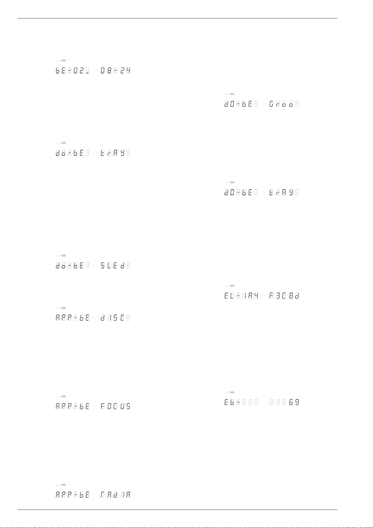
Version
Servicetestebene: BeVer
Die Version ist die Laufwerkversions-Nummer.
F T S
SHUFFLE
PAUSE SCAN A B-CHAPTER TITLE TRACK
CHAPTER
1 2 3 4 5 6 7 8 9 10 11 12 13 14 15 +--------------
Durch Drücken der Taste NEXT können die Laufwerktests gestartet
werden.
Schubladen-Test
Servicetestebene: BeTrayOut/In
Als erstes wird die Schublade überprüft. Dieser Test soll außerdem
eine Möglichkeit geben, eine Disc in den DVD-Player einzulegen, die
für einige Laufwerktests notwendig ist. Dieser Test wird am Ende der
Laufwerktests nur deshalb wiederholt, damit die Disc wieder aus der
Schublade genommen werden kann. Im Display erscheint:
F T S
SHUFFLE
PAUSE SCAN A B-CHAPTER TITLE TRACK
CHAPTER
1 2 3 4 5 6 7 8 9 10 11 12 13 14 15 +--------------
Durch Drücken der Taste PLAY oder PAUSE kann die Schublade
geschlossen oder geöffnet werden. Am Ende dieser Überprüfung
sollte die Schublade geschlossen sein. Beachten Sie, daß dieser Test
nicht in das Ergebnis des Laufwerktests eingeht. Durch Drücken der
Taste NEXT kann auf den nächsten Test weitergeschaltet werden.
Schlitten (optischer Test)
Servicetestebene: BeSledgeOut/In
Im zweiten Laufwerktest wird der Schlitten überprüft. Dabei kann der
Schlitten mit den Tasten PLAY (Ebene BeSledgeOut) und PAUSE
(Ebene BeSledgeIn) beliebig oft aus- und eingefahren werden. Durch
Drücken von NEXT kann auf den nächsten Test weitergeschaltet
werden. Beachten Sie, daß dieser Test nicht in das Ergebnis des
Laufwerktests eingeht. Während der Überprüfung erscheint im Display:
F T S
SHUFFLE
PAUSE SCAN A B-CHAPTER TITLE TRACK
CHAPTER
1 2 3 4 5 6 7 8 9 10 11 12 13 14 15 +--------------
Disc Motor (optischer Test)
Servicetestebene: BeDiscMotorOn/Off
Im dritten Laufwerktest wird der Disc-Motor überprüft. Im Display
erscheint:
F T S
SHUFFLE
PAUSE SCAN A B-CHAPTER TITLE TRACK
CHAPTER
1 2 3 4 5 6 7 8 9 10 11 12 13 14 15 +--------------
Durch Drücken der Taste PLAY wird das Laufen des Disc-Motors
bestätigt. Durch Drücken der Taste PAUSE wird signalisiert, daß der
Motor nicht funktioniert.
Mit der Taste NEXT kann auf den nächsten Test weitergeschaltet
werden. Durch ein vorzeitiges Drücken der Taste NEXT wird das
Testergebnis verfälscht.
Fokus (akustischer Test, mit CD)
Servicetestebene: BeFocusOn/Off
Der vierte Laufwerktest dient zur Überprüfung der Fokussierung. Im
Display erscheint:
F T S
SHUFFLE
PAUSE SCAN A B-CHAPTER TITLE TRACK
CHAPTER
1 2 3 4 5 6 7 8 9 10 11 12 13 14 15 +--------------
Durch Drücken der Taste PLAY wird ein fehlerloses Fokussieren
bestätigt. Durch Drücken der Taste PAUSE wird dem Gerät eine
Fehlfunktion mitgeteilt.
Mit der Taste NEXT kann auf den nächsten Test weitergeschaltet
werden. Durch ein vorzeitiges Drücken der Taste NEXT wird das
Testergebnis verfälscht.
Radialsteuerung (optischer und akustischer Test, mit CD)
Servicetestebene: BeRadialOn/Off
Der fünfte Laufwerktest dient zur Überprüfung der Radialsteuerung.
Im Display erscheint:
F T S
SHUFFLE
PAUSE SCAN A B-CHAPTER TITLE TRACK
CHAPTER
1 2 3 4 5 6 7 8 9 10 11 12 13 14 15 +--------------
D V D
V C D
D V D
V C D
D V D
V C D
D V D
V C D
D V D
V C D
D V D
V C D
REPEAT
REPEAT
REPEAT
REPEAT
REPEAT
REPEAT
TOTALTRACKTITLE
TOTALTRACKTITLE
TOTALTRACKTITLE
TOTALTRACKTITLE
TOTALTRACKTITLE
TOTALTRACKTITLE
REM TRACK TIME
REM TRACK TIME
REM TRACK TIME
REM TRACK TIME
REM TRACK TIME
REM TRACK TIME
Durch Drücken der Taste PLAY wird ein fehlerlose Radialsteuerung
bestätigt. Durch Drücken der Taste PAUSE wird dem Gerät eine
Fehlfunktion mitgeteilt.
Mit der Taste NEXT kann auf den nächsten Test weitergeschaltet
werden. Durch ein vorzeitiges Drücken der Taste NEXT wird das
Testergebnis verfälscht.
Spursprungtest (akustischer Test, mit CD)
Servicetestebenen: BeGroovesIn/Mid/Out
Der sechste und letzte Laufwerktest prüft das Spursprungverhalten.
Im Display erscheint:
F T S
SHUFFLE
PAUSE SCAN A B-CHAPTER TITLE TRACK
CHAPTER
1 2 3 4 5 6 7 8 9 10 11 12 13 14 15 +--------------
D V D
V C D
REPEAT
TOTALTRACKTITLE
REM TRACK TIME
Durch Drücken der Taste PLAY können die drei verschiedenen
Spureinstellungen gewählt werden (vorwärts in der Folge In-Mid-Out)
oder PAUSE (rückwärts in der Folge Out-Mid-In). Die Spureinstellungen werden zyklisch umgeschaltet. Beachten Sie, daß dieser Test
nicht in das Ergebnis des Laufwerktests eingeht. Mit NEXT kann auf
den nächsten Test weitergeschaltet werden.
Schublade
Servicetestebene: BeTrayOut/In
Am Ende der Laufwerktests wird der Schubladentest wiederholt. Im
Display erscheint:
F T S
SHUFFLE
PAUSE SCAN A B-CHAPTER TITLE TRACK
CHAPTER
1 2 3 4 5 6 7 8 9 10 11 12 13 14 15 +--------------
D V D
V C D
REPEAT
TOTALTRACKTITLE
REM TRACK TIME
Dieser Test bietet die Möglichkeit, die Disc aus der Schublade zu
nehmen. Durch Drücken der Taste PLAY oder PAUSE kann die
Schublade geschlossen oder geöffnet werden. Vor dem Weiterschalten
zum nächsten Test mit der NEXT-Taste muß die Schublade geschlossen sein.
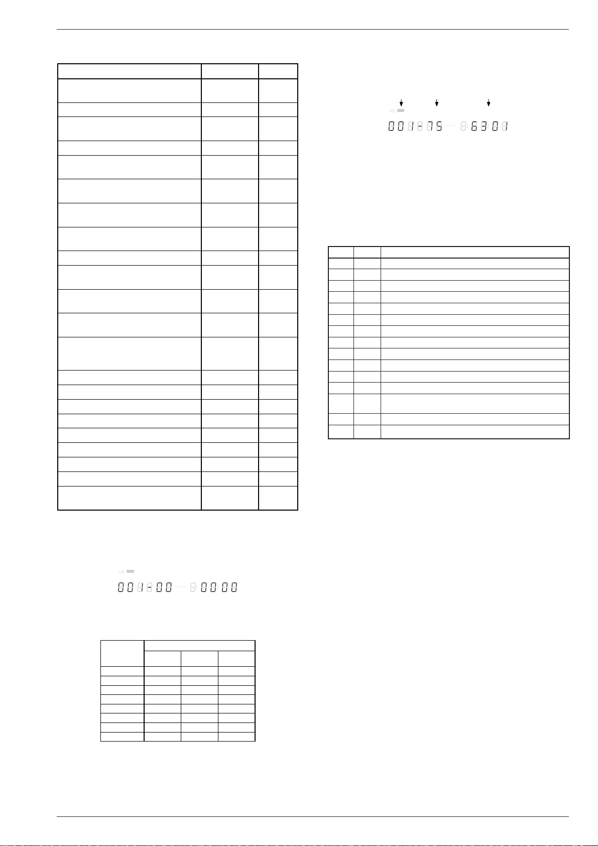
2.2 Fehlerprotokoll und Fehlerbits
Fehlerprotokoll (ERROR LOG)
Servicetestebene: LogReadErr
Durch Lesen des Fehlerprotokolls und der Fehlerbits sind Fehler
festzustellen, die in letzter Zeit bei Normalbetrieb des DVD-Player
aufgetreten sind. Im Display erscheint z.B.:
F T S
SHUFFLE
PAUSE SCAN A B-CHAPTER TITLE TRACK
CHAPTER
1234 5 6 7 8 9 10 11 12 13 14 15 +--------------
Durch Drücken der Taste PLAY (vorwärts) oder PAUSE (rückwärts)
können die protokollierten Fehler fortgeschaltet werden. Die aufleuchtende Zahl zeigt an, welcher Fehlercode gerade am Display gezeigt
wird (in obigem Beispiel ist es Fehlercode Nummer 4). Erscheint
“0000” an allen Stellen, ist das Fehlerprotokoll leer. Die protokollierten
Fehler werden zyklisch angezeigt. Der Fehlercode mit der niedrigsten
Zahl ist der zuletzt festgestellte Fehler.
Mit der Taste NEXT kann auf den nächsten Test weitergeschaltet
werden.
Eine Übersicht der ERROR LOGs findet sich nachstehend.
Fehlerbits
Die Fehlerbits werden in der Ebene ReadBits gelesen. Während dem
Lesen der Fehlerbits erscheint folgende Information auf dem Display:
F T S
SHUFFLE
PAUSE SCAN A B-CHAPTER TITLE TRACK
CHAPTER
1 2 3 4 5 6 7 8 9 10 11 12 13 14 15 +--------------
Es werden nur gesetzte Fehlerbits mit ihrer Nummer (dezimal) angezeigt. Die Bedeutung der Bits ist nachstehend erklärt. Zeigt das
Display nur “EB-0”, sind keine Fehlerbits gesetzt worden.
Mit Taste NEXT kann auf den nächsten Test weitergeschaltet werden.
D V D
V C D
D V D
V C D
REPEAT
REPEAT
TOTALTRACKTITLE
TOTALTRACKTITLE
REM TRACK TIME
REM TRACK TIME
6 GRUNDIG Service
Page 7
GDV 110 Servicetestprogramm
Fehler Ebene Fehlerbeschreibung
0601 6 Berechnete Prüfsumme des FLASH ist nicht richtig
0901 9 Der DVD-DRAM ist defekt
1104 11 Aktivität auf I2C-Bus vor Start
1102 NVRAM Zugriffsunterbrechung
1103 Keine Rückmeldung vom NVRAM
1104 Keine Rückmeldung vom NVRAM
1201 12 Aktivität auf I2C-Bus
1202 I2C-Bus arbeitet nicht
1203 Slave-Controller antwortet nicht
1204 Antwort vom Slave ist nicht richtig
1301 13 Paritätsfehler vom Laufwerk zum seriellen Bus
1302 Paritätsfehler vom seriellen Bus zum Laufwerk
1303 Keine Kommunikation zwischen seriellem Bus und Lauf-
werk
1304 Fehler Kommunikationsunterbrechung
1601 16 Der SDRAM ist defekt
2.2.1 Fehlermeldungen
Fehlerbeschreibung Fehlerprotokoll Fehlerbits
Befehl in diesem Status nicht erlaubt 15101 8
oder unbekannt
Parameter nicht gültig für Befehl 15102 7
Schlitten konnte nicht in Ausgangs- 15103 6
position gebracht werden
Fokussierungsfehler 15104 5
Motor innerhalb der Unterbrechung 15105 4
nicht auf Geschwindigkeit
Servo konnte nach mehreren Ver- 15106 3
suchen die Spur nicht finden
PLL konnte nicht auf Zugriff oder 15107 2
Tracking synchronisieren
Subcode oder Sektor konnte nicht 15108 1
gelesen werden
Gewünschter Subcode nicht gefunden 15109 16
Schublade konnte nicht vollständig 1510A 15
geöffnet oder geschlossen werden
TOC konnte nicht rechtzeitig gelesen 1510B 14
werden
Eingabe als eine Suchfunktion nicht 1510C 13
möglich
Datenpfad versucht, auf einen nicht 1510D 12
existenten Einlaufbereich Zugriff zu
nehmen
Nicht existierender Burst angefordert 1510E 11
S2b Kommunikations-Fehler 151F0 10
S2b Kommunikations-Fehler 151F1 9
S2b Kommunikations-Fehler 151F3 24
S2b Kommunikations-Fehler 151F4 23
S2b Kommunikations-Fehler 151F5 22
Kommunikationsfehler mit STi 5505 90000 32
Kommunikationsfehler mit STi 5505 90001 31
Kommunikationsfehler mit Display- 190000 40
prozessor
können nur die Fehler entdeckt werden, die im Rahmen des Servicetestprogramms liegen), sondern auch ein Zähler, der anzeigt, wie oft
die Testschleife bereits durchlaufen wurde.
Beispiel:
Modul Zyklen Fehlercode
F T S
SHUFFLE
PAUSE SCAN A B-CHAPTER TITLE TRACK
CHAPTER
1 2 3 4 5 6 7 8 9 10 11 12 13 14 15 +--------------
D V D
V C D
REPEAT
TOTALTRACKTITLE
REM TRACK TIME
Die Zahl nach dem Bindestrich gibt die Anzahl der Testschleifen an.
Die 4 Stellen rechts am Display zeigen den letzten Fehler an, der in
der Testschleife entdeckt wurde: die beiden linken Stellen dieses
Codes zeigen, in welcher Ebene der Fehler aufgetreten ist, die
beiden rechten Stellen bezeichnen den Fehlercode innerhalb dieser
Ebene. Eine detaillierte Beschreibung des Fehlercodes finden Sie
nachstehend.
Fehlercodenummern im Dauerlauftest:
2.3 Dauerlaufprüfung
Zu Beginn der Testschleife erscheint zunächst das Ergebnis des
interaktiven Playertests:
F T S
SHUFFLE
PAUSE SCAN A B-CHAPTER TITLE TRACK
CHAPTER
1 2 3 4 5 6 7 8 9 10 11 12 13 14 15 +--------------
Auf der linken Seite des Displays steht ein 3-stelliger Code mit einem
Wertebereich zwischen 000 und 111. Diese Werte sind wie folgt zu
interpretieren:
Angezeigter
Beim Dauerlauftest werden alle Ebenen abgearbeitet wie beim automatischen Systemtest, sie werden jedoch in einer Endlosschleife
wiederholt. Am Display des DVD-Player erscheinen nicht nur die drei
Zahlen, die anzeigen, welche Module defekt/nicht defekt sind, und der
zuletzt festgestellte Fehlercode (wie bereits an anderer Stelle erwähnt
Wert
000 ok ok ok
001 ok ok Fehler
010 ok Fehler ok
011 ok Fehler Fehler
100 Fehler ok ok
101 Fehler ok Fehler
110 Fehler Fehler ok
111 Fehler Fehler Fehler
GRUNDIG Service 7
Anzeige für das jeweilige Modul
Laufwerk Mono-
D V D
V C D
REPEAT
board
TOTALTRACKTITLE
REM TRACK TIME
Bedieneinheit
Page 8

Servicetestprogramm GDV 110
3. PC-Systemtest
Hardwareanforderung:
– Service-PC
– freier COM-Port (COM1) am Service-PC
– Spezialkabel (Service Serial Interface – RS232)
RS232 SOCKET
BACKSIDE VIEW
1 = TX1P
2 = IACK5N
3 = RX1P
4 = RTSEX
5 = GROUND
6 = CTS1P
7 = +5V
672354 1
PHR-7 CONNECTOR
Softwareanforderung:
– Terminal-Emulationsprogramm
(z.B. OS2 – Wrap Terminal oder Windows 95 – Procomm)
Spezialkabel am Service Serial Interface des DVD-Players und am
freien COM-Port des Service-PC anschließend. Mit diesem Spezialkabel wird der Testpin am Service Serial Interface mit Masse verbunden (d.h. Testpin aktiviert).
Terminal-Emulationsprogramm starten und folgende COM-Port-Einstellungen prüfen: 19200bps, 8 Datenbits, keine Parität, 1 Stoppbit,
kein Protokoll und keine Umwandlung.
Aufruf der Bedienvarianten
Player einschalten. Am Bildschirm des Service-PC erscheint folgender Text:
DVD2 Diagnostic Software version 3.1
SDRAM Interconnection test passed
Basic Sdram test passed.
Karaoke init OK
(M)enu, (C)ommand (S)2B–interface or (D)ownload? [M]:@
Die erste Zeile enthält die Versionnummer des Servicetestprogramms.
Die nächsten beiden Zeilen zeigen, daß zwei weitere Tests mit Erfolg
abgeschlossen wurden. Die Beschreibung zu diesen Ebenen finden
Sie im Kapitel "Servicetestebenen". Erscheinen nicht alle diese Meldungen auf dem Bildschirm des Service-PC, wurde in der entsprechenden Ebene ein Fehler entdeckt.
In der 4. Zeile müssen Sie die Bedienvariante (M)enu oder (C)ommand
wählen und mit <return> bestätigen.
Beenden der Bedienvariante
Zum Beenden der aktiven Bedienvariante muß der DVD-Player abgeschaltet werden.
3.1 Bedienvariante (M)enu
Die Bedienvariante (M)enu ist Bestandteil des Servicetestprogramms
Level 2.
Das gewünschte Menü kann durch Eingabe der Nummer des gewählten Menüpunktes aufgerufen werden. Jede Eingabe ist mit einem
<return> zu bestätigen. Ungültige Eingaben zeigt der Menüverwalter
mit folgender Fehlermeldung:
Select> 34
0001 Invalid menu selection ER @
Press RETURN to continue…@
Ergebnis und Ausgabe der gewählten Servicetestebene erscheinen
am Service-Terminal im Punkt 3.2 beschriebenen Standardformat.
Select> 5
1601 Data line X is not connected to the DSM/DVP ER @
Press RETURN to continue…@
Nach Drücken einer Taste erscheint das aktuelle Menü wieder auf dem
Bildschirm.
Zum Hauptmenü gelangt man aus einem Untermenü durch Drücken
der Taste <return>.
3.1.1 Menü- und Untermenütafeln
Das Symbol hinten den jeweiligen Menüpunkten verweist auf ein
weiteres Untermenü. Die in den Klammern aufgeführte Nummer ist die
Nummer der Servicetestebene (Punkt 4).
Hauptmenü
MAIN MENU
1. Audio –>
2. Basic engine –>
3. Display PWB –>
4. Processor & Peripherals –>
5. Karaoke –>
6. Log –>
7. Miscellaneous –>
8. Video –>
Untermenüebene 1
AUDIO MENU
1. Deemphasis –>
2. Mute –>
3. PinkNoise –>
4. SineWave –>
BASIC ENGINE MENU
1. Disc Motor –>
2. Focus –>
3. Grooves –>
4. Radial –>
5. Reset [44]
6. Sledge –>
7. Tray –>
8. Version [37]
DISPLAY PWB MENU
1. Display [30]
2. Keyboard [27]
3. LEDs [29]
4. Remote control [28]
5. Version [26]
PROCESSOR AND PERIPHERALS MENU
1. Clock –>
2. DRAM (normally not equiped) write/read [9]
3. Flash –>
4. I2C –>
5. S2B –>
6. SDRAM write/read [16]
KARAOKE MENU
1. Karaoke Mode Off [48a]
2. Karaoke Mode On [48b]
3. Karaoke Mic Input [49]
4. Karaoke Key On [50a]
5. Karaoke Key Off [50b]
LOG MENU
1. Read last errors [31]
2. Read error bits [32]
3. Reset [33]
MISCELLANEOUS MENU
1. NVRam Utils –>
2. PalNtsc Line –>
3. 2B Utils –>
4. Statistics Info –>
5. Read Application version [46]
VIDEO MENU
1. Colourbar –>
2. Scart –>
8 GRUNDIG Service
Page 9

GDV 110 Servicetestprogramm
Untermenüebene 2
DEEMPHASIS MENU
1. Deemphasis 0 On [18a]
2. Deemphasis 0 Off [18b]
3. Deemphasis 1 On [18c]
4. Deemphasis 1 Off [18d]
MUTE MENU
1. Mute on [19a]
2. Mute off [19b]
NOISE MENU
1. Pink Noise on [20a]
2. Pink Noise off [20b]
SINEWAVE MENU
1. Audio Sine on [21a]
2. Audio Burst on [21b]
DISC MOTOR MENU
1. Disc motor on [39a]
2. Disc motor off [39b]
FOCUS MENU
1. Focus on [38a]
2. Focus off [38b]
GROOVES MENU
1. Jump grooves to inside [42a]
2. Jump grooves to middle [42b]
3. Jump grooves to outside [42c]
RADIAL MENU
1. Radial control on [40a]
2. Radial control off [40b]
SLEDGE MENU
1. Sledge inwards [41a]
2. Sledge outwards [41b]
TRAY MENU
1. Open tray [43b]
2. Close tray [43a]
UCLOCK MENU
1. uClock A_CLK in CDDA mode [7a]
2. uClock A_CLK in DVD mode [7b]
FLASH MENU
1. Checksum FLASH [6]
2. Flash write access [10]
I2C MENU
1. I2C NVRAM access [11]
2. I2C Display PWB [12]
S2B MENU
1. S2B echo [13]
2. S2B pass–through [14]
NVRAM MENU
1. NVRAM Config [34]
2. NVRAM reset [35]
3. NVRAM Mod [36]
4. NVRAM write/read [15]
PALNTSC MENU
1. PalNtsc Hi [45a]
1. PalNtsc Lo [45b]
2B UTILS MENU
1. I2C Scart Check [48]
2. Scart To DVD [49a]
3. Scart Pass through [49b]
4. Video Col Setup I2C [46]
5. Video Col Setup Hi [47a]
6. Video Col Setup Lo [47b]
STATISTICS INFO MENU
1. Total Nr of times Tray Open [47a]
2. Total Time Power On [47b]
3. Total Play-time CDDA & VCD [47c]
4. Total Play-time DVD [47d]
VIDEO COLOURBAR MENU
1. Colourbar DENC on [23a]
2. Colourbar DENC off [23b]
SCART MENU
1. Scart low [25a]
2. Scart medium [25b]
3. Scart high [25c]
3.1.2 Bildschirmdarstellung der Menüs
Bei der Verwendung von Menüs ist keine spezielle Bildschirmdarstellung festgelegt: Mit Ausnahme des vorher beschriebenen Formats gibt
es für die Menüs kein bestimmtes Layout.
Eine typische Menü-Session sieht wie folgt aus:
DVD2 Diagnostic Software version 1.37
SDRAM Interconnection test passed
Basic Sdram test passed.
Karaoke init OK
(M)enu, (C)ommand (S)2B–interface or (D)ownload? [M]:@ M ↵
MAIN MENU
1. Audio –>
2. Basic engine –>
3. Display PWB –>
4. Processor & Peripherals –>
5. Karaoke –>
6. Log –>
7. Miscellaneous –>
8. Video –>
Select> 4 ↵
PROCESSOR AND PERIPHERALS MENU
1. Clock –>
2. DRAM (normally not equiped) write/read [9]
3. Flash –>
4. I2C –>
5. S2B –>
6. SDRAM write/read [16]
Select> 3 ↵
Je nach Höhe des Bildschirms rollt der Text von der Oberkante des
Bildschirms nach unten.
3.2 Bedienvariante (C)ommand
Die Bedienvariante (C)ommand ist Bestandteil des Servicetestprogramms Level 1.
Nach der Eingabeauffoderung "DD>" können als Befehle die Bezeichnungen oder Nummern der Servicetestebenen (Punkt 4) eingegeben
und mit einem <return> bestätigt werden. Eine Korrektur der eingetippten Befehle ist mit der Rücktaste möglich.
Bei Eingabefehlern erscheint z.B. folgende Fehlermeldung:
DD>123↵
0001 Unknown command ER @
DD>
Anzeige bei keinem Gerätedefekt:
DD>12↵
1200 OK @
DD>
Anzeige bei Gerätedefekt:
DD>12↵
1201 <TEXT> ER @
DD>
<TEXT> ist eine kurze englische Erklärung des aufgetretenen Fehlers.
GRUNDIG Service 9
Page 10

Servicetestprogramm GDV 110
4. Service-Testebenen
1 (BasicSpAcc)
Dieser Basis-Test ist Voraussetzung für eine korrekte Funktion der
Diagnose Software.
Es wird der RS232-Port initialisiert und eine Meldung ausgegeben,
daß die Diagnose Software gestartet wurde.
2 (BasicInterconDram, BasicInterconSdram)
Test der Verbindungen der Daten- und Adressleitungen des Prozessors. Dieser Test kann fehlerhafte (kurzgeschlossene) Adressleitungen
erkennen und gibt aus, welche Leitung fehlerhaft ist.
Anmerkung: Dieser Test funktioniert nur, wenn ein DRAM installiert
ist.
3 (BasicDramWrR)
Dieser Basis-Test ist Voraussetzung für eine korrekte Funktion der
Diagnose Software.
Es wird ein Mustertest des Teiles des DRAM durchgeführt, der von der
Diagnose Software benutzt wird. Es werden dabei auch die Datenleitungen auf Fehler (Kurzschlüsse) getestet.
Anmerkung: Dieser Test funktioniert nur, wenn ein DRAM installiert
ist.
4 (BasicSdramWrR)
Dieser Basis-Test ist Voraussetzung für eine korrekte Funktion der
Diagnose Software.
Es wird ein Mustertest des Teiles des SDRAM durchgeführt, der von
der Diagnose Software benutzt wird. Es werden dabei auch die
Datenleitungen auf Fehler (Kurzschlüsse) getestet.
5 (BasicSramWrR)
Dieser Basis-Test ist Voraussetzung für eine korrekte Funktion der
Diagnose Software.
Es wird ein Mustertest des internen SDRAM des STi5505 (IC7200)
durchgeführt.
6 (PapChksFlash)
Berechnet und überprüft die Checksumme des FLASH.
7a (PapUclkAclkCdda)
Dieser Test schaltet die A_CLK-Leitung auf 11,2896MHz (CD_DA).
Die korrekte Funktion kann nicht von der Diagnose Software erkannt
werden, sondern muß extern überprüft werden (z.B. mit einem
Frequenzzähler).
Anmerkung: Dieser Test arbeitet nur, wenn der externe Takt aktiviert
ist.
7b (PapUclkAclkDvd)
Dieser Test schaltet die A_CLK-Leitung auf 12,288MHz (DVD).
Die korrekte Funktion kann nicht von der Diagnose Software erkannt
werden, sondern muß extern überprüft werden (z.B. mit einem
Frequenzzähler).
Anmerkung: Dieser Test arbeitet nur, wenn der externe Takt aktiviert
ist.
9 (PapDramWrR)
Mustertest aller Speicherzellen im DRAM. Dieser Test kann Fehler in
den DRAMS erkennen und auch feststellen, welches DRAM fehlerhaft
ist. Die Ergebnisse des Tests sind nur dann gültig, wenn die Zugriffe
auf die DRAMs korrekt funktionieren.
Anmerkung: Dieser Test funktioniert nur, wenn ein DRAM installiert
ist.
10 (PapFlashWrAcc)
Liest die Chip Identifizierungsnummer. Der Test schreibt eine definierte Sequenz in das FLASH-RAM die es ermöglicht, die Identifizierungsnummer auszulesen.
Anmerkung: Wenn die Diagnose Software im FLASH läuft, hängt sich
dieser Test auf. Durch das Schreiben ins FLASH wird der OutputEnable-Pin auf HIGH gesetzt (Output disabled) und der Code im
FLASH kann nicht weiter ausgeführt werden. Wenn dies geschieht
wurde der Output-Enable-Pin auf HIGH gesetzt und der Test war
offenbar erfolgreich.
11 (PapI2cNvram)
Überprüft das I2C-Interface zum NVRAM indem von einer beliebigen
Adresse gelesen wird.
12 (PapI2cDisp)
Überprüft das I2C-Interface zum Slave-Prozessor auf der Displayplatte mit einem Echo-Befehl.
13 (PapS2bEcho)
Überprüft das S2B-Interface zum Laufwerk mit einem Echo-Befehl.
14 (PapS2bPass)
Schaltet den RS232-Port und den S2B-Port auf Durchgang. Der
einzige Weg diesen Test zu beenden ist, den DVD-Spieler auszuschaltet.
15 (PapNvramWrR)
Nicht zerstörender Mustertest aller Speicherzellen im NVRAM. Dieser
Test erkennt Fehler im NVRAM.
16 (CompSdramWrR)
Mustertest aller Speicherzellen im SDRAM. Dieser Test kann Fehler
in den SDRAMS erkennen und auch feststellen, welches SDRAM
fehlerhaft ist. Die Ergebnisse des Tests sind nur dann gültig, wenn die
Zugriffe auf die SDRAMs korrekt funktionieren.
18a (AudioDeemp0On)
Der Test aktiviert die Audio-Deemphase für 44,1kHz.
Die korrekte Funktion kann von der Software nicht erkannt werden,
sondern muß durch externe Messungen überprüft werden.
18b (AudioDeemp0Off)
Der Test deaktiviert die Audio-Deemphase für 44,1kHz.
Die korrekte Funktion kann von der Software nicht erkannt werden,
sondern muß durch externe Messungen überprüft werden.
18c (AudioDeemp1On)
Der Test aktiviert die Audio-Deemphase für 48kHz.
Die korrekte Funktion kann von der Software nicht erkannt werden,
sondern muß durch externe Messungen überprüft werden.
18d (AudioDeemp1Off)
Der Test deaktiviert die Audio-Deemphase für 48kHz.
Die korrekte Funktion kann von der Software nicht erkannt werden,
sondern muß durch externe Messungen überprüft werden.
19a (AudioMuteOn)
Der Test aktiviert die Audio-Mute-Funktion.
Die korrekte Funktion kann von der Software nicht erkannt werden,
sondern muß durch externe Messungen überprüft werden.
Anmerkung: Die NF wird vom DAC gemutet.
19b (AudioMuteOff)
Der Test deaktiviert die Audio-Mute-Funktion.
Die korrekte Funktion kann von der Software nicht erkannt werden,
sondern muß durch externe Messungen überprüft werden.
Anmerkung: Die NF wird vom DAC gemutet.
20a (AudioPinkNoiseOn) (nur optional)
Dieser Test generiert im STi5505 ein rosa Rauschen das durch den
DAC in eine analoges Audio-Signal gewandelt wird.
Die korrekte Funktion kann von der Software nicht erkannt werden,
sondern muß durch externe Messungen überprüft werden.
20b (AudioPinkNoiseOff)
Dieser Test deaktiviert das rose Rauschen, das durch den Test 20a
aktiviert wurde.
Die korrekte Funktion kann von der Software nicht erkannt werden,
sondern muß durch externe Messungen überprüft werden.
21a (AudioSineOn)
AudioSineOn erzeugt ein 1kHz-Sinussignal am Analog-Ausgang.
Die Daten für dieses Sinussignal werden im Audio-Puffer des SDRAM
gespeichert, durch den Audio-Decoder durchgeschleift und ohne
weiter Wandlung im DAC in ein analoges Audio-Signal umgeformt.
Das Signal kann durch Drücken der STOP-Taste am DVD-Spieler
beendet werden.
Die korrekte Funktion kann von der Software nicht erkannt werden,
sondern muß durch externe Messungen überprüft werden.
Anmerkung: Im interaktiven Systemtest wird das Kommando
AudioSineBurst benutzt.
21b (AudioSineBurst)
AudioSineBurst erzeugt für ca. 4 Sekunden ein 1kHz-Sinussignal am
Analog-Ausgang. Das Signal wird auf die gleiche Weise erzeugt wie
bei AudioSineOn.
Die korrekte Funktion kann von der Software nicht erkannt werden,
sondern muß durch externe Messungen überprüft werden.
Anmerkung: Im interaktiven Systemtest wird das Kommando
AudioSineBurst benutzt.
10 GRUNDIG Service
Page 11

GDV 110 Servicetestprogramm
23a (VideoColDencOn)
Der Test VideoColDencOn schaltet den Farbtestbalken im DENC des
STi5505 ein.
Die korrekte Funktion kann von der Software nicht erkannt werden,
sondern muß extern überprüft werden.
23b (VideoColDencOff)
Der Test Nucleus VideoColDencOff schaltet den Farbtestbalken im
DENC des STi5505 aus.
Die korrekte Funktion kann von der Software nicht erkannt werden,
sondern muß extern überprüft werden.
25a (VideoScartLo)
Der Pin16 der Euro-AV-Buchse wird auf LOW (0 … 2V) gesetzt.
Die korrekte Funktion kann von der Software nicht erkannt werden,
sondern muß durch externe Messungen überprüft werden.
25b (VideoScartMi)
Der Pin16 der Euro-AV-Buchse wird auf MEDIUM (4,5 … 7V) gesetzt.
Die korrekte Funktion kann von der Software nicht erkannt werden,
sondern muß durch externe Messungen überprüft werden.
25c (VideoScartHi)
Der Pin16 der Euro-AV-Buchse wird auf HIGH (9,5 … 12V) gesetzt.
Die korrekte Funktion kann von der Software nicht erkannt werden,
sondern muß durch externe Messungen überprüft werden.
26 (DispVer)
Liefert die Versionsnummer des Slave-Prozessors auf der Displayplatte.
27 (DispKeyb)
Überprüft, ob alle Tasten einmal gedrückt werden (beliebige Reihenfolge). Eine Rückmeldung über die gedrückte Taste gibt das Display
des DVD-Spielers aus. Beenden des Test durch Drücken der NEXTTaste für mindestens 1 Sekunde.
28 (DispRc)
Zeigt auf dem Display Header-, System- und Kommandocode für jede
empfangene Fernbedienbefehl. Ist die erste gedrückte Taste die
PLAY-Taste wird dieser Test nicht durchgeführt, sondern es kann der
Regionalcode geändert werden.
Dieser Fernbedientest wird beendet durch Drücken der NEXT-Taste
am Gerät.
29 (DispLed)
Alle LEDs werden eingeschaltet bis die NEXT-Taste am Gerät gedrückt wird.
30 (DispDisplay)
Zeigt Testmuster im Display des Gerätes bis die NEXT-Taste am
Gerät gedrückt wird. Weiterschalten durch die einzelnen Testmuster
mit den Tasten PLAY (vorwärts) und PAUSE (rückwärts).
Anmerkung: Testmuster siehe Seite 4.
31 (LogReadErr)
Auslesen des Fehlerprotokolls aus dem NVRAM und Ausgabe der
Fehlernummern.
32 (LogReadBits)
Auslesen der Fehlerbits aus dem NVRAM und Ausgabe, welche Bits
gesetzt sind.
33 (LogReset)
Löschen des Fehlerprotokolls und der Fehlerbits im NVRAM.
34 (MiscReadConfig)
In diesem Test werden die Konfigurationsdaten des DVD-Spielers aus
dem NVRAM ausgelesen und ausgegeben.
35 (MiscNvramReset)
Löscht das gesammte NVRAM.
Nach dem Löschen des NVRAMs muß die Gerätefunktion wiederhergestellt werden (Seite 3)!
36 (MiscNvramMod)
Auslesen und Ändern jeder beliebigen Speicherzelle im NVRAM.
37 (BeVer)
Ausgabe der Versionsnummer des Laufwerks.
38a (BeFocusOn)
Prüfung der Fokussierung des Lasers.
38b (BeFocusOff)
Ausschalten des Fokussierungs-Tests (38a).
39a (BeDiscmotorOn)
Disc-Motor einschalten.
39b (BeDiscmotorOff)
Disc-Motor ausschalten.
40a (BeRadialOn)
Radial-Regelschleife einschalten.
40b (BeRadialOff)
Radial-Regelschleife ausschalten.
41a (BeSledgeIn)
Pick-Up-Einheit ganz nach innen fahren.
41b (BeSledgeOut)
Pick-Up-Einheit ganz nach außen fahren.
42a (BeGroovesIn)
Laserpunkt bei eingelegter DVD-Disc auf die Innenspur fahren.
42b (BeGroovesMid)
Laserpunkt bei eingelegter DVD-Disc in Mittelstellung fahren.
42c (BeGroovesOut)
Laserpunkt bei eingelegter DVD-Disc auf die Außenspur fahren.
43a (BeTrayIn)
Schublade schließen.
43b (BeTrayOut)
Schublade öffnen.
44 (BeReset)
Kompletter Reset des Laufwerks.
45a/b (MiscPalNtscHi, MiscPalNtscLo)
Überprüft, ob die PAL/NTSC-Leitung HIGH oder LOW ist. Das Ergebnis dieses Tests hängt von der Stellung des PAL/NTSC-Umschalters
am Gerät ab.
46 (MiscApplVer)
Auslesen der Versionsnummer der Bediensoftware aus dem NVRAM.
47a (MiscBeTrayOpen)
Auslesen war aus dem NVRAM wie oft die Schublade offen.
47b (MiscBePower)
Auslesen der Einschaltzeit aus dem NVRAM.
47c (MiscBePlayTimeCDDA)
Auslesen der Laufzeit des Laufwerks im CDDA-Modus aus dem
NVRAM.
47d (MiscBePlayTimeDVD)
Auslesen der Laufzeit des Laufwerks im DVD-Modus aus dem
NVRAM.
GRUNDIG Service 11
Page 12

Service Test Programme GDV 110
GB
Service Test Programme
The Service Test Programme is divided into 3 different parts:
– Automatic System Test
– Manual System Test
– PC System Test
The basis of these System Tests are the Service Test Levels, which are
carried out automatically with the respective test or can be called up
manually.
1. Automatic System Test
With the Automatic System Test the hardware of the DVD-Player can
be checked without further equipment.
During the Automatic System Test the Service Test Levels, which are
listed in the table, are called and executed. If the DVD-Player is faulty,
"Error" is shown on the display and the Service Test Levels have to be
executed with the Manual System Test or the PC System Test.
Remark: With the Automatic System Test the A/V-MUX-board is not
tested.
Start of the Automatic System Test
Press 2 keys simultaneously
<OPEN/CLOSE> + <PAUSE>
Switch power ON
During the test, the display shows
the number of Levels
which have to be tested.
1 2 3 4 5 6 7 8 9 10 11 12 13 14 15 +--------------
D V D
V C D
2. Manual System Test
The Manual System Test is a possibility to check which of the modules
(Keyboard Control Unit, Monoboard or Drive Mechanism) is faulty. In
addition to that, it is possible to check all ERRORS by reading the
ERROR log and the ERROR bits, including the ERRORS which have
appeared in the normal use of the DVD-Player. At the end of the
Manual System Test a Loop Test is started (the Service Test Levels of
the Automatic System Test are running in an endless loop).
For this test the DVD-Player has to be connected to a TV Set (PAL or
Multisystem), to control the results of the Service Test Levels.
To check the results of some Service Test Levels, the System Test
requires interactive actions from the user (e.g. confirmation of a
testpicture or a testsound). For some levels (e.g. levels for testing the
Drive Mechanism functions) the DVD-Player has to be opened to
control the function of the moveable components.
The test only checks functions, which can be checked by the Service
Test Software.
Start of the Manual System Test
Press 2 keys simultaneously
<OPEN/CLOSE> + <STOP>
Switch power ON
Interactive Test
Keyboard Control Unit
Display Test
LED Test
Keyboard Test
Remote Control Test
DispDisplay
DispLed
DispKeyb
DispRc
Number
on
display
6
5
4
3
2
1
YES
NO
1 2 3 4 5 6 7 8 9 10 11 12 13 14 15 +--------------
1 2 3 4 5 6 7 8 9 10 11 12 13 14 15 +--------------
Calculate and verify checksum
FLASH memory
Pattern test of all locations in the
DRAM(s)
checks the I2C interface with the
slave processor on the display PCB
2
Checks the I
drive mechanism
Checks the I
NVRAM
Pattern test of all locations in the
SDRAM(s)
C interface to the
2
C interface with the
SET OK
To exit Automatic Systemtest, switch power OFF
Nucleus Description
PapChksFl
PapDramWrR
Papl2cDisp
PapS2bEcho
Papl2cNvram
CompSdramWrR
D V D
V C D
D V D
V C D
Digital Board
Picture Test 1
Sound Test
Basic Engine
Version Number
Tray Test
Sledge Test
Disc Motor Test
Focus Test
Radial Test
Jump Test
Tray Test
Error Log & -Bits
Loop Test
Switch power OFF to end
player test
VideoColDencOn/Off
AudioSinOn
BeVer
BeTrayOut/In
BeSledgeOut/In
BeDiscMotorOn/Off
BeFocusOn/Off
BeRadialOn/Off
BeGroovesIn/Mid/Out
BeTrayOut/In
LogReadErr
LogReadbits
2.1 Interactive Tests
2.1.1 Keyboard Control Unit
Display Test
Service Test Level: DispDisplay
By showing a series of test patterns on the local display, the local
display is tested. To step through all different patterns, the user must
either press PLAY (pattern is OK) or PAUSE (pattern was incorrect) to
proceed to the next pattern. The display of patterns is continued
cyclically manner until the user presses NEXT.
Note that a different sample pattern is used here to show all different
display patterns. All other pattern in this document are simplified for
essentials.
If the user presses NEXT before all display patterns are tested, it will
cause an error in the overall result of the System Test.
12 GRUNDIG Service
Page 13

GDV 110 Service Test Programme
RC Key ID Hexadecimal
code
RC Key ID Hexadecimal
code
STANDBY C
STOP 31
PLAY 2C
PLAY BACKWARD 2 d
PAUSE 30
STEP FORWARD F6
STEP BACKWARD F5
FORWARD 28
FORWARD 4x dF
FORWARD 8x E0
BACKWARD 29
BACKWARD 4x dE
BACKWARD 8x
dd
SLOW 22
SLOW 2 d8
55
66
77
88
99
TOGGLE C8
ANGLE 85
AUDIO 4E
SUBTITLES 4 b
SUBTITLE ON/OFF E3
ROOT MENU 54
TITLE MENU 71
MENU d1
SETUP MENU 82
OSD ON/OFF F
SLOW BACKWARD 23
SLOW BACKWARD 2 db
NEXT 20
PREVIOUS 21
CURSOR UP 58
CURSOR DOWN 59
CURSOR LEFT 5A
CURSOR RIGHT 5b
OK 5C
00
11
22
33
44
RETURN 83
RESUME d7
SCAN 2A
SHUFFLE 1C
REPEAT 1D
A/B REPEAT 3D
TOGGLE SCART 43
OPEN/CLOSE 42
FTS FB
KARAOKE E4
OPTION FA
F T S
SHUFFLE
PAUSE SCAN A B-CHAPTER TITLE TRACK
1 2 3 4 5 6 7 8 9 10 11 12 13 14 15 +--------------
1 2 3 4 5 6 7 8 9 10 11 12 13 14 15 +--------------
1 2 3 4 5 6 7 8 9 10 11 12 13 14 15 +--------------
CHAPTER
press PLAY
F T S
SHUFFLE
CHAPTER
press PLAY
F T S
SHUFFLE
CHAPTER
press PLAY
D V D
V C D
if Not OK,
if OK,
press PAUSE
PAUSE SCAN A B-CHAPTER TITLE TRACK
D V D
V C D
if Not OK,
if OK,
press PAUSE
PAUSE SCAN A B-CHAPTER TITLE TRACK
D V D
V C D
if Not OK,
if OK,
press PAUSE
press NEXT to continue
LED Test
Service Test Level: DispLed
The user must check if the LED is lighted; if it is, press PLAY, if it is not
lit up press PAUSE. By pressing NEXT the script will proceed to the
next test. If the user presses NEXT before PLAY or PAUSE, it will
cause an error in the overall result of the System Test.
Keyboard Test
Service Test Level: DispKeyb
The user must press all keys on the local keyboard once. The code of
the key pressed is shown on the local display (hexadecimal) immediately followed by a (hexadecimal) number indicating how many times
that key has been pressed. The display always shows the code
numbers of the last 3 pressed keys (from the beginning of the test).
Example of the local display during this test:
F T S
SHUFFLE
PAUSE SCAN A B-CHAPTER TITLE TRACK
CHAPTER
1 2 3 4 5 6 7 8 9 10 11 12 13 14 15 +--------------
D V D
V C D
tb: Keyboard test
83: key BACKWARD pressed 3 times
A1: key FORWARD pressed the first time
A2: key FORWARD pressed the second time
Key ID. Key
0 PLAY
1 NEXT
2 PREVIOUS
3 PAUSE
4 STOP
5 REPEAT
6 FTS
7 SCAN
8 BACKWARD
9 OPEN / CLOSE
A FORWARD
b SHUFFLE
If any key is detected more than once (due to hardware error), the keycode is displayed twice (or more), with the second digit increased by 1.
The user can leave the keyboard test by pressing the NEXT key on the
local display of the DVD player for at least one full second. The result
of the keyboard test is shown on local display as follows:
if OK:
if Not OK:
Pressing NEXT on the local keyboard again will proceed to the next
test.
Remote Control Test
Service Test Level: DispRc
The user must press any key on the remote control just once. The code
of the key pressed will be shown on the local display in hexadecimal
format as long as the key is pressed.
GRUNDIG Service 13
F T S
SHUFFLE
PAUSE SCAN A B-CHAPTER TITLE TRACK
CHAPTER
1 2 3 4 5 6 7 8 9 10 11 12 13 14 15 +--------------
F T S
SHUFFLE
CHAPTER
1 2 3 4 5 6 7 8 9 10 11 12 13 14 15 +--------------
D V D
V C D
PAUSE SCAN A B-CHAPTER TITLE TRACK
D V D
V C D
F T S
SHUFFLE
PAUSE SCAN A B-CHAPTER TITLE TRACK
CHAPTER
1 2 3 4 5 6 7 8 9 10 11 12 13 14 15 +--------------
D V D
V C D
REPEAT
REPEAT
REPEAT
REPEAT
REPEAT
REPEAT
REPEAT
TOTALTRACKTITLE
TOTALTRACKTITLE
TOTALTRACKTITLE
TOTALTRACKTITLE
TOTALTRACKTITLE
TOTALTRACKTITLE
TOTALTRACKTITLE
REM TRACK TIME
REM TRACK TIME
REM TRACK TIME
REM TRACK TIME
REM TRACK TIME
REM TRACK TIME
REM TRACK TIME
The user can leave the remote-control test by pressing NEXT on the
local keyboard of the DVD player. The remote control test is successful
if a code was received before the user pressed the NEXT key; pressing
the NEXT key before pressing a key on the remote control results in an
error in the remote control test. The user can manually check this code
by using a code-table for the remote control key-codes.
After pressing NEXT, the result of the remote control test is displayed
on the local display of the DVD player as follows:
if OK:
if Not OK:
F T S
SHUFFLE
PAUSE SCAN A B-CHAPTER TITLE TRACK
CHAPTER
1 2 3 4 5 6 7 8 9 10 11 12 13 14 15 +--------------
F T S
SHUFFLE
PAUSE SCAN A B-CHAPTER TITLE TRACK
CHAPTER
1 2 3 4 5 6 7 8 9 10 11 12 13 14 15 +--------------
D V D
V C D
D V D
V C D
REPEAT
REPEAT
TOTALTRACKTITLE
TOTALTRACKTITLE
REM TRACK TIME
REM TRACK TIME
Pressing NEXT on the local keyboard again will proceed to the next
test.
2.1.2 Monoboard
Picture Test 1
Service Test Level: VideoColDencOn
A colour bar is generated on the TV screen. The display will show the
following message:
F T S
SHUFFLE
PAUSE SCAN A B-CHAPTER TITLE TRACK
CHAPTER
1 2 3 4 5 6 7 8 9 10 11 12 13 14 15 +--------------
By pressing PLAY the user confirms the test, pressing PAUSE will
indicate the picture was invisible or incorrect.
Pressing NEXT will proceed to the next test; if the user presses NEXT
without pressing PLAY or PAUSE first, the result of this test will be
FALSE.
Sound Test
Service Test Level: AudioSinOn
The second sound test is performed by starting a sinus sound of 3
seconds; the display will show the following message:
F T S
SHUFFLE
PAUSE SCAN A B-CHAPTER TITLE TRACK
CHAPTER
1 2 3 4 5 6 7 8 9 10 11 12 13 14 15 +--------------
To end the test press STOP.
By pressing PLAY the user confirms the test (reset of the sound),
pressing PAUSE will indicate the sound was inaudible or incorrect.
Pressing NEXT will proceed to the next test; if the user presses NEXT
without pressing PLAY or PAUSE first, the result of this test will be
FALSE.
D V D
V C D
D V D
V C D
REPEAT
REPEAT
TOTALTRACKTITLE
TOTALTRACKTITLE
REM TRACK TIME
REM TRACK TIME
Page 14

Service Test Programme GDV 110
2.1.3 Drive Mechanism
Version Number
Service Test Level: BeVer
In the Drive Mechanism tests, the version number of the Drive
Mechanism will be shown first, as the following example:
F T S
SHUFFLE
PAUSE SCAN A B-CHAPTER TITLE TRACK
CHAPTER
1 2 3 4 5 6 7 8 9 10 11 12 13 14 15 +--------------
By pressing the NEXT key, the Drive Mechanism tests are started.
Tray Test
Service Test Level: BeTrayOut/In
First, the tray is tested. The purpose of this test is also to give the user
the possibility to put a disc in the tray of the DVD player. Some tests on
the Drive Mechanism require that a disc is present in the player. At the
end of the Drive Mechanism tests this tray test will be repeated solely
to enable the user to remove the disc in the tray. The local display will
look as follows:
F T S
SHUFFLE
PAUSE SCAN A B-CHAPTER TITLE TRACK
CHAPTER
1 2 3 4 5 6 7 8 9 10 11 12 13 14 15 +--------------
By pressing PLAY or PAUSE the user can toggle the position of the
tray. The user should close the tray at the end of this test. Note that this
test will not contribute to the test result of the Drive Mechanism.
Pressing NEXT will proceed to the next test.
Sledge Test (visual test)
Service Test Level: BeSledgeOut/In
The second Drive Mechanism test tests the sledge; the user can move
the sledge as many times as desired by using PLAY (Level
BeSledgeOut) and PAUSE (Level BeSledgeIn). Pressing NEXT on the
local keyboard proceeds to the next test. Note that this test will not
contribute to the test result of the Drive Mechanism. The local display
will look as follows during the sledge test:
F T S
SHUFFLE
PAUSE SCAN A B-CHAPTER TITLE TRACK
CHAPTER
1 2 3 4 5 6 7 8 9 10 11 12 13 14 15 +--------------
Disc Motor Test (visual test)
Service Test Level: BeDiscMotorOn/Off
The third Drive Mechanism test tests the disc motor; the local display
looks as follows:
F T S
SHUFFLE
PAUSE SCAN A B-CHAPTER TITLE TRACK
CHAPTER
1 2 3 4 5 6 7 8 9 10 11 12 13 14 15 +--------------
By pressing PLAY the user confirms that the disc motor is running;
pressing PAUSE indicates the disc motor does not work. Pressing
NEXT proceeds to the next test. If the user presses NEXT before
pressing PLAY or PAUSE, the result of this test will be FALSE.
Focus Test (listening test, with CD)
Service Test Level: BeFocusOn/Off
The fourth Drive Mechanism test tests the focussing function. The
display will look as follows:
F T S
SHUFFLE
PAUSE SCAN A B-CHAPTER TITLE TRACK
CHAPTER
1 2 3 4 5 6 7 8 9 10 11 12 13 14 15 +--------------
By pressing PLAY the user confirms that focussing was succesful;
pressing PAUSE indicates a focussing failure. Pressing NEXT proceeds to the next test; if NEXT is pressed before PLAY or PAUSE, the
result of this test will be false.
Radial Test (visual & listening test, with CD)
Service Test Level: BeRadialOn/Off
The fifth Drive Mechanism test tests the radial functionality; the local
display looks as follows:
F T S
SHUFFLE
PAUSE SCAN A B-CHAPTER TITLE TRACK
CHAPTER
1 2 3 4 5 6 7 8 9 10 11 12 13 14 15 +--------------
By pressing PLAY the user confirms that the radial function works;
pressing PAUSE indicates the function does not work. Pressing NEXT
proceeds to the next test. If the user presses NEXT before pressing
PLAY or PAUSE, the result of this test will be FALSE.
D V D
V C D
D V D
V C D
D V D
V C D
D V D
V C D
D V D
V C D
D V D
V C D
REPEAT
REPEAT
REPEAT
REPEAT
REPEAT
REPEAT
TOTALTRACKTITLE
TOTALTRACKTITLE
TOTALTRACKTITLE
TOTALTRACKTITLE
TOTALTRACKTITLE
TOTALTRACKTITLE
REM TRACK TIME
REM TRACK TIME
REM TRACK TIME
REM TRACK TIME
REM TRACK TIME
REM TRACK TIME
Jump Test (listening test, with CD)
Service Test Level: BeGroovesIn/Mid/Out
The sixth and last Drive Mechanism test tests the jumping. During this
test, the local display looks as follows:
F T S
SHUFFLE
PAUSE SCAN A B-CHAPTER TITLE TRACK
CHAPTER
1 2 3 4 5 6 7 8 9 10 11 12 13 14 15 +--------------
D V D
V C D
REPEAT
TOTALTRACKTITLE
REM TRACK TIME
The user can switch between the three different types of groove
settings by pressing PLAY (forward in the list In-Mid-Out) or PAUSE
(backward in the list In-Mid-Out). This is done in a cyclic manner; note
that this test will not contribute to the test result of the Drive Mechanism.
Pressing NEXT proceeds to the next test.
Tray Test
Service Test Level: BeTrayOut/In
At the end of the Drive Mechanism tests, the tray test is repeated. The
local display will look as follows:
F T S
SHUFFLE
PAUSE SCAN A B-CHAPTER TITLE TRACK
CHAPTER
1 2 3 4 5 6 7 8 9 10 11 12 13 14 15 +--------------
D V D
V C D
REPEAT
TOTALTRACKTITLE
REM TRACK TIME
This test is meant to give the user the possibility to remove the disc in
the tray. The tray position can be toggled using the PLAY and PAUSE
key. The user must close the tray before proceeding to the next test
with the NEXT key.
2.2 Error Log and Error Bits
Error Log
Service Test Level: LogReadErr
Reading the error log and error bits information can be useful to
determine any errors that occurred recently during normal operation of
the DVD player. The display during the errorlog readout looks as
follows :
F T S
SHUFFLE
PAUSE SCAN A B-CHAPTER TITLE TRACK
CHAPTER
1234 5 6 7 8 9 10 11 12 13 14 15 +--------------
By pressing PLAY or PAUSE the user can move forward or backward
(respectively) through the logged error codes. The highlighted number
indicates which error code is currently on display (in the example
above, error code number 4 is displayed). If “0000” is displayed at all
positions, the error log is empty. Display of the logged errors is done
in a cyclic manner. The error code with the lowest highlighted number
is the most recent.
By pressing NEXT on the local keyboard, the user can proceed to the
next test.
See below for ERROR LOG information.
Error Bits
Reading the error bits is done in the Level ReadBits. The display during
the error bits readout looks as follows:
F T S
SHUFFLE
PAUSE SCAN A B-CHAPTER TITLE TRACK
CHAPTER
1 2 3 4 5 6 7 8 9 10 11 12 13 14 15 +--------------
Only the set errorbits will be shown by their (decimal) number. See
below for the explanation of each bit number. If the display only shows
“EB-0”, no error bits were set.
By pressing NEXT the user can continue to the next test.
D V D
V C D
D V D
V C D
REPEAT
REPEAT
TOTALTRACKTITLE
TOTALTRACKTITLE
REM TRACK TIME
REM TRACK TIME
14 GRUNDIG Service
Page 15

GDV 110 Service Test Programme
Error DescriptionLevel
No.
Error
Code
0601 6 Calculated checksum of FLASH is not correct
0901 9 The DVD DRAM is faulty
1104 11 I2C bus busy before start
1102 NVRAM access time-out
1103 No NVRAM Acknowledge
1104 NVRAM reply time-out
1201 12 I2C bus busy
1202 I2C bus not working
1203 Slave controller not working
1204 Slave response is not correct
1301 13 Parity error from basic engine to serial
1302 Parity error from serial to basic engine
1303 No communication between serial and basic engine
1304 Communication time-out error
1601 16 The SDRAM is faulty
2.2.1 Error Messages
Error Message Error Log Error bits
Command not allowed in this state or 15101 8
unknown
parameter not valid for command 15102 7
sledge could not be moved to home 15103 6
position
focus failure 15104 5
motor not on speed within time-out 15105 4
servo didn’t get on track after several 15106 3
retries
PLL could not lock in Accessing or 15107 2
Tracking state
subcode or sector information could 15108 1
not be read
requested subcode item could not be 15109 16
found
tray could not be closed or opened 1510A 15
completely
TOC read could not be read in time 1510B 14
Set when a seek couldn’t be 1510C 13
performed
datapath tries to access a non existing 1510D 12
lead in area
A non existing burts cutting area is 1510E 11
requested
S2b communikation error 151F0 10
S2b communikation error 151F1 9
S2b communikation error 151F3 24
S2b communikation error 151F4 23
S2b communikation error 151F5 22
communikation error with the STi 5505 90000 32
communikation error with the STi 5505 90001 31
communikation error with the display 190000 40
processor
software), but also a loop counter indicating how many times the loop
has been gone through. Example:
module loops error code
F T S
SHUFFLE
PAUSE SCAN A B-CHAPTER TITLE TRACK
CHAPTER
1 2 3 4 5 6 7 8 9 10 11 12 13 14 15 +--------------
D V D
V C D
REPEAT
TOTALTRACKTITLE
REM TRACK TIME
The number after the hyphen indicates the number of times the loop
test has been performed. The 4 digits at the right side of the display
show the last error that was found when running the loop test: the two
digits on the left indicate which Level resulted in a fault; the two digits
on the right refer to the error code within that Level. For further
explanation of this error code, see list of error codes.
Error codes during Loop Test:
2.3 Loop Test
At the start of the loop test, the display will show the result of the
interactive player test:
F T S
SHUFFLE
PAUSE SCAN A B-CHAPTER TITLE TRACK
CHAPTER
1 2 3 4 5 6 7 8 9 10 11 12 13 14 15 +--------------
The left side of the display contains a 3-digit code, which can have a
value between 000 and 111. These values are to be interpreted as
follows:
The loop test will perform the same Levels as the Automatic System
Test, but it will loop through the list of Levels. The display of the DVD
player will display not only the three digits indicating correct/faulty
modules and the last found error code (as mentioned, earlier faults are
detected as far as they can be within the scope of the diagnostic
Displayed
Value
000 ok ok ok
001 ok ok faulty
010 ok faulty ok
011 ok faulty faulty
100 faulty ok ok
101 faulty ok faulty
110 faulty faulty ok
111 faulty faulty faulty
GRUNDIG Service 15
Indication for each module
Basic
Engine
D V D
V C D
REPEAT
Mono
Board
TOTALTRACKTITLE
REM TRACK TIME
Keyboard
Control Unit
Page 16

Service Test Programme GDV 110
3. PC System Test
Hardware required:
– Service PC
– one free COM port on the Service PC
– special cable (Service Serial Interface – RS232)
RS232 SOCKET
BACKSIDE VIEW
1 = TX1P
2 = IACK5N
3 = RX1P
4 = RTSEX
5 = GROUND
6 = CTS1P
7 = +5V
672354 1
PHR-7 CONNECTOR
Software required:
– terminal emulation programme (e.g. OS2 WarpTerminal or
Procomm in Windows 95)
The free COM port must be connected via a special cable to the RS232
port of the DVD player. This special cable will also connect the test pin,
which is available on the connector, to ground (i.e. activate test pin).
Activate the terminal emulation programme and check that the port
settings for the free COM port are: 19200 bps, 8 data bits, no parity, 1
stop bit and no flow control.
Activation of the operating variants
Switch the player on and the following text will appear on the screen of
the terminal (programme):
DVD2 Diagnostic Software version 3.1
SDRAM Interconnection test passed
Basic Sdram test passed.
Karaoke init OK
(M)enu, (C)ommand (S)2B–interface or (D)ownload? [M]:@
The first line indicates that the Diagnostic software has been activated
and contains the version number of the diagnostic. The next two lines
are the succesful result of two subsequent basic tests (Level 55 and 2
respectively); see “Service Test Levels" for an explanation of these
Level. If not all these messages appear on the terminal screen, then the
related Levels found an error. The fourth line is the prompt asking to
choose for an interface form ((M)enu or(C)ommand and then <return>)
Ending of an interface
To switch between interfaces, the DVD player needs to be switched off
and on again.
3.1 Operating variant (M)enu
A selection can be given by the user by typing the number of the menuitem chosen at the prompt. Each entry must be terminated with a
<return>. Invalid selections will cause an error message by the Menu
Handler. Example:
Select> 34
0001 Invalid menu selection ER @
Press RETURN to continue…@
Result and output of an activated (and terminated) Level will be sent
back to the service terminal according to the standard layout as defined
in point 3.2. Example:
Select> 5
1601 Data line X is not connected to the DSM/DVP ER @
Press RETURN to continue…@
3.1.1 Layout of menus and submenus for the Service Terminal
NOTE: a symbol “–>” in the next menu layouts indicates that specific
menu choice will invoke the display of a submenu. The number in
brackets is the number of the Service Test Level (point 4).
Main Menu
MAIN MENU
1. Audio –>
2. Basic engine –>
3. Display PWB –>
4. Processor & Peripherals –>
5. Karaoke –>
6. Log –>
7. Miscellaneous –>
8. Video –>
Submenu level 1
AUDIO MENU
1. Deemphasis –>
2. Mute –>
3. PinkNoise –>
4. SineWave –>
BASIC ENGINE MENU
1. Disc Motor –>
2. Focus –>
3. Grooves –>
4. Radial –>
5. Reset [44]
6. Sledge –>
7. Tray –>
8. Version [37]
DISPLAY PWB MENU
1. Display [30]
2. Keyboard [27]
3. LEDs [29]
4. Remote control [28]
5. Version [26]
PROCESSOR AND PERIPHERALS MENU
1. Clock –>
2. DRAM (normally not equiped) write/read [9]
3. Flash –>
4. I2C –>
5. S2B –>
6. SDRAM write/read [16]
KARAOKE MENU
1. Karaoke Mode Off [48a]
2. Karaoke Mode On [48b]
3. Karaoke Mic Input [49]
4. Karaoke Key On [50a]
5. Karaoke Key Off [50b]
LOG MENU
1. Read last errors [31]
2. Read error bits [32]
3. Reset [33]
MISCELLANEOUS MENU
1. NVRam Utils –>
2. PalNtsc Line –>
3. 2B Utils –>
4. Statistics Info –>
5. Read Application version [46]
VIDEO MENU
1. Colourbar –>
2. Scart –>
After the user presses a key, the current menu is rebuilt on screen.
Pressing <return> at the prompt without any further input at the
terminal will always rebuild the main menu.
16 GRUNDIG Service
Page 17

GDV 110 Service Test Programme
Submenu level 2
DEEMPHASIS MENU
1. Deemphasis 0 On [18a]
2. Deemphasis 0 Off [18b]
3. Deemphasis 1 On [18c]
4. Deemphasis 1 Off [18d]
MUTE MENU
1. Mute on [19a]
2. Mute off [19b]
NOISE MENU
1. Pink Noise on [20a]
2. Pink Noise off [20b]
SINEWAVE MENU
1. Audio Sine on [21a]
2. Audio Burst on [21b]
DISC MOTOR MENU
1. Disc motor on [39a]
2. Disc motor off [39b]
FOCUS MENU
1. Focus on [38a]
2. Focus off [38b]
GROOVES MENU
1. Jump grooves to inside [42a]
2. Jump grooves to middle [42b]
3. Jump grooves to outside [42c]
RADIAL MENU
1. Radial control on [40a]
2. Radial control off [40b]
SLEDGE MENU
1. Sledge inwards [41a]
2. Sledge outwards [41b]
TRAY MENU
1. Open tray [43b]
2. Close tray [43a]
UCLOCK MENU
1. uClock A_CLK in CDDA mode [7a]
2. uClock A_CLK in DVD mode [7b]
FLASH MENU
1. Checksum FLASH [6]
2. Flash write access [10]
I2C MENU
1. I2C NVRAM access [11]
2. I2C Display PWB [12]
S2B MENU
1. S2B echo [13]
2. S2B pass–through [14]
NVRAM MENU
1. NVRAM Config [34]
2. NVRAM reset [35]
3. NVRAM Mod [36]
4. NVRAM write/read [15]
PALNTSC MENU
1. PalNtsc Hi [45a]
1. PalNtsc Lo [45b]
2B UTILS MENU
1. I2C Scart Check [48]
2. Scart To DVD [49a]
3. Scart Pass through [49b]
4. Video Col Setup I2C [46]
5. Video Col Setup Hi [47a]
6. Video Col Setup Lo [47b]
STATISTICS INFO MENU
1. Total Nr of times Tray Open [47a]
2. Total Time Power On [47b]
3. Total Play-time CDDA & VCD [47c]
4. Total Play-time DVD [47d]
VIDEO COLOURBAR MENU
1. Colourbar DENC on [23a]
2. Colourbar DENC off [23b]
SCART MENU
1. Scart low [25a]
2. Scart medium [25b]
3. Scart high [25c]
3.1.2 Screen layout with menus
When menus are used, no specific screen layout can be given: menu
information will not be in a special format, except for the layout as
mentioned in the previous paragraphs.
A typical menu session can look as follows:
SDRAM Interconnection test passed
Basic Sdram test passed.
Karaoke init OK
(M)enu, (C)ommand (S)2B–interface or (D)ownload? [M]:@ M ↵
MAIN MENU
1. Audio –>
2. Basic engine –>
3. Display PWB –>
4. Processor & Peripherals –>
5. Karaoke –>
6. Log –>
7. Miscellaneous –>
8. Video –>
Select> 4 ↵
PROCESSOR AND PERIPHERALS MENU
1. Clock –>
2. DRAM (normally not equiped) write/read [9]
3. Flash –>
4. I2C –>
5. S2B –>
6. SDRAM write/read [16]
Select> 3 ↵
Depending on the height of the screen, the text will start scrolling off the
top of the screen.
3.2 Operating variant (C)ommand
The Operating variant (C)ommand is part of level 1 diagnostic mode.
The commands that can be given are the names or the numbers of the
Service Test Level (point 4). A command must be terminated with a
<return> character from the control PC. When typing commands, the
backspace key can be used to make corrections.
In case of typing errors in the command, an error message is returned.
Example:
DD>123↵
0001 Unknown command ER @
DD>
Example in case the DVD-Player is correct:
DD>12↵
1200 OK @
DD>
Example in case the DVD-Player is faulty:
DD>12↵
1101 <TEXT> ER @
DD>
<TEXT> is a short explanation of the fault.
GRUNDIG Service 17
Page 18

Service Test Programme GDV 110
4. Service Test Levels
1 (BasicSpAcc)
This is a Basic Diagnostic Nucleus required for correct operation of the
Diagnostic Software.
Checks and initialises RS232 port and outputs a message that the
Diagnostic software has been started.
2 (BasicInterconDram, BasicInterconSdram)
Interconnection test of the address/data lines from and to the processor. This nucleus can detect stuck at fault and permanent coupling
errors in the address lines and will give an indication which lines are
faulty.
Note: The test BasicInterconDram will only work when a DRAM is
available.
3 (BasicDramWrR)
This is a Basic Diagnostic Nucleus required for correct operation of the
Diagnostic Software.
It performs a pattern test (checkerboard) of only that part of the DRAM
which is required by the Diagnostic Software. It automatically includes
a test of the data lines in which stuck at faults and permanent coupling
errors can be detected.
Note: This test will only work when a DRAM is available.
4 (BasicSdramWrR)
This is a Basic Diagnostic Nucleus required for correct operation of the
Diagnostic Software. It performs a pattern test (checkerboard) of only
that part of the SDRAM which is required by the Diagnostic Software.
It automatically includes a test of the data lines in which stuck at faults
and permanent coupling errors can be detected.
5 (BasicSramWrR)
This is a Basic Diagnostic Nucleus required for correct operation of the
Diagnostic Software. It performs a pattern test (checkerboard) of the
internal SRAM of the STi5505 (IC7200).
6 (PapChksFlash)
Calculate and verify checksum FLASH
7a (PapUclkAclkCdda)
Diagnostic Nucleus PapUclkAclkCdda Switches clock A_CLK from the
microclock to 11.2896MHz (CD_DA).
Correct operation cannot be detected by the Diagnostic Software but
must be checked with external equipment (e.g. a frequency counter).
Note: This nucleus will only work if the external clock is enabled.
7b (PapUclkAclkDvd)
Diagnostic Nucleus PapUclkAclkDvd Switches clock A_CLK from the
microclock to 12.288MHz (DVD).
Correct operation cannot be detected by the Diagnostic Software but
must be checked with external equipment (e.g. a frequency counter).
Note: This nucleus will only work if the external clock is enabled.
9 (PapDramWrR)
Pattern test (checker board) of all locations in the DRAM(s). This
Nucleus can detect stuck at fault and permanent coupling errors in a
DRAM chip and will give an indication if and which DRAM chip is faulty.
The conclusion of this test are only valid under the assumption that the
access to the DRAM is OK.
Note: This test will only work when a DRAM is available.
10 (PapFlashWrAcc)
Reads out the Chip Identification Number. This nucleus tests the write
access by writing a defined sequence of data to the FLASH chip, to be
able to read the FLASH ID.
Note: If the diagnostic software runs from FLASH, this test will hang.
By writing to FLASH memory, the FLASH output-enable-pin is set high
(output disabled) and the code which sits in FLASH memory can not
continue to be executed. However, if the test hangs the output enable
pin is high, and the test apparently was successful.
11 (PapI2cNvram)
Checks the I2C interface with the NVRAM by reading from an arbitrary
address.
12 (PapI2cDisp)
Checks the I2C interface with the slave processor on the display PWB
with the echo command.
13 (PapS2bEcho)
Checks the S2B interface to the Drive Mechanism with an ‘echo’
command.
14 (PapS2bPass)
Switches the RS232 port and the S2B port in pass-through mode. The
only way to exit this nucleus is via a power off of the DVD player.
15 (PapNvramWrR)
Non destructive pattern test (checker board) of all locations in the
NVRAM. This Nucleus can detect stuck at faults and permanent
coupling errors in the NVRAM chip.
16 (CompSdramWrR)
Pattern test (checker board) of all locations in the SDRAM. This
Nucleus can detect stuck at fault and permanent coupling errors in an
SDRAM chip and will give an indicates if the SDRAM chip is faulty. The
conclusion of this test is only valid under the assumption that the
access to the SDRAM is OK.
18a (AudioDeemp0On)
Diagnostic Nucleus AudioDeemp0On switches the audio de-emphasis on for 44.1kHz.
Correct operation cannot be detected by the Diagnostic Software but
must be checked externally.
18b (AudioDeemp0Off)
Diagnostic Nucleus AudioDeemp0Off switches the audio de-emphasis off for 44.1kHz.
Correct operation cannot be detected by the Diagnostic Software but
must be checked externally.
18c (AudioDeemp1On)
Diagnostic Nucleus AudioDeemp1On switches the audio de-emphasis on for 48kHz.
Correct operation cannot be detected by the Diagnostic Software but
must be checked externally.
18d (AudioDeemp1Off)
Diagnostic Nucleus AudioDeemp1Off switches the audio de-emphasis off for 48kHz.
Correct operation cannot be detected by the Diagnostic Software but
must be checked externally.
19a (AudioMuteOn)
Diagnostic Nucleus AudioMuteOn switches the audio mute on.
Correct operation cannot be detected by the Diagnostic Software but
must be checked externally.
Note: The audio will be muted by the DAC.
19b (AudioMuteOff)
Diagnostic Nucleus AudioMuteOff switches the audio mute off.
Correct operation cannot be detected by the Diagnostic Software but
must be checked externally.
Note: The audio will be muted by the DAC.
20a (AudioPinkNoiseOn) (only optional)
Diagnostic Nucleus AudioPinkNoiseOn will generate internally on the
STi5505 a pinknoise which will be passed to the DAC were it is
converted to an analogue audio signal.
Correct operation cannot be detected by the Diagnostic Software but
must be checked externally.
20b (AudioPinkNoiseOff)
Diagnostic AudioPinkNoiseOff will switch off the pinknoise generated
with AudioPinkNoiseOn.
Correct operation cannot be detected by the Diagnostic Software but
must be checked externally.
21a (AudioSineOn)
Nucleus AudioSineOn will generate a sine signal of 1 kHz on the
analogue output. The sine signal digital data are stored in the audio
buffer in SDRAM, passed through the audio decoder and without any
further processing to the audio DAC were it is converted to an analogue
audio signal.
Correct operation cannot be detected by the Diagnostic Software but
must be checked externally. The signal can be stopped by pressing the
STOP-key on the DVD player.
Correct operation cannot be detected by the Diagnostic Software but
must be checked externally.
Note: In the playerscript the test AudioSineBurst will be used.
18 GRUNDIG Service
Page 19

GDV 110 Service Test Programme
21b (AudioSineBurst)
Nucleus AudioSineBurst will generate a sine signal of 1kHz on the
analogue output that lasts for about four seconds. The generation of
the signal is the same as in AudioSineOn.
Correct operation cannot be detected by the Diagnostic Software but
must be checked externally.
Note: In the playerscript the test AudioSineBurst will be used.
23a (VideoColDencOn)
Diagnostic Nucleus VideoColDencOn enables colour bar in the DENC
in the STi5505.
Correct operation cannot be detected by the Diagnostic Software but
must be checked externally.
23b (VideoColDencOff)
Diagnostic Nucleus VideoColDencOff disables colour bar in the DENC
in the STi5505.
Correct operation cannot be detected by the Diagnostic Software but
must be checked externally.
25a (VideoScartLo)
VideoScartLo steers pin16 on the Euro AV connector with the value
Low (0 to 2V)
Correct operation cannot be detected by the Diagnostic Software but
must be checked externally.
25b (VideoScartMi)
VideoScartMi steers pin16 on the Euro AV connector with the value
Medium (4.5 to 7V)
Correct operation cannot be detected by the Diagnostic Software but
must be checked externally.
25c (VideoScartHi)
VideoScartHi steers pin16 on the Euro AV connector with the value
High (9.5 to 12V).
Correct operation cannot be detected by the Diagnostic Software but
must be checked externally.
26 (DispVer)
Get version number of the slave processor on the Display PWB
27 (DispKeyb)
Checks that all keys will be pressed once (arbitrary sequence). Feed
back will be given via the local display for each key that has been
pressed. The test will be terminated by pushing the NEXT key for at
least 1 second.
28 (DispRc)
Displays Header, System and Command code for each received RC
code on the local display. If the first key that is pressed is the PLAY-key,
the remote-control test will not be executed, but the region code can be
changed. The remote control test can be left by pressing the NEXT key
on the local keyboard.
29 (DispLed)
Lights all local LEDs until the NEXT key on the local keyboard is
pressed.
30 (DispDisplay)
Displays test patterns on the local display until the NEXT key on the
local keyboard is pressed. Test patterns can be walked through by
pressing PLAY (next pattern) and PAUSE (previous pattern).
Note: For the specification of the test patterns see page 12.
31 (LogReadErr)
Read error log from NVRAM and output the data as error numbers only.
32 (LogReadBits)
Read error bits from NVRAM and output the numbers of the error bits
which are set.
33 (LogReset)
Reset all error log and bits in the NVRAM.
34 (MiscReadConfig)
Read configuration area from NVRAM and output as raw data.
35 (MiscNvramReset)
Reset the whole NVRAM to zero.
After resetting the NVRAM the Player must be reactivated (page 3)!
36 (MiscNvramMod)
Read/Modify any location in NVRAM.
37 (BeVer)
Get version number of the Drive Mechanism.
38a (BeFocusOn)
Diagnostic Nucleus BeFocusOn puts the laser of the BE into focus
(focus loop).
38b (BeFocusOff)
Diagnostic Nucleus BeFocusOff switches the focus loop off.
39a (BeDiscmotorOn)
BeDiscmotorOn switches the disc motor (=spindle motor) on
39b (BeDiscmotorOff)
BeDiscmotorOff switches the disc motor (=spindle motor) off
40a (BeRadialOn)
Diagnostic Nuclei BeRadialOn closes the radial loop
40b (BeRadialOff)
Diagnostic Nuclei BeRadialoff opens the radial loop
41a (BeSledgeIn)
Diagnostic Nuclei BeSledgeIn moves the sledge fully inwards.
41b (BeSledgeOut)
Diagnostic Nuclei BeSledgeOut moves the sledge fully outwards.
42a (BeGroovesIn)
Diagnostic Nuclei BeGroovesIn lets the laser spot jump to the inside
limit of the disc.
42b (BeGroovesMid)
Diagnostic Nuclei BeGroovesMid lets the laser spot jump to the middle
of the disc.
42c (BeGroovesOut)
Diagnostic Nuclei BeGroovesOut lets the laser spot jump to the outside
limit of the disc.
43a (BeTrayIn)
Diagnostic Nucleus BeTrayIn closes the disc tray.
43b (BeTrayOut)
Diagnostic Nucleus BeTrayOut opens the disc tray.
44 (BeReset)
Reset the Drive Mechanism.
45 (MiscPalNtscHi, MiscPalNtscLo)
Check if the PAL/NTSC line on the STi5505 is high or low. The result
of this nucleus depends on the input signal that is put on this line
externally by an operator.
46 (MiscApplVer)
Read the version of the application software from the NVRAM.
47a (MiscBeTrayOpen)
Read the total number of times tray open from a fixed location in the
NVRAM.
47b (MiscBePower)
Read the total time of power on from a fixed location in the NVRAM.
47c (MiscBePlayTimeCDDA)
Read the total playtime in CDDA mode from a fixed location in the
NVRAM.
47d (MiscBePlayTimeDVD)
Read the total playtime in DVD mode from a fixed location in the
NVRAM.
GRUNDIG Service 19
Page 20

Fehlersuchanleitung GDV 110
Fehlersuchanleitung Monoboard
D
Allgemeines
• Die Impedanz der Meßgeräte muß >1MΩ sein.
• Am Eingang I2S muß zur Überprüfung des Monoboard ein Laufwerk
mit eingelegter DVD-Disc oder ein Laufwerk-Emulator ange–
schlossen sein.
• Die Analogsignale Audio und Video müssen auf der A/V-MUXPlatte meßbar sein.
• Mit Hilfe des PC-Systemtests des Servicetestprogrammes (S. 8) ist
eine Funktionsprüfung einzelner Komponenten des Monoboard
möglich.
Bedienhinweis: Service-PC am Service Serial Interface anschließen und Bedienvariante (C)ommand aufrufen (S. 8 / 9).
Durch den Aufruf der in den Tabellen angegebenen Nummern
(Ref. #) oder Befehle sind wichtige Funktionsgruppen prüfbar. Die
Meldungen auf dem PC-Monitor sind ab der S. 10 (4. Servicetestebenen) erläutert.
1. DVD-Decoder/Host-Prozessor IC7200
1.1 Überprüfung der Initialisierung
Beim Einschalten des Netzteils sind folgende Resets zu prüfen:
Power ON
T1~200ms
DC, 2V/div, 100ms/div
T2~500ms
+3V3
Connector 1200-(1)
Reset IN
IC7200-(29)
Betriebsspannungen VDD1…17 des IC7200 prüfen: >3,10V
Masseanschlüsse GND1…17 des IC7200 prüfen: <0,2V
1.2 Überprüfung der Systemtakte
Die Toleranz der einzelnen Systemtakte ist maximal 0,01%.
Takt Meßpunkt Frequenz
27M_CLK IC7200-(118) 27MHz
PCM_CLK IC7200-(45) 13,5MHz
1.3 Softwaretests
Mit den folgenden Funktionen werden wichtige Komponenten des
IC7200 geprüft:
Ref. # Befehl Anmerkung
6 PapChksFl Checksum FLASH
7a PapUclkAclkCdda µClock A CLK in CD-DA mode
7b PapUclkAclkDvd µClock A CLK in DVD mode
9 PapDramWrR DRAM Write Read
10 PapFlashWrAcc FLASH Write Access
11 PapI2cNvram I2C NVRAM access
12 PapI2cDisp I2C Display PWB
13 PapS2bEcho S2B Echo
14 PapS2bPass S2B Pass-through
15 PapNvramWrR NVRAM Write Read
2. Audiosignalweg
Die A/V-MUX-Platte muß für folgende Tests am Monoboard angeschlossen sein.
Ref. # Befehl Anmerkung
21a AudioSineOn Audio MMA/AC3 Sinus On
21b AudioSineBurst Audio MMA/AC3 Sinus Off
Der in der Servicetestebene 21a erzeugte Pegel des 1kHz-Tones muß
an den Audio-Chinch-Buchsen 1,8V
±0,25V betragen.
eff
Mit den folgenden Befehlen ist die Überprüfung der Audio-Deemphasis
und Audio-Stummschaltung möglich:
Ref. # Befehl Anmerkung Meßpunkt Pegel
18a AudioDeemp0On Audio-Deemphasis 0 Ein 1208-(3) >3,0V
18b AudioDeemp0Off Audio-Deemphasis 0 Aus 1208-(3) <0,2V
18c AudioDeemp1On Audio-Deemphasis 1 Ein 1208-(4) >3,0V
18d AudioDeemp1Off Audio-Deemphasis 1 Aus 1208-(4) <0,2V
19a AudioMuteOn Audio-Mute Ein 1208-(11) >3,0V
19b AudioMuteOff Audio-Mute Aus 1208-(11) <0,2V
Mit dem folgenden Befehl wird die S2B-Kommunikation mit dem
Laufwerk geprüft und das Monoboard im transparenten CDDA-Modus
betrieben:
Ref. # Befehl Anmerkung
20 PapS2bEcho S2B Echo
3. Videosignalweg
Damit ein Großteil des Videosignalwegs (DSM-LSI-DVP-Denc) überprüft werden kann, ist mit folgenden Befehlen ein Farbbalkentestbild
generierbar:
Ref. # Befehl Anmerkung
23a VideoColDencOn Farbbalken DENC Ein
23b VideoColDencOff Farbbalken DENC Aus
Nach dem Aufruf des Befehls 23a sind an der EURO-AV-Buchse
folgende Pegel zu messen:
Signal EURO-AV-Kontakt Pegel
FBAS Burst 19 300mVss ±15%
FBAS Sync 19 300mVSS ±15%
FBAS Weißwert 19 700mVss ±15%
FBAS Chroma 19 450mVss ±15%
EURO-AV – Blau 7 900mVss ±15%
EURO-AV – Grün 11 900mVss ±15%
EURO-AV – Rot 15 900mVss ±15%
Die EURO-AV-Schaltspannung am Steckerkontakt 1208-(15) kann
entsprechend der Betriebsart 0V, 6V oder 12V betragen.
Mit den folgenden Funktionen ist diese Spannung prüfbar:
Ref. # Befehl Anmerkung
25a VideoScartLo Ausgangspegel 0V ±10%
25b VideoScartMi Ausgangspegel 6V ±10%
25c VideoScartHi Ausgangspegel 12V ±10%
Audiotaktfrequenzen (Toleranz ±0,01%) prüfen:
Takt Meßpunkt Frequenz
ACLK 1208-(5) 12,288MHz
WST 1208-(8) 48,0kHz
SCKT 1208-(7) 3,072MHz
20 GRUNDIG Service
Page 21

GDV 110 Test Instructions
GB
Test Instructions Monoboard
General
• Impedance of measuring-equipment should be > 1MΩ.
• To check the Monoboard a Drive Mechanism with DVD-Disc or a
B.E.-Emulator must be connected to the I2S input.
• The analogsignals Audio and Video must be measurable at the
A/V-MUX-Board.
• With the PC Systemtest of the Service Test Software (p. 16) single
components of the Monoboard can be checked.
Remark: Connect Service-PC to Service Serial Interface and call
operating variant (C)ommand (p. 16 / 17).
The most important functions can be checked by the numbers
(Ref. #) or commands. The messages on the PC-Monitor are
described at p. 18 (4. Service Test Level).
1. DVD Decoder/Host Processor IC7200
1.1 Check initialisation
While switching on the supply check next reset timing:
Power ON
T1~200ms
DC, 2V/div, 100ms/div
T2~500ms
+3V3
Connector 1200-(1)
Reset IN
IC7200-(29)
Check operating voltages VDD1…17 of IC7200: >3.10V
Check ground connections GND1…17 of IC7200: <0.2V
1.2 Clock check
The tolerance of all clocks is maximum 0,01%.
Clock Testpoint Frequency
27M_CLK IC7200-(118) 27MHz
PCM_CLK IC7200-(45) 13.5MHz
2. Audio Path
For the next test, the A/V-MUX Board must be connected to the
Monoboard.
Ref. # Command Remark
21a AudioSineOn Audio MMA/AC3 Sinus On
21b AudioSineOff Audio MMA/AC3 Sinus Off
The level of the 1kHz-tone, which is generated by Service Test Level
21a, must be 1.8V
±0.25V at the audio chinch sockets.
rms
With the following commands, the Audio de-emphasis and Audio mute
can be checked.
Ref. # Command Remark Testpoint Level
18a AudioDeemp0On Audio-De-emphasis 0 On 1208-(3) >3.0V
18b AudioDeemp0Off Audio-De-emphasis 0 Off 1208-(3) <0.2V
18a AudioDeemp1On Audio-De-emphasis 1 On 1208-(4) >3.0V
18b AudioDeemp1Off Audio-De-emphasis 1 Off 1208-(4) <0.2V
19a AudioMuteOn Audio-Mute On 1208-(11) >3.0V
19b AudioMuteOff Audio-Mute Off 1208-(11) <0.2V
With the following commands we test if the S2B communication with
the B.E .-Emulator is O.K. and then via the second test the Monoboard
will operate in CDDA transparent mode.
Ref. # Command Remark
20 PapS2bEcho S2B Echo
3. Video Path
To check a large part of the video-path (DSM-LSI-DVP-Denc) a
colorbar can be generated via next commands:
Ref. # Command Remark
23a VideoColDencOn Colourbar DENC On
23b VideoColDencOff Colourbar DENC Off
With Colourbar On(23a), the following can be measured on the EUROAV socket:
1.3 Softwaretests
The following commands are testing the most important components
of IC7200.
Ref. # Command Remark
6 PapChksFl Checksum FLASH
7a PapUclkAclkCdda µClock A CLK in CD-DA mode
7b PapUclkAclkDvd µClock A CLK in DVD mode
9 PapDramWrR DRAM Write Read
10 PapFlashWrAcc FLASH Write Access
11 PapI2cNvram I2C NVRAM access
12 PapI2cDisp I2C Display PWB
13 PapS2bEcho S2B Echo
14 PapS2bPass S2B Pass-through
15 PapNvramWrR NVRAM Write Read
Check audioclockfrequencys (tolerance ±0.01%):
Clock Testpoint Frequency
ACLK 1208-(5) 12.288MHz
WST 1208-(8) 48.0kHz
SCKT 1208-(7) 3.072MHz
Signal EURO-AV contact Level
CVBS burst 19 300mVPP ±15%
CVBS sync 19 300mVPP ±15%
CVBS white level 19 700mVPP ±15%
CVBS chroma 19 450mVPP ±15%
EURO-AV – blue 7 900mVpp ±15%
EURO-AV – green 11 900mVPP ±15%
EURO-AV – red 15 900mVPP ±15%
The Euro-AV-switching voltage can be 0V, 6V, 12V.
Check at connector 1400-(15) the output-voltage while using next
commands:
Ref. # Command Remark
25a VideoScartLo Output Level 0V ±10%
25b VideoScartMi Output Level 6V ±10%
25c VideoScartHi Output Level 12V ±10%
GRUNDIG Service 21
Page 22

22 GRUNDIG Service
A/V-MUX
Platte / Board
Netzteil
Power Supply
Bedieneinheit / Display
Keyboard Control Unit / Display Unit
Kopfhörerplatte
Headphone Board
Laufwerk (ohne Monoboard)
Drive Mechanism (w/o Monoboard)
81
65
25
251
40
1
53
52
Explosionszeichnungen und Ersatzteillisten / Exploded Views and Spare Parts Lists
Explosionszeichnungen und Ersatzteillisten / Exploded Views and Spare Parts Lists GDV 110
1
Page 23

GDV 110 Explosionszeichnungen und Ersatzteillisten / Exploded Views and Spare Parts Lists
1
Ersatzteilliste
Spare Parts List
10 / 99
MATERIAL-NR. / PART NO.: 75867 610 7200
BESTELL-NR. / ORDER NO.: G.MH 77-00
POS. NR. ABB. MATERIAL-NR. ANZ. BEZEICHNUNG DESCRIPTION
POS. NO. FIG. PART NUMBER QTY.
75867 610 7200 GDV 110 GDV 110
0001.000 1 75988 042 8300 FRONTPLATTE KPL FRONT PANEL CPL
0025.000 1 75988 042 7100 DVD LOGO DVD LOGO
0040.000 1 75988 042 7800 HALTER, PLASTIK HOLDER, PLASTIC
0052.000 1 75988 042 7300 KNOPF POWER KNOB POWER
0053.000 1 75988 042 7000 KNOPF VOLUME KNOB VOLUME
0065.000 1 75988 042 8400 TUER, CD DOOR, CD
0081.000S1 75988 045 4200 X LAUFWERK CD KPL DRIVE MECHANISM CD CPL
0251.000 75954 027 1400 4 FUSS SCHWARZ FOOT BLACK
0301.000S 75954 029 9300 NETZKABEL POWER CABLE
0318.000 75988 042 7700 FERNBEDIENUNG RP100D GV REMOTE CONTROL RP100D GV
72010 537 3000 BEDIENUNGSANLEITUNG D/I INSTRUCTION MANUAL D/I
72010 537 3100 BEDIENUNGSANLEITUNG DK/S INSTRUCTION MANUAL DK/S
72010 537 3200 BEDIENUNGSANLEITUNG E/P INSTRUCTION MANUAL E/P
72010 537 3300 BEDIENUNGSANLEITUNG NL/F INSTRUCTION MANUAL NL/F
72010 537 3400 BEDIENUNGSANLEITUNG GB/SF INSTRUCTION MANUAL GB/SF
72010 537 2000 SERVICE MANUAL D/GB SERVICE MANUAL D/GB
72010 531 9600 SERVICE MANUAL GDV 100D/002 SERVICE MANUAL GDV 100D/002
72010 800 0000 SERVICE MANUAL SICHERHEIT D/GB SAFETY SERVICE MANUAL D/GB
d©
KEIN E-TEIL NO SPARE PART
VIDEO
GDV 110
X = SIEHE GESONDERTE E-LISTE X = SEE SEPARATE PARTS LIST
POS. NR. MATERIAL-NR. BEZEICHNUNG
POS. NO. PART NUMBER DESCRIPTION
75988 042 8200 A/V-MUX PLATTE
A/V-MUX BOARD
01501 75988 042 3200 STECKER 22POL./CONNECTOR
01503 75988 042 3300 EURO AV-BUCHSE 21POL.
EURO AV SOCKET
08004 75988 042 9200 FLEX. LEITUNG 22P A/V-MUX
FLEXIBLE CABLE
D 06501 75988 042 0300 DIODE BZX284-C15
D 06502 75988 042 0300 DIODE BZX284-C15
D 06503 75988 042 0300 DIODE BZX284-C15
D 06504 75988 042 0300 DIODE BZX284-C15
D 06505 75988 042 0300 DIODE BZX284-C15
D 06506 75988 042 0300 DIODE BZX284-C15
IC 07501 75988 042 0400 IC MC33079D
IC 07503 75954 024 0500 IC TDA 1305T/N2
L 05501 75954 050 2100 DIGITAL AUSGANGSTRAFO
DIGITAL OUTPUT TRANSFORMER
L 05504 75988 042 0200 SPULE DSS306-92Y5S221M100
L 05505 75988 042 0200 SPULE DSS306-92Y5S221M100
L 05507 75988 042 0200 SPULE DSS306-92Y5S221M100
POS. NR. MATERIAL-NR. BEZEICHNUNG
POS. NO. PART NUMBER DESCRIPTION
L 05508 75988 042 0200 SPULE DSS306-92Y5S221M100
L 05509 75988 042 0200 SPULE DSS306-92Y5S221M100
L 05510 75988 042 0200 SPULE DSS306-92Y5S221M100
L 05511 75988 042 0200 SPULE DSS306-92Y5S221M100
L 05512 75988 042 0200 SPULE DSS306-92Y5S221M100
L 05513 75988 042 0200 SPULE DSS306-92Y5S221M100
R 3582 S 75988 042 0100 WIDERST 4,7 OHM 5%/RESISTOR
R 3584 S 75988 042 0100 WIDERST 4,7 OHM 5%/RESISTOR
S 01510 75988 042 0000 SCHALTER NTSC/PAL/SWITCH
T 07359 83010 048 4600 SMD TRANS BC846B
T 07520 83010 068 1700 SMD TRANS.BC 817-40
T 07521 83010 068 1700 SMD TRANS.BC 817-40
T 07522 83010 068 1700 SMD TRANS.BC 817-40
T 07523 83010 068 1700 SMD TRANS.BC 817-40
T 07524 83010 048 4600 SMD TRANS BC846B
T 07525 83010 048 5600 SMD TRANS.BC 856 B
T 07526 83010 048 4600 SMD TRANS BC846B
T 07527 83010 048 4600 SMD TRANS BC846B
T 07528 83010 048 5600 SMD-TRANS.BC 856 B
T 07529 83010 048 4600 SMD TRANS BC846B
T 07530 83010 048 4600 SMD TRANS BC846B
ÄNDERUNGEN VORBEHALTEN / SUBJECT TO ALTERATION
GRUNDIG Service 23
Page 24

Explosionszeichnungen und Ersatzteillisten / Exploded Views and Spare Parts Lists GDV 110
POS. NR. MATERIAL-NR. BEZEICHNUNG
POS. NO. PART NUMBER DESCRIPTION
T 07531 83010 048 5600 SMD-TRANS.BC 856 B
T 07532 83010 048 4600 SMD TRANS BC846B
T 07533 83010 048 4600 SMD TRANS BC846B
T 07534 83010 048 5600 SMD-TRANS.BC 856 B
T 07535 83010 048 4600 SMD TRANS BC846B
T 07536 83010 048 4600 SMD TRANS BC846B
T 07537 83010 048 5600 SMD-TRANS.BC 856 B
T 07538 83010 048 4600 SMD TRANS BC846B
75988 042 8200 MONOPLATTE
MONO BOARD
NETZSCHALTERPL. PSU DVD-2A KPL
POWER SUPPLY PSU DVD-2A CPL
00009 S 75988 045 2600 SICHERUNGSHALTER/
FUSE HOLDER
00101 S 75988 045 9300 NETZBUCHSE/POWER JACK
01120 S 83156 215 0300 SI 5X20 T2,5A H 250V
01125 S 75988 045 0600 FUNKENSTRECKE DSP-501N-A2
SPARK GAP
C 02131 S 75988 045 0800 KONDENS. 2.2NF 20% 250V
D 06110 75988 050 2600 DIODE BYD33J
D 06111 75988 050 2600 DIODE BYD33J
D 06114 75987 538 9500 DIODE BYD 33 D
D 06120 75988 042 4800 DIODE S1NB80
D 06129 83253 842 4000 SMD Z-DIODE BZX84C24V
D 06132 75987 538 9500 DIODE BYD 33 D
D 06210 75988 045 1300 DIODE PBYR1080
D 06220 75987 538 9500 DIODE BYD 33 D
D 06230 75988 045 1300 DIODE PBYR1080
D 06250 75987 538 9500 DIODE BYD 33 D
D 06256 83092 100 1600 SMD DIODE BAS16 AV215 -G8
D 06260 75988 050 2600 DIODE BYD33J
POS. NR. MATERIAL-NR. BEZEICHNUNG
POS. NO. PART NUMBER DESCRIPTION
75988 042 8900 LP-LASEREINHEITSTEUERUNG
LASER UNIT C.B.A
75988 042 8500 DISPLAY PLATTE
DISPLAY BOARD
A 01600 75988 042 3400 DISPLAY 14-ST-18GK
D 06605 75988 042 3700 DIODE TLHR4400-SC36 (ROT)
D 06606 75988 042 3800 DIODE BZX284-C9V1
D 06607 75988 042 9000 DIODE BZX284-C2V4
D 06609 75954 020 9000 SMD-DIODE BAS 216 0805
D 06610 75954 049 2100 DIODE GP1U28XP
IC 07600 75988 042 3900 IC TMP87PM74ZF
IC 07607 75954 027 4000 IC MC 79L24ACP
L 01621 75988 042 3500 QUARZOSZILLATOR 8MHZ
R 03603 S 75988 042 0100 WIDERST. 4,7 OHM 5%
R 03701 75954 069 2300 ESTR 10 K X 2 20% 0,025W
S 01601 75950 002 0200 TAKTSCHALTER
S 01603 75950 002 0200 TAKTSCHALTER
S 01604 75950 002 0200 TAKTSCHALTER
S 01605 75950 002 0200 TAKTSCHALTER
S 01606 75950 002 0200 TAKTSCHALTER
S 01607 75950 002 0200 TAKTSCHALTER
S 01608 75950 002 0200 TAKTSCHALTER
S 01609 75950 002 0200 TAKTSCHALTER
S 01610 75950 002 0200 TAKTSCHALTER
S 01613 75950 002 0200 TAKTSCHALTER
S 01615 75950 002 0200 TAKTSCHALTER
S 01619 75950 002 0200 TAKTSCHALTER
PUSH BUTTON SWITCH
(NON LOCKING)
F 05120 S 75987 538 8300 NETZ-FILTER
IC 07110 75988 027 7900 IC MC 44603 F
IC 07200 S 75988 045 1600 IC CQY80NG
IC 07201 75988 045 1700 IC KA431LZTA
IC 07221 75988 042 6000 IC LM317T GVD 100 D
IC 07233 83052 057 0600 IC MC7805CT MOT
IC 07237 75988 045 1700 IC KA431LZTA
IC 07259 83052 057 0100 IC 78M05 MOT/FAI/NEC/SGS/
EL 05125 75988 045 0500 SPULE 100MHZ
EL 05210 75988 045 2500 SPULE 6.8UH 20%
EL 05222 81405 264 1200 DR AX 0411 10UH 10%
EL 05230 81405 264 1200 DR AX 0411 10UH 10%
EL 05233 81405 264 1200 DR AX 0411 10UH 10%
EL 05240 81405 264 1900 DR AX 0411-GA 1UH 10%
EL 05259 81405 264 1200 DR AX 0411 10UH 10%
ET 07125 75988 045 1500 TRANS. STP4NA60FI
ET 07223 75990 100 1000 SMD-TRANS. BC 847
ET 07226 83010 068 5700 SMD-TRANS.BC 857 C
ET 07228 75990 100 1000 SMD-TRANS. BC 847
ET 07235 75990 100 1000 SMD-TRANS. BC 847
ET 07236 75988 045 1800 TRANS. STP16NE06
ET 07255 83032 753 3700 TRANS. BC 337-40
ET 07256 83010 068 5700 SMD-TRANS.BC 857 C
ETR5131 S 75988 042 8600 SCHALTTRAFO/SWITCH TRAFO
T 07604 83010 068 4800 SMD-TRANS.BC 848 C
T 07606 83010 068 5800 SMD-TRANS.BC 858 C
T 07650 83010 068 1700 SMD-TRANS.BC 817-40
T 07651 83010 068 0800 SMD-TRANS.BC 808-40
KOPFHOERERPLATTE
HEADPHONE BOARD
KEIN E-TEIL/NO SPARE PART
IC 07700 75950 002 1100 IC TCA 0372 DP 1
J 01701 75954 069 2000 BUCHSE KOPFHOERER
L 05701 75988 042 8800 FILTER CER NFM41R10C102T3
L 05702 75988 042 8700 FILTER, L/C 100V 1N 20%
Es gelten die Vorschriften und Sicherheitshinweise
gemäß dem Service Manual "Sicherheit", Mat.-Num-
!
mer 72010 800 0000, sowie zusätzlich die eventuell
abweichenden, landesspezifischen Vorschriften!
24 GRUNDIG Service
( ! )
The regulations and safety instructions shall be valid
as provided by the "Safety" Service Manual, part
number 72010 800 0000, as well as the respective
national deviations.
ÄNDERUNGEN VORBEHALTEN / SUBJECT TO ALTERATION
Page 25

GRUNDIG Service 25
GDV 110 Explosionszeichnungen und Ersatzteillisten / Exploded Views and Spare Parts Lists
2
Page 26

Explosionszeichnungen und Ersatzteillisten / Exploded Views and Spare Parts Lists GDV 110
1
Ersatzteilliste
Spare Parts List
10 / 99
DRIVE MECHANISM CD
MATERIAL-NR. / PART NO.:75988 045 4200
POS. NR.ABB. MATERIAL-NR. ANZ. BEZEICHNUNG DESCRIPTION
POS. NO.FIG. PART NUMBERQTY.
75988 045 4200 LAUFWERK CD KPL DRIVE MECHANISM CPL
0001.000 2 75988 045 2700 RAHMEN CCD-CHASSIS FRAME CCD-CHASSIS
0002.000 2 75988 045 2800 MOTOR DC MOTOR DC
0003.000 2 75988 045 2900 FEDER SPRING
0004.000 2 75988 045 3000 SCHALTER SWITCH
0013.000 2 75988 045 2900 FEDER SPRING
0014.000 2 75988 045 3100 ZAHNRAD WHEEL
0017.000 2 75988 045 3200 RIEMEN BELT
0018.000 2 75988 045 3300 ZAHNRAD WHEEL
0019.000 2 75988 045 3400 ZAHNRAD WHEEL
0020.000 2 75988 045 3500 SCHIEBER SLIDER
0021.000 2 75988 045 3600 SCHUBLADE TRAY
0032.000 2 75988 045 3700 FEDER SPRING
0033.000 2 75988 045 3800 STIFT PIN
0034.000 2 75988 045 3800 STIFT PIN
0041.000 2 75988 045 3900 PLATTE PLATE
d©
LAUFWERK CD
VIDEO
75988 045 0300 FLEXIBLE LEITUNG JBE 34-POL. FLEXIBLE CABLE JBE 34-P
75988 045 0400 FLEXIBLE LEITUNG CWAS 16-POL. FLEXIBLE CABLE CWAS 16-P
Es gelten die Vorschriften und Sicherheitshinweise
gemäß dem Service Manual "Sicherheit", Mat.-Nummer 72010 800 0000, sowie zusätzlich die eventuell
abweichenden, landesspezifischen Vorschriften!
26 GRUNDIG Service
!
( ! )
The regulations and safety instructions shall be valid
as provided by the "Safety" Service Manual, part
number 72010 800 0000, as well as the respective
national deviations.
ÄNDERUNGEN VORBEHALTEN / SUBJECT TO ALTERATION
 Loading...