

Page 1
DVD Service Manual
LIVANCE
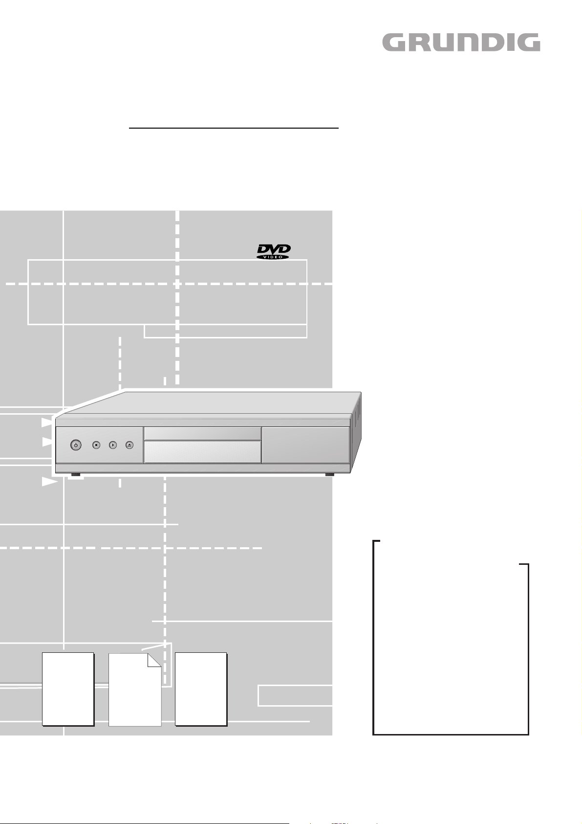
GDP 3200/710
GMJ8200
GDP 3205/710
ʀ
GMI9800
ǵ
NUR FÜR INTERNEN GEBRAUCH
Zusätzlich erforderliche Unterlagen für den Komplettservice
Additionally required Service Documents for the Complete Service
Service
Manual
GDP31…
Materialnr./Part No.
720105409500
Ergänzung
Supplement
GDP32…
Materialnr./Part No.
720105409600
FOR INTERNAL USE ONLY
Service
Manual
Sicherheit
Safety
Materialnr./Part No.
720108000000
Grundig Service
Hotline Deutschland…
Technik:
TV
TV
SAT
VCR/LiveCam
HiFi/Audio
Car Audio
Telekommunikation
Planatron
Ersatzteil-Verkauf: Mo.-Fr. 8.00-19.00 Uhr
Kundendienst/Werkstätten:
gebührenpflichtig
(8.00-22.00 Uhr)
…Mo.-Fr. 8.00-18.00 Uhr
0180/52318-41
0180/52318-49
0180/52318-48
0180/52318-42
0180/52318-43
0180/52318-44
0180/52318-45
Fax:
Telefon: 0180/52318-40
Telefon:
Fax:
0180/52318-51
0180/52318-99
0180/52318-50Fax:
Mo.-Fr. 8.00-18.00 Uhr
0180/52318-52
0180/52318-46
Dieses Service Manual ist nur in Datenform verfügbar / This Service Manual is only available as data
Änderungen vorbehalten / Subject to alteration
Made by GRUNDIG in Germany • http://www.grundig.com
H-S41 • 1102 • 720105409700
Page 2

GRUNDIG Service Livance – GDP 32…/KIT710
Inhaltsverzeichnis
Seite
Allgemeiner Teil ......................................... 2…4
Einführung ....................................................................................... 2
Ausbauhinweise – Laufwerk KIT710............................................... 3
Platinenabbildungen
und Schaltpläne ....................................... 5…13
Digital-Platte .................................................................................... 6
• Hauptschaltplan (P1 –
• Audio/Interface (P2 –
• Frontend (P3) ............................................................................... 5
Netzteil ............................................................................................ 8
Laufwerk-Platte ............................................................................... 9
Auszug
) ..................................................... 5
Auszug
) ...................................................... 5
Explosionszeichnungen
und Ersatzteillisten ................................ 14…18
Allgemeiner Teil
Achtung: ESD-Vorschriften beachten
Einführung
In dieser Service-Manual-Ergänzung sind bedingt durch den Einsatz
des Laufwerkes KIT710 die dafür erforderlichen Ausbauhinweise,
Schaltpläne und Platinenabbildungen dokumentiert.
Erkennbar sind die Geräte über die auf dem Typenschild aufgedruckten Gerätenamen GDP3200/710 bzw. GDP3205/710 bzw. dem Laufwerk (an dem nicht demontierbaren Bügel K, Fig. 6).
Die Digitalplatte, das Netzteil und die Laufwerkeinheit KIT710 sind zur
Vorgängervariante nicht kompatibel.
Hinweis:
Grundlage für den Service sind folgende Service Manuals:
– Service Manual Sicherheit, Materialnummer 720108000000
– Service Manual GDP31…, Materialnummer 720105409500
– Ergänzung GDP32…, Materialnummer 720105409600
Table of Contents
Page
General Section .......................................... 2…4
Introduction ..................................................................................... 2
Disassemly Instructions – Drive Mechanism KIT710 ...................... 3
Layout of PCBs
and Circuit Diagrams ............................... 5…13
Digital Board ................................................................................... 6
• Main Circuit Diagram (P1 –
• Audio/Interface (P2 –
• Frontend (P3) ............................................................................... 5
Power Supply .................................................................................. 8
Drive Board ..................................................................................... 9
Extract
Extract
).............................................. 5
) ....................................................... 5
Exploded Views and
Spare Parts Lists .................................... 14…18
General Section
Attention: Observe the ESD safety regulations
Introduction
This Supplement Service Manual contains the disassembly instructions, circuit diagrams, and PCB layouts required for the drive mechanism KIT710 fitted in the unit.
These units can be recognized by the unit name GDP3200/710 or
GDP3205/710 printed on the type Label, or by the drive mechanism (by
the not removable bracket K, Fig. 6).
The Digital board, the power supply unit and the drive mechanism unit
KIT710 are not compatible with the preceding variant.
Note:
Basic instructions for servicing are given in the following Service
Manuals:
– Service Manual Safety, Part Number 720108000000
– Service Manual GDP31…, Part Number 720105409500
– Supplement GDP32…, Part Number 720105409600
2
Page 3
GRUNDIG Service Livance – GDP 32…/KIT710
Ausbauhinweise
– Laufwerkeinheit KIT710
1. DVD/CD aus defektem Laufwerk entfernen
– Mit einem dünnen Schraubendreher durch das Loch A (Fig. 2) den
Schieber ca. 2cm nach innen schieben und Schublade herausziehen.
2. Laufwerkeinheit zerlegen
2.1 Laufwerk-Platte ausbauen
– 4 Schrauben B (Fig. 3) herausdrehen und Laufwerk-Platte abneh-
men.
– Gegebenenfalls Steckverbindungen lösen.
Achtung: Die Lasereinheit ist sehr empfindlich
gegen statische Aufladungen (MOS-Bauteile)!
Schließen Sie deshalb die Flexprintleitung zur
Lasereinheit vor dem Lösen der Steck-
verbindung mit einer Büroklammer kurz oder
bringen Sie die Schutzlötstellen E (Fig. 4) an.
2.2 Schublade ausbauen
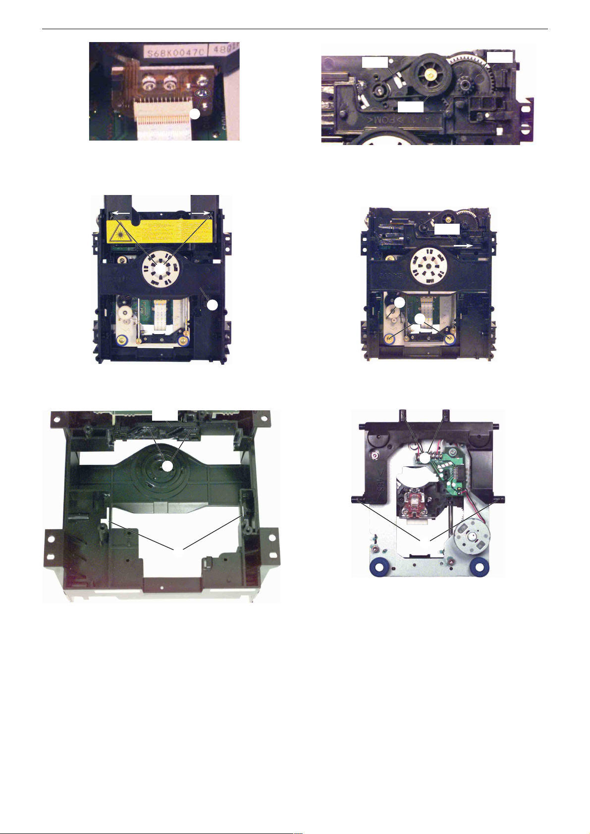
– Zahnrad DM05 (Fig. 1) in Pfeilrichtung drehen bis sich die Schubla-
de bewegt, diese dann bis zum Anschlag herausziehen.
– 2 Rastnasen F (Fig. 6) in Pfeilrichtung drücken und Schublade
herausziehen.
Montagehinweis:
– Schieber DM03 (Fig. 7) in Pfeilrichtung schieben
– Schublade in die Führungen einsetzen und einschieben.
2.3 Lademotor ausbauen
– Zahnrad DM05 (Fig. 1) in Pfeilrichtung drehen bis sich die Schubla-
de bewegt, diese dann so weit herausziehen bis der Riemen DM04
zugänglich ist.
– Riemen DM04 (Fig. 5) abnehmen.
– Laufwerk-Platte ausbauen (Punkt 2.1).
– Schraube C (Fig. 3) herausdrehen.
– 3 Rastnasen D (Fig. 3) lösen und Lademotor herausnehmen.
2.4 Sledge-Motor ausbauen
– Laufwerk-Platte ausbauen (Punkt 2.1).
– 2 Schrauben G (Fig. 7) herausdrehen und Sledge-Motor nach
unten herausnehmen.
2.5 Laufwerk ausbauen
– Laufwerk-Platte ausbauen (Punkt 2.1).
– Zahnrad DM05 (Fig. 1) in Pfeilrichtung drehen bis sich die Schubla-
de bewegt, dann bis zum Anschlag herausziehen.
– 2 Schrauben H (Fig. 7) herausdrehen.
– Laufwerk ausfädeln und nach unten herausnehmen.
Montagehinweis zum Einbau eines neuen Laufwerks:
– Schieber DM03 nach in Pfeilrichtung schieben (Fig. 7).
– Führungsstifte L (Fig. 9) in die die Führungen I (Fig. 8) des
Laufwerk-Rahmens einführen.
– Laufwerk zur Vorderseite schieben und die Führungsstifte M
(Fig. 9) in die beiden Führungen J (Fig. 8) des Schiebers DM03
stecken.
– Flexprint an der Lasereinheit und an CN100 der Laufwerkplatte
anschließen.
– werkseitig angebrachte Schutzlötstellen der Lasereinheit entfernen
(Fig. 4).
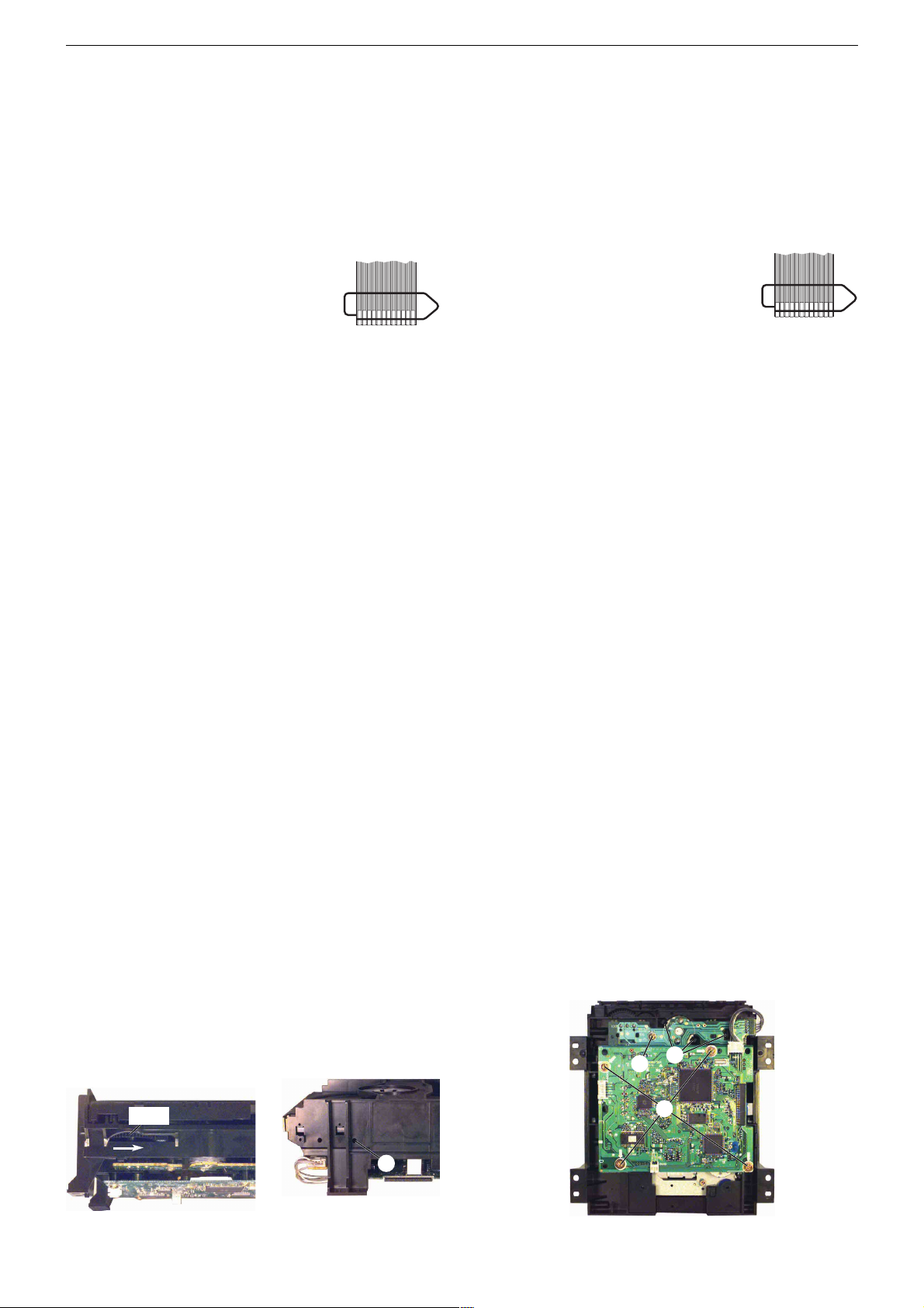
FLEXPRINT
Disassembly Instructions
– Drive Mechanism Unit KIT710
1. Opening the Tray when the Drive is Defective
– Insert a thin screw driver through the hole A (Fig. 2), push the slider
about 2cm in inward direction then pull out the tray.
2. Disassembling the Drive Mechanism Unit
2.1 Removing the Drive Board
– Undo the 4 screws B (Fig. 3) then remove the drive board.
– Unplug the connectors if necessary.
Attention: The laser unit is very sensitive to
static charges (MOS components)!
For this reason, before disconnecting the
Flexprint lead from the laser unit, short-circuit it
by means of a paper clip or apply the protective
soldering points E (Fig. 4).
2.2 Removing the Tray
– Turn the toothed wheel DM05 (Fig. 1) in direction of the arrow until
the tray moves then pull out the tray until it´s stop.
– Press the 2 locking lugs F (Fig. 6) in direction of the arrow then pull
out the tray.
Reassembly hint:
– Move the slider DM03 (Fig. 7) in direction of the arrow.
– Fit the tray into the guides then slide it in.
2.3 Removing the Loading Motor
– Turn the toothed wheel DM05 (Fig. 1) in direction of the arrow until
the tray moves then pull out the tray until the belt DM04 becomes
accessible.
– Remove the belt DM04 (Fig. 5).
– Remove the drive board (Point 2.1).
– Undo the screw C (Fig. 3).
– Disengage the 3 locking lugs D (Fig. 3) then remove the loading
motor.
2.4 Removing the Sledge Motor
– Remove the drive board (Point 2.1).
– Undo the 2 screws G (Fig. 7) then remove the sledge motor in
downward direction.
2.5 Removing the Drive Mechanism
– Remove the drive board (Point 2.1).
– Turn the toothed wheel DM05 (Fig. 1) in direction of the arrow until
the tray moves then pull out the tray until it´s stop.
– Undo the 2 screws H (Fig. 7).
– Unthread the drive mechanism then remove it.
Instructions for Mounting a new Drive Mechanism
– Move the slider DM03 in direction of the arrow (Fig. 7).
– Insert the guide pins L (Fig. 9) into the guides I (Fig. 8) of the drive
mechanism frame.
– Slide the drive mechanism to the front then fit the guide pins M
(Fig. 9) into the two guides J (Fig. 8) of the slider DM03.
– Connect the Flexprint lead to the laser unit and to CN100 on the drive
board.
– Remove the factory-applied protective soldering joints from the
laser unit (Fig. 4).
FLEXPRINT
DM05
D
C
B
A
Fig. 2Fig. 1
3
Fig. 3
Page 4
GRUNDIG Service Livance – GDP 32…/KIT710
F
E
K
DM04
DM05
DM07
Fig. 5Fig. 4
DM03
G
H
Fig. 6 Fig. 7
DM03
M
J
L
I
Fig. 8 Fig. 9
4
Page 5
GRUNDIG Service Livance – GDP 32…/KIT710
P2 TV_PIN16_O
P2 TV_PIN8_EN
P2 4:3/16:9
V1.8 V3.3
L14
2.2uH SMD TDK
L15
2.2uH SMD TDK
L12
10uH SMD TDK
FROM
POWER SUPPLY
TO
DRIVE BOARD
Connector CN104
3.3V
1.8V
Dig ital Ground
Analogue Ground
Drive Ground
+15V+12V+5.0V
+5.0V
V3.3
GNDA
GNDA
GNDAGNDAGNDAGNDAGNDA
GNDAGNDA
+30V
GNDA
GNDA GNDA
GNDA GNDA
GNDA
J15
1
2
3
4
5
6
TAB=GND
IN
GND
OUT
U19
L7809CD2T
3
1
2
C137
100uF 16V
J1
1
2
3
4
5
6
7
9
11
10
8
C56
100uF 16V
C138
0.1uF
C18
470uF 25V
C119
0.1uF
C55
0.1uF
C48
0.1uF
C127
0.1uF
C115
0.1uF
C5
100uF
16V
C54
470uF
25V N/A
C66
100uF 16V
TOP VIEW
T0-252
DPAK
GND VIN
VOUT
13
2
U6
LM1117DT-1.8
R101
0R 1206 N/A
L11 39uH
C124
0.1uF
C112
0.1uF
C136
0.33uF
C114
0.1uF
C47
0.1uF
C49
100uF 16V
L10
not for KIT710
only for KIT710
39uH N/F
GNDA
TOP VIEW
T0-252
DPAK
GND VIN
VOUT
13
2
U23
LM1117DT-3.3
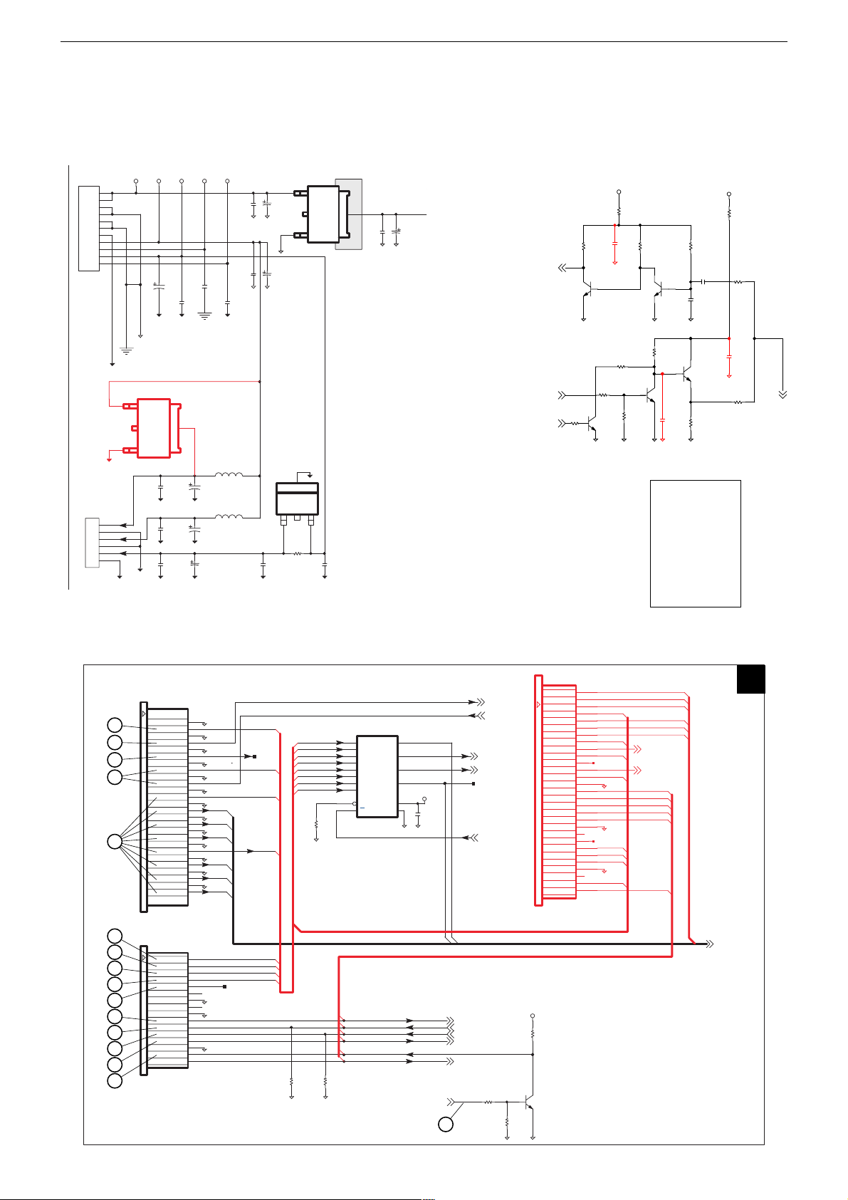
Platinenabbildungen und Schaltpläne / Layout of PCBs and Circuit Diagrams
Digitalplatte – Hauptschaltplan (P1 –
Auszug
Digital Board – Main Circuit Diagram (P1 –
Digitalplatte / Digital Board – Frontend (P3)
)
Extract
Digitalplatte – Audio/Interface (P2 –
)
Digital Board – Audio/Interface (P2 –
V3.3
R149
0R
R125
C262
R114
22k
R128
0.1uF
100k
Q8
BC847C
C129
0.1uF N/A
R111
10k
R113
22k
Q24
BC847AL
R119
22k
Seiten "3-…" – siehe Basis-Service-Manual
Pages "3-…" – see Main Service Manual
ROT = Änderungen
RED = Changes
Q20
BC847AL
C264
0.1uF
Reference
IC Block Diagrams ..... 3-3
Oscillograms ............ 3-29
Digital Board
– P1 ....................... 5, 3-11
– P2 ....................... 5, 3-13
– P3 ................................. 5
– P4 ........................... 3-15
– P5 ........................... 3-16
– P6 ........................... 3-16
Drive Board ...................... 9
Keyboard Control ....... 3-19
Power Supply ...................8
SCARTIRIN P1
TV_PIN8_EN P1
4:3/16:9 P1
R116
22k
100k
Q7
BC847C
Q25
BC847AL
R129
100k
R118
22k
C126
1uF
+15V
Auszug
Extract
R148
220R
R134
1k
C263
1uF
R115
2k4
)
)
TVPIN8
TV SCART J5-(8)
21
20
19
18
17
BACK-END CONNECTOR
FOR SANYO DRIVE
16
15
14
13
12
11
10
9
8
7
BACK-END CONNECTOR
FOR SANYO DRIVE
DCLK
DBGN
DERR
DACK
DREQ
STD0
SDT1
SDT2
SDT3
SDT4
SDT5
SDT6
SDT7
J10
TOP VIEW
SPDIF
CD-Data
LRCK
C2PO
EMPH
GND_d
GND_d
RDY_HIF
SCLK
GND_d
HRST
J11
TOP VIEW
GND
GND
GND
GND
GND
GND
GND
GND
GND
GND
GND
GND
GND
BCK
16M
RxD
TxD
NC
26
25
24
23
22
21
20
19
18
17
16
15
14
13
12
11
10
9
8
7
6
5
4
3
2
1
16
15
14
13
12
11
10
9
8
7
6
5
4
3
2
1
DSYNC
DERR
DREQ
DVD1
DVD2
DVD3
DVD5
DVD6
DVD7
C2PO
TS13
ENABLE
SSPCLK0B
SSPOUT0B
SSPIN0
HRST
W
DCLK-FE
TS11
DACK-FE DACK-FE
DVD0-FE
DVD4-FE
FE-SPDIF
CDDA-FE
BCK-FE
LRCK-FE
AIT
DVD0-FE
CDDA-FE
DCLK-FE
BCK-FE
LRCK-FE
DVD4-FE
FE-SPDIF
R142
10k N/A
MUXEN
R67
150R
R141
10k N/A
2
3
5
6
11
10
14
13
15
1
74ACT257MTC
MULTIPLEXER
ENABLE
SSPCLK0B
SSPOUT0B
SSPIN0
WAIT
U11
1A
1B
2A
2B
3A
3B
4A
4B
G
A/B
DVD[7:0]
VCC
GND
P3
DVD[7:0] P1
DREQ P1
DSYNC P1
HRST
SSPIN0
SSPOUT0B
SSPCLK0B
ENABLE
WAIT
DVD7
DVD6
DVD5
DVD3
DVD2
DVD1
29
SDT7
28
DSYNC P1
DREQ P1
DVD0
4
1Y
7
2Y
9
3Y
DVD4
12
4Y
+5.0V
16
8
C109
0.1uF
(XIO14)
(XIO12)
DRVRST-
P1
6
DCLK P1
DSTB P1
TS12
REQ P1
(XIO13)
ENABLE P1
SSPCLK0B P1
SSPOUT0B P1
SSPIN0 P1
WAIT P1
R99
4k7
R138
4k7
SDT6
SDT5
SDT4
SDT3
SDT2
SDT1
SDT0
DREQ
DACK
DERR
DBGN
DCLK
GND_d
HRST
TxD
RxD
SCLK
RDY_HIF
GND_d
EMPH
C2P0
LRCK
BCK
CD-Data
GND_d
16M
SPDIF
HD_INT
TOP VIEW
BACK-END CONNECTOR
FOR SANYO 710 DRIVE
+5.0V
R100
10k
The reset signal
for DVD Drive
is activ HIGH
Q6
BC847AL
27
26
25
24
23
22
21
20
19
18
17
16
15
14
13
12
11
10
9
8
7
6
5
4
3
2
1
J16
DVD4-FE
DVD0-FE
DACK-FE
TS11
DCLK-FE
TS13
LRCK-FE
CDDA-FE
FE-SPDIF
BCK-FE
5
Page 6
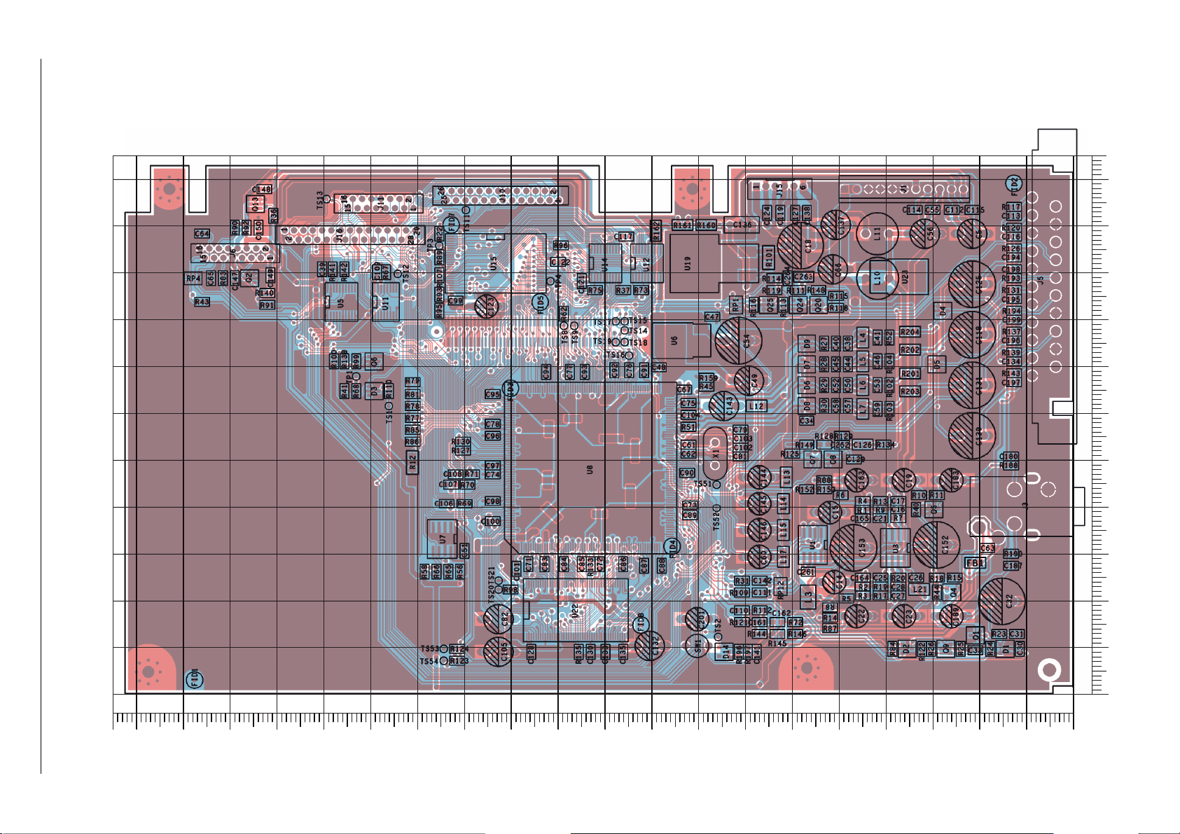
GRUNDIG Service Livance – GDP 32…/KIT710
Digital-Platte / Board
Ansicht von der Bestückungsseite / View of Component Side
200
190
180
170
160
150
140
130
120
110
100
90
80
70
60
50
40
30
20
10
6
10 20 30 40 50 60 70 80 90 100 110
0
Y
0
X
Page 7

GRUNDIG Service Livance – GDP 32…/KIT710
Digital-Platte / Board
Koordinaten für die Bauteile / Coordinates of the Components
POS. X Y POS. X Y POS. X Y POS. X Y POS. X Y POS. X Y POS. X Y POS. X Y POS. X Y
C5 24 99
C14 53 24
C15 54 39
C16 37 39
C17 37 41
C18 61 96
C19 38 46
C21 41 38
C22 48 17
C23 38 17
C25 41 25
C26 33 25
C27 37 21
C28 37 23
C30 11 10
C31 12 13
C32 17 20
C33 20 9
C34 57 59
C38 48 75
C39 161 91
C40 50 75
C41 41 76
C44 48 71
C45 50 71
C46 41 71
C47 77 81
C48 88 70
C49 72 67
C50 48 66
C51 130 31
C52 50 66
C53 41 66
C54 74 76
C55 30 104
C56 34 99
C57 48 62
C58 50 62
C59 41 61
C60 69 29
C61 82 53
C62 82 52
C63 18 31
C64 186 99
C65 185 89
C66 54 91
C67 83 65
C71 116 28
C72 101 28
C73 82 40
C74 124 47
C75 82 62
C76 95 69
C77 108 69
C78 124 58
C79 71 57
C81 71 51
C82 125 16
C83 113 28
C84 109 28
C85 105 28
C86 96 28
C87 92 27
C88 88 27
C89 82 38
C90 82 47
C91 92 69
C92 98 69
C93 104 69
C94 113 69
C95 124 64
C96 124 55
C97 124 49
C98 124 41
C99 132 84
C100 124 37
C101 119 27
C102 71 53
C103 71 55
C104 82 60
C105 125 9
C106 134 41
C107 133 45
C108 132 47
C109 149 90
C110 71 18
C111 67 22
C112 26 104
C113 12 102
C114 33 104
C115 21 104
C116 12 98
C117 95 98
C118 24 77
C119 62 103
C121 105 88
C122 110 93
C123 128 83
C124 65 103
C125 24 88
C126 45 53
C127 59 103
C128 116 9
C129 47 50
C130 103 9
C131 24 66
C132 93 10
C133 100 9
C134 12 71
C135 96 9
C136 73 101
C137 53 101
C138 57 103
C139 24 55
C141 68 9
C142 67 24
C143 77 62
C144 69 46
C145 69 41
C146 69 35
C147 179 89
C148 173 108
C149 172 90
C150 174 100
C152 31 32
C153 49 31
C161 67 15
C162 63 15
C163 48 46
C164 45 25
C165 45 38
C180 13 51
C183 28 46
C187 13 27
C189 28 17
C194 12 94
C195 12 85
C196 12 76
C197 12 67
C198 12 91
C199 12 80
C201 83 16
C261 56 26
C262 49 55
C263 57 89
C264 61 89
D1 14 10
D2 35 10
D3 150 65
D4 27 82
D5 29 71
D6 57 66
D7 57 71
D8 57 62
D9 57 75
D14 75 9
FB1 20 28
FID1 188 3
FID2 12 109
FID3 120 66
FID4 86 31
FID5 114 84
FID7 133 101
FID8 92 15
J1 48 108
J3 5 44
J5 8 106
J6 172 95
J10 110 106
J11 141 106
J12 2342 62
J15 68 109
J16 169 99
L3 56 21
L4 45 76
L5 45 71
L6 45 66
L7 45 61
L10 39 89
L11 39 99
L12 68 62
L13 61 46
L14 62 41
L15 62 35
L17 62 29
L21 33 22
Q1 20 12
Q2 176 89
Q4 26 22
Q5 29 39
Q6 150 71
Q7 55 50
Q8 51 50
Q9 27 10
Q13 175 105
Q20 54 83
Q24 59 83
Q25 65 83
R1 45 39
R2 45 23
R3 45 21
R4 45 41
R5 48 20
R6 49 43
R7 37 38
R8 52 18
R9 41 39
R10 33 43
R11 29 43
R12 141 50
R13 41 41
R14 52 16
R15 25 25
R17 41 21
R18 29 25
R19 41 23
R20 37 25
R22 136 99
R23 15 13
R24 17 10
R25 24 10
R26 30 10
R27 53 75
R28 53 71
R29 53 66
R30 53 62
R31 71 24
R36 171 102
R37 96 87
R40 33 39
R41 156 65
R43 186 84
R44 29 22
R45 78 66
R51 82 57
R52 39 76
R56 131 26
R58 139 26
R62 109 81
R65 134 26
R66 136 26
R67 147 90
R68 153 65
R69 130 41
R70 130 45
R71 129 47
R72 59 15
R73 92 87
R75 102 87
R77 141 59
R78 141 62
R79 141 67
R81 141 64
R83 182 89
R84 38 10
R85 141 57
R86 141 54
R87 52 14
R88 53 46
R89 136 94
R90 179 100
R91 172 83
R92 177 100
R93 136 86
R95 136 82
R96 109 96
R98 120 22
R99 153 71
R100 158 71
R101 65 94
R102 39 66
R103 39 61
R104 39 71
R107 136 90
R109 71 22
R110 146 65
R111 59 87
R112 67 18
R113 62 83
R114 64 89
R115 50 85
R116 68 83
R117 12 104
R118 50 83
R119 64 87
R120 12 100
R121 71 15
R122 32 10
R123 132 7
R124 132 10
R125 60 52
R126 12 95
R127 130 52
R128 53 53
R129 49 53
R130 130 54
R131 12 87
R133 103 28
R134 40 53
R135 106 9
R137 12 78
R138 156 71
R139 12 73
R140 172 86
R141 158 91
R142 156 91
R143 12 69
R144 67 13
R145 63 13
R146 59 13
R148 54 87
R149 57 53
R152 57 44
R153 53 44
R159 78 68
R160 78 101
R161 83 101
R162 89 99
R188 13 49
R190 13 30
R193 12 89
R194 12 82
R196 71 9
R197 69 9
R201 34 69
R202 34 74
R203 34 65
R204 34 78
RP1 72 83
RP4 188 89
RP12 62 23
SW1 83 10
TP1 153 68
TP3 136 96
TP4 112 88
TS1 146 62
TS2 76 12
TS8 109 79
TS9 107 79
TS11 130 104
TS12 144 90
TS13 160 106
TS14 96 78
TS15 96 80
TS16 95 73
TS17 98 80
TS18 96 75
TS19 98 75
TS20 123 22
TS21 123 24
TS51 76 45
TS52 76 40
TS53 135 10
TS54 135 7
U1 55 32
U3 38 31
U5 157 84
U6 83 76
U7 135 33
U8 103 48
U11 147 84
U12 91 92
U14 100 92
U15 123 92
U19 75 92
U22 106 18
U23 37 89
7
Page 8

Seiten "3-…" – siehe Basis-Service-Manual
Reference
IC Block Diagrams ..... 3-3
Oscillograms ............ 3-29
Digital Board
– P1 ....................... 5, 3-11
– P2 ....................... 5, 3-13
– P3 ................................. 5
– P4 ........................... 3-15
– P5 ........................... 3-16
– P6 ........................... 3-16
Drive Board ...................... 9
Keyboard Control ....... 3-19
Power Supply ................... 8
8
Pages "3-…" – see Main Service Manual
Netzteil / Power Supply
GRUNDIG Service Livance – GDP 32…/KIT710
Ansicht von der Best
ückungsseite / View of Component Side
Page 9

GRUNDIG Service Livance – GDP 32…/KIT710
Laufwerk-Platte / Drive Board – KIT710
Koordinaten für die Bauteile / Coordinates of the Components
POS. X Y POS. X Y POS. X Y POS. X Y POS. X Y POS. X Y POS. X Y POS. X Y POS. X Y
C1000 86 45
C1001 85 45
C1002 84 45
C1003 82 45
C1006 102 48
C1007 62 20
C1008 80 45
C1009 66 35
C1010 76 37
C1011 63 45
C1012 71 37
C1013 83 58
C1014 81 71
C1015 77 65
C1016 66 75
C1017 80 63
C1018 81 63
C1019 84 63
C1020 86 63
C1021 82 63
C1022 85 70
C1023 85 66
C1024 84 63
C1027 105 50
C1029 90 57
C1030 104 54
C1031 104 45
C1033 95 54
C1035 92 50
C1036 95 47
C1037 95 51
C1041 87 63
C1042 87 51
C1043 74 57
C1044 89 46
C1045 80 55
C1046 91 58
C1047 64 74
C1048 48 30
C1049 87 42
C1050 67 17
C1300 50 55
C1302 31 63
C1304 60 72
C1305 60 71
C1306 55 71
C1308 58 65
C1310 62 68
C1311 62 66
C1312 62 65
C1313 62 64
C1314 62 63
C1315 62 62
C1316 62 60
C1317 62 59
C1318 62 58
C1319 62 57
C1320 62 56
C1321 62 54
C1322 59 58
C1323 50 79
C1324 49 82
C1325 30 78
C1327 28 63
C1328 27 64
C1329 27 66
C1330 26 66
C1331 26 67
C1332 26 71
C1333 26 72
C1334 27 76
C1335 27 78
C1336 54 63
C1337 28 83
C1338 28 85
C1339 37 86
C1340 46 81
C1341 32 54
C1342 12 71
C1343 46 55
C1344 50 69
C1345 42 55
C1346 38 55
C1347 49 55
C1351 43 87
C1360 11 65
C1361 11 66
C1362 11 64
C1363 11 63
C1364 11 61
C1365 11 60
C1366 11 59
C1367 11 58
C1368 11 57
C1369 11 55
C1370 15 53
C1371 15 51
C1372 21 53
C1373 21 52
C1374 21 51
C1375 21 50
C1376 21 49
C1377 21 47
C1378 21 46
C1379 12 39
C1380 12 41
C1381 21 45
C1382 12 40
C1383 19 44
C1384 18 44
C1400 54 62
C1500 19 14
C1501 20 18
C1502 20 21
C1504 39 21
C1507 27 19
C1508 39 44
C1509 15 37
C1512 37 8
C1513 15 12
C1600 11 87
C1601 9 35
C1602 85 18
C1603 85 34
C1604 87 33
C1605 97 33
C1606 81 19
C1608 88 16
C1609 8 37
C1610 103 84
C1611 100 88
C1612 102 93
C1701 18 63
C1705 9 32
C1900 96 71
C1901 107 67
C1902 104 65
C1903 107 63
C1904 105 31
C1905 107 55
C1906 91 90
C1907 85 89
C1909 53 82
C1910 57 82
C1911 83 90
C1913 55 86
C1998 89 51
CAN 79 67
CN100 59 18
CN101 14 88
CN102 9 48
CN103 9 52
CN104 109 62
CN105 75 9
D1000 62 16
D1001 64 16
D1600 98 90
IC100 83 54
IC130 44 66
IC131 41 76
IC132 37 84
IC150 30 20
IC151 43 41
IC153 18 11
IC160 92 26
IC161 106 89
IC191 55 83
IC192 88 89
L1001 67 19
L1002 91 41
L1302 31 76
Q1000 58 15
Q1001 57 11
Q1002 62 12
Q1003 66 12
Q1004 69 35
Q1005 66 44
Q1006 62 75
Q1007 62 79
Q1008 72 24
Q1009 77 29
Q1010 76 24
Q1702 19 61
Q1703 10 31
Q1704 10 27
R1000 85 41
R1001 86 41
R1002 82 41
R1003 84 41
R1004 84 45
R1005 86 45
R1006 82 45
R1007 85 45
R1009 82 51
R1011 81 51
R1013 77 51
R1014 81 45
R1015 80 51
R1016 79 45
R1017 77 50
R1018 59 17
R1020 55 15
R1022 60 11
R1023 57 9
R1024 64 9
R1027 71 36
R1028 69 37
R1029 68 41
R1030 67 41
R1031 91 46
R1032 77 53
R1033 67 23
R1034 69 24
R1035 71 26
R1036 74 26
R1039 91 49
R1040 91 47
R1041 72 27
R1042 74 29
R1043 76 31
R1044 76 27
R1045 62 14
R1046 65 14
R1047 66 38
R1048 87 45
R1049 80 60
R1050 80 63
R1051 78 63
R1052 66 73
R1053 80 66
R1054 81 66
R1055 83 63
R1056 87 63
R1057 82 66
R1058 82 67
R1059 85 63
R1060 86 66
R1061 90 58
R1062 92 54
R1063 95 52
R1064 94 51
R1065 95 49
R1068 79 66
R1069 92 49
R1073 92 51
R1076 92 52
R1077 89 53
R1078 83 51
R1079 85 49
R1080 79 51
R1081 79 66
R1082 86 66
R1083 86 63
R1084 84 68
R1085 86 69
R1086 82 63
R1087 84 66
R1088 72 70
R1089 70 70
R1090 62 82
R1091 59 56
R1092 80 42
R1093 79 42
R1094 81 63
R1095 65 74
R1300 60 78
R1301 55 70
R1302 55 69
R1314 28 61
R1317 24 62
R1318 25 63
R1319 25 64
R1320 25 66
R1321 25 67
R1322 26 69
R1323 26 70
R1324 26 69
R1325 26 68
R1326 26 71
R1327 26 73
R1328 26 73
R1329 27 74
R1330 27 75
R1331 27 77
R1332 33 80
R1333 36 82
R1334 50 81
R1335 27 75
R1337 34 82
R1338 59 77
R1339 58 80
R1396 12 70
R1397 12 69
R1404 54 60
R1411 27 77
R1500 36 17
R1501 35 17
R1502 37 9
R1503 38 9
R1504 37 10
R1505 34 17
R1506 36 10
R1507 33 17
R1508 35 10
R1509 31 17
R1510 33 10
R1511 30 17
R1512 32 10
R1513 31 10
R1514 30 10
R1515 29 10
R1516 27 10
R1517 29 17
R1518 28 17
R1519 26 10
R1520 27 17
R1521 25 10
R1522 24 10
R1523 23 10
R1524 25 17
R1525 20 12
R1526 20 13
R1527 20 14
R1528 20 15
R1529 18 14
R1530 19 20
R1531 22 27
R1532 27 22
R1533 27 28
R1534 27 27
R1535 20 31
R1536 20 32
R1537 20 33
R1538 20 34
R1539 22 36
R1540 22 37
R1541 22 38
R1542 22 39
R1543 26 35
R1544 27 37
R1545 27 35
R1546 28 37
R1547 29 35
R1548 29 37
R1549 30 35
R1550 31 41
R1551 31 43
R1552 31 40
R1553 31 39
R1554 31 44
R1555 28 25
R1556 29 25
R1557 31 25
R1558 32 25
R1559 33 25
R1560 34 25
R1561 35 25
R1562 37 25
R1563 42 45
R1564 42 43
R1565 42 42
R1566 42 41
R1567 43 26
R1568 43 25
R1569 43 24
R1570 43 23
R1571 35 23
R1572 35 22
R1573 35 21
R1574 43 20
R1575 43 19
R1576 43 18
R1577 43 17
R1578 43 15
R1579 43 14
R1580 43 13
R1581 43 12
R1583 17 84
R1584 14 84
R1585 16 84
R1586 15 84
R1591 36 9
R1592 35 9
R1593 27 23
R1608 85 19
R1609 81 18
R1610 85 33
R1611 82 34
R1612 87 34
R1613 88 35
R1614 97 36
R1615 97 35
R1617 99 34
R1618 99 35
R1619 107 84
R1620 105 84
R1621 104 84
R1622 102 88
R1623 102 85
R1624 101 88
R1625 91 17
R1626 91 18
R1627 85 73
R1704 10 25
R1705 16 60
R1707 17 58
R1900 95 86
R1901 90 85
R1903 107 67
R1904 108 67
TP001 84 16
TP002 86 18
TP003 82 12
TP004 84 14
TP005 53 46
TP006 54 44
TP007 52 43
TP008 52 41
TP009 54 42
TP010 20 30
TP011 23 31
TP012 51 52
TP013 54 48
TP014 49 51
TP015 52 47
TP016 47 47
TP017 48 48
TP018 46 49
TP019 46 51
TP020 44 48
TP021 43 51
TP022 42 48
TP023 40 50
TP024 39 48
TP025 34 47
TP026 37 48
TP027 38 50
TP028 33 50
TP029 35 52
TP030 32 52
TP031 74 63
TP032 71 69
TP033 73 68
TP034 77 68
TP035 62 78
TP036 66 68
TP037 59 75
TP038 67 67
TP039 80 70
TP040 73 72
TP041 79 72
TP042 71 74
TP043 83 71
TP044 31 62
TP045 34 61
TP046 29 65
TP047 31 64
TP048 41 84
TP049 40 86
TP050 31 43
TP051 31 45
TP052 32 35
TP053 33 37
TP054 35 13
TP055 33 13
TP056 31 13
TP057 46 7
TP058 43 17
TP059 43 15
TP060 96 38
TP061 83 36
TP062 81 15
TP063 12 22
TP064 10 70
TP122 75 38
TP124 64 42
TP141 60 27
TP142 62 28
TP143 63 26
TP144 80 22
TP145 76 21
TP146 74 19
TP147 77 24
TP148 57 26
TP149 60 26
TP150 63 41
TP151 64 32
TP152 65 30
TP153 63 17
TP200 54 23
TP201 56 25
TP202 65 25
TP203 62 26
TP204 89 47
TP205 62 73
TP206 60 69
TP207 99 21
TP208 101 25
TP209 99 28
TP210 15 55
TP211 55 77
TP212 53 74
TP213 52 80
TP214 51 82
TP215 69 76
TP216 50 28
TP217 69 79
TP218 75 90
TP219 66 67
TP220 71 56
TP221 75 58
TP222 17 27
TP223 15 44
TP224 15 45
TP225 20 45
TP226 16 47
TP227 20 47
TP228 10 38
TP229 23 47
TP230 21 48
TP231 21 50
TP232 21 52
TP233 20 56
TP234 18 54
TP235 16 51
TP236 13 13
TP237 17 54
TP238 16 56
TP239 14 56
TP240 19 26
TP241 24 55
TP242 15 60
TP243 29 53
TP244 14 65
TP245 19 55
TP246 15 68
TP247 14 75
TP250 92 46
TP251 76 5
TP252 80 3
TP253 83 5
TP254 86 3
TP255 89 5
TP256 14 14
TP257 12 16
TP258 24 13
TP300 96 83
TP301 113 54
TP302 110 55
TP505 37 13
TP507 33 9
TP508 50 40
TP509 29 13
TP510 27 13
TP511 39 39
TP512 55 39
TP513 60 57
TP514 46 35
TP515 48 27
TP516 19 27
TP550 40 16
TP551 38 15
TP552 40 14
TP553 29 9
TP564 37 81
TP566 22 13
TP580 29 29
TP581 30 30
TP582 29 32
TP583 34 30
TP584 32 31
TP585 32 34
TP586 39 18
TP608 88 38
TP624 97 17
TP625 94 16
TP626 14 85
TP627 18 85
X1300 25 83
X1500 18 20
9
Page 10

0
0
10
20
30
40
50
60
70
80
90
102030405060708090100110
Y
X
176170160150140133
132
130
120
110
100
90
89
88 80
70
60 50 45
44
40
30
20
10
1
64605049
48
40
33
32 30 20 17
16
10
1
1
10
20
25
26304050
51
60
70
75
76 80 90 100
*UPDATE
DGND
RFN
RFP
TE
FE
11016
17203032
IC151
IC130
IC150
CN103
X1500
CN101
IC100
IC160
CN104
CN105
X1300
1AD4B10D0790A
F01
94V-0
D07900
FR4
AGND
S
L
3.3V
DGND
5V
AGND
9V_A
GND_M
TP026
TP021
TP019
TP023
TP028
TP027
TP225
TP230
TP224
TP025
TP227
TP229
TP215
TP201
TP053
TP049
TP014
TP232
TP236
TP058
TP060
TP203
TP231
TP033
TP515
TP062
TP221
TP012
TP205
TP217
TP057
TP507
TP206
TP035
TP016
TP512
TP017
TP513
TP008
TP200
TP022
TP202
TP009
TP516
TP052
TP036
TP030
TP007
TP043
TP037
TP005
TP029
TP034
TP032
TP566
TP059
TP514
TP122
TP006
TP031
TP246
TP050
TP247
TP020
TP051
TP042
TP024
TP039
TP608
TP234
TP018
TP040
TP233
TP218
TP124
TP210
TP061
TP038
TP223
TP048
TP553
TP013
TP300
TP301
TP302
TP148TP149
TP153
TP063
TP564
IC130
C1909
IC191
C1910
R1324
R1503
R1337
R1332
R1615
C1701
C1000
R1592
R1016
R1020
L1001
C1001
C1906
R1617
R1705
C1305
C1011
R1618
C1512
R1030
R1543
R1014
C1024
R1411
R1329
R1608
Q1005
C1602
R1053
R1334
C1913
R1549
C1335
R1584
R1325
C1342
C1304
R1058
Q1004
C1328
C1003
IC132
C1044
R1068
R1327
R1502
C1329
R1320
R1083
D1001
IC160
C1041
C1009
R1321
C1327
IC153
R1547
R1333
C1002
C1017
R1022
IC100
R1018
C1340
R1612
R1611
R1548
C1907
D1000
R1546
R1545
R1319
R1330
R1900
R1901
R1326
R1318
R1396
R1300
C1608
R1585
C1606
R1610
R1609
R1317
C1008
Q1000
R1544
R1314
R1397
IC192
R1586
C1018
R1583
C1007
R1027
C1339
R1054
Q1702
R1707
C1513
R1614
R1024
R1613
R1530
C1905
C1903C1901
IC150
CN103
R1591
R1086
R1087
R1059
R1082
C1023
C1022
R1088
R1089
C1500
Q1002Q1003
R1031
R1048
C1049
Q1008
R1033
R1034
R1035R1036
R1045
R1046
R1093
R1092
C1603
R1039
R1040
C1047
R1095
Q1006
R1052C1016
Q1703
Q1704
R1704
C1605
C1604
R1047
C1048
C1046
Q1001
R1023
Q1009
Q1010
R1043
R1044
R1041
R1042
IC151
C
C
C
C
C
C
C
C
C
R1028
R1029
C1050
DEFG
Laufwerk-Platte / Drive Board – KIT710
SMD-Bestückung der Oberseite – Ansicht von der Bestückungsseite / SMD Assembly of the Upper Side – View of Component Side
GRUNDIG Service Livance – GDP 32…/KIT710
10
Page 11

0
0
10
20
30
40
50
60
70
80
90
10 20 30 40 50 60 70 80 90 100 110
Y
X
DEFG
44
40
30
2322
20
10
1
1AD4B10D0790A
1
4
5
8
94V-0 F01
PICK-UP
IC131
CN102
CN100
D07900
FR4
TP228
TP226
TP216
TP015
TP625
TP214
TP509
TP001
TP002
TP510
TP250
TP580
TP213
TP581
TP003
TP552
TP004
TP141
TP241
TP010
TP583
TP055
CN101
TP626
TP142
TP582
TP222
TP207
TP585
TP143
TP044
TP239
TP238
TP624
TP211
TP551
TP046
TP243
TP505
TP204
TP240
X1500
TP584
TP245
TP219
TP056
TP011
TP550
X1300
TP047
TP235
CN104
TP237
TP212
TP041
TP054
TP244
TP220
TP209
TP242
TP627
TP045
TP508
TP208
TP511
TP586
TP144
TP145
TP147
TP146
TP255
TP254
TP253
TP252
TP251
TP258
TP257
TP256
TP152
TP064
TP151
TP150
CN105
IC161
C1902
C1027
C1031
C1010
C1012
C1509
C1904
C1900
C1043
C1030
IC131
R1015
R1518
C1319
L1302
R1524
C1366
C1015
C1507
R1065
C1365
R1500
C1311
C1314
C1345
R1554
C1380
R1017
C1341
R1572
C1013
R1509
R1032
C1042
C1320
R1003
C1381
R1516
C1316
C1400
C1338
C1371
R1508
C1363
R1013
C1504
C1324
R1529
R1050
C1601
R1519
R1404
R1542
CN100
C1344
C1361
R1069
R1061
R1531
R1525
C1312
R1555
R1557
R1002
R1338
R1528
C1362
R1532
R1001
C1369
C1600
C1351
C1036
R1049
R1553
R1526
R1556
R1552
R1569
C1313
R1538
R1000
C1306
R1506
C1360
C1373
R1328
C1014
C1383
R1537
C1337
R1541
R1009
R1051
R1540
R1514
R1055
C1310
R1535
R1570
R1571
R1006
R1301
C1332
C1370
C1384
CAN
R1567
R1064
R1560
R1335
R1577
R1561
R1507
R1579
C1308
C1300
R1505
C1033
R1523
R1565
C1375
R1574
C1378
R1063
R1512
R1551
R1005
C1029
R1533
C1376
R1558
R1536
R1079
R1566
R1550
C1508
R1575
R1078
R1094
R1515
C1364
R1534
R1011
C1020
L1002
C1911
C1037
C1006
R1077
C1330
C1501
R1559
R1062
R1302
R1539
C1035
R1517
C1609
C1334
C1998
C1372
R1568
C1019
R1593
C1367
C1317
C1346
R1056
C1315
C1377
R1331
R1576
C1379
C1336
R1007
R1578
R1073
R1076
R1564
C1325
R1513
C1502
R1511
C1321
R1521
R1080
R1504
C1323
R1580
R1527
R1004
C1347
R1562
C1331
C1343
C1302
R1563
C1368
R1573
C1374
R1501
R1322
R1323
R1081
R1520
R1581
C1322
C1318
C1333
R1522
C1382
R1510
C1705
CN102
R1084
R1057
C1021
R1085
R1060
R1626
R1625
IC161
R1619
R1620
R1621
R1623
R1622
R1624
C1610
C1611
C1612
R1339
R1904
R1903
R1627
C1045
D1600
Q1007
R1090
R1091
SMD-Bestückung der Unterseite – Ansicht von der Lötseite / SMD Assembly of the Lower Side – View of Solder Side
11
GRUNDIG Service Livance – GDP 32…/KIT710
Page 12

GRUNDIG Service Livance – GDP 32…/KIT710
D
G
Laufwerk-Platte / Drive Board – KIT710
3.3V
F-
1
F+
2
T+
3
T-
4
(NC)
5
B
6
A
7
E
8
GND-PD
9
VC
10
VCC
11
F
12
D
13
C
14
CD/DVD
15
(NC)
16
(LD-CD)
17
VR-CD
18
VR-DVD
19
MD
20
LD-CD
21
HFM
22
LD-DVD
23
GND-LD
24
PICK-UP
MECHANISM
LOADING-M
M
MLD1
MLD2
CLOSE_SW
12345
SLED-M
M
SPIN-M
M
LIMIT-SW
GND_D
8
7
6
5
4
3
2
1
LMT_SW
OPEN_SW
SLED1
SLED2
SP1+
SP1-
DGND
CN100
FF+
T+
T-
RF (NC)
B
A
E
GND-PD
VC
VCC
F
D
C
CD/DVD
MD
(LD-CD)
VR-CD
VR-DVD
DVD MD
LD-CD
HFM
LD-DVD
GND-LD
RF5
OPEN_SW
CLOSE_SW
NC NC
NC
TP147
TP146
1
2
3
4
5
6
7
8
9
10
11
12
13
14
15
16
17
18
19
20
21
22
23
24
L1001
DGND
MLD2
MLD1
CN101
CN102
SLED1
SLED2
SP1+
SP1-
NC
DGND
LMT_SW
VR
R1077
*
PVR
R1076
*
TP250
PVR
TP145
TP144
FO-
FO+
TO+
TO-
B
A
E
F
D
C
TP149
TP142
TP153
AGND
RF5
C1004 C1005
AGND
**
C1006 C1007
0.1 0.1
8.2K
8.2K
8.2K
TP148
A
R1002
R1001
R1
RF5
TP141
18
R1028
C1011
1P
Q1005
2SA1036K
R1029
R1022
Q1002
AGND
2SC2412K
R1024
3.3K
Q1003
AGND
2SC2412K
D1
KDS120E
C1010
10/16
RF5
18
C1012
10/16
RF5
TP143
TP152
D1001
KDS121E
TP150
C1009
1P
Q1004
2SA1036K
18
R1027
TP151
TP122
18
R1030
TP124
8.2K
DCB
R1003
R1018
AGND
Q1001
2SC2412K
4.7K
AGND
10K
Q1
2SC2412K
SP1+
SP1-
PVR
56P
C1044
C1037
0.01
*
C1036
AGND
TP204
CAP
RF5
C1
56P
B
C1001
R1020
10K
R1023
10K
DVD_CD
56P
A
C1002
56P
D
C1003
TP203 TP202 TP201 TP200
56P
C
R1079
2.2M
47K
R1004
RF5
R1078
1.2M
R1013
820K
FOST
F
E
AGND
D
47K
R1005
B
47K
R1006
C
47K
R1007
10
A
*
R1009
11
R1011
*
12
R1092
AGND
10K
R1014
39K
R1093
13
R1016
10K
39K
470P
C1008
14
15
16
1.2M
820K
2.2M
R1015
RF5
R1620
5.6K
R1619
DGND
5.6K
R1080
R1017
TOST
C1610
1P
R1621 R1623
4.7K 10K
R1047
1234
BA10358
0.1
C1612
VR
5678
R1627
0
IC161
4.7K
R1622
PDRF
AGND
C1998
C1035
R1065
3.3K
0
R1069
CAN
1
CAP
VCC
2
VCC
3
PDRF
4
PD1
5
PD2
6
PD3
7
PD4
8
GND
9
FIN1
R1063
0.1
22K
N/C
RFP
IC100
LA9703W
C1033
C1031
AGND
47/6.3
8.2K
R1062
RFN
PREF
FSET
GND
(RF)
*
47P
330
R1064
R1073
1K
VCC
(RF)
CA0
FIN2
PIN1
PIN2
TIN1
TIN2
LDD1
LDS1
LDD2
LDS2
0
17 18 19 20 21 22 23 24 25 26 27 28 29 30 31 32
AGND
*
R1032
LDON1
AGND
RF5
GU
BCA
GUP
LDON2
AGOFF
BCA
AGOF
LDON2
LDON1
LDTH
GND
C1048
KFG
1SS355
18K
0.01
R1624
C1611
D1600
9V
TP626
3.3V
TP627
10K
10K
R1585
R1583
R1586
10K
5
4
3
2
1
1
2
3
4
5
6
7
8
*OPN_SW
R1584
10K
*CLS_SW
0.1
C1600
DGND
DGND
TP624
TP004TP003
TP625
*
C1609
0.1
C1601
TP063
DGND
TP001
TO-
TO+
SP1+
SP1-
FO-
0
0
FO+
R1625
R1626
TP002
*
C1602
3.3V
10K
R1591
*LSW
R1592
10K
0.1
C1512
DGND
3.3V
10K
R1707
9V
12K10K
GND_M
IC160
VREF-IN
VIN1-SW
VREF-OUT
LA6560
REG-OUT
REG-IN
SLDO
R1618R1617
0.1
C1608
DGND
*CLOSE
*OPEN
S-GND
GND_M
TP209
VCONT
MUTE
VIN4
VIN4-
VIN4+
272625242322212019 363534333231302928
VIN3+
VIN3-
VIN3
VIN2+
VIN2-
VIN2
VIN1+BVIN1-B
*DMUTE
R1615
10K
C1605
*
5V
0.1
C1606
AGND
R1612
15K
C1604
*
27K
*
R1610
C1603
TDO
R1614
10K
TP060
VR
TP061
R1613
10K
FDO
SPDO
R1611
10K
TP608
DGND
TP208
TP207
FWD
1
REV
2
VCC2
3
VLO-
4
VLO+
5
VO4+
6
VO4-
7
VO3+
8
VO3-
9
VO2+
VO2-
VO1+
VO1-
VCC1
VIN1
VIN1-A
GND_M
22K
VIN1+A
18 17 16 15 14 13 12 11 10
R1608
R1609
10K
TP062
SPD_FG
AGND
100P
AGND
PC_TXD
PC_RXD
PC_CTS
PC_RTS
RDY_HIF
TP058
HD_INT
TP059
TP551
RFOP
DVD/*CD
A3
A2
A1
A0
TXD
RXD
SCLK
TP586
TP550
RFP
DVD_CD
P76
TP552
DGND
RFON
DPD/*TE
P71
PVR
TP206TP205
RFN
N/C
WO/*PP
RF5
WO_PP
AGND
*
C1503
R1563
3.3K
R1564
3.3K
R1565
3.3K
R1566
3.3K
R1567
10K
R1568
10K
R1569
10K
R1570
10K
R1571
10K
R1572
10K
R1573
10K
0.1
C1507
R1574
10K
R1575
10K
R1576
33K
R1577
33K
R1578
33K
R1579
33K
R1580
33K
R1581
33K
3.3V
4321
KEY
3.3V
for test
VR
0.1
C1029
47/6.3
C1027
C1046
LPC
SREF
VCC
TH
3.3V
C1030
47/6.3
AGND
1
36K
AGND
R1061
49505152535455565758596061626364
PHC
BCAI
SREFI
PH
BH
ISET
WOC
PPN
PP
WO
TE
FE
RREC
CP
TEBL
FEBL
FC
BST
33 34 35 36 37 38 39 40 41 42 43 44 45 46 47 48
SGC
XHTR
TP042
TP043
R1060
6.8K
R1059
6.8K
*
0
AGND
R1082
R1083
C1024
R1086
R1056
62K
C1020
1
AGND
R1055
10K
C1019
0.047
R1054
4700P
C1018
R1051
6.8K
TP035
R1050
10K
C1013
5.6K
R1049
TP032
TP031
PHBCA
R1084
0
ADPH
*
56P
R1085
C1022
C1023
1500P
VR
AGND
4700P
R1057
0
6.8K
*
R1087
VR
C1017
33K
4700P
R1094
TP036
0
100P
TP034
TP033
33K
R1058
BHC
R1088
0
*
560P
R1089
C1021
AGND
AGNDAGND
TP040
TP041
TP039
R1068
WO
0
TP038
33K
R1053
TEC
R1052
R1095
6.8K
TP037
C1047
C1016
1P
AGND
C1015
560P
ADRREC
R1081
39K
AGND
VR
C1014
1P
TBAL
FBAL
FC
BST
R1090
Q1006
*
*
SGC
XHTR
DEFECTO
*
C1045
TP052
TP053
A9A8A7A6A5
A4
3.3K
3.3K
3.3V
R1561
R1562
0.1
C1504
DGND
A4
A3
767778798081828384858687888990919293949596979899100
A2
A1
A0
PC_TXD
PC_RXD
PC_CTS
PC_RTS
TXD
RXD
SCLK
VCC
AVCC
VREF
AVSS
VSS
*NMI
*RDY_HIF
*HD_INT
P76
P75
P74
P73
P72
P71
KEY
P67
1 2 3 4 5 6 7 8 9 10 11 12 13 14 15 16 17 18 19 20 21 22 23 24 25
*
10K
R1503
33K
10K
R1502
R1501
R1500
P67
TP057
TP505
A12
A11
A10
3.3K
3.3K
3.3K
3.3K
3.3K
3.3K
3.3K
R1554
R1555
R1556
R1557
R1558
R1559
R1560
A9A8A7A6A5
A11
A12
A10
M37911S4MHP
WRQ
SPDL_FG
*INT_DEC
*LSW
*OPN_SW
*CLS_SW
L(L/*S)
*
*
*
3.3K
3.3K
R1504
R1505
R1506
R1507
R1508
WRQ
*LSW
SPD_FG
*CLS_SW
*OPN_SW
TP210
*INT_DEC
3.3K
R1553
IC150
R1091
DVD_CD
TP050
TP051
TP583
TP585
TP582
TP584
A16
A15
A14
A13
3.3K
3.3K
3.3K
R1552
A13
P57
33K
R1509
JITTER
TP507
33K
33K
33K
33K
33K
R1545
R1548
R1547
R1546
R1550
R1551
R1549
A14
A15
A16
A17
P05
SVMON
DECMON1
DECMON0
P47
P55
JVMON
*DMUTE
ERRMON
*OPEN
*CLOSE
*LSI_RST
10K
33K
10K
10K
10K
10K
10K
R1510
R1511
R1516
R1513
R1515
R1514
R1512
*OPEN
ERROR
*DMUTE
*CLOSE
TP055TP054
TP553
TP056
*LSI_RST
RF5
ADBH
*
ADTE
*
ADFE
VR
3.3V
*
Q
TP219TP220
WRQ
AGND
TP221
TP581
TP580
P07P06P05DECM1DECM2SVM
33K
33K
R1543
R1544
P07
P06
P46
*CS_DVD
*
*
R1518
R1517
P46
TP509
*CS_DVD
D4D3D2D1D0
3.3K
3.3K
3.3K
3.3K
3.3K
R1542
R1541
R1540
R1539
R1538
51525354555657585960616263646566676869707172737475
D2D1D0
VSS
MD1
D3
D4
D5
D6
D7
LDON1
LDON2
(AGOFF)
(BCA)
GUP
DVD_CD
TE_BIAS
(WO_PP)
VCC
XOUT
XIN
VSS
MD0
*RESET
VCONT
BYTE
*RDY
*RD
*WR
FWRITER
*ROM
3.3K
R1519
*ROM
26 27 28 29 30 31 32 33 34 35 36 37 38 39 40 41 42 43 44 45 46 47 48 49 50
*UPDATE
FPRxEN
P41
P40
33K
10K
10K
33K
3.3K
R1520
R1522
R1521
R1523
R1524
FPRXEN
*UPDATE
P41
P40
TP566
TP510
*
C1040
C1043
220/6.3
*
C1309
A
DGN
12
Page 13

GRUNDIG Service Livance – GDP 32…/KIT710
*
5
6
TP301
To Digital Board
TP302
TP300
R1903
DGND AGND
TP564
C1335
R1411
R1330
10K
R1329
0
R1326
10K
*
R1314
0
R1904
0
R1333
1M
45
3.3V
IC132
TC7SHU04FU
0.1
3.3V
0.1
C1900
C1901
220/6.3
DGND
5V
C1902
100/6.3
AGND
9V
0.1 0.1
C1904
C1905 C1903
100/16
GND_M
321
DGND
16M
PQ1X251M2ZP
220
A2.5V
R1335
WO
*
TP047
6.8K
ADJV
C1333
560P
3.3V
22K
22K
R1325
R1324
0.1
C1331
0.1
C1330
AGND
*
TP046
C1329
R1321
R1320
*
*
C1328
R1319
1.2K
R1318
*
0.1
C1327
R1317
680
0.1
TP045
TP044
C1371
C1370
C1369
***********
DGND
TP222
TP246
TP247
TP243
TP242
TP241TP240
TP245 TP244
TP239
TP238
TP237
TP236
TP235
TP234
TP233
TP232
TP231
TP230
TP229
TP228
TP227
TP226
TP225
TP224
TP223
*************
C1372
C1373
C1374
C1375
2.5V
DGND
1
C1909
*
C1999
AGND
R1397
10K
3.3V
C1368
C1367
C1366
C1365
C1364
C1363
C1362
C1361
C1360
*
HD_INT
SPDIF
R1396
16M
C1342
100P
CDDATA
BCK
LRCK
C2PO
EMPH
RDY_HIF
SCLK
RXD
TXD
HRST
DCLK
*DBGN
*DERR
*DACK
*DREQ
SDT0
SDT1
SDT2
SDT3
SDT4
SDT5
SDT6
SDT7
*UPDATE
C1376
DGND
C1377
C1378
C1379
C1380
C1381
C1382
C1383
C1384
PC_CTS
PC_RTS
PC_RXD
PC_TXD
FWRITER
*UPDATE
FPRXEN
MD9
MD8
MD11
MD12
MD13
MD14
MD15
MD10
*MCASL
0.1
*
C1040
C1041
AGND
L1002
5V
0.1
C1042
C1043
220/6.3
AGND
3.3V
2.5V
KFG
3.3V
VR
*
0.1
AGND
C1307
0.1
C1308
C1310
AGND
FOST
TOST
FC
BST
TBAL
FBAL
SGC
SLDO
SPDO
TDO
FDO
*********
*
C1320
C1321
SPD_FG
DGND
*INT_DEC
*RDY
*LSI_RST
*RD
*WR
*CS_DVD
0.1
C1302
L1302
A2.5V
R1339
0
R1300
*
PHBCA
ADJV
ADRREC
ADPH
ADBH
ADTE
ADFE
RFP
C1304
470P
RFN
C1305
470P
C1306
0.1
R1301
100K
R1302
4.7K
BHC
WO
TEC
C1319
C1318
C1317
C1316
C1315
C1314
C1313
C1312
C1322
0.1
D0
*
*
R1404
C1323
C1400
DGND
*
C1301
0.1
C1300
DGND
TP211
VR
6.8K
DGND
176175174173172171170169168167 166165164163162161160159158157 156155154153152151150149148147 146145144143142141140139138137 136135134133
R1338
DVSS
AD1
1
DVDD0
AD0
2
JV
3
RREC
4
RF_PH
5
RF_BH
6
TE
7
FE
8
TEST0
9
EFMINP
10
TEST1
11
DGND
EFMINN
12
SLCLPFO
13
SLCLPFI
14
SLCO1
15
SLCO2
16
AVDD1(A/DD/A)
17
AVSS
18
AGND
BHC
19
WO
20
TEC
21
VREF
22
TSTD1
TSTD0
F0
BST
TBAL
FBAL
SGC
SLDO
SPDO
TDO
FDO
*
DVDD0
DVSS
C1311
FG(PP1)
HIRQB
HWAITB
HRESB
HRDB
HCSB
HWRB
HDAT0
DVDD1
(I/O)
44 43 42 41 40 39 38 37 36 35 34 33 32 31 30 29 28 27 26 25 24 23
HDAT1
DVSS
0.1
45 46 47 48 49 50 51 52 53 54 55 56 57 58 59 60 61 62 63 64 65 66 67 68 69 70 71 72 73 74 75 76 77 78 79 80 81 82 83 84 85 86 87 88
DGND
D1D2D3
TP005
44 43 42 41 40 39 38 37 36 35 32 31 30 29 28 27 26 25 24 23
VSS
VSS
I/O15
I/O14
I/O13
I/O12
VCC
I/O0
MD0
0
R1334
0.1
C1341
DVSS
DEFECTI(PP0)
HADR2
HADR1
TP013
TP014
I/O1
MD1
DVDD1(I/O)
HADR3
TP015
I/O11
M11L416256SA
VCC
I/O4
I/O3
I/O2
MD4
MD3
MD2
MD7
MD6
MD5
MD4
3.3V
MD7
MD6
ND5
MD4
MWEB
HADR6
HADR5
HADR4
A6A5A4A3A2A1A0
*MWE
TP017
TP016
TP018
0.1
C1351
TP218
TP216
TP217
TP215
WRQ
DEFECTO
XHTR
TP214
TP212
TP213
HFLIO
TESIO
DEFECTO
WRQ(RFP0)
BUSY(RFP2)
XHTR(RFP1)
FBUSY(RFP3)
HADR0
HDAT7
HDAT6
HDAT5
HDAT4
HDAT3
HDAT2
D4
D5D6D7
TP007
TP009
TP011
TP006
TP008
TP010
TP012
I/O9
I/O8I/O7
*CASL
NC
I/O10
IC131
I/O6
I/O5
MD5
MD6
MD7
MD0
MD1
MD2
MD3
0.1
C1340
MD3
MD2
MD1
MD0
DVDD3(DRAM)
DVDD3(DRAM)
IC130
LC78663W
DVDD3(DRAM)
MA3
MA2
MA1
MA0
MRAS1B
DGND
MA3
MA2
MA1
MA0
*MRAS
*
C1343
*
DVSS
DVSS
C1347
3.3V
OE
A11
R1530
R1525
R1537
R1536
R1535
R1593
R1532
1M
R1528
R1527
R1526
47K
FWRITER
A11
3.3K
D5
3.3K
D6
3.3K
D7
R1534
10K
LDON1
R1533
10K
LDON2
AGOFF
BCA
GUP
10K
DVD_CD
10K
WO_PP
C1502
5P
X1500
16MHZ
C1501
5P
R1529
10K
C1500
0.1
TP513
*RDY
10K
*RD
3.3K
*WR
3.3K
TP512
TP511
TP516
TP515
TP514
3.3V
0.1
C1509
C1508
47/6.3
DGND
1
A9
A9
2
A8
A8
3
A13
A13
4
A14
A14
5
NC
6
WE
*WR
7
VCC
8
NC
9
IC151
A16
A16
10
A15
A15
11
A12
A12
12
A7
A7
13
A6
A6
14
A5
A5
15
A4 A3
A4 A3
16
A10
DQ7
DQ6
DQ5
DQ4
DQ3
VSS
DQ2
SST39LF010
DQ1
DQ0
*RD
A10
CE
*ROM
D7
D6
D5
D4
D3
D2
D1
D0
A0
A0
A1
A1
A2
A2
17 18 19 20 21 22 23 24 25 26 27 28 29 30 31 32
*MOE
*MCASU
*OEA8A7A6A5
*CASH
*RASNCA0A1A2
*WENCNC
*MWE
*MRAS
MD15
MD14
MD15
MD14
MA5
MA4
MA5
MA4
TP019
0.1
C1324
DGND
MA4
MA5
MA6
MA7
MA8
DGND
VSS
A4
*
C1352
VCC
A3
2221201918171615141310987654321
MA3
MA2
MA1
MA0
MD8
MD9
MD10
MD13
MD12
MD11
MD9
MD8
MD13
MD12
DVSS
MD11
MD10
MCASUB
MOEB
MA10
MA9
MA8
MA7
MA6
MA8
MA7
MA6
*MOE
*MCASU
TP023
TP024
TP021
*
TP020
TP022
C1344
*
C1345
DVSS
MCASLB
*MCASL
DGNDDGND
DVDD1(I/O)
HADR7
A7A8A9
TP025
*
C1346
SPDIF
DOUT
HADR8
TP026
TP049TP048
TP027
FSEQ(FSX)
SYEQ(EFLG)
HADR10
HADR9
A10
TP028
DVDCKIO
HADR11
A11
TP029
TP030
3.3V
TEST2
HADR12
A12
X16MIO
C2F
C2PO
16.9344MHZ
X1300
15P
C1338
820
R1337
DVSS
XOUT
DVDD0(2V)
AVDD2(EFM/PLL)
VCOCTL
DVDD0(2V)
EFMOUT
AVERRB
AVSCTB
AVDACK
AVACKO
AVREQI
ROMCK
ROMXA
BCK
CDDATA
DGND
15P
0.1
C1337
C1339
R1332
1M
XIN
DVSS
DVDD2
VCOC
VRPFR
VPDO
AVSS
AVDD3
JVRVO
JVAIN
JVAO
JVCPC
JVCPI
AVSS
DVDFR
CDFR
FISET
PISET
PCN
LF3
LF2
LF1
FPDO
PPDO
DGND
DGND
C1336
0.1
0.1
C1334
R1331
5.6K
R1328
*
R1327
C1332
0.01
R1323
1.2K
AGND
R1322
1.8K
DVSS
PCK
AVD7
AVD0
EMPH
DVSS
DVDD1
LRSY
C1325
0.1
LRCK
SDT7
SDT6
SDT5
SDT4
SDT3
SDT2
SDT1
SDT0
*DERR
*DBGN
DCLK
*DACK
*DREQ
EMPH
89 90 91 92 93 94 95 96 97 98 99 100 101102103104105106107108109110 111112113114115116117118119 120121122123124125126127128129 130131132
3.3V
TP508
45
Reference
IC Block Diagrams ..... 3-3
Oscillograms ............ 3-29
Digital Board
– P1 ....................... 5, 3-11
– P2 ....................... 5, 3-13
– P3 ................................. 5
– P4 ........................... 3-15
– P5 ........................... 3-16
– P6 ........................... 3-16
Drive Board ...................... 9
Keyboard Control ....... 3-19
Power Supply ...................8
Seiten "3-…" – siehe Basis-Service-Manual
Pages "3-…" – see Main Service Manual
1
2
3
IC153
HRST
0.01
C1513
DGND
3.3V
P1, Connector J1
CN104
1
3.3V
2
DGND
3
5V
4
AGND
5
9V_A
6
GND_M
54
DGND
DGND
TP252
DGND
TP256
TP257
3.3V
1
C1913
To Digital Board
P3, Connector J1
CN103
1
*HD_INT
2
SPDIF
3
16M
4
DGND
5
CDDATA
6
BCK
7
LRCK
8
C2PO
9
EMPH
10
DGND
11
*RDY_HIF
12
SCLK
13
RXD
14
TXD
15
HRST
16
DGND
17
DCLK
18
*DBGN
19
*DERR
20
*DACK
21
*DREQ
22
SDT0
23
SDT1
24
SDT2
25
SDT3
26
SDT4
27
SDT5
28
SDT6
29
SDT7
2
DGND
1
*UPDATE
CN105
for test
6
PC_CTS
5
PC_RTS
4
DGND
3
PC_RXD
2
PC_TXD
1
5V_D
for test
7
DGND
6
FWRITER
5
NC
4
*UPDATE
3
MCVCC
2
FPRXEN
1
3.3V
321
IC191
0.1
C1910
DGND
1K
DGND
TP251
TP254
TP255
TP253
5V
TP258
13
Page 14

GRUNDIG Service Livance – GDP 32…/KIT710
Explosionszeichnungen und Ersatzteillisten
Exploded Views and Spare Parts Lists
DM20
DM21
DM22
DM19
DM17
DM18
DM23
DM17
DM18
DM38
DM17
DM18
DM24
DM25
DM26
DM27
DM28
DM29
DM30
DM36
DM17
DM18
1
DM32
DM33
DM34
DM39
DM05
DM08
DM37
DM02
DM03
DM04
DM06
DM07
DM13
DM09
DM14
DM12
DM10
DM11
14
Page 15

GRUNDIG Service Livance – GDP 32…/KIT710
3
1
15
10
17
23
18
11
21
9
9
12
9
4
22
14
9
15
Page 16

ǵ
GRUNDIG Service Livance – GDP 32…/KIT710
ǵ
Ersatzteilliste
Spare Parts List
9 / 2002
POS. NR. ABB. MATERIAL-NR. ANZ. BEZEICHNUNG DESCRIPTION
POS. NO. FIG. PART NUMBER QTY.
926710151402 LIVANCE GDP 3200/710 LIVANCE GDP 3200/710
0001.000 3 267210030001 GEH-OBERTEIL TOP COVER
0004.000 3 267120300201 FRONTBLENDE KPL SILBER FRONT PANEL
0009.000 3 267160020001 FUSS GUMMI RUBBER FEET
0010.000 3 267275000501 X DVD-LAUFWERK SANYO KIT710LL DVD-DRIVE SANYO KIT710LL
0011.000 3 267290990101 X DVD-DIGITALPLATTE DVD-DIGITALBOARD
0012.000 3 267270150301 DVD-NETZTEIL PSSH160401A DVD POWER SUPPLY PSSH106401A
0014.000 3 267290810501 X DVD-BEDIENPLATTE DVD CONTROL BOARD ASSY
0015.000 3 267170080004 ABDECKUNG SCHUBLADE SILBER DRAWER COVER
0017.000 3 267260470001 FLEXIBLE LEITUNG 29POL FLEXIBLE CABLE 29POL
0018.000 3 267260460001 FLEXIBLE LEITUNG 6-FACH FLEXIBLE CABLE 6POL
0021.000 3 267260350002 FLEX. LEITUNG. 16-POL FLEXIBLE CABLE 16POL
0022.000 3 267140100301 TASTENLEISTE LINKS SILBER BUTTON SET LEFT SILVER
0023.000 3 267130160001 FENSTER WINDOW
0027.000 S 829099122000 NETZKABEL POWER CABLE
0028.000 267280120001 FERNBEDIENUNG TP81D REMOTE CONTROL TP81D
16
275990172601 SOFTWARE UPGRADE CD-ROM SOFTWARE UPGRADE CD-ROM
267109415601 BEDIENUNGSANLEITUNG D/GB/F/I/NL INSTRUCTION MANUAL D/GB/F/I/NL
267109415801 BEDIENUNGSANLEITUNG E/P/DK/S/N/FIN INSTRUCTION MANUAL E/P/DK/S/N/FIN
720105409500 SERVICE MANUAL D/GB SERVICE MANUAL D/GB
720105409600 SERVICE MANUAL D/GB 1. ERGAENZUNG SERVICE MANUAL D/GB 1ST SUPPLEMENT
720105409700 SERVICE MANUAL D/GB 2. ERGAENZUNG SERVICE MANUAL D/GB 2ND SUPPLEMENT
d©
KEIN E-TEIL NO SPARE PART
KEIN E-TEIL NO SPARE PART
LIVANCE GDP 3200/710
MATERIAL-NR. / PART NO.: 926710151402
BESTELL-NR. / ORDER NO.: GMJ8200
DVD
Ersatzteilliste
Spare Parts List
9 / 2002
POS. NR. ABB. MATERIAL-NR. ANZ. BEZEICHNUNG DESCRIPTION
POS. NO. FIG. PART NUMBER QTY.
926710151002 LIVANCE GDP 3205/710 LIVANCE GDP 3205/710
0001.000 3 267210030001 GEH-OBERTEIL TOP COVER
0004.000 3 267120300201 FRONTBLENDE KPL SILBER FRONT PANEL SILVER
0009.000 3 267160020001 FUSS GUMMI RUBBER FEET
0010.000 3 267275000501 X DVD-LAUFWERK SANYO KIT710LL DVD-DRIVE SANYO KIT710LL
0011.000 3 267291080101 X DVD-DIGITALPLATTE DVD DIGITALBOARD
0012.000 3 267270150301 NETZTEILPLATTE PSU PSSH106401A POWER SUPPLY PSSH106401A
0014.000 3 267290810501 X DVD-BEDIENPLATTE KPL. DVD-CONTROL BOARD ASSY
0015.000 3 267170080004 ABDECKUNG SCHUBLADE SILBER DRAWER COVER SILVER
0017.000 3 267260470001 FLEXIBLE FOLIENLEITUNG 29 POL FLEXIBLE CABLE 29 POL
0018.000 3 267260460001 FLEXIBLE FOLIENLEITUNG 6 POL FLEXIBLE CABLE 6 POL
0021.000 3 267260350001 FLEX.FOLIENLTG.16-POL FLEXIBLE CABLE 16 POL
0022.000 3 267140100301 TASTENLEISTE LINKS SILBER BUTTONS SET LEFT SILBER
0023.000 3 267130160001 FENSTER WINDOW
0027.000 S 829099122000 NETZKABEL KPL POWER CABLE
0028.000 267280120001 FERNBEDIENUNG TP81D REMOTE CONTROL TP81D
275990172700 SOFTWARE UPGRADE CD-ROM SOFTWARE UPGRADE CD-ROM
267109415701 BEDIENUNGSANLEITUNG D, GB, HU INSTROCTION MANUAL D/GB/HU
267109415901 BEDIENUNGSANLEITUNG PL/CZ/SL/HR INSTRUCTION MANUAL PL/CZ/SL/HR
720105409500 SERVICE MANUAL D/GB SERVICE MANUAL D/GB
720105409600 SERVICE MANUAL D/GB 1. ERGAENZUNG SERVICE MANUAL D/GB 1ST SUPPLEMENT
720105409700 SERVICE MANUAL D/GB 2. ERGAENZUNG SERVICE MANUAL D/GB 2ND SUPPLEMENT
d©
KEIN E-TEIL NO SPARE PART
KEIN E-TEIL NO SPARE PART
LIVANCE GDP 3205/710
MATERIAL-NR. / PART NO.: 926710151002
BESTELL-NR. / ORDER NO.: GMI9800
DVD
X = SIEHE GESONDERTE E-LISTE X = SEE SEPARATE PARTS LIST
Es gelten die Vorschriften und Sicherheitshinweise
gemäß dem Service Manual "Sicherheit", Mat.-Nummer 720108000000, sowie zusätzlich die eventuell abweichenden, landesspezifischen Vorschriften!
The regulations and safety instructions shall be valid
!
as provided by the "Safety" Service Manual, part
number 720108000000, as well as the respective
( ! )
national deviations.
ÄNDERUNGEN VORBEHALTEN / SUBJECT TO ALTERATION
X = SIEHE GESONDERTE E-LISTE X = SEE SEPARATE PARTS LIST
ÄNDERUNGEN VORBEHALTEN / SUBJECT TO ALTERATION
Page 17

ǵ
GRUNDIG Service Livance – GDP 32…/KIT710
ǵ
Ersatzteilliste
Spare Parts List
9 / 2002
POS. NR. ABB. MATERIAL-NR. ANZ. BEZEICHNUNG DESCRIPTION
POS. NO. FIG. PART NUMBER QTY.
267290990101 DVD DIGITALPLATTE KPL. DVD DIGITAL BOARD
POS. NR. MATERIAL-NR. BEZEICHNUNG
POS. NO. PART NUMBER DESCRIPTION
D 1 832521205300 SMD-DIODE BAT54A
D 14 830931309900 SMD DIODE BAV99 AV215-G8
D 2 832521205300 SMD-DIODE BAT54A
D 3 832521205300 SMD-DIODE BAT54A
D 4 830938404700 SMD-Z DIODE BZX 84 C4V7
D 5 830938404700 SMD-Z DIODE BZX 84 C4V7
D 6 830931309900 SMD DIODE BAV99 AV215-G8
D 7 830931309900 SMD DIODE BAV99 AV215-G8
D 8 830931309900 SMD DIODE BAV99 AV215-G8
D 9 830931309900 SMD DIODE BAV99 AV215-G8
L 12 814052981200 SMD DR 10UH 5% 1008NLV25T-1
17
L 13 814052980600 SMD DR 2,2UH 5% 1008NLV25TL 14 814052980600 SMD DR 2,2UH 5% 1008NLV25TL 15 814052980600 SMD DR 2,2UH 5% 1008NLV25TL 17 814052980600 SMD DR 2,2UH 5% 1008NLV25TL 21 814052981200 SMD DR 10UH 5% 1008NLV25T-1
L 3 814052980900 SMD DR 1210 400MA SBY322513
L 4 814052980600 SMD DR 2,2UH 5% 1008NLV25TL 5 814052980600 SMD DR 2,2UH 5% 1008NLV25TL 6 814052980600 SMD DR 2,2UH 5% 1008NLV25TL 7 814052980600 SMD DR 2,2UH 5% 1008NLV25T-
Q 1 830100785700 SMD TRANS BC857
Q 13 830100784700 SMD TRANS BC847
Q 2 830100784700 SMD TRANS BC847
Q 20 830100784700 SMD TRANS BC847
Q 24 830100784700 SMD TRANS BC847
Q 25 830100784700 SMD TRANS BC847
Q 4 830100784700 SMD TRANS BC847
Q 5 830100784700 SMD TRANS BC847
Q 6 830100784700 SMD TRANS BC847
Q 7 830100684800 SMD TRANS BC848C/ BC847C P
Q 8 830100684800 SMD TRANS BC848C/ BC847C P
Q 9 830100784700 SMD TRANS BC847
RP 1 877003403700 SMD R-NETZ 1206 4X33 OHM 5%
RP 12 877003403700 SMD R-NETZ 1206 4X33 OHM 5%
RP 4 877003403700 SMD R-NETZ 1206 4X33 OHM 5%
U 1 830571543400 SMD IC CS4334KS SO8 CRYSTAL
d©
POS. NR. MATERIAL-NR. BEZEICHNUNG
POS. NO. PART NUMBER DESCRIPTION
U 11 830579125700 SMD IC 74ACT257MTC FAI
U 12 830470057300 SMD IC 74LCX573MTC FAI
U 14 830470057300 SMD IC 74LCX573MTC FAI
U 15 267310250601 FLASH LIVANCE 3XX
U 19 830576470900 SMD IC L7809CD2T STM
U 22 830467463200 SMD IC K4S643232-TC/L70 SA
U 23 830469111700 SMD IC LD1117S33TR STM
U 3 830575983400 SMD IC LM833M NSC
U 5 830497454100 SMD IC 74VHCT541AMTC FAI
U 6 830576111700 SMD IC LM1117DT-1.8 SOT252
U 7 830596001600 SMD IC M24C16CM1TR/-MN6T/CA
U 8 830477202300 SMD IC PANTERA NDV8602VWA L
DVD DIGITALPLATTE
DVD DIGITAL BOARD
MATERIAL-NR. / PART NO.: 267290990101
SMD IC M29W800AT-90N1 STM
DVD
Ersatzteilliste
Spare Parts List
9 / 2002
POS. NR. ABB. MATERIAL-NR. ANZ. BEZEICHNUNG DESCRIPTION
POS. NO. FIG. PART NUMBER QTY.
267291080101 DVD DIGITALPLATTE KPL. DVD DIGITAL BOARD
POS. NR. MATERIAL-NR. BEZEICHNUNG
POS. NO. PART NUMBER DESCRIPTION
D 1 832521205300 SMD-DIODE BAT54A
D 14 830931309900 SMD DIODE BAV99 AV215-G8
D 2 832521205300 SMD-DIODE BAT54A
D 3 832521205300 SMD-DIODE BAT54A
D 4 830938404700 SMD-Z DIODE BZX 84 C4V7
D 5 830938404700 SMD-Z DIODE BZX 84 C4V7
D 6 830931309900 SMD DIODE BAV99 AV215-G8
D 7 830931309900 SMD DIODE BAV99 AV215-G8
D 8 830931309900 SMD DIODE BAV99 AV215-G8
D 9 830931309900 SMD DIODE BAV99 AV215-G8
L 12 814052981200 SMD DR 10UH 5% 1008NLV25T-1
L 13 814052980600 SMD DR 2,2UH 5% 1008NLV25TL 14 814052980600 SMD DR 2,2UH 5% 1008NLV25TL 15 814052980600 SMD DR 2,2UH 5% 1008NLV25TL 17 814052980600 SMD DR 2,2UH 5% 1008NLV25TL 21 814052981200 SMD DR 10UH 5% 1008NLV25T-1
L 3 814052980900 SMD DR 1210 400MA SBY322513
L 4 814052980600 SMD DR 2,2UH 5% 1008NLV25TL 5 814052980600 SMD DR 2,2UH 5% 1008NLV25TL 6 814052980600 SMD DR 2,2UH 5% 1008NLV25TL 7 814052980600 SMD DR 2,2UH 5% 1008NLV25T-
Q 1 830100785700 SMD TRANS BC857
Q 13 830100784700 SMD TRANS BC847
Q 2 830100784700 SMD TRANS BC847
Q 20 830100784700 SMD TRANS BC847
Q 24 830100784700 SMD TRANS BC847
Q 25 830100784700 SMD TRANS BC847
Q 4 830100784700 SMD TRANS BC847
Q 5 830100784700 SMD TRANS BC847
Q 6 830100784700 SMD TRANS BC847
Q 7 830100684800 SMD TRANS BC848C/ BC847C P
Q 8 830100684800 SMD TRANS BC848C/ BC847C P
Q 9 830100784700 SMD TRANS BC847
RP 1 877003403700 SMD R-NETZ 1206 4X33 OHM 5%
RP 12 877003403700 SMD R-NETZ 1206 4X33 OHM 5%
RP 4 877003403700 SMD R-NETZ 1206 4X33 OHM 5%
U 1 830571543400 SMD IC CS4334KS SO8 CRYSTAL
d©
POS. NR. MATERIAL-NR. BEZEICHNUNG
POS. NO. PART NUMBER DESCRIPTION
U 11 830579125700 SMD IC 74ACT257MTC FAI
U 12 830470057300 SMD IC 74LCX573MTC FAI
U 14 830470057300 SMD IC 74LCX573MTC FAI
U 15 267310250901 FLASH LIVANCE 3XX
U 19 830576470900 SMD IC L7809CD2T STM
U 22 830467463200 SMD IC K4S643232-TC/L70 SA
U 23 830469111700 SMD IC LD1117S33TR STM
U 3 830575983400 SMD IC LM833M NSC
U 5 830497454100 SMD IC 74VHCT541AMTC FAI
U 6 830576111700 SMD IC LM1117DT-1.8 SOT252
U 7 830596001600 SMD IC M24C16CM1TR/-MN6T/CA
U 8 830477202300 SMD IC PANTERA NDV8602VWA L
DVD DIGITALPLATTE
DVD DIGITAL BOARD
MATERIAL-NR. / PART NO.: 267291080101
DVD
SMD ICM29W800AT-90N1 ST
Es gelten die Vorschriften und Sicherheitshinweise
gemäß dem Service Manual "Sicherheit", Mat.-Nummer 720108000000, sowie zusätzlich die eventuell abweichenden, landesspezifischen Vorschriften!
The regulations and safety instructions shall be valid
!
as provided by the "Safety" Service Manual, part
number 720108000000, as well as the respective
( ! )
national deviations.
ÄNDERUNGEN VORBEHALTEN / SUBJECT TO ALTERATION
Page 18

ǵ
GRUNDIG Service Livance – GDP 32…/KIT710
ǵ
Ersatzteilliste
Spare Parts List
10 / 2002
POS. NR. ABB. MATERIAL-NR. ANZ. BEZEICHNUNG DESCRIPTION
POS. NO. FIG. PART NUMBER QTY.
759880802600 LP-LAUFWERKPLATTE DRIVE BOARD
0001.000 759880804200 FLEXIBLE LEITUNG 8POL FLEXIBLE CABLE 8P
0002.000 759880804300 FLEXIBLE LEITUNG 24POL FLEXIBLE CABLE 24P
POS. NR. MATERIAL-NR. BEZEICHNUNG
POS. NO. PART NUMBER DESCRIPTION
D 1000 759880673900 DIODE KDS120E
D 1001 759880674000 DIODE DAN222
D 1600 759813509100 DIODE 1SS355
IC 100 759880803000 IC LA9703WL-MPB
IC 130 759880803100 IC LC78663NW
IC 131 759880803200 IC IS41LV16256-35T
IC 132 759880660100 IC TC7SHU04FU
IC 150 759880803300 IC M37911S4M-1000HP
18
IC 151 759880802900 IC KPL SST39VF010-90-4C-WH
IC 153 759880803400 IC PST596JN
IC 160 759880803500 IC LA6560-A
IC 161 830569715800 SMD IC BA10358F-E1
IC 191 759880803600 IC MM1572FN
L 1001 759880662400 SPULE 1000 OHM
L 1002 759880662400 SPULE 1000 OHM
L 1302 759880662400 SPULE 1000 OHM
Q 1000 759880653500 SMD TRANS 2SC2412K-R
Q 1001 759880653500 SMD TRANS 2SC2412K-R
Q 1002 759880653500 SMD TRANS 2SC2412K-R
Q 1003 759880653500 SMD TRANS 2SC2412K-R
Q 1004 759880661900 TRANS 2SA1036K-R
Q 1005 759880661900 TRANS 2SA1036K-R
Q 1300 759880672200 QUARZ 16.9344 MHZ
Q 1500 759880673800 QUARZ 16.0 MHZ
d©
KEIN E-TEIL NO SPARE PART
POS. NR. MATERIAL-NR. BEZEICHNUNG
POS. NO. PART NUMBER DESCRIPTION
LAUFWERKPLATTE
MATERIAL-NR. / PART NO.: 759880802600
DVD
DRIVE BOARD
Ersatzteilliste
Spare Parts List
9 / 2002
POS. NR. ABB. MATERIAL-NR. ANZ. BEZEICHNUNG DESCRIPTION
POS. NO. FIG. PART NUMBER QTY.
267275000501 DVD LAUFWERK SANYO KIT710LL DVD DRIVE SANYO KIT710LL
759880802600 X LP-LAUFWERPLATTE DVD DRIVE BOARD
0004.000 1 759880803700 RIEMEN RIEMEN
0010.000 1 759880804000 LP-SCHALTER MODUL SWITCH BOARD C.B.A
0012.000 1 759880666900 LADEMOTOR LOADING MOTOR
0034.000 1 759880803900 SLEDGEMOTOR SLEDGEMOTOR
0038.000 1 759880671200 2 DAEMPFUNG DUMPING
0039.000 1 759880804100 2 DAEMPFUNG DUMPING
d©
KEIN E-TEIL NO SPARE PART
DVD LAUFWERK KIT 710 LL
MATERIAL-NR. / PART NO.: 267275000501
DVD
Es gelten die Vorschriften und Sicherheitshinweise
gemäß dem Service Manual "Sicherheit", Mat.-Nummer 720108000000, sowie zusätzlich die eventuell abweichenden, landesspezifischen Vorschriften!
The regulations and safety instructions shall be valid
!
as provided by the "Safety" Service Manual, part
number 720108000000, as well as the respective
( ! )
national deviations.
ÄNDERUNGEN VORBEHALTEN / SUBJECT TO ALTERATION
ÄNDERUNGEN VORBEHALTEN / SUBJECT TO ALTERATION
 Loading...