

Video Service Manual
GDV Modul 1
G.AF 1400
ʀ
Zusätzlich erforderliche Unterlagen für den Komplettservice
Additionally required Service Documents for the Complete Service
Service
Manual
Sicherheit
Safety
Materialnr./Part No.
72010 800 0000
Materialnummer/Part Number 72010 027 9000
Änderungen vorbehalten/Subject to alteration • Printed in Germany WÜ
E-BS35 0400
http://www.grundig.com
Grundig Service
Hotline Deutschland...
Technik:
TV
TV
SAT
VCR/LiveCam
HiFi/Audio
Car Audio
Telekommunikation
Planatron
Ersatzteil-Verkauf: ...Mo.-Fr. 8.00-19.00 Uhr
(8.00-22.00 Uhr)
...Mo.-Fr. 8.00-18.00 Uhr
Fax:
Telefon:
Fax:
0180/52318-41
0180/52318-49
0180/52318-48
0180/52318-42
0180/52318-43
0180/52318-44
0180/52318-45
0180/52318-51
0180/52318-99
0180/52318-40
0180/52318-50

Allgemeiner Teil / General Section GDV Modul 1
Es gelten die Vorschriften und Sicherheitshinweise
gemäß dem Service Manual "Sicherheit", Materialnummer 72010 800 0000, sowie zusätzlich die eventuell abweichenden, landesspezifischen Vorschriften!
D
Inhaltsverzeichnis
Seite
Allgemeiner Teil ................................ 1-3…1-16
Messgeräte / Messmittel ............................................................. 1-3
Technische Daten ....................................................................... 1-3
Ausbauhinweise.......................................................................... 1-4
Servicehinweise .......................................................................... 1-6
Dauerlauffunktionen..................................................................... 1-6
Bedienhinweise........................................................................... 1-7
Servicetestprogramm ......................... 2-1…2-4
Fehlersuchdiagramme........................ 3-1…3-6
Netzteil ......................................................................................... 3-1
Eject-Platte................................................................................... 3-2
A/V-MUX-Platte............................................................................ 3-3
DVD-Monoboard ......................................................................... 3-6
The regulations and safety instructions shall be valid
as provided by the "Safety" Service Manual, part
number 72010 800 0000, as well as the respective
national deviations.
GB
Table of Contents
Page
General Section................................. 1-3…1-26
Test Equipment / Jigs ................................................................. 1-3
Specifications.............................................................................. 1-3
Disassemly Instructions .............................................................. 1-4
Service Instructions..................................................................... 1-6
Continuous Mode Functions (REPEAT) ...................................... 1-6
Operating Hints ......................................................................... 1-17
Service Test Programme ..................... 2-5…2-8
Trouble Shooting Diagram .................. 3-1…3-8
Power Supply............................................................................... 3-1
Eject Board .................................................................................. 3-2
A/V MUX Board............................................................................ 3-3
DVD-Monoboard ......................................................................... 3-7
Platinenabbildungen
und Schaltpläne ................................ 4-1…4-42
Verdrahtungsplan........................................................................ 4-1
Blockschaltpläne ......................................................................... 4-4
Netzteil ........................................................................................ 4-9
A/V-MUX-Platte......................................................................... 4-13
• Video-IN/OUT ......................................................................... 4-15
• Audio....................................................................................... 4-17
• EURO-AV-Buchsen ................................................................ 4-19
• Ausgangsbuchsen .................................................................. 4-21
Eject-Platte................................................................................. 4-22
DVD-Monoboard ........................................................................ 4-23
• Signal-Prozessor, Laser- und Laufwerksteuerung.................. 4-27
• Servo....................................................................................... 4-29
• Decoder .................................................................................. 4-31
• Speicher.................................................................................. 4-33
• Prozessor und Decoder .......................................................... 4-35
• Audio/Video............................................................................. 4-37
• Messpunkte............................................................................. 4-39
Oszillogramme ........................................................................... 4-41
Explosionszeichnungen
und Ersatzteillisten .............................. 5-1…5-4
„Dolby“, „Dolby Pro Logic“, „AC 3“ ist gefertigt unter Lizenz von Dolby Laboratories
Licensing Corporation.
„Dolby“, „Dolby Pro Logic“, „AC 3“ und das Doppel-D-Symbol „ij“ sind Warenzeichen der Dolby Laboratories Licensing Corporation. Copyright 1992 Dolby
Laboratories, Inc. Alle Rechte vorbehalten.
Layout of the PCBs
and Circuit Diagrams ........................ 4-1…4-42
Wiring Diagram ............................................................................ 4-1
Block Circuit Diagrams................................................................. 4-4
Power Supply............................................................................... 4-9
A/V MUX Board.......................................................................... 4-13
• Video IN/OUT.......................................................................... 4-15
• Audio....................................................................................... 4-17
• EURO-AV Sockets.................................................................. 4-19
• Ouput Sockets ........................................................................ 4-21
Eject Board ................................................................................ 4-22
DVD-Monoboard ........................................................................ 4-23
• Signal Processor, Laser and Drive Control............................. 4-27
• Servo....................................................................................... 4-29
• Decoder .................................................................................. 4-31
• Memory ................................................................................... 4-33
• Processor and Decoder .......................................................... 4-35
• Audio/Video............................................................................. 4-37
• Test Points .............................................................................. 4-39
Oscillograms .............................................................................. 4-41
Exploded Views and
Spare Parts Lists................................. 5-1…5-4
“Dolby“, “Dolby Pro Logic“, “AC 3” manufactured under license from Dolby
Laboratories Licensing Corporation.
“Dolby“, “Dolby Pro Logic“, “AC 3” and the double-D symbol “ij” are trademarks of
the Dolby Laboratories Licensing Corporation. Copyright 1992 Dolby Laboratories,
Inc. All rights reserved.
1 - 2 GRUNDIG Service

GDV Modul 1 Allgemeiner Teil / General Section
Allgemeiner Teil
Messgeräte / Messmittel
Regeltrenntrafo Zweikanaloszilloskop
Digitalmultimeter Millivoltmeter
Frequenzzähler
Beachten Sie bitte das Grundig Messtechnik-Programm, das Sie unter
folgender Adresse erhalten:
Geschäftsbereich Instruments
Test- und Messsysteme
Würzburger Str. 150, D 90766 Fürth
Tel.: 0911 / 703-4118; Fax: 0911 / 703-4130
eMail: instruments@grundig.de
Internet: http://www.grundig-instruments.de
Technische Daten
Netzspannung: 198V … 264V~, 50Hz
Leistungsaufnahme: ca. 20W
Umgebungstemperatur: +10°C … +35°C
Relative Luftfeuchte: ≤80%
Wiedergabe-Norm: PAL, 50Hz, 625 Zeilen
NTSC, 60Hz, 525 Zeilen
Wiedergabe-System: DVD-Video, Video-CD, Audio-CD
Multistandard PAL/NTSC,
CD-R, CD-RW
DVD Disk Format: Durchmesser 8cm und 12cm
General Section
Test Equipment / Jigs
Variable isolating transformer Dual channel oscilloscope
Digital multimeter Millivoltmeter
Frequency counter
Please note the Grundig Catalog "Test and Measuring Equipment"
obtainable from:
Grundig AG
Specifications
Supply Voltage: 198V … 264V~, 50Hz
Power Requirement: ca. 20W
Ambient Temperature: +10°C … +35°C
Relative Air Humidity: ≤80%
Playback Norm: PAL, 50Hz, 625 lines
NTSC, 60Hz, 525 lines
Playback System: DVD-Video, Video-CD, Audio-CD
Multi-standard PAL/NTSC
CD-R, CD-RW
DVD Disc Format: Diameter 8cm and 12cm
Video Format
Signal: Digital
Digital compression: MPEG2 für DVD
MPEG1 für VCD
DVD 50Hz 60Hz
Horiz. Auflösung: 720 Pixel 720 Pixel
Vert. Auflösung: 576 Zeilen 480 Zeilen
VCD 50Hz 60Hz
Horiz. Auflösung: 352 Pixel 352 Pixel
Vert. Auflösung: 288 Zeilen 240 Zeilen
Audio Format
Digital: MPEG/AC-3 Compressed Digital
PCM 16, 20, 24 bit
48 / 96kHz
Analog: Stereoton, Dolby Surround, 3D Sound
Audio Performance
Signal: Analog
DVD: fs 96kHz 4Hz … 44kHz
fs 48kHz 4Hz … 22kHz
VCD: fs 48kHz 4Hz … 22kHz
CD: fs 44,1kHz 4Hz … 20kHz
Rauschabstand (1kHz): >110dB
Dynamik (1kHz): >100dB
Übersprechdämpfung (1kHz):>115dB
Anschlußbuchsen/Umschalter
Netzbuchse: 2-polig
Digital-Audio-Buchse: 1 Cinch, 1 Optisch
2 Audio-Buchsen: 2 Cinch
Video-Buchse: 1 Cinch
FBAS 1VSS / 75Ω
S-Video-Buchse: 1 Hosiden
Luminanz 1VSS / 75Ω
Chrominanz 0,3VSS / 75Ω
Euro-AV-Buchse: 21-polig
mit RGB-Ausgang 0,7VSS / 75Ω
Video Format
Signal: Digital
Digital compression: MPEG2 for DVD
MPEG1 for VCD
DVD 50Hz 60Hz
Horiz. resolution: 720 pixel 720 pixel
Vert. resolution: 576 lines 480 lines
VCD 50Hz 60Hz
Horiz. resolution: 352 pixel 352 pixel
Vert. resolution: 288 lines 240 lines
Audio Format
Digital: MPEG/AC-3 Compressed Digital
PCM 16, 20, 24 bit
48 / 96kHz
Analog: Stereoton, Dolby Surround, 3D Sound
Audio Performance
Signal: Analog
DVD: fs 96kHz 4Hz … 44kHz
fs 48kHz 4Hz … 22kHz
VCD: fs 48kHz 4Hz … 22kHz
CD: fs 44.1kHz 4Hz … 20kHz
Signal-to-noise ratio (1kHz): >110dB
Dynamic range (1kHz): >100dB
Crosstalk damping (1kHz): >115dB
Connection sockets/Switches
Mains Socket: 2-poled
Digital Audio Socket: 1 Cinch, 1 optical
2 Audio Sockets: 2 Cinch
Video Sockets: 1 Cinch
CVBS 1VPP / 75Ω
S-Video Sockets: 1 Cinch
Luminance 1VPP / 75Ω
Chrominance 0.3VPP / 75Ω
Euro-AV Socket: 21 pin
with RGB output 0.7VPP / 75Ω
GRUNDIG Service 1 - 3

Allgemeiner Teil / General Section GDV Modul 1
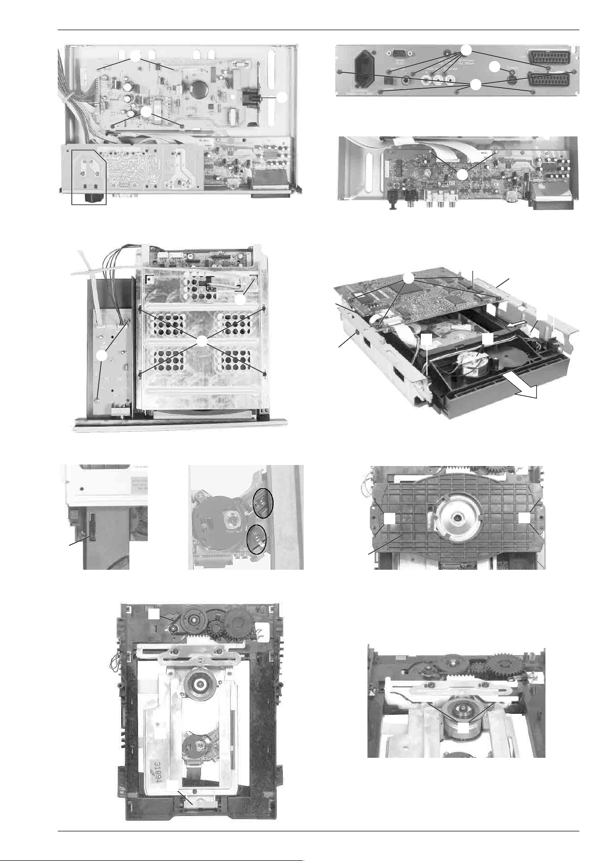
Ausbauhinweise
Öffnen der Schublade bei defektem Laufwerk
– Laufwerkeinheit ausbauen (Pkt. 4).
– Schieber
– Die Schublade kann jetzt herausgezogen werden.
1.Netzteil ausbauen
– 3 Schrauben
– 2 Rastnasen B (Fig. 1) lösen und Netzteil herausnehmen.
– Gegebenenfalls Steckverbindungen lösen.
2.A/V-MUX-Platte ausbauen
– je 5 Schrauben C/D und Schraube E (Fig. 2) herausdrehen.
– Blende mit Adapterplatte RS232 oder mit AUX-Platte abnehmen.
Achtung: Bei Inbetriebnahme auf die Netzanschlussbuchse T der
Adapterplatte RS232 (optional) achten (Fig. 1).
– 2 Rastnasen F (Fig. 3) lösen und A/V-MUX-Platte herausneh-
men.
– Gegebenenfalls Steckverbindungen lösen.
3. Eject-Platte ausbauen
– 2 Schrauben G (Fig. 4) herausdrehen und Eject-Platte herausneh-
men.
– Gegebenenfalls Steckverbindungen lösen.
4.Laufwerkeinheit ausbauen
– 4 Schrauben H (Fig. 4) herausdrehen.
– Laufwerk (inklusive Abschirmungen und DVD-Monoboard) an der
Rückseite anheben und herausnehmen.
– Gegebenenfalls Steckverbindungen lösen.
– Abschirmungen abnehmen.
4.1 DVD-Monoboard ausbauen
– 4 Schrauben I (Fig. 5) herausdrehen und DVD-Monoboard ab-
nehmen.
– Gegebenenfalls Steckverbindungen lösen.
Achtung: Die Lasereinheit ist sehr empfind-
lich gegen statische Aufladungen (MOS-
Bauteile)!
Schließen Sie deshalb die Flexprintleitung
zur Lasereinheit vor dem Abziehen mit
einer Büroklammer kurz.
4.2 Laufwerk ausbauen
– DVD-Monoboard ausbauen (Pkt. 4.1).
– Schraube J (Fig. 4) herausdrehen und Mikroschalter abnehmen.
– 2 Schrauben B (Fig. 5) herausdrehen.
– 4 Gummipuffer C (Fig. 5) aushängen und die Laufwerksmechanik
vorsichtig in Pfeilrichtung herausziehen.
Montagehinweis zum Einbau eines neuen Laufwerks:
– Flexprint an der Lasereinheit anschließen.
– offenes Ende des Flexprint mit einer Büroklammer kurz schließen
(MOS-Schutz).
– werkseitig angebrachte Schutzlötstellen der Lasereinheit entfernen
(Fig. 7).
4.3 Laufwerk zerlegen
– Laufwerk ausbauen (Pkt. 4.2).
4.3.1 Schublade ausbauen
– Schieber A (Fig. 5) bis zum Anschlag nach links schieben.
– Schublade herausziehen.
– Rastnase E (Fig. 6) vorsichtig mit einem kleinen Schraubendreher
anheben und Schublade ganz herausziehen.
4.3.2 Lasereinheit ausbauen
– 4 Rastnasen F (Fig. 8) ausrasten und DVD-Abdeckung G abneh-
men.
– Bügel I (Fig. 9) ausrasten und Lasereinheit J herausnehmen.
Beim Wiedereinbau auf korrekten Sitz der Lasereinheit in den
Führungen K (Fig. 10) achten!
4.3.3 Lademotor ausbauen
– Riemen H (Fig. 9) abnehmen.
– Bügel D (Fig. 5) ausrasten und Lademotor herausnehmen.
A (Fig. 5) bis zum Anschlag nach links schieben.
A (Fig. 1) herausdrehen.
FLEXPRINT
Disassembly Instructions
Opening the Tray when the Drive is defective
– Remove the Drive Mechanism (para 4).
– Push the slider
– The tray can be pulled out now.
1. Removing the Power Supply
– Undo 3 screws
– Disengage the 2 locking lugs B (Fig. 1) and remove the Power
Supply.
– Unplug the connectors if necessary.
2. Removing the A/V-MUX Board
– Undo the 5 screws C/D and the screw E (Fig. 2).
– Remove the panel together with the Adapter Board RS232 or
with the AUX Board.
Attention: When putting the set into operation, observe the mains
connection socket T on the Adapter Board RS232 (optional, Fig. 1).
– Disengage the 2 locking lugs F (Fig. 3) and remove the A/V-
MUX Board.
– Unplug the connectors if necessary.
3. Removing the Eject Board
– Undo 2 screws G (Fig. 4) and remove the Eject board.
– Unplug the connectors if necessary.
4. Removing the Drive Mechanism
– Undo 4 screws H (Fig. 4).
– Lift the Drive Mechanism (including the shieldings and the DVD-
Monoboard) at its rear side and remove it.
– Unplug the connectors if necessary.
– Remove the shieldings.
4.1 Removing the DVD-Monoboard
– Undo 4 screws I (Fig. 5) and remove the DVD-Monoboard.
– Unplug the connectors if necessary.
Attention: The laser unit is very sensitive to
static charges (MOS components)!
Therefore, short-circuit the Flexprint to the
laser unit with a paper clip before discon-
necting it.
4.2 Disassembling the Drive Mechanism
– Remove the DVD-Monoboard (para 4.1).
– Undo the screw J (Fig. 4) and remove the microswitch.
– Undo 2 screws B (Fig. 5).
– Unhook the 4 rubber shock-mounts C (Fig. 5) and pull out carefully
the drive mechanism in direction of the arrow.
Instructions for Mounting a new Drive Mechanism:
– Connect the Flexprint to the laser unit.
– Short the open end of the Flexprint with a paper clip (MOS
protection).
– Remove the factory-applied protective soldering joints from the
laser unit (Fig. 7).
4.3 Disassembling the Drive Mechanism
– Remove the drive mechanism (para 4.2).
4.3.1 Removing the Tray
– Push the slider A (Fig. 5) to the left until its stop.
– Pull the tray out.
– Carefully lift the locking lug E with a small screw driver (Fig. 6) and
pull the tray out completely.
4.3.2 Removing the Laser Unit
– Disengage the 4 locking lugs F (Fig. 8) and remove the DVD
cover G.
– Unhook the clip I (Fig. 9) and remove the Laser Unit J.
When reassembling, the laser unit must fit in the guides K
(Fig. 10)!
4.3.3 Removing the Loading Motor
– Remove the belt H (Fig. 9).
– Unhook the clip D (Fig. 5) and remove the loading motor.
A (Fig. 5) to the left until its stop.
A (Fig. 1).
FLEXPRINT
1 - 4 GRUNDIG Service
GDV Modul 1 Allgemeiner Teil / General Section
T
G
B
A
A
Fig. 1 Fig. 3
J
C
H
B
I
C
C
E
D
Fig. 2
F
C
B
C
A
D
E
Fig. 9
H
J
Fig. 4
Fig. 5
F
F
G
Fig. 7Fig. 6
Fig. 8
K
Fig. 10
I
GRUNDIG Service 1 - 5

Allgemeiner Teil / General Section GDV Modul 1
Servicehinweise
Wiederherstellen der Gerätefunktion nach Austausch der Digitalplatte oder Löschen des NVRAMs
• DVD aus Gerät nehmen, Schublade schließen und warten bis auf
dem Bildschirm "no disc" erscheint.
• Auf der Fernbedienung die Taste PLAY Q drücken und die Zahlenfolge "274 002 000 000 000" eingeben.
• Eingabe mit Taste PLAY Q bestätigen und warten, bis sich das
Gerät neu initialisiert.
Achtung: Nur bei richtiger Zahlencode-Eingabe sind alle Gerätefunktionen gewährleistet.
Wichtige Masseverbindungen!
Beim Zusammenbau des Gerätes ist darauf zu achten, dass die
Masseverbindungen zwischen den einzelnen Platinen und dem Rahmen sowie dem Laufwerk und dem Rahmen gewährleistet sind.
Durchführen von Messungen
Bei Messungen mit dem Oszilloskop an Halbleitern sollten Sie nur
Tastköpfe mit 10:1 - Teiler verwenden. Außerdem ist zu beachten,
dass nach vorheriger Messung mit AC-Kopplung der Koppelkondensator des Oszilloskops aufgeladen sein kann. Durch die Entladung
über das Messobjekt können diese Bauteile beschädigt werden.
Messwerte und Oszillogramme
Bei den in den Schaltplänen und Oszillogrammen angegebenen
Messwerten handelt es sich um Näherungswerte!
Service Instructions
Reactivation of the DVD-Player after exchanging the digital board
or resetting the NVRAM
• Remove the DVD from the unit, close the tray and wait until "no disc"
appears on the picture screen.
• Press PLAY Q on the remote control and enter the numbers
"274 002 000 000 000".
• Press PLAY Q on the remote control to confirm the entry and wait
until the DVD-Player is initialized
Attention: All functions will operate only if the code number has been
entered correctly.
Important: Chassis Connections!
When reassembling the machine it is essential to observe that the
chassis connections between the individual circuit boards and the
frame as well as between the Drive Mechanism and the frame are in
good order.
Carrying out Measurements
When making measurements on semi-conductors with an oscilloscope, ensure that the test probe is set to 10:1 dividing factor. Further,
please note that if the previous measurement is made on AC input, the
coupling capacitor in the oscilloscope will be charged. Discharge via
the item being checked can damage components.
Measured Values and Oscillograms
The measured values given in the circuit diagrams and oscillograms
are approximates!
Dauerlauffunktionen
Bei diesen Funktionen wird der momentan laufende Abschnitt oder der
momentan laufende Titel oder der gesamte Inhalt der DVD wiederholt.
Hinweis: Die Dauerlauffunktion ist mit der Taste
dienung z.B. RP100D anwählbar.
Während der Wiedergabe Taste
REPEAT drücken.
0
– Auf dem Bildschirm erscheint " b chapter ". Der laufende Abschnitt
wird wiederholt.
Während der Wiedergabe Taste
REPEAT zweimal drücken.
0
– Auf dem Bildschirm erscheint " b title ". Der laufende Titel wird
wiederholt.
Während der Wiedergabe Taste
REPEAT dreimal drücken.
0
– Auf dem Bildschirm erscheint " b repeat ". Der Inhalt der DVD wird
wiederholt.
Zum Beenden der REPEAT-Funktionen Taste
drücken
REPEAT der Fernbe-
0
REPEAT ein viertes Mal
0
Continuous Mode Functions (REPEAT)
With these functions the currently running section or the currently
running title or the total contents of the DVD is repeated.
Note: the continuous play function can be selected with the
button on the remote control, e.g. the RP100D.
Press the
REPEAT button during playback.
0
–" b chapter " appears on the screen. The section currently running
is repeated.
Press the
REPEAT button twice during playback.
0
–" b title " appears on the screen. The title currently running is
repeated.
Press the
REPEAT button three times during playback.
0
–" b repeat " appears on the screen. The contents of the DVD are
repeated.
To finish the REPEAT functions, press the
REPEAT button a fourth time.
0
REPEAT
0
1 - 6 GRUNDIG Service
GDV Modul 1 Allgemeiner Teil / General Section
GRUNDIG Service 1 - 7
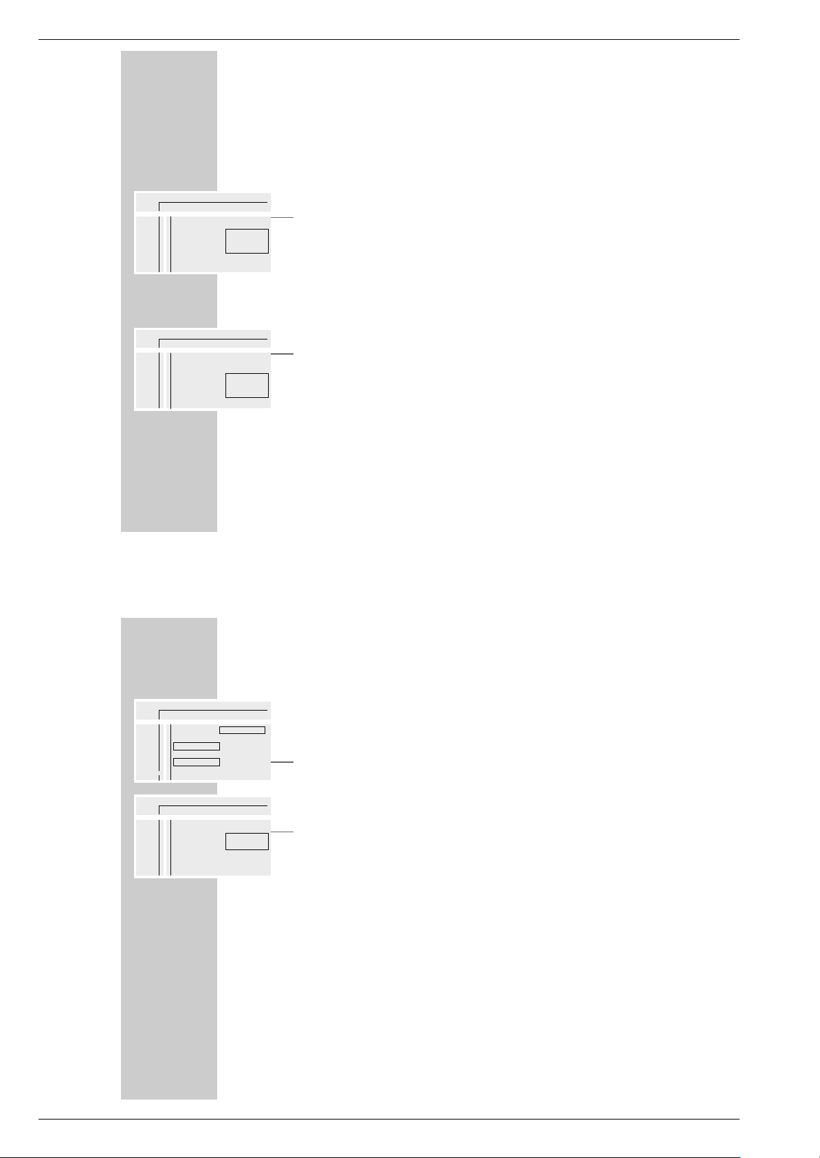
Bedienhinweise Dieses Kapitel enthält Auszüge aus der Bedienungsanleitung. Weitergehende Informationen entnehmen Sie bitte der
gerätespezifischen Bedienungsanleitung, deren Materialnummer Sie in den entsprechenden Ersatzteillisten finden.
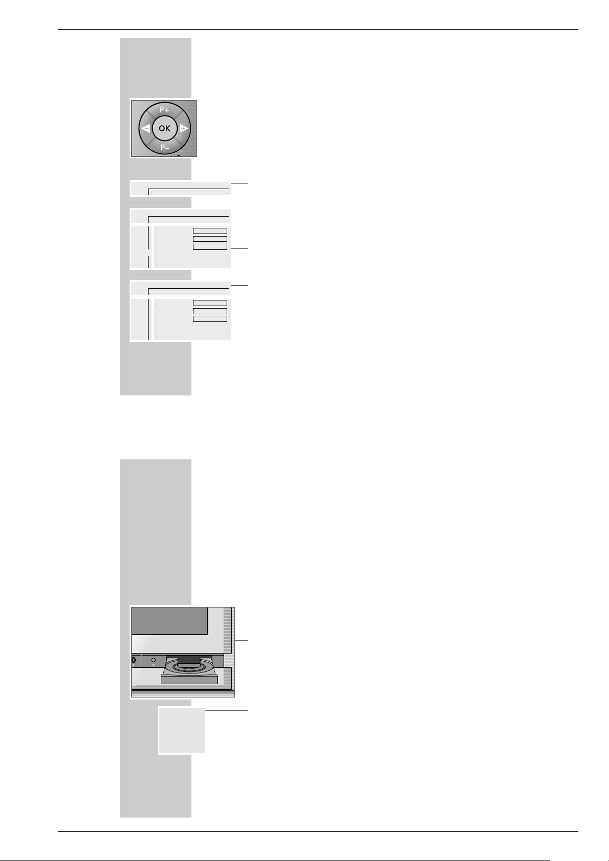
DIE BENUTZERFÜHRUNG
__________________________________
Mit der Benutzerführung können Sie alle Funktionen anwählen sowie die
notwendigen Einstellungen durchführen.
Symbole, Tasten und Dialogzeilen zeigen die möglichen Bedienschritte.
Die Menüzeile
1 Menüzeile mit »OSD AUX« aufrufen.
– Die Abbildungen zeigen Ihnen die Möglichkeiten der Menüzeile.
»Ö« = Menüpunkt »Einstellungen«:
»
P« = zum Anwählen von Titeln.
»K« = zum Anwählen von Kapiteln.
»(« = zum Anwählen der Tonspur.
»I« = zum Anwählen der Sprache von Untertiteln.
»R« = zum Anwählen verschiedener Blickwinkel.
»k« = zum Anwählen der Zoomfunktion.
2 Die Fortsetzung der Menüzeile mit »
Ƿ
« anwählen.
»_« = zum Programmieren von Szenen.
»Z« = zum Anwählen der Klangart.
»:« = zum Vor-/Zurückschalten des Standbildes.
»
;« = zum Anwählen verschiedener Zeitlupen-Geschwindigkeiten.
»
N« = zum Anwählen verschiedener Bildsuchlauf-Geschwindigkeiten.
»L« = zum minutengenauen Anwählen eines Abschnittes.
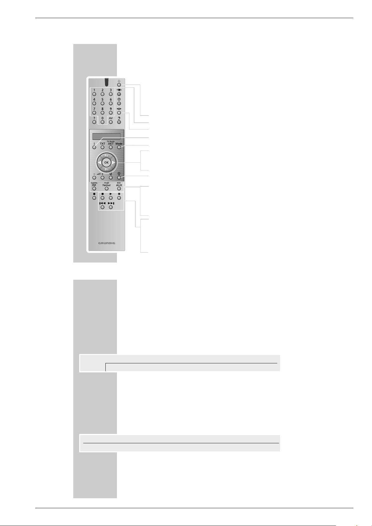
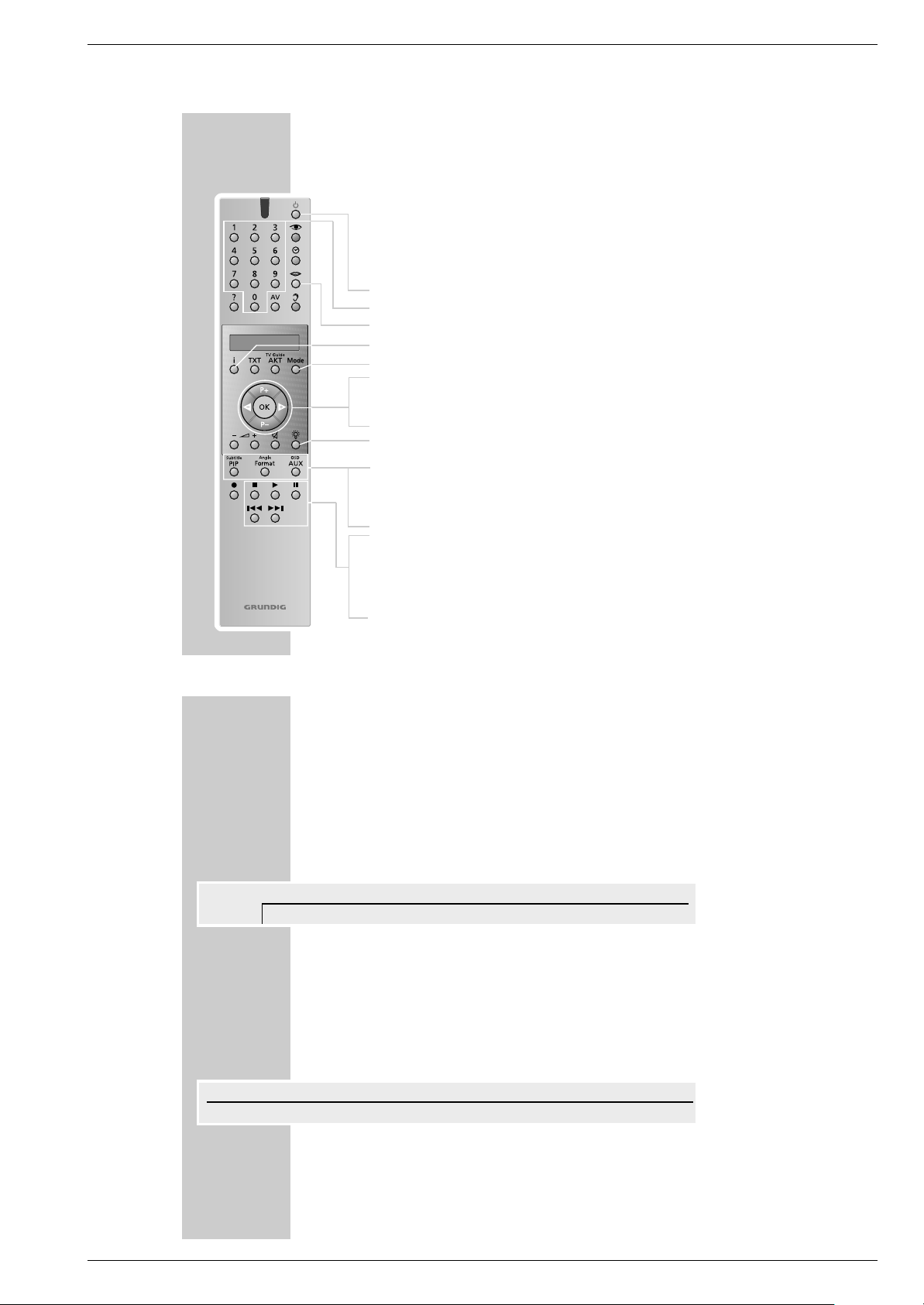
AUF EINEN BLICK
______________________________________________________
Mit der Fernbedienung „Personal Remote 10“ Ihres Fernsehgerätes bedienen
Sie auch Ihren DVD-Player.
Zum Bedienen des DVD-Players die Taste »Mode« so oft drücken, bis »
DVD«
in der Anzeige steht.
9
Schaltet das Fernsehgerät ab (Stand-by).
1 … 0 Ziffern-Tasten für verschiedene Eingaben.
M
Zum Anwählen der Synchronsprache der DVD.
i Ruft das Titelmenü der DVD/Video-CD auf.
Mode Schaltet die Fernbedienung auf Bedienebene DVD.
P+ P– Wählen in den Menüs verschiedene Funktionen.
ǸǷ Wählen in den Menüs verschiedene Funktionen.
OK Bestätigt Eingaben in den Menüs.
R Schaltet die Anzeigen-Beleuchtung ein/aus. Die Beleuchtung
wird nach kurzer Zeit automatisch abgeschaltet.
Subtitle PIP Blendet während der Wiedergabe die Untertitel der DVD ein.
Angle Format Wählt während der Wiedergabe verschiedene Blickwinkel
(Kamera-Standorte) von bestimmten Szenen oder Passagen der
DVD.
OSD AUX Blendet die Menüzeile ein und wieder aus.
7
Beendet alle Funktionen, schaltet den DVD-Player auf „STOP“.
8
Startet die Wiedergabe;
aktiviert durch zweimaliges Drücken die Funktion „Resume“.
II Standbild bei DVD und Video-CD; Pause bei Audio-CD.
5as6
Schaltet während der Wiedergabe auf Bildsuchlauf vorwärts
oder rückwärts in verschiedene Geschwindigkeiten.
Die Fernbedienung
_
ZZ
:;
NN
LL
off st
ÖÖ PP KK (( II RR kk
//
121offnooff
DVD
A
sa
>
sa
<
S
Personal Remote 10

Allgemeiner Teil / General Section GDV Modul 1
1 - 8 GRUNDIG Service
DIE BENUTZERFÜHRUNG
_________________________________________________________
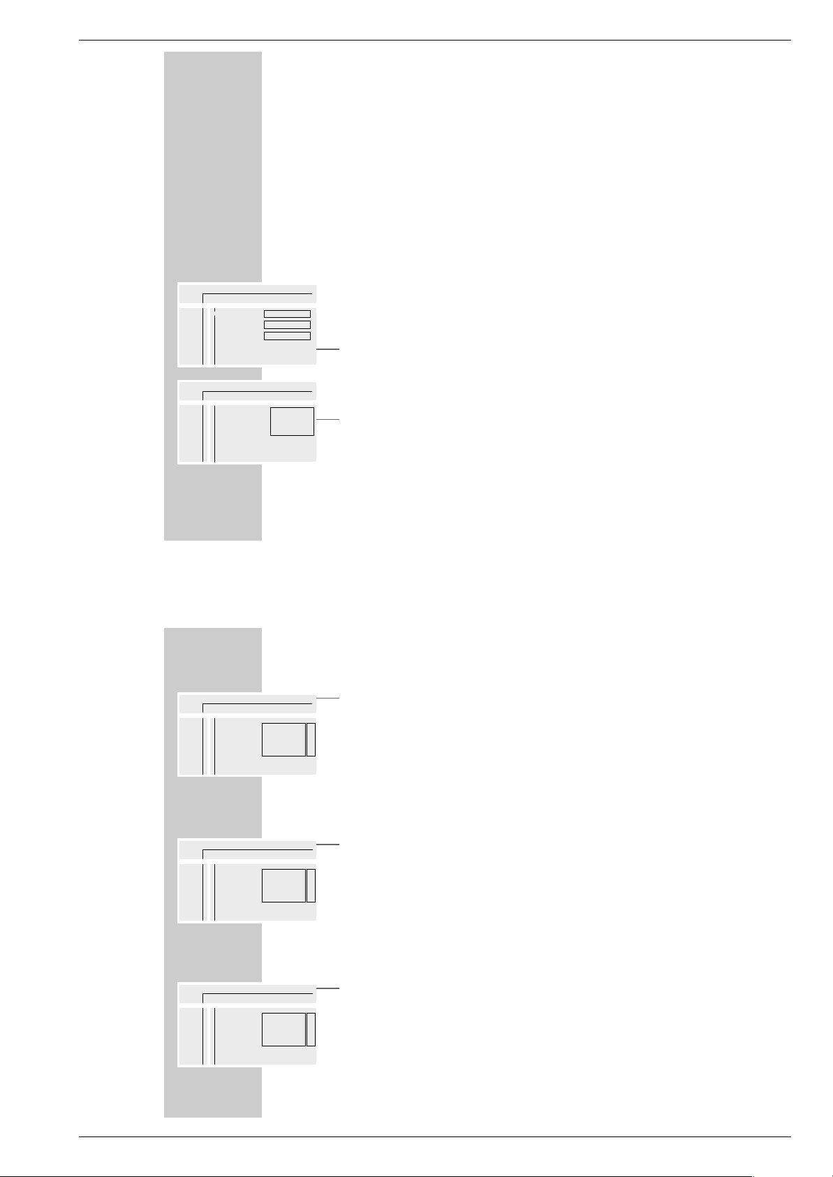
Der Menüpunkt »Einstellungen«
»O« = »Bildmenü« mit den Funktionen
– Bildformat,
– Schwarzwerteinstellung,
– Bildverschiebung.
»>« = »Tonmenü« mit den Funktionen
– Digitalausgang,
– Analogausgang,
– Nachtmodus.
»U« = »Sprachmenü« mit den Funktionen
– Audio,
– Untertitel,
– Menü.
»
Ü« = Menü »Sonderfunktionen« mit den Funktionen
– Zugriffskontrolle,
– Statusfenster,
– Standby (ohne Funktion).
DIE BENUTZERFÜHRUNG
_________________________________________________________
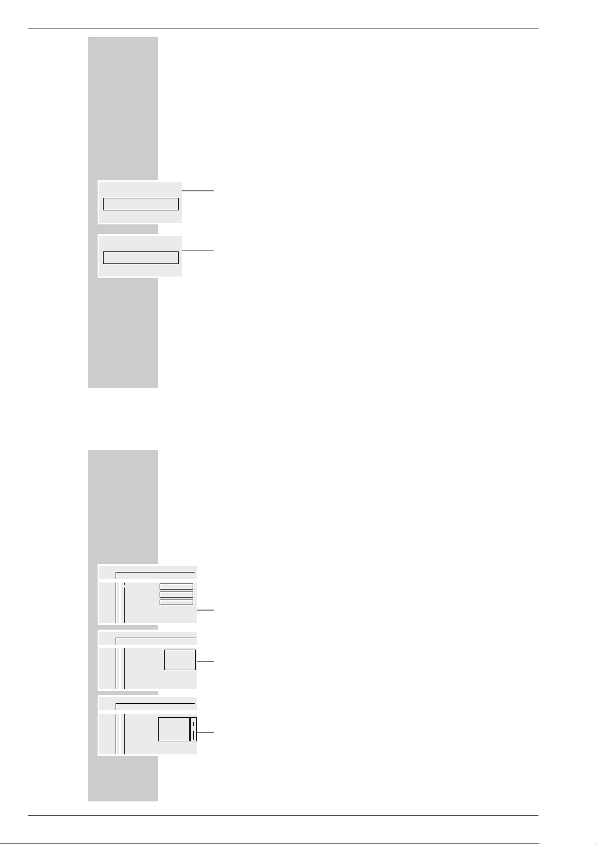
Die Statusanzeige
In der Statusanzeige werden Informationen über die eingelegte DVD/VideoCD, die Gesamtspielzeit und die abgelaufene Spielzeit der DVD/Video-CD
eingeblendet. Zusätzlich sehen Sie die jeweilige Funktion.
»2 : 05 :30« = Gesamtspielzeit.
»0 : 15 :00« = Abgelaufene Spielzeit.
»..« DVD = DVD eingelegt.
»..« VCD = Video-CD eingelegt.
»,,« reading = DVD wird gelesen.
»{« no disc = keine DVD oder Video-CD eingelegt.
»]« opened = Schublade geöffnet.
»[« closing = Schublade geschlossen.
»
ǵ
!
« error = Störungsmeldung.
»8play« = Wiedergabe.
»7stop« = Wiedergabe beenden.
»II pause« = Wiedergabe-Pause.
»
EW
x 4 x 8 x 32« = Bildsuchlauf vorwärts/rückwärts.
» 1/4 1/8 1/2 1« = Zeitlupe vorwärts/rückwärts.
Die Dialoganzeige
In der Dialogzeile sehen Sie Informationen über den Betriebszustand.
» « = Funktion nicht möglich.
» « = Kindersicherung aktiviert.
» « = Kindersicherung abgeschaltet.
» « = Blickwinkel für Szenen.
» « = Wiedergabe wird fortgesetzt.
resume
%
2/2
R
safe
H
locked
G
x
ÖÖ PP KK (( II RR kk
//
121offnooff
OO
AA
S
8
>>
UU
ÜÜ
Bildformat
Schwarzwerteinstellung
Bildverschiebung
■■◊■■■■■■■
Aus
16:9
ÖÖ PP
//
1
..
!
DVD pause
2 : 04 : 26
0 : 00 : 21
>
a
GDV Modul 1 Allgemeiner Teil / General Section
GRUNDIG Service 1 - 9
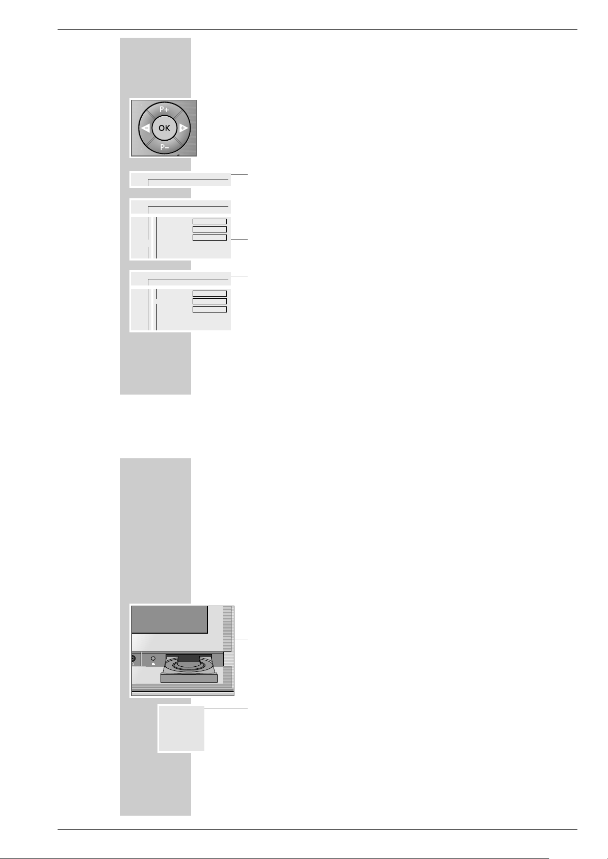
DIE BENUTZERFÜHRUNG
_________________________________________________________
Die Bedienung mit der Benutzerführung
Entnehmen Sie dem folgenden Beispiel den Aufbau der Benutzerführung und
die Anwahl der verschiedenen Menüs und Einstellungen.
Die Menüzeile wählen Sie mit der Taste »
OSD AUX«, die einzelnen Menüpunk-
te wählen Sie mit den Tasten »P – « oder »P +«, »
Ǹ
« oder »Ƿ«.
Der aktive Menüpunkt ist blau hervorgehoben. Menüpunkte, die mit der jeweiligen DVD keine Funktion haben sind grau markiert und können nicht angewählt
werden.
Die Fortsetzung der Menüzeile wählen Sie mit »Ƿ«.
1 Menüzeile mit »OSD AUX« aufrufen.
– Die Menüzeile wird eingeblendet.
2 Gewünschten Menüpunkt (im Beispiel »
Ö
«) mit »Ǹ« oder »Ƿ« wählen
und mit »P – « aktivieren.
– Das Menü wird eingeblendet.
3 Menü (im Beispiel »U«) mit »P –« oder » P +« wählen und mit »
Ƿ
«
aktivieren.
– Das Sprachmenü wird eingeblendet.
4 Funktion (im Beispiel »Untertitel«) mit »P –« oder » P +« wählen und mit
»Ƿ« aktivieren.
5 Gewünschte Einstellung mit »P –« oder » P +« wählen.
Hinweis:
Mit »OK« kann schrittweise zurückgeschaltet werden zu den vorherigen
Menüs und Menüpunkten.
6 Menüzeile mit »OSD AUX« abschalten.
– Die eingestellten Funktionen oder Werte werden automatisch gespeichert.
ÖPPK(IRk
/ 121offno off
ÖÖ
PK(IRk
/ 121offno off
O
>>
U
Ü
Audio
Untertitel
Menü
Deutsch
Deutsch
Deutsch
S
a
A
>
>
sa
A
S
ÖÖ
PK(IRk
/ 121offno off
O
>>
U
Ü
Audio
Untertitel
Menü
Deutsch
Deutsch
Deutsch
A
S
8
>
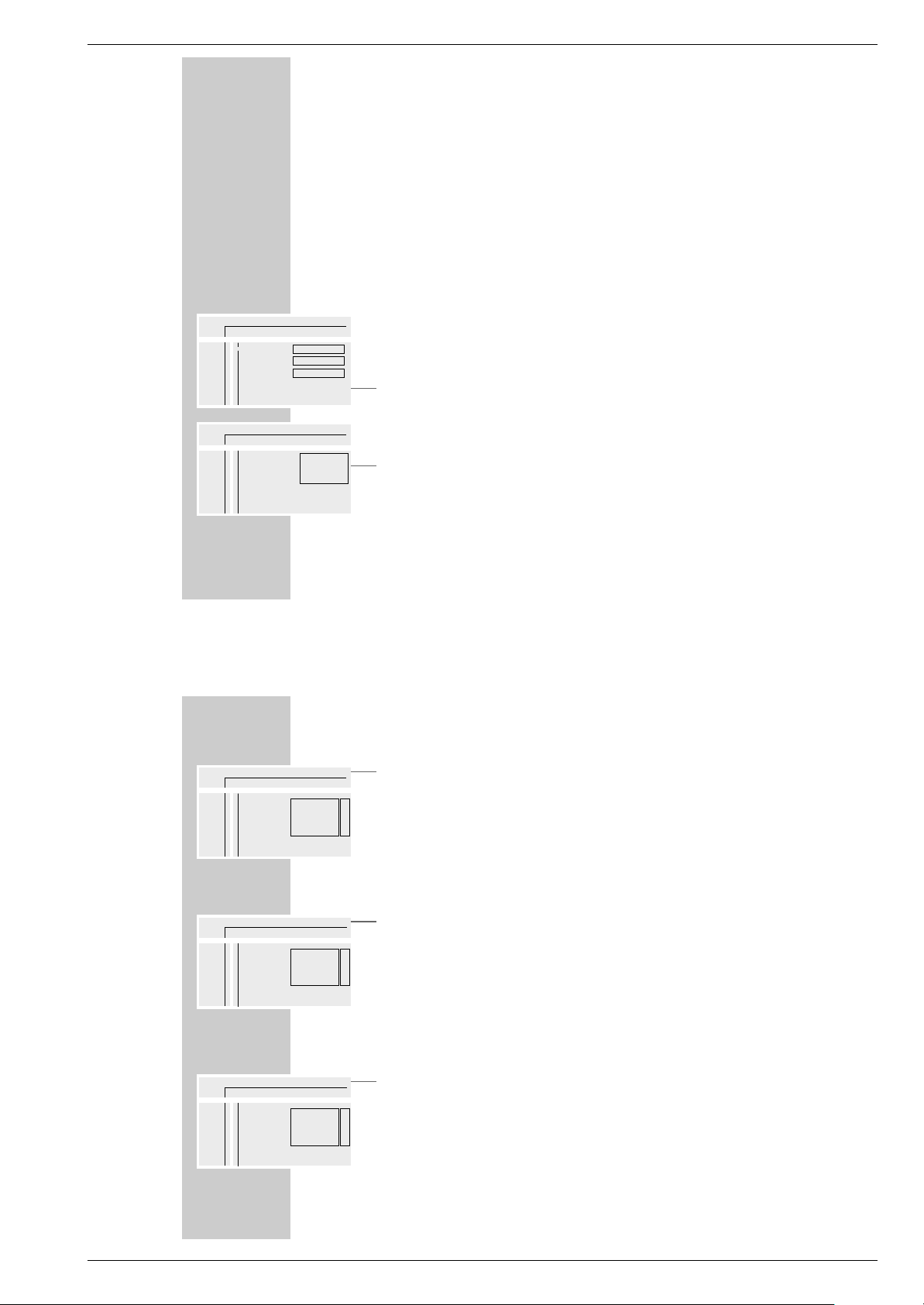
WIEDERGABE EINER DVD/VIDEO-CD
____________________________________
Vor der Wiedergabe
Vorbereiten
1 Fernbedienung mit »Mode« auf DVD-Betrieb schalten.
– In der Anzeige der Fernbedienung erscheint: »DVD«.
2 HiFi-Anlage einschalten (wenn gewünscht) und den entsprechenden Tonein-
gang für den DVD-Player wählen.
DVD/Video-CD einlegen
1 Bedienteilabdeckung am Fernsehgerät öffnen.
2 Zum Öffnen der Schublade »
ə
« am Fernsehgerät drücken.
– Die Schublade öffnet sich.
3 Gewünschte DVD/Video-CD mit dem Aufdruck nach oben in die Schublade
einlegen.
4 Zum Schließen der Schublade »
ə
« drücken.
– Die Schublade schließt automatisch.
– Anzeige in der Statusanzeige: »,,reading«, die Wiedergabe startet auto-
matisch.
Hinweis:
Ist die Kindersicherung aktiviert und die DVD/Video-CD wurde nicht freigegeben (siehe Kapitel „KINDERSICHERUNG“), muß die Geheimzahl
eingegeben werden.
,,
7
reading stop
- : -- : - -
- : -- : - -

Allgemeiner Teil / General Section GDV Modul 1
1 - 10 GRUNDIG Service
WIEDERGABE EINER DVD/VIDEO-CD
____________________________________
Funktionsanzeige aufrufen
Jede Funktion die Sie angewählt haben (zum Beispiel die Spielzeit, der aktuelle
Titel, usw.), kann am Bildschirm angezeigt werden.
1 Funktionsanzeige mit »OSD AUX« einblenden.
2 Funktionsanzeige mit »OSD AUX« ausblenden.
Wiedergabe eines Titels
Nach dem Schließen der Schublade startet die Wiedergabe automatisch.
1 Auf Wiedergabe-Pause (Standbild) mit »II« schalten.
2 Wiedergabe mit »8« fortsetzen.
3 Wiedergabe mit »7« beenden.
Hinweise:
Abhängig von der verwendeten DVD/Video-CD kann es notwendig sein,
aus einem Inhaltsverzeichnis der DVD/Video-CD Titel oder Kapitel
auszuwählen.
Zum Auswählen benutzen Sie die Tasten »P – « oder »P +«, zum
Aktivieren die Taste »OK«.
Ist die Auswahl numeriert, verwenden Sie die Tasten »1 … 0 «.
..
8
DVD play
2 : 04 : 26
0 : 11 : 30
..
8
DVD play
2 : 04 : 26
0 : 15 : 00
WIEDERGABE EINER DVD/VIDEO-CD
____________________________________
Einen anderen Titel oder Kapitel anwählen ...
Wenn eine DVD/Video-CD mehrere Titel und/oder Kapitel enthält, können Sie
diese anwählen.
... mit dem Menü des DVD-Players
1
Menüzeile mit »OSD AUX« einblenden.
2 Menüpunkt »
P
« (für Titel) mit »Ǹ« oder »Ƿ« anwählen
oder
Menüpunkt »K« (für Chapter/Kapitel) mit »Ǹ« oder »Ƿ« anwählen.
3 Nächsten Titel/Kapitel mit »P –« oder » P +« auswählen.
Hinweis:
Titel oder Kapitel können auch direkt angewählt werden, dazu die Nummer
des betreffenden Titels oder Kapitels mit »1 … 0 « ein- oder zweistellig
eingeben.
... mit dem Titelmenü der DVD/Video-CD
Das Titelmenü der DVD/Video-CD kann Auswahlmöglichkeiten für Titel,
Abschnitte oder Szenen enthalten.
1 Inhalt der DVD/Video-CD mit »i« aufrufen.
– Wenn die DVD/Video-CD ein Titelmenü enthält, erscheint es am Bild-
schirm.
2 Wenn die Auswahlmöglichkeiten numeriert sind, entsprechenden Titel und
Abschnitt mit »1 … 0 « wählen.
3 Sind die Auswahlmöglichkeiten nicht numeriert, Titel und Abschnitte mit
»P – « oder »P +« wählen und mit »OK« aktivieren.
ÖPPK(IR k
/ 1 2 1 off no off
>
s
a
A
S
Ö PKK(IR k
/ 1 2 1 off no off
>
s
a
A
S
ÖPPK(IR k
/ 2 2 1 off no off
>
s
a
A
S
GDV Modul 1 Allgemeiner Teil / General Section
GRUNDIG Service 1 - 11
KINDERSICHERUNG
________________________________________________
Mit der Kindersicherung können Sie:
– Die Benutzung des DVD-Players ausschließen;
– bestimmte DVDs oder Video-CDs für die Wiedergabe freigeben oder sperren;
– Szenen von DVDs oder Video-CDs, die nicht für Kinder geeignet sind
sperren oder alternative Szenen auswählen.
Kindersicherung des DVD-Players aktivieren und
abschalten
Kindersicherung des DVD-Players aktivieren
1 Menüzeile mit »OSD AUX« aufrufen.
2 Menüpunkt »
Ö
« (Einstellungen) mit »Ǹ« oder »Ƿ« anwählen und mit
»P – « aktivieren.
3 Zeile »
Ü
« (Sonderfunktionen) mit »P – « auswählen und mit »Ƿ«
aktivieren.
4 Zeile »Zugriffskontrolle« mit »P –« oder » P +« anwählen und mit »
Ƿ
«
aktivieren.
5 Vierstellige Geheimnummer mit »1...0« eingeben.
Hinweis:
Wenn die Geheimnummer das erste Mal eingegeben wird, wechselt die
Anzeige in »Kode bestätigen«.
Vierstellige Geheimnummer mit »1...0 « nocheinmal eingeben.
6 Zeile »Kindersicherung« mit »P –« oder » P +« anwählen und mit »
Ƿ
«
aktivieren.
ÖÖ
PK(IRk
/ 121offno off
O
>>
U
Ü
Zugriffskontrolle
Statusfenster
Standby
Normal
Ein
Kode eingeben...
>
S
s
ÖÖ
PK(IRk
/ 121offno off
O
>>
U
Ü
Zugriffskontrolle
Statusfenster
Standby
>
a
( ) ( ) ( ) ( )
Kode eingeben
a
KINDERSICHERUNG
__________________________________________________________________
7 Das Symbol »
D
« mit »P – « oder »P +« anwählen.
8 Einstellung mit »OSD AUX« beenden.
– Der DVD-Player ist verriegelt.
Hinweis:
Wird jetzt eine DVD oder Video-CD in die Schublade gelegt, erscheint die
Meldung »locked« (gesperrt) und Sie müssen die vierstellige Geheimnummer
eingeben.
Kindersicherung des DVD-Players abschalten
1 Zum Abschalten der Kindersicherung die Punkte 1 bis 8 im Kapitel „Kinder-
sicherung des DVD-Players aktivieren“ wiederholen und das Symbol »F«
mit »P – « oder »P +« anwählen.
– Die Kindersicherung ist abgeschaltet.
Hinweis:
Falls Sie die Geheimnummer vergessen oder verlegt haben, dann lesen Sie
bitte das Kapitel „Störungen selbst beheben“ auf Seite 42.
Geheimzahl ändern
1 Zum Ändern der Geheimzahl die Punkte 1 bis 5 im Kapitel „Kinder-
sicherung des DVD-Players aktivieren“ wiederholen.
2 Zeile »Kode ändern« mit »P –« oder »P +« anwählen und mit »
Ƿ
«
aktivieren.
3 Neue vierstellige Geheimnummer mit »1...0« eingeben.
Vierstellige Geheimnummer mit »1...0 « nocheinmal eingeben.
4 Einstellung mit »OSD AUX« beenden.
ÖÖ
PK(IRk
/ 121offno off
O
>>
U
Ü
Zugriffskontrolle
Statusfenster
Standby
>
Kindersicherung
Sicherungsstufe
Land ändern
Kode ändern
D
F
a
S
ÖÖ
PK(IRk
/ 121offno off
O
>>
U
Ü
Zugriffskontrolle
Statusfenster
Standby
>
Kindersicherung
Sicherungsstufe
Land ändern
Kode ändern
D
F
a
A
ÖÖ
PK(IRk
/ 121offno off
O
>>
U
Ü
Zugriffskontrolle
Statusfenster
Standby
>
Kindersicherung
Sicherungsstufe
Land ändern
Kode ändern
()
()
()
()
s
A
S
Allgemeiner Teil / General Section GDV Modul 1
1 - 12 GRUNDIG Service
KINDERSICHERUNG
__________________________________________________________________
DVDs oder Video-CDs für die Wiedergabe freigeben
Benutzung des DVD-Players zulassen
Wenn die Kindersicherung aktiviert ist, erscheint am Bildschirm das Menü
»Zugriffskontrolle«. Sie können wählen, ob die DVD oder Video-CD einmal
abgespielt wird oder uneingeschränkt.
Wenn Sie die Funktion »Immer wiedergeben« wählen, wird die DVD oder
Video-CD in einer „Liste“ gespeichert und die Wiedergabe dieser DVD oder
Video-CD ist nicht eingeschränkt. In dieser „Liste“ können maximal 50 DVD
oder Video-CD aufgenommen werden.
1 DVD oder Video-CD in die Schublade einlegen.
– Am Bildschirm erscheint die Tafel »Zugriffskontrolle«.
2 Zeile »Einmal wiedergeben« mit »P –« oder »P +« (für den einmaligen
Gebrauch) anwählen, oder
Zeile »Immer wiedergeben« mit »P – « oder »P +« anwählen.
3 Vierstellige Geheimnummer mit »1...0« eingeben.
– Die Wiedergabe startet automatisch.
Die Funktion »Immer wiedergeben« abschalten
1 DVD oder Video-CD in die Schublade einlegen.
– Die Wiedergabe beginnt automatisch.
2 Taste »7« drücken, während H eingeblendet wird.
– Die Berechtigung, diese DVD oder Video-CD immer wiederzugeben ist
aufgehoben.
locked Zugriffskontrolle
G
‘Immer wiedergeben‘ wählen, um die Disk in
die Kinderliste aufzunehmen
Einmal wiedergeben ( ) ( ) ( ) ( )
Immer wiedergeben ( ) ( ) ( ) ( )
locked Zugriffskontrolle
G
‘Immer wiedergeben‘ wählen, um die Disk in
die Kinderliste aufzunehmen
Einmal wiedergeb • • • ( )
Immer wiedergeben ( ) ( ) ( ) ( )
S
KINDERSICHERUNG
__________________________________________________________________
Inhalt der DVD autorisieren
DVDs können Spielfilme anbieten, deren Inhalt oder auch Szenen nicht für Kinder
geeignet sind. Diese DVDs enthalten Informationen, die diesen Inhalt oder diese
Szenen markieren und sind mit Kennzahlen von 1 bis 8 versehen. Sie können eine
der Kennzahlen anwählen und damit alternative Szenen zur Wiedergabe autorisieren.
1 Menüzeile mit »OSD AUX« aufrufen.
2 Menüpunkt »
Ö
« (Einstellungen) mit »Ǹ« oder »Ƿ« anwählen und mit
»P – « aktivieren.
3 Zeile »
Ü
« (Sonderfunktionen) mit »P – « auswählen und mit »Ƿ«
aktivieren.
4 Zeile »Zugriffskontrolle« mit »P –« oder »P +« anwählen und mit »
Ƿ
«
aktivieren.
5 Vierstellige Geheimnummer mit »1...0« eingeben.
6 Zeile »Kindersicherung« mit »P –« oder »P +« anwählen und mit »
Ƿ
«
aktivieren.
7 Zeile »Sicherungsstufe« mit »P –« oder »P +« anwählen und mit »
Ƿ
«
aktivieren.
8 Gewünschte Kennzahl (von 1 bis 8) mit »P –« oder » P +« anwählen.
9 Einstellung mit »OSD AUX« beenden.
ÖÖ
PK(IRk
/ 1 2 1 off no off
O
>>
U
Ü
Zugriffskontrolle
Statusfenster
Standby
>
Kindersicherung
Sicherungsstufe
Land ändern
Kode ändern
5
a
S
ÖÖ
PK(IRk
/ 1 2 1 off no off
O
>>
U
Ü
Zugriffskontrolle
Statusfenster
Standby
Normal
Ein
Kode eingeben...
>
S
s
a
ÖÖ
PK(IRk
/ 1 2 1 off no off
O
>>
U
Ü
Zugriffskontrolle
Statusfenster
Standby
>
a
( ) ( ) ( ) ( )
Kode eingeben
A
GDV Modul 1 Allgemeiner Teil / General Section
GRUNDIG Service 1 - 13
KINDERSICHERUNG
__________________________________________________________________
Land ändern
1 Menüzeile mit »OSD AUX« aufrufen.
2 Menüpunkt »
Ö
« (Einstellungen) mit »Ǹ« oder »Ƿ« anwählen und mit
»P – « aktivieren.
3 Zeile »
Ü
« (Sonderfunktionen) mit »P – « auswählen und mit »Ƿ«
aktivieren.
4 Zeile »Zugriffskontrolle« mit »P –« oder » P +« anwählen und mit »
Ƿ
«
aktivieren.
5 Vierstellige Geheimnummer mit »1...0« eingeben.
6 Zeile »Kindersicherung« mit »P –« oder » P +« anwählen und mit »
Ƿ
«
aktivieren.
7 Zeile »Land ändern« mit »P –« oder » P +« anwählen und mit »
Ƿ
«
aktivieren.
8 Gewünschtes Land mit »P –« oder » P +« anwählen.
9 Einstellung mit »OSD AUX« beenden.
ÖÖ
PK(IRk
/ 121offno off
O
>>
U
Ü
Zugriffskontrolle
Statusfenster
Standby
>
Kindersicherung
Sicherungsstufe
Land ändern
Kode ändern
5
a
S
ÖÖ
PK(IRk
/ 121offno off
O
>>
U
Ü
Zugriffskontrolle
Statusfenster
Standby
Normal
Ein
Kode eingeben...
>
S
s
a
ÖÖ
PK(IRk
/ 121offno off
O
>>
U
Ü
Zugriffskontrolle
Statusfenster
Standby
>
a
( ) ( ) ( ) ( )
Kode eingeben
A
EINSTELLUNGEN
_________________________________________________________
Bildeinstellungen
Bildmenü anwählen
1 Menüzeile mit »OSD AUX« einblenden.
2 Menüpunkt »
Ö
« (Einstellungen) mit »Ǹ« oder »Ƿ« anwählen und mit
»P – « aktivieren.
3 Zeile »
O
« (Bildmenü) mit »P – « oder »P +« wählen und mit »Ƿ«
aktivieren.
Hinweis:
Die weitere Bedienung entnehmen Sie bitte den folgenden Kapiteln, jeweils ab
Pkt. 1.
Format des Fernsehgerätes
Bei Ihrem Fernsehgerät mit dem Bildformat 16:9 brauchen Sie keine Einstellung
vorzunehmen, die Einstellung 16:9 ist voreingestellt und sollte nicht geändert
werden.
Schwarzwerteinstellung (nur für NTSC-Sendungen)
Diese Einstellung paßt die Farbdynamik an, damit wird ein besserer Bildkontrast erzielt.
1 Zeile »Schwarzwerteinstellung« mit »P –« oder » P +« wählen und mit
»Ƿ« aktivieren.
2 Funktion mit »P –« oder »P +« ein-/ oder ausschalten.
3 Menü mit »OSD AUX« abschalten.
ÖÖ
PK(IRk
/ 121offno off
O
>>
U
Ü
Bildformat
Schwarzwerteinstellung
Bildverschiebung
■■"■■■■■■
Aus
16:9
A
S
8
>
ÖÖ
PK(IRk
/ 121offno off
O
>>
U
Ü
Bildformat
Schwarzwerteinstellung
Bildverschiebung
>
Ein
Aus
a
A

Allgemeiner Teil / General Section GDV Modul 1
1 - 14 GRUNDIG Service
EINSTELLUNGEN
________________________________________________________________________
Bildlage einstellen
In der Werkseinstellung wird das Bild auf dem Bildschirm zentriert.
Benutzen Sie diese Einstellung, um die Bildlage auf Ihrem Fernsehgerät nach
Ihrem persönlichen Geschmack einzustellen, indem Sie das Bild nach links oder
nach rechts verschieben.
1 Zeile »Bildverschiebung« mit »P –« oder »P +« wählen und mit »
Ƿ
«
aktivieren.
2 Bildlage mit »
Ǹ
« oder »Ƿ« verschieben und mit »OK« speichern.
3 Menü mit »OSD AUX« abschalten.
ÖÖ
PK(IRk
/ 1 2 1 off no off
O
>>
U
Ü
Bildformat
Schwarzwerteinstellung
Bildverschiebung
>
■■as■■ ■■■■
Ende: OK drücken
EINSTELLUNGEN
________________________________________________________________________
Toneinstellungen
Tonmenü anwählen
1 Menüzeile mit »OSD AUX« einblenden..
2 Menüpunkt »
Ö
« (Einstellungen) mit »Ǹ« oder »Ƿ« anwählen und mit
»P – « aktivieren.
3 Zeile »
>
« (Tonmenü) mit »P – « oder »P +« wählen und mit »Ƿ«
aktivieren.
Hinweis:
Die weitere Bedienung entnehmen Sie bitte den folgenden Kapiteln, jeweils ab
Pkt. 1.
Digitalausgänge des DVD-Players an ein externes
Audio-Gerät anpassen
Wenn Sie einen digitalen Mehrkanal-Audio/Video-Empfänger benutzen, müssen Sie die Einstellung »Alle« (MPEG, AC 3 und PCM) oder »Nur PCM« (normaler Stereoton) wählen, das ist abhängig vom verwendeten Empfänger.
1 Zeile »Digitalausgang« mit »P –« oder »P +« wählen und mit »
Ƿ
«
aktivieren.
2 Benötigte Einstellung »Nur PCM« oder »Alle« mit » P –« oder »P +«
wählen.
Hinweis:
Für Ihr Fernsehgerät wählen Sie die Einstellung »Aus«.
3 Menü mit »OSD AUX« abschalten.
ÖÖ
PK(IRk
/ 1 2 1 off no off
O
>>
U
Ü
Digitalausgang
Analogausgang
Nachtmodus
Aus
Aus
Aus
A
S
8
>
ÖÖ
PK(IRk
/ 1 2 1 off no off
O
>>
U
Ü
Digitalausgang
Analogausgang
Nachtmodus
>
Aus
Nur PCM
Alle
a
S
GDV Modul 1 Allgemeiner Teil / General Section
GRUNDIG Service 1 - 15
EINSTELLUNGEN
________________________________________________________________________
Tonart des DVD-Players wählen
Voreinstellung für Ihr Fernsehgerät: »Dolby Surround«.
1 Zeile »Analogausgang« mit »P –« oder »P +« wählen und mit »
Ƿ
«
aktivieren.
2 Benötigte Einstellung »Stereo« oder »Dolby Surround« oder »3D-Klang« mit
»P – « oder »P +« wählen.
3 Menü mit »OSD AUX« abschalten.
Nachtmodus ein-/ausschalten
Diese Funktion optimiert die Klangdynamik bei geringer Wiedergabelautstärke.
1 Zeile »Nachtmodus« mit »P –« oder »P +« wählen und mit »
Ƿ
«
aktivieren.
2 Nachtmodus mit »P –« oder »P +« Ein-/oder Ausschalten.
3 Menü mit »OSD AUX« abschalten.
ÖÖ
PK(IRk
/ 121offno off
O
>>
U
Ü
Digitalausgang
Analogausgang
Nachtmodus
>
Stereo
Dolby Surround
3D-Klang
a
A
S
ÖÖ
PK(IRk
/ 121offno off
O
>>
U
Ü
Digitalausgang
Analogausgang
Nachtmodus
>
Ein
Aus
a
A
KOMFORTEINSTELLUNGEN
_____________________________
Sie können für bestimmte Wiedergabefunktionen Ihre individuellen Einstellungen im Menü des DVD-Players wählen.
Sprachmenü anwählen
1 Menüzeile mit »OSD AUX« einblenden.
2 Menüpunkt »
Ö
« (Einstellungen) mit »Ǹ« oder »Ƿ« anwählen und mit
»P – « aktivieren.
3 Zeile »M« (Sprachmenü) mit »P –« oder »P +« wählen und mit »
Ƿ
«
aktivieren.
Hinweis:
Die weitere Bedienung entnehmen Sie bitte den folgenden Kapiteln, jeweils ab
Pkt. 1.
Synchronsprache des Tons wählen
Wenn auf der eingelegten DVD mehrere Sprachen zur Verfügung stehen, wird
der Ton in der von Ihnen gewählten Sprache wiedergegeben.
Ist die gewählte Synchronsprache auf der DVD nicht vorhanden, schaltet der
DVD-Player auf die erste Synchronsprache der DVD.
1 Zeile »Audio« mit »P –« oder »P +« wählen und mit »
Ƿ
« aktivieren.
2 Gewünschte Synchronsprache mit »P –« oder » P +« wählen.
3 Menü mit »OSD AUX« abschalten.
ÖÖ
PK(IRk
/ 121offno off
O
>>
U
Ü
Audio
Untertitel
Menü
Deutsch
Deutsch
Deutsch
A
S
8
>
ÖÖ
PK(IRk
/ 121offno off
O
>>
U
Ü
Audio
Untertitel
Menü
>
Português
Italiano
Deutsch
A
S
a
Allgemeiner Teil / General Section GDV Modul 1
1 - 16 GRUNDIG Service
KOMFORTEINSTELLUNGEN
_____________________________________________________
Sprache der Untertitel wählen
Wenn auf der eingelegten DVD Untertitel zur Verfügung stehen, werden diese in
der von Ihnen gewählten Sprache wiedergegeben.
Ist die gewählte Sprache der Untertitel nicht auf der DVD vorhanden, schaltet
der DVD-Player auf die erste Sprache der DVD.
1 Zeile »Untertitel« mit »P –« oder »P +« wählen und mit »
Ƿ
« aktivieren.
2 Gewünschte Sprache mit »P –« oder »P +« wählen.
3 Menü mit »OSD AUX« abschalten.
Hinweis:
Untertitel können während der Wiedergabe mit »SUBTITLE« ein- und ausgeschaltet werden.
Sprache der Bildschirmmenüs des DVD-Players wählen
1 Zeile »Menü« mit »P –« oder »P +« wählen und mit »
Ƿ
« aktivieren.
2 Gewünschte Sprache der Bildschirmmenüs mit »P –« oder »P +« wählen.
3 Menü mit »OSD AUX« abschalten.
ÖÖ
PK(IRk
/ 1 2 1 off no off
O
>>
U
Ü
Audio
Untertitel
Menü
>
Português
Italiano
Deutsch
A
S
ÖÖ
PK(IRk
/ 1 2 1 off no off
O
>>
U
Ü
Audio
Untertitel
Menü
>
Português
Italiano
Deutsch
A
S
a
a
KOMFORTEINSTELLUNGEN
_____________________________________________________
Statusanzeige des DVD-Players Ein-/oder Ausschalten
1 Menüzeile mit »OSD AUX« einblenden.
2 Menüpunkt »
Ö
« (Einstellungen) mit »Ǹ« oder »Ƿ« anwählen und mit
»P – « aktivieren.
3 Zeile »
Ü
« (Sonderfunktionen) mit »P – « oder »P +« wählen und mit »Ƿ«
aktivieren.
4 Zeile »Statusfenster« mit »P –« oder »P +« wählen und mit »
Ƿ
«
aktivieren.
5 Statusanzeige mit »P –« oder » P +« Ein-/oder Ausschalten.
6 Menü mit »OSD AUX« abschalten.
ÖÖ
PK(IRk
/ 1 2 1 off no off
O
>>
U
Ü
Zugriffskontrolle
Statusfenster
Standby
Normal
Ein
Kode eingeben...
>
A
s
ÖÖ
PK(IRk
/ 1 2 1 off no off
O
>>
U
Ü
Zugriffskontrolle
Statusfenster
Standby
>
a
Ein
Aus
S
GDV Modul 1 Allgemeiner Teil / General Section
GRUNDIG Service 1 - 17
Operating Hints This chapter contains excerpts from the user manual. For further particulars please refer to the appropriate user
manual the part number of which is indicated in the relevant spare parts lists.
USER GUIDE
_____________________________________________________________________
The user guide enables you to select all functions and make the required settings.
Symbols, keys and dialogue lines indicate the possible operating steps.
Menu line
1 Call up the menu line with the »OSD AUX« button.
– The illustrations show the options available in the menu line.
»Ö« = Menu item »Settings«:
»P« = for selecting titles.
»K« = for selecting chapters.
»(« = for selecting the audio track.
»I« = for selecting the language of the sub-titles.
»R« = for selecting various angles.
»k« = for selecting the zoom function.
2 Select continuation of the menu line with »
Ƿ
«.
»_« = for programming scenes.
»Z« = for selecting the type of sound.
»:« = for advancing/rewinding the freeze-frame.
»;« = for selecting various slow-motion speeds.
»
N« = for selecting various frame search speeds.
»
L« = for selecting a section to the nearest minute.
OVERVIEW
________________________________________________________________________
The remote control unit “Personal Remote 10” of your television set is also used
to operate your DVD player.
To operate the DVD player, press the »Mode« key repeatedly, until »
DVD«
appears in the display.
9
Switches off the television set (stand-by).
1 ... 0 Number keys for various inputs.
M
For selecting the synchronised language of the DVD.
i Calls up the title menu of the DVD/video CD.
Mode Switches the remote control to the DVD operating level.
P+ P– Select various functions in the menus.
ǸǷ Select various functions in the menus.
OK Confirms menu entries.
R Switches display illumination on/off. The illumination automa-
tically switches off after a short time.
Subtitle PIP Displays sub-titles during DVD playback.
Angle Format Selects various angles (camera locations) for particular scenes
or sections in DVDs.
OSD AUX Displays and removes the menu line.
7
Terminates all functions, switches the DVD player to “STOP”.
8
Starts playback;
pressing twice activates the “Resume” function.
II Freeze-frame for DVDs and video CDs; pause for audio CDs.
5as6
Switch to forwards or backwards frame search at various
speeds during playback.
Remote control
_
ZZ
:;
NN
LL
off st
ÖÖ PP KK (( II RR kk
//
121offnooff
DVD
A
sa
>
sa
<
S
Personal Remote 10

Allgemeiner Teil / General Section GDV Modul 1
1 - 18 GRUNDIG Service
USER GUIDE
________________________________________________________________________________
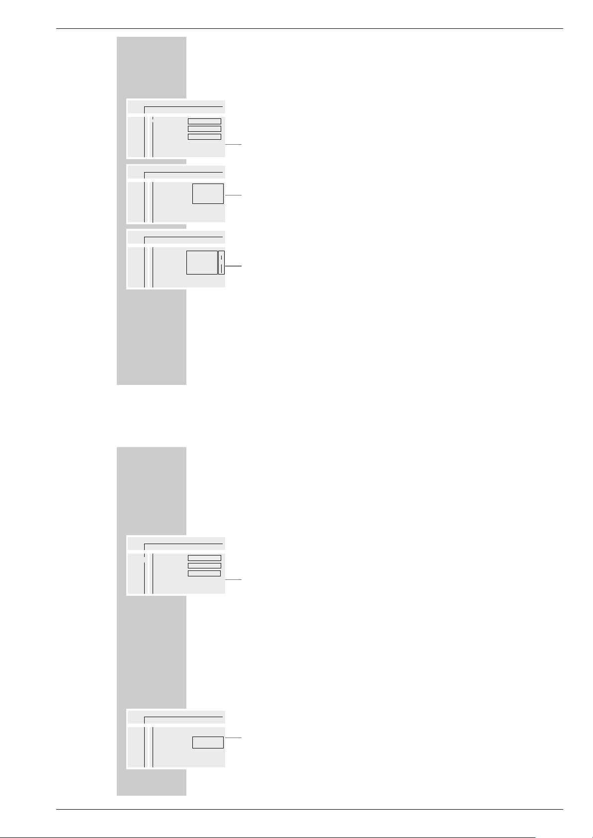
The menu item »Settings«
»O« = »Picture menu« with the functions
– Screen format,
– Black level setting,
– Screen shift.
»>« = »Sound menu« with the functions
– Digital output,
– Analog output,
– Night-time mode.
»U« = »Language menu« with the functions
– Audio,
– Sub-titles,
– Menu.
»
Ü« = Menu »Special functions« with the functions
– Access control,
– Status window,
– Stand-by (no function).
USER GUIDE
________________________________________________________________________________
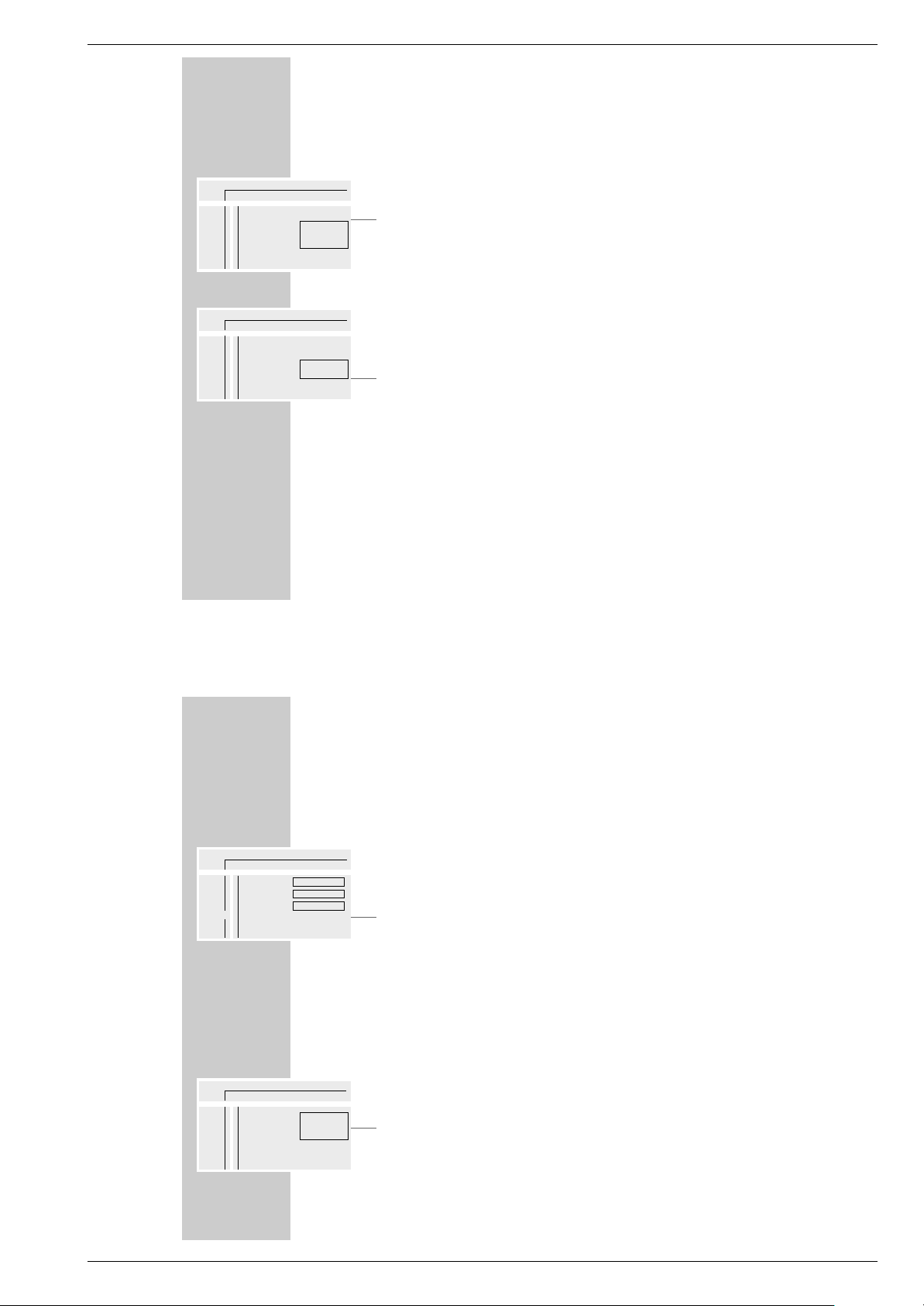
Status display
In the status display, information about the inserted DVD/video CD, the total
running time and the elapsed running time of the DVD/video CD are displayed. The active function is also displayed.
»2 : 05 :30« = Total running time.
»0 : 15 :00« = Elapsed running time.
»
..
« DVD = DVD inserted.
»
..
« VCD = Video CD inserted.
»
,,
« reading = DVD is being read.
»{« no disc = No DVD or video CD inserted.
»]« opened = Disc tray opened.
»[« closing = Disc tray closed.
»
ǵ
!
« error = Error message.
»8play« = Playback.
»7stop« = Ending playback.
»II pause« = Playback pause.
»
EW
x 4 x 8 x 32« = Frame search forwards/backwards.
»1/4 1/8 1/2 1« = Slow motion forwards/backwards.
Dialogue display
The dialogue line displays information about the operating condition.
» « = Function not possible.
» « = Security system activated.
» « = Security system switched off.
» « = Angle format of scene.
» « = Playback resumed.
resume
%
2/2
R
safe
H
locked
G
x
ÖÖ PP
//
1
..
!
DVD pause
2 : 04 : 26
0 : 00 : 21
a
ÖÖ PP KK (( II RR kk
//
121offnooff
OO
AA
S
8
>>
UU
ÜÜ
TV Shape
Black level shift
Video shift
■■◊■■■■■■■
Off
16:9
>
GDV Modul 1 Allgemeiner Teil / General Section
GRUNDIG Service 1 - 19
USER GUIDE
________________________________________________________________________________
Operation with the user guide
The following example illustrates the structure of the user guide and the selection
of various menus and settings.
Select the menu line with the »
OSD AUX« key, select individual menu items with
the keys »P – « or »P +«, »
Ǹ
« or »Ƿ«.
The active menu item is highlighted in blue. Menu items having no function on
the respective DVD are highlighted in grey and cannot be selected.
Select the continuation of the menu line by pressing »Ƿ«.
1 Call up the menu line with the »OSD AUX« button.
– The menu line is displayed.
2 Select the desired menu item (in the example, »
Ö
«) by pressing »Ǹ« or
»Ƿ« and activate with »P – «.
– The menu is displayed.
3 Select the desired menu (in the example, »U«) by pressing »P –« or
»P+« and activate with »
Ƿ
«.
– The language menu is displayed.
4 Select function (in the example, »Subtitle«) by pressing »P –« or »P+« and
activate with »Ƿ«.
5 Select desired setting with »P –« or » P +«.
Note:
You can switch back step-by-step to the previous menus and menu items with
»OK«.
6 Cancel menu line with the »OSD AUX« button.
– The set functions or values are automatically saved.
ÖPPK(IRk
/ 121offno off
ÖÖ
PK(IRk
/ 121offno off
O
>>
U
Ü
Audio
Subtitle
Menu
English
English
English
S
a
A
>
>
sa
A
S
ÖÖ
PK(IRk
/ 121offno off
O
>>
U
Ü
Audio
Subtitle
Menu
English
English
English
A
S
8
>
PLAYBACK OF A DVD/VIDEO CD
___________________________________________
Before playback
Preparation
1 Switch the remote control to DVD mode by pressing »Mode«.
– The following appears in the remote control display: »DVD«.
2 Switch on the Hi-fi system (if you wish) and select the audio input appropria-
te for the DVD player.
Inserting a DVD/video CD
1 Open the control unit cover on the TV.
2 Press »
ə
« on the TV set to open the disc tray.
– The disc tray opens.
3 Insert the desired DVD/video CD in the disc tray with the label facing
upwards.
4 Press »
ə
« to close the disc tray.
– The disc tray closes automatically.
– Display in the status display: »,,reading«, playback starts automatically.
Note:
If the security system is activated and the DVD/video CD has not been started (see the chapter entitled “SECURITY SYSTEM”), the code number must
be entered.
,,
7
reading stop
- : -- : - -
- : -- : - -

Allgemeiner Teil / General Section GDV Modul 1
1 - 20 GRUNDIG Service
PLAYBACK OF A DVD/VIDEO CD
___________________________________________
Calling up function display
Each function you have selected (for example, running time, current title etc.)
can be displayed on the screen.
1 Display the function display by pressing the »OSD AUX« button.
2 Remove the function display by pressing the »OSD AUX« button.
Playback of a title
After the disc tray is closed, playback starts automatically.
1 Switch to playback pause (freeze-frame) by pressing »II«.
2 Resume playback by pressing »8«.
3 End playback by pressing »7«.
Note:
It may be necessary depending on the DVD/video CD being used, to select
from an index of the DVD/video CD or chapter.
To select, use the»P – « or »P +« keys; to activate, use the »OK« key.
If the selections are numbered, use the »1 ... 0 « keys.
..
8
DVD play
2 : 04 : 26
0 : 11 : 30
..
8
DVD play
2 : 04 : 26
0 : 15 : 00
PLAYBACK OF A DVD/VIDEO CD
___________________________________________
Selecting another title or chapter ...
If a DVD/video CD contains several titles and/or chapters, you may select
these.
... with the menu of the DVD player
1
Display the menu line by pressing the »OSD AUX« button.
2 Select menu item »
P
« (for title) with »Ǹ« or »Ƿ«.
or
Select menu item »K« (for chapter) with »Ǹ« or »Ƿ«.
3 Select the next title/chapter with »P –« or » P +«.
Note:
Titles or chapters can also be directly selected by entering the number of the
title or chapter in question as one or two digits with »1 ... 0«.
... with the title menu of the DVD/Video CD
The title menu of the DVD/video CD may contain selection options for titles, sections or scenes.
1 Call up the contents of the DVD/video CD by pressing »i«.
– If the DVD/video CD possesses a title menu, it appears on the screen.
2 If the selection options are numbered, select the appropriate title and section
with »1 ... 0 «.
3 If the selection options are not numbered, select titles and sections with
»P–« or »P +« and activate with »OK«.
ÖPPK(IR k
/ 1 2 1 off no off
>
s
a
A
S
Ö PKK(IR k
/ 1 2 1 off no off
>
s
a
A
S
ÖPPK(IR k
/ 2 2 1 off no off
>
s
a
A
S
GDV Modul 1 Allgemeiner Teil / General Section
GRUNDIG Service 1 - 21
SECURITY SYSTEM
____________________________________________________
With the security system, you can:
– Prevent the DVD player from being used;
– Activate or block access for playback of particular DVDs, video CDs or CDs;
– Block scenes which are not appropriate for children from DVDs or
video CDs, or select alternative scenes.
Activating and switching off the security system
of the DVD player
Activating the security system of the DVD player
1 Call up the menu line with »OSD AUX«.
2 Select menu item »
Ö
« (Settings) by pressing »Ǹ« or »Ƿ« and activate
with »P–«.
3 Activate line »
Ü
« (Special functions) with »P – « and activate by pressing
»
Ƿ
«.
4 Select the »Access control« line with »P –« or »P +« and activate by pres-
sing »Ƿ«.
5 Enter the four-digit code number with keys »1 ... 0«.
Note:
When the code number is entered for the first time, the display changes to
»Confirm code«.
Enter the four-digit code number again with keys »1 ... 0 «.
6 Select the »Child lock« line with »P –« or »P +« and activate by pressing
»Ƿ«.
ÖÖ
PK(IRk
/ 121offno off
O
>>
U
Ü
Access control
Status window
Low power standby
Off
On
Enter code..
>
S
s
ÖÖ
PK(IRk
/ 121offno off
O
>>
U
Ü
Access control
Status window
Low power standby
>
a
( ) ( ) ( ) ( )
Enter code
a
SECURITY SYSTEM
_____________________________________________________________________
7 Select the symbol »
D
« with »P – « or »P +«.
8 Quit setting with »OSD AUX«.
– The DVD player is locked.
Note:
If a DVD or video CD is now inserted in the disc tray, the message »locked«
appears and the four-digit code number must be entered.
De-activating the security system of the DVD player
1 To de-activate the security system, repeat steps 1 to 8 from the section en-
titled “Activating the security system of the DVD player” and select the
symbol »F« with »P – « or »P +«.
– The security system is de-activated.
Note:
If you forget or lose the code number, read the section entitled “Rectifying
malfunctions yourself” on Page 42.
Changing the code number
1 To change the code number, repeat steps 1 to 5 from the section, “Activa-
ting the security system of the DVD player”.
2 Select the »Change code« line with »P –« or » P +« and activate with »
Ƿ
«.
3 Enter the new four-digit code number with keys »1 ... 0«.
Enter the four-digit code number again with keys »1 ... 0 «.
4 Quit setting with »OSD AUX«.
ÖÖ
PK(IRk
/ 121offno off
O
>>
U
Ü
Access control
Status window
Low power standby
>
Child lock
Parental level
Change country
Change code
D
F
a
S
ÖÖ
PK(IRk
/ 121offno off
O
>>
U
Ü
Access control
Status window
Low power standby
>
Child lock
Parental level
Change country
Change code
D
F
a
A
ÖÖ
PK(IRk
/ 121offno off
O
>>
U
Ü
Access control
Status window
Low power standby
>
Child lock
Parental level
Change country
Change code
()
()
()
()
s
A
S

Allgemeiner Teil / General Section GDV Modul 1
1 - 22 GRUNDIG Service
SECURITY SYSTEM
_____________________________________________________________________
Activating DVDs or video CDs for playback
Permitting use of the DVD player
When the security system is activated, the »Access control« menu appears on
the screen. You may choose whether you want the DVD or video CD to be played once or continuously.
If you select the function »Play always«, the DVD or video CD is saved in a “list”
and playback of this DVD or video CD is unlimited. A maximum of 50 DVDs or
video CDs can be saved in this “list”.
1 Insert the DVD or video CD in the disc tray.
– The »Access control« menu appears on the screen.
2 Select the »Play once« line with »P –« or »P +« (for one-time use), or
Select the »Play always« line with »P – « or »P +«.
3 Enter the four-digit code number with keys »1 ... 0«.
– Playback starts automatically.
De-activating the »Play always« function
1 Insert the DVD or video CD in the disc tray.
– Playback starts automatically.
2 Press »7« while H is visible.
– Permission to play back this DVD or video CD is cancelled.
locked Access control
G
Choose ‘Play always‘ to insert the disc in
the child-safe list
Play once ( ) ( ) ( ) ( )
Play always ( ) ( ) ( ) ( )
S
locked Access control
G
Choose ‘Play always‘ to insert the disc in
the child-safe list
Play once • • • ( )
Play always ( ) ( ) ( ) ( )
S
SECURITY SYSTEM
_____________________________________________________________________
Authorising the content of a DVD
DVDs may offer films whose content or individual scenes are not appropriate for
children. These DVDs contain information which identifies such content or scenes,
and provides them with ratings from 1 to 8. You can select one of the ratings and
thereby authorise alternative scenes for playback.
1 Call up the menu line with »OSD AUX«.
2 Select menu item »
Ö
« (Settings) with »Ǹ« or »Ƿ« and activate with
»P–«.
3 Select line »
Ü
« (Special functions) with »P – « and activate by pressing
»Ƿ«.
4 Select the »Access control« line with »P –« or »P +« and activate with
»Ƿ«.
5 Enter the four-digit code number with keys »1 ... 0«.
6 Select the »Child lock« line with »P –« or »P +« and activate by pressing
»Ƿ«.
7 Select the »Parental level« line with »P –« or »P +« and activate by pres-
sing »Ƿ«.
8 Select the desired code number (from 1 to 8) with »P –« or » P +«.
9 Quit setting with »OSD AUX«.
ÖÖ
PK(IRk
/ 1 2 1 off no off
O
>>
U
Ü
Access control
Status window
Low power standby
>
Child lock
Parental level
Change country
Change code
5
a
S
ÖÖ
PK(IRk
/ 1 2 1 off no off
O
>>
U
Ü
Access control
Status window
Low power standby
On
On
Enter code...
>
S
s
a
ÖÖ
PK(IRk
/ 1 2 1 off no off
O
>>
U
Ü
Access control
Status window
Low power standby
>
a
( ) ( ) ( ) ( )
Enter code
A

GDV Modul 1 Allgemeiner Teil / General Section
GRUNDIG Service 1 - 23
SECURITY SYSTEM
_____________________________________________________________________
Changing country
1 Call up the menu line with »OSD AUX«.
2 Select menu item »
Ö
« (Settings) with »Ǹ« or »Ƿ« and activate with
»P–«.
3 Select line »
Ü
« (Special functions) with »P – « and activate by pressing
»Ƿ«.
4 Select the »Access control« line with »P –« or » P +« and activate with
»Ƿ«.
5 Enter the four-digit code number with keys »1 ... 0«.
6 Select the »Child lock« line with »P–« or »P+« and activate by pressing
»Ƿ«.
7 Select the »Change country« line with »P –« or »P +« and activate by pres-
sing »
Ƿ
«.
8 Select your country of choice with »P –« or » P +«.
9 Quit setting with »OSD AUX«.
ÖÖ
PK(IRk
/ 121offno off
O
>>
U
Ü
Access control
Status window
Low power standby
>
Child lock
Parental level
Change country
Change code
5
a
S
ÖÖ
PK(IRk
/ 121offno off
O
>>
U
Ü
Access control
Status window
Low power standby
On
On
Enter code...
>
S
s
a
ÖÖ
PK(IRk
/ 121offno off
O
>>
U
Ü
Access control
Status window
Low power standby
>
a
( ) ( ) ( ) ( )
Enter code
A
SETTINGS
____________________________________________________________________________
Picture settings
Selecting picture menu
1 Display the menu line by pressing »OSD AUX«.
2 Select menu item »
Ö
« (Settings) with »Ǹ« or »Ƿ« and activate with
»P–«.
3 Select »
O
« (Picture menu) with »P – « or »P +« and activate with »Ƿ«.
Note:
For further operation, see the following chapters, each one starting from
step 1.
TV format
Your 16:9 picture format television set does not require any adjustment; the
16:9 setting is preset and should not be changed.
Black-and-white setting (only for NTSC transmissions)
This setting adjusts the color dynamics to create a better picture contrast.
1 Select the »Black level shift« line with »P –« or »P +« and activate by pres-
sing »Ƿ«.
2 Switch function on/off with »P –« or »P +«.
3 Switch off menu with the »OSD AUX« button.
ÖÖ
PK(IRk
/ 121offno off
O
>>
U
Ü
TV Shape
Black level shift
Video shift
■■"■■■■■■
Off
16:9
A
S
8
>
ÖÖ
PK(IRk
/ 121offno off
O
>>
U
Ü
TV Shape
Black level shift
Video shift
>
On
Off
a
A

Allgemeiner Teil / General Section GDV Modul 1
1 - 24 GRUNDIG Service
SETTINGS
____________________________________________________________________________________
Adjusting the screen position
The ex-works setting centres the picture on the screen.
Use this setting to adjust the position of the picture on your TV screen according
to your personal taste, by shifting the picture to the left or to the right.
1 Select the »Video shift« line with »P –« or »P +« and activate by pressing
»Ƿ«.
2 Shift the screen position with »
Ǹ
« or »Ƿ« and save with »OK«.
3 Switch off menu with the »OSD AUX« button.
ÖÖ
PK(IRk
/ 1 2 1 off no off
O
>>
U
Ü
TV Shape
Black level shift
Video shift
>
■■as■■ ■■■■
OK to exit
SETTINGS
____________________________________________________________________________________
Sound settings
Selecting the sound menu
1 Display the menu line by pressing »OSD AUX«.
2 Select menu item »
Ö
« (Settings) with »Ǹ« or »Ƿ« and activate with
»P–«.
3 Select »
>
« (Sound menu) with »P – « or »P +« and activate with »Ƿ«.
Note:
For further operation, see the following chapters, each one starting from
step 1.
Adapting the digital outputs of the DVD player to an
external audio device
If you are using a multiple-channel audio/video receiver, you must select the setting »All« (MPEG, AC 3 and PCM) or »PCM only« (normal
stereo sound), depending on the receiver used.
1 Select the »Digital output« line with »P–« or »P+« and activate by pres-
sing »Ƿ«.
2 Select required setting, »PCM only« or »All«, with »P–« or »P+«.
Note:
For your television, select the setting »Off«.
3 Switch off menu with the »OSD AUX« button.
ÖÖ
PK(IRk
/ 1 2 1 off no off
O
>>
U
Ü
Digital output
Analogue output
Night mode
Off
Stereo
All
A
S
8
>
ÖÖ
PK(IRk
/ 1 2 1 off no off
O
>>
U
Ü
Digital output
Analogue output
Night mode
>
Off
PCM only
All
a
S

GDV Modul 1 Allgemeiner Teil / General Section
GRUNDIG Service 1 - 25
SETTINGS
____________________________________________________________________________________
Selecting type of sound on the DVD player
Presetting for your TV set: »Dolby Surround«.
1 Select the »Analogue output« line with »P –« or »P +« and activate by
pressing »Ƿ«.
2 Select required setting, »Stereo« or »Dolby Surround« or »3D-sound«, with
»P – « or »P +«.
3 Switch off menu with the »OSD AUX« button.
Switching night-time mode on/off
This function optimises the sound dynamics at low playback volume.
1 Select the »Night mode« line with »P –« or » P +« and activate by pressing
»
Ƿ
«.
2 Switch night-time mode on/off with »P –« or » P +«.
3 Switch off menu with the »OSD AUX« button.
ÖÖ
PK(IRk
/ 121offno off
O
>>
U
Ü
Digital output
Analogue output
Night mode
>
Stereo
Dolby Surround
3D sound
a
A
S
ÖÖ
PK(IRk
/ 121offno off
O
>>
U
Ü
Digital output
Analogue output
Night mode
>
On
Off
a
A
COMFORT SETTINGS
______________________________________________
You can select your own individual setting for certain playback functions in the
menu of the DVD player.
Selecting language menu
1 Display the menu line by pressing »OSD AUX«.
2 Select menu item »
Ö
« (Settings) with »Ǹ« or »Ƿ« and activate with
»P–«.
3 Select »M« (Language menu) with »P –« or »P+« and activate with
»Ƿ«.
Note:
For further operation, see the following chapters, each one starting from
step 1.
Selecting dubbed language
When several languages are available on the inserted DVD, the sound is played
back in the language you have selected.
If the language you have selected is not contained in the DVD, the first dubbed
language on the DVD is automatically selected.
1 Select the »Audio« line with »P –« or » P +« and activate by pressing »
Ƿ
«.
2 Select the desired dubbed language with »P –« or » P +«.
3 Switch off menu with the »OSD AUX« button.
ÖÖ
PK(IRk
/ 121offno off
O
>>
U
Ü
Audio
Subtitle
Menu
English
English
English
A
S
8
>
ÖÖ
PK(IRk
/ 121offno off
O
>>
U
Ü
Audio
Subtitle
Menu
>
English
Español
Français
A
S
a

Allgemeiner Teil / General Section GDV Modul 1
1 - 26 GRUNDIG Service
COMFORT SETTINGS
_________________________________________________________________
Selecting the language of the sub-titles
When sub-titles are available on the inserted DVD, they are played back in the
language you have selected.
If the language you have selected for the sub-titles is not on the DVD, the first
language on the DVD is automatically selected.
1 Select the »Subtitle« line with »P –« or »P +« and activate by pressing
»
Ƿ
«.
2 Select the desired language with »P –« or »P +«.
3 Switch off menu with the »OSD AUX« button.
Note:
Sub-titles can be switched on and off during playback with »SUBTITLE«.
Selecting the language of the DVD player’s picture menu
1 Select the »Menu« line with »P –« or »P +« and activate by pressing »
Ƿ
«.
2 Select the desired language for the picture menu with »P –« or » P +«.
3 Switch off menu with the »OSD AUX« button.
ÖÖ
PK(IRk
/ 1 2 1 off no off
O
>>
U
Ü
Audio
Subtitle
Menu
>
English
Español
Français
A
S
ÖÖ
PK(IRk
/ 1 2 1 off no off
O
>>
U
Ü
Audio
Subtitle
Menu
>
English
Español
Français
A
S
a
a
COMFORT SETTINGS
_________________________________________________________________
Switching on/off the status display of the DVD player
1 Display the menu line by pressing »OSD AUX«.
2 Select menu item »
Ö
« (Settings) with »Ǹ« or »Ƿ« and activate with
»P–«.
3 Select »
Ü
« (Special functions) with »P – « or »P +« and activate with
»
Ƿ
«.
4 Select the »Status window« line with »P –« or »P +« and activate by pres-
sing »Ƿ«.
5 Switch status display on/off with »P –« or » P +«.
6 Switch off menu with the »OSD AUX« button.
ÖÖ
PK(IRk
/ 1 2 1 off no off
O
>>
U
Ü
Access control
Status window
Low power standby
On
On
Enter code...
>
A
s
ÖÖ
PK(IRk
/ 1 2 1 off no off
O
>>
U
Ü
Access control
Status window
Low power standby
>
a
On
Off
S

GDV Modul 1 Servicetestprogramm
1.1 Menü- und Untermenütafeln
D
Servicetestprogramm
Das Symbol “–>” hinter den jeweiligen Menüpunkten verweist auf ein
weiteres Untermenü. Die in den Klammern aufgeführte Nummer ist die
Nummer der Service-Testebene (Punkt 3).
PC-Systemtest
Hardwareanforderung:
– Service-PC
– freier COM-Port (COM1) am Service-PC
– Spezialkabel (Service Serial Interface – RS232)
RS232 SOCKET
BACKSIDE VIEW
1 = TX1P
2 = IACK5N
3 = RX1P
4 = RTSEX
5 = GROUND
6 = CTS1P
7 = +5V
672354 1
PHR-7 CONNECTOR
Softwareanforderung:
– Terminal-Emulationsprogramm
(z.B. OS2 – Wrap Terminal oder Windows 95 – Procomm)
Spezialkabel am Service Serial Interface des DVD-Players und am
freien COM-Port des Service-PC anschließend. Mit diesem Spezialkabel wird der Testpin am Service Serial Interface mit Masse verbunden (d.h. Testpin aktiviert).
Terminal-Emulationsprogramm starten und folgende COM-Port-Einstellungen prüfen: 19200bps, 8 Datenbits, keine Parität, 1 Stoppbit,
kein Protokoll und keine Umwandlung.
Aufruf der Bedienvarianten
Player einschalten. Am Bildschirm des Service-PC erscheint folgender Text:
DVDv2B Diagnostic Software version 0.6
SDRAM Interconnection test passed
Basic Sdram test passed.
Karaoke init OK
(M)enu, (C)ommand (S)2B–interface or (D)ownload? [M]:@
Die erste Zeile enthält die Versionsnummer des Servicetestprogramms.
Die nächsten beiden Zeilen zeigen, dass zwei weitere Tests (Ebene 2
bzw. 4) mit Erfolg abgeschlossen wurden. Die Beschreibung zu diesen
Ebenen finden Sie im Kapitel "Servicetestebenen". Erscheinen nicht
alle diese Meldungen auf dem Bildschirm des Service-PC, wurde in
der entsprechenden Ebene ein Fehler entdeckt.
In der 4. Zeile müssen Sie die Bedienvariante (M)enu oder (C)ommand
wählen und mit <return> bestätigen.
Beenden der Bedienvariante
Zum Beenden der aktiven Bedienvariante muss der DVD-Player
abgeschaltet werden.
1. Bedienvariante (M)enu
Die Bedienvariante (M)enu ist Bestandteil des Servicetestprogramms.
Das gewünschte Menü kann durch Eingabe der Nummer des gewählten Menüpunktes aufgerufen werden. Jede Eingabe ist mit einem
<return> zu bestätigen. Ungültige Eingaben zeigt der Menüverwalter
mit folgender Fehlermeldung. Beispiel:
Select> 9
Invalid menu choice, number out of range ER @
Press RETURN to continue...@
Hauptmenü
MAIN MENU
1. Audio –>
2. Basic engine –>
3. Display PWB –>
4. Processor & Peripherals –>
5. Karaoke –>
6. Log –>
7. Miscellaneous –>
8. Video –>
Untermenüebene 1
AUDIO MENU
1. Deemphasis –>
2. Mute –>
3. PinkNoise –>
4. SineWave –>
BASIC ENGINE MENU
1. Disc Motor –>
2. Focus –>
3. Grooves –>
4. Radial –>
5. Reset [44]
6. Sledge –>
7. Tray –>
8. Version [37]
DISPLAY PWB MENU
1. Display [30]
2. Keyboard [27]
3. LEDs [29]
4. Remote control [28]
5. Version [26]
PROCESSOR AND PERIPHERALS MENU
1. Clock –>
2. DRAM Write/Read [9]
3. Flash –>
4. I2C –>
5. S2B –>
6. SDRAM Write/Read [16]
KARAOKE MENU
1. Karaoke Mode Off [48a]
2. Karaoke Mode On [48b]
3. Karaoke Mic Input [49]
4. Karaoke Key On [50a]
5. Karaoke Key Off [50b]
6. Karaoke Echo On [51a]
7. Karaoke Echo Off [51b]
LOG MENU
1. Read last errors [31]
2. Read error bits [32]
3. Reset [33]
MISCELLANEOUS MENU
1. NVRam Utils –>
2. 2B Utils –>
3. Statistics Info –>
4. Read Application version [46]
VIDEO MENU
1. Colourbar –>
2. Scart –>
Ergebnis und Ausgabe der gewählten Servicetestebene erscheinen
am Service-Terminal im Punkt 2 beschriebenen Standardformat.
Beispiel:
Select> 6
1600 OK @
Press RETURN to continue…@
Nach Drücken der Taste <return> erscheint das aktuelle Menü wieder
auf dem Bildschirm.
Zum Hauptmenü gelangt man aus einem Untermenü durch Drücken
der Taste <return>.
GRUNDIG Service 2 - 1
Ķ

Servicetestprogramm GDV Modul 1
Untermenüebene 2
DEEMPHASIS MENU
1. Deemphasis On [18a]
2. Deemphasis Off [18b]
MUTE MENU
1. Mute on [19a]
2. Mute off [19b]
NOISE MENU
1. Pink Noise on [20a]
2. Pink Noise off [20b]
SINEWAVE MENU
1. Audio Sine on [21a]
2. Audio Burst on [21b]
DISC MOTOR MENU
1. Disc motor on [39a]
2. Disc motor off [39b]
FOCUS MENU
1. Focus on [38a]
2. Focus off [38b]
GROOVES MENU
1. Jump grooves to inside [42a]
2. Jump grooves to middle [42b]
3. Jump grooves to outside [42c]
RADIAL MENU
1. Radial control on [40a]
2. Radial control off [40b]
SLEDGE MENU
1. Sledge inwards [41a]
2. Sledge outwards [41b]
TRAY MENU
1. Open tray [43b]
2. Close tray [43a]
UCLOCK MENU
1. uClock A_CLK in CDDA mode [7a]
2. uClock A_CLK in DVD mode [7b]
FLASH MENU
1. Checksum FLASH [6]
2. Flash write access [10]
I2C MENU
1. I2C NVRAM access [11]
2. I2C Display PWB [12]
S2B MENU
1. S2B echo [13]
2. S2B pass-through [14]
NVRAM MENU
1. NVRAM Config [34]
2. NVRAM reset [35]
3. NVRAM Mod [36]
4. NVRAM write/read [15]
2B UTILS MENU
1. I2C Scart Check [54]
2. Scart To DVD [55a]
3. Scart Pass through [55b]
4. Video Col Setup I2C [52]
5. Video Col Setup Hi [53a]
6. Video Col Setup Lo [53b]
STATISTICS INFO MENU
1. Total Nr of times Tray Open [47a]
2. Total Time Power On [47b]
3. Total Play-time CDDA & VCD [47c]
4. Total Play-time DVD [47d]
VIDEO COLOURBAR MENU
1. Colourbar DENC on [23a]
2. Colourbar DENC off [23b]
SCART MENU
1. Scart low [25a]
2. Scart medium [25b]
3. Scart high [25c]
1.2 Bildschirmdarstellung der Menüs
Bei der Verwendung von Menüs ist keine spezielle Bildschirmdarstellung festgelegt: Mit Ausnahme des vorher beschriebenen Formats gibt
es für die Menüs kein bestimmtes Layout.
Eine typische Menü-Session sieht wie folgt aus:
DVDv2B Diagnostic Software version 0.6
SDRAM Interconnection test passed
Basic Sdram test passed.
Karaoke init OK
(M)enu, (C)ommand (S)2B–interface or (D)ownload? [M]:@ M ↵
MAIN MENU
1. Audio –>
2. Basic engine –>
3. Display PWB –>
4. Processor & Peripherals –>
5. Karaoke –>
6. Log –>
7. Miscellaneous –>
8. Video –>
Select> 4 ↵
PROCESSOR AND PERIPHERALS MENU
1. Clock –>
2. DRAM Write/Read [9]
3. Flash –>
4. I2C –>
5. S2B –>
6. SDRAM Write/Read [16]
Select> 3 ↵
2. Bedienvariante (C)ommand
Die Bedienvariante (C)ommand ist Bestandteil des Servicetestprogramms.
Nach der Eingabeaufforderung "DD>" ist die Nummer der Servicetestebene einzugeben und mit einem <return> zu bestätigen. Eine Korrektur des eingetippten Befehls ist mit der Rücktaste möglich.
Bei Eingabefehlern erscheint z.B. folgende Fehlermeldung:
DD>123↵
0001 Unknown command ER @
DD>
Anzeige bei keinem Gerätedefekt:
DD>12↵
1200 OK @
DD>
Anzeige bei Gerätedefekt:
DD>12↵
1201 <TEXT> ER @
DD>
<TEXT> ist eine kurze englische Erklärung des aufgetretenen Fehlers.
2 - 2 GRUNDIG Service
Ķ

GDV Modul 1 Servicetestprogramm
3. Service-Testebenen
Die Service-Testebenen 1 bis 5 sind nicht manuell aufrufbar. Diese
werden beim Starten des PC-Systemtests entsprechend der Gerätebestückung automatisch aufgerufen.
1 (BasicSpAcc)
Dieser Basis-Test ist Voraussetzung für eine korrekte Funktion der
Diagnose Software.
Es wird der RS232-Port initialisiert und eine Meldung ausgegeben,
dass die Diagnose Software gestartet wurde.
2 (BasicInterconDram, BasicInterconSdram)
Test der Verbindungen der Daten- und Adressleitungen des Prozessors. Dieser Test kann fehlerhafte (kurzgeschlossene) Adressleitungen erkennen und gibt aus, welche Leitung fehlerhaft ist.
3 (BasicDramWrR)
Dieser Basis-Test ist Voraussetzung für eine korrekte Funktion der
Diagnose Software.
Es wird ein Mustertest des Teiles des DRAM durchgeführt, der von der
Diagnose Software benutzt wird. Dabei werden auch die Datenleitungen auf Fehler (Kurzschlüsse) getestet.
Anmerkung: Dieser Test funktioniert nur, wenn ein DRAM installiert ist.
4 (BasicSdramWrR)
Dieser Basis-Test ist Voraussetzung für eine korrekte Funktion der
Diagnose Software.
Es wird ein Mustertest des Teiles des SDRAM durchgeführt, der von
der Diagnose Software benutzt wird. Dabei werden auch die Datenleitungen auf Fehler (Kurzschlüsse) getestet.
5 (BasicSramWrR)
Dieser Basis-Test ist Voraussetzung für eine korrekte Funktion der
Diagnose Software.
Es wird ein Mustertest des internen SDRAM des STi5505 (IC7200)
durchgeführt.
6 (PapChksFl)
Berechnet und überprüft die Checksumme des FLASH.
7a (PapUclkAclkCdda)
Dieser Test schaltet die A_CLK-Leitung auf 11,2896MHz (CD_DA).
Die korrekte Funktion kann nicht von der Diagnose Software erkannt
werden, sondern muss extern überprüft werden (z.B. mit einem
Frequenzzähler an Messpunkt F703).
Anmerkung: Dieser Test arbeitet nur, wenn der externe Takt aktiviert ist.
7b (PapUclkAclkDvd)
Dieser Test schaltet die A_CLK-Leitung auf 12,2880MHz (DVD).
Die korrekte Funktion kann nicht von der Diagnose Software erkannt
werden, sondern muss extern überprüft werden (z.B. mit einem
Frequenzzähler an Messpunkt F703).
Anmerkung: Dieser Test arbeitet nur, wenn der externe Takt aktiviert ist.
9 (PapDramWrR)
Mustertest aller Speicherzellen im DRAM. Dieser Test kann Fehler in
den DRAMS erkennen und auch feststellen, welches DRAM fehlerhaft
ist. Die Ergebnisse des Tests sind nur dann gültig, wenn die Zugriffe
auf die DRAMs korrekt funktionieren.
Anmerkung: Dieser Test funktioniert nur, wenn ein DRAM installiert ist.
10 (PapFlashWrAcc)
Liest die Chip Identifizierungsnummer. Der Test schreibt eine definierte Sequenz in das FLASH-RAM die es ermöglicht, die Identifizierungsnummer auszulesen.
Anmerkung: Wenn die Diagnose Software im FLASH läuft, hängt sich
dieser Test auf. Durch das Schreiben ins FLASH wird der OutputEnable-Pin auf HIGH gesetzt (Output disabled) und der Code im
FLASH kann nicht weiter ausgeführt werden. Wenn dies geschieht war
der Test offenbar erfolgreich.
11 (PapI2cNvram)
Überprüft das I2C-Interface zum NVRAM indem von einer beliebigen
Adresse gelesen wird.
12 (PapI2cDisp)
Überprüft das I2C-Interface zum Slave-Prozessor auf der Displayplatte mit einem Echo-Befehl.
13 (PapS2bEcho)
Überprüft das S2B-Interface zum Laufwerk mit einem Echo-Befehl.
14 (PapS2bPass)
Schaltet den RS232-Port und den S2B-Port auf Durchgang. Der
einzige Weg diesen Test zu beenden ist, den DVD-Spieler vom Netz
zu trennen.
15 (PapNvramWrR)
Nicht zerstörender Mustertest aller Speicherzellen im NVRAM. Dieser
Test erkennt Fehler im NVRAM.
16 (CompSdramWrR)
Mustertest aller Speicherzellen im SDRAM. Dieser Test kann Fehler
in den SDRAMS erkennen und auch feststellen, welches SDRAM
fehlerhaft ist. Die Ergebnisse des Tests sind nur dann gültig, wenn die
Zugriffe auf die SDRAMs korrekt funktionieren.
18a (AudioDeempOn)
Der Test aktiviert die Audio-Deemphase.
Die korrekte Funktion ist von der Software nicht erkennbar, sondern
durch externe Messungen zu überprüfen.
18b (AudioDeempOff)
Der Test deaktiviert die Audio-Deemphase.
Die korrekte Funktion ist von der Software nicht erkennbar, sondern
durch externe Messungen zu überprüfen.
19a (AudioMuteOn)
Der Test aktiviert die Audio-Mute-Funktion.
Die korrekte Funktion ist von der Software nicht erkennbar, sondern
durch externe Messungen zu überprüfen.
Anmerkung: Die NF wird vom DAC gemutet.
19b (AudioMuteOff)
Der Test deaktiviert die Audio-Mute-Funktion.
Die korrekte Funktion ist von der Software nicht erkennbar, sondern
durch externe Messungen zu überprüfen.
Anmerkung: Die NF wird vom DAC gemutet.
20a (AudioPinkNoiseOn)
Dieser Test generiert im STi5505 ein rosa Rauschen das durch den
DAC in ein analoges Audio-Signal gewandelt wird.
Die korrekte Funktion ist von der Software nicht erkennbar, sondern
durch externe Messungen zu überprüfen.
20b (AudioPinkNoiseOff)
Dieser Test deaktiviert das rosa Rauschen, das durch den Test 20a
aktiviert wurde.
Die korrekte Funktion ist von der Software nicht erkennbar, sondern
durch externe Messungen zu überprüfen.
21a (AudioSineOn)
AudioSineOn erzeugt ein 1kHz-Sinussignal am Analog-Ausgang.
Die Daten für dieses Sinussignal werden im Audio-Puffer des SDRAM
gespeichert, durch den Audio-Decoder geschleift und ohne weiter
Wandlung im DAC in ein analoges Audio-Signal umgeformt.
Der einzige Weg diesen Test zu beenden ist, den DVD-Spieler vom
Netz zu trennen.
Die korrekte Funktion ist von der Software nicht erkennbar, sondern
durch externe Messungen zu überprüfen.
21b (AudioSineBurst)
AudioSineBurst erzeugt für ca. 4 Sekunden ein 1kHz-Sinussignal am
Analog-Ausgang. Das Signal wird auf die gleiche Weise erzeugt wie
bei AudioSineOn.
Die korrekte Funktion ist von der Software nicht erkennbar, sondern
durch externe Messungen zu überprüfen.
23a (VideoColDencOn)
Der Test VideoColDencOn schaltet den Farbtestbalken im DENC des
STi5505 ein.
Die korrekte Funktion ist von der Software nicht erkennbar.
23b (VideoColDencOff)
Der Test VideoColDencOff schaltet den Farbtestbalken im DENC des
STi5505 aus.
Die korrekte Funktion ist von der Software nicht erkennbar.
25a (VideoScartLo)
Der Pin 8 der Euro-AV-Buchse wird auf LOW (0…0,5V) gesetzt.
Die korrekte Funktion ist von der Software nicht erkennbar, sondern
durch externe Messungen zu überprüfen.
25b (VideoScartMi)
Der Pin 8 der Euro-AV-Buchse wird auf MEDIUM (6V ±10%) gesetzt.
Die korrekte Funktion ist von der Software nicht erkennbar, sondern
durch externe Messungen zu überprüfen.
GRUNDIG Service 2 - 3
Ķ

Servicetestprogramm GDV Modul 1
25c (VideoScartHi)
Der Pin 8 der Euro-AV-Buchse wird auf HIGH (12V ±10%) gesetzt.
Die korrekte Funktion ist von der Software nicht erkennbar, sondern
durch externe Messungen zu überprüfen.
26 (DispVer)
Liefert die Versionsnummer des Slave-Prozessors auf der EjectPlatte.
31 (LogReadErr)
Auslesen des Fehlerprotokolls aus dem NVRAM und Ausgabe der
Fehlernummern.
32 (LogReadBits)
Auslesen der Fehlerbits aus dem NVRAM und Ausgabe, welche Bits
gesetzt sind.
Fehlerbeschreibung Fehlerprotokoll Fehlerbits
Befehl in diesem Status nicht erlaubt 150101 8
oder unbekannt
Parameter nicht g ltig f r Befehl 150102 7
Schlitten konnte nicht in Ausgangs- 150103 6
position gebracht werden
Fokussierungsfehler 150104 5
Motor kam nicht auf Geschwindigkeit 150105 4
innerhalb der vorgegebenen Zeit
Servo konnte nach mehreren Ver- 150106 3
suchen die Spur nicht finden
PLL konnte nicht auf Zugriff oder 150107 2
Tracking synchronisieren
Subcode oder Sektor konnte nicht 150108 1
gelesen werden
Gew nschten Subcode nicht gefunden 150109 16
Schublade konnte nicht vollst ndig 15010A 15
ge ffnet oder geschlossen werden
TOC konnte nicht rechtzeitig gelesen 15010B 14
werden
Eingabe als eine Suchfunktion nicht 15010C 13
m glich
Datenpfad versucht auf einen nicht 15010D 12
existenten Einlaufbereich zuzugreifen
Nicht existierender Burst angefordert 15010E 11
S2b Kommunikations-Fehler 1501F0 10
S2b Kommunikations-Fehler 1501F1 9
S2b Kommunikations-Fehler 1501F3 24
S2b Kommunikations-Fehler 1501F4 23
S2b Kommunikations-Fehler 1501F5 22
Kommunikationsfehler mit STi 5505 90000 32
Kommunikationsfehler mit STi 5505 90001 31
Kommunikationsfehler mit Display- 190000 40
prozessor
33 (LogReset)
Löschen des Fehlerprotokolls und der Fehlerbits im NVRAM.
34 (MiscReadConfig)
In diesem Test werden die Konfigurationsdaten des DVD-Spielers aus
dem NVRAM als RAW-Daten ausgelesen und ausgegeben.
35 (MiscNvramReset)
Löscht das gesamte NVRAM.
Nach dem Löschen des NVRAMs muss die Gerätefunktion wieder
hergestellt werden (Seite 1-6)!
36 (MiscNvramMod)
Auslesen und Ändern jeder beliebigen Speicherzelle im NVRAM.
37 (BeVer)
Ausgabe der Versionsnummer des Laufwerks.
38a (BeFocusOn)
Prüfung der Fokussierung des Lasers.
38b (BeFocusOff)
Ausschalten des Fokussierungs-Tests (38a).
39a (BeDiscmotorOn)
Disc-Motor einschalten.
39b (BeDiscmotorOff)
Disc-Motor ausschalten.
40a (BeRadialOn)
Radial-Regelschleife einschalten.
40b (BeRadialOff)
Radial-Regelschleife ausschalten.
41a (BeSledgeIn)
Pick-Up-Einheit nach innen fahren.
41b (BeSledgeOut)
Pick-Up-Einheit nach außen fahren.
42a (BeGroovesIn)
Laserpunkt bei eingelegter DVD-Disc auf die Innenspur fahren.
42b (BeGroovesMid)
Laserpunkt bei eingelegter DVD-Disc in Mittelstellung fahren.
42c (BeGroovesOut)
Laserpunkt bei eingelegter DVD-Disc auf die Außenspur fahren.
43a (BeTrayIn)
Schublade schließen.
43b (BeTrayOut)
Schublade öffnen.
44 (BeReset)
Kompletter Reset des Laufwerks.
46 (MiscApplVer)
Auslesen der Versionsnummer der Bediensoftware aus dem NVRAM.
47a (MiscTrayOpenNr)
Auslesen aus dem NVRAM, wie oft die Schublade offen war.
47b (MiscPowerOnTime)
Auslesen der Einschaltzeit aus dem NVRAM.
47c (MiscPlayTimeCddaVcd)
Auslesen der Laufzeit des Laufwerks im CDDA-Modus aus dem
NVRAM.
47d (MiscPlayTimeDvd)
Auslesen der Laufzeit des Laufwerks im DVD-Modus aus dem NVRAM.
55a (VideoScartSwDvd)
Signalweg von DVD zu TV freigeschaltet.
55b (VideoScartSwPass)
Signalweg von AUX zu TV freigeschaltet.
2 - 4 GRUNDIG Service
Ķ

GDV Modul 1 Service Test Programme
1.1 Layout of menus and submenus for the Service Terminal
GB
Service Test Programme
NOTE: a symbol “–>” in the next menu layouts indicates that specific
menu choice will invoke the display of a submenu. The number in
brackets is the number of the Service Test Level (point 3).
PC System Test
Hardware required:
– Service PC
– one free COM port (COM 1) on the Service PC
– special cable (Service Serial Interface – RS232)
RS232 SOCKET
BACKSIDE VIEW
1 = TX1P
2 = IACK5N
3 = RX1P
4 = RTSEX
5 = GROUND
6 = CTS1P
7 = +5V
672354 1
PHR-7 CONNECTOR
Software required:
– terminal emulation programme (e.g. OS2 WarpTerminal or
Procomm in Windows 95)
The free COM port must be connected via a special cable to the RS232
port of the DVD player. This special cable will also connect the test pin,
which is available on the connector, to ground (i.e. activate test pin).
Activate the terminal emulation programme and check that the port
settings for the free COM port are: 19200 bps, 8 data bits, no parity, 1
stop bit and no flow control.
Activation of the operating variants
Switch the player on and the following text will appear on the screen of
the terminal (programme):
DVDv2B Diagnostic Software version 0.6
SDRAM Interconnection test passed
Basic Sdram test passed.
Karaoke init OK
(M)enu, (C)ommand (S)2B–interface or (D)ownload? [M]:@
The first line indicates that the Diagnostic software has been activated
and contains the version number of the diagnostic. The next two lines
are the succesful result of two subsequent basic tests (Level 2 and 4
respectively); see “Service Test Levels" for an explanation of these
Level. If not all these messages appear on the terminal screen, then the
related Levels found an error. The fourth line is the prompt asking to
choose for an interface form ((M)enu or(C)ommand and then <return>)
Ending of an interface
To switch between interfaces, the DVD player needs to be switched off
and on again.
1. Operating variant (M)enu
A selection can be given by the user by typing the number of the menuitem chosen at the prompt. Each entry must be terminated with a
<return>. Invalid selections will cause an error message by the Menu
Handler. Example:
Select> 9
Invalid menu choice, number out of range ER @
Press RETURN to continue...@
Main Menu
MAIN MENU
1. Audio –>
2. Basic engine –>
3. Display PWB –>
4. Processor & Peripherals –>
5. Karaoke –>
6. Log –>
7. Miscellaneous –>
8. Video –>
Submenu level 1
AUDIO MENU
1. Deemphasis –>
2. Mute –>
3. PinkNoise –>
4. SineWave –>
BASIC ENGINE MENU
1. Disc Motor –>
2. Focus –>
3. Grooves –>
4. Radial –>
5. Reset [44]
6. Sledge –>
7. Tray –>
8. Version [37]
DISPLAY PWB MENU
1. Display [30]
2. Keyboard [27]
3. LEDs [29]
4. Remote control [28]
5. Version [26]
PROCESSOR AND PERIPHERALS MENU
1. Clock –>
2. DRAM Write/Read [9]
3. Flash –>
4. I2C –>
5. S2B –>
6. SDRAM Write/Read [16]
KARAOKE MENU
1. Karaoke Mode Off [48a]
2. Karaoke Mode On [48b]
3. Karaoke Mic Input [49]
4. Karaoke Key On [50a]
5. Karaoke Key Off [50b]
6. Karaoke Echo On [51a]
7. Karaoke Echo Off [51b]
LOG MENU
1. Read last errors [31]
2. Read error bits [32]
3. Reset [33]
MISCELLANEOUS MENU
1. NVRam Utils –>
2. 2B Utils –>
3. Statistics Info –>
4. Read Application version [46]
VIDEO MENU
1. Colourbar –>
2. Scart –>
Result and output of an activated (and terminated) Level will be sent
back to the service terminal according to the standard layout as defined
in point 3.2. Example:
Select> 6
1600 OK @
Press RETURN to continue…@
After the user presses <return>, the current menu is rebuilt on screen.
Pressing <return> at the prompt without any further input at the
terminal will always rebuild the main menu.
GRUNDIG Service 2 - 5
ķ

Service Test Programme GDV Modul 1
Submenu level 2
DEEMPHASIS MENU
1. Deemphasis On [18a]
2. Deemphasis Off [18b]
MUTE MENU
1. Mute on [19a]
2. Mute off [19b]
NOISE MENU
1. Pink Noise on [20a]
2. Pink Noise off [20b]
SINEWAVE MENU
1. Audio Sine on [21a]
2. Audio Burst on [21b]
DISC MOTOR MENU
1. Disc motor on [39a]
2. Disc motor off [39b]
FOCUS MENU
1. Focus on [38a]
2. Focus off [38b]
GROOVES MENU
1. Jump grooves to inside [42a]
2. Jump grooves to middle [42b]
3. Jump grooves to outside [42c]
RADIAL MENU
1. Radial control on [40a]
2. Radial control off [40b]
SLEDGE MENU
1. Sledge inwards [41a]
2. Sledge outwards [41b]
TRAY MENU
1. Open tray [43b]
2. Close tray [43a]
UCLOCK MENU
1. uClock A_CLK in CDDA mode [7a]
2. uClock A_CLK in DVD mode [7b]
FLASH MENU
1. Checksum FLASH [6]
2. Flash write access [10]
I2C MENU
1. I2C NVRAM access [11]
2. I2C Display PWB [12]
S2B MENU
1. S2B echo [13]
2. S2B pass-through [14]
NVRAM MENU
1. NVRAM Config [34]
2. NVRAM reset [35]
3. NVRAM Mod [36]
4. NVRAM write/read [15]
2B UTILS MENU
1. I2C Scart Check [54]
2. Scart To DVD [55a]
3. Scart Pass through [55b]
4. Video Col Setup I2C [52]
5. Video Col Setup Hi [53a]
6. Video Col Setup Lo [53b]
STATISTICS INFO MENU
1. Total Nr of times Tray Open [47a]
2. Total Time Power On [47b]
3. Total Play-time CDDA & VCD [47c]
4. Total Play-time DVD [47d]
VIDEO COLOURBAR MENU
1. Colourbar DENC on [23a]
2. Colourbar DENC off [23b]
SCART MENU
1. Scart low [25a]
2. Scart medium [25b]
3. Scart high [25c]
1.2 Screen layout with menus
When menus are used, no specific screen layout can be given: menu
information will not be in a special format, except for the layout as
mentioned in the previous paragraphs.
A typical menu session can look as follows:
DVDv2B Diagnostic Software version 0.6
SDRAM Interconnection test passed
Basic Sdram test passed.
Karaoke init OK
(M)enu, (C)ommand (S)2B–interface or (D)ownload? [M]:@ M ↵
MAIN MENU
1. Audio –>
2. Basic engine –>
3. Display PWB –>
4. Processor & Peripherals –>
5. Karaoke –>
6. Log –>
7. Miscellaneous –>
8. Video –>
Select> 4 ↵
PROCESSOR AND PERIPHERALS MENU
1. Clock –>
2. DRAM Write/Read [9]
3. Flash –>
4. I2C –>
5. S2B –>
6. SDRAM Write/Read [16]
Select> 3 ↵
2. Operating variant (C)ommand
The Operating variant (C)ommand is part of diagnostic mode.
The commands that can be given the numbers of the Service Test
Level (point 3). A command must be terminated with a <return>
character from the control PC. When typing commands, the backspace
key can be used to make corrections.
In case of typing errors in the command, an error message is returned.
Example:
DD>123↵
0001 Unknown command ER @
DD>
Example in case the DVD-Player is correct:
DD>12↵
1200 OK @
DD>
Example in case the DVD-Player is faulty:
DD>12↵
1101 <TEXT> ER @
DD>
<TEXT> is a short explanation of the fault.
2 - 6 GRUNDIG Service
ķ

GDV Modul 1 Service Test Programme
3. Service Test Levels
The service test levels 1 to 5 cannot be called up manually. They are
called up automatically as a function of the unit’s equipment when
starting the PC system test.
1 (BasicSpAcc)
This is a Basic Diagnostic Nucleus required for correct operation of the
Diagnostic Software.
Checks and initialises RS232 port and outputs a message that the
Diagnostic software has been started.
2 (BasicInterconDram, BasicInterconSdram)
Interconnection test of the address/data lines from and to the processor.
This nucleus can detect stuck at fault and permanent coupling errors in
the address lines and will give an indication which lines are faulty.
3 (BasicDramWrR)
This is a Basic Diagnostic Nucleus required for correct operation of the
Diagnostic Software.
It performs a pattern test (checkerboard) of only that part of the DRAM
which is required by the Diagnostic Software. It automatically includes
a test of the data lines in which stuck at faults and permanent coupling
errors can be detected.
Note: This test will only work when a DRAM is available.
4 (BasicSdramWrR)
This is a Basic Diagnostic Nucleus required for correct operation of the
Diagnostic Software. It performs a pattern test (checkerboard) of only
that part of the SDRAM which is required by the Diagnostic Software.
It automatically includes a test of the data lines in which stuck at faults
and permanent coupling errors can be detected.
5 (BasicSramWrR)
This is a Basic Diagnostic Nucleus required for correct operation of the
Diagnostic Software. It performs a pattern test (checkerboard) of the
internal SRAM of the STi5505 (IC7200).
6 (PapChksFlash)
Calculate and verify checksum FLASH
7a (PapUclkAclkCdda)
Diagnostic Nucleus PapUclkAclkCdda Switches clock A_CLK from the
microclock to 11.2896MHz (CD_DA).
Correct operation cannot be detected by the Diagnostic Software but
must be checked with external equipment (e.g. a frequency counter at
testpoint F703).
Note: This nucleus will only work if the external clock is enabled.
7b (PapUclkAclkDvd)
Diagnostic Nucleus PapUclkAclkDvd Switches clock A_CLK from the
microclock to 12.2880MHz (DVD).
Correct operation cannot be detected by the Diagnostic Software but
must be checked with external equipment (e.g. a frequency counter at
testpoint F703).
Note: This nucleus will only work if the external clock is enabled.
9 (PapDramWrR)
Pattern test (checker board) of all locations in the DRAM(s). This
Nucleus can detect stuck at fault and permanent coupling errors in a
DRAM chip and will give an indication if and which DRAM chip is faulty.
The conclusion of this test are only valid under the assumption that the
access to the DRAM is OK.
Note: This test will only work when a DRAM is available.
10 (PapFlashWrAcc)
Reads out the Chip Identification Number. This nucleus tests the write
access by writing a defined sequence of data to the FLASH chip, to be
able to read the FLASH ID.
Note: If the diagnostic software runs from FLASH, this test will hang.
By writing to FLASH memory, the FLASH output-enable-pin is set high
(output disabled) and the code which sits in FLASH memory can not
continue to be executed. However, if the test hangs the output enable
pin is high, and the test apparently was successful.
11 (PapI2cNvram)
Checks the I2C interface with the NVRAM by reading from an arbitrary
address.
12 (PapI2cDisp)
Checks the I2C interface with the slave processor on the display PWB
with the echo command.
13 (PapS2bEcho)
Checks the S2B interface to the Drive Mechanism with an ‘echo’
command.
14 (PapS2bPass)
Switches the RS232 port and the S2B port in pass-through mode. The
only way to exit this nucleus is via disconnected the DVD player from
the mains.
15 (PapNvramWrR)
Non destructive pattern test (checker board) of all locations in the
NVRAM. This nucleus can detect stuck at faults and permanent
coupling errors in the NVRAM chip.
16 (CompSdramWrR)
Pattern test (checker board) of all locations in the SDRAM. This
Nucleus can detect stuck at fault and permanent coupling errors in an
SDRAM chip and will give an indicates if the SDRAM chip is faulty. The
conclusion of this test is only valid under the assumption that the
access to the SDRAM is OK.
18a (AudioDeempOn)
Diagnostic Nucleus AudioDeempOn switches the audio de-emphasis on.
Correct operation cannot be detected by the Diagnostic Software but
must be checked externally.
18b (AudioDeempOff)
Diagnostic Nucleus AudioDeempOff switches the audio de-emphasis off.
Correct operation cannot be detected by the Diagnostic Software but
must be checked externally.
19a (AudioMuteOn)
Diagnostic Nucleus AudioMuteOn switches the audio mute on.
Correct operation cannot be detected by the Diagnostic Software but
must be checked externally.
Note: The audio will be muted by the DAC.
19b (AudioMuteOff)
Diagnostic Nucleus AudioMuteOff switches the audio mute off.
Correct operation cannot be detected by the Diagnostic Software but
must be checked externally.
Note: The audio will be muted by the DAC.
20a (AudioPinkNoiseOn)
Diagnostic Nucleus AudioPinkNoiseOn will generate internally on the
STi5505 a pinknoise which will be passed to the DAC were it is
converted to an analogue audio signal.
Correct operation cannot be detected by the Diagnostic Software but
must be checked externally.
20b (AudioPinkNoiseOff)
Diagnostic AudioPinkNoiseOff will switch off the pinknoise generated
with AudioPinkNoiseOn.
Correct operation cannot be detected by the Diagnostic Software but
must be checked externally.
21a (AudioSineOn)
Nucleus AudioSineOn will generate a sine signal of 1kHz on the
analogue output. The sine signal digital data are stored in the audio
buffer in SDRAM, passed through the audio decoder and without any
further processing to the audio DAC were it is converted to an analogue
audio signal.
The signal can be stopped by disconnect the DVD player from the
mains.
Correct operation cannot be detected by the Diagnostic Software but
must be checked externally.
21b (AudioSineBurst)
Nucleus AudioSineBurst will generate a sine signal of 1kHz on the
analogue output that lasts for about four seconds. The generation of
the signal is the same as in AudioSineOn.
Correct operation cannot be detected by the Diagnostic Software but
must be checked externally.
23a (VideoColDencOn)
Diagnostic Nucleus VideoColDencOn enables colour bar in the DENC
in the STi5505.
Correct operation cannot be detected by the Diagnostic Software but
must be checked externally.
GRUNDIG Service 2 - 7
ķ

Service Test Programme GDV Modul 1
23b (VideoColDencOff)
Diagnostic Nucleus VideoColDencOff disables colour bar in the DENC
in the STi5505.
Correct operation cannot be detected by the Diagnostic Software but
must be checked externally.
25a (VideoScartLo)
VideoScartLo steers pin 8 on the Euro AV connector with the value Low
(0 to 0.5V)
Correct operation cannot be detected by the Diagnostic Software but
must be checked externally.
25b (VideoScartMi)
VideoScartMi steers pin 8 on the Euro AV connector with the value
Medium (6V ±10%)
Correct operation cannot be detected by the Diagnostic Software but
must be checked externally.
25c (VideoScartHi)
VideoScartHi steers pin 8 on the Euro AV connector with the value High
(12V ±10%).
Correct operation cannot be detected by the Diagnostic Software but
must be checked externally.
26 (DispVer)
Get version number of the slave processor on the Eject PWB
31 (LogReadErr)
Read error log from NVRAM and output the data as error numbers only.
32 (LogReadBits)
Read error bits from NVRAM and output the numbers of the error bits
which are set.
Error Message Error Log Error bits
Command not allowed in this state or 150101 8
unknown
parameter not valid for command 150102 7
sledge could not be moved to home position 150103 6
focus failure 150104 5
motor not on speed within time-out 150105 4
servo didn’t get on track after several retries 150106 3
PLL could not lock in Accessing or 150107 2
Tracking state
subcode or sector information could 150108 1
not be read
requested subcode item could not be found 150109 16
tray could not be closed or opened 15010A 15
completely
TOC read could not be read in time 15010B 14
Set when a seek couldn’t be performed 15010C 13
datapath tries to access a non existing 15010D 12
lead in area
A non existing burts cutting area is 15010E 11
requested
S2b communikation error 1501F0 10
S2b communikation error 1501F1 9
S2b communikation error 1501F3 24
S2b communikation error 1501F4 23
S2b communikation error 1501F5 22
communikation error with the STi 5505 90000 32
communikation error with the STi 5505 90001 31
communikation error with the display 190000 40
processor
36 (MiscNvramMod)
Read/Modify any location in NVRAM.
37 (BeVer)
Get version number of the Drive Mechanism.
38a (BeFocusOn)
Diagnostic Nucleus BeFocusOn puts the laser of the BE into focus
(focus loop).
38b (BeFocusOff)
Diagnostic Nucleus BeFocusOff switches the focus loop off.
39a (BeDiscmotorOn)
BeDiscmotorOn switches the disc motor (=spindle motor) on
39b (BeDiscmotorOff)
BeDiscmotorOff switches the disc motor (=spindle motor) off
40a (BeRadialOn)
Diagnostic Nuclei BeRadialOn closes the radial loop
40b (BeRadialOff)
Diagnostic Nuclei BeRadialoff opens the radial loop
41a (BeSledgeIn)
Diagnostic Nuclei BeSledgeIn moves the sledge inwards.
41b (BeSledgeOut)
Diagnostic Nuclei BeSledgeOut moves the sledge outwards.
42a (BeGroovesIn)
Diagnostic Nuclei BeGroovesIn lets the laser spot jump to the inside
limit of the disc.
42b (BeGroovesMid)
Diagnostic Nuclei BeGroovesMid lets the laser spot jump to the middle
of the disc.
42c (BeGroovesOut)
Diagnostic Nuclei BeGroovesOut lets the laser spot jump to the outside
limit of the disc.
43a (BeTrayIn)
Diagnostic Nucleus BeTrayIn closes the disc tray.
43b (BeTrayOut)
Diagnostic Nucleus BeTrayOut opens the disc tray.
44 (BeReset)
Reset the Drive Mechanism.
46 (MiscApplVer)
Read the version of the application software from the NVRAM.
47a (MiscBeTrayOpen)
Read the total number of times tray open from a fixed location in the
NVRAM.
47b (MiscBePower)
Read the total time of power on from a fixed location in the NVRAM.
47c (MiscBePlayTimeCDDA)
Read the total playtime in CDDA mode from a fixed location in the
NVRAM.
47d (MiscBePlayTimeDVD)
Read the total playtime in DVD mode from a fixed location in the
NVRAM.
55a (VideoScartSwDvd)
Activated the signal path from DVD to TV.
55b (VideoScartSwPass)
Activated the signal path from AUX to TV.
33 (LogReset)
Reset all error log and bits in the NVRAM.
34 (MiscReadConfig)
Read configuration area from NVRAM and output as raw data.
35 (MiscNvramReset)
Reset the whole NVRAM to zero.
After resetting the NVRAM the Player must be reactivated
(page 1-6)!
2 - 8 GRUNDIG Service
ķ

GRUNDIG Service 3 - 1
Netzteil in Ordnung
Netzteil in Ordnung
Ausgangsspannungen prüfen
+12V, +5V Stand by, -5V, +5V, +3V3, +2V9
Ausgangsspannungen prüfen
+12V, +5V Stand by, -5V, +5V, +3V3, +2V9
OK
JA
nicht OK
nicht OK
nicht OK
nicht OK
nicht OK
Steckverbindungen 0205 und 0207 lösen
Lastwiderstände anschließen:
10Ω/10W zwischen +3V3 und GND
15Ω/10W zwischen +12V und GND
• Netzteil in Ordnung
• Prüfen: – DVD-Monoboard
– Eject-Platte
– A/V-MUX-Platte
OK
NEIN
OK
OK
OK
+3V3 und +12V Ausgangsspannung prüfen
• +12V: Überprüfen von 6240, 2240, 5240
• +3V3: Überprüfen von 6210, 2210, 5210
• Schaltungsteile der fehlenden Spannungen prüfen:
7233, 7259, 7236, 7237, 7221
• Standby-Schaltung prüfen
Gerät über einen Regeltrenntrafo
am Netz anschließen
Trenntrafospannung beginnend ab 0V
erhöhen und Spannung am C2121 messen
U
c
=1,41 x AC (U
c
ca. 324V)
• folgende Bauteile überprüfen:
1120, 3122, 5120, 6120, 2121
Betriebsspannung V
cc
= 12V…16V
an IC7110-(1) messen
"Pumpt" das Netzteil?
• Belastung der Ausgänge prüfen
• Überspannungsschutzschaltung prüfen:
3135, 6114, 2114, 3115, 3116
• Oszillatorspannung an IC7110-(10) prüfen:
2102, 3110 IC7110
• Ansteuerschaltung des MOSFET 7125 prüfen:
3112, 3113, 2113, 3125
• Regelkreis prüfen:
• Spannung an IC7110-(6) mit Oszilloskop messen
• Bei >2,5V Regelkreis prüfen:
7200, 7201, 6210, 6240, 3201, 3202, 3204, 3205, 3206,
2201, 2202, 3104, 3105, 3106, 3109, 2104, 2106, 2109
• Anlaufschaltung und Spannungsversorgung prüfen:
3123, 3134, 2129, 6129, 3129, 3111, 2111
• IC7110 prüfen
D
GB
Power Supply OK
Check DC voltages
+12V, +5V Stand by, -5V, +5V, +3V3, +2V9
Check DC voltages
+12V, +5V Stand by, -5V, +5V, +3V3, +2V9
OK
YES
not OK
not OK
not OK
not OK
not OK
Unplug the connections 0205 and 0207
Connect a dummy load resistors:
10Ω/10W between 3V3 and GND
15Ω/10W between +12V and GND
• Power Supply OK
• Check: – DVD-Monoboard
– Eject Board
– A/V MUX Board
OK
NO
OK
OK
OK
OK
Check the voltages +3V3 and 12V
• +12V: check 6240, 2240, 5240
• +3V3: check 6210, 2210, 5210
• Check path of fault voltage: 7233, 7259, 7236, 7237, 7221
• Check standby circuit
Connect the mains inlet to a mains
isolated variac
Turn input voltage up from 0V and check
the voltage across C2121
this voltage should be 1.41 x AC (ca. 324V)
• Check the functionality of the following components:
1120, 3122, 5120, 6120, 2121
Check V
cc
of IC7110-(1)
V
cc
= 12V...16V
Is power supply ticking?
• Check the load on the secondary outputs
• Check overvoltage protection:
3135, 6114, 2114, 3115, 3116
• Check oscillator voltage on IC7110-(10):
check 2102, 3110, 7110
• Check drive circuit of MOSFET 7125:
3112, 3113, 2113, 3125
• Check working of regulation circuit:
• measure voltage on IC7110-(6) with oscilloscope
• if >2.5V check the regulation circuit: 7200, 7201, 6210,
6240, 3201, 3202, 3204, 3205, 2201, 2202, 3104, 3105,
3106, 3109, 2104, 2106, 2109
• Check start circuit and Vcc supply:
3132, 3134, 2129, 6129, 3129, 3111, 2111
• Check IC7110
Power Supply OK
Fehlersuchdiagramm – Netzteil
Trouble Shooting Diagram
GDV Modul 1 Fehlersuchdiagramme / Trouble Shooting Diagram
– Power Supply

3 - 2 GRUNDIG Service
Eject Platte OK
KEINE FUNKTION
• H-Impulse an IC7000-(22) vorhanden, wenn eine Taste auf der Fernbedienung gedr
ückt wird.
• Kontrolle des IR-Empfängers IC84002 (LED-Platte).
• Versorgungsspannung +5Vstb an 1002-(3)
• Oszillatorfrequenz 8MHz an IC7000-(8)
• Reset-Impuls an IC7000-(10):
• Kontrolle der Tastaturabfrage an IC7000-(37):
– Pull-Up-Widerstände 10kΩ an IC7000-(37) anschlie
ßen.
– Scanning-Takte an IC7000-(29/37) pr
üfen.
Tastaturfunktion?
NEIN
JA
Fernbedienung?
NEIN
JA
+5Vstby
(1002-(3))
Reset
(IC7000-(10))
400-700ms
power on
DC, 2V/Div, 200ms/Div
5V
DC, 2V/Div, 10ms/Div
Eject Board OK
NO FUNCTION
• Check presence of high pulses at pin 22 of IC7600 while pressing a key on remote control.
• Check IR receiver IC84002 (LED Board).
• Check supply voltages +5Vstb at 1002-(3)
• Check oscillator frequency 8MHz at IC7000-(8)
• Check reset impuls at IC7000-(10):
• Check matrix scanning at
IC7000-(37):
– Connect 10kΩ pull-up-resistors to IC7000-(37).
– Check matrix scanning from IC7000-(29/37).
Key Function?
NO
YES
Remote Control?
NO
YES
+5Vstby
(1002-(3))
Reset
(IC7000-(10))
400-700ms
power on
DC, 2V/Div, 200ms/Div
5V
DC, 2V/Div, 10ms/Div
Fehlersuchdiagramm
– Eject-Platte
Trouble Shooting Diagram
– Eject Board
Fehlersuchdiagramme / Trouble Shooting Diagram GDV Modul 1

GRUNDIG Service 3 - 3
Sinus-Signal einschalten
Netzteil?
• IC7403 prüfen
• T7404…T7407 prüfen
• VREFA, 1,6V an IC7401 pr
üfen
• IC7401 prüfen
• Verbindungsleitung zum DVD-Monoboard pr
üfen
• DVD-Monoboard pr
üfen
• Servicetestprogramm "PC-Systemtest": 21a (AudioSineOn)
• Versorgungsspannung pr
üfen, +3,3V (IC7400), +8VAud (IC7304),
-8Vstby, +12Vstby
• Verbindungsleitung zum DVD-Monoboard pr
üfen
nicht OK
OK
PCM_OUT0
LRCLK, SCLK
PCM_CLK?
nicht OK
OK
NF an
TP12?
nicht OK
OK
NF am
CINCH-Ausgang
TP13?
nicht OK
Kein Ton
Ton OK
• IC7403 prüfen
• C2372, C2373 prüfen
• IC7917 prüfen
• IC7401 prüfen
• C2455, C2459, C2461, C2464 pr
üfen
• IC7403 prüfen
• C2456, C2462 pr
üfen
• IC7403 prüfen
• T7404…T7407 prüfen
• R3453, R3464 pr
üfen
OK
NF-Pegel?
nicht OK
OK
OK
Tonstörung?
JA
NEIN
NF an
EURO-AV-Buchsen
AUX / TV?
nicht OK
Oszillogramme: siehe Seite 4-42
Oscillograms: see page 4-42
Switch on the sinus signal
Power Supply?
• Check IC7403
• Check T7404…T7407
• Check VREFA, 1,6V at IC7401
• Check IC7401
• Check flex connection to DVD-Monoboard
• Check DVD-Monoboard
• Service Test Programme "PC System Test": 21a (AudioSineOn)
• Check supply voltages +3,3V (IC7400), +8VAud (IC7304),
-8Vstby, +12Vstby
• Check flex connection to DVD-Monoboard
not OK
OK
PCM_OUT0
LRCLK, SCLK
PCM_CLK?
not OK
OK
AF at
TP12?
not OK
OK
AF at
CINCH Output
TP13?
not OK
NO SOUND
SOUND OK
• Check IC7403
• Check C2372, C2373
• Check IC7917
• Check IC7401
• Check C2455, C2459, C2461, C2464
• Check IC7403
• Check C2456, C2462
• Check IC7403
• Check T7404…T7407
• Check R3453, R3464
OK
AF Level?
not OK
OK
Distortion?
YES
NO
OK
NF at
EURO-AV sockets
AUX / TV?
not OK
Fehlersuchdiagramm
– A/V-MUX-Platte (Audio)
Trouble Shooting Diagram
– A/V-MUX Board (Audio)
GDV Modul 1 Fehlersuchdiagramme / Trouble Shooting Diagram

3 - 4 GRUNDIG Service
Sinus-Signal einschalten
• 5V an 6400-(2)
• 6400 prüfen
• Verbindungsleitung zum DVD-Monoboard pr
üfen
• DVD-Monoboard pr
üfen
• Servicetestprogramm "PC-Systemtest": 21a (AudioSineOn)
DIG_OUT
TP11?
nicht OK
OK
Digital out
coax
TP18?
nicht OK
OK
Digital out
optisch?
nicht OK
Kein Ton an Digitalausgang
Digitalausgang OK
• Trafo 5400 prüfen
OK
Oszillogramme: siehe Seite 4-44
Switch on the sinus signal
• 5V at 6400-(2)
•
Check
6400
• Check flex connection to DVD-Monoboard
• Check DVD-Monoboard
• Service Test Programme "PC System Test": 21a (AudioSineOn)
DIG_OUT
TP11?
not OK
OK
Digital out
coax
TP18?
not OK
OK
Digital out
optical?
not OK
No Sound at Digital output
Digital output OK
• Check Trafo 5400
OK
Oscillograms: see page 4-42
Fehlersuchdiagramm
– A/V-MUX-Platte (Digitalausgang)
Trouble Shooting Diagram
– A/V-MUX Board (Digital Output)
Fehlersuchdiagramme / Trouble Shooting Diagram GDV Modul 1
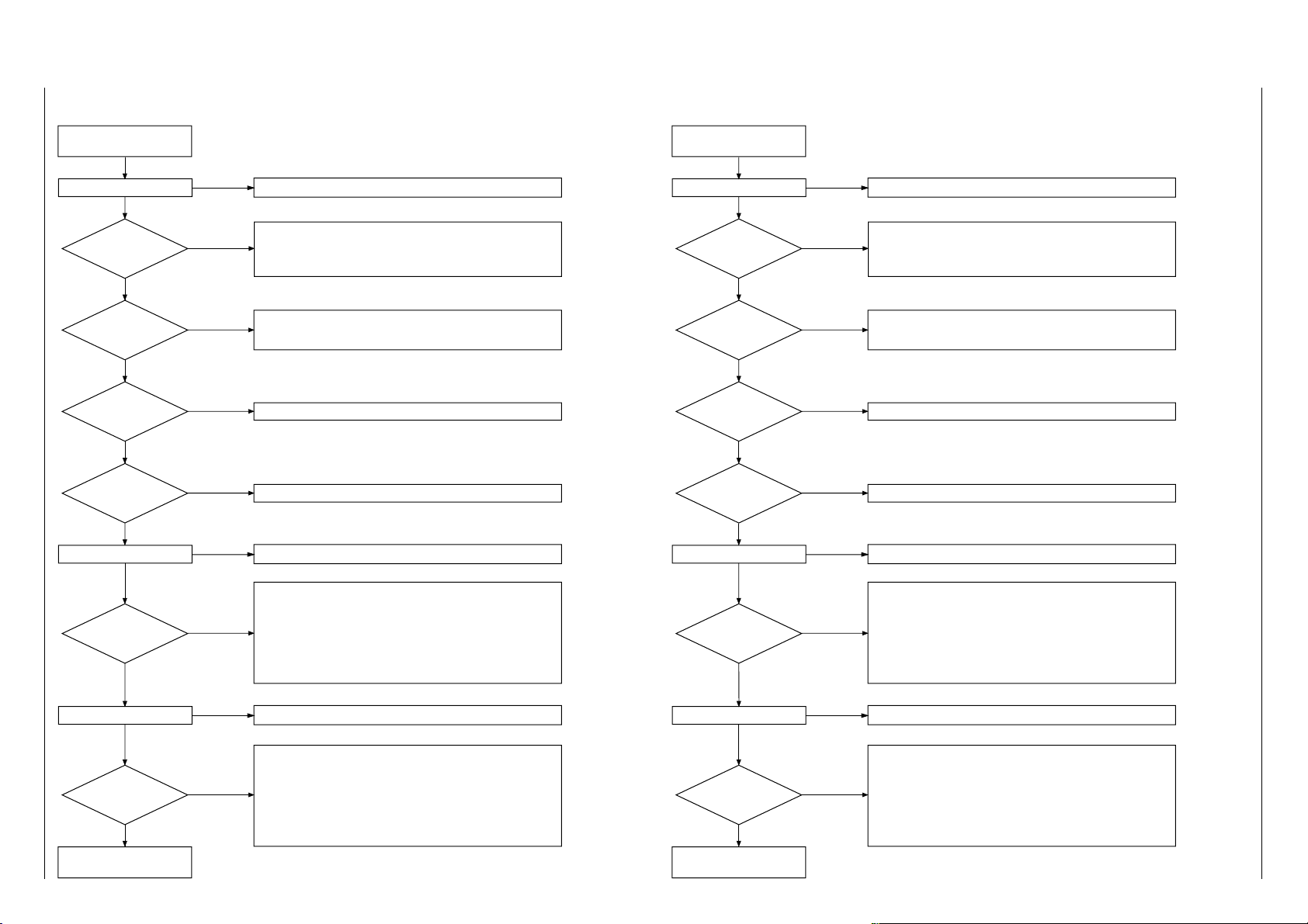
GRUNDIG Service 3 - 5
Netzteil?
• +10V an Steckerkontakt 1300-(8)
• Verbindungsleitung zum DVD-Monoboard pr
üfen
• 0V an T7943-(C) "SELECT" und T7935-(C) "SELECT HIGH"
• IC7900…IC7905 prüfen
• 9V an EURO-AV-TV-Buchse Kontakt 8 und 5V an Kontakt 16
• VIDEO-Buffer prüfen: T7925…T7930, T7933…T7934,
T7937…T7939, T7941
• VIDEO-Buffer T7300, T7301, T7310 pr
üfen
• Verbindungsleitung zum DVD-Monoboard pr
üfen
• DVD-Monoboard pr
üfen
• Versorgungsspannung pr
üfen: +8Vstby, -8Vstby, +12Vstby, +6V, +5V
• IC7304, R3615, R3620, R3802, R3803 pr
üfen
• Verbindungsleitung zum DVD-Monoboard pr
üfen
nicht OK
OK
VIDEO-
Stecker 1300/1301
TP1…6?
nicht OK
OK
VIDEO
Cinch-Buchse
TP19?
nicht OK
OK
Testbild über
EURO-AV am TV
sichtbar?
nicht OK
Kein Bild
Bild Teil OK
• VIDEO-Buffer T7006
…T7008, T7009…T7011 prüfen
OK
VIDEO
Y/C-Buchse
TP20/21?
nicht OK
• 0V an Steckerkontakt 1300-(8)
• Verbindungsleitung zum DVD-Monoboard pr
üfen
• 6V an T7943-(C) "SELECT" und 12V an T7935-(C) "SELECT HIGH"
• IC7900…IC7905 prüfen
• Schaltspannungen an den EURO-Buchsen-(8/16) pr
üfen
• VIDEO-Buffer prüfen: T7925…T7930, T7933…T7934,
T7937…T7939, T7941
Bild von
EURO-AV-AUX am TV
sichtbar
nicht OK
OK
OK
Testbild einschalten
• Servicetestprogramm "PC-Systemtest": 23a (VideoColDencOn)
Test-Signal freischalten
• Servicetestprogramm "PC-Systemtest": 55a (VideoScartSwDvd)
Durchschleifbetrieb aktivieren
• Servicetestprogramm "PC-Systemtest": 55b (VideoScartSwPass)
Oszillogramme: siehe Seite 4-42
Power Supply?
• Check +10V at plug connector 1300-(8)
•
Check flex connection to DVD-Monoboard
• 0V at T7943-(C) "SELECT" and T7935-(C) "SELECT HIGH"
• Check IC7900…IC7905
• 9V at EURO-AV-TV socket contact 8 and 5V at contact 16
•
Check
VIDEO Buffer: T7925
…T7930, T7933…T7934,
T7937…T7939, T7941
•
Check
VIDEO Buffer T7300, T7301, T7310
•
Check flex connection to DVD-Monoboard
•
Check DVD-Monoboard
•
Check supply voltages:
+8Vstby, -8Vstby, +12Vstby, +6V, +5V
•
Check
IC7304, R3615, R3620, R3802, R3803
•
Check flex connection to DVD-Monoboard
not OK
OK
VIDEO-
Connector 1300/1301
TP1…6?
not OK
OK
VIDEO
Cinch Socket
TP19?
not OK
OK
Pattern via
EURO-AV at TV
visible?
not OK
NO PICTURE
Video Part OK
•
Check
VIDEO Buffer T7006
…T7008, T7009…T7011
OK
VIDEO
Y/C Socket
TP20/21?
not OK
• Check 0V at plug connector 1300-(8)
•
Check flex connection to DVD-Monoboard
• 6V at T7943-(C) "SELECT" and 12V at T7935-(C) "SELECT HIGH"
• Check IC7900…IC7905
• Check the switch voltage at the EURO sockets contact 8/16
•
Check
VIDEO Buffer: T7925
…T7930, T7933…T7934,
T7937…T7939, T7941
Pattern from
EURO-AV-AUX at TV
visible
not OK
OK
OK
Switch on the test pattern
• Service Test Programme "PC System Test": 23a (VideoColDencOn)
Switch on the Test Mode
• Service Test Programme "PC System Test": 55a (VideoScartSwDvd)
Switch on the loop trough mode
• Service Test Programme "PC System Test": 55b (VideoScartSwPass)
Oscillograms: see page 4-42
Fehlersuchdiagramm
– A/V-MUX-Platte (Video)
Trouble Shooting Diagram
– A/V-MUX Board (Video)
GDV Modul 1 Fehlersuchdiagramme / Trouble Shooting Diagram
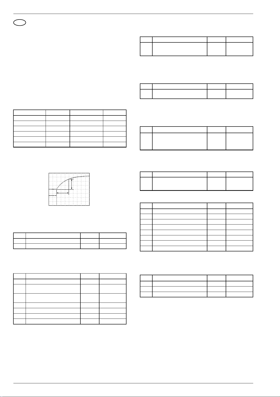
Fehlersuchdiagramme / Trouble Shooting Diagram GDV Modul 1
D
Fehlersuchanleitung – DVD-Monoboard
Allgemeines
• Die Impedanz der Messgeräte muss >1MΩ sein.
• Am Eingang I2S muss zur Überprüfung des DVD-Monoboard ein
Laufwerk mit eingelegter DVD-Disc oder ein Laufwerk-Emulator
angeschlossen sein.
• Die Analogsignale Audio und Video müssen auf der A/V-MUXPlatte messbar sein.
• Mit Hilfe des PC-Systemtests des Servicetestprogrammes (S. 2-1)
ist eine Funktionsprüfung einzelner Komponenten des DVDMonoboards möglich.
Bedienhinweis: Service-PC am Service Serial Interface anschließen und Bedienvariante (C)ommand aufrufen (S. 2-1 / 2-2).
Durch den Aufruf der in den Tabellen angegebenen Nummern
(Ref. #) sind wichtige Funktionsgruppen prüfbar. Die Meldungen auf
dem PC-Monitor sind ab der S. 2-3 (3. Servicetestebenen) erläutert.
1. Betriebspannungen
Messpunkt Messwert Messpunkt Messwert
1600-(1) 3,3V 1600-(7) GND
1600-(2) 3,3V 1600-(8) GND
1600-(3) 5V 1600-(9) -8V
1600-(4) 5V 1600-(10) 0V
1600-(5) 6V 1600-(11) 12V
1600-(6) GND 1600-(12) GND
2. DVD-Decoder/Host-Prozessor IC7305
2.1 Überprüfung der Initialisierung
Beim Einschalten des Netzteils sind folgende Resets zu prüfen:
3. Audiosignalweg
Die A/V-MUX-Platte muss für folgende Tests am DVD-Monoboard
angeschlossen sein.
Ref. # Anmerkung Testpunkt Messwert
21a Audio MMA/AC3 Sinus einschalten F628, F629 siehe Seite 4-41
Test beenden: F630, F631
DVD-Player vom Netz trennen
Der in der Servicetestebene 21a erzeugte Pegel des 1kHz-Tones
muss an den Audio-Chinch-Buchsen 1,8V
±0,25V betragen.
eff
Mit den folgenden Befehlen ist die Überprüfung der Audio-Stummschaltung möglich:
Ref. # Anmerkung Testpunkt Messwert
19a Audio-Mute Ein F619 5V
19b Audio-Mute Aus F619 -8V
4. Videosignalweg
Damit ein Großteil des Videosignalwegs (DSM-LSI-DVP-Denc) über-
prüft werden kann, ist mit folgenden Befehlen ein Farbbalkentestbild
generierbar:
Ref. # Anmerkung Testpunkt Messwert
23a Farbbalken DENC Ein F636, F639 siehe Seite 4-41
23b Farbbalken DENC Aus
F642, F645
F646, F653
Die EURO-AV-Schaltspannung an Testpunkt F613 kann entsprechend der Betriebsart 0V, 6V oder 12V betragen.
Mit den folgenden Funktionen ist diese Spannung prüfbar:
F502
ch1
F505
ch2
Ch1 1V= / Ch2 2V= M 50.0ms
RESET TIMING
150ms
∆U1 = 2.4V
∆T1
2.2 Überprüfung der Systemtakte
Die Toleranz der einzelnen Systemtakte ist maximal 0,02%.
Ref. # Anmerkung Testpunkt Messwert
– 27M_CLK F551 27MHz
– PCM_CLK F703 11,2896MHz
2.3 Softwaretests
Mit den folgenden Funktionen werden wichtige Komponenten des
IC7305 geprüft:
Ref. # Anmerkung Testpunkt Messwert
6 Check-Summe des FLASH –
7a Audiotaktfrequenz CD-DA F703 11,2896MHz
7b Audiotaktfrequenz DVD F703 12,2880MHz
11 I2C NVRAM access –
12 I2C -Interface-Test für Eject µC –
13 S2B-Interface-Test für Laufwerk –
15 NVRAM Write Read –
±0,02%
±0,02%
Ref. # Anmerkung Testpunkt Messwert
25a LOW-Pegel für EURO-AV-TV-(8) F613 0V…0,5V
25b MEDIUM-Pegel für EURO-AV-TV-(8) F613 6V ±10%
25c HIGH-Pegel für EURO-AV-TV-(8) F613 12V ±10%
5. Laufwerk
Ref. # Anmerkung Testpunkt Messwert
44 Laufwerk-Reset –
– Referenzspannung Vref F91 2,5V ±0,3V
– I2S-Interface B_BCLK F361 6MHz
– I2S-Interface CL1 F390 12MHz
– I2S-Interface B_WCLK F362 HIGH
– I2S-Interface Stopclk F391 HIGH
– I2S-Interface B_Sync F358 HIGH
– I2S-Interface B_V4 9201 HIGH
5.1 Disk-Motor
Vor dem Einschalten des Diskmotors sind folgende Messungen durchzuführen:
Ref. # Anmerkung Testpunkt Messwert
– Stby-Steuerspannung U310 HIGH
– Stby-Steuerspannung invers F370 LOW
– Motorsteuerspannung F376 3V ±0,3V
3 - 6 GRUNDIG Service

GDV Modul 1 Fehlersuchdiagramme / Trouble Shooting Diagram
Disk-Motor in Betrieb
Ref. # Anmerkung Testpunkt Messwert
39a Disk-Motor einschalten –
– Stby-Steuerspannung U310 LOW
– Stby-Steuerspannung invers F370 HIGH
– Motorsteuerspannung F376 2,5V ±0,5V
– Motorspannungen A1…A3 F368, F367 siehe Seite 4-41
F365
– FG-Impulse T1…T3 F281, F384 siehe Seite 4-41
F387
– Spannung VH F381 3,3V
– Hall-Sensor-Spannungen H1…H3 F369, F374 siehe Seite 4-41
F379, F380
F383, F386
39b Disk-Motor ausschalten –
5.2 Radial-Steuerung
Ref. # Anmerkung Testpunkt Messwert
40a Radial-Steuerung einschalten F24, F32 4,3V
40b Radial-Steuerung ausschalten
5.3 Sledge-Steuerung
Ref. # Anmerkung Testpunkt Messwert
– Ruhezustand F104, F105 4,5V ±0,5V
41a Pick-Up-einheit nach außen fahren F104–F105 10V
(symetrisch)
41b Pick-Up-einheit nach innen fahren F85, F97 2,7V ±0,3V
F84, F87 2V ±0,3V
F90, F93 2V ±0,3V
5.4 Schubladen-Steuerung
Ref. # Anmerkung Testpunkt Messwert
– Ruhezustand F12, F81 4,5V ±0,5V
43b Schublade öffnen
43a Schublade schließen F12–F81 8V
(symetrisch)
5.5 Fokus
Ref. # Anmerkung Testpunkt Messwert
38a Fokus ein F27, F30 siehe Seite 4-41
38b Fokus aus F27, F30 4,3V ±0,5V
5.6 HF-Teil
DVD-Disk wiedergeben.
Ref. # Anmerkung Testpunkt Messwert
– Diodenausgänge A, B, C, D F45, F49
F50, F52 2,6V ±0,2V
siehe Seite 4-41
– Diodenausgänge E, F F55, F54 2,5V ±0,2V
– DVDALAS-Ausgänge RFO DC F53 2,5V ±0,2V
siehe Seite 4-41
– DVDALAS-Ausgänge O-A, O-B F59, F62 25mV ±10mV
DVDALAS-Ausgänge O-C, O-D F69, F72 25mV ±10mV
– DVDALAS-Ausgänge S1, S2 F75, F77 25mV ±10mV
GB
Test Instructions – DVD-Monoboard
General
• Impedance of measuring-equipment should be > 1MΩ.
• To check the DVD-Monoboard a Drive Mechanism with DVD-Disc
or a B.E.-Emulator must be connected to the I2S input.
• The analog signals Audio and Video must be measurable at the
A/V-MUX-Board.
• With the PC Systemtest of the Service Test Software (p. 2-5) single
components of the Digital Board can be checked.
Remark: Connect Service-PC to Service Serial Interface and call
operating variant (C)ommand (p. 2-5 / 2-6).
The most important functions can be checked by the numbers
(Ref. #). The messages on the PC-Monitor are described at p. 2-7
(3. Service Test Levels).
1. Power Supply Voltages
Testpoint Value Testpoint Value
1600-(1) 3.3V 1600-(7) GND
1600-(2) 3.3V 1600-(8) GND
1600-(3) 5V 1600-(9) -8V
1600-(4) 5V 1600-(10) 0V
1600-(5) 6V 1600-(11) 12V
1600-(6) GND 1600-(12) GND
2. DVD Decoder/Host Processor IC7305
2.1 Check initialisation
SS
SS
While switching on the supply check next reset timing:
F502
ch1
F505
ch2
Ch1 1V= / Ch2 2V= M 50.0ms
RESET TIMING
∆T1
150ms
∆U1 = 2.4V
2.2 Clock check
The tolerance of all clocks is maximum 0,02%.
Ref. # Remark Testpoint Value
– 27M_CLK F551 27MHz
– PCM_CLK F703 11.2896MHz
2.3 Softwaretests
The following commands are testing the most important components
of IC7305.
Ref. # Remark Testpoint Value
6 Checksum FLASH –
7a µClock A CLK in CD-DA mode F703 11.2896MHz
7b µClock A CLK in DVD mode F703 12.2880MHz
11 I2C NVRAM access –
12 I2C Eject PWB –
13 S2B Echo –
15 NVRAM Write Read –
±0.02%
±0.02%
GRUNDIG Service 3 - 7

Fehlersuchdiagramme / Trouble Shooting Diagram GDV Modul 1
3. Audio Path
For the next test, the A/V-MUX Board must be connected to the DVDMonoboard.
Ref. # Remark Testpoint Value
21a Audio MMA/AC3 Sinus On F628, F629 see page 4-41
Terminating the test: Disconnect F630, F631
the DVD player from the mains
The level of the 1kHz-tone, which is generated by Service Test Level
21a, must be 1.8V
±0.25V at the audio chinch sockets.
rms
With the following commands, the Audio mute can be checked.
Ref. # Remark Testpoint Value
19a Audio-Mute On F619 5V
19b Audio-Mute Off F619 -8V
4. Video Path
To check a large part of the video-path (DSM-LSI-DVP-Denc) a
colorbar can be generated via next commands:
Ref. # Remark Testpoint Value
23a Colourbar DENC On F636, F639 see page 4-41
23b Colourbar DENC Off
F642, F645
F646, F653
The Euro-AV-switching voltage can be 0V, 6V, 12V.
Check at testpoint F613 the output-voltage while using next commands:
Ref. # Remark Testpoint Value
25a LOW Level at EURO-AV-TV-(8) F613 0V…0,5V
25b MEDIUM Level at EURO-AV-TV-(8) F613 6V ±10%
25c HIGH Level at EURO-AV-TV-(8) F613 12V ±10%
Disc Motor operating
Ref. # Remark Testpoint Value
39a Disc motor on –
– Stby control voltage U310 LOW
– Stby control voltage invers F370 HIGH
– Motor control voltage F376 2.5V ±0.5V
– Motor voltages A1…A3 F368, F367 see page 4-41
F365
– FG pulse T1…T3 F281, F384 see page 4-41
F387
– Voltage VH F381 3.3V
– Hall sensor voltage H1…H3 F369, F374 see page 4-41
F379, F380
F383, F386
39b Disc motor off –
5.2 Radial Control
Ref. # Remark Testpoint Value
40a Radial control on F24, F32 4.3V
40b Radial control off
5.3 Sledge Control
Ref. # Remark Testpoint Value
– Standstill F104, F105 4.5V ±0.5V
41a Pick up unit moves outwards F104–F105 10V
(balanced)
41b Pick up unit moves inwards F85, F97 2.7V ±0.3V
F84, F87 2V ±0.3V
F90, F93 2V ±0.3V
PP
5. Drive Mechanism
Ref. # Remark Testpoint Value
44 Reset for Drive Mechanism –
– Reference voltage Vref F91 2.5V ±0.3V
– I2S Interface B_BCLK F361 6MHz
– I2S Interface CL1 F390 12MHz
– I2S Interface B_WCLK F362 HIGH
– I2S Interface Stopclk F391 HIGH
– I2S Interface B_Sync F358 HIGH
– I2S Interface B_V4 9201 HIGH
5.1 Disc Motor
Before switching on the disk motor the following measurements must
be carried out:
Ref. # Remark Testpoint Value
– Stby control voltage U310 HIGH
– Stby control voltage invers F370 LOW
– Motor control voltage F376 3V ±0.3V
5.4 Tray Control
Ref. # Remark Testpoint Value
– Standstill F12, F81 4.5V ±0.5V
43b Disc tray open
43a Disc tray close F12–F81 8V
(balanced)
5.5 Focus
Ref. # Remark Testpoint Value
38a Focus on F27, F30 see page 4-41
38b Focus off F27, F30 4.3V ±0.5V
5.6 RF Part
Play back the DVD disc.
Ref. # Remark Testpoint Value
– Diodes outputs A, B, C, D F45, F49
F50, F52 2.6V ±0.2V
see page 4-41
– Diodes outputs E, F F55, F54 2.5V ±0.2V
– DVDALAS outputs RFO DC F53 2.5V ±0.2V
see page 4-41
– DVDALAS outputs O-A, O-B F59, F62 25mV ±10mV
DVDALAS outputs O-C, O-D F69, F72 25mV ±10mV
– DVDALAS outputs S1, S2 F75, F77 25mV ±10mV
PP
3 - 8 GRUNDIG Service

GDV Modul 1 Platinenabbildungen und Schaltpläne / Layout of PCBs and Circuit Diagrams
Reference
Oscillograms.........4-41
A/V-MUX Board....4-13
– 1A......................4-15
– 1B......................4-17
– 2A......................4-19
– 2B......................4-21
Eject Board...........4-22
DVD-Monoboard...4-23
– 1........................4-27
– 2........................4-29
– 3........................4-31
– 4........................4-33
– 5........................4-35
– 6........................4-37
Power Supply.....4-9/11
Platinenabbildungen und Schaltpläne / Layout of PCBs and Circuit Diagrams
Verdrahtungsplan / Wiring Diagram
DVD-Laufwerk (DVD-Monoboard)
DVD Drive Mechanism (DVD-Monoboard)
2
GDV Modul 1 Platinenabbildungen und Schaltpläne / Layout of PCBs and Circuit Diagrams
Buchsenplatte
Socket Board
ST-NS1 ST-DVD
ST-SV1ST-H-AV
ST-LSTR ST-IR-K3
1600
12 1
ST-MOT1 ST-IR-KB1
ST-MDA
ST-STA2
ST-WEB1
ST1
ST-NS1
ST-NETZ3 ST-NETZ2
ST-E
SW
Eject-Platte
Eject Board
1000
5
11 1
1002 1004
4
MASSEANSCHLUSS
1603
1
22
1604
1
16
1602 1501
1
5
GND CONNECTION
3 5 2
Bedieneinheit
Control Unit
ST-NETZ-M
ST-NETZ1
4
ZU /TO CHASSIS
(Seite/Page 4-3)
MASSELEITUNG
GND CABLE
ZU CHASSIS-BEFESTIGUNGSSCHRAUBE LINKS
TO CHASSIS FASTENING
12
0205
Netzteil
0101
Power Supply
SCREW LEFT
(Seite/Page 4-3)
1112
0207
FLEXPRINT
FLEXPRINT
ZU /TO CHASSISZU /TO CHASSISZU /TO CHASSISZU /TO CHASSISZU /TO CHASSISZU /TO CHASSISZU /TO CHASSIS
ZU /TO CHASSIS
(Seite/Page 4-3)
ST-FF1
ST-WEB2
7
1410
1
DIGITAL OUT
OPTICAL COAX AUDIO OUT
GRUNDIG Service 4 - 1 GRUNDIG Service 4 - 2
1122 16
RL
VIDEO OUT
S-VIDEO
A/V-Mux-Platte
A/V-Mux Board
AUX / TV
5
6
2
1
ST-WEB3
13011300
AUX-Platte 12V
AUX Board 12V
21
1
2
ST-FF1
6
BU2
5
BU1
12VTELEFON 12V
2
LED-Platte
LED Board
ST-IR-KB1
ST-DET1
ST-IR2
DVD-Einschub
DVD Plug-in Unit

Platinenabbildungen und Schaltpläne / Layout of PCBs and Circuit Diagrams GDV Modul 1 Platinenabbildungen und Schaltpläne / Layout of PCBs and Circuit Diagrams GDV Modul 1
SLAVE PROCESSOR
Button Eject
POWER SUPPLY
St_by
HEADPHONE
A/V-MUX BOARD
JBE
(servo)
RAM ROM
HOST
Sti5505
I2S
S2B
DVD-MONOBOARD
A/V signals
I2C
SCART
SWITCHING
AUX
TV
Y/C
CVBS(/YC not on SCART)
CVBS
CVBS
0/6/12V
RGB
UDA1328T
3
Kill
8Vstab
3V3stab
+12Vstby
Video
IC's and
audio
buffers
DAC
Headphone out
RGB/CVBS
RGB/CVBS
CVBS
AUDIO
AUDIO
AUDIO
L + R
DAC
SCART
SCART
EJECT BOARD
LED BOARD
RGB/CVBS
L+R
I2C
DIG_OUT
PCM
-5Vstab
-8Vstby
Switches
OPTICAL
OUTPUT
DIGITAL
OUTPUT
RC
7104
TEA6420
AUDIO SCART
SWITCHING
7917
7401
7403
7900-7905
7200
+12V stby
+5V stby
-8V stby
-40V
+5V
+3V3
Reference
Oscillograms.........4-41
A/V-MUX Board....4-13
– 1A......................4-15
– 1B......................4-17
– 2A......................4-19
– 2B......................4-21
Eject Board...........4-22
DVD-Monoboard...4-23
– 1........................4-27
– 2........................4-29
– 3........................4-31
– 4........................4-33
– 5........................4-35
– 6........................4-37
Power Supply.....4-9/11
Blockschaltplan / Block Circuit Diagram
CHASSIS-BEFESTIGUNGSSCHRAUBE RECHTS
CHASSIS FASTENING SCREW RIGHT
ST-BR
BEDIENEINHEIT
CONTROL UNIT
(Seite/Page 4-2)
ZU / TO
ST-NETZ1
1
UB1-1
UB1-2
1
3
4
5
6
TR60001
7
9
11
4
NETZ2
1
NETZ1
1
ST-UB2
2
22
21
20
19
18
17
16
15
14
13
12
6
TR53010
ST-JOCH
18
DF-3
ST-MK
EURO-AV1
121
220
EURO-AV2
121
220
(Seite/Page 4-2)
ZU / TO
AUX-Platte 12V
AUX Board 12V
ST-MM1
111
ST-GM
6 1
ST-P1
16
ST-PI1
13
ST-FF1
16
21
ST-MDA
13
ST-P5
2
1
FEATURE-BOX
111
ST-P2
ST-RGB
17
NF-BAUSTEIN
111
ST-P3
1
11
ST-PI2
ST-P4
18
ST-SV1
13
ST-AV3V
ST-FBAS2
ST-AV3
51
1
BU1
12
BU2
6
ST-RGB_SAT
115
115
42
43
16
ZU MASSEANSCHLUSS DVD-LAUFWERK
TO GND CONNECTION DVD DRIVE MECHANISM
(Seite/Page 4-2)
ZU MASSEBAND BILDRÖHRE
TO GND STRAP CRT
MASSELEITUNG KPL.
GND CABLE CPL.
CHASSIS-BEFESTIGUNGSSCHRAUBE lINKS
CHASSIS FASTENING SCREW LEFT
4 - 3 GRUNDIG Service 4 - 4 GRUNDIG Service

GDV Modul 1 Platinenabbildungen und Schaltpläne / Layout of PCBs and Circuit Diagrams
Reference
Oscillograms.........4-41
A/V-MUX Board....4-13
– 1A......................4-15
– 1B......................4-17
– 2A......................4-19
– 2B......................4-21
Eject Board...........4-22
DVD-Monoboard...4-23
– 1........................4-27
– 2........................4-29
– 3........................4-31
– 4........................4-33
– 5........................4-35
– 6........................4-37
Power Supply.....4-9/11
Blockschaltplan / Block Circuit Diagram – DVD-Monoboard
GDV Modul 1 Platinenabbildungen und Schaltpläne / Layout of PCBs and Circuit Diagrams
LOADER VAL3000
CDM
OPU
CD-LASER
DVD-LASER
FOCUS
RADIAL
DISK MOTOR
M
HALL
FLEX 24P
FLEX 11P
DVD-MONOBOARD SERVO PART
DVDALAS2
TZA1023
Diode
Amplifiers
MUX
1101
2
+5 GND
1301
4
6
6
4
4
DVD
CD
V & I references
Dual Laser
Supply
Laser#1
Laser#2
DPD
Push Pull
Offset
MUX
compensations
3 Beam
Tracking
Processing
DIAGRAM 1 3
SIGNAL PROCESSOR
LASER SUPPLY
7102
RFo
Var Gain
Header
Land
Land/Groove
Swap
Mute
FTC
Servo
Signals
D1-D6
DIAGRAM
DECODER
MOTOR-IC
FTC comp.
Serial
I/Face
SILD
SICL
7304
BA6856FP
TACHO-OUT
MOTO-IN
DRIVE
HALL-FEEDBACK
MEMORY
7310
S-RAM
132K
CY7C199-15C
8
DATA
RF-IN
DECODER
HD61
SAA7335HL/E/M2
3
1
AD[0:7]
15
ADDRESS
1
CONTROL
B_V4
B_SYNC
B_FLAG
B_DATA
B_BCLK
B_WCLK
7311
TO STi5505 ON DIAGRAM
I2S
6
BLOCKDIAGRAM DIGITAL PART
5
SLEDGE MOTOR
1102
M
HALL
FLEX 8P
ADC
CONTROL
LINES
uP (8051 CORE)
SERVO
TRAY MOTOR
LM833D
M
PCS-PRE-AMPL
END-SWITCH
4-WIRES
GRUNDIG Service 4 - 5 GRUNDIG Service 4 - 6
1100
4
4
DRIVERS
BA5938FM
2
4
7103
7104
SLEDGE
RADIAL
FOCUS
TRAY1
TRAY2
2
2
5
1
PHI-INPUT
REF
SERVO OUTPUTS
TRAY-SWITCH
MACE2
SAA7399
PCS
8.46 MHz
A[8:16]
TXD_BE
RXT_BE
CFR
SUR
7200
CONTROL BUS
DATA/ADDRESS BUS
FLASH ROM
PSENN
AD[0:7]AD[0:7]
AM29F002
ADRESS LATCH
AD[0:7]
74HCT573D
7202
A[0:16]
7201
A[0:7]
6 MHz
S2B
4
DIAGRAM
SERVO
4229_136
9936
2
TO STi5505 ON DIAGRAM
BLOCKDIAGRAM DIGITAL PART
5

Platinenabbildungen und Schaltpläne / Layout of PCBs and Circuit Diagrams GDV Modul 1 Platinenabbildungen und Schaltpläne / Layout of PCBs and Circuit Diagrams GDV Modul 1
Reference
Oscillograms.........4-41
A/V-MUX Board....4-13
– 1A......................4-15
– 1B......................4-17
– 2A......................4-19
– 2B......................4-21
Eject Board...........4-22
DVD-Monoboard...4-23
– 1........................4-27
– 2........................4-29
– 3........................4-31
– 4........................4-33
– 5........................4-35
– 6........................4-37
Power Supply.....4-9/11
Blockschaltplan / Block Circuit Diagram – DVD-Monoboard
DVD-MONOBOARD DIGITAL PART
DIAGRAM
5
uP & DECODER PART
TO /FROM
MACE2
(DIAGRAM )
2
FROM
HD61 DECODER
(DIAGRAM )
3
S2B
4
I2S
6
7503
TXD_BE
RXD_BE
CFR
SUR
B_V4
B_WCLK
B_DATA
B_BCLK
B_FLAG
B_SYNC
RESETN
UART UART
FRONT END
INTERFACE
HOST
ST20
MEMORY INTERFACE
SYSTEM DATA BUS
STB_CONT
4
DEMULTIPLEXER
SYSTEM ADDRESS BUS
RAM/ROM INTERFACE
16Mb
FLASH
AM29LV160BT
7401
AUDIO
SUBPICTURE
STi5505
MT48LC1M16A1TG -7S
VIDEO
16Mb
SDRAM
MPEG DECODER
SDRAM INTERFACE
7404
OSD
7405
16Mb
SDRAM
MT48LC1M16A1TG-7S
SERVICE
PAL_NTSC
PROGRAMMABLE
I/O
AUDIO
DECODER
VIDEO
ENCODER
CONTROLLER
7504
27 MHz
SCART[0:1]
DIAGRAM 6. VIDEO/AUDIO OUTPUT PART
TXD_SER
RXD_SER
RTS_SER
CTS_SER
2
2
7600
7604, 7607
SCART
6
4
SERVICE
DEEM[0:1]
0_6_12V
CONN.
1602
INTERFACE
CONN.
1603
SERVICE
SERIAL
0/6/12V
SCLK
PCM_OUT0
PCM_CLK
LRCLK
SPDIF_OUT
R_OUT
G_OUT
B_OUT
C_OUT
CVBS_OUT
Y_OUT
MUTE
5
DIG. OUT
CVBS
RGB
PCM (3X)
6
S-VHS
7608,7609,7610
MUTE
7611
3V3
5V
7612-7618
VIDEO
FILTER
MUTE_AV
5
R/C
G
B/CVBS
4
CVBS/Y
BCLK
DATA
ACLK
WCLK
DIG_OUT
TO/FROM
A/V-MUX
BOARD
BUFFER
PAL_NTSC
PCM__CLK
CLOCK
SEL_ACLK
SYNTHESIZER
MK2742
I2C
SDA
2
I2CSDRAM CONTROLLER
7505
EEPROM
ST24E32M6
SCLK
2
SDA
SCLK
SDA
SCLK
7616
2
OPTION
STB_CONT
2
+5V
ACLK
-5V
2
+3V3
+6Vstby
+12Vstby
-8Vstby
PCMout1
PCMout2
HSYNC
+3V3
+5Vstby
-8Vstby
+6Vstby
+12Vstby
P50
+5V
Y - C
CONN.
1604
CONN.
1600
CONN.
1501
TO
A/V-MUX
BOARD
POWER
SUPPLY
TO/FROM
DISPLAY
DIAGRAM
4
MEMORY PART
4 - 7 GRUNDIG Service 4 - 8 GRUNDIG Service
4229_136
9936

GDV Modul 1 Platinenabbildungen und Schaltpläne / Layout of PCBs and Circuit Diagrams
Netzteil / Power Supply
Ansicht von der Bestückungsseite / View of Component Side
GDV Modul 1 Platinenabbildungen und Schaltpläne / Layout of PCBs and Circuit Diagrams
1234567891011
3133
5131
A
2126
3124
5120
B
0101
C
D
T2.5A H 250V
1120
3122
2125
3123
1125
3120
2110
2120
3134
2129
7110
3129
6120
+
2121
3115
6113
6110
3101
3128
3132
3126
3127
2127
3125
6111
0000
5125
7125
3135
6114
6132
2131
2132
2133
7200
6220
9260
9261
6250
2221
2231
2241
2251
2211
6240
7201
2220
6230
6210
2210
2261
9262
2250
6260
2240
2230
2239
7221
9250
3233
2260
9230
7236
7255
2259
2222
7259
7237
XHXH
5222
5240
5259
3235
5239
9210
5233
7233
5230
5210
0206
3122 423 30336
2233
0207
9214
3228
0205
0000 C5
0101 B1
0205 C10
0206 D10
0207 A10
1120 D2
1125 C3
2110 D3
2120 C2
A
2121 C4
2121a C4
2125 B3
2126 A3
2127 B5
2129 D3
2131 C7
2132 C6
2133 D6
2210 C8
2211 C8
B
2220 A8
2221 A8
2222 A9
2230 B8
2231 B8
2233 B10
2239 D9
2240 A8
2241 A8
2250 B8
C
2251 B8
2259 B9
2260 A9
2261 A8
3101 D4
3115 D4
3120 C2
3120a C2
3122 C3
3123 B3
3124 B3
D
3125 D5
3126 B5
3127 B5
3128 B5
3129 D3
3132 A5
3133 A3
3134 D2
3135 B6
3228 B11
3233 B9
3235 C10
5120 A2
5125 B5
5131 B6
5210 D10
5222 A9
5230 C10
5233 B10
5239 C10
5240 A9
5259 C10
6110 B4
6111 C5
6113 D4
6114 C6
6120 B3
6132 C6
6210 C8
6220 A7
6230 B8
6240 A8
6250 B7
6260 A8
7110 D3
7125 C5
7200 D7
7201 D8
7221 A9
7233 B10
7236 C9
7237 D9
7255 B9
7259 B9
9210 A10
9214 A11
9230 C9
9250 B9
9260 B7
9261 D7
9262 B8
1234567891011
Ansicht von der Lötseite / View of Solder Side
1011 987654321
3224
3256
3258
3255
3257
7235
3223
7223
3253
7256
6256
2238
A
7226
3226
7228
2225
3227
3225
B
C
D
3122 423 30336
1011 987654321
3221
3254
3238
4250
2101 C 3
2102 C 3
2103 D 3
2104 D 3
2106 D 3
2107 D 4
2109 C 4
3222
3260
3131
3136
2114
3107
3113
4121
3108
2107
3112
3109
2109
2111
2101
21022103
3103
3116
3102
3110
2104
3104
6129
3105
3106
2106
4128
4125
2113
3236
3237
3203
3205
3202
3204
3206
3201
2201
2202
3111
2111 D 3
2113 C 5
2114 C 6
2201 D 7
A
2202 D 8
2225 A 11
2238 C 9
3102 D 3
3103 D 3
3104 D 3
3105 D 3
3106 D 3
3107 D 4
3108 D 4
3109 C 4
B
3110 D 3
3111 D 6
3112 D 4
3113 D 4
3116 D 4
3131 B 4
3136 B 4
3201 D 7
3202 D 8
3203 D 8
C
3204 D 8
3205 D 8
3206 D 7
3221 A 9
3222 A 9
3223 A 10
3224 A 10
3225 A 11
3226 A 11
3227 A 11
3236 C 9
D
3237 D 9
3238 C 9
3253 A 9
3254 A 9
3255 B 9
3256 B 10
3257 B 10
3258 C 10
3260 A 9
4121 D 4
4125 C 5
4128 C 5
4250 B 9
6129 D 2
6256 B 10
7223 A 9
7226 A 11
7228 A 11
7235 C 10
7256 B 10
F101 C 1
F102 B 1
F103 B 3
F104 A 2
F105 B 4
F106 B 4
F107 B 6
F108 A 3
F109 D 3
F110 D 4
F111 D 4
F201 B 10
F202 B 10
F203 C 11
F204 C 11
F205 C 10
F206 C 11
F207 B 11
F208 A 10
F209 A 9
F210 B 11
F211 C 10
F212 C 11
F213 C 11
F214 C 11
F215 C 10
F216 A 10
F217 A 10
F218 A 10
F219 A 10
F220 C 10
F221 C 11
F222 C 11
F223 B 11
F224 D 7
F225 D 8
F226 D 9
F227 D 9
GRUNDIG Service 4 - 9 GRUNDIG Service 4 - 10

Platinenabbildungen und Schaltpläne / Layout of PCBs and Circuit Diagrams GDV Modul 1 Platinenabbildungen und Schaltpläne / Layout of PCBs and Circuit Diagrams GDV Modul 1
Reference
Oscillograms.........4-41
A/V-MUX Board....4-13
– 1A......................4-15
– 1B......................4-17
– 2A......................4-19
– 2B......................4-21
Eject Board...........4-22
DVD-Monoboard...4-23
– 1........................4-27
– 2........................4-29
– 3........................4-31
– 4........................4-33
– 5........................4-35
– 6........................4-37
Power Supply.....4-9/11
Netzteil / Power Supply
0101 B 1
0101 A 1
0205 E15
0205 E15
0205 D15
0205 B15
0205 D15
A
ST-NETZ 2
B
TO CONTROL UNIT
C
D
E
F
G
I
J
0205 H16
0205 I16
0205 I16
0205 C15
0205 D15
0205 A15
0205 I16
2
0101
1
0101
MP3
F101
1120
T2.5AH250V
F102
Only for US versions
10M
3133
3102
3103
0206 J13
0206 K13
0207 A16
0207 A16
0207 B16
0207 C16
0207 D16
3120
15K
3105
385V
2101
82pF
2102
680pF
22K
3K6
2103
3104
0207 C16
0207 F16
0207 D16
0207 F16
1120 A 2
1125 A 3
2101 G 2
*
15K
3122
2120
330nF
82K
3101
2104
2R7
4.7nF
15
12
14
13
2102 H 2
2103 H 2
2104 I 2
2106 K 2
2107 J 3
2109 J 4
2110 J 4
1125
7110
MC44603P
DEMAGNETIZATION
DETECT
8
DEMAGNETISATION
MANAGEMENT
iref
SYNC INPUT
9
OSCILLATOR
CT
10
RF
STANDBY
RP
STANDBY
(reduced frequency)
2.5V
ERROR
AMP
VOLTAGE
FEEDBACK
E/A OUT
FOLDBACK
*
2107
3108
F103
5120
3
4
STANDBY
VSB OUT
FOLDBACK
INPUT
5
18K
180K
3107
2111 G 7
2113 H 7
2114 I 7
2120 B 3
2121 B 6
2125 A 4
2126 B 4
3124
220R
1
2
3110
10K
Vstby
CURRENT
SENSE
CURRENT
SENSE INPUT
7
2109
1.5nF
4561 7 8 9 101112131415162 173
F104
reference
VOSC PROT
VOSC
SOFT-START
CONTROL
3109
330R
16
Vref iref
block
2127 C 9
2129 E 5
2131 A 9
2132 E 8
2133 E 7
2201 I10
2202 I10
2125
2N2/400V
2126
2N2/400V
=1
Dmax &
SOFT START
& DMAX
11
2110
2210 E11
2211 E10
2220 F11
2221 F10
2222 F13
2225 G13
2230 E11
6120
F108F109
18K
3123
18K
3134
2129
Vref enable
initialization block
Set
LATCH
Reset
THERMAL
SHUTDOWN
iref
UVL01
Vref
2.2uF/50V
S1NB80
MP4
6129
4.7uF/50V
supply
Q
2231 D10
2233 B14
2238 E13
2239 E14
2240 B11
2241 A10
2250 C11
F105F106
2121
100uF/400V
3129
10K
BZX84-C24
UVL01
BUFFER
Vref Voc
OVER
VOLTAGE
MANAGEMENT
3131
270K
3136
270K
3111
22R
1
VC
OUT
GND
OVER
VOLTAGE
PROTECT
2251 C10
2259 C14
2260 D11
2261 C10
3101 G 2
3102 H 2
3103 H 2
6110
6111
2111
2
F110
3
4
6
3116
180R
BYD33J
BYD33J
100nF
3112
150R
6113
3115
1K
3104 I 2
3105 I 2
3106 K 2
3107 J 3
3108 J 3
3109 J 4
3110 G 4
3132
0.27R
MP2
3113
33R
BYV10-40
2114
100nF
F111
3111 F 6
3112 H 7
3113 H 7
3115 I 7
3116 I 6
3120 B 2
3122 A 3
2133
2113
2.2nF
6114
BYD33D
MP1
7125
STP3N60FI
1K
3125
2132
*
6132
BYD33D
100uF/25V
3126
4R7
3123 C 5
3124 A 4
3125 C 8
3126 D 8
3127 D 8
3128 D 9
3129 E 6
F107
5125
31271R3128
3135
6R8
BEAD
2127
1R
3131 B 6
3132 B 7
3133 B 1
3134 D 5
3135 E 9
3136 C 6
3201 H10
2131
2.2nF
5131
ETD29
1
5
47pF/1KV
7
9
7200
CQY80NG
3202 I11
3203 K12
3204 I11
3205 J11
3206 J11
3221 G12
3222 F12
15
11
14
17
12
10
13
16
18
GNDs GNDs
F225
BYW29F-200
2251
1nF/1KV
6250
BYD33D
2261
330pF/1KV
6260
BYD33J
PBYR1080
PBYR1060
BYD33D
+12V
10R
3201
F224
2201
100nF
7201
KA431LZ
3223 H12
3224 G13
3225 G13
3226 G14
3227 G14
3228 G15
3233 E12
2241
6240
2231
6230
2211
6210
2221
6220
2202
100nF
*
2250
10R
3260
*
*
2230
2210
*
2220
3204
270R
3235 E12
3236 E14
3237 E14
3238 E13
3253 C12
3254 C11
3255 C12
2240
470uF/25V
-8V
220uF/16V
2260
1000uF/10V
4700uF/6V3
220uF/10V
3202
3205
3206
3256 D13
3257 C13
3258 D14
3260 D11
4250 B13
5120 B 3
5125 C 8
4250 To be included for DVD2B version @
1K
3254
3u3/50V
3235
15K
7221
IO
LM317L
7223
BC847
1K8
To be left out of DVD2B version @
4K7
-8V
0R
3203
100R
5131 A 9
5210 F15
5222 F15
5230 D15
5233 B15
5239 D15
5240 A15
+12V
4250
To be left out of DVD2B version @
3253
27K
7255
BC337-40
3255
680R
3256
470R
7236
STP16NE06
1K
7235
BC847
KA431LZ
To be left out of DVD2B version @
2222
+6V
100uF/6V3
GNDs
3225
7226
BC857
3224
10K
1
2
+6V
A
7256
BC857
3222
3221
GNDs
3223
GNDsGNDs
F226
F227
+12V
3233
1K
1K3
10K
0206
0206
5259 C14
6110 B 6
6111 C 6
6113 H 7
6114 I 8
6120 B 5
6129 E 5
3257
2238
*
7237
10K
6132 E 8
6210 E10
6220 F10
6230 D10
6240 A10
6250 C10
6256 D13
7233
IO
78M05
G
7259
I
79M05
G
27K
6256
BAS16
F208
F209
3238
*
2225
GNDs
3226
10K
BC847
6260 C10
7110 G 3
7125 C 8
7200 H 9
7201 J10
7221 F12
7223 G12
5240
1uH
5233
10uH
2233
100uF/6V3
O
3236
3237
100nF
7228
3258
10K
4K7
4K7
+6V
3227
2259
2239
10K
F205
5259
10uH
100uF/25V
F207
5230
10uH
5239
100uF/6V3
5210
6.8uH
5222
10uH
3228
15K
@ DVD2B version: GDV MODUL 1
* = RESERVED ITEM NUMBER
7226 G13
7228 G14
7233 B14
7235 E12
7236 D13
7237 E13
7255 C12
F206
F210
F211
F214
F215
F220
F223 F222 F221
7256 D12
7259 C14
F201 F202
+12V
11
+5V Stand By
4
F203
-5V (-8V Stand By)
9
Stand By
10
+6V Stand By
5
+5V
3
+3V3
2
+3V3
1
6
7
8
GND
12
0205
DVD-Monoboard
F204
F213F212
F216 F217
F219F218
GNDs
+12V
1
GND
2
+5V Stand By
3
6
-40V
4
-40V
8
+5V
5
+2V9
9
GND +2V9
7
0207
EJECT Board
A
B
C
D
E
F
G
HH
I
J
2106
680R
27nF
K
3106
4561 7 8 9 101112131415162 173
4 - 11 GRUNDIG Service 4 - 12 GRUNDIG Service
K

GDV Modul 1 Platinenabbildungen und Schaltpläne / Layout of PCBs and Circuit Diagrams
A/V-MUX-Platte / Board
Ansicht von der Bestückungsseite
View of Component Side
GDV Modul 1 Platinenabbildungen und Schaltpläne / Layout of PCBs and Circuit Diagrams
Ansicht von der Lötseite
View of Solder Side
GRUNDIG Service 4 - 13 GRUNDIG Service 4 - 14

Platinenabbildungen und Schaltpläne / Layout of PCBs and Circuit Diagrams GDV Modul 1 Platinenabbildungen und Schaltpläne / Layout of PCBs and Circuit Diagrams GDV Modul 1
Reference
Oscillograms.........4-41
A/V-MUX Board....4-13
– 1A......................4-15
– 1B......................4-17
– 2A......................4-19
– 2B......................4-21
Eject Board...........4-22
DVD-Monoboard...4-23
– 1........................4-27
– 2........................4-29
– 3........................4-31
– 4........................4-33
– 5........................4-35
– 6........................4-37
Power Supply.....4-9/11
A/V-MUX-Platte/Board – Video-IN/OUT
123
4567
8 9 10 11
12 13 14
SUPPLY &
VIDEO SWITCHING
1300 (a)
1
A
B
C
DC_OFF
1301 (b)
D
E
FROM DVD MONOBOARD (1604) FROM DVD MONOBOARD (1603)
TP1
2
TP2
3
TP3
5
TP4
6
F260
8
F113
9
0V
6403
6302
BAS216
BAS216
2
F130
8
F138
10
F142
13
14
15
16
9
TP5
TP6
F135 F275
3622
F
F278
3625
1K
F281
0V
7335
BC847B
DC_OFF
10K
+6V
3617
F274
-1.2V
+11.5V
3624
10K
B
G
R
CVBS
CVBS
0|6|12
10K
3619
SCL
SDA
C_ENC
Y_ENC
3621
4K7
F280
0.7V
-9.5V
10K
+10.8V
F277
3616
4K7
F273
-0.6V
+12Vstby
3627
0R
3623
F279
F271
+12V
BC327-25
4K7
0V
7334
BC847B
3626
0R
F269 F270
7331
BC547B
-8.6V
1K
3618
0V
F272
7332
BC857B
7333
3620
4R7
3615
4R7
F276
-9.2V
2545
+11.2V
47u
+12Vstby
-8Vstby
SELECT
RCOUT_TV
SELECT
CVBS
G
0V
10K
3696
U229
7935
BC847B
SELECT
SELECT_HIGH
YCVBSIN_AUX
0|6|12
H
3720
I
3723
56K
U275
0.7V
56K
3722
56K
U230
0.7V
+6V
3695
10K
U228
7943
BC847B
0V
+6V
22n
16
7903-A
Vdd
HEF4053BT
S
11
Z
14
Vee8Vss
E
6
7
+6V
-5V
16
7903-B
Vdd
HEF4053BT
S
10
Z
15
E
Vee7Vss
6
8
-5V
+6V
16
7903-C
Vdd
HEF4053BT
S
9
Z
4
E
Vee7Vss
6
8
-5V
+6V
2532
22n
16
7900-A
Vdd
HEF4053BT
S
11
Z
14
+6V +6V
16
Vdd
S
10
Z
15
+6V +6V
16
Vdd
S
9
Z
4
E
Vee7Vss
6
-5V
7900-B
HEF4053BT
E
Vee8Vss
6
7
-5V
7900-C
HEF4053BT
E
Vee7Vss
6
-5V
8
2533
8
Y0
Y1
22n
Y0
Y1
Y0
Y1
220n
Y0
12
U182
2524
Y1
13
2530
22n
Y0
2
Y1
1
RCIN_AUX
Y0
5
Y1
3
CVBS SWITCHING
12
YCVBSOUT_TV
13
2
1
5
3
SELECT
R
GOUT_TV
SELECT
CVBS
YCVBSIN_TV
RGB switching
+6V
25282527
22n
16
7904-A
Vdd
HEF4053BT
S
11
Z
14
E
Vee7Vss
6
8
2531
+6V
-5V
16
7904-B
Vdd
HEF4053BT
S
10
Z
15
E
Vee8Vss
6
7
-5V
+6V
16
7904-C
Vdd
HEF4053BT
S
9
Z
4
E
Vee8Vss
6
7
-5V -5V
+6V
2535
22n
16
7901-A
Vdd
HEF4053BT
S
11
Z
14
Vee8Vss
E
6
7
2537
-5V
16
7901-B
Vdd
HEF4053BT
S
10
Z
15
Vee7Vss
E
8
6
-5V
16
7901-C
Vdd
HEF4053BT
S
9
Z
4
Vee8Vss
E
6
7
-5V
Y0
Y1
22n
Y0
Y1
Y0
Y1
Y0
Y1
22n
Y0
Y1
Y0
Y1
12
U183
13
2
1
5
3
YCVBSOUT_AUX
12
13
2
1
5
3
220n
2525
GIN_AUX
G
SELECT_HIGH
SELECT
BC_TV
FBOUT_TV
SLB_TV
+6V
S
11
Z
14
+6V
S
10
Z
15
+6V
S
9
Z
4
+12Vstby
11
14
+12Vstby
10
15
+12Vstby
9
4
16
Vdd
HEF4053BT
16
Vdd
HEF4053BT
16
Vdd
HEF4053BT
16
Vdd
S
Z
16
Vdd
S
Z
16
Vdd
S
Z
2529
22n
7905-A
E
Vee8Vss
7
6
-5V
7905-B
E
Vee7Vss
6
-5V
7905-C
E
Vee7Vss
6
2536
22n
7902-A
HEF4053BT
Vee7Vss
E
6
7902-B
HEF4053BT
E
Vee8Vss
6
7
7902-C
HEF4053BT
Vee7Vss
E
6
2534
8
8
Y0
Y1
22n
Y0
Y1
Y0
Y1
12
13
2
1
5
3
Y0
12
Y1
13
8
Y0
Y1
Y0
Y1
8
220n
F211
2384
BC_AUX
BLANKING
+5V
7945
BC857B
+12Vstby
2
0|6|12
7946
BC857B
1
5
3
+12Vstby
3770
F500
3774
3771
B
47K
3804
47K
47K47K
FBIN_AUX
SLB_AUX
F502
3772
47K
3769
47K
F501
3805
F503
3773
10K
10K
7949
BC847B
7947
BC847B
11.4V
+12Vstby
2354
220n
8V
+8VAud
2452
220n
SELECT:
0V DURING PLAYER SCRIPT: "SCART DVD"
6V DURING PLAYER SCRIPT: "SCART LOOP"
SELECT HIGH:
0V DURING PLAYER SCRIPT: "SCART DVD"
12V DURING PLAYER SCRIPT: "SCART LOOP"
ALL DC VOLTAGES MEASURED
IN STOP MODE.
7304
LF80C
1
IN3OUT
GND
7400
L78L33
13
6404
3762
-8Vstby
supply
2
2
BZX284-C5V1
270R
8V
F120
-5.2V
U185
2412
47u
3.3V
F401
2453
47u
-5V
3433
0R
2541
100n
3V3
F121
+8VAud
+8Vstby
1300-1 A1
1300-2 A1
1300-3 A1
1300-5 A1
1300-6 B1
1300-8 B1
1300-9 B1
1301-10 D1
1301-13 D1
1301-14 D1
1301-15 E1
1301-16 E1
1301-2 D1
1301-8 D1
A
1301-9 E1
2354 B13
2384 B11
2412 B14
2452 C13
2453 C14
2524 B6
2525 B9
2527 A6
2528 A8
2529 A10
B
2530 C6
2531 C8
2532 F6
2533 G6
2534 C10
2535 F8
2536 F10
2537 G8
2541 B14
2545 C4
3433 B14
3615 B3
C
3616 B3
3617 C2
3618 C3
3619 C2
3620 E3
3621 F2
3622 F2
3623 F3
3624 F2
3625 G1
3626 B3
3627 E3
D
3695 H2
3696 G3
3720 H2
3722 H2
3723 I2
3762 D13
3769 G12
3770 G11
3771 H11
3772 I11
3773 I12
E
3774 H11
3804 G11
3805 G12
6302 C2
6403 C1
6404 D13
7304 B13
7331 B3
7332 C3
7333 F3
7334 F3
7335 G2
F
7400 C13
7900-A F6
7900-B G6
7900-C H6
7901-A F8
7901-B G8
7901-C H8
7902-A F10
7902-B G10
7902-C H10
7903-A B6
7903-B C6
G
7903-C D6
7904-A B8
7904-B C8
7904-C D8
7905-A B10
7905-B C10
7905-C D10
7935 H3
7943 I2
7945 F11
7946 H11
H
7947 I12
7949 G12
F106 A2
F109 A2
F110 A2
F112 B2
F113 B2
F120 B13
F121 B14
F130 D2
F135 E2
F138 D2
I
F142 D2
F144 D2
F150 E2
F211 B11
F260 B2
F269 B3
F270 B4
F271 B3
F272 C3
F273 C2
F274 C2
F275 E3
F276 E4
F277 F2
F278 F2
F279 F3
F280 F2
F281 G1
F401 C14
F500 G11
F501 G12
F502 H11
F503 I12
U182 B6
U183 B8
U185 D13
U228 H2
U229 G3
U230 H2
U275 I2
123
4 - 15 GRUNDIG Service 4 - 16 GRUNDIG Service
456
7 8 9 10 11 12 13 14

GDV Modul 1 Platinenabbildungen und Schaltpläne / Layout of PCBs and Circuit Diagrams
Reference
Oscillograms.........4-41
A/V-MUX Board....4-13
– 1A......................4-15
– 1B......................4-17
– 2A......................4-19
– 2B......................4-21
Eject Board...........4-22
DVD-Monoboard...4-23
– 1........................4-27
– 2........................4-29
– 3........................4-31
– 4........................4-33
– 5........................4-35
– 6........................4-37
Power Supply.....4-9/11
A/V-MUX-Platte/Board – Audio
GDV Modul 1 Platinenabbildungen und Schaltpläne / Layout of PCBs and Circuit Diagrams
A
B
C
1301 (a)
D
E
F
G
H
I
1
3
4
5
6
7
11
12
1300 (b)
4
7
10
11
12
13
14
15
16
17
FROM DVD MONOBOARD (1603) FROM DVD MONOBOARD (1604)
18
19
20
21
22
123
AUDIO
F497
3802
4R7
3511
F478
F448
F455
F419
F422
F425
F432
10K
F504
F414
2460
22n
7401
UDA1328T
10 BCK
11 WS
13 DI34
14 DI56
27 TST1
16 SYSCLK
7
VOL/MUTE/DEEMPH
8
10K
3512
NC
15
28
TP12
VO1P
29 VO1N
1VO3 2VO4
4VO5 5VO6
VDDA
TP12
+6V
3803
4R7
6
22n
2469
3V3
F505
KILL
TP7
TP8
TP9
TP10
STANDBY
TP11
DIG_OUT
3V3
21
20
VDDD
VSSD
DIGITAL
INTERFACE
CONTROL
INTERFACE
INTERPOL FILTER
NOISE SHAPER
DAC’S
VREFA
VSSA
3
2471
100n
+5V
KILL
9STATIC
23MUTE
24DEEM112 DI12
25DEEM0
18L3CLK
19L3DATA
17L3MODE
22TST2
DS
26
32VO2P
31VO2N
30
F437
+1.6V
2472
47u
{PCM_OUT0,PCM_OUT1,PCM_OUT2,SCLK,LRCLK,PCM_CLK,DEEM0,DEEM1}
3519
5K6
3766
22K
TP12
U189
U190
U191
7402
BC817-25
3634
3V3
3767
2K2
F412
22K
TP12
3V3
456 101112
2459
100p
3454
7948
BC857B
10K
3455
10K
3459
10K
KILL
2455
100p
3444
10K
3448
10K
3451
10K
F403
F408
F415
F418
3
2
5
6
+8VAud
-8Vstby
3464
2464
100p
+8VAud
-8Vstby
3453
2461
100p
7403-A
4
MC33079
F404
1
11
10K
2450
22n
7403-B
4
MC33079
7
11
10K
F421
22n
2458
KILL:
-8V DURING PLAY
+4.8V DURING STOP, NEXT, PREVIOUS
3764
2462
100U
2456
100U
10K
3765
10K
3456
100R
U187
3632
U227
3631
100R
0V
789
+8VAud
4
11
-8Vstby
7406
BC817-40
TP13
+8VAud
4
11
-8Vstby
DC_OFF
7403-C
MC33079
8
3461
10K
10K1n1n
7403-D
MC33079
14
F400
2463
STEREO_R
STEREO_L
24573445
F413
100R
7944
BC847B
KILL
3517
100R
Option L/R
KILL
3462
2K7
3446
2K7
KILL
+12Vstby
3768
6V
2542
F423
47K
F266
2u2
F410
3447
2K7
+5V
3611
F268
3613
KILL
3612
47K
F405
F416
4K7
0.7V
2K7
3463
2K7
7404
BC817-40
F424
BC817-40
3614
3457
100R
7407
BC817-40
F411
3442
100R
7405
+6V
4K7
3610
7329
BC847B
0.6V
F267
22K
F265
F417
10
9
F406
12
13
0V
7330
BC847B
TP13
TP14
TP14
DIG_OUTSTANDBY
1402-C
YKC21-3930
6
5
4
3
1402-B
YKC21-3930
3505
100R
3507
100R
HP_R
2543
HP_R
1K
3340
F180
50
4u7
F177
23R420R519
DECODER
SUPPLY
F176
F181
3339
1K
3508
68R
47K
3341
AUDIO SCART SWITCHING
2122
NC
RO1 12
RO2 14
RO3 16
RO4 18
SDA 28VS3
SCL 27
BUS
ADDR 26
LO4 17
LO3 15
LO2 13
LO1 11
NC
78
10
3338
47K
HP_L
F489
2519
2373
RIN_TV
RIN_AUX
7917
TEA6420
+12V
3635
220R
9.2V
6401
2498
2496
22n
100u
BZX284-C9V1
HP_L
F486
5400
7CHA
2544
F487
47p
34
10u
2
1
78
U226
U186
2497
6
4.6V
22u
R125R224R3
C2
GND1
L14L25L36L49L5
LIN_TV
LIN_AUX
2372
4u7
50
F488
F490
13 14
TP15
ROUT_TV
ROUT_AUX
100n
F139
F141
2361
TP15
TP18
100n
TP15
47p
LOUT_AUX
LOUT_TV
2495
2360
47p
3321
3322
100R
TP15
+8VAud
-8Vstby
100R
HP_L
HP_R
6400
GP1F32T
1
1405
YKC21-3416
3
2
TP16
TP17
+5V
DRIVER
1300-10 G1
1300-11 G1
1300-12 G1
1300-13 G1
1300-14 G1
1300-15 H1
1300-16 H1
1300-17 H1
1300-18 H1
1300-19 I1
1300-20 I1
1300-21 I1
1300-22 I1
A
1300-4 F1
1300-7 F1
1301-1 D1
1301-11 E1
1301-12 F1
1301-3 D1
1301-4 D1
1301-5 E1
1301-6 E1
1301-7 E1
1402-B D10
1402-C C10
B
1405 I14
1410 D14
2360 C14
2361 C13
2372 D12
SDA
SCL
1410
EH-B
1
2
3
4
NC
5
6
7
2488
100n
2
3
1
2373 A12
2450 C6
2455 D4
2456 D6
2457 D9
2458 D6
2459 A5
C
2460 A2
2461 E6
2462 B6
2463 B9
2464 C6
2469 D2
2471 D3
2472 D3
2488 H14
2495 I13
2496 C11
D
2497 C11
2498 C11
2519 I13
2542 H7
2543 H10
2544 H11
3321 C14
3322 C14
3338 E13
3339 E12
3340 A12
3341 A13
E
3442 D8
3444 D4
3445 D9
3446 D7
3447 E7
3448 D5
3451 E5
3453 E6
3454 A5
3455 B5
3456 B7
3457 B8
F
3459 B5
3461 B9
3462 B7
3463 C8
3464 B6
3505 H10
3507 H10
3508 H12
3511 C1
3512 C2
3517 C7
G
3519 A3
3610 F8
3611 G7
3612 H7
3613 G7
3614 H8
3631 D7
3632 C6
3634 A4
3635 B11
3764 H6
3765 H6
H
3766 C3
3767 C4
3768 G7
3802 E1
3803 G2
5400 H11
6400 H14
6401 C11
7329 G8
7330 H8
7401 B2
7402 A4
I
7403-A B6
7403-B D6
7403-C A9
7403-D E9
7404 D8
7405 E8
7406 C8
7407 B8
7917 B12
7944 G7
7948 C4
F139 C13
F141 C13
F176 D12
F177 B12
F180 A12
F181 D12
F265 G8
F266 H7
F267 H8
F268 G7
F400 A9
F403 B5
F404 B6
F405 B8
F406 B8
F408 B5
F410 B7
F411 C8
F412 A4
F413 E9
F414 A2
F415 D5
F416 D8
F417 D8
F418 D5
F419 B1
F421 D6
F422 B1
F423 D7
F424 E8
F425 B1
F432 C1
F437 D3
F448 G1
F455 G1
F478 I1
F486 H11
F487 H11
F488 H12
F489 H13
F490 H12
F497 E1
F504 E1
F505 G2
U186 C12
U187 B7
U188 C3
U189 C3
U190 E3
U191 E3
U226 C12
U227 D7
1
GRUNDIG Service 4 - 17 GRUNDIG Service 4 - 18
23
4567891011121314

Platinenabbildungen und Schaltpläne / Layout of PCBs and Circuit Diagrams GDV Modul 1 Platinenabbildungen und Schaltpläne / Layout of PCBs and Circuit Diagrams GDV Modul 1
Reference
Oscillograms.........4-41
A/V-MUX Board....4-13
– 1A......................4-15
– 1B......................4-17
– 2A......................4-19
– 2B......................4-21
Eject Board...........4-22
DVD-Monoboard...4-23
– 1........................4-27
– 2........................4-29
– 3........................4-31
– 4........................4-33
– 5........................4-35
– 6........................4-37
Power Supply.....4-9/11
A/V-MUX-Platte/Board – EURO-AV-Buchsen/Socket
1 10 11 12 13
23456789
SCART
2509
2u2
U208
2508
2u2
+8Vstby
3642
3748
2.2V
3643
+8Vstby
2511
2u2
U217
3640
3757
2.2V
U213
3641
+8Vstby
100K
100K
100K
U278
3646
3758
2.2V
U210
3647
U223
U221
U220
U219
7.4V
U161
100K
7.4V
100K
100K
+8Vstby
3651
3744
U216
+8Vstby
U153
100K
7.4V
100K
U184
100K
330R
U160
7930
BC847B
1.6V
3731
330R
2507
3650
U152
7928
BC847B
1.6V
3734
3687
4K7
+8Vstby
3653
3732
3684
100R
22R
2u2
330R
330R
U279
330R
U170
7934
BC847B
1.6V
3724
330R
U159
7.4V
+8Vstby
3638
3756
2.2V
U215
3639
3682
100R
22R
3688
100R
22R
3747
330R
100K
100K
100K
2.6V
+8Vstby
7.4V
U147
7.4V
U151
+8Vstby
3800
U169
7.4V
3733
330R
+8Vstby
3649
3736
37353725
330R
7931
BC847B
2.6V
7939
BC857B
U134
330R
U146
7926
BC847B
1.6V
3726
22R
330R
+8Vstby
2.6V
U163
4K7
+8Vstby
3685
100R
3680
100R
U133
3801
4K7
7941
BC857B
F103
2.6V
U158
U145
7.4V
7938
BC857B
3683
100R
3689
100R
BC847B
-0.6V
3737
330R
U212
3703
6K8
U168
7918
2.6V
U150
+8Vstby
-8Vstby
2353
4u7
2355
4u7
2357
4u7
2359
4u7
+8Vstby
+8Vstby
2.6V
+6V
U162
2.6V
50
50
50
50
7929
BC847B
2V
3700
7937
BC857B
3681
100R
U132
+8Vstby
BC857B
7942
3701
470R
+8Vstby
1K
150R
3676
3721
150R
U209
U157
U144
7927
BC847B
2V
3699
7933
BC847B
2V
3702
3690
F114
F115
F127
F133
3675
75R
2.6V
U149
1K
U167
1K
1K
2503
220p
3314
1K
3315
470R
3319
1K
3323
470R
2502
+8Vstby
3698
3674
75R
3677
75R
220p
7925
BC847B
2V
2501
3343
75R
1K
2504
U143
220p
220p
3318
47K
3325
47K
2371
220p
3673
75R
3316
47K
3320
47K
2500
SLB_TV
2358
220p
2521
220p
220p
F148
3313
220R
F137
F145
F149
U148
U156
TV-SCART
1304-1
F134
F140
U154
U142
U155
F183
1304-3
MT1 MT2
1A
2A
3A
4A
5A
6A
7A
8A
9A
10A
11A
12A
13A
14A
15A
16A
17A
18A
19A
20A
21A
0350808190
2378
4u7
50
2382
4u7
50
2383
4u7
50
2385
4u7
50
-0.6V
-0.6V
-0.6V
-0.6V
7936
BC857B
3679
100R
U131
F193
F195
F205
F212
U200
U199
U201
U138
U206
2.6V
3348
1K
3351
470R
3363
1K
3394
470R
3691
1K
3409
220R
3692
1K
3693
1K
+8Vstby
3694
1K
7923
BC847B
2V
3697
U137
1K
3407
75R
3432
75R
47K75R
3672
75R
3349
47K
3359
47K
3366
47K
3397
47K
3629
75R
3425
75R
3413
3408
2404
220p
2409
220p
220p
2499
2522
220p
2523
220p
2395
220p
2408
220p
2402
220p
F216
F219
F222
F218
U225
F229
F234
F247
U204
U136
F259
AUX-SCART
1304-2
1B
2B
3B
4B
5B
6B
7B
8B
9B
10B
11B
12B
13B
14B
15B
16B
17B
18B
19B
20B
21B
U218
U214
U211
100K
7.4V
100K
100K
U141
+8Vstby
3648
7924
BC847B
1.6V
3738
U193
U194
U195
U196
U197
U198
U202
U203
U140
330R
3727
330R
22R
3678
100R
7919
BC847B
3704
6K8
7920
BC847B
3705
6K8
7921
BC847B
3706
6K8
U139
7.4V
3739
330R
+8Vstby
-8Vstby
+8Vstby
-8Vstby
+8Vstby
-8Vstby
2.6V
+8Vstby
A
B
C
D
E
F
+8Vstby
3636
3749
2506
G
U205
2.2V
2u2
U222
3637
H
+8Vstby
7922
I
U207
BC847B
3707
6K8
-8Vstby
1304-1 C13
1304-2 C6
1304-3 G13
2353 A10
2355 A10
2357 B10
2358 A12
2359 B10
2371 I11
2378 A3
2382 A3
2383 B3
2385 C3
A
2395 C5
2402 F5
2404 E5
2408 F5
2409 I5
2499 G5
2500 E12
2501 F11
2502 C11
2503 G11
2504 H11
2506 G2
B
2507 D9
2508 F8
2509 C8
2511 H8
2521 B12
2522 A5
2523 B5
3313 D12
3314 A11
3315 A11
3316 A12
3318 B11
C
3319 B11
3320 B12
3323 B11
3325 B11
3343 I11
3348 A4
3349 A5
3351 B4
3359 B5
3363 B4
3366 B5
D
3394 C4
3397 C5
3407 E5
3408 F4
3409 D4
3413 D4
3425 F5
3432 I4
3629 C5
3636 G2
3637 G2
3638 D9
E
3639 E9
3640 E8
3641 F8
3642 C8
3643 D8
3646 H8
3647 I8
3648 G2
3649 D9
3650 E8
3651 C8
F
3653 H9
3672 G5
3673 E11
3674 F11
3675 C11
3676 G10
3677 H11
3678 G3
3679 G3
3680 D10
3681 D10
3682 F9
G
3683 F10
3684 C9
3685 C10
3687 G9
3688 H9
3689 H10
3690 I11
3691 C4
3692 D4
3693 E4
3694 I4
3697 G4
H
3698 E11
3699 F10
3700 C10
3701 G10
3702 I10
3703 I10
3704 D3
3705 E3
3706 F3
3707 I3
3721 G10
I
3724 H9
3725 F9
3726 E9
3727 G3
3731 C9
3732 I9
3733 H9
3734 F8
3735 F9
3736 E9
3737 E10
3738 H2
3739 G3
3744 D8
3747 C9
3748 C8
3749 G2
3756 D9
3757 F8
3758 H8
3800 G9
3801 G10
7918 I10
7919 C3
7920 D3
7921 E3
7922 I3
7923 G4
7924 G2
7925 D11
7926 D9
7927 F10
7928 F9
7929 C10
7930 C8
7931 G9
7933 H10
7934 H9
7936 G3
7937 D10
7938 F10
7939 C9
7941 H9
7942 G10
F103 H10
F114 A11
F115 A11
F127 B11
F133 B11
F134 C13
F137 C13
F140 C13
F145 D13
F148 D12
F149 D13
F183 F13
F193 A4
F195 B4
F205 B4
F212 C4
F216 C6
F218 D6
F219 C6
F222 C6
F229 D6
F234 D6
F247 E6
F259 F6
U131 G3
U132 E10
U133 F10
U134 C9
U136 F6
U137 G4
U138 G4
U139 G3
U140 G2
U141 G2
U142 D13
U143 E11
U144 D11
U145 D10
U146 D9
U147 E9
U148 E13
U149 F11
U150 F10
U151 F9
U152 F9
U153 F8
U154 D13
U155 E13
U156 F13
U157 C10
U158 C10
U159 C9
U160 C9
U161 C8
U162 G10
U163 G9
U167 H11
U168 H10
U169 H9
U170 H9
U184 H8
U193 A2
U194 B2
U195 B2
U196 C2
U197 C2
U198 D2
U199 D4
U200 C4
U201 E4
U202 E2
U203 F2
U204 E6
U205 G2
U206 I4
U207 I2
U208 I8
U209 I10
U210 H8
U211 H8
U212 G10
U213 F8
U214 F8
U215 D9
U216 D8
U217 C8
U218 C8
U219 B8
U220 B8
U221 A8
U222 G2
U223 A8
U225 D6
U278 G8
U279 G9
12
4 - 19 GRUNDIG Service 4 - 20 GRUNDIG Service
43 11 12 13
5678910

GDV Modul 1 Platinenabbildungen und Schaltpläne / Layout of PCBs and Circuit Diagrams
VDD
sink o.drain
V25
V26
V27
V28
V29
V30
V31
V32
V33
V34
V35
V36
VKK
-SCK1
SI1
SO1
P03
P04
P05
P06
P07
80k pull down80k pull down
80k pull down
drain
P6-P9 source open drain
source open
drain 80k p.d.
80k pull
down
sink open
3-B. I/O P3
AIN5
AIN6
AIN7
AIN10
AIN11
AIN12
AIN13
V0
V1
V2
V3
V4
V5
V6
V7
V8
V9
V10
V11
V12
V13
V14
V15
V16
V17
V18
V19
V20
V21
V22
V23
V24
output port with latch output port with latchout w. latch P8
out. port w. latch P9
8-Bit h. breakdown v.
8-Bit high breakdown voltage 8-Bit high breakdown v.
5-Bit h. breakd. v.
out w. latch PD
VSS
VAREF
VASS
XOUT
XIN
-RESET
TEST
XTOUT
XTIN
-STOP
-INT0
-INT1
TC2
-DV0
-SCKO
AIN0
AIN1
AIN2
AIN3
AIN4
P1
(tri state)
8-Bit Input/Output
P4
(tri-state)
8-Bit Input/Output
SCA
SCL
INT4
INT2
TC1
TC4
Counter
Program
ROMRAM
8-Bit h. break. v.
CPU
VFT driver circuit (automatic display)
8-Bit A/D
Converter
8-Bit Input/Output
(tri-state)
P0
3-Bit In/Output
with latch P2
4-Bit In/Output
(tri-state) P5
P6P7
F105 B6
F106 B6
F107 B7
F108 C7
F109 D6
F110 D6
F111 D7
F112 D3
2008 F5
2009 F4
3000 B8
3001 B7
3002 D7
A
B
C
D
2
GND
+12V
OPEN / CLOSE
678
E
F
1000-1 D8
1000-2 E8
1000-3 D8
2345
1000-4 D8
1000-5 E8
1001 B7
1002 D2
1003 D4
1004 F2
2000 A6
2001 D3
2002 E4
2003 E4
2004 E7
2005 E7
2006 E5
2007 F3
3012 C6
3013 C7
3014 C6
3015 C6
3016 C7
6000 F3
7000 A2
7001 F5
F113 D5
F114 D5
F115 D6
F116 D7
F118 D3
F119 D7
F120 D4
+5V stb
-40V
OPTION OPTION
OPTION
SCA
SCL
STBY control
345678
F122 E2
F123 E3
F124 E5
F125 E5
F126 F3
F127 F4
3003 D7
3004 D6
3005 D6
3006 D6
3007 D3
3008 E2
3009 E5
3010 F4
3011 F4
F123
F124
10K
+5Vstb
22p
2005
3002
10u
10R
3005
10K
3001
2007
+5Vstb
2002
22p
F107
SKHH
1001
34
2
1
10R
3006
+5Vstby
+5Vstb
+5Vstby
3009
1K
3004
10R
1
F116
F110
F108
F111
BAS216
6000
1003
3010
10K
100K
3011
1n
2009
F113
F112
F109
F115
F120
74
75
76
77
78
79
8809
40
F114
6
6061626364
65
66
67
68
69
7
70
71
72
73
4546474849550515253545556575859
3
30
31
32
33
34
35
36
37
38
39
4
41424344
15 16 17 18 19220 21 22 23 24
25
26
27
28
29
7000
TMP87CH74F
1
10 11 12 13 14
+5Vstb
+5Vstb
2003
22p
4
+5Vstb
3007
4R7
F127
+5Vstb
4K7
3003
22p
2004
TO
POWER SUPPLY
(0207)
1002
1
2
3
4
3
F126
+5Vstb
1004
TO LED BOARD
(ST-IR2)
1
2
10u
2001
+5Vstb
+5Vstb
3000
3016
10K
+5Vstb
4K7
3014
10K
3015
10K
3013
10K
5
3012
10K
3
2
33n
2000
+5Vstb
2008
33n
7001
BC847B
1
F105
2
1000
TO
DVD MONOBOARD
(1501)
3
F119
F122
F118
3008
22K
F125
2006
1n
OUT_P50
INIT_4
INIT_4
F106
C
D
E
F
A
B
GDV Modul 1 Platinenabbildungen und Schaltpläne / Layout of PCBs and Circuit Diagrams
A/V-MUX-Platte/Board – Ausgangsbuchsen/Output Socket
5678910
A
+8Vstby
+8Vstby
3751
CVBS & YC
B
C
D
E
F
-5V
G
H
Reference
Oscillograms.........4-41
A/V-MUX Board....4-13
– 1A......................4-15
CVBS
Y_ENC
0|6|12
3039
47K
3040
27K
3044
22K
0.6V
C_ENC
5678910
– 1B......................4-17
– 2A......................4-19
– 2B......................4-21
Eject Board...........4-22
100K
7.4V
3752
100K
2538
2.2V
2u2
U276
F107
3750
100K3761
+8Vstby
3753
100K
3755
7.4V
100K
2539
2.2V
2u2
U277
3754
100K
+5V +5V
3038
22K
7007
BC847B
7008
BC847B
+8Vstby
100K
3760
100K
2.2V
2u2
F600
3759
100K
0.6V
7.4V
I196
2540
DVD-Monoboard...4-23
– 1........................4-27
– 2........................4-29
– 3........................4-31
3300
330R
3301
F100
100R
7301
BC847B
1.6V
3730
22R
3746
330R
+8Vstby
3056
330R
3058
I242
100R
7013
BC847B
1.6V
I251
3728
3740
330R
+8Vstby
3043
330R
3045
I211
100R
7010
BC847B
1.6V
I221
3729
3742
330R
F101
7.4V
3745
330R
7.4V
I241
22R
I189
7006
BC847B
I210
7.4V
22R
– 4........................4-33
– 5........................4-35
– 6........................4-37
Power Supply.....4-9/11
2.6V
3741
330R
3743
330R
+8Vstby
2.6V
3036
2K2
2.6V
7300
BC857B
3763
100R
U130
+8Vstby
7012
BC857B
+8Vstby
7009
BC857B
+8Vstby
2.6V
7310
BC847B
2V
3345
F104
75R
3347
1K
+8Vstby
2.6V
I245
I246
3059
100R
3041
8K2
I214
3046
I215
100R
2.6V
3063
1K
+8Vstby
7014
BC847B
2V
7011
BC847B
2V
220R
I219
3050
I247
2032
470n
2377
220p
3062
75R
TP19
F108
I208
3049
75R
YKC21-3930
2
1
TP20
TP21
2505
220p
1402-A
2520
220p
1
3
4
2
Y/C OUT
1303
TCS79
5
7
6
Eject Platte / Board
1303 F10
A
1402-A B9
2032 H8
2377 B9
2505 G9
2520 G9
2538 B5
2539 D6
2540 H6
3036 F7
3038 F6
3039 F5
3040 F5
B
3041 F7
3043 G6
3044 F5
3045 G6
3046 H7
3049 G9
3050 H8
3056 D6
3058 D6
3059 D7
3062 D9
C
3063 E8
3300 B6
3301 B6
3345 B8
3347 B8
3728 D6
3729 H6
3730 B6
3740 E6
3741 D7
3742 H6
3743 H7
D
3745 B7
3746 B6
3750 B6
3751 A6
3752 B6
3753 D6
3754 E6
3755 D6
3759 H6
3760 G6
3761 G6
3763 B7
E
3999 I1
7006 F6
7007 F6
7008 F6
7009 G7
7010 H6
7011 H8
7012 D7
7013 D6
7014 D8
7300 B7
F
7301 B6
7310 B8
F100 B6
F101 B7
F104 B8
F107 B6
F108 B9
F600 H6
I189 F7
I191 F6
I196 F6
I200 G5
G
I208 F9
I210 G7
I211 G6
I214 H7
I215 H8
I219 H8
I221 H6
I241 D7
I242 D6
I245 D7
I246 D8
I247 D8
H
I251 D6
U130 B7
U192 G9
U224 G9
U276 B6
U277 D6
Ansicht von der Bestückungsseite
View of Component Side
GRUNDIG Service 4 - 22GRUNDIG Service 4 - 21
Ansicht von der Lötseite
View of Solder Side

Platinenabbildungen und Schaltpläne / Layout of PCBs and Circuit Diagrams GDV Modul 1 Platinenabbildungen und Schaltpläne / Layout of PCBs and Circuit Diagrams GDV Modul 1
DVD-Monoboard
Ansicht von der Bestückungsseite / View of Component Side
4 - 23 GRUNDIG Service 4 - 24
GRUNDIG Service

GDV Modul 1 Platinenabbildungen und Schaltpläne / Layout of PCBs and Circuit Diagrams
DVD-Monoboard
Ansicht von der Lötseite / View of Solder Side
GDV Modul 1 Platinenabbildungen und Schaltpläne / Layout of PCBs and Circuit Diagrams
GRUNDIG Service 4 - 26GRUNDIG Service 4 - 25

Platinenabbildungen und Schaltpläne / Layout of PCBs and Circuit Diagrams GDV Modul 1 Platinenabbildungen und Schaltpläne / Layout of PCBs and Circuit Diagrams GDV Modul 1
Reference
Oscillograms.........4-41
A/V-MUX Board....4-13
– 1A......................4-15
– 1B......................4-17
– 2A......................4-19
– 2B......................4-21
Eject Board...........4-22
DVD-Monoboard...4-23
– 1........................4-27
– 2........................4-29
– 3........................4-31
– 4........................4-33
– 5........................4-35
– 6........................4-37
Power Supply.....4-9/11
DVD-Monoboard – Signal-Prozessor, Laser- und Laufwerksteuerung
DVD-Monoboard – Signal Processor, Laser and Drive Control
12345678910111213
+5V
7109
47n
2100
100n
3113
3175
22K
F21
F28
3177
10K
L78M09
IN1OUT
GND
2
7103
BA5938FM
VOL-
1
2
VOL+
VIN1
3
VIN2
4
MUTE
7
NC1
5
NC2
6
NC3
9
NC5
11
VO2+
12
VO2-
13
2.0V
1.5V
82p
2135
+5Vx
F99
F107
3
3154
3
2
22R
X2
X2
X2
X2
MUTE
2115
+5V
3172
10p
3180
2101
100n
-
VOLTAGE
CONTROL
LOGIC
TRAY
REV
15
22n
3155
F76
3159
F82
3164
4R7
2132
100n
7105-A
8
MC34072
4
2144
+5V
100R
100R
330R
F2
+
FWD
3141
3151
100n
2122
100n
2125
1
21
VCC3
16
22K
22K
22
10
VCC1
VCC2
+
-
+
-
GND114GND2
8
F61
22n
2117
F67
F94
+9V
+
-
MT
29
MT1
CALF_MACE
30
X2
X2
X2
X2
MT2
VO4-
VO4+
VIN5
VIN4
BIAS
VIN3
VREF
VO3+
VO3-
GND3
5
6
28
+5Vx
27
26
25
24
23
20
19
18
17
8
4
F8
F15
F23
F26
2108
100n
F37
F43
F51
7105-B
MC34072
3103
3104
2R2
2R2
3107
3106
2R2
2R2
3114
27K
470R
+9V
7
3118
3120
22K
3116
470R
2.5V
3127
2R2
3131
2R2
9100
+3V3S
9101
3128
2R2
3132
2R2
4R7
3100
3194
47R
5K6
7100
BC847B
5K6
22K
7111
BC848B
7102
CD-A
CD-B
CD-C
CD-D
CD-REF
CD-E
CD-F
VDDA1
VSSA1
DVD-MI
NC1
DVD-A
DVD-B
DVD-C
DVD-D
DVD-REF
3187
64
DVD-LO
NC217NC3
F3
330R
3196
F34
3198
+5L
2102
3111
180R
10K
3K9
63
VDDL
18
+3V3D
47u
4n7
2103
F13
1M
3108
2107
120p
2K2
3189
F31
3193
3192
62
CD-MI
TM
19
F116
2K2
2K2
2140
100n
+5V
2R2
3125
+5A2
2113
100n
12K
3134
59
57
60
61
R-EXT
CD-LO
VSSA258VSSA3
VDDA2
VAR GAIN
DIODE
AMPLIFIERS
MUXMUX
PROCESSING
PUSH PULL
OFFSET
COMPENS.
3 BEAM
TRACKING
HEADER LAND
VDDD3
SICL
SIDA23SILD
HEADER
LAND
22
24
21
20
100n
2129
F100
3169
3122
F101
3179
3181
1R
1R
+3V3S
F4
7107
BC847B
3129
47R
55
RFP
VSSD
26
2130
7108
BC847B
47R
1.5V
RF-REF
MUX
F103
180p
54
COP
27
3171
3112
F14
1M
2137
2138
3191
1M
2139
100p
+5V
3126
2114
53
52
VDDA3
LAND/
GROOVE
SWAP
MUTE
COM28COO
29
+5V
470K
1
F19
2R2
100n
3115
180R
F25
F35
3133
56
RFN
DPD
25 31
F102
3182
3102
680R
56p
100p
U308
+5A3
O-CENTRAL
VDDD5
30
2128
2R23166
100n
F11
3
7106
BFS20
2
3190
NC549NC650NC751NC8
VDDA4
VSSA4
LPF-DPD2
LPF-DPD1
FTC-REF
STB
NC4
32
+5D
1M
TDO
O-A
O-B
O-C
O-D
TD2
TD1
FTC
F113
2104
S1
S2
15p
3119
100R
2111
220p
3109
47R
3188
48
47
46
45
44
43
42
41
40
39
38
37
36
35
34
33
3135
12K
680R
2118
100n
F29
F72
3
F6
1
7101
BFS20
2
3183
47R
F16
3186
680R
2110
F53
1138
3n3
F47
F59
3136
F62
10K
3137
3138
10K
12K
3143
F69
12K
10K
3146
3149
3150
10K
2.5V
3168
3170
2.0V
F95
12K
+5A4
F78
F80
10K
220R
2123
F92
3152
2R2
39K
3157
180p
3165
4100
+5V
2124
F38
F111
3160
F84
F10
3121
91R
27K
F87
F90
F93
3144
91R
F56
+5V
+5V
3101
F115
3178
27K
2105
F5
F18
2141
100n
100R
270R
270R
2127
3199
3161
3163
F33
3142
100R
3148
100R
2R2
3153
3110
680R
2142
4n7
7110
BST82
270R
270R
22n
47p
F46
F48
+5V
3158
3162
2148
2153
22p
F36
3117
3139
100R
3145
100R
F88
3173
100R
100n
2121
15p
2150
10K
TRAYSW
F12
F81
F24
F27
F30
F32
F110
+5V
3
2
100K
2146
+5V
5
6
100K
2147
F45
F49
F50
F52
F54
F55
8
4
3167
22p
8
4
3176
22p
2119
F74
7104-A
LM833D
7104-B
LM833D
100n
2126
100n
3140
2152
220n
1
7
4R7
F44
F58
F64
+5V
F57
+5V
F85
F97
F104
F105
F106
3184
1R
2149
15p
3197
10K
F89
8K2
F22
F65
F108
F68
F71
2116
22n
F91
15p
3130
+5A1
+12Vstby
F41
2143
+5L
100n
2109
2151
3105
F9
3185
3195
100n
TZA1023
1
2
3
4
5
6
7
8
9
10
11
12
13
14
15
16
15p
A
1100
F7
1
2
3
TO
4
(TRAY MOTOR)
DRIVE MECHANISM
B
C
D
E
1101
1
2
3
4
5
6
7
8
9
10
11
12
TO
13
14
(PICK UP UNIT)
DRIVE MECHANISM
15
16
17
18
19
20
21
22
23
24
F
+3V3S
F79
1102
52207
G
TO
H
8
7
6
5
4
3
(SLEDGE MOTOR)
2
DRIVE MECHANISM
1
I
+12Vstby
F60
F63
F70
F73
F75
F77
180p
STB_DALAS
3174
22K
F1
F20
F98
2136
F1 A9
F2 A10
F3 A5
F4 A6
F5 A4
F6 A7
F7 A1
F8 A12
F9 A4
F10 A1
F11 A6
F12 A2
A
F13 A5
F14 A6
F15 B12
F16 B7
F18 B3
F19 B6
F20 B9
F21 B9
F22 B4
F23 B12
F24 B2
F25 B6
F26 B11
B
F27 B2
F28 B9
F29 B7
F30 B2
F31 B5
F32 C2
F33 C3
F34 C4
F35 C6
F36 C3
F37 C11
F38 C1
C
F41 C4
F43 C12
F44 C2
F45 C2
F46 C3
F47 D7
F48 D3
F49 D2
F50 D2
F51 D12
F52 D2
D
F53 D7
F54 D2
F55 D2
F56 E2
F57 E3
F58 E2
F59 E7
F60 E8
F61 E11
F62 E7
F63 E8
F64 E2
E
F65 E4
F67 F11
F68 F4
F69 F7
F70 F8
F71 F4
F72 F7
F73 F8
F74 F2
F75 F8
F76 F10
F77 F8
F
F78 G7
F79 G1
F80 G7
F81 B2
F82 G10
F84 G1
F85 G2
F87 G1
F88 F3
F89 F4
F90 G1
G
F91 G4
F92 G8
F93 H1
F94 I10
F95 H7
F97 H2
F98 H9
F99 H9
1100-1 A1
1100-2 A1
1100-3 A1
1100-4 B1
H
1101 B1
1102 G1
1138 D8
2100 A9
2101 A10
2102 A5
2103 A5
2104 A7
2105 A3
2107 B5
2108 B11
2109 E4
2110 D7
I
2111 D7
2113 E5
2114 E6
2115 E10
2116 F4
2117 E10
2118 F7
2119 F2
2121 G4
2122 F10
2123 G8
2124 G8
2125 G10
2126 G2
2127 H3
2128 H6
2129 H5
2130 I6
2132 H10
2135 H9
2136 I9
2137 B6
2138 B6
2139 C6
2140 C5
2141 B3
2142 B3
2143 C4
2144 I10
2146 H2
2147 I2
2148 H3
2149 H4
2150 H3
2151 H4
2152 E2
2153 B3
3100 A4
3101 A2
3102 A6
3103 A12
3104 A12
3105 A4
3106 B12
3107 B12
3108 B5
3109 A7
3110 A3
3111 A5
3112 B6
3113 B9
3114 B12
3115 A6
3116 B12
3117 E4
3118 B12
3119 D7
3120 C12
3121 C1
3122 I5
3125 D5
3126 D6
3127 C12
3128 C13
3129 D6
3130 A4
3131 D12
3132 D13
3133 E5
3134 E5
3135 E7
3136 E8
3137 E8
3138 E8
3139 E3
3140 E2
3141 E10
3142 E3
3143 E8
3144 E1
3145 F3
3146 F8
3148 F3
3149 F8
3150 F7
3151 E10
3152 F8
3153 F3
3154 F10
3155 F10
3157 G8
3158 G3
3159 F10
3160 F1
3161 G3
3162 G3
3163 G3
3164 G10
3165 H8
3166 H6
3167 G2
3168 I7
3169 I5
3170 I7
3171 I6
3172 H10
3173 F3
3174 H9
3175 H9
3176 I2
3177 I9
3178 I2
3179 I5
3180 I10
3181 I5
3182 I5
3183 A8
3184 B4
3185 B4
3186 B7
3187 B4
3188 B7
3189 B5
3190 B6
3191 C6
3192 C5
3193 C5
3194 A5
3195 C4
3196 B4
3197 C4
3198 C4
3199 F3
4100 I8
7100 A4
7101 A7
7102 E4
7103 A10
7104-A G2
7104-B H2
7105-A H10
7105-B E11
7106 A7
7107 B6
7108 C6
7109 A9
7110 C3
7111 C4
9100 B12
9101 C13
F100 H5
F101 H5
F102 H5
F103 H6
F104 I2
F105 I2
F106 I2
F107 I10
F108 E4
F110 C2
F111 E1
F113 I7
F115 C2
F116 I5
U308 D6
123456
4 - 27 GRUNDIG Service 4 - 28 GRUNDIG Service
7 8 910111213

GDV Modul 1 Platinenabbildungen und Schaltpläne / Layout of PCBs and Circuit Diagrams
Reference
Oscillograms.........4-41
A/V-MUX Board....4-13
– 1A......................4-15
– 1B......................4-17
– 2A......................4-19
– 2B......................4-21
Eject Board...........4-22
DVD-Monoboard...4-23
– 1........................4-27
– 2........................4-29
– 3........................4-31
– 4........................4-33
– 5........................4-35
– 6........................4-37
Power Supply.....4-9/11
DVD-Monoboard – Servo
1234 5678 91011121314
CSTCC
+3A
+3V3S
1200
3200
10K
3203
1M
3204
330R
PCS
Focus
Ex
Dx
OPC
Uopb
118
3224
150R
F266
2213
100n
F202
CLOCK
Signal
cond.
F211
7
6
XTLI
GEN.
Laser
control
ALPHAO
4
3226
10K
XXTLO
F270
+5V
A
7200
SAA7399
10
9202
F223
F229
F236
F238
F252
RAC_SW
8
REFSIN
SINPHI
125
9
REFCOS
COSPHI
126
128
ACT_EMFP
1
ACT_EMFN
XDET
127
72
SL
80
RP
70
RA
81
TL_FTL
71
FO
Sledge
control
Radial
control
control
93
DEFOn
92
DEFIn
115
FTCH
FTCL
116
79
OTD
D1|MIRN
106
D2|TLN
107
D3|REN
108
D4|FEN
111
S1
112
S2
113
A1
121
A2
122
CALF
123
PW
124
77
ATIPin
F267
2212
100n
Defect
detector
Track
counter
Uopt
117
+3V3S
2204
100n
F228
F235
2206
33n
+3V3S
2207
1n
2210
1n
2211
22n
+3V3S
3222
11K
2205
100n
+3V3S
3219
10K
+3V3S
3223
11K
3217
22K
3221
10K
B
C
D
FTCH-L
E
F
3209
4K7
3211
4K7
3205
10K
3206
10K
p93-89
F217
3208
2K7
3210
3K9
3214
3K9
3215
10K
F278
3216
3218
F260
F263
CALF_MACE
F213
F215
F232
F265
G
3237
+3A
10K
H
ATIP_IN
from 7200-18
LDON
97
5
SELPLL
LLP
94
2200
100n
F277
9200
F206
99
TS1
TEST
ADC/
AGC
ref.
VRH
105
3225
270K
102
TS2
F200
F201
103
TS3
IREFT
114
F208
F207
75
76
CLKOUT
DEB_OUT
DEBUG
P6
P6
104
F269
9206
F209
I2CSDA
91
F210
74
MON_A73MON_D
8051
core
Port 5
I2CSCL
SRV_INT_LGR
89
90
p93-89
3201
OPC_INT
88
F281
I
2R2
FOK
87
STBY
+3V3S
+5V
F203
120
VddAop
CLO
86
F271
3231
10K
+3V3S
2201
100n
119
VssAop
SFR
TEN
TPWM
85
84
F290
F289
110
VddAs
3202
2R2
F205
100n
109
VssAs
2202
+3A
22
RDN
42
F284
9208
F293
VddDc2
F285
F294
+3A
+3A
69
82
21
83
VddDc1
VssDc1
VssDc2
VddDp6
ROM
RAM
Port 3
INT1
INT0_PWD
TXD2
RXD2
WRN
35
38
41
40
39
F273
F297
F272
4200
p93-89
3238
9209
F295
CFR
10K
F296
3228
10K
SUR
+3A
{CFR,SUR,RXD_BE,TXD_BE}
{ALE,PSENn,RDI,WRI,CSI,WE,OTD-HD61,POR,PORN,RSTN,INT,MOTO1,RFo,T1,T2,T3}
68
VssDp6
TXD1
34
RXD_BE
GDV Modul 1 Platinenabbildungen und Schaltpläne / Layout of PCBs and Circuit Diagrams
+3V3S
+3A
44
43
VddDp3
VssDp3
interface
Port 1
PXT018PXT1
PXT2
17
16
F274
+3A
+3A
F204
96
95
VddDp2
Port
4
Port
2
Port
0
System
PXT2en
15
VssDp2
5200
INT214INT3|ALEh
13
F276
100MHZ
57
56
VddDp1
VssDp1
H2|CSDN
O-CENTRAL
3236
4K7
2203
100n
H3|CSBN
H1|A17
H0|A16
A15
A14
A13
A12
A11
A10
ALE
PSENn
EAn
DSDen
RSTI
NC1
NC2
NC3
NC4
+3V3S
H7
H6
H5
H4
A9
A8
AD7
AD6
AD5
AD4
AD3
AD2
AD1
AD0
NC5
NC6
NC8
NC7
A
F212
30
F214
29
28
27
F901
26
25
F220
24
F221
23
52
51
50
49
48
47
46
45
65
64
63
62
61
60
59
58
54
F257
53
55
78
98
F264
2
3
36
37
67
101
100
F239
F241
F243
F245
F247
F249
F251
F254
3220
10K
F256
9204
9205
9203
SILD
SICL
TRAYSW
AM(0:17)
F222
F224
F225
F227
F230
7620
F233
F234
F237
AMD(0:7)
AMD(0:7)
AMD(7)
AMD(0) AMD(0)
AMD(6)
AMD(1)
AMD(5)
AMD(2)
AMD(4)
AMD(3)
AMD(3)
AMD(4)
AMD(2)
AMD(5)
AMD(1)
AMD(6)
AMD(0)
AMD(7)
F259F900
F261
+3V3S +3V3S
2215
22u
F287
BAS216
3234
8K2
6200
F283
7201
74HCT573D
1
EN
11
C1
219
1D
318
417
516
615
714
813
912
2216
100K
1n
3235
Vcc
GND
BC857B
7203
3232
2R2
+3V3S
+5V
3212
4R7
2208
20
100n
10
AM(0:17)
F909
F908
F907
F906
F905
F904
F903
F902
+3V3S
2214
22n
F282
F288
7202
Am29F002B
12
AM(0)
11
AM(1)
10
AM(2)
9
AM(3)
8
AM(4)
7
AM(5)
6
AM(6)
5
AM(7)
27
AM(8)
26
AM(9)
23
AM(10)
25
AM(11)
4
AM(12)
28
AM(13)
29
AM(14)
3
AM(15)
2
AM(16)
30
+3V3S
+5VC
A0
A1
A2
A3
A4
A5
A6
A7
A8
A9
A10
A11
A12
A13
A14
A15
A16
A17
3227
4K7
1201
3229
12K
+5V
VCC
3213
4R7
2209
100n
32
DQ0
DQ1
DQ2
DQ3
DQ4
DQ5
DQ6
DQ7
RESET_
CE_
OE_
WE_
VSS
16
F279
B
C
D
13
14
AMD(1)
15
AMD(2)
17
AMD(3)
18
AMD(4)
19
AMD(5)
20
AMD(6)
21
AMD(7)
+5VC
1
22
24
F262
31
E
F
G
H
I
F292
RXD1
33
+3A
12
VddDp5
3230
10K
F298
11
VssDp5
TXD_BE
+3A
32
31
VssDp4
VddDp4
WRNH
RDNH
20
19
ATIP_IN
SIDA
F286
+5V
9210
F291
1200 A4
1201 I13
2200 A4
2201 A6
2202 A7
2203 A10
2204 B2
2205 B2
2206 C1
2207 D1
2208 D13
2209 D14
2210 D1
2211 E1
2212 H3
2213 H4
2214 H13
2215 H11
2216 H12
3200 A4
3201 A6
3202 A7
3203 A4
3204 A4
3205 B2
3206 B2
3208 C2
3209 C2
3210 C2
3211 D2
3212 D13
3213 D14
3214 D2
3215 D2
3216 E2
3217 E2
3218 E2
3219 F2
3220 F10
3221 F2
3222 F1
3223 F2
3224 H3
3225 H5
3226 H4
3227 H13
3228 I7
3229 H13
3230 H8
3231 H6
3232 H12
3234 I11
3235 I12
3236 H9
3237 H2
3238 I8
4200 H8
5200 A9
6200 H12
7200 A3
7201 D12
7202 D13
7203 H12
7620 D11
9200 A5
9202 C2
9203 C10
9204 F10
9205 F10
9206 H5
9208 I7
9209 I7
9210 I8
F200 A5
F201 A5
F202 A4
F203 A6
F204 A9
F205 A7
F206 A5
F207 A5
F208 A5
F209 A5
F210 A6
F211 A4
F212 B10
F213 B2
F214 B10
F215 B2
F217 B2
F220 C10
F221 C10
F222 C11
F223 C2
F224 C11
F225 C11
F227 C11
F228 C1
F229 C2
F230 C11
F232 D2
F233 D11
F234 D11
F235 D1
F236 D2
F237 D11
F238 D2
F239 D10
F241 D10
F243 E10
F245 E10
F247 E10
F249 E10
F251 E10
F252 E2
F254 E10
F256 F10
F257 F10
F259 F11
F260 F2
F261 F11
F262 F14
F263 F2
F264 F10
F265 G2
F266 H4
F267 H3
F269 H5
F270 H4
F271 H6
F272 H7
F273 H8
F274 H9
F276 H9
F277 H4
F278 E2
F279 H14
F281 H6
F282 H13
F283 H12
F284 H7
F285 H7
F286 H8
F287 I11
F288 I12
F289 I6
F290 I6
F291 I8
F292 I12
F293 I7
F294 I7
F295 I7
F296 I7
F297 H8
F298 I8
F900 F10
F901 B10
F902 E13
F903 E13
F904 E13
F905 E13
F906 E13
F907 E13
F908 D13
F909 D13
1
2 3 4 5 6 7 8 9 10 11 12 13 14
GRUNDIG Service 4 - 30GRUNDIG Service 4 - 29

Platinenabbildungen und Schaltpläne / Layout of PCBs and Circuit Diagrams GDV Modul 1 Platinenabbildungen und Schaltpläne / Layout of PCBs and Circuit Diagrams GDV Modul 1
Reference
Oscillograms.........4-41
A/V-MUX Board....4-13
– 1A......................4-15
– 1B......................4-17
– 2A......................4-19
– 2B......................4-21
Eject Board...........4-22
DVD-Monoboard...4-23
– 1........................4-27
– 2........................4-29
– 3........................4-31
– 4........................4-33
– 5........................4-35
– 6........................4-37
Power Supply.....4-9/11
DVD-Monoboard – Decoder
12
A
B
+5VA
2306
3304
2K7
2307
10u
22n
C
D
E
F
34 5
+5V
3305
2K7
2317
AMD(0:7)
5301
100MHZ
2305
22n
2302
100n
F326
2304
22n
3309
10K
3310
22K
2303
47u
+5VA
F332
F335
F371
F340
F323
3330
+5V
22K
F333
F382
3331
3K3
22p
3306
1K8
9314
2316
15p
9300
+5V
9301
7311
SAA7335
14
NC1
16
NC2
MUXSW
24
23
PORE
21
TEST1
22
TEST2
25
NC3
3
REFLO
4
REFHI
5
VREF
6
HFIN
IREF
2
12
OTD
8
AGCOUT
43
DA0
41
DA1
40
DA2
39
DA3
DA4
37
DA5
35
34
DA6
33
DA7
46
WRI
47
RDI
48
ALE
49
CSI
36
NC4
+5VA
+5VA
100 9
1
VSSA17VSSA2
VDDA1
GENERATION
ANALOG
DATA
CAPTURE
SUB-CPU
INTERFACE
NC5
BCAIN
38 42
27
F356
F355
3313
3312
4K7
4K7
1300
3301
VDDA2
CLOCK
CONTROL
SCL28SDA
29
67
CSTCC
+5V
1M
+5VB
3302
220R
F322
F324
10
11
9495
CRIN
VSSD1
VDDD119VDDD231VDDD344VDDD459VDDD572VDDD681VDDD792VDDD898VDDD9
DETECTOR
MOTOR
INTERFACE
NC651NC762NC8
MEAS113MOTO115MOTO2|T3
CL1
97
26
F390
F353
F354
3311
22K
2309
100n
INT
CROUT
30
+5VB
BIT
+5VB
20
VSSD2
TACHO
BLOCK
T2
100MHZ
+5VB
32 45
VSSD3
18T117
F321
5300
STOPCLK54SYNC
F391
+5VB
2301
100n
+5VB
VSSD460VSSD573VSSD682VSSD793VSSD899VSSD9
DEMOD
SERIAL OUT
INTERFACE
V4
EBUOUT55FLAG
50
52
53
9201
F358
F359
B_SYNC
B_V4
89
+5VB
+5VB
+5VB
F325
RRW
61
F327
71
RDA0
F328
70
RDA1
F329
RDA2
68
F330
67
RDA3
F331
66
RDA4
F334
65
RDA5
F336
64
RDA6
F337
RDA7
63
F338
74
RAD0
F339
75
RAD1
F341
76
RAD2
F342
77
RAD3
DATA
BCLK96CFLG
56
F361
F360
B_DATA
B_FLAG
57
B_BCLK
WCLK
F362
58
B_WCLK
NC9
69
DETECTOR
RAD10
RAD11
RAD12
RAD13
RAD14
NC10
F363
RAD4
RAD5
RAD6
RAD7
RAD8
RAD9
86
F343
78
F344
79
F345
80
F346
83
F347
84
F348
85
F349
87
F350
88
F351
89
F352
90
F372
91
+5V
7310
CY7C199
10 11 12 13
3300
F320
2300
100n
28
4R7
VCC
27
22
19
18
17
16
15
13
12
11
10
9
8
7
6
5
4
3
2
1
26
25
24
23
21
WE_
OE_
I|O0
A14
A13
A12
A11
A10
A1
I|O1
A9
A8
A7
A6
A5
A4
A3
A2
A0
I|O7
I|O6
I|O5
I|O4
I|O3
I|O2
GND
14
CE_
20
1300 A6
1301 G12
2300 A10
2301 A7
2302 A4
2303 A4
2304 B4
2305 C4
2306 C2
2307 C2
2309 F6
2310 G10
A
2311 H11
2312 H11
2313 H12
2314 H7
2315 I8
2316 C4
2317 B3
3300 A10
3301 A6
3302 A6
3304 B2
3305 C3
3306 C3
B
3309 C4
3310 E4
3311 F6
3312 F5
3313 F5
3314 G8
3315 G8
3316 G8
3317 G8
3318 H6
3319 H12
3320 H6
C
3321 H11
3322 H8
3323 H8
3324 I8
3325 I11
3326 I12
3327 I11
3328 I11
3329 I12
3330 B4
3331 B4
D
5300 A7
5301 A4
6301 G7
6302 G7
6303 G6
7304 G11
7310 A10
7311 A5
7312 I12
7315 H6
9300 C4
9301 E5
E
9313 H8
9314 C4
F
+5V
+5V
+5V
2310
25
+
-
H BIAS
MT1
29
VCC
100n
DRIVER
GAIN
CONTROL
-+
GND
8
F364
28
F384
F387
RNF
VM2
27
26
VM1
REV
24
REV
PS
23
PS
EC
22
21
ECR
CNF
20
VH
19
18
FG1
FG2
17
FG3
16
MT2
30
G
S1D
+5V
3318
S1D
6303
4K7
7315
BC847B
+12Vstby
H
STBY
U310
3320
4K7
F373
6301
F375
6302
S1D
2314
100n
F377
3314
1R
3322
4K7
+5V
3315
1R
3323
4K7
3324
100K
9313
3316
1R
2315
100n
3317
1R
F370
F376
F378
F366
I
123
4 - 31 GRUNDIG Service 4 - 32 GRUNDIG Service
4 5 6 7 8 9 10 11 12 13
BA6856FB
+
-
+
-
+
-
+
-
+
-
+
-
7304
NC1
NC2
H1+
H1-
NC3
NC4
H2+
H2-
NC5
H3+
H3-
F381
F385
7312
BC857B
+5V
U309
3326
47R
1301
11
10
9
8
7
6
5
TO
4
3
2
1
52207
(DISC MOTOR)
DRIVE MECHANISM
F365
A3
3
A2
A1
F367
5
7
1
2311
100n
2
9
10
4
6
11
12
15
13
14
F389
3327
6K8
2312
100n
3325
6K8
F374
F380
3321
6K8
F386
F368
3328
22K
2313
100n
F369
F379
F383
NOT MOUNTED
F388
3329
22K
+5V
3319
47R
G
H
I

GDV Modul 1 Platinenabbildungen und Schaltpläne / Layout of PCBs and Circuit Diagrams
Reference
Oscillograms.........4-41
A/V-MUX Board....4-13
– 1A......................4-15
– 1B......................4-17
– 2A......................4-19
– 2B......................4-21
Eject Board...........4-22
DVD-Monoboard...4-23
– 1........................4-27
– 2........................4-29
– 3........................4-31
– 4........................4-33
– 5........................4-35
– 6........................4-37
Power Supply.....4-9/11
DVD-Monoboard – Speicher / Memory
GDV Modul 1 Platinenabbildungen und Schaltpläne / Layout of PCBs and Circuit Diagrams
1
234567891011
12 13 14
MEMORY PART
A
NOT USED
SYSTEM DATA Bus
SYSTEM ADDRESS Bus
B
VDD_MEM
2400
100n
2402
C
100n
VDD_MEM
2409
100n
3400
3401
VDD_4MB
3402
3403
GND_4MB
F404
F405
D
7403
HYB314175BJ
1
VCC1
2
I|O1
3
I|O2
4
E
F
G
I|O3
5
I|O4
6
VCC2
7
I|O5
8
I|O6
9
I|O7
10
I|O8
11
NC1
12
NC2
13
WE_
14
RAS_
15
NC3
16
A0
17
A1
18
A2
19
A3
20
VCC3
VSS3
I|O16
I|O15
I|O14
I|O13
VSS2
I|O12
I|O11
I|O10
I|O9
NC4
LCAS_
UCAS_
OE_
VSS1
40
39
38
37
36
35
34
33
32
31
30
29
28
27
26
A8
25
A7
24
A6
23
A5
22
A4
21
H
5400
I
+3V3
100MHZ
2419
100u
F403
VDD_MEM
VDD_MEM
7400
GM71V18163CJ
17
A0
18
A1
19
A2
20
A3
23
A4
24
A5
25
A6
26
A7
27
A8
28
A9
16
A10
15
A11
11
NC1
12
NC2
32
NC3
VCC11VCC26VCC3
VSS122VSS237VSS3
+3V3
21
LCAS_
UCAS_
42
5401
100MHZ
2401
100n
2403
100n
2408
100n
I|O0
I|O1
I|O2
I|O3
I|O4
I|O5
I|O6
I|O7
I|O8
I|O9
I|O10
I|O11
I|O12
I|O13
I|O14
I|O15
RAS_
WE_
OE_
2420
VDD_MEM2
13
VCCQ2
2405
100n100n
2412
100n
2416
100n
44
VCCQ338VCCQ4
NC1
NC2
GND1
GND2
GNDQ1
GNDQ2
GNDQ3
GNDQ4
3404
7405
21
22
23
24
27
28
29
30
31
32
20
19
2
3
5
6
8
9
11
12
39
40
42
43
45
46
48
49
14
36
34
35
15
18
16
17
MT48LC1M16A1TG-7S
AD0
33
37
26
50
4
10
41
47
AD1
AD2
AD3
AD4
AD5
AD6
AD7
AD8
AD9
AD10
AD11
DQ0
DQ1
DQ2
DQ3
DQ4
DQ5
DQ6
DQ7
DQ8
DQ9
DQ10
DQ11
DQ12
DQ13
DQ14
DQ15
DQML
DQMU
VDD_MEM2
CLK
WEN
CSN1
CASN
RASN
F420
2404
2411
100n
2415
100n
7404
1
25
7
21
A0
VCC1
VCC2
22
A1
23
A2
24
A3
27
A4
28
A5
29
A6
30
A7
31
A8
32
A9
20
A10
19
A11
2
DQ0
3
DQ1
5
DQ2
6
DQ3
8
DQ4
9
DQ5
11
DQ6
12
DQ7
39
DQ8
40
DQ9
42
DQ10
43
DQ11
45
DQ12
46
DQ13
48
DQ14
49
DQ15
14
LDQM
36
UDQM
34
CKE
35
CLK
15
WEN
18
CSN
16
CASN
17
RASN
VCCQ1
VDD_MEM
23
VCC
VSS113VSS2
2410
100n
DQ0
DQ1
DQ2
DQ3
DQ4
DQ5
DQ6
DQ7
DQ8
DQ9
DQ10
DQ11
DQ12
DQ13
DQ14
DQ15|A-1
32
15
17
19
21
24
26
28
30
16
18
20
22
25
27
29
31
VDD_MEM2
D10
D11
D12
D13
D14
D15
D0
D1
D2
D3
D4
D5
D6
D7
D8
D9
3413
10K
MT48LC1M16A1TG-7S
AD0
AD1
AD2
AD3
AD4
AD5
AD6
AD7
AD8
AD9
AD10
AD11
DQ0
DQ1
DQ2
DQ3
DQ4
DQ5
DQ6
DQ7
DQ8
DQ9
DQ10
DQ11
DQ12
DQ13
DQ14
DQ15
DQML
DQMU
CLK
WEN
CSN1
CASN
RASN
2
3
4
5
7
8
9
10
33
34
35
36
38
39
40
41
14
31
30
13
29
100u
F422
A1
A2
A3
A4
A5
A6
A7
A8
A9
A10
A11
A12
A13
A14
A15
A16
A17
A18
A19
3405
A20
VDD_MEM2
3406
3409
F400
3407
3408
10K
3411
VDD_MEM
F419
3410
F402
VDD_MEM
7401
Am29LV160BT
11
A0
10
A1
9
A2
8
A3
7
A4
6
A5
5
A6
4
A7
42
A8
41
A9
40
A10
39
A11
38
A12
37
A13
36
A14
35
A15
34
A16
3
A17
2
A18
43
A19
12
CE_
14
OE_
44
WE_
1
RESET_
33
BYTE_
VDD_MEM
U313
3412
RAM/ROM Interface
SDRAM Interface
VDD_MEM2
2404
2411
100n
2415
100n
1
25
7
13
A0
VCC1
VCC2
VCCQ1
A1
A2
A3
A4
A5
A6
A7
A8
A9
A10
A11
DQ0
DQ1
DQ2
DQ3
DQ4
DQ5
DQ6
DQ7
DQ8
DQ9
DQ10
DQ11
DQ12
DQ13
DQ14
DQ15
LDQM
UDQM
CKE
CLK
WEN
CSN
CASN
RASN
VCCQ2
2405
100n100n
2412
100n
2416
100n
44
VCCQ338VCCQ4
NC1
NC2
GND1
GND2
GNDQ1
GNDQ2
GNDQ3
GNDQ4
33
37
26
50
4
10
41
47
2400 C3
2401 B6
2402 C3
2403 C6
2404 C10
2405 C11
2406 C13
2407 C14
2408 C6
2409 C3
2410 C8
A
2411 C10
2412 C11
2413 C13
2414 C14
2415 D10
2416 D11
2417 D13
2418 D14
2419 I2
2420 I6
3400 C4
B
3401 C4
3402 D4
3403 D4
3404 D12
3405 F7
3406 G7
3407 G7
3408 G7
3409 G7
3410 H7
3411 H7
3412 H7
C
3413 I9
5400 I1
5401 I6
7400 C5
7401 C7
7403 D2
7404 D10
7405 D12
D
E
F
G
H
I
12345678910111213
GRUNDIG Service 4 - 34GRUNDIG Service 4 - 33
14
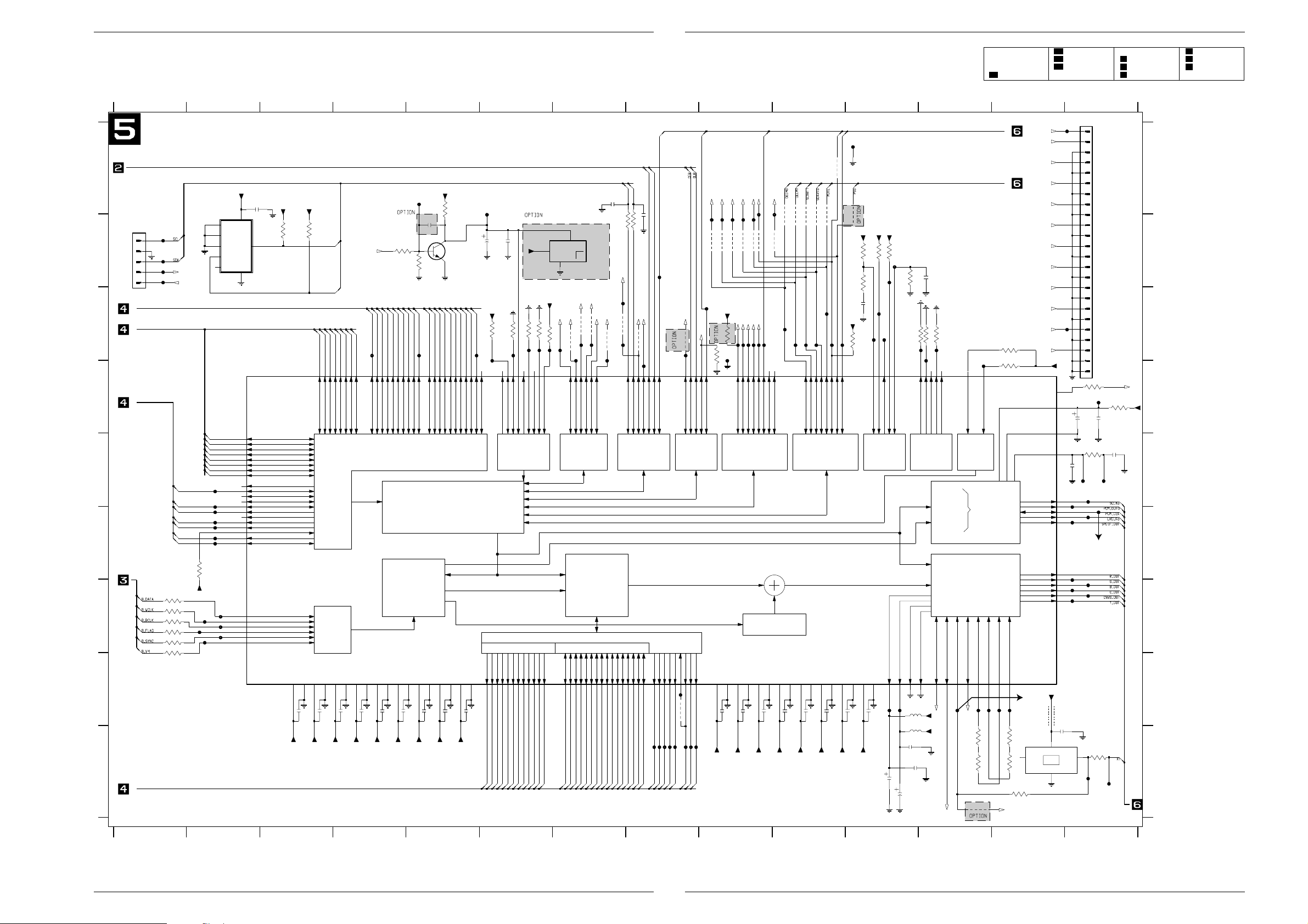
Platinenabbildungen und Schaltpläne / Layout of PCBs and Circuit Diagrams GDV Modul 1 Platinenabbildungen und Schaltpläne / Layout of PCBs and Circuit Diagrams GDV Modul 1
Reference
Oscillograms.........4-41
A/V-MUX Board....4-13
– 1A......................4-15
– 1B......................4-17
– 2A......................4-19
– 2B......................4-21
Eject Board...........4-22
DVD-Monoboard...4-23
– 1........................4-27
– 2........................4-29
– 3........................4-31
– 4........................4-33
– 5........................4-35
– 6........................4-37
Power Supply.....4-9/11
DVD-Monoboard – Prozessor und Decoder / Processor and Decoder
1234567891011121314
A
B
BASIC ENGINE INTERFACE Bus
1501
F503
1
2
F504
3
F505
4
F507
5
TO/FROM EJECT BOARD (1000)
C
RAM/ROM Interface
D
E
F
3528 10R
G
3529
3530 10R
3532 10R
H
I
SDRAM Interface
+5Vstby
E0
E1
E2
SCL
WC_
VCC
VSS
SDA
2500
100n
8
5
4
STB_CONT
P50
7505
ST24E32M6
1
2
3
6
7
SYSTEM ADDRESS Bus
SYSTEM DATA Bus
7503
STi5505
DATA7
148
RWN
CAS0ND
CAS1ND
CE_FLASHN
CE_ROMN
RAS0ND
OEND
10R3527
10R
10R3531
10K
3526
VDD_STI
F543
F545
F547
D7
D6
D5
D4
D3
D2
D1
D0
F525
F527
F531
F529
F533
F534
F535
F542
F544
F546
147
146
145
144
143
142
141
128
133
121
122
129
132
124
125
126
135
127
123
36
40
37
38
39
42
DATA6
DATA5
DATA4
DATA3
DATA2
DATA1
DATA0
RAS1n_OR_HOLDREQ
READNOTWRITE_OR_DMAACK
WE0n
WE1n
CAS0n_OR_HOLDACK
CAS1n_OR_DMAREQn
CE1n
CE2n
CE3n
CSn
RAS0n_OR_CE4n
OEn
B_DATA
B_WCLK
B_BCLK
B_FLAG
B_SYNC
B_V4
+5Vstby
3500
3K3
VDD1
1
VDD_STI
+5Vstby
3501
GND14
100n
2510
I2C Bus
3K3
SDA
SCL
D8
D9
D10
D11
151
152
153
154
DATA10
DATA11
DATA8
DATA9
FRONT-END
VDD218
VDD334
GND219GND335
100n
2511
VDD_STI
STB_CONT
D12
D13
157
155
156
DATA14
DATA12
DATA13
Interface
100n
2512
VDD_STI
D14
D15
F597
158
161
162
ADR1
ADR2
DATA15
MEMORY interface
2
I S
VDD467
VDD575
GND468
100n
2513
VDD_STI
VDD_STI
3506
10K
163
164
165
166
167
168
ADR3
ADR4
ADR5
ADR6
ADR7
ADR8
A/V/Sub
demultiplexer
VDD686
GND577
GND687
100n
100n
2514
2515
VDD_STI
VDD_STI
F501
3502
2501
100p
7501
BC847B
4K7
3507
A9A8A7A6A5A4A3A2A1
A10
A11
A12
A13
A14
A15
F600
169
170
173
174
175
176
177
ADR10
ADR11
ADR12
ADR13
ADR14
ADR9
ADR15
uP ST20cpu
Audio
Video
VDD795VDD8102
GND796
103 GND8
100n
100n
2517
2516
VDD_STI
VDD_STI
22K
A18
A17
A16
178
179
180
181
ADR16
ADR17
ADR18
ADR19
Subpicture
VDD9
GND9
110
111
2518
VDD_STI
A19
A20
182
ADR20
F502
2502
F599
183
ADR21
4u7
2503
VDD_STI
3K3
3511
3512
F518
OS_BOOT
F700
27
28
BRM2
BRM1_OR_BOOTFROMROM
VDD_STI
100n
RESETN
10K
10K
3515
3514
3K3
F585
F584
137
138
136
29
134
116
26
RSTn
PPC_CLK
AUXCLK
DMAXFER
READY
PPCn_MODE
BRM0_OR_OSLINK_SEL
2
VDD_STI
3516
F586
7502
MC33464N
1
RESET_
IN
NC
4
3
DEEM0
SEL_ACLK2
FLASH_OEN
10K
9518
F581
9517
F587
F520
16
PIO-0|417PIO-0|520PIO-0|621PIO-0|722PIO-1|09PIO-1|210PIO-1|3
PIO-0|015PIO-0|3
5
9519
F582
DEEM1
PCMout2
2532
100p
MUTE
9520
F701
TXD_BE
SCL
SDA
2533
100p
100R
3541
3542 100R
FLASH_OEN
F574
YC7
SEL_ACLK1
9516
9521
F583
F521
198
199
PIO-1|4
PIO-1|511PIO-1|612PIO-1|713PIO-2|03PIO-2|35PIO-2|46PIO-2|57PIO-2|7
TXD_SER
RXD_BE
F506
SERVICE
9522
F598
CTS_SER
YC0
F567
9508
F510
RSTN
3519
8
F568
9509
YC1
F569
9510
VDD_STI
3540
F799
10K
YC2
YC3
F570
9511
OSLINKIN
OSLINKOUT
4K7
F591
F401
201
202
PIO-3|0
PIO-3|1
YC4
YC5
F571
9513
9512
ErrorOUT
CPUreset
CPUanalyse
F592
F593
F594
203
204
205
PIO-3|2
PIO-3|3
PIO-3|4
RTS_SER
F566
F572
9514
F512
206
207
PIO-3|5
PIO-3|6
PIO-3|7
YC6
2
SYSTEM USE JTAGPORT 2 I/O PORT 3 I/O PORT 4 I/O
MPEG
DECODER
Subpicture
decoder
SDRAM CONTROLLER
ADDRESS DATA
SDCASn
89
F558
F557
CSN2
F559
RASN
CASN
90
3533
F560
WEN
MEMCLKIN
MEMCLKOUT
76
104
F548
F561
CLK
DQML91DQMU
105
F563
F562
DQMU
DQML
VDD10119
2519
VDD_STI
GND10
120
100n
VDD11130
GND11131
2520
VDD_STI
100n
VDD12139
GND12140
100n
2521
VDD_STI
VDD13149
100n
AD078AD1
AD280AD381AD469AD570AD671AD7
79
AD2
AD1
AD0
AD3
AD4
AD5
AD6
72
AD7
AD873AD9
AD8
DQ12
DQ13
DQ14
DQ294DQ397DQ498DQ599DQ6
DQ7
DQ092DQ1
AD1082AD11
74
93
83
DQ8
100
101
106
DQ15
DQ9
DQ10
DQ11
SDCS0n84SDCS1n85SDRASn88SDWEn
112
113
114
115
107
108
109
F556
DQ7
DQ6
DQ5
DQ4
DQ3
DQ2
DQ1
DQ0
AD11
AD10
AD9
DQ8
DQ9
DQ10
DQ12
DQ11
DQ14
DQ13
DQ15
CSN1
9503
9502
F576
F513
GND13150
100n
2522
VDD_STI
9504
F514
191
192
PIO-4|0
PIO-4|1
VDD14159
GND14160
2523
VDD_STI
9505
F515
100n
193
194
PIO-4|2
PIO-4|3
VDD15171
VDD_STI
9506
F575
195
PIO-4|4
F516
2524
196
PIO-4|5
GND15172
100n
SERVICE
RXD_SER
9501
VDD_STI
F517
14
197
PIO-4|6
PIO-4|7
VDD16184
VDD_STI
9507
3513
2525
GND16
185
100n
F500
3503
3508
2504
VDD_STI
10K
VDD17208
VDD_STI
10K
68R
100p
F577
2526
TCK
188
TCK
GND17200
100n
10K3504
TDI
186
TDI
VDD_STI
VDD_STI
3505
F580
F578
F579
TDO
TMS
189
187
TDO
TMS
VDDA153VDDA2
F549
2530
10K
F508
TRSTN
190
TRSTn
60
F550
4u7
2531
10K
3509
10K
3520
F588
VSSA154VSSA2
VDD_STI
5501
2u2
5502
2u2
2528
100n
2529
100n
4u7
2505
3521
10K
31
32
TEST130TEST2
TEST3
TEST
61
VDD_STI
F702
22n
10K
3522
F589
41
TEST433TEST5
AC3
LPCM
MPEG1/2
VIDEO
ENCODER
PIXCLK_27MHz
HSYNCn
ODD_OR_EVEN
OSD_ACTIVE
51
52
118
F551
VSYNC
HSYNC
27M_CLK
27M_CLK
HSYNC
F519
IRQ1 25
IRQ0 23
IRQPORT 0 I/O PORT 1 I/O
AUDIO
DECODER
V_REF_DAC_RGB
V_REF_DAC_YCC
58
65
117
F552
F553
OSD_ACTIVE
10K
3534
3537
330R
3543
3517
3K3
3523
3K3
I_REF_DAC_RGB
I_REF_DAC_YCC
59
66
F555
F554
15K
3535
1
3538
680R
100R
3539
27M_CLK1
OSD_ACTIVE
YC0
YC1
YC2
YC3
YC4
YC5
YC6
YC7
HSYNC
VSYNC
27M_CLK1
VDD_STI
RESERVED 24
VDDA_PCM 48
VSSA_PCM 50
VREF_PCM 49
SCLK
PCM_OUTO
PCM_CLK
LRCLK
SPDIF_OUT
R_OUT
G_OUT
B_OUT
C_OUT
CVBS_OUT
Y_OUT
+5V
27M_CLK
5503
2527
7504
100n
FXO-31FT
4
VDD
TS
OSC
GND
2
F573
F509
43
44
45
46
47
57
56
55
63
64
62
BLM21
OUT
2506
2509
F528
F530
F532
F537
F539
F541
1506
330p
F523
3
1
2
3
4
5
6
7
8
9
10
11
NC
12
13
14
15
16
17
18
19
20
21
22
23
24
3524
100R
F522
10u
2507
3525
10K
F524
F526
F703
12.2896MHz
F538
F540
3536
100R
F564
1501-1 B1
1501-2 B1
1501-3 B1
1501-4 B1
1501-5 B1
1506-1 A14
1506-10 B14
1506-11 B14
1506-12 B14
1506-13 B14
1506-14 B14
1506-15 B14
A
1506-16 C14
1506-17 C14
1506-18 C14
1506-19 C14
1506-2 A14
1506-20 C14
1506-21 C14
1506-22 C14
1506-23 D14
1506-24 D14
1506-3 A14
1506-4 A14
1506-5 A14
B
1506-6 A14
1506-7 A14
1506-8 A14
1506-9 B14
2500 A2
2501 B5
2502 B6
2503 B6
2504 C11
2505 B12
2506 D14
C
2507 D14
2508 E14
2509 E14
2510 I3
2511 I3
2512 I4
2513 I4
2514 I4
PCMout1
VDD_STI
3545
220R
100n
2508
3n3
{SCLKo,PCM_OUTO,PCM_CLK,LRCLKo,SPDIF_OUT,R_OUT,G_OUT,B_OUT,C_OUT,CVBS_OUT,Y_OUT,X1}
F565
2515 I4
2516 I5
2517 I5
2518 I5
D
2519 I9
2520 I9
2521 I9
2522 I10
2523 I10
2524 I10
2525 I11
2526 I11
2527 I13
2528 I11
2529 I11
2530 I11
E
2531 I11
2532 A7
2533 B8
3500 B3
3501 B3
3502 A5
3503 B11
3504 B11
3505 B11
3506 B4
3507 B5
3508 B11
F
3509 B11
3511 C6
3512 C6
3513 C11
3514 C6
3515 C6
3516 C6
3517 C13
3519 C9
3520 C11
3521 C12
G
3522 C12
3523 D13
3524 D14
3525 E14
3526 F2
3527 G1
3528 G1
3529 G1
3530 G1
3531 G1
3532 G1
3533 H8
H
3534 I12
3535 I13
3536 I14
3537 I12
3538 I13
3539 I13
3540 C9
3541 B7
3542 B8
3543 I12
3545 D14
5501 H11
5502 I11
I
5503 H13
7501 B5
7502 B7
7503 D2
7504 I13
7505 A2
9501 A10
9502 B10
9503 B10
9504 B10
9505 B10
9506 B10
9507 B11
9508 B9
9509 B9
9510 B9
9511 B9
9512 B9
9513 B9
9514 B10
9516 C7
9517 C7
9518 C7
9519 C7
9520 C7
9521 C8
9522 C8
1234
4 - 35 GRUNDIG Service 4 - 36 GRUNDIG Service
5678
91011
12 13 14

GDV Modul 1 Platinenabbildungen und Schaltpläne / Layout of PCBs and Circuit Diagrams
Reference
Oscillograms.........4-41
A/V-MUX Board....4-13
– 1A......................4-15
– 1B......................4-17
– 2A......................4-19
– 2B......................4-21
Eject Board...........4-22
DVD-Monoboard...4-23
– 1........................4-27
– 2........................4-29
– 3........................4-31
– 4........................4-33
– 5........................4-35
– 6........................4-37
Power Supply.....4-9/11
DVD-Monoboard – Audio/Video
GDV Modul 1 Platinenabbildungen und Schaltpläne / Layout of PCBs and Circuit Diagrams
123456789101112 13
1n5
6K8
1n5
6K8
F654
F652
F649
F625
F627
F655
U311
U9
U8
U7
U6
0_6_12V
1602
7
2
1
3
4
5
6
1603
8
11
9
10
7
12
22
17
13
4
20
19
1
16
14
18
15
21
5
3
2
6
1604
1
2
3
4
5
6
7
8
9
10
11
12
13
14
15
16
TO/FROM PC INTERFACE
TO A/V MUX BOARD (1300)
TO A/V MUX BOARD (1301)
SERVICE
SERIAL PC INTERFACE
A
F604
+3V3
7611
74HCT365D
&
GND
NOT USED
X
X
X
VCC
VDD_STI
VDD_STI
F656
16
8
10K
3612
10K
3642
2610
3
5
7
9
11
13
3600
3601
3602
3603
3604
3641
GDV MODUL 1
3613
10K
3614
10K
100n
X
X
X
F603
F615
F536
7607
BC847B
F605
2
GND
1
H600
2612
100n
2613 F623
100n
6
ACLK
PCLK
7
14
3_68M
13_5M
10
9
27M
+3V3S
+5VOSC
2630
100n
3
4
VDD
GND
F662
MCKO 10
F663
10u
2608
2604
100u
+12Vstby
H601 H602
VDD_STI
VDD_MEM
VDD_MEM2
3640
68R
3639
F632
9315
9316
+3V3S
+5V
-8Vstby
STB_CONT
PCM_CLK
SCART1
SCART0
MUTE
DEEM0
DEEM1
+5V
SCLKo
PCM_OUTO
PCM_CLK
LRCLKo
SPDIF_OUT
R_OUT
G_OUT
B_OUT
X1
CVBS_OUT
MONO DVD2A RGB MONO DVD2A Y/C MONO DVD2B
ITEM
3641
3644
3645
3646
3649
3652
C_OUT
Y_OUT
5601
100MHZ
1
15
2
4
6
10
12
14
X
X
X
+12Vstby
3627
470R
F606
7604
BC847B
F611
3628
470R
MOUNTING DEPENDS ON TYPE/VERSION
SEE TABLE
3630
220R
2605
F595
F658
F659
F661
3644
3645
7600-F
74HCT14D
0_6_12V
22n
VDD_STI
3646
3649
3618
14
22K
3652
+5V
7
+5Vstby
3643
3650
3653
74HCT14D
1312
2633
3651
3654
432R
3648
432R
F650
2626
7600-E
6600
BAT254
100u
2632
3647
432R
F647
2624
68p
3633
432R
F643
2622
5608
22u
68p
14
100u
F640
5607
+5V
7
3631
432R
2620
68p
22u
3622
2606
F637
2616
5606
22u
F651
2627
1110
3619
432R
68p
100R
F616
100u
22K
F633
2614
5605
22u
F648
2625
68p
68p
F622
5604
22u
F644
2623
3655
68p
68p
5602
22u
F641
2621
68p
3656
432R
F638
2617
68p
3657
432R
3606
F618
3629
7610
BC847B
F634
+5V
7618
BC847B
2615
68p
3661
432R
47K
4K7
F621
+5V
7617
BC847B
3658
68p
3664
432R
+5V
1K
BC857B
3632
432R
+5V
7615
BC847B
3659
1K
100n
F608
F590
2609
F612
2607
2618
100n
CLOCK
SYNTHESIS
+5VOSC
2631
100n
MODE
CONTROL
I/F
PLL1
2603
2611
2628
5609
100MHZ
BLM31
47u
100u
F620
100u
VDD_STI
VDD_STI
+5VOSC
VDD2
+2
GND2
2629
100n
8
VDDP
COUNTER P
COUNTER Q
47u
+5Vstby
+6Vstby
13
OUTPUT
BUFFER
OUTPUT
BUFFER
OUTPUT
BUFFER
OUTPUT
BUFFER
OUTPUT
BUFFER
11
7
GNDP
2619
100n
16
VDDB
7605
LD1117
IN3OUT
H603
3668
2R2
15
GNDB
SCKO4 13
SCKO3 17
SCKO2 14
SCKO1 12
MCKO_ 11
F610
1600
1
B
C
D
E
SEL_ACLK1
+5VOSC
F
+5V
+5VOSC
3605
PH-B
NC
5603
BLM21
7616
MK2742
10K
8
12
15
16
1
2
3
AS0
AS1
PS0
PS1
PS2
X2
X1
G
H
+3V3S
SEL_ACLK1
SEL_ACLK2
I
2
3
4
5
6
7
8
9
10
FROM POWER SUPPLY (0205)
11
F617
12
+3V3
1605
18
9
5610
100MHZ
BLM31
1
CFLG
2
3
B_FLAG
F624
+5VOSC
+5VOSC
4
VDD1
CLOCK SYNTHESIS AND
CONTROL CICUITRY
CLOCK SYNTHESIS
AND
CONTROL CICUITRY
CLOCK
BUFFER/
CRYSTAL
OSCILL.
GND1
5
7619
PLL1700
MODE2
MD19
MC20
ML1
RST_
XT16
XT25
RES
PLL2
OSC
TXD_SER
RXD_SER
RTS_SER
CTS_SER
F614
7608
7609
BC857B
-8Vstby
3615
10K
3666
3623
100R
3667
330R
3665
22R
+5V
432R
+5V
7613
BC847B
7614
BC847B
3662
1K
3660
1K
NOT USED IN MONOBOARD FOR DVD2A
(RGB) & (Y/C)
F653
-8Vstby
3624
100R
7612
BC847B
3663
1K
-8Vstby
MUTE_AV
3625
100R
3626
1K
-8Vstby
-8Vstby
F646
-8Vstby
+5V
1
7600-A
74HCT14D
74HCT14D
+5V
+5V
3608
100K
34
7600-B
74HCT14D
74HCT14D
3637
3K3
+5V
F636
-8Vstby
F639
F642
C_VID
Y_VID
14
7
7600-C
14
7
7600-D
+5Vstby
3617
2600
22n
2
F601
+5V
14
56
7
F607
+5V
14
98
7
+5V
10K
10K
3616
SCLK
LRCLK
R_VID
G_VID
B_VID
CVBS
+5V
F602
3607
-8Vstby
F609
3609
-8Vstby
HSYNC
PCMout2
PCMout1
+12Vstby
100K
100K
-8Vstby
-8Vstby
+6Vstby
+3V3
5600
BLM21
3620
100R
2601
3610
10K
3635
3621
100R
2602
3611
10K
3636
F613
+5V
+5V
F619
F628
F629
F630
F631
F635
SCL
SDA
F645
1600 B2
1602-1 A13
1602-2 A13
1602-3 A13
1602-4 B13
1602-5 B13
1602-6 B13
1602-7 A13
1603-1 E13
1603-10 C13
1603-11 C13
1603-12 D13
A
1603-13 D13
1603-14 E13
1603-15 E13
1603-16 E13
1603-17 D13
1603-18 E13
1603-19 E13
1603-2 F13
1603-20 E13
1603-21 F13
1603-22 D13
1603-3 F13
1603-4 D13
B
1603-5 F13
1603-6 F13
1603-7 D13
1603-8 C13
1603-9 C13
1604 G13
1605 D1
2600 A12
2601 A13
2602 B13
2603 A2
2604 B3
C
2605 C8
2606 D9
2607 C2
2608 B3
2609 C2
2610 D6
2611 D2
2612 D3
2613 E3
2614 F9
2615 F10
2616 G9
D
2617 G10
2618 E2
2619 E3
2620 G9
2621 G10
2622 H9
2623 H10
2624 I9
2625 I9
2626 I9
2627 I9
E
2628 G2
2629 H2
2630 H3
2631 H2
2632 D9
2633 D9
3600 F6
3601 F6
3602 F6
3603 F6
3604 F6
3605 E1
F
3606 C10
3607 B12
3608 B11
3609 C12
3610 A13
3611 B13
3612 B6
3613 B6
3614 C6
3615 C11
3616 D12
3617 D12
G
3618 D8
3619 D9
3620 A13
3621 B13
3622 C9
3623 E11
3624 E11
3625 E11
3626 F11
3627 B7
3628 C7
H
3629 D10
3630 C8
3631 F9
3632 F10
3633 G9
3635 B13
3636 C13
3637 C11
3639 E3
3640 E4
3641 G6
3642 C6
3643 F8
I
3644 G8
3645 G8
3646 H8
3647 G9
3648 H9
3649 H8
3650 I8
3651 I9
3652 I8
3653 I8
3654 I9
3655 I10
3656 I10
3657 H10
3658 I10
3659 I10
3660 H11
3661 G10
3662 G11
3663 G11
3664 G10
3665 E11
3666 D11
3667 E11
3668 G3
5600 A13
5601 D5
5602 F10
5603 E1
5604 F10
5605 G10
5606 H9
5607 I9
5608 I9
5609 A2
5610 D2
6600 C9
7600-A A11
7600-B B11
7600-C A12
7600-D B12
7600-E A9
7600-F A8
7604 B7
7605 A3
7607 B6
7608 C11
7609 C10
7610 D10
7611 D5
7612 F11
7613 F11
7614 G10
7615 H10
7616 E1
7617 I10
7618 I10
7619 H1
9315 I4
9316 I4
1234
5 6 7 8 9 10 11 12 13
GRUNDIG Service 4 - 38GRUNDIG Service 4 - 37

Platinenabbildungen und Schaltpläne / Layout of PCBs and Circuit Diagrams GDV Modul 1 Platinenabbildungen und Schaltpläne / Layout of PCBs and Circuit Diagrams GDV Modul 1
DVD-Monoboard – Messpunkte / Test Points
Ansicht von der Lötseite / View of Solder Side
4 - 39 GRUNDIG Service 4 - 40 GRUNDIG Service

GDV Modul 1 Platinenabbildungen und Schaltpläne / Layout of PCBs and Circuit Diagrams
0V
Ch1 100V M 5µs
MP1:
T7125 — Drain
Oszillogramme / Oscillograms
Ch1 200mV~ M 1.00ms
F24: RAD+
Ch1 200mV~ M 100ns
F53: RFO
Ch1 200mV~ M 2.00ms
F369, F374, F379, F380,
F383, F386: H1…H3
Ch1 500mV~ M 100µs
F30: FOC +
Ch1 2V~ M 2.00ms
F281, F384, F387: T1…T3
Ch1 2V~ M 50.0ns
F390: CL1
Ch1 200mV~ M 1.00ms
F32: RAD -
Ch1 2V~ M 50.0ns
F361: B_BCLK
Ch1 2V~ M 100ns
F628: SCLK
Ch1 100mV~ M 50.0ns
F45, F49, F50, F52:
Ch1 2V~ M 2.00ms
DIODES OUT
F365, F367, F368: A1…A3
Ch1 2V~ M 100ns
F629: PCM_OUT0
Ch1 2V~ M 20.0ns
F630: PCM_CLK
Ch1 200mV~ M 20.0µs
F639:
G_VID
Ch1 2V~ M 20.0ns
F703: 44.1kHz Audio clock
Ch1 2V~ M 10.0µs
F631: LRCLK
1
Ch1 20mV~ M 20.0µs
F642: B_VID
Ch1 2V~ M 20.0ns
F703: 48kHz Audio Clock
Ch1 200mV~ M 20.0µs
F653:
Y_VID
1
Ch1 200mV~ M20.0µs
F645:
C_VID
Ch1 200mV~ M 20.0µs
F636:
R_VID
Ch1 200mV~ M 20.0µs
F646: CVBS
Ch1 1V M 5µs
MP2:
T7125 — Gate
0V
GRUNDIG Service 4 - 41

Platinenabbildungen und Schaltpläne / Layout of PCBs and Circuit Diagrams GDV Modul 1
Ch1 200mV~ M 20.0µs
TP2: video G
Ch1 2V~ M 100ns
TP10: PCM_CLK
Ch1 1V~ M 500µs
TP14: AUDIO HP_R & HP_L
Ch1 200mV~ M 200ns
TP18: DIGITAL OUT
0V
0V
Ch1 200mV M 5µs
MP3: IC7110-(10)
Ch1 200mV M 5µs
MP4:
T7125 — Source
Ch1 200mV~ M 20.0µs
TP1: video B
Ch1 200mV~ M 20.0µs
TP3: video R
Ch1 2V~ M 500ns
TP7: PCM_OUT0
Ch1 2V~ M 100ns
TP11: DIG_OUT
Ch1 200mV~ M 20.0µs
TP4: CVBS
Ch1 2V~ M 10.0µs
TP8: LRCK
Ch1 1V~ M 500µs
TP12: ANALOG OUTPUT DAC
Ch1 200mV~ M 20.0µs
TP5: C_ENC
Ch1 2V~ M 100ns
TP9: SCLK
Ch1 1V~ M 500µs
TP13: AUDIO CINCH OUTPUT
Ch1 200mV~ M 20.0µs
TP6: Y_ENC
Ch1 1V~ M 500µs
TP15: AUDIO OUTPUT SCART
Ch1 500mV~ M 20.0µs
TP19: CVBS_OUT
Ch1 2V~ M 50.0ms
TP16: SDA
Ch1 50mV~ M 20.0µs
TP20: Y_OUT
Ch1 2V~ M 50.0ms
TP17: SCL
Ch1 500mV~ M 20.0µs
TP21: C_OUT
4 - 42 GRUNDIG Service

GRUNDIG Service 5 - 1
Explosionszeichnungen und Ersatzteillisten
Exploded Views and Spare Parts Lists
1160.000
GDV Modul 1 Explosionszeichnungen und Ersatzteillisten / Exploded Views and Spare Parts Lists
1
2
1080.000
1050.000
1120.000
1060.000
1181.000
1100.000
1070.000
1340.000
1195.000
1330.000
1305.000

5 - 2 GRUNDIG Service
Explosionszeichnungen und Ersatzteillisten / Exploded Views and Spare Parts Lists GDV Modul 1
3
ǵ
Ersatzteilliste
Spare Parts List
DVD
4 / 2000
POS. NR. ABB. MATERIAL-NR. ANZ. BEZEICHNUNG DESCRIPTION
POS. NO. FIG. PART NUMBER QTY.
92801 619 1000 GDV MODUL 1 GDV MODULE 1
0100.000 28016 019 1000 DVD-EINHEIT DVD-UNIT
1050.000 1 29638 256 1100 X DVD LAUFWERK V3.XX DVD DRIVE MECHANISM V3.XX
1050.000 1 75988 045 5500 X DVD LAUFWERK DVD DRIVE MECHANISM
75988 045 5600 DVD-MONOBOARD V5.XX DVD-MONOBOARD V5.XX
75988 045 5601 DVD-MONOBOARD V6.XX DVD-MONOBOARD V6.XX
1060.000 1 29638 256 2100 DVD EJECT-PLATTE DVD EJECT BOARD
1070.000 2 29638 256 3100 DVD EURO-AV-PLATTE (AV-MUX) DVD EURO-AV BOARD (AV-MUX)
1080.000S2 29638 256 4100 DVD NETZTEILPLATTE DVD POWER SUPPLY BOARD
1100.000 1 29636 461 0101 BEDIEN-EINSCHUB DRUCK KPL CONTROL SLIDE IN UNIT PRINT CPL
1120.000 1 29636 478 0101 ABDECKUNG TRAY OUT OFB COVER TRAY OUT SURFACETREATED
1160.000 1 29703 358 3100 SCHALTER HEBEL SWITCH LEVER
1181.000 1 29501 740 0102 TASTE OFB KEY SURFACE TREATED
1195.000 2 29700 548 5104 HALTER HOLDER
1305.000 2 29632 243 0102 BLECHABDECKUNG DRUCK KPL METAL COVER PRINT CPL
1330.000 2 82900 052 1300 2 ABSTANDSHALTER LP 4,8 SPACER PCB 4.8
1340.000 2 82900 052 1400 2 ABSTANDSHALTER LP 11,4 SPACER PCB 11.4
29120 215 0200 BEDIENUNGSANLEITUNG D OPERATING INSTRUCTION D
29120 215 0300 BEDIENUNGSANLEITUNG GB/I OPERATING INSTRUCTION GB/I
29120 215 0400 BEDIENUNGSANLEITUNG F/NL OPERATING INSTRUCTION F/NL
29120 215 0500 BEDIENUNGSANLEITUNG E/P OPERATING INSTRUCTION E/P
29120 215 0600 BEDIENUNGSANLEITUNG DK/FIN OPERATING INSTRUCTION DK/FIN
29120 215 0700 BEDIENUNGSANLEITUNG S/N OPERATING INSTRUCTION S/N
72010 537 9000 TRAININGS MANUAL D/GB TRAININGS MANUAL D/GB
72010 026 4000 MONTAGEANLEITUNG GDV MODUL MOUNTING INSTRUCTIONS GDV MODULE
72010 027 9000 SERVICE MANUAL D/GB SERVICE MANUAL D/GB
d©
KEIN E-TEIL NO SPARE PART
MIT DVD-MONOBOARD WITH DVD-MONOBOARD
OHNE DVD-MONOBOARD WITHOUT DVD-MONOBOARD
X = SIEHE GESONDERTE E-LISTE X = SEE SEPARATE PARTS LIST
GDV MODUL 1
MATERIAL-NR. / PART NO.: 92801 619 1000
BESTELL-NR. / ORDER NO.: G.AF 14-00
POS. NR. MATERIAL-NR. BEZEICHNUNG
POS. NO. PART NUMBER DESCRIPTION
29638 256 3100 EURO-AV PLATTE (AV-MUX)
D2521 75988 043 7700 DIODE BZX284-C5V1
D2522 75988 043 7800 DIODE BAS216
D2523 75988 042 3800 DIODE BZX284-C9V1 GVD 10
D2524 75988 043 7900 OPT SEN GP1F32T
D2525 75988 043 7800 DIODE BAS216
IC2412 75988 043 7200 IC SM TEA6420D
IC2450 72008 658 6600 IC HEF 4053 BT
IC2452 72008 658 6600 IC HEF 4053 BT
EURO-AV BOARD (AV-MUX)
KEIN E-TEIL/NO SPARE PART
POS. NR. MATERIAL-NR. BEZEICHNUNG
POS. NO. PART NUMBER DESCRIPTION
IC2453 72008 658 6600 IC HEF 4053 BT
IC2455 72008 658 6600 IC HEF 4053 BT
IC2456 72008 658 6600 IC HEF 4053 BT
IC2457 72008 658 6600 IC HEF 4053 BT
IC2462 75988 042 0400 IC MC33079D
IC2464 75988 043 7400 IC SM UDA1328T/N1
IC2469 75988 043 7500 IC L78L33ACZ
IC2500 75988 043 7600 IC SM LF80CDT (ST00)
J7943 75988 043 8200 CINCHBUCHSE H 1P F
J7944 75988 043 8300 CINCHBUCHSE H 3P F
J7945 75988 043 8400 EUROBUCHSE H 42P F
J7946 75988 043 8500 MDIN-BUCHSE H 4P F TCS792
ÄNDERUNGEN VORBEHALTEN / SUBJECT TO ALTERATION

GRUNDIG Service 5 - 3
POS. NR. MATERIAL-NR. BEZEICHNUNG
POS. NO. PART NUMBER DESCRIPTION
J7947 75988 043 8600 VERBINDER V 16P F
J7949 75988 043 8700 VERBINDER V 22P F
L2527 75988 043 8000 SPULE VAR 7MM 7CHA 100U P
R2528 75988 043 9000 WIDERST PROCESS CHIP
R2531
S 75988 043 8100 SICHERHEITSWIDERST 4,7 OH
R2532
S 75988 043 8100 SICHERHEITSWIDERST 4,7 OH
S 75988 043 8100 SICHERHEITSWIDERST 4,7 OH
A3653
T1300 83010 048 4700 SMD TRANS BC847B
T1301 83010 048 4700 SMD TRANS BC847B
T1303 83010 048 5700 SMD TRANS BC857B
T1304 83010 048 5700 SMD TRANS BC857B
T1402 83010 048 4700 SMD TRANS BC847B
T1405 83010 048 4700 SMD TRANS BC847B
T2032 83010 048 5700 SMD TRANS BC857B
T2353 83010 048 5700 SMD TRANS BC857B
T2354 83010 048 5700 SMD TRANS BC857B
T2355 83010 048 5700 SMD TRANS BC857B
T2357 83010 048 5700 SMD TRANS BC857B
T2358 83010 048 5700 SMD TRANS BC857B
T2359 83010 048 4700 SMD TRANS BC847B
T2360 83010 048 4700 SMD TRANS BC847B
T2361 83010 048 4700 SMD TRANS BC847B
T2371 83010 048 4700 SMD TRANS BC847B
T2372 83010 048 4700 SMD TRANS BC847B
T2373 83010 048 4700 SMD TRANS BC847B
T2377 83010 048 4700 SMD TRANS BC847B
T2378 83010 048 4700 SMD TRANS BC847B
T2382 83010 048 4700 SMD TRANS BC847B
T2383 83010 048 4700 SMD TRANS BC847B
T2384 83010 048 4700 SMD TRANS BC847B
T2385 83010 048 4700 SMD TRANS BC847B
T2395 83010 048 4700 SMD TRANS BC847B
T2402 83010 048 4700 SMD TRANS BC847B
T2404 83010 048 4700 SMD TRANS BC847B
T2408 83010 048 4700 SMD TRANS BC847B
T2409 83010 048 4700 SMD TRANS BC847B
T2458 83010 068 1700 SMD TRANS BC817-40
T2459 83010 068 1700 SMD TRANS BC817-40
T2460 83010 068 1700 SMD TRANS BC817-40
T2461 83010 068 1700 SMD TRANS BC817-40
T2463 75988 043 7300 TRANS SM BC817-25
T2471 83010 048 4700 SMD TRANS BC847B
T2472 83010 048 4700 SMD TRANS BC847B
T2488 83032 733 2700 TRANS BC327-25
T2495 83010 048 5700 SMD TRANS BC857B
T2496 83022 002 2300 TRANS BC 547 B
T2497 83010 048 4700 SMD TRANS BC847B
T2498 83010 048 4700 SMD TRANS BC847B
T2499 83010 048 4700 SMD TRANS BC847B
T2501 83010 048 4700 SMD TRANS BC847B
T2502 83010 048 5700 SMD TRANS BC857B
T2503 83010 048 4700 SMD TRANS BC847B
T2504 83010 048 4700 SMD TRANS BC847B
T2505 83010 048 5700 SMD TRANS BC857B
T2506 83010 048 4700 SMD TRANS BC847B
T2507 83010 048 4700 SMD TRANS BC847B
T2508 83010 048 5700 SMD TRANS BC857B
T2509 83010 048 4700 SMD TRANS BC847B
T2511 83010 048 4700 SMD TRANS BC847B
T2520 83010 048 4700 SMD TRANS BC847B
POS. NR. MATERIAL-NR. BEZEICHNUNG
POS. NO. PART NUMBER DESCRIPTION
S 29638 256 4100 NETZTEILPLATTE
1120
S 83156 215 0300 SI 5X20 T2,5A H 250V
1125
S 75988 043 9900 FUNKENSTRECKE DSP-501N-A2
C2127 75988 044 7400 KONDENS DC DE-SL 1KV 47P
C2251 75988 044 7500 KONDENS DC DE-B 1KV S 1N
D5233 75988 050 2600 DIODE BYD33J
D5240 75988 050 2600 DIODE BYD33J
D5259 75988 044 7700 DIODE BYV10-40 A
D6110 75987 538 9500 DIODE BYD 33 D
D6111 75988 044 7800 BRUECKENDIODE S1NB80-4101
D6113 75988 044 7900 DIODE BZX84-C24
D6114 75987 538 9500 DIODE BYD 33 D
D6120 75988 044 8000 DIODE PBYR1060
D6129 75988 045 1300 DIODE PBYR1080
D6132 75987 538 9500 DIODE BYD 33 D
D6210 75988 050 2600 DIODE BYD33J
D6250 75988 045 1600 IC CQY80NG
F7233 75988 044 8200 FILTER CU15D3
IC6230 75988 027 7900 IC MC 44603 F
IC6260 75988 045 1700 IC KA431LZTA
IC7110 75988 044 8100 IC L78M05CV
T7200 75988 045 1800 IC STP16NE06
L7236 75988 044 8400 SPULE LAL04 1U PM20
R3120 75988 043 9800 VDR DC 1MA/423V S MAX 800
R3132
S 75988 044 7600 SICHERHEITSWIDERST NFR25
S7235 75988 044 8300 SCHALTTRAFO CT29
T6240 75988 045 1500 TRANS STP4NA60FI
T7125 75990 100 1000 SMD-TRANS. BC 847
29638 256 2100 EJECT-PLATTE
D6000 75988 043 7800 DIODE BAS216
IC7000 75988 043 9100 CMOS 8-BIT MICROCONTROLLE
Q1003 75988 043 8900 CER RES 8 MHZ CST 8.00MTW
S 75988 043 8100 SICHERHEITSWIDERST 4,7 OH
R3007
R3999 75988 043 9000 WIDERST PROCESS CHIP
T1001 75988 043 8800 SCHALTER TAKT SKHHLV
T7001 83010 048 4700 SMD TRANS BC847B
POWER SUPPLY
KEIN E-TEIL/NO SPARE PART
EJECT BOARD
KEIN E-TEIL/NO SPARE PART
ǵ
Ersatzteilliste
Spare Parts List
3 / 2000
DRIVE MECHANISM DVD
POS. NR. ABB. MATERIAL-NR. ANZ. BEZEICHNUNG DESCRIPTION
POS. NO. FIG. PART NUMBER QTY.
29638 256 1100 LAUFWERK DVD DRIVE MECHANISM DVD
0001.000 3 75988 045 2700 RAHMEN CCD-CHASSIS FRAME CCD-CHASSIS
0002.000 3 75988 045 2800 MOTOR DC MOTOR DC
0003.000 3 75988 045 2900 FEDER SPRING
0004.000 3 75988 045 3000 SCHALTER SWITCH
0013.000 3 75988 045 2900 FEDER SPRING
0014.000 3 75988 045 3100 ZAHNRAD WHEEL
0017.000 3 75988 045 3200 RIEMEN BELT
0018.000 3 75988 045 3300 ZAHNRAD WHEEL
0019.000 3 75988 045 3400 ZAHNRAD WHEEL
0020.000 3 75988 045 3500 SCHIEBER SLIDER
0021.000 3 75988 045 3600 SCHUBLADE TRAY
0032.000 3 75988 045 3700 FEDER SPRING
0033.000 3 75988 045 3800 STIFT PIN
0034.000 3 75988 045 3800 STIFT PIN
0041.000 § 75988 045 3900 PLATTE PLATE
75988 045 0300 FLEXIBLE LEITUNG JBE 34-POL. FLEXIBLE CABLE JBE 34-P
75988 045 0400 FLEXIBLE LEITUNG CWAS 16-POL. FLEXIBLE CABLE CWAS 16-P
d©
MATERIAL-NR. / PART NO.: 29638 256 1100
LAUFWERK DVD
GDV Modul 1 Explosionszeichnungen und Ersatzteillisten / Exploded Views and Spare Parts Lists
DVD
Es gelten die Vorschriften und Sicherheitshinweise
gemäß dem Service Manual "Sicherheit", Mat.-Nummer 72010 800 0000, sowie zusätzlich die eventuell
abweichenden, landesspezifischen Vorschriften!
The regulations and safety instructions shall be valid
!
as provided by the "Safety" Service Manual, part
number 72010 800 0000, as well as the respective
( ! )
national deviations.
ÄNDERUNGEN VORBEHALTEN / SUBJECT TO ALTERATION

Kundendienst Europa
Kundendienst Deutschland
GRUNDIG ESPAÑA S.A.
Solsonés, 2 planta baja B3
Edificio Muntadas (Mas Blau)
E-08820 El Prat De Llobregat (Barcelona)
00 34-93-4 79 92 00
GRUNDIG BELUX N.V.
Deltapark, Weihoek 3, Unit 3G
B-1930 Zaventem
00 32-2-7 16 04 00
GRUNDIG UK LTD.
Elstree Way, Borehamwood, Herts, WD6 1RX
GB Großbritannien/Great Britain
00 44-1 81-3 24 94 00
GRUNDIG IRELAND LTD.
2 Waverley Office Park, Old Naas Road
EIR Dublin 12
0 03 53-1-4 50 97 17
GRUNDIG FRANCE S.A.
5 Boulevard Marcel Pourtout
F-92563 Rueil Malmaison Cedex
00 33-1-41 39 26 26
GRUNDIG SCHWEIZ AG
Steinacker Str. 28
CH-8302 Kloten
00 41-1-8 15 81 11
GRUNDIG PORTUGUESA
Comércio de Artigos Electrónicos, Lda.
Rua Bento de Jesus Caraça 17
P-1495 1495 Cruz Quebrada, Lisboa
0 03 51-1-4 15 67 00
GRUNDIG NEDERLAND B. V.
Gebouw Amstelveste
Joan Muyskenweg 22
NL-1096 CJ Amsterdam
00 31-20-5 68 15 68
GRUNDIG ITALIANA S.P.A.
Via G.B. Trener, 8
I-38100 Trento
00 39-04 61-89 31 11
GRUNDIG OY
Luoteisrinne 5
FIN-02271
Espoo
0 03 58-98 04 39 10
GRUNDIG AUSTRIA Ges.m.b.H.
Breitenfurter Straße 43-45
A-1120 Wien
00 43-1-81 11 76 03
GRUNDIG POLSKA SP.Z.O.O.
Ul. Czéstochowska 140
PL-62800 Kalisz
00 48-62-7 66 77 70
GRUNDIG NORGE A. S.
Glynitveien 25, Postboks 234
N-1402 Ski
00 47-64 87 82 00
GRUNDIG DANMARK A/S
Lejrvej 19
DK-3500 Værløse
00 45-44 48 68 22
GRUNDIG SVENSKA AB
Albygatan 109 d, Box 4050
S-17104 Solna
00 46-8-6 29 85 30
Technical Service
Unit 35. Woodside Park, Wood Street
Rugby, Warwickshire, CV21 2NP
Großbritannien/Great Britain
00 44-1 78-8 57 00 88
Dudenstr. 45-53
68167 Mannheim
Tel. 06 21/33 76-230
Fax 06 21/33 76-251
Kolumbusstr. 14
22113 Hamburg
Tel. 0 40/7 33 31-248
Fax 0 40/7 33 31-333
Wittestr. 30e
13509 Berlin
Tel. 0 30/4 38 03-21
Fax 0 30/4 32 55 97
Beuthener Str. 65
90471 Nürnberg
Tel. 09 11/7 03-12 61
Fax 09 11/7 03-11 27
Horbeller Str. 19
50858 Köln
Tel. 0 22 34/95 81-281
Fax 0 22 34/95 81-278
KUNDENDIENST MITTE
KUNDENDIENST WEST
KUNDENDIENST NORD
KUNDENDIENST OST
KUNDENDIENST SÜD
 Loading...