

Page 1
SAT Service Manual
Sinio DTR 6110 S
GAG5900
Sinio DTR 6111 S CI
GAG6000
GAG6010
ǵ
TV/R
Ǽ
Zusätzlich erforderliche Unterlagen für den Komplettservice
Additionally required Service Documents for the Complete Service
TV-G
i
inio
S
Service
Manual
Sicherheit
Safety
Materialnr./Part No.
720108000000
Materialnummer/Part Number 720100434000
Änderungen vorbehalten/Subject to alteration
H-S44 • 0702
http://www.grundig.com
+
P
OK
-
P
Grundig Service
Hotline Deutschland…
Technik:
TV
TV
SAT
VCR/LiveCam
HiFi/Audio
Car Audio
Telekommunikation
Planatron
Ersatzteil-Verkauf: Mo.-Fr. 8.00-19.00 Uhr
Kundendienst/Werkstätten:
gebührenpflichtig
(8.00-22.00 Uhr)
…Mo.-Fr. 8.00-18.00 Uhr
0180/52318-41
0180/52318-49
0180/52318-48
0180/52318-42
0180/52318-43
0180/52318-44
0180/52318-45
Fax:
0180/52318-51
0180/52318-99
Telefon: 0180/52318-40
0180/52318-50Fax:
Mo.-Fr. 8.00-18.00 Uhr
Telefon:
Fax:
0180/52318-52
0180/52318-46
Page 2

Allgemeiner Teil / General Section Sinio DTR 6110 S / 6111 S CI
Es gelten die Vorschriften und Sicherheitshinweise gemäß dem Service Manual "Sicherheit",
Materialnummer 720108000000, sowie zusätzlich die eventuell abweichenden, landesspezifischen Vorschriften!
Inhaltsverzeichnis
Seite
Allgemeiner Teil ........................... 1 - 3 … 1 - 12
Allgemeine Hinweise.................................................................. 1 - 3
Technische Daten ...................................................................... 1 - 3
Servicehinweise ......................................................................... 1 - 4
Bedienhinweise .......................................................................... 1 - 5
Schaltpläne und
Platinenabbildungen .................... 2 - 1 … 2 - 26
Schaltpläne
Netzteil ................................................................................... 2 - 1
Display-Platte, Tasten-Platte .................................................. 2 - 2
Haupt-Platte (5512 Main Processor) ...................................... 2 - 3
Haupt-Platte (DRAM, SDRAM, EEprom) ............................... 2 - 4
Haupt-Platte (Flash) ............................................................... 2 - 5
Haupt-Platte (MPEG Video/Audio Decoder) .......................... 2 - 6
Haupt-Platte (CI Controller) .................................................... 2 - 7
Haupt-Platte (CI Connector) ................................................... 2 - 8
Haupt-Platte (Microcontroller) ................................................ 2 - 9
Haupt-Platte (27MHz VCO, POR, RS232) ........................... 2 - 10
Haupt-Platte (Connectors) ................................................... 2 - 11
Haupt-Platte (MPEG Audio DAC) ........................................ 2 - 12
Haupt-Platte (Audio MUX) .................................................... 2 - 13
Haupt-Platte (Audio Buffers) ................................................ 2 - 14
Haupt-Platte (Digital Video Encoder) ................................... 2 - 15
Haupt-Platte (Video MUX) .................................................... 2 - 16
Haupt-Platte (TV Euro-AV) ................................................... 2 - 17
Haupt-Platte (VCR Euro-AV) ................................................ 2 - 18
Haupt-Platte (QPSK NIM) .................................................... 2 - 19
Haupt-Platte (22kHz) ............................................................ 2 - 20
Haupt-Platte (DCU Connector) ............................................ 2 - 21
Platinenabbildungen
Netzteil ................................................................................. 2 - 22
Display-Platte ....................................................................... 2 - 22
Tasten-Platte ........................................................................ 2 - 22
Haupt-Platte ......................................................................... 2 - 23
The regulations and safety instructions shall be
valid as provided by the "Safety" Service Manual,
part number 720108000000, as well as the
respective national deviations.
Table of Contents
Page
General Section ............................ 1 - 3 … 1 - 20
General Notes ............................................................................ 1 - 3
Technical Data ........................................................................... 1 - 3
Service Hints .............................................................................. 1 - 4
Operating Hints ........................................................................ 1 - 13
Circuit Diagrams and
Layout of the PCBs ...................... 2 - 1 … 2 - 26
Circuit Diagrams
Power Supply ......................................................................... 2 - 1
Display Board, Key Board ...................................................... 2 - 2
Main Board (5512 Main Processor) ....................................... 2 - 3
Main Board (DRAM, SDRAM, EEprom) ................................. 2 - 4
Main Board (Flash) ................................................................. 2 - 5
Main Board (MPEG Video/Audio Decoder) ............................ 2 - 6
Main Board (CI Controller) ..................................................... 2 - 7
Main Board (CI Connector) .................................................... 2 - 8
Main Board (Microcontroller) .................................................. 2 - 9
Main Board (27MHz VCO, POR, RS232) ............................ 2 - 10
Main Board (Connectors) ..................................................... 2 - 11
Main Board (MPEG Audio DAC) .......................................... 2 - 12
Main Board (Audio MUX) ..................................................... 2 - 13
Main Board (Audio Buffers) .................................................. 2 - 14
Main Board (Digital Video Encoder) ..................................... 2 - 15
Main Board (Video MUX) ..................................................... 2 - 16
Main Board (TV Euro-AV) .................................................... 2 - 17
Main Board (VCR Euro-AV) ................................................. 2 - 18
Main Board (QPSK NIM) ...................................................... 2 - 19
Main Board (22kHz) ............................................................. 2 - 20
Main Board (DCU Connector) .............................................. 2 - 21
Layout of the PCBs
Power Supply ....................................................................... 2 - 22
Display Board ....................................................................... 2 - 22
Key Board ............................................................................ 2 - 22
Main Board ........................................................................... 2 - 23
Ersatzteillisten ................................ 3 - 1 … 3 - 4
Sinio DTR 6110 S ...................................................................... 3 - 1
Sinio DTR 6111 S CI.................................................................. 3 - 3
1 - 2 GRUNDIG Service
Spare Parts Lists ............................ 3 - 1 … 3 - 4
Sinio DTR 6110 S ...................................................................... 3 - 1
Sinio DTR 6111 S CI .................................................................. 3 - 3
Page 3

Sinio DTR 6110 S / 6111 S CI Allgemeiner Teil / General Section
Allgemeiner Teil
Allgemeine Hinweise
Vor dem Öffnen des Gehäuses zuerst den Netzstecker ziehen!
Leitungsverlegung
Bevor Sie die Leitungen und insbesondere die Masseleitungen lösen,
muss die Leitungsverlegung zu den einzelnen Baugruppen beachtet
werden.
Nach erfolgter Reparatur ist es notwendig, die Leitungsführung wieder
in den werkseitigen Zustand zu versetzen um evtl. spätere Ausfälle
oder Störungen zu vermeiden.
Technische Daten
Software
TV / Radioprogramme: .................................................. insges. 2000
OSD: ........................... 4 Farben, Anzeige und Programmierfunktion
Suchlauf: ........................................................ automatisch / manuell
Last Station Memory: ................. für das zuletzt gewählte Programm
Timer: ....................................... 8 vorprogrammierbare Timer-Zeiten
Tuner / LNB
Empfangsbereich: .................................................. 950 … 2150MHz
Eingangspegel: ........................................................... 44 … 83dBµV
SAT-ZF-Eingang: ........................................................ 1 F-connector
LNB-Versorgung: ................................................ 14V/18Vј; 500mA
LNB-Schaltsignal: ................................................................ 0/22kHz
LNB-Oszillator: ................................................... frei programmierbar
DiSEqC: ............................. Tone Burst (Mini-DiSEqC) / DiSEqC 1.0
ZF-Bandbreite: ....................................................................... 36MHz
Demodulation: ......................................................................... QPSK
FEC: ................................................................. 1/2, 2/3, 3/4, 5/6, 7/8
Symbolrate: ................... Variabel 2-45 MSymbole/sec MCPC/SCPC
MPEG-Decodierung
MPEG 2: ...................................................... Main Level/Main Profile
Video: .......................... 720 x 576 x 25 (Pixels x lines x Frames/sec)
Audio: .......................................MPEG 2 Layer 1+2; 32, 44,1, 48kHz
Prozessor
CPU: ........................................................................................ 32 Bit
Speicher: ...................................................................... 4MB SDRAM
........................................................................ 16kB Eprom
.......................................................................... 2MB Flash
Anschlüsse
Sat-Eingang: ......................................................... 1 F-Buchse (75Ω)
Serielle Schnittstelle: ............................................................. RS 232
Audio-Ausgang links + rechts: .............. 2 Cinch-Buchsen für Stereo
Euro-AV TV: ...................................................... 1 EURO/AV-Buchse
Euro-AV VCR: ................................................... 1 EURO/AV-Buchse
Video out: ................................................................ 1 SVHS-Buchse
Digital Audio out: ......................... 1 Cinch-Buchse (Dolby digital 5.1)
VCR control: ............................................................. 1 Cinch-Buchse
Anzeige: ....................................................... 4 x 7 Segment-Anzeige
Netzanschluss: ............................................... 220 … 240V, 50/60Hz
Leistungsaufnahme:........................................ 22W / 0,5W Stand-by
Umgebungstemperatur: ................................................. 0°C … 50°C
Abmessung: ......................................................... 360 x 264 x 68mm
Gewicht: .............................................................................. ca. 2,8kg
Fernbedienung: .................................................................. TP 760 S
General Section
General Notes
Before opening the cabinet disconnect the mains plug!
Wiring
Before disconnecting any leads and especially the earth connecting
leads observe the way they are routed to the individual assemblies.
On completion of the repairs the leads must be laid out as originally
fitted at the factory to avoid later failures or disturbances.
Technical Data
Software
TV / radio programs: .......................................................... total 2000
OSD: ........................... 4 colours, display and programming function
Search function: .................................................. automatic / manual
Last station memory: ....................... for the last selected programme
Timer: ........................................................ for 8 programmed events
Tuner / LNB
Reception range: .................................................... 950 … 2150MHz
Input level: ................................................................... 44 … 83dBµV
SAT IF input: ............................................................... 1 F connector
LNB supply: ......................................................... 14V/18Vј; 500mA
LNB switching signal: ........................................................... 0/22kHz
LNB Oscillator: .................................................... free programmable
DiSEqC: ............................. Tone Burst (Mini-DiSEqC) / DiSEqC 1.0
IF bandwidth: ......................................................................... 36MHz
Demodulation: ......................................................................... QPSK
FEC: ................................................................. 1/2, 2/3, 3/4, 5/6, 7/8
Symbol rate: ...................variable 2-45 MSymbols/sec MCPC/SCPC
MPEG decoding
MPEG 2: ...................................................... Main Level/Main Profile
Video: ............................720 x 576 x 25 (pixels x lines x frames/sec)
Audio: .......................................MPEG 2 Layer 1+2; 32, 44.1, 48kHz
Processor
CPU: ........................................................................................ 32 Bit
Memory: ....................................................................... 4MB SDRAM
......................................................................... 16kB Eprom
........................................................................... 2MB Flash
Connectors
Sat input: .......................................................... 1 F connector (75Ω)
Serial interface: ..................................................................... RS 232
Audio output left + right: ........................... 2 Cinch sockets for stereo
Euro AV TV: ........................................................ 1 EURO/AV socket
Euro AV VCR: ..................................................... 1 EURO/AV socket
Video out: .................................................................. 1 SVHS socket
Digital Audio out: ........................... 1 Cinch socket (Dolby digital 5.1)
VCR control: ............................................................... 1 Cinch socket
Display: ........................................................... 4 x 7 segment display
Mains voltage: ................................................ 220 … 240V, 50/60Hz
Power consumption: ..................................... 22W / 0.5W in standby
Ambient temperature: .................................................... 0°C … 50°C
Dimensions: ......................................................... 360 x 264 x 68mm
Weight: ............................................................................about 2.8kg
Remote control: .................................................................. TP 760 S
GRUNDIG Service 1 - 3
Page 4
Allgemeiner Teil / General Section Sinio DTR 6110 S / 6111 S CI
Servicehinweise
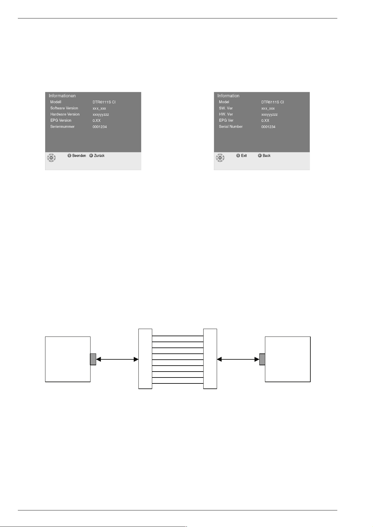
Aufruf der Software-Versionsnummer
Mit der Taste "Ǻ" das "Hauptmenü" aufrufen. Zeile "System Einstellungen" mit den Tasten "P+/P-" anwählen und mit der Taste "OK"
aufrufen. Zeile "Informationen" mit den Tasten "P+/P-" anwählen und
mit der Taste "OK" aufrufen.
Zurück zum Menü "System Einstellungen" mit der Taste "Z", oder
Einstellungen beenden mit der Taste "Ǻ".
Generelle Geheimzahl
Unabhänging von der persönlich eingestellten Geheimzahl kann auch
"8500" eingegeben werden.
Software-Update über die serielle Schnittstelle (RS232)
- SAT-Receiver und PC mit einem seriellen Kabel (Belegung 1:1,
siehe unten) verbinden.
- Am PC die Download-Software "
"
Configuration
werden.
- SAT-Receiver vom Netz trennen und wieder anschliessen. Der
SAT-Receiver zeigt jetzt am Display "boot".
- Am PC wird jetzt die Software-Version des SAT-Receivers angezeigt.
- Über "
und mit "OK" bestätigen. Der Download beginnt jetzt sofort.
Während des Downloads den SAT-Receiver nicht ausschalten oder
die Verbindung mit dem PC trennen.
- Nach erfolgreichem Download erscheint am PC die Meldung
"
download completed
" kann bei Bedarf die korrekte Schnittstelle eingestellt
Browse
" das Verzeichnis mit der neuen Software auswählen
" und der SAT-Receiver startet neu.
Serial Loader.exe
" starten. Im Feld
Service Hints
Calling up the Software Version Number
Press button "Ǻ" to call up the "Main Menu". Select the line "System
Setup" with buttons "P+/P-" and call up with button "OK". Select line
"Information" with buttons "P+/P-" and call up with button "OK".
Return to menu "System Setup" with button "Z", or end settings with
button "Ǻ".
General Password
Independent of the individually set password, "8500" can also be used.
Software Update via Serial Interface (RS232)
- Connect the SAT Receiver and PC via a serial cable (wiring 1:1, see
below).
- On the PC start the download software "
"
Configuration
- Disconnect the SAT Receiver from the mains and reconnect again.
The display of the SAT Receiver shows now "boot".
- The PC will now show the software version installed in the SAT
Receiver .
- Via "
Browse
confirm with "OK". The download now starts immediately.
During the download, do not switch off the SAT Receiver or disconnect the connection with the PC.
- After the download is successful the PC shows a message
"
download completed
" you can set the correct serial port if necessary.
" select the directory containing the new software and
" and the SAT Receiver starts again.
Serial Loader.exe
". Under
1
2
3
DTR 6110 S
DTR 6111 S CI
1 - 4 GRUNDIG Service
RS-232 PORT RS-232 PORT
4
5
6
7
8
9
Male Female
1
2
3
4
5
6
7
8
9
PC
Page 5
Sinio DTR 6110 S / 6111 S CI Allgemeiner Teil / General Section
10
AUF EINEN BLICK
______________________________________________________________________
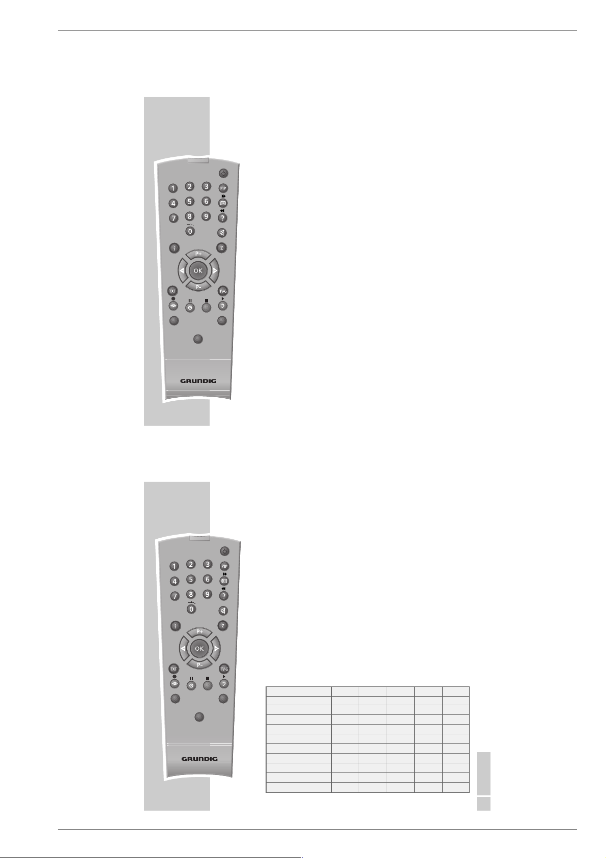
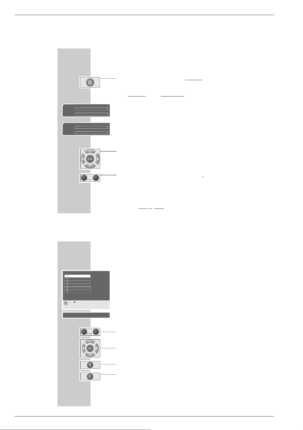
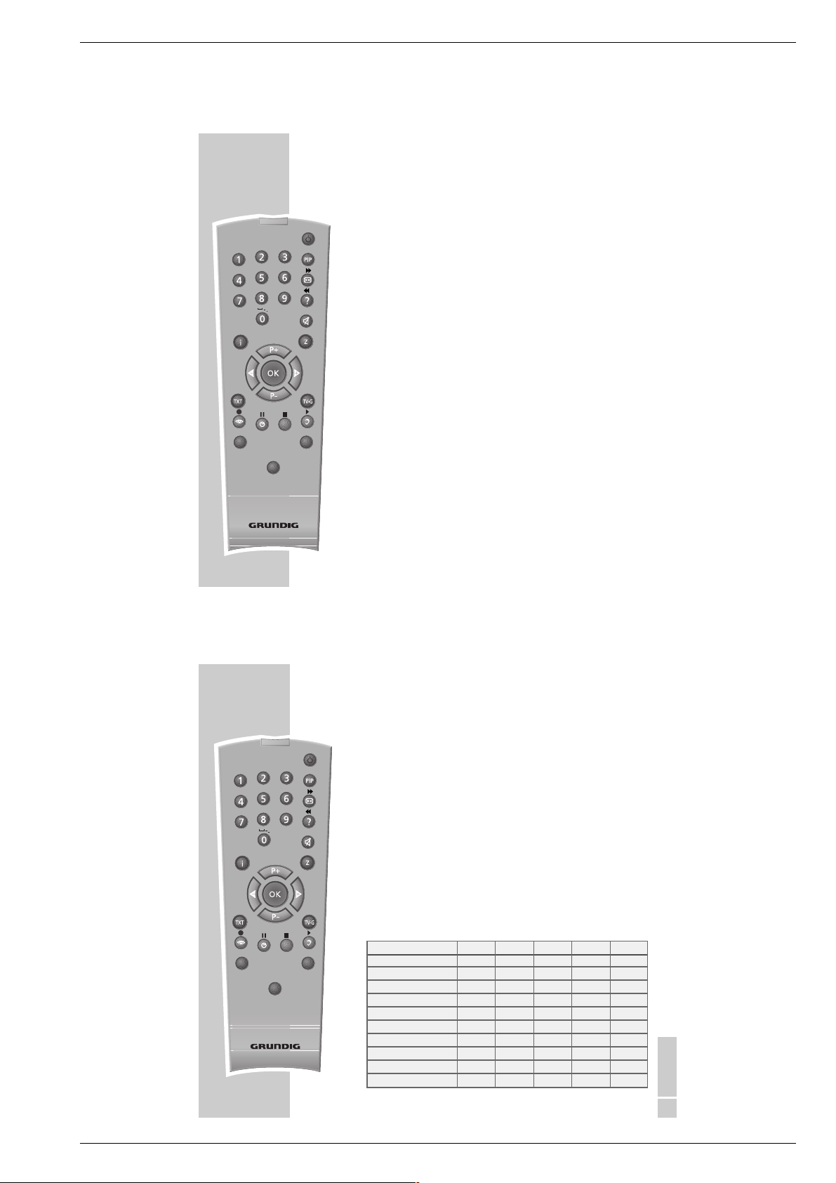
Die Tastenfunktionen der Fernbedienung
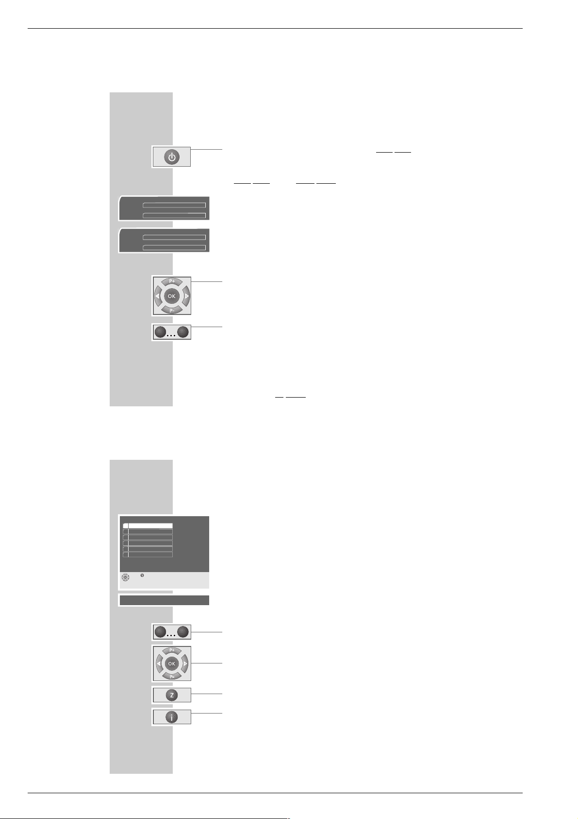
Ǽ
Schaltet den Satellitenreceiver in Bereitschaft (Stand-by) und von
Bereitschaft wieder zum zuletzt gewählten Programmplatz .
1… 0 Zifferntasten, zur Programmplatzwahl und zur alphanumerischen Ein-
gabe (Ziffern, Zeichen und Buchstaben) in bestimmten Untermenüs.
E
Schaltet auf das zuletzt eingestellte TV oder Radioprogramm.
D
Schaltet um zwischen den verschiedenen Programmlisten TV, Radio
und Favoriten.
Ǻ
Menu
Ein- und Ausblenden des Hauptmenüs auf dem Bildschirm.
In den Untermenüs: Zurück zum Hauptmenü, Änderungen werden
automatisch gespeichert.
d Nur bei GRUNDIG TV-Geräten: Ton stummschalten, (Ton aus- und
wieder einschalten).
Z
Exit
In den Untermenüs: Zurück zur vorherigen Einstellung bzw. Menü,
Änderungen werden automatisch gespeichert.
P+, P-
Programmplätze schrittweise „durchblättern”.
In den Untermenüs: Cursor nach oben/unten bewegen; Anwahl der
einzelnen Menüzeilen.
ǸǷ
Lautstärkewert ändern. In den Untermenüs: Zur vorherigen oder nächsten Menüseite; Cursor nach links/rechts bewegen; Werte ändern.
OK Im Hauptmenü: Ruft Untermenüs auf. In den Untermenüs: Einstellungen
aufrufen, bestätigen und speichern.
TXT
Info Ruft Informationen über das aktuelle TV- oder Radioprogramm auf.
T
V-G Ruft den TV Guide auf.
z
rot
Funktion in den Untermenüs.
Ȅ
grün
Ruft das Untermenü Timer auf.
@
gelb
Ruft die aktuelle Programmliste TV , Radio oder Favoriten 1 bis 4 auf.
F
blau
Ruft das Untermenü Audio auf.
Tele Pilot 760 S
Exit
Info
TV
VCR
SAT
Menu
ABC
DEF
GHI
JKL
MNO
PQRS
TUV
WXYZ
@
Hinweis:
Die nicht beschriebenen Tasten der Fernbedienung sind für diesen Satellitenreceiver ohne Funktion. Sie können allerdings Funktionen bei anderen
GRUNDIG Geräten steuern (siehe Beschreibung der Tasten »VCR«, »SAT«,
und »TV« ).
VCR GRUNDIG Videorecorder bedienen: Gleichzeitiges Drücken dieser
Taste und der gewünschten Funktionstaste mit dem zugehörigen Symbol.
SAT
Einen zweiten GRUNDIG Satellitenreceiver fernbedienen.
TV GRUNDIG TV-Gerät bedienen: Gleichzeitiges Drücken dieser Taste
und der gewünschten Funktionstaste mit dem zugehörigen Symbol.
Die alphanumerischen Funktionen der Zifferntasten
In bestimmten Untermenüs werden die Zifferntasten 1 … 0 der Fernbedienung
auch zur Eingabe von Buchstaben benötigt.
Die Tabelle zeigt die alphanumerische Belegung der Zifferntasten.
Lesen Sie bitte auf der folgenden Seite weiter!
DEUTSCH
11
AUF EINEN BLICK
______________________________________________________________________
Tele Pilot 760 S
Exit
Info
TV
VCR
SAT
Menu
ABC
DEF
GHI
JKL
MNO
PQRS
TUV
WXYZ
@
Zifferntaste drücken 1 x 2 x 3 x 4 x 5 x
1 1
2
ABC
2ABC
3
DEF
3DEF
4
GHI
4GHI
5
JKL
5JKL
6
MNO
6MNO
7
PQRS
7PQRS
8
TUV
8TUV
9
WXYZ
9WXYZ
0
,
leer
0
,
leer
Bedienhinweise
Dieses Kapitel enthält Auszüge aus der Bedienungsanleitung. Weitergehende Informationen entnehmen Sie bitte der gerätespezifischen
Bedienungsanleitung, deren Materialnummer Sie in der entsprechenden Ersatzteilliste finden.
GRUNDIG Service 1 - 5
Page 6
Allgemeiner Teil / General Section Sinio DTR 6110 S / 6111 S CI
16
EINSCHALTEN, PROGRAMME WÄHLEN
_____
Satellitenreceiver ein- und ausschalten
1 Satellitenreceiver mit einer beliebigen Taste der Fer
nbedienung einschalten.
EIN/Betrieb: Im Display erscheinen zuerst 4 waagerechte »
----
«
Striche und danach die eingestellte Programmplatznummer.
Den Satellitenreceiver wieder in Bereitschaft (Stand-by) schalten mit »
Ǽ
«
der Fer
nbedienung oder des Satellitenreceivers.
AUS/Stand-by: Im Display leuchtet die rote Anzeige.
Hinweise:
Nach jedem Einschalten und Programmplatzwechsel erscheint kurzzeitig
am Bildschirm eine Menüeinblendung, welche Sie über das momentan
aktuelle TV-, Radio- oder Favoritenprogramm, die Programmplatznummer,
den Namen der Sendeanstalt, Sendung mit digitalem Begleitton, die
Nummer der Favoritenliste, den Titel der aktuellen Sendung, die aktuelle
Uhrzeit, die Start- und Endzeit der aktuellen Sendung und den Titel der
nachfolgenden Sendung informiert.
Programmplatznummer wählen
1 Programmplätze schrittweise weiterschalten, dazu»
P+, P-
« am Satelliten-
receiver oder der Fernbedienung entsprechend oft drücken.
2 Programmplätze schnell „durchblättern”, dazu »
P+, P-
« am Satellitenreceiver
oder der Fernbedienung entsprechend lange drücken.
3 Mehrstellige Programmplatznummern innerhalb von 3 Sekunden mit »1...0«
der Fernbedienung eingeben und den Programmplatz mit »OK
« direkt auf-
rufen.
4 Entsprechende »Programmliste TV oder Radio « mit »
@
« (gelb) der Fern-
bedienung aufrufen, gewünschtes Programm mit »
P+, P-
« anwählen und
anschließend mit »
OK
« aufrufen.
5 Zurück zum zuletzt
eingestellten TV oder Radioprogramm mit »E«.
Tagesschau
112. Das Erste 1/1
8
20:00
7
20:15
Heimatmelodie
TV
Jetzt
w
20:04
Es folgt
Schöne Stimmen
6. Bayern 4 Klassik 1/1
8
14:05
7
15:00
B 4-Panorama
Radio
Jetzt
w
14:34
Es folgt
DIE MENÜFÜHRUNG
__________________________________________________
18
Die benutzerfreundliche Menüführung
Dieser Satellitenreceiver ist mit einer sehr umfassenden, benutzerfreundlichen
Menüführung ausgestattet. Die Menüführung wird am Bildschirm des TV-Gerätes
eingeblendet.
Das »Hauptmenü« ist die Steuerzentrale Ihres Satellitenreceivers. Die Menü-
führung fordert zum Dialog zwischen Ihnen und dem Satellitenreceiver auf.
1 Das »Hauptmenü« mit » Ǻ Men u« am Bildschirm aufrufen.
– Das Hauptmenü zeigt die nächsten und möglichen Bedienschritte.
Viele Funktionen, die Sie mit der Fernbedienung anwählen, beantwortet der
Satellitenreceiver mit informativen Menüs, in deren Symbolzeilen sehen Sie
immer die jeweils wichtigsten Tasten der Fernbedienung, sie führen zu den
möglichen Einstellungen.
1 … 0 Zifferntasten; zum direkten Aufrufen der Untermenüs und der daraus
resultierenden Einstellungen.
P+, P-
Cursor nach oben/unten bewegen; Eingaben anwählen.
OK Aktivieren, Aufrufen oder Bestätigen der gewählten Funktion.
ǸǷ
Cursor nach links/rechts bewegen; zur vorherigen oder nächsten
Menüseite.
Z Zurück zum zuletzt aufgerufenen Menü. Änderungen werden auto-
matisch gespeichert.
Ǻ Me nu Beenden aller Menüs mit Wechsel zur zuletzt aktiven Funktion
(z.B. zurück zur aktuellen Fernsehsendung). Änderungen werden
automatisch gespeichert.
In den nachfolgenden Untermenüskönnen Sie vielfältige Einstellungen
vornehmen und Informationen zur Bedienung Ihres Satellitenreceivers erhalten.
Probieren Sie es einfach aus, Sie können nichts falsch machen.
*Nur möglich bei Sinio DTR 6111 S CI
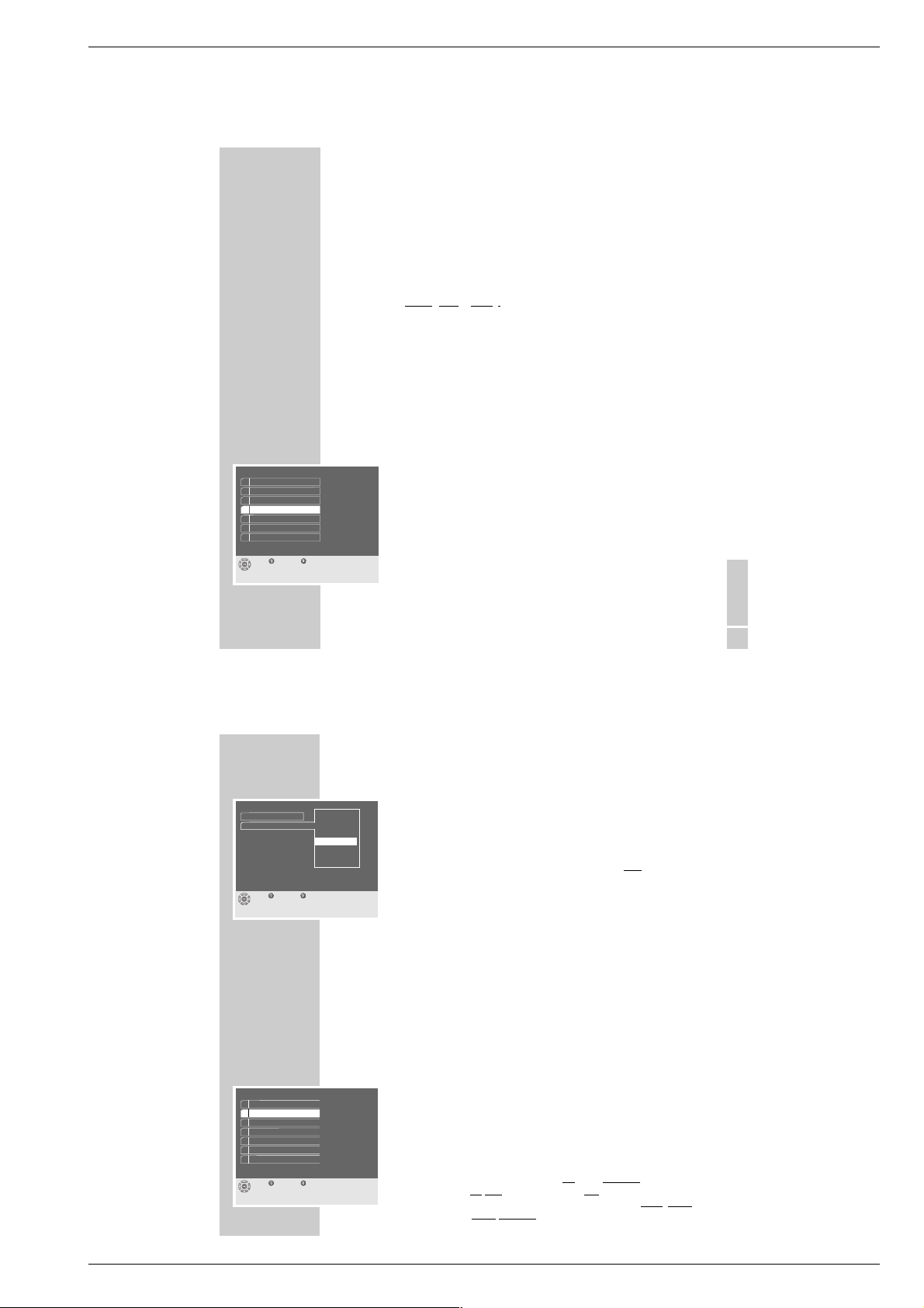
Hauptmenü
Beenden
1 Programmlisten
2 Suchlauf
3 System Einstellungen
4 Timer
5 Download über Satellit
ǵ
6 CI Einstellungen*
0
1
1 - 6 GRUNDIG Service
0
1
Page 7
Sinio DTR 6110 S / 6111 S CI Allgemeiner Teil / General Section
DEUTSCH
19
Menüsprache wählen, Zeitverschiebung eingeben
Sie können im Untermenü »Sprache, Zeit« die gewünschte Sprache der
Menüführung wählen. Die Menüsprache ist die Sprache, in der die Menü-
einblendungen am Bildschirm erscheinen.
Damit der elektronische Programmführer Ihnen immer die aktuellen Sendungen
zeitlich
richtig anzeigt, muss die Zeitverschiebung eingegeben werden,
die an Ihrem Ort im Vergleich zur GMT-Zeit (Greenwich Mean Time, Längengrad „0 “) gilt.
Alle Zeitangaben des elektronischen Programmführers werden dann auf Ihre
Ortszeit umgerechnet.
Eine Zeittabelle finden Sie auf Seite 69 dieser Bedienungsanleitung oder
z.B. im Videotext-Angebot von ARD und ZDF.
Wichtig:
Bei Zeitumstellungen (z.B. Winter-/Sommerzeit) muss die Zeitverschiebung
korrigiert werden.
1 Das »Hauptmenü« mit »
Ǻ Me nu « am Bildschirm aufrufen.
2 Zeile »System Einstellungen« mit »
P+, P-
« anwählen und mit »OK« auf-
rufen.
3 Zeile »Sprache, Zeit« mit »
P+, P-
« anwählen und mit »OK« aufrufen.
4 Zeile »Menüsprache« mit »
OK
« aktivieren.
– Am Bildschirm erscheint ein Auswahlfenster.
5 Gewünschte Menüsprache (z.B. »Deutsch«) mit »
P+, P-
« auswählen und
mit »
OK
« bestätigen.
Lesen Sie bitte auf der folgenden Seite weiter!
GRUNDEINSTELLUNGEN
_____________________________
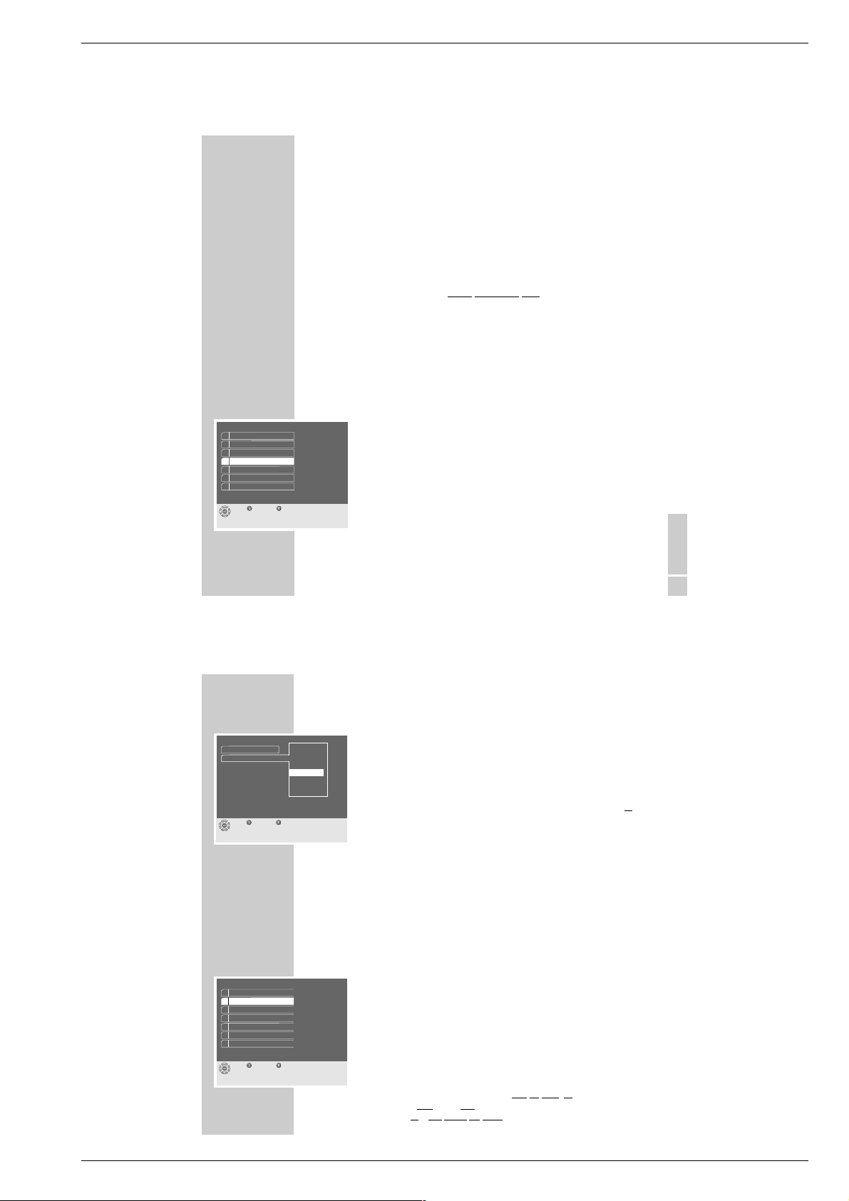
System Einstellungen
Beenden Zurück
1 LNB Einstellungen
2 AV Einstellungen
3 Favoritenprogramme
4 Sprache, Zeit
5 Informationen
6 Geheimzahl eingeben
7 Werksauslieferung
20
GRUNDEINSTELLUNGEN
__________________________________________________________
6 Zeile »Zeitverschiebung« mit »
P+, P-
« anwählen und mit »OK« aufrufen.
7 Wenn notwendig, die entsprechende Zeitverschiebung (GMT – 3 Stunden
bis GMT + 4 Stunden) mit »
P+, P-
« anwählen und mit »OK« bestätigen.
8 Zurück zum Menü »System Einstellungen« mit »Z«, oder
Einstellungen beenden mit »Ǻ Men u«.
Den Satellitenreceiver an das TV-Gerät anpassen
Damit Sie die Satellitenprogramme in bestmöglicher Bildqualität sehen, muss
der Satellitenreceiver an das angeschlossene TV-Gerät angepasst werden.
Im Untermenü »AV Einstellungen« können Sie AV-Schnittstellen festlegen, z.B. die
notwendige Bildsignal-Konfiguration der EURO-AV-Buchsen einstellen (RGB
oder FBAS), das richtige Bildformat wählen (4 : 3 oder Auto) und die Letterbox
Conversion ein- oder ausschalten.
1 Das »Hauptmenü« mit »
Ǻ Me nu « am Bildschirm aufrufen.
2 Zeile »AV Einstellungen « mit »
P+, P-
« anwählen und mit »OK« aufrufen.
3 Die markierte Zeile »TV« mit »
OK
« aktivieren.
– Am Bildschirm erscheint ein Auswahlfenster.
Wichtig:
Die beste Bildwiedergabe erhalten Sie mit der Einstellung »RGB«.
Die Werkseinstellung »FBAS« sollte nur
dann verändert werden, wenn Sie
ein TV-Gerät mit
RGB-Eingängen besitzen und
wenn Ihr TV-Gerät und der Satellitenreceiver mit dem beiliegenden, vollbeschaltetem EURO
AV-Kabel verbunden sind.
– Informieren Sie sich in der Bedienungsanleitung Ihres TV-Gerätes.
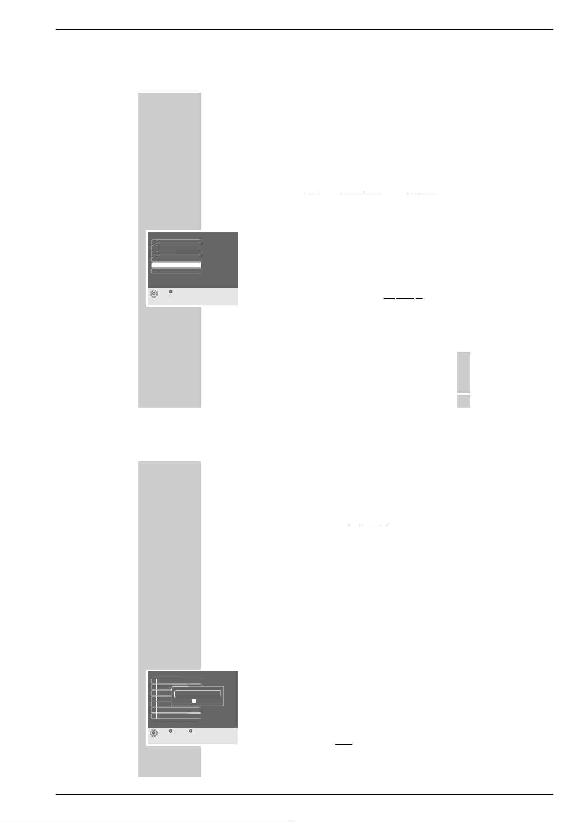
Sprache, Zeit
Deutsch
Zeitverschiebung
Menüsprache
GMT - 3 Stunden
GMT - 2 Stunden
GMT - 1 Stunde
GMT
GMT +2 Stunden
GMT +3 Stunden
GMT +4 Stunden
GMT +1 Stunde
Beenden Zurück
System Einstellungen
Beenden Zurück
1 LNB Einstellungen
2 AV Einstellungen
3 Favoritenprogramme
4 Sprache, Zeit
5 Informationen
6 Geheimzahl eingeben
7 Werksauslieferung
GRUNDIG Service 1 - 7
Page 8

Allgemeiner Teil / General Section Sinio DTR 6110 S / 6111 S CI
DEUTSCH
21
GRUNDEINSTELLUNGEN
__________________________________________________________
4 Die entsprechende Einstellung »RGB« oder »FBAS« für Ihr TV-Gerät mit
»
P+, P-
« auswählen und mit »OK« bestätigen.
5 Zeile »Bildformat« mit »
P+, P-
« anwählen und mit »OK« aufrufen.
Hinweis:
Fernsehsendungen werden im Bildformat 4:3 oder 16:9 ausgestrahlt.
Der Satellitenreceiver erkennt diese Bildformate automatisch und bereitet sie
entsprechend auf.
6 Die entsprechende Einstellung »4:3« oder »Auto « für Ihr TV-Gerät mit
»
P+, P-
« auswählen und mit »OK« bestätigen.
Hinweis:
Wenn die Einstellung »Auto« gewählt wurde, erlischt die Zeile »Letterbox «.
Das angeschlossene TV-Gerät (16: 9) wird automatisch mit dem
„richtigen” Bildformat versorgt.
7 Wenn möglich, Zeile »Letterbox « mit »
P+, P-
« anwählen und mit »OK«
aufrufen.
8 Die entsprechende Einstellung »Ein« oder »Aus« mit »
P+, P-
« auswählen
und mit »OK« bestätigen.
9 Zurück zum Menü »System Einstellungen« mit »Z«, oder
Einstellungen beenden mit »Ǻ Men u«.
AV Einstellungen
Beenden Zurück
TV
Bildformat
Letterbox
FBAS
4:3
Aus
AV Einstellungen
Beenden Zurück
TV
Bildformat
Letterbox
FBAS
4:3
Ein
60
DEN SATELLITENRECEIVER ANPASSEN
________
Den Satellitenreceiver an die Satellitenantenne und
LNB Anordnung anpassen
Um den Satellitenreceiver an die verschiedenen Antennenanlagen optimal
anpassen zu können, stehen verschiedene LNB Anordnungen zur Wahl.
Hinweis:
Der Fachinstallateur bzw. Fachhändler, welcher die Satellitenantenne installiert hat, informiert Sie gerne über alle notwendigen Einstellungen.
Wichtig:
Für jede Einstellmöglichkeit die Sie nutzen wollen, müssen Sie im Untermenü »LNB Einstellungen« die Oszillatorfrequenzen (Low und High) der
verwendeten LNBs eingeben.
Die Anzahl der möglichen Oszillatorfrequenzen hängt von der gewählten
LNB Anordnung ab.
Um den Empfang von Programmen verschiedener Satelliten zu gewährleisten,
werden beim Umschalten zu einem anderen Satellitenprogramm verschiedene
Schaltsignale ausgegeben, um den benötigten LNB und dessen Frequenzbereich definiert anzuwählen.
1 Das »Hauptmenü« mit »
Ǻ Me nu « am Bildschirm aufrufen.
2 Zeile »System Einstellungen« mit »
P+, P-
« anwählen und mit »OK« auf-
rufen.
3 Zeile »LNB Einstellungen« mit »
P+, P-
« anwählen und mit »OK« aufrufen.
4 Zeile »LNB Anordnung« mit »
P+, P-
« anwählen und mit der »OK« aufrufen.
5 Die entsprechende LNB Anordnung, abhängig von der Satellitenantenne und
des verwendeten LNBs, im Beispiel LNB Anordnung 4, mit »
P+, P-
«
anwählen und mit »OK« bestätigen.
LNB Einstellungen
Beenden Zurück
09750 MHz
Low A
LNB Anordnung
09750 MHz
Low B
10600 MHz
High A
10600 MHz
High B
4
Satelliten auswählen
1 - 8 GRUNDIG Service
Page 9

Sinio DTR 6110 S / 6111 S CI Allgemeiner Teil / General Section
DEUTSCH
61
DEN SATELLITENRECEIVER ANPASSEN
__________________________________
6 Zeile »Low A« mit »Ǹ, Ƿ, P+, P-
« anwählen und mit »OK« aktivieren,
danach die Oszillatorfrequenz mit »1 … 0« immer 5-stelli
g eingeben und
mit »OK« bestätigen.
7 Zeile »High A « mit »
Ǹ, Ƿ
, P+, P-
« anwählen und mit »OK« aktivieren,
danach die Oszillatorfrequenz mit »1 … 0 « immer 5-stelli
g eingeben und
mit »OK« bestätigen.
8 Zeile »Low B« mit »
Ǹ, Ƿ
, P+, P-
« anwählen und mit »OK« aktivieren,
danach die Oszillatorfrequenz mit »1 … 0 « immer 5-stelli
g eingeben und
mit »OK« bestätigen.
9 Zeile »High B« mit »
Ǹ, Ƿ
, P+, P-
« anwählen und mit »OK« aktivieren,
danach die Oszillatorfrequenz mit »1 … 0 « immer 5-stelli
g eingeben und
mit »OK« bestätigen.
10 Zeile »Satelliten auswählen« mit »
Ǹ, Ƿ
, P+, P-
« anwählen und mit »OK«
aufrufen.
– Am Bildschirm erscheint das Untermenü »Satelliten auswählen«.
11 Gewünschten Satelliten mit »
Ǹ, Ƿ
, P+, P-
« anwählen und mit »OK«
bestätigen.
– Am Bildschirm erscheint das Untermenü »Satelliten zuordnen «.
12 Die markierte Zeile »DiSEqC-Schalter« mit »OK« aktivieren.
– Am Bildschirm erscheint ein Auswahlfenster.
13 Entsprechende Zuordnung für den gewählten Satelliten mit »
P+, P-
«
anwählen und mit »OK« bestätigen.
14 Zurück zum Untermenü »Satelliten auswählen« mit »Z«, oder
Einstellungen beenden mit »Ǻ Me nu«.
LNB Einstellungen
Beenden Zurück
09750 MHz
Low A
LNB Anordnung
09750 MHz
Low B
10600 MHz
High A
10600 MHz
High B
4
1
Satelliten auswählen
Satelliten zuordnen
Beenden Zurück
Name
DiSEqC-Schalter
EutelSat 13° O
B
62
COMMON INTERFACE
_________________________________
Schnittstelle des Satellitenreceivers für den Empfang
verschlüsselter Satellitenprogramme
Common Interface (C I) ist eine Schnittstelle für digitale Satellitenreceiver (auch
SET-TOP-Boxen genannt).
Diese Schnittstelle dient dem Anschluss eines CA-Moduls (CA = Conditional
Access) verschiedener Verschlüsselungssysteme.
V
erschlüsselte Satellitenprogramme können nur mit einem dem Verschlüsselungssystem entsprechenden CA-Modul in Verbindung mit der dazugehörigen Smartcard gesehen werden.
Sie enthalten alle Funktionen für die Berechtigung, Entschlüsselung und Teilnehmerfreischaltung unterschiedlich verschlüsselter Satellitenprogramme der
verschiedenenen Anbieter.
Wenden Sie sich an die Anbieter, wenn Sie an PAY-TV-Programmen interessiert
sind.
Mit dem Satellitenreceiver DTR 6111 S CI und CA-Modulen können alle „fr
eien”
digitalen Satellitenprogramme und bestimmte „verschlüsselte
” empfangen und
verarbeitet werden.
Der Satellitenreceiver DTR 6111 S CI ist an seiner Vorderseite mit einem
Common-Interface-Schacht für zwei CA-Module ausgestattet.
In die CA-Module werden die käuflich erworbenen Smartcards der entsprechenden Anbieter zum „Freischalten” gewünschter verschlüsselter Satellitenprogramme eingeschoben.
Wichtig:
Für den Einsatz der Karten sind Sie allein verantwortlich.
Verwahren Sie die Smartcard und Ihren PIN-Code bei Nichtgebrauch
an sicherer Stelle.
Beachten Sie auch die Bedienhinweise des Anbieters.
Funktioniert nur bei
DTR 6111 S CI
GRUNDIG Service 1 - 9
Page 10

Allgemeiner Teil / General Section Sinio DTR 6110 S / 6111 S CI
DEUTSCH
63
Gehen Sie so vor:
1 Klappe an der Vorderseite des Satellitenreceivers öffnen, CA-Modul und
entsprechende Smartcard in den ober
en Schacht A oder den unteren
Schacht B schieben.
– Am Bildschirm erscheint kurzzeitig die Einblendung:
CAM wird initialisiert
Hinweis:
Welche Karte sich im CA-Modul befindet, erfahren Sie im Untermenü
»CI Einstellungen «.
2 Das »Hauptmenü« mit »
Ǻ Me nu « am Bildschirm aufrufen.
3 Zeile »CI Einstellungen« mit »
P+, P-
« anwählen und mit »OK« aufrufen.
– Im Beispiel befindet sich nur im ober
en Schacht A eine ASTON-Karte.
4 Wenn Sie die Zeile »Schacht A« mit »OK« aufrufen, dann erscheint am
Bildschirm ein Menü, das vom entsprechenden CA-Modul generiert wird.
Wichtig:
Über dieses Menü erhalten Sie wichti
ge Bedienhinweise und nach der
Eingabe Ihres PIN-Codes den Zugriff auf die verschiedenen Programme
des PAY-TV-Anbieters.
5 Zurück zum »Hauptmenü« mit »Z«, oder
Einstellungen beenden mit »Ǻ Me nu«.
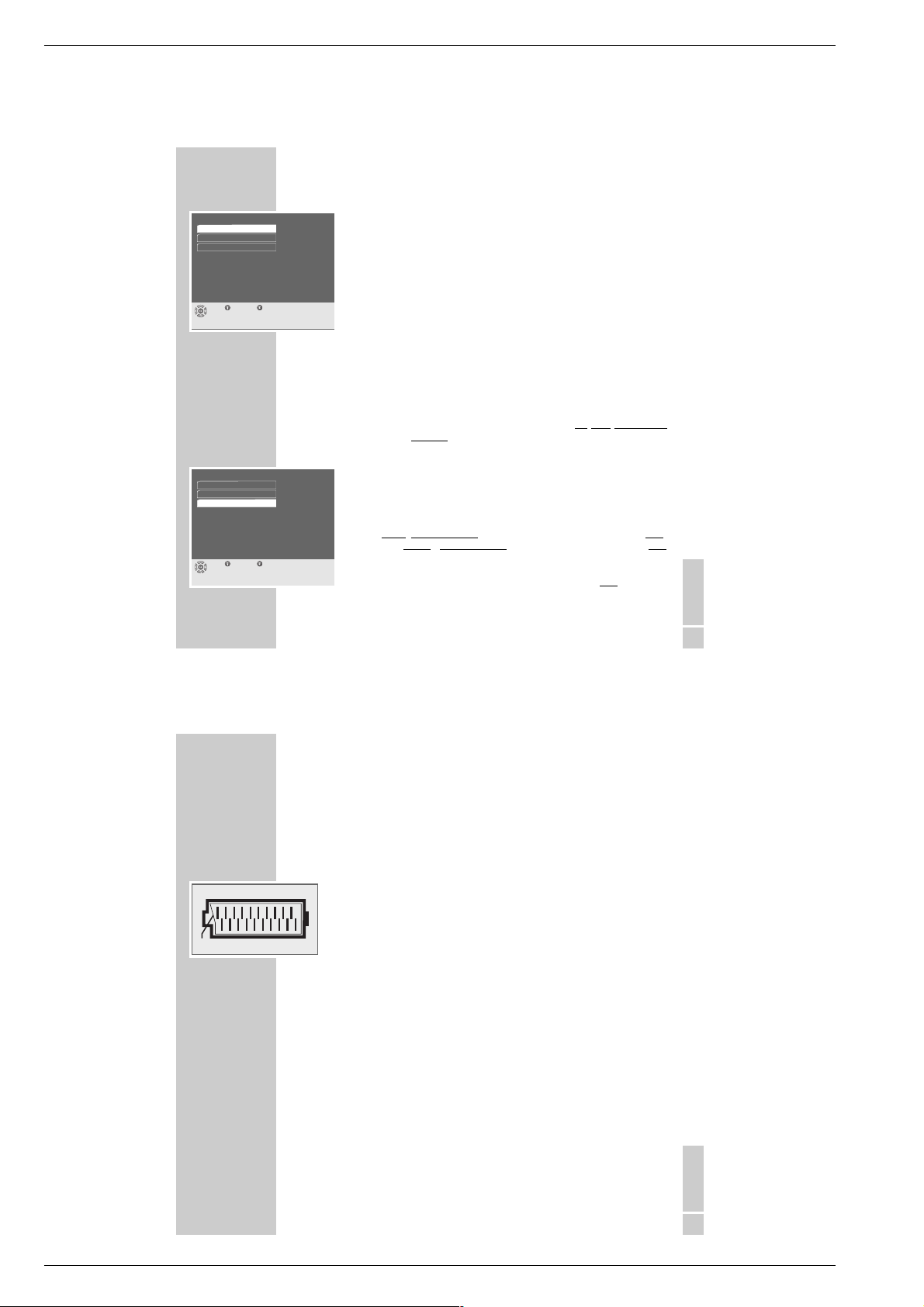
COMMON INTERFACE
______________________________________________________________
CI Einstellungen
Beenden Zurück
Schacht A
Schacht B
ASTON
Leer
64
WISSENSWERTES
___________________________________________________________
Das Untermenü Informationen
Im Untermenü »Informationen« finden Sie einige wichtige Produktangaben, z.B.
wie aktuell ist der Elektronische Programmführer (EPG Version), die Software
und Hardware Version sowie die Seriennummer des Satellitenreceivers.
Wichtig:
Im Servicefall sollten Sie diese Gerätedaten dem Fachhandel bzw. der
Kundendienststelle telefonisch mitteilen.
1 Das »Hauptmenü« mit »
Ǻ Me nu « am Bildschirm aufrufen.
2 Zeile »System Einstellungen« mit »
P+, P-
« anwählen und mit »OK« auf-
rufen.
3 Zeile » Informationen« mit »
P+, P-
« anwählen und mit »OK« aufrufen.
– Bitte informieren Sie sich!
4 Zurück zum Menü »System Einstellungen« mit »Z«, oder
Einstellungen beenden mit »Ǻ Me nu«.
Informationen
Beenden Zurück
Modell
Software Version
Hardware Version
EPG Version
DTR6111S CI
xxx_xxx
xxxyyyzzz
0.XX
Seriennummer
0001234
1 - 10 GRUNDIG Service
Page 11
Sinio DTR 6110 S / 6111 S CI Allgemeiner Teil / General Section
DEUTSCH
65
WISSENSWERTES
______________________________________________________________________
Die Software des Satellitenreceivers aktualisieren
Die zukunftsorientierte Digitaltechnik dieses Satellitenreceivers ermöglicht, dass
seine Betriebssoftware über den Satelliten Astra aktualisiert wird.
Ob eine „neue ” Betriebssoftware verfügbar ist, erfahren Sie im Untermenü
»Informationen«.
Voraussetzung für eine Softwarw Aktualisierung ist:
Ihre Satellitenanlage muss
auf den Satelliten Astra 19,2° Ost ausgerichtet sein.
1 Wählen Sie ein Satellitenprogramm des Satelliten Astra.
2 Das »Hauptmenü« mit »
Ǻ Me nu « am Bildschirm aufrufen.
3 Zeile »Download über Satellit« mit »
P+, P-
« anwählen und mit »OK«
aufrufen.
– Am Bildschirm erscheint ein Auswahlfenster.
4 Einstellung »Ja« mit »
P+, P-
« anwählen und mit »OK« bestätigen.
– Der Bildschirm des TV-Gerätes und das Display an der Vorderseite des
Satellitenreceivers werden dunkelgesteuert.
– Danach erscheint im Display an der Vorderseite des Satellitenreceivers
die Anzeige, »
boot
« (Download gestartet), bitte
warten Sie.
Hinweis:
Der Satellitenreceiver überprüft grundsätzlich immer seine „eigene”
Betriebssoftware mit der „angebotenen ” Betriebssoftware des Satelliten
Astra und entscheidet, ob ein Download erforderlich ist.
Der Vorgang kann einige Minuten dauern.
Sollte es keine neue Version der Betriebssoftware geben, erscheint am Bildschirm
die Einblendung:
*****Download nicht erforderlich*****
und danach wieder das zuletzt eingestellte Programm.
Lesen Sie bitte auf der folgenden Seite weiter!
Hauptmenü
Beenden
1 Programmlisten
2 Suchlauf
3 System Einstellungen
4 Timer
5 Download über Satellit
ǵ
6 CI Einstellungen
66
WISSENSWERTES
______________________________________________________________________
Wichtig:
Wenn dagegen der Vorgang mehrere Minuten dauert, dann wird eine
„neue” Betriebssoftware geladen, bitte
warten Sie.
Ist der Vorgang „Download” beendet , erscheint im Display an der Vorderseite
des Satellitenreceivers die Anzeige »
oooo
« und danach am Bildschirm die
Einblendung:
*****Download beendet *****
Ihr Satellitenreceiver ist jetzt mit der aktuellen Betriebssoftware programmiert.
Anschließend schaltet der Satellitenreceiver auf das zuletzt eingestellte
Programm.
– Im Untermenü »Informationen« wird jetzt die „neue ” Software Version
angezeigt.
Den Satellitenreceiver in den Zustand der Werksauslieferung zurücksetzen
Sie können die werkseitig eingestellten Parameter wieder herstellen und Änderungen zurücksetzen.
1 Das »Hauptmenü« mit »
Ǻ Me nu « am Bildschirm aufrufen.
2 Zeile »System Einstellungen« mit »
P+, P-
« anwählen und mit »OK« auf-
rufen.
3 Zeile »Werksauslieferung« mit »
P+, P-
« anwählen und mit »OK« auf-
rufen.
– Am Bildschirm erscheint das Fenster »Geheimzahl eingeben«.
4 Geheimzahl mit »1 . . . 0« 4
-stellig eingeben.
System Einstellungen
Beenden Zurück
1 Satellitenantenne
2 AV Einstellungen
4 Sprache, Zeit
5 Informationen
6 Geheimzahl eingeben
7 Werksauslieferung
3 Favoritenprogramme
Geheimzahl eingeben
* * *
*
GRUNDIG Service 1 - 11
Page 12
Allgemeiner Teil / General Section Sinio DTR 6110 S / 6111 S CI
DEUTSCH
67
WISSENSWERTES
______________________________________________________________________
5 Zeile »Werkseinstellung« mit »
P+, P-
« anwählen und mit »OK« aufrufen.
– Am Bildschirm erscheint ein Auswahlfenster.
6 Wenn notwendig, Einstellung »Ja« mit »
P+, P-
« wählen und mit »OK«
bestätigen.
– Die Daten des Satellitenreceivers werden auf den Zustand der Werkein-
stellung zurückgesetzt und automatisch gespeichert.
7 Zeile »Alle Einstellungen löschen« mit »
P+, P-
« anwählen und mit »OK«
aufrufen.
– Am Bildschirm erscheint ein Auswahlfenster.
8 Wenn notwendig, Einstellung »Ja« mit »
P+, P-
« wählen und mit »OK«
bestätigen.
– Die Eingaben und Änderungen des Satellitenreceivers werden gelöscht.
Hinweis:
Wenn Sie zwei Satellitenreceiver DTR 61xx mit nur
einer Fernbedienung
TP 760 S bedienen
wollen, dann muss für einen der beiden Satellitenreceiver
eine andere Fernbedienebene gewählt werden.
9 Zeile »Fernbedienebene« mit »
P+, P-
« anwählen und mit »OK« aufrufen.
– Am Bildschirm erscheint ein Auswahlfenster.
10 Entsprechende Einstellung, z.B. »Sat2«, mit »
P+, P-
« anwählen und mit
»OK« bestätigen.
– Dieser
Satellitenreceiver wird jetzt über die Fernbedienebene »Sat2«,
der ander
e Satellitenreceiver über die Fernbedienebene »Sat1«
(= Werksauslieferung) fernbedient.
11 Zurück zum Untermenü »System Einstellungen« mit »Z«, oder
Einstellungen beenden mit »Ǻ Me nu«.
Werksauslieferung
Beenden Zurück
Sat1
Werkseinstellung
Alle Einstellungen löschen
Fernbedienebene
Werksauslieferung
Beenden Zurück
SAT1
Werkseinstellung
Alle Einstellungen löschen
Fernbedienebene
DEUTSCH
71
TECHNISCHE DATEN
_________________________________________________________________
Kontaktbelegung der EURO-AV-Buchsen
Wenn Sie an die EURO-AV-Buchsen des Satellitenreceivers Zusatzgeräte anschließen wollen (z. B. Videorecorder, Decoder), dann kann Ihr Fachhändler
anhand der folgenden Kontaktbelegung eine normgerechte Verbindung herstellen.
Kontakt Signal TV VCR
01 = Audio Ausgang rechts x x
02 = Audio Eingang rechts x
03 = Audio Ausgang links x x
04 = Audio Masse x x
05 = Blau Masse x x
06 = Audio Eingang links x
07 = RGB Blau x
08 = Schaltspannung x
1)
x
1)
09 = Grün Masse x x
10 = –
11 = RGB Grünxx
12 = –
13 = Rot Masse
14 = Masse
15 = RGB Rot Eingang, (S-Video = Chrominanz)
16 = RGB Schaltspannung
17 = Video Masse
18 = RGB Schaltspannung Masse
19 = Video Ausgang
20 = Video Eingang, (S-Videoo = Luminanz)
21 = Abschirmung/Masse
x = belegt
x
1
)
Schaltspannung nur bei der Betriebsart »SAT« vorhanden.
Technische Änderungen und Irrtümer vorbehalten!
1 - 12 GRUNDIG Service
21
220
119
Page 13
Sinio DTR 6110 S / 6111 S CI Allgemeiner Teil / General Section
10
AT A GLANCE
_____________________________________________________________________________
The functions of the remote control buttons
Ǽ
Switches the receiver in standby or from standby to the last selected
service position.
1 … 0 Numeric buttons for service position selection (also from standby) and
for entering alphanumeric data (digits, signs, letters) in certain menus.
E
Switches to the last selected TV or Radio service position.
D
Switches between the TV, Radio and Favourite services lists.
Ǻ
Menu
Displays and exits the Main Menu on the picture screen.
When in a menu: back to the Main Menu. Changes are automatically
saved.
d Only with GRUNDIG TV sets: sound mute (sound on and off).
Z
Exit
When in a submenu: back to the previous menu or setting. Changes are
automatically saved.
P+, P-
Step-by-step service position switching.
When in a submenu: move cursor up/down; select menu rows.
ǸǷ
Volume control. When in a submenu: for paging forward and backward; for moving the cursor to the left/right; for changing settings.
OK When in the Main Menu: for calling up submenus. When in a sub-
menu: for calling up, confirming and saving settings.
TXT
Info For calling up information on the current TV or Radio programme.
T
V-G Displays the TV Guide menu.
z
red
Function in the submenus.
Ȅ
green
Displays the Timer menu.
@
yellow
Displays the current Channel Lists TV, Radio or Favourites User 1 to 4.
F
blue
Displays the Audio menu.
Tele Pilot 760 S
Exit
Info
TV
VCR
SAT
Menu
ABC
DEF
GHI
JKL
MNO
PQRS
TUV
WXYZ
@
ENGLISH
11
Note:
Buttons not described have no function for this satellite receiver. They may,
however, have a function for other GRUNDIG units (see the following
description of the »VCR«, »SAT«, and » TV« buttons).
VCR For controlling GRUNDIG video recorders: press this button and the
function button carrying the corresponding symbol at the same time.
SAT
For controlling a second GRUNDIG satellite receiver.
TV For controlling a GRUNDIG TV set: press this button and the function
button carrying the corresponding symbol at the same time.
The alphanumeric functions of the numeric buttons
In certain menus, the numeric buttons 1 … 0 on the remote control are also
used for entering letters.
The table shows the alphanumeric assignment of the numeric buttons.
Please read also the following page!
AT A GLANCE
_____________________________________________________________________________
Tele Pilot 760 S
Exit
Info
TV
VCR
SAT
Menu
ABC
DEF
GHI
JKL
MNO
PQRS
TUV
WXYZ
@
Press numeric button 1 x 2 x 3 x 4 x 5 x
1 1
2
ABC
2ABC
3
DEF
3DEF
4
GHI
4GHI
5
JKL
5JKL
6
MNO
6MNO
7
PQRS
7PQRS
8
TUV
8TUV
9
WXYZ
9WXYZ
0
,
blank
0
,
blank
Operating Hints
This chapter contains excerpts from the operating instructions. For further particulars please refer to the appropriate user instructions the part number
of which is indicated in the relevant spare parts list.
GRUNDIG Service 1 - 13
Page 14
Allgemeiner Teil / General Section Sinio DTR 6110 S / 6111 S CI
16
SWITCHING ON, SELECTING SERVICES
_______
Switching the satellite receiver on and off
1 Switch the satellite receiver on by pressing any key on the r
emote control.
ON: in the display appear at first 4 horizontal lines »
----
«, and then
the number of the selected service position.
To switch the satellite receiver back in standby, use the »
Ǽ
« button on the
r
emote control or on the satellite receiver.
OFF/standby: in the display the red indicator is lit.
Note:
Each time when switching on and when changing the service position, an
on-screen display briefly gives you the following information: current TV,
radio or favourite service, service position number, station name,
programme with digital sound service, number of the Favourites list, title of
the current programme, current time, start and end time of the current programme, and title of the following programme.
Selecting service positions
1 Repeatedly press the »
P+, P-
« buttons on the satellite receiver or the remote
control to select the service positions step by step.
2 Keep the »
P+, P-
« buttons on the satellite receiver or on the remote control
pressed to scroll the service positions at high speed.
3 Enter multi-position service position numbers within 3 seconds using the
numeric buttons »1...0« on the remote control then call up the service
position directly using the »OK
« button.
4 Call up the desired »Channel Lists TV, Radio or Favourites User 1 to 4«
using the yellow »
@
« button on the remote control, select the desired
service using the »
P+, P
« buttons, and finally call it up with the »OK«
button.
5 Go back to the last
selected TV or Radio service by pressing the »E«
button.
Schöne Stimmen
6. Bayern 4 Klassik 1/1
8
14:05
7
15:00
B 4-Panorama
Radio
Now
w
14:34
Next
Tagesschau
112. Das Erste 1/1
8
20:00
7
20:15
Heimatmelodie
TV
Now
w
20:04
Next
THE ON-SCREEN MENU GUIDE
_________________________
18
The user-friendly menu guide
This satellite receiver is provided with a very comprehensive, user-friendly menu
guide. On-screen menus provide the dialogue between the user and the
receiver.
The »Main Menu« is the control centre of your satellite receiver.
1 Press the »Ǻ Me nu « button to display the »Main Menu« on the picture
screen.
– The Main Menu shows the next possible operating steps.
The receiver will respond to many of the functions selected via the remote control
by displaying info menus and on-screen symbol lines. In these lines, the remote
control buttons are shown which lead to the possible settings.
1 … 0 numeric buttons for directly selecting the submenus and the corres-
ponding settings.
P+, P-
for moving the cursor up/down and selecting settings.
OK For calling up and confirming the selected function.
ǸǷ
for moving the cursor to the left/right, for paging the menus
forward/backward.
Z back to last menu. Changed settings are automatically saved.
Ǻ Me nu exit all menus with automatic switching to the last active function
(e.g. back to current TV programme). Changed settings are automatically saved.
In the following submenus you can carry out many settings and obtain information about the operation of the satellite receiver.
Just try it out, you can’t do anything wrong.
*Only with the Sinio DTR 6111 S CI
Main Menu
Exit
1 Service Table
2 Search
3 System Setup
4 Timer
5 Over-Air Download
ǵ
6 CI Setup*
0
1
1 - 14 GRUNDIG Service
0
1
Page 15
Sinio DTR 6110 S / 6111 S CI Allgemeiner Teil / General Section
ENGLISH
19
Selecting the desired menu language,
entering the time offset
You may select your desired menu language in the »Language, Time« menu.
The menu language is the language in which all indications appear in the onscreen menus.
To make sure that the electronic program guide EPG of the satellite receiver
always indicates the cor
rect transmission times of the various programmes, it is
necessary to enter the time offset of your location with respect to the GMT time
(Greenwich Mean Time, degree of longitued „0“).
All time indications of the electronic program guide then are transformed into
your local time.
A time table is to be found on page 69 of this user manual, or for example, on
the teletext pages of BBC.
Important:
In the event of time readjustments (e.g. summer to winter time), the time
offset must be corrected.
1 Call up the »Main Menu« using the »
Ǻ Me nu « button.
2 Select the »System Setup« menu row using the »
P+, P-
« buttons, and then
confirm with the »
OK
« button.
3 Select the »Language, Time« menu row using the »
P+, P-
« buttons, and
then confirm with the »
OK
« button.
4 Activate the »Language« menu row using the »
OK
« button.
– A menu appears on the picture screen.
5 Select the desired menu language (e.g.»English«) using the »
P+, P-
«
buttons, and then confirm with the »
OK
« button.
Please read also the following page!
BASIC SETTINGS
____________________________________________
System Setup
Exit Back
1 LNB Settings
2 AV Setup
3 Favourites
4 Language, Time
5 Information
6 Password Set
7 Factory Settings
20
BASIC SETTINGS
________________________________________________________________________
6 Select the »Time Offset« row using the »
P+, P-
« buttons, and then confirm
with the »
OK
« button..
7 If required, select the appropriate time offset (GMT – 3 hours to GMT + 4
hours) using the »
P+, P-
« buttons, then confirm with the »OK« button.
8 Return to the »System Setup« menu by pressing the »Z« button, or
end the settings by pressing the »Ǻ Men u« button.
Adjusting the satellite receiver to the TV set
To make sure that the satellite programmes are received with best picture and
sound quality, it is necessary to adjust the satellite receiver to the connected TV set.
In the »AV Setup« menu you can set up the AV interfaces, e.g. the necessary
picture signal configuration of the EURO-AV sockets (RGB or CVBS), the correct
picture format (4 : 3 or Auto), and activate/deactivate the Letterbox conversion
function.
1 Display the »Main Menu« on the picture screen using the »
Ǻ Menu « button.
2 Select the »AV Setup« menu row using the »
P+, P-
« buttons, then confirm
with »OK«.
3 Activate the highlighted »TV« row by pressing »
OK
«.
– A dialogue box appears on the picture screen.
Important:
The best picture quality is obtained with the »RGB« setting.
The factory setting »CVBS« should only
be changed it your TV set is equip-
ped with RGB
inputs, and your TV set is connected with the satellite receiver
via the su
pplied EURO AV cable.
– Please consult the user manual of your TV set.
Language, Time
En
Time Offset
Language
GMT - 3 Hours
GMT - 2 Hours
GMT - 1 Hour
GMT
GMT +2 Hours
GMT +3 Hours
GMT +4 Hours
GMT +1 Hour
Exit Back
System Setup
Exit Back
1 LNB Settings
2 AV Setup
3 Favourites
4 Language, Time
5 Information
6 Password Set
7 Factory Settings
GRUNDIG Service 1 - 15
Page 16

Allgemeiner Teil / General Section Sinio DTR 6110 S / 6111 S CI
ENGLISH
21
BASIC SETTINGS
________________________________________________________________________
4 Select the setting »RGB« or »CVBS« required for your TV set using the
»
P+, P-
« buttons, then confirm with »OK«.
5 Select the »Picture Format« menu row using the »
P+, P-
« buttons, then
confirm with »OK«.
Note:
TV programmes are boradcast with the 4:3 or 16:9 picture format.
The satellite receiver recognizes automatically these formats and processes
them accordingly.
6 Select the »4:3« or »Auto« setting for your TV set using the »
P+, P-
«
buttons, then confirm with »OK«.
Note:
If you select the »Auto « setting, the »Letterbox« row disapears.
The TV set (16: 9) is automatically provided with the correct picture
format.
7 If applicable, select the »Letterbox « row using the »
P+, P-
« buttons, then
confirm with »OK«.
8 Select »On« or »Off« using the »
P+, P-
« buttons, then confirm with »OK«.
9 Press »Z« to return to the »System Setup« menu, or
press »Ǻ Men u« to end the settings.
AV Setup
Exit Back
TV
Picture Format
Letterbox
CVBS
4:3
Off
AV Setup
Exit Back
TV
Picture Format
Letterbox
CVBS
4:3
On
60
ADJUSTING THE SATELLITE RECEIVER
___________
Adjusting the satellite receiver to the satellite antenna
and the LNB configuration
In order to adjust the satellite receiver in an optimum way to the different antenna
systems, four LNB configurations are available.
Note:
Your antenna technician or specialized dealer which has installed your
antenna system will be glad to provide you with detailed information about
all settings required.
Important!
For every setting you want to use you must enter the oscillator frequencies
(low and high) of the LNBs into the »LNB setup« menu.
The number of the possible oscillator frequencies depends on the selected
LNB configuration.
To ensure the reception of services of different satellites, different switching signals are emitted when selecting another satellite service in order to select the
required LNB along with its frequency in a unique way.
1 Call up the »Main Menu« on the picture screen using the »
Ǻ Menu « button.
2 Select the »System Setup« row using the »
P+, P-
« buttons, and then
confirm with »OK«.
3 Select the »LNB Settings« row using the »
P+, P-
« buttons, and then confirm
with »OK«.
4 Select the »LNB Type« row using the »
P+, P-
« buttons, and then confirm
with »OK«.
5 Select the appropriate LNB Type, depending on the satellite antenna and the
LNB, LNB Type 4 in the example, using the »
P+, P-
« buttons, and then
confirm with »OK«.
LNB Settings
Exit Back
09750 MHz
Low A
LNB Type
09750 MHz
Low B
10600 MHz
High A
10600 MHz
High B
4
Select Satellites
1 - 16 GRUNDIG Service
Page 17

Sinio DTR 6110 S / 6111 S CI Allgemeiner Teil / General Section
ENGLISH
61
ADJUSTING THE SATELLITE RECEIVER
___________________________________
6 Select the »Low A« row using the »Ǹ, Ƿ, P+, P-
« buttons, activate it
using the »OK« button, enter the oscillator frequency as
5 digits using the
numeric buttons »1 … 0«, and finally confirm with »OK«.
7 Select the »High A« row using the »
Ǹ, Ƿ
, P+, P-
« buttons, activate it
using the »OK« button, enter the oscillator frequency as
5 digits using the
numeric buttons »1 … 0«, and finally confirm with »OK«.
8 Select the »Low B« row using the »
Ǹ, Ƿ
, P+, P-
« buttons, activate it
using the »OK« button, enter the oscillator frequency as
5 digits using the
numeric buttons »1 … 0«, and finally confirm with »OK«.
9 Select the »High B« row using the »
Ǹ, Ƿ
, P+, P-
« buttons, activate it
using the »OK« button, enter the oscillator frequency as
5 digits using the
numeric buttons »1 … 0«, and finally confirm with »OK«.
10 Select the »Select Satellites« row using the »
Ǹ, Ƿ
, P+, P-
« buttons, and
then confirm with »OK«.
– The »Assign Satellite« menu appears on the picture screen.
11 Select the desired satellite using the »
Ǹ, Ƿ
, P+, P-
« buttons then
confirm with »OK«.
– The »Edit Satellite« menu appears on the picture screen.
12 Activate the highlighted »DiSEqC switch« row using the »OK« button.
– A dialogue box appears on the picture screen.
13 Select the appropriate satellite assignment using the »
P+, P-
« buttons then
confirm with »OK«.
14 Press »Z« to return to the »Assign Satellite« menu, or
press »Ǻ Me nu« to end the settings.
LNB Settings
Exit Back
09750 MHz
Low A
LNB Type
09750 MHz
Low B
10600 MHz
High A
10600 MHz
High B
4
1
Select Satellites
Edit Satellite
Exit Back
Name
DiSEqC Switch
EutelSat 13° O
B
62
COMMON INTERFACE
_________________________________
The satellite receiver’s interface for the reception of
scrambled satellite services
The Common Interface (C I) is an interface for digital satellite receivers (also
called SET-TOP boxes):
This interface serves for connecting a CA module (CA = Conditional Access)
available for various scrambling systems.
Scrambled
satellite services can only be received with the help of a CA module
which complies with the scrambling system, in connection with a corresponding
smart card.
The smart cards comprise the data for the access authorization to the
scrambled services of the provider from which the card has been purchased.
Please contact the Pay-TV provider you are interested in for more information.
With the satellite receiver DTR 6111 S CI in connection with CA modules, you can
receive all fr
ee and certain scrambled satellite services.
The satellite receiver DTR 6111 S CI is provided with a Common Interface
compartment for two CA modules in its front panel.
Insert the smart cards which you have purchased from a pay TV provider into
the CA modules to get access to the desired scrambled satellite services.
Important!
Only you are responsible for the use of the smart card.
When not used, keep your smart card and your PIN code in a safe place.
Observe also the user instructions of the Pay-TV provider.
Only with the
DTR 6111 S CI
GRUNDIG Service 1 - 17
Page 18

Allgemeiner Teil / General Section Sinio DTR 6110 S / 6111 S CI
ENGLISH
63
Follow these steps:
1 Open the flap on the font side of the satellite receiver, and then insert the
CA module along with the smart card into the to
p compartment A or the
bottom
compartment B.
– The following message appears briefly on the picture screen:
CAM Initialising
Note:
The »CI Setup« menu informs you about the installed CA modules.
2 Call up the »Main Menu« on the picture screen using the »
Ǻ Menu « button.
3 Select the »CI Setup« row using the »
P+, P-
« buttons then confirm with
»OK«.
– In the example, an ASTON card is inserted in the to
p compartment A.
4 If you call up the row »Slot A« by pressing »OK«, a menu which is gene-
rated by the CA module inserted in this slot appears on the picture screen.
Important!
This menu provides you with important o
perating instructions. After having
entered your PIN code, you get access to the various services of your PayTV provider.
5 Press »Z« to return to the »Main Menu«, or
press »Ǻ Me nu« to end the settings.
COMMON INTERFACE
______________________________________________________________
CI Setup
Exit Back
Slot A
Slot B
ASTON
Empty
64
IMPORTANT INFORMATION
________________________________
The Information menu
The »Information« menu provides you with several important product data, e.g.
the version of the electronic programme guide EPG, the software and hardware
versions, as well as the serial number of the satellite receiver.
Important!
In the event of service, you should communicate this unit data the
specialized dealer or the service centre concerned.
1 Call up the »Main Menu« on the picture screen using the »
Ǻ Menu « button.
2 Select the »System Setup« row using the »
P+, P-
« buttons, and then
confirm with »OK«.
3 Select the » Information« row using the »
P+, P-
« buttons then confirm with
»OK«.
– Please, inform you!
4 Press »Z« to return to the »System Setup« menu, or
press »Ǻ Me nu« to end the settings.
Information
Exit Back
Model:
SW.Ver.
HW.Ver.
EPG Ver.
DTR6111S CI
xxx_xxx
xxxyyyzzz
0.XX
Serial Number
0001234
1 - 18 GRUNDIG Service
Page 19

Sinio DTR 6110 S / 6111 S CI Allgemeiner Teil / General Section
ENGLISH
65
IMPORTANT INFORMATION
___________________________________________________
Updating the satellite receiver’s software
The future-oriented digital technology of this satellite receiver enables updating
of the receiver’s operating software via the ASTRA satellite.
The »Information« menu informs you whether a new operating software is
available
Condition for the software download is that the satellite receiver is directed at
the satellite
Astra 19.2° East.
1 Select a service of the Astra satellite.
2 Call up the »Main Menu« on the picture screen using the »
Ǻ Menu « button.
3 Select the » Over-Air Download« row using the »
P+, P-
« buttons then
confirm with »OK«.
– A dialogue box appears on the picture screen.
4 Select the »Ye s« option using the »
P+, P-
« buttons then confirm with
»OK«.
– The picture screen of the TV set and the display on the front side of the
satellite receiver are blanked (dark screen).
– Following that, the message »
boot
« appears in the satellite receiver’s
display. Please
wait.
Note:
The satellite receiver compares principally its own operating software with
the software offered by the Astra satellite and decides whether a download
is necessary.
This can take a few minutes.
If no new software version is available, the message
*****Update Not Necessary*****
appears on the picture screen, and then the last selected channel again.
Please read also the following page!
Main Menu
Exit
1 Service Table
2 Search
3 System Setup
4 Timer
5 Over-Air Download
ǵ
6 CI Setup
66
IMPORTANT INFORMATION
___________________________________________________
Important!
If the action takes several minutes, a new operating software is being
loaded. Please
wait.
When downloading is completed, the indication »
oooo
« appears in the
satellite receiver’s display, and then the following message on the picture
screen:
*****Update Completed*****
Your satellite receiver then is programmed with the current operating software.
The last selected satellite service appears again on the picture screen.
– The new software version is shown in the »Information« menu.
Resetting the satellite receiver to the factory settings
You can restore the factory settings and reset all changed settings.
1 Call up the »Main Menu« on the picture screen using the »
Ǻ Menu « button.
2 Select the »System Setup« row using the »
P+, P-
« buttons then
confirm with »OK«.
3 Select the »Factory Settings« row using the »
P+, P-
« buttons then confirm
with »OK«.
– The »Please enter Password« text box appears on the picture screen.
4 Enter your password as 4 digits using the »1 … 0 « buttons
.
System Setup
Exit Back
1 LNB Settings
2 AV Setup
3 Favourites
4 Language, Time
5 Information
6 Password Set
7 Factory Settings
Please enter Password
* * *
*
GRUNDIG Service 1 - 19
Page 20

Allgemeiner Teil / General Section Sinio DTR 6110 S / 6111 S CI
ENGLISH
67
IMPORTANT INFORMATION
___________________________________________________
5 Select the »Factory Defaults« row using the »
P+, P-
« buttons then confirm
with »OK«.
– A dialogue box appears on the picture screen.
6 If not yet done, select the »Ye s« option using the »
P+, P-
« buttons then
confirm with »OK«.
– The satellite receiver is reset to the factory settings and these are auto-
matically saved.
7 Select the »Remove All Services« row using the »
P+, P-
« buttons then
confirm with »OK«.
– A dialogue box appears on the picture screen.
8 If not yet done, select the »Ye s« option using the »
P+, P-
« buttons then
confirm with »OK«.
– All changed settings of the satellite receiver are cancelled.
Note:
If you want to control two satellite receivers DTR 61xx with onl
y one
remote control TP 760 S, you must select for one satellite receiver a different
remote control code.
9 Select the »Remote Control« row using the »
P+, P-
« buttons then
confirm with »OK«.
– A dialogue box appears on the picture screen.
10 Select the appropriate option, e.g. »SAT2«, using the »
P+, P-
« buttons then
confirm with »OK«.
– This
satellite receiver then is controlled with the » SAT2 « remote control
code, the other
satellite receiver with the » SAT1 « remote control code
(= factory setting).
11 Press »Z« to return to the »System Setup« menu, or
press »Ǻ Me nu« to end the settings.
Factory Settings
Exit Back
SAT 1
Factory Defaults
Remove All Se rvices
Remote Control
Factory Settings
Exit Back
SAT 1
Factory Defaults
Remove All Se rvices
Remote Control
ENGLISH
71
TECHNICAL DATA
______________________________________________________________________
Pin assignment of the EURO-AV sockets
If you want to connect additional units (e. g. video recorder, decoder) to your
SAT receiver, your specialist dealer will be able to create a standard connection
using the following connection table.
Contact Signal TV VCR
01 = Audio output, right x x
02 = Audio input, right x
03 = Audio output, left x x
04 = Audio earth x x
05 = Blue earth x x
06 = Audio input, left x
07 = RGB blue x
08 = Switching voltage x
1
)
x
1
)
09 = Green earth x x
10 = –
11 = RGB green x x
12 = –
13 = Red earth
14 = Earth
15 = RGB red input, (S-Video = chrominance)
16 = RGB switching voltage
17 = Video earth
18 = RGB switching voltage earth
19 = Video output
20 = Video input, (S-Videoo = luminance)
21 = Screen/earth
x = connected
x
1
)
switching voltage only in »SAT« mode.
Subject to technical alterations and errors.
21
1 - 20 GRUNDIG Service
220
119
Page 21

GRUNDIG Service 2 - 1
1
2
3
Netzteil / Power Supply
Schaltpläne und Platinenabbildungen / Circuit Diagrams and Layout of the PCBs
Sinio DTR 6110 S / 6111 S CI Schaltpläne und Platinenabbildungen / Circuit Diagrams and Layout of the PCBs
Seite/page
2-11
Page 22

2 - 2 GRUNDIG Service
Display- und Tasten-Platte / Display and Key Board
Seite/page
2-9
Schaltpläne und Platinenabbildungen / Circuit Diagrams and Layout of the PCBs Sinio DTR 6110 S / 6111 S CI
Page 23

GRUNDIG Service 2 - 3
Haupt-Platte / Main Board
(5512 Main Processor)
Sinio DTR 6110 S / 6111 S CI Schaltpläne und Platinenabbildungen / Circuit Diagrams and Layout of the PCBs
Page 24

2 - 4 GRUNDIG Service
Haupt-Platte / Main Board
(DRAM, SDRAM. EEprom)
Schaltpläne und Platinenabbildungen / Circuit Diagrams and Layout of the PCBs Sinio DTR 6110 S / 6111 S CI
Page 25

GRUNDIG Service 2 - 5
Haupt-Platte / Main Board
(Flash)
Sinio DTR 6110 S / 6111 S CI Schaltpläne und Platinenabbildungen / Circuit Diagrams and Layout of the PCBs
Page 26

2 - 6 GRUNDIG Service
Haupt-Platte / Main Board
(MPEG Video/Audio Decoder)
Schaltpläne und Platinenabbildungen / Circuit Diagrams and Layout of the PCBs Sinio DTR 6110 S / 6111 S CI
Page 27

GRUNDIG Service 2 - 7
Haupt-Platte / Main Board (nur/only DTR 6111 S CI)
(CI Controller)
Sinio DTR 6110 S / 6111 S CI Schaltpläne und Platinenabbildungen / Circuit Diagrams and Layout of the PCBs
Page 28

2 - 8 GRUNDIG Service
Haupt-Platte / Main Board (nur/only DTR 6111 S CI)
(CI Connector)
Schaltpläne und Platinenabbildungen / Circuit Diagrams and Layout of the PCBs Sinio DTR 6110 S / 6111 S CI
Page 29

GRUNDIG Service 2 - 9
Haupt-Platte / Main Board
(Microcontroller)
Sinio DTR 6110 S / 6111 S CI Schaltpläne und Platinenabbildungen / Circuit Diagrams and Layout of the PCBs
Seite/page
2-2
Page 30

2 - 10 GRUNDIG Service
Haupt-Platte / Main Board
(27MHz VCO, POR, RS232)
Schaltpläne und Platinenabbildungen / Circuit Diagrams and Layout of the PCBs Sinio DTR 6110 S / 6111 S CI
Page 31

GRUNDIG Service 2 - 11
Haupt-Platte / Main Board
(Connectors)
Sinio DTR 6110 S / 6111 S CI Schaltpläne und Platinenabbildungen / Circuit Diagrams and Layout of the PCBs
Seite/page
2-1
Page 32

2 - 12 GRUNDIG Service
Haupt-Platte / Main Board
(MPEG Audio DAC)
Schaltpläne und Platinenabbildungen / Circuit Diagrams and Layout of the PCBs Sinio DTR 6110 S / 6111 S CI
Page 33

GRUNDIG Service 2 - 13
Haupt-Platte / Main Board
(Audio MUX)
Sinio DTR 6110 S / 6111 S CI Schaltpläne und Platinenabbildungen / Circuit Diagrams and Layout of the PCBs
Page 34

2 - 14 GRUNDIG Service
Haupt-Platte / Main Board
(Audio Buffers)
Schaltpläne und Platinenabbildungen / Circuit Diagrams and Layout of the PCBs Sinio DTR 6110 S / 6111 S CI
Page 35

GRUNDIG Service 2 - 15
Haupt-Platte / Main Board
(Digital Video Encoder)
Sinio DTR 6110 S / 6111 S CI Schaltpläne und Platinenabbildungen / Circuit Diagrams and Layout of the PCBs
Page 36

2 - 16 GRUNDIG Service
Haupt-Platte / Main Board
(Video MUX)
Schaltpläne und Platinenabbildungen / Circuit Diagrams and Layout of the PCBs Sinio DTR 6110 S / 6111 S CI
Page 37

GRUNDIG Service 2 - 17
Haupt-Platte / Main Board
(TV Euro AV)
Sinio DTR 6110 S / 6111 S CI Schaltpläne und Platinenabbildungen / Circuit Diagrams and Layout of the PCBs
Page 38

2 - 18 GRUNDIG Service
Haupt-Platte / Main Board
(VCR Euro AV)
Schaltpläne und Platinenabbildungen / Circuit Diagrams and Layout of the PCBs Sinio DTR 6110 S / 6111 S CI
Page 39

GRUNDIG Service 2 - 19
Haupt-Platte / Main Board
(QPSK NIM)
Sinio DTR 6110 S / 6111 S CI Schaltpläne und Platinenabbildungen / Circuit Diagrams and Layout of the PCBs
Page 40

2 - 20 GRUNDIG Service
Haupt-Platte / Main Board
(22kHz)
Schaltpläne und Platinenabbildungen / Circuit Diagrams and Layout of the PCBs Sinio DTR 6110 S / 6111 S CI
Page 41

GRUNDIG Service 2 - 21
Haupt-Platte / Main Board
(DCU Connector)
Sinio DTR 6110 S / 6111 S CI Schaltpläne und Platinenabbildungen / Circuit Diagrams and Layout of the PCBs
Page 42

2 - 22 GRUNDIG Service
Netzteil / Power Supply
Display-Platte / Display Board
Schaltpläne und Platinenabbildungen / Circuit Diagrams and Layout of the PCBs Sinio DTR 6110 S / 6111 S CI
Tasten-Platte / Key Board
Page 43

Sinio DTR 6110 S / 6111 S CI Schaltpläne und Platinenabbildungen / Circuit Diagrams and Layout of the PCBs Sinio DTR 6110 S / 6111 S CI Schaltpläne und Platinenabbildungen / Circuit Diagrams and Layout of the PCBs
Haupt-Platte / Main Board
Bestückungsseite / Component Side
GRUNDIG Service GRUNDIG Service
2 - 242 - 23
Page 44

Haupt-Platte / Main Board
Lötseite / Solder Side
Schaltpläne und Platinenabbildungen / Circuit Diagrams and Layout of the PCBs Sinio DTR 6110 S / 6111 S CISchaltpläne und Platinenabbildungen / Circuit Diagrams and Layout of the PCBs Sinio DTR 6110 S / 6111 S CI
2 - 25 2 - 26
GRUNDIG Service GRUNDIG Service
Page 45

GRUNDIG Service 3 - 1
ǵ
Ersatzteilliste
Spare Parts List
2 / 2002
MATERIAL-NR. / PART NO.: 926710180101
BESTELL-NR. / ORDER NO.: GAG5900 SCHWARZ/BLACK
POS. NR. ABB. MATERIAL-NR. ANZ. BEZEICHNUNG DESCRIPTION
POS. NO. FIG. PART NUMBER QTY.
926710180101 DIGITAL SATELLIT RECEIVER DTR6110 DIGITAL SATELLITE
0210.000 1 267120260101 FRONTBLENDE FRONT MASK
0230.000 1 267130160001 FENSTER NEU DVD DVD NEW WINDOW
0267.000 1 267160020001 4 FUSS GUMMI RUBBER FEET
0282.000 1 267140100101 KNOPF LINKS SW BUTTON LEFT BL
0283.000 1 267140140101 KNOPF RECHTSW BUTTON RIGHT BL
2000.000 S 267270150001 LP NETZTEIL KPL LP POWR SUPPLY
2100.000 S 829099122000 NETZKABEL KPL POWER CABLE CPL
2400.000 238000060200 TELEPILOT 760 S REMOTE CONTROL 760 S
267109413701 BEDIENUNGSANLEITUNG D/GB DTR6110 USER MANUAL D/GB
720100420500 SERVICE MANUAL D/GB SERVICE MANUAL D/GB
TV/R
Ǽ
267120260101 267130160001 267160020001
i
267140100101 267140140101
d©
KEIN E-TEIL NO SPARE PART
ǵ
TV-G
inio
S
SINIO DTR 6110 S
+
P
OK
-
P
SAT
POS. NR. MATERIAL-NR. BEZEICHNUNG
POS. NO. PART NUMBER DESCRIPTION
C 00226 845299706400 EKO 1000UF 10V WW. EPK2 F
C 00227 845299706400 EKO 1000UF 10V WW. EPK2 F
C 00228 845299706400 EKO 1000UF 10V WW. EPK2 F
C 00229 845299706400 EKO 1000UF 10V WW. EPK2 F
C 00230 845299706400 EKO 1000UF 10V WW. EPK2 F
C 00231 845299706400 EKO 1000UF 10V WW. EPK2 F
C 00355 845299706400 EKO 1000UF 10V WW. EPK2 F
D 00001 830999150000 LE-DIODE ROT 5MM CSL-500E
D 00002 832600112600 SMD LE-DIODE 1206 GRUEN C
D 00003 832529921200 SMD DIODE DAN212KT ROHM
D 00004 832529921200 SMD DIODE DAN212KT ROHM
D 00005 832529921200 SMD DIODE DAN212KT ROHM
D 00006 832529921200 SMD DIODE DAN212KT ROHM
D 00007 830970109400 Z-DIODE BZX79B6V8
D 00008 832529921200 SMD DIODE DAN212KT ROHM
FT 00002 814054521200 SMD EMIFIL 0805 NFM2012P1
J 00005 829017544600 LP-VERBINDER 16-POL FPC/F
J 00008 829017504400 EURO-AV BUCHSENL.SSS224
J 00016 813200115600 D-SUB BUCHSENL.9-POL LIEG
J 00018 812612534000 CINCH-BUCHSE 2-FACH LP SK
L 00001 810498233100 SMD DAEMPF-PERLE 0805 BLM
L 00002 810498233100 SMD DAEMPF-PERLE 0805 BLM
L 00003 810498233100 SMD DAEMPF-PERLE 0805 BLM
L 00004 810498233100 SMD DAEMPF-PERLE 0805 BLM
L 00007 810498233100 SMD DAEMPF-PERLE 0805 BLM
L 00008 810498233100 SMD DAEMPF-PERLE 0805 BLM
L 00009 814052989800 SMD DR 1812 18UH 10% NINL 00010 814052989800 SMD DR 1812 18UH 10% NINL 00011 814052989800 SMD DR 1812 18UH 10% NINL 00012 814052989800 SMD DR 1812 18UH 10% NINL 00018 810498233100 SMD DAEMPF-PERLE 0805 BLM
L 00024 810498233100 SMD DAEMPF-PERLE 0805 BLM
L 00026 814052989900 SMD DR 1812 100UH 10% NIN
L 00027 810498233100 SMD DAEMPF-PERLE 0805 BLM
Q 00001 830220057700 TRANS.BC 547
Q 00002 830220057700 TRANS.BC 547
Q 00003 830220057700 TRANS.BC 547
Q 00003 830141530400 SMD TRANS MMBT3904MTF SA
Q 00004 830141530400 SMD TRANS MMBT3904MTF SA
Q 00004 830220057700 TRANS.BC 547
Q 00005 830141530400 SMD TRANS MMBT3904MTF SA
Q 00005 830220057700 TRANS.BC 547
Q 00006 830220057700 TRANS.BC 547
Q 00006 830141530400 SMD TRANS MMBT3904MTF SA
Q 00007 830141530400 SMD TRANS MMBT3904MTF SA
Q 00007 830220057700 TRANS.BC 547
Q 00008 830141530400 SMD TRANS MMBT3904MTF SA
Q 00009 830141530400 SMD TRANS MMBT3904MTF SA
Q 00010 830141530400 SMD TRANS MMBT3904MTF SA
Q 00011 830141530400 SMD TRANS MMBT3904MTF SA
Q 00012 830141530400 SMD TRANS MMBT3904MTF SA
Q 00013 830141530400 SMD TRANS MMBT3904MTF SA
Q 00014 830141530400 SMD TRANS MMBT3904MTF SA
Q 00015 830141530400 SMD TRANS MMBT3904MTF SA
Q 00016 830141530400 SMD TRANS MMBT3904MTF SA
Q 00017 830141530400 SMD TRANS MMBT3904MTF SA
Q 00018 830141530400 SMD TRANS MMBT3904MTF SA
Q 00022 830141530400 SMD TRANS MMBT3904MTF SA
Q 00024 830141530600 SMD TRANS MMBT3906MTF SA
Q 00025 830141530600 SMD TRANS MMBT3906MTF SA
Q 00026 830141530600 SMD TRANS MMBT3906MTF SA
Q 00027 830141530600 SMD TRANS MMBT3906MTF SA
Q 00028 830141530600 SMD TRANS MMBT3906MTF SA
Q 00029 830141530600 SMD TRANS MMBT3906MTF SA
POS. NR. MATERIAL-NR. BEZEICHNUNG
POS. NO. PART NUMBER DESCRIPTION
Q 00031 830141500600 SMD TRANS MMBTA56 FAI
Q 00032 830141500600 SMD TRANS MMBTA56 FAI
Q 00033 830141530400 SMD TRANS MMBT3904MTF SA
Q 00034 830141530400 SMD TRANS MMBT3904MTF SA
Q 00035 830141530400 SMD TRANS MMBT3904MTF SA
Q 00036 830141530400 SMD TRANS MMBT3904MTF SA
Q 00037 830141530400 SMD TRANS MMBT3904MTF SA
Q 00038 830141530400 SMD TRANS MMBT3904MTF SA
Q 00039 830139559100 SMD TRANS FMMT591A SOT23
Q 00040 830141530600 SMD TRANS MMBT3906MTF SA
Q 00041 830141530600 SMD TRANS MMBT3906MTF SA
Q 00042 830142503200 SMD TRANS MJD32C MOT
Q 00043 830141530400 SMD TRANS MMBT3904MTF SA
Q 00044 830141530400 SMD TRANS MMBT3904MTF SA
Q 00045 830141530400 SMD TRANS MMBT3904MTF SA
Q 00046 830141500600 SMD TRANS MMBTA56 FAI
Q 00047 830141500600 SMD TRANS MMBTA56 FAI
Q 00048 830141500600 SMD TRANS MMBTA56 FAI
Q 00049 830141500600 SMD TRANS MMBTA56 FAI
RP 00001 877003403700 SMD R-NETZ 1206 4X33 OHM
RP 00002 877003403700 SMD R-NETZ 1206 4X33 OHM
RP 00003 877003403700 SMD R-NETZ 1206 4X33 OHM
RP 00004 877003403700 SMD R-NETZ 1206 4X33 OHM
RP 00005 877003403700 SMD R-NETZ 1206 4X33 OHM
RP 00006 877003403700 SMD R-NETZ 1206 4X33 OHM
RP 00007 877003403700 SMD R-NETZ 1206 4X33 OHM
RP 00008 877003403700 SMD R-NETZ 1206 4X33 OHM
RP 00009 877003403700 SMD R-NETZ 1206 4X33 OHM
RP 00010 877003403700 SMD R-NETZ 1206 4X33 OHM
RP 00011 877003403700 SMD R-NETZ 1206 4X33 OHM
RP 00012 877003403700 SMD R-NETZ 1206 4X33 OHM
RP 00013 877003403700 SMD R-NETZ 1206 4X33 OHM
RP 00014 877003403700 SMD R-NETZ 1206 4X33 OHM
RP 00015 876900004900 SMD R/C-NETZ 2512 100 OHM
RP 00016 876900004900 SMD R/C-NETZ 2512 100 OHM
RP 00017 876900004900 SMD R/C-NETZ 2512 100 OHM
RP 00018 876900004900 SMD R/C-NETZ 2512 100 OHM
RP 00019 877003400000 SMD R-NETZ 1206 4X0 OHM 5
RP 00020 877003400000 SMD R-NETZ 1206 4X0 OHM 5
RP 00021 877003400000 SMD R-NETZ 1206 4X0 OHM 5
SW 00001 813402018600 SCHALTER SKQNAC ALPS
SW 00002 813402018600 SCHALTER SKQNAC ALPS
SW 00003 813402018600 SCHALTER SKQNAC ALPS
SW 00004 813402018600 SCHALTER SKQNAC ALPS
SW 00005 813402018600 SCHALTER SKQNAC ALPS
SW 00006 813402018600 SCHALTER SKQNAC ALPS
SW 00007 813402018600 SCHALTER SKQNAC ALPS
SW 00008 813402018600 SCHALTER SKQNAC ALPS
SW 00009 813402018600 SCHALTER SKQNAC ALPS
U 00001 830518016500 IC 74HC165N TID/PHI/MOT/N
U 00001 830598839300 SMD IC PS393CSE PERICOM
U 00002 830497400000 SMD IC 74VHCT00 TID
U 00002 830518057400 IC 74HC574N TID/PHI/MOT/
U 00003 830546183500 IC TSOP1836SS3V IR RECEIV
U 00005 267310200201 TS87C52-X2XXX-LCBR V??? F
U 00006 830596005700 SMD IC M24256AWMN-6T SGS
U 00010 830581317900 SMD IC MC33179D
U 00011 830598501400 SMD IC 74LVC14 TID
U 00012 830592362900 SMD IC ML6429
U 00013 839334127000 SMD VCXO #270 27MHZ RALT
U 00016 830595751100 SMD IC STI5512-AWEBGA256
U 00018 831200313700 RELAIS HX2-5V MAT
U 00021 830470916000 SMD IC M29W160DT-90N1
U 00035 830588443000 SMD IC K4S641632D-TC1L000
BEDIENPLATTE
BEDIENPLATTE
Sinio DTR 6110 S / 6111 S CI Ersatzteillisten / Spare Parts Lists
ÄNDERUNGEN VORBEHALTEN / SUBJECT TO ALTERATION
ÄNDERUNGEN VORBEHALTEN / SUBJECT TO ALTERATION
Page 46

3 - 2 GRUNDIG Service
POS. NR. MATERIAL-NR. BEZEICHNUNG
POS. NO. PART NUMBER DESCRIPTION
POS. NR. MATERIAL-NR. BEZEICHNUNG
POS. NO. PART NUMBER DESCRIPTION
Ersatzteillisten / Spare Parts Lists Sinio DTR 6110 S / 6111 S CI
U 00036 295044510400 TUNER SAT (NIM-MODUL) FTA
U 00039 830583973300 SMD IC TLC7733ID TID
U 00042 830575620400 SMD IC MAX202ECSE-RS232
U 00043 830450435300 SMD IC AK4353-VF24VSOP A
U 00045 830598513900 SMD IC 74LVC139D/T3
U 00050 830593351000 SMD IC HY57V333210BTC-8
VR 00001 830469111700 SMD IC LD1117S33 STM
X 00001 838221511100 QUARZ #215 11,0592MHZ
X 00002 838270732700 SMD QUARZ 32,768KHZ 20PPM
267270150001 LP NETZTEIL KPL (GDP6150)
PU 00001S 759880802100 NETZBUCHSE 2P
B 00001 759880801500 FERRITPERLE BC3533
CN 00002 759880801600 VERBINDER AUSGANG 18 POL.
CX 00101S 759880802200 KOND. 220NF 275V
CY 00101S 759880802400 KOND. 1,5NF 400V
D 00101 830921503300 DIODE 1N4007 ITT/SES/TFK
D 00102 830921503300 DIODE 1N4007 ITT/SES/TFK
D 00103 830921503300 DIODE 1N4007 ITT/SES/TFK
D 00104 830921503300 DIODE 1N4007 ITT/SES/TFK
D 00105 830951603800 DIODE BYV38 TFK
D 00106 830951703200 DIODE BYW32 TEMIC
D 00107 830951603800 DIODE BYV38 TFK
D 00201 759880800100 DIODE SBL1040CT
D 00202 759880800200 DIODE FES8BT
D 00203 759880800300 DIODE UGF10GCT
D 00204 759880402100 DIODE SBYV27-200
D 00205 759880800400 DIODE EGP20G
D 00206 759880800400 DIODE EGP20G
D 00207 759880801800 DIODE SB180
D 00208 759880300600 DIODE 1N 4148
D 00209 759880300600 DIODE 1N 4148
F 00101 S 759813734800 SICHERUNG 250V/T2AH
IC 00101 759880800000 IC 1M0365R
IC 00102 830547025300 IC TNY253 POWER INTEGRAT
IC 00201 759880756300 IC KA431AZ/KIA431
L 00201 759880801400 SPULE 3.8 UH 5X20
L 00202 759880801300 SPULE 6.8UH
L 00203 759880801100 SPULE 47 UH
L 00204 759880801200 SPULE 300UH
L 00205 759880801100 SPULE 47 UH
L 00206 759880801200 SPULE 300UH
L 00207 759880801100 SPULE 47 UH
LF 00101S 759880801000 FILTER 15MH 1A
PC 00101S 759880800600 OPTOKOPPLER H11A817A
PC 00103S 759880800600 OPTOKOPPLER H11A817A
Q 00202 759880756400 TRANS KSP2222A/KTN2222A
LP POWER SUPPLY GDP6150
POWER JACK 2P
RV 00001S 759880800700 ESTR. EVN-1AC-A00-B13
RY 00101S 759880802300 WIDERST. SR37 0.5W, 4.7M
RY 00102S 759880802300 WIDERST. SR37 0.5W, 4.7M
T 00101 S 759880800900 TRAFO TSG-004
T 00102 S 759880802000 TRAFO TSG-005
TH 00101S 759880800800 VARISTOR 8 OHM
ZD 00101 759880800500 DIODE UZ-15BSC
ZD 00102 759880801700 Z-DIODE P6KE160A
ZD 00201 759880801900 Z-DIODE UZ-2.7BSB
Es gelten die Vorschriften und Sicherheitshinweise
gemäß dem Service Manual "Sicherheit", Mat.-Nummer 720108000000, sowie zusätzlich die eventuell abweichenden, landesspezifischen Vorschriften!
The regulations and safety instructions shall be valid
!
as provided by the "Safety" Service Manual, part
number 720108000000, as well as the respective
( ! )
national deviations.
ÄNDERUNGEN VORBEHALTEN / SUBJECT TO ALTERATION
Page 47

GRUNDIG Service 3 - 3
ǵ
Ersatzteilliste
Spare Parts List
2 / 2002
MATERIAL-NR. / PART NO.: 926710180201 BESTELL-NR. / ORDER NO.: GAG6010 SILBER/SILVER
MATERIAL-NR. / PART NO.: 926710180401 BESTELL-NR. / ORDER NO.: GAG6000 SCHWARZ/BLACK
POS. NR. ABB. MATERIAL-NR. ANZ. BEZEICHNUNG DESCRIPTION
POS. NO. FIG. PART NUMBER QTY.
926710180201 SINIO DTR 6111 S CI SILBER SINIO DTR6111 S CI SILVER
926710180401 SINIO DTR 6111 S CI SCHWARZ SINIO DTR6111 S CI BLACK
0210.000 1 267120250001 FRONTBLENDE SILBER FRONT MASK SILVER
0210.000 1 267120250101 FRONTBLENDE SCHWARZ FRONT MASK BLACK
0230.000 1 267130140001 FENSTER SILBER WINDOW SILVER
0230.000 1 267130160001 FENSTER SCHWARZ WINDOW BLACK
0267.000 1 267160020001 4 FUSS GUMMI RUBBER FEET
0282.000 1 267140070101 TASTENSATZ LINKS SILBER KEY SET LEFT SILVER
0282.000 1 267140100101 KNOPF LINKS SCHWARZ KNOB LEFT BLACK
0283.000 1 267140140001 KNOPF RECHTS SILBER KNOB RIGHT SILVER
0283.000 1 267140140101 TASTENSATZ RECHTS SCHWARZ KEY SET RIGHT BLACK
2000.000 267270150001 LP NETZTEIL KPL POWER SUPPLY CPL
2100.000 829099122000 NETZKABEL KPL GWN9.10-1 POWER CABLE CPL GWN9.10-1
2400.000 238000060100 TELEPILOT 760 S SILBER REMOTE CONTROL 760 S SILVER
2400.000 238000060200 TELEPILOT 760 S SCHWARZ REMOTE CONTROL 760 S BLACK
267109413701 BEDIENUNGSANLEITUNG D/GB OPERATING INSTRUCTION D/GB
720100420500 SERVICE MANUAL D/GB SERVICE MANUAL D/GB
TV/R
Ǽ
267120250001 SILBER 267130140001 SILBER 267160020001
267120250101 SCHWARZ 267130160001 SCHWARZ
i
267140070101 SILBER 267140140001 SILBER
267140100101 SCHWARZ 267140140101 SCHWARZ
d©
KEIN E-TEIL NO SPARE PART
KEIN E-TEIL NO SPARE PART
ǵ
TV-G
inio
S
SINIO DTR 6111 S CI
+
P
OK
-
1
2
P
SAT
POS. NR. MATERIAL-NR. BEZEICHNUNG
POS. NO. PART NUMBER DESCRIPTION
C 00226 845299706400 EKO 1000UF 10V WW. EPK2 F
C 00227 845299706400 EKO 1000UF 10V WW. EPK2 F
C 00228 845299706400 EKO 1000UF 10V WW. EPK2 F
C 00229 845299706400 EKO 1000UF 10V WW. EPK2 F
C 00230 845299706400 EKO 1000UF 10V WW. EPK2 F
C 00231 845299706400 EKO 1000UF 10V WW. EPK2 F
C 00355 845299706400 EKO 1000UF 10V WW. EPK2 F
D 00001 830999150000 LE-DIODE ROT 5MM CSL-500E
D 00002 832600112600 SMD LE-DIODE 1206 GRUEN C
D 00003 832529921200 SMD DIODE DAN212KT ROHM
D 00004 832529921200 SMD DIODE DAN212KT ROHM
D 00005 832529921200 SMD DIODE DAN212KT ROHM
D 00006 832529921200 SMD DIODE DAN212KT ROHM
D 00007 830970109400 Z-DIODE BZX79B6V8
D 00008 832529921200 SMD DIODE DAN212KT ROHM
FT 00002 814054521200 SMD EMIFIL 0805 NFM2012P1
J 00005 829017544600 LP-VERBINDER 16-POL FPC/F
J 00008 829017504400 EURO-AV BUCHSENL.SSS224
J 00016 813200115600 D-SUB BUCHSENL.9-POL LIEG
J 00017 829017502500 STECKVERB.PCMCIA 2X68-POL
J 00018 812612534000 CINCH-BUCHSE 2-FACH LP SK
L 00001 810498233100 SMD DAEMPF-PERLE 0805 BLM
L 00002 810498233100 SMD DAEMPF-PERLE 0805 BLM
L 00003 810498233100 SMD DAEMPF-PERLE 0805 BLM
L 00004 810498233100 SMD DAEMPF-PERLE 0805 BLM
L 00007 810498233100 SMD DAEMPF-PERLE 0805 BLM
L 00008 810498233100 SMD DAEMPF-PERLE 0805 BLM
L 00009 814052989800 SMD DR 1812 18UH 10% NINL 00010 814052989800 SMD DR 1812 18UH 10% NINL 00011 814052989800 SMD DR 1812 18UH 10% NINL 00012 814052989800 SMD DR 1812 18UH 10% NINL 00018 810498233100 SMD DAEMPF-PERLE 0805 BLM
L 00024 810498233100 SMD DAEMPF-PERLE 0805 BLM
L 00026 814052989900 SMD DR 1812 100UH 10% NIN
L 00027 810498233100 SMD DAEMPF-PERLE 0805 BLM
L 00031 810498233100 SMD DAEMPF-PERLE 0805 BLM
Q 00001 830220057700 TRANS.BC 547
Q 00002 830220057700 TRANS.BC 547
Q 00003 830141530400 SMD TRANS MMBT3904MTF SA
Q 00003 830220057700 TRANS.BC 547
Q 00004 830220057700 TRANS.BC 547
Q 00004 830141530400 SMD TRANS MMBT3904MTF SA
Q 00005 830141530400 SMD TRANS MMBT3904MTF SA
Q 00005 830220057700 TRANS.BC 547
Q 00006 830141530400 SMD TRANS MMBT3904MTF SA
Q 00006 830220057700 TRANS.BC 547
Q 00007 830141530400 SMD TRANS MMBT3904MTF SA
Q 00007 830220057700 TRANS.BC 547
Q 00008 830141530400 SMD TRANS MMBT3904MTF SA
Q 00009 830141530400 SMD TRANS MMBT3904MTF SA
Q 00010 830141530400 SMD TRANS MMBT3904MTF SA
Q 00011 830141530400 SMD TRANS MMBT3904MTF SA
Q 00012 830141530400 SMD TRANS MMBT3904MTF SA
Q 00013 830141530400 SMD TRANS MMBT3904MTF SA
Q 00014 830141530400 SMD TRANS MMBT3904MTF SA
Q 00015 830141530400 SMD TRANS MMBT3904MTF SA
Q 00016 830141530400 SMD TRANS MMBT3904MTF SA
Q 00017 830141530400 SMD TRANS MMBT3904MTF SA
Q 00018 830141530400 SMD TRANS MMBT3904MTF SA
Q 00022 830141530400 SMD TRANS MMBT3904MTF SA
Q 00024 830141530600 SMD TRANS MMBT3906MTF SA
Q 00025 830141530600 SMD TRANS MMBT3906MTF SA
Q 00026 830141530600 SMD TRANS MMBT3906MTF SA
Q 00027 830141530600 SMD TRANS MMBT3906MTF SA
Q 00028 830141530600 SMD TRANS MMBT3906MTF SA
Q 00029 830141530600 SMD TRANS MMBT3906MTF SA
POS. NR. MATERIAL-NR. BEZEICHNUNG
POS. NO. PART NUMBER DESCRIPTION
Q 00031 830141500600 SMD TRANS MMBTA56 FAI
Q 00032 830141500600 SMD TRANS MMBTA56 FAI
Q 00033 830141530400 SMD TRANS MMBT3904MTF SA
Q 00034 830141530400 SMD TRANS MMBT3904MTF SA
Q 00035 830141530400 SMD TRANS MMBT3904MTF SA
Q 00036 830141530400 SMD TRANS MMBT3904MTF SA
Q 00037 830141530400 SMD TRANS MMBT3904MTF SA
Q 00038 830141530400 SMD TRANS MMBT3904MTF SA
Q 00039 830139559100 SMD TRANS FMMT591A SOT23
Q 00040 830141530600 SMD TRANS MMBT3906MTF SA
Q 00041 830141530600 SMD TRANS MMBT3906MTF SA
Q 00042 830142503200 SMD TRANS MJD32C MOT
Q 00043 830141530400 SMD TRANS MMBT3904MTF SA
Q 00044 830141530400 SMD TRANS MMBT3904MTF SA
Q 00045 830141530400 SMD TRANS MMBT3904MTF SA
Q 00046 830141500600 SMD TRANS MMBTA56 FAI
Q 00047 830141500600 SMD TRANS MMBTA56 FAI
Q 00048 830141500600 SMD TRANS MMBTA56 FAI
Q 00049 830141500600 SMD TRANS MMBTA56 FAI
RP 00001 877003403700 SMD R-NETZ 1206 4X33 OHM
RP 00002 877003403700 SMD R-NETZ 1206 4X33 OHM
RP 00003 877003403700 SMD R-NETZ 1206 4X33 OHM
RP 00004 877003403700 SMD R-NETZ 1206 4X33 OHM
RP 00005 877003403700 SMD R-NETZ 1206 4X33 OHM
RP 00006 877003403700 SMD R-NETZ 1206 4X33 OHM
RP 00007 877003403700 SMD R-NETZ 1206 4X33 OHM
RP 00008 877003403700 SMD R-NETZ 1206 4X33 OHM
RP 00009 877003403700 SMD R-NETZ 1206 4X33 OHM
RP 00010 877003403700 SMD R-NETZ 1206 4X33 OHM
RP 00011 877003403700 SMD R-NETZ 1206 4X33 OHM
RP 00012 877003403700 SMD R-NETZ 1206 4X33 OHM
RP 00013 877003403700 SMD R-NETZ 1206 4X33 OHM
RP 00014 877003403700 SMD R-NETZ 1206 4X33 OHM
RP 00015 876900004900 SMD R/C-NETZ 2512 100 OHM
RP 00016 876900004900 SMD R/C-NETZ 2512 100 OHM
RP 00017 876900004900 SMD R/C-NETZ 2512 100 OHM
RP 00018 876900004900 SMD R/C-NETZ 2512 100 OHM
SW 00001 813402018600 SCHALTER SKQNAC ALPS
SW 00002 813402018600 SCHALTER SKQNAC ALPS
SW 00003 813402018600 SCHALTER SKQNAC ALPS
SW 00004 813402018600 SCHALTER SKQNAC ALPS
SW 00005 813402018600 SCHALTER SKQNAC ALPS
SW 00006 813402018600 SCHALTER SKQNAC ALPS
SW 00007 813402018600 SCHALTER SKQNAC ALPS
SW 00008 813402018600 SCHALTER SKQNAC ALPS
SW 00009 813402018600 SCHALTER SKQNAC ALPS
U 00001 830598839300 SMD IC PS393CSE PERICOM
U 00001 830518016500 IC 74HC165N TID/PHI/MOT/N
U 00002 830518057400 IC 74HC574N TID/PHI/MOT/
U 00002 830497400000 SMD IC 74VHCT00 TID
U 00003 830546183500 IC TSOP1836SS3V IR RECEIV
U 00010 830581317900 SMD IC MC33179D
U 00011 830598501400 SMD IC 74LVC14 TID
U 00012 830592362900 SMD IC ML6429
U 00013 839334127000 SMD VCXO #270 27MHZ RALT
U 00016 830595751100 SMD IC STI5512-AWEBGA256
U 00018 831200313700 RELAIS HX2-5V MAT
U 00021 830470916000 SMD IC M29W16ODT-90N1 ST
U 00035 830588443000 SMD IC K4S641632D-TC1L000
U 00036 295044510400 TUNER SAT (NIM-MODUL) FTA
U 00037 830497167300 SMD IC 74AHCT16373DGGR T
U 00038 830497300900 SMD IC CIMAX 2.0 SCM MIC
U 00039 830583973300 SMD IC TLC7733ID TID
U 00041 830598524500 SMD IC 74LVC245A TID
BEDIENPLATTE
BEDIENPLATTE
Sinio DTR 6110 S / 6111 S CI Ersatzteillisten / Spare Parts Lists
ÄNDERUNGEN VORBEHALTEN / SUBJECT TO ALTERATIONÄNDERUNGEN VORBEHALTEN / SUBJECT TO ALTERATION
Page 48

3 - 4 GRUNDIG Service
POS. NR. MATERIAL-NR. BEZEICHNUNG
POS. NO. PART NUMBER DESCRIPTION
POS. NR. MATERIAL-NR. BEZEICHNUNG
POS. NO. PART NUMBER DESCRIPTION
Ersatzteillisten / Spare Parts Lists Sinio DTR 6110 S / 6111 S CI
U 00042 830575620400 SMD IC MAX202ECSE-RS232
U 00043 830450435300 SMD IC AK4353-VF24VSOP A
U 00045 830598513900 SMD IC 74LVC139D/T3
U 00046 830497400000 SMD IC 74VHCT00 TID
U 00049 830576817100 SMD IC LTC1471CS LIN.TEC
U 00050 830593351000 SMD IC HY57V333210BTC-8
VR 00001 830469111700 SMD IC LD1117S33 STM
X 00001 838221511100 QUARZ #215 11,0592MHZ
X 00002 838270732700 SMD QUARZ 32,768 KHZ 20 PPM
S 267270150001 LP NETZTEIL KPL (GDP6150)
PU 00001S 759880802100 NETZBUCHSE 2P
B 00001 759880801500 FERRITPERLE BC3533
CN 00002 759880801600 VERBINDER AUSGANG 18 POL.
CX 00101S 759880802200 KOND. 220NF 275V
CY 00101S 759880802400 KOND. 1,5NF 400V
D 00101 830921503300 DIODE 1N4007 ITT/SES/TFK
D 00102 830921503300 DIODE 1N4007 ITT/SES/TFK
D 00103 830921503300 DIODE 1N4007 ITT/SES/TFK
D 00104 830921503300 DIODE 1N4007 ITT/SES/TFK
D 00105 830951603800 DIODE BYV38 TFK
D 00106 830951703200 DIODE BYW32 TEMIC
D 00107 830951603800 DIODE BYV38 TFK
D 00201 759880800100 DIODE SBL1040CT
D 00202 759880800200 DIODE FES8BT
D 00203 759880800300 DIODE UGF10GCT
D 00204 759880402100 DIODE SBYV27-200
D 00205 759880800400 DIODE EGP20G
D 00206 759880800400 DIODE EGP20G
D 00207 759880801800 DIODE SB180
D 00208 759880300600 DIODE 1N 4148
D 00209 759880300600 DIODE 1N 4148
F 00101 S 759813734800 SICHERUNG 250V/T2AH
IC 00101 759880800000 IC 1M0365R
IC 00102 830547025300 IC TNY253 POWER INTEGRAT
IC 00201 759880756300 IC KA431AZ/KIA431
L 00201 759880801400 SPULE 3.8 UH 5X20
L 00202 759880801300 SPULE 6.8UH
L 00203 759880801100 SPULE 47 UH
L 00204 759880801200 SPULE 300UH
L 00205 759880801100 SPULE 47 UH
L 00206 759880801200 SPULE 300UH
L 00207 759880801100 SPULE 47 UH
LF 00101S 759880801000 FILTER 15MH 1A
PC 00101S 759880800600 OPTOKOPPLER H11A817A
PC 00103S 759880800600 OPTOKOPPLER H11A817A
Q 00202 759880756400 TRANS KSP2222A/KTN2222A
LP POWER SUPPLY (GDP6150)
POWER JACK 2P
RV 00001S 759880800700 ESTR. EVN-1AC-A00-B13
RY 00101S 759880802300 WIDERST. SR37 0.5W, 4.7M
S 759880802300 WIDERST. SR37 0.5W, 4.7M
RY 00102
T 00101
S 759880800900 TRAFO TSG-004
T 00102 S 759880802000 TRAFO TSG-005
S 759880800800 VARISTOR 8 OHM
TH 00101
ZD 00101 759880800500 DIODE UZ-15BSC
ZD 00102 759880801700 Z-DIODE P6KE160A
ZD 00201 759880801900 Z-DIODE UZ-2.7BSB
Es gelten die Vorschriften und Sicherheitshinweise
gemäß dem Service Manual "Sicherheit", Mat.-Nummer 720108000000, sowie zusätzlich die eventuell abweichenden, landesspezifischen Vorschriften!
The regulations and safety instructions shall be valid
!
as provided by the "Safety" Service Manual, part
number 720108000000, as well as the respective
( ! )
national deviations.
ÄNDERUNGEN VORBEHALTEN / SUBJECT TO ALTERATION
 Loading...