

Page 1
Scope of delivery
1 decoder module with installation material
1 adapter plate
2 flat ribbon cables
1 15-pin adapter cable Submin-D/Euro-AV
1 installation instructions
General
The DNS UNIVERSAL serves for retrofitting the analog GRUNDIG SAT twin
cassettes (series 33x and series 12xx) and the GRUNDIG headend stations
STC 50 and STC 1880.
The following equipment, for example, can be connected to this retrofit kit :
– licensed decoder (descrambler)
– video recorder (e.g. for operation in a hotel), or
– video cameras (e.g. for monitoring playgrounds).
The kit is suited for coupling in and out video and audio signals.
In addition this retrofit kit can remotely be controlled via a 0/12 V switching
voltage, for example, to switch between the signals from a monitor video
camera and SAT TV or SAT radio broadcasts.
The external equipment is switched via the 12 V switching voltage input, pin 3 of the
Sub-Min-D socket, into the signal path.
Most decoders (descramblers), video recorders and video cameras deliver a 12 V
switching voltage at the EURO/AV socket (pin 8 ).
If the connected equipment does not provide a 12 V switching voltage, please
refer to the paragraph "Switching the picture/sound signal of external equipment
permanently into the signal path" on next page.
Remote switching
It is possible to remotely switch between the video/audio signals of SAT broadcasts and the external equipment.
Switching can be effected, for example, manually, or via a timer, or via a
dimming switch.
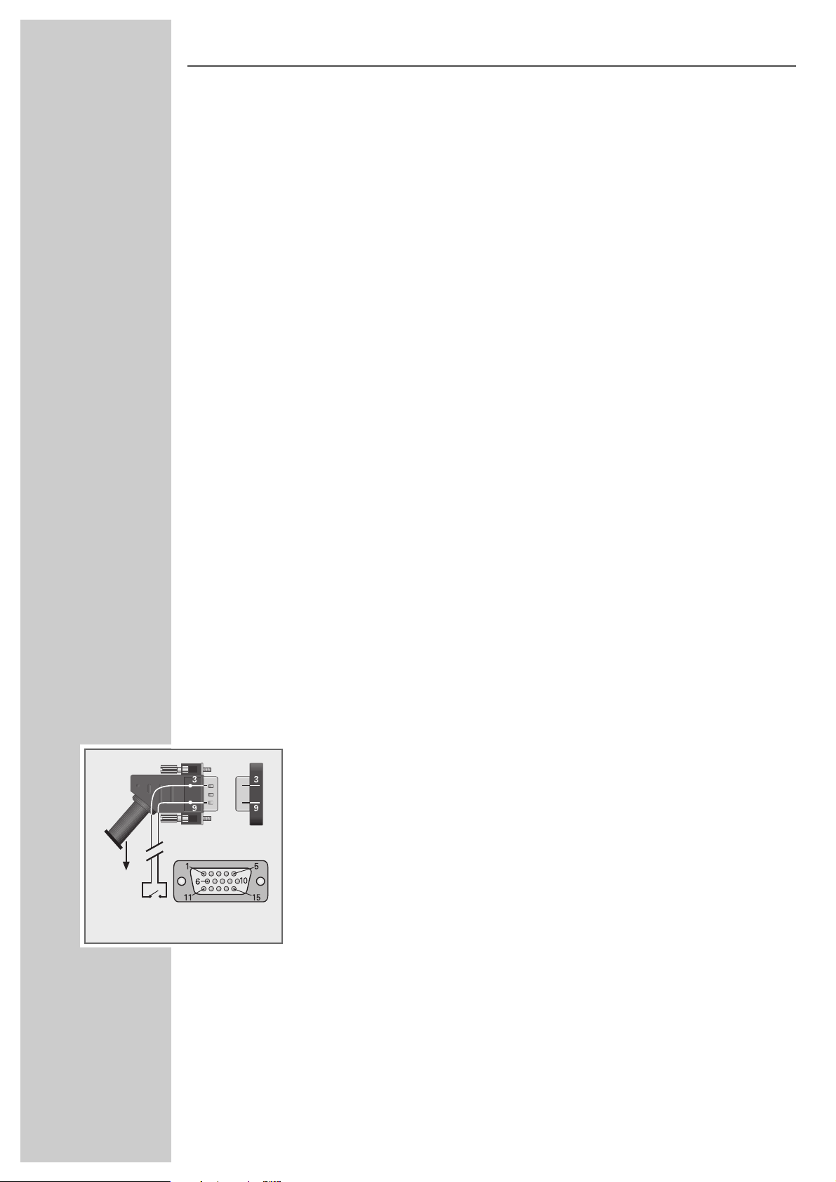
1 Connect the remote switch to pin 9 (12 V/10 mA switching voltage) and
pin 3 inside the 15-pin plug of the adapter cable supplied (see Fig.).
Continued on next page.
DNS UNIVERSAL
ǵ
front side
of plug
Socket
EURO-AV
Page 2
Switching the video/audio signal of external
equipment permanently into the signal path
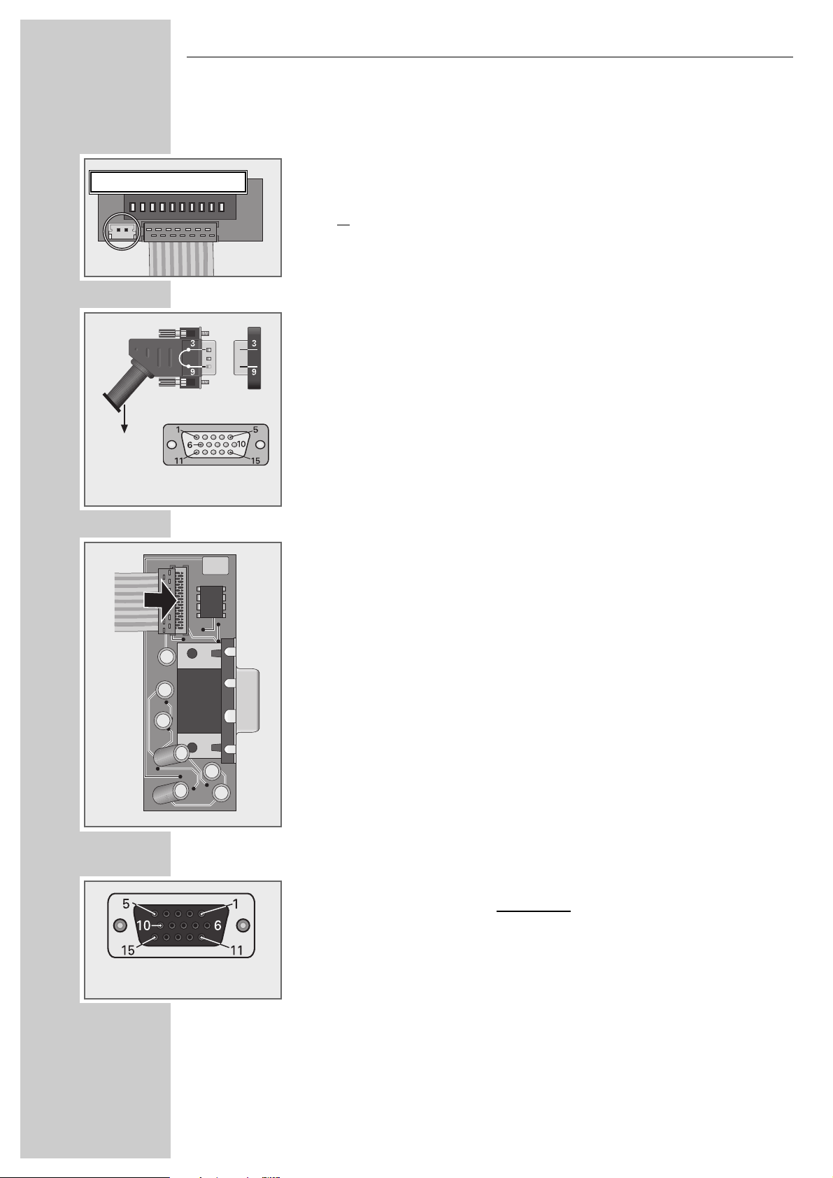
1 Connect the two pins on the component or solder side of the adapter board
with each other (see Fig.)
or
inside the 15-pin plug of the enclosed adapter cable, connect the Pin 9
(12 V/10 mA switching voltage) with the Pin 3 (see Fig.).
Note!
Only if the external equipment and the cassette are connected via the
modified adapter cable, the video/audio signal from the external equipment
is switched into the signal path of the cassette.
3 Complete the retrofit kit (decoder module, adapter plate and flat ribbon
cable).
Important
How to install the retrofit kit into the cassette or headend
station is desribed in the corresponding user manual.
Pin assignment of the Sub-Min-D socket
01 = Audio – left input
02 = Composite signal input, uncontr
olled
03 = 12 V– switching voltage input
04 = Baseband output (unclamped, PAL deemphasis
05 = Composite signal output (clamped, PAL deemphasis)
06 = Audio – right input
07 = ––
08 = Earth
09 = 12 V–/10 mA switching voltage output
10 = ––
11 = Earth
12 = Audio – left output
13 = Audio – right output
14 = ––
15 = ––
Subject to technical alterations and errors.
DNS UNIVERSAL
26400 965 0100 GDP 1/41
connect 2 plug pins!
front side of socket
Socket
front side
of plug
EURO-AV
 Loading...