

Grundig CUC400 Service Manual
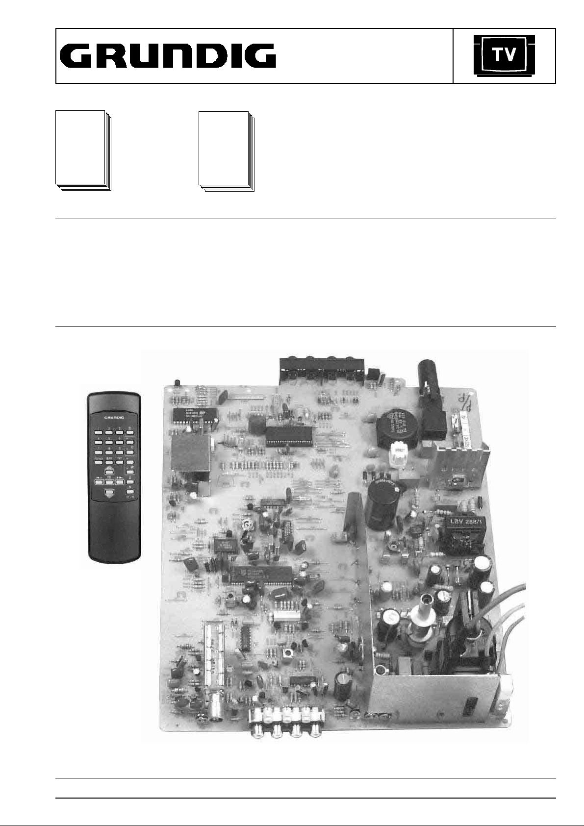
SERVICE MANUAL
Service
Manual
Additionally
required Service
Sach-Nr./Part No.
72010-019.80
P14 - 6210/4 (9.21508-0302 / G.CD 3902)
P14 - 6210/4 text
P14 - 6210/6
P14 - 6210/6 text
P14 - 6210/8 (9.21508-0202 / G.CD 3602)
P14 - 6210/8 text (9.21508-2202 / G.CE 0502)
T20 - 6210/4 (9.21509-0375 / G.CD 4075)
T20 - 6210/4 text
T20 - 6210/6
T20 - 6210/6 text
TP 711 (29642-062.01)
Manuals for the
Complete Service:
Service
Manual
Safety
Sach-Nr./Part No.
72010-800.00
CUC 400
T20 - 6210/8
T20 - 6210/8 text (9.21509-0275 / G.CD 3775)
T51 - 721/5
T51 - 721/5 text (9.21509-0475 / G.CE 2375)
T21 - 6210/4
T21 - 6210/4 text (9.21510-0375 / G.CD 4175)
T21 - 6210/6
T21 - 6210/6 text
T21 - 6210/8
T21 - 6210/8 text (9.21510-0275 / G.CD 3875)
Subject to alteration VK 221 / 0797 Service Manual Part No. 72010-019.80A
General Section CUC 400
Table of Contents
Page
General Section.................................... 1-2…1-7
Safety Advice ............................................................................... 1-2
Circuit Diagram Symbols ............................................................. 1-2
Technical Data ............................................................................. 1-3
Operating Instructions.................................................................. 1-4
Alignments.....................................................2-1
Layout of the PCBs
and Circuit Diagrams ........................... 3-1…3-7
Oscillograms Chassis Board........................................................ 3-1
General Circuit Diagram .............................................................. 3-2
Chassis Board PCB ..................................................................... 3-5
CTR Panel PCB ........................................................................... 3-7
Spare Parts List.................................... 4-1…4-5
General Section
The regulations and safety instructions shall be valid as provided
by the "Safety" Service Manual, part number 72010-800.00, as
well as the respective national deviations.
Safety Advice
The X-radiation developing in the sets conforms to the X-radiation
Regulations (January 8, 1987), issued by the Physikalisch-Technische
Bundesanstalt (federal physiotechnical institution).
The high tension for the picture tube and thus the developing Xradiation depends on the precise adjustment of the +A power supply.
After every repair of the power supply unit or the horizontal deflection
stage it is imperative that the EHT for the picture tube is checked and
re-adjusted if necessary.
To avoid consequential damages to the chassis or the picture tube
the integrated protective circuits are allowed to be put out of operation
only for a short time.
When replacing the picture tube use only the types specified in the
spare parts lists.
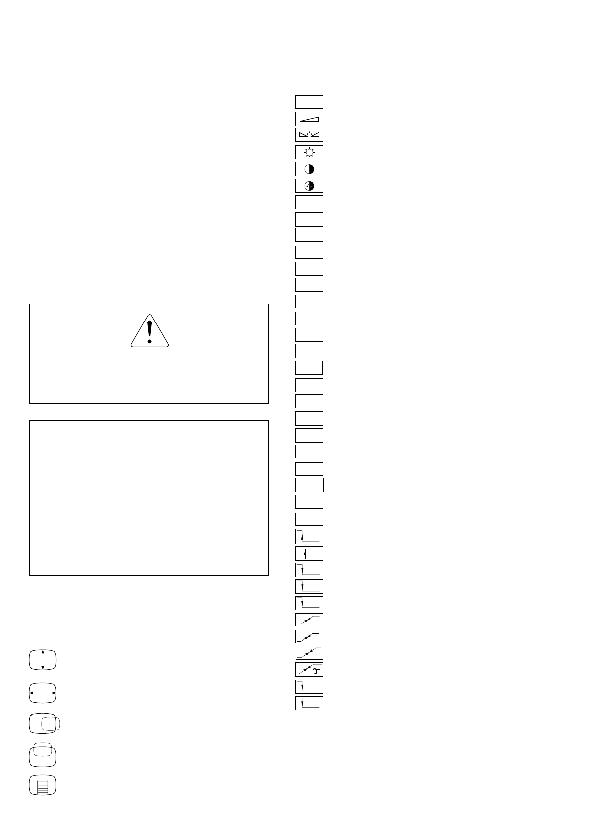
Circuit Diagram Symbols
Vertical amplitude
Horizontal amplitude
25Hz
AGC
AUDIO
AUDIO
IN
AUDIO
OUT
B
BB
COIN
FBAS
G
HOR.
SYNC1
IF
R
SB
SCL
SDA
SOUND
IF
VERT.
SYNC
VIDEO
VIDEO
IN
VIDEO
OUT
U
AV
U
DATA
U
NORM
U
STBY
U
UHF
U
U
TUN.
TUN
U
U
VH
U
VL
25Hz interlace signal
Volume
Tint
Brightness
Contrast
Colour contrast
Automatic gain control
Audio signal
Audio signal input
Audio signal output
Blue signal
Baseband
Coincidence
CCVS signal
Green signal
Horizontal synchronizing pulse
Intermediate frequency
Red signal
Beam current limiting
I2C-Bus Clock
I2C-Bus data
Sound intermediate frequency
Vertical synchronizing pulse
Video signal
Video signal input
Video signal output
Switching voltage AV
Switching voltage data mode
Switching voltage norm
Switching voltage standby
UHF switching voltage
Automatic frequency control voltage
AFC
Voltage synthesizer tuning
Tuning voltage
ADJ.
Delayed control voltage
Switching voltage VHF high band
Switching voltage VHF low band
Horizontal picture position
Vertical picture position
Vertical linearity
1 - 2 GRUNDIG Service
GRUNDIG Service 1 - 3
P14-6210/4
P14-6210/4 text
P14-6210/6
P14-6210/6 text
P14-6210/8
P14-6210/8 text
T20-6210/4
T20-6210/4 text
T20-6210/6
T20-6210/6 text
T20-6210/8
T20-6210/8 text
T 51-721/5
T 51-721/5 text
T21-6210/4
T21-6210/4 text
T21-6210/6
T21-6210/6 text
T21-6210/8
T21-6210/8 text
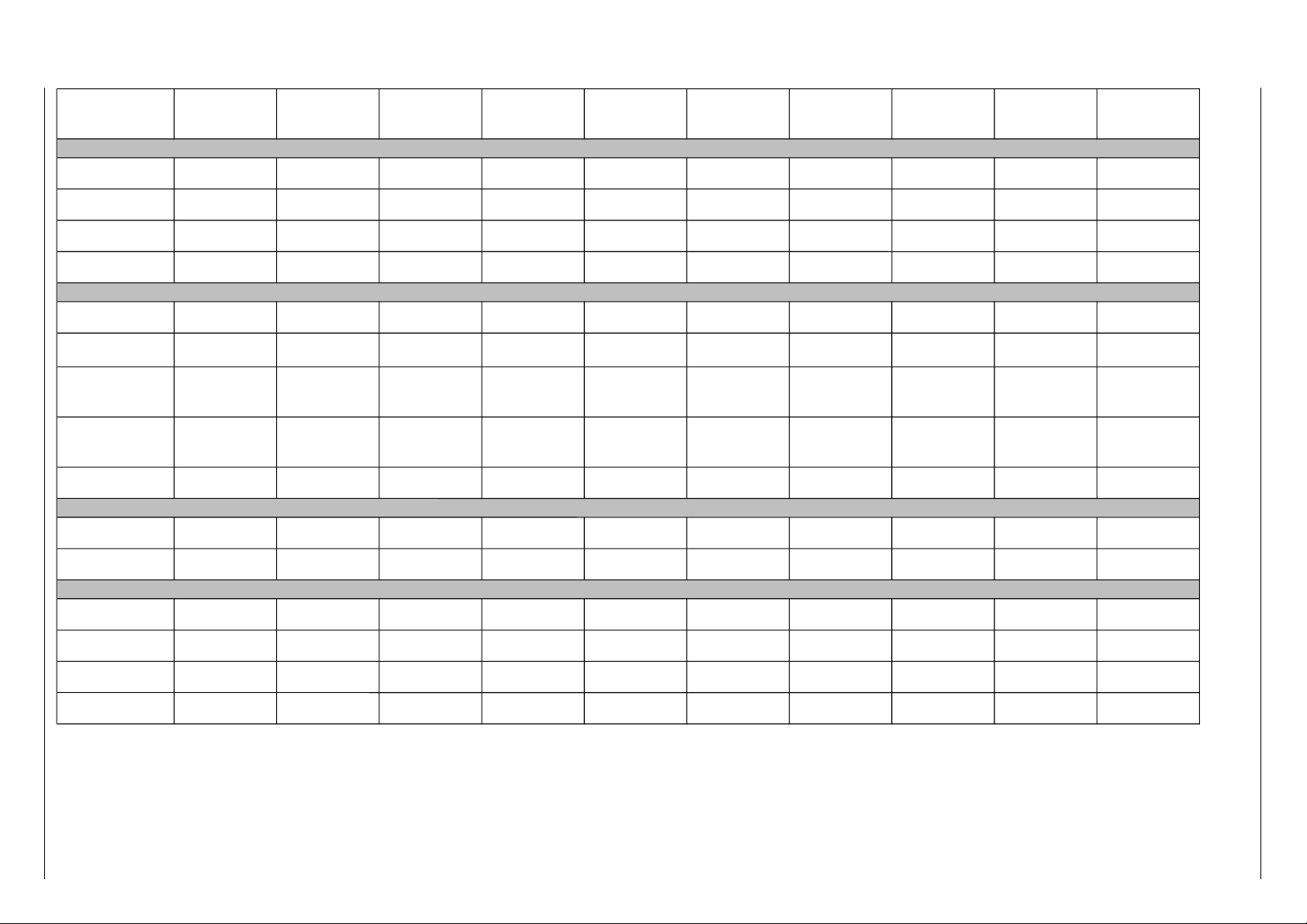
Picture Tube
Visible picture 34cm 34cm 34cm 48cm 48cm 48cm 48cm 51cm 51cm 51cm
Screen diagonale 37cm (14") 37cm (14") 37cm (14") 51cm (20") 51cm (20") 51cm (20") 51cm (20") 55cm (21") 55cm (21") 55cm (21")
Deflection angle 90° 90° 90° 90° 90° 90° 90° 90° 90° 90°
Vertical frequency 50Hz 50Hz 50Hz 50Hz 50Hz 50Hz 50Hz 50Hz 50Hz 50Hz
Electronic
Programme positions 99 TV + 1 AV 99 TV + 1 AV 99 TV + 1 AV 99 TV + 1 AV 99 TV + 1 AV 99 TV + 1 AV 99 TV + 1 AV 99 TV + 1 AV 99 TV + 1 AV 99 TV + 1 AV
Tuner hyperband (optional) hyperband hyperband hyperband (optional) hyperband hyperband hyperband hyperband (optional) hyperband hyperband
TV-Standard
PAL/
NTSC 3.58 / 4.43MHz
B/G
PAL/SECAM/
NTSC 3.58 / 4.43MHz
B/G, D/K
PAL/SECAM/
NTSC 3.58 / 4.43MHz
B/G, D/K, M, I
PAL/
NTSC 3.58 / 4.43MHz
B/G
PAL/SECAM/
NTSC 3.58 / 4.43MHz
B/G, D/K
PAL/SECAM/
NTSC 3.58 / 4.43MHz
B/G, D/K, M, I
PAL/SECAM/
NTSC 4.43MHz
B/G, D/K
PAL/
NTSC 3.58 / 4.43MHz
B/G
PAL/
NTSC 3.58 / 4.43MHz
B/G
PAL/SECAM/
NTSC 3.58 / 4.43MHz
B/G, D/K, M, I
Teletext
East / West
only model with text
East / West
only model with text
East / West
only model with text
East / West
only model with text
East / West
only model with text
East / West
only model with text
Cyrillic
only model with text
East / West
only model with text
East / West
only model with text
East / West
only model with text
Music power 3W 3W 3W 4W 4W 4W 4W 8W 8W 8W
Connections Rear Panel
Video IN / OUT 2 x Cinch 2 x Cinch 2 x Cinch 2 x Cinch 2 x Cinch 2 x Cinch 2 x Cinch 2 x Cinch 2 x Cinch 2 x Cinch
Audio IN / OUT 2 x Cinch 2 x Cinch 2 x Cinch 2 x Cinch 2 x Cinch 2 x Cinch 2 x Cinch 2 x Cinch 2 x Cinch 2 x Cinch
Mains Stage
Mains voltage (variable) 90…270V 90…270V 90…270V 90…270V 90…270V 90…270V 90…270V 90…270V 90…270V 90…270V
Mains frequency 50 / 60Hz 50 / 60Hz 50 / 60Hz 50 / 60Hz 50 / 60Hz 50 / 60Hz 50 / 60Hz 50 / 60Hz 50 / 60Hz 50 / 60Hz
Power consumption ca. 40W ca. 40W ca. 40W ca. 55W ca. 55W ca. 55W ca. 55W ca. 60W ca. 60W ca. 60W
Standby ca. 7W ca. 7W ca. 7W ca. 7W ca. 7W ca. 7W ca. 7W ca. 7W ca. 7W ca. 7W
CUC 400 General Section
Technical Data
1 - 4 GRUNDIG Service
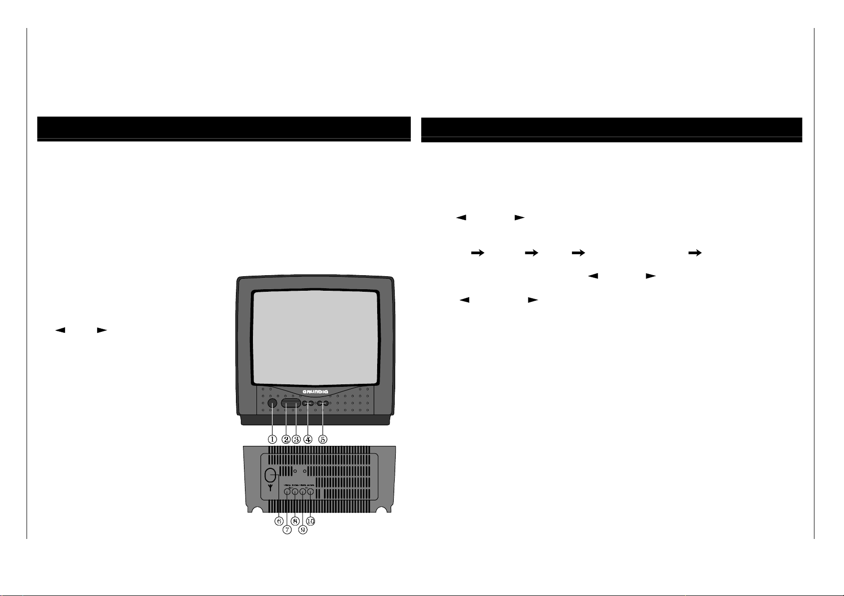
LOCAL CONTROL OPERATION
1. Mains On/Off Switch.
Press the power switch 1 on the TV set. The indicator will light up. Program
number is automatically appears on upper left corner of the screen for
approximately 5 seconds.
Press the power switch once again to switch off the set.
2. Indicator - Operating (
green*/red
),
Standby (
red
).
3. Remote Sensor.
4. (
-), (+
) for setting the sound
volume.
5. ( P- ), ( P+) Program selection button.
6. Aerial input 75 Ohms.
7. Video Output.
8. Audio Output.
9. Video Input.
10. Audio Input.
* For particular models
PICTURE ADJUSTMENT MODE
Press (
-) and (+
-) and
(+
) simultaneously into
picture adjustment mode.
With button (P+), the symbol and scale will be selected sequentially as follows :
Brightness Contrast Colour Tint (in case of NTSC) Brightness.
Adjust to required analog level with (
) buttons.
Press (
-) and (+
) simultaneously or no other local key is pressed for
approximately 5 seconds will go back to normal.
Operating Instructions CUC 400
Note:
This chapter contains excerpts from the operating instructions. For further particulars please refer to the
appropriate user instructions.
General Section CUC 400
GRUNDIG Service 1 - 5
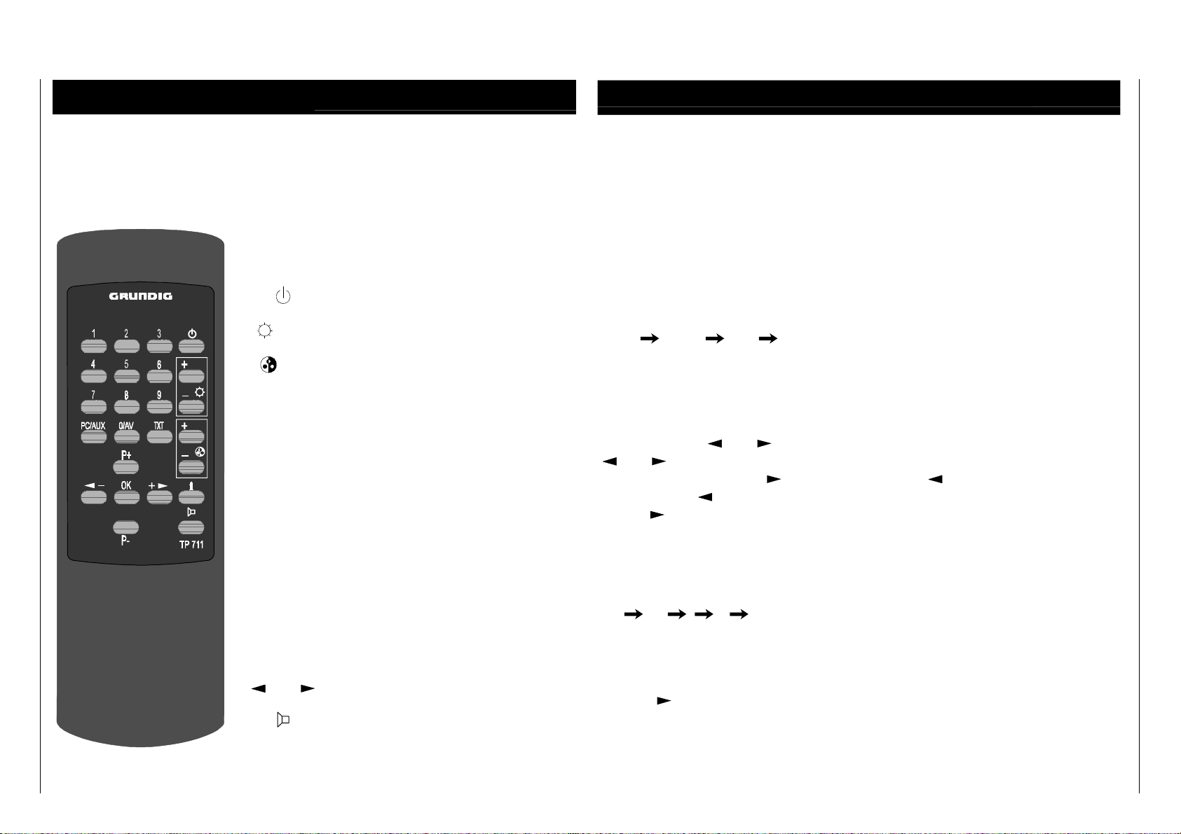
REMOTE CONTROL UNIT
The Remote Control Unit is the Primary Control Unit of your TV receiver. It allows
you to operate all functions and setting.
1...
9 (0/AV)
Direct select program position
(also AV).
Standby On/Off.
- / +
Brightness, Contrast.
- / +
Colour, Tint.
PC/AUX
Shift key for Contrast, Tint.
Hold down for 3 seconds to call up the
tuning system and program setting
data.
TXT
Teletext On/Off.
P+ / P-
Select program position.
i
DispIay program position.
Display sleep timer.
Teletext overview.
Hold down for 3 seconds to call up the
multifunction menu.
OK
To confirm and store selected values.
Press and hold for 3 seconds to call up
optimum analogue parameters.
- +
Volume.
Sound On/Off (muting).
TUNING AND PROGRAMMING
Press the (PC/AUX) button for approx. 3 seconds. The programming menu appears,
active parameter will become
red
, and the other remain
cyan
. To terminate press
(PC/AUX) button for approx. 3 seconds to leave the menu at any position.
Press (0...9) or (P+ P-) buttons to select program number.
Press (PC/AUX) button to move to the next parameter.
Press (P+) button to select frequency band sequentially as follows:
VHF L VHF H UHF VHF L
Press (PC/AUX) button to move to the next parameter.
Press (P+) button to select 'AUTO' (automatic tuning) or 'MANUAL' (manual
tuning).
Press (PC/AUX) button to move to the next parameter.
Start tuning with
-
+
buttons.
-
+
buttons are for manual tuning (positive and negative direction).
To start auto tuning with +
button and stop with
- , during this time you can
press and hold
- button to reverse tuning for overjumped station.
Press + button again to continous auto tuning.
Press (PC/AUX) button to move to the next parameter.
SOUND SYSTEM
Press (P+) button to select system sequentially as follows:
BG DK I M BG
Press (PC/AUX) button to move to the next parameter.
STATION LABEL (particular model only)
Press (+
) buttons to select one of four digits and (P+), (P-) buttons to select
charactors.
Press (OK) button to call up the STORE mode.
CUC 400 General Section
1 - 6 GRUNDIG Service
STORE P_ _appears to request for the displayed number or a possibly new program
number (copy function is also possible).
You can activate this function by pressing (OK) button at any position.
Press OK, storage and display of the current programming menu.
Press (PC/AUX) button for approx. 3 seconds to leave the menu.
SOUND MUTE
By pressing the button (
) the sound can be cut off and press the same button
once to get the sound back.
SLEEP TIMER
You can set the timer so that the TV is automatically switched off to Stand By mode
after a period of 5 to 120 minutes in steps of 5 minutes.
For example, if you wish to set the timer to switch off after 60 minutes, press the
button (i) for approximately 3 seconds till multifunction display is on the screen.
Press the button (i) to select symbol (
) change from
cyan
to
red
, then
repeatedly
press (P+) to change the time from OFF to 60 minutes. The TV
automatically switches to stand by after 60 minutes. If you have made a wrong entry
and want to cancel the entry set the timer to (OFF).
During the timer is activated, you can recall the remaining time by pressing (i)
button once.
SECRET CODE
With a four digit secret code you can protect your TV against unauthorised use.
Press the button (i) for approx. 3 sec. till multifunction display is on the screen.
Press the button (i) to move to the 'key' symbol change from
cyan
to
red.
Enter a four digits secret code via 0...9, confirm by OK button and leave the menu
with storage by pressing the button (i) for approx. 3 seconds.The 'XXXX' show that
the set will be locked after having been switched off once by mains button.
Erasing the secret code by entering the last code again.
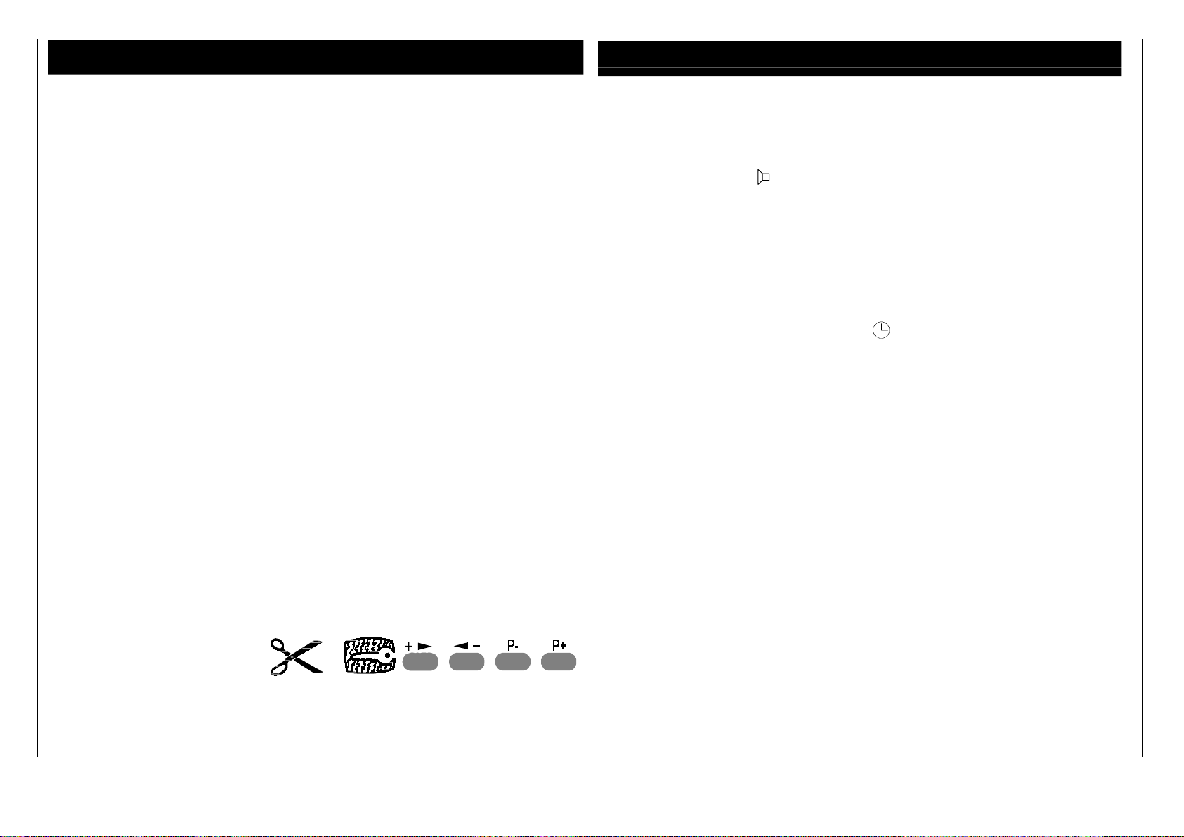
NOTE
If you ever forget your secret code number, the key on the last page will help you. Pressing the button combinations as shown will cancel
the secret code and restore the unit back into operation. Please cut and keep this portion of cover in the safe custody immediately on
purchase.
General Section CUC 400
 Loading...