

Page 1
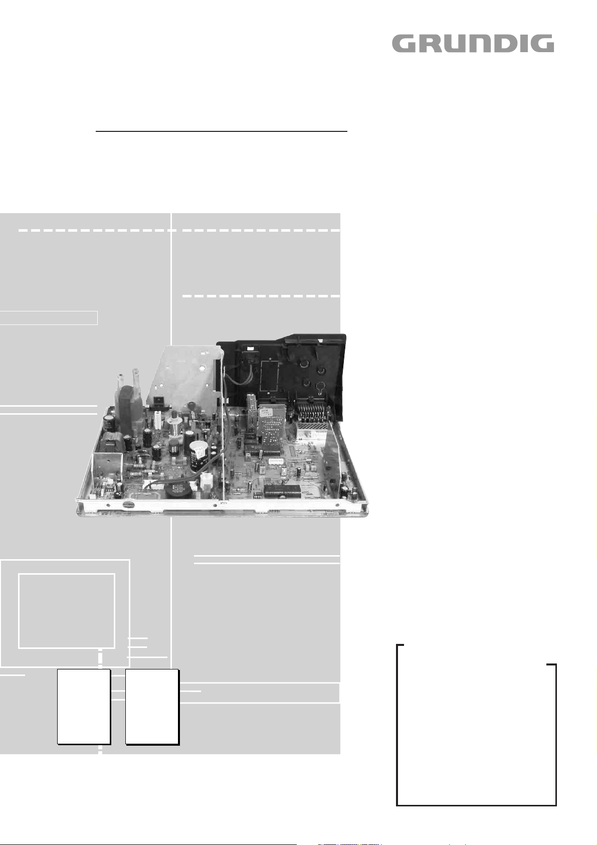
TV Service Manual
CUC 2030 N
ST 70 – 602 NIC/TOP
(G.CK 1975 / VNM)
ST 70 – 703 NIC/TOP
(G.CK 0175 / VNM)
CUC 2050 N
DAVIO 70
ST 70 – 853 NIC/PIP
(G.CK 0272 / VNM)
CUC 2058 N
MW 82 – 2699 NIC/FT
(G.CK 2575 GB / VNM)
MW 82 – 2699 NIC/TOP
(G.CI 1078 / VNA)
Zusätzlich erforderliche Unterlagen für den Komplettservice
Additionally required Service Documents for the Complete Service
Service
Manual
Sicherheit
Safety
Materialnr./Part No.
72010 800 0000
Materialnummer/Part Number 72010 026 0000
Änderungen vorbehalten/Subject to alteration • Printed in Germany MÜ
E-BS 38 0999 • 8002/8012, 8003/8013
http://www.grundig.de
Service
Training
CUC 2000
Materialnr./Part No.
Ķ 72010 350 3500
ķ 72010 350 3600
CUC 2059 N
MW 70 – 2699 NIC/FT
(G.CK 2475 GB / VNM)
MW 70 – 2699 NIC/TOP
(G.CI 1178 / VNA)
CUC 2080 N
ST 84 – 896 NIC/TOP
(G.CF 8491 / VNA)
Grundig Service
Technik:
TV
TV
SAT
VCR/LiveCam
HiFi/Audio
Car Audio
Telekommunikation
Planatron
Ersatzteil-Verkauf: ...Mo.-Fr. 8.00-19.00 Uhr
Fax:
(8.00-22.00
Telefon:
Fax:
Hotline Deutschland...
...Mo.-Fr. 8.00-18.00 Uhr
0180/52318-41
0180/52318-49
0180/52318-48
0180/52318-42
0180/52318-43
0180/52318-44
0180/52318-45
0180/52318-51
0180/52318-99
Uhr)
0180/52318-40
0180/52318-50
Page 2

Allgemeiner Teil / General Section CUC 2030 N / 2050 N / 2058 N / 2059 N / 2080 N
Es gelten die Vorschriften und Sicherheitshinweise
gemäß dem Service Manual "Sicherheit", Materialnummer72010 800 0000, sowie zusätzlich die eventuell abweichenden, landesspezifischen Vorschriften!
D
Inhaltsverzeichnis
Seite
Allgemeiner Teil ................................. 1-2…1-24
Meßgeräte .................................................................................... 1-3
Allgemeiner Hinweis .................................................................... 1-3
Typenschild des Gerätes (Version Number) ................................ 1-3
Technische Daten ........................................................................ 1-4
Modulübersicht ............................................................................. 1-5
Sicherheits- / Service Hinweise ................................................... 1-6
Schaltplansymbole ....................................................................... 1-7
Bedienhinweise (MW 82 – 2699 NIC/TOP) ............................... 1-11
Service- und Sonderfunktionen .................................................. 1-20
The regulations and safety instructions shall be
valid as provided by the "Safety" Service Manual,
part number 72010 800 0000, as well as the
respective national deviations.
GB
Table of Contents
Page
General Section .................................. 1-2…1-24
Test Equipment ............................................................................ 1-3
General Note ................................................................................ 1-3
Type Label on the set (Version Number) ..................................... 1-3
Technical Data ............................................................................. 1-4
Module List ................................................................................... 1-5
Safty Advices / Service Notes ...................................................... 1-6
Circuit Diagram Symbols ............................................................. 1-7
Operating Hints (MW 82 – 2699 NIC/TOP) ................................ 1-15
Service and Special Functions................................................... 1-22
Abgleich ................................................ 2-1…2-3
Platinenabbildungen
und Schaltpläne ................................. 3-1…3-59
Chassisplatte ............................................................................... 3-1
Chassisplatte (vergrößert) ........................................................... 3-9
Oszillogramme (Chassis) ........................................................... 3-13
Netz-Chassis .............................................................................. 3-15
Signal-Chassis A ........................................................................ 3-19
Signal-Chassis B ........................................................................ 3-23
Keyboard 29501 083 2400/2500, 29306 214 0100.................... 3-26
Netzschalterplatte 29305 165 7100/7200 .................................. 3-27
Netzschalterplatte 29305 165 7400/7600 .................................. 3-29
Bedieneinheit 29501 082 7000 .................................................. 3-31
Keyboard 29501 083 7000......................................................... 3-31
Bedieneinheit 29501 082 5200/5900/6300/6800/7500/
7900/8000/8100/8200 ................................................................ 3-33
Cinch-Buchsenplatte 29305 008 3500/3700/4000 ..................... 3-35
Panorama View 29305 129 0400 ............................................... 3-36
Feature-Platte CTI/LTI 29305 119 3500 .................................... 3-37
Feature-Platte 29305 129 0700 ................................................. 3-39
Bildrohrplatte 29305 122 2100/2300/2500 ................................. 3-41
Bildrohrplatte 29305 122 2800 ................................................... 3-43
PIP-Baustein 29504 106 5100/5200 .......................................... 3-46
Dolby-Surround-Platte 29504 104 7700 .................................... 3-51
SAT-Baustein 29504 106 2500 .................................................. 3-55
Ersatzteillisten .................................... 4-1…4-21
Alignment.............................................. 2-4…2-6
Layout of the PCBs
and Circuit Diagrams ......................... 3-1…3-59
Chassis Board .............................................................................. 3-1
Chassis Board (enlarged) ............................................................ 3-9
Oscillograms (Chassis) .............................................................. 3-13
Mains Chassis ............................................................................ 3-15
Chassis Signal A ........................................................................ 3-19
Chassis Signal B ........................................................................ 3-23
Keyboard 29501 083 2400/2500, 29306 214 0100.................... 3-26
Mains Switch Board 29305 165 7100/7200 ............................... 3-27
Mains Switch Board 29305 165 7400/7600 ............................... 3-29
Control Unit 29501 082 7000 ..................................................... 3-31
Keyboard 29501 083 7000......................................................... 3-31
Control Unit 29501 082 5200/5900/6300/6800/7500/
7900/8000/8100/8200 ................................................................ 3-33
Phone Socket Board 29305 008 3500/3700/4000 ..................... 3-35
Panorama View 29305 129 0400 ............................................... 3-36
Feature Board CTI/LTI 29305 119 3500 .................................... 3-37
Feature Board 29305 129 0700 ................................................. 3-39
CRT Panel 29305 122 2100/2300/2500 .................................... 3-41
CRT Panel 29305 122 2800 ...................................................... 3-43
PIP Module 29504 106 5100/5200 ............................................ 3-46
Dolby Surround Board 29504 104 7700 .................................... 3-51
SAT Module 29504 106 2500 .................................................... 3-55
Spare Parts Lists ................................ 4-1…4-21
1 - 2 GRUNDIG Service
Page 3
CUC 2030 N / 2050 N / 2058 N / 2059 N / 2080 N Allgemeiner Teil / General Section
Allgemeiner Teil
Meßgeräte
Beachten Sie bitte das Grundig Meßtechnik-Programm, das Sie unter
folgender Adresse erhalten:
Geschäftsbereich Instruments
Test- und Meßsysteme
Würzburger Str. 150
D-90766 Fürth
Tel.: 0911 / 703-4118
Fax: 0911 / 703-4130
eMail: instruments@grundig.de
Internet: http://www.grundig-instruments.de
Allgemeiner Hinweis
Ersatzteillisten
Die vierstelligen, von der Ersatzteilbezeichnung abgesetzten Zahlen
beziehen sich auf die letzten vier Stellen der Materialnummern der
Chassis oder der Bausteine.
Beispiel: 3100^= 29704 004 3100
General Section
Test Equipment
Please note the Grundig Catalog "Test and Measuring Equipment"
obtainable from:
Grundig AG
General Note
Spare Parts Lists
The set off four figures in the designation of the spare parts refer
to the four figures at the end of the part numbers of the chassis or
modules.
Example: 3100^= 29704 004 3100
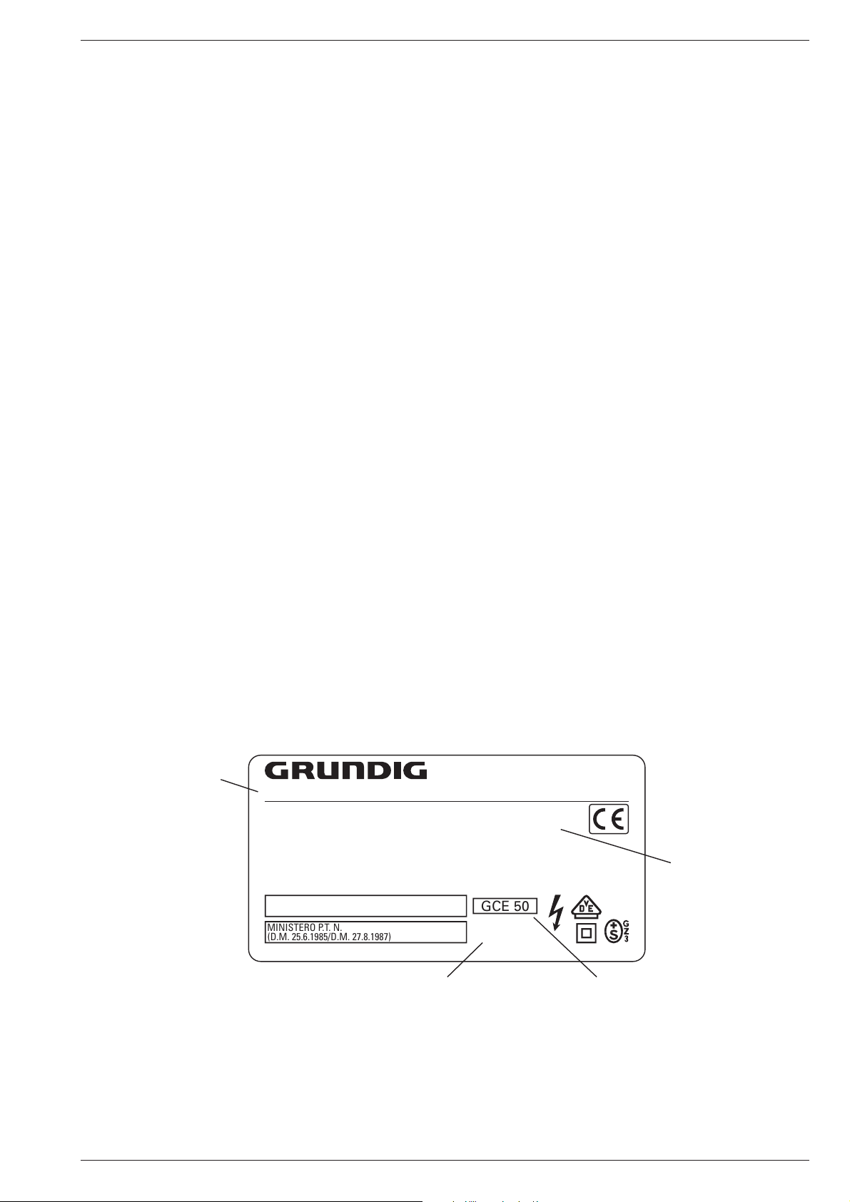
Typenschild des Gerätes
Zusätzlich zum Gerätetyp und der Chassisbezeichnung enthält das
Gerätetypenschild eine sogenannte "Version number" z.B. VNA. Diese Kennzeichnung gibt Aufschluß über den technischen/mechanischen Fertigungsstand.
Für die Bestellung von Ersatzteilen sind deshalb folgende Angaben
unbedingt erforderlich:
- Gerätetype (z.B. "T 51-731 text")
- Chassis-Bezeichnung (z.B. "CUC 7303")
- Version number (z.B. "VNA")
- Materialnummer des Ersatzteils
Gerätetype
Type of product
T 51-731 text
220-240V~ 50/60Hz 55W
EIGENSICHERE KATHODENSTRAHLRÖHRE NACH ANLAGE III
DER RÖNTGENVERORDNUNG.
BESCHLEUNIGUNGSSPANNUNG MAX. 25kV, 1.0mA.
TUBOS DE RADIACIÓN CATÓDICA AUTOLIMITADA, SEGÚN ANEXO III DE LA NORMATIVA
RADIOLÓGICA. TENSIÓN DE ACELERACIÓN MÁX. 25kV, 1.0mA.
ATENCION! NO ABRIR SIN ANTES DESCONECTAR LA TENSION DE RED.
STACCARE LA SPINA DI RETE PRIMA DI TOGLIERE IL PANNELLO POSTERIORE.
PROTEGGERE L'APPARECCHIO DALL'UMIDITA`. ATTENZIONE ALTA TENSIONE 25kV, 1.0mA.
MINISTERO P.T. N.
(D.M. 25.6.1985/D.M. 27.8.1987)
MADE IN AUSTRIA FABRICANTE: GRUNDIG AG, WIEN
Type Label on the set
In addition to the type of the TV set and the designation of the chassis,
a so-called "Version number", e.g. VNA, is printed on the type label.
This identification gives information on the technical/mechanical state
of production.
Do not fail to give the following particulars when ordering spare parts:
- type of TV set (e.g. "T 51-731 text")
- name of chassis (e.g. "CUC 7303")
- version number (e.g. "VNA")
- part number spare part
VNA
Version number
GCE 50
CUC 7303
25kV
Chassis-Bezeichnung
Chassis designation
GRUNDIG Service 1 - 3
Bestellnummer ohne Farbkennzeichnung
Order number without colour code
Page 4
1 - 4 GRUNDIG Service
ST 70 – 602 NIC/TOP
(VNM)
CUC 2030 N
ST 70 – 703 NIC/TOP
(VNM)
CUC 2030 N
DAVIO
ST 70 – 853 NIC/PIP
(VNM)
CUC 2050 N
MW 82 – 2699 NIC/FT
(VNM)
CUC 2058 N
MW 82 – 2699 NIC/TOP
(VNA)
CUC 2058 N
MW 70 – 2699 NIC/FT
(VNM)
CUC 2059 N
MW 70 – 2699 NIC/TOP
(VNA)
CUC 2059 N
ST 84 – 896 NIC/TOP
(VNA)
CUC 2080 N
Bildröhre / Picture Tube
Sichtbares Bild
Visible picture
66cm 66cm 66cm 76cm 76cm 66cm 66cm 80cm
Bildschirmdiagonale
Screen diagonale
70cm (28")
Black Line D
70cm (28")
Black Line D
70cm (28")
Black Line D
82cm (32") Super Flat,
Black Line Invar
82cm (32") Super Flat,
Black Line Invar
70cm (28") Super Flat,
Black Line Invar
70cm (28") Super Flat,
Black Line Invar
84cm (33") Black Matrix,
Black Line Invar
Ablenkwinkel
Deflection angle
110° 110° 110° 104° 104° 104° 104° 110°
Bildwechselfrequenz
Vertical frequency
50Hz 50Hz 50Hz 50Hz 50Hz 50Hz 50Hz 50Hz
Elektronik / Electronic
Programmspeicherplätze
Programme positions
99 TV + 3 AV 99 TV + 3 AV
99 + 3 AV
199 TV/SAT + 59 Radio + 3 AV
(bei Nachrüstung SAT/
when retrofitted with SAT)
99 + 3 AV
199 TV/SAT + 59 Radio + 3 AV
(bei Nachrüstung SAT/
when retrofitted with SAT)
99 + 3 AV
199 TV/SAT + 59 Radio + 3 AV
(bei Nachrüstung SAT/
when retrofitted with SAT)
99 + 3 AV
199 TV/SAT + 59 Radio + 3 AV
(bei Nachrüstung SAT/
when retrofitted with SAT)
99 + 3 AV
199 TV/SAT + 59 Radio + 3 AV
(bei Nachrüstung SAT/
when retrofitted with SAT)
99 + 3 AV
199 TV/SAT + 59 Radio + 3 AV
(bei Nachrüstung SAT/
when retrofitted with SAT)
AV-Auswertung
AV evaluation
auf jeden Programmplatz programmierbar / programmable for every programme position
Tuner
PLL-Frequenz synthesizer
tuning UHF/VHF
PLL frequency synthesizer tuning
UHF/VHF
PLL-Frequenz synthesizer
tuning UHF/VHF
PLL frequency synthesizer tuning
UHF/VHF
PLL-Frequenz synthesizer
tuning UHF/VHF
PLL frequency synthesizer tuning
UHF/VHF
PLL-Frequenz synthesizer
tuning UHF/VHF
PLL frequency synthesizer tuning
UHF/VHF
PLL-Frequenz synthesizer
tuning UHF/VHF
PLL frequency synthesizer tuning
UHF/VHF
PLL-Frequenz synthesizer
tuning UHF/VHF
PLL frequency synthesizer tuning
UHF/VHF
PLL-Frequenz synthesizer
tuning UHF/VHF
PLL frequency synthesizer tuning
UHF/VHF
PLL-Frequenz synthesizer
tuning UHF/VHF
PLL frequency synthesizer tuning
UHF/VHF
TV-Normen
TV-Standard
PAL,
NTSC 4,43MHz, B/G,
I, D/K,K'/D (nur/only PAL)
PAL,
NTSC 4,43MHz, B/G,
I, D/K,K' (nur/only PAL)
NTSC über/via AV 3.58MHz
PAL,
NTSC 4,43MHz, B/G,
I, D/K,K' (nur/only PAL)
NTSC über/via AV 3.58MHz
PAL,
NTSC 4,43MHz, B/G,
I, D/K,K' (nur/only PAL)
PAL,
NTSC 4,43MHz, B/G,
I, D/K,K' (nur/only PAL)
PAL,
NTSC 4,43MHz, B/G,
I, D/K,K' (nur/only PAL)
PAL,
NTSC 4,43MHz, B/G,
I, D/K,K' (nur/only PAL)
PAL,
NTSC 4,43MHz, B/G,
I, D/K,K' (nur/only PAL)
NTSC über/via AV 3.58MHz
Stereo Systeme
Stereo systems
Deutsch A2 für B/G/D/K
German A2 for B/G/D/K
Nicam 5,85+6,52MHz
Deutsch A2 für B/G/D/K
German A2 for B/G/D/K
Nicam 5,85+6,52MHz
Deutsch A2 für B/G/D/K
German A2 for B/G/D/K
Nicam 5,85+6,52MHz
Deutsch A2 für B/G/D/K
German A2 for B/G/D/K
Nicam 5,85+6,52MHz
Deutsch A2 für B/G/D/K
German A2 for B/G/D/K
Nicam 5,85+6,52MHz
Deutsch A2 für B/G/D/K
German A2 for B/G/D/K
Nicam 5,85+6,52MHz
Deutsch A2 für B/G/D/K
German A2 for B/G/D/K
Nicam 5,85+6,52MHz
Deutsch A2 für B/G/D/K
German A2 for B/G/D/K
Nicam 5,85+6,52MHz
Videotext
Teletext
8 Seiten TOP/FLOF-text, VPS,
8 pages TOP/FLOF-text, VPS,
8 Seiten TOP/FLOF-text, VPS,
8 pages TOP/FLOF-text, VPS,
8 Seiten TOP/FLOF-text, VPS,
8 pages TOP/FLOF-text, VPS,
8 Seiten TOP/FLOF-text, VPS,
8 pages TOP/FLOF-text, VPS,
8 Seiten TOP/FLOF-text, VPS,
8 pages TOP/FLOF-text, VPS,
8 Seiten TOP/FLOF-text, VPS,
8 pages TOP/FLOF-text, VPS,
8 Seiten TOP/FLOF-text, VPS,
8 pages TOP/FLOF-text, VPS,
8 Seiten TOP/FLOF-text, VPS,
8 pages TOP/FLOF-text, VPS,
Musikleistung
Music power
Stereo 2 X 8W Stereo 2 X 8W Stereo 2 X 20W Stereo 2 X 20W Stereo 2 X 20W Stereo 2 X 20W Stereo 2 X 20W Stereo 2 X 20W
Anschlüsse Front / Connections Front
Kopfhörer
Headphones
Stereo 3,5mm Klinkenbuchse, Lautstärke regelbar, individuelle Tonkanalwahl bei 2-Ton-Empfang / Stereo 3.5mm jacksocket, adjusta
ble volume, individual channel selection with dual-sound broadcasts
Cinch-AV-Buchse
Cinch-AV socket
1x FBAS Video / in
1x CCVS Video / in
2x Audio / in
(AV 3 Position)
1x FBAS Video / in
1x CCVS Video / in
2x Audio / in
(AV 3 Position)
1x FBAS Video / in
1x CCVS Video / in
2x Audio / in
(AV 3 Position)
1x FBAS Video / in
1x CCVS Video / in
2x Audio / in
(AV 3 Position)
1x FBAS Video / in
1x CCVS Video / in
2x Audio / in
(AV 3 Position)
1x FBAS Video / in
1x CCVS Video / in
2x Audio / in
(AV 3 Position)
1x FBAS Video / in
1x CCVS Video / in
2x Audio / in
(AV 3 Position)
1x FBAS Video / in
1x CCVS Video / in
2x Audio / in
(AV 3 Position)
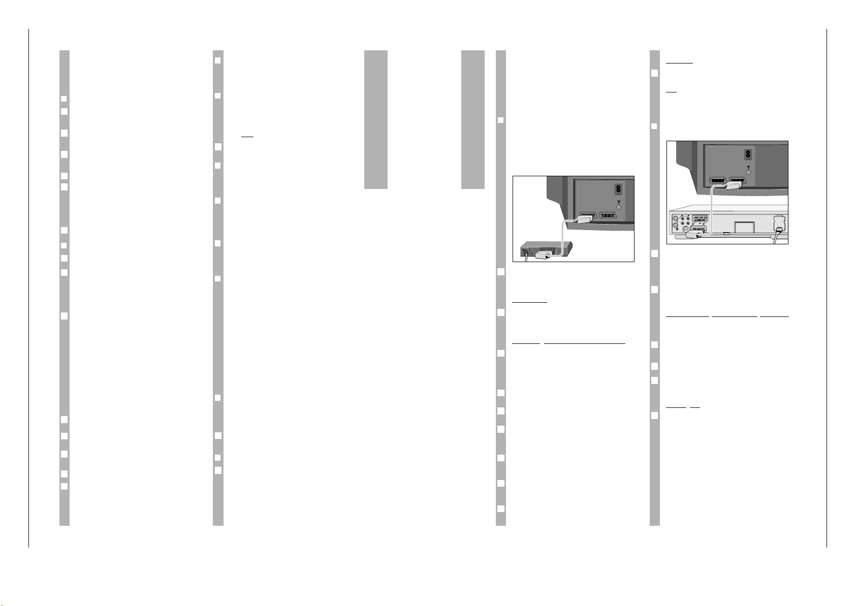
Anschlüsse Rückwand / Connections Rear Panel
Euro AV 1 (schwarz/black)
FBAS in-/output,
SBAS input, RGB input,
MicroSat Fernbedienung (Pin 8)
MicroSat remote control (Pin 8)
FBAS in-/output,
SBAS input, RGB input,
MicroSat Fernbedienung (Pin 8)
MicroSat remote control (Pin 8)
FBAS in-/output,
SBAS input, RGB input
FBAS in-/output,
SBAS input, RGB input
FBAS in-/output,
SBAS input, RGB input
FBAS in-/output,
SBAS input, RGB input
FBAS in-/output,
SBAS input, RGB input
FBAS in-/output,
SBAS input, RGB input
Euro AV 2 (schwarz/black)
FBAS in-/output,
SBAS input, RGB input
FBAS in-/output,
SBAS input, RGB input
FBAS in-/output,
SBAS input, RGB input
FBAS in-/output,
SBAS input, RGB input
FBAS in-/output,
SBAS input, RGB input
FBAS in-/output,
SBAS input, RGB input
FBAS in-/output,
SBAS input, RGB input
FBAS in-/output,
SBAS input, RGB input
Netzteil / Mains Stage
Netzspannung (Regelbereich)
Mains voltage (variable)
165…265V 165…265V 165…265V 165…265V 165…265V 165…265V 165…265V 165…265V
Netzfrequenz
Mains frequency
50 / 60Hz 50 / 60Hz 50 / 60Hz 50 / 60Hz 50 / 60Hz 50 / 60Hz 50 / 60Hz 50 / 60Hz
Leistungsaufnahme
Power consumption
ca. 80W ca. 75W ca. 80W ca. 95W ca. 95W ca. 95W ca. 95W ca. 110W
Standby ca. 5W ca. 5W ca. 5W ca. 6W ca. 6W ca. 5W ca. 5W ca. 5W
Allgemeiner Teil / General Section CUC 2030 N / 2050 N / 2058 N / 2059 N / 2080 N
Technische Daten / Technical Data
Page 5

GRUNDIG Service 1 - 5
ST 70 – 602
NIC/TOP
(VNM)
CUC 2030 N
ST 70 – 703
NIC/TOP
(VNM)
CUC 2030 N
DAVIO 70
ST 70 – 853
NIC/PIP
(VNM)
CUC 2050 N
MW 82 – 2699
NIC/FT
(VNM)
CUC 2058 N
MW 82 – 2699
NIC/TOP
(VNA)
CUC 2058 N
MW 70 – 2699
NIC/FT
(VNM)
CUC 2059 N
MW 70 – 2699
NIC/TOP
(VNA)
CUC 2059 N
ST 84 – 896
NIC/TOP
(VNA)
CUC 2080 N
Bestell-Nr.
Order No.
G.CK 1975 G.CK 0175 G.CK 0272 G.CK 2575 GB G.CI 1078 G.CK 2475 GB G.CI 1178 G.CF 8491
Chassis-Nr.
Chassis No.
29704 009 0400
ww / or 29704 009 0500
29704 009 0700 29704 009 3900 29704 003 4000 29704 009 3100 29704 003 7400 29704 009 3300 29704 003 9600
Tuner
29504 301 0100
••••••••
81406 016 1200 ww / or ww / or ww / or ww / or ww / or ww / or ww / or ww / or
Feature-Platte CTI/LTI
Feature Board CTI/LTI
29305 119 3500
––
••
–
•
––
Feature-Platte
Feature Board
29305 129 0700
––––
•
–
••
Panorama View 29305 129 0400
–––
••••
–
Bildrohrplatte
CRT Panel
29305 122 2300
•••
–––––
29305 122 2500
–––
•
–
•
––
29305 122 2800
––––
•
–
••
Bedieneinheit
Control Unit
29501 082 5900
–
•
––––––
29501 082 7000
–––––––
•
29501 082 8200
––
•
–––––
Netzschalterplatte
Mains Switch Board
29305 165 7100
–––
••••
–
29305 165 7600
•
–––––––
Keyboard
29501 081 8500
•
–––––––
29501 083 2500
–––
••••
–
29501 083 7000
–––––––
•
Cinch-Buchsenplatte
Phone Socket Board
29305 008 3700
–––
••••
–
TP 715 29642 062 1102
••
––––––
TP 800 29642 061 0104
––
•
–––––
TP 810 C 29642 061 1001
–––
•••••
PIP Baustein
PIP Module
29524 106 5100
––
•
–––––
Nachrüstsatz PIP 4
Retrofit kit PIP 4
G.AD 9000
–––
nachrüstbar
retrofitable
nachrüstbar
retrofitable
nachrüstbar
retrofitable
nachrüstbar
retrofitable
nachrüstbar
retrofitable
NF-Baustein DPL 2
AF Module DPL 2
G.AD 8900
––
nachrüstbar
retrofitable
nachrüstbar
retrofitable
nachrüstbar
retrofitable
nachrüstbar
retrofitable
nachrüstbar
retrofitable
nachrüstbar
retrofitable
SAT-Baustein SER 250
SAT Module SER 250
G.AE 0700
––
nachrüstbar
retrofitable
nachrüstbar
retrofitable
nachrüstbar
retrofitable
nachrüstbar
retrofitable
nachrüstbar
retrofitable
nachrüstbar
retrofitable
Modulübersicht / Module List
CUC 2030 N / 2050 N / 2058 N / 2059 N / 2080 N Allgemeiner Teil / General Section
Page 6

Allgemeiner Teil / General Section CUC 2030 N / 2050 N / 2058 N / 2059 N / 2080 N
Sicherheits-Hinweise
Die in den Fernsehgeräten auftretende Röntgenstrahlung entspricht
den Bestimmungen der Physikalisch-Technischen Bundesanstalt
vom 8. Januar 1987.
Die Hochspannung für die Bildröhre und die damit auftretende
Röntgenstrahlung ist abhängig von der exakten Einstellung der
Netzteilspannung +A.
Nach jeder Reparatur im Netzteil oder in der Horizontalablenkung ist
die Hochspannung zu messen und ggf. einzustellen.
Schutzschaltungen im Gerät dürfen nur kurzzeitig außer Betrieb
gesetzt werden, um Folgeschäden am Chassis oder an der Bildröhre zu vermeiden.
Beim Austausch der Bildröhre dürfen nur die in den Ersatzteillisten
vorgeschriebenen Typen verwendet werden.
D
Servicehinweise
Chassisausbau
Bevor Sie die Chassis-Verbindungsleitungen lösen, muß die Leitungsverlegung zu den einzelnen Baugruppen wie Netzschalterplatte, Bedieneinheit, Bildrohrplatte, Ablenkeinheit oder Lautsprecher beachtet werden.
Nach erfolgter Reparatur ist es notwendig, die Leitungsführung wieder
in den werksseitigen Zustand zu versetzen, um evtl. spätere Ausfälle
oder Störungen zu vermeiden.
Safety Advices
The X-radiation developing in the sets conforms to the X-radiation
Regulations (January 8, 1987), issued by the Physikalisch-Technische Bundesanstalt (federal physiotechnical institution).
The high tension for the picture tube and thus the developing Xradiation depends on the precise adjustment of the +A power
supply.
After every repair of the power supply unit or the horizontal deflection
stage it is imperative that the EHT for the picture tube is checked and
re-adjusted if necessary.
To avoid consequential damages to the chassis or the picture tube
the integrated protective circuits are allowed to be put out of
operation only for a short time.
When replacing the picture tube use only the types specified in the
spare parts lists.
Cable dereseau
Ces appareils ne peuvent être utilisés qu ' avec un cable de connecion
original de réseau avec bobine antiparasite intégré dans la fiche de
secteur. Ce câble de réseau empêche des perturbations de réseau et
est partie de l'autorisation d'appareil. Si nécessaire commandez
uniquement le cable de réseau selon la liste de pièces détachées.
Netzkabel
Diese Geräte dürfen nur mit dem Original-Netzanschlußkabel mit
integrierter Entstördrossel betrieben werden. Dieses Netzkabel verhindert Störungen aus dem Netz und ist Bestandteil der Gerätezulassung. Im Ersatzfall bestellen Sie bitte ausschließlich das Netzkabel laut Ersatzteilliste.
GB
Service Notes
Disassembly of the chassis
Before disconnecting the chassis connecting leads observe the way
they are routed to the individual assemblies like the mains switch
panel, keyboard control panel, picture tube panel, deflection unit or
loudspeaker.
On completion of the repairs the leads must be laid out as originally
fitted at the factory to avoid later failures or disturbances.
Mains cable
The TV receiver must only be operated with an original mains connecting
cable with an interference suppressor choke integrated in the mains
plug.This mains cable prevents interference from the mains supply and
is part of the product approval. For replacement please order exclusively
the mains connecting cable specified in the spare parts list.
F
Information pour la maintenance
Dèmontage de chassis
Avant de défaire les connecteurs du châssis princip, il y a lieu de
repérer auparavant les liaisons correspondant à chaque platine comme
par exemple le C.I. Inter secteur, le C.I. Commande, le C.I. Tube, le
bloc déviation ou les haut-parleurs.
A la fin de l'intervention, les connexions doivent être remises dans leur
position d'origine afin d'éviter par après d'éventuelles défaillances ou
perturbations.
I
Nota di servizio
Smontaggio del telaio
Prima di sfilare i cavi di collegamneto col telaio è necessario osservare
la disposizione originaria degli stessi verso le singole parti come la
piastra alimentazione, l'unità comandi, la piastra cinescopio, il giogo o
l'altoparlante.
Dopo la riparazione è necessario che gli ancoraggi e le guide
garantiscano la disposizione dei cavi analogamente a quella data in
fabrica e ciò per evitare disturbi o danni nel tempo.
Cavo rete
Gli apperechi devono essere messi in funzioni solo con il cavo originale
il colle gamento di rete e la sua spina di rete deve essere munita di una
bombina d´induttanza. In causa di sostituzione ordinate solo il cavo di
alimentatore che corrésponde alla lista degli accessori.
E
Nota de servicio
Desmontaje del chassis
Antes de desconectar las conecciones del Chassis hay que observar
la dirección de dichas conecciones a los distintos grupos de construcción
como la placa de conmutación de red, unidad de control, placa del
zócalo del tubo de imagen, unidad de deflección o altavoces.
Después de haber realizado la reparación y para evitar fallos o
pertubaciones posteriores es necesario reponer las conecciones tal
como fueron instaladas originalmente en fabrica.
Cable de red
El aparato solo se puede usar con el cable de red original con choque
antiparásito integrado en el enchufe de red. Este cable de red evita
perturbaciones de la red y es parte de la autorización del aparato. En
caso necesario puede pedir el cable de red según lista de piezas de
repuestos.
1 - 6 GRUNDIG Service
Page 7
CUC 2030 N / 2050 N / 2058 N / 2059 N / 2080 N Allgemeiner Teil / General Section
+
-
REF
A-AM
ABK
AUDIO
AUDIO-L
AUDIO-R
AUDIO
MAC
AUDIO
L-MAC
AUDIO
R-MAC
AUDIO
SUB
AUDIO
TV
AUDIO
VCR
A-ZF 1
A-ZF 2
B EXT
BB
B EXT
B
OSD
B PIP
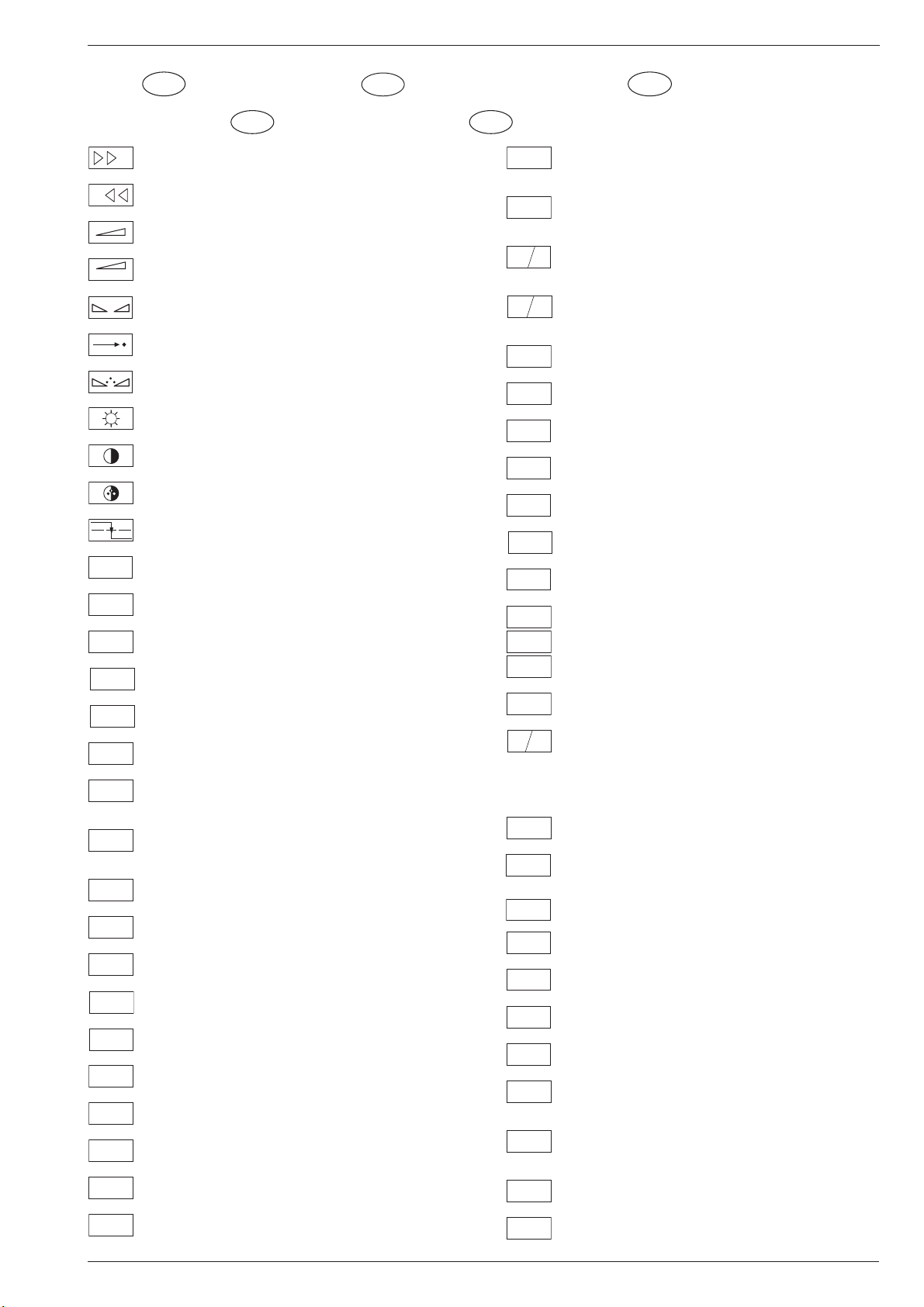
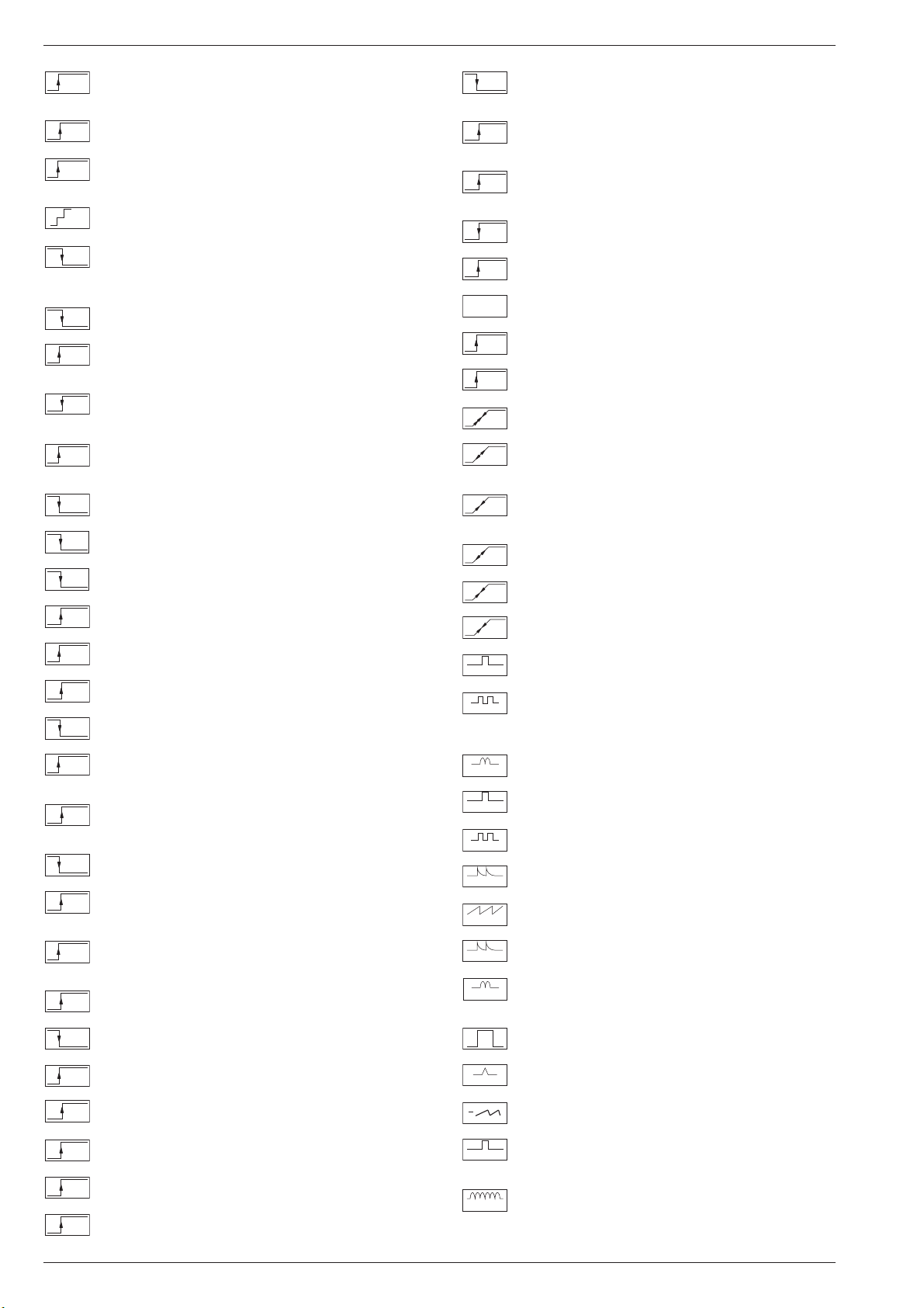
Schaltplansymbole
D
Simboli sullo schema
I
Feinabst. + / Fine tuning + / Réglage fine + / Sint. fine + / Sint. fina +
Feinabst. - / Fine tuning - / Réglage fine - / Sint. fine - / Sint. fina -
Lautstärke / Volume / Volume / Volume sonore / Volumen
Referenz Lautstärke / Volume ref. volt. / Tens. de réf. vol. sonore /
Tens di rif. volume / Tens. ref. volumen
Balance / Balance / Balance / Balanciam. / Balance
Suchlauf / Self seek / Recherche autom. / Sint. autom. / Sintonia
automatica
Farbton / Tint / Teinte / Tinta / Tinte
Helligkeit / Brightness / Luminosité / Luminosita / Brillo
Kontrast / Contrast / Contraste / Contrasto / Contraste
Farbkontrast / Colour contrast / Contraste des coleurs / Contrasto
colore / Contraste de color
Schutzschaltung / Protection circuit / Circuit de sécurité / Circuito di
protezione / Circuito de protección
Audio AM
(Burst Key): Burstaustastimpuls / Burst blanking pulse / Impulsion de
suppress. de burst / Imp. di soppress. del burst / Imp. supresion burst
Ton-Signal / Audio signal / Signal audio / Segnale audio / Señal audio
Ton-Signal links / Audio signal left / Signal audio gauche / Segnale
audio sinistra / Señal audio izquierda
Ton-Signal rechts / Audio signal right / Signal audio droit / Segnale
audio destra / Señal audio derecha
Tonsignal D2 Mac / Audio signal D2MAC / Signal audio D2MAC /
Segnale audio D2MAC / Señal de sonido D2MAC /
Tonsignal links D2 Mac / Audio signal left D2MAC / Signal audio
gauche D2MAC / Segnale audio sinistro D2MAC / Señal de sonido
izquirdo D2MAC
Tonsignal rechts D2 MAC / Audio signal right D2MAC / Signal audio
droit D2MAC / Segnale audio destro D2MAC / Señal de sonido
derecho D2MAC /
Audio Tieftöner / Audio sub woofer / Audio haut-parleur pour les
frequences basses / Audio toni bassi / Audio sonido bajo
Audio-Signal FS Gerät / Audio signal TV set / Signal audio
téléviseur / Segnale audio TV / Señal audio TV
Tonsignal VCR Gerät / Audio signal VCR unit / Signal audio
magnetoscope / Segnale audio VCR / Señal audio VCR
Audio ZF 1 / Audio IF 1 / Audio FI 1 / Audio FI 1 / Audio FI 1
Audio ZF 2 / Audio IF 2 / Audio FI 2 / Audio FI 2 / Audio FI 2
Blau-Signal / Blue signal / Signal bleu / Segnale blu / Señal azul
Basisband / Baseband / Bande de base / Banda base / Banda base
Blau-Signal extern / Signal blue external /Signal bleu externe /
Segnale blu esterno / Señal azul externa
OSD-Einblendung blau / OSD blue / Eblouissement OSD bleu /
Visualizzazione OSD blu / Visualisacione OSD azul
Blau-Signal PIP / PIP Blue signal / Signal bleu PIP / Segnale blu
PIP / Señal azul PIP
GB
Circuit Diagram Symbols
F
Simbolos en los esquemas
E
Blau - Signal - 50Hz vert.,15625Hz hor. / Blue signal - 50Hz vert.,
B/50
15625Hz hor. / Signal bleu - 50Hz vert., 15625Hz hor. / Segnale bleu
- 50Hz vert., 15625Hz hor. / Señal azul - 50Hz vert., 15625Hz hor.
B/100
B-Y 50
B-Y 100
CENTER
CINCH
AUDIO L
CINCH
AUDIO R
CHROMA
CHROMA
CS 100
DATA
ENABLE
ENABLE
ENABLE
EURO-AV
AUDIO-L
EURO-AV
AUDIO-R
EURO-AV
VIDEO
Blau-Signal -100Hz vert., 31250Hz hor. / Blue signal -100Hz vert.,
31250Hz hor. / Signal bleu -100Hz vert., 31250Hz hor. / Segnale blu
-100Hz vert., 31250Hz hor. / Señal azul -100Hz vert., 31250Hz hor.
B-Y -Signal - 50Hz vert., 15625Hz hor. / B-Y -Signal - 50Hz vert.,
15625Hz hor. / Signal B-Y - 50Hz vert., 15625Hz hor. / Segnale BY - 50Hz vert., 15625Hz hor. / Señal B-Y - 50Hz vert., 15625Hz hor.
B-Y -Signal - 100Hz vert., 31250Hz hor. / B-Y -Signal - 100Hz vert.,
31250Hz hor. / Signal B-Y - 100Hz vert., 31250Hz hor. / Segnale BY - 100Hz vert., 31250Hz hor. / Señal B-Y - 100Hz vert., 31250Hz hor.
Kanalwahl / Channel selection / Sélection de canaux / Selez.
C
canale / Seleccion canal
Mittelpunkt-Lautsprecher / Center loudspeaker / Haut-parleur de
centre / Alto parlante punto centrale / Altavoz del centro
CHIP
Chip Adresse / Chip adress / Chip direction / Indiri. del chip /
ADR
Direccion chip
Ton-Signal Cinch links / Audio signal cinch left / Signal audio cinch
gauche / Segnale audio cinch sinistra / Señal audio cinch izquierda
Ton-Signal Cinch rechts / Audio signal cinch right / Signal audio
cinch droit / Segnale audio cinch destra / Señal audio cinch derecha
Chroma Signal / Chroma signal / Signal dégree / Croma segnale /
Señal croma
Chroma S-VHS-Signal / Chroma S-VHS-Signal / Signal dégree de
S-VHS
S-VHS / Croma segnale S-VHS / Señal croma S-VHS
Clock
CLK
CL 1
CL 2
Composite Sync. Imp. für VT / Composite sync pulse for TT / Imp. de
CSY
sync. vidéo-composite pour TXT / Imp. hor. para Video Comp.
Kombiniertes Hor./vert. Sync. Signal 31250Hz/100Hz (Composite
Sync.) / Combined hor./vert. sync signal 31250Hz/100Hz (Composite Sync) / Signal synchr. hor./vert. combiné 31250Hz/100Hz
(Synchr. composité) / Segnale sincr. orizz./vert. 31250Hz/100Hz
(Sincr. Composito) / Señal combinada sincr. hor./vert. 31250/100Hz
(Sincr. compuesto)
Daten / Data / Données / Dati / Datos
Verzögerungsleitung / Delay line / Ligne à retard / Linea di ritardo /
DL
Linea de retardo
Freigabe / Enable / Autorisation / Consenso / Habilitacion
ENA
ENA
Freigabe ZF / IF Enable / Validation FI / Consenso FI / Autorizacón FI
ZF
Freigabe FT / Finetuning enable / Autorisation Réglage fin / Abilitaz.
FT
Sintonia fine / Habilitacion Sintoinia fina
Freigabe LED / LED enable / Autorisation LED / Abilitaz. LED /
LED
Habilitacion LED
Freigabe Ton / Sound enable / Autorisation son / Abilitaz. audio /
TON
Habilitacion sonido
Audio-Signal EURO-AV links / Audio signal EURO-AV left / Signal
audio EURO-AV gauche / Segnale audio EURO-AV sinistra / Señal
audio izquierda EURO-AV
Audio-Signal EURO-AV rechts / Signal audio EURO-AV right /
Signal audio EURO-AV droit / Segnale audio EURO-AV destra /
Señal audio derecha EURO-AV
Video-Signal EURO-AV / Video signal EURO-AV / Signal video
EURO-AV / Segnale video EURO-AV / Señal video EURO-AV
Farb-Signal / Chroma signal / Signal chroma / Segnale chroma /
F
Señal croma
Symboles schéma
GRUNDIG Service 1 - 7
Page 8

Allgemeiner Teil / General Section CUC 2030 N / 2050 N / 2058 N / 2059 N / 2080 N
FBAS
FBAS
CINCH
FBAS
MAC
FBAS
TON
FBAS
TXT
FBAS
TEXT
FBAS
SYNC.
FBAS
S-VHS
F
H
FRM
FT
F
U
F
V
G
G
OSD
G PIP
G EXT
G/50
G/100
GND - H
HA
HDR
HC
H
SYNC
HFB
HS
I2S CL
I2S TER
I2S IN
I2S WS
I BEAM
ICL
FBAS-Signal / CCVS signal / Signal vidéo composite / Segnale video
composito / señal video compuesta
FBAS-Signal-Cinch Buchse / CCVS signal-cinch socket / FBASprise à cinch / FBAS-presa cinch / FBAS-cinch
FBAS-D2 MAC / D2MAC CCVS signal / Signal vidéo compositeD2MAC / FBAS-D2MAC / FBAS-D2MAC
Basisband / Baseband / Bande de base / Banda base / Banda base
FBAS-Videotext / CCVS videotext / Signal vidéo compositeTélétexte / FBAS-Televideo / FBAS-Teletexto
FBAS Sync. Signal / CCVS sync signal / Signal sync. vidéo col.
comp. / Segnal sincr. video col. comp. / Señal sincr. video
compuesta
FBAS Signal S-VHS / CCVS signal S-VHS / Signal vidéo col. comp. SVHS / Segnal video col. comp. S-VHS / Señal video compuesta S-VHS
Hochspg. / EHT voltage / Haute tens. / Alta tens. / MAT
Rahmensignal / Frame signal / Signal d'encadrement / Segnale
cornice / Señal de marco
Feinabstimmung / Fine tuning / Reglage fin / Sint. fine / Sint. fina
FU-Signal / FU-signal / Signal FU / Segnale FU / Senal FU
FV-Signal / FV-signal / Signal FV / Segnale FV / Senal FV
Grün-Signal / Green signal / Signal green external / Signal vert /
Segnale verde / Señal verde
OSD-Einblendung grün / OSD green / Eblouissement OSD vert /
Visualizzazione OSD verde / Visualisacione OSD verde
Grün-Signal PIP / Green signal PIP / Signal green PIP/ Signal vert
PIP / Segnale verde PIP / Señal verde PIP
Grün-Signal extern / Green signal vertical / Signal vert externe /
Segnale verde esterno / Señal verde externa
Grün-Signal - 50Hz vert.,15625Hz hor. / Green signal - 50Hz vert.,
15625Hz hor. / Signal vert - 50Hz vert., 15625Hz hor. / Segnale
verde - 50Hz vert., 15625Hz hor. / Señal verde -50Hz vert., 15625Hz hor.
Grün-Signal -100Hz vert., 31250Hz hor. / Green signal -100Hz vert.,
31250Hz hor. / Signal vert -100Hz vert., 31250Hz hor. / Segnale
verde -100Hz vert., 31250Hz hor. / Señal verde -100Hz vert.,
31250Hz hor.
Nullpunkt Heizung / Ground filament / Point neutre-Chauffage /
Punto zero-Filamento / Punto medio filamento
Horiz. Sync. Impuls / Horiz. Sync pulse / Impulsion synchro. horiz. /
Impulso sincro orizzontale / Impulso de sinc. horiz.
Horiz. Ansteuerimpuls / Horiz. drive pulse / Impulsion de commande
horiz. / Impulso comando orizzontale / Impulso de control horiz.
Horiz. Klemmimpuls / Horiz. clamp pulse / Impulsion de serrage
horiz. / Impulso comando orizzontale / Impulso de garras horiz.
Horizontaler Sync-Impuls / Horizontal Sync impuls / Sync impuls
horizontale / Sinc impulso orrizontale / Impulso sync horizontal
Horiz. Rückschlagimpuls / Horiz. flyback / Impulsion de retour
horiz. / Impulso rotorno orizzontale / Impulso de retroceso horiz.
Hor. Sync. Implus für VT / Hor. sync pulse for TT / Imp. de sync. hor. pour
TXT / Imp. sincr. orizz. per Televideo / Imp. hor. para Video Comp.
Digitale Datensignale / Digtital data signals / Signal donneé digital /
Segnali dati digitali / Señal datos digital
Strahlstrom / Current beam / Current rayon / Corrante del irradire /
Corriente de haz
I2C Bus -Clock
IR
IM
CLOCK
IM
IDENT
IM
RESET
IR CLK
IR DATA
IR
VIDEO
KB
KH
AUDIO-L
KH
AUDIO-R
L
LED
M
MEGA
LOGIC
MODE
NIC CLK
NORM
OWA
P
P/C
PIP
P1
R
REMOTE
R
OSD
R PIP
R EXT
R-Y 50
R-Y 100
S
Infrarot-Signal / Signal infrared / Signal infra-rouge / Segnale
infrarosso / Señal infrarojo.
I2C Bus -Clock
I2C Bus -Kennung / I2C-Bus Identification / Identification I2C-Bus /
2
Ident. I
C-Bus, Identification I2C-Bus
I2C Bus -Reset
Infrarot Clock / Infrared clock / Signal I.R. horloge / Clock segnale
R.I. / Clock infrarojos
Infrarot Signal / Infrared signal / Signal I.R. / Segnale infrarosso /
Data infrarrojos
Infrarot Signal Video / Infrared signal video / Signal I.R. video /
Segnale infrarosso video / Data infrarrojos video
Keyboard
Tonsignal Kopfhörer links / Audio signal headphone left / Signal
audio gauche de casque / Segnale audio sinistra cuffia / Señal audio
izquierda auriculares
Tonsignal Kopfhörer rechts / Audio signal headphone right / Signal
audio droit de casque / Segnale audio sinistra cuffia / Señal audio
derecha auriculares
Lautstärke / Volume / Volume / Volume sonore / Volumen
Leuchtdiode / Light emitting diode / Diode lumineuse / Diodo
luminoso / Diodo luminescente
Speicher Taste / Memory button / Touche mémoire / Tasto di
memoria / Puls. memoria
Megalogic Daten / Megalogic data / Megalogic dates / Dati
Megalogic / Megalogic datas
Modus / Mode / Mode / Modo / Modo
NICAM Clock / Clock NICAM / Horloge NICAM / Clock NICAM /
Clock NICAM
Norm Taste / TV standard select button / touche de norme / Tasto
norma / Puls. de norma
Ost-West Ansteuerimpuls / East-west drive impuls / Impulsion de
commande Est-Ouest / Impulso comando Est-Ovest / Impulso de
control Este-Oeste
Programm / Program / Programme / Programma /Programa
Programm-Kanalwahl / Program channel selection / Progr. sélection
de canaux / Progr. selez.canale / Progr. selec. canal
Bild im Bild / Picture in picture / Image dans l'image / PIP / Imagen
en la imagen
Progr. Taste / Progr. button / Touche Progr. / Tasto Progr. / Puls.
Progr.
Rot-Signal / Red signal / Signal rouge / Segnale rosso / Señal rojo
Fernbedienung / Remote control / Telecommande / Telecomando /
Mando a distancia
OSD-Einblendung rot / OSD red / Eblouissement OSD rouge /
Visualizzazione OSD rosso / Visualisacione OSD rojo
Rot-Signal PIP / Red signal PIP / Signal rouge PIP / Segnale rosso
PIP / Señal rojo PIP
Rot-Signal extern / Signal red external / Signal rouge externe /
Segnale rosso esterno / Señal rojo externa
R-Y -Signal - 50Hz vert., 15625Hz hor. / R-Y -Signal - 50Hz vert.,
15625Hz hor. / Signal R-Y - 50Hz vert., 15625Hz hor. / Segnale RY - 50Hz vert., 15625Hz hor. / Señal R-Y - 50Hz vert., 15625Hz hor.
R-Y -Signal - 100Hz vert., 31250Hz hor. / R-Y -Signal - 100Hz vert.,
31250Hz hor. / Signal R-Y - 100Hz vert., 31250Hz hor. / Segnale
R-Y - 100Hz vert., 31250Hz hor. / Señal R-Y - 100Hz vert., 31250Hz hor.
Sonderkanal / Special channel / Canal special / Canale speciale /
Canal especial
1 - 8 GRUNDIG Service
Page 9

CUC 2030 N / 2050 N / 2058 N / 2059 N / 2080 N Allgemeiner Teil / General Section
SB
SCL
SCL 100
SDA
SHIFT
VIDEO
SHIFT
TEXT
SS
SSB
SSC
SSC
PIP
SSC 100
SSC 50
SUR-
ROUND
SYNC
SYNC.
BTX
SYNC.
VT
SW
TE
T1
T2
TT
U
FOC
U
G1
U
H
U
G2
VA
VB
VCL
VDR
VG
Strahlstrombegrenzung / Beam current lim. / Lim. cour. de faisceau /
Lim. corr. di raggio / Corriente media de haz
I2C-Bus Clock
Schneller I2C-Bus Clock / I2C-Bus clock high speed / I2C-Bus grande
2
vitesse / I
I2C-Bus Daten / I2C-Bus data / I2C-Bus données / I2C-Bus dati /
I
Dynamische vert. Versch. 25Hz, aktiv bei Video u. Mix Betrieb /
Dynam. vert. shift 25Hz, active on video and mix operation / Decal
dynam. de l'image 25Hz, actif sur video et fonction. mixte / Spostam.
vert. dinam. 25Hz, attivo con video e. funzionam. misto / Desplaz.
dinamico vert. 25Hz, activo con video Y funciones mixtas
Dynamische vert. Versch. 25Hz, aktiv bei Standbild u. VT / Dyn. vert.
shift 25Hz, active on freeze-frame and Teletext / Decal dynam. de
l'image 25Hz, actif sur arret immage et Vidéotext (Antiope) / Spostam.
vert. dinam. 25Hz, attivo con fermo immag. e Televideo / Desplaz.
dinamico vert. 25Hz, activo con imagen parada Y Videotexto
Schutzschaltung / Protection circuit / Cablage protecteur / Pot. de
prot. / Circuito de proteccion
Spitzenstrahlstrombegrenzung / Peak beam current limiting / Lim.
de faisceau crete / Lim. corr. catod. di pico / Corrente pico de haz
Supersandcastle
Supersandcastle PIP
Supersandcastle 100Hz vert., 31250Hz hor.
Supersandcastle 50Hz vert., 15625Hz hor.
Surround
Sync.-Signal / Sync.-Signal / Signal sync / Segnale sync. / Señal de sync.
Sync. BTX / Viewdata Sync / Sync. Télétext / Sincr. Videotel / Sincr.
Videotexto
Sync. VT / Sync. Teletext / Sync Vidéotexte / Sincr. Televideo / Sincr.
Videotexto
Schwarzwert / Black level / Niveau du noir / Livello del nero / Nivel de negro
TEXT-Freigabe / TEXT enable / Autorisation TEXTE / Abilitaz.
TELEVIDEO / Habilatation TEXTE
Bei Zweiton, Ton 1 / On two channel sound, sound 1 / Pour double
son, son 1 / In bicanale, audio 1 / En dual, sonido 1
Bei Zweiton, Ton 2 / On two channel sound, sound 2 / Pour double
son, son 2 / In bicanale, audio 2 / En dual, sonido 2
Tieftöner / Woofer / Haut-parleur pour les frequences basses / Toni
bassi / Sonido bajo
Fokusspg. / Focussing volt. / Tens. de focalis. / Tens di focalizz. /
Tens focalizacion
Spg. Gitter G 1 / Volt. grid G1 / Tens grille G 1 / Tens. griglia G1 / Tens.
rejillas G 1
Hochspannung / High voltage / Haute tension / EAT / Alte tension
Schirmgitter Spg. / Screen-grid volt. / Tens. de grille - écran / Tens.di
griglia schermo / Tens. de rejilla
Vertikaler Ansteuerimpuls / Vert. drive pulse / Impulsion de commande
verticale / Impulso di comando verticale / Impulso de control vertical
VCR - Clock
Freigabe Anzeigebaustein / Display enable / Autorisation pour module
indicateur / Modulo indicazione / Habilitacion modulo indicacion
Vert. Gegenkopplung / Vert. feedback / Contre-reaction verticale /
Controreazione vert. / Aliment. neg. vert.
2
C-Bus datos
C-Bus veloce / Clock del I2C-Bus de alta velocida
VIDEO
VT DATA
VT SCL
VT SDA
V SYNC
Y 50
Y 100
U
U
U
U
U
U
U
U
U
U
U
U
U
U
U
U
U
U
Video Signal / Video signal / Signal vidéo / Segnale video / Señal video
Videotext Daten / Teletext data / Données Teletexte / Linea dati
Televideo / Data Teletexto
Videotext Clock / Teletext clock / Signal horloge Vidéotext / Clock
Televideo / Clock Teletexto
I2C Bus: VT Daten / Teletext data / Données Vidéotext / Dati
Televideo / Data Teletexto
Vertikaler Sync-Impuls / Vertical Sync impuls / Sync impuls vertical
/ Sinc impulso vertical / Impulso sync vertical
Y
Y-Signal / Y Signal / Signal Y /Segnale Y / Señal Y
Y -Signal - 50Hz vert., 15625Hz hor. / Y -Signal - 50Hz vert., 15625Hz
hor. / Signal Y - 50Hz vert., 15625Hz hor. / Segnale
Y - 50Hz vert., 15625Hz hor. / Señal Y - 50Hz vert., 15625Hz hor.
Y - Signal - 100Hz vert., 31250Hz hor. / Y -Signal - 100Hz vert.,
31250Hz hor. / Signal Y - 100Hz vert., 31250Hz hor. / Segnale
Y - 100Hz vert., 31250Hz hor. / Señal Y - 100Hz vert., 31250Hz hor
Zwischenfrequenz / IF / FI / FI / FI
ZF
AFC
Schaltspg. AFC / AFC switching volt. / Tens. de commut. AFC/ Tens.
di commut. AFC / Tens. conmut. CAF
AV
Schaltspg. AV / Switching volt. AV / Tens. de commut. AV / Tens. di
commut. AV / Tens. conmut. AV
B1
Schaltspg. Band 1 / Switching volt. band 1 / Tens. de commut.
bande 1 / Tens. di commut. banda 1 / Tens. conmut. de banda 1
B2
Schaltspg. Band 3/ / Switching volt. band 3 / Tens. de commut.
bande 3 / Tens. di commut. banda 3 / Tens. conmut. de banda 3
BA
Schaltspg. Bildamplitude / Switching voltage vertical amplitude /
Tension de coupure amplitude dìmage / Tensione di commutaz.
ampiezza d'imagine / Tension de conm. amplitude de imagen di
commut. PAL / Tens. conmut. PAL
BTX
Schaltspg. BTX / Switching volt. BTX (Viewdata) / Tens. commut.
Télétext / Tens. commut. VIDEOTEL / Tens. conmut. Teletexto
C-AV
Schaltspg. Camera Wiederg. über Camera-AV Eingang / Switching
volt. cam. playback via Camera-AV input / Tens de commut pour lec.
de camera par l'entree Camera-AV / Tens.de commut. in riproduz.
camera tramite ingresso Camera-AV / Tens. de serv. reprod. camera
a traves de la entrada Camera-AV
DATA
Schaltspg. Datenbetr. / Switching volt. data mode / Tens. de commut. fonct. données / Tens. di commut. dati / Tens conmut. datos
DATA
Schaltspg. U Data extern / Switching volt Data ext. / Tension de
EXT
commutation U Data externe / Tens. di commutazione U-Data
esterno / Tensión de conmutatón externa U
DATA
Schaltspg. für Bildschirm-Einblendung / Switching volt. for On
OSD
Screen Display / Tens. commut. pour eblouissement On Screen
Display / Tens. commut. per di visualizzazione On Screen Display /
Tens. conmut. para On Screen Display
DEEM
Schaltspg. Deemphasis / Switching volt. deemphasis / Tens. commut. desaccent. / Tens. commut. deenfasi / Tens. conmut. deenfasis
DS
Schaltspg. Dolby-Surround / Switching volt. Dolby-Surround / Tens.
commut. Dolby-Surround / Tens. commut. di Dolby-Surround / Tens.
de conmut. Dolby-Surround
EURO-
Schaltspg. EURO-AV / Switching volt. EURO-AV / Tens. de commut.
AV
EURO-AV / Tens. di commut. EURO-AV / Tens. conmut. EURO-AV
EU-AV
Schaltspg. EURO-AV-Cinch-Buchse / Switching volt. EURO-AV-
CINCH
Cinch socket / Tens. commut. prisa Scart - Cinch / Tens. commut.
presa Scart -Cinch / Tens. conm. EURO-AV - Cinch
FBAS
Schaltspannung für Video-Ausgang EURO-AV Buchse / Switch.
voltage for video output EURO-AV socket / Tension de commut.
pour sortie vidéo EURO-AV / Tension commut. per presa d'uscita
video EURO-AV / Tension de conmut. para salida EURO-AV
HIFI
Schaltspg. HIFI / Switching voltage HIFI / Tens. de commut. HIFI /
Tens di commut. HIFI / Tens. conmut. HIFI
HIFI
Stummschaltung HiFi / Muting volt. HiFi / Commutation de silence
MUTE
HiFi / Silenzametno HiFi / Muting HiFi
HUB
Schaltspg. HUB / Switching volt. deviation / Tens. commut.
déviation / Tens. commut. deviazione / Tens. conmut. deviacion
GRUNDIG Service 1 - 9
Page 10
Allgemeiner Teil / General Section CUC 2030 N / 2050 N / 2058 N / 2059 N / 2080 N
U
U
U
U
U
IDENT
Schaltspg. Signalkennung AV 3 / Switching volt. signal identification
AV 3 / Tens de commut.identification de signal AV3 / Tens. commut.
identificazione segnale / Tens. conmut. identifi. segñal AV3
KH
Stummschaltung Kopfhörer / Muting volt. headphone / Commutation
MUTE
de silence casque / Silenzamento cuffia / Muting auriculares
KLEMM
Gleichspannung für SAT-Basissignal / DC for SAT basic signal /
Tens. continue pour SAT base signal / Tens continua per segnale
SAT base / Tens. continua para segñal SAT base
KOIN
Schaltspg. Koinz. / Switching volt. coinc. / Tens de commut. coinc. /
50/60Hz
Tens di commut. coinc. / Tens. conmut. coinc.
KOIN
Schaltspg. Koinz. mit Videoquelle verknüpft / Coinc. switching volt.
VQ
linked with video source / Signal de coincid. combiné avec source
video / Tens. di commut. a coinc. combinata con sorg video segñal
U
U
U
U
U
WISCH
Schaltspg. Wischerkontakt / Schwitching voltage temp. contact /
Tens. de commut. contact fugitif / Tens. commut. contatto temporaneo / Contacto supresor tens. de conmut.
W/N
Schaltspg. ZF breit - schmal / IF switching volt. wide - narrow / Tens.
commut. FI large - etroit / Tens. commut. FI larga - stretta / Tens. FI
ancho - estrecho
I / III
Schaltspg. Bandwahl / Band sel. switching volt. / Tens. de commut.
select. bande / Tens. di commut. selez. banda / Tens. conmut. selec.
banda
14V
14V Schaltspg. / 14V switching volt. / Tens. commut. 14V / Tens.
commut. 14V / Tens. de conm. 14V
22kHz
22kHz Schaltspg. / 22kHz switching volt. / Tens. commut. 22kHz /
Tens. commut. 22kHz / Tens. de conm. 22kHz
de coincidencia combinada con video
U
U
U
U
U
U
U
U
U
U
U
U
U
U
U
U
U
U
U
U
U
U
U
LED
Schaltspg. LED / Switching volt. LED / Tens de commut. LED / Tens.
commut. LED / Conmut. LED
Leucht-
Schaltspg. Leuchtpunktunterdrückung / Switching volt. beam spot
punkt
suppression / Tens. de commut. suppress. du spot lumineux / Tens.
soppr. punto luminoso / Tens. de conmut. filtro supresor del punto luz
LNC
Schaltspg. LNC "Aus" / Switching volt. LNC "OFF" / Tens. de
OFF
commut. LNC "OFF" / Tensione di commut. "Spento" LNC / Tension
LNC "OFF"
MAC
Schaltspg. D2MAC / Switching volt. D2MAC / Tension de
commutation D2MAC / Tens. di commutazione D2MAC / Tensión de
conmutación D2MAC
MUTE
Stummschaltung / Muting / Silencieux / Silenziamento /Muting
NF 1
Schaltspg. NF 1 / Switching volt. AF 1 / Tension commut. BF 1 / Tens.
commut BF 1 / Tens. conm. BF 1
NF 2
Schaltspg. NF 2 / Switching volt. AF 2 / Tension commut. BF 2 / Tens.
commut BF 2 / Tens. conm. BF 2
NIC
Schaltspg. NICAM / Switching volt. NICAM / Tens. de commut.
NICAM / Tens. commut. NICAM / Tens. de conmut. NICAM
NORM
Schaltspg. Norm / Switching volt. Norm / Tens. de commut.
standard / Tens. di commut. Norma / Tens. conmut. Norma
PAL
Schaltspg. PAL / Switching volt. PAL / Tens. de commut. PAL / Tens.
di commut. PAL / Tens conmut. PAL
POL.
Schaltspg. Polarität / Switching volt. polarity / Tension commut.
polarite / Tens. commut. polarita / Tens. conmut polarizacion
POWER
Schaltspg. Ökoschalter / Switching volt. eco switch / Tens. de
OFF
commut. interr. eco. / Tens. commut. interr. ecologico / Tens.
conmut. interr. ecol.
PV
Schaltspg. Panorama View / Switching volt. Panorama View / Tens.
de commut. Panorama View / Tens. commut. Panorama View /
Tens. conmut. Panorama View
RESET
Schaltspg. Reset / Switching volt. Reset / Tens. commut. Reset /
Tens. commut. Reset / Tens. conmut. Reset
RGB
Schaltspg. RGB1 - RGB2 / Switching volt. RGB1 - RGB2 / Tens. de
commut. RGB1 - RGB2 / Tens. di commut. RGB1 - RGB2 / Tens.
conmut. RGB1 - RGB2
SCHUTZ
Schaltspg.-Schutzfunktion / Switching volt.-protective func. / Tens
de commut.-sécurité / Tens. di commut.-funz di protez. / Tens.
conmut.-proteccion
SEC
Schaltspg. SECAM / Switching volt. SECAM / Tens. de commut.
SECAM / Tens. di commut. SECAM / Tens. conm. SECAM
STBY
Schaltspg. Standby / Switching volt. Standby / Tens. commut.
Veille / Tens. commut. Standby / Tens. conmut. Standby
S-VHS
Schaltspg. S-VHS / Switching volt. S-VHS / Tens.de commut.
S-VHS / Tens. de commut. S-VHS / Tens. de conmut. S-VHS
TON
Schaltspg. Ton 1-2 / Switching volt. sound 1-2 / Tens. commut. audio
1/2
1-2 / Tens. commut. son 1-2 / Tens. conmut. son 1-2
UHF
Schaltspg. UHF / UHF switching volt. / Tens. de commut. UHF / Tens
di commut. UHF / Tens. conmut. UHF
VHF
Schaltspg. VHF / VHF switching volt. / Tens. de commut. VHF / Tens
di commut. VHF / Tens. conmut. VHF
VQ
Schaltspg. Videoquelle / Switching volt. video source / Tens. de
commut. source video / Tens. di commut. sorg. video / Tens conmut.
0/3/6/9V
U
U
U
U
U
U
U
U
HOR.2FH
VER.2FV
VERT. 100
VERT. 100
PULSE
0/3/6/9V Schaltspg. / 0/3/6/9V switching volt. / Tens. commut.
0/3/6/9V / Tens. commut. 0/3/6/9V / Tens. de conm. 0/3/6/9V
4.5MHz
Schaltspg. 4,5MHz / Switching volt. 4.5MHz / Tens. de commut.
4,5MHz / Tens. di commut. 4,5MHz / Tens conmut. 4,5MHz
50/60
Schaltspg. 50-60Hz / Switching volt. 50-60Hz / tens. de commut.
Hz
50-60Hz / Tens. di commut. 50-60Hz / Tens. conmut. 50-60Hz
Regelspg. AFC / AFC contr. volt. / Tens. de regul. AFC / Tens. di
AFC
contr. AFC / Tens. regul. CAF
AFC
Regelspg. AFC Satellitentuner / AFC contr. volt. SAT tuner / Tens.
SAT
de regul. AFC tuner SAT / Tens. di contr. AFC Tuner SAT / Tens.
regul. CAF Tuner SAT
Feldstärkeabhängige Spg. / Fieldstrength-depent volt. / Contr. auto-
AGC
matique de gain / Tens. dipent. intens. campo / Contr. autom. de gain
tens. CAG
Regelspg. / Contr. volt. / Tens. de regul. / Tens. di contr. / Tens regul.
RE
Abstimmspg. Tuner / Tuning volt. tuner / Tens. d'accord tuner / Tens.
TUN.
di sintonia tuner / Tens. sintonia tuner
Regelspg. Verzög. / Delayed contr. volt. / Tens. de regul. retardee /
τ
Tens. regul. retardada
Horizontale Ansteuerung / Horiz. drive / Synchr. lignes / Pilotaggio
HOR.
orizz. / Exitación horiz.
31250Hz Ansteuerimp. für Zeilenendstufe / 31250Hz Triggering
pulse for horiz. output / 31250Hz commande pour l'étage final
lignes / Imp. Pilotaggio di 31250Hz per stadio finale di riga / Impulso
de exitación 31250Hz para paso final de lineas
Vert. Parabel / Vert. parabolic signal / Signal parabolique vert. /
VERT.
Segnale parab. vert. / Senal parabolica vert.
Vert. Tastimpuls / Vert. Gating pulse / Imp. trame / Imp. a cadenza
VERT.
vert. / Imp. cuadro
Vert. Tastimpuls 100Hz / Vert. Gating pulse 100Hz / Imp. trame
100Hz / Imp. a cadenza vert. 100Hz / Imp. cuadro 100Hz
Vert. Sägezahn / Vert. saw tooth / Signal dent de scie / Dente di sega
VERT.
vert. / Dientede sierra vert.
Vert. Tastimpuls / Vert. Gating pulse / Imp. trame / Imp. a cadenza
VERT.
vert. / Imp. cuadro
Vert Sägezahn 100Hz / Vert saw tooth 100Hz / Signal dent de scie
100Hz / Dente di sega vert. 100Hz / Dientede sierra vert. 100Hz
Vert. Parabel 100Hz / Vert. parabolic 100Hz signal / Signal parabolique 100Hz vert. / Segnale parab. vert. 100Hz / Senal parabolica
vert. 100Hz
Tastimpuls / Gating pulse / Impuls de declenchement / Impulso a
cadenza / Imp. puerta
Ref. Impuls hor. / Reference impulse hor. / Imp. de refer.hor. / Imp.
REF.
di rifer. hor. / Imp. refer. horiz.
Klemmung Ein-Aus / Clamping On-Off / Clampage Marche-Arrêt /
Clamping Ins.-Disins. / Clamping Enc.-Apag.
Pulse für Polarotor / Pulses for Polar-Rotor / Impulsions Rotor de
Polariastion / Impulsi per Rotore Polarizzazione / Impulsos dara
Polarrotor
O-W Amplitude / E-W amplitude / Amplitude E-O / Ampiezza E-O /
O/W
Amplitud E-O
video
1 - 10 GRUNDIG Service
Page 11
CUC 2030 N / 2050 N / 2058 N / 2059 N / 2080 N Allgemeiner Teil / General Section
GRUNDIG Service 1 - 11
Bedienhinweise
Materialnummer Sie in der entsprechenden Ersatzteilliste finden.
Einstellungen
Der Vorgang kann – je nach Anzahl der zu empfangenden Fernseh-Programme – eine Minute und
länger dauern.
Der Programmsuchlauf kann mit Taste
¢
TXT
abgebro-
chen werden.
Nach dem Suchvorgang schaltet das Gerät auf
Programmplatz 1 und die Seite »SORTIER.« wird
eingeblendet.
❒
Programme löschen
Programm, das gelöscht werden soll, mit Taste p
oder P anwählen.
Programm mit Taste
¢
AUX löschen.
Um weitere Programme zu löschen, ist der Vorgang
ab Pkt. zu wiederholen.
❒
Programme sortieren
Programm, das umsortiert werden soll, mit Taste
p oder P anwählen.
Programm mit Taste G markieren.
Neuen Programmplatz mit Taste p oder P an-
wählen.
Einstellung mit Taste G speichern.
Zum Sortieren weiterer Programme ist der Vorgang
ab Pkt. zu wiederholen.
Einstellungen mit Taste
¢
TXT
beenden.
Die Seiten »AUTOMATIC TUNING SYSTEM«,
»SORTIER.« (unter »PROGRAMM SORTIERUNG«)
und »SPRACHAUSWAHL« können auch direkt aus
dem »DIALOG CENTER« aufgerufen werden.
Ǻ
5
1
Ǻ
4
3
2
1
1
Ǻ
2
1
Ǻ
Ǻ
Ǻ
Programmplätze belegen, mit dem
Suchlauf-Speicher-System ATS
Das Gerät ist mit dem automatischen Programmsuchlauf ATS ausgestattet, der Ihnen das manuelle
Belegen der Programmplätze abnimmt.
Sie starten den Suchlauf und können danach die
Programme in der Reihenfolge Ihrer Wahl
sortieren.
Sie können auch Programme – die mehrmals
gefunden wurden oder deren Empfangsqualität zu
schlecht ist – aus der Programmliste löschen.
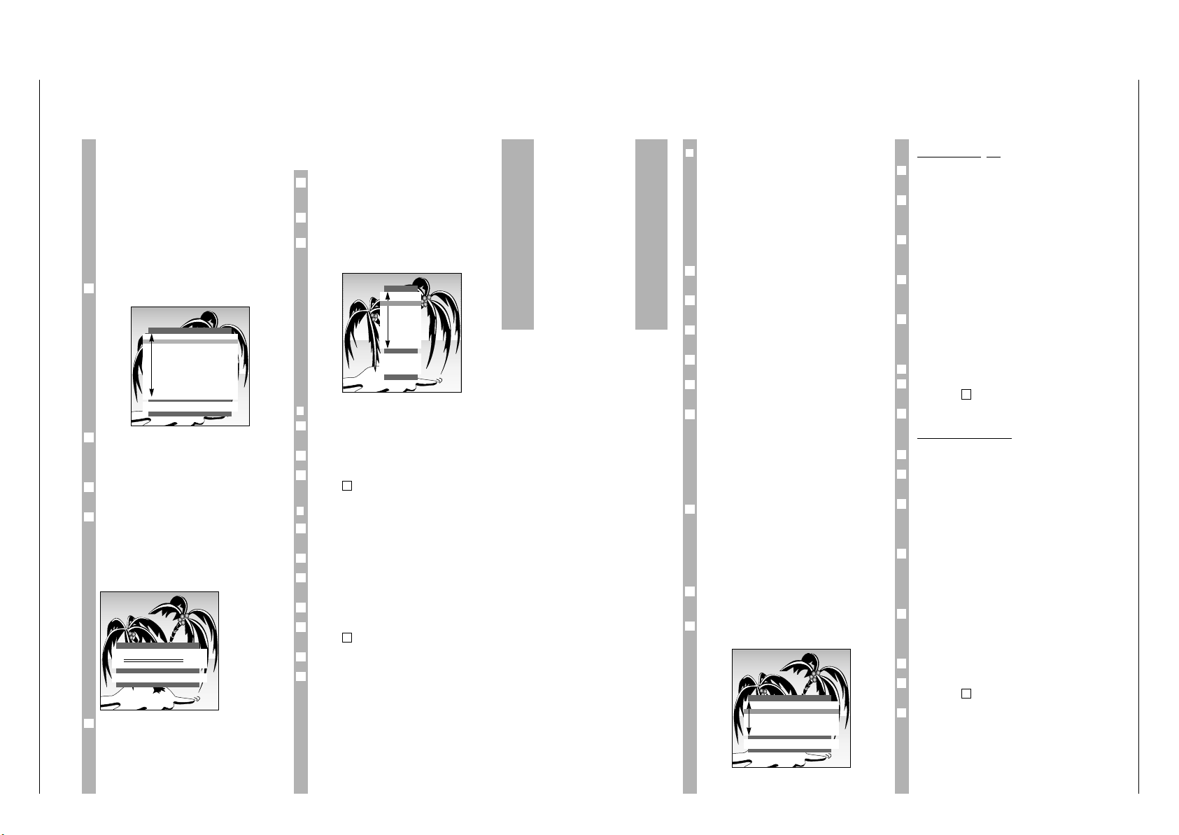
Nach dem Einschalten des Gerätes wird die
Seite »SPRACHAUSWAHL« eingeblendet.
Für den Dialog zwischen Ihnen und dem Fernsehgerät kann aus mehreren Sprachen gewählt
werden. Die Einblendungen der Benutzerführung
erfolgen in der gewählten Sprache.
Dialogsprache mit Taste p
oder
P auswählen und
mit Taste G bestätigen.
»Land« mit Taste p oder P auswählen und mit
Taste G bestätigen.
Finden Sie Ihr Land nicht in der Liste, dann wählen
Sie »*übrige« und bestätigen mit Taste G.
Die Seite »AUTOMATIC TUNING SYSTEM« blendet
sich ein.
Die Seite »AUTOMATIC TUNING SYSTEM« kann
auch direkt aus dem »DIALOG CENTER« aufgerufen
werden.
Ǻ
3
2
Ǻ
1
AUTOMATIC TUNING SYSTEM
■
SORTIER.
OK Sortier.
AUX Lšschen
ǺǺ
ZurŸck
TXT
TV
P 01
P 02
P 03
P 04
P 05
P 06
P 07
P 08
P 09
P 10
SPRACHAUSWAHL
OK
D Deutsch
DK Dansk
E Espa–ol
F Fran•ais
GB English
GR Hellas
I Italiano
N Norge
NL Nederlands
P Portugues
S Svenska
SF Suomi
TR TŸrk•e
Einstellungen
❒
Begrenzen der Programmplatzwahl
Der ATS-Suchlauf speichert alle gefundenen
Programme und “sperrt“ den ersten nichtbelegten
Programmplatz automatisch. Dadurch können bei
der schrittweisen Programmplatzwahl (“Zappen“)
mit den Tasten p, P nur die gefundenen Programme angewählt werden.
Sie können diese Begrenzung auch manuell eingeben. Im Beispiel wurde ab Programmplatz 6
“gesperrt“.
Taste h und anschließend Taste G drücken.
Die Seite »DIALOG CENTER« blendet sich ein.
Die Zeile »MANUELLE ABSTIMMUNG« mit Taste p
oder
P anwählen und mit Taste G bestätigen.
In der Seite »MANUELLE ABSTIMMUNG« mit Taste
F oder E Programmplatz 6 wählen.
Die Zeile »C/S« wählen und mit Taste F
oder
E
»Kanal« wählen.
Die Zeile »Kanal« wählen und mit den Ziffern-
Tasten 0…9 »00« eingeben.
Einstellung mit Taste G speichern und mit Taste
¢
TXT
beenden.
Jetzt können die ersten 5 Programme in schneller
Folge durchgeschaltet werden, die nachfolgenden
Programmplätze sind mit den Tasten p, P nicht
mehr anwählbar. Alle einstelligen Programmplätze
können weiterhin mit den Zifferntasten
0 … 9 angewählt werden.
Wird ab Programmplatz 11 gesperrt, können alle
nachfolgenden Programmplätze mit den Zifferntasten 0 … 9 angewählt werden.
Fernseh-Programme manuell
einstellen
Taste h und anschließend Taste G drücken.
Die Seite »DIALOG CENTER« blendet sich ein.
Die Zeile »MANUELLE ABSTIMMUNG« mit Taste p
oder P anwählen und mit Taste G bestätigen.
2
1
Ǻ
6
5
4
3
2
1
Direkte Kanaleingabe
Programmplatz mit den Zifferntasten 0 … 9 oder
mit Taste F
oder
E wählen.
Die Zeile »C/S« mit Taste p oder P wählen.
Mit Taste F
oder
E »Kanal« oder »Sonderkanal«
wählen.
Die Zeile »Kanal« mit Taste p oder P anwählen.
Gewünschte Kanalzahl mit den Zifferntasten
0 … 9 oder mit Taste F
oder
E eingeben.
Die Zeile »Standard« mit Taste p oder P
anwählen. Mit Taste F
oder
E benötigte Einstel-
lung wählen.
Bild eventuell feinabstimmen. Dazu die Zeile
»Finetun.« mit Taste p oder P anwählen.
Feinabstimmung mit den Tasten F
oder
E verän-
dern.
Einstellung mit Taste G speichern.
Zum Einstellen weiterer Programme ist der Vor-
gang ab Pkt. zu wiederholen.
Einstellung mit Taste
¢
TXT
beenden.
Automatischer Suchlauf
Die Zeile »Kanal« mit Taste p oder P anwählen.
Mit der »blauen« Taste den automatischen Sendersuchlauf starten.
Die Zeile »Programm« mit Taste p oder P
anwählen. Programmplatz, auf dem Sie das gefundene Programm speichern möchten, mit den
Zifferntasten 0 … 9 (01 – 99) wählen.
Die Farb- und Tonnorm wird automatisch zugeordnet. Ist die Farbe und/oder der Ton nicht in Ordnung, wählen Sie die Zeile »Standard« mit Taste p
oder P an. Mit Taste F
oder
E benötigte Einstel-
lung wählen.
Bild eventuell feinabstimmen. Dazu die Zeile
»Finetun.« mit Taste p oder P anwählen.
Feinabstimmung mit den Tasten F
oder
E verän-
dern.
Einstellung mit Taste G speichern.
Zum Einstellen weiterer Programme ist der Vorgang ab Pkt. zu wiederholen.
Einstellung mit Taste
¢
TXT
beenden.
6
1
Ǻ
5
4
Ǻ
3
2
1
7
1
Ǻ
6
5
4
3
2
1
MANUELLE ABSTIMMUNG
ǺǺ
OK Speich. 0 – 9 TXT
Programm ľ01
ı
C/S Kanal
Kanal
C 34
Finetun. 00
Standard automatisch
Dieses Kapitel enthält Auszü ge aus der Bedienungsanleitung. Weitergehende Informationen entnehmen Sie bitte der gerätespezifischen Bedienungsanleitung, deren
Page 12
Allgemeiner Teil / General Section CUC 2030 N / 2050 N / 2058 N / 2059 N / 2080 N
1 - 12 GRUNDIG Service
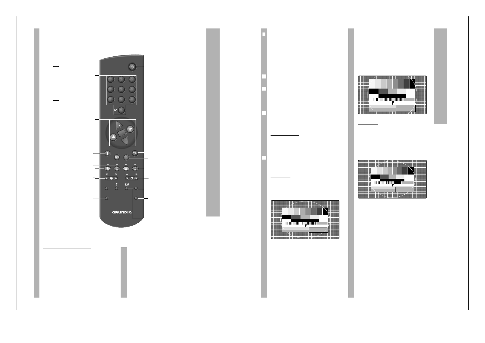
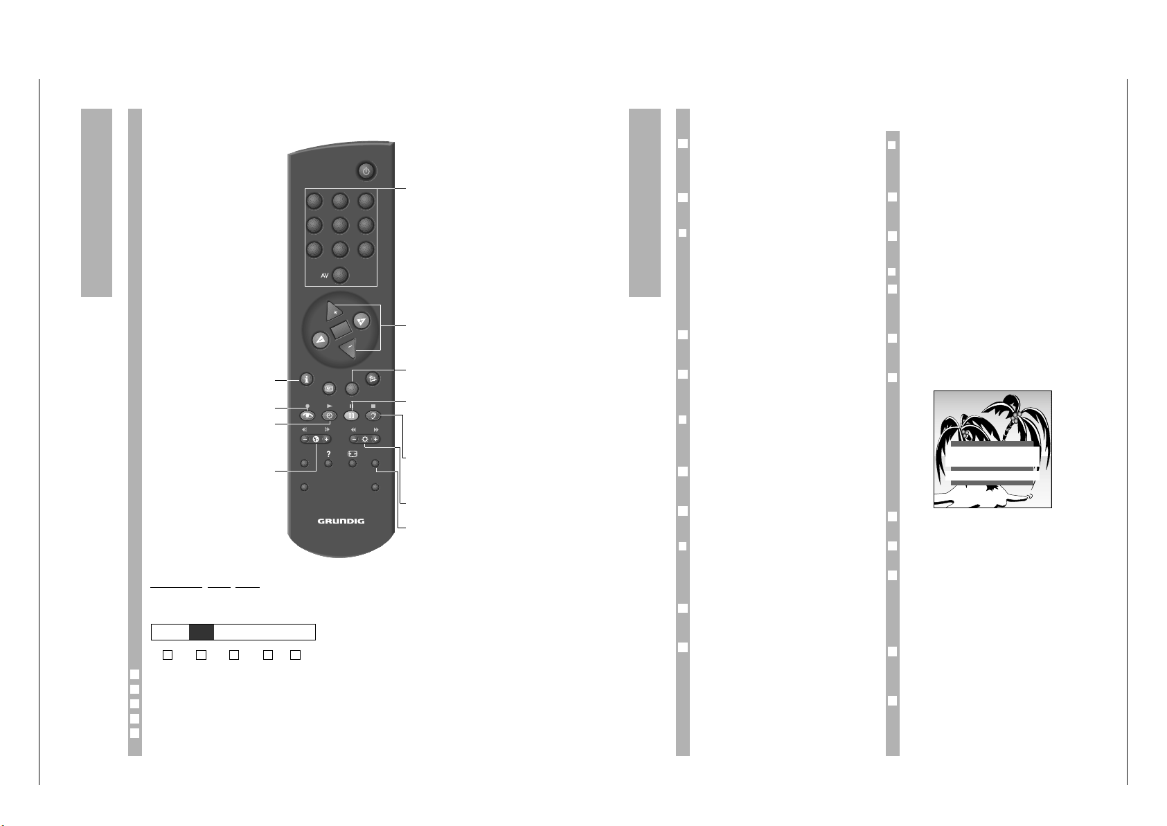
Die Fernbedienung bei Fernseh-Betrieb, Kurzbeschreibung
Auf dieser Seite sind die Tasten der Fernbedienung
nur kurz erklärt. Ausführliche Beschreibungen entnehmen Sie bitte den jeweiligen Kapiteln.
Video-Recorder fernbedienen
Mit der Fernbedienung dieses Fernsehgerätes können Sie auch GRUNDIG-Video-Recorder fernbedienen. Welche hierzu geeignet sind, sagt Ihnen Ihr
Fachhändler.
Taste VIDEO drücken und gedrückt halten.
Damit schalten Sie die Fernbedienung auf VideoRecorder-Betrieb.
Anschließend die gewünschte Taste drücken.
Entnehmen Sie der folgenden Aufstellung, mit
welchen Tasten die Recorderfunktionen ausgelöst
werden können.
ĵķ (Taste – i) = Bildsuchlauf rückwärts
ĶŁ (Taste i +) = Bildsuchlauf vorwärts
● (Taste k) = Aufnahmestart
■ (Taste g) = Stop
ĵĵ (Taste –
v
) = schneller Rücklauf
ŁŁ (Taste
v
+) = schneller Vorlauf
ll ll (Taste j) = Pause
ı (Taste h) = Wiedergabestart
p = Programmplatz –
P = Programmplatz +
0…9 Gerät aus Bereitschaft (Stand-
by) einschalten;
oder
Programmplatz wählen.
AV
0
AV-Stellung wählen
P Programmplatz schrittweise
fortschalten (1, 2, 3 …)
p Programmplatz schrittweise
zurückschalten (… 3, 2, 1)
oder
p, P Cursor-Bewegung nach oben/unten
FE Lautstärke
oder
FE Cursor-Bewegung links/rechts.
G Umschalten zwischen den bei-
den zuletzt gesehenen Programmen.
Ändern und Aktivieren verschiedener Funktionen;
Auf Optimal-Werte schalten
(Taste
-
und G).
h »DIALOG CENTER« aufrufen
(mit
h und G).
h Uhr ein/aus (Anzeige der Uhrzeit
nur bei Fernsehprogrammen mit
Videotext).
k Menü »Bild« anwählen.
™
Farbstärke ändern.
VIDEO GRUNDIG Video-Recorder fern-
bedienen (dazu Taste VIDEO
gedrückt halten).
VIDEO SAT
PIP AUX
321
654
987
0
TXT
TV-GUIDE
TELEP ILOT 810C
OK
P
P
A Gerät in Bereitschaft (Stand-by)
schalten.
¢
ĭ Ton ein /aus (stummschalten).
¢
TXT
Videotext/-Betrieb ɫ TV-Betrieb.
¢
D
ohne Funktion.
g Menü »TON« anwählen.
®
Helligkeit ändern.
AUX
Menü »Aux« anwählen;
Tonauswahl (mit
-
und 2).
SAT GRUNDIG Satelliten-Receiver fern-
bedienen (dazu Taste SAT ge-
drückt halten und Satelliten-Programm mit Taste
P oder p
wählen).
E
Bildformat-Umschaltung
❒
Bildformat-Umschaltung
PALplus ist die – von europäischen Rundfunkanstalten und europäischen Unternehmen der Unterhaltungselektronik verwirklichte – kompatible Weiterentwicklung des seit Jahrzehnten bewährten
PAL-Farbfernsehens im Bildformat 16:9.
In einschlägigen Zeitschriften und im Videotext
(ARD, ZDF) wird besonders auf PALplus-Sendungen im 16: 9 Format hingewiesen.
Bei PALplus-Sendungen schaltet das Gerät automatisch auf das Format 16:9.
Bei schlechten Empfangsverhältnissen kann es vorkommen, daß das Bildformat zwischen 16:9 und
4:3 wechselt. In diesem Fall kann die automatische
Bildformatumschaltung ausgeschaltet werden.
Lesen Sie dazu das Kapitel »Service « auf Seite 15.
Mit der Taste
¢
E
können Sie zwischen den Bildformaten »Format automatik«,»Format 16:9«,
»CINEMA«, »Format 4:3« und »PANORAMA«
wählen.
Format automatik
Bei 16:9 Sendung wird automatisch auf das Bildformat »16:9« geschaltet.
Bei 4:3 Sendung wird das Bild automatisch Bildschirmfüllend dargestellt.
Diese Einstellung ist nur möglich, wenn die Bildformatumschaltung im Menü «Service» auf «manuell»
steht. (siehe Seite 15)
Format 16:9
Bei 4:3 Sendungen – und gewählter Funktion »Format 16:9« – erscheint das Bild horizontal verbreitert.
Die Bildgeometrie wird in horizontaler Richtung
linear gedehnt.
Bei tatsächlichen 16:9 Signalquellen – von einem
Beistell-Decoder (z. Beispiel Settop-Decoder Digitales Fernsehsystem) über die Euro-AV-Buchse zugeführt – ist das Bild voll ausgefüllt und die Bildgeometrie korrekt.
Ǻ
1
Ǻ
Ǻ
CINEMA
Diese Betriebsart eignet sich besonders für Sendungen im Format 16:9.
Die bisher üblichen schwarzen Streifen oben und
unten im Bild werden überschrieben.
Die Betriebsart Cinema gibt 4:3 Bilder formatfüllend
wieder.
Die gesendeten Bilder werden vergrößert, dabei
geht oben und unten etwas Bildinhalt verloren. Die
Bildgeometrie bleibt aber erhalten.
P
ANORAMA
Diese Betriebsart eignet sich für Kinofilme - von
Sendern übertragen - mit extremen Breiten-Höhenverhältnissen.
Bei 4:3 Sendungen – und gewählter Funktion
»PANORAMA« – erscheint das Bild horizontal verbreitert.
Die Bildgeometrie wird in horizontaler Richtung
gedehnt.
Bildformat-Umschaltung 16:9
Page 13
CUC 2030 N / 2050 N / 2058 N / 2059 N / 2080 N Allgemeiner Teil / General Section
GRUNDIG Service 1 - 13
Der Videotext-Betrieb
Kurzbeschreibung für den
Videotext-Betrieb
Die Bedeutung der Symbole
Symbol-Zeile mit Taste
¢
AUX
einblenden.
Funktion auswählen mit Taste F oder E.
Funktion aufrufen mit Taste G.
Zeichenhöhe vergrößern.
Wartezeit überbrücken im Fernseh-Betrieb.
Unterseite direkt abrufen.
Antwortfreigabe.
Seitenstop.
5
4
3
2
1
54321
G K HLI
ǵ…Ǿ
Videotext-Seiten anwählen.
p, P Page Catching.
Videotext-Seiten direkt
anwählen und mit Taste
G aufrufen.
¢
TXT
Videotext-Betrieb
ɫ
TV-Betrieb.
j (gelb) Weiterschalten zum
nächsten Kapitel mit
Überlauf zum nächsten
Thema; weiterschalten
zur nächsten 10 er Seite.
g (blau) Weiterschalten zum
nächsten Thema; weiterschalten zur nächsten
100er Seite.
®
» + « Antwortfreigabe;
» – « Seitenstop.
¢
AUX Symbol-Zeile aufrufen
(siehe unten).
VIDEO SAT
PIP AUX
321
654
987
0
TXT
TV-GUIDE
TELEP ILOT 810C
OK
P
P
h Videotext-Übersichts-
Seite aufrufen.
k (rot) Seite zurückblättern.
h (grün) Weiterblättern zur näch-
sten Seite mit Überlauf
zum nächsten Kapitel.
™
»+« Seite vergrößern;
»–« Unterseite direkt aufrufen.
Komfortfunktionen
Sonderfunktionen
Die folgenden Einstellungen werden mit dem
»DIALOG CENTER« durchgeführt.
»DIALOG CENTER« mit Taste h und Taste G
aufrufen.
Die Einstellungen werden jeweils mit Taste
¢
TXT
beendet.
❒
Einschalten mit ...
Wenn Sie das Gerät häufig als AV-Monitor einsetzen – z.B. zusammen mit einer Camera als
Über-wachungsanlage oder bei Betrieb mit einem
Satelliten-Receiver – kann mit dieser Funktion dem
Programmplatz »AV« Vorrang eingeräumt werden.
Nach dem Einschalten des Gerätes, mit der Netztaste, erscheint anstelle des Programmplatzes »P 1«
der Programmplatz »AV«.
Aus dem »DIALOG CENTER« die Zeile »SONDERFUNKTIONEN« mit Taste p oder P anwählen und
mit Taste G bestätigen .
Die Zeile »TV einsch. mit« anwählen und mit Taste
F oder E den gewünschten Programmplatz,
»Prog 1« oder »AV«, wählen.
❒
Bild-/Tonskala
Beim Einstellen der Funktionen Lautstärke, Helligkeit und Farbkontrast wird jeweils eine Skala eingeblendet. Dieses kann unterbunden werden.
Aus dem »DIALOG CENTER« die Zeile »SONDERFUNKTIONEN« mit Taste p oder P anwählen und
mit Taste G bestätigen.
Die Zeile »Bild-/Toneinst.« anwählen und mit Taste
F oder E »aus« einstellen.
❒
Sendername (Service-Funktion )
Von einigen Sendeanstalten wird der Sendername
angeboten. Dieser wird beim Wechseln des Programmplatzes kurz angezeigt. Sie können diese
Anzeige abschalten.
Aus dem »DIALOG CENTER« die Zeile »SERVICE«
mit Taste p oder P anwählen und mit Taste G
bestätigen .
Die Zeile »Sendername« anwählen und mit Taste
F oder E »aus« einstellen.
Beim Wechseln des Programmplatzes wird nur
noch die Nummer des Programmplatzes angezeigt.
2
1
2
1
2
1
Ǻ
Ǻ
❒
Lautstärke anpassen
Die Lautstärke zwischen normalen Fernsehsendungen und Werbeeinblendungen kann unterschiedlich
laut sein. Dies können Sie ausgleichen.
Aus dem »DIALOG CENTER« die Zeile »SONDERFUNKTIONEN« mit Taste p oder P anwählen und
mit Taste G bestätigen.
Die Zeile »Autom. Lautst.« anwählen und mit Taste
F oder E »ein« wählen.
❒
Sleep Timer einstellen
Mit dem Menü »SLEEP TIMER« können Sie für ihr
Fernsehgerät eine Ausschaltzeit eingeben. Das
Gerät schaltet nach Ablauf der eingestellten Zeit in
Bereitschaft (standby).
Aus dem »DIALOG CENTER« die Zeile »SLEEP
TIMER« mit Taste P oder p anwählen und mit
Taste G bestätigen.
Das Menü »SLEEP TIMER« wird eingeblendet.
Mit den Ziffern-Tasten 0…9 die gewünschte Ausschaltzeit zweistellig eingeben (von 01…99 min).
Mit Taste-kann die eingegebene Ausschaltzeit
gelöscht werden.
Mit Taste
¢
TXT
wird die Einstellung beendet.
Programmplatznummer einblenden
Sie können die Programmplatznummer des
gewählten Programmplatzes ständig einblenden.
Taste h drücken und warten bis die Einblendung
»OK Dialog Center« erlischt.
Die Programmplatznummer wird ständig eingeblendet.
Funktion aufheben, dazu Taste h zweimal drücken.
2
1
5
4
3
2
1
Ǻ
2
1
SLEEP TIMER
ǺǺ
0 – 9 TXT
Ȅ
– –
Ȅ
min.
Page 14
Allgemeiner Teil / General Section CUC 2030 N / 2050 N / 2058 N / 2059 N / 2080 N
1 - 14 GRUNDIG Service
Komfortfunktionen
Die Kindersicherung
Mit dieser Funktion können Sie eine Geheimzahl
eingeben, mit der alle Funktionen gesperrt werden
❒
Kindersicherung aktivieren
»DIALOG CENTER« mit den Tasten h und G
aufrufen.
Die Zeile »Kindersicherung« anwählen und aufrufen.
Geheimzahl mit den Ziffern-Tasten 0 … 9 immer
vierstellig eingegeben (z.B. 1111).
Geheimzahl mit Taste G speichern.
Der Schlüssel erscheint in “Rot“, die Seite
»KINDERSICHERUNG« mit Taste
¢
TXT
abschalten.
Nach Aus- und Wiedereinschalten des Fernsehgerätes blendet sich die Seite »Kindersicherung« ein;
alle Funktionen sind gesperrt.
Bitte die gespeicherte Geheimzahl gut merken!
❒
Kindersicherung abschalten
Gerät einschalten.
Geheimzahl mit den Ziffern-Tasten 0 … 9 immer
vierstellig eingegeben (z.B. 1111).
Das Gerät schaltet auf das Fernsehbild.
Nach erneutem Aus- und Wiedereinschalten des
Gerätes ist die Kindersicherung wieder aktiv.
Funktion Kindersicherung aufheben (deaktivieren)
Hierzu aus dem »DIALOG CENTER« die Zeile
»Kindersicherung« anwählen und aufrufen.
Geheimzahl vierstellig eingeben und die Taste
¢
AUX
drücken.
Falls Sie die Geheimzahl vergessen haben, hilft
Ihnen eine Ziffernkombination auf der letzten Seite
dieser Bedienungsanleitung weiter. Wenn Sie nacheinander diese Tasten der Fernbedienung drücken,
wird die „Verriegelung“ aufgehoben.
SERVICE
»DIALOG CENTER« mit Taste h und Taste G
aufrufen.
Die Zeile »SERVICE« mit Taste P oder p
anwählen und mit Taste G aufrufen.
Gewünschte Funktionen mit Taste P oder p
anwählen.
Mit Taste F oder E verändern.
Die Einstellungen werden jeweils mit Taste
¢
TXT
beendet.
Ǻ
4
3
2
1
Ǻ
2
1
Ǻ
Ǻ
4
3
2
1
❒
Decoderauswahl
Siehe »Einstellung für Betrieb mit Decoder«
(siehe Seite 16).
❒
Farbe (Farbnorm manuell einstellen)
Beim Belegen der Programmplätze mit dem Programmsuchlauf wird die Farbnorm automatisch
zugeordnet. Ist die Farbe der verschiedenen Programme in Ordnung, brauchen Sie diese Einstellung nicht durchführen.
Die benötigte Farbnorm wählen.
❒
Blauer Bildschirm wählen
Mit dieser Einstellung kann bei verrauschtem Bild
auf ein blaues Bild umgeschaltet werden.
❒
Schwarzer Bildschirm wählen
Mit dieser Einstellung wird störendes Programmflimmern während des Umschalten des Programmplatzes vermieden.
❒
Sendername ein/aus
Anzeige des Sendernamens ein oder ausschalten
(siehe »Sendername«).
❒
SAT
Diese Einstellung ist nur notwendig, wenn ein externer MicroSAT-Receiver SNR 105 angeschlossen
ist.
Drei Einstellungen stehen zur Wahl: »ON1«, »ON2«,
»aus«. Welche Einstellungen Sie vornehmen müssen, entnehmen Sie der Bedienungsanleitung des
SNR 105
Ń
!
Ist kein SNR 105 angeschlossen, muß diese Einstellung auf »aus« stehen.
Wurde SAT »ON1« ohne angeschlossenen SNR
105 gewählt, ist keine Programmplatzwahl möglich.
Der Bildschirm bleibt dunkel und »SAT« wir eingeblendet.
❒
Formatumschaltung
Bei schlechten Empfangsverhältnissen kann die
automatische Bildformatumschaltung ausgeschaltet werden.
Gewünschte Einstellung wählen.
❒
Service Code
Die Funktionen dieser Zeile sind dem Fachhändler
vorbehalten.
Ǻ
1
1
Anschlußmöglichkeiten
Bedienung
Programmplatz wählen, mit dem das verschlüsselte
Programm belegt ist;
oder
für den Betrieb mit Satelliten-Receiver Programm-
platz »AV1« mit Taste
AV
0
anwählen.
❒
Videorecorder oder SET-TOP-Box an
Buchse »AV 1« oder »AV 2« anschließen
Buchse »AV1«oder»AV 2« des Fernsehgerätes und
die entsprechende Buchse des Video-Recorders
oder SET-TOP-Box mit einem EURO/AV (Scart)Kabel verbinden.
Taste
AV
0
so oft drücken, bis am Gerät »AV1«
oder »AV2« angezeigt wird.
V
ideostandard (VHS oder SVHS) einstellen
Diese Einstellung ist vom angeschlossenen Videorecorder abhängig
»DIALOG CENTER« mit den Tasten h und G
aufrufen.
Die Zeile »SONDERFUNKTIONEN« anwählen.
Die Zeile »Video« anwählen und aufrufen und mit
Taste F oder E »VHS« oder »SVHS« wählen.
Wiedergabe
Videorecorder oder SET-TOP-Box einschalten und
die gewünschte Funktion wählen.
Am Fernsehgerät sehen und hören Sie die Bild- und
Ton-Informationen des externen Gerätes.
1
3
2
1
2
1
AV1 AV2
EURO-AV
AUDIO
1
Die AUDIO-/VIDEO-Anschlüsse
Das Fernsehgerät ist mit verschiedenen Buchsen
ausgestattet. Daran können verschiedene Zusatzgeräte – wie z.B. Camera-Recorder, Video-Recorder, SAT-Receiver, SET-TOP-Box, Pay-TV-Decoder
usw. – angeschlossen werden.
❒
Decoder oder Satelliten-Receiver an
Buchse »AV 1« anschließen
Einige Sender – deren Programme über Kabelanlagen oder Satelliten-Receiver zugeführt werden –
verschlüsseln ihre Sendungen. Bild und Ton sind
damit unkenntlich. Mit einem Decoder können Sie
derartige Programme entschlüsseln.
An diese Buchse kann alternativ auch ein SatellitenReceiver oder ein zweiter Videorecorder angeschlossen werden.
Anschließen
Buchse »AV1« des Fernsehgerätes und die entsprechende Buchse des Decoders oder Satelliten-Receivers mit einem EURO/AV (Scart)-Kabel verbinden.
Einstellung für den Betrieb mit Decoder
Programmplatz wählen, mit dem das verschlüsselte
Programm belegt ist.
Das Fernsehgerät schaltet automatisch auf Programmplatz »AV1«.
»DIALOG CENTER« mit den Tasten h und G
aufrufen.
Die Zeile »SONDERFUNKTIONEN« anwählen und
aufrufen.
Die Zeile »Decoder P ..« anwählen. In dieser Zeile
wird der Programmplatz angezeigt, der zuvor
gewählt wurde.
Taste F oder E drücken (Wahl zwischen ON1,
ON2, ON3 – dies ist abhängig vom verwendeten
Decoder).
Diese Einstellung kann auch in der Seite
»SERVICE« für alle Programmplätze (1 – 99) aktiviert werden.
Seite mit Taste
¢
TXT
verlassen.
6
Ǻ
5
4
3
2
1
1
Ǻ
AV1 AV2
Page 15
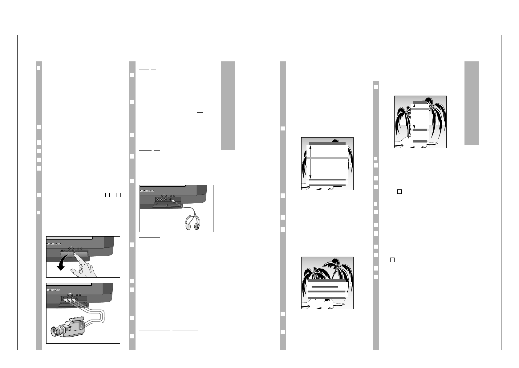
CUC 2030 N / 2050 N / 2058 N / 2059 N / 2080 N Allgemeiner Teil / General Section
GRUNDIG Service 1 - 15
Operating Hints
This chapter contains excerpts from the operating instructions. For further particulars please refer to the
appropriate user instructions the part number of which is indicated in the relevant spare parts list.
Anschlußmöglichkeiten
Bildsignal
Die gelbe Buchse (VIDEO) des Fernsehgerätes mit
der entsprechenden Bild-Buchse des CameraRecorders verbinden.
Tonsignal (Stereo oder Mono)
Die weiße und rote Buchse (AUDIO links/rechts)
des Fernsehgerätes mit den Tonbuchsen des Stereo-Camera-Recorders verbinden, oder
Die weiße Buchse (AUDIO links) des Fernsehgerätes mit der Tonbuchse des Mono-Camera-Recorders verbinden.
Taste
AV
0
so oft drücken, bis am Gerät »AV3«
angezeigt wird.
Wiedergabe
Camera-Recorder einschalten, Cassette einschieben und die Wiedergabe starten.
Am Fernsehgerät sehen und hören Sie die Bild- und
Ton-Informationen vom Camera-Recorder.
❒
Kopfhörer
Anschließen
Kopfhörer-Stecker (3,5 mm ø Klinke) in die Kopfhörer-Buchse an der Frontseite des Gerätes stecken.
Die Kopfhörer-Lautstärke können Sie gesondert
einstellen (Kopfhörer-Impedanz max. 32 ° ).
T
on (Stereo-/Zweiton, Mono) des
Ko
pfhörers ändern
Seite »TON« mit Taste g anwählen.
Die Zeile »y « anwählen und mit Taste F oder E
gewünschte Tonart wählen:
Bei Stereo »Stereo« oder »Mono«;
bei Nicam Stereo »Stereo« oder »Analog«;
bei Zweiton-Sendungen »Dual A« oder »Dual B«.
Seite »TON« mit Taste g oder
¢
TXT
abschalten.
Lautstärke des Kopfhörers ändern
Taste
¢
AUX
drücken und danach mit Taste F oder
E die Kopfhörer-Lautstärke ändern.
Der geänderte Wert wird auf einer Skala angezeigt.
1
3
2
1
1
VIDEO
L AUDIO R
m
P
1
2
1
1
❒
Überspielen von Videoaufzeichnungen
über das Fernsehgerät
Sie können Aufzeichnungen von einem Video-/
Camera-Recorder zu einem Videorecorder überspielen.
Die Möglichkeiten:
Camera-Recorder (AV3) auf Videorecorder (AV1)
Videorecorder (AV1) auf Videorecorder (AV2)
Videorecorder (AV2) auf Videorecorder (AV1).
Sie können während des Überspielens auf ein Fernsehprogramm schalten.
Das Überspielen von einem SVHS-Video-/CameraRecorder zu einem SVHS-Video-/Camera-Recorder
ist nicht möglich.
AV-Programmplatz mit Taste
AV
0
wählen.
Taste
¢
AUX drücken.
Mit Taste
AV
0
die Copier-Funktion aktivieren.
Wiedergabe/Aufnahme an Camera-Recorder/Videorecorder starten.
Die Überspielung läuft, jetzt können Sie mit dem
Fernsehgerät jedes Programm sehen, ohne die Aufzeichnung zu stören.
Kopierfunktion abschalten, dazu die Pkt. bis
widerholen.
❒
Camera-Recorder an Buchse »AV 3«
anschließen
Klappe durch Drücken öffnen (siehe Abbildung)
VIDEO
L AUDIO R
m
P
31
Ǻ
4
3
2
1
Ǻ
Settings
Assigning programme positions
with the automatic tuning system
ATS
The set is equipped with the automatic programme
position search system ATS which carries out programme position assignment for you.
You start the automatic search and may afterwards
sort the programmes in a sequence of your choice.
You may also delete programmes which have been
found more than once or those with bad reception
from the programme list.
After switching on the set the page
»LANGUAGE SELECTION« appears.
A selection can be made from several languages for
the dialogue between you and the TV.
The user guide displays appear in the selected
language.
Select the dialogue language with button p or P
and confirm with the G button.
Select the countrywith the por button P and confirm with the G button.
If you do not find your country in the list, then select »Others« and confirm with the G button.
The page » AUTOMATIC TUNING SYSTEM« appears.
The page » AUTOMATIC TUNING SYSTEM « can
also be called up directly from the » DIALOG
CENTER«.
Depending on the number of programs received, this
activity can take one minute or longer.
Ǻ
Ǻ
3
2
Ǻ
1
AUTOMATIC TUNING SYSTEM
OK Start
■
After searching, the set switches to program position 1 and the page »SORT« appears.
❒
Deleting programmes
Select the programme to be deleted with button p,
P.
Delete the programme with the
-
button.
To delete more programmes, repeat, beginning
with step .
❒
Sorting programmes
Select the programme which is to be re-sorted by
pressing button p, P.
Mark the programme with the G button.
Select a new programme position with button p,
P.
Save the setting with the G button.
To sort more programmes, repeat, beginning with
step .
Exit setting by pressing
¢
TXT
.
Pages »AUTOMATIC TUNING SYSTEM«, » SORT«
(under » Programme sorting «) and » LANGUAGE
SELECTION« can also be called up directly from the
»DIALOG CENTER«.
Ǻ
5
1
Ǻ
4
3
2
1
1
Ǻ
2
1
Ǻ
SORT
OK Sort
AUX Delete
ǺǺ
Return
TXT
TV
P 01
P 02
P 03
P 04
P 05
P 06
P 07
P 08
P 09
P 10
LANGUAGE SELECTION
OK
D Deutsch
DK Dansk
E Espa–ol
F Fran•ais
GB English
GR Hellas
I Italiano
N Norge
NL Nederlands
P Portugues
S Svenska
SF Suomi
TR TŸrk•e
P
Page 16
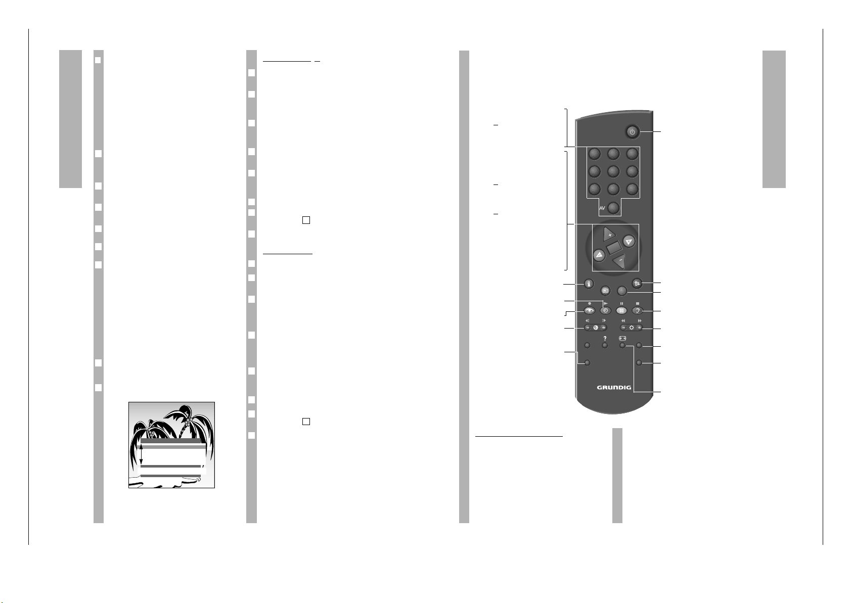
Allgemeiner Teil / General Section CUC 2030 N / 2050 N / 2058 N / 2059 N / 2080 N
1 - 16 GRUNDIG Service
Settings
❒
Limiting the programme position
selection
The ATS search saves all programmes it has found
and automatically “locks” the first position to which
no program is assigned. In this way, when programme positions are selected step by step (“zapping“), using buttons p, P only programmes
which have been found can be selected.
You may also enter this limit manually, in the example the “lock” has been activated as of programme
position 6.
Press the h button and then G.
The page » DIALOG CENTER « will appear on the
screen.
Select the line » MANUAL TUNING « using button
p or P and confirm with G.
Select programme position 6 on the » MANUAL
TUNING« page with the F or E button.
Select the line called »C/S«, then select »Channel «
using F or E.
Select the line called »Channel«, then select » 00«
using 0 … 9.
Save this setting with G and exit using button
¢
TXT
.
Now only the first 5 channel positions can be switched through in rapid sequence with the p or P
button.
All single digit channel positions – as well as the
“blocked” – can continue to be selected using the
digit buttons 0 … 9.“All” channel positions can
be selected using the digit buttons if a two digit
channel position is blocked.
Setting TV programmes manually
Press the h button and then the G button.
The page »DIALOG CENTER« appears.
Select the line »MANUAL TUNING« with the p or
P button and confirm with the G button.
2
1
6
5
4
3
2
1
Direct channel input
Select the programme position with the digit buttons 0 … 9 or with the F
or
E button.
Select the line »C/S« with the p or P button.
Select »channel« or »s-channel« with the F
or
E
button.
Select the line »Channel« with the p or P button.
Enter the desired channel number with the digit
buttons 0 … 9 or with the F
or
E button.
Select the line »Standard« witht the p or P button.
Select the required setting with the F
or
E button.
Fine-tune the picture if necessary. To do this select
the line »Finetun.« with button p or P.
Alter fine tuning with buttons F
or
E.
Store setting with the G button.
To set more programmes, repeat the procedure
starting at point .
End setting with the
¢
TXT
button.
Automatic search
Select the line »Channel« with the p or P button.
Start the automatic station search with the »blue«
button.
Select the line »Programme« with button p or P.
Select the channel position, at which you would like
to save the channel once found, with the numeric
buttons 0 … 9 (01 – 99).
The colour and sound standards are allocated automatically. If the colour and/or sound not correct,
select the line »Standard« with button p or P. Select the required setting with the F
or
E button.
Fine-tune the picture if necessary. To do this select
the line »Finetun.« with button p or P.
Alter fine tuning with buttons F
or
E.
Store setting with the G button.
To set more programmes, repeat the procedure
starting at point .
End setting with the
¢
TXT
button.
6
1
Ǻ
5
4
Ǻ
3
2
1
7
1
Ǻ
6
5
4
3
2
1
MANUAL TUNING
ǺǺ
OK Memorize 0 – 9 TXT
Program ľ 01 ı
C/S
Channel
Channel C 34
Finetun. 00
Standard automatic
The remote control
Short description for TV operation
On this page the buttons of the remote control are
only briefly explained. Detailed descriptions can be
found in the various chapters.
Remote control video recorder
You may also use the remote control for this TV set
to operate a GRUNDIG video recorder. Your
specialist dealer can inform you on which ones are
suitable.
Press the VIDEO button and keep it depressed.
This converts the remote control to video recorder
operation.
Now press the required button.
The following list tells you which button operates
which recorder functions.
ĵķ (Button – i) = Picture search backward
ĶŁ (Button i +) = Picture search forward
● (Button k) = Record start
■ (Button g) = Stop
ĵĵ (Button –
v
) = Rewind
ŁŁ (Button
v
+) = Fast forward
ll ll (Button j) = Pause
ı (Button h) = Playback start
p = Channel position –
P = Channel position +
0…9 Switch on set from standby;
or
select programme position
AV
0
Select AV.
P Move forwards from one program-
me position to the next (1, 2, 3 …).
p Move backwards from one program-
me position to the next (… 3, 2, 1)
or
p, P Move the cursor up/down
FE Volume;
or
FE Move the cursor to the
left/rightts.
G Switches between both of the
channels last viewed.
Changes and activates several
functions,
Switches to optimum values
(button
-
and G).
h Call up » DIALOG CENTER «
(button
h and G).
h Clock ON/OFF (Time display only
for TV programmes with videotex
k Select »Picture « menu.
™
Adjust colour intensit.
VIDEO Remote control GRUNDIG video
recorder (keep VIDEO button
depressed).
VIDEO SAT
PIP AUX
321
654
987
0
TXT
TV-GUIDE
TELEP ILOT 810C
OK
P
P
A Switch set to standby.
¢
ĭ Sound on /off (mute)
¢
TXT
Videotext operatation ɫTV operation
¢
D
ohne Funktion.
g Select »SOUND « menu..
®
Adjust brightnessn.
AUX
Select » Aux« menu; sound selection (with
-
and 2).
SAT Remote control GRUNDIG satelliten
receiver (keep SAT button depressed and select satellite program
using button p or P ).
E
Switch picture format from 4:3 to
16:9 )
Page 17
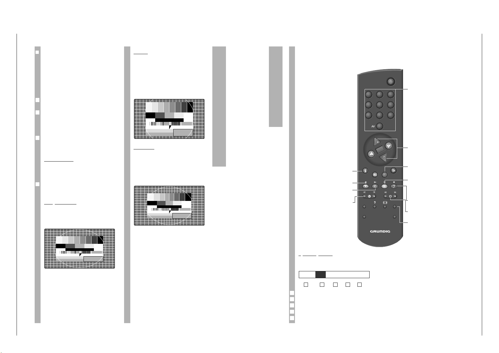
CUC 2030 N / 2050 N / 2058 N / 2059 N / 2080 N Allgemeiner Teil / General Section
GRUNDIG Service 1 - 17
Switching the picture format to 16:9
❒
Switching picture formats
PALplus is the compatible further developement of
the PAL color television which has proved itself
over decades in a new 16:9 picture format which
has been developed by European broadcasting corporations and entertainment electronics corporations.
PALplus transmissions in 16:9 format are noted
specially in relevant magazines and in videotext
(ARD, ZDF).
The unit switches automatically to the 16:9 format
during PALplus transmissions.
Under bad reception conditions, it is possible for
the picture format to switch between 16:9 and 4:3.
In this case, the automatic picture format switching
function can be turned off. Read page 15 in the
chapter «Service» for information on this topic.
With the
¢
E
button, you can choose between
the picture formats: » Automatic format «,
» Format 16:9 «, » CINEMA «, » Format 4:3 « and
»PANORAMA «.
Automatic format
During 16:9 transmissions, the unit switches automatically to the »16:9« picture format.
During 4:3 transmissions, the picture is always displayed so as to fill the entire screen.
This setting is possible only if the the picture switching format in the »Service« menu is set to
»manual« (see page 15)
16:9 picture format
During 4:3 transmissions– with the » 16:9 picture
format « function selected – the picture appears
spread out horizontally.
The picture geometry is stretched out in the horizontal direction.
With actual 16:9 signal sources – fed in from a
separate decoder (for example a digital television
system » set-on-top « decoder) via the Euro AV
socket – the picture is completely filled and the picture geometry is correct.
Ǻ
1
Ǻ
Ǻ
CINEMA
This operating mode is designed primarily for
transmissions in the 16:9 format.
The black stripes one normally sees above and
below the picture are overwritten.
The Cinema operating mode displays 4:3 pictures
so that they fill the entire screen.
The transmitted pictures are enlarged, which means
that some picture content on the top and bottom of
the screen is lost. Howevere the picture geometry is
maintained.
PANORAMA
This operating mode is designed for cinema films transmitted by broadcasters – with extreme
width/height ratios.
For 4:3 transmissions – with the »Panorama Zoom«
function selected– the picture appears spead out
horizontally.
The picture geometry is stretched out in the horizontal direction.
Videotext operation
S
ymbol explanatons
Make symbol line appear using button -.
Select function using button F or E.
Call up function using G.
Enlarge character height.
Bridge waiting time during TV operation.
Call up sub-page directly.
Answer release.
Page-freeze.
5
4
3
2
1
54321
G K HLI
Short description for videotext
operation
ǵ…Ǿ
Select videotext pages.
p, P Page Catching. Select
videotext pages directly
and call up using the
G button.
¢
TXT
Videotext operation
ɫ
TV operation.
j
(yellow) Move on to next chapter
with overflow to next
topic; move on to next
“10” page.
g (blue)
Move on to next topic;
move on to next “100” page
®
» + « Answer release;
» – « Stop page.
¢
AUX
Call up symbol line (see
below).
VIDEO SAT
PIP AUX
321
654
987
0
TXT
TV-GUIDE
TELEP ILOT 810C
OK
P
P
h Call up videotext table of
contents.
k (red) Page back.
h (green) Page forward with over-
flow to next chapter.
™
» + « Enlarge page;
»–«
Call up sub-page
directly.
Page 18
Allgemeiner Teil / General Section CUC 2030 N / 2050 N / 2058 N / 2059 N / 2080 N
1 - 18 GRUNDIG Service
Comfort functions
Special functions
The following adjustments are carried out using the
»DIALOG CENTER«.
Call up »DIALOG CENTER« with button h and but-
ton G.
Adjustments are always terminated by pressing
¢
TXT
.
❒
TV on with ...
If you frequently use the set as an AV monitor – e.g.
together with a camera as a monitoring system or
together with a satellite receiver – then this function
can give priority to the programme position
» AV «. After switching on with the on/off switch,
instead of programme position »P 1«, programme
position »AV« will appear.
Select the line » SPECIAL FUNCTIONS « from the
»DIALOG CENTER« with button p or P and confirm with G.
Select the line »TV on with« and select the desired
program position »Prog 1« or » AV« with F or E.
❒
Picture/sound scale
To adjust volume, brightness and colour contrast,
scales appear. These may be switched off.
Select the line » SPECIAL FUNCTIONS « from the
»DIALOG CENTER« with button p or P and confirm with G.
Select the line » Pic./sound opt. « and select » off «
with button F or E.
❒
Station name (SERVICE-functions)
Some broadcasting stations broadcast their station
name. When changing programme position this is
briefly displayed. You may switch this display off.
Select the line » SERVICE « from the » DIALOG
CENTER « with button p or P and confirm with
G.
Select the line » Station name « and select » off «
with button F or E.
When changing programme position, only the number of the programme position is displayed.
2
1
2
1
2
1
Ǻ
Ǻ
❒
Equalizing the volume
The volume of normal TV broadcasts and commercials may be different. You may equalize this
volume.
Select the line » SPECIAL FUNCTIONS « from the
»DIALOG CENTER« with button p or P and confirm with G.
Select the line » Volume limiter « and select »on«
with button F or E.
❒
Setting the Sleep Timer
You can input a switch off time for your TV set with
the »SLEEP TIMER« menu. The set switches to
standby after the set time has elapsed.
Select the »SLEEP TIMER« line from the »DIALOG
CENTER« with the P or p button and confirm by
pressing the G button.
The »SLEEP TIMER« menu appears.
Input the desired switch off time to two places
(from 01 … 99 min) with the 0 … 9 digit keys.
The input switch off time can be canceled with the
-
button.
Setting is ended with the
¢
TXT
button.
Displaying the programme position
number
It is possible to permantently display the number of
the selected programme position.
Press the h button until the »OK Dialog Center«
on-screen display disappears.
The programme position number is permanently
displayed.
Press the h button twice if you wish to cancel this
function.
2
1
5
4
3
2
1
Ǻ
2
1
SLEEP TIMER
ǺǺ
0 – 9 TXT
Ȅ
– –
Ȅ
min.
Comfort functions
Parental lock
Using this function, you may enter a number code
which blocks all functions.
❒
Activating parental lock
Call up the » DIALOG CENTER « using buttons h
and G.
Select and call up the line »Parental lock«.
Enter a number code with the number buttons
0…9, always using four digits (e.g. 1111).
Save the number code with G.
The key appears in red, switch off the page
»PARENTAL LOCK« with button
¢
TXT
.
After switching off the set and switching on again
the page »Parental lock« appears, all functions are
locked.
Please take good note of the number code!
❒
Switching off parental lock
Switch on the set.
Enter a number code with the number buttons
0 … 9, always using four digits (e.g. 1111).
The set switches to the TV screen. After switching
off again the parental lock is activated again.
To cancel the parental lock function, select and call
up the line “Parental lock” from the » DIALOG
CENTER «. Enter the number code with four digits
and press button
-
.
If you forget the number code, a number combination on the last page of this instruction manual will
assist you. If you press these buttons in sequence
on the remote control, the “lock” will be cancelled.
SERVICE
Call up the »DIALOG CENTER« with the h and the
G buttons.
Select the »SERVICE« line with the P or p button
and call it up using the G button.
Select the desired functions with the P or p but-
tons.
Change with the F or E buttons.
Each setting is ended with the
¢
TXT
button.
Ǻ
4
3
2
1
Ǻ
2
1
Ǻ
Ǻ
4
3
2
1
❒
Decoder selection
Refer to »Setting for operation with decoder«
(refer to page 16).
❒
Colour (manually adjust the colour
norms)
The colour norms are automatically assigned when
allocating the channel position with channel search.
You do not
need to carry out this setting if the
colour is already well adjusted on the different
channels.
Select the required colour norm (PAL or auto).
❒
Select the blue screen
With this setting a grainy image can be switched to
a blue image.
❒
Select the black screen
With this setting it is possible to avoid distracting
flickering of channels whilst switching channel
position.
❒
Station name on/off
Switch the station display on or off (see »Station
name«).
❒
SAT
This settin is only necessary if an external SNR 105
MicroSAT receiver is connected.
Three settings can be selected: »ON1«, »ON2« and
»off«. See the operating manual of the SNR 105 to
determine which setting you must make.
Ń
!
If no SNR 105 is connected, this setting must be set
to »off«.
Channel position selection is not possible if SAT
»ON1« is selected without a connected SNR 105,
the screen remains dark and »SAT« is displayed.
❒
Switching formats
The automatic picture format switching function
can be switched off in poor reception conditions.
Select the desired setting.
❒
Service Code
The functions of this line are reserved for authorised dealers.
Ǻ
1
1
Page 19
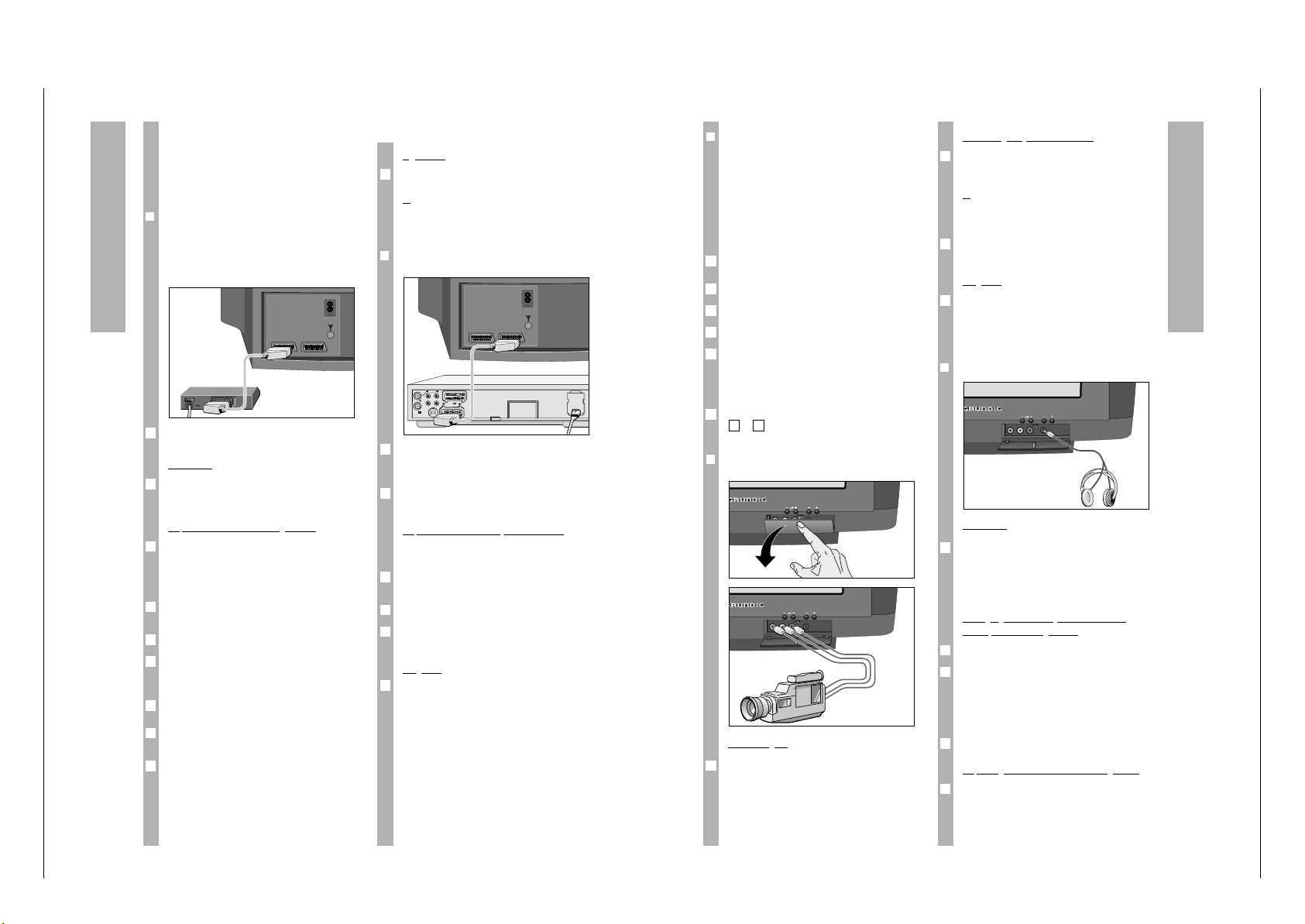
CUC 2030 N / 2050 N / 2058 N / 2059 N / 2080 N Allgemeiner Teil / General Section
GRUNDIG Service 1 - 19
Connection possibilities
Operation
Select the programme position to which the encoded programme is assigned;
or
for operation using a satellite receiver programme
position, select » AV1 « with button
AV
0
.
❒
Connecting a video recorder or SET TOP
box to the »AV 2« socket
Connect the »AV2 « socket of the TV set and corresponding socket of the SET TOP box with a
EURO/AV (Scart) cable.
Press button
AV
0
repeatedly until the set displays
»AV2 «.
Adjust video standar
d (VHS or SVHS)
This adjustment depends on the video recorder
connected.
Call up the »DIALOG CENTER« with buttons h and
G.
Select and call up the line »SPECIAL FUNCTIONS«.
Select and call up the line »Video« and using button F or E select » VHS« or » SVHS«.
Playback
Switch on the video recorder or SET TOP box and
select the desired function.
The TV set will let you see and hear the picture and
sound information from the external device.
1
3
2
1
2
1
AV1 AV2
EURO-AV
AUDIO
1
AUDIO/VIDEO connections
The TV set is equipped with a variety of socket
connections. Various auxiliary devices – e.g. camcorder, video recorder, SAT receiver, SET TOP box,
Pay TV decoder etc. – may be connected here.
❒
Connecting a decoder to the »AV 1«
socket
Some stations – whose programs are received by
cable or satellite receiver – encode their broadcasts.
Both picture and sound become unrecognizable.
A decoder will allow you to decode these programs.
Alternatively, a satellite receiver may be connected
to this socket or a second video recorder.
Connecting
Connect the » AV1 « socket of the TV set and the
corresponding socket of the decoder or satellite
receiver with a EURO/AV (Scart) cable.
Adjustment for decoder operation
Select the program position to which the encoded
program is assigned.
The TV set automatically switches to program position »AV1 «.
Call up the » DIALOG CENTER« with buttons h and
G.
Select and call up the line »SPECIAL FUNCTIONS«.
Select the line » Decoder P .. «. This line displays
the programme position which was previously selected.
Press button F or E (choice between ON1, ON2,
ON3 – this depends on the decoder used).
This setting can also be activated on the »SERVICE«
page for all program positions (1 – 99).
Exit with button
¢
TXT
.
6
Ǻ
5
4
3
2
1
1
Ǻ
AV1 AV2
Connection possibilities
Sound signal (stereo or mono)
Connect the white and red socket (AUDIO IN
left/right) of the TV set to the sound sockets of the
stereo camcorder.
or
Connect the white socket (AUDIO IN left) of the TV
set to the sound socket of the mono camcorder.
Press button
AV
0
repeatedly until the set displays
»AV3«.
Playback
Switch the camcorder on, insert the cassette and
playback.
The TV set will let you see and hear the picture and
sound information from the camcorder.
❒
Headphones
Connectin
g
Insert the headphone connector (3.5 mm ø jack)
into the headphone socket on the front side of the
set.
The volume for the headphones may be adjusted
separately (headphone impedance max. 32 ° ).
Changin
g the sound (stereo/two-tone,
mono
) of the headphones
Select page »SOUND« with button g.
Select the line »
y « and with button F or E sel-
ect the desired tone:
For stereo »stereo« or » mono«;
for Nicam stereo »stereo« or » analogue«;
for two-tone transmission » Dual A« or »Dual B «.
Switch off page »SOUND« with button g.
Adjusting the volume of the headphones
Press button -and then adjust the volume of the
headphones using button F or E.
The altered value is displayed on a scale.
1
3
2
1
1
VIDEO
L AUDIO R
m
P
1
2
1
❒
Copying video tapes via the TV set
You may copy video recorder/camcorder tapes
onto a video recorder.
The possibilities:
camcorder (AV3) to video recorder (AV1)
video recorder (AV1) to video recorder (AV2)
video recorder (AV2) to video recorder (AV1).
You may switch over to TV viewing during the
recording.
It is not possible to copy from a SVHS video/camcorder to a SVHS video/camcorder.
Select the AV program position with button
AV
0
.
Press button
-
.
Activate the copy function with button
AV
0
.
Start playback/copying on the camcorder/video
recorder.
Copying has started, you may now view any TV programme without interfering with the recording.
Switch off the copy function, to do this repeat steps
to .
❒
Connecting a camcorder to the
»AV 3« socket
Pictur
e signal
Connect the yellow socket (VIDEO IN) of the TV set
to the corresponding picture socket of the camera
recorder.
1
VIDEO
L AUDIO R
m
P
31
Ǻ
4
3
2
1
Ǻ
P
Page 20
Allgemeiner Teil / General Section CUC 2030 N / 2050 N / 2058 N / 2059 N / 2080 N
Service- und Sonderfunktionen
1. Einschaltfunktionen
1.1 ATS-Reset (Automatic Tuning System)
Netzschalter "EIN" mit gedrückter Fernbedientaste
wahl –> OK.
Das Automatische Sendersuchsystem stoppt bei jedem empfangswürdigen Sender (AFC und Koinzidenz) und speichert automatisch die
entsprechenden Senderdaten mit dem jeweiligen Standard (die Speicherung findet unmittelbar im NVM statt). Danach wird der Suchlauf
fortgesetzt.
Tastendruck "TXT" bricht den ATS-Lauf ab.
1.2 Mittelwerte / Notdatensatz laden (ROM-Daten)
Fernbedienbedientaste "P-" gedrückt halten und das Gerät mit dem
Netzschalter einschalten. Dadurch wird z. B. nach Austausch des
IC82005 (NVM) das Gerät mit dem Notdatensatz gestartet.
Mit diesem Vorgang werden die Grund-Daten aus dem ROM des
Prozessors IC81050 in den NVM IC82005 kopiert:
IC82005: (gerätespezifische Daten, über das Dialog Center einstellbar)
- Farb- und Ton-Normen
- Decodereinstellungen
- Zwangs-Mono
- Umkehrpunkt
- Sendername on/off
- OSD Position
- Blue Screen on/off, Black Screen on/off
- ATS-Reset
- Hotel-Mode on/off
- AGC und AFC
- Öko-Schalter
- Bildröhrentype
- Analogwerte (Lautstärke, Helligkeit usw.)
- Bildschärfe
- Overscan
- Security on/off
- Geometrieabgleich
- Programmdaten (Kanal- Feinabstimmung, Senderkennung)
Danach über das Dialog Center die persönlichen Werte, Bildgeometrie
eingeben.
1.3 Programmsperre dauerhaft aufheben
Die Zahl 7038 hebt die Sperre dauerhaft auf.
2. Sonderfunktionen im Dialog Center
2.1 Einschalten mit Programm "1" oder "AV"
Mit Taste "Ǻ" die Dialogzeile "TV einsch. mit" über "DIALOG CENTER"
–> "SONDERFUNKTIONEN" aufrufen. In Stellung "AV1" erscheint
beim Einschalten das AV-Bild.
2.2 "Bild-/Ton-Skala" ein oder aus für alle Programme
Mit Taste "Ǻ" die Dialogzeile "Bild-/Toneinst." über "DIALOG CENTER"
–> "SONDERFUNKTIONEN" aufrufen. In Stellung "aus" erscheinen
keine Balkenanzeigen für die Analogwerte auf dem Bildschirm.
2.3 Automatische Lautstärkeregelung (optionell)
Mit Taste "Ǻ" die Dialogzeile "Autom. Lautst." über "DIALOG CENTER"
–> "SONDERFUNKTIONEN" aufrufen. In Stellung "ein" wird bei
großen Senderhüben die Lautstärke automatisch an den normalen
Hub angepaßt.
2.4 Programmplatzbezogene Decoder-Einstellung
Mit Taste "Ǻ" die Dialogzeile "Decoder Pxx" über "DIALOG CENTER"
–> "SONDERFUNKTIONEN" aufrufen. Mit den Tasten ǷǸ können
Sie programmplatzbezogen für verschlüsselte Sendungen einen analogen oder digitalen Decoder auf interne oder externe Umschaltung
stellen (siehe 5.2).
2.5 Öko-Netzschalter aktivieren bzw. deaktivieren (optionell)
Mit Taste "Ǻ" die Dialogzeile "Eko-Switch" über "DIALOG CENTER"
–> "SONDERFUNKTIONEN" aufrufen. Mit den Tasten ǷǸ "1h…3h"
stellen.
Das Gerät schaltet sich nach der eingestellten Zeit, oder durch
zweimaligen Tastendruck der Taste Ǽ aus dem Standby-Betrieb
komplett ab.
In Stellung "aus" wird diese Funktion nicht genutzt.
Ƿ –> Sprachaus-
3. Bild-Einstellungen
Grundeinstellung
Mit der roten Taste (Auge) das Bild-Menü aufrufen. Über die Menüführung ist die Regulierung von Kontrast, Bildschärfe und Tint (nur bei
NTSC-Quellen) möglich.
Die Analogwerte für Kontrast, Bildschärfe und Tint werden beim
Verlassen des Menüs automatisch gespeichert.
4. Ton-Einstellungen
4.1 Tonumschaltung
Mit der blauen Taste (Ohr) das Ton-Menü aufrufen. Je nach SenderNorm sind für die Tonumschaltung verschiedene Einstellungen anwählbar:
- "Mono": bei reinen Mono-Sendungen
- "Mono A / Mono B": bei 2-Ton-Sendungen
- "Stereo / Mono": bei schlechtem Stereo-Ton kann auf Mono geschaltet werden
- "Nicam / FM"
- "Nicam A / Nicam B / FM"
- "Nicam Stereo / FM"
Die Werte für Zwangs-Mono, Balance, Bässe, Höhen und ähnliches
werden beim Verlassen des Menüs automatisch gespeichert.
4.2 Kopfhörer-Tonumschaltung
Mit der blauen Taste das Ton-Menü aufrufen. Je nach Sender-Norm
sind für den Kopfhörer verschiedene Einstellungen anwählbar:
- "Mono A / B", unabhängig von den Lautsprechern
- "Nicam A / Nicam B / FM", unabhängig von den Lautsprechern
Bei allen anderen Einstellungen ist der Kopfhörerton mit dem
Lautsprecherton fest gekoppelt.
5. Offene Service-Einstellungen
5.1 Maximale Programmnummer (Umkehrpunkt):
Programmnummer aufrufen, ab der die Programmplätze gesperrt
werden sollen. Mit Taste "Ǻ" die Dialogzeile "MANUELLE ABSTIMMUNG" über das "DIALOG CENTER" aufrufen. Über die Menüführung
in der Dialogzeile Band "00" einstellen. Mit "OK" bestätigen und Menü
beenden. Danach können im Programm-Mode mit den Tasten "P+/P-"
die nachfolgenden Programme nicht mehr fortgeschaltet werden.
5.2 Decoder P1…79
Mit Taste "Ǻ" die Dialogzeile "Decoder (P1-79)" über "DIALOG
CENTER" –> "SERVICE" aufrufen. Mit den Tasten ǷǸ können Sie für
die Programme 1…79 bei verschlüsselten Sendungen einen analogen
oder digitalen Decoder auf interne oder externe Umschaltung stellen.
Einstellungen des Decoders: "manuell", "aus", "ON1", "ON2", "ON3".
In Stellung "manuell" kann die Decoderumschaltung für die einzelnen
Programme auf unterschiedlicher Eingabe, wie "aus" oder "ON" stehen (siehe 2.4).
Bedeutung der Decoderstellungen:
Ton Bild
Decoder "aus" intern intern
Decoder "ON1"
Ton autom. extern Analog extern
intern Nicam-Ton
Decoder "ON2"
alle Töne extern Analog extern
extern Nicam-Ton
Decoder "ON3"
alle Töne intern Analog extern
intern Nicam-Ton
Die unterschiedlichen Einstellmöglichkeiten der Decoderfunktion stellen immer den richtigen Signalweg für das Audiosignal sicher.
GRUNDIG Service1 - 20
Page 21

CUC 2030 N / 2050 N / 2058 N / 2059 N / 2080 N Allgemeiner Teil / General Section
Die drei möglichen Scramble-Verfahren:
Betriebsart:
Bild Ton Menü-Anzeige
1. Bild Analogton verschlüsselt Analog ext. bzw. ON1
verschlüsselt Nicamton unverschlüsselt Nicam intern
2. Bild Analogton verschlüsselt Analog ext. bzw. ON2
verschlüsselt Nicamton verschlüsselt Nicam intern
3. Bild Analogton unverschlüsselt Analog int. bzw. ON3
verschlüsselt Nicamton unverschlüsselt Nicam intern
Das Verfahren 1 ist für Canal + Betrieb.
Das Verfahren 2 und 3 wird z. B. in England verwendet.
Bildsignalweg
Da das Bild generell verschlüsselt ist, muß nur die Decoder-Schaltspannung für die Videoumschaltung angelegt werden.
Audiosignalweg
Fall 1:
Decoder nicht stereotauglich, deswegen Nicamton unverschlüsselt.
Der Decoder schaltet den Audioweg in Abhängigkeit des NicamDecoders zwischen intern und extern um.
Fall 2:
Decoder stereotauglich für verschlüsselten Analog- und Nicamton.
Deswegen wird auf Externbetrieb umgeschaltet (Regelfall).
Fall 3:
Ton wird generell nur intern verbunden (keine Beschaltung am
Audiozweig der Scartbuchse).
5.3 Farb-Zwangsumschaltung
Mit Taste "Ǻ" die Dialogzeile "Farbe" über "DIALOG CENTER" –>
"SERVICE" aufrufen. Mit den Tasten ǷǸ können Sie in schlechter
Empfangslage programmplatzbezogen die automatische Farbumschaltung zwangsweise auf "PAL", "SECAM" oder "NTSC" einstellen.
5.4 Blauen Bildschirmhintergrund abschalten
Mit Taste "Ǻ" die Dialogzeile "Blauer Bildschirm" über "DIALOG
CENTER" –> "SERVICE" aufrufen. In Stellung "aus" ist der blaue
Hintergrund (z.B. bei fehlendem Antennensignal) abgeschaltet.
5.5 Schwarzer Bildschirm bei der Programmumschaltung
Mit Taste "Ǻ" die Dialogzeile "Schwarz. Bildschirm" über "DIALOG
CENTER" –> "SERVICE" aufrufen. In Stellung "ein" wird der Bildschirm bei Programmwechsel dunkelgeschaltet.
5.6 Sendername aus- bzw. einblenden
Die Kennung wird über VT bzw. VPS ausgelesen.
Mit Taste "Ǻ" die Dialogzeile "Sendername" über "DIALOG CENTER"
–> "SERVICE" aufrufen. In Stellung "aus" können Sie die kurzzeitige
Einblendung des Sendernamens bei der Programmumschaltung unterdrücken.
5.7 Gruppenlaufzeit / Ländernormen einstellen
Mit Taste "Ǻ" die Dialogzeile "B/G FM 5,5 NIC" über "DIALOG CENTER"
–> "SERVICE" aufrufen. Je nach Empfangsort gewünschte Norm
einstellen. S/SF/N = linear, B/DK/E = entzerrt.
Bei Ländern mit Mischbetrieb (z.B. Dänemark) muß diese Einstellung
im Dialogmenü "Manuelle Abstimmung" –> "Standard" vorgenommen
werden.
6. Service-Einstellungen für den Fachhandel
6.1 Service Menü
Mit Taste "Ǻ" das Service Menü über "DIALOG CENTER" –> "SERVICE"
–> Service Code aufrufen.
Nach Eingabe der Codezahl "8500" kann der Fachhändler den Geräteabgleich lt. Menüführung durchführen für:
- Geometrie
- Weißabgleich
- AGC
- AFC
- Tube
- Cut-off align
- Over-scan
Abgleich: Seite 2-1
6.2 OSD-Lage
Mit Taste "Ǻ" die Dialogzeile "OSD" über "DIALOG CENTER" –>
"SERVICE" –> Service Code "8500" aufrufen.
Mit den Tasten ǷǸ können Sie die horizontale, oder vertikale Lage
des Einblend-Menüs verschieben und "mit Speich." sichern.
6.3 Hotel-Mode
6.3.1 Hotel-Mode aktivieren
Mit Taste "Ǻ" die Dialogzeile "Hotel" über "DIALOG CENTER"
–> "SERVICE" –> Service Code "8500" aufrufen.
Bei aktiviertem "Hotel-Mode" ist:
- der Aufruf des "DIALOG CENTER" mit der Taste "Ǻ" nicht mehr
möglich.
- die zuletzt eingestellte Lautstärke wird als maximale Lautstärke
gespeichert.
6.3.2 Hotel-Mode ausschalten
Taste "Ǻ" der Fernbedienung gedrückt halten und das Gerät mit dem
Netzschalter einschalten. Im Menü "SERVICE" Hotel-Mode wieder
ausschalten.
6.4 Schutzschaltung deaktivieren
Taste "Ǻ" der Fernbedienung gedrückt halten und das Gerät mit dem
Netzschalter einschalten. Solange das Service Menü angezeigt wird,
wird die Schutzschaltung des Gerätes am Videoprozessor IC34015-(50)
nicht ausgewertet.
7. Einstellung der Analogwerte
Maximalwert Optimalwert
Helligkeit 63 32
Farbkontrast 63 40
SW-Kontrast 63 48
Lautstärke 63 30
Kopfhörer. Lautst. 63 50
Tint 63 32
Bässe 25 15
Höhen 25 18
Bildschärfe 5 2
Automatische Speicherung der Analogwerte:
Nach ca. 8 Sekunden,
nach Schalten in Standby,
nach Wechsel von TV zu AV,
nach Wechsel der einzelnen AV-Stellungen.
Nach Speicherung der Minimal-Lautstärke erscheint beim Einschalten
des Gerätes der Lautstärkebalken für ca. 10 Sekunden.
Mit "AUX" –> "OK" können Sie die Optimalwerte für die Ton- und
Bildeinstellungen wiederherstellen.
Die Optimalwerte werden aus dem EEPROM IC82005 geladen.
8. Audio-/Video-Anschlüsse
Überspielmöglichkeiten:
AV 1 –> AV 2 (Scart1 –> Scart2 mit 2 Scart-Buchsen)
AV 2 –> AV 1 (Scart2 –> Scart1 mit 2 Scart-Buchsen)
AV 3 –> AV 1, AV2 (Camera –> Scart1,2 mit 2 Scart-Buchsen)
AV 2 –> AV 1 (Camera –> Scart mit 1 Scart-Buchse)
Die Überspielmöglichkeit wird durch Anwahl Taste "0/AV" der Quelle
automatisch aktiviert.
Sicherung einer Überspielung:
Nach Anwahl der Quelle durch Taste "0 /AV" –> Taste "AUX" –> Taste
"0/AV", Anzeige "kopieren ein" wird die Überspielung gesichert. Es
kann in ein anderes Programm umgeschaltet werden. Wiederholung
der Tastenfolge hebt das Sichern der Überspielung auf "kopieren aus".
Hinweise:
- Sind bei AV-Anwahl schon alle Videowege belegt, z.B. weil Copy
aktiv ist, wird dies erkannt und auf die nächste technisch mögliche
AV-Stellung geschaltet.
- Bei Ländereinstellung Italien hat eine AV-RGB-Einspeisung mit
Austastsignal (Pin 16) Vorrang.
- Bei allen AV-Stellungen erscheint kein blauer Bildschirm.
GRUNDIG Service
1 - 21
Page 22

Allgemeiner Teil / General Section CUC 2030 N / 2050 N / 2058 N / 2059 N / 2080 N
AV-Buchsenbeschaltung
Buchse Eingang Ausgang Schaltsignal
AV1 RGB - 6/12V (Schaltspg.)
+1V (Fastblanking)-Auswertung
FBAS FBAS 6/12V
SBAS (Y/C) FBAS 6/12V
(gewandelt)
AV2 RGB - 6/12V + 1V Auswertung
FBAS FBAS 6/12V
SBAS (Y/C) FBAS 6/12V
(gewandelt)
AV3 FBAS - 5V selbst erzeugt aus Sync.
Camera
9. Bildformat-Umschaltung
Im AV-Betrieb kann mit der Fernbedientaste " " das Bildformat in
Abhängigkeit der Bildschirmgrößen umgeschaltet werden.
Formatumschaltung 4:3 und 16:9 in AV und Programmplatz mit Peribit.
Als Indikator dient die an Pin 8 der AV 1- und AV 2-Buchse anliegende
Schaltspannung.
- 4:3-Format 12V
- 16:9 Format 6V
Für 16:9 Camcorder-Wiedergabe nötig, um die vertikale Dehnung zu
kompensieren, da diese keine 16:9 Schaltspannung liefern.
Service and Special Functions
1. Switching-on Options
1.1 ATS Reset (Automatic Tuning System)
Press the power "ON" button while pressing button
Control –> LANGUAGE SELECTION –> OK.
The ATS system stops at every station of acceptable reception quality
(AFC and coincidence) and stores the station data and the respective
standard automatically (data is stored immediately in the NVM). The
system then continues searching.
Pressing the "TXT" button stops the ATS function.
1.2 Loading the Average Values / Emergency Data Set (ROM Data)
Press and hold the "P-" button on the Remote Control and switch on
with the mains button. After replacement of IC82005 (NVM) for
example, the TV set is started with the emergency data set.
In doing so, the basic data is read out from the ROM of processor
IC81050 and loaded into the NVM IC82005:
IC82005: (data specific to the TV can be set via the Dialog Center):
- chroma and audio standards
- decoder settings
- forced mono
- reversing point
- station ident on/off
- OSD position
- blue screen on/off, black screen on/off
- ATS reset
- Hotel Mode on/off
- AGC and AFC
- economy switch
- type of picture tube
- analog values (volume, brightness etc.)
- picture sharpness
- overscan
- security on/off
- geometry adjustment
- programme data (channel finetuning, station ident)
Ƿ on the Remote
Subsequently enter your personal values, picture geometry via the
Dialog Center.
1.3 Cancelling the Parental Lock Continuously
To cancel the parental lock enter the number 7038.
2. Special Functions in the Dialog Center
2.1 Switching on with Programme "1" or "AV"
Reach "TV on with" menu with button "Ǻ" via "DIALOGCENTER" –>
"SPECIAL FUNCTIONS". In "AV1" position the TV starts showing the
AV picture.
2.2 Picture/Sound Options On or Off for all Programmes
Reach the "Pict./sound opt." menu via "DIALOG CENTER" –>
"SPECIAL FUNCTIONS" by pressing button "Ǻ". When selecting "off"
the scales indicating the analog values do not appear.
2.3 Automatic Volume Control (option)
Reach the "Volume Limiter" dialog via "DIALOG CENTER" –>
"SPECIAL FUNCTIONS" by pressing button "Ǻ". The volume of stations with large deviation is adjusted to normal deviation when selecting "on".
2.4 Decoder Settings for Individual Programme Positions
By pressing button "Ǻ" call up the "Decoder Pxx" dialog via "DIALOG
CENTER" –> "SPECIAL FUNCTIONS". With the ǷǸ buttons it is
possible to set an analog or digital decoder to be switched over
internally or externally on a per-programme basis for scrambled
stations (see 5.2)
2.5 Activating or Deactivating the Economy Mains Switch (option)
Reach the "Economy mains switch" menu with button "Ǻ" via "DIALOG
CENTER" –> "SPECIAL FUNCTIONS". With the buttons ǷǸ select
"1h…3h".
The TV receiver switches off completely from Standby mode at the
predetermined time or by pressing the mains button Ǽ twice.
This function is not used when "off" is selected.
GRUNDIG Service1 - 22
Page 23
CUC 2030 N / 2050 N / 2058 N / 2059 N / 2080 N Allgemeiner Teil / General Section
3. Picture Settings
Basic Adjustment
Call up the picture settings menu with the red button (eye). Via the
menu guide it is possible to change the contrast, picture sharpness and
tint (only NTSC sources).
The analog values for contrast, picture sharpness and tint are stored
automatically when leaving the menu.
4. Sound Settings
4.1 Sound Switching:
Call up the sound settings menu with the blue button (ear). Different
types of sounds are available dependent on the TV standard:
- "Mono": in the case of pure mono transmissions
- "Mono A / Mono B": in the case of 2-channel sound transmissions
- "Stereo / Mono": in the case of poor stereo sound quality, the sound
can be switched over to mono
- "Nicam / FM"
- "Nicam A / Nicam B / FM"
- "Nicam Stereo / FM"
The forced-mono, balance, bass, treble and similar values are stored
automatically when leaving the menu.
4.2 Headphone Sound Switching
Call up the sound settings menu with the blue button. Dependent on the
TV standard, different settings are possible for the headphones:
- "Mono A / B", independent of the loudspeakers
- "Nicam A / Nicam B / FM", independent of the loudspeakers
With all other options, separate selection of the sound for the headphones and loudspeakers is not possible.
5. Open Service Settings
5.1 Maximum Programme Number (reversing point)
Call up the programme number which is to be the highest selectable
programme position. With button "Ǻ" select the dialog line "MANUAL
TUNING" via the "DIALOG CENTER". Following the menu guide, enter
"00" in the dialog line Band. Confirm with "OK" and terminate the menu.
After this setting only those programme positions can be selected with
the "P+/P-" buttons in Programme Mode which are lower than the "00"
position.
5.2 Decoder P1…79
By pressing button "Ǻ" call up the dialog line "Decoder (P1-79)" via
"DIALOG CENTER" –> "SERVICE". With the ǷǸ buttons it is possible
to set an analog or digital decoder to be switched over internally or
externally on the programme positions 1...79 for scrambled stations.
Possible decoder settings are: "Manual", "off", "ON1", "ON2", "ON3".
With the "Manual" setting it is possible to select the decoder switching
function to be "off" or "ON" for the individual programme positions
(see 2.4).
Meaning of the decoder settings:
Sound Picture
Decoder "off" internal internal
Decoder "ON1"
Sound autom. external Analog external
internal Nicam
Decoder "ON2"
all sounds external Analog external
external Nicam
Decoder "ON3"
all sounds internal Analog external
internal Nicam
The different possibilities of setting the decoder function ensure that
the audio signal path is always switched correctly.
The three possible scrambling methods are:
Operating mode:
Picture Sound Menu Display
1. Scrambled Analog scrambled Analog ext. or ON1
Nicam not scrambled Nicam internal
2. Scrambled Analog scrambled Analog ext. or ON2
Nicam scrambled Nicam internal
3. Scrambled Analog not scrambled Analog int. or ON3
Nicam not scrambled Nicam internal
Method 1 is for Canal+ operation.
Methods 2 and 3 are used for example in Great Britain.
Video signal path
Due to the fact that the video signal is generally scrambled it is only
necessary to apply the decoder video signal switching voltage.
Audio signal path
Case 1:
The decoder is not stereo capable. Therefore the Nicam sound is not
scrambled. The decoder changes the audio path in dependence of the
Nicam decoder between internal and external.
Case 2:
The decoder is stereo capable for scrambled analog and Nicam sound.
Therefore the decoder is switched over to external operation (usual
case).
Case 3:
The sound is generally connected only internally (no connection to the
audio path of the Scart socket).
5.3 Forced Chroma Switching
Call up the dialog line "Color" via "DIALOG CENTER" –> "SERVICE"
with button "Ǻ". With the buttons ǷǸ it is possible to force the automatic
chroma standard switching function into "PAL", "SECAM" or "NTSC"
on a per-programme basis under poor reception conditions.
5.4 Switching off the Blue Screen Background
Call up the dialog line "Blue Screen" via "DIALOG CENTER" –>
"SERVICE" with button "Ǻ". When this function is set to "off" the blue
background is switched off (e.g. when the aerial signal is missing).
5.5 Black Screen when Changing the Programme
Call up the dialog line "Black Screen" via "DIALOG CENTER" –>
"SERVICE" with button "Ǻ". When this function is set to "on" the screen
is blanked when changing the programme.
5.6 Display of the Station Name On or Off
The station ident is read out from VT (teletext) or the VPS signal.
Call up the dialog line "Station name" via "DIALOG CENTER"
–> "SERVICE" with button "Ǻ". With this function set to "off" it is possible
to avoid the station name being displayed on the screen for a short time
when changing the programme.
5.7 Group Delay Time / Setting the National Standards
Call up the dialog line "B/G FM 5.5 NIC" via "DIALOG CENTER"
–> "SERVICE" with button "Ǻ". Select the standard corresponding to
the country where the set is operated.
S/SF/N = linear, B/DK/E = equalized.
In countries with standards mix operation (e.g. Danmark) the standard
is to be set via the dialog menu "Manual tuning" –> "Standard".
6. Service Setting for the Dealer
6.1 Service Menu
Call up the Service Menu with button "Ǻ" via "DIALOG CENTER"
–> "SERVICE" –> Service Code.
Having entered the code number "8500" the dealer can change the
following settings under menu guide:
- Geometry
- White balance
- AGC
- AFC
- Tube
- Cut-off align
- Over-scan
Alignment: page 2-4
GRUNDIG Service
1 - 23
Page 24
Allgemeiner Teil / General Section CUC 2030 N / 2050 N / 2058 N / 2059 N / 2080 N
6.2 OSD Position
Call up the dialog line "OSD" with button "Ǻ" via "DIALOG CENTER"
–> "SERVICE" –> Service Code "8500".
With the ǷǸ buttons it is possible to shift the on screen display in the
horizontal or vertical direction and to store this position "with mem.".
6.3 Hotel Mode
6.3.1 Activating the Hotel Mode
Call up the dialog line "Hotel" with button "Ǻ" via "DIALOG CENTER"
–> "SERVICE" –> Service Code "8500".
With activated "Hotel Mode":
- it is no longer possible to call up the "DIALOG CENTER" menu with
button "Ǻ".
- the last volume setting is stored as the maximum level possible.
6.3.2 Deactivating the Hotel Mode
Depress and hold button "Ǻ" on the remote control handset while
switching the TV set on with the mains switch. Under the "SERVICE"
menu switch the Hotel Mode off.
6.4 Deactivating the Protection Circuit
Depress and hold button "Ǻ" on the remote control handset while
switching the TV set on with the mains switch. As long as the Service
Menu is displayed the protection circuit of the TV set is not evaluated
on video processor IC34015-(50).
7. Setting the Analog Values
Maximum Optimum
Brightness 63 32
Colour contrast 63 40
Black/white contrast 63 48
Volume 63 30
Headphone volume 63 50
Tint 63 32
Bass 25 15
Treble 25 18
Sharpness 5 2
AV socket configuration
Socket Input Output Switching Signal
AV1 RGB - 6/12V (switching voltage)
+1V (fastblanking) evaluation
CCVS CCVS 6/12V
SBAS (Y/C) CCVS 6/12V
(converted)
AV2 RGB - 6/12V + 1V evaluation
CCVS FBAS 6/12V
SBAS (Y/C) CCVS 6/12V
(converted)
AV3 CCVS - 5V generated from sync
Camera
9. Changing the Picture Format
In AV mode, the picture format can be switched over with remote
control button " " in dependence of the size of the picture tube.
The picture formate is changed between 4:3 and 16:9 in AV mode and
on the programme position with Peribit.
This status is indicated by the switching voltage applied to pin 8 of the
AV 1 and AV 2 socket.
- 4:3 format 12V
- 16:9 format 6V
Necessary for 16:9 camcorder playback to compensate for the vertical
extension because supply of the 16:9 switching voltage is not provided.
The analog values are stored automatically:
after about 8 seconds,
on switching to Standby mode,
on switching over from TV to AV mode,
on changing the individual AV settings.
Having stored the minimum volume level the volume indicator bar is
displayed for about 10 seconds when switching the TV receiver on.
With "AUX" –> "OK" it is possible to re-set the optimum values for
picture and sound.
The optimum values are read out from EEPROM IC82005.
8. Audio / Video Connectors
Re-recording possibilities:
AV 1 –> AV 2 (Scart1 –> Scart2 with 2 AV sockets)
AV 2 –> AV 1 (Scart2 –> Scart1 with 2 AV sockets)
AV 3 –> AV 1, AV2 (Camera –> Scart1,2 with 2 AV sockets)
AV 2 –> AV 1 (Camera –> Scart with 1 AV socket)
Re-recording is activated automatically by selecting button "0/AV" of
the source.
Securing a re-recording:
A re-recording is secured by selecting the source with button "0 /AV"
–> button "AUX" –> button "0/AV", indication "copy on". The programme can be changed. The securing function can be cancelled by
repeating this sequence: "Copying off".
Notes:
- Should all video signal paths be in use on selection of AV because
Copy is active for example, this situation is identified and the TV
switches over to the next technically possible AV position.
- On selection of the country Italy in the menu, an AV-RGB signal with
blanking signal (Pin 16) has priority.
- The blue screen background does not appear in all AV settings.
GRUNDIG Service1 - 24
Page 25

CUC 2030 N / 2050 N / 2058 N / 2059 N / 2080 N Abgleich / Alignment
D
Abgleich
Hinweis:
Es werden in den Chassis CUC 20xx TDA 8843/8375 bzw. TDA 8843-N2/8844-N2 eingebaut. Bei dem Typ TDA 8843-N2/8844-N2 ist ein PLLDemodulator integriert und somit entfällt der AFC-Abgleich im Service Menü.
Achtung!
1. Nach einer Reparatur bzw. Wechsel des NVM (IC82005) muß kontrolliert werden, ob der NTSC Quarz 3,58MHz bestückt ist. Bei nicht bestücktem
Quarz, muß über das Service Menü die Dialogzeile "NTSC 3,6" auf "aus" gestellt werden.
Taste "Ǻ" –> "OK" –> "SERVICE" –> "OK" –> Service Code "8500" –> NTSC 3,6 "aus" und über die Dialogzeile "End" mit "with mem." sichern.
2. Ist kein SAT-Receiver (SNR 105 microSAT) an der AV1-Buchse angeschlossen, muß im Service-Menü SAT auf "aus" gestellt werden.
Taste "Ǻ" –> "OK" –> "SERVICE" –> "OK" die Dialogzeile "SAT" aufrufen und auf "aus" stellen.
Alle nicht beschriebenen Einstellelemente sind werkseitig abgeglichen und dürfen im Service-Fall nicht verstellt werden.
1. Chassisplatte
Meßgeräte: Zweikanal-Oszilloskop, Tastkopf 10:1, Digitalvoltmeter, Farbgenerator, Spektrumanalyser oder HF-Millivoltmeter.
Servicearbeiten nach Austausch bzw. Reparatur:
- Netzteil: Abgleich 1.1
- Tuner: Abgleich 1.2, 1.3 / 1.4
- NVM IC82005: Abgleich 1.2…1.8, 2.1, 2.2, 3.1, 3.3
- Zeilenablenkung: Abgleich 1.9
Abgleich Vorbereitung Abgleichvorgang
1.1 +A Spannung
1.2 Tuner-AGC
1.3 AFC-Referenz
nur VST-Tuner
1.4 AFC-Referenz
nur PLL-Tuner
Abgleich enfällt bei
TDA 8843-N2
TDA 8844-N2
Nach jeder Reparatur und vor jedem Abgleich kontrollieren
und gegebenenfalls einstellen.
Helligkeit: Minimum
Digital-Voltmeter: Kathode D61016
Spektrumanalyser oder HF-Millivoltmeter symmetrisch an
Tunerkontakt 10, 11.
Senderbild oder Generator über die Antenne einspeisen,
70…80dBµV.
Dialogzeile "AGC" über "Ǻ" (DIALOG CENTER) –> "OK"
–> SERVICE –> "OK" –> Service Code "8500" –> aufrufen.
Generator mit Bildträger 38,9MHz, ca. 120mV an Tunerkontakt 10, 11 einspeisen.
Dialogzeile "AFC" über "Ǻ" (DIALOG CENTER) –> "OK"
–> SERVICE –> "OK" –> Service Code "8500" –> aufrufen.
Sender mit genormtem Kanalraster ohne Finetuning im
Band 1 (Kanal 2…4) einspeisen.
Dialogzeile "AFC" über "Ǻ" (DIALOG CENTER) –> "OK"
–> SERVICE –> "OK" –> Service Code "8500" –> aufrufen.
R60037 bzw. R61313 nach Tabelle (Seite 3-16) im Schalt-
bild Netz-Chassis einstellen.
Mit den Tasten Ǹ oder Ƿ 102dBµV (360mV
Ersatzweise wird ohne Spektrumanalyser oder HF-Milli-
voltmeter mit den Tasten Ǹ oder Ƿ das Bild so abgestimmt,
daß es gerade zu rauschen beginnt. Dann soweit zurückstellen, bis das Bild wieder rauschfrei wird.
Dialogzeile "End" mit "with mem" beenden.
Einstellung mit "OK" aktivieren.
Der interne Abgleich des PLL-Demodulators wird durchgeführt.
Erscheint nach dem Abgleich ein Pfeil neben der Schrift,
AFC mit Demodulatorfilter F33025 nachgleichen bis die
Pfeile verschwinden. Die Pfeile links oder rechts des AFCWertes im Menü geben die Drehrichtung für den Filterabgleich an.
Pfeil rechts, Filterkern zu weit innen.
Pfeil links, Filterkern zu weit herausgedreht.
Abgleich mit "OK" wiederholen.
Dialogzeile "End" mit "with mem." beenden.
Einstellung mit "OK" aktivieren.
Der interne Abgleich der PLL-Demodulators wird durchgeführt.
Erscheint nach dem Abgleich ein Pfeil neben der Schrift,
AFC mit Demodulatorfilter F33025 nachgleichen bis die
Pfeile verschwinden. Die Pfeile links oder rechts des AFCWertes im Menü geben die Drehrichtung für den Filterabgleich an.
Pfeil rechts, Filterkern zu weit innen.
Pfeil links, Filterkern zu weit herausgedreht.
) einstellen.
ss
1.5 OSD
GRUNDIG Service
Dialogzeile "OSD" über "Ǻ" (DIALOG CENTER) –> "OK"
–> SERVICE –> "OK" –> Service Code "8500" –> aufrufen.
Abgleich mit "OK" wiederholen.
Dialogzeile "End" mit "with mem." beenden.
Mit den Tasten Ǹ oder Ƿ das Menü in die Bildmitte
stellen.
Dialogzeile "End" mit "with mem." beenden.
2 - 1
Page 26

Abgleich / Alignment CUC 2030 N / 2050 N / 2058 N / 2059 N / 2080 N
Abgleich Vorbereitung Abgleichvorgang
1.6 Tube
(Bildröhrentyp)
1.7 Overscan
1.8 NTSC 3,6
1.9 Zeilenschärfe
nur bei Geräten
mit
Focusblock
Zeilenschärfe
nur bei Geräten
ohne
Focusblock
Dialogzeile "Tube" über "Ǻ" (DIALOG CENTER) –> "OK"
–> SERVICE –> "OK" –> Service Code "8500" –>
aufrufen.
Nur mit IC TDA8843 oder TDA8844 sowie bei Philips 72cm/
84cm in 4:3- und 70cm/82cm in16:9-Format Bildröhren.
Dialogzeile "Overscan" über "Ǻ" (DIALOG CENTER) –>
"OK" –> SERVICE –> "OK" –> Service Code "8500" –>
aufrufen.
Dialogzeile "NTSC 3,6" über "Ǻ" (DIALOG CENTER) –>
"OK" –> SERVICE –> "OK" –> Service Code "8500" –>
aufrufen.
- Konvergenztestbild einspeisen.
- Bildformat auf 16:9 einstellen (bei 16:9 Geräten).
- Kontrast ({) Maximum.
- Bildschirmhelligkeit (v) so einstellen, daß der schwarze
Testbildhintergrund sich gerade aufzuhellen beginnt.
- Konvergenztestbild einspeisen.
- Bildformat auf 16:9 einstellen (bei 16:9 Geräten).
- Kontrast ({) Maximum.
- Bildschirmhelligkeit (v) so einstellen, daß der schwarze
Testbildhintergrund sich gerade aufzuhellen beginnt.
Mit den Tasten Ǹ oder Ƿ die richtige Bildschirmdiagonale
eingeben.
Dialogzeile "End" mit "with mem." beenden.
Mit den Tasten Ǹ oder Ƿ auf "aus" stellen.
Dialogzeile "End" mit "with mem." beenden.
Mit den Tasten Ǹ oder Ƿ je nach Gerät auf "aus" oder "ein"
stellen.
Dialogzeile "End" mit "with mem." beenden.
Mit dem Schärferegler Focus 1 die horizontalen Linien in
Schirmmitte auf kleinste vertikale Breite einstellen.
Dann mit dem Schärferegler Focus 2 die vertikalen Linien
ca. 5cm vom rechten und linken Bildrand auf kleinste
horizontale Breite einstellen.
Mit dem Focusregler 0 die vertikalen Linien ca. 5cm vom
rechten und linken Bildrand auf kleinste horizontalen Breite einstellen.
Die Mittenschärfe darf nicht schlechter als die Randschärfe
erscheinen, ggf. mitteln.
2. Bildgeometrie
Meßgeräte: Farbgenerator, Zweikanal-Oszilloskop mit Tastkopf 10:1.
Servicearbeiten nach Austausch bzw. Reparatur:
Geometrieeinstellung mit dem Vertikal-Abgleich beginnen!
- Zeilen- und Bildablenkung und Bildrohrwechsel: Abgleich 2.1, 2.2
- Brückenspule L53074: Nur nach unsachgemäßem Eingriff in der Horizontalablenkung notwendig: Abgleich 2.3
- NVM IC82005: Abgleich 1.2…1.8, 2.1, 2.2, 3.1, 3.3
Abgleich Vorbereitung Abgleichvorgang
2.1 Vertical Slope
2.2 Horizontal Shift
Menü "Vertical Slope" über "Ǻ" (DIALOG CENTER) –>
"OK" –> SERVICE –> "OK" –> Service Code "8500" –>
"GEOMETRIE" –> "OK" aufrufen.
Helligkeit max.
Dialogzeile "Horizontal Width" (Bildbreite) über "Ǻ"
(DIALOG CENTER) –> "OK" –> SERVICE –> "OK" –>
Service Code "8500" –> "GEOMETRIE" –> "OK" aufrufen
und Bildbreite mit den Tasten Ǹ oder Ƿ verkleinern.
Dialogzeile "Horizontal Shift" aufrufen.
Die Mittellinie des Testbildes in der Dialogzeile "Vertical
Slope" (typ. 30…33) mit den Tasten Ǹ oder Ƿ so abglei-
chen, daß sie gerade noch sichtbar ist.
Taste "Ǻ" zweimal drücken (GEOMETRIE –> SERVICE)
und Dialogzeile "End" mit "with mem." beenden.
Die Bildgeometrie stellt sich nach jedem Einschalten auf
den zuletzt gespeicherten Wert ein.
Bildinhalt mit den Tasten Ǹ oder Ƿ mittig ins Raster stellen.
(Horizontal Width) Bildbreite wieder nach Testbild einstellen.
Mit dem Stecker "ST-Shift" am Chassis (optional), das
Testbild in die Bildschirmmitte stellen.
Dieser Stecker kann je nach Bildröhrenstreuung auch nachbestückt, verdreht aufgesetzt, oder im Widerstandswert
verändert werden.
Taste "Ǻ" zweimal drücken (GEOMETRIE –> SERVICE)
und Dialogzeile "End" mit "with mem." beenden.
Die Bildgeometrie stellt sich nach jedem Einschalten auf
den zuletzt gespeicherten Wert ein.
2.3 Brückenspule
L53074
Die Brückenspule L53074 wird in der Fertigung abgeglichen und sollte nicht verdreht werden.
Dialogzeile "Horizontal Width" über "Ǻ" (DIALOG CENTER)
–> "OK" –> SERVICE –> "OK" –> Service Code "8500"
–> "GEOMETRIE" –> "OK" aufrufen.
Horizontal Width (Bildbreite) auf Minimum stellen.
Oszilloskop Kanal 1: Kollektor T53001.
Oszilloskop Kanal 2: Kathode D53072.
Gleiche Impulsbreite der Oszillogramme kontrollieren und
gegebenenfalls mit Spule L53074 abgleichen.
Bildbreite nach Testbild einstellen.
GRUNDIG Service2 - 2
Page 27

CUC 2030 N / 2050 N / 2058 N / 2059 N / 2080 N Abgleich / Alignment
162,5V±2,5V
3. Bildrohrplatte
Meßgeräte: hochohmiges Voltmeter, Zweikanal-Oszilloskop mit Tastkopf 10:1.
Servicearbeiten nach Austausch bzw. Reparatur:
- Bildröhre, Bildrohrplatte Abgleich 3.1…3.3
- NVM IC82005: Abgleich 1.2…1.8, 2.1, 2.2, 3.1, 3.3
Abgleich Vorbereitung Abgleichvorgang
3.1 Weißwert
3.2 Schirmgitterspannung U
mit TDA8375
3.3 Schirmgitterspannung U
mit TDA8843
oder TDA8844
Schwarzweiß-Grautreppe mit Burst einspeisen.
Kontrast ({) Maximum.
Farbkontrast (
Bildschirmhelligkeit (
i) Mittelwert.
v) Mittelwert.
Dialogzeile "WHITE ADJUSTMENT" über "Ǻ" (DIALOG
CENTER) –> "OK" –> SERVICE –> "OK" –> Service Code
"8500" aufrufen.
Gerät in AV-Stellung.
Schwarzbild einspeisen.
G2
Bildschirmhelligkeit: Graufläche gerade dunkel.
Voltmeter über 220kΩ an Testpunkt R, G und B.
Höchsten Spannungswert ermitteln.
Voltmeter (220kΩ) oder Oszilloskop am Testpunkt mit
höchster Spannung
Dialogzeile "Cut-off align" über "Ǻ" (DIALOG CENTER) –>
"OK" –> SERVICE –> "OK" –> Service Code "8500"
G2
aufrufen.
Mit "OK" bestätigen.
Mit den Tasten
Ǹ oder Ƿ die Werte für "Grün" bzw. "Blau"
so einstellen, daß das Testbild unbunt wird.
Kontrolle des Weißabgleichs mit Kontrast Minimum und
Maximum.
Dialogzeile "End" mit "with mem." beenden.
Am Voltmeter 162,5V±2,5V mit Einstellregler UG2 auf der
Bildrohrplatte einstellen.
Oder mit Oszílloskop lt. Skizze.
Schwarzwert
105-110V
Mit dem Einstellregler UG2 auf der Bildrohrplatte (oder
Fokusblock) den zuerst erscheinenden roten, grünen, blauen oder mischfarbenen Strich gerade gut sichtbar einstellen.
Mit "OK" zurück ins Menü.
GRUNDIG Service
2 - 3
Page 28

Abgleich / Alignment CUC 2030 N / 2050 N / 2058 N / 2059 N / 2080 N
GB
Alignment
Note:
The CUC 20xx chassis are either fitted with TDA 8843/8375 or TDA 8843-N2/8844-N2. Type TDA 8843-N2/8844-N2 has a PLL demodulator
integrated in it so that the AFC adjustment in the Service Menu is not necessary.
Attention!
1. After any repair or replacement of NVM (IC82005) check whether the NTSC 3.58MHz quartz is fitted. If it is not, the dialog line "NTSC 3,6" in the
Service Menu must be set to "off".
Button "Ǻ" –> "OK" –> "SERVICE" –> "OK" –> Service Code "8500" –> NTSC 3,6 "off" and in dialog line "End" store the setting "with mem.".
2. When no SAT Receiver (SNR 105 microSAT) is connected to the AV1 socket, SAT in the Service Menu is to be set to "off".
Button "Ǻ" –> "OK" –> "SERVICE" –> "OK", select dialog line "SAT" and switch to "off".
All adjustment controls not mentioned in this description are pre-set at the factory and must not be re-adjusted in the case of repairs.
1. Chassis Board
Measuring instruments: Dual-channel oscilloscope, 10:1 test probe, digital voltmeter, colour video generator, spectrum analyser or RF millivoltmeter
Service works after replacement or repair of the following modules:
- Power supply: alignment 1.1
- Tuner: alignment 1.2, 1.3 / 1.4
- NVM IC82005: alignment 1.2 …1.8, 2.1, 2.2, 3.1, 3.3
- Horizontal deflection: alignment 1.9
Alignment Preparations Alignment Process
1.1 +A voltage
1.2 Tuner AGC
1.3 AFC Reference
only VST Tuner
1.4 AFC Reference
only PLL-Tuner
No adjustment
necessary with
TDA 8843-N2
TDA 8844-N2
This voltage must be checked and re-adjusted if necessary
after every repair and before every alignment.
Brightness: Minimum
Digital voltmeter: Cathode D61016
Spectrum analyser or RF millivoltmeter symmetrical to
tuner contact 10, 11.
Feed in a standard test pattern or generator via the aerial,
70…80dBµV.
Call up the dialog line "AGC" via "Ǻ" (DIALOG CENTER) –>
"OK" –> SERVICE –> "OK" –> Service Code "8500".
Feed in a generator test pattern with vision carrier 38.9MHz,
ca. 120mV to tuner contact 10, 11.
Call up the dialog line "AFC" via "Ǻ" (DIALOG CENTER) –>
"OK" –> SERVICE –> "OK" –> Service Code "8500".
Feed in a standard test pattern with standardized channel
spacing, band 1 (channel 2…4) without finetuning.
Call up the dialog line "AFC" via "Ǻ" (DIALOG CENTER) –>
"OK" –> SERVICE –> "OK" –> Service Code "8500".
Adjust R60037 or R61313 acc. to the table (page 3-16) on
the power supply circuit diagram.
Adjust 102dBµV (360mV
Alternatively, without using a spectrum analyser or RF
millivoltmeter, adjust the picture with button Ǹ or Ƿ so that
noise just appears on the screen. Then reset until the
picture is again free of noise.
Dialog line "End", terminate "with mem".
Activate the setting with "OK".
Internal adjustment of the PLL demodulator is carried out.
If an arrow is displayed beside the text after adjustment,
re-adjust the AFC with demodulator filter F33025 until the
arrows disappear. The arrow on the left or right of the AFC
value in the menu indicates the sense of rotation for
adjusting the filter.
Arrow on the right, core of the filter turned in too far.
Arrow on the left, core of the filter turned out too far.
Repeat this adjustment with "OK".
Dialog line "End", terminate "with mem.".
Activate the setting with "OK".
Internal adjustment of the PLL demodulator is carried out.
If an arrow is displayed beside the text after adjustment,
re-adjust the AFC with demodulator filter F33025 until the
arrows disappear. The arrow on the left or right of the AFC
value in the menu indicates the sense of rotation for
adjusting the filter.
Arrow on the right, core of the filter turned in too far.
Arrow on the left, core of the filter turned out too far.
) with button Ǹ or Ƿ.
pp
1.5 OSD
1.6 Tube
(Type of picture
tube)
Call up the dialog line "OSD" via "Ǻ" (DIALOG CENTER) –>
"OK" –> SERVICE –> "OK" –> Service Code "8500".
Call up the dialog line "Tube" via "Ǻ" (DIALOG CENTER) –>
"OK" –> SERVICE –> "OK" –> Service Code "8500".
Repeat this adjustment with "OK".
Dialog line "End", terminate "with mem.".
With button Ǹ or Ƿ position the menu in the middle of the
picture.
Dialog line "End", terminate "with mem.".
With button Ǹ or Ƿ enter the correct screen diagonal.
Dialog line "End", terminate "with mem.".
GRUNDIG Service2 - 4
Page 29

CUC 2030 N / 2050 N / 2058 N / 2059 N / 2080 N Abgleich / Alignment
Alignment Preparations Alignment Process
1.7 Overscan
1.8 NTSC 3.6
1.9 Line Sharpness
only TV's
with
Focus Block
Line Sharpness
only TV's
without
Focus Block
Only with IC TDA8843 or TDA8844 as well as with Philips
72cm/84cm in 4:3 and 70cm/82cm in 16:9 format picture
tubes.
Call up the dialog line "Overscan" via "Ǻ" (DIALOG
CENTER) –> "OK" –> SERVICE –> "OK" –> Service Code
"8500".
Call up the dialog line "NTSC 3,6" via "Ǻ" (DIALOG
CENTER) –> "OK" –> SERVICE –> "OK" –> Service
Code "8500".
- Feed in a convergency test pattern.
- Set the16:9 picture format (with 16:9 TV sets).
- Contrast (
- Set the screen brightness (v) so that the black
background of the test pattern just starts to brighten.
- Feed in a convergency test pattern.
- Set the16:9 picture format (with 16:9 TV sets).
- Contrast ({) to maximum.
- Set the screen brightness (v) so that the black
background of the test pattern just starts to brighten.
{) to maximum.
Set to "off" with button Ǹ or Ƿ.
Dialog line "End", terminate "with mem.".
Set to "off" or "on" with button Ǹ or Ƿ dependent on the type
of television receiver.
Dialog line "End", terminate "with mem.".
With focus control Focus 1 adjust the horizontal lines in the
middle of the screen to minimum vertical width.
Subsequently, with focus control Focus 2, adjust the vertical
lines approx. 5cm from the right and left picture edge to
minimum horizontal width.
With focus control 0, adjust the vertical lines approx. 5cm
from the right and left picture edge to minimum horizontal
width.
The sharpness in the middle must not seem to be worse
than the sharpness at the edges. If necessary, take an
average.
2. Picture Geometry
Measuring instruments: Colour video generator, dual-channel oscilloscope with 10:1 test probe.
Service works after replacement or repair:
Start with the vertical slope when adjusting the geometry!
- Horizontal and vertical deflection and replacement of the picture tube: alignment 2.1, 2.2
- Bridge coil L53074: Only necessary after unskillful manipulation of the horizontal deflection: alignment 2.3
NVM IC82005: alignment 1.2 …1.8, 2.1, 2.2, 3.1, 3.3
Alignment Preparations Alignment Process
2.1 Vertical Slope
2.2 Horizontal Shift
2.3 Bridge Coil
L53074
Call up the "Vertical Slope" menu via "Ǻ" (DIALOG CENTER)
–> "OK" –> SERVICE –> "OK" –> Service Code "8500" –
> "GEOMETRY"
Max. brightness.
Call up dialog line "Horizontal Width" via "Ǻ" (DIALOG
CENTER) –> "OK" –> SERVICE –> "OK" –> Service Code
"8500" –> "GEOMETRY" –> "OK" and reduce the width of
the picture using button Ǹ or Ƿ.
Call up dialog line "Horizontal Shift".
Bridge coil L53074 is adjusted in the factory and this
setting must not be changed.
Call up dialog line "Horizontal Width" via "Ǻ" (DIALOG
CENTER) –> "OK" –> SERVICE –> "OK" –> Service Code
"8500" –> "GEOMETRY" –> "OK".
Set Horizontal Width to minimum.
Oscilloscope channel 1: collector T53001.
Oscilloscope channel 2: cathode D53072.
Adjust the center line of the test pattern in the dialog line
"Vertical Slope" (typ. 30…33) with button Ǹ or Ƿ so that it
is just still visible.
Press button "Ǻ" twice (GEOMETRY –> SERVICE) and
terminate the dialog line "End" with "with mem.".
The picture geometry is adjusted to the value last stored
whenever the TV set is switched on.
Position the picture content in the middle of the raster using
button Ǹ or Ƿ.
Re-adjust the horizontal width according to the test pattern.
With connector "ST-Shift" on the chassis (option), position
the test pattern in the middle of the screen.
Dependent on the scanning spread of the picture tube this
connector may be retrofitted, connected the other way
round, or the rating of the resistor may be changed.
Press button "Ǻ" twice (GEOMETRY –> SERVICE) and
terminate the dialog line "End" with "with mem.".
The picture geometry is adjusted to the value last stored
whenever the TV set is switched on.
Check the oscillograms for the same pulse width and readjust it if necessary with coil L53074.
Adjust the horizontal width according to the test pattern.
GRUNDIG Service
2 - 5
Page 30

Abgleich / Alignment CUC 2030 N / 2050 N / 2058 N / 2059 N / 2080 N
3. CRT Panel
Measuring instruments: High-resistance voltmeter, dual-channel oscilloscope with 10:1 test probe.
Service works after replacement or repair:
- CRT, CRT panel: alignment 3.1…3.3
- NVM IC82005: alignment 1.2 …1.8, 2.1, 2.2, 3.1, 3.3
Alignment Preparations Alignment Process
3.1 White Balance
3.2 Screen Grid
Voltage U
with TDA8375
G2
3.3 Screen Grid
Voltage U
with TDA8843
G2
or TDA8844
Feed in a grey scale black/white test pattern with burst.
Contrast ({) to maximum.
Colour contrast (i) to mid-position.
Screen brightness (v) to mid-position.
Call up dialog line "WHITE ADJUSTMENT" via "Ǻ"
(DIALOG CENTER) –> "OK" –> SERVICE –> "OK" –>
Service Code "8500".
TV set in AV position.
Feed in a black raster.
Screen brightness: Grey raster just becoming dark.
Connect the voltmeter via 220kΩ to test points R, G and B.
Determine the point with the highest voltage level.
Voltmeter (220kΩ) or oscilloscope to test point with highest
voltage level.
Call up dialog line "Cut-off align" via "Ǻ" (DIALOG CENTER)
–> "OK" –> SERVICE –> "OK" –> Service Code "8500".
Confirm with "OK".
With button
Ǹ or Ƿ set the values for "Green" or "Blue" so
that the picture becomes achromatic.
Check the white balance at minimum contrast and maximum
contrast.
Terminate the dialog line "End" with "with mem.".
Set the voltmeter to read 162.5V±2.5V with adjustment
control UG2 on the picture tube panel.
Or adjust the oscilloscope as shown below.
Black level
105-110V
162.5V±2.5V
With adjustment control U
Focus Block), adjust the line appearing first - red, green,
on the picture tube panel (or
G2
blue or mixed-colour - so that it is just well visible.
Return to the menu with "OK".
GRUNDIG Service2 - 6
Page 31

Platinenabbildungen und Schaltpläne / Layout of PCBs and Circuit DiagramsCUC 2030 N / 2050 N / 2058 N / 2059 N / 2080 N
Platinenabbildungen und Schaltpläne / Layout of PCBs and Circuit Diagrams
Chassisplatte
Koordinaten für die Bauteile der Lötseite (Unterseite)
Pos.-Nr./ Koordinaten/
Pos. No. Coordinates
XY
CBR100 110 43
CBR101 130 54
CBR102 168 211
CBR103 116 49
CBR105 99 49
CBR107 137 91
CBR109 165 233
CBR111 145 27
CBR112 131 49
CBR120 41 194
CBR121 73 188
CBR123 73 186
CBR130 136 103
CBR136 97 143
CBR137 44 66
CBR139 82 59
CBR141 118 116
CBR143 161 233
CBR145 144 46
CBR146 176 164
CBR147 116 63
CBR148 156 148
CBR149 162 229
CBR151 115 108
CBR156 172 117
CBR157 86 151
CBR161 20 209
CBR164 28 26
CBR167 180 228
CBR173 109 46
CBR174 170 102
CC31019 140 228
CC31047 139 237
CC31051 140 224
CC31052 140 222
CC32026 53 99
CC32109 135 98
CC32110 127 99
CC32118 124 97
CC32121 105 89
CC32122 105 86
CC32123 105 84
CC32124 105 81
CC32301 61 194
CC32302 62 202
CC32303 66 194
CC32304 73 195
CC32306 69 194
CC32307 40 173
CC32308 40 169
CC32309 32 187
CC32310 29 187
CC32311 35 173
CC32312 35 169
CC32313 30 173
CC32314 27 187
CC32315 24 187
CC32316 30 169
CC32317 25 173
CC32318 25 169
CC32319 21 187
CC32321 20 173
CC32322 20 169
CC32328 41 202
CC32333 56 206
CC32336 60 25
CC32337 60 28
CC32341 41 179
CC32345 35 187
CC32347 34 194
CC32348 62 211
CC32350 40 186
CC32365 58 202
CC32401 120 87
CC32412 153 200
Pos.-Nr./ Koordinaten/
Pos. No. Coordinates
XY
CC32413 148 160
CC32422 119 185
CC33014 139 127
CC33016 145 133
CC33017 137 133
CC33018 145 156
CC33020 133 167
CC33021 152 158
CC33025 145 130
CC34022 130 127
CC34027 113 148
CC34032 75 89
CC34037 119 156
CC34039 121 130
CC34041 110 148
CC34042 105 145
CC34043 116 165
CC34044 101 164
CC34061 112 140
CC34064 130 132
CC34067 133 132
CC34072 148 156
CC40022 42 66
CC40026 38 64
CC40042 38 86
CC40046 39 77
CC43001 49 194
CC43003 29 228
CC43006 52 194
CC43008 23 228
CC43011 28 194
CC43013 22 244
CC43016 31 194
CC43018 15 228
CC43021 43 194
CC43023 89 230
CC43026 46 194
CC43028 86 230
CC43031 23 194
CC43033 83 244
CC43036 26 194
CC43038 79 231
CC43046 100 247
CC43047 86 253
CC43055 149 247
CC43057 39 247
CC43058 33 247
CC43061 47 247
CC43073 108 230
CC43074 149 242
CC43099 122 242
CC43248 72 247
CC43259 120 203
CC43261 95 228
CC43281 99 198
CC43283 115 224
CC43284 77 169
CC43286 140 26
CC46004 145 67
CC46014 80 54
CC46015 77 54
CC46016 82 49
CC46017 102 49
CC46021 104 49
CC46022 107 49
CC46023 82 34
CC46024 77 59
CC46026 81 43
CC46027 79 34
CC50003 192 226
CC50004 198 221
CC50011 179 200
CC50012 173 203
CC50014 182 201
CC50017 176 203
Pos.-Nr./ Koordinaten/
Pos. No. Coordinates
CC52216 132 156
CC52217 133 148
CC52246 128 161
CC52248 124 156
CC52266 129 67
CC55001 161 158
CC57004 163 123
CC57007 157 158
CC57016 170 105
CC57021 101 133
CC61038 182 146
CC61039 179 146
CC61041 181 152
CC61051 181 104
CC61058 181 100
CC61059 160 71
CC61060 178 100
CC61061 181 58
CC61062 181 52
CC61064 178 58
CC80001 105 30
CC80002 108 30
CC80007 99 25
CC81003 99 20
CC81006 182 8
CC81007 97 59
CC81008 145 35
CC81012 96 67
CC81013 84 69
CC81016 119 49
CC81020 120 77
CC81021 82 30
CC81023 113 29
CC81026 116 29
CC81028 119 29
CC81032 122 29
CC81033 89 49
CC81034 92 49
CC81036 94 49
CC81038 98 43
CC81041 93 30
CC81042 90 30
CC81043 87 30
CC81046 122 25
CC81048 129 29
CC81050 108 76
CC81055 102 76
CC81057 125 29
CC81058 126 72
CC81059 96 80
CC81062 113 43
CC81082 88 16
CC81508 176 9
CC82001 141 50
CC82004 132 38
CD32411 144 185
CD32421 141 185
CD80007 97 25
CIC32410 128 84
CIC43050 157 245
CR31003 77 201
CR31006 77 199
CR31008 69 20
CR31009 77 11
CR31011 67 45
CR31019 130 219
CR31021 140 230
CR31022 132 215
CR31029 89 215
CR31039 91 215
CR31041 124 213
CR31042 129 215
CR31043 131 211
CR31044 131 204
XY
Chassis Board
Coordinates of the Components on the Solder Side (Bottom Side)
Pos.-Nr./ Koordinaten/
Pos. No. Coordinates
XY
CR31045 131 208
CR31046 142 237
CR31047 131 234
CR31048 150 232
CR31051 89 219
CR31052 91 219
CR32021 135 185
CR32026 53 106
CR32101 124 100
CR32102 118 110
CR32103 132 120
CR32104 118 106
CR32105 127 92
CR32107 120 101
CR32108 125 117
CR32109 130 99
CR32110 133 103
CR32111 114 97
CR32112 114 89
CR32113 108 98
CR32114 110 98
CR32119 119 92
CR32124 101 82
CR32128 90 99
CR32129 94 98
CR32131 88 115
CR32132 119 90
CR32133 109 82
CR32141 105 97
CR32142 105 99
CR32143 105 94
CR32144 105 92
CR32150 114 86
CR32300 73 190
CR32301 73 192
CR32302 54 194
CR32303 37 187
CR32304 18 190
CR32306 85 172
CR32307 42 173
CR32309 33 178
CR32310 30 178
CR32311 37 173
CR32313 32 173
CR32314 27 178
CR32315 25 178
CR32317 27 173
CR32318 22 178
CR32319 22 173
CR32334 73 183
CR32335 55 186
CR32336 38 194
CR32337 58 174
CR32338 51 186
CR32339 58 20
CR32340 61 20
CR32341 46 186
CR32342 43 186
CR32345 49 159
CR32360 35 204
CR32364 62 187
CR32401 127 77
CR32402 125 77
CR32403 120 82
CR32404 130 72
CR32406 120 84
CR32407 120 80
CR32408 122 77
CR32409 151 117
CR32410 129 77
CR32411 152 172
CR32412 155 197
CR32414 155 194
CR32416 144 164
CR32417 132 77
Pos.-Nr./ Koordinaten/
Pos. No. Coordinates
XY
CR32418 134 77
CR32419 149 164
CR32420 138 185
CR32431 148 174
CR32432 148 184
CR33014 141 132
CR33016 145 133
CR33018 160 177
CR33019 102 173
CR33020 142 156
CR33025 145 125
CR34032 75 86
CR34033 74 92
CR34038 100 139
CR34039 101 157
CR34040 102 155
CR34041 121 156
CR34042 108 148
CR34043 116 156
CR34044 110 170
CR34045 107 155
CR34046 86 146
CR34047 88 149
CR34048 93 143
CR34049 90 144
CR34053 112 108
CR34054 105 104
CR34055 93 115
CR34057 137 131
CR34058 152 101
CR34059 150 101
CR34061 106 141
CR34062 64 122
CR34064 125 125
CR34067 118 125
CR34076 101 142
CR40021 28 113
CR40026 38 67
CR40031 20 113
CR40041 25 113
CR40046 37 81
CR40051 23 113
CR40058 16 107
CR40059 27 104
CR40060 21 101
CR40061 15 74
CR40062 38 69
CR40063 39 81
CR40064 15 72
CR40070 18 113
CR40071 16 109
CR40072 16 142
CR41011 38 18
CR41022 16 35
CR41023 21 35
CR41032 28 28
CR41033 31 27
CR43001 48 202
CR43002 44 215
CR43003 32 228
CR43006 51 202
CR43008 20 228
CR43011 29 203
CR43013 17 244
CR43016 32 203
CR43018 18 228
CR43021 44 202
CR43023 91 230
CR43026 46 202
CR43028 83 230
CR43031 21 203
CR43033 80 244
CR43036 23 203
CR43038 76 231
CR43040 81 253
Pos.-Nr./ Koordinaten/
Pos. No. Coordinates
XY
CR43041 89 244
CR43042 86 244
CR43043 30 244
CR43044 27 244
CR43045 25 244
CR43046 98 243
CR43047 93 243
CR43048 155 238
CR43051 161 252
CR43052 111 243
CR43053 109 247
CR43054 36 247
CR43055 109 251
CR43056 159 252
CR43057 161 236
CR43058 168 246
CR43061 151 252
CR43062 46 243
CR43063 51 243
CR43066 38 243
CR43067 33 243
CR43072 106 243
CR43073 108 226
CR43074 107 247
CR43076 169 253
CR43077 166 246
CR43078 121 230
CR43079 118 219
CR43095 118 243
CR43096 115 244
CR43097 102 227
CR43181 157 252
CR43182 157 238
CR43183 153 252
CR43184 161 238
CR43241 57 244
CR43242 60 244
CR43243 62 244
CR43246 62 249
CR43247 55 244
CR43249 114 203
CR43250 103 203
CR43254 120 200
CR43255 118 200
CR43256 107 202
CR43257 158 214
CR43258 116 203
CR43259 116 195
CR43261 103 221
CR43262 111 223
CR43263 105 221
CR43265 66 175
CR43266 100 221
CR43267 63 231
CR43271 94 219
CR43274 85 178
CR43276 115 219
CR43277 105 226
CR43278 111 203
CR43279 110 199
CR43281 99 200
CR43282 108 221
CR43283 96 219
CR43284 86 222
CR43285 64 175
CR43286 99 202
CR43287 99 204
CR43288 152 44
CR43289 155 39
CR43290 136 26
CR46001 87 49
CR46003 134 67
CR46004 150 66
CR46007 142 67
CR46008 148 67
GRUNDIG Service 3 - 1
Page 32

Platinenabbildungen und Schaltpläne / Layout of PCBs and Circuit Diagrams CUC 2030 N / 2050 N / 2058 N / 2059 N / 2080 N
Pos.-Nr./ Koordinaten/
Pos. No. Coordinates
XY
CR46009 140 67
CR46011 148 71
CR46012 149 62
CR46013 142 62
CR46016 84 49
CR46022 85 34
CR46024 80 59
CR46026 84 43
CR46027 79 49
CR50002 180 196
CR50004 189 232
CR50012 177 194
CR52216 139 149
CR52217 156 150
CR52247 125 161
CR52250 159 165
CR52251 131 139
CR52252 140 156
CR52253 170 226
CR52254 166 226
CR52255 152 174
CR52256 120 149
CR52263 178 225
CR52266 132 67
CR55001 180 180
CR55002 176 186
CR57001 172 120
CR57002 169 160
CR57003 166 126
CR57004 161 119
CR57006 168 126
CR57008 167 114
CR57012 161 117
CR57020 167 152
CR57021 167 71
CR57022 165 71
CR57101 181 169
CR57102 154 114
CR57103 151 105
CR57104 181 172
CR57105 181 165
CR57113 169 238
CR57116 175 253
Pos.-Nr./ Koordinaten/
Pos. No. Coordinates
XY
CR57117 177 247
CR57121 172 253
CR57124 178 232
CR61041 181 158
CR61044 174 134
CR61046 153 80
CR61051 181 109
CR61054 161 67
CR61056 163 71
CR80001 106 34
CR80007 101 29
CR81001 131 16
CR81002 94 11
CR81004 108 12
CR81005 101 31
CR81006 145 32
CR81007 97 49
CR81008 130 57
CR81009 100 34
CR81010 86 43
CR81011 80 66
CR81012 87 73
CR81013 84 73
CR81014 104 64
CR81015 132 13
CR81016 114 49
CR81017 87 69
CR81018 108 22
CR81019 115 25
CR81020 81 78
CR81021 95 34
CR81022 96 43
CR81023 114 33
CR81025 111 22
CR81026 117 33
CR81027 117 43
CR81028 119 33
CR81029 119 43
CR81030 94 20
CR81031 89 49
CR81032 122 33
CR81033 84 59
CR81034 92 59
Pos.-Nr./ Koordinaten/
Pos. No. Coordinates
XY
CR81035 92 49
CR81036 94 59
CR81037 98 34
CR81038 79 75
CR81040 89 43
CR81041 93 34
CR81042 90 34
CR81043 87 34
CR81044 91 43
CR81045 93 43
CR81046 124 33
CR81047 122 43
CR81048 129 33
CR81049 133 26
CR81050 84 100
CR81055 101 105
CR81056 124 43
CR81057 126 33
CR81059 97 104
CR81060 116 82
CR81061 105 76
CR81062 101 108
CR81063 96 83
CR81064 75 109
CR81066 121 49
CR81067 124 49
CR81068 126 49
CR81072 130 222
CR81073 82 23
CR81074 82 20
CR81076 82 26
CR81077 87 26
CR81080 91 26
CR81081 83 16
CR81082 86 16
CR81083 103 43
CR81084 108 43
CR81086 112 49
CR81087 109 49
CR81500 175 39
CR81501 172 39
CR81502 149 24
CR81503 178 42
CR81505 145 24
Pos.-Nr./ Koordinaten/
Pos. No. Coordinates
XY
CR81507 173 9
CR81508 179 9
CR81509 159 40
CR81511 157 76
CR82001 136 52
CR82003 128 43
CR82004 126 43
CR82006 132 40
CR82007 136 39
CR82008 105 19
CT31005 78 16
CT31010 63 48
CT31020 60 65
CT31030 63 56
CT32105 131 117
CT32111 114 102
CT32119 119 96
CT32122 109 86
CT32123 109 93
CT32124 100 97
CT32128 94 95
CT32132 114 93
CT32308 41 165
CT32310 36 165
CT32312 31 165
CT32315 26 165
CT32318 21 165
CT32415 138 169
CT32430 142 169
CT32431 148 169
CT34031 101 147
CT34075 91 126
CT40059 16 101
CT41022 16 38
CT41030 21 30
CT43095 119 247
CT43246 67 247
CT43255 120 195
CT43290 59 135
CT46004 145 62
CT46009 138 62
CT57005 167 120
CT57103 176 173
Pos.-Nr./ Koordinaten/
Pos. No. Coordinates
XY
CT57124 173 232
CT61043 174 139
CT61053 166 65
CT81010 80 70
CT81015 99 67
CT81030 73 28
CT81058 112 77
CT81080 87 22
CT81091 127 15
CT81502 168 40
CT81503 173 32
CT81508 175 15
CT82006 127 21
_CBR154 92 11
_CC32107 129 109
_CC32111 113 82
_CC32152 136 127
_CC32154 142 109
_CC32411 134 156
_CC32451 63 167
_CC32452 59 169
_CC34069 150 132
_CC40028 28 59
_CC40032 10 69
_CC40036 24 73
_CC40038 39 61
_CC40048 16 88
_CC40049 30 86
_CC40052 16 96
_CC40056 16 91
_CC40059 24 101
_CC43289 150 44
_CC46020 100 58
_CC57003 138 156
_CC81063 148 51
_CC81081 83 16
_CD32152 139 117
_CD32153 136 117
_CR31013 64 62
_CR31018 62 43
_CR31028 60 61
Pos.-Nr./ Koordinaten/
Pos. No. Coordinates
XY
_CR31038 63 52
_CR32106 120 106
_CR32151 133 109
_CR32152 137 124
_CR32153 138 107
_CR32156 138 109
_CR32157 138 113
_CR32158 139 103
_CR32326 109 185
_CR32327 112 185
_CR32421 136 77
_CR32422 138 77
_CR32426 114 185
_CR32433 157 175
_CR32436 155 192
_CR32437 157 178
_CR32438 153 178
_CR32439 157 180
_CR32441 133 185
_CR32451 61 159
_CR32452 56 157
_CR32453 56 159
_CR32454 57 169
_CR34034 80 105
_CR34071 162 136
_CR34072 137 67
_CR40028 28 62
_CR40036 15 69
_CR40038 35 61
_CR40042 30 113
_CR40048 16 84
_CR40049 30 89
_CR40056 16 94
_CR43004 26 228
_CR43014 20 244
_CR81003 100 43
_CR81024 115 43
_CR81091 106 43
_CR81092 92 16
_CT32435 158 184
_CT32453 58 164
_CT32454 53 164
3 - 2 GRUNDIG Service
Page 33

Platinenabbildungen und Schaltpläne / Layout of PCBs and Circuit DiagramsCUC 2030 N / 2050 N / 2058 N / 2059 N / 2080 N
Chassisplatte
Koordinaten für die Bauteile der Bestückungsseite (Oberseite)
Pos.-Nr./ Koordinaten/
Pos. No. Coordinates
XY
AN14 191 114
AN30 344 251
AN31 10 251
ASIS01 135 21
ASIS02 135 31
ASIS03 98 29
ASIS04 131 43
ASIS05 131 46
ASIS06 74 67
ASIS07 147 86
ASIS08 144 83
ASIS09 94 111
ASIS10 104 110
ASIS11 109 110
ASIS12 159 151
ASIS13 170 44
ASIS14 147 91
ASIS15 175 46
ASIS16 108 71
BR102 170 178
BR104 114 14
BR105 61 125
BR106 154 108
BR107 123 16
BR108 117 14
BR109 120 16
BR110 347 236
BR111 284 148
BR112 185 167
BR113 148 74
BR114 147 71
BR115 68 224
BR119 24 74
BR123 278 11
BR124 159 24
BR126 131 121
BR127 199 167
BR128 203 155
BR129 186 184
BR130 208 165
BR131 191 160
BR132 121 214
BR133 168 137
BR135 67 147
BR136 233 85
BR139 80 92
BR140 60 90
BR142 104 46
BR144 63 81
BR147 211 132
BR150 194 166
BR151 185 136
BR155 27 149
BR156 177 102
BR159 25 149
BR160 61 84
BR161 79 125
BR163 68 38
BR164 71 35
BR167 217 176
BR169 289 175
BR171 161 54
BR173 200 133
BR175 35 149
BR177 116 144
BR178 123 144
BR179 18 194
BR180 72 189
BR181 63 222
BR183 109 199
BR184 166 16
BR185 88 89
BR186 59 117
BR187 138 26
Pos.-Nr./ Koordinaten/
Pos. No. Coordinates
XY
BR189 141 26
BR190 135 26
BR192 264 246
BR194 190 11
BR195 275 16
BR196 199 211
BR197 209 246
BR198 192 144
BR202 9 91
BR206 93 105
BR208 43 9
BR209 195 226
BR212 127 183
BR213 101 108
BR214 98 23
BR215 156 214
BR216 176 126
BR217 121 117
BR218 45 230
BR219 185 94
BR220 108 230
BR221 49 144
BR222 49 147
BR223 127 144
BR224 23 115
BR228 71 33
BR232 158 59
BR233 108 77
BR234 240 106
BR235 14 43
BR236 29 55
BR238 80 84
BR239 73 98
BR240 158 62
BR243 47 37
BR245 65 25
BR246 335 49
BR247 41 177
BR248 45 215
BR251 142 247
BR15800 22 149
BR31001 94 189
BR31002 74 128
BR31003 56 128
BR31004 94 186
BR31006 96 181
BR31007 75 115
BR31008 57 71
BR31051 75 211
BR31052 73 211
BR32301 97 177
BR32337 46 156
BR32342 61 151
BR32359 18 213
BR32364 58 191
BR32418 134 67
BR34038 94 144
BR34039 96 144
BR40070 19 153
BR43052 142 250
BR43057 165 245
BR43061 61 222
BR43097 95 192
BR43098 162 234
BR43245 108 211
BR43255 106 211
BR43257 160 90
BR43258 164 94
BR43278 96 183
BR43281 108 195
BR46022 125 109
BR50027 209 209
BR52002 210 226
BR52006 215 241
BR53001 269 220
Pos.-Nr./ Koordinaten/
Pos. No. Coordinates
XY
BR53011 239 150
BR53076 289 178
BR53077 287 178
BR53078 296 187
BR54002 269 190
BR55001 184 188
BR55002 196 190
BR55003 177 199
BR55004 186 233
BR55006 180 196
BR55007 189 235
BR55008 200 179
BR57021 155 111
BR60012 294 84
BR60021 233 99
BR61020 262 143
BR61027 276 136
BR61028 175 100
BR61307 328 21
BR61308 327 6
BR61312 341 15
BR62500 286 65
BR62501 264 76
BR62502 240 44
BR62503 240 21
BR81006 162 20
BR81007 160 29
BR81020 63 77
BR81033 63 74
BR81041 69 33
BR81042 66 38
BR81043 68 35
BR81061 161 50
BR81073 71 48
BR81074 75 123
BR82006 132 26
C31001 70 137
C31041 149 229
C31042 157 225
C31044 156 203
C31046 159 193
C32021 120 175
C32023 61 111
C32024 60 96
C32108 135 98
C32327 46 207
C32332 54 206
C32334 57 121
C32343 24 210
C32346 31 210
C32360 37 208
C32364 60 210
C32423 112 175
C33019 156 161
C34021 127 128
C34041 116 160
C34063 156 155
C40011 23 61
C40012 26 36
C40014 18 81
C40061 19 74
C40062 29 49
C40063 42 78
C41011 31 20
C41022 11 36
C41032 16 28
C43002 29 220
C43007 35 222
C43012 10 230
C43017 21 220
C43022 42 222
C43027 48 222
C43032 73 226
C43037 55 222
C43079 118 228
Chassis Board
Coordinates of the Components on the Components Side (Top Side)
Pos.-Nr./ Koordinaten/
Pos. No. Coordinates
XY
C43098 124 228
C43249 69 239
C43266 95 225
C43282 112 223
C46001 74 61
C50013 195 149
C50016 202 191
C50026 213 191
C50027 214 209
C52001 204 234
C52002 193 236
C52003 200 234
C52004 226 221
C52006 213 234
C52247 125 169
C52254 156 169
C53001 290 221
C53002 253 228
C53006 281 221
C53007 264 221
C53009 234 244
C53011 304 246
C53013 235 236
C53016 353 220
C53017 353 200
C53031 292 188
C53032 288 188
C53072 235 221
C53073 222 195
C54001 290 166
C54002 274 161
C54004 214 151
C54011 251 158
C54012 228 143
C55003 192 188
C55004 205 182
C57016 169 82
C60001 288 105
C60002 335 40
C60007 281 99
C60009 334 89
C60010 340 89
C60011 314 49
C60013 335 58
C60014 325 44
C60016 325 35
C60022 213 98
C60023 238 73
C60024 196 81
C60026 228 65
C60027 215 65
C60036 346 34
C60037 317 57
C60038 329 68
C61016 345 154
C61017 346 179
C61026 313 159
C61027 296 152
C61036 292 139
C61037 264 128
C61042 192 136
C61052 192 123
C61056 296 127
C61057 280 123
C61063 175 52
C61301 320 13
C61311 338 15
C62021 195 25
C62022 195 19
C62048 301 111
C62501 249 68
C62502 213 31
C62505 201 38
C81061 148 52
C81072 148 235
Pos.-Nr./ Koordinaten/
Pos. No. Coordinates
XY
C81073 78 25
D31001 69 144
D31007 73 15
D32128 82 95
D40064 10 77
D40066 16 51
D43284 71 168
D43292 53 140
D50011 189 184
D50013 189 164
D50014 190 219
D50016 199 194
D52001 200 241
D53003 293 205
D53071 242 220
D53072 222 215
D54001 319 169
D54002 269 156
D54011 250 152
D55004 206 190
D57011 164 104
D57012 167 104
D57013 169 104
D57014 170 131
D57021 155 111
D57023 162 80
D57101 172 169
D57122 177 233
D60005 316 78
D60006 321 82
D60007 306 81
D60012 300 93
D60013 321 49
D60023 213 73
D60037 315 66
D61016 353 160
D61026 317 154
D61036 290 136
D61056 298 124
D81012 81 77
D81020 110 65
D81051 118 65
D81052 121 65
D81053 123 65
D81501 269 20
EUROAV01 39 244
EUROAV02 99 244
F32020 139 180
F32101 127 93
F32109 127 102
F32121 99 89
F32410 148 198
F32412 139 168
F33025 145 125
IC32000 45 190
IC32420 116 185
IC34015 124 144
IC40000 33 74
IC43280 107 211
IC50020 187 205
IC60010 328 54
IC61040 184 155
IC61050 184 105
IC61060 184 55
IC61310 328 13
IC80000 106 25
IC81050 105 46
IC82000 138 50
IC82005 138 39
IND01 55 231
IND02 22 231
L31043 125 201
L32023 67 111
Pos.-Nr./ Koordinaten/
Pos. No. Coordinates
XY
L32026 58 102
L32109 131 109
L32342 53 165
L43098 162 234
L46021 104 61
L46022 125 110
L50027 209 209
L53001 270 239
L53002 244 236
L53003 266 234
L53011 294 239
L53012 247 141
L53021 246 191
L53074 247 171
L54002 272 186
L55006 217 167
L60006 340 83
L60012 309 99
L61016 350 148
L61026 335 149
L61036 330 149
L61056 320 144
L62501 238 33
L81062 72 41
M01 92 131
MONO01 110 192
MONO01 73 167
MONO02 106 186
MONO02 52 188
NETZ01 283 53
NETZ02 275 53
NETZSCH. 287 35
OK60031 316 24
Q32305 66 208
Q34043 115 167
Q34044 102 167
Q80001 106 34
R21117 305 174
R32023 79 102
R32359 11 214
R32413 162 165
R34031 88 86
R34056 114 125
R34057 110 125
R34058 106 125
R34059 103 125
R34062 80 120
R34063 85 112
R34066 85 109
R40011 49 36
R40012 49 46
R40014 45 30
R40066 16 48
R41022 30 149
R41030 33 149
R43050 61 87
R43098 130 247
R43099 127 239
R43248 83 249
R43291 51 133
R43292 51 131
R50001 169 217
R50003 169 220
R50011 203 152
R50021 196 210
R50022 201 210
R50023 205 210
R50024 205 203
R50026 208 199
R52001 210 226
R52002 290 245
R52004 214 221
R52006 215 241
GRUNDIG Service 3 - 3
Page 34

Platinenabbildungen und Schaltpläne / Layout of PCBs and Circuit Diagrams CUC 2030 N / 2050 N / 2058 N / 2059 N / 2080 N
Pos.-Nr./ Koordinaten/
Pos. No. Coordinates
XY
R53001 279 236
R53002 290 208
R53011 288 234
R53016 272 172
R53021 263 196
R54001 329 171
R54002 269 190
R54003 280 191
R54012 269 152
R55003 196 175
R55006 204 171
R57007 164 173
R57011 168 114
R57016 172 104
R57017 163 136
R57118 177 246
R60001 340 63
R60002 345 45
R60003 345 63
R60004 349 43
R60005 319 66
R60006 322 66
R60007 340 45
R60008 279 85
R60009 274 100
Pos.-Nr./ Koordinaten/
Pos. No. Coordinates
XY
R60012 294 84
R60013 331 64
R60014 329 40
R60015 309 99
R60016 295 96
R60018 306 39
R60021 236 61
R60029 296 78
R60031 335 33
R60032 316 31
R60033 315 35
R60036 345 30
R60037 314 38
R61018 339 156
R61019 270 148
R61027 219 126
R61043 177 153
R61053 170 65
R61301 303 11
R61302 310 16
R61303 310 7
R61304 278 14
R61306 280 9
R61311 334 14
R61312 341 15
Pos.-Nr./ Koordinaten/
Pos. No. Coordinates
XY
R61313 347 16
R61314 354 126
R62049 294 111
R62505 203 58
R81020 114 65
R81051 118 65
R81052 121 65
R81053 123 65
R81054 126 63
R81504 160 33
SI40012 46 54
SI40070 41 15
SI52001 201 221
SI60001 241 114
SI61026 321 160
SI61036 306 142
SI61056 306 133
SI62501 269 76
STBR 205 138
STCI01 61 15
STE 220 57
STH 19 19
STJOCH 231 174
STKB\IR 144 15
Pos.-Nr./ Koordinaten/
Pos. No. Coordinates
XY
STLSL 15 59
STLSL01 17 58
STLSR 22 90
STLSR01 24 88
STMASSE 353 250
STNETZ01 272 60
STNF01 10 135
STNF02 10 193
STPIP01 146 215
STPIP02 146 91
STPIP03 101 160
STRGB 107 114
STSB 81 173
STSHIFT 274 221
T52001 208 234
T53001 278 244
T55002 198 246
T60006 316 69
T61301 310 12
T81501 173 26
TR52001 222 231
TR53010 322 213
TR53011 321 210
TR61000 329 118
TR61001 333 121
Pos.-Nr./ Koordinaten/
Pos. No. Coordinates
XY
TUNER 136 222
_BR31041 64 153
_BR32451 67 166
_BR34073 80 117
_BR40042 57 68
_BR43005 35 198
_BR43009 49 193
_BR52001 201 222
_BR53001 270 239
_BR53012 239 152
_BR53072 235 221
_BR53074 285 181
_BR60018 338 85
_BR60019 233 102
_BR61040 274 132
_BR61301 303 11
_C32438 151 189
_C32454 48 173
_C34071 155 136
_C60018 310 88
_C60019 263 89
_C60021 263 99
_C60028 233 80
_D60019 267 96
Pos.-Nr./ Koordinaten/
Pos. No. Coordinates
XY
_D60021 256 106
_F32152 145 115
_F32153 145 119
_L31041 125 213
_L32451 62 167
_L60028 247 95
_L81061 161 50
_R40014 44 30
_R41011 41 21
_R53074 260 174
_R61305 316 10
_R61307 328 21
_R61308 327 6
_STKA 97 125
_STMP 102 15
3 - 4 GRUNDIG Service
Page 35

Platinenabbildungen und Schaltpläne / Layout of PCBs and Circuit Diagrams Platinenabbildungen und Schaltpläne / Layout of PCBs and Circuit DiagramsCUC 2030 N / 2050 N / 2058 N / 2059 N / 2080 N CUC 2030 N / 2050 N / 2058 N / 2059 N / 2080 N
152V
63cm
SAMSUNG
82cm/16:9
PHILIPS
70cm/16:9
PHILIPS
82cm/16:9 VC
70cm/16:9 VC
149V
149V
149V
149V
160V84cm VC
155V70cm VC
84cm
72cm SF
63cm SF
70cm BM
63cm BM
63cm TESLA
154V
142V
142V
152V
152V
152V
+A
Chassisplatte / Chassis Board
Bestückungsseite, Ansicht von oben / Component Side, Top View
39 3235 34 38 40 373033 45 36 46 46A
0 10 20 30 40 50 60 70 80 90 100 110 120 130 140 150 160 170 180 190 200 210 220 230 240 250 260 270 280 290 300
X
0
Y
23
10
ST-H
20
C41022
30
40
R40066
50
D40066
ST-LSL1
60
70
D40064
80
90
BR202
100
110
120
130
140
19
150
160
170
180
190
200
210
19
R32359
220
230
240
250
260
GRUNDIG Service GRUNDIG Service
13
C41032
C40012
BR235
ST-LSL
13
12
C40061
C40014
ROT
ST-LSR
BR15800
BR40070
ST-NF1
ST-NF2
BR179
IC32000
27 52
C32343
BR32359
C43012
C43017
IND2
220
EURO-AV1
121
LOETRICHTUNG
C41011
(CUC2040 T1,6A)
C40062
BR236
C40011
115
BR119
IC40000
13
12
ST-LSR1
BR224
29304-764.22 2L(15)
R41030
R41022
BR159
BR155
BR175
12
11
1
10
8
2
39
4
75
6
_BR43009
_BR43005
C32360
C32346
C43002
16
C43022
C43007
BR218
BR208
SI40070
T2,5A
_R41011
_R40014
R40011
BR243
(CUC2033/35 T2A)
SI40012
T1,6A
R40012
_BR40042
C40063
R43050
GRUNDIG
BR186
C32334
BR31003
D43292
BR221
BR222
BR32337
_C32454
BR247
C32327
C32332
BR248
C43037
C43027
IND1
ST-CI1
BR81041
BR81043
BR81042
(CUC2030 T1,25A)
BR31008
BR81033
BR81020
BR160
BR140
C32024
L32026
C32023
BR105
R43292
R43291
BR135
BR32342
L32342
_L32451
MONO2-
1
BR32364
C32364
BR43061
13
29304-764.22 4B(15)
D31007
15
BR245
BR228
BR164
BR163
L81062
BR81073
C46001
1
ASIS6
BR144
BR139
BR239
R32023
L32023
R34066
R34063
BR31007
R34062
D31001
_BR31041
BR181
_BR34073
BR31002
C31001
ST-SB
MONO1-
_BR32451
D43284
1
BR180
126
Q32305
BR31052
BR115
220
121
C43249
15
ASIS3
_ST-MP
1
IC80000
31
C81073
BR214
Q80001
BR142
L46021
D81020
ASIS16
R81020
1
27 52
D81012
BR233
R34031
BR238
D32128
BR161
15
BR31051
1
C43032
EURO-AV2
BR185
BR81074
M-1
ST-PIP3
Q34044
BR206
BR34038
BR31004
BR31001
BR43097
C43266
F32121
ASIS11
BR213
1
1
ASIS10
ASIS9
R34059
_ST-KA
1
BR34039
BR32301
BR31006
BR43278
BR43281
IC43280
20
1 10
BR43255
BR43245
R34058
13
IC34015
28
17
Q34043
C32423
1
MONO2
814
MONO1
BR183
C43282
BR220
BR46022
1
ST-RGB
R34057
C34041
1
R43248
1
BR108
BR104
IC81050
R81051
D81051
BR107
BR109
R81052
R81053
D81052
D81053
ASIS1
ASIS2
R81054
F32101
BR82006
BR190
ASIS4
126
1
1
58
ASIS5
IC82000
58
BR32418
ST-KB\IR
BR187
1
14
14
BR114
ST-PIP2
C32108
F32109
L46022
17
R34056
BR217
L32109
_F32152
_F32153
BR126
F33025
C34021
BR177
BR178
BR223
C32021
IC32420
L31043
11
C43079
C52247
17
BR132
C43098
R43098
BR212
11 1
R43099
F32412
F32020
TUNER
15
BR184
19
BR189
BR81006
BR124
BR81007
T81501
R81504
IC82005
BR81061
C81061
BR113
1
ASIS8
1
ASIS7
1
ASIS14
17
BR106
BR171
BR232
BR240
D57023
BR43257
BR43258
D57021
BR57021
ASIS13
+M
_L81061
R61053
D57011
D57012
R57011
1
C61063
C57016
BR61028
D57013
R57016
D57014
R57017
1
_C34071
ASIS12
5629
C52254
1
C34063
C33019
R32413
BR133
R61043
D57101
R57007
_C32438
BR102
C31046
F32410
C31044
BSO-PL.
ST-PIP1
BR215
R50001
R50003
D57122
BR43057
C81072
BR251
BR43052
C31041
BR43098
L43098
C31042
BR194
C62022
E B
C62021
C62505
ASIS15
1
IC61060
13
D60023
-+
BR219
BR156
-+
C60024
IC61050
13
BR151
C61042
BR198
BR173
ST-BR
15
C61052
BR216
IC61040
C50013
R50011
BR112
BR55006
BR55003
BR55001
IC50020
BR131
13
D50013
BR55008
D50011
BR129
113
D50014
C52002
BR55004
BR55007
BR150
R55003
C55003
R50021
BR209
T55002
BR127
C50016
BR55002
D50016
BR196
SI52001
C52003
D52001
BR128
R55006
R50026
R50024
R50022
T315mA
_BR52001
GS
R57118
3 - 5 3 - 6
C62502
R62505
C60022
C54004
BR130
C55004
D55004
C50026
BR50027
R50023
BR52002
L50027
R52004
R52001
T52001
C52001
BR197
C60027
3
BR147
BR167
C50027
C52006
E B
BR52006
R52006
R61027
L55006
D53072
C52004
TR52001
BR62503
ST-E
1
C60026
C54012
1 7
C53073
R61306
BR123
R61304
D81501
NETZSCHALTER
L62501
BR62502
ST-NETZ1
7
T2,5A
SI62501
_C60019
13
NETZ2
C60023
_C60028
BR136
BR60021
R60021
C62501
BR62501
_L60028
_BR60019
_D60019
46
_C60021
BR234
(WB T2,5A)
_D60021
SI60001
T1,6A
R60009
C61037
BR53011
L53012
_BR61040
BR61020
T4A
CUC2030 T2,5A
_BR53012
CUC2033/35/40/
R61019
D54011
D54002
C54011
C54002
_R53074
L53074
ST-JOCH
R53016
L54002
BR54002
R54002
L53021
R53021
DYN-FOK. / PANORAMA VIEW / UG 2
C53072
_BR53072
D53071
C53002
C53013
C53007
L53002
ST-SHIFT
12
BR53001
L53001
L53003
_BR53001
C53009
BR192
BR195
1
NETZ2
(WB T4A)
R60008
BR61027
58D/59D
T5A
C53032
R54003
C53006
R53001
T53001
19 1516 16A50A47A 201314 1755 7 12212242 43415154525347 49 50 8 44 23 9 10 11
NETZ1
1
NETZ1
1
BR62500
R60016
C60007
D61036
R54012
BR111
C54001
BR53076
BR53077
_BR53074
R53002
R53011
BE
R60029
R60012
C60001
C61057
C61056
C61027
BR169
C53031
L53011
R52002
_BR61301
R61302
BR60012
D60012
R62049
SI61056
C61036
R21117
BR53078
1
A
D53003
B
C
C53001
C53011
310 320 330 340 350 360
C61301
_R61308
_R61305
13
46
R60033
R60037
C60037
D60037
R60005
BR61308
58
14
BR61307
_R61307
C60016
R60014
C60014
D60013
14
IC60010
58
R60013
R60006
IC61310
R61311
R60036
R60031
C60002
BR246
R61312
BR61312
C61311
R60007
C60013
R60001
R61313
R60002 R60003
R61303
T61301
R61301
EC
OK60031
R60018
C60011
R60032
C60038
D60007
_C60018
L60012
R60015
C62048
D61056
T2,5A
D60005
D60006
11
10 2
10
12
L61056
SI61036
C61026
D61026
SI61026
GDS
7
8
T4A
R54001
5
6
L61036
L61026
R61018
T60006
L60006
_BR60018
1
17
2
4
C61016
D61016
D54001
C61017
12
1
M
10
L
K
D
E
G
F
H
I
TR53011
TR53010
C53016
BR110
18
C60036
R60004
C60009
C60010
TR61001
TR61000
R61314
L61016
C53017
+A
(OPTION A)
+A
1
3
5
2
4
Page 36

Platinenabbildungen und Schaltpläne / Layout of PCBs and Circuit Diagrams Platinenabbildungen und Schaltpläne / Layout of PCBs and Circuit Diagrams CUC 2030 N / 2050 N / 2058 N / 2059 N / 2080 NCUC 2030 N / 2050 N / 2058 N / 2059 N / 2080 N
23
29304-764.22 2L(15)
CR52216
CR52255
CC32413
CR81087
CR81086
CR80001
CR81016
CR81007
CR43263
CR43262
CR43282
CR43277
CR32302
_CR32156
_CR32153
CR43073
CR34042
CC33016
CR32402
CR32401
CR32403
CR32418
CR32406
CR32408
CR32407
CR32417
_CR32421
_CR32422
CR52256
CR32409
CR32410
CR57102
CC46022
CC80002
CC81036
CC81034
CC81020
CC46017
CC34064 CC34022
CC34027
CC34061
CC32345
CC32315
CC32310
CC32301
CC32314
CC32311
CC32347
CC32303
CC32317
CC43001
CC43006
CC43011
CC43016
CC43021
CC43026
CC43031
CC43036
CC32313
CC32309
CC32307
CC32306
_CC32154
CC52216
CC33014
CC52248
CC34042
CC34041
_CC32152
CR33014
CC33025
_CC32411
CC32401
CC32321
_CC57003
CC32319
CC81033
CC80001
CC46021
CR34054
CR57020
CC34072
CIC43050
CIC32410
CR32341
CT57021
CT52253
CT32318
CT41022
CT81511
CT41030
CT31030
CT31020
CT31010
CT32124
CT31005
CT57020
CT32122
CT32308
CT43289
CT34031
CT43244
_CT32440
CT57113
CT57112
CT32310
CT32312
CT32315
CR81020
CR43271
CR31029
CR31052 CR31039
_CR32327
_CR32326
CR43281
CR43286
CR81023
CR82007
CR43256
CR81030
CR43259
CR43249
CR81081
CR81074
CR81073
CR81082
_CR81091
CR81060
CR81076
CR34044
_CR32152
_CR34072
_CR32437
_CR32441
CR34032
CR32026
_CR32451
CR52263
_CR32453
CR52250
CR40064
CR46007
CR40060
CR32319
CR32318
CR32334
CR43283
CR43284
CR31042
CR31041
CR31043
CR41023
CR31021
CR31022
CR81509
CR40058
CR40059
CR32109
CR31019
CR34039
CR32021
CR52247
CR34058
CR61046
CR43254
CR55001
CR50012
CR55002
CR52251
CR57121
CR43076 CR57113
CR57124
CR81001
CR81503
CR81505
CR81500
CR61056
CR43289
CR57022
CR43250
CR32364
CR43078
CR32431
CR81045
CR46016
_CR81003
CR81083
CR82004
CR81056
CR81021
CR81012
CR81029
CR81043
CR32404
CR81041
CR81022
CR81042
CR81037
CR46024
CR81034
_CR81024
CR81027
CR82003
CR81013
CR81036
CR52266
CR46022
CR81044
CR81040
CR81010
CR32144
CR81047
CR32102
CR34040
CR43242
CR43243
CR43006
CR31011
CR32107
CR34059
CR81507
CR43255
CR43258
CR43241
CR43013
CR43261
CR81502
CR43285CR43246
CR57021
CR61041
CR57012
CR57001
CR57008
CR32338
CR32339
CR43274
CR32310
CR32314
CR32315
CR43036
CR32313CR32311
CR32307
_CR43004
_CR43014
CR43008
CR43011
CR43042
CR43021
CR43026
CR43016
CR43031
CR32309
CR33025
CR32103
_CR32438
CR81063
CR32411
CR32113
CR43044
_CR31018
_CR31038
CR57117
CR43072
CR43056
CR43074
CR43047
CR43053
CR43062
CR43067
CR43063
CR43096
CR43079
CR43181
CR43058
CR43184
CR43077
CR43046
CR43095
CR43276
CR43041
CR43043
CR43183
CR43182
CR43048
CR43061
_CR32439
_CR32433
_CR34071
CR32112
CR34064
CR32141
CR32150
CR32143
CR32124
CR32132
CR32114
CR31044
CR31045
_CR32436
CR32420
CR31046
CR81072
CR31006
CR46026
CR32432
CR40031
CR32340
CR41022
_CR40036
_CR40049
_CR40028
CR40041
_CR40038
CR40051
CR40026
CR40063
CR34038
CR40021
CR50002
CR52217
CR81508
CR61051
CR80007
CR81017
CR81014
CR81033
CR57004
CR43023
CR43290
CR43266
CR43001
CR32360
CR32317
CR43267
CR43003
CR43028
CR43033
CR43038
CR31008
CR43051
CR43052
CR43066
CR43247
CR40061
_CR40048
CR40046
_CR40056
CR40062
CR41011
CR33019
CR34041
CR34067
_CR32157
CR32101
CR32110
CR52252
CR32104
CR32412
CR57002
CR31009
CR46001
CR81004
CR43265
CR34076
CR32416
CR57116
CR31047
CR31003
CR82001
CR81006
CR81008
CR81084
CR43057
CR50004
CR81501
CR61044
CR61054
CR81011
CR81077
CR32142
CR57003
CR41032
CR32108
CR32105
CR32128
CR32119
CR32133
CR43288
_CR31028
_CR31013
_CR32452
CR43018
CR41033
CR81511
CR32129
CR32335
CR32131
CR57006
_CR32106
CR46008
CR46009
CR46004
CR46003
CR81059
_CR32454
CR52254
CR52253
CR34033
CR57101
_CR40042
CR81055
CR81050
_CR32158
CR43054
CR81062
CR33018
CR32111
CR81061
_CR32151
CR32303
CR32304
CR34043
CR81038
CR43045
CR81025
_CR81092
CR81002
CR81005
CR81009
CR46012
CR46013
CR46011
CR43279
CR81018
CR81049
CR81046 CR81032
CR81026
CR81028
CR82006
CR81057
CR43278
CR81019
CR81048
CR34053
_CR32426
CR43287
_CR34034
CR31051
CR32306
CR43257
CR34062
CR33020
CR43002
CR40071
CR81068
CR81067
CR81066
CR81015
CR57103
CR43097
CR34046
CR82008
CR32337
CR32419
CR31048
CR32300
CR43040
CR43055
CR40070
CR34061
CR32336
CR34047
CR32301
CC81016
CC43281
CC43284
CC81046
CC81057
CC81032
CC81048
CC43259
CC81038
CC81082
CC46027
CC81021
CC81043
CC81062
CC81042
CC81041
CC46023
_CC46020
CC33018
CC81055
CC34032
CC50012
CC50017
_CC81063
_CC32111
CC32322
_CC43289
CC50003
CC61038
CC61041
CC61062
CC32302
CC46024
CC81008
CC81013
CC81023
CC81007
CC46016
CC46026
CC57016
CC43073
CC43283
CC52266
CC34039
CC32336
CC32350
CC43023
CC43038
CC43018
CC32328
CC43003
CC32121
CC32412
_CC34069
CC43074
CC43046
CC43061
CC43013
CC43099
CC52246
CC32118
CC32110
CC31019
CC33020
CC57004
_CC40028
_CC40049
_CC40052
CC40042
_CC40032
CC34043
CC50004
CC50011
CC61039
CC61061
CC61064
CC61051
CC61060
CC43286
CC32124
CC32341
CC32333
CC32312 CC32316
CC32348
CC32365
CC43008
CC43028
CC32337
CC32318
CC43033
CC43055
CC43261
CC43058
CC40022
_CC40036
CC40046
_CC40038
_CC40048
CC34044
CC32123
CC32122
CC33017
CC31052
CC40026
CC31051
CC43057
CC61058
CC32026
CC82001
CC32422
_CC40056
CC43047
CC32109
CC82004
CC81508
CC81012
CC57021
CC61059
CC32308
CC43248
_CC40059
CC46004
_CC32452
_CC32451
CC50014
CC55001
CC52217
CC57007
CC81050
CC81059
CC33021
CC34037
_CC32107
CC81006
_CC81081
CC80007
CC81003
CC81058
CC81028
CC81026
CC32304
CT82006
_CT32454
CT40059
CT81508
CT57005
CT61043
CT81015
CT43255
CT43246
CT32132
CT32123
CT32111
CT32105
CT34075
CT81502
CT61053
CT43290
CT32119
_CT32435
CT81010
CT32431
CT43095
CT32415
CT32430
CT57124
CT32128
CT81080
CT81058
CT46009
_CT32453
CT57103
CT46004
CT81030
CT81091
CBR123
CBR147
_CBR154
CBR139
CBR161
CBR164
CBR157
CBR136
CBR146
CBR107
CBR101
CBR100
CBR111
CBR137
CBR141
CBR148
CBR149
CBR130
CBR145
CBR112
CBR105
CBR156
CBR109
CBR151
CBR143
CBR102
CBR167
CBR174
CBR120
CBR121
CBR173
CC46015
CR34055
CD32421
_CD32153
CD32411
_CD32152
CD80007
CBR103
CR57104
CR32342
CC31047
CR34057
CC34067
CR40072
CR33016
CR81064
CR81080
CR32414
CC46014
CR46027
CR34045
CR34049
CR32345
CR34048
CT81503
CR57105
29304-764.22 4LS(15)
0
0102030405060708090100110120130140150160170180190200210220230240250260270280290300
230240250260270280
10
20
30
40
50
60
70
80
90
100
110
120
130
140
150
160
170
180
190
200
210
220
230
240
250
260
Y
X
3932 3435384037 30 3345364646A
18
4
5
A
B
C
D
H
I
K
L
M
E
G
F
1915 1616A 50A 47A20 13 1417 55712 21 22 4243 41 51 54 52 53 4749508442391011
2
3
1
Ausschnitt 1
Detail 1
Seite / Page 3-9
Ausschnitt 2
Detail 2
Seite / Page 3-11
Chassisplatte / Chassis Board
Lötseite, Ansicht von unten / Solder Side, Bottom View
GRUNDIG Service GRUNDIG Service
3 - 7 3 - 8
Page 37

Platinenabbildungen und Schaltpläne / Layout of PCBs and Circuit Diagrams Platinenabbildungen und Schaltpläne / Layout of PCBs and Circuit DiagramsCUC 2030 N / 2050 N / 2058 N / 2059 N / 2080 N CUC 2030 N / 2050 N / 2058 N / 2059 N / 2080 N
Chassisplatte (vergrößert) Ausschnitt 1
Chassis Board (enlarged) Detail 1
CC81006
CC61062
CC61061
CC61058
CC61051
CR61051
CR81508
CR81503
CBR156
CR57001
CR61044
CR81507
CC81508
CT81508
CT81503
CR81500
CC61064
CC61060
CC57016
CR81501
CR57021
CBR174
CR57008
CR57006
CT61043
CT81502
CT61053
CT57020
CT57021
CT57005
CR57003
_CR34071
CR61054
CR61056
CR57022
CR57012
CC57004
CR81509
CR46004
CC61059
CT81511
CR57102
CR57004
CR81502
CR43289
CR43288
CR46008
CR81511
CR61046
CR34058
CR57103
CR32409
CBR111
CR81006
CC81008
CT43289
_CC43289
_CC81063
CR46012
CR46011
CR34059
_CC32154
_CC34069
CR81505
CT46004
CC46004
_CR32153
_CR32157
CR33025
CC33025
CC33016
CR33016
CBR145
CC82001
CR46013
CR46007
_CD32152
CR43290
CC43286
CC82004
CR82007
CR82001
CT46009
CR46009
_CR34072
_CR32422
CBR107
CC32109
_CR32158
_CR32156
_CD32153
_CR32152
CC33014
CR33014
CC33017
CR81015
CR81049
CR81048
CR82006
CR82003
CBR112
CBR101
CR81008
CR46003
CR32418
_CR32421
CR32109
CBR130
CT32105
_CC32152
CR34057
CR52251
CR81019
CC81026
CR81026
CR81028
CR81027
_CR81024
CC81016
CBR147
CC81020
CR32407
CR32150
CR32406
CT32119
CR32104
CR32102
CC34039
3932
CC81062
CBR103
CR81016
_CC32111
CR81060
CR32112
CT32132
CR32111
CT32111
CBR151
CR34067
CR81025
CC81023
CC80002
CR81023
CBR100
CR81087
CR81086
CT81058
CR32133
CT32122
CT32123
CR32114
CR34053
CC34061
CR81004
CR81018
CC80001
CR80001
CR81083
CR81084
_CR81091
CBR173
CC46022
CC46021
_CC46020
CR81014
CR81061
CC81050
CC32124
CR32141
CR32142
CR32113
CR34054
CR82008
CC80007
CR81009
CC81038
_CR81003
CC46017
CC81007
CC81055
CC32123
CC32122
CC32121
CR32144
CR32143
CT32124
CR81062
CC57021
CR34038
CC81003
CR81030
CR80007
CR81005
CR81037
CR81021
CR81045
CR81022
CBR105
CR81007
CT81015
CC81012
CC81059
CR32124
CT32128
CR32129
CR81059
CR81055
CR81002
_CBR154
CD80007
CR81080
CR81044
CC81036
CR81036
CR81063
CR34055
CC81082
_CR81092
CC81041
CC81042
CR81041
CR81042
CR81040
CR81010
CC81034
CC81033
CR81034
CR81017
CR32131
CT34075
CR81082
CT81080
CR81076
CR81077
CC81043
CR81043
CR46026
CR46016
CR46001
CR81033
CBR139
CC81013
CR81012
CR32128
CR46022
CC46026
CR81013
384037 30 33
CT81091
CR81001
CT82006
CC81046
CC81057
CC81032
CR81047
CR81068
CC81058
CR32404
CR32402
CR32132
CR32119
CC32118
CC32110
CR32101
_CC32107
CC81028
CR81029
CR81067
CR81066
CR32408
CR32403
CC32401
CR32107
_CR32106
CBR141
CR34064
CC81048
CR81057
CR81046 CR81032
CR81056
CR82004
CR52266
CC52266
CR32417
CR32410
CR32401
CIC32410
CR32105
CR32110
_CR32151
CR32108
CR32103
CC34064 CC34022
CC34067
CR31009
_CC81081
CR81081
CR81074
CR81073
CC81021
CC46023
CR46027
CC46016
CC46014
CR46024
CT81010
CR81020
CR81050
CT31005
CC46027
CC46015
CC46024
CR81011
CR81038
_CR34034
CR81064
CR31008
CT81030
_CR31013
CR34032
CC34032
CR34033
CR31011
_CR31018
CR34062
CR32340
CT31010
_CR31038
CT31030
CT31020
CT43290
CR32339
CC32336
CC32337
_CR31028
CC32026
CR32026
Lötseite, Ansicht von unten
Solder Side, Bottom View
CR41011
CBR164
CR41033
CR41032
CR41023
_CR40038
_CC40038
CBR137
CR40062
CC40022
CC40046
CR40063
CC40042
CC40026
CR40026
CR40046
_CC40049
_CR40049
CR40059
CR40021
_CR40042
_CC40028
_CR40028
_CC40036
CR40041
29304-764.22 2L(15)
CT41030
CR40060
_CC40059
CR40031
CR40051
CT41022
_CR40036
CT40059
CR40070
23
CR41022
CR40064
CR40061
_CR40048
_CC40048
_CC40056
_CR40056
_CC40052
CR40058
CR40071
_CC40032
X
0102030405060708090100110120130140150160170180190200210
Y
0
102030405060708090100110120130140
3435
GRUNDIG Service GRUNDIG Service
3 - 9 3 - 10
4536 4646A
Page 38

Platinenabbildungen und Schaltpläne / Layout of PCBs and Circuit Diagrams Platinenabbildungen und Schaltpläne / Layout of PCBs and Circuit Diagrams CUC 2030 N / 2050 N / 2058 N / 2059 N / 2080 NCUC 2030 N / 2050 N / 2058 N / 2059 N / 2080 N
CR52216
CR52255
CC32413
CR43263
CR43262
CR43282
CR43277
CR32302
CR43073
CR34042
CC33016
CR52256
CC34064
CC34027
CC34061
CC32345
CC32315
CC32310
CC32301
CC32314
CC32311
CC32347
CC32303
CC32317
CC43001
CC43006
CC43011
CC43016
CC43021
CC43026
CC43031
CC43036
CC32313
CC32309
CC32307
CC32306
CC52216
CC52248
CC34042
CC34041
CR33014
CC33025
_CC32411
CC32321
_CC57003
CC32319
CR57020
CC34072
CIC43050
CR32341
CT52253
CT32318
CT32308
CT34031
CT43244
_CT32440
CT57113
CT57112
CT32310
CT32312
CT32315
CR43271
CR31029
CR31052 CR31039
_CR32327
_CR32326
CR43281
CR43286
CR43256
CR43259
CR43249
CR34044
_CR32437
_CR32441
_CR32451
CR52263
_CR32453
CR52250
CR32319
CR32318
CR32334
CR43283
CR43284
CR31042
CR31041
CR31043
CR31021
CR31022
CR31019
CR34039
CR32021
CR52247
CR43254
CR55001
CR50012
CR55002
CR52251
CR57121
CR43076 CR57113
CR57124
CR43250
CR32364
CR43078
CR32431
CR34040
CR43242
CR43243
CR43006
CR43255
CR43258
CR43241
CR43013
CR43261
CR43285CR43246
CR61041
CR32338
CR43274
CR32310
CR32314
CR32315
CR43036
CR32313CR32311
CR32307
_CR43004
_CR43014
CR43008
CR43011
CR43042
CR43021
CR43026
CR43016
CR43031
CR32309
_CR32438
CR32411
CR43044
CR57117
CR43072
CR43056
CR43074
CR43047
CR43053
CR43062
CR43067
CR43063
CR43096
CR43079
CR43181
CR43058
CR43184
CR43077
CR43046
CR43095
CR43276
CR43041
CR43043
CR43183
CR43182
CR43048
CR43061
_CR32439
_CR32433
_CR34071
CR31044
CR31045
_CR32436
CR32420
CR31046
CR81072
CR31006
CR32432
CR34038
CR50002
CR52217
CR43023
CR43266
CR43001
CR32360
CR32317
CR43267
CR43003
CR43028
CR43033
CR43038
CR43051
CR43052
CR43066
CR43247
CR33019
CR34041
CR52252
CR32412
CR57002
CR43265
CR34076
CR32416
CR57116
CR31047
CR31003
CR43057
CR50004
CR61044
_CR32452
CR43018
CR32335
_CR32454
CR52254
CR52253
CR57101
CR43054
CR33018
CR32303
CR32304
CR34043
CR43045
CR43279
CR43278
_CR32426
CR43287
CR31051
CR32306
CR43257
CR33020
CR43002
CR43097
CR34046
CR32337
CR32419
CR31048
CR32300
CR43040
CR43055
CR34061
CR32336
CR34047
CR32301
CC43281
CC43284
CC43259
CC33018
CC50012
CC50017
CC32322
CC50003
CC61038
CC61041
CC32302
CC43073
CC43283
CC34039
CC32350
CC43023
CC43038
CC43018
CC32328
CC43003
CC32412
_CC34069
CC43074
CC43046
CC43061
CC43013
CC43099
CC52246
CC31019
CC33020
CC34043
CC50004
CC50011
CC61039
CC32341
CC32333
CC32312 CC32316
CC32348
CC32365
CC43008
CC43028
CC32318
CC43033
CC43055
CC43261
CC43058
CC34044
CC33017
CC31052
CC31051
CC43057
CC32422
CC43047
CC57021
CC32308
CC43248
_CC32452
_CC32451
CC50014
CC55001
CC52217
CC57007
CC33021
CC34037
CC32304
_CT32454
CT61043
CT43255
CT43246
CT43290
_CT32435
CT32431
CT43095
CT32415
CT32430
CT57124
_CT32453
CT57103
CBR123
CBR161
CBR157
CBR136
CBR146
CBR148
CBR149
CBR109
CBR143
CBR102
CBR167
CBR120
CBR121
CD32421
CD32411
CR57104
CR32342
CC31047
CR34057
CC34067
CR40072
CR33016
CR32414
CR34045
CR34049
CR32345
CR34048
CR57105
0102030405060708090100110120130140150160170180190200210
130140150160170180190200210220230240250260
Y
X
55712 21 22 4243 41
50A 47A 5154 52534749508 44
2391011
Chassisplatte (vergrößert) Ausschnitt 2
Chassis Board (enlarged) Detail 2
Lötseite, Ansicht von unten
Solder Side, Bottom View
3 - 11 3 - 12
GRUNDIG Service GRUNDIG Service
Page 39

Oszillogramme Chassis / Oscillograms Chassis
0V/G
0V/R
0V/B
45
R
G
B
500mV/cm, 20µs/cm
ohne / without OSD
Platinenabbildungen und Schaltpläne / Layout of PCBs and Circuit Diagrams Platinenabbildungen und Schaltpläne / Layout of PCBs and Circuit DiagramsCUC 2030 N / 2050 N / 2058 N / 2059 N / 2080 N CUC 2030 N / 2050 N / 2058 N / 2059 N / 2080 N
1
3 1V/cm, 5µs/cm
2 5V/cm, 5µs/cm
7 22 23
2V/cm, 5ms/cm
13 10V/cm, 20µs/cm
49
1V/cm, 20µs/cm
2
0V
1
0V
0V
3
1
3
1V/cm, 5µs/cm
2 5V/cm, 5µs/cm
2
0V
1
0V
0V
3
4 100mV/cm, 5µs/cm
0V
5 50V/cm, 10ms/cm
0V
34
36
500mV/cm, 20µs/cm
35
ohne / without OSD
G
R
B
0V/G
0V/R
0V/B
37 1V/cm, 100µs/cm
CLK
0V
0V
DATA
0V
38 2V/cm, 100µs/cm
0V
39 2V/cm, 50ns/cm
Standby
0V
46A
0V
43
0V
42
0V
0V
44 1V/cm, 10µs/cm
46
*
0V
47 1V/cm, 5ms/cm
30% Weißbild / White raster
23
0V
22
8
0V
0V
7
0V
8 200mV/cm, 5ms/cm
0V
8
500mV/cm, 5ms/cm
11 5V/cm, 5ms/cm
11
0V
9 5V/cm, 5ms/cm
10
20V/cm, 5ms/cm
12 10V/cm, 5ms/cm
13
0V
49
15
0V
0V
14
0V
14
15 500V/cm, 20µs/cm
5V/cm, 20µs/cm
16
16A
50V/cm, 10ms/cm
100V/cm, 10ms/cm
Bild / Picture
16A
16
0V
0V
16
16A
50V/cm, 20µs/cm
100V/cm, 20µs/cm
Zeile / Line
0V
16A
0V
10
0V
9
0V
12
0V
40 2V/cm, 2ms/cm
0V
0V
41 1V/cm, 20µs/cm
43 42
1V/cm, 20µs/cm
S-VHS
16
0V
0V
45 500mV/cm, 5µs/cm
mit / with OSD
0V
46
46A
2V/cm, 10µs/cm
50V/cm, 10µs/cm
* Trigger Cathode Pin 11
17 20V/cm, 20µs/cm
21
5V/cm, 20µs/cm
30 100mV/cm, 10µs/cm
18
17
0V
21
0V
18
20 100V/cm, 20µs/cm
19 50V/cm, 20µs/cm
0V
32
2V/cm, 50µs/cm
0V
19
0V
0V
20
SCL
0V
SDA
0V
22 500mV/cm, 5ms/cm
33 1V/cm, 10µs/cm
0V
0V
23 500mV/cm, 5ms/cm
0V
47A 1V/cm, 5ms/cm
100% Weißbild / White raster
0V
0V
34 500mV/cm, 5µs/cm
35
36
mit / with OSD
0V
0V
51 100mV/cm
4,43 / 3,58MHz
0V
49 2V/cm, 20µs/cm
50 2V/cm, 10µs/cm
Zeile / Line
52
53
0V
52
53 54 1V/cm, 10µs/cm
0V
54
0V
0V
55 1V/cm, 20ns/cm
0V
0V
50A 2V/cm, 200µs/cm
Bild / Picture
0V
GRUNDIG Service GRUNDIG Service
3 - 13 3 - 14
Page 40

Platinenabbildungen und Schaltpläne / Layout of PCBs and Circuit Diagrams Platinenabbildungen und Schaltpläne / Layout of PCBs and Circuit Diagrams CUC 2030 N / 2050 N / 2058 N / 2059 N / 2080 NCUC 2030 N / 2050 N / 2058 N / 2059 N / 2080 N
2
1
2
k
2
k
k
k
k
k
k
k
k
k
k
k
0
5
1
1
1
1
1
1
11
1
1
Netz-Chassis / Mains Chassis
+F
1
WISCH
U
OFF2
POWER
U
CR81507
4,7k
+M
1k
CR81508
M M
n.v.
D81501
1N4148
CC81508
CT81508
BC848B
2,2n
WISCH
U
M
M
T81501
BC875
M
+H
+M
ENTF.BEI EXT.NETZSCH.PLATTE
DELETED WITH EXT.MAINS SWITCH BOARD
N’EXISTE PAS C.I.INTERR.SECTEUR
MANCA CON PIASTRA INTERR.DI RETE ESTERNA
NO EXISTE EN PLACA INTERRUPTOR DE RED EXT.
!
BR62500
1
NETZ2
NETZ1
1
ST-NETZ1
1
3
SEITE / PAGE 3-31/33SEITE / PAGE 3-27/29
A LA UNIDAD DE MANDO
ALLA UNITA DI COMANDO
VERS UNITA DE COMANDE
TO CONTROL UNIT
ZUR BEDINEIHEIT
ZUR NETZSCHALTERPL.
TO MAINS SWITCH BOARD
VERS C.I.INTERR.SECTEUR
ALLA PIASTRA INTERR.DI RETE
5
7
M
ST-E
A LA PLACA INTERRUPTOR DE RED
1
3
P
S2KO004
NETZSCHALTER
PRIMAERMASSE / NICHT NETZGETRENNTES SCHALTUNGSTEIL
PRIMARY CHASSIS, NOTE / CIRCUT NOT MAINS ISOLATED
MASSE PRIMAIRE / CIRCUIT NON ISOLE DU SECTEUR
MASSA PRIMARIO / CIRCUITO NON SEPAR., DALA RETE
MASA PRIMARIA / SECTOUR DE COM. NO SEP. DE LA RED
SI62501
*
BR62501
n.v.
F
C62505
0,1u/MKS4-R/250V-AC
Bei den in den Schaltplänen angegebenen Messwerten handelt es
sich um Näherungswerte!
The measured values given in the circuit diagrams are approximates!
Spannungstabelle
Table of Voltages
+2 +5V +E/1 +8V +G
+3 +8V +E/2 +8V +H +5V
+4 +8V +E/3 +8V +H/1 +5V
+5 +8V +E/4 +8V +M
+C +200V +F +5V +OEKO
CR81511
CR81509
56k
CT81511
BC858B
CT81503
BSP50
n.v.
CR81501
4,7k
10k
CR81500
M
NUR BEI OEKO-SCHALTER
ONLY WITH ECO SWITCH
SEUL. POUR INTERR. ECOLOG.
SOLO CON INTERR. ECOLOGICO
SOLO CON EL INTERR. ECOL.
F
C62501
0,1u/MP3/250V
+27V (CUC2050/51/58/59/80)
+16.5V
+14.5V (CUC2030)
+16.5V
+14.5V (CUC2030)
+16.5V
27k
+M
CR81503
CT81502
M
n.v.
BR62502
L62501
*
BR62503
n.v.
+M
22k
BC848B
R62505
8311-*
SCHUTZ
U
CR81502
22k
R81504
10k
C62021
C62022
OFF
POWER
U
CUC 2030 (63/70cm PHI/VC)
CUC 2031 (72cm PHI)
CUC 2032 (63/70cm PHI/VC+SER250) 6,8
CUC 2033 (72cm PHI+SER250)
CUC 2035/40 (63/70cm PHI/DPL)
CUC 2050 (70cm PHI/VC/DPL2)
CUC 2051 (72cm PHI/DPL2)
CUC 2058/2059 (70/82cm 16:9 VC+PHI)
CUC 2080 (84cm PHI) 341.97
CUC 2080 (84cm VC)
CUC 2040 WEITBEREICH
10k
CR81505
M
*
R60001*R60007
AOPTION OPTION
X
X
X
X
XX
XX
XX
XX
XX
X
*
C60002
R60004
2
P
*
P
F
C60013
*/MKT400V
3
7
1
0,22u
F
C62502
0,1u/MP3/250V
R60021
NTC4,7
1n/400V_AC
P
1n/400V_AC
C60022
*/385V
+
P
1n
C60023
13
1n
C60024
D60023
B380-*
!
_BR60019
_D60021
_D60019
C60026
C60027
R60003
*
SI60001
MUR460
MUR460
1n
1n
680k
K
27p
_C60021
K
27p
_C60019
*
_L60028
F
33n
_C60028
P
R60002
680k
BR60021
5
R60029
*
F
10n
C60036
R60036
R60031
P
P
4,7M
1n/400V_AC
M
R62049
M
C62048
R61312
3,3k
15k
3,3k
15k
15k
3,3k
12k 68k
10k
15k
XX
18k 342.97
15k
STAND
BY
_C60018
F
3,3n/FPK1/1250V
PFC
*
R60032
5,6k
220
P
R60001
1
2
IC60010
TDA4605/3
_BR60018
n.v.
*
R60037
C60002
R60007
2,7n
150k
270k
270k
270k
270k
270k
270k
270k
270k
270k
270k
100k
2,2n
2,2n
2,2n
2,7n
2,7n
2,7n
2,7n
2,7n
2,7n
2,2n
220p/
68k 680 T4A
120k2,2n
220p/
220p/
100k
220p/
68k
220p/
68k
220p/
68k
220p/
220p/
68k
220p/
68k
220p/
68k
220p/
68k
1n
C60001
P
D60005
BAV21
4,7
R60005
R60006
PP
B
n.V.
4
F
R60013
10k
K
C60014
5
6
1n
D60013
R60014
BAV21
33k
LOGIKSTART
8
R60018
10k
+U /14V
3
C60016
0,1u
P P
+A
Min.
OK60031
5
42
2,2k
CNY17F1
R60033
C60037
1
_BR61301
n.V.
+
BR61308
_R61308
R61301
AOPTION
+E +8V +F/2 +5V
3 - 15 3 - 16
GRUNDIG Service GRUNDIG Service
220p/
22
1u/63V
XX
T61301
BC548B
470
M
BR60012
C60007
P
33n/630V
T60006
*
2
G
D
S
BR60012
*
D60012
R60012
BAV21
*
+
C60011
100u/25V
P
D60037
BAV21
n.V.
C60038
PP
R60016
2
56
*/MKT400V
+H
R61302
1
1k
IC61310
LM358N
n.V.
_R61305
680k
C61301
K
4,7n
R60012
3,3
3,3
3,3
3,3
3,3
3,3
3,3
3,3
3,3
3,3
3,3
4
P
M
+H
_R61307
BR61307
R60015L60012C60010C60009 BR61027B
2
22k
R60009
2
22k
R60008
BYT54M
D60007
BYT54M
D60006
F
C60009
/FKP1/2kV
*
P
L60012
*
81049 820 1400
R60015
F
C60010
/FKP1/2kV
*
P
4
3
+
2
-
8
/5V
n.V.
XX
1
L60006
3,6u
*
R61311
R61303
10k
C60022
220u
220u
220u
220u
300uw.w
330u
300uw.w
330u
300uw.w
330u
300uw.w
330u
300uw.w
330u
300uw.w
330u
470u
450V
(1)
(5)
P
(7) (10)
K
2,2k
C61311
R60036 TR61000
1,6k
TR61001
2
5
(2)(3)
4
(4)
1
7
6
(6)
81049 820 1400
12
8
81049 820 1400
1011
n.V.
BR61312
R61313
R61312
*
4,7n
MM
R61306
1,2k
1k
R61304
82330u
470
470
470
470
470
470
470
470
TR61000
29201-*
C61016
L61036
M
L61056
22k
+H
F
M
M
C60038R60037
1,2k
5,6n
3,3n
3,3n
3,3n
3,3n
3,3n
3,3n
3,3n
3,3n
3,3n
3,3n
100p/FKP1/1,6kV
L61026
81049 820 1400
OPTION
SI61036
*
SI61056
T2,5A
M
+A
Min.
R61314
+A
120k
337.97
337.97
336.97
341.97
340.97
339.97
L61016
81049 820 1400
SI61026
T4A
B
C61036
100p
D61036
*
C61037
M
C61056
100p
D61056
BYW172D
C61057
TABELLE 1 / OPTIONLIST 1
TR61001
520.97
BYT108-400TFK
+
*
_BR61040
+
470u/40V
M
D61016
*
C61026
100p
D61026
CC61038
n.V.
CC61058
SI61036
R61018
D61016
180kBYW178
SF5408
220k
SF5408
SF5408
220k
SF5408
220k
SF5408
220k
SF5408
220k
SF5408
220k
SF5408
220k
SF5408
220k
SF5408
220k
SF5408
220k
+
C61027
R61027
600u/63V
M
M
32
IC61040
IN OUT
LM317
ADJUST
0,1u
0,1u
CC61039
M
R61043
1,2k/1%
32
IC61050
IN OUT
LM317T
ADJUST
0,1u
0,1u
CC61060
M
M
CT61053
BC848B
680/1%
R61053
1
0,1u
0,1u
CC61064
CC61061
M
M
*
63cm BM
70cm BM
63cm SF
72cm SF
84cm
70cm/16:9 PHI
82cm/16:9 PHI
63cm TESLA
70cm/16:9 VC
82cm/16:9 VC
152V
152V
142V
142V
154V
149V
149V
152V
155V70cm VC
160V84cm VC
149V
149V
152V63cm SAMSUNG
D61036
BYW172D
T2,5A
MUR840
T4A
MUR840
T5A
MUR840
T5A
T4A
MUR840
T4A338.97
MUR840
T5A344.97CUC 2058D/2059D(70/82cm 16:9 VC)
MUR840
T4A
MUR840
T4A
MUR840
T4A
MUR840
MUR840
T5A
+
C61017
100u/250V
M
BR61028
22k
*
BR61027
1
CR61041
CT61043
BC848B
CR61044
MM
1
CR61051
MM
IC61060
MC7805
2
OPTION C OPTION D
+A
220/1%
CR61046
22k
220/1%
3
470u/40V
1000u/63V
1000u/63VMUR840220k343.973,3n470270k
1000u/63V
1000u/63V
1000u/63V
1000u/63V
1000u/63V
1000u/63V
1000u/63V
1000u/63V
1000u/63V
R61018
M
+G
CC61041
22k
CC61051
CR61054
CC61062
C61037
L62501
812.97
812.97
812.97
825.97
812.97
825.97
825.97
825.97
825.97
825.97
825.97
828.97
+A
*
/+27V
(+16,5V)
/+14,5V
/+16,5V
+M
/+8V
+E
+
0,1u
C61042
470u/25V
MMM
/+5V
+F
+
0,1u
C61052
470u/25V
M
M
CR61056
22k
22k
0,1u
+
C61063
MMM
CC61059
+H
/+5V
470u/10V
OPTION E
M M
2,2n
R60029
82k
82k
82k
82k
82k
82k
82k
82k
82k
82k
82k
39k
R21117
6,2/1W
6,2/1W
6,8/1W
6,8/1W
7,5/1W
8,2/4W
8,2/4W
6,2/1W
2,7/2W
3,3/2W
3,3/2W
3,3/2W
2,7/2W
D60023
C1500
C1500
C1500
C1500
C1500
C1500
C1500
C1500
C1500
C1500
C1500
C2200
CR55001
1k/5%
1n
CC55001
M
R50001
D50016
BAV21
BAV21
BAV21
BAV21
BAV21
R600
270
R50003
CR50004
6,8
6,8
6,8
6,8
6,8
6,8
6,8
6,8
6,8
6,8
15
270
2,2k
R
Page 41

R50001
6
0023
R60004 SI62501
1500
6,8k
1500
6,8k
1500
6,8k
1500
6,8k
1500
6,8k
1500
6,8k
1500
6,8k
1500
6,8k
1500
6,8k
1500
6,8k
1500
6,8k
2200
15k
270
270
R50003
2,2k
CR50004
55001
k/5%
D50016
BAV21
BAV21
BAV21
BAV21
BAV21
BR55001
AENDERUNGEN VORBEHALTEN
SUBJECT TO ALTERNATION
SOURS RESERVE DE MODIFIC
CON RISERVA DI MODIFICA
RESERV. EL DEREC. DE MODIFIC.
2,2
1,3
1,3
1,8
1,5
1,5
1,8 1,8
1,5
1,5
1,8 1,81,81,8
T2,5A
T2,5A
T2,5A
T2,5A
T2,5A
T2,5A
T2,5A
T2,5A
T2,5A
T2,5A
T2,5A
T4A
CR50002
27k
1n
CC50004
M
*
CC50003
1,8
1,8
1,3
1,3
1,8
1,5
1,5
1,8
1,8
1,8
SI60001
T1,6A
T1,6A
T1,6A
T1,6A
T1,6A
T1,6A
T1,6A
T1,6A
T1,6A
T1,6A
T1,6A
T2,5A
M
7
M
M
R62505
T60006
BUZ90
BUZ90
BUZ90
BUZ90
BUZ90
PC50
TABELLE 2
PC50
PC50
PC50
PC50
PC50
PC50
OPTIONLIST 2
200-011
BLACK SWITCH OFF
29305 119 4400
+45V
33
R50011
D50011
M
ZPD51
CR50012
M
5,6k
CC50011
0,1u
CC50012
M
0,1u
10
1
1n
2
12
13
R50024
1,8
120
1,82,2
100
1,3
100
1,3
100
1,6
100
100
150 9n/1,5kV
1,61,8
2,2
220
2,7
220
220
120
2,22,2
8
C50026
0,1u
0,1u
0,1u
0,22u
0,1u
0,1u
0,1u
0,1u
0,1u
0,1u
0,1u
0,1u
0,1u
C50013
22u/50V
D50013
1N4004
U
M
+16V
+
REF.
7
M
BR55003
BR55004
T55002
STP7N20
BY
STAND
U
9421
+16V
CC50017
0,1u
CC50014
0,1u
4
IC50020
TDA8350Q
CR55002
100k/2%
L50027BR50027
OWA
D50014
1N4148
BR55006
DG
BR55007
S
M
VA
M
MM
9
3
5
11
VB
K
C50016
2,2
2,2
2,2
2,2
2,2
2,2
2,2
VG
SCHUTZ
U
D57101
10n/100V
R50021
*
BR55002
C55003
BR52006
BR52002 R52006R52001
BAT42
D50016
11
F
H
SYNC
*
BR50027
*
R50022
R55003
BR55008
68n
M
SCHUTZ
U
9
1
*
0,22
0,22
0,22
0,22
0,22
0,22
0,22
Platinenabbildungen und Schaltpläne / Layout of PCBs and Circuit Diagrams Platinenabbildungen und Schaltpläne / Layout of PCBs and Circuit DiagramsCUC 2030 N / 2050 N / 2058 N / 2059 N / 2080 N CUC 2030 N / 2050 N / 2058 N / 2059 N / 2080 N
V
SYNC
HDR
492123228
+
C52002
D52001
CT57112
BC858B
+F
10
R50026
R50024
*
L50027
*
*
R50023
+
C55004
4,7u/100V
OPTION D
0,68u/
0,68u/
0,68u/
0,68u/
0,68u/
1,2u/
1,2u/
0,68u/
0,68u/
0,68u/
1,2u/
1,2u/
0,68u/
CT57103
BC848B
n.v.
K
CR57117
R57118
+F
CR57101
C52004
MMM
CR57116
270k/2%
10k/2%
*
+E
4,7u/100V
K
C52001
1N4148
+E
CR57113
CT57113
OPTION C
CR57104
10k
SI52001
T315mA
_BR52001
C52003
470p
T52001
BC637
1n
10k
BC858B
M
M
1
*
F
C50026
M
ST-JOCH
*/100V
*
ST-JOCH
F
12
C50027
0,1u/100v
M
L55006
*
*
D55004
9n/FKP1
9n/FKP1
14n/FKP1
14n/FKP1
11,5n/FKP1
13,5n/FKP1
13,5n/FKP1
9,5n/1,6kV
11,5n/FKP1
15,5n/FKP1
15,5n/FKP1
9,5n/1,6kV
R55006
/NKS3
5m
TABELLE 2 / OPTIONLIST 2
BU508AF
BU508AF
S2000N
S2000N
S2000N
S2000N
S2000N
BU508AF
BU508AF
S2000N
S2000N
S2000N
BU508AF
_R.....=
3,9k
M
R52001
*
BR52002
4
1
TR52001
09246 866 0400
*
13
6
3
1
27
R52004
K
2,2n
17
CR57121
D57122
M
L53002
D53071
D53072
0,26u
0,33u
0,33u
0,33u
0,33u
0,2u
0,22u
0,26u
0,33u
0,33u
0,26u
0,26u0,26u
0,33u
R52006
L/
22k
1N4148
81049 820 5600
BY228
BYW76
TR53010
-029.52
-029.52
-029.59
-029.59
-029.60
-029.63
-029.65
-029.52
-029.52
-029.63
-029.63
-029.52
C52006
F
10n
M MM
+F
CT57124
BC848B
1k
CR57124
M
J5
JV
J4
0,21u
0,21u
0,21u
0,21u 1,2u/MKP10
0,21u
0,2u
0,2u
0,21u
0,21u
0,21u
0,26u
0,21u
R52002
M
*
1
BR52006
C53001
/MKS4/160V
*
F
C53002
_BR53072
F
C53072
MMMM
14
120
90
*
16
n.v.
C53073
/400V
*
110.95
110.95
124.95
124.95
110.95
110.95
110.95
118.95
110.95
110.95
110.95
110.95
110.95
n.v.
T53001
*
o
F
*
DYN. FOKUSSIERUNG 29305 025 3500
DYNAMIC FOCUSSING
FOC. DYNAMIQUE
10
FOCALIZZ. DINAMICA
B
ENFOQUE DYNAMICO
2/3
M
PANORAMA VIEW 29305 119 6800
4
SEITE / PAGE 3-36
+F
UG2-SHIFT 29305 119 4300
1
ST22
ST23
78
1
2
DF1
5
+A
15
*
2,2m
n.v.
M
R53002
D53003
BA157
M
24n
24n
20n
20n
20n
16n
16n
24n
24n
16n
16n
24n
L53001
_BR53001
L53003
10k
81049 820 5600
81049 820 5600
L53021
29203-*
u36/MKP10
u36/MKP10
u68/MKP10
u68/MKP10
1,2u/MKP4
1,2u/MKP4
u36/MKP10
u36/MKP10
u68/MKP10
1,2u/MKP4
1,2u/MKP4
u36/MKP10
R53001
F
C53006
1
R53021
ST-JOCH
JH
ST-JOCH
BR53001
8,2
F
C53007
/MKP10/160V
820
J1
J3
L53074
09246-
_R53074
n.v.
846.51
846.51
846.21
846.57
846.56
846.56
846.56
846.51
846.51
846.56
846.56
846.56
846.51
ST-SHIFT
1
2
/MKP10/160V
**
F
C53009
17
F
C53013
M
16A
*
4
XX
NUR BEI 4:3
ONLY WITH
SEUL. POUR
SOLO CON PIP
SOLAM. CON
R53011
1
6,8
18n/FKP1/63V
L53011
10u
2,5%2,5%
142p/FKP1/2kV
1,5n/FKP2/250V
n.v.
_BR53074
22u
22u120
18u
18u
18u
5,6u
18u
33u
22u
C53011
L/
M
R54002L54002BR54002
470
470
470
470
470
470
470
470
470
F
BR53011
n.v.
BR53077
BR53076
BR55002
BR55001
ST-JOCH
ST-JOCH
R53016
F
C53017
M
L53012
J7
J6
6,8/7W
0,33u/MKC4SV21/250V
n.v.
R55003
+F
OPTION
4,7k
CR57105
CR57102
0
TR53010/TR53011(BEI 16:9)
n.v.
_BR53012
L
I
F
C53016
M
0,33u/MKC4SV21/250V
D
E
BR53078
SB
D55004
ZY33
5,6
ZY33
5,6
ZY33
5,6
ZY33
5,6
ZY33
5,6
ZY33
5,6
ZY33
5,6
5,6
ZY33
ZY33
5,6
E
CR57103
I
E
TR53011
TR53010
29201-*
R55006T53001R50023R50022R50021 C53006 C53072C53001 C53007 L53021C53002 L53074C53073
5,6/NKS3
5,6/NKS3
5,6/NKS3
5,6/NKS3
5,6/NKS3
4,7/NKS3
4,7/NKS3
5,6/NKS3
5,6/NKS3
5,6/NKS3
4,7/NKS3
4,7/NKS3
5,6/NKS3
ZUM SIGNAL-CHASSIS B
TO SIGNAL CHASSIS B /
AL CHASSIS SEGNALE B /
SEITE / PAGE 3-23
PV
U
0
R61019
+A
*
F
H
B
A
R54001
D54001
G
C
F
H
B
R57118
3k/2%
3k/2%
3,9k/2%
3,9k/2%
2,7k/2%
3,3k/2%
3,3k/2%
3k/2%
3k/2%
2,2k/2%24n-029.661502,22,2
3,3k/2%
3,3k/2%
3k/2%
18
R54003
M
20
1
12
BR54002
*
R54002
19
*
L54002
680k
390k
330k
330k
330k
330k
330k
330k
390k
330k
330k
330k
470k
*
R54012
1/0,75W
200-010
200-010
200-010
200-010
200-010
200-010
200-010
200-012
200-012
200-012
200-012
200-012
200-012
2,2
R61019 R62505
BYV16
C54002
100p
D54002
BYV28-200
C54011
100p
D54011
BYV28-200
+
C54004
M
VERS CHASSIS SIGNAL B
AL CHASIS SENAL B
SB
18n
F
C53032
18n
F
C53031
+
C54001
10u/350V
M
+45V
+36V 61cm/16:9
100u/63V
+
C54012
4700u/25V
M
200V
+16V
M
M
M
BG1899-022-644
29201 474 0100
R21117
1
F
*
BR61020
+A
NUR BEI GM
NETZ-CHASSIS
MAINS CHASSIS
CHASSIS DI SECTEUR
CHASSIS DI RETE
CHASIS INTERR. RED
CUC 2030
CUC 2031
CUC 2032
CUC 2033
CUC 2035
CUC 2040
CUC 2050
CUC 2051
CUC 2058
CUC 2059
CUC 2058D
CUC 2059D
CUC 2080
NUR BEI 16:9
ONLY WITH
SEUL.POUR
SOLO CON
SOLO CON
U
U
M
M
+C+C
21641 907 0100
H
/
FOC.
240899
G2
/
ST-BR
1
2
3
4
5
VERS C.I. TUBE CATHOD.
A LA PLACA-ZOCALO TRC
ALLA PIASTRA CINESC.
TO CRT PANEL
ZUR BILDROHRPLATTE
SEITE / PAGE 3-41/43
GRUNDIG Service GRUNDIG Service
3 - 17 3 - 18
Page 42

Platinenabbildungen und Schaltpläne / Layout of PCBs and Circuit Diagrams Platinenabbildungen und Schaltpläne / Layout of PCBs and Circuit Diagrams CUC 2030 N / 2050 N / 2058 N / 2059 N / 2080 NCUC 2030 N / 2050 N / 2058 N / 2059 N / 2080 N
C
DVSS
P
3
0
4
5
6
6
0
0
T
C
H
Signal-Chassis A / Signal Chassis A
SIGNAL-CHASSIS A
CHASSIS SIGNAL A
CHASSIS SEGNALE A
CHASIS SENAL A
+45V
D31007
ZPD4,7V
CT31005
22k
CR31008
M
SAT-BAUSTEIN
SAT. MODULE
MOD. SAT.
MOD. SATELITTE
SAT. MODULE
A-AM
LED-PLATTE
PLACA LED
PIASTRA LED
C.I. LED
LED-BOARD
SDA
SCL
VDR
+F
VERS UNITA DE COMANDE
TO CONTROL UNIT
ZUR BEDINEIHEIT
ST-KB\IR
IR
+H
KB
U
LED
POWER
U
OFF2
+M
WISCH
U
1
U
IDEN1
*
CUC 2058/59
CR31009
BC858B
F
C31001
M M
o,1u
100
CR31003
100
CR31006
BR31006
AFC
SDA
SCL
FBAS
A-ZF1
_ST-MP
ALLA UNITA DI COMANDO
U
U
SDA
SCL
5
4
3
+F
2
M
1
A LA UNIDAD DE MANDO
A LA PLACA INTERRUPTOR DE RED
ALLA PIASTRA INTERR.DI RETE
VERS C.I.INTERR.SECTEUR
TO MAINS SWITCH BOARD
ZUR NETZSCHALTERPL.
SEITE / PAGE 3-31/33
ASIS1
40
9
+H/1
8
M
7
6
5
4
+M
3
2
1
CR31009
*
VST-TUNER
PLL-TUNER
+33V
*
D31001
29504 106 2500
SER 250
SEITE / PAGE 3-55
ST-SB
123 45678 9 10 1112 13 14 15
M
A
SAT.
N.B.2058D/59D
BR31001
+33V
BR31004
0
CR81064
SAT.
TER
BUS
SAT
n.v.
SEITE / PAGE 3-27/29
ASIS2
BR190
1
1
CR81006
M
4,7k
CR81015
BR81007
180
(330)
BR81006
680
680
270
270
+M/FM
OFF2
POWER
U
+F
BR31007
BR31008
+M
1
WISCH
U
U
10n
M
D31001
ZTK33D
ZD33B
ZD33B
ZPY33/2%CUC 2058D/59D
BR31002
BR31003
+E
SAT
IDEN1
CC81006
DiSEqC
+H/1
CR81011
CC81007
CR81007
n.V.
CR81012
CT81010
BC848B
n.V.
4,7k
M
M
1n
10
VSS
M
1k
FR
+F
CR81004
CR81001
M
27k
CC81008
M
820
CT81091
BC848B
270
(1k)
CT31010
VST
BC858B
_CR31018
XX
CT31020
BC858B
_CR31028
XX
CT31030
BC858B
_CR31038
XX
BR228
BR163
BR164
n.V.
UHF
U
CR81013
CC81013
CR81008
1n
CR81010
B1
UB3U
D81012
1N4148
47k
270p
0
CR81020
220p
CC81012
CT81015
BC848B
M
100k
CR81014
CC81016
330
P2.0
P1.0
23
P1.6
0
M
100p
CR81016
22k
36
42 4344 45 46 47 48 49 50
P3.2
P3.3
P3.5
Prozessorplatte 29305 119 .../-219 XXXX
+F/2
n.v.
4,7k
+H/1
_CR81003
0
4,7k
CR81005
CR81009
10k
100p
CR81002
CC81003
M
M
CR31011
+F
BR81042
PLL
TEMIC
BR81043
BR81041
BR81020
+H/1
IC81050
**
w.w.
XTAL2
CR80001
CC80001
+F/1
CR31041
0
_CR31013
M
220
CR81017
M
M
39
**
Q80001
**
**
0
CR31019
CR31029
100
CR31039
100
xx
M
SCL1
MEGA
LOGIC
CC81021
M
CR81022
+F/2
CC80002
GB
100
BR31051
10n
4,7k
XTAL1
**
MM
100
CR31051
BR31052
SCL
TER
U
CR81021
P1.4
PLL
CC31052
100p
CC31051
100p
100
CR31052
SDA
100
CC81032
M
FIL1SCL
**
CR46026
CC46026
M M M
+E +F
+F/1
n.v.
_BR31041
56k
CR31022
CR31021
VST
_L31041
56k
M
100p
CC31019
M
34567
B1
B3
UHF
(ADR)
(SCL)
(SDA)
VST: UV 1315 // UV 1343 UHF only
PLL: 29504 301 0100 w.w. TEMIC 5002
M12
M13
12 13 14 15
M
M
PLL
F
C81072
33n
M
22k
VST
CR81072
TUN
SDA1
U
U
U
10n
IDENT
CR81032
10k
M
CC81020
100p
ENA2
R81020
100
CC81026
M
CR81027
+F/2
P3.4
FIL3SCL
2526 27 2829
**
**
CR46022
**
**
CC46027
CR46027
**
**
CC46022
+H/1
CC46023
CR46024
**
CC46024
P0.3
FIL2SCL
+H/1
XX
0
CR31042
C31041
220u/10V
TUNERTUNER
M14
M
M
SDA
100p
CR81026
4,7k
LCOUT
L46021
**
30
**
83052 100 6500
IC80000
MC33164
n.v.
CR31045
+F/1
C31042
M
220u/10V
+
M15
+
C31046
+E
CC32401
10k
CR32402
SDA
100
CC81028
M
CR81029
+F/2
P0.1
CC46021
CR80007
10k
RESET
0
+
CR31048
22u/50V
0,1u
M
32
LCIN
_CC46020
**
MM
3
M
L31043
CR31043
M
8
1k
CR32406
56k
CR32403
10k
CR32401
SCL
SCL
+H/1
100p
CR81028
4,7k
+F/2
XX
n.V.
M
ASIS3
12
8,2uH
0
PLL
CR81018
100
CT82006
CR81019
P0.2
CC80007
CD80007
+33V
CR31044
AGC
12
CC31047
CR31047
CR31046
M
56k
CR32407
CR32408
ENA2
27k
zum
100k
CC81023
M
_CR81024
4,7k
n.V.
M
1u
BA592
**
79 Prog.
99 Prog.
47k
56k
SAT
0
C31044
10u/50V
9
ZF
ZF
1n
56k
10k
BUS
100p
M
RST
1
+
CR81030
CR81025
FR
11
10
M
+E/3
FR
1
STROBE
MC14094
2
DATA
CIC32410
3
CLOCK
M
CR32404
EURO-
U
BC848B
CT81030
M
0
CR81034
220
100
CR81023
P0.0
CUC 2040 INDIA
RESET
MSP
IC82005
X24C04
X24C08
M
F32410
81405 313 5100
81411 076 0000
6
2
4
0
CR32414
M
NIC
0
16:9
INL.
AV1
EURO-
U
+H/1
CR81038
2-SCART
10k
M
10n
1k
M
P2.2
P3.7
P3.6
10k
CR81087
CR81086
+H/1
FR
1615
4
5
6
7
14
13
12
11
1098
AV2
27k
10k
CR81033
10n
CC81034
1k
CR81035
M
P2.3
D81020
10k
n.V.
ENTFAELLT BEI
NOT FITTED ON
N’EXISTE PAS POUR
MANCA NELLA VERS.
NO EXISTE EN
ST-PIP1
_+33V
_+F
CD32421
BA592
CD32411
BA592
CR32420
3
5
M
1
INL
87
M
0,1u
CC32412
CR32412
M
2,2k
NIC
FR
CR32410
0
BR32409
0
NORM1
NORM3
U
U
AFC
U
BR81033
10k
CR81036
M
CC81033
CC81036
M
CR81031
P2.1
P4.0
16:9
+H/1
CR81084
1N4148
+H/1
ENA2
CC82001
M
10n
7
TEST
4321
M
SIGNAL-BAUSTEIN
SIGNAL MODULE
MODULE SIGNAL
MOD. SIGNALE
MOD. SENAL
10
F32412
0
1
2
M
OFWK6260
OFWK3451(FR)
0
OFWG1984(INL)
OFWK3452(OIRT)
OFW3453
M
CR32417
6,8k
PV
NORM2
U
U
MSP
RESET
M
M
1k
CR81037
10n
100p
CC81038
M
1819 20 21 22
P1.5
CR82001
4,7k
**
MP124
ASIS4
+H/1
8
VCC
SDA
IC82000
X24C08
SCL
A0A1A2VSS
4
5
8
3
M
M
CUC2058D
CUC2059D
n.V.
3,3p
_CC32411
FR
MONO
CR32418
4,7k
R32413
1k
ZF_
B1
U
CC81042
10n
CC81041
10n
10k
CR81041
PLL
1k
VST
3,3k
P1.3
P3.0
P3.1
12
CR82003
4,7k
38
CLK
DATA
1
1
ASIS5
+H/1
5
5
SDA
6
6
SCL
MEMORY
+E/3
2,2k
CR32021
CT32415
BC848B
47k
CR32416
0
CR32419
CR32411
1n
CC32413
M
ZF.
UHF
UB3U
CR81043
10k
CR81042
P1.2
P1.1
+H/1
CR82008
M
8
VCC
IC82005
**
A0 A1 A2 VSS
M
2
n.V.
47k
n.V.
10n
CC81043
VST
10k
CR81040
22k
CR81044
22k
CR81045
22k
CC82004
M
100p
zum
CR81018
0
n.V.
CT82006
BC848B
TEST
4321
M
1
F32020
L9460
+
C32021
M
M
+E
xx
_CR32422
xx
_CR32421
M
M
+F/2
PLL
PLL
PLL
P0.7
BR82006
7
M
FR
3
10u/50V
CT32431
BC848B
BY
STAND
U
CR81046
CR82004
4,7k
CR82006
CR82007
14
5
1
4
2
BR32418
CC81046
100
CR81047
+H/1
P0.4
1k
1k
CC32422
M
+E/3
CR32431
M
MONO
1k
_CR32433
1
AUDIO
OFF
POWER
U
10n
M
4,7k
CR81048
3456789
P0.6
P1.7
+H/1
_CR81091
+H/1
100
+E/3
0,1u
LOGICAGC
8
+E/3
CR32432
47k
CT32430
BC848B
M
+E/3
_CT32440
22k
BC858B
_CR32436
_CT32435
BC848B
_CR32439
22k
10k
_CR32437
M M
WISCH
U
100p
CR81057
CC81048
M
100k
CR81049
M
+H/1
P0.5
**
CR46016
CC46015**CC46014
M
CR81083
+F/2
5,6k
CC81082
2,2n
CR81082
18k
10k
n.V.
_CR81092
0
22u/50V
10
2,2k
CC81057
M
100
4,7k
CR81056
IREF
**
100p
M
+
C32423
M
4
1312 11
IC32420
STV8225
6
_CT32453
BC848B
0
_CR32441
+
10u/50V
_C32438
1,2k
_CR32438
FBAS
TEXT
21
33
F
0,33u
C46001
CR46013
n.V.
**
CR46001
M
OPTION A
303132 3334
CVBS
VDDA
0,1u
CC46016
M
CR81081
100p
_CC81081
M
3
M
_CR32453
_CR32454
A
_CT32454
BC848B
H
SYNCVSYNC
0
CR46003
120k
CR46011
M
CC46004
CR46004
HS/SC
VDD
373839 40 41
0,1u
CC46017
M
CR81080
CT81080
BC846B
6,8k
M
7
9
5
_CR32426
MONO
+E
470
_CR32452
10k
_CR32451
A
CR46009
820
10n
CR46012
3,3k
M
+H/1
0
0
390k
_CC32452
3,3n
100k
A
4,7u/100V
MSP
RESET
7
BC848B
CT46009
1k
1k
CR46008
CR46007
M
1k
M
VS/P4.7
CC81062
CR81077
M
VST
_CR32327
_BR32451
3,3n
_CC32451
4,7m
_L32451
A
_C32454
+
R
OSD
+F
CR81050
1,2k
D81051
BC848B
CT46004
MP115
VDD
111213 1415 1617
0,1u
SER250
180
CR81076
C81061
BR32301
0
0
_CR32326
A
MSP
AUDIO
RESET
EURO-AV
34 35
G
OSD
**
CR81055**CC81050
**
**
**
R81051
D81052
**
CR81066**CR81067
M
R
G
B
VSSA
CUR
5152
+H/1
+
0,1u
470u/10V
_CC81063
MM
M
00
CR81073
22k
22k
150k
CR81074
M
+33V
n.V.
MONO1-
MONO1
1
MONO2
1
VERS UNITA DE COMANDE
ALLA UNITA DI COMANDO
A LA UNIDAD DE MANDO
ZUR NETZSCHALTERPL.
TO MAINS SWITCH BOARD
VERS C.I.INTERR.SECTEUR
ALLA PIASTRA INTERR.DI RETE
A LA PLACA INTERRUPTOR DE RED
CR32301
0
DOLBY
1
MONO2-
1
ZUR BEDINEIHEIT
TO CONTROL UNIT
SEITE / PAGE 3-31/33
SEITE / PAGE 3-29
CR32302
470
0
CR32303
CC32302
1n
CC32304
A A
1n
CC32301
**
R81052
BLAN
VSS
BR81073
C81073
A-AM
**
CC81058
M
24
35
F
M
F
C32334
FBAS
CINCH
33n
33n
0,1u
0,22u
2-SCART
FBAS
CINCH-
M
M
CC81055
XX
CR81062
CR81061
M
CT81058
BC848B
CR81060
M
M
+H/1
+F/2
**
PROZESSORPL.
SDA 5256C/5257C
119 3700/4000/7500
SDA 5257-2/A 32
-119.XX
SDA 5257-2/B13
219 XXXX/319 XXXX
I2S
D_IN
**
CC81059
XX
CR81063
M
100k
IC81050
CR32300
A-ZF2
M
**
XX
M
M
BR81061
_L81061
PERLE
L81062
PERLE
0
0
CR32306
A-ZF1
B
OSD
CR81059
n.V.
D81053
CR81068
CR46001
470k
470k
470k
560k
(1M)(VST-TUNER)
470k
CINCH-BUCHSENPLAT
PHONE SOCKET BOAR
C.I. PRISES CINCH
PIASTRA PRESE CINC
PLACA DE TOMAS CIN
SEITE / PAGE 3-35
ST-CI1
CINCH
AUDIO-R
CINCH
AUDIO-L
FBAS
CINCH-
10n
A
SAT
CC32309
3,3n
SAT
OSD
DATA
U
**
5
4
3
2
1
FR
47
ANA_IN1+
49
ANA_IN2+
48
ANA_IN-
DACA_R
XTAL_IN
51 52
21 22
Q32305
18,432MHz
1,5p
CC32303
3,3k
CC32307
CR32309
10n
CT32308
BC858B
3,3k
CR32307
560p
CC32308
TUN
SAT
DiSEqC
U
BR81074
SER250
36 37
**
470
**
R81054
R81053
**
M
n.V.
+H
+F
OSD OSZIFBAS
CC46021 CC46022
L46021
33p/2%
6,8u/2%
A
M
n.V.
CC32310
3,3n
A
KH
FBAS
TEXT
SYNC
SYNC
OSD
U
120p/2%
470
CR32339
44 14 15 1
ADR_WS
MONO_IN
XTAL_OUT
55
1,5p
CC32306
AA
CR32310
CR32311
CC32312
100
R41030
AUDIO-R
1
H
1
V
1
R
1
G
ASIS1
OSD
1
B
ASIS11
OSD
1
ASIS1
+M
1
ASIS1
1
ASIS1
+H
1
DATA
ASIS1
OSD
1
A
ADR_CL
MS
DACA_L
3,3k
C
3,3k
560p
AA
ASIS6
ASIS7
ASIS8
ASIS9
CC4
12
47
*
I2S_DA_IN2
3 - 19 3 - 20
GRUNDIG Service GRUNDIG Service
Page 43

Platinenabbildungen und Schaltpläne / Layout of PCBs and Circuit Diagrams Platinenabbildungen und Schaltpläne / Layout of PCBs and Circuit DiagramsCUC 2030 N / 2050 N / 2058 N / 2059 N / 2080 N CUC 2030 N / 2050 N / 2058 N / 2059 N / 2080 N
2
S
O
g
HSENPLATTE
KET BOARD
CINCH
ESE CINCH
OMAS CINCH
3-35
BR32342
CR32336
SC_3_IN_L
AVSS
45
0
37 38
DACM_R
+F
+F/DPL-MSP
CC32337
470p
IC32000
SC_3_IN_R
MSP3401
MSP3400C
VREF1
AHVSS
29
35 36
470
CR32339
44
XTAL_OUT
470
CR32340
CC32336
A
470p
14 15 16
18 19 20
NC
ADR_CL
ADR_WS
I2S_DA_IN2
MSP3410
FR NIC
DACA_L
VREF2
DVSS
17
22 23 24 25 26 3412
55
AA
1,5p
A
310
n
CR32310
CR32311
CC32312
100
CC32314
A A
3,3n
3,3k
CC32311
10n
CT32310
BC858B
3,3k
560p
A
R41022
KH
AUDIO-L
CR32314
CR32313
CC32316
100
AA
3,3k
3,3k
560p
CC32313
10n
CT32312
BC858B
CC32315
_BR43009
n.V.
_BR43005
L32342
10u
CC32341
A
0,1u
A
CC32350
A
1n
1-SCART
2-SCART
DACM_L
C32327
A AA A
3,3n
3,3k
CR32315
3,3k
CR32317
A
560p
CC32318
A
AUDIO-R
DVSUP
STANDBYQ
INL
INL
AGNDC
+
4,7u/100V
CC32317
10n
CT32315
BC858B
27k
CR32345
A
56
ADR_SEL
DACM_SUB
0,1u
CC32328
A
OPTION
BEI SUB-WOOFER
AUDIO-L
CR32364
1,8
CC32345
A
47n
C32360
+
A
220u/10V
RESETQ
TESTENNCVREFTOP
43
5052
A
+
C32332
10u/50V
CC32333
3,3n
CC32319
3,3k
CC32321
CR32318
10n
CT32318
BC858B
3,3k
CR32319
560p
CC32322
A
BR32359
+
C32343
10u/50V
32 3334
CAPL_A
D_CTR_OUT0
0,1u
A
A
SUB
AUDIO
BR32364
+E
A
82
R32359
A
A
CR32360
0
CC32347
+
C32346
10u/50V
AHVSUP
CAPL_M
D_CTR_OUT1
I2S_CL
I2C_DA
I2C_CL
78910111213
220
CR32337
BR32337
U
RGB
KLEMM
U
CR32334
C32364
100u/10V
CC32348
1n
CC32365
0,1u
+E2
0,1u
I2S_WS
220
SCL
+
A
46
AVSUP
ADR_DA
I2S_DA_IN1
I2S_DA_OUT
CR32338
220
CR32335
CL
I2S
SDA
41 42
SC1_IN_R
SC1_IN_L
AUD_CL_OUT
180
CR32341
WS
I2S
CR43001
470
470p
CC43001
A
CR43006
470
470p
CC43006
A
SC1_OUT_R
SC1_OUT_L
SC2_IN_L
SC2_IN_R
SC2_OUT_R
SC2_OUT_L
DOLBY
180
180
CR32342
I2S
TER
OPTIONLIST
CUC 2040 INDIA
30
31
39
40
27
28
NUR FUER
INDIEN-GERAETE
CR43002
0
CC43011
CC43016
CC43021
CC43026
CC43031
CC43036
IND2
IND2
IND2
IND2
IND2
IND2
A M
C43002
+
4,7u/100V
C43007
+
4,7u/100V
CR43011
220
1n
A
CR43016
220
1n
A
CR43021
470
470p
A
CR43026
470
470p
A
CR43031
220
1n
A
CR43036
220
1n
C43012
+
22u/50V
C43017
+
22u/50V
C43022
+
4,7u/100V
C43027
+
4,7u/100V
C43032
+
22u/50V
C43037
+
22u/50V
A
CC43003
CC43008
CC43013
CC43018
CC43023
CC43028
CC43033
CC43038
A
A
A
A
A
A
A
AA
IND1
32 1654321
470p
470p
1n
CR43018
220
1n
CR43023
470
470p
CR43028
470
470p
CR43033
220
1n
CR43038
220
1n
IND1
CR43003
470
_CR43004
470
CR43008
470
MONO
CR43013
220
_CR43014
220
6
2
1
3
6
2
1
3
CR43267
IND1
M
75
EURO-AV1
10 12
8
20
16
15
11
7
19
21
DEC
18
PERIDEC1
17
14
13
9
5
M
4
A
A
10 12
8
20
16
15
EURO-AV2
11
2121
7
19
21
VCR
18
PERIDEC1
17
CR43096
14
13
9
5
CR43095
M
4
A
+E/1
0
CR43055
47
CR43053
75
CR4305275CR43046
75
CT43095
BC848B
1k
M
CR43097
R43248
2,2
47
CR43048
CC43046
MM M
+
C43098
0
+
10n
C43249
CC43248
MM
CR43247
75
75
47
CR4306775CR4306675CR43062
CR43051
M M
0,1u
0,1u
CC43047
CR43078
75
M
CR43047
R43099
2,2
100u/10V
M
BR43097
+E/1
CC43099
M
10n
FBAS
C43079
OUT_2
100u/10v
CT43244
CC43057
0,1u
75
F
CR43079
IN_2
FBAS
BC858B
M
0,22u
47
CR43241
75
CR43063
CR43042
6,8k
CR43041
M
CR43040
AV2
EURO-
U
CR43246
1k
M
10k
0
0
680
1-SCART
CR43242
0
1k
1-SCART
BR43061
CR43056
47
BR43057
CC43058
0,1u
CC43061
0,1u
M
CR43072
M
CC43074
CR43074
75
CC43073
CR43073
AV_2
CHROMA
CT43246
BC848B
1k
CR43243
M
CR43057
47
CR43058
47
CR43061
47
0,1u
47
CR43076
0,1u
47
RGB
U
M
1-SCART
CR43077
47k
18k
+E
+E/3
+E/3
CR43182
CIC43050
8
11
MC14551
12
2
3
6
10
15
1
MC14551
BR43098
BR43052
0
9
+E/4
L43098
22u
R43098
6,8
1-SCART
CR43181
16
13
4
2-SCART
5
14
7
CR43183
0
CR43184
0
1-SCART
0
+E/4
10n
M
+E/3
+E/4
+E/1
M
CC43055
RGB
DATA
U
AV_1
FBAS
OUT_1
CHROMA
IN_1
FBAS
CR43054
MEGA
LOGIC
0
CR43044
CR43043
AV1
EURO-
U
n.V.
15k
10k
M
CR43045
R43050
SAT-BST
BUS
SAT
10k
1
Spannungstabelle
Table of Volta
es
+2 +5V
+3 +8V
+4 +8V
+5 +8V
+C +200V
+E +8V
+E/1 +8V
+E/2 +8V
+E/3 +8V
+E/4 +8V
+F +5V
+F/2 +5V
+27V (CUC2050/51/58/59/80)
+G
+16.5V
+H +5V
+H/1 +5V
+14.5V (CUC2030)
+M
+16.5V
+14.5V (CUC2030)
+OEKO
+16.5V
Bei den in den Schaltplänen
angegebenen Messwerten handelt
es sich um Näherungswerte!
The measured values given in the
circuit diagrams are approximates!
+E/2
KH
KH
AUDI-L
AUDI-R
AS
ASIS6
XT
1
ASIS7
NC
1
ASIS8
NC
1
ASIS9
D
1
ASIS10
SD
1
ASIS11
SD
1
ASIS13
M
1
ASIS14
1
ASIS15
H
1
ATA
ASIS16
SD
1
46022 CC46027CC46023
0p/2%
120p
*
SI40012
R40012
C40012
R40011
SI40070
CC46015CC46014
CT41022
BC808-40
CT41030
BC808-40
I-REF
0,1u470p
100
CR41023
100
CR41022
100u/25V
A
C41022
+
+E/2
CR41033
CR41032
100
100
+
C41032
KH
KH
100u/25V
A
T1,6A T1,6A T1,6A
T1,25A
1000u
2,7/4W
CR46016
82k
82k
27k
T1,6A
2,7/6,5W 2,7/6,5W 2,7/6,5W
1,8/4W
CR46022
o,22u
8,2k
27k
2,7k
ST-H
L
3
A
2
R
1
+E/2
CUC
20332032 2035
T2A T2A
2,2/6,5W 2,2/6,5W
CR46024
CC46024
CC46026 CR46026
6,8k33n
ZUR KH-BUCHSE
TO HEADPHONE SOCKET
VERS PRISE CASQUE
ALLA PRESA CUFFIA
A LA TOMA DE AURICUL.
SEITE / PAGE 3-29/31/33/35
n.V.
NUR BEI VC
A
+
C41011
204020312030
T1,6A
0,1u
0,1u
BR15800
_R41011
4,7
CR41011
4,7
100u/25V
A
CR46027
0
0
2050
2051
2059
2200u2200u2200u2200u2200u 2200u
T2,5A
A
+E
CC80001
WISCH
U
56p
33p
33p
BY
STAND
U
CR40058
CT40059
BC848B
A
A
CR40062
10k
CR80001
10k
_CC40059
CR40060
OSZIFILTER 1-3
33
0
0
+E
CR40059
XX
2,2k
R40066
10k
D40066
1N4148
Q80001
18MHz
BY-
KH
STAND
AUDI-RKHAUDI-L
U
1k
_CC40032
0,1u
A
_CC40052
n.V.
D40064
1N4148
CC80002
6MHz
6MHz
CR40064
CR40061
10k
15p
33p 33p
(
IC34015/TDA8375
33p
(
IC34015/TDA8375
(
IC34015/TDA8375
n.V.
0,1u
A
100
CR81050
CR81055
CR81059
2,2k
1,5k
1,1k wenn
1,5k
1,1k wenn
1,5k
1,1k wenn
_CR40036
1k
_CR40056
1k
_CC40056
0,1u
C40061
+
100u/25V
_CC40036
CC81050
CC81055
CC81059
)
)
w.w.
)
A
39p
68p
33p
68p
3,3n
CR40063
10k
n.V.
RGB
R81051
R81052
R81053
3,3k
680
680
AUDIO-L
AUDIO-L
_BR40042
MONO
0
_CR40042
C40063
CR81066
CR81067
CR81068
560
3,3k2,2k 33p
470
560
470
MONO
MONO
+
A
AUDIO-R
1u/100V
D81051
D81052
D81053
1N4148
1N4148
CR40051
2,2k
CR40021
2,2k
CC40022
0,1u
CC40042
0,1u
CR40031
CR40041
1u/100V
CR81084
10k
0
10k
10k
(0) )(
10k
2,2k
2,2k
+
C40062
A
(b.CT46004)
+E
+M
+M1
CR40026
1k
CR40046
1k
OPTION A
X
X
X
X
X
A
A
CC40026
3,3n
CC40046
3,3n
***** ******
_R40014
8,2
n.V.
SI40012
*
4
5
12
11
7
6
10
R40011
R40012
Vref
*
*
3
STANDBY
MUTE
89
WERT NICHT RELEVANT
C40014
F
0,1u
C40011
F
0,1u
C40012
+
13
+
-
IC40000
TDA7297
+
-
+
-
+
-
A
SUB
A
AUDIO
M
BR40070
321
A
*
1
2
15
14
DOLBY-SURROUND-PL.29504 104 7500
DOLBY SURROUND BOARD
C. I. DOLBY SURROUND
PIASTRA DOLBY SURROUND
PLACA DOLBY SURROUND
SEITE / PAGE 3-51
INDIEN:
n.V.
_CC40028
_CR40028
4,7
22n
_CC40038
_CR40038
4,7
22n
n.V.
4,7
_CR40049
22n
_CC40049
A
SCL
SDA
ST-NF1
4,7
_CR40048
22n
_CC40048
A
WISCH
STAND
U
U
CR40071
CR40070
654
A
A
BY-
+G
0
SI40070
0
8
7
CL
*
9
MSP
I2S
I2S
TER
I2SWSI2S
D_IN
RESET
2,2k
CR32304
54321
+F/DPL-MSP
+E
A
6
987
SEITE / PAGE 3-23
AL CHASSIS SENAL B
TO SIGNAL CHASSIS B
ZUM SIGNAL-CHASSIS B
AL CHASSIS SEGNALE B
VERS CHASSIS SIGNAL B
ST-NF2
104 7700
29504 104 7800SUB-WOOFER-PL.
CR40072
AM
0
DOLBY
ST-LSL
1
ST-H
2
MONO
3
A
2
ST-LSL1
1
MONO
2
ST-LSR1
1
ST-LSR
1
2
MONO
3
GRUNDIG Service GRUNDIG Service
3 - 21 3 - 22
Page 44

Platinenabbildungen und Schaltpläne / Layout of PCBs and Circuit Diagrams Platinenabbildungen und Schaltpläne / Layout of PCBs and Circuit Diagrams CUC 2030 N / 2050 N / 2058 N / 2059 N / 2080 NCUC 2030 N / 2050 N / 2058 N / 2059 N / 2080 N
2
5
S
6
C
2
Signal-Chassis B / Signal Chassis B
SIGNAL-CHASSIS B
CHASSIS SIGNAL B
CHASSIS SEGNALE B
CHASIS SENAL B
PIP-BAUSTEIN 29504 106 5100
PIP MODULE
MODULE PIP
MODULO PIP
MODULO PIP
SEITE / PAGE 3-48
106 5200
ST-PIP1
54321
7
M
_+F
_+33V
0
FBAS
CR43257
PIP
DATA
U
V
H
SYNC
ST-PIP2
65432
BR43258
BR43257
+E
SYNC
M
SDA
SCL
M
M
100k
M
10n
CR43286
B
CR43256
M
M
17
14
7421
0
CR43282
0
M
FBAS
1-SCART
0
CR43254
2,2k
CR43259
CR43258
0
CR43287
OUT_2
BR43255
CR43255
1k
0
CHROMA
2,2k
CT43255
B
41 42
43
BC848B
CC43259
0,22u
119
VIDEO
+E/3
FBAS
F
C32024
M
+E
2,2k
_CR32151
0
BA592
_CD32152
2,2k
_CR32156
0
_CR32158
NORM3
U
C32023
1,5n/2,5%
2,2n/2,5%
680
_CR32152
_CD32153
_CR32157
_CC32154
M
F
INL
2,2k
_CC32152
47p
BA592
2,2k
10n
1u
L32023
M
CT32105
BC817-25
M
R32023
220
+E
CR32102
470
CR32103
BB
CR32108
270
M
220
n.V.
_CC32107
22p
L32109
CR32110
10u
15u
F32109
TPS6,0MB
2,7u
L46022
INL
BR46022
INL
TPS5,5MB
M
6
F32101
81411 124 0500
71
CR32119
NORM1
U
INL
47
10
INL
+
C32108
0
22
CR32109
CR32105
0
34
CR32101
2
**
8
M
4,7k
CC32118
CT32119
BC848B
M
39p
M
CC32110
22p
M
100u/10V
M
INL
+E
8,2k
2,7k
CR32104
1K
820
CR32107
M
+E
CC32109
M
XX
_CR32106
0
CR32111
470
CR32114
M
10n
n.V.
INL
M
_CC32111
CR32112CR32113
L32026
10u
10k
47p
CR32026
CC32026
M
M
A
_F32152
5,5MHz
_CR32153
M
_F32153
M
6,5MHzOIRT
6,0MHzFR
MONO
PIP
FBAS
IN_1
A-ZF2
AUDIO
ZF-MONO
1-SCART
BR43245
CR43250
F
C43266
CR43266
220
CR43284
SCL1
+E/3
220u/10V
A
B
+E/3
M
2,2k
CR43249
M
2,2k
C43282
M
+
CC43283
M
47n
IC43280
TEA6415
TEA6425
20 19
A
CR43281
220
CC43281
BR43281
100k
100k
M
0
CHROMA
A
CR43278
AV_2
FBAS
+E/3
CR43262
CR43263
0
0,1u
CC43261
100k
100k
M
13
12
47
CR43261
1-SCART
1-SCART
0
0,1u
0,22u
0
47
56
A
10
8
BUS CONTROLLED VIDEO MATRIX
31516
A
1N4148
D43284
0,22u
1M
CR43265
CR43283
100k
A
CR43285
KLEMM
U
SDA1
IN_2
FBAS
CR43271
FBAS
OUT_2
18
CC43284
CINCH
47
FBAS
+F
+45V
470k
M
100p
1-SCART
MONO
RGB
U
CT43289
CC43286
M
D43292
1N4148
+E
BC858B
0,1u
47k
CR43290
M
+E
R43292
R43291
2-SCART
3,9k
3,9k
MONO
1-SCART
CT43290
BC848B
FBAS
CINCH-
CR43274
FBAS
CR43289
100k
CR43288
_CC43289
M
1
IDEN1
AV_1
CHROMA
IDENT
U
U
0
FBAS
OUT_1
2-SCART
BR43278
+E/3
CR43276
CR43277
M
CR43279
M
FBAS
CINCH
FBAS
CINCH-
FBAS
TEXT
SSC
V
SYNC
H
SYNC
U
RGB
FBAS
CHROMA
AV_1
CHROMA
AV_2
FBAS
IN_1
FBAS
IN_2
FBAS
OUT_1
FBAS
OUT_2
R
G
B
R
OSD
SEITE / PAGE 3-22
G
OSD
B
OSD
A-ZF2
AL CHASSIS SENAL A
AL CHASSIS SEGNALE A
TO SIGNAL CHASSIS A
VERS CHASSIS SIGNAL A
ZUM SIGNAL-CHASSIS A
U
DATA
OSD
U
DATA
U
TER
U
NORM1
U
NORM2
U
NORM3
+M/FM
U
IDENT
U
KLEMM
U
SDA
SCL
SDA1
SCL1
ZF.
ZF_
AUDIO
1
AUDIO
EURO-AV
AUDIO-L
FBAS
TEXT
VIDEO
0
_CR34034
KAMMF.
n.V.
CR34033
**
**
CR34032
CC34032
R34031
**
CT34031
BC858B
+M/FM
**
CR34046
**
CR34047
SSC
M
ERSATZPL.29305 119 4200/4500
ALTERNATIVE BOARD
PLAQUE DE RECHANGE
PIASTRA DI RICAMBIO
PLACA ALTERNATIVA
INTERFACE 29305-129.06
SEITE / PAGE 3-38/40
TO FEATURE BOARD
BILD_FEATURES 1 (ST-BF1)
CR34044
**
DATA
U
OSD
DATA
U
ZF_
ZF.
U
U
BB
SDA
SCL
FBAS
FBAS
CINCH
VIDEO
CHROMA
GBR
44
330
CR34076
CC34022
M
C34021
M
470u/10V
48
49
54
**
53
5
9
**
M
26
23
24
25
27
CR34038
0
+E
10n
+
AGC
RGB
39 38
**
CC34037
M
**
**
CR34040
CR34039
CC34027
M
**
53 54
CT34075
BC848B
+E
**
22k
CR33018
CR33019
+E
CC33020
M
10n
C33019
M
M
CC33017
M
**
CC33014
0,1u
0,1u
**
+E
+
CC33018
0
CR33020
CR33014
390
1n
M
CC33016
CC33021
**
CR33016
M
52
**
BR34038
**
BR34039
CR34048
0
CR34049
**
CR34041
/3500
SEITE / PAGE 3-38/40
3412
M
**
+E
CR34043
TO FEATURE BOARD
C34041
7
6
5
4
ST-PIP3
3
2
BILD_FEATURES 2 (ST-BF2)
1
M
+
**
NUR BEI GM
F33025
8140-535-**
4
36
2
CR33025
CC33025
10n
37
OSC.ZF
AFC
** MULTI/FR/16:9
w.w TDA8375/FR
16
**
CC34039
M
M
17
8
M
**
**
43215655
IC34015
CC34041
0
CR34045
**
CR34057
CR34061
M
VIDEO
**
***
CR34042
3,3n
M
CC34042
ENTFAELLT BEI GM
100
CR34059
100
CR34058
CC34061
1-SCART
876
2
I C
PAL/NTSC-DECODER MATRIX H-DRIVE
36 35 3433 32 31302928
82k
Q34043
0,1u
CC34043
MM
R34063
0
CR34062
0
*
CR34064
M
0,1u
CC34064
47
R34062
17
1312 11 10
FBAS Y/C
DELAY
PEAKING
Q34044
4,43MHz
51
18p
CC34044
*
*
R34066
*
CC34067
3,58MHz
18p
M
*
1
AUDIO
AUDIO
EURO-AV
0
_CR34072
56k
_CR34071
+
22u/50V
_C34071
*
CR34067
M
AUDIO
BLACK
STRE.
3
3
1n
CC52246
M M
NUR BEI NTSC 3,58MHz
ONLY WITH
SEUL. POUR
SOLO CON
SOLO CON
AUDIO
_CC34069
CC34072
M
M
+
C34063
CR52247
+
C52247
M
MONO
AUDIO-L
ZF-MONO
1n
INL
1n
47u/16V
18k
1u/100V
_BR34073
3
2
1
_ST-KA
15
5,6n
CC52248
MONO
n.V.
M-1
SCUTZ
U
100
R57007
50
RGB-MATRIX
V-DRIVE
4443 42 41
14
M
1
50
50A
100p
CC57007
M
1n
_CC57003
M
+E
CR52251
CR52253
+E
n.v.
21
20
19
18
22
46
47
51
45
52
40
CR52256
8,2k
12k
M
CR34055
27k
CR34054
27k
CR34053
27k
45
R34059
**
R34056
**
CR52252
M
330
R
OSDGOSDBOSD
R34058
**
R34057
+E
F
C52254
39k
1
CR52250
M
CC52216
CR52254
1k
CT52253
BC858B
M
**
CR52255
0,1u/5%
+E/3
0
ASIS12
1n
M
ZUR BILDROHRPLATTE
ST-RGB
7
M
6
5
4
M
3
2
1
46
47
47A
n.V.
xx
100p
CC52217
M
CR57020
+E
A LA PLACA-ZOCALO TRC
ALLA PIASTRA CINESC.
VERS C.I. tube cathod
TO CART BASE
SEITE / PAGE 3-41/43
R
+E
G
B
SW
BR57021
D57021
M
**
**
1n
CC57021
M
***
CR57022
100
M
CR52217
CR52216
100
100
CR52263
330
SSC
CR57012
***
D57012
1N4148
R57017
10k
CT57021
BC858B
+F
CR57021
M
+F
CT57020
BC858B
680
+E
1M
CR57004
150k
CR57008
1N4148
D57011
+
C57016
M
D57023
1N4148
CC52266
33p
CR52266
15k/2%
CC57004
33n
CT57005
BC848B
R57011
***
10u/50V
M
R57016
22k
2223
21
8
CR57003
39k
M
1N4148
D57013
CC57016
M
U
SCHUTZ
VG
VA
VB
OWA
HDR
H
SYNC
+E
100k
CR57002
D57014
1N4148
47n
n.v.
NETZ-CHASSIS
MAINS CHASSIS
CHASSIS SECTEUR
CHASSIS DI RETE
CHASIS RED
SEITE / PAGE 3-15
***
CR57006
1M
CR57001
SB
SCUTZ
SCUTZ
U
UPVU
AFC
BY
OFF
1
H
WISCH
STAND
SYNCVSYNC
POWER
WISCH
U
U
U
*
CUC2030-2040
CUC2030-2040
CUC2030-2040
CUC2030-2040
INDIA
CUC2050-2080
+H
+F
+E
+M
+45V
1-SCART
1-SCART+SAT
2-SCART
2-SCART+SAT
2-SCART/PIP CUC2050-2080
2-SCART/PIP+
***
IC34401
CR5700
R57011
CR5701
CR5702
3 - 23 3 - 24
GRUNDIG Service GRUNDIG Service
Page 45

Platinenabbildungen und Schaltpläne / Layout of PCBs and Circuit Diagrams Platinenabbildungen und Schaltpläne / Layout of PCBs and Circuit DiagramsCUC 2030 N / 2050 N / 2058 N / 2059 N / 2080 N CUC 2030 N / 2050 N / 2058 N / 2059 N / 2080 N
C
C
2,2k
R81513
1,2k
R81514
4,7k
R81512
1
2
ST-KB
L-
P-
+5V
KEYB.
L+
P+
8,2k
R81511
1
2
KEYB
KEYB.
+5V
010897
29306 214 0100
083 2500
KEYBOARD 29501 083 2400
A LA PLACA INTERRUPTOR DE RED
ALLA PIASTRA INTERR.DI RETE
VERS C.I.INTERR.SECTEUR
TO MAINS SWITCH BOARD
ZUR NETZSCHALTERPL.
SEITE / PAGE 3-27
Keyboard 29501 083 2500
M
+E
_CC32111
10n
M
XX
n.V.
0
INL
470
M M
INL
n.V.
100n
560
CR32112
CT32111
BC848B
CR32141
470
CR32113
1,8k
CR32142
CR32150
1,5k
0
81411 113 6000
470
CT32124
INL
+E
OPTIONSLIST CUC2040 INDIA
CR43003/08
CR43013/18
CC43003/08
CC43013/18
CR81047/56
CR81035/31
SUBWOOFER
CR81015
CR81004
CR81001
F32121
24
8
M M
CR32143
1,5k
CR32144
1,8k
BC858B
CR32131
*
DEFAULT
470
220
470p
4,7k
180/330 0
270/1k
1n
6
M
31
7
CT32128
*
CR32129
FBAS
CUC2040STANDART
INDIA
*
2,7k
1k
820
330
CR32124
0
0
CC32122
68p
CC32121
56p
33
CT32123
BC848B
D32128
TER
U
CC32123
68p
CC32124
68p
CR32128
*
*
_R.....=
CT32122
BC858B
**
10k
CR32133
CT32132
BC848B
100k
CR32132
+E
NORM2
U
CUC
IC34015 TDA 8375 TDA 8375
Ersatz- 29305 29305 29305 29305
Featurepl.
CR33018
CR34044/34046/34047
BR34038/34039
CR34039/34040
CR34038
CR34041
C34041
CR34043
C33019
F33025
CR33025
CC33025
R34057/34058/34059
R34031
CR34032
CR34033
CC34032
CC34037
CC34039
BR57021
D57021
CR34057 2,7k 2,7k 2,7k 2,7k
2040 2040 2040 2080 2080 2040 2040
TDA8843N1
220u/10V 220u/10V 220u/10V
-391 -391 -391
1,5p
330p
0,1u
0,22u
2,7k
n.v.
2030- 2030- 2030- 2030-2030-
119 4200119 4500
2,2uCC33021
6,8MCR33016
6,8k6,8k
0
000
0000
00
2,2u/100V 2,2u/100V 2,2u/100V 2,2u/100V4,7u/100V 4,7u/100V 4,7u/100V
8,2k 8,2k8,2k
3,9p 3,9p
1,2k 1,2k1,5k 1,5k 1,5k 1,5k 1,5k
1,1k wenn IC8150
390
560
29305 219 xxxx
2,2k
00
0,1u
)(
2,2k
00
0,1u
BAT42BAT42
2050 -2050 -
TDA8844N2TDA8843N2 TDA8843N2
119 3500 119 3500
(3,9k) (3,9k) (3,9k) (3,9k)
(5,6k) (5,6k) (5,6k) (5,6k)
470 470680/470 680/470560CR32101 820/560 820/560
00
390 390 390
390
560 560 560
560
(33p) (33p) (33p) (33p)
0,1u 0,1u 0,1u
0,1u
0,22u 0,22u 0,22u
0,22u
FR FRFRINL/NIC INL/NIC INL/NIC INL/NIC
TDA8844N2
1u 1u
1n1n1n1n1n1nCC33016
006,8k 6,8k0
0
0
8,2k8,2k8,2k8,2k4704708,2kR34056
0
0
Bestückungsseite, Ansicht von oben / Component Side, Top View
1
ST-KB
21
2
R81512
+L
R81511
-L
R81513
-P
R81514
+P
3
706.24/2l(02)
29304-
706.24/4b(01)
29304-
(IC8150=SDA5156/57)
IC8150=SDA5257-2
*
ART
CART+SAT
ART
CART+SAT
CART/PIP
CART/PIP+SAT
CUC
***
R57011
CR57012
CR57022
GRUNDIG Service GRUNDIG Service
R34066
100
CR34064
0
CR34067
CC34064
R34063
CC34067
0100
0,1u
470
0,1u
470
0100
0,1u
470 470
470
0,1u
STANDART STANDART
DEFAULT DEFAULT
63cm BM 63cm BM
70cm BM 70cm BM
63cm 63cm
TESLA TESLA
470k 470kCR57006
3,9k 3,9k
3,9k 3,9k
VIDEOCOLOR VIDEOCOLOR
TDA8375 TDA8375 TDA8375TDA8843/44 TDA8843/44 TDA8843/44 TDA8843/44 TDA8843/44 TDA8843/44 TDA8843/44 TDA8843/44 TDA8843/44IC344015
4,7k
470
470
4,7k
470
2030
2050
70cm VC 70cm VC
2030
3,9k 3,9k
3,9k 3,9k
BC848B
1N4148
BC848B
1N4148
0
BC848B
1N4148
BC848B
1N4148
0
BC848B
1N4148
2031 2031
2051 2051
63cm SF 63cm SF
72cm SF 72cm SF
2,7k 2,7k
2,7k 2,7k
CR32128D32128CT32128CR32129CR32131
VIDEO
MATRIX
4,7k
4,7k
A
4,7k
A
4,7k
B
4,7k
82cm/16:9 82cm/16:9
2,7k 2,7k
2,7k 2,7k
B
VCPHI
CR34067
CC34067
0
0
470
0,1u
470
0,1u
470
0,1u
470
0,1u
470
0,1u
2059 2059
70cm/16:9 70cm/16:9
3,3k 3,3k
3,3k 3,3k
VCPHI
2,2M2,2M2,2M2,2M
1n
1n
1n
20802058 2058
84cm
PHI
470k470k 470k 1M 1M1M
2,7k 2,7k
2,7k 2,7k
0
0
0
CR81064CR32306CC32304
2080 VC
84cm
VC
1k/2%1k/2%1,3k/2%1k/2%1,1k/2%1k/2%1,1k/2%1k/2%1,1k/2%1k/2%1,1k/2%1k/2%
SIGNAL-CHASSIS
CHASSIS SIGNAL
CHASSIS SEGNALE
0
0
0
CHASIS SENAL
CUC 2030
CUC 2031
CUC 2032
CUC 2033
CUC 2035
CUC 2040
CUC 2050
CUC 2051
CUC 2058
CUC 2059
CUC 2058D
CUC 2059D
CUC 2080
Spannungstabelle
Table of Voltages
+2 +5V
+3 +8V
+4 +8V
+5 +8V
+C +200V
+E +8V
+E/1 +8V
+E/2 +8V
+E/3 +8V
+E/4 +8V
+F +5V
+F/2 +5V
+27V (CUC2050/51/58/59/80)
+G
+16.5V
Bei den in den Schaltplänen angegebenen Messwerten handelt es
sich um Näherungswerte!
The measured values given in the circuit diagrams are approximates!
+H +5V
+H/1 +5V
AENDERUNGEN VORBEHALTEN
SUBJECT TO ALTERNATE
SOURS RESERVE DE MODIFIC
CON RISERVA DI MODIFICA
RESERV. EL DEREC. DE MODIFIC.
230899
21641 907 0200
+M
+OEKO
+14.5V (CUC2030)
+16.5V
+14.5V (CUC2030)
+16.5V
3 - 25 3 - 26
Page 46

29304-540.10/2l(01)
2
R81505
D81501
31
ST-IR1
21
ST-KB1
B
E
T81501
CE
T81502
R81503R81501
R81500
R81504
R81502
BR002
GR
D85001
BR001
BR003
BR004
91
ST-KB\IR
21
ST-KB
R44509
BR005
81
ST-KB\IR1
51
ST-IR
29304-540.10/4b(02)
Netz 2
Netz 1
keine netztrennung
Platinenabbildungen und Schaltpläne / Layout of PCBs and Circuit Diagrams Platinenabbildungen und Schaltpläne / Layout of PCBs and Circuit Diagrams CUC 2030 N / 2050 N / 2058 N / 2059 N / 2080 NCUC 2030 N / 2050 N / 2058 N / 2059 N / 2080 N
Netzschalterplatte / Mains Switch Board 29305 165 7100
NETZSCHALTERPLATTE 29305 165 7100
MAINS SWITCH PANEL
C.I. INTERR. SECTEUR
PIASTRA INTERR. DI RETE
PLACA INTERRUPTOR RED
ST-IR
U
IDEN1
SEITE / PAGE 3-35SEITE / PAGE 3-26
IR
+H
LA PLACA DE TOMAS CINCH
ALLA PIASTRA PRESE CINCH
VERS C.I.PRISES CINCH
TO PHONE SOCKET BOARD
ZUR CINCH-BUCHSENPLATTE
ST-KB
KB
+H
AL TECLADO
ALLA TASTIERA
VERS CLAVIER
TO KEYBOARD
ZUM KEYBOARD
*
5
4
3
+H
2
IR
1
*
1
2
+H
ENTFAELLT BEI 165 7100
NOT FITTED WITH
N’EXISTE PAS POUR
MANCA NELLA VERS.
NO EXISTE EN
1N4148
D81501
+OEKO (DIGI 6)
+M (CUC 2000)
IR
T81501
BC875
165 7200
**+OEKO (DIGI 6)
**+M (CUC 2000)
BR001
**+OEKO
R81503
R81501
4,7k
10k
R81500
IR
+H
IR
S60000
28500 708 9700
22k
T81502
BC548B
BR003
IR
R81504
10k
+H
D85001
G
2
1
3
R
*
BR005
**+OEKO
18k
R81502
10k
R81505
IR
NICHT NETZGETR.SCHALTUNGSTEIL
CIRCUIT NOT MAINS ISOLATED
CIRCUIT NON ISOLE DU SECTEUR
CIRCUITO NON SEPAR., DALA RETE
SECDOR DE COM. NO SEP. DE LA RED
*
+H
IR
+16.5V
**+OEKO
+14.5V
(CUC2030)
47k
R44509
IR
IR
IR
+OEKO
ST-IR-KB1
ST-KB\IR
+5V
n.V.
ST-KB1
ST-IR1
9
8
7
6
5
4
3
2
1
2
1
3
2
1
8
7
6
5
4
3
2
1
NETZ3
1
2
*
*
*
IR
+H
KB
U
LED1
POWER
OFF
U
+M
U
WISCH
U
IDEN1
+H
KB
+H
IR
IR
+H
KB
U
LED1
POWER
OFF
U
U
LED2
+OEKO
SEITE / PAGE 3-19
AL TELAIO
AL CHASIS
VERS CHASSIS
TO CHASSIS
ZUM CHASSIS
AL TECLADO
ALLA TASTIERA
VERS CLAVIER
TO KEYBOARD
ZUM KEYBOARD
LA PLACA DE TOMAS CINCH
ALLA PIASTRA PRESE CINCH
VERS C.I.PRISES CINCH
TO PHONE SOCKET BOARD
ZUR CINCH-BUCHSENPLATTE
ZUM CHASSIS
TO CHASSIS
VERS CHASSIS
AL TELAIO
AL CHASIS
Bestückungsseite, Ansicht von oben / Component Side, Top View
4
3
3 - 27 3 - 28
*
DIGI 6
165 7200
CUC2000
165 7100
ST-IR
ST-KB
ST-KB\IR
X
ST-KB1
ST-IR1
ST-IR-KB1
X
D85001
LU5351
TLHR4601
NETZ1
2
1
BR005BR003BR001
21
060597
2
1
SEITE / PAGE 3-15
GRUNDIG Service GRUNDIG Service
Page 47

Platinenabbildungen und Schaltpläne / Layout of PCBs and Circuit Diagrams Platinenabbildungen und Schaltpläne / Layout of PCBs and Circuit DiagramsCUC 2030 N / 2050 N / 2058 N / 2059 N / 2080 N CUC 2030 N / 2050 N / 2058 N / 2059 N / 2080 N
4
(02)2L
29304-540.06
BU10
D81501
13
IC84001
1
ST1
BU11
BR006
BR004
BR003
BR005
C84001
C44504
C44502
C44508
C84002
C44501
C41502
C41501
C41503
C44503
C44506
D85001
S60000
CE
T44505
CE
T44510
R44511
BR001
1
NETZ1-1
1
NETZ1-2
1
NETZ2-1
1
NETZ2-2
R81502
R84002
R44507
R44509
R44506
R83001
R83003
R83004
R84001
R41503
R44501
R44503
R41501
R83002
19
ST-KB\IR
13
ST-H
15
ST-CI1
4B(00)
29304-540.06
Netztrennung
Keine
Netzschalterplatte / Mains Switch Board 29305 165 7600
NETZSCHALTERPLATTE 29305 165 7400
MAINS SWITCH PANEL
C.I.INTERR.SECTEUR
PIASTRA INTERR.DI RETE
PLACA INTERRUPTOR DE RED
29305 165 7600
IR
IC84001
TFMS5300
IR
+H
+5V
1
R83003
4,7k
R83001
1,2k
3
2
C84001
R83004
8,2k
R83002
2,2k
+
IR
47u/10V
ST-1
5
4
3
2
1
R84002
100
KEYBOARD
29501 081 8500
ST-1
5
4
3
2
1
R84001
270
-L
+L
-P
+P
+H
+5V
D85001
+H
+16.5V
+14.5V
(CUC2030)
TLHR4601
+M
ST-KB\IR
9
8
IR
7
6
5
4
3
2
1
U
POWER
U
U
U
IR
+H
KB
LED
OFF
+M
WISCH
IDEN1
Bestückungsseite, Ansicht von oben / Component Side, Top View
SEITE / PAGE 3-19
GRUNDIG Service GRUNDIG Service
ENTFAELLT BEI 7600
DELETED WITH
N’EXISTE PAS
MANCA NELLA VERS.
NO EXISTE EN
1N4148
D81501
+M
KH
R
L
FBAS
1
C84002
K
0,1u
BU11
BU10
R
3
L
2
IR
A
A
V
R44509
+H
S60000
28500 708 9700
R44501
470
R44503
470
75
K
C41502
C44501
C44503
8,2n
K
K
K
C41501
KH
2,2u/100V
470p
2,2u/100V
470p
C44508
0,22u
n.V.
5,6n
C44502
+
n.V.
R44511
+
82k
R44508
47k
K
C44506
C44504
T44505
BC548B
F
VV
NICHT NETZGETRENNTES SCHALTUNGSTEIL
CIRCUIT NOT MAINS ISOLATED
CIRCUIT NON ISOLE DU SECTEUR
CIRCUITO NON SEPAR., DALA RETE
SECTOUR DE COM. NO SEP. DE LA RED
K
5,6n
C41503
KH
V
3,3k
R44506
8,2n
1,8k
R44507
VV
BC558C
T44510
R41501
33
R41503
33
+H
KH
ST-H
1
2
3
KH
AUDIO-R
KH
AUDIO-L
ZUM CHASSIS
TO CHASSIS
VERS CHASSIS
AL TELAIO
AL CHASIS
SEITE / PAGE 3-21
ST-CI1
CINCH
5
AUDIO-R
CINCH
4
A
V
AUDIO-L
3
FBAS
2
CINCH
1
SEITE / PAGE 3-20
V
ST-NETZ2
1
2
ST-NET11
4
3
2
1
ST-NETZ1
2
1
010798
ZUM CHASSIS
TO CHASSIS
VERS CHASSIS
AL TELAIO
AL CHASIS
SEITE / PAGE 3-15
3 - 29 3 - 30
Page 48

9
0
6
29304-702.95/2L(04)
NETZ1
R4506
CE
T4505
1
ST4
CHINCH
C1829
C1828
C1804
CE
T4510
OS1
S
OS2
S600
1
ST9
NETZ2
SV1
H
IR
AU
R1826
R1827
R1821
R1836
R1833
R1832
R1830
R1804
R1822
R1831
BR002
C1830
C1827
C1826
C1821
C1823
C1822
MP
KB
L1821
L1822
B
E
T1836
BR001
BR003
R4508
R4507
BR004
R4511
C4508
C4506
91
ST-KB\IR
R1805
51
ST-CI1
R4509
31
ST-H1
R1850
D1831
BR005
CE
CE
T1831
BR006
43
21
keine Netztrennung
4b(04)
29304-702.95
bediengrundpl.(cuc6360)29501-080.95
Platinenabbildungen und Schaltpläne / Layout of PCBs and Circuit Diagrams Platinenabbildungen und Schaltpläne / Layout of PCBs and Circuit Diagrams CUC 2030 N / 2050 N / 2058 N / 2059 N / 2080 NCUC 2030 N / 2050 N / 2058 N / 2059 N / 2080 N
Bedieneinheit / Control Unit 29501 082 7000
Keyboard 29501 083 7000
IR
D1846
TLHR4601
P-
L+
L-
P+
KEYBOARD
29501 083 7000
IC8400
TFMS5300
+H
1
IR
R1852
2,2k
R1853
4,7k
R1854
8,2k
R1851
1,2k
+5V
3
ST9 ST9
IR
9
8
2
7
6
5
4
3
2
+H
1
ST4 ST4
4
3
2
1
9
8
7
6
5
4
3
2
1
4
3
2
1
IR
D1831
+M
BR002
BR004
R
L
FBAS
n.V.
1N4148
BR005
IR
+H
1
KH
BU11
A
BU11
A
BU11
V
C1804
+
47u/16V
BU10
R
3
L
2
R1827
470
R1826
470
75
R4509
BR001
+H
S600
28500 708 9700
C1830
K
0,1u
R1805
100
K
C1827
K
C1826
IR
470p
A
470p
A
BEDIENEINHEIT 29501 082 7000
CONTROL UNIT
UNITE DE COMANDE
UNITA DI COMANDO
UNIDAD DE MANDO
R1804
270
K
C1823
8,2n
K
C1822
5,6n
+H
+5V
KH
K
5,6n
C1821
KH
C1828
+
2,2u/100V
C1829
+
2,2u/100V
T4505
BC548B
C4508
F
0,22u
n.V.
R4511
V
47k
R4506
+M
3,3k
K
8,2n
R4507
1,8k
C4506
VV
BC558C
82k
R4508
VV
NICHT NETZGETRENNTES SCHALTUNGSTEIL
CIRCUIT NOT MAINS ISOLATED
CIRCUIT NON ISOLE DU SECTEUR
CIRCUITO NON SEPAR., DALA RETE
SECTOUR DE COM. NO SEP. DE LA RED
T4510
R1822
33
R1821
33
+16.5V
+14.5V
(CUC2030)
BR006
V
ST-KB\IR
9
8
IR
7
6
5
4
+M
3
2
1
ST-H
1
2
KH
3
ST-CI1
5
4
A
3
2
V
1
NETZ21
1
NETZ22
1
NETZ11
1
NETZ12
1
150198
IR
+H
KB
U
LED
POWER
OFF
U
+M
WISCH
U
IDEN1
U
KH
AUDIO-R
KH
AUDIO-L
CINCH
AUDIO-R
CINCH
AUDIO-L
FBAS
CINCH
SEITE / PAGE 3-1
ZUM CHASSIS
TO CHASSIS
VERS CHASSIS
AL TELAIO
AL CHASIS
SEITE / PAGE 3-21
SEITE / PAGE 3-2
ZUM CHASSIS
TO CHASSIS
VERS CHASSIS
AL TELAIO
AL CHASIS
SEITE / PAGE 3-15
Bestückungsseite, Ansicht von oben / Component Side, Top View
3 - 31 3 - 32
GRUNDIG Service GRUNDIG Service
Page 49

Bedieneinheit / Control Unit 29501 082 5900/8200
10
29306-202.15/2l(08)
12
34
R62501
43
21
ST-H
71
ST-KB\IR
ST-CI1
B
E
T81501
CE
T81502
R81503
SI62501
C62502
C62501
34
5
12
C62505
+P
-L
+L
-P
D85001
1
2
3
4
BR62501
KH
R83001
R81500
R81501
BU
R62505
ST-E
13
IC84001
R83002
R44509
CE
T44510
CE
31
C84002
51
R85001
91
C44508
29306-202.15/4b(08)
bediengrundpl.29501-082...
st_netz3
T 3.15A H
st_netz1
st_netz2
BR005
R44507
BR004
Platinenabbildungen und Schaltpläne / Layout of PCBs and Circuit Diagrams Platinenabbildungen und Schaltpläne / Layout of PCBs and Circuit DiagramsCUC 2030 N / 2050 N / 2058 N / 2059 N / 2080 N CUC 2030 N / 2050 N / 2058 N / 2059 N / 2080 N
Bestückungsseite, Ansicht von oben / Component Side, Top View
DEMAGNETISACION
SMAGNETIZZAZIONE
DEMAGNETISATION
DEGAUSSING
ENTMAGNETISIERUNG
CONTROL UNIT
UNITE DE COMANDE
UNITA DI COMANDO
UNIDAD DE MANDO
IR
IC84001
+5V
TFMS5300
1
IR
T81501
BC875
R81500
IR IR
ENTFAELLT BEI 5900/8000
DELETED WITH
N’EXISTE PAS
MANCA NELLA VERS.
NO EXISTE EN
R84002
3
R84001
2
+
C84001
47u/10V
IR
R81501
4,7k
10k
T81502
BC548B
BU10
1
C84002
K
0,1u
R
L
ENTFAELLT BEI 6800/7500
DELETED WITH
N’EXISTE PAS
MANCA NELLA VERS.
NO EXISTE EN
BU11
FBAS
1N4148
D81501
+M (CUC 2000)
+OEKO (DIGI BASIC)
ST-E
1
2
F
C62505
R62505
83112 000 1000
3
0,1u/MKS4-R/250V~
1
2
29501 082 5200BEDIENEINHEIT
100
270
+H
R81503
15k
R81504
10k
IR IR
11
3
R
2
L
10
IR
R44501
A
R44503
S60000
75
R44509
+H
A
V
28500 708 9700
082 5900
082 6300
082 6800
082 7500
082 7900
082 8000
082 8100
082 8200
+H
R81502
R81505
470
470
22k
10k
K
C41502
+M
8,2n
K
C44501
K
C44503
R83004
R83003
R83002
R83001
C44502
2,2u/100V
470p
C44504
2,2u/100V
470p
CC44508
0,22u
8,2k
4,7k
2,2k
1,2k
T44505
BC548B
**
NUR BEI 082 5200/6300/
**
ONLY WITH
SEUL. POUR
SOLO CON SOLO CON
SOLO CON SOLO CON
*
!
SI62501
T3,15A
F
C62501
-L
+L
-P
+P
K
5,6n
C41501
+
n.V.
R44511
+
F
6800/7500/7900
47k
+H
82k
R44508
VV
NICHT NETZGETRENNTES SCHALTUNGSTEIL
CIRCUIT NOT MAINS ISOLATED
CIRCUIT NON ISOLE DU SECTEUR
CIRCUITO NON SEPAR., DALA RETE
SECTOUR DE COM. NO SEP. DE LA RED
29500 812 9700
0,22u/MP3/250V~
L62501
*
D85001
+H
TLHR4601
NUR BEI 082 7900
8000/8200
ONLY WITH
SEUL. POUR
SOLO CON
SOLO CON
K
5,6n
C41503
V
R44506
3,3k
K
8,2n
C44506
1,8k
R44507
VV
BC558C
T44510
*
NUR BEI 08200/5900/8000
*
ONLY WITH
SEUL. POUR
NTC4,7
F
XX
C62502
n.V.
R41501
33
*
**100
R41503
33
*
**100
**
R62501
**
+H
+16.5V
+14.5V
(CUC2030)
+H
+16.5V
+14.5V
(CUC2030)
390
R85001
V
ST-NETZ2
ST-KB\IR1
+5V
IR
+M
ST-KB\IR
+5V
IR
+M
A
V
ST-CI1
1
2
ST-NETZ1
2
1
020899
IR
7
+H
6
5
KB
4
U
3
2
1
9
8
7
6
5
4
3
2
1
ST-H
1
2
3
5
4
3
2
1
LED
POWER
OFF
U
+OEKO
IR
+H
KB
U
***
LED
POWER
OFF
U
+M
WISCH
U
IDEN1
U
KH
AUDIO-R
KH
AUDIO-L
CINCH
AUDIO-R
CINCH
AUDIO-L
FBAS
CINCH
4
3
2
1
SEITE / PAGE 3-19
ZUM CHASSIS
TO CHASSIS
VERS CHASSIS
AL TELAIO
AL CHASIS
SEITE / PAGE 3-21
SEITE / PAGE 3-20
ZUM CHASSIS
TO CHASSIS
VERS CHASSIS
AL TELAIO
AL CHASIS
SEITE / PAGE 3-15
GRUNDIG Service GRUNDIG Service
3 - 33 3 - 34
Page 50

Platinenabbildungen und Schaltpläne / Layout of PCBs and Circuit Diagrams Platinenabbildungen und Schaltpläne / Layout of PCBs and Circuit Diagrams CUC 2030 N / 2050 N / 2058 N / 2059 N / 2080 NCUC 2030 N / 2050 N / 2058 N / 2059 N / 2080 N
1
24
5
CNY17-G
OK64103
DF2
56k
R64109
4,7k
R64102
220k
R64104
BC547
T64101
220
R64106
M
680
R64103
M
33k
R64107
BR5023
U
PV
K
10n/1,5kV
C5021
1KO
1
2
UG2
56k
R5024
BY203
D5022
1k
R5021
560k
R5023
560k
R5022
BY203
D5021
BZT03D240
D5023
+F
4,7k
R64100
STP7N20
T64108
DF2
DF2
DF2
0,36u/250V/5%
C64108
+F
+5V
+F
240399
29305 129 0400
29305 119 6800
29305 119 4300
UG2-SHIFT 29305 119 4300
129 0400
PANORAMA VIEW 29305 119 6800
OPTION A
OPTION B
*
X
X
X
X
BR5023BLOCK BBLOCK A
A LA PLACA-ZOCALO
ALL APIASTRA CINESC.
VERS C.I.TUBE CATH.
TO CRT PANEL
ZUR BR-PLATTE
11
7
8
4
5
RESERV. EL DEREC. DE MODIFIC.
CON RISERVA DI MODIFICA
SOURS RESERVE DE MODIFIC
SUBJECT TO ALTERNATE
AENDERUNGEN VORBEHALTEN
SEITE / PAGE 3-17 SEITE / PAGE 3-17
SEITE / PAGE 3-17SEITE / PAGE 3-17
04
29304-792.43/2L(00)
C64108
2
1
DF5
2
1
DF7
2
1
DF4
SG
T64108
D5023
D5021
R5022
R5023
R5021
D5022
R5024
C5021
R64100
R64107
R64103
R64106
R64104
R64102
R64109
2
1
DF8
EC
T64101
64
3
1
OK64103
2
1
DF2
2
1
DF3
2
1
DF1
2
1
DF10
D5024
21
UG2
29304-792.43/4B (01)
Cinch-Buchsenplatte / Phone Socket Board 29305 008 3700
ST-IR1
*
CINCH-BUCHSENPLATTE 29305 008 3500
PHONE SOCKET BOARD
C.I. PRISES CINCH
PIASTRA PRESE CINCH
PLACA DE TOMAS CINCH
1
KH
R
L
FBAS
R44509
47k
n.v.
V
3 - 35 3 - 36
29305 008 3700
29305 008 4000
IC84001
TFMS5300
IR
BU10
+5V
1
C84002
K
R
R84002
IR
3
100
R84001
270
2
1n
KH
+
C84001
IR
47u/16V
008 3500
DIGI BASIC
008 3700
CUC 2000
008 4000
DIGI BASIC++
3
*
ST-CI1
ST-H ST-H1
ST-IR1
X
X
R41501
ST-CI2
ST-IR
R44504
X
*
K
2
L
K
C41502
8,2n
C41501
KH
5,6n
R41503
*
K
5,6n
C41503
BU12
R44501
KH
470
BU12
A
R44503
K
C44501
A
470p
470
A
BU12
K
C44503
A
470p
BR44510
*
V
Bestückungsseite, Ansicht von oben / Component Side, Top View
R84002
R84001
31
51
ST-IR1
R44506
*
R44504
V
C44508
F
0,22u
R44508
31
U1
C84001
C41502
31
C84002
R41503
31
ST-H1
BU10
R41501
C41503
C44502
C44506
C41501
R44509
NUR BEI 008 3700
ONLY WITH
SEUL.POUR
SOLO NELLA VERS.
SOLAM.CON
R44501
C44501
51
51
ST-CI2
R44507
BC558C
82k
T44510
V
BC548C
T44505
BU12
R44503
C44504
C44503
T44510
CE
T44505
R44504
R44508
CE
+H
+5V
75
75
C44502
+
2,2u/100V
C44504
+
2,2u/100V
V
K
8,2n
C44506
VV
BR44510
BR44510
KH
R44506
3,3k
1,8k
R44507
29304-678.35/2l(00)
C44508
29304-678.35/4b(01)
2
IR
IR
ST-IR
*
R41501
R41503
100
33
100
*
ST-CI2
ST-CI1
A
V
280897
3
2
1
5
4
3
2
1
ST-H1
ST-H
1
2
3
*
5
4
3
2
1
+H
IR
+H
U
IDEN1
IR
+H
KH
AUDIO-R
KH
AUDIO-L
AUDIO-R
CAV
AUDIO-L
CAV
FBAS
A LA PLACA INTERRUPTOR RED
ALLA PIASTRA INTERR. DI RETE
VERS C.I. INTERR. SECTEUR
TO MAINS SWITCH BOARD
ZUR NETZSCHALTERPLATTE
SEITE / PAGE 3-27SEITE / PAGE 3-21SEITE / PAGE 3-20
AL CHASIS SENAL
AL CHASSIS SEGNALE
VERS CHASSIS SIGNAL
TO SIGNAL CHASSIS
ZUM SIGNAL-CHASSIS
GRUNDIG Service GRUNDIG Service
Panorama View 29305 129 0400
Bestückungsseite, Ansicht von oben
Component Side, Top View
Page 51

B-Y
Y
Y
STUFE
SPEICHER
X
Y
D
D
B-YB-Y
R-Y R-Y
Y
Y
180 ns560...840 ns
10
11
12
13
14
15 16
17
18
6
7
8
9
1
2
3
4
5
TDA4566
IC35410
M
10n
CC35412
1,2k/2%
CR35642
R-Y
10n
CC35411
100p
CC35433
100p
CC35436
220p
CC35423
220p
CC35422
4,43MHz
100
CR35422
100
CR35423
0
CR35413
M
+
100u/25V
C35401
R-Y
330p
CC35426
B-Y
1k
CR35671
LS4148
CD35671
SSC
BC858B
CT35672
+E
BC848B
CT35671
M
4,7k
CR35681
LS4148
CD35681
BC858B
CT35682
BC848B
CT35681
M
4,7k
CR35691
LS4148
CD35691
BC858B
CT35692
BC848B
CT35691
M
M
+
100u/10V
C35421
M
+
4,7u/63V
C35432
M
+
4,7u/63V
C35437
M
M
M
M
M
M
M
3,3n
CC35401
BC848B
CT35402
Y
Y
100k
CR35404
B-Y
R-Y
B-Y
R-Y
n.v.
18k
CR35488
M
680
CR35487
U
BY
PASS
M
+
100u/10V
C35548
M
M
n.V.
0,1u
CC35542
0,1u
CC35544
0,1u
CC35543
5,6k
CR35547
0
CR35541
M
BR103
3k/2%
CR35563
M
0
CR35548
BC858B
CT35700
M
16
15
14
1312 11
10
9
87
654
3
2
1
TDA9176
IC35540
M
0,1u
CC35541
M
47n
CC35548
0
CR35567
M
0
CR35561
n.V.
M
820
CR35702
820
CR35703
M
0,1u
CC35671
0
CBR100
BR102
BR105
BR106
BR107
SSC
+M
+M
n.v.
xx
CR35550
n.V.
7
8
9
1
2
3
4
5
6
ST-PIP3
M
M
1k
CR35481
470
CR35482
0
CBR35542
M
M
M
M
3,3k
CR35485
2,2
CR35549
47k
CR35401
ST-BF2
ST-BF2
ST-BF2
ST-BF2
ST-BF2
ST-BF2
100k
CR35403
ST-BF1
ST-BF1
ST-BF1
ST-BF2
100k
CR35402
100k
CR35484
2,2k
CR35701
2,2k
CR35486
ST-BF1
LS4148
CD35483
+
4,7u/63V
C35431
BC848B
CT35484
BC848B
CT35401
BC858B
CT35483
+E
+E
+E
+E
+E
+E
+E
+E
+12V
+12V
+M
+M
+M
+16.5V
+14.5V (CUC2030)
010399
YUV - INTERFACE 29305 129 0600
FEATURE-PLATTE CTI/LTI 29305 119 3500
NUR BEI 119 3500
NUR BEI 129 0600
SEUL. POUR
SEUL. POUR
ONLY WITH
ONLY WITH
SOLO CON
SOLO CON
SOLO CON
SOLO CON
AL MOT. PIP
AL MOD. PIP
VER C.I. PIP
TO PIP-MOT.
ZUM PIP-BAUST.
C.I. FEATURE CTI/LTI
7
6
5
4
3
2
1
4
3
2
1
PLACA FEATURE CTI/LTI
PIASTRA FEATURE CTI/LTI
FEATURE CTI/LTI BOARD
VERS CHASSIS
ALLO CHASSIS
AL CHASIS
TO CHASSIS
ZUM CHASSIS
SUBJECT TO ALTERNATION
RESERV. EL DEREC. DE MODIFIC.
CON RISERVA DI MODIFICA
SOURS RESERVE DE MODIFIC
AENDERUNGEN VORBEHALTEN
YYRRBB
+14.5V
(CUC2030)
+16.5V
+8V
SEITE / PAGE 3-23
SEITE / PAGE 3-50
Platinenabbildungen und Schaltpläne / Layout of PCBs and Circuit Diagrams Platinenabbildungen und Schaltpläne / Layout of PCBs and Circuit DiagramsCUC 2030 N / 2050 N / 2058 N / 2059 N / 2080 N CUC 2030 N / 2050 N / 2058 N / 2059 N / 2080 N
Feature-Platte CTI/LTI / Feature Board CTI/LTI 29305 119 3500
Bestückungsseite, Ansicht von oben
Component Side, Top View
90
SD1
0 1 2 3 4 5 6 7 8 9
7
1
ST-PIP3
C35401
19
C35431
IC35410
1 9
C35432
29304-792.35/2L
02
1018
C35437
BR105
BR107
BR103
BR106
C35548
1
8
IC35540
916
80
70
60
50
40
30
BR104
/4B(02)
29304-792.35
FEATURE-MODUL
BR101
C35421
BR100
20
10
BR102
17
ST-BF2
Koordinaten für die Bauteile der
Bestückungsseite (Oberseite)
Coordinates of the Components on
the Components Side (Top Side)
Pos.-Nr./ Koordinaten/
Pos. No. Coordinates
XY
BR100 14 13
BR101 21 11
BR102 28 8
BR103 12 44
BR104 13 25
BR105 19 37
BR106 14 37
BR107 16 37
C35401 24 72
C35421 8 19
C35431 24 66
C35432 25 49
C35437 28 59
C35548 6 27
IC35410 14 58
IC35540 15 37
SD01 32 73
STBF01 14 1
STBF02 30 1
STPIP03 34 57
GRUNDIG Service GRUNDIG Service
14
ST-BF1
010203040
0
Y
X
Koordinaten für die Bauteile der Lötseite (Unterseite)
Coordinates of the Components on the Solder Side (Bottom Side)
Pos.-Nr./ Koordinaten/
Pos. No. Coordinates
CBR100 31 64
CBR101 33 9
CBR102 29 14
CBR103 27 9
CBR105 30 59
CBR108 9 58
CBR109 14 23
CBR110 28 25
CBR111 27 33
CBR112 32 33
CC35401 27 44
CC35411 15 65
CC35412 18 65
CC35422 11 49
CC35423 6 58
CC35426 14 58
CC35433 23 58
CC35436 20 58
CC35541 19 37
CC35542 14 45
CC35543 16 45
CC35544 19 49
CC35548 9 30
CC35672 32 42
XY
90
80
70
60
50
40
30
20
10
0
Y
Lötseite, Ansicht von unten
Solder Side, Bottom View
29304-792.35/2L
0
CR35487
02
CR35484
CD35483
CT35483
CR35413
CBR108
CC35423
CR35423
CC35422
CR35541
CR35547
CC35542
CR35561
CR35563
CC35548
CR35549
CR35701
CBR109
10 20 30 40
XY
X
Pos.-Nr./ Koordinaten/
Pos. No. Coordinates
CD35483 9 67
CD35671 33 30
CD35681 33 28
CD35691 34 22
CR35401 28 41
CR35402 23 44
CR35403 27 47
CR35404 20 30
CR35413 11 58
CR35422 15 50
CR35423 4 58
CR35481 25 69
CR35482 28 53
CR35484 5 71
CR35485 19 69
CR35486 13 65
CR35487 9 72
CR35488 18 73
CR35541 9 45
CR35547 11 45
CR35548 16 37
CR35549 7 27
CR35550 14 37
CR35561 8 37
CR35488
CR35485
CC35411
CR35642
CC35544
CC35543
CC35541
CR35404
CT35672
CC35412
CC35436
CR35567
CBR111
CT35691
CT35692
CR35481
CC35433
CR35482
CR35402
CR35403
CR35401
CT35402
CT35671
CR35702
CBR103
CT35681
CR35691
CT35484
CR35486
CC35426
CR35422
CR35548
CR35550
CT35700
CR35671
CR35681
CT35682
29304-792.35/4LS(02)
Pos.-Nr./ Koordinaten/
Pos. No. Coordinates
CR35563 6 37
CR35567 21 38
CR35642 17 58
CR35671 20 28
CR35681 20 25
CR35691 28 17
CR35701 12 27
CR35702 25 22
CR35703 30 17
CT35401 31 37
CT35402 25 37
CT35483 5 67
CT35484 14 71
CT35671 26 28
CT35672 21 22
CT35681 30 22
CT35682 16 17
CT35691 23 17
CT35692 23 13
CT35700 14 30
OM01 30 69
OM40 35 70
OM41 7 8
7
0 1 2 3 4 5 6 7 8 9
CBR100
CBR105
CC35401
CC35672
CT35401
CBR112
CD35671
CD35681
CBR110
CD35691
CR35703
CBR102
CBR101
XY
3 - 37 3 - 38
Page 52

4,7n
CC65231
M
4,7n
CC65216
2,2k
CR65207
2,2n
CC65202
BR35404
M
M
n.V.
BC818-40
CT65200
BC858B
CT65205
10p
CC65208
M
LS4148
CD65209
M
M
M
1n
CC65213
3
2
1
ST-GM1
n.V.
BC848B
CT65230
BC858B
CT65215
1,5k
CR65209
27k
CR65212
33
CR65216
1,5k
CR65223
n.V.
33
CR65231
BR35412
10p
CC65222
5,1k
CR65214
27k
CR65213
4,7k
CR65211
LS4148
CD65208
22
CR65221
1,8k
CR65203
820
CR65222
330
CR65201
10
CR65206
0,1u
CC65217
820
CR65208
1n
CC65212
2,7n
CC65204
2,2n
CC65206
B-Y
Y
Y
STUFE
SPEICHER
X
Y
D
D
B-YB-Y
R-Y R-Y
Y
Y
180 ns560...840 ns
10
11
12
13
14
15 16
17
18
6
7
8
9
1
2
3
4
5
TDA4566
IC35410
M
10n
CC35412
1,2k/2%
CR35642
R-Y
10n
CC35411
100p
CC35433
100p
CC35436
220p
CC35423
220p
CC35422
U
DATA
100
CR35422
100
CR35423
0
CR35413
M
+
*
C35401
R-Y
330p
CC35426
B-Y
1k
CR35671
LS4148
CD35671
SSC
BC858B
CT35672
+E
BC848B
CT35671
M
4,7k
CR35681
LS4148
CD35681
BC858B
CT35682
BC848B
CT35681
M
4,7k
CR35691
LS4148
CD35691
BC858B
CT35692
BC848B
CT35691
M
M
+
100u/10V
C35421
M
+
4,7u/63V
C35432
M
+
4,7u/63V
C35437
M
M
M
M
M
M
M
Y
Y
B-Y
R-Y
B-Y
R-Y
BR35411
18k
CR35488
M
680
CR35487
U
BY
PASS
n.V.
0,1u
CC35544
0,1u
CC35543
BR35403
M
BC858B
CT35700
M
M
820
CR35702
820
CR35703
M
0,1u
CC35671
22
CR65202
1M
CR65204
SSC
+M
+M
M
7
8
9
1
2
3
4
5
6
ST-PIP3
M
M
1k
CR35481
470
CR35482
3,3k
CR35485
ST-BF2
ST-BF2
ST-BF2
ST-BF2
ST-BF2
ST-BF2
ST-BF1
ST-BF1
ST-BF1
ST-BF2
100k
CR35484
*
CR35701
2,2k
CR35486
ST-BF1
LS4148
CD35483
+
4,7u/63V
C35431
BC848B
CT35484
BR35426
BC328/25
T35483
+E
+E
+E
+E
+E
+E
+M
+12V
+12V
+12V
+12V
+12V
+12V
190899
TO CRT PANEL
A LA PLACA-ZOCALO TRC
ALLA PIASTRA CINESCOPIO
VERS C.I. TUBE CATHODIQUE
ZUR BILDROHRPLATTE
FEATURE-PLATTE 29305 129 0700
BR35426
BR35412
BR35411
29305 129 0700
OPTION B
470
2,2k
2,2k
220u/16V
100u/25V
C35401 CR35701
*
*
*
V02
V01
*
OPTION BOPTION A
OPTION A
AL MOT. PIP
AL MOD. PIP
VER C.I. PIP
TO PIP-MOT.
ZUM PIP-BAUST.
C.I. FEATURE CTI/LTI
7
6
5
4
3
2
1
4
3
2
1
PLACA FEATURE CTI/LTI
PIASTRA FEATURE CTI/LTI
FEATURE CTI/LTI BOARD
VERS CHASSIS
ALLO CHASSIS
AL CHASIS
TO CHASSIS
ZUM CHASSIS
SUBJECT TO ALTERATION
RESERV. EL DEREC. DE MODIFIC.
CON RISERVA DI MODIFIC.
SOUS RESERVE DE MODIFIC.
AENDERUNGEN VORBEHALTEN
+M
+16.5V
+14.5V (CUC2030)
+M
+14.5V
(CUC2030)
+16.5V
+8V
SEITE / PAGE 3-43
SEITE / PAGE 3-23
SEITE / PAGE 3-50
Platinenabbildungen und Schaltpläne / Layout of PCBs and Circuit Diagrams Platinenabbildungen und Schaltpläne / Layout of PCBs and Circuit Diagrams CUC 2030 N / 2050 N / 2058 N / 2059 N / 2080 NCUC 2030 N / 2050 N / 2058 N / 2059 N / 2080 N
Feature-Platte / Feature Board 29305 129 0700
Bestückungsseite, Ansicht von oben
Component Side, Top View
C35401
13
0
9
432
8
765
BR35411
IC35410
C35432
BR35412
29304-792.40/2L(01)
ST-GM1
EC
19
C35431
BR35404
ST-PIP3
1 9
T35483
BR35403
BR35426
C35437
29304-792.40
/4B(01)
FEATURE/SVM-PLATTE
ST-BF2
BR35422
BR35421
C35421
BR35423
17
Koordinaten für die Bauteile der
Bestückungsseite (Oberseite)
Coordinates of the Components on
the Components Side (Top Side)
MI-
1
14
15
2
3
4
1018
2
ST-BF1
90
80
70
60
50
40
30
20
10
0
Y
010203040
X
90
80
70
60
50
40
30
20
10
0
Y
Koordinaten für die Bauteile der Lötseite (Unterseite)
Coordinates of the Components on the Solder Side (Bottom Side)
Lötseite, Ansicht von unten
Solder Side, Bottom View
CC65202
CR65202
CR65201
CR65231
CC65231
CC65213
CR65204
CR65209
CD65208
CC65204
CC65206
CD35483
CC35411
CR35423
CC35422
CC35543
CC35544
CR65206
CR35701
CC35423
CR35487
CBR106
CR35422
2
0
X
10 20 30 40
CR65203
CD65209
CT65205
CR65211
CR65223
CC65212
CR65212
CT65230
CR65207
CC65208
CR65214
CR35413
CT35682
CR65213
CR65216
CC65216
CR35488
CC35412
CC35426
CT35700
CT65215
CT35484
CBR101
CR35642
CR35671
CR35681
CT35672
CT35691
CT35692
CR35486
CR35485
CC35433
CC35436
CT35671
CC65222
CR65208
CR35702
29304-792.40/4LS(00)
CR65222
CR35484
CC35671
CR35481
CR35482
CBR108
CT35681
CR35691
CBR102
CC65217
CR65221
CBR100
29304-792.40/2L(01)
CBR105
CD35671
CD35681
CD35691
CR35703
CBR107
XY
Pos.-Nr./ Koordinaten/
Pos. No. Coordinates
XY
BR35403 15 59
BR35404 28 58
BR35411 18 51
BR35412 20 35
BR35421 14 25
BR35422 21 10
BR35423 14 13
BR35426 16 32
C35401 24 77
C35421 9 19
C35431 25 51
C35432 23 34
C35437 31 37
IC35410 16 43
ST-BF01 14 1
ST-BF02 30 1
ST-GM01 34 74
ST-PIP03 34 54
T35483 28 69
3 - 39 3 - 40
Pos.-Nr./ Koordinaten/
Pos. No. Coordinates
CBR100 33 68
CBR101 18 52
CBR102 30 13
CBR105 34 34
CBR106 12 43
CBR107 33 9
CBR108 30 33
CC35411 5 50
CC35412 18 49
CC35422 7 36
CC35423 9 43
CC35426 16 43
CC35433 25 43
CC35436 22 43
CC35543 11 33
CC35544 12 29
CC35671 31 56
CC65202 7 79
CC65204 6 62
CC65206 5 55
CC65208 14 67
CC65212 16 73
CC65213 11 68
CC65216 19 62
CC65217 28 80
CC65222 24 69
CC65231 10 72
CD35483 11 54
CD35671 33 31
CD35681 33 27
CD35691 35 22
CD65208 10 60
CD65209 23 80
CR35413 14 43
CR35422 11 36
CR35423 7 43
CR35481 24 54
CR35482 31 41
CR35484 25 63
CR35485 24 56
CR35486 23 63
CR35487 13 51
CR35488 16 56
CR35642 19 43
CR35671 22 31
CR35681 22 27
CR35691 28 17
CR35701 13 23
CR35702 25 22
CR35703 30 17
CR65201 6 76
CR65202 10 79
CR65203 18 81
CR65204 6 66
CR65206 9 28
CR65207 15 70
Pos.-Nr./ Koordinaten/
Pos. No. Coordinates
XY
Pos.-Nr./ Koordinaten/
Pos. No. Coordinates
CR65208 23 67
CR65209 10 64
CR65211 18 77
CR65212 14 73
CR65213 14 63
CR65214 14 58
CR65216 16 60
CR65221 29 74
CR65222 25 72
CR65223 25 74
CR65231 10 74
CT35484 20 57
CT35671 27 28
CT35672 21 22
CT35681 30 22
CT35682 16 17
CT35691 23 16
CT35692 23 11
CT35700 17 30
CT65200 6 71
CT65205 13 78
CT65215 19 66
CT65230 20 72
OM01 3 83
OM40 35 67
OM41 6 7
XY
GRUNDIG Service GRUNDIG Service
Page 53

Bildrohrplatte / CRT Panel 29305 122 2300/2500
+C
1
2
3
4
5
ST-BR
+200V
R21501
100k
15
1
4
5
6
7
8
9
10
11
12
V2BU014
+A
R21512
1,8k
R21502
4,7M
F
10n/1,5kV
C21504
29201 361
R24082
1
2
ST-DF1
1
2
3
45
6
7
8
9
IC24000
TDA6106Q
1N4004
D21502
+
4,7u/25V
C24022
1
16k
R24021
PBF259
T21510
10k
R240122
+
4,7u/350V
C21502
33n
C21503
*
R24023
1
2
ST-UG
R21504
1,5k
R24081
82
*
R24041
R21506
**
R24001
150
R21514
27k
K
22n
C21511
BC558B
T21515
R21503
270
+
10u/350V
C24081
BAV21
D21511
R24071
150
V
R21511
10k
1
2
3
45
6
7
8
9
IC24070
TDA6106Q
V
1,8k
R24032
F
33n/250V
C24002
K
**
C24001
V
K
C24037
560p
V
K
C24007
560p
F
33n/250V
C24032
V
K
C24077
560p
1
2
3
45
6
7
8
9
IC24030
TDA6106Q
V
F
33n/250V
C24072
V
R24008
1,5k
K
**
C24031
K
**
C24071
K
4,7n
C24021
SW
+E
B
G
R
R24031
150
7
1
2
3
4
5
6
RGB
V
V
V
V
V
1,8k
R24002
68k
R24033
R24078
1,5k
R24038
1,5k
BC558C
T22023
22u
L24001
68k
R24073
*
R21505
68k
R24003
1,8k
R24072
+8V
+8V
+8V
+1
+1
+1
+1
M
M
M
M
M
M
M
M
M
+C
+C
V
V
VV
VVV
V
V
V
V
V
020399
122 2500 (84cm VC/70cm 16:9 VC/82cm 16:9 VC)
91
BILDROHRPLATTE 29305 122 2100 (70cm 16:9 PHI/72cm PHI)
R24082
.01
.18
.18
NUR BEI 122 2300/2500
150k
R21505
100122 2500
PLACA ZOCALO TRC
SEUL. POUR
ONLY WITH
*
*
270
130
56
100
R24023R24041
122 2300
122 2100
SOLO CON
SOLO CON
122 2300 (63/70cm PHI-VC-TESLA)
**
SOLAM. PREVISTO PARA
SOLO PREVISTO
PREVU
ONLY IF REQUIRED
NUR VORGESEHEN
ZUM CHASSIS
TO CHASSIS
VERS CHASSIS
AL TELAIO
AL CHASIS
AL CHASIS DE RED
AL CHASSIS DI RETE
VERS CHASSIS DE SECTEUR
TO MAINS CHASSIS
ZUM NETZ-CHASSIS
70/82cm 16:9 TOS
NUR BEI 72cm TOS
SOLAM. CON
SOLO NELLA
SEUL.POUR
ONLY WITH
U
PANORAMA VIEW
UNIDAD DE REGULACION
UNITE REGULATEUR
UNITA‘ REGOLATORI
CONTROL UNIT
REGLER-EINHEIT
PIASTRA CINESCOPIO
C.I. TUBE CATHODIQUE
CRT PANEL
FOC.
DYN. FOC.
4
5
6
BR-SOCKEL
H
U
U
RESERV. EL DEREC. MODIFIC.
CON RISERVA DI MODIFICA
SOURS RESERVE DE MODIFIC
SUBJECT TO ALTERNATE
AENDERUNGEN VORBEHALTEN
1
2
3
g
b
r
SEITE / PAGE 3-24SEITE / PAGE 3-18
SEITE / PAGE 3-18
29304-722.43/2l(01)
3
R24072
R21505
C24022
R24002
R24031
R24032
R24071
R21514
R24001
R21506
R24041
R24081
R21502
L24001
R24082
BR100
BR101
91
IC24030
91
IC24070
91
IC24000
C24071
C24031
C24077
C24007
C24037
C24001
C21511
C24072
C24032
C24002
C21503
D21511
R24021
R24078
EC
T21515
EC
T21510
R24073
R24003
R24038
R21501
R24033
R24008
R21504
C21504
1
ST1
R24023
ST-UG
C21502
1
7
RGB
12
ST-DF1
15
ST-BR
R21512
R21503
D21502
C24081
10
9
8
111
12
4
3
2
7
6
5
C24021
EC
T22023
4
5
6
7
8
910
11
12
R24022
R21511
29304-722.43/4B(01)
BILDROHRPLATTE
29305-022.48
Reglereinheit
Control Unit
3
2
1
5
6
4
0V
0V
0V
1 2 3
1
3
2
500mV/cm, 20µs/cm
0V
0V
0V
4
6
5
4
5 6 50V/cm, 10µs/cm
Platinenabbildungen und Schaltpläne / Layout of PCBs and Circuit Diagrams Platinenabbildungen und Schaltpläne / Layout of PCBs and Circuit DiagramsCUC 2030 N / 2050 N / 2058 N / 2059 N / 2080 N CUC 2030 N / 2050 N / 2058 N / 2059 N / 2080 N
GRUNDIG Service GRUNDIG Service
Lötseite, Ansicht von unten / Solder Side, Bottom View
3 - 41 3 - 42
Page 54

Platinenabbildungen und Schaltpläne / Layout of PCBs and Circuit Diagrams Platinenabbildungen und Schaltpläne / Layout of PCBs and Circuit Diagrams CUC 2030 N / 2050 N / 2058 N / 2059 N / 2080 NCUC 2030 N / 2050 N / 2058 N / 2059 N / 2080 N
ǸǹǺ
ǻ
Ǽ
mit Gittermuster
with grid pattern
ǽ
Bildrohrplatte / CRT Panel 29305 122 2800
n.V.
R21505
V
R21501
+C
100k
T21515
27k
BC558B
C21504
M
F
10n/1,5kV
REGLER-EINHEIT
CONTROL UNIT
UNITE REGULATEUR
UNITA‘ REGOLATORI
UNIDAD DE REGULACION
F
n.V.
C65032
56p/100V
GM GM
GRUNDIG Service GRUNDIG Service
R
G
SEITE / PAGE 3-24
ZUM CHASSIS
TO CHASSIS
B
AL TELAIO
AL CHASIS
VERS CHASSIS
+E
SW
ST-RGB
PANORAMA VIEW
+C
+A
SEITE / PAGE 3-18
U
AL CHASIS DE RED
AL CHASSIS DI RETE
VERS CHASSIS DE SECTEUR
TO MAINS CHASSIS
ZUM NETZ-CHASSIS
DYN. FOC.
U
FOC.
U
H
SEITE / PAGE 3-18
+12V
SEITE / PAGE 3-40
GM
A LA PLACA FEATURE/SVM
ALLA PIASTRA FEATURE/SVM
VERS C.I. FEATURE/SVM
TO FEATURE/SVM BOARD
ZUR FEATURE/SVM-PLATTE
BILDROHRPLATTE
CRT PANEL
C.I. TUBE CATHODIQUE
PIASTRA CINESCOPIO
PLACA ZOCALO TRC
3
7
V
6
5
4
3
2
1
ST-PV2
ST-PV1
ST-BR
5
4
3
2
1
ST-DF1
1
2
ST-GM1
1
2
3
1
1
V
GM
V
+8V
M
M
L65302
PERLE
2
1
7
+A
GM
F
C65301
GM
0,1u
8
AENDERUNGEN VORBEHALTEN
SUBJECT TO ALTERATION
SOUS RESERVE DE MODIFIC.
CON RISERVA DI MODIFIC.
RESERV. EL DEREC. MODIFIC.
R65301
R65302
29305 122 2800 70/82cm 16:9 VC / 84 VC
C24001
K
**
R24001
150
+8V
+
10k
C24022
K
C24021
R24022
4,7u/100V
4,7n
R24021
R24023
16k
VVVV
C24031
K
**
R24031
150
L24001
R24041
22u
100
C24071
K
**
R24071
150
+A
PERLE
+
C24081
V
F
C65308
+200V
10u/350V
R65324
0,1u
PTC
+
C65309
R24081
82
L65301
GM GM
T65308
GM
BC558B
2,2k
T65304
BC548B
2,2k
GM
R24002
91
T22023
BC558C
R24032
R24072
+C
+1
10u/50V
R65325
C65302
1,8k
V
1,8k
V
1,8k
V
2
1k
1k
T65310
R65308
BC338/40
+
10u/50V
T65305
BC328/40
1k
R65303
GM GM
63cm BM
70cm BM
63cm SF
72cm SF
84cm
F
0,1u
C65323
GM GM
R65307
R65306
V
R24003
68k
V
R24033
68k
V
R24073
68k
+
C65322
12
12
10u/350V
C24002
F
33n/250V
3
1
C24032
F
33n/250V
3
1
C24072
F
33n/250V
3
1
+A
70cm/16:9
152V
PHILIPS
152V
82cm/16:9
PHILIPS
142V
63cm TESLA 152V
142V
154V
D65321
R65321
F
C65321
F
C65311
R65311
D65311
+1
+1
+1
1N4148
4,7k
4,7n
4,7n
4,7k
1N4148
GM
6
IC24000
TDA6106Q
6
IC24030
TDA6106Q
6
IC24070
TDA6106Q
+A
149V
149V
155V70cm VC
R65322
R65323
R65312
R65313
GM
2
8
9
7
45
V
r
2
8
9
7
45
V
g
2
8
9
7
45
V
b
70cm/16:9 VC 149V
82cm/16:9 VC
63cm
SAMSUNG
1,3k
T65325
2SA1837
220k
220k
T65315
2SC4793
1,2k
C65327
33
R65326
33
R65316
GM
C24007
C24037
C24077
+A
160V84cm VC
149V
152V
10n
K
K
K
K
9
R24008
1,5k
560p
R24038
1,5k
560p
R24078
1,5k
560p
R65327
0,1u/100V
R65317
K
C65317
22
C65025
22
10n
GM
+8V
22n
F
C21511
D21511
VVV
R21512
F
**
R21511
10k
BAV21
R21514
1,8k
n.V.
L65031
PERLE
BR65031
NUR VORGESEHEN
ONLY IF REQUIRED
PREVU
SOLO PREVISTO
SOLAM. PREVISTO PARA
3 - 43 3 - 44
*
4,7u/350V
T21510
PBF259
V
1,5k
R21504
R24082
29201 361 1800
M
L65032
81406 014 4100
R21502
4,7M
C21502
+
1N4004
D21502
V
6
5
4
n.V.
BR21507
R21503
R65033
R65036
C21503
F
33n/250V
270
8
6
11
7
9
10
M
5
12
M
4
A
14
M
15
M
B
M
R21506
V
M
470
R65034
GM GM
470
R65037
GM
GM
V
ST-BR-SOCKEL
V2BR004
10
M
1
ST-M1
1
ST-M2
n.V.
ST-GM2
3
2
470
1
3
2
470
1
260499
8
6
11
7
9
10
5
4
1
2
BEI 82cm PH
WITH
POUR
NELLA VERS.
CON
NUR BEI 72/82cm TOSH
ONLY WITH
SEUL. POUR
SOLO NELLA VERS.
SOLO CON
82cm PH
NUR BEI 72/82cm TOSH
ONLY WITH
SEUL. POUR
SOLO NELLA VERS.
SOLO CON
GM
132
ST-GM2
ǵ
Ƕ
Ƿ
Page 55

Lötseite, Ansicht von unten / Solder Side, Bottom View
Platinenabbildungen und Schaltpläne / Layout of PCBs and Circuit Diagrams Platinenabbildungen und Schaltpläne / Layout of PCBs and Circuit DiagramsCUC 2030 N / 2050 N / 2058 N / 2059 N / 2080 N CUC 2030 N / 2050 N / 2058 N / 2059 N / 2080 N
PIP-Baustein / Module PIP 29504 106 5100
Koordinaten für die Bauteile der Bestückungsseite (Oberseite)
Coordinates of the Components on the Components Side (Top Side)
8
9
13
L65301
C65309
R65308
R65302
EC
T65308
EC
C65302
R65306
C65311
R65312
R65316
T65325
BE
C65321
C65301
ST-GM1
T65305
R65303
D65311
R65311
R65313
BE
T65315
R65317
R65323
BR65031
C65032
C65317
31
ST-GM2
13
L65031
1
ST-GM
4
C65323
C65025
C65322
32
L65032
R65034 R65036
R65037
R65033
Reglereinheit
Control Unit
3
29304-722.94/4B(01)
29304-722.94/2L(00)
BR101
R65322
R65321
C65327
R65301
BR100
EC
R65327
R65326
1
C21504
ST-PV2
EC
T65310
R65307
C65308
IC24000
D65321
R21504
ST-PV1
R21503
T65304
123 7
T22023
R24041
C24072
R24078
1
ST-M1
C24022
R24072
C24071
R24073
T21510
R21506
C24077
T21515
D21511
R21502
R21505
C21502
R24081
R21501
R65325
R24071
IC24070
ST-RGB
L65302
R24002
C24001
R24001
2
3
48
5
17
L24001
1
0
51
9
42
C24031
3
7
6
R24032
R24033
C24081
R24031
IC24030
C24007
91
R24003
R24008
8
R24038
C24032
109
11
91
C24037
R21512
C24002
712
6
5
4
ST-DF1
12
BR21507
R24082
ST-M2
DYN2
ST-BR-SOCKEL
R24021
C24021
EC
BILDROHRPLATTE CUC 2000 MIT GM
R24022
R24023
R21511
R21514
91
EC
EC
C21511
C21503
R65324
D21502
15
ST-BR
Pos.-Nr./ Koordinaten/
Pos. No. Coordinates
XY
BR100 136 40
BR101 108 38
BR102 116 38
BR103 156 23
BR104 106 38
BR105 108 59
BR106 106 59
BR107 101 54
BR108 114 71
BR109 67 80
BR110 95 91
BR113 34 24
BR116 98 93
BR117 162 17
BR118 155 13
BR119 33 36
C27001 37 106
C27006 50 106
C28001 50 68
Pos.-Nr./ Koordinaten/
Pos. No. Coordinates
XY
C28003 57 68
C28016 40 52
C28039 112 76
C28052 74 78
C28054 47 53
C28056 71 63
C28058 43 117
C28059 71 71
C29001 112 50
C29007 112 32
C29041 112 44
C29042 112 26
C29046 144 23
F28000 38 59
F28001 63 70
F28002 52 81
IC28030 102 74
IC28050 76 51
Pos.-Nr./ Koordinaten/
Pos. No. Coordinates
XY
L27002 43 106
L27006 57 106
L28000 39 65
L29042 63 106
L29073 105 48
Q28021 86 72
Q28027 80 72
Q29031 132 29
R27012 43 73
R29001 119 41
ST+05 59 120
STPIP01 36 7
STPIP02 159 7
STPIP03 77 28
T28056 37 119
TUNER 73 93
4
6
5
Koordinaten für die Bauteile der Lötseite (Unterseite)
Coordinates of the Components on the Solder Side (Bottom Side)
Pos.-Nr./ Koordinaten/
Pos. No. Coordinates
XY
CBR100 139 30
CBR102 47 30
CBR103 52 86
CBR105 77 55
CBR108 73 54
CBR110 63 55
CBR111 100 63
CBR112 95 63
CC27002 30 30
CC28002 64 48
CC28004 69 36
CC28006 72 48
CC28007 56 39
CC28017 119 74
CC28021 93 72
CC28022 90 72
CC28023 86 64
CC28027 80 64
CC28037 102 77
CC28038 112 73
CC28041 112 68
CC28042 112 65
CC28051 75 68
CC28053 68 46
CC28057 66 55
CC28058 61 48
CC28061 69 55
CC28076 76 48
Pos.-Nr./ Koordinaten/
Pos. No. Coordinates
XY
CC28077 55 55
CC28081 135 58
CC28082 127 56
CC28084 125 60
CC28086 119 60
CC29002 112 52
CC29003 132 50
CC29004 129 50
CC29006 126 50
CC29008 123 36
CC29026 164 28
CC29031 149 30
CC29032 128 27
CC29033 128 30
CC29042 112 47
CC29043 123 30
CC29047 136 26
CC29051 100 33
CC29061 102 40
CC29071 85 48
CC29073 98 47
CC29074 104 29
CC29075 41 18
CC29091 78 36
CC29092 81 36
CC29093 85 36
CC29096 91 47
CC29097 97 40
Pos.-Nr./ Koordinaten/
Pos. No. Coordinates
XY
CC29098 97 37
CC29099 54 106
CC29100 34 21
CD28037 102 73
CD28058 65 114
CD29021 158 30
CD29071 34 27
CD29075 34 12
CIC29040 139 40
CR27001 80 89
CR27002 40 106
CR27005 103 91
CR27006 103 94
CR27007 52 89
CR27008 50 60
CR27009 58 55
CR27010 50 76
CR27011 41 80
CR27012 68 89
CR27097 49 37
CR27098 43 54
CR27099 68 49
CR28001 38 47
CR28002 38 43
CR28003 46 47
CR28004 61 55
Pos.-Nr./ Koordinaten/
Pos. No. Coordinates
XY
CR28009 88 36
CR28011 82 48
CR28021 89 64
CR28023 83 56
CR28024 83 64
CR28026 83 69
CR28031 47 60
CR28032 50 44
CR28037 102 70
CR28038 112 79
CR28043 117 56
CR28044 125 56
CR28045 107 58
CR28046 119 56
CR28047 122 56
CR28051 91 83
CR28052 50 40
CR28054 53 111
CR28055 69 111
CR28056 69 108
CR28057 34 117
CR28058 53 116
CR28059 68 67
CR28071 52 55
CR28072 51 48
CR28073 53 48
CR28074 58 48
CR28076 56 48
Pos.-Nr./ Koordinaten/
Pos. No. Coordinates
XY
CR28078 47 65
CR28081 133 56
CR28082 130 56
CR28083 93 55
CR28084 127 66
CR28085 118 65
CR28086 117 60
CR28087 122 60
CR28089 114 61
CR29002 122 47
CR29006 123 33
CR29008 152 30
CR29021 153 36
CR29022 142 52
CR29023 155 30
CR29026 167 20
CR29030 164 25
CR29034 165 20
CR29041 119 43
CR29042 119 25
CR29043 116 28
CR29047 141 30
CR29048 144 26
CR29049 144 30
CR29051 96 33
CR29061 102 43
CR29071 88 48
Pos.-Nr./ Koordinaten/
Pos. No. Coordinates
XY
CR29072 91 49
CR29073 98 50
CR29074 104 25
CR29075 41 15
CR29076 98 30
CR29082 146 30
CR29085 76 36
CR29086 78 48
CR29091 34 23
CR29093 50 33
CR29096 70 40
CT28001 43 42
CT28057 48 119
CT28073 129 61
CT28084 123 66
CT29074 98 25
CT29075 34 16
CT29090 62 34
CT29095 58 28
GRUNDIG Service GRUNDIG Service
3 - 45 3 - 46
Page 56

Platinenabbildungen und Schaltpläne / Layout of PCBs and Circuit Diagrams Platinenabbildungen und Schaltpläne / Layout of PCBs and Circuit Diagrams CUC 2030 N / 2050 N / 2058 N / 2059 N / 2080 NCUC 2030 N / 2050 N / 2058 N / 2059 N / 2080 N
n
0
M
Bestückungsseite, Ansicht von oben / Component Side, Top View
130
2
C28058
ST-+5
1
L27006
L27002
C27006
CE
T28056
120
110
L29042
BR108
C29001
C28039
BR116
BR110
1
169
Q28021
Q28027
C28052
IC28030
8
52 27
BR107
BR106
BR105
L29073
C28056
C28059
BR109
F28002
F28001
C28003
C28001
111
R27012
C27001
31
L28000
F28000
29304-362.51/2L(04)
0 1 2 3 4 5 6 7 8 9
100
90
80
70
60
50
C28016
12
10
9
8
BR103
BR117
ST-PIP2
BR118
71
111
2
4
567
C29046
BR100
3
Q29031
R29001
C29041
BR102
BR101
C29007
C29042
BR104
1
IC28050
ST-PIP3
19
C28054
26
Pip-Baustein
29304-362.51/4B(03)
BR113
ST-PIP1
15
BR119
40
10
30
20
10
0
Y
0102030405060708090100110120130140150160170180
X
Lötseite, Ansicht von unten / Solder Side, Bottom View
130
CR28001
CT28001
CC29075
CR29075
CR27002
CR27007
CR27011
CR28078
CR28031
CR27098
CR28003
CR27097
CT28057
CR28058
CR28054
CC29099
29304-362.51/4LS(03)
CBR103
CR27010
CR27008
CR28071
CC28077
CR28072
CR28073
CR28076
CR28032
CR28052
CR29093
CBR102
CT29095
CR27009
CR28074
CT29090
CR28004
CC28058
CD28058
CBR110
CC28002
CR27012
CC28057
CR27099
CC28053
CC28004
CR28059
CC28061
CR29096
CR28055
CR28056
CC28051
CBR108
CC28006
CR27001
CBR105
CC28076
CR29085
CC28027
CR29086
CC29091
CR28024
CR28023
CR28011
CC29092
CR28026
CC29071
CC29093
CC28022
CC28023
CR28021
CR29071
CR28009
CR29072
CC29096
CC29097
CC29098
CR29051
CT29074
CR27006
CR27005
CR28051
CC28021
CBR112
CR28083
CR29076
CC28037
CD28037
CR28037
CBR111
CR29073
CC29073
CR29061
CC29061
CC29051
CC29074
CR29074
CR28045
CR28038
CC28038
CC28041
CC28042
CR28089
CC29002
CC29042
CR28086
CR29043
CC28017
CR28085
CC28086
CR28043
CR29041
CR29006
CR29042
CT28084
CR28087
CR28047
CR28046
CC29008
CC29043
CC28084
CR28044
CR29002
CR28084
CT28073
CR28081
CC28081
CC28082
CR28082
CC29004
CC29003
CC29006
32 17
1
CBR100
CC29033
CC29047
CC29032
CR29022
CR29049
CR29047
CR29048
16
CR29082
CC29031
CR29021
CR29008
CR29023
CD29021
CC29026
CR29030
CR29034
CR29026
120
CR28057
110
100
90
80
29304-362.51/2L(04)
0 1 2 3 4 5 6 7 8 9
70
60
50
40
CR28002
10
30
20
10
0
Y
CD29071
CR29091
CC29100
CC27002
CT29075
CD29075
SEITE / PAGE 3-23SEITE / PAGE 3-23
VERS CHASSIS
ALLO CHASSIS
AL CHASIS
TO CHASSIS
ZUM CHASSIS
VERS CHASSIS
ALLO CHASSIS
AL CHASIS
TO CHASSIS
ZUM CHASSIS
ENTFAELLT BEI TEMIC
DELETED WITH
N’EXISTE PAS
MANCA NELLA VERS.
NO EXISTE EN
ENTFAELLT BEI GRUNDIG 301 0100
DELETED WITH
N’EXISTE PAS
MANCA NELLA VERS.
NO EXISTE EN
FBAS
5
PIP
+33V
U
4
M
3
DATA
2
+F
1
ST-PIP1
ST-+5
1
+12V
2
ENTF. BEI 106 5200
ZUR AKTIVEN ANTENNENWEICHE
V
7
SYNC
H
6
SYNC
+E
5
M
4
M
3
SDA
2
SCL
1
ST-PIP2
+33V
+2
(+5V)
+E
(+8V)
CR28052
2,2
CR28051
2,2
M
CR27001
B1
100
CR27005
SCL
C28016
47u/16V
47u/16V
0
CR27012
0
M
345
B3
67
TUNER
CHIP SEL.
TEMIC_5002
GRUNDIG 29504 301 0100
M14
M13
M12
12 13 14 15 12
M
100
CR27006
SDA
CR27097
100
0,1u
CC28017
MM
22n
CC28053
22n
CC28051
M
+3
+4
+5
+
100u/16V
+
C28054
M M
+
C28052
M
+2
**
8,2u
L27006
CC27002
M
C27006
+
220u/25V
M15
R27012
+3
10k
CR27011
4,7k
1,5k
CR27010
CC29099
8
M
**
CR28004
0 (106 5200)
M
ENTFAELLT BEI 106 5200
DELETED WITH
N’EXISTE PAS
MANCA NELLA VERS.
NO EXISTE EN
+33V
22n
**
8,2u
L27002
CR27002
CC29100
M
C27001
22n
+
M
4,7u/63V
9
M
11
ZF
ZF
10
ZF
ZF
AGC
U
CR27007
1k
+
C28001
4,7u/100V
L28000
8,2u
TPT01B
F28000
OUT IN
GND
150
CR27098
CR27099
M
220
M
T28056
BC328/25
CR28057
+M
100k
CT28057
BC848B
3,3k
CR28054
AENDERUNGEN VORBEHALTEN
SUBJECT TO ALTERNATE
SOURS RESERVE DE MODIFIC
CON RISERVA DI MODIFICA
RESERV. EL DEREC. DE MODIFIC.
M
4
6
U
CD28058
CR28055
2
-605
AGC
+3
CR28002
150
LS4148
CR28058
680
CR28056
F28002
78
CR28001
M
CC28007
2,2k
C28058
18k
ENTFAELLT BEI 106 5200
DELETED WITH
N’EXISTE PAS
MANCA NELLA VERS.
NO EXISTE EN
+3
68k
CR27008
CR27009
68k
3
M
1
MM
CT28001
BC848B
CR28003
**
+3
**
M
+12V
+
47u/16V
M
+3
(+8V)
M
1k
CR28009
M
OFW63955M
F28001
1
2
M
+3
**
4
5
3
M
C28003
+
22u/16V
CR28078
**
10k (106 5200)
CC28002
47n
CC28004
M
1k
CR28011
M
47n
CC28006
1n
+5
+4
41
33
34
31
29
AGC
30
22
32
20
17
9
16
47
18
CC28
M
19
38
22
MM
18p
100k
0,1u
3,58MHz
CC28023
Q28021
CC28021
CR28021
4,7n
CC28022
MM M
CR28038
+3
2,2
CC28038
+
22n
C28039
M
0
X
3 - 47 3 - 48
10 20 30 40 50 60 70 80 90 100 110 120 130 140 150 160 170 180
GRUNDIG Service GRUNDIG Service
Page 57

Platinenabbildungen und Schaltpläne / Layout of PCBs and Circuit Diagrams Platinenabbildungen und Schaltpläne / Layout of PCBs and Circuit DiagramsCUC 2030 N / 2050 N / 2058 N / 2059 N / 2080 N CUC 2030 N / 2050 N / 2058 N / 2059 N / 2080 N
100k
0
1
g
C28056
CC28057
M
22n
48 46 45 44 43 42
18p
CC28023
3,58MHz
Q28021
CR28023
+5 +5+5
u
,
M
1
2
4
16
3
+
22n
C28039
47u/16V
M
M
M
M
+
+
C28059
1u/100V
2,2u/100V
M
12k
CR28059
CC28061
0,1u
CC28058
4,7n
21
H-DRIVE
V-DRIVE
SSC
IC28050
TDA8310
TDA8310A(106 5200)
PAL/NTSC-DECODER
**
CR28026
18p
8,2k
8,2k
CR28024
4,43MHz
M
CC28037
M
**
INTER-
CONTROL IDENT. SWITCH
FACE
ACC BELL PLL
M
CC28041
0,1u
CC29093
CC29092
M
SSC BYR
4039
27 26 25 24 23
CC28027
**
**
Q28027
CR280320CR28071
CR28031
+4
+3
15 14 13 12 11
TUNING
0.1u
M
8765
CC28042
M
CR28072
DEEM
PHASIS
IC28030
TDA8395N3
0,22u
0,1u
0,1u
CC29091
RGB/UVY
SWITCH
**
**
CR28073
-(B-Y)
-(R-Y)
+3
10k
CR29085
CR29086
5150
CR28076
M
10
9
4,7k
141312111037 3635
**
CR28074
52
49
28
15
**
MM MM
**
M
R
8
Y
7
6
B
5
R
1
Y
2
B
3
4
CC28077
0,1u
CC28076
0,1u
CR28037
0
CD28037
**
NUR VORGESEHEN
ONLY IF REQUIRED
PREVU
SOLO PREVISTO
SOLAM. PREVISTO
Bei den in den Schaltplänen angegebenen Messwerten handelt es
sich um Näherungswerte!
The measured values given in the circuit diagrams are approximates!
CC29098
0,1u
CC29097
0,1u
CR28089
0
M
+3
M
CR28084
CT28084
BC848B
2,2k
CR28083
M
CC28086
470
CR28085
CR28045
1,8k
**
CR28043
820
CR28044
1,8k
CR28046
12k
CR28047
CR28086
10k
M M
470
CC28084
**
CR28087
470
**
**
M
CC29096
0,1u
M
CC28081
CT28073
+3
0,1u
BC848B
180
CR28082
CC28082
820p
Spannungstabelle
Table of Volta
es
+2 +5V +E/1 +8V +G
+3 +8V +E/2 +8V +H +5V
+4 +8V +E/3 +8V +H/1 +5V
+5 +8V +E/4 +8V +M
+C +200V +F +5V +OEKO
+E +8V +F/2 +5V
**
CR29002
560
CR28081
M
**
CR29006
M MM
R29001
**
+
C29007
+
C29001
M
CC29003
0,1u
CC29006
0,1u
CC29008
1u/100V
CC29002
1u/100V
10n
10n
M
CC29004
0,1u
CR29008
M
0
M M
31
28
CLAMPING
CIRCUIT
30
2
26
15
23
24
CR29021
CD29021
M
ZPD5,6V
CR29023
C29041
47u/16V
TRIPLE
ADC
2
I C
+27V (CUC2050/51/58/59/80)
+16.5V
+14.5V (CUC2030)
+16.5V
+14.5V (CUC2030)
+16.5V
CR29041
1
CC29042
+
10n
29
INPUT
PROCCESSING
OUTPUT OUTPUT
CLOCK CLOCK
GENERATUR GENERATUR
27
2221 20 19 181716
MM
180
1k
CR29022
180
C29042
+
47u/16V
M
1
PIP FIELD
MEMORY
READ
WRITE
CONTROLLER
SYNC-SIGNAL-PROCESSING
25
M
M
33p
CC29026
M
CR29026
+2
8,2u
L29042
1
CR29043
CC29043
CR29034
3,9k
CR29042
1
10n
OUTPUT
SIGNALSIGNAL
PROCESSING32
15k
+2
CD29071
CR29091
M
CC29047
10n
C29046
MM M
+
47u/16V
10
TRIPLE
DAC
CIC29040
SDA9288X
27MHz
NUMERICAL
PLL
14
43
Q29031
20,48MHz
10n
CC29032
15p
CC29031
M M M
**
CR29030
M
LS4148
3,9k
M
BC858B
CR29096
M
M
65
CC29033
CT29090
2,2k
11
7
8
9
12
13
15p
+3
CR29093
CR29047
4,7k
CR29049
56
CD29075
LS4148
1,2k
CR29048
CC29075
**
CT29075
BC848B
M
2,7k
100p
CT29095
BC858B
M
CR29074
CR29075
1k
10k
M
CR29082
CT29074
BC848B
M
M
330
CC29074
4,7k
CR29076
M
M
+M
330
270p
CR29071
CC29071
CR29061
M M M
270
CR29072
27p
CC29073
M
33p
CR29073
M
M
390
CC29061
820
L29073
56p
CR29051
ST-PIP3
470
CC29051
9
8
7
6
5
4
3
2
1
390p
Y
Y
B-Y
R-Y
SEITE / PAGE 3-37/39
B-Y
R-Y
SSC
ZUR FEATURE CTI/LTI-PLATTE
TO FEATURE CTI/LTI BOARD
+M
M
8,2u
M
GRUNDIG Service GRUNDIG Service
3 - 49 3 - 50
PIP - BAUSTEIN 29504 106 5100
PIP MODULE
MODULE PIP
MODULO PIP
MODULO PIP
29504 106 5200
220698
Page 58

Platinenabbildungen und Schaltpläne / Layout of PCBs and Circuit Diagrams Platinenabbildungen und Schaltpläne / Layout of PCBs and Circuit Diagrams CUC 2030 N / 2050 N / 2058 N / 2059 N / 2080 NCUC 2030 N / 2050 N / 2058 N / 2059 N / 2080 N
Dolby-Surround-Platte / Dolby Surround Board
BR40051
DOLBY-SURROUND-PL. 29504 104 7700
DOLBY SURROUND BOARD
C. I. DOLBY SURROUND
PIASTRA DOLBY SURROUND
PLACA DOLBY SURROUND
44
14 15 16
18 19 20
1N4148
D40051
n.V.
A
47
ANA_IN1+
49
ANA_IN2+
48
ANA_IN-
DACA_R
21 22 23 24 25 26 3412
270
CR40010
CC40012
3,3n
CC40013
3,3k
CR40013
CC40016
3,3k
CR40014
560p
CC40017
MONO_IN
XTAL_IN
A
10n
CT40015
BC858B
XTAL_OUT
Q40012
18,432MHz
1,5p
CC40014
A
+E/1 +E/1 +E/1 +E/1
2,2k
CR40016
NC
ADR_CL
ADR_WS
I2S_DA_IN2
DACA_L
VREF2
DVSS
AVSS
17
270
AAA
CR40015
1,5p
CC40018
CR40017
CR40018
CC40022
3,3n
3,3k
CC40021
10n
CT40020
BC858B
3,3k
560p
CC40023
A
CR40021
45
3,3n
AAAAAA
37 38
SC_3_IN_L
DACM_R
CR40020
2,2k
CR40024
CR40026
CC40028
CR40002
270
+F
IC32930
SC_3_IN_R
SDIP52
DPL3519A
VREF1
AHVSS
29
35 36
270
CC40031
AA
3,3n
3,3k
CR40028
CC40027
10n
CT40025
BC858B
3,3k
560p
L40002
10u
CC40001
A
0,1u
CC40004
1n
DACM_L
270
CR40025
2,2k
3,3k
CR40032
3,3k
CR40034
560p
CC40036
AA
CR40005
STANDBYQ
AGNDC
+
C40018
CC40033
10n
CT40030
BC858B
1,5
56
DVSUP
ADR_SEL
CC40019
4,7u/100V
CR40036
270
CR40006
CC40006
47n
RESETQ
TESTENNCVREFTOP
DACM_SUB
5051 52
0,1u
+
AA
C40020
2,2k
A
CC40003
1n
43
10u/50V
+
C40007
4,7u/100V
CC40005
1n
32 3334
CAPL_A
D_CTR_OUT0
1n
CC40025
CC40029
AA
0,1u
CC40024
AA
+E/1
220u/16V
+
C40005
+
C40008
4,7u/100V
CC40009
0,1u
AHVSUP
CAPL_M
D_CTR_OUT1
I2C_CL
1n
I2S_WS
I2S_CL
I2C_DA
7 8 9 10111213
+38V
+G/1
470u/10V
+
A
C40001
CC40011
0,1u
CC40010
A
46
AVSUP
SC1_IN_L
ADR_DA
I2S_DA_IN1
I2S_DA_OUT
18k
CR40110
A
A
AAAA
1n
41 42
SC1_OUT_R
SC1_OUT_L
SC1_IN_R
SC2_OUT_R
SC2_OUT_L
AUD_CL_OUT
18k
C40111
CR40111
SC2_IN_L
SC2_IN_R
+
C40108
1000u/50V
30
31
39
40
27
28
+
+
C40109
1000u/50V
T40105
BDX54A
+
C40110
1000u/50V
M
+E/1
1000u/50V
CR40103
3,3k
CT40101
BC817-25
+
C40037
A
R40106
1/6,5W
M
R40037
10
1000u/16V
+F
+E
D40102
ZPD3,3V
M
C40101
47u/16V
+E
CC40035
CR40035
270
CR40039
270
CR40011
270
+
R40107
100
0,1u
CC40039
AA
CR40012
D40101
1N4004
CR40101
3,3k
R40105
0,1u
270
CC40105
100
M
A
0,1u/50V
M
ST-NF2
9
8
7
6
5
4
3
2
1
ST-NF1
9
8
7
6
5
4
3
2
1
RESET
D_IN
U
U
SCL
SDA
+F
+E
MSP
I2S
I2S
TER
I2S
WS
I2S
CL
+G
STAND
BY
WISCH
ZUM CHASSIS
SEITE / PAGE 3-22
TO CHASSIS
VERS CHASSIS
AL TELAIO
AL CHASIS
+G/1
+
C40052
CT40050
BC548C
1u/100V
CR40052
CR40053
D40052
M
10n
CC40055
A
10k
CR40049
A
AENDERUNGEN VORBEHALTEN
SUBJECT TO ALTERNATE
SOURS RESERVE DE MODIFIC
CON RISERVA DI MODIFICA
RESERV. EL DEREC. DE MODIFIC.
ZPD4,3V
15k
22k
CC40041
0,1u/50V
1k
R40041
CC40044
A
+
C40072
n.V.
CR40051
5
7
3,3n
9
100u/35V
CC40043
0,1u/50V
1k
R40043
1k
+G/1
C40071
F
0,22u
3
IC40070
TDA7265
A A
11
CC40046
0,1u/50V
1k
R40046
CC40108
0,1u/50V
CC40048
0,1u/50V
1k
R40048
M
4
18k
R40071
CR40077
R40076
18k
560
CR40072
560
+
C40078
CR40078
0
n.V.
22u/50V
0
CR40073
+
C40073
8
10
2
AA
0,1u
A
CC40042
A
CC40073
3,3n
1
6
M M
10n
CC40075
A
CC40109
10n
CC40079
n.V.
22u/50V
0,1u/50V
D40055
1N4148
A
0.1u
CC40106
D40053
3,3n
CC40049
A
+
C40107
100u/35V
3,3n
CC40047
A
ZPD5,1V
CR40054
**
5
7
9
11
n.V.
M
+G/1
IC40080
TDA7265
1
C40081
0,22u
3
C40064
+
1000u/35V
4,7
R40063
CC40063
M
4,7
F
R40061
M
CC40061
4
R40081
8
CR400870CR40088
10
R40086
2
18k
18k
560
CR40082
560
+
C40088
n.V.
22u/50V
CR40083
0
+
C40083
10n
CC40089
AA
n.V.
22u/50V
AA
6
10n
CC40085
A
M
0,1u
4,7
M
0,1u
4,7
M
0,1u
C40062
+
1000u/35V
0,1u
C40067
+
1000u/35V
CC40066
R40066
C40069
+
1000u/35V
CC40068
R40068
n.V.
n.V.
4.7k
R40064
M
4.7k
CR40062
M
n.V.
CR40067
M
n.V.
4.7k
4.7k
CR40069
M
ST-LS2
7
6
5
4
3
2
1
M
L
R
CENTRE
SURR
Spannungstabelle
ZUR BUCHSENPLATTE
TO SOCKET BOARD
VERS C.I.PRISES
ALLA PIASTRA PRESE
LA PLACA DE TOMAS
Table of Voltages
+2 +5V
+3 +8V
+4 +8V
+5 +8V
+C +200V
+E +8V
+E/1 +8V
+E/2 +8V
+E/3 +8V
+E/4 +8V
+F +5V
+F/2 +5V
+27V (CUC2050/51/58/59/80)
+G
+16.5V
+H +5V
+H/1 +5V
+14.5V (CUC2030)
+M
+16.5V
+14.5V (CUC2030)
+OEKO
+16.5V
Bei den in den Schaltplänen angegebenen Messwerten handelt es
sich um Näherungswerte!
The measured values given in the circuit diagrams are approximates!
220299
3 - 51 3 - 52
GRUNDIG Service GRUNDIG Service
Page 59

4
29304-352.72/2L(03)
0123456789
CC40005
CC40003
CC40004
CC40001
CC40024
CC40025
CC40029
CC40055
CC40075
CC40041
CC40046
CC40043
CC40048
CC40018
CC40012
CC40047
CC40049
CC40066
CC40068
CC40061
CC40063
CC40044
CC40042
CC40022
CC40021
CC40023
CC40027
CC40028
CC40036
CC40011
CC40019
CC40014
CC40013
CC40009
CC40033
CC40010
CC40031
CC40017
CC40016
CC40006
CC40079
CC40106
CC40073
CC40105
CC40035
CC40039
CC40089
CC40085
CT40050
CT40101
CR40039
CR40110
CR40111
CR40054
CR40010
CR40015
CR40020
CR40025
CR40017
CR40018
CR40021
CR40014
CR40016
CR40013
CR40034
CR40028
CR40005
CR40026
CR40036
CR40012
CR40024
CR40032
CR40006
CR40051
CR40053
CR40052
CR40083
CR40087
CR40088
CR40082
CR40072
CR40078
CR40077
CR40073
CR40103
CR40101
CR40062
CR40067
CR40049
CR40069
CR40035
CR40011
CR40002
CT40020
CT40015
CT40025
CT40030
CBR100
CBR101
CC40108
CC40109
0
10
20
30
40
50
60
70
80
90
100
110
120
Y
0 102030405060708090100110120130
X
Platinenabbildungen und Schaltpläne / Layout of PCBs and Circuit Diagrams Platinenabbildungen und Schaltpläne / Layout of PCBs and Circuit DiagramsCUC 2030 N / 2050 N / 2058 N / 2059 N / 2080 N CUC 2030 N / 2050 N / 2058 N / 2059 N / 2080 N
Bestückungsseite, Ansicht von oben / Component Side, Top View Lötseite, Ansicht von unten / Solder Side, Bottom View
120
ST-LS2
17
C40078
IC32930
2752
BR105
R40071
IC40070
R40076
C40073
BR113
R40041
R40064
C40007
R40043
C40072
111
R40068
R40066
C40067
C40083
C40052
BR116
R40081
C40088
C40107
IC40080
R40086
111
D40052
BR108
D40102
R40106
C40101
D40101
Koordinaten für die Bauteile der Bestückungsseite (Oberseite)
Coordinates of the Components on the Components Side (Top Side)
Pos.-Nr./ Koordinaten/
Pos. No. Coordinates
BR104 63 32
BR105 117 90
BR108 117 41
BR110 35 71
BR113 65 107
BR116 78 65
BR40051 44 11
C40001 40 60
C40005 39 90
C40007 39 98
C40008 41 76
C40018 39 81
XY
Pos.-Nr./ Koordinaten/
Pos. No. Coordinates
C40020 41 69
C40037 39 38
C40052 93 69
C40062 66 62
C40064 78 33
C40067 76 73
C40069 70 87
C40071 82 85
C40072 81 94
C40073 82 103
C40078 87 108
C40081 83 43
R40063
T40105
R40061
BE
D40053
D40055
XY
C40081
C40064
ST-NF1
19
Pos.-Nr./ Koordinaten/
Pos. No. Coordinates
C40083 86 70
C40088 87 62
C40101 106 21
C40107 78 58
C40108 66 43
C40109 66 23
C40110 31 26
C40111 21 39
D40051 44 11
D40052 109 54
D40053 93 21
D40055 93 18
C40109
XY
C40005
C40069
C40018
C40008
C40020
C40062
C40001
R40046
R40048
C40108
BR104
R40105
BR40051
Pos.-Nr./ Koordinaten/
Pos. No. Coordinates
D40101 102 14
D40102 111 20
IC32930 23 80
IC40070 93 94
IC40080 93 49
L40002 47 27
Q40012 28 50
R40037 42 26
R40041 69 100
Q40012
C40037
L40002
XY
BR110
R40037
R40107
Pos.-Nr./ Koordinaten/
Pos. No. Coordinates
R40043 67 96
R40046 63 55
R40048 63 52
R40061 91 35
R40063 90 30
R40064 68 104
R40066 88 76
R40068 91 80
R40071 109 94
R40076 96 94
R40081 117 55
R40086 96 49
0123456789
29304-352.72/4B(03)
1 26
C40111
C40110
ST-NF2
4
19
XY
Pos.-Nr./ Koordinaten/
Pos. No. Coordinates
R40105 44 16
R40106 103 20
R40107 44 14
STLS02 71 112
STNF01 90 7
STNF02 31 7
T40105 88 25
29304-352.72/2L(03)
110
100
90
80
70
60
50
40
30
20
10
0
Y
010203040506070809010011 0120130
X
XY
Koordinaten für die Bauteile der Lötseite (Unterseite)
Coordinates of the Components on the Solder Side (Bottom Side)
Pos.-Nr./ Koordinaten/
Pos. No. Coordinates
XY
CBR100 24 66
CBR101 10 26
CC40001 21 84
CC40003 28 95
CC40004 18 84
CC40005 33 89
CC40006 11 90
CC40009 28 91
CC40010 28 69
CC40011 33 69
CC40012 10 97
CC40013 27 58
CC40014 27 55
CC40016 39 104
CC40017 43 107
CC40018 19 96
CC40019 28 85
CC40021 45 97
Pos.-Nr./ Koordinaten/
Pos. No. Coordinates
XY
CC40022 50 98
CC40023 20 107
CC40024 27 76
CC40025 20 64
CC40027 49 49
CC40028 44 43
CC40029 20 61
CC40031 10 100
CC40033 53 76
CC40035 48 5
CC40036 53 59
CC40039 39 13
CC40041 50 101
CC40042 81 100
CC40043 52 89
CC40044 81 94
CC40046 49 53
CC40047 84 58
CC40048 56 68
Pos.-Nr./ Koordinaten/
Pos. No. Coordinates
XY
CC40049 82 49
CC40055 106 56
CC40061 102 36
CC40063 98 31
CC40066 80 76
CC40068 83 80
CC40073 84 99
CC40075 82 85
CC40079 101 87
CC40085 80 40
CC40089 102 39
CC40105 109 9
CC40106 80 55
CC40108 49 56
CC40109 56 71
CR40002 30 12
CR40005 24 69
CR40006 9 90
CR40010 10 94
Pos.-Nr./ Koordinaten/
Pos. No. Coordinates
XY
CR40011 16 13
CR40012 24 13
CR40013 34 108
CR40014 39 108
CR40015 19 93
CR40016 39 99
CR40017 34 105
CR40018 44 101
CR40020 18 107
CR40021 45 92
CR40024 54 47
CR40025 10 102
CR40026 49 47
CR40028 44 55
CR40032 56 81
CR40034 56 76
CR40035 20 13
CR40036 49 68
Pos.-Nr./ Koordinaten/
Pos. No. Coordinates
XY
CR40039 13 13
CR40049 99 72
CR40051 92 15
CR40052 97 69
CR40053 114 58
CR40054 100 23
CR40062 68 69
CR40067 71 69
CR40069 73 100
CR40072 98 105
CR40073 89 105
CR40077 96 105
CR40078 93 105
CR40082 105 63
CR40083 86 62
CR40087 100 63
CR40088 97 63
CR40101 100 14
Pos.-Nr./ Koordinaten/
Pos. No. Coordinates
XY
CR40103 93 26
CR40110 67 25
CR40111 67 28
CT40015 49 106
CT40020 50 94
CT40025 44 48
CT40030 53 63
CT40050 110 58
CT40101 98 27
GRUNDIG Service GRUNDIG Service
3 - 53 3 - 54
Page 60

Platinenabbildungen und Schaltpläne / Layout of PCBs and Circuit Diagrams Platinenabbildungen und Schaltpläne / Layout of PCBs and Circuit Diagrams CUC 2030 N / 2050 N / 2058 N / 2059 N / 2080 NCUC 2030 N / 2050 N / 2058 N / 2059 N / 2080 N
CC3888
1
SAT-Baustein / SAT Module
6
TR3900
SEITE / PAGE 3-19
VERS CHASSIS
ALLO CHASSIS
AL CHASIS
TO CHASSIS
ZUM CHASSIS
11-26V
+33V
+5V
ENA
SDA
SCL
+12V
13
STL
1
STL
6
STL
11
STL
15
STL
10
STL
4
STL
3
STL
2
STL
11-26V
14
STL
11-26V
DISEQC
ENA
SDA
SCL
W2TR067
1
D3918
10k
ZPY16
D3919
BYT54M
CT3920
Si9945/2
M
82/1%
CR3914
CR3913
M
M
L = PAL / H = LIN
L = TERR H = SAT
L = FBAS / H = BB
3
CR3919
13k/1%
CR3920
820/1%
360
0,11
CR3903
L3904
47u
+
0,1u
C3904
L3902
47u
M
10k
CC3904
470u/35V
MM
+33V
M
+
C3902
100u/25V
M
CR3901
CT3901
BC848B
CR3906
10k
CR3907
10k
CR3908
10k
+5V
M
10k
CR3905
CR3911
CR3900
1
STROBE
2
DATA
3
CLOCK
100
6
IC3910
MC34063
100/SI
CR3904
7
543
4,7k
CR3930
220k
+5V+5V
16 15
CIC3900
HEF4094
HEF4094
M
8
1
CT3920
100
390
M
CR3935
2,2k
LS4148
CD3934
CC3914
CD3914
LS4148
BC858B
CT3914
0
Si9945/1
1n
MM
CT3910
BC848B
M
4,7k
CR3916
CT3915
BC848B
CR3917
2
CC3921
M
LNC_OFF
14/18V
7
22KHZ
6
CHIPSELECT
5
DEEM
4
SAT/TERR
CR3915
220p
CR3910
CR3912
POL
PAL/BB
M
14
Q5
Q4
Q3
13
Q6
Q2
Q1
12
Q7
11
Q8
1098
SDA
+5V
5
4
CC3923
MM
10n
M
CC3933
10k
M
0,1u
CR3933
+
C3923
CC3927
5
4
2,2k/1%
CR3932
M
D3921
M
BYV27-200
M
470u/35V
0,1u
3
CIC3930
7
CC3915
1u
CC3920
xx
CC3916
0,1u
L3923
100u
4,7k
NE555
33k
+
C3925
M
CR3929
6
2
SCL
TRENNSTELLE: bei 12V an Pin 14
POINT OF SEPERATION: at 12V on Pin 14
+5V
L4004
47uH
L4002
47u
+
C4004
47u/50V
M
CD4002
LS4148
+
C4002
47uF/16V
CT4006
M
CR4008
BC848B
33k
CR4007
MM
10k
CR4006
10k
M
M
CR4002
1/SI
8765
KF120
CIC4002
M
M
4321
+
C4006
47u/16V
M
+12V
Bei den in den Schaltplänen angegebenen Messwerten handelt es
sich um Näherungswerte!
The measured values given in the circuit diagrams are approximates!
CR3925
470u/35V
CT3925
BC848B
4,7k
M
20k/2%
M
M
+5V
CC3925
M
CR3928
8
1
CR3931
0,1u
CC3917
1
2
3
4
5
6
7
100n
2,2k
4,7k
M
CC3931
M
AIN0
AIN1
AIN2
AIN3
A0
A1
A2
1,5n/2%
+5V
VDD
CIC3920
PCF8591
VSS
CD3923
BYG22D
CR3921
CR3922
M
+
C3936
16
AOUT
VREF
AGND
8
M
SI4947
CT3930
xx
M
100u/25V
EXT
OSC
SCL
SDA
CC3932
15
14
13
12
11
10
9
CC3926
0,1u
MM
M
CC3918
CC3924
47u
L3936
+5V
CR3918
M
56n
M
1k
0,1u
CR3827
10k
CR3823
M
+5V
4,7k
CR3826
2,2k
C3821
M
+
1000u/6,3V
BC858B
CT3826
7
2
RXE040/400mA
+5V
L3821
1
+5V/2
47u
4
MF3820
+5V/2
3
5
6
14
15
M
CR3833
1k
C3841
470u/10V
CC3843
100u/25V
5,6p
M
+
C3844
CC3832
+33V
470
CR3821
CC3822
0,1u
8
29504 201 9200
SAT-TUNER
A
M
M
91011 1213
M
+5V
xx
CC3824
5
SDA
6
SCL
Spannungstabelle
Table of Voltages
0,1u
M
CC3830
8
VCC
CIC3830
TEST
X24C64
A0 A1 A2 VSS
M
M
7
M
4321
1k
+2 +5V +E/1 +8V +G
+3 +8V +E/2 +8V +H +5V
+4 +8V +E/3 +8V +H/1 +5V
+5 +8V +E/4 +8V +M
+C +200V +F +5V +OEKO
+E +8V +F/2 +5V
4,7/SI
CR3841
15k
CR3843
0,1u
CT3845
BC848B
+
13k
CR3844
M
0,1u
M
CC3854
CR3854
+27V (CUC2050/51/58/59/80)
+16.5V
+14.5V (CUC2030)
+16.5V
+14.5V (CUC2030)
+16.5V
CR3846
CR3847
M
M
M
+5V/1
560
560
CC3865
22p
CC3864
22p
BC848B
CT3853
L3866
27u
CR3867
4,7k
CR3868
100
M
10k
BC858B
10k
47p
CC3869
CR3852
CR3853
CC3866
CC3868
CC3958
CT3852
CR3864
1,2k
15p
10p
CT3865
BF550
CR3849
CR3866
10k
L3869
15u
1n
M
CC3842
0,1u
CT3860
BC848B
C3861
22u/16V
1k
+5V/1
M
+
CT3866
BC848B
CC3870
M
M
20
CR3869
M
CC3881
22k
0,1u
0,1u
CR3881
1
CR3888
820
3 - 55 3 - 56
GRUNDIG Service GRUNDIG Service
Page 61

0,1u
CC3881
1k
CR3881
19 18
+12V/1
C3862
M
220u/16V
M
CC3863
+12V
+
0,1u
CIC3860
TDA6151
330
CR3983
CR3862
CT3982
BC858B
3,3
+12V/1
1615 14 13 12
+
4,7u/16v
120
CR3982
C3864
Platinenabbildungen und Schaltpläne / Layout of PCBs and Circuit DiagramsCUC 2030 N / 2050 N / 2058 N / 2059 N / 2080 N
M
CT3988
BC858B
CR3989
CR3988
M
330
330
CC3989
xx
CR3990
xx
CT3980
BC858B
xx
CR3991
CT3989
xx
M
BC848B
CT3994
M
5.6k
CR3995
xx
ST1
1
2
M
7
FBAS
CHASSIS
STL
CR3888
820
CC3888
17
M
CR3885
M
220
CR3889
22p
470p
CC3889
MM
+5V/1
CR3891
4,7k
CR3996
CT3996
BC858B
4.7k
CR3997
15k
M
BC848B
CT3999
CR3998
6,8k
CR3994
10k
+5V/1
CR4001
CR3999
680
470
STL
STL
STL
5
SEITE / PAGE 3-19
VERS CHASSIS
ALLO CHASSIS
AL CHASIS
TO CHASSIS
ZUM CHASSIS
9
FM
CHASSIS
11
10
987654321
1k
1k
0,1u
CC3898
CC3867
M
M
15p
CC3892
CR3892
IN OUT
23 22 21 20 19 18 17 16 15 14 13
0,1u
F3892
F202004
GND
CC3896
150n
11
9865124
12
CR3893
CR3894
100
1k
CT3895
BC858B
+12V/1
CR3896
1,8k
M
M
M
MM
SAT-BAUSTEIN 29504 106 2500
SAT. MODULE
MOD. SAT.
MOD. SATELITTE
SAT. MODULE
040299
GRUNDIG Service 3 - 57
Page 62

Platinenabbildungen und Schaltpläne / Layout of PCBs and Circuit Diagrams CUC 2030 N / 2050 N / 2058 N / 2059 N / 2080 N
Bestückungsseite, Ansicht von oben / Component Side, Top View
L3923
D3918
13
D3919
C3904
TR3900
IC3910
41
L3904
C3925
D3921
456
C4004
58
L4004
15
10
9
8
7
C3923
L4002
12
6
L3936
C4006
111
5
2
3
4
C4002
L3902
C3936
2
+12V
STL
LNC-POW
RXE040/400mA
ST1
C3864
1
C3862
+12V/1
SAT-MODUL
29304-362.29/4B(01)
C3902
F3892
Koordinaten für die Bauteile der Bestückungsseite (Oberseite)
Coordinates of the Components on the Components Side (Top Side)
MF3820
C3861
SER 250
60
50
111
C3844
C3821
C3841
+5V/1
+5V
L3866
+33V
1
L3821
L3869
SDA
SCL
SAT-TUNER
40
30
20
10
0
Y
010203040506070809010011 0120130140150
X
Pos.-Nr./ Koordinaten/
Pos. No. Coordinates
XY
C3821 43 44
C3841 52 36
C3844 53 45
C3861 65 39
C3862 75 40
C3864 84 33
C3902 94 17
Pos.-Nr./ Koordinaten/
Pos. No. Coordinates
XY
C3904 141 15
C3923 121 37
C3925 128 56
C3936 97 47
C4002 101 21
C4004 121 22
C4006 107 33
Pos.-Nr./ Koordinaten/
Pos. No. Coordinates
XY
D3918 145 48
D3919 145 35
D3921 129 41
F3892 69 14
IC3910 132 27
Pos.-Nr./ Koordinaten/
Pos. No. Coordinates
XY
L3821 33 44
L3866 43 25
L3869 33 34
L3902 103 14
L3904 131 14
L3923 139 53
L3936 102 40
Pos.-Nr./ Koordinaten/
Pos. No. Coordinates
XY
L4002 113 18
L4004 122 14
MF3820 67 60
SATTUN. 27 55
Pos.-Nr./ Koordinaten/
Pos. No. Coordinates
XY
ST01 93 37
STL 82 2
TR3900 137 41
3 - 58 GRUNDIG Service
Page 63

Lötseite, Ansicht von unten / Solder Side, Bottom View
Platinenabbildungen und Schaltpläne / Layout of PCBs and Circuit DiagramsCUC 2030 N / 2050 N / 2058 N / 2059 N / 2080 N
Y
60
50
40
30
20
10
CC3824
CR3869
CC3822
1
CIC3830
CC3918
CC3830
CR3821
CIC3920
CC3917
CR3918
CC3916
CT3826
CT3866
CR3866
CR3925
CC3920
1
CT3853
CR3868
CT3865
CR3867
CC3869
CC3915
CC3958
CR4001 CT4006
MP26
CC3870
0
0 102030405060708090100110120130140150
X
CR3841
CR3853
CC3868
CR3827
CR3852
CR3864
CC3865
CT3999
CR3826
CR3847
CT3845
CR3846
CR3844
CT3852
CT3860
CR3849
CC3866
MP1
CR3833
CC3843
CC3889
CR3885
CC3864
CR3997
CR3998
CR3843
MP24
CC3888
CR3999
MP2
MP3
CC3832
MP28
CC3842
CR3889
MP25
CC3892
CR3892
Koordinaten für die Bauteile der Lötseite (Unterseite)
Coordinates of the Components on the Solder Side (Bottom Side)
CC3924
CR3823
CC3854
MP27
CR3891
MP23
CR3888
CC3898
CC3867
1
CIC3860
MP4
CR3854
CR3862
CR3881
CC3896
CT3996
CR3996
CC3863
CR3983
CR3896
MP6
CR3900
MP36
CT3982
CT3988
CT3895
CIC3900
CR3901
CC3881
CR3982
CR3894
CR3893
MP7
1
CT3901
CR3989
CT3989
CR3988
CT3994
MP9
CR3990
CT3980
CR3908
CR3907
CR3906
CC3989
CR3991
CR3995
MP11
MP10
CC3933
CR4002
CR3994
CR3931
CC3932
CR3932
CIC4002
1
CD4002
CD3934
CIC3930
CC3931
CR4008
1
MP13
MP20
CR3912
CR3930
CC3927
CR3928
CR3917
CT3910
MP14
CR3933
MP19
CR3929
CT3925
CT3915
CR4006
CR4007
CR3921
1
CR3922
CR3914
CR3911
CD3923
CT3930
CR3913
CR3920
CR3910
CC3926
CC3923
CC3914
CR3919
CD3914
CC3925
CC3904
CR3904
CT3914
29304-362.29/4LS(02)
CR3905
CR3903
CC3921
CR3915
1
CT3920
CR3916
Pos.-Nr./ Koordinaten/
Pos. No. Coordinates
XY
CC3822 23 52
CC3824 16 59
CC3830 15 48
CC3832 57 50
CC3842 57 42
CC3843 50 52
CC3854 64 49
CC3863 74 31
CC3864 50 17
CC3865 50 20
CC3866 46 24
CC3867 56 24
CC3868 41 24
CC3869 37 22
CC3870 41 11
CC3881 77 39
CC3888 51 29
CC3889 51 26
CC3892 54 19
CC3896 65 17
CC3898 56 27
CC3904 133 31
CC3914 131 24
CC3915 30 22
CC3916 27 26
Pos.-Nr./ Koordinaten/
Pos. No. Coordinates
XY
CC3917 23 29
CC3918 15 35
CC3920 30 31
CC3921 140 29
CC3923 127 33
CC3924 67 56
CC3925 132 54
CC3926 124 44
CC3927 115 43
CC3931 108 39
CC3932 106 42
CC3933 98 52
CC3958 37 19
CC3989 89 29
CD3914 128 18
CD3923 122 58
CD3934 105 57
CD4002 100 15
CIC3830 10 42
CIC3860 65 28
CIC3900 85 51
CIC3920 25 39
CIC3930 107 48
CIC4002 101 26
Pos.-Nr./ Koordinaten/
Pos. No. Coordinates
XY
CR3821 23 49
CR3823 67 53
CR3826 43 52
CR3827 40 51
CR3833 48 58
CR3841 40 45
CR3843 53 42
CR3844 47 42
CR3846 47 45
CR3847 43 50
CR3849 46 29
CR3852 40 40
CR3853 38 40
CR3854 71 48
CR3862 72 43
CR3864 46 27
CR3866 36 40
CR3867 39 27
CR3868 39 30
CR3869 29 52
CR3881 72 39
CR3885 51 23
CR3888 57 34
CR3889 54 32
CR3891 63 41
Pos.-Nr./ Koordinaten/
Pos. No. Coordinates
XY
CR3892 57 19
CR3893 81 13
CR3894 81 18
CR3896 72 18
CR3900 78 42
CR3901 77 48
CR3903 138 34
CR3904 131 30
CR3905 138 39
CR3906 89 39
CR3907 92 47
CR3908 91 53
CR3910 132 21
CR3911 118 25
CR3912 113 27
CR3913 121 31
CR3914 118 27
CR3915 133 24
CR3916 142 17
CR3917 115 35
CR3918 19 31
CR3919 125 26
CR3920 122 26
CR3921 118 44
CR3922 121 44
Pos.-Nr./ Koordinaten/
Pos. No. Coordinates
XY
CR3925 25 29
CR3928 113 39
CR3929 114 47
CR3930 109 23
CR3931 100 47
CR3932 99 38
CR3933 114 53
CR3935 99 56
CR3982 80 36
CR3983 80 27
CR3988 84 19
CR3989 86 29
CR3990 86 33
CR3991 90 25
CR3994 100 10
CR3995 91 14
CR3996 76 52
CR3997 45 12
CR3998 50 12
CR3999 50 14
CR4001 35 16
CR4002 97 15
CR4006 116 19
CR4007 116 14
CR4008 104 13
Pos.-Nr./ Koordinaten/
Pos. No. Coordinates
XY
CT3826 35 51
CT3845 48 48
CT3852 48 38
CT3853 38 35
CT3860 47 32
CT3865 35 27
CT3866 29 49
CT3895 77 18
CT3901 85 40
CT3910 113 24
CT3914 133 17
CT3915 116 31
CT3920 143 22
CT3925 117 39
CT3930 121 51
CT3980 88 19
CT3982 78 31
CT3988 77 24
CT3989 85 24
CT3994 86 12
CT3996 76 57
CT3999 43 16
CT4006 108 18
GRUNDIG Service 3 - 59
Page 64

4 - 1 GRUNDIG Service
Ersatzteilliste
Spare Parts List
9 / 99
POS. NR. ABB. MATERIAL-NR. ANZ. BEZEICHNUNG DESCRIPTION
POS. NO. FIG. PART NUMBER QTY.
0200.000 29625 693 0302 GEH-VORDERTEIL OFB CABINET FRONT PART SURFACE TREATED
0256.000 29501 652 0100 ABDECKUNG CINCH BUCHSE COVER CINCH SOCKET
0256.000 29700 638 0109 ABDECKUNG EURO-AV COVER EURO-AV
0256.000 29633 568 0100 ABDECKUNG DRUCK KPL PROGR./LAUTST. COVER CPL. PROGRAMME/VOLUME
0262.000 29633 523 0300 2 GITTER LAUTSPRECHER GRILLE LOUDSPEAKER
0263.000 29628 812 0100 2 BESPANNUNG LAUTSPRECHER GRILLE CLOTH
0264.000 19126 025 9701 2 LAUTSPRECHER LOUDSPEAKER
0266.000 S 29628 609 0100 ISOLIERFOLIE BRANDSCHUTZ ISOLIERFOIL FIRE PROTECTION
0270.000 29632 082 0200 EMBLEM GRUNDIG EMBLEM GRUNDIG
0300.000 29631 839 0303 GEH-RUECKTEIL OFB CABINET REAR PART SURFACE TREATED
0320.000 29110 044 6301 TYPENAUFKLEBER TYPE LABEL
1100.000
1100.000
1200.000
1900.000 29305 165 7600 NETZSCHALTERPLATTE POWER SWITCH BOARD
1910.000 29703 357 0100 TASTSCHALTER PROGRAMM + KEY SWITCH PROGRAMME +
1920.000 29703 357 0100 TASTSCHALTER PROGRAMM - KEY SWITCH PROGRAMME -
1930.000 29703 357 0100 TASTSCHALTER LAUTSTAERKE + KEY SWITCH VOLUME +
1940.000 29703 357 0100 TASTSCHALTER LAUTSTAERKE - KEY SWITCH VOLUME -
1950.000 29501 629 0100 TASTENSATZ PROGRAMM/LAUTSTAERKE KEYS SET PROGRAMME/VOLUME
1960.000
WW.
1970.000 29634 903 0100 TASTENKNOPF NETZSCHALTER KEY HEAD MAINS SWITCH
1980.000 29303 168 0500 CINCH-BUCHSE 3-FACH FBAS/NF L,R CINCH SOCKET 3 FOLD FBAS/AF L,R
1990.000 29303 390 4200 KOPFHOERERBUCHSE 3,5 O.SCHALTER HEADPHONE SOCKET 3,5 W/O SWITCH
2100.000
2300.000
2400.000 29642 062 1102 TELEPILOT TP 715 REMOTE CONTROL TP 715
ǵ
TV
ST 70-602 NIC/TOP
MATERIAL-NR. / PART NO.: 92186 902 7500
BESTELL-NR. / ORDER NO.: G.CK 19-75 SCHWARZ/BLACK
d©
92186 902 7500 ST 70-602 NIC/TOP SCHWARZ ST 70-602 NIC/TOP BLACK
S 83000 304 3500 BILDR.A66EAK71X01 PHILIPS PICT.TUBE A66EAK71X01 PHILIPS
S 83000 304 9500 BILDR. A66EHJ43X31 VIDEOCOLOR PICT.TUBE A66EHJ43X31 VIDEOCOLOR
S 29201 360 0211 ANODENKAPPE M.HOCHSPANNUNGSKABEL ANODE CAP W.HIGH VOLTAGE CABLE
S 29703 291 2200 NETZSCHALTER 2,5A POWER SWITCH 2,5A
S 29703 291 3200 NETZSCHALTER 4A POWER SWITCH 4A
29501 081 8500 KEYBOARD KEYBOARD
S 82909 913 1600 NETZKABEL KPL MIT ENTSTOERDROSSEL POWER CABLE WITH INTERFERENCE COIL
S 29305 122 2300 X BILDROHRPLATTE PICTURE TUBE BOARD
21869 941 0100 BEDIENUNGSANLEITUNG OPERATING INSTRUCTION
72010 026 0000 SERVICE MANUAL D/GB SERVICE MANUAL D/GB
72010 800 0000 SERVICE MANUAL SICHERHEIT D/GB SERVICE MANUAL SECURITY D/GB
29656 004 1500 MONTAGEZUBEHOER F.BILDROHR MOUNTING ACCESSORIES F.CRT
29704 009 0400 X CHASSIS-FS-STEREO PHILIPS-BR CHASSIS TV STEREO PHILIPS-PT
29704 009 0500 X CHASSIS-FS-STEREO VIDEOCOLOR-BR CHASSIS TV STEREO VIDEOCOLOR-PT
KEIN E-TEIL NO SPARE PART
KEIN E-TEIL NO SPARE PART
KEIN E-TEIL NO SPARE PART
CUC 2030 NIC CUC 2030 NIC
KEIN E-TEIL NO SPARE PART
CUC 2030 NIC CUC 2030 NIC
KEIN E-TEIL NO SPARE PART
POS. NR. MATERIAL-NR. BEZEICHNUNG
POS. NO. PART NUMBER DESCRIPTION
29305 165 7600 NETZSCHALTERPLATTE
C 84002 86682 030 2300 ABBLOCK-C 0,1 UF -GR 25V
D 00857 83099 446 0100 LE DIODE TLHR 4601 TFK
IC 84001 83053 675 3000 IC TFMS5300 STEHEND/ TSOP
R 44509 87000 112 4600 KSW 0204 75 OHM 5%
T 44505 83032 055 4800 TRANS BC548B
T 44510 83032 075 5800 TRANS BC558C
POWER SWITCH BOARD
POS. NR. MATERIAL-NR. BEZEICHNUNG
POS. NO. PART NUMBER DESCRIPTION
29625 693 0302
29633 523 0300
29634 903 0100
29501 629 0100
29632 082 0200
29303 390 4200
Ersatzteillisten / Spare Parts Lists CUC 2030 N / 2050 N / 2058 N / 2059 N / 2080 N
Btx *32700#
X = SIEHE GESONDERTE E-LISTE X = SEE SEPARATE PARTS LIST
WW. = WAHLWEISE WW. = OPTIONAL
ÄNDERUNGEN VORBEHALTEN / SUBJECT TO ALTERATION
Es gelten die Vorschriften und Sicherheitshinweise
gemäß dem Service Manual "Sicherheit", Mat.-Nummer 72010 800 0000, sowie zusätzlich die eventuell
abweichenden, landesspezifischen Vorschriften!
Btx *32700#
The regulations and safety instructions shall be valid
!
as provided by the "Safety" Service Manual, part
number 72010 800 0000, as well as the respective
( ! )
national deviations.
ÄNDERUNGEN VORBEHALTEN / SUBJECT TO ALTERATION
Page 65

GRUNDIG Service 4 - 2
ǵ
Ersatzteilliste
Spare Parts List
9 / 99
MATERIAL-NR. / PART NO.: 92185 845 7500
POS. NR. ABB. MATERIAL-NR. ANZ. BEZEICHNUNG DESCRIPTION
POS. NO. FIG. PART NUMBER QTY.
d©
BESTELL-NR. / ORDER NO.: G.CK 01-75 SCHWARZ/BLACK
ST 70-703 NIC/TOP
TV
POS. NR. MATERIAL-NR. BEZEICHNUNG
POS. NO. PART NUMBER DESCRIPTION
C 84002 86682 030 2300 ABBLOCK-C 0,1 UF -GR 25V
D 00805 83099 446 0100 LE DIODE TLHR 4601 TFK
IC 84001 83053 675 3000 IC TFMS5300 STEHEND/ TSOP
R 44509 87000 112 4600 KSW 0204 75 OHM 5%
T 44505 83032 055 4800 TRANS BC548B
T 44510 83032 075 5800 TRANS BC558C
BLOCKING CAPACITOR
POS. NR. MATERIAL-NR. BEZEICHNUNG
POS. NO. PART NUMBER DESCRIPTION
CUC 2030 N / 2050 N / 2058 N / 2059 N / 2080 N Ersatzteillisten / Spare Parts Lists
92185 845 7500 ST 70-703 NIC/TOP SCHWARZ ST 70-703 NIC/TOP BLACK
0200.000 29635 191 0101 GEH-VORDERTEIL DRUCK KPL CABINET FRONT PART PRINT
0250.000 29501 688 0100 TASTE NETZSCHALTER KEY POWER SWITCH
0251.000 29628 417 0100 DRUCKFEDER NETZWERK PRESS SPRING POWER KEY
0256.000 29636 032 0100 ABDECKUNG BUCHSEN CINCH COVER SOCKET CINCH
0256.000 29700 638 0109 ABDECKUNG EURO-AV COVER EURO-AV
0264.000 19126 037 9701 2 LAUTSPRECHER LOUDSPEAKER
0269.000 29633 431 0100 INFRA-FENSTER INFRA WINDOW
0270.000 29632 114 0100 EMBLEM GRUNDIG EMBLEM GRUNDIG
0300.000 29636 293 8702 GEH-RUECKTEIL CABINET REAR PART
0320.000 29618 888 6301 TYPENAUFKLEBER TYPE LABEL
0700.000
S 09246 131 8504 ENTMAGNETISIERUNGSSPULE M. HALTER DEGAUSSING COIL W.HOLDER
1100.000
S 83000 304 9600 BILDR. A66EHJ43X69 VIDEOCOLOR PICT.TUBE A66EHJ43X69 VIDEOCOLOR
1200.000
S 29201 360 0211 ANODENKAPPE M.HOCHSPANNUNGSKABEL ANODE CAP W.HIGH VOLTAGE CABLE
1300.000 29501 082 5900 BEDIENEINHEIT CONTROL UNIT
1310.000 29703 357 1100 TASTSCHALTER PROGRAMM + KEY SWITCH PROGRAMME +
1320.000 29703 357 1100 TASTSCHALTER PROGRAMM - KEY SWITCH PROGRAMME -
1330.000 29703 357 1100 TASTSCHALTER LAUTSTAERKE + KEY SWITCH VOLUME +
1340.000 29703 357 1100 TASTSCHALTER LAUTSTAERKE - KEY SWITCH VOLUME -
1350.000 29501 671 0600 TASTEN-SATZ PROGRAMM/LAUTSTAERKE KEY SET PROGRAMME/VOLUME
1360.000
S 29703 291 2200 NETZSCHALTER 2,5A POWER SWITCH
WW.
S 29703 291 3200 NETZSCHALTER 4A POWER SWITCH 4A
1380.000 29303 168 0500 CINCH-BUCHSE 3-FACH FBAS/NF L,R CINCH SOCKET 3 FOLD FBAS/AF L,R
1390.000 29303 390 4200 KOPFHOERERBUCHSE 3,5 O.SCHALTER HEADPHONE SOCKET 3,5 W/O SWITCH
2100.000
S 82909 914 2100 NETZKABEL KPL POWER CABLE KPL
2300.000
S 29305 122 2300 X BILDROHRPLATTE PICTURE TUBE BOARD
2400.000 29642 062 1102 TELEPILOT TP 715 REMOTE CONTROL TP 715
21858 941 0100 BEDIENUNGSANLEITUNG OPERATING INSTRUCTIONS
72010 026 0000 SERVICE MANUAL D/GB SERVICE MANUAL D/GB
72010 800 0000 SERVICE MANUAL SICHERHEIT D/GB SAFETY SERVICE MANUAL D/GB
29656 004 1500 MONTAGEZUBEHOER F.BILDROHR MOUNTING ACCESSORIES F.CRT
29704 009 0700 X CHASSIS-FS-STEREO CHASSIS TV STEREO
KEIN E-TEIL NO SPARE PART
KEIN E-TEIL NO SPARE PART
CUC 2030 NIC CUC 2030 NIC
KEIN E-TEIL NO SPARE PART
X = SIEHE GESONDERTE E-LISTE X = SEE SEPARATE PARTS LIST
WW. = WAHLWEISE WW. = OPTIONAL
29635 191 0101
29501 688 0100
29632 114 0100
29501 671 0600
29303 168 0500
29303 390 4200
ÄNDERUNGEN VORBEHALTEN / SUBJECT TO ALTERATION
Es gelten die Vorschriften und Sicherheitshinweise
gemäß dem Service Manual "Sicherheit", Mat.-Nummer 72010 800 0000, sowie zusätzlich die eventuell
abweichenden, landesspezifischen Vorschriften!
The regulations and safety instructions shall be valid
!
as provided by the "Safety" Service Manual, part
number 72010 800 0000, as well as the respective
( ! )
national deviations.
ÄNDERUNGEN VORBEHALTEN / SUBJECT TO ALTERATION
Page 66

4 - 3 GRUNDIG Service
Ersatzteilliste
Spare Parts List
9 / 99
POS. NR. ABB. MATERIAL-NR. ANZ. BEZEICHNUNG DESCRIPTION
POS. NO. FIG. PART NUMBER QTY.
0200.000 29635 249 0102 GEH-VORDERTEIL DRUCK KPL CABINET FRONT PART PRINT
0250.000 29501 688 0205 TASTE NETZ SCHALTER KEY POWER SWITCH
0251.000 29628 417 0100 DRUCKFEDER NETZTASTE PRESS SPRING KEY POWER SWITCH
0256.000 29636 289 0205 BUCHSENABDECKUNG SOCKET COVER
0256.000 29636 298 0201 ABDECKUNG DRUCK KPL COVER PRINT CPL
0256.000 29700 638 0109 ABDECKUNG EURO-AV COVER EURO-AV
0300.000 29636 329 0100 GEH-RUECKTEIL KPL CABINET REAR PART CPL
0320.000 29618 889 0501 TYPENAUFKLEBER TYPE LABEL
0700.000
1010.000 29620 013 5100 AKTIVE-ANTENNENWEICHE ACTIVE ANTENNA MULTIPLEXE
1100.000
1200.000
1300.000 29501 082 8200 BEDIENEINHEIT CONTROL UNIT
1310.000 29703 357 1100 TASTSCHALTER PROGRAMM + KEY SWITCH PROGRAMME +
1320.000 29703 357 1100 TASTSCHALTER PROGRAMM - KEY SWITCH PROGRAMME -
1330.000 29703 357 1100 TASTSCHALTER LAUTSTAERKE + KEY SWITCH VOLUME +
1340.000 29703 357 1100 TASTSCHALTER LAUTSTAERKE - KEY SWITCH VOLUME -
1350.000 29501 716 0101 TASTEN-SATZ PROGRAMM/LAUTSTAERKE KEYS SET PROGRAMME/VOLUME
1360.000
WW.
1380.000 29303 168 0503 CINCH-BUCHSE 3-FACH FBAS/NF L,R CINCH SOCKET 3 FOLD FBAS/AF L,R
1390.000 29303 390 4200 KOPFHOERERBUCHSE 3,5 O.SCHALTER HEADPHONE SOCKET 3,5 W/O SWITCH
2100.000
2300.000
2400.000 29642 061 0104 TELEPILOT TP 800 REMOTE CONTROL TP 800
ǵ
TV
DAVIO 70 ST 70-853 NIC/PIP
MATERIAL-NR. / PART NO.: 92185 945 7200
BESTELL-NR. / ORDER NO.: G.CK 02-72 AGANA-GRAU/AGANA GREY
d©
92185 945 7200 ST 70-853 NIC/PIP DAVIO 70 ST 70-853 NIC/PIP DAVIO 70
S 09246 131 8504 ENTMAGNETISIERUNGSSPULE M.HALTER DEGAUSSING COIL W.HOLDER
S 83000 304 9600 BILDR. A66EHJ43X69 VIDEOCOLOR PICT.TUBE A66EHJ43X69 VIDEOCOLOR
S 29201 360 0211 ANODENKAPPE M.HOCHSPANNUNGSKABEL ANODE CAP W.HIGH VOLTAGE CABLE
S 29703 291 2205 NETZSCHALTER POWER SWITCH
S 29703 291 3200 NETZSCHALTER 4A POWER SWITCH 4A
S 82909 914 2100 NETZKABEL KPL POWER CABLE KPL
S 29305 122 2300 X BILDROHRPLATTE PICTURE TUBE BOARD
21859 941 0100 BEDIENUNGSANLEITUNG OPERATING INSTRUCTION
72010 026 0000 SERVICE MANUAL D/GB SERVICE MANUAL D/GB
72010 800 0000 SERVICE MANUAL SICHERHEIT SAFETY SERVICE MANUAL
29656 004 1500 MONTAGEZUBEHOER F.BILDROHR MOUNTING ACCESSORIES F.CRT
29704 009 3900 X CHASSIS-FS-STEREO CHASSIS TV STEREO
KEIN E-TEIL NO SPARE PART
PROGRAMM/LAUTSTAERKE PROGRAMME/VOLUME
KEIN E-TEIL NO SPARE PART
CUC 2050 NIC CUC 2050 NIC
KEIN E-TEIL NO SPARE PART
POS. NR. MATERIAL-NR. BEZEICHNUNG
POS. NO. PART NUMBER DESCRIPTION
29501 082 8200 BEDIENEINHEIT
C 84002 86682 030 2300 ABBLOCK-C 0,1 UF -GR 25V
D 00805 83099 446 0100 LE DIODE TLHR 4601 TFK
IC 84001 83053 675 3000 IC TFMS5300 STEHEND/ TSOP
R 44509 87000 112 4600 KSW 0204 75 OHM 5%
T 44505 83032 055 4800 TRANS BC548B
T 44510 83032 075 5800 TRANS BC558C
CONTROL UNIT
BLOCKING CAPACITOR
POS. NR. MATERIAL-NR. BEZEICHNUNG
POS. NO. PART NUMBER DESCRIPTION
29635 249 0102
29501 688 0205
29501 716 0101
29636 298 0201
29636 289 0205
Ersatzteillisten / Spare Parts Lists CUC 2030 N / 2050 N / 2058 N / 2059 N / 2080 N
Btx *32700#
X = SIEHE GESONDERTE E-LISTE X = SEE SEPARATE PARTS LIST
WW. = WAHLWEISE WW. = OPTIONAL
ÄNDERUNGEN VORBEHALTEN / SUBJECT TO ALTERATION
Btx *32700#
The regulations and safety instructions shall be valid
as provided by the "Safety" Service Manual, part
number 72010 800 0000, as well as the respective
national deviations.
ÄNDERUNGEN VORBEHALTEN / SUBJECT TO ALTERATION
Page 67

GRUNDIG Service 4 - 4
ǵ
Ersatzteilliste
Spare Parts List
9 / 99
MATERIAL-NR. / PART NO.: 92182 061 7500
POS. NR. ABB. MATERIAL-NR. ANZ. BEZEICHNUNG DESCRIPTION
POS. NO. FIG. PART NUMBER QTY.
BESTELL-NR. / ORDER NO.: G.CK 25-75 GB SCHWARZ/BLACK
d©
MW 82-2699 NIC/FT
TV
POS. NR. MATERIAL-NR. BEZEICHNUNG
POS. NO. PART NUMBER DESCRIPTION
D 85001 83099 661 0000 LE-DIODE TLDR4100
IC 84001 83053 675 3000 IC TFMS5300 STEHEND
R 44504 87000 112 4600 KSW 0204 75 OHM 5%
T 44505 83032 075 4800 TRANS BC548C
T 44510 83032 075 5800 TRANS BC558C
POS. NR. MATERIAL-NR. BEZEICHNUNG
POS. NO. PART NUMBER DESCRIPTION
CUC 2030 N / 2050 N / 2058 N / 2059 N / 2080 N Ersatzteillisten / Spare Parts Lists
92182 061 7500 MW 82-2699 NIC/FT SCHWARZ MW 82-2699 NIC/FT BLACK
0200.000 29635 326 0101 GEH-VORDERTEIL DRUCK KPL CABINET FRONT PART PRINT
0201.000 19116 011 7200 2 LAUTSPRECHER LOUDSPEAKER
0201.000 19115 007 9700 2 HOCHTON-LAUTSPRECHER TWEETER
0203.000 29636 214 0100 ABDECKUNG LS COVER LOUDSPEAKER CPL
0208.000 29636 343 0101 KLAPPE DRUCK KPL FLAP PRINT CPL
0211.000 29602 601 5100 EMBLEM GRUNDIG EMBLEM GRUNDIG
0212.000 29636 435 0100 IR-FENSTER DRUCK KPL IR WINDOW PRINT CPL
0225.000 29634 112 0100 2 KLAPPENLAGER KPL. FLAP BEARING CPL.
0264.000 09647 889 0100 ABGLEICHELEMENT MAGNETSCHEIBE ALIGNMENT PART MAGNETIC WASHER
0300.000 29636 178 0100 GEH-RUECKTEIL OFB REAR PANEL SURF. TREATED
0320.000 29618 829 0501 TYPENAUFKLEBER TYPE LABEL
0351.000 29700 638 0109 ABDECKUNG EURO-AV COVER EURO-AV
0700.000
S 09246 152 8504 ENTMAGNETISIERUNGSSPULE M.HALTER DEGAUSSING COIL W.HOLDER
1020.000 29305 008 3700 BUCHSENPLATTE SOCKET BOARD
1023.000 29303 390 4200 KOPFHOERERBUCHSE 3,5 O.SCHALTER HEADPHONE SOCKET 3,5 W/O SWITCH
1024.000 29303 168 0503 CINCH-BUCHSE 3-FACH FBAS/NF L,R CINCH SOCKET 3 FOLD FBAS/AF L,R
1025.000 29501 699 0100 AUFNAHME-BUCHSENPLATTE HOLDER PCB SOCKETBOARD
1100.000 S 83000 760 2300 BILDR.W76EGV023X015 VIDEOCOLOR PICT.TUBE W76EGV023X015 VIDEOCOLOR
1200.000
S 29201 474 0101 ANODENKABEL M.HS-KONDENSATOR ANODE CABLE HV CAPACITOR
29501 083 2500 KEYBOARD KEYBOARD
1341.000 29703 357 0100 TASTSCHALTER PROGRAMM + KEY SWITCH PROGRAMME +
1342.000 29703 357 0100 TASTSCHALTER PROGRAMM - KEY SWITCH PROGRAMME -
1343.000 29703 357 0100 TASTSCHALTER LAUTSTAERKE + KEY SWITCH VOLUME +
1344.000 29703 357 0100 TASTSCHALTER LAUTSTAERKE - KEY SWITCH VOLUME -
1345.000 29501 698 0103 TASTEN-SATZ PROGRAMM/LAUTSTAERKE KEY SET PROGRAMME/VOLUME
1900.000 29305 165 7100 NETZSCHALTERPLATTE POWER SWITCH BOARD
1960.000
S 29703 291 2205 NETZSCHALTER POWER SWITCH
WW.
S 29703 291 3200 NETZSCHALTER 4A POWER SWITCH 4A
1970.000 29501 696 0100 TASTE M.LICHTLEITER KPL NETZ KEY LIGHT GUIDE CPL POWER
2100.000
S 82909 913 8600 NETZKABEL KPL POWER CABLE CPL
2300.000
S 29305 122 2500 X BILDROHRPLATTE PICTURE TUBE BOARD
2400.000 29642 061 1001 TELEPILOT TP 810 C TP 810 C REMOTE CONTROL
21820 941 0800 BEDIENUNGSANLEITUNG OPERATING INSTRUCTION
72010 026 0000 SERVICE MANUAL D/GB SERVICE MANUAL D/GB
72010 800 0000 SERVICE MANUAL SICHERHEIT D/GB SAFETY SERVICE MANUAL D/G
29656 004 2700 MONTAGEZUBEHOER FUER BILDROHR MOUNTING ACCESSORIES F.CRT
29704 003 4000 X CHASSIS-FS-STEREO CHASSIS TV STEREO
KEIN E-TEIL NO SPARE PART
KEIN E-TEIL NO SPARE PART
KEIN E-TEIL NO SPARE PART
CUC 2058 NIC CUC 2058 NIC
KEIN E-TEIL NO SPARE PART
29635 326 0101
29501 696 0100
29602 601 5100
29501 698 0103
X = SIEHE GESONDERTE E-LISTE X = SEE SEPARATE PARTS LIST
WW. = WAHLWEISE WW. = OPTIONAL
ÄNDERUNGEN VORBEHALTEN / SUBJECT TO ALTERATION
Es gelten die Vorschriften und Sicherheitshinweise
gemäß dem Service Manual "Sicherheit", Mat.-Nummer 72010 800 0000, sowie zusätzlich die eventuell
abweichenden, landesspezifischen Vorschriften!
The regulations and safety instructions shall be valid
!
as provided by the "Safety" Service Manual, part
number 72010 800 0000, as well as the respective
( ! )
national deviations.
ÄNDERUNGEN VORBEHALTEN / SUBJECT TO ALTERATION
Page 68

4 - 5 GRUNDIG Service
Ersatzteilliste
Spare Parts List
10 / 99
POS. NR. ABB. MATERIAL-NR. ANZ. BEZEICHNUNG DESCRIPTION
POS. NO. FIG. PART NUMBER QTY.
0200.000 29635 211 0101 GEH-VORDERTEIL DRUCK KPL CABINET FRONT PART PRINT
0201.000 19116 011 7200 2 LAUTSPRECHER LOUDSPEAKER
0202.000 19115 007 9700 2 HOCHTON-LAUTSPRECHER TWEETER LOUDSPEAKER
0203.000 29636 181 0100 VNM HALTER LAUTSPRECHER HOLDER LOUDSPEAKER
0206.000 29636 214 0100 ABDECKUNG LAUTSPRECHER COVER LOUDSPEAKER CPL
0212.000 29700 638 0109 ABDECKUNG EURO-AV COVER EURO-AV
0229.000 29602 601 5100 EMBLEM GRUNDIG EMBLEM GRUNDIG
0230.000 29636 435 0100 IR-FENSTER DRUCK KPL IR WINDOW PRINT CPL
0253.000 09647 889 0100 ABGLEICHELEMENT MAGNETSCHEIBE ALIGNMENT PART MAGNETIC WASHER
0300.000 29636 178 0100 VNM GEH-RUECKTEIL OFB REAR PANEL SURFACE TREATED
0300.000 29636 178 8004 VNA GEH-RUECKTEIL REAR PANEL
0320.000 29618 835 0601 VNA TYPENAUFKLEBER TYPE LABEL
0320.000 29618 835 0500 VNM TYPENAUFKLEBER TYPE LABEL
0700.000
0911.000 29703 357 0100 TASTSCHALTER PROGRAMM + KEY SWITCH PROGRAMME +
0912.000 29703 357 0100 TASTSCHALTER PROGRAMM - KEY SWITCH PROGRAMME -
0913.000 29703 357 0100 TASTSCHALTER LAUTSTAERKE + KEY SWITCH VOLUME +
0914.000 29703 357 0100 TASTSCHALTER LAUTSTAERKE - KEY SWITCH VOLUME -
0950.000 29501 698 0103 TASTEN-SATZ PROGRAMM/LAUTSTAERKE KEY SET PROGRAMME/VOLUME
1010.000 29305 008 3700 BUCHSENPLATTE SOCKET BOARD
1011.000 29303 168 0503 CINCH-BUCHSE 3-FACH FBAS/NF L,R CINCH SOCKET 3 FOLD FBAS/AF L,R
1012.000 29303 390 4200 KOPFHOERERBUCHSE 3,5 O.SCHALTER HEADPHONE SOCKET 3,5 W/O SWITCH
1013.000 29501 699 0100 AUFNAHME-BUCHSENPLATTE HOLDER PCB SOCKETBOARD
1100.000
1100.000
1200.000
1200.000
1900.000 29305 165 7100 NETZSCHALTERPLATTE POWER SWITCH BOARD
1960.000
WW.
1970.000 29501 696 0100 TASTE M.LICHTLEITER KPL KEY LIGHT GUIDE CPL
2100.000
2300.000
2300.000
2400.000 29642 061 1001 VNA TP 810 C FERNBEDIENUNG TP 810 C REMOTE CONTROL
2400.000 29642 061 0104 VNM TP 800 FERNBEDIENUNG TP 800 REMOTE CONTROL
ǵ
TV
MW 82-2699 NIC/TOP
MATERIAL-NR. / PART NO.: 92182 002 7500 BESTELL-NR. / ORDER NO.: G.CI 10-75 SCHWARZ/BLACK
MATERIAL-NR. / PART NO.: 92182 022 7800 BESTELL-NR. / ORDER NO.: G.CI 10-78 SCHWARZ/BLACK
d©
92182 002 7500 VNM MW 82-2699 NIC/TOP SCHWARZ MW 82-2699 NIC/TOP BLACK
92182 022 7800 VNA MW 82-2699 NIC/TOP SCHWARZ MW 82-2699 NIC/TOP BLACK
S 09246 152 8504 ENTMAGNETISIERUNGSSPULE M.HALTER DEGAUSSING COIL W.HOLDER
29501 083 2500 KEYBOARD KEYBOARD
S 83000 760 2400 VNA BILDR.W76EGV023X115 VIDEOCOLOR PICT.TUBE W76EGV023X115 VIDEOCOLOR
S 83000 760 2300 VNM BILDR.W76EGV023X015 VIDEOCOLOR PICT.TUBE W76EGV023X015 VIDEOCOLOR
S 29201 474 0101 VNA ANODENKABEL M.HS-KONDENSATOR ANODE CABLE HV CAPACITOR
S 29201 474 0100 VNM ANODENKABEL M.HS-KONDENSATOR ANODE CABLE HV CAPACITOR
S 29703 291 2205 NETZSCHALTER POWER SWITCH
S 29703 291 3200 NETZSCHALTER 4A POWER SWITCH 4A
S 82909 913 1600 NETZKABEL KPL MIT ENTSTOERDROSSEL POWER CABLE WITH INTERFERENCE COIL
S 29305 122 2800 VNA, X BILDROHRPLATTE PICTURE TUBE BOARD
S 29305 122 2500 VNM, X BILDROHRPLATTE PICTURE TUBE BOARD
21820 941 0500 VNA BEDIENUNGSANLEITUNG D/GB OPERATING INSTRUCTIONS D/GB
21820 941 0100 VNM BEDIENUNGSANLEITUNG D/GB OPERATING INSTRUCTIONS D/GB
72010 020 7000 VNM SERVICE MANUAL D/GB SERVICE MANUAL D/GB
72010 020 7400 VNM SERVICE MANUAL D/GB 4.ERGAENZUNG SERVICE MANUAL D/GB 4TH SUPPLEMENT
72010 020 7600 VNM SERVICE MANUAL D/GB 6.ERGAENZUNG SERVICE MANUAL D/GB 6TH SUPPLEMENT
72010 026 0000 VNA SERVICE MANUAL D/GB SERVICE MANUAL D/GB
72010 800 0000 SERVICE MANUAL SICHERHEIT D/GB SAFETY SERVICE MANUAL D/GB
KEIN E-TEIL NO SPARE PART
KEIN E-TEIL NO SPARE PART
KEIN E-TEIL NO SPARE PART
ÄNDERUNGEN VORBEHALTEN / SUBJECT TO ALTERATION
VERSION NR./VERSION NO.: VNM
VERSION NR./VERSION NO.: VNA
POS. NR. ABB. MATERIAL-NR. ANZ. BEZEICHNUNG DESCRIPTION
POS. NO. FIG. PART NUMBER QTY.
29656 004 2700 MONTAGEZUBEHOER FUER BILDROHR MOUNTING ACCESSORIES F.CRT
29704 009 3100 VNA,X CHASSIS-FS-STEREO CHASSIS TV STEREO
29704 003 4000 VNM, X CHASSIS-FS-STEREO CHASSIS TV STEREO
POS. NR. MATERIAL-NR. BEZEICHNUNG
POS. NO. PART NUMBER DESCRIPTION
29305 165 7100 NETZSCHALTERPLATTE
D 85001 83099 661 0000 LE-DIODE TLDR4100
29305 008 3700 BUCHSENPLATTE
IC 84001 83053 675 3000 IC TFMS5300 STEHEND/TSOP
R 44504 87000 112 4600 KSW 0204 75 OHM 5%
T 44505 83032 075 4800 TRANS BC548C
T 44510 83032 075 5800 TRANS BC558C
Es gelten die Vorschriften und Sicherheitshinweise
gemäß dem Service Manual "Sicherheit", Mat.-Nummer 72010 800 0000, sowie zusätzlich die eventuell
abweichenden, landesspezifischen Vorschriften!
POWER SWITCH BOARD
SOCKET BOARD
d©
KEIN E-TEIL NO SPARE PART
CUC 2058 NIC CUC 2058 NIC
KEIN E-TEIL NO SPARE PART
CUC 2058 NIC CUC 2058 NIC
KEIN E-TEIL NO SPARE PART
X = SIEHE GESONDERTE E-LISTE X = SEE SEPARATE PARTS LIST
WW. = WAHLWEISE WW. = OPTIONAL
POS. NR. MATERIAL-NR. BEZEICHNUNG
POS. NO. PART NUMBER DESCRIPTION
The regulations and safety instructions shall be valid
!
as provided by the "Safety" Service Manual, part
number 72010 800 0000, as well as the respective
( ! )
national deviations.
ÄNDERUNGEN VORBEHALTEN / SUBJECT TO ALTERATION
Ersatzteillisten / Spare Parts Lists CUC 2030 N / 2050 N / 2058 N / 2059 N / 2080 N
29635 211 0101
29501 696 0100
29602 601 5100
29501 698 0103
Page 69

GRUNDIG Service 4 - 6
ǵ
Ersatzteilliste
Spare Parts List
9 / 99
MATERIAL-NR. / PART NO.: 92182 161 7500
POS. NR. ABB. MATERIAL-NR. ANZ. BEZEICHNUNG DESCRIPTION
POS. NO. FIG. PART NUMBER QTY.
BESTELL-NR. / ORDER NO.: G.CK 24-75 GB SCHWARZ/BLACK
d©
MW 70-2699 NIC/FT
TV
POS. NR. MATERIAL-NR. BEZEICHNUNG
POS. NO. PART NUMBER DESCRIPTION
D 85001 83099 661 0000 LE-DIODE TLDR4100
IC 84001 83053 675 3000 IC TFMS5300 STEHEND
T 44505 83032 075 4800 TRANS BC548C
T 44510 83032 075 5800 TRANS BC558C
POS. NR. MATERIAL-NR. BEZEICHNUNG
POS. NO. PART NUMBER DESCRIPTION
CUC 2030 N / 2050 N / 2058 N / 2059 N / 2080 N Ersatzteillisten / Spare Parts Lists
92182 161 7500 MW 70-2699 NIC/FT SCHWARZ MW 70-2699 NIC/FT BLACK
0200.000 29625 844 0101 GEH-VORDERTEIL DRUCK KPL CABINET FRONT PART PRINT
0250.000 29501 696 0100 TASTE M.LICHTLEITER KPL KEY LIGHT GUIDE CPL
0255.000 29501 698 0103 TASTEN-SATZ KEY SET
0256.000 29700 638 0109 ABDECKUNG COVER
0257.000 29636 310 0101 KLAPPE DRUCK KPL FLAP PRINT CPL
0264.000 19126 025 9701 2 LAUTSPRECHER LOUDSPEAKER
0270.000 29602 603 5100 EMBLEM GRUNDIG EMBLEM GRUNDIG
0272.000 29636 181 0100 HALTER HOLDER
0275.000 09647 889 0100 ABGLEICHELEMENT MAGNETSCHEIBE ALIGNMENT PART MAGNETIC WASHER
0282.000 29703 357 0100 TASTSCHALTER PROGRAMM + KEY SWITCH PROGRAMME +
0283.000 29703 357 0100 TASTSCHALTER PROGRAMM - KEY SWITCH PROGRAMME -
0284.000 29703 357 0100 TASTSCHALTER LAUTSTAERKE + KEY SWITCH VOLUME +
0285.000 29703 357 0100 TASTSCHALTER LAUTSTAERKE - KEY SWITCH VOLUME -
0300.000 29636 172 8007 GEH-RUECKTEIL CABINET REAR PART
0320.000 29618 828 0501 TYPENAUFKLEBER TYPE LABEL
0700.000
S 09246 151 8500 ENTMAGNETISIERUNGSSPULE M.HALTER DEGAUSSING COIL W.HOLDER
1020.000 29305 008 3700 BUCHSENPLATTE SOCKET BOARD
1021.000 29303 168 0503 CINCH-BUCHSE 3-FACH FBAS/NF L,R CINCH SOCKET 3 FOLD FBAS/AF L,R
1022.000 29303 390 4200 KOPFHOERERBUCHSE 3,5 O.SCHALTER HEADPHONE SOCKET 3,5 W/O SWITCH
1023.000 29501 699 0100 AUFNAHME-BUCHSENPLATTE HOLDER PCB SOCKETBOARD
1100.000
S 83000 660 2300 BILDR.W66EGV023X015 VIDEOCOLOR PICT.TUBE W66EGV023X015 VIDEOCOLOR
1200.000
S 29201 474 0101 ANODENKABEL M.HS-KONDENSATOR ANODE CABLE HV CAPACITOR
1900.000 29305 165 7100 NETZSCHALTERPLATTE POWER SWITCH BOARD
1960.000
S 29703 291 2205 NETZSCHALTER POWER SWITCH
WW.
S 29703 291 3200 NETZSCHALTER 4A POWER SWITCH 4A
2100.000
S 82909 913 8600 NETZKABEL KPL. POWER CABLE CPL
2300.000
S 29305 122 2500 X BILDROHRPLATTE PICTURE TUBE BOARD
2400.000 29642 061 1001 TELEPILOT TP 810 C REMOTE CONTROL TP 810 C
21821 941 0800 BEDIENUNGSANLEITUNG OPERATING INSTRUCTION
72010 020 7000 SERVICE MANUAL SERVICE MANUAL
72010 026 0000 SERVICE MANUAL SERVICE MANUAL
29501 083 2500 KEYBOARD KEYBOARD
29656 004 2600 MONTAGEZUBEHOER FUER BILDROHR MOUNTING ACCESSORIES F.CRT
29704 003 7400 X CHASSIS-FS-STEREO CHASSIS TV STEREO
KEIN E-TEIL NO SPARE PART
KEIN E-ETEIL NO SPARE PART
KEIN E-TEIL NO SPARE PART
CUC 2059 NIC CUC 2059 NIC
KEIN E-TEIL NO SPARE PART
29625 844 0101
29501 696 0100
29602 603 5100
X = SIEHE GESONDERTE E-LISTE X = SEE SEPARATE PARTS LIST
WW. = WAHLWEISE WW. = OPTIONAL
ÄNDERUNGEN VORBEHALTEN / SUBJECT TO ALTERATION
Es gelten die Vorschriften und Sicherheitshinweise
gemäß dem Service Manual "Sicherheit", Mat.-Nummer 72010 800 0000, sowie zusätzlich die eventuell
abweichenden, landesspezifischen Vorschriften!
The regulations and safety instructions shall be valid
!
as provided by the "Safety" Service Manual, part
number 72010 800 0000, as well as the respective
( ! )
national deviations.
ÄNDERUNGEN VORBEHALTEN / SUBJECT TO ALTERATION
Page 70

4 - 7 GRUNDIG Service
Ersatzteilliste
Spare Parts List
10 / 99
POS. NR. ABB. MATERIAL-NR. ANZ. BEZEICHNUNG DESCRIPTION
POS. NO. FIG. PART NUMBER QTY.
0200.000 29625 823 0101 VNA GEH-VORDERTEIL DRUCK KPL CABINET FRONT PART PRINT
0200.000 29625 823 0100 VNM GEH-VORDERTEIL DRUCK KPL CABINET FRONT PART PRINT
0201.000 19126 025 9701 VNA, 2 LAUTSPRECHER LOUDSPEAKER
0201.000 19126 025 9700 VNM, 2 LAUTSPRECHER LOUDSPEAKER
0212.000 29700 638 0109 ABDECKUNG EURO-AV COVER EURO-AV
0225.000 29636 310 0101 KLAPPE DRUCK KPL FLAP PRINT CPL
0229.000 29602 603 5100 EMBLEM GRUNDIG EMBLEM GRUNDIG
0253.000 09647 889 0100 ABGLEICHELEMENT MAGNETSCH ALIGNMENT PART MAGNETIC
0300.000 29636 172 8007 VNA GEH-RUECKTEIL REAR PANEL
0300.000 29636 172 8000 VNM GEH-RUECKTEIL REAR PANEL
0320.000 29618 834 0601 VNA TYPENAUFKLEBER TYPE LABEL
0320.000 29618 834 0501 VNM TYPENAUFKLEBER TYPE LABEL
0350.000 29628 483 0403 4 DISTANZSTUECK RUECKWANDBEFEST. SPACER REAR PANEL FIXING
0700.000
0911.000 29703 357 0100 TASTSCHALTER PROGRAMM + KEY SWITCH PROGRAMME +
0912.000 29703 357 0100 TASTSCHALTER PROGRAMM - KEY SWITCH PROGRAMME -
0913.000 29703 357 0100 TASTSCHALTER LAUTSTAERKE + KEY SWITCH VOLUME +
0914.000 29703 357 0100 TASTSCHALTER LAUTSTAERKE - KEY SWITCH VOLUME -
0950.000 29501 698 0103 TASTEN-SATZ PROGRAMM/LAUTST. KEY SET PROGRAMME/VOLUME
1010.000 29305 008 3700 BUCHSENPLATTE SOCKET BOARD
1011.000 29303 168 0503 CINCH-BUCHSE 3-FACH FBAS/NF L,R CINCH SOCKET 3 FOLD FBAS/AF L,R
1012.000 29303 390 4200 KOPFHOERERBUCHSE 3,5 O.SCHALTER HEADPHONE SOCKET 3,5 W/O SWITCH
1013.000 29501 699 0100 AUFNAHME-BUCHSENPLATTE HOLDER PCB SOCKETBOARD
1100.000
1100.000
1200.000
1200.000
1900.000 29305 165 7100 NETZSCHALTERPLATTE POWER SWITCH BOARD
1960.000
WW. 29703 291 3200 NETZSCHALTER 4A POWER SWITCH 4A
1970.000 29501 696 0100 TASTE M.LICHTLEITER KPL KEY LIGHT GUIDE CPL
2100.000
2300.000
2300.000
2400.000 29642 061 1001 VNA TP 810 C FERNBEDIENUNG TP 810 C REMOTE CONTROL
2400.000 29642 061 0104 VNM TP 800 FERNBEDIENUNG TP 800 REMOTE CONTROL
ǵ
TV
MW 70-2699 NIC/TOP
MATERIAL-NR. / PART NO.: 92182 102 7500 BESTELL-NR. / ORDER NO.: G.CI 11-75 SCHWARZ/BLACK
MATERIAL-NR. / PART NO.: 92182 122 7800 BESTELL-NR. / ORDER NO.: G.CI 11-78 SCHWARZ/BLACK
d©
92182 102 7500 VNM MW 70-2699 NIC/TOP SCHWARZ MW 70-2699 NIC/TOP BLACK
92182 122 7800 VNA MW 70-2699 NIC/TOP SCHWARZ MW 70-2699 NIC/TOP BLACK
S 09246 151 8500 ENTMAGNETISIERUNGSSPULE M.HALTER DEGAUSSING COIL W.HOLDER
29501 083 2500 KEYBOARD KEYBOARD
S 83000 660 2400 VNA BILDR.W66EGV023X115 VIDEOCOLOR PICT.TUBE W66EGV023X115 VIDEOCOLOR
S 83000 660 2300 VNM BILDR.W66EGV023X015 VIDEOCOLOR PICT.TUBE W66EGV023X015 VIDEOCOLOR
S 29201 474 0101 VNA ANODENKABEL M.HS-KONDENSATOR ANODE CABLE W. HV CAPACITOR
S 29201 474 0100 VNM ANODENKABEL M.HS-KONDENSATOR ANODE CABLE W. HV CAPACITOR
S 29703 291 2205 NETZSCHALTER POWER SWITCH
S 82909 913 1600 NETZKABEL KPL MIT ENTSTOERDROSSEL POWER CABLE W. INTERFERENCE COIL
S 29305 122 2800 VNA, X BILDROHRPLATTE PICTURE TUBE BOARD
S 29305 122 2500 VNM, X BILDROHRPLATTE PICTURE TUBE BOARD
21821 941 0500 VNA BEDIENUNGSANLEITUNG D/GB OPERATING INSTRUCTIONS D/GB
21821 941 0100 VNM BEDIENUNGSANLEITUNG D/GB OPERATING INSTRUCTIONS D/GB
72010 020 7000 VNM SERVICE MANUAL D/GB SERVICE MANUAL D/GB
72010 020 7400 VNM SERVICE MANUAL D/GB 4.ERGAENZUNG SERVICE MANUAL D/GB 4TH SUPPLEMENT
72010 020 7600 VNM SERVICE MANUAL D/GB 6.ERGAENZUNG SERVICE MANUAL D/GB 6TH SUPPLEMENT
72010 026 0000 VNA SERVICE MANUAL D/GB SERVICE MANUAL D/GB
72010 800 0000 SERVICE MANUAL SICHERHEIT D/GB SAFETY SERVICE MANUAL D/GB
KEIN E-TEIL NO SPARE PART
KEIN E-TEIL NO SPARE PART
KEIN E-TEIL NO SPARE PART
ÄNDERUNGEN VORBEHALTEN / SUBJECT TO ALTERATION
VERSION NR./VERSION NO.: VNM
VERSION NR./VERSION NO.: VNA
POS. NR. ABB. MATERIAL-NR. ANZ. BEZEICHNUNG DESCRIPTION
POS. NO. FIG. PART NUMBER QTY.
29656 004 2600 MONTAGEZUBEHOER FUER BILDROHR MOUNTING ACCESSORIES F.CRT
29704 009 3300 VNA, X CHASSIS-FS-STEREO CHASSIS TV STEREO
29704 003 7400 VNM, X CHASSIS-FS-STEREO CHASSIS TV STEREO
POS. NR. MATERIAL-NR. BEZEICHNUNG
POS. NO. PART NUMBER DESCRIPTION
29305 165 7100 NETZSCHALTERPLATTE
D 85001 83099 661 0000 LE-DIODE TLDR4100
29305 008 3700 BUCHSENPLATTE
IC 84001 83053 675 3000 IC TFMS5300 STEHEND/ TSOP
R 44504 87000 112 4600 KSW 0204 75 OHM 5%
T 44505 83032 075 4800 TRANS BC548C
T 44510 83032 075 5800 TRANS BC558C
Es gelten die Vorschriften und Sicherheitshinweise
gemäß dem Service Manual "Sicherheit", Mat.-Nummer 72010 800 0000, sowie zusätzlich die eventuell
abweichenden, landesspezifischen Vorschriften!
POWER SWITCH BOARD
SOCKET BOARD
d©
KEIN E-TEIL NO SPARE PART
CUC2059 NIC CUC 2059 NIC
KEIN E-TEIL NO SPARE PART
CUC2059 NIC CUC 2059 NIC
KEIN E-TEIL NO SPARE PART
X = SIEHE GESONDERTE E-LISTE X = SEE SEPARATE PARTS LIST
WW. = WAHLWEISE WW. = OPTIONAL
POS. NR. MATERIAL-NR. BEZEICHNUNG
POS. NO. PART NUMBER DESCRIPTION
The regulations and safety instructions shall be valid
!
as provided by the "Safety" Service Manual, part
number 72010 800 0000, as well as the respective
( ! )
national deviations.
ÄNDERUNGEN VORBEHALTEN / SUBJECT TO ALTERATION
29625 823 0100
29625 823 0101
29501 696 0100
29602 603 5100
29303 168 0503
29303 390 4200
Ersatzteillisten / Spare Parts Lists CUC 2030 N / 2050 N / 2058 N / 2059 N / 2080 N
Page 71

GRUNDIG Service 4 - 8
ǵ
Ersatzteilliste
Spare Parts List
10 / 99
MATERIAL-NR. / PART NO.: 92170 602 9000 BESTELL-NR. / ORDER NO.: G.CF 84-90 ANTHRAZIT-SOFT/ANTHRACITE SOFT
MATERIAL-NR. / PART NO.: 92170 622 9100 BESTELL-NR. / ORDER NO.: G.CF 84-91 ANTHRAZIT-SOFT/ANTHRACITE SOFT
POS. NR. ABB. MATERIAL-NR. ANZ. BEZEICHNUNG DESCRIPTION
POS. NO. FIG. PART NUMBER QTY.
92170 602 9000 VNM ST 84-896 NIC/TOP ANTHRAZIT-SOFT ST 84-896 NIC/TOP ANTHRACITE SOFT
92170 622 9100 VNA ST 84-896 NIC/TOP ANTHRAZIT-SOFT ST 84-896 NIC/TOP ANTHRACITE SOFT
0200.000 29625 713 0100 GEH-VORDERTEIL OFB CABINET FRONT SURFACE TREATED
0201.000 19126 025 9701 VNA, 2 LAUTSPRECHER LOUDSPEAKER
0201.000 19126 025 9700 VNM, 2 LAUTSPRECHER LOUDSPEAKER
0207.000 29633 595 5100 ABDECKUNG M.STOFF KPL COVER W. FABRIC CPL
WW. 29633 595 0100 ABDECKUNG M.STOFF KPL COVER W. FABRIC CPL
0212.000 29700 638 0109 VNA ABDECKUNG EURO-AV COVER EURO-AV
0212.000 29700 638 0100 VNM ABDECKUNG EURO-AV COVER EURO-AV
0217.000 29608 864 0102 5 SOCKELEINLAGE BASE INSERT
0229.000 29602 601 5100 VNA EMBLEM GRUNDIG EMBLEM GRUNDIG
0229.000 29632 168 0100 VNM EMBLEM GRUNDIG EMBLEM GRUNDIG
0300.000 29631 493 0508 VNA GEH-RUECKTEIL OFB REAR PANEL SURFACE TREATED
0300.000 29631 493 0500 VNM GEH-RUECKTEIL OFB REAR PANEL SURFACE TREATED
0320.000 29618 734 0610 VNA TYPENAUFKLEBER TYPE LABEL
0320.000 29618 734 0400 VNM TYPENAUFKLEBER TYPE LABEL
0700.000
S 09246 120 8500 ENTMAGNETISIERUNGSSPULE M.HALTER DEGAUSSING COIL W.HOLDER
1100.000
S 83000 208 1000 VNA BILDR.A80EJA33X104 VIDEOCOLOR PICT.TUBE A80EJA33X104 VIDEOCOLOR
1100.000
S 83000 208 0500 VNM BILDR.A80EFF272X11 PHILIPS PICT.TUBE A80EFF272X11 PHILIPS
1200.000
S 29201 360 0311 VNA ANODENKAPPE M.HOCHSPANNUNGSKABEL ANODE CAP W.HIGH VOLTAGE CABLE
1200.000 29201 360 0300 VNM ANODENKAPPE M.HOCHSPANNUNGSKABEL ANODE CAP W.HIGH VOLTAGE CABLE
1300.000 29501 082 7000 BEDIENEINHEIT CONTROL UNIT
1310.000 29703 357 0100 TASTSCHALTER PROGRAMM + KEY SWITCH PROGRAMME +
1320.000 29703 357 0100 TASTSCHALTER PROGRAMM - KEY SWITCH PROGRAMME -
1330.000 29703 357 0100 TASTSCHALTER LAUTSTAERKE + KEY SWITCH VOLUME +
1340.000 29703 357 0100 TASTSCHALTER LAUTSTAERKE - KEY SWITCH VOLUME -
1360.000
S 29703 291 2205 VNA NETZSCHALTER POWER SWITCH
1360.000
S 29703 291 2200 VNM NETZSCHALTER 2,5A POWER SWITCH 2,5A
WW.
S 29703 291 3200 NETZSCHALTER 4A POWER SWITCH 4A
1370.000 29501 639 5100 NETZTASTENKNOPF POWER KEY
1383.000 29303 390 4200 KOPFHOERERBUCHSE 3,5 O.SCHALTER HEADPHONE SOCKET 3,5 W/O SWITCH
1384.000 29303 168 0503 VNA CINCH-BUCHSE 3-FACH FBAS/NF L,R CINCH SOCKET 3 FOLD FBAS/AF L,R
1384.000 29303 168 0500 VNM CINCH-BUCHSE 3-FACH FBAS/NF L,R CINCH SOCKET 3 FOLD FBAS/AF L,R
1391.000 29501 593 0100 RAHMEN M.TASTEN FRAME W.KEYS
1396.000 29501 599 0102 VNA ABDECKUNG S-BUCHSEN COVER S-SOCKETS
1396.000 29501 599 0100 VNM ABDECKUNG S-BUCHSEN S-SOCKET-COVER
2100.000
S 82909 913 1600 NETZKABEL KPL MIT ENTSTOERDROSSEL POWER CABLE WITH INTERFERENCE COIL
2300.000
S 29305 122 2800 VNA, X BILDROHRPLATTE PICTURE TUBE BOARD
2300.000
S 29305 122 2500 VNM, X BILDROHRPLATTE PICTURE TUBE BOARD
2400.000 29642 061 1001 VNA TP 810 C FERNBEDIENUNG TP 810 C REMOTE CONTROL
2400.000 29642 061 0100 VNM TP 800 FERNBEDIENUNG TP 800 REMOTE CONTROL
21706 941 0400 VNA BEDIENUNGSANLEITUNG D/GB OPERATING INSTRUCTIONS D/GB
21706 941 0100 VNM BEDIENUNGSANLEITUNG D/GB OPERATING INSTRUCTIONS D/GB
72010 020 7000 VNM SERVICE MANUAL D/GB SERVICE MANUAL D/GB
72010 020 7100 VNM SERVICE MANUAL D/GB 1. ERGAENZUNG SERVICE MANUAL D/GB 1ST SUPPLEMENT
72010 020 7200 VNM SERVICE MANUAL D/GB 2. ERGAENZUNG SERVICE MANUAL D/GB 2ND SUPPLEMENT
72010 020 7300 VNM SERVICE MANUAL D/GB 3. ERGAENZUNG SERVICE MANUAL D/GB 3RD SUPPLEMENT
72010 020 7400 VNM SERVICE MANUAL D/GB 4. ERGAENZUNG SERVICE MANUAL D/GB 4TH SUPPLEMENT
72010 026 0000 VNA SERVICE MANUAL D/GB SERVICE MANUAL D/GB
72010 800 0000 SERVICE MANUAL SICHERHEIT D/GB SAFETY SERVICE MANUAL D/GB
d©
KEIN E-TEIL NO SPARE PART
KEIN E-TEIL NO SPARE PART
ÄNDERUNGEN VORBEHALTEN / SUBJECT TO ALTERATION
ST 84-896 NIC/TOP
VERSION NR./VERSION NO.: VNM
VERSION NR./VERSION NO.: VNA
TV
POS. NR. ABB. MATERIAL-NR. ANZ. BEZEICHNUNG DESCRIPTION
POS. NO. FIG. PART NUMBER QTY.
29656 004 2800 MONTAGEZUBEHOER F. BILDROHR MOUNTING ACCESSORIES F.CRT
29704 003 9600 VNA, X CHASSIS-FS-STEREO CHASSIS TV STEREO
29704 003 4100 VNM, X CHASSIS-FS-STEREO CHASSIS TV STEREO
POS. NR. MATERIAL-NR. BEZEICHNUNG
POS. NO. PART NUMBER DESCRIPTION
29501 082 7000 BEDIENEINHEIT
C 01830 86682 030 2300 ABBLOCK-C 0,1 UF -GR 25V
D 01846 83099 446 0100 LE DIODE TLHR 4601 TFK
IC 08400 83053 675 3000 IC TFMS5300 STEHEND/ TSOP
R 04509 87000 112 4600 KSW 0204 75 OHM 5%
T 04505 83032 055 4800 TRANS BC548B
T 04510 83032 055 5800 TRANS BC558B
Es gelten die Vorschriften und Sicherheitshinweise
gemäß dem Service Manual "Sicherheit", Mat.-Nummer 72010 800 0000, sowie zusätzlich die eventuell
abweichenden, landesspezifischen Vorschriften!
CONTROL UNIT
d©
KEIN ET-EIL NO SPARE PART
CUC 2080 NIC CUC 2080 NIC
KEIN E-TEIL NO SPARE PART
CUC 2080 NIC CUC 2080 NIC
KEIN E-TEIL NO SPARE PART
X = SIEHE GESONDERTE E-LISTE X = SEE SEPARATE PARTS LIST
WW. = WAHLWEISE WW. = OPTIONAL
POS. NR. MATERIAL-NR. BEZEICHNUNG
POS. NO. PART NUMBER DESCRIPTION
29625 713 0100
29501 639 5100
29501 593 0100
29602 601 5100
29632 168 0100
29633 595 0100
29633 595 5100
The regulations and safety instructions shall be valid
!
as provided by the "Safety" Service Manual, part
number 72010 800 0000, as well as the respective
( ! )
national deviations.
ÄNDERUNGEN VORBEHALTEN / SUBJECT TO ALTERATION
CUC 2030 N / 2050 N / 2058 N / 2059 N / 2080 N Ersatzteillisten / Spare Parts Lists
Page 72

4 - 9 GRUNDIG Service
Ersatzteilliste
Spare Parts List
10 / 99
POS. NR. ABB. MATERIAL-NR. ANZ. BEZEICHNUNG DESCRIPTION
POS. NO. FIG. PART NUMBER QTY.
0100.000 29504 301 0100 TUNER-GLOBAL (PLL) TUNER-GLOBAL (PLL)
WW. 81406 016 1200 TUNER PLL 5002PH5-3X0003 TUNER PLL 5002PH5-3X0003
0255.000 29303 119 6600 2 EURO-AV BUCHSENLEISTE 21-POL. SW EURO-AV SOCKET STRIP 21 P BLACK
1000.000
2200.000
2410.000 29303 153 0107 MONTAGECLIP IC50020 MOUNTING CLIP IC50020
2420.000 29303 153 0200 2 MONTAGECLIP IC40000/T53001 MOUNTING CLIP IC40000/T53001
2440.000 29303 153 1208 3 MONTAGECLIP IC61040/61050/61060 MOUNTING CLIP IC61040/61050/61060
2450.000 29303 153 1600 MONTAGECLIP T60020 MOUNTING CLIP T60020
2480.000 29303 156 2000 4 FOLIE WAERMELEITEND IC61040/61050/ FOIL HEAT CONDUCTING IC61040/61050/
POS. NR. MATERIAL-NR. BEZEICHNUNG
POS. NO. PART NUMBER DESCRIPTION
C 40012 84151 661 0600 ELKO 1000UF 20% 16V
C 53002 85159 111 1400 FOKO KF #35 9000PF 3,5% 1500V
C 53002 85159 116 9600 FOKO FKP1 9500PF 3,5% 2000V
C 53009 85159 116 0200 FOKO FKP1 142PF 2,5% 2000V
C 54002 86500 670 4600 HV-KERKO 100PF 20% 1KV
C 54011 86500 670 4600 HV-KERKO 100PF 20% 1KV
C 54012 84529 961 5500 ELKO 4700UF 20% 25V
C 60001 86500 811 2500 HV-KERKO 1000PF 20% 1KV
C 60010 85159 116 0500 FOKO FKP1 220PF 5% 2000V
C 60023 86500 811 2500 HV-KERKO 1000PF 20% 1KV
C 60024 86500 811 2500 HV-KERKO 1000PF 20% 1KV
C 60026 86500 811 2500 HV-KERKO 1000PF 20% 1KV
C 60027 86500 811 2500 HV-KERKO 1000PF 20% 1KV
C 61016 85159 110 3800 FOKO FKP1 100PF 10% 1600V
C 61036 86500 670 4600 HV-KERKO 100PF 20% 1KV
C 61056 86500 670 4600 HV-KERKO 100PF 20% 1KV
C 62021
C 62022
C 62048
C 62501
C 62502
C 62505
CD 32411 83094 015 9200 SMD DIODE BA592
CD 32421 83094 015 9200 SMD DIODE BA592
CD 80007 83094 015 9200 SMD DIODE BA592
ǵ
CHASSIS-FS-STEREO CUC 2030 NIC
CHASSIS TV STEREO CUC 2030 NIC
d©
29704 009 0400 CHASSIS-FS-STEREO CUC2030 NIC CHASSIS TV STEREO CUC2030 NIC
29704 009 0500 CHASSIS-FS-STEREO CUC2030 NIC CHASSIS TV STEREO CUC2030 NIC
29704 009 0700 CHASSIS-FS-STEREO CUC2030 NIC CHASSIS TV STEREO CUC2030 NIC
S 09621 113 0206 4 SICHERUNGSHALTER SI 60001/62501 FUSE HOLDER SI 60001/62501
S 29303 399 5100 NETZ EINBAUGERAETESTECKER APPLIANCE COUPLER W.CABLE
009 0400
009 0500/009 0700
S 86600 982 3400 SI-KERKO B-SS 1000PF 20% 400V
S 86600 982 3400 SI-KERKO B-SS 1000PF 20% 400V
S 86600 982 3400 SI-KERKO B-SS 1000PF 20% 400V
S 85117 930 1800 MP3 0,1UF 20% 250VW
S 85117 930 1800 MP3 0,1UF 20% 250VW
S 85637 324 2500 FOKO KF #25 0,1UF 20% 250V
KEIN E-TEIL NO SPARE PART
KEIN E-TEIL NO SPARE PART
KEIN E-TEIL NO SPARE PART
61060/T60020 61060/T60020
WW. = WAHLWEISE WW. = OPTIONAL
MATERIAL-NR. / PART NO.: 29704 009 0400/0500/0700
POS. NR. MATERIAL-NR. BEZEICHNUNG
POS. NO. PART NUMBER DESCRIPTION
CIC32410 83058 140 9400 SMD IC MC14094BD
CIC43050 83058 145 5100 SMD IC MC14551BD
CT 31005 83010 038 5800 SMD-TRANS.BC 858 B
CT 32105 83010 058 1700 SMD-TRANS.BC 817-25
CT 32111 83010 048 4800 SMD-TRANS.BC 848 B
CT 32119 83010 048 4800 SMD-TRANS.BC 848 B
CT 32122 83010 038 5800 SMD-TRANS.BC 858 B
CT 32123 83010 048 4800 SMD-TRANS.BC 848 B
CT 32124 83010 038 5800 SMD-TRANS.BC 858 B
CT 32132 83010 048 4800 SMD-TRANS.BC 848 B
CT 32308 83010 038 5800 SMD-TRANS.BC 858 B
CT 32310 83010 038 5800 SMD-TRANS.BC 858 B
CT 32312 83010 038 5800 SMD-TRANS.BC 858 B
CT 32315 83010 038 5800 SMD-TRANS.BC 858 B
CT 32415 83010 048 4800 SMD-TRANS.BC 848 B
CT 32430 83010 048 4800 SMD-TRANS.BC 848 B
CT 32431 83010 048 4800 SMD-TRANS.BC 848 B
CT 34031 83010 038 5800 SMD-TRANS.BC 858 B
CT 34075 83010 048 4800 SMD-TRANS.BC 848 B
CT 40059 83010 048 4800 SMD-TRANS.BC 848 B
CT 41022 83010 068 0800 SMD-TRANS.BC 808-40
CT 41030 83010 068 0800 SMD-TRANS.BC 808-40
CT 43095 83010 048 4800 SMD-TRANS.BC 848 B
CT 43246 83010 048 4800 SMD-TRANS.BC 848 B
CT 43255 83010 048 4800 SMD-TRANS.BC 848 B
CT 43289 83010 038 5800 SMD-TRANS.BC 858 B
CT 46004 83010 048 4800 SMD-TRANS.BC 848 B
TV
POS. NR. MATERIAL-NR. BEZEICHNUNG
POS. NO. PART NUMBER DESCRIPTION
CT 46009 83010 048 4800 SMD-TRANS.BC 848 B
CT 52253 83010 038 5800 SMD-TRANS.BC 858 B
CT 57005 83010 048 4800 SMD-TRANS.BC 848 B
CT 57020 83010 038 5800 SMD-TRANS.BC 858 B
CT 57021 83010 038 5800 SMD-TRANS.BC 858 B
CT 57112 83010 038 5800 SMD-TRANS.BC 858 B
CT 57113 83010 038 5800 SMD-TRANS.BC 858 B
CT 57124 83010 048 4800 SMD-TRANS.BC 848 B
CT 61043 83010 048 4800 SMD-TRANS.BC 848 B
CT 61053 83010 048 4800 SMD-TRANS.BC 848 B
CT 81030 83010 048 4800 SMD-TRANS.BC 848 B
CT 81058 83010 048 4800 SMD-TRANS.BC 848 B
CT 81091 83010 048 4800 SMD-TRANS.BC 848 B
CT 81508 83010 048 4800 SMD-TRANS.BC 848 B
CT 81511 83010 038 5800 SMD-TRANS.BC 858 B
D 31001 83097 071 3500 Z DIODE 33 B 0,5W
D 31007 83097 200 4800 Z DIODE 4,7 C 0,5W
D 40064 83092 150 4500 DIODE 1N4148
D 40066 83092 150 4500 DIODE 1N4148
D 43284 83092 150 4500 DIODE 1N4148
D 50011 83097 205 1000 Z DIODE 51 C 0,5W
D 50013 83092 150 2000 DIODE 1 N 4004
D 50014 83092 150 4500 DIODE 1N4148
D 52001 83092 150 4500 DIODE 1N4148
D 53003 83092 010 0500 DIODE BA157
D 53071
S 83092 042 2800 DIODE BY228 PHI
D 53072
S 83092 101 4400 DIODE BYW76 009 0700
S 83092 042 6800 DIODE BYV16 TEMIC
D 54001
D 54002 83095 162 8300 DIODE BYV 28-200
D 54011 83095 162 8300 DIODE BYV 28-200
D 55004 83097 090 3300 Z DIODE ZY 33
D 57011 83092 150 4500 DIODE 1N4148
D 57012 83092 150 4500 DIODE 1N4148
D 57013 83092 150 4500 DIODE 1N4148
D 57014 83092 150 4500 DIODE 1N4148
D 57023 83092 150 4500 DIODE 1N4148
D 57101 83091 985 4200 DIODE BAT42/43
D 57122 83092 150 4500 DIODE 1N4148 A
D 60005 83092 000 2100 DIODE BAV21 ITT/ TFK
D 60006 83095 168 5400 DIODE BYT 54 M
D 60007 83095 168 5400 DIODE BYT 54 M
D 60012 83092 000 2100 DIODE BAV21 ITT/ TFK
D 60023 83085 603 8400 GLR.SKB380C1500
D 60037 83092 000 2100 DIODE BAV21 ITT/ TFK
D 61016
S 83095 171 7800 DIODE BYW178 TEMIC
D 61036
S 83095 171 7200 DIODE BYW172D
D 61056
S 83095 171 7200 DIODE BYW172D TEMIC
D 81051 83092 150 4500 DIODE 1N4148
D 81052 83092 150 4500 DIODE 1N4148
D 81053 83092 150 4500 DIODE 1N4148
F 32101 81411 124 0500 FILTER 7X7 405 SIGN 11240
F 32109 86027 550 4200 CER.TRAP 42
F 32121 81411 113 6000 FILTER 7X7 360 SIGN 11136
F 32410 81411 076 0000 SPULE 7X7 #600 FARBE342
F 32412 83190 034 5200 OFWFIL K3453K/ K3452K
IC 32000 83054 334 1100 IC MSP3410D-PO-B4
IC 34015 83053 388 4300 IC TDA8843N2S1
IC 40000 83053 672 9700 IC TDA7297
IC 43280 83053 664 1500 IC TEA6415B/ TEA6415C
IC 50020 83053 383 5000 IC TDA8350Q/N5
IC 60010 83053 546 0500 IC TDA4605/3
IC 61040 83052 043 1700 IC LM317T NSC/MOT/SGS
IC 61050 83052 043 1700 IC LM317T NSC/MOT/SGS
IC 61060 83052 057 0300 IC MC7805CT
IC 80000 83052 100 6500 IC MC33164P-5RP A
IC 81050 29798 205 0100 IC SDA545X OTP PROG.KPL
009 004/009 0500
POS. NR. MATERIAL-NR. BEZEICHNUNG
POS. NO. PART NUMBER DESCRIPTION
IC 81050 29798 206 0100 IC SDA545X OTP PROG.KPL
WW. 83051 551 1100 IC SDA5257-2-G211 009 0700
WW. 83051 551 1200 IC SDA5257-2-G212 009 0700
WW. 83051 551 2100 IC SDA5257-2-G201
WW. 83051 551 2200 IC SDA5257-2-G202
IC 82005 83051 240 0800 IC M24C08B1
L 31043 81405 264 4000 DR ST 0411-GRP 8,2UH 10%
L 32023 81405 264 1900 DR AX 0411-GA 1UH 10%
L 32026 81405 260 3400 DR 0309 10UH 5%
L 32109 81405 264 4400 DR ST 0309-GRP 10UH 5%
L 32342 81405 052 4900 DR A AX-GA 10UH 10%
L 43098 81405 117 4800 DR 0411 22UH 10%
L 46022 81405 264 5800 DR 0309 2,7UH 5%
L 53001 81049 820 5600 FERRITPERLE HF70 BTL 3,5X
L 53002 81049 820 5600 FERRITPERLE HF70 BTL 3,5X
L 53003 81049 820 5600 FERRITPERLE HF70 BTL 3,5X
L 53011 81405 052 4900 DR A AX-GA 10UH 10%
L 53012 09240 110 5100 DROSSEL 2,2 MH/CHOKE COIL
L 53021 29203 110 9500 LINEARITAETSREGLER (110)
L 53074 09246 846 5100 „BRUECKENSPULE 110““ 1,5 MH“
L 54002 81405 263 6400 DR 0411 18UH 5%
L 55006 09245 816 0100 O/W AUSKOPPELSPULE
L 60006 81049 820 5700 FERRITPERLE 3,6UH 5720500
L 61016 81049 820 1400 DAEMPF-PERLE 433003038102
L 61036 81049 820 1400 DAEMPF-PERLE 433003038102
L 61056 81049 820 1400 DAEMPF-PERLE 433003038102
L 62501
S 29500 812 9700 FUNKENTSTOERDROSSEL
L 81062 81049 820 5100 FERRITPERLE HF55 BTL 3,5X
Q 32305 83824 391 8600 QUARZ #439-9 18,432MHZ 12 PF
Q 34043 83821 360 0400 QUARZ #136 2A 4,433619MHZ
Q 34044 83820 470 0300 QUARZ 3,579545 MHZ
Q 80001 83822 460 9600 QUARZ 6,0 MHZ
R 21117
S 87053 210 2000 MOW 0411 6,2 OHM 5%
R 21117
S 87053 610 1100 MOW 0617 2,7 OHM 5%
R 32359
S 87003 290 4700 KSW NB 0207 82 OHM 5%
R 40011
S 87322 924 1100 DRW 4 2,7 OHM 10%
R 43098
S 87011 190 2100 KSW SI B 6,8 OHM 5%
R 50011
S 87011 210 3700 KSW SI B 33 OHM 5%
R 50021
S 87663 272 0600 MSW 0207 1,6 OHM 2%
R 50022
S 87663 272 0600 MSW 0207 1,6 OHM 2%
R 50023
S 87663 272 0600 MSW 0207 1,6 OHM 2%
R 50024
S 87663 570 4900 MSW 0414 100 OHM 5%
R 50024
S 87663 570 5500 MSW 0414 180 OHM 5%
R 52001
S 87003 290 0900 KSW NB 0207 2,2 OHM
R 52004
S 87053 290 3300 MOW 0411 27 OHM 5%
R 52006
S 87053 289 8400 MOW 0411 0,22 OHM 10%
R 53001
S 87004 290 2300 KSW NB 0207 8,2 OHM 5%
R 53002
S 87004 290 9700 KSW NB 0207 10 KOHM 5%
R 53016
S 87301 792 2100 DRW 7 6,8 OHM 10%
R 53021
S 87053 290 7100 MOW 0411 820 OHM 5%
R 54001
S 87053 290 2700 MOW 0411 12 OHM 5%
009 0700
009 004/009 0500
009 004/009 0500
FERRITE BEAD
LINEARITY CONTROL
BRIDGE COIL
E/W DECOUPLING COIL
FERRITE BEAD
DAMPING BEAD
INTERFERENCE SUPPR. COIL
009 0400/009 0500
FERRITE BEAD
009 0400
009 0500/009 0700
009 0400
009 0500/009 0700
Ersatzteillisten / Spare Parts Lists CUC 2030 N / 2050 N / 2058 N / 2059 N / 2080 N
ÄNDERUNGEN VORBEHALTEN / SUBJECT TO ALTERATION
ÄNDERUNGEN VORBEHALTEN / SUBJECT TO ALTERATION
Page 73

GRUNDIG Service 4 - 10
POS. NR. MATERIAL-NR. BEZEICHNUNG
POS. NO. PART NUMBER DESCRIPTION
R 54003 S 87003 290 0900 KSW NB 0207 2,2 OHM
R 54012
S 87350 032 0100 DRW 0,75W 1 OHM 10%
S 87053 290 1900 MOW 0411 5,6 OHM 5%
R 55003
R 55006
S 87012 300 1900 NKS 3 5,6 OHM 5% ROE
R 60008
S 87053 691 0500 MOW 0617 22 KOHM 5%
R 60009
S 87053 691 0500 MOW 0617 22 KOHM 5%
R 60016
S 87053 690 4300 MOW 0617 56 OHM 5%
R 60021 83110 050 1700 NTC 4,7 OHM 30%
R 60029
S 87053 693 1900 MOW 0617 82 KOHM 10%
R 60037 87900 500 3600 ESTR.SK10-A 1,2 KOHM LIN
R 62049
S 87663 491 6100 MSW SI 0414 4,7 MOHM 5%
R 62505
S 83112 000 1000 PTC #1 DUO 009 0400
R 62505
S 83112 000 1200 PTC #3 DUO 009 0500/009 0700
S 83156 182 2500 SI LOET T1,25A 250V
SI 40012
S 83156 120 2700 SI LOET T315MA 250V
SI 52001
SI 60001
S 83156 190 0300 SI 5X20 T1,6A L 250V
SI 61036
S 83156 210 2700 SI LOET T2,5A 250V
SI 61056
S 83156 210 2700 SI LOET T2,5A 250V
SI 62501
S 83156 170 0600 SI 5X20 T2,5A L 250V
T 52001 83032 856 3700 TRANS.BC 637
T 53001
S 83029 000 1800 TRANS S2000N TOS
T 60020 83022 690 8900 TRANS BUZ90
TR 52001
S 09246 866 0400 TRAFO TREIBER
S 29221 029 5200 TRAFO DIODEN-SPLIT KPL
TR 53010
TR 61000
S 29201 520 9700 TRAFO SPERRWANDLER
DRIVER TRANSFORMER
DIODE SPLIT TRANSFORMER
B.O.-TYPE CONVERTER
TRANSFORMER
POS. NR. MATERIAL-NR. BEZEICHNUNG
POS. NO. PART NUMBER DESCRIPTION
ǵ
Ersatzteilliste
Spare Parts List
CHASSIS-FS-STEREO CUC 2050 NIC/PIP
CHASSIS TV STEREO CUC 2050 NIC/PIP
POS. NR. ABB. MATERIAL-NR. ANZ. BEZEICHNUNG DESCRIPTION
POS. NO. FIG. PART NUMBER QTY.
29704 009 3900 CHASSIS-FS-STEREO CUC2050NIC/TOP CHASSIS TV STEREO CUC2050 NIC/TOP
0100.000 29504 301 0100 TUNER-GLOBAL (PLL) TUNER-GLOBAL (PLL)
0255.000 29303 119 6600 2 EURO-AV BUCHSENLEISTE 21-POL. SW EURO-AV SOCKET STRIP 21 P BLACK
0272.000 29700 639 0106 HALTER BAUSTEIN FEATURE CTI/LTI HOLDER MODULE FEATURE CTI/LTI
0400.000 29305 119 3500 X FEATURE CTI/LTI PLATTE FEATURE BOARD CTI/LTI
0900.000 29504 106 5100 X BAUSTEIN PIP MODULE PIP
1000.000
S 09621 113 0206 4 SICHERUNGSHALTER SI60001/62501 FUSE HOLDER SI60001/62501
2200.000
S 29303 399 5100 NETZ EINBAUGERAETESTECKER APPLIANCE COUPLER W.CABLE
2410.000 29303 153 0107 MONTAGECLIP T60006 MOUNTING CLIP T60006
2420.000 29303 153 0200 MONTAGECLIP IC40000 MOUNTING CLIP IC40000
2421.000 29303 153 0208 MONTAGECLIP T53001 MOUNTING CLIP T53001
2440.000 29303 153 1208 3 MONTAGECLIP IC61040/61050/61060 MOUNTING CLIP IC61040/61050/61060
2470.000 29303 156 1801 FOLIE WAERMELEITEND T60006 FOIL HEAT CONDUCTING T60006
2480.000 29303 156 2000 2 FOLIE WAERMELEITEND IC61040/61050 FOIL HEAT CONDUCTING IC61040/61050
POS. NR. MATERIAL-NR. BEZEICHNUNG
POS. NO. PART NUMBER DESCRIPTION
d©
KEIN E-TEIL NO SPARE PART
X = SIEHE GESONDERTE E-LISTE X = SEE SEPARATE PARTS LIST
POS. NR. MATERIAL-NR. BEZEICHNUNG
POS. NO. PART NUMBER DESCRIPTION
MATERIAL-NR. / PART NO.: 29704 009 3900
CUC 2030 N / 2050 N / 2058 N / 2059 N / 2080 N Ersatzteillisten / Spare Parts Lists
TV
Es gelten die Vorschriften und Sicherheitshinweise
gemäß dem Service Manual "Sicherheit", Mat.-Nummer 72010 800 0000, sowie zusätzlich die eventuell
abweichenden, landesspezifischen Vorschriften!
The regulations and safety instructions shall be valid
!
as provided by the "Safety" Service Manual, part
number 72010 800 0000, as well as the respective
( ! )
national deviations.
ÄNDERUNGEN VORBEHALTEN / SUBJECT TO ALTERATION
C 40012 84529 961 5000 ELKO 2200UF 20% 25V
C 53002 85159 116 9600 FOKO FKP1 9500PF 3,5% 2000V
C 53009 85159 116 0200 FOKO FKP1 142PF 2,5% 2000V
C 54002 86500 670 4600 HV-KERKO 100PF 20% 1KV
C 54011 86500 670 4600 HV-KERKO 100PF 20% 1KV
C 54012 84529 961 5500 ELKO 4700UF 20% 25V
C 60001 86500 811 2500 HV-KERKO 1000PF 20% 1KV
C 60009 85159 116 0500 FOKO FKP1 220PF 5% 2000V
C 60023 86500 811 2500 HV-KERKO 1000PF 20% 1KV
C 60024 86500 811 2500 HV-KERKO 1000PF 20% 1KV
C 60026 86500 811 2500 HV-KERKO 1000PF 20% 1KV
C 60027 86500 811 2500 HV-KERKO 1000PF 20% 1KV
C 61016 85159 110 3800 FOKO FKP1 100PF 10% 1600V
C 61026 86500 670 4600 HV-KERKO 100PF 20% 1KV
C 61036 86500 670 4600 HV-KERKO 100PF 20% 1KV
C 61037 84520 970 5700 ELKO 28 1000UF 63V
C 61056 86500 670 4600 HV-KERKO 100PF 20% 1KV
C 62021
S 86600 982 3400 SI-KERKO B-SS 1000PF 20% 400V
C 62022
S 86600 982 3400 SI-KERKO B-SS 1000PF 20% 400V
C 62048
S 86600 982 3400 SI-KERKO B-SS 1000PF 20% 400V
C 62501
S 85117 930 1800 MP3 0,1UF 20% 250VW
C 62502
S 85117 930 1800 MP3 0,1UF 20% 250VW
CD 32411 83094 015 9200 SMD DIODE BA592 SIE
CD 32421 83094 015 9200 SMD DIODE BA592 SIE
CD 80007 83094 015 9200 SMD DIODE BA592 SIE
CIC32410 83058 140 9400 SMD IC MC14094BD
CIC43050 83058 145 5100 SMD IC MC14551BD/R2 MOT
CT 31005 83010 038 5800 SMD TRANS BC858B
CT 32105 83010 058 1700 SMD-TRANS.BC 817-25
CT 32111 83010 048 4800 SMD-TRANS.BC 848 B
Btx *32700#
CT 32119 83010 048 4800 SMD-TRANS.BC 848 B
CT 32122 83010 038 5800 SMD TRANS BC858B
CT 32123 83010 048 4800 SMD-TRANS.BC 848 B
CT 32124 83010 038 5800 SMD TRANS BC858B
CT 32128 83010 048 4800 SMD-TRANS.BC 848 B
CT 32132 83010 048 4800 SMD-TRANS.BC 848 B
CT 32308 83010 038 5800 SMD TRANS BC858B
CT 32310 83010 038 5800 SMD TRANS BC858B
CT 32312 83010 038 5800 SMD TRANS BC858B
CT 32315 83010 038 5800 SMD TRANS BC858B
CT 32415 83010 048 4800 SMD-TRANS.BC 848 B
CT 32430 83010 048 4800 SMD-TRANS.BC 848 B
CT 32431 83010 048 4800 SMD-TRANS.BC 848 B
CT 34031 83010 038 5800 SMD TRANS BC858B
CT 34075 83010 048 4800 SMD-TRANS.BC 848 B
CT 40059 83010 048 4800 SMD-TRANS.BC 848 B
CT 41022 83010 068 0800 SMD-TRANS.BC 808-40
CT 41030 83010 068 0800 SMD-TRANS.BC 808-40
CT 43095 83010 048 4800 SMD-TRANS.BC 848 B
CT 43246 83010 048 4800 SMD-TRANS.BC 848 B
CT 43255 83010 048 4800 SMD-TRANS.BC 848 B
CT 43289 83010 038 5800 SMD TRANS BC858B
CT 46004 83010 048 4800 SMD-TRANS.BC 848 B
CT 46009 83010 048 4800 SMD-TRANS.BC 848 B
CT 52253 83010 038 5800 SMD TRANS BC858B
CT 57005 83010 048 4800 SMD-TRANS.BC 848 B
CT 57020 83010 038 5800 SMD TRANS BC858B
CT 57021 83010 038 5800 SMD TRANS BC858B
CT 57112 83010 038 5800 SMD TRANS BC858B
CT 57113 83010 038 5800 SMD TRANS BC858B
CT 57124 83010 048 4800 SMD-TRANS.BC 848 B
CT 61043 83010 048 4800 SMD-TRANS.BC 848 B
CT 61053 83010 048 4800 SMD-TRANS.BC 848 B
ÄNDERUNGEN VORBEHALTEN / SUBJECT TO ALTERATION
Page 74

4 - 11 GRUNDIG Service
POS. NR. MATERIAL-NR. BEZEICHNUNG
POS. NO. PART NUMBER DESCRIPTION
POS. NR. MATERIAL-NR. BEZEICHNUNG
POS. NO. PART NUMBER DESCRIPTION
POS. NR. MATERIAL-NR. BEZEICHNUNG
POS. NO. PART NUMBER DESCRIPTION
POS. NR. MATERIAL-NR. BEZEICHNUNG
POS. NO. PART NUMBER DESCRIPTION
Ersatzteillisten / Spare Parts Lists CUC 2030 N / 2050 N / 2058 N / 2059 N / 2080 N
CT 81030 83010 048 4800 SMD-TRANS.BC 848 B
CT 81058 83010 048 4800 SMD-TRANS.BC 848 B
CT 81091 83010 048 4800 SMD-TRANS.BC 848 B
CT 81508 83010 048 4800 SMD-TRANS.BC 848 B
CT 81511 83010 038 5800 SMD TRANS BC858B
D 31001 83097 071 3500 Z DIODE 33 B 0,5W
D 31007 83097 200 4800 Z DIODE 4,7 C 0,5W
D 32128 83092 150 4500 DIODE 1N4148
D 40064 83092 150 4500 DIODE 1N4148
D 40066 83092 150 4500 DIODE 1N4148
D 50011 83097 205 1000 Z DIODE 51 C 0,5W
D 50013 83092 150 2000 DIODE 1 N 4004
D 50014 83092 150 4500 DIODE 1N4148
D 52001 83092 150 4500 DIODE 1N4148
D 53003 83092 010 0500 DIODE BA157
D 53071
S 83092 042 2800 DIODE BY228 PHI/GI/TFK
S 83092 101 4400 DIODE BYW76 TEMIC
D 53072
D 54001
S 83092 042 6800 DIODE BYV16 TEMIC
D 54002 83095 162 8300 DIODE BYV 28-200
D 54011 83095 162 8300 DIODE BYV 28-200
D 55004 83097 090 3300 Z DIODE ZY 33 ITT
D 57011 83092 150 4500 DIODE 1N4148
D 57012 83092 150 4500 DIODE 1N4148
D 57013 83092 150 4500 DIODE 1N4148
D 57014 83092 150 4500 DIODE 1N4148
D 57023 83092 150 4500 DIODE 1N4148
D 57101 83091 985 4200 DIODE BAT42/43
D 57122 83092 150 4500 DIODE 1N4148
D 60005 83092 000 2100 DIODE BAV21 ITT/ TFK
D 60006 83095 168 5400 DIODE BYT 54 M
D 60007 83095 168 5400 DIODE BYT 54 M
D 60012 83092 000 2100 DIODE BAV21 ITT/ TFK
D 60023 83085 603 8400 GLR.SKB380C1500
D 60037 83092 000 2100 DIODE BAV21 ITT/ TFK
D 61016
S 83092 115 0800 DIODE SF5408 VIS
D 61036 83095 171 0800 DIODE BYT108-400 TFK
D 61056
S 83095 171 7200 DIODE BYW172D
D 81051 83092 150 4500 DIODE 1N4148
D 81052 83092 150 4500 DIODE 1N4148
D 81053 83092 150 4500 DIODE 1N4148
F 32101 81411 124 0500 FILTER 7X7 405 SIGN 11240
F 32109 86027 550 4200 CER.TRAP 42
F 32121 81411 113 6000 FILTER 7X7 360 SIGN 11136
F 32410 81411 076 0000 SPULE 7X7 #600 FARBE342
F 32412 83190 034 5200 OFWFIL K3453K SIE
IC 32000 83054 334 1100 IC MSP3410D-PO-C5
IC 34015 83053 388 4300 IC TDA8843N2S1
IC 40000 83053 672 9700 IC TDA7297
IC 43280 83053 664 2500 IC TEA6425 SGS
IC 50020 83053 383 5000 IC TDA8350Q/N6
IC 60010 83053 546 0500 IC TDA4605/3
IC 61040 83052 043 1700 IC LM317T NSC/MOT/SGS
IC 61050 83052 043 1700 IC LM317T NSC/MOT/SGS
IC 61060 83052 057 0300 IC MC7805CT
IC 61310 83052 043 5700 IC LM358N NSC/TID/MOT/RAY
IC 80000 83052 100 6500 IC MC33164P-5RP
IC 81050 83051 551 3100 IC SDA5257-2-G301
IC 82005 83051 240 0800 IC M24C08B1/ M24C08-BN6
L 31043 81405 264 4000 DR ST 0411-GRP 8,2UH 10%
L 32023 81405 264 1900 DR AX 0411-GA 1UH 10%
L 32026 81405 260 3400 DR 0309 10UH 5%
L 32109 81405 264 4400 DR ST 0309-GRP 10UH 5%
L 32342 81405 052 4900 DR A AX-GA 10UH 10%
L 43098 81405 117 4800 DR 0411 22UH 10%
L 46022 81405 264 5800 DR 0309 2,7UH 5%
Btx *32700#
L 53001 81049 820 5600 FERRITPERLE HF70 BTL 3,5X
L 53002 81049 820 5600 FERRITPERLE HF70 BTL 3,5X
L 53003 81049 820 5600 FERRITPERLE HF70 BTL 3,5X
L 53011 81405 052 4900 DR A AX-GA 10UH 10%
L 53012 09240 110 5100 DROSSEL 2,2 MH/CHOKE COIL
L 53021 29203 110 9500 LINEARITAETSREGLER (110)
L 53074 09246 846 5100 BRUECKENSPULE 110" 1,5 MH
L 54002 81405 263 6400 DR 0411 18UH 5%
L 55006 09245 816 0100 O/W AUSKOPPELSPULE
L 60006 81049 820 5700 FERRITPERLE 3,6UH 5720500
L 60012 81049 820 1400 DAEMPF-PERLE 433003038102
L 61016 81049 820 1400 DAEMPF-PERLE 433003038102
L 61026 81049 820 1400 DAEMPF-PERLE 433003038102
L 61036 81049 820 1400 DAEMPF-PERLE 433003038102
L 61056 81049 820 1400 DAEMPF-PERLE 433003038102
L 62501
S 29500 825 9700 ENTSTOER-DR/CHOKE COIL
L 81062 81049 820 5100 FERRITPERLE HF55 BTL 3,5X
S 83060 000 1200 OPTOKOPPLER CNY17F1
OK 60031
Q 32305 83824 391 8600 QUARZ #439-9 18,432MHZ 12PF
Q 34043 83821 360 0400 QUARZ #136 2A 4,433619MHZ
Q 34044 83820 470 0300 QUARZ 3,579545 MHZ
Q 80001 83822 460 9600 QUARZ 6,0 MHZ
S 87053 610 1100 MOW 0617 2,7 OHM 5%
R 21117
R 32359
S 87003 290 4700 KSW NB 0207 82 OHM 5%
R 40012
S 87322 960 1100 DRW 6,5 2,7 OHM 10%
R 43098
S 87011 190 2100 KSW SI B 6,8 OHM 5%
R 50011
S 87011 210 3700 KSW SI B 33 OHM 5%
R 50021
S 87663 272 0700 MSW 0207 1,8 OHM 2%
R 50022
S 87663 272 0700 MSW 0207 1,8 OHM 2%
R 50023
S 87663 274 0900 MSW 0207 2,2 OHM 1%
R 50024
S 87663 570 5500 MSW 0414 180 OHM 5%
R 52001
S 87003 290 0900 KSW NB 0207 2,2 OHM
R 52004
S 87053 290 3300 MOW 0411 27 OHM 5%
R 52006
S 87053 289 8400 MOW 0411 0,22 OHM 10%
R 53001
S 87004 290 2300 KSW NB 0207 8,2 OHM 5%
R 53002
S 87004 290 9700 KSW NB 0207 10 KOHM 5%
R 53016
S 87301 792 2100 DRW 7 6,8 OHM 10%
R 53021
S 87053 290 7100 MOW 0411 820 OHM 5%
R 54001
S 87053 290 2700 MOW 0411 12 OHM 5%
R 54003
S 87003 290 0900 KSW NB 0207 2,2 OHM
R 54012
S 87350 032 0100 DRW 0,75W 1 OHM 10%
R 55003
S 87053 290 1900 MOW 0411 5,6 OHM 5%
R 55006
S 87012 300 1900 NKS 3 5,6 OHM 5%
R 57118 87650 972 8400 MSW 0204 3 KOHM 2%
R 60008
S 87053 691 0500 MOW 0617 22 KOHM 5%
R 60009
S 87053 691 0500 MOW 0617 22 KOHM 5%
R 60016
S 87053 690 4300 MOW 0617 56 OHM 5%
R 60021 83110 050 1700 NTC 4,7 OHM 30%
R 60029
S 87053 693 1900 MOW 0617 82 KOHM 10%
R 61019
S 87001 213 3500 KSW 0207 390 KOHM 5%
R 61313 87900 500 5400 ESTR.SK10-A 22 KOHM LIN
R 62049
S 87663 491 6100 MSW SI 0414 4,7 MOHM 5%
R 62505
S 83112 000 1200 PTC #3 DUO
S 83156 202 2500 SI LOET T2A 250V
SI 40012
SI 40070
S 83156 210 2700 SI LOET T2,5A 250V
SI 52001
S 83156 120 2700 SI LOET T315MA 250V
SI 60001
S 83156 190 0300 SI 5X20 T1,6A L 250V
SI 61026
S 83156 230 0800 SI LOET T4A 250V
ÄNDERUNGEN VORBEHALTEN / SUBJECT TO ALTERATION
FERRITE BEAAD
LINEARITY CONTROL
BRIDGE COIL
E/W DECOUPLING COIL
FERRITE BEAD
DAMPING BEAD
FERRITE BEAD
SI 61036 S 83156 230 0800 SI LOET T4A 250V
SI 61056
S 83156 210 2700 SI LOET T2,5A 250V
S 83156 170 0600 SI 5X20 T2,5A L 250V
SI 62501
T 52001 83032 856 3700 TRANS.BC 637
T 53001 83029 000 1800 TRANS S2000N TOS
T 60006 83028 050 5000 TRANS IRFPC50
T 61301 83032 055 4800 TRANS BC548B
TR 52001 09246 866 0400 TRAFO TREIBER
TR 53010
S 29221 029 5200 TRAFO DIODEN-SPLIT KPL.
TR 61000
S 29201 341 9700 TRAFO SPERRWANDLER
Es gelten die Vorschriften und Sicherheitshinweise
gemäß dem Service Manual "Sicherheit", Mat.-Nummer 72010 800 0000, sowie zusätzlich die eventuell
abweichenden, landesspezifischen Vorschriften!
Btx *32700#
DRIVER TRANSFORMER
DIODE SPLIT TRANSFORMER CPL
B.O.-TYPE CONVERTER
TRANSFORMER
The regulations and safety instructions shall be valid
!
as provided by the "Safety" Service Manual, part
number 72010 800 0000, as well as the respective
( ! )
national deviations.
ÄNDERUNGEN VORBEHALTEN / SUBJECT TO ALTERATION
Page 75

GRUNDIG Service 4 - 12
ǵ
Ersatzteilliste
Spare Parts List
10 / 99
POS. NR. ABB. MATERIAL-NR. ANZ. BEZEICHNUNG DESCRIPTION
POS. NO. FIG. PART NUMBER QTY.
29704 003 4000 CHASSIS-FS-STEREO CUC 2058 NIC CHASSIS TV STEREO CUC 2058 NIC
29704 009 3100 CHASSIS-FS-STEREO CUC 2058 NIC CHASSIS TV STEREO CUC 2058 NIC
0100.000 29504 301 0100 TUNER-GLOBAL (PLL) TUNER-GLOBAL (PLL)
WW. 81406 016 1200 TUNER PLL 5002PH5-3X0003 TUNER PLL 5002PH5-3X0003
0247.000 29303 119 6600 2 EURO-AV BUCHSENLEISTE 21-POL. SW EURO-AV SOCKET STRIP 21 P BLACK
0400.000 29305 119 3500 X FEATURE CTI/LTI PLATTE 003 4000 FEATURE BOARD CTI/LTI 003 4000
0400.000 29305 129 0700 X FEATURE/SVM PLATTE 009 3100 FEATURE/SVM BOARD 009 3100
0800.000 29305 129 0400 X PANORAMA VIEW PANORAMA VIEW
S 09621 113 0206 4 SICHERUNGSHALTER SI60001/62501 FUSE HOLDER SI60001/62501
1000.000
2200.000
S 29303 399 5100 NETZ EINBAUGERAETESTECKER APPLIANCE COUPLER W.CABLE
2400.000 29303 153 0107 2 MONTAGECLIP T60006/IC50020 MOUNTING CLIP T60006/IC50020
2420.000 29303 153 0208 3 MONTAGECLIP IC40000/T53001/55002 MOUNTING CLIP IC40000/T53001/55002
2430.000 29303 153 1208 3 MONTAGECLIP IC61040/61050/61060 MOUNTING CLIP IC61040/61050/61060
2450.000 29303 153 1605 3 MONTAGECLIP IC60006/61060/61050/ MOUNTING CLIP IC60006/61060/61050/
2460.000 29303 156 1801 FOLIE WAERMELEITEND T60006 FOIL HEAT CONDUCTING T60006
2480.000 29303 156 2000 5 FOLIE WAERMELEITEND IC60006/61060/ FOIL HEAT CONDUCTING IC60006/61060/
POS. NR. MATERIAL-NR. BEZEICHNUNG
POS. NO. PART NUMBER DESCRIPTION
C 40012 84529 961 5000 ELKO 2200UF 20% 25V
C 53002 85159 117 0600 FOKO FKP1/4 0,0155UF 3,5%1600V
C 53009 85159 116 0200 FOKO FKP1 142PF 2,5% 2000V
C 54002 86500 670 4600 HV-KERKO 100PF 20% 1KV
C 54011 86500 670 4600 HV-KERKO 100PF 20% 1KV
C 54012 84529 961 5500 ELKO 4700UF 20% 25V
C 60001 86500 811 2500 HV-KERKO 1000PF 20% 1KV
C 60009 85159 116 0500 FOKO FKP1 220PF 5% 2000V
C 60022 84433 060 5900 ELKO 15 300/330UF 385V
WW. 84519 971 2400 ELKO #6 300UF +50-20% 385V
C 60023 86500 811 2500 HV-KERKO 1000PF 20% 1KV
C 60024 86500 811 2500 HV-KERKO 1000PF 20% 1KV
C 60026 86500 811 2500 HV-KERKO 1000PF 20% 1KV
C 60027 86500 811 2500 HV-KERKO 1000PF 20% 1KV
C 61016 85159 110 3800 FOKO FKP1 100PF 10% 1600V
C 61026 86500 670 4600 HV-KERKO 100PF 20% 1KV
C 61027 84520 970 5500 ELKO #16 600/680UF 35V
C 61036 86500 670 4600 HV-KERKO 100PF 20% 1KV
C 61037 84520 970 5700 ELKO 28 1000UF 63V
C 61056 86500 670 4600 HV-KERKO 100PF 20% 1KV
C 62021
S 86600 982 3400 SI-KERKO B-SS 1000PF 20% 400V
C 62022
S 86600 982 3400 SI-KERKO B-SS 1000PF 20% 400V
C 62048
S 86600 982 3400 SI-KERKO B-SS 1000PF 20% 400V
C 62501
S 85117 930 1800 MP3 0,1UF 20% 250VW
C 62502
S 85117 930 1800 MP3 0,1UF 20% 250VW
C 62505
S 85637 324 2500 FOKO KF #25 0,1UF 20% 250V
CD 32411 83094 015 9200 SMD DIODE BA592 SIE
d©
KEIN E-TEIL NO SPARE PART
KEIN E-TEIL NO SPARE PART
61050/61040/50020 61050/61040/50020
X = SIEHE GESONDERTE E-LISTE X = SEE SEPARATE PARTS LIST
WW. = WAHLWEISE WW. = OPTIONAL
CHASSIS-FS-STEREO CUC 2058 NIC
CHASSIS TV STEREO CUC 2058 NIC
MATERIAL-NR. / PART NO.: 29704 003 4000/009 3100
POS. NR. MATERIAL-NR. BEZEICHNUNG
POS. NO. PART NUMBER DESCRIPTION
CD 32421 83094 015 9200 SMD DIODE BA592 SIE
CD 80007 83094 015 9200 SMD DIODE BA592 SIE
CIC32410 83058 140 9400 SMD IC MC14094BD
CIC43050 83058 145 5100 SMD IC MC14551BD/R2 MOT
CT 31005 83010 038 5800 SMD TRANS BC858B
CT 32105 83010 058 1700 SMD-TRANS.BC 817-25
CT 32111 83010 048 4800 SMD-TRANS.BC 848 B
CT 32119 83010 048 4800 SMD-TRANS.BC 848 B
CT 32122 83010 038 5800 SMD TRANS BC858B
CT 32123 83010 048 4800 SMD-TRANS.BC 848 B
CT 32124 83010 038 5800 SMD TRANS BC858B
CT 32128 83010 048 4800 SMD-TRANS.BC 848 B
CT 32132 83010 048 4800 SMD-TRANS.BC 848 B
CT 32308 83010 038 5800 SMD-TRANS.BC 858 B
CT 32310 83010 038 5800 SMD TRANS BC858B
CT 32312 83010 038 5800 SMD-TRANS.BC 858 B
CT 32315 83010 038 5800 SMD TRANS BC858B
CT 32415 83010 048 4800 SMD-TRANS.BC 848 B
CT 32431 83010 048 4800 SMD-TRANS.BC 848 B
CT 34031 83010 048 4800 SMD-TRANS.BC 848 B
CT 40059 83010 048 4800 SMD-TRANS.BC 848 B
CT 41022 83010 068 0800 SMD-TRANS.BC 808-40
CT 41030 83010 068 0800 SMD-TRANS.BC 808-40
CT 43095 83010 048 4800 SMD-TRANS.BC 848 B
CT 43246 83010 048 4800 SMD-TRANS.BC 848 B
CT 43255 83010 048 4800 SMD-TRANS.BC 848 B
TV
POS. NR. MATERIAL-NR. BEZEICHNUNG
POS. NO. PART NUMBER DESCRIPTION
CT 43289 83010 038 5800 SMD TRANS BC858B
CT 46004 83010 048 4800 SMD-TRANS.BC 848 B
CT 46009 83010 048 4800 SMD-TRANS.BC 848 B
CT 52253 83010 038 5800 SMD-TRANS.BC 858 B
CT 57005 83010 048 4800 SMD-TRANS.BC 848 B
CT 57020 83010 038 5800 SMD-TRANS.BC 858 B
CT 57021 83010 038 5800 SMD TRANS BC858B
CT 57112 83010 038 5800 SMD-TRANS.BC 858 B
CT 57113 83010 038 5800 SMD TRANS BC858B
CT 57124 83010 048 4800 SMD-TRANS.BC 848 B
CT 61043 83010 048 4800 SMD-TRANS.BC 848 B
CT 61053 83010 048 4800 SMD-TRANS.BC 848 B
CT 81030 83010 048 4800 SMD-TRANS.BC 848 B
CT 81058 83010 048 4800 SMD-TRANS.BC 848 B
CT 81091 83010 048 4800 SMD-TRANS.BC 848 B
CT 81508 83010 048 4800 SMD-TRANS.BC 848 B
CT 81511 83010 038 5800 SMD TRANS BC858B
D 31001 83097 071 3500 Z DIODE 33 B 0,5W
D 31007 83097 200 4800 Z DIODE 4,7 C 0,5W
D 32128 83092 150 4500 DIODE 1N4148 A
D 40064 83092 150 4500 DIODE 1N4148
D 40066 83092 150 4500 DIODE 1N4148
D 50011 83097 205 1000 Z DIODE 51 C 0,5W
D 50013 83092 150 2000 DIODE 1 N 4004 -GA
D 50014 83092 150 4500 DIODE 1N4148
D 52001 83092 150 4500 DIODE 1N4148
D 53003 83092 010 0500 DIODE BA157
D 53071
S 83092 042 2800 DIODE BY228 PHI/GI/TFK
D 53072
S 83092 101 4400 DIODE BYW76 TEMIC
D 54001
S 83092 042 6800 DIODE BYV16 TEMIC
D 54002 83095 162 8300 DIODE BYV 28-200
D 54011 83095 162 8300 DIODE BYV 28-200
D 57011 83092 150 4500 DIODE 1N4148
D 57012 83092 150 4500 DIODE 1N4148
D 57013 83092 150 4500 DIODE 1N4148
D 57014 83092 150 4500 DIODE 1N4148
D 57023 83092 150 4500 DIODE 1N4148
D 57101 83091 985 4200 DIODE BAT42/43
D 57122 83092 150 4500 DIODE 1N4148
D 60005 83092 000 2100 DIODE BAV21 ITT/ TFK
D 60006 83095 168 5400 DIODE BYT 54 M
D 60007 83095 168 5400 DIODE BYT 54 M
D 60012 83092 000 2100 DIODE BAV21 ITT/ TFK
D 60023 83085 603 8400 GLR.SKB380C1500
D 60037 83092 000 2100 DIODE BAV21 ITT/ TFK
D 61016
S 83095 168 5600 DIODE BYT 56 M TFK 003 4000
D 61016
S 83092 115 0800 DIODE SF5408 VIS 009 3100
D 61036 83095 171 0800 DIODE BYT108-400 TFK
D 61036 83098 208 4000 DIODE MUR 840
D 61056
S 83095 171 7200 DIODE BYW172D TEMIC
D 81020 83092 150 4500 DIODE 1N4148
D 81052 83092 150 4500 DIODE 1N4148
D 81053 83092 150 4500 DIODE 1N4148
F 32101 81411 124 0500 FILTER 7X7 405 SIGN 11240
F 32109 86027 550 4200 CER.TRAP 42
F 32121 81411 113 6000 FILTER 7X7 360 SIGN 11136
F 32410 81411 076 0000 SPULE 7X7 #600 FARBE342
F 32412 83190 034 5200 OFWFIL K3453K
IC 32000 83054 334 1100 IC MSP3410D-PO-C5
IC 34015 83053 388 4300 IC TDA8843N2S1
IC 40000 83053 672 9700 IC TDA7297
IC 43280 83053 664 2500 IC TEA6425 SGS
IC 50020 83053 383 5000 IC TDA8350Q/N6
IC 60010 83053 546 0500 IC TDA4605/3
IC 61040 83052 043 1700 IC LM317T NSC/MOT/SGS
IC 61050 83052 043 1700 IC LM317T NSC/MOT/SGS
IC 61060 83052 057 0300 IC MC7805CT
003 4000
009 3100
POS. NR. MATERIAL-NR. BEZEICHNUNG
POS. NO. PART NUMBER DESCRIPTION
IC 61310 83052 043 5700 IC LM358N NSC/TID/MOT/RAY
IC 80000 83052 100 6500 IC MC33164P-5RP
IC 81050 29798 215 0100 IC SDA545X OTP PROG.KPL
WW. 83051 553 5200 IC SDA5257-2-G302
IC 81050 83051 551 3100 IC SDA5257-2-G301
WW. 29305 219 0600 PROZESSORPLATTE
IC 82005 83051 240 0800 IC M24C08B1
L 31043 81405 264 4000 DR ST 0411-GRP 8,2UH 10%
L 32023 81405 264 1900 DR AX 0411-GA 1UH 10%
L 32026 81405 260 3400 DR 0309 10UH 5%
L 32109 81405 264 4400 DR ST 0309-GRP 10UH 5%
L 32342 81405 052 4900 DR A AX-GA 10UH 10%
L 43098 81405 117 4800 DR 0411 22UH 10%
L 46022 81405 264 5800 DR 0309 2,7UH 5%
L 53001 81049 820 5600 FERRITPERLE HF70 BTL 3,5X
L 53002 81049 820 5600 FERRITPERLE HF70 BTL 3,5X
L 53003 81049 820 5600 FERRITPERLE HF70 BTL 3,5X
L 53011 81405 052 4900 DR A AX-GA 10UH 10%
L 53012 09240 110 5100 DROSSEL 2,2 MH/CHOKE COIL
L 53021 29203 110 9500 LINEARITAETSREGLER (110)
L 53074 09246 846 5600 BRUECKENSPULE (110)
L 55006 09245 816 0100 O/W AUSKOPPELSPULE
L 60006 81049 820 5700 FERRITPERLE 3,6UH 5720500
L 60012 81049 820 1400 DAEMPF-PERLE 433003038102
L 61016 81049 820 1400 DAEMPF-PERLE 433003038102
L 61026 81049 820 1400 DAEMPF-PERLE 433003038102
L 61036 81049 820 1400 DAEMPF-PERLE 433003038102
L 61056 81049 820 1400 DAEMPF-PERLE 433003038102
L 62501
S 29500 825 9700 FUNKENTSTOERDROSSEL
L 62501 S29500 812 9700 FUNKENTSTOERDROSSEL
L 81062 81049 820 5100 FERRITPERLE HF55 BTL 3,5X
OK60031
S 83060 000 1200 OPTOKOPPLER CNY17F1
Q 32305 83824 391 8600 QUARZ #439-9 18,432MHZ 12PF
Q 34043 83821 360 0400 QUARZ #136 2A 4,433619MHZ
Q 80001 83822 460 9600 QUARZ 6,0 MHZ
R 21117
S 87053 690 1300 MOW 0617 3,3 OHM 5%
R 32359
S 87003 290 4700 KSW NB 0207 82 OHM 5%
R 40012
S 87322 960 1100 DRW 6,5 2,7 OHM 10%
R 43098
S 87011 190 2100 KSW SI B 6,8 OHM 5%
R 50011
S 87011 210 3700 KSW SI B 33 OHM 5%
R 50021
S 87663 274 0500 MSW 0207 1,5 OHM 1%
R 50022
S 87663 272 0700 MSW 0207 1,8 OHM 2%
R 50024
S 87663 570 5700 MSW 0414 220 OHM 5%
R 52004
S 87053 290 3300 MOW 0411 27 OHM 5%
R 53001
S 87004 290 2300 KSW NB 0207 8,2 OHM 5%
R 53002
S 87004 290 9700 KSW NB 0207 10 KOHM 5%
R 53016
S 87301 792 2100 DRW 7 6,8 OHM 10%
R 53021
S 87053 290 7100 MOW 0411 820 OHM 5%
R 54001
S 87053 290 2700 MOW 0411 12 OHM 5%
R 54003
S 87003 290 0900 KSW NB 0207 2,2 OHM
R 54012
S 87350 032 0100 DRW 0,75W 1 OHM 10%
R 55006
S 87012 308 1700 NKS 3 4,7 OHM 5%
R 60008
S 87053 691 0500 MOW 0617 22 KOHM 5%
R 60009
S 87053 691 0500 MOW 0617 22 KOHM 5%
R 60016
S 87053 690 4300 MOW 0617 56 OHM 5%
009 3100
FERRITE BEAD
LINEARITY CONTROL
BRIDGE COIL
E/W DECOUPLING COIL
FERRITE BEAD
DAMPING BEAD
009 3100
003 4000
INTERFERENCE SUPPR. COIL
FERRITE BEAD
009 3100
003 4000
003 4000
CUC 2030 N / 2050 N / 2058 N / 2059 N / 2080 N Ersatzteillisten / Spare Parts Lists
ÄNDERUNGEN VORBEHALTEN / SUBJECT TO ALTERATION
ÄNDERUNGEN VORBEHALTEN / SUBJECT TO ALTERATION
Page 76

4 - 13 GRUNDIG Service
POS. NR. MATERIAL-NR. BEZEICHNUNG
POS. NO. PART NUMBER DESCRIPTION
R 60021 83110 050 1700 NTC 4,7 OHM 30%
R 60029
R 61019
R 61313 87900 500 5400 ESTR.SK10-A 22 KOHM LIN
R 62049
R 62505
SI 40012
SI 40070
SI 52001
SI 60001
SI 61026
SI 61036
SI 61056
SI 62501
T 52001 83032 856 3700 TRANS.BC 637
T 53001 83029 000 1900 TRANS S2000N TOS
T 55002 83029 901 2000 TRANS STP10NB20FP SGS
T 60006 83022 690 8900 TRANS BUZ90
T 60006 83028 050 5000 TRANS IRFPC50
T 61301 83032 055 4800 TRANS BC548B
TR 52001 09246 866 0400 TRAFO TREIBER
TR 53010
TR 61001
S 87053 693 1900 MOW 0617 82 KOHM 10%
S 87001 213 3300 KSW 0207 330 KOHM 5%
S 87663 491 6100 MSW SI 0414 4,7 MOHM 5%
S 83112 000 1200 PTC #3 DUO
S 83156 190 2800 SI LOET T1,6A 250V
S 83156 210 2700 SI LOET T2,5A 250V
S 83156 120 2700 SI LOET T315MA 250V
S 83156 190 0300 SI 5X20 T1,6A L 250V
S 83156 230 0800 SI LOET T4A 250V
S 83156 230 0800 SI LOET T4A 250V
S 83156 210 2700 SI LOET T2,5A 250V
S 83156 170 0600 SI 5X20 T2,5A L 250V
003 4000
009 3100
S 29221 029 6300 TRAFO DIODEN-SPLIT (110)
S 29201 340 9700 TRAFO SPERRWANDLER
DRIVER TRANSFORMER
DIODE SPLIT TRANSFORMER
B.O.-TYPE CONVERTER
TRANSFORMER
POS. NR. MATERIAL-NR. BEZEICHNUNG
POS. NO. PART NUMBER DESCRIPTION
ǵ
Ersatzteilliste
Spare Parts List
10 / 99
POS. NR. ABB. MATERIAL-NR. ANZ. BEZEICHNUNG DESCRIPTION
POS. NO. FIG. PART NUMBER QTY.
29704 003 7400 CHASSIS-FS-STEREO CUC 2059 NIC CHASSIS-TV-STEREO CUC 2059 NIC
29704 009 3300 CHASSIS-FS-STEREO CUC 2059 NIC CHASSIS-TV-STEREO CUC 2059 NIC
0100.000 29504 301 0100 TUNER-GLOBAL (PLL) TUNER-GLOBAL (PLL)
WW. 81406 016 1200 TUNER PLL 5002PH5-3X0003 TUNER PLL 5002PH5-3X0003
0247.000 29303 119 6600 2 EURO-AV BUCHSENLEISTE 21-POL. SW EURO-AV SOCKET STRIP 21 P BLACK
0300.000 29305 119 3500 X FEATURE CTI/LTI PLATTE 003 7400 FEATURE BOARD CTI/LTI 003 7400
0400.000 29305 129 0700 X FEATURE/SVM PLATTE 009 3300 FEATURE/SVM BOARD 009 3300
0800.000 29305 129 0400 X PANORAMA VIEW PANORAMA VIEW
1000.000
S 09621 113 0206 4 SICHERUNGSHALTER SI60001/62501 FUSE HOLDER SI60001/62501
2200.000
S 29303 399 5100 NETZ EINBAUGERAETESTECKER APPLIANCE COUPLER W.CABLE
2400.000 29303 153 0107 2 MONTAGECLIP T60006/IC50020 MOUNTING CLIP T60006/IC50020
2410.000 29303 153 0200 MONTAGECLIP IC40000 MOUNTING CLIP IC40000
2420.000 29303 153 0208 2 MONTAGECLIP T53001/55002 MOUNTING CLIP IC40000/T53001/55002
2430.000 29303 153 1208 7 MONTAGECLIP IC61040/61050/61060 MOUNTING CLIP IC61040/61050/61060
2440.000 29303 153 1605 MONTAGECLIP T55002 MOUNTING CLIP T55002
2460.000 29303 156 1801 4 FOLIE WAERMELEITEND T60006 FOIL HEAT CONDUCTING T60006
2470.000 29303 156 2000 2 FOLIE WAERMELEITEND IC61040/61050 FOIL HEAT CONDUCTING IC61040/61050
POS. NR. MATERIAL-NR. BEZEICHNUNG
POS. NO. PART NUMBER DESCRIPTION
d©
KEIN E-TEIL NO SPARE PART
KEIN E-TEIL NO SPARE PART
61040/50020/T53001/55002 61040/50020/T53001/55002
61050/61040/50020 61050/61040/50020
X = SIEHE GESONDERTE E-LISTE X = SEE SEPARATE PARTS LIST
WW. = WAHLWEISE WW. = OPTIONAL
CHASSIS-FS-STEREO CUC 2059 NIC
CHASSIS TV STEREO CUC 2059 NIC
MATERIAL-NR. / PART NO.: 29704 003 7400/009 3300
POS. NR. MATERIAL-NR. BEZEICHNUNG
POS. NO. PART NUMBER DESCRIPTION
Ersatzteillisten / Spare Parts Lists CUC 2030 N / 2050 N / 2058 N / 2059 N / 2080 N
TV
Es gelten die Vorschriften und Sicherheitshinweise
gemäß dem Service Manual "Sicherheit", Mat.-Nummer 72010 800 0000, sowie zusätzlich die eventuell
abweichenden, landesspezifischen Vorschriften!
The regulations and safety instructions shall be valid
!
as provided by the "Safety" Service Manual, part
number 72010 800 0000, as well as the respective
( ! )
national deviations.
ÄNDERUNGEN VORBEHALTEN / SUBJECT TO ALTERATION
C 40012 84529 961 5000 ELKO 2200UF 20% 25V
C 53002 85159 117 0600 FOKO FKP1/4 0,0155UF 3,5%1600V
C 53009 85159 116 0200 FOKO FKP1 142PF 2,5% 2000V
C 54002 86500 670 4600 HV-KERKO 100PF 20% 1KV
C 54011 86500 670 4600 HV-KERKO 100PF 20% 1KV
C 54012 84529 961 5500 ELKO 4700UF 20% 25V
C 60001 86500 811 2500 HV-KERKO 1000PF 20% 1KV
C 60009 85159 116 0500 FOKO FKP1 220PF 5% 2000V
C 60022 84433 060 5900 ELKO 15 300/330UF 385V
WW. 84519 971 2400 ELKO #6 300UF +50-20% 385V
C 60023 86500 811 2500 HV-KERKO 1000PF 20% 1KV
C 60024 86500 811 2500 HV-KERKO 1000PF 20% 1KV
C 60026 86500 811 2500 HV-KERKO 1000PF 20% 1KV
C 60027 86500 811 2500 HV-KERKO 1000PF 20% 1KV
C 61016 85159 110 3800 FOKO FKP1 100PF 10% 1600V
C 61026 86500 670 4600 HV-KERKO 100PF 20% 1KV
C 61036 86500 670 4600 HV-KERKO 100PF 20% 1KV
C 61037 84520 970 5700 ELKO 28 1000UF 63V
C 61056 86500 670 4600 HV-KERKO 100PF 20% 1KV
C 62021
S 86600 982 3400 SI-KERKO B-SS 1000PF 20% 400V
C 62022
S 86600 982 3400 SI-KERKO B-SS 1000PF 20% 400V
C 62048
S 86600 982 3400 SI-KERKO B-SS 1000PF 20% 400V
C 62501
S 85117 930 1800 MP3 0,1UF 20% 250VW
C 62502
S 85117 930 1800 MP3 0,1UF 20% 250VW
C 62505
S 85637 324 2500 FOKO KF #25 0,1UF 20% 250V
CD 32411 83094 015 9200 SMD DIODE BA592 SIE
CD 32421 83094 015 9200 SMD DIODE BA592 SIE
CD 80007 83094 015 9200 SMD DIODE BA592 SIE
CIC32410 83058 140 9400 SMD IC MC14094BD
CIC43050 83058 145 5100 SMD IC MC14551BD/R2 MOT
CT 31005 83010 038 5800 SMD TRANS BC858B
CT 32105 83010 058 1700 SMD-TRANS.BC 817-25
CT 32111 83010 048 4800 SMD-TRANS.BC 848 B
CT 32119 83010 048 4800 SMD-TRANS.BC 848 B
CT 32122 83010 038 5800 SMD TRANS BC858B
CT 32123 83010 048 4800 SMD-TRANS.BC 848 B
CT 32124 83010 038 5800 SMD TRANS BC858B
CT 32128 83010 048 4800 SMD-TRANS.BC 848 B
CT 32132 83010 048 4800 SMD-TRANS.BC 848 B
CT 32308 83010 038 5800 SMD-TRANS.BC 858 B
CT 32310 83010 038 5800 SMD TRANS BC858B
CT 32310 83010 038 5800 SMD-TRANS.BC 858 B
CT 32315 83010 038 5800 SMD TRANS BC858B
CT 32415 83010 048 4800 SMD-TRANS.BC 848 B
CT 32430 83010 048 4800 SMD-TRANS.BC 848 B
CT 32431 83010 048 4800 SMD-TRANS.BC 848 B
CT 34031 83010 038 5800 SMD TRANS BC858B
CT 34075 83010 048 4800 SMD-TRANS.BC 848 B
CT 40059 83010 048 4800 SMD-TRANS.BC 848 B
ÄNDERUNGEN VORBEHALTEN / SUBJECT TO ALTERATION
Page 77

GRUNDIG Service 4 - 14
POS. NR. MATERIAL-NR. BEZEICHNUNG
POS. NO. PART NUMBER DESCRIPTION
POS. NR. MATERIAL-NR. BEZEICHNUNG
POS. NO. PART NUMBER DESCRIPTION
POS. NR. MATERIAL-NR. BEZEICHNUNG
POS. NO. PART NUMBER DESCRIPTION
POS. NR. MATERIAL-NR. BEZEICHNUNG
POS. NO. PART NUMBER DESCRIPTION
CUC 2030 N / 2050 N / 2058 N / 2059 N / 2080 N Ersatzteillisten / Spare Parts Lists
CT 41022 83010 068 0800 SMD-TRANS.BC 808-40
CT 41030 83010 068 0800 SMD-TRANS.BC 808-40
CT 43095 83010 048 4800 SMD-TRANS.BC 848 B
CT 43246 83010 048 4800 SMD-TRANS.BC 848 B
CT 43255 83010 048 4800 SMD-TRANS.BC 848 B
CT 43289 83010 038 5800 SMD TRANS BC858B
CT 46004 83010 048 4800 SMD-TRANS.BC 848 B
CT 46009 83010 048 4800 SMD-TRANS.BC 848 B
CT 52253 83010 038 5800 SMD-TRANS.BC 858 B
CT 57005 83010 048 4800 SMD-TRANS.BC 848 B
CT 57020 83010 038 5800 SMD-TRANS.BC 858 B
CT 57021 83010 038 5800 SMD TRANS BC858B
CT 57112 83010 038 5800 SMD-TRANS.BC 858 B
CT 57113 83010 038 5800 SMD TRANS BC858B
CT 57124 83010 048 4800 SMD-TRANS.BC 848 B
CT 61043 83010 048 4800 SMD-TRANS.BC 848 B
CT 61053 83010 048 4800 SMD-TRANS.BC 848 B
CT 81030 83010 048 4800 SMD-TRANS.BC 848 B
CT 81058 83010 048 4800 SMD-TRANS.BC 848 B
CT 81091 83010 048 4800 SMD-TRANS.BC 848 B
CT 81508 83010 048 4800 SMD-TRANS.BC 848 B
CT 81511 83010 038 5800 SMD TRANS BC858B
D 31001 83097 071 3500 Z DIODE 33 B 0,5W
D 31007 83097 200 4800 Z DIODE 4,7 C 0,5W
D 32128 83092 150 4500 DIODE 1N4148
D 40064 83092 150 4500 DIODE 1N4148
D 40066 83092 150 4500 DIODE 1N4148
D 50011 83097 205 1000 Z DIODE 51 C 0,5W
D 50013 83092 150 2000 DIODE 1 N 4004
D 50014 83092 150 4500 DIODE 1N4148
D 52001 83092 150 4500 DIODE 1N4148
D 53003 83092 010 0500 DIODE BA157
D 53071
S 83092 042 2800 DIODE BY228 PHI/GI/TFK
D 53072
S 83092 101 4400 DIODE BYW76 TEMIC
D 54001
S 83092 042 6800 DIODE BYV16 TEMIC
D 54002 83095 162 8300 DIODE BYV 28-200
D 54011 83095 162 8300 DIODE BYV 28-200
D 57011 83092 150 4500 DIODE 1N4148
D 57012 83092 150 4500 DIODE 1N4148
D 57013 83092 150 4500 DIODE 1N4148
D 57014 83092 150 4500 DIODE 1N4148
D 57023 83092 150 4500 DIODE 1N4148
D 57101 83091 985 4200 DIODE BAT42/43
D 57122 83092 150 4500 DIODE 1N4148
D 60005 83092 000 2100 DIODE BAV21 ITT/ TFK
D 60006 83095 168 5400 DIODE BYT 54 M
D 60007 83095 168 5400 DIODE BYT 54 M
D 60012 83092 000 2100 DIODE BAV21 ITT/ TFK
D 60023 83085 603 8400 GLR.SKB380C1500
D 60037 83092 000 2100 DIODE BAV21 ITT/ TFK
D 61016
S 83092 115 0800 DIODE SF5408 VIS 009 3300
D 61016
S 83095 168 5600 DIODE BYT 56 M TFK 003 7400
D 61026 83095 171 0800 DIODE BYT108-400 TFK
D 61036 83095 171 0800 DIODE BYT108-400 TFK 009 3300
D 61036 83098 208 4000 DIODE MUR 840 003 7400
D 61056
S 83095 171 7200 DIODE BYW172D TEMIC
D 81020 83092 150 4500 DIODE 1N4148
D 81051 83092 150 4500 DIODE 1N4148
D 81052 83092 150 4500 DIODE 1N4148
D 81053 83092 150 4500 DIODE 1N4148
F 32101 81411 124 0500 FILTER 7X7 405 SIGN 11240
F 32109 86027 550 4200 CER.TRAP 42
F 32121 81411 113 6000 FILTER 7X7 360 SIGN 11136
F 32410 81411 076 0000 SPULE 7X7 #600 FARBE342
F 32412 83190 034 5200 OFWFIL K3453K SIE
IC 32000 83054 334 1100 IC MSP3410D-PO-B3
IC 34015 83053 388 4300 IC TDA8843N2S1
IC 40000 83053 672 9700 IC TDA7297
IC 43280 83053 664 2500 IC TEA6425 SGS
IC 50020 83053 383 5000 IC TDA8350Q/N5
IC 60010 83053 546 0500 IC TDA4605/3
IC 61040 83052 043 1700 IC LM317T NSC/MOT/SGS
IC 61050 83052 043 1700 IC LM317T NSC/MOT/SGS
IC 61060 83052 057 0300 IC MC7805CT
IC 61310 83052 043 5700 IC LM358N NSC/TID/MOT/RAY
IC 80000 83052 100 6500 IC MC33164P-5RP
IC 80920 19798 534 0500 IC 27C512-200NS PROG.KPL
IC 81050 83051 551 3100 IC SDA5257-2-G301
WW. 29305 219 0600 PROZESSORPLATTE
IC 82005 83051 240 0800 IC M24C08B1
L 31043 81405 264 4000 DR ST 0411-GRP 8,2UH 10%
L 32023 81405 264 1900 DR AX 0411-GA 1UH 10%
L 32026 81405 260 3400 DR 0309 10UH 5%
L 32109 81405 264 4400 DR ST 0309-GRP 10UH 5%
L 32342 81405 052 4900 DR A AX-GA 10UH 10%
L 43098 81405 117 4800 DR 0411 22UH 10%
L 46022 81405 264 5800 DR 0309 2,7UH 5%
L 53001 81049 820 5600 FERRITPERLE HF70 BTL 3,5X
L 53002 81049 820 5600 FERRITPERLE HF70 BTL 3,5X
L 53003 81049 820 5600 FERRITPERLE HF70 BTL 3,5X
L 53011 81405 052 4900 DR A AX-GA 10UH 10%
L 53012 09240 110 5100 DROSSEL 2,2 MH/CHOKE COIL
L 53021 29203 110 9500 LINEARITAETSREGLER (110)
L 53074 09246 846 5600 BRUECKENSPULE (110)
L 55006 09245 816 0100 O/W AUSKOPPELSPULE
L 60006 81049 820 5700 FERRITPERLE 3,6UH 5720500
L 60012 81049 820 1400 DAEMPF-PERLE
L 61016 81049 820 1400 DAEMPF-PERLE
L 61026 81049 820 1400 DAEMPF-PERLE
L 61036 81049 820 1400 DAEMPF-PERLE
L 61056 81049 820 1400 DAEMPF-PERLE
L 62501
S 29500 812 9700 FUNKENTSTOERDROSSEL
L 62501
S 29500 825 9700 FUNKENTSTOERDROSSEL
L 80901 81405 229 2200 DR ST 0411 6,8UH 2% SIE
L 81062 81049 820 5100 FERRITPERLE HF55 BTL 3,5X
OK 60031
S 83060 000 1200 OPTOKOPPLER CNY17F1
Q 32305 83824 391 8600 QUARZ #439-9 18,432MHZ 12PF
Q 34043 83821 360 0400 QUARZ #136 2A 4,433619MHZ
Q 80001 83822 460 9600 QUARZ 6,0 MHZ
Q 80917 86023 311 5500 KERRES #155 18MHZ RAD
R 21117
S 87053 690 1300 MOW 0617 3,3 OHM 5%
R 32359
S 87004 290 4700 KSW NB 0207 82 OHM 5%
R 40012
S 87322 960 1100 DRW 6,5 2,7 OHM 10%
R 43098
S 87011 190 2100 KSW SI B 6,8 OHM 5%
R 50011
S 87011 210 3700 KSW SI B 33 OHM 5%
R 50021
S 87663 274 0500 MSW 0207 1,5 OHM 1%
R 50022
S 87663 272 0700 MSW 0207 1,8 OHM 2%
R 50024
S 87663 570 5700 MSW 0414 220 OHM 5%
R 52004
S 87053 290 3300 MOW 0411 27 OHM 5%
R 53001
S 87004 290 2300 KSW NB 0207 8,2 OHM 5%
R 53002
S 87004 290 9700 KSW NB 0207 10 KOHM 5%
R 53016
S 87301 792 2100 DRW 7 6,8 OHM 10%
R 53021
S 87053 290 7100 MOW 0411 820 OHM 5%
ÄNDERUNGEN VORBEHALTEN / SUBJECT TO ALTERATION
FERRITE BEAD
LINEARITY CONTROL
BRIDGE COIL
E/W DECOUPLING COIL
FERRITE BEAD
DAMPING COIL
003 7400
009 3300
INTERFERENCE SUPPR. COIL
FERRITE BEAD
R 54001 S 87053 290 2700 MOW 0411 12 OHM 5%
R 54003
S 87003 290 0900 KSW NB 0207 2,2 OHM
S 87350 032 0100 DRW 0,75W 1 OHM 10%
R 54012
R 55006
S 87012 308 1700 NKS 3 4,7 OHM 5%
R 60008
S 87053 691 0500 MOW 0617 22 KOHM 5%
R 60009
S 87053 691 0500 MOW 0617 22 KOHM 5%
R 60016
S 87053 690 4300 MOW 0617 56 OHM 5%
R 60021 83110 050 1700 NTC 4,7 OHM 30%
R 60029
S 87053 693 1900 MOW 0617 82 KOHM 10%
R 61019
S 87001 213 3300 KSW 0207 330 KOHM 5%
R 61313 87900 500 5400 ESTR.SK10-A 22 KOHM LIN
R 62049
S 87663 491 6100 MSW SI 0414 4,7 MOHM 5%
R 62505
S 83112 000 1200 PTC #3 DUO
S 83156 190 2800 SI LOET T1,6A 250V
SI 40012
S 83156 210 2700 SI LOET T2,5A 250V
SI 40070
SI 52001
S 83156 120 2700 SI LOET T315MA 250V
SI 60001
S 83156 190 0300 SI 5X20 T1,6A L 250V
SI 61026
S 83156 230 0800 SI LOET T4A 250V
SI 61036
S 83156 230 0800 SI LOET T4A 250V
S 83156 210 2700 SI LOET T2,5A 250V
SI 61056
SI 62501
S 83156 170 0600 SI 5X20 T2,5A L 250V
T 52001 83032 856 3700 TRANS.BC 637
T 53001 83029 000 1900 TRANS S2000N TOS
T 55002 83029 901 2000 TRANS STP10NB20FP SGS
T 60006 83022 690 8900 TRANS BUZ 90 003 7400
T 60006 83028 050 5000 TRANS IRF PC 50 009 3300
T 61301 83032 055 4800 TRANS BC548B
TR 52001 09246 866 0400 TRAFO TREIBER
TR 53010
S 29221 029 6300 TRAFO DIODEN-SPLIT (110)
TR 61000
S 29201 340 9700 TRAFO SPERRWANDLER
Es gelten die Vorschriften und Sicherheitshinweise
gemäß dem Service Manual "Sicherheit", Mat.-Nummer 72010 800 0000, sowie zusätzlich die eventuell
abweichenden, landesspezifischen Vorschriften!
DRIVER TRANSFORMER
DIODE SPLIT TRANSFORMER
B.O.-TYPE CONVERTER
TRANSFORMER
The regulations and safety instructions shall be valid
!
as provided by the "Safety" Service Manual, part
number 72010 800 0000, as well as the respective
( ! )
national deviations.
ÄNDERUNGEN VORBEHALTEN / SUBJECT TO ALTERATION
Page 78

4 - 15 GRUNDIG Service
Ersatzteilliste
Spare Parts List
10 / 99
POS. NR. ABB. MATERIAL-NR. ANZ. BEZEICHNUNG DESCRIPTION
POS. NO. FIG. PART NUMBER QTY.
0100.000 29504 301 0100 TUNER-GLOBAL (PLL) TUNER-GLOBAL (PLL)
WW. 81406 016 1200 TUNER PLL 5002PH5-3X0003 TUNER PLL 5002PH5-3X0003
0247.000 29303 119 6600 2 EURO-AV BUCHSENLEISTE 21-POL. SW EURO-AV SOCKET STRIP 21 P BLACK
0400.000 29305 119 3500 X FEATURE CTI/LTI PLATTE 003 4100 FEATURE BOARD CTI/LTI 003 4100
0400.000 29305 129 0700 X FEATURE/SVM PLATTE 003 9600 FEATURE/SVM BOARD 003 9600
1000.000
2200.000
2400.000 29303 153 0107 2 MONTAGECLIP T60006/IC50020 MOUNTING CLIP T60006/IC50020
2410.000 29303 153 0200 MONTAGECLIP IC40000 MOUNTING CLIP IC40000
2411.000 29303 153 0208 MONTAGECLIP T60020 MOUNTING CLIP T60020
2430.000 29303 153 1208 3 MONTAGECLIP IC61040/61050/61060 MOUNTING CLIP IC61040/61050/61060
2460.000 29303 156 1801 FOLIE WAERMELEITEND T60006 FOIL HEAT CONDUCTING T60006
2470.000 29303 156 2000 2 FOLIE WAERMELEITEND IC61040/61050 FOIL HEAT CONDUCTING IC61040/61050
POS. NR. MATERIAL-NR. BEZEICHNUNG
POS. NO. PART NUMBER DESCRIPTION
C 40012 84529 961 5000 ELKO 2200UF 20% 25V
C 53002 85159 115 3200 FOKO FKP1/4 0,0115UF 3,5%1600V
C 53009 85159 116 0200 FOKO FKP1 142PF 2,5% 2000V
C 54002 86500 670 4600 HV-KERKO 100PF 20% 1KV
C 54011 86500 670 4600 HV-KERKO 100PF 20% 1KV
C 54012 84529 961 5500 ELKO 4700UF 20% 25V
C 60001 86500 811 2500 HV-KERKO 1000PF 20% 1KV
C 60009 85159 116 0500 FOKO FKP1 220PF 5% 2000V
C 60022 84433 060 5900 ELKO 15 300/330UF 385V
WW. 84519 971 2400 ELKO #6 300UF +50-20% 385V
C 60023 86500 811 2500 HV-KERKO 1000PF 20% 1KV
C 60024 86500 811 2500 HV-KERKO 1000PF 20% 1KV
C 60026 86500 811 2500 HV-KERKO 1000PF 20% 1KV
C 60027 86500 811 2500 HV-KERKO 1000PF 20% 1KV
C 61016 85159 110 3800 FOKO FKP1 100PF 10% 1600V
C 61026 86500 670 4600 HV-KERKO 100PF 20% 1KV
C 61027 84520 970 5500 ELKO #16 600/680UF 63V
C 61027 84520 970 5500 ELKO #16 600/680UF 63V
C 61036 86500 670 4600 HV-KERKO 100PF 20% 1KV
C 61037 84520 970 5700 ELKO 28 1000UF 63V
C 61056 86500 670 4600 HV-KERKO 100PF 20% 1KV
C 62021
C 62022
C 62048
C 62501
C 62502
C 62505
ǵ
CHASSIS-FS-STEREO CUC 2080 NIC
CHASSIS TV STEREO CUC 2080 NIC
d©
29704 003 4100 CHASSIS-FS-STEREO CUC 2080 NIC CHASSIS TV STEREO CUC 2080 NIC
29704 003 9600 CHASSIS-FS-STEREO CUC 2080 NIC CHASSIS TV STEREO CUC 2080 NIC
S 09621 113 0206 4 SICHERUNGSHALTER SI60001/62501 FUSE HOLDER SI60001/62501
S 29303 399 5100 NETZ EINBAUGERAETESTECKER APPLIANCE COUPLER W.CABLE
S 86600 982 3400 SI-KERKO B-SS 1000PF 20% 400V
S 86600 982 3400 SI-KERKO B-SS 1000PF 20% 400V
S 86600 982 3400 SI-KERKO B-SS 1000PF 20% 400V
S 85117 930 1800 MP3 0,1UF 20% 250VW
S 85117 930 1800 MP3 0,1UF 20% 250VW
S 85637 324 2500 FOKO KF #25 0,1UF 20% 250V
KEIN E-TEIL NO SPARE PART
KEIN E-TEIL NO SPARE PART
X = SIEHE GESONDERTE E-LISTE X = SEE SEPARATE PARTS LIST
WW. = WAHLWEISE WW. = OPTIONAL
MATERIAL-NR. / PART NO.: 29704 003 4100/003 9600
POS. NR. MATERIAL-NR. BEZEICHNUNG
POS. NO. PART NUMBER DESCRIPTION
CD 32411 83094 015 9200 SMD DIODE BA592 SIE
CD 32421 83094 015 9200 SMD DIODE BA592 SIE
CD 80007 83094 015 9200 SMD DIODE BA592 SIE
CIC32410 83058 140 9400 SMD IC MC14094BD
CIC43050 83058 145 5100 SMD IC MC14551BD/R2 MOT
CT 31005 83010 038 5800 SMD TRANS BC858B
CT 32105 83010 058 1700 SMD-TRANS.BC 817-25
CT 32111 83010 048 4800 SMD-TRANS.BC 848 B
CT 32119 83010 048 4800 SMD-TRANS.BC 848 B
CT 32122 83010 038 5800 SMD TRANS BC858B
CT 32123 83010 048 4800 SMD-TRANS.BC 848 B
CT 32124 83010 038 5800 SMD TRANS BC858B
CT 32128 83010 048 4800 SMD-TRANS.BC 848 B
CT 32132 83010 048 4800 SMD-TRANS.BC 848 B
CT 32308 83010 038 5800 SMD TRANS BC858B
CT 32310 83010 038 5800 SMD TRANS BC858B
CT 32312 83010 038 5800 SMD TRANS BC858B
CT 32315 83010 038 5800 SMD TRANS BC858B
CT 32415 83010 048 4800 SMD-TRANS.BC 848 B
CT 32430 83010 048 4800 SMD-TRANS.BC 848 B
CT 32431 83010 048 4800 SMD-TRANS.BC 848 B
CT 34031 83010 038 5800 SMD TRANS BC858B
CT 34075 83010 048 4800 SMD-TRANS.BC 848 B
CT 40059 83010 048 4800 SMD-TRANS.BC 848 B
CT 41022 83010 068 0800 SMD-TRANS.BC 808-40
CT 41030 83010 068 0800 SMD-TRANS.BC 808-40
TV
POS. NR. MATERIAL-NR. BEZEICHNUNG
POS. NO. PART NUMBER DESCRIPTION
CT 43095 83010 048 4800 SMD-TRANS.BC 848 B
CT 43246 83010 048 4800 SMD-TRANS.BC 848 B
CT 43255 83010 048 4800 SMD-TRANS.BC 848 B
CT 43289 83010 038 5800 SMD TRANS BC858B
CT 46004 83010 048 4800 SMD-TRANS.BC 848 B
CT 46009 83010 048 4800 SMD-TRANS.BC 848 B
CT 52253 83010 038 5800 SMD TRANS BC858B
CT 57005 83010 048 4800 SMD-TRANS.BC 848 B
CT 57020 83010 038 5800 SMD TRANS BC858B
CT 57021 83010 038 5800 SMD TRANS BC858B
CT 57112 83010 038 5800 SMD TRANS BC858B
CT 57113 83010 038 5800 SMD TRANS BC858B
CT 57124 83010 048 4800 SMD-TRANS.BC 848 B
CT 61043 83010 048 4800 SMD-TRANS.BC 848 B
CT 61053 83010 048 4800 SMD-TRANS.BC 848 B
CT 81030 83010 048 4800 SMD-TRANS.BC 848 B
CT 81058 83010 048 4800 SMD-TRANS.BC 848 B
CT 81091 83010 048 4800 SMD-TRANS.BC 848 B
CT 81508 83010 048 4800 SMD-TRANS.BC 848 B
CT 81511 83010 038 5800 SMD TRANS BC858B
D 31001 83097 071 3500 Z DIODE 33 B 0,5W
D 31007 83097 200 4800 Z DIODE 4,7 C 0,5W
D 32128 83092 150 4500 DIODE 1N4148
D 40064 83092 150 4500 DIODE 1N4148
D 40066 83092 150 4500 DIODE 1N4148
D 50011 83097 205 1000 Z DIODE 51 C 0,5W
D 50013 83092 150 2000 DIODE 1 N 4004 -GA
D 50014 83092 150 4500 DIODE 1N4148
D 52001 83092 150 4500 DIODE 1N4148
D 53003 83092 010 0500 DIODE BA157
D 53071
S 83092 042 2800 DIODE BY228 PHI/GI/TFK
D 53072
S 83092 101 4400 DIODE BYW76 TEMIC
D 54001
S 83092 042 6800 DIODE BYV16 TEMIC
D 54002 83095 162 8300 DIODE BYV 28-200
D 54011 83095 162 8300 DIODE BYV 28-200
D 55004 83097 090 3300 Z DIODE ZY 33 ITT
D 57011 83092 150 4500 DIODE 1N4148
D 57012 83092 150 4500 DIODE 1N4148
D 57013 83092 150 4500 DIODE 1N4148
D 57014 83092 150 4500 DIODE 1N4148
D 57023 83092 150 4500 DIODE 1N4148
D 57101 83091 985 4200 DIODE BAT42/43
D 57122 83092 150 4500 DIODE 1N4148
D 60005 83092 000 2100 DIODE BAV21 ITT/ TFK
D 60006 83095 168 5400 DIODE BYT 54
D 60007 83095 168 5400 DIODE BYT 54 M
D 60012 83092 000 2100 DIODE BAV21 ITT/ TFK
D 60023 83085 603 8400 GLR.SKB380C1500
D 60037 83092 000 2100 DIODE BAV21 ITT/ TFK
D 61016 83092 115 0800 DIODE SF5408 VIS
D 61036 83095 171 0800 DIODE BYT108-400 TFK
D 61056
S 83095 171 7200 DIODE BYW172D TEMIC
D 81051 83092 150 4500 DIODE 1N4148
D 81052 83092 150 4500 DIODE 1N4148
D 81053 83092 150 4500 DIODE 1N4148
F 32101 81411 124 0500 FILTER 7X7 405 SIGN 11240
F 32109 86027 550 4200 CER.TRAP 42
F 32121 81411 113 6000 FILTER 7X7 360 SIGN 11136
F 32410 81411 076 0000 SPULE 7X7 #600 FARBE342
F 32412 83190 034 5200 OFWFIL K3453K SIE
IC 32000 83054 334 1100 IC MSP3410D-PO-C5
IC 34015 83053 388 4300 IC TDA8843N2S1
IC 40000 83053 672 9700 IC TDA7297
IC 43280 83053 664 2500 IC TEA6425 SGS
IC 50020 83053 383 5000 IC TDA8350Q/N6
IC 60010 83053 546 0500 IC TDA4605/3
IC 61040 83052 043 1700 IC LM317T NSC/MOT/SGS
POS. NR. MATERIAL-NR. BEZEICHNUNG
POS. NO. PART NUMBER DESCRIPTION
IC 61050 83052 043 1700 IC LM317T NSC/MOT/SGS
IC 61060 83052 057 0300 IC MC7805CT
IC 61310 83052 043 5700 IC LM358N NSC/TID/MOT/RAY
IC 80000 83052 100 6500 IC MC33164P-5RP
IC 81050 83051 551 3100 IC SDA5257-2-G301
IC 82005 83051 240 0800 IC M24C08B1
L 31043 81405 264 4000 DR ST 0411-GRP 8,2UH 10%
L 32023 81405 264 1900 DR AX 0411-GA 1UH 10%
L 32026 81405 260 3400 DR 0309 10UH 5%
L 32109 81405 264 4400 DR ST 0309-GRP 10UH 5%
L 32342 81405 052 4900 DR A AX-GA 10UH 10%
L 43098 81405 117 4800 DR 0411 22UH 10%
L 46022 81405 264 5800 DR 0309 2,7UH 5%
L 50027 81049 820 5600 FERRITPERLE HF70 BTL 3,5X
L 53001 81049 820 5600 FERRITPERLE HF70 BTL 3,5X
L 53002 81049 820 5600 FERRITPERLE HF70 BTL 3,5X
L 53003 81049 820 5600 FERRITPERLE HF70 BTL 3,5X
L 53011 81405 052 4900 DR A AX-GA 10UH 10%
L 53012 09240 110 5100 DROSSEL 2,2 MH/CHOKE COIL
L 53021 29203 110 9500 LINEARITAETSREGLER (110)
L 53074 09246 846 5600 BRUECKENSPULE (110)
L 54002 81405 263 6500 DR 0411 33UH 5%
L 55006 09245 816 0100 O/W AUSKOPPELSPULE
L 60006 81049 820 5700 FERRITPERLE 3,6UH 5720500
L 60012 81049 820 1400 DAEMPF-PERLE 433003038102
L 61016 81049 820 1400 DAEMPF-PERLE 433003038102
L 61026 81049 820 1400 DAEMPF-PERLE 433003038102
L 61036 81049 820 1400 DAEMPF-PERLE 433003038102
L 61056 81049 820 1400 DAEMPF-PERLE 433003038102
L 62501
S 29500 825 9700 FUNKENTSTOERDROSSEL
L 81062 81049 820 5100 FERRITPERLE HF55 BTL 3,5X
OK 60031
S 83060 000 1200 OPTOKOPPLER CNY17F1
Q 32305 83824 391 8600 QUARZ #439-9 18,432MHZ 12PF
Q 34043 83821 360 0400 QUARZ #136 2A 4,433619MHZ
Q 34044 83820 470 0300 QUARZ 3,579545 MHZ
Q 80001 83822 460 9600 QUARZ 6,0 MHZ
R 21117
S 87053 690 1300 MOW 0617 3,3 OHM 5%
R 32359
S 87003 290 4700 KSW NB 0207 82 OHM 5%
R 40012
S 87322 960 1100 DRW 6,5 2,7 OHM 10%
R 43098
S 87011 190 2100 KSW SI B 6,8 OHM 5%
R 50011
S 87011 210 3700 KSW SI B 33 OHM 5%
R 50011
S 87011 210 3700 KSW SI B 33 OHM 5%
R 50021
S 87663 274 0900 MSW 0207 2,2 OHM 1%
R 50022
S 87663 274 0900 MSW 0207 2,2 OHM 1%
R 50023
S 87663 274 1100 MSW 0207 2,7 OHM 1%
R 50024
S 87663 570 5700 MSW 0414 220 OHM 5%
R 52001
S 87003 290 0900 KSW NB 0207 2,2 OHM
R 52004
S 87053 290 3300 MOW 0411 27 OHM 5%
R 52006
S 87053 289 8400 MOW 0411 0,22 OHM 10%
R 53001
S 87004 290 2300 KSW NB 0207 8,2 OHM 5%
R 53002
S 87004 290 9700 KSW NB 0207 10 KOHM 5%
R 53016
S 87301 792 2100 DRW 7 6,8 OHM 10%
R 53021
S 87053 290 7100 MOW 0411 820 OHM 5%
R 54001
S 87053 290 2700 MOW 0411 12 OHM 5%
R 54003
S 87003 290 0900 KSW NB 0207 2,2 OHM
R 54012
S 87350 032 0100 DRW 0,75W 1 OHM 10%
R 55003
S 87053 290 1900 MOW 0411 5,6 OHM 5%
R 55006
S 87012 300 1900 NKS 3 5,6 OHM 5%
R 60008
S 87053 691 0500 MOW 0617 22 KOHM 5%
FERRITE BEAD
BRIDGE COIL
E/W DECOUPLING COIL
FERRITE BEAD
DAMPING BEAD
INTERFERENCE SUPPR. COIL
FERRITE BEAD
Ersatzteillisten / Spare Parts Lists CUC 2030 N / 2050 N / 2058 N / 2059 N / 2080 N
ÄNDERUNGEN VORBEHALTEN / SUBJECT TO ALTERATION
ÄNDERUNGEN VORBEHALTEN / SUBJECT TO ALTERATION
Page 79

GRUNDIG Service 4 - 16
POS. NR. MATERIAL-NR. BEZEICHNUNG
POS. NO. PART NUMBER DESCRIPTION
R 60009
S 87053 691 0500 MOW 0617 22 KOHM 5%
R 60016
S 87053 690 4300 MOW 0617 56 OHM 5%
R 60021 83110 050 1700 NTC 4,7 OHM 30%
S 87053 693 1900 MOW 0617 82 KOHM 10%
R 60029
R 61019
S 87001 213 3300 KSW 0207 330 KOHM 5%
R 61313 87900 500 5400 ESTR.SK10-A 22 KOHM LIN
R 62049
S 87663 491 6100 MSW SI 0414 4,7 MOHM 5%
R 62505
S 83112 000 1200 PTC #3 DUO
S 83156 190 2800 SI LOET T1,6A 250V
SI 40012
SI 40070
S 83156 210 2700 SI LOET T2,5A 250V
SI 52001
S 83156 120 2700 SI LOET T315MA 250V
SI 60001
S 83156 190 0300 SI 5X20 T1,6A L 250V
SI 61026
S 83156 230 0800 SI LOET T4A 250V
SI 61036
S 83156 230 0800 SI LOET T4A 250V
S 83156 210 2700 SI LOET T2,5A 250V
SI 61056
SI 62501
S 83156 170 0600 SI 5X20 T2,5A L 250V
SI 62501
S 83156 170 0600 SI 5X20 T2,5A L 250V
T 52001 83032 856 3700 TRANS.BC 637
T 60006 83028 050 5000 TRANS IRFPC50
T 60020 83029 000 1900 TRANS S2000N TOS
T 61301 83032 055 4800 TRANS BC548B
TR 52001 09246 866 0400 TRAFO TREIBER
TR 53010
S 29221 029 6600 TRAFO DIODEN-SPLIT KPL.
S 29201 342 9700 TRAFO SPERRWANDLER
TR 61000
DRIVER TRANSFORMER
DIODE SPLIT TRANSFORMER
B.O.-TYPE CONVERTER
POS. NR. MATERIAL-NR. BEZEICHNUNG
POS. NO. PART NUMBER DESCRIPTION
ǵ
Ersatzteilliste
Spare Parts List
3 / 99
POS. NR. ABB. MATERIAL-NR. ANZ. BEZEICHNUNG DESCRIPTION
POS. NO. FIG. PART NUMBER QTY.
0100.000 S 29303 752 9500 BILDROHRFASSUNG CRT SOCKET
0200.000
S 29201 361 0100 FOKUS U.UG2-REGLEREINHEIT FOCUS AND UG2-CONTROL UNIT
2430.000 29303 153 0300 3 MONTAGECLIP IC 24000/24030/24070 MOUNTING CLIP IC 24000/24030/24070
POS. NR. MATERIAL-NR. BEZEICHNUNG
POS. NO. PART NUMBER DESCRIPTION
C 21504 85637 316 1200 FOKO KF #21 0,01UF 20% 1500V
D 21502 83092 150 2000 DIODE 1 N 4004 -GA
D 21511 83092 150 4500 DIODE 1N4148
IC 24000 83053 361 0600 IC TDA6106Q PHI
IC 24030 83053 361 0600 IC TDA6106Q PHI
IC 24070 83053 361 0600 IC TDA6106Q PHI
L 24001 81405 260 2200 DR AX 0309-GA 22UH 5%
R 21502 87000 113 6100 KSW 0204 4,7 MOHM 5%
R 21503 87024 010 5900 KMW 0411 270 OHM 5%
R 21504 87024 010 7700 KMW 0411 1,5 KOHM 10%
R 24008 87024 010 7700 KMW 0411 1,5 KOHM 10%
R 24021 87650 965 0200 MSW 0204 16 KOHM 1%
R 24038 87024 010 7700 KMW 0411 1,5 KOHM 10%
R 24078 87024 010 7700 KMW 0411 1,5 KOHM 10%
R 24081
S 87004 290 4700 KSW NB 0207 82 OHM 5%
T 21510 83034 012 9900 TRANS.BF299 G ITT
T 21515 83032 055 5800 TRANS BC558B
T 22023 83032 075 5800 TRANS BC558C
d©
POS. NR. MATERIAL-NR. BEZEICHNUNG
POS. NO. PART NUMBER DESCRIPTION
BILDROHRPLATTE
PICTURE TUBE BOARD
MATERIAL-NR. / PART NO.: 29305 122 2300
CUC 2030 N / 2050 N / 2058 N / 2059 N / 2080 N Ersatzteillisten / Spare Parts Lists
TV
Es gelten die Vorschriften und Sicherheitshinweise
gemäß dem Service Manual "Sicherheit", Mat.-Nummer 72010 800 0000, sowie zusätzlich die eventuell
abweichenden, landesspezifischen Vorschriften!
The regulations and safety instructions shall be valid
!
as provided by the "Safety" Service Manual, part
number 72010 800 0000, as well as the respective
( ! )
national deviations.
ÄNDERUNGEN VORBEHALTEN / SUBJECT TO ALTERATION
Page 80

4 - 17 GRUNDIG Service
ǵ
Ersatzteillisten / Spare Parts Lists CUC 2030 N / 2050 N / 2058 N / 2059 N / 2080 N
ǵ
Ersatzteilliste
Spare Parts List
7 / 98
PICTURE TUBE BOARD
POS. NR. ABB. MATERIAL-NR. ANZ. BEZEICHNUNG DESCRIPTION
POS. NO. FIG. PART NUMBER QTY.
0010.000
0020.000
POS. NR. MATERIAL-NR. BEZEICHNUNG
POS. NO. PART NUMBER DESCRIPTION
C 21504 85637 316 1200 KF 21 0,01 UF 20% 1500V
D 21502 83092 150 2000 DIODE 1 N 4004 -GA
L 24001 81405 260 2200 DR AX 0309-GA 22UH 5%
R 21502 87000 113 6100 KSW 0204 4,7 MOHM 5%
R 24021 87650 965 0200 MSW 0204 16 KOHM 1%
R 24081
T 21510 83034 012 9900 TRANS.BF299 G ITT/PBF259
T 21515 83032 055 5800 TRANS BC558B
T 22023 83032 035 5800 TRANS BC558A
Es gelten die Vorschriften und Sicherheitshinweise
gemäß dem Service Manual "Sicherheit", Mat.-Nummer 72010 800 0000, sowie zusätzlich die eventuell
abweichenden, landesspezifischen Vorschriften!
Btx *32700#
29305 122 2500 BILDROHRPLATTE PICTURE TUBE BOARD
S 29303 752 9500 BILDROHRFASSUNG CRT SOCKET
S 29201 361 1800 FOKUS U.UG2-REGLER FOCUS AND UG2-CONTROLLER
S 87004 290 4700 KSW NB 0207 82 OHM 5%
d©
POS. NR. MATERIAL-NR. BEZEICHNUNG
POS. NO. PART NUMBER DESCRIPTION
The regulations and safety instructions shall be valid
!
as provided by the "Safety" Service Manual, part
number 72010 800 0000, as well as the respective
( ! )
national deviations.
ÄNDERUNGEN VORBEHALTEN / SUBJECT TO ALTERATION
MATERIAL-NR. / PART NO.: 29305 122 2500
TV
BILDROHRPLATTE
Ersatzteilliste
Spare Parts List
9 / 99
POS. NR. ABB. MATERIAL-NR. ANZ. BEZEICHNUNG DESCRIPTION
POS. NO. FIG. PART NUMBER QTY.
29305 122 2800 BILDROHRPLATTE PICTURE TUBE BOARD
S 29303 752 9500 BILDROHRFASSUNG CRT SOCKET
0800.000
0900.000
S 29201 361 1800 FOKUS U.UG2-REGLER FOCUS AND UG2-CONTROLLER
2430.000 29303 153 0300 3 MONTAGECLIP IC24000/24030/24070 MOUNTING CLIP IC24000/24030/24070
POS. NR. MATERIAL-NR. BEZEICHNUNG
POS. NO. PART NUMBER DESCRIPTION
C 21504 85637 316 1200 FOKO KF #21 0,01UF 20% 1500V
D 21502 83092 150 2000 DIODE 1 N 4004 -GA
D 21511 83092 000 2100 DIODE BAV21 ITT/ TFK
D 65311 83092 150 4500 DIODE 1N4148
D 65321 83092 150 4500 DIODE 1N4148
IC 24000 83053 361 0600 IC TDA 6106 Q
IC 24030 83053 361 0600 IC TDA 6106 Q
IC 24070 83053 361 0600 IC TDA 6106 Q
L 24001 81405 117 4800 DR 0411 22UH 10%
L 65032 81405 228 8900 DR 2X50UH 0,5A 5730550110
L 65301 81049 820 1400 DAEMPF-PERLE 433003038102
L 65302 81049 820 1400 DAEMPF-PERLE 433003038102
R 21502 87000 113 6100 KSW 0204 4,7 MOHM 5%
R 21503 87024 010 5900 KMW 0411 270 OHM 5%
R 21504 87024 010 7700 KMW 0411 1,5 KOHM 10%
R 24003 87650 443 1700 MSW 0414 68 KOHM 2%
R 24008 87024 010 7700 KMW 0411 1,5 KOHM 10%
R 24021 87000 113 0200 KSW 0204 16 KOHM 5%
R 24023 87000 112 4800 KSW 0204 91 OHM 5%
R 24033 87650 443 1700 MSW 0414 68 KOHM 2%
R 24038 87024 010 7700 KMW 0411 1,5 KOHM 10%
R 24073 87650 443 1700 MSW 0414 68 KOHM 2%
R 24078 87024 010 7700 KMW 0411 1,5 KOHM 10%
R 24081 87004 290 4700 KSW NB 0207 82 OHM 5%
R 65322 87000 112 7600 KSW 0204 1,3 KOHM 5%
R 65324 83112 120 7000 PTC C 890 A120-A70 SIE
R 65325
S 87053 690 7300 MOW 0617 1 KOHM 5%
T 07175 83026 118 3700 TRANS.2 SA 1837 TOS
T 07185 83026 247 9300 TRANS.2 SC 4793 TOS
T 21510 83034 012 9900 TRANS.BF299 G ITT/PBF259
T 21515 83032 055 5800 TRANS BC558B
T 22023 83032 075 5800 TRANS BC558C
T 65304 83032 055 4800 TRANS BC548B
T 65305 83032 753 2800 TRANS.BC 328-40
Es gelten die Vorschriften und Sicherheitshinweise
gemäß dem Service Manual "Sicherheit", Mat.-Nummer 72010 800 0000, sowie zusätzlich die eventuell
abweichenden, landesspezifischen Vorschriften!
DAMPING BEAD
d©
POS. NR. MATERIAL-NR. BEZEICHNUNG
POS. NO. PART NUMBER DESCRIPTION
T 65308 83032 055 5800 TRANS BC558B
T 65310 83032 753 3800 TRANS.BC 338-40
The regulations and safety instructions shall be valid
!
as provided by the "Safety" Service Manual, part
number 72010 800 0000, as well as the respective
( ! )
national deviations.
ÄNDERUNGEN VORBEHALTEN / SUBJECT TO ALTERATION
BILDROHRPLATTE
PICTURE TUBE BOARD
MATERIAL-NR. / PART NO.: 29305 122 2800
TV
Page 81

GRUNDIG Service 4 - 18
ǵ
CUC 2030 N / 2050 N / 2058 N / 2059 N / 2080 N Ersatzteillisten / Spare Parts Lists
ǵ
Ersatzteilliste
Spare Parts List
5 / 98
POS. NR. ABB. MATERIAL-NR. ANZ. BEZEICHNUNG DESCRIPTION
POS. NO. FIG. PART NUMBER QTY.
29305 119 3500 FEATURE CTI/LTI PLATTE FEATURE BOARD CTI/LTI
POS. NR. MATERIAL-NR. BEZEICHNUNG
POS. NO. PART NUMBER DESCRIPTION
CD 35483 83250 041 4800 SMD DIODE LS 4148
CD 35671 83250 041 4800 SMD DIODE LS 4148
CD 35681 83250 041 4800 SMD DIODE LS 4148
CD 35691 83250 041 4800 SMD DIODE LS 4148
CT 35483 83010 038 5800 SMD-TRANS.BC 858 B
CT 35484 83010 048 4800 SMD-TRANS.BC 848 B
CT 35671 83010 048 4800 SMD-TRANS.BC 848 B
CT 35672 83010 038 5800 SMD-TRANS.BC 858 B
CT 35681 83010 048 4800 SMD-TRANS.BC 848 B
CT 35682 83010 038 5800 SMD-TRANS.BC 858 B
CT 35691 83010 048 4800 SMD-TRANS.BC 848 B
CT 35692 83010 038 5800 SMD-TRANS.BC 858 B
CT 35700 83010 038 5800 SMD-TRANS.BC 858 B
IC 35410 83053 345 6600 IC TDA4566
d©
POS. NR. MATERIAL-NR. BEZEICHNUNG
POS. NO. PART NUMBER DESCRIPTION
FEATURE CTI/LTI PLATTE
FEATURE BOARD CTI/LTI
MATERIAL-NR. / PART NO.: 29305 119 3500
TV
Ersatzteilliste
Spare Parts List
9 / 99
POS. NR. ABB. MATERIAL-NR. ANZ. BEZEICHNUNG DESCRIPTION
POS. NO. FIG. PART NUMBER QTY.
29305 129 0700 FEATURE/SVM PLATTE FEATURE/SVM BOARD
POS. NR. MATERIAL-NR. BEZEICHNUNG
POS. NO. PART NUMBER DESCRIPTION
CD 35483 83250 041 4800 SMD DIODE LS 4148
CD 35671 83250 041 4800 SMD DIODE LS 4148
CD 35681 83250 041 4800 SMD DIODE LS 4148
CD 35691 83250 041 4800 SMD DIODE LS 4148
CD 65208 83250 041 4800 SMD DIODE LS 4148
CD 65209 83250 041 4800 SMD DIODE LS 4148
CT 35484 83010 048 4800 SMD-TRANS.BC 848 B
CT 35671 83010 048 4800 SMD-TRANS.BC 848 B
CT 35672 83010 038 5800 SMD TRANS BC858B
CT 35681 83010 048 4800 SMD-TRANS.BC 848 B
CT 35682 83010 038 5800 SMD TRANS BC858B
CT 35691 83010 048 4800 SMD-TRANS.BC 848 B
CT 35692 83010 038 5800 SMD TRANS BC858B
CT 35700 83010 038 5800 SMD TRANS BC858B
CT 65200 83010 068 1800 SMD-TRANS.BC 818-40
CT 65205 83010 038 5800 SMD TRANS BC858B
CT 65215 83010 038 5800 SMD TRANS BC858B
CT 65230 83010 048 4800 SMD-TRANS.BC 848 B
IC 35410 83053 345 6600 IC TDA4566
T 35483 83022 001 7400 TRANS BC328-25
d©
POS. NR. MATERIAL-NR. BEZEICHNUNG
POS. NO. PART NUMBER DESCRIPTION
FEATURE/SVM PLATTE
FEATURE/SVM BOARD
MATERIAL-NR. / PART NO.: 29305 129 0700
TV
Es gelten die Vorschriften und Sicherheitshinweise
gemäß dem Service Manual "Sicherheit", Mat.-Nummer 72010 800 0000, sowie zusätzlich die eventuell
abweichenden, landesspezifischen Vorschriften!
The regulations and safety instructions shall be valid
!
as provided by the "Safety" Service Manual, part
number 72010 800 0000, as well as the respective
( ! )
national deviations.
ÄNDERUNGEN VORBEHALTEN / SUBJECT TO ALTERATION
Page 82

4 - 19 GRUNDIG Service
ǵ
Ersatzteillisten / Spare Parts Lists CUC 2030 N / 2050 N / 2058 N / 2059 N / 2080 N
ǵ
Ersatzteilliste
Spare Parts List
7 / 99
POS. NR. ABB. MATERIAL-NR. ANZ. BEZEICHNUNG DESCRIPTION
POS. NO. FIG. PART NUMBER QTY.
29305 129 0400 PANORAMA VIEW PANORAMA VIEW
POS. NR. MATERIAL-NR. BEZEICHNUNG
POS. NO. PART NUMBER DESCRIPTION
OK 64103 83060 000 1200 OPTOKOPPLER CNY17F1/ CNY1
T 05008 83029 907 2000 TRANS STP10NB20/ STP7N20
T 64101 83032 055 4800 TRANS BC548B
d©
POS. NR. MATERIAL-NR. BEZEICHNUNG
POS. NO. PART NUMBER DESCRIPTION
PANORAMA VIEW
MATERIAL-NR. / PART NO.: 29305 129 0400
Ersatzteilliste
Spare Parts List
2 / 98
MATERIAL-NR. / PART NO.: 28016 414 8300
POS. NR. ABB. MATERIAL-NR. ANZ. BEZEICHNUNG DESCRIPTION
POS. NO. FIG. PART NUMBER QTY.
0001.000 29620 013 5100 AKTIVE-ANTENNENWEICHE ACTIVE ANTENNA MULTIPLEXE
0002.000 29700 639 0100 2 HALTER BAUSTEIN HOLDER MODULE
0003.000 28017 941 8800 BEDIENUNGSANLEITUNG OPERATING INSTRUCTIONS
0004.000 72010 020 1800 MONTAGEANLEITUNG MOUNTING INSTRUCTIONS
29504 106 5100 X 2 BAUSTEIN PIP MODULE PIP
d©
BESTELL-NR. / ORDER NO.: G.AD 9000
MODUL PIP4
TV
TV
Ersatzteilliste
Spare Parts List
4 / 98
POS. NR. ABB. MATERIAL-NR. ANZ. BEZEICHNUNG DESCRIPTION
POS. NO. FIG. PART NUMBER QTY.
0100 000 81406-016.12 TUNER PLL 5002PH53X0003 TUNER PLL 5002PH53X0003
WW. 29504-301.01 TUNER GLOBAL TUNER GLOBAL
POS. NR. MATERIAL-NR. BEZEICHNUNG
POS. NO. PART NUMBER DESCRIPTION
CD 28058 83250-041.48 SMD DIODE LS 4148
CD 29021 83094-550.56 MELF-Z DIODE 5,6 C 0
CD 29071 83250-041.48 SMD DIODE LS 4148
CIC 29040 83059-492.88 SMD IC SDA9288X SIE
CT 28001 83010-048.48 SMD-TRANS.BC 848 B
CT 28057 83010-048.48 SMD-TRANS.BC 848 B
CT 28073 83010-048.48 SMD-TRANS.BC 848 B
CT 29090 83010-038.58 SMD-TRANS.BC 858 B
CT 29095 83010-038.58 SMD-TRANS.BC 858 B
F 28000 86027-550.66 KERTRAP #66 6MHZ
F 28001 83190-039.55 OFW G3955M SIE
F 28002 81405-336.05 SPULE 7X7 605 SIGN 5
IC 28030 83053-383.96 IC TDA8395P/N3
IC 28050 83053-383.11 IC TDA8310 PHI
L 27002 81405-269.78 DR S 8,2MH 5% RM5
L 27006 81405-269.78 DR S 8,2MH 5% RM5
L 28000 81405-269.78 DR S 8,2MH 5% RM5
L 29042 81405-269.78 DR S 8,2MH 5% RM5
L 29073 81405-269.78 DR S 8,2MH 5% RM5
Q 28021 83820-470.03 QUARZ 3,579545 MHZ
Q 28027 83821-350.04 QUARZ 4,433619 MHZ
Q 29031 86023-311.60 KERRES #160 20,48MHZ
R 27012 87920-021.46 ESTR.S6 4,7 KOHM LIN
T 28056 83022-001.74 TRANS BC328-25
d©
POS. NR. MATERIAL-NR. BEZEICHNUNG
POS. NO. PART NUMBER DESCRIPTION
MATERIAL-NR. / PART NO.: 29504 106 5100
BAUSTEIN PIP
MODULE PIP
TV
X = SIEHE GESONDERTE E-LISTE X = SEE SEPARATE PARTS LIST
Es gelten die Vorschriften und Sicherheitshinweise
gemäß dem Service Manual "Sicherheit", Mat.-Nummer 72010 800 0000, sowie zusätzlich die eventuell
abweichenden, landesspezifischen Vorschriften!
Btx *32700#
The regulations and safety instructions shall be valid
!
as provided by the "Safety" Service Manual, part
number 72010 800 0000, as well as the respective
( ! )
national deviations.
ÄNDERUNGEN VORBEHALTEN / SUBJECT TO ALTERATION
Es gelten die Vorschriften und Sicherheitshinweise
gemäß dem Service Manual "Sicherheit", Mat.-Nummer 72010 800 0000, sowie zusätzlich die eventuell
abweichenden, landesspezifischen Vorschriften!
The regulations and safety instructions shall be valid
!
as provided by the "Safety" Service Manual, part
number 72010 800 0000, as well as the respective
( ! )
national deviations.
ÄNDERUNGEN VORBEHALTEN / SUBJECT TO ALTERATION
Page 83

GRUNDIG Service 4 - 20
ǵ
CUC 2030 N / 2050 N / 2058 N / 2059 N / 2080 N Ersatzteillisten / Spare Parts Lists
ǵ
Ersatzteilliste
Spare Parts List
5 / 99
MATERIAL-NR. / PART NO.: 92801 641 5300
POS. NR. ABB. MATERIAL-NR. ANZ. BEZEICHNUNG DESCRIPTION
POS. NO. FIG. PART NUMBER QTY.
92801 641 5300 SER 250 NACHRUESTSATZ SER 250 SUPPL. KIT
0100.000 29504 106 2500 BAUSTEIN SAT (SER 250) MODULE SAT (SER 250)
2500.000 29798 001 0100 IC 27C020-15NS PROG.KPL IC 27C020-15NS PROG.CPL
2600.000 72010 023 2000 MONTAGEANLEITUNG MOUNTING INSTRUCTIONS
28017 942 0400 BEDIENUNGSANLEITUNG OPERATING INSTRUCTIONS
d©
BESTELL-NR. / ORDER NO.: G.AE 07-00
SAT
SER 250
Ersatzteilliste
Spare Parts List
3 / 99
POS. NR. ABB. MATERIAL-NR. ANZ. BEZEICHNUNG DESCRIPTION
POS. NO. FIG. PART NUMBER QTY.
0100.000 29504 201 9200 TUNER ANALOG SAT SER 2000 TUNER ANALOG SAT SER 2000
POS. NR. MATERIAL-NR. BEZEICHNUNG
POS. NO. PART NUMBER DESCRIPTION
C 03821 84529 670 2100 ELKO AMMO5 1000UF 6,3V
CD 03914 83250 041 4800 SMD DIODE LS 4148
CD 03923 83253 280 2300 SMD DIODE BYG22D
CD 03934 83250 041 4800 SMD DIODE LS 4148
CD 04002 83250 041 4800 SMD DIODE LS 4148
CIC03830 83059 600 6500 SMD IC M24C64-MN6T
CIC03860 83058 461 5100 SMD IC TDA6151X
CIC03900 83057 340 9400 SMD IC HEF4094BT
CIC03920 83058 185 9100 SMD IC PCF8591T-T3
CIC03930 83058 105 5500 SMD IC NE555D
CIC04002 83059 861 2000 IC KF120BD-TR SGS
CR4002
CT 03826 83010 038 5800 SMD-TRANS.BC 858 B
CT 03845 83010 048 4800 SMD-TRANS.BC 848 B
CT 03852 83010 038 5800 SMD-TRANS.BC 858 B
CT 03853 83010 048 4800 SMD-TRANS.BC 848 B
CT 03860 83010 048 4800 SMD-TRANS.BC 848 B
CT 03865 83011 305 5000 SMD TRANS BF550
CT 03866 83010 048 4800 SMD-TRANS.BC 848 B
CT 03895 83010 038 5800 SMD-TRANS.BC 858 B
CT 03910 83010 048 4800 SMD-TRANS.BC 848 B
CT 03914 83010 038 5800 SMD-TRANS.BC 858 B
CT 03915 83010 048 4800 SMD-TRANS.BC 848 B
CT 03920 83017 099 5500 SMD TRANS SI9945AEY-T1
CT 03925 83010 048 4800 SMD-TRANS.BC 848 B
CT 03930 83017 094 4700 SMD TRANS SI4947DYT1
CT 03980 83010 038 5800 SMD-TRANS.BC 858 B
CT 03982 83010 038 5800 SMD-TRANS.BC 858 B
CT 03988 83010 038 5800 SMD-TRANS.BC 858 B
CT 03994 83010 048 4800 SMD-TRANS.BC 848 B
CT 03996 83010 038 5800 SMD-TRANS.BC 858 B
CT 03999 83010 048 4800 SMD-TRANS.BC 848 B
D 03918 83097 030 2000 Z-DIODE ZPY16 ITT
D 03919 83095 168 5400 DIODE BYT 54 M
D 03921 83095 162 7200 DIODE BYV27/200 PHI/TFK/
F 03892 81406 023 1900 FILTER 5X5 #319 4FACH
29504 106 2500 BAUSTEIN SAT MODULE SAT
S 87063 200 0100 SMD R SI 1206 1 OHM 5%
d©
POS. NR. MATERIAL-NR. BEZEICHNUNG
POS. NO. PART NUMBER DESCRIPTION
IC 03910 83052 100 6300 IC MC34063AP MOT
L 03821 81405 254 5500 SIEBDR.-GR 47UH LHLC06
L 03866 81405 264 8500 DR ST 0309-GRP 27UH 10%
L 03869 81405 260 6300 DR 0309 15UH 10%
L 03902 81405 254 5500 SIEBDR.-GR 47UH LHLC06
L 03904 81405 254 5500 SIEBDR.-GR 47UH LHLC06
L 03923 81405 254 4400 SIEBDR.-GR 100UH LHL08
L 03936 81405 254 5500 SIEBDR.-GR 47UH LHLC06
L 04002 81405 254 5500 SIEBDR.-GR 47UH LHLC06
L 04004 81405 264 5900 DR 0309 47UH 5%
MF3820
TR 03900 81406 014 3700 UEBERTRAGER EF12,6 5451911
MATERIAL-NR. / PART NO.: 29504 106 2500
S 83151 001 6400 MULTIFUSE 400MA
BAUSTEIN SAT
MODULE SAT
SAT
Es gelten die Vorschriften und Sicherheitshinweise
gemäß dem Service Manual "Sicherheit", Mat.-Nummer 72010 800 0000, sowie zusätzlich die eventuell
abweichenden, landesspezifischen Vorschriften!
Btx *32700#
The regulations and safety instructions shall be valid
!
as provided by the "Safety" Service Manual, part
number 72010 800 0000, as well as the respective
( ! )
national deviations.
ÄNDERUNGEN VORBEHALTEN / SUBJECT TO ALTERATION
Es gelten die Vorschriften und Sicherheitshinweise
gemäß dem Service Manual "Sicherheit", Mat.-Nummer 72010 800 0000, sowie zusätzlich die eventuell
abweichenden, landesspezifischen Vorschriften!
The regulations and safety instructions shall be valid
!
as provided by the "Safety" Service Manual, part
number 72010 800 0000, as well as the respective
( ! )
national deviations.
ÄNDERUNGEN VORBEHALTEN / SUBJECT TO ALTERATION
Page 84

4 - 21 GRUNDIG Service
ǵ
Ersatzteillisten / Spare Parts Lists CUC 2030 N / 2050 N / 2058 N / 2059 N / 2080 N
ǵ
Ersatzteilliste
Spare Parts List
11 / 99
MATERIAL-NR. / PART NO.: 28016 414 9100
POS. NR. ABB. MATERIAL-NR. ANZ. BEZEICHNUNG DESCRIPTION
POS. NO. FIG. PART NUMBER QTY.
28016 414 9100 MODUL DPL 2 MODULE DPL 2
0206.000 29700 638 0109 ABDECKUNG COVER
0256.000 29303 395 0900 FEDERKLEMME 8-FACH SPRING CLAMP 8 FOLD
0500.000 29504 104 7700 BAUSTEIN NF-VERSTAERKER M.DPL MODULE AF AMPLIFIER WITH DPL
1395.000 29700 639 0106 HALTER BAUSTEIN HOLDER MODULE
2500.000 28017 941 8900 BEDIENUNGSANLEITUNG OPERATING INSTRUCTIONS
2550.000 72010 020 2100 MONTAGEANLEITUNG MOUNTING INSTRUCTIONS
POS. NR. MATERIAL-NR. BEZEICHNUNG
POS. NO. PART NUMBER DESCRIPTION
L 40071 09238 224 0600 HF-DROSSEL
L 40073 09238 224 0600 HF-DROSSEL
L 40076 09238 224 0600 HF-DROSSEL
L 40078 09238 224 0600 HF-DROSSEL
d©
KEIN E-TEIL NO SPARE PART
POS. NR. MATERIAL-NR. BEZEICHNUNG
POS. NO. PART NUMBER DESCRIPTION
BESTELL-NR. / ORDER NO.: G.AD 89-00
MODUL DPL 2
MODULE DPL 2
TV
Ersatzteilliste
Spare Parts List
5 / 98
POS. NR. MATERIAL-NR. BEZEICHNUNG
POS. NO. PART NUMBER DESCRIPTION
C40037 84529 671 0400 ELKO AMMO5 1000UF 16V
C40062 84529 961 8700 ELKO 1000UF 20% 35V
C40064 84529 961 8700 ELKO 1000UF 20% 35V
C40067 84529 961 8700 ELKO 1000UF 20% 35V
C40069 84529 961 8700 ELKO 1000UF 20% 35V
C40108 84529 962 7000 ELKO 1000UF 20% 50V
C40109 84529 962 7000 ELKO 1000UF 20% 50V
C40110 84529 962 7000 ELKO 1000UF 20% 50V
C40111 84529 962 7000 ELKO 1000UF 20% 50V
CT40015 83010 038 5800 SMD-TRANS.BC 858 B
CT40020 83010 038 5800 SMD-TRANS.BC 858 B
CT40025 83010 038 5800 SMD-TRANS.BC 858 B
CT40030 83010 038 5800 SMD-TRANS.BC 858 B
CT40050 83010 068 4800 SMD-TRANS.BC 848 C
CT40101 83010 058 1700 SMD-TRANS.BC 817-25
CT40105 83022 180 5400 TRANS.BDX 54 A/B/C
D40052 83097 200 4300 Z DIODE 4,3 C 0,5W
D40101 83092 150 2000 DIODE 1 N 4004 -GA
D40102 83097 200 3300 Z DIODE 3,3 C 0,5W
IC32930 83051 474 1900 IC DPL3519A-PP DIP52
IC40070 83053 372 6500 IC TDA7265 SGS
IC40080 83053 372 6500 IC TDA7265 SGS
L 40002 81405 052 4900 DR A AX-GA 10UH 10%
Q 40012 83824 391 8600 QUARZ #439-9 18,432MHz
R40037
S 87011 210 2500 KSW SI B 10 OHM 5% L
R40061
S 87003 290 1700 KSW NB 0207 4,7 OHM
R40063
S 87003 290 1700 KSW NB 0207 4,7 OHM
R40066
S 87003 290 1700 KSW NB 0207 4,7 OHM
R40068
S 87003 290 1700 KSW NB 0207 4,7 OHM
R40106
S 87322 960 0100 DRW 6,5 1 OHM 10% KPL
BAUSTEIN NF-VERSTAERKER MIT DPL 4 KANAL
MODULE AF AMPLIFIER WITH DPL 4 CHANNEL
POS. NR. MATERIAL-NR. BEZEICHNUNG
POS. NO. PART NUMBER DESCRIPTION
MATERIAL-NR. / PART NO.: 29504 104 7700
TV
Es gelten die Vorschriften und Sicherheitshinweise
gemäß dem Service Manual "Sicherheit", Mat.-Nummer 72010 800 0000, sowie zusätzlich die eventuell
abweichenden, landesspezifischen Vorschriften!
The regulations and safety instructions shall be valid
!
as provided by the "Safety" Service Manual, part
number 72010 800 0000, as well as the respective
( ! )
national deviations.
ÄNDERUNGEN VORBEHALTEN / SUBJECT TO ALTERATION
Es gelten die Vorschriften und Sicherheitshinweise
gemäß dem Service Manual "Sicherheit", Mat.-Nummer 72010 800 0000, sowie zusätzlich die eventuell
abweichenden, landesspezifischen Vorschriften!
Btx *32700#
The regulations and safety instructions shall be valid
!
as provided by the "Safety" Service Manual, part
number 72010 800 0000, as well as the respective
( ! )
national deviations.
ÄNDERUNGEN VORBEHALTEN / SUBJECT TO ALTERATION
 Loading...