

Page 1
Service Manual
TV
CUC 2059 D
ARGANTO 70
MW 70 – 500 IRDT
( G.CI 3952 GB / VNM)
ARGANTO 70
MW 70 – 505 IRDT / DPL
(G.CI 4052 GB / VNM)
CUC 2058 D
ARGANTO 82
MW 82 – 500 IRDT
(G.CI 3752 GB / VNM)
Service
Manual
CUC 2058 D
CUC 2059 D
Materialnr./Part No
72010 025 9000
Zusätzlich erforderliche
Unterlagen für den Komplettservice
Additionally required
Service Documents for the Complete Service
Service
Manual
Sicherheit
Safety
Materialnr./Part No.
72010 800 0000
Service
Training
CUC 2000
Materialnr./Part No.
j 72010 350 3500
k 72010 350 3600
ARGANTO 82
MW 82 – 505 IRDT / DPL
(G.CI 3852 GB / VNM)
Btx * 32700 #
Materialnummer
Part Number 72010 025 9000
Änderungen vorbehalten
Subject to alteration
Printed in Germany • WÜ
E-BS 38 0799
8002/8012 (GB)
http:\\www.grundig.de
Page 2

Allgemeiner Teil / General Section CUC 2058 D / 2059 D
Es gelten die Vorschriften und Sicherheitshinweise
gemäß dem Service Manual "Sicherheit", Materialnummer 72010 800 0000, sowie zusätzlich die eventuell abweichenden, landesspezifischen Vorschriften!
Inhaltsverzeichnis
Seite
Allgemeiner Teil ................................. 1-2…1-28
Meßgeräte .................................................................................... 1-2
Typenschild des Gerätes (Version Number) ................................ 1-3
Modulübersicht ............................................................................. 1-3
Technische Daten ........................................................................ 1-4
Sicherheits- / Service Hinweise ................................................... 1-5
Schaltplansymbole ....................................................................... 1-6
Bedienhinweise (nur in englischer Sprache)
(ARGANTO 82 MW 82-505 IRDT/DPL) ..................................... 1-10
Service und Sonderfunktionen ................................................... 1-26
Abgleich ................................................ 2-1…2-2
Platinenabbildungen
und Schaltpläne ................................. 3-1…3-46
Keyboard ...................................................................................... 3-1
Chassisplatte ............................................................................... 3-3
Chassisplatte (vergrößert) ........................................................... 3-9
Oszillogramme (Chassis) ........................................................... 3-13
Netz-Chassis .............................................................................. 3-17
Signal-Chassis A ........................................................................ 3-21
Signal-Chassis B ........................................................................ 3-25
Panorama View .......................................................................... 3-28
Netzschalterplatte ...................................................................... 3-29
YUV-Interface ............................................................................ 3-31
Buchsenplatte ............................................................................ 3-33
Prozessorplatte .......................................................................... 3-34
Bildrohrplatte .............................................................................. 3-37
IRDT-Baustein ........................................................................... 3-39
Dolby-Surround-Platte ............................................................... 3-41
NF-Verstärker ............................................................................ 3-45
The regulations and safety instructions shall be
valid as provided by the "Safety" Service Manual,
part number 72010 800 0000, as well as the
respective national deviations.
Table of Contents
Page
General Section .................................. 1-2…1-30
Test Equipment ............................................................................ 1-2
Type Label on the set (Version Number) ..................................... 1-3
Module List ................................................................................... 1-3
Technical Data ............................................................................. 1-4
Safty Advices / Service Notes ...................................................... 1-5
Circuit Diagram Symbols ............................................................. 1-6
Operating Hints
(ARGANTO 82 MW 82-505 IRDT/DPL) ..................................... 1-10
Service and Special Functions................................................... 1-28
Alignment.............................................. 2-3…2-4
Layout of the PCBs
and Circuit Diagrams ......................... 3-1…3-46
Keyboard ...................................................................................... 3-1
Chassis Board .............................................................................. 3-3
Chassis Board (Enlarged) ............................................................ 3-9
Oscillograms (Chassis) .............................................................. 3-13
Mains Chassis ............................................................................ 3-13
Signal Chassis A ........................................................................ 3-21
Signal Chassis B ........................................................................ 3-25
Panorama View .......................................................................... 3-28
Mains Switch Board ................................................................... 3-29
YUV Interface ............................................................................. 3-31
Socket Board ............................................................................. 3-33
Processor Board ........................................................................ 3-34
CRT Panel ................................................................................. 3-37
IRDT Module .............................................................................. 3-39
Dolby Surround Board ............................................................... 3-41
AF Amplifier ............................................................................... 3-45
Ersatzteillisten ...................................... 4-1…4-6
Allgemeiner Teil
Meßgeräte
Beachten Sie bitte das Grundig Meßtechnik-Programm, das Sie unter
folgender Adresse erhalten:
Grundig AG
Geschäftsbereich Instruments
Test- und Meßsysteme
Würzburger Str. 150
D-90766 Fürth
Tel.: 0911 / 703-4118
Fax: 0911 / 703-4130
eMail: instruments@grundig.de
Internet: http://www.grundig-instruments.de
1 - 2 GRUNDIG Service
Spare Parts Lists .................................. 4-1…4-6
General Section
Test Equipment
Please note the Grundig Catalog "Test and Measuring Equipment"
obtainable from:
Page 3
CUC 2058 D / 2059 D Allgemeiner Teil / General Section
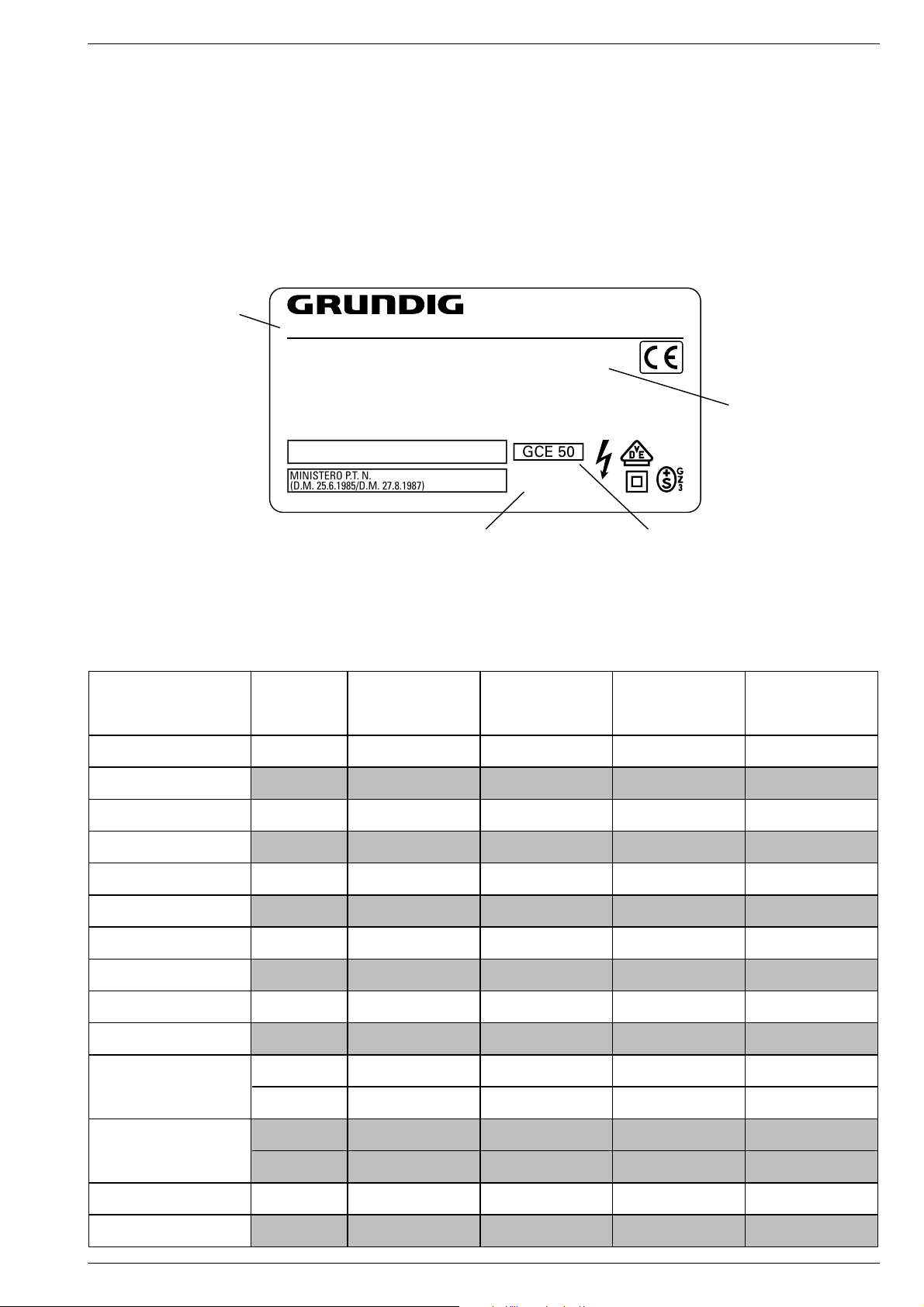
Typenschild des Gerätes
Zusätzlich zum Gerätetyp und der Chassisbezeichnung enthält das
Gerätetypenschild künftig eine sogenannte "Version number" z.B.
VNA. Diese Kennzeichnung gibt Aufschluß über den technischen/
mechanischen Fertigungsstand.
Für die Bestellung von Ersatzteilen sind deshalb folgende Angaben
unbedingt erforderlich:
- Gerätetype (z.B. "T 51-731 text")
- Chassis-Bezeichnung (z.B. "CUC 7303")
- Version number (z.B. "VNA")
- Materialnummer des Ersatzteils
Gerätetype
Type of product
T 51-731 text
220-240V~ 50/60Hz 55W
EIGENSICHERE KATHODENSTRAHLRÖHRE NACH ANLAGE III
DER RÖNTGENVERORDNUNG.
BESCHLEUNIGUNGSSPANNUNG MAX. 25kV, 1.0mA.
TUBOS DE RADIACIÓN CATÓDICA AUTOLIMITADA, SEGÚN ANEXO III DE LA NORMATIVA
RADIOLÓGICA. TENSIÓN DE ACELERACIÓN MÁX. 25kV, 1.0mA.
ATENCION! NO ABRIR SIN ANTES DESCONECTAR LA TENSION DE RED.
STACCARE LA SPINA DI RETE PRIMA DI TOGLIERE IL PANNELLO POSTERIORE.
PROTEGGERE L'APPARECCHIO DALL'UMIDITA`. ATTENZIONE ALTA TENSIONE 25kV, 1.0mA.
MINISTERO P.T. N.
(D.M. 25.6.1985/D.M. 27.8.1987)
MADE IN AUSTRIA FABRICANTE: GRUNDIG AG, WIEN
Type Label on the set
In addition to the type of the TV set and the designation of the chassis,
a so-called "Version number", e.g. VNA, is printed on the type label.
This identification gives information on the technical/mechanical state
of production.
Do not fail to give the following particulars when ordering spare parts:
– Type of product (e.g. "T 51-731 text")
– Chassis designation (e.g. "CUC 7303")
– Version number (e.g. "VNA")
– Part number of spare part
VNA
Version number
GCE 50
CUC 7303
25kV
Modulübersicht / Module List
Materialnr.
Part Number
Bestell-Nr.
Order No.
Chassis
Tuner PLL 29504 301 0100
Keyboard 29501 083 8300
Bildrohrplatte
CRT Panel
Prozessorplatte
Processor Board
Netzschalterplatte
Main Switch Panel
Panorama View 29305 129 0400
YUV-Interface-Platte
YUV Interface Board
IRDT-Baustein
IRDT Module
Buchsenplatte
Socket Board
nachrüstbar#
retrofittable#
Dolby-Surround-Platte
Dolby Surround Board
nachrüstbar#
retrofittable#
NF-Verstärker
AF Amplifier
TP 815 C 29642 061 1400
29305 122 2500
29305 219 1300
29305 165 8300
29305 129 0600
29504 207 0100
29305 160 6300
29305 160 6300
29504 104 8500
29504 104 8500
29504 104 8400
Chassis-Bezeichnung
Chassis designation
ARGANTO 70
MW 70-500 IRDT
CUC 2059 D (VNM)
G.CI 3952 GB G.CI 4052 GB G.CI 3752 GB G.CI 3852 GB
29704 003 8600 29704 003 8700 29704 003 8800 29704 003 8900
ARGANTO 70
MW 70-505 IRDT/DPL
CUC 2059 D (VNM)
Bestellnummer ohne Farbkennzeichnung
Order number without colour code
ARGANTO 82
MW 82-500 IRDT
CUC 2058 D (VNM)
ARGANTO 82
MW 82-505 IRDT/DPL
CUC 2058 D (VNM)
••••
••••
••••
••••
••••
••••
••••
••••
–
•
–
•
•
•
–
•
–
–
–
•
–
•
•
•
–
•
–
–
••••
GRUNDIG Service 1 - 3
Page 4
Allgemeiner Teil / General Section CUC 2058 D / 2059 D
Technische Daten / Technical Data
Bildröhre / Picture Tube
Sichtbares Bild
Visible picture
Bildschirmdiagonale
Screen diagonal
Ablenkwinkel
Deflection angle
Bildwechselfrequenz
Vertical frequency
Elektronik / Electronic
Programmspeicherplätze
Programme positions
AV-Auswertung
AV evaluation
Tuner
TV-Normen
TV-Standards
Stereo Systeme
Stereo systems
Videotext / Digital MHEG
Teletext / Digital MHEG
Musikleistung (ohne Dolby)
Music power (without Dolby)
Musikleistung (mit Dolby Prologic)
Music power (with Dolby Prologic)
Anschlüsse Front / Connections Front
Kopfhörer
Headphones
Analog 99 TV / Digital 99 TV + 3 AV Analog 99 TV / Digital 99 TV + 3 AV Analog 99 TV / Digital 99 TV + 3 AV Analog 99 TV / Digital 99 TV + 3 AV
tuning UHF/VHF (global pinning)
PLL frequency synthesizer tuning
ARGANTO 70
MW 70-500 IRDT
CUC 2059 D (VNM)
66cm 66cm 76cm 76cm
16:9, 70cm (28")
Videocolor,
Super Flat , Black Line Invar
104° 104° 104° 104°
50Hz 50Hz 50Hz 50Hz
auf jeden Programmplatz programmierbar / programmable for every programme position
PLL-Frequenz synthesizer
UHF/VHF (global pinning)
PAL,
NTSC 4,43MHz, I
Nicam 6,52MHz Nicam 6,52MHz Nicam 6,52MHz Nicam 6,52MHz
8 Seiten TOP/FLOF-text,
VPS, WSS
8 pages TOP/FLOF-text,
VPS, WSS
Stereo 2 X 15W,
Subwoofer 30W
—
Stereo 3,5mm Klinkenbuchse, Lautstärke regelbar, individuelle Tonkanalwahl bei 2-Ton-Empfang
Stereo 3.5mm jacksocket, adjustable volume, individual channel selection with dual-sound broadcasts
ARGANTO 70
MW 70-505 IRDT/DPL
CUC 2059 D (VNM)
16:9, 70cm (28")
Videocolor,
Super Flat , Black Line Invar
PLL-Frequenz synthesizer
tuning UHF/VHF (global pinning)
PLL frequency synthesizer tuning
UHF/VHF (global pinning)
PAL,
NTSC 4,43MHz, I
8 Seiten TOP/FLOF-text,
VPS, WSS
8 pages TOP/FLOF-text,
VPS, WSS
Stereo 2 X 15W,
Subwoofer 30W
Stereo 2 X 15W L/R, 30W Center,
15W rear, 30W Subwoofer,
ARGANTO 82
MW 82-500 IRDT
CUC 2058 D (VNM)
16:9, 82cm (32")
Videocolor,
Super Flat , Black Line Invar
PLL-Frequenz synthesizer
tuning UHF/VHF (global pinning)
PLL frequency synthesizer tuning
UHF/VHF (global pinning)
PAL,
NTSC 4,43MHz, I
8 Seiten TOP/FLOF-text,
VPS, WSS
8 pages TOP/FLOF-text,
VPS, WSS
Stereo 2 X 15W,
Subwoofer 30W
—
ARGANTO 82
MW 82-505 IRDT/DPL
CUC 2058 D (VNM)
16:9, 82cm (32")
Super Flat , Black Line Invar
PLL-Frequenz synthesizer
tuning UHF/VHF (global pinning)
PLL frequency synthesizer tuning
UHF/VHF (global pinning)
NTSC 4,43MHz, I
8 Seiten TOP/FLOF-text,
8 pages TOP/FLOF-text,
Stereo 2 X 15W,
Subwoofer 30W
Stereo 2 X 15W L/R, 30W Center,
15W rear, 30W Subwoofer,
Videocolor,
PAL,
VPS, WSS
VPS, WSS
Video IN 1 x Cinch 1 x Cinch 1 x Cinch 1 x Cinch
Audio IN 2 x Cinch 2 x Cinch 2 x Cinch 2 x Cinch
Anschlüsse Rückwand / Connections Rear Panel
Euro AV 1 (schwarz/black)
Euro AV 2 (schwarz/black)
Interface
Netzteil / Mains Stage
Netzspannung (Regelber.)
Mains voltage (variable)
Netzfrequenz
Mains frequency
Leistungsaufnahme
Power consumption
Standby aktiv / passiv
Standby active / passive
FBAS Ein-/Ausgang, S-Video-
Eingang, RGB Eingang
CCVS in-/output, S-Video input,
RGB input
FBAS Ein-/Ausgang, S-Video-
Eingang, RGB Eingang
CCVS in-/output, S-Video input,
RGB input
RS 232, RJ 11 Modem
165…265V 165…265V 165…265V 165…265V
50 / 60Hz 50 / 60Hz 50 / 60Hz 50 / 60Hz
ca. 100W ca. 110W ca. 105W ca. 120W
ca. 65W / ca. 6W ca. 65W / ca. 6W ca. 65W / ca. 6W ca. 65W / ca. 6W
*
FBAS Ein-/Ausgang, S-Video-
Eingang, RGB Eingang
CCVS in-/output, S-Video input,
RGB input
FBAS Ein-/Ausgang, S-Video-
Eingang, RGB Eingang
CCVS in-/output, S-Video input,
RGB input
RS 232, RJ 11 Modem
*
FBAS Ein-/Ausgang, S-Video-
Eingang, RGB Eingang
CCVS in-/output, S-Video input,
RGB input
FBAS Ein-/Ausgang, S-Video-
Eingang, RGB Eingang
CCVS in-/output, S-Video input,
RGB input
RS 232, RJ 11 Modem
*
FBAS Ein-/Ausgang, S-Video-
Eingang, RGB Eingang
CCVS in-/output, S-Video input,
RGB input
FBAS Ein-/Ausgang, S-Video-
Eingang, RGB Eingang
CCVS in-/output, S-Video input,
RGB input
RS 232, RJ 11 Modem
*
* GENEHMIGT für den Anschluß an die in der Bedienungs-
anleitung genannten Telekommunikationssysteme unter den
darin genannten Bedingungen.
* APPROVED for connection to telecommunication systems
specified in the instructions for use subject to the conditions set
out in them.
610107
1 - 4 GRUNDIG Service
Page 5

CUC 2058 D / 2059 D Allgemeiner Teil / General Section
Sicherheits-Hinweise
Die in den Fernsehgeräten auftretende Röntgenstrahlung entspricht
den Bestimmungen der Physikalisch-Technischen Bundesanstalt
vom 8. Januar 1987.
Die Hochspannung für die Bildröhre und die damit auftretende
Röntgenstrahlung ist abhängig von der exakten Einstellung der
Netzteilspannung +A.
Nach jeder Reparatur im Netzteil oder in der Horizontalablenkung ist
die Hochspannung zu messen und ggf. einzustellen.
Schutzschaltungen im Gerät dürfen nur kurzzeitig außer Betrieb
gesetzt werden, um Folgeschäden am Chassis oder an der Bildröhre zu vermeiden.
Beim Austausch der Bildröhre dürfen nur die in den Ersatzteillisten
vorgeschriebenen Typen verwendet werden.
D
Servicehinweise
Chassisausbau
Bevor Sie die Chassis-Verbindungsleitungen lösen, muß die Leitungsverlegung zu den einzelnen Baugruppen wie Netzschalterplatte, Bedieneinheit, Bildrohrplatte, Ablenkeinheit oder Lautsprecher beachtet werden.
Nach erfolgter Reparatur ist es notwendig, die Leitungsführung wieder
in den werksseitigen Zustand zu versetzen, um evtl. spätere Ausfälle
oder Störungen zu vermeiden.
Safety Advices
The X-radiation developing in the sets conforms to the X-radiation
Regulations (January 8, 1987), issued by the Physikalisch-Technische Bundesanstalt (federal physiotechnical institution).
The high tension for the picture tube and thus the developing Xradiation depends on the precise adjustment of the +A power
supply.
After every repair of the power supply unit or the horizontal deflection
stage it is imperative that the EHT for the picture tube is checked and
re-adjusted if necessary.
To avoid consequential damages to the chassis or the picture tube
the integrated protective circuits are allowed to be put out of
operation only for a short time.
When replacing the picture tube use only the types specified in the
spare parts lists.
Cable dereseau
Ces appareils ne peuvent être utilisés qu ' avec un cable de connecion
original de réseau avec bobine antiparasite intégré dans la fiche de
secteur. Ce câble de réseau empêche des perturbations de réseau et
est partie de l'autorisation d'appareil. Si nécessaire commandez
uniquement le cable de réseau selon la liste de pièces détachées.
Netzkabel
Diese Geräte dürfen nur mit dem Original-Netzanschlußkabel mit
integrierter Entstördrossel betrieben werden. Dieses Netzkabel verhindert Störungen aus dem Netz und ist Bestandteil der Gerätezulassung. Im Ersatzfall bestellen Sie bitte ausschließlich das Netzkabel laut Ersatzteilliste.
GB
Service Notes
Disassembly of the chassis
Before disconnecting the chassis connecting leads observe the way
they are routed to the individual assemblies like the mains switch
panel, keyboard control panel, picture tube panel, deflection unit or
loudspeaker.
On completion of the repairs the leads must be laid out as originally
fitted at the factory to avoid later failures or disturbances.
Mains cable
The TV receiver must only be operated with an original mains connecting
cable with an interference suppressor choke integrated in the mains
plug.This mains cable prevents interference from the mains supply and
is part of the product approval. For replacement please order exclusively
the mains connecting cable specified in the spare parts list.
F
Information pour la maintenance
Dèmontage de chassis
Avant de défaire les connecteurs du châssis princip, il y a lieu de
repérer auparavant les liaisons correspondant à chaque platine comme
par exemple le C.I. Inter secteur, le C.I. Commande, le C.I. Tube, le
bloc déviation ou les haut-parleurs.
A la fin de l'intervention, les connexions doivent être remises dans leur
position d'origine afin d'éviter par après d'éventuelles défaillances ou
perturbations.
I
Nota di servizio
Smontaggio del telaio
Prima di sfilare i cavi di collegamneto col telaio è necessario osservare
la disposizione originaria degli stessi verso le singole parti come la
piastra alimentazione, l'unità comandi, la piastra cinescopio, il giogo o
l'altoparlante.
Dopo la riparazione è necessario che gli ancoraggi e le guide
garantiscano la disposizione dei cavi analogamente a quella data in
fabrica e ciò per evitare disturbi o danni nel tempo.
Cavo rete
Gli apperechi devono essere messi in funzioni solo con il cavo originale
il colle gamento di rete e la sua spina di rete deve essere munita di una
bombina d´induttanza. In causa di sostituzione ordinate solo il cavo di
alimentatore che corrésponde alla lista degli accessori.
E
Nota de servicio
Desmontaje del chassis
Antes de desconectar las conecciones del Chassis hay que observar
la dirección de dichas conecciones a los distintos grupos de construcción
como la placa de conmutación de red, unidad de control, placa del
zócalo del tubo de imagen, unidad de deflección o altavoces.
Después de haber realizado la reparación y para evitar fallos o
pertubaciones posteriores es necesario reponer las conecciones tal
como fueron instaladas originalmente en fabrica.
Cable de red
El aparato solo se puede usar con el cable de red original con choque
antiparásito integrado en el enchufe de red. Este cable de red evita
perturbaciones de la red y es parte de la autorización del aparato. En
caso necesario puede pedir el cable de red según lista de piezas de
repuestos.
GRUNDIG Service 1 - 5
Page 6
Allgemeiner Teil / General Section CUC 2058 D / 2059 D
+
-
REF
A-AM
ABK
AUDIO
AUDIO-L
AUDIO-R
AUDIO
MAC
AUDIO
L-MAC
AUDIO
R-MAC
AUDIO
SUB
AUDIO
TV
AUDIO
VCR
A-ZF 1
A-ZF 2
B EXT
BB
B EXT
B
OSD
B PIP
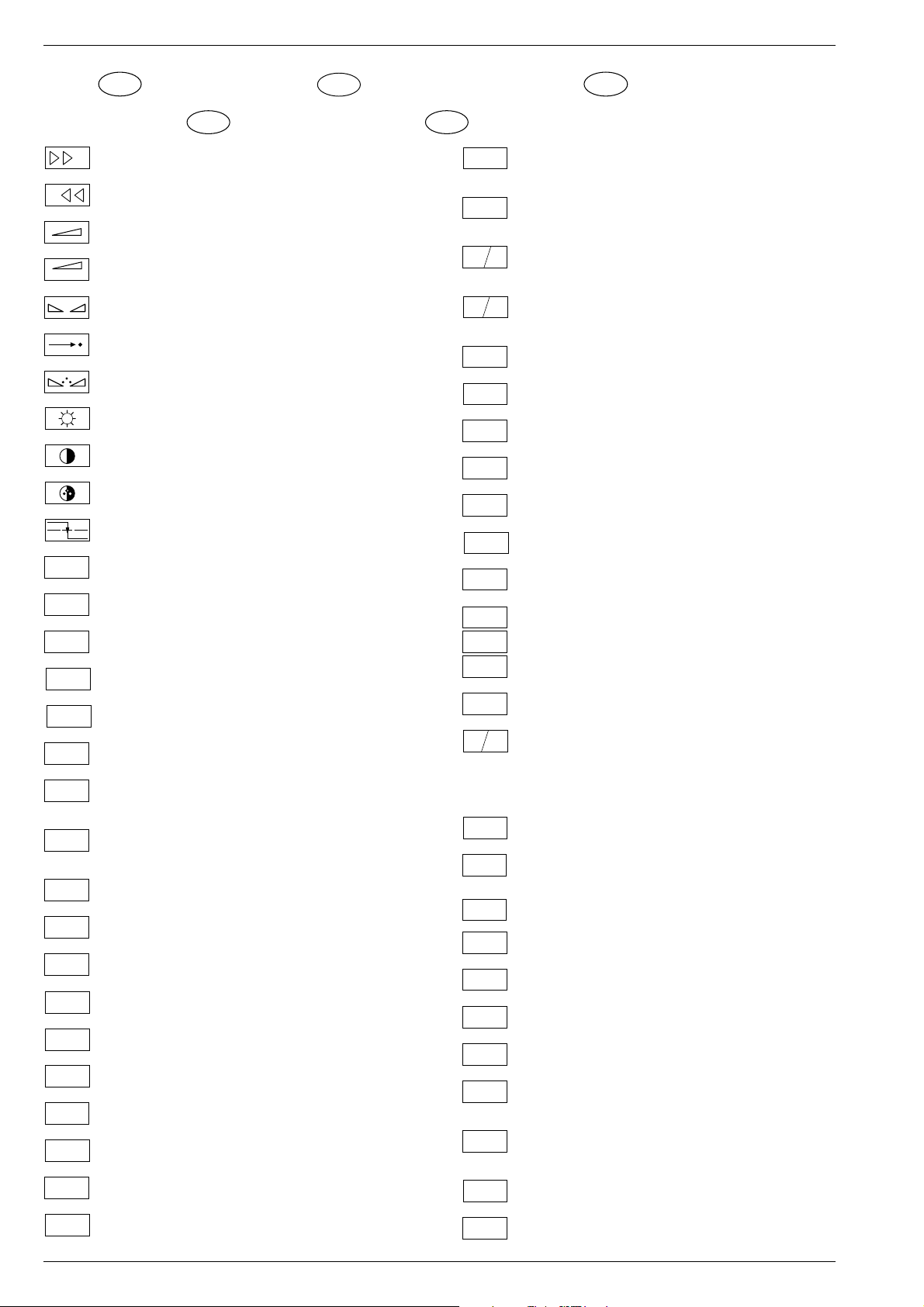
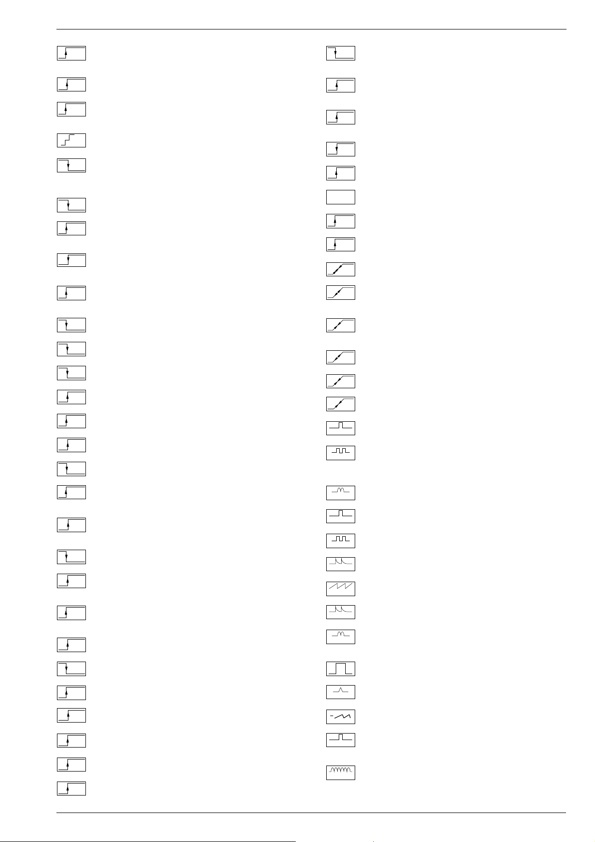
Schaltplansymbole
D
Simboli sullo schema
I
Feinabst. + / Fine tuning + / Réglage fine + / Sint. fine + / Sint. fina +
Feinabst. - / Fine tuning - / Réglage fine - / Sint. fine - / Sint. fina -
Lautstärke / Volume / Volume / Volume sonore / Volumen
Referenz Lautstärke / Volume ref. volt. / Tens. de réf. vol. sonore /
Tens di rif. volume / Tens. ref. volumen
Balance / Balance / Balance / Balanciam. / Balance
Suchlauf / Self seek / Recherche autom. / Sint. autom. / Sintonia
automatica
Farbton / Tint / Teinte / Tinta / Tinte
Helligkeit / Brightness / Luminosité / Luminosita / Brillo
Kontrast / Contrast / Contraste / Contrasto / Contraste
Farbkontrast / Colour contrast / Contraste des coleurs / Contrasto
colore / Contraste de color
Schutzschaltung / Protection circuit / Circuit de sécurité / Circuito di
protezione / Circuito de protección
Audio AM
(Burst Key): Burstaustastimpuls / Burst blanking pulse / Impulsion de
suppress. de burst / Imp. di soppress. del burst / Imp. supresion burst
Ton-Signal / Audio signal / Signal audio / Segnale audio / Señal audio
Ton-Signal links / Audio signal left / Signal audio gauche / Segnale
audio sinistra / Señal audio izquierda
Ton-Signal rechts / Audio signal right / Signal audio droit / Segnale
audio destra / Señal audio derecha
Tonsignal D2 Mac / Audio signal D2MAC / Signal audio D2MAC /
Segnale audio D2MAC / Señal de sonido D2MAC /
Tonsignal links D2 Mac / Audio signal left D2MAC / Signal audio
gauche D2MAC / Segnale audio sinistro D2MAC / Señal de sonido
izquirdo D2MAC
Tonsignal rechts D2 MAC / Audio signal right D2MAC / Signal audio
droit D2MAC / Segnale audio destro D2MAC / Señal de sonido
derecho D2MAC /
Audio Tieftöner / Audio sub woofer / Audio haut-parleur pour les
frequences basses / Audio toni bassi / Audio sonido bajo
Audio-Signal FS Gerät / Audio signal TV set / Signal audio
téléviseur / Segnale audio TV / Señal audio TV
Tonsignal VCR Gerät / Audio signal VCR unit / Signal audio
magnetoscope / Segnale audio VCR / Señal audio VCR
Audio ZF 1 / Audio IF 1 / Audio FI 1 / Audio FI 1 / Audio FI 1
Audio ZF 2 / Audio IF 2 / Audio FI 2 / Audio FI 2 / Audio FI 2
Blau-Signal / Blue signal / Signal bleu / Segnale blu / Señal azul
Basisband / Baseband / Bande de base / Banda base / Banda base
Blau-Signal extern / Signal blue external /Signal bleu externe /
Segnale blu esterno / Señal azul externa
OSD-Einblendung blau / OSD blue / Eblouissement OSD bleu /
Visualizzazione OSD blu / Visualisacione OSD azul
Blau-Signal PIP / PIP Blue signal / Signal bleu PIP / Segnale blu
PIP / Señal azul PIP
GB
Circuit Diagram Symbols
F
Simbolos en los esquemas
E
Blau - Signal - 50Hz vert.,15625Hz hor. / Blue signal - 50Hz vert.,
B/50
15625Hz hor. / Signal bleu - 50Hz vert., 15625Hz hor. / Segnale bleu
- 50Hz vert., 15625Hz hor. / Señal azul - 50Hz vert., 15625Hz hor.
B/100
B-Y 50
B-Y 100
CENTER
CINCH
AUDIO L
CINCH
AUDIO R
CHROMA
CHROMA
CS 100
DATA
ENABLE
ENABLE
ENABLE
EURO-AV
AUDIO-L
EURO-AV
AUDIO-R
EURO-AV
VIDEO
Blau-Signal -100Hz vert., 31250Hz hor. / Blue signal -100Hz vert.,
31250Hz hor. / Signal bleu -100Hz vert., 31250Hz hor. / Segnale blu
-100Hz vert., 31250Hz hor. / Señal azul -100Hz vert., 31250Hz hor.
B-Y -Signal - 50Hz vert., 15625Hz hor. / B-Y -Signal - 50Hz vert.,
15625Hz hor. / Signal B-Y - 50Hz vert., 15625Hz hor. / Segnale BY - 50Hz vert., 15625Hz hor. / Señal B-Y - 50Hz vert., 15625Hz hor.
B-Y -Signal - 100Hz vert., 31250Hz hor. / B-Y -Signal - 100Hz vert.,
31250Hz hor. / Signal B-Y - 100Hz vert., 31250Hz hor. / Segnale BY - 100Hz vert., 31250Hz hor. / Señal B-Y - 100Hz vert., 31250Hz hor.
Kanalwahl / Channel selection / Sélection de canaux / Selez.
C
canale / Seleccion canal
Mittelpunkt-Lautsprecher / Center loudspeaker / Haut-parleur de
centre / Alto parlante punto centrale / Altavoz del centro
CHIP
Chip Adresse / Chip adress / Chip direction / Indiri. del chip /
ADR
Direccion chip
Ton-Signal Cinch links / Audio signal cinch left / Signal audio cinch
gauche / Segnale audio cinch sinistra / Señal audio cinch izquierda
Ton-Signal Cinch rechts / Audio signal cinch right / Signal audio
cinch droit / Segnale audio cinch destra / Señal audio cinch derecha
Chroma Signal / Chroma signal / Signal dégree / Croma segnale /
Señal croma
Chroma S-VHS-Signal / Chroma S-VHS-Signal / Signal dégree de
S-VHS
S-VHS / Croma segnale S-VHS / Señal croma S-VHS
Clock
CLK
CL 1
CL 2
Composite Sync. Imp. für VT / Composite sync pulse for TT / Imp. de
CSY
sync. vidéo-composite pour TXT / Imp. hor. para Video Comp.
Kombiniertes Hor./vert. Sync. Signal 31250Hz/100Hz (Composite
Sync.) / Combined hor./vert. sync signal 31250Hz/100Hz (Composite Sync) / Signal synchr. hor./vert. combiné 31250Hz/100Hz
(Synchr. composité) / Segnale sincr. orizz./vert. 31250Hz/100Hz
(Sincr. Composito) / Señal combinada sincr. hor./vert. 31250/100Hz
(Sincr. compuesto)
Daten / Data / Données / Dati / Datos
Verzögerungsleitung / Delay line / Ligne à retard / Linea di ritardo /
DL
Linea de retardo
Freigabe / Enable / Autorisation / Consenso / Habilitacion
ENA
ENA
Freigabe ZF / IF Enable / Validation FI / Consenso FI / Autorizacón FI
ZF
Freigabe FT / Finetuning enable / Autorisation Réglage fin / Abilitaz.
FT
Sintonia fine / Habilitacion Sintoinia fina
Freigabe LED / LED enable / Autorisation LED / Abilitaz. LED /
LED
Habilitacion LED
Freigabe Ton / Sound enable / Autorisation son / Abilitaz. audio /
TON
Habilitacion sonido
Audio-Signal EURO-AV links / Audio signal EURO-AV left / Signal
audio EURO-AV gauche / Segnale audio EURO-AV sinistra / Señal
audio izquierda EURO-AV
Audio-Signal EURO-AV rechts / Signal audio EURO-AV right /
Signal audio EURO-AV droit / Segnale audio EURO-AV destra /
Señal audio derecha EURO-AV
Video-Signal EURO-AV / Video signal EURO-AV / Signal video
EURO-AV / Segnale video EURO-AV / Señal video EURO-AV
Farb-Signal / Chroma signal / Signal chroma / Segnale chroma /
F
Señal croma
Symboles schéma
1 - 6 GRUNDIG Service
Page 7

CUC 2058 D / 2059 D Allgemeiner Teil / General Section
FBAS
FBAS
CINCH
FBAS
MAC
FBAS
TON
FBAS
TXT
FBAS
TEXT
FBAS
SYNC.
FBAS
S-VHS
F
H
FRM
FT
F
U
F
V
G
G
OSD
G PIP
G EXT
G/50
G/100
GND - H
HA
HDR
HC
H
SYNC
HFB
HS
I2S CL
I2S TER
I2S IN
I2S WS
I BEAM
ICL
FBAS-Signal / CCVS signal / Signal vidéo composite / Segnale video
composito / señal video compuesta
FBAS-Signal-Cinch Buchse / CCVS signal-cinch socket / FBASprise à cinch / FBAS-presa cinch / FBAS-cinch
FBAS-D2 MAC / D2MAC CCVS signal / Signal vidéo compositeD2MAC / FBAS-D2MAC / FBAS-D2MAC
Basisband / Baseband / Bande de base / Banda base / Banda base
FBAS-Videotext / CCVS videotext / Signal vidéo compositeTélétexte / FBAS-Televideo / FBAS-Teletexto
FBAS Sync. Signal / CCVS sync signal / Signal sync. vidéo col.
comp. / Segnal sincr. video col. comp. / Señal sincr. video
compuesta
FBAS Signal S-VHS / CCVS signal S-VHS / Signal vidéo col. comp. SVHS / Segnal video col. comp. S-VHS / Señal video compuesta S-VHS
Hochspg. / EHT voltage / Haute tens. / Alta tens. / MAT
Rahmensignal / Frame signal / Signal d'encadrement / Segnale
cornice / Señal de marco
Feinabstimmung / Fine tuning / Reglage fin / Sint. fine / Sint. fina
FU-Signal / FU-signal / Signal FU / Segnale FU / Senal FU
FV-Signal / FV-signal / Signal FV / Segnale FV / Senal FV
Grün-Signal / Green signal / Signal green external / Signal vert /
Segnale verde / Señal verde
OSD-Einblendung grün / OSD green / Eblouissement OSD vert /
Visualizzazione OSD verde / Visualisacione OSD verde
Grün-Signal PIP / Green signal PIP / Signal green PIP/ Signal vert
PIP / Segnale verde PIP / Señal verde PIP
Grün-Signal extern / Green signal vertical / Signal vert externe /
Segnale verde esterno / Señal verde externa
Grün-Signal - 50Hz vert.,15625Hz hor. / Green signal - 50Hz vert.,
15625Hz hor. / Signal vert - 50Hz vert., 15625Hz hor. / Segnale
verde - 50Hz vert., 15625Hz hor. / Señal verde -50Hz vert., 15625Hz hor.
Grün-Signal -100Hz vert., 31250Hz hor. / Green signal -100Hz vert.,
31250Hz hor. / Signal vert -100Hz vert., 31250Hz hor. / Segnale
verde -100Hz vert., 31250Hz hor. / Señal verde -100Hz vert.,
31250Hz hor.
Nullpunkt Heizung / Ground filament / Point neutre-Chauffage /
Punto zero-Filamento / Punto medio filamento
Horiz. Sync. Impuls / Horiz. Sync pulse / Impulsion synchro. horiz. /
Impulso sincro orizzontale / Impulso de sinc. horiz.
Horiz. Ansteuerimpuls / Horiz. drive pulse / Impulsion de commande
horiz. / Impulso comando orizzontale / Impulso de control horiz.
Horiz. Klemmimpuls / Horiz. clamp pulse / Impulsion de serrage
horiz. / Impulso comando orizzontale / Impulso de garras horiz.
Horizontaler Sync-Impuls / Horizontal Sync impuls / Sync impuls
horizontale / Sinc impulso orrizontale / Impulso sync horizontal
Horiz. Rückschlagimpuls / Horiz. flyback / Impulsion de retour
horiz. / Impulso rotorno orizzontale / Impulso de retroceso horiz.
Hor. Sync. Implus für VT / Hor. sync pulse for TT / Imp. de sync. hor. pour
TXT / Imp. sincr. orizz. per Televideo / Imp. hor. para Video Comp.
Digitale Datensignale / Digtital data signals / Signal donneé digital /
Segnali dati digitali / Señal datos digital
Strahlstrom / Current beam / Current rayon / Corrante del irradire /
Corriente de haz
I2C Bus -Clock
IR
IM
CLOCK
IM
IDENT
IM
RESET
IR CLK
IR DATA
IR
VIDEO
KB
KH
AUDIO-L
KH
AUDIO-R
L
LED
M
MEGA
LOGIC
MODE
NIC CLK
NORM
OWA
P
P/C
PIP
P1
R
REMOTE
R
OSD
R PIP
R EXT
R-Y 50
R-Y 100
S
Infrarot-Signal / Signal infrared / Signal infra-rouge / Segnale
infrarosso / Señal infrarojo.
I2C Bus -Clock
I2C Bus -Kennung / I2C-Bus Identification / Identification I2C-Bus /
2
Ident. I
C-Bus, Identification I2C-Bus
I2C Bus -Reset
Infrarot Clock / Infrared clock / Signal I.R. horloge / Clock segnale
R.I. / Clock infrarojos
Infrarot Signal / Infrared signal / Signal I.R. / Segnale infrarosso /
Data infrarrojos
Infrarot Signal Video / Infrared signal video / Signal I.R. video /
Segnale infrarosso video / Data infrarrojos video
Keyboard
Tonsignal Kopfhörer links / Audio signal headphone left / Signal
audio gauche de casque / Segnale audio sinistra cuffia / Señal audio
izquierda auriculares
Tonsignal Kopfhörer rechts / Audio signal headphone right / Signal
audio droit de casque / Segnale audio sinistra cuffia / Señal audio
derecha auriculares
Lautstärke / Volume / Volume / Volume sonore / Volumen
Leuchtdiode / Light emitting diode / Diode lumineuse / Diodo
luminoso / Diodo luminescente
Speicher Taste / Memory button / Touche mémoire / Tasto di
memoria / Puls. memoria
Megalogic Daten / Megalogic data / Megalogic dates / Dati
Megalogic / Megalogic datas
Modus / Mode / Mode / Modo / Modo
NICAM Clock / Clock NICAM / Horloge NICAM / Clock NICAM /
Clock NICAM
Norm Taste / TV standard select button / touche de norme / Tasto
norma / Puls. de norma
Ost-West Ansteuerimpuls / East-west drive impuls / Impulsion de
commande Est-Ouest / Impulso comando Est-Ovest / Impulso de
control Este-Oeste
Programm / Program / Programme / Programma /Programa
Programm-Kanalwahl / Program channel selection / Progr. sélection
de canaux / Progr. selez.canale / Progr. selec. canal
Bild im Bild / Picture in picture / Image dans l'image / PIP / Imagen
en la imagen
Progr. Taste / Progr. button / Touche Progr. / Tasto Progr. / Puls.
Progr.
Rot-Signal / Red signal / Signal rouge / Segnale rosso / Señal rojo
Fernbedienung / Remote control / Telecommande / Telecomando /
Mando a distancia
OSD-Einblendung rot / OSD red / Eblouissement OSD rouge /
Visualizzazione OSD rosso / Visualisacione OSD rojo
Rot-Signal PIP / Red signal PIP / Signal rouge PIP / Segnale rosso
PIP / Señal rojo PIP
Rot-Signal extern / Signal red external / Signal rouge externe /
Segnale rosso esterno / Señal rojo externa
R-Y -Signal - 50Hz vert., 15625Hz hor. / R-Y -Signal - 50Hz vert.,
15625Hz hor. / Signal R-Y - 50Hz vert., 15625Hz hor. / Segnale RY - 50Hz vert., 15625Hz hor. / Señal R-Y - 50Hz vert., 15625Hz hor.
R-Y -Signal - 100Hz vert., 31250Hz hor. / R-Y -Signal - 100Hz vert.,
31250Hz hor. / Signal R-Y - 100Hz vert., 31250Hz hor. / Segnale
R-Y - 100Hz vert., 31250Hz hor. / Señal R-Y - 100Hz vert., 31250Hz hor.
Sonderkanal / Special channel / Canal special / Canale speciale /
Canal especial
GRUNDIG Service 1 - 7
Page 8

Allgemeiner Teil / General Section CUC 2058 D / 2059 D
SB
SCL
SCL 100
SDA
SHIFT
VIDEO
SHIFT
TEXT
SS
SSB
SSC
SSC
PIP
SSC 100
SSC 50
SUR-
ROUND
SYNC
SYNC.
BTX
SYNC.
VT
SW
TE
T1
T2
TT
U
FOC
U
G1
U
H
U
G2
VA
VB
VCL
VDR
VG
Strahlstrombegrenzung / Beam current lim. / Lim. cour. de faisceau /
Lim. corr. di raggio / Corriente media de haz
I2C-Bus Clock
Schneller I2C-Bus Clock / I2C-Bus clock high speed / I2C-Bus grande
2
vitesse / I
I2C-Bus Daten / I2C-Bus data / I2C-Bus données / I2C-Bus dati /
I
Dynamische vert. Versch. 25Hz, aktiv bei Video u. Mix Betrieb /
Dynam. vert. shift 25Hz, active on video and mix operation / Decal
dynam. de l'image 25Hz, actif sur video et fonction. mixte / Spostam.
vert. dinam. 25Hz, attivo con video e. funzionam. misto / Desplaz.
dinamico vert. 25Hz, activo con video Y funciones mixtas
Dynamische vert. Versch. 25Hz, aktiv bei Standbild u. VT / Dyn. vert.
shift 25Hz, active on freeze-frame and Teletext / Decal dynam. de
l'image 25Hz, actif sur arret immage et Vidéotext (Antiope) / Spostam.
vert. dinam. 25Hz, attivo con fermo immag. e Televideo / Desplaz.
dinamico vert. 25Hz, activo con imagen parada Y Videotexto
Schutzschaltung / Protection circuit / Cablage protecteur / Pot. de
prot. / Circuito de proteccion
Spitzenstrahlstrombegrenzung / Peak beam current limiting / Lim.
de faisceau crete / Lim. corr. catod. di pico / Corrente pico de haz
Supersandcastle
Supersandcastle PIP
Supersandcastle 100Hz vert., 31250Hz hor.
Supersandcastle 50Hz vert., 15625Hz hor.
Surround
Sync.-Signal / Sync.-Signal / Signal sync / Segnale sync. / Señal de sync.
Sync. BTX / Viewdata Sync / Sync. Télétext / Sincr. Videotel / Sincr.
Videotexto
Sync. VT / Sync. Teletext / Sync Vidéotexte / Sincr. Televideo / Sincr.
Videotexto
Schwarzwert / Black level / Niveau du noir / Livello del nero / Nivel de negro
TEXT-Freigabe / TEXT enable / Autorisation TEXTE / Abilitaz.
TELEVIDEO / Habilatation TEXTE
Bei Zweiton, Ton 1 / On two channel sound, sound 1 / Pour double
son, son 1 / In bicanale, audio 1 / En dual, sonido 1
Bei Zweiton, Ton 2 / On two channel sound, sound 2 / Pour double
son, son 2 / In bicanale, audio 2 / En dual, sonido 2
Tieftöner / Woofer / Haut-parleur pour les frequences basses / Toni
bassi / Sonido bajo
Fokusspg. / Focussing volt. / Tens. de focalis. / Tens di focalizz. /
Tens focalizacion
Spg. Gitter G 1 / Volt. grid G1 / Tens grille G 1 / Tens. griglia G1 / Tens.
rejillas G 1
Hochspannung / High voltage / Haute tension / EAT / Alte tension
Schirmgitter Spg. / Screen-grid volt. / Tens. de grille - écran / Tens.di
griglia schermo / Tens. de rejilla
Vertikaler Ansteuerimpuls / Vert. drive pulse / Impulsion de commande
verticale / Impulso di comando verticale / Impulso de control vertical
VCR - Clock
Freigabe Anzeigebaustein / Display enable / Autorisation pour module
indicateur / Modulo indicazione / Habilitacion modulo indicacion
Vert. Gegenkopplung / Vert. feedback / Contre-reaction verticale /
Controreazione vert. / Aliment. neg. vert.
C-Bus veloce / Clock del I2C-Bus de alta velocida
2
C-Bus datos
VIDEO
VT DATA
VT SCL
VT SDA
V SYNC
Y 50
Y 100
U
U
U
U
U
U
U
U
U
U
U
U
U
U
U
U
U
U
Video Signal / Video signal / Signal vidéo / Segnale video / Señal video
Videotext Daten / Teletext data / Données Teletexte / Linea dati
Televideo / Data Teletexto
Videotext Clock / Teletext clock / Signal horloge Vidéotext / Clock
Televideo / Clock Teletexto
I2C Bus: VT Daten / Teletext data / Données Vidéotext / Dati
Televideo / Data Teletexto
Vertikaler Sync-Impuls / Vertical Sync impuls / Sync impuls vertical
/ Sinc impulso vertical / Impulso sync vertical
Y
Y-Signal / Y Signal / Signal Y /Segnale Y / Señal Y
Y -Signal - 50Hz vert., 15625Hz hor. / Y -Signal - 50Hz vert., 15625Hz
hor. / Signal Y - 50Hz vert., 15625Hz hor. / Segnale
Y - 50Hz vert., 15625Hz hor. / Señal Y - 50Hz vert., 15625Hz hor.
Y - Signal - 100Hz vert., 31250Hz hor. / Y -Signal - 100Hz vert.,
31250Hz hor. / Signal Y - 100Hz vert., 31250Hz hor. / Segnale
Y - 100Hz vert., 31250Hz hor. / Señal Y - 100Hz vert., 31250Hz hor
Zwischenfrequenz / IF / FI / FI / FI
ZF
AFC
Schaltspg. AFC / AFC switching volt. / Tens. de commut. AFC/ Tens.
di commut. AFC / Tens. conmut. CAF
AV
Schaltspg. AV / Switching volt. AV / Tens. de commut. AV / Tens. di
commut. AV / Tens. conmut. AV
B1
Schaltspg. Band 1 / Switching volt. band 1 / Tens. de commut.
bande 1 / Tens. di commut. banda 1 / Tens. conmut. de banda 1
B2
Schaltspg. Band 3/ / Switching volt. band 3 / Tens. de commut.
bande 3 / Tens. di commut. banda 3 / Tens. conmut. de banda 3
BA
Schaltspg. Bildamplitude / Switching voltage vertical amplitude /
Tension de coupure amplitude dìmage / Tensione di commutaz.
ampiezza d'imagine / Tension de conm. amplitude de imagen di
commut. PAL / Tens. conmut. PAL
BTX
Schaltspg. BTX / Switching volt. BTX (Viewdata) / Tens. commut.
Télétext / Tens. commut. VIDEOTEL / Tens. conmut. Teletexto
C-AV
Schaltspg. Camera Wiederg. über Camera-AV Eingang / Switching
volt. cam. playback via Camera-AV input / Tens de commut pour lec.
de camera par l'entree Camera-AV / Tens.de commut. in riproduz.
camera tramite ingresso Camera-AV / Tens. de serv. reprod. camera
a traves de la entrada Camera-AV
DATA
Schaltspg. Datenbetr. / Switching volt. data mode / Tens. de commut. fonct. données / Tens. di commut. dati / Tens conmut. datos
DATA
Schaltspg. U Data extern / Switching volt Data ext. / Tension de
EXT
commutation U Data externe / Tens. di commutazione U-Data
esterno / Tensión de conmutatón externa U
DATA
Schaltspg. für Bildschirm-Einblendung / Switching volt. for On
OSD
Screen Display / Tens. commut. pour eblouissement On Screen
Display / Tens. commut. per di visualizzazione On Screen Display /
Tens. conmut. para On Screen Display
DEEM
Schaltspg. Deemphasis / Switching volt. deemphasis / Tens. commut. desaccent. / Tens. commut. deenfasi / Tens. conmut. deenfasis
DS
Schaltspg. Dolby-Surround / Switching volt. Dolby-Surround / Tens.
commut. Dolby-Surround / Tens. commut. di Dolby-Surround / Tens.
de conmut. Dolby-Surround
EURO-
Schaltspg. EURO-AV / Switching volt. EURO-AV / Tens. de commut.
AV
EURO-AV / Tens. di commut. EURO-AV / Tens. conmut. EURO-AV
EU-AV
Schaltspg. EURO-AV-Cinch-Buchse / Switching volt. EURO-AV-
CINCH
Cinch socket / Tens. commut. prisa Scart - Cinch / Tens. commut.
presa Scart -Cinch / Tens. conm. EURO-AV - Cinch
FBAS
Schaltspannung für Video-Ausgang EURO-AV Buchse / Switch.
voltage for video output EURO-AV socket / Tension de commut.
pour sortie vidéo EURO-AV / Tension commut. per presa d'uscita
video EURO-AV / Tension de conmut. para salida EURO-AV
HIFI
Schaltspg. HIFI / Switching voltage HIFI / Tens. de commut. HIFI /
Tens di commut. HIFI / Tens. conmut. HIFI
HIFI
Stummschaltung HiFi / Muting volt. HiFi / Commutation de silence
MUTE
HiFi / Silenzametno HiFi / Muting HiFi
HUB
Schaltspg. HUB / Switching volt. deviation / Tens. commut.
déviation / Tens. commut. deviazione / Tens. conmut. deviacion
1 - 8 GRUNDIG Service
Page 9
CUC 2058 D / 2059 D Allgemeiner Teil / General Section
U
U
U
U
50/60Hz
U
IDENT
Schaltspg. Signalkennung AV 3 / Switching volt. signal identification
AV 3 / Tens de commut.identification de signal AV3 / Tens. commut.
identificazione segnale / Tens. conmut. identifi. segñal AV3
KH
Stummschaltung Kopfhörer / Muting volt. headphone / Commutation
MUTE
de silence casque / Silenzamento cuffia / Muting auriculares
KLEMM
Gleichspannung für SAT-Basissignal / DC for SAT basic signal /
Tens. continue pour SAT base signal / Tens continua per segnale
SAT base / Tens. continua para segñal SAT base
KOIN
Schaltspg. Koinz. / Switching volt. coinc. / Tens de commut. coinc. /
Tens di commut. coinc. / Tens. conmut. coinc.
KOIN
Schaltspg. Koinz. mit Videoquelle verknüpft / Coinc. switching volt.
VQ
linked with video source / Signal de coincid. combiné avec source
video / Tens. di commut. a coinc. combinata con sorg video segñal
U
U
U
U
U
WISCH
Schaltspg. Wischerkontakt / Schwitching voltage temp. contact /
Tens. de commut. contact fugitif / Tens. commut. contatto temporaneo / Contacto supresor tens. de conmut.
W/N
Schaltspg. ZF breit - schmal / IF switching volt. wide - narrow / Tens.
commut. FI large - etroit / Tens. commut. FI larga - stretta / Tens. FI
ancho - estrecho
I / III
Schaltspg. Bandwahl / Band sel. switching volt. / Tens. de commut.
select. bande / Tens. di commut. selez. banda / Tens. conmut. selec.
banda
14V
14V Schaltspg. / 14V switching volt. / Tens. commut. 14V / Tens.
commut. 14V / Tens. de conm. 14V
22kHz
22kHz Schaltspg. / 22kHz switching volt. / Tens. commut. 22kHz /
Tens. commut. 22kHz / Tens. de conm. 22kHz
de coincidencia combinada con video
U
U
U
U
U
U
U
U
U
U
U
U
U
U
U
U
U
U
U
U
U
U
U
LED
Schaltspg. LED / Switching volt. LED / Tens de commut. LED / Tens.
commut. LED / Conmut. LED
Leucht-
Schaltspg. Leuchtpunktunterdrückung / Switching volt. beam spot
punkt
suppression / Tens. de commut. suppress. du spot lumineux / Tens.
soppr. punto luminoso / Tens. de conmut. filtro supresor del punto luz
LNC
Schaltspg. LNC "Aus" / Switching volt. LNC "OFF" / Tens. de
OFF
commut. LNC "OFF" / Tensione di commut. "Spento" LNC / Tension
LNC "OFF"
MAC
Schaltspg. D2MAC / Switching volt. D2MAC / Tension de
commutation D2MAC / Tens. di commutazione D2MAC / Tensión de
conmutación D2MAC
MUTE
Stummschaltung / Muting / Silencieux / Silenziamento /Muting
NF 1
Schaltspg. NF 1 / Switching volt. AF 1 / Tension commut. BF 1 / Tens.
commut BF 1 / Tens. conm. BF 1
NF 2
Schaltspg. NF 2 / Switching volt. AF 2 / Tension commut. BF 2 / Tens.
commut BF 2 / Tens. conm. BF 2
NIC
Schaltspg. NICAM / Switching volt. NICAM / Tens. de commut.
NICAM / Tens. commut. NICAM / Tens. de conmut. NICAM
NORM
Schaltspg. Norm / Switching volt. Norm / Tens. de commut.
standard / Tens. di commut. Norma / Tens. conmut. Norma
PAL
Schaltspg. PAL / Switching volt. PAL / Tens. de commut. PAL / Tens.
di commut. PAL / Tens conmut. PAL
POL.
Schaltspg. Polarität / Switching volt. polarity / Tension commut.
polarite / Tens. commut. polarita / Tens. conmut polarizacion
POWER
Schaltspg. Ökoschalter / Switching volt. eco switch / Tens. de
OFF
commut. interr. eco. / Tens. commut. interr. ecologico / Tens.
conmut. interr. ecol.
PV
Schaltspg. Panorama View / Switching volt. Panorama View / Tens.
de commut. Panorama View / Tens. commut. Panorama View /
Tens. conmut. Panorama View
RESET
Schaltspg. Reset / Switching volt. Reset / Tens. commut. Reset /
Tens. commut. Reset / Tens. conmut. Reset
RGB
Schaltspg. RGB1 - RGB2 / Switching volt. RGB1 - RGB2 / Tens. de
commut. RGB1 - RGB2 / Tens. di commut. RGB1 - RGB2 / Tens.
conmut. RGB1 - RGB2
SCHUTZ
Schaltspg.-Schutzfunktion / Switching volt.-protective func. / Tens
de commut.-sécurité / Tens. di commut.-funz di protez. / Tens.
conmut.-proteccion
SEC
Schaltspg. SECAM / Switching volt. SECAM / Tens. de commut.
SECAM / Tens. di commut. SECAM / Tens. conm. SECAM
STBY
Schaltspg. Standby / Switching volt. Standby / Tens. commut.
Veille / Tens. commut. Standby / Tens. conmut. Standby
S-VHS
Schaltspg. S-VHS / Switching volt. S-VHS / Tens.de commut.
S-VHS / Tens. de commut. S-VHS / Tens. de conmut. S-VHS
TON
Schaltspg. Ton 1-2 / Switching volt. sound 1-2 / Tens. commut. audio
1/2
1-2 / Tens. commut. son 1-2 / Tens. conmut. son 1-2
UHF
Schaltspg. UHF / UHF switching volt. / Tens. de commut. UHF / Tens
di commut. UHF / Tens. conmut. UHF
VHF
Schaltspg. VHF / VHF switching volt. / Tens. de commut. VHF / Tens
di commut. VHF / Tens. conmut. VHF
VQ
Schaltspg. Videoquelle / Switching volt. video source / Tens. de
commut. source video / Tens. di commut. sorg. video / Tens conmut.
0/3/6/9V
U
U
U
U
U
U
U
U
HOR.2FH
VER.2FV
VERT. 100
VERT. 100
PULSE
0/3/6/9V Schaltspg. / 0/3/6/9V switching volt. / Tens. commut.
0/3/6/9V / Tens. commut. 0/3/6/9V / Tens. de conm. 0/3/6/9V
4.5MHz
Schaltspg. 4,5MHz / Switching volt. 4.5MHz / Tens. de commut.
4,5MHz / Tens. di commut. 4,5MHz / Tens conmut. 4,5MHz
50/60
Schaltspg. 50-60Hz / Switching volt. 50-60Hz / tens. de commut.
Hz
50-60Hz / Tens. di commut. 50-60Hz / Tens. conmut. 50-60Hz
Regelspg. AFC / AFC contr. volt. / Tens. de regul. AFC / Tens. di
AFC
contr. AFC / Tens. regul. CAF
AFC
Regelspg. AFC Satellitentuner / AFC contr. volt. SAT tuner / Tens.
SAT
de regul. AFC tuner SAT / Tens. di contr. AFC Tuner SAT / Tens.
regul. CAF Tuner SAT
Feldstärkeabhängige Spg. / Fieldstrength-depent volt. / Contr. auto-
AGC
matique de gain / Tens. dipent. intens. campo / Contr. autom. de gain
tens. CAG
Regelspg. / Contr. volt. / Tens. de regul. / Tens. di contr. / Tens regul.
RE
Abstimmspg. Tuner / Tuning volt. tuner / Tens. d'accord tuner / Tens.
TUN.
di sintonia tuner / Tens. sintonia tuner
Regelspg. Verzög. / Delayed contr. volt. / Tens. de regul. retardee /
τ
Tens. regul. retardada
Horizontale Ansteuerung / Horiz. drive / Synchr. lignes / Pilotaggio
HOR.
orizz. / Exitación horiz.
31250Hz Ansteuerimp. für Zeilenendstufe / 31250Hz Triggering
pulse for horiz. output / 31250Hz commande pour l'étage final
lignes / Imp. Pilotaggio di 31250Hz per stadio finale di riga / Impulso
de exitación 31250Hz para paso final de lineas
Vert. Parabel / Vert. parabolic signal / Signal parabolique vert. /
VERT.
Segnale parab. vert. / Senal parabolica vert.
Vert. Tastimpuls / Vert. Gating pulse / Imp. trame / Imp. a cadenza
VERT.
vert. / Imp. cuadro
Vert. Tastimpuls 100Hz / Vert. Gating pulse 100Hz / Imp. trame
100Hz / Imp. a cadenza vert. 100Hz / Imp. cuadro 100Hz
Vert. Sägezahn / Vert. saw tooth / Signal dent de scie / Dente di sega
VERT.
vert. / Dientede sierra vert.
Vert. Tastimpuls / Vert. Gating pulse / Imp. trame / Imp. a cadenza
VERT.
vert. / Imp. cuadro
Vert Sägezahn 100Hz / Vert saw tooth 100Hz / Signal dent de scie
100Hz / Dente di sega vert. 100Hz / Dientede sierra vert. 100Hz
Vert. Parabel 100Hz / Vert. parabolic 100Hz signal / Signal parabolique 100Hz vert. / Segnale parab. vert. 100Hz / Senal parabolica
vert. 100Hz
Tastimpuls / Gating pulse / Impuls de declenchement / Impulso a
cadenza / Imp. puerta
Ref. Impuls hor. / Reference impulse hor. / Imp. de refer.hor. / Imp.
REF.
di rifer. hor. / Imp. refer. horiz.
Klemmung Ein-Aus / Clamping On-Off / Clampage Marche-Arrêt /
Clamping Ins.-Disins. / Clamping Enc.-Apag.
Pulse für Polarotor / Pulses for Polar-Rotor / Impulsions Rotor de
Polariastion / Impulsi per Rotore Polarizzazione / Impulsos dara
Polarrotor
O-W Amplitude / E-W amplitude / Amplitude E-O / Ampiezza E-O /
O/W
Amplitud E-O
video
GRUNDIG Service 1 - 9
Page 10
Allgemeiner Teil / General Section CUC 2058 D / 2059 D
Operating Hints This chapter contains excerpts from the operating instructions. For further particulars please refer to the appropriate user
instructions the part number of which is indicated in the relevant spare parts list.
WELCOME …
… to digital terrestrial television
Welcome to a new form of entertainment with new free to air – and subscription
services.
Future features are interactive via the modem and Common Interface, and are
used for home shopping, home banking and other services.
What is digital TV and why is the world changing to
digital transmission?
Digital transmission will do for the eyes what the Compact Disc brought for the
ears!
No noise in the picture, no cross effects between the picture and sound content,
no influence of multipath reception as a result of reflections to the aerial. The
quality of reception is outstanding.
Digital terrestrial television is received through the same aerial that is used for
existing analogue TV reception and is transmitted preferably in the widescreen
format 16:9 (speak 16 by nine).
Please note, a few TV transmitter stations will have to transmit some of the digital services on new frequencies outside of the existing frequency range.
This would make it necessary to have a broadband aerial installed in order to
receive all the new services.
How can I record digital transmissions?
Dont worry, this is possible via the Scart extension from your Grundig TV. Refer
to page 14.
More good news: Digital terrestrial TV was introduced in november ‘98, but
new features for interactivities may change the existing TV’s software. Don’t
worry! Your TV is prepared for updating any kind of change via the Common
Interface (PCMIA) slot on the rear of the TV. Refer to page 10.
Flashcards to do this are available, if needed, via your dealer or our Service
Organisation.
If you want to judge the picutre quality, just follow the instructions on page 62.
Your GRUNDIG IDTV (Integrated Digital TV) displays an integrated colour bar
test pattern in digital mode – in digital resolution.
4
Impressive this new TV generation – isn’t it. Grundig made for you.
_____________________________________________________________________
10
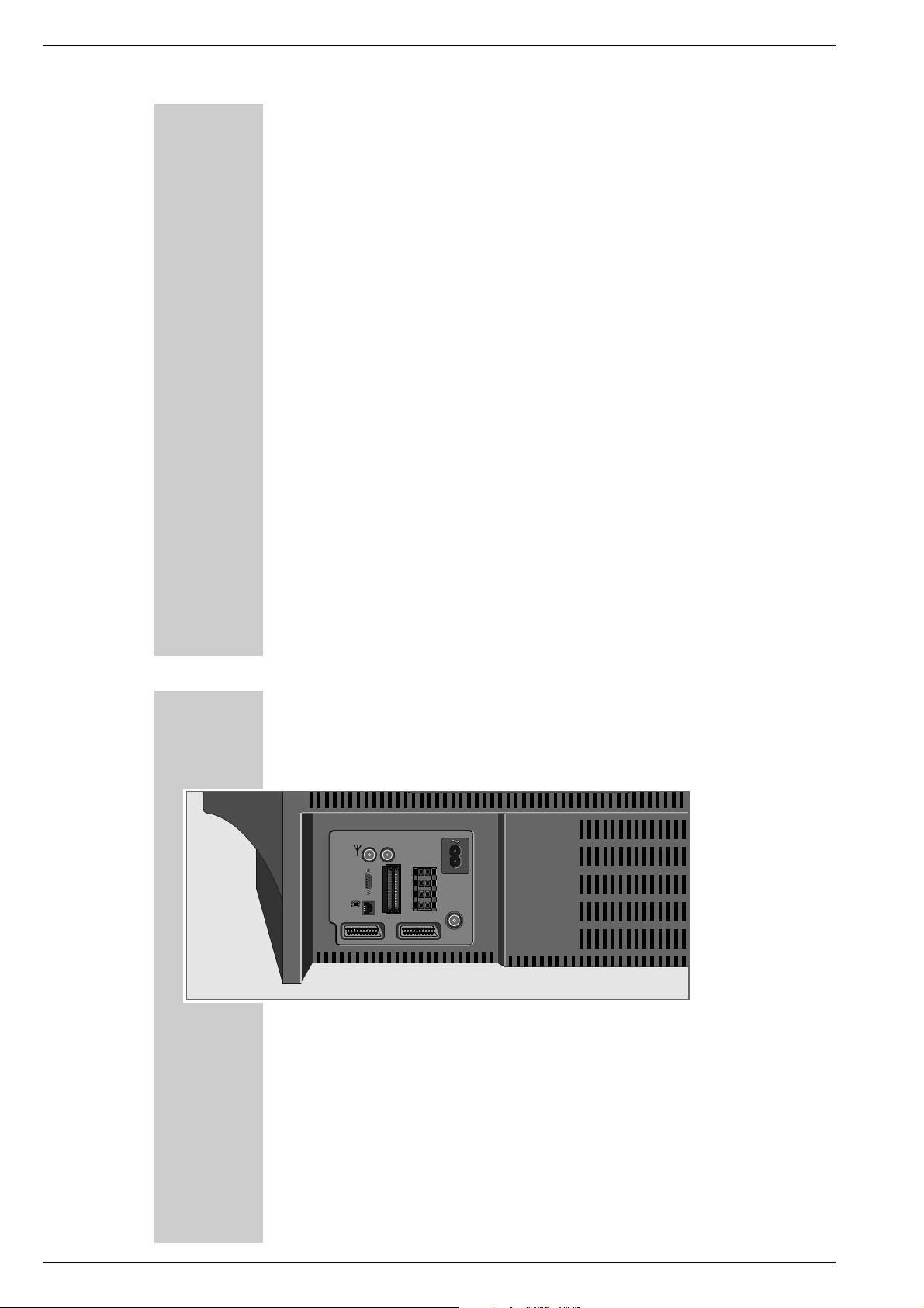
AT A GLANCE
The rear of the TV set
ANTENNA IN
SERIAL
PORT
LINE
AV1
ANTENNA IN Input for house aerial.
ANTENNA LOOP Aerial output (to »ANTENNA LOOP IN«
OUT socket or to external equipment).
~ Mains cable to mains socket.
SERIAL PORT Service connector for specialized dealer.
ü LINE Modem connection socket.
CI1 CI2 Common Interface slots for expansion modules.
L R Clamping terminals for front loudspeakers.
S Clamping terminals for surround loudspeakers.
ANTENNA LOOP Aerial input.
IN
AV 1 Euro/AV socket (Mecalogic, CSCC, S-VHS).
AV 2 Euro/AV socket (CSCC, S-VHS).
_____________________________________________________________________________
ANTENNA
LOOP OUT
L
R
ANTENNA
S
CI1 CI2
LOOP IN
AV2
These modules must be 3,3 V or 5 V compatible.
1 - 10 GRUNDIG Service
Page 11
Allgemeiner Teil / General SectionCUC 2058 D / 2059 D
TELEP ILOT 815C
1
4 5 6
7 8 9
i-ACTIV AUX
VIDEO SAT
32
0
P
OK
P
EPG
TXT
D/A
CL
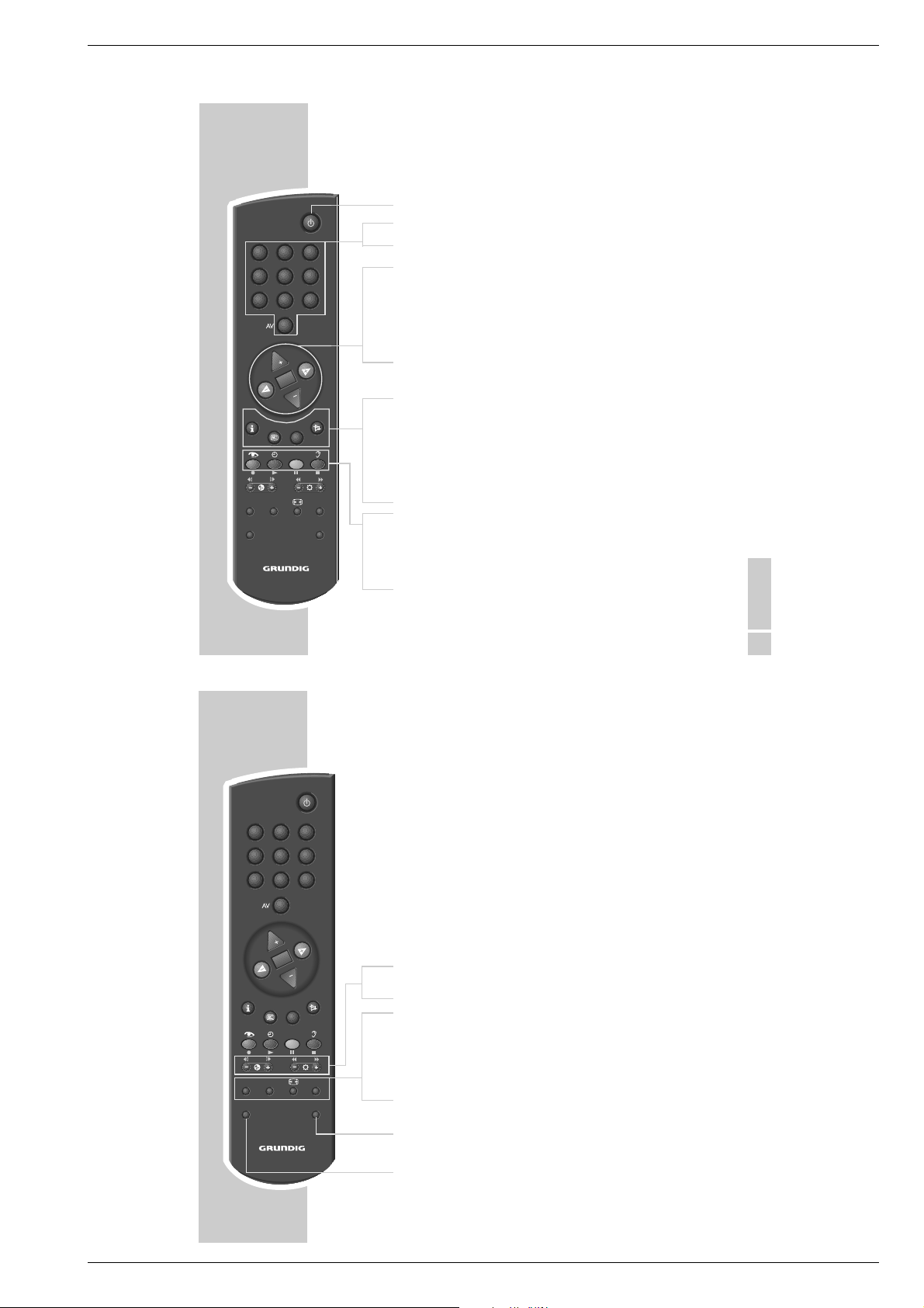
AT A GLANCE
The remote control
88
1…9 Switch the TV set on from stand-by;
0 AV select channel and AV programme positions directly;
..,,
FF EE
OK Changes and activates different functions;
i Calls up the digital and the analogue Dialogue Centre
EPG
TXT Switches between teletext and TV mode in analogue mode and
aa
zz
´´
D/A Switches between analogue and digital TV channels (services).
FF
_____________________________________________________________________________
Switches the TV set to stand-by.
enter the teletext page numbers.
Switch the TV set on from stand-by (only »,,«);
select channels step by step;
move cursor up/down.
Change volume setting;
move cursor to the left/to the right.
switches between the two TV channels last viewed;
switches to optimum settings (»AUX« and »OK«).
(»i « and »OK«).
Calls up the “electronic TV Programme Guide” in digital mode.
ff
MHEG application in digital mode.
Sound on/off (mute)
Calls up the »Picture settings« menu.
Clock time on/off.
Calls up the »Sound settings« menu.
TELEP ILOT 815C
1
4 5 6
7 8 9
i-ACTIV AUX
VIDEO SAT
32
0
P
OK
P
EPG
TXT
D/A
CL
AT A GLANCE
– E
RR
–
i-ACTIV Switches the remote control buttons between MHEG operation and
CL Ends a running Timer recording.
E
AUX Preselection button for various functions;
SAT Switches to remote control of a GRUNDIG satellite receiver. See
VIDEO Switches to remote control of a GRUNDIG video recorder. See
_____________________________________________________________________________
+
Adjust colour intensity.
+
Adjust brightness.
TV operation.
Switches the picture format.
calls up the »AUX« menu.
page 63 for a description of the possible functions.
page 63 for a description of the possible functions.
ENGLISH
11
12
GRUNDIG Service 1 - 11
Page 12
Allgemeiner Teil / General Section CUC 2058 D / 2059 D
AV1
AV2
ANTENNA
LOOP IN
L
R
S
ANTENNA
LOOP OUT
ANTENNA IN
LINE
SERIAL
PORT
CI1 CI2
TV R
SAT
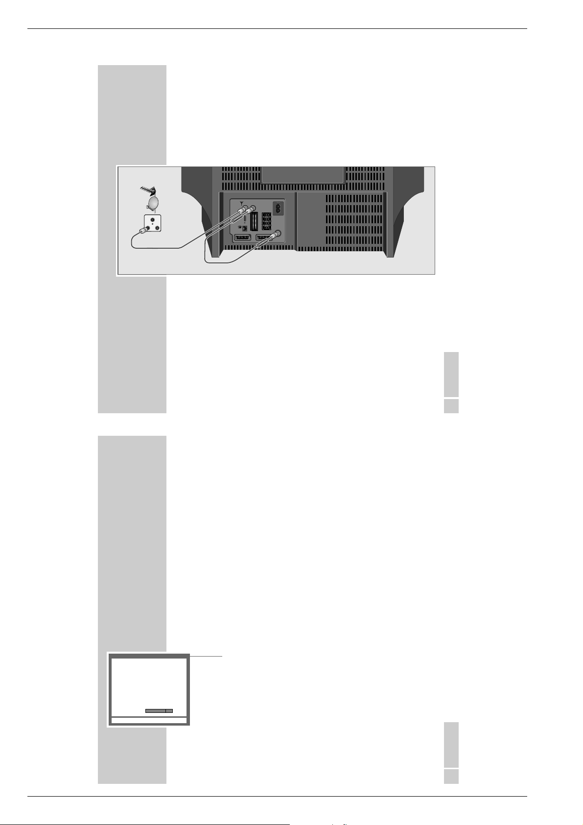
CONNECTION AND PREPARATION
Connecting the aerial, a video recorder,
a satellite receiver
Connecting the aerial to the TV set
1 Connect the cable from the house aerial with the »
socket on the TV set.
2 Connect the aerial cable supplied with the »ANTENNA LOOP OUT«
socket and the »ANTENNA LOOP IN « socket on the TV set.
Note:
When receiving stations in band 1 (45 MHz - 62 MHz) or in band 3
(175 MHz - 225 MHz), it is necessary to connect a frequency filtre in front of
the aerial input »
ANTENNA IN« (Ask your GRUNDIG Dealer).
ANTENNA IN«
_______________
AUTOMATIC TUNING SYSTEM
Prog UHF Signal Service Found
SETTINGS
______________________________________________________________________________
Channel programming
The TV set is equipped with an automatic tuning system for analogue and digital
TV channels. The tuning can take approx. 15 minutes.
When the set is first powerd up and you start the automatic tuning system the TV
set searches at first for digital TV channels and then for analogue TV channels.
99 channel positions for digital TV channels (services) and 99 channel positions
for analogue TV channels are available.
When the automatic search is completed, you may sort the channels in a
sequence of your choice for digital and then for analogue channels. Mixing is
not possible.
You may delete TV channels which have been found several times, or those with
poor reception quality, from the TV programme charts.
Programming digital and analogue TV channels
using the automatic tuning system
1 Switch the TV set on by pressing »IO« on the TV set.
– The »AUTOMATIC TUNING SYSTEM« screen appears.
ENGLISH
13
2 Start the search with »OK«.
– The TV set searches at first for digital TV channels and then for analogue
TV channels. Depending on the number of channels which can be recei-
Progress
OK Start Digital Automatic Tuning System TXT
ved, the search can take some time.
– When the search is completed, the TV set switches to channel position 1
and the »DIGITAL PROGRAM SORT« screen appears.
ENGLISH
19
1 - 12 GRUNDIG Service
Page 13
Allgemeiner Teil / General SectionCUC 2058 D / 2059 D
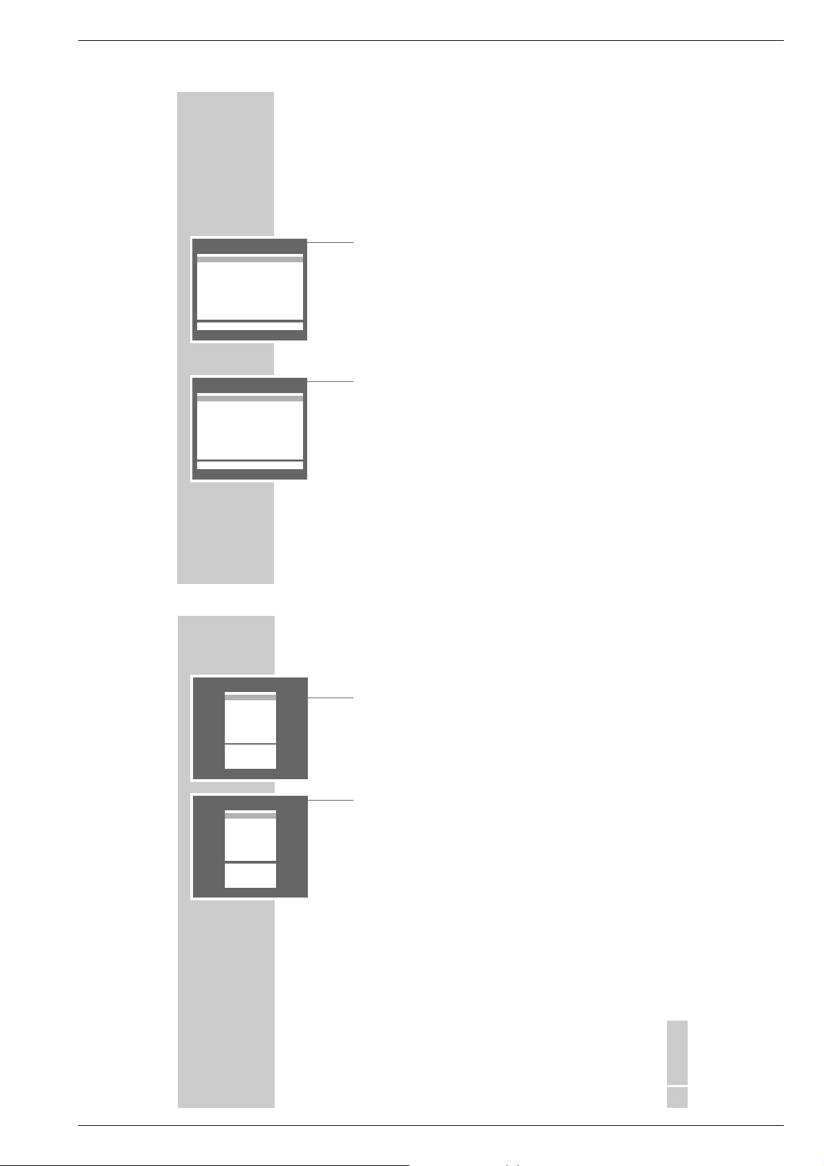
DIGITAL PROGRAM SORT
u
D01 BBC CHOICE
D02 ITV
D03 FILM FOUR
D04 UK GOLD
D05 TNT
D06 ITV 2
D07 BBC NEWS 24
D08 BBC ONE
D09 BBC TWO
D10 CARTOON NETWORK
–––––––––––––––––––––––
i
OK AUX Delete 6 Back TXT
DIGITAL PROGRAM SORT
u
D01 BBC CHOICE
D02 ITV
D03 FILM FOUR
D04 UK GOLD
D05 TNT
D06 ITV 2
D07 BBC NEWS 24
D08 BBC ONE
D09 BBC TWO
D10 CARTOON NETWORK
–––––––––––––––––––––––
i
OK AUX Delete 6 Back TXT
SETTINGS
____________________________________________________________________________________
Note:
The search can be aborted at any time by pressing »TXT«.
If the search system has found no digital TV services, the message »No
Digital Services Found« appears.
Delete digital TV channel positions
1 In the »DIGITAL PROGRAM SORT« table, select the channel to be cleared
with »,,« or »..«.
2 Delete the channel with »AUX «.
Notes:
To clear further channel positions, repeat the steps 1 and 2.
If the channel position is locked (see chapter „Parental Lock“ on page 44), it
cannot be deleted.
Sorting digital TV channels
1 In the »DIGITAL PROGRAM SORT« table, select the channel position of the
channel to be moved to another position with »,,« or »..«.
2 Mark the channel with »OK«.
3 Select the channel position to which the marked channel is to be moved with
»,,« or »..«.
4 Store the setting with »OK«.
Note:
To sort further channels, repeat the steps 1 to 4.
20
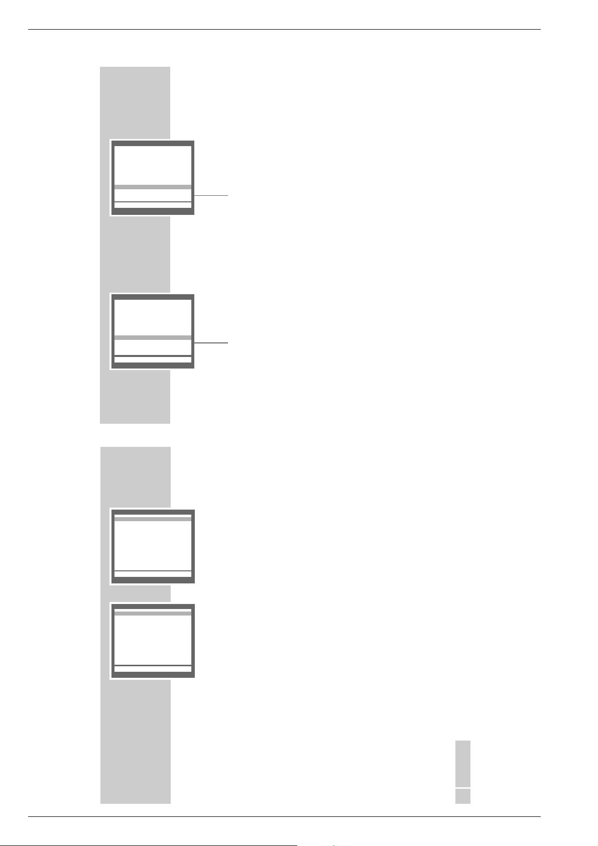
SORT
u
A 01
A 02
A 03
A 04
A 05
A 06
A 07
A 08
A 09
A 10
–––––––––––––––––
i
OK Sort
AUX Delete.
6 Return
TXT TV
SORT
u
A 01
A 02
A 03
A 04
A 05
A 06
A 07
A 08
A 09
A 10
–––––––––––––––––
i
OK Sort
AUX Delete.
6 Return
TXT TV
SETTINGS
5 Continue the setting for analogue TV channels by pressing »TXT«.
____________________________________________________________________________________
Delete analogue TV channel positions
1 In the »SORT« table, select the channel to be cleared with »
,,
« or »..« .
2 Delete the channel with »AUX «.
Note:
To clear further channel positions, repeat the steps 1 and 2.
Sorting analogue TV channels
1 In the »SORT« table, select the channel position of the channel to be moved
to another position with »,,« or »..«.
2 Mark the channel with »OK«.
3 Select the channel position to which the marked channel is to be moved with
»,,« or »..«.
4 Store the setting with »OK«.
Note:
To sort further channels, repeat the steps 1 to 4.
5 End the setting with »TXT«.
ENGLISH
21
GRUNDIG Service 1 - 13
Page 14
Allgemeiner Teil / General Section CUC 2058 D / 2059 D
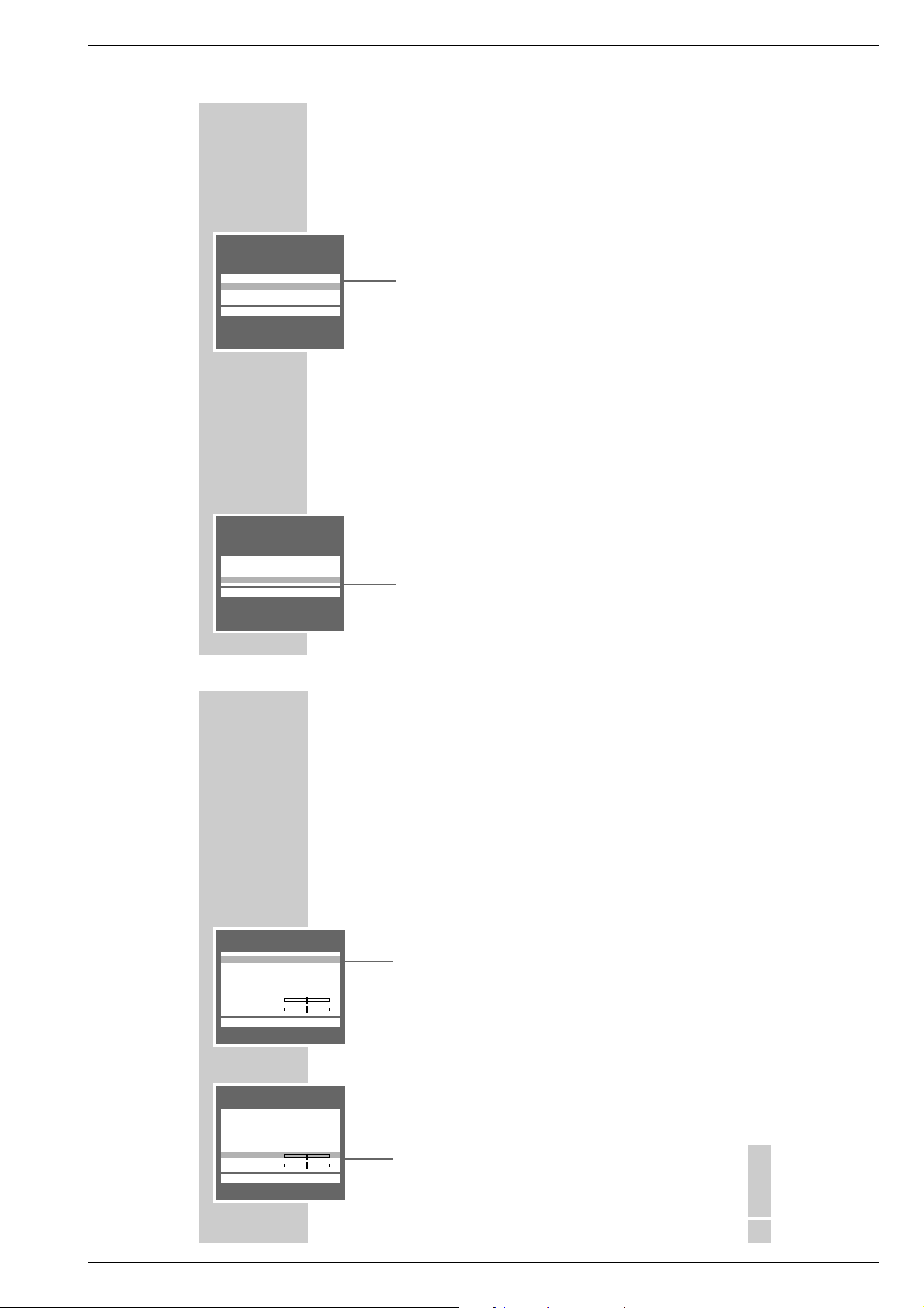
DIGITAL DIALOGUE CENTRE
u
SLEEP TIMER
RECORD TIMER
PARENTAL LOCK
PARENTAL CHANNEL LOCK
SPECIAL FUNCTIONS
PROGRAM SORT
MANUAL TUNING
AUTOMATIC TUNING SYSTEM
CONFIGURATION
COMMON INTERFACE
–––––––––––––––––––––––––––
i
OK■Analogue TXT
ANALOGUE DIALOGUE CENTRE
u
SLEEP TIMER
PARENTAL LOCK
SPECIAL FUNCTIONS
PROGRAM SORT
ANALOGUE MANUAL TUNING
ANALOGUE AUTOMATIC TUNING
SERVICE
–––––––––––––––––––––––––––
i
OK■Digital TXT
SETTINGS
____________________________________________________________________________________
Programming new digital TV channels using the
automatic tuning system
The TV set searches for new digital TV services. These are added to the already
existing services in the »DIGITAL PROGRAM SORT« table. This can take
approx. 15 minutes.
1 In digital mode, call up the »DIGITAL DIALOGUE CENTRE« by pressing »i«
and then »OK«.
2 Select the »AUTOMATIC TUNING SYSTEM« row with »
confirm with »OK«.
3 Start the search with »OK«.
– The end of searching is indicated by the menu »DIGITAL PROGRAM
SORT«.
See page 20 for information about sorting and clearing digital services.
Programming new analogue TV channels using the
automatic tuning system
The TV set searches for new analogue TV channels. These are inserted in the
»SORT« table in the place of the existing channels.
1 In analogue mode, call up the »ANALOGUE DIALOGUE CENTRE« by pres-
sing »i« and then »OK«.
2 Select the »AUTOMATIC TUNING SYSTEM« row with »
confirm with »OK«.
3 Start the search with »OK«.
– The end of searching is indicated by the menu »SORT«.
See page 21 for information about sorting and clearing analogue TV
channels.
,,
« or »..« then
,,
« or »..« then
22
ANALOGUE DIALOGUE CENTRE
u
SLEEP TIMER
PARENTAL LOCK
SPECIAL FUNCTIONS
PROGRAM SORT
ANALOGUE MANUAL TUNING
ANALOGUE AUTOMATIC TUNING
SERVICE
–––––––––––––––––––––––––––
i
OK■Digital TXT
DIGITAL DIALOGUE CENTRE
u
SLEEP TIMER
RECORD TIMER
PARENTAL LOCK
PARENTAL CHANNEL LOCK
SPECIAL FUNCTIONS
PROGRAM SORT
MANUAL TUNING
AUTOMATIC TUNING SYSTEM
CONFIGURATION
COMMON INTERFACE
–––––––––––––––––––––––––––
i
OK■Analogue TXT
SETTINGS
____________________________________________________________________________________
The Dialogue Centre
In the Dialogue Centre you can make a variety of settings, call up information,
and get specific help for operating your television.
For this TV set, two Dialogue Centres are available:
– the analogue Dialogue Centre for operation with analogue TV programmes,
– the digital Dialogue Centre for operation with digital TV programmes.
The line »COMMON INTERFACE« is greyed out. Please see page 54 for information on possible future upgrades.
Functions which are the same for analogue and digital reception are to be
found under the same function names.
The Digital Dialogue Centre comprises additional functions which are possible
when receiving digital TV channels (services).
1 Call up the Dialogue Centre with »i« and then »OK«.
– Which Dialogue Centre appears, depends on which TV programme (ana-
– Button symbols and dialogue lines display possible operating steps.
– The characters on the screen are symbols for the following buttons on the
Symbol Button Function
6
w
q step by step.
re
OK OK Confirms functions.
TXT TXT Ends settings.
2 Switch between the »ANALOGUE DIALOGUE CENTRE« and the »DIGITAL
DIALOGUE CENTRE« by pressing »D/A«.
3 Exit the »DIALOGU E C ENTRE« by pressing »TXT«.
logue or digital) has been selected.
remote control:
hh
Calls up the »DIALOGUE CENTRE« (»
and switches back to the »Dialogue Centre« when you
are on an individual page.
,, ..
Call up rows or functions on a page
FF EE
Change settings.
i« then »OK«)
ENGLISH
23
1 - 14 GRUNDIG Service
Page 15
Allgemeiner Teil / General SectionCUC 2058 D / 2059 D
24
u
––––––––
i
u
––––––––
i
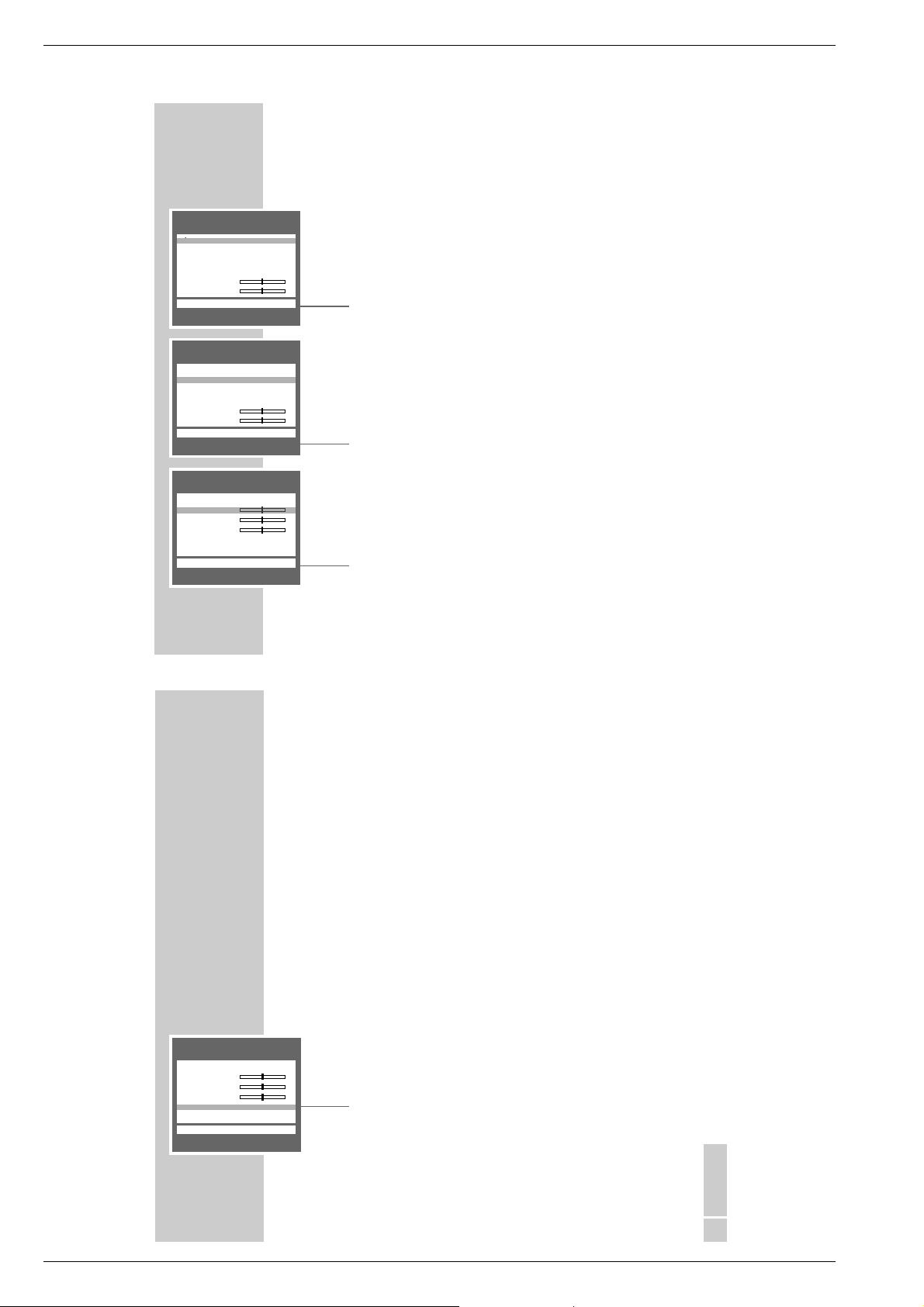
PICTURE
Contrast r ■■■■■■■■■ –
Sharpness ■■■■■■■■■–
PICTURE
Contrast ■■■■■■■■■–
Sharpness ■■■■■■■■■–
Tint r ■■■■■■■■■–
SETTINGS
Picture settings
_–_–_
e
_–_–_
TXT
_–_–_
_–_–_
_–_–_
e
TXT
____________________________________________________________________________________
Adjusting the contrast and sharpness
1 Call up the »PICTURE« menu with »z «.
– The »PICTURE« menu appears.
2 Select the desired function (»Contrast« or »Sharpness«) with »
,,
«or
»..«.
3 Adjust the contrast or sharpness with »
FF
« or »EE«, respectively.
Note:
The TV set has been tested using maximum contrast, in order to check for
reliability of all modules. Depending on the location of the set and the
brightness in the room (surrounding light) it does however make sense to
reduce the contrast slightly for the best possible picture impression.
The sharpness adjustment is not needed for digital services, i.e. the row
»Sharpness« is not available in digital mode.
4 End the setting with »TXT«.
Adjusting the tint for NTSC broadcasts
Note:
The »Tint« row appears only with NTSC broadcasts.
1 Call up the »PICTURE« menu with »z «.
– The »PICTURE« menu appears.
FF
« or »EE«.
,,
« or »..«.
2 Select the »Tint« row with »
3 Adjust the tint with »
4 End the setting with »TXT«.
SOUND
u
TVrL/R
++
Effects Dolby Pro Logic
++
A01 Stereo
UU
Stereo
""
!!
–––––––––––––––––––
i
OK TXT
SOUND
u
TV L/R
++
Effects Dolby Pro Logic
++
A01 Stereo
UU
Stereo
""
re
!!
–––––––––––––––––––
i
OK TXT
SETTINGS
Sound settings
e
____________________________________________________________________________________
Stereo/two-channel sound, mono
If the TV set receives two-channel sound transmissions – e.g. a film in the origi-
nal language on sound channel B (display: » DUAL B «) and the synchronized
version on sound channel A (display: » DUAL A «) – then you may select the
desired sound channel.
If the set receives stereo or NICAM transmissions, it automatically switches to
stereo sound (display: »Stereo«). If stereo reception is poor, then the sound
should be switched to » Mono «.
1 Call up the »SOUND« menu with »
2 Select the »
then select the desired sound mode with »FF« or »EE« .
A 01« (A = analogue TV channel) row with »,,« or »..«
+
FF
«.
3 If the sound for a particular channel is to be permanently in mono, select the
»+P..« row with
»,,« or »..«
then press »OK«.
Note:
To cancel this setting, repeat step 3.
4 End the setting with »TXT«.
Adjusting the bass and treble
1 Call up the »SOUND« menu with »
2 Select the desired row (»"« – bass, or »! « – treble) with »
3 Adjust the bass or treble with »
FF
«.
FF
« or »EE«, respectively.
,,
« or »..«.
4 End the setting with »TXT«.
– The setting is saved automatically.
25
ENGLISH
GRUNDIG Service 1 - 15
Page 16
Allgemeiner Teil / General Section CUC 2058 D / 2059 D
SOUND
u
TVrL/R
++
Effects Dolby Pro Logic
++
A01 Stereo
UU
Stereo
""
!!
–––––––––––––––––––
i
OK TXT
SOUND
u
TV L/R
++
Effects
r
Dolby Pro Logic
++
A01 Stereo
UU
Stereo
""
!!
–––––––––––––––––––
i
OK TXT
u
++ ++
BB
re
V Center
V Surround
V ■■■■■ –
++
–––––––––––––––––––
i
6 TXT
_–_–_–_–_–_
SETTINGS
____________________________________________________________________________________
Sound settings for Dolby Pro Logic mode
With this setting you select:
– the Dolby effects;
e
e
– the loudspeaker configuration required;
– the loudspeaker volume levels;
– the overall volume.
1 Call up the »SOUND« menu with »
2 Select the »
select the desired loudspeaker configuration.
.. TV« row with »,,« or »..« then use »FF« or »EE« to
+
– Configurations available:
»L/R« – The loudspeakers of the TV set are used as left/right loud-
speakers.
»Center« – The loudspeakers of the TV set are used as centre loud-
speaker.
»off« – The loudspeakers of the TV set are switched off. Instead,
external front and/or centre loudspeakers are used.
3 Select the »Effects« row with »
,,
select the desired Dolby effect.
– Dolby effects available:
»off«, »Dolby Pro Logic «, »Dolby 3 Stereo«, » Pro Logic Phantom«,
»Panorama «, »Pseudo Surround«.
– If the »Center« loudspeaker configuration has been selected in the
.. TV« row, only the Dolby effects » Dolby Pro Logic«, » Dolby 3
»
+
Stereo« or »Pseudo Surround « can be selected.
4 Select the »
– The menu appears and you will hear a noise (test signal) from the loud-
.. TV« row with »,,« or »..« then press »OK«.
+
speakers.
FF
«.
« or »..« then use »FF« or »EE« to
28
u
++ ++
BB
V Center
V Surround
V
++
–––––––––––––––––––
i
6 TXT
r
■■■■■–
SETTINGS
_–_–_–_–_–_
e
____________________________________________________________________________________
– The test signal is emitted in the following order:
balance (right/left),
centre loudspeaker,
surround loudspeakers.
– The highlighted cursor bar and the red loudspeaker symbol indicate which
loudspeaker is currently emitting the test signal.
– As long as the cursor bar is highlighted, it is possible to adjust the corres-
ponding loudspeaker configuration for optimum sound in your living room.
5 When »
uu
« (Balance) is highlighted, use »FF« or »EE« to adjust the front
loudspeakers so that they emit with the same volume.
6 When »
V
Center« is highlighted, use »FF« or »EE« to adjust the centre
loudspeaker so that it emits with the same volume as the front loudspeakers.
7 When »
V
Surround« is highlighted, use »FF« or »EE« to adjust the surround loudspeakers so that they emit with the same volume as the front loudspeakers.
Note:
As long as »FF« or »EE« is pressed in the steps 5 to 7, the cursor remains
on the selected position.
The test signal is emitted only from the selected loudspeakers.
As soon as »FF« or »EE« is released, the cursor bar jumps to the next position in the test signal cycle.
8 Select the »
V
« row with »,,« or »..« then use »FF« or »EE« to select
the desired volume for all loudspeakers.
9 End the setting with »TXT«.
ENGLISH
29
1 - 16 GRUNDIG Service
Page 17
Allgemeiner Teil / General SectionCUC 2058 D / 2059 D
TV OPERATION
D 1 17:12 Now 16:55–17:30 Signal Quality 06
Channel 4 Ricki Lake
OK Dialogue Centre6MoreeNext
Entertainment
You Don’t Believe I Cheat? Here’s Proof: Women who don’t
believe their men are cheating on them are proved wrong
and advised Dr. Jennifer Duffy not to accept their
Subtitles Audio:
D 1 17:12 Now 16:55 – 17:30
Channel 4 Ricki Lake
OK Dialogue Centre6ExiteNext
w
P+/P–
q
w
P+/P–
q
__________________________________________________________________________
Functions for digital TV services
Information about the digital TV service
This information comprises the station name, the start and end time of the
broadcast, and information about the broadcast, if available.
This information is displayed in the bottom part of the picture screen.
1 Press »i« to call up the information.
– The information about the current broadcast on the channel selected is
briefly displayed.
D 1 Channel 4 – Channel position with station name.
17:12 – Current time.
NOW 16:55 – 17:30 – Current broadcast with start and end time.
Signal Quality 06 – Signal quality indication. If no suitable signal is pre-
Note:
i« will display more information about the current broadcast.
Pressing »
This information shows subtitles and the language if available.
See chapter „SPECIAL SETTINGS“ on page 62 for information about selecting subtitles and language.
If this channel is locked, this will be indicated as »P. Lock«.
2 To get information about the next broadcast on the same channel, press
»EE«. To return to the information about the current broadcast, press »FF«.
3 To get information about further channels, press »
Note:
Press »OK« if you wish to watch the programme on the channel about
which information is currently displayed on the picture screen.
4 Press »i« once or twice to switch the information display off.
sent, the message »Bad Signal« will be displayed in
place.
,,
« or »..«.
ENGLISH
33
TV OPERATION
DIGITAL TV GUIDE-NOW
u
Date : 11/05/99 Time : 13:57
D01 BBC CHOICE 13:00 Eastenders
D02 ITV 12:30 Terminator 3
D03 FILM FOUR 13:15 Snooker
D04 UK GOLD 13:30 Steptoe & Son
D05
D06
D07 BBC NEWS 24 13:45 Weather
D08 BBC ONE 13:30 Neighbours
D09 BBC TWO 13:25 Tribal instincts
CARTOON NETWORK
D10
–––––––––––––––––––––––––––
i
OK 6 More e NEXT TXT
u
Date : 11/05/99 Time : 13:57
D01 BBC CHOICE 14:30 Can´t Cook Won´t Cook
D02 ITV 14:45 The Mask
D03 FILM FOUR 14:30 Grand Prix
D04 UK GOLD 14:00 The Persuaders
D05
D06
D07 BBC NEWS 24 14:05 Regional news
D08 BBC ONE 14:00 Film: The Sound of M.
D09 BBC TWO 14:10 Local weather
D10
–––––––––––––––––––––––––––
i
OK 6 More r NOW TXT
u
Date : 11/05/99 Time : 13:57
D01 BBC CHOICE 14:30 - 15:30
D02 ITV This is BBC Choice
D03 FILM FOUR The BBC bring you into the
D04 UK GOLD digital age with BBC Choise.
D05 Tune in for a broader view
D06 of TV. A new fresh approach
D07 BBC NEWS 24
D08 BBC ONE
D09 BBC TWO
D10
–––––––––––––––––––––––––––
i
OK 6 List e NEXT TXT
13:45 Bugs Bunny
DIGITAL TV GUIDE-NEXT
CARTOON NETWORK
14:00 Tom
DIGITAL TV GUIDE-NOW
CARTOON NETWORK
& Jerry
__________________________________________________________________________
TV Guide for digital TV services
The TV Guide informs you about all broadcasts on all digital channels. This
information comprises the channel position, the station name, the start and end
time of the broadcast, and information about the broadcast, if available.
1 Press »EPG« to call up the information.
– The »DIGITAL TV GUIDE – NOW« with information about the first 10
channel positions appears on the picture screen:
Date 11/05/99 – current date
Time:13:57 – current time
D01 BBC CHOICE – channel position 1 and station name
13:00 Eastenders – current broadcast
Note:
The channel positions 11 to 99 can be selected with »,,« or »..«.
2 To get information about the next broadcast on the same channel, press
»EE«. To return to the information about the current boradcast, press »FF«.
3 To get detailed information, use »
,,
« or »..« to select the desired channel
position then press »i«.
– The information is displayed in the right-hand window. Press »
i« again to
switch the information off.
4 It is possible to select a channel directly in the »DIGITAL TV GUIDE« menu.
To do this, select the channel position with »,,« or »..« then press »OK«.
– The menu is switched off and you will see the selected TV programme.
5 Press »TXT« to switch the »DIGITAL TV GUIDE« menu off.
34
GRUNDIG Service 1 - 17
Page 18
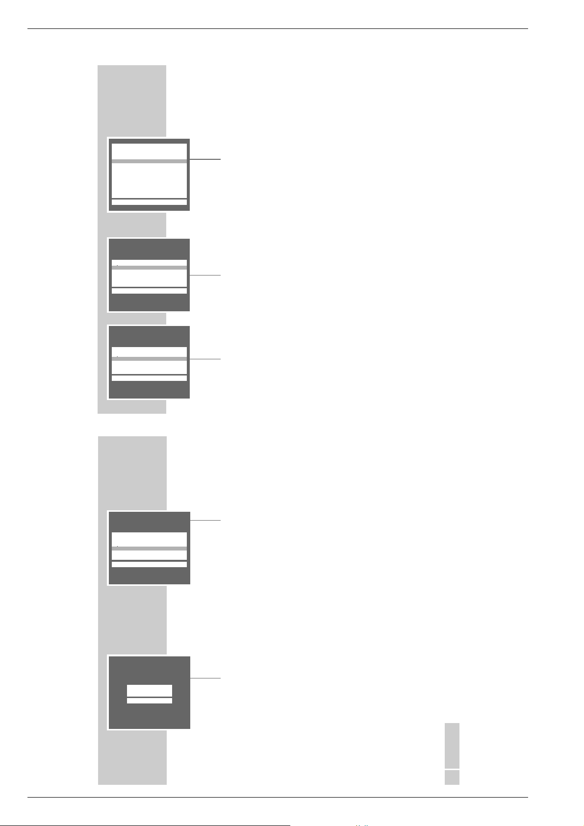
Allgemeiner Teil / General Section CUC 2058 D / 2059 D
ANALOGUE DIALOGUE CENTRE
u
SLEEP TIMER
PARENTAL LOCK
SPECIAL FUNCTIONS
PROGRAM SORT
ANALOGUE MANUAL TUNING
ANALOGUE AUTOMATIC TUNING
SERVICE
–––––––––––––––––––––––––––
i
OK22Digital TXT
SPECIAL FUNCTIONS
u
TV on with r Prog 1 e
Pic./sound opt. on
Volume Limiter off
––––––––––––
i
6 TXT
SPECIAL FUNCTIONS
u
TV on with Prog 1
Pic./sound opt. r on e
Volume Limiter off
––––––––––––
i
6 TXT
CONVENIENCE FUNCTIONS
Convenience functions via the
»SPECIAL FUNCTIONS« menu
1 Call up the »DIALOGUE CENTER« by pressing »i« and then »OK«.
2 Select the »SPECIAL FUNCTIONS« row from the »DIALOGUE CENTRE«
with »,,« or »..« then confirm with »OK«.
Note:
See the following chapters for further operation.
TV on with ...
If you frequently use the set as an AV monitor – e.g. together with a camera as a
monitoring system or together with a satellite receiver – then this function can
give priority to the programme position » AV «.
After switching on with the on/off switch, instead of programme position
» P 1 «, programme position » AV « will appear.
1 Select the »TV on with« row with »
»AV« with »FF« or »EE«.
2 End the setting by pressing »TXT«.
Picture/sound scale on/off
To adjust volume, brightness and colour contrast, scales appear. These may be
switched off.
1 Select the »Pic./Sound opt.« row with »
»FF« or »EE« ».
2 End the setting by pressing »TXT«.
,,
« or »..« then select channel position
,,
« or »..« then select »off« with
_________________________________
40
SPECIAL FUNCTIONS
u
TV on with Prog 1
Pic./sound opt. on
Volume Limiter r off e
––––––––––––
i
6 TXT
SLEEP TIMER
´
6 0-9 TXT
CONVENIENCE FUNCTIONS
Equalizing the volume
The volume of normal TV broadcasts and commercials may be different. You
may equalize this volume.
1 Select the »Volume Limiter« row with »
»FF« or »EE« ».
Note:
This function is only possible if »off« has been selected in the »Effects« row
in the »SOUND« menu.
2 End the setting by pressing »TXT«.
Entering a switch-off time in the »SLEEP TIMER« menu
You can input a switch-off time for your TV set via the »SLEEP TIMER« menu. The
set switches to stand-by after the set time has elapsed.
1 Select the »SLEEP TIMER« row from the »DIALOGUE CENTER« with »
or »..« then confirm with »OK«.
– The »SLEEP TIMER« menu appears.
2 Enter the desired switch-off time (01…99 minutes) with two digits using the
–– ––
min.
´
»1…0« buttons.
Note:
The switch-off time can be cleared with »AUX«.
3 Confirm the setting by pressing »TXT«.
___________________________________________________
,,
« or »..« then select »on« with
,,
«
ENGLISH
41
1 - 18 GRUNDIG Service
Page 19
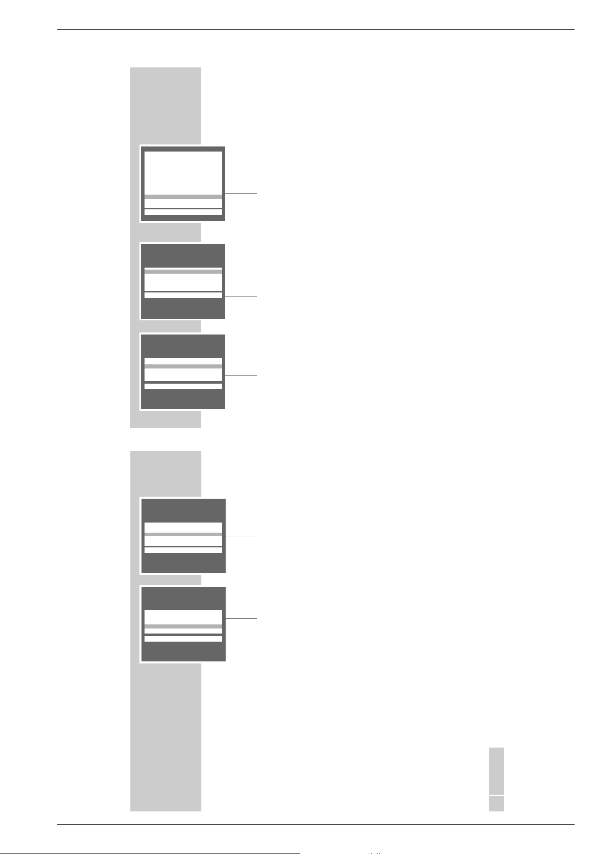
Allgemeiner Teil / General SectionCUC 2058 D / 2059 D
ANALOGUE DIALOGUE CENTRE
u
SLEEP TIMER
PARENTAL LOCK
SPECIAL FUNCTIONS
PROGRAM SORT
ANALOGUE MANUAL TUNING
ANALOGUE AUTOMATIC TUNING
SERVICE
–––––––––––––––––––––––––––
i
OK22Digital TXT
SERVICE
u
Color A 01 r auto e
Blue Screen on
Black Screen off
Format switch-over auto
Service Code ----
––––––––––
i
6 TXT
SERVICE
u
Color A 01 off
Blue Screen r on e
Black Screen off
Format switch-over auto
Service Code ----
––––––––––
i
6 TXT
CONVENIENCE FUNCTIONS
___________________________________________________
Convenience functions via the »SERVICE« menu
Note:
These convenience functions are only possible with analogue TV programmes.
The »Service Code« function is provided for the specialized dealer only.
1 Call up the »DIALOGUE CENTRE« by pressing »i« and then »OK«.
2 Select the »SERVICE« row from the »DIALOGUE CENTRE« with »
»..« then confirm with »OK«.
Note:
See the following chapters for further operation.
Adjusting manually the colour norm
The colour norms are automatically assigned when allocating the channel position with the automatic station search. You do not need to carry out this setting if
the colour is already well adjusted on the different channels.
1 Select the »Color« row with »
norm using »FF« or »EE«.
2 End the setting by pressing »TXT«.
Selecting a blue picture screen
With this function, a grainy image is switched to a blue image.
1 Select the »Blue screen« row with »
to select »on«.
2 End the setting by pressing »TXT«.
,,
« or »..« then select the required colour
,,
« or »..« then use »FF« or »EE«
,,
«or
42
SERVICE
u
Color A 01 off
Blue Screen on
Black Screen r off e
Format switch-over auto
Service Code ----
––––––––––
i
6 TXT
SERVICE
u
Color A 01 off
Blue Screen on
Black Screen off
Format switch-over r auto e
Service Code ----
––––––––––
i
6 TXT
CONVENIENCE FUNCTIONS
Selecting a black picture screen
With this setting, it is possible to avoid distracting flickering of channels whilst
switching channel positions.
1 Select the »Black screen« row with »
to select »on«.
2 End the setting by pressing »TXT«.
Picture format switch-over
If recpetion conditions are poor in analogue mode, you may switch off the automatic picture format switchover.
1 Select the »Format switch-over« row with »
»EE« to select »manual«.
2 End the setting by pressing »TXT«.
___________________________________________________
,,
« or »..« then use »FF« or »EE«
,,
« or »..« then use »FF«or
ENGLISH
43
GRUNDIG Service 1 - 19
Page 20
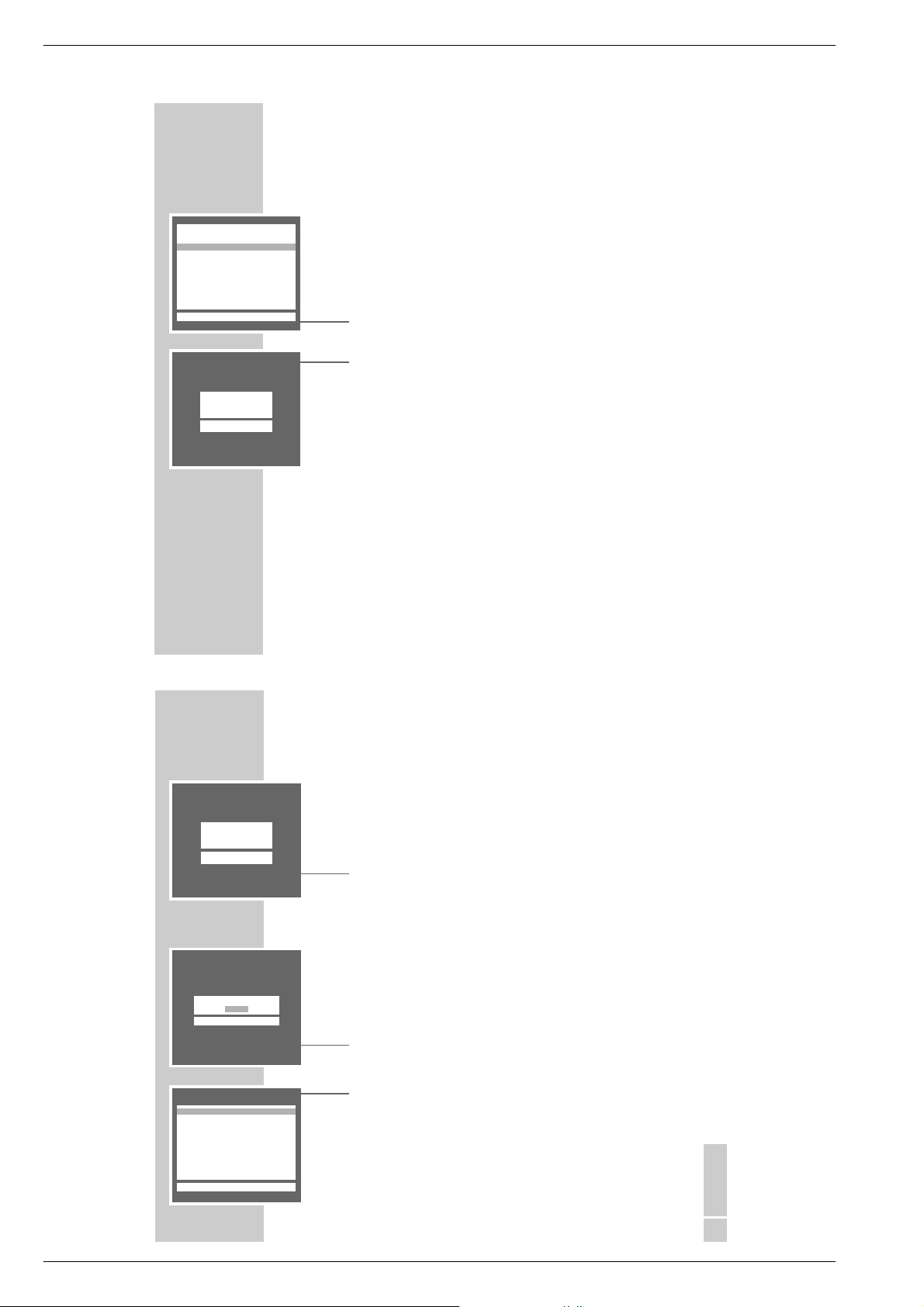
Allgemeiner Teil / General Section CUC 2058 D / 2059 D
DIGITAL DIALOGUE CENTRE
u
SLEEP TIMER
RECORD TIMER
PARENTAL LOCK
PARENTAL CHANNEL LOCK
SPECIAL FUNCTIONS
PROGRAM SORT
MANUAL TUNING
AUTOMATIC TUNING SYSTEM
CONFIGURATION
COMMON INTERFACE
–––––––––––––––––––––––––––
i
OK■Analogue TXT
Enter New Pin
44
PARENTAL LOCK
v
– – – –
7
6 0-9 TXT
PARENTAL LOCK
By using this function, you may protect the TV set against unauthorized use.
You may block all functions or certain digital channels.
Blocking all functions of the TV set
Note:
This function can be selected both in the »DIGITAL DIALOGUE CENTRE« and
the »ANALOGUE DIALOGUE CENTRE«.
1 Call up the »DIALOGUE CENTRE« by pressing »i« and then »OK«.
2 Select the »PARENTAL LOCK« row from the »DIALOGUE CENTRE« with
»,,« or »..« then confirm with »OK«.
3 Enter a four-digit code number using the »1...0 « buttons then save the num-
ber with »OK«.
– The key symbol is displayed in red.
4 End the setting by pressing »TXT«.
– After switching off the set and switching on again, the page »Parental
lock« appears, all functions are locked.
Note:
If you forget the number code, a number combination given in the „CORRECTING PROBLEMS YOURSELF“ chapter on page 67 will allow you to
unlock the set.
Unlocking the TV set temporarily
1 Switch the TV set on.
2 Enter the four-digt code using the »1...0 « buttons.
– The TV programme becomes visible.
After switching off the set and switching on again, the parental lock is
activated again.
____________________________________________________________
PARENTAL LOCK
Enter Pin
v
– – – –
7
6 0-9 TXT
PARENTAL CHANNEL LOCK
Enter New Pin:
– – – –
7
6 Back 0-9 TXT
PARENTAL CHANNEL LOCK
u
D01 BBC CHOICE r YES e
D02 ITV NO
D03 FILM FOUR NO
D04 UK GOLD NO
D05 TNT NO
D06 ITV 2 NO
D07 BBC NEWS 24 NO
D08 BBC ONE NO
D09 BBC TWO NO
D10 CARTOON NETWORK YES
–––––––––––––––––––––––
i
6 Back TXT
PARENTAL LOCK
Cancelling the parental lock
1 Switch the TV set on and enter the four-digt code using the »1...0 « buttons.
– The key symbol is displayed in red.
2 Call up the »DIALOGUE CENTRE« by pressing »i« and then »OK«.
3 Select the »PARENTAL LOCK« row from the »DIALOGUE CENTRE« with
»,,« or »..« then confirm with »OK«.
4 Enter the four-digit code number using the »1...0 « buttons then confirm the
number with »AUX«.
– The parental lock is cancelled.
5 End the setting by pressing »TXT«.
Locking digital services
1 Call up the »DIGITAL DIALOGUE CENTRE« by pressing »i« and then
»OK«.
2 Select the »PARENTAL CHANNEL LOCK« row with »
confirm with »OK«.
3 Enter a four-digit code number using the »1...0 « buttons then store the
number with »OK«.
– The »PARENTAL CHANNEL LOCK« menu appears.
4 Select the service which is to be locked with »
the lock with »EE«.
– The indication »NO« changes into »YES« and the channel is locked. If the
locked service is selected, the TV set demands you to enter the code
number.
– To lock further services, repeat the step 4.
5 End the setting by pressing »TXT«.
Note:
To unlock the locked services, repeat the setting from step 1, but press »OK«
again in step 4.
________________________________________________________________________
,,
« or »..« then
CC
« or »DD« then activate
45
ENGLISH
1 - 20 GRUNDIG Service
Page 21

Allgemeiner Teil / General SectionCUC 2058 D / 2059 D
MHEG FUNCTIONS
What is MHEG?
The MHEG functions (Multimedia and Hypermedia Experts Group) are an
extended and convenient teletext service.
With the MHEG functions and the integrated modem, your TV set is prepared
for interactive operation with external devices and TV stations, such as home
shopping and homebanking.
The MHEG functions will probably be introduced by the TV broadcasters at the
end of 1999.
Please consult your specialized dealer for more information about software
updates and retrofit kits via a common interface.
Operation with the MHEG functions
If a station is broadcasting the MHEG service, this is indicated by the yellow LED
next to the mains button.
..
The »TXT«, »CL«, »,,«
automatically switched over to MHEG mode.
Pressing the »
mode.
i Activ« button switches between MHEG mode and normal TV
, »
______________________________________________________
«,»FF«,»EE«, and the four colour buttons are
54
MODEM FUNCTIONS
Notes:
Connect your modem socket only to an exchange line.
Do not use the modem as an extension to a pay telephone.
Your TV set is provided with a so-called Ringer Equivalence number. The
number is 1.
It is possible to connect further telecommunication devices to the telephone
line provided not more than 4 Ringer Equivalence numbers are used.
The modem in your TV set is provided to function with Common Interface (CI)
modules.
For further instructions see the Common Interface user manual.
_________________________________________________
ENGLISH
55
GRUNDIG Service 1 - 21
Page 22

Allgemeiner Teil / General Section CUC 2058 D / 2059 D
AV1
AV2
ANTENNA
LOOP IN
L
R
S
ANTENNA
LOOP OUT
ANTENNA IN
LINE
SERIAL
PORT
CI1 CI2
1 2 3
0
4 5 6
7 8 9
R 2
R 1
–
+
56
MODEM FUNCTIONS
________________________________________________________________
Connecting the TV set to a telephone socket
1 Connect the » ü LINE « socket on the TV set (RJ11 plug) and the telepho-
ne adapter (431A plug) with a commercially available modem cable (with
ferrite-clip).
2 Connect the telephone lead with the second socket on the telephone
adapter.
3 Plug the telephone adapter into the telephone socket.
Note:
When using a cable without ferrite clip, this must be retrofitted. When doing
this, one winding must be inserted through the clip. This clip is available from
your Grundig dealer.
MODEM FUNCTIONS
________________________________________________________________
Settings for modem operation
With this setting you determine
– the dialling mode.
This requires you to inform the modem of what type of phone line you use
(pulse or tone dialling). Pick up and listen to the sound coming from your
phone during dailing. If it is continuous, then you must select ”TONE”, if it is
intermittent, then you must select ”PULSE”
– the dialling prefix and prefix number.
The TV set may be operated in a place where its use and viewing is communal, for example in offices, schools or shops. If this is the case, the prefix
DIGITAL DIALOGUE CENTRE
u
SLEEP TIMER
RECORD TIMER
PARENTAL LOCK
PARENTAL CHANNEL LOCK
SPECIAL FUNCTIONS
PROGRAM SORT
MANUAL TUNING
AUTOMATIC TUNING SYSTEM
CONFIGURATION
COMMON INTERFACE
–––––––––––––––––––––––––––
i
OK■Analogue TXT
MODEM SETUP
u
DIALLING MODE r TONE e
DIALLING PREFIX DISABLE
PREFIX NUMBER 09
––––––––––––
i
6 Back TXT
needs to be enabled. This is done by selecting the ”ENABLE” setting. In addition, the prefix number (0 to 9) needs to be adjusted to accommodate that of
the normal phonelines of the office, school or shop.
If the TV set is used at home, this setting is not required.
1 Call up the »DIGITAL DIALOGUE CENTRE« by pressing »i« and then
»OK«.
2 Select the »CONFIGURATION« row with »
,,
« or »..« then confirm with
»OK«.
3 Select the »MODEM SETUP« row from the »CONFIGURATION« menu with
»,,« or »..« then confirm with »OK«.
– The »MODEM SETUP« menu appears on the picture screen, the
»DIALLING MODE« row is highlighted.
4 Select your dialling mode with »
5 Select the »DIALLING PREFIX« row with »
FF
« or »EE« :»PULSE« or »TONE«.
,,
« or »..« then use »FF«or
»EE« to select the »ENABLE« setting.
6 Select the »PREFIX NUMBER« row with »
»1 ... 0« buttons to enter the prefix number (0 to 9).
7 Press »TXT« to end the setting.
,,
« or »..« then use the
ENGLISH
57
1 - 22 GRUNDIG Service
Page 23

Allgemeiner Teil / General SectionCUC 2058 D / 2059 D
ANALOGUE MANUAL TUNING
u
Program r 06 e
C/S Channel
Channel C 44
Finetun. 00
Standard automatic
––––––––––
i
6 OK Memorize 0-9 TXT
ANALOGUE MANUAL TUNING
u
Program 06
C/S Channel
Channel r 00 e
Finetun. 00
Standard automatic
––––––––––
i
6 OK Memorize 0-9 ■ Tune TXT
58
SPECIAL SETTINGS
________________________________________________________
Limiting the analogue channel position selection
The ATS search saves all channels it has found and automatically “locks” the first
position to which no channel is assigned.
In this way, when channel positions are selected step by step using the »,,«or
»..« button, only channels which have been found can be selected.
You may also enter this limit manually, in the following example the “lock” has
been activated as of channel position 6.
1 Call up the »ANALOGUE DIALOGUE CENTRE« by pressing »i« and then
»OK«.
– The »ANALOGUE DIALOGUE CENTRE« appears on the picture screen.
2 Select the »MANUAL TUNING« row from the »DIALOGUE CENTRE« with
»,,« or »..« then confirm with »OK«.
3 Select the channel position (6 in the example) with »
tons »1...0«.
4 Select the »C/S« row with »
ect the »Channel« option.
5 Select the »Channel« row with »
to enter »00«.
6 Save the setting with »OK«.
7 Press »TXT« to end the setting.
Note:
– Now only the first 5 channel positions (and the »AV« positions) can be
selected in rapid sequence with the »,,« or »..« button.
– All single digit channel positions – as well as the “blocked” – can further
be selected using the buttons
All channel positions can be selected using the buttons
position 11 is blocked.
,,
« or »..« then press »FF« or »EE« to sel-
,,
« or »..« then use the buttons »1... 0«
»1...0«.
FF
« or »EE« or the but-
»1...0« if channel
ANALOGUE MANUAL TUNING
u
Program r 06 e
C/S Channel
Channel C 44
Finetun. 00
Standard automatic
––––––––––
i
6 OK Memorize 0-9 TXT
ANALOGUE MANUAL TUNING
u
Program 06
C/S Channel
Channel r C 26 e
Finetun. 00
Standard automatic
––––––––––
i
6 OK Memorize 0-9 ■ Tune TXT
ANALOGUE MANUAL TUNING
u
Program 06
C/S Channel
Channel C 26
Finetun. r 00 e
Standard automatic
––––––––––
i
6 OK Memorize TXT
SPECIAL SETTINGS
____________________________________________________________________
Programming analogue TV channels manually
This setting is only required if, for example, a cable provider adds a new
channel and you wish to keep your favourite channel order.
1 »Call up the »ANALOGUE DIALOGUE CENTRE« by pressing »i« and then
»OK«.
– The »ANALOGUE DIALOGUE CENTRE« appears on the picture screen.
2 Select the »ANALOGUE MANUAL TUNING« row from the »ANALOGUE
DIALOGUE CENTRE« with »,,« or »..« then confirm with »OK«.
3 Select the channel position with »
4 Select the »C/S« row with »
the »Channel« or » Special Channel« option.
5 Select the »Channel« row with »
the buttons »1... 0« and enter the desired channel number.
6 Select the »Standard« row with »
select the standard required.
7 Fine-tune the picture if necessary. For this, select the »Finetun.« row with
»,,« or »..« then use »FF« or »EE« to alter the finetuning.
8 Save the setting with »OK«.
Note:
To programme further channels, repeat the steps 3 to 8.
FF
« or »EE« or the buttons »1...0 «
,,
« or »..« then use »FF« or »EE« to select
,,
« or »..« then use »FF« or »EE« or
,,
« or »..« then use »FF« or »EE« to
9 Press »TXT« to end the setting.
ENGLISH
59
GRUNDIG Service 1 - 23
Page 24

Allgemeiner Teil / General Section CUC 2058 D / 2059 D
ANALOGUE MANUAL TUNING
u
Program 06
C/S r Channel e
Channel C 44
Finetun. 00
Standard automatic
––––––––––
i
6 OK Memorize 0-9 Program TXT
ANALOGUE MANUAL TUNING
u
Program 06
C/S Channel
Channel r C 44 e
Finetun. 00
Standard automatic
––––––––––
i
6 OK Memorize 0-9 ■ Tune TXT
SPECIAL SETTINGS
____________________________________________________________________
Programming analogue TV channels using the
automatic tuning system
1 »Call up the »ANALOGUE DIALOGUE CENTRE« by pressing »i« and then
»OK«.
– The »ANALOGUE DIALOGUE CENTRE« appears on the picture screen.
2 Select the »ANALOGUE MANUAL TUNING« row from the »ANALOGUE
DIALOGUE CENTRE« with »,,« or »..« then confirm with »OK«.
3 Select the »Program« row with »
nel position using the buttons »1...0«.
4 Select the »Channel« row with »
tuning system with the blue »FF« button.
Note:
The colour and sound standards are allocated automatically. If the colour
and/or sound is not correct, select the row »Standard« with button »,,«or
»..« then select the required setting with the »FF« or »EE« button.
5 Fine-tune the picture if necessary. For this, select the »Finetune« row with
»,,« or »..« then use »FF« or »EE« to alter the finetuning.
6 Save the setting with »OK«.
Note:
To programme further channels, repeat steps 3 to 6.
7 Press »TXT« to end the setting.
,,
« or »..« then enter the desired chan-
,,
« or »..« then start the automatic
60
DIGITAL DIALOGUE CENTRE
u
SLEEP TIMER
RECORD TIMER
PARENTAL LOCK
PARENTAL CHANNEL LOCK
SPECIAL FUNCTIONS
PROGRAM SORT
MANUAL TUNING
AUTOMATIC TUNING SYSTEM
CONFIGURATION
COMMON INTERFACE
–––––––––––––––––––––––––––
i
OK■Analogue TXT
DIGITAL MANUAL TUNING
UHF Channel r 52 e
Multiplex Emley Moor
Transport ID 100a
Network ID 301b
Serbices found 5
New Services 5
New Services stored at program
Carrier Locked
BER 5.17E-003
6 Back 0-9 TXT
SPECIAL SETTINGS
Programming digital TV services manually
This setting is only required if, for example, a cable provider adds a new
service and you wish to keep your favourite service order.
1 »Call up the »DIGITAL DIALOGUE CENTRE« by pressing »i« and then »OK«.
– The »DIGITAL DIALOGUE CENTRE« appears on the picture screen.
2 Select the »MANUAL TUNING« row from the »DIGITAL DIALOGUE
CENTRE« with »,,« or »..« then confirm with »OK«.
3 Enter the channel position with the buttons »1...0«.
– The digital TV channels offered under this channel number are automati-
cally transferred in the programme chart.
– Information about the data transfer is given by the following menu rows:
D10 - D14
Note:
To programme further digital services, repeat step 3.
4 Press »TXT« to end the setting.
____________________________________________________________________
Multiplex – System information
Transport ID – System information
Network ID – System information
Services found – number of digital services found.
New Services – new services among the found services.
New Services – channel positions on which the new digital
stored at program services are stored.
ENGLISH
61
1 - 24 GRUNDIG Service
Page 25

Allgemeiner Teil / General SectionCUC 2058 D / 2059 D
CONFIGURATION
u
MODEM SETUP
LANGUAGES
COLOUR BARS TEST
––––––––
i
OK i Back TXT
LANGUAGES
u
AUDIO r ENGLISH e
SUBTITLES NONE
––––––––
MHEG NONE
i
OK i Back TXT
CONFIGURATION
u
MODEM SETUP
LANGUAGES
COLOUR BARS TEST
––––––––
i
OK i Back TXT
SPECIAL SETTINGS
____________________________________________________________________
Selecting the language and subtitles for digital
services
1 Call up the »DIGITAL DIALOGUE CENTRE« by pressing »i« and then »OK«.
2 Select the »CONFIGURATION« row with »
,,
»OK«.
3 Select the »LANGUAGES« row from the »CONFIGURATION« menu with
»,,« or »..« then confirm with »OK«.
– The »LANGUAGES« menu appears on the picture screen, the
»AUDIO« row is highlighted.
4 Select the desired language with »
5 Select the »SUBTITLES« row with »
FF
« or »EE«.
,,
« or »..« then use »FF« or »EE« to
select the subtitles.
6 Press »TXT« to end the setting.
Selecting the colour bars test for displaying the
digital picture quality
1 Call up the »DIGITAL DIALOGUE CENTRE« by pressing »i« and then »OK«.
2 Select the »CONFIGURATION« row with »
»OK«.
3 Select the »COLOUR BARS TEST« row from the »CONFIGURATION« menu
with »,,« or »..« then confirm with »OK«.
– The »COLOUR BARS TEST« appears on the picture screen.
,,
« or »..« then confirm with
« or »..« then confirm with
62
INFORMATION
DVB Common Interface:
2 x
RS 232:
Service and future expansion for update via PC.
Modem:
V 22, V 22 bis
complys to NTR3
REN =1
610107
__________________________________________________________________________
APPROVED for connection to telecommunication systems
specified in the instructions for use subject to the conditions set
out in them.
ENGLISH
65
GRUNDIG Service 1 - 25
Page 26

Allgemeiner Teil / General Section CUC 2058 D / 2059 D
Service- und Sonderfunktionen
Die Analog-Software für die Service- und Sonderfunktionen der Punkte 1 – 9 befindet sich im Prozessor IC81050 und EEPROM IC82005.
1. Einschaltfunktionen
1.1 ATS-Reset (Automatic Tuning System)
Netzschalter "EIN" mit gedrückter Fernbedientaste "L+" –> OK.
Das Automatische Sendersuchsystem stoppt bei jedem empfangswürdigen Sender (AFC und Koinzidenz) und speichert automatisch die
entsprechenden Senderdaten mit dem jeweiligen Standard (die Speicherung findet unmittelbar im NVM statt). Danach wird der Suchlauf
fortgesetzt.
Tastendruck "TXT" bricht den ATS-Lauf ab.
1.2 Mittelwerte / Notdatensatz laden (ROM-Daten)
Fernbedientaste "P-" gedrückt halten und das Gerät mit dem Netzschalter einschalten. Dadurch wird z. B. nach Austausch des IC82005
(NVM) das Gerät mit dem Notdatensatz gestartet.
Mit diesem Vorgang werden die Grunddaten aus dem ROM des
Prozessors IC81050 in den NVM IC82005 kopiert:
IC82005: (gerätespezifische Daten, über das Dialog Center einstellbar)
- Farb- und Ton-Normen
- Zwangs-Mono
- Umkehrpunkt
- OSD Position
- Blue Screen on/off, Black Screen on/off
- ATS-Reset
- Hotel-Mode on/off
- AGC
- Öko-Schalter
- Bildröhrentype
- Analogwerte (Lautstärke, Helligkeit usw.)
- Bildschärfe
- Overscan
- Security on/off
- Geometrieabgleich
- Programmdaten (Kanal- Feinabstimmung, Senderkennung)
Danach über das Dialog Center die persönlichen Werte, Bildgeometrie
eingeben.
1.3 Programmsperre dauerhaft aufheben
Die Zahl 7038 hebt die Sperre dauerhaft auf.
2. Sonderfunktionen im Dialog Center
2.1 Einschalten mit Programm "1" oder "AV"
Mit Taste "6" die Dialogzeile "TV einsch. mit" über "DIALOG CENTER"
–> "SONDERFUNKTIONEN" aufrufen. In Stellung "AV1" erscheint
beim Einschalten das AV-Bild.
2.2 "Bild-/Ton-Skala" ein oder aus für alle Programme
Mit Taste "6" die Dialogzeile "Bild-/Toneinst." über "DIALOG CENTER"
–> "SONDERFUNKTIONEN" aufrufen. In Stellung "aus" erscheinen
keine Balkenanzeigen für die Analogwerte auf dem Bildschirm.
2.3 Automatische Lautstärkeregelung (optionell)
Mit Taste "6" die Dialogzeile "Autom. Lautst." über "DIALOG CENTER"
–> "SONDERFUNKTIONEN" aufrufen. In Stellung "ein" wird bei
großen Senderhüben die Lautstärke automatisch an den normalen
Hub angepaßt.
2.4 Öko-Netzschalter aktivieren bzw. deaktivieren (optionell)
Mit Taste "6" die Dialogzeile "Eco-Switch" über "DIALOG CENTER"
–> "SONDERFUNKTIONEN" aufrufen. Mit den Tasten 3 4 "1h…3h"
stellen.
Das Gerät schaltet sich nach der eingestellten Zeit oder durch zweimaligen Tastendruck der Taste 8 aus dem Standby-Betrieb komplett ab.
In Stellung "aus" wird diese Funktion nicht genutzt.
3. Bild-Einstellungen
Grundeinstellung
Mit der roten Taste (Auge) das Bild-Menü aufrufen. Über die Menüführung ist die Regulierung von Kontrast, Bildschärfe und Tint (nur bei
NTSC-Quellen) möglich.
Die Analogwerte für Kontrast, Bildschärfe und Tint werden beim
Verlassen des Menüs automatisch gespeichert.
4. Ton-Einstellungen
4.1 Tonumschaltung
Mit der blauen Taste (Ohr) das Ton-Menü aufrufen. Je nach Sendernorm sind für die Tonumschaltung verschiedene Einstellungen anwählbar:
- "Mono": bei reinen Mono-Sendungen
- "Mono A / Mono B": bei 2-Ton-Sendungen
- "Stereo / Mono": bei schlechtem Stereo-Ton kann auf Mono geschaltet werden
- "Stereo / Analog"
- "Stereo A / Stereo B / Analog"
Die Werte für Zwangs-Mono, Balance, Bässe, Höhen und ähnliches
werden beim Verlassen des Menüs automatisch gespeichert.
4.2 Kopfhörer-Tonumschaltung
Mit der blauen Taste das Ton-Menü aufrufen. Je nach Sendernorm
sind für den Kopfhörer verschiedene Einstellungen anwählbar:
- "Mono A / B", unabhängig von den Lautsprechern
- "Stereo A / Stereo B / Analog", unabhängig von den Lautsprechern
Bei allen anderen Einstellungen ist der Kopfhörerton mit dem
Lautsprecherton fest gekoppelt.
5. Offene Service-Einstellungen
5.1 Maximale Programmnummer (Umkehrpunkt):
Programmnummer aufrufen, ab der die Programmplätze gesperrt
werden sollen. Mit Taste "6" die Dialogzeile "MANUELLE ABSTIMMUNG" über das "DIALOG CENTER" aufrufen. Über die Menüführung
in der Dialogzeile Kanal "C 00" einstellen. Mit "OK" bestätigen und
Menü beenden. Danach können im Programm-Mode mit den Tasten
"P+/P-" die nachfolgenden Programme nur bis zu dem mit "C 00"
belegten Programmplatz fortgeschaltet werden.
5.2 Farb-Zwangsumschaltung
Mit Taste "6" die Dialogzeile "Farbe" über "DIALOG CENTER" –>
"SERVICE" aufrufen. Mit den Tasten 3 4 können Sie in schlechter
Empfangslage programmplatzbezogen die automatische Farbumschaltung zwangsweise auf "PAL" oder "NTSC" einstellen.
5.3 Blauen Bildschirmhintergrund abschalten
Mit Taste "6" die Dialogzeile "Blauer Bildschirm" über "DIALOG
CENTER" –> "SERVICE" aufrufen. In Stellung "aus" ist der blaue
Hintergrund (z.B. bei fehlendem Antennensignal) abgeschaltet.
5.4 Schwarzer Bildschirm bei der Programmumschaltung
Mit Taste "6" die Dialogzeile "Schwarz. Bildschirm" über "DIALOG
CENTER" –> "SERVICE" aufrufen. In Stellung "ein" wird der Bildschirm bei Programmwechsel dunkelgeschaltet.
6. Service-Einstellungen für den Fachhandel
6.1 Service Menü
Mit Taste "6" das Service Menü über "DIALOG CENTER" –> "SERVICE"
–> Service Code aufrufen.
Nach Eingabe der Codezahl "8500" kann der Fachhändler den Geräteabgleich lt. Menüführung durchführen für:
- GEOMETRIE
- WHITE ADJUSTMENT
- AGC
- OSD horizontal
- OSD vertical
- Hotel
- Tube
- Cut-off align
Abgleich: Seite 2-1
1 - 26 GRUNDIG Service
Page 27

CUC 2058 D / 2059 D Allgemeiner Teil / General Section
6.2 OSD-Lage
Mit Taste "6" die Dialogzeile "OSD" über "DIALOG CENTER" –>
"SERVICE" –> Service Code "8500" aufrufen.
Mit den Tasten 3 4 können Sie die horizontale, oder vertikale Lage
des Einblend-Menüs verschieben und "mit Speich." sichern.
6.3 Hotel-Mode
6.3.1 Hotel-Mode aktivieren
Mit Taste "6" die Dialogzeile "Hotel" über "DIALOG CENTER"
–> "SERVICE" –> Service Code "8500" aufrufen.
Bei aktiviertem "Hotel-Mode" ist:
- der Aufruf des "DIALOG CENTER" mit der Taste "6" nicht mehr
möglich.
- die zuletzt eingestellte Lautstärke als maximale Lautstärke gespeichert.
6.3.2 Hotel-Mode ausschalten
Taste "6" der Fernbedienung gedrückt halten und das Gerät mit dem
Netzschalter einschalten. Im Menü "SERVICE" Hotel-Mode wieder
ausschalten.
6.4 Schutzschaltung deaktivieren
Taste "6" der Fernbedienung gedrückt halten und das Gerät mit dem
Netzschalter einschalten. Solange das Service Menü angezeigt wird,
wird die Schutzschaltung des Gerätes am Videoprozessor IC34015-(50)
nicht ausgewertet.
7. Einstellung der Analogwerte
Maximalwert Optimalwert
Helligkeit 63 32
Farbkontrast 63 40
SW-Kontrast 63 48
Lautstärke 63 30
Kopfhörer. Lautst. 63 50
Tint 63 32
Bässe 25 15
Höhen 25 18
Bildschärfe 5 2
Automatische Speicherung der Analogwerte:
Nach ca. 8 Sekunden,
nach Schalten in Standby,
nach Wechsel von TV zu AV,
nach Wechsel der einzelnen AV-Stellungen.
Nach Speicherung der Minimal-Lautstärke erscheint beim Einschalten
des Gerätes der Lautstärkebalken für ca. 10 Sekunden.
Mit "AUX" –> "OK" können Sie die Optimalwerte für die Ton- und
Bildeinstellungen wiederherstellen.
Die Optimalwerte werden aus dem EEPROM IC82005 geladen.
8. Audio-/Video-Anschlüsse
Überspielmöglichkeiten:
AV 1 –> AV 2 (EURO-AV1 –> EURO-AV2 mit 2 EURO-AV-Buchsen)
AV 2 –> AV 1 (EURO-AV2 –> EURO-AV1 mit 2 EURO-AV-Buchsen)
AV 3 –> AV 1 (Camera –> EURO-AV1 mit 2 EURO-AV-Buchsen)
Die Überspielmöglichkeit wird durch Anwahl Taste "0/AV" der Quelle
automatisch aktiviert.
Sicherung einer Überspielung:
Nach Anwahl der Quelle durch Taste "0 /AV" –> Taste "AUX" –> Taste
"0/AV", Anzeige "kopieren ein" wird die Überspielung gesichert. Es
kann in ein anderes Programm umgeschaltet werden. Wiederholung
der Tastenfolge hebt das Sichern der Überspielung auf "kopieren aus".
Hinweise:
- Sind bei AV-Anwahl schon alle Videowege belegt, z.B. weil Copy
aktiv ist, wird dies erkannt und auf die nächste technisch mögliche
AV-Stellung geschaltet.
- Bei allen AV-Stellungen erscheint kein blauer Bildschirm.
AV-Buchsenbeschaltung
Buchse Eingang Ausgang Schaltsignal
AV1 RGB - 6/12V (Schaltspg.)
FBAS FBAS 6/12V
SBAS (Y/C) FBAS 6/12V
(gewandelt)
AV2 RGB - 6/12V + 1V Auswertung
FBAS FBAS 6/12V
SBAS (Y/C) FBAS 6/12V
(gewandelt)
AV3 FBAS - 5V selbst erzeugt aus Sync.
Camera
+1V (Fastblanking)-Auswertung
9. Bildformat-Umschaltung
Mit der Fernbedientaste "
Bildschirmgrößen umgeschaltet werden.
Formatumschaltung 4:3 und 16:9 in AV und Programmplatz mit Peribit.
Als Indikator dient die an Pin 8 der AV 1- und AV 2-Buchse anliegende
Schaltspannung.
- 4:3-Format 12V
- 16:9-Format 6V
Für 16:9 Camcorder-Wiedergabe nötig, um die vertikale Dehnung
zu kompensieren, da diese keine 16:9 Schaltspannung liefern.
- Panorama-Format 12V
- Cinema-Format 12V
- Automatic-Format 12V
Nur möglich wenn im Service Menü –> Format switch over –>
"manual" eingestellt wurde.
Im Digital-Modus wird bei Programmwechsel immer das 16:9-Format
automatisch angewählt.
" kann das Bildformat in Abhängigkeit der
10. Programmierung der Digital-Software über
RS-232 Schnittstelle
10.1 Vorbereitung
Die GRUNDIG-Digital-Software ist über die GRUNDIG-Organisation
zu beziehen.
Diese Software Pcbootld.exe, Dos4gw.exe und das DownloadProgramm (z.B. Version gcad1043.s3r) auf den PC installieren.
Das ausgeschaltete TV-Gerät mit einem PC über die RS-232-Schnittstelle verbinden.
Dazu wird ein Verbindungskabel (handelsüblich) benötigt, an dem
jeweils der Pin 2, 3 und 5 der 9-poligen Sub-D-Buchse mit dem 9poligen Sub-D-Stecker verbunden ist.
10.2 Übertragungseigenschaften:
- Baud rate = 115200
- Parity bits = keine
- Data bits = 8
- Stop bits = 1
10.3 Download der Software
Communications Setup (einmalige Einstellung)
Am PC die Taste "F1" (Comms Setup) drücken –> im geöffneten Menü
Com1 (Communications Port: 1) und die Baud rate 115200 einstellen
–> "ESC"-Taste drücken (zurück zum Haupt-Menü).
Die Taste "F2" (Select File) drücken –> Filename z.B. gcad1043.s3r
des Programms eingeben –> "Return"-Taste drücken.
Die Taste "F3" (Download) drücken –> Meldung: "Waiting to download"
–> TV-Gerät einschalten und warten bis die Meldung "Ready" erscheint –> TV-Gerät ausschalten und RS-232-Verbindung entfernen.
Das TV-Gerät ist betriebsbereit.
GRUNDIG Service 1 - 27
Page 28

Allgemeiner Teil / General Section CUC 2058 D / 2059 D
11. Programmierung der Digital-Software über
PCMCIA-Card
11.1 Vorbereitung
Die GRUNDIG-Digital-Software ist über die GRUNDIG-Organisation
zu beziehen.
Diese Software Pcbootld.exe, Dos4gw.exe und das DownloadProgramm (z.B. Version gcad1043.s3r) auf dem PC installieren.
Die im PC installierte Digital-Software über einen handelsüblichen PCAnschlußadapter (PCMCIA-Card-Dock) auf eine ebenfalls handelsübliche Flashcard (PCMCIA-Card) laden.
11.2 Download der Software
Um das TV-Gerät mit der neuen Software zu laden, muß die Flashcard
bei ausgeschalteten TV-Gerät in die auf der Rückseite des Gerätes
befindlichen Buchse CI2 (Common Interface Slot 2) gesteckt werden.
ANTENNA
CI1 CI2
LOOP OUT
L
R
S
AV 2
ANTENNA
LOOP IN
ANTENNA IN
SERIAL
PORT
LINE
AV 1
Common Interface Slot 2
Nach dem Einschalten des TV-Gerätes, wird die Software auf der
Flashcard erkannt und automatisch geladen. Dabei wird während des
ca. 15sec. dauerenden Ladevorgangs auf dem blauen Bildschirm die
OSD-Einblendung "Software download" eingeblendet.
Nach dem Ladevorgang schaltet das Gerät automatisch auf TVBetrieb um.
Das Gerät ausschalten und die Flashcard abziehen.
Auf diese Flashcard kann jederzeit die neueste Digital-Software geladen werden.
Service and Special Functions
The analog software for the Service and Special Functions, points
1 – 9, is stored in the processor IC81050 and EEPROM IC82005.
1. Switching-on Options
1.1 ATS Reset (Automatic Tuning System)
Press the power "ON" button while pressing button "L+" on the
Remote Control –> OK.
The ATS system stops at every station of acceptable reception quality
(AFC and coincidence) and stores the station data and the respective
standard automatically (data is stored immediately in the NVM). The
system then continues searching.
Pressing the "TXT" button stops the ATS function.
1.2 Loading the Average Values / Emergency Data Set (ROM Data)
Press and hold the "P-" button on the Remote Control and switch on
with the mains button. After replacement of IC82005 (NVM) for
example, the TV set is started with the emergency data set.
In doing so, the basic data is read out from the ROM of processor
IC81050 and loaded into the NVM IC82005:
IC82005: (data specific to the TV can be set via the Dialog Center):
- chroma and audio standards
- forced mono
- reversing point
- OSD position
- blue screen on/off, black screen on/off
- ATS reset
- Hotel Mode on/off
- AGC
- economy switch
- type of picture tube
- analog values (volume, brightness etc.)
- picture sharpness
- overscan
- security on/off
- geometry adjustment
- programme data (channel finetuning, station ident)
Subsequently enter your personal values, picture geometry via the
Dialog Center.
1.3 Cancelling the Parental Lock Continuously
To cancel the parental lock enter the number 7038.
2. Special Functions in the Dialog Center
2.1 Switching on with Programme "1" or "AV"
Reach the "TV on with" menu with button "6" via "DIALOG CENTER" –>
"SPECIAL FUNCTIONS". In "AV1" position the TV starts with the AV
picture.
2.2 Picture/Sound Options On or Off for all Programmes
Reach the "Pict./sound opt." menu via "DIALOG CENTER" –>
"SPECIAL FUNCTIONS" by pressing button "6". When selecting "off"
the scales indicating the analog values do not appear.
2.3 Automatic Volume Control (option)
Reach the "Volume Limiter" dialog via "DIALOG CENTER" –>
"SPECIAL FUNCTIONS" by pressing button "6". The volume of stations with large deviation is adjusted to normal deviation when selecting "on".
2.4 Activating or Deactivating the Economy Mains Switch (option)
Reach the "Economy mains switch" menu with button "6" via "DIALOG
CENTER" –> "SPECIAL FUNCTIONS". With the buttons 3 4 select
"1h…3h".
The TV receiver switches off completely from Standby mode at the
predetermined time or by pressing the mains button 8 twice.
This function is not used when "off" is selected.
1 - 28 GRUNDIG Service
Page 29

CUC 2058 D / 2059 D Allgemeiner Teil / General Section
3. Picture Settings
Basic Adjustment
Call up the picture settings menu with the red button (eye). Via the
menu guide it is possible to change the contrast, picture sharpness and
tint (only NTSC sources).
The analog values for contrast, picture sharpness and tint are stored
automatically when leaving the menu.
4. Sound Settings
4.1 Sound Switching:
Call up the sound settings menu with the blue button (ear). Different
types of sounds are available dependent on the TV standard:
- "Mono": in the case of pure mono transmissions
- "Mono A / Mono B": in the case of 2-channel sound transmissions
- "Stereo / Mono": in the case of poor stereo sound quality, the sound
can be switched over to mono
- "Stereo / Analog"
- "Stereo A / Stereo B / Analog"
The forced-mono, balance, bass, treble and similar values are stored
automatically when leaving the menu.
4.2 Headphone Sound Switching
Call up the sound settings menu with the blue button. Dependent on the
TV standard, different settings are possible for the headphones:
- "Mono A / B", independent of the loudspeakers
- "Stereo A / Stereo B / Analog", independent of the loudspeakers
With all other options, separate selection of the sound for the headphones and loudspeakers is not possible.
5. Open Service Settings
5.1 Maximum Programme Number (reversing point)
Call up the programme number which is to be the highest selectable
programme position. With button "6" select the dialog line "MANUAL
TUNING" via the "DIALOG CENTER". Following the menu guide, enter
"C 00" in the dialog line channel. Confirm with "OK" and terminate the
menu. After this setting only those programme positions can be
selected with the "P+/P-" buttons in Programme Mode which are lower
than the "C 00" position.
5.2 Forced Chroma Switching
Call up the dialog line "Color" via "DIALOG CENTER" –> "SERVICE"
with button "6". With the buttons 3 4 it is possible to force the automatic
chroma standard switching function into "PAL" or "NTSC" on a perprogramme basis under poor reception conditions.
5.3 Switching off the Blue Screen Background
Call up the dialog line "Blue Screen" via "DIALOG CENTER" –>
"SERVICE" with button "6". When this function is set to "off" the blue
background is switched off (e.g. when the aerial signal is missing).
5.4 Black Screen when Changing the Programme
Call up the dialog line "Black Screen" via "DIALOG CENTER" –>
"SERVICE" with button "6". When this function is set to "on" the screen
is blanked when changing the programme.
6. Service Settings for the Dealer
6.1 Service Menu
Call up the Service Menu with button "6" via "DIALOG CENTER"
–> "SERVICE" –> Service Code .
Having entered the code number "8500" the dealer can change the
following settings under menu guide:
- GEOMETRY
- WHITE ADJUSTMENT
- AGC
- OSD horizontal
- OSD vertical
- Hotel
- Tube
- Cut-off align
- Overscan
- NTSC 3,6
Alignment: page 2-3
6.2 OSD Position
Call up the dialog line "OSD" with button "6" via "DIALOG CENTER"
–> "SERVICE" –> Service Code "8500".
With the 3 4 buttons it is possible to shift the on screen display in the
horizontal or vertical direction and to store this position "with mem.".
6.3 Hotel Mode
6.3.1 Activating the Hotel Mode
Call up the dialog line "Hotel" with button "6" via "DIALOG CENTER"
–> "SERVICE" –> Service Code "8500".
With activated "Hotel Mode":
- it is no longer possible to call up the "DIALOG CENTER" menu with
button "6".
- the last volume setting is stored as the maximum level possible.
6.3.2 Deactivating the Hotel Mode
Depress and hold button "6" on the Remote Control while switching the
TV set on with the mains switch. Under the "SERVICE" menu switch
the Hotel Mode off.
6.4 Deactivating the Protection Circuit
Depress and hold button "6" on the Remote Control while switching the
TV set on with the mains switch. As long as the Service Menu is
displayed the protection circuit of the TV set is not evaluated on video
processor IC34015-(50).
7. Setting the Analog Values
Maximum Optimum
Brightness 63 32
Colour contrast 63 40
Black/white contrast 63 48
Volume 63 30
Headphone volume 63 50
Tint 63 32
Bass 25 15
Treble 25 18
Sharpness 5 2
The analog values are stored automatically:
after about 8 seconds,
on switching to Standby mode,
on switching over from TV to AV mode,
on changing the individual AV settings.
Having stored the minimum volume level the volume indicator bar is
displayed for about 10 seconds when switching the TV receiver on.
With "AUX" –> "OK" it is possible to re-set the optimum values for
picture and sound.
The optimum values are read out from EEPROM IC82005.
8. Audio / Video Connectors
Re-recording possibilities:
AV 1 –> AV 2 (EURO-AV1 –> EURO-AV2 with 2 AV sockets)
AV 2 –> AV 1 (EURO-AV2 –> EURO-AV1 with 2 AV sockets)
AV 3 –> AV 1 (Camera –> EURO-AV1 with 2 AV sockets)
Re-recording is activated automatically by selecting button "0/AV" of
the source.
Securing a re-recording:
A re-recording is secured by selecting the source with button "0 /AV"
–> button "AUX" –> button "0/AV", indication "copy on". The programme can be changed. The securing function can be cancelled by
repeating this sequence: "Copying off".
Notes:
- Should all video signal paths be in use on selection of AV because
Copy is active for example, this situation is identified and the TV
switches over to the next technically possible AV position.
- The blue screen background does not appear in all AV settings.
GRUNDIG Service 1 - 29
Page 30

Allgemeiner Teil / General Section CUC 2058 D / 2059 D
AV socket configuration
Socket Input Output Switching Signal
AV1 RGB - 6/12V (switching voltage)
+1V (fastblanking) evaluation
CCVS CCVS 6/12V
SCVS (Y/C) CCVS 6/12V
(converted)
AV2 RGB - 6/12V + 1V evaluation
CCVS CCVS 6/12V
SCVS (Y/C) CCVS 6/12V
(converted)
AV3 CCVS - 5V generated from sync
Camera
9. Changing the Picture Format
Dependent on the size of the screen the picture format can be changed
using button "
The picture format is changed between 4:3 and 16:9 in AV mode and
on the programme position with Peribit.
This status is indicated by the switching voltage applied to pin 8 of the
AV 1 and AV 2 socket.
- 4:3 format 12V
- 16:9 format 6V
Is necessary for playing back from a camcorder in 16:9 format to
compensate for the vertical expansion because camcorders do not
supply the 16:9 switching voltage.
- Panorama format 12V
- Cinema format 12V
- Automatic format 12V
Only possible when the format is set as follows: Service Menu –>
Format switch over –> "manual".
In digital mode, the 16:9 format is always selected automatically when
changing the programme.
" on the Remote Control.
11. Programming the Digital Software via the
PCMCIA-Card
11.1 Preparation
The GRUNDIG Digital Software is available from the GRUNDIG
organisation.
Install this software, Pcbootld.exe, Dos4gw.exe, and the download
programme (e.g. version gcad1043.s3r) on the PC.
Load the Digital Software installed on the PC via a commonly available
PC connecting adapter (PCMCIA-Card-Dock) on to an also commonly
available flashcard (PCMCIA-Card).
11.2 Downloading the Software
For storing the new software in the TV set, the flashcard is to be
plugged into the socket CI2 (Common Interface Slot 2) on the back of
the switched off TV set.
ANTENNA
CI1 CI2
LOOP OUT
L
R
S
AV 2
ANTENNA
LOOP IN
ANTENNA IN
SERIAL
PORT
LINE
AV 1
10. Programming the Digital Software via the
RS-232 Interface
10.1 Preparation
The GRUNDIG Digital Software is available from the GRUNDIG
organisation.
Install this software, Pcbootld.exe, Dos4gw.exe, and the download
programme (e.g. version gcad1043.s3r) on the PC.
Connect the switched off TV set via the RS-232 interface with the PC.
For this, a connecting cable (commonly available) is necessary which
connects pins 2, 3 and 5 of the 9-pin Sub-D socket with the same pins
of the 9-pin Sub-D plug.
10.2 Transfer Specifications:
- Baud rate = 115200
- Parity bits = keine
- Data bits = 8
- Stop bits = 1
10.3 Downloading the Software
Communications Setup (setting made once)
Press button "F1" (Comms Setup) on the PC –> enter Com1
(Communications Port: 1) and the baud rate 115200 in the open menu
–> press button "ESC" (to return to the main menu).
Press button "F2" (Select File) –> enter the File Name of the
programme e.g. gcad1043.s3r –> press the "Return" button.
Press button "F3" (Download) –> message: "Waiting to download" –>
switch the TV set on and wait for the message "Ready" to appear –>
switch the TV set off and undo the RS-232 connection.
The TV set is ready for operation.
Common Interface Slot 2
On switching the TV set on, the software on the flashcard is identified
and automatically loaded. During the loading process lasting about
15sec, the OSD message "Software download" is indicated on the blue
screen.
On completion of the loading process the TV switches automatically to
normal TV operation.Switch the TV set off and pull the flashcard out.
This flashcard can be loaded at any time with the latest Digital
Software.
1 - 30 GRUNDIG Service
Page 31

CUC 2058 D / 2059 D Abgleich / Alignment
D
Abgleich
Achtung!
Nach einer Reparatur bzw. Wechsel des NVM (IC82005) muß kontrolliert werden, ob der NTSC Quarz 3,58MHz bestückt ist. Bei nicht bestücktem
Quarz, muß über das Service Menü die Dialogzeile "NTSC 3,6" auf "aus" gestellt werden.
Taste "6" –> "OK" –> "SERVICE" –> "OK" –> Service Code "8500" –> NTSC 3,6 "aus" und über die Dialogzeile "End" mit "with mem." sichern.
Hinweise!
1. Bei Wechsel des IRDT-Modules ist kein Anpassungsabgleich notwendig.
2. Die Geräte mit IRDT-Baustein können auch ohne diesen Baustein betrieben werden. Werden diese Geräte ohne IRDT-Baustein betrieben, muß
die Steckverbindung ST-PIP3 zum YUV-Interface gelöst werden und bei Verwendung der Cinch-Eingänge die Steckverbindung ST-CI1 auf dem
Keyboard mit der Steckverbindung ST-CI1 auf der Chassisplatte verbunden werden. Das TV-Gerät arbeitet dann nur noch im Analog-Betrieb.
Alle nicht beschriebenen Einstellelemente sind werkseitig abgeglichen und dürfen im Service-Fall nicht verstellt werden.
Chassis- / Bildrohrplatte
Meßgeräte: Zweikanal-Oszilloskop, Tastkopf 10:1, Digitalvoltmeter, Farbgenerator, Spektrumanalyser oder HF-Millivoltmeter.
Geometrieeinstellung mit dem Vertikal-Abgleich beginnen!
Servicearbeiten nach Austausch bzw. Reparatur:
- Netzteil: Abgleich 1
- Tuner: Abgleich 2
- NVM IC82005: Abgleich 2…8, 11
- Zeilen- und Bildablenkung und Bildrohrwechsel: Abgleich 10…12
- Brückenspule L53074: Nur nach unsachgemäßem Eingriff in der Horizontalablenkung notwendig: Abgleich 9
Abgleich
1. +A Spannung
2. Tuner-AGC
3. OSD
4. Bildröhrentyp
(Tube)
5. Overscan
Vorbereitung
Nach jeder Reparatur und vor jedem Abgleich kontrollieren
und gegebenfalls einstellen.
Helligkeit: Minimum
Digital-Voltmeter: Kathode D61016
Spektrumanalyser oder HF-Millivoltmeter symmetrisch an
Tunerkontakt 10, 11.
Senderbild oder Generator über die Antenne einspeisen,
70…80dBµV.
Dialogzeile "AGC" über "6" (DIALOG CENTER) –> "OK"
–> SERVICE –> "OK" –> Service Code "8500" –> aufrufen.
Dialogzeile "OSD" über "6" (DIALOG CENTER) –> "OK"
–> SERVICE –> "OK" –> Service Code "8500" –> aufrufen.
Dialogzeile "Tube" über "6" (DIALOG CENTER) –> "OK"
–> SERVICE –> "OK" –> Service Code "8500" –>
aufrufen.
Nur bei IC TDA8843 oder TDA8844 sowie bei Philips-Bildröhren 72cm/84cm in 4:3- und 70cm/82cm in16:9-Format.
Dialogzeile "Overscan" über "6" (DIALOG CENTER) –>
"OK" –> SERVICE –> "OK" –> Service Code "8500" –>
aufrufen.
Abgleichvorgang
R60037 bzw. R61313 nach Tabelle (Seite 3-18) im Schalt-
bild Netz-Chassis einstellen.
Mit den Tasten "V -" oder "+ C" 102dBµV (360mVss)
einstellen.
Ersatzweise wird ohne Spektrumanalyser oder HF-Millivoltmeter mit den Tasten "V -" oder "+ C" das Bild so
abgestimmt, daß es gerade zu rauschen beginnt. Dann
soweit zurückstellen, bis das Bild wieder rauschfrei wird.
Dialogzeile "End" mit "with mem" beenden.
Mit den Tasten "V -" oder "+ C" das Menü in die Bildmitte
stellen.
Dialogzeile "End" mit "with mem." beenden.
Mit den Tasten "V -" oder "+ C" die richtige Bildschirm-
diagonale eingeben.
Dialogzeile "End" mit "with mem." beenden.
Mit den Tasten "V -" oder "+ C" auf "aus" stellen.
Dialogzeile "End" mit "with mem." beenden.
6. NTSC 3,6
7. Mittelpunkt
S-Korrektur
(Vertical Slope)
GRUNDIG Service
Dialogzeile "NTSC 3,6" über "6" (DIALOG CENTER) –>
"OK" –> SERVICE –> "OK" –> Service Code "8500" –>
aufrufen.
Menü "Vertical Slope" über "6" (DIALOG CENTER) –>
"OK" –> SERVICE –> "OK" –> Service Code "8500" –>
"GEOMETRIE" –> "OK" aufrufen.
Mit den Tasten "V -" oder "+ C" je nach Gerät auf "aus"
oder "ein" stellen.
Dialogzeile "End" mit "with mem." beenden.
Die Mittellinie des Testbildes in der Dialogzeile "Vertical
Slope" (typ. 30…33) mit den Tasten "V -" oder "+ C" so
abgleichen, daß sie gerade noch sichtbar ist.
Taste "6" zweimal drücken (GEOMETRIE –> SERVICE)
und Dialogzeile "End" mit "with mem." beenden.
Die Bildgeometrie stellt sich nach jedem Einschalten auf
den zuletzt gespeicherten Wert ein.
2 - 1
Page 32

Abgleich / Alignment CUC 2058 D / 2059 D
Abgleich Vorbereitung Abgleichvorgang
8. Horizontale
Bildlage
(Horizontal Shift)
9. Brückenspule
L53074
10. Fokus
11. Weißwert
Helligkeit Maximum
Dialogzeile "Horizontal Width" (Bildbreite) über "6"
(DIALOG CENTER) –> "OK" –> SERVICE –> "OK" –>
Service Code "8500" –> "GEOMETRIE" –> "OK" aufrufen
und Bildbreite mit den Tasten "V -" oder "+ C" verklei-
nern.
Dialogzeile "Horizontal Shift" aufrufen.
Die Brückenspule L53074 wird in der Fertigung abgeglichen und sollte nicht verdreht werden.
Dialogzeile "Horizontal Width" über "6" (DIALOG CENTER)
–> "OK" –> SERVICE –> "OK" –> Service Code "8500"
–> "GEOMETRIE" –> "OK" aufrufen.
Horizontal Width (Bildbreite) auf Minimum stellen.
Oszilloskop Kanal 1: Kollektor T53001.
Oszilloskop Kanal 2: Kathode D53072.
- Konvergenztestbild einspeisen.
- Bildformat auf 16:9 einstellen (bei 16:9 Geräten).
- Kontrast (W) Maximum.
- Bildschirmhelligkeit (R) so einstellen, daß der schwarze
Testbildhintergrund sich gerade aufzuhellen beginnt.
Grautreppe mit Burst einspeisen.
Kontrast (W) Maximum.
Farbkontrast (E) Mittelwert.
Bildschirmhelligkeit (R) Mittelwert.
Dialogzeile "WHITE ADJUSTMENT" über "6" (DIALOG
CENTER) –> "OK" –> SERVICE –> "OK" –> Service Code
"8500" aufrufen.
Bildinhalt mit den Tasten "V -" oder "+ C" mittig ins
Raster stellen.
(Horizontal Width) Bildbreite wieder nach Testbild einstellen.
Mit dem Stecker "ST-Shift" am Chassis (optional), das
Testbild in die Bildschirmmitte stellen.
Dieser Stecker kann je nach Bildröhrenstreuung auch
nachbestückt, verdreht aufgesetzt, oder im Widerstandswert verändert werden.
Taste "6" zweimal drücken (GEOMETRIE –> SERVICE)
und Dialogzeile "End" mit "with mem." beenden.
Die Bildgeometrie stellt sich nach jedem Einschalten auf
den zuletzt gespeicherten Wert ein.
Gleiche Impulsbreite der Oszillogramme kontrollieren und
gegebenenfalls mit Spule L53074 abgleichen.
Bildbreite nach Testbild einstellen.
Mit dem Fokusregler 0 auf der Bildrohrplatte die vertikalen Linien ca. 5cm vom rechten und linken Bildrand auf
kleinste horizontale Breite einstellen.
Die Mittenschärfe darf nicht schlechter als die Randschärfe
erscheinen, ggf. mitteln.
Mit den Tasten "V -" oder "+ C" die Werte für "Grün"
bzw. "Blau" so einstellen, daß das Testbild unbunt wird.
Kontrolle des Weißabgleichs mit Kontrast Minimum und
Maximum.
Dialogzeile "End" mit "with mem." beenden.
12. Schirmgitter spannung U
Dialogzeile "Cut-off align" über "6" (DIALOG CENTER) –>
"OK" –> SERVICE –> "OK" –> Service Code "8500" aufru-
G2
fen.
Mit "OK" bestätigen.
Mit dem Einstellregler UG2 auf der Bildrohrplatte den zuerst
erscheinenden roten, grünen, blauen oder mischfarbenen
Strich gerade gut sichtbar einstellen.
Mit "OK" zurück ins Menü.
GRUNDIG Service2 - 2
Page 33

CUC 2058 D / 2059 D Abgleich / Alignment
GB
Alignment
Attention!
After any repair or replacement of NVM (IC82005) check whether the NTSC 3.58MHz quartz is fitted. If it is not, the dialog line "NTSC 3,6" in the Service
Menu must be set to "off".
Button "6" –> "OK" –> "SERVICE" –> "OK" –> Service Code "8500" –> NTSC 3,6 "off" and in dialog line "End" store the setting "with mem.".
Notes!
1. When changing the IRDT module no matching is necessary.
2. The TV receivers with IRDT Module can also be operated without this module. When operating these TV sets without the IRDT module, the
connector ST-PIP3 to the YUV interface is to be detached. When using the Cinch inputs, the connector ST-CI1 on the keyboard is to be connected
to the connector ST-CI1 on the chassis board. In this way, the TV set works only in analog mode.
All adjustment controls not mentioned in this description are pre-set at the factory and must not be re-adjusted in the case of repairs.
Chassis / CRT Panel
Measuring instruments: Dual-channel oscilloscope, 10:1 test probe, digital voltmeter, colour video generator, spectrum analyser or RF millivoltmeter
Service works after replacement or repair of the following modules:
- Power supply: alignment 1
- Tuner: alignment 2
- NVM IC82005: alignment 2…8, 11
- Horizontal and vertical deflection and replaced picture tube: alignment 10…12
- Bridge Coil L53074: only necessary in the case of inexpert manipulation of the horizontal deflection: alignment 9
Alignment
1. +A voltage
2. Tuner AGC
3. OSD
4. Tube
(Type of picture
tube)
5. Overscan
Preparations
This voltage must be checked and re-adjusted if necessary
after every repair and before every alignment.
Brightness: Minimum
Digital voltmeter: Cathode D61016
Spectrum analyser or RF millivoltmeter symmetrical to
tuner contact 10, 11.
Feed in a standard test pattern or generator via the aerial,
70…80dBµV.
Call up the dialog line "AGC" via "6" (DIALOG CENTER) –>
"OK" –> SERVICE –> "OK" –> Service Code "8500".
Call up the dialog line "OSD" via "6" (DIALOG CENTER) –>
"OK" –> SERVICE –> "OK" –> Service Code "8500".
Call up the dialog line "Tube" via "6" (DIALOG CENTER) –>
"OK" –> SERVICE –> "OK" –> Service Code "8500".
Only for IC TDA8843 or TDA8844 as well as with Philips
picture tubes 72cm/84cm in 4:3 and 70cm/82cm in 16:9
format.
Call up the dialog line "Overscan" via "6" (DIALOG
CENTER) –> "OK" –> SERVICE –> "OK" –> Service Code
"8500".
Alignment Process
Adjust R60037 or R61313 acc. to the table (page 3-18) on
the power supply circuit diagram.
Adjust 102dBµV (360mVpp) with button "V -" or "+ C".
Alternatively, without using a spectrum analyser or RF
millivoltmeter, adjust the picture with button "V -" or "+ C"
so that noise just appears on the screen. Then reset until
the picture is again free of noise.
Dialog line "End", terminate "with mem".
With button "V -" or "+ C" position the menu in the
middle of the picture.
Dialog line "End", terminate "with mem.".
With button "V -" or "+ C" enter the correct screen
diagonal.
Dialog line "End", terminate "with mem.".
Set to "off" with button "V -" or "+ C".
Dialog line "End", terminate "with mem.".
6. NTSC 3.6
7. Vertical Slope
GRUNDIG Service
Call up the dialog line "NTSC 3,6" via "6" (DIALOG
CENTER) –> "OK" –> SERVICE –> "OK" –> Service
Code "8500".
Call up the "Vertical Slope" menu via "6" (DIALOG CENTER)
–> "OK" –> SERVICE –> "OK" –> Service Code "8500" –>
"GEOMETRY"
Set to "off" or "on" with button "V -" or "+ C" dependent
on the type of television receiver.
Dialog line "End", terminate "with mem.".
Adjust the center line of the test pattern in the dialog line
"Vertical Slope" (typ. 30…33) with button "V -" or "+ C"
so that it is just still visible.
Press button "6" twice (GEOMETRY –> SERVICE) and
terminate the dialog line "End" with "with mem.".
The picture geometry is adjusted to the value last stored
whenever the TV set is switched on.
2 - 3
Page 34

Abgleich / Alignment CUC 2058 D / 2059 D
Alignment Preparations Alignment Process
8. Horizontal Shift
9. Bridge Coil
L53074
10. Focus
11. White Balance
Brightness Maximum.
Call up dialog line "Horizontal Width" via "6" (DIALOG
CENTER) –> "OK" –> SERVICE –> "OK" –> Service Code
"8500" –> "GEOMETRY" –> "OK" and reduce the width of
the picture using button "V -" or "+ C".
Call up dialog line "Horizontal Shift".
Bridge coil L53074 is adjusted in the factory and this setting
must not be changed.
Call up dialog line "Horizontal Width" via "6" (DIALOG
CENTER) –> "OK" –> SERVICE –> "OK" –> Service Code
"8500" –> "GEOMETRY" –> "OK".
Set Horizontal Width to minimum.
Oscilloscope channel 1: collector T53001.
Oscilloscope channel 2: cathode D53072.
- Feed in a convergency test pattern.
- Set the16:9 picture format (with 16:9 TV sets).
- Contrast (W) to maximum.
- Set the screen brightness (R) so that the black
background of the test pattern just starts to brighten.
Feed in a grey scale test pattern with burst.
Contrast (W) to maximum.
Colour contrast (E) to mid-position.
Screen brightness (R) to mid-position.
Call up dialog line "WHITE ADJUSTMENT" via "6"
(DIALOG CENTER) –> "OK" –> SERVICE –> "OK" –>
Service Code "8500".
Position the picture content in the middle of the raster
using button "V -" or "+ C".
Re-adjust the horizontal width according to the test pattern.
With connector "ST-Shift" on the chassis (option), position
the test pattern in the middle of the screen.
Dependent on the scanning spread of the picture tube this
connector may be retrofitted, connected the other way
round, or the rating of the resistor may be changed.
Press button "6" twice (GEOMETRY –> SERVICE) and
terminate the dialog line "End" with "with mem.".
The picture geometry is adjusted to the value last stored
whenever the TV set is switched on.
Check the oscillograms for the same pulse width and readjust it if necessary with coil L53074.
Adjust the horizontal width according to the test pattern.
With focus control 0 on the picture tube panel, adjust
the vertical lines approx. 5cm from the right and left picture
edge to minimum horizontal width.
The sharpness in the middle must not seem to be worse
than the sharpness at the edges. If necessary, take an
average.
With button "V -" or "+ C" set the values for "Green" or
"Blue" so that the picture becomes achromatic.
Check the white balance at minimum contrast and
maximum contrast.
Terminate the dialog line "End" with "with mem.".
12. Screen Grid
Voltage U
Call up dialog line "Cut-off align" via "6" (DIALOG CENTER)
G2
–> "OK" –> SERVICE –> "OK" –> Service Code "8500".
Confirm with "OK".
With adjustment control U
adjust the line appearing first - red, green, blue or mixedcolour - so that it is just well visible.
on the picture tube panel,
G2
Return to the menu with "OK".
GRUNDIG Service2 - 4
Page 35

CUC 2058 D / 2059 D
203.01
2L\(00) 1
29306-
R44002
R44003
BR44013
BR85007
BR85001
5
6
7
2
3
4
12
111
8
9
10
BR100
BR101
BR44001
BR44003
BU11
C84002
R44016
R44013
RG
D85001
-P +P-L +L
EC
T44013
EC
T44011
EC
T85000
EC
T85005
BU10
C44013
17
ST1
13
IC84001
C44012
C44001
C44002
C44003
C44004
C44007
C84001
C44008
C44006
R84001
R83001
R44012
R83002
R83003
R83004
R44014
R44004
R44007
R44011
R84002
R85003
R85006
R85007
R85001
R85002
BR102
13
ST-H
D85007
15ST-CI1
DURCHLAUFRICHTUNG AUT.BEST.
29306-203.01/4B\(00\)
203.01
2L\(00) 1
29306-
R44002
R44003
BR44013
BR85007
BR85001
567
2
3
4
12
111
8
9
10
BR100
BR101
BR44001
BR44003
BU11
C84002
R44016
R44013
RG
D85001
-P+P -L+L
EC
T44013
EC
T44011
EC
T85000
EC
T85005
BU10
C44013
17
ST1
13
IC84001
C44012
C44001
C44002
C44003
C44004
C44007
C84001
C44008
C44006
R84001
R83001
R44012
R83002
R83003
R83004
R44014
R44004
R44007
R44011
R84002
R85003
R85006
R85007
R85001
R85002
BR102
13
ST-H
D85007
15 ST-CI1
DURCHLAUFRICHTUNG AUT.BEST.
29306-203.01/4B\(00\)
Platinenabbildungen und Schaltpläne / Layout of the PCBs and Circuit Diagrams
CUC 2058 D / 2059 D
Keyboard
KEYBOARD 29501 083 8300
KEYBOARD
CLAVIER
KEYBOARD
TECLADO
+H
IC84001
TFMS5300
R83004
R83003
R83002
R83001
MODE
IR
+5V
1
IR
8,2k
4,7k
2,2k
1,2k
LED D85001
Farbe / Color
3
2
+
C84001
-L
-L
+L
+L
-P
-P
+P
+P
R84002
100
R84001
270
47u/10V
IR
SIGNAL
KN PIN5
IR
R85001
U
TV ON grün / green LOW
MHEG, TV OFF
Standby aktiv
Standby active
Standby passiv
Standby passive
BU11
gelb / yellow
rot / red HIGH
FBAS
V
BU11
R
A
BU11
L
GRUNDIG Service GRUNDIG Service
A
V2BK003
KH
BU10
1
11
10
C84002
F
0,1u
R44004
470
R44007
470
R
3
L
2
C44001
IR
K
R44016
C44004
C44007
8,2n
C44002
C44003
+H
180
LED
K
K
K
K
75
V
470p
A
470p
A
KH
KH
2
LVB371GK
D85001
+H
n.V.
2,2u/100V
2,2u/100V
5,6n
5,6n
n.V.
BR85007
D85007
1N4148
R44011
C44013
0,22u
C44006
+
C44008
+
R44002
33
R44003
33
BR85001
3
G
R
1
R85007
T85005
BC858B
T44011
BC548B
47k
V
K
8,2n
C44012
V
F
82k
R44014
V
n.V.
+H
1k
+H
R44012
V
BR44013
R44013
1,8k
n.V.
R85002
4,7k
R85006
10k
T85000
BC858B
3,3k
T44013
BC558B
V
+H
IR
R85003
+H
V
A
KH
1
2
3
4
5
6
7
1k
ST-CI1
1
2
3
4
5
ST-H
1
2
3
030399
KNKNKN
IR
+H
KB
U
LED
U
IDENT
CHINCH
FBAS
CHINCH
AUDIO-L
CHINCH
AUDIO-R
KH
AUDIO-R
KH
AUDIO-L
ZUR NETZSCHALTERPL.
TO MAINS SWITCH BOARD
VERS C.I. INTERR. SECTEUR
ALLA PIASTRA INTERR. DI RETE
A LA PLACA INTERRUPTOR RED
SEITE / PAGE 3-29
IRDT-BAUSTEIN
IRDT MODULE
MODULE IRDT
MODULO IRDT
MODULO IRDT
SEITE / PAGE 3-39
ZUM CHASSIS
TO CHASSIS
VERS CHASSIS
AL TELAIO
AL CHASIS
SEITE / PAGE 3-23
Bestückungsseite, Ansicht von oben / Component Side, Top View
Lötseite, Ansicht von unten / Solder Side, Bottom View
Page 36

Platinenabbildungen und Schaltpläne / Layout of the PCBs and Circuit Diagrams
Platinenabbildungen und Schaltpläne / Layout of the PCBs and Circuit Diagrams
Chassisplatte / Chassis Board
0 10 20 30 40 50 60 70 80 90 100 110 120 130 140 150 160 170 180 190 200 210 220 230 240 250 260 270 280 290 300
X
0
Y
19
10
ST-H
20
30
40
50
60
70
80
90
100
110
120
130
140
150
160
170
180
190
200
210
220
230
240
250
C41032
C41022
R40066
D40066
ST-LSL1
ST-LSL
D40064
BR202
19
ST-NF1
ST-NF2
19
R32359
13
C40012
BR235
13
12
C40061
C40014
ROT
ST-LSR
_BR158
BR40070
BR179
IC32000
27
C32343
BR32359
C43012
C43017
IND2
22
EURO-AV1
12
LOETRICHTUNG
C41011
(CUC2040 T1,6A)
C40062
BR236
C40011
115
BR119
IC40000
13
12
ST-LSR1
BR224
29304-764.22 2L(13)
R41030
R41022
BR159
BR155
BR175
12
1
11
10
8
2
4
75
6
_BR43005
C32360
C32346
C43002
C43007
BR218
16
_R40014
BR243
SI40012
T1,6A
R43050
C32334
BR32337
_C32454
39
_BR43009
C32327
C43022
C43027
BR208
SI40070
T2,5A
_R41011
ST-CI1
R40011
BR81041
BR81043
BR81042
(CUC2030 T1,25A)
(CUC2032/33 T2A)
R40012
_BR40042
C40063
BR31008
BR81033
BR81020
BR160
BR140
C32024
L32026
C32023
GRUNDIG
BR186
D43292
BR221
BR222
BR247
C32332
BR248
BR31003
L32342
MONO2-
1
C32364
C43037
IND1
BR105
R43292
R43291
D31001
BR135
BR32342
_BR31041
_L32451
BR32364
BR181
BR43061
13
R34062
39 3235 34 38 40 373033 45 36 46 46A
29304-764.22 4B(13)
D31007
15
BR245
BR228
BR164
BR163
L81062
BR81073
C81073
BR214
ASIS3
Q80001
27
_ST-MP
1
IC80000
BR142
15
BR104
31
R81020
BR108
BR109
IC81050
R81052
R81051
R81053
ASIS1
BR107
ASIS2
R81054
126
52
ST-KB\IR
1
BR82006
BR190
BR187
1
14
ASIS4
1
58
1
14
ASIS5
IC82000
58
C46001
1
ASIS6
D81012
BR144
L32023
BR139
BR239
R32023
R34066
R34063
BR31007
BR238
D32128
_BR34073
R34031
BR185
BR81074
BR161
BR31002
C31001
ST-SB
MONO1-
_BR32451
D43284
ST-PIP3
1
Q34044
BR180
126
52
Q32305
BR31052
BR31051
1 15
BR115
C43032
EURO-AV2
22
0
12
1
C43249
R43248
L46021
D81020
ASIS16
BR233
F32121
BR206
ASIS11
BR213
1
1
ASIS10
ASIS9
R34059
_ST-KA
13
28
BR34039
BR34038
29
Q34043
C32423
BR32301
BR31006
BR43278
BR31004
MONO2
BR31001
MONO1
BR43097
BR43281
BR183
IC43280
20
1 10
BR43255
BR43245
C43282
C43266
BR220
1
D81051
D81052
D81053
BR32418
F32101
C32108
F32109
BR46022
L46022
1
ST-RGB
R34057
R34058
17
R34056
BR217
L32109
_F32152
_F32153
BR126
IC34015
BR177
17
C34041
C32021
1
1
814
IC32420
11
C43079
C34021
BR178
BR223
C52247
17
BR212
TUNER
L31043
BR132
C43098
0
111
1
R43099
R43098
BR114
ST-PIP2
F33025
F32412
BR43051
BR43052
19
BR81061
C81061
ASIS8
1
ASIS7
1
ASIS14
BR81006
R81504
BR232
BR240
BR43257
BR124
BR184
BR81007
_L81061
BR171
D57023
BR43258
D57011
ASIS13
+M
D57012
BR189
IC82005
BR113
1
17
BR106
D57021
BR57021
R57011
R57017
1
_C34071
ASIS12
1
56
C34063
C33019
BR32409
C52254
R57007
F32020
_C32438
C31046
F32410
C31044
ST-PIP1
BR215
R50001
15
R50003
C31042
C31041
BR43098
C81072
L43098
BR43057
T81501
1
R61053
C57016
D57013
BR133
D57101
BR102
BSO-PL.
1
C61063
BR61028
R57016
D57014
BR216
R61043
D57122
R57118
Bestückungsseite, Ansicht von oben / Component Side, Top View
_L60028
_D60021
SI60001
C61037
D54011
L53074
BR192
L62501
ST-NETZ1
C62501
BR62501
13
T1,6A
C54011
BR54002
R53021
C53007
L53001
BR123
BR226
E B
ASIS15
BR156
IC61040
BR55006
BR55003
BR55001
IC50020
BR194
C62022
C62021
C62505
IC61060
13
D60023
-+
BR219
C60024
IC61050
13
BR151
C61052
C61042
BR198
C50013
BR131
13
BR150
BR112
D50013
R55003
BR55008
D50011
BR129
D50014
BR55004
C50016
BR55002
C55003
D50016
R50021
BR196
113
BR209
C52002
SI52001
C52003
D52001
T55002
BR55007
C62502
R62505
C60027
-+
C60022
BR173
R50011
BR127
R50024
T315mA
BR147
ST-BR
R61019
15
C55004
C50026
BR50027
L50027
R52004
R52001
E B
BR52006
BR167
C50027
C52006
R52006
C54004
L55006
D53072
BR128
BR130
R55006
R50026
R50022
R50023
_BR52001
BR52002
T52001
C52001
GS
BR197
D55004
13
R61027
C54012
C52004
TR52001
BR62503
BR62502
C60023
_C60028
BR136
BR60021
R60021
ST-E
C60026
_BR60019
46
BR234
(WB T2,5A)
L53012
BR53011
_BR53012
1 7
ST-JOCH
C53073
L53021
DYN-FOK. / PANORAMA VIEW / UG 2
C53072
D53071
C53013
C53002
L53002
_BR53072
C53009
R61306
R61304
BR195
D81501
NETZSCHALTER
NETZ1
NETZ2
T2,5A
SI62501
_C60019
NETZ2
1
NETZ1
(WB T4A)
1
17
BR62500
R60008
R60016
_D60019
_C60021
R60009
_BR61040
T4A
(CUC2040 T5A)
(CUC2030 T2,5A)
D54002
C54002
_R53074
R53016
L54002
BR61027
D61036
R54012
C54001
BR53077
_BR53074
C60007
BR111
BR53076
C53032
R54002
R54003
R53002
C53006
ST-SHIFT
12
BR53001
L53003
R53001
R53011
_BR53001
BE
T53001
R60029
C60001
C61057
C61056
C61027
BR169
C53031
L53011
R52002
_BR61301
BR60012
R60012
D60012
1
D53003
C53001
310 320 330 340 350 360
C61301
_R61308
_R61305
13
46
R60033
R60037
C60037
D60037
R60005
R60006
BR61308
58
IC61310
14
BR61307
_R61307
R60036
C60016
R60031
C60002
R60014
C60014
D60013
BR246
14
IC60010
58
R60013
R61311
T61301
R61301
R61302
OK60031
R60018
R61303
EC
R60032
C60011
C60038
D60005
D60007
D60006
GDS
11
12
SI61026
7
10 2
8
10
L61056
D61026
L61036
T4A
R54001
5
6
L61026
R62049
C61036
R21117
_C60018
L60012
C62048
D61056
T2,5A
SI61056
R60015
SI61036
C61026
D54001
C61017
BR53078
A
1
B
C
D
H
G
TR53011
TR53010
C53011
E
F
R61312
BR61312
C61311
R60007
C60013
R60001
T60006
L60006
4
C61016
R61018
10
K
I
R61313
R60002 R60003
_BR60018
1
17
2
D61016
12
M
L
C53016
BR110
C60036
R60004
C60009
C60010
TR61001
TR61000
R61314
L61016
C53017
+A
R61313
(OPTION)
+A
R60037
1
3
5
2
4
L53074
3 - 3
260
19 1516 16A50A47A 201314 1755 7 12212242 43415154525347 49 50 8 44 23 9 10 11
GRUNDIG Service GRUNDIG Service
3 - 4
18
Page 37

CUC 2058 D / 2059 D Platinenabbildungen und Schaltpläne / Layout of the PCBs and Circuit Diagrams
Chassisplatte
Koordinaten für die Bauteile der Bestückungsseite (Oberseite)
Pos.-Nr./ Koordinaten/
Pos. No. Coordinates
XY
AN14 191 114
AN30 344 251
AN31 10 251
ASIS01 135 21
ASIS02 135 31
ASIS03 98 29
ASIS04 131 43
ASIS05 131 46
ASIS06 74 67
ASIS07 147 86
ASIS08 144 83
ASIS09 94 111
ASIS10 104 110
ASIS11 109 110
ASIS12 159 151
ASIS13 170 44
ASIS14 147 91
BR102 170 178
BR104 114 14
BR105 61 125
BR106 154 108
BR107 123 16
BR108 117 14
BR109 120 16
BR110 347 236
BR111 284 148
BR112 185 167
BR113 148 74
BR114 147 71
BR115 68 224
BR119 24 74
BR123 278 11
BR124 161 25
BR126 131 121
BR127 199 167
BR128 203 155
BR129 186 184
BR130 208 165
BR131 191 160
BR132 121 214
BR133 168 137
BR135 67 147
BR136 233 85
BR139 80 92
BR140 60 90
BR142 104 46
BR144 63 81
BR147 211 132
BR150 194 166
BR151 185 136
BR155 27 149
BR156 177 102
BR159 25 149
BR160 61 84
BR161 79 125
BR163 68 38
BR164 71 35
BR167 217 176
BR169 289 175
BR171 161 54
BR173 200 133
BR175 35 149
BR177 116 144
BR178 123 144
BR179 18 194
BR180 72 189
BR181 63 222
Pos.-Nr./ Koordinaten/
Pos. No. Coordinates
XY
BR183 109 199
BR184 167 28
BR185 88 89
BR186 59 117
BR187 138 26
BR189 141 26
BR190 135 26
BR192 264 246
BR194 190 11
BR195 275 16
BR196 199 211
BR197 209 246
BR198 192 144
BR202 9 91
BR206 93 105
BR208 43 9
BR209 195 226
BR212 127 183
BR213 101 108
BR214 98 23
BR215 156 214
BR216 176 126
BR217 121 117
BR218 45 230
BR219 185 94
BR220 108 230
BR221 49 144
BR222 49 147
BR223 127 144
BR224 23 115
BR225 71 48
BR226 262 143
BR228 71 33
BR232 158 59
BR233 108 77
BR234 240 106
BR235 14 43
BR236 29 55
BR238 80 84
BR239 73 98
BR240 158 62
BR243 47 37
BR245 65 25
BR246 335 49
BR247 41 177
BR248 45 215
BR31001 94 189
BR31002 74 128
BR31003 56 128
BR31004 94 186
BR31006 96 181
BR31007 75 115
BR31008 57 71
BR31051 75 211
BR31052 73 211
BR32301 97 177
BR32337 46 156
BR32342 61 151
BR32359 18 213
BR32364 58 191
BR32409 162 165
BR32418 134 67
BR34038 94 144
BR34039 96 144
BR40070 19 153
BR43045 61 87
Pos.-Nr./ Koordinaten/
Pos. No. Coordinates
XY
BR43051 142 247
BR43052 142 250
BR43057 165 245
BR43061 61 222
BR43097 95 192
BR43098 162 234
BR43245 108 211
BR43255 106 211
BR43257 160 90
BR43258 164 94
BR43278 96 183
BR43281 108 195
BR46022 125 109
BR50027 209 209
BR52002 210 226
BR52006 215 241
BR53001 269 220
BR53011 239 150
BR53076 289 178
BR53077 287 178
BR53078 296 187
BR54002 269 190
BR55001 184 188
BR55002 196 190
BR55003 177 199
BR55004 186 233
BR55006 180 196
BR55007 189 235
BR57021 155 111
BR60012 294 84
BR60021 233 99
BR61027 276 136
BR61028 175 100
BR61307 328 21
BR61308 327 6
BR61312 341 15
BR62500 286 65
BR62501 264 76
BR62502 241 45
BR62503 239 25
BR81006 161 21
BR81007 162 30
BR81020 63 77
BR81033 63 74
BR81041 69 33
BR81042 66 38
BR81043 68 35
BR81061 161 50
BR82006 132 26
C31001 70 137
C31041 149 229
C31042 157 225
C31044 156 203
C31046 159 193
C32021 120 175
C32023 61 111
C32024 60 96
C32108 135 98
C32327 46 207
C32332 54 206
C32334 57 121
C32343 24 210
C32346 31 210
C32360 37 208
C32364 60 210
C32423 112 175
Chassis Board
Coordinates of the Components on the Components Side (Top Side)
Pos.-Nr./ Koordinaten/
Pos. No. Coordinates
XY
C33019 156 161
C34021 127 128
C34041 116 160
C34063 156 155
C40011 23 61
C40012 28 36
C40014 18 81
C40061 19 74
C40062 29 49
C40063 42 78
C41011 31 20
C41022 13 36
C41032 15 29
C43002 29 220
C43007 35 222
C43012 10 230
C43017 21 220
C43022 42 222
C43027 48 222
C43032 73 226
C43037 55 222
C43079 118 228
C43098 124 228
C43249 69 239
C43266 95 225
C43282 112 223
C46001 74 61
C50013 195 149
C50016 202 191
C50026 213 191
C50027 214 209
C52001 204 234
C52002 193 236
C52003 200 234
C52004 226 221
C52006 213 234
C52247 125 169
C52254 156 169
C53001 290 221
C53002 253 228
C53006 281 221
C53007 264 221
C53009 234 244
C53011 304 246
C53013 235 236
C53016 353 220
C53017 353 200
C53031 292 188
C53032 288 188
C53072 235 221
C53073 222 195
C54001 290 166
C54002 274 161
C54004 214 151
C54011 251 158
C54012 228 143
C55003 192 188
C55004 205 182
C57016 169 82
C60001 288 105
C60002 335 40
C60007 281 99
C60009 334 89
C60010 340 89
C60011 314 49
C60013 335 58
Pos.-Nr./ Koordinaten/
Pos. No. Coordinates
XY
C60014 325 44
C60016 325 35
C60022 213 98
C60023 238 73
C60024 196 81
C60026 228 65
C60027 215 65
C60036 346 34
C60037 317 57
C60038 329 68
C61016 345 154
C61017 346 179
C61026 313 159
C61027 296 152
C61036 292 139
C61037 264 128
C61042 192 136
C61052 192 123
C61056 296 127
C61057 280 123
C61063 175 52
C61301 320 13
C61311 338 15
C62021 195 25
C62022 195 19
C62048 301 111
C62501 249 68
C62502 213 31
C62505 201 38
C81061 148 52
C81072 148 235
C81073 78 25
D31001 69 144
D31007 73 15
D32128 82 95
D40064 10 77
D40066 16 51
D43284 71 168
D43292 53 140
D50011 189 184
D50013 189 164
D50014 190 219
D50016 199 194
D52001 200 241
D53003 293 205
D53071 242 220
D53072 222 215
D54001 319 169
D54002 269 156
D54011 250 152
D55004 206 190
D57011 164 104
D57012 167 104
D57013 169 104
D57014 170 131
D57021 155 111
D57023 162 80
D57101 172 169
D57122 177 233
D60005 316 78
D60006 321 82
D60007 306 81
D60012 300 93
D60013 321 49
D60023 213 73
D60037 315 66
Pos.-Nr./ Koordinaten/
Pos. No. Coordinates
XY
D61016 353 160
D61026 317 154
D61036 290 136
D61056 298 124
D81012 81 77
D81020 110 65
D81051 118 65
D81052 121 65
D81053 123 65
D81501 269 20
EU-AV01 39 244
EU-AV02 99 244
F32020 139 180
F32101 127 93
F32109 127 102
F32121 99 89
F32410 148 198
F32412 139 168
F33025 145 125
IC32000 45 190
IC32420 116 185
IC34015 124 144
IC40000 33 74
IC43280 107 211
IC50020 187 205
IC60010 328 54
IC61040 184 155
IC61050 184 105
IC61060 184 55
IC61310 328 13
IC80000 106 25
IC81050 105 46
IC82000 138 50
IC82005 138 39
IND01 55 231
IND02 22 231
L31043 125 201
L32023 67 111
L32026 58 102
L32109 131 109
L32342 53 165
L43098 162 234
L46021 104 61
L46022 125 110
L50027 209 209
L53001 270 239
L53002 244 236
L53003 266 234
L53011 294 239
L53012 247 141
L53021 246 191
L53074 247 171
L54002 272 186
L55006 217 167
L60006 340 83
L60012 309 99
L61016 350 148
L61026 335 149
L61036 330 149
L61056 320 144
L62501 238 33
L81062 72 41
MONO01 110 192
GRUNDIG Service 3 - 5
Page 38

Platinenabbildungen und Schaltpläne / Layout of the PCBs and Circuit Diagrams CUC 2058 D / 2059 D
Pos.-Nr./ Koordinaten/
Pos. No. Coordinates
XY
MONO01- 73 167
MONO02 106 186
MONO02- 52 188
NETZ01 283 53
NETZ02 275 53
NETZSC.. 287 35
OK60031 316 24
Q32305 66 208
Q34043 115 167
Q34044 102 167
Q80001 106 34
R21117 305 174
R32023 79 102
R32359 11 213
R34031 88 86
R34056 114 125
R34057 110 125
R34058 106 125
R34059 103 125
R34062 80 121
R34063 85 112
R34066 85 109
R40011 49 36
R40012 49 46
R40066 16 48
R41022 30 149
R41030 33 149
R43098 130 247
R43099 127 239
R43248 83 249
R43291 51 133
R43292 51 131
R50001 169 217
R50003 169 220
Pos.-Nr./ Koordinaten/
Pos. No. Coordinates
XY
R50011 203 152
R50021 196 210
R50022 201 210
R50023 205 210
R50024 205 203
R50026 208 199
R52001 210 226
R52002 290 245
R52004 214 221
R52006 215 241
R53001 279 236
R53002 290 208
R53011 288 234
R53016 272 172
R53021 263 196
R54001 329 171
R54002 269 190
R54003 280 191
R54012 269 152
R55003 196 175
R55006 204 171
R57007 164 173
R57011 168 114
R57016 172 104
R57017 163 136
R57118 177 246
R60001 340 63
R60002 345 45
R60003 345 63
R60004 349 43
R60005 319 66
R60006 322 66
R60007 340 45
R60008 279 85
R60009 274 100
Pos.-Nr./ Koordinaten/
Pos. No. Coordinates
XY
R60012 294 84
R60013 331 64
R60014 329 40
R60015 309 99
R60016 295 96
R60018 306 39
R60021 236 61
R60029 296 78
R60031 335 33
R60032 316 31
R60033 315 35
R60036 345 30
R60037 314 38
R61018 339 156
R61019 215 139
R61027 219 125
R61043 177 153
R61053 170 65
R61301 303 11
R61302 310 16
R61303 310 7
R61304 278 14
R61306 280 9
R61311 334 14
R61312 341 15
R61313 347 16
R61314 354 126
R62049 294 111
R62505 203 58
R81020 114 65
R81051 118 65
R81052 121 65
R81053 123 65
R81054 126 63
R81504 161 33
Pos.-Nr./ Koordinaten/
Pos. No. Coordinates
XY
SI40012 46 54
SI40070 41 15
SI52001 201 221
SI60001 241 114
SI61026 321 160
SI61036 306 142
SI61056 306 133
SI62501 269 76
ST-BR 205 138
ST-CI01 61 15
ST-E 220 57
ST-H 19 19
ST-JOCH 231 174
ST-KB\IR 144 15
ST-LSL 15 59
ST-LSL01 17 58
ST-LSR 22 90
ST-LSR01 24 88
ST-MAS. 353 250
ST-NET01 272 60
ST-NF01 10 135
ST-NF02 10 193
ST-PIP01 146 215
ST-PIP02 146 91
ST-PIP03 101 160
ST-RGB 107 114
ST-SB 81 173
ST-SHIFT 274 221
T52001 208 234
T53001 278 244
T55002 198 246
T60006 316 69
T61301 310 12
T81501 175 34
Pos.-Nr./ Koordinaten/
Pos. No. Coordinates
XY
TR52001 222 231
TR53010 322 213
TR53011 321 210
TR61000 329 118
TR61001 333 121
TUNER 136 222
_BR158 22 149
_BR31041 64 153
_BR32451 67 166
_BR34073 80 117
_BR40042 57 68
_BR43005 35 198
_BR43009 49 193
_BR52001 201 222
_BR53001 270 239
_BR53012 239 152
_BR53072 235 221
_BR53074 285 181
_BR60018 338 85
_BR60019 233 102
_BR61040 274 132
_BR61301 303 11
_C32438 151 189
_C32454 48 173
_C34071 155 136
_C60018 310 88
_C60019 263 89
_C60021 263 99
_C60028 233 80
_D60019 267 96
_D60021 256 106
_F32152 145 115
_F32153 145 119
_L31041 125 213
Pos.-Nr./ Koordinaten/
Pos. No. Coordinates
XY
_L32451 62 167
_L60028 247 95
_L81061 161 50
_R40014 44 30
_R41011 41 21
_R53074 260 174
_R61305 316 10
_R61307 328 21
_R61308 327 6
_ST-KA 97 125
_ST-MP 102 15
3 - 6 GRUNDIG Service
Page 39

CUC 2058 D / 2059 D
CUC 2058 D / 2059 D
Chassisplatte / Chassis Board
29304-764.22 4LS(13)
1
3
5
2
4
M
L
K
I
H
G
Lötseite, Ansicht von unten / Solder Side, Bottom View
3932 3435384037 30 3345364646A
310320330340350360
0102030405060708090100110120130140150160170180190200210220230240250260270280290300
X
Y
0
CT41030
_CC40059
CC32315
CC43031
CR43045
CT41022
CR40051
CC32319
CR43036
CBR161
CC43008
CC43013
CR40060
CR40031
CT32318
CC32322
CR32319
CR32318
CR43008
_CR43014
_CR40036
CR40070
CR40072
CC32321
CR43031
CR43018
CR41022
CT40059
CR32304
CR43013
CC43018
19
CR40064
CR40061
_CR40048
_CC40048
_CC40056
_CR40056
_CC40052
CR40058
CR40071
_CC40032
10
20
30
40
50
60
70
80
90
100
110
120
130
140
150
160
170
180
190
200
210
220
230
240
250
260
CR81002
CR82008
CC80007
CR81009
_CR81003
CC46017
CC81007
CC81055
CC32123
CC32122
CC32121
CR32144
CR32143
CC57021
CR34076
CC34044
CR43250
CR43261
CC43046
CC81003
CC81038
CBR105
CT81015
CR32124
CT32124
CT34031
CR43266
CR81030
CR80007
CR81005
CR81037
CR81021
CR81022
CC81059
CR81059
CR34038
CC43281
CR43281
CR43286
CR43287
CC43261
CR43046
CR81045
CR81007
CT32128
CR32129
CR43283
CD80007
CR81080
CR81044
CC81036
CR81036
CC81012
CR81063
CT34075
CBR136
CR43271
CR43047
_CBR154
CC81041
CR81041
CR81040
CC81034
CR31039
CR31052
CR43023
CC81082
CT81080
_CR81092
CC81042
CR81042
CR81010
CC81033
CR81034
CR81017
CR32128
CR32131
CBR157
CR31029
CR31051
CC43023
CR43041
CC81043
CR81043
CR46026
CR46001
CR81033
CC81013
CR81012
CR34047
CR32306
CC43028
CR43042
CC43047
CR81082
CR81076
CR81077
CR46022
CR46016
CBR139
CR81013
CR43284
_CC81081
CC46026
CC46016
CR46024
CR81050
CR34046
CR43274
CC43033
CR81081
CR81074
CR81073
CC81021
CC46023
CR46027
CT81010
CBR123
CBR121
CR32300
CR32301
CC32304
CR31006
CR31003
CR43028
CR43033
CR43040
CR31009
CT31005
CC46027
CC46014
CR81011
CR81020
CC43038
CT81030
CC46015
CC46024
CR81038
_CR34034
CC43284
CR32334
CR43038
CR34032
CC34032
CR34033
CC43248
CR31008
CR31011
_CR31013
CC32306
_CR32451
_CC32451
CR43265
CT43246
_CR31018
CR34062
CC32303
CR32340
CT31010
CT31030
CR32364
CC32301
CC32302
CC32348
_CC32452
CR43285CR43246
CR43267
CR43243
CC32336
CC32337
_CR31038
_CR31028
CT31020
CT43290
_CT32453
CC32365
CR43242
CT43244
CR32339
CR32026
CR32337
CR32335
CR32302
CR43241
CC32026
_CR32452
_CR32453
_CT32454
_CR32454
CR32338
CC43006
CC32333
CR43247
CC43001
CR43006
CR43063
CC43061
CR32307
CR32341
CC43026
CR43001
CBR137
CC32308
CR32342
CR43026
CR43002
CR43062
CC32307
CC32341
CC43021
CBR120
CR43021
_CC40038
CR41011
CC40022
CR40062
CC40046
CR40063
CC40042
CT32308
CC32312 CC32316
CC32311
CC32350
CR32303
CC32328
CR43066
CC43057
_CR40038
CC40026
CR40026
CR40046
CT32310
CC32345
CR32336
CC32347
CR43054
CBR164
CR41033
CR41032
CR41023
_CC40028
_CR40028
_CC40036
_CC40049
_CR40049
CR40059
CR40041
CR40021
_CR40042
29304-764.22 2L(13)
CT32315
CT32312
CC32318
CC32317
CC32313
CR32313CR32311
CR32317
CR32310
CR32314
CR32315
CR32309
CC32310
CC32309
CC32314
CC43011
CC43016
CC43036
CR43011
CR43016
CR32360
CR43003
CC43003
_CR43004
CR43044
CR43067
CR43043
CC43058
CR81006
CC81008
_CC43289
CR33025
CC33025
CC33016
CR33016
CC33022
_CC34072
CR32416
CT32431
CR32431
CR32432
CC43074
CC43055
CC82001
CT46004
CC46004
_CR32153
_CR32157
CC33018
CD32411
CR31046
CR81505
CBR145
CR46013
CR46007
_CD32152
CR33014
CR52216
CR33020
CT32430
CD32421
CC43286
CR82001
CT46009
CR46009
_CR32422
CBR107
_CR32158
_CR32156
_CR32152
CC33014
CR52252
CR81015
CR43290
CC82004
CR82007
CR82006
_CR34072
_CR32421
CC32109
_CD32153
CC33017
_CC57003
CT32415
CR32420
CR31044
CR31045
CR31043
CR31022
CC31052
CC31051
CC31019
CR31021
CC31047
CR81049
CR81048
CR82003
CR46003
CR32418
CBR130
_CC32152
CR34057
CR52251
_CC32411
CC33020
CR32021
CR81001
CC81048
CR81057
CR81046 CR81032
CR82004
CBR112
CBR101
CR81008
CR52266
CR32417
CR32410
CIC32410
CR32105
CR32109
CR32110
_CR32151
CT32105
CC34067
CC52217
CC52216
_CR32441
CR31047
CT81091
CT82006
CR81056
CC52266
CR32404
CR32401
CC32110
_CC32107
CR32108
CR32103
CC34064 CC34022
CC52246
CR31042
CR31019
CR81072
CC81057
CR81068
CC81058
CR32132
CR32119
CC32118
CC52248
CR31041
CC81046
CC81032
CR81047
CR81067
CR32402
CR32408
CC32401
CR32101
CR34064
CR52247
CT43255
CC43259
CR43078
CC81028
CR81029
CR81066
CR32403
CR32107
_CR32106
CBR141
CR52256
CR34041
CC32422
CR43254
CC43099
CT43095
CR81026
CR81028
CR81027
CC81016
CBR147
CC81020
CR32407
CT32119
CC34039
CC34037
CR43079
CR43095
CR81019
CC81026
_CR81024
CBR103
CR81060
CR32150
CR32406
CR32104
CR32102
CR34067
CR34043
CC34043
CR43255
CR43258
CC81062
CR81016
CR32112
CT32132
CT32111
CBR151
_CR32426
CR43259
CR43276
CC43283
CR43096
CR81023
_CC32111
CC34061
CC34027
CR34044
CR43279
CR43249
CR43073
CR81025
CC81023
CC80002
CBR100
CR81087
CR81086
CT81058
CR32133
CT32122
CT32123
CR32114
CC34041
_CR32327
_CR32326
CR43256
CR43278
CR43262
CC43073
CR43052
CR43053
CR43055
CR81004
CR81018
CC80001
CR81084
CC46022
_CC46020
CR81014
CC81050
CC32124
CR32141
CR32113
CR81062
CR34061
CC34042
CR34042
CR43282
CR80001
CR81083
_CR81091
CBR173
CC46021
CR81061
CR32142
CR81055
CR34040
CR33019
CR43263
CR43072
CR43074
CR34039
CR43277
CR43097
CR81507
CC61058
CC61051
CR61051
CR57101
CR57104
CR55001
CC61062
CC61061
CC61038
CC61041
CC50014
CR52263
CBR167
CR57124
CC81006
CR81500
CC61064
CBR156
CR57001
CR61044
CC61039
CR61041
CT57103
CR55002
_CC50018
CR50002
CC50011
CR57117
CC61060
CT61043
CC50017
CT81508
CR81503
CBR146
CR50012
CC50012
CT52253
CT57124
CT57112
CT57113
CR57116
CR81508
CC81508
CR81501
CBR174
CC57016
CR57002
CR57121
CR57006
CBR102
CR52253
CR43058
CR43076 CR57113
CT81502
CR57021
CR57008
CR57003
CR57020
CR52254
CR43057
CR43184
CT61053
CT57020
CT57021
CT57005
CBR109
CR43077
CR61054
CR57022
CR57012
_CR34071
CC55001
_CR32437
CBR149
CR61056
CC57004
CR52250
CR33018
_CR32436
CR32414
CR32412
CR43257
CIC43050
CR43051
CR81509
CC61059
CR57004
CBR148
CR52217
CC57007
_CR32433
_CT32435
CC32412
CBR143
CR43056
CR81502
CR46004
CT81511
CR57102
CR32419
CR43182
CR43181
CR43289
CR43288
CR46008
CR81511
CR34058
CR57103
CR32409
CC33021
CR32411
_CR32439
CR43048
CT43289
CR61046
_CT32440
CR31048
CR43183
CBR111
_CC81063
CR46012
CR46011
_CC34069
CR52255
_CR32438
CR43061
CR34059
_CC32154
Ausschnitt 1
Detail 1
Page 9-10
_CR61020
Ausschnitt 2
Detail 2
Page15-16
A
B
C
D
E
F
CC50004
CC50003
CR50004
18
GRUNDIG Service GRUNDIG Service
1915 1616A 50A 47A20 13 1417 55712 21 22 4243 41 51 54 52 53 4749508442391011
3 - 7
3 - 8
Page 40

Platinenabbildungen und Schaltpläne / Layout of the PCBs and Circuit Diagrams
Platinenabbildungen und Schaltpläne / Layout of the PCBs and Circuit Diagrams
Chassisplatte (vergrößert) Ausschnitt 1
Chassis Board (enlarged) Detail 1
CC61058
CC61051
CR61051
_CR61020
CC61062
CC61061
CC81006
CR81500
CC61064
CC61060
CBR156
CR57001
CR61044
CT61043
CT81508
CR81503
CR81501
CBR174
CC57016
CR81507
CR81508
CC81508
CT81502
CR57021
CR57008
CR57006
CT61053
CT57020
CT57021
CT57005
CR57003
CR61054
CR61056
CR57022
CR57012
_CR34071
CR57004
CC57004
CR81502
CR43289
CR81509
CR46004
CC61059
CT81511
CR57102
CT43289
CR43288
CR46008
CR81511
CR61046
CR34058
CR57103
CR32409
CBR111
CR81006
CC81008
_CC43289
_CC81063
CR46012
CR46011
CR34059
_CC32154
_CC34069
CC82001
CT46004
CC46004
_CR32153
_CR32157
CR33025
CC33025
CC33016
CR33016
CR81505
CC43286
CBR145
CR46013
CR46009
CR46007
_CR32422
_CR32158
_CR32156
_CD32152
_CR32152
CC33014
CR33014
CR81015
CR43290
CC82004
CR82007
CR82001
CT46009
_CR34072
_CR32421
CBR107
CC32109
_CD32153
CC33017
CR81049
CR81048
CR82006
CR82003
CBR112
CR81008
CR46003
CR32418
CIC32410
CR32105
CR32109
CBR130
_CR32151
CT32105
_CC32152
CR34057
CR52251
CR81019
CC81026
CR81026
CR81028
CR81027
_CR81024
CC81016
CC81020
CR32407
CR32406
CT32119
CR32104
CR32102
CC34039
CC81062
CBR103
CR81016
CR81060
CR32150
CR32112
CT32132
CT32111
CBR151
CBR141
CR34067
3932
CR81025
CC81023
CR81023
CBR100
CR81086
CT81058
_CC32111
CR32133
CR32114
CC34061
CR81004
CR81018
CC80001
CC80002
CR81084
CR81087
CC46022
_CC46020
CR81014
CC81050
CC32124
CT32122
CT32123
CR32141
CR32142
CR32113
CR81062
CR82008
CR80001
CR81083
_CR81003
_CR81091
CBR173
CC46021
CR81061
CR81055
CC57021
CR34076
CC80007
CR81009
CC81038
CC46017
CC81007
CC81055
CC32123
CC32122
CC32121
CR32144
CR32143
CT32124
CC81003
CR81030
CR80007
CR81005
CR81037
CR81021
CR81022
CBR105
CR81007
CT81015
CC81059
CR32124
CR81063
CT32128
CR32129
CR81059
CR34038
CR81002
CD80007
CR81080
CR81045
CR81044
CC81036
CR81036
CC81012
_CBR154
_CR81092
CC81041
CR81041
CR81040
CC81034
CC81033
CR81034
CT34075
CC81082
CT81080
CC81043
CC81042
CR81043
CR81042
CR46026
CR81010
CR46001
CR81033
CC81013
CR81017
CR81012
CR32128
CR32131
CR81082
CR81076
CR81077
CR46022
CR46016
CBR139
CR81013
384037 30 33
CT81091
CR81001
CT82006
CC81046
CC81057
CC81032
CR81047
CR81068
CC81058
CR32402
CR32132
CR32119
CC32118
CR32101
CC32110
_CC32107
CR32108
CC81028
CR81029
CR81067
CR81066
CBR147
CR32408
CR32403
CC32401
CR32107
_CR32106
CR34064
CC81048
CR81057
CR81046 CR81032
CR81056
CR82004
CBR101
CR52266
CC52266
CR32404
CR32417
CR32410
CR32401
CR32110
CR32103
CC34064 CC34022
CC34067
_CC81081
CR81081
CC81021
CC46023
CC46026
CR46027
CC46016
CR46024
CR81050
CR31009
CT31005
CR81074
CR81073
CC46027
CC46014
CR81011
CT81010
CR81020
_CR34034
CT81030
CC46015
CC46024
CR81038
CR31008
CR31011
_CR31013
CR34032
CC34032
CR34033
_CR31018
CR34062
CR32340
CT31010
_CR31038
CT31030
CT31020
CR32339
CC32336
CC32337
_CR31028
CT43290
CC32026
CR32026
Lötseite, Ansicht von unten
Solder Side, Bottom View
CR41011
CBR164
CR41033
CR41032
CT41030
CR41023
_CR40038
CBR137
_CC40038
CC40022
CR40062
CR40063
CC40026
CR40026
CC40046
CR40046
CC40042
_CC40049
_CR40049
CR40059
CR40021
_CR40042
_CC40028
_CR40028
_CC40036
CR40041
29304-764.22 2L(13)
CT41022
CR40060
_CC40059
CR40051
_CR40036
CR40031
CR40070
CR41022
_CR40048
_CC40048
_CC40056
_CR40056
_CC40052
CT40059
19
CR40064
CR40061
CR40058
CR40071
_CC40032
X
0102030405060708090100110120130140150160170180190200210220
Y
0
102030405060708090100110120130140
3 - 9
3435
GRUNDIG Service GRUNDIG Service
4536 4646A
3 - 10
Page 41

CUC 2058 D / 2059 D Platinenabbildungen und Schaltpläne / Layout of the PCBs and Circuit Diagrams
Chassisplatte
Koordinaten für die Bauteile der Lötseite (Unterseite)
Pos.-Nr./ Koordinaten/
Pos. No. Coordinates
XY
CBR100 110 43
CBR101 130 54
CBR102 168 211
CBR103 116 49
CBR105 99 49
CBR107 137 91
CBR109 165 233
CBR111 145 27
CBR112 131 49
CBR120 41 194
CBR121 73 188
CBR123 73 186
CBR130 136 103
CBR136 94 143
CBR137 44 66
CBR139 82 59
CBR141 117 109
CBR143 161 233
CBR145 144 46
CBR146 176 164
CBR147 116 63
CBR148 156 148
CBR149 162 229
CBR151 112 108
CBR156 172 117
CBR157 86 150
CBR161 20 209
CBR164 28 26
CBR167 180 228
CBR173 109 46
CBR174 170 102
CC31019 140 228
CC31051 140 224
CC31052 140 222
CC32026 53 99
CC32109 135 98
CC32110 127 99
CC32118 124 97
CC32121 105 89
CC32122 105 86
CC32123 105 84
CC32124 105 81
CC32301 61 194
CC32302 62 202
CC32303 66 194
CC32304 73 195
CC32306 69 194
CC32307 40 173
CC32308 40 169
CC32309 32 187
CC32310 29 187
CC32311 35 173
CC32312 35 169
CC32313 30 173
CC32314 27 187
CC32315 24 187
CC32316 30 169
CC32317 25 173
CC32318 25 169
CC32319 21 187
CC32321 20 173
CC32322 20 169
CC32328 41 202
CC32333 56 206
CC32336 60 25
CC32337 60 28
CC32341 41 179
Pos.-Nr./ Koordinaten/
Pos. No. Coordinates
XY
CC32345 35 187
CC32347 34 194
CC32348 62 211
CC32350 42 186
CC32365 58 202
CC32401 120 87
CC32412 155 194
CC32422 119 185
CC33014 139 128
CC33016 145 133
CC33017 137 133
CC33018 145 156
CC33020 133 167
CC33021 152 158
CC33022 148 156
CC33025 145 130
CC34022 130 127
CC34027 113 148
CC34032 75 89
CC34037 119 156
CC34039 121 130
CC34041 110 148
CC34042 105 146
CC34043 116 165
CC34044 101 164
CC34061 112 140
CC34064 130 132
CC34067 133 132
CC40022 42 66
CC40026 38 64
CC40042 38 86
CC40046 39 77
CC43001 49 194
CC43003 29 228
CC43006 52 194
CC43008 23 228
CC43011 28 194
CC43013 22 244
CC43016 31 194
CC43018 15 228
CC43021 43 194
CC43023 89 230
CC43026 46 194
CC43028 86 230
CC43031 23 194
CC43033 83 244
CC43036 26 194
CC43038 79 231
CC43046 100 247
CC43047 86 253
CC43055 149 247
CC43057 39 247
CC43058 33 247
CC43061 47 247
CC43073 108 230
CC43074 149 242
CC43099 122 242
CC43248 72 247
CC43259 120 203
CC43261 95 228
CC43281 99 198
CC43283 115 224
CC43284 77 169
CC43286 140 26
CC46004 145 67
CC46016 82 49
CC46017 102 49
CC46021 104 49
Pos.-Nr./ Koordinaten/
Pos. No. Coordinates
CC46022 107 49
CC46023 82 34
CC46024 77 59
CC46026 81 43
CC46027 79 34
CC50003 192 226
CC50004 198 221
CC50011 179 200
CC50012 173 203
CC50014 182 201
CC50017 176 203
CC52216 132 156
CC52217 133 148
CC52246 128 161
CC52248 124 156
CC52266 129 67
CC55001 161 158
CC57004 163 123
CC57007 157 158
CC57016 170 105
CC57021 101 133
CC61038 182 146
CC61039 179 146
CC61041 181 152
CC61051 181 104
CC61058 181 100
CC61059 160 71
CC61060 178 100
CC61061 181 58
CC61062 181 52
CC61064 178 58
CC80001 105 30
CC80002 108 30
CC80007 99 25
CC81003 99 20
CC81006 175 11
CC81007 97 59
CC81008 145 35
CC81012 96 67
CC81013 84 69
CC81016 119 49
CC81020 120 77
CC81021 82 30
CC81023 113 29
CC81026 116 29
CC81028 119 29
CC81032 122 29
CC81033 89 49
CC81034 92 49
CC81036 94 49
CC81038 98 43
CC81041 93 30
CC81042 90 30
CC81043 87 30
CC81046 122 25
CC81048 129 29
CC81050 108 76
CC81055 102 76
CC81057 125 29
CC81058 126 72
CC81059 96 80
CC81062 113 43
CC81082 88 16
CC81508 174 17
CC82001 141 50
CC82004 132 38
CD32411 144 185
CD32421 141 185
XY
Chassis Board
Coordinates of the components on the Solder Side (Bottom Side)
Pos.-Nr./ Koordinaten/
Pos. No. Coordinates
XY
CD80007 97 25
CIC32410 128 84
CIC43050 157 245
CR31003 77 201
CR31006 77 199
CR31008 69 20
CR31009 77 11
CR31011 67 45
CR31019 130 219
CR31021 140 230
CR31022 132 215
CR31029 89 215
CR31039 91 215
CR31041 124 213
CR31042 129 215
CR31043 131 211
CR31044 131 204
CR31045 131 208
CR31046 141 236
CR31047 131 234
CR31048 150 232
CR31051 89 219
CR31052 91 219
CR32021 135 185
CR32026 53 106
CR32101 124 100
CR32102 114 107
CR32103 132 120
CR32104 118 106
CR32105 127 92
CR32107 120 101
CR32108 125 117
CR32109 130 99
CR32110 133 103
CR32111 114 97
CR32112 114 89
CR32113 108 98
CR32114 110 98
CR32119 119 92
CR32124 101 82
CR32128 90 99
CR32129 94 98
CR32131 88 115
CR32132 119 90
CR32133 109 82
CR32141 105 97
CR32142 105 99
CR32143 105 94
CR32144 105 92
CR32150 114 86
CR32300 73 190
CR32301 73 192
CR32302 54 194
CR32303 37 187
CR32304 18 190
CR32306 85 172
CR32307 42 173
CR32309 33 178
CR32310 30 178
CR32311 37 173
CR32313 32 173
CR32314 27 178
CR32315 25 178
CR32317 27 173
CR32318 22 178
CR32319 22 173
CR32334 73 183
Pos.-Nr./ Koordinaten/
Pos. No. Coordinates
XY
CR32335 55 186
CR32336 38 194
CR32337 58 174
CR32338 51 186
CR32339 58 20
CR32340 61 20
CR32360 35 204
CR32364 62 187
CR32401 127 77
CR32402 125 77
CR32403 120 82
CR32404 130 72
CR32406 120 84
CR32407 120 80
CR32408 122 77
CR32409 151 117
CR32410 129 77
CR32411 152 172
CR32412 155 197
CR32416 144 164
CR32417 132 77
CR32418 134 77
CR32419 149 164
CR32420 138 185
CR32431 148 174
CR32432 148 184
CR33014 141 132
CR33018 160 177
CR33019 102 173
CR33020 142 156
CR33025 145 125
CR34032 75 86
CR34033 74 92
CR34038 95 140
CR34039 101 157
CR34040 103 155
CR34041 121 156
CR34042 108 148
CR34043 116 156
CR34044 110 170
CR34046 86 148
CR34047 89 145
CR34058 152 101
CR34059 150 101
CR34061 106 141
CR34062 64 123
CR34064 125 125
CR34067 118 125
CR34076 102 141
CR40021 28 113
CR40026 38 67
CR40031 20 113
CR40041 25 113
CR40046 37 81
CR40051 23 113
CR40058 16 107
CR40059 27 104
CR40060 21 101
CR40061 15 74
CR40062 38 69
CR40063 39 81
CR40064 15 72
CR40070 18 113
CR40071 16 109
CR41011 38 18
CR41022 19 33
CR41023 23 33
CR41032 28 28
Pos.-Nr./ Koordinaten/
Pos. No. Coordinates
XY
CR41033 31 27
CR43001 48 202
CR43002 44 215
CR43003 32 228
CR43006 51 202
CR43008 20 228
CR43011 29 203
CR43013 17 244
CR43016 32 203
CR43018 18 228
CR43021 44 202
CR43023 91 230
CR43026 46 202
CR43028 83 230
CR43031 21 203
CR43033 80 244
CR43036 23 203
CR43038 76 231
CR43040 81 253
CR43041 89 244
CR43042 86 244
CR43043 30 244
CR43044 27 244
CR43045 25 244
CR43046 98 243
CR43047 93 243
CR43048 155 238
CR43051 161 252
CR43052 111 243
CR43053 109 247
CR43054 36 247
CR43055 109 251
CR43056 159 252
CR43057 161 236
CR43058 168 246
CR43061 151 252
CR43062 46 243
CR43063 51 243
CR43066 38 243
CR43067 33 243
CR43072 106 243
CR43073 108 226
CR43074 107 247
CR43076 169 253
CR43077 166 246
CR43078 121 230
CR43079 118 219
CR43095 118 243
CR43096 115 244
CR43097 102 227
CR43181 157 252
CR43182 157 238
CR43183 153 252
CR43184 161 238
CR43241 57 244
CR43242 60 244
CR43243 62 244
CR43246 62 249
CR43247 55 244
CR43249 114 203
CR43250 103 203
CR43254 120 200
CR43255 118 200
CR43256 107 202
CR43257 158 214
CR43258 116 203
CR43259 116 195
CR43261 103 221
GRUNDIG Service 3 - 11
Page 42

Platinenabbildungen und Schaltpläne / Layout of the PCBs and Circuit Diagrams CUC 2058 D / 2059 D
Pos.-Nr./ Koordinaten/
Pos. No. Coordinates
XY
CR43262 111 223
CR43263 105 221
CR43265 66 175
CR43266 100 221
CR43267 63 231
CR43271 94 219
CR43274 85 178
CR43276 115 219
CR43277 105 226
CR43278 111 203
CR43279 110 199
CR43281 99 200
CR43282 108 221
CR43283 96 219
CR43284 86 222
CR43285 64 175
CR43286 99 202
CR43287 99 204
CR43288 152 44
CR43289 155 38
CR43290 136 26
CR46001 87 49
CR46003 134 67
CR46004 150 66
CR46007 142 67
CR46008 148 67
CR46009 140 67
CR46011 148 71
CR46012 149 62
CR46013 142 62
CR46016 84 49
CR46022 85 34
CR46024 80 59
CR46026 84 43
CR50002 180 196
CR50004 189 232
CR50012 177 194
CR52217 156 150
CR52247 125 161
CR52250 159 165
CR52251 131 139
CR52252 140 156
CR52253 170 226
CR52254 166 226
CR52255 152 174
CR52256 120 149
CR52263 178 225
CR52266 132 67
CR55001 180 180
CR55002 176 186
Pos.-Nr./ Koordinaten/
Pos. No. Coordinates
XY
CR57001 172 120
CR57002 169 160
CR57003 166 126
CR57004 161 119
CR57006 168 126
CR57008 167 114
CR57012 161 117
CR57021 167 71
CR57022 165 71
CR57101 181 169
CR57102 154 114
CR57103 151 105
CR57104 181 172
CR57113 169 238
CR57116 175 253
CR57117 177 247
CR57121 172 253
CR57124 178 232
CR61041 181 158
CR61044 174 134
CR61046 153 80
CR61051 181 109
CR61054 161 67
CR61056 163 71
CR80001 106 34
CR80007 101 29
CR81001 131 16
CR81002 94 11
CR81004 108 12
CR81005 101 31
CR81006 145 32
CR81007 97 49
CR81008 130 57
CR81009 100 34
CR81010 86 43
CR81011 80 66
CR81012 87 73
CR81013 84 73
CR81014 104 64
CR81015 132 13
CR81016 114 49
CR81017 87 69
CR81018 108 22
CR81019 115 25
CR81020 81 78
CR81021 95 34
CR81022 96 43
CR81023 114 33
CR81025 111 22
CR81026 117 33
Pos.-Nr./ Koordinaten/
Pos. No. Coordinates
XY
CR81027 117 43
CR81028 119 33
CR81029 119 43
CR81030 94 20
CR81031 89 49
CR81032 122 33
CR81033 84 59
CR81034 92 59
CR81035 92 49
CR81036 94 59
CR81037 98 34
CR81038 79 75
CR81039 92 63
CR81040 89 43
CR81041 93 34
CR81042 90 34
CR81043 87 34
CR81044 91 43
CR81045 93 43
CR81046 124 33
CR81047 122 43
CR81048 129 33
CR81049 133 26
CR81050 84 100
CR81055 101 105
CR81056 124 43
CR81057 126 33
CR81059 97 104
CR81060 116 82
CR81061 105 76
CR81062 101 108
CR81063 96 83
CR81066 121 49
CR81067 124 49
CR81068 126 49
CR81072 130 222
CR81073 82 23
CR81074 82 20
CR81076 82 26
CR81077 87 26
CR81081 83 16
CR81082 86 16
CR81083 103 43
CR81084 108 43
CR81086 112 49
CR81087 109 49
CR81500 177 38
CR81501 172 38
CR81502 149 24
CR81503 175 40
Pos.-Nr./ Koordinaten/
Pos. No. Coordinates
XY
CR81505 145 24
CR81507 173 11
CR81508 174 15
CR81509 159 38
CR81511 157 76
CR82001 136 52
CR82003 128 43
CR82004 126 43
CR82006 132 40
CR82007 136 39
CR82008 105 19
CT31005 78 16
CT31010 63 48
CT31020 60 65
CT31030 63 56
CT32105 131 117
CT32111 114 102
CT32119 119 96
CT32122 109 86
CT32123 109 93
CT32124 100 97
CT32128 94 95
CT32132 114 93
CT32308 41 165
CT32310 36 165
CT32312 31 165
CT32315 26 165
CT32318 21 165
CT32415 138 169
CT32430 142 169
CT32431 148 169
CT34031 101 146
CT34075 91 129
CT40059 16 101
CT41022 21 37
CT41030 23 30
CT43095 119 247
CT43244 58 249
CT43246 67 247
CT43255 120 195
CT43289 151 38
CT43290 59 135
CT46004 145 62
CT46009 138 62
CT52253 173 226
CT57005 167 120
CT57020 166 76
CT57021 164 104
CT57103 176 173
Pos.-Nr./ Koordinaten/
Pos. No. Coordinates
XY
CT57112 173 238
CT57113 173 245
CT57124 173 232
CT61043 174 139
CT61053 166 65
CT81010 80 70
CT81015 99 67
CT81030 73 28
CT81058 112 77
CT81080 87 22
CT81091 127 15
CT81502 168 38
CT81508 174 22
CT81511 157 80
CT82006 127 21
OM01 338 9
OM02 28 253
OM30 345 242
OM31 20 251
OM32 300 4
OM40 88 57
_CBR154 92 11
_CC32107 129 109
_CC32111 113 82
_CC32152 136 128
_CC32154 142 109
_CC32411 134 156
_CC32451 63 167
_CC32452 59 169
_CC34069 150 132
_CC34072 148 160
_CC40028 28 59
_CC40032 10 69
_CC40036 24 73
_CC40038 39 61
_CC40048 16 88
_CC40049 30 86
_CC40052 16 96
_CC40056 16 91
_CC40059 24 101
_CC43289 150 44
_CC46020 100 58
_CC50018 173 190
_CC57003 138 156
_CC81063 148 51
_CC81081 83 16
_CD32152 139 117
_CD32153 136 117
Pos.-Nr./ Koordinaten/
Pos. No. Coordinates
XY
_CR31013 64 62
_CR31018 62 43
_CR31028 60 61
_CR31038 63 52
_CR32106 120 106
_CR32151 133 109
_CR32152 137 124
_CR32153 138 107
_CR32156 138 109
_CR32157 138 113
_CR32158 139 103
_CR32326 109 185
_CR32327 112 185
_CR32421 136 77
_CR32422 138 77
_CR32426 114 185
_CR32433 157 175
_CR32436 155 192
_CR32437 157 178
_CR32438 153 178
_CR32439 157 180
_CR32441 133 185
_CR32451 61 159
_CR32452 56 157
_CR32453 56 159
_CR32454 57 169
_CR34034 80 105
_CR34071 162 136
_CR34072137 67
_CR40028 28 62
_CR40036 15 69
_CR40038 35 61
_CR40042 30 113
_CR40048 16 84
_CR40049 30 89
_CR40056 16 94
_CR43004 26 228
_CR43014 20 244
_CR61020 211 135
_CR81003 100 43
_CR81024 115 43
_CR81064 75 109
_CR81065 72 28
_CR81091 106 43
_CR81092 92 16
_CT32435 158 184
_CT32440 153 184
_CT32453 58 164
_CT32454 53 164
3 - 12 GRUNDIG Service
Page 43

CUC 2058 D / 2059 D Platinenabbildungen und Schaltpläne / Layout of the PCBs and Circuit Diagrams
Oszillogramme Chassis / Oscillograms Chassis
1
3 1V/cm, 5∝s/cm
2 5V/cm, 5∝s/cm
7 22 23
2V/cm, 5ms/cm
13 10V/cm, 20∝s/cm
49
1V/cm, 20∝s/cm
2
0V
1
0V
0V
3
1
3
1V/cm, 5∝s/cm
2
0V
1
0V
0V
3
4 100mV/cm, 5∝s/cm
0V
0V
5 50V/cm, 10ms/cm
2 5V/cm, 5∝s/cm
Standby
23
0V
8
10
0V
0V
22
0V
7
0V
8 200mV/cm, 5ms/cm
0V
8
500mV/cm, 5ms/cm
11 5V/cm, 5ms/cm
11
0V
9 5V/cm, 5ms/cm
10
20V/cm, 5ms/cm
9
0V
12
0V
12 10V/cm, 5ms/cm
13
0V
49
15
0V
0V
14
0V
14
15 500V/cm, 20∝s/cm
5V/cm, 20∝s/cm
16
16A
50V/cm, 10ms/cm
100V/cm, 10ms/cm
Bild / Picture
0V
16A
0V
16
16
0V
16A
0V
16
16A
50V/cm, 20∝s/cm
100V/cm, 20∝s/cm
Zeile / Line
17 20V/cm, 20∝s/cm
21
5V/cm, 20∝s/cm
30 100mV/cm, 10∝s/cm
18
17
0V
21
0V
18
20 100V/cm, 20∝s/cm
0V
19
0V
0V
20
22 500mV/cm, 5ms/cm
0V
0V
23 500mV/cm, 5ms/cm
19 50V/cm, 20∝s/cm
SCL
0V
32
2V/cm, 50∝s/cm
0V
SDA
0V
33 1V/cm, 10∝s/cm
0V
0V
34 500mV/cm, 5∝s/cm
35
36
mit / with OSD
0V
0V
GRUNDIG Service 3 - 13
Page 44

Platinenabbildungen und Schaltpläne / Layout of the PCBs and Circuit Diagrams CUC 2058 D / 2059 D
0V
0V
43 42
42
43
1V/cm, 20∝s/cm
S-VHS
0V
47 1V/cm, 5ms/cm
30% Weißbild / White raster
0V
50A 2V/cm, 200∝s/cm
Bild / Picture
G
R
B
0V/G
0V/R
34
36
500mV/cm, 20∝s/cm
35
ohne / without OSD
0V/B
37 1V/cm, 100∝s/cm
0V
38 2V/cm, 100∝s/cm
CLK
0V
DATA
0V
0V
39 2V/cm, 50ns/cm
40 2V/cm, 2ms/cm
45 500mV/cm, 5∝s/cm
mit / with OSD
47A 1V/cm, 5ms/cm
100% Weißbild / White raster
0V
0V
41 1V/cm, 20∝s/cm
G
R
B
0V
0V
0V
45
500mV/cm, 20∝s/cm
ohne / without OSD
0V/G
0V/R
0V/B
46
46A
* Trigger Pin 11
2V/cm, 10∝s/cm
50V/cm, 10∝s/cm
0V
0V
46A
0V
46
*
0V
44 1V/cm, 10∝s/cm
0V
0V
49 2V/cm, 20∝s/cm
50 2V/cm, 10∝s/cm
Zeile / Line
52
53
0V
54
0V
0V
55 1V/cm, 20ns/cm
0V
51 100mV/cm
0V
52
53 54 1V/cm, 10∝s/cm
4,43 / 3,58MHz
3 - 14 GRUNDIG Service
Page 45

CUC 2058 D / 2059 D
CUC 2058 D / 2059 D
Chassisplatte (vergrößert) Ausschnitt 2
Chassis Board (enlarged) Detail 2
_CR61020
CC61038
CC61041
CR57101
CR57104
CR55001
CC50014
CC50004
CC50003
CR50004
CBR167
CR57124
CR61041
CT57103
CR55002
_CC50018
CC50011
CR52263
CR57117
CR61044
CC61039
CR50012
CR50002
CC50017
CR57116
CT61043
CBR146
CC50012
CT52253
CT57124
CT57112
CT57113
CR57121
CR57002
CBR102
CR52253
CR43058
CR43076 CR57113
CR57020
CR52254
CBR109
CR43057
CR43184
CR43077
_CR34071
CC55001
CR52250
CR33018
_CR32437
_CR32436
CR32414
CR32412
CBR149
CR43051
CBR148
CR52217
CC57007
_CR32433
_CT32435
CC32412
CR43257
CBR143
CR43182
CIC43050
CR43056
CC33021
CR32419
CR32411
_CR32439
CR43048
CR43181
_CC34069
_CR32438
_CT32440
CR31048
CR43183
CR43061
CC33016
CR33016
CC33022
_CC34072
CT32431
CR52255
CR32432
CC43055
CC33018
CR32416
CR32431
CD32411
CR31046
CC43074
CC33017
CR33014
CR52216
CR33020
CT32430
CD32421
CR34057
CR52251
CR52252
_CC57003
CT32415
CR32420
CR31044
CR31045
CR31043
CR31022
CC31052
CC31051
CC31019
CR31021
CC31047
50A 47A 5154 52534749508 44
_CC32411
CC33020
CR32021
CR31047
CC34067
CC52217
CC52216
_CR32441
CC34064
CC52246
CR31042
CR31019
CR81072
CR52256
CC52248
CC43259
CR31041
CC34039
CR34041
CR52247
CC32422
CT43255
CR43254
CR43078
CC43099
CT43095
CR34043
CC34037
CC34043
CR43255
CR43079
CR43095
CC34061
CC34027
_CR32426
CR43259
CR43249
CR43258
CR43276
CR43073
CC43283
CR43096
CR34061
CC34041
CR34044
_CR32327
_CR32326
CR43279
CR43256
CR43278
CR43262
CC43073
CR43052
CR43053
CR43055
CC34042
CR34040
CR34042
CR43282
CC57021
CR34076
CR34039
CC34044
CR33019
CR43250
CR43263
CR43261
CR43277
CR43097
CR43072
CR43074
CT34031
CR43266
CC43046
CR34038
CBR136
CC43281
CR43281
CR43286
CR43287
CR43283
CC43261
CR43046
CR31039
CR43271
CR31052
CR43023
CR43047
CR34047
CBR157
CR31029
CR31051
CC43023
CC43028
CR43041
CC43047
CR32306
CR43284
CR43042
CR34046
CR43274
CR32300
CR32301
CC32304
CR43028
CC43033
CBR123
CBR121
CR31006
CR31003
CC43038
CR43033
CR43040
CC43284
CR32334
CR43038
CC43248
_CR32451
_CC32451
CR43265
CC32306
CT43246
CR43285CR43246
CR32364
CC32301
CC32303
CC32302
CC32348
CR43267
CR43243
CT43290
_CT32453
_CC32452
CC32365
CR43242
CR43241
CT43244
_CR32452
_CR32453
_CR32454
CR32337
CR32335
CR32302
CC32333
CR43247
_CT32454
CR32338
CC43001
CC43006
CR43006
CR43063
CC32308
CR32307
CR32341
CC43026
CR43001
CR43002
CC43061
Lötseite, Ansicht von unten
Solder Side, Bottom View
CT32308
CT32310
CR32309
CC32345
CR32336
CC32347
CR32360
CR43054
CT32312
CC32313
CR32313CR32311
CR32310
CC32310
CC32309
CC43016
CR43016
CR43003
CR43067
CC43058
CC32307
CC32341
CR32342
CC43021
CBR120
CR43021
CR43026
CR43062
CC32312 CC32316
CC32311
CC32350
CR32303
CC32328
CR43066
CC43057
CC32317
CR32317
CR32314
CC32314
CC43011
CC43036
CR43011
CC43003
CR43044
CR43043
CT32315
CC32318
CR32315
CC32315
CC43031
CR43036
CC43008
_CR43004
CR43045
CT32318
CC32322
CR32319
CR32318
CC32319
CBR161
CR43008
_CR43014
CC43013
CR40072
CC32321
CR32304
CR43031
CR43018
CR43013
CC43018
X
0102030405060708090100110120130140150160170180190200210220
Y
130140150160170180190200210220230240250260
14 55712 21 22 4243 41
GRUNDIG Service GRUNDIG Service
2391011
3 - 15
3 - 16
Page 46

Platinenabbildungen und Schaltpläne / Layout of the PCBs and Circuit Diagrams
,
270
8
8
8
5
2
2
2
2
2
2
2
2
0
Netz-Chassis / Mains Chassis
Platinenabbildungen und Schaltpläne / Layout of the PCBs and Circuit Diagrams
1
OFF2
WISCH
POWER
U
U
CR81507
4,7k
CR81508
+M
+H
ENTF.BEI EXT.NETZSCH.PLATTE
DELETED WITH EXT.MAINS SWITCH BOARD
N’EXISTE PAS C.I.INTERR.SECTEUR
MANCA CON PIASTRA INTERR.DI RETE ESTERNA
NO EXISTE EN PLACA INTERRUPTOR DE RED EXT.
BR62500
1
NETZ2
1
NETZ1
ST-NETZ1
1
3
5
7
A LA PLACA INTERRUPTOR DE RED
ALLA PIASTRA INTERR.DI RETE
VERS C.I.INTERR.SECTEUR
TO MAINS SWITCH BOARD
ZUR NETZSCHALTERPL. SEITE / PAGE 3-29
S2KO004
NETZSCHALTER
M
ST-E
1
3
PRIMAERMASSE / NICHT NETZGETRENNTES SCHALTUNGSTEIL
PRIMARY CHASSIS, NOTE / CIRCUT NOT MAINS ISOLATED
MASSE PRIMAIRE / CIRCUIT NON ISOLE DU SECTEUR
P
MASSA PRIMARIO / CIRCUITO NON SEPAR., DALA RETE
MASA PRIMARIA / SECTOUR DE COM. NO SEP. DE LA RED
WISCH
U
CT81508
BC848B
1k
2,2n
CC81508
M M M
n.v.
D81501
1N4148
+M
!
SI62501
*
BR62501
n.v.
F
C62505
CR81511
CR81509
T81501
BC875
M
0,1u/MKS4-R/250V-AC
27k
56k
CT81511
BC858B
+M
CR81503
CR81501
4,7k
10k
CR81500
M
NUR BEI OEKO-SCHALTER
ONLY WITH ECO SWITCH
SEUL. POUR INTERR. ECOLOG.
SOLO CON INTERR. ECOLOGICO
SOLO CON EL INTERR. ECOL.
n.v.
BR62502
L62501
F
C62501
0,1u/MP3/250V
BR62503
n.v.
+F
+M
22k
CT81502
BC848B
M
*
R62505
8311-*
SCHUTZ
U
CR81502
R81504
10k
C62021
C62022
22k
OFF
POWER
U
CUC 2030 (63/70cm PHI/VC)
CUC 2031 (72cm PHI)
CUC 2032 (63/70cm PHI/VC+SER250)
CUC 2033
CUC 2035/40 (63/70cm PHI/DPL)
CUC 2050 (70cm PHI/DPL2)
CUC 2051 (72cm PHI/DPL2)
CUC 2058 (82cm 16:9)
CUC 2059 (70cm 16:9)
CUC 2080 (84cm PHI)
CUC 2080 (84cm VC)
CUC 2040 WEITBEREICH
10k
CR81505
M
P
F
C62502
0,1u/MP3/250V
R60021
NTC4,7
1n
C60023
1n/400V_AC
13
P
1n
C60024
1n/400V_AC
P
C62048
M
C60022
*/385V
D60023
B380-*
1n/400V_AC
+
P
R62049
M
!
_BR60019
_D60021
_D60019
C60026
C60027
4,7M
*
R60001*R60007
*
R60003
680k
*
SI60001
K
27p
MUR460
_C60021
K
27p
MUR460
_C60019
*
_L60028
1n
F
1n
33n
_C60028
P
AOPTION OPTION
X
X
X
X
XX
XX
XX
XX
XX
X
C60002
R60002
P
680k
R60004
*
P
F
C60013
BR60021
5
R60029
2
*
F
10n
C60036
R60036
R60031
XX
*/MKT400V
3
STAND
BY
7
1
0,22u
_C60018
3,3n/FPK1/1250V
*
R60032
5,6k
220
P
B
R61312
3,3k
12k
3,3k
15k
15k
3,3k
10k
10k
15k
18k
15k
C60002
R60001
150k
270k
270k
270k
270k
270k
270k
270k
270k
270k
270k
270k
R60007
2,7n
100k
2,2n
2,2n
2,2n
2,7n
2,7n
2,7n
2,7n
2,7n
2,7n
2,2n
68k
120k2,2n
100k
68k
68k
68k
68k
68k
68k
68k
68k
C60001
220p/
220p/
220p/
220p/
220p/
220p/
220p/
220p/
220p/
220p/
220p/
1n
P
1
D60005
PFC
F
2
IC60010
TDA4605/3
_BR60018
n.v.
LOGIKSTART
8
R60018
10k
3
+U /14V
B
PP
n.V.
C60016
0,1u
4
R60013
F
C60014
4,7
R60005
5
R60006
6
10k
BAV21
D60013
K
1n
33k
R60014
BAV21
22
220p/
BR60012
C60007
P
33n/630V
T60006
*
2
G
D
S
BR60012
*
D60012
R60012
BAV21
*
+
C60011
100u/25V
P
R60016
2
56
P P
D60037
BAV21
C60037
_BR61301
n.V.
+
1
R61301
1u/63V
BR61308
_R61308
XX
T61301
BC548B
470
M
+H
R61302
1k
n.V.
C60038
PP
*/MKT400V
1
IC61310
LM358N
n.V.
_R61305
680k
C61301
4,7n
K
R60037
+A
Min.
*
OK60031
5
42
2,2k
CNY17F1
R60033
AOPTION
P
M
R60012
3,3
3,3
3,3
3,3
3,3
3,3
3,3
3,3
3,3
3,3
3,3
4
4
8
+H
/5V
n.V.
_R61307
BR61307
R60015L60012C60010C60009
2
22k
R60009
2
22k
R60008
BYT54M
D60007
BYT54M
D60006
F
C60009
*
P
L60012
*
8104-982-014
R60015
F
C60010
*
P
3
+
2
-
XX
1
L60006
3,6u
/FKP1/2kV
*
/FKP1/2kV
R61311
R61303
10k
BR61027
C60022
220u
220u
220u
220u
300u
300u
300u
300u
300u
300u
470u
450V
P
K
2,2k
C61311
5
1
(1)
7
(5)
(7) (10)
n.V.
BR61312
R61312
*
4,7n
R60036 TR61000
1,6k
680
470
470
470
470
470
470
470
470
TR61001
2
(2)(3)
4
(4)
6
(6)
8104-982-014
12
8
8104-982-014
1011
R61313
MM
R61306
+H
1,2k
1k
R61304
M
82330u
TR61000
29201-*
F
C61016
M
L61036
M
L61056
22k
C60038R60037
1,2k
100p/FKP1/1,6kV
L61026
8104-982-014
OPTION
SI61036
*
SI61056
T2,5A
M
+A
Min.
R61314
120k
5,6n
3,3n
3,3n
3,3n
3,3n
3,3n
3,3n
3,3n
3,3n
3,3n
3,3n
8104-982-014
C61036
100p
D61036
C61056
100p
D61056
BYW172D
+A
337.97
343.973,3n470
337.97
336.97
341.97
338.97
340.97
340.97
341.97
342.97
339.97
L61016
SI61026
T4A
B
*
+
C61037
M
+
C61057
M
70cm/16:9 PHI
82cm/16:9 PHI
70cm/16:9 VC
82cm/16:9 VC
TR61001
520.97
D61016
C61026
100p
D61026
MUR840
*
_BR61040
470u/40V
*
63cm BM
70cm BM
63cm SF
72cm SF
84cm
63cm TESLA
*
CC61038
n.V.
CC61058
SI61036
T2,5A
T4A
T4A
T5A
T5A
T4A
T4A
T4A
T4A
T4A
T4A
T5A
+
M
*
1
1
BC848B
R50011
33
33
33
33
33
33
33
22
33
33
33
33
100u/250V
BR61028
CT61043
BC848B
IC61060
MC7805
2
D50016
D61036
BYW172D
MUR840
MUR840
MUR840
MUR840
MUR840
MUR840
MUR840
MUR840
MUR840
MUR840
R61018
CR61041
CR61044
CR61051
MM
BAV21
BAV21
BAV21
BAV21
BAV21
R61018
D61016
180kBYW178
BYT56M
220k
BYT56M
BYT56M
220k
BYT56M
220k
BYT56M
220k
BYT56M
220k
BYT56M
220k
BYT56M
220k
BYT56M
220k
BYT56M
220k
BYT56M
220k
C61017
+
C61027
22k
R61027
600u/63V
M
M
BR61027
32
IC61040
IN OUT
LM317
ADJUST
0,1u
0,1u
CC61039
M
R61043
1,2k/1%
32
IC61050
IN OUT
LM317T
ADJUST
0,1u
0,1u
CC61060
M
M
CT61053
680/1%
R61053
1
0,1u
0,1u
CC61064
CC61061
M
M
R21117
+A
152V
6,2/1W
152V
6,2/1W
142V
6,8/1W
142V
6,8/1W
154V
7,5/1W
8,2/4W
149V
8,2/4W
149V
152V
6,2/1W
2,7/2W155V70cm VC
3,3/2W
160V84cm VC
149V
3,3/2W
149V
3,3/2W
M
MMM
3
*
220/1%
CR61046
22k
220/1%
CC61041
22k
CC61051
CR61054
CC61062
C61037
470u/40V
1000u/63V
1000u/63VMUR840220k
1000u/63V
1000u/63V
1000u/63V
1000u/63V
1000u/63V
1000u/63V
1000u/63V
1000u/63V
1000u/63V
+A
+G
/+38V
+M
(+16,5V)
/+14,5V
/+16,5V
+E
+
0,1u
C61042
470u/25V
MMM
+F
+
0,1u
C61052
470u/25V
M
M
CR61056
22k
22k
M M
+H
+
0,1u
C61063
470u/10V
MMM
1,6
1,8
1,6
1,6
1,3
1,3
1,3
1,3
1,8
1,8
1,5
1,5
1,5
1,5
1,6 1,6
1,8 1,8
1,8
1,5
1,8
1,5
L62501
812.97
812.97
812.97
825.97
812.97
825.97
825.97
825.97
825.97
825.97
825.97
828.97
/+8V
/+5V
CC61059
/+5V
R60029
D60023
C1500
C1500
C1500
C1500
C1500
C1500
C1500
C1500
C1500
C1500
C1500
C2200
R50001
R60
6,
8,
6,
6,
8,
8,
8,
8,
8,
8,
8,
1
270
R50003
82k
82k
82k
82k
82k
82k
82k
82k
82k
82k
82k
39k
2k
2
CR50004
CR55001
1k/5%
1n
CC55001
M
2,2n
R50024
100
100
100
100
100
100
100
180
1502,22,22,2
220
220
C50026
0,1u
0,1u
0,1u
0,22u
0,1u
0,1u
0,1u
0,1u
0,1u1802,2
0,1u
0,1u
0,1u
R50023R50022R50021
1,8
1,6
1,3
1,3
1,6
1,6
TABELLE 1 / OPTIONLIST 1
3 - 17
GRUNDIG Service GRUNDIG Service
3 - 18
Page 47

CUC 2058 D / 2059 D
1n
CUC 2058 D / 2059 D
ZUM SIGNAL-CHASSIS B SEITE / PAGE 3-25
TO SIGNAL CHASSIS B /
AL CHASSIS SEGNALE B /
VERS CHASSIS SIGNAL B
AL CHASIS SENAL B
10
1
2
12
13
T60006
BUZ90
BUZ90
BUZ90
BUZ90
BUZ90
BUZ90
BUZ90
BUZ90
BUZ90
BUZ90
BUZ90
PC50
D50011
ZPD51
CR50012
5,6k
CC50011
0,1u
CC50012
0,1u
BR52006
BR52002 R52006R52001
R62505
200-011
+45V
R50011
TABELLE 2
OPTIONLIST 2
BLACK SWITCH OFF
29305 119 4400
M
+16V
+16V
*
C50013
+
22u/50V
D50013
1N4004
8
U
REF.
IC50020
TDA8350Q
7
M
BR55003
BR55004
T55002
*
C53001
0,68u/
0,22
0,68u/
0,22
0,68u/
0,22
0,68u/
0,68u/
0,22
1,2u/
1,2u/
0,68u/
0,22
0,68u/
0,22
0,68u/
1,2u/
1,2u/
BY
STAND
U
9421
_CC50018
0,1u
CC50017
0,1u
CC50014
0,1u
4
CR55002
100k/2%
VA
OWA
D50014
1N4148
11
BR55006
DG
BR55007
S
M
C53002
9n/FKP1
9n/FKP1
14n/FKP1
14n/FKP1
11,5n/FKP1
13,5n/FKP1
13,5n/FKP1
9,5n/1,6kV
9,5n/1,6kV
11,5n/FKP1
15,5n/FKP1
15,5n/FKP1
VB
M
M
MM
K
C50016
9
3
5
VG
H
SCHUTZ
SYNC
U
BAT42
D57101
*
D50016
10n/100V
BR50027
*
R50022
R50021
11
*
BR55008
BR55002
*
R55003
1
**
68n
F
C55003
M
T53001 C53006
BU508AF
0,21u
0,21u
BU508AF
S2000N
0,21u
S2000N
0,21u
S2000N
0,21u
S2000N
0,2u
S2000N
S2000N
S2000N
0,2u
0,21u
0,21u
0,21u
0,26u
BU508AF
BU508AF
BU508AF
HDR
492123228
C52002
D52001
CT57112
BC858B
V
+
4,7u/100V
1N4148
SCHUTZ
U
+F
10
R50026
1
R50024
*
9
C55004
*
L50027
*
*
*
R50023
*
+
D55004
4,7u/100V
C53007 L53021
0,26u
0,33u
0,33u
0,33u
0,33u
0,2u
0,22u
0,26u
0,33u
0,33u
0,26u
0,26u0,26u
SYNC
+F
CT57103
*
CR57104
*
CR57101
M
SI52001
+E
T315mA
_BR52001
n.v.
C52003
K
470p
T52001
K
C52001
+E
10k
CR57113
CT57113
BC858B
BC637
1n
M
10k/2%
CR57117
*
R57118
R52004
C52004
MMM
CR57116
270k/2%
M
J5
ST-JOCH
F
*/100V
C50026
M
J4
ST-JOCH
F
12
C50027
0,1u/100v
M
R55006
/NKS3
L55006
5m
*
TABELLE 2 / OPTIONLIST 2
TR53010
-029.52
-029.52
-029.59
-029.59
-029.60
-029.63
-029.65
-029.52
-029.52
-029.63
-029.63
110.95
110.95
124.95
124.95
110.95
110.95
110.95
118.95
110.95
110.95
110.95
110.95
C53072
24n
24n
20n
20n
20n
16n
16n
24n
24n
24n-029.66
16n
16n
*
R52001
*
BR52002
*
1
27
F
10n
+F
CR57124
13
K
C52006
CT57124
BC848B
1k
M
JV
u36/MKP10
u36/MKP10
u68/MKP10
1,2u/MKP10
u68/MKP10
1,2u/MKP4
1,2u/MKP4
u36/MKP10
u36/MKP10
u68/MKP10
1,2u/MKP4
1,2u/MKP4
_R.....=
TR52001
09246 866 0400
1
6
2,2n
M MM
17
L/
22k
CR57121
1N4148
D57122
M
L53002
BY228
D53071
BYW76
D53072
L53074C53073
846.51
846.51
846.21
846.57
846.56
846.56
846.56
846.51
846.51
846.56
846.56
846.56
n.v.
4
R52002
3
*
1
R52006
C53001
/MKS4/160V
*
F
C53002
_BR53072
8104-982-056
F
C53072
MMMM
14
120
M
*
BR52006
o
90
F
*
16
n.v.
C53073
/400V
*
T53001
*
*
PV
DYN. FOKUSSIERUNG 29305 025 3500
DYNAMIC FOCUSSING
FOC. DYNAMIQUE
10
FOCALIZZ. DINAMICA
B
ENFOQUE DYNAMICO
2/3
M
PANORAMA VIEW 29305 129 0400
4
SEITE / PAGE 3-28
+F
UG2-SHIFT 29305 119 4300
1
ST22
ST23
78
DF1
1
2
CR57102
5
CR57103
0
U
0
+A
+A
15
2,2m
M
n.v.
L53001
_BR53001
L53003
R53002
10k
D53003
BA157
L53021
29203-*
8104-982-056
R53001
8104-982-056
F
C53006
1
820
R53021
ST-JOCH
BR53001
8,2
F
C53007
/MKP10/160V
J1
ST-SHIFT
1
2
/MKP10/160V
**
F
C53009
17
F
C53013
M
NUR BEI 4:3
ONLY WITH
SEUL. POUR
SOLO CON PIP
SOLAM. CON
R53011
1
6,8
18n/FKP1/63V
L53011
10u
2,5%2,5%
142p/FKP1/2kV
1,5n/FKP2/250V
C53011
L/
F
JH
L53012
BR53011
ST-JOCH
J6 J7
ST-JOCH
6,8/7W
R53016
F
C53017
M
0,33u/MKC4SV21/250V
TR53010/TR53011(BEI 16:9)
n.v.
_BR53012
L
I
F
C53016
M
0,33u/MKC4SV21/250V
I
E
TR53011
TR53010
29201-*
F
H
B
A
D54001
R54001
G
R54003
C
1
BYV16
12
18
BR54002
*
R54002
19
*
L54002
BYV28-200
*
*
M
D55004
ZY33
ZY33
ZY33
ZY33
ZY33
ZY33
ZY33
ZY33
BR53077
BR53078
SB
R55006
5,6/NKS3
5,6/NKS3
5,6/NKS3
5,6/NKS3
5,6/NKS3
4,7/NKS3
4,7/NKS3
5,6/NKS3
5,6/NKS3
5,6/NKS3
4,7/NKS3
4,7/NKS3
D
E
3,3k/2%
3,3k/2%
3,9k/2%
3,9k/2%
2,7k/2%
3,3k/2%
3,3k/2%
3,3k/2%
3,3k/2%
2,2k/2%
3,3k/2%
3,3k/2%
R57118
F
H
B
CR57104
CT57103CR57101
BC848B10k
M
20
R61019 R62505
680k
390k
330k
330k
330k
330k
330k
330k
390k
330k
330k
330k
R54012
1/0,75W
BYV28-200
200-010
200-010
200-010
200-010
200-010
200-010
200-010
200-012
200-012
200-012
200-012
200-012
J3
L53074
_R53074
4
XX
n.v.
16A
*
T55002
STP7N20
STP7N20
STP7N20
STP7N20
ST-JOCH
09246-
BR55002
R54003
R54002L54002BR54002
18u
470
18u
470
18u
470
18u
470
18u
470
18u
470
18u
470
18u
470
BR55001
2,2
2,2
2,2
2,2
2,2
2,2
2,2
1
2,2
2,2
2,2
2,2
n.v.
R55003
5,6
5,6
5,6
5,6
5,6
5,6
5,6
5,6
_BR53074
M
BR55008
BR53076
C54002
100p
D54002
C54011
100p
D54011
R61019
*
C54004
M
SB
C54001
+
C54012
M
18n
F
C53032
18n
F
C53031
+
10u/350V
M
+45V
+36V 61cm/16:9
100u/63V
+
4700u/25V
200V
+16V
M
M
M
BG1899-022-644
29201 474 0100
F
+A
_CR61020
NETZ-CHASSIS
MAINS CHASSIS
CHASSIS DI SECTEUR
CHASSIS DI RETE
CHASIS INTERR. RED
CUC 2058
CUC 2059
R21117
1
*
0
n.V.
NUR BEI 16:9
ONLY WITH
SEUL.POUR
SOLO CON
SOLO CON
M
M
+C+C
21641 907 0100
U
U
/
H
FOC.
010299
G2
/
ST-BR
1
2
3
4
5
VERS C.I. TUBE CATHOD.
A LA PLACA-ZOCALO TRC
ALLA PIASTRA CINESC.
TO CRT PANEL
ZUR BILDROHRPLATTE SEITE / PAGE 3-37
60023
C1500
C1500
C1500
C1500
C1500
C1500
C1500
C1500
C1500
C1500
C1500
C2200
R60004 SI62501
6,8k
8,2k
6,8k
6,8k
8,2k
8,2k
8,2k
8,2k
8,2k
8,2k
8,2k
15k
T2,5A
T2,5A
T2,5A
T2,5A
T2,5A
T2,5A
T2,5A
T2,5A
T2,5A
T2,5A
T2,5A
T4A
SI60001
T1,6A
T1,6A
T1,6A
T1,6A
T1,6A
T1,6A
T1,6A
T1,6A
T1,6A
T1,6A
T1,6A
T2,5A
M
7
CC50003
L50027BR50027
M
M
M
M
1n
M
2,2
2,2
2,2
2,2
2,2
2,2
CR50002
270
R50001
R55001
1k/5%
C50026
0,1u
0,1u
0,1u
0,22u
0,1u
0,1u
0,1u
0,1u
0,1u
0,1u
0,1u
0,1u
27k
270
R50003
1n
2,2k
CC50004
CR50004
M
BR55001
*
AENDERUNGEN VORBEHALTEN
SUBJECT TO ALTERNATION
SOURS RESERVE DE MODIFIC
CON RISERVA DI MODIFICA
RESERV. EL DEREC. DE MODIFIC.
GRUNDIG Service GRUNDIG Service
3 - 19
3 - 20
Page 48

Platinenabbildungen und Schaltpläne / Layout of the PCBs and Circuit Diagrams
AUDI
R
7
5
3
VREF2
9
Signal-Chassis A / Signal Chassis A
SIGNAL-CHASSIS A
CHASSIS SIGNAL A
CHASSIS SEGNALE A
CHASIS SENAL A
CT31010
_CR31018
_CR31028
BR228
B1
CR81020
CC81012
CR81014
36
P3.3
n.v.
4,7k
0
CR81005
10k
CC81003
BC858B
XX
CT31020
BC858B
XX
CT31030
BC858B
_CR31038
XX
n.V.
0
CT81015
BC848B
220p
100k
CC81016
100p
CR81016
22k
42
P3.5
+H/1
4,7k
100p
M
CR31011
+F
BR81042
PLL
TEMIC
BR81043
BR81041
BR81020
IC81050
XTAL2
CR80001
CC80001
IRDT-BAUSTEIN
IRDT MODULE
MODULE IRDT
MODULO IRDT
MODULO IRDT
SEITE / PAGE 3-39
FBAS
A-AM
A-ZF1
LED-PLATTE
PLACA LED
PIASTRA LED
C.I. LED
LED-BOARD
_ST-MP
SDA
5
SCL
4
VDR
3
+F
2
1
A LA PLACA INTERRUPTOR RED
ALLA PIASTRA INTERR. DI RETE
VERS C.I. INTERR. SECTEUR
TO MAINS SWITCH BOARD
ZUR NETZSCHALTERPLATTE
SEITE / PAGE 3-29
ST-KB\IR
IR
9
+H
8
7
KB
LED
POWER
OFF2
+M
WISCH
IDEN1
6
5
4
3
2
1
1
U
U
U
U
D31007
CR31008
CR31003
CR31006
SDA
SCL
M
40
ZPD4,7V
22k
M
100
+F
+H/1
M
BC858B
CT31005
BR31006
100
AFC
U
U
SDA
SCL
ASIS1
BR81007
+M
+45V
ST-SB
TER
1
M
BR81006
680
CR31009
F
o,1u
C31001
M
ZTK33D (VST-TUNER)
ZD33B (PLL-TUNER)
29504 207 0100
123 45678 9
10 1112 13 14 15
BR31001
M
A
SAT.
+33V
BR31004
ENA
SAT
n.v.
ASIS2
CR81006
4,7k
CR81015
(330)
+M/FM
POWER
U
1
180
U
BR190
D31001
+F
OFF2
WISCH
U
10n
*
M
BR31002
BR31003
BR31007
BR31008
+M
1
IDEN1
U
M
+33V
+E
SAT
CC81006
DiSEqC
+H/1
CR81011
CC81007
CR81007
n.V.
CT81010
BC848B
4,7k
M
M
1n
10
M
1k
+F
CR81004
CR81001
CR81012
27k
n.V.
CC81008
VSS
FR
820
270
(1k)
M
VST
BR163
BR164
UHF
U
UB3U
D81012
1N4148
47k
CR81013
270p
CC81013
M
CR81008
330
1n
M
44
34
P3.2
P2.0
Prozessorplatte 29305 119 XXXX/ 219 XXXX
P1.0
P1.6
17
23
+F/2
0
CR81010
_CR81003
M
CR81009
CT81091
BC848B
CR81002
M
0
M
CR81017
M
+H/1
**
w.w.
**
Q80001
**
+F/1
CR31041
CR31029
CR31039
_CR31013
MEGA
LOGIC
220
M
+F/2
39
**
0
CR31019
100
100
100
xx
M
SCL1
CC81021
M
CR81022
XTAL1
1213
CC80002
MM
GB
CR31051
BR31051
SCL
TER
U
10n
CR81021
4,7k
**
100
CR31052
BR31052
SDA
100
19
P1.4
CC81032
CR46026
CC46026
+33V
n.v.
M
+
M15
+
C31046
M
+E
CC32401
CR31045
+F/1
C31042
220u/10V
22u/50V
0,1u
M
+F
0
L31043
CR31043
+
M
8
CR31048
1k
CR32403
8,2uH
0
CR31044
0
PLL
C31044
+
10u/50V
7
9
11
ZF
10
ZF
AGC
1
CC31047
M
1n
CR31047
+E/3
47k
56k
CR31046
M
FR
56k
56k
CR32407
CR32408
1
STROBE
10k
MC14094
2
DATA
CR32406
56k
M
8141-107-600
FR
6
2
4
0
CR32414
M
NIC
1615
F32410
531-351
PLL
+F/1
CC31052
100p
CC31051
100p
100
n.v.
_BR31041
56k
CR31022
CR31021
VST
56k
M
100p
CC31019
M
3456
B1
B3
UHF
(ADR)
(SCL)
(SDA)
VST: UV 1315 // UV 1343 UHF only
PLL: 29504 301 0100 w.w. TEMIC 5002
M12
2
12 13 14 15
M
M
PLL
F
C81072
33n
M
+E
_L31041
M13
XX
CR31042
M
0
C31041
220u/10V
TUNERTUNER
M14
CIC32410
CR32402
SDA
SDA
10k
10k
CR32401
SCL
SCL
SDA1
U
IDENT
CR81072
TUN
U
22k
VST
U
ENA2
32
+H/1
10k
10n
CR81032
M
CC81020
M
100p
R81020
100
+F/2
CR46022
**
CC46023
FIL3SCL
2526 27
**
**
43
P3.4
CC46027
CR46027
**
**
6789
P0.3
FIL1SCL
FIL2SCL
**
**
CR46024
**
CC46024
M M M
+H/1
100
100p
CR81026
CC81026
M
4,7k
CR81027
P0.1
LCOUT
L46021
**
30
**
CC46021
CC46022
+H/1
CR80007
10k
83052 100 6500
IC80000
RESET
MC33164
CC81028
M
CR81029
+F/2
LCIN
3839
_CC46020
MM
3
M
**
100p
4,7k
n.V.
CR81028
XX
M
ASIS3
12
100
CR81019
+F/2
P0.2
ENA2
ENA
SAT
U
CR81064
CR81018
27k
zum
CT82006
100k
M
M
CC80007
1u
CD80007
BA592
79 Prog.
99 Prog.
BUS
SAT
0
CC81023
M
_CR81024
4,7k
n.V.
1
**
3
CLOCK
1098
M
CR32404
0
16:9
INL.
AV1
AV2
EURO-
EURO-
U
U
+H/1
BC848B
CT81030
M
27k
CR81038
0
CR81030
10k
M
CR81033
CR81034
220
CR81025
10n
CC81034
100
100p
CR81023
1k
CR81035
M
P2.2
P0.0
CUC 2040 INDIA
RST
P3.7
RESET
MSP
IC82005
X24C04
X24C08
40 41
CR81087
CR81086
+H/1
P3.6
10k
10k
n.V.
15
ST-PIP1
_+33V
_+F
M
CC32412
M
4
5
6
7
14
13
12
11
U
BR81033
n.V.
CR81036
10k
M
10n
CC81033
1k
CR81031
M
3132 33
P2.3
16:9
1N4148
D81020
ENA2
Platinenabbildungen und Schaltpläne / Layout of the PCBs and Circuit Diagrams
MODULE SIGNAL
MOD. SIGNALE
10
F32412
OFWK6260
3
M
n.V.
CR32418
4,7k
BR32409
PV
U
CC81042
M
10n
CC81041
M
10n
PLL
1k
100p
M
4,7k
DATA
1
+H/1
5
SDA
6
SCL
A0A1A2VSS
MEMORY
SIGNAL-BAUSTEIN
n.V.
47k
10n
CC81043
VST
10k
22k
22k
22k
CC82004
M
100p
zum
n.V.
CT82006
BC848B
TEST
4321
M
2
1
F32020
L9460
+
C32021
BR32418
M
+E
xx
_CR32422
xx
_CR32421
M
M
+F/2
PLL
PLL
PLL
BR82006
7
M
FR
3
10u/50V
M
P0.7
CR82004
CR82006
CR82007
5
4
CT32431
BC848B
BY
STAND
U
CC81046
CR81046
+H/1
P0.4
4,7k
1k
1k
14
1
2
+E/3
MONO
_CR32433
1
AUDIO
POWER
U
M
100
CR81047
CR81048
+H/1
CC32422
M
CR32431
M
1k
OFF
10n
4,7k
100
345
P0.6
P1.7
16
_CR81091
+H/1
0,1u
8
47k
_CR32436
_CR32437
CC81048
CR81049
M
CR81083
5,6k
10k
+E/3
2,2k
CR32021
4
5
8
M
_CC32411
FR
MONO
B1
U
CR81041
P3.0
52
CT32415
BC848B
CR32416
CR32419
ZF.
ZF_
UB3U
10k
10k
CR81042
VST
3,3k
20 21 22
P1.2
P1.3
+H/1
4,7k
38
47k
0
UHF
CR81043
CR82008
CR32411
CR81040
CR81044
CR81045
P1.1
CR81018
0
3,3p
P3.1
12
CR82003
CLK
1
M
ASIS5
+H/1
5
6
VCC
IC82005
SDA
SCL
**
A0 A1 A2 VSS
8
M
LOGICAGC
22u/50V
1312 11
10
M
+
+E/3
+E/3
2,2k
CR32432
CT32430
BC848B
M
+E/3
_CT32440
22k
BC858B
_CT32435
BC848B
_CR32439
22k
10k
M M
WISCH
U
100p
CC81057
M
100
100p
CR81057
M
100k
4,7k
CR81056
CR46001
+H/1
P0.5
IREF
**
**
CR46016
CC46015**CC46014
M
+F/2
CC81082
2,2n
CR81082
18k
n.V.
_CR81092
_CC81081
0
C32423
M
4
IC32420
STV8225
6
_CT32453
_CR32441
+
_C32438
1,2k
_CR32438
FBAS
TEXT
F
C46001
n.V.
**
M
CVBS
VDDA
2829
CC46016
M
100p
M
0
30
ENTFAELLT BEI
NOT FITTED ON
N’EXISTE PAS POUR
MANCA NELLA VERS.
NO EXISTE EN
CD32421
BA592
CD32411
BA592
CR32420
3
0
5
1
M
INL
1
2
87
M
OFWK3451(FR)
0
OFWG1984(INL)
0,1u
OFWK3452(OIRT)
CR32412
M
2,2k
NIC
FR
CR32410
CR32417
0
6,8k
CR32409
0
NORM2
NORM1
NORM3
U
U
U
AFC
MSP
RESET
10k
1k
CR81037
2-SCART
10n
CC81036
CC81038
M
18
P2.1
P1.5
P4.0
14
+H/1
**
CR81084
+H/1
CC82001
8
M
10n
VCC
7
IC82000
TEST
X24C08
4321
M
SIGNAL MODULE
MOD. SENAL
CR82001
ASIS4
7
9
5
3
BC848B
10u/50V
M
_CR32453
_CR32454
A
_CT32454
BC848B
+E
470
10k
_CR32426
0
MONO
_CR32452
_CC32452
_CR32451
A
3,3n
390k
100k
_CR32327
_BR32451
_CC32451
4,7m
_L32451
A
_C32454
+
4,7u/100V
A
MSP
RESET
7
H
SYNCVSYNC
21
33
0
CR46009
CR46003
0,33u
820
120k
CR46011
CR46013
M
CR46012
CC46004
CR46004
OPTION A
M
45 46 47 48 49 50
HS/SC
VDD
37
10n
3,3k
CT46009
10k
1k
CR46008
M
1k
M
VS/P4.7
+F
BC848B
1,2k
CR46007
CT46004
VDD
11
R
CR81050
D81051
BC848B
+H/1
0,1u
0,1u
CC81062
M
SER250
CR81077
180
VST
0
0,1u
CR81081
CC46017
6,8k
M
M
CR81080
CT81080
BC846B
BR32301
0
0
_CR32326
3,3n
A
AUDIO
EURO-AV
34 35
G
OSD
**
CR81055**CC81050
**
**
R81051
D81052
**
CR81066**CR81067
M
R
G
+
C81061
_CC81063
470u/10V
MM
M
CR81073
22k
150k
CR81076
M
+33V
IRDT-BAUSTEIN
SEITE / PAGE 3-39
MSP
RESET
A-AM
OSD
**
**
R81052
M
B
BLAN
24
VSSA
35
VSS
CUR
51
+H/1
0,1u
BR81073
00
22k
F
C81073
CR81074
MONO1
1
MONO2
1
AUDIO-R
AUDIO-L
CINCH-
IRDT MODULE
MODULE IRDT
MODULO IRDT
MODULO IRDT
CR32301
0
DOLBY
F
0,1u
0,22u
C32334
2-SCART
FBAS
FBAS
CINCH
M
XX
**
CR81061
M
CT81058
CC81058
33n
CR81060
M
+H/1
+F/2
**
SDA 5256C/5257C
119 3700/ 4000/ 7500
SDA 5257-2/A 32
119 XXXX
SDA 5257-2/B13
219 XXXX/ 319 XXXX
33n
M
n.V.
MONO1-
MONO2-
ST-CI1
CINCH
CINCH
FBAS
0
CR32303
CC32301
CR32300
I2S
D_IN
CINCH-
M
M
**
CC81055
CC81059
XX
CR81063
CR81062
M
BC848B
100k
M
BR81061
_L81061
PERLE
L81062
PERLE
IC81050
PROZESSORPL.
1
1
5
4
A
3
2
1
M
CR32302
470
CC32302
1n
CC32304
CC32309
A A
1n
0
0
CR32306
A-ZF1
A-ZF2
B
OSD
**
CR81059
XX
n.V.
36 37
M
M
D81053
CR81068
M
CR46001
470k
470k
470k
560k
(1M)(VST-TUNER)
470k
470
CR32339
FR
47
ANA_IN1+
49
ANA_IN2+
48
ANA_IN-
DACA_R
XTAL_IN
10n
21 22
51 52
CR32309
CR32307
CC32308
BR81074
SAT
**
CC32303
3,3k
3,3k
560p
DiSEqC
R81054
Q32305
18,432MHz
1,5p
CC32307
10n
CT32308
BC858B
TUN
U
470
A
A
SAT
3,3n
SAT
DATA
U
**
**
OSD
R81053
**
n.V.
+H
+F
OSD OSZIFBAS
CC46021 CC46022
L46021
33p/2%
6,8u/2%
470
CR32340
44 14 151718 1
ADR_WS
MONO_IN
XTAL_OUT
55
1,5p
CC32306
AA
CC32310
3,3n
CR32310
CR32311
CC32312
100
R41030
KH
AUDIO-R
FBAS
TEXT
1
H
SYNC
1
V
SYNC
1
R
OSD
1
G
OSD
1
B
OSD
1
+M
1
1
+H
1
U
DATA
OSD
1
120p/2%
A
ADR_CL
MSP3410
DACA_L
AA
ASIS6
ASIS7
ASIS8
ASIS9
ASIS10
ASIS11
ASIS13
ASIS14
ASIS15
ASIS16
CC46014
CC3
I2S_DA_IN2
DVSS
3,3k
CC3231
10n
CT32
BC8
3,3k
560p
120p
470p
*
4
NC
-
KH
3 - 21
GRUNDIG Service GRUNDIG Service
3 - 22
Page 49

CUC 2058 D / 2059 D
CR32311
CR32310
1
5
CC32312
5
CUC 2058 D / 2059 D
IND2
IND2
IND2
IND2
C43012
+
22u/50V
C43017
+
22u/50V
C43022
+
4,7u/100V
C43027
+
4,7u/100V
C43032
+
22u/50V
C43037
+
22u/50V
AUDIO-L
AUDIO-L
_BR40042
0
_CR40042
CR81066
CR81067
CR81068
560
470
560
470
MONO
MONO
MONO
+
C40063
3,3k
IND2
A
A
_BR43009
n.V.
_BR43005
+E
R32359
BR32359
+
C32346
10u/50V
32 3334
CAPL_A
D_CTR_OUT0
D_CTR_OUT1
BR32364
C32364
+
A
100u/10V
CC32348
82
A
1n
CC32365
A
CR32360
+
0,1u
+E2
0
CC32347
0,1u
10u/50V
AHVSUP
CAPL_M
I2S_DA_OUT
I2S_WS
I2S_CL
I2C_DA
I2C_CL
7 8 9 10111213
A
41 42
46
AVSUP
SC1_IN_L
ADR_DA
I2S_DA_IN1
CC43001
CC43006
SC1_OUT_R
SC1_OUT_L
SC1_IN_R
SC2_OUT_R
SC2_OUT_L
AUD_CL_OUT
CR43001
470
470p
A
CR43006
470
470p
A
SC2_IN_L
SC2_IN_R
CR43002
OPTIONLIST
CUC 2040 INDIA
30
31
39
40
27
28
BR32342
L32342
10u
CC32341
A
0,1u
A
CC32350
A
1n
1-EURO-AV
STANDBYQ
2-EURO-AV
DOLBY
AHVSS
DACM_L
35 36
16
DVSUP
AGNDC
A
56
ADR_SEL
DACM_SUB
CR32336
AVSS
45
0
37 38
SC_3_IN_L
DACM_R
+F
+F/DPL-MSP
CC32337
470p
IC32000
MSP3401
SC_3_IN_R
MSP3400C
VREF1
29
470
32340
CC32336
A
470p
14 15
18 19
NC
ADR_CL
I2S_DA_IN2
MSP3410
FR NIC
DACA_L
VREF2
DVSS
22 23 24 25 26 3412
17
CR32364
1,8
CC32345
A
47n
C32360
+
A
220u/10V
C32343
20
RESETQ
TESTENNCVREFTOP
43
50
A
AA
,
CC32314
A A
3,3n
3,3k
CC32311
10n
CT32310
BC858B
3,3k
560p
A
R41022
KH
AUDIO-L
CR32314
CR32313
CC32316
100
AA
3,3k
3,3k
560p
CC32313
10n
CT32312
BC858B
CC32315
3,3n
+E/2
KH
KH
AUDI-L
1
1
1
1
1
1
1
1
1
1
2
ASIS6
ASIS7
ASIS8
ASIS9
ASIS10
ASIS11
ASIS13
ASIS14
ASIS15
ASIS16
120p
AUDI-R
BC808-40
BC808-40
I-REF
CC46015CC46014
0,1u470p
CT41022
CT41030
CR41023
CR41022
CR46016
82k
82k
27k
100
100
100u/25V
A
SI40012
R40012
C40012
R40011
SI40070
C41022
+
+E/2
CR41033
CR41032
A
*
CR46022
8,2k
2,7k
100
100
T1,25A
1000u
2,7/4W
27k
**** ******
+
0,1u
CC32328
4,7u/63V
A AA A
CC32317
10n
CT32315
BC858B
A
CR32318
CR32319
A
CC32322
OPTION
CUC 2040 INDIA
AUDIO-L
ST-H
SEITE / PAGE 3-1
ZUR KH-BUCHSE
3
TO HEADPHONE SOCKET
VERS PRISE CASQUE
2
ALLA PRESA CUFFIA
A LA TOMA DE AURICUL.
1
n.V.
+E/2
A
AUDIO-R
+
C41032
CR32315
CR32317
CC32318
A
KH
L
KH
R
100u/25V
C32327
3,3k
3,3k
560p
CUC
2032 2035
2033
T2A
T1,6A T1,6A T1,6A
2,2/6,5W
2,7/6,5W 2,7/6,5W 2,7/6,5W
FILTER 1-3
CR46024
CC46024
CC46023
CC46026 CR46026
o,22u
CC46027
6,8k33n
C32332
CC32319
3,3k
3,3k
560p
A
+
C41011
T1,6A
0,1u
0,1u
+
3,3n
CC32321
CT32318
BC858B
_R41011
CR41011
100u/25V
A
CC32333
10u/50V
10n
4,7
4,7
CR46027
A
2050
2051
2052204020312030
2059
2200u2200u2200u 2200u
T2,5A
0
0
A
AUDIO
0,1u
SUB
CR32337
BR32337
RGB
U
WISCH
U
+E
CC80001
56p
33p
33p
220
KLEMM
U
BY
STAND
U
CR40058
A
A
CR40062
10k
CR80001
10k
CT40059
BC848B
_CC40059
CR40060
33
0
0
CR32334
SCL
CR40059
XX
2,2k
R40066
10k
D40066
1N4148
OSZI
220
STAND
U
+E
A
Q80001
18MHz
6MHz
6MHz
CR32335
SDA
BY-
1k
D40064
1N4148
CR32338
220
CL
I2S
KH
AUDI-RKHAUDI-L
10k
CC80002
15p
33p
33p
180
CR32341
WS
I2S
CR40061
(
(
(
_CC40032
DOLBY
180
180
CR32342
I2S
TER
_CR40036
0,1u
n.V.
_CC40052
0,1u
n.V.
A
CR40064
100
CR81050
CR81055
CR81059
2,2k
1,5k
1,1k wenn
IC34015/TDA8375
2,2k 33p
1,5k
1,1k wenn
IC34015/TDA8375
1,5k
1,1k wenn
IC34015/TDA8375
1k
_CR40056
1k
_CC40056
0,1u
C40061
+
100u/25V
)
)
)
654321
A M
NUR FUER
INDIEN-GERAETE
C43002
+
0
4,7u/100V
C43007
+
4,7u/100V
CR43011
220
1n
CC43011
A
CR43016
220
1n
CC43016
A
CR43021
470
470p
CC43021
A
CR43026
470
470p
CC43026
A
CR43031
220
1n
CC43031
A
CR43036
220
1n
CC43036
3,3n
_CC40036
A
A
CR40063
10k
n.V.
RGB
CC81050
R81051
CC81055
R81052
CC81059
R81053
39p
3,3k
33p
680
68p
33p
w.w.
680
68p
IND2
CC43003
CC43008
CC43013
CC43018
CC43023
CC43028
CC43033
CC43038
AUDIO-R
1u/100V
D81051
D81052
D81053
1N4148
1N4148
A
A
A
A
A
A
A
AA
CR40051
CR40021
CC40022
CC40042
IND1
IND1
32 1
CR43003
470
_CR43004
470
470p
CR43008
470
MONO
470p
CR43013
220
_CR43014
1n
220
CR43018
220
1n
CR43023
470
470p
CR43028
470
470p
CR43033
220
1n
CR43038
220
1n
2,2k
CR40031
2,2k
2,2k
CR40041
2,2k
0,1u
0,1u
+
C40062
1u/100V
A
CR81084
(b.CT46004)
10k
0
10k
10k
(0) )(
10k
IND1
EURO-AV1
6
2
1
3
6
2
1
3
+E
+M1
CR40026
1k
CR40046
1k
OPTION A
X
X
X
X
X
10 12
PERIDEC1
10 12
2 12 1
PERIDEC1
+M
A
A
CR43267
M
75
8
20
16
15
11
7
19
21
DEC
18
17
14
13
9
5
M
4
A
A
8
20
16
15
EURO-AV2
11
7
19
21
VCR
18
17
14
13
9
5
M
4
A
_R40014
8,2
n.V.
SI40012
*
CC40026
3,3n
4
CC40046
3,3n
5
12
11
7
6
10
WERT NICHT RELEVANT
*
CR43096
CR43095
M
Vref
75
1k
+E/1
CR43055
CR43053
CR4305275CR43046
CT43095
BC848B
R40011
R40012
R43248
2,2
10n
CC43248
CR43247
75
0
47
75
CR43097
*
*
47
47
CR4306775CR4306675CR43062
CR43051
CR43048
0,1u
MM M
R43099
+
C43098
M
0
STANDBY
MUTE
CC43047
75
CR43047
2,2
CC43099
100u/10V
BR43097
C40014
C40011
C40012
13
+
-
IC40000
TDA7297
+
-
+
-
+
-
A
0,1u
CR43078
+E/1
10n
M
FBAS
F
0,1u
F
0,1u
+
*
CC43046
3
89
A
+
C43249
100u/10v
MM
CT43244
BC858B
CC43057
0,1u
75
M
M M
75
M
F
0,22u
C43079
47
CR43079
IN_2
FBAS
OUT_2
A
A
A
1
2
15
14
CR43241
CR43063
CR43042
CR43041
M
CR43040
75
6,8k
1k
M
CR43246
680
CR43242
1-EURO-AV
BR43061
CR43056
BR43057
CC43058
CC43061
M
10k
CR43072
0
0
1-EURO-AV
0
1k
47
0,1u
0,1u
M
CC43074
CR43074
75
CC43073
CR43073
CT43246
CR43243
M
CR43057
47
CR43058
47
CR43061
47
0,1u
47
CR43076
0,1u
47
BC848B
1k
M
1-EURO-AV
CR43077
47k
18k
+E
+E/3
+E/3
AV2
EURO-
U
SUB
AUDIO
BR40070
1
M
AV_2
CHROMA
SDA
U
RGB
SCL
WISCH
STAND
U
U
CR40071
CR40070
65432
ST-NF1
DOLBY-SURROUND-PL.29504 104 8500
DOLBY SURROUND BOARD
C. I. DOLBY SURROUND
PIASTRA DOLBY SURROUND
PLACA DOLBY SURROUND
AF AMPLIFIER
n.V.
_CC40028
_CR40028
4,7
_CR40038
4,7
_CR40049
_CC40049
A
_CC40038
n.V.
4,7
22n
22n
22n
_CR40048
_CC40048
A
A
4,7
22n
A
8
11
12
2
3
6
10
15
1
BY-
0
CR43182
0
CIC43050
MC14551
MC14551
9
+E/4
BR43098
L43098
22u
BR43052
R43098
6,8
+G
0
SI40070
987
1-EURO-AV
CR43183
CR43184
BR43051
1-EURO-AV
*
CR40072
A
CR43181
0
+E/4
16
10n
M1
13
4
2-EURO-AV
5
14
7
M1
0
0
+E/3
+E/4
+E/1
CL
29504 104 8400NF-VERSTAERKER M.WOOFER
0
ST-LSL
1
2
3
2
1
2
1
ST-LSR
1
2
3
CC43055
MM1
RGB
I2S
I2S
TER
I2SWSI2S
321
SEITE / PAGE 3-41
AM
ST-H
MONO
ST-LSL1
MONO
ST-LSR1
MONO
DATA
U
MSP
D_IN
RESET
2,2k
A
CR32304
654
ST-NF2
SEITE / PAGE 3-45
AV_1
FBAS
CHROMA
FBAS
OUT_1
+E
IN_1
MEGA
+F/DPL-MSP
987
0
CR43054
15k
CR43044
10k
CR43043
M
CR43045
R43050
SAT-BST
AV1
EURO-
BUS
SAT
LOGIC
U
SEITE / PAGE 3-25
AL CHASSIS SENAL B
AL CHASSIS SEGNALE B
VERS CHASSIS SIGNAL B
TO SIGNAL CHASSIS B
ZUM SIGNAL-CHASSIS B
IC32000
PIN V
1 0
2 2,2
3 0
4 0
5 0
6 5,0
7 5,0
8 4,8
9 2,5
10 2,5
11 2,5
12 1,5
13 1,1
14 1,1
15 1,1
16 5,0
17 0
18 1,5
19 0
20 5,0
21 1,5
22 1,5
23 0
24 0
10k
25 0
26 0
1
PIN V
27 3,6
28 3,6
29 0
30 3,6
31 3,6
32 5,4
33 7,0
34 6,0
35 0
36 3,6
37 3,6
38 3,6
39 3,6
40 3,6
41 3,6
42 3,6
43 2,5
44 3,6
45 0
46 4,9
47 1,4
48 1,4
49 1,8
50 0
51 2,3
52 2,0
IC40000
PIN V
1 7,3
2 7,3
3 14,6
4 1,5
5 0
6 5,0
7 5,5
8 0
PIN V
9 0
10 0
11 0
12 1,5
13 14,6
14 7,3
15 7,3
GRUNDIG Service GRUNDIG Service
3 - 23
3 - 24
Page 50

Platinenabbildungen und Schaltpläne / Layout of the PCBs and Circuit Diagrams
2
Signal-Chassis B / Signal Chassis B
Platinenabbildungen und Schaltpläne / Layout of the PCBs and Circuit Diagrams
SIGNAL-CHASSIS B
CHASSIS SIGNAL B
CHASSIS SEGNALE B
CHASIS SENAL B
IC34015
PIN V
1 1,3
2 3,8
3 3,8
4 3,8
5 3,0
6 3,4
7 5,0
8 5,0
9 6,8
10 0
11 4,0
12 8,0
13 3,8
14 0
15 3,4
16 0
17 3,8
18 4,8
19 3,3
20 3,0
21 3,0
22 3,5
23 3,6
24 3,6
25 3,6
26 0
27 3,0
28 3,0
PIN V
29 2,4
30 2,4
31 2,4
32 2,4
33 0
34 2,5
35 2,5
36 5,0
37 8,0
38 3,2
39 5,0
40 2,0
41 0,7
42 3,2
43 4,0
44 0
45 0,5
46 2,5
47 2,5
48 4,6
49 4,6
50 2,3
51 3,8
52 3,8
53 4,0
54 4,0
55 3,0
56 3,8
IC43280
PIN V
1 2,8
2 4,9
3 3,2
4 4,8
5 2,8
6 3,8
7 0
8 3,8
9 7,7
10 2,8
PIP-BAUSTEIN 29504 106 5100
PIP MODULE
MODULE PIP
MODULO PIP
MODULO PIP
ST-PIP1
54321
_+33V
PIP
FBAS
M
CR43257
DATA
U
_+F
0
PIN V
11 2,8
12 3,1
13 3,1
14 1,8
15 1,8
16 3,4
17 1,8
18 3,1
19 0
20 2,6
106 5200
V
65432
7
BR43257
H
SYNC
SYNC
ST-PIP2
+E
MP159
BR43258
M
MP158
SDA
SCL
1-SCART
BR43245
CR43250
F
C43266
CR43266
220
+E/3
CR43284
SCL1
M
2,2k
CR43249
M
2,2k
C43282
M
+
220u/10V
CC43283
M
47n
9
IC43280
TEA6415
A
B
TEA6425
20 19
A
CR43281
220
CC43281
BR43281
+E/3
M
0
CHROMA
CR43278
100k
100k
AV_2
A
FBAS
+E/3
CR43262
CR43263
0
0,1u
CC43261
100k
100k
M
13
12
CR43261
0
47
1-SCART
56
1-SCART
0,1u
0,22u
0
47
A
10-
8
18
47
CR43271
CC43284
FBAS
IN_2
FBAS
OUT_2
FBAS
CINCH
BUS CONTROLLED VIDEO MATRIX
31
A
1N4148
D43284
0,22u
1M
CR43265
CR43283
100k
A
CR43285
KLEMM
U
SDA1
+F
+45V
470k
M
100p
1-SCART
RGB
U
CC43286
MONO
CT43289
BC858B
0,1u
M
D43292
1N4148
+E
CR43290
M
+E
R43292
47k
R43291
3,9k
2-SCART
MONO
3,9k
1-SCART
CT43290
BC848B
FBAS
CINCH-
CR43274
FBAS
CR43289
100k
CR43288
_CC43289
M
1
IDEN1
AV_1
CHROMA
IDENT
U
U
0
FBAS
OUT_1
2-SCART
BR43278
+E/3
CR43276
CR43277
M
CR43279
M
1-SCART
14
CR43256
0
CR43254
CR43259
M
CR43258
M
17
2,2k
1k
BR43255
CR43255
0
2,2k
CT43255
BC848B
B
CC43259
11
+E/3
0,22u
CC32026
A
47p
M
_F32152
5,5MHz
L32026
10k
CR32026
M
10u
_CR32153
M
_F32153
M
6,5MHzOIRT
A-ZF2
AUDIO
ZF-MONO
6,0MHzFR
MONO
7421
516
0
100k
CR43282
M
M
10n
CR43286
M
M
B
0
FBAS
CR43287
OUT_2
0
CHROMA
41 42
43
VIDEO
FBAS
PIP
FBAS
IN_1
F
C32024
M
+E
_CR32151
0
_CD32152
_CR32156
_CR32158
NORM3
U
1,5n/2,5%
2,2n/2,5%
2,2k
BA592
_CD32153
2,2k
_CR32157
0
_CC32154
C32023
680
_CR32152
BA592
M
F
INL
2,2k
_CC32152
47p
2,2k
10n
L32023
M
CT32105
BC817-25
M
1u
R32023
220
+E
CR32103
BB
CR32102
M
470
CR32108
220
270
INL
L46022
2,7u
_CC32107
BR46022
INL
n.V.
22p
L32109
10u
15u
TPS6,0MB
TPS5,5MB
F32109
CR32110
47
10
M
6
F32101
8141-112-405
71348
M
4,7k
CR32119
NORM1
U
CR32109
CR32105
CC32118
M
INL
INL
0
22
0
2
M
33p
CT32119
BC848B
CR32101
CC32110
M
INL
M
+E
+
C32108
CC32109
100u/10V
M
+E
CR32104
CR32107
M
2,7k
820
M
XX
_CR32106
0
CR32111
470
CR32114
M
INL
8,2k
**
1K
22p
10n
n.V.
100n
_CC32111
560
CR32112
CT32111
BC848B
CR32141
470
CR32113
M
n.V.
CR32150
1,8k
CR3214
1,5k
0
FBAS
CINCH
FBAS
CINCH-
FBAS
TEXT
SSC
V
SYNC
H
SYNC
U
RGB
FBAS
CHROMA
AV_1
CHROMA
AV_2
FBAS
IN_1
FBAS
IN_2
FBAS
OUT_1
FBAS
OUT_2
R
G
B
R
OSD
G
OSD
B
OSD
A-ZF2
AL CHASSIS SENAL A
AL CHASSIS SEGNALE A
TO SIGNAL CHASSIS A
VERS CHASSIS SIGNAL A
ZUM SIGNAL-CHASSIS A
SEITE / PAGE 3-21…3-24
U
DATA
OSD
U
DATA
U
TER
U
NORM1
U
NORM2
U
NORM3
+M/FM
U
IDENT
U
KLEMM
U
SDA
SCL
SDA1
SCL1
ZF.
ZF_
AUDIO
1
AUDIO
EURO-AV
AUDIO-L
FBAS
TEXT
VIDEO
0
_CR34034
KAMMF.
n.V.
CR34033
**
**
CR34032
CC34032
R34031
**
CT34031
+M/FM
**
CR34046
**
CR34047
SSC
BC858B
M
YUV-INTERFACE 29305 129 0600
CR34044
**
+E
**
GBR
+E
SEITE / PAGE 3-32
ST-PIP3
3412
M
**
CR34041
CR34043
U
**
+E
DATA
CR34076
CT34075
C34041
+
AFC
OSD
DATA
U
U
330
BC848B
+E
CR33019
CC33020
M
10n
C33019
M
+
**
CC33014
M
0,1u
CC33017
M
0,1u
7
6
5
4
ST-PIP3
3
SEITE / PAGE 3-32
2
1
M
**
U
22k
CC33018
0
CR33020
CR33014
390
CR33018
1n
M
CC33022
CC33016
52
CR34039
ZF.
**
**
M
**
BR34038
**
BR34039
**
ZF_
M
M
CC33021
1n
CR33016
CR34040
CC34022
10n
C34021
470u/10V
48
49
54
**
53
5
9
**
M
26
23
24
25
27
CR34038
**
+E
CC34027
+
M
AGC
RGB
39 38
**
**
CC34037
M
5354
8140-535-**
4
36
10n
37
** MULTI/FR/16:9
w.w TDA8375/FR
16
**
CC34039
M
MP209
F33025
2
CR33025
**
CC33025
**
OSC.ZF
AFC
302928
BB
44
M
17
CR34057
8
M
M
43
VIDEO
IC34015
**
***
PAL/NTSC-DECODER MATRIX
33
CR34042
3,3n
CC34041
CC34042
FBAS
SDA
SCL
FBAS
CR34062
0
2,7k
CR34061
100
CR34059
100
CR34058
CC34061
1-SCART
R34062
131211 10
876
FBAS Y/C
2
I C
36 35 34
82k
Q34043
4,43MHz
51
18p
0,1u
CC34043
MMM
CINCH
CR34064
0,1u
17
VIDEO
R34063
0
M
CC34064
47
DELAY
PEAKING
Q34044
CC34044
CHROMA
*
*
R34066
CC34067
*
3,58MHz
18p
M
*
*
CR34067
32 31
*
M
215655
AUDIO
BLACK
STRE.
3
1
AUDIO
AUDIO
_C34071
EURO-AV
0
_CR34072
56k
_CR34071
+
22u/50V
AUDIO
_CC34069
_CC34072
M
ZF-MONO
2,7n
M
+
C34063
47u/16V
3
18k
CR52247
+
1n
C52247
CC52246
1u/100V
M M
M
NUR BEI NTSC 3,58MHz
ONLY WITH
SEUL. POUR
SOLO CON
SOLO CON
MONO
AUDIO-L
1n
CC52248
15
MONO
_BR34073
3
2
1
_ST-KA
n.V.
H-DRIVE
1n
SCUTZ
U
R57007
50
RGB-MATRIX
V-DRIVE
14
4443 42 41
M
50
50A
100
CC57007
_CC57003
100p
M
1n
M
+E
CR52251
CR52253
n.v.
21
20
19
18
22
46
47
51
45
52
40
CR52256
8,2k
12k
M
+E
CR34055
27k
CR34054
27k
CR34053
27k
45
R34059
**
R34056
**
CR52252
330
R
R34058
**
+E
C52254
39k
M
CT52253
BC858B
M
OSDGOSDBOSD
R34057
**
F
0,1u/5%
CR52255
+E/3
1
0
ASIS12
CR52250
M
1n
CC52216
M
CR52254
1k
M
M
xx
CC52217
M
+E
SEITE / PAGE 3-37
ST-RGB
7
6
5
4
3
2
1
46
47
47A
n.V.
A LA PLACA-ZOCALO TRC
ALLA PIASTRA CINESC.
VERS C.I. tube cathod
TO CART BASE
ZUR BILDROHRPLATTE
R
+E
G
B
SW
BR57021
**
D57021
**
1n
CC57021
M
100p
***
CR57022
100
CR57020
M
CR52217
CR52216
100
CR52263
M
100
330
SSC
CR57012
D57012
1N4148
R57017
10k
CT57021
BC858B
+F
CR57021
***
+F
CT57020
BC858B
680
M
+E
CR57004
CR57008
D57011
+
C57016
M
D57023
1N4148
CC52266
CR52266
1M
CT57005
BC848B
150k
1N4148
10u/50V
33p
15k
CC57004
33n
R57011
***
R57016
22k
BY
STAND
U
1
WISCH
OFF
WISCH
POWER
U
U
CUC2030-2040
CUC2030-2040
CUC2030-2040
CUC2030-2040
1-EURO-AV
1-EURO-AV+SAT
2-EURO-AV
2-EURO-AV+SAT
INDIA 100
2-EURO-AV/PIP CUC2050-2080
STANDART STANDART
CUC
DEFAULT DEFAULT
63cm BM 63cm BM
70cm BM 70cm BM
63cm 63cm
***
TESLA TESLA
IC344015
CR57012
CR57022
TDA8843/44 TDA8843/44
470k 470kCR57006 470k 470k
R57011
3,9k 3,9k
3,9k 3,9k
1k 1k
_R.....=
+H
+F
+E
+M
+45V
R34063
*
R34066
100
100
470
470
470
2-EURO-AV/PIP+SATCUC2050-2080
VIDEOCOLOR VIDEOCOLOR
470
2030 2030
70cm VC 70cm VC
TDA8375 TDA8375
3,9k 3,9k
3,9k 3,9k
1,1k 1,1k
n.v.
H
SCUTZ
SYNCVSYNC
UPVU
+E
100k
39k
1N4148
M
SCHUTZ
VG
D57014
1N4148
47n
n.v.
CR57002
***
CR57006
1M
CR57001
SB
SCUTZ
U
SEITE / PAGE 3-17
NETZ-CHASSIS
MAINS CHASSIS
CHASSIS SECTEUR
CHASSIS DI RETE
CHASIS RED
SEITE / PAGE 3-17
CR57003
M
M
D57013
CC57016
2223
U
VA
VB
OWA
8
HDR
AENDERUNGEN VORBEHALTEN
SUBJECT TO ALTERNATE
21
H
SYNC
SOURS RESERVE DE MODIFIC
CON RISERVA DI MODIFICA
RESERV. EL DEREC. DE MODIFIC.
3 - 25
GRUNDIG Service GRUNDIG Service
3 - 26
Page 51

CUC 2058 D / 2059 D
1
24
5
CNY17-G
OK64103
DF2
56k
R64109
4,7k
R64102
220k
R64104
BC547
T64101
220
R64106
M
680
R64103
M
33k
R64107
BR5023
U
PV
K
10n/1,5kV
C5021
1KO
1
2
UG2
56k
R5024
BY203
D5022
1k
R5021
560k
R5023
560k
R5022
BY203
D5021
BZT03D240
D5023
+F
4,7k
STP7N20
T64108
DF2
DF2
DF2
0,36u/250V/5%
C64108
+F
+F
OPTION A
190199
OPTION B
*
X
X
X
X
29305 129 0400
UG2-SHIFT 29305 119 4300
129 0400
PANORAMA VIEW 29305 119 6800
29305 119 6800
BR5023BLOCK BBLOCK A
29305 119 4300
ZUR BR-PLATTE
TO CRT PANEL
VERS C.I.TUBE CATH.
ALL APIASTRA CINESC.
A LA PLACA-ZOCALO
11
7
8
4
5
RESERV. EL DEREC. DE MODIFIC.
CON RISERVA DI MODIFICA
SOURS RESERVE DE MODIFIC
SUBJECT TO ALTERNATE
AENDERUNGEN VORBEHALTEN
R64100
X
SEITE / PAGE 3-37
CR32112
CR32113
CUC 2058 D / 2059 D
Panorama View
INL
470
INL
+E
CC34064
CC34067
0
F32121
8141-111-360
8
M
CR32143
CR32144
CT32124
BC858B
CR32131
100n
560
CT32111
BC848B
CR32141
1,8k
CR32142
470
M
R34063
R34066
100
n.V.
CR32150
1,5k
0
0100
470
0,1u
470
0,1u
0100
470 470
0,1u
0,1u
470
24
1,5k
1,8k
*
CR34067
CR34064
470
470
470
6
M
31
7
M
MP145
CT32128
*
CR32129
4,7k
4,7k
*
FBAS
CC32122
CC32121
CR32124
33
CT32123
BC848B
68p
56p
D32128
TER
U
CR32128
*
0
0
CC32123
68p
CC32124
68p
*
BC848B
BC848B
BC848B
BC848B
BC848B
CT32122
BC858B
10k
CR32133
CT32132
BC848B
100k
CR32132
+E
OPTIONSLIST CUC2040 INDIA
CUC2040STANDART
CR43003/08
CR43013/18
CC43003/08
CC43013/18
CR81047/56
CR81035/31
SUBWOOFER
CR81015
DEFAULT
470
220
470p
1n
4,7k
180/330 0
CR81004
CR81001
270/1k
INDIA
2,7k
820
330
0
0
1k
180CR32342
NORM2
U
VIDEO
CC34067
1N4148
1N4148
1N4148
1N4148
1N4148
0,1u
0,1u
0,1u
0,1u
0,1u
CR34067
0
0
1n
470
470
1n
470
470
470
1n
CR32128D32128CT32128CR32129CR32131
MATRIX
4,7k
4,7k
A
4,7k
A
4,7k
B
4,7k
B
CR81064CR32306CC32304
0
0
0
0
0
0
2030-
VIDEOCOLOR
GRUNDIG Service GRUNDIG Service
2051 2051
63cm SF 63cm SF
72cm SF 72cm SF
70cm VC
TDA8375 TDA8375TDA8843/44 TDA8843/44 TDA8843/44 TDA8843/44 TDA8843/44 TDA8843/44 TDA8843/44
470k 1M
3,9k
2,7k 2,7k
3,9k
2,7k 2,7k
1k 1k 1k 1k 1k
1,1k 1,1k 1,1k
2031 2031
2030
2058 2058 2059 2059
82cm/16:9 82cm/16:9
470k 470k
1M
2,7k 2,7k
2,7k 2,7k
2080
70cm/16:9 70cm/16:9
VCPHI
3,3k 3,3k
3,3k 3,3k
SIGNAL-CHASSIS
CHASSIS SIGNAL
CHASSIS SEGNALE
CHASIS SENAL
VCPHI
1,3k
84cm
PHI
470k470k 470k
2,7k 2,7k
2,7k 2,7k
CUC 2058
CUC 2059
2080 VC
84cm
VC
1M
**
CUC
IC34015 TDA 8375 TDA 8375
Featurepl.
CR32101 820/560 820/560
CC33021
CC33022
CR33016
CR33018
CR34044/34046/34047
BR34038/34039
CR34039/34040
CR34038
CR34041
C34041
CR34043
C33019
CR33025
CC33025
R34057/34058/34059
R34031
CR34032
CR34033
CC34032
CC34037
CC34039
BR57021
D57021
TDA8843N1
Ersatz- 29305 29305 29305 29305
4,7u/100V 4,7u/100V 4,7u/100V
F33025
2030- 2030-
2040 2040 2040 2080 2080
INL/NIC INL/NIC INL/NIC
0
220u/10V
-391 -391 -391
1,5p
1,1k wenn IC8150
390
560
330p
0,1u
0,22u
FR
119 4200119 4500
560
1u
1u
6,8M
6,8k6,8k
8,2k 8,2k
3,9p 3,9p
1,2k 1,2k1,5k
2,2k
0,1u
0
000
0000
00
BAT42BAT42
2,2k
3,3k3,3k
220p220p
0,1u
)(
00
29305 219 xxxx
00
TDA8844N2TDA8843N2
119 3500 119 3500
680/470
00
2,2u/100V 2,2u/100V
1,5k 1,5k
390
(3,9k) (3,9k)
560
(5,6k) (5,6k)
(33p) (33p)
0,1u
0,22u
2030-
2050 -2050 -
2040
FR FR
INL/NIC
TDA8843N2
TDA8844N2
470 470
680/470
1u 1u
6,8M 6,8M
6,8k
006,8k
0
0
220u/10V
220u/10V
2,2u/100V
2,2u/100V
1,5k
390
390
(3,9k)
560
560
(5,6k)
(33p)
0,1u
0,1u
0,22u
0,22u
8,2k
8,2k8,2k4704708,2kR34056
2030-
2040
1,5k
(3,9k)
(5,6k)
(33p)
0,1u
0,22u
0
0
390
560
8,2k
IC8150=SDA5156/57
010299
21641 907 0200
(IC8150=SDA5257-2)
Bestückungsseite, Ansicht von oben
Component Side, Top View
SG
29304-792.43/2L(00)
T64108
R64107
R64109
R64104
2
04
1
DF10
R5021
64
OK64103
R64102
R64103
2
1
DF8
DF7
2
1
29304-792.43/4B (01)
C64108
R64106
3
1
R64100
R5024
D5021
EC
T64101
DF5
2
2
1
1
D5024
R5023
DF4
2
1
R5022
DF3
UG2
D5023
D5022
DF2
2
1
21
C5021
DF1
2
1
Lötseite, Ansicht von unten
Solder Side, Bottom View
UG2
DF1
2
1
21
D5023
D5022
C5021
R5022
DF2
2
1
DF3
2
1
R5024
D5024
R5023
DF4
SG
R64106
R64109
R64104
D5021
T64101
3
EC
1
DF5
2
2
1
1
T64108
R64107
R64102
R64103
R64100
DF7
2
1
R5021
2
1
OK64103
64
DF8
29304-792.43/4B (01)
29304-792.43/2L(00)
C64108
DF10
2
04
1
Page 52

Platinenabbildungen und Schaltpläne / Layout of the PCBs and Circuit Diagrams
29304-540.95/2L(00)
1
8
9
10
11
12
1
2
3
5
6
7
4
BR100
BR101
BR81001
1
8
ST-IR\KB1
19
ST-IR\KB
17
ST-IR\KB2
17
ST-IR\KB3
EC
T81002
E B
T81001
D81501
R81000
R81001
R81003
R81005
R81004
R81002
S60000
11 1 1
29304-540.95/4B(00)
29304-540.95/2L(00)
1
8
9
10
11
12
1
2
3
567
4
BR100
BR101
BR81001
1
8
ST-IR\KB1
19
ST-IR\KB
17
ST-IR\KB2
17
ST-IR\KB3
EC
T81002
EB
T81001
D81501
R81000
R81001
R81003
R81005
R81004
R81002
S60000
1 111
29304-540.95/4B(00)
Platinenabbildungen und Schaltpläne / Layout of the PCBs and Circuit Diagrams
Netzschalterplatte / Mains Switch Board
NETZSCHALTERPLATTE
MAINS SWITCH PANEL
C.I. INTERR. SECTEUR
PIASTRA INTERR. DI RETE
PLACA INTERRUPTOR RED
ST-IR\KB2
ZUM KEYBOARD
TO KEYBOARD
VERS CLAVIER
AL KEYBOARD
AL TECLADO
SEITE / PAGE 3-1
ZUM CHASSIS
TO CHASSIS
VERS CHASSIS
AL TELAIO
AL CHASIS
IR
+H
KB
U
LED1
U
LED2
IR
+H
KB
U
LED1
POWER
OFF
U
U
LED2
+OEKO
ST-IR\KB1
ST ST
7
6
5
IR
4
3
2
1
8
7
IR
6
5
4
3
2
+OEKO
1
T81001
BC875
IR
R81000
BR81001
n.V.
R81001
10k
29305 165 8300
+OEKO
4,7k
R81003
IRIR
22k
T81002
BC548B
R81004
10k
+OEKO
R81002
R81005
Bestückungsseite, Ansicht von oben / Component Side, Top View
ST-IR\KB3
22k
IR
+OEKO
IR
1
2
3
4
5
6
7
ST-IR\KB
9
8
7
6
5
4
3
2
1
JSTJST
IR
+H
KB
U
LED1
U
IDENT
IR
+H
KB
U
LED1
POWER
OFF
U
+OEKO
U
WISC
U
IDENT
ZUM KEYBOARD
TO KEYBOARD
VERS CLAVIER
AL KEYBOARD
AL TECLADO
SEITE / PAGE 3-1
ZUM CHASSIS
TO CHASSIS
VERS CHASSIS
AL TELAIO
AL CHASIS
SEITE / PAGE 3-21
Lötseite, Ansicht von unten / Solder Side, Bottom View
10k
IR
ZUM CHASSIS
TO CHASSIS
VERS CHASSIS
AL TELAIO
AL CHASIS
SEITE / PAGE 3-17
NETZ1
NETZ
1N4148
D81501
+OEKO
1
1
+H
S60000
NICHT NETZGETRENNTES SCHALTUNGSTEIL
CIRCUIT NOT MAINS ISOLATED
CIRCUIT NON ISOLE DU SECTEUR
CIRCUITO NON SEPAR., DALA RETE
SECTOUR DE COM. NO SEP. DE LA RED
NETZ2
1
1
NETZ_
120299
ZUM CHASSIS
TO CHASSIS
VERS CHASSIS
AL TELAIO
AL CHASIS
SEITE / PAGE 3-17
GRUNDIG Service GRUNDIG Service
Page 53

7
02
0 1 2 3 4 5 6 7 8 9
29304-792.35/2L
1
9
1018
IC35410
BR100
BR101
C35421
C35432
C35437
C35431
C35548
C35401
1
8
916
IC35540
1
7
ST-BF2
BR104
1
SD1
19
ST-PIP3
BR102
14
ST-BF1
BR105
BR107
BR106
BR103
/4B(02)
29304-792.35
FEATURE-MODUL
7
02
0 1 2 3 4 5 6 7 8 9
29304-792.35/2L
CT35671
CT35681
CT35691
CT35401
CT35484
CT35402
CC35412
CC35411
CC35433
CC35436
CC35423
CC35422
CC35426
CC35542
CC35544
CC35543
CC35541
CC35548
CC35401
CC35672
CBR101
CBR102
CBR103
CBR105
CBR108
CBR109
CBR110
CR35701
CR35642
CR35422
CR35423
CR35413
CR35671
CR35681
CR35691
CR35547
CR35541
CR35563
CR35548
CR35550
CR35567
CR35561
CR35549
CR35401
CR35403
CR35486
CR35484
CR35402
CR35485
CR35482
CR35481
CR35404
CR35487
CR35703
CR35702
CR35488
CBR100
CT35700
CT35672
CT35682
CT35692
CT35483
CD35671
CD35681
CD35691
CD35483
CBR112
CBR111
29304-792.35/4LS(02)
CUC 2058 D / 2059 D
CUC 2058 D / 2059 D
YUV-Interface
+M
CT35483
BC858B
+12V
470
CR35482
CR35481
1k
CR35484
CT35484
M
NUR BEI 119 3500
ONLY WITH
SEUL. POUR
SOLO CON
SOLO CON
C35431
+
4,7u/63V
100k
BC848B
17
CD35483
3,3k
CR35485
M
AENDERUNGEN VORBEHALTEN
SUBJECT TO ALTERNATION
SOURS RESERVE DE MODIFIC
CON RISERVA DI MODIFICA
RESERV. EL DEREC. DE MODIFIC.
CR35413
560...840 ns
GRUNDIG Service GRUNDIG Service
M
M
4,7u/63V
CC35433
CC35436
4,7u/63V
C35432
C35437
2
+
3
100p
4
100p
1
+
D
X
D
Y
18
M
2,2k
LS4148
CR35486
CR35487
680
CR35488
18k
M
M
0
13
Y
IC35410
TDA4566
B-Y
R-Y R-Y
5
CC35426
M
+E
+12V
10n
C35401
CC35411
+
100u/25V
CC35412
M
10
15 16
180 ns
SPEICHER
STUFE
330p
M
10n
11
Y
12
14
7
B-Y
6
9
8
CR35541
CR35642
1,2k/2%
CR35422
100
CR35423
100
0
+
C35548
M
CR35548
CR35550
CR35547
MM
M
CC35422
220p
CC35423
220p
100u/10V
CC35548
0
xx
5,6k
47n
M
CC35541
M
M
2
3
10
0,1u
M
CR35561
1
CC35543
0
0,1u
0
M
CR35567
7
CR35549
15
IC35540
TDA9176
12 11
654
BR105 BR106BR107
0,1u
CC35544
2,2
CBR35542
0
+E
CC35542
n.v.
0,1u
NUR BEI 129 0600
ONLY WITH
SEUL. POUR
SOLO CON
SOLO CON
n.v.
CT35671
BC848B
8
CR35563
16
M
3k/2%
14
9
YYRRBB
M
13
CT35672
BC858B
CT35681
BC848B
CT35682
BC858B
+E
2,2k
CR35701
CT35700
CT35691
BC848B
CT35692
BC858B
BC858B
M
CR35402
100k
+E
100k
CT35401
BC848B
CR35404
CT35402
BC848B
M
n.V.
FEATURE-PLATTE CTI/LTI 29305 119 3500
FEATURE CTI/LTI BOARD
C.I. FEATURE CTI/LTI
PIASTRA FEATURE CTI/LTI
PLACA FEATURE CTI/LTI
YUV - INTERFACE 29305 129 0600
NUR MIT IRDT-BAUSTEIN
ONLY WITH IRDT MODULE
M
M
CR35401
MM M
M
47k
+E
CR35671
+E
CR35681
+E
CR35691
CR35403
CC35401
1k
CD35671
LS4148
4,7k
CD35681
LS4148
4,7k
CD35691
LS4148
100k
3,3n
M
CR35702
820
+E
820
CR35703
+
C35421
M
CBR100
100u/10V
CC35671
M
BR102
n.V.
+M
0
BR103
+M
0,1u
n.V.
ST-PIP3
7
6
5
4
3
2
1
4
3
2
M
1
010399
9
8
7
6
5
4
3
2
1
ST-BF2
ST-BF2
ST-BF2
ST-BF2
ST-BF2
ST-BF2
ST-BF2
ST-BF1
ST-BF1
ST-BF1
ST-BF1
B-Y
R-Y
B-Y
R-Y
SSC
U
PASS
+M
B-Y
R-Y
B-Y
R-Y
4,43MHz
+E
+M
SSC
Y
Y
SEITE / PAGE 3-40
BY
Y
Y
ZUM CHASSIS ST-PIP3
TO CHASSIS ST-PIP3
VERS CHASSIS ST-PIP3
ALLO CHASSIS ST-PIP3
AL CHASIS ST-PIP3
SEITE / PAGE 3-25
ZUM IRDT-BAUSTEIN
TO IRDT MODULE
VERS MODULE IRDT
AL MODULO IRDT
AL MODULO IRDT
Bestückungsseite, Ansicht von oben
Component Side, Top View
Lötseite, Ansicht von unten
Solder Side, Bottom View
Page 54

Platinenabbildungen und Schaltpläne / Layout of the PCBs and Circuit Diagrams
Platinenabbildungen und Schaltpläne / Layout of the PCBs and Circuit Diagrams
Buchsenplatte / Socket Board
ST-LS1
L
R
CENTRE
SURR.
SEITE / PAGE 3-42
VERS C.I. DOLBY
AL MOD. DOLBY
ZUM DOLBY BAUSTEIN
AL MODULO DOLBY
TO DOLBY MODULE
BUCHSENPLATTE 29305 160 5300
SOCKET BOARD
C.I.PRISES
PIASTRA PRESE
PLACA DE TOMAS
1
2
3
4
5
6
7
M1
29305 160 6300
L40071
09238-224.06
4,7n
CC40071
M1 M1
L40076
09238-224.06
4,7n
CC40076
CR40071
CR40072
M1
CR40076
CR40077
M1
22
2,2k
22
2,2k
4
FEDERKLEMME
FEDERKLE
2
n.V.
4
EMME MME
M1 M1
Prozessorplatte / Processor Board
Bestückungsseite, Ansicht von oben / Component Side, Top View
29304-792.37/2L(07)
(14)
16
IC80920
L40073
09238-224.06
LS-RLS-L
3
4,7n
CC40073
1
L40078
09238-224.06
SURR.CENTER
3
CC40078
4,7n
M1
CR40073
CR40074
M1
CR40078
CR40079
M1M1
22
2,2k
22
2,2k
17 32
27
126
11
61
26
ST-TRT
116
Q80917
CC80902
STL2
42
L80901
52
STL1
1
20
29304-792.37/4B(02)
10
1
29304-792.37/4LS(00)
Bestückungsseite, Ansicht von oben
Component Side, Top View
ST-LS
71
L40076
29304-519.88/4B(00)
L40071
0123456789
L40073
2
L40078
29304-519.88/2L(00)
FEDERKL
FEDERKLEMME
2
1
M1M1
Lötseite, Ansicht von unten
Solder Side, Bottom View
2
CR40078
CC40078
CR40079
29304-519.88/2L(00)
29304-519.88/4LS(00)
CC40076
020399
CR40076
CR40077
CC40073
CR40073 CR40074
CR40072
CR40071
CC40071
0123456789
CR80932
CR80944
CR80934
CR80937
CR80938
CR80931
CR80936
CR80920
CR80918
CR80919
CBR80922
CBR80926
CBR80921
CR80951
CR80952
CC80921
CBR80925
CR80946
CR80942
CC80915
CR80917
CBR80924
CBR80923
20 1
CR80908
CC80906
CR80947
CR80941
CR80939
40
CC80903
CR80948
CR80943
60
CC80904
CR80907
CR80949
29304-792.37/4BS(05)
29304-792.37/2B(06)
CR80909
CR80910
CR80914
CR80913
CR80912
CR80911
CC80901
CR80905
CC80918
CC80917
CR80916
CC80914
CC80913
CC80912
CC80911
CR80906
0123456789
GRUNDIG Service GRUNDIG Service
Page 55

CUC 2058 D / 2059 D
CUC 2058 D / 2059 D
STL1
STL1
STL1
STL1
STL1
STL1
STL1
STL1
STL1
STL1
STL1
STL1
STL1
STL1
STL1
STL1
STL1
STL1
STL1
STL1
STL1
STL1
STL1
STL1
STL1
STL1
STL2
STL2
STL2
STL2
STL2
STL2
STL2
STL2
STL2
STL2
STL2
STL2
STL2
STL2
STL2
STL2
STL2
STL2
STL2
STL2
STL2
STL2
STL2
STL2
STL2
STL2
P0-1
P1-7
P0-0
P1-6
M
M
CC80902
XX
CC80901
100p/2%
VS/P4-7
P1-5
45
HS/SC
P1-4
n.V.
1
2
3
4
5
6
7
8
9
10
M
11
+5V
12
13
14
15
16
17
18
19
20
21
22
23
24
25
26
1
2
3
4
5
6
7
8
9
10
11
12
13
14
15
16
17
18
19
20
21
22
23
24
25
26
n.V.
CR80920
0
CR80951
0
CR80952
0
M
CR80918
+5V
CR80919
M
CR80946
+5V
n.V.
CR80947
CR80948
CR80949
01
02
03
04
05
06
04
03
02
31
A17
15
19
2020
21
2222
23
25
0
26
27
29
0
30
31
32
33
34
36
0
40
0
41
0
42
0
43
44
45
46
47
48
52
CR80942
0
CR80943
0
CR80931
4,7k
CR80934
4,7k
CC80911
M
0,22u
CC80912
M
33n
CC80913
M
33n
+5V
CC80914
M
0,1u
+5V
+5V
100
CR80944
CR80937
+5V
CR80938
M
4
5
6
ST-TRT
+5V
OPTION
ZUM IRDT-BAUSTEIN
TO IRDT MODULE
VERS MODULE IRDT
AL MODULO IRDT
AL MODULO IRDT
SEITE / PAGE 3-39
CR80911
8,2k
CR80912
6,8k
CR80913
6,8k
CR80914
82k
n.V.
CR80916
M
CR80932
M
CR809033
100
0
2
3
STANDBYUC2UP
470k
10k
100
CR80936
1
UP2UC
CR80939
100
4,7k
+5V
4,7k
CR80941
32
33
34
25
26
27
+5V
29
30
40
41
42
43
36
44
PROZESSOR-PLATTE
PROCESSING BOARD
PLAQUE CALCULATEUR
PIASTRA CALCOLATORE
PLACA CALCOLADOR
05
P0-4
61
P0-5
62
P0-6
63
P0-7
64
P2-3
65
P2-2
66
P2-1
67
P2-0
68
M
VSSA
69
FIL3
70
FIL1
71
FIL2
72
VDDA
73
IREF
74
CVBS
75
P3-7
76
P3-6
77
P3-5
78
P3-4
79
P3-3
80
P3-2
07070808090946
06
P0-3
P0-2
TXT
RXD
P3-1
P3-0
12345678
52
01
16161717181819
29305 219 1300
CC80906
M
2,2p
CC80903
L80901
6,8u/2%
39
38
33p/2%
+5V
CC80904
0,1u
M
51515050494948
M
M
COR
VSS
VDD
LCIN
LCOUT
CIC80905
ICQF80
SDA5250
P1-3
20
P1-1
P1-2
9 1011121314151617181920
21
22
P1-0
23
VSS
M
CC80915
M
CC80917
M
+5V
0,1u
56p
BLAN
VDD
4.7k
CR80905
470
CR80906
BL
XTAL2
13
CR80917
Q80917
CC80918
M
+5V
CR80909
CR80907
GR
XTAL1
12
33
18MHz
15p
4,7k
CR80910
470
CR80908
+5V
0,1u
A15
IC80920
28 PIN
M
CC80921
1
M27C2001
31 30 2 3 29 28 4 25 23 26 727 5 6 8 9 10 11 12 21 20 19 18 17 15 14 13
M
2814201
CF
VCC
GND
n.V.
4,7k
D0
D1
D2
D3
D4
D5
D6
D7
A0
A1
A2
A3
A4
A5
A6
A7
A8
A9
A10
A11
A12
A13A13
A14A14
A15
A16
A17
A18
A14
A9
A10
A11
A12
A13
A8
D7
D6
D5
D4
D3
D2
D1
D0
A7
A6
A5
A4
A3
A2
A1
A0
CBR80924
0
CBR80926
XX
n.V.
CBR80922
+5V
0
XX
CBR80923
XX
CBR80921
0
CBR80925
27
24
21
23
2
26
25
22
M
19
18
17
16
15
13
12
11
3
4
5
6
7
8
9
10
A14
A9
A10
A11
A12
A13
A8
OE
D7
D6
D5
D4
D3
D2
D1
D0
A7
A6
A5
A4
A3
A2
A1
A0
A10
A10
A11
A11
A13
A13
A12
A12
A14
A14
A15
A15
D3
D2
D4
D1
4142434445464748495051525354555657585960
40
D1
D5
D5
39
D0
D0
38
D6
D6
37
A0
A0
A0
36
D7
D7
35
A1A1
A1
A1
34
A2
A2
A2
33
A10
32
A3
A3
A3
31
A4
A4
A4
30
A11
29
A5
A5
A5
28
A9
A9
A9
27
A6
A6
A6
26
A8
A8
A8
25
A7
A7
A7
24
A13
23
A12
22
A14
21
A15
A18
A16
A17
47
470
D4
D2
D3
RT
A18/P4-1
A16
ALE
A17/P4-0
A17
RST
15
322422
IC80920
32 PIN
M
16
290399
GRUNDIG Service GRUNDIG Service
Page 56

Platinenabbildungen und Schaltpläne / Layout of the PCBs and Circuit Diagrams
+C
12345
ST-BR
R21501
100k
15
1
4
5
678
9
10
11
12
V2BU014
+A
R21512
1k
R21502
4,7M
F
10n/1,5kV
C21504
29201-361.
R24082
UG
2
1
2
ST-DF1
1
2
3
45
6
789
IC24000
TDA6106Q
1N4004
D21502
+
4,7u/25V
C24022
1
16k
R24021
PBF259
T21510
10k
R240122
+
4,7u/350V
C21502
33n
C21503
*
R24023
1
2
ST-UG
R21504
1,5k
R24081
82
*
R24041
R21506
**
R24001
150
R21514
15k
K
22n
C21511
BC558B
T21515
R21503
270
+
10u/350V
C24081
1N4148
D21511
R24071
150
V
R21511
10k
1
2
3
45
6
789
IC24070
TDA6106Q
V
1,8k
R24032
F
33n/250V
C24002
K
**
C24001
V
K
C24037
560p
V
K
C24007
560p
F
33n/250V
C24032
V
K
C24077
560p
1
2
3
45
6
789
IC24030
TDA6106Q
V
F
33n/250V
C24072
V
R24008
1,5k
K
**
C24031
K
**
C24071
K
4,7n
C24021
SW
+E
B
G
R
R24031
150
7
12345
6
RGB
V
V
V
V
V
1,8k
R24002
68k
R24033
R24078
1,5k
R24038
1,5k
BC558C
T22023
22u
L24001
68k
R24073
*
R21505
68k
R24003
1,8k
R24072
+8V
+8V
+8V
+1
+1
+1
+1
M
M
M
M
M
M
M
M
M
+C
+C
V
V
VV
VVV
V
V
V
V
V
230998
91
BILDROHRPLATTE 29305 122 2100 (70cm 16:9 PHI/72cm PHI)
122 2300 (63/70cm PHI-VC-TESLA)
122 2500 (84cm VC)
R24082
.01
.18
.18
NUR BEI 122 2300/ 2500
150k
R21505
100122 2500
PLACA ZOCALO TRC
SEUL. POUR
ONLY WITH
*
*
270
130
56
100
R24023R24041
122 2300
122 2100
SOLO CON
SOLO CON
**
SOLAM. PREVISTO PARA
SOLO PREVISTO
PREVU
ONLY IF REQUIRED
NUR VORGESEHEN
B
G
R
ZUM CHASSIS
TO CHASSIS
VERS CHASSIS
AL TELAIO
AL CHASIS
SEITE / PAGE 3-26
AL CHASIS DE RED
SEITE / PAGE 3-20
AL CHASSIS DI RETE
VERS CHASSIS DE SECTEUR
TO MAINS CHASSIS
ZUM NETZ-CHASSIS
70/82cm 16:9 TOS
NUR BEI 72cm TOS
SOLAM. CON
SOLO NELLA
SEUL.POUR
ONLY WITH
U
110
o
PANORAMA VIEW
SEITE / PAGE 3-28
UNIDAD DE REGULACION
UNITE REGULATEUR
UNITA‘ REGOLATORI
CONTROL UNIT
REGLER-EINHEIT
PIASTRA CINESCOPIO
C.I. TUBE CATHODIQUE
CRT PANEL
FOC.
DYN. FOC.
4
5
6
BR-SOCKEL
H
U
U
RESERV. EL DEREC. MODIFIC.
CON RISERVA DI MODIFICA
SOURS RESERVE DE MODIFIC
SUBJECT TO ALTERNATE
AENDERUNGEN VORBEHALTEN
1
3
2
SEITE / PAGE 3-20
29304-722.43/2l(01)
3
R24072
R21505
C24022
R24002
R24031
R24032
R24071
R21514
R24001
R21506
R24041
R24081
R21502
L24001
Reglereinheit
Control Unit
BR100
BR101
91
IC24030
91
IC24070
91
IC24000
C24071
C24031
C24077
C24007
C24037
C24001
C21511
C24072
C24032
C24002
C21503
D21511
R24021
R24078
EC
T21515
EC
T21510
R24073
R24003
R24038
R21501
R24033
R24008
R21504
C21504
1
ST1
R24023
ST-UG
C21502
1
7
RGB
12
ST-DF1
15
ST-BR
R21512
R21503
D21502
C24081
10
9
8
11 1
12
4
3
2
765
C24021
EC
T22023
4
5
6
7
8
910
11
12
R24022
R21511
29304-722.43/4B(01)
BILDROHRPLATTE
1
2
3
5
4
6
29304-722.43/2l(01)
3
Reglereinheit
Control Unit
1
2
3
5
4
6
R24072
R21505
C24022
R24002
R24031
R24032
R24071
R21514
R24001
R21506
R24041
R24081
R21502
L24001
R24082
BR100
BR101
91
IC24030
91
IC24070
91
IC24000
C24071
C24031
C24077
C24007
C24037
C24001
C21511
C24072
C24032
C24002
C21503
D21511
R24021
R24078
EC
T21515
EC
T21510
R24073
R24003
R24038
R21501
R24033
R24008
R21504
C21504
1
ST1
R24023
ST-UG
C21502
17
RGB
12
ST-DF1
15
ST-BR
R21512
R21503
D21502
C24081
10
9
8
111
12
4
3
2
765
C24021
EC
T22023
4
5
6
7
8
910
11
12
R24022
R21511
29304-722.43/4B(01)
BILDROHRPLATTE
29305-022.48
0V
0V
0V
1 2 3
1
3
2
500mV/cm, 20∝s/cm
0V
0V
0V
4
6
5
4
5 6 50V/cm, 10∝s/cm
Platinenabbildungen und Schaltpläne / Layout of the PCBs and Circuit Diagrams
Bildrohrplatte / CRT Panel
Bestückungsseite, Ansicht von oben / Component Side, Top View
Lötseite, Ansicht von unten / Solder Side, Bottom View
GRUNDIG Service GRUNDIG Service
Page 57

CUC 2058 D / 2059 D
1
Ch1 0.2V M 10µs
2
Ch1 0.5V M 10µs
3
Ch1 0.5V M 10µs
4
Ch1 1V M 10µs
IRDT-Baustein / IRDT Module
CUC 2058 D / 2059 D
+33V
ZOFDM
TERRESTRIAL TUNER
LOOP
V22.BIS
CONTROLLER
18,286MHz
COFDM
DEMOD
VCXO
DATA
PUMP
RS232
BUFFER
PC / MODEM BOARD
9-PIN DTYPE
FEMALE
SWITCHINGFEC
PAL
ENCODER
RJIIDAA
CI
MATRIX
CI SOCKET
1
CI SOCKET
2
LPF
STANDBY
CNTRL
DC-DC
CONVERTER
+3,3V
+9V
+5V+16V
+5V
VCR
27MHz
VCXO
INTER-PROCESSOR LINK
ST-TRT
Processor Board
29305 219 1300
+5V
ANALOG
TUNER
MIPS/
MPEG DEMUX
DRAM FLASH SDRAM
12345
BY
UC2UP
STAND
UP2UC
12345
UC
MPEG A/V
DECODER
AUDIO DAC
NVM
+5V
(optional)
3
4
5
CINCH
AUDIO-R
5
CINCH
AUDIO-L
4
3
+5V
+5V
6
OPTION
ST-TRT
SEITE / PAGE 3-35
6
SEITE / PAGE 3-1
Keyboard
ST-CI1A
ST-CI1
29501 083 8300
2
I C
GRUNDIG CHASSIS CUC 2058 D / 2059 D
O/P CTRL
1 2
VVAA
1
2
FBAS
CINCH-
OHNE IRDT-BAUSTEIN
WITHOUT IRDT MODULE
*
1
2
ST-CI1B
ST-CI1
4
5
CINCH
CINCH
AUDIO-R
AUDIO-L
4
5
SEITE / PAGE 3-22
230V AC
1
2
3
ST-PIP3
FBAS
CINCH-
ST-PIP3
SEITE / PAGE 3-32
1
2
3
YUV - Interface
29305 129 0600
SMPS
9
Y
9
+M / +16V
5V
TV - Analog
TV - Digital
O/PO/P
SWITCHSWITCH
3
+33V
+M/+16V
4
7
8
Y
8
B-Y
7
6
R-Y
6
5
B-Y
5
4
R-Y
4
3
SSC
3
2
BY
PASS
U
2
1
+M
1
12345
ENA
SDA
SCL
+33V
U
12345
YUV
Sat Module Connector
789
6
AFC
SAT
FBAS
U
789
6
SEITE / PAGE 3-21
A-AM
101112
A-ZF1
101112
131415
*Hinweis:
TER
+M
U
+E
131415
SAT
+F
Die Geräte mit IRDT-Baustein können auch
ohne diesen Baustein betrieben werden.
DiSEqC
Die Steckverbindung ST-PIP3 zur YUV-Interface muß gelöst werden.
Um die Cinch-Eingänge auch ohne eingebauten IRDT-Baustein nutzen zu können, muß
die Steckverbindung ST-CI1 auf dem
Keyboard und die Steckverbindung ST-CI1
auf der Chassis-Platte verbunden werden.
*Note:
The TV receivers with IRDT Module can also
be operated without this module.
The connector ST-PIP3 to the YUV interface
must be detached.
To make it possible to use the Cinch inputs
also without the IRDT Module being built in,
connect the connector ST-CI1 on the Keyboard
and the connector ST-CI1 on the Chassis
Board.
GRUNDIG Service GRUNDIG Service
030599
Page 58

Platinenabbildungen und Schaltpläne / Layout of the PCBs and Circuit Diagrams
Dolby-Surround-Platte / Dolby Surround Board
DOLBY-SURROUND-PL. 29504 104 8500
DOLBY SURROUND BOARD
C. I. DOLBY SURROUND
PIASTRA DOLBY SURROUND
PLACA DOLBY SURROUND
44
14 15
18 19
ADR_CL
ADR_WS
I2S_DA_IN2
DACA_L
XTAL_OUT
270
MMM
CR40015
1,5p
CC40018
M
3,3n
3,3k
2,2k
CR40017
CC40021
CT40020
3,3k
CR40018
560p
CC40022
CC40012
M
47
ANA_IN1+
49
ANA_IN2+
48
ANA_IN-
DACA_R
21 22 23 24 25 26 3412
270
CR40010
3,3n
CC40013
3,3k
CR40013
CC40016
3,3k
CR40014
560p
CC40017
MONO_IN
XTAL_IN
51 52
Q40012
18,432MHz
1,5p
CC40014
M
+E/1 +E/1 +E/1 +E/1
CR40016
10n
CT40015
BC858B
MMMMMM
CC40041
0,1u/50V
1k
R40041
+G/1
C40071
F
0,22u
3
CENTRE
IC40070
TDA7265
CC40071
M
0,1u
CC40044
M
+
C40072
5
7
3,3n
9
100u/35V
M
11
SURR
CC40042
M
0,1u
M
3,3n
CC40073
6
1
M
NC
DVSS
17
10n
BC858B
VREF2
M
M
4
8
10
2
37 38
SC_3_IN_L
AVSS
45
CC40023
3,3n
CR40021
CC40043
R40043
R40071
R40076
CC40075
IC32930
SC_3_IN_R
SDIP52
DPL3519A
DACM_R
VREF1
AHVSS
29
35 36
270
CR40020
MM
2,2k
3,3k
CR40024
CC40027
10n
CT40025
BC858B
3,3k
CR40026
560p
CC40028
CC40108
0,1u/50V
1k
18k
CR40077
18k
560
CR40072
560
+
C40078
0,1u/50V
CR40078
22u/50V
MM
10n
M
+F
CC40031
3,3n
CR40028
CC40046
R40046
0
n.V.
L40002
10u
CC40001
M
0,1u
CC40004
1n
DACM_L
CR40025
2,2k
CR40032
CR40034
CC40036
MM
0,1u/50V
1k
0
CR40073
C40073
1,5
CR40005
56
16
DVSUP
ADR_SEL
STANDBYQ
AGNDC
270
+
C40018
CC40019
4,7u/100V
3,3k
CR40036
CC40033
10n
CT40030
BC858B
3,3k
560p
CC40109
CC40048
0,1u/50V
R40048
10n
CC40079
M
+
n.V.
22u/50V
AENDERUNGEN VORBEHALTEN
SUBJECT TO ALTERNATE
SOURS RESERVE DE MODIFIC
CON RISERVA DI MODIFICA
RESERV. EL DEREC. DE MODIFIC.
270
CR40006
CC40006
47n
20
RESETQ
DACM_SUB
TESTENNCVREFTOP
50
0,1u
MM
C40020
2,2k
0,1u/50V
1k
M
0,1u
CC40106
CC40003
+
10u/50V
CC40049
M
+
C40107
M
CC40047
M
M
+
C40007
1n
43
CC40025
CC40024
5
7
3,3n
9
100u/35V
11
3,3n
+E/1
+
C40008
4,7u/100V
CC40005
MMM
1n
32 3334
CAPL_M
CAPL_A
D_CTR_OUT0
D_CTR_OUT1
I2C_CL
7 8 9 10111213
1n
1n
CC40029
MM
0,1u
MM
+G/1
C40081
0,22u
3
L/C
IC40080
TDA7265
R/C
1
M
220u/16V
4,7u/100V
CC40009
AHVSUP
I2C_DA
F
6
+
C40005
0,1u
I2S_CL
M
4
8
10
2
I2S_WS
R40107
470u/10V
M
C40001
CC40011
CC40010
M
46
AVSUP
ADR_DA
I2S_DA_IN1
I2S_DA_OUT
R40105
100
100
CT40205
BC858B
2,2k
CR40206
+
C40207
22u/50V
M
18k
R40081
CR400870CR40088
560
18k
R40086
10n
CC40085
M
Platinenabbildungen und Schaltpläne / Layout of the PCBs and Circuit Diagrams
+
M
M
0,1u
M
1n
41 42
SC1_IN_R
SC1_IN_L
AUD_CL_OUT
+G/1
CR40203
22k
CR40207
M
CR40202
CR40082
560
+
C40088
22u/50V
MM
SC1_OUT_R
SC1_OUT_L
SC2_IN_L
SC2_IN_R
SC2_OUT_R
SC2_OUT_L
1k
D40202
1N4148
2,2k
M
CR40083
n.V.
30
31
39
40
27
28
0
+E
+
C40083
CR40039
CC40089
M
n.V.
22u/50V
CR40229
270
270
CR40012
10n
270
1000u/35V
R40063
CC40063
M
+
C40229
M
4,7
R40061
CC40061
0,1u
4,7
0,1u
4,7
CR40231
R40215
C40064
+
0,1u
C40062
1000u/35V
4,7
0,1u
M
CC40066
M
CC40068
M
2,2k
100u/25V
CR40011
22k
n.V.
CR40064
M
+
n.V.
C40067
+
1000u/35V
R40066
C40069
+
1000u/35V
R40068
C40231
2,2u/100V
270
4.7k
+
+E/1
+23V
+G/1
CC40217
M
R40062
M
n.V.
R40067
n.V.
5,6n
4.7k
4.7k
M
CR40069
CR40232
CR40110
4.7k
M
C40232
2,2u/100V
47k
M
C40037
M
CR40035
6,8k
CR40111
+
+
1000u/16V
270
6,8k
CR40233
1k
R40037
10
T40105
BDX54A
+
C40109
C40110
2200u/35V
M
CR40226
CR40227
M
CT40215
BC848B
CR40217
CC40233
M
+E
+
CR40223
220k
D40226
220k
C40226
+G/1
D40213
CR40216
22k
0,1u
BC817-25
2200u/35V
100
BAT42
+
220u/10V
M
ZPD4,3V
15k
C40213
0,1u
CC40216
A
C40221
R40106
0,22/4W
CR40103
3,3k
CT40101
D40224
1N4148
CR40213
+
1u/100V
CC40222
C40236
+
100u/25V
A
10k
+
M
5
7
9
0,1u
A
11
1u/100V
M
CR40239
n.V.
M
CR40224
M
C40212
0,22u
M
XX
CR40102
M
CT40225
BC848C
470k
+G/1
F
WOOFER
IC40200
TDA7265
1
M
+F
+E
D40102
ZPD3,3V
470k
M
M
C40211
2200u/35V
3
C40101
47u/16V
CR40219
33k
M
+
6
M
CC40035
+
M
5,6n
4
8
10
2
M
0,1u
CC40039
MM
D40101
1N4004
CR40101
3,3k
R40218
33k
CT40220
BC848B
M
CC40247
R40247
R40237
CC40237
M
CC40243
0,1u
5,6n
39k
CR40246
560
CR40238
560
39k
5,6n
M
CC40105
M
0,1u/50V
M
R40242
CC40242
R40241
CC40241
ST-NF2
+F
9
+E
8
7
6
RESET
5
MSP
I2S
4
D_IN
I2S
3
TER
I2S
2
WS
I2S
1
CL
ZUM CHASSIS
TO CHASSIS
VERS CHASSIS
AL TELAIO
AL CHASIS
SEITE / PAGE 3-24
ST-NF1
9
+G
8
U
STAND
7
6
5
4
3
2
1
U
WISCH
SCL
SDA
AUDIO
SUB
BY
ST-LS2
L
7
R
6
CENTRE
SURR.
ZUR BUCHSENPLATTE
TO SOCKET BOARD
VERS C.I.PRISES
ALLA PIASTRA PRESE
A LA PLACA DE TOMAS
SEITE / PAGE 3-33
5
4
3
2
1
M
4,7
ST-TT
2
0,1u
1
M
4,7
0,1u
M
180399
GRUNDIG Service GRUNDIG Service
Page 59

CUC 2058 D / 2059 D
29304-352.77/2L(01)
3
0123456789
R40068
R40076
R40086
BR40205
R40046
BR40207
C40001
C40018
C40008
C40007
C40020
BR40067
C40037
C40067
C40064
C40069
C40062
Q40012
D40224
BR40201
R40061
R40037
R40066
R40063
C40071
C40081
R40105
R40107
R40041
19
ST-NF2
19
ST-NF1
17
ST-LS2
R40215
1
26
27
52
IC32930
111
IC40080
111
IC40070
R40247
R40071
R40237
R40043
BR40066
BR40209
R40062
C40109
EB
T40105
BR40102
D40226
BR40206
C40005
C40107
C40072
BR40203
D40213
D40202
BR40202
C40236
C40207
C40226
C40212
C40231
R40048
R40106
BR40204
10
9
8
11 1
12
432
7
6
5
C40232
R40081
BR40208
C40213
C40221
R40241
C40211
2
1
ST-C
L40002
C40229
111
IC40200
R40242
C40110
2
1
ST-TT
29304-352.77/4B(01)
29304-352.77/2L(01)
3
0123456789
CR40110
CR40039
CT40101
CC40085
CC40089
CC40039
CC40035
CC40105
CC40073
CC40106
CC40079
CC40006
CC40016
CC40017
CC40031
CC40010
CC40033
CC40009
CC40013
CC40014
CC40019
CC40011
CC40036
CC40028
CC40027
CC40023
CC40021
CC40022
CC40042
CC40044
CC40063
CC40061
CC40068
CC40066
CC40049
CC40047
CC40012
CC40018
CC40048
CC40043
CC40046
CC40041
CC40075
CC40029
CC40025
CC40024
CC40001
CC40004
CC40003
CC40005
CR40218
CC40101
CR40067
CT40225
CR40111
CR40010
CR40015
CR40020
CR40025
CR40017
CR40018
CR40021
CR40014
CR40016
CR40013
CR40034
CR40028
CR40005
CR40026
CR40036
CR40012
CR40024
CR40032
CR40006
CR40083
CR40087
CR40088
CR40082
CR40072
CR40077
CR40103
CR40101
CR40223
CR40069
CR40035
CR40011
CC40217
CR40022
CR40023
CR40224
CT40020
CT40015
CT40025
CT40030
CBR100
CBR101
CC40108
CC40109
CR40238
CC40237
CT40220
CR40203
CR40207
CR40202
CC40247
CR40232
CR40226
CC40071
CR40231
CT40215
CR40217
CR40216
CC40243
CC40216
CC40241
CC40222
CR40227
CC40233
CR40102
CR40213
CT40205
CR40233
CR40219
CR40229
CR40064
CR40206
CR40239
CR40246
CC40242
CC40102
29304-352.77/4LS(01)
CUC 2058 D / 2059 D
Bestückungsseite, Ansicht von oben / Component Side, Top View
Lötseite, Ansicht von unten / Solder Side, Bottom View
GRUNDIG Service GRUNDIG Service
Page 60

Platinenabbildungen und Schaltpläne / Layout of the PCBs and Circuit Diagrams
2
29304-352.76/2L(00)
C40221
C40213
C40231
C40216
C40247
R40201
R40246
CE
T40225
R40258
D40213
C40217
R40233
4
7
6
5
3
2
1
12
11
10
9
8
R40241
C40226
C40211
R40238
C40241
C40242
BR40202
111
IC40200
R40242
C40237
C40243
R40239
91
ST-NF2
BR40203
C40233
C40232
C40207
C40222
R40206
C40229
R40232
CE
T40250
D40228
CE
T40215
R40226
R40217
C40258
CE
T40220
R40257
C40212
R40202
R40229
EB
T40255
R40227
R40207
D40202
R40215
R40224
BR40205
CE
T40205
BR40201
91
ST-NF1
C40236
R40213
2
1
ST-TT
R40252
R40247
R40253
R40219
R40256
R40231
BR40204
R40251
R40218
R40203
R40216
C40251
R40237
D40226
R40228
29304-352.76/4B(00)
2
29304-352.76/2L(00)
C40221
C40213
C40231
C40216
C40247
R40201
R40246
CE
T40225
R40258
D40213
C40217
R40233
4
7
6
5
3
2
11211
10
9
8
R40241
C40226
C40211
R40238
C40241
C40242
BR40202
11 1
IC40200
R40242
C40237
C40243
R40239
91
ST-NF2
BR40203
C40233
C40232
C40207
C40222
R40206
C40229
R40232
CE
T40250
D40228
CE
T40215
R40226
R40217
C40258
CE
T40220
R40257
C40212
R40202
R40229
EB
T40255
R40227
R40207
D40202
R40215
R40224
BR40205
CE
T40205
BR40201
91
ST-NF1
C40236
R40213
2
1
ST-TT
R40252
R40247
R40253
R40219
R40256
R40231
BR40204
R40251
R40218
R40203
R40216
C40251
R40237
D40226
R40228
29304-352.76/4B(00)
NF-Verstärker / AF Amplifier
Platinenabbildungen und Schaltpläne / Layout of the PCBs and Circuit Diagrams
Bestückungsseite, Ansicht von oben / Component Side, Top View
+G
3 - 45
100
R40224
BAT42
D40226
R40226
+
220k
C40226
R40227
A
A
R40218
R40219
A
220k
D40228
1N4148
220u/10V
NF-VERSTAERKER M. WOOFER 29504 104 8400
AF AMPLIFIER
AMPL. BF
BF AMPL.
AMPL. BF
+G1
33k
33k
R40228
A
R40215
K
C40217
T40225
BC548C
470k
22k
5,6n
A
R40216
K
C40216
T40215
BC548B
T40220
BC548B
A
D40213
ZPD4,3V
R40213
A
10k
15k
0,1u
A
+
C40213
R40217
1u/100V
22k
A
K
C40233
0,1u
C40222
0,1u
K
C40221
+
C40236
100u/25V
A
5
7
9
11
+
1u/100V
A
1k
R40233
M
A
0,1u
C40212
D40251
1N4004
+G1
C40211
M
+
F
2200u/35V
3
M
K
5,6n
C40247
4
39k
R40247
8
IC40200
TDA7265
1
A
2,2u/63V
C40232
10
39k
R40237
2
K
5,6n
6
M
+
C40237
M
47k
R40232
A
R40251
C40251
R40246
560
R40238
560
3,3k
+
M
+G1
47u/35V
n.V.
D40252
ZPD3,3V
C40243
XX
R40239
2,2u/63V
C40231
R40206
+
22k
R40207
C40207
22u/50V
A
A
T40255
BDX54A
6,8k
6,8k
R40257
R40256
M M
R40253
470k
R40252
M
R40242
F
5,6n
+
C40242
A
R40241
C40241
AENDERUNGEN VORBEHALTEN
SUBJECT TO ALTERNATE
SOURS RESERVE DE MODIFIC
CON RISERVA DI MODIFICA
RESERV. EL DEREC. DE MODIFIC.
2,2k
F
3,3k
T40250
BC548B
M
4,7
0,1u
R40258
0,47/4W
R40203
R40202
A
T40205
BC558B
1k
1N4148
D40202
2,2k
K
C40258
M
+E
R40201
270
+G
0,1u
+G
A
M
ST-NF2
9
8
7
6
5
4
3
2
1
ST-NF1
9
8
7
6
5
4
3
2
1
ST-TT
2
1
RESET
D_IN
U
U
AUDIO
+E
MSP
I2S
I2S
TER
+G
STAND
BY
WISCH
SUB
ZUM CHASSIS
TO CHASSIS
VERS CHASSIS
AL TELAIO
AL CHASIS
SEITE / PAGE 3-24
M
Lötseite, Ansicht von unten / Solder Side, Bottom View
4,7
2,2k
R40231
+E
R40229
+
C40229
3 - 46
270
100u/25V
A
180399
F
0,1u
M
GRUNDIG Service GRUNDIG Service
Page 61

GRUNDIG Service 4 - 1
1
Ersatzteilliste
Spare Parts List
ARGANTO 70 MW 70-500 IRDT
7 / 99
MATERIAL-NR. / PART NO.: 92182 863 5200 BESTELL-NR. / ORDER NO.: G.CI 39-52 GB POLAR
POS. NR. ABB. MATERIAL-NR. ANZ. BEZEICHNUNG DESCRIPTION
POS. NO. FIG. PART NUMBER QTY.
MATERIAL-NR. / PART NO.: 92182 864 5200 BESTELL-NR. / ORDER NO.: G.CI 40-52 GB POLAR
d©
ARGANTO 70 MW 70-505 IRDT/DPL
TV
VERSION NR./VERSION NO.: VNM
POS. NR. ABB. MATERIAL-NR. ANZ. BEZEICHNUNG DESCRIPTION
POS. NO. FIG. PART NUMBER QTY.
72010 025 9000 SERVICE MANUAL D/GB SERVICE MANUAL D/GB
29656 004 2600 MONTAGEZUBEHOER FUER BILDROHR MOUNTING ACCESSORIES F.CRT
29704 003 8600 X CHASSIS-FS-STEREO G.CI 39-52 GB CHASSIS TV STEREO G.CI 39-52 GB
29704 003 8700 X CHASSIS-FS-STEREO G.CI 40-52 GB CHASSIS TV STEREO G.CI 40-52 GB
d©
KEIN E-TEIL NO SPARE PART
CUC 2059 D CUC 2059 D
KEIN E-TEIL NO SPARE PART
CUC 2059 D CUC 2059 D
KEIN E-TEIL NO SPARE PART
CUC 2058 D / 2059 D Ersatzteillisten / Spare Parts Lists
92182 863 5200 ARGANTO 70 MW 70-500 IRDT ARGANTO 70 MW 70-500 IRDT
92182 864 5200 ARGANTO 70 MW 70-505 IRDT/DPL ARGANTO 70 MW 70-505 IRDT/DPL
0200.000 29635 313 0101 GEH-VORDERTEIL DRUCK KPL CABINET FRONT PART PRINT
0240.000 29636 327 0201 TASTENKNOPF KEY POWER
0252.000 29303 390 4200 KOPFHOERERBUCHSE 3,5 O.SCHALTERHEADPHONE SOCKET 3,5 W/O SWITCH
0253.000 29303 168 5800
0255.000 29636 328 0203 TASTENSATZ KEY SET
0256.000 29501 599 0102 ABDECKUNG S-BUCHSEN COVER S-SOCKETS
0257.000 29636 439 0602 KLAPPE DRUCK KPL G.CI 39-52 GB FLAP PRINT CPL G.CI 39-52 GB
0257.000 29636 439 0702 KLAPPE DRUCK KPL G.CI 40-52 GB FLAP PRINT CPL G.CI 40-52 GB
0258.000 27033 221 0100 DRUCKSCHNAEPPER PRESSURE CATCH
0259.000 29638 023 0101 DAEMPFUNGSBLOCK G.CI 39-52 GB DAMPING BLOCK G.CI 39-52 GB
0259.000 29638 023 1301 DAEMPFUNGSBLOCK G.CI 40-52 GB DAMPING BLOCK G.CI 40-52 GB
0260.000 29303 375 0101 DRAHTFEDER WIRE SPRING
0264.000 19116 012 0200 2 LAUTSPRECHER LOUDSPEAKER
0267.000 29608 864 0102 4 SOCKELEINLAGE BASE INSERT
0269.000 29636 326 0202 IR-FENSTER IR WINDOW
0279.000 29638 119 0101 2 SCHALLWAND BAFFLE
0280.000 29638 138 0301 2 ABDECKUNG OFB COVER SURFAC TREATED
0281.000 29636 504 0401 BEDIENUNGSEINSATZ DRUCK KPL. CONTROL INSERT PRINT CPL
0300.000 29636 319 0701 GEH-RUECKTEIL KPL OFB CABINET REAR PART CPL SUR
0320.000 29618 823 0502 TYPENAUFKLEBER G.CI 39-52 GB TYPE LABEL SELF-ADH. G.CI 39-52 GB
0320.000 29618 824 0502 TYPENAUFKLEBER G.CI 40-52 GB TYPE LABEL SELF-ADH. G.CI 40-52 GB
0510.000 29636 324 0101 BOX-RUECKTEIL G.CI 40-52 GB BOX REAR PART G.CI 40-52 GB
0520.000 29632 209 0202 GITTER KPL. G.CI 40-52 GB GRID CPL G.CI 40-52 GB
0530.000 19124 024 6100 LAUTSPRECHER G.CI 40-52 GB LOUDSPEAKER G.CI 40-52 GB
0700.000
S 09246 151 8500 ENTMAGNETISIERUNGSSPULE M.HALTER DEGAUSSING COIL W.HOLDER
1100.000 83000 660 2300 BILDR.W66EGV023X015 VIDEOCOLOR PICT.TUBE W66EGV023X015 VIDEOCOLOR
1110.000 09647 889 0100 ABGLEICHELEMENT MAGNETSCHEIBE ALIGNMENT PART MAGNETIC WASHER
1200.000 29201 474 0100 ANODENKABEL M.HS-KONDENSATOR ANDODE CABLE WITH HS CONDENSER
1300.000 29501 083 8300 KEYBOARD KEYBOARD
1310.000 29703 357 1100 TASTSCHALTER PROGRAMM + KEY SWITCH PROGRAMME +
1320.000 29703 357 1100 TASTSCHALTER PROGRAMM - KEY SWITCH PROGRAMME -
1330.000 29703 357 1100 TASTSCHALTER LAUTSTAERKE + KEY SWITCH VOLUME +
1340.000 29703 357 1100 TASTSCHALTER LAUTSTAERKE - KEY SWITCH VOLUME -
1360.000 29703 291 2205 NETZSCHALTER POWER SWITCH
2100.000
S 82909 913 8600 NETZKABEL KPL GWN9.32 WF: POWER CABLE CPL GWN9.32 W
2200.000 29305 160 6300 BUCHSENPLATTE CLICK FITG.CI 40-52 GB SOCKET BOARD CLICK FIT G.CI 40-52 GB
2300.000 29305 122 2500 X BILDROHRPLATTE PICTURE TUBE BOARD
2400.000 29642 061 1400 FERNBEDIENUNG TP 815 C REMONTE CONTROL TP 815 C
2450.000
S 29607 307 0102 2 SCHLAUFE LOOP
2470.000 81049 001 7000 FERRIT SFC-8 KITAGAWA SPLIT TOROIDAL CORES SFC-8 KITAGAWA
2480.000 81406 010 2000 SPERRFILTER SKF20 SUPPRESSION FILTER SKF20
21828 941 0100 BEDIENUNGSANLEITUNG GB G.CI39-52GB OPERATING INSTRUCT. GB G.CI 39-52 GB
21828 941 0200 BEDIENUNGSANLEITUNG GB G.CI40-52GB OPERATING INSTRUCT. GB G.CI 40-52 GB
Btx *32700#
KEIN E-TEIL NO SPARE PART
KEIN E-TEIL NO SPARE PART
CINCH-BUCHSE 3-FACH RT=SCHALTER/WS/GE
MIT SUBWOOFER WITH SUBWOOFER
KEIN E-TEIL NO SPARE PART
ÄNDERUNGEN VORBEHALTEN / SUBJECT TO ALTERATION
CINCH SOCKET 3 FOLD RD=SWITCH/WH/YE
X = SIEHE GESONDERTE E-LISTE X = SEE SEPARATE PARTS LIST
POS. NR. MATERIAL-NR. BEZEICHNUNG
POS. NO. PART NUMBER DESCRIPTION
D 85001 83099 783 7100 LE-DIODE LUB371GK SIE/ LT
D 85007 83092 150 4500 DIODE 1N4148
IC 84001 83053 675 3000 IC TFMS5300 STEHEND/ TSOP
T 44011 83032 055 4800 TRANS BC548B
T 44013 83032 055 5800 TRANS BC558B
T 85000 83032 055 5800 TRANS BC558B
T 85005 83032 055 5800 TRANS BC558B
Es gelten die Vorschriften und Sicherheitshinweise
gemäß dem Service Manual "Sicherheit", Mat.-Nummer 72010 800 0000, sowie zusätzlich die eventuell
abweichenden, landesspezifischen Vorschriften!
Btx *32700#
POS. NR. MATERIAL-NR. BEZEICHNUNG
POS. NO. PART NUMBER DESCRIPTION
29635 313 0101
29636 327 0201
The regulations and safety instructions shall be valid
!
as provided by the "Safety" Service Manual, part
number 72010 800 0000, as well as the respective
( ! )
national deviations.
ÄNDERUNGEN VORBEHALTEN / SUBJECT TO ALTERATION
Page 62

4 - 2 GRUNDIG Service
Ersatzteilliste
Spare Parts List
7 / 99
POS. NR. ABB. MATERIAL-NR. ANZ. BEZEICHNUNG DESCRIPTION
POS. NO. FIG. PART NUMBER QTY.
1
TV
ARGANTO 82 MW 82- 500 IRDT
ARGANTO 82 MW 82- 505 IRDT/DPL
MATERIAL-NR. / PART NO.: 92182 763 5200 BESTELL-NR. / ORDER NO.: G.CI 37-52 GB POLAR
MATERIAL-NR. / PART NO.: 92182 764 5200 BESTELL-NR. / ORDER NO.: G.CI 38-52 GB POLAR
d©
VERSION NR./VERSION NO.: VNM
VERSION NR./VERSION NO.: VNM
POS. NR. ABB. MATERIAL-NR. ANZ. BEZEICHNUNG DESCRIPTION
POS. NO. FIG. PART NUMBER QTY.
29704 003 8800 X CHASSIS-FS-STEREO G.CI 37-52 GB CHASSIS TV STEREO G.CI 37-52 GB
29704 003 8900 X CHASSIS-FS-STEREO G.CI 38-52 GB CHASSIS TV STEREO G.CI 38-52 GB
d©
CUC 2058 D CUC 2058 D
KEIN E-TEIL NO SPARE PART
CUC 2058 D CUC 2058 D
KEIN E-TEIL NO SPARE PART
X = SIEHE GESONDERTE E-LISTE X = SEE SEPARATE PARTS LIST
Ersatzteillisten / Spare Parts Lists CUC 2058 D / 2059 D
92182 763 5200 ARGANTO 82 MW 82-500 IRDT POLAR ARGANTO 82 MW 82-500 IRDT POLAR
92182 764 5200 ARGANTO 82 MW 82-505 IRDT/DPL POLAR ARGANTO 82 MW 82-505 IRDT/DPL POLAR
0200.000 29635 315 0101 GEH-VORDERTEIL DRUCK KPL CABINET FRONT PART PRINT
0240.000 29636 327 0201 TASTENKNOPF KEY POWER
0252.000 29303 390 4200 KOPFHOERERBUCHSE 3,5 O.SCHALTER HEADPHONE SOCKET 3,5 W/O SWITCH
0253.000 29303 168 5800
0255.000 29636 328 0203 TASTENSATZ KEY SET
0256.000 29501 599 0102 ABDECKUNG S-BUCHSEN COVER S-SOCKETS
0257.000 29636 439 0502 KLAPPE DRUCK KPL G.CI 37-52 GB FLAP PRINT CPL G.CI 37-52 GB
0257.000 29636 439 0802 KLAPPE DRUCK KPL G.CI 38-52 GB FLAP PRINT CPL G.CI 38-52 GB
0258.000 27033 221 0100 DRUCKSCHNAEPPER PRESSURE CATCH
0259.000 29638 023 1301 DAEMPFUNGSBLOCK DAMPING BLOCK
0260.000 29303 375 0101 DRAHTFEDER WIRE SPRING
0264.000 19116 012 0200 2 LAUTSPRECHER LOUDSPEAKER
0267.000 29608 864 0102 5 SOCKELEINLAGE BASE INSERT
0269.000 29636 326 0202 IR-FENSTER IR WINDOW
0279.000 29638 119 0101 2 SCHALLWAND BAFFLE
0281.000 29636 504 0301 BEDIENUNGSEINSATZ DRUCK KPL. CONTROL INSERT PRINT CPL
0300.000 29636 319 0601 GEH-RUECKTEIL KPL OFB REAR PANEL CPL SURF.TREAT
0320.000 29618 821 0502 TYPENAUFKLEBER G.CI 37-52 GB TYPE LABEL SELF-ADH. G.CI 37-52 GB
0320.000 29618 822 0502 TYPENAUFKLEBER G.CI 38-52 GB TYPE LABEL SELF-ADH. G.CI 38-52 GB
0510.000 29636 324 0101 BOX-RUECKTEIL G.CI 38-52 GB BOX REAR PART G.CI 38-52 GB
0520.000 29632 209 0202 GITTER KPL G.CI 38-52 GB GRID CPL G.CI 38-52 GB
0530.000 19124 024 6100 LAUTSPRECHER G.CI 38-52 GB LOUDSPEAKER G.CI 38-52 GB
0700.000
S 09246 152 8504 ENTMAGNETISIERUNGSSPULE M.HALTER DEGAUSSING COIL W.HOLDER
1100.000 83000 760 2300 BILDR.W76EGV023X015 VIDEOCOLOR PICT.TUBE W76EGV023X015 VIDEOCOLOR
1110.000 09647 889 0100 ABGLEICHELEMENT MAGNETSCHEIBE ALIGNMENT PART MAGNETIC WASHER
1200.000 29201 474 0100 ANODENKABEL M.HS-KONDENSATOR ANDODE CABLE WITH HS CONDENSER
1300.000 29501 083 8300 KEYBOARD KEYBOARD
1310.000 29703 357 1100 TASTSCHALTER PROGRAMM + KEY SWITCH PROGRAMME +
1320.000 29703 357 1100 TASTSCHALTER PROGRAMM - KEY SWITCH PROGRAMME -
1330.000 29703 357 1100 TASTSCHALTER LAUTSTAERKE + KEY SWITCH VOLUME +
1340.000 29703 357 1100 TASTSCHALTER LAUTSTAERKE - KEY SWITCH VOLUME -
1360.000 29703 291 2205 NETZSCHALTER POWER SWITCH
2100.000
S 82909 913 8600 NETZKABEL KPL GWN9.32 WF: POWER CABLE CPL GWN9.32 W
2200.000 29305 160 6300 BUCHSENPLATTE CLICK FIT G.CI 38-52 GB SOCKET BOARD CLICK FIT G.CI 38-52 GB
2300.000 29305 122 2500 X BILDROHRPLATTE PICTURE TUBE BOARD
2400.000 29642 061 1400 FERNBEDIENUNG TP 815 C REMONTE CONTROL TP 815 C
2450.000
S 29607 307 0102 2 SCHLAUFE LOOP
2470.000 81049 001 7000 FERRIT SFC-8 KITAGAWA SPLITTOROIDAL CORES SFC-8 KITAGAWA
2480.000 81406 010 2000 SPERRFILTER SKF20 SUPPRESSION FILTER SKF20
21827 941 0100 BEDIENUNGSANLEITUNG GB G.CI 37-52 GB OPERATING INSTRUCT. GB G.CI 37-52 GB
21827 941 0200 BEDIENUNGSANLEITUNG GB G.CI 38-52 GB OPERATING INSTRUCT. GB G.CI 38-52 GB
72010 025 9000 SERVICE MANUAL D/GB SERVICE MANUAL D/GB
29656 004 2700 MONTAGEZUBEHOER FUER BILDROHR MOUNTING ACCESSORIES F.CRT
Btx *32700#
KEIN E-TEIL NO SPARE PART
KEIN E-TEIL NO SPARE PART
CINCH-BUCHSE 3-FACH RT=SCHALTER/WS/GE
MIT SUBWOOFER WITH SUBWOOFER
KEIN E-TEIL NO SPARE PART
KEIN E-TEIL NO SPARE PART
ÄNDERUNGEN VORBEHALTEN / SUBJECT TO ALTERATION
CINCH SOCKET 3 FOLD RD=SWITCH/WH/YE
POS. NR. MATERIAL-NR. BEZEICHNUNG
POS. NO. PART NUMBER DESCRIPTION
D 85001 83099 783 7100 LE-DIODE LUB371GK SIE/ LT
D 85007 83092 150 4500 DIODE 1N4148
IC 84001 83053 675 3000 IC TFMS5300 STEHEND/ TSOP
T 44011 83032 055 4800 TRANS BC548B
T 44013 83032 055 5800 TRANS BC558B
T 85000 83032 055 5800 TRANS BC558B
T 85005 83032 055 5800 TRANS BC558B
Es gelten die Vorschriften und Sicherheitshinweise
gemäß dem Service Manual "Sicherheit", Mat.-Nummer 72010 800 0000, sowie zusätzlich die eventuell
abweichenden, landesspezifischen Vorschriften!
Btx *32700#
POS. NR. MATERIAL-NR. BEZEICHNUNG
POS. NO. PART NUMBER DESCRIPTION
The regulations and safety instructions shall be valid
!
as provided by the "Safety" Service Manual, part
number 72010 800 0000, as well as the respective
( ! )
national deviations.
ÄNDERUNGEN VORBEHALTEN / SUBJECT TO ALTERATION
29635 315 0101
29636 327 0201
Page 63

GRUNDIG Service 4 - 3
1
Ersatzteilliste
Spare Parts List
6 / 99
POS. NR. ABB. MATERIAL-NR. ANZ. BEZEICHNUNG DESCRIPTION
POS. NO. FIG. PART NUMBER QTY.
29704 003 8800 CHASSIS-FS-STEREO CUC2058D 16:9 CHASSIS TV STEREO CUC2058D 16:9
29704 003 8900 CHASSIS-FS-STEREO CUC2058D 16:9 CHASSIS TV STEREO CUC2058D 16:9
29704 003 8600 CHASSIS-FS-STEREO CUC2059D 16:9 CHASSIS TV STEREO CUC2059D 16:9
29704 003 8700 CHASSIS-FS-STEREO CUC2059D 16:9 CHASSIS TV STEREO CUC2059D 16:9
0100.000 29504 301 0100 TUNER-GLOBAL (PLL) TUNER-GLOBAL (PLL)
0255.000 29303 119 6600 2 EURO-AV BUCHSENLEISTE 21-POL EURO-AV SOCKET STRIP 21 P
0268.000 29700 639 1101 HALTER BAUSTEIN HOLDER MODULE
0500.000 29305 129 0400 X PANORAMA VIEW PANORAMA VIEW
0600.000 29504 207 0100 IRDT/FTA-MODUL IRDT/FTA-MODUL
0700.000 29504 104 8400 X BAUSTEIN SUBWOOFER 8600/8800 MODULE SUBWOOFER 8600/8800
0800.000 29504 104 8500 X BAUSTEIN DOLBY 8700/8900 MODULE DOLBY 8700/8900
0900.000 29305 129 0600 X INTERFACE Y-UV PLATTE INTERFACE Y-UV BOARD
1000.000
S 09621 113 0206 4 SICHERUNGSHALTER FUSE HOLDER
S 29303 399 5100 NETZ EINBAUGERAETESTECKER APPLIANCE COUPLER W.CABLE
2400.000
2410.000 29303 153 0107 2 MONTAGECLIP IC50020/T60006 MOUNTING CLIP IC50020/T60006
2420.000 29303 153 0200 MONTAGECLIP IC40000 MOUNTING CLIP IC40000
2430.000 29303 153 0208 MONTAGECLIP T53001 MOUNTING CLIP T53001
2440.000 29303 153 1208 3 MONTAGECLIP IC61040/61050/61060 MOUNTING CLIP IC61040/61050/61060
2450.000 29303 153 1605 MONTAGECLIP T55002 MOUNTING CLIP T55002
2470.000 29303 156 1801 FOLIE WAERMELEITEND T60006 FOIL HEAT CONDUCTING T60006
2480.000 29303 156 2000 2 FOLIE WAERMELEITEND IC61040/61050 FOIL HEAT CONDUCTING IC61040/61050
POS. NR. MATERIAL-NR. BEZEICHNUNG
POS. NO. PART NUMBER DESCRIPTION
C 40012 84529 961 5000 ELKO 2200UF 20% 25V CB
C 40062 84529 961 8700 ELKO 1000UF 20% 35V CB 8900
C 40064 84529 961 8700 ELKO 1000UF 20% 35V CB 8900
C 40067 84529 961 8700 ELKO 1000UF 20% 35V CB 8900
C 40069 84529 961 8700 ELKO 1000UF 20% 35V CB 8900
C 53002 85159 117 0600 FOKO FKP1/4 0,0155UF 3,5%
C 53009 85159 116 0200 FOKO FKP1 142PF 2,5% 2000V
C 53072 85159 114 1300 FOKO FKP1 0,016UF 5% 400V
C 54002 86500 670 4600 HV-KERKO 100PF 20% 1KV
C 54011 86500 670 4600 HV-KERKO 100PF 20% 1KV
C 54012 84529 961 5500 ELKO 4700UF 20% 25V CB
C 60001 86500 811 2500 HV-KERKO 1000PF 20% 1KV
C 60002 85552 690 3500 FOKO KT/MKT 6 2700PF 5% 400V
C 60009 85159 116 0500 FOKO FKP1 220PF 5% 2000V
C 60023 86500 811 2500 HV-KERKO 1000PF 20% 1KV
C 60024 86500 811 2500 HV-KERKO 1000PF 20% 1KV
C 60026 86500 811 2500 HV-KERKO 1000PF 20% 1KV
C 60027 86500 811 2500 HV-KERKO 1000PF 20% 1KV
C 60038 85552 690 3700 FOKO KT/MKT 6 3300PF 5% 400V
C 61016 85159 110 3800 FOKO FKP1 100PF 10% 1600V
8600/8700
d©
KEIN E-TEIL NO SPARE PART
KEIN E-TEIL NO SPARE PART
KEIN E-TEIL NO SPARE PART
KEIN E-TEIL NO SPARE PART
X = SIEHE GESONDERTE E-LISTE X = SEE SEPARATE PARTS LIST
CHASSIS-FS-STEREO CUC 2058 D 16:9
CHASSIS-FS-STEREO CUC 2059 D 16:9
MATERIAL-NR. / PART NO.: 29704 003 8800/8900 (CUC2058D)
MATERIAL-NR. / PART NO.: 29704 003 8600/8700 (CUC2059D)
POS. NR. MATERIAL-NR. BEZEICHNUNG
POS. NO. PART NUMBER DESCRIPTION
C 61026 86500 670 4600 HV-KERKO 100PF 20% 1KV
C 61036 86500 670 4600 HV-KERKO 100PF 20% 1KV
C 61037 84520 970 5700 ELKO 28 1000UF 63V
C 61056 86500 670 4600 HV-KERKO 100PF 20% 1KV
C 62021
S 86600 982 3400 SI-KERKO B-SS 1000PF 20%
C 62022
S 86600 982 3400 SI-KERKO B-SS 1000PF 20%
C 62048
S 86600 982 3400 SI-KERKO B-SS 1000PF 20%
C 62501
S 85117 930 1800 MP3 0,1UF 20% 250VW WIM/P
C 62502
S 85117 930 1800 MP3 0,1UF 20% 250VW WIM/P
C 62505
S 85637 324 2500 FOKO KF #25 0,1UF 20% 250V
CD 32411 83094 015 9200 SMD DIODE BA592 SIE/ BA78
CD 32421 83094 015 9200 SMD DIODE BA592 SIE/ BA78
CD 80007 83094 015 9200 SMD DIODE BA592 SIE/ BA78
CIC32410 83058 140 9400 SMD IC MC14094BD
CIC43050 83058 145 5100 SMD IC MC14551BD/R2 MOT A
CT 31005 83010 038 5800 SMD TRANS BC858B
CT 32105 83010 058 1700 SMD-TRANS.BC 817-25
CT 32111 83010 048 4800 SMD-TRANS.BC848B
TV
POS. NR. MATERIAL-NR. BEZEICHNUNG
POS. NO. PART NUMBER DESCRIPTION
CT 32119 83010 048 4800 SMD-TRANS.BC848B
CT 32122 83010 038 5800 SMD TRANS BC858B
CT 32123 83010 048 4800 SMD-TRANS.BC848B
CT 32124 83010 038 5800 SMD TRANS BC858B
CT 32132 83010 048 4800 SMD-TRANS.BC848B
CT 32308 83010 038 5800 SMD TRANS BC858B
CT 32310 83010 038 5800 SMD TRANS BC858B
CT 32312 83010 038 5800 SMD TRANS BC858B
CT 32315 83010 038 5800 SMD TRANS BC858B
CT 32318 83010 038 5800 SMD TRANS BC858B
CT 32415 83010 048 4800 SMD-TRANS.BC848B
CT 32430 83010 048 4800 SMD-TRANS.BC848B
CT 32431 83010 048 4800 SMD-TRANS.BC848B
CT 34031 83010 038 5800 SMD TRANS BC858B
CT 34075 83010 048 4800 SMD-TRANS.BC848B
CT 35484 83010 048 4800 SMD-TRANS.BC848B
CT 35671 83010 048 4800 SMD-TRANS.BC848B
CT 35681 83010 048 4800 SMD-TRANS.BC848B
CT 35691 83010 048 4800 SMD-TRANS.BC848B
CT 40059 83010 048 4800 SMD-TRANS.BC848B
CT 41022 83010 068 0800 SMD-TRANS.BC 808-40
CT 41030 83010 068 0800 SMD-TRANS.BC 808-40
CT 43095 83010 048 4800 SMD-TRANS.BC848B
CT 43246 83010 048 4800 SMD-TRANS.BC848B
CT 43255 83010 048 4800 SMD-TRANS.BC848B
CT 43289 83010 038 5800 SMD TRANS BC858B
CT 46004 83010 048 4800 SMD-TRANS.BC848B
CT 46009 83010 048 4800 SMD-TRANS.BC848B
CT 52253 83010 038 5800 SMD TRANS BC858B
CT 57005 83010 048 4800 SMD-TRANS.BC848B
CT 57020 83010 038 5800 SMD TRANS BC858B
CT 57021 83010 038 5800 SMD TRANS BC858B
CT 57112 83010 038 5800 SMD TRANS BC858B
CT 57113 83010 038 5800 SMD TRANS BC858B
CT 57124 83010 048 4800 SMD-TRANS.BC848B
CT 61043 83010 048 4800 SMD-TRANS.BC848B
CT 61053 83010 048 4800 SMD-TRANS.BC848B
CT 81058 83010 048 4800 SMD-TRANS.BC848B
CT 81091 83010 048 4800 SMD-TRANS.BC848B
CT 81508 83010 048 4800 SMD-TRANS.BC848B
CT 81511 83010 038 5800 SMD TRANS BC858B
D 31001 83097 030 3300 Z-DIODE ZPY33 2%/ BZX85B3
D 31007 83097 200 4800 Z DIODE 4,7 C 0,5W
D 40064 83092 150 4500 DIODE 1N4148
D 40066 83092 150 4500 DIODE 1N4148
D 50011 83097 205 1000 Z DIODE 51 C 0,5W
D 50013 83092 150 2000 DIODE 1 N 4004 -GA
D 50014 83092 150 4500 DIODE 1N4148
D 52001 83092 150 4500 DIODE 1N4148
D 53003 83092 010 0500 DIODE BA157
D 53071
S 83092 042 2800 DIODE BY228 PHI/GI/TFK
D 53072
S 83092 101 4400 DIODE BYW76 TEMIC/ MR858
D 54001
S 83092 042 6800 DIODE BYV16 TEMIC/ BYV96E
D 54002 83095 162 8300 DIODE BYV 28-200 RA 12,5/
D 54011 83095 162 8300 DIODE BYV 28-200 RA 12,5/
D 57011 83092 150 4500 DIODE 1N4148
D 57012 83092 150 4500 DIODE 1N4148
D 57013 83092 150 4500 DIODE 1N4148
D 57014 83092 150 4500 DIODE 1N4148
D 57023 83092 150 4500 DIODE 1N4148
D 57101 83091 985 4200 DIODE BAT42/43/BAT85/86 A
D 57122 83092 150 4500 DIODE 1N4148
D 60005 83092 000 2100 DIODE BAV21 ITT/ TFK
D 60006 83095 168 5400 DIODE BYT 54 M GEG.N.AV 6
D 60007 83095 168 5400 DIODE BYT 54 M GEG.N.AV 6
D 60012 83092 000 2100 DIODE BAV21 ITT/ TFK
D 60023 83085 603 8400 GLR.SKB380C1500/ FBI2L52D 60037 83092 000 2100 DIODE BAV21 ITT/ TFK
D 61016
S 83092 115 0800 DIODE SF5408 VIS
POS. NR. MATERIAL-NR. BEZEICHNUNG
POS. NO. PART NUMBER DESCRIPTION
D 61036 83098 208 4000 DIODE MUR 840/BYV 29-400/
S 83095 171 7200 DIODE BYW172D TEMIC/ FUF5
D 61056
D 81020 83092 150 4500 DIODE 1N4148
F 32101 81411 124 0500 FILTER 7X7 405 SIGN 11240
F 32109 86027 550 4200 CER.TRAP 42
F 32121 81411 113 6000 FILTER 7X7 360 SIGN 11136
F 32410 81411 076 0000 SPULE 7X7 #600 FARBE342 3
F 32412 83190 034 5200 OFWFIL K3453K/ K3452K S
IC 32000 83054 334 1100 IC MSP3410D-PO-B4
IC 32930 83051 474 1900 IC DPL3519A-PO-A2 DIP 52 8900
IC 34015 83053 388 4300 IC TDA8843N2S1
IC 40000 83053 672 9700 IC TDA7297
IC 40070 83053 372 6500 IC TDA7265 SGS 8700/8900
IC 40080 83053 372 6500 IC TDA7265 SGS 8700/8900
IC 43280 83053 664 2500 IC TEA6425 SGS
IC 50020 83053 383 5000 IC TDA8350Q/N6
IC 60010 83053 546 0500 IC TDA4605/3
IC 61040 83052 043 1700 IC LM317T NSC/MOT/SGS
IC 61050 83052 043 1700 IC LM317T NSC/MOT/SGS
IC 61060 83052 057 0300 IC MC7805CT
IC 61310 83052 043 5700 IC LM358N NSC/TID/MOT/RAY
IC 80000 83052 100 6500 IC MC33164P-5RP
IC 81050 29325 219 1300 PROZESSORPLATTE
IC 82005 83051 240 0800 IC M24C08B1/ M24C08-BN6
L 31043 81405 264 4000 DR ST 0411-GRP 8,2UH 10%
L 32023 81405 264 1900 DR AX 0411-GA 1UH 10%
L 32026 81405 260 3400 DR 0309 10UH 5%
L 32109 81405 264 4400 DR ST 0309-GRP 10UH 5%
L 32342 81405 052 4900 DR A AX-GA 10UH 10%
L 40002 81405 052 4900 DR A AX-GA 10UH 10%
L 43098 81405 117 4800 DR 0411 22UH 10%
L 46022 81405 264 5800 DR 0309 2,7UH 5%
L 53001 81049 820 5600 FERRITPERLE HF70 BTL 3,5X
L 53002 81049 820 5600 FERRITPERLE HF70 BTL 3,5X
L 53003 81049 820 5600 FERRITPERLE HF70 BTL 3,5X
L 53011 81405 052 4900 DR A AX-GA 10UH 10%
L 53012 09240 110 5100 DROSSEL 2,2 MH/CHOKE COIL
L 53021 29203 110 9500 LINEARITAETSREGLER (110)
L 53074 09246 846 5600 BRUECKENSPULE (110)
L 55006 09245 816 0100 O/W AUSKOPPELSPULE
L 60006 81049 820 5700 FERRITPERLE 3,6UH 5720500
L 60012 81049 820 1400 DAEMPF-PERLE 433003038102
L 61016 81049 820 1400 DAEMPF-PERLE 433003038102
L 61026 81049 820 1400 DAEMPF-PERLE 433003038102
L 61036 81049 820 1400 DAEMPF-PERLE 433003038102
L 61056 81049 820 1400 DAEMPF-PERLE 433003038102
L 62501
S 29500 825 9700 ENTSTOER-DR/CHOKE COIL
L 81062 81049 820 5100 FERRITPERLE HF55 BTL 3,5X
OK 60031
S 83060 000 1200 OPTOKOPPLER CNY17F1/ CNY1
Q 20093 83821 620 4100 QUARZ 4 MHZ LNG8-638 NDK
Q 32305 83824 391 8600 QUARZ #439-9 18,432MHZ 12
Q 34043 83821 360 0400 QUARZ #136 2A 4,433619MHZ
Q 40012 83824 391 8600 QUARZ#439-9 18,432MHZ 12
R 21117
S 87053 690 1300 MOW 0617 3,3 OHM 5%
R 32359
S 87003 290 4700 KSW NB 0207 82 OHM 5%
8700/8900
FERRITE BEAD
LINEARITY CONTROL
BRIDGE COIL
E/W DECOUPLING COOIL
FERRITE BEAD
DAMPPING BEAD
FERRITE BEAD
8700/8900
CUC 2058 D / 2059 D Ersatzteillisten / Spare Parts Lists
Btx *32700#
ÄNDERUNGEN VORBEHALTEN / SUBJECT TO ALTERATION
Btx *32700#
ÄNDERUNGEN VORBEHALTEN / SUBJECT TO ALTERATION
Page 64

4 - 4 GRUNDIG Service
POS. NR. MATERIAL-NR. BEZEICHNUNG
POS. NO. PART NUMBER DESCRIPTION
R 40012 S 87322 960 1100 DRW 6,5 2,7 OHM 10%
R 40037
R 40061
R 40063
R 40066
R 40068
R 40106
R 43098
R 50011
R 50021
R 50022
R 50024
R 52004
R 53001
R 53002
R 53011 87052 270 2100 MOW 0411 6,8 OHM 5%
R 53016
R 53021
R 54001
R 54003
R 54012
R 55006
R 60008
R 60009
R 60016
R 60021 83110 050 1700 NTC 4,7 OHM 30%
R 60029
R 61019
R 61313 87900 500 5400 ESTR.SK10-A 22 KOHM LIN
R 62049
R 62505
SI 40012
SI 40070
SI 52001
SI 60001
SI 61026
SI 61036
SI 61056
SI 62501
T 40105 83022 170 9500 TRANS BDW94B STM
T 52001 83032 856 3700 TRANS.BC 637
T 53001 83029 000 1900 TRANS S2000N TOS
T 55002 83029 901 2000 TRANS STP10NB20FP SGS
T 60006 83028 050 5000 TRANS IRFPC50 IRF/ 2SK26
T 61301 83032 055 4800 TRANS BC548B
TR 52001 09246 866 0400 TRAFO TREIBER
TR 53010
TR 61000
S 87011 210 2500 KSW SI B 10 OHM 5%
S 87004 290 1700 KSW NB 0207 4,7 OHM 5%
S 87004 290 1700 KSW NB 0207 4,7 OHM 5%
S 87004 290 1700 KSW NB 0207 4,7 OHM 5%
S 87004 290 1700 KSW NB 0207 4,7 OHM 5%
S 87322 919 8600 DRW 4 0,27 OHM 10%
S 87011 190 2100 KSW SI B 6,8 OHM 5%
S 87011 210 3700 KSW SI B 33 OHM 5%
S 87663 274 0500 MSW 0207 1,5 OHM 1%
S 87663 272 0700 MSW 0207 1,8 OHM 2%
S 87663 570 5700 MSW 0414 220 OHM 5%
S 87053 290 3300 MOW 0411 27 OHM 5%
S 87004 290 2300 KSW NB 0207 8,2 OHM 5%
S 87004 290 9700 KSW NB 0207 10 KOHM 5%
S 87301 792 2100 DRW 7 6,8 OHM 10%
S 87053 290 7100 MOW 0411 820 OHM 5%
S 87053 290 2700 MOW 0411 12 OHM 5%
S 87003 290 0900 KSW NB 0207 2,2 OHM
S 87350 032 0100 DRW 0,75W 1 OHM 10%
S 87012 308 1700 NKS 3 4,7 OHM 5%
S 87053 691 0500 MOW 0617 22 KOHM 5%
S 87053 691 0500 MOW 0617 22 KOHM 5%
S 87053 690 4300 MOW 0617 56 OHM 5%
S 87053 693 1900 MOW 0617 82 KOHM 10%
S 87001 213 3300 KSW 0207 330 KOHM 5%
S 87663 491 6100 MSW SI 0414 4,7 MOHM 5%
S 83112 000 1200 PTC #3 DUO
S 83156 190 2800 SI LOET T1,6A 250V
S 83156 210 2700 SI LOET T2,5A 250V
S 83156 120 2700 SI LOET T315MA 250V
S 83156 190 0300 SI 5X20 T1,6A L 250V
S 83156 230 0800 SI LOET T4A 250V
S 83156 240 0100 SI LOET T 5A 250V
S 83156 210 2700 SI LOET T2,5A 250V
S 83156 170 0600 SI 5X20 T2,5A L 250V
S 29221 029 6300 TRAFO DIODEN-SPLIT (110)
S 29201 344 9701 TRAFO SPERRWANDLER
8700/8900
8700/8900
8700/8900
8700/8900
8700/8900
8700/8900
8700/8900
DRIVER TRANSFORMER
DIODE SPLIT TRANSFORMER
B.O.-TYPE CONVERTER
TRANSFORMER
POS. NR. MATERIAL-NR. BEZEICHNUNG
POS. NO. PART NUMBER DESCRIPTION
1
Ersatzteilliste
Spare Parts List
7 / 98
POS. NR. ABB. MATERIAL-NR. ANZ. BEZEICHNUNG DESCRIPTION
POS. NO. FIG. PART NUMBER QTY.
0010.000
0020.000
POS. NR. MATERIAL-NR. BEZEICHNUNG
POS. NO. PART NUMBER DESCRIPTION
C 21504 85637 316 1200 KF 21 0,01 UF 20% 1500V
D 21502 83092 150 2000 DIODE 1 N 4004 -GA
L 24001 81405 260 2200 DR AX 0309-GA 22UH 5%
R 21502 87000 113 6100 KSW 0204 4,7 MOHM 5%
R 24021 87650 965 0200 MSW 0204 16 KOHM 1%
R 24081
T 21510 83034 012 9900 TRANS.BF299 G ITT/PBF259
T 21515 83032 055 5800 TRANS BC558B
T 22023 83032 035 5800 TRANS BC558A
29305 122 2500 BILDROHRPLATTE PICTURE TUBE BOARD
S 29303 752 9500 BILDROHRFASSUNG CRT SOCKET
S 29201 361 1800 FOKUS U.UG2-REGLER FOCUS AND UG2-CONTROLLER
S 87004 290 4700 KSW NB 0207 82 OHM 5%
d©
POS. NR. MATERIAL-NR. BEZEICHNUNG
POS. NO. PART NUMBER DESCRIPTION
PICTURE TUBE BOARD
MATERIAL-NR. / PART NO.: 29305 122 2500
Ersatzteillisten / Spare Parts Lists CUC 2058 D / 2059 D
TV
BILDROHRPLATTE
Es gelten die Vorschriften und Sicherheitshinweise
gemäß dem Service Manual "Sicherheit", Mat.-Nummer 72010 800 0000, sowie zusätzlich die eventuell
abweichenden, landesspezifischen Vorschriften!
Btx *32700#
The regulations and safety instructions shall be valid
!
as provided by the "Safety" Service Manual, part
number 72010 800 0000, as well as the respective
( ! )
national deviations.
ÄNDERUNGEN VORBEHALTEN / SUBJECT TO ALTERATION
Page 65

GRUNDIG Service 4 - 5
1
CUC 2058 D / 2059 D Ersatzteillisten / Spare Parts Lists
1
Ersatzteilliste
Spare Parts List
7 / 99
POS. NR. ABB. MATERIAL-NR. ANZ. BEZEICHNUNG DESCRIPTION
POS. NO. FIG. PART NUMBER QTY.
29305 129 0600 INTERFACE Y-UV PLATTE INTERFACE Y-UV BOARD
POS. NR. MATERIAL-NR. BEZEICHNUNG
POS. NO. PART NUMBER DESCRIPTION
CD 35483 83250 041 4800 SMD DIODE LS 4148
CD 35671 83250 041 4800 SMD DIODE LS 4148
CD 35681 83250 041 4800 SMD DIODE LS 4148
CD 35691 83250 041 4800 SMD DIODE LS 4148
CT 35483 83010 038 5800 SMD TRANS BC858B
CT 35484 83010 048 4800 SMD-TRANS.BC 848 B
CT 35671 83010 048 4800 SMD-TRANS.BC 848 B
CT 35672 83010 038 5800 SMD TRANS BC858B
CT 35681 83010 048 4800 SMD-TRANS.BC 848 B
CT 35682 83010 038 5800 SMD TRANS BC858B
CT 35691 83010 048 4800 SMD-TRANS.BC 848 B
CT 35692 83010 038 5800 SMD TRANS BC858B
CT 35700 83010 038 5800 SMD TRANS BC858B
d©
POS. NR. MATERIAL-NR. BEZEICHNUNG
POS. NO. PART NUMBER DESCRIPTION
INTERFACE Y-UV PLATTE
INTERFACE Y-UV BOARD
MATERIAL-NR. / PART NO.: 29305 129 0600
TV
Ersatzteilliste
Spare Parts List
7 / 99
POS. NR. ABB. MATERIAL-NR. ANZ. BEZEICHNUNG DESCRIPTION
POS. NO. FIG. PART NUMBER QTY.
29305 129 0400 PANORAMA VIEW PANORAMA VIEW
POS. NR. MATERIAL-NR. BEZEICHNUNG
POS. NO. PART NUMBER DESCRIPTION
OK 64103 83060 000 1200 OPTOKOPPLER CNY17F1/ CNY1
T 05008 83029 907 2000 TRANS STP10NB20/ STP7N20
T 64101 83032 055 4800 TRANS BC548B
d©
POS. NR. MATERIAL-NR. BEZEICHNUNG
POS. NO. PART NUMBER DESCRIPTION
PANORAMA VIEW
MATERIAL-NR. / PART NO.: 29305 129 0400
TV
Es gelten die Vorschriften und Sicherheitshinweise
gemäß dem Service Manual "Sicherheit", Mat.-Nummer 72010 800 0000, sowie zusätzlich die eventuell
abweichenden, landesspezifischen Vorschriften!
Btx *32700#
The regulations and safety instructions shall be valid
!
as provided by the "Safety" Service Manual, part
number 72010 800 0000, as well as the respective
( ! )
national deviations.
ÄNDERUNGEN VORBEHALTEN / SUBJECT TO ALTERATION
Page 66

4 - 6 GRUNDIG Service
1
Ersatzteillisten / Spare Parts Lists CUC 2058 D / 2059 D
1
Ersatzteilliste
Spare Parts List
7 / 99
POS. NR. ABB. MATERIAL-NR. ANZ. BEZEICHNUNG DESCRIPTION
POS. NO. FIG. PART NUMBER QTY.
29504 104 8400 BAUSTEIN SUBWOOFER MODULE SUBWOOFER
2410.000 29303 156 3101 FOLIE WAERMELEITEND IC40200 FOIL HEAT CONDUCTING IC40200
POS. NR. MATERIAL-NR. BEZEICHNUNG
POS. NO. PART NUMBER DESCRIPTION
D 40213 83097 200 4300 Z DIODE 4,3 C 0,5W
D 40225 83092 150 4500 DIODE 1N4148
D 40226 83091 985 4200 DIODE BAT42/43/BAT85/86 A
IC 40200 83053 372 6500 IC TDA7265 SGS
R 40241
S 87004 290 1700 KSW NB 0207 4,7 OHM 5%
R 40242
S 87004 290 1700 KSW NB 0207 4,7 OHM 5%
S 87322 919 9600 DRW 4 0,68 OHM 10%
R 40258
T 40215 83032 055 4800 TRANS BC548B
T 40220 83032 055 4800 TRANS BC548B
T 40225 83032 055 4800 TRANS BC548B
T 40250 83032 055 4800 TRANS BC548B
T 40255 83022 180 5400 TRANS.BDX 54 A/B/C
d©
POS. NR. MATERIAL-NR. BEZEICHNUNG
POS. NO. PART NUMBER DESCRIPTION
BAUSTEIN SUBWOOFER
MODULE SUBWOOFER
MATERIAL-NR. / PART NO.: 29504 104 8400
TV
Ersatzteilliste
Spare Parts List
7 / 99
POS. NR. ABB. MATERIAL-NR. ANZ. BEZEICHNUNG DESCRIPTION
POS. NO. FIG. PART NUMBER QTY.
29504 104 8500 BAUSTEIN DOLBY MODULE DOLBY
1310.000 29303 156 3101 3 FOLIE WAERMELEITEND FOIL HEAT CONDUCTING
POS. NR. MATERIAL-NR. BEZEICHNUNG
POS. NO. PART NUMBER DESCRIPTION
C 40037 84151 661 0600 ELKO 1000UF 20% 16V
C 40109 84529 961 9000 ELKO 2200UF 20% 35V
C 40110 84529 961 9000 ELKO 2200UF 20% 35V
C 40211 84529 961 9000 ELKO 2200UF 20% 35V
CT 40015 83010 038 5800 SMD TRANS BC858B
CT 40020 83010 038 5800 SMD TRANS BC858B
CT 40025 83010 038 5800 SMD TRANS BC858B
CT 40030 83010 038 5800 SMD TRANS BC858B
CT 40101 83010 058 1700 SMD-TRANS.BC 817-25
CT 40215 83010 048 4800 SMD-TRANS.BC 848 B
CT 40220 83010 048 4800 SMD-TRANS.BC 848 B
CT 40225 83010 048 4800 SMD-TRANS.BC 848 B
D 40213 83097 200 4300 Z DIODE 4,3 C 0,5W
D 40224 83092 150 4500 DIODE 1N4148
D 40226 83091 985 4200 DIODE BAT42/43/BAT85/86 A
IC 32930 83051 474 1900 IC DPL3519A-PO-A2 DIP52
IC 40070 83053 372 6500 IC TDA7265 SGS
IC 40080 83053 372 6500 IC TDA7265 SGS
IC 40200 83053 372 6500 IC TDA7265 SGS
L 40002 81405 052 4900 DR A AX-GA 10UH 10%
Q 40012 83824 391 8600 QUARZ #439-9 18,432MHZ 12
R 40037
S 87011 210 2500 KSW SI B 10 OHM 5%
R 40061
S 87004 290 1700 KSW NB 0207 4,7 OHM 5%
R 40063
S 87004 290 1700 KSW NB 0207 4,7 OHM 5%
R 40066
S 87004 290 1700 KSW NB 0207 4,7 OHM 5%
R 40068
S 87004 290 1700 KSW NB 0207 4,7 OHM 5%
R 40106
S 87322 919 8600 DRW 4 0,27 OHM 10%
R 40241
S 87004 290 1700 KSW NB 0207 4,7 OHM 5%
R 40242
S 87004 290 1700 KSW NB 0207 4,7 OHM 5%
T 40105 83022 170 9500 TRANS BDW94B STM
d©
IC40070/40080/40200 IC40070/40080/40200
POS. NR. MATERIAL-NR. BEZEICHNUNG
POS. NO. PART NUMBER DESCRIPTION
BAUSTEIN DOLBY
MATERIAL-NR. / PART NO.: 29504 104 8500
MODULE DOLBY
TV
Es gelten die Vorschriften und Sicherheitshinweise
gemäß dem Service Manual "Sicherheit", Mat.-Nummer 72010 800 0000, sowie zusätzlich die eventuell
abweichenden, landesspezifischen Vorschriften!
Btx *32700#
The regulations and safety instructions shall be valid
!
as provided by the "Safety" Service Manual, part
number 72010 800 0000, as well as the respective
( ! )
national deviations.
ÄNDERUNGEN VORBEHALTEN / SUBJECT TO ALTERATION
 Loading...