

GRUNDIG CUC2050N, CUC2051N Service Manual
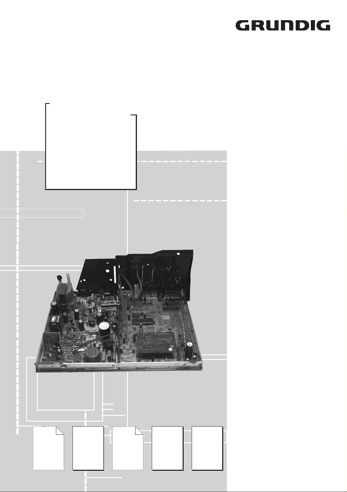
Service Manual
Grundig Service
Technik:
TV/SAT
VCR/LiveCam
HiFi/Audio
Car Audio
T elekommunikation
Fax:
Hotline Deutschland...
...Mo.-Fr. 8.00-16.30 Uhr
0180/52318-41
0180/52318-42
0180/52318-43
0180/52318-44
0180/52318-45
0180/52318-51
TV
CUC 2030 N
2050 N
2051 N
2058 N
2059 N
Ersatzteil-Bestellannahme:
Telefon:
Fax:
2080 N
0180/52318-40
0180/52318-50
ST 63-705 NIC/TEXT
ST 70-705 NIC/TEXT
Greenville 7004 NIC/TOP
ST 63-875 DPL/FT
ST 70-875 DPL/FT
ST 70-810 DPL
ST 70-819 NIC/TOP
ST 72-700 TOP
MELBOURNE
SE 7210 A NIC/TOP
MW 82-2690 NIC/TOP
MW 70-2690 NIC/TOP
Ergänzung
Supplement
4
Sach-Nr./Part No.
72010 020 7400
Zusätzlich erforderliche
Unterlagen für den Komplettservice
Additionally required
Service Documents for the Complete Service
Service
Manual
CUC 2030/N
CUC 2031/N
Sach-Nr./Part No.
72010-020.70
Ergänzung
Supplement
1+3
Sach-Nr./Part No.
72010-020.71
72010 020 7300
Service
Manual
Sicherheit
Safety
Sach-Nr./Part No.
72010-800.00
Service
Training
CUC 2000
Sach-Nr./Part No.
72010-350.35
ST 84-896 NIC/TOP
Btx * 32700 #
Sachnummer
Part Number 72010 020 7400
Änderungen vorbehalten
Subject to alteration
Printed in Germany
VK22/232 0698

Allgemeiner Teil / General Section CUC 2030 N … 2080 N
Es gelten die Vorschriften und Sicherheitshinweise gemäß dem Service Manual "Sicherheit",
Sach-Nummer 72010-800.00, sowie zusätzlich
die eventuell abweichenden, landesspezifischen
Vorschriften!
D
Für diese Geräte gilt das Service Manual CUC 2030 / CUC 2031 N.
Diese Ergänzung dokumentiert die Unterschiede bzw. zusätzlichen
Bestückungen der Geräte.
Die Bausteinbestückung und die Sachnummern der einzelnen Bausteine entnehmen Sie bitte den Tabellen auf Seite 3 und 4.
Grundlage für den Service sind:
– Sicherheitsvorschriften (Sach-Nr. 72010-800.00)
– Service Manual CUC 2030 / CUC 2031 N (Sach-Nr. 72010-020.70)
– 1. Ergänzung CUC 2030 N … CUC 2040 (Sach-Nr. 72010-020.71)
– 3. Ergänzung CUC 2030 … 2040 India (Sach-Nr. 72010 020 7300).
Inhaltsverzeichnis
Seite
Modulauflistung – Service Manual mit Ergänzungen...................... 3
Modulübersicht................................................................................ 4
Technische Daten ........................................................................... 5
Abgleich .......................................................................................... 7
Netzschalterplatte 29305-165.76 .................................................. 13
Netz-Chassis................................................................................. 15
Signal-Chassis A........................................................................... 19
Signal-Chassis B........................................................................... 23
Chassisplatte PCBs ...................................................................... 26
Bildrohrplatte 29305-122.21/.23.................................................... 35
Bildrohrplatte 29305-122.22.......................................................... 37
Buchsenplatte 29305-008.38 ........................................................ 39
Feature-Platte CTI/LTI 29305-119.35 ........................................... 40
Dolby-Surround-Platte 29504-104.77 ........................................... 43
Bedieneinheit 29501-082.70 ......................................................... 46
Keyboard 29501-083.70 ............................................................... 46
UG2 Shift/Panorama View 29305-119.43/.68............................... 48
Prozessorplatte 29501-119.40/.71................................................ 49
PIP Baustein 29504-106.51/.52 .................................................... 52
Dyn. Focus 29305-025.35............................................................. 57
Bedieneinheit 29501-082.73 ......................................................... 59
Keyboard 29501-083.16 ............................................................... 59
Ersatzteillisten............................................................................... 61
The regulations and safety instructions shall be
valid as provided by the "Safety" Service Manual,
part number 72010-800.00, as well as the
respective national deviations.
GB
For these TV sets the Service Manual CUC 2030 / CUC 2031 N is applicable.
This Manual describes the differences and the additionally fitted
modules of the TV receivers.
The individual modules and the relevant part numbers are listed in the
tables on page 3 and 4.
Basic instructions for servicing are given in the:
– Safety Instructions (Part No. 72010-800.00)
– Service Manual CUC 2030 / CUC 2031 N (Part No. 72010-020.70)
– 1st Suppl. CUC 2030 N … CUC 2040 (Part No.72010-020.71)
– 3st Suppl. CUC 2030 … 2040 India (Part No.72010 020 7300).
Table of Contents
Page
List of Module – Service Manual with Supplements ....................... 3
Module List...................................................................................... 4
Technical Data ................................................................................ 5
Alignment ...................................................................................... 10
Mains Switch Board 29305-165.76 ............................................... 13
Mains Chassis............................................................................... 15
Signal Chassis A ........................................................................... 19
Signal Chassis B ........................................................................... 23
Chassis Board PCBs .................................................................... 26
CRT Panel 29305-122.21/.23 ....................................................... 35
CRT Panel 29305-122.22 ............................................................. 37
Socket Board 29305-008.38 ......................................................... 39
Feature Board CTI/LTI 29305-119.35........................................... 40
Dolby Surround Board 29504-104.77 ........................................... 43
Control Unit 29501-082.70............................................................ 46
Keyboard 29501-083.70 ............................................................... 46
UG2 Shift/Panorama View 29305-119.43/.68............................... 48
Processor Board 29501-119.40/.71 .............................................. 49
Module PIP 29504-106.51/.52 ...................................................... 52
Dyn. Focus 29305-025.35............................................................. 57
Control Unit 29501-082.73............................................................ 59
Keyboard 29501-083.16 ............................................................... 59
Spare Parts Lists........................................................................... 61
Allgemeiner Teil
Meßgeräte / Meßmittel
Beachten Sie bitte das Grundig Meßtechnik-Programm, das Sie unter
folgender Adresse erhalten:
Grundig Instruments
Test- und Meßsysteme GmbH
Würzburger Str. 150, D-90766 Fürth/Bay.
Tel. 0911/703-4118, Telefax 0911/703-4130
eMail: instruments@grundig.de
Internet: http://www.grundig-instruments.de
2 GRUNDIG Service
General Part
Test Equipment / Aids
Please note the Grundig Catalog "Test and Measuring Equipment"
obtainable from:
Grundig Instruments
Test- und Meßsysteme GmbH
Würzburger Str. 150, D-90766 Fürth/Bay.
Tel. 0911/703-4118, Telefax 0911/703-4130
eMail: instruments@grundig.de
Internet: http://www.grundig-instruments.de
CUC 2030 N … 2080 N Allgemeiner Teil / General Section
Modulauflistung – Service Manual mit Ergänzungen
List of Modules – Service Manual with Supplements
Modul
Module
Dyn. Focus 29305-025.35 Seite / Page 57
Netzschalterplatte
Mains Switch Panel
Dolby-Surround-Platte
Dolby Surround Board
(DPL-Modul 2) 29504-104.77 Seite / Page 43
NF-Verstärker
AF Amplifier
Feature-Platte CTI/LTI
Feature Board CTI/LTI
Bedieneinheit
Control Unit
Keyboard 29501-083.16 Seite / Page 59
BSO-Platte
BSO Panel
Prozessorplatte
Processor Panel
Ersatzplatte
Alternative Board
Buchsenplatte
Socket Board
Bildrohrplatte
CRT Panel
UG2-Schift 29305-119.43 Seite / Page 48
Modul-Sachnummer
Module Part Number
29305-165.71 Seite / Page 3 - 27
29305-165.73 Seite / Page 3 - 28
29305-165.76 Seite / Page 13
29504-104.75 Seite / Page 13
29524-104.78 Seite / Page 13
29305-119.35 Seite / Page 40
29501-082.59 Seite / Page 3 - 33
29501-082.61 Seite / Page 3 - 33
29501-082.62 Seite / Page 22
29501-082.66 Seite / Page 24
29501-082.69 Seite / Page 29
29501-082.70 Seite / Page 46
29501-082.72 Seite / Page 27
29501-082.73 Seite / Page 59
29501-083.25 Seite / Page 3 - 32
29501-083.44 Seite / Page 3 - 32
29501-083.70 Seite / Page 46
29305-119.44 Seite / Page 3 - 24
29305-119.37 Seite / Page 3 - 25 Seite / Page 26
29305-119.39 Seite / Page 3 - 25
29305-119.40 Seite / Page 3 - 25 Seite / Page 26 Seite / Page 49
29305-119.46 Seite / Page 3 - 25 Seite / Page 26
29305-119.71 Seite / Page 49
29305-119.75 Seite / Page 26
29305-119.42 Seite / Page 3 - 31
29305-119.45 Seite / Page 3 - 31
29305-008.34 Seite / Page 3 - 29
29305-008.35 Seite / Page 3 - 30
29305-008.37 Seite / Page 3 - 30
29305-008.38 Seite / Page 3 - 29 Seite / Page 39
29305-008.39 Seite / Page 27
29305-160.53 Seite / Page 26
29305-122.16 Seite / Page 3 - 11
29305-122.18 Seite / Page 3 - 11
29305-122.21/.23 Seite / Page 35
29305-122.22 Seite / Page 37
Service Manual
CUC 2030/2030 N
CUC 2031/2031 N
72010-020.70 72010-020.71 72010 020 7300 72010 020 7400
1. Ergänzung
1. Supplement
CUC 2030 N/2031
CUC 2031 N/2040
3. Ergänzung
3. Supplement
CUC 2030/2030 N
CUC 2040 N/2040 India
4. Ergänzung
4. Supplement
CUC 2030 N … 2080 N
Panorama View 29305-119.68 Seite / Page 48
PIP-Baustein
PIP Module
(PIP-Modul 4)
(PIP Module 4)
29504-106.52 Seite / Page 52
29504-106.51 Seite / Page 52
GRUNDIG Service 3
4 GRUNDIG Service
Sachnummer
Part Number
ST 63-705
NIC/TEXT
CUC 2030 N
ST 70-705
NIC/TEXT
CUC 2030 N
ST 63-875
DPL/FT
CUC 2050 N
ST 70-875
DPL/FT
CUC 2050 N
ST 70-810
DPL
CUC 2050 N
ST 70-819
NIC/TOP
CUC 2050 N
Melbourne
SE 7210 A
NIC/TOP
CUC 2051 N
MW82-2690
NIC/TOP
CUC 2058 N
MW70-2690
NIC/TOP
CUC 2059 N
ST 84-896
NIC/TOP
CUC 2080 N
GREENVILLE
7004
NIC/TOP
CUC 2050 N
ST 72-700
TOP
CUC 2051 N
Bestell-Nr.
Order No.
G.CH 4175 G.CH 4075 G.CF 7375 GB G.CG 6775 GB G.CH 0775 G.CH 4675
G.CG 0524
G.CG 0575
G.CF 9775 G.CF 9875 G.CF 8490 G.CH 5075 G.CH 6575
Chassis
29704-003.21 29704-003.20 29704-003.50 29704-003.45 29704-003.45 29704-003.51 29704-003.44 29704-003.39 29704-003.37 29704-003.41 29704-003.53 29704-003.52
Tuner PLL 29504-301.01
–––––––––––
ww.
8140-601-612
––
••••••••••
Tuner VST
8140-601-614
ww.
8140-601-610
••
––––––––––
Bedieneinheit
Control Unit
29501-082.62
––
••••
––––––
29501-082.70
–––––––––
•
––
29501-082.73
–––––––––––
•
Keyboard 29501-083.70
–––––––––
•
––
29501-083.44
––––––
•
–––
•
–
29501-083.25
–––––––
••
–––
29501-083.16
–––––––––––
•
29501-081.85
••
––––––––––
Buchsenplatte
Socket Board
29305-008.38
––––––
•
–––
•
–
29305-008.37
–––––––
••
–––
29305-160.53
––
•••
–––––––
Bildrohrplatte
CRT Panel
29305-122.22
–––––––
•
––––
29305-122.21/.23
––––––
•
–
••
–
•
29305-122.16
••••••
––––
•
–
Feature-Platte CTI / LTI
Feature Board CTI / LTI
29305-119.35
––
••••••••••
PIP-Baustein
PIP Module
29504-106.52
–––––––––––
•
(PIP-Modul 4)
(PIP Module 4)
29504-106.51
––
nachrüstbar nachrüstbar nachrüstbar nachrüstbar nachrüstbar nachrüstbar nachrüstbar nachrüstbar nachrüstbar nachrüstbar
Prozessorplatte
Processor Panel
29305-119.71
––
••••••••••
29305-119.40
••
––––––––––
Netzschalterplatte
Main Switch Panel
29305-165.71
–––––––
••
–––
29305-165.73
––––––
•
–––
•
–
29305-165.76
••
––––––––––
BSO-Platte
BSO Board
29305-119.44
––––––
••••
–
•
Dolby-Surround-Platte
Dolby Surround Board
29504-104.77
––
•••
nachrüstbar nachrüstbar nachrüstbar nachrüstbar nachrüstbar nachrüstbar nachrüstbar
Panorama View
29305-119.68
––––––––
•
–––
UG2-Schift
29305-119.43
––––––
•
––
•
–
•
Dyn. Focus
29305-025.35
–––––––
•
––––
TP 900 29642-061.11
––––––
•
–––
•
–
TP 800 29642-061.01
––––
••
–
•••
–
•
TP 715 29642-062.11
••••
––––––––
Allgemeiner Teil / General Section CUC 2030 N … 2080 N
Modulübersicht / Module List
GRUNDIG Service 5
ST 63-705 NIC / TEXT
(CUC 2030 N)
ST 70-705 NIC / TEXT
(CUC 2030 N)
Greenville 7004 NIC/TOP
(CUC 2050 N)
ST 63-875 DPL / FT
(CUC 2050 N )
ST 70-875 DPL / FT
(CUC 2050 N )
ST 70-810 DPL
(CUC 2050 N )
Bildröhre / Picture Tube
Sichtbares Bild
Visible picture
59cm 66cm 66cm 59cm 66cm 66cm
Bildschirmdiagonale
Screen diagonale
63cm (25")
Black Line D
70cm (28")
Black Line D
70cm (28")
Black Line D
63cm (25")
Black Line D
70cm (28")
Black Line D
70cm (28")
Black Line D
Ablenkwinkel
Deflection angle
110° 110° 110° 110° 110° 110°
Bildwechselfrequenz
Vertical frequency
50Hz 50Hz 50Hz 50Hz 50Hz 50Hz
Elektronik / Electronic
Programmspeicherplätze
Programme positions
79 TV + 3 AV 79 TV + 3 AV 99 TV + 3 AV 99 TV + 3 AV 99 TV + 3 AV 99 TV + 3 AV
AV-Auswertung
AV evaluation
auf jeden Programmplatz programmierbar / programmable for every programme position
Tuner
VST-Spannungs synthesizer
tuning UHF/VHF
VST voltage synthesizer tuning
UHF/VHF
VST-Spannungs synthesizer
tuning UHF/VHF
VST voltage synthesizer tuning
UHF/VHF
PLL-Frequenz synthesizer
tuning UHF/VHF
PLL frequency synthesizer tuning
UHF/VHF
PLL-Frequenz synthesizer
tuning UHF/VHF
PLL frequency synthesizer tuning
UHF/VHF
PLL-Frequenz synthesizer
tuning UHF/VHF
PLL frequency synthesizer tuning
UHF/VHF
PLL-Frequenz synthesizer
tuning UHF/VHF
PLL frequency synthesizer tuning
UHF/VHF
TV-Normen
TV-Standard
PAL,
NTSC 4,43MHz, B/G,
I, D/K,K' (nur/only PAL)
PAL,
NTSC 4,43MHz, B/G,
I, D/K,K' (nur/only PAL)
PAL,
NTSC 4,43MHz, B/G,
I, D/K,K'/D (nur/only PAL)
PAL,
NTSC 4,43MHz, B/G,
I, D/K,K' (nur/only PAL)
PAL,
NTSC 4,43MHz, B/G,
I, D/K,K' (nur/only PAL)
PAL,
NTSC 4,43MHz, B/G,
I, D/K,K' (nur/only PAL)
Stereo Systeme
Stereo systems
Deutsch A2 für B/G/D/K
German A2 for B/G/D/K
Nicam 5,85+6,52MHz
Deutsch A2 für B/G/D/K
German A2 for B/G/D/K
Nicam 5,85+6,52MHz
Deutsch A2 für B/G/D/K
German A2 for B/G/D/K
Nicam 5,85+6,52MHz
Deutsch A2 für B/G/D/K
German A2 for B/G/D/K
Nicam 5,85+6,52MHz
Deutsch A2 für B/G/D/K
German A2 for B/G/D/K
Nicam 5,85+6,52MHz
Deutsch A2 für B/G/D/K
German A2 for B/G/D/K
Nicam 5,85+6,52MHz
Videotext
Teletext
1 Seiten Text
1 page text
1 Seiten Text
1 page text
8 Seiten TOP/FLOF-text, VPS,
8 pages TOP/FLOF-text, VPS,
8 Seiten TOP/FLOF-text, VPS,
8 pages TOP/FLOF-text, VPS,
8 Seiten TOP/FLOF-text, VPS,
8 pages TOP/FLOF-text, VPS,
8 Seiten TOP/FLOF-text, VPS,
8 pages TOP/FLOF-text, VPS,
Musikleistung (ohne Dolby)
Music power (without Dolby)
Stereo 2 X 8W Stereo 2 X 8W Stereo 2 X 20W Stereo 2 X 20W Stereo 2 X 20W Stereo 2 X 20W
Musikleistung (mit Dolby Prologic)
Music power (with Dolby Prologic)
———
Stereo 4 X 18W
for L/R-, center-, rear channel
Stereo 4 X 18W
for L/R-, center-, rear channel
Stereo 4 X 18W
for L/R-, center-, rear channel
Anschlüsse Front / Connections Front
Kopfhörer
Headphones
Stereo 3,5mm Klinkenbuchse, Lautstärke regelbar, individuelle Tonkanalwahl bei 2-Ton-Empfang / Stereo 3.5mm jacksocket, adjustable volume, individual channel selection with dual-sound broadcasts
Video IN 1 x Cinch 1 x Cinch 1 x Cinch 1 x Cinch 1 x Cinch 1 x Cinch
Audio IN 2 x Cinch 2 x Cinch 2 x Cinch 2 x Cinch 2 x Cinch 2 x Cinch
Anschlüsse Rückwand / Connections Rear Panel
Euro AV 1 (schwarz/black)
FBAS in-/output,
SBAS input, RGB input,
MicroSat Fernbedienung (Pin 8)
MicroSat remote control (Pin 8)
FBAS in-/output,
SBAS input, RGB input,
MicroSat Fernbedienung (Pin 8)
MicroSat remote control (Pin 8)
FBAS in-/output,
SBAS input, RGB input,
MicroSat Fernbedienung (Pin 8)
MicroSat remote control (Pin 8)
FBAS in-/output,
SBAS input, RGB input,
MicroSat Fernbedienung (Pin 8)
MicroSat remote control (Pin 8)
FBAS in-/output,
SBAS input, RGB input,
MicroSat Fernbedienung (Pin 8)
MicroSat remote control (Pin 8)
FBAS in-/output,
SBAS input, RGB input,
MicroSat Fernbedienung (Pin 8)
MicroSat remote control (Pin 8)
Euro AV 2 (schwarz/black)
FBAS in-/output,
SBAS input, RGB input
FBAS in-/output,
SBAS input, RGB input
FBAS in-/output,
SBAS input, RGB input
FBAS in-/output, RGB input,
SBAS input
FBAS in-/output, RGB input,
SBAS input
FBAS in-/output, RGB input,
SBAS input
Netzteil / Mains Stage
Netzspannung (Regelber.)
Mains voltage (variable)
165…265V 165…265V 165…265V 165…265V 165…265V 165…265V
Netzfrequenz
Mains frequency
50 / 60Hz 50 / 60Hz 50 / 60Hz 50 / 60Hz 50 / 60Hz 50 / 60Hz
Leistungsaufnahme
Power consumption
ca. 70W ca. 75W ca. 80W
Daten noch nicht verfügbar
data not yet available
ca. 95W ca. 95W
Standby ca. 5W ca. 5W ca. 5W
Daten noch nicht verfügbar
data not yet available
ca. 5W ca. 6W
Technische Daten / Technical Data
CUC 2030 N … 2080 N Allgemeiner Teil / General Section
6 GRUNDIG Service
ST 70-819 NIC / TOP
(CUC 2050 N )
Melbourne SE 7210 a
NIC / TOP
(CUC 2051 N)
ST 72-700 TOP
(CUC 2051 N )
MW 82-2690 NIC / TOP
(CUC 2058 N )
MW 70-2690 NIC / TOP
(CUC 2059 N )
ST 84-896 NIC / TOP
(CUC 2080 N)
Bildröhre / Picture Tube
Sichtbares Bild
Visible picture
66cm 68cm 68cm 76cm 66cm 80cm
Bildschirmdiagonale
Screen diagonale
70cm (28")
Black Line D
72cm (29")
Black Line S
72cm (29")
Black Line S
82cm (32")
16:9, Black Line
70cm (28")
16:9, Black Matrix
84cm (33")
Black Line S
Ablenkwinkel
Deflection angle
110° 110° 110° 106° 106° 110°
Bildwechselfrequenz
Vertical frequency
50Hz 50Hz 50Hz 50Hz 50Hz 50Hz
Elektronik / Electronic
Programmspeicherplätze
Programme positions
99 TV + 3 AV 99 TV + 3 AV 99 TV + 3 AV 99 TV + 3 AV 99 TV + 3 AV 99 TV + 3 AV
AV-Auswertung
AV evaluation
auf jeden Programmplatz programmierbar / programmable for every programme position
Tuner
PLL-Frequenz synthesizer
tuning UHF/VHF
PLL frequency synthesizer tuning
UHF/VHF
PLL-Frequenz synthesizer
tuning UHF/VHF
PLL frequency synthesizer tuning
UHF/VHF
PLL-Frequenz synthesizer
tuning UHF/VHF
PLL frequency synthesizer tuning
UHF/VHF
PLL-Frequenz synthesizer
tuning UHF/VHF
PLL frequency synthesizer tuning
UHF/VHF
PLL-Frequenz synthesizer
tuning UHF/VHF
PLL frequency synthesizer tuning
UHF/VHF
PLL-Frequenz synthesizer
tuning UHF/VHF
PLL frequency synthesizer tuning
UHF/VHF
TV-Normen
TV-Standard
PAL,
NTSC 4,43MHz, B/G,
I, D/K,K' (nur/only PAL)
PAL,
NTSC 4,43MHz, B/G,
I, D/K,K' (nur/only PAL)
PAL,
NTSC 4,43MHz, B/G,
I, D/K,K' (nur/only PAL)
PAL,
NTSC 4,43MHz, B/G,
I, D/K,K' (nur/only PAL)
PAL,
NTSC 4,43MHz, B/G,
I, D/K,K' (nur/only PAL)
PAL,
NTSC 4,43MHz, B/G,
I, D/K,K' (nur/only PAL)
Stereo Systeme
Stereo systems
Deutsch A2 für B/G/D/K
German A2 for B/G/D/K
Nicam 5,85+6,52MHz
Deutsch A2 für B/G/D/K
German A2 for B/G/D/K
Nicam 5,85+6,52MHz
Deutsch A2 für B/G/D/K
German A2 for B/G/D/K
Nicam 5,85+6,52MHz
Deutsch A2 für B/G/D/K
German A2 for B/G/D/K
Nicam 5,85+6,52MHz
Deutsch A2 für B/G/D/K
German A2 for B/G/D/K
Nicam 5,85+6,52MHz
Deutsch A2 für B/G/D/K
German A2 for B/G/D/K
Nicam 5,85+6,52MHz
Videotext
Teletext
8 Seiten TOP/FLOF-text, VPS,
8 pages TOP/FLOF-text, VPS,
8 Seiten TOP/FLOF-text,
8 pages TOP/FLOF-text.
8 Seiten TOP/FLOF-text,
8 pages TOP/FLOF-text.
8 Seiten TOP/FLOF-text, VPS,
8 pages TOP/FLOF-text, VPS,
8 Seiten TOP/FLOF-text, VPS,
8 pages TOP/FLOF-text, VPS,
8 Seiten TOP/FLOF-text, VPS,
8 pages TOP/FLOF-text, VPS,
Musikleistung
Music power
Stereo 2 X 20W Stereo 2 X 20W Stereo 2 X 20W Stereo 2 X 20W Stereo 2 X 20W Stereo 2 X 20W
Musikleistung (mit Dolby Prologic)
Music power (with Dolby Prologic)
——————
Anschlüsse Front / Connections Front
Kopfhörer
Headphones
Stereo 3,5mm Klinkenbuchse, Lautstärke regelbar, individuelle Tonkanalwahl bei 2-Ton-Empfang / Stereo 3.5mm jacksocket, adjustable volume, individual channel selection with dual-sound broadcasts
Video IN 1 x Cinch 1 x Cinch 1 x Cinch 1 x Cinch 1 x Cinch 1 x Cinch
Audio IN 2 x Cinch 2 x Cinch 2 x Cinch 2 x Cinch 2 x Cinch 2 x Cinch
Anschlüsse Rückwand / Connections Rear Panel
Euro AV 1 (schwarz/black)
FBAS in-/output,
SBAS input, RGB input,
MicroSat Fernbedienung (Pin 8)
MicroSat remote control (Pin 8)
FBAS in-/output,
SBAS input, RGB input,
MicroSat Fernbedienung (Pin 8)
MicroSat remote control (Pin 8)
FBAS in-/output,
SBAS input, RGB input,
MicroSat Fernbedienung (Pin 8)
MicroSat remote control (Pin 8)
FBAS in-/output,
SBAS input, RGB input,
MicroSat Fernbedienung (Pin 8)
MicroSat remote control (Pin 8)
FBAS in-/output,
SBAS input, RGB input,
MicroSat Fernbedienung (Pin 8)
MicroSat remote control (Pin 8)
FBAS in-/output,
SBAS input, RGB input,
MicroSat Fernbedienung (Pin 8)
MicroSat remote control (Pin 8)
Euro AV 2 (schwarz/black)
FBAS in-/output, RGB input,
SBAS input
FBAS in-/output, RGB input,
SBAS input
FBAS in-/output, RGB input,
SBAS input
FBAS in-/output, RGB input,
SBAS input
FBAS in-/output, RGB input,
SBAS input
FBAS in-/output, RGB input,
SBAS input
Netzteil / Mains Stage
Netzspannung (Regelber.)
Mains voltage (variable)
165…265V 165…265V 165…265V 165…265V 165…265V 165…265V
Netzfrequenz
Mains frequency
50 / 60Hz 50 / 60Hz 50 / 60Hz 50 / 60Hz 50 / 60Hz 50 / 60Hz
Leistungsaufnahme
Power consumption
ca. 80W ca. 90W ca. 90W ca. 90W ca. 90W ca. 110W
Standby ca. 5W ca. 6W ca. 6W ca. 5W ca. 5W ca. 5W
Allgemeiner Teil / General Section CUC 2030 N … 2080 N
CUC 2030 N … CUC 2080 N Abgleich / Alignment
D
Abgleich
Hinweis:
Es werden in den Chassis CUC 20xx TDA 8843/8375 bzw. TDA 8843-N2/8844-N2 eingebaut. Bei dem Typ TDA 8843-N2/8844-N2 ist ein PLLDemodulator integriert und somit entfällt der AFC-Abgleich im Service Menü.
Achtung!
1. Nach einer Reparatur bzw. Wechsel des NVM (IC82005) muß kontrolliert werden, ob der NTSC Quarz 3,58MHz bestückt ist. Bei nicht bestücktem
Quarz, muß über das Service Menü die Dialogzeile "NTSC 3,6" auf "aus" gestellt werden.
Taste "6" –> "OK" –> "SERVICE" –> "OK" –> Service Code "8500" –> NTSC 3,6 "aus" und über die Dialogzeile "End" mit "with mem." sichern.
2.Ist kein SAT-Receiver (SNR 105 microSAT) an der AV1-Buchse angeschlossen, muß im Service-Menü SAT auf "aus" gestellt werden.
Taste "6" –> "OK" –> "SERVICE" –> "OK" die Dialogzeile "SAT" aufrufen und auf "aus" stellen.
Alle nicht beschriebenen Einstellelemente sind werkseitig abgeglichen und dürfen im Service-Fall nicht verstellt werden.
1. Chassisplatte
Meßgeräte: Zweikanal-Oszilloskop, Tastkopf 10:1, Digitalvoltmeter, Farbgenerator, Spektrumanalyser oder HF-Millivoltmeter.
Servicearbeiten nach Austausch bzw. Reparatur:
- Netzteil: Abgleich 1.1
- Tuner: Abgleich 1.2, 1.3 / 1.4
- NVM IC82005: Abgleich 1.2…1.8, 2.1, 2.2, 3.1, 3.3
- Zeilenablenkung: Abgleich 1.9
Abgleich Vorbereitung Abgleichvorgang
1.1 +A Spannung
1.2 Tuner-AGC
1.3 AFC-Referenz
nur VST-Tuner
1.4 AFC-Referenz
nur PLL-Tuner
Abgleich enfällt bei
TDA 8843-N2
TDA 8844-N2
Nach jeder Reparatur und vor jedem Abgleich kontrollieren
und gegebenfalls einstellen.
Helligkeit: Minimum
Digital-Voltmeter: Kathode D61016
Spektrumanalyser oder HF-Millivoltmeter symmetrisch an
Tunerkontakt 10, 11.
Senderbild oder Generator über die Antenne einspeisen,
70…80dBµV.
Dialogzeile "AGC" über "6" (DIALOG CENTER) –> "OK"
–> SERVICE –> "OK" –> Service Code "8500" –> aufrufen.
Generator mit Bildträger 38,9MHz, ca. 120mV an Tunerkontakt 10, 11 einspeisen.
Dialogzeile "AFC" über "6" (DIALOG CENTER) –> "OK"
–> SERVICE –> "OK" –> Service Code "8500" –> aufrufen.
Sender mit genormtem Kanalraster ohne Finetuning im
Band 1 (Kanal 2…4) einspeisen.
Dialogzeile "AFC" über "6" (DIALOG CENTER) –> "OK"
–> SERVICE –> "OK" –> Service Code "8500" –> aufrufen.
R60037 bzw. R61313 nach Tabelle (Seite 16) im Schaltbild
Netz-Chassis einstellen.
Mit den Tasten "V -" oder "+ C" 102dBµV (360mVss)
einstellen.
Ersatzweise wird ohne Spektrumanalyser oder HF-Millivoltmeter mit den Tasten "V -" oder "+ C" das Bild so
abgestimmt, daß es gerade zu rauschen beginnt. Dann
soweit zurückstellen, bis das Bild wieder rauschfrei wird.
Dialogzeile "End" mit "with mem" beenden.
Einstellung mit "OK" aktivieren.
Der interne Abgleich des PLL-Demodulators wird durchgeführt.
Erscheint nach dem Abgleich ein Pfeil neben der Schrift,
AFC mit Demodulatorfilter F33025 nachgleichen bis die
Pfeile verschwinden. Die Pfeile links oder rechts des AFCWertes im Menü geben die Drehrichtung für den Filterabgleich an.
Pfeil rechts, Filterkern zu weit innen.
Pfeil links, Filterkern zu weit herausgedreht.
Abgleich mit "OK" wiederholen.
Dialogzeile "End" mit "with mem." beenden.
Einstellung mit "OK" aktivieren.
Der interne Abgleich der PLL-Demodulators wird durchgeführt.
Erscheint nach dem Abgleich ein Pfeil neben der Schrift,
AFC mit Demodulatorfilter F33025 nachgleichen bis die
Pfeile verschwinden. Die Pfeile links oder rechts des AFCWertes im Menü geben die Drehrichtung für den Filterabgleich an.
Pfeil rechts, Filterkern zu weit innen.
Pfeil links, Filterkern zu weit herausgedreht.
1.5 OSD
GRUNDIG Service
Dialogzeile "OSD" über "6" (DIALOG CENTER) –> "OK"
–> SERVICE –> "OK" –> Service Code "8500" –> aufrufen.
Abgleich mit "OK" wiederholen.
Dialogzeile "End" mit "with mem." beenden.
Mit den Tasten "V -" oder "+ C" das Menü in die Bildmitte
stellen.
Dialogzeile "End" mit "with mem." beenden.
7
Abgleich / Alignment CUC 2030 N … CUC 2080 N
Abgleich Vorbereitung Abgleichvorgang
1.6 Tube
(Bildröhrentyp)
1.7 Overscan
1.8 NTSC 3,6
1.9 Zeilenschärfe
nur bei Geräten
mit
Focusblock
Zeilenschärfe
nur bei Geräten
ohne
Focusblock
Dialogzeile "Tube" über "6" (DIALOG CENTER) –> "OK"
–> SERVICE –> "OK" –> Service Code "8500" –>
aufrufen.
Nur mit IC TDA8843 oder TDA8844 sowie bei Philips 72cm/
84cm in 4:3- und 70cm/82cm in16:9-Format Bildröhren.
Dialogzeile "Overscan" über "6" (DIALOG CENTER) –>
"OK" –> SERVICE –> "OK" –> Service Code "8500" –>
aufrufen.
Dialogzeile "NTSC 3,6" über "6" (DIALOG CENTER) –>
"OK" –> SERVICE –> "OK" –> Service Code "8500" –>
aufrufen.
- Konvergenztestbild einspeisen.
- Bildformat auf 16:9 einstellen (bei 16:9 Geräten).
- Kontrast (W) Maximum.
- Bildschirmhelligkeit (R) so einstellen, daß der schwarze
Testbildhintergrund sich gerade aufzuhellen beginnt.
- Konvergenztestbild einspeisen.
- Bildformat auf 16:9 einstellen (bei 16:9 Geräten).
- Kontrast (W) Maximum.
- Bildschirmhelligkeit (R) so einstellen, daß der schwarze
Testbildhintergrund sich gerade aufzuhellen beginnt.
Mit den Tasten "V -" oder "+ C" die richtige Bildschirm-
diagonale eingeben.
Dialogzeile "End" mit "with mem." beenden.
Mit den Tasten "V -" oder "+ C" auf "aus" stellen.
Dialogzeile "End" mit "with mem." beenden.
Mit den Tasten "V -" oder "+ C" je nach Gerät auf "aus"
oder "ein" stellen.
Dialogzeile "End" mit "with mem." beenden.
Mit dem Schärferegler Focus 1 die horizontalen Linien in
Schirmmitte auf kleinste vertikale Breite einstellen.
Dann mit dem Schärferegler Focus 2 die vertikalen Linien
ca. 5cm vom rechten und linken Bildrand auf kleinste
horizontale Breite einstellen.
Mit dem Focusregler 0 die vertikalen Linien ca. 5cm vom
rechten und linken Bildrand auf kleinste horizontalen Breite einstellen.
Die Mittenschärfe darf nicht schlechter als die Randschärfe
erscheinen, ggf. mitteln.
2. Bildgeometrie
Meßgeräte: Farbgenerator, Zweikanal-Oszilloskop mit Tastkopf 10:1.
Servicearbeiten nach Austausch bzw. Reparatur:
Geometrieeinstellung mit dem Vertikal-Abgleich beginnen!
- Zeilen- und Bildablenkung und Bildrohrwechsel: Abgleich 2.1, 2.2
- Brückenspule L53074: Nur nach unsachgemäßem Eingriff in der Horizontalablenkung notwendig: Abgleich 2.3
- NVM IC82005: Abgleich 1.2…1.8, 2.1, 2.2, 3.1, 3.3
Abgleich Vorbereitung Abgleichvorgang
2.1 Vertical Slope
2.2 Horizontal Shift
Menü "Vertical Slope" über "6" (DIALOG CENTER) –>
"OK" –> SERVICE –> "OK" –> Service Code "8500" –>
"GEOMETRIE" –> "OK" aufrufen.
Helligkeit max.
Dialogzeile "Horizontal Width" (Bildbreite) über "6"
(DIALOG CENTER) –> "OK" –> SERVICE –> "OK" –>
Service Code "8500" –> "GEOMETRIE" –> "OK" aufrufen
und Bildbreite mit den Tasten "V -" oder "+ C" verklei-
nern.
Dialogzeile "Horizontal Shift" aufrufen.
Die Mittellinie des Testbildes in der Dialogzeile "Vertical
Slope" (typ. 30…33) mit den Tasten "V -" oder "+ C" so
abgleichen, daß sie gerade noch sichtbar ist.
Taste "6" zweimal drücken (GEOMETRIE –> SERVICE)
und Dialogzeile "End" mit "with mem." beenden.
Die Bildgeometrie stellt sich nach jedem Einschalten auf
den zuletzt gespeicherten Wert ein.
Bildinhalt mit den Tasten "V -" oder "+ C" mittig ins
Raster stellen.
(Horizontal Width) Bildbreite wieder nach Testbild einstellen.
Mit dem Stecker "ST-Shift" am Chassis (optional), das
Testbild in die Bildschirmmitte stellen.
Dieser Stecker kann je nach Bildröhrenstreuung auch nachbestückt, verdreht aufgesetzt, oder im Widerstandswert
verändert werden.
Taste "6" zweimal drücken (GEOMETRIE –> SERVICE)
und Dialogzeile "End" mit "with mem." beenden.
Die Bildgeometrie stellt sich nach jedem Einschalten auf
den zuletzt gespeicherten Wert ein.
2.3 Brückenspule
L53074
Die Brückenspule L53074 wird in der Fertigung abgeglichen und sollte nicht verdreht werden.
Dialogzeile "Horizontal Width" über "6" (DIALOG CENTER)
–> "OK" –> SERVICE –> "OK" –> Service Code "8500"
–> "GEOMETRIE" –> "OK" aufrufen.
Horizontal Width (Bildbreite) auf Minimum stellen.
Oszilloskop Kanal 1: Kollektor T53001.
Oszilloskop Kanal 2: Kathode D53072.
Gleiche Impulsbreite der Oszillogramme kontrollieren und
gegebenenfalls mit Spule L53074 abgleichen.
Bildbreite nach Testbild einstellen.
GRUNDIG Service8
CUC 2030 N … CUC 2080 N Abgleich / Alignment
162,5V±2,5V
3. Bildrohrplatte
Meßgeräte: hochohmiges Voltmeter, Zweikanal-Oszilloskop mit Tastkopf 10:1.
Servicearbeiten nach Austausch bzw. Reparatur:
- Bildröhre, Bildrohrplatte Abgleich 3.1…3.3
- NVM IC82005: Abgleich 1.2…1.8, 2.1, 2.2, 3.1, 3.3
Abgleich Vorbereitung Abgleichvorgang
3.1 Weißwert
3.2 Schirmgitter spannung U
mit TDA8375
3.3 Schirmgitter spannung U
mit TDA8843
oder
TDA8844
Schwarzweiß-Grautreppe mit Burst einspeisen.
Kontrast (W) Maximum.
Farbkontrast (E) Mittelwert.
Bildschirmhelligkeit (R) Mittelwert.
Dialogzeile "WHITE ADJUSTMENT" über "6" (DIALOG
CENTER) –> "OK" –> SERVICE –> "OK" –> Service Code
"8500" aufrufen.
Gerät in AV-Stellung.
Schwarzbild einspeisen.
G2
Bildschirmhelligkeit: Graufläche gerade dunkel.
Voltmeter über 220kΩ an Testpunkt R, G und B.
Höchsten Spannungswert ermitteln.
Voltmeter (220kΩ) oder Oszilloskop am Testpunkt mit
höchster Spannung
Dialogzeile "Cut-off align" über "6" (DIALOG CENTER) –>
"OK" –> SERVICE –> "OK" –> Service Code "8500"
G2
aufrufen.
Mit "OK" bestätigen.
Mit den Tasten "V -" oder "+ C" die Werte für "Grün"
bzw. "Blau" so einstellen, daß das Testbild unbunt wird.
Kontrolle des Weißabgleichs mit Kontrast Minimum und
Maximum.
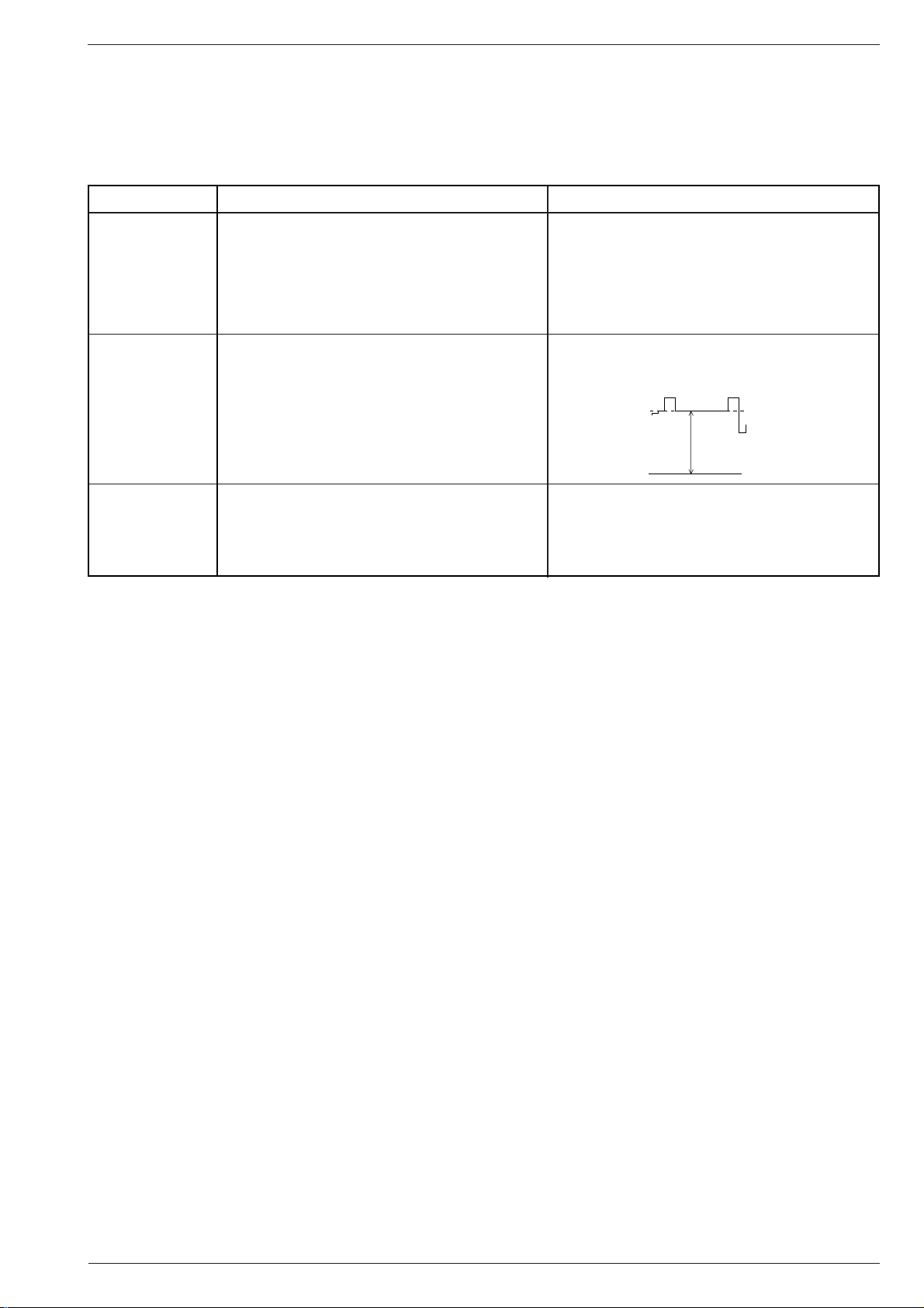
Dialogzeile "End" mit "with mem." beenden.
Am Voltmeter 162,5V±2,5V mit Einstellregler UG2 auf der
Bildrohrplatte einstellen.
Oder mit Oszílloskop lt. Skizze.
Schwarzwert
105-110V
Mit dem Einstellregler UG2 auf der Bildrohrplatte (oder
Fokusblock) den zuerst erscheinenden roten, grünen, blauen oder mischfarbenen Strich gerade gut sichtbar einstellen.
Mit "OK" zurück ins Menü.
GRUNDIG Service
9

Abgleich / Alignment CUC 2030 N … CUC 2080 N
GB
Alignment
Note:
The CUC 20xx chassis are either fitted with TDA 8843/8375 or TDA 8843-N2/8844-N2. Type TDA 8843-N2/8844-N2 has a PLL demodulator
integrated in it so that the AFC adjustment in the Service Menu is not necessary.
Attention!
1. After any repair or replacement of NVM (IC82005) check whether the NTSC 3.58MHz quartz is fitted. If it is not, the dialog line "NTSC 3,6" in the
Service Menu must be set to "off".
Button "6" –> "OK" –> "SERVICE" –> "OK" –> Service Code "8500" –> NTSC 3,6 "off" and in dialog line "End" store the setting "with mem.".
2.When no SAT Receiver (SNR 105 microSAT) is connected to the AV1 socket, SAT in the Service Menu is to be set to "off".
Button "6" –> "OK" –> "SERVICE" –> "OK", select dialog line "SAT" and switch to "off".
All adjustment controls not mentioned in this description are pre-set at the factory and must not be re-adjusted in the case of repairs.
1. Chassis Board
Measuring instruments: Dual-channel oscilloscope, 10:1 test probe, digital voltmeter, colour video generator, spectrum analyser or RF millivoltmeter
Service works after replacement or repair of the following modules:
- Power supply: alignment 1.1
- Tuner: alignment 1.2, 1.3 / 1.4
- NVM IC82005: alignment 1.2 …1.8, 2.1, 2.2, 3.1, 3.3
- Horizontal deflection: alignment 1.9
Alignment Preparations Alignment Process
1.1 +A voltage
1.2 Tuner AGC
1.3 AFC Reference
only VST Tuner
1.4 AFC Reference
only PLL-Tuner
No adjustment
necessary with
TDA 8843-N2
TDA 8844-N2
This voltage must be checked and re-adjusted if necessary
after every repair and before every alignment.
Brightness: Minimum
Digital voltmeter: Cathode D61016
Spectrum analyser or RF millivoltmeter symmetrical to
tuner contact 10, 11.
Feed in a standard test pattern or generator via the aerial,
70…80dBµV.
Call up the dialog line "AGC" via "6" (DIALOG CENTER) –>
"OK" –> SERVICE –> "OK" –> Service Code "8500".
Feed in a generator test pattern with vision carrier 38.9MHz,
ca. 120mV to tuner contact 10, 11.
Call up the dialog line "AFC" via "6" (DIALOG CENTER) –>
"OK" –> SERVICE –> "OK" –> Service Code "8500".
Feed in a standard test pattern with standardized channel
spacing, band 1 (channel 2…4) without finetuning.
Call up the dialog line "AFC" via "6" (DIALOG CENTER) –>
"OK" –> SERVICE –> "OK" –> Service Code "8500".
Adjust R60037 or R61313 acc. to the table (page 16) on
the power supply circuit diagram.
Adjust 102dBµV (360mVpp) with button "V -" or "+ C".
Alternatively, without using a spectrum analyser or RF
millivoltmeter, adjust the picture with button "V -" or "+ C"
so that noise just appears on the screen. Then reset until
the picture is again free of noise.
Dialog line "End", terminate "with mem".
Activate the setting with "OK".
Internal adjustment of the PLL demodulator is carried out.
If an arrow is displayed beside the text after adjustment,
re-adjust the AFC with demodulator filter F33025 until the
arrows disappear. The arrow on the left or right of the AFC
value in the menu indicates the sense of rotation for
adjusting the filter.
Arrow on the right, core of the filter turned in too far.
Arrow on the left, core of the filter turned out too far.
Repeat this adjustment with "OK".
Dialog line "End", terminate "with mem.".
Activate the setting with "OK".
Internal adjustment of the PLL demodulator is carried out.
If an arrow is displayed beside the text after adjustment,
re-adjust the AFC with demodulator filter F33025 until the
arrows disappear. The arrow on the left or right of the AFC
value in the menu indicates the sense of rotation for
adjusting the filter.
Arrow on the right, core of the filter turned in too far.
Arrow on the left, core of the filter turned out too far.
1.5 OSD
1.6 Tube
(Type of picture
tube)
Call up the dialog line "OSD" via "6" (DIALOG CENTER) –>
"OK" –> SERVICE –> "OK" –> Service Code "8500".
Call up the dialog line "Tube" via "6" (DIALOG CENTER) –>
"OK" –> SERVICE –> "OK" –> Service Code "8500".
Repeat this adjustment with "OK".
Dialog line "End", terminate "with mem.".
With button "V -" or "+ C" position the menu in the
middle of the picture.
Dialog line "End", terminate "with mem.".
With button "V -" or "+ C" enter the correct screen
diagonal.
Dialog line "End", terminate "with mem.".
GRUNDIG Service10
CUC 2030 N … CUC 2080 N Abgleich / Alignment
Alignment Preparations Alignment Process
1.7 Overscan
1.8 NTSC 3.6
1.9 Line Sharpness
only TV's
with
Focus Block
Line Sharpness
only TV's
without
Focus Block
Only with IC TDA8843 or TDA8844 as well as with Philips
72cm/84cm in 4:3 and 70cm/82cm in 16:9 format picture
tubes.
Call up the dialog line "Overscan" via "6" (DIALOG
CENTER) –> "OK" –> SERVICE –> "OK" –> Service Code
"8500".
Call up the dialog line "NTSC 3,6" via "6" (DIALOG
CENTER) –> "OK" –> SERVICE –> "OK" –> Service
Code "8500".
- Feed in a convergency test pattern.
- Set the16:9 picture format (with 16:9 TV sets).
- Contrast (W) to maximum.
- Set the screen brightness (R) so that the black
background of the test pattern just starts to brighten.
- Feed in a convergency test pattern.
- Set the16:9 picture format (with 16:9 TV sets).
- Contrast (W) to maximum.
- Set the screen brightness (R) so that the black
background of the test pattern just starts to brighten.
Set to "off" with button "V -" or "+ C".
Dialog line "End", terminate "with mem.".
Set to "off" or "on" with button "V -" or "+ C" dependent
on the type of television receiver.
Dialog line "End", terminate "with mem.".
With focus control Focus 1 adjust the horizontal lines in the
middle of the screen to minimum vertical width.
Subsequently, with focus control Focus 2, adjust the vertical
lines approx. 5cm from the right and left picture edge to
minimum horizontal width.
With focus control 0, adjust the vertical lines approx. 5cm
from the right and left picture edge to minimum horizontal
width.
The sharpness in the middle must not seem to be worse
than the sharpness at the edges. If necessary, take an
average.
2. Picture Geometry
Measuring instruments: Colour video generator, dual-channel oscilloscope with 10:1 test probe.
Service works after replacement or repair:
Start with the vertical slope when adjusting the geometry!
- Horizontal and vertical deflection and replacement of the picture tube: alignment 2.1, 2.2
- Bridge coil L53074: Only necessary after unskillful manipulation of the horizontal deflection: alignment 2.3
NVM IC82005: alignment 1.2 …1.8, 2.1, 2.2, 3.1, 3.3
Alignment Preparations Alignment Process
2.1 Vertical Slope
2.2 Horizontal Shift
2.3 Bridge Coil
L53074
Call up the "Vertical Slope" menu via "6" (DIALOG CENTER)
–> "OK" –> SERVICE –> "OK" –> Service Code "8500" –
> "GEOMETRY"
Max. brightness.
Call up dialog line "Horizontal Width" via "6" (DIALOG
CENTER) –> "OK" –> SERVICE –> "OK" –> Service Code
"8500" –> "GEOMETRY" –> "OK" and reduce the width of
the picture using button "V -" or "+ C".
Call up dialog line "Horizontal Shift".
Bridge coil L53074 is adjusted in the factory and this
setting must not be changed.
Call up dialog line "Horizontal Width" via "6" (DIALOG
CENTER) –> "OK" –> SERVICE –> "OK" –> Service Code
"8500" –> "GEOMETRY" –> "OK".
Set Horizontal Width to minimum.
Oscilloscope channel 1: collector T53001.
Oscilloscope channel 2: cathode D53072.
Adjust the center line of the test pattern in the dialog line
"Vertical Slope" (typ. 30…33) with button "V -" or "+ C"
so that it is just still visible.
Press button "6" twice (GEOMETRY –> SERVICE) and
terminate the dialog line "End" with "with mem.".
The picture geometry is adjusted to the value last stored
whenever the TV set is switched on.
Position the picture content in the middle of the raster using
button "V -" or "+ C".
Re-adjust the horizontal width according to the test pattern.
With connector "ST-Shift" on the chassis (option), position
the test pattern in the middle of the screen.
Dependent on the scanning spread of the picture tube this
connector may be retrofitted, connected the other way
round, or the rating of the resistor may be changed.
Press button "6" twice (GEOMETRY –> SERVICE) and
terminate the dialog line "End" with "with mem.".
The picture geometry is adjusted to the value last stored
whenever the TV set is switched on.
Check the oscillograms for the same pulse width and readjust it if necessary with coil L53074.
Adjust the horizontal width according to the test pattern.
GRUNDIG Service
11
Abgleich / Alignment CUC 2030 N … CUC 2080 N
3. CRT Panel
Measuring instruments: High-resistance voltmeter, dual-channel oscilloscope with 10:1 test probe.
Service works after replacement or repair:
- CRT, CRT panel: alignment 3.1…3.3
- NVM IC82005: alignment 1.2 …1.8, 2.1, 2.2, 3.1, 3.3
Alignment Preparations Alignment Process
3.1 White Balance
3.2 Screen Grid
Voltage U
with TDA8375
G2
3.3 Screen Grid
Voltage U
with TDA8843
G2
or
TDA8844
Feed in a grey scale black/white test pattern with burst.
Contrast (W) to maximum.
Colour contrast (E) to mid-position.
Screen brightness (R) to mid-position.
Call up dialog line "WHITE ADJUSTMENT" via "6"
(DIALOG CENTER) –> "OK" –> SERVICE –> "OK" –>
Service Code "8500".
TV set in AV position.
Feed in a black raster.
Screen brightness: Grey raster just becoming dark.
Connect the voltmeter via 220kΩ to test points R, G and B.
Determine the point with the highest voltage level.
Voltmeter (220kΩ) or oscilloscope to test point with highest
voltage level.
Call up dialog line "Cut-off align" via "6" (DIALOG CENTER)
–> "OK" –> SERVICE –> "OK" –> Service Code "8500".
Confirm with "OK".
With button "V -" or "+ C" set the values for "Green" or
"Blue" so that the picture becomes achromatic.
Check the white balance at minimum contrast and maximum
contrast.
Terminate the dialog line "End" with "with mem.".
Set the voltmeter to read 162.5V±2.5V with adjustment
control UG2 on the picture tube panel.
Or adjust the oscilloscope as shown below.
Black level
105-110V
162.5V±2.5V
With adjustment control U
Focus Block), adjust the line appearing first - red, green,
on the picture tube panel (or
G2
blue or mixed-colour - so that it is just well visible.
Return to the menu with "OK".
GRUNDIG Service12
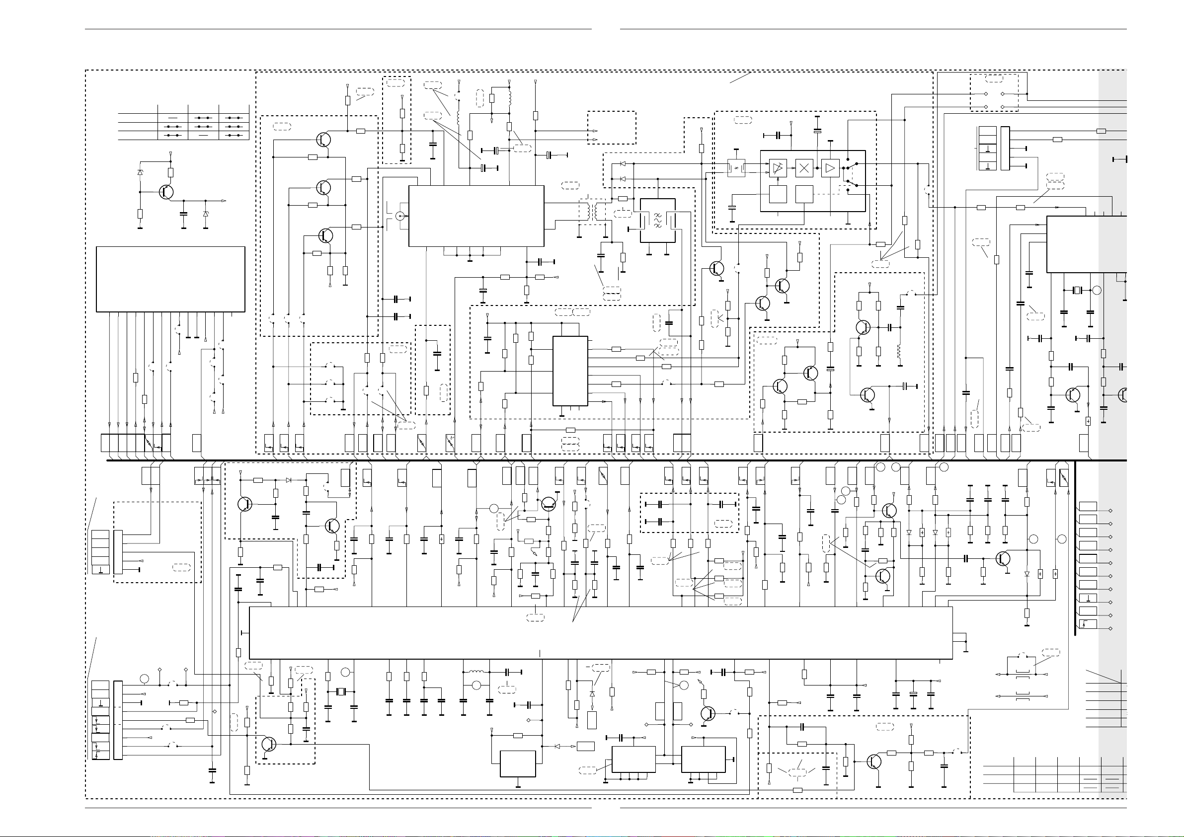
CUC 2030 N … 2080 N Platinenabbildungen und Schaltpläne / Layout of the PCBs and Circuit Diagrams
K
8,2n
C44506
+H
U
LED
FBAS
1N4148
D81501
R83001
1,2k
+M
IR
IR
+5V
1
2
3
TFMS5300
IC84001
U
IDEN1
1
2
3
4
5
ST-CI1
CINCH
AUDIO-L
CINCH
AUDIO-R
+
47u/10V
C84001
BU11
K
0,1u
C84002
L
R
1
2
3
BU10
KH
AUDIO-R
KH
AUDIO-L
K
470p
C44501
R41501
33
R44503
470
K
8,2n
C41502
K
5,6n
C41501
K
5,6n
C41503
K
470p
C44503
R44501
470
R41503
33
R84001
270
R
L
+
2,2u/100V
C44504
R83004
8,2k
R83003
4,7k
R83002
2,2k
R44511
47k
TLHR4601
D85001
+
2,2u/100V
C44502
-L
+L
+P
-P
KB
U
OFF
POWER
7
8
9
1
2
3
4
5
6
ST-KB\IR
SEITE / PAGE 19SEITE / PAGE 20
SEITE / PAGE 15
TO ST-NETZ1
SEITE / PAGE 21
1
2
3
ST-H
FBAS
CINCH
R44509
75
28500-708.97
S60000
n.V.
R84002
100
R44508
82k
1
2
3
4
ST-NET11
1
2
ST-NETZ1
BC558C
T44510
BC548B
T44505
1
2
ST-NETZ2
n.V.
R44506
3,3k
R44507
1,8k
U
WISCH
F
0,22u
C44508
A
A
A
IR
IR
IR
IR
+M
+M
V
VV
V
VV
V
V
KH
KH
KH
KH
+H
+H
+H
+H
+H
280897
ENTFAELLT BEI .76
NO EXISTE EN
MANCA NELLA VERS.
N’EXISTE PAS
DELETED WITH
29305-165.76
PLACA INTERRUPTOR DE RED
PIASTRA INTERR.DI RETE
C.I.INTERR.SECTEUR
MAINS SWITCH PANEL
NETZSCHALTERPLATTE 29305-165.74
CIRCUIT NOT MAINS ISOLATED
AL TELAIO
AL CHASSIS SEGNALE
SECTOUR DE COM. NO SEP. DE LA RED
CIRCUITO NON SEPAR., DALA RETE
CIRCUIT NON ISOLE DU SECTEUR
NICHT NETZGETRENNTES SCHALTUNGSTEIL
AL CHASSIS SENAL
VERS CHASSIS SIGNAL
TO SIGNAL CHASSIS
ZUM SIGNAL-CHASSIS
ZUM CHASSIS
TO CHASSIS
VERS CHASSIS
AL CHASIS
Platinenabbildungen und Schaltpläne / Layout of the PCBs and Circuit Diagrams
Netzschalterplatte / Mains Switch Board 29305-165.76
Bestückungsseite, Ansicht von oben / Component Side, Top View
BR001
R44511
R44509
C44508
T44505
CE
R44506
C84002
BU11
R84002
R83002
29304-540.06
R83001
(02)2L
C84001
ST-KB\IR
29304-540.06
4B(00)
R83003
BR005
19
BR003
BR006
R83004
BR004
BU10
C41502
C41501
R41503
ST-H
13
C44501
C41503
R41501
R44503
C44502
C44503
ST-CI1
R44501
CE
T44510
R81502
C44504
15
R44507
C44506
1
D81501
R84001
4
IC84001
ST1
13
Keine
NETZ2-1
D85001
S60000
1
NETZ1-1
Netztrennung
1
NETZ1-2
1
NETZ2-2
1
CUC 2030 N … 2080 N Platinenabbildungen und Schaltpläne / Layout of the PCBs and Circuit Diagrams
GRUNDIG Service
Lötseite, Ansicht von unten / Solder Side, Bottom View
S60000
Netztrennung
1
NETZ1-2
D85001
1
NETZ1-1
NETZ2-2
1
Keine
NETZ2-1
1
13
IC84001
ST1
1
4
D81501
R83004
R84001
BR003
BR004
BR005
BR006
29304-540.06
4B(00)
BU11
R84002
R83002
R83001
R83003
(02)2L
C84001
ST-KB\IR
19
R44509
C44508
29304-540.06
T44505
CE
R44506
C84002
BR001
R44511
R44501
CE
T44510
R81502
R44507
C44504
C44506
15
ST-CI1
C44501
C44502
C44503
C41503
R44503
C41502
C41501
R41501
R41503
ST-H
13
BU10
13
GRUNDIG Service
14
Platinenabbildungen und Schaltpläne / Layout of the PCBs and Circuit Diagrams CUC 2030 N… 2080 N
C
5
0
0
0
0
0
0
0
0
0
2
E
S
N
Netz-Chassis / Mains Chassis
Platinenabbildungen und Schaltpläne / Layout of the PCBs and Circuit Diagrams CUC 2030 N … 2080 N
1
OFF2
WISCH
POWER
U
U
CR81507
4,7k
+H
ENTF.BEI EXT.NETZSCH.PLATTE
DELETED WITH EXT.MAINS SWITCH BOARD
N’EXISTE PAS C.I.INTERR.SECTEUR
MANCA CON PIASTRA INTERR.DI RETE ESTERNA
NO EXISTE EN PLACA INTERRUPTOR DE RED EXT.
BR62500
1
NETZ2
1
NETZ1
ST-NETZ1
SEITE / PAGE 14, 46, 59
TO ST-NET11
ALLA PIASTRA INTERR.DI RETE
VERS C.I.INTERR.SECTEUR
TO MAINS SWITCH BOARD
ZUR NETZSCHALTERPL.
1
3
5
7
A LA PLACA INTERRUPTOR DE RED
M
ST-E
1
3
PRIMAERMASSE / NICHT NETZGETRENNTES SCHALTUNGSTEIL
PRIMARY CHASSIS, NOTE / CIRCUT NOT MAINS ISOLATED
MASSE PRIMAIRE / CIRCUIT NON ISOLE DU SECTEUR
P
MASSA PRIMARIO / CIRCUITO NON SEPAR., DALA RETE
MASA PRIMARIA / SECTOUR DE COM. NO SEP. DE LA RED
15
1k
CC81508
CR81508
M M M
+M
S2KO004
NETZSCHALTER
CT81508
n.v.
D81501
1N4148
BC848B
2,2n
SI62501
BR62501
WISCH
U
M
+M
!
*
n.v.
F
C62505
0,1u/MKS4-R/250V-AC
CR81511
27k
56k
CT81511
BC858B
+M
CR81503
CR81501
CR81500
M
NUR BEI OEKO-SCHALTER
ONLY WITH ECO SWITCH
SEUL. POUR INTERR. ECOLOG.
SOLO CON INTERR. ECOLOGICO
SOLO CON EL INTERR. ECOL.
F
C62501
4,7k
10k
0,1u/MP3/250V
CT81502
M
n.v.
BR62502
L62501
*
BR62503
n.v.
T81501
BC875
CR81509
+F
+M
22k
BC848B
R62505
8311-*
SCHUTZ
U
CR81502
22k
R81504
10k
C62021
C62022
OFF
POWER
U
10k
CR81505
M
F
C62502
0,1u/MP3/250V
R60021
NTC4,7
1n/400V_AC
P
1n/400V_AC
CUC 2030 (63/70cm PHI)
CUC 2031 (72cm PHI)
CUC 2040 (63/70cm PHI/DPL)
CUC 2051 (72cm PHI/DPL2)
CUC 2058 (82cm PHI 16:9)
CUC 2059 (70cm PHI 16:9)
CUC 2080 (84cm PHI)
CUC 2040 WEITBEREICH
C60022
*/385V
+
P
1n
C60023
13
1n
C60024
D60023
B380-*
P
P
C62048
1n/400V_AC
M
M
*
!
_BR60019
C60026
C60027
R62049
R60001*R60007
R60003
680k
*
SI60001
MUR460
_D60021
_C60021
MUR460
_D60019
_C60019
1n
1n
_C60028
4,7M
AOPTION OPTION
XX
XX
XX
XX
XX
XX
XX
XX
*
R60002
680k
R60004
K
27p
BR60021
K
27p
*
_L60028
5
F
33n
P
R60029
2
*
F
C60036
C60002
P
P
F
C60013
10n
*
R61312
1n
C60001
P
*/MKT400V
3
7
1
0,22u
_C60018
3,3n/FPK1/1250V
*
R60036
R60032
5,6k
220
R60031
P
3,3k
15k
15k
3,3k
3,3k
3,3k
15k
15k
STAND
BY
PFC
F
R60001
150k
150k
270k
270k
270k
270k
270k
270k
270k
270k
1
2
IC60010
TDA4605/3
n.v.
R60037
TABELLE 1 / OPTIONLIST 1
R60007
C60002
2,7n
100k
2,7n
100k
2,2n
2,2n
2,7n
2,7n
2,7n
2,7n
2,7n
2,2n
LOGIKSTART
8
3
_BR60018
R60018
10k
220p/
68k 680 T4A
220p/
68k
220p/
68k
220p/
68k
220p/
68k
220p/
68k
220p/
68k
220p/
68k
5
+U /14V
C60016
0,1u
6
B
4
PP
R60013
10k
n.V.
F
K
1n
C60014
220p/
220p/
R60005
D60013
R60014
BR60012
D60005
BAV21
4,7
2
R60006
22
+
C60011
100u/25V
P
BAV21
33k
T60006
BR60012
*
R60012
*
R60012
3,3
3,3
3,3
3,3
3,3
3,3
3,3
3,3
C60007
P
33n/630V
4
*
G
D
S
P
D60012
BAV21
R60016
2
56
P P
D60037
BAV21
+A
Min.
*
OK60031
5
42
2,2k
CNY17F1
R60033
C60037
_BR61301
n.V.
+
BR61308
1
_R61308
R61301
1u/63V
XX
T61301
BC548B
470
M
+H
R61302
1k
n.V.
C60038
PP
*/MKT400V
1
IC61310
LM358N
n.V.
_R61305
680k
C61301
4,7n
M
+H
K
AOPTION
GRUNDIG Service
16
R60015L60012C60010C60009 BR61027B
1
1
8104-982-014
4
+
-
8
/5V
n.V.
_R61307
XX
BR61307
2
R60009
2
R60008
D60007
D60006
F
C60009
P
*
F
C60010
P
C60022
220u
220u
220u
220u
220u
220u
220u
220u
220u
470u
450V
22k
22k
BYT54M
L60006
BYT54M
/FKP1/2kV
*
L60012
R60015
*
/FKP1/2kV
*
3
2
R61303
5
1
(1)
3,6u
7
(5)
P
(7) (10)
n.V.
BR61312
R61312
*
K
2,2k
C61311
4,7n
R61311
MM
R61306
R61304
1,2k
1k
10k
M
1,2kCUC 2030 (63/70cm VC)
2
F
C61016
M
4
L61036
6
8104-982-014
M
L61056
8
R61313
22k
C60038R60037
5,6n
5,6n
3,3n
3,3n
3,3n
3,3n
3,3n
3,3n
3,3n
3,3n
100p/FKP1/1,6kV
L61026
8104-982-014
OPTION
CUC2050 CUC2051
SI61036
*
SI61056
T2,5A
M
+A
Min.
R61314
120k
337.97
336.97
341.97CUC 2050 (70cm PHI/DPL2)
340.97
340.97
341.97
339.97
8104-982-014
C61036
D61036
C61056
D61056
BYW172D
+A
R60036 TR61000
1,6k
1,6k
470
470
470
470
470
470
470
TR61001
TR61000
29201-*
(2)(3)
(4)
(6)
12
8104-982-014
1011
+H
100p
100p
L61016
SI61026
T4A
B
*
TR61001
520.97
520.97
+
C61037
M
+
C61057
*
470u/40V
M
D61016
BYW178
BYW178
BYT56M
BYT56M
BYT56M
BYT56M
BYT56M
BYT56M
BYT56M
BYT56M
D61016
*
C61026
100p
D61026
MUR840
CUC2080
_BR61040
SI61036
T2,5A
T2,5A
T5A
T4A
T4A338.97
T4A
T4A
T4A
T5A
+
C61017
M
22k
M
*
BR61027
IC61040
IN OUT
LM317
ADJUST
1
R61043
1,2k/1%
IC61050
IN OUT
LM317T
ADJUST
1
0,1u
CT61053
BC848B
680/1%
R61053
1
0,1u
+A
152V
152V
142V
142V
154V
146V
146V
152V
D61036
BYW172D
BYW172D
MUR840
MUR840
MUR840
MUR840
MUR840
MUR840
MUR840
MUR840
100u/250V
BR61028
CT61043
BC848B
IC61060
MC7805
2
R61018
180k
180k
220k
220k
220k
220k
220k
220k
220k
220k
+
C61027
R61027
600u/63V
M
32
0,1u
0,1u
CC61039
CC61038
M
n.V.
32
0,1u
CC61060
CC61058
M
M
0,1u
CC61064
CC61061
M
M
*
63cm BM
70cm BM
63cm SF
72cm SF
84cm
70cm/16:9
82cm/16:9
63cm TESLA
R61018
CR61041
CR61044
CR61051
MM
6,2/1W
6,2/1W
6,8/1W
6,8/1W
7,5/1W
8,2/4W
8,2/4W
6,2/1W
C61037
470u/40V
470u/40V
1000u/63V
1000u/63V
1000u/63V
1000u/63V
1000u/63V
1000u/63V
1000u/63V
1000u/63V
*
M
220/1%
CC61041
CR61046
22k
MMM
220/1%
CC61051
3
CC61062
R50011
22k
CR61054
L62501
812.97
812.97
812.97
812.97
812.97
812.97
812.97
812.97
812.97
828.97
+A
+G
/+38V
+M
(+16,5V)
/+14,5V
/+16,5V
+E
+
0,1u
C61042
470u/25V
MMM
+F
+
0,1u
C61052
470u/25V
M
M
CR61056
22k
22k
M M
+H
+
0,1u
C61063
470u/10V
MMM
D50016
33
33
BAV21
33
BAV21
33
BAV21
33
BAV21
33
BAV21
33
22
33
R60029
82k
82k
82k
82k
82k
82k
82k
82k
82k
39k
/+8V
/+5V
CC61059
/+5V
D60023
C1500
C1500
C1500
C1500
C1500
C1500
C1500
C1500
C1500
C2200
CR55001
CC55001
M
2,2n
1,8
1,6
1,6
1,6
1,3
1,3
1,3
1,3
1,8
1,8
1,5
1,5
1,5
1,5
1,6 1,6
1,8 1,8
GRUNDIG Service
R60004 SI62501
T2,5A
8,2k1,2k
T2,5A
8,2k
T2,5A
8,2k
T2,5A
8,2k
T2,5A
8,2k
T2,5A
8,2k
T2,5A
8,2k
T2,5A
8,2k
T2,5A
8,2k
15k
270
R50001
270
R50003
2,2k
CR50004
1k/5%
1n
SUBJ
R50023R50022R50021R21117
1,8
1,6
1,3
1,3
1,6
1,6
2,22,7/2W155V70cm VC
T4A
R500
CC50004
BR
AEN
SOU
CO
RE
10
10
10
10
10
10
10
18
18

CUC 2030 N … 2080 N Platinenabbildungen und Schaltpläne / Layout of the PCBs and Circuit Diagrams
CR50004
4
CUC 2030 N … 2080 N Platinenabbildungen und Schaltpläne / Layout of the PCBs and Circuit Diagrams
ZUM SIGNAL-CHASSIS B
TO SIGNAL CHASSIS B /
AL CHASSIS SEGNALE B /
VERS CHASSIS SIGNAL B
AL CHASIS SENAL B
SEITE / PAGE 23
VA
M
M
MM
9
3
5
11
VB
K
C50016
0,68u/
0,68u/
0,68u/
0,68u/
0,68u/
1,2u/
1,2u/
0,68u/
0,68u/
SCHUTZ
U
D57101
10n/100V
*
BR55002
F
C55003
VG
H
BAT42
D50016
R50021
11
BR55008
R55003
**
68n
M
9n/FKP1
9n/FKP1
14n/FKP1
14n/FKP1
11,5n/FKP1
13,5n/FKP1
13,5n/FKP1
9,5n/1,6kV
9,5n/1,6kV
SYNC
*
*
*
1
SCHUTZ
U
+F
BR50027
*
R50022
9
C55004
CT57112
*
R50023
+
BU508AF
BU508AF
S2000N
S2000N
S2000N
S2000N
S2000N
BU508AF
BU508AF
HDR
492123228
C52002
D52001
BC858B
10
D55004
4,7u/100V
+
1N4148
R50026
1
R50024
*
L50027
*
*
V
SYNC
+F
CT57103
*
CR57104
*
CR57101
SI52001
+E
T315mA
_BR52001
K
C52001
+E
10k
CR57113
CT57113
BC858B
C52003
470p
T52001
BC637
1n
M
n.v.
K
CR57117
R57118
MP300
MMM
CR57116
270k/2%
10k/2%
*
4,7u/100V
M
ST-JOCH
F
*/100V
C50026
M
ST-JOCH
F
12
C50027
0,1u/100v
M
R55006
*
/NKS3
L55006
5m
*
TABELLE 2 / OPTIONLIST 2
0,26u
0,33u
0,33u
0,33u
0,33u
0,2u
0,22u
0,26u
0,33u
TR53010
-029.52
-029.52
-029.59
-029.59
-029.60
-029.63
-029.65
-029.52
-029.52
0,21u
0,21u
0,21u
0,27u
0,21u
0,2u
0,2u
0,21u
0,21u
*
M
R52001
BR52002
1
R52004
F
C52004
J5
J4
*
*
27
10n
+F
CT57124
BC848B
CR57124
M
C52006
1k
110.95
110.95
124.95
124.95
110.95
110.95
110.95
118.95
110.95
13
K
JV
_R.....=
TR52001
09246-866.04
1
6
2,2n
M MM
17
22k
CR57121
1N4148
D57122
M
L53002
D53071
D53072
24n
24n
20n
20n
20n
16n
16n
24n
24n
4
3
1
R52006
L/
8104-982-056
BY228
BYW76
n.v.
R52002
*
C53001
/MKS4/160V
*
F
C53002
F
C53072
u36/MKP10
u36/MKP10
u68/MKP10
u68/MKP10
u68/MKP10
1,2u/MKP4
1,2u/MKP4
u36/MKP10
u36/MKP10
SI62501
T2,5A
T2,5A
T2,5A
T2,5A
T2,5A
T2,5A
T2,5A
T2,5A
T2,5A
T4A
SI60001
T1,6A
T1,6A
T1,6A
T1,6A
T1,6A
T1,6A
T1,6A
T1,6A
T1,6A
T2,5A
T60006
R62505
BUZ90
BUZ90
BUZ90
BUZ90
BUZ90
BUZ90
TABELLE 2
BUZ90
BUZ90
BUZ90
PC50
OPTIONLIST 2
200-011
BY
STAND
U
OWA
BLACK SWITCH OFF
29304-792.44
nicht bei 70cm
+45V
*
R50011
D50011
M
ZPD51
CR50012
7
M
CC50003
C50026
0,1u
0,1u
0,1u
0,22u
0,1u
0,1u
0,1u
0,1u
0,1u180
M
5,6k
M
CC50011
0,1u
CC50012
M
0,1u
n.v.
10
1
1n
2
12
13
M
C50013
22u/50V
D50013
1N4004
8
U
L50027BR50027
2,2
2,2
2,2
2,2
2,2
2,2
2,2
2,2
CR50002
27k
270
R50003
1n
2,2k
CC50004
M
BR55001
*
AENDERUNGEN VORBEHALTEN
SUBJECT TO ALTERNATION
SOURS RESERVE DE MODIFIC
CON RISERVA DI MODIFICA
RESERV. EL DEREC. DE MODIFIC.
R50024
023 C53006 C53072C53001 C53007 L53021C53002 L53074C53073
100
,8
100
,6
100
,3
100
,3
100
,6
100
100
180
,6
,2
M
+16V
+
REF.
7
M
BR55003
BR55004
T55002
+16V
IC50020
TDA8350Q
CR55002
100k/2%
*
BR52006
BR52002 R52006R52001
9421
_CC50018
0,1u
CC50017
0,1u
CC50014
0,1u
D50014
1N4148
4
DG
BR55006
BR55007
S
M
0,22
0,22
0,22
0,22
0,22
0,22
0,22
0,22
T53001
14
120
M
*
BR52006
o
90
F
*
16
_BR53072
n.v.
C53073
*
/400V
*
MMMM
*
M
n.v.
M
846.51
846.51
846.21
846.57
846.56
846.56
846.56
846.51
846.51
+F
15
_BR53001
R53002
10k
D53003
BA157
SEITE / PAGE 57
DYN. FOKUSSIERUNG 29305-025.35
DYNAMIC FOCUSSING
FOC. DYNAMIQUE
10
B
FOCALIZZ. DINAMICA
ENFOQUE DYNAMICO
2/3
M
SEITE / PAGE 48
4
PANORAMA VIEW 29305-119.68
UG2-SHIFT 29305-119.43 (72/84cm 4:3)
1
BR53001
L53001
8104-982-056
8,2
R53001
L53003
8104-982-056
F
C53007
C53006
/MKP10/160V
1
820
L53021
R53021
29203-*
ST-JOCH
J1
JH
J3
ST-JOCH
09246-
BR55002
R54003
2,2
2,2
2,2
2,2
2,2
2,2
2,2
1
2,2
BR55001
T55002
STP7N20
STP7N20
ST22
F
**
L53074
_R53074
XX
n.v.
4
ST23
78
ST-SHIFT
1
2
R53011
/MKP10/160V
F
C53009
142p/FKP1/2kV
17
F
C53013
1,5n/FKP2/250V
M
16A
*
R55003
5,6
5,6
5,6
5,6
5,6
5,6
5,6
1
6,8
2,5%2,5%
L53011
n.v.
BR55008
DF1
SEITE / PAGE 58
NUR BEI 4:3
ONLY WITH
SEUL. POUR
SOLO CON PIP
SOLAM. CON
C53011
F
18n/FKP1/63V
10u
L/
BR53076
_BR53074
M
D55004
ZY33
ZY33
ZY33
ZY33
ZY33
ZY33
ZY33
1
2
BR53011
5
+A
2,2m
L53012
ST-JOCH
J6 J7
ST-JOCH
6,8/7W
R53016
F
C53017
C53016
M
0,33u/MKC4SV21/250V
BR53077
BR53078
R55006T53001
5,6/NKS3
5,6/NKS3
5,6/NKS3
5,6/NKS3
5,6/NKS3
4,7/NKS3
4,7/NKS3
5,6/NKS3
5,6/NKS3
CR57102
CR57103
0
n.v.
_BR53012
TR53011
TR53010
29201-*
L
I
F
M
0,33u/MKC4SV21/250V
D
E
SB
CR57104
R57118
3,3k/2%
3,3k/2%
3,9k/2%
3,9k/2%
2,7k/2%
3,3k/2%
3,3k/2%
3,3k/2%
3,3k/2%
PV
U
0
TR526(BEI 16:9)
I
E
A
G
C
F
H
B
CT57103CR57101
BC848B10k
F
H
B
18
R54003
M
20
R61019 R62505
680k
390k
330k
330k
330k
330k
330k
330k
390k
19
*
200-010
200-010
200-010
200-010
200-010
200-010
200-010
200-012
200-012
n.V.
R54012
1/0,75W
R54001
1
12
BR54002
R54002
470
L54002
47u
+A
D54001
BYV16
C54002
100p
D54002
BYV28-200
C54011
D54011
BYV28-200
100p
R61019
*
+
C54004
SB
+
C54001
M
+36V 61cm/16:9
100u/63V
M
+
C54012
4700u/25V
M
0,018u
F
C53032
0,018u
F
C53031
10u/350V
+45V
200V
+16V
M
M
M
BG1899-022-644
29201-474.01
R21117
1
F
*
+A
_CR61020
0
n.V.
NETZ-CHASSIS
MAINS CHASSIS
CHASSIS DI SECTEUR
CHASSIS DI RETE
CHASIS INTERR. RED
CUC 2030
CUC 2031
CUC 2040
CUC 2050
CUC 2051
CUC 2058
CUC 2059
CUC 2080
NUR BEI 16:9
ONLY WITH
SEUL.POUR
SOLO CON
SOLO CON
M
M
+C+C
U
H
U
/
FOC.
/
G2
ST-BR
1
2
3
4
5
VERS C.I. TUBE CATHOD.
ALLA PIASTRA CINESC.
TO CRT PANEL
ZUR BILDROHRPLATTE
SEITE / PAGE 35, 37
A LA PLACA-ZOCALO TRC
GRUNDIG Service
110598
17
GRUNDIG Service
18
Platinenabbildungen und Schaltpläne / Layout of the PCBs and Circuit Diagrams CUC 2030 N… 2080 N
A
2
1
5
3
9
2
T
C
Signal-Chassis A / Signal Chassis A
+33V
n.v.
+F/1
M
220u/10V
+
M15
+
C31046
M
+E
CC32401
10k
CR32402
SDA
0
CR31045
C31042
CR31048
22u/50V
0,1u
M
CR31043
+
M
8
1k
CR32403
CR32401
SCL
+F
L31043
CR32406
56k
10k
8,2uH
0
PLL
CR31046
56k
CR31044
AGC
12
CC31047
CR31047
47k
56k
M
CR32407
CR32408
ENA2
0
C31044
10u/50V
9
ZF
ZF
1n
56k
10k
+
11
10
1
2
3
M
8140-107-600
FR
M
+E/3
FR
STROBE
MC14094
DATA
CIC32410
CLOCK
M
CR32404
0
16:9
INL.
4
6
F32410
531-351
2
M
NIC
1615
1098
SIGNAL-CHASSIS A
CHASSIS SIGNAL A
CHASSIS SEGNALE A
CHASIS SENAL A
TEMIC 5002
UV 1316
TEC 2949
D31007
CR31008
M
SIGNAL-BAUSTEIN
SIGNAL MODULE
MODULE SIGNAL
MOD. SEGNALE
MOD. SENAL
100
CR31003
CR31006
SDA
SCL
FBAS
A-AM
A-ZF1
ZPD4,7V
BC858B
CT31005
22k
BR31006
100
AFC
U
U
ST-SB
TER
+45V
CR31009
BR31001
BR31004
ENA1
680
F
C31001
ZTK33D (VST-TUNER)
*
0,33u
D31001
M
M
ZD33B (PLL-TUNER)
29504-162.52
29504-000.00SAT-BAUSTEIN
123 45678 9 10 1112 13 14 15
M
A
+F
BR31002
+33V
BR31007
BR31003
BR31008
+M
+M/FM
+F/1
0
XX
CR31011
+F
BR81043
BR81042
BR81041
CR31041
0
_CR31013
CR31019
100
CR31029
100
CR31039
100
xx
M
BR31051
BR81041BR81042BR81043PLL-TUNER
CT31010
VST
BC858B
_CR31018
XX
CT31020
BC858B
BR163
_CR31028
BR228
XX
CT31030
BC858B
_CR31038
+33V
BR164
GB
CR31051
100
CR31052
BR31052
PLL
CC31052
100p
CC31051
100p
PLL
100
+F/1
56k
CR31022
56k
CR31021
M
B1
(SDA)
VST: UV 1315 // UV 1343 UHF only
PLL: UV 1316 w.w. TEC 2949 w.w. TEMIC 5002
M
M
CR81072
+E
n.v.
_BR31041
VST
CC31019
M
B3
XX
_L31041
0
CR31042
100p
C31041
220u/10V
34567
UHF
TUNERTUNER
(ADR)
(SCL)
M12
M13
M14
12 13 14 15
M
F
33n
C81072
M
22k
VST
M
+E
UB3U
B1
SCL1
SCL
UHF
U
SDA
SDA1
2-SCART
TUN
U
U
SEITE / PAGE 54
ST-PIP1
_+33V
_+F
78
CC32412
M
4
CR32410
5
6
7
14
CR32409
13
12
11
U
Platinenabbildungen und Schaltpläne / Layout of the PCBs and Circuit Diagrams CUC 2030 N … 2080 N
ENTFAELLT BEI
NOT FITTED ON
N’EXISTE PAS POUR
MANCA NELLA VERS.
NO EXISTE EN
CD32421
BA592
CD32411
BA592
CR32420
3
0
1
INL
1
2
M
M
0
0,1u
OFWK3451(FR)
OFWG1984(INL)
CR32412
OFWK3452(OIRT)
M
2,2k
NIC
FR
CR32417
0
6,8k
0
NORM2
NORM1
NORM3
U
U
SIGNAL MODULE
MODULE SIGNAL
MOD. SIGNALE
MOD. SENAL
10
F32412
OFWK6260
3
M
n.V.
_CC32411
FR
MONO
CR32418
4,7k
BR32409
PV
U
SIGNAL-BAUSTEIN
+E/3
2,2k
CR32021
4
5
8
M
3,3p
ZF_
ZF.
CT32415
BC848B
CR32416
CR32419
47k
0
CR32411
n.V.
47k
M
2
1
F32020
L9460
+
C32021
BR32418
M
+E
xx
_CR32422
xx
_CR32421
M
3
10u/50V
M
FR
CT32431
BC848B
5
4
14
1
2
+E/3
_CR32433
1
AUDIO
CC32422
M
CR32431
M
MONO
1k
0,1u
47k
+E/3
22u/50V
LOGICAGC
10
8
+E/3
2,2k
CR32432
CT32430
BC848B
M
+E/3
_CT32440
22k
BC858B
_CR32436
_CT32435
BC848B
_CR32439
22k
10k
_CR32437
M M
M
+
C32423
M
1312 11
4
IC32420
STV8225
6
_CT32453
BC848B
0
_CR32441
+
10u/50V
_C32438
1,2k
_CR32438
3
M
_CR32453
_CR32454
A
_CT32454
BC848B
7
9
5
_CR32426
+E
470
10k
A
0
MONO
390k
_CR32452
_CC32452
3,3n
100k
_CR32451
A
RESET
MSP
_CR32327
_BR32451
_CC32451
4,7m
_L32451
A
_C32454
+
4,7u/100V
0
3,3n
BR32301
0
_CR32326
A
AUDIO
SEITE / PAGE 14, 30, 46, 59
MSP
RESET
EURO-AV
TO CONTROL UNIT
ZUR BEDINEIHEIT
A-AM
n.V.
MONO1-
MONO1
1
MONO2
1
CINCH
AUDIO-R
CINCH
AUDIO-L
CINCH-
A LA UNIDAD DE MANDO
ALLA UNITA DI COMANDO
VERS UNITA DE COMANDE
CR32301
0
CUC2040
F
0,1u
0,22u
C32334
2-SCART
FBAS
FBAS
CINCH
CINCH-
FBAS
MONO2-
ST-CI1
CR32303
I2S
D_IN
0
CC32301
CR32300
A-ZF2
1
1
5
4
3
2
1
CR32302
CC32304
0
CR32339
A
M
SIG.-B
470
47
ANA_IN1+
49
ANA_IN2+
48
ANA_IN-
10n
CC32302
A
1n
SIG.-B
CC32309
A A
3,3n
CR32309
1n
CR32307
0
CC32308
CR32306
SIG.-B
A-ZF1
470
FR
DACA_R
21 22
CC32303
3,3k
CC32307
3,3k
560p
XTAL_IN
51 52
Q32305
18,432MHz
1,5p
CC32310
3,3n
10n
CT32308
BC858B
A
R41030
KH
CR32340
44 14 151718 1
ADR_WS
MONO_IN
XTAL_OUT
55
CC32306
AA
100
AUDIO-R
470
ADR_CL
DACA_L
1,5p
CR32310
CR32311
CC32312
AA
A
I2S_DA_IN2
MSP3410
DVSS
3,3k
CC3231
10n
CT32
BC8
3,3k
560p
CC3
47
NC
VREF2
LED-PLATTE
PLACA LED
PIASTRA LED
C.I. LED
LED-BOARD
_ST-MP
SDA
SCL
VDR
+F
A LA PLACA INTERRUPTOR RED
ALLA PIASTRA INTERR. DI RETE
VERS C.I. INTERR. SECTEUR
TO MAINS SWITCH BOARD
ZUR NETZSCHALTERPLATTE
ST-KB\IR
IR
+H
KB
U
LED
POWER
U
OFF2
+M
WISCH
U
1
U
IDEN1
19
SDA
SCL
5
4
3
+F
2
M
1
SEITE / PAGE 14, 46, 59
ASIS1
40
9
8
7
6
5
4
3
2
1
1
+H/1
M
BR81007
+M
BR81006
BR190
M
n.v.
ASIS2
CR81006
4,7k
CR81015
(330)
+H/1
1
OFF2
IDEN1
WISCH
POWER
U
U
U
1
180
10n
CC81006
M
MP98
CR81012
27k
CT81010
BC848B
NUR BEI MEGALOGIC
4,7k
CR81011
M
M
CC81008
1n
CC81007
10
VSS
M
1k
CR81007
FR
+F
470
n.V.
CR81004
270
CR81001
M
1n
M
CR81010
CT81091
BC848B
M
(1k)
D81012
CR81013
CC81013
M
CR81008
330
P2.0
P1.0
23
0
M
1N4148
47k
P1.6
0
CR81020
220p
CC81012
270p
100k
CR81014
CC81016
100p
CR81016
36
42 4344 45 46 47 48 49 50
P3.2
P3.3
P3.5
Prozessorplatte 29305-119.37/39/40/46
SEITE / PAGE 49
+F/2
n.v.
4,7k
+H/1
_CR81003
0
4,7k
CR81009
CR81005
10k
100p
CR81002
CC81003
M
BR81020
CT81015
BC848B
22k
CC80001
CR81017
M
+H/1
IC81050
**
w.w.
XTAL2
**
CR80001
Q80001
TER
MEGA
LOGIC
U
10n
CR81021
CC81021
220
M
M
4,7k
CR81022
+F/2
XTAL1
39
**
**
**
CC80002
MM
P1.4
100
CC81032
CC46026
IDENT
U
10n
CR81032
M
P0.3
FIL1SCL
FIL2SCL
**
CR46024
CR46026
**
CC46024
M M M
10k
CC81020
M
100p
ENA2
R81020
100
CC81026
M
CR81027
100p
4,7k
SDA
CR81026
+F/2
P3.4
FIL3SCL
2526 27 2829
**
**
CR46022
**
**
CC46023
CC46027
M
**
LCOUT
CC46022
L46021
**
30
**
P0.1
100
CC81028
M
+F/2
CC46021
+H/1
32
CR81029
LCIN
_CC46020
**
MM
SCL
n.V.
+H/1
100p
CR81028
4,7k
+F/2
P0.2
XX
n.V.
M
ASIS3
CR80007
8305-210-065
IC80000
RESET
MC33164
ENA1
_CR81064
_CR81065
CR81018
100
CT82006
CR81019
M
CC80007
10k
3
M
27k
zum
100k
M
_CR81024
1u
0
0
CC81023
4,7k
n.V.
SAT
BUS
100p
M
RST
1
12
BC848B
CT81030
0
CR81030
220
CR81025
CR81023
P0.0
CUC 2040 INDIA
CD80007
BA592
AV1
EURO-
U
M
CR81034
100
P2.2
CR81087
+H/1
CR81038
CR81039
10k
M
10n
1k
M
P3.7
10k
CR81086
+H/1
GRUNDIG Service
AV2
EURO-
U
27k
10k
CR81033
CC81034
CR81035
P3.6
10k
RESET
MSP
n.V.
2-SCART
10k
10n
1k
M
P2.3
D81020
BR81033
M
CC81033
CR81031
16:9
1N4148
ENA2
U
CR81036
AFC
MSP
RESET
CC81042
M
CC81041
M
1k
10k
CR81037
10n
CC81036
P2.1
P4.0
CR81084
+H/1
CC82001
M
10n
7
TEST
4321
M
100p
CC81038
M
M
1819 20 21 22
P1.5
CR82001
+H/1
4,7k
10k
ASIS4
+H/1
8
VCC
SDA
IC82000
X24C08
SCL
A0A1A2VSS
20
10n
VST
100p
4321
M
+F/2
PLL
PLL
PLL
BR82006
7
M
P0.7
CR82004
BY
STAND
U
CC81046
CR81046
+H/1
P0.4
4,7k
CR82006
CR82007
POWER
U
M
100
CR81047
CR81048
1k
1k
OFF
10n
4,7k
P0.6
_CR81091
+H/1
10n
10n
PLL
1k
P3.0
DATA
1
5
6
MEMORY
B1
U
CR81041
P3.1
UHF
UB3U
CC81043
10k
10k
10k
CR81042
CR81043
CR81040
22k
CR81044
VST
3,3k
P1.3
12
CR82003
4,7k
38
CLK
ASIS5
1
+H/1
5
SDA
6
SCL
CR81045
P1.2
P1.1
+H/1
M
CR81018
0
CR82008
CT82006
M
8
VCC
IC82005
**
A0 A1 A2 VSS
22k
22k
CC82004
zum
BC848B
TEST
M
100
3456789
P1.7
+H/1
CC81048
CR81049
M
CR81083
5,6k
10k
U
100p
CR81057
M
100k
CC81082
CR81082
n.V.
_CR81092
WISCH
+H/1
P0.5
CR46016
+F/2
2,2n
18k
10k
0
CC81057
M
100
CR81056
IREF
82k
100p
4,7k
_CC81081
FBAS
C46001
n.V.
CR46001
M
VDDA
CC46016
M
**
TEXT
F
M
100p
33
303132 3334
CVBS
0,1u
21
0,33u
CR46013
M
CR81081
M
H
SYNCVSYNC
0
CR46003
120k
CR46011
CC46004
CR46004
M
HS/SC
VDD
373839 40 41
+H/1
0,1u
CC46017
M
CT81080
BC846B
6,8k
7
CT46009
10k
CR46009
820
1k
CR46008**CR46007
M
10n
CR46012
1k
3,3k
VS/P4.7
VST
CR81077
M
+F
BC848B
M
CC81062
180
CT46004
BC848B
VDD
111213 1415 1617
R
OSD
CR81050
D81051
0,1u
C81061
+33V
CR81074
CR81076
G
OSD
**
CR81055**CC81050
**
**
R81051
D81052
**
CR81066**CR81067
M
R
G
B
+
0,1u
_CC81063
470u/10V
MM
M
22k
CR81073
22k
150k
M
**
**
R81052
VSSA
VSS
CUR
5152
+H/1
F
C81073
M
M
BLAN
BR225
33n
**
CC81058
33n
24
35
M
CR81061
M
M
M
CC81055
**
**
CR81062
M
CT81058
BC848B
100k
CR81060
M
+H/1
+F/2
IC81050
**
SDA 5256C
SDA 5257-2
PROZESSORPL.
f. SDA 5257-2
M
**
CC81059
CR81063
**
M
M
B
OSD
**
**
CR81059
36 37
**
D81053
R81053
**
CR81068
M
BR81061
_L81061
PERLE
L81062
PERLE
CR46001 CR46007
3,3k
470k
1M 1,2K
3,3k
470k
TUN
OSD
DATA
U
U
470
**
R81054
n.V.
+H
+F
CR46016
56k
82k
56k
GRUNDIG Service
FBAS
TEXT
H
SYNC
V
SYNC
R
OSD
G
OSD
B
OSD
+M
+H
U
DATA
OSD
CC46021
1
1
1
1
1
1
1
1
1
1
*
SI40012
R40012
C40012
R40011
SI40070
ASIS6
ASIS7
ASIS8
ASIS9
ASIS10
ASIS11
ASIS13
ASIS14
ASIS15
ASIS16
L46021
6,8u/2%
CUC
133p/2%
34 35
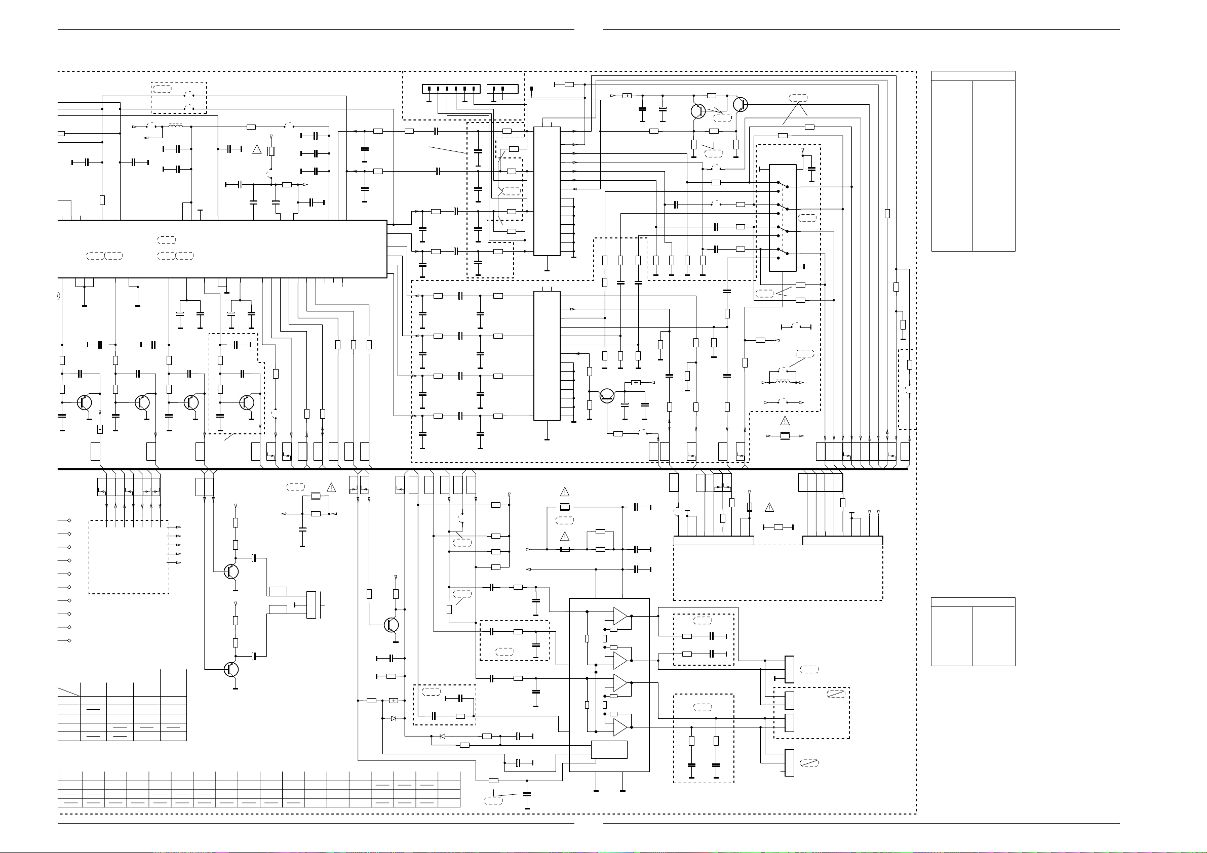
CUC 2030 N … 2080 N Platinenabbildungen und Schaltpläne / Layout of the PCBs and Circuit Diagrams
CR32311
CR32310
0
0
0
CUC 2030 N … 2080 N Platinenabbildungen und Schaltpläne / Layout of the PCBs and Circuit Diagrams
IND2
IND2
IND2
IND2
C43012
+
22u/50V
C43017
+
22u/50V
C43022
+
4,7u/100V
C43027
+
4,7u/100V
C43032
+
22u/50V
C43037
+
22u/50V
IND2
A
_BR43009
n.V.
_BR43005
+E
R32359
BR32359
+
C32346
10u/50V
32 3334
CAPL_A
D_CTR_OUT0
D_CTR_OUT1
BR32364
C32364
+
A
100u/10V
CC32348
82
A
1n
CC32365
A
CR32360
+
0,1u
+E2
0
CC32347
0,1u
10u/50V
AHVSUP
CAPL_M
I2S_DA_OUT
I2S_WS
I2S_CL
I2C_DA
I2C_CL
7 8 9 10111213
A
46
41 42
AVSUP
SC1_IN_L
ADR_DA
I2S_DA_IN1
CC43001
CC43006
SC1_OUT_R
SC1_OUT_L
SC1_IN_R
SC2_OUT_R
SC2_OUT_L
AUD_CL_OUT
CR43001
470
470p
A
CR43006
470
470p
A
SC2_IN_L
SC2_IN_R
CR43002
OPTIONLIST
CUC 2040 INDIA
30
31
39
40
27
28
BR32342
L32342
10u
CC32341
A
0,1u
A
CC32350
A
1n
1-SCART
STANDBYQ
2-SCART
DOLBY
AHVSS
DACM_L
35 36
DVSUP
AGNDC
A
56
ADR_SEL
DACM_SUB
CR32336
AVSS
0
37 38
SC_3_IN_L
DACM_R
+F
+F/DPL-MSP
CC32337
470p
IC32000
MSP3401
SC_3_IN_R
MSP3400C
VREF1
29
70
2340
CC32336
A
470p
415 16
18 19 20
NC
ADR_CL
I2S_DA_IN2
FR NIC
MSP3410
DACA_L
VREF2
DVSS
17
22 23 24 25 26 3412
CR32364
1,8
CC32345
A
47n
C32360
+
A
220u/10V
C32343
RESETQ
TESTENNCVREFTOP
50
4345
A
CC32314
A A
3,3n
3,3k
CC32311
10n
CT32310
BC858B
3,3k
560p
A
R41022
KH
AUDIO-L
CC32316
100
CR32314
CR32313
AA
3,3k
3,3k
560p
CC32313
10n
CT32312
BC858B
AA
CC32315
3,3n
A
AUDIO-R
+
C32327
4,7u/63V
A AA A
3,3k
CC32317
CR32315
10n
CT32315
BC858B
3,3k
CR32317
560p
CC32318
A
CC32328
A
AUDIO-L
0,1u
C32332
CC32319
3,3k
CR32318
3,3k
CR32319
560p
CC32322
A
OPTION
CUC 2040 INDIA
+
3,3n
CC32321
CT32318
10u/50V
10n
BC858B
CC32333
A
A
AUDIO
0,1u
SUB
CR32337
BR32337
RGB
U
220
KLEMM
U
CR32334
SCL
220
CR32335
SDA
CR32338
220
I2S
220
220
220
CR32341
CR32342
WS
CL
I2S
TER
I2S
A M
NUR FUER
INDIEN-GERAETE
C43002
+
0
4,7u/100V
C43007
+
4,7u/100V
CR43011
220
1n
CC43011
A
CR43016
220
1n
CC43016
A
CR43021
470
470p
CC43021
A
CR43026
470
470p
CC43026
A
CR43031
220
1n
CC43031
A
CR43036
220
1n
CC43036
IND2
CC43003
A
CC43008
A
CC43013
A
CC43018
A
CC43023
A
CC43028
A
CC43033
A
CC43038
AA
470p
470p
1n
CR43018
1n
CR43023
470p
CR43028
470p
CR43033
1n
CR43038
1n
IND1
32 1654321
CR43003
220
470
470
220
220
IND1
470
_CR43004
470
CR43008
470
MONO
CR43013
220
_CR43014
220
IND1
EURO-AV1
10 12
6
2
PERIDEC1
1
3
10 12
6
2
2 12 1
PERIDEC1
1
3
CR43267
M
75
8
20
16
15
11
7
19
21
DEC
18
17
14
13
9
5
4
A
A
8
20
16
15
EURO-AV2
11
7
19
21
VCR
18
17
14
13
9
5
4
A
M
CR43096
CR43095
M
+E/1
0
CR43048
CR43055
47
CC43046
CR43053
75
CR4305275CR43046
75
CT43095
BC848B
1k
CR43097
R43248
2,2
MM M
+
C43098
0
10n
CC43248
MM
CR43247
75
47
47
CR4306775CR4306675CR43062
CR43051
0,1u
0,1u
CC43047
CR43078
75
CR43047
R43099
2,2
+E/1
10n
CC43099
100u/10V
M
M
BR43097
FBAS
OUT_2
+
C43249
100u/10v
CT43244
BC858B
CC43057
0,1u
75
CR43063
M
M M
75
M
F
0,22u
C43079
CR43041
47
CR43079
IN_2
FBAS
CR43241
M
75
CR43042
6,8k
M
CR43040
AV2
EURO-
U
CR43246
680
CR43242
1k
1-SCART
BR43061
CR43056
BR43057
CC43058
CC43061
M
10k
0
0
1-SCART
0
1k
47
0,1u
0,1u
CR43072
M
CC43074
CR43074
75
CC43073
CR43073
AV_2
CHROMA
CT43246
BC848B
CR43243
M
CR43057
47
CR43058
47
CR43061
47
0,1u
47
CR43076
0,1u
47
RGB
U
1k
1-SCART
CR43077
47k
18k
+E
+E/3
+E/3
8
M
11
12
2
3
6
10
15
1
CR43182
0
CIC43050
MC14551
MC14551
9
+E/4
BR43098
L43098
22u
BR43052
R43098
6,8
1-SCART
CR43183
CR43184
BR43051
1-SCART
CR43181
+E/4
16
10n
M1
13
4
2-SCART
5
14
7
M1
0
0
+E/3
+E/4
+E/1
IC32000
PIN V
1 0
2 2,2
3 0
4 0
5 0
6 5,0
10k
M
CR43045
BUS
SAT
10k
7 5,0
8 4,8
9 2,5
10 2,5
11 2,5
12 1,5
13 1,1
14 1,1
15 1,1
16 5,0
17 0
18 1,5
19 0
20 5,0
21 1,5
22 1,5
23 0
24 0
25 0
26 0
0
CC43055
CR43054
CR43044
0
15k
MM1
CR43043
BR43045
RGB
DATA
U
AV_1
CHROMA
FBAS
OUT_1
IN_1
FBAS
MEGA
LOGIC
AV1
EURO-
U
PIN V
27 3,6
28 3,6
29 0
30 3,6
31 3,6
32 5,4
33 7,0
34 6,0
35 0
36 3,6
37 3,6
38 3,6
39 3,6
40 3,6
41 3,6
42 3,6
43 2,5
44 3,6
45 0
46 4,9
47 1,4
48 1,4
49 1,8
50 0
51 2,3
52 2,0
BY
PV
H
STAND
SYNCVSYNC
U
U
ASIS6
ASIS7
ASIS8
ASIS9
ASIS10
ASIS11
ASIS13
ASIS14
ASIS15
ASIS16
*
012
012
012
011
070
L46021
6,8u/2%
CUC
T1,25A
1000u
2,7/4W
CC46022
120p/5%
NETZ-CHASSIS
MAINS CHASSIS
CHASSIS SECTEUR
CHASSIS DI RETE
CHASIS RED
SEITE / PAGE 15
T1,6A T1,6A T1,6A
2,7/6,5W 2,7/6,5W 2,7/6,5W
2000u 2000u 2000u
CR46022
8,2k
WISCH
CC46023
0,1u
33n27k
OFF
1
WISCH
POWER
U
U
204020312030
T1,6A
CC46024
CC46026 CR46026
2050
2051
2052
2059
T2,5A
CR46024
6,8k33n
+M
+F
+H
+E
+45V
KH
AUDI-R
CC46027
0,1u
KH
AUDI-L
CT41022
BC808-40
CT41030
BC808-40
CC80001
56p
33p
+E/2
CR41023
CR41022
+E/2
CR41033
CR41032
100
100
C41022
100u/25V
A
100
100
C41032
100u/25V
A
CR80001
33
0
n.V.
_R41011
4,7
L
R
CC80002
CR41011
+
C41011
100u/25V
A
ST-H
3
A
2
1
CC81050
CC81055
CC81059
15p
33p 33p
4,7
39p
39p
ZUR KH-BUCHSE
CR81050
CR81055
CR81059
2,2k
2,2k
TO HEADPHONE SOCKET
+E/2
+
KH
KH
+
Q80001
18MHz
6MHz
BY
WISCH
STAND
U
U
+E
CR40058
A LA TOMA DE AURICUL.
ALLA PRESA CUFFIA
VERS PRISE CASQUE
SEITE / PAGE 14, 39, 46, 59
A
A
CR40062
10k
R81051
R81052
R81053
3,3k
3,3k
10k
CT40059
BC848B
_CC40059
CR40060
CR81061
CR81062
CR81063
1,5k1002,7k
CR40059
XX
2,2k
R40066
10k
D40066
1N4148
STAND
U
+E
A
CR81066
CR81067
CR81068
BY-
1k
KH
AUDI-RKHAUDI-L
n.V.
_CC40052
0,1u
D81051
D81052
D81053
1N4148560
A
D40064
1N4148
IC82005
X24C04
X24C08
X24C09
AUDIO-L
AUDIO-L
_BR40042
MONO
MONO
0
_CR40042
_CC40056
0,1u
_CR40056
CR40061
1k
MONO
10k
AUDIO-R
CR40064
CR40051
2,2k
CR40031
2,2k
CR40021
2,2k
CR40041
2,2k
CC40022
0,1u
_CC40032
0,1u
CC40042
0,1u
100
CR40063
10k
n.V.
n.V.
+E
+M1
CR40026
1k
_CR40036
1k
CR40046
1k
C40061
+
100u/25V
C40062
+
1u/100V
+M
+
C40063
CC40026
A
_CC40036
A
CC40046
A
A
A
1u/100V
A
3,3n
3,3n
3,3n
_R40014
8,2
n.V.
SI40012
*
4
5
12
11
7
6
10
R40011
*
R40012
*
Vref
C40014
F
C40011
C40012
13
A
0,1u
F
0,1u
+
*
A M
A
A
1
2
15
14
3
+
-
IC40000
TDA7297
+
-
+
-
+
-
STANDBY
MUTE
89
A
SUB
AUDIO
BR40070
3
2
1
DOLBY-SURROUND-PL.29504-104.75
DOLBY SURROUND BOARD
C. I. DOLBY SURROUND
PIASTRA DOLBY SURROUND
PLACA DOLBY SURROUND
INDIEN:
n.V.
_CR40028
4,7
_CR40038
4,7
n.V.
4,7
_CR40049
22n
_CC40049
A
SCL
SDA
ST-NF1
_CC40028
22n
_CC40038
22n
_CR40048
_CC40048
WISCH
STAND
U
U
CR40070
654
4,7
22n
A
BY-
CR40071
0
7
A
A
AM
0
SEITE / PAGE 43
CL
+G
0
*
SI40070
CR40072
9
8
MSP
I2S
I2S
TER
I2SWSI2S
D_IN
RESET
2,2k
+F/DPL-MSP
+E
A
CR32304
AL CHASSIS SENAL B
AL CHASSIS SEGNALE B
VERS CHASSIS SIGNAL B
TO SIGNAL CHASSIS B
654
321
ZUM SIGNAL-CHASSIS B
987
ST-NF2
-104.77
29504-104.78SUB-WOOFER-PL.
IC40000
PIN V
1 7,3
2 7,3
3 14,6
4 1,5
5 0
ST-LSL
1
ST-H
2
MONO
3
A
2
1
2
1
ST-LSR
1
2
3
ST-LSL1
ST-LSR1
MONO
MONO
6 5,0
7 5,5
8 0
PIN V
9 0
10 0
11 0
12 1,5
13 14,6
14 7,3
15 7,3
GRUNDIG Service
21
GRUNDIG Service
22
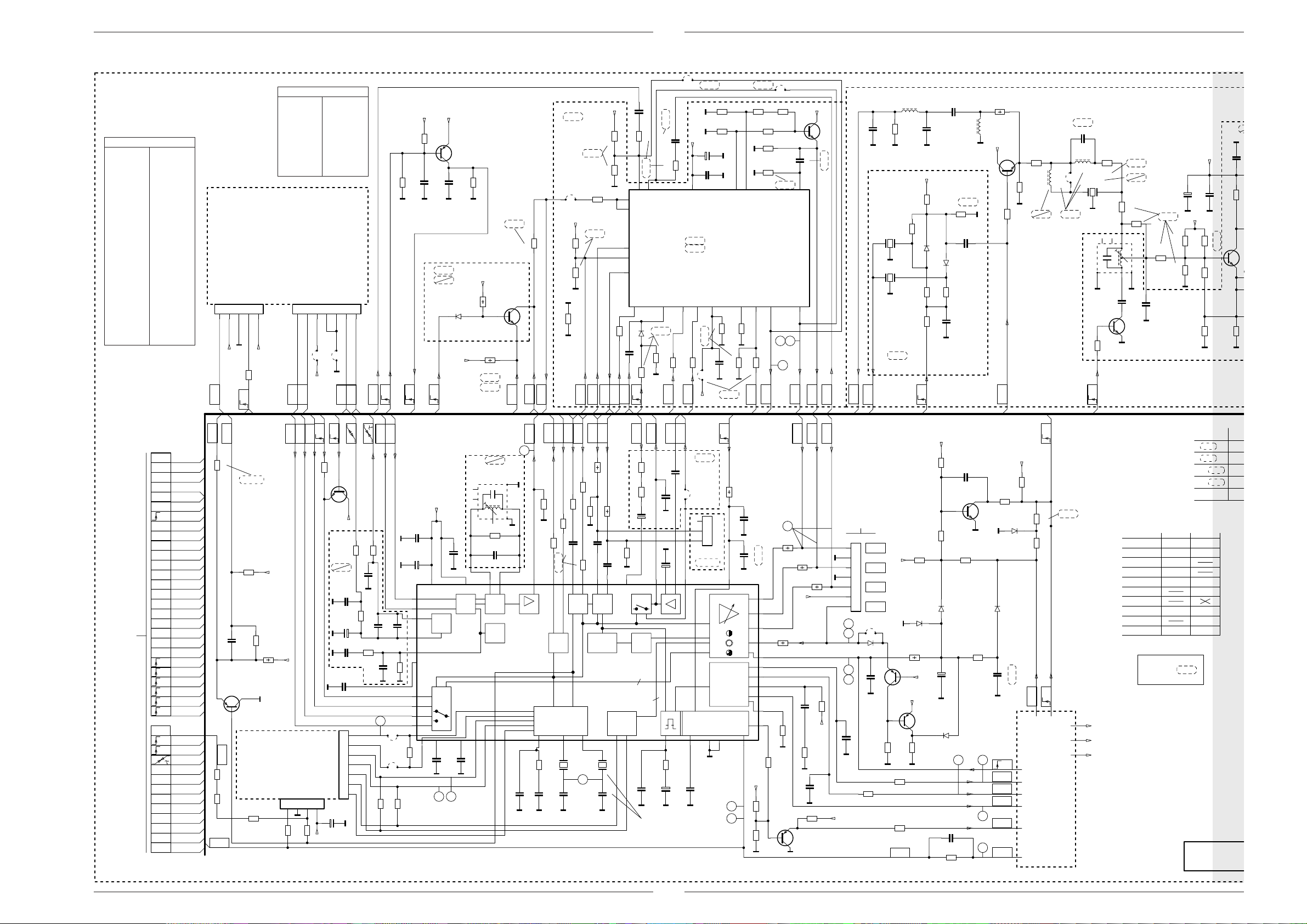
Platinenabbildungen und Schaltpläne / Layout of the PCBs and Circuit Diagrams CUC 2030 N… 2080 N
C
B
C
100n
6
6
A
O
A
I
A
Signal-Chassis B / Signal Chassis B
Platinenabbildungen und Schaltpläne / Layout of the PCBs and Circuit Diagrams CUC 2030 N … 2080 N
SIGNAL-CHASSIS B
CHASSIS SIGNAL B
CHASSIS SEGNALE B
CHASIS SENAL B
IC34015
PIN V
1 1,3
2 3,8
3 3,8
4 3,8
5 3,0
6 3,4
7 5,0
8 5,0
9 6,8
10 0
11 4,0
12 8,0
13 3,8
14 0
15 3,4
16 0
17 3,8
18 4,8
19 3,3
20 3,0
21 3,0
22 3,5
23 3,6
24 3,6
25 3,6
26 0
27 3,0
28 3,0
PIN V
29 2,4
30 2,4
31 2,4
32 2,4
33 0
34 2,5
35 2,5
36 5,0
37 8,0
38 3,2
39 5,0
40 2,0
41 0,7
42 3,2
43 4,0
44 0
45 0,5
46 2,5
47 2,5
48 4,6
49 4,6
50 2,3
51 3,8
52 3,8
53 4,0
54 4,0
55 3,0
56 3,8
PIN V
1 2,8
2 4,9
3 3,2
4 4,8
5 2,8
6 3,8
7 0
8 3,8
9 7,7
10 2,8
PIP-BAUSTEIN 29504-106.51
PIP MODULE
MODULE PIP
MODULO PIP
MODULO PIP
SEITE / PAGE 54
ST-PIP1
54321
M
_+F
_+33V
0
CR43257
PIP
FBAS
DATA
U
-106.52
7
V
H
SYNC
SYNC
IC43200
PIN V
11 2,8
12 3,1
13 3,1
14 1,8
15 1,8
16 3,4
17 1,8
18 3,1
19 0
20 2,6
ST-PIP2
65432
BR43258
BR43257
M
+E
SDA
SCL
1-SCART
BR43245
CR43250
F
C43266
CR43266
220
CR43284
SCL1
M
CR43249
M
+E/3
C43282
+
220u/10V
CC43283
47n
IC43280
TEA6415
A
B
TEA6425
A
220
BR43281
+E/3
2,2k
2,2k
M
M
20 19
CR43281
CC43281
CR43278
100k
100k
M
AV_2
CHROMA
A
FBAS
+E/3
CR43262
CR43263
0
0,1u
CC43261
100k
100k
M
13
12
CR43261
0
47
1-SCART
56
1-SCART
0,1u
0,22u
0
47
A
10
8
18
47
CR43271
CC43284
FBAS
IN_2
FBAS
OUT_2
FBAS
CINCH
BUS CONTROLLED VIDEO MATRIX
31516
A
1N4148
D43284
0,22u
1M
CR43265
CR43283
100k
A
CR43285
KLEMM
U
SDA1
+F
+45V
470k
M
100p
1-SCART
MONO
RGB
U
CC43286
M
D43292
1N4148
CT43289
BC858B
0,1u
+E
CR43290
M
MP157
47k
+E
R43292
R43291
3,9k
2-SCART
MONO
3,9k
1-SCART
CT43290
BC848B
FBAS
CINCH-
CR43274
FBAS
CR43289
100k
CR43288
_CC43289
M
1
IDEN1
AV_1
CHROMA
IDENT
U
U
0
FBAS
OUT_1
2-SCART
BR43278
+E/3
CR43276
CR43277
CR43279
M
0
M
1-SCART
14
CR43256
0
CR43254
CR43259
M
CR43258
M
17
2,2k
1k
0
BR43255
CR43255
2,2k
CT43255
BC848B
B
CC43259
119
+E/3
0,22u
CC32026
A
47p
M
_F32152
5,5MHz
CR32026
M
L32026
10u
10k
_CR32153
M
_F32153
M
6,5MHzOIRT
A-ZF2
AUDIO
ZF-MONO
6,0MHzFR
MONO
7421
0
100k
CR43282
M
M
10n
CR43286
M
M
B
0
CR43287
FBAS
OUT_2
0
CHROMA
41 42
43
VIDEO
FBAS
PIP
FBAS
IN_1
F
C32024
M
+E
_CR32151
0
_CD32152
_CR32156
_CR32158
NORM3
U
1,5n/2,5%
2,2n/2,5%
2,2k
BA592
_CD32153
2,2k
_CR32157
0
_CC32154
C32023
680
_CR32152
_CC32152
BA592
2,2k
10n
M
2,2k
INL
47p
L32023
M
CT32105
BC817-25
M
1u
R32023
220
+E
CR32103
CR32102
M
470
CR32108
220
270
INL
L46022
2,7u
_CC32107
BR46022
INL
n.V.
22p
L32109
10u
15u
CR32110
47
10
F32109
TPS6,0MB
TPS5,5MB
M
6
F32101
8141-112-405
71
F
M
4,7k
CR32119
BB
NORM1
U
CR32109
34
8
CC32118
M
CR32105
ENTFAELLT BEI
NOT FITTED ON
N’EXISTE PAS POUR
MANCA NELLA VERS.
NO EXISTE EN
INL
INL
0
22
0
CR32101
2
M
33p
22p
CC32110
M
CT32119
BC848B
INL
8,2k
680
CR32104
560
1K
CR32107
SIGNAL MODULE
MODULE SIGNAL
MOD. SEGNALE
MOD. SENAL
+
C32108
CC32109
100u/10V
M
+E
2,7k
_CR32106
820
CR32111
M
CR32114
SIGNAL-B
+E
10n
M
XX
n.V.
0
470
M
M
_CC32111
CR32112
CR32113
M
560
470
TO SIGNAL CHASSIS A
ZUM SIGNAL-CHASSIS A
SEITE / PAGE 19
23
FBAS
CINCH
FBAS
CINCH-
FBAS
TEXT
SSC
V
SYNC
H
SYNC
U
RGB
FBAS
CHROMA
AV_1
CHROMA
AV_2
FBAS
IN_1
FBAS
IN_2
FBAS
OUT_1
FBAS
OUT_2
R
G
B
R
OSD
G
OSD
B
OSD
A-ZF2
AL CHASSIS SENAL A
AL CHASSIS SEGNALE A
VERS CHASSIS SIGNAL A
U
DATA
OSD
U
DATA
U
TER
U
NORM1
U
NORM2
U
NORM3
+M/FM
U
IDENT
U
KLEMM
U
SDA
SCL
SDA1
SCL1
ZF.
ZF_
AUDIO
1
AUDIO
EURO-AV
AUDIO-L
FBAS
TEXT
VIDEO
0
_CR34034
KAMMF.
CR34033
**
**
CR34032
CC34032
CT34031
BC858B
ERSATZPL.29305-119.42/.45/.35
ALTERNATIVE BOARD
PLAQUE DE RECHANGE
PIASTRA DI RICAMBIO
PLACA ALTERNATIVA
+M/FM
**
CR34046
**
CR34047
CR34044
**
SSC
+E
**
R34031
+E
**
M
SEITE / PAGE 42
TO FEATURE BOARD
BILD_FEATURES 1
CR34041
GBR
M
**
3412
**
+E
CR34043
DATA
U
CR34076
SEITE / PAGE 42
AFC
OSD
DATA
U
U
330
CT34075
BC848B
+E
CR33019
SIG.-B
CC33020
M
10n
CR33020
C33019
M
+
**
CC33014
CR33014
M
0,1u
CC33017
M
0,1u
7
6
5
4
ST-PIP3
3
BILD_FEATURES 2
TO FEATURE BOARD
2
1
C34041
M
+
**
U
22k
CR33018
CC33018
M
0
CC33022
390
ZF.
**
1n
CC33016
M
52
BR34038
BR34039
CR34039
ZF_
**
CC33021
1n
**
**
**
CR34040
M
M
470u/10V
CR33016
M
CR34038
**
CC34022
10n
C34021
48
49
54
**
53
5
9
**
26
23
24
25
27
+
**
8140-535-**
4
CC34027
M
**
10n
16
CC34039
M
36
37
** MULTI/FR/16:9
w.w TDA8375/FR
**
+E
AGC
RGB
39 38
CC34037
M
5354
BB
SDA
SCL
FBAS
FBAS
CINCH
VIDEO
CHROMA
44
SIG.-B
F33025
M
17
8
2
M
CR33025
**
CC33025
**
43 215655
OSC.ZF
AFC
IC34015
CC34041
100
CR34061
CR34057
M
CR34059
100
CC34061
CR34058
1-SCART
876
VIDEO
2
I C
**
PAL/NTSC-DECODER MATRIX H-DRIVE
36 35 3433 32 31302928
82k
Q34043
CR34042
3,3n
0,1u
CC34043
CC34042
MMM
R34063
0
CR34062
0
*
CR34064
M
100
0,1u
CC34064
47
R34062
17
1312 11 10
FBAS Y/C
DELAY
PEAKING
Q34044
4,43MHz
51
18p
CC34044
*
R34066
*
CC34067
3,58MHz
18p/2%
M
*
GRUNDIG Service
AUDIO
EURO-AV
_CR34072
_CR34071
+
_C34071
*
CR34067
*
M
AUDIO
BLACK
STRE.
3
CC52246
NUR BEI NTSC 3,58MHz
ONLY WITH
SEUL. POUR
SOLO CON
SOLO CON
1
AUDIO
ZF-MONO
_CC34069
2,7n
_CC34072
M
MONO
AUDIO-L
1n
AUDIO
0
56k
22u/50V
M
+
C34063
47u/16V
15
3
18k
CR52247
+
1n
C52247
CC52248
1u/100V
M M
M
24
MONO
_BR34073
3
2
1
_ST-KA
KAMMF.
10n
SCUTZ
U
R57007
RGB-MATRIX
V-DRIVE
4443 42 41
14
M
50
50A
100
CC57007
_CC57003
50
100p
M
1n
M
+E
CR52251
CR52253
n.v.
21
20
19
18
22
46
47
51
45
52
40
CR52256
8,2k
12k
M
R34059
R34056
470
CR52252
330
R
45
**
R34058
+E
39k
M
CT52253
BC858B
M
OSDGOSDBOSD
**
R34057
**
F
C52254
0,1u/5%
CR52255
+E/3
0
ASIS12
CR52250
M
1n
CC52216
M
CR52254
1k
7
M
6
5
4
M
3
2
1
46A
46
47
47A
***
CC52217
+E
A LA PLACA-ZOCALO TRC
ALLA PIASTRA CINESC.
VERS C.I. tube cathod
TO CART BASE
ZUR BILDROHRPLATTE
SEITE / PAGE 35, 37
ST-RGB
R
G
B
SW
BR57021
**
D57021
**
1n
CC57021
M
100p
M
CR57022
CR52216
100
+E
M
**
M
CR52217
100
CR52263
330
SSC
CR57012
D57012
1N4148
R57017
10k
CT57021
BC858B
+F
CR57021
***
+F
CT57020
BC858B
680
M
+E
CR57004
CR57008
D57011
+
C57016
M
D57023
1N4148
CC52266
CR52266
1M
CT57005
BC848B
150k
1N4148
33p
15k
CC57004
33n
R57011
***
***
R57016
22k
R340
SCUTZ
U
+E
100k
39k
D57014
1N4148
CR57002
CR57006
CR57001
470k
1M
72cmPhi
1M
CR57003
M
M
OPTIONSLIST CUC2040 INDIA
DEFAULT
CR43003/08
CR43013/18
CC43003/08
CC43013/18
CR81056/57
470
220
470p
220p
4,7k
CR81035/31
SUBWOOFER
180/330 0
1N4148
D57013
47n
n.v.
CC57016
M
SB
2223
U
SCHUTZ
VG
SCUTZ
U
NETZ-CHASSIS
MAINS CHASSIS
CHASSIS SECTEUR
CHASSIS DI RETE
CHASIS RED
SEITE / PAGE 15
+H
+F
+E
VA
VB
OWA
8
HDR
R81015
CR81004
CR81001
270/1k
_R.....=
SIGNAL-CHASSIS
CHASSIS SIGNAL
CHASSIS SEGNALE
CHASIS SENAL
CUC 2030
CUC 2031
CUC 2040
CUC 2050
*
R340
PIP
SAT
CUC2040STANDART
INDIA
1-SCART
2-SCART
INDIA
100
470
2-SCART
470
2-SCART
470
100
0
0
2,7k
1k
270
330
n.v.
CUC 2051
21
H
SYNC
CUC 2058
CUC 2059
CUC 2080
AENDERUNGEN VORBEH
SUBJECT TO ALTERNATE
SOURS RESERVE DE MOD
CON RISERVA DI MODIFIC
RESERV. EL DEREC. DE M
GRUNDIG Service
 Loading...