

Page 1
TV Service Manual
2. Ergänzung / Supplement 2
CUC 2003 H
T 55 – 830 Multi/COM
GCL5272 / VNM
Zusätzlich erforderliche Unterlagen für den Komplettservice
Additionally required Service Documents for the Complete Service
Service
Manual
CUC 2003
CUC 2003 H
Materialnr./Part No.
720100240000
Materialnummer/Part Number 720100240200
Änderungen vorbehalten/Subject to alteration • Printed in Germany HD
E-BS-SA 12 0301
http://www.grundig.com
Ergänzung
Supplement
1
Materialnr./Part No.
720100240100
Service
Manual
Sicherheit
Safety
Materialnr./Part No.
720108000000
Service
Training
CUC 2000
Materialnr./Part No.
Ķ 720103503500
ķ 720103503600
Grundig Service
Hotline Deutschland...
Technik:
TV
TV
SAT
VCR/LiveCam
HiFi/Audio
Car Audio
Telekommunikation
Planatron
Ersatzteil-Verkauf: ...Mo.-Fr. 8.00-19.00 Uhr
(8.00-22.00 Uhr)
...Mo.-Fr. 8.00-18.00 Uhr
Fax:
Telefon:
Fax:
0180/52318-41
0180/52318-49
0180/52318-48
0180/52318-42
0180/52318-43
0180/52318-44
0180/52318-45
0180/52318-51
0180/52318-99
0180/52318-40
0180/52318-50
Page 2

Allgemeiner Teil / General Section CUC 2003 H
Es gelten die Vorschriften und Sicherheitshinweise
gemäß dem Service Manual "Sicherheit", Materialnummer 720108000000, sowie zusätzlich die eventuell abweichenden, landesspezifischen Vorschriften!
Für die auf der Titelseite aufgeführten Chassis gilt das Service Manual
CUC 2003 / 2003 H.
Diese Ergänzung dokumentiert die Unterschiede bzw. zusätzlichen
Bestückungen der Geräte.
Grundlage für den Service sind:
–Service Manual CUC 2003 / 2003 H (Materialnummer 720100240000)
– 1. Ergänzung CUC 2003 / 2003 H (Materialnummer 720100240100)
–Service Manual "Sicherheit" (Materialnummer 720108000000)
Inhaltsverzeichnis
The regulations and safety instructions shall be
valid as provided by the "Safety" Service Manual,
part number 720108000000, as well as the
respective national deviations.
The Service Manual CUC 2003 / 2003 H applies to the chassis
specified on the front page.
This Manual describes the differences and the additionally fitted
components of the TV receivers.
Basic instructions for servicing are given in the:
–Service Manual CUC 2003 / 2003 H (Part number 720100240000)
–1st Supplement CUC 2003 / 2003 H (Part number 720100240100)
–Service Manual “Safety” (Part number 720108000000)
Table of Contents
Seite
Hinweise ......................................................................................... 2
Modulauflistung – Service Manual mit Ergänzungen ...................... 3
Modulübersicht ................................................................................ 3
Technische Daten ........................................................................... 4
Beschreibung (COM Modul) nur in Englisch ................................... 5
Kabelverlegung nach VDE ............................................................ 12
Netzteil .......................................................................................... 13
LS-Buchsenplatte .......................................................................... 13
COM Modul ................................................................................... 14
•Blockschaltplan ........................................................................ 14
•Mikrocomputer ......................................................................... 15
•Mega Text ................................................................................ 16
•Modulator FSK ......................................................................... 17
•Diplexer-Schaltung ................................................................... 18
•Stromversorgung ..................................................................... 19
Leiterplatte Multi/Com ................................................................... 20
Ersatzteillisten ............................................................................... 21
Hinweise
Vor dem Öffnen des Gehäuses zuerst den Netzstecker ziehen!
Leitungsverlegung
Bevor Sie die Leitungen und insbesondere die Masseleitungen lösen,
muss die Leitungsverlegung zu den einzelnen Baugruppen wie z.B.
Chassis, Netzschalterplatte, Bedieneinheit, Bildrohrplatte, Ablenkeinheit, Lautsprecher usw. beachtet werden.
Nach erfolgter Reparatur ist es notwendig, die Leitungsführung wieder
in den werkseitigen Zustand zu versetzen um eventuell spätere
Ausfälle oder Störungen zu vermeiden.
Netzkabel
Diese Geräte dürfen nur mit dem Original-Netzanschlusskabel mit
integrierter Entstördrossel betrieben werden. Dieses Netzkabel verhindert Störungen aus dem Netz und ist Bestandteil der Geräte-
zulassung. Im Ersatzfall bestellen Sie bitte ausschließlich das Netzkabel laut Ersatzteilliste.
Page
Notes ............................................................................................... 2
List of Modules – Service Manual with Supplements ...................... 3
Module List ...................................................................................... 3
Technical Data ................................................................................ 4
Description (COM Module) ............................................................. 5
Wiring according to VDE ............................................................... 12
Mains Section ............................................................................... 13
LS Socket Board ........................................................................... 13
COM Module ................................................................................. 14
•Block Circuit Diagram .............................................................. 14
•Microcomputer ......................................................................... 15
•Mega Text ................................................................................ 16
•Modulator FSK ......................................................................... 17
•Diplexer circuit ......................................................................... 18
•Power circuit ............................................................................ 19
Multi/Com PCB ............................................................................. 20
Spare Parts Lists ........................................................................... 21
Notes
Before opening the cabinet disconnect the mains plug!
Wiring
Before disconnecting any leads and especially the earth connecting
leads observe the way they are routed to the individual assemblies like
the chassis, mains switch panel, keyboard control panel, picture tube
panel, deflection unit, loudspeaker and so on.
On completion of the repairs the leads must be laid out as originally
fitted at the factory to avoid later failures or disturbances.
Mains cable
The TV receiver must only be operated with an original mains connecting
cable with an interference suppressor choke integrated in the mains
plug.This mains cable prevents interference from the mains supply and
is part of the product approval. For replacement please order exclusively
the mains connecting cable specified in the spare parts list.
2 GRUNDIG Service
Page 3
CUC 2003 H Allgemeiner Teil / General Section
Modulauflistung – Service Manual mit Ergänzungen
List of Modules – Service Manual with Supplements
Modul
Module
Ton - Filterplatte
Sound Filter Panel
Bildrohrplatte
CRT Panel
Netzteil (5V / 0,4A)
Mains Section (5V / 0,4A)
LS-Buchsenplatte
LS Socket Board
COM - Modul
COM - Module
Materialnummer
Part Number
293051290100
293050221900
293040508400
293051606600
295041082400
Service Manual
CUC 2003 / 2003 H
720100240000 720100240200
Seite / Page 3-30 –
Seite / Page 3-25 –
– Seite / Page 13
– Seite / Page 13
– Seite / Page 14
2. Ergänzung
Supplement 2
CUC 2003 H
Modulübersicht / Module List
Materialnummer
Bestell-Nr.
Order No.
Chassis-Nr.
Chassis No.
Tuner
Ton - Filterplatte
Sound Filter Panel
Bildrohrplatte
CRT Panel
Netzteil (5V / 0,4A)
Mains Section (5V / 0,4A)
LS-Buchsenplatte
LS Socket Board
Part Number
295043010100
29305 129 0100
293050221900
293040508400
293051606600
T 55 - 830 Multi/COM
CUC 2003 H
VNM
GCL5272
297040064000
297040065900
297040066000
L
•
•
•
•
Fernbedienung TP 800 H
Remote Control TP 800 H
COM - Modul
COM - Module
GRUNDIG Service 3
296420611900
295041082400
•
•
Page 4
Allgemeiner Teil / General Section CUC 2003 H
Technische Daten / Technical Data
T 55 – 830 Multi/COM
CUC 2003 H
VNM
Bildröhre / Picture Tube
Sichtbares Bild
Visible picture
51cm
Bildschirmdiagonale
Screen diagonale
Ablenkwinkel
Deflection angle
Bildwechselfrequenz
Vertical frequency
Elektronik / Electronic
Programmspeicherplätze
Programme positions
Blue stretch, ja / yes
AV-Auswertung
AV evaluation
Tuner
TV-Normen
TV-Standards
Videotext
Teletext
Musikleistung
Music power
Anschlüsse Front / Connections Front
Kopfhörer
Headphones
Anschlüsse Rückwand / Connections Rear Panel
auf jeden Programmplatz programmierbar
programmable for every programme position
PLL-Frequenz synthesizer tuning UHF / VHF
PLL-frequency synthesizer tuning UHF / VHF
schaltet eingebauten Lautsprecher ab /
55cm (21"), FST
Black Line D, small neck
90°
50Hz
99 + 1 AV
PAL / SECAM / NTSC 4,43MHz,
B/G, L/L', I DK/K'
8 Seiten TOP/FLOF-text,
8 pages TOP/FLOF-text
Mono 8W
Mono 3,5mm Klinke,
Mono 3.5mm jack,
switch off inserted Loudspeaker
FBAS-Ein-/Ausgang, RGB-Eingang
Euro AV 1(schwarz/black)
Netzteil / Mains Stage
Netzspannung (Regelber.)
Mains voltage (variable)
Netzfrequenz
Mains frequency
Leistungsaufnahme
Power consumption
Standby ca. 12W
S-Video Eingang
CCVS in-/output, RGB input,
S-Video input
230V ±15%
50 / 60Hz
ca. 65W
4 GRUNDIG Service
Page 5
GRUNDIG Service 5
iTV-Card / COM-Card
Page 1 of 15
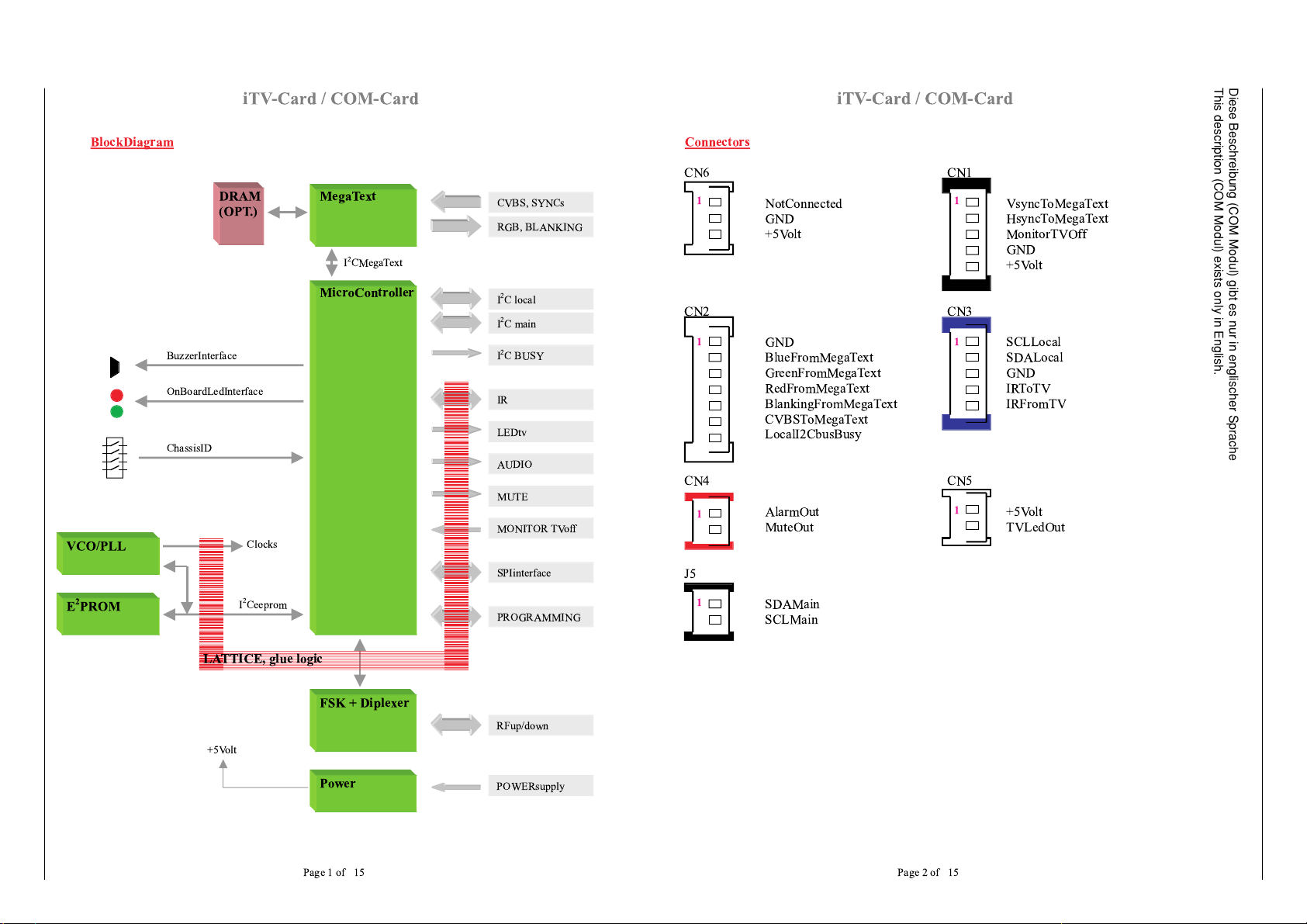
BlockDiagram
CVBS, SYNCs
RGB, BLANKING
I
2
C local
I
2
C main
POWERsupply
IR
LEDtv
AUDIO
MUTE
I
2
C BUSY
SPIinterface
RFup/down
PROGRAMMING
MegaText
MicroController
Power
FSK + Diplexer
E
2
PROM
MONITOR TVoff
DRAM
(OPT.)
VCO/PLL
I
2
Ceeprom
I
2
CMegaText
Clocks
+5Volt
OnBoardLedInterface
BuzzerInterface
ChassisID
LATTICE, glue logic
iTV-Card / COM-Card
Page 2 of 15
Connectors
CN6 CN1
NotConnected VsyncToMegaText
GND HsyncToMegaText
+5Volt MonitorTVOff
GND
+5Volt
CN2 CN3
GND SCLLocal
BlueFromMegaText SDALocal
GreenFromMegaText GND
RedFromMegaText IRToTV
BlankingFromMegaText IRFromTV
CVBSToMegaText
LocalI2CbusBusy
CN4 CN5
AlarmOut +5Volt
MuteOut TVLedOut
J5
SDAMain
SCLMain
1
1
1
1
1
1
1
Diese Beschreibung (COM Modul) gibt es nur in englischer Sprache
This description (COM Modul) exists only in English.
CUC 2003 H Allgemeiner Teil / General Section
Page 6
6 GRUNDIG Service
iTV-Card / COM-Card
Page 3 of 15
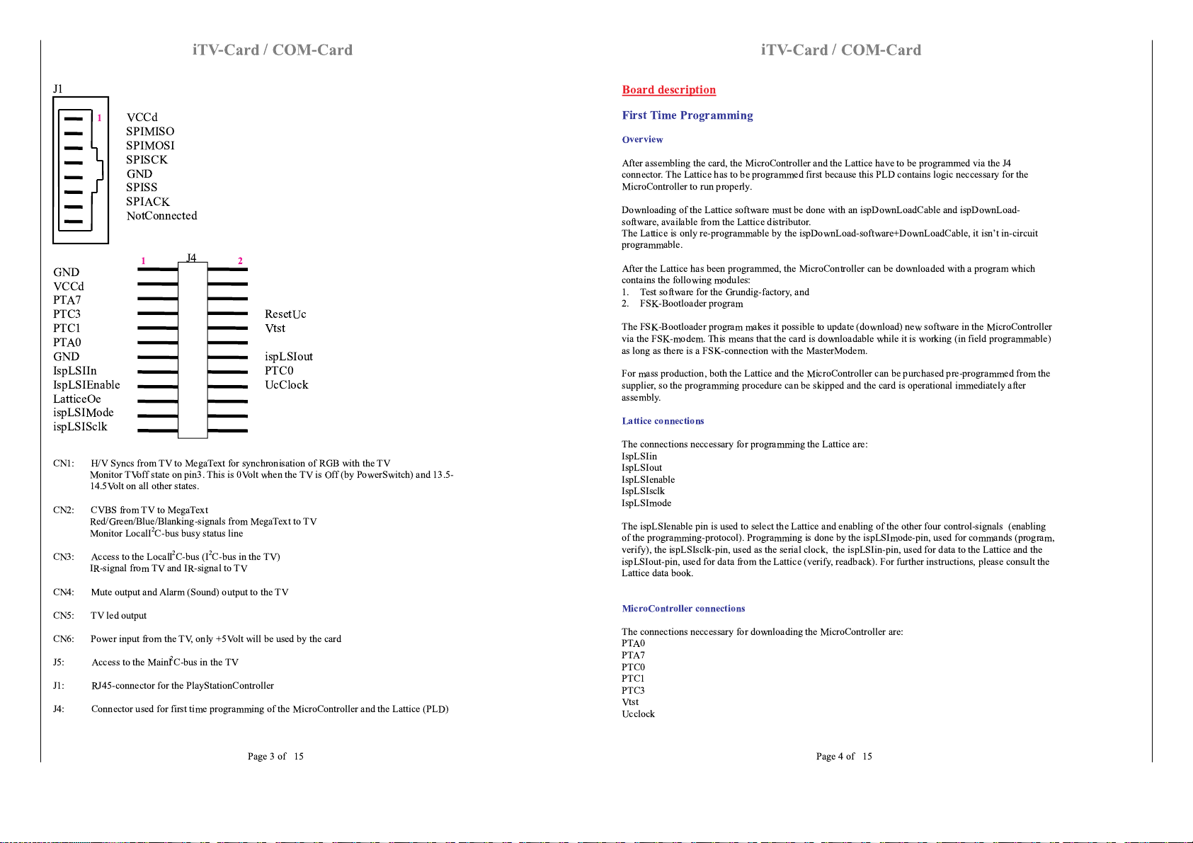
J1
VCCd
SPIMISO
SPIMOSI
SPISCK
GND
SPISS
SPIACK
NotConnected
J4
GND
VCCd
PTA7
PTC3 ResetUc
PTC1 Vtst
PTA0
GND ispLSIout
IspLSIIn PTC0
IspLSIEnable UcClock
LatticeOe
ispLSIMode
ispLSISclk
CN1: H/V Syncs from TV to MegaText for synchronisation of RGB with the TV
Monitor TVoff state on pin3. This is 0Volt when the TV is Off (by PowerSwitch) and 13.5-
14.5Volt on all other states.
CN2: CVBS from TV to MegaText
Red/Green/Blue/Blanking-signals from MegaText to TV
Monitor LocalI
2
C-bus busy status line
CN3: Access to the LocalI
2
C-bus (I
2
C-bus in the TV)
IR-signal from TV and IR-signal to TV
CN4: Mute output and Alarm (Sound) output to the TV
CN5: TV led output
CN6: Power input from the TV, only +5Volt will be used by the card
J5: Access to the MainI
2
C-bus in the TV
J1: RJ45-connector for the PlayStationController
J4: Connector used for first time programming of the MicroController and the Lattice (PLD)
1
12
iTV-Card / COM-Card
Page 4 of 15
Board description
First Time Programming
Overview
After assembling the card, the MicroController and the Lattice have to be programmed via the J4
connector. The Lattice has to be programmed first because this PLD contains logic neccessary for the
MicroController to run properly.
Downloading of the Lattice software must be done with an ispDownLoadCable and ispDownLoad-
software, available from the Lattice distributor.
The Lattice is only re-programmable by the ispDownLoad-software+DownLoadCable, it isnÕt in-circuit
programmable.
After the Lattice has been programmed, the MicroController can be downloaded with a program which
contains the following modules:
1. Test software for the Grundig-factory, and
2. FSK-Bootloader program
The FSK-Bootloader program makes it possible to update (download) new software in the MicroController
via the FSK-modem. This means that the card is downloadable while it is working (in field programmable)
as long as there is a FSK-connection with the MasterModem.
For mass production, both the Lattice and the MicroController can be purchased pre-programmed from the
supplier, so the programming procedure can be skipped and the card is operational immediately after
assembly.
Lattice connections
The connections neccessary for programming the Lattice are:
IspLSIin
IspLSIout
IspLSIenable
IspLSIsclk
IspLSImode
The ispLSIenable pin is used to select the Lattice and enabling of the other four control-signals (enabling
of the programming-protocol). Programming is done by the ispLSImode-pin, used for commands (program,
verify), the ispLSIsclk-pin, used as the serial clock, the ispLSIin-pin, used for data to the Lattice and the
ispLSIout-pin, used for data from the Lattice (verify, readback). For further instructions, please consult the
Lattice data book.
MicroController connections
The connections neccessary for downloading the MicroController are:
PTA0
PTA7
PTC0
PTC1
PTC3
Vtst
Ucclock
Allgemeiner Teil / General Section CUC 2003 H
Page 7
GRUNDIG Service 7
iTV-Card / COM-Card
Page 5 of 15
LatticeOE
ResetUc
Programming will be done by an 9600Baud serial protocol, where PTA0 is the bidirectional data in/out of
the MicroController, and PTA7, PTC0, PTC1, PTC3 are used to select this programming-mode. In this
mode the MicroController expects a 9.8304MHz clock, therefore we supply this clock to the card while
disabling the onboard MicroController-clock by the LatticeOE pin. The onboard clock is routed through the
Lattice with the possibility to TRI-state the output with the LatticeOE line. In normal operation, the
LatticeOE-pin wonÕt be used and the onboard clock is always driving the MicroController.
With the ResetUc it is possible to reset the MicroController if this is neccessary for the programming-
protocol.
iTV-Card / COM-Card
Page 6 of 15
Clock generation
Overview
The onboard clocks can be divided into three parts, the MegaText clock, the DownConverter clock and the
clocks for the MicroController + FSK transmission and receiving.
MegaTextClock
All the internal clocks used by the MegaText-chip (U1) are derived from one external XTAL of 20.48MHz
(X6), connected directly to the MegaText-chip.
From this XTAL, the MegaText will generate a synchronised internal-clock to the external supplied H and
V-sync(or CVBS), and uses this clock for the R/G/B and Blanking output-signals. This means that the
MegaText output is always synchronised to theTV.
DownConverterClock
The DownConverter (U7, MC13156DW) has one external clock-input (LocalOscillator-input) used to
down-convert the incoming signal to 10.7MHz. The XTAL (X4) used for the generation of this
LocalOscillator is a 3th overtone 63.3625MHz crystal with a load-capacitance of 32pF. The crystal-circuit
of X4, L14, L15, C62, C63, C64, R101, R102 and R149 makes sure that the crystal will run on the 3th-
harmonic.
MicroController + FSK-clocks
The clocks for the MicroController and the FSK-part have to be synchronised to make sure that the two
FSK-transmission frequencies are in phase, the MicroController is in phase with the FSK-transmission
frequencies and that the MicroController-clock is in phase with the extracted FSK-data. Therefore a
multiple VCO/PLL-chip (U12, FS6377) is used wich will use only one external XTAL (X7, 16MHz) to
produce four programmable output clocks.
The programming of the chip will be done by the MicroController via an I
2
C-bus interface. The four output
clocks are:
1. 32MHz, used for the MicroController,
2. 42.8MHz, used to extract the data from the received FSK-signal,
3. 16MHz and
4. 16.125MHz as FSK-transmission frequencies.
All these four clock-signals are routed directly into the PLD, the 16MHz and 16.125MHz for FSK-
generation, the 42.8MHz for FSK data extraction and the 32MHz to have the possibility to disable (TRI-
state) this clock (see
MicroController connections
section) and to switch the MicroController to the desired
clock source.
After PowerUp of the card the VCO/PLL-chip has all his registers in the reset-state, wich will mean that all
the outputs reflect the incoming clock, in this case 16MHz. At this point there isnÕt a 32MHz-clock for the
MicroController. Therefore the MicroController-clock will be switches after PowerUp into the PLD to
16MHz (the 16MHz-output of the VCO/PLL-chip). The MicroController will then initialize everything
including the VCO/PLL-chip. When this chip is programmed the MicroController will select the 32MHz-
clock source as his clock by clearing the uCClockSwitch-line wich will cause the PLD to switch to 32MHz
instead of 16MHz.
CUC 2003 H Allgemeiner Teil / General Section
Page 8
8 GRUNDIG Service
iTV-Card / COM-Card
Page 7 of 15
DownConverter
The receiving FSK-frequency is 74/74.125MHz. DownConverting this input with a 63.3625MHz clock will
produce two frequencies of 10.6375 and 10.7625. This means that we have a centre frequency of 10.7MHz
plus or minus 62.5kHz. This makes it possible to use a common, low-cost ceramic filter of 10.7MHz.
After the downconversion, the signal will pass two 10.7MHz filters before entering the 74HCU04 (U8).
Using all 6 stages of the 74HCU04 will produce a nice digital TTL-signal representing the FSK-input. A
hysteresis-circuit at the first two stages (R143, 470K) makes sure that noise at the input will be suppressed.
The digital-data with the 10.7MHz centre-frequency will then be routed to the PLD to extract the FSK-
signal.
iTV-Card / COM-Card
Page 8 of 15
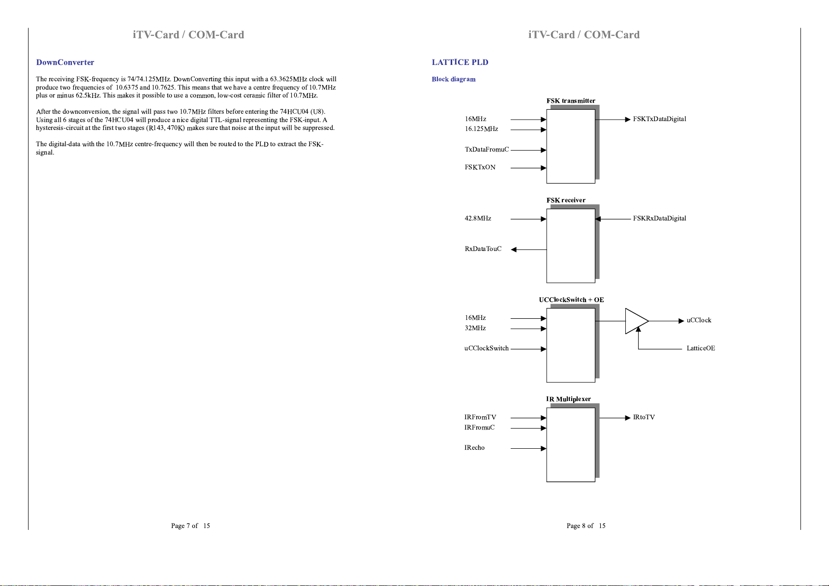
LATTICE PLD
Block diagram
16MHz
16.125MHz
FSK transmitter
TxDataFromuC
FSKTxON
FSKTxDataDigital
42.8MHz
FSK receiver
RxDataTouC
FSKRxDataDigital
16MHz
32MHz
UCClockSwitch + OE
uCClockSwitch
uCClock
LatticeOE
IR Multiplexer
IRtoTV
IRFromTV
IRFromuC
IRecho
Allgemeiner Teil / General Section CUC 2003 H
Page 9

GRUNDIG Service 9
iTV-Card / COM-Card
Page 9 of 15
Switch uControllerClock + TriState
See the
microcontroller connections
in the
first time programming
section for a description of the
LatticeOE-pin.
After PowerUp, the 16MHz input is connected to the MicroControllerClock output. After initialising of the
VCO/PLL-chip, the MicroController switches the uCClockSwitch-line to select the 32MHz (see
MicroController + FSK-clocks
in the
clock generation
section).
IR
The
IR-interface
in the
microcontroller
section describes the function of the IR multiplexer.
FSK Transmitter
The two frequencies are 16 and 16.125Mhz, both coming from the VCO/PLL-chip and therefore in phase.
Depending on the transmitted-data from the MicroControllerUART the FSK digital output of the PLD
(Pin31) will be 16 or 16.125MHz. The PLD-logic makes sure that switching from one frequency to the
other will be done when the two frequencies are in phase.
It is important that the data from the Microcontroller is also synchronised to the two FSK frequencies to
avoid loss of data while waiting for the Òswitch momentÓ of these two frequencies.
The digital FSK-data will then be bufferred, filtered and fed into the diplexer.
FSK Receiver
The FSK-input comes from the 74HCU04 and will be a digital FSK-signal with a centre frequency of
10.7MHz (see
DownConverter
section). The extraction of the data from this FSK-signal will be done in the
PLD and uses an 42.8MHz clock (4 times 10.7MHz).
The extracted data is synchronised to the MicroController-clock because that clock comes from the same
source as the 42.8MHz (the VCO/PLL-chip). This synchronisation makes sure that there is no data-loss in
the MicroControllerUART receiver.
The data from the PLD is routed directly to the MicroController UART input.
iTV-Card / COM-Card
Page 10 of 15
MicroController
Overview
The following list shows all the functions of the MicroController:
1. FSK-Transceiver
2. PlayStationController-Interface
3. I
2
C-interfaces
4. IR-interface
5. TVled interface
6. OnBoardled interface
7. Buzzer/Audio/Mute-interface
8. ChassisID/HardwareID-interface
FSK-Transceiver
Most of the FSK is already explained in the
PLD
and
DownConverter
sections. The MicroController uses
the on-chip UART (pins 9 and 10) as the transceiver of the asynchronous-serial data. The selected baud-
rate used for the transmission is 125Kbaud.
With the FSKtx_on line (pin7) it is possible to disable the FSK-transmission, that means that there is no
output out of the card into the cable-network.
PlayStationController-Interface
The PlayStationController is connected to the SPI-bus interface. The pins used for this interface are:
1. SPImosi (pin14)
2. SPImiso (pin13)
3. SPIsck (pin15)
4. SPIack (pin6)
5. SPIss (pin4)
The MicroController is the master on the SPI-bus, that means that it supplies the SPIclock and SlaveSelect
to the PlayStationController. The PlayStationController will be selected by the assertion of the SlaveSelect-
line, the SPIclock will be available and data-access is possible.
I
2
C-interfaces
The MicroController uses four I
2
C-interfaces, two onboard and two to access the TV.
The I
2
C-bus called SDA/SCLeeprom (pin28 and 29) is used to access the onboard serial-E
2
PROM and to
program the VCO/PLL-chip.
A separate I
2
C-bus is used for the MegaText (pin22 and 23) because the MegaText has the possibility to
use a higher speed for the transmission than the normal I
2
C specification.
The I
2
C-busses SDA/SCLlocal (pin 26 and 27) and SDA/SCLmain (pin 2 and 3) are used to communicate
with the TV.
The Local-bus will be used for access of the EEPROMÕs in the TV. Before accessing this bus the
LocalI2CbusBusy-line (pin38) must be monitored to be sure that the bus is free.
The Main-bus is directly connected to the MainI
2
C-bus in the TV.
CUC 2003 H Allgemeiner Teil / General Section
Page 10

10 GRUNDIG Service
iTV-Card / COM-Card
Page 11 of 15
IR-interface
The InfraRed from the TV is a TTL-level signal and will be buffered first before feeding to the
MicroController (pin20) and the PLD (pin19). The IR-signal made by the MicroController (pin18) is fed
directly into the PLD (pin20).
The MicroController will be able to control the IR-signal flow with the IRecho-line (pin5). It is possible to
echo all the incoming IR-signals from the TV directly back-to the TV (echo-mode), or to send
MicroController IR-commands to the TV.
TVled interface
The MicroController has to control the TVled (pin36) which is in front off the TV. The following table
shows the different states of the TV-led:
NormalMode
FactoryMode
TV-OFF(with switch)
OFF OFF
TV-ON
DIMMED DIMMED
TV-STANDBY
ON ON
TV-MESSAGE
FLASHING -----
The TV-OFF state will be monitored by CN1, pin3. When the TV is off this pin has a voltage of 0Volt, and
in all other states thereÕs an unregulated DC-voltage of 13.5-14.5Volt. This signal will be regulated to
4.7Volt by a zener-diode (D9) and fed to the MicroController (pin33).
OnBoardled interface
The two LEDs onboard will reflect the state of FSK-communication. The REDled (pin32) will be used to
show if thereÕs a MasterModem in the system (ON), and the green one (pin39) is ON when the card is
actually polled by the MasterModem.
This means that when the Redled is ON and the GREENled is OFF that the card is not being polled by the
MasterModem.
Buzzer/Audio/Mute-interface
The Buzzer will be controlled by the MicroController (pin19) with a square-wave of a certain frequency.
This pin is also connected to CN4, pin1 to give exactly the same signal to the TV.
The Mute-out will be controlled by the MicroController (pin37) with an open-collector output-stage.
ChassisID/HardwareID-interface
With a dipswitch of four contacts (SW1) itÕs possible to select the chassis-number of the TV. The
MicroController reads this information (pins34, 35, 36 and 39) after PowerUp or a Reset. In this way 16
different chassis-numbers can be selected.
In the same way, only with resistors connected to GND instead of a dipswitch itÕs possible to give the card
a hardwareID. Three pins (pins 4, 14 and 15) are reserved for this purpose to give a total number of 8
possible revisions.
iTV-Card / COM-Card
Page 12 of 15
MegaText
Overview
In this application, the MegaText-chip (U1, SDA5273) is only used to generate overlay information for all
the iTV on-screen menuÕs. The TeleText decoding is being done by the TV and not by the MegaText-chip.
For this OSD-application the SDA5273 is sufficient, but it is also possible to use the more expensive
SDA5275 (pin-compatible, iTV-softwaresupports both types).
For future applications the MegaText-chip can decode Level 1.5 and 2.5 TeleText information. For level
1.5-TeleText decoding the SDA5273 can be used, but for full decoding of level 2.5-TeleText the SDA5275
+ external DRAM must be used.
Syncs
The MegaText-chip will run in slave-sync-mode, this means that it will follow the incoming Vsync and
Hsync-signals from the TV to synchronise the outgoing R/G/B/Blanking signals.
The CVBS-signal supplied by the TV will not be used in this application because thereÕsno need for
Video/TeleText-information.Another reason for the use of the separate H/V-syncs is that these syncs are
on TTL-level and therefore easy to use instead of separating sync-information by clamping and data-slicing
of the incoming CVBS-signal.
Overlay
The overlay will be controlled by the BLANKING-output-pin of the MegaText. This is an OpenDrain-
output and displays the RGB-information when BLANKING is high. When BLANKING is low, thereÕs no
overlay and the TVÕs internal source will be displayed on the screen.
Memory
The MegaText has sufficient onboard-memory for the current application. For future applications an
external DRAM (U2) can be placed on the PCB. This optional DRAM can have the size of 256K, 1M, 4M
or 16Mbit.
Signals
The signals between the TV and the MegaText-chip are:
CVBS (pin10)
VSYNC (pin4)
HSYNC (pin5)
RED (pin61)
GREEN (pin62)
BLUE (pin63)
BLANKING (pin64)
The R/G/B gain and DC-level can be adjusted by the MegaText internal-registers (software-controllable).
Allgemeiner Teil / General Section CUC 2003 H
Page 11

GRUNDIG Service 11
iTV-Card / COM-Card
Page 13 of 15
Diplexer + FilterCircuits
Overview
The function of the passive-diplexer is to transmit the FSK-frequency (16 and 16.125MHz), receive all the
input-channels and fed them to the TV and to receive the incoming FSK-frequency (74 and 74.125MHz).
One part of the diplexer is the low-pass filter formed by L2, L3, C19 and C89. This part and the FSK-
transmission filter in front makes sure that only the FSK-transmission frequencies will be transmitted onto
the cable-network.
The receiver-side of the diplexer is a high-pass filter formed by L1, L4, L22, L23, L24, C17, C18, C20,
C87, C88, C90, C91 and C92. This filter makes sure that everything below 45MHz will be supressed and
not feeded to the TV or FSK-receiver including the FSK-transmit frequencies.
The FSK-receiver frequencies will be ÒtappedÓ just before the output to the TV by a TAP. The band-pass
filter and input-network in front of the down-converter-chip makes sure that only the 74MHz and
74.125MHz will be received, and that thereÕs a perfect impedance-match to the chip for these frequencies.
Attenuation networks
The FSK-output is set to 90dB
∝
V typical by two attenuator networks (called T-network). The first one
consists of R109, R110 and R111 and has an attenuation of Ð17dB, and the second one with R96, R97 and
R98 of Ð3dB. The total amount of attenuation is Ð20dB.
A pi-network (R144, R145 and R146) is directly placed after the TAPto be sure that the TAP always seeÕs
75Ohm for all frequencies. The attenuation is as low as possible, -2dB.
Diplexer Characteristics
Diplexer-loss <2.5dB
High-pass filter 45MHz - >900MHz
Gain-flatness >900MHz
iTV-Card / COM-Card
Page 14 of 15
Specifications
Electrical Characteristics
Supply voltage 5V DC
Supply current 400mA typical
Input/Output Levels
RGB signals 1V
pp
CVBS signal 1V
pp
IR signals TTL
I2C signal TTL
RGB output impedance 270½
Memory
Memory 20Kbyte FLASH
8Kbyte E_PROM
Optional 256K, 1M, 4M or 16Mbit DRAM for MegaText
Data Modem
Communication Asynchron, 125Kbaud, Half-duplex
Receive frequency 74MHz/74.125MHz
Receive level >40dBµV
Transmit frequency 16MHz/16.125MHz
Transmit level 90dBµV typical
Modulation FSK (Frequency Shift Keying)
CUC 2003 H Allgemeiner Teil / General Section
Page 12

12 GRUNDIG Service
iTV-Card / COM-Card
Page 15 of 15
Card Configuration
On each card, two parameters can be configured:
1. TvSetId (4 hexadecimal digits), defining the card number
2. RcuLevel (1 digit), defining the RCU level that the card will respond to.
In order to configure the card, a RCU level 6 (engineering remote controller) is needed; pressing TvInfo on
a RcuLevel 6 remote controller will bring up the configuration menu where these parameters can be
programmed and stored into the E
2
PROM on the card. Whenever the card is in factory mode, the
configuration window will be presented upon power-up automatically.
Upon power-up, the iTV-card is in one of 9 possible states:
State
Description
Exception
0 Only sensitive to RCU level 0 messages
Rest ignored
RcuLevel6+TvInfo
All RcuLevel7 keys
1 Only sensitive to RCU level 1 messages
Rest ignored
RcuLevel6+TvInfo
All RcuLevel7 keys
2 Only sensitive to RCU level 2 messages
Rest ignored
RcuLevel6+TvInfo
All RcuLevel7 keys
3 Only sensitive to RCU level 3 messages
Rest ignored
RcuLevel6+TvInfo
All RcuLevel7 keys
4 Only sensitive to RCU level 4 messages
Rest ignored
RcuLevel6+TvInfo
All RcuLevel7 keys
5 Only sensitive to RCU level 5 messages
Rest ignored
RcuLevel6+TvInfo
All RcuLevel7 keys
6 Only sensitive to RCU level 6 messages
Rest ignored
RcuLevel6+TvInfo
All RcuLevel7 keys
7 Only sensitive to RCU level 7 messages
Rest ignored
RcuLevel6+TvInfo
All RcuLevel7 keys
Factory Mode All keys passed unaltered to TV RcuLevel6+TvInfo
Kabelverlegung nach VDE / Wiring according to VDE
Achtung! Nach einer Reparatur auf korrekte Leitungsverlegung mit Kabelbinder achten.
Warning! After a repair always pay attention to a correct wiring using the cable clamps.
Allgemeiner Teil / General Section CUC 2003 H
Page 13

CUC 2003 H Platinenabbildungen und Schaltpläne / Layout of the PCBs and Circuit Diagrams
Baustein Netzteil / Module Mains Unit 293040508400
NETZ
220V-240V~
NETZ1
NETZ2
!
SI60251
T2A
P
R60251
C60261
+
10u/385V
NETZTEIL
MAINS SECTION
BLOC DÕALIMENT.
SEZIONE RETE
SECTOR DE RED
PRIMAERMASSE / NICHT NETZGETRENNTES SCHALTUNGSTEIL
P
PRIMARY CHASSIS, NOTE / CIRCUTNOT MAINS ISOLATED
MASSE PRIMAIRE / CIRCUIT NON ISOLE DU SECTEUR
MASSA PRIMARIO / CIRCUITO NON SEPAR., DALLA RETE
MASA PRIMARIA / SECTOUR DE COM. NO SEP. DE LA RED
L60251
4,7M
C60251
SI60201
D60202
F
823.96
0,1u/250V_AC
T200mA
BR60201
TR60201
29201-619.97
5
BA159
n.V.
0,1u/250V_AC
7
F
C60252
L61211
-014
29304 050 8000
29304 050 8100
29304 050 8400
D60256
1n
1N4007
C60256
P
D60257
1n
1N4007
C60257
C61211
K
SI61211
100p
D61211
BYT53D
*
D60258
1N4007
D60259
1N4007
C60258
C60259
C60254
1n
1n
C60253
M
*
M
*
D60203
BZT03D180
4
C60203
+
P
47u/40V
R60203
F
C60204
PP
*
-050.8000
-050.8100
-050.8400 330
D60204
BAV21
39
C60205
R60205
F
12k
23
1
2,7n
F
C60206
P
22n
IC60201
VIPER20A
45
8,2k
R60207
6,8n
F
0,1u
C60207
PP
R60213
R60212
47
20/1%
47
R60204
3
2
8
9
OK60210
CNY17F1
M
1
24
*
P
5
P
*
C60210
P
P
1n/400V_AC
6810 MC7805
150
220 7,5V/0,5W/2%
M
K
11V/0,5W/2%
M
IC61211D60213R60204
MC781216V/0,5W/2%
MC7805
R60212
*
R60213
*
D60213
C61212
SI61211
T630mA
T800mA
T800mA
+
470/35V
M M
1n/400V_AC
1n/400V_AC
C61213
LS-Buchsenplatte / LS Socket Board 293051606600
LS-BUCHSENPLATTE 29305 160 6600
ST-LS
ST-LS1
1
M
2
3
3,3n
3,3n
CC40407
1
2
3
CC40408
n.V.
CC40401
MM
0,1u
M
R40402
0,33
R40408
0,33
R40403
0,33
R40409
0,33
R40401
2,2/2W
3,3n
CC40403
R40407
2,2/2W
3,3n
3,3n
CC40409
CC40411
MM
22n
CC40404
BU40410
1
F
0,33u
C60253
C60254
050400
IC61211
*
3
2
F
0,1u
C61216
M M M
V2BD004
ST-HOTEL1
1
M
2
3
+
C61217
100u/35V
170700
-050.8000
+12V
+5V
+17V
+12V
-050.8100
-050.8400
+9V
+5V
ZUR HOSPITAL/
HOTEL-INTERFACE-PLATTE
GRUNDIG Service 13
Page 14

14 GRUNDIG Service
Blockschaltplan / Block Circuit Diagram
COM Modul / COM Module 295041082400
Platinenabbildungen und Schaltpläne / Layout of the PCBs and Circuit Diagrams CUC 2003 H
Page 15

Mikrocomputer / Microcomputer
GRUNDIG Service 15
CUC 2003 H Platinenabbildungen und Schaltpläne / Layout of the PCBs and Circuit Diagrams
Page 16

16 GRUNDIG Service
Platinenabbildungen und Schaltpläne / Layout of the PCBs and Circuit Diagrams CUC 2003 H
Mega Text
Page 17

Modulator FSK
GRUNDIG Service 17
CUC 2003 H Platinenabbildungen und Schaltpläne / Layout of the PCBs and Circuit Diagrams
Page 18

18 GRUNDIG Service
Diplexer-Schaltung / Diplexer circuit
Platinenabbildungen und Schaltpläne / Layout of the PCBs and Circuit Diagrams CUC 2003 H
Page 19

Stromversorgung / Power circuit
GRUNDIG Service 19
CUC 2003 H Platinenabbildungen und Schaltpläne / Layout of the PCBs and Circuit Diagrams
Page 20

20 GRUNDIG Service
CN 1 schwarz / black V Sync ST-ASIS 1, Pin 1 29210 805 2200
H Sync ST-ASIS 1, Pin 2
+ M / +14V ST-ASIS 1, Pin 3
Masse / Ground ST-ASIS 1, Pin 4
+ 5 V / ASIS ST-ASIS 1, Pin 5
CN 2 wei§ / white Masse / Ground ST-ASIS 2, Pin 1 29210 807 0100
B ST-ASIS 2, Pin 2
G ST-ASIS 2, Pin 3
R ST-ASIS 2, Pin 4
RGB-Schaltspannung
RGB switching voltage ST-ASIS 2, Pin 5
FBAS Text / CCVS text ST-ASIS 2, Pin 6
BUS Reset ST-ASIS 2, Pin 7
CN 3 blau / blue Clock ST-ASIS 3, Pin 1 29210 805 8200
Data ST-ASIS 3, Pin 2
Masse / Ground ST-ASIS 3, Pin 3
IR Ausgang / IR out ST-ASIS 3, Pin 4
IR Eingang / IR in ST-ASIS 3, Pin 5
CN 4 rot / red NF ST-ASIS 4, Pin 1 29210 802 4200
NF Stumm / NF Mute ST-ASIS 4, Pin 2
CN 5 wei§ / white ST-M-LED, Pin 1 29210 802 0200
ST-M-LED, Pin 2
CN 6 wei§ / white Standby Netzteil Pin 1 / Standby Power Supply Pin 1 29210 803 0200
Masse / Ground Standby Netzteil Pin 2 / Standby Power Supply Pin 2
+ 5V Standby Netzteil Pin 3 / Standby Power Supply Pin 3
29210 895 1101
Steckerbelegung CUC 2003 H zum Multi/Com Modul / Plug Configuration CUC 2003 H to Multi/Com Module
Stecker auf
Multi/Com
Modul
Plugs on
Multi/Com
Module
Stecker Chassis
Chassis Plug
Signal
Signal
Farbe
Stecker
Colour of Plug
Materialnummer
der Kabel
Part Number
of Cable
Lage der Stecker im
TV Gerät
Position of Plugs
TV Set
J5
schwarz / black
ST Hosp 1, Pin 2
Hotel Reset
1. Ergnzung
Supplement 1
Seite / Page 20
1. Ergnzung
Supplement 1
Seite / Page 23
1. Ergnzung
Supplement 1
Seite / Page 18
1. Ergnzung
Supplement 1
Seite / Page 17
2. Ergnzung
Supplement 2
Seite / Page 13
nicht belegt / not used
1. Ergnzung
Supplement 1
Seite / Page 17
1. Ergnzung
Supplement 1
Seite / Page 17
CN 6
CN 2CN 4J 5
Materialnummer / Part Number 295041082400
Platinenabbildungen und Schaltpläne / Layout of the PCBs and Circuit Diagrams CUC 2003 H
Leiterplatte Multi/Com / Multi/Com PCB
CN 5 CN 3
CN 1
Page 21

GRUNDIG Service 21
ǵ
POS. NR. MATERIAL-NR. BEZEICHNUNG
POS. NO. PART NUMBER DESCRIPTION
POS. NR. MATERIAL-NR. BEZEICHNUNG
POS. NO. PART NUMBER DESCRIPTION
CUC 2003 H Ersatzteillisten / Spare Parts Lists
Ersatzteilliste
Spare Parts List
ERSETZT AUSGABE 5/2000
SUBSTITUTE EDITION 5/2000
1 / 2001
MATERIAL-NR. / PART NO.: 921945587200 BESTELL-NR. / ORDER NO.: GCL5272 AGANA-GRAU/AGANA GREY
POS. NR. ABB. MATERIAL-NR. ANZ. BEZEICHNUNG DESCRIPTION
POS. NO. FIG. PART NUMBER QTY.
d©
T 55-830 MULTI/COM
VERSION NR./VERSION NO.: VNM
TV
T 55-830 MULTI/COM
921945587200 T 55-830 MULTI/COM T 55-830 MULTI/COM
0200.000 296352520100 GEH-VORDERTEIL DRUCK KPL CABINET FRONT PART PRINT CPL
0201.000 191160083300 LAUTSPRECHER SPEAKER
0216.000 295017160101 TASTENSATZ PROGRAMM/LAUTSTAERKE KEYS SET PROGRAMME/VOLUME
0218.000 295016880206 NETZTASTENKNOPF KEY POWER
0219.000 296284170101 DRUCKFEDER NETZTASTENKNOPF PRESSURE SPRING KEY POWER
0230.000 296362900203 INFRA-FENSTER INFRA WINDOW
0240.000 293033904300 KOPFHOERERBUCHSE 3,5mm M.SCHALTER HEADPHONE SOCKET 3,5mm W. SWITCH
0300.000 296362850102 GEH-RUECKTEIL OFB CABINET REAR PART SURFACE TREATED
0320.000 291102176302 TYPENAUFKLEBER VNM TYPE LABEL SELF ADHESIVE VNM
0700.000 S 092461287508 ENTMAGNETISIERUNGSSPULE COIL DEGAUSSING
1100.000 S 830002051100 BILDROHR A51 EER131X28 SAMSUNG PICT. TUBE A51 EER131X28 SAMSUNG
1100.000 S 830002051300 BILDROHR A51 EER 33X78 SAMSUNG PICT. TUBE A51 EER33X78 SAMSUNG
1100.000 S 830002065500 BILDROHR A51 EAL155X01 PHILIPS PICT. TUBE A51 EAL155X01 PHILIPS
1100.000 S 830002058300 BILDROHR A51 EFS83X191 VIDEOCOLOR PICT. TUBE A51 EFS83X191 VIDEOCOLOR
1200.000 S 292013600111 ANODENKAPPE M.HOCHSPANNUNGSKABEL ANODE CAP W.HIGH VOLTAGE CABLE
2100.000 S 829099131600 NETZKABEL KPL MIT ENTSTOERDROSSEL POWER CABLE CPL W.INTERFERENCE COIL
2200.000 293033532400 KOAXVERBINDUNG COAX CONNECTION
2300.000 S 293050221900 X BILDROHRPLATTE PICTURE TUBE BOARD
2400.000 296420611900 TP 800 H FERNBEDIENUNG TP 800 H REMOTE CONTROL
219459410100 BEDIENUNGSANLEITUNG D/GB OPERATING INSTRUCTION D/GB
219459410300 BEDIENUNGSANLEITUNG GB/TR OPERATING INSTRUCTION GB/TR
219459410200 BEDIENUNGSANLEITUNG FR/I OPERATING INSTRUCTION FR/I
720100240000 SERVICE MANUAL D/GB SERVICE MANUAL D/GB
720100240100 SERVICE MANUAL D/GB 1.ERGAENZUNG SERVICE MANUAL D/GB 1ST SUPPLEMENT
720100240200 SERVICE MANUAL D/GB 2.ERGAENZUNG SERVICE MANUAL D/GB 2ND SUPPLEMENT
296560040600 MONTAGEZUBEHOER F.BILDROHR MOUNTING ACCESSORIES F.PICT.TUBE
297040064000 X CHASSIS-FS-MONO PHILIPS-BR CHASSIS TV MONO PHILIPS-PT
297040065900 X CHASSIS-FS-MONO VIDEOCOLOR-BR CHASSIS TV MONO VIDEOCOLOR-PT
297040066000 X CHASSIS-FS-MONO SAMSUNG-BR CHASSIS TV MONO SAMSUNG-PT
AGANA-GRAU AGANA GREY
KEIN E-TEIL NO SPARE PART
AUFSTELLER PUTTING
AUFSTELLER PUTTING
AUFSTELLER PUTTING
KEIN E-TEIL NO SPARE PART
CUC 2003/INL/MULTI/COM CUC 2003/INL/MULTI/COM
KEIN E-TEIL NO SPARE PART
CUC 2003/INL/MULTI/COM CUC 2003/INL/MULTI/COM
KEIN E-TEIL NO SPARE PART
CUC 2003/INL/MULTI/COM CUC 2003/INL/MULTI/COM
KEIN E-TEIL NO SPARE PART
296352520100
295016880206
296362900203
295017160101
293033904300
X = SIEHE GESONDERTE E-LISTE X = SEE SEPARATE PARTS LIST
ÄNDERUNGEN VORBEHALTEN / SUBJECT TO ALTERATION
Es gelten die Vorschriften und Sicherheitshinweise
gemäß dem Service Manual "Sicherheit", Mat.-Nummer 720108000000, sowie zusätzlich die eventuell abweichenden, landesspezifischen Vorschriften!
The regulations and safety instructions shall be valid
!
as provided by the "Safety" Service Manual, part
number 720108000000, as well as the respective
( ! )
national deviations.
ÄNDERUNGEN VORBEHALTEN / SUBJECT TO ALTERATION
Page 22

22 GRUNDIG Service
Ersatzteilliste
Spare Parts List
4 / 2000
POS. NR. ABB. MATERIAL-NR. ANZ. BEZEICHNUNG DESCRIPTION
POS. NO. FIG. PART NUMBER QTY.
0100.000 29504 301 0100 TUNER-GLOBAL (PLL) TUNER-GLOBAL (PLL)
0209.000 29700 643 2501 ABDECKUNG MULTI/COM COVER MULTI/COM
0247.000 29303 119 0602 EURO-AV BUCHSENLEISTE 21-POL EURO-AV SOCKET STRIP 21 P
0300.000 29504 108 2400 COM-MODUL COM-MODULE
0400.000 29304 050 8400 NETZTEIL 5V/0,4A GRUNDIG POWER SUPPLY 5V/0.4A GRUNDIG
0710.000 29305 129 0100 X TON FILTERPLATTE SOUND FILTER BOARD
0950.000 29305 160 6600 LS-BUCHSENPLATTE SPEAKER SOCKET BOARD
0955.000 09622 435 0200 LAUTSPRECHERBUCHSE SCHWARZ R SPEAKER SOCKET BLACK R
1000.000 S 09621 113 0206 4 SICHERUNGSHALTER SI60251/62501 FUSE HOLDER SI60251/62501
1311.000 29703 357 1100 TASTSCHALTER PROGRAMM+ KEY SWITCH PROGRAMME+
1312.000 29703 357 1100 TASTSCHALTER PROGRAMM- KEY SWITCH PROGRAMME-
1313.000 29703 357 1100 TASTSCHALTER LAUTSTAERKE+ KEY SWITCH VOLUME+
1314.000 29703 357 1100 TASTSCHALTER LAUTSTAERKE- KEY SWITCH VOLUME-
1383.000 29303 390 4300 KOPFHOERERBUCHSE 3,5 M.SCHALTER HEADPHONE SOCKET 3,5 WITH SWITCH
2000.000 S 29703 291 2105 NETZSCHALTER O.WISCHER POWER SWITCH W/O WIPER
WW. S 29703 291 3100 NETZSCHALTER O.WISCHER 4A POWER SWITCH W/O WIPER 4A
2200.000 S 29303 399 5100 NETZ EINBAUGERAETESTECKER APPLIANCE COUPLER W.CABLE
2410.000 29303 153 0200 MONTAGECLIP IC40050 MOUNTING CLIP IC40050
2410.000 29303 153 0208 2 MONTAGECLIP IC50010/T53001 MOUNTING CLIP IC50010/T53001
2430.000 29303 153 1208 MONTAGECLIP IC61211 MOUNTING CLIP IC61211
2440.000 29303 153 1600 MONTAGECLIP T60020 MOUNTING CLIP T60020
2440.000 29303 153 1605 2 MONTAGECLIP IC61040/61060 MOUNTING CLIP IC61040/61060
2470.000 29303 156 2000 3 FOLIE WAERMELEITEND FOIL HEAT CONDUCTING
POS. NR. MATERIAL-NR. BEZEICHNUNG
POS. NO. PART NUMBER DESCRIPTION
C 40057 84151 661 0600 ELKO 1000UF 20% 16V
C 53002 85159 111 1400 FOKO KF #35 9000PF 3,5% 1500V
C 54011 86500 670 4600 KERKO HV C 100PF 20% 1KV
C 54012 84529 961 8700 ELKO 1000UF 20% 35V
C 54031 86500 670 4600 KERKO HV C 100PF 20% 1KV
C 60001 86500 811 2500 KERKO HV C 1000PF 20% 1KV
C 60009 85159 116 0500 FOKO FKP1 220PF 5% 2000V
C 60023 86500 811 2500 KERKO HV C 1000PF 20% 1KV
C 60024 86500 811 2500 KERKO HV C 1000PF 20% 1KV
C 60026 86500 811 2500 KERKO HV C 1000PF 20% 1KV
C 60027 86500 811 2500 KERKO HV C 1000PF 20% 1KV
C 60210 S 86600 982 3400 SI-KERKO B-SS 1000PF 20%
C 60251 S 85117 930 1800 MP3 0,1UF 20% 250VW
C 60252 S 85117 930 1800 MP3 0,1UF 20% 250VW
C 60253 S 86600 982 3400 SI-KERKO B-SS 1000PF 20%
ǵ
CHASSIS-FS-MONO CUC 2003 INL/MULTI/COM
CHASSIS TV MONO CUC 2003 INL/MULTI/COM
d©
29704 006 4000 CHASSIS-FS-MONO CHASSIS TV MONO
CUC 2003 INL/MULTI/COM CUC 2003 INL/MULTI/COM
KEIN E-TEIL NO SPARE PART
(COMBINER/MODEM/MEGA.TEXT) (COMBINER/MODEM/MEGA.TEXT)
KEIN E-TEIL NO SPARE PART
IC61040/61060/T60020 IC61040/61060/T60020
X = SIEHE GESONDERTE E-LISTE X = SEE SEPARATE PARTS LIST
WW. = WAHLWEISE WW. = OPTIONAL
POS. NR. MATERIAL-NR. BEZEICHNUNG
POS. NO. PART NUMBER DESCRIPTION
C 60254 S 86600 982 3400 SI-KERKO B-SS 1000PF 20%
C 60261 84520 971 3500 ELKO #35 10UF 385V
C 61036 86500 670 4600 KERKO HV C 100PF 20% 1KV
C 61056 86500 670 4600 KERKO HV C 100PF 20% 1KV
C 61211 86500 670 4600 KERKO HV C 100PF 20% 1KV
C 62021 86600 982 3400 SI-KERKO B-SS 1000PF 20%
C 62022 86600 982 3400 SI-KERKO B-SS 1000PF 20%
C 62048 S 86600 982 3400 SI-KERKO B-SS 1000PF 20%
C 62501 S 85117 930 3300 FOKO MP3 0,22UF 20% 250VW
CD 32201 83094 015 9200 SMD DIODE BA592/ BA78
CD 32411 83094 015 9200 SMD DIODE BA592/ BA78
CD 32421 83094 015 9200 SMD DIODE BA592/ BA78
CD 32460 83094 015 9200 SMD DIODE BA592/ BA78
CD 32465 83094 015 9200 SMD DIODE BA592/ BA78
MATERIAL-NR. / PART NO.: 29704 006 4000
TV
POS. NR. MATERIAL-NR. BEZEICHNUNG
POS. NO. PART NUMBER DESCRIPTION
CD 32475 83094 015 9200 SMD DIODE BA592/ BA78
CIC32410 83058 140 9400 SMD IC MC14094BD
CT 32105 83010 058 1700 SMD-TRANS.BC 817-25
CT 32111 83010 048 4800 SMD TRANS BC848B/ BC847B
CT 32119 83010 048 4800 SMD TRANS BC848B/ BC847B
CT 32122 83010 038 5800 SMD TRANS BC858B/ BC857B
CT 32123 83010 048 4800 SMD TRANS BC848B/ BC847B
CT 32124 83010 038 5800 SMD TRANS BC858B/ BC857B
CT 32132 83010 048 4800 SMD TRANS BC848B/ BC847B
CT 32201 83010 048 4800 SMD TRANS BC848B/ BC847B
CT 32205 83010 048 4800 SMD TRANS BC848B/ BC847B
CT 32435 83010 048 4800 SMD TRANS BC848B/ BC847B
CT 32440 83010 038 5800 SMD TRANS BC858B/ BC857B
CT 32455 83010 048 4800 SMD TRANS BC848B/ BC847B
CT 32460 83010 048 4800 SMD TRANS BC848B/ BC847B
CT 32465 83010 048 4800 SMD TRANS BC848B/ BC847B
CT 32470 83010 048 4800 SMD TRANS BC848B/ BC847B
CT 32475 83010 048 4800 SMD TRANS BC848B/ BC847B
CT 32480 83010 048 4800 SMD TRANS BC848B/ BC847B
CT 32501 83010 048 4800 SMD TRANS BC848B/ BC847B
CT 34031 83010 038 5800 SMD TRANS BC858B/ BC857B
CT 40065 83010 048 4800 SMD TRANS BC848B/ BC847B
CT 43244 83010 038 5800 SMD TRANS BC858B/ BC857B
CT 43246 83010 048 4800 SMD TRANS BC848B/ BC847B
CT 46004 83010 048 4800 SMD TRANS BC848B/ BC847B
CT 46009 83010 048 4800 SMD TRANS BC848B/ BC847B
CT 52260 83010 038 5800 SMD TRANS BC858B/ BC857B
CT 54020 83010 038 5800 SMD TRANS BC858B/ BC857B
CT 57005 83010 048 4800 SMD TRANS BC848B/ BC847B
CT 57020 83010 038 5800 SMD TRANS BC858B/ BC857B
CT 57021 83010 038 5800 SMD TRANS BC858B/ BC857B
CT 57112 83010 038 5800 SMD TRANS BC858B/ BC857B
CT 57113 83010 038 5800 SMD TRANS BC858B/ BC857B
CT 57124 83010 048 4800 SMD TRANS BC848B/ BC847B
CT 61043 83010 048 4800 SMD TRANS BC848B/ BC847B
CT 81058 83010 058 0800 SMD TRANS BC808-25/BC807CT 81065 83010 038 5800 SMD TRANS BC858B/ BC857B
CT 81070 83010 038 5800 SMD TRANS BC858B/ BC857B
CT 81075 83010 038 5800 SMD TRANS BC858B/ BC857B
CT 81120 83010 038 5800 SMD TRANS BC858B/ BC857B
CT 81125 83010 038 5800 SMD TRANS BC858B/ BC857B
D 40012 83092 150 4500 DIODE 1N4148
D 40060 83092 150 4500 DIODE 1N4148
D 40061 83092 150 4500 DIODE 1N4148
D 40062 83092 150 4500 DIODE 1N4148
D 40063 83097 200 7100 Z DIODE 7,5 C 0,5W
D 40065 83092 150 4500 DIODE 1N4148
D 43055 83092 150 4500 DIODE 1N4148
D 43056 83092 150 4500 DIODE 1N4148
D 43071 83092 150 4500 DIODE 1N4148
D 43072 83092 150 4500 DIODE 1N4148
D 43073 83092 150 4500 DIODE 1N4148
D 50022 83092 000 2100 DIODE BAV21
D 50023 83092 150 2000 DIODE 1 N 4004
D 50026 83097 205 1000 Z DIODE 51 C 0,5W
D 50027 83091 985 4200 DIODE BAT42/43/BAT85/86 A
D 52001 83092 150 4500 DIODE 1N4148
D 53003 83092 010 0500 DIODE BA157
D 54001 S 83092 042 6800 DIODE BYV16/ BYV96E
D 54011 83092 010 0500 DIODE BA157
D 54021 83097 200 3600 Z DIODE 3,6 C 0,5W
D 54022 83097 071 3500 Z DIODE 33 B 0,5W
D 54031 83092 010 0500 DIODE BA157
D 57011 83092 150 4500 DIODE 1N4148
D 57013 83092 150 4500 DIODE 1N4148
D 57023 83092 150 4500 DIODE 1N4148
D 57122 83092 150 4500 DIODE 1N4148
POS. NR. MATERIAL-NR. BEZEICHNUNG
POS. NO. PART NUMBER DESCRIPTION
D 60006 83095 168 5400 DIODE BYT 54 M
D 60007 83095 168 5400 DIODE BYT 54 M
D 60012 83092 000 2100 DIODE BAV21
D 60022 83092 151 2700 DIODE 1 N 4007
D 60024 83092 151 2700 DIODE 1 N 4007
D 60026 83092 151 2700 DIODE 1 N 4007
D 60027 83092 151 2700 DIODE 1 N 4007
D 60037 83092 000 2100 DIODE BAV21
D 60202 83092 011 5900 DIODE BA159
D 60203 83096 631 8000 Z-DIODE BZT03D180
D 60204 83092 000 2100 DIODE BAV21
D 60213 83097 200 7400 Z DIODE 7,5 B 0,5W
D 60256 83092 151 2700 DIODE 1 N 4007
D 60257 83092 151 2700 DIODE 1 N 4007
D 60258 83092 151 2700 DIODE 1 N 4007
D 60259 83092 151 2700 DIODE 1 N 4007
D 61016 S 83095 171 7800 DIODE BYW178/ FUF54
D 61036 83095 171 0800 DIODE BYT108-400
D 61056 S 83095 171 7200 DIODE BYW172D/ FUF5
D 61211 83095 167 5500 DIODE BYT 53 D
D 81054 83092 150 4500 DIODE 1N4148
D 81123 83092 150 4500 DIODE 1N4148
D 85001 83099 661 0000 LE-DIODE TLDR4100
F 32101 81411 124 0500 FILTER 7X7 405 SIGN 112405
F 32109 86027 550 4200 CER.TRAP 42
F 32121 81411 113 6000 FILTER 7X7 360 SIGN 111360
F 32410 81405 313 5100 SPULE 7X7 351 FARBE 718
F 32412 83190 034 5100 OFWFIL K3451K
F 32420 83190 094 6000 OFW L 9460
F 32430 83190 095 5400 OFWFIL K9554
F 32493 81405 353 5200 SPULE 7X7 #352 SIGN535352
IC 32490 83053 344 8800 IC U4488
IC 32520 83050 050 5300 IC HEF4053BP
IC 34015 83053 388 4100 IC TDA8842N2S1
IC 40050 83053 372 6600 IC TDA7266M MULTI1
IC 50010 83053 383 5600 IC TDA8356N6 (TDA8356N5)
IC 60010 83053 546 0500 IC TDA4605/3
IC 60201 83055 800 2000 IC VIPER20A/022Y
IC 61040 83052 043 1700 IC LM317T
IC 61060 83052 057 0300 IC MC7805CT
IC 61211 83052 057 0300 IC MC7805CT
IC 80000 83052 100 6500 IC MC33164P-5RP/ TS831-5IZ
IC 80010 83053 675 3000 IC TFMS5300 STEHEND
IC 81050 83051 551 9100 IC SDA5257-2-G411
IC 81050 29798 201 0100 IC SDA545X OTP PROG.KPL
IC 82005 83051 240 0800 IC M24C08B1/ M24C08-BN6
L 31043 81405 264 4000 DR ST 0411-GRP 8,2UH 10%
L 32108 81405 264 5800 DR 0309 2,7UH 5% ST
L 32109 81405 264 4400 DR ST 0309-GRP 10UH 5%
L 32201 81405 269 4400 DR N-GR 4,7MH 5%
L 41011 81049 820 1400 DAEMPF-PERLE 433003038102
L 53003 81049 820 5600 FERRITPERLE HF70 BTL 3,5X
L 53011 81405 052 4900 DR A AX-GA 10UH 10%
L 53021 29203 114 9500 LINEARITAETSREGLER
L 53074 09246 838 5100 ZB-SPULE / COIL
L 60006 81049 820 5700 FERRITPERLE 3,6UH 5720500
L 60251 S 29500 823 9600 FUNKENTSTOERDROSSEL
L 61038 81049 820 0300 FERRITPERLE BL02RN2-R62
L 61211 81049 820 1400 DAEMPF-PERLE 433003038102
35MHZ 0,8UH
DAMPING BEAD
FERRITE BEAD
LINEARITY-CONTROL
FERRITE BEAD
INTERFERENCE CHOKE
FERRITE BEAD
DAMPING BEAD
Ersatzteillisten / Spare Parts Lists CUC 2003 H
ÄNDERUNGEN VORBEHALTEN / SUBJECT TO ALTERATION
ÄNDERUNGEN VORBEHALTEN / SUBJECT TO ALTERATION
Page 23

GRUNDIG Service 23
POS. NR. MATERIAL-NR. BEZEICHNUNG
POS. NO. PART NUMBER DESCRIPTION
L 62501 S 29500 826 9700 FUNKENTSTOERDROSSEL
L 81061 81049 820 5100 FERRITPERLE HF55 BTL 3,5X
OK 60210S 83060 000 1200 OPTOKOPPLER CNY17F1
Q 34043 83821 360 0400 QUARZ #136 2A 4,433619MHZ 20PF
Q 80001 83822 460 9600 QUARZ 6,0 MHZ Q 270/2A
R 40053 S 87011 190 0900 KSW SI B 2,2 OHM 5%
R 50023 S 87003 290 3700 KSW NB 0207 33 OHM 5%
R 50046 S 87004 292 0600 KSW NB 0207 1,6 OHM 2%
R 50047 S 87004 292 0700 KSW NB 0207 1,8 OHM 2%
R 52004 S 87055 210 5300 MOW 0411 150 OHM 5%
R 53002 S 87004 290 9700 KSW NB 0207 10 KOHM 5%
R 53011 S 87053 212 2100 MOW 0411 6,8 OHM 5%
R 53016 S 87301 894 2500 DRW 9 10 OHM 10% 214-3
R 53021 S 87055 210 7100 MOW 0411 820 OHM 5%
R 53033 S 87053 210 0400 MOW 0411 1,5 OHM 5%
R 53074 S 87053 690 7100 MOW 0617 820 OHM 5%
R 54001 S 87053 290 2500 MOW 0411 10 OHM 5%
R 54006 S 87350 032 0100 DRW 0,75W 1 OHM 10%
R 54031 S 87003 290 2300 KSW NB 0207 8,2 OHM 5%
R 60001 87650 443 2500 MSW 0414 150 KOHM 2%
R 60002 87650 441 4100 MSW 0411 680 KOHM 5%
R 60003 87650 441 4100 MSW 0411 680 KOHM 5%
R 60007 87650 443 2100 MSW 0414 100 KOHM 2%
R 60008 S 87055 611 0500 MOW 0617 22 KOHM 5%
R 60009 S 87055 611 0500 MOW 0617 22 KOHM 5%
R 60016 S 87055 610 4300 MOW 0617 56 OHM 5%
R 60021 83110 050 1700 NTC 4,7 OHM 30% S237/S234
R 60029 S 87055 611 1700 MOW 0617 68 KOHM 5%
R 60037 87900 500 3700 ESTR.SK10-A 1,5 KOHM LIN/VARR.
R 60251 S 87650 491 6100 MSW SI 0414 4,7 MOHM VDE
R 61018 S 87001 471 2900 KSW 0411 220 KOHM 5%
R 62049 S 87650 491 6100 MSW SI 0414 4,7 MOHM VDE
R 62505 S 83112 000 1600 PTC DUO T2S1-A80-A10
SI 52001 S 83156 090 2600 SI LOET T160MA 250V
SI 60201 S 83156 100 2600 LOET-SI.-GR 200 MA/T
SI 60251 S 83156 200 0300 SI 5X20 T2A L 250V
SI 61211 S 83156 162 0500 SI LOET T800MA 250V
SI 62501 S 83156 170 0600 SI 5X20 T2,5A L 250V
T 00665 83028 050 4000 TRANS.IRF BC 40
T 52001 83032 856 3700 TRANS.BC 637
T 53001 83029 000 2000 TRANS S2055N/ BU508DF
TR 52001 09246 868 0400 TRAFO TREIBER
TR 53010 S 29221 031 6800 TRAFO DIODEN-SPLIT KPL (90)
TR 60201 S 29201 619 9700 SPERRWANDLERTRAFO KPL
TR 61000 S 29201 521 9700 SPERRWANDLERTRAFO
Es gelten die Vorschriften und Sicherheitshinweise
gemäß dem Service Manual "Sicherheit", Mat.-Nummer 72010 800 0000, sowie zusätzlich die eventuell
abweichenden, landesspezifischen Vorschriften!
INTERFERENCE CHOKE
FERRITE BEAD
OPTOCOUPLER
DRIVER TRANSFORMATOR
DIODE SPLIT TRANSFORMATOR
B.O.-TYPE CONVERTER
TRANSFORMER
POS. NR. MATERIAL-NR. BEZEICHNUNG
POS. NO. PART NUMBER DESCRIPTION
The regulations and safety instructions shall be valid
!
as provided by the "Safety" Service Manual, part
number 72010 800 0000, as well as the respective
( ! )
national deviations.
ÄNDERUNGEN VORBEHALTEN / SUBJECT TO ALTERATION
Ersatzteilliste
Spare Parts List
1 / 2001
POS. NR. ABB. MATERIAL-NR. ANZ. BEZEICHNUNG DESCRIPTION
POS. NO. FIG. PART NUMBER QTY.
297040065900 CHASSIS-FS-MONO CHASSIS TV MONO
0100.000 295043010100 TUNER-GLOBAL (PLL) TUNER-GLOBAL (PLL)
0206.000 297006437500 ABDECKUNG BUCHSEN MONTIERT KPL COVER SOCKETS MOUNTED CPL
0216.000 297033571100 TASTSCHALTER PROGRAMM + KEY SWITCH PROGRAMME +
0216.000 297033571100 TASTSCHALTER PROGRAMM - KEY SWITCH PROGRAMME -
0216.000 297033571100 TASTSCHALTER LAUTSTAERKE + KEY SWITCH VOLUME +
0216.000 297033571100 TASTSCHALTER LAUTSTAERKE - KEY SWITCH VOLUME -
0240.000 293033904300 KOPFHOERERBUCHSE 3,5mm M.SCHALTER HEADPHONE SOCKET 3,5mm WITH
SWITCH
0247.000 293031190602 EURO-AV BUCHSENLEISTE 21-POL SW EURO-AV SOCKET STRIP 21 PIN BLACK
0300.000 293051290100 X TON FILTERPLATTE SOUND FILTER BOARD
0400.000 S 293040508400 NETZTEIL 5V/0,4A POWER SUPPLY 5V/0.4A
0500.000 295041082400 COM-MODUL KPL COM-MODULE CPL
0910.000 S 292107030100 FOKUSLEITUNG FOCUSING CABLE
1000.000 S 096211130206 4 SICHERUNGSHALTER SI60251/62501 FUSE HOLDER SI60251/62501
2000.000 S 297032912105 NETZSCHALTER O.WISCHER POWER SWITCH W/O WIPER
WW. S 297032913100 NETZSCHALTER O.WISCHER 4A POWER SWITCH W/O WIPER 4A
2200.000 S 293033995100 NETZ EINBAUGERAETESTECKER APPLIANCE COUPLER
2410.000 293031530200 MONTAGECLIP IC40050 MOUNTING CLIP IC40050
2415.000 293031530208 2 MONTAGECLIP T53001/IC50010 MOUNTING CLIP T53001/IC50010
2430.000 293031531208 3 MONTAGECLIP IC61040/61060/61211 MOUNTING CLIP IC61040/61060/61211
2440.000 293031531600 MONTAGECLIP T60006 MOUNTING CLIP T60006
2470.000 293031562000 4 FOLIE WAERMELEITEND IC61040/ FOIL HEAT CONDUCTING IC61040/
POS. NR. MATERIAL-NR. BEZEICHNUNG
POS. NO. PART NUMBER DESCRIPTION
C 40057 841516610600 ELKO 1000UF 20% 16V
C 53002 851591111400 FOKO KF #35 9000PF 3,5% 1500V
C 54011 865006704600 KERKO HV C 100PF 20% 1KV
C 54012 845299618700 ELKO 1000UF 20% 35V
C 54031 865006704600 KERKO HV C 100PF 20% 1KV
C 60001 865008112500 KERKO HV C 1000PF 20% 1KV
C 60009 851591103800 FOKO FKP1 100PF 10% 1600V
C 60023 865008112500 KERKO HV C 1000PF 20% 1KV
C 60024 865008112500 KERKO HV C 1000PF 20% 1KV
C 60026 865008112500 KERKO HV C 1000PF 20% 1KV
C 60027 865008112500 KERKO HV C 1000PF 20% 1KV
C 60210 S 866009823400 KERKO SI 1000PF 20% 400V
C 60251 S 851179301800 MP3 0,1UF 20% 250V
C 60252 S 851179301800 MP3 0,1UF 20% 250V
C 60256 865008112500 KERKO HV C 1000PF 20% 1KV
C 60257 865008112500 KERKO HV C 1000PF 20% 1KV
C 60258 865008112500 KERKO HV C 1000PF 20% 1KV
C 60259 865008112500 KERKO HV C 1000PF 20% 1KV
CHASSIS-FS-MONO CUC 2003/INL MULTI/COM
CHASSIS TV MONO CUC 2003/INL MULTI/COM
d©
CUC 2003/INL/MULTI/COM CUC 2003/INL/MULTI/COM
KEIN E-TEIL NO SPARE PART
61060/61211/T60006 61060/61211/T60006
X = SIEHE GSONDERTE E-LISTE X = SEE SEPARATE PARTS LIST
WW. = WAHLWEISE WW. = OPTIONAL
POS. NR. MATERIAL-NR. BEZEICHNUNG
POS. NO. PART NUMBER DESCRIPTION
C 61036 865006704600 KERKO HV C 100PF 20% 1KV
C 61056 865006704600 KERKO HV C 100PF 20% 1KV
C 61211 865006704600 KERKO HV C 100PF 20% 1KV
C 62021 866009823400 KERKO SI 1000PF 20% 400V
C 62022 866009823400 KERKO SI 1000PF 20% 400V
C 62501 S 851179303300 FOKO MP3 0,22UF 20% 250V
C 81063 814054010400 EMIFIL 0,1 UF -GR
CD 32201 830940159200 SMD DIODE BA591
CD 32411 830940159200 SMD DIODE BA591
CD 32421 830940159200 SMD DIODE BA591
CD 32460 830940159200 SMD DIODE BA591
CD 32465 830940159200 SMD DIODE BA591
CD 32475 830940159200 SMD DIODE BA591
CIC32410 830581409400 SMD IC MC14094BD
CT 32105 830100581700 SMD-TRANS BC817-25
CT 32111 830100484800 SMD TRANS BC848B/BC847B
CT 32119 830100484800 SMD TRANS BC848B/BC847B
ÄNDERUNGEN VORBEHALTEN / SUBJECT TO ALTERATION
ǵ
TV
MATERIAL-NR. / PART NO.: 297040065900
CUC 2003 H Ersatzteillisten / Spare Parts Lists
Page 24

24 GRUNDIG Service
POS. NR. MATERIAL-NR. BEZEICHNUNG
POS. NO. PART NUMBER DESCRIPTION
POS. NR. MATERIAL-NR. BEZEICHNUNG
POS. NO. PART NUMBER DESCRIPTION
POS. NR. MATERIAL-NR. BEZEICHNUNG
POS. NO. PART NUMBER DESCRIPTION
POS. NR. MATERIAL-NR. BEZEICHNUNG
POS. NO. PART NUMBER DESCRIPTION
Ersatzteillisten / Spare Parts Lists CUC 2003 H
CT 32122 830100385800 SMD TRANS BC858B/BC857B
CT 32123 830100484800 SMD TRANS BC848B/BC847B
CT 32124 830100385800 SMD TRANS BC858B/BC857B
CT 32132 830100484800 SMD TRANS BC848B/BC847B
CT 32201 830100484800 SMD TRANS BC848B/BC847B
CT 32205 830100484800 SMD TRANS BC848B/BC847B
CT 32435 830100484800 SMD TRANS BC848B/BC847B
CT 32440 830100385800 SMD TRANS BC858B/BC857B
CT 32455 830100484800 SMD TRANS BC848B/BC847B
CT 32460 830100484800 SMD TRANS BC848B/BC847B
CT 32465 830100484800 SMD TRANS BC848B/BC847B
CT 32470 830100484800 SMD TRANS BC848B/BC847B
CT 32475 830100484800 SMD TRANS BC848B/BC847B
CT 32480 830100484800 SMD TRANS BC848B/BC847B
CT 32501 830100484800 SMD TRANS BC848B/BC847B
CT 34031 830100385800 SMD TRANS BC858B/BC857B
CT 40065 830100484800 SMD TRANS BC848B/BC847B
CT 43244 830100385800 SMD TRANS BC858B/BC857B
CT 43246 830100484800 SMD TRANS BC848B/BC847B
CT 46004 830100484800 SMD TRANS BC848B/BC847B
CT 46009 830100484800 SMD TRANS BC848B/BC847B
CT 52260 830100385800 SMD TRANS BC858B/BC857B
CT 54020 830100385800 SMD TRANS BC858B/BC857B
CT 57005 830100484800 SMD TRANS BC848B/BC847B
CT 57020 830100385800 SMD TRANS BC858B/BC857B
CT 57021 830100385800 SMD TRANS BC858B/BC857B
CT 57112 830100385800 SMD TRANS BC858B/BC857B
CT 57113 830100385800 SMD TRANS BC858B/BC857B
CT 57124 830100484800 SMD TRANS BC848B/BC847B
CT 61043 830100484800 SMD TRANS BC848B/BC847B
CT 81058 830100580800 SMD TRANS BC808-25/BC807
CT 81065 830100385800 SMD TRANS BC858B/BC857B
CT 81070 830100385800 SMD TRANS BC858B/BC857B
CT 81075 830100385800 SMD TRANS BC858B/BC857B
CT 81120 830100385800 SMD TRANS BC858B/BC857B
CT 81125 830100385800 SMD TRANS BC858B/BC857B
D 40012 830921504500 DIODE 1N4148
D 40060 830921504500 DIODE 1N4148
D 40061 830921504500 DIODE 1N4148
D 40062 830921504500 DIODE 1N4148
D 40063 830972007100 Z DIODE 7,5C 0,5W
D 40065 830921504500 DIODE 1N4148
D 43055 830921504500 DIODE 1N4148
D 43056 830921504500 DIODE 1N4148
D 43071 830921504500 DIODE 1N4148
D 43072 830921504500 DIODE 1N4148
D 43073 830921504500 DIODE 1N4148
D 50022 830920002100 DIODE BAV21
D 50023 830921502000 DIODE 1N4004
D 50026 830972051000 Z DIODE 51C 0,5W
D 50027 830919854200 DIODE BAT42
D 52001 830921504500 DIODE 1N4148
D 53003 830920100500 DIODE BA157
D 54001 S 830920426800 DIODE BYV16
D 54011 830920100500 DIODE BA157
D 54021 830972003600 Z DIODE 3,6C 0,5W
D 54022 830972033000 Z-DIODE 30B 0,5W
D 54031 830920100500 DIODE BA157
D 57011 830921504500 DIODE 1N4148
D 57013 830921504500 DIODE 1N4148
D 57023 830921504500 DIODE 1N4148
D 57122 830921504500 DIODE 1N4148
D 60006 830951685400 DIODE BYT54M
D 60007 830951685400 DIODE BYT54M
D 60012 830920002100 DIODE BAV21
D 60022 830921512700 DIODE 1N4007
D 60024 830921512700 DIODE 1N4007
D 60026 830921512700 DIODE 1N4007
D 60027 830921512700 DIODE 1N4007
D 60037 830920002100 DIODE BAV21
D 60202 830920115900 DIODE BA159
D 60203 830966318000 Z-DIODE BZT03D180
D 60204 830920002100 DIODE BAV21
D 60213 830972007400 Z DIODE 7,5B 0,5W
D 60256 830921512700 DIODE 1N4007
D 60257 830921512700 DIODE 1N4007
D 60258 830921512700 DIODE 1N4007
D 60259 830921512700 DIODE 1N4007
D 61016 S 830951717800 DIODE BYW178
D 61036 830951710800 DIODE BYT108-400
D 61056 S 830951717200 DIODE BYW172D
D 61211 830951675500 DIODE BYT53D
D 81054 830921504500 DIODE 1N4148
D 81123 830921504500 DIODE 1N4148
D 85001 830996610000 LE-DIODE TLDR4100
F 32101 814111240500 FILTER 7X7 405 SIGN 11240
F 32109 860275504200 CER.TRAP 42
F 32121 814111136000 FILTER 7X7 360 SIGN 11136
F 32410 814053445100 SPULE 7X7 #451 SIGN534451
F 32412 831900345100 OFWFIL K3451K
F 32420 831900946000 OFW L 9460
F 32430 831900955400 OFWFIL K9554
F 32493 814053535200 SPULE 7X7 #352 SIGN535352
IC 32490 830533448800 IC U4488
IC 32520 830500505300 IC HEF4053BP
IC 34015 830533884100 IC TDA8842N2S1
IC 40050 830533726600 IC TDA7266M
IC 50010 830533835600 IC TDA8356N6
IC 60010 830535460500 IC TDA4605/3
IC 60201 830558002000 IC VIPER20A/022Y
IC 61040 830520431700 IC LM317T
IC 61060 830520570600 IC MC7805CT
IC 61211 830520570600 IC MC7805CT
IC 80000 830521006500 IC MC33164P-5RP
IC 80010 830536753000 IC TFMS5300 STEHEND/TSOP
IC 81050 830515519100 IC SDA5257-2-G411
IC 81050 297982010100 IC SDA545X OTP PROG.KPL
IC 82005 830512400800 IC M24C08B1
L 31043 814052644000 DR ST 0411-GRP 8,2UH 10%
L 32108 814052645800 DR 0309 2,7UH 5%
L 32109 814052644400 DR ST 0309-GRP 10UH 5%
L 32201 814052694400 DR N-GR 4,7MH 5%/CHOKE
L 41011 810498201400 DAEMPF-PERLE 433003038102
L 53003 810498205600 FERRITPERLE HF70 BTL 3,5X
L 53011 814050524900 DR A AX-GA 10UH 10%/CHOKE
L 53021 292031149500 LINEARITAETSREGLER
L 53074 092468385100 ZB-SPULE/ZB COIL
L 60006 810498205700 FERRITPERLE 3,6UH 5720500
L 60251 S 295008239600 FUNKENTSTOERDROSSEL
L 61038 810498200300 FERRITPERLE BL02RN2-R62
L 61211 810498201400 DAEMPF-PERLE 433003038102
L 62501 S 295008269700 FUNKENTSTOERDROSSEL
L 81061 810498205100 FERRITPERLE HF55 BTL 3,5X
OK 60210S 830600001200 OPTOKOPPLER CNY17F1
ÄNDERUNGEN VORBEHALTEN / SUBJECT TO ALTERATION
DAMPING BEAD
FERRITE BEAD
FERRITE BEAD
INTERFERENCE CHOKE
FERRITE BEAD
DAMPING BEAD
INTERFERENCE CHOKE
FERRITE BEAD
OPTO COUPLER
Q 34043 838213600400 QUARZ #136 2A 4,433619MHZ
Q 80001 838224609600 QUARZ 6,0 MHZ
R 40053 S 870111900900 KSW SI B 2,2 OHM 5%
R 50023 S 870032903700 KSW NB 0207 33 OHM 5%
R 50046 S 870042920700 KSW NB 0207 1,8 OHM 2%
R 50047 S 870042920700 KSW NB 0207 1,8 OHM 2%
S 870552105300 MOW 0411 150 OHM 5%
R 52004
R 53002
S 870042909700 KSW NB 0207 10 KOHM 5%
R 53009 871033814500 MGW AX 1 MOHM 5%
R 53011 S 870532122100 MOW 0411 6,8 OHM 5%
R 53016 S 873018942500 DRW 9 10 OHM 10% 214-3
R 53021 S 870552107100 MOW 0411 820 OHM 5%
R 53033 S 870532098400 MOW 0411 0,22 OHM 5%
R 53074 S 870536907100 MOW 0617 820 OHM 5%
R 54001 S 870532902500 MOW 0411 10 OHM 5%
R 54006 S 873500320100 DRW 0,75W 1 OHM 10%
R 54031 S 870032902300 KSW NB 0207 8,2 OHM 5%
R 60008 S 870556110500 MOW 0617 22 KOHM 5%
R 60009 S 870556110500 MOW 0617 22 KOHM 5%
R 60016 S 870556104300 MOW 0617 56 OHM 5%
R 60021 831100501700 NTC 4,7 OHM 30%
R 60029 S 870556111700 MOW 0617 68 KOHM 5%
R 60037 879005003700 ESTR.SK10-A 1,5 KOHM LIN
R 60251 S 876504916100 MSW SI 0414 4,7 MOHM VDE
R 61018 S 870014712900 KSW 0411 220 KOHM 5%
R 62049 S 876504916100 MSW SI 0414 4,7 MOHM VDE
R 62505 S 831120001800 PTC DUO B59709-T60-A110
SI 52001 S 831560902600 SI LOET T160MA 250V
SI 60201 S 831561002600 SI LOET 200 MA/T
SI 60251 S 831562000300 SI 5X20 T2A L 250V
SI 61211 S 831561620500 SI LOET T800MA 250V
SI 62501 S 831561700600 SI 5X20 T2,5A L 250V
T 52001 830328563700 TRANS BC637
T 53001 830290002000 TRANS S2055N
T 60006 830280504000 TRANS IRFBC40
TR 52001 092468680400 TRAFO TREIBER
TR 53010 S 292210316800 TRAFO DIODEN-SPLIT
TR 60201 292016199700 SPERRWANDLERTRAFO
TR 61000 S 292015219700 SPERRWANDLERTRAFO
Es gelten die Vorschriften und Sicherheitshinweise
gemäß dem Service Manual "Sicherheit", Mat.-Nummer 720108000000, sowie zusätzlich die eventuell abweichenden, landesspezifischen Vorschriften!
TRANSFORMER DRIVER
TRANFORMER DIODE SPLIT
293040508400
B.O.TYPE CONVERTER
TRANSFORMER
The regulations and safety instructions shall be valid
!
as provided by the "Safety" Service Manual, part
number 720108000000, as well as the respective
( ! )
national deviations.
ÄNDERUNGEN VORBEHALTEN / SUBJECT TO ALTERATION
Page 25

GRUNDIG Service 25
ǵ
Ersatzteilliste
Spare Parts List
2 / 2001
POS. NR. ABB. MATERIAL-NR. ANZ. BEZEICHNUNG DESCRIPTION
POS. NO. FIG. PART NUMBER QTY.
297040066000 CHASSIS-FS-MONO CHASSIS TV MONO
0100.000 295043010100 TUNER-GLOBAL (PLL) TUNER-GLOBAL (PLL)
0206.000 297006437500 ABDECKUNG BUCHSEN MONTIERT KPL COVER SOCKETS MOUNTED CPL
0216.000 297033571100 TASTSCHALTER PROGRAMM + KEY SWITCH PROGRAMME +
0216.000 297033571100 TASTSCHALTER PROGRAMM - KEY SWITCH PROGRAMME -
0216.000 297033571100 TASTSCHALTER LAUTSTAERKE + KEY SWITCH VOLUME +
0216.000 297033571100 TASTSCHALTER LAUTSTAERKE - KEY SWITCH VOLUME -
0240.000 293033904300 KOPFHOERERBUCHSE 3,5mm M.SCHALTER HEADPHONE SOCKET 3,5mm WITH
SWITCH
0247.000 293031190602 EURO-AV BUCHSENLEISTE 21-POL SW EURO-AV SOCKET STRIP 21 PIN BLACK
0300.000 293051290100 X TON FILTERPLATTE SOUND FILTER BOARD
0400.000 S 293040508400 NETZTEIL 5V/0,4A POWER SUPPLY 5V/0.4A
0500.000 295041082400 COM-MODUL KPL COM-MODULE CPL
0910.000 S 292107030100 FOKUSLEITUNG FOCUSING CABLE
1000.000 S 096211130206 4 SICHERUNGSHALTER SI60251/62501 FUSE HOLDER SI60251/62501
2000.000 S 297032912105 NETZSCHALTER O.WISCHER POWER SWITCH W/O WIPER
WW. S 297032913100 NETZSCHALTER O.WISCHER 4A POWER SWITCH W/O WIPER 4A
2200.000 S 293033995100 NETZ EINBAUGERAETESTECKER APPLIANCE COUPLER
2410.000 293031530200 MONTAGECLIP IC40050 MOUNTING CLIP IC40050
2415.000 293031530208 2 MONTAGECLIP T53001/IC50010 MOUNTING CLIP T53001/IC50010
2430.000 293031531208 3 MONTAGECLIP IC61040/61060/61211 MOUNTING CLIP IC61040/61060/61211
2440.000 293031531600 MONTAGECLIP T60006 MOUNTING CLIP T60006
2470.000 293031562000 4 FOLIE WAERMELEITEND IC61040/ FOIL HEAT CONDUCTING IC61040/
POS. NR. MATERIAL-NR. BEZEICHNUNG
POS. NO. PART NUMBER DESCRIPTION
C 40057 841516610600 ELKO 1000UF 20% 16V
C 53002 851591110200 FOKO FKP1/4 8500PF 3,5% 1500V
C 54011 865006704600 KERKO HV C 100PF 20% 1KV
C 54012 845299618700 ELKO 1000UF 20% 35V
C 54031 865006704600 KERKO HV C 100PF 20% 1KV
C 60001 865008112500 KERKO HV C 1000PF 20% 1KV
C 60009 851591103800 FOKO FKP1 100PF 10% 1600V
C 60023 865008112500 KERKO HV C 1000PF 20% 1KV
C 60024 865008112500 KERKO HV C 1000PF 20% 1KV
C 60026 865008112500 KERKO HV C 1000PF 20% 1KV
C 60027 865008112500 KERKO HV C 1000PF 20% 1KV
C 60210 S 866009823400 KERKO SI 1000PF 20% 400V
C 60251 S 851179301800 MP3 0,1UF 20% 250V
C 60252 S 851179301800 MP3 0,1UF 20% 250V
C 60256 865008112500 KERKO HV C 1000PF 20% 1KV
C 60257 865008112500 KERKO HV C 1000PF 20% 1KV
C 60258 865008112500 KERKO HV C 1000PF 20% 1KV
C 60259 865008112500 KERKO HV C 1000PF 20% 1KV
C 61036 865006704600 KERKO HV C 100PF 20% 1KV
C 61056 865006704600 KERKO HV C 100PF 20% 1KV
C 61211 865006704600 KERKO HV C 100PF 20% 1KV
CHASSIS-FS-MONO CUC 2003/INL/MULTI/COM
CHASSIS TV MONO CUC 2003/INL/MULTI/COM
MATERIAL-NR. / PART NO.: 297040066000
d©
CUC 2003/INL/MULTI/COM CUC 2003/INL/MULTI/COM
KEIN E-TEIL NO SPARE PART
61060/61211/T60006 61060/61211/T60006
X = SIEHE GESONDERTE E-LISTE X = SEE SEPARATE PARTS LIST
WW. = WAHLWEISE WW. = OPTIONAL
POS. NR. MATERIAL-NR. BEZEICHNUNG
POS. NO. PART NUMBER DESCRIPTION
C 62021 866009823400 KERKO SI 1000PF 20% 400V
C 62022 866009823400 KERKO SI 1000PF 20% 400V
C 62048 S 866009823400 KERKO SI 1000PF 20% 400V
C 62501 S 851179303300 FOKO MP3 0,22UF 20% 250VW
C 81063 814054010400 EMIFIL 0,1 UF -GR
CD 32201 830940159200 SMD DIODE BA591
CD 32411 830940159200 SMD DIODE BA591
CD 32421 830940159200 SMD DIODE BA591
CD 32460 830940159200 SMD DIODE BA591
CD 32465 830940159200 SMD DIODE BA591
CD 32475 830940159200 SMD DIODE BA591
CIC32410 830581409400 SMD IC MC14094BD
CT 32105 830100581700 SMD-TRANS BC817-25
CT 32111 830100484800 SMD TRANS BC848B/BC847B
CT 32119 830100484800 SMD TRANS BC848B/BC847B
CT 32122 830100385800 SMD TRANS BC858B/BC857B
CT 32123 830100484800 SMD TRANS BC848B/BC847B
CT 32124 830100385800 SMD TRANS BC858B/BC857B
TV
POS. NR. MATERIAL-NR. BEZEICHNUNG
POS. NO. PART NUMBER DESCRIPTION
CT 32132 830100484800 SMD TRANS BC848B/BC847B
CT 32201 830100484800 SMD TRANS BC848B/BC847B
CT 32205 830100484800 SMD TRANS BC848B/BC847B
CT 32435 830100484800 SMD TRANS BC848B/BC847B
CT 32440 830100385800 SMD TRANS BC858B/BC857B
CT 32455 830100484800 SMD TRANS BC848B/BC847B
CT 32460 830100484800 SMD TRANS BC848B/BC847B
CT 32465 830100484800 SMD TRANS BC848B/BC847B
CT 32470 830100484800 SMD TRANS BC848B/BC847B
CT 32475 830100484800 SMD TRANS BC848B/BC847B
CT 32480 830100484800 SMD TRANS BC848B/BC847B
CT 32501 830100484800 SMD TRANS BC848B/BC847B
CT 34031 830100385800 SMD TRANS BC858B/BC857B
CT 40065 830100484800 SMD TRANS BC848B/BC847B
CT 43244 830100385800 SMD TRANS BC858B/BC857B
CT 43246 830100484800 SMD TRANS BC848B/BC847B
CT 46004 830100484800 SMD TRANS BC848B/BC847B
CT 46009 830100484800 SMD TRANS BC848B/BC847B
CT 52260 830100385800 SMD TRANS BC858B/BC857B
CT 54020 830100385800 SMD TRANS BC858B/BC857B
CT 57005 830100484800 SMD TRANS BC848B/BC847B
CT 57020 830100385800 SMD TRANS BC858B/BC857B
CT 57021 830100385800 SMD TRANS BC858B/BC857B
CT 57112 830100385800 SMD TRANS BC858B/BC857B
CT 57113 830100385800 SMD TRANS BC858B/BC857B
CT 57124 830100484800 SMD TRANS BC848B/BC847B
CT 61043 830100484800 SMD TRANS BC848B/BC847B
CT 81058 830100580800 SMD TRANS BC808-25/BC807
CT 81065 830100385800 SMD TRANS BC858B/BC857B
CT 81070 830100385800 SMD TRANS BC858B/BC857B
CT 81075 830100385800 SMD TRANS BC858B/BC857B
CT 81120 830100385800 SMD TRANS BC858B/BC857B
CT 81125 830100385800 SMD TRANS BC858B/BC857B
D 40012 830921504500 DIODE 1N4148
D 40060 830921504500 DIODE 1N4148
D 40061 830921504500 DIODE 1N4148
D 40062 830921504500 DIODE 1N4148
D 40063 830972007100 Z DIODE 7,5C 0,5W
D 40065 830921504500 DIODE 1N4148
D 43055 830921504500 DIODE 1N4148
D 43056 830921504500 DIODE 1N4148
D 43071 830921504500 DIODE 1N4148
D 43072 830921504500 DIODE 1N4148
D 43073 830921504500 DIODE 1N4148
D 50022 830920002100 DIODE BAV21
D 50023 830921502000 DIODE 1N4004
D 50026 830972051000 Z DIODE 51C 0,5W
D 50027 830919854200 DIODE BAT42
D 52001 830921504500 DIODE 1N4148
D 53003 830920100500 DIODE BA157
D 54001
S 830920426800 DIODE BYV16
D 54011 830920100500 DIODE BA157
D 54021 830972003600 Z DIODE 3,6C 0,5W
D 54022 830972033000 Z-DIODE 30B 0,5W
D 54031 830920100500 DIODE BA157
D 57011 830921504500 DIODE 1N4148
D 57013 830921504500 DIODE 1N4148
D 57023 830921504500 DIODE 1N4148
D 57122 830921504500 DIODE 1N4148
D 60006 830951685400 DIODE BYT54M
D 60007 830951685400 DIODE BYT54M
D 60012 830920002100 DIODE BAV21
D 60022 830921512700 DIODE 1N4007
D 60024 830921512700 DIODE 1N4007
D 60026 830921512700 DIODE 1N4007
D 60027 830921512700 DIODE 1N4007
D 60037 830920002100 DIODE BAV21
D 60202 830920115900 DIODE BA159
D 60203 830966318000 Z-DIODE BZT03D180
POS. NR. MATERIAL-NR. BEZEICHNUNG
POS. NO. PART NUMBER DESCRIPTION
D 60204 830920002100 DIODE BAV21
D 60213 830972007400 Z DIODE 7,5B 0,5W
D 60256 830921512700 DIODE 1N4007
D 60257 830921512700 DIODE 1N4007
D 60258 830921512700 DIODE 1N4007
D 60259 830921512700 DIODE 1N4007
D 61016 S 830951717800 DIODE BYW178
D 61036 830951710800 DIODE BYT108-400
D 61056 S 830951717200 DIODE BYW172D
D 61211 830951675500 DIODE BYT53D
D 81054 830921504500 DIODE 1N4148
D 81123 830921504500 DIODE 1N4148
D 85001 830996610000 LE-DIODE TLDR4100
F 32101 814111240500 FILTER 7X7 405 SIGN 11240
F 32109 860275504200 CER.TRAP 42
F 32121 814111136000 FILTER 7X7 360 SIGN 11136
F 32410 814053445100 SPULE 7X7 #451 SIGN534451
F 32412 831900345100 OFWFIL K3451K
F 32420 831900946000 OFW L 9460
F 32430 831900955400 OFWFIL K9554
F 32493 814053535200 SPULE 7X7 #352 SIGN535352
IC 32490 830533448800 IC U4488
IC 32520 830500505300 IC HEF4053BP
IC 34015 830533884100 IC TDA8842N2S1
IC 40050 830533726600 IC TDA7266M
IC 50010 830533835600 IC TDA8356N6
IC 60010 830535460500 IC TDA4605/3
IC 60201 830558002000 IC VIPER20A
IC 61040 830520431700 IC LM317T
IC 61060 830520570600 IC MC7805CT
IC 61211 830520570600 IC MC7805CT
IC 80000 830521006500 IC MC33164P-5RP
IC 80010 830536753000 IC TFMS5300 STEHEND/TSOP
IC 81050 830515519100 IC SDA5257-2-G411
WW. 297982010100 IC SDA545X OTP PROG.KPL
IC 82005 830512400800 IC M24C08B1
L 31043 814052644000 DR ST 0411-GRP 8,2UH 10%
L 32108 814052645800 DR 0309 2,7UH 5%
L 32109 814052644400 DR ST 0309-GRP 10UH 5%
L 32201 814052694400 DR N-GR 4,7MH 5%CHOKE
L 41011 810498201400 DAEMPF-PERLE 433003038102
L 53003 810498205600 FERRITPERLE HF70 BTL 3,5X
L 53011 814050524900 DR A AX-GA 10UH 10%
L 53021 292031149500 LINEARITAETSREGLER
L 53074 092468385100 ZB-SPULE/ZB COIL
L 60006 810498205700 FERRITPERLE 3,6UH 5720500
L 60251 S 295008239600 FUNKENTSTOERDROSSEL
L 61038 810498200300 FERRITPERLE BL02RN2-R62
L 61211 810498201400 DAEMPF-PERLE 433003038102
L 62501 S 295008269700 FUNKENTSTOERDROSSEL
L 81061 810498205100 FERRITPERLE HF55 BTL 3,5X
OK 60210S 830600001200 OPTOKOPPLER CNY17F1
Q 34043 838213600400 QUARZ #136 2A 4,433619MHZ
Q 80001 838224609600 QUARZ 6,0 MHZ
DAMPING BEAD
FERRITE BEAD
CHOKE
LINEARITY CONTROL
FERRITE BEAD
INTERFERENCE CHOKE
FERRITE BEAD
DAMPING BEAD
INTERFERENCE CHOKE
FERRITE BEAD
OPTO COUPLER
CUC 2003 H Ersatzteillisten / Spare Parts Lists
ÄNDERUNGEN VORBEHALTEN / SUBJECT TO ALTERATION
ÄNDERUNGEN VORBEHALTEN / SUBJECT TO ALTERATION
Page 26

26 GRUNDIG Service
POS. NR. MATERIAL-NR. BEZEICHNUNG
POS. NO. PART NUMBER DESCRIPTION
R 40053 S 870111900900 KSW SI B 2,2 OHM 5%
R 50023 S 870032903700 KSW NB 0207 33 OHM 5%
R 50046 S 870042920700 KSW NB 0207 1,8 OHM 2%
R 50047
R 52004
R 53002 S 870042909700 KSW NB 0207 10 KOHM 5%
R 53009 871033814500 MGW AX 1 MOHM 5%
R 53011 S 870532122100 MOW 0411 6,8 OHM 5%
R 53016
R 53021
R 53033
R 53074
R 54001 S 870532902500 MOW 0411 10 OHM 5%
R 54006 S 873500320100 DRW 0,75W 1 OHM 10%
R 54031 S 870032902300 KSW NB 0207 8,2 OHM 5%
R 60008 S 870556110500 MOW 0617 22 KOHM 5%
R 60009 S 870556110500 MOW 0617 22 KOHM 5%
R 60016 S 870556104300 MOW 0617 56 OHM 5%
R 60021 831100501700 NTC 4,7 OHM 30%
R 60029 S 870556111700 MOW 0617 68 KOHM 5%
R 60037 879005003700 ESTR.SK10-A 1,5 KOHM LIN
R 60251 S 876504916100 MSW SI 0414 4,7 MOHM VDE
R 61018 S 870014712900 KSW 0411 220 KOHM 5%
R 62049 S 876504916100 MSW SI 0414 4,7 MOHM VDE
R 62505 S 831120001800 PTC DUO B59709-T60-A110
SI 52001 S 831560902600 SI LOET T160MA 250V
SI 60201 S 831561002600 SI LOET 200 MA/T
SI 60251 S 831562000300 SI 5X20 T2A L 250V
SI 61211 S 831561620500 SI LOET T800MA 250V
SI 62501 S 831561700600 SI 5X20 T2,5A L 250V
T 00665 830280504000 TRANS IRFBC40
T 52001 830328563700 TRANS BC637
T 53001 830290002000 TRANS S2055N
TR 52001 092468680400 TRAFO TREIBER
TR 53010 S 292210316800 TRAFO DIODEN-SPLIT
TR 60201 S 292016199700 SPERRWANDLERTRAFO
TR 61000 S 292015219700 SPERRWANDLERTRAFO
S 870042920700 KSW NB 0207 1,8 OHM 2%
S 870552105300 MOW 0411 150 OHM 5%
S 873018942500 DRW 9 10 OHM 10%
S 870552107100 MOW 0411 820 OHM 5%
S 870532098400 MOW 0411 0,22 OHM 5%
S 870536907100 MOW 0617 820 OHM 5%
TRANSFORMER DRIVER
TRANSFORMER DIODE SPLIT
293040508400
B.O.TYPE CONVERTER
TRANSFORMER
POS. NR. MATERIAL-NR. BEZEICHNUNG
POS. NO. PART NUMBER DESCRIPTION
Ersatzteillisten / Spare Parts Lists CUC 2003 H
Es gelten die Vorschriften und Sicherheitshinweise
gemäß dem Service Manual "Sicherheit", Mat.-Nummer 720108000000, sowie zusätzlich die eventuell abweichenden, landesspezifischen Vorschriften!
The regulations and safety instructions shall be valid
!
as provided by the "Safety" Service Manual, part
number 720108000000, as well as the respective
( ! )
national deviations.
ÄNDERUNGEN VORBEHALTEN / SUBJECT TO ALTERATION
 Loading...