

Page 1
VIDEO
OK
AUX
SAT PIP
TP 800
321
654
987
0
TXT
P
P
Service Manual
01560156
0156
01560156
P R O • L O G I C
TV
CUC 1952/1984/
1983/1842/
1894
(Digi 6)
M 70-269/9Reference
Trento SE 7016/9 Ref. PIP
M 82-269/9 Reference
Denver SE 8216/9 Ref./PIP
M 82-269 PALplus/LOG
M 72-410 Reference
M 72-410/9 Reference
M 72-410 Reference/PIP
M 95-410/9 Reference/PIP
21
3
4 5 6
7 8 9
0
P
OK
P
TXT
SAT PIP
AUX
VIDEO
TP 900
TP 800
Service
Manual
Digi 6
Sach-Nr./Part No.
72010-019.90
Zusätzlich erforderliche
Unterlagen für den Komplettservice
Additionally required
Service Manuals for the Complete Service
Service
Manual
Sicherheit
Safety
Sach-Nr./Part No.
72010-800.00
Service
Training
Digi 6
Sach-Nr./Part No.
d 72010-350.30
© 72010-350.31
Btx * 32700 #
Sachnummer
Part Number 72010-019.90
Änderungen vorbehalten
Subject to alteration
Printed in Germany
VK22 0197
TP 900
Page 2

Allgemeiner Teil / General Section Digi 6
Es gelten die Vorschriften und Sicherheitshinweise gemäß dem Service Manual "Sicherheit",
Sach-Nummer 72010-800.00, sowie zusätzlich
die eventuell abweichenden, landesspezifischen
Vorschriften!
D
Inhaltsverzeichnis
Seite
Allgemeiner Teil ................................. 1-1... 1-20
Modulübersicht ............................................................................. 1-3
Technische Daten ....................................................................... .1-5
Hinweise zu den Bauteilen und Oszillogrammen ......................... 1-6
Sicherheitshinweise ..................................................................... 1-7
Schaltplansymbole ....................................................................... 1-8
Bedienungsanleitung (SE 8216/9 Ref./PIP Denver) .................. 1-12
Service und Sonderfunktionen ................................................... 1-14
Abgleich ................................................2-1... 2-6
Abgleichlagepläne ........................................................................ 2-1
1. Chassisplatte ........................................................................... 2-5
2. Bildrohrplatte ............................................................................ 2-6
Platinenabbildungen
und Schaltpläne ................................. 3-1... 3-66
Oszillogramme-Meßpunkte Netz Chassisplatte ........................... 3-1
Oszillogramme-Meßpunkte Signal Chassisplatte ........................ 3-3
Netz Chassis ................................................................................ 3-5
Signal Chassis ........................................................................... 3-11
Chassis Oszillogramme ............................................................. 3-17
Speicherplatte 29305-119.21/.24 ............................................... 3-19
Aktive Antennenweiche 29620-013.01/.02/.03 .......................... 3-19
Netzschalterplatte 29305-165.59/Bedieneinh.29501-082.56 ..... 3-20
Bedieneinheit 29501-082.38/.55 ................................................ 3-21
Bedieneinheit 29501-082.26/.54 ................................................ 3-22
Gesamtschaltplan Netz-Chassis ................................................ 3-23
Gesamtschaltplan Signal-Chassis ............................................. 3-27
Buchsenplatte 29305-008.33 ..................................................... 3-34
Euro-AV-Buchsenplatte 29305-160.34 ...................................... 3-34
Tuner 29504-201.21/.31/-201.22 ............................................... 3-35
Signal-Baustein 29504-102.35................................................... 3-37
Signal-Baustein 29504-162.35................................................... 3-39
Feature-Box 29504-103.38/.41 .................................................. 3-41
PALplus Platte 29305-014.40 .................................................... 3-44
Dram-LFR-Speicherplatte 29305-014.41 ................................... 3-47
Bildrohrplatte 29305-122.07/.14................................................. 3-49
Bildrohrplatte 29305-122.15....................................................... 3-51
NF-Verstärker 29504-104.72/.73 ............................................... 3-53
NF-Verstärker 29504-104.71 ..................................................... 3-55
Dolby-Surround-Platte 29305-119.17 ........................................ 3-57
PIP-Baustein 29305-165.96/.97 ................................................. 3-59
Fokussierungsplatte 29305-025.24/.28/.29................................ 3-62
SAT-Baustein 29504-106.24 ...................................................... 3-63
VGA-Baustein 29305-160.35 .................................................... 3-66
The regulations and safety instructions shall be
valid as provided by the "Safety" Service Manual,
part number 72010-800.00, as well as the
respective national deviations.
GB
Table of Contents
Page
General Section .................................. 1-1... 1-20
Module List ................................................................................... 1-3
Technical Data ............................................................................. 1-5
Hints to the Oscillograms and the Components ........................... 1-6
Service Notes ............................................................................... 1-7
Circuit Diagram Symbols ............................................................. 1-8
Operating Instructions (SE 8216/9 Ref./PIP Denver)................. 1-13
Service and Special Functions................................................... 1-14
Adjustment ........................... 2-1…2-4, 2-7…2-8
Alignment Layouts ....................................................................... 2-1
1. Chassis Board .......................................................................... 2-7
2. CRT Panel ............................................................................... 2-8
Layout of the PCBs
and Circuit Diagrams .........................3-1... 3-66
Oscillograms Mains Chassis ........................................................ 3-1
Oscillograms Mains Chassis ........................................................ 3-3
Mains Chassis .............................................................................. 3-5
Signal Chassis ........................................................................... 3-11
Oscillograms Chassis ................................................................ 3-17
Memory Board 29305-119.21/.24 .............................................. 3-19
Active Antenna Diplexer 29620-013.01/.02/.03 ......................... 3-19
Mains Switch 29305-165.59/Control Unit 29501-082.56 ........... 3-20
Control Unit 29501-082.38/.55 ................................................... 3-21
Control Unit 29501-082.26/.54 ................................................... 3-22
Circuit Diagram Mains Chassis .................................................. 3-23
Circuit Diagram Signal Chassis ................................................. 3-27
Socket Board 29305-008.33 ...................................................... 3-34
Euro-AV-Socket Board 29305-160.34 ....................................... 3-34
Tuner 29504-201.21/.31/-201.22 ............................................... 3-35
Signal Module 29504-102.35 ..................................................... 3-37
Signal Module 29504-162.35 ..................................................... 3-39
Feature Box 29504-103.38/.41 .................................................. 3-41
PALplus Board 29305-014.40 .................................................... 3-44
Dram-LFR-Memory Board 29305-014.41 .................................. 3-47
CRT Panel 29305-122.07/.14 .................................................... 3-49
CRT Panel 29305-122.15 .......................................................... 3-51
IF Amplifier 29504-104.72/.73 .................................................... 3-53
IF Amplifier 29504-104.71 .......................................................... 3-55
DSP Board 29305-119.17 .......................................................... 3-57
PIP Module 29305-165.96/.97 ................................................... 3-59
Focusing Board 29305-025.24/.28/.29 ....................................... 3-62
SAT Module 29504-106.24 ........................................................ 3-63
VGA Module 29305-160.35 ....................................................... 3-66
Ersatzteilliste ......................................4-1... 4-10
Allgemeiner Teil
Meßgeräte / Meßmittel
Regeltrenntrafo Meß-/Wobbelsender
Farbgenerator Oszilloskop
DC-Voltmeter NF-Voltmeter
NF-Generator Frequenzzähler
Beachten Sie bitte das Grundig Meßtechnik-Programm, das Sie unter
folgender Adresse erhalten:
Grundig electronics GmbH
Würzburger Str. 150
D-90766 Fürth/Bay.
Tel.0911/703-0
Telefax 0911/703-4479
1 - 2 GRUNDIG Service
Spare Parts List .................................. 4-1... 4-10
General Part
Test Equipment / Aids
Variable isolating transformer Test/Sweep Generator
Colour Generator Oscilloscope
DC Voltmeter AF Voltmeter
AF Generator Frequency counter
Please note the Grundig Catalog "Test and Measuring Equipment"
obtainable from:
Grundig electronics GmbH
Würzburger Str. 150
D-90766 Fürth/Bay.
Tel.0911/703-0
Telefax 0911/703-4479
Page 3

GRUNDIG Service 1 - 3
Sachnummer
Part Number
M 70-269/9
Reference
(CUC1952)
M 82-269/9
Reference
(CUC 1984)
M 82-269/9
Reference (Phil.)
(CUC 1984)
M 82-269
PALPLUS/LOG
(CUC1983)
Denver SE 8216/9
Ref./PIP
(CUC 1984)
Denver SE 8216/9
Ref./PIP (Phil.)
(CUC 1984)
Tuner 29504-201.21
•• • • • •
Signal-Baustein 29504-102.35
–– – – – –
Signal Module 29504-162.35
•• • • • •
Bedieneinheit 29501-082.56
–– – – – –
Control Unit 29501-082.55
–– – – – –
29501-082.54
–– – – – –
29501-082.38
–
•• • • •
29501-082.26
•
–– – – –
Buchsenplatte
Socket Board
29305-008.33
–– – – – –
Bildrohrplatte 29305-122.07
••
–
••
–
CRT Panel 29305-122.14
–– – – – –
29305-122.15
––
•
––
•
Feature Box 29504-103.38
–– –
•
––
29504-103.41
•• •
–
••
NF-Verstärker 29504-104.71
–
•
––
AF Amplifier 29504-104.72
•• •
–
••
29504-104.73
–– – – – –
Fokussierungsplatte
Focusing Board
29305-025.24
•• • • • •
VGA-Baustein
VGA Module
29305-160.35
–
•• • • •
EURO-AV 29305-160.34
•• • • • •
PIP Baustein 29504-165.96
–– – –
•
–
PIP Module 29504-165.97
–– – – – –
Netzschalterplatte
Main Switch Panel
29305-165.59
•
–– – – –
Aktive Antennenweiche
Active Antenna Diplexer
29620-013.01
–– – – –
•
TP 800 29642-061.01
•• • •
––
TP 900 29642-061.11
–– – –
••
Speicherplatte
Memory Board
29305-119.21
•• • • • •
Modulübersicht / Module List
Digi 6 Allgemeiner Teil / General Section
Page 4
1 - 4 GRUNDIG Service
Sachnummer
Part Number
Trento
SE 7016/9
Ref./PIP
(CUC 1952)
M 72-410
Reference
(CUC 1842)
M 72-410
Reference/PIP
(CUC 1842)
M 72-410/9
Reference
(CUC 1842)
M 95-410/9
Reference/PIP
(CUC 1894)
Tuner 29504-201.21
•• • • •
Signal-Baustein 29504-102.35
–
••
––
Signal Module 29504-162.35
•
––
••
Bedieneinheit 29501-082.56
–
•• •
–
Control Unit 29501-082.55
–– – –
•
29501-082.54
•
–– – –
29501-082.38
–– – – –
29501-082.26
–– – – –
Buchsenplatte
Socket Board
29305-008.33
–
•• •
–
Bildrohrplatte 29305-122.07
•• • • •
CRT Panel 29305-122.14
–– – – –
29305-122.15
–– – – –
Feature Box 29504-103.38
–– – – –
29504-103.41
•• • • •
NF-Verstärker 29504-104.71
–– – – –
AF Amplifier 29504-104.72
•
–– –
•
29504-104.73
–
•• •
–
Fokussierungsplatte
Focusing Board
29305-025.24
•• • • •
VGA-Baustein
VGA Module
29305-160.35
––
•••
EURO-AV 29305-160.34
•• • • •
PIP Baustein 29504-165.96
•
–– –
•
PIP Module 29504-165.97
–– –
•
–
Netzschalterplatte
Main Switch Panel
29305-165.59
–– – – –
Aktive Antennenweiche
Active Antenna Diplexer
29620-013.01
–– – – –
TP 800 29642-061.01
–
•• • •
TP 900 29642-061.11
•
–– – –
Speicherplatte
Memory Board
29305-119.21
•
–
•••
Allgemeiner Teil / General Section Digi 6
Modulübersicht / Module List
Page 5

GRUNDIG Service 1 - 5
M 70-269/9
Reference
(CUC1952)
M 82-269/9
Reference
(CUC 1984)
M 82-269/9
Reference (Phil.)
(CUC 1984)
M 82-269
PALPLUS/LOG
(CUC1983)
Denver SE 8216/9
Ref./PIP
(CUC 1984)
Denver SE 8216/9
Ref./PIP (Phil.)
(CUC 1984)
Trento SE 7016/9
Ref./PIP
(CUC 1952)
M 72-410
Reference
(CUC 1842)
M 72-410
Reference/PIP
(CUC 1842)
M 72-410/9
Reference
(CUC 1842)
M 95-410/9
Reference/PIP
(CUC 1894)
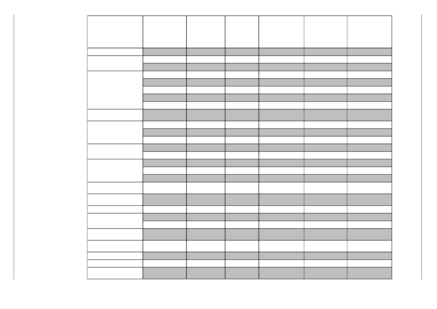
Bildröhre / Picture Tube
Sichtbares Bild
Visible picture
66cm 76cm 76cm 76cm 76cm 76cm 66cm 68cm 68cm 68cm 89cm
Bildschirmdiagonale
Screen diagonale
70cm (28")
Black Matrix, CCS
82cm (32")
Black Matrix, CCS
82cm (32")
Black Matrix, CCS
82cm (32")
Black Matrix, CCS
82cm (32")
Black Matrix, CCS
82cm (32")
Black Matrix, CCS
70cm (28")
Black Matrix, CCS
72cm (29")
Black Matrix, CCS
72cm (29")
Black Matrix, CCS
72cm (29")
Black Matrix, CCS
95cm (37")
Black Matrix, CCS
Ablenkwinkel
Deflection angle
105° 106° 106° 106° 106° 106° 105° 108° 108° 108° 110°
Bildwechselfrequenz
Vertical frequency
100Hz 100Hz 100Hz 100Hz 100Hz 100Hz 100Hz 100Hz 100Hz 100Hz 100Hz
Elektronik / Electronic
Programmspeicherplätze
Programme positions
99 TV + 4 AV 99 TV + 5 AV 99 TV + 5 AV 99 TV + 5 AV 99 TV + 5 AV 99 TV + 5 AV 99 TV + 4 AV 99 TV + 5 AV 99 TV + 5 AV 99 TV + 5 AV 99 TV + 5 AV
Perfect clear, Blue stretch,
Gamma adjustment
ja/yes ja/yes ja/yes ja/yes ja/yes ja/yes ja/yes ja/yes ja/yes ja/yes ja/yes
AV-Auswertung
AV evaluation
auf jeden Programmplatz programmierbar / programmable for every programme position
Tuner
Kabeltuner-Raster 8MHz für Hyperband / cable tuner - 8MHz spacing for hyperband
TV-Normen
TV-Standard
PAL/SECAM/
NTSC4,43MHz+3,58MHz
B/G, I, DK/K'/D, M, L/L',
PAL/SECAM/
NTSC4,43MHz+3,58MHz
B/G, I, DK/K'/D, M, L/L',
PAL/SECAM/
NTSC4,43MHz+3,58MHz
B/G, I, DK/K'/D, M, L/L',
PAL/SECAM/
NTSC4,43MHz+3,58MHz
B/G, I, DK/K'/D, M, L/L',
PAL/SECAM/
NTSC4,43MHz+3,58MHz
B/G, I, DK/K'/D, M, L/L',
PAL/SECAM/
NTSC4,43MHz+3,58MHz
B/G, I, DK/K'/D, M, L/L',
PAL/SECAM/
NTSC4,43MHz+3,58MHz
B/G, I, DK/K'/D, M, L/L',
PAL/SECAM/
NTSC4,43MHz,
über/via AV 3,58MHz
PAL/SECAM/
NTSC4,43MHz,
über/via AV 3,58MHz
PAL/SECAM/
NTSC4,43MHz+3,58MHz
B/G, I, DK/K'/D, M, L/L',
PAL/SECAM/
NTSC4,43MHz+3,58MHz
B/G, I, DK/K'/D, M, L/L',
Stereo Systeme
Stereo systems
Deutsch A2 für B/G
German A2 for B/G
DK, Nicam 5,85+6,52
Deutsch A2 für B/G
German A2 for B/G
DK, Nicam 5,85+6,52
Deutsch A2 für B/G
German A2 for B/G
DK, Nicam 5,85+6,52
Deutsch A2 für B/G
German A2 for B/G
DK, Nicam 5,85+6,52
Deutsch A2 für B/G
German A2 for B/G
DK, Nicam 5,85+6,52
Deutsch A2 für B/G
German A2 for B/G
DK, Nicam 5,85+6,52
Deutsch A2 für B/G
German A2 for B/G
DK, Nicam 5,85+6,52
Deutsch A2
German A2
Deutsch A2
German A2
Deutsch A2 für B/G
German A2 for B/G
DK, Nicam 5,85+6,52
Deutsch A2 für B/G
German A2 for B/G
DK, Nicam 5,85+6,52
Videotext
Teletext
Mega Text , VPS,
512 Seiten
Mega Text , VPS,
512 pages
Mega Text , VPS,
512 Seiten
Mega Text , VPS,
512 pages
Mega Text , VPS,
512 Seiten
Mega Text , VPS,
512 pages
Mega Text , VPS,
512 Seiten
Mega Text , VPS,
512 pages
Mega Text , VPS,
512 Seiten
Mega Text , VPS,
512 pages
Mega Text , VPS,
512 Seiten
Mega Text , VPS,
512 pages
Mega Text , VPS,
512 Seiten
Mega Text , VPS,
512 pages
Mega Text , VPS,
512 Seiten
Mega Text , VPS,
512 pages
Mega Text , VPS,
512 Seiten
Mega Text , VPS,
512 pages
Mega Text , VPS,
512 Seiten
Mega Text , VPS,
512 pages
Mega Text , VPS,
512 Seiten
Mega Text , VPS,
512 pages
Musikleistung
Music power
Stereo 3-Kanal 80W
Stereo 3-channel 80W
Stereo 3-Kanal 80W
Stereo 3-channel 80W
Stereo 3-Kanal 80W
Stereo 3-channel 80W
Stereo 5-Kanal 120W
Stereo 5-channel 120W
Stereo 3-Kanal 80W
Stereo 3-channel 80W
Stereo 3-Kanal 80W
Stereo 3-channel 80W
Stereo 3-Kanal 80W
Stereo 3-channel 80W
Stereo 2 x 40W Stereo 2 x 40W Stereo 2 x 40W
Stereo 3-Kanal 80W
Stereo 3-channel 80W
Anschlüsse Front / Connections Front
Kopfhörer
Headphones
Stereo 3,5mm Klinkenbuchse, Lautstärke einstellbar / Stereo 3.5mm jacksocket, volume controllable
Video IN
1 x Cinch 1 x Cinch 1 x Cinch 1 x Cinch 1 x Cinch 1 x Cinch 1 x Cinch 1 x Cinch 1 x Cinch 1 x Cinch 1 x Cinch
Audio IN
2 x Cinch 2 x Cinch 2 x Cinch 2 x Cinch 2 x Cinch 2 x Cinch 2 x Cinch 2 x Cinch 2 x Cinch 2 x Cinch 2 x Cinch
S-Video
Hosiden Hosiden Hosiden Hosiden Hosiden Hosiden — Hosiden Hosiden Hosiden Hosiden
Anschlüsse Rückwand / Connections Rear Panel
Euro AV 1(schwarz/black)
FBAS in-/output, RGB input,
S-Video in/output, Megalogic
–> D2-Mac Decoder
FBAS in-/output, RGB input,
S-Video in/output, Megalogic
–> D2-Mac Decoder
FBAS in-/output, RGB input,
S-Video in/output, Megalogic
–> D2-Mac Decoder
FBAS in-/output, RGB input,
S-Video in/output, Megalogic
–> D2-Mac Decoder
FBAS in-/output, RGB input,
S-Video in/output, Megalogic
–> D2-Mac Decoder
FBAS in-/output, RGB input,
S-Video in/output, Megalogic
–> D2-Mac Decoder
FBAS in-/output, RGB input,
S-Video in/output, Megalogic
–> D2-Mac Decoder
FBAS in-/output, RGB input,
S-Video in/output, Megalogic
–> D2-Mac Decoder
FBAS in-/output, RGB input,
S-Video in/output, Megalogic
–> D2-Mac Decoder
FBAS in-/output, RGB input,
S-Video in/output, Megalogic
–> D2-Mac Decoder
FBAS in-/output, RGB input,
S-Video in/output, Megalogic
–> D2-Mac Decoder
Euro AV 2 (orange)
FBAS in-/output, RGB input,
S-Video input
FBAS in-/output, RGB input,
S-Video input
FBAS in-/output, RGB input,
S-Video input
FBAS in-/output, RGB input,
S-Video input
FBAS in-/output, RGB input,
S-Video input
FBAS in-/output, RGB input,
S-Video input
FBAS in-/output, RGB input,
S-Video input
FBAS in-/output, RGB input,
S-Video input
FBAS in-/output, RGB input,
S-Video input
FBAS in-/output, RGB input,
S-Video input
FBAS in-/output, RGB input,
S-Video input
Euro AV 3 (blue) FBAS in-/output FBAS in-/output FBAS in-/output FBAS in-/output FBAS in-/output FBAS in-/output FBAS in-/output FBAS in-/output FBAS in-/output FBAS in-/output FBAS in-/output
Standart VGA
2 x Cinch NF/in
nachrüstbar Modul VGA 1
retrofitting possible module
VGA 1
Bildauflösung/resolution
640x480, 31,5 kHz/60Hz
Textmode 31,5 kHz/70Hz
Bildauflösung/resolution
640x480, 31,5 kHz/60Hz
Textmode 31,5 kHz/70Hz
Bildauflösung/resolution
640x480, 31,5 kHz/60Hz
Textmode 31,5 kHz/70Hz
Bildauflösung/resolution
640x480, 31,5 kHz/60Hz
Textmode 31,5 kHz/70Hz
Bildauflösung/resolution
640x480, 31,5 kHz/60Hz
Textmode 31,5 kHz/70Hz
nachrüstbar Modul VGA 1
retrofitting possible module
VGA 1
Bildauflösung/resolution
640x480, 31,5 kHz/60Hz
Textmode 31,5 kHz/70Hz
Bildauflösung/resolution
640x480, 31,5 kHz/60Hz
Textmode 31,5 kHz/70Hz
Bildauflösung/resolution
640x480, 31,5 kHz/60Hz
Textmode 31,5 kHz/70Hz
Bildauflösung/resolution
640x480, 31,5 kHz/60Hz
Textmode 31,5 kHz/70Hz
Audio OUT stereo
2 x Cinch 2 x Cinch 2 x Cinch 2 x Cinch 2 x Cinch 2 x Cinch 2 x Cinch 2 x Cinch 2 x Cinch 2 x Cinch 2 x Cinch
Lautsprecherbuchsen
Loudspeaker socket
———
4 x DIN———————
Netzteil / Mains Stage
Netzspannung (Regelber.)
Mains voltage (variable)
165…264V 165…264V 165…264V 165…264V 165…264V 165…264V 165…264V 165…264V 165…264V 165…264V 165…264V
Netzfrequenz
Mains frequency
50 / 60Hz 50 / 60Hz 50 / 60Hz 50 / 60Hz 50 / 60Hz 50 / 60Hz 50 / 60Hz 50 / 60Hz 50 / 60Hz 50 / 60Hz 50 / 60Hz
Leistungsaufnahme
Power consumption
ca. 165W ca. 175W ca. 175W ca. 185W ca. 175W ca. 175W ca. 160W ca. 170W ca. 170W ca. 170W ca. 180W
Standby
ca. 6W ca. 7W ca. 7W ca. 7W ca. 7W ca. 7W ca. 6W ca. 6W ca. 6W ca. 6W ca. 6W
Technische Daten / Technical Data
Digi 6 Allgemeiner Teil / General Section
Page 6
Allgemeiner Teil / General Section Digi 6
Hinweise zu den Oszillogrammen / Hints to the Oscillograms / Note relative agli Oscillogr./
Indications pour les Oscillogrammes / Observaciones con respecto a los Oscilogramas
D
Die Spannungswerte an den Oszillogrammen entsprechen Näherungswerten!
The voltages indicated in the oscillograms
are approximates!
I valori delle tensioni indicati sugli oscillogrammi sono approssimativi !
Les valeurs de tension indiquées pour les
oscillogrammes sont des valeurs approximatives!
Los valores de tensión en los oscilogramas
son aproximados!
GB
. . . V
ss
. . . ms/cm
. . . Hz
I
. . . V Gleichspannungswert / DC voltage / Valore tensione continua / Tension
continue / Valor de tensión continua
Spitze-Spitze - Wert / Peak to peak value / Valore picco-picco / Crêtecrête / Valor pico a pico
Zeitbasis des Oszilloskops / Time base of the oscilloscope / Base del
tempo dell´oscilloscopio / Base de temps de l´oscilloscope/ Base de
tiempo del oscilocopio
Frequenz / Frequency / Frequenza / Fréquence / Frecuencia
F
E
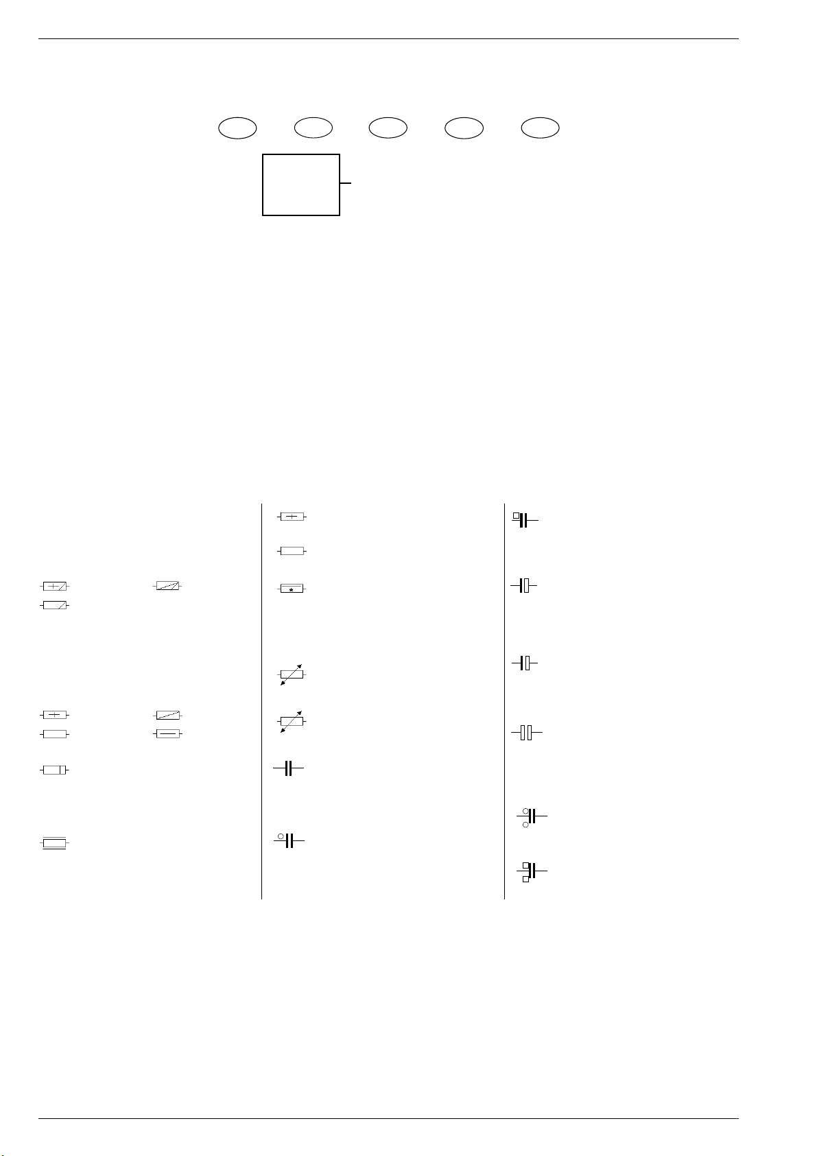
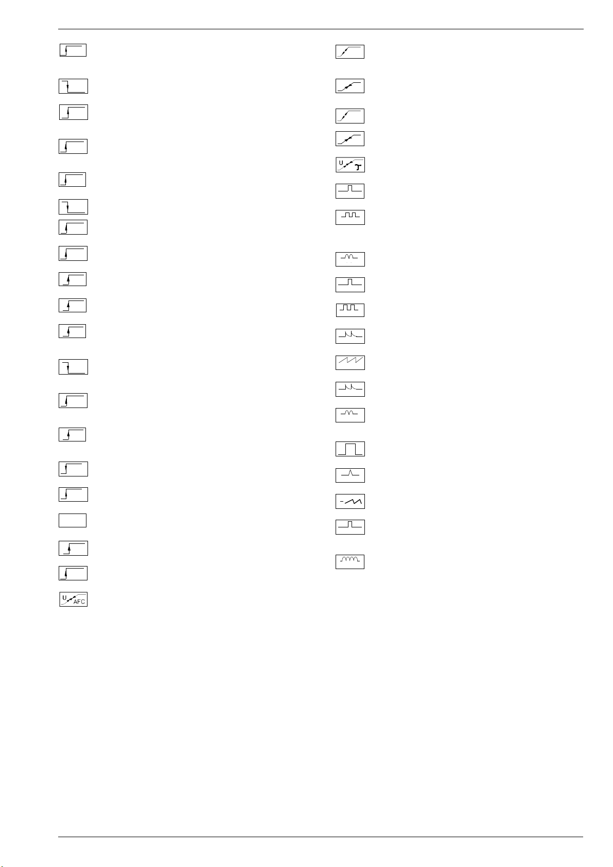
Hinweise zu den Bauteilen / Hints to Components / Istruzioni sui Componenti /
Observaciones sobre los Componentes / Precautions a observer
Metallschichtwiderstände
Metal film resistors
Resistenza a strato metallico
Resistencia de capa metálica
Film métallique
DIN 0204
DIN 0207
Kohleschichtwiderstände
Carbon film resistors
Resistenza a strato di carbone
Resistencia de capa de carbón
Film carbonique
DIN 0204
DIN 0207
Metalloxidwiderstand
Metal oxid resistor
Resistenza ad ossido metallico
Resistencia de óxido metálico
Métaloxide
Schwer entflammbarer Widerstand
Flame resistant resistor
Resistenza anti-infiammabile
Resistencia ininflamable
Ininflammable
DIN 0414
DIN 0414
DIN 0617
Sicherungswiderstand
SI-R
Safety resistor
Resistenza di sicurezza
Resistencia con resorte de seguridad
SI-R
Rés. fusible
Drahtwiderstand m. Wattangabe
Wire wound resistor w. wattage
Resistenza a filo
Resistencia bobinada (Disipación)
Bobinée avec ind. puissance
Heißleiter / NTC resistor
NTC
Termistore NTC / Resistencia CNT
Varistor (CTN)
Kaltleiter / PTC resistor
PTC
Termistore PTC / Resistencia CPT
Varistor (CTP)
Keramikkondensator
K
Ceramic capacitor
Condensatore ceramico
Condensador cerámico
Céramique
Kondensator, Capacitor
Condensatore, Condensador
Condensador, 250 V=
T
Kondensator, Capacitor
Condensatore, Condensador
Condensador, 630 V=
Elektrolytkondensator
Electrolytic capacitor
+
Condensatore elettrolitico
Condensador electrolitico
Electrolytique
Tantal-Elektrolytkondensator
+
Tantalum electrolytic capacitor
Condensatore elettro. al tantalio
Condensador de tantalio
Tantale
bipolarer Elektrolytkondensator
bipolar electrolytic capacitor
Condensatore elettrolitico bipolare
Condensador electrolitico bipolar
Electrolytique bipolaisé
Kondensator, Capacitor
Condensatore, Condensador
Condensador, 400 V=
Kondensator, Capacitor
Condensatore, Condensador
Condensador, 1000 V=
1 - 6 GRUNDIG Service
Page 7

Digi 6 Allgemeiner Teil / General Section
Sicherheits-Hinweise
Die in den Fernsehgeräten auftretende Röntgenstrahlung entspricht
den Bestimmungen der Physikalisch-Technischen Bundesanstalt
vom 8. Januar 1987.
Die Hochspannung für die Bildröhre und die damit auftretende
Röntgenstrahlung ist abhängig von der exakten Einstellung der
Netzteilspannung +A.
Nach jeder Reparatur im Netzteil oder in der Horizontalablenkung ist
die Hochspannung zu messen und ggf. einzustellen.
Schutzschaltungen im Gerät dürfen nur kurzzeitig außer Betrieb
gesetzt werden, um Folgeschäden am Chassis oder an der Bildröhre zu vermeiden.
Beim Austausch der Bildröhre dürfen nur die in den Ersatzteillisten
vorgeschriebenen Typen verwendet werden.
D
Servicehinweise
Chassisausbau
Bevor Sie die Chassis-Verbindungsleitungen lösen, muß die Leitungsverlegung zu den einzelnen Baugruppen wie Netzschalterplatte, Bedieneinheit, Bildrohrplatte, Ablenkeinheit oder Lautsprecher beachtet werden.
Nach erfolgter Reparatur ist es notwendig, die Leitungsführung wieder
in den werksseitigen Zustand zu versetzen, um evtl. spätere Ausfälle
oder Störungen zu vermeiden.
Safety Advices
The X-radiation developing in the sets conforms to the X-radiation
Regulations (January 8, 1987), issued by the Physikalisch-Technische Bundesanstalt (federal physiotechnical institution).
The high tension for the picture tube and thus the developing Xradiation depends on the precise adjustment of the +A power supply.
After every repair of the power supply unit or the horizontal deflection
stage it is imperative that the EHT for the picture tube is checked and
re-adjusted if necessary.
To avoid consequential damages to the chassis or the picture tube
the integrated protective circuits are allowed to be put out of
operation only for a short time.
When replacing the picture tube use only the types specified in the
spare parts lists.
Cable dereseau
Ces appareils ne peuvent être utilisés qu ' avec un cable de connecion
original de réseau avec bobine antiparasite intégré dans la fiche de
secteur. Ce câble de réseau empêche des perturbations de réseau et
est partie de l'autorisation d'appareil. Si nécessaire commandez
uniquement le cable de réseau selon la liste de pièces détachées.
Netzkabel
Diese Geräte dürfen nur mit dem Original-Netzanschlußkabel mit
integrierter Entstördrossel betrieben werden. Dieses Netzkabel verhindert Störungen aus dem Netz und ist Bestandteil der Gerätezulassung. Im Ersatzfall bestellen Sie bitte ausschließlich das Netzkabel laut Ersatzteilliste.
GB
Service Notes
Disassembly of the chassis
Before disconnecting the chassis connecting leads observe the way
they are routed to the individual assemblies like the mains switch
panel, keyboard control panel, picture tube panel, deflection unit or
loudspeaker.
On completion of the repairs the leads must be laid out as originally
fitted at the factory to avoid later failures or disturbances.
Mains cable
The TV receiver must only be operated with an original mains connecting
cable with an interference suppressor choke integrated in the mains
plug.This mains cable prevents interference from the mains supply and
is part of the product approval. For replacement please order exclusively
the mains connecting cable specified in the spare parts list.
F
Information pour la maintenance
Dèmontage de chassis
Avant de défaire les connecteurs du châssis princip, il y a lieu de
repérer auparavant les liaisons correspondant à chaque platine comme
par exemple le C.I. Inter secteur, le C.I. Commande, le C.I. Tube, le
bloc déviation ou les haut-parleurs.
A la fin de l'intervention, les connexions doivent être remises dans leur
position d'origine afin d'éviter par après d'éventuelles défaillances ou
perturbations.
I
Nota di servizio
Smontaggio del telaio
Prima di sfilare i cavi di collegamneto col telaio è necessario osservare
la disposizione originaria degli stessi verso le singole parti come la
piastra alimentazione, l'unità comandi, la piastra cinescopio, il giogo o
l'altoparlante.
Dopo la riparazione è necessario che gli ancoraggi e le guide
garantiscano la disposizione dei cavi analogamente a quella data in
fabrica e ciò per evitare disturbi o danni nel tempo.
Cavo rete
Gli apperechi devono essere messi in funzioni solo con il cavo originale
il colle gamento di rete e la sua spina di rete deve essere munita di una
bombina d´induttanza. In causa di sostituzione ordinate solo il cavo di
alimentatore che corrésponde alla lista degli accessori.
E
Nota de servicio
Desmontaje del chassis
Antes de desconectar las conecciones del Chassis hay que observar
la dirección de dichas conecciones a los distintos grupos de construcción
como la placa de conmutación de red, unidad de control, placa del
zócalo del tubo de imagen, unidad de deflección o altavoces.
Después de haber realizado la reparación y para evitar fallos o
pertubaciones posteriores es necesario reponer las conecciones tal
como fueron instaladas originalmente en fabrica.
Cable de red
El aparato solo se puede usar con el cable de red original con choque
antiparásito integrado en el enchufe de red. Este cable de red evita
perturbaciones de la red y es parte de la autorización del aparato. En
caso necesario puede pedir el cable de red según lista de piezas de
repuestos.
GRUNDIG Service 1 - 7
Page 8
Allgemeiner Teil / General Section Digi 6
-
REF.
ABK
AUDIO
AUDIO-L
AUDIO-R
AUDIO
MAC
AUDIO
L - MAC
AUDIO
R - MAC
AUDIO
TV
AUDIO
VCR
B
BB
BB
B
EXT
B
OSD
B
PIP
B/50
B/100
B-Y
50
B-Y
100
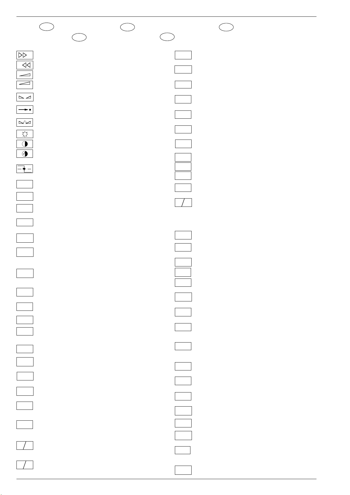
Schaltplansymbole
D
Simboli sullo schema
I
Feinabst. + / Fine tuning + / Réglage fine + / Sint. fine + / Sint. fina +
+
GB
Feinabst. - / Fine tuning - / Réglage fine - / Sint. fine - / Sint. fina -
Lautstärke / Volume / Volume / Volume sonore / Volumen
Referenz Lautstärke / Volume ref. volt. / Tens. de réf. vol. sonore /
Tens di rif. volume / Tens. ref. volumen
Balance / Balance / Balance /Balanciam. / Balance
Suchlauf / Self seek / Recherche autom. / Sint. autom. / Sintonia
automatica
Farbton / Tint / Teinte / Tinta / Tinte
Helligkeit / Brightness / Luminosité / Luminosita / Brillo
Kontrast / Contrast / Contraste / Contrasto / Contraste
Farbkontrast / Colour contrast / Contraste des coleurs / Contrasto
colore / Contraste de color
Schutzschaltung / Protection circuit / Circuit de sécurité / Circuito di
protezione / Circuito de protección
(Burst Key): Burstaustastimpuls / Burst blanking pulse / Impulsion de
suppress. de burst / Imp. di soppress. del burst / Imp. supresion burst
Ton-Signal / Audio signal / Signal audio / segnale audio / Señal audio
Ton-Signal links / Audio signal left / Signal audio gauche / Segnale
audio sinistra / Señal audio izquierda
Ton-Signal rechts / Audio signal right / Signal audio droit / Segnale
audio destra / Señal audio derecha
Tonsignal D2 Mac / Audio signal D2MAC / Signal audio D2MAC /
Segnale audio D2MAC / Señal de sonido D2MAC /
Tonsignal links D2 Mac / Audio signal left D2MAC / Signal audio
gauche D2MAC / Segnale audio sinistro D2MAC / Señal de sonido
izquirdo D2MAC /
Tonsignal rechts D2 MAC / Audio signal right D2MAC / Signal audio
droit D2MAC / Segnale audio destro D2MAC / Señal de sonido
derecho D2MAC /
Audio-Signal FS Gerät / Audio signal TV set / Signal audio
téléviseur / Segnale audio TV / Señal audio TV
Tonsignal VCR Gerät / Audio signal VCR unit / Signal audio
magnetoscope / Segnale audio VCR / Señal audio VCR
Blau-Signal / Blue signal / Signal bleu / Segnale blu / Señal azul
Rechner Stop I2C Bus frei / Computer Stop I2C Bus is free /
Microprocesseur stop I2C Bus disponible / Calcol. stop I2C Bus
libero / Stop micropr. disponible
Basisband / Baseband / Bande de base / Banda base / Banda base
Blau-Signal extern / Signal blue external /Signal bleu externe /
Segnale blu esterno / Señal azul externa
OSD-Einblendung blau / OSD blue / Eblouissement OSD bleu /
Visualizzazione OSD blu / Visualisacione OSD azul
Blau-Signal PIP / PIP Blue signal / Signal bleu PIP / Segnale blu
PIP / Señal azul PIP
Blau - Signal - 50Hz vert.,15625Hz hor. / Blue signal - 50Hz vert.,
15625Hz hor. / Signal bleu - 50Hz vert., 15625Hz hor. / Segnale bleu
- 50Hz vert., 15625Hz hor. / Señal azul - 50Hz vert., 15625Hz hor.
Blau-Signal -100Hz vert., 31250Hz hor. / Blue signal -100Hz vert.,
31250Hz hor. / Signal bleu -100Hz vert., 31250Hz hor. / Segnale blu
-100Hz vert., 31250Hz hor. / Señal azul -100Hz vert., 31250Hz hor.
B-Y -Signal - 50Hz vert., 15625Hz hor. / B-Y -Signal - 50Hz vert.,
15625Hz hor. / Signal B-Y - 50Hz vert., 15625Hz hor. / Segnale BY - 50Hz vert., 15625Hz hor. / Señal B-Y - 50Hz vert., 15625Hz hor.
B-Y -Signal - 100Hz vert., 31250Hz hor. / B-Y -Signal - 100Hz vert.,
31250Hz hor. / Signal B-Y - 100Hz vert., 31250Hz hor. / Segnale BY - 100Hz vert., 31250Hz hor. / Señal B-Y - 100Hz vert., 31250Hz hor.
Circuit Diagram Symbols
E
Simbolos en los esquemas
Kanalwahl / Channel selection / Sélection de canaux / Selez.
C
canale / Seleccion canal
CENTER
CHIP
CINCH
AUDIO L
CINCH
AUDIO R
CHROMA
CHROMA
S-VHS
CLK
CL 1
CL 2
CSY
CS
DATA
ENA
ENABLE
ENABLE
ENABLE
EURO-AV
AUDIO-L
EURO-AV
AUDIO-R
EURO-AV
VIDEO
FBAS
FBAS
FBAS
FBAS
FBAS
SYNC.
FBAS
S-VHS
Mitttelpunkt-Lautsprecher / Center loudspeaker / Haut-parleur de
centre / Alto parlante punto centrale / Altavoz del centro
Chip Adresse / Chip adress / Chip direction / Indiri. del chip /
AD
Direccion chip
Ton-Signal Cinch links / Audio signal cinch left / Signal audio cinch
gauche / Segnale audio cinch sinistra / Señal audio cinch izquierda
Ton-Signal Cinch rechts / Audio signal cinch right / Signal audio
cinch droit / Segnale audio cinch destra / Señal audio cinch derecha
Chroma Signal / Chroma signal / Signal dégree / Croma segnale /
Señal croma
Chroma S-VHS-Signal / Chroma S-VHS-Signal / Signal dégree de
S-VHS / Croma segnale S-VHS / Señal croma S-VHS
Clock
Composite Sync. Imp. für VT / Composite sync pulse for TT / Imp. de
sync. vidéo-composite pour TXT / Imp. hor. para Video Comp.
Kombiniertes Hor./vert. Sync. Signal 31250Hz/100Hz (Composite
100
Sync.) / Combined hor./vert. sync signal 31250Hz/100Hz (Composite Sync) / Signal synchr. hor./vert. combiné 31250Hz/100Hz
(Synchr. composité) / Segnale sincr. orizz./vert. 31250Hz/100Hz
(Sincr. Composito) / Señal combinada sincr. hor./vert. 31250/100Hz
(Sincr. compuesto)
Daten / Data / Données / Dati / Datos
Verzögerungsleitung / Delay line / Ligne à retard / Linea di ritardo /
DL
Linea de retardo
Freigabe / Enable / Autorisation / Consenso / Habilitacion
Freigabe ZF / IF Enable / Validation FI / Consenso FI / Autorizacón FI
ENA
ZF
Freigabe FT / Finetuning enable / Autorisation Réglage fin / Abilitaz.
FT
Sintonia fine / Habilitacion Sintoinia fina
Freigabe LED / LED enable / Autorisation LED / Abilitaz. LED /
LED
Habilitacion LED
Freigabe Ton / Sound enable / Autorisation son / Abilitaz. audio /
TON
Habilitacion sonido
Audio-Signal EURO-AV links / Audio signal EURO-AV left / Signal
audio EURO-AV gauche / Segnale audio EURO-AV sinistra / Señal
audio izquierda EURO-AV
Audio-Signal EURO-AV rechts / Signal audio EURO-AV right /
Signal audio EURO-AV droit / Segnale audio EURO-AV destra /
Señal audio derecha EURO-AV
Video-Signal EURO-AV / Video signal EURO-AV / Signal video
EURO-AV / Segnale video EURO-AV / Señal video EURO-AV
Farb-Signal / Chroma signal / Signal chroma / Segnale chroma /
F
Señal croma
FBAS-Signal / CCVS signal / Signal vidéo composite / Segnale video
composito / señal video compuesta
FBAS-D2 MAC / D2MAC CCVS signal / Signal vidéo composite-
MAC
D2MAC / FBAS-D2MAC / FBAS-D2MAC
Basisband / Baseband / Bande de base / Banda base / Banda base
TON
FBAS-Videotext / CCVS videotext / Signal vidéo composite-
TXT
Télétexte / FBAS-Televideo / FBAS-Teletexto
FBAS Sync. Signal / CCVS sync signal / Signal sync. vidéo col.
comp. / Segnal sincr. video col. comp. / Señal sincr. video
compuesta
FBAS Signal S-VHS / CCVS signal S-VHS / Signal vidéo col. comp. SVHS / Segnal video col. comp. S-VHS / Señal video compuesta S-VHS
Symboles schéma
F
1 - 8 GRUNDIG Service
Page 9

Digi 6 Allgemeiner Teil / General Section
HA
PIP
F
H
FRM
FT
F
U
F
V
G
G
OSD
G
PIP
G
EXT
G/50
G/100
GND - H
HDR
HC
HFB
HS
I
BEAM
ICL
IR
IM
CLOCK
IM
IDENT
IM
RESET
IR CLK
IR DATA
IR
VIDEO
KB
KH
AUDIO-L
KH
AUDIO-R
L
LED
M
Hochspg. / EHT voltage / Haute tens. / Alta tens. / MAT
Rahmensignal / Frame signal / Signal d'encadrement / Segnale
cornice / Señal de marco
Feinabstimmung / Fine tuning / Reglage fin / Sint. fine / Sint. fina
FU-Signal / FU-signal / Signal FU / Segnale FU / Senal FU
FV-Signal / FV-signal / Signal FV / Segnale FV / Senal FV
Grün-Signal / Green signal / Signal green external / Signal vert /
Segnale verde / Señal verde
OSD-Einblendung grün / OSD green / Eblouissement OSD vert /
Visualizzazione OSD verde / Visualisacione OSD verde
Grün-Signal PIP / Green signal PIP / Signal green PIP/ Signal vert
PIP / Segnale verde PIP / Señal verde PIP
Grün-Signal extern / Green signal vertical / Signal vert externe /
Segnale verde esterno / Señal verde externa
Grün-Signal - 50Hz vert.,15625Hz hor. / Green signal - 50Hz vert.,
15625Hz hor. / Signal vert - 50Hz vert., 15625Hz hor. / Segnale
verde - 50Hz vert., 15625Hz hor. / Señal verde -50Hz vert., 15625Hz hor.
Grün-Signal -100Hz vert., 31250Hz hor. / Green signal -100Hz vert.,
31250Hz hor. / Signal vert -100Hz vert., 31250Hz hor. / Segnale
verde -100Hz vert., 31250Hz hor. / Señal verde -100Hz vert.,
31250Hz hor.
Nullpunkt Heizung / Ground filament / Point neutre-Chauffage /
Punto zero-Filamento / Punto medio filamento
Horiz. Sync. Impuls / Horiz. Sync pulse / Impulsion synchro. horiz. /
Impulso sincro orizzontale / Impulso de sinc. horiz.
Horiz. Ansteuerimpuls / Horiz. drive pulse / Impulsion de commande
horiz. / Impulso comando orizzontale / Impulso de control horiz.
Horiz. Klemmimpuls / Horiz. clamp pulse / Impulsion de serrage
horiz. / Impulso comando orizzontale / Impulso de garras horiz.
Horiz. Rückschlagimpuls / Horiz. flyback / Impulsion de retour
horiz. / Impulso rotorno orizzontale / Impulso de retroceso horiz.
Hor. Sync. Implus für VT / Hor. sync pulse for TT / Imp. de sync. hor. pour
TXT / Imp. sincr. orizz. per Televideo / Imp. hor. para Video Comp.
Strahlstrom / Current beam / Current rayon / Corrante del irradire /
Corriente de haz
I2C Bus -Clock
Infrarot-Signal / Signal infrared / Signal infra-rouge / Segnale
infrarosso / Señal infrarojo.
I2C Bus -Clock
I2C Bus -Kennung / I2C-Bus Identification / Identification I2C-Bus /
Ident. I2C-Bus, Identification I2C-Bus
I2C Bus -Reset
Infrarot Clock / Infrared clock / Signal I.R. horloge / Clock segnale
R.I. / Clock infrarojos
Infrarot Signal / Infrared signal / Signal I.R. / Segnale infrarosso /
Data infrarrojos
Infrarot Signal Video / Infrared signal video / Signal I.R. video /
Segnale infrarosso video / Data infrarrojos video
Keyboard
Tonsignal Kopfhörer links / Audio signal headphone left / Signal
audio gauche de casque / Segnale audio sinistra cuffia / Señal audio
izquierda auriculares
Tonsignal Kopfhörer rechts / Audio signal headphone right / Signal
audio droit de casque / Segnale audio sinistra cuffia / Señal audio
derecha auriculares
Lautstärke / Volume / Volume / Volume sonore / Volumen
Leuchtdiode / Light emitting diode / Diode lumineuse / Diodo
luminoso / Diodo luminescente
Speicher Taste / Memory button / Touche mémoire / Tasto di
memoria / Puls. memoria
MEGA
LOGIC
MODE
NIC CLK
NORM
OWA
REMOTE
R
OSD
R
R
R-Y
R-Y
SCL
SCL 100
SDA
SHIFT
VIDEO
SHIFT
TEXT
SSB
SSC
SSC
SSC
SUR-
ROUND
Megalogic Daten / Megalogic data / Megalogic dates / Dati
Megalogic / Megalogic datas
Modus / Mode / Mode / Modo / Modo
NICAM Clock / Clock NICAM / Horloge NICAM / Clock NICAM /
Clock NICAM
Norm Taste / TV standard select button / touche de norme / Tasto
norma / Puls. de norma
Ost-West Ansteuerimpuls / East-west drive impuls / Impulsion de
commande Est-Ouest / Impulso comando Est-Ovest / Impulso de
control Este-Oeste
Programm / Program / Programme / Programma /Programa
P
Programm-Kanalwahl / Program channel selection / Progr. sélection
P/C
de canaux / Progr. selez.canale / Progr. selec. canal
Bild im Bild / Picture in picture / Image dans l'image / PIP / Imagen
en la imagen
Progr. Taste / Progr. button / Touche Progr. / Tasto Progr. / Puls.
P1
Progr.
Rot-Signal / Red signal / Signal rouge / Segnale rosso / Señal rojo
R
Fernbedienung / Remote control / Telecommande / Telecomando /
Mando a distancia
OSD-Einblendung rot / OSD red / Eblouissement OSD rouge /
Visualizzazione OSD rosso / Visualisacione OSD rojo
Rot-Signal PIP / Red signal PIP / Signal rouge PIP / Segnale rosso
PIP
PIP / Señal rojo PIP
Rot-Signal extern / Signal red external / Signal rouge externe /
EXT
Segnale rosso esterno / Señal rojo externa
R-Y -Signal - 50Hz vert., 15625Hz hor. / R-Y -Signal - 50Hz vert.,
50
15625Hz hor. / Signal R-Y - 50Hz vert., 15625Hz hor. / Segnale RY - 50Hz vert., 15625Hz hor. / Señal R-Y - 50Hz vert., 15625Hz hor.
R-Y -Signal - 100Hz vert., 31250Hz hor. / R-Y -Signal - 100Hz vert.,
100
31250Hz hor. / Signal R-Y - 100Hz vert., 31250Hz hor. / Segnale
R-Y - 100Hz vert., 31250Hz hor. / Señal R-Y - 100Hz vert., 31250Hz hor.
Sonderkanal / Special channel / Canal special / Canale speciale /
S
Canal especial
Strahlstrombegrenzung / Beam current lim. / Lim. cour. de faisceau /
SB
Lim. corr. di raggio / Corriente media de haz
I2C-Bus Clock
Schneller I2C-Bus Clock / I2C-Bus clock high speed / I2C-Bus grande
vitesse / I2C-Bus veloce / Clock del I2C-Bus de alta velocida
I2C-Bus Daten / I2C-Bus data / I2C-Bus données / I2C-Bus dati /
I2C-Bus datos
Dynamische vert. Versch. 25Hz, aktiv bei Video u. Mix Betrieb /
Dynam. vert. shift 25Hz, active on video and mix operation / Decal
dynam. de l'image 25Hz, actif sur video et fonction. mixte / Spostam.
vert. dinam. 25Hz, attivo con video e. funzionam. misto / Desplaz.
dinamico vert. 25Hz, activo con video Y funciones mixtas
Dynamische vert. Versch. 25Hz, aktiv bei Standbild u. VT / Dyn. vert.
shift 25Hz, active on freeze-frame and Teletext / Decal dynam. de
l'image 25Hz, actif sur arret immage et Vidéotext (Antiope) / Spostam.
vert. dinam. 25Hz, attivo con fermo immag. e Televideo / Desplaz.
dinamico vert. 25Hz, activo con imagen parada Y Videotexto
Schutzschaltung / Protection circuit / Cablage protecteur / Pot. de
SS
prot. / Circuito de proteccion
Spitzenstrahlstrombegrenzung / Peak beam current limiting / Lim.
de faisceau crete / Lim. corr. catod. di pico / Corrente pico de haz
Supersandcastle
SSC
Supersandcastle PIP
PIP
Supersandcastle 100Hz vert., 31250Hz hor.
100
Supersandcastle 50Hz vert., 15625Hz hor.
50
Surround
GRUNDIG Service 1 - 9
Page 10

Allgemeiner Teil / General Section Digi 6
SYNC
SYNC.
BTX
SYNC.
VT
SW
TE
T1
T2
T T
U
FOC
U
G1
U
H
U
SG
U
G 2
VA
VB
VCL
VDR
VG
VIDEO
VT DATA
VT SCL
VT SDA
Y
Y
50
Y
100
ZF
AFC
U
U
AV
U
BA
U
BTX
U
C-AV
Sync.-Signal / Sync.-Signal / Signal sync / Segnale sync. / Señal de sync.
Sync. BTX / Viewdata Sync / Sync. Télétext / Sincr. Videotel / Sincr.
Videotexto
Sync. VT / Sync. Teletext / Sync Vidéotexte / Sincr. Televideo / Sincr.
Videotexto
Schwarzwert / Black level / Niveau du noir / Livello del nero / Nivel
de negro
TEXT-Freigabe / TEXT enable / Autorisation TEXTE / Abilitaz.
TELEVIDEO / Habilatation TEXTE
Bei Zweiton, Ton 1 / On two channel sound, sound 1 / Pour double
son, son 1 / In bicanale, audio 1 / En dual, sonido 1
Bei Zweiton, Ton 2 / On two channel sound, sound 2 / Pour double
son, son 2 / In bicanale, audio 2 / En dual, sonido 2
Tieftöner / Woofer / Haut-parleur pour les frequences basses / Toni
bassi / Sonido bajo
Fokusspg. / Focussing volt. / Tens. de focalis. / Tens di focalizz. /
Tens focalizacion
Spg. Gitter 1 / Volt. grid 1 / Tens grille G 1 / Tens. griglia 1 / Tens.
rejillas G 1
Hochspannung / High voltage / Haute tension / EAT / Alte tension
Schirmgitter Spg. / Screen-grid volt. / Tens. de grille - écran / Tens.di
griglia schermo / Tens. de rejilla
Vertikaler Ansteuerimpuls / Vert. drive pulse / Impulsion de
commande verticale / Impulso di comando verticale / Impulso de
control vertical
VCR - Clock
Freigabe Anzeigebaustein / Display enable / Autorisation pour
module indicateur / Modulo indicazione / Habilitacion modulo
indicacion
Vert. Gegenkopplung / Vert. feedback / Contre-reaction verticale /
Controreazione vert. / Aliment. neg. vert.
Video Signal / Video signal / Signal vidéo / Segnale video / Señal
video
VT Daten / Teletext data / Données Teletexte / Linea dati Televideo /
Data Teletexto
Videotext Clock / Teletext clock / Signal horloge Vidéotext / Clock
Televideo / Clock Teletexto
I2C Bus: VT Daten / Teletext data / Données Vidéotext / Dati
Televideo / Data Teletexto
Y-Signal / Y Signal / Signal Y /Segnale Y / Señal Y
Y -Signal - 50Hz vert., 15625Hz hor. / Y -Signal - 50Hz vert.,
15625Hz hor. / Signal Y - 50Hz vert., 15625Hz hor. / Segnale
Y - 50Hz vert., 15625Hz hor. / Señal Y - 50Hz vert., 15625Hz hor.
Y - Signal - 100Hz vert., 31250Hz hor. / Y -Signal - 100Hz vert.,
31250Hz hor. / Signal Y - 100Hz vert., 31250Hz hor. / Segnale
Y - 100Hz vert., 31250Hz hor. / Señal Y - 100Hz vert., 31250Hz hor
Zwischenfrequenz / IF / FI / FI / FI
Schaltspg. AFC / AFC switching volt. / Tens. de commut. AFC/ Tens.
di commut. AFC / Tens. conmut. CAF
Schaltspg. AV / Switching volt. AV / Tens. de commut. AV / Tens. di
commut. AV / Tens. conmut. AV
Schaltspg. Bildamplitude / Switching voltage vertical amplitude /
Tension de coupure amplitude dìmage / Tensione di commutaz.
ampiezza d'imagine / Tension de conm. amplitude de imagen di
commut. PAL / Tens. conmut. PAL
Schaltspg. BTX / Switching volt. BTX (Viewdata) / Tens. commut.
Télétext / Tens. commut. VIDEOTEL / Tens. conmut. Teletexto
Schaltspg. Camera Wiederg. über C-AV Eingang/ Switching volt.
cam. playback via C-AV input / Tens de commut pour lec. de camera
par l'entree C-AV / Tens.de commut. in riproduz. cam tramite ingresso
C-AV / Tens. de serv. reprod. camera a traves de la entrada C-AV
U
CAM
AV
U
DATA
U
U DATA
EXT
U
DEEM
U
DS
U
MAC
U
EURO-
U
EU-AV
CINCH
U
FBAS
U
HIFI
U
HI FI
MUTE
U
HUB
U
IDENT
U
KH
MUTE
U
KLEMM
U KOIN
50/60Hz
KOIN
U
VQ
U
LED
U
Leucht-.
punkt
U
LNC
OFF
U
MUTE
U
NF 1
U
NF 2
U
NIC
U
NORM
U
PAL
U
POL.
Schaltspg. Camera Wiedergabe / Switching volt. camera playback /
Tens. commut. reprod. camera / Tens. commut. riproduz. telecam /
Tens. conm. reprod. camara
Schaltspg. Datenbetr. / Switching volt. data mode / Tens. de commut. fonct. données / Tens. di commut. dati / Tens conmut. datos
Schaltspg. U Data extern / Switching volt Data ext. / Tension de
commutation U Data externe / Tens. di commutazione U-Data
esterno / Tensión de conmutatón externa U
Schaltspg. Deemphasis / Switching volt. deemphasis / Tens. commut. desaccent. / Tens. commut. deenfasi / Tens. conmut. deenfasis
Schaltspg. Dolby-Surround / Switching volt. Dolby-Surround / Tens.
commut. Dolby-Surround / Tens. commut. di Dolby-Surround / Tens.
de conmut. Dolby-Surround
Schaltspg. D2MAC / Switching volt. D2MAC / Tension de
commutation D2MAC / Tens. di commtazione D2MAC / Tensión de
conmutación D2MAC
Schaltspg. EURO-AV / Switching volt. EURO-AV / Tens. de commut.
AV
EURO-AV / Tens. di commut. EURO-AV / Tens. conmut. EURO-AV
Schaltspg. EURO-AV-Cinch-Buchse / Switching volt. EURO-AVCinch socket / Tens. commut. prisa Scart - Cinch / Tens. commut.
presa Scart -Cinch / Tens. conm. EURO-AV - Cinch
Schaltspannung für Video-Ausgang EURO-AV Buchse / Switch.
voltage for video output EURO-AV socket / Tension de commut.
pour sortie vidéo EURO-AV / Tension commut. per presa d'uscita
video EURO-AV / Tension de conmut. para salida EURO-AV
Schaltspg. HIFI / Switching voltage HIFI / Tens. de commut. HIFI /
Tens di commut. HIFI / Tens. conmut. HIFI
Stummschaltung HiFi / Muting volt. HiFi / Commutation de silence
HiFi / Silenzametno HiFi / Muting HiFi
Schaltspg. HUB / Switching volt. deviation / Tens. commut.
déviation / Tens. commut. deviazione / Tens. conmut. deviacion
Schaltspg. Signalkennung AV 3 / Switching volt. signal identification
AV 3 / Tens de commut.identification de signal AV3 / Tens. commut.
identificazione segnale / Tens. conmut. identifi. segñal AV3
Stummschaltung Kopfhörer / Muting volt. headphone / Commutation
de silence casque / Silenzamento cuffia / Muting auriculares
Gleichspannung für SAT-Basissignal / DC for SAT basic signal /
Tens. continue pour SAT base signal / Tens continua per segnale
SAT base / Tens. continua para segñal SAT base
Schaltspg. Koinz. / Switching volt. coinc. / Tens de commut. coinc. /
Tens di commut. coinc. / Tens. conmut. coinc.
Schaltspg. Koinz. mit Videoquelle verknüpft / Coinc. switching volt.
linked with video source / Signal de coincid. combiné avec source
video / Tens. di commut. a coinc. combinata con sorg video segñal
de coincidencia combinada con video
Schaltspg. LED / Switching volt. LED / Tens de commut. LED / Tens.
commut. LED / Conmut. LED
Schaltspg. Leuchtpunktunterdrückung / Switching volt. beam spot
suppression / Tens. de commut. suppress. du spot lumineux / Tens.
soppr. punto luminoso / Tens. de conmut. filtro supresor del punto luz
Schaltspg. LNC "Aus" / Switching volt. LNC "OFF" / Tens. de
commut. LNC "OFF" / Tensione di commut. "Spento" LNC / Tension
LNC "OFF"
Stummschaltung / Muting / Silencieux / Silenziamento /Muting
Schaltspg. NF 1 / Switching volt. AF 1 / Tension commut. BF 1 / Tens.
commut BF 1 / Tens. conm. BF 1
Schaltspg. NF 2 / Switching volt. AF 2 / Tension commut. BF 2 / Tens.
commut BF 2 / Tens. conm. BF 2
Schaltspg. NICAM / Switching volt. NICAM / Tens. de commut.
NICAM / Tens. commut. NICAM / Tens. de conmut. NICAM
Schaltspg. Norm / Switching volt. Norm / Tens. de commut.
standard / Tens. di commut. Norma / Tens. conmut. Norma
Schaltspg. PAL / Switching volt. PAL / Tens. de commut. PAL / Tens
Schaltspg. Polarität / Switching volt. polarity / Tension commut.
polarite / Tens. commut. polarita / Tens. conmut polarizacion
1 - 10 GRUNDIG Service
Page 11
Digi 6 Allgemeiner Teil / General Section
.
U
POWER
OFF
U
RESET
U
RGB
U
SCHUTZ
U
SEC
STAND
U
BY
U
S-VHS
U TON
1/2
U
UHF
U
VHF
U
VQ
U
WISCH
U
W/N
U
I / III
U
14V
U
22kHz
0/3/6/9V
U
4.5MHz
U
50/60
HZ
Schaltspg. Ökoschalter / Switching volt. eco switch / Tens. de
commut. interr. eco. / Tens. commut. interr. ecologico / Tens.
conmut. interr. ecol.
Schaltspg. Reset / Switching volt. Reset / Tens. commut. Reset /
Tens. commut. Reset / Tens. conmut. Reset
Schaltspg. RGB1 - RGB2 / Switching volt. RGB1 - RGB2 / Tens. de
commut. RGB1 - RGB2 / Tens. di commut. RGB1 - RGB2 / Tens.
conmut. RGB1 - RGB2
Schaltspg.-Schutzfunktion / Switching volt.-protective func. / Tens
de commut.-sécurité / Tens. di commut.-funz di protez. / Tens.
conmut.-proteccion
Schaltspg. SECAM / Switching volt. SECAM / Tens. de commut.
SECAM / Tens. di commut. SECAM / Tens. conm. SECAM
Schaltspg. Standby / Switching volt. Standby / Tens. commut.
Veille / Tens. commut. Standby / Tens. conmut. Standby
Schaltspg. S-VHS / Switching volt. S-VHS / Tens.de commut.
S-VHS / Tens. de commut. S-VHS / Tens. de conmut. S-VHS
Schaltspg. Ton 1-2 / Switching volt. sound 1-2 / Tens. commut. audio
1-2 / Tens. commut. son 1-2 / Tens. conmut. son 1-2
Schaltspg. UHF / UHF switching volt. / Tens. de commut. UHF / Tens
di commut. UHF / Tens. conmut. UHF
Schaltspg. VHF / VHF switching volt. / Tens. de commut. VHF / Tens
di commut. VHF / Tens. conmut. VHF
Schaltspg. Videoquelle / Switching volt. video source / Tens. de
commut. source video / Tens. di commut. sorg. video / Tens conmut.
video
Schaltspg. Wischerkontakt / Schwitching voltage temp. contact /
Tens. de commut. contact fugitif / Tens. commut. contatto / Contacto
supresor tens. de conmut.
Schaltspg. ZF breit - schmal / IF switching volt. wide - narrow / Tens.
commut. FI large - etroit / Tens. commut. FI larga - stretta / Tens. FI
ancho - estrecho
Schaltspg. Bandwahl / Band sel. switching volt. / Tens. de commut.
select. bande / Tens. di commut. selez. banda / Tens. conmut. selec.
banda
14V Schaltspg. / 14V switching volt. / Tens. commut. 14V / Tens.
commut. 14V / Tens. de conm. 14V
22kHz Schaltspg. / 22kHz switching volt. / Tens. commut. 22kHz /
Tens. commut. 22kHz / Tens. de conm. 22kHz
0/3/6/9V Schaltspg. / 0/3/6/9V switching volt. / Tens. commut.
0/3/6/9V / Tens. commut. 0/3/6/9V / Tens. de conm. 0/3/6/9V
Schaltspg. 4,5MHz / Switching volt. 4.5MHz / Tens. de commut.
4,5MHz / Tens. di commut. 4,5MHz / Tens conmut. 4,5MHz
Schaltspg. 50-60Hz / Switching volt. 50-60Hz / tens. de commut.
50-60Hz / Tens. di commut. 50-60Hz / Tens. conmut. 50-60Hz
Regelspg. AFC / AFC contr. volt. / Tens. de regul. AFC / Tens. di
contr. AFC / Tens. regul. CAF
U
AFC
SAT
U
AGC
U
RE
U
TUN
HOR.
HOR.2FH
VERT.
VERT.
VER. 2FV
VERT.
VERT.
VERT.100
VERT.100
REF.
PULSE
O/W
Regelspg. AFC Satellitentuner / AFC contr. volt. SAT tuner / Tens.
de regul. AFC tuner SAT / Tens. di contr. AFC Tuner SAT / Tens.
regul. CAF Tuner SAT
Feldstärkeabhängige Spg. / Fieldstrength-depent volt. / Contr. automatique de gain / Tens. dipent. intens. campo / Contr. autom. de gain
tens. CAG
Regelspg. / Contr. volt. / Tens. de regul. / Tens. di contr. / Tens regul.
Abstimmspg. Tuner / Tuning volt. tuner / Tens. d'accord tuner / Tens.
di sintonia tuner / Tens. sintonia tuner
Regelspg. Verzög. / Delayed contr. volt. / Tens. de regul. retardee /
Tens. regul. retardada
Horizontale Ansteuerung / Horiz. drive / Synchr. lignes / Pilotaggio
orizz. / Exitación horiz.
31250Hz Ansteuerimp. für Zeilenendstufe / 31250Hz Triggering
pulse for horiz. output / 31250Hz commande pour l'étage final
lignes / Imp. Pilotaggio di 31250Hz per stadio finale di riga / Impulso
de exitación 31250Hz para paso final de lineas
Vert. Parabel / Vert. parabolic signal / Signal parabolique vert. /
Segnale parab. vert. / Senal parabolica vert.
Vert. Tastimpuls / Vert. Gating pulse / Imp. trame / Imp. a cadenza
vert. / Imp. cuadro
Vert. Tastimpuls 100Hz / Vert. Gating pulse 100Hz / Imp. trame
100Hz / Imp. a cadenza vert. 100Hz / Imp. cuadro 100Hz
Vert. Sägezahn / Vert. saw tooth / Signal dent de scie / Dente di sega
vert. / Dientede sierra vert.
Vert. Tastimpuls / Vert. Gating pulse / Imp. trame / Imp. a cadenza
vert. / Imp. cuadro
Vert Sägezahn 100Hz / Vert saw tooth 100Hz / Signal dent de scie
100Hz / Dente di sega vert. 100Hz / Dientede sierra vert. 100Hz
Vert. Parabel 100Hz / Vert. parabolic 100Hz signal / Signal parabolique 100Hz vert. / Segnale parab. vert. 100Hz / Senal parabolica
vert. 100Hz
Tastimpuls / Gating pulse / Impuls de declenchement /Impulso a
cadenza / Imp. puerta
Ref. Impuls hor. / Reference impulse hor. / Imp. de refer.hor. / Imp.
di rifer. hor. / Imp. refer. horiz.
Klemmung Ein-Aus / Clamping On-Off / Clampage Marche-Arrêt /
Clamping Ins.-Disins. / Clamping Enc.-Apag.
Pulse für Polarotor / Pulses for Polar-Rotor / Impulsions Rotor de
Polariastion / Impulsi per Rotore Polarizzazione / Impulsos dara
Polarrotor
O-W Amplitude / E-W amplitude / Amplitude E-O / Ampiezza E-O /
Amplitud E-O
GRUNDIG Service 1 - 11
Page 12
1 - 12 GRUNDIG Service
Bedienhinweise Hinweis: Dieses Kapitel enthält Auszüge aus der Bedienungsanleitung. Weitergehende Informationen entnehmen Sie bitte der gerätespezifischen Bedienungsanleitung, deren
Sachnummer Sie in der entsprechenden Ersatzteilliste finden.
Allgemeiner Teil / General Section Digi 6
❒
Programmplätze belegen
Das Gerät ist mit dem automatischen Programmsuchlauf ATS euro plus ausgestattet, der Ihnen die
Programmplatzbelegung abnimmt.
Nach dem Einschalten des Gerätes bestätigen Sie
die Dialogsprache »Deutsch« mit der Taste O.
Wenn die Seite »Dialogsprache wählen« nicht erscheint, drücken Sie die
Taste
.
und anschließend die Taste O.
Das Dialogcenter blendet sich ein.
Wählen Sie mit den Tasten
] oder | die Zeile »Automatische Pro-
grammierung« an.
Drücken Sie die Taste
O
.
Wählen Sie mit den Tasten
] oder | die Zeile »Komplette Neupro-
grammierung« an und drücken Sie die Taste
O
.
Bestätigen Sie den Gerätestandort mit der Taste O.
Nach Beenden der automatischen Programmplatzbe-
legung erhalten Sie Hinweise zum Easy Dialog
System.
❒
Das Easy Dialog System
Ihr Fernsehgerät ist mit einem »Easy Dialog
System« ausgestattet.
Das heißt, alle Bedienhinweise sind nicht wie sonst
in einer gedruckten Anleitung, sondern in Dialogfeldern enthalten, die in das Bild eingeblendet werden
können.
❒
Das Dialogcenter
Das Dialogcenter ist die Steuerzentrale Ihres Fernsehgerätes. Durch Drücken der Taste .und
anschließendes Bestätigen mit der Taste
O
rufen Sie das Dialogcenter auf. Hier können Sie vielfältige Einstellungen vornehmen, Informationen abrufen und gezielt Hilfen zur Bedienung Ihres Fernsehgerätes (z.B. Erklärung der Fernbedienung, Stichwortverzeichnis, Tips und Tricks) erhalten.
Probieren Sie es einfach aus. Sie können nichts
falsch machen
❒
Die Grundbedienung
Die Dialogzeichen zeigen bei jedem Bedienschritt
an, mit welchen Tasten bestimmte Funktionen ausgeführt werden können.
]/| Bewegen des gelben Balkens nach
oben/unten.
Bei zweiseitigen Menüs wird auf die zweite Seite
»umgeblättert«.
xc
Einstellen von Werten.
O
Aufrufen oder bestätigen der angewählten Funktion.
¢
TXT
Zurück zum Fernsehbild.
¢
?
Aufrufen der aktuellen Hilfe.
OK
TXT
P
P
]
|
Zur 1. Seite
xc
O
Aufrufen
¢
?
Hilfe
¢
TXT
TV
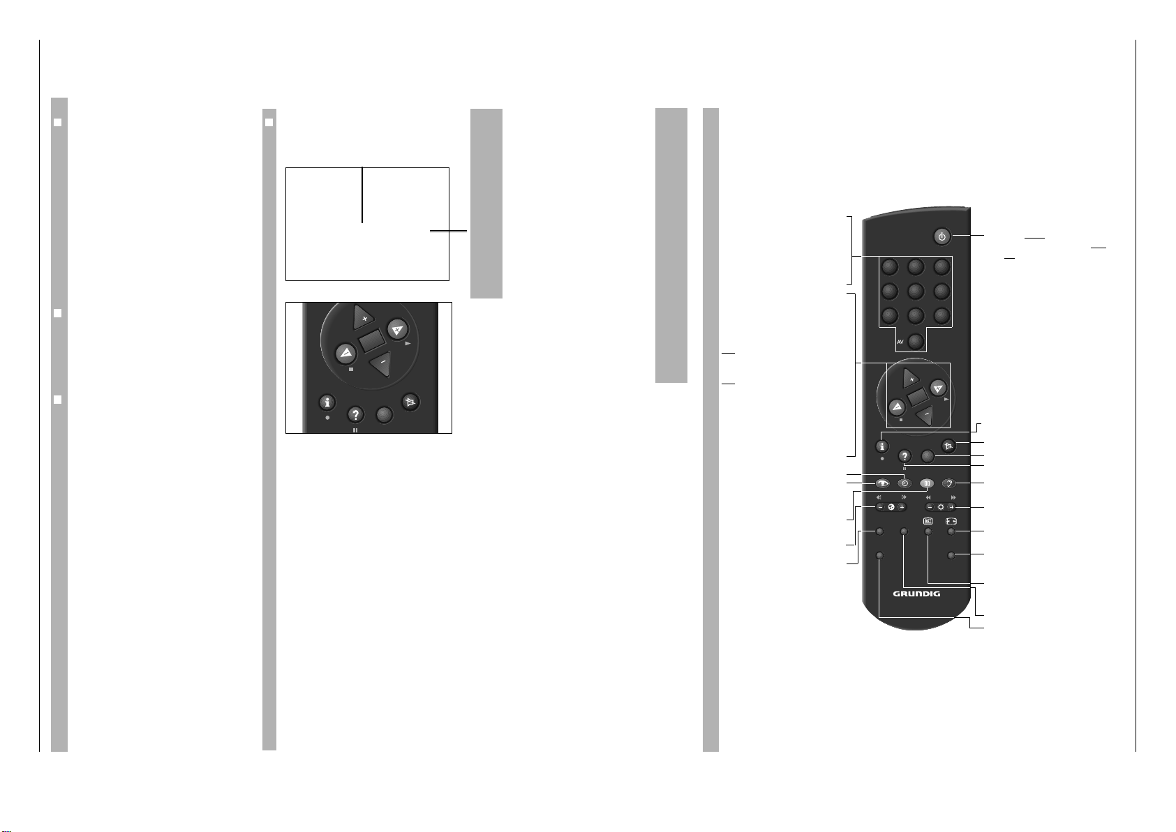
Easy Dialog System
Die Tasten der Fernbedienung
Auf dieser Seite sind die Tasten der Fernbedienung
kurz erklärt.
Im Dialogcenter sind unter »Fernbedienung« alle
Funktionen der Fernbedienung erklärt.
Probieren Sie die Funktionen einfach aus.
1…9
Programmplatz-Wahl und
AV
0
Einschalten des Gerätes aus
Bereitschaft oder
– AV-Stellung wählen
– Eingeben der Seitennummern
im Videotext-Betrieb
P Einschalten des Gerätes aus
Bereitschaft. Programmplatz
schrittweise fortschalten
(1, 2, 3 ...)
p Programmplatz schrittweise
zurückschalten (... 3, 2, 1)
oder
p, P Cursor-Bewegung nach oben unten
xc
Lautstärke
oder
xc
Cursor nach links/rechts.
Wird eine der Tasten P oder p gedrückt
gehalten, werden die Programmplatzkennungen eingeblendet und schnell durchlaufen. Das Gerät schaltet nach Loslassen der
Taste auf den gewählten Programm-platz.
G Ändern und Aktivieren verschie-
dener Funktionen
h
Uhrzeit ein/aus.
k
Bildeinstellungen
Vorwahl zum Einstieg in das
Menü »Bildeinstellungen«
j
Standbild oder
¢
AUX und
j
ist Program scan
- E + Farbstärke ändern.
SAT Satelliten-Receiver fernbedienen
(dazu Taste SAT gedrückt halten).
b
Taste einmal drücken: Gerät in
Bereitschaft schalten.Taste zwei
mal drücken: Gerät komplett ausschalten (vorausgesetzt der ÖkoNetzschalter ist aktiviert).
h Einstieg ins DIALOG CENTER
(mit
h und G )
¢
a
Ton ein/aus (stummschalten).
¢
TXT
Videotext/-Betrieb Ç TV-Betrieb.
¢
D
Kurzanleitung aufrufen
g
Toneinstellungen
Vorwahl zum Einstieg in das
Menü »Toneinstellungen«
- R +
Helligkeit ändern.
E
Bildformat-Umschaltung
AUX
Vorwahltaste für verschiedene
Funktionen, z.B.
¢
AUX und
j
ist Program scan
C
Info über die aktuelle Sendung
PIP Bild im Bild ein/aus
VIDEO Video-Recorder fernbedienen
(dazu Taste VIDEO gedrückt
halten).
SAT PIP
VIDEO
321
654
987
0
P
OK
P
TXT
AUX
TP 800
Page 13
GRUNDIG Service 1 - 13
Operating Hints Note: This chapter contains excerpts from the operating instructions. For further particulars please refer to the appropriate user instructions the part number of which is indicated in the
relevant spare parts list.
Digi 6 Allgemeiner Teil / General Section
❒
Assigning programme positions
This set is equipped with the automatic tuning
system ATS euro plus which performs the programme assignment for you.
After switching on the set, confirm the »English«
dialogue language by pressing the Obutton.
If the »Select dialog language« page does not appear, press the .button and then the
O
button.
The dialogcenter appears on the screen.
Use the
] or | button to select the »Automatic programming« menu
line.
Press the
O
button.
Use the
] or | button to select the »Completely new programming«
line and then press the
O
button.
Confirm your country with the Obutton.
When the automatic programme allocation is com-
pleted, hints to the Easy Dialog System are displayed.
❒
The Easy Dialog System
Your television is provided with the »Easy Dialog
System«.
With this system, all hints on operating the TV set
are no longer to be found in a printed instructions
manual but in dialog boxes which can be displayed
on the picture screen.
❒
The Dialogcenter
The Dialogcenter is the control centre of your TV
set. It is called up by pressing the .and then the
O
button. Via the displayed menu, you can make
settings, call up information and select precise help
for operating your TV set (for example an explanation
of the remote control handset, an index, tips and
tricks, etc.).
Simply try it out. You can do no harm!
❒
Basic operation
The dialogue symbols indicate for each operating
step with which buttons the different functions can
be carried out.
]/| Yellow bar up/down
In two-page menus, selection of the second page.
xc
Set values.
O
Confirm selected function.
¢
TXT
Return to TV picture.
¢
?
Help.
OK
TXT
P
P
]
|
To 1st page
xc
O
Call up
¢
?
Help
¢
TXT
TV
Easy Dialog System
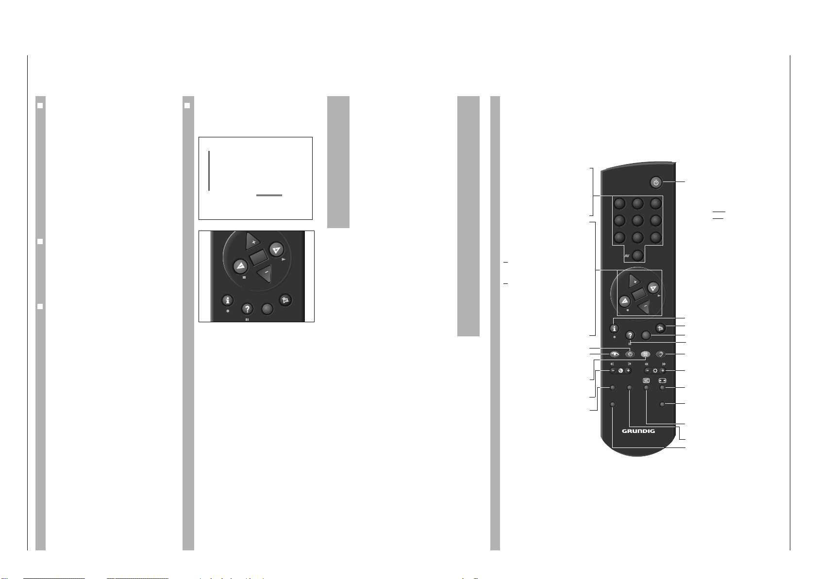
The Buttons on the Remote Control Handset
This is a brief explanation of the remote control buttons.
All functions will be explained in detail under
»Remote control« in the Dialogcentre.
Simply try out the functions.
1…9
Select programme position
AV
0
and switch on the TV set from
standby,
or
– select AV position,
– enter page numbers in Teletext
mode.
P Switch on from standby. Select
programme positions step by
step
(1, 2, 3 ...)
p Select programme positions
step by step (... 3, 2, 1)
or
pP Move cursor up / down.
xc
Volume
or
xc
Move cursor to the left / right.
When holding down the P or p button,
the programme position identifications
will scroll on the screen. When releasing
the pressed button, the TV set switches to
the selected programme position.
G Modify and activate certain
functions.
h
Time display on/off.
k
Picture adjustments.
Access to the »Picture settings«
menu.
j
Still picture, or
¢
AUX plus
j
Program scan
- E + Colour contrast.
SAT Satellite receiver remote control
(press and hold down the SAT
button).
b
Press once: switch to standby.
Press twice
: switch definitively off
(provided the mains economy
switch is activated.
h Access to the DIALOG CENTER
¢
+ Sound on/off (mute).
¢
TXT
Teletext mode Ç TV mode
¢
D
Call up brief instructions.
g
Sound adjustments.
Access to the »Sound settings«
menu.
- R +
Brightness
E
Picture format switching
AUX
Preselect button for certain functions, e.g.
¢
AUX plus
j
Program scan
C
Info about current broadcast
PIP Picture-in-picture on/off.
VIDEO Video recorder remote control
(press and hold down the
VIDEO button).
SAT PIP
VIDEO
0
P
TP 800
OK
321
654
987
P
TXT
AUX
Page 14

Allgemeiner Teil / General Section Digi 6
Service- und Sonderfunktionen
1. Einschaltfunktionen
1.1 ATS-Reset und Demo-Mode
Netzschalter "EIN" mit gedrückter Nahbedientaste "L+".
1x Netz ein: Demo-Mode wird aktiviert. Mit der Taste "P-" kann kurzmit "L+": zeitig deaktiviert und mit Taste "P+" aktiviert werden.
2x Netz ein: Demo-Mode ("Demo off") wird ausgeschaltet und ATS
mit "L+": aktiviert (Einblendung "ATS Reset").
Das ATS sucht mit aufsteigender Frequenz, angezeigt wird der Kanal.
Bei der Ländereinstellung "F" und "übrige" kann wahlweise auf Kanaloder Frequenzanzeige umgeschaltet werden.
Das ATS-System ermittelt das ATS-Signal oder das ACI-Signal für die
Senderkennung.
Wird ein ACI-Sender gefunden, bricht der ATS-Suchlauf ab und die
ACI-Daten werden übernommen und in der Programmtabelle gespeichert. Beim Wechsel von ATS auf ACI ist für 30sec ein ACI-Abbruch
mit der Taste "6" möglich (zurück zu ATS).
Tastendruck "TXT" bricht den ATS-Lauf ab ohne zu speichern.
Weiterhin wird für die Programme 1…99 bzw. 1…179 (bei SATBaustein) der Lautstärkeoffset zurückgesetzt und die Grundwerte für
"Lumadelay" und "Peaking", sowie das länderbezogene Peribit vorbelegt.
1.2 Prozessor-Initialisierung
Pin 10 und 12 der schwarzen Scartbuchse verbinden. Durch diesen
Vorgang wird nach Austausch des Prozessors das interne EEPROM
geladen und damit der Prozessor initialisiert.
1.3 Mittelwerte / Notdatensatz laden (ROM-Daten)
Dies ist nur einmal nach NVM- oder µP-Wechsel möglich.
Nahbedientaste "P-" gedrückt halten und das Gerät mit dem Netzschalter einschalten. Dadurch wird nach Austausch des IC87080
(NVM) das Gerät mit dem Notdatensatz gestartet.
Durch diesen Vorgang werden die nachfolgenden Daten aus dem
EPROM IC87030 in den NVM IC87080 kopiert:
IC87080: (gerätespezifische Daten, über das Dialog Center einstellbar)
- Rauschreduktion
- Lautstärkeoffset
- Kammfilter
- Decoder, Peri
- Analog- und Digitalton Decoder
- Analogwerte (Lautstärke, Helligkeit usw.)
- Farbdeckung und Bildschärfe
- Programmdaten (Kanal- Feinabstimmung, Senderkennung)
- SAT-Daten (Frequenz, Ebene, Kennung, Audiohub usw.)
nur bei eingebautem SAT-Nachrüstsatz
- DSP-Daten (nur bei eingebautem DSP-Baustein)
1.4 Service - Mode Programm (zur Fehlersuche im I2C-Bus)
Nahbedientaste P+ gedrückt halten und das Gerät mit dem Netzschalter einschalten.
Mit der Nahbedientaste "L+" können evtl. weitere fehlerhafte Schnittstellen ermittelt werden. Werden keine weiteren fehlerhaften Schnittstellen erkannt, versucht die Software das Gerät zu starten.
Achtung: Die Fehlermeldungen des DSP-, SAT- und PIP-Bausteins
werden nur angezeigt, wenn diese Module auch bestückt sind und
mindestens eine I2C-Bus-Adresse auf dem fehlerhaften Baustein
erkannt wurde.
Diese Fehlermeldungen beziehen sich nur auf Störungen im I2C-Bus,
also auf Bausteine oder Schaltkreise bei denen keine Rückmeldung
(Acknowledge) über den I2C-Bus erfolgt. Beispielsweise keine Betriebsspannung am Baustein, Unterbrechung der Leiterbahn oder I2CSchnittstelle defekt.
Schnitt- Fehler- fehlerhafter
stelle Code Baustein/Schaltkreis
S-DDC E1 CIC1410, Feature-Box
Display-Prozessor E4 CIC1640, Feature-Box
Comb Filter Video -Proz. E5 CIC1350, Feature-Box
Component Interf.-Proz. E6 CIC1360, Feature-Box
Megatext - IC46010, Signal-Chassis
RGB-Prozessor E7 IC34510, Signal-Chassis
Audio-Prozessor E8 IC32300, Signal-Chassis
Service and Special Functions
1. Switching-on Options
1.1 ATS Reset and Demo Mode
Press and hold button "L+" on the TV and switch the mains button "ON".
1x mains on: Demo Mode is activated. Short-time deactivation is posswith "L+": ible with "P-" and reactivation with "P+".
2x mains on: Demo Mode ("Demo off") is switched off and ATS is actiwith "L+": vated (indication "ATS Reset" appears).
The ATS system scans the ascending frequencies indicating the
channel. When setting the country "F" and "others", the display mode
can be changed optionally to indicate either the channel or the
frequency.
The ATS system searches for the ATS or ACI signal for the station
identification.
When finding an ACI station, ATS search is stopped, the ACI data are
taken over and entered into the station table. When changing from ATS
to ACI it is possible during a period of 30sec to stop the ACI function
with button "6" (back to ATS).
Pressing the "TXT" button stops the ATS function without storing any data.
Additionally, for the programmes 1...99 or 1...179 (with SAT Module),
the volume offset is reset and the default values for "Lumadelay" and
"Peaking" are stored together with the Peri-bit for the respective
country.
1.2 Initialising the Processor
By connecting pin 10 and pin 12 of the Scart socket after replacement
of the processor, the internal EEPROM is loaded thus initialising the
processor.
1.3 Loading the Average Values / Emergency Data Set (ROM Data)
This is only possible once on replacement of the NVM or µP.
By pressing and holding the "P-" button on the TV and switching on with
the mains button after replacement of IC87080 (NVM) the TV set is
started with the emergency data set.
In doing so, the following data is read out from EPROM IC 87030 and
loaded into the non-volatile memories IC87070:
IC87080: (data specific to the TV, can be set via the Dialog Center):
- noise reduction
- volume offset
- comb filter
- decoder, Peri
- analog and digital sound decoder
- analog values (volume, brightness etc.)
- colour match and peaking
- programme data (channel fine tuning, station ident)
- SAT data (frequency, level, identification, audio deviation etc.)
only with built-in SAT retrofit kit
- DSP data (only with built-in DSP module)
1.4 Service Mode Programme (for fault finding in the I2C bus)
Press and hold the P+ button on the TV set and switch on with the
mains button.
The "L+" button on the TV set allows to discover other potentially
defective interfaces. If there are no other defective interfaces the
software tries to start the TV set.
Attention: The error messages for the DSP, SAT and PIP modules are
only indicated if these modules are actually fitted and at least one I2C
bus address on the defective module has been identified.
These error messages refer only to interferences in the I2C bus, that is
to those modules or integrated circuits which do not return an Acknowledge bit via the I2C bus, for example to indicate that there is no
operating voltage present on the module, that there is a break in the
circuit path or that the I2C interface is defective.
Interface Error Defective
Code Module / Integrated Circuit
S-DDC E1 CIC1410, Feature Box
Display Processor E4 CIC1640, Feature Box
Comb Filter Video Proc. E5 CIC1350, Feature Box
Component Interf. Proc. E6 CIC1360, Feature Box
Megatext - IC46010, Signal-Chassis
RGB Processor E7 IC34510, Signal-Chassis
Audio Processor E8 IC32300, Signal-Chassis
GRUNDIG Service1 - 14
Page 15

Digi 6 Allgemeiner Teil / General Section
NVM E9/EA/ IC87080, Signal-Chassis
EC/EE
Video Matrix EH IC43150, Signal-Chassis
Video Matrix EL IC43200, Signal-Chassis
Tuner, NVM EP CIC2120, Signal-Chassis
Tuner, PLL Eb CIC2161, Signal-Chassis
Audio Matrix (optional) EF IC43210, Signal-Chassis
Memory Sync Controller E2 CIC1600, Feat-Box -103.41
Picture-Prozessor E3 CIC1600, Feat-Box -103.41
Line Flicker Reduction Eh CIC1700, Feat-Box -103.41
Scan Videoprozessor En CIC70270, Feat-Box -103.38
Audio-Prozessor (DSP) Ec IC40010, Dolby-Platte
Dolby Prozessor Ed CIC40040, Dolby-Platte
NVM ER CIC3830, SAT-Baustein
PLL Eo CIC9170, SAT-Tuner
PIP-Prozessor EU CIC29040, PIP-Baustein
PIP-Tuner PLL Er CIC2161, PIP-Baustein
1.5 SAT-Modul-Programmierung (nur mit bestücktem SAT-Baustein)
Fernbedientaste "6" gedrückt halten und das Gerät mit dem Netzschalter einschalten. Dadurch wird z.B. nach EEPROM Wechsel des
SAT-Bausteins aus dem EPROM IC87030 die gespeicherte Sendertabelle übertragen.
1.6 PIP-Abgleich
Fernbedientaste "PIP" gedrückt halten und das Gerät mit dem Netzschalter
einschalten. Dadurch werden bei eingebautem PIP-Baustein der PIPAbgleich-Mode aufgerufen. Über die Menüführung können Sie mit den
Tasten 3 4 2 1 die PIP-Position verändern und mit "OK" speichern.
1.7 Programmsperre aufheben
(nicht das Menü Sperrung "Kindergefährdende Sendungen")
Die Tastenfolge 3 4 2 1 hebt die persönliche Kennzahl auf.
1.8 EPROM-Versionsnummer
Mit Taste "6" das Menü "DIALOGCENTER" aufrufen. Taste "AUX"
zeigt die Versionsnummer an. Der Index 07 in der Sachnummer
(19798-311.07) ergibt den EPROM-Stand.
2. Sonderfunktionen im Dialogcenter
2.1 Öko-Netzschalter aktivieren bzw. deaktivieren
Mit Taste "6" das Menü "Ökonetzschalter" über "DIALOGCENTER" –>
"SONDERFUNKTIONEN" aufrufen. Mit den Tasten 3 4 auf "aus"
oder "1h…4h" stellen.
Bei aktiviertem "Öko-Netzschalter" trennt der Netzschalter das Gerät
durch zweimaligen Tastendruck der Taste 8 vom Netz.
2.2 Einschalten mit Programm "1" oder "AV"
Mit Taste "6" das Menü "Einschalten mit" über "DIALOGCENTER" –>
"SONDERFUNKTIONEN" aufrufen. Mit den Tasten 3 4 auf "Programm" oder "AV" stellen.
2.3 "Bild-/Ton-Skala" ein oder aus für alle Programme
Mit Taste "6" das Menü "Bild-/Ton-Skala" über "DIALOGCENTER" –>
"SONDERFUNKTIONEN" aufrufen. Bei "unsichtbar" erscheinen keine Balkenanzeigen für die Analogwerte.
2.4 "Megalogic-Info"
Mit Taste "6" das Menü "Megalogic-Info" über "DIALOGCENTER" –>
"SONDERFUNKTIONEN" aufrufen. Bei "ohne" wird keine MegalogicInformation (z.B. Wiedergabe oder Stop) angezeigt.
NVM E9/EA/ IC87080, Signal-Chassis
Video Matrix EH IC43150, Signal-Chassis
Video Matrix EL IC43200, Signal-Chassis
Tuner, NVM EP CIC2120, Signal-Chassis
Tuner, PLL Eb CIC2161, Signal-Chassis
Audio Matrix (option) EF IC43210, Signal-Chassis
Memory Sync Controller E2 CIC1600, Feat Box -103.41
Picture Processor E3 CIC1600, Feat Box -103.41
Line Flicker Reduction Eh CIC1700, Feat Box -103.41
Scan Video Processor En CIC70270, Feat Box -103.38
Audio Processor (DSP) Ec IC40010, Dolby Board
Dolby Processor Ed CIC40040, Dolby Board
NVM ER CIC3830, SAT Module
PLL Eo CIC9170, SAT Tuner
PIP Processor EU CIC29040, PIP Module
PIP Tuner PLL Er CIC2161, PIP Module
1.5 SAT Module Programmierung (only with built-in SAT Module)
Press and hold the "6" button on the remote control and switch the TV
on with the mains switch. Consequently, on replacement of the
EEPROM on the SAT Module for example, the stored station table is
read out from EPROM IC87030.
1.6 PIP Adjustment
Press and hold the "PIP" button on the remote control and switch the
TV on with the mains switch. In doing so, with built-in PIP Module, the
PIP Adjustment Mode is called up. Using the 3 4 2 1 buttons the PIP
position can be changed via the menu and stored with "OK".
1.7 Cancelling the Parental Lock
(not Lock programme menu, "unfit for children")
To cancel your personal code number press the buttons 3 4
this order.
1.8 EPROM Version Number
Press button "6" to call up the "DIALOGCENTER" menu. The version
number is shown by pressing the "AUX" button. The index 07 of the part
number (19798-311.07) indicates the EPROM version.
EC/EE
2 12 1
2 1 in
2 12 1
2. Special Functions in the Dialog Center
2.1 Activating or Disactivating the Economy Mains Switch
Reach the "Economy mains switch" menu with button "6" via
"DIALOGCENTER" –> "SPECIAL FUNCTIONS". With the buttons 3
4 select "off" or "1h…4h".
On activation of "Economy mains switch" the mains switch disconnects
the TV from the mains by pressing the button 8 twice.
2.2 Switching on with Programme "1" or "AV"
Reach "Switch on with" menu with button "6" via "DIALOGCENTER" –>
"SPECIAL FUNCTIONS". With the buttons 3 4 select "Progr" or "AV".
2.3 Picture/Sound Options On or Off for all Programmes
Reach the "Pict./sound scales" menu via "DIALOGCENTER" –> "SPECIAL FUNCTIONS" by pressing button "6". When selecting "invisible"
the scales indicating of the analog values do not appear.
2.4 "Megalogic-Info"
Reach the "Megalogic-Info" menu via "DIALOGCENTER" –> "SPECIAL FUNCTIONS" by pressing button "6". When selecing "Without" the
Megalogic information (e.g. playback or stop) is not indicated.
3. Service-Einstellungen für den Fachhandel
3.1 Blauen Bildschirmhintergrund abschalten
Mit Taste "6" das Menü "Nur für den Fachhändler" über "DIALOGCENTER" –> "SERVICE FÜR DEN FACHHANDEL" –> Kennzahl 8500
–> aufrufen. Gelbe Taste drücken. Nach der Programmumschaltung
ist der blaue Hintergrund abgeschaltet.
Mit Ausschalten des Gerätes wird diese Funktion wieder aufgehoben.
3.2 Farbdeckung (Luma-Delay) für Groß- und PIP-Bild
Mit Taste "6" das Menü "Farbdeckung P." über "DIALOGCENTER"
–> "SERVICE FÜR DEN FACHHANDEL" aufrufen. Mit den Tasten 3
4 wird die Farbdeckung programmplatzbezogen eingestellt.
3.3 COLORplus-Menü (nur bei PALplus-Geräten)
Mit Taste "6" das Menü "COLORplus " über "DIALOGCENTER"
–> "SERVICE FÜR DEN FACHHANDEL" aufrufen. Mit den Tasten 3
4 wird die COLORplus-Erkennung auf "aus" oder "autom." gestellt.
In der Stellung "aus" schaltet das Gerät bei schlechten PALplusSendungen (Empfang) auf Standard-PAL.
GRUNDIG Service
3. Service Settings for the Dealer
3.1 Switching off the Blue Screen Background
Reach "Only for the retailer" via "DIALOGCENTER"–> "SERVICE"
–> Code Number 8500 pressing button "6". Press the yellow button.
After switching over the programme, the blue background is switched
off.
Switching off the TV set cancels this function.
3.2 Colour Match (Luma Delay) for Normal and PIP picture
Reach the "Colour match" menu via "DIALOGCENTER" –> "SERVICE" pressing button "6" . With the buttons 3 4 the luma delay is set
on a per-programme basis.
3.3 COLORplus-Menü (only PALplus models)
Reach the "COLORplus " menu via "DIALOGCENTER" –> "SERVICE" pressing button "6". Use the 3 4 buttons to change the COLORplus
identification to "Off" or "Auto".
When selecting "Off" the TV receiver switches to Standard PAL on poor
reception of PALplus broadcasts.
1 - 15
Page 16
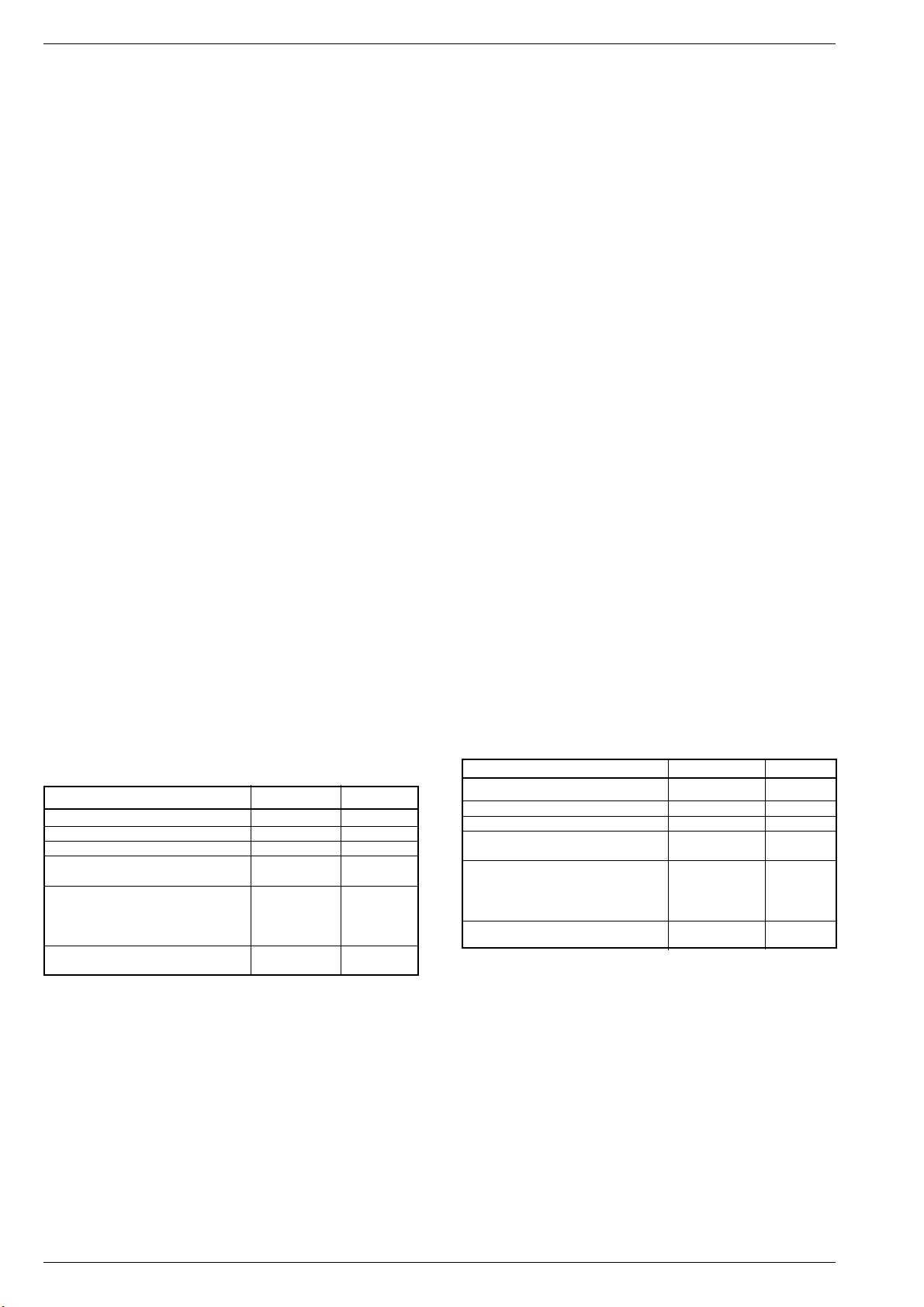
Allgemeiner Teil / General Section Digi 6
3.4 Blackline Detektor (nur bei PALplus- und 16:9 Geräten)
Mit Taste "6" das Menü "Blackline-Detect." über "DIALOGCENTER"
–> "SERVICE FÜR DEN FACHHANDEL" aufrufen. Mit den Tasten 3Ê 4
stellen Sie den "Blackline-Detect." auf "aus" oder "autom.". In Stellung
"autom." werden Cinemascope-Filme (schwarze Streifen am oberen und
unteren Bildrand) selbsttätig erkannt und die Bildamplitude vergrößert.
3.5 PALplus-Menü (nur bei PALplus-Geräten)
Mit Taste "6" das "PALplus-Menü" über "DIALOGCENTER" –> "SERVICE FÜR DEN FACHHANDEL" –> "Nur für den Fachhändler" aufrufen. Mit den Tasten 3 4 2 1 können Sie die Einstellungen im
PALplus-Menü nur temporär verändern. Auslieferungszustand "ein".
3.6 Rauschreduktion 1…99 bzw. 1…179 (bei SAT-Baustein)
Mit Taste "6" das Menü "Rauschredukt." über "DIALOGCENTER" –>
"SERVICE FÜR DEN FACHHANDEL" aufrufen. Mit den Tasten 3 4
können Sie die Rauschreduktion für die Programme 1…99, bzw.
1…179 (bei SAT-Baustein) auf "aus", "schwach" oder "autom." stellen.
In Stellung "manuell" kann die Rauschreduktion für die einzelnen
Programme auf unterschiedlicher Eingabe, wie "aus", "schwach" oder
"autom." stehen.
3.7 Decoder P1…99 bzw. 1…179 (bei SAT-Baustein)
Mit Taste "6" das Menü "Decoder" über "DIALOGCENTER" –> "SERVICE FÜR DEN FACHHANDEL" aufrufen. Mit den Tasten 3 4 können
Sie den Decoder für alle Programme auf "aus" oder "ein" stellen. In
Stellung "manuell" kann die Decoderumschaltung für die einzelnen
Programme auf unterschiedlicher Eingabe, wie "aus" oder "ein" stehen.
3.8 Decoder P X für verschlüsselte Sendungen
Mit Taste "6" das Menü "Decoder-Ton P." über "DIALOGCENTER" –>
"SERVICE FÜR DEN FACHHANDEL" aufrufen. Mit den Tasten 3 4
können Sie programmplatzbezogen für verschlüsselte Sendungen
einen analogen oder digitalen Decoder auf interne oder externe
Umschaltung stellen.
3.9 Service AV-Anschlüsse
Mit Taste "6" das Menü "Service AV-Anschlüsse." über "DIALOGCENTER" –> "SERVICE FÜR DEN FACHHANDEL" aufrufen. Mit den Tasten
3 4 und 1 2 können Sie die Signalart lt. Menüführung umschalten.
Mit den Tasten 3 4 kann die Decoder-Priorität auf "niedrig", "hoch" oder
"aus" eingestellt werden.
Wird die Decoder-Priorität AV 1 auf "hoch" gestellt, schaltet DecoderPriorität AV 2 automatisch auf niedrig.
Der Decoder mit der Priorität "hoch" wird durch Anlegen einer Schaltspannung (z.B. VCR-Wiedergabe) nicht abgeschaltet.
TV-Zeitkonstante = langsame Zeitkonstante
AV-Zeitkonstante = schnelle Zeitkonstante
Tabelle der Zeitkonstanten- und Kammfilterumschaltung:
TV-Mode Zeitkonstante Kammfilter
AV AV aus
Terr./SAT/Decoder TV aktiv
AV1+ML-Videoplayer TV aus
Terr./SAT/Decoder + xxx,"AV"- AV aus
Senderkennung
"Ext. Receiver" einstellen TV aktiv
(Service für den Fachhandel –>
Service AV-Anschlüsse –> AV x: –>
Signalart "Ext. Receiver")
AV x –> keine Koinzidenz TV aktiv
+ Einblendung
3.10 Automatische Präsentation
Mit Taste "6" das Menü "Automatische Präsentation" über "DIALOGCENTER" –> "SERVICE FÜR DEN FACHHANDEL" aufrufen. Mit der
Taste "OK" läuft die automatische Geräte-Präsentation an. Ausschalten des Gerätes mit dem Netzschalter, oder den Nahbedientasten
"P+" oder"P-". Deaktivieren über ATS-Reset 1.1.
3.11 IR-Dataprogrammer (nicht bei bestücktem SAT-Modul)
Mit Taste "6" das Menü "IR-Dataprogrammer" über "DIALOGCENTER"
–> "SERVICE FÜR DEN FACHHANDEL" aufrufen. Mit der Taste "OK"
können mit dem IR-Dataprogrammer 2 max. 99 Programmplätze mit
Daten für Kanal, Norm, Peri, 4-stellige Sendereinblendung, FinetuningMitte und Lautstärke-Offset "0" abgespeichert werden.
Der Programmer AP überträgt nur Kanäle und die 4-stelligen Senderkennzeichen mit Finetuning Mitte und Lautstärke-Offset "0".
Achtung: Die Datenübertragung kann durch Störfelder elektrischer
Beleuchtungskörper beeinflußt werden.
3.4 Blackline Detector (only PALplus and 16:9 models)
Reach the "Blackline-Detect." menu via "DIALOGCENTER"
–> "SERVICE" pressing the "6" button. Use the 3Ê 4 buttons to set
"Blackline-Detect." to "Off" or "Auto". When selecting "Auto" the TV set
can automatically identify cinemascope films (black bars on the upper
and lower edge of the picture) and increase the vertical amplitude.
3.5 PALplus Menu (only PALplus-sets)
Call up the "PALplus-Menu" with button "6" via "DIALOGCENTER"
–> "SERVICE" –> "Only for the retailer" . The buttons
3 4 2 1 allow to change the PALplus-Menu only temporarily.
PALplus receivers are delivered with "On" as a standard setting.
3.6 Noise Reduction P1…99 or 1...179 (with SAT Module)
Reach the "Noise reduct." menu via "DIALOGCENTER" –> "SERVICE" pressing button "6". With the buttons 3 4 the noise reduction can
be set to "Off", "weak", or "Auto" for all of the programmes 1...99 or
1...179 (with SAT module). With "Manual" the noise reduction setting
for the individual programmes can be different, that is "Off", "weak" or
"Auto" stehen.
3.7 Decoder P1…99 or 1...179 (with SAT Module)
Call up the "Decoder" menu with the "6" button via "DIALOGCENTER"
–> "SERVICE". With the buttons 3 4 it is possible to switch the
decoder to "Off" or "On" for all programmes. With "Manual", the
decoder can be switched "on" or "off" for the individual programme
positions.
3.8 Decoder P X for Coded Transmissions
Call up the "Decoder Sound P." menu with button "6" via
"DIALOGCENTER" –> "SERVICE". With the 3 4 buttons it is possible
to set an analog or digital decoder for coded transmissions to internal
or external on a per-programme basis.
3.9 Service AV Connections
Call up the "Service AV connections." menu with button "6" via
"DIALOGCENTER" –> "SERVICE". With the 3 4 and 1 2 buttons it
is possible to switch over the signal type according to the menu guide.
With the 3 4 buttons the decoder priority can be changed to "low",
"high" or "Off".
When setting the AV 1 decoder priority to "high", the AV 2 decoder
priority is automatically changed to low.
The decoder with "high" priority is not switched off on application of a
switching voltage (e.g. VCR playback).
TV time constant = slow time constant
AV time constant = fast time constant
Table: Time constant and comb filter switch-over
TV Mode Time Constant Comb Filter
AV AV off
Terr./SAT/Decoder TV active
AV1+ML-Videoplayer TV off
Terr./SAT/Decoder + xxx,"AV"- AV off
station identification
Setting "Ext. Receiver" TV active
(Service –> Service AV
Connections –> AV x: –> Signal
type "Ext. Receiver")
AV x –> no coincidence TV active
+ display on screen
3.10 Automatic Presentation
Call up the "Automatic presentation" menu with button "6" via
"DIALOGCENTER" –> "SERVICE ". Start the automatic presentation
of the TV set with the "OK" button. Switch the TV set off with the mains
button or the local "P+" or"P-" button. Deactivate with ATS Reset 1.1.
3.11 IR Data Programmer (SAT Module not fitted)
Reach the "IR-Dataprogrammer" menu via "DIALOGCENTER" –>
"SERVICE" pressing button "6". The IR Data Programmer 2 makes it
possible to store a maximum of 99 programme positions with the data
for channel, TV standard, Peri, 4-place station identification, fine tuning
center frequency, and the volume offset "0" using the "OK" button.
The Programmer AP transfers only the channels and 4-place station
identifications with fine tuning center frequency and volume offset "0".
Attention: The data transfer can be affected by interferences from
electrical lighting fixtures.
GRUNDIG Service1 - 16
Page 17

Digi 6 Allgemeiner Teil / General Section
3.12 Einschalten mit Testbild oder TV
Mit Taste "6" das Menü "Einschalten mit Testbild oder TV" über
"DIALOGCENTER" –> "SERVICE FÜR DEN FACHHANDEL" aufrufen. In Stellung "Testbild" erscheint nach dem Wiedereinschalten am
Bildschirm ein geräteeigenes Testbild. Mit der Taste "TXT" schalten
Sie das Gerät in den Programm-Mode zurück (wird ca. 20s keine Taste
gedrückt, erscheint das Testbild wieder).
Abschalten des Testbild-Modes wieder über das Menü.
3.13 Nur für den Fachhändler
Mit Taste "6" das Menü "Nur für den Fachhändler" über "DIALOGCENTER" –> "SERVICE FÜR DEN FACHHANDEL" aufrufen und mit
Taste "OK" bestätigen. Nach Eingabe der Codezahl "8500" kann der
Fachhandel den Geräteabgleich lt. Menüführung durchführen.
(Siehe Abgleich Kap. Abgleich, Seite 2-5).
4. Ton-Einstellungen
4.1 Tonumschaltung
Mit der blauen Taste das Menü "TON EINSTELLUNGEN" aufrufen. Je
nach Sender-Norm sind für die Tonumschaltung verschiedene Einstellungen anwählbar:
- "Mono": bei reinen Mono-Sendungen
- "Mono A / Mono B": bei 2-Ton-Sendungen
- "Stereo / Mono": bei schlechtem Stereo-Ton kann auf Mono ge-
schaltet werden
- "Nicam / FM"
- "Nicam A / Nicam B / FM"
- "Nicam Stereo / FM"
4.2 Kopfhörer-Tonumschaltung
Mit der blauen Taste das Menü "TON EINSTELLUNGEN" aufrufen. Je
nach Sender-Norm sind für "Kopfhörer" verschiedene Einstellungen
anwählbar:
- "Mono A / B", unabhängig von den Lautsprechern
- "Nicam A / Nicam B / FM", unabhängig von den Lautsprechern
Bei allen anderen Einstellungen ist der Kopfhörerton mit dem
Lautsprecherton fest gekoppelt.
4.3 Programmplatzbezogene Lautstärkeeinstellung
Mit der blauen Taste das Menü "TON EINSTELLUNGEN" aufrufen.
Über "Lautstärke P ." wird mit den Tasten 3 4 die Lautstärke
programmplatzbezogen eingestellt (Lautstärke-Offset).
4.4 Ton-Effekte Pro Logic Phantom (nur mit Dolby Surround-Baustein)
Mit der blauen Taste das Menü "TON-EINSTELLUNGEN" aufrufen.
Unter "Toneffekte" sind mit den Tasten 3 4 und 1 2 unterschiedliche
Dolby-Toneffekte und Lautsprechereinstellungen über das Menü anwählbar.
Die Einstellungen "Toneffekte" werden nur gespeichert, wenn eine
manuelle Dolby-Umschaltung erfolgte. Nach automatischer DolbyUmschaltung (Sendung mit Dolby Surround wurde erkannt) werden
die Ton-Effekte nur temporär eingestellt.
Nach manueller Umschaltung geben "Netz aus" oder "Standby" die
automatische Dolby-Umschaltung wieder frei.
5. Bild-Einstellungen
5.1 Grundeinstellung
Mit der roten Taste das Menü "BILD-EINSTELLUNGEN" aufrufen.
Über die Menüführung sind die Einstellungen "Persönliche Werte",
"Am Tag", "Am Abend" und "Soft" anwählbar. Die "Persönliche Werte"Einstellung läßt eine Regulierung von Kontrast, Bildschärfe und Weißbalance zu. Die Bildschärfe-Einstellung wird programmplatzbezogen
verändert. In den anderen Einstellungen sind diese Werte fest vorgegeben.
Abweichungen der Einstellungen gegenüber "Normal":
- "Am Tag": Vollkontrast und geänderte Weißbalance
- "Am Abend": reduzierter Kontrast und geänderte Weißbalance
- "Soft": veränderte Bildschärfe, Rauschreduktion und Kontrast
5.2. Bildschärfe
Mit der roten Taste das Menü "BILD-EINSTELLUNGEN" aufrufen und
"Bildschärfe P." anwählen.
Mit den Tasten 3 4 können Sie die Bildschärfe in drei Schritten
verändern.
5.3 Perfect Clear
Mit der roten Taste das Menü "BILD-EINSTELLUNGEN" aufrufen und
"Perfect Clear" anwählen.
Mit den Tasten 3 4 können Sie "Perfect Clear" ein- bzw. ausschalten.
3.12 Switching on with the Test Pattern or TV Mode
Call up the menu "Switch on with test pattern or TV", with the "6" button
via "DIALOGCENTER" –> "SERVICE". On selection of "Test pattern"
an integrated test pattern will appear on the screen when switching the
TV on again. The "TXT" button is used to switch the TV back to
Programme Mode (if no other button is pressed during a period of ca.
20s the test pattern reappears).
The Test Pattern Mode can be switched off via the menu.
3.13 Only for the Retailer
Call up the menu "Only for the retailer" with the "6" button via
"DIALOGCENTER" –> "SERVICE" and confirm with the "OK" button.
When entering the code number "8500" the dealer can adjust the TV
set according to the menu.
(See chap. Alignment, page 2-7).
4. Sound Settings
4.1 Sound Switching:
Call up the "SOUND SETTINGS" menu with the blue button. Different
types of "Sound" are available dependent on the TV standard:
- "Mono": in the case of pure mono transmissions
- "Mono A / Mono B": in the case of 2-channel sound transmissions
- "Stereo / Mono": in the case of poor stereo sound quality, the sound
can be switched over to mono
- "Nicam / FM"
- "Nicam A / Nicam B / FM"
- "Nicam Stereo / FM"
4.2 Headphone Sound Switching
Call up the "SOUND SETTINGS" menu with the blue button. Dependent on the TV standard, different settings are possible under "HPsound change over":
- "Mono A / B", independent of the loudspeakers
- "Nicam A / Nicam B / FM", independent of the loudspeakers
With all other options, separate selection of the sound for the headphones and loudspeakers is not possible.
4.3 Setting the Volume on a Per-Programme Basis
Call up the "SOUND SETTINGS" menu with the blue button.The
volume can be set for each individual programme position with
"Volume P ." (volume offset).
4.4 Sound Effects Pro Logic Phantom (only with Dolby Surround
Module)
Call up the "SOUND SETTINGS" menu with the blue button.
Under "Sound effects" different Dolby sound effects and loudspeaker
settings can be selected with the buttons 3 4 and 1 2 via the menu.
The settings under "Sound effects" are stored only on manual selection
of Dolby. When switching over to Dolby is effected automatically (on
identification of a transmission with Dolby Surround) the sound effects
are set only temporarily.
After manual selection of Dolby, the automatic Dolby switching mode
is reactivated when entering "Mains off" or "Standby".
5. Picture Settings
5.1 Basic Adjustment
Call up the "PICTURE SETTINGS" menu with the red button. Via the
menu guide, the following options can be selected: "Personal", "During
the day", "In the evening" and "Soft". The "Personal" option allows to
change the contrast, picture sharpness, and white balance. The
picture sharpness can be changed on a per-programme basis. The
values for the other options are fixed.
Differences between these options and "Personal":
- "During the day": maximum contrast and changed white balance
- "In the evening": reduced contrast and changed white balance
- "Soft": changed picture sharpness, noise reduction and contrast
5.2 Picture Sharpness
Call up the "PICTURE SETTINGS" menu with the red button and select
"Sharpness P."
The picture sharpness can be changed in three steps with the 3 4
buttons.
5.3 Perfect Clear
With the red button call up the "PICTURE SETTINGS" menu and select
"Perfect Clear".
With the 3 4 buttons this function can be switched on or off.
GRUNDIG Service
1 - 17
Page 18

Allgemeiner Teil / General Section Digi 6
5.4 Kammfilter
Mit der roten Taste das Menü "BILD-EINSTELLUNGEN" aufrufen und
"Kammfilter" anwählen.
Mit den Tasten 3 4 können Sie das Kammfilter programmplatzbezogen auf "aus" oder "autom." stellen.
5.5 Zeilenflimmer-Reduktion
Mit der roten Taste das Menü "BILD-EINSTELLUNGEN" aufrufen und
"Zeilenflimmer-Redukt." anwählen.
Mit den Tasten 3 4 können Sie die Einstellungen auf "aus" oder
"autom." stellen.
5.6 Rauschreduktion P . (programmplatzbezogen)
Mit der roten Taste das Menü "BILD-EINSTELLUNGEN" aufrufen und
Rauschreduktion anwählen.
Mit den Tasten 3 4 können Sie die Rauschreduktion programmplatzbezogen zwischen "aus", "autom.", "stark!" und "schwach" stellen. Der
µP speichert nur die Einstellungen "aus", "schwach" und "automatisch" beim Verlassen des Menüs. Die Option "stark!" ist nur vorübergehend anwählbar.
6. Einstellungen über die Senderkennung
Programmbezogene Einstellungen über die Senderkennung schalten
das Gerät in einen Zwangsmode, dadurch wird die automatische
Auswertung unterdrückt.
6.1 Maximale Programmnummer (Umkehrpunkt)
Mit Taste "6" das Menü "TV-Programm-Tabelle" über "DIALOGCENTER" aufrufen.
Nach Eingabe der Kanalziffer "00'" auf einem beliebigen Programmplatz
über die TV-Kanal-Tabelle, können mit den Tasten 1 2 die nachfolgenden
Programme nicht mehr fortgeschaltet werden. Liegt der Umkehrpunkt ≤ 10
ist nur eine einstellige Programmplatzanwahl möglich.
6.2 Einstellungen über die Senderkennung
Mit Taste "6" das Menü "TV-PROGRAMM-TABELLE" über "DIALOGCENTER" –> "OK" aufrufen und gewünschten Sender aktivieren.
Die programmbezogenen Zwangseinstellungen werden in der Senderkennung auf den letzten drei Stellen programmiert, mit dem Komma
am Anfang. Es stehen dann noch die ersten drei Stellen "X" für die
eigentliche Senderkennung zur Verfügung.
Beispiel: xxx,MO nur Monoton
Bei richtiger Einstellung werden als Senderkennung nur die ersten drei
Stellen angezeigt, die Schaltinformation wird unterdrückt.
Anzeige: xxx
Mögliche Schaltstellungen:
- Senderkennung xxx,MO -> Zwangsmono bei Stereosend.
- Senderkennung xxx,2T -> Selektion 2. Tonträger bei
Zweitonsendungen
- Senderkennung xxx,PB -> PAL B/G/H/I mit 50Hz
- Senderkennung xxx,PM -> PAL M mit 60Hz
- Senderkennung xxx,PN -> PAL N mit 50Hz
- Senderkennung xxx,P6 -> PAL mit 60Hz
- Senderkennung xxx,SE -> SECAM mit 50Hz
- Senderkennung xxx,NM -> NTSC M mit 60Hz
- Senderkennung xxx,N4 -> NTSC 4,43 mit 60Hz
- Senderkennung xxx,AF -> AFC-Regelung aktiv
- Senderkennung xxx,AV -> VCR-Zeitkonstante aktiv
- Senderkennung AVxxxx -> VCR-Zeitkonstante aktiv
6.3 Zwangseinstellungen im AV-Mode (AV1…AV4)
Mit Taste "6" das Menü "TV-PROGRAMM-TABELLE" über "DIALOGCENTER" aufrufen. Mit der Taste 4 die AV-Ebene anwählen, gewünschtes AV-Programm aufrufen und mit "blauer Taste" aktivieren.
Die Eingaben bedeuten:
AV,NM NTSC mit 60Hz
AV,N4 NTSC 4,43 mit 60Hz
AV,PB PAL B/G/H/I mit 50Hz
AV,PM PAL M mit 60Hz
AV,PN PAL N mit 60Hz
AV,P6 PAL mit 60Hz
AV,SE SECAM mit 50Hz
AV,2T Selektion 2. Tonträger bei Zweitonsendungen
5.4 Comb Filter
Call up the "PICTURE SETTINGS" menu with the red button and select
"Comb filter".
The comb filter can be set to "Off" or "Auto" on each programme
position using the 3 4 buttons.
5.5 Line Flicker Reduction
Call up the "PICTURE SETTINGS" menu with the red button and select
"Line flicker reduct.".
With the 3 4 buttons the setting can be changed to "Off" or "Auto".
5.6 Noise Reduction P . (on individual programme positions)
With the red button call up the "PICTURE SETTINGS" menu and select
"Noise reduct.".
With the 3 4 buttons it is possible to select the settings "Off", "Auto",
"High!" and "weak" for each individual programme position. The µP
stores the settings "Off", "weak" and "Auto" when leaving the menu.
The option "High!" can be selected only temporarily.
6. Settings via the Station Ident
Settings entered in the station identification for an individual programme position cause the TV set to switch to a forced operating
mode; as a result, the automatic evaluation function is suppressed.
6.1 Maximum Programme Number (reversing point)
Call up the "TV-PROGRAMME-CHART" menu via "DIALOGCENTER"
pressing the "6" button.
When entering the channel number "00" on any programme position
of the TV programme chart and entering "00", programme selection with
the buttons 1 2 is limited to the numbers lower than this position. If the
reversing point is ≤ 10, only single-digit programme selection is
possible.
6.2 Settings via the Station Ident
Call up the"TV-PROGRAMME-CHART" menu via "DIALOGCENTER"
–> "OK" using button "6" and activate the desired TV station.
The forced operating modes for the individual programme positions
must be entered into the last 3 places of the station identification
beginning with a comma so that the first three places "X" are still left for
the actual station identification.
Example: xxx,MO only mono sound
The correct setting of the station ident shows only the first three places,
the switching information will not be displayed.
Indication: xxx
Possible switch settings:
- Station ident xxx,MO -> forced mono on stereo transm.
- Station ident xxx,2T -> selection of 2nd sound carrier of
dual sound transmissions
- Station ident xxx,PB -> PAL B/G/H/I with 50Hz
- Station ident xxx,PM -> PAL M with 60Hz
- Station ident xxx,PN -> PAL N with 50Hz
- Station ident xxx,P6 -> PAL with 60Hz
- Station ident xxx,SE -> SECAM with 50Hz
- Station ident xxx,NM -> NTSC M with 60Hz
- Station ident xxx,N4 -> NTSC 4.43 with 60Hz
- Station ident xxx,AF -> AFC active
- Station ident xxx,AV -> VCR time constant active
- Station ident AVxxxx -> VCR time constant active
6.3 Forced Settings in AV Mode (AV1…AV4)
Press the "6" button to call up the "TV-PROGRAMME-CHART" menu
via "DIALOGCENTER". Select the AV level with button 4 , call up the
desired AV programme and activate with the "blue button".
The entries mean:
AV,NM NTSC with 60Hz
AV,N4 NTSC 4.43 with 60Hz
AV,PB PAL B/G/H/I with 50Hz
AV,PM PAL M with 60Hz
AV,PN PAL N with 60Hz
AV,P6 PAL with 60Hz
AV,SE SECAM with 50Hz
AV,2T selection of 2nd sound carrier on dual sound
transmissions
GRUNDIG Service1 - 18
Page 19

Digi 6 Allgemeiner Teil / General Section
7. Einstellung der Analogwerte
Auslieferungszustand nach ATS (Optimalwert).
Unterschreiten Sie für die nachfolgenden Analogwerte (Maximalwert 63) den Minimalwert lt. Tabelle, wird beim Einschalten des
Gerätes oder Wechsel von HF –> AV der Optimalwert initialisiert.
Minimalwert Optimalwert
Helligkeit 15 32
Farbkontrast 11 30
SW-Kontrast 15 57
Lautstärke - 21
Kopfhörer. Lautst. - 20
Tint - 30
Bässe - +3
Höhen - +5
Bildschärfe - 1
Bei der Lautstärke-Einstellung < 8, erscheint beim Einschalten des
Gerätes der Lautstärkebalken.
Mit "AUX" –> "OK" können die werksseitigen analogen Auslieferwerte
für die Ton- und Bildeinstellungen und, falls vorhanden, die Anzeigehelligkeit des VFD-Display wiederhergestellt werden.
Die Optimalwerte stammen bei einem Start mit dem Notdatensatz aus
dem EPROM IC87030. Bei Normalstart werden die Optimalwerte aus
dem EEPROM IC87080 geladen.
8. PIP-Betrieb
Je nach Gerätekonfiguration unterscheidet sich die Bedienung.
a: ohne PIP-Baustein mit PIP-Bild der Feature-Box.
b: PIP-Baustein ohne PIP-Tuner und ohne Megalogic-Videorecorder
c: PIP-Baustein ohne PIP-Tuner und mit Megalogic-Videorecorder
d: PIP-Baustein mit PIP-Tuner (PAL, SECAM, NTSC).
Die Taste "PIP" ruft das PIP-Menü auf.
- Der AV-Monitor startet mit dem AV- bzw. Programmplatz der zuletzt
als PIP-Bild eingestellt war.
- Mit den Tasten 1 2 wird die PIP-Quelle angewählt.
Zeigt das Großbild einen AV-Platz, sind alle Programm- (evtl. nur bis
zum Umkehrpunkt C 00) und AV-Plätze anwählbar. In der Konfiguration a. und b. sind bei der SAT-Aufnahme alle AV-Plätze und der
SAT-Aufnahmeplatz anwählbar, jedoch keine terrestrischen Programme.
- Mit der Format- und "AKT"-Taste können Sie die PIP-Position bzw.
die PIP-Bildgröße verändern.
- PIP-Positionsabgleich siehe Seite 1-4, Kapitel 1.5.
Hinweis: VGA kann nicht als PIP-Bild eingeblendet werden.
9. Audio-/Video-Anschlüsse
Überspielmöglichkeiten:
AV 1 –> AV 2 oder AV 3
AV 2 –> AV 1 oder AV 3
AV 3 –> AV 1 oder AV 2
AV 4 –> AV 1, AV 2 oder AV 3
Hinweise:
- Es ist nicht möglich über die Hosiden- und Cinch-Anschlußbuchsen
(AV 4) gleichzeitig Signale einzuspeisen.
- Sind bei AV- bzw. PIP-Anwahl schon alle Videowege belegt, z.B.
weil Copy aktiv ist, wird dies erkannt und auf die nächste technisch
mögliche AV-Stellung geschaltet.
- Bei Ländereinstellung Italien hat eine AV-RGB-Einspeisung mit
Austastsignal (Pin 16) Vorrang.
- Bei allen AV-Stellungen erscheint kein blauer Bildschirm
7. Setting the Analog Values
State of delivery is after execution of ATS (optimum value).
When exceeding the minimum possible analog values (maximum
value is 63) as specified in the table below, the optimum value is
initialised when switching the TV on or changing from RF –> AV.
Minimum Value Optimum Value
Brightness 15 32
Colour 11 30
Contrast 15 57
Volume - 21
Headphones - 20
Tint - 30
Bass - +3
Treble - +5
Sharpness - 1
If the volume is set to a value < 8, the volume scale appears on the
screen when switching the TV on.
The factory default analog values for the picture and sound settings and
the brightness of the VFD display, as far as provided, can be recalled
by pressing the "AUX" –> "OK" buttons.
The optimum values are read out from EPROM IC87030 when starting
the TV with the emergency data set. On normal start, the optimum
values from EEPROM IC87080 are loaded.
8. PIP Operation
The operation differs with the configuration of the TV set.
a: without PIP module with PIP picture from the Feature Box.
b: PIP module without PIP tuner and without Megalogic video recorder
c: PIP module without PIP tuner and with Megalogic video recorder
d: PIP module with PIP tuner (PAL, SECAM, NTSC).
The "PIP" button calls up the PIP menu.
- The AV monitor starts with the AV or programme position last used
in PIP mode.
- The 1 2 buttons are used to select the PIP source.
When the normal picture shows an AV position, all programme
positions (or else only up to the reversing point C 00) and AV positions
are selectable. With the configurations a. and b., on SAT recording, all
AV positions as well as the SAT position being recorded can be
selected but terrestrial programmes cannot.
- The PIP position and PIP size can be changed with the format and
"AKT" button.
- Instructions for adjusting the PIP position are given on page 1-4,,
chapter 1.5.
Note: VGA cannot be inserted as a PIP picture.
9. Audio Video Connectors
Rerecording is possible from
AV 1 –> AV 2 or AV 3
AV 2 –> AV 1 or AV 3
AV 3 –> AV 1 or AV 2
AV 4 –> AV 1, AV 2 or AV 3
Notes:
- It is not possible to feed in signals at the same time via the Hosiden
and Cinch connecting sockets (AV 4).
- Should all video signal paths be in use on selection of AV or PIP
because Copy is active for example, this situation is identified and
the TV switches over to the next technically possible AV position.
- On selection of the country Italy in the menu, an AV-RGB signal with
blanking signal (Pin 16) has priority
- The blue screen background does not appear in all AV settings.
GRUNDIG Service
1 - 19
Page 20
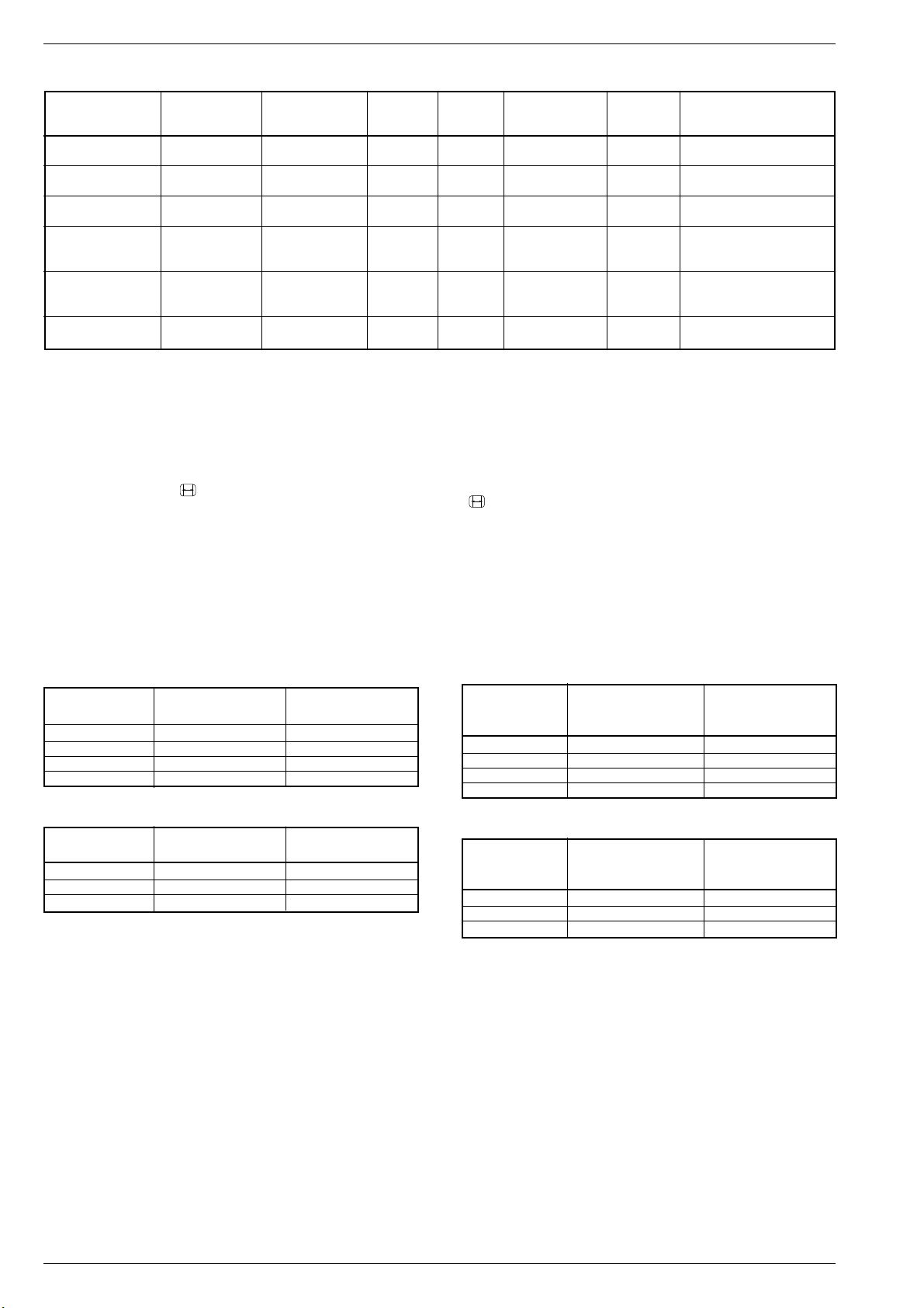
Allgemeiner Teil / General Section Digi 6
Buchsenbelegung / Socket Configuration
AV-Buchse FBAS In/Out SVHS In/Out RGB In Decoder Megalogic VGA In 6/12V-Idendifikation
AV socket CCVS In/Out Scart Pin 8 6/12V-Idendification
AV 1 schwarz/black x/x x/x x** x x - x
AV 2 orange x/x x/- x** x - - x
AV 3 blau/blue x/x* -/- - - - - x
AV 4 Camera x/- -/- - - - - Cinch
AV 4 Camera -/- x/- - - - - Hosiden
AV 5 VGA -/- -/- - - - x -
* Keine Ausgabe von Terr.- bzw. Sat-FBAS möglich. Nur FBAS der
schwarzen, orangen Scart-, Cinch- oder Hosidenbuchse.
** RGB-Einspeisung ist nur an der schwarzen oder orangen Scartbuchse
möglich (nicht gleichzeitig).
10. Bildformat-Umschaltung
Mit der Fernbedientaste "
der Bildschirmgrößen umgeschaltet werden. PALplus erscheint nur,
wenn es bereits automatisch erkannt wurde!
In der Stellung "auto" wird bei jedem Statuswechsel in Abhängigkeit
von der Sender-Information (WSS) automatisch auf das entsprechende Format geschaltet.
Das Gerät paßt in Abhängigkeit von der an Pin 8 der aktiven ScartBuchse anstehenden Spannung das Bildformat an. Die BildformatUmschaltung ist bei AV-Betrieb für die schwarze, orange und blaue
AV-Buchse (AV1, AV 2, AV 3), bei Peribetrieb für die schwarze und
orange Scart-Buchse aktiv.
bei 16:9-Bildröhren
Bildformat vor dem neues Bildformat nach neues Bildformat nach
Spannungswechsel Pin 8: 0/12V –> 6V Pin 8: 6V –> 0/12V
16:9 - altes Format *
Cinema Zoom 16:9 Panorama Zoom 16:9 4:3 16:9 -
bei 4:3-Bildröhren
Bildformat vor dem neues Bildformat nach neues Bildformat nach
Spannungswechsel Pin 8: 0/12V –> 6V Pin 8: 6V –> 0/12V
16:9 - altes Format *
4:3 16:9 Panorama Zoom 16:9 -
* unter altem Format wird das letzte vor dem Spannungswechsel
manuell eingestellte Bildformat verstanden.
" kann das Bildformat in Abhängigkeit von
* Output of terrestrial or SAT CCVS signal is not possible. CCVS signal
only from the black, orange Scart, Cinch or Hosiden socket.
** RGB input is only possible at the black or orange Scart socket (not
simultaneously).
10. Changing the Picture Format
The picture format can be switched over with remote control button
"
" in dependence of the size of the picture tube. PALplus appears
only if it was previously identified automatically.
In "auto" mode, the format is automatical changed accordingly with
every change of the status in dependence of the transmitter information (WSS).
The TV set selects the picture format in dependence of the voltage
applied to Pin 8 of the active Scart socket. On AV operation, the format
switching function is active for the black, orange, and blue AV socket
(AV1, AV 2, AV 3), on Peri operation it is active for the black and orange
Scart sockets.
for 16:9 picture tubes
Picture format New picture format New picture format
before voltage after voltage change after voltage change
change Pin 8: 0/12V –> 6V Pin 8: 6V –> 0/12V
16:9 - old format *
Cinema Zoom 16:9 Panorama Zoom 16:9 4:3 16:9 -
for 4:3 picture tubes
Picture format New picture format New picture format
before voltage after voltage change after voltage change
change Pin 8: 0/12V –> 6V Pin 8: 6V –> 0/12V
16:9 - old format *
4:3 16:9 Panorama Zoom 16:9 -
* the expression "old format" means the picture format last selected
manually before the voltage is switched over.
GRUNDIG Service1 - 20
Page 21
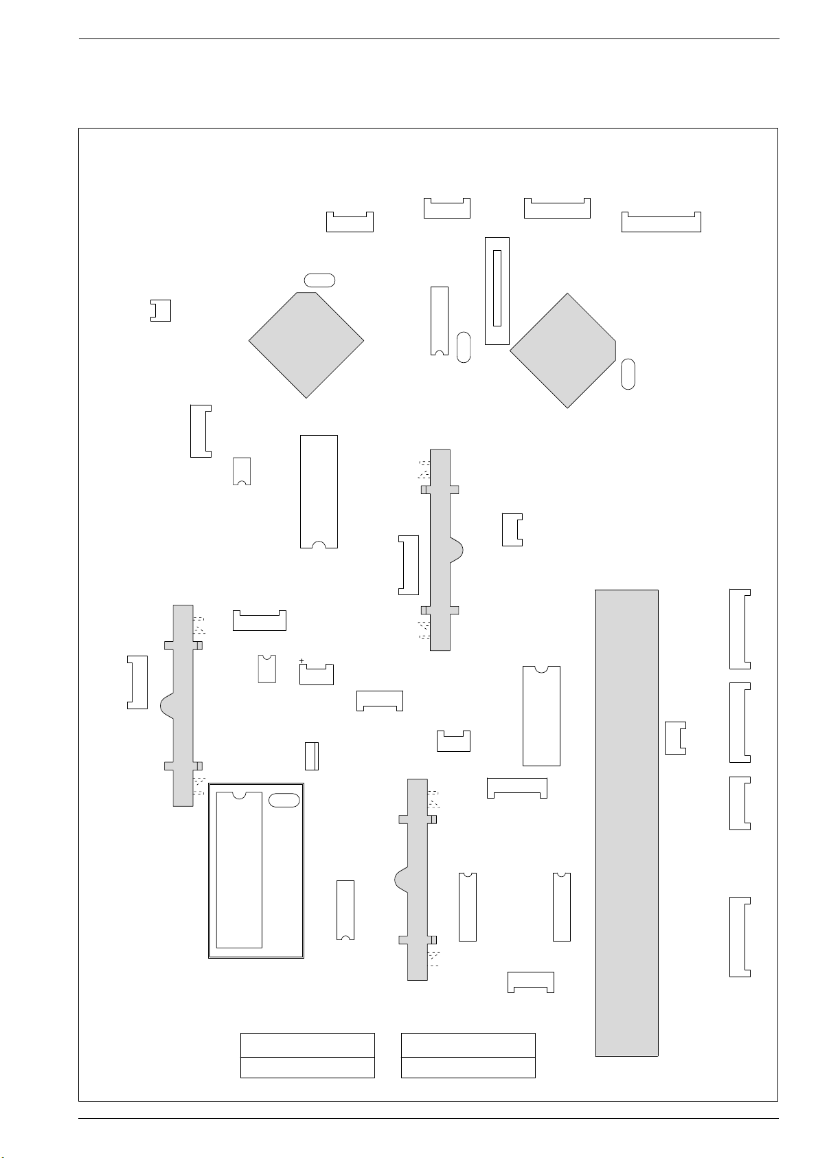
Digi 6 Abgleich / Alignment
15
ST-AV3
15
ST-V3
15
ST-MP
15
_ST-KB
13
_ST-AV
13
ST-SV
13
ST-GM
13
ST-VGA2
121
220
121
220
1
6
ST-DO1
1
6
ST-CH2
1
6
ST-TEST1
1
6
ST-H-AV
1
10
ST-CH1
1
10
ST-CH3
1
10
ST-CH4
1
10
_ST-VFD
Q32305
Q87004
Q87054
Q46001
132
33
64
IC32300
14
58
IC41010
14
IC87080
17
ST-RGB
17
ST-VGA1
IC43200
110
11
20
IC43150
110
11
20
1
10
11
20
1
13
24
12
IC43210
2
1
22
IC46020
IC46010
IC87020
1 16
1732
IC87030
1
2815
14
IC34510
1
2
ST-VGA3
13
IC32340
1
8
ST-IR-KB
11
5
1
15
15
1
27
26
9
10
61
60
44
43
43
44
27
26
9
10
1
60
61
IC87000
Buchse -AV2 / Socket AV 2
Videotext
Dynamic RAM
IR/Standby-Proz.
Mikrocomputer
EEPROM
Kopfhörerverstärker
Headphone Amplifier
Matrix
Audio-Prozessor
Matrix
Matrix
Bildröhrentreiber
CRT Driver
PIP-Baustein / PIP Module
Signal Baustein / Signal Module
Feature-Box
+ 5V für / for IC32300
Buchse -AV2 / Socket AV 1
NF/DPL-Baustein / AF/DPL Module
EPROM
Abgleich / Alignment
Abgleichlageplan Signalchassis Bestückungsseite / Alignment Layout Signal Chassis Components Side
GRUNDIG Service
2 - 1
Page 22
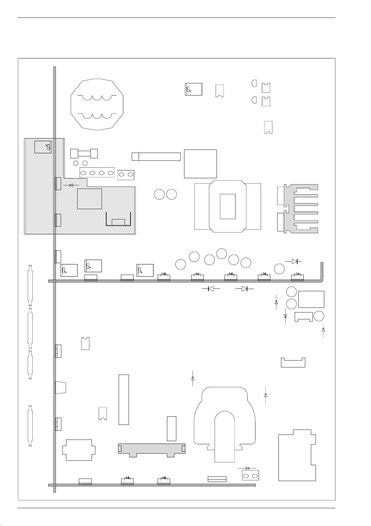
Abgleich / Alignment Digi 6
Abgleichlageplan Netzchassis Bestückungsseite / Alignment Layout Mains Chassis Components Side
E
OK60046
1
C
T61316
34
E
1
34
C
T61301
OK60031
5
8
IC60010
NETZTEIL
POWER SUPPLY
1
20
21
22
6
STANDBY REGELUNG
STANDBY CONTROL
6
4
1
G
D
T60006
S
G
D
T60005
S
2
1
SI62501
T3,15A H
R61001
+ H/+5V
NETZ1
+OEKO/>10V
+ H/+5V
IC61001
1 3
D61001
TR60220
6
IC61006
+ Q/+9V
STANDBY NETZTEIL
STANDBY POWER SUPPLY
1 3
L62501
NETZ2
ST-NETZ1
45
3
2
1
21
41
ST-E
D
SG
T60223
R61313
+ A
4
4
5
8
1
IC61310
REGELVERSTÄRKER
3
~
~
-
+
CONTROL AMPLIFIER
63
D60023
B380/C2200
SI60201
T100mA
SI60001
T2A
L60028
12
9
7
536
11
4
TR61000
1516171819
121314
101
ST-CH4
101
ST-CH3
61
ST-CH2
101
ST-CH1
3
R61051
+ N/+5V
IC61050
+ N +5V
1
T50028
BEBE
R61031
+ B/12V
IC61030
+ B/12V
IC58010
85
41
IC50010
VERTIKAL ENDSTUFE
26
1 7
VERTICAL OUTPUT
T50029
31
78
OST/WEST
EAST/WEST
TR52001
T52003
B
6
E
4
ZEILENTREIBER
LINE DRIVER
13
SCHUTZSCHALTUNG
PROTECTION CIRCUIT
IC55010
4
5
8
1
13
IC61040
+F/+5V
81
ST-J
110
D53072
R61041
+F/+5V
D61036
ST-SH1
ST-SH2
DYNAM.FOKUS
3
D53071
T2,5A
SI61036
D61026
+ M/+16V
D54006
T2,5A
SI61026
D61061
+ K/+14V
+ C/200V
SI61056
T2A
SI61061
TR53001
T53001
T2,5A
SI61066
D61056
+ N/+5V
BE
T2A
SI61012
D61066
- K/-14V
D21001
T4A
21
D61011
+ G/+19V
- 27V
D54001
+ D 26V
ST-UG2
T2A
SI61022
SI61808
D61808
+ 8V
D61801
1
D61021
+ LNC/+26V
D61016
T800mA
TR61800
4
4
ST-HZ
/T800mA
SI61801
6
ST-BR
DA
K53030
KASKADE
CASCADE
13
6
1
SI61803
T800mA
- 8V
D61803
GRUNDIG Service2 - 2
Page 23
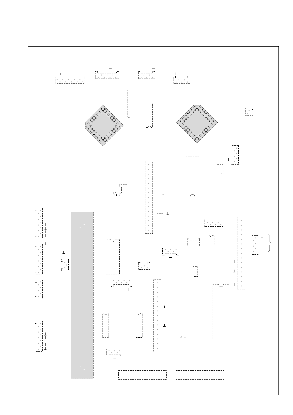
Digi 6 Abgleich / Alignment
1
5
ST-AV3
1
5
ST-V3
ST-MP
_ST-KB
1
ST-AV
1
3
ST-SV
1
1
ST-GM
1
3
ST-VGA2
121 121
1
2
6
ST-DO1
I S Bus
1
6
ST-CH2
1
6
ST-TEST1
ST-H-AV
1
10
ST-CH1
ST-CH3
1
10
1
10
ST-CH4
1
11
1
_ST-VFD
Öko+HACK
Data
Power off
LED1
ICB
Standby
+Q
+H
+Öko
+N
+N
SW
+F
+F
+G
+G
-G
-G
+LNC
DF
OWA
Vert
Vert
VG
Ref
Horz. 2F
Standby
I Beaum
SB
SS
BS off
DF
Öko
LED2
Power off
ICB+HIR
LED1
LED2KB+H
+A
V-Sync
H-Sync
-G
+F
Data
B
G
R
Data
WS
Clock
Terr.
MSP-Reset
+B
+5V
+H
SDA
SCL
+33V
+F
+B
SCL
SDA
Vert 2F
Data
B
G
R
SSC100
FBAS
+G
+G
-G
-G
SDA
SCL
MSP-Reset
+F
+B
Audio
Audio R
Audio L
+F
VOR
SCL
SDA
ICH-R/3
ICH-L/1
Audio
Audio
Quarz
132
33
64
IC32300
1
4
5
8
IC41010
ICH-Verstärker
1
4
IC87080
17
ST-RGB
ST-VGA1
IC43200
1
1011
20
1
1011
20
IC43150
1
10
11
20
1
13
24
12
IC43210
1
22
IC46020
IC46010
IC87020
1 16
1732
IC87030
1
1
43
28
15 14
IC34510
1
ST-VGA3
1
3
IC32340
ST-IR-KB
1
15
15
1
+B
+LNC
Terr. / SAT
+F
Intercarrier (5,5MHz)
NF
FBAS
AFC
ENA
SDA
SCL
33V
15
1
27
28
26
9
1
10
11
61
60
44
43
45
43
45
44
27
26
28
9
10
1
60
62
68
61
IC87000
Videio 2VSS
Schaltspannung PIN 8
+Q
Video
RGBSW
62
68
AV2 AV1
Megatext
EEPROM
AudioMatrix
Audio-Prozessor
VideoMatrix
Feature-Box
EPROM
Abgleichlageplan Signalchassis Lötseite / Alignment Layout Signal Chassis Solder Side
GRUNDIG Service
2 - 3
Page 24

Abgleich / Alignment Digi 6
Abgleichlageplan Netzchassis Lötseite / Alignment Layout Mains Chassis Solder Side
STANDBY REGELUNG
STANDBY CONTROL
D61021
+ LNC/26V
D61016
13
TR61800
6
SI61803
T800mA
D61803
- 8V
4
1
4
ST-HZ
6
ST-BR
DA
K53030
KASKADE
CASCADE
OK60046
1
6
34
1
6
34
OK60031
4
5
8
1
IC60010
NETZTEIL
POWER SUPPLY
G
D
T60006
S
G
D
T60005
S
T2A
SI61022
D61011
+ G/+19V
T800mA
SI61808
- 27V
D61808
+ 8V
D61801
/T800mA
SI61801
1
D54001
+ D 26V
ST-UG2
E
C
T61316
E
C
T61301
REGELVERSTÄRKER
CONTROL AMPLIFIER
1
21
22
4
19
20
T4A
SI61066
SI61012
536
18
T2A
D61056
+ N/+5V
D61066
- K/-14V
TR53001
D21001
21
4
1
R61313
5
8
+ A
IC61310
63
L60028
12
9
7
11
TR61000
15
16
17
T2,5A
SI61056
13
14
T2A
SI61061
12
T2,5A
SI61026
D61026
+ M/+16V
D61061
+ K/+14V
D54006
T53001
BE
+
D60023
B380/C2200
SI60201
T100mA
SI60001
T2A
T2,5A
SI61036
D61036
+ C/200V
ST-SH1
ST-SH2
DYNAM.FOKUS
D53071
~
~
1
R61041
+F/+5V
1 3
IC61040
+F/+5V
3
D53072
L62501
4
3
SI62501
T3,15A H
21
ST-E
NETZ2
41
ST-NETZ1
45
3
TR60220
2
1
D
SG
T60223
R61031
+ B 12V
1 3
IC61030
+ B 12V
85
SCHUTZSCHALTUNG
PROTECTION CIRCUIT
81
VERTIKAL ENDSTUFE
VERTICAL OUTPUT
ST-J
IC55010
4
5
8
1
OST/WEST
EAST/WEST
2
1
NETZ1
D61001
+OEKO/+10V
6
R61051
+ N +5V
IC58010
41
IC50010
IC61006
T50028
1 7
T50029
31
78
TR52001
110
6
T52003
E
4
B
ZEILENTREIBER
LINE DRIVER
R61001
+ H/+5V
+ H/+5V
IC61001
1 3
+ Q/+9V
1 3
3
1
BEBE
26
STANDBY NETZTEIL
STANDBY POWER SUPPLY
+ N +5V
IC61050
01
1011
61
101
ST-CH4
ST-CH3
ST-CH2
ST-CH1
GRUNDIG Service2 - 4
Page 25

Digi 6 Abgleich / Alignment
Abgleich
Alle nicht beschriebenen Einstellelemente sind werkseitig abgeglichen und dürfen im Service-Fall nicht verstellt werden.
1. Chassisplatte
Meßgeräte: Zweikanal-Oszilloskop, Tastkopf 10:1, Digitalvoltmeter, Farbbildgenerator
Servicearbeiten nach Austausch bzw. Reparatur:
- Chassis Abgl. 1.1
- Tuner, ZF-Verstärker Abgl. 1.2, 1.3, 1.4.1 bzw. 1.4.2
- IC87080, Abgl. 1.5…1.10
- Zeilen- und Bildablenkung Abgl. 1.11…1.13 und 2.2
- IC87020, Abgl. 1.10…1.13
Abgleich
1.1 +A Spannung
+B Spannung
+F Spannung
+H Spannung
+N Spannung
1.2 Tuner-AGC
1.3 AFC-Referenz
1.4.1 PLL-Demodulatorkreis für
Bildträger 38,9MHz
1.4.2 PLL-Demodulatorkreis für
Bildträger 33,4MHz
(Multi-ZF/IF)
1.5 Text RGB-Pegel
Vorbereitung
Nach jeder Reparatur und vor jedem Abgleich unbedingt kontrollieren und gegebenfalls einstellen.
Helligkeit: Minimum
Normtestbild auf Kanal 60 (UHF) einspeisen; HF=1,5mV
(64dBµV). Bei Zwei-Tuner PIP-Geräten ohne Antennen-Splitter.
Voltmeter: Tunerkontakt 2.
Sender mit genormten Kanalraster ohne Finetuning im
Band 1 (Kanal 2…4) einspeisen.
Mit Taste "6" das Menü "AFC-Referenz" über "Dialog
Center" –> "OK" –> "SERVICE FÜR DEN FACHHANDEL"
–> "OK" –> "Nur für den Fachhändler" –> "OK" –> Kennzahl "8500" –> aufrufen (Menüführung).
- Sender mit genormtem Kanalraster, Band 3 mit dazuge höriger Norm einspeisen.
- Voltmeter an Steckerleiste Kontakt 5 Signalbaustein.
- 1.4.1 überprüfen, bzw. abgleichen.
- Sender mit genormten Kanalraster, Band 1 in FrankreichNorm einspeisen.
- Voltmeter an Steckerleiste Kontakt 5 Signalbaustein.
Mit Taste "6" das Menü "RGB-Pegel" über "Dialog Center"
–> "OK" –> "SERVICE FÜR DEN FACHHANDEL" –> "OK"
–> "Nur für den Fachhändler" –> "OK" –> Kennzahl "8500"
–> aufrufen (Menüführung).
Abgleichvorgang
Mit Regler R61313 nach Tabelle im Schaltbild Netz-Chassis.
Mit Regler R61031 auf 12V an Kontakt 36 der Feature-Box.
Mit Regler R61041 auf 5V an Kontakt 9/10 der Feature-Box.
Mit Regler R61001 auf 5V an Kontakt 8 der Feature-Box.
Mit Regler R61051 auf 5V an Kontakt 32/33 der Feature-Box.
3,3V ± 0,1V mit R32033 (Signalbaustein) einstellen.
Mit der Aktivierung der AFC-Referenz (automatisch) wird
eine ZF-Richtspannung vom AFC-Ausgang des IC32010 an
der Steckerleiste des Signalbausteins, Kontakt 5 gemessen
und als Vergleichswert beim Sendersuchlauf bzw. für die
Videowiedergabe über den Antenneneingang (Senderkennung "AV") zur Nachregelung der Modulatordrift herangezogen (typ. 127±10). Einstellung mit OK aktivieren.
2,5V mit FI32043 auf dem Signalbaustein einstellen.
2,5V mit R32057 auf dem Signalbaustein einstellen.
Bei RGB-Einblendung kann bei Zeilenreißen mit den Tasten
4 3 durch die Einstellung "halbe Pegel" oder "volle Pegel"
die Anzeigeintensität angepaßt werden. Der eingestellte
Wert wird beim Verlassen des Menüs gespeichert.
1.6 Weißabgleich
1.7 Bildröhrentyp
1.8 GM
(Geschwindigkeitsmodulation)
1.9 CIP 3250A
1.10 PIP-Position
Schwarzweiß-Grautreppe mit Burst einspeisen.
Weißbalance Mittenstellung.
Kontrast (W) Maximum.
Farbkontrast (E) Mittelwert.
Bildschirmhelligkeit (R) Mittelwert.
"Perfect Clear" ausschalten
("rote Taste" –> "BILD-EINSTELLUNGEN" –> "OK").
Mit Taste "6" das Menü "Weißabgleich" über "Dialog Center" –> "OK" –> "SERVICE FÜR DEN FACHHANDEL" –>
"OK" –> "Nur für den Fachhändler" –> "OK" –> Kennzahl
"8500" –> aufrufen (Menüführung).
Mit Taste "6" das Menü "Bildröhrentyp" über "Dialog Center" –> "OK" –> "SERVICE FÜR DEN FACHHANDEL" –>
"OK" –> "Nur für den Fachhändler" –> "OK" –> Kennzahl
"8500" –> aufrufen (Menüführung).
Mit Taste "6" das Menü "GM" über "Dialog Center" –> "OK"
–> "SERVICE FÜR DEN FACHHANDEL" –> "OK" –> "Nur
für den Fachhändler" –> "OK" –> Kennzahl "8500" –>
aufrufen (Menüführung).
Mit Taste "6" das Menü "CIP 3250A" über "Dialog Center"
–> "OK" –> "SERVICE FÜR DEN FACHHANDEL" –> "OK"
–> "Nur für den Fachhändler" –> "OK" –> Kennzahl "8500"
–> aufrufen (Menüführung).
Sender- und AV-Bild einspeisen.
Fernbedientaste "6" gedrückt halten und mit dem Netzschalter einschalten.
Mit den Tasten 4 3 die Werte für VG und VB so einstellen,
daß das Bild unbunt wird.
Mit "OK" speichern.
Die Taste "?" Grundwerte stellt den zuletzt gespeicherten
Weißwert ein.
Mit den Tasten 4 3 P55, T70/16:9, T82/16:9, T63, P63, P63
BLS, T72, P72, T82, T95, P70 einstellen
(T = Toshiba Bildröhre, P = Philips Bildröhre).
Der eingestellte Wert wird beim Verlassen des Menüs
gespeichert.
Mit den Tasten 4 3 die Geschwindigkeitsmodulation einoder ausschalten.
Mit den Tasten 4 3 A1 oder B1 einstellen.
Diese Festlegung ist vom CIC1360 in der Feature-Box
abhängig. Nach dem Wiedereinschalten des Gerätes sind
bei unrichtiger Einstellung die Farben falsch.
Mit den Tasten 4 3 und 1 2 die PIP-Position verändern
und mit "OK" speichern.
GRUNDIG Service
2 - 5
Page 26

Abgleich / Alignment Digi 6
Abgleich
1.11 Bildgeometrie
1.11.1 Bildgeometrie
VGA
Vorbereitung
Geometriebild einspeisen, oder internes Testbild einschalten.
Mit Taste "6" das Menü "Geometrie" über "Dialog Center" –> "OK" –> "SERVICE FÜR DEN FACHHANDEL" –>
"OK" –> "Nur für den Fachhändler" –> "OK" –> Kennzahl
"8500" –> aufrufen (Menüführung).
Achtung: Der Abgleich "Line shift" beeinflußt die Zeilenphase.
Vor dieser Einstellung die Bildbreite auf Minimum stellen und
evtl. die Rasterlage mit dem Stecker "H-Shift" korrigieren.
Reset: Das Feld "Reset" enthält:
- entweder die optimalen Bildgeometriedaten des Gerätes aus der Fertigung
- oder einen mittleren Datensatz aus dem ROM, wenn das
Gerät mit dem Notdatensatz gestartet wurde.
Nach einem Fehlabgleich können Sie diese Grundwerte
jederzeit wieder laden über:
Mit Taste "6" das Menü "Geometrie" über "Dialog Center" –> "OK" –> "SERVICE FÜR DEN FACHHANDEL" –>
"OK" –> "Nur für den Fachhändler" –> "OK" –> Kennzahl
"8500" –> aufrufen (Menüführung).
Gerät in Programmstellung "A 5" schalten und Geometriebild über PC einspeisen.
Mit Taste "6" das Menü "Geometrie" über "Dialog Center" –> "OK" –> "SERVICE FÜR DEN FACHHANDEL" –>
"OK" –> "Nur für den Fachhändler" –> "OK" –> Kennzahl
"8500" –> aufrufen (Menüführung).
Abgleichvorgang
Über die Menüführung Geometrie überprüfen und gegebenenfalls einstellen.
Erst danach mit den Tasten 4Ê oder 3 Bildinhalt mittig ins
Raster stellen. Bildbreite wieder nach Testbild einstellen.
Speichern:
"Without memory" aufrufen und mit den Tasten 4Ê oder 3 auf
"With memory" ändern.
Taste "OK" speichert die Einstellung.
Die Bildgeometrie stellt sich nach jedem Einschalten auf
den zuletzt abgespeicherten Wert ein.
Über die Menüführung Geometrie überprüfen und gegebenenfalls abgleichen.
Im IC87030 ist für die Stellung A 5 ein eigener Geometriedatensatz abgelegt.
1.12 Brückenspule
L53074
(Netz-Chassis)
Die Brückenspule L53074 wird in der Fertigung abgeglichen und sollte nicht verdreht werden.
Mit Taste "6" das Menü "Geometrie" über "Dialog Center" –> "OK" –> "SERVICE FÜR DEN FACHHANDEL" –>
"OK" –> "Nur für den Fachhändler" –> "OK" –> Kennzahl
"8500" –> aufrufen (Menüführung).
Bildbreite (Width) auf Minimum stellen.
Oszilloskop Kanal 1: Kollektor T53001.
Oszilloskop Kanal 2: Kathode D53072.
1.13 Zeilenschärfe
Konvergenztestbild einspeisen:
Kontrast (W) Maximum
Helligkeit (R) so einstellen, daß sich der schwarze Testbildhintergrund gerade aufhellt.
2. Bildrohrplatte
Meßgeräte: hochohmiges Voltmeter, Zweikanal-Oszilloskop mit Tastkopf 10:1.
Servicearbeiten nach Austausch bzw. Reparatur:
- Bildröhre, Bildrohrplatte Abgl. 2.1 und 2.2
Abgleich
2.1 Weißabgleich
siehe 1.6
Schwarzweiß-Grautreppe mit Burst einspeisen.
Weißbalance Mittenstellung.
Kontrast (W) Maximum.
Farbkontrast (E) Mittelwert.
Bildschirmhelligkeit (R) Mittelwert.
"Perfect Clear" ausschalten
("rote Taste" –> "BILD-EINSTELLUNGEN" –> "OK").
Mit Taste "6" das Menü "Weißabgleich" über "Dialog Center" –> "OK" –> "SERVICE FÜR DEN FACHHANDEL" –>
"OK" –> "Nur für den Fachhändler" –> "OK" –> Kennzahl
"8500" –> aufrufen (Menüführung).
Vorbereitung
Gleiche Impulsbreite der Oszillogramme kontrollieren und
gegebenenfalls mit Spule L53074 abgleichen.
Bildbreite wieder nach Testbild einstellen.
Mit dem Focusregler an der Kaskade die horizontalen
Linien auf maximale Schärfe einstellen.
Anschließend mit dem dyn. Focusregler
(dyn. Focussierungsplatte) die vertikalen Linien auf maximale Schärfe abgleichen. Einstellungen wechselseitig wiederholen.
Abgleichvorgang
Mit den Tasten 4 3 die Werte für VG und VB so einstellen,
daß das Bild unbunt wird.
Mit "OK" speichern.
Die Taste "?" Grundwerte stellt den zuletzt gespeicherten
Weißwert ein.
2.2 Schirmgitterspannung
U
, U
G2
SG
Reglereinheit sitzt
bei der Philips
Bildröhre auf dem
Chassis.
"Perfect Clear" ausschalten.
("rote Taste" –> "BILD-EINSTELLUNGEN" –> "OK").
Gerät in AV-Stellung.
Schwarzbild einspeisen.
Bildschirmhelligkeit: Graufläche gerade dunkel.
Voltmeter über 220kΩ an Testpunkt R, G und B.
Höchsten Spannungswert ermitteln.
Mit dem Einstellregler U
Testpunkt mit den höchsten Spannungswert auf ca.
, USG auf der Bildrohrplatte den
G2
162,5V±2,5V abgleichen.
Schwarzwert
105-110V
160V…165V
GRUNDIG Service2 - 6
Page 27

Digi 6 Abgleich / Alignment
GB
Alignment
All adjustment controls not mentioned in this description are pre-set at the factory and must not be re-adjusted in the case of repairs.
1. Chassis Board
Measuring instruments: Dual-channel oscilloscope, 10:1 test probe, digital voltmeter, colour video generator.
Service works after replacement or repair of the following modules:
- Chassis: alignment 1.1
- Tuner, IF amplifier: alignment 1.2, 1.3, 1.4.1 or 1.4.2
- IC80070: alignment 1.5 …1.10
- horizontal and field deflection: alignment 1.11…1.13 and 2.2
- IC87020: alignment 1.10…1.13
Alignment
1.1 +A voltage
+B voltage
+F voltage
+H voltage
+N voltage
1.2 Tuner AGC
1.3 AFC Reference
1.4.1 PLL demodulator circuit for
38.9MHz
vision carrier
1.4.2 PLL demodulator circuit for
33.4 MHz
vision carrier
(Multi-IF)
1.5 Text RGB level
Preparations
These voltages must strictly be checked and re-adjusted
if necessary after every repair and before every
alignment.
Brightness: Minimum
Feed in a standard test pattern at channel 60 (UHF); RF =1.5mV
(64dBµV). PIP receivers with two tuners without antenna splitter.
Voltmeter: tuner contact 2.
Tune to a station in band I (channel 2...4) with standardized
channel spacing and without fine tuning.
With button "6" call up the "AFC reference" menu via
DIALOGCENTER –> "OK" –> "SERVICE" –> "OK" –> "Only
for the retailer" –> "OK" –> Code Number "8500" –> (menu guide).
- Feed in a standard test pattern with standardized
channel spacing, band 3, with the respective TV
standard.
- Voltmeter to multipoint connector contact 5 of signal module.
- Check and if necessary readjust 1.4.1.
- Feed in a standard test pattern with standardized
channel spacing, band 1, French TV standard.
- Voltmeter to multipoint connector contact 5 of the signal
module.
With button "6" call up the "Text RGB level" menu via
DIALOGCENTER –> "OK" –> "SERVICE" –> "OK" –>
"Only for the retailer" –> "OK" –> Code Number "8500" –>
(menu guide).
Alignment Process
With R61313 acc. to the table on power supply chassis pcb.
With R61031 set 12V on contact 36 of the Feature Box.
With R61041 set 5V on contact 9/10 of the Feature Box.
With R61001 set 5V on contact 8 of the Feature Box.
With R61051 set 5V on contact 32/33 of the Feature Box.
Set 3.3V ± 0.1V with R32033 (Signal Module).
On activation of AFC Reference a rectified IF-voltage from
the AFC output of IC32010 is measured at the multipoint
connector,contact 5, of the signal module which is used on
station search or for VCR-RF playback (station identification
"AV") as a comparative value to readjust the modulator
drift (typ. 127±10). Activate with "OK".
Set 2.5V with FI32043 on the signal module.
Set 2.5V with R32057 on the signal module.
In RGB operation it is possible to set the RGB level to "Half
level" or "Full level" with the buttons 4 3 to eliminate line
tearing in this mode and to adjust the display intensity. The
setting is stored when terminating the menu.
1.6 White balance
1.7 Type of
picture tube
1.8 VM
(Velocity
Modulation)
1.9 CIP 3250A
1.10 PIP position
Feed in a grey scale black/white test pattern with burst.
Set white balance to mid-position.
Contrast (W) to maximum.
Colour contrast (E) to mid-position.
Screen brightness (R) to mid-position.
Switch off "Perfect Clear".
("red key" –> "PICTURE SETTINGS" –> "OK")
With button "6" call up the "White balance" menu via DIALOGCENTER –> "OK" –> "SERVICE" –> "OK" –> "Only for the
retailer" –> "OK" –> Code Number "8500" –> (menu guide).
With button "6" call up the "Tube type" menu via "DIALOGCENTER –> "OK" –> "SERVICE" –> "OK" –> "Only for the
retailer" –> "OK" –> Code Number "8500" –> (menu guide).
With button "6" call up the "GM" menu via "DIALOGCENTER –> "OK" –> "SERVICE" –> "OK" –> "Only for
the retailer" –> "OK" –> Code Number "8500" –> (menu
guide).
With button "6" call up the "CIP 3250A" menu via
"DIALOGCENTER –> "OK" –> "SERVICE" –> "OK" –>
"Only for the retailer" –> "OK" –> Code Number "8500" –>
(menu guide).
Feed in the transmitter and AV picture.
Press and hold the "6" button on the remote control while
switching on with the mains button.
With the 4 3 buttons set the values for VG and VB so that
the picture becomes achromatic.
Store with "OK".
The "?" key, default values, is used to call up the last stored
white value.
With the 4 3 buttons set P55, T70/16:9, T82/16:9, T63,
P63, P63 BLS, T72, P72, T82, T95, P70
(T = Toshiba tube, P = Philips tube).
The selected type is stored when terminating the menu.
With the 4 3 buttons switch the velocity modulation on or
off.
With the 4 3 buttons select A1 or B1.
This definition depends on CIC1360 in the Feature Box.
On selection of the wrong setting, the colours are not
correct when switching the TV set on again.
Change the PIP position with the 4 3 and 1 2 buttons
and store with "OK".
GRUNDIG Service
2 - 7
Page 28

Abgleich / Alignment Digi 6
160V…165V
Alignment
1.11 Picture
geometry
1.11.1 Picture
geometry
VGA
Preparations
Feed in the geometry test pattern or switch on the internal
test pattern.
Call up the menu "Geometry" with button "6" via "DIALOGCENTER" –> "OK" –> "SERVICE" –> "OK" –> "Only for the
retailer" –> "OK" –> Code Number "8500"(menu guide).
Attention: The "Line shift" alignment influences the line phase.
Before this adjustment, set the horizontal amplitude to minimum
and if necessary correct the raster position with the "H-Shift" plug.
Reset:
The "Reset" menu contains:
- either the optimum picture geometry data entered in the
factory
- or the average data set read out from the ROM if the TV
has been switched on with the emergency data set.
On misalignment, these basic values can be re-loaded at
any time as follows:
With button "6" call up the "Geometry" menu via "DIALOGCENTER" –> "OK" –> "SERVICE" –> "OK" –> "Only for the
retailer" –> "OK" –> Code Number "8500"(menu guide).
Switch the TV to "A 5" programme position and feed in a
geometry pattern via PC.
With the "6" button call up the "Geometry" menu via "DIALOGCENTER" –> "OK" –> "SERVICE" –> "OK" –> "Only for the
retailer" –> "OK" –> Code Number "8500"(menu guide).
Alignment Process
Check the geometry via the menu guide and correct the
setting if necessary.
With 4 or 3 button, move the picture into the centre of the
raster. Re-adjust the horizontal amplitude according to the
test pattern.
Store:
Call up "End without memory" and change to "End with
memory" with the 4 or 3 button .
Store the setting with "OK".
Whenever the TV is switched on the picture geometry is set
to the value stored last.
Check the geometry via the menu guide and correct the
setting if necessary.
A separate geometry data set for programme position A5 is
stored in IC87030 .
1.12 Bridge coil
L53074
(Mains
Chassis)
The bridge coil L53074 is adjusted in the factory and should
not be readjusted any more.
With button "6" call up the "Geometry" menu via "DIALOGCENTER" –> "OK" –> "SERVICE" –> "OK" –> "Only for the
retailer" –> "OK" –> Code Number "8500"(menu guide).
Set the horizontal amplitude (width) to minimum.
Oscilloscope channel 1: collector T53001.
Check the pulse width of the oscillograms and correct it if
necessary with coil L53074 so that it is the same for both
oscillograms.
Re-adjust the horizontal amplitude according to the test
pattern.
Oscilloscope channel 2: cathode D53072.
1.13 Line
sharpness
- Select the convergence test pattern:
- Contrast (W) to maximum.
- Set the brightness (R) so that the black background of
the test pattern is just brightening.
With the focus control
horizontal lines for maximum sharpness.
Subsequently, adjust the vertical lines for maximum
sharpness using the dynamic focus control
focusing board). Repeat alternately.
2. Picture Tube Board
Measuring instruments: High-resistance voltmeter, Dual -channel oscilloscope with test probe 10:1.
Service works after replacement or repair of:
- picture tube, picture tube board: Alignment no. 2.1 and 2.2
Alignment
2.1.White balance
see 1.6
Feed in a grey scale black/white test pattern with burst.
Set white balance to mid-position.
Contrast (W) to maximum.
Colour contrast (E) to mid-position.
Screen brightness (R) to mid-position.
Switch off "Perfect Clear"
("red key" –> "PICTURE SETTINGS" –> "OK" Personal values).
With button "6" call up the "White balance" menu via
"DIALOGCENTER" –> "OK" –> "SERVICE" –> "OK" –>
"Only for the retailer" –> "OK" –> Code Number
"8500"(menu guide).
Preparations
With the 4 3 buttons set the values for VG and VB so that
the picture becomes achromatic.
Store with "OK".
The "?" key, default values, is used to call up the last stored
white value.
on the cascade adjust the
(dynamic
Alignment Process
2.2.Screen grid
voltage U
, U
G2,
The control unit of
the Philips picture
tube is fitted on the
chassis.
Switch off "Perfect Clear"
("red key" –> "PICTURE SETTINGS" –> "OK" Personal values).
SG
TV receiver to AV mode.
Feed in a black raster.
Screen brightness: grey aera just becomes dark.
Voltmeter via 220 kΩ to R, G, and B test point.
Determine highest voltage level.
With the control UG2 or U
test point with the highest voltage level to approx.
on the picture tube panel set the
SG
162.5V±2.5V.
Black level
105-110V
GRUNDIG Service2 - 8
Page 29

Digi 6
Platinenabbildungen und Schaltpläne / Layout of the PCBs and Circuit Diagrams
Oszillogramm-Meßpunkte Netz Chassisplatte / Oscillogram Test Points Mains Chassis Board
Digi 6
Lötseite, Ansicht von unten
Solder side, bottom view
12
9
8
21
22
20
16
17
19
23 25
24 26
18
10
11
29304-730.62/2L(03) 07
4
3
27
28
15
14
13
GRUNDIG Service
3 - 1
GRUNDIG Service
2
1
6
7
5
3 - 2
Page 30

Platinenabbildungen und Schaltpläne / Layout of the PCBs and Circuit Diagrams
Platinenabbildungen und Schaltpläne / Layout of the PCBs and Circuit Diagrams
Oszillogramm-Meßpunkte Signal Chassisplatte
Oscillogram Test Points Signal Chassis Board
43
34A
34
33
38
18A
39
40
41
48
47
46
42
35
36
37
44
45
55
Lötseite, Ansicht von unten
Solder side, bottom view
56
29304-730.12/2L(04)
54
50
52
53
59
58
57
60
30
29
32
51
8
49
3 - 3
31
0 1 2 3 4 5 6 7 8 9
GRUNDIG Service
3 - 4
GRUNDIG Service
Page 31

Digi 6 Platinenabbildungen und Schaltpläne / Layout of the PCBs and Circuit Diagrams
Bestückungskoordinaten der Bauteile auf dem
Netz-Chassis
- Die Koordinaten X und Y sind sowohl als metrische Koordinaten für die Originalplatine in Millimeter, als auch als absolute
Koordinaten für die vergrößerten Abbildungen der Platinen
verwendbar.
C --> Kondensator CC --> Chip-Kondensator
D --> Diode CD --> Chip-Diode
IC --> Integrierter Schaltkreis CIC--> Chip-IC
L --> Spule CL --> Chip-Spule
R --> Widerstand CR --> Chip-Widerstand
T --> Transistor CT --> Chip-Transistor
Chassisplatte
Koordinaten für die Bauteile der Bestückungsseite (Oberseite)
Pos.-Nr./ Koordinaten/
Pos. No. Coordinates
C21001 18 203
C21202 125 210
C21206 119 211
C21212 112 244
C21221 148 84
C21231 129 95
C21232 129 175
C21233 83 220
C50004 94 9
C50011 67 44
C50012 77 45
C50013 91 20
C50014 59 45
C50016 105 53
C50024 105 40
C50026 92 48
C50027 40 24
C52001 59 66
C52002 40 13
C52003 18 40
C52004 18 23
C53006 59 117
C53007 59 135
C53012 59 109
C53013 54 89
C53016 110 165
C53017 100 165
C53031 65 247
C53032 59 247
C53033 79 239
C53036 38 194
C53037 60 201
C53038 40 201
C53071 29 117
C53072 30 91
C53073 65 99
C54001 89 209
C54002 112 192
C54006 99 149
C54007 95 135
C55003 69 61
C55004 80 58
C55011 83 76
C55012 56 83
C55013 82 66
C58001 118 56
C58004 138 70
C58011 130 85
C58012 123 81
C58013 127 71
XY
Pos.-Nr./ Koordinaten/
Pos. No. Coordinates
C58014 138 93
C58021 126 45
C58023 140 45
C60001 255 204
C60002 296 228
C60007 279 241
C60009 240 208
C60011 288 203
C60012 284 185
C60013 306 195
C60014 325 228
C60016 308 177
C60017 300 195
C60018 275 195
C60019 299 145
C60021 311 150
C60022 228 121
C60023 272 114
C60024 299 129
C60026 272 125
C60027 291 129
C60028 262 117
C60031 329 216
C60201 225 51
C60202 214 57
C60203 211 84
C60204 214 50
C60221 226 59
C60224 244 85
C61001 254 15
C61002 265 23
C61003 265 13
C61004 276 14
C61006 245 23
C61007 245 13
C61008 235 12
C61011 190 196
C61012 154 171
C61013 163 199
C61014 214 199
C61015 160 185
C61016 210 213
C61017 142 191
C61017A142 1 91
C61018 189 242
C61021 190 225
C61022 141 167
C61026 190 145
C61027 164 127
XY
Pos.-Nr./ Koordinaten/
Pos. No. Coordinates
C61028 173 36
C61031 173 43
C61032 166 59
C61036 190 120
C61037 164 111
C61038 170 99
C61041 170 75
C61042 166 88
C61051 191 20
C61052 201 17
C61056 191 170
C61057 164 173
C61058 210 18
C61061 167 159
C61062 164 145
C61063 157 160
C61064 134 108
C61066 167 185
C61301 328 181
C61311 335 177
C61801 150 225
C61802 138 223
C61803 138 246
C61806 135 208
C61808 166 219
C61809 147 210
C62021 314 110
C62022 314 116
C62048 206 108
C62501 295 56
C62502 328 95
C62505 297 84
D21001 26 189
D21201 126 235
D21202 126 199
D21203 130 235
D21206 113 203
D21212 124 251
D21221 115 19
D21222 108 21
D21231 139 58
D21232 141 59
D50013 76 34
D52003 20 53
D52006 30 48
D53039 119 181
D53071 16 120
D53072 16 90
XY
Assembly coordinates of the components at
the Mains Chassis
- The X and Y coordinates can be used as both metric coordinates in mm for the original circuit board and absolute
coordinates for the enlarged diagrams of the circuit boards.
C --> Capacitor CC --> Chip Capacitor
D --> Diode CD --> Chip Diode
IC --> Integrated Circuit CIC--> Chip IC
L --> Coil CL --> Chip Coil
R --> Resistor CR --> Chip Resistor
T --> Transistor CT --> Chip Transistor
Chassis Board
Coordinates of the components on the components side (top side)
Pos.-Nr./ Koordinaten/
Pos. No. Coordinates
D54001 86 204
D54006 100 144
D55003 90 75
D55004 90 63
D55012 45 66
D58001 117 70
D58003 43 35
D58004 117 66
D58007 117 63
D58011 126 84
D58012 130 74
D58021 131 41
D58022 135 41
D60006 275 213
D60007 283 228
D60012 289 186
D60014 305 186
D60019 292 149
D60021 305 149
D60023 282 114
D60201 225 48
D60202 228 63
D60203 211 66
D60204 219 66
D60207 246 105
D60208 246 100
D60223 216 88
D60224 256 80
D60225 253 84
D60226 250 88
D61001 259 44
D61011 184 203
D61016 184 230
D61021 196 228
D61026 184 148
D61033 124 139
D61036 184 120
D61056 184 175
D61061 174 159
D61062 149 138
D61063 136 135
D61066 174 186
D61067 147 151
D61068 137 144
D61801 151 220
D61803 140 251
D61807 156 236
D61808 163 214
IC50010 93 35
XY
Pos.-Nr./ Koordinaten/
Pos. No. Coordinates
IC55010 71 70
IC58010 129 55
IC60010 306 206
IC61001 260 33
IC61006 230 33
IC61030 183 60
IC61040 183 90
IC61050 200 33
IC61310 336 166
K53030 37 230
L53001 16 149
L53002 36 144
L53003 24 158
L53012 115 96
L53021 79 114
L53074 113 125
L55014 28 71
L60006 265 199
L60021 260 134
L60028 276 150
L61011 213 183
L61014 213 188
L61016 204 240
L61021 213 192
L61026 216 152
L61036 216 148
L61037 216 173
L61056 216 167
L61061 216 163
L61066 215 177
L62501 325 65
OK60031328 20 4
OK60046 339 204
R21001 24 174
R21101 94 249
R21102 99 234
R21102A 95 233
R21201 126 222
R21202 130 221
R21203 123 228
R21206 91 200
R21211 106 236
R21212 110 251
R21213 119 235
R21214 126 247
R21221 144 81
R21222 146 91
R21223 151 84
R21224 145 95
XY
Pos.-Nr./ Koordinaten/
Pos. No. Coordinates
R21226 126 26
R21227 129 23
R21231 145 69
R21232 130 152
R21233 86 226
R21234 99 219
R50001 101 39
R50002 101 51
R50003 80 15
R50004 84 14
R50007 66 18
R50008 66 21
R50027 54 21
R50028 113 34
R50029 111 50
R52001 66 56
R52003 21 13
R52006 25 48
R52007 16 177
R53002 35 150
R53003 34 156
R53012 113 111
R53016 98 101
R53021 80 126
R53031 65 235
R53032 60 235
R53036 74 211
R53037 71 234
R53038 86 228
R53039 117 185
R54001 101 206
R54006 85 144
R54007 113 148
R55001 93 196
R55002 95 192
R55003 94 73
R55004 81 61
R55006 70 78
R55007 86 75
R55011 79 75
R55012 55 76
R55014 44 70
R55016 99 68
R58001 56 59
R58002 66 53
R58003 51 48
R58004 117 74
R58007 130 64
R58011 113 85
XY
GRUNDIG Service 3 - 5
Page 32

Platinenabbildungen und Schaltpläne / Layout of the PCBs and Circuit Diagrams Digi 6
Koordinaten für die Bauteile der Bestückungsseite
(Oberseite)
Pos.-Nr./ Koordinaten/
Pos. No. Coordinates
R58013 134 74
R58014 134 86
R58021 136 56
R58022 144 55
R60001 304 230
R60002 310 230
R60005 263 235
R60006 272 219
R60007 263 221
R60008 272 229
R60012 274 177
R60013 296 194
R60016 274 170
R60021 314 126
R60023 249 140
R60026 269 127
R60027 297 127
R60029 295 173
R60031 299 215
R60032 313 215
XY
Pos.-Nr./ Koordinaten/
Pos. No. Coordinates
R60033 324 211
R60046 315 229
R60201 234 53
R60202 225 55
R60203 215 66
R60206 214 95
R60207 231 95
R60208 210 95
R60211 231 66
R60212 222 78
R60213 222 95
R60214 219 85
R60221 239 81
R60222 246 73
R60223 234 83
R61001 290 20
R61002 297 20
R61003 256 26
R61007 225 20
R61008 215 20
XY
Pos.-Nr./ Koordinaten/
Pos. No. Coordinates
R61009 234 26
R61013 196 204
R61018 203 245
R61022 152 120
R61029 190 71
R61031 192 62
R61032 176 60
R61033 142 130
R61039 191 90
R61041 189 105
R61042 176 90
R61051 189 42
R61052 195 26
R61059 198 45
R61062 165 136
R61063 156 146
R61301 333 190
R61302 324 185
R61303 328 169
R61304 339 156
XY
Coordinates of the Components on the Components Side
(Top Side)
Pos.-Nr./ Koordinaten/
Pos. No. Coordinates
R61305 331 180
R61306 329 155
R61311 339 179
R61312 345 165
R61313 338 145
R61314 340 127
R61316 344 185
R61317 347 185
R61802 145 235
R61803 141 238
R61806 138 238
R62049 325 242
R62505 283 84
SI60001 251 126
SI60201 251 116
SI61012 195 188
SI61022 190 215
SI61026 200 145
SI61036 194 134
XY
Pos.-Nr./ Koordinaten/
Pos. No. Coordinates
SI61056 203 167
SI61061 198 158
SI61066 198 177
SI61801 161 225
SI61803 151 247
SI61808 171 225
SI62501 284 54
ST-BR 113 226
ST-CH01 61 10
ST-CH02 11 1 10
ST-CH03 14 1 10
ST-CH04 17 6 10
ST-E 267 88
ST-HZ 151 235
ST-J 83 87
ST-NETZ 269 65
ST-UG02 21 191
T21211 126 243
T21221 149 74
T21233 91 221
XY
Pos.-Nr./ Koordinaten/
Pos. No. Coordinates
T50028 123 33
T50029 63 33
T52003 15 55
T53001 17 164
T58012 137 81
T60005 228 216
T60006 239 230
T60203 229 99
T60206 215 76
T60213 218 98
T60223 228 83
T61301 329 194
T61316 342 194
TR52001 4 1 50
TR53001 6 2 170
TR60220 2 47 59
TR61000 2 41 17 3
TR61800 1 65 24 1
XY
3 - 6 GRUNDIG Service
Page 33

Digi 6
Digi 6
Netz Chassisplatte / Mains Chassis Board
R62049
R60002
R60001
R60046
C60014
29304-730.62/2L(03) 07
BR025
C60031
OK60046
46
46
T61316
1 3
R61317
R61312
R61304
R61313
R61314
L62501
1 3
CE
R61301
C61311
R61311 R61316
41
IC61310
CE
C61301
R61305
85
BR007
C62022
C62021
C62502
4
2
T61301
R61303
R61306
29304-730.62/4B(03)
CHASSIS 29701-098...
R60032
R60033
OK60031
R61302
R60021
41
IC60010
C60016
C60021
BR304
BR305
3
1
C60002
R60031
C60011
C60017
85
C60013
D60014
D60021
R60013
R60029
C60019
D60019
C60024
C60027
BR308
R60027 R60026
R61002
R61001
C60007
R60005
R60008
D60007
BR013
D60006
D60012
~
~
BR024
C62505
BR303
R60012
+
-
C62501
R60006
C60012
R60016
63
BR301
D60023
C60026C60023
1
21
R62505
BR302
SI62501
T3,15A H
NETZ2
NETZ1
C61002
C61004
G
D
T60006
R60007
C60009
C60001
1
3
L60006
C60018
4
5
6
7
9
L60028
11
R60023
12
L60021
BR006
SI60201
T100mA
D60207
D60208
C60028
D60226
D60225
D60224
ST-E
41
45
ST-NETZ1
TR60220
D61001
IC61001
13
R61003 R61009
+
C61001
C61003
BR038
SI60001
T2A
C60224
R60222
C61006
C61007
S
TR61000
R60221
123
6
G
T60203
R60207
BR005
D60202
C61008
BR014
R60223
T60223
R60211
R60201
IC61006
D
T60005
22
21
20
19
18
17
16
15
14
13
12
CE
D
SG
R60212
C60201
13
R61007
R60213
S
BR039
T60213
CE
R60214
D60204
CE
C60221
R60202
D60201
L61056
L61061
L61026
L61036
SI61026
T2,5A
R60206
D60223
R60203
R61008
C61058
L61066
L61037
SI61061
T2A
C60203
T60206
D60203
C60202
C60204
DURCHLAUFRICHTUNG
R61018
C61018
L61016
C61014
L61021
L61014
L61011
SI61036
T2,5A
C60022
C62048
R60208
C61016
IC61050
C61052
D61021
R61013
BR009
R61059
SI61056
BR010
BR003
R61031
R61052
T2,5A
R61041
13
C61051
D61016
C61021
T2A
SI61022
D61011
C61011
SI61012
T4A
T2A
SI61066
BR026
C61056
D61036 D61026 D61056
C61036 C61026
13
R61039
IC61040
R61029
13
IC61030
R61051
ST-CH4
10 1
10
BR011
TR61800
T800mA
SI61808
C61013
C61057
D61061 D61066
C61027 C61062
C61038
C61041
R61032 R61042
SI61803
T800mA
6
13
R61803
ST-HZ
D61807
1
4
SI61801
C61808
D61808
C61809
C61801
T800mA
R61802
D61801
4
+
+
C61063
D61067
R61063
D61068
C61037
R21223
T21221
10
C21221
CE
R21231
R58022
ST-CH3
+
C61022
C61064
C58014
D21232
C58023
C61017
C61015
BR002
C61012
+
C61061 C61066
+
D61062
R61062
R61033
++
BR001
R61022
+
R21224
R21222
C61042
C61032
BR016
BR029
C61031
C61028
BR031
1
10 1
D61803
C61802
C61806
+
CE
R21221
T58012
C58004
BR033
D21231
D58022
CE
R21214
C61803
D21201
D21203
R61806
R21202
R21201
C21202
BR040
C21232
R21232
D61063
BR004
C21231
C58011
R58014
D58011 D21202
R58013
C58013
D58012
R58007
85
41
R58021
D58021
T50028
R21227
1
D21212
C21206
D53039
L53012
IC58010
C58021
BR015
R21212
C21212
T21211
6
R21213
R21203
ST-BR
D21206
C54002
R53039
C53016
R54007
D61033
R53012
R58011
C58012
R58004
D58007
BR008
R50029
R50028
BE
R21226
.
61
.
6
BR036
D58001
C58001
ST-CH2
1
D54006
BR034
D58004
C50016
C50024
R21211
BR035
R54001
R53016
BR306 BR307
D21221
1
Bestückungsseite, Ansicht von oben
Component side, top view
BR300
R21101
R21102
R21234
C53033
R53038
R21233
CE
T21233
C21233
C54001
D54001
R21206
R55001
R55002
BR018
C53017
BR017
C54006
R54006
R53021
C54007
L53074
L53021
C53073
D55003
R55016
R50001
C50013
C50004
R55007
D55004
R55003
26
ST-J
17
BR022
C55011
C55013
C50026
R55004
IC50010
R50004
D50013
81
8
BR030
R50002
BR028
BR027
D21222
C53031
R53031
R53037
R53036
C53006
C53012
1
C55012
R55011
R55006
41
IC55010
85
C55003
R52001
C55004
R58002
C50011
C50012
BR032
R50008
R50003
R50007
10 1
10
C53007
ST-SH2
T50029
ST-CH1
R53032
C53013
C50014
BE
R50027
DXXXX1
C53032
DA
K53030
C53038C53037
C53036
BR023
R53003
R53002
TR53001
BR020
10
ST-SH1
10
101
DYNAM.FOKUS
3
3
1
BR021
R55012
BR012
R55014
D55012
C52001
R58001
31
R58003
1
1
TR52001
64
BR037
78
D52006
D58003
C50027
C52002
R52006
R52003
DXXXX2
ST-UG2
D21001
R21001
L53003
L53002
C53072
C21001
R52007
T53001
L53001
C53071
BR019
D52003
C52003
C52004
21
BE
D53072 D53071
L55014
T52003
E
B
260
250
240
230
220
210
200
190
180
170
160
150
140
130
120
110
100
90
80
70
60
50
40
30
20
10
0
Y
GRUNDIG Service
3 - 7
GRUNDIG Service
0102030405060708090100110120130140150160170180190200210220230240250260270280290300310320330340350360
X
3 - 8
Page 34

Platinenabbildungen und Schaltpläne / Layout of the PCBs and Circuit Diagrams
Platinenabbildungen und Schaltpläne / Layout of the PCBs and Circuit Diagrams
Netz Chassisplatte / Mains Chassis Board
260
Y
250
240
230
220
210
200
190
180
170
160
150
140
130
120
110
100
90
80
70
60
50
40
30
20
10
DXXXX2
C21001
21
ST-UG2
R52007
D21001
BE
R21001
T53001
L53001
L53003
L53002
BR020
C53071
D53072D53071
BR019
C53072
L55014
T52003
E
BR037
B
D52003
C52003
R52006
C52004
R52003
DXXXX1
K53030
C53038 C53037
C53036
BR023
R53003
TR53001
R53002
10
DYNAM.FOKUS
1
R55012
R55014
TR52001
64
D52006
D58003
C50027
C52002
0
10 1
10
3
3
1
BR021
D55012
78
31
C53032
DA
R53032
C53007
ST-SH1
C53013
IC55010
BR012
C52001
R58001
C50014
R58003
T50029
BE
R50008
R50027
ST-CH1
1
C53031
R53031
R53037
R53036
C21233
D54001
R21206
R55001
R55002
BR017
R54006
ST-SH2
1
18
C55012
R52001
R58002
C50011
R50007
R53021
C53006
C53012
C55011
R55011
R55006
41
C55003
85
C55004
C50012
BR032
R50003
101
10
C53073
C53033
R53038
R21233
ST-J
R55004
D50013
CE
T21233
C54001
L53021
R55007
C55013
C50026
IC50010
1 7
26
R50004
BR022
BR300
C53017
C54006
C54007
D55003
D55004
R55003
R50002
C50013
C50004
R21212
R21211
R21101
R21102
R21234
R54001
BR018
D54006
L53074
R53016
8
BR030
R55016
BR306BR307
R50001
BR028
BR027
D21222
D21221
11
D21212
C21212
6
R21213
BR035
1
ST-BR
C21206
BR036
D21206
C54002
R53039
D53039
C53016
R54007
D61033
R53012
L53012
R58011
BR034
C58012
R58004
D58001
D58004
R58007
D58007
C58001
C50016
BR008
C58021
C50024
R50029
R50028
BR015
BE
R21226
ST-CH2
.
61
.
6
T21211
CE
D21201
R21203
R21201
C21202
BR040
C21232
D61063
BR004
D58011D21202
C21231
C58011
C58013
D58012
IC58010
41
D58021
T50028
R21227
R21214
D21203
R21202
R21232
BR033
R58013
85
R58021
D61803
C61803
R61806
C61802
C61806
R58014
+
C61022
C58014
CE
R21221
T58012
C58004
D21232
D21231
D58022
ST-CH3
ST-HZ
R61803
4
D61801
+
C61064
C21221
C58023
T800mA
R61802
C61801
+
C61063
D61067
D61068
D61062
CE
R21231
R58022
BR002
C61012
R61022
BR031
101
10
1
T800mA
C61809
C61017
R61063
R61033
BR001
C61037
R21224
R21222
R21223
T21221
DURCHLAUFRICHTUNG
SI61803
6
D61807
13
4
SI61801
C61808
D61808
+
C61015
+
+
R61062
C61061C61066
++
+
C61042
C61032
BR016
BR029
C61031
C61028
1
TR61800
T800mA
SI61808
C61013
C61057
D61061D61066
C61027C61062
C61038
C61041
R61032R61042
BR011
ST-CH4
D61016
D61011
SI61012
D61036D61026D61056
1 3
1 3
IC61030
R61051
C61018
T2A
C61011
T4A
BR026
IC61040
R61029
101
10
C61021
SI61022
SI61066
T2A
T2,5A
C61056
BR010
C61036C61026
R61039
BR003
1 3
R61052
C61051
SI61056
R61041
BR009
IC61050
R61018
L61016
D61021
R61013
C61014
L61021
L61014
L61011
SI61036
T2,5A
C62048
R61031
R61059
C61052
C61016
L61066
L61037
SI61061
T2A
SI61026
T2,5A
L61056
L61061
L61026
L61036
C60022
R60208
C60203
T60206
D60203
C60202
C60204
R61008
C61058
R60206
R60214
R60203
BR039
T60213
D60223
S
T60005
CE
D60204
CE
C60221
R60202
D60201
D
22
21
20
19
18
17
16
15
14
13
12
CE
R60213
R60223
D
SG
T60223
R60212
R60211
D60202
C60201
IC61006
1 3
C61008
R61007
TR61000
T60203
R60207
G
BR005
R60201
BR014
S
SI60001
C60224
R60221
123
6
R60005
G
D
T60006
C60009
C60001
1
3
4
5
6
7
9
11
R60023
L60021
T2A
BR006
SI60201
D60207
T100mA
D60208
D60226
D60225
D60224
R60222
45
TR60220
1 3
C61006
R61003R61009
R60006
R60007
L60006
C60018
R60016
L60028
12
BR301
C60028
ST-E
21
41
ST-NETZ1
D61001
IC61001
C61002
+
C61001
C61007
C61003
BR038
C60007
R60008
D60023
C60026 C60023
BR302
R62505
T3,15A H
SI62501
NETZ2
NETZ1
C61004
R60012
1
C62501
D60007
D60006
C60012
63
BR303
BR013
+
-
R61001
D60012
~
~
BR024
C62505
C60002
R60013
D60019
C60027
R60027R60026
R60031
C60011
C60019
R60002
R60001
R60046
C60014
R60032
41
IC60010
D60021
BR305
C60013
C60016
BR304
R60033
C60021
R60021
3
1
OK60031
T61301
R61302
C60017
85
D60014
R60029
C60024
BR308
R61002
29304-730.62/4B(03)
CHASSIS 29701-098...
R62049
BR025
C60031
46
13
CE
C61301
R61305
R61303
R61306
C62022
C62021
C62502
Lötseite, Ansicht von unten
Solder side, bottom view
OK60046
46
T61316
13
R61317
CE
R61301
C61311
R61311R61316
41
85
IC61310
BR007
4
2
R61304
R61313
R61314
R61312
29304-730.62/2L(03) 07
L62501
3 - 9
0
X
10 20 30 40 50 60 70 80 90 100 110 120 130 140 150 160 170 180 190 200 210 220 230 240 250 260 270 280 290 300 310 320 330 340 350 360
GRUNDIG Service
3 - 10
GRUNDIG Service
Page 35

Digi 6 Platinenabbildungen und Schaltpläne / Layout of the PCBs and Circuit Diagrams
Signal-Chassisplatte
Koordinaten für die Bauteile der Bestückungsseite (Oberseite)
Pos.-Nr./ Koordinaten/
Pos. No. Coordinates
BU-AV01 14 85
BU-AV02 14 145
C32327 79 76
C32332 98 76
C32343 61 79
C32346 72 79
C32355 134 54
C32360 67 76
C32364 105 76
C34500 173 161
C34501 140 188
C34506 146 160
C34509 128 188
C34510 134 188
C34511 122 188
C34521 153 188
C34522 149 188
C34523 145 188
C40011 170 28
C40012 196 28
C41006 151 74
C41007 151 66
C41012 167 80
C41014 159 59
C43022 23 115
C43023 91 189
C43045 44 152
C43049 28 174
C43051 38 144
C43058 48 97
C43059 48 104
C43061 76 108
C43062 48 112
C43078 46 140
C43089 40 83
C43091 40 75
C43092 40 60
C43093 40 68
C43122 89 98
C43123 98 95
C43126 88 106
XY
Pos.-Nr./ Koordinaten/
Pos. No. Coordinates
C43127 98 102
C43151 92 148
C43157 64 161
C43158 55 142
C43179 61 170
C43181 66 170
C43187 80 170
C43199 90 175
C43202 51 182
C43208 92 181
C43221 60 110
C43223 68 110
C43224 58 89
C43225 73 89
C43226 51 89
C43227 66 89
C43228 88 89
C43229 81 89
C46004 280 209
C46005 294 208
C46006 290 201
C46007 297 197
C46008 301 190
C46011 261 198
C46012 253 183
C46013 258 190
C46016 276 159
C46017 301 150
C65533 205 196
C65542 209 176
C70509 66 228
C70511 105 233
C70516 119 225
C70527 33 238
C70541 96 251
C87055 303 100
C87057 320 59
C87111 314 45
D32342 147 100
D32343 136 92
XY
Pos.-Nr./ Koordinaten/
Pos. No. Coordinates
D40010 155 48
D41011 179 88
D87091 281 28
IC32300 86 60
IC32340 129 87
IC34510 144 173
IC41010 161 70
IC43150 73 145
IC43200 73 181
IC43210 71 100
IC46010 280 183
IC46020 303 156
IC87000 291 135
IC87020 284 85
IC87030 228 90
IC87080 235 61
IC87090 313 80
L32341 95 46
L32342 129 63
L32359 106 180
L40010 183 25
L46001 286 211
L46002 256 194
L46003 254 179
L46004 253 186
L70508 82 238
L87052 203 79
Q32305 112 77
Q46001 271 204
Q87004 281 144
Q87054 306 90
R32315 255 141
R32342 161 108
R32359 141 83
R34501 217 115
R34546 234 186
R34547 234 183
R34548 234 190
R41011 179 84
R41016 144 57
R43021 54 190
XY
Signal Chassis Board
Coordinates of the components on the components side (top side)
Pos.-Nr./ Koordinaten/
Pos. No. Coordinates
R43031 16 188
R46001 242 221
R46003 233 245
R46009 238 213
R46010 239 217
R46014 234 165
R65501 189 156
R65541 215 195
R65542 218 180
R80007 315 84
R87013 314 219
R87022 260 66
R87022 259 69
R87023 264 64
R87067 305 57
R87069 303 57
R87070 329 114
R87085 213 36
R87086 284 28
R87090 225 19
R87091 286 28
R87098 198 93
R87102 317 139
R87111 309 55
ST-AV 159 89
ST-AV03 14 9 113
ST-CH01 61 2 47
ST-CH02 111 247
ST-CH03 141 247
ST-CH04 176 247
ST-DO01 156 22
ST-GM 213 162
ST-H-AV 1 79 6 8
ST-IR-KB 333 1 79
ST-KB 333 138
ST-MP 328 101
ST-RGB 117 164
ST-SV 134 140
ST-TEST 250 46
ST-V03 44 169
XY
Pos.-Nr./ Koordinaten/
Pos. No. Coordinates
ST-VFD 328 217
ST-VGA1 200 123
ST-VGA2 135 222
ST-VGA3 295 31
XY
Koordinaten für die Bauteile der Lötseite
(Unterseite)
Pos.-Nr./ Koordinaten/
Pos. No. Coordinates
CBR01 168 192
CBR02 170 175
CBR03 69 79
CBR04 163 175
CBR05 166 192
CBR06 65 197
CBR07 71 65
CBR08 101 76
CBR09 120 46
CBR10 142 44
CBR11 36 174
CBR12 30 91
CBR13 163 192
CBR14 13 136
CBR15 167 158
CBR16 87 134
CBR17 94 162
CBR18 78 46
CBR19 37 102
CBR20 81 134
CBR21 179 122
CBR23 186 52
CBR24 176 122
CBR25 112 193
CBR28 131 192
CBR29 98 236
CBR30 290 165
CBR31 304 115
CBR33 242 38
CBR34 260 141
CBR35 305 109
CBR36 256 194
CBR37 272 114
CBR38 245 113
CBR39 248 113
CBR40 251 113
CBR41 246 38
XY
Pos.-Nr./ Koordinaten/
Pos. No. Coordinates
CBR42 252 38
CBR43 226 49
CBR44 229 49
CBR45 308 115
CBR46 310 115
CBR48 242 113
CBR49 167 175
CBR52 316 120
CBR53 228 61
CBR54 210 169
CBR55 10 86
CBR56 266 110
CBR58 285 121
CBR60 264 45
CBR61 314 37
CBR62 117 52
CBR63 33 178
CBR64 167 89
CBR65 167 92
CBR66 321 122
CBR67 328 122
CBR68 324 122
CBR69 61 197
CBR70 61 233
CBR71 66 180
CC32301 108 76
CC32302 110 65
CC32303 115 79
CC32306 115 74
CC32307 81 57
CC32308 88 58
CC32309 72 46
CC32310 69 46
CC32311 56 61
CC32312 67 60
CC32313 79 39
XY
Pos.-Nr./ Koordinaten/
Pos. No. Coordinates
CC32314 65 54
CC32315 62 54
CC32316 69 39
CC32317 65 39
CC32318 54 39
CC32321 99 54
CC32322 96 54
CC32323 93 54
CC32324 91 54
CC32326 60 46
CC32328 73 66
CC32331 57 46
CC32333 99 65
CC32336 81 73
CC32337 84 73
CC32338 79 66
CC32339 76 66
CC32340 134 90
CC32341 81 46
CC32342 122 86
CC32343 131 90
CC32345 75 46
CC32347 68 66
CC32348 108 65
CC32350 88 54
CC32354 108 56
CC32359 125 55
CC32365 102 65
CC34502 158 160
CC34503 156 161
CC34504 153 161
CC34506 139 158
CC34507 146 163
CC34508 135 158
CC34509 132 158
CC34517 122 154
CC34518 142 169
XY
Coordinates of the Components on the Solder Side
(Bottom Side)
Pos.-Nr./ Koordinaten/
Pos. No. Coordinates
CC34519 145 169
CC34520 148 169
CC34524 159 174
CC34525 166 170
CC34526 157 176
CC40013 175 34
CC40014 180 34
CC41008 155 71
CC41009 158 70
CC41013 160 70
CC41017 163 63
CC41018 171 63
CC41021 168 63
CC41022 174 68
CC41029 171 68
CC43001 88 65
CC43002 94 65
CC43006 91 65
CC43007 96 65
CC43011 57 66
CC43012 62 66
CC43016 59 66
CC43017 65 66
CC43026 41 192
CC43028 25 203
CC43052 33 139
CC43053 31 128
CC43056 15 123
CC43057 29 123
CC43083 32 76
CC43086 32 68
CC43087 32 63
CC43088 29 63
CC43095 28 106
CC43101 26 111
CC43131 98 168
CC43134 100 155
XY
Pos.-Nr./ Koordinaten/
Pos. No. Coordinates
CC43136 94 155
CC43141 38 147
CC43143 48 136
CC43147 92 139
CC43148 87 139
CC43152 79 145
CC43153 89 150
CC43156 64 145
CC43166 56 164
CC43178 93 167
CC43183 63 170
CC43196 92 172
CC43201 63 181
CC43202 85 195
CC43206 69 180
CC43222 65 110
CC46002 275 213
CC46003 275 218
CC46014 269 208
CC46015 274 208
CC46021 252 176
CC46022 249 198
CC46023 251 187
CC65505 195 164
CC65506 178 179
CC65507 178 188
CC65508 195 160
CC65517 191 187
CC65518 191 182
CC65527 198 174
CC65528 194 182
CC65531 184 174
CC65532 206 193
CC70501 145 214
CC70502 77 213
CC70503 77 206
XY
Pos.-Nr./ Koordinaten/
Pos. No. Coordinates
CC70506 128 200
CC70507 128 197
CC70508 71 213
CC70511 102 194
CC70512 123 206
CC70513 117 206
CC70528 43 232
CC87001 282 134
CC87002 328 173
CC87003 279 148
CC87004 284 148
CC87005 281 88
CC87006 300 135
CC87007 292 144
CC87008 295 144
CC87009 298 144
CC87052 208 87
CC87053 310 93
CC87054 310 88
CC87056 281 85
CC87062 301 37
CC87064 311 37
CC87067 296 48
CC87069 299 48
CC87071 292 106
CC87073 299 104
CC87074 288 106
CC87077 319 37
CC87078 297 106
CC87079 290 103
CC87081 290 37
CC87082 295 37
CC87084 241 33
CC87087 227 37
CC87088 258 51
CC87093 315 83
CC87094 224 61
XY
GRUNDIG Service 3 - 11
Page 36

Platinenabbildungen und Schaltpläne / Layout of the PCBs and Circuit Diagrams Digi 6
Koordinaten für die Bauteile der Lötseite
(Unterseite)
Pos.-Nr./ Koordinaten/
Pos. No. Coordinates
CD32315 59 119
CD34513 118 193
CD34517 137 170
CD43026 30 202
CD43208 98 185
CD65521 190 173
CD70506 108 226
CD70507 124 233
CD70508 120 233
CD70517 113 233
CD70521 51 233
CD70522 47 233
CD70523 58 220
CD70541 85 244
CD70543 124 254
CD87087 224 37
CD87090 285 37
CD87093 304 58
CD87113 319 72
CIC43020 33 194
CR32301 86 123
CR32307 84 57
CR32308 144 64
CR32309 71 54
CR32310 68 54
CR32311 64 60
CR32312 144 70
CR32313 72 39
CR32314 66 46
CR32315 63 46
CR32316 124 42
CR32317 57 39
CR32318 134 42
CR32319 53 131
CR32320 58 131
CR32331 82 65
CR32332 84 65
CR32334 100 45
CR32335 98 45
CR32336 96 45
CR32337 93 45
CR32338 91 45
CR32339 88 42
CR32364 101 54
CR34501 168 166
CR34502 166 161
CR34503 171 166
CR34504 160 135
CR34505 148 155
CR34506 155 150
CR34507 150 155
CR34508 152 150
CR34509 159 192
CR34510 157 192
CR34511 118 180
CR34512 124 189
CR34513 118 185
CR34514 117 233
CR34515 125 155
CR34516 111 228
CR34517 137 176
CR34518 156 172
CR34519 151 176
CR34521 140 176
CR34522 143 176
CR34523 145 177
CR34524 148 174
CR34525 160 170
CR34526 153 176
CR34531 164 187
CR34532 169 187
CR34541 160 156
CR34542 156 157
CR34543 153 157
CR41001 144 66
CR41002 149 61
XY
Pos.-Nr./ Koordinaten/
Pos. No. Coordinates
CR41003 144 74
CR41004 149 71
CR41006 156 77
CR41007 156 63
CR40011 222 49
CR40012 145 27
CR41021 168 68
CR41022 174 63
CR43001 86 76
CR43002 92 76
CR43006 89 76
CR43007 95 76
CR43011 53 70
CR43012 55 79
CR43016 53 73
CR43017 58 79
CR43022 23 117
CR43023 89 192
CR43024 46 144
CR43027 27 206
CR43028 25 200
CR43032 27 187
CR43036 37 187
CR43037 32 187
CR43038 39 202
CR43039 34 202
CR43040 50 150
CR43041 16 151
CR43042 16 143
CR43043 16 136
CR43045 66 138
CR43046 16 168
CR43047 16 163
CR43048 16 157
CR43049 38 165
CR43050 35 168
CR43051 26 166
CR43052 29 136
CR43053 28 128
CR43056 18 123
CR43057 26 123
CR43066 34 187
CR43067 36 202
CR43068 29 187
CR43069 41 202
CR43071 16 91
CR43072 16 84
CR43073 16 76
CR43074 16 96
CR43075 30 115
CR43076 16 108
CR43077 15 104
CR43078 26 106
CR43080 71 138
CR43083 29 76
CR43086 29 68
CR43087 31 59
CR43088 26 63
CR43095 28 102
CR43096 34 102
CR43097 31 106
CR43098 31 102
CR43099 31 111
CR43101 28 111
CR43131 98 173
CR43132 98 164
CR43133 98 159
CR43134 98 155
CR43136 103 155
CR43137 138 143
CR43140 58 139
CR43141 58 145
CR43142 61 145
CR43143 76 145
CR43144 74 138
CR43145 90 139
CR43146 73 145
CR43147 84 138
XY
Pos.-Nr./ Koordinaten/
Pos. No. Coordinates
CR43148 84 145
CR43149 138 137
CR43151 87 150
CR43152 81 145
CR43153 79 138
CR43161 53 163
CR43162 59 162
CR43163 53 158
CR43166 56 158
CR43167 56 154
CR43168 53 154
CR43169 67 155
CR43171 63 154
CR43172 67 146
CR43173 69 146
CR43176 75 162
CR43177 72 162
CR43178 69 162
CR43179 67 163
CR43181 70 168
CR43182 78 162
CR43183 78 168
CR43186 83 162
CR43187 83 169
CR43188 74 180
CR43189 72 181
CR43191 86 162
CR43192 89 162
CR43193 91 162
CR43196 92 170
CR43197 77 180
CR43198 80 181
CR43199 81 162
CR43201 60 181
CR43202 55 193
CR43203 81 195
CR43204 106 185
CR43208 88 183
CR43209 102 187
CR43210 105 181
CR43222 77 89
CR43223 70 89
CR43224 95 89
CR43225 92 89
CR43226 81 138
CR43227 77 138
CR43228 109 179
CR43229 109 182
CR46002 272 218
CR46011 295 200
CR46012 300 187
CR46013 300 193
CR46015 244 169
CR46016 277 184
CR46017 277 187
CR46018 277 182
CR65500 199 170
CR65502 181 161
CR65503 181 174
CR65505 199 165
CR65506 178 174
CR65507 174 166
CR65508 200 160
CR65509 203 165
CR65511 194 187
CR65513 183 182
CR65516 185 182
CR65517 188 182
CR65518 190 178
CR65521 186 173
CR65526 181 182
CR65527 194 175
CR65528 202 180
CR65531 202 184
CR65536 209 181
CR65537 210 185
CR70501 70 238
XY
Coordinates of the Components on the Solder Side
(Bottom Side)
Pos.-Nr./ Koordinaten/
Pos. No. Coordinates
CR70502 76 237
CR70504 71 197
CR70506 102 231
CR70507 102 235
CR70508 102 226
CR70509 68 197
CR70511 102 197
CR70512 123 229
CR70513 116 228
CR70516 113 228
CR70521 102 200
CR70522 47 220
CR70523 34 232
CR70524 51 220
CR70526 51 228
CR70527 38 232
CR70528 41 232
CR70541 96 246
CR70542 89 244
CR70543 124 251
CR83006 318 87
CR87001 277 135
CR87002 330 158
CR87003 282 126
CR87004 281 141
CR87007 315 219
CR87008 320 216
CR87009 317 216
CR87010 292 134
CR87011 312 219
CR87012 320 212
CR87014 285 78
CR87016 281 82
CR87017 283 78
CR87024 265 77
CR87026 263 88
CR87027 263 85
CR87028 263 91
CR87029 265 79
CR87030 229 79
CR87031 261 79
CR87032 263 82
CR87033 268 93
CR87034 262 94
CR87036 269 96
CR87037 263 98
CR87038 269 99
CR87039 264 100
CR87041 271 102
CR87042 265 103
CR87043 272 105
CR87044 303 72
CR87046 303 75
CR87047 303 78
CR87048 304 80
CR87049 305 83
CR87051 287 82
CR87052 287 85
CR87053 287 88
CR87054 303 90
CR87056 299 98
CR87057 299 96
CR87058 301 93
CR87061 278 60
CR87062 298 37
CR87063 292 66
CR87064 308 37
CR87065 310 109
CR87066 298 66
CR87068 294 66
CR87071 296 110
CR87072 301 110
CR87073 308 109
CR87074 286 111
CR87075 282 112
CR87076 316 37
CR87077 240 118
CR87078 291 100
XY
Pos.-Nr./ Koordinaten/
Pos. No. Coordinates
CR87079 294 102
CR87080 278 108
CR87081 292 37
CR87082 305 60
CR87083 238 53
CR87084 237 38
CR87087 261 40
CR87088 258 40
CR87089 238 33
CR87092 278 111
CR87093 314 76
CR87094 278 113
CR87096 282 107
CR87097 208 92
CR87101 316 124
CR87103 289 134
CR87104 290 126
CR87106 287 127
CR87107 287 134
CR87112 322 68
CR87113 319 76
CR87114 320 49
CR87116 317 47
CT32308 75 55
CT32310 60 60
CT32312 75 40
CT32315 61 40
CT34500 165 166
CT34530 167 181
CT43020 93 194
CT43030 24 192
CT43050 31 168
CT43075 35 115
CT43080 75 156
CT43090 30 96
CT43095 35 96
CT43100 35 108
CT43130 102 174
CT43135 102 167
CT43140 102 161
CT43160 49 155
CT43165 60 156
CT43170 70 156
CT43175 74 169
CT43185 80 156
CT43190 85 156
CT43195 87 169
CT43200 71 190
CT43205 76 190
CT43210 81 190
CT46005 279 217
CT65502 195 168
CT65503 187 166
CT65504 182 166
CT65505 174 173
CT65506 203 169
CT65508 182 188
CT65510 187 188
CT65525 198 179
CT65530 198 188
CT65535 206 188
CT65536 206 181
CT70505 109 233
CT70520 47 225
CT70525 54 225
CT70540 97 241
CT87090 231 37
CT87100 302 125
CT87105 297 125
CT87115 318 54
OM01 20 5
OM02 20 256
OM03 353 249
OM30 14 5
OM31 14 256
OM32 358 249
XY
3 - 12 GRUNDIG Service
Page 37

Digi 6
Digi 6
Signal Chassisplatte / Signal Chassis Board
_BR168
10
R87013
BR158
_BR092
BR155
R87067
26
27
_BR101
IC46020
C46017
11
9
10
R87069
C46007
10
C46005
C46006
26
2743
2
IC87000
BR159
C87055
1
19
BR013
BR017
BR047
ST-VGA3
1
2
_ST-VFD
1
BR144
8
ST-IR-KB
BR182
1
BR169
22
_ST-KB
R87102
BR183
15
BR035
BR167
R87070
ST-MP
15
BR157
R80007
BR184
BR018
C87057
CHASSIS 29701-097...
29304-730.12/4B(04)
IC87090
BR032
C87111
C46008
BR154
Q87054
31
R87111
BR023
1
BR019
61
BR163
L46001
C46004
10
10
Q87004
110
20
6061
60
BR147
27 43
26
2726
BR072
BR043
BR014
R87091
D87091
_R87086
Q46001
9
19
IC46010
44
4443
C46016
BR133
8
IC87020
44
BR056
BR116
BR165
BR153
BR175
C46011
BR048
BR058
29304-730.12/2L(04)
BR122
R46010
L46002
C46013
61
L46004
61
60
60
BR095
R32315
BR151
44
43
1
L46003
BR152
BR024
BR016
BR015
BR059
R87023
BR068
BR057
ST-TEST1
BR160
17
R87022
R87021
BR060
C46012
R46003
R46001
R46009
R34548
R34547
BR121
R46014
+B
1
PIP
1
BR102
BR104
58
6
BR135
BR105
IC87030
14
BR166
BR091
BR031
IC87080
R87090
BR093
BR097
BR096
R34546
BR124
BR110
BR111
BR112
BR094
BR100
BR086
BR128
BR129
BR130
BR114
R65541
13
ST-GM
R34501
BR146
BR143
R87085
BR118
BR120
BR176
+A
R65542
BR140
BR174
32
BR145
BR119
C65533
116
BR148
DURCHLAUFRICHTUNG
+OEKO
+H
+Q
+G
-G
+LNC
+F
SCL
SDA
C65542
BR085
BR006
ST-VGA1
R87098
L87052
BR156
BR178
C40012
BR005
BR090
BR164
17
BR089
1
BR138
+H
R65501
BR007
BR088
BR113
D41011
R41011
6
15
15
4
3
L40010
BR141
BR042
BR087
ST-CH4
+N
FEATURE-BOX
BR083
C34500
BR055
15
BR123
BR106
C41012
ST-H-AV
1
2
1
ST-CH3
10
1
BR131
+F
BR137
2
1
C34523
C34521
C34522
28 15
1
C34506
15
BR067
BR029
BR041
15
BR180
ST-AV3
R32342
D32342
13
_ST-AV
C41006
58
IC41010
C41014
1
C41007
R41016
14
BR181
D40010
C40011
6
ST-DO1
BR108
10
BR132
C34509C34510
BR046
17
BR030
14
13
1
C70516
C34511
BR003
15
BR107 BR109
ST-VGA2
13
C34501
BR051
IC34510
ST-SV
6
ST-CH2
BR064
BR099
BR142
L32359
ST-RGB
BR185
BR187
C70511
BR117
BR098
BR002
_C70541
BR115
BR189
L70508
BR134
C43023
20
C43208
1 10
C43199
C43151
20
BR188
1 10
15
C43127
C43123
BR082
C43126
C43122
C43228
C32332
IC32300
BR062
BR069
BR054
C43229
R32359
D32343
1 3
C32355
NF-DPL
IC32340
L32342
BR045
BR080
BR044
BR039
Q32305
64
1
BR066
1
1
BR009
C32364
BR001
C43187
12
IC43210
13
C32346
C32327
BR161
L32341
BR012
IC43150
C43061
C43225
AUDIO-R
BR074
AUDIO-L
1
IC43200
C43181
C43157
ZF
C43223
C43227
C32360
ST-CH1
11
C43179
11
C43221
1
24
C43224
33
32
BR162
R43021
BR027
BR026
C70509
BR081
BR011
BR025
C32343
10
42
C43202
BR040
C43158
C43078
BR063
BR079
15
1
C70527
43
BR070
BR053
1
ST-V3
5
C43045
BR036
BR022
1
BR065
C43062
C43059
C43058
C43226
C43089
C43091
C43093
C43092
BR075
0 1 2 3 4 5 6 7 8 9
Bestückungsseite, Ansicht von oben
Component side, top view
260
250
240
BR084
BR071
230
220
210
200
R43031
BR004
BR076
C43049
190
180
170
160
BR028
C43051
BU-AV2
BR021
150
140
130
BR037
121
220
C43022
BR078
120
110
100
BU-AV1
BR020
90
80
BR010
70
121
220
BR179
BR186
60
50
40
30
20
10
GRUNDIG Service
3 - 13
GRUNDIG Service
0
Y
010203040506070809010011 0120130140150160170180190200210220230240250260270280290300310320330340350360370
X
3 - 14
Page 38

Platinenabbildungen und Schaltpläne / Layout of the PCBs and Circuit Diagrams
Platinenabbildungen und Schaltpläne / Layout of the PCBs and Circuit Diagrams
Signal Chassisplatte / Signal Chassis Board
260
250
CD70522
CD70521
CR70524
CR43202
CR43161
CR43168
CR32319
CT32310
CC32331
CR70526
EB
CC43166
CR43167
CT43165
CR43141
CR43140
CR43012
CR32311
CC32315
CC32318
CR32317
CT70525
CR43201
CR43162
CR43166
EB
CR32320
CD32315
CR43017
CC43016
EB
CC32326
CT32315
CBR070
CD70523
CC70508
CBR069
CBR006
CT43200
CC43201
CC43183
CR43171
CR43172
CC43156
CR43142
CC43222
CC43012
CC32312
CC32314
CR32314
CR32315
EB
CC32317
CBR071
CR43169
CR43045
CC43017
240
230
220
210
200
190
180
170
160
150
140
130
120
110
100
90
80
70
60
50
40
30
20
CBR014
CR43077
CBR055
CR43046
CR43047
CR43041
CC43056
CR43076
CR43074
CR43072
CC43028
CR43028
CR43048
CR43042
CR43043
CR43022
CC43101
CR43071
CR43073
CT43030
CR43052
CR43056
CR43101
CR43078
CC43095
CR43095
CR70523
CR43027
EB
CR43032
CR43051
CR43053
CR43057
CR43075
CT43090
CR43086
CR43088
CR70527
CR70528
CD43026
CR43067
CR43038
CR43039
CIC43020
CR43037
CR43066
CR43036
CR43068
CBR063
CC43141
CBR012
CR43083
CC43088
EB
CT43050
CC43052
CC43057
EB
CC43083
CR43087
CC43053
EB
EB
CR43097
CR43098
EB
CC43086
CC43087
CBR011
CR43050
CT43075
CR43099
CT43100
CR43096
CBR019
CT43095
0 1 2 3 4 5 6 7 8 9
CC70528
CT70520
CR43069
CC43026
CR43049
CR43040
CR43024
EB
CR70522
CR43163
CT43160
CC43143
CR43016
CR43011
EB
CC43011
CC32311
CR70501
CR70502
CR70509
CR70504
EB
CC43206
CR43189
CR43188
CT43175
CR43181
CR43179
CR43177
CR43176
CR43178
CT43170EBCT43185
EB
CR43146
CR43173
CR43144
CR43080
CR43223
CBR003
CC32328
CC32347
CBR007
CR32310
CR32309
EB
CC32309
CC32345
CC32310
CC32316
CR32313
CT43205
CR43203
EB
CR43197
CR43183
EB
CR43182
CT43080
EB
CR43143
CR43153
CR43227
CR32301
CR43222
CC32339
CT32308
CBR018
EB
CT32312
CC70502
CC70503
CR43199
CC43152
CR43226
CBR020
CC32336
CC32338
CR32331
CC32307
CC32341
CC32313
CT43210
EB
CR43198
CR43187
CR43186
CR43148
CR43152
CC32337
_CD70541
CC43202
CR43208
CT43195
CR43191
CT43190
EB
CR43151
CR43147
CR43001
CR32332
CC43001
CC32308
CR32307
CC32350
CR32339
_CR70542
CBR029
CR43023
CC43196
CC43178
EB
CBR017
CR43192
CR43193
CC43153
CR43145
CBR016
_CR43225
CR43006
CR43002
CC43006
_CC32324
CR32338
_CR70541
_CT70540
EB
CR70506
CT43020
EB
CD43208
CR43196
CC43131
CR43132
CC43136
CC43147
_CR43224
CR43007
CC43002
CC43007
_CC32322
_CC32323
CR32337
CR32336
CR70521
CC70511
CR43209
CR43131
CR43133
CC43134
CR43134
CBR008
CC32333
_CC32321
CR32335
CR32334
CR70507
CR70508
EB
EB
EB
CR43136
CC32365
CR32364
CD70506
CR70511
CR43204
CR43210
CR43228
CT43130
CT43135
CT43140
CC32301
CC32348
CC32354
CT70505
EB
CR34516
CBR025
CR43229
CC32302
_CD70543
_CR70543
CD70517
CR34514
CR70513
CR70516
CR34513
CC32306CC32303
CBR062
CC70513
CR34511
CD70508
CD70507
CR70512
CC70512
CC70506
CD34513
CBR028
CR34512
CC34517
CR34515
CR43137
CR43149
CC32342
CC32359
CBR009
CR32316 CR32318
CC70507
CC34509
CC32343
CC32340
CR34517
CD34517
CC34508
CR41003
CR32312
CR41001
CR34521
CC34518
CC34506
CR34523
CR34522
CC34519
CC34507
CR32308
CBR010
_CR40012
CC70501
CR34524
CR34543
CR34505
CR41004
CR41002
CR34519
CC34520
CC34504
CR34507
CR34508
CC41008
CR34510
CR34531
CR34526
CC34526
CR34518
CC34503
CR34506
CR41006
CR41007
CR34509
CC34524
CR34525
CR34542
CR34541
CR34504
CC41009
CT34500
CC34502
CBR005
CBR013
CT34530
CBR004
CBR049
EB
CR34502
CBR065
CBR064
CC41013
CC41017
CBR001
CR34532
EB
CBR002
CC34525
CR34501
CBR015
CR41021
CC41021
CC40013 CC40014
CR65526
CT65505
CR65507
CR34503
CBR024
CC41029
CC41022
CC41018
CR41022
CC65507
CC65506
CR65506
EB
CR65503
CT65508
CR65513
CC65531
CT65504
CR65502
CBR021
EB
CR65516
EB
CBR023
CT65510
CR65517
CT65503
EB
CC65518
CR65518
CR65521
EB
CC65517
CC65528
CT65502
CD65521
CC65505
CC65508
CR65511
CT65525
CR65527
CT65530
EB
EB
CR65505
CR65508
CR65531
EB
CR65528
CC65527
CR65500
EB
EB
CT65536
CT65506
EB
CR65509
CR87097
CC65532
CT65535
CR65537
CR65536
CC87052
CBR054
CC87094
_CR40011
CD87087
CR87030
CBR043
CC87087
CBR053
CBR044
EB
CT87090
_CR87077
CR87083
CR87084
CR87089
CR46015
CBR048
CBR033
CC87084
29304-730.12/2L(04)
29304-730.12/4LS(04)
_CC46022
CBR036
_CC46023
_CC46021
CBR034
CBR039
CBR040
CBR038
CR87042
CR87039
CR87037
CR87034
CR87028
CR87026
CR87027
CR87032
CR87031 CR87029
CC87088
CR87087
CBR042
CR87088
CBR041
CC46003
CR46002
CT46005
EB
CC46002
CC46014
CC46015
CR46017
CR46016
CR46018
CC87003
CR87004
CR87001
CC87001
CR87003
8
CBR037
CR87094
CR87080
CR87043
CR87041
CR87038
CR87036
CC87005
CC87056
CR87016
CR87075
CR87092
CR87061
CD87090
CBR056
CR87033
CR87024 CR87046
CBR060
CC87004
CBR058
CR87096
CC87079
CR87017
CR87014
CBR030
CR87103
CR87107
CR87106
CR87074
CC87074
CR87078
CC87007
CR87104
CC87071
CR87053
CR87052
CR87051
CR87063
CC87081
CR87081
CR46011
CR46013
CR46012
CC87009
CC87008
CR87010
CT87105EBCT87100
EB
CR87071
_CC87078
_CR87079
CR87058
CR87047
CR87068
CC87067
CC87082
CR87062
CC87006
CR87072
CC87073
CR87056
CR87057
CR87054
CR87066
CR87082
CC87069
CD87093
CC87062
CBR031
CBR035
CC87054
CR87044
CBR045
CR87073
CR87049
CR87048
CR87064
CR87011
CBR046
CR87065
CC87053
CR87093
CC87064
CR87007
CR87101
CBR052
CR83006
CT87115
CR87116
CR87076
CBR061
CR87008 CR87012
CR87009
CC87093
CC87077
CBR066
CR87113
CD87113
EB
CR87114
CBR068
CR87112
Lötseite, Ansicht von unten
Solder side, bottom view
CC87002
CR87002
CBR067
Y
3 - 15
10
0
0 10 20 30 40 50 60 70 80 90 100 110 120 130 140 150 160 170 180 190 200 210 220 230 240 250 260 270 280 290 300 310 320 330 340 350 360 370
X
GRUNDIG Service
3 - 16
GRUNDIG Service
Page 39

Digi 6 Platinenabbildungen und Schaltpläne / Layout of the PCBs and Circuit Diagrams
29 500mV/cm, 10∝s/cm
0V
Chassis Oszillogramme / Chassis Oscillograms
1
2
500V/cm, 5∝s/cm
2V/cm
Standby
7 20V/cm, 5∝s/cm
Standby
13 14
20V/cm, 2ms/cm
0V
0V
0V
0V
0V
1
2
3 4 5V/cm, 5
∝s/cm
Standby
0V
0V
3
4
5 1V/cm, 5∝s/cm
Standby
0V
6 10V/cm, 5∝s/cm
Standby
0V
0V
8
0V
9
0V
8
1V/cm, 2∝s/cm
5V/cm
9
13
14
15
16
20V/cm, 10∝s/cm
5V/cm
0V
0V
15
16
10
11
17
18
100V/cm, 2∝s/cm
1V/cm, 2∝s/cm
500V/cm, 5∝s/cm
2V/cm
10
0V
11
0V
0V
0V
12 100V/cm, 2∝s/cm
19
17
18
19
20
50V/cm, 10∝s/cm
100V/cm
0V
20
0V
21
22
33 34
20V/cm, 10∝s/cm
100V/cm
1V/cm, 20∝s/cm
S-VHS
0V
0V
0V
0V
21
23
25
27
0V
0V
22
23 24
50V/cm, 10∝s/cm
Zeile / Line
24
0V
25 26 50V/cm, 5ms/cm
Bild / Picture
0V
0V
26
28
0V
27
28
10V/cm, 10∝s/cm
2V/cm
0V
30 20V/cm, 10∝s/cm
31 500mV/cm, 20∝s/cm
0V
32 1V/cm, 50ns/cm
0V
Bei Programmwechsel /
when changing the program
33
0V
34
34A 1V/cm, 20∝s/cm
37 36 35 1V/cm, 20∝s/cm
0V
0V
0V
37
36
35
38 39 40 2V/cm, 2ms/cm
0V
0V
0V
38
39
40
GRUNDIG Service 3 - 17
Page 40

Platinenabbildungen und Schaltpläne / Layout of the PCBs and Circuit Diagrams Digi 6
0V
43 1V/cm, 5∝s/cm
0V
0V
44 18A 2V/cm, 5∝s/cm
Zeile / Line
44
18A
0V
49 1V/cm, 20ns/cm
0V
0V
0V
0V
596058 57 2V/cm, 5∝s/cm
10V/cm
59
60
57
58
Chassis Oszillogramme / Chassis Oscillograms
41 500mV/cm, 5ms/cm
45 2V/cm, 2ms/cm
Bild / Picture
525351 50
500mV/cm, 5∝s/cm
2V/cm
0V
0V
0V
0V
0V
0V
0V
42 1V/cm, 2ms/cm
46
0V
47
0V
47 46 2V/cm, 1ms/cm
52
51
50
53
0V
54 1V/cm, 50ns/cm
48 1V/cm, 5∝s/cm
55
56
2V/cm, 2∝s/cm
200mV/cm
0V
55
0V
56
0V
3 - 18 GRUNDIG Service
Page 41
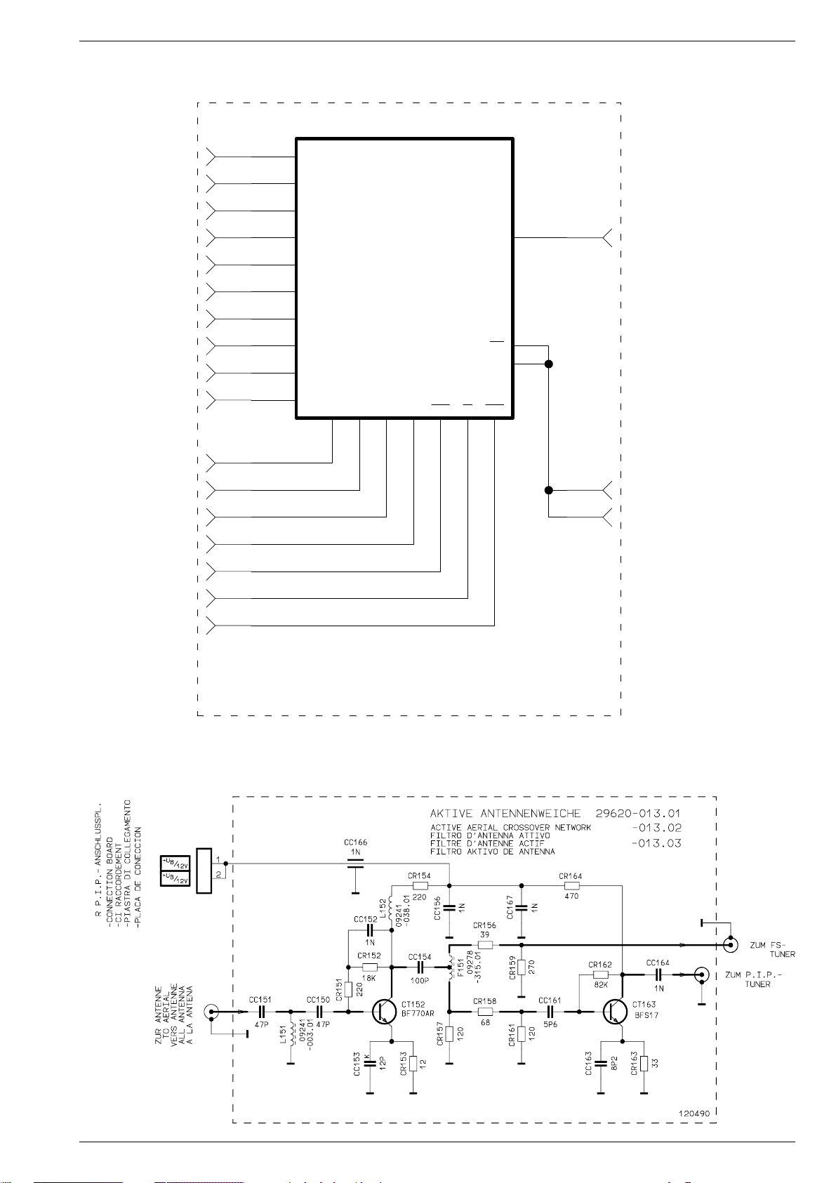
Digi 6 Platinenabbildungen und Schaltpläne / Layout of the PCBs and Circuit Diagrams
Seite/Page 3-59
Speicherplatte / Memory Board 29305-119.21/.24
13
11
10
3
7
4
6
2
8
9
STL
20
STL
18
STL
16
STL
14
STL
12
STL
19
STL
17
STL
STL
STL
STL
STL
STL
STL
STL
STL
STL
16
A6
15
A5
12
A3
10
A1
17
A7
14
A4
11
A2
9
A0
18
A8
5
A9
IC1
256K x4
HYB514256BJ-60(.21)
4M x1
HYB514400BJ-70(.24)
SPEICHERPLATTE 29305-119.21
MEMORY BOARD
C.I.DE MEMOIRE
PIASTRA MEMORIZZAZIONE
PLACA DE MEMORISACION
29305-119.24
VCC
OE
VSS
RASWECASD3D1D2D0
13
22
26
4323252241
STL
15
STL
1
STL
5
151096
Aktive Antennenweiche / Active Aerial Crossover Network 29620-013.01/.02/.03
GRUNDIG Service 3 - 19
Page 42

Platinenabbildungen und Schaltpläne / Layout of the PCBs and Circuit Diagrams Digi 6
Netzschalterplatte / Mains Switch Board 29305-165.59
Bedieneinheit / Control Unit 29501-082.56
-L
IC84001
TFMS5300
R83004
8,2k
R83003
4,7k
+H
+
C84001
IR
R84002
100
R84001
270
47u/10V
IR
3
+5V
2
1
IR
R83002
2,2k
R83001
1,2k
+H
+L
-P
+P
IR
2
+OEKO
D85001
LU5351
NUR BEI -082.56
ONLY WITH
SEUL.POUR
SOLO NELLA VERS.
SOLO CON
+H
3
1
+OEKO
ST-IR_KB1
8
7
IR
6
5
4
3
2
1
IR
+H
KB
U
LED1
POWER
OFF
U
U
LED2
+OEKO
ZUM CHASSIS
TO CHASSIS
VERS CHASSIS
AL TELAIO
AL CHASIS
Seite/Page 3-23
BED.-EINHEIT
CONTROL UNIT
UNITE DE COMMANDE
UNITA DI COMANDO
UNIDAD DE MANDO
Seite/Page 3-21
ZUM CHASSIS
TO CHASSIS
VERS CHASSIS
AL TELAIO
AL CHASIS
Seite/Page 3-23
1N4148
D81501
S60000
+OEKO
28500-708.97
ST-NETZ1
1
2
NETZSCHALTERPLATTE 29305-165.59
NETZSCHALTERPLATTE
MAINS SWITCH BOARD
C.I.INTERR.SECTEUR
PIASTRA INTERR.DI RETE
PLACA INTERRUPTOR DE RED
T81501
BC875
R81500
IR IRIR
R81501
4,7k
10k
T81502
BC548B
R81504
10k
R81505
R81502
10k
22k
R81503
IR
NICHT NETZGETRENNTES SCHALTUNGSTEIL
CIRCUIT NOT MAINS ISOLATED
CIRCUIT NON ISOLE DU SECTEUR
CIRCUITO NON SEPAR., DALA RETE
SECTOUR DE COM. NO SEP. DE LA RED
18k
+OEKO
ST-NETZ2
2
1
ZUM CHASSIS
TO CHASSIS
VERS CHASSIS
AL TELAIO
AL CHASIS
Seite/Page 3-23
BEDIENEINHEIT 29501-082.56
CONTROL UNIT
UNITE DE COMANDE
UNITA DI COMANDO
UNIDAD DE MANDO
231096
3 - 20 GRUNDIG Service
Page 43

Digi 6
BC875
T81501
28500-708.97
S60000
1
2
ST-KB
U
OFF
POWER
R44506
75
BC548B
T81502
1
2
ST-NETZ1
KB
12
34
U
LED2
1
2
3
LU5351
D83001
R81502
18k
KB
IR
+OEKO
1N4148
D81501
U
LED1
+H
R81504
10k
1
2
ST-NETZ2
R81505
10k
R81503
22k
R81501
4,7k
R44504
75
+H
7
8
1
2
3
4
5
6
ST-IR-KB
U
LED2
IR
+OEKO
U
LED1
+H
1
2
3
4
5
6
ST-H-AV
R84001
270
K
0,1u
C41500
n.V.
R81500
10k
IR
+5V
1
2
3
TFMS5300
IC84001
R83001
1,2k
+
47u/10V
C84001
7
8
1
2
3
4
5
6
ST-IR-KB1
FBAS
AUDIO-L
CAV
AUDIO-R
CAV
BU11
U
OFF
POWER
KB
L
R
1
2
3
BU10
KH
AUDIO-R
KH
AUDIO-L
K
470p
C44501
R41501
100
K
8,2n
C41502
K
5,6n
C41501
K
5,6n
C41503
K
470p
C44503
R44503
470
R44501
470
R41503
100
R
L
+
2,2u/100V
C44504
R83004
8,2k
R83003
4,7k
R83002
2,2k
+
2,2u/100V
C44502
-L
+L
+P
-P
100
R84002
CHROMA
S-VHS
FBAS
VIDEO
1
2
3
ST-SV1
n.V.
n.V.
+H
+H
+OEKO
+OEKO
+OEKO
+OEKO
A
A
A
A
A
KH
KH
KH
KH
V
VV
V
V
V
IR
IR
IR
IR
IR
IR
IR IRIR
051196
ENTF.BEI -082.26
NO EXISTE EN
MANCA CON
N’EXISTE PAS POUR
DELETED WITH
NUR BEI -082.26
NUR BEI -082.50/.54
-082.54
ZUR NETZSCHALTERPL.
A LA PLACA INTERRUPTOR RED
Seite/Page 3-20
ALLA PIASTRA INTERR. DI RETE
VERS C.I. INTERR. SECTEUR
TO MAINS SWITCH BOARD
-082.50
SOLAN. CON
SOLAN. CON
SOLO CON
SOLO CON
SEUL. POUR
SEUL. POUR
ONLY WITH
ONLY WITH
AL TECLADO
ALLA TASTIERA
VERS CLAVIER
TO KEYBOARD
ZUM KEYBOARD
FUER M 70 - 269 PAL/PLUS /FS469
CIRCUIT NOT MAINS ISOLATED
AL TELAIO
AL TELAIO
SECTOUR DE COM. NO SEP. DE LA RED
CIRCUITO NON SEPAR., DALA RETE
CIRCUIT NON ISOLE DU SECTEUR
NICHT NETZGETRENNTES SCHALTUNGSTEIL
ZUM CHASSIS
ZUM CHASSIS
TO CHASSIS
TO CHASSIS
VERS CHASSIS
VERS CHASSIS
AL CHASIS
Seite/Page 3-23
AL CHASIS
Seite/Page 3-23
BED.-EINHEIT 29501-082.26
DRUCK 29306-202.04
UNIDAD DE MANDO
UNITA DI COMANDO
UNITE DE COMMANDE
CONTROL UNIT
AL TELAIO
AL CHASIS
Seite/Page 3-20
VERS CHASSIS
TO CHASSIS
ZUM CHASSIS
7
8
1
234
5
6
ST-IR-KB
BC875
T81501
123
ST-SV1
12
34
FBAS
VIDEO
CHROMA
S-VHS
10
9
7542
1
6
83
PC
ED
A
B
DP
G
FC
TDSG3150
DP1841
10
9
7542
1
6
83
PC
ED
A
B
DP
G
FC
TDSG3150
DP1871
E
Z
+F
VDR
SCL
SDA
VDR
DATA IN
CLK
CURR
DATA OUT
UAA2022
1
23 456
7
89 10 11 121314 15
16
17
18
19 202122
23
24
IC1870
820
R1843
4,7k
R1845
K
1n
C1842
F
0,1u
C1843
+
220u/10V
C1844
28500-708.97
S60000
U
OFF
POWER
10k
R81500
BC548B
T81502
1
2
ST-NETZ1
KB
-P
+P
+L
-L
+
2,2u/100V
C44502
R1852
2,2k
R1853
4,7k
+
2,2u/100V
C44504
L
R
K
470p
C44503
K
5,6n
C41503
K
5,6n
C41501
K
8,2n
C41502
K
470p
C44501
KH
AUDIO-L
KH
AUDIO-R
L
R
1
2
3
BU10
K
0,1u
C84002
BU11
+
47u/10V
C84001
AUDIO-R
CAV
AUDIO-L
CAV
U
LED2
270
R84001
IR
+5V
1
2
3
TFMS5300
IC84001
IR
+OEKO
1N4148
D81501
FBAS
U
LED1
+H
12345
6
ST-H-AV
18k
R81502
R1851
1,2k
1
2
ST-NETZ2
R1854
8,2k
12345
MP
1
1
1
1
1
1
1
10k
R81504
470
R44503
470
R44501
100
R41503
100
41501
10k
R81505
22k
R81503
4,7k
R81501
75
R44504
75
R44506
100
R84002
123
LU5351
D85001
KH
KH
KH
KH
+OEKO
+OEKO
+OEKO
+OEKO
V
VV
V
A
A
A
A
A
+H +H
+H
+H
MM
M
M
MM
+F
+F +F
+F
+F
+F
+F+F
IR
IR
IR IRIR
IR
IR
IR
IR
281096
ANZEIGE-EINHEIT MIT TASTEN 29501-083.38
160996
-082.55
BEDIENEINHEIT 29501-082.38
-083.49
ENTFAELLT BEI -083.49
NO EXISTE EN
MANCA NELLA VERS.
N’ EXISTE PAS POUR
NOT FITTED ON
**
*
*
*
**
*
*
DISPLAY UNIT WITH BUTTONS
UNITE D’INDICATION AVEC TOUCHES
UNITA D’INDICAZIONE CON TASTI
UNIDAD DE INDICACION CON TECLAS
CIRCUIT NOT MAINS ISOLATED
AL TELAIOAL TELAIO
SECTOUR DE COM. NO SEP. DE LA RED
CIRCUITO NON SEPAR., DALA RETE
CIRCUIT NON ISOLE DU SECTEUR
NICHT NETZGETRENNTES SCHALTUNGSTEIL
ZUM CHASSISZUM CHASSIS
TO CHASSISTO CHASSIS
VERS CHASSISVERS CHASSIS
AL CHASIS
Seite/Page 3-23
AL CHASIS
Seite/Page 3-23
AL TELAIO
UNIDAD DE MANDO
UNITA DI COMANDO
UNITE DE COMANDE
CONTROL UNIT
AL CHASIS
Seite/Page 3-23
VERS CHASSIS
TO CHASSIS
ZUM CHASSIS
Digi 6
Bedieneinheit / Control Unit 29501-082.38/.55
GRUNDIG Service
3 - 21
Bedieneinheit / Control Unit 29501-082.26/.50/.54
GRUNDIG Service
3 - 22
Page 44

Platinenabbildungen und Schaltpläne / Layout of the PCBs and Circuit Diagrams
Gesamtschaltplan Netz-Chassis / General Circuit Diagram Mains Chassis
SI60201
T100mA
1k
NETZ2
NETZ1
ST-NET11
A LA PLACA INTERRUPTOR DE RED
Seite/Page 3-20
ALLA PIASTRA INTERR.DI RETE
VERS C.I.INTERR.SECTEUR
TO MAINS SWITCH BOARD
ZUR NETZSCHALTERPL.
M
ST-E
PRIMAERMASSE / NICHT NETZGETRENNTES SCHALTUNGSTEIL
PRIMARY CHASSIS, NOTE / CIRCUT NOT MAINS ISOLATED
MASSE PRIMAIRE / CIRCUIT NON ISOLE DU SECTEUR
P
MASSA PRIMARIO / CIRCUITO NON SEPAR., DALA RETE
MASA PRIMARIA / SECTOUR DE COM. NO SEP. DE LA RED
L62501
29500-*
F
C62501
SI62501
T3,15A_H
0,47u/MP3/250V
NUR , WENN
NETZENTSTOERUNG
AM CHASSIS
BESTUECKT IST
1
2
BR302
3
4
1
2
OFFEN , WENN
NETZENTSTOERUNG
AM CHASSIS
BESTUECKT IST
BR303
F
C62505
0,1u/MKS4-R/250V-AC
C62021
C62022
R62505
C60201
1,5n
C60202
+
1u/63V
BR308
R60026
1,2/8W
2,2n/400V_AC
2,2n/400V_AC
8311-200-
F
D60202
1N4148
C62502
BR305
R60201
D60201
F
*
1N4148
R60202
1k
/MP3/250V
*
R60027
1,2/8W
R60021
NTC4,7
BR304
C60023
P
C60024
D60204
ZPD13/2%
300u/385V
P
1n
1n
D60023
B380/C2200
C60022
C60203
R60203
D60203
+
C60026
+-
C60027
K
2,2k
ZPD8,2/2%
L60021
K
C62048
5
100p
C60204
T2A
SI60001
3,6u
MUR460
D60021
MUR460
D60019
1n
1n
PMP
1n/400V_AC
T60206
BC558C
+
10u/50V
R60001
270k
R60002
680k
R60023
1
180k
K
27p
C60021
K
27p
C60019
0,3u
L60028
F
C60028
0,1u/MP3/400V-AC
P
R62049
M
R60206
1k
BR301
2,7M
R60213
P
R60207
C60002
P
P
C60013
R60046
P
100
T60203
BC548B
D60207
4,7
D60208
1n
C60001
P
2,7n/FKC3
3
7
1
F
0,22u
P
R60029
R60032
6,8k
220
R60031
P P
4,7k
4
1N4001
1N4001
STAND
BY
n.v.
2
47k
R60208
8
T60213
BC558B
68
R60214
4,7k
2
START LOGIK
IC60010
TDA4605/3
11
K
C60017
C60018
10n/FKP1/1250V
OK60031
5
2,4k
R60033
K
2,2n
C60031
OK60046
5
P
2,7M
R60211
2,7M
R60212
D60223
8
220p
P
F
CNY17F1
CNY17F1
C60221
1N4148
P
F
R60221
R60223
/14V+U
B
4
1
24
R61301
1
24
3,9n
330
3
220K
R60013
10k
T61301
BC548B
470
M
M
T60223
BUZ90A
D60226
BZT03D180
BZT03D180
D60224
2
SDG
1
WEITBEREICH
MULTIVOLTAGE
MULTIVOLTAGGIO
W.W.
R60005
4,7
R60006
5
4,7
6
+Q
R61302
1k
+H
270
R61316
T61316
BC548B
6
D60225
BA159
R61317
R60222
T60005
BD50
R60007
+
C60011
+
C60014
R61305
C61301
22k
Platinenabbildungen und Schaltpläne / Layout of the PCBs and Circuit Diagrams
7
12
3456
M
330
F
C60224
100p/FKP1/1,6kV
P
33n/FKP1/630V
T60006
P
PC50
G
9
2,2k
C60012
P
K
270p/2kV
D60012
220u/40V
P
BYT53B
D60014
BAV21
1u/63V
P P
M
4
1
IC61310
LM358N
8
+Q
220k
K
3,3n
D61001
BYT53B
+
C61001
M
TR60220
+M
C61006
15k/7W
P
R60012
R60016
4,7n/FKC3
3
2
47
2
56
R61313
R61312
R61311
R60008
MUR460
D60007
MUR460
D60006
F
C60009
220p/FKP1/1,6kV
P
*
+A
47k
K
2,2k
C61311
L60006
R61314
Min.
2,7n
C60007
10
D
S
C60016
+
-
M M
R61304
R61306
1,2k/1%
1k/1%
R61303
10k
M
AENDERUNGEN VORBEHALTEN
SUBJECT TO ALTERNATE
SOURS RESERVE DE MODIFIC
CON RISERVA DI MODIFICA
RESERV. EL DEREC. DE MODIFIC.
C61002
470u/40V
F
0,1u
M
TR61000
3,6u
*
F
M
M
R61008
M
0,1u
R61002
560/1%
5
6
4
3
7
9
P
R61007
360/1%
1,1k/1%
+A
+Q
IC61001
LM317T
ADJUST
R61001
IC61006
LM317T
ADJUST
1
220
1
19
20
22
C61016
21
13
12
17
14
16
15
18
23
OUTIN
R61003
220/1%
23
OUTIN
R61009
220/1%
L61011
-014
F
100p/FKP1/1,6kV
M
L61021
-014
L61026
-014
L61036
-014
L61037
-014
L61056
-014
M
L61061
-014
L61066
-014
SI61012
C61014
L61016
-014
SI61022
T2A
SI61026
T2,5A
SI61036
T2,5A
SI61056
T2,5A
SI61061
T2A
SI61066
T2A
F
0,1u
C61003
F
0,1u
C61007
M M
C61011
D61011
T4A
MUR840
L61014
-014
K
4,7n
M M
D61016
MUR880
12
C61021
D61021
MUR420
C61026
D61026
MUR840
C61036
D61036
MUR840
C61056
D61056
MUR840
C61061
D61061
MUR420
D61066
MUR420
C61066
+
C61004
MM
+
C61008
100p
C61012
C61015
+
C61017
100u/250V
M M
100p
100p
100p
100p
100p
100p
1000u/25V
220u/25V
F
0,1u
M
F
0,1u
C61018
+
C61027
M
+
C61057
M
+
C61062
+
C61063
+
C61013
4,7n
3,3k
R61022
M
470u/40V
+
C61037
M
470u/40V
470u/40V
470u/40V
R61013
1000u/63V
R61018
+
C61022
M
C61028
F
M
0,1u
R61029
M
1,8k/1%
1000u/63V
C61058
F
M
0,1u
R61059
M
R61062
R61063
2
1,8k
1
100k
M
M
M
*
470
470
FEATURE-B.
CONT. 8
600u/63V
C61038
F
0,1u
R61039
560/1%
M
+OEKO
+H
+H
+Q
+G
-G
+A
R61031
R61051
D61062
1N4003
*
R61059
D61067
1N4003
/+5V
/+9,5V
/+19V
/-19V
/
R61033
IC61030
470
R61041
IC61050
220
/>10V
*
4
100
LM317T
ADJUST
LM350
ADJUST
1
IC61040
220
1
D61063
1N4003
220/5%
D61068
1N4003
29201.380.01(-106.01)
29201-382.01(-106.02)
D61033
1N4001
23
OUTIN
R61032
220/1%
23
OUTIN
LM350
ADJUST
R61042
1
220/1%
23
OUTIN
R61052
220/1%
IDTVPAL/PLUS
560/2%
TR61800
14
SI61801
T800mA
5
SI61803
6
T800mA
SI61808
3
T800mA
2
M
BEZUGSPOTENTIAL VON +8V/-8V/-27V
REFERENCE POTENTIAL OF
TENSION DE REF. DE
POTENZIALE DI RIF. A
POTENCIAL REFERENTE A
+LNC
+D
+M
+B
+
1000u/25V
M
FEATURE-B.
CONT. 36
F
C61031
0,1u
C61032
M
+F
+
F
0,1u
C61042
C61041
2200U/16V
M
M
+N
+
F
0,1u
C61051
C61052
100u/25V
M
M
+K
NUR BEI PHI-ROEHRE
ONLY WITH
+
SEUL.POUR
SOLO CON
C61064
SOLAM.CON
2200u/25V
M
-K
C61801
100p
D61801
BYT53B
C61803
100p
D61803
BYT53B
C61808
100p
D61808
BYT53B
NUR BEI VFD-DISPLAY
ONLY WITH
SEUL.POUR
SOLO CON
SOLAM.CON
/+26V
/+26V
/+16V
/+12V
+B
/+5V
+F
FEATURE-B.
CONT. 9/10
/+5V
(+3,3V PAL+)
+N
FEATURE-B.
CONT. 9/10
/+14V
/-14V
C6101/C6103/C6108
ENTF. BEI
NOT FITTED IN
SUPRIME SUR
MANCAND NEL
SUPRIMIDO EN
+
1k
C61802
R61802
+
1k
C61806
R61806
R61803
220u/40V
220u/40V
D61807
+
C61809
M
M
4,7k
ZPY9,1
470u/40V
ST-HZ
1
2
3
4
3 - 23
*
70cm /16:9 TOS
72cm / 4:3 TOS
82cm /16:9 TOS
95cm / 4:3 TOS
70cm /16:9 PHI
82cm /16:9 PHI
+A
150V
148V
150V
159V
144V
R21101 R21102
4,3/3W
4,3/3W
4,3/3W
0,47/1W/BWF
4,3/2W/LI4,7/2W/LI 144V
3,3/2W/LI 3,3/2W/LI
R21214
820k
820k
820k
820k
150k
150k
R21226
2k
2k
R50007
1,81,8
1,5 1,5
1,5 1,5
1,5
1,5
2,4 2,4
GRUNDIG Service
R52001
8,2
4,7
8,2
4,7
8,2
8,2
TR53001R50008
29201-025.17
29201-025.07
29201-025.17
29201-025.14
29201-025.202,4 2,4
29201-025.19
3 - 24
T53001
2SC4288A
2SC4542
2SC4288A
2SC4288A
2SC4288A
2SC4288A
C53007
C53006
0,25u
0,25u
0,25u 0,25u
0,25u
0,25u
0,41u
0,3u
0,3u 0,3u
0,41u
0,3u
R53012
130k/2%
120k/5%
110k/2%
110k/2%
120k/5%
100k/2%
R53016
6,8/7W
6,8/11W
6,8/7W
6,8/7W/RSI
6,8/7W/RSI
6,8/7W/RSI
R53021
470
390
470
390
470
470
L53021
29203-117.97
29203-122.97
29203-117.97
29203-117.97
29203-122.97
29203-122.97
K53030
BG2034-642-3206G
BG2034-642-3206G
BG2034-642-3206G
BG2034-642-3206G
BG2034-642-3206G
BG2034-641-3000
R53032
R53031
330k
330k 330k
330k
560k
560k
560k
100k
100k
330k
330k
330k
R53039
2k
2k
2k
2k
1,8k
1,8k
9,5n
9,5n
9,5n
9n
10,5n
11n
C53072C53071
27n
27n
27n
20n
20n
20n
L53074
09246-859.51
09246-859.52
09246-859.51
09246-859.53
09246-859.62
09246-859.62
GRUNDIG Service
Page 45

Digi 6
Gesamtschaltplan Netz-Chassis / General Circuit Diagram Mains Chassis
OWA
10
L‘
R58011
M
R55011
F
+
VERT.
VERT.
8
9
*
F
C58012
C52001
+
470u/25V
K
10n
4,7k
1n
R55012
47u/50V
M
TR61000
VG
R58003
R58001
20k/2%
M
+M
R52001
15
4
R52003
F
C52004
F
M
1
*
7
3,9k
C58011
F
0,22u
1
39/5%
68n/100V
C55011
6
M
*
*
TR52001
-812.31
+D
5
D58003
R58002
D55012
22k
22k
22k
10k
22k
22k
REF
4
ZPD5,1
M
D58001
1N4148
*
D58011
ZPD33
M
3
M
D58012
1N4148
1N4148
16
R52006
ST-HZ
1
2
3
4
L53074
46-859.51
46-859.52
46-859.51
46-859.53
46-859.62
46-859.62
10
M
GND
HEIZ.
-8V
+8V
-27V
82k
R50001
51k
F
2,2n
C50016
M
2,7k
R55016
R55001
3,9k
R55002
C
33k
R55007
C55004 R55012
0,33u
0,33u
22n
0,1u
22n
22n
39k
39k
39k
82k
82k
82k
+G
+F
7
8
9
R50003
R50002
5
6
+G
82k
M
C50011
F
MM
0,1u
C50012
+
1000U/25V
1
1
7
7
F
C50024
15k
R55004
M M
D55004
1N4148
220/1%
R55003
ZD4,3V/2%
D55003
M M M
820/1W/LI
820/1W/LI
820/1W/LI
-G
4
+LNC
C50004
F
2,2n
R50004
51k
0,1u
C55004
R58002
3,3k
3,3k
3,3k/2%
+LNC
3
+K
+
C50026
F
F
C55003
3k
3k
+A
1
2
+A
R50007
C50013
F
0,1u
D50013
BYV28/200
2
IC50010
TDA4173AF
4
4
-K
1000u/25V
MM
*
7
8
28
1
2,2n
3
12k
R55006
M
R58004
13k
13k
13k
11k/2%
13k/1%
13k/2%
ST-CH3
*
62
6
IC55010
R50008
+
C50014
3
3
5
5
8
R55007
TDA8145
R58011
+Q
+Q
14
R50027
C50027
M
3,3k
4,7K
2,7k
2,7K
2,7K
2,7K
10
+H+F -G
*
MM
220u/50V
F
*
+H+o+N
7
8
9
+OEKO
40
T50029
BD543B
13
T50028
BD544B
R50028
4,7
1,5
0,22/MKS4-16
IB
UA
C58011
0,47u
0,47u
0,47u
0,47u
0,56u3,3k/2%
0,47u
+B
ST-CH4
1
2
3
4
5
6
M
ST-J8
270
ST-J7
+B
JV
+
C52002
4,7u/63V
C52003
470p
T52003
BDX43
1N4148
D52003
M M M
5
C55012
6
C55013
+N
R50029
-K
2
IC
UB
4
M
R58014R58013
29201-567.97
8,2k10k
29201-567.97
8,2k
10k
11k
7,5k
29201-567.97
8,2k
10k
11k
8,2k10k
7,5k
29201-571.97
29201-572.97
29201-572.97
+F
HOR.2FT
5.6k
R21227
ST-CH1
1
2
D21222
1N4148
D21221
1N4148
+
C58001
MM
+
C58013
MM
F
C21001
4
1
D52006
R21226
M
D58004
22u/25V
+B
+B
47u/35V
D21001
BY203/S-20
10n/MKS4/1,5kV
M
100
1N4001
R52007
*
ZPD2,7/2%
1N4148
M
C58004
+
47u/35V
T58012
BC548B
R21001
L53001
M M M M
BR307
27
R55014
4,7/NKS3
R61314R61313
L62501
15k
832.97
15k
834.97
15k
832.97
27k
832.97
15k
832.97
15k
832.97
R21224
D58007
L55014
5m
C62502
0,33u
0,1u
0,33u
0,33u
0,33u
0,33u
-K
R21222
680
M
*
R58004
M
R58013
R58014
1k/0,75W
R53003
1,5
L53003
-056
T53001
*
-056
L53002
R58007
M
D53071
26
24
D53072
4.7k
BC548C
T21221
1,8k
*
C58014
+
1u/100V
*
-056
R53002
BY359
BY229/600
M M
R62505
-010
-010
-010
-012
-010
-010
F
C21221
2
3
5
6
C53071
C53072
1,5
F
10n
-
+
IC58010
+
-
M
17
/FKP1/2kV
*
27n/MKP10
NUR BEI PHI-ROEHRE
ONLY WITH
SEUL.POUR
SOLO CON
SOLAM.CON
10k
R21223
R21221
R21231
47k
8
1
LM393
7
4
M
ST-SH1
BA157
D53004
XX
R53004
ST-SH2
C53073
0,68u/MKP10
+A
BEI BEDARF
ON REQUEST
SI NECESSAIRE
SE OCCORRE
EN CASO NECESARIO
H-SHIFT
Digi 6
D21231
33k
F
0,15u
C21231
M
+B
1,2k
R58021
+
C58021
47u/50V
M
R58022
1,2k
+
C58023
47u/50V
M
L53012
1,5m
F
F
C53006
C53007
/MKP10/250V
**
1N4148
1N4148
D21232
D58021
1N4148
D58022
1N4148
+B
/MKP10/250V
BY
STAND
U
6
I/BEAM
18
5
F
C53012
F
C53013
SB
4
M
B-S
SS
U
3
ST-J5ST-J6
142p/2kV
L‘
1,8n/2,5%
OFF
2
*
2
*
29203-
L53021
R53021
ST-J1/J2
JH
ST-J3/J4
2523
L53074
M
0,33u/MKP10
C53017
*
NETZ-CHASSIS DIGI 6
MAINS CHASSIS
CHASSIS DI SECTEUR
CHASSIS DI RETE
CHASIS INTERR. RED
CUC 1842
CUC 1894
CUC 1952
CUC 1962
CUC 1983
CUC 1984
R21232
DF
ST-CH2
1
+M
1N4148
D21202
R21202
+
C21202
M
R21206
B
entf. bei PHI-Roehre
n.V.
BR306
*
R53016
19
C53016
0,33u/MKP10
M
20
M
10k
56k
47u/25V
68k
R53012
*
11
L
9
I
5
E
6
F
7
G
29201-
C21232
F
1u
D21203
1N4148
D21206
BAV21
TR53001
*
M
10k
F
C21233
R21233
M
22k
R21201
1N4148
D21201
T21211
S298
10k
R21203
DYN. FOK. 29305-025.24/.28
DYNAMIC FOCUSSING
FOCALISATION DYNAMIQUE
F
4,7n
FOCALIZZAZIONE DINAMICA
C21206
ENFOQUE DYNAMICO
M
12
1
A
R54006
10
K
4
D
3
C
21
8
H
22
2
B
ST-UG2
2
1
NUR BEI PHI-ROEHRE
ONLY WITH
SEUL. POUR
SOLO CON
M
SOLAM. CON
R21212
1,5M
C21212
+
4,7u/350V
*
R21214
M
C
10
21
1
3
R21234
ST-DF1
T21233
BC548C
1n
M
+C
R21211
M
100k
M
R53032
*
F
*
C53031
R53031
C54006
100p
D54006
1
BYV38
10
+
C54007
M
M
C54001
560p
D54001
1N4936
ZUR BILDROHRPLATTE
TO CART BASE
VERS C.I. TUBE CATHOD
ALLA PIASTRA CINESC.
A LA PLACA-ZOCALO TRC
Seite/Page 3-49,
3-51
100
D21212
2
F
33n
C53032
C53033
R54007
1
10
4,7u/350V
R54001
0,33u/0,75W
M
MM
M
F
1N4004
33n
0,68u
K
C53036
BR300
R21101
2
*
R21213
10k
U/DF
A
UF
D
220p/400V_AC
M
+C
/+200V
+
C54002
STANDART
K53030
F
C53037
F
C53038
M
100u/50V
M
R21102
*
+C
UH
PU~
30M
R53034
M
R53036
3
330k
3
R53037
10n/1,5kV/MKS4
3
R53038
R53039
10n/1,5kV/MKS4
+D
(26V)
M
330k
330k
*
ST-BR
M
M
U
FOK/DF
D53039
070197
1
2
3
4
5
6
U
H
ZPD5,1
M
A LA PLACA-ZOCALO TRC
ALLA PIASTRA CINESC.
VERS C.I. TUBE CATHOD
TO CART BASE
ZUR BILDROHRPLATTE
82cm PHI
FOKUS-BLOCK
U/DF
A
UF
UH
K53030
D
Seite/Page 3-49, 3-51
U
FOK1
U
FOK2
U
SG
M
U
H
70cm/16:9 PHI
A
UF
UH
K53030
D
U
F
U
H
GRUNDIG Service
GRUNDIG Service
Page 46

Platinenabbildungen und Schaltpläne / Layout of the PCBs and Circuit Diagrams
R46001
CD70506
VIDEO
CSY
CC46002
CR46002
7
Gesamtschaltplan Signal-Chassis / General Circuit Diagram Signal Chassis
Platinenabbildungen und Schaltpläne / Layout of the PCBs and Circuit Diagrams
+F
+G
-G
+LNC
+A
+Q
+H
+OEKO
+N
+B
OWA
VERT.
VERT.
VG
REF
HOR.2FH
U
STAND
I
BEAM
SB
SS
B_S
U
OFF
DF
1
62 63
Q32305
18,432MHz
1,5p
CC32310
+B/1
10n
CT32308
BC858B
KH
2
A
CC32345
CC32306
3,3n
CR32308
AUDIO-R
IC32340
78M05
47n
A
A
A
20 21 22 23
32
1,5p
AA
CR32310
2,2k
CR32311
CC32312
AA
L32342
3
15u
+
0,1u
C32355
CC32342
AUDIO-L
AV
CC32336
470p
CC32337
470p
19
56 41 42
47u/10V
CC32359
AA
AUDIO-R
A
CR32332
_ST-AV
470
AV
35
321
CR32331
470
A
CC32314
3,3n
+B/1
3,3k
CC32311
10n
CT32310
BC858B
3,3k
470p
CR32312
AA
KH
AUDIO-L
2,2k
CR32314
CR32313
CC32316
A
3,3k
CC32313
3,3k
470p
10n
CT32312
BC858B
47n
CC32341
A
0,1u
CC32350
A
1n
470p
470p
CC32339
CC32338
43444546 47
AUDIO-UP
IC32300
MSP3410
48
51
A
CC32326
C32327
CC32315
AAA
3,3n
+B +B
3,3k
CR32315
2,2k
CC32317
CR32316
3,3k
CR32317
470p
CC32318
A
AUDIO-R
15u
390p
+
4,7u/63V
10n
CT32315
BC858B
18
L32341
A
CC32331
CC32328
CR32318
AA
AUDIO-L
CR32364
AA
0,1u
AA
2,2
390p
2,2k
24
61
A
+
C32332
64
A
10u/50V
CC32354
C32360
100u/10V
C32343
54
CC32333
A
A
+
AA
47n
+Q
47
R32359
+
CC32347
A
0,1u
+
C32346
10u/50V
10u/50V
38 3940
45678 9 10 11 12 13 14 15231
0,1u
CR32335
220
CR32334
U
RGB
SCL
SDA
57
220
CR32337
0
CR323360CR32338
CL
I2SWSI2S
I2S
C32364
+
47u/10V
CC32348
1n
CC32365
0,1u
0
TER
A
A
A
_CC32321
_CC32322
_CC32323
_CC32324
CR32339
I2S
D-IN
0
49 50
xx
xx
xx
xx
+Q1
-G
CR43001
470p
CC43001
A
CR43006
470p
CC43006
A
CR43011
1n
CC43011
33
34
52
53
36
37
A
A
A
A
A
CC43016
A
CC43002
A
CC43007
A
CC43012
A
CC43017
A
CR43016
1n
CR43002
470p
CR43007
470p
CR43012
1n
CR43017
1n
AUDIO-L
AUDIO-L/AV1/IN
AV1/IN
470
TEILSCHALTPLAN/EINGANGSSIGNALUMSCHALTUNG
CIRCUIT DIAGRAM SECTION
INPUT SIGNAL CHANGE-OVER SWITCH Page
AUDIO-R
AUDIO-R/AV1/IN
AV1/IN
470
AUDIO-R
AUDIO-R/AV1/OUT
AV1/OUT
220
AUDIO-L
AUDIO-L/AV1/OUT
AV1/OUT
220
AUDIO-L
AUDIO-L/AV2/IN
AV2/IN
470
AUDIO-R
AUDIO-R/AV2/IN
AV2/IN
470
AUDIO-R
AUDIO-R/AV2/OUT
AV2/OUT
220
AUDIO-L
AUDIO-L/AV2/OUT
AV2/OUT
220
RxD
FBAS
SDA
SCL
U
RGB
VIDEO
CHROMA
FBAS
Seite 3-21…22
3-21…22
V
A
U
DATA
G
B
R
37
V
38
39
V
40
41
V
42
43
U/TER
AV1
AV2
EURO-
EURO-
MEGA
LOGIC
IDENT
U
U
PIP
U
AV3
EURO-
U
TER
Y
REF
U
+H
CC70501
18A
8
0,1u
+N
CC70502
M
M M
4,7n
CC70503
M
0,1u
3332
FEATURE-BOX
29504-103.38
29504-103.40
29504-103.41
5317
3534
2423 222120
33
27k
CR70502
CR70504
33
27k
CR70501
CR70509
4039383334353637
34A
100
100
100
-(B-Y)
-(R-Y)
VIDEO
CHROMA
VERT.
VERT.
VG
+F
OWA
CC70506
4,7n
CC70507
0,1u
ST-VGA2
41
VERT.2FV
109
3
2
1
L70508
M
M
M
+B
09241-035.97
CC70508
4,7n
C70509
+
2200u/25V
36
9 MB-PAL PLUS
12 MB-PAL PLUS
100Hz-LFR
I
BEAM
HOR.2FH
M
30282625
CR70511
11
CC70511
100
SSC
4,7k
CR70506
1,2k
CR70507
180k
CR70508
3,3k
1412
10n
4645444342
SCL
16
4
SDA
ST-CH3
1
M
2
3
4
5
6
7
8
9
10
ST-CH4
1
2
3
4
5
6
7
8
9
10
ST-CH1
1
2
3
4
5
6
7
8
9
10
ST-CH2
1
BY
2
3
4
5
6
L32359
10u
M
M
+LNC
+A
+Q1
+Q
+H
+OEKO
+N+N
M
+B
+F
+G
-G
MSP
RESET
+33V
CD32315
A
15
ZPD33V
12k/4W
TER
U
4
12
R32315
1
CR32319
SCL
+B
11
29504-162.35
SIGNAL-BAUSTEIN
IF AMPLIFIER
FI-AMPLIFICATEUR
AMPLIFICATORE FI
AMPLIFICADOR FI
100
CR32320
100
SDA
ENA
R32342
12
AFC
U
+B+F+A +LNC
14 13
(MULTI)
M
2930
SS
FBAS
D32342
1N4002
765432
9
10
M
_CT70540
BC848C
M
D32343
1N4002
8
_CR70541
100
0,1u
0,1u
CC32343
CC32340
AA A
+B
680
CR32301
55 16 17
31
CC32301
58
1n
60
59
10n
25 26 27 28 293031 32
CC32302
A
CC32303
CC32309
A
3,3n
+F
3,3k
CR32309
12k/2%
LS4148
_CR70543
_CD70543
CC32307
+
_C70541
10k/2%
_CR70542
100u/25V
LS4148
_CD70541
MM
CR32307
CC32308
3,3k
470p
ST-MP
1
SDA
SDA
2
SCL
SCL
3
VDR
VDR
4
+F
+F
IR
IR
+H
+H
KB
KB
LED1
POWER
POWER
LED2
LED1
LED2
KB
KB
+H
+H
STAND
STAND
KB
KB
LED1
POWER
POWER
CLK
CLK
ACK
ACK
+H
+H
5
ST-IR-KB
1
2
3
4
5
6
OFF
OFF
7
8
_ST-KB
5
4
3
2
1
_ST-VFD
1
BY
BY
2
3
4
OFF
OFF
5
6
7
8
9
10
A LA PLACA LED
ALLA PIASTRA LED
VERS C.I.LED
TO LED BOARD
ZUR LED -PLATTE
U
U
U
U
U
+OEKO
U
U
U
U
U
U
U
A LA UNIDAD DE MANDO / PLACA INTERRUPTOR DE RED
Seite/Page 3-21…22
ALL’UNITA DI COMANDO / PIASTRA INTERR.DI RETE
VERS L’UNITE DE COMMANDE / C.I.INTERR.SECTEUR
TO CONTROL UNIT / MAINS SWITCH BOARD
ZUR BED.-EINHEIT / NETZSCHALTERPLATTE
U
U
DATA
DATA
+OEKO
SDA
+F
+H
+OEKO
+H
+H
M
+OEKO
M
+H
10k
CR87083
VRH
CR87056
4,7k
+
C87055
1u/100V
L87052
HF55BTL
8104-982-051
CR87082
CR87084
CC87084
M
CR87057
10k
R87085
27k
47k
270p
PA0
MODA
+H
CR87087
4,7k
CR87058
+H
22k
PD1
MODB
M
+H
+H
M
4,7k
CC87056
PE4
IRQ
0,1u
AV3
EURO-
U
CR87092
CR87096
XIRQ
C87057
MMMMM
0
CR87094
2,7k
10k
62602942382826
PE5
RESET
PA6
PA7
PA5
VDD
3418
+
220u/10V
CD87087
LS4148
CR87088
CC87088
M
PD5
PA1
CR87097
33
41
17
36
35
37
100k
100p
+H
330
CD87093
LS4148
10k
ST-VGA3
2
M
1
+H
R87111
CR87116
RESET
U
CC87093
270k
CR87114
0
820k
+H
M
0,1u
8
VCC
EEPROM
7
IC87080
TEST
ST24C08
4321
M
+H
CR87093
8,2k
RESET_IC
12
IC87090
MC33164
3
M
CR87113
8,2k
CR87112
CT87115
BC858B
M
M
CC87094
0,1u
SDA
SCL
A0A1A2VSS
M
470
M
5
6
LS4148
SDA
CD87113
SCL
+F
CR46016
4,7k
MEGA
LOGIC
220p
M
CC87087
CT87090
BC848B
+H
220
CR87089
M
R87091
R87098
+H
47k
C87111
F
+F
330n
+F
BY
CR87003
4,7k
STAND
U
SCL
BY
STAND
U
OFF
POWER
U
+H
CR87001
RESET
U
CC87001
MM
54
22k
3
0,1u
20
IR/STANDBY-UP
IC87000
+H
CC87006
0,1u
199
+H
MM
68HC05J1
M
CR87002
M
CC87002
CR83006
M
1 2 6 7 8 10 11 12 13 14 15 16 17 18
390
M
4,7k
M
CR87004
10M
R80007
1k
CC87003
Q87004
4MHz
27p
CC87005
CC87007
CC87004
1n
M
100p
27p
MM
CC87008
1n
M
+H
CR87009
330
CR87007
330
M
R87102
CR87101
100p
100p
CC87009
M MM
100k
CR87010
180
180
M
CR87008
330
CR87103
+H
10k
CR87104
CT87100
BC858B
+H
4,7k
+H
CR87106
CT87105
BC858B
M
4,7k
CR87030
CR87011
10k
CR87107
+H+H
47k
4,7k
CR87012
+H
4,7k
4,7k
R87013
CR87016
47k
CC87062
CR87061
40
39
61
23
59
CR87014
CR87017
TER
U
0,1u
CR87062
4,7k
PA2
PA3
PE1
PG4
PE0
47k
47k
CC87064
100
CR87063
PG0
R87021
ENA
100p
CC87067
100
CR87064
4,7k
CR87066
PG5
PD2
PD3
PD4
32 3031 44 4543
330
R87022
CR87024
330
R87023
A16
A17
A18
330
A15
SDA
100p
R87067
4,7k
PB6
PB7
330
CR87026
A14
CC87069
150
CR87068
202227
PG7
PB5
CR87027
330
CR87028
A13
330
MMMM
+F+F+F+F
4,7k
PB4
CR87029
330
A12
SCL
100p
R87069
A11
CR87072
100
CC87071
PG6
PB2
PB3
330
CR87032
CR87031
A10
330
A9
IDENT
U
47k
M
CR87071
10n
PB0
PB1
330
CR87033
A8
M M
2,7k
CR87065
100k
CC87073
PE2
PF6
PF7
330
CR87037
CR87034
330
CR87036
A6
A7
AV1
EURO-
U
R87070
CR87073
10n
PE3
PF5
330
330
CR87038
A5
EPROM
IC87030
27C40
CR87075
8,2k
CC87074
PF4
CR87039
330
A3
A4
AV2
EURO-
U
2,7k
CR87080
CR87074
10n
PF3
5655545352515049484746
330
CR87041
A2
8,2k
10k
PE6
PF1
PF2
57
CR87042
330
A1
CC87077
CR87076
330
CR87043
M
MMMM
IC87020
MC68HC11F
68-PIN PLCC
PF0
A0
POWER
U
100p
100k
330
OFF
25 6664656321
PG2
UP
CR87044
D7
xx
_CR87077
_CC87078
M
CC87079
M
PC6
PC7
330
CR87046
330
CR87047
D6
AFC
U
xx
CR87078
10n
PE7
PC5
CR87048
D5
M
100k
CC87081
PC4
330
D4
_CR87079
M
PC3
330
CR87049
MSP
RESET
10n
+H
CC87082
M
xx
_R87086
1k
CR87081
LS4148
CD87090
100p
M
24 4 5 8
PG3ER/WNCPG1
PC1
PC2
PC0
1011121314151658
9 67
330
330
CR87053
CR87051
330
330
CR87052
1314151718192021121110986527 726232542829323031
D0
D1D3D2
xx
1N4148
VRL
M
49
1
32
24
22
16
RxD
R87090
D87091
SDA
SCL
100
6
5
4
3
2
1
ST-TEST1
+H
PD0
PA4
EXTAL
M
Q87054
16MHz
CR87054
10M
18p
XTAL
CC87054
CC87052
M
18p
0,1u
VSS
16 7 68 3 2 19
CC87053
3 - 27
GRUNDIG Service
3 - 28
GRUNDIG Service
Page 47

Digi 6
Gesamtschaltplan Signal-Chassis / General Circuit Diagram Signal Chassis
Digi 6
CR70506
1,2k
CR70507
180k
CR70508
3,3k
US
LUS
14
10n
SCL
SDA
CD87113
SDA
SCL
+F
CR46016
CD70506
CSY
VIDEO
R46001
CR46002
CC46002
4,7k
LS4148
2721
181716
CC70512
CC70513
48474654
390
CC46003
390
27p
CR46017
13
15
19
29
31
100p
100p
180p
4,7k
2
4
6
DF
CR46018
CD70507
M
M
M
M
+Q
R46003
4,7k
+F
LS4148
SS
1k
C46004
CT46005
BC858B
MM
CD70508
CR70516
CD70517
SB
0,1u
1
2
8
9
14
15
18
19
20
46
66
67
68
K
C46017
ZPD12
C70516
10u/50V
CR70513
270k
27k
LS4148
M
CD70522
M
CR70526
OFF
B_S
U
K
CVBS
SCL
SDA
IICEN
0,1u
MMM
C70511
M
+
47u/25V
CT70505
BC848B
M
+
5,6k
CR70512
M
M
12
6
M
+Q1
13 4 5 7 8 9 10 11 14 15
1k
ZPD3,3V
CR70522
CT70520
BC848C
CD70521
CR70521
+Q1
CD70523
BC858C
CT70525
CR70527
+
C70527
LS4148
CR70524
CC70528
12k
2,2u/250V
470
+A
330k
CR70523
1k
33n
33k
CR70528
M
M
100
SSC
ZPD5,1V
1k
+A
VERT.2FV
R46009
C46016
33p
15
1
5
VS/VCS
K
ONLLY WITH
SEUL.POUR
CSY
SOLO CON
SOLO CON
100
100
R46010
VCC
VSS
VSS
L46001
C46005
+
M
10u/50v
C46006
K
M
0,1u
HS
VDD1
CASWERASD3D2D1DO
234
WE
RAS
CAS
+F
+33V
12
PIP-BAUSTEIN
PIP MODULE
MODULO PIP
PIASTRA PIP
MODULO PIP
PIP
DATA
SDA
SCL
VERT.2FV
U
PHI-ROEHRENUR BEI
PHI-TUBE
+F+F
10u
VDDA
678 9 10
+
C46007
CR46011
M
22k
RES
VDD4
VDD3
VDD2
TEXT
IC46010
SDA5273P(1MB)
(n.v SDA5275P 4MB)
68-PIN PLCC
A11
IC46020
256Kx4
w.w.
SPEICHERPL. 29305-119.21
MEMORY BOARD
C. I. DE MEMOIRE
PIASTRA MEMORIZZAZIONE
PLACA DE MEMORISACION
+B +Q0
CR34516
+B
3
PIP
29504-165.96
M
33
CR34504
ST-VGA1
M
1
2
3
4
5
6
+F
7
CR34514
4,7k
R34501
B
10u/50V
CR46012
M
33k
C46008
M
1u/100V
A10A9A8A7A6A5A4A3A2A1AO
+
+F
CR46013
VREF
PIPRPIPGPIP
_CC46022
M
_CC46021
M
22k
M
-G
xx
xx
C46011
22p
C46012
22p
57
16
FBAS
OSDBOSD
3,9u
L46002
K
K
B
1718 19202122
PIP
G
L46003
SB
R
OSD
3,9u
L46004
G
11 1213 14
DYNAMIC RAM
6,8k/2%
CR34510
9,1k
SDA
3,9u
R
220
OSD
DATA
U
R46014
XOUT
XIN
VSS4
VSS3
VSS2
VSSA2
RGB
VSS1
VSSA1
VBB
5633 3432313029282726353637414042433839455453
CR34509
SCL
_CC46023
150
CR46015
1,5k
53525150
C46013
22p
6461626368234847241725211612112235410
BLAN
+Q
1M
CD34513
LS4148
CR34513
22k
CR34512
M
1,5M
+
C34511
M
2,2u/100V
CR34511
CR34501
CT34500
390
BC848C
CR34502
6,8
M M
+Q0
+
10k
C34500
CR34503
+
22n
10k
10k
M
2,2u/100V
CC34508
CC65518
22n
MP86
CT65530
BC858C
10n
10u/50V
MM
MM
C34510
CC34509
+
171615
22n
CR65531
CR65528
CT65525
CR65527
4,7u/63V
IC34510
TDA4780
CR34507
1k
CR34508
1k
CR34506
1k
180
180
55
BC848C
CC65527
47n
68
M
19
COMP.ZAEHLERLIMITING
CC65531
CC65528
CR34517
1,8k
25
23
21
20
22
24
M
M
M
CUC 1952
CUC 1962
CUC 1983
CUC 1984
CUC 1842
CUC 1894
0,1u
M
CT65535
BC848B
CR65537
10n
CT65536
CR65536
BC858B
M
M
C34521
F
0,22u
C34522
F
0,22u
C34523
F
0,22u
57
58
59
CC65532
47
47
M
CR34515
+B
CR34521
100
CR34522
100
CR34523
100
0,1u
C65533
MM
M
M
M
+
M
100k
M
M
+Q0
CD34517
47u/25V
56
C65542
10u/250V
LS4148
CC34517
60
7
6
5
4
3
2
1
ST-RGB
M
+
270p
R65542
R65541
SW
3
2
1
2
1k/2W
PTC
+A
M
B
G
R
ST-GM
8311-212-070
Kabel in Z-Anschlag
1
VERS C.I. TUBE CATHOD
A LA PLACA-ZOCALO TRC
ALLA PIASTRA CINESC.
TO CART BASE
ZUR BILDROHRPLATTE
0
_CR40012
I2S
TER
PLACA ZOCALO-TRC
Seite/Page 3-49, 3-51
PIASTRA CINESCOPIO
C.I. TUBE CATHODIQUE
PICTURE TUBE BOARD
BILDROHR-PLATTE
+Q0
CR34525
Y
100
M
M
CR34531
CR34532
M
CR34526
56
100
-(R-Y)
22k
10k
CC34518
0,1u
15
100
-(B-Y)
PIP
DATA
U
R65501
+B
CR65500
CC34519
CC34520
M
CR34524
75
CC34524
100p
OSD
DATA
U
CT65506
CR65502
330
CC65505
10k
CR65505
CT65502
BC858B
22n
22n
C34501
1u/100V
BC858B
330
22
2,2n
+
M
M
M
220u/10V
CC34507
M
8
7
6
18
+B
CR65509
M
C34506
47n
10k
CC65508
+B
CR65503
M
BC818-40
M
BC818-40
+
CR65508
1,8k
CR65506
CT65505
BC858B
CT65504
CT65503
5
Y
SSC
14
CC34502
390
CR34541
M M M
R34546
R
OSD
SSC
100
Y
100
22
2,2n
CC65506
22
180p
M
MATRIX
22n
CR34542
680
9
CC34503
390
R34547
G
CC65507
CR65507
MM
28 2726
A
22n
CR34543
680
OSD
2
IC
D
4321
22n
CC34504
390
680
R34548
B
OSD
DATA
U
OSD
CR34505
M
DATA
U
13 121110
1k
PIP
+B
CR65511
180p
CT65508
BC848C
1M
CR65517
CD65521
CR65521
M
CT65510
BC848C
1k
LS4148
68
C34509
CC34506
R
PIPGPIPBPIP
SIGNAL-CHASSIS
SIGNAL CHASSIS
SIGNAL CHASSIS
CHASSIS SEGNALE
CHASIS SENAL
4,7k
CR65513
CR65516
CC65517
220p
CR65518
4,7k
CR65526
2,2k
CT34530
BC848B
M
CR34519
M
62
CC34526
M
100p
CR34518
M
18
CC34525
M
220
100p
M
xx
+F
K
MM
50
54
CC46014
6
51
15p
52
Q46001
CC46015
20,48MHz
7
15p
44
49
55
58
59
60
13
M
NF-BAUSTEIN
AF MODULE
MODULO BF
PIASTRA BF
MODULO BF
ST-DO1
I2SCLI2SWSI2S
D-IN
10k
CR41002
CC41009
A
3,3n
+F
CR41007
KH
CR41001
C41007
CR41007
M M
+B
61
245316
65432
M
1,8k
AUDIO-R
10k
10k
AA
CR41004
0,22u
F
10k
CC41008
A
3,3n
M
-G
29500-817.97
C40011
+
1u/100V
CC40013
0,1u
NF-DPL
TT LS-L LS-R
29504-104.71
29504-104.72
A
1,8k
CR41006
AUDIO-L
AUDIO-R
KH
AUDIO-L
10k
CR41003
R41011
2,2k
0,22u
F
C41006
D41011
1N4148
10k
CR41006
+F
5
4
CC41013
A
C41014
A
470u/16V
+B/1
+G
L40010
C40012
+
1u/100V
CC40014
0,1u
1514131278
121221
5K 120W-DPL bei PAL+
3K 100W bei LFR
10119
M
SCL
A
+
220u/10V
C41012
A
876
IC41010
TDA3006
3
KH
+
R41016
+B
R
CC41017
0,1u
12
0,1u
1N4001
D40010
0
_CR40011
+F
MSP
SDA
RESET
1
CR41021
A
5,6n
0,1u
CC41021
CC41018
1
2
CC41022
CR41022
5,6n
1
A
CC41029
0,1u
AUDIO-L
AV
AUDIO-R
AV
KH
3-21…22
Seite 3-21…22
6
5
A
4
3
2
1
ZUR KH-BUCHSE
A LA TOMA DE AURICUL.
ALLA PRESA CUFFIA
VERS PRISE CASQUE
L
ST-H-AV
TO HEADPHONE SOCKET Page
070197
GRUNDIG Service
GRUNDIG Service
Page 48

Platinenabbildungen und Schaltpläne / Layout of the PCBs and Circuit Diagrams
Gesamtschaltplan Signal-Chassis / General Circuit Diagram Signal Chassis
Q4
R43021
6,8
47u/16V
1k
V
16
13
4
5
14
7
CR43028
CR43032
CT43030
BC848B
CR43024
100
CIC43020
MC14551
MC14551
10k
47k
CR43022
2,2
9
V
C43022
8
11
12
2
3
6
10
15
1
CT43050
CR43046
V
BC848B
1k
Q5
Q4
2,2
C43049
CR43049
+
47u/16V
68
CR43050
CR43047
75
CR43075
68
CR4307675CR43077
V
1k
V
MP121
MP122
MP123
MP124
MP125
MP126
CT43075
BC848B
MP135
MP136
MP137
MP138
Q5
+
47u/16V
V
Q3
Q2
CR43036
47
V
CR43037
47
CR43038
47
CR43039
47
CR43069
47
CR43066
47
CR43067
47
CR43068
47
75
CR43041
75
CR4307175CR4307275CR43073
V V V
75
CR43042
VV
CR43043
V
75
Q5
CC43095
V
47n
75
CR43095
CT43090
BC858B
CT43095
BC858B
Q5
CR43096
+Q1
+Q1
CT43020
BC808/25
R
R
G
G
B
B
DATA
-G
RGB
RxD
U/DATA
-G
U/RGB
RXD
CR43027
100k
CD43026
U
Seite 3-27
Page 3-27
TO GENERAL CIRCUIT DIAGRAM SIGNAL CHASSIS
ZUM GESAMTSCHALTPLAN SIGNAL-CHASSIS
U
TEILSCHALTPLAN / EINGANGSSIGNAL-UMSCHALTUNG
CIRCUIT DIAGRAM SECTION / INPUT SIGNAL CHANGE-OVER SWITCH
ZUM CHASSIS
TO CHASSIS
VERS CHASSIS
AL TELAIO
AL CHASIS
Seite/Page 3-27
EURO-AV-BUCHSENPL. 29305-160.34
EURO-AV SOCKET BOARD
C.I.PRISES PERI-TV
PIASTRA PRESE EURO-AV
PLACA CONECTORES EURO-AV
CC43026
V
0,1u
MP120
LS4148
CC43028
V VV
R43031
10k
+
C43023
CR43023
Q2
47n
Q2
V
V
V
V
V
MP134
V
V
V
V
75
V
21
19
17
15
13
11
9
7
5
3
1
BU-AV2
21
19
17
15
13
11
9
7
5
3
1
BU-AV1
CT43100
20
18
16
14
12
10
8
6
4
2
20
18
16
14
12
10
8
6
4
2
BC848B
MP132
V
MP131
MP130
MP129
MP128
MP127
MP133
V
MP146
MP142
MP141
MP140
MP139
Q5
CR43098
CR43101
CC43101
V
V
A
CR43057
MP145
MP144
MP143
A
CR43088
470
2,2k
4,7p
CR43048
75
CR43052
470
CR43053
470
CR43056
470
470
CR43074
V
CR43083
470
CR43086
470
CR43087
470
470
CC43052
75
MP147
CR43078
CC43083
CR43099
V
V
V
V
A
CR43097
4,7k
1,1k
470p
75
470p
CC43053
CC43086
470p
Platinenabbildungen und Schaltpläne / Layout of the PCBs and Circuit Diagrams
C43051
+
1u/25V
75
CR43051
V
C43058
+
4,7u/63V
C43059
470p
Q5
CC43056
CC43087
470p
470p
CC43057
CC43088
AAA
4,7u/63V
C43061
22u/25V
C43062
22u/25V
470p
AAAA
C43078
1u/25V
C43089
4,7u/63V
C43091
4,7u/63V
C43092
22u/25V
C43093
22u/25V
470p
+
+
+
CR43080
+
+
+
+
+
47
CR43045
47
18k
CR43131
BC858C
CT43130
VERS L’UNITE DE COMANDE
TO CONTROL UNIT
ZUR BED.-EINHEIT
ALL’UNITA DI COMANDO
A LA UNIDAD DE MANDO
VERS C.I.PRISES EURO-AV
TO EURO-AV SOCKET BOARD
ZUR EURO-AV BUCHSENPL.
47n
CC43131
BC858B
CR43136
VIDEO
S-VHS
CHROMA
S-VHS
ST-SV
CC43143
0,1u
AUDIO-R
AV3/IN
AUDIO-L
AV3/IN
AUDIO-L
AV3/OUT
AUDIO-R
AV3/OUT
A LA PLACA DE TOMAS EURO-AV
ALLA PIASTRA EURO-AV
CC43141
0,1u
18k
CR43132
CR43133
CT43135
CT43140
BC848B
CC43134
0,1u
330k
V
MP148
3
2
1
CR43149
CR43144
47
CC43136
MP149
MP150
75
V
CR43137
V
CC43147
Q2
CR43143
CR43146
V
C43151
1u/25V
75
0,1u
120k
82k
+
5
4
3
2
1
ST-AV3
ST-V3
1
2
3
4
5
CR43140
10k
47n
CR43134
V
CR43145
47
MP159
MP158
MP157
MP156
MP155
MP153
MP152
Q4
MP151
47
Q2
10k
VV
CR43151
47
A
V
Q2
CR43141
CR43142
CC43153
V
Q2
CR43147
CR43148
V
C43045
1u/25V
120k
82k
V
150p
120k
82k
+
CR43040
CC43148
V
150p
MP154
CR43161
47
Q2
CC43152
V
V
Q2
470
8
6
11
10
20
1
5
12
47n
CR43152
CT43160
BC858B
Q2
1k
CR43163
CR43167
1,8k
CR43162
CR43166
V
CC43166
BUS CONTROLLED
VIDEO MATRIX SWITCH
IC43150
TEA6417
2
I
C
3
V
CR43153
120k
82k
C43158
V
V
V
+
2,2k
1k
10p
V
220u/16V
CR43168
CT43165
CR43172
2,2k
V
C43157
V
680
BC848B
+
CR43171
13
14
15
16
17
18
2
4
9197
220u/16V
C43123
4.7u/63V
C43127
22u/25V
2,2k
CR43169
CC43156
V
220n
_CR43225
+
+
2,2k
CR43173
2,2k
Q2
XX
C43122
4.7u/63V
C43126
22u/25V
V
XX
_CR43224
+
+
CT43170
BC848B
CT43080
BC848B
CT43185
BC848B
CT43190
BC848B
Q
Q
Q
Q
3 - 31
GRUNDIG Service
3 - 32
GRUNDIG Service
Page 49

Digi 6 Platinenabbildungen und Schaltpläne / Layout of the PCBs and Circuit Diagrams
Gesamtschaltplan Signal-Chassis / General Circuit Diagram Signal Chassis
MEGA
MEGA/LOGIC
LOGIC
U
EURO-
U/EURO-AV2
AV2
U
EURO-
U/EURO-AV3
AV3
AUDIO-L
AUDIO-L/AV2/IN
AV2/IN
AUDIO-R
Q3
CC43222
A A
0,1u
19
6
9
10
18
7
15
16
8
17
12
11
C43221
A
C43223
+
220u/16V
3
BUS CONTROLLED
AUDIO MATRIX SWITCH
IC43210
TEA6420
2
I
C
A
+
22u/25V
14
13
21
4
20
5
24
23
2212
C43226
+
4,7u/63V
CR43222
100
C43227
+
4,7u/63V
CR43223
100
CR43226
C43228
+
4,7u/63V
C43224
+
4,7u/63V
100
CR43227
C43229
+
4,7u/63V
C43225
+
4,7u/63V
100
CR43228
100
CR43229
100
AV2/IN
AUDIO-L
AV1/IN
AUDIO-R
AV1/IN
AUDIO-L
AV1/OUT
AUDIO-R
AV1/OUT
AUDIO-L
AV2/OUT
AUDIO-R
AV2/OUT
SDA
SCL
AUDIO-R/AV2/IN
AUDIO-L/AV1/IN
AUDIO-R/AV1/IN
AUDIO-L/AV1/OUT
AUDIO-R/AV1/OUT
AUDIO-L/AV2/OUT
AUDIO-R/AV2/OUT
Seite 3-27
Page 3-27
CT43170
BC848B
CT43080
BC848B
CT43185
BC848B
CT43190
BC848B
Q2
CC43178
V
220n
2,2k
C43179
CR43179
BC858B
V
CR43181
V
CR43183
V
CR43187
V
CR43196
V
150
150
150
150
+
1u/25V
C43181
1u/25V
CC43183
0,1u
Q2
CR43199
V
C43187
1u/25V
CC43196
0,1u
+
2,2k
+
C43199
+
1u/25V
Q2
CR43188
CR43189
V
Q2
CR43197
CR43198
V
CC43201
120k
82k
120k
82k
CR43177
2,2k
CR43178
160
CR43176
2,2k
CR43182
160
CT43175
CT43195
Q2
Q2
Q2
BC858B
2,2k
2,2k
CR43191
CR43192
CR43186
Q2
160
CR43193
160
47n
Q2
100k
CR43201
VV
8
6
11
10
20
1
5
12
3
BUS CONTROLLED
VIDEO MATRIX SWITCH
IC43200
TEA6417
2
I
C
+
C43202
220u/16V
V
CR43208
47
CD43208
LS4148
V
CC43206
13
14
15
16
17
18
2
4
9197
220n
V
1M
CR43209
V
Q2
C43208
+
4,7u/25V
CR43210
100k
CT43200
BC848B
CT43205
BC848B
CT43210
BC848B
Q2
CC43202
220n
CR43202
CR43203
CR43204
V
V
V
34 34A
330
330
330
V
VIDEO
TO GENERAL CIRCUIT DIAGRAM SIGNAL CHASSIS
ZUM GESAMTSCHALTPLAN SIGNAL-CHASSIS
33
29
CHROMA
FBAS
PIP
FBAS
U
TER
U
IDENT
U
EURO-
AV1
GRUNDIG Service 3 - 33
Page 50

Platinenabbildungen und Schaltpläne / Layout of the PCBs and Circuit Diagrams Digi 6
Buchsen-Platte
Socket Board
29305-008.33
R84002
BU10
A
A
IR
3
100
47u/10V
K
C41502
+
C84001
8,2n
+5V
2
1
IR
R
3
L
2
R44501
470
R44503
470
IC84001
TFMS5300
1
KH
R
L
BU11
FBAS
V
BUCHSENPLATTE 29305-008.33
SOCKET BOARD
C.I.PRISES
PIASTRA PRESE
PLACA DE TOMAS
-008.xx
n.V.
IR
K
C41501
KH
K
C41503
KH
K
C44501
A
K
C44503
A
R44504
V
R84001
270
nur bei 008.xx
R41501
100
5,6n
R41503
100
5,6n
C44502
2,2u/100V
470p
470p
34
12
75
C44504
2,2u/100V
ST-IR1
3
2
IR
1
ST-H-AV
6
KH
5
+
+
V
n.V.
R44506
VV
4
3
A
2
1
75
1n
K
C84002
ST-SV1
3
V
2
1
121296
IR
+H
KH
AUDIO-L
KH
AUDIO-R
AUDIO-R
CAV
AUDIO-L
CAV
CHROMA
S-VHS
FBAS
S-VHS
AL CHASIS SENAL
Seite/Page 3-27
AL CHASSIS SEGNALE
VERS CHASSIS SIGNAL
TO SIGNAL CHASSIS
ZUM SIGNAL-CHASSIS
Euro-AV Buchsen-Platte / Euro-AV Socket Board 29305-160.34
AUDIO-R
AV3/OUT
AUDIO-L
AV3/OUT
AUDIO-L
AV3/IN
AUDIO-R
AV3/IN
AL CHASIS
AL TELAIO
VERS CHASSIS
TO CHASSIS
ZUM CHASSIS
FBAS
AV/3IN
U
EURO-
AV3
FBAS
AV3/OUT
ST-AV3X
5
4
3
2
1
Seite/Page 3-31
ST-V3
1
2
3
4
5
A
470p
CC43121
470p
CC43119
CC43118
A A A A
CR43126
8,2k
Q4
V
75
CR43116
V
CT43110
BC848B
CR43110
470p
CR43121
CR43119
CR43118
CR43117
470p
CC43117
68
47u/25V
470
470
470
470
CR43113
+
C43113
V
1
2
3
4
A
V
2,2
6
8
10
12
14
16
18
20
AV3
Q4
5
7
9
11
13
15
17
V
19
21
V
75
CR43111
EURO-AV-BUCHSENPL. 29305-160.34
EURO-AV SOCKET BOARD
C.I.PRISES PERI-TV
PIASTRA PRESE EURO-AV
PLACA CONECTORES EURO-AV
190696
1k
CR43112
V
3 - 34 GRUNDIG Service
Page 51

Digi 6
Tuner 29504-201.21/.22/-231.21
Digi 6
U
+33V
ADR
SDA
SCL
+UB/5V
+UB/12V
09241-014
1n
L2086
CR2086
10n
CR2113
15
09241-164
22
CR2089
10
+12V
CC2039
CC2113
1n
CC2048
1,2p
CC2089
2,2p
CC2091
10n
CD2051
CR2056
270p
CR2118
CR2117
BB545
18k
CD2092
BB639
18k
CR2115
MP5
18k
MP8
CC2053
18k
CC2051
1,2p
8,2p
CC2119
CD2121
CC2056
L2091
10n
BB640
L2057
09241-163
8,2p
09241-227.04
L2121
L2123
+12V
C2052
Druck
L2092
0
CR2057
Druck Druck
09241-173
Druck
CC2121
0,47p
09241-228
CR2122
3,3
CR2121
09246-162
L2122
220
CR2058
0
CC2096
CD2096
CC2118
10n
09241-213
L2062
09241-196.04
Druck
L2099
09241-157
82p
BB639
L2097
09241-157
Druck
18k
CR2119
1n
CC20581nCC2059
CD2066
CC2063
6,8p
CC2064
6,8p
1n
CR2098
CC2097
CR2096
CR2097
1n
CC2123
CD2124
B11P
BB640
CD2123
MP4
L2124
09241-045
CR2123
MP9
10n
CC2122
BB545
18k
18k
18k
CR2124
18k
18k
09246-263
L2067
09246-263
CC2099
470p
CC2098
470p
CC2124
L2066
4,7p
CC2174
L2113
CR2125
CC2125
10n
09241-166
22
10n
CC2066
100p
CC2067
100p
CC2126
1n
CC2167
470p
CR2167
5,6k
CR2132
29504-201.21
29504-231.21
29504-201.22
CC2127
470p
CC2128
470p
CC2129
470p
CD2167
180k
BAW56
*
CR2133
180k
CR2131
180k
16
17
18
19
20
21
23
24
12
CC2170
CIC2160
TUA2009XS
SELECT
22
CR2166
47k
470p
3,3p
3,9p
3,3p
BAND
+UB
2
CC2112
15
CC2168
10n
56p
47p
56p
+12V
CC2182CC2194CC2037
9,1p
10p
9,1p
11
G
UHF
G
VHF2
G
VHF1
ZF
10n
-189
470p
10p
-189
470p
CC2176
1,2p
CC2177
10
1,2p
CC2178
9
1,2p
CC2179
8
1,2p
CC2183
7
2,2p
CC2184
6
2,2p
CC2186
5
2,2
CC2187
4
2,2p
CC2189
3
1,8p
CC2191
1
1,5p
CR2195
13
14
68
CR2190
68
-196
-221-219
-196
L2193
09241-020
09241-020
L2192
L2178
L2188
L2189
L2178L2062L2033CC2081
-224
-220
-224
CC2175
09241-197.04
09241-171
CC2185
CD2189
BB640
09241-200
CC2193
CC2192
210695
CC2081 CC2081
18k 10n
18k
18k
CD2181
CC2181
L2181
09241-056
0,5p
1k
CR2181
CC2182
100p
CC2188
BB639
CD2188
/+0,1p /+0,1p
0,5p
CR2187
10k
CC2194
10n
CC9003
10n
CC9002
BB545
100p
10n
470p
*
18k
CR2182
18k
CR2188
MP10MP2
*
18k
CR2192
ST1
ZF
CC2190
9
ST1
ZF
10
*
10p
10p
TUNER 29504-201.21
TUNER
29504-231.21
TUNER
TUNER
29504-201.22
TUNER
L2103
L2033
CC2049
L2073
09241-212
1n
CD2036
BB545
09241-170
CR2102
C2151
0,18u
8,2k
F
CC2155
CC2036
CD2078
CC2078
CD2103
CC2153
CC2152
1n
1n
3,3k
CR2031
CC2031
CD2031
BA592
BU1
1
CR2136
CC2138
CC2134
CC2142
CC2141
CR2135
470k
10n
1n
CR2142
100p
CR2141
100p
470
10n
CC2136
10n
CC2139
47
47
8
VCC
5
SDA
CIC2120
6
SCL
+5V
TEST
X24C01
VSSA2A1A0
1234
7
ST1
2
ST1
4
ST1
3
ST1
8
ST1
7
ST1
6
ST1
5
ST1
1
CC2133
CC2131
+5V
10n
+12V
10n
CC2007
120p
MP1
+12V
CR2146
10k
L2006
CC2005
CC2006
09241-176
120p
CC2143
+5V
CC2135
47p
CC2065
15p
10n
CR2026
10k
1n
Q2143
4MHz
CD2071
BA592
CD2101
BA592
20
1
13
19
18
12
9
100p
3,3k
CR2071
CC2072
1n
3,3k
CR2101
CC2102
1n
3,3p
CC2101
45
G
CIC2161
F
TY44860MR2
1
F
2
2
DECODER
I C
BUS
D/A D/A D/A
31
2 VOLT.
PHASE
COMP
---
+++
F
BUFFERS
2
F
1
10 11
L2102
09241-194
REF.
B1B3B5B7
14151617
09241-127.05
-
+
09241-189
Druck
L2072
3
2
8
7
6
+12V
CC2042
47p
*
3,3p
CC2037
18k
CR2038
18k
CR2079
CC2085
CD2077
B10P
BB639
270p
CD2104
B10P
BB640
CC2106
39n
CR2151
CR2138
CR2139
CC21561nCC21581nCC2162
CC2081
*
18k
CR2078
18k
CR2077
MP3
CC2107
470p
18k
CR2106
18k
10n
CR2112
18k
10k
10k
1n
1n
CC2154
MP7
CC2151
CR2046
47k
CR2084
CR2109
1n
CC2043
47k
47k
1n
G1
G2 S
1n
CR2087
CC2084
CC2111
CR2111
CT2045
S982TR
3,3
15
CC2041
470p
CT2085
BF1012
G1
G2 S
1n
CT2115
S982T
G1
G2 S
10n
D
CC2047
L2047
470p
CC2076
D
CC2086
D
CR2191
18k
GRUNDIG Service
3 - 35
GRUNDIG Service
3 - 36
Page 52

Platinenabbildungen und Schaltpläne / Layout of the PCBs and Circuit Diagrams
Signal-Baustein / Signal Module 29504-102.35
Platinenabbildungen und Schaltpläne / Layout of the PCBs and Circuit Diagrams
+LNC
SCL
SDA
ENA
+33V
U
FM
FBAS
7
6
7
6
STL2
STL2
STL2
+33V
ENA
SDA
SCL
4
3
2
1
2
1
STL2
STL2
4
3
STL2
STL2
M M
+33V
CD32031
LS4148
13
STL
2
STL
3
STL
4
STL
CR32032
0
+12V/1
4,7u
L32002
M
CR32000
CR32001
+
C32008
M
+
4,7u/63V
M
+
C32000
M
390
390
47u/16v
C32003
CD32000
LS4148
100u/25V
Tuner 29504-201.21
TUNER X1
+5V
+33V
+12V/1
+12V
+
C32001
100u/25v
M
6
STL
10
STL
11
+F
STL
1
STL
14
+B
STL
5
AFC
STL
L32001
15u
M
L32008
15u
+F
9
9
10
10
STL2
STL2
+LNC
STL2
+12V
131412
131412
STL2
Usat
11
11
STL2
+12V/1
+33V
+5V1
+5V1
L32003
8,2u
54321
109876
CC32002
CC32002
4,7n
C32002
+
220u/10V
ZF
ZF
M
M
ww 8140-533.606
CC32039
F32041
8140-833-606
4
15p
876
M
CR32041
M M
3
1
1,8k
M
CC32041
10n
**
U
NUR VORGESEHEN
ONLY IF REQUIRED
PREVU
SOLO PREVISTO
SOLAMENTE PREVISTO
CBR32060
CBR32066
10k
CC32132
CBR32068
0
1n
F32043
8140-535-391
31
307
7
M
15p
8
CC32043
M
+12V
M
M
+
0,1u
CC32045
G3955
F32054
0
M
3
M
G9251
F32051
1
0
3
0
M
CBR32067
M
26
27
29
30
4
52
IC32010
TDA6932
1
2
4
5
3
M
RV
C32044
2,2u/100V
28
14 15 16
23
VIF
OPT
AGC
AM
AM
12
6789
M
+
C32058
M
R32033
CR32033
2,7k
4,7k
56k
CR32038
M
CR32029
10k
10n
CC32029
M
1u/100V
AGC
17
APC
24 25
CC32058
C32039
+
47u/16v
10n
CC32032
M
0,1u
CC32028
M
F PLL
0,1u
M
CR32039
68k
CR32058
6,2k
M
CONTR.
15
47u/16v
CR32048
+
M
C32041
CC32042
M
0,1u
22
CC32047
U B2
AFC
U B1
181920
4,7n
C32047
CR32047
10
150
CR32102
21
470
11
CR32027
13
33k
1u
CBR32069
0
F
M
CT32104
BC858B
M
MP47
CR32071
CR32106
270
CR32107
+12V
22k
2,2k
M
+12V
CR32104
470
CR32109
L32124
300
12u
F32124
TPS5,5
M
+12V/1
15k
CR32028
18k
CR32019
M
CR32136
CC32134
1n
CR32137
CBR32070
0
CR32123
M
CR32120
M
SIGNAL-BAUSTEIN 29504-102.35
SIGNAL MODULE
MODULE SIGNALE
MODULO SEGNALE
MODULO SENAL
10k
M
+12V
CR32219
CT32111
BC848B
470
470
CT32133
BFS20
220
CR32138
M
CC32219
M
0,1u
F32111
8141-111-360-
510
560
CR32218
31
76
M
CR32216
1,8k
CR32215
1,8k
+5V+5V
10k
CR32134
CR32135
CR32217
2,7k
56p
CR32125
CC32125
4,7k
CT32217
BC848B
39
56p
CT32216
BC858B
CT32134
BC858B
M
CC32124
STL
INTERC
9
STL
AM
8
STL
TER
U
12
STL
FBAS
7
M
041296
GRUNDIG Service
GRUNDIG Service
Page 53
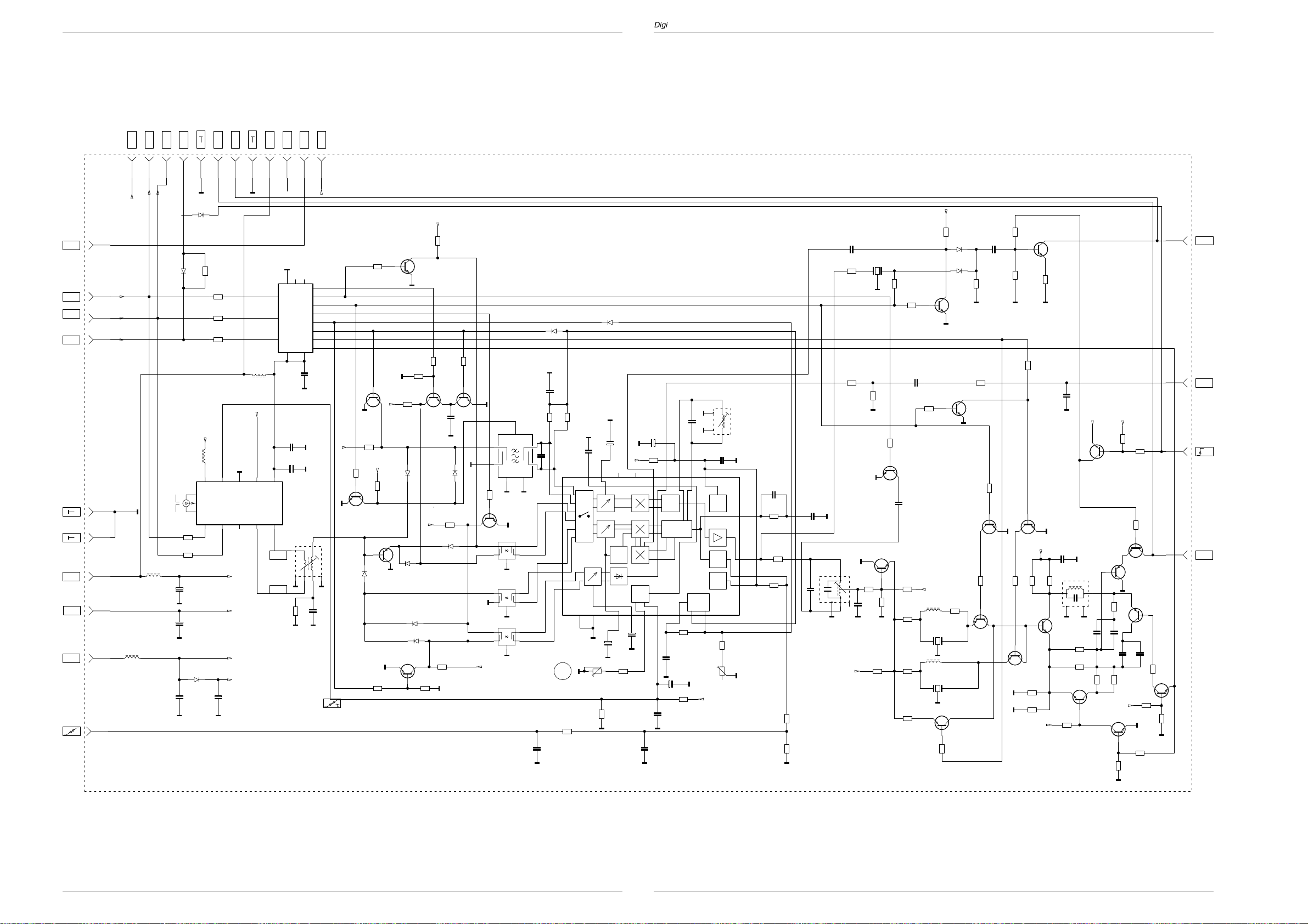
Digi 6
Signal-Baustein / Signal Module 29504-162.35
Digi 6
U
+LNC
SCL
SDA
ENA
+F
+33V
+B
FM
FBAS
7
6
7
6
STL2
STL2
STL2
+33V
ENA
SDA
SCL
4
3
2
1
2
1
STL2
STL2
4
3
STL2
STL2
M M
13
STL
2
STL
3
STL
4
STL
+33V
CD32032
CD32031
LS4148
LS4148
CR32032
CR32031
CR32034
CR32035
0
**
10k
10k
10k
+5V1
+12V/1
4,7u
L32002
M
CR32000
CR32001
+
C32008
M
+
4,7u/63V
M
+
C32000
M
390
390
47u/16v
C32003
CD32000
LS4148
100u/25V
Tuner 29504-201.21
TUNER X1
+5V
+33V
+12V/1
+12V
+
C32001
100u/25v
M
6
STL
10
STL
11
STL
1
STL
14
STL
5
AFC
STL
L32001
15u
M
L32008
15u
+F
9
9
10
10
STL2
STL2
+LNC
STL2
+12V
131412
131412
STL2
Usat
11
11
STL2
+12V/1
47k
C32088
0,47u
12p
F
L32124
CT32132
BC848B
CR32112
47k
+12V
L32109
12u
F32109
TPS4,5
10u
F32124
TRAP21
CT32101
+5V
CR32139
CR32111
M
M
CR32101
M
2,7k
4,7k
BA582
CD32133
BA582
CD32132
10
BC858B
BC848B
M
CT32110
BC848B
CR32088
CR32238
CT32108
CR32141
CT32109
BF660/40
0
CC32134
1k
CR32210
2,7k
10k
CR32136
10k
M
2,2k
CR32310
CR32219
CT32111
BC848B
CR32123
470
CR32120
470
CT32133
BFS20
220
CR32138
MM
47k
1n
CC32238
M
CT32211
BC848B
M
+12V
CC32219
0,1u
F32111
8141-111-360-
510
560
CR32218
31
76
M
CR32216
1,5k
CR32215
1,5k
10k
+12V
CR32211
+5V+5V
10k
CR32134
CR32135
BC858B
CT32217
BC848B
4,7k
CR32217
2,7k
CT32134
BC858B
M
CT32216
M
CT32215
39
CR32125
M
68p
68p
CC32124
CC32125
56p
CC32215
CC32216
1,8k
1,8k
CR32214
CR32200
CT32114
CR32213
+12V
BC848B
CR32122
M
CR32212
47k
22k
M
CT32113
BC848B
BC848B
1n
CR32137
560
M
CR32142
CT32112
BC858B
M
M
BC858B
47p
CR32312
47k
10k
CT32115
CR32124
M
33k
091096
STL
INTERC
9
STL
AM
8
STL
U
ZF
12
STL
FBASZF
7
8,2u
L32003
+33V
+5V1
3
2
1
54321
109876
ZF
M
CLOCK
CIC32030
DATA
MC14094
STROBE
CC32002
CC32002
4,7n
C32002
+
220u/10V
8140-533-605
4
CR32041
*
*
CC32030
F32041
876
M
M M
M
M
1,8k
1098
1615
10n
M
3
1
CC32041
+12V
1,8k
CR32049
CT32042
BC848B
1,8k
CD32047
BA582
CD32043
BA582
CD32044
BA582
M
47k
BA582
CR32037
22k
+12V
CR32062
47k
CR32042
10k
CR32044
CT32041
BC848B
CC32044
CR32061
10k
CD32042
BA582
M
CR32045
10n
M
BA582
CD32046
47k
M
1
2
M
47k
CR32063
CT32061
BC848B
K9551M
F32051
1
F32052
G3957
14
2
M
1
2
+12V
F32054
OFWK6262
3
M
M
3
M
3
M
3
M
CT32062
CR32073
11
12
13
14
7
6
5
4
BC848B
47k
M
CR32043
+12V
M
CT32045
BC858B
CR32046
+12V
10k
+12V
47k
CR32064
10k
CR32065
M
CT32064
BC848B
CT32043
BF660
CD32041
M
BA582
M
10n
CD32048
CR32040
CT32044
BC848B
M
47k
U
SIGNAL-BAUSTEIN 29504-162.35
SIGNAL MODULE
MODULE SIGNALE
MODULO SEGNALE
MODULO SENAL
**
NUR VORGESEHEN
ONLY IF REQUIRED
PREVU
SOLO PREVISTO
SOLAMENTE PREVISTO
CD32071
LS4148
CD32072
LS4148
M
0,1u
CC32052
56k
56k
CR32053
8
4
5
CC32053
CC32029
M
CR32052
M
2,2u/100V
0,1u
CC32045
2,7p
28
RV
CR32029
10k
IC32010
TDA6930S
3
M
23
AM
R32033
4,7k
VIF
OPT
12
M
+
C32058
M
56k
M
26
27
29
30
1
2
4
5
10n
10
M
F32053
L9460
4
52
5
4
5
M
C32041
M
+12V
+
C32057
AGC
9
M
47u/16v
CR32048
17
1u/100V
CC32028
+
15
24 25
10n
M
0,1u
M
CC32058
M
C32039
CC32032
+
C32044
14 15 16
AGC
AM
6
1u/100V
CR32033
2,7k
CR32038
+
APC
F PLL
78
CR32058
6,2k
0,1u
CR32039
68k
CC32043
47u/16v
CONTR.
M
M
15p
M
R32057
7
8
22
181920
10k
+12V/1
CC32042
0,1u
U B2
AFC
U B1
CR32059
F32043
8140-535-391
31
307
M
10
21
11
13
10k
M
+8,5V
CC32047
4,7n
CR32047
150
CR32102
CR32027
33k
470
CR32028
CR32019
M
15k
18k
C32047
1u
CC32102
M
F
8141-112-405
F32101
6,8p
761
M
3
CC32132
CR32133
560
CR32087
+12V
1n
1k
M
2
CC32101
22p
M
CR32105
270
M
SFSH4,5
F32132
CR32086
M
CT32104
BC858B
CR32107
M
CR32104
470
M
10k
CR32131
CR32119
CC32118
2,2k
4,7k
CR32132
47k
CT32119
BC848B
CR32106
22k
270
CR32108
CR32109
220
CR32103
270
GRUNDIG Service
GRUNDIG Service
Page 54

Platinenabbildungen und Schaltpläne / Layout of the PCBs and Circuit Diagrams
D
T
,
R
3
C
Feature-Box 29504-103.38/.41
Platinenabbildungen und Schaltpläne / Layout of the PCBs and Circuit Diagrams
+B/12V
+F/5V
+N/5V
+H/5V
FBAS
CHROMA
G50
B50
U
SDA
SCL
I
BEAM
DATA
VG
SS
REF
L1351
BU
36
09241-035.97
L1353
BU
9
09241-035.97
BU
10
L1357
BU
32
09241-035.97
BU
33
L1358
BU
8
BU
34
Y
BU
38
BU
40
A
BU
42
BU
35
43
BU
R
50
39
BU
41
BU
BU
37
BU
16
BU
14
+1
BU
13
BU
15
BU
17
BU
19
BU
29
BU
31
M
L1401
BU
22
10u
L1402
BU
25
10u
L1403
27
BU
10u
L1407
28
BU
10u
CR2050
CR2051
L1310
L1313
L1315
L1317
CR1415
1,5k
1k
56
CR1401
3,3k/5%
CR1402
CD1403
LS4148
CD1407
LS4148
CD1419
CR1414
330
+
C1354
220u/25V
A A
+
C1353
220u/16V
+
C1357
220u/16V
M M
+
C1359
100u/25V
8140-602-319
F2000
1
TH2450
GND1 GND2
2
AA
CC1307
56p/5%
L1306
1,8u
8140-532-085
27p/5%
CC1306
A
27p/5%
CC1311
27p/5%
CC1313
27p/5%
CC1315
27p/5%
CC1317
+
C1415
ZPD3,9V
10u/50V
M
+4
43/2%
CD1418
M
BAR42
10k/5%
CR1412
+4A
47n
CC1401
M
+4A
68n
CC1402
M
1k/2%
CR1403
CC1403
MMM M
CC1407
M
27p
4,7k
CR1407
CC1408
M
27p
CC1352
CC1356
MM
CC1358
CC1359
MM
4
OUTIN
3
CC1308
A A A
CR1304
AA
CR1305
AA
CR1306
AA
CR1307
AA
L1412
4,7u
+4A
0,1u
M
CC1422
0,1u
M
CC1419
0,1u
M
CC1417
0,1u
M
CC1415
CR1406
CR1408
M
CR1404
CR1433
470p
CD1406
Q1408
+1
0,1u
+2
0,1u
+3
0,1u
+4
0,1u
CR2052
100
1k
CR2056
A
CC1309
68p/5%
L1308
3,3u
8140-532-086
270p/5%
75
75
75
75
** ** ** **
M
C1423
1,2V
25
2,5V
18
4,0V
14
11
32
**
0
15
34
0
33
0
12
27 28
ZPD5,1V/2%
26
2
12MHz
3
/12V
+1
/5V
/3,3V PAL/PLUS
/5V LFR
/5V
A
CC1310
L1411
4,7u
+4 +4
+
L1421
220u/16V
M
17
24
CIC1410
SDA9362
S-DDC
394041
+1
CR2057
330p/5%
9
10
1k
CT2057
BC858B
+4A
CR1422
38
16
CR2053
31
23
3
1,1k
**
CR1423
IC1310
L78M05CX
1
2
A
CC2056
1,1k
CR1303
L1423
M
0
C1427
+
220u/16V
43
CC1426
13
19
0,1u
42
44
37
36
35
30
1
4
5
6
7
8
29
20
22
21
CC1428
100p/5%
CC1421
1,5n/5%
M
CR1421
1,8k/2%
CR1428
M
+5
0,1u
0,1u
CC2057
AA
M
+2
M
M
CC1320
0
M
/5V
+4
+2
+2
+5
Chroma(Rot)
CR1310
680
8
4
0,1u
MM
** = NUR VORGESEHEN
L1350
C1350
CD1350
LS4148
L1352
+
C1352
100u/25V
A
L1360
100uH
C1360
A A
CC1362
A
C1364
A
10u/50V
F
0,22u
C1361
C1314
F
0,22u
56
RST
RSET
CRN
TL7705A
RESIN
CIC1320
REF.
CT
123
0,1u
0,1u
CC1322
CC1321
MM
47n
+
C1367
F
0,68u
C1368
F
0,22u
C1369
F
0,22u
C1323
M
100u/16V
+
220u/16V
+
C1312
F
0,22u
C1316
F
0,22u
7
+
CC1351
AA
CD1351
LS4148
CC1361
A
A
2,2u/100V
0,1u
CC1365
3,3p
CC1366
3,3p
CR1367
1k
CC1354
A
CC1353
A
0,1u
A
0
CR1311
Q1365
0,1u
0,1u
M
20,25MHz
A
M
A
4
31
36
57
66
3
1
2
67
58
68
5
6
7
8
9
59
65
64
63
62
61
60
10 111213
HC
16
10k
CR2060
CT2058
BC848B
LL1,5X
SDA
SCL
HS-2
VS-3
VBLK
SCC/100
HOR
OWA
V-OUT/POS
V-OUT/NEG
U TV VGA
CIC1350
VPC3210A-PS
C3
SCL
SDA
+4
CR2061
1,1k
RES
5455 56
15
CR2063
18
20
21
22
23
24
25
28
29
38
39
40
41
42
43
46
47
17
14
26
27
30
32
35
37
33
44
51
52
50
49
48
34
45
53
19
VS
150
**
CR2062
M
CR2071
M
LL3
CR2069
2,2k
CT2059
BC848B
0
BLN0
Y7
Y6
Y5
Y4
Y3
Y2
Y1
Y0
C7
C6
C5
C4
C3
C2
C1
C0
HS‘
M
+4
LL1,5=27MHz
LL3=13.5MHz
+2
+2
+5
RES
2,2k
CR2070
CR2067
L1370
L1372
L1374
100uH
**
+
C1370
100u/25V
A A
+
C1372
100u/25V
+
C1374
220u/16V
R50
G50
B50
FS
CR1316
CC1376
M
CR2068
CR2065
CR2066
4,7k
51
50
49
48
47
46
45
44
43
42
41
40
39
38
37
36
29
30
53
0,1u
CC1371
19
0.1u
CC1373
AA
57
0,1u
CC1375
AA
35
67
65
63
61
54
10
xx
678
M
**
**
M
33 34
3132
9
345
+4
CIC1360
CIP3250A
55
10
1
24 25 26 27
11
15
2
13
14
CIC2020
74HC4053
M
FEATURE-BOX 29504 - 103.41
CR1319
0
**
CC1319
M
2
3
4
5
6
7
8
9
D-Y7
10
D-Y6
11
D-Y5
12
D-Y4
13
D-Y3
14
D-Y2
15
D-Y1
16
D-Y0
17
20
D-U1
D-U0
21
D-V1
22
D-V0
23
28
59
+
C1377
CC1378
10u/50V
58
62
64
66
A
1
18
52
56
60
68
M
A
LL3
INTLC
SDA
SCL
VS
RES
CR1825
CR1823
CR1821
CR1819
CR1817
CR1815
0.1u
AA
LL1,5
11
ST1
1
+3
+2
+1
CR1824
68
68
CR1822
68
68
CR1820
68
68
CR1818
68
68
CR1816
68
68
CR1814
68
68
ST1
2
ST1
+3
3
ST1
4
ST1
+2
5
ST1
10
ST2
+1
25
ST1
24
ST1
23
ST1
22
ST1
21
ST1
20
ST1
19
ST1
18
ST1
17
ST1
16
ST1
15
ST1
14
ST1
13
ST1
7
ST1
8
ST1
9
ST1
29
ST1
30
ST1
M
PAL/PLUS-PL. 29305-014.40
(29504-103.38)
LFR-PLATTE 29305-014.41
(29504-103.41)
26
ST1
6
ST1
5
ST2
4
ST2
12
ST1
3
ST2
+4
16
0,1u
CC2020
M
12
VVGA
LL1.5X
9
ST2
29504 - 103.38
ST2
ST2
ST2
ST2
ST2
ST2
ST2
ST2
ST2
ST2
ST2
ST2
ST2
ST2
ST2
ST2
ST2
ST2
ST2
ST2
ST2
ST2
ST2
ST2
ST2
10 11
64
65
66
67
CR1914
CR1916
CR1918
CR1920
CR1922
CR1924
CR1926
CR1928
1
68
25
M
Y7
24
Y6
68
23
Y5
22
Y4
68
21
Y3
20
Y2
68
19
Y1
18
Y0
68
16
U1
15
U0
68
14
V1
13
V0
68
12
UVA7
7
UVA6
68
6
UVA5
5
UVA4
68
2
3
4
PROCESSOR
M
63
60
43
28
M
29
41
M
3031
383940
HS2
RES
LL1.5X
VS2/VS3
CR1913
13
68
14
CR1915
15
68
16
CR1917
17
68
18
CR1919
19
68
20
CR1921
21
68
22
CR1923
23
68
24
CR1925
25
68
26
CR1927
27
68
28
2
1
11
29
30
CR1669
BLN2
12
VS3
8
HS2287
CSY
6
M
220u/16V
26
CIC1640
SDA9280
DISPLAY
CC1673
M
39p
C1641
+
42
CR1673
SDA
L1641
61 62
+2
SDA
220
CC1648
0,1u
INPU
32333637
CR1674
SCL
GN
SCL
C
220
C
2
3 - 41
GRUNDIG Service
3 - 42
GRUNDIG Service
Page 55

CR1673
SDA
Digi 6 Platinenabbildungen und Schaltpläne / Layout of the PCBs and Circuit Diagrams
Feature-Box 29504-103.38/.41
BU-
Y/100
+2
L1641
CC1648
41
+
6V
OR
61 62
36
SDA
M
0,1u
51
V
45
48
52
CC1652
58
49
CC1653
54
U
CR1659
57
300/2%
56
CR1661
59
55
53
50
46
CC1623
M
A
A
11k/2%
A
0,1u
0,1u
0,1u
A
CC1661
CC1642
M
+
C1651
+
C1656
CR1662
15k/1%
0,1u
A
A
A
0,1u
220u/16V
220u/16V
A
47
Y
44
35
34
CR1671
1,8k/2%
CC1672
CC1671
1,5n/5%
M
INPUT
GND
32
27
17
9
8
1
SCL
CC1674
M
39p
+1
CT1675
220
220
BC848B
CR1674
CR1676
2,2k
SCL
CR1677
27
CR1678
CC1644
M
100p/5%
M
L1651
L1656
L1662
560
0,1u
M
10u
CR1681
2,2k
CC1646
CC1662
0,1u
0,1u
A
CC1681
M
CR1649
CR1658
+
C1663
CR1668
CT1680
BC848B
1n
+2
+2
150/2%
A
150/2%
A
100u/25V
A
150/2%
A
CD1663
A
+2
CR1682
CR1683
CR1663
1k
ZPD5,1V/2%
10u/50V
56
560
M
C1501
F
1u
C1511
F
1u
C1521
CR1501
CR1502
CR1511
CR1512
+1
CR1521
+
CR1522
HVGA
VVGA
51k/2%
CT1501
BC849B
10k/2%
A
51K/2%
CT1511
BC849B
10k/2%
A
51k/2%
CT1521
BC849B
10k/2%
A
VBLK
+2
CD1532
CD1530
M
+2
CD1533
CD1534
M
CR1503
CR1504
CR1513
CR1514
CR1523
CR1524
LS4148
LS4148
LS4148
LS4148
SSC
240/2%
180/2%
240/2%
180/2%
240/2%
180/2%
CR1531
100
+2
CR1532
100
CR1506
100/2%
CR1507
300/2%
CR1516
100/2%
CR1517
300/2%
CR1526
100/2%
CR1527
200/2%
CR1561
2,2k
HOR.
CR1541
4,7k
CR1562
56
CR1544
CT1506
BCX51-16
CT1516
BCX51-16
CT1526
BCX51-16
CT1541
BC848B
620
CT1561
BC848B
CR1543
M
CC1544
M
CR1508
68/2%
CR1518
68/2%
CR1528
68/2%
CR1542
L1543
330
CT1545
BC848B
47u
L1538
220
10u
10u
M
CR1563
M
CR1549
M
+
C1509
CC1526
M
560
470
220u/25V
L1508
L1518
0,1u
L1532
10u
L1531
L1533
L1563
10u
L1536
L1537
10u
CR1546
220
CR1545
56
L1546
10u
L1544
10u
L1509
+7
+1
2,2u
BU
5
-(R-Y)
100
BU
6
+7
BU
3
-(B-Y)
100
BU
4
+7
BU
1
Y
100
BU
2
BU
7
VERT.2FV
BU
18
CSY
BU
11
HVGA
BU
21
DF
BU
12
VVGA
BU
26
SSC
100
+1
BU
30
HOR.2FH
+1
BU
20
OWA
BU
23
V/AP
BU
24
V/AN
171096
01
MASSE
02
-(B-Y)/100
03
MASSE
04
-(R-Y)/100
05
MASSE
06
VERT.2FV
07
+H (+4/5V)
08
+F (+2/5V)
09
+F (+2/5V)
10
HVGA
11
VVGA
12
MASSE
13
SCL
14
MASSE
15
SDA
16
MASSE
17
CSY
18
MASSE
19
OWA
20
DF
21
VG
22
V/AP
23
24
V/AN
IBEAM
25
SSC/100
26
SS
27
28
29
30
31
32
33
34
35
36
37
38
39
40
41
42
43
C
E
B
1
11
12
10
26
27 43
REF
MASSE
HOR.2FH
MASSE
+N (+3/5V)
+N (+3/5V)
FBAS
CHROMA
+B(+1/12V)
U
DATA
50
MASSE ANALOG
R50
MASSE ANALOG
G50
MASSE ANALOG
B50
BCX
51-16
IC VON OBEN
IC TOP VIEW
IC VUES DE DESSOUS
IC VEDUTO DA SOPRA
IC VISTO DESDE ARRIBA
44
IC1410
SDA9360
168
CIC1390
CIC1360
CIC1640
C
BC848
849
E
B
34
33
23
22
61
60
44
GRUNDIG Service 3 - 43
Page 56

Platinenabbildungen und Schaltpläne / Layout of the PCBs and Circuit Diagrams Digi 6
8
YIN5
PALplus Platte 9M-Bit / PALplus Board 9M-Bit 29305-014.40
VS
LL3
LL1.5
HS2
VS2
SDA
SCL
HS2
1
2
3
4
5
30
29
13
12
26
11
7
8
5
4
6
7
8
9
29
30
BU1
BU1
BU1
BU1
BU1
BU2
BU2
BU1
BU1
BU1
BU1
BU2
BU2
BU2
BU2
BU2
BU1
BU1
BU1
BU1
BU1
CC70134
L70111
100u
L70112
CC70111
M
EXTHSYNC
EXTVSYNC
EXTCLK1
HDEFL
VDEFL
SDA
SCL
HDEFL
X1
1
6,75MHz
CR70129
27p
CC70131
L70101
L70107
**
M
Q70130
1,2k
68p
+5V/A
CC70112
CR70133**CC70133
0,1u
CC70101
M M
0,1u
CC70107
CL70113
+
0,1u
C70111
100u/16V
VV
V
V
150
CR70121
CR70122
CL70121
CR70128
V
470/2%
CC70128
0,1u
1M
CR70132
+3,3V
**
+
C70102
+
C70108
+
C70112
150
CL70122
CR70127
470/2%
CC70127
0,1u
M
CR70141
CR70143
CR70147
100u/16V
100u/16V
MM
100u/25V
V
**
**
**
+3,3V
+5V
+5V/A
CC70121
0,1u
150
CR70123
CR70126
470/2%
CC70126
0,1u
CR70130
330
M
M
0
CR70131
CR70142
**
CR70146
**
CR70148
**
CVBSIN6
CVBSIN3
CVBSIN1
CVBSIN2
CVBSIN4
CVBSIN0
P2HTG7
P2HTG6
EXTCLK1
111 112 113 114 115 117 118 119
87 88 89 91 92 93 94 96 97 98 99 101 102 103 104 106 107 108 109
NC
NC
NC
NC
NC
NC
P2HTG7
P2HTG6
159
VREF
158
AVOUT
157
AUOUT
156
AYOUT
18
EXTHSYNC
19
EXTVSYNC
20
EXTCLK1
21
EXTCKL2
40
HDEFL
41
VDEFL
49
SDA
50
SCL
9
VIDEO0
10
VIDEO1
11
VIDEO2
12
VIDEO3
13
VIDEO4
14
VIDEO5
15
VIDEO6
16
VIDEO7
1
AVBIAS
3
AUBIAS
5
AYBIAS
2
AVCOMP
4
AUCOMP
6
AYCOMP
43
DIVCLKIN
45
I2CADDR
46
XTAL2
47
XTAL1/CLKIN
23
TEST1
24
TEST2
127
VIN7
128
VIN6
129
VIN5
130
VIN4
132
VIN3
133
VIN2
134
P2HTG29
135
P2HTG30
CVBSIN5
CVBSIN7
BLN2
P1SADD0
P2HTG14
P2HTG13
CL70131
NC
NC
BLN2
P2HTG13
P2HTG14
P1SADD0
CVBSIN8
CVBSIN9
P2HTG11
P2HTG12
P2HTG11
P2HTG12
17
16
BU1
BU115BU114BU125BU124BU123BU122BU121BU120BU119BU118BU1
CVBSIN10
CVBSIN11
P2HTG8
P2HTG9
P2HTG10
P2HTG8
P2HTG9
P2HTG10
CIC70115
F312918APCE
P2HTG2
P2HTG3
P2HTG2
P2HTG3
ES2
P2HTG1
P2HTG0
P2HTG1
P2HTG0
STILL
STILL
XRST
72737475
59606162
IO4
IO5
IO6
IO7
P1HTG1
P1HTG0
AUXCK
AUXDT
RESETZ
64
P2HTG30
P2HTG29
44
AUXDT
AUXCK
P1HTG1
P1HTG0
BU2
3
BU1
6
RESET
INTLC
OSCGND
76 78 79 8051 52
82 83 84 8565 66 68 69 70 71
P2HTG5
P2HTG4
P2HTG5
P2HTG4
P2IMCLK
P2IMODE
122 123 124 125
P2IMCLK
P2IMODE
P2SADD1
UVIN4
UVIN5
UVIN6
UVIN7
137 138 139 140 141 142 143 144 146 147 14
UVIN3
UVIN2
UVIN1
UVIN0
M
UVIN1
UVIN0
UVIN3
UVIN2
P2SADD1
YIN8
YIN8
YIN7
YIN7
NUR VORGESEHEN!
**
3 - 44 GRUNDIG Service
YIN6
YIN6
Page 57

Digi 6
PALplus Platte 9M-Bit / PALplus Board 9M-Bit 29305-014.40
136
MM
CIC70271
P11
1
INTLC
CL70132
5455565758596061
IO0
IO1
IO2
IO3
IO4
IO5
IO6
SVP1CLK
SVP2CLK
YIN2
YIN3
YIN4
YIN5
YIN6
YIN7
YIN8
4
146 147 148 149 150 151 152 153 154
YIN2
YIN7
YIN6
YIN5
YIN4
YIN3
YIN1
YIN8
P9
26 27
CLK1
SCLK1
CLK2
SCLK2
YIN1
1
**
YIN0
VCLK
YIN0
CL70133
160
155
145
136
131
126
121
116
110
105
100
95
90
86
81
77
67
63
53
48
42
35
32
29
25
22
17
8
7
120
28
30
31
33
34
36
37
38
39
CL70143
M
CL70137
CL70141
LL1.5X
V
CC70116
**
0,1u
CC70151
0,1u
CC70152
0,1u
CC70153
0,1u
CC70156
0,1u
CC70157
0,1u
CC70158
0,1u
CC70141
0,1u
CC70142
0,1u
CC70143
0,1u
CC70146
0,1u
CC70117
CL70136
CL70138
CL70142
CLK2
+5V/A
+3,3V
V
VCLK
+5V
0,1u
**
**
M
1
1
1
P17
1
BVCLK2
+5V/A
P6
P12
P10
CR70172
CR70173
VCLK
**
0
SVP2CLK
CVBSIN11
CVBSIN10
CVBSIN9
CVBSIN8
CVBSIN7
CVBSIN6
CVBSIN5
CVBSIN4
CVBSIN3
CVBSIN2
CVBSIN1
CVBSIN0
EXTCLK1
P1HTG1
P1HTG0
P1SADD0
OSCGND
P2SADD1
2,2k
CR70271
M
+3,3V
P2HTG29
2
D11 Q11
3
D10
4
D9
5
D8
6
D7
7
D6
8
D5
9
D4
10
D3
11
D2
12
D1
13
D0
14
SWCK
15
RSTW
16
WE
17
IE
18
BVCLK2
P2HTG30
TM4C2973
Q10
Q9
Q8
Q7
Q6
Q5
Q4
Q3
Q2
Q1
Q0
SRCK
RSTR
RE
OE
35
34
33
32
31
30
29
28
27
26
25
24
23
22
21
20
19
+3,3V
P2HTG5
CC70271
M
P2HTG7
P2HTG6
0,1u
M
CR70291
470
330
CR70293
P2HTG9
CLK2
P2HTG8
FAQ11
FAQ10
FAQ9
FAQ8
FAQ7
FAQ6
FAQ5
FAQ4
FAQ3
FAQ2
FAQ1
FAQ0
136
CIC70272
2
FBD11
FBD10
FBD9
FBD8
FBD7
FBD6
FBD5
FBD4
FBD3
FBD2
FBD1
FBD0
CLK2
TM4C2973
D11 Q11
3
D10
4
D9
5
D8
6
D7
7
D6
8
D5
9
D4
10
D3
11
D2
12
D1
13
D0
14
SWCK
15
RSTW
16
WE
17
IE
18
+3,3V
136
CIC70273
MM
2
FBD11
FBD10
FBD9FBD9
FBD8
FBD7
FBD6
FBD5
FBD4
FBD3
FBD2
FBD1
FBD0
TM4C2973
D11 Q11
3
D10
4
D9
5
D8
6
D7
7
D6
8
D5
9
D4
10
D3
11
D2
12
D1
13
D0
14
SWCK
15
RSTW
16
WE
17
IE
18
Q10
SRCK
RSTR
Q10
SRCK
RSTR
MM
35
FCQ11
34
FCQ10FCQ10
33
FCQ9
Q9
32
FCQ8
Q8
31
FCQ7
Q7
30
FCQ6
Q6
29
FCQ5
Q5
28
FCQ4
Q4
27
FCQ3
Q3
26
FCQ2
Q2
25
FCQ1
Q1
24
FCQ0
Q0
23
BVCLK2
22
P2HTG8
21
P2HTG9
RE
20
OE
19
CC70272
M
0,1u
35
FBQ11
34
FBQ10
33
FBQ9
Q9
32
FBQ8
Q8
31
FBQ7
Q7
30
FBQ6
Q6
29
FBQ5
Q5
28
FBQ4
Q4
27
FBQ3
Q3
26
FBQ2
Q2
25
FBQ1
Q1
24
FBQ0
Q0
23
BVCLK2
22
21
RE
20
OE
19
+3,3V
0,1u
CC70273
M
BVCLK2
P2HTG0
P2HTG1
P2HTG2
P2HTG4
P2HTG3
+3,3V
Digi 6
FBD0
FBD1
FBD2
FBD3
FBD4
FBD5
FBD6
FBD7
FBD8
FBD9
FBD10
FBD11
+3,3V
136
138
139
145
146
147
148
149
151
152
153
154
156
157
158
159
160
M
46
37
DI23
CR2
DI22
DI21
DI20
DI19
DI18
DI17
DI16
DI15
DI14
DI13
DI12
33
DO0
34
DO1
35
DO2
36
DO3
38
DO4
39
DO5
40
DO6
41
DO7
42
DO8
43
DO9
44
DO10
45
DO11
DI11
DI10
DI9
DI8
DI7
1
DI6
2
DI5
3
DI4
5
DI3
6
DI2
7
DI1
8
DI0
9
10
DSCLK
11
DSDTO
12
DSACK
DO14
DO13
DO12
47 48 49 505152 53 54 55 56
YIN2
YIN1
YIN0
CR1
DO15
YIN3
787980
CR0
DO16
YIN4
DI24
DO17
YIN5
DI25
DO18
YIN6
DI26
DO19
YIN7
132133134135
DI27
DO20
YIN8
DI28
DI29
RSTRH
SRCK
59 60 61
BVCLK2
P2HTG12
127128129130
DI30
DI31
DO21
RE
65 66 67
UVIN0
P2HTG13
DI32
DO22
UVIN1
M
122123124125
69 70 71 72 73 74 75 76 77
DI33
DI34
DI35
DO25
CIC70270
D37553APCE
ROM-SVPII
RSTWH
SWCK
MCK
DO24
DO23
103
68
UVIN3
UVIN2
BVCLK2BVCLK2
SVP2CLK
P2HTG10
DO26
DO27
IS
WE
140141142143
M
P2HTG11
DO28
AUXCK
AUXDT
AUXCK
DO29
AUXDT
+3,3V
87 88 89 90 91 92 93
DO30
DO31
TESTGO
IGFLGB
XRST
IMODE
IMODECK
2627282930
XRST
STILL
P2IMCLK
P2IMODE
CL6
CL7
TESTAK
IGFLGA
P2HTG14
M
CL4
CL5
TESTCK
TESTEN
TESTRE
141516171819 2021222324
31 32
M
102
TESTRS
+3,3V
+3,3V
0,1u
0,1u
0,1u
CC70281
CC70282
CC70283
126
131
137
144
150
155
CR7027633CR70277
101
PFDOUT
VCOIN
VCORNG
CL0
CL1
CL2
CL3
CR7
CR6
CR5
CR4
CR3
OS
AUXFBWE
INTREQ
SVP#0
SVP#2
DI36
DI37
DI38
DI39
DI40
DI41
DI42
DI43
DI44
DI45
DI46
DI47
PLL1
PLL2
PLL0
1,5k
100
CR70278
99
33k
98
CR70283
97
2,2k
96
95
94
86
85
84
M
83
82
81
62
58
+3,3V
+3,3V
25
121
120
119
118
117
116
115
114
113
112
111
M
110
109
108
107
105
CR70281
106
104
M
2,2k
UVIN0
UVIN1
UVIN2
UVIN3
YIN0
YIN1
YIN2
YIN3
57
M
64
YIN4
YIN5
SVP#1
M
OE
TESTMD
CR70282
63
4
13
M
1k
YIN6
YIN7
YIN8
BLN2
LL1.5X
CC70287
M
CC70277
M
M
0,1u
0,1u
1
BU2
BU2
BU2
BU2
BU2
BU2
BU2
BU2
BU2
BU2
BU2
BU2
BU2
BU2
BU2
BU2
BU2
1
2
11
24
23
22
21
20
19
18
17
16
15
14
13
P5
12
9
GRUNDIG Service
CR70272
CR70273
2,2k
2,2k
CR70376
MMM
2,2k
+3,3V
+5V
CR70311
**
CR70312
**
CC70311
M
**
CR70313
CR70316
M
M
**
**
M
P16
1
1
CIC70310
P8
74AC541
M
CR70317
987654321
**
10
P7
**
P15
20191817161514131211
M
CL70311
CL70313
1
1
**
**
CL70312
P13
1
**
3 - 45
GRUNDIG Service
+3,3V
CR70297
470
330
CR70298
M
CR70292
470
330
CR70296
M
+3,3V
221196
3 - 46
Page 58

Platinenabbildungen und Schaltpläne / Layout of the PCBs and Circuit Diagrams
Dram-LFR-Speicherplatte / Dram-LFR-Memory Board 29305-014.41
+3
CC1601
M
0,1u
CC1602
M
0,1u
52
1
789
2,7k
VS1
CR1697
1,8k/2%
C1662
F
0,1u
M
C1663
F
15n
CR1621
68
CR1623
68
CR1626
68
CR1628
68
CR1631
68
CR1633
68
CR1622
68
CR1624
68
CR1627
68
CR1629
68
CR1632
68
CR1634
68
+3
CC1661
M
0,1u
16
1
2
34
14
15
9
10
11
6
7
&
R
CIC1660
CX
CX/RX
&
R
CX
CX/RX
74lS221
1
13
Q1
Q1
1
5
Q2
12
Q2
8
M
WT
RB
SAC
68
CR1656
68
SAR
CR1657
HS2
68
CR165127CR165268CR1653
29
39
LL3X
CR1654
11
CIC1650
SDA9220
MSC
32 33 34
34
CC1697
100p/5%
CC1698
Q1695
6,75MHz
33p
M MMM
CC1699
33p
BU1
BU1
BU1
BU1
BU1
BU1
BU1
BU1
BU1
BU1
BU1
BU1
BU1
BU1
BU1
BU1
BU1
BU2
BU1
BU1
BU1
BU1
BU1
D-Y7
25
D-Y6
24
D-Y5
23
D-Y4
22
D-Y3
21
D-Y2
20
D-Y1
19
D-Y0
18
D-U1
17
D-U0
16
D-V1
15
D-V0
14
4
5
+2
1
2
3
10
L1608
CC1606
CC1608
0,1u
C1607
M
0,1u
C1609
+
+
100u/25V
M
100u/25V
MM
+3
+1
7
8
9
29
30
42
41
40
39
38
37
36
35
34
33
32
31
14
/5V
13
12
11
M
30
/5V
29
28
27
M
58
/12V
57
60
56
55
54
53
44
10
59
M
CIC1600
SDA9290
PP
45464748 4950
51
61
62
63
64
26
25
24
23
65
66
67
68
22
21
20
19
2
3
4
5
6
18
17
16
15
43
M
CR1687
1k
CR1600
0
HS2
CD1687
SCL
LL1.5X
1
ZPD5,1V/2%
L1686
7
CR1686
L1687
CR1601
68
VS
LL1.5X
BLN
LL3
VS1
SCL
SDA
DREQ
3536
22 23 24
2
+3
0,1u
CC1688
LL3X
CC1691
SDA
BLN
8
SCL
42
13
0,1u
RES
SDA
LL3
VSD
43
28
100u
+
C1687
220u/10V
DREQ
38
25
CC1692
CR1662
3k/2%
CR1663
VS
RES
3031
0,1u
CC1696
1,5n/5%
MMMMM
BU1
26
LL_3
BU1
13
BLN
BU1
12
VS
BU2
9
LL1.5X
BU2
3
RES
BU2
5
SDA
BU2
4
SCL
BU2
7
HS2
+1
Y7
Y6
Y4
YR7
YR6
YR5
YR4
Y0
YR3
YR2
YR1
YR0
U1
U0
V1
V0
UR1
UR0
VR1
VR0
0
CR1661
VSD
RA
RE
SCAD
68
68
CR1670
CR1665
1617 1819
10
1
56
68
CR1675
14 15
12
20 21
68
CR1679
26
SCA
68
9
37
40
41
27
44
M
CSY
CR1680
Platinenabbildungen und Schaltpläne / Layout of the PCBs and Circuit Diagrams
+3
CC1611
28
CIC1605
SDA9251-2X
2223 24
456789
CC1616
M M
28
CIC1610
SDA9251-2X
2223 24
456789
CC1618
M M
28
CIC1615
SDA9251-2X
2223 24
456789
OEBA OEBA OEBA
CC1621
M M
28
CIC1620
SDA9251-2X
2223 24
Y7 Y7
Y4 Y4
Y6 Y6Y5Y5 Y5
YR7 YR7
456789
YR5 YR5
YR6 YR6
YR4 YR4
CC1626
M M
28
CIC1625
SDA9251-2X
2223 24
456789
Y0 Y0Y1Y1 Y1Y2Y2 Y2Y3Y3 Y3U1 U1
YR0 YR0
YR1 YR1
YR2 YR2
YR3 YR3
CC1628
M M
28
CIC1630
SDA9251-2X
2223 24
UR1 UR1
UR0 UR0
VR1 VR1
456789
VR0 VR0
OEBB OEBB OEBB
V0 V0
U0 U0
V1 V1
ZM
VS2
BLN2
68
CC1612
0,1u
0,1u
0,1u
0,1u
0,1u
0,1u
LL3X LL3X LL3X LL3X LL3XLL3X
0,1u
1
14 15
16 1718 19 20
WTWTWTWTWTWT
RBRBRBRBRBRB
SARQSARQSARQSARQSARQSARQ
SCADSCADSCADSCADSCADSCAD
+3
CC1617
0,1u
1
14 15
16 1718 19 20
+3
CC1619
0,1u
1
14 15
16 1718 19 20
+3
CC1622
0,1u
1
14 15
16 1718 19 20
+3
CC1627
0,1u
1
14 15
16 1718 19 20
+3
CC1629
0,1u
14 15
1
16 1718 19 20
SACQ SACQ SACQ SACQ SACQ SACQ
VS
HS2
n.v.
10111213
RENARENARENA
10111213
10111213
10111213
10111213
10111213
RENB RENB RENB
MM
A
RARARARARARA
A
A
B
B
B
RESET
SET
CLOCK
DATA
21
SCASCASCASCASCASCA
21
21
21
21
21
+3
14
VCC
CIC1651
1/2
74HC74T
GND
7
M
OEA
25
M
OEA
25
M
OEA
25
M
OEA
25
M
OEA
25
M
OEA
25
M
CC1651
xx
RENA
RENB
CR1636
68
CR1638
68
CR1641
68
CR1643
68
CR1660
68
CR1684
68
CR1689
68
CR1691
68
CR1693
68
CR1695
68
CR1655
68
CR1688
68
CR1637
68
CR1639
68
CR1646
68
CR1648
68
CR1664
68
CR1685
68
CR1690
68
CR1692
68
CR1694
68
CR1696
68
CR1642
68
CR1644
68
CR1647
68
CR1650
68
IC VON OBEN
IC TOP VIEW
IC VUES DE DESSOUS
IC VEDUTO DA SOPRA
IC VISTO DESDE ARRIBA
+3
CC1632
CC1631
M
0,1u
CC1633
M
0,1u
48
11
9
YA7
8
YA6
7
Ya5
6
YA4
5
YA3
4
YA2
3
YA1
2
YA0
1
UA1
80
UA0
79
VA1
78
VA0
72
27
YB7
26
YB6
25
YB5
24
YB4
10
30
47
28
M
54
70
M
23
YB3
22
Yb2
21
YB1
20
YB0
19
UB1
18
UB0
17
VB1
16
VB0
63
29
73
31
CIC1700
SDA9270
FM
(LFR)
6667
M
0,1u
CC1636
M
0,1u
CC1637
M
0,1u
71
55
43
Y7
44
Y6
45
Y5
46
Y4
49
Y3
50
Y2
51
Y1
52
Y0
53
UVQ7
56
UVQ6
57
UVQ5
58
UVQ4
59
UVQ3
60
UVQ2
61
UVQ1
62
UVQ0
12
13
14
15
74
75
76
77
M
65
M
CR1640
68
BLN3
42
69
34 353637 38
3940 41
64
3233
68
CR1699
68
CR1698
BU2
13
BU2
14
BU2
15
BU2
16
BU2
17
BU2
18
BU2
19
BU2
20
BU2
21
BU2
22
BU2
23
BU2
24
BU2
25
BU2
26
BU2
27
BU2
28
BU2
29
BU2
30
BU2
1
BU2
2
BU2
11
BU2
12
68
BU2
6
8
BU2
80
1
IC1700
SDA9360
20
21
6
7
17
10
26
27
144 40
CIC1650
18
CIC1600
168
61
60
41
40
39
29
28
61
60
44
43
26
27
2
3
26
27
2
3
26
27
2
3
26
27
2
3
26
27
2
3
26
27
2
3
OEBB
OEBA
VSD
ZM
SAC
SAR
SDA
SCL
RE
BLN
BLN2
VS1
VS2
SARQ
SACQ
SCAD
SCA
VS3
LL1.5X
CSY
VS3
M
CR1645
Q
xx
DRAM-LFR-SPEICHERPL. DIGI 6 29305-014.41
Q
xx
CR1649
190796
GRUNDIG Service
GRUNDIG Service
Page 59

Digi 6
15
1
4
5
678
9
10
11
12
V2BU014
C65023
33n
R
U
PUNKT
LEUCHT-
B
1
G
+
47u/25V
C24011
+
1u/250V
C21111
SW
+200V
R
+12V
B
G
ZPD3,3V
D24011
1
2
3
45
6
7
89
TDA6111N4
IC24000
1
2
3
45
6
7
89
TDA6111N4
IC24030
1
2
3
45
6
7
89
TDA6111N4
IC24070
100
R24077
100
R24007
100
R24037
F
560p
C24007
C24072
33n
F
560p
C24037
F
560p
C24077
R65021
4,7k
R24071
2,7k/2%
R24002
2,7k
R24032
2,7k
*
R21101
R24072
2,7k
R24011
2,2k
4,7k
R24036
470k
R21104
*
R21103
C24032
33n
K
1,8p
C24001
K
22n
C24003
K
0,1u
C24006
K
0,1u
C24036
K
22n
C24033
K
1,8p
C24031
K
0,1u
C24013
K
22n
C24073
K
1,8p
C24071
R21106
1k
1k
R24078
1k
R24038
1k
R24008
100k/2%
R24033
100k/2%
R24003
100k/2%
R24073
1
2
ST-UG2
470k
R21102
7
12345
6
ST-RGB
1
2
ST-DF1
+A1
1
2
123
ST-GM2
HEIZ.
U
R24031
2,7k/2%
R65020
220
C65021
4,7n
R24001
2,7k/2%
F
0,1u
C65008
BC338/40
T65010
F
0,1u/100V
C65025
1,3k
R65022
BC328/40
T65005
+
47u/25V
C65027
+
47u/25V
C65017
1N4148
D65002
R65027
27
R65007
12
1k
R65008
1N4148
D24071
123
ST-GM1
1N4148
D65003
+
1u/100V
C65002
1k
R65003
F
4,7n
C65011
C21116
22n/MKP20
R65012
220k
1N4148
D65021
4,7k
R24076
1N4148
D65011
R65013
1,2k
R65011
4,7k
2SC4793
T65015
R65006
12
+
1u/250V
C65022
BAV21
D65017
K
56p
C65026
180
R21116
C24002
33n
220k
R65023
2SA1837
T65025
BAV21
D65027
R65026
39
R65017
27
R65016
39
F
C21104
15n/1,5kV
12345
6
ST-BR
4,7k
R24006
+12V
+12V
+12V
+12V
+12V
+12V
M
M
MM
M
MM
M
M
M
M
MM
M
M
M
M
MM
M
M
M
M
M
M
M
M
M
M
M
M
M
MM
+200V
+200V
+200V
+200V
+200V
+A1
+A1
9
8
071196
72cm (TOS)
NUR BEI 70/82cm 16:9(TOS)
SOLO CON
SOLO NELLA
SEUL.POUR
ONLY WITH
NUR BEI -122.07
1M-122.14
-122.14(70cm 16:9 PHI)
BILDROHRPLATTE 29305-122.07(70/82cm 16:9 TOS)
-122.07
R21103
470k120k
R21101
*
SOLAM. CON
SEUL. POUR
SOLAM. CON
SEUL. POUR
AL CHASSIS SENAL
AL CHASSIS SEGNALE
VERS CHASSIS SIGNAL
TO SIGNAL CHASSIS Page 3-27
ZUM SIGNAL-CHASSIS Seite 3-27
ST-GM2
ST-GM2
NUR BEI 72cm
1
3
2
GM
AL CHASIS INTERR. RED
AL CHASSIS DI RETE
VERS CHASSIS DI SECTEUR
ZUM NETZCHASSIS Seite 3-23
TO MAINS CHASSIS Page 3-23
PLACA - ZOCALO TRC
PIASTRA CINESCOPIO
C.I. TUBE CATHODIQUE
CRT BOARD
SOLO NELLA
SOLO NELLA
ONLY WITH
ONLY WITH
UG2
FOC.
DYN. FOC.
*
*
1
2
3
4
5
6
4
5
10
9
7
11
6
8
AL CHASIS
AL TELAIO
VERS CHASSIS
TO CHASSIS
ZUM CHASSIS
V
J
J
H
J
1
1
423
567
8
BR-SOCKEL
H
U
U
0
110
RESERV. EL DEREC. MODIFIC.
CON RISERVA DI MODIFICA
SOURS RESERVE DE MODIFIC
SUBJECT TO ALTERNATE
AENDERUNGEN VORBEHALTEN
AL CHASSIS SENAL
AL CHASSIS SEGNALE
VERS CHASSIS SIGNAL
TO SIGNAL CHASSIS Page 3-27
ZUM SIGNAL-CHASSIS Seite 3-27
29304-722.92/2l(02)
4
UG2
D65017
6
1
ST-BR
C21104
C65027
BR101
R24002
C24007
C65023
R24003
R24007
R24011
R24078
R21102
ST-DF1
R21103
U62
C24001
ST-RGB
12
11
10
9
8
7
6
5
4
1
BR-SOCKEL
R24076
R65006
13
T65015
EC
T65010
EC
T65005
ST-GM2
R24036
R24006
D24011
D24071
D65003
D65011
D65002
D65021
D65027
C24002
C24032
C24072
C21116
19
C65017
C65002
19
C24037
C24077
C65011
C65021
C65008
R24033
R24073
R24037
R24077
C24011
R24001
R24031
BRU100
R24071
R24072
R65013
C21111
R65011
R24038
R24008
R21101
R21104
R21106
C24003
C24006
C24036
C24033
C24031
C24013
C24073
C24071
C65025
R65012
R65027
R65016C65022
R65003
R65020
R65017
R65008
R65022
R65007
13
T65025
ST-GM1
R65023
R24032
C65026
R65021
R65026
ST-UG2
19
R21116
R21117
29304-722.92/4b(03)
29305-122.07
(digi 6)
bildrohrpl.
8
4
2 13
1
26
7
659
0V
0V
0V
1 2V/cm, 5∝s/cm
1
223
3
0V
8 200mV/cm, 2∝s/cm
Digi 6
Bildrohrplatte / CRTBoard 29305-122.07/.14
Bestückungsseite, Ansicht von oben
Component side, top view
GRUNDIG Service
3 - 49
GRUNDIG Service
100V/cm, 5∝s/cm
4
5
6
9 5V/cm, 2∝s/cm
6
0V
5
0V
4
0V
0V
3 - 50
Page 60

Platinenabbildungen und Schaltpläne / Layout of the PCBs and Circuit Diagrams
C65023
33n
1
2
ST-UG
R
U
PUNKT
LEUCHT-
B
1
G
+
47u/25V
C24011
+
1u/250V
C21111
SW
+200V
R
+12V
B
G
ZPD3,3V
D24011
1
2
3
45
6
7
89
TDA6111N4
IC24000
1
2
3
45
6
7
89
TDA6111N4
IC24030
1
2
3
45
6
7
89
TDA6111N4
IC24070
100
R24077
100
R24007
100
R24037
F
560p
C24007
C24072
33n
F
560p
C24037
F
560p
C24077
R65021
4,7k
R24071
2,7k/2%
R24002
2,7k
R24032
2,7k
R24072
2,7k
R24011
2,2k
4,7k
R24036
C24032
33n
K
1,8p
C24001
K
22n
C24003
K
0,1u
C24006
K
0,1u
C24036
K
22n
C24033
K
1,8p
C24031
K
0,1u
C24013
K
22n
C24073
K
1,8p
C24071
R21106
1k
1k
R24078
1k
R24038
1k
R24008
100k/2%
R24033
100k/2%
R24003
100k/2%
R24073
7
12345
6
ST-RGB
+A1
1
2
123
ST-GM2
HEIZ.
U
FOKUS
1
R24031
2,7k/2%
R65020
220
C65021
4,7n
R24001
2,7k/2%
F
0,1u
C65008
BC338/40
T65010
F
0,1u/100V
C65025
1,3k
R65022
BC328/40
T65005
+
47u/25V
C65027
+
47u/25V
C65017
1N4148
D65002
R65027
27
R65007
12
1k
R65008
1N4148
D24071
123
ST-GM1
1N4148
D65003
+
1u/100V
C65002
1k
R65003
F
4,7n
C65011
C21116
22n/MKP20
R65012
220k
1N4148
D65021
4,7k
R24076
1N4148
D65011
R65013
1,2k
R65011
4,7k
2SC4793
T65015
R65006
12
+
1u/250V
C65022
BAV21
D65017
K
56p
C65026
180
R21116
C24002
33n
220k
R65023
2SA1837
T65025
BAV21
D65027
R65026
39
R65017
27
R65016
39
F
C21104
15n/1,5kV
12345
6
ST-BR
4,7k
R24006
FOKUS
2
2151
5
678
9
101112
V2BU015
+12V
+12V
+12V
+12V
+12V
+12V
M
M
MM
M
MM
M
M
M
M
MM
M
M
M
M
MM
M
M
M
M
M
M
M
M
M
M
M
M
M
MM
+200V
+200V
+200V
+200V
+200V
+A1
+A1
9
8
181296
A
B
/SG
U
BILDROHRPLATTE 29305-122.15(82cm 16:9 PHI)
2
1
82cm
106
5
10
9
7
11
6
8
AL CHASIS
AL TELAIO
VERS CHASSIS
TO CHASSIS
ZUM CHASSIS
V
J
J
H
J
142
3
567
8
BR-SOCKEL
0
ST-GM2
ST-GM2
1
3
2
GM
AL CHASIS INTERR. RED
AL CHASSIS DI RETE
VERS CHASSIS DI SECTEUR
ZUM NETZCHASSIS Seite 3-23
TO MAINS CHASSIS Page 3-23
PLACA - ZOCALO TRC
PIASTRA CINESCOPIO
C.I. TUBE CATHODIQUE
CRT BOARD
1
2
3
4
5
6
H
U
RESERV. EL DEREC. MODIFIC.
CON RISERVA DI MODIFICA
SOURS RESERVE DE MODIFIC
SUBJECT TO ALTERNATE
AENDERUNGEN VORBEHALTEN
AL CHASSIS SENAL
AL CHASSIS SEGNALE
VERS CHASSIS SIGNAL
TO SIGNAL CHASSIS Page 3-27
ZUM SIGNAL-CHASSIS Seite 3-27
AL CHASSIS SENAL
AL CHASSIS SEGNALE
VERS CHASSIS SIGNAL
TO SIGNAL CHASSIS Page 3-27
ZUM SIGNAL-CHASSIS Seite 3-27
29304-722.92/2l(02)
4
UG2
D65017
6
1
ST-BR
C21104
C65027
BR101
R24002
C24007
C65023
R24003
R24007
R24011
R24078
R21102
ST-DF1
R21103
U62
C24001
ST-RGB
12
11
10
9
8
7
6
5
4
1
BR-SOCKEL
R24076
R65006
13
T65015
EC
T65010
EC
T65005
ST-GM2
R24036
R24006
D24011
D24071
D65003
D65011
D65002
D65021
D65027
C24002
C24032
C24072
C21116
19
C65017
C65002
19
C24037
C24077
C65011
C65021
C65008
R24033
R24073
R24037
R24077
C24011
R24001
R24031
BRU100
R24071
R24072
R65013
C21111
R65011
R24038
R24008
R21101
R21104
R21106
C24003
C24006
C24036
C24033
C24031
C24013
C24073
C24071
C65025
R65012
R65027
R65016C65022
R65003
R65020
R65017
R65008
R65022
R65007
13
T65025
ST-GM1
R65023
R24032
C65026
R65021
R65026
ST-UG2
19
R21116
R21117
29304-722.92/4b(03)
29305-122.07
(digi 6)
bildrohrpl.
8
4
2 13
1
26
7
659
0V
0V
0V
1 2V/cm, 5∝s/cm
1
223
3
0V
8 200mV/cm, 2∝s/cm
Platinenabbildungen und Schaltpläne / Layout of the PCBs and Circuit Diagrams
Bildrohrplatte / CRT Panel 29305-122.15
Bestückungsseite, Ansicht von oben
Component side, top view
GRUNDIG Service
100V/cm, 5∝s/cm
4
5
6
9 5V/cm, 2∝s/cm
6
0V
5
0V
4
0V
0V
GRUNDIG Service
Page 61

Digi 6
NF-Verstärker / AF Amplifier 29504-104.72/.73
Digi 6
+B
U
WISC
+G
-G
AUDIO-R
AUDIO-L
STL
7
n.V.
STL
9
STL
15
STL
14
CC40031
STL
13
STL
12
STL
3
STL
2
STL
4
STL
5
D40051
1N4001
+B
+G
D40016
+
C40016
M
CD40056
LS4148
0,1u
1N4001
220u/16V
+
C40032
M
+
C40036
M
33k
CR40017
0
CD40017
22k
CR40056
+
C40033
4700u/40V
M
+
C40037
4700u/40V
M M
4700u/40V
4700u/40V
M
AENDERUNGEN VORBEHALTEN
SUBJECT TO ALTERNATE
SOURS RESERVE DE MODIFIC
CON RISERVA DI MODIFICA
RESERV. EL DEREC. DE MODIFIC.
R40039
150
CR40051
150
CD40052
MM
R40058
13k
CR40057
8,2k
1
1
1k
R40034
M
1
1
1k
R40036
ZPD8,2V
CR40059
CR40063
CC40034
M
CC40038
M
+
C40039
M
+
C40051
7,5k
M
5,1k
0,1u
0,1u
1000u/10V
100u/10V
CD40058
LL101C
6
5
3
2
/+19V
+G
/-19V
-G
+2
ENFAELLT BEI -104.73
NOT FITTED ON
N’EXISTE PAS POUR
MANCA NELLA VERS.
NO EXISTE EN LA VERS.
+B
+8V
8
-
+
IC40020
LM393P
+
-
4
MM M
7
1
CD40061
LS4148
CD40062
LS4148
M
CR40061
CR41063
150k
C40058
+
470u/16V
4,7k
CR40062
22k
+2
CR41062
F
C41061
CR41061
CT40061
BC857B
47k
0,22u
100k
M
M
+8V
D40063
CR41068
16k
BYR01-45
C40061
+
1000u/16V
CR40064
CC41021
M
68n
22k
NF-VERSTAERKER 29504-104.72
AF AMPLIFIER
AMPL.BF
BF AMPL.
AMPL. BF
R40067
15
(.73)
CT40066
BC817/40
M
CR40066
470k
R40067
15
(.72)
CR40068
-G
+2
CT41021
BC849C
8,2k
CR41021
16k
F
C41031
CR41031
CR41048
0,22u
100k
C41022
F
0,33u
2,2k
CR41022
M
C41023
F
0,47u
M
15k
M
-104.73
Kuehlblech
+
C40068
47u/35V
-G
CR41023
1,8k
5,6k
CR40069
-G
CR40099
R40105
R40200
1,8k
CR40095
4,7k
4,7k
R40100
1,8k(.72)
0,47u(.73)
4,7k
CC40074
0,1u
C40200
F
0,15u(.72)
0,47u(.73)
C40100
F
0,15u
M
CC40092
CR40091
C40091
M
CC40102
CR40109
C40109
M
CC40202
CR40209
C40209
M
+
+
+
CR40092
3,3n
100
100u/25V
CR40102
3,3n
100
100u/25V
CR40202
3,3n
100
100u/25V
ENFAELLT BEI -104.73
NOT FITTED ON
N’EXISTE PAS POUR
MANCA NELLA VERS.
NO EXISTE EN LA VERS.
-G
+G
0,1u
CC40090
7
47n
22k
CC40093
M
M
56
22k
CR40093
IC40090
TDA2052
M
-G
C40095
F
0,47u
234
+G
H
CD40096
+
-
TDA2052
1
CR40096
4,7k
LS4148
F
C40097
R40097
M
0,22u
4,7
2,2k
CR40098
M
TT
M
1
2
TT
-G
+G
0,1u
CC40100
7
22k
3,3n
CC40103
M
M
56
22k
CR40103
IC40100
TDA2052
M
-G
C40195
F
0,47u
234
+G
H
CD40106
+
-
TDA2052
1
CR40106
3,3k
LS4148
F
C40107
R40107
M
0,22u
4,7
CC40501
M
CR40501
2,2k
3,3n
LS-R
2
M
1
CR40503
M
470
AUDIO-R
M
AUDIO-R
CINCH
-G
+G
0,1u
CC40200
7
22k
3,3n
CC40203
M
M
56
22k
CR40203
IC40200
TDA2052
M
-G
C40205
F
0,47u
234
+G
H
CD40206
+
-
TDA2052
1
CR40206
3,3k
LS4148
F
C40207
R40207
M
M
0,22u
4,7
CC40220
0,1u
CR40502
2,2k
3,3n
CC40502
M M
M
LS-L
2
M
1
CR40504
071096
470
AUDIO-L
M
AUDIO-L
CINCH
GRUNDIG Service
GRUNDIG Service
Page 62

Platinenabbildungen und Schaltpläne / Layout of the PCBs and Circuit Diagrams
NF-Verstärker / AF Amplifier 29504-104.69/.71
NF-VERSTAERKER 29504-104.69
+H
SCL
SDA
+B
U
WISC
+G
-G
AUDIO-R
AUDIO-L
AF AMPLIFIER
AMPL.BF
BF AMPL.
AMPL. BF
STL
8
STL
10
STL
11
STL
7
n.V.
CT40037
D40016
+
C40016
*
D
CR40052
1N4001
220u/16V
GS
5,6k
+B
CR40017
CD40017
M
STL
9
STL
15
STL
14
STL
13
STL
12
STL
6
STL
3
STL
2
STL
4
CD40056
LS4148
CC40031
D
100n
CR40056
+
C40032
M
+
C40036
M
M
STL
5
AENDERUNGEN VORBEHALTEN
SUBJECT TO ALTERNATE
SOURS RESERVE DE MODIFIC
CON RISERVA DI MODIFICA
RESERV. EL DEREC. DE MODIFIC.
BSS138
D40051
33k
ZPD5,6V
22k
M M M
4700u/40V
4700u/40V
R40039
150
CR40051
150
1N4001
+G
CR40057
8,2k
+
C40033
4700u/40V
M
+
C40037
4700u/40V
M M
-104.71
+
C40230
D
CR40036
100
CD40052
R40058
13k
R40034
M
R40036
1
1
1
1
220u/10V
**
ZPD8,2V
CR40059
CR40063
1k
1k
M
+
C40039
M
+
C40051
MM
7,5k
5,1k
CC40034
M
CC40038
M
1000u/10V
100u/10V
CD40058
LL101C
6
5
3
2
100n
100n
+H
+2
NUR BEI -104.69
*
ONLY WITH
SEUL.POUR
SOLO NELLA
SOLAM.CON SOLAM.CON
+B
+8V
8
CD40061
7
-
+
IC40020
LM393P
+
-
LS4148
CD40062
1
LS4148
4
M
/+19V
+G
/-19V
-G
CR41031
CR41061
100k
100k
C41031
F
0,22u
C41061
F
0,22u
DOLBY SURROUND PLATTE 29305-119.17
DOLBY SURROUND BOARD
C.I.DOLBY SURROUND
PIASTRA DOLBY SURROUND
PLACA DOLBY SURROUND
+H
D
NUR BEI -104.71
**
ONLY WITH
SEUL.POUR
SOLO NELLA
C40058
+
M
CR40061
+2
CR41032
CR41033
+2
CR41062
CR41063
470u/16V
4,7k
CR40062
47k
CR41034
150k
47k
CR41064
150k
+8V
D40063
BYR01-45
C40061
CC41046
CT41066
BC849C
CC41066
+
1000u/16V
CR40064
22k
+2
CR41047
MM M
+2
CR41067
MMM
2,2k
2,2k
M
CR41048
CR41068
16k
16k
68n
68n
CT40061
BC857B
22k
CT41046
BC849C
470
470
M
BC817/40
CC41021
CR40043
M
CT40066
CR40066
470k
68n
ST1ST2ST3
M+8V
2,2k
CR40026
CR41021
M
8,2k
2,2k
-G
C41022
F
0,33u
D01
151413121110987654321
R40067
Platinenabbildungen und Schaltpläne / Layout of the PCBs and Circuit Diagrams
CC40074
R40070
1,8K
M
R40080
1,8K
M
C40071
100u/25V
C40081
100u/25V
-G
R40075
4,7k
C40070
F
0,47u
CC40072
CR40071
+
100
C40080
F
0,47u
CC40082
R40081
+
100
1
--> Chass
6
R40205
4,7k
Kuehlblech
**
CR40095
15
CR40068
+
15k
C40068
47u/35V
CR40069
5,6k
4,7k
M
-G
CC40092
4,7k
R40100
1,8k
M
C40091
M
100u/25V
C40109
100u/25V
CR40091
+
100
C40100
F
0,15u
**
1u
*
CC40102
CR40109
+
100
+2
CR41022
M
CT41021
BC849C
C41023
F
0,47u
2,2k
CR40099
R40105
4,7k
CR41023
1,8k
**
C40209
100u/25V
C40200
F
0,15u
**
1u
*
CC40202
CR40209
+
100
R40200
1,8K
M
M
0,1u
CR40072
M
3,3n
CR40082
M
3,3n
CR40092
M
3,3n
CR40102
M
3,3n
CR40202
M
3,3n
-G
+G
-G
C40075
F
0,1u
-G
-G
56
CR40073
M
0,1u
56
CR40083
M
0,1u
56
CR40093
M
0,1u
56
CR40103
M
0,1u
56
CR40203
M
IC40070
TDA2052
TDA2052
22k
+G
IC40080
TDA2052
TDA2052
22k
+G
IC40090
TDA2052
TDA2052
22k
+G
IC40100
TDA2052
TDA2052
22k
+G
IC40200
TDA2052
TDA2052
22k
0,47u
234
H
1
+
-
CR40076
3,3k
-G
C40085
F
0,47u
234
H
1
+
-
CR40086
3,3k
-G
C40095
F
0,47u
234
H
1
+
-
CR40096
4,7k
-G
C40195
F
0,47u
234
H
1
+
-
CR40106
3,3k
-G
C40205
F
0,47u
234
H
1
+
-
CR40206
3,3k
CC40070
7
22k
3,3n
CC40073
M
CC40080
7
22k
3,3n
CC40083
M
-G
CC40090
7
47n
22k
CC40093
-G
CC40100
7
22k
3,3n
CC40103
M
CC40200
7
22k
3,3n
CC40203
M
+G
LS4148
CD40076
+G
LS4148
CD40086
+G
LS4148
CD40096
+G
LS4148
CD40106
+G
LS4148
CD40206
CR40077
09238-224.06
C40079
F
0,22u
CR40087
09238-224.06
C40086
F
0,22u
F
C40097
R40097
M
F
C40107
R40107
F
C40207
R40207
M
22
L40077
22
L40087
0,22u
4,7
0,22u
4,7
M
0,22u
4,7
R40079
4,7
R40089
4,7
CR40098
M
23
23
2,2k
CR40108
CR40208
M
M
CR40078
2,2k
CC40077
5,6n
CENTER
CR40088
2,2k
CC40088
5,6n
SURR.
2,2k
2,2k
M
M
CR40123
CC40123
CR40223
CC40223
V2BD002
1
V2BD002
1
22
LSB-R
5,6n
22
LSB-L
5,6n
+B
CT40300
4,7k
BC817/40
CR40302
M
CR40301
100k
M
D40301
1N4001
M
1
RE40300
16
RELAIS
7
8
10
9
12
11
5
6
LS-L
3
14
13
4
2
1
LS-R
2
1
AUDIO-L
AUDIO-R
M
CR40094
M
0
CR40097
M
0
TT
1
2
TT
CINCH-BUCHSENPLATTE 29305-160.52
*
PHONE SOCKET BOARD
C.I. PRISES CINCH
PIASTRA PRESE CINCH
L40123
L40223
1
M
1
M
-224.06
V2BD002
-224.06
V2BD002
PLACA DE TOMAS CINCH
*
CR40121
0
M
*
CR40221
0
CR40501
3,3n
CC40501
M
CR40502
3,3n
CC40502
M M
CC40220
M
2,2k
2,2k
23
23
0,1u
**
CR40503
CR40504
231096
CH
*
1
3
2
2
3
1
CH
AUDIO-R
CINCH
M
470
M
AUDIO-L
CINCH
M
470
K
C40501
K
C40502
3,3n
3,3n
R40501
2,2k
R40502
2,2k
R40503
R40504
AUDIO-R
CINCH
470
470
AUDIO-L
CINCH
GRUNDIG Service
GRUNDIG Service
Page 63

Digi 6
Digi 6
Dolby-Surround-Platte
Dolby Surround Board
29305-119.17
DOLBY - SURROUND - PL. 29305-119.17
DOLBY SURROUND BOARD
C. I. DOLBY SURROUND
PIASTRA DOLBY SURROUND
PLACA DOLBY SURROUND
C41036
+
3
2
1
+
C40001
M
0,1u
M
+8V
0,1u
CR40006
CR40001
CC40090
220u/10V
CC40009
10k
0
CC40001
CR41047
0,1u
CR41046
22u/16V
CC40080
22u/16V
M
470
470
0,1u
C41037
0,1u
M
MM
+
C40006
0,1u
+
CC40011
10u/50V
C40008
10u/50V
C40007
10u/50V
470p
CC40002
470p
CC40003
M
CC41047
CC41046
CINCH
AUDIO-R
CINCH
--> Chass
AUDIO-L
AU1
+H
15u
L40001
+8V
CC40004
L40002
10u
AU
CINCH
CINCH
1
2
3
AUDIO-R
AUDIO-L
ZUR CINCH - BUCHSE
AENDERUNGEN VORBEHALTEN
SUBJECT TO ALTERNATE
SOURS RESERVE DE MODIFIC
CON RISERVA DI MODIFICA
RESERV. EL DEREC. DE MODIFIC.
CR41036
M
CR41037
+
+
M
M
CR40023
CC40023
220
220
100p
100p
33
49 50
57
38 3940
67
43444546 47
20 21 22 23 24
23
55 16 17 18
CC40024
3,3n
4,7k
CR40024
56k
1,5n
CC41036
M
CC41037
M
34
585960
+8V
CT40024
BC848
470p
470p
52
53
IC40010
MSP3400C
36
37
CC40012
M
STL
8
STL
7
10
STL
9
STL
NUR VORGESEHEN
ONLY IF REQUIRED
PREVU
SOLO PREVISTO
SOLAM.PREVISTO
DO1
D
6
I2S
5
D-OUT
I2S
4
WS
I2S
3
CL
I2S
2
TER
I2S
1
STL
STL
STL
STL
STL
STL
STL
STL
STL
STL
STL
SAT
U
RESET
SCL
SDA
U
RESET
U
REL.
CENTRE
SUROUND
27
SCKR
EXTAL
CIC40040
XC56004F350
49 5051
SCKT
DSI
1
+H
CR40012
270
CR40011
270
SDA
SCL
45
8 9 10 11 12 13 14 15
54
M
6162 63 64
CC40017
CC40016
51
M
48
35
56 41 42
19
Q40012
25 26 27 28 2930 31 32
10n
CR40033
CC40033
390p
390p
M
CC40014
1,5p
CC40013
18,432MHz
1,5p
CC40034
4,7k
CR40034
1,5n
M
M
3,3n
56k
CC40022
10u/50V
C40021
CC40019
4,7u/63V
C40018
CT40042
BC848
0,1u
+
0,1u
+
M
M
M
M
MM
+8V
CC40046
CC40044
CC40043
CC40042
0,1u
D
0,1u
D
0,1u
D
0,1u
D
CR40041
+H
+H
46
SDO1
9
28
QVCC
53
10
29
QGND
52
6
17
AVCC
8
15
AGND
21
1
40
48
SVCC
34
44
SGND
54
70
DVCC
43
66
72
DGND
76
GPIO0
75
GPIO1
74
GPIO2
73
GPIO3
45
79
80
37
MODA
38
MODB
39
MODC
10k
26
SCL
35
SDA
41
HA
D
42
HA0
57
WST
SDI0
DSCK
DSO
5859 60 61
55
WSR
DR
47
SDO0
SDI1
JGND
JVCC
PDAP
MD0
MD1
MD2
MD3
MD4
MD5
MD6
MD7
MRD
MWR
MCS0
MA0
MA1
MA2
MA3
MA4
MA5
MA6
MA7
MA8
MA9
MA10
MA11
MA12
MA13
MA14
PRINT
RESET
CR40047
10k
56
31
33
32
71
69
68
67
65
64
63
62
77
78
25
24
23
22
20
19
18
16
14
13
12
11
30
36
2
7
5
4
3
D +8V
0,1u
CC40048
C40047
CR40048
D
+H
F
0,1u
1
2
24
25
22
3
9
10
11
12
14
15
16
17
18
5
**
**
CR40049
D
4
23
+H
I/01
I/02
I/03
I/04
CIC40050
HYB514256BJ-60
OE
CS
A0
A1
A2
A3
A4
A5
A6
A7
A8
A9
RAS
CAS
**
+H
I/O4
26
GND
13
VDD
NUR VORGESEHEN
ONLY IF REQUIRED
PREVU
SOLO PREVISTO
SOLAM.PREVISTO
D
M
D
CC40049
+H
CC40051
0,1u
4
11
5
13
0,1u
1
2
3
6
15
12
14
110396
AL CHASIS
AL CHASIS
AL TELAIO
VERS CHASSIS
TO CHASSIS
ZUM CHASSIS
GRUNDIG Service
GRUNDIG Service
Page 64

Platinenabbildungen und Schaltpläne / Layout of the PCBs and Circuit Diagrams
PIP-Baustein / PIP Module 29504-165.96/.97
Platinenabbildungen und Schaltpläne / Layout of the PCBs and Circuit Diagrams
FBAS
FBAS
STL15
1
1
NUR BEI -165.97
ONLY WITH
SEUL.POUR
SOLO NELLA VERS.
SOLAM. CON
PIP1
2
M
1
STL15
15
STL15
12
STL15
6
M
CR27097
CC27001
22n
220
+33V
10u
5,6k
L27002
CR27002
C27001
+
4,7u/63V
451
+2
10u
L27001
CC27002
22n
C27003
M
+
220u/10V
+B
10u
L27006
M
M
L27007
3,3u
X1
TUNER
29504-201.21
367
M
100
CR27005
SCL
CR27006
SDA
M
8
M
100
CR27011
+3
18k
10
9
2
100u/25V
ZF
ZF
U
R27012
+
C27006
M
4,7k
CR27098
CR27099
M
ST-L
CR27007
1k
M
CR27010
8140-533-605
OUT IN
470
560
**
1,5k
F28002
U
F28000
SBP4108
GND
1
2
CC28020
AGC
M
CR27009
M
M
+3
M
56k
M
CR28002
330
CR28001
**
CR27008
CC28001
M
68k
22n
CR28000
CR28005
M
CT28001
BC548B
27k
22k
M
BA582
CD28002
M
C28001
4,7u/25V
CT28005
BC848
1
2
+
CR28003
M
BA582
CD28001
10
F28001
OFWK6260K
3
M
1k
+3
M
CR28010
8
M
C28003
22u/16V
CR28007
10k
4
5
+
220
CR28009
**
12p
M
0
**
CBR100
CR28078
+3
10k
CC28002
CC28004
47n
CC28006
M
1k
CR28011
M
47n
1n
CC28019
33
34
31
29
30
22
32
20
17
9
16
68p
CC28018
CD38003
M
+4
41
AGC
18
M
F28003
8140-833-600
13
8
**
BA582
7
M
M
M
+
C28056
+5
19
38
M
CC28057
22n
M
CR28018
22k
M
+
C28059
1u/1000V
2,2u/100V
M
M
12k
CR28059
CC28061
100n
CC28058
21
35 3637
H-DRIVE
V-DRIVE
SSC
IC28050
TDA8310A(-165.96)
TDA8310 (-165.97)
PAL/NTSC-DECODER
4,7n
39 40
42434445464748
M
M
M
M
10 11 12 13 14
RGB/UVY
SWITCH
2324252627
50 51
M
+3
8
7
6
5
1
2
3
52
49
4
28
15
M
M
M
M
M
CC28076
100n
CT28084
CR28085
470
CR28086
BC848A
**
M
CR28084
CC28086
CC28077
470
CC28084
CR28087
**
100n
**
470
CT28073
BC848A
+3
M
620
CR28081
62
CR28082
CC28082
**
M
+5V
+12V
STL15
2
STL15
3
560
CR28012
1,5k
CR28013
M
+
C28013
M
T28013
BC338
1u/100V
R28014
C28014
100u/25V
12
+
C28016
M
L28011
10u
+
CR28051
CR28052
100u/25V
2,2
2,2
C28012
M
CC28051
CC28053
CC28017
M
+
M
M
M
100n
22u/16V
22n
22n
CC28013
M
+
C28052
M
M
+
C28054
M
47n
47u/16V
47u/16V
0
**
**
**
**
CR28033
CR28037
10k
CC28042
M
CR28034
**
SWITCHIDENT.CONTROL
PHASIS
IC28030
TDA8395
220n
**
DEEM
**
CR28036
1112131415
-(B-Y)
-(R-Y)
CR28071
M
10
CR28072
9
CR28073
CR28076
M
M
(+5V)
+1
CC28021
(+5V)
+2
M
+B
+4
+5
+3
+3
CR28021
4,7n
CC28022
Q28021
3,58MHz
100k
CR28023
18p
100n
CC28023
+5 +5 +5
M
M
CR28038
2.2
CC28038
**
Q28024
**
CC28024
**
CR27013
**
+5
M
1
2
4
16
3
+
22n
C28039
47u/16V
M
M
8,2k
CR28024
M
INTER-
Q28026
**
CC28026
M
CC28037
**
FACE
**
8,2k
CR28026
Q28027
CC28027
M
4,43MHz
**
18p
+3
CR28032
CR28031
+4
PLLBELLACC
TUNING
56 7 8
M
100n
CC28041
M
**
CR28074
CR28049
CR28050
12k
CR28043
820
+4
CR28044
3,6k
M
M
3,9k
M
10k
12k
CR28047
CR28046
M
M
3 - 59
GRUNDIG Service
3 - 60
GRUNDIG Service
Page 65

Digi 6
**
0V
50 500mV/cm, 20ms/cm
52 200V/cm, 20ms/cm
0V
ST-DF1
BC639
T64016
F
180p/2000V/FKP1
C64006
F
1,5n/6kV
C64001
BAV21
D64013
120M
R64006
2,7k
R64017
1400V
BAV21
D64011
BAV21
D64012
29201-447.97
TR64001
BAV21
C64014
820
R64011
F
0,15u/63V
C64012
470k
R64012
F
1,5n/6kV
C64002
220
R64016
-025.29
ST-DF
ST-DF
ST-DF
10k
R64003
ST-DF
181296
(.29)120p/2000V/FKP1
29305-025.29 (82cm PHILIPS 16:9)
29305-025.28 (95cm TOSH.)
(.28)
(.24)
150p/2000V/FKP1
52
51
50
FOKUSSIERUNGSPLATTE 29305-025.24
C.I. DE FOCALISATION
1
3
VERS C.I. TUBE CATHOD
A LA PLACA-ZOCALO TRC
ALLA PIASTRA CINESC.
TO CART BASE
ZUR BILDROHRPLATTE
10
2
1
8
6
3
4
5
PLACA DE FOCALISACION
PIASTRA DI FOCALIZZ.
FOCUSING BOARD
52A
Digi 6
PIP-Baustein / PIP Module 29504-165.96/.97
CT29053
BC848A
1k
CR29053
M
CT29063
BC848A
CR29063
M
CT29073
BC848A
1k
CR29073
M
1k
CR29083
M
+1
STL15
11
+1
STL15
10
1k
+1
STL15
+1
STL15
R
G
B
9
U
DATA
8
P.I.P.-BAUSTEIN 29504-165.96
PIP MODULE
MODULE PIP
MODULO PIP
MODULO PIP
NUR VORGESEHEN
**
ONLY IF REQUIRED
PREVU
SOLO PREVISTO
SOLAM.PREVISTO
**
CR29002
CR29001
**
+
C29001
CC29002
1u/100V
M
M
CC29003
100n
CC29004
CC29006
100n
+
**
C29007
CR29006
M
10n
1u/100V
CC29008
M
M
-165.97
M
47u/16V
10n
100n
M
CR29008
0
31
28
CLAMPING
30
CIRCUIT
TRIPLE
32
2
26
15
23
24
ADC
I C
C29041
2
+
CC29042
10n
29
INPUT
SIGNAL
PROCCESSING
OUTPUT
CLOCK
GENERATUR
16 17 18192021 22
27
M
M
+2
L29042
CR29041
1
CR29043
C29042
+
M
M
47u/16V
M
1
PIP FIELD
MEMORY
READ
WRITE
CONTROLLER
SYNC-SIGNAL-PROCESSING
25
M
M
560
CR29051
M
10u
CR29042
1
OUTPUT
SIGNAL
M
CC29047
47u/16V
C29046
10
M
10n
M
+
M
560
CR29061
M
11
TRIPLE
DAC
CR29047
7
8
9
12
13
9,1k
M
560
CR29071
1
CC29043
10n
56
PROCESSING
CIC29040
OUTPUT
GENERATUR
CLOCK
CC29031
14
M
SDA9288X
10n
CC29032
27MHz
NUMERICAL
PLL
Q29031
20,48MHz
15p
M
34
CC29033
M
M
0
CR29050
15p
(100Hz)
**
CR29049
0
(50Hz)
CR29054
560
CR29064
560
CR29074
560
CC29053
47p
CC29063
47p
CC29073
47p
CR29082
M
CC29054
M
CC29064
M
CC29074
M
CC29081
CR29081
330
CT29051
BC858B
2,7p
CT29061
BC858B
2,7p
CT29071
BC858B
2,7p
82p
27k
CR29052
M
CR29062
M
CR29072
M
1,5k
1,5k
1,5k
CT29081
BC848A
Fokussierungsplatte / Focusing Board 29305-025.24/.28/.29
0V
51 20V/cm, 2ms/cm
CR28047
M
GRUNDIG Service
10k
CR29034
15k
CR29021
CD29021
M
180
ZPD5,6V
CR29022
1k
CR29023
180
18k
CR29030
M
**
CR29024
M
CR29026
3,9k
STL15
13
STL15
STL15
STL15
HA
CSY
VERT
7
52A
SCL
4
SDA
5
200V/cm, 10∝s/cm
0V
AENDERUNGEN VORBEHALTEN
SUBJECT TO ALTERNATE
SOURS RESERVE DE MODIFIC
CON RISERVA DI MODIFICA
RESERV. EL DEREC. DE MODIFIC.
061296
GRUNDIG Service
Page 66

Platinenabbildungen und Schaltpläne / Layout of the PCBs and Circuit Diagrams
15k
820
33k
SAT-Baustein / SAT Module 29504-106.24
Platinenabbildungen und Schaltpläne / Layout of the PCBs and Circuit Diagrams
+26V
+5V
+33V
+12V
ENA
SDA
SCL
STL
STL
STL
STL
STL
STL
STL
STL
STL
SAT-BAUSTEIN 29504-106.24
SAT. MODULE
MOD. SAT.
MOD. SATELITTE
SAT. MODULE
D3923
MUR480
56n
CC3924
M1 M1M1M1
+5V
M
MP19
CR3823
330u/10V
CR3903
13
11
1
14
6
L3904
47u
L3902
47u
L3903
47u
M
M1
+
C3904
CC3903
470u/35V
+33V
+12V
M1M1
+
C3902
0,1u
+5V
100u/16v
+5V+5V
10
4
3
2
ENA
SDA
SCL
M
10k
CR3901
1
2
3
STROBE
DATA
CLOCK
16 15
CIC3900
HEF4094
HEF4094
Q5
Q4
Q3
Q6
Q2
Q1
Q7
Q8
1098
M
14
7
6
13
5
4
12
11
6
100
CR3898
7
4,7k
CR3911
CT3910
BC848B
LNC_OFF
14/18V
22KHZ
HUB1
HUB2
DEEM
SAT/TERR
PAL/BB
SDA
4,7k
8
1
IC3910
MC34063
2
M1
543
M1
47/1%
CR3914
CR3916
CR3912
CC3921
CR3920
820/1%
330/1%
1n
M1
CT3915
BC848B
M1M1M1
4,7k
CR3915
270
CR3917
CR3934
CR3924
220
CR3919
13k/1%
CT3934
BC548B
10k
L = HUB 16 MHz
L = HUB 22.5 MHz
L = PAL / H = LIN
L = TERR H = SAT
L = FBAS / H = BB
1
1
1
CR3905
CR3904
CR3910
M1
MP20
CC3934
+5V
27
D3921
BYT53D
M1
220n
M1M1
L3921
+
C3922
10n
CC3933
10k
T3905
MJE210
150u
470u/25V
M1
CR3933
2,2k/1%
CR3932
L3923
100u
5
4
C3923
CC3927
M1
2,2n
4,7k
CR3923
3
NE555
CIC3930
7
+
M1
470u/35V
M1
6
2
20k/2%
1k
CR3922
CT3925
BC848B
8
1
CR3931
0,1u
M1
CC3931
M1
CC3926
+
C3936
1,5n/2%
100
100u/25V
CR3921
T3920
BD438
CC3932
M1M1
47u
L3936
0,1u
C3821
2,2k
+
47u
L3821
+33V
CR3821
4
10 9 87
2,2k
CC3824
CR3824
+5V/2
+5V/2
4,7
MP28
MP24
CT3845
BC848B
CR3841
CR3846
CR3847
560
680
470
CC3822
0,1u
1
SAT-TUN
29504-201.83
C3841
+
M
220u/10V
M
ER
A
CC3843
0,1u
C3844
6
100u/25V
15k
CR3843
+
13k
CR3844
M
M
32
TUNERPORT
0,1u
1k
CR3825
MM
5
6
5
CR3826
ADRESSE
1k
M
+5V
VCC
SDA
CIC3830
X24165
SCL
A0 A1 A2 VSS
MM
M
+5V
10k
CR3827
0,1u
CC3830
8
TEST
+5V/2
CC3865
M
22p
CC3864
M
22p
7
4321
+5V/1
M
L3866
27u
CR3867
4,7k
CR3868
100
M
47p
CC3869
MP29
CR3864
CC3866
CC3868
MP26
1,2k
15p
10p
CT3865
BF550
CC3958
1k
R3848
CR3849
CR3866
10k
L3869
15u
1n
1k
M
CR3861
MP23
M
CC3842
0,1u
390
4,7u/16V
CC3881
CT3866
BC848B
C3861
0,1u
CR3869
CC3870
+5V/1
M
+
22k
CD3834
CR3883
CR3884
0,1u
560
2,7k
LL4148
+5V/1
CR3881
CR3882
M
+12V
20
1
CR3888
1,8k
8,2k
CR3886
CR3887
LL4148
CD3887
SCL
+5V
3 - 63
GRUNDIG Service
3 - 64
GRUNDIG Service
Page 67

Digi 6 Platinenabbildungen und Schaltpläne / Layout of the PCBs and Circuit Diagrams
8
2k
1
8k
SAT-Baustein / SAT Module 29504-106.24
MP36
+
4,7u/16v
CR3982
C3864
120
M
CT3988
BC858B
CR3989
CR3988
270
CR3990
330
1,8k
CT3980
BC858B
7
FBAS
CHASSIS
CT3994
BC848B
M
STL
MP7
M
+12V
3,3
CR3991
C3991
M
M
M
19 18
+
220u/16V
CC3863
CR3983
100u/25V
C3862
+
0,1u
330
+12V
CR3862
CT3982
BC858B
3,3
+12V/1
1615 14 13 12
CIC3860
TDA6151
11
10
17
CR3889
CC3889
CR3885
220
470p
1k
MP27
M
1k
CC3892
CR3892
CC3898
M
15p
0,1u
CC3867
820
15k
CC3888
M
22p
CR3888
,
,
CR3886
MM
33k
CR3887
10k
CD3891
CR3890
LL4148
+5V/1
LL4148
CD3887
CR3891
IN OUT
23 22 21 20 19 18 17 16 15 14 13
10k
LL4148
CD3890
M
0,1u
F3892
F202004
GND
987654321
CC3896
M
150n
+12V/1
1,8k
CR3896
9865124
11
12
CR3893
CR3894
100
1k
CT3895
BC858B
M
CR3994
10k
CD3994
LL4148
MP5
STL
5
U
SAT
M
CR3997
15k
CT3999
BC848B
MP9
STL
9
FM
CHASSIS
470
6,8k
CR3999
CR3998
MM
160496
GRUNDIG Service 3 - 65
Page 68

Ersatzteilliste / Spare Parts List Digi 6
VGA-Baustein / VGA Module 29305-160.35
U
VGA
AL CHASIS
VERS CHASSIS
TO CHASSIS
ZUM CHASSIS
AL TELAIO
AUDIO-R
AV3/IN
AUDIO-L
AV3/IN
AUDIO-L
AV3/OUT
AUDIO-R
LA PLACA DE TOMAS
ALLA PIASTRA PRESE
VERS C.I.PRISES
TO SOCKET BOARD
ZUR BUCHSENPLATTE
AV3/OUT
ST-VGA3
ROT
R
L
WEISS
ST-AV3X
VGA - BAUSTEIN 29305-160.35
VGA MODULE
MODULO VGA
MODULO VGA
MODULO VGA
V
75
10k
R45603
R45606
R45608
12
13
2
1
5
3
0
C45636
75
R45602
0
0
R45609
V
-4V
IC45610
74HCT86N
4
5
2
1
13
12
9
10
+F
R45631
IC45630
74HC4053N
678
A
F
0,1u
R45636
A
-4V
VGA-VIDEO
6
V
R45617
4,7k
H-SYNC
V-SYNC
10k
V
F
C45621
F
C45627
V
10
0,1u
+F
0,47u
7
8
9
1
2
3
4
5
C45617
R45621
V
R45627
F
VV
V
R45624
V
V
V
V
R45607
V
0,1u
270
R45623
10k
270
A
A
11
12
13
14
15
+F
10
R45605
1N4148
D45605
1N4148
D45607
V
2
V
1
D45604
D45606
V
1N4148
1N4148
R45604
10
R45616
+F
1M
R45614
V
C
A
B
V
1M
R45615
V_60
H_31
R45622
10k
R45626
220k
+F
SYNC
JUMPER
POSITIV
A
AUTOMATIK
B
NEGATIV
C
CHINCH
R45632
470
AA
K
470p
C45632
R45633
A
470
K
470p
C45633
A
5
4
A
3
2
1
+F
100
R45601
C45601
F
V
0,1u
16
IC45600
14
11
V
74HC4053N
15
10
V
4
9
V
75
V
R45611
10k
F
C45611
V
12
13
V
2
1
V
R45613
5
220
3
678
0,1u
+F
V
T45613
PH2369
+
C45612
V
8104-982.003
22u/25V
+F
1k
R45618
L45613
ST-VGA1
1
V
-4V
D45611
V
2
3
4
5
6
7
ZPD3,9V/2%
R
PIP
G
PIP
B
PIP
U
DATA
PIP
+F
-4V
V
+F
C45616
F
V V
0,1u
14
6
=1
3
=1
11
=1
8
=1
7
V
+F
+F
C45521
F
0,1u
14
IC45620
74HC125
23
1
56
4
10
13
89
1112
7
D45612
R45628
27
R45629
27
R45612
680
1N4148
ST-VGA2
V
V
H31
3
2
V60
1
AL CHASIS
VERS CHASSIS
TO CHASSIS
ZUM CHASSIS
AL TELAIO
V
100
C45631
F
A
0,1u
16
14
A
11
15
10
4
9
A
10k
ST-AV3
A
201196
AUDIO-R
1
AV3/VGA
AUDIO-L
2
AV3/VGA
3
AUDIO-L
4
AV3/OUT
AUDIO-R
5
AV3/OUT
3 - 66 GRUNDIG Service
Page 69

GRUNDIG Service 4 - 1
BEZEICHNUNG
DESCRIPTION
SACHNUMMER
PART NUMBER
POS. NR.
POS. NO.
Ersatzteilliste
Spare Parts List
D
Btx * 32700
8 / 96
SACH-NR. / PART NO.: 9.21608-0275 BESTELL-NR. / ORDER NO.: G.CE 9875
SACH-NR. / PART NO.: 9.21608-2275 BESTELL-NR. / ORDER NO.: G.CF 3875
POS. NR.
ABB.
SACHNUMMER ANZ.
FIG.
POS. NO.
0001.000 29635-150.02 GEHAEUSE LACKIERT KPL HOUSING LACQUERED CPL.
0001.100 29602-603.51 GRUNDIG-EMBLEM GRUNDIG EMBLEM
0001.200 29633-592.80 GITTER RECHTS GRILLE RIGHT
0001.300 29633-593.80 GITTER LINKS GRILLE LEFT
0004.000 29636-071.01 KLAPPE DRUCK KPL FLAP PRESSURE CPL.
0006.000 19126-025.97 2 LAUTSPRECHER LOUDSPEAKER
0009.000 29631-883.13 GEHAEUSERUECKTEIL LACKIERT REAR PANEL LACQUERED
0010.000 29618-311.04 AUFKLEBER TYPE 02 ADHESIVE LABEL 02
0010.000 29618-384.04 AUFKLEBER TYPE 22 ADHESIVE LABEL 22
0021.000 29607-219.01 10 SPULENHAKEN 02 COIL HOOK 02
0024.000
0024.000
0025.000
0025.000
0029.000
0030.000 29501-082.26 BEDIENEINHEIT CONTROL UNIT
0030.200 29303-168.05 CINCHBUCHSE 3-FACH CINCH SOCKET 3 FOLD
0030.300 29303-390.42 KOPFHOERERBUCHSE STEREO HEADPHONE SOCKET STEREO
0030.400 29703-357.01 4 TASTSCHALTER TACT SWITCH
0030.500 29303-522.06 S-VHS-BUCHSE S-VHS-SOCKET
0031.000 29501-643.01 TASTENKNOPF NETZ KEY BUTTON MAINS
0033.000
0033.100
0035.100 19154-031.97 LAUTSPRECHER BASS-BOX LOUDSPEAKER BASS-BOX
0038.000 29642-061.01 TELEPILOT TP 800 REMOTE CONTROL TP 800
PART NUMBER QTY.
29656-003.81 MONTAGEZUBEHOER F.BILDROHR 02 MOUNTING ACCESSORIES FOR CRT 02
29656-004.11 MONTAGEZUBEHOER F.BILDROHR 22 MOUNTING ACCESSORIES FOR CRT 22
S 09246-188.71 ENTMAGNETISIERUNGSSPULE 02 DEGAUSSING COIL 02
S 09246-151.75 ENTMAGNETISIERUNGSSPULE 22 DEGAUSSING COIL 22
S 8300-066-697 BILDR.W66KZA696X98 (B) 02 PICT.TUBE W66KZA696X99 (B) 02
S 8300-066-203 BILDR.W66ESF202X44 PHI 22 PICT.TUBE W66ESF202X44 PHI 22
S 8290-991-316 NETZKABEL KPL. POWER CABLE CPL
S 29305-165.59 NETZSCHALTERPLATTE POWER SWITCH BOARD
S 29703-291.71 NETZSCHALTER ECO O.W. POWER SWITCH
29305-122.07 X BILDROHRPLATTE 02 PICTURE TUBE BOARD 02
29305-122.14 X BILDROHRPLATTE 22 PICTURE TUBE BOARD 22
72010-019.90 SERVICE MANUAL SERVICE MANUAL
21608-941.01 BEDIENUNGSANLEITUNG OPERATING INSTRUCTIONS
29701-097.03 X CUC-FS-STEREO HF 02 CUC TV STEREO HF 02
29701-097.15 X CHASSIS-FS-STEREO HF 22 CHASSIS TV STEREO HF 22
29701-098.03 X CUC -FS-STEREO NETZ 02 CUC TV STEREO MAINS SUPPLY 02
29701-098.14 X CHASSIS-FS-STEREO NETZ 22 CHASSIS TV STEREO MAINS SUPPLY 22
BEZEICHNUNG
KEIN E-TEIL NO SPARE PART
KEIN E-TEIL NO SPARE PART
KEIN E-TEIL NO SPARE PART
CUC 1952 CUC 1952
KEIN E-TEIL NO SPARE PART
KEIN E-TEIL NO SPARE PART
CUC 1952 CUC 1952
KEIN E-TEIL NO SPARE PART
M 70-269/9 REFERENCE
COSMOS-SCHWARZ/COSMOS BLACK
COSMOS-SCHWARZ/COSMOS BLACK
D
DESCRIPTION
GB
Digi 6 Ersatzteilliste / Spare Parts Lists
POS. NR.
POS. NO.
D 81501 8309-215-045 DIODE 1N4148
#
IC 84001 8305-367-530 IC TFMS 5300
T 81501 8303-295-875 TRANS.BC 875/877/879 SIE
T 81502 8303-205-548 TRANS BC548B
29633-593.80
29501-643.01
1.3
31
SACHNUMMER
PART NUMBER
BEZEICHNUNG
DESCRIPTION
1
29635-150.02
1.1
29602-603.51
1.2
29633-592.80
X = SIEHE GESONDERTE E-LISTE X = SEE SEPARATE PARTS LIST
Es gelten die Vorschriften und Sicherheitshinweise gemäß dem Service Manual "Sicherheit",
Sach-Nummer 72010-800.00, sowie zusätzlich
die eventuell abweichenden, landesspezifischen
Vorschriften!
( )
The regulations and safety instructions shall be
valid as provided by the "Safety" Service Manual,
part number 72010-800.00, as well as the
respective national deviations.
Page 70

4 - 2 GRUNDIG Service
BEZEICHNUNG
DESCRIPTION
SACHNUMMER
PART NUMBER
POS. NR.
POS. NO.
11 / 96
POS. NR.
POS. NO.
0001.000 29625-731.02 GEHAEUSEVORDERTEIL OFB CABINET FRONT
0001.100 29632-148.01 EMBLEM GRUNDIG EMBLEM GRUNDIG
0001.200 29628-834.02 GITTER LINKS KPL. GRILLE LEFT CPL.
0001.300 29628-835.02 GITTER RECHTS KPL. GRILLE RIGHT CPL.
0001.400 29636-094.51 ABDECKUNG DRUCK KPL. COVER PRESSURE CPL.
0006.000 19126-025.97 2 LAUTSPRECHER LOUDSPEAKER
0010.000 29631-883.13 GEHAEUSERUECKTEIL LACKIERT REAR PANEL LACQUERED
0011.000 29618-319.04 TYPENAUFKLEBER 02 ADHESIVE LABEL TYPE 02
0011.000 29618-383.04 TYPENAUFKLEBER 22 ADHESIVE LABEL TYPE 22
0021.000 29607-219.01 10 SPULENHAKEN 02 COIL HOOK 02
0024.000
0024.000
0025.000
0025.000
0027.000 29633-684.01 ABDECKUNG BUCHSEN COVER SOCKET
0030.000 29501-082.54 BEDIENEINHEIT CONTROL UNIT
0030.100 29303-168.05 CINCHBUCHSE 3-FACH CINCH SOCKET 3 FOLD
0030.200 29303-390.42 KOPFHOERERBUCHSE 3,5 O.SC HEADPHONE SOCKET STEREO 3,5 O.SC
0030.300
0030.400 29703-357.01 4 TASTSCHALTER KEY SWITCH
0031.000 29501-648.02 TASTENKNOPF NETZ GRUEN KEY BUTTON MAINS SUPPLY GREEN
0032.000 29501-685.06 TASTEN-SATZ KEY SET
0047.000
0048.100 19154-031.97 LAUTSPRECHER BASS-BOX LOUDSPEAKER BASS-BOX
0049.000 29642-061.11 TELEPILOT TP 900 REMOTE CONTROL TP 900
Ersatzteilliste
Spare Parts List
D
Btx * 32700
TRENTO SE 7016/9 PIP REFERENCE
SACH-NR. / PART NO.: 9.21621-0275 BESTELL-NR. / ORDER NO.:
SACH-NR. / PART NO.: 9.21621-2275 BESTELL-NR. / ORDER NO.:
ABB.
SACHNUMMER ANZ.
FIG.
PART NUMBER QTY.
29656-003.81 MONTAGEZUBEHOER F.BILDROHR 02 MOUNTING ACCESSORIES FOR CRT 02
29656-004.11 MONTAGEZUBEHOER F.BILDROHR 22 MOUNTING ACCESSORIES FOR CRT 22
S 09246-188.71 ENTMAGNETISIERUNGSSPULE 02 DEGAUSSING COIL 02
S 09246-151.75 ENTMAGNETISIERUNGSSPULE 22 DEGAUSSING COIL 22
S 8300-066-697 BILDR.W66KZA696X98 (B) 02 PICT.TUBE W66KZA696X98 (B) 02
S 8300-066-203 BILDR.W66ESF202X44 PHI 22 BILDR.W66ESF202X44 PHI 22
29501-083.54 KEYBOARD KEYBOARD
BEZEICHNUNG
KEIN E-TEIL NO SPARE PART
KEIN E-TEIL NO SPARE PART
KEIN E-TEIL NO SPARE PART
D
S 29703-291.71 NETZSCHALTER ECO O.WISCHER POWER SWITCH ECO W/O WIPER
S 8290-991-316 NETZKABEL KPL. POWER CABLE CPL GWN9.22
29305-122.07 X BILDROHRPLATTE 02 PICTURE TUBE BOARD 02
29305-122.14 X BILDROHRPLATTE 22 PICTURE TUBE BOARD 22
72010-019.90 SERVICE MANUAL SERVICE MANUAL
21621-941.01 BEDIENUNGSANLEITUNG INSTRUCTION MANUAL
29701-097.09 X CHASSIS-FS-STEREO HF 02 CHASSIS TV STEREO HF 02
29701-097.14 X CHASSIS-FS-STEREO HF 22 CHASSIS TV STEREO HF 22
29701-098.03 X CHASSIS-FS-STEREO NETZ 02 CHASSIS TV STEREO MAINS SUPPLY 02
29701-098.14 X CHASSIS-FS-STEREO NETZ 22 CHASSIS TV STEREO MAINS SUPPLY 22
CUC 1952 CUC 1952
KEIN E-TEIL NO SPARE PART
CUC 1952 CUC 1952
KEIN E-TEIL NO SPARE PART
CUC 1952 CUC 1952
KEIN E-TEIL NO SPARE PART
CUC 1952 CUC 1952
KEIN E-TEIL NO SPARE PART
X = SIEHE GESONDERTE E-LISTE X = SEE SEPARATE PARTS LIST
G.CF 0975 COSMOS-SCHWARZ/COSMOS BLACK
G.CF 3975 COSMOS-SCHWARZ/COSMOS BLACK
DESCRIPTION
GB
POS. NR.
POS. NO.
D 81501 8309-215-045 DIODE 1N4148
#
IC 84001 8305-367-530 IC TFMS 5300
T 81501 8303-295-875 TRANS.BC 875/877/879 SIE
T 81502 8303-205-548 TRANS BC548B
29628-834.02
1.2
Es gelten die Vorschriften und Sicherheitshinweise gemäß dem Service Manual "Sicherheit",
Sach-Nummer 72010-800.00, sowie zusätzlich
die eventuell abweichenden, landesspezifischen
( )
SACHNUMMER
PART NUMBER
The regulations and safety instructions shall be
valid as provided by the "Safety" Service Manual,
part number 72010-800.00, as well as the
respective national deviations.
BEZEICHNUNG
DESCRIPTION
1
1.3
1.1
29625-731.02
29628-835.02
29632-148.01
Vorschriften!
Ersatzteilliste / Spare Parts Lists Digi 6
Page 71

GRUNDIG Service 4 - 3
BEZEICHNUNG
DESCRIPTION
SACHNUMMER
PART NUMBER
POS. NR.
POS. NO.
Ersatzteilliste
Spare Parts List
D
Btx * 32700
5 / 96
SACH-NR. / PART NO.: 9.21535-0290 BESTELL-NR. / ORDER NO.: G.CC 7390
SACH-NR. / PART NO.: 9.21534-0290 BESTELL-NR. / ORDER NO.: G.CC 7290
POS. NR.
ABB.
POS. NO.
0001.000 29625-690.01 GEHAEUSEVORDERTEIL CABINET FRONT
0001.100 29602-603.51 GRUNDIG-EMBLEM GRUNDIG EMBLEM
0001.200 29628-073.01 4 FUSS FOOT
0004.000 29628-277.01 MONTAGEPLATTE MOUNTING PANEL
0005.000 29633-504.57 ABDECKUNG M.STOFF KPL.
0006.000 19126-025.97 2 LAUTSPRECHER LOUDSPEAKER
0008.000 29501-593.01 RAHMEN MIT TASTEN FRAME
0010.000 29631-883.12 GEHAEUSERUECKTEIL LACKIERT
0010.000 29631-883.11 GEHAEUSERUECKTEIL LACKIERT
0010.200 19154-031.97 LAUTSPRECHER BASS-BOX LOUDSPEAKER BASS-BOX
0010.300 29633-505.01 6 ZWISCHENSTUECK RUCKWANDBEFESTIG. INTERMEDIATE PIECE REAR PANEL FIXING
0011.000 29618-195.04 AUFKLEBER TYP
0011.000 29618-189.04 AUFKLEBER TYP
0021.000 29607-219.01 10 SPULENHAKEN COIL HOOK
0024.000
0025.000
0030.000 29501-082.38 BEDIENEINHEIT CONTROL UNIT
0030.100 29303-390.42 KOPFHOERERBUCHSE STEREO HEADPHONE SOCKET STEREO
0030.200 29303-522.06 S-VHS-BUCHSE S-VHS-SOCKET
0030.300
0030.400 29703-357.01 4 TASTSCHALTER KEY SWITCH
0030.600 29303-168.05 CINCHBUCHSE 3-FACH CINCH SOCKET 3-FOLD
0031.000 29633-504.51 ABDECKUNG M. STOFF KPL GCC7290 COVER WITH CLOTH CPL. GCC7290
0045.000 29633-875.01 ABDECKUNG BUCHSEN COVER SOCKET
0045.100 29210-435.01 HF-ANTENNENKABEL GCC7290 ANTENNA CABLE GCC7290
0046.000
0048.000 29633-435.01 TASTENKNOPF NETZ KEY BUTTON MAINS
0049.000 29642-061.01 TELEPILOT TP 800 REMOTE CONTROL TP 800
SACHNUMMER ANZ.
FIG.
PART NUMBER QUA.
29656-003.66 MONTAGE ZUBEHOER F.BILDROHR MOUNTING ACCESSORIES FOR CRT
S 09246-120.71 ENTMAGNETISIERUNGSSPULE DEGAUSSING COIL
S 8300-076-690 BILDR.W76LHS690X96 TOS PICT.TUBE W76LHS690X96 TOS
S 29703-291.71 NETZSCHALTER ECO O.W. POWER SWITCH
S 8290-991-316 NETZKABEL KPL POWER CABLE CPL GWN9.22
29305-122.07 X BILDROHRPLATTE PICTURE TUBE BOARD
72010-019.90 SERVICE MANUAL SERVICE MANUAL
21535-941.01 BEDIENUNGSANLEITUNG
21534-941.01 BEDIENUNGSANLEITUNG
29701-097.04 X CHASSIS-FS HF
29701-097.01 X CHASSIS-FS STEREO HF
29701-098.04 X CHASSIS-FS NETZ
29701-098.02 X CHASSIS-FS STEREO NETZ
BEZEICHNUNG
KEIN E-TEIL NO SPARE PART
CUC 1984 DIGI 6 CUC 1984 DIGI 6
KEIN E-TEIL NO SPARE PART
KEIN E-TEIL NO SPARE PART
CUC 1984 DIGI 6 CUC 1984 DIGI 6
KEIN E-TEIL NO SPARE PART
KEIN E-TEIL NO SPARE PART
D
GCC7390
GCC7290
GCC7390
GCC7390
GCC7390
GCC7390
GCC7290
GCC7290
GCC7290
M 82-269/9 REFERENCE
M 82-269 PAL-PLUS/LOG
DESCRIPTION
COVER
GCC7390
GCC7390
REAR PANEL LACQUERED
GCC7290
REAR PANEL LACQUERED
ADHESIVE LABEL
ADHESIVE LABEL
OPERATING INSTRUCTIONS
OPERATING INSTRUCTIONS
CHASSIS TV HF
CHASSIS TV STEREO HF
CHASSIS TV MAINS SUPPLY
CHASSIS TV MAINS SUPPLY
GCC7390
GCC7290
GCC7390
ANTHRAZIT SOFT
ANTHRAZIT SOFT
GB
GCC7390
GCC7290
GCC7390
GCC7290
GCC7290
GCC7390
GCC7290
POS. NR.
POS. NO.
C 84002 8668-203-023 ABBLOCK-C 0,1 UF -GR
#
D 81501 8309-215-045 DIODE 1N4148
DP 1841 8309-953-150 LED DISPLAY TDSG 3150 TFK
DP 1871 8309-953-150 LED DISPLAY TDSG 3150 TFK
IC 1870 8305-202-242 IC UAA 2022 MOT
IC 84001 8305-367-530 IC TFMS 5300
T 81501 8303-295-875 TRANS.BC 875/877/879 SIE
T 81502 8303-205-548 TRANS BC548B
SACHNUMMER
PART NUMBER
BEZEICHNUNG
DESCRIPTION
1
29625-690.01
1.1
29602-603.51
Digi 6 Ersatzteilliste / Spare Parts Lists
X = SIEHE GESONDERTE E-LISTE X = SEE SEPARATE PARTS LIST
Es gelten die Vorschriften und Sicherheitshinweise gemäß dem Service Manual "Sicherheit",
Sach-Nummer 72010-800.00, sowie zusätzlich
die eventuell abweichenden, landesspezifischen
Vorschriften!
( )
The regulations and safety instructions shall be
valid as provided by the "Safety" Service Manual,
part number 72010-800.00, as well as the
respective national deviations.
Page 72

4 - 4 GRUNDIG Service
BEZEICHNUNG
DESCRIPTION
SACHNUMMER
PART NUMBER
POS. NR.
POS. NO.
1 / 97
POS. NR.
POS. NO.
0001.000 29625-690.01 GEHAEUSEVORDERTEIL CABINET FRONT
0001.100 29602-603.51 EMBLEM GRUNDIG EMBLEM GRUNDIG
0001.200 29628-073.01 4 FUSS FOOT
0005.000 29628-277.01 MONTAGEPLATTE MOUNTING PANEL
0006.000 19126-025.97 2 LAUTSPRECHER LOUDSPEAKER
0007.000 29633-504.61 ABDECKUNG M.STOFF KPL COVER
0010.000 29631-883.12 GEHAEUSERUECKTEIL LACKIERT REAR PANEL VARNISHED
0011.000 29618-391.04 TYPENAUFKLEBER TYPE LABEL
0024.000
0025.000
0027.000 29633-875.01 ABDECKUNG BUCHSEN COVER SOCKET
0030.000 29501-082.38 BEDIENEINHEIT CONTROL UNIT
0030.100 29303-168.05 CINCHBUCHSE 3-FACH CINCH SOCKET 3 FOLD
0030.200 29303-390.42 KOPFHOERERBUCHSE 3,5 O.SC HEADPHONE SOCKET STEREO 3,5
0030.300 29303-522.06 S-VHS-BUCHSE S-VHS-SOCKET
0030.400
0030.500 29703-357.01 4 TASTSCHALTER KEY SWITCH
0032.000 29633-435.11 TASTENKNOPF NETZ KEY BUTTON MAINS SUPPLY
0047.000
0048.000 19154-031.97 LAUTSPRECHER BASS-BOX LOUDSPEAKER BASS-BOX
0049.000 29642-061.11 TELEPILOT TP 900 REMOTE CONTROL TP 900
0999.915 29305-122.15 X BILDROHRPLATTE PICTURE TUBE BOARD
Ersatzteilliste
Spare Parts List
D
Btx * 32700
DENVER SE 8216/9 REFERENCE /PIP
SACH-NR. / PART NO.: 9.21620-2290
BESTELL-NR. / ORDER NO.: G.CF 4190 ANTHRAZIT SOFT
ABB.
SACHNUMMER ANZ.
FIG.
PART NUMBER QTY.
29656-004.12 MONTAGEZUBEHOE.R F.BILDROHR MOUNTING ACCESSORIES FOR CRT
S 09246-152.75 SPULE ENTMAGNETISIERUNG DEGAUSSING COIL
S 8300-076-231 BILDR.W76ESF231X44 PHI PICT.TUBE W76ESF231X44 PHI
BEZEICHNUNG
KEIN E-TEIL NO SPARE PART
D
S 29703-291.71 NETZSCHALTER ECO O.WISCHER POWER SWITCH ECO W/O WIPER
S 8290-991-316 NETZKABEL KPL. POWER CABLE CPL GWN9.22
72010-019.90 SERVICE MANUAL SERVICE MANUAL
21620-941.01 BEDIENUNGSANLEITUNG OPERATING INSTRUCTIONS
29701-097.17 X CHASSIS-FS-STEREO HF CHASSIS TV STEREO HF
29701-098.16 X CHASSIS-FS-STEREO NETZ CHASSIS TV STEREO MAINS SUPPLY
CUC 1984 CUC 1984
KEIN E-TEIL NO SPARE PART
CUC 1984 CUC 1984
KEIN E-TEIL NO SPARE PART
DESCRIPTION
GB
Ersatzteilliste / Spare Parts Lists Digi 6
POS. NR.
POS. NO.
D 81501 8309-215-045 DIODE 1N4148
#
DP 1841 8309-953-150 LED DISPLAY TDSG 3150 TFK
DP 1871 8309-953-150 LED DISPLAY TDSG 3150 TFK
IC 1870 8305-202-242 IC UAA 2022 MOT
IC 84001 8305-367-530 IC TFMS 5300
T 81501 8303-295-875 TRANS.BC 875/877/879 SIE
T 81502 8303-205-548 TRANS BC548B
SACHNUMMER
PART NUMBER
BEZEICHNUNG
DESCRIPTION
1
29625-690.01
1.1
29602-603.51
X = SIEHE GESONDERTE E-LISTE X = SEE SEPARATE PARTS LIST
Es gelten die Vorschriften und Sicherheitshinweise gemäß dem Service Manual "Sicherheit",
Sach-Nummer 72010-800.00, sowie zusätzlich
die eventuell abweichenden, landesspezifischen
Vorschriften!
( )
The regulations and safety instructions shall be
valid as provided by the "Safety" Service Manual,
part number 72010-800.00, as well as the
respective national deviations.
Page 73

GRUNDIG Service 4 - 5
BEZEICHNUNG
DESCRIPTION
SACHNUMMER
PART NUMBER
POS. NR.
POS. NO.
Ersatzteilliste
Spare Parts List
D
Btx * 32700
11 / 96
SACH-NR. / PART NO.: 9.21626-0175 BESTELL-NR. / ORDER NO.:
SACH-NR. / PART NO.: 9.21626-0275 BESTELL-NR. / ORDER NO.:
SACH-NR. / PART NO.: 9.21626-2175 BESTELL-NR. / ORDER NO.:
POS. NR.
ABB.
POS. NO.
0001.000 29635-177.02 GEHAEUSEVORDERTEIL KPL. CABINET FRONT CPL.
0001.100 29602-603.51 GRUNDIG-EMBLEM GRUNDIG EMBLEM
0001.200 29633-850.01 IR-FENSTER DRUCK KPL. IR WINDOW PRINT CPL
0001.300 29633-810.01 GITTER M.STOFF KPL. GRILLE WITH CLOTH CPL.
0001.400 29633-811.01 GITTER M.STOFF KPL. GRILLE WITH CLOTH CPL.
0004.000 19115-007.97 2 HOCHTON-LAUTSPRECHER TWEETER LOUDSPEAKER
0006.000 29633-780.01 ABDECKUNG BUCHSEN COVER SOCKET
0010.000 29636-121.02 RUECKTEIL LACKIERT KPL. REAR PANEL LACQUERED CPL.
0010.100 19154-043.61 2 LAUTSPRECHER RUND DMR130 LOUDSPEAKER ROUND DIAM.130
0011.000 29618-325.04 TYPENAUFKLEBER 01 TYPE LABEL 01
0011.000 29618-326.04 TYPENAUFKLEBER 02 TYPE LABEL 02
0011.000 29618-388.04 TYPENAUFKLEBER 21 TYPE LABEL 21
0024.000
0025.000
0029.000 29305-008.33 BUCHSENPLATTE SOCKET BOARD
0030.000 29501-082.56 BEDIENEINHEIT CONTROL UNIT
0030.100 29303-168.05 CINCHBUCHSE 3-FACH CINCH SOCKET 3 FOLD
0030.200 29303-390.42 KOPFHOERERBUCHSE 3,5 O.SC HEADPHONE SOCKET STEREO 3 O.SC
0030.300 29303-522.06 S-VHS-BUCHSE S-VHS-SOCKET
0030.400 29501-665.01 HALTER BUCHSENPLATTE HOLDER SOCKET BOARD
0030.500
0030.600 29703-357.01 4 TASTSCHALTER KEY SWITCH
0032.000 29501-643.01 TASTENKNOPF NETZ KEY BUTTON MAINS SUPPLY
0033.000 29501-668.01 TASTENSATZ KEY SET
0044.000
0045.000 29642-061.01 TELEPILOT TP 800 REMOTE CONTROL TP 800
SACHNUMMER ANZ.
FIG.
PART NUMBER QTY.
29656-004.08 MONTAGEZUBEHOER F.BILDROHR MOUNTING ACCESSORIES FOR CRT
S 09246-135.76 SPULE ENTMAGNETISIERUNG DEGAUSSING COIL
S 8300-068-695 BILDR.A68LBT696X99 PICT.TUBE A68LBT696X99
S 29703-291.71 NETZSCHALTER ECO O.WISCHER POWER SWITCH ECO W/O WIPE
S 8290-991-316 NETZKABEL KPL. POWER CABLE CPL GWN9.22
29305-122.07 X BILDROHRPLATTE PICTURE TUBE BOARD
72010-019.90 SERVICE MANUAL SERVICE MANUAL
21626-941.01 BEDIENUNGSANLEITUNG 01 INSTRUCTION MANUAL 01
21626-941.02 BEDIENUNGSANLEITUNG 02 INSTRUCTION MANUAL 02
21626-941.03 BEDIENUNGSANLEITUNG 21 INSTRUCTION MANUAL 21
29701-097.10 X CHASSIS-FS-STEREO HF 01 CHASSIS TV STEREO HF 01
29701-097.11 X CHASSIS-FS-STEREO HF 02 CHASSIS TV STEREO HF 02
29701-097.13 X CHASSIS-FS-STEREO HF 21 CHASSIS TV STEREO HF 21
29701-098.10 X CHASSIS-FS-STEREO NETZ CHASSIS TV STEREO MAINS SUPPLY
BEZEICHNUNG
KEIN E-TEIL NO SPARE PART
CUC 1842 DIGI 6 CUC 1842 DIGI 6
KEIN E-TEIL NO SPARE PART
CUC 1842 DIGI 6 CUC 1842 DIGI 6
KEIN E-TEIL NO SPARE PART
CUC 1842 DIGI 6 CUC 1842 DIGI 6
KEIN E-TEIL NO SPARE PART
CUC 1842 DIGI 6 CUC 1842 DIGI 6
KEIN E-TEIL NO SPARE PART
X = SIEHE GESONDERTE E-LISTE X = SEE SEPARATE PARTS LIST
G.CE 6175 COSMOS-SCHWARZ/COSMOS BLACK
G.CE 6275 COSMOS-SCHWARZ/COSMOS BLACK
G.CF 6075 COSMOS-SCHWARZ/COSMOS BLACK
D
M 72-410 REFERENCE
M 72-410/9 REFERENCE
M 72-410 REFERENCE/PIP
DESCRIPTION
GB
POS. NR.
POS. NO.
D 81501 8309-215-045 DIODE 1N4148
#
D 85001 8309-978-371 LE-DIODE LUB371GK SIE/ L
IC 84001 8305-367-530 IC TFMS 5300
T 81501 8303-295-875 TRANS.BC 875/877/879 SIE
T 81502 8303-205-548 TRANS BC548B
Es gelten die Vorschriften und Sicherheitshinweise gemäß dem Service Manual "Sicherheit",
Sach-Nummer 72010-800.00, sowie zusätzlich
die eventuell abweichenden, landesspezifischen
( )
SACHNUMMER
PART NUMBER
The regulations and safety instructions shall be
valid as provided by the "Safety" Service Manual,
part number 72010-800.00, as well as the
respective national deviations.
BEZEICHNUNG
DESCRIPTION
1
29635-177.02
1.1
29602-603.51
Vorschriften!
Digi 6 Ersatzteilliste / Spare Parts Lists
Page 74

4 - 6 GRUNDIG Service
BEZEICHNUNG
DESCRIPTION
SACHNUMMER
PART NUMBER
POS. NR.
POS. NO.
1 / 97
ERSETZT AUSGABE 11/96
SUBSTITUTE EDITION 11/96
POS. NR.
POS. NO.
0001.000 21603-910.01 GEHAEUSE LACKIERT KPL. HOUSING VARNISHED CPL
0001.100 29602-601.51 GRUNDIG-EMBLEM GRUNDIG EMBLEM
0001.200 29602-861.01 PLAKETTE MONOLITH PLAQUETTE MONOLITH
0002.000 29636-092.51 BEDIENEINSATZ MIT STOFF KPL. CONTROL INSERT WITH PLUG CPL.
0010.000 29636-029.01 GEHAEUSERUECKTEIL OFB REAR PANEL
0011.000 29618-320.04 TYPENAUFKLEBER TYPE LABEL
0013.000 19126-025.97 2 LAUTSPRECHER LOUDSPEAKER
0021.000 29607-277.01 2 SPULENLASCHE COIL STRAP
0022.000 29607-198.01 14 SPULENHAKEN COIL HOOK
0024.000
0025.000
0030.000 29501-082.55 BEDIENEINHEIT CONTROL UNIT
0030.100 29303-168.05 CINCHBUCHSE 3-FACH CINCH SOCKET 3 FOLD
0030.200 29303-390.42 KOPFHOERERBUCHSE 3,5 O.SC HEADPHONE SOCKET STEREO 3,5 O.SC
0030.300 29303-522.06 S-VHS-BUCHSE S-VHS-SOCKET
0030.400
0030.500 29703-357.01 4 TASTSCHALTER KEY SWITCH
0042.000
0048.000 19144-117.97 RUNDLAUTSPRECHER BASS-BOX ROUND LOUDSPEAKER BASS-BOX
0049.000 29501-593.01 RAHMEN MIT TASTEN FRAME
0054.000 29633-435.01 TASTENKNOPF NETZ KEY BUTTON MAINS SUPPLY
0056.000 29642-061.01 TELEPILOT TP 800 REMOTE CONTROL TP 800
Ersatzteilliste
Spare Parts List
D
Btx * 32700
M 95-410/9 REFERENCE/PIP
SACH-NR. / PART NO.: 9.21603-0290
BESTELL-NR. / ORDER NO.: G.CE 6390 ANTHRAZIT-SOFT
ABB.
SACHNUMMER ANZ.
FIG.
PART NUMBER QTY.
29656-003.83 MONTAGE ZUBEHOER F.BILDROHR MOUNTING ACCESSORIES FOR CRT
S 09246-126.71 SPULE ENTMAGNETISIERUNG DEGAUSSING COIL
S 8300-020-895 BILDR.A 89 KQF 96X98 (ZK) PICT.TUBE A 89 KQF 96X98 (ZK)
BEZEICHNUNG
KEIN E-TEIL NO SPARE PART
D
S 29703-291.71 NETZSCHALTER ECO O.WISCHER POWER SWITCH ECO W/O WIPER
S 8290-991-316 NETZKABEL KPL. POWER CABLE CPL GWN9.22
29305-122.07 X BILDROHRPLATTE PICTURE TUBE BOARD
72010-019.90 SERVICE MANUAL SERVICE MANUAL
21603-941.01 BEDIENUNGSANLEITUNG INSTRUCTION MANUAL
29701-097.08 X CHASSIS-FS-STEREO HF CHASSIS TV STEREO HF
29701-098.12 X CHASSIS-FS-STEREO NETZ CHASSIS TV STEREO MAINS SUPPLY
CUC 1984 DIGI 6 CUC 1894 DIGI 6
KEIN E-TEIL NO SPARE PART
CUC 1984 DIGI 6 CUC 1894 DIGI 6
KEIN E-TEIL NO SPARE PART
DESCRIPTION
GB
POS. NR.
POS. NO.
D 81501 8309-215-045 DIODE 1N4148
#
IC 84001 8305-367-530 IC TFMS 5300
T 81501 8303-295-875 TRANS.BC 875/877/879 SIE
T 81502 8303-205-548 TRANS BC548B
29633-435.01
54
SACHNUMMER
PART NUMBER
BEZEICHNUNG
DESCRIPTION
1
1.1
21603-910.01
29602-601.51
Ersatzteilliste / Spare Parts Lists Digi 6
X = SIEHE GESONDERTE E-LISTE X = SEE SEPARATE PARTS LIST
WW. = WAHLWEISE WW. = OPTIONAL
Es gelten die Vorschriften und Sicherheitshinweise gemäß dem Service Manual "Sicherheit",
Sach-Nummer 72010-800.00, sowie zusätzlich
die eventuell abweichenden, landesspezifischen
Vorschriften!
( )
The regulations and safety instructions shall be
valid as provided by the "Safety" Service Manual,
part number 72010-800.00, as well as the
respective national deviations.
Page 75

GRUNDIG Service 4 - 7
BEZEICHNUNG
DESCRIPTION
SACHNUMMER
PART NUMBER
POS. NR.
POS. NO.
Ersatzteilliste
Spare Parts List
D
Btx * 32700
12 / 96
POS. NR.
ABB.
POS. NO.
0001.000 29504-104.73 X BAUSTEIN NF-VERSTAERKER 10/11/13 MODULE AF-AMPLIFIER 10/11/13
0001.000 29504-104.72 X BAUSTEIN NF-VERSTAERKER 04/09/03 MODULE AF-AMPLIFIER 04/09/03
0001.000 29504-104.71 X BAUSTEIN NF-VERSTAERKER 01 MODULE AF-AMPLIFIER 01
0002.000 29504-162.35 X BAUSTEIN SIGNAL / ZF+TUNER
0002.000 29504-102.35 X BAUSTEIN SIGNAL / ZF+TUNER
0003.000 29504-103.41 X FEATURE-BOX 10/11/04/13/09/03 FEATURE BOX 10/11/04/13/09/03
0003.000 29504-103.38 X FEATURE-BOX 01 FEATURE BOX 01
0004.000 29700-631.04 ABDECKUNG EURO-AV+TUNER 11 COVER EURO-AV+TUNER 11
0005.000 29700-636.02 BAUSTEINHALTER 10/11/09/03/01 MODULE HOLDER 10/11/09/03/01
0005.000 29700-636.01 BAUSTEINHALTER 04 MODULE HOLDER 04
0006.000 29504-165.97 X BAUSTEIN PIP 13 MODULE PIP 13
0006.000 29504-165.96 X BAUSTEIN PIP 09 MODULE PIP 09
0007.000 29620-013.01 AKTIVE-ANTENNENWEICHE 13 ACTIVE-AERIAL 13
0007.100 29700-631.07 ABDECKUNG 13 COVER 13
0007.100 29700-631.06 ABDECKUNG 04 COVER 04
0007.100 29700-631.02 ABDECKUNG 01 COVER 01
0007.100 29700-631.03 ABDECKUNG 10/09/03 COVER 10/09/03
0008.000 29303-119.66 EURO-AV BUCHSENLEISTE 21-POL. EURO-AV SOCKET STRIP 21 P.
0009.000 29303-119.68 EURO-AV BUCHSENLEISTE 21-POL. EURO-AV SOCKET STRIP 21 P.
0012.000 29305-160.34 BAUSTEIN EURO-AV 11/04/13/09/01 MODULE EURO-AV 11/04/13/09/01
0012.100 29303-119.71 EURO-AV BUCHSE BL EURO-AV SOCKET BU
0013.100 29303-119.18 D-SUB BUCHSENLEISTE 15-POL. 11/04/13/01 D-SUB SOCKET STRIP 15 P. 11/04/13/01
0013.200 29303-168.71 CINCHBUCHSE 2-FACH RT-WS 11/04/13/01 CINCH SOCKET 2 FOLD RT-WS 11/04/13/01
POS. NR.
POS. NO.
C 46004 8668-203-023 ABBLOCK-C 0,1 UF -GR 13/03
C 46006 8668-203-023 ABBLOCK-C 0,1 UF -GR 13/03
C 46017 8668-203-023 ABBLOCK-C 0,1 UF -GR 13/03
C 70509 8452-996-150 ELKO 2200UF 20% 25V
CD 32315 8309-455-330 MELF Z-DIODE 33C 0,5W
CD 34513 8325-004-148 SMD DIODE LS 4148
CD 34517 8325-004-148 SMD DIODE LS 4148
CD 43026 8325-004-148 SMD DIODE LS 4148
CD 43208 8325-004-148 SMD DIODE LS 4148
CD 65521 8325-004-148 SMD DIODE LS 4148
CD 70506 8325-004-148 SMD DIODE LS 4148
CD 70507 8325-004-148 SMD DIODE LS 4148
CD 70508 8309-455-121 MELF-Z DIODE 12 B 0,5W
CD 70517 8325-004-148 SMD DIODE LS 4148
CD 87087 8325-004-148 SMD DIODE LS 4148
SACHNUMMER ANZ.
FIG.
PART NUMBER QTY.
29305-160.35 BAUSTEIN VGA 11/04/01 MODULE VGA 11/04/01
72010-019.90 SERVICE MANUAL SERVICE MANUAL
SACHNUMMER
PART NUMBER
BEZEICHNUNG
DESCRIPTION
CLOCKING CAPACITOR
CUC 1962 Signal DIGI 6 Palplus SACH-NR. / PART NO.: 29701-097.01
CUC 1952 Signal DIGI 6 SACH-NR. / PART NO.: 29701-097.03
CUC 1984 Signal DIGI 6 SACH-NR. / PART NO.: 29701-097.04
CUC 1952 Signal SACH-NR. / PART NO.: 29701-097.09
CUC 1842 Signal SACH-NR. / PART NO.: 29701-097.10
CUC 1842 Signal DIGI 6 SACH-NR. / PART NO.: 29701-097.11/.13
BEZEICHNUNG
KEIN E-TEIL NO SPARE PART
X = SIEHE GESONDERTE E-LISTE X = SEE SEPARATE PARTS LIST
D
11/04/09/03/01
10/12/13
POS. NR.
POS. NO.
CD 87090 8325-004-148 SMD DIODE LS 4148
CD 87093 8325-004-148 SMD DIODE LS 4148
CD 87113 8325-004-148 SMD DIODE LS 4148
CIC 43020 8305-814-551 SMD IC MC14551BD/R2 MOT
CT 152 8301-181-093 SMD-TRANS.BFR93AR PHI/TE 13
CT 163 8301-188-017 SMD-TRANS.BFS 17 SIE 13
CT 32308 8301-003-858 SMD-TRANS.BC 858 B
CT 32310 8301-003-858 SMD-TRANS.BC 858 B
CT 32312 8301-003-858 SMD-TRANS.BC 858 B
CT 32315 8301-003-858 SMD-TRANS.BC 858 B
CT 34500 8301-006-848 SMD-TRANS.BC 848 C
CT 34530 8301-004-848 SMD-TRANS.BC 848 B
CT 43020 8301-005-808 SMD-TRANS.BC 808-25
CT 43030 8301-004-848 SMD-TRANS.BC 848 B
CT 43050 8301-004-848 SMD-TRANS.BC 848 B
DESCRIPTION
MODULE SIGNAL / IF+TUNER
MODULE SIGNAL / IF+TUNER
SACHNUMMER
PART NUMBER
BEZEICHNUNG
DESCRIPTION
GB
11/04/09/03/01
10/12/13
POS. NR.
POS. NO.
CT 43075 8301-004-848 SMD-TRANS.BC 848 B
CT 43080 8301-004-848 SMD-TRANS.BC 848 B
#
CT 43090 8301-003-858 SMD-TRANS.BC 858 B
CT 43095 8301-003-858 SMD-TRANS.BC 858 B
CT 43100 8301-004-848 SMD-TRANS.BC 848 B
CT 43110 8301-004-848 SMD-TRANS.BC 848 B
CT 43130 8301-006-858 SMD-TRANS.BC 858 C
CT 43135 8301-003-858 SMD-TRANS.BC 858 B
CT 43140 8301-004-848 SMD-TRANS.BC 848 B
CT 43160 8301-003-858 SMD-TRANS.BC 858 B
CT 43165 8301-004-848 SMD-TRANS.BC 848 B
CT 43170 8301-004-848 SMD-TRANS.BC 848 B
CT 43175 8301-003-858 SMD-TRANS.BC 858 B
CT 43185 8301-004-848 SMD-TRANS.BC 848 B
CT 43190 8301-004-848 SMD-TRANS.BC 848 B
CT 43195 8301-003-858 SMD-TRANS.BC 858 B
CT 43200 8301-004-848 SMD-TRANS.BC 848 B
CT 43205 8301-004-848 SMD-TRANS.BC 848 B
CT 43210 8301-004-848 SMD-TRANS.BC 848 B
CT 46005 8301-003-858 SMD-TRANS.BC 858 B
CT 65502 8301-003-858 SMD-TRANS.BC 858 B
CT 65503 8301-006-818 SMD-TRANS.BC 818-40
CT 65504 8301-006-818 SMD-TRANS.BC 818-40
CT 65505 8301-003-858 SMD-TRANS.BC 858 B
CT 65506 8301-003-858 SMD-TRANS.BC 858 B
CT 65508 8301-006-848 SMD-TRANS.BC 848 C
CT 65510 8301-006-848 SMD-TRANS.BC 848 C
CT 65525 8301-006-848 SMD-TRANS.BC 848 C
CT 65530 8301-006-858 SMD-TRANS.BC 858 C
CT 65535 8301-004-848 SMD-TRANS.BC 848 B
CT 65536 8301-003-858 SMD-TRANS.BC 858 B
CT 70505 8301-004-848 SMD-TRANS.BC 848 B
CT 87090 8301-004-848 SMD-TRANS.BC 848 B
CT 87100 8301-003-858 SMD-TRANS.BC 858 B
CT 87105 8301-003-858 SMD-TRANS.BC 858 B
CT 87115 8301-003-858 SMD-TRANS.BC 858 B
D 6000 8680-115-025 BUBQ5-00 5X6 1000PF 13
D 32342 8309-215-104 DIODE 1 N 4002 -GA
D 32343 8309-215-104 DIODE 1 N 4002 -GA
D 40010 8309-215-006 DIODE 1 N 4001 -GA
D 41011 8309-215-045 DIODE 1N4148
D 45604 8309-215-045 DIODE 1N4148 11/13
D 45605 8309-215-045 DIODE 1N4148 11/13
D 45606 8309-215-045 DIODE 1N4148 11/13
D 45607 8309-215-045 DIODE 1N4148 11/13
D 45611 8309-720-038 Z DIODE 3,9 B 0,5W 11/13
D 45612 8309-215-045 DIODE 1N4148 11/13
D 87091 8309-215-045 DIODE 1N4148
F 151 09278-315.01 UEBERTRAGER 13
IC 32300 8305-433-410 IC MSP 3410-15
IC 32340 8305-205-701 IC 78 M 05 MOT
IC 34510 8305-334-780 IC TDA 4780 V3
IC 41010 8305-333-006 IC TDA3006 SMI
IC 43150 8305-366-415 IC TEA6415B/ TEA6415C
IC 43200 8305-366-415 IC TEA6415B/ TEA6415C
IC 43210 8305-366-420 IC TEA6420 SGS
IC 45600 8305-181-053 IC 74 HC 4053 N TID/PHI/ 11/13
IC 45610 8305-182-086 IC 74HCT86N 11/13
IC 45620 8305-180-125 IC 74HC125 11/13
TRANSFORMER
IC 45630 8305-181-053 IC 74 HC 4053 N TID/PHI/ 11/13
IC 46010 8305-945-273 SMD IC SDA5273P/C26 PLCC6
IC 46020 8305-931-400 IC HYB514400BJ-60
IC 87000 8305-686-640 IC ZC 411181 P
IC 87020 8305-686-811 IC MC 68 HC 11 F1/FN4
IC 87030 19798-311.06 IC
IC 87030 19798-311.01 IC
IC 87030 19798-311.02 IC 27C801-150NS PROG.KPL. 09
IC 87080 8305-124-008 IC ST 24 C 08 SGS
IC 87090 8305-210-064 IC MC 33164 P-5RP
L 151 09241-003.01 HF-SPULE/COIL 13
WW. 09241-003.06 HF-SPULE/COIL 13
L 152 09241-038.01 HF-SPULE/COIL 13
WW. 09241-038.06 HF-SPULE/COIL 13
L 32341 8140-526-363 DR 0411 15UH 5%
L 32342 8140-526-363 DR 0411 15UH 5%
L 32359 8140-526-361 DR 0411 10UH 5%
L 40010 29500-817.97 FUNKENTSTOERDROSSEL/
L 45613 8104-982-003 FERRITPERLE BL02RN2-R62/
L 46001 8140-526-361 DR 0411 10UH 5%
L 46002 8140-526-355 DR 0411 3,9UH 5%
L 46003 8140-526-355 DR 0411 3,9UH 5%
L 46004 8140-526-355 DR 0411 3,9UH 5%
L 70508 09241-035.97 STABKERNDROSSEL/
L 87052 8104-982-051 FERRITPERLE HF55 BTL 3,5X/
Q 32305 8382-439-185 QUARZ 18,432 MHZ
Q 46001 8602-341-160 KERRES #160 20,48MHZ
Q 87004 8602-341-085 CER.RES.85 4,00 MG
Q 87054 8602-341-145 KERRES #145/2 16MHZ
R 32315
R 32342
R 32359
R 41016
R 43021
R 65541 8311-212-070 PTC C 890 A120-A70 SIE
R 65542
T 45613 8303-812-369
Es gelten die Vorschriften und Sicherheitshinweise
gemäß dem Service Manual "Sicherheit", Sach-Nummer 72010-800.00, sowie zusätzlich die eventuell
abweichenden, landesspezifischen Vorschriften!
( )
SACHNUMMER
PART NUMBER
S 8705-370-099 MOW 0922 12 KOHM 5%
S 8701-121-027 KSW SI B 12 OHM 5%
S 8700-329-041 KSW NB 0207 47 OHM 5%
S 8700-329-027 KSW NB 0207 12 OHM 5%
S 8701-121-021 KSW SI B 6,8 OHM 5%
S 8705-369-073 MOW 0617 1 KOHM 5%
The regulations and safety instructions shall be
valid as provided by the "Safety" Service Manual,
part number 72010-800.00, as well as the respective
national deviations.
BEZEICHNUNG
DESCRIPTION
27C801-150NS PROG.KPL 10/11
M27C801-150NS F1 PROG.
INTERFERENCE SPPR. COIL
FERRITE BEAD 11/04
BAR CORE CHOKE COIL
FERRITE BEAD
TRANS.ESM 2369 THO WW.PH 11/13
04/01/03
Digi 6 Ersatzteilliste / Spare Parts Lists
Page 76

BEZEICHNUNG
DESCRIPTION
SACHNUMMER
PART NUMBER
POS. NR.
POS. NO.
Änderungen vorbehalten Printed in Germany Service Manual Sach-Nr. / Part No. 72010-019.90
Subject to alteration VK 22 0197 8002/8012, 8003/8013, 8005/8015
8 / 96
POS. NR.
ABB.
POS. NO.
0001.000
0003.000 29303-153.13 MONTAGECLIP T644 MOUNTING CLIP T644
0004.000 29303-153.12 MONTAGECLIP D61011/61016/61056/ MOUNTING CLIP D61011/61016/61056/
0005.000 29303-153.01 MONTAGECLIP T53001 MOUNTING CLIP T53001
0006.000 29303-153.16 MONTAGECLIP T52003 MOUNTING CLIP T52003
0007.000 29303-156.18 FOLIE WAERMELEITEND T644 FOIL HEAT CONDUCTING T644
0008.000 29303-156.20 FOLIE WAERMELEITEND IC61001/61006/ FOIL HEAT CONDUCTING IC61001/61006/
0009.000 29303-156.23 FOLIE WAERMELEITEND T53001 FOIL HEAT CONDUCTING T53001
0010.000 29303-230.02 FUNKENSTRECKE 1,6KV SPARK GAP 1.6KV
0011.000
POS. NR.
POS. NO.
C 21001 8563-731-613 MKS 4 (100) 0,01 UF 10%
C 50012 8452-996-147 ELKO 1000UF 20% 25V
C 50026 8452-996-147 ELKO 1000UF 20% 25V
C 53012 8515-911-602 FKP1 142PF 2,5% 2000V
C 53036
C 53037 8563-731-613 MKS 4 (100) 0,01 UF 10%
C 53038 8563-731-613 MKS 4 (100) 0,01 UF 10%
C 53071 8515-911-696 FKP1 9500PF 3,5% 2000V
C 54006 8650-067-046 HV-KERKO 100PF 20% 1KV
C 60001 8650-081-125 HV-KERKO 1000PF 20% 1KV
C 60009 8515-911-040 FKP1 220PF 10% 1600V
C 60012 8650-081-111 HV-KERKO 270PF 20% 2KV
C 60023 8650-081-125 HV-KERKO 1000PF 20% 1KV
C 60024 8650-081-125 HV-KERKO 1000PF 20% 1KV
C 60026 8650-081-125 HV-KERKO 1000PF 20% 1KV
C 60027 8650-081-125 HV-KERKO 1000PF 20% 1KV
C 60224 8515-911-038 FKP1 100PF 10% 1600V
C 61004 8452-996-147 ELKO 1000UF 20% 25V
C 61011 8650-067-046 HV-KERKO 100PF 20% 1KV
C 61013 8452-097-057 ELKO 28 1000UF 63V
C 61016 8515-911-038 FKP1 100PF 10% 1600V
C 61021 8650-067-046 HV-KERKO 100PF 20% 1KV
C 61026 8650-067-046 HV-KERKO 100PF 20% 1KV
C 61032 8452-996-147 ELKO 1000UF 20% 25V
C 61036 8650-067-046 HV-KERKO 100PF 20% 1KV
C 61037 8452-097-057 ELKO 28 1000UF 63V
C 61042 8452-996-107 ELKO 2200UF 20% 16V
C 61056 8650-067-046 HV-KERKO 100PF 20% 1KV
C 61061 8650-067-046 HV-KERKO 100PF 20% 1KV
C 61066 8650-067-046 HV-KERKO 100PF 20% 1KV
C 62021
C 62022
C 62048
C 62501
C 62502
SACHNUMMER ANZ.
FIG.
PART NUMBER QTY.
S 29303-399.51 NETZ EINBAUGERAETESTECKER POWER BUILT-IN APPLIANCE
S 09621-113.02 2 SICHERUNGSHALTER FUSE HOLDER
29305-025.24 DYNAMISCHE FOKUSIERUNG DYNAMIC FOCUSING
SACHNUMMER
PART NUMBER
BEZEICHNUNG
DESCRIPTION
S 8660-098-219 SI-KERKO.B-SS 220PF 20%
S 8660-098-238 SI-KERKO B-SS 2200PF 20%
S 8660-098-238 SI-KERKO B-SS 2200PF 20%
S 8660-098-234 SI-KERKO B-SS 1000PF 20%
S 8511-793-047 MP 3 0,47 UF 20% 250VW
S 8511-793-045 MP 3 0,33 UF 20% 250VW
Ersatzteilliste
Spare Parts List
D
CUC 1842 NETZ DIGI 6 SACH-NR. / PART NO.: 29701-098.10
CUC 1952 NETZ DIGI 6 SACH-NR. / PART NO.: 29701-098.03
CUC 1983 NETZ DIGI 6 Palplus SACH-NR. / PART NO.: 29701-098.02
CUC 1984 NETZ IDTV DIGI 6 SACH-NR. / PART NO.: 29701-098.04
BEZEICHNUNG
IC61001/61006/61050/T50028/IC50010/ IC61001/61006/61050/T50028/IC50010/
T50029/D53072/53071/IC61030/D61036/61026 T50029/D53072/53071/IC61030/D61036/61026
61050/T50028/IC50010/T50029/52003/ 61050/T50028/IC50010/T50029/52003/
D53072/53071/IC61030/D61036/61026/ D53072/53071/IC61030/D61036/61026/
D61011/61016/61056 D61011/61016/61056
KEIN E-TEIL NO SPARE PART
D
POS. NR.
POS. NO.
C 64001
C 64002
C 64006 8515-911-600 FKP1 100PF 5% 2000V
D 21001 8309-204-015 DIODE BY203S-20 TFK
D 21201 8309-215-045 DIODE 1N4148
D 21202 8309-215-045 DIODE 1N4148
D 21203 8309-215-045 DIODE 1N4148
D 21206 8309-200-021 DIODE BAV21 ITT/ TFK
D 21212 8309-215-020 DIODE 1 N 4004 -GA
D 50013 8309-516-283 DIODE BYV 28-200 RA 12,5/
D 52003 8309-215-045 DIODE 1N4148
D 52006 8309-215-006 DIODE 1 N 4001 -GA
D 53039 8309-720-052 Z DIODE 5,1 C 0,5W
D 53071 8309-204-359 DIODE BY 359
D 53072 8309-204-230 DIODE BY 229-600
D 54001 8309-215-466 DIODE 1 N 4936
D 54006 8309-516-038 DIODE BYV38 TFK
D 55004 8309-215-045 DIODE 1N4148
D 55012 8309-720-333 Z DIODE 33 C 0,5W
D 58001 8309-215-045 DIODE 1N4148
D 58003 8309-720-052 Z DIODE 5,1 C 0,5W
D 58004 8309-215-045 DIODE 1N4148
D 58007 8309-720-028 Z DIODE 2,7 B 0,5W
D 58011 8309-215-045 DIODE 1N4148
D 58012 8309-215-045 DIODE 1N4148
D 58021 8309-215-045 DIODE 1N4148
D 58022 8309-215-045 DIODE 1N4148
D 60006 8309-820-460 DIODE MUR460
D 60007 8309-820-460 DIODE MUR460
D 60012 8309-516-754 DIODE BYT53B TFK/ EGP10B
D 60014 8309-200-021 DIODE BAV21 ITT/ TFK
D 60023 8308-560-520 GLR.B 380 C 3700/2200
D 60201 8309-215-045 DIODE 1N4148
D 60202 8309-215-045 DIODE 1N4148
DESCRIPTION
SACHNUMMER
PART NUMBER
S 8502-200-066 FOKO WIMADUR 1500PF 20% 6
S 8502-200-066 FOKO WIMADUR 1500PF 20% 6
Btx * 32700
GB
BEZEICHNUNG
DESCRIPTION
POS. NR.
POS. NO.
D 60204 8309-720-131 Z DIODE 13 B 0,5W
D 60207 8309-215-006 DIODE 1 N 4001 -GA
#
D 60208 8309-215-006 DIODE 1 N 4001 -GA
D 60223 8309-215-045 DIODE 1N4148
D 60224 8309-201-159 DIODE BA159
D 60225 8309-663-180 Z-DIODE BZT03D180
D 61001 8309-516-754 DIODE BYT53B TFK/ EGP10B
D 61011 8309-820-840 DIODE MUR 840/BYV 29-400/
D 61016 8309-820-880 DIODE MUR 880
D 61021 8309-820-420 DIODE MUR420
D 61026 8309-820-840 DIODE MUR 840/BYV 29-400/
D 61033 8309-215-006 DIODE 1 N 4001 -GA
D 61036 8309-820-840 DIODE MUR 840/BYV 29-400/
D 61056 8309-820-840 DIODE MUR 840/BYV 29-400/
D 61061 8309-820-420 DIODE MUR420
D 61062 8309-215-010 DIODE 1 N 4003 -GA
D 61063 8309-215-010 DIODE 1 N 4003 -GA
D 61066 8309-820-420 DIODE MUR420
D 61067 8309-215-010 DIODE 1 N 4003 -GA
D 61068 8309-215-010 DIODE 1 N 4003 -GA
D 64011 8309-200-021 DIODE BAV21 ITT/ TFK
D 64012 8309-200-021 DIODE BAV21 ITT/ TFK
D 64013 8309-200-021 DIODE BAV21 ITT/ TFK
D 64014 8309-200-021 DIODE BAV21 ITT/ TFK
IC 50010 8305-344-173 IC TDA 4173 AF
IC 55010 8305-338-145 IC TDA 8145
IC 58010 8305-204-393 IC LM 393P TID/393N RAY/
IC 60010 8305-354-605 IC TDA 4605/3
IC 61001 8305-204-317 IC LM 317 T NSC/MOT/
IC 61006 8305-204-317 IC LM 317 T NSC/MOT/
IC 61030 8305-204-317 IC LM 317 T NSC/MOT/
IC 61040 8305-204-350 IC LM 350 T
IC 61050 8305-204-350 IC LM 350 T
IC 61310 8305-204-357 IC LM 358 N NSC/TID/MOT/
K 53030
S 8324-800-326 KASKADE BG 2034 642 3206
L 53001 8104-982-056 FERRITPERLE HF 70 BTL
L 53002 8104-982-056 FERRITPERLE HF 70 BTL
L 53003 8104-982-056 FERRITPERLE HF 70 BTL/
L 53012 09240-114.04 DROSSEL 1,5 MH/
L 53021 29203-117.97 LINEARITAETSREGLER/
L 53074 09246-859.51 BRUECKENSPULE MIT KERN/
L 55014 09245-816.01 O/W AUSKOPPELSPULE/
L 60006 29701-739.08 DAEMPFUNGSPERLE
L 61011 8104-982-014 DAEMPFUNGSPERLE
L 61014 8104-982-014 DAEMPFUNGSPERLE
L 61016 8104-982-014 DAEMPFUNGSPERLE
L 61021 8104-982-014 DAEMPFUNGSPERLE
L 61026 8104-982-014 DAEMPFUNGSPERLE
L 61036 8104-982-014 DAEMPFUNGSPERLE
L 61037 8104-982-014 DAEMPFUNGSPERLE
L 61056 8104-982-014 DAEMPFUNGSPERLE
L 61061 8104-982-014 DAEMPFUNGSPERLE
L 61066 8104-982-014 DAEMPFUNGSPERLE/
L 62501
S 29500-832.97 FUNKENTSTOERDROSSEL/
L 62501
S 29500-834.97 FUNKENTSTOERDROSSEL/
OK 60031
S 8306-000-012 OPTOKOPPLER CNY17F1/ CNY1
OK 60046
S 8306-000-012 OPTOKOPPLER CNY17F1/ CNY1
R 21001
S 8735-003-273 DRW 0,75W 1 KOHM 10% BWF
R 21102
S 8730-239-216 DRW SI ST7 3W 4,3 OHM 5%
R 50007
S 8766-327-405 MSW 0207 1,5 OHM 1% TK50
FERRITE BEAD
CHOKE COIL
LINEARITY CONTROL
BRIDGE COIL
E/W DECOUPLING COIL
DAMPING BEAD
INTERFERENCE SUPPR. COIL
INTERFERENCE SUPPR.COIL .10
R 50008
R 50027
R 50029
R 52001
R 52003
R 52006
R 53002
R 53003
R 53016
R 53021
R 53036
R 53037
R 53038
R 54001
R 54006
R 54007
R 55001
R 55014
R 58003
R 60016
R 60023
R 60029
R 60207
R 60211
R 60212
R 61001 8790-050-017 ESTR.SK10-A 220 OHM LIN
R 61013
R 61018
R 61031 8790-050-025 ESTR.SK10-A 470 OHM LIN
R 61033
R 61041 8790-050-017 ESTR.SK10-A 220 OHM LIN
R 61051 8790-050-017 ESTR.SK10-A 220 OHM LIN
R 61313 8790-050-051 ESTR.SK10-A 10 KOHM LIN
R 62049
R 62505
R 64006 8799-999-621 FOKUSREG.90/120 MOHM1887N
SI 60001
SI 60201
SI 61012
SI 61022
SI 61026
SI 61036
SI 61056
SI 61061
SI 61066
SI 62501
T 644 8302-805-050 TRANS.IRF PC 50
T 21211 8303-401-299 TRANS.S 298 T TFK/PBF 259
T 50028 8302-210-544 TRANS.BD 538
T 50029 8302-210-543 TRANS.BD 537 SGS
T 52003 8302-218-043 TRANS.BDX 43
T 53001 8302-624-288 TRANS.2 SC 4288 A
T 58012 8303-205-548 TRANS BC548B
T 60203 8303-205-548 TRANS BC548B
T 60206 8303-207-558 TRANS.BC 558 C
T 60213 8303-205-558 TRANS BC558B
T 60223 8302-269-091 TRANS.BUZ 90 A TYP 2/3
T 61301 8303-205-548 TRANS BC548B
T 61316 8303-205-548 TRANS BC548B
T 64016 8303-287-639 TRANS.BC 639
TR 52001 09245-812.31 TREIBER-UEBERTRAGER/
TR 53001
TR 60220
TR 61000
TR 64001
SACHNUMMER
PART NUMBER
S 8766-327-206 MSW 0207 1,6 OHM 2% TK100
S 8700-121-209 KSW 0207 2,2 OHM 5%
S 8766-357-059 MSW 0414 270 OHM 5% TK100
S 8705-321-223 MOW 0411 8,2 OHM 10% SXS
S 8705-370-039 MOW 0922 39 OHM 5%
S 8705-370-001 MOW 0922 1 OHM 5%
S 8700-121-205 KSW 0207 1,5 OHM 5%
S 8700-121-205 KSW 0207 1,5 OHM 5%
S 8730-280-021 DRW SI S11 7W 6,8 OHM 5%
S 8705-369-065 MOW 0617 470 OHM 5%
S 8760-503-133 MSW 330 KOHM 5% PR03 2322
S 8760-503-133 MSW 330 KOHM 5% PR03 2322
S 8760-503-133 MSW 330 KOHM 5% PR03 2322
S 8735-003-033 DW 0,75W 0,33 0HM 10%
S 8705-329-025 MOW 0411 10 OHM 5% DRA
S 8705-329-025 MOW 0411 10 OHM 5% DRA
S 8766-357-287 MSW 0414 3,9 KOHM 2% TK10
S 8701-230-817 NKS 3 4,7 OHM 5% ROE
S 8766-302-087 MSW 0207 3,9 KOHM FP
S 8705-369-043 MOW 0617 56 OHM 5%
S 8705-329-127 MOW 0411 180 KOHM 5%
S 8705-369-113 MOW 0617 47 KOHM 5%
S 8700-329-017 KSW NB 0207 4,7 OHM 5%
S 8765-049-155 MSW 0414 2,7 MOHM VDE B
S 8765-049-155 MSW 0414 2,7 MOHM VDE B
S 8705-369-079 MOW 0617 1,8 KOHM 5%
S 8705-329-321 MOW 0411 100 KOHM 10%
S 8705-370-058 MOW 0922 100 OHM 10%
S 8765-049-155 MSW 0414 2,7 MOHM VDE B
S 8311-200-010 PTC #1 DUO
S 8315-620-225 LOET-SI.-GR 2 A/T
S 8315-607-026 LOET-SI.-GR 100 MA/T
S 8315-623-008 LOET-SI.-GR 4 A/T
S 8315-620-225 LOET-SI.-GR 2 A/T
S 8315-621-027 LOET-SI.-GR 2,5 A/T
S 8315-621-027 LOET-SI.-GR 2,5 A/T
S 8315-621-027 LOET-SI.-GR 2,5 A/T
S 8315-620-225 LOET-SI.-GR 2 A/T
S 8315-620-225 LOET-SI.-GR 2 A/T
S 8315-622-503 SI 5X20 T3,15A H 250V/FUSE
S 29201-025.17 ZEILENTRAFO KPL./
S 29201-701.97 TRAFO STAND-BY/
S 29201-567.97 TRAFO SPERRWANDLER/
S 29201-447.97 FOKUSIERUEBERTRAGER/
BEZEICHNUNG
DESCRIPTION
TRANSFORMER
LINE TRANSFORMER
TRANSFORMER STAND-BY
B.O.-TYPE CONVERTER
TRANSFORMER
TRANSFORMER
Ersatzteilliste / Spare Parts Lists Digi 6
 Loading...