

Page 1
TV Service Manual
Service
Manual
DIGI 100 mit/with DVD/AC3
CUC 1935A
FINE ARTS VISION
MFW 82-725/9 DVD
GBA4400 / VNM
FINE ARTS VISION
MFW 82-730/9 DVD
GCM2000 / VNM
Zusätzlich erforderliche Unterlagen für den Komplettservice
Additionally required Service Documents for the Complete Service
Service
Manual
DVD-KIT1
Materialnr./Part No.
720100424000
Materialnummer/Part Number 720100452000
Änderungen vorbehalten/Subject to alteration • Printed in Germany WÜ
H-S46 1202
http://www.grundig.com
Sicherheit
Safety
Materialnr./Part No.
720108000000
Service
Training
DIGI 100
Materialnr./Part No.
Ķ 720103502101
ķ 720103502201
Grundig Service
Hotline Deutschland…
Technik:
TV
TV
SAT
VCR/LiveCam
HiFi/Audio
Car Audio
Telekommunikation
Planatron
Ersatzteil-Verkauf: Mo.-Fr. 8.00-19.00 Uhr
Kundendienst/Werkstätten:
gebührenpflichtig
(8.00-22.00 Uhr)
…Mo.-Fr. 8.00-18.00 Uhr
0180/52318-41
0180/52318-49
0180/52318-48
0180/52318-42
0180/52318-43
0180/52318-44
0180/52318-45
Fax:
Telefon: 0180/52318-40
Telefon:
Fax:
0180/52318-51
0180/52318-99
0180/52318-50Fax:
Mo.-Fr. 8.00-18.00 Uhr
0180/52318-52
0180/52318-46
Page 2

GRUNDIG Service DIGI 100
Es gelten die Vorschriften und Sicherheitshinweise
gemäß dem Service Manual "Sicherheit", Materialnummer 720108000000, sowie zusätzlich die eventuell abweichenden, landesspezifischen Vorschriften!
Inhaltsverzeichnis
Seite
Allgemeiner Teil ................................. 1-3…1-26
Messgeräte .................................................................................. 1-3
Allgemeine Hinweise .................................................................... 1-3
Modulübersicht ............................................................................. 1-4
Technische Daten ........................................................................ 1-5
Sicherheits- / Service Hinweise ................................................... 1-6
Schaltplansymbole ....................................................................... 1-7
Bedienhinweise (FINE ARTS VISION MFW 82-730/9 DVD) ..... 1-11
Ausbauhinweise ......................................................................... 1-19
Service- und Sonderfunktionen .................................................. 1-24
Abgleich ................................................ 2-1…2-3
The regulations and safety instructions shall be valid
as provided by the "Safety" Service Manual, part
number 720108000000, as well as the respective
national deviations.
Table of Contents
Page
General Section .................................. 1-3…1-28
Test Equipment ............................................................................ 1-3
General Notes .............................................................................. 1-3
Module List ................................................................................... 1-4
Technical Data ............................................................................. 1-5
Safety Advices / Service Notes .................................................... 1-6
Circuit Diagram Symbols ............................................................. 1-7
Operating Hints (FINE ARTS VISION MFW 82-730/9 DVD) ..... 1-15
Disassembly Instructions ........................................................... 1-19
Service and Special Functions................................................... 1-26
Alignment.............................................. 2-4…2-6
Platinenabbildungen
und Schaltpläne ............................... 3-1…3-123
Verdrahtungsplan ......................................................................... 3-1
Adapterplatte 293051604500 ....................................................... 3-6
Oszillogramme (Chassis) ............................................................. 3-9
Messpunkte (Chassis) ............................................................... 3-11
Chassisplatte ............................................................................. 3-14
Netz-Chassis .............................................................................. 3-22
Signal-Chassis ........................................................................... 3-26
PIP/VGA-Baustein 295042062100 ............................................ 3-29
PIP-Signalbaustein 295042120400 ........................................... 3-32
Signal-Baustein 295042622300 ................................................. 3-36
Feature-Modul 295042033000 ................................................... 3-48
D-Verstärker 295042041800 ...................................................... 3-62
Bildrohrplatte 293051223200 ..................................................... 3-70
Fokussierungsplatte 293050255100 .......................................... 3-74
Bedienplatte 295010856500 / 295010857300 ........................... 3-76
LED-Platte 293050176800 ......................................................... 3-78
Buchsenplatte 293050085700 / 293050086300 ........................ 3-80
Buchsenplatte Click-Fit 293051604300 ..................................... 3-82
Potentiometerplatte 293051292200 ........................................... 3-83
* SAT-Baustein 295042220200 ................................................. 3-84
* FTA-Modul SAT 295041066100 .............................................. 3-89
* FTA-Netzteilplatte 293052022200 ......................................... 3-106
* FTA-Modul Terrestrisch 295041066300 ................................ 3-108
* nachrüstbar
Ersatzteillisten .................................... 4-1…4-12
Layout of the PCBs
and Circuit Diagrams ....................... 3-1…3-123
Wiring Diagram ............................................................................ 3-1
Adapter Board 293051604500 ..................................................... 3-6
Oscillograms (Chassis) ................................................................ 3-9
Testpoints (Chassis) .................................................................. 3-11
Chassis Board............................................................................ 3-14
Mains Chassis............................................................................ 3-22
Signal Chassis ........................................................................... 3-26
PIP/VGA Module 295042062100 ............................................... 3-29
PIP Signal Module 295042120400 ............................................ 3-32
Signal Module 295042622300 ................................................... 3-36
Feature Module 295042033000 ................................................. 3-48
D-Amplifier 295042041800 ........................................................ 3-62
CRT Panel 293051223200 ........................................................ 3-70
Focusing Board 293050255100 ................................................. 3-74
Control Board 295010856500 / 295010857300 ......................... 3-76
LED Board 293050176800 ........................................................ 3-78
Socket Board 293050085700 / 293050086300 ......................... 3-80
Socket Board Click-Fit 293051604300 ...................................... 3-82
Potentiometer Board 293051292200 ......................................... 3-83
* SAT Module 295042220200 .................................................... 3-84
* FTA Module SAT 295041066100 ............................................ 3-89
* FTA Mains Section Board 293052022200............................. 3-106
* FTA Module Terrestrical 295041066300 ............................... 3-108
* retrofittable
Spare Parts Lists ................................ 4-1…4-12
1 - 2
Page 3
GRUNDIG Service DIGI 100
Allgemeiner Teil
Messgeräte
100MHz-Oszilloskop mit Tastkopf 10:1
Digitalvoltmeter
Farbbildgenerator
Allgemeine Hinweise
Achtung: ESD-Vorschriften beachten
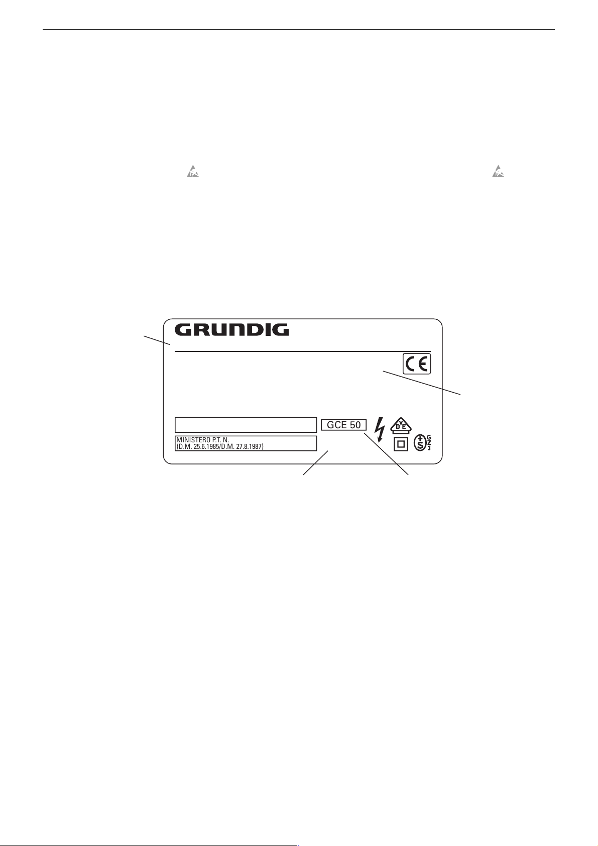
Typenschild des Gerätes
Zusätzlich zum Gerätetyp und der Chassisbezeichnung enthält das
Gerätetypenschild eine sogenannte "Version number" z.B. VNA. Diese Kennzeichnung gibt Aufschluß über den technischen/mechanischen Fertigungsstand.
Für die Bestellung von Ersatzteilen sind deshalb folgende Angaben
unbedingt erforderlich:
- Gerätetype (z.B. "T 51-731 text")
- Chassis-Bezeichnung (z.B. "CUC 7303")
- Version number (z.B. "VNA")
- Materialnummer des Ersatzteils
Gerätetype
Type of product
T 51-731 text
220-240V~ 50/60Hz 55W
EIGENSICHERE KATHODENSTRAHLRÖHRE NACH ANLAGE III
DER RÖNTGENVERORDNUNG.
BESCHLEUNIGUNGSSPANNUNG MAX. 25kV, 1.0mA.
TUBOS DE RADIACIÓN CATÓDICA AUTOLIMITADA, SEGÚN ANEXO III DE LA NORMATIVA
RADIOLÓGICA. TENSIÓN DE ACELERACIÓN MÁX. 25kV, 1.0mA.
ATENCION! NO ABRIR SIN ANTES DESCONECTAR LA TENSION DE RED.
STACCARE LA SPINA DI RETE PRIMA DI TOGLIERE IL PANNELLO POSTERIORE.
PROTEGGERE L'APPARECCHIO DALL'UMIDITA`. ATTENZIONE ALTA TENSIONE 25kV, 1.0mA.
MINISTERO P.T. N.
(D.M. 25.6.1985/D.M. 27.8.1987)
MADE IN AUSTRIA FABRICANTE: GRUNDIG AG, WIEN
General Section
Test Equipment
100MHz oscilloscop with 10:1 test probe
Digital voltmeter
Colour video generator
General Notes
Attention: Observe the ESD safety regulations
Type Label on the Set
In addition to the type of the TV set and the designation of the chassis,
a so-called "Version number", e.g. VNA, is printed on the type label.
This identification gives information on the technical/mechanical state
of production.
Do not fail to give the following particulars when ordering spare parts:
- type of TV set (e.g. "T 51-731 text")
- name of chassis (e.g. "CUC 7303")
- version number (e.g. "VNA")
- part number spare part
VNA
Version number
GCE 50
CUC 7303
25kV
Chassis-Bezeichnung
Chassis designation
Wegen Veränderung des Schwerpunktes beim Abnehmen der
Rückwand bzw. Ausbau des Chassis oder Entfernen eines eventuell vorhandenen Standfußes ist das Gerät gegen Kippen zu
sichern.
Vor dem Öffnen des Gehäuses zuerst den Netzstecker ziehen!
Leitungsverlegung
Bevor Sie die Leitungen und insbesondere die Masseleitungen lösen,
muss die Leitungsverlegung zu den einzelnen Baugruppen wie z.B.
Chassis, Netzschalterplatte, Bedieneinheit, Bildrohrplatte, Ablenkeinheit, Lautsprecher usw. beachtet werden.
Nach erfolgter Reparatur ist es notwendig, die Leitungsführung wieder
in den werkseitigen Zustand zu versetzen um evtl. spätere Ausfälle
oder Störungen zu vermeiden.
Netzkabel
Diese Geräte dürfen nur mit dem Original-Netzanschlusskabel mit
integrierter Entstördrossel betrieben werden. Dieses Netzkabel verhindert Störungen aus dem Netz und ist Bestandteil der Gerätezulassung. Im Ersatzfall bestellen Sie bitte ausschließlich das Netzkabel laut Ersatzteilliste.
DOLBY-Hinweis
DOLBY und das Doppel-D-Symbol ij sind Warenzeichen der Dolby
Laboratories Licensing Corporation.
Bestellnummer ohne Farbkennzeichnung
Order number without colour code
Because of the change of the centre of gravity when removing the
rear panel, the chassis or an existing stand, it is necessary to
protect the set from tipping.
Before opening the cabinet disconnect the mains plug!
Wiring
Before disconnecting any leads and especially the earth connecting
leads observe the way they are routed to the individual assemblies like
the chassis, mains switch panel, keyboard control panel, picture tube
panel, deflection unit, loudspeaker and so on.
On completion of the repairs the leads must be laid out as originally
fitted at the factory to avoid later failures or disturbances.
Mains Cable
The TV receiver must only be operated with an original mains connecting
cable with an interference suppressor choke integrated in the mains
plug.This mains cable prevents interference from the mains supply and
is part of the product approval. For replacement please order exclusively
the mains connecting cable specified in the spare parts list.
DOLBY Hint
DOLBY and the double-D symbol ij are trademarks of Dolby
Laboratories Licensing Corporation.
1 - 3
Page 4

GRUNDIG Service DIGI 100
Modulübersicht / Module List
Bestell-Nr.
Order No.
Chassis-Nr.
Chassis No.
Tuner
Signal-Baustein
Signal Module
PIP-Signal-Baustein
PIP Signal Module
Feature-Modul
Feature Module
Bildrohrplatte
CRT Panel
Fokussierungsplatte
Focusing Board
LED-Platte
LED Board
Bedienplatte
Control Board
Materialnummer
Part Number
295043010200
295042622300
295042120400
(Flash 32 Mbit) 295042033000
293051223200
293050255100
293050176800
295010856500
FINE ARTS VISION
MFW 82-725/9 DVD
(VNM)
CUC 1935A
GBA4400 GCM2000
297040210300 297040210300
FINE ARTS VISION
MFW 82-730/9 DVD
(VNM)
CUC 1935A
••
••
*
•
••
••
••
••
–•
*
•
295010857300
Buchsenplatte
Socket Board
Buchsenplatte Click-Fit
Socket Board Click-Fit
D-Verstärker
D-Amplifier
PIP/VGA-Baustein
PIP/VGA Module
Potentiometerplatte
Potentiometer Board
Personal Remote 11 296420613500
Adapterplatte
Adapter Board
DVD-KIT1
SAT-Baustein SER 300A
SAT Module SER 300A
Modul DER 1100 S-CI
Module DER 1100 S-CI
Modul DER 1101 T
Module DER 1101 T
WT 2
(DVD-Teil)
(DVD Part)
293050085700
293050086300
293051604300
295042041800
295042062100
293051292200
293051604500
Service Manual
720100424000
GAF9000
GAG6600
GAG6900
GAG8900
•–
–•
•–
••
••
••
–•
••
••
••
nachrüstbar*
retrofittable*
nachrüstbar*
retrofittable*
nachrüstbar*
retrofittable*
nachrüstbar
retrofittable
nachrüstbar*
retrofittable*
nachrüstbar*
retrofittable*
nachrüstbar*
retrofittable*
nachrüstbar
retrofittable
*nur mit einem Baustein/Modul bestückbar! / only to fit out with one Module!
1 - 4
Page 5
GRUNDIG Service DIGI 100
Technische Daten / Technical Data
FINE ARTS VISION
MFW 82-725/9 DVD
(VNM)
CUC 1935A
Bildröhre / Picture Tube
Sichtbares Bild
Visible picture
Bildschirmdiagonale
Screen diagonal
Formatumschaltung
Format switching
Elektronik / Electronic
Flash
Programmspeicherplätze
Programme positions
TV Guide
Easy dialog
Tuner
TV-Normen
TV Standards
Stereo-Systeme
Stereo systems
Videotext
Teletext
Teleweb
Musikleistung ohne externe LS
Music power without external LS
Musikleistung mit Dolby Prologic
Music power with Dolby Prologic
Dolby surround sound
VGA
PIP
SAT
Digital-SAT
Digital-Terrestrisch
Digital terrestrial
WT-Modul
WT module
Drehfuß
Revolving Foot
Anschlüsse Front / Connections Front
Kopfhörer
Headphones
Cinch-AV-Buchse
Cinch-AV socket
S-Video
Anschlüsse Rückwand / Connections Rear Panel
Euro AV 1 (schwarz/black)
Euro AV 2 (orange)
Standard-VGA
Interface (10 Pin)
Interface (6 Pin)
Lautsprecherbuchsen
Loudspeaker socket
Kopfhörer
Headphones
Cinch-NF-Buchse Ausgang
Cinch-AF socket output
Cinch-Digital-Ausgang
Cinch digital output
Digital-Eingang
Digital input
Netzteil / Mains Stage
Netzspannung (Regelbereich)
Mains voltage (variable)
Netzfrequenz
Mains frequency
Leistungsaufnahme
Power consumption
Standby
*nur mit einem Baustein/Modul bestückbar! / only to fit out with one Module!
4:3, Cinema Zoom variable, Panorama Zoom, Format Automatic, 14:9, 16:9, automatic switching PALplus (in cinema zoom)
(199 TV/SAT + 59 Radio + 3 AV + VGA + DVD bei Nachrüstung SAT/ when retrofitted with SAT)
PLL Frequenz Synthesizer Tuning UHF/VHF, globale Pinbelegung / PLL frequency synthesizer tuning UHF/VHF, global pinning
TOP/FLOF Level 2.5, VPS, 2000 Seiten, mit Teleweb ca. 300 Seiten
TOP/FLOF level 2.5, VPS, 2000 pages, with teleweb ca. 300 pages
ja (drahtloser Digitalempfang via VBI-Line) / yes (wireless- digital reception via VBI-Lines)
Stereo 6-Channel 140W: 40W Subwoofer + 2x20W L/R + 20W center + 2x20W rear L/R
nachrüstbar* mit SAT-Baustein SER 300a / retrofittable* with SAT Module SER 300a
nachrüstbar* mit Modul DER 1100 S-CI / retrofittable* with Module DER 1100 S-CI
–
Stereo 3,5mm Klinkenbuchse, Lautstärke regelbar, individuelle Tonkanalwahl bei 2-Ton-Empfang
Stereo 3.5mm jack, adjustable volume, individual channel selection with dual-sound broadcasts
FBAS Ein-/Ausgang, RGB Eingang, SBAS Ein-/Ausgang, Megalogic, Datalink für VCR Fernbedienung, Decoder, 16:9 / Pin8
CCVS in-/output, RGB input, SCVS in-/output, Megalogic, datalink for VCR remote control, decoder capable, 16:9 / Pin 8
FBAS Ein-/Ausgang, RGB Eingang, SBAS Ein-/Ausgang (Chroma aus 15+7), Datalink für VCR Fernbedienung, Decoder, 16:9 / Pin8
CCVS in-/output, RGB input, SCVS in-/output (Chroma out 15+7), datalink for VCR remote control, decoder capable, 16:9 / Pin8
ja, incl. NF/Eingang via 3,5mm Klinkenstecker / yes, incl. AF/input via 3.5mm jack
Service-Schnittstelle (Software update/flash) / Service interface (software update/flash)
Kombibuchse für Klinkenstecker 3,5mm ø oder Optisches Kabel / Combination socket for jack plug 3.5 mm ø or optical cable
FINE ARTS VISION
MFW 82-730/9 DVD
76cm
Format 16:9, 82cm (32") MEGATRON plus, Toshiba V2
32 Mbit
99 + 3 AV + VGA + DVD
ja / yes
ja / yes
B/G, I, D/K, K', M, L/L'
PAL, SECAM, NTSC 4.43MHz+3.58MHz
Deutsch A2 / German A2 (B/G/D/K)
Nicam 5.85 (B/G, L) + 6.52MHz (I)
Stereo 3-Channel 80W: 40W Subwoofer + 2x20W L/R
Dolby Digital AC3
ja / yes
ja* / yes*
nachrüstbar* mit Modul DER 1101 T
retrofittable* with Module DER 1101 T
nachrüstbar mit Modul WT 2
retrofittable with module WT 2
Motorbetrieben drehbar ca 80°
Motor driven ca. 80° rotable
1x FBAS Video / in , 1x CCVS Video / in, 2x Audio / in
4-polige Buchse Y-Chroma / in / 4-pin socket Y-Chroma / in
1 x Digital out SPDIF (Sony/Philips Digital Interface)
Digital in SPDIF (Sony/Philips Digital Interface)
(AV 4 Position)
WT-Modul / WT-module
6 x 2 Click-Fit 4Ω
Stereo 3,5mm Klinkenbuchse
Stereo 3.5mm jack
6 x Line
230V±15%
50 / 60Hz
ca. 140W
ca. 2W
(VNM)
CUC 1935A
1 - 5
Page 6

GRUNDIG Service DIGI 100
Sicherheits-Hinweise
Die in den Fernsehgeräten auftretende Röntgenstrahlung entspricht
den Bestimmungen der Physikalisch-Technischen Bundesanstalt
vom 8. Januar 1987.
Die Hochspannung für die Bildröhre und die damit auftretende
Röntgenstrahlung ist abhängig von der exakten Einstellung der
Netzteilspannung +A.
Nach jeder Reparatur im Netzteil oder in der Horizontalablenkung ist
die Hochspannung zu messen und ggf. einzustellen.
Schutzschaltungen im Gerät dürfen nur kurzzeitig außer Betrieb
gesetzt werden, um Folgeschäden am Chassis oder an der Bildröhre zu vermeiden.
Beim Austausch der Bildröhre dürfen nur die in den Ersatzteillisten
vorgeschriebenen Typen verwendet werden.
D
Servicehinweise
Chassisausbau
Bevor Sie die Chassis-Verbindungsleitungen lösen, muss die Leitungsverlegung zu den einzelnen Baugruppen wie Netzschalterplatte, Bedieneinheit, Bildrohrplatte, Ablenkeinheit oder Lautsprecher beachtet werden.
Nach erfolgter Reparatur ist es notwendig, die Leitungsführung wieder
in den werksseitigen Zustand zu versetzen, um evtl. spätere Ausfälle
oder Störungen zu vermeiden.
Netzkabel
Diese Geräte dürfen nur mit dem Original-Netzanschlusskabel mit
integrierter Entstördrossel betrieben werden. Dieses Netzkabel verhindert Störungen aus dem Netz und ist Bestandteil der Gerätezulassung. Im Ersatzfall bestellen Sie bitte ausschließlich das Netzkabel laut Ersatzteilliste.
GB
Service Notes
Disassembly of the chassis
Before disconnecting the chassis connecting leads observe the way
they are routed to the individual assemblies like the mains switch
panel, keyboard control panel, picture tube panel, deflection unit or
loudspeaker.
On completion of the repairs the leads must be laid out as originally
fitted at the factory to avoid later failures or disturbances.
Safety Advices
The X-radiation developing in the sets conforms to the X-radiation
Regulations (January 8, 1987), issued by the Physikalisch-Technische Bundesanstalt (federal physiotechnical institution).
The high tension for the picture tube and thus the developing Xradiation depends on the precise adjustment of the +A power
supply.
After every repair of the power supply unit or the horizontal deflection
stage it is imperative that the EHT for the picture tube is checked and
re-adjusted if necessary.
To avoid consequential damages to the chassis or the picture tube
the integrated protective circuits are allowed to be put out of
operation only for a short time.
When replacing the picture tube use only the types specified in the
spare parts lists.
Cable dereseau
Ces appareils ne peuvent être utilisés qu ' avec un cable de connecion
original de réseau avec bobine antiparasite intégré dans la fiche de
secteur. Ce câble de réseau empêche des perturbations de réseau et
est partie de l'autorisation d'appareil. Si nécessaire commandez
uniquement le cable de réseau selon la liste de pièces détachées.
I
Nota di servizio
Smontaggio del telaio
Prima di sfilare i cavi di collegamneto col telaio è necessario osservare
la disposizione originaria degli stessi verso le singole parti come la
piastra alimentazione, l'unità comandi, la piastra cinescopio, il giogo o
l'altoparlante.
Dopo la riparazione è necessario che gli ancoraggi e le guide
garantiscano la disposizione dei cavi analogamente a quella data in
fabrica e ciò per evitare disturbi o danni nel tempo.
Cavo rete
Gli apperechi devono essere messi in funzioni solo con il cavo originale
il colle gamento di rete e la sua spina di rete deve essere munita di una
bombina d´induttanza. In causa di sostituzione ordinate solo il cavo di
alimentatore che corrésponde alla lista degli accessori.
Mains cable
The TV receiver must only be operated with an original mains connecting
cable with an interference suppressor choke integrated in the mains
plug.This mains cable prevents interference from the mains supply and
is part of the product approval. For replacement please order exclusively
the mains connecting cable specified in the spare parts list.
F
Information pour la maintenance
Dèmontage de chassis
Avant de défaire les connecteurs du châssis princip, il y a lieu de
repérer auparavant les liaisons correspondant à chaque platine comme
par exemple le C.I. Inter secteur, le C.I. Commande, le C.I. Tube, le
bloc déviation ou les haut-parleurs.
A la fin de l'intervention, les connexions doivent être remises dans leur
position d'origine afin d'éviter par après d'éventuelles défaillances ou
perturbations.
E
Nota de servicio
Desmontaje del chassis
Antes de desconectar las conecciones del Chassis hay que observar
la dirección de dichas conecciones a los distintos grupos de construcción
como la placa de conmutación de red, unidad de control, placa del
zócalo del tubo de imagen, unidad de deflección o altavoces.
Después de haber realizado la reparación y para evitar fallos o
pertubaciones posteriores es necesario reponer las conecciones tal
como fueron instaladas originalmente en fabrica.
Cable de red
El aparato solo se puede usar con el cable de red original con choque
antiparásito integrado en el enchufe de red. Este cable de red evita
perturbaciones de la red y es parte de la autorización del aparato. En
caso necesario puede pedir el cable de red según lista de piezas de
repuestos.
1 - 6
Page 7
GRUNDIG Service DIGI 100
+
-
REF
A-AM
ABK
AUDIO
AUDIO-L
AUDIO-R
AUDIO
MAC
AUDIO
L-MAC
AUDIO
R-MAC
AUDIO
SUB
AUDIO
TV
AUDIO
VCR
A-ZF 1
A-ZF 2
B EXT
BB
B EXT
B
OSD
B PIP
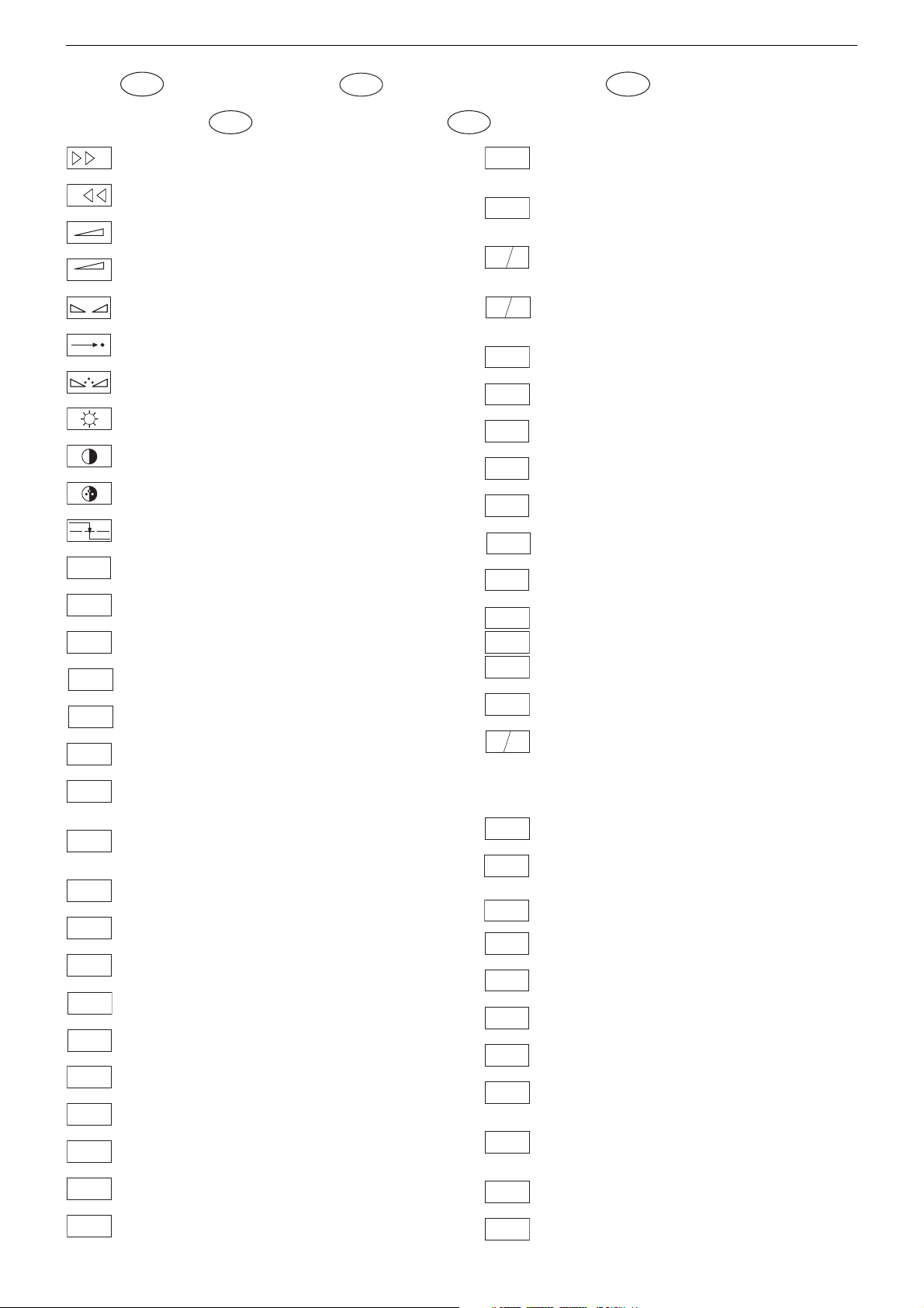
Schaltplansymbole
D
Simboli sullo schema
I
Feinabst. + / Fine tuning + / Réglage fine + / Sint. fine + / Sint. fina +
Feinabst. - / Fine tuning - / Réglage fine - / Sint. fine - / Sint. fina -
Lautstärke / Volume / Volume / Volume sonore / Volumen
Referenz Lautstärke / Volume ref. volt. / Tens. de réf. vol. sonore /
Tens di rif. volume / Tens. ref. volumen
Balance / Balance / Balance / Balanciam. / Balance
Suchlauf / Self seek / Recherche autom. / Sint. autom. / Sintonia
automatica
Farbton / Tint / Teinte / Tinta / Tinte
Helligkeit / Brightness / Luminosité / Luminosita / Brillo
Kontrast / Contrast / Contraste / Contrasto / Contraste
Farbkontrast / Colour contrast / Contraste des coleurs / Contrasto
colore / Contraste de color
Schutzschaltung / Protection circuit / Circuit de sécurité / Circuito di
protezione / Circuito de protección
Audio AM
(Burst Key): Burstaustastimpuls / Burst blanking pulse / Impulsion de
suppress. de burst / Imp. di soppress. del burst / Imp. supresion burst
Ton-Signal / Audio signal / Signal audio / Segnale audio / Señal audio
Ton-Signal links / Audio signal left / Signal audio gauche / Segnale
audio sinistra / Señal audio izquierda
Ton-Signal rechts / Audio signal right / Signal audio droit / Segnale
audio destra / Señal audio derecha
Tonsignal D2 Mac / Audio signal D2MAC / Signal audio D2MAC /
Segnale audio D2MAC / Señal de sonido D2MAC /
Tonsignal links D2 Mac / Audio signal left D2MAC / Signal audio
gauche D2MAC / Segnale audio sinistro D2MAC / Señal de sonido
izquirdo D2MAC
Tonsignal rechts D2 MAC / Audio signal right D2MAC / Signal audio
droit D2MAC / Segnale audio destro D2MAC / Señal de sonido
derecho D2MAC /
Audio Tieftöner / Audio sub woofer / Audio haut-parleur pour les
frequences basses / Audio toni bassi / Audio sonido bajo
Audio-Signal FS Gerät / Audio signal TV set / Signal audio
téléviseur / Segnale audio TV / Señal audio TV
Tonsignal VCR Gerät / Audio signal VCR unit / Signal audio
magnetoscope / Segnale audio VCR / Señal audio VCR
Audio ZF 1 / Audio IF 1 / Audio FI 1 / Audio FI 1 / Audio FI 1
Audio ZF 2 / Audio IF 2 / Audio FI 2 / Audio FI 2 / Audio FI 2
Blau-Signal / Blue signal / Signal bleu / Segnale blu / Señal azul
Basisband / Baseband / Bande de base / Banda base / Banda base
Blau-Signal extern / Signal blue external /Signal bleu externe /
Segnale blu esterno / Señal azul externa
OSD-Einblendung blau / OSD blue / Eblouissement OSD bleu /
Visualizzazione OSD blu / Visualisacione OSD azul
Blau-Signal PIP / PIP Blue signal / Signal bleu PIP / Segnale blu
PIP / Señal azul PIP
GB
Circuit Diagram Symbols
Simbolos en los esquemas
E
Blau - Signal - 50Hz vert.,15625Hz hor. / Blue signal - 50Hz vert.,
B/50
15625Hz hor. / Signal bleu - 50Hz vert., 15625Hz hor. / Segnale bleu
- 50Hz vert., 15625Hz hor. / Señal azul - 50Hz vert., 15625Hz hor.
B/100
B-Y 50
B-Y 100
CENTER
CINCH
AUDIO L
CINCH
AUDIO R
CHROMA
CHROMA
Blau-Signal -100Hz vert., 31250Hz hor. / Blue signal -100Hz vert.,
31250Hz hor. / Signal bleu -100Hz vert., 31250Hz hor. / Segnale blu
-100Hz vert., 31250Hz hor. / Señal azul -100Hz vert., 31250Hz hor.
B-Y -Signal - 50Hz vert., 15625Hz hor. / B-Y -Signal - 50Hz vert.,
15625Hz hor. / Signal B-Y - 50Hz vert., 15625Hz hor. / Segnale BY - 50Hz vert., 15625Hz hor. / Señal B-Y - 50Hz vert., 15625Hz hor.
B-Y -Signal - 100Hz vert., 31250Hz hor. / B-Y -Signal - 100Hz vert.,
31250Hz hor. / Signal B-Y - 100Hz vert., 31250Hz hor. / Segnale BY - 100Hz vert., 31250Hz hor. / Señal B-Y - 100Hz vert., 31250Hz hor.
Kanalwahl / Channel selection / Sélection de canaux / Selez.
C
canale / Seleccion canal
Mittelpunkt-Lautsprecher / Center loudspeaker / Haut-parleur de
centre / Alto parlante punto centrale / Altavoz del centro
CHIP
Chip Adresse / Chip adress / Chip direction / Indiri. del chip /
ADR
Direccion chip
Ton-Signal Cinch links / Audio signal cinch left / Signal audio cinch
gauche / Segnale audio cinch sinistra / Señal audio cinch izquierda
Ton-Signal Cinch rechts / Audio signal cinch right / Signal audio
cinch droit / Segnale audio cinch destra / Señal audio cinch derecha
Chroma Signal / Chroma signal / Signal dégree / Croma segnale /
Señal croma
Chroma S-VHS-Signal / Chroma S-VHS-Signal / Signal dégree de
S-VHS
S-VHS / Croma segnale S-VHS / Señal croma S-VHS
Clock
CLK
CL 1
CL 2
Composite Sync. Imp. für VT / Composite sync pulse for TT / Imp. de
CSY
sync. vidéo-composite pour TXT / Imp. hor. para Video Comp.
Kombiniertes Hor./vert. Sync. Signal 31250Hz/100Hz (Composite
Sync.) / Combined hor./vert. sync signal 31250Hz/100Hz (Composite Sync) / Signal synchr. hor./vert. combiné 31250Hz/100Hz
(Synchr. composité) / Segnale sincr. orizz./vert. 31250Hz/100Hz
(Sincr. Composito) / Señal combinada sincr. hor./vert. 31250/100Hz
(Sincr. compuesto)
Daten / Data / Données / Dati / Datos
Verzögerungsleitung / Delay line / Ligne à retard / Linea di ritardo /
DL
Linea de retardo
Freigabe / Enable / Autorisation / Consenso / Habilitacion
ENA
ENA
Freigabe ZF / IF Enable / Validation FI / Consenso FI / Autorizacón FI
ZF
Freigabe FT / Finetuning enable / Autorisation Réglage fin / Abilitaz.
FT
Sintonia fine / Habilitacion Sintoinia fina
Freigabe LED / LED enable / Autorisation LED / Abilitaz. LED /
LED
Habilitacion LED
Freigabe Ton / Sound enable / Autorisation son / Abilitaz. audio /
TON
Habilitacion sonido
Audio-Signal EURO-AV links / Audio signal EURO-AV left / Signal
audio EURO-AV gauche / Segnale audio EURO-AV sinistra / Señal
audio izquierda EURO-AV
Audio-Signal EURO-AV rechts / Signal audio EURO-AV right /
Signal audio EURO-AV droit / Segnale audio EURO-AV destra /
Señal audio derecha EURO-AV
Video-Signal EURO-AV / Video signal EURO-AV / Signal video
EURO-AV / Segnale video EURO-AV / Señal video EURO-AV
Farb-Signal / Chroma signal / Signal chroma / Segnale chroma /
F
Señal croma
1 - 7
CS 100
DATA
ENABLE
ENABLE
ENABLE
EURO-AV
AUDIO-L
EURO-AV
AUDIO-R
EURO-AV
VIDEO
Symboles schéma
F
Page 8

GRUNDIG Service DIGI 100
FBAS
FBAS
CINCH
FBAS
MAC
FBAS
TON
FBAS
TXT
FBAS
TEXT
FBAS
SYNC.
FBAS
S-VHS
F
H
FRM
FT
F
U
F
V
G
G
OSD
G PIP
G EXT
G/50
G/100
GND - H
HA
HDR
HC
H
SYNC
HFB
HS
I2S CL
I2S TER
I2S IN
I2S WS
I BEAM
ICL
FBAS-Signal / CCVS signal / Signal vidéo composite / Segnale video
composito / señal video compuesta
FBAS-Signal-Cinch Buchse / CCVS signal-cinch socket / FBASprise à cinch / FBAS-presa cinch / FBAS-cinch
FBAS-D2 MAC / D2MAC CCVS signal / Signal vidéo compositeD2MAC / FBAS-D2MAC / FBAS-D2MAC
Basisband / Baseband / Bande de base / Banda base / Banda base
FBAS-Videotext / CCVS videotext / Signal vidéo compositeTélétexte / FBAS-Televideo / FBAS-Teletexto
FBAS Sync. Signal / CCVS sync signal / Signal sync. vidéo col.
comp. / Segnal sincr. video col. comp. / Señal sincr. video
compuesta
FBAS Signal S-VHS / CCVS signal S-VHS / Signal vidéo col. comp. SVHS / Segnal video col. comp. S-VHS / Señal video compuesta S-VHS
Hochspg. / EHT voltage / Haute tens. / Alta tens. / MAT
Rahmensignal / Frame signal / Signal d'encadrement / Segnale
cornice / Señal de marco
Feinabstimmung / Fine tuning / Reglage fin / Sint. fine / Sint. fina
FU-Signal / FU-signal / Signal FU / Segnale FU / Senal FU
FV-Signal / FV-signal / Signal FV / Segnale FV / Senal FV
Grün-Signal / Green signal / Signal green external / Signal vert /
Segnale verde / Señal verde
OSD-Einblendung grün / OSD green / Eblouissement OSD vert /
Visualizzazione OSD verde / Visualisacione OSD verde
Grün-Signal PIP / Green signal PIP / Signal green PIP/ Signal vert
PIP / Segnale verde PIP / Señal verde PIP
Grün-Signal extern / Green signal vertical / Signal vert externe /
Segnale verde esterno / Señal verde externa
Grün-Signal - 50Hz vert.,15625Hz hor. / Green signal - 50Hz vert.,
15625Hz hor. / Signal vert - 50Hz vert., 15625Hz hor. / Segnale
verde - 50Hz vert., 15625Hz hor. / Señal verde -50Hz vert., 15625Hz hor.
Grün-Signal -100Hz vert., 31250Hz hor. / Green signal -100Hz vert.,
31250Hz hor. / Signal vert -100Hz vert., 31250Hz hor. / Segnale
verde -100Hz vert., 31250Hz hor. / Señal verde -100Hz vert.,
31250Hz hor.
Nullpunkt Heizung / Ground filament / Point neutre-Chauffage /
Punto zero-Filamento / Punto medio filamento
Horiz. Sync. Impuls / Horiz. Sync pulse / Impulsion synchro. horiz. /
Impulso sincro orizzontale / Impulso de sinc. horiz.
Horiz. Ansteuerimpuls / Horiz. drive pulse / Impulsion de commande
horiz. / Impulso comando orizzontale / Impulso de control horiz.
Horiz. Klemmimpuls / Horiz. clamp pulse / Impulsion de serrage
horiz. / Impulso comando orizzontale / Impulso de garras horiz.
Horizontaler Sync-Impuls / Horizontal Sync impuls / Sync impuls
horizontale / Sinc impulso orrizontale / Impulso sync horizontal
Horiz. Rückschlagimpuls / Horiz. flyback / Impulsion de retour
horiz. / Impulso rotorno orizzontale / Impulso de retroceso horiz.
Hor. Sync. Implus für VT / Hor. sync pulse for TT / Imp. de sync. hor. pour
TXT / Imp. sincr. orizz. per Televideo / Imp. hor. para Video Comp.
Digitale Datensignale / Digtital data signals / Signal donneé digital /
Segnali dati digitali / Señal datos digital
Strahlstrom / Current beam / Current rayon / Corrante del irradire /
Corriente de haz
I2C Bus -Clock
IR
IM
CLOCK
IM
IDENT
IM
RESET
IR CLK
IR DATA
IR
VIDEO
KB
KH
AUDIO-L
KH
AUDIO-R
L
LED
M
MEGA
LOGIC
MODE
NIC CLK
NORM
OWA
P
P/C
PIP
P1
R
REMOTE
R
OSD
R PIP
R EXT
R-Y 50
R-Y 100
S
Infrarot-Signal / Signal infrared / Signal infra-rouge / Segnale
infrarosso / Señal infrarojo.
I2C Bus -Clock
I2C Bus -Kennung / I2C-Bus Identification / Identification I2C-Bus /
2
Ident. I
C-Bus, Identification I2C-Bus
I2C Bus -Reset
Infrarot Clock / Infrared clock / Signal I.R. horloge / Clock segnale
R.I. / Clock infrarojos
Infrarot Signal / Infrared signal / Signal I.R. / Segnale infrarosso /
Data infrarrojos
Infrarot Signal Video / Infrared signal video / Signal I.R. video /
Segnale infrarosso video / Data infrarrojos video
Keyboard
Tonsignal Kopfhörer links / Audio signal headphone left / Signal
audio gauche de casque / Segnale audio sinistra cuffia / Señal audio
izquierda auriculares
Tonsignal Kopfhörer rechts / Audio signal headphone right / Signal
audio droit de casque / Segnale audio sinistra cuffia / Señal audio
derecha auriculares
Lautstärke / Volume / Volume / Volume sonore / Volumen
Leuchtdiode / Light emitting diode / Diode lumineuse / Diodo
luminoso / Diodo luminescente
Speicher Taste / Memory button / Touche mémoire / Tasto di
memoria / Puls. memoria
Megalogic Daten / Megalogic data / Megalogic dates / Dati
Megalogic / Megalogic datas
Modus / Mode / Mode / Modo / Modo
NICAM Clock / Clock NICAM / Horloge NICAM / Clock NICAM /
Clock NICAM
Norm Taste / TV standard select button / touche de norme / Tasto
norma / Puls. de norma
Ost-West Ansteuerimpuls / East-west drive impuls / Impulsion de
commande Est-Ouest / Impulso comando Est-Ovest / Impulso de
control Este-Oeste
Programm / Program / Programme / Programma /Programa
Programm-Kanalwahl / Program channel selection / Progr. sélection
de canaux / Progr. selez.canale / Progr. selec. canal
Bild im Bild / Picture in picture / Image dans l'image / PIP / Imagen
en la imagen
Progr. Taste / Progr. button / Touche Progr. / Tasto Progr. / Puls.
Progr.
Rot-Signal / Red signal / Signal rouge / Segnale rosso / Señal rojo
Fernbedienung / Remote control / Telecommande / Telecomando /
Mando a distancia
OSD-Einblendung rot / OSD red / Eblouissement OSD rouge /
Visualizzazione OSD rosso / Visualisacione OSD rojo
Rot-Signal PIP / Red signal PIP / Signal rouge PIP / Segnale rosso
PIP / Señal rojo PIP
Rot-Signal extern / Signal red external / Signal rouge externe /
Segnale rosso esterno / Señal rojo externa
R-Y -Signal - 50Hz vert., 15625Hz hor. / R-Y -Signal - 50Hz vert.,
15625Hz hor. / Signal R-Y - 50Hz vert., 15625Hz hor. / Segnale RY - 50Hz vert., 15625Hz hor. / Señal R-Y - 50Hz vert., 15625Hz hor.
R-Y -Signal - 100Hz vert., 31250Hz hor. / R-Y -Signal - 100Hz vert.,
31250Hz hor. / Signal R-Y - 100Hz vert., 31250Hz hor. / Segnale
R-Y - 100Hz vert., 31250Hz hor. / Señal R-Y - 100Hz vert., 31250Hz hor.
Sonderkanal / Special channel / Canal special / Canale speciale /
Canal especial
1 - 8
Page 9

GRUNDIG Service DIGI 100
SB
SCL
SCL 100
SDA
SHIFT
VIDEO
SHIFT
TEXT
SS
SSB
SSC
SSC
PIP
SSC 100
SSC 50
SUR-
ROUND
SYNC
SYNC.
BTX
SYNC.
VT
SW
TE
T1
T2
TT
U
FOC
U
G1
U
H
U
G2
VA
VB
VCL
VDR
VG
Strahlstrombegrenzung / Beam current lim. / Lim. cour. de faisceau /
Lim. corr. di raggio / Corriente media de haz
I2C-Bus Clock
Schneller I2C-Bus Clock / I2C-Bus clock high speed / I2C-Bus grande
2
vitesse / I
I2C-Bus Daten / I2C-Bus data / I2C-Bus données / I2C-Bus dati /
I
Dynamische vert. Versch. 25Hz, aktiv bei Video u. Mix Betrieb /
Dynam. vert. shift 25Hz, active on video and mix operation / Decal
dynam. de l'image 25Hz, actif sur video et fonction. mixte / Spostam.
vert. dinam. 25Hz, attivo con video e. funzionam. misto / Desplaz.
dinamico vert. 25Hz, activo con video Y funciones mixtas
Dynamische vert. Versch. 25Hz, aktiv bei Standbild u. VT / Dyn. vert.
shift 25Hz, active on freeze-frame and Teletext / Decal dynam. de
l'image 25Hz, actif sur arret immage et Vidéotext (Antiope) / Spostam.
vert. dinam. 25Hz, attivo con fermo immag. e Televideo / Desplaz.
dinamico vert. 25Hz, activo con imagen parada Y Videotexto
Schutzschaltung / Protection circuit / Cablage protecteur / Pot. de
prot. / Circuito de proteccion
Spitzenstrahlstrombegrenzung / Peak beam current limiting / Lim.
de faisceau crete / Lim. corr. catod. di pico / Corrente pico de haz
Supersandcastle
Supersandcastle PIP
Supersandcastle 100Hz vert., 31250Hz hor.
Supersandcastle 50Hz vert., 15625Hz hor.
Surround
Sync.-Signal / Sync.-Signal / Signal sync / Segnale sync. / Señal de sync.
Sync. BTX / Viewdata Sync / Sync. Télétext / Sincr. Videotel / Sincr.
Videotexto
Sync. VT / Sync. Teletext / Sync Vidéotexte / Sincr. Televideo / Sincr.
Videotexto
Schwarzwert / Black level / Niveau du noir / Livello del nero / Nivel de negro
TEXT-Freigabe / TEXT enable / Autorisation TEXTE / Abilitaz.
TELEVIDEO / Habilatation TEXTE
Bei Zweiton, Ton 1 / On two channel sound, sound 1 / Pour double
son, son 1 / In bicanale, audio 1 / En dual, sonido 1
Bei Zweiton, Ton 2 / On two channel sound, sound 2 / Pour double
son, son 2 / In bicanale, audio 2 / En dual, sonido 2
Tieftöner / Woofer / Haut-parleur pour les frequences basses / Toni
bassi / Sonido bajo
Fokusspg. / Focussing volt. / Tens. de focalis. / Tens di focalizz. /
Tens focalizacion
Spg. Gitter G 1 / Volt. grid G1 / Tens grille G 1 / Tens. griglia G1 / Tens.
rejillas G 1
Hochspannung / High voltage / Haute tension / EAT / Alte tension
Schirmgitter Spg. / Screen-grid volt. / Tens. de grille - écran / Tens.di
griglia schermo / Tens. de rejilla
Vertikaler Ansteuerimpuls / Vert. drive pulse / Impulsion de commande
verticale / Impulso di comando verticale / Impulso de control vertical
VCR - Clock
Freigabe Anzeigebaustein / Display enable / Autorisation pour module
indicateur / Modulo indicazione / Habilitacion modulo indicacion
Vert. Gegenkopplung / Vert. feedback / Contre-reaction verticale /
Controreazione vert. / Aliment. neg. vert.
C-Bus veloce / Clock del I2C-Bus de alta velocida
2
C-Bus datos
VIDEO
VT DATA
VT SCL
VT SDA
V SYNC
Y 50
Y 100
U
U
U
U
U
U
U
U
U
U
U
U
U
U
U
U
U
U
Video Signal / Video signal / Signal vidéo / Segnale video / Señal video
Videotext Daten / Teletext data / Données Teletexte / Linea dati
Televideo / Data Teletexto
Videotext Clock / Teletext clock / Signal horloge Vidéotext / Clock
Televideo / Clock Teletexto
I2C Bus: VT Daten / Teletext data / Données Vidéotext / Dati
Televideo / Data Teletexto
Vertikaler Sync-Impuls / Vertical Sync impuls / Sync impuls vertical
/ Sinc impulso vertical / Impulso sync vertical
Y
Y-Signal / Y Signal / Signal Y /Segnale Y / Señal Y
Y -Signal - 50Hz vert., 15625Hz hor. / Y -Signal - 50Hz vert., 15625Hz
hor. / Signal Y - 50Hz vert., 15625Hz hor. / Segnale
Y - 50Hz vert., 15625Hz hor. / Señal Y - 50Hz vert., 15625Hz hor.
Y - Signal - 100Hz vert., 31250Hz hor. / Y -Signal - 100Hz vert.,
31250Hz hor. / Signal Y - 100Hz vert., 31250Hz hor. / Segnale
Y - 100Hz vert., 31250Hz hor. / Señal Y - 100Hz vert., 31250Hz hor
Zwischenfrequenz / IF / FI / FI / FI
ZF
AFC
Schaltspg. AFC / AFC switching volt. / Tens. de commut. AFC/ Tens.
di commut. AFC / Tens. conmut. CAF
AV
Schaltspg. AV / Switching volt. AV / Tens. de commut. AV / Tens. di
commut. AV / Tens. conmut. AV
B1
Schaltspg. Band 1 / Switching volt. band 1 / Tens. de commut.
bande 1 / Tens. di commut. banda 1 / Tens. conmut. de banda 1
B2
Schaltspg. Band 3/ / Switching volt. band 3 / Tens. de commut.
bande 3 / Tens. di commut. banda 3 / Tens. conmut. de banda 3
BA
Schaltspg. Bildamplitude / Switching voltage vertical amplitude /
Tension de coupure amplitude dìmage / Tensione di commutaz.
ampiezza d'imagine / Tension de conm. amplitude de imagen di
commut. PAL / Tens. conmut. PAL
BTX
Schaltspg. BTX / Switching volt. BTX (Viewdata) / Tens. commut.
Télétext / Tens. commut. VIDEOTEL / Tens. conmut. Teletexto
C-AV
Schaltspg. Camera Wiederg. über Camera-AV Eingang / Switching
volt. cam. playback via Camera-AV input / Tens de commut pour lec.
de camera par l'entree Camera-AV / Tens.de commut. in riproduz.
camera tramite ingresso Camera-AV / Tens. de serv. reprod. camera
a traves de la entrada Camera-AV
DATA
Schaltspg. Datenbetr. / Switching volt. data mode / Tens. de commut. fonct. données / Tens. di commut. dati / Tens conmut. datos
DATA
Schaltspg. U Data extern / Switching volt Data ext. / Tension de
EXT
commutation U Data externe / Tens. di commutazione U-Data
esterno / Tensión de conmutatón externa U
DATA
Schaltspg. für Bildschirm-Einblendung / Switching volt. for On
OSD
Screen Display / Tens. commut. pour eblouissement On Screen
Display / Tens. commut. per di visualizzazione On Screen Display /
Tens. conmut. para On Screen Display
DEEM
Schaltspg. Deemphasis / Switching volt. deemphasis / Tens. commut. desaccent. / Tens. commut. deenfasi / Tens. conmut. deenfasis
DS
Schaltspg. Dolby-Surround / Switching volt. Dolby-Surround / Tens.
commut. Dolby-Surround / Tens. commut. di Dolby-Surround / Tens.
de conmut. Dolby-Surround
EURO-
Schaltspg. EURO-AV / Switching volt. EURO-AV / Tens. de commut.
AV
EURO-AV / Tens. di commut. EURO-AV / Tens. conmut. EURO-AV
EU-AV
Schaltspg. EURO-AV-Cinch-Buchse / Switching volt. EURO-AV-
CINCH
Cinch socket / Tens. commut. prisa Scart - Cinch / Tens. commut.
presa Scart -Cinch / Tens. conm. EURO-AV - Cinch
FBAS
Schaltspannung für Video-Ausgang EURO-AV Buchse / Switch.
voltage for video output EURO-AV socket / Tension de commut.
pour sortie vidéo EURO-AV / Tension commut. per presa d'uscita
video EURO-AV / Tension de conmut. para salida EURO-AV
HIFI
Schaltspg. HIFI / Switching voltage HIFI / Tens. de commut. HIFI /
Tens di commut. HIFI / Tens. conmut. HIFI
HIFI
Stummschaltung HiFi / Muting volt. HiFi / Commutation de silence
MUTE
HiFi / Silenzametno HiFi / Muting HiFi
HUB
Schaltspg. HUB / Switching volt. deviation / Tens. commut.
déviation / Tens. commut. deviazione / Tens. conmut. deviacion
1 - 9
Page 10

GRUNDIG Service DIGI 100
U
U
U
U
U
U
U
U
U
U
U
U
U
U
U
U
U
U
U
U
U
U
U
U
U
U
U
U
IDENT
Schaltspg. Signalkennung AV 3 / Switching volt. signal identification
AV 3 / Tens de commut.identification de signal AV3 / Tens. commut.
identificazione segnale / Tens. conmut. identifi. segñal AV3
KH
Stummschaltung Kopfhörer / Muting volt. headphone / Commutation
MUTE
de silence casque / Silenzamento cuffia / Muting auriculares
KLEMM
Gleichspannung für SAT-Basissignal / DC for SAT basic signal /
Tens. continue pour SAT base signal / Tens continua per segnale
SAT base / Tens. continua para segñal SAT base
KOIN
Schaltspg. Koinz. / Switching volt. coinc. / Tens de commut. coinc. /
50/60Hz
Tens di commut. coinc. / Tens. conmut. coinc.
KOIN
Schaltspg. Koinz. mit Videoquelle verknüpft / Coinc. switching volt.
VQ
linked with video source / Signal de coincid. combiné avec source
video / Tens. di commut. a coinc. combinata con sorg video segñal
de coincidencia combinada con video
LED
Schaltspg. LED / Switching volt. LED / Tens de commut. LED / Tens.
commut. LED / Conmut. LED
Leucht-
Schaltspg. Leuchtpunktunterdrückung / Switching volt. beam spot
punkt
suppression / Tens. de commut. suppress. du spot lumineux / Tens.
soppr. punto luminoso / Tens. de conmut. filtro supresor del punto luz
LNC
Schaltspg. LNC "Aus" / Switching volt. LNC "OFF" / Tens. de
OFF
commut. LNC "OFF" / Tensione di commut. "Spento" LNC / Tension
LNC "OFF"
MAC
Schaltspg. D2MAC / Switching volt. D2MAC / Tension de
commutation D2MAC / Tens. di commutazione D2MAC / Tensión de
conmutación D2MAC
MUTE
Stummschaltung / Muting / Silencieux / Silenziamento /Muting
NF 1
Schaltspg. NF 1 / Switching volt. AF 1 / Tension commut. BF 1 / Tens.
commut BF 1 / Tens. conm. BF 1
NF 2
Schaltspg. NF 2 / Switching volt. AF 2 / Tension commut. BF 2 / Tens.
commut BF 2 / Tens. conm. BF 2
NIC
Schaltspg. NICAM / Switching volt. NICAM / Tens. de commut.
NICAM / Tens. commut. NICAM / Tens. de conmut. NICAM
NORM
Schaltspg. Norm / Switching volt. Norm / Tens. de commut.
standard / Tens. di commut. Norma / Tens. conmut. Norma
PAL
Schaltspg. PAL / Switching volt. PAL / Tens. de commut. PAL / Tens.
di commut. PAL / Tens conmut. PAL
POL.
Schaltspg. Polarität / Switching volt. polarity / Tension commut.
polarite / Tens. commut. polarita / Tens. conmut polarizacion
POWER
Schaltspg. Ökoschalter / Switching volt. eco switch / Tens. de
OFF
commut. interr. eco. / Tens. commut. interr. ecologico / Tens.
conmut. interr. ecol.
PV
Schaltspg. Panorama View / Switching volt. Panorama View / Tens.
de commut. Panorama View / Tens. commut. Panorama View /
Tens. conmut. Panorama View
RESET
Schaltspg. Reset / Switching volt. Reset / Tens. commut. Reset /
Tens. commut. Reset / Tens. conmut. Reset
RGB
Schaltspg. RGB1 - RGB2 / Switching volt. RGB1 - RGB2 / Tens. de
commut. RGB1 - RGB2 / Tens. di commut. RGB1 - RGB2 / Tens.
conmut. RGB1 - RGB2
SCHUTZ
Schaltspg.-Schutzfunktion / Switching volt.-protective func. / Tens
de commut.-sécurité / Tens. di commut.-funz di protez. / Tens.
conmut.-proteccion
SEC
Schaltspg. SECAM / Switching volt. SECAM / Tens. de commut.
SECAM / Tens. di commut. SECAM / Tens. conm. SECAM
STBY
Schaltspg. Standby / Switching volt. Standby / Tens. commut.
Veille / Tens. commut. Standby / Tens. conmut. Standby
S-VHS
Schaltspg. S-VHS / Switching volt. S-VHS / Tens.de commut.
S-VHS / Tens. de commut. S-VHS / Tens. de conmut. S-VHS
TON
Schaltspg. Ton 1-2 / Switching volt. sound 1-2 / Tens. commut. audio
1/2
1-2 / Tens. commut. son 1-2 / Tens. conmut. son 1-2
UHF
Schaltspg. UHF / UHF switching volt. / Tens. de commut. UHF / Tens
di commut. UHF / Tens. conmut. UHF
VHF
Schaltspg. VHF / VHF switching volt. / Tens. de commut. VHF / Tens
di commut. VHF / Tens. conmut. VHF
VQ
Schaltspg. Videoquelle / Switching volt. video source / Tens. de
commut. source video / Tens. di commut. sorg. video / Tens conmut.
video
1 - 10
U
WISCH
W/N
U
I / III
U
14V
U
22kHz
U
0/3/6/9V
4.5MHz
U
50/60
U
Hz
U
AFC
U
AFC
SAT
U
AGC
U
RE
U
TUN.
U
τ
HOR.
HOR.2FH
VERT.
VERT.
VER.2FV
VERT.
VERT.
VERT. 100
VERT. 100
REF.
PULSE
O/W
Schaltspg. Wischerkontakt / Schwitching voltage temp. contact /
Tens. de commut. contact fugitif / Tens. commut. contatto temporaneo / Contacto supresor tens. de conmut.
Schaltspg. ZF breit - schmal / IF switching volt. wide - narrow / Tens.
commut. FI large - etroit / Tens. commut. FI larga - stretta / Tens. FI
ancho - estrecho
Schaltspg. Bandwahl / Band sel. switching volt. / Tens. de commut.
select. bande / Tens. di commut. selez. banda / Tens. conmut. selec.
banda
14V Schaltspg. / 14V switching volt. / Tens. commut. 14V / Tens.
commut. 14V / Tens. de conm. 14V
22kHz Schaltspg. / 22kHz switching volt. / Tens. commut. 22kHz /
Tens. commut. 22kHz / Tens. de conm. 22kHz
0/3/6/9V Schaltspg. / 0/3/6/9V switching volt. / Tens. commut.
0/3/6/9V / Tens. commut. 0/3/6/9V / Tens. de conm. 0/3/6/9V
Schaltspg. 4,5MHz / Switching volt. 4.5MHz / Tens. de commut.
4,5MHz / Tens. di commut. 4,5MHz / Tens conmut. 4,5MHz
Schaltspg. 50-60Hz / Switching volt. 50-60Hz / tens. de commut.
50-60Hz / Tens. di commut. 50-60Hz / Tens. conmut. 50-60Hz
Regelspg. AFC / AFC contr. volt. / Tens. de regul. AFC / Tens. di
contr. AFC / Tens. regul. CAF
Regelspg. AFC Satellitentuner / AFC contr. volt. SAT tuner / Tens.
de regul. AFC tuner SAT / Tens. di contr. AFC Tuner SAT / Tens.
regul. CAF Tuner SAT
Feldstärkeabhängige Spg. / Fieldstrength-depent volt. / Contr. automatique de gain / Tens. dipent. intens. campo / Contr. autom. de gain
tens. CAG
Regelspg. / Contr. volt. / Tens. de regul. / Tens. di contr. / Tens regul.
Abstimmspg. Tuner / Tuning volt. tuner / Tens. d'accord tuner / Tens.
di sintonia tuner / Tens. sintonia tuner
Regelspg. Verzög. / Delayed contr. volt. / Tens. de regul. retardee /
Tens. regul. retardada
Horizontale Ansteuerung / Horiz. drive / Synchr. lignes / Pilotaggio
orizz. / Exitación horiz.
31250Hz Ansteuerimp. für Zeilenendstufe / 31250Hz Triggering
pulse for horiz. output / 31250Hz commande pour l'étage final
lignes / Imp. Pilotaggio di 31250Hz per stadio finale di riga / Impulso
de exitación 31250Hz para paso final de lineas
Vert. Parabel / Vert. parabolic signal / Signal parabolique vert. /
Segnale parab. vert. / Senal parabolica vert.
Vert. Tastimpuls / Vert. Gating pulse / Imp. trame / Imp. a cadenza
vert. / Imp. cuadro
Vert. Tastimpuls 100Hz / Vert. Gating pulse 100Hz / Imp. trame
100Hz / Imp. a cadenza vert. 100Hz / Imp. cuadro 100Hz
Vert. Sägezahn / Vert. saw tooth / Signal dent de scie / Dente di sega
vert. / Dientede sierra vert.
Vert. Tastimpuls / Vert. Gating pulse / Imp. trame / Imp. a cadenza
vert. / Imp. cuadro
Vert Sägezahn 100Hz / Vert saw tooth 100Hz / Signal dent de scie
100Hz / Dente di sega vert. 100Hz / Dientede sierra vert. 100Hz
Vert. Parabel 100Hz / Vert. parabolic 100Hz signal / Signal parabolique 100Hz vert. / Segnale parab. vert. 100Hz / Senal parabolica
vert. 100Hz
Tastimpuls / Gating pulse / Impuls de declenchement / Impulso a
cadenza / Imp. puerta
Ref. Impuls hor. / Reference impulse hor. / Imp. de refer.hor. / Imp.
di rifer. hor. / Imp. refer. horiz.
Klemmung Ein-Aus / Clamping On-Off / Clampage Marche-Arrêt /
Clamping Ins.-Disins. / Clamping Enc.-Apag.
Pulse für Polarotor / Pulses for Polar-Rotor / Impulsions Rotor de
Polariastion / Impulsi per Rotore Polarizzazione / Impulsos dara
Polarrotor
O-W Amplitude / E-W amplitude / Amplitude E-O / Ampiezza E-O /
Amplitud E-O
Page 11
GRUNDIG Service DIGI 100
Bedienhinweise Dieses Kapitel enthält Auszüge aus der Bedienungsanleitung. Weitergehende Informationen entnehmen Sie bitte der
gerätespezifischen Bedienungsanleitung, deren Materialnummer Sie in der entsprechenden Ersatzteilliste finden.
AUF EINEN BLICK
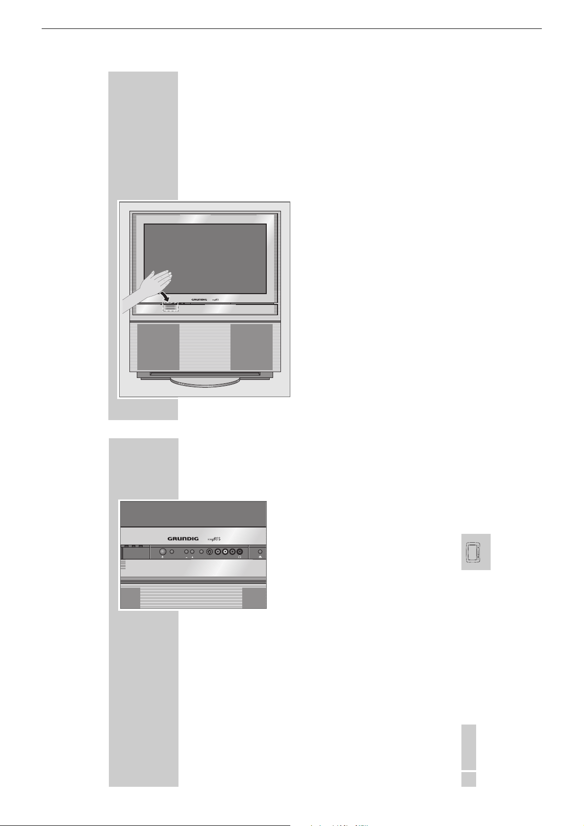
Die Vorderseite des Fernsehgerätes
Automatisches Öffnen der Bedienteilabdeckung
Bei Annäherung mit der Hand gleitet die Bedienteilabdeckung automatisch
nach unten und gibt die Bedienelemente frei.
Nach einigen Sekunden fährt die Glasscheibe automatisch wieder nach
oben.
__________________________________________________________
Hinweis:
Ist an den Buchsen an der Vorderseite des Fernsehgerätes ein Camera-/Videorecorder oder
Kopfhörer angeschlossen, fährt die Bedienteilabdeckung nicht automatisch nach oben.
14
AUF EINEN BLICK
Slider
Video in
Mode
Audio inLR
S-VHS
______________________________________________________________________
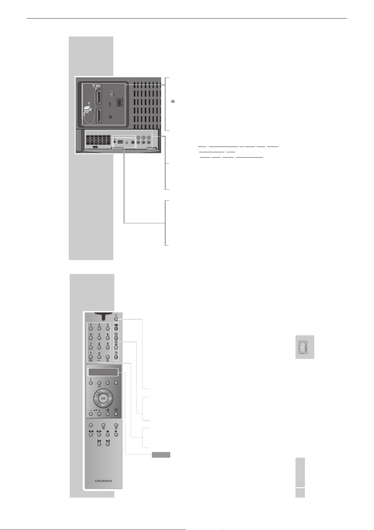
Bedienelemente
Ǽ
Mode Vorwahl für
+ Lautstärke/Programmwahl.
–
Slider Schaltet das automatische Schließen der Bedienteil-
S-VHS S-VHS Bildsignaleingang für Camerarecorder.
Video in Bildsignaleingang für Camerarecorder.
L Audio in R Tonsignaleingang für Camerarecorder.
y
ə
Schaltet das Fernsehgerät ein/aus.
Eine Leuchtanzeige zeigt den jeweiligen Betriebszu-
stand an.
Grün = Betrieb;
Gelb = Stand-by (TV-Guide-Betrieb,
Copy-Betrieb, Timer-Betrieb);
Rot = Stand-by (Energiesparbetrieb,
Timer programmiert).
Lautstärke oder Programmwahl.
abdeckung aus/ein.
Kopfhöreranschluß.
Öffnet/schließt die Schublade des DVD-Players.
(Die Schublade des DVD-Players kann nach dem
Einschalten des Fernsehgerätes erst geöffnet werden, wenn die Einblendung des Programmplatzes
am Bildschirm erlischt)
1 - 11
DEUTSCH
15
Page 12
GRUNDIG Service DIGI 100
Personal Remote 11
ModeTV +TXT
Menu
PIP Format Z
SP/LP Timer on/off
ABC DEF Title
GHI JKL MNO
PQRS TUV WXYZ
16
IN
SUB-
WOOFER
CENTER LFE L R L RFRONT
S
AUF EINEN BLICK
______________________________________________________________________
Die Anschlüsse an der Rückseite
É
AV 1 Euro/AV-Buchse
AV 2 Euro/AV-Buchse
VGA
AV1
AUDIO IN
AV2
SURROUND
E
I
DIGITAL IN
WT 2
LL
CENTER
COAX/
OPTICAL
DIGITAL
SUBWOOFER
SURROUNDRFRONT R
OUT
LFE
VGA Anschluss für Computer.
AUDIO IN Ton-Anschluss für Computer.
ʋ Netzbuchse für Netzkabel.
FRONT L R Ausgangsbuchsen für Front-Lautsprecher.
SURROUND L R Ausgangsbuchsen für Surround-Lautsprecher.
CENTER Ausgangsbuchse für Center-Lautsprecher.
SUBWOOFER LFE Ausgangsbuchse für Subwoofer.
I E S Steckbrücke für passiven Subwoofer.
DIGITAL OUT Digitaler Tonausgang (zum Anschluss eines externen
DIGITAL IN Digitaler Toneingang (Kombibuchse für Klinkenstecker
WT2 Anschluss für Sender WT 2 (für Grundig für Aktiv-
y
Antennenbuchse
Servicebuchse für den Fachhändler
(unter der Abdeckung).
Lauts
precheranschlüsse für aktive Lautsprecher
(Cinch-Buchsen) bzw.
echer (Klemm-Buchsen):
Lautspr
passive
Dolby Digital Verstärkers).
3,5mm ø oder Optisches Kabel) zum Anschließen
externer Dolby Digital Geräte.
Laut-sprecherboxen LSP2 und LSP3).
Kopfhöreranschluss (für WST 864 oder Funkkopfhö-
rer).
AUF EINEN BLICK
______________________________________________________________________
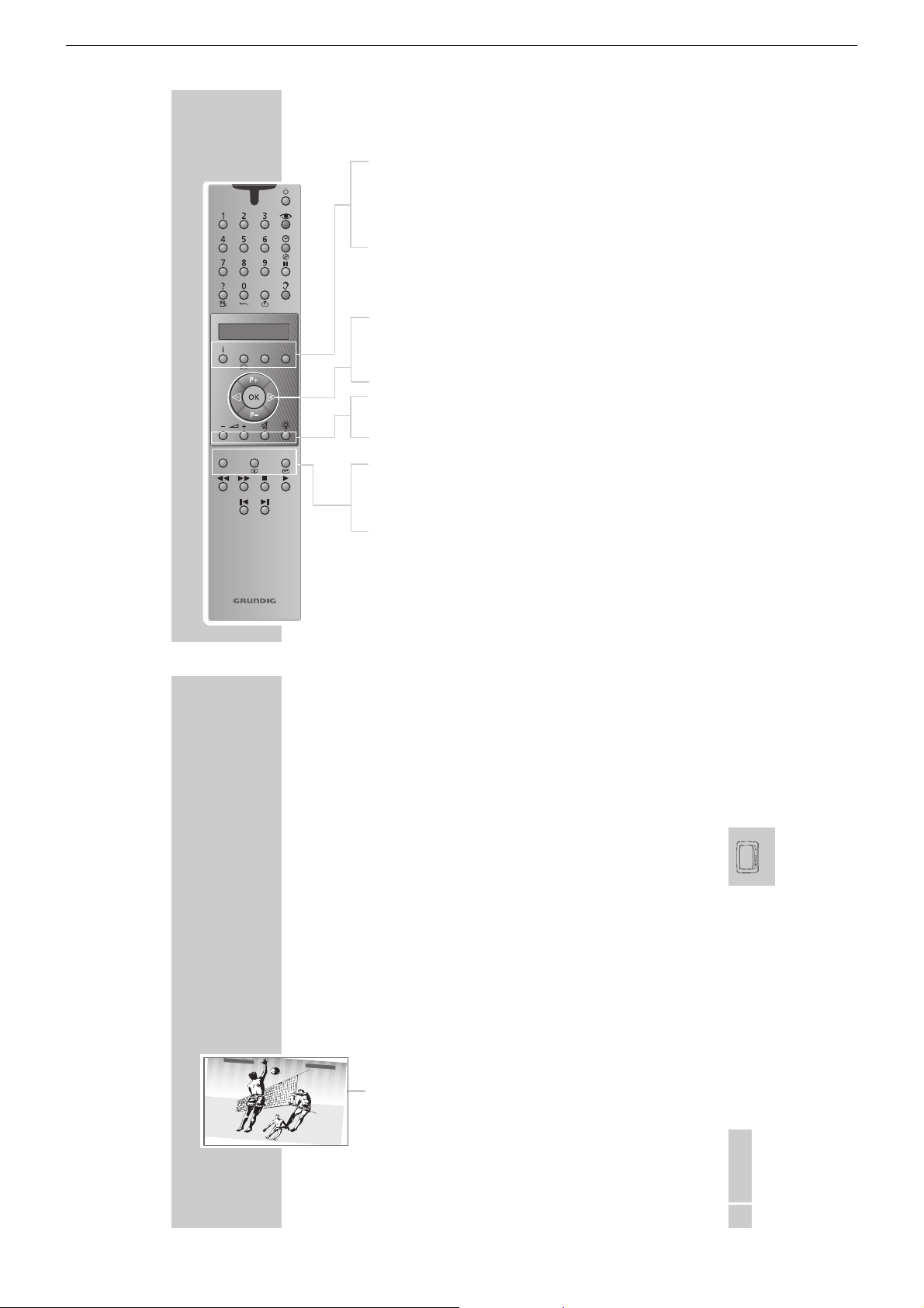
Die Fernbedienung
Mit der Fernbedienung Personal Remote 11 können Sie zusätzlich zum
Fernsehgerät auch einen Grundig Videorecorder, einen externen Grundig DVDPlayer und einen externen Grundig Satelliten-Receiver bedienen.
Für den Betrieb mit externen DVD-Player und Satelliten-Receiver muß die Fernbedienung vorbereitet werden. Siehe Seite 25)
Bedienen des Fernsehgerätes
Zum Bedienen des Fernsehgerätes muß »TV« in der Anzeige der Fernbedie-
TV
nung stehen. Gegegebenenfalls Taste »Mode« so oft drücken, bis »TV« in der
Anzeige steht.
Ǽ
z
Ȅ
Schaltet das Fernsehgerät ab (Stand-by).
Menü »Bild« aufrufen.
Uhrzeit und Programmplatzinformation ein/aus.
II Standbild.
F
Menü »Ton« aufrufen.
1…0 Programmwahl und Einschalten aus Stand-by;
Alphanumerische Programmwahl;
Eingabe der Videotext-Seitennummern
D
TV
Stichwortverzeichnis A–Z aufrufen.
Anzeige
DEUTSCH
17
1 - 12
Page 13

GRUNDIG Service DIGI 100
Personal Remote 11
ModeTV +TXT
Menu
PIP Format Z
SP/LP Timer on/off
ABC DEF Title
GHI JKL MNO
PQRS TUV WXYZ
TV
AUF EINEN BLICK
i
TXT Videotext-Betrieb, TV-Betrieb.
TV+ TV-Guide, Info über aktuelle Sendung;
Mode Umschaltung zur Bedienung der Grundfunktionen eines exter-
P+ P– Einschalten des Fernsehgerätes aus Bereitschaft;
ǸǷ
OK Ändern und Aktivieren verschiedener Funktionen.
}
+ Lautstärke.
–
d
R
PIP Im Videotext-Betrieb – Double Window (Fernsehbild und
Format Bildformat-Umschaltung.
Z Zappfunktion.
______________________________________________________________________
Menü »EASY DIALOG« aufrufen.
aus DVD- bzw. TeleWeb-Betrieb zurück zum TV-Betrieb..
nen Grundig DVD-Players (AUX), Videorecorders (VCR), Digitalen Videorecorders (PDR) und eines externen Grundig Satelliten-Receivers (SAT).
Welche Funktionen Sie ausführen können, hängt von der Ausstattung des Gerätes ab. Probieren Sie es einfach aus.
Programmfortschaltung, Cursor nach oben/unten.
Cursor nach links/rechts.
Ton ein/aus (stummschalten).
Anzeigen-Beleuchtung ein/aus. Die Beleuchtung wird nach
kurzer Zeit automatisch abgeschaltet.
Videotext auf den Bildschirmhälften);
im Fernseh-Betrieb – Kleinbild im Bild.
18
EINSTELLUNGEN
________________________________________________________________________
Drehfuß
Ihr Fernsehgerät ist mit einem motorbetriebenen Drehfuß ausgestattet. Bequem
von Ihrem Sitzplatz aus, können Sie mit der Fernbedienung das Fernsehgerät in
die gewünschte Position drehen. Wenn Sie es wünschen, dreht sich das Fernsehgerät nach dem Ausschalten in Stand-by automatisch in eine von Ihnen vorgegebene Ruheposition.
Endpositionen, Ruheposition und Rotation einstellen
Sie können festlegen, wie weit sich das Fernsehgerät nach links (Endposition1)
bzw nach rechts (Endposition2) drehen lässt. Außerdem können Sie noch die
Position festlegen, in die sich das Gerät nach dem Ausschalten in Stand-by drehen soll (Ruheposition).
Je nach Standort Ihres Gerätes kann das Erdmagnetfeld unterschiedliche Auswirkungen auf die Lage des Fernsehbildes haben. Diese ‘Schieflage’ des Fernsehbildes kann für jede Position korrigiert werden.
1
Easy-Dialog mit »i« aufrufen.
2
Menü »Installation« mit »P+« oder »P-« wählen und mit »OK« bestätigen.
3
Menü »Drehfuß« mit »P+« oder »P-« wählen und mit »OK« bestätigen.
4
Zeile »Ruheposition« mit »P+« oder »P-« wählen und gewünschte Position
mit »
« oder »Ƿ« einstellen.
Ǹ
5
Zeile »Rotationskorrektur« mit »P+« oder »P-« wählen und eine eventuelle
Schieflage des Bildes mit »
beiden am oberen Bildrand platzierten Balken.
« oder »Ƿ« korrigieren. Als Hilfe dienen die
Ǹ
6
Zeile »Endpositon 1« mit »P+« oder » P-« wählen und gewünschte Position
mit »
« oder »Ƿ« einstellen.
Ǹ
1 - 13
DEUTSCH
21
Page 14

GRUNDIG Service DIGI 100
EINSTELLUNGEN
7
Zeile »Rotationskorrektur« mit »P+« oder »P-« wählen und eine eventuelle
Schieflage des Bildes mit »
beiden am oberen Bildrand platzierten Balken.
8
Zeile »Endpositon 2« mit »P+« oder » P-« wählen und gewünschte Position
mit »
Ǹ
9
Zeile »Rotationskorrektur« mit »P+« oder »P-« wählen und eine eventuelle
Schieflage des Bildes mit »
beiden am oberen Bildrand platzierten Balken.
Hinweis:
Soll sich das Fernsehgerät nach dem Ausschalten in Stand-by in die Ruheposition drehen, muß in der Zeile »Ruheposition anfahren« die Einstellung »ja«
gewählt werden.
Bedienung des Drehfußes
1
Im Fernsehbetrieb mit »Ǹ« oder »Ƿ« das Fernsehgerät in die gewünschte
Position drehen.
Hinweis:
Im DVD-Betrieb oder wenn ein Menü gewählt ist, ist die Drehung des Fernsehgerätes nicht möglich.
________________________________________________________________________
« oder »Ƿ« korrigieren. Als Hilfe dienen die
Ǹ
« oder »Ƿ« einstellen.
« oder »Ƿ« korrigieren. Als Hilfe dienen die
Ǹ
22
ZUSATZFUNKTIONEN
______________________________________________________________
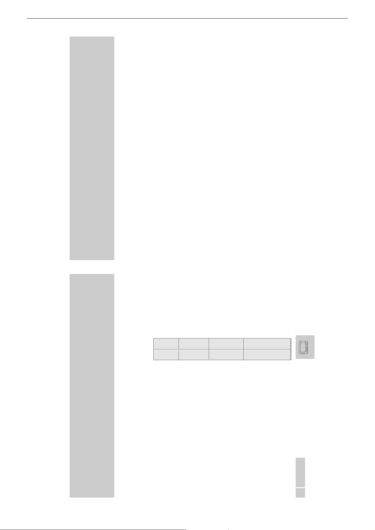
Zusätzliche Geräte fernbedienen
Zum Betrieb eines externen Grundig Satelliten-Receivers und eines externen
Grundig DVD-Players muß in die Fernbedienung eine Codezahl eingegeben
werden. Für den DVD Player gibt es zwei Codezahlen. Werkseitig ist die Codezahl »123« programmiert. Sollte Ihr Grundig DVD-Player nicht auf die Fernbedienung ansprechen, geben Sie die Codezahl »456« ein.
Gerät DVD-Player Satellitenreceiver Satellitenreceiver aus
Codezahl 123 oder 4 56 4 24 859
Hinweis:
Die Bedienung des DVD Players GDV 120 und GDV 130 mit der Fernbedienung Personal Remote 11 ist nicht möglich
Codezahl eingeben
1
»Mode « drücken und gedrückt halten.
2
Mit »1...0« Codezahl eingeben.
– Die Fernbedienung ist jetzt für die Bedienung des zusätzlichen Gerätes
vorbereitet.
Bedienung
1
»Mode « so oft drücken, bis »AUX« (für DVD-Player) oder »SAT« (für
Satelliten-Receiver) in der Anzeige erscheint.
2
Gewünschte Funktion wählen.
Welche Funktionen Sie ausführen können, hängt von der Ausstattung des
Gerätes ab. Probieren Sie es einfach aus.
1 - 14
DEUTSCH
25
Page 15
GRUNDIG Service DIGI 100
Operating Hints This chapter contains excerpts from the operating instructions. For further particulars please refer to the appropriate user
instructions the part number of which is indicated in the relevant spare parts list.
OVERVIEW
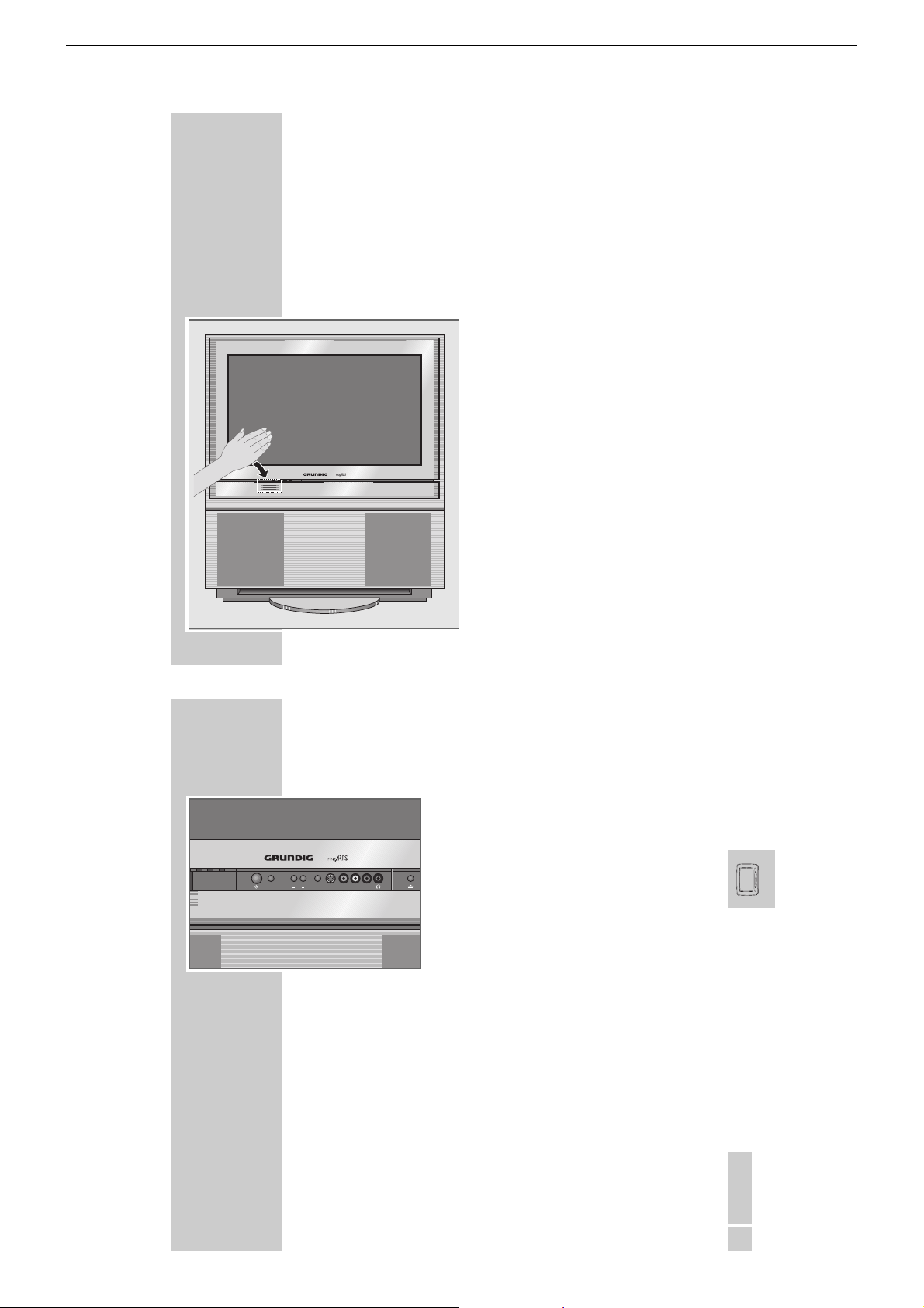
The front of the TV set
Automatic opening of the control unit cover
__________________________________________________________________________
When moving your hand towards the cover of the control unit, this slides
automatically downwards and reveals the control elements.
After a few moments, the glass pane slides up again.
Note
If a camcorder, video recorder or headphones
are connected to the sockets at the front of the TV
set, the cover of the control unit does not close
automatically.
14
OVERVIEW
Mode
Slider
__________________________________________________________________________________
Control elements
Ǽ
Video in
Audio inLR
S-VHS
Mode Preselection for
+ Volume/channel selection.
–
Slider Switches the automatic close function of the control
S-VHS S-VIDEO camcorder video input.
Video in Video signal input.
L Audio in R Audio signal input.
y
ə
Switches the television on/off.
An indicator light shows the current operating
mode.
Green= In operation;
Yellow= Stand-by (TV Guide mode,
Copy mode, Timer mode);
Red = Stand-by (Energy-saving mode,
timer programmed).
volume or channel selection
unit on and off.
Headphone jack.
Opens/closes the disc tray of the DVD player.
After the TV set has been switched on, the tray of
the DVD player can only be opened once the channel position display disappears from the screen
1 - 15
ENGLISH
15
Page 16
GRUNDIG Service DIGI 100
Personal Remote 11
ModeTV +TXT
Menu
PIP Format Z
SP/LP Timer on/off
ABC DEF Title
GHI JKL MNO
PQRS TUV WXYZ
16
IN
SUB-
WOOFER
CENTER LFE L R L RFRONT
S
OVERVIEW
__________________________________________________________________________________
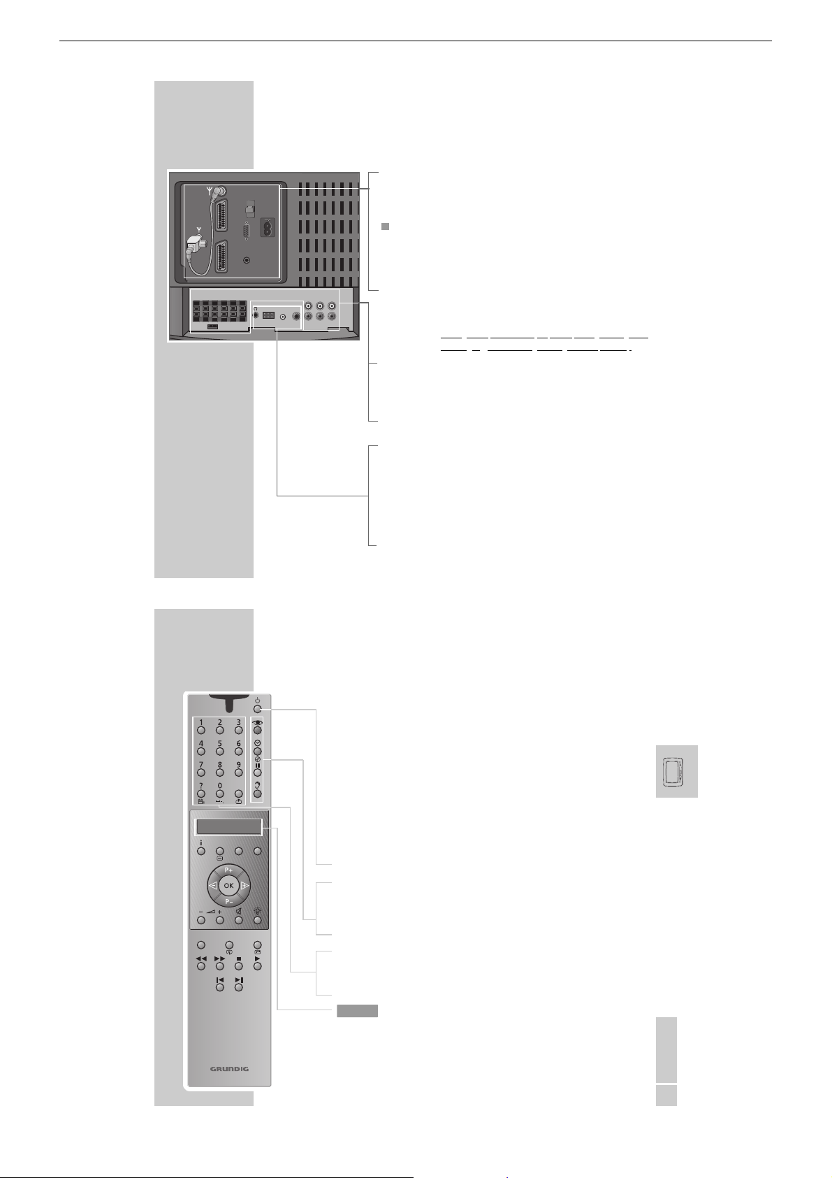
The Connections on the back of the television
É
AV 1 Euro/AV socket
AV 2 Euro/AV socket
VGA
AV1
AUDIO IN
AV2
SURROUND
E
I
DIGITAL IN
WT 2
OPTICAL
LL
CENTER
COAX/
DIGITAL
SUBWOOFER
SURROUNDRFRONT R
OUT
LFE
VGA Connection for computer.
AUDIO IN Audio connection for computer.
ʋ Socket for mains cable.
FRONT L R Output socket for front loudspeakers.
SURROUND L R Output socket for surround loudspeakers.
CENTER Output socket for center loudspeakers.
SUBWOOFER LFE Output socket for subwoofers.
I E S Jumper for passive subwoofers.
DIGITAL OUT Digital audio output (for connecting an external Dolby
DIGITAL IN Digital audio input (combination socket for jack plug
WT2 Connection for station WT 2 (for Grundig, for active
y
Antenna socket
Service socket for dealers (under the cover panel).
Louds
peaker connections for active loudspeakers (cinch
sockets) or passive loudspeakers (terminal sockets):
Digital amplifier).
3.5 mm ø or optical cable) for connecting external
Dolby Digital devices.
loudspeakers LSP2 and LSP3).
Headphone jack (for WST 864 or wireless headpho-
nes).
OVERVIEW
__________________________________________________________________________________
The remote control
In addition to the television, you can also operate a Grundig video recorder, an
external Grundig DVD player and an external Grundig satellite receiver with the
Personal Remote 11 remote control.
The remote control must be set up for use with an external DVD player and satellite receiver. (See Page 25)
Operating the TV set
For the operation of the TV set, »TV« must be visible in the display of the
TV
remote control. If this is not the case, press the »Mode « button repeatedly until
»TV« is visible in the display.
Ǽ
z
Ȅ
Switches off the television (stand-by).
Calls up »Picture« menu.
Time and channel position information on/off.
II Freeze-frame.
F
Calls up »Sound« menu.
1…0 Channel selection and switching on from stand-by;
Alphanumeric channel selection;
Entry of teletext page numbers.
D
TV
Calls up A–Z index.
Display
ENGLISH
17
1 - 16
Page 17
GRUNDIG Service DIGI 100
Personal Remote 11
ModeTV +TXT
Menu
PIP Format Z
SP/LP Timer on/off
ABC DEF Title
GHI JKL MNO
PQRS TUV WXYZ
TV
OVERVIEW
__________________________________________________________________________________
i
TXT Teletext mode, TV mode
TV+ TV Guide, information about the current programme;
Mode Switch to operate the basic functions of an external Grundig
P+ P– Switch on the television from stand-by
ǸǷ
OK
}
–
d
R
PIP In teletext mode: double window function (TV picture and tele-
Format Changes picture format.
Z Zap function.
Calls up the »EASY DIALOG« menu.
Returns to TV mode from DVD or TeleWeb mode.
DVD player (AUX), video recorder (VCR), digital video
recorder (PDR) and an external Grundig satellite receivers (SAT).
The functions available to you depend on the model of the
device you are using. Simply try it out.
Channel tuning, cursor up/down
Move cursor to the left/right.
M
odifies and activates various functions.
+ Volume
Sound on/off (mute).
Display illumination on/off. After some time, the illumination
switches off automatically.
text in two screen windows;
in TV mode: picture-in-picture mode.
18
SETTINGS
____________________________________________________________________________________
Swivel mount
Your TV set is equipped with a motor-driven swivel mount. You can turn the TV
set to the desired position with the remote control from the comfort of your chair.
If you like, the TV set will automatically return to a preset position in stand-by
after you turn the TV off.
Setting final positions, resting position and rotation
You can set how far the TV set can turn to the left (final position 1) and/or to the
right (final position 2). As well, you can also set the position in which the unit is
to return in stand-by after being switched off (resting position).
Depending on the location of your TV set, the earth’s magnetic field may affect
the position of your TV picture. This ‘inclination of the picture’ can be corrected
for every position.
1
Call up Easy-Dialogue with »i«.
2
Select the menu »Installation« with »P+« or »P-« and confirm with »OK«.
3
Select the menu »Swivel base« with »P+« or »P-« and confirm with »OK«.
4
Select the line »Home position« with »P+« or »P-« and set the desired
position with »
5
Select the line »Rotation correction« with »P+« or » P-« and correct any
possible inclination of the picture with »
located on the upper part of the screen offer additional help.
6
Select the line »End position 1« with »P+« or »P-« and set the desired
position with »
« or »Ƿ«.
Ǹ
« or »Ƿ«.
Ǹ
« or »Ƿ«. Both of the bars
Ǹ
ENGLISH
21
1 - 17
Page 18
GRUNDIG Service DIGI 100
SETTINGS
____________________________________________________________________________________
7
Select the line »Rotation correction« with »P+« or » P-« and correct any
possible inclination of the picture with »
located on the upper part of the screen offer additional help.
8
Select the line »End position 2« with »P+« or »P-« and set the desired
position with »
9
Select the line »Rotation correction« with »P+« or » P-« and correct any
possible inclination of the picture with »
located on the upper part of the screen offer additional help.
Note:
If the TV set is to return to the resting position in stand-by after being
switched off, the setting »ja« must be selected in the line »Ruheposition
anfahren«.
« or »Ƿ«.
Ǹ
« or »Ƿ«. Both of the bars
Ǹ
« or »Ƿ«. Both of the bars
Ǹ
Operating the swivel mount
1
While in TV mode, turn the TV set to the desired position with »Ǹ« or »Ƿ«.
Note:
Rotating the TV set is not possible in DVD mode or when a menu has been
selected.
22
ADDITIONAL FUNCTIONS
_______________________________________________________
Remote controlling additional devices
A code must be entered into the remote control to operate an external Grundig
satellite receiver and an external Grundig DVD player. There are two codes for
the DVD player. The code »123« is programmed at the factory. If your Grundig
DVD player does not respond to the remote control, enter the code »456«.
Device DVD-player Satellite receiver Satellite receiver off
Codenumber 123 or 456 424 859
Note:
The DVD players GDV 120 and GDV 130 cannot be operated with the
remote control Personal Remote 11.
Entering a code
1
Press and hold »Mode«.
2
Enter the code with »1...0«.
– The remote control is not ready to operate additional devices.
Operation
1
Press »Mode« so many times until »AUX« (for DVD player) or »SAT« (for
satellite receiver) appears on the display.
2
Select desired function.
The functions that are possible depend on the features of your appliance. Just
try it out.
1 - 18
ENGLISH
25
Page 19
GRUNDIG Service DIGI 100
S
l
i
d
e
r
V
o
l
u
m
e
P
r
o
g
r
a
m
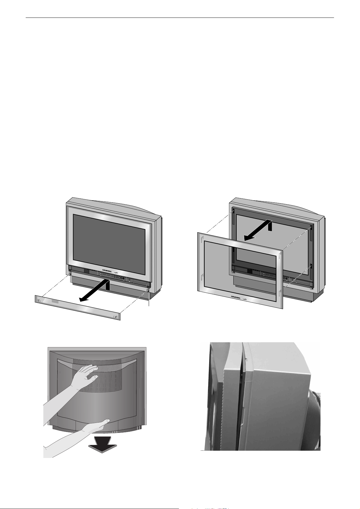
Ausbauhinweise
1. Glasscheiben abnehmen
– Netzstecker einstecken und Bedienteilabdeckung nach unten glei-
ten lassen.
– Netzstecker ziehen.
–
Die beiden Befestigungsschrauben A lösen und die Bedienteil-
abdeckung nach oben abnehmen (Fig. 1).
–
Glasscheibe nach oben schieben und nach vorne abnehmen (Fig. 2).
2. Öffnen des Gehäuses
– Rückwandabdeckung nach hinten abziehen (Fig. 3).
– Achtung: Wegen des hohen Gewichtes der Rückwand darf diese
3. Blende ausbauen
– Glasscheiben abnehmen (Pkt. 1)
– Blende B abziehen (Fig. 4)
nur nach oben abgenommen werden, um Beschädigungen der Bildrohrplatte und des Bildrohrs zu vermeiden.
Beim Herausschrauben der 6 Rückwandschrauben die
Rückwand festhalten und vorsichtig nach oben abnehmen bis die Masseverbindung und die Subwoofer-Leitung gelöst werden kann.
Disassembly Instructions
1. Removing the front glasses
– Connect the mains plug and make the glass cover of the keyboard
control unit slide down.
– Disconnect the mains plug.
– Undo the two fastening screws A and lift the glass cover of the
keyboard control unit to remove it (Fig. 1).
–
Lift the front glass and remove it towards the front. (Fig. 2).
2. Opening the cabinet
– Withdraw the cover from the rear cabinet (Fig. 3).
– Attention: To avoid damage to the picture tube panel and the
3. Removing the frame
– Take the front glasses off (point 1)
– Pull the frame off B (point 4)
picture tube, the rear cabinet is to be removed only in
upward direction because of its considerable weight.
Hold the rear cabinet when undoing the 6 screws and
lift it carefully by an amount so that it is possible to
disconnect the earthing cable and the subwoofer cable.
V
o
l
u
m
e
P
r
o
g
r
a
m
S
l
i
d
e
r
S
-
V
H
S
V
id
e
o
i
n
L
A
u
d
i
o
i
n
R
A
A
Fig. 1 Fig. 2
B
V
o
l
u
m
e
P
r
o
g
r
a
m
S
l
i
d
e
r
S
-
V
H
S
V
id
e
o
in
A
u
d
io
inL
R
Fig. 3
Fig. 4
1 - 19
Page 20
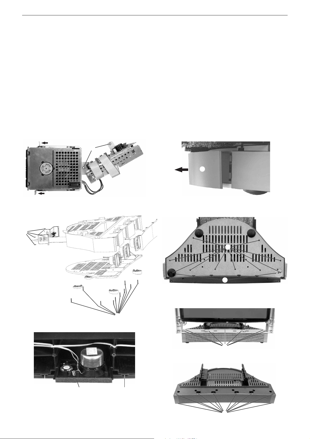
GRUNDIG Service DIGI 100
4. DVD-Einheit ausbauen
– Gehäuse öffnen (Pkt. 2)
– 4 Schrauben C (Fig. 5) herausschrauben, die DVD-Einheit vorsich-
tig herausnehmen.
– Leitungen gegebenenfalls abziehen.
Achtung: Leitungsverlegung beachten!
5. D-Verstärker ausbauen
– Gehäuse öffnen (Pkt. 2)
– TV-Gerätesockelabdeckung D nach hinten abziehen (Fig. 6).
– 4 Schrauben E herausschrauben (Fig. 7) und D-Verstärker vorsich-
tig herausziehen.
– Leitungen gegebenenfalls abziehen.
6. Lautsprecher-Kombination ausbauen (Tischgerät)
– Glasscheiben abnehmen (Pkt. 1).
– Gerät auf die Frontseite legen (Bildröhre nicht verkratzen).
– Gerätefüße G abnehmen, 10 Schrauben F herausschrauben und
die Bodenplatte abnehmen (Fig. 7 und 8).
– Rastnasen H der Lautsprecherblende lösen und Lautsprecher-
Kombination I herausziehen (Fig. 9).
– Leitungen gegebenenfalls abziehen.
C
C
4. Removing the DVD unit
– Open the cabinet (point 2).
– Undo 4 screws C (Fig. 5), take the DVD unit carefully out.
– If necessary disconnect the cables.
Attention: Note the cable layout!
5. Removing the D-Amplifier
– Open the cabinet (point 2).
– Withdraw the cover D from the TV base (Fig. 6).
– Undo 4 screws E (Fig. 7), take the D-Amplifier carefully out.
– Disconnect the cables if necessary.
6. Removing the multi-loudspeaker (table version)
– Remove the front glasses (point 1).
– Put the TV set down on its front side (do not scratch the tube).
– Remove the feet G of the TV set, undo 10 screws F and remove the
bottom plate (Fig. 7 and 8).
– Disengage the catches H of the loudspeaker mask and pull the
multi-loudspeaker I out (Fig. 9).
– If necessary disconnect the cables.
D
Fig. 5
E
Fig. 7
C
Fig. 6
F
G
Fig. 8
F
Fig. 9
H I
H
1 - 20
Fig. 10
Fig. 11
J
K
Page 21
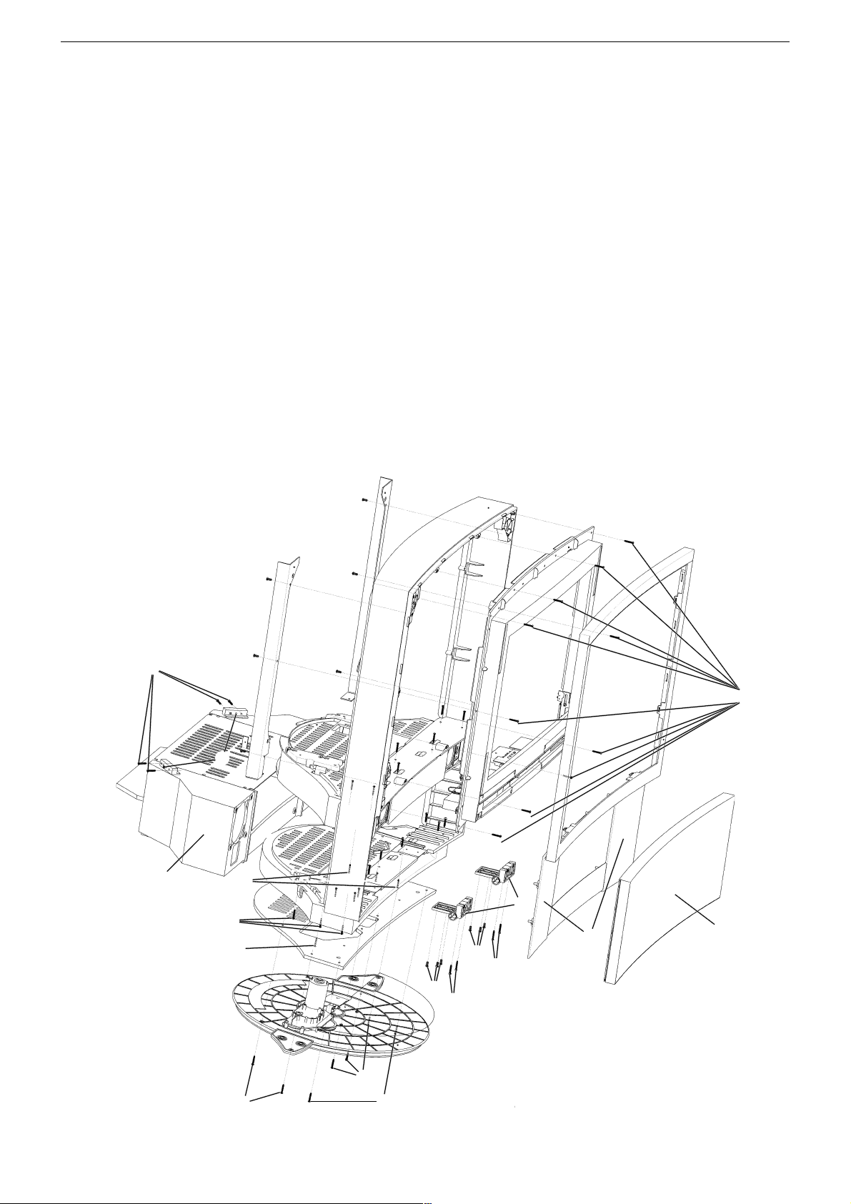
GRUNDIG Service DIGI 100
7. Lautsprecher-Kombination ausbauen (Standgerät)
– Glasscheiben abnehmen (Pkt. 1).
– Gerät auf die Frontseite legen (Bildröhre nicht verkratzen).
–
6 Schrauben L
– Leitungen gegebenenfalls abziehen.
–
2 Schrauben M
– 6 Schrauben N, 4 Schrauben O (2 Justageschrauben P sind für die
Neigungseinstellung) herausschrauben und Unterbau Q mit den
Lautsprechern nach hinten herausziehen
– Leitungen gegebenenfalls lösen.
– 10 Schrauben F der Bodenplatte entfernen
– Rastnasen H der Lautsprecherblende lösen und Lautsprecher-
Kombination I herausziehen (Fig. 9).
– Leitungen gegebenenfalls abziehen.
8. Gitter der Lautsprecher-Kombination ausbauen
– Glasscheiben abnehmen (Pkt. 1).
– Gehäuse öffnen (Pkt. 2).
– Gerät auf die Frontseite legen (Bildröhre nicht verkratzen).
– DVD-Einheit ausbauen (Pkt. 4), die beiden Chassisschrauben her-
rausschrauben und das Chassis aushängen.
– Gerätefüße G abnehmen und 10 Schrauben F der Bodenplatte
entfernen
– Leitungen gegebenenfalls lösen.
– 7 Schrauben J entfernen und Unterteil abnehmen (Fig. 10).
–
Lautsprechergitter durch Lösen der Rastnasen K abnehmen (Fig. 11).
Hinweis: Beim Standgerät muß zusätzlich Unterbau Q (Fig. 12) mit
den Lautsprechern und der Drehfuß ausgebaut werden (Pkt. 7).
(Fig. 8)
entfernen
entfernen
.
und den Drehfuß abnehmen (Fig. 12).
und die Bodenplatte abnehmen (Fig. 12).
(Fig. 12)
.
(Fig. 7 und 8)
.
7. Removing the multi-loudspeaker (stand version)
– Remove the front glasses (point 1).
– Put the TV set down on its front side (do not scratch the tube).
– Undo 6 screws L and remove the revolving foot (Fig. 12).
– If necessary disconnect the cables.
– Undo 2 screws M and remove the bottom plate (Fig. 12).
– Undo 6 screws N, undo 4 screws O (2 adjustment screws P for
setting the tilt) and pull the base Q with the loudspeakers towards
the back (Fig. 12).
– If necessary disconnect the cables.
– Undo 10 screws F of the bottom plate (Fig. 7 and 8).
– Disengage the catches H of the loudspeaker mask and pull the
multi-loudspeaker I out (Fig. 9).
– If necessary disconnect the cables.
8. Removing the multi-loudspeaker grille
– Remove the front glasses (point 1).
– Open the cabinet (point 2).
– Put the TV set down on its front side (do not scratch the tube).
– Removing the DVD unit (Pkt. 4), undo the both Chassis screws and
unhinge the Chassis.
– Remove the feet G of the TV set, undo 10 screws F of the bottom
plate (Fig. 8).
– Undo 7 screws J and remove the bottom (Fig. 10).
–
Detach the loudspeaker grille by disengaging the catches Q (Fig. 11).
Note: The stand version requires additionally to remove the base Q
(Fig. 12) together with the loudspeakers and the revolving foot
(point 7).
O
Q
P
N
L
N
L
W
S
W
S
V
R
C
T
Fig. 12
L
M
1 - 21
Page 22

GRUNDIG Service DIGI 100
9. Tief- und Mittelton-Lautsprecher ausbauen (Standgerät)
– Lautsprecherblende R nach vorne abziehen (Fig. 12).
– 4 Schrauben der Lautsprecher herausschrauben und Lautsprecher
nach vorne aus dem Unterbau herausnehmen.
10. Geräteklappe ausbauen (Standgerät)
– Glasscheiben abnehmen (Pkt. 1)
– Gerät auf die Frontseite legen (Bildröhre nicht verkratzen)
–
6 Schrauben L
– Leitungen gegebenenfalls abziehen.
–
2 Schrauben M
(Fig. 12).
– 6 Schrauben N, 4 Schrauben O (2 Justageschrauben P sind für
die Neigungseinstellung) herausschrauben und Unterbau Q mit
den Lautsprechern nach hinten herausziehen
– Leitungen gegebenenfalls lösen.
– 4 Schrauben S herausschrauben, Geräteklappe T leicht öffnen
und diese abziehen (Fig. 12).
Hinweis: Die 2 Schrauben V (Fig. 12) sind Justageschrauben
zum Ausrichten der Geräteklappe.
11. Scharniere ausbauen (Standgerät)
– Geräteklappe ausbauen (Pkt. 10).
– 6 Schrauben W herausschrauben und Scharniere (Fig. 12) aus der
Front ziehen.
12. Bedieneinheit ausbauen
– Gehäuse öffnen (Pkt. 2).
– DVD-Einheit ausbauen (Pkt. 4).
– Die beiden Chassisschrauben herausschrauben und das Chassis
ein Stück nach hinten ziehen.
– 3 Schrauben X (Fig. 13) herausschrauben und Bedieneinheit
nach hinten abnehmen.
– Leitungen gegebenenfalls abziehen.
entfernen
entfernen
und den Drehfuß abnehmen (Fig. 12).
und die Bodenplatte abnehmen
(Fig. 12)
.
9. Removing the low- and mid-frequency speakers (stand version)
– Pull off the loudspeaker mask R towards the front (Fig. 12).
– Undo 4 screws of the loudspeakers and remove them from the base
towards the front.
10. Removing the flap (stand version)
– Remove the front glasses (point 1)
– Put the TV set down on its front side (do not scratch the tube).
– Undo 6 screws L and remove the revolving foot (Fig. 12).
– If necessary disconnect the cables.
– Undo 2 screws M and remove the bottom plate (Fig. 12).
– Undo 6 screws N, undo 4 screws O (2 adjustment screws P for
setting the tilt) and pull the base Q with the loudspeakers towards
the back (Fig. 12).
– If necessary disconnect the cables.
– Undo 4 screws S, open the flap T slightly and pull it off (Fig. 12).
Note: The 2 screws V (Fig. 12) are used for adjusting the position
of the flap.
11. Removing the hinges (stand version)
– Remove the flap (point 10).
– Undo 6 screws W and pull the hinges out from the front (Fig. 12).
12. Removing the keyboard control unit
– Open the cabinet (point 2).
– Removing the DVD unit (Pkt. 4).
– Undo the both Chassis screws and pull the chassis a bit towards the
back.
– Undo 3 screws X (Fig. 13) and remove the control unit towards the
back.
– Disconnect the cables if necessary.
D
Fig. 13
D
X
Z
Y
1 - 22
Page 23

GRUNDIG Service DIGI 100
13. LED-Platte ausbauen
– Glasscheiben abnehmen (Pkt. 1).
– Gehäuse öffnen (Pkt. 2).
– Leitungen gegebenenfalls lösen.
– 4 Schrauben Y (Fig. 13) herausschrauben und die Blende mit der
LED-Platte aus dem Gehäuse ziehen.
– 3 Schrauben Z (Fig. 13) herausschrauben und LED-Platte abneh-
men.
14. Getriebemotor (Bedienteilabdeckung) ausbauen
– Glasscheiben abnehmen (Pkt. 1).
– Gehäuse öffnen (Pkt. 2).
– LED-Platte ausbauen (Pkt. 13).
– Anschlußleitung des Getriebemotors abziehen
– 2 Schrauben A und Schraube B herausschrauben, Antriebsrie-
men abnehmen und Getriebemotor herausnehmen (Fig. 14).
15. Getriebemechanik (Bedienteilabdeckung) ausbauen
– Glasscheiben abnehmen (Pkt. 1).
– Gehäuse öffnen (Pkt. 2).
– LED-Platte ausbauen (Pkt. 13).
– DVD-Einheit ausbauen (Pkt. 4).
– Bedieneinheit ausbauen (Pkt. 12).
– Blende B abziehen (Pkt. 3).
– Getriebemotor (Bedienteilabdeckung) ausbauen (Pkt. 14).
– 10 Schrauben C (Fig. 12) herausschrauben, Blende abnehmen
und Schalter- und Masseleitungen lösen.
– 4 Schrauben D (Fig. 13 und 15) herausschrauben und Mechanik
aus der Blende nehmen. Hinweis für den Einbau: Linkes und
rechtes Zahnrad auf gleicher Position in die Zahnstangenführung
E einbauen (Fig. 15).
13. Removing the LED board
– Remove the front glasses (point 1).
– Open the cabinet (point 2).
– If necessary disconnect the cables.
– Undo 4 screws Y (Fig. 13) and the cover with the LED board pull
it out of the cabinet.
– Undo 3 screws Z (Fig. 13) and remove the LED board.
14. Removing the gear motor (cover of the keyboard control)
– Remove the front glasses (point 1).
– Open the cabinet (point 2).
– Removing the LED board (point 13).
– Pull off the gear motor connecting cable.
– Undo 2 screws A and screw B, remove the drive belt and take out
the gear motor (Fig. 14).
15. Removing the gear drive (cover of the keyboard control)
– Remove the front glasses (point 1).
– Open the cabinet (point 2).
– Removing the LED board (point 13).
– Remove the DVD unit (point 4).
– Remove the keyboard control unit (point 12).
– Pull the frame B off (point 3).
– Removing the gear motor (cover of the keyboard control) (point 14).
– Undo 10 screws C (Fig. 12), remove the frame and disconnect the
switch and earthing cables.
– Undo the 4 screws D (Fig. 13 and 15) and remove the gear drive
from the frame. Note on reassembling: Fit the left and right
gearwheel to the same position on the toothed rack E (Fig. 15).
A
B
Fig. 14
16. Motorsteuerung (Drehfuß) ausbauen
– Glasscheiben abnehmen (Pkt. 1).
– Gerät auf die Frontseite legen (Bildröhre nicht verkratzen).
–
6 Schrauben L
– 3 Schrauben F herausschrauben und Motorsteuerung heraus-
nehmen (Fig. 16).
– Leitungen gegebenenfalls lösen.
17. Drehmotor ausbauen
– Motorsteuerung (Drehfuß) ausbauen (Punkt 16).
– 5 Schrauben G (Fig. 17) herausschrauben, Drehmotor mit An-
triebsmechanik herausnehmen und Antriebsriemen abnehmen.
– 3 Schrauben H (Fig. 18) herausschrauben und Drehmotor heraus-
nehmen.
entfernen
und den Drehfuß abnehmen (Fig. 12).
D
D
E
Fig. 15
16. Removing the Motor Control (Turning Foot)
– Remove the front glasses (point 1).
– Put the TV set down on its front side (do not scratch the tube).
– Undo 6 screws L and remove the turning foot (Fig. 12).
– Undo 3 screws F and remove the Motor Control (Fig. 16).
– If necessary disconnect the cables.
17. Removing the Rotary Motor
– Removing the Motor Control (turning foot) (Point 16).
– Undo 5 screws G (Fig. 17), remove the rotary motor together with
the drive mechanism and the drive belt.
– Undo the 3 screws H (Fig. 18) and remove the rotary motor.
F
G
Fig. 16 Fig. 17 Fig. 18
1 - 23
H
Page 24

GRUNDIG Service DIGI 100
Service- und Sonderfunktionen
Aufruf des Service-Menüs: Taste "Ǻ" (EASY DIALOG)
Aufruf der Dialogzeile: Tasten "P+" oder "P-" –> "OK"
Einstellung in der Dialogzeile ändern : Tasten "L+" oder "L-" –> "OK"
Zurück ins vorherige Menü: "blaue" Taste
Beenden des Menüs: Taste "Ǻ"
Servicemenü für Händler (Codezahl) 8500
1. Einschaltfunktionen
1.1 ATS-Reset
Netzschalter "EIN" mit gedrückter Nahbedientaste "-".
- Gerät wird mit Analog-Grundwerten geladen.
- ATS-Bit wird gesetzt. Diese Option löst beim nächsten Einschalten
das ATS euro plus aus. Die bisherigen Einstellungen "Sprache",
"Land" und "Programmbelegung" bleiben erhalten.
1.2 ATS Start
Über "Menüsprache" –> "Land" –> Satelliten (optional), das Auto
Tuning System (ATS) starten.
Das ATS sucht mit aufsteigender Frequenz, angezeigt wird der Kanal.
Bei der Ländereinstellung F oder *übrige kann wahlweise auf Kanaloder Frequenzanzeige umgeschaltet werden.
Das ATS-System ermittelt die Programme mit Senderkennung und
speichert sie in die Programmtabelle.
Tastendruck "OK" bricht den ATS-Lauf ab. Das ATS-Bit wird nicht
zurückgesetzt.
ATS-Bit zurücksetzen ohne die bestehende Programmbelegung zu
verändern:
Nach Abbruch des Suchlaufes mit "OK" Kanaldirekteingabe in der
Programmtabelle anwählen, angezeigten Kanal erneut eingeben und
mit "OK" bestätigen.
Nach dem Abspeichern ist das ATS-Bit zurückgesetzt.
1.3 Speicherbelegung CIC38091 (SAT-Baustein)
- SAT-Kennung, Video-Daten (HUB, H/V), Tonfrequenz "High" und "Low"
- Peri, Finetuning, Kanalnummer
- Luma, Noise, Norm, Text/Menü
- Laut-Fine, Ton Peak
- Senderkennung
- LNC-Frequenz
1.4 Programmsperre (Kindersicherung)
Die Tastenfolge "7 0 3 8 5 8 0" hebt die persönliche Kennzahl auf.
1.5 Software-Versionsnummer
Das Menü "EASY DIALOG" aufrufen. Durch Betätigen der "grünen"
Taste wird die Software-Versionsnummer des TV-Gerätes angezeigt.
1.6 Flashprogrammierung
Benötigtes Equipment
Flash-Programmer F-Prog 1 / ab Version 2.0 oder
Service Toolbox Materialnummer 772004001200.
1.7 PIP-Position (nur mit PIP-Baustein)
Fernbedientaste "PIP" gedrückt halten und das Gerät mit dem Netzschalter einschalten. Dadurch wird der PIP-Mode aufgerufen.
Die horizontale und vertikale Position einstellen.
Mit der Format-Taste kann die PIP-Position oben rechts/links, unten
rechts/links gewechselt werden.
Mit "OK" Position speichern.
Hinweis: VGA- oder RGB-Signale können nicht als PIP-Bild eingeblendet werden.
1.8 Service - Mode Programm (zur Fehlersuche im I2C-Bus)
Diese Fehlermeldungen beziehen sich nur auf Störungen im I2C-Bus,
also auf Bausteine oder Schaltkreise bei denen keine Rückmeldung
(Acknowledge) über den I2C-Bus erfolgt. Beispielsweise keine Betriebsspannung am Baustein, Unterbrechung der Leiterbahn oder I2CSchnittstelle defekt.
1.8.1 I2C-Bus, IC-Test
In diesem Fehlersuchprogramm fragt der Mikroprozessor CIC80050
die am I2C-Bus angeschlossenen Bausteine oder Schaltkreise ab und
zeigt den fehlerhaften Baustein oder Schaltkreis als auszählbare
Blinkfolge an der LED im Bedienteil an.
Fernbedientaste "P+" gedrückt halten und das Gerät mit dem Netzschalter einschalten.
Die Anzahl der Blinkimpulse zeigt den defekten Baustein lt. Tabelle an.
Beispiel der Blinkfolge:
rote LED blinkt schnell 10s
gelbe LED leuchtet 4s
grüne LED blinkt (z.b. 2x) = Zehnerstelle (2)
gelbe LED leuchtet 4s
grüne LED blinkt (z.B. 8x) = Einerstelle (8)
Ergebnis = 28
Mit der Fernbedientaste "L+" können evtl. weitere fehlerhafte Schnitt-
stellen ermittelt werden.
IC- Blink- Fehlerhafter
Bezeichnung Frequenz Baustein/Schaltkreis
CIC31010 1 Signal Baustein
CIC70200 2 Feature Modul
CIC70250 3 Feature Modul
CIC70300 4 Feature Modul
CIC33010 5 Signal Baustein
IC43140 6 Signal Baustein
TUNER 7 Signal Baustein
CIC32040 8 Signal Baustein
Erforderliche Hardware (Minimum)
Pentium-PC, Microsoft Windows 95
- freier Arbeitsspeicher 32MB
- CD-ROM-Laufwerk
- serielle Schnittstelle
- Internet-Zugang
Abrufen der aktuellen Gerätesoftware
Die Software ist in einem mit Grundig-Kundennummer und Passwort
geschützten Bereich im Internet unter Grundig/Partnerweb (B2B)
abrufbar.
Hinweis zum Abrufen der Software:
- Internet-Browser starten.
- http://partnerweb.grundig.de eingeben und starten.
- Folgen Sie der Menüführung unter "Kundendienst –> SoftwareDownload".
2. Sonderfunktionen im Menü "Installation"
2.1 Buchstaben-Eingabe
Das Menü "Buchstaben-Eingabe" über "EASY DIALOG" –> "Installation" –> "Sonderfunktionen" aufrufen.
Sie können die Buchstaben-Eingabe für die Programmwahl zwischen
"aus", "ein" und "mix" wählen.
2.2 "Tonskala" sichtbar oder unsichtbar für alle Programme
Das Menü "Tonskala" über "EASY DIALOG" –> "Installation" –>
"Sonderfunktionen" aufrufen.
Bei "aus" erscheint keine Balkenanzeige für die Lautstärke.
2.3 Einschalten mit Programm "1" oder "automatisch"
Das Menü "Einschalten" über "EASY DIALOG" –> "Installation" –>
"Sonderfunktionen" aufrufen.
Auf "Programmplatz 1" oder "automatisch" stellen.
Bei "automatisch" wird der beim Ausschalten eingestellte Programmplatz beim Einschalten wieder aufgerufen (Last station memory).
2.4 "Megalogic-Info" (nur wenn Megalogic-Gerät erkannt wurde).
Das Menü "Megalogic Info" über "EASY DIALOG" –> "Installation" –>
"Sonderfunktionen" aufrufen.
Die Megalogic-Steuerung kann auf "ein" bzw. "aus" geschaltet werden.
1 - 24
Page 25
GRUNDIG Service DIGI 100
2.5 Statusanzeige
Das Menü "Statusanzeige" über "EASY DIALOG" –> "Installation" –>
"Sonderfunktionen" aufrufen.
Sie können wählen an welcher Position ("oben" oder "unten") die
Information über Tonart und Bildformat eingeblendet wird.
Bei "aus " wird nach Progammwechsel keine Information eingeblendet.
2.6 Automatische Lautstärke
Das Menü "Autom. Lautstärke" über "EASY DIALOG" –> "Installation"
–> "Sonderfunktionen" aufrufen.
In Stellung "ein" regelt der Ton-IC bei erhöhter Senderlautstärke (z. B.
erhöhter HUB bei der Werbung) die Lautstärke intern auf den normalen Wert zurück.
2.7 Rauschreduktion P1…99 (bzw. P1…199 bei SAT-Baustein)
Das Menü "Rauschreduktion P. 1…99" über "EASY DIALOG" –>
"Installation" –> "Sonderfunktionen" aufrufen. Sie können die Rauschreduktion für die Programme 1…99 bzw. 1…199 auf "aus", "gering"
oder "automatisch" stellen.
Bei "manuell" wird angezeigt, dass ein oder mehrere Programme
unterschiedliche Einstellungen haben.
2.8 Bildschärfe P1…99 (bzw. P1…199 bei SAT-Baustein)
Das Menü "Bildschärfe" über "EASY DIALOG" –> "Installation" –>
"Sonderfunktionen" (zur Seite 2) aufrufen.
Die Bildschärfe wird für alle Programme eingestellt.
2.9 Farbdeckung
Das Menü "Farbdeckung" über "EASY DIALOG" –> "Installation" –>
"Sonderfunktionen" (zur Seite 2) aufrufen.
Die Farbdeckung (Luma-Delay) wird programmplatzbezogen eingestellt.
Bei Geräten mit PIP-Baustein ist die Farbdeckung des PIP-Bildes
zusätzlich einstellbar.
(siehe Abgleich Punkt 6).
2.10 Rotation
Das Menü "Rotation" über "EASY DIALOG" –> "Installation" –> "Sonderfunktionen" aufrufen.
Den Darstellungswinkel zum Bildschirm auf Null abgleichen.
3. Formatumschaltung
3.1 Formatumschaltung mit Schaltspannungs-Auswertung
Das Gerät passt in Abhängigkeit von der an Pin 8 der aktiven EUROAV-Buchse anstehenden Spannung das Bildformat an. Die Bildformat-Umschaltung ist bei AV-Betrieb für die AV-Buchse aktiv (AV 1,
AV 2, AV 3).
bei 16:9-Bildröhren
Bildformat vor dem neues Bildformat nach neues Bildformat nach
Spannungswechsel Pin 8: 0/12V –> 6V Pin 8: 6V –> 0/12V
16:9 - altes Format *
Cinema Zoom 16:9 altes Format *
Panorama Zoom 16:9 altes Format *
4:3 16:9 altes Format *
bei 4:3-Bildröhren
Bildformat vor dem neues Bildformat nach neues Bildformat nach
Spannungswechsel Pin 8: 0/12V –> 6V Pin 8: 6V –> 0/12V
16:9 - altes Format *
4:3 16:9 altes Format *
Panorama Zoom 16:9 altes Format *
* unter altem Format wird das letzte vor dem Spannungswechsel
manuell eingestellte Bildformat verstanden.
4. Service-Einstellungen für den Fachhandel
4.1 Bildschirmgeometrie
Das Menü "Bildschirmgeometrie" über "EASY DIALOG" –> "Installation"
–> "Servicemenü für Händler" –> "8500" aufrufen.
Geometrietestbild mit vertikal beginnend abgleichen (siehe Abgleich
Punkt 12).
4.2 Bildeinstellungen
4.2.1 Weißabgleich
Das Menü "Weißabgleich" über "EASY DIALOG" –> "Installation" –>
"Servicemenü für Händler" –> "8500" –> "Bildeinstellungen" aufrufen.
Den Wert für "rot", "grün" und "blau" so einstellen, dass es weiß ergibt.
(siehe Abgleich Punkt 9).
4.2.2 Blauen Bildschirmhintergrund ein/ausschalten
Das Menü "Blauer Bildschirm" über "EASY DIALOG" –> "Installation"
–> "Servicemenü für Händler" –> "8500" –> "Bildeinstellungen" aufrufen.
Auf "ein" oder "aus" stellen.
4.3 Hardware-Einstellungen
4.3.1 Bildröhrentyp
Das Menü "Bildröhrentyp" über "EASY DIALOG" –> "Installation" –>
"Servicemenü für Händler" –> Kennzahl "8500" –> "Hardware-Einstellungen" aufrufen.
Bildröhrentyp einstellen.
4.3.2 ZF-Typ
Das Menü "ZF-Typ" über "EASY DIALOG" –> "Installation" –>
"Servicemenü für Händler" –> Kennzahl "8500" –> "Hardware-Einstellungen" aufrufen.
Nach Wechsel des NVM auf dem Signal-Modul muss der ZF-Typ
eingestellt werden:
Inland-Geräte: Inland
Multi 8-Geräte: Multi 8
Multi 9-Geräte: Multi 9
(siehe Abgleich Punkt 16).
4.3.3 Terr.Tuner
Das Menü "Terr. Tuner" über "EASY DIALOG" –> "Installation" –>
"Servicemenü für Händler" –> Kennzahl "8500" –> "Hardware-Einstellungen" aufrufen.
Auf den im Gerät eingebauten Tuner einstellen.
(Siehe Abgleich Punkt 2).
4.3.4 Fernbedienung
Das Menü "Fernbedienung" über "EASY DIALOG" –> "Installation" –>
"Servicemenü für Händler" –> Kennzahl "8500" –> "Hardware-Einstellungen" aufrufen.
Fernbedien-Typ einstellen.
4.3.5 Hosiden-Buchse
Das Menü "Hosiden-Buchse" über "EASY DIALOG" –> "Installation"
–> "Servicemenü für Händler" –> Kennzahl "8500" –> "HardwareEinstellungen" aufrufen.
Auf "ja" oder "nein" stellen.
4.3.6 Subwoofer
Das Menü "Subwoofer" über "EASY DIALOG" –> "Installation" –>
"Servicemenü für Händler" –> Kennzahl "8500" –> "Hardware-Einstellungen" aufrufen.
Auf "ja" oder "nein" stellen.
4.3.7 Lautsprecher-Funkmodul
Die Einstellungen für das Lautsprecher-Funkmodul werden in der
Montageanleitung "WT 2" (720100430000) beschrieben.
4.4 Sonderfunktionen
4.4.1 Watchdog On/Off
Das Menü "Watchdog" über "EASY DIALOG" –> "Installation" –>
"Servicemenü für Händler" –> "8500" –> "Sonderfunktionen" aufrufen.
Wird der Watchdogtimer nicht in regelmäßigen Zeitabständen zurückgesetzt, wird ein Neustart ausgelöst.
Watchdog auf "aus" oder "ein" schalten.
4.4.2 IR-Dataprogrammer (nur mit terr. Baustein)
Das Menü "IR-Dataprogrammer" über "EASY DIALOG" –> "Installation"
–> "Servicemenü für Händler" –> "8500" –> "Sonderfunktionen" aufrufen. Mit der Taste "OK" können mit dem IR-Dataprogrammer 2 max. 99
Programmplätze mit Daten für Kanal, Norm, Peri, 6-stellige Sendereinblendung, Finetuning-Mitte und Lautstärke-Offset "0" abgespeichert
werden.
4.4.3 AGC-Einstellung
Das Menü "AGC-Einstellung" über "EASY DIALOG" –> "Installation"
–> "Servicemenü für Händler" –> Kennzahl "8500" –> "Sonderfunktionen" aufrufen.
(Siehe Abgleich Punkt 3).
1 - 25
Page 26

GRUNDIG Service DIGI 100
4.4.4 TV-Guide-Flash löschen
Das Menü "TV-Guide-Flash löschen" über "EASY DIALOG" –> "Installation" –> "Servicemenü für Händler" –> Kennzahl "8500" –> "Sonderfunktionen" aufrufen.
Nach Drücken der Taste "OK" wird das TV-Guide-Flash gelöscht.
4.4.5 Videotext-Level-2.5-Unterstützung
Das Menü "Videotext Level 2.5" über "EASY DIALOG" –> "Installation"
–> "Servicemenü für Händler" –> Kennzahl "8500" –> "Sonderfunktionen" aufrufen.
Auf "ja" oder "nein" stellen.
4.4.6 SAT vorprogrammieren (nur mit bestücktem SAT-Baustein)
Das Menü "SAT vorprogrammieren" über "EASY DIALOG" –>
"Installation" –> "Servicemenü für Händler" –> Kennzahl "8500" –>
"Sonderfunktionen" aufrufen.
Mit der Taste "OK" bestätigen. Dadurch wird die gespeicherte SATSendertabelle im SAT-Baustein übernommen.
4.4.7 Erkanntes SPDIF-Signal
Das Menü "Erkanntes SPDIF-Signal" über "EASY DIALOG" –>
"Installation" –> "Servicemenü für Händler" –> Kennzahl "8500" –>
"Sonderfunktionen" kann nicht aufgerufen werden. Es dient nur zur
Anzeige des SPDIF-Signals.
Folgende Möglichkeiten können angezeigt werden:
Nicht dekodierbar MPEG Layer 2
fehlerhaftes Signal Dolby Digital 2-Ton
unbekanntes Signal Dolby Digital 1/0
Zeitsignal Dolby Digital 2/0
Rauschgenerator Dolby Digital 3/0
kein digitaler Datenstrom Dolby Digital 2/1
PCM-Daten Dolby Digital 3/1
PCM-Audio Dolby Digital 2/2
DTS Dolby Digital 3/2
4.4.8 DVD-Einstellungen
Die DVD-Einstellungen werden im Service Manual "DVD-KIT1"
(720100424000) beschrieben.
5. Ton-Einstellungen
Mit "blauer" Taste das Menü "Ton" aufrufen.
Im Menü "Voreinstellungen" sind die Einstellungen "Sprache", "Musik"
oder manuell anwählbar.
Die "manuell"-Einstellung lässt eine Einstellung des Klanges zu. In den
anderen Einstellungen sind bestimmte Werte fest vorgegeben.
6. Bild-Einstellungen
Mit "roter" Taste das Menü "Bild" aufrufen.
Im Menü "Voreinstellungen" sind die Einstellungen "Am Tag", "Am
Abend" und "manuell" anwählbar.
Die "manuell"-Einstellung lässt eine Regulierung von Kontrast und
Schärfe zu. In den anderen Einstellungen sind bestimmte Werte fest
vorgegeben.
7. Einstellungen über die Senderbelegung
7.1 Zwangseinstellungen im Programm-Mode
Das Menü "Tonkanal" über "EASY DIALOG" –> "Programmtabelle" –>
"grüne Taste" –> "Kanaleinstellungen ändern" aufrufen.
Sie können zwischen "autom.", "Mono", "Mono B" und "Mono C"
wählen.
Mono B = Orginalton
Mono C = Bei Digitalem Ton-Empfang (Nicam).
Service and Special Functions
Call up the Service Menu: Button "Ǻ" (EASY DIALOG)
Call up the dialogue line: Buttons "P+" or "P-" –> "OK"
Changing the setting in the dialogue line: Buttons "L+" or "L-" –> "OK"
Back to previous menu: "Blue" button
Exit menu: "Ǻ" button
Service menu for retailer (code number) 8500
1. Switching-on Options
1.1 ATS Reset
Press mains button "ON " while holding down the "-" button on the TV
set.
- The basic analogue values are loaded.
- The ATS bit is set. When switching on the next time, this option
releases the ATS euro plus function. The existing settings
"Language", "Country" and "Programme Chart" remain unchanged.
1.2 ATS Start
Start the Auto Tuning System via "Adjust language on screen" –>
"Adjust country" –> Satellite (optional).
The ATS explores the frequencies in ascending order, indicating the
channels.
When setting the country F or *others, the display mode can be
changed optionally to indicate either the channel or the frequency.
The ATS system determines the channels with station identification and
stores them in the station table.
A pressure on the "OK" button ends the AT search. The ATS bit is not
reset.
Resetting the ATS bit without changing the existing channel table:
After ending the channel search with "OK", select channel entry in the
channel table, enter the indicated channel again then confirm with
"OK".
After storing this setting, the ATS bit is reset.
1.3 Memory Allocation CIC38091 (SAT module)
- SAT ident, video data (deviation, H/V), audio frequencies "High" and
"Low"
- Peri, finetuning, channel number
- Luminance, noise, TV standard, text/menu
- Volume fine, sound peak
- Station ident
- LNC frequency
1.4 Electronic Programme Lock (parental lock)
Enter the key sequence "7 0 3 8 5 8 0" to cancel your personal code
number.
1.5 Software Version Number
Call up the "EASY DIALOG" menu. Pressing the "green" button
displays the software version number of the TV set.
1.6 Flash Programming
Required equipment
Flash programmer F-Prog 1 / from version 2.0 on or
Service Toolbox part number 772004001200.
Required hardware
Pentium-PC, Microsoft Windows 95
- Free memory of 32MB or higher
- CD-ROM drive
- COM port
- Internet access
Calling up the current TV software
The software can be called up from an area of the Grundig partnerweb
(B2B), protected via a Grundig customer number and a password.
Note to downloading the software:
- Start the Internet Browser.
- Input the address http://partnerweb.grundig.com and start.
- Follow the menu guide in "Service -> Software Download".
1 - 26
Page 27
GRUNDIG Service DIGI 100
1.7 PIP Position (only with PIP module)
Press and hold down the "PIP" button on the remote control while
switching the set on with the mains switch. This activates the PIP
mode.
Adjust the horizontal and vertical position.
Using the Format button, you can change the upper right/left and
bottom right/left PIP position.
Press "OK" to save the position.
Note: It is not possible to display VGA or RGB signals as PIP picture.
1.8 Service Mode Programme (for fault finding on the I2C bus)
These error messages refer only to interferences on the I2C bus, that is,
to modules or circuits which do not return an acknowledgement via the
I2C bus, e.g. no operating voltage supplied to the module, break in the
circuit path, or I2C interface defective.
1.8.1 I2C Bus, IC Test
In this fault finding programme, the CIC80050 processor scans the
individual modules or circuits connected to the I2C bus and indicates
defectives modules or circuits as countable flashing sequence on the
LED of the keyboard control unit.
Press and hold down "P+" on the remote control and switch the TV set
on with the mains button.
The number of flashing pulses indicates the defective module according
to the table.
Flashing sequence example:
red LED flashes quickly for 10s
yellow LED lights for 4s
green LED flashes (e.g. 2 times) = tens's place (2)
green LED lights for 4s
green LED flashes (e.g. 8 times) = units's place (8)
Result = 28
With the "L+" button on the remote control it is possible to find out
further defective interfaces.
IC Flashing Defective module/
designation frequency integrated circuit
CIC31010 1 Signal Module
CIC70200 2 Feature Module
CIC70250 3 Feature Module
CIC70300 4 Feature Module
CIC33010 5 Signal Module
IC43140 6 Signal Module
TUNER 7 Signal Module
CIC32040 8 Signal Module
2.5 Status Display
Call up the "Status display" menu via "EASY DIALOG" –>
"Installation" –> "Special functions".
You may select the position (top or bottom) where the information
about the sound mode and the picture format is displayed.
With the "off" option, no information is displayed when changing the
programme.
2.6 Automatic Volume
Call up the "Autom.volume" menu via "EASY DIALOG" –>
"Installation" –> "Special functions".
In the "ON" position, the sound IC regulates the volume internally to the
normal value (e.g. increased deviation in the case of advertising).
2.7 Noise Reduction P1…99 (or P1…199 with SAT module)
Call up the "Noise reduction P. 1…99" menu via "EASY DIALOG" –>
"Installation" –> "Special functions. For the programmes 1…99 or
1…199 you may set the noise reduction to "off", "low" or "automatic".
With the "manual" setting, the display indicates that one or several
programmes have different settings.
2.8 Picture Sharpness P1…99 (or P1…199 with SAT module)
Call up the "Sharpness" menu via "EASY DIALOG" –>
"Installation" –> "Special functions" (to page 2).
The picture sharpness is set for all programmes.
2.9 Colour Match
Call up the "Colour match" menu via "EASY DIALOG" –> "Installation"
–> "Special functions" (to page 2).
The colour match (luma delay) is set for every programme.
On sets with PIP module, the colour match for the PIP picture can be
set individually.
(see Alignment, Point 6).
2.10 Rotation
Call up the "Rotation" menu via "EASY DIALOG" –> "Installation" –>
"Special functions".
Adjust the display angle of the picture with respect to the picture to zero.
3. Format Switching
3.1 Format Switching with Evaluation of the Switching Voltage
Depending on the voltage present on Pin 8 of the active EURO-AV
socket, the set adjusts the picture format. In AV mode, the picture
format switching is active for the AV socket (AV 1, AV 2, AV 3).
With 16:9 picture tubes
Picture format be- New picture format after New picture format after
fore voltage change Pin 8: 0/12V –> 6V Pin 8: 6V –> 0/12V
16:9 - old format *
Cinema Zoom 16:9 old format*
Panorama Zoom 16:9 old format *
4:3 16:9 old format* *
2. Special Functions in the "Installation" Menu
2.1 Entry of Letters
Call up the "Letter entry" menu via "EASY DIALOG" –> "Installation"
–> "Special functions".
You may select between "off", "on" and "mix" for the programme
selection letter entry.
2.2 Visible or Unvisible "Sound scale" for all Programmes
Call up the "Sound scale" menu via "EASY DIALOG" –> "Installation"
–> "Special functions".
With "off" selected, no volume bar is displayed.
2.3 Switch on with Programme "1", or automatically
Call up the "Switch on " menu via "EASY DIALOG" –> "Installation" –>
"Special functions" .
Set the option "Programme position 1" or "automatic".
With the "automatc" setting, the programme position selected when
switching off is selected again when switching the set on again (Last
station memory).
2.4 "Megalogic info" (only if the Megalogic feature is identified)
Call up the "Megalogic info" menu via "EASY DIALOG" –>
"Installation" –> "Special functions".
The Megalogic´control can be switched to "on" or "off".
With 4:3 picture tubes
Picture format be- New picture format after New picture format after
fore voltage change Pin 8: 0/12V –> 6V Pin 8: 6V –> 0/12V
16:9 - old format *
4:3 16:9 old format *
Panorama Zoom 16:9 old format *
* old format means the format adjusted manually before the last voltage
change.
4. Service Settings for the Retailer
4.1 Picture Screen Geometry
Call up the "Screen geometry" menu via "EASY DIALOG" –>
"Installation" –> "Only for the retailer" –> "8500".
Align the geometry test pattern beginning with the vertical alignment
(see alignment point 12).
1 - 27
Page 28

GRUNDIG Service DIGI 100
4.2 Picture Settings
4.2.1 White Balance
Call up the "White balance" menu via "EASY DIALOG" –> "Installation"
–> "Only for the retailer" –> "8500" –> "Picture settings".
Adjust the values for "red", "green" and "blue" so that a white picture
is obtained. (See Alignment, Point 9).
4.2.2 Switching the Blue Screen Background On and Off
Call up the "Blue screen" menu via "EASY DIALOG" –> "Installation"
–> "Only for the retailer" –> "8500" –> "Picture settings".
Select "on" or "off".
4.3 Hardware Settings
4.3.1 Picture Tube Type
Call up the "Tube type" menu via "EASY DIALOG" –>
"Installation" –> "Only for the retailer" –> Code number "8500" –>
"Hardware settings".
Select the appropriate picture tube type.
4.3.2 IF Type
Call up the "IF Type" menu via "EASY DIALOG" –> "Installation" –>
"Only for the retailer" –> Code number "8500" –> "Hardware settings".
After replacing the NVM on the Signal module, it is necessary to adjust
the IF type:
Inland sets: National
Multi-8 sets: Multi 8
Multi-9 sets: Multi 9
(see Alignment, Point 16).
4.3.3 Terr. Tuner
Call up the "Terr. Tuner" menu via "EASY DIALOG" –> "Installation"
–> "Only for the retailer" –> Code number "8500" –> "Hardware
settings".
Select the appropriate tuner type.
(see Alignment, Point 2).
4.3.4 Remote Control
Call up the "Remote control" menu via "EASY DIALOG" –>
"Installation" –> "Only for the retailer" –> Code number "8500" –>
"Hardware settings".
Select the appropriate remote control type.
4.3.5 Hosiden Socket
Call up the "Hosiden socket" menu via "EASY DIALOG" –>
"Installation" –> "Only for the retailer" –> Code number "8500" –>
"Hardware settings".
Select "yes" or "no".
4.3.6 Subwoofer
Call up the "Subwoofer" menu via "EASY DIALOG" –> "Installation"
–> "Only for the retailer" –> Code number "8500" –>"Hardware
settings".
Select "yes" or "no".
4.3.7 Wireless loudspeaker module
The settings for the wireless loudspeaker module are described in the
Mounting Instructions "WT 2" (720100430000).
4.4 Special Functions
4.4.1 Watchdog On/Off
Call up the "Watchdog" menu via "EASY DIALOG" –> "Installation"
–> "Only for the retailer" –> "8500" –> "Special functions".
If the Watchdog timer is not reset in regular intervals, a new start is
initialized.
Set the Watchdog to "off" or "on".
4.4.2 IR Data Programmer (only with terrestrial module)
Call up the "IR-Dataprogrammer" menu via "EASY DIALOG" –>
"Installation" –> "Only for the retailer" –> "8500" –> "Special functions".
Using the "OK" button, it is possible to store up to 99 programme
positions with data for channel, TV standard, Peri, 6-position station
name, centre fine tuning, and "0" volume offset, with the help of the IR
data programmer.
4.4.3 AGC Setting
Feed in a standard channel raster without finetuning in band 1.
Call up the "AGC setting" menu via "EASY DIALOG" –> "Installation"
–> "Only for the retailer" –> Code number "8500" –> "Special functions".
(See Alignment, Point 3).
4.4.4 Cancel the EPG Flash
Call up the "Cancel EPG flash" menu via "EASY DIALOG" –> "Installation" –> "Only for the retailer" –> Code number "8500" –> "Special
functions".
Pressing the "OK" button will cancel the EPG Flash.
4.4.5 Videotext Level 2.5 Support
Call up the "Videotext level 2.5" menu via "EASY DIALOG" –>
"Installation" –> "Only for the retailer" –> Code number "8500" –>
"Special functions".
Select "yes" or "no".
4.4.6 SAT Preprogramming (only with a SAT module fitted)
Call up the "SAT preprogramming" menu via "EASY DIALOG" –>
"Installation" –> "Only for the retailer" –> Code number "8500" –>
"Special functions".
Press "OK" for confirmation. This transfers the stored SAT station table
to the SAT module.
4.4.7 Recognized SPDIF Signal
The menu "Recognized SPDIF signal" cannot be called up via "EASY
DIALOG" –> "Installation" –> "Service menu for the authorized retailer"
–> Code number "8500" –> "Special functions". It serves only for the
indication of the SPDIF signal.
The following options can be displayed:
Not decodable MPEG Layer 2
Incorrect signal Dolby Digital 2-channels
Unknown signal Dolby Digital 1/0
Clock signal Dolby Digital 2/0
Noise generator Dolby Digital 3/0
No digital data stream Dolby Digital 2/1
PCM data Dolby Digital 3/1
PCM audio Dolby Digital 2/2
DTS Dolby Digital 3/2
4.4.8 DVD Settings
The DVD settings are described in the Service Manual "DVD-KIT1"
(720100424000).
5. Sound Settings
Press the "blue" button to call up the "Sound settings" menu.
The settings "Voice", "Music", or manual can be selected in the
"Presettings" menu.
The "manual" setting allows you to adjust the sound to suit your taste.
For the other settings, specific values are preprogrammed.
6. Picture Settings
Press the "red" button to call up the "Picture settings" menu.
In the "Presettings" menu, the settings "During the day", "In the
evening", and "manual" can be selected.
With the "manual" option, you may set the contrast and the picture
sharpness. For the other settings, specific values are preprogrammed.
7. Settings via the Channel Allocation
7.1 Forced Settings in Programme Mode
Call up the "Sound channel" menu via "EASY DIALOG" –>
"Programme chart" –> "green button" –> "Change channel settings".
You may select between "autom.", "Mono", "Mono B" and
"Mono C".
Mono B = Original sound track
Mono C = For digital sound reception (Nicam).
1 - 28
Page 29

GRUNDIG Service DIGI 100
Abgleich
Alle nicht beschriebenen Einstellelemente sind werkseitig abgeglichen und dürfen im Servicefall nicht verstellt werden.
Aufruf des Service-Menüs: Taste "Ǻ" (EASY DIALOG)
Aufruf der Dialogzeile: Tasten "P+" oder "P-" –> "OK"
Einstellung in der Dialogzeile ändern: Tasten "L+" oder "L-" –> "OK"
Zurück ins vorherige Menü: "blaue" Taste
Beenden des Menüs: Taste "Ǻ"
Servicemenü für Händler (Codezahl): "8500"
Messgeräte: 100MHz Oszilloskop mit Tastkopf 10:1, Digitalvoltmeter, Farbbildgenerator, Service Toolbox
Servicearbeiten nach Austausch bzw. Reparatur:
- Chassis: Abgleich 1
- Signal-Baustein: Abgleich 2, 3
- CIC31010 (Signal-Baustein): Abgleich 2, 3, 16
- PIP/Signal-Baustein: Abgleich 4, 5
- CIC80230 (Feature-Modul): Abgleich 6…12, 16, 17
- Zeilenablenkung: Abgleich 13, 14, (15)
Abgleich Vorbereitung Abgleichvorgang
1. +A Spannung
2. Terr. Tuner-Typ
3. Tuner-AGC
(Signalbaustein)
4. Tuner-AGC/PIP
(PIP/Signalbaustein)
5. PLL-Demodulatorkreis für
Bildträger
38,9MHz
(PIP/Signalbaustein)
Nach jeder Reparatur und vor jedem Abgleich unbedingt kontrollieren und gegebenenfalls einstellen.
Digitalvoltmeter: D61516 / Kathode
Helligkeit: Minimum
Das Menü "Terr. Tuner" über "EASY DIALOG" –>
"Installation" –> "Servicemenü für Händler" –> Kennzahl
"8500" –> "Hardware-Einstellungen" aufrufen.
100MHz-Oszilloskop an Tunerkontakt 10 oder 11 gegen
Tunermasse anschließen.
Testbild (mit abgeschaltetem Tonträger) über die Antenne
einspeisen, 70…80dBµV.
Das Menü "AGC-Einstellung" über "EASY DIALOG " –>
"Installation" (Zur Seite 2) –> "Servicemenü für Händler" –>
"8500" –> "Sonderfunktionen" aufrufen.
100MHz-Oszilloskop an Tunerkontakt 10 oder 11 gegen
Tunermasse anschließen.
Farbbildgenerator: Testbild (mit abgeschaltetem Tonträger) über die Antenne einspeisen, 70…80dBµV.
PIP-Bild einblenden.
Sendersignal mit genormtem Kanalraster, Band 1 (B/G)
einspeisen.
Gerät auf Sender abstimmen, Feintuning muss "00" sein.
PIP-Bild einblenden.
Voltmeter: IC32110-22
Voltmeter: IC32110-11
Mit Regler R61508 auf Wert nach Tabelle (Seite 3-22)
einstellen.
Auf den im Gerät eingebauten Tuner einstellen.
Auf 300-350mVss einstellen.
Mit RV-Regler R32122 auf dem PIP/Signalbaustein
(295042120400) 300-350mVss einstellen.
Genaue Betriebsspannung UB ermitteln.
Halbe Betriebsspannung UB/2 mit F32085 auf dem
PIP/Signalbaustein (295042120400) einstellen.
PLL-Demodulatorkreis für
Bildträger
33,4MHz
(PIP/Signalbaustein)
6. Farbdeckung
7. Rauschreduktion
programmplatzbezogen
Programme
1…199
Sendersignal mit genormtem Kanalraster, Band 1 (L`)
einspeisen.
Gerät auf Sender abstimmen, Feintuning muss "00" sein.
PIP-Bild einblenden.
Voltmeter: IC32110-22
Voltmeter: IC32110-11
Das Menü "Farbdeckung" über "EASY DIALOG" –>
"Installation" –> "Sonderfunktionen" (Zur Seite 2) aufrufen.
Das Menü "Rauschreduktion" über "EASY DIALOG" –>
"Einstellungen" –> "Bild" (Zur Seite 2) aufrufen.
Das Menü "Rauschreduktion P. 1…199" über "EASY
DIALOG" –> "Installation" –> "Sonderfunktionen" aufrufen.
2 - 1
Genaue Betriebsspannung UB ermitteln.
Halbe Betriebsspannung UB/2 mit R32334 auf dem
PIP/Signalbaustein (295042120400) einstellen.
Eventuelle Laufzeitunterschiede zwischen Y und Chroma
optimieren. Die Programme 1…199 werden dabei gleich-
zeitig optimiert.
Die Rauschreduktion ("aus", "gering", "automatisch",
"stark") programmplatzbezogen einstellen.
Die Rauschreduktion für die Programme 1…199 gleich-
zeitig auf ("manuell", "aus", "gering", "automatisch") stellen.
Page 30
GRUNDIG Service DIGI 100
Abgleich Vorbereitung Abgleichvorgang
8. Bildschärfe
9. Weißwert
10. Bildröhrentyp
11. PIP-Position
12. Bildgeometrie
Das Menü "Bildschärfe P. 1…199" über "EASY DIALOG"
–> "Installation" –> "Sonderfunktionen" (Zur Seite 2) aufrufen.
Grautreppe mit Burst einspeisen.
Weißbalance: Mittenstellung
Kontrast: Maximum
Farbkontrast: Mittelwert
Bildschirmhelligkeit: Mittelwert
Das Menü "Weißabgleich" über "EASY DIALOG" –>
"Installation" (Zur Seite 2) –> "Servicemenü für Händler" –>
"8500" –> "Bildeinstellungen" aufrufen.
Das Menü "Bildröhrentyp" über "EASY DIALOG" –>
"Installation" (Zur Seite 2) –> "Servicemenü für Händler" –>
"8500" –> "Hardware-Einstellungen" aufrufen.
Senderbild einspeisen.
Fernbedientaste "PIP" gedrückt halten und mit dem Netzschalter einschalten.
Das Menü "Bildschirmgeometrie" über "EASY DIALOG" –>
"Installation" (Zur Seite 2) –> "Servicemenü für Händler" –>
"8500" aufrufen.
Geometrietestbild einspeisen.
Achtung: Der Abgleich "Horiz. Pos." beeinflußt die Zeilenphase. Vor dieser Einstellung die Bildbreite auf Minimum
stellen und evtl. die Rasterlage mit dem Stecker "H-Shift"
korrigieren.
Bild auf beste Schärfe ("manuell" oder "0…3") einstellen.
Die Programme 1…199 werden dabei gleichzeitig einge-
stellt.
Die Werte für rot, grün und blau so einstellen, dass das
Bild unbunt wird.
Bildröhrentyp (T=Toshiba, P=Philips, V=Videocolor) einstellen.
(Diese Einstellung geht auf den Spitzenstrahlstrom ein).
Die vertikale und horizontale PIP-Position so einstellen,
dass das Kleinbild nicht vom Bildrand begrenzt wird.
Nacheinander über die Menüführung die Geometriewerte
der Vertikal- danach die Einstellung der Horizontalablenkung vornehmen.
Erst danach Bildinhalt mittig ins Raster stellen. Bildbreite
wieder nach Testbild einstellen.
Bildgeometrie
VGA
Bildgeometrie
TeleWeb
Reset: Das Feld "Reset" enthält:
- entweder die optimalen Bildgeometriedaten des Gerätes
aus der Fertigung.
- oder einen mittleren Datensatz aus dem ROM, wenn das
Gerät mit dem Notdatensatz gestartet wurde.
Nach einem Fehlabgleich können Sie diese Grundwerte
jederzeit wieder laden:
Das Menü "Reset" über "EASY DIALOG " –> "Installation"
(Zur Seite 2) –> "Servicemenü für Händler" –> "8500" –>
Bildschirmgeometrie aufrufen.
Gerät in Programmstellung "AV5" schalten und Geometriebild über die VGA-Buchse einspeisen.
Das Menü "Reset" über "EASY DIALOG " –> "Installation"
(Zur Seite 2) –> "Servicemenü für Händler" –> "8500" –>
Bildschirmgeometrie aufrufen.
Das Menü "TeleWeb" über "EASY DIALOG" –> "Installation"
–> "TeleWeb" –> "TeleWeb" aufrufen.
Auf "ein" stellen.
Das Menü "Installation – Servicemenü für Händler" über
"EASY DIALOG " –> "Installation" (Zur Seite 2) –> "Servicemenü für Händler" –> "8500" aufrufen und mit der Taste "Ǻ"
wieder verlassen.
Das Menü "Bildgeometrie" über "EASY DIALOG" –>
"Infothek" –> "TeleWeb" –> Bildformatumschalt-Taste "i"
aufrufen.
Beenden des Geometrieabgleichs:
Mit der Taste "Ǻ" das Menü "TeleWeb-Funktionen" aufrufen
und über Menü-Punkt "Beenden" verlassen.
Speichern:
Der eingestellte Wert wird durch Drücken der "gelben"
Taste gespeichert.
Die Bildgeometrie stellt sich nach jedem Einschalten auf
den zuletzt abgespeicherten Wert ein.
Über die Menüführung Geometrie überprüfen und gegebenenfalls abgleichen.
Speichern:
Der eingestellte Wert wird durch Drücken der "gelben"
Taste gespeichert.
Die Bildgeometrie stellt sich nach jedem Einschalten auf
den zuletzt abgespeicherten Wert ein.
Über die Menüführung Geometrie, mit Hilfe des eingeblendeten Geometrie-Testbildes die Geometrie überprüfen und
gegebenenfalls abgleichen.
Speichern:
Der eingestellte Wert wird durch Drücken der "gelben"
Taste gespeichert.
Die Bildgeometrie stellt sich nach jedem Einschalten auf
den zuletzt abgespeicherten Wert ein.
2 - 2
Page 31

GRUNDIG Service DIGI 100
Abgleich Vorbereitung Abgleichvorgang
13. Zeilenschärfe
(Geräte ohne
Fokus-Block)
Konvergenztestbild einspeisen.
Bildformat bei 16:9-Geräten auf 16:9 stellen.
Kontrast: Maximum
Mit dem Schärferegler FOC auf der Bildrohrplatte die
vertikalen Linien ca. 5cm vom rechten und linken Bildrand
auf kleinste horizontale Breite einstellen.
Helligkeit so einstellen, dass sich der schwarze Testbildhintergrund gerade aufhellt.
Zeilenschärfe
(Geräte mit
Fokussierungsplatte)
Zeilenschärfe
(Geräte mit
Fokus-Block)
14. Schirmgitterspannung U
15. Abgleich der
Brückenspule
L53574
Konvergenztestbild einspeisen.
Bildformat bei 16:9-Geräten auf 16:9 stellen.
Kontrast: Maximum
Helligkeit so einstellen, dass sich der schwarze Testbildhintergrund gerade aufhellt.
Konvergenztestbild einspeisen.
Bildformat bei 16:9-Geräten auf 16:9 stellen.
Kontrast: Maximum
Helligkeit so einstellen, dass sich der schwarze Testbildhintergrund gerade aufhellt.
Schwarzbild einspeisen.
Bildschirmhelligkeit so einstellen, dass die Graufläche
SG
gerade dunkel wird.
Gerät auf AV-Betrieb schalten.
Hochohmiges Voltmeter: Testpunkt R, G, B
(Bildrohrplatte)
Testpunkt mit höchstem Spannungwert ermitteln.
Die Brückenspule L53574 wird in der Fertigung abgeglichen
und sollte nicht verdreht werden.
Das Menü "Bildschirmgeometrie" über "EASY DIALOG" –>
"Installation" (Zur Seite 2) –> "Servicemenü für Händler" –>
"8500" aufrufen.
Die Bildbreite (Width) auf Minimum stellen.
Oszilloskop Kanal 1: Kollektor T53501
Oszilloskop Kanal 2: Kathode D53572
Mit dem Schärferegler FOC auf der Bildrohrplatte die
horizontalen Linien in Bildmitte auf kleinste vertikale Breite
einstellen.
Dann mit Schärferegler auf der Fokussierungsplatte die
vertikalen Linien ca. 5cm vom rechten und linken Bildrand
auf kleinste horizontale Breite einstellen.
Mit dem Schärferegler FOCUS 1 auf dem Fokus-Block die
horizontalen Linien in Bildmitte auf kleinste vertikale Breite
einstellen.
Die obere Randschärfe darf nicht schlechter als die Mittenschärfe erscheinen, gegebenenfalls mitteln.
Dann mit Fokusregler FOCUS 2 auf dem Fokus-Block die
vertikalen Linien ca. 5cm vom rechten und linken Bildrand
auf kleinste horizontale Breite einstellen.
Geräte ohne Fokus-Block:
Mit dem Einstellregler SG (rechter Einsteller der Reglereinheit) auf der Bildrohrplatte 170V±2,5V abgleichen.
Geräte mit Fokus-Block:
Mit dem Regler "SCREEN" (unterer Regler auf FokusBlock) 170V±2,5V abgleichen.
Gleiche Impulsbreite der Oszillogramme kontrollieren und
gegebenenfalls mit Spule L53574 abgleichen.
Bildbreite wieder nach Testbild einstellen.
16. ZF-Typ
17. OSD Layout
Das Menü "ZF-Typ" über "EASY DIALOG" –> "Installation"
(Zur Seite 2) –> "Servicemenü für Händler" –> "8500" –>
"Hardware-Einstellungen" aufrufen.
Das Menü "OSD Layout" über "EASY DIALOG" –> "Installation" –> "Servicemenü für Händler" –> "8500" –> "Sonderfunktionen" aufrufen.
Auf im Gerät eingebauten ZF-Typ einstellen.
Inland, Multi 8 oder Multi 9.
OSD Layout auf "grün" stellen.
2 - 3
Page 32

GRUNDIG Service DIGI 100
Alignment
All adjustment controls not mentioned in this description are adjusted during production and must not be re-adjusted in the case of repairs.
Call up the service menu: Button "Ǻ" (EASY DIALOG)
Call up the dialogue line: Buttons "P+" or "P-" –> "OK"
Change setting in the dialogue line: Buttons "L+" or "L-" –> "OK"
Back to previous menu: "blue" button
Exit menu: Button "Ǻ"
Service menu for the dealer (code no.): "8500"
Measuring instruments: 100MHz oscilloscope with 10:1 test probe, digital voltmeter, colour test pattern generator, Service Toolbox
Checks and adjustments after replacement or repair of:
- Chassis: alignment 1
- Signal module: alignment 2, 3
- CIC31010 (signal module): alignment 2, 3, 16
- PIP/signal module: alignment 4, 5
- CIC80230 (feature module): alignment 6…12, 16, 17
- Horizontal deflection: alignment 13, 14, (15)
Alignment Preparations Alignment procedure
1. +A voltage
2. Terr. Tuner Typ
3. Tuner AGC
(signal module)
4. Tuner AGC/PIP
(PIP/signal
module)
5. PLL demodulator circuit for
38.9MHz
picture carrier
(PIP/signal
module)
It is absolutely necessary to check and re-adjust these
voltages if necessary after every repair and before
every alignment.
Digital voltmeter: D61516 / cathode
Brightness: Minimum
Call up the "Terr. Tuner" menu via "EASY DIALOG" –>
"Installation" –> "Only for the retailer" –> Code number
"8500" –> "Hardware settings".
Connect the 100MHz oscilloscope to the tuner contact 10
or 11 and to tuner ground.
Feed in a test pattern (sound carrier switched off) via the
aerial, 70…80dBµV.
Call up the "AGC setting" menu via "EASY DIALOG " –>
"Installation" (to page 2) –> "Dealer service menu" –>
"8500" –> "Special functions".
Connect the 100MHz oscilloscope to the tuner contact 10
or 11 and to tuner ground.
Feed in a test pattern (with sound carrier switched off) via
the aerial, 70…80dBµV.
Display a PIP picture.
Feed in a transmitter signal with standard channel spacing,
Band 1 (B/G).
Tune the set to a transmitter with "00" finetuning.
Display a PIP picture.
Voltmeter: IC32110-22
Voltmeter: IC32110-11
Use the R61508 control to adjust the value according to the
table (page 3-22).
Select the appropriate tuner type.
Set to 300-350mVpp.
Use the RV R32122 control to set 300-350mVpp on the
PIP/signal module (295042120400).
Determine the exact operating voltage UB.
Set half the operating voltage UB/2 with F32085 on the
PIP/signal module (295042120400).
PLL demodulator circuit for
33.4MHz
picture carrier
(PIP/signal
module)
6. Colour match
7. Channel positionrelated noise
reduction
Programme
positions
1…199
Feed in a transmitter signal with standard channel spacing,
Band 1 (L`).
Tune the set to a transmitter with "00" finetuning.
Display a PIP picture.
Voltmeter: IC32110-22
Voltmeter: IC32110-11
Call up the "Colour match" menu via "EASY DIALOG" –>
"Installation" –> "Special functions" (to page 2).
Call up the "Noise reduction" menu via "EASY DIALOG" –>
"Settings" –> "Picture" (to page 2) .
Call up the "Noise reduction P. 1…199" menu via "EASY
DIALOG" –> "Installation" –> "Special functions".
2 - 4
Determine the exact operating voltage UB.
Adjust half the operating voltage UB/2 with R32334 on
the PIP/signal module (295042120400).
Optimize existing run time differences between the Y and
chroma signals. The channel positions 1…199 are
optimized at the same time.
Set the noise reduction ("off", "low", "automatic", "high") for
every channel position.
Set the noise reduction ("manual", "off", "low", "automatic")
for the channel positions 1…199 at the same time.
Page 33

GRUNDIG Service DIGI 100
Alignment Preparations Alignment procedure
8. Picture
sharpness
9. White level
10. Picture tube
type
11. PIP position
12. Screen
geometry
Call up the "Picture sharpness P. 1…199" menu via
"EASY DIALOG" –> "Installation" –> "Special functions"
(to page 2).
Feed in a grey scale test pattern with burst.
White balance: Central position
Contrast: Maximum
Colour contrast: Mean value
Screen brighness: Mean value
Call up the "White level alignment" menu via "EASY
DIALOG" –> "Installation" (to page 2) –> "Dealer service
menu" –> "8500" –> "Picture settings".
Call up the "Picture tube type" menu via "EASY
DIALOG" –> "Installation" (to page 2 / option) –> "Dealer
service menu" –> "8500" –> "Special functions".
Feed in a transmitter picture.
Press and hold down the "PIP" button while switching on
with the mains switch.
Call up the "Screen geometry" menu via "EASY DIALOG" –>
"Installation" (to page 2) –> "Dealer service menu" –>
"8500".
Feed in a geometry test pattern.
Attention: The "Horiz. Pos." alignment influences the
horizontal phase. Prior to carrying out this adjustment, set
the picture width to minimum and correct the lock-in position
if necessary using the "H-Shift" plug.
Adjust picture for best sharpness ("manual" or "0…3").
The channel positions 1…199 are adjusted at the same
time.
Adjust the values for red, green and blue so that the
picture becomes achromatic.
Set the picture type (T=Toshiba, P=Philips, V=Videocolor).
(This effects the peak beam current).
Adjust the vertical and horizontal PIP position so that the
small picture is not confined by the picture borders.
With the help of the user guide adjust the geometry values
first for the vertical deflection and then for the horizontal
deflection.
Only when this is done position the picture contents into the
centre of the screen. Re-adjust the picture width according
to the test pattern.
Screen
geometry
VGA
Screen
geometry
TeleWeb
Reset: The "Reset" field contains:
- either the optimum picture geometry data set at the
factory,
- or an average data record from the ROM if the set has
been started with the emergency data record.
After an incorrect alignment you may reload this basic data
at any time:
Call up the "Reset" menu via "EASY DIALOG" –>
"Installation" (to page 2) –> "Dealer service menu" –>
"8500" –> "Screen geometry".
Switch the set to channel position "AV5" and feed in a
geometry test pattern via the VGA socket.
Call up the "Reset" menu via "EASY DIALOG" –>
"Installation" (to page 2) –> "Dealer service menu" –>
"8500" –> "Screen geometry".
Call up the "TeleWeb" menu via "EASY DIALOG" –>
"Installation" –> "TeleWeb" –> "TeleWeb".
Select "On".
Call up the "Installation – Dealer service menu" menu via
"EASY DIALOG" –> "Installation" (to page 2) –> "Dealer
service menu" –> "8500", and exit the menu by pressing the
"Ǻ" button.
Call up the "Screen geometry" menu via "EASY DIALOG"
–> "Info" –> "TeleWeb" –> picture format button "i".
Ending the geometry alignment:
Use the "Ǻ" button to call up the "TeleWeb functions" menu,
and exit the menu via the "Exit" menu item.
Saving:
The set value is saved by pressing the "yellow" button.
The picture geometry adjusts itself to the last saved value
when switching the TV set on again.
Check the geometry via the menu guide and correct it if
necessary.
Saving:
The set value is saved by pressing the "yellow" button.
The picture geometry adjusts itself to the last saved value
when switching the TV set on again.
Following the Geometry menu guide and referring to the
displayed geometry test pattern, check the picture geometry
and align it if necessary.
Saving:
The set value is saved by pressing the "yellow" button.
The picture geometry adjusts itself to the last saved value
when switching the TV set on again.
2 - 5
Page 34

GRUNDIG Service DIGI 100
Alignment Preparations Alignment procedure
13. Picture
sharpness
(TV sets without
focus block)
Feed in a convergence test pattern.
On 16:9 units, set the picture format to 16:9.
Contrast: Maximum
Set the brightness so that the black test pattern background
Use the FOC control on the picture tube panel to adjust the
vertical lines about 5 cm to the right and left picture border
for minimum horizontal width.
just brightens.
Line sharpness
(TV sets with
focus board)
Line sharpness
(TV sets with
focus block)
14. Screen grid
voltage U
SG
15. Adjustment of
the bridge coil
L53574
Feed in a convergence test pattern.
On 16:9 units, set the picture format to 16:9.
Contrast: Maximum
Set the brightness so that the black test pattern background
just brightens.
Feed in a convergence test pattern.
On 16:9 units, set the picture format to 16:9.
Contrast: Maximum
Set the brightness so that the black test pattern background
just brightens.
Feed in a black raster.
Adjust the picture screen brightness so that the grey area
just darkens.
Switch the unit to AV mode.
High-impedance voltmeter: Test point R, G, B
(picture tube plate)
Determine the test point with the highest voltage level.
The bridge coil L53574 is adjusted during production and
should not be re-adjusted any more.
Call up the "Screen geometry" menu via "EASY DIALOG" –>
"Installation" (to page 2) –> "Dealer service menu" –>
"8500".
Set the picture width to minimum.
Oscilloscope channel 1: collector T53501
Oscilloscope channel 2: cathode D53572
Use the FOC control on the picture tube panel to adjust the
horizontal lines in the picture centre for minimum vertical
width. When this is done, use the focus control on the focus
board to adjust the vertical lines about 5 cm to the right and
left picture border for minimum horizontal width.
Use the FOCUS 1 control on the focus block to adjust the
horizontal lines in the picture centre for minimum vertical
width. The upper border sharpness must not be worse than
the centre sharpness - set to average value if necessary.
When this is done, use the FOCUS 2 control on the focus
block to adjust the vertical lines about 5 cm to the right and
left picture border for minimum horizontal width.
Units without focus block:
Use the SG control (right control on the regulating section)
on the picture tube panel to adjust 170V±2.5V.
Units with focus block:
Use the "SCREEN" control (bottom control on the focus
block) to adjust 170V±2.5V.
Check for equal impulse width of the oscillograms and
correct if necessary using the coil L53574.
Re-adjust the picture width according to the test pattern.
16. IF-Type
17. OSD Layout
Call up the "IF-Type" menu via "EASY DIALOG" –>
"Installation" (to page 2) –> "Dealer service menu" –>
"8500" –> "Hardware settings".
Call up the "OSD Layout" menu via "EASY DIALOG" –>
"Installation" –> "Dealer service menu" –> "8500" –>
"Special functions".
Adjust to IF Type built into the set.
National, Multi 8, Multi 9.
Set the OSD Layout to "green".
2 - 6
Page 35

GRUNDIG Service DIGI 100
Platinenabbildungen und Schaltpläne / Layout of the PCBs and Circuit Diagrams
Verdrahtungsplan Teil 1 / Wiring Diagram Part 1
6
33
Flexprint
PICK UP
DVD-Mechanik
DVD Mechanism
CN011
SLEDGE
MOTOR
LIMIT
SWITCH
SPINDLE
MOTOR
TRAY MOTOR
LIMIT SWITCH
2
2
CN900
CN540
CN630
CN510
Laufwerkplatte
Drive Board
11
Flexprint
5
CN100
CN620
CN620
CN200
CN500
CN600
Flexprint
Flexprint
26
16
5
1
7
2
BEGRENZUNGSSCHALTER
BEDIENTEILABDECKUNG
LIMIT SWITCH
COVER OF THE KEYBOARD
J15
1
6
1
120
J7
J5
J8
18
1
J10
26
1
J11
16
J6
1
16
120
J3
10
Flexprint
U8
Digital-Platte
Digital Board
J13
71
31
IC87030
31
ST-MOT3
ST-MOT1
ST-DET1
ST-DR1
ST-I2C_5V
14
IC87040
85
6
61
41
41
41
3
3
4
4
5
2
6
4
7
4
8
2
9
2
10
101101
51
ST-AV3
ST-J8
ST-RGB-50
J2
21
ST-SPD
ST-MOT2
J4
10
18
ST-J4
Flexprint
21
ST-+M2
29304-218.09/4B (02)
85
IC87020
14
Q87055
3
IC87010
21
ST-+M
1
1
21
43
L87100
ST-DVD_M
Adapterplatte
Adapter Board
293051604500
14
85
DVD-Teil
DVD Part
3 - 1
Page 36

GRUNDIG Service DIGI 100
Verdrahtungsplan Teil 2 / Wiring Diagram Part 2
2
11
3
12
3
13
9
14
ST-H1
ST-TT1
19
13
13
ST-H2
13
12
ST-I2C_5V-2
13
ST-M1
ST-DV3
12
ST-DV4
13
ST-G_IN1
16
ST-LS1
ST-DV2
1
3
4
ST-CI
ST-LS2
1
2
1
1
2
4
12
ST-LSR
ST-LSL
ST-LS3
1
2
ST-DV1
1
8
125
IC40260
CENTRE
ǁ
LS-L
ǁ
LS-R
ǁ
293062300300
15
293062331600
KOPFHÖRER
HEADPHONE
BU1
2
1
2
6
5
1
7
2
PIP/VGA-Baustein
1
PIP/VGAModule
295042062100
ST-PIP1
10
293062342100
IC40080
125
IC40210
ST-WT
BU1
WT2 MODUL
WT2 WODULE
6
16
ST-LS1
Buchsenplatte Click-Fit
Socket Board Click-Fit
293051604300
12
P2
ļ
SUBWOOFER
VGA-VIDEO
BU-DI
DIGITAL
IN
ST-LS2
ST-TT1
29304-519.93/4B(01)
125
4
2
12
14
ST-LS3
12
11
ST-PIP2
BU1
10 1
VGA-AUDIO
BU-DA
DIGITAL
OUT
IC40030
D-Verstärker
D-Amplifier
295042041600
BU-CINCH
CENTRE
SURR.
LFE
125
AUDIO
L+R
REAR-R
ǁ
REAR-L
ǁ
LS-R
ǁ
LS-L
ǁ
SUBWOOFER
ǁ
CENTRE
ǁ
L+R
125
IC40150
3 2 8 4 3
18
ST-DV1
IC33430
IC33460
IC41010
ST-G_IN1
13
13
ST-SAT
42 2
43 1
ST-SPD
12 12
Signal-Baustein
Signal Module
295042622300
(OPTION)
16
ST-I2S
(OPTION)
S2
13
ST-DV3
Terr./PIP-Signal-Baustein
Signal Module Terr./PIP
295042120400
STL
115
b
11 1
TUNER
15
ST-AV3
ST-DV4
19
ST-AV3V
IC43180
IC43230
17
ST-RGB-50
14
ST-DV2
293062302200
IC32110
TUNER
15
16
111
1
17
b
2111
202
AV1AV2
AV1AV2
21
3
202
18
6
19
43
20
10
21
10
22
3 - 2
Page 37
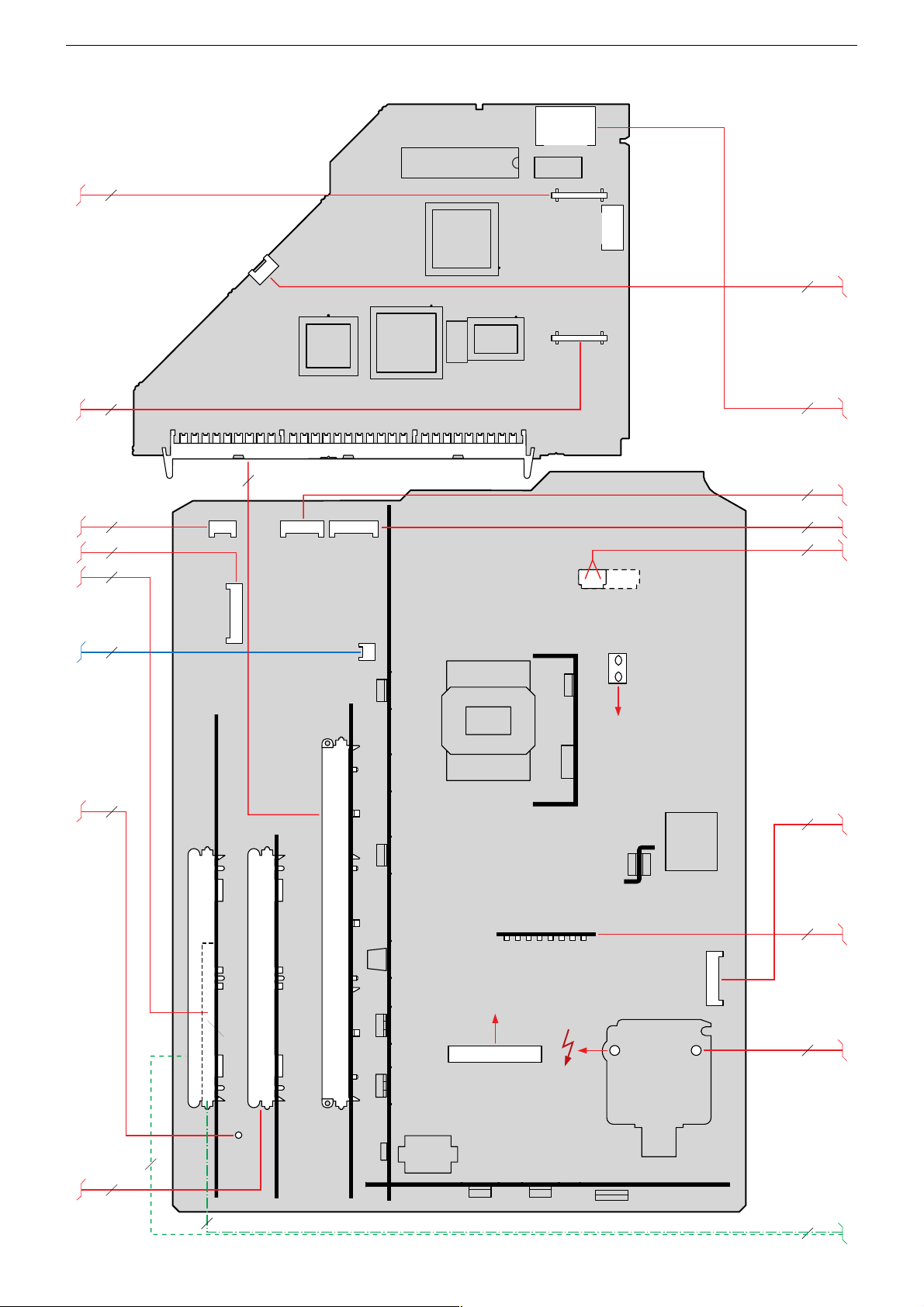
GRUNDIG Service DIGI 100
Verdrahtungsplan Teil 3 / Wiring Diagram Part 3
ST-RGB
19
19
ST-JTAG
16
2
15
1
ST-PIP1
ST-PIP2
10
1
2
9
10
ST-PRG1
FLASH PROGRAMMING
FLASH-PROGRAMIERUNG
10
3
23
9
24
1
1
2
293062312400
1
22
21
IC82021
10
CIC80000
ST_I2S_5V
13
13
14
CIC70300
Feature-Modul
Feature Module
10
295042033000
62
63
S3
CIC70250
ST70281
1
2
CIC70200
13
14
16
10
17
63
3
9
15
2
1
ST-H1
13
ST-TT1
19
43
42
DVB MODULE
DVB-MODUL
42
61
43
ST-CI1
ST-IR_KB1
17
ST+M
12
D61521 D61524
63
62
FEATUREMODULE
FEATURE-MODUL
Chassisplatte
Chassis Board
TR60500
ST1
75
ST-E
D60506
ZUR ENTMAGNETISIERUNG
TO DEMAGNETIZATION
T60506
D60521
D60519
L60528
6
25
7
26
2
27
8
28
20
8
SIGNAL-BAUSTEIN
SIGNAL MODULE
SAT/PIP-SIGNAL-BAUSTEIN
SAT/PIP SIGNAL MODULE
IC50510
T50529
DF-8
ZU DEN ABLENKSPULEN
TO DEFLECTION COILS
6 1
DF-7
DF-6
DF-5
DF-4
DF-3
DF-2
DF-1
ST-BR
81
ST-JOCH
T50528
2
2
1
1
ST-V1
293062400100
43
43
15
2
1
T52503
TR52501
SH2
SH3
SH1
D53571D53572
(OPTION)
TR53500
T53501
15 / 43
29
1
30
16
3 - 3
Page 38

GRUNDIG Service DIGI 100
Verdrahtungsplan Teil 4 / Wiring Diagram Part 4
29306-202.47/4B(03)
27
23
11
15
26
24
12
25
28
21
85
41
SCR
BEDIENTEILABDECKUNG
M
COVER OF THE
KEYBOARD
230V~
Bedienplatte / Control Board
295010856500
2
2
9
3
2
6
3
4
8
3
7
9
2
3
6
4
7
4
5
8
18
ST-BR
293047222100
18
169
IC92005
ST-DR2
21
ST-+M2
1
2
ST-M1
MODE
ST-RGB
11
12
TR1
112
21
1
6
ST-MOT1
-
+
29304-678.51/4B (02)
19
910
8
7
6
5
4
12
ST-DF1
ST-I2C_5V
31
ST-I2C_5V2
21
31
ST-MOT6
ST-I2C_5V1
41
6
3
12
4
1
S1
BU5
Bildrohrplatte
CRT Panel
293051223200
T65025
UG2
ST-NS1
41
ST-IR_KB2
71
ST-IR_KB1
51
5
43
BU11
ST-NS1
41
T65015
13
ST-GM2
54
6
TR92019
7
8
ST-CI2
ST-H1
61
31
R
D85001
ST-IR-KB1
NETZ_
3
2
1
41
58
IC92010
Buchsenplatte
Socket Board
293050085700
BU4
IC84004
D84003
G
D84004
ST-LED121ST-LED2
21
51
41
ST_DET1
78
2
3
L62501
4
1
56
NETZ2
ST-DR1
41
IC84000
D84006
LED-Platte
LED Board
293050176800
ST-IR1
31
9
16
IC84001
ST-IR2A
31
31
ST-IR2
65
1
2
S60000
SI60001
T3,15A H
SI92001
T315mA_L
8
IC93020
1
ST-DR2
IC84002
ST-MIC1
21
3
4
ST-NETZ1
IC61545
85
ST-MOT4
2121
81
ST-SM1
21
ST-SM2
13
EJECT
43
L61548
14
29304-704.60/4B(01)
29
30
8
ST2
ST1
21
ST-DF1
ST-ROT3
ZUR ROTATIONSSPULE
ST-DFB
1
TR64001
Fokussierungsplatte
Focusing Board
293047322200
IC64220
21
14
ST-UB1
TO ROTATION COIL
M
Poti-Platte / Poti Board
293051292200
29306-201.22/4B(02)
R99011
31
ST-MOT2
293047322200
DF-7
DF-8
DF-6
DF-5
DF-4
DF-3
DF-2
DF-1
DREHFUß
3
4
3 - 4
TURNING FOOT
Page 39

GRUNDIG Service DIGI 100
Verdrahtungsplan Teil 5 / Wiring Diagram Part 5
12
(OPTION)
112
ST-FTA1
IC60015
3 1
FTA-Netzteilplatte
FTA Mains Section Board
293052022200
12
12
OK60021
34
34
CIC12641
1
OK60020
IC60010
1
_CIC08201
1
CIC08301
CIC07101
1
(OPTION)
TR60010
CIC03321
1
CIC07001
1
(OPTION)
29306-102.22
ST12501
2
1
1
CIC03301
1
_CIC08601
76
77
CIC05001
152
153
42
43
10
9
8
7
6
4
1
3
1
3
2
CIC01001
29304-362.61/4B (06)
Q12601
1
CIC12601
BU05001
304
229
228
L60002
FTA-Modul
FTA Module
295041066100
1
9
10
2
1
1
1
CIC13601
5
4
3
2
1
CIC03001
CIC06100
1
CIC09701
1
ST13311
T1AH
ST-J1
230V~
(OPTION)
(OPTION)
29
1
13
CIC09601
1
SI60001
12
1
ST01001
BU04001
_ST13801
2
1
12
ST02101
111
BU13701
13
N
COMMON INTERFACE
DIGITAL OUT
SPDIF
16
18
19
16
(OPTION)
43
(OPTION)
3
31
(OPTION)
6
ST-AUX1B
ST-I2S1
61
293062320100
IC38000
TR38050
IC38030
STL
(OPTION)
15
1 11
(OPTION)
(OPTION)
(OPTION)
(OPTION)
SAT-Baustein
SAT Module
295042220200
SAT-Baustein
SAT Module
295042220200
SAT-TUNER
N
F38183
115
3 - 5
Page 40

GRUNDIG Service DIGI 100
4
V
Adapterplatte / Adapter Board 293051604500
ST_A3
ZUM SIGNAL-BAUSTEIN
TO SIGNAL MODULE
SEITE / PAGE 3-40
ZUM SIGNAL-BAUSTEIN
TO SIGNAL MODULE
SEITE / PAGE 3-41
ZUM DVD-MODUL
ZUM SIGNAL-BAUSTEIN
TO SIGNAL MODULE
SEITE / PAGE 3-39
ZUM DVD-MODUL
L-A3
IN
R-A3
IN
R-AV3
IN
L-AV3
IN
L-AV
OUT
R-AV3
OUT
VIDEO
IN-AV3
DATA
U
SAT
R
G
B
CHROMA
IN
VIDEO
IN
SPDIF
SPDIF
RxD
TxD
1
2
3
4
5
ST-AV3
1
2
3
4
5
ST-RGB-50
7
6
5
4
3
2
1
10
9
8
7
6
5
4
3
1
ST_V3
1
2
3
4
ST-SPD
2
1
10
ST-J4
9
ST-J4
4
ST-J4
5
ST-J4
1
ST-J4
GND_A
ST-J8
ST-J8
ST-J8
ST-J8
ST-J8
ST-J8
ST-J8
ST-J8
ST-J8
GND
GND_A
GND_A
MCL4148
GND
MCL4148
CD87052
CD87051
L87051
4,7u
GND_A
GND
+
C87051
47u/16V
BUS-ADAPTERPLATTE 29305-160.4500
DVD NETZTEIL
ADAPTOR BOARD
C.I. ADAPTEUR
PIASTRA ADATTATORE
PLACA ADAPTADOR
+5V
CT87005
BC858B
CR87002
CR87001
CC87052
GNDGND
1k
n.V.
CR87092
CR87093
CR87050
2,2
0,1u
0
0
CR87051
100
12
131415
11
GND_A
10
+5V/1
+5V_M
+5V/3
+5V
2,2k
CR87003
4,7k
1
2
+5V
345
CR87052
100
CIC87005
74HC4053
9
16
GND_AGND_A
CC87006
GND_A
GND
GND
n.V.
CR87058
n.V.
CR87057
+5V/3
678
GND_A
+5V
0,1u
CR87060
47
n.V.
CR87094
+5V/3
1k
CR87095
GND
1k
n.V.
470
0,1u
CR87059
3839404142 22232425262728293031323334353637
CIC87050
M38513
P2.5
P2.4
P2.3
P2.2
1k
1k
123456789101112131415161718192021
CC87054
GND
+5V/3
GND_A
GNDGNDGND
Q87055
7,38MHz
33p
100n
CC87057
CC87055
GND
CR87056
10k
CD87056
MCL4148
n.V.
+
n.V.
C87056
47u/16V
GND GND
CC87056
GNDGND
1
33p
IC87010
MC3316
3
+5
ZUR
BEDIENPLATTE
TO CONTROL BOARD
ZU / TO ST-I2C_5V1
SEITE / PAGE 3-76
CR87055
10
+5V/1
GND
CR87053
100
CR87054
100
Koordinaten für die Bauteile der Bestückungsseite (Oberseite)
Coordinates of the Components on the Components Side (Top Side)
+IR
+5V/1
4
SCL
3
2
SDA
1
ST-I2C_5V
Spannungstabelle
Table of Voltages
+80V +80V
+C +200V
+D +29V
+F +5V
+14,7V +14.7V
-14,7V -14.7V
+G +17V
+27.5V D-Amplifier (AC3)
+M +16.5V
+H + 3.3V
+K +13.6V
+16V/TOS-Real Flat-CRT
/Thomson-CRT
-K -13.6V
-16V/TOS-Real Flat-CRT
/Thomson-CRT
+N +3.3V
+Q +8.5V
+OEKO +13.5V
Pos.-Nr./ Koordinaten/
Pos. No. Coordinates
XY
BR100 45 7
BR101 45 9
BR102 48 27
BR103 61 35
BR104 27 46
BR105 28 53
C87051 111 48
C87056 88 31
C87100 47 16
C87106 41 27
C87107 54 34
C87108 33 61
C87109 33 45
C87112 44 55
C87113 55 55
C87117 44 67
Pos.-Nr./ Koordinaten/
Pos. No. Coordinates
XY
C87118 55 67
IC87010 85 20
IC87020 33 14
IC87030 18 46
IC87040 20 63
L87051 111 58
L87100 27 30
L87101 44 37
L87102 44 45
L87103 54 45
L87104 44 77
L87105 55 77
Q87055 93 20
ST-+M 64 25
Pos.-Nr./ Koordinaten/
Pos. No. Coordinates
XY
ST-+M02 64 13
ST-AV03 156 23
ST-DET01 120 69
ST-DR01 101 69
ST-DVD_M 66 56
ST-I2C_5V 86 69
ST-J04 108 5
ST-J08 141 5
ST-MOT02 121 48
ST-MOT03 156 68
ST-MOT01 139 71
ST-RGB-50 139 44
ST-S01 87 41
ST-SPD 116 18
ST_A03 156 44
ST_V03 139 22
3 - 6
Page 41

GRUNDIG Service DIGI 100
3
7
E
ST-MOT2
1
CR87080
100
CR87081
100
CR87082
CR87083
100
CR87084
100
100
010
3164
ND
+5V/3
6
+
C87108
470u/35V
M1
+M
+
C87109
470u/35V
M1 M1
+M
+
C87100
+5V/3
2
470u/35V
M1 M1
CC87115
M1
CC87110
CC87101
0,22u
0,22u
0,22u
1
CR87107
1
CR87102
CR87100
CC87102
M1 M1
CR87108
M1
CR87103
M1
20k
2,7n
1
7
CR87109
1k/1%
6
1
7
CR87104
1k/1%
5
3
2
CC87103
0,1u
IC87040
MC34063
IC87030
MC34063
IC87020
9,1k
CR87101
8
M1 M1
8
M1 M1
L4978
1
M1
CC87104
22n
1
2
345
CD87102
330p
M1
CC87116
CR87110
8,2k/1%
1
2
345
CD87101
560p
M1
CC87111
CR87105
2,7k/1%
8
4
67
CC87105
0,1u
M1 M1
L87104
100u
STPS340U
CR87111
910/1%
L87102
100u
STPS340U
CR87106
430/1%
41
CD87100
STPS340U
Bei den in den Schaltplänen angegebenen Messwerten handelt es
sich um Näherungswerte!
The measured values given in the circuit diagrams are approximates!
L87100
59u
L87105
10u
+
C87117
M1 M1
+
C87112
M1 M1
C87106
+
C87118
470u/35V
L87103
10u
+
C87113
470u/35V
L87101
10u
+
C87107
470u/35V
M1 M1 M1
+5V/3
470u/25V
470u/25V
+
+12V/DVD
+5V/DVD
CC87108
470u/25V
CR87085
CR87067
+5V/3
+5V/3
0,1u
100
100
n.V.
CR87072
10k
CR87086
100
+3,3V/DVD
CR87069
100
CR87066
100
+5V/3
GND
CR87061
CR87063
CR87090
CR87112
CR87073
10k
10k
+12V/DVD
100
1k
22k
CC87068
10n
CR87062
CR87064
+5V/DVD
GND
+5V/3
+5V/3
GND
+5V/3
10k
10k
+3,3V/DVD
M1
CC87119
n.V.
CR87065
xx
CR87075
3k3
n.V.
CR87068
xx
CR87070
0
CR87071
10k
M1
1k
0,1u
GND
CR87115
100k
+5V_M
CC87120
CT87070
BC848B
0,1u
+5V/3
+M
M1
+M
M1
GND
+5V/3
GND
GND
ST-DVD_M
ST-DVD_M
ST-DVD_M
ST-DVD_M
ST-DVD_M
ST-DVD_M
ST-DVD_M
ST-DVD_M
ST-DVD_M
ST-DVD_M
ST-DVD_M
ST-DVD_M
ST-DVD_M
ST-DVD_M
ST-DVD_M
ST-DVD_M
ST-DVD_M
ST-DVD_M
VSL18SAI
GND
ST-MOT3
ST-MOT1
ST-+M2
ST-+M
ST-DR1
ST-DET1
GND
120802
2
3
1
2
3
1
2
3
4
5
6
1
2
1
2
ST-S1
1
2
4
3
2
1
1
2
3
4
/1
/2
/3
/4
/5
/6
/7
/8
/9
/10
/11
/12
/13
/14
/15
/16
/17
/18
ZUR POTENTIOMETERPLATTE
TO POTENTIOMETER BOARD
SEITE / PAGE 3-83
limit switch top
1
2
3
limit switch bottom
+5V_M
U
UEST
ZUR BEDIENPLATTE
U
UP
TO CONTROL BOARD
U
SEITE / PAGE 3-76
DOWN
U
MOT
STOP
+3,3V
DVD-MODUL
+5V
+12V
+M
ZUR BEDIENPLATTE
TO CONTROL BOARD
SEITE / PAGE 3-76
ZUM CHASSIS
+M
TO CHASSIS
SEITE / PAGE 3-23
Zum FTA/DVD-
Zusatznetzteil
U
Over
ZUR BUCHSENPLATT
Curr
TO SOCKET BOARD
U
Dir1
SEITE / PAGE 3-80
U
Dir2
+5V_M
ZUR LED-PLATTE
IR
OUT
TO LED-BOARD
VERS C.I. LED
IR
IN
ALL PIASTRA LED
SEITE / PAGE 3-78
Koordinaten für die Bauteile der Lötseite (Unterseite)
Coordinates of the components on the Solder Side (Bottom Side)
Pos.-Nr./ Koordinaten/
Pos. No. Coordinates
XY
CBR87000 129 35
CBR87001 129 33
CBR87002 133 15
CBR87003 133 13
CBR87004 111 64
CBR87005 130 50
CBR87006 114 26
CBR87007 114 29
CBR87008 116 52
CBR87009 111 67
CBR87010 111 69
CBR87011 125 76
CBR87012 96 41
CBR87013 94 38
CBR87014 94 36
CBR87015 110 38
CBR87016 104 41
CBR87017 104 37
CBR87018 117 35
CBR87019 116 35
Pos.-Nr./ Koordinaten/
Pos. No. Coordinates
XY
CBR87020 107 36
CBR87021 114 32
CBR87022 116 29
CBR87030 96 58
CBR87031 111 71
CBR87032 95 63
CBR87033 93 57
CBR87117 91 54
CC87006 134 30
CC87052 114 48
CC87054 100 36
CC87055 91 22
CC87056 91 19
CC87057 94 25
CC87068 120 36
CC87101 33 18
CC87102 25 15
CC87103 25 13
CC87104 34 10
Pos.-Nr./ Koordinaten/
Pos. No. Coordinates
XY
CC87105 41 13
CC87108 69 45
CC87110 20 62
CC87111 25 44
CC87115 18 44
CC87116 27 61
CC87119 69 74
CC87120 69 70
CD87051 115 9
CD87052 115 11
CD87056 83 25
CD87100 28 24
CD87101 38 53
CD87102 38 69
CIC87005 127 24
CIC87050 105 26
CR87001 133 45
CR87002 129 41
Pos.-Nr./ Koordinaten/
Pos. No. Coordinates
CR87003 129 38
CR87050 127 52
CR87051 105 15
CR87052 103 15
CR87053 86 54
CR87054 88 54
CR87055 91 64
CR87056 83 23
CR87057 114 35
CR87058 110 15
CR87059 118 26
CR87060 125 5
CR87061 142 62
CR87062 145 62
CR87063 130 69
CR87064 130 67
CR87065 84 45
CR87066 84 54
CR87067 82 54
3 - 7
XY
Pos.-Nr./ Koordinaten/
Pos. No. Coordinates
XY
CR87068 93 45
CR87069 96 54
CR87070 85 43
CR87071 100 54
CR87072 98 41
CR87073 99 41
CR87075 92 42
CR87080 116 41
CR87081 114 41
CR87082 107 42
CR87083 107 40
CR87084 111 41
CR87085 98 54
CR87086 101 41
CR87090 91 38
CR87091 118 41
CR87092 96 60
CR87093 130 65
CR87094 110 36
Pos.-Nr./ Koordinaten/
Pos. No. Coordinates
XY
CR87095 119 29
CR87100 25 18
CR87101 35 13
CR87102 17 48
CR87103 19 48
CR87104 10 42
CR87105 11 46
CR87106 11 50
CR87107 22 65
CR87108 19 65
CR87109 13 59
CR87110 14 63
CR87111 14 68
CR87112 98 44
CR87115 124 52
CT87005 129 45
CT87070 101 46
Page 42

GRUNDIG Service DIGI 100
Adapterplatte / Adapter Board 293051604500
Bestückungsseite, Ansicht von oben / Component Side, Top View
31
ST-MOT3
51
ST_A3
51
ST-AV3
10 1
6
ST-MOT1
ST-RGB-50
4
ST_V3
1
71
1
ST-J8
4
ST-DET1
1
31
ST-MOT2
Durchlaufrichtung
C87051
2
ST-SPD
10 1
MI-
0
9
432
8
765
1
29304-218.09/4B (02)
4
ST-DR1
1
L87051
1
2
15
3
4
ST-J4
4
ST-I2C_5V
2
ST-S1
C87056
13
Q87055
1
1
IC87010
ST-DVD_M
1
ST-+M
1
ST-+M2
1
BR103
L87105
C87118
C87113
L87103
C87107
2
2
BR101
L87104
C87112
L87101
BR102
C87100
BR100
C87117
L87102
C87109
C87106
85
C87108
BR105
21
14
IC87020
IC87040
14
IC87030
14
BR104
43
85
L87100
80
70
60
85
50
40
30
20
10
0
Y
0102030405060708090100110120130140150160170
X
Lötseite, Ansicht von unten / Solder Side, Bottom View
80
CR87111
CR87107
70
60
29304-218.09/4LS (02)
50
40
30
20
CR87110
CR87109
CR87105
CR87104
CR87106
CC87110
CR87103
CR87102
CC87115
CR87100
CC87102
CC87103
CR87108
CC87116
CC87111
CD87100
10
0
Y
0
X
10 20 30 40 50 60 70 80 90 100 110 120 130 140 150 160 170
CC87101
CC87104
CR87101
CD87102
CD87101
CC87105
CC87120
CC87108
CC87119
CR87067
CR87065
CR87070
CD87056
CR87056
CR87066
CR87053
CBR87117
CR87054
CR87068
CR87075
CR87090
CC87055
CR87055
CBR87033
CBR87013
CBR87014
CC87057
CC87056
CBR87032
CR87092
CBR87030
CBR87012
CR87072
CC87054
1
21
CR87069
CT87070
CR87086
CR87073
CR87085
CR87071
CBR87016
CR87082
CR87083
CBR87017
CIC87050
CR87052
CR87051
CBR87015
CR87094
CBR87020
CR87058
CBR87031
CBR87010
CBR87009
CBR87004
CBR87008
CC87052
CR87057
42 22
CBR87007
CBR87006
CD87052
CD87051
CR87084
CBR87018
CBR87019
CBR87021
CBR87022
CR87059
CR87080
CR87081
CC87068
CR87095
1
CR87050
MP37
CR87091
CIC87005
CR87060
CBR87011
CT87005
CR87063
CR87064
CR87093
CBR87005
CR87002
CR87003
CBR87000
CBR87001
CR87001
CC87006
CBR87002
CBR87003
CR87061
CR87062
3 - 8
Page 43

GRUNDIG Service DIGI 100
Oszillogramme Chassis / Oscillograms Chassis
ǵ Ƕ
ǹ
ǽ
Ǻ
Ŋm
Ƿ
ǻ
Ŋɨ
Ǹ
Ǽ
Ŋ˳
Ŋu
Ŋx
˲ɨ
Ŋ{
Ŋ~
Ŋi
Ŋy
˲˳ ˲u
3 - 9
Ŋv
˲m
˲{
Page 44

GRUNDIG Service DIGI 100
˲i
˲y
Bild/Picture
˲v
Ľm
Zeile/Line
˲x
Ľɨ
Ľu Ľ{ Ľi
Zeile/Line
˲~
Ľ˳
Ľv
Bild/Picture
Ľx
Ńɨ
Ľ~
Ľy
Ń˳ Ńu
3 - 10
Ńm
Page 45
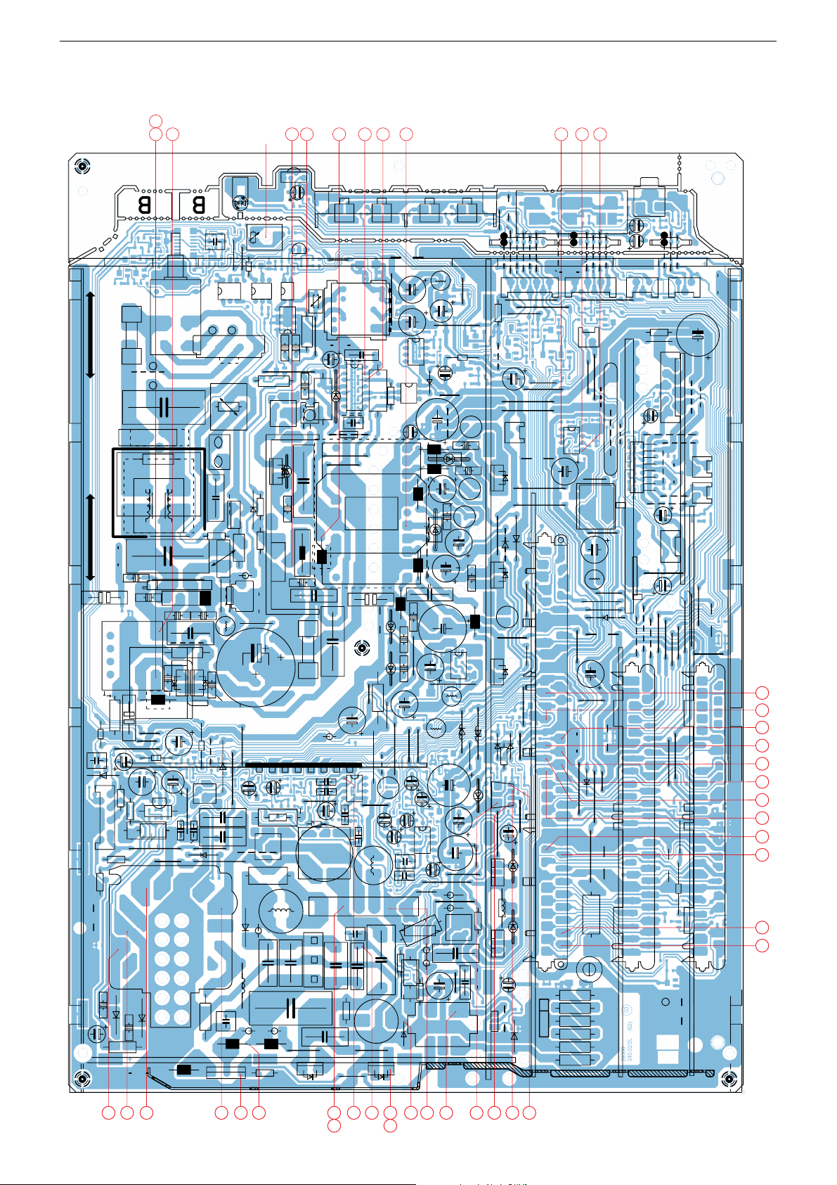
GRUNDIG Service DIGI 100
1
+A
R61508
19
30
18
27
29
22
31
17
15
16
14
35
21
13
26
28
23
24
25
20
9
10
12
11
2
7
8
6
5
3
4
32
39
38
40
36
37
43
41
42
33
34
A
BC
KL
M
D
J
E
F
G
H
Messpunkte (Chassis) / Testpoints (Chassis)
Lötseite, Ansicht von unten / Solder Side, Bottom View
3 - 11
Page 46

GRUNDIG Service DIGI 100
Messpunkte (Chassis) / Testpoints (Chassis)
Lötseite, Ansicht von unten / Solder Side, Bottom View
25
24
23
A
BC
D
E
F
G
22
19
20
2628
31
21
2729
30
13
18
17
15
M
KL
H
J
16
14
35
32 39 3840 36374341423334
3 - 12
Page 47

GRUNDIG Service DIGI 100
7 8
6
+A
R61508
3
9
10
12
11
2
1
4
5
3 - 13
Page 48

GRUNDIG Service DIGI 100
0
10
20
30
40
50
60
70
80
90
100
110
120
130
140
150
160
170
180
190
200
210
220
230
240
250
260
Y
0102030405060708090100110120130140150160170180190200210220230240250260270280290300
310320330340350360
X
C61552
1
2
3
4
56
S62501
MI-
1
2
3
4
5
6
7
8
9
0
51
2
3
4
BR62502
BR318
R60512
R52513
BR62501
D61562
31
ST-BED1
BR171
R52516
BR199
BR129
BR144
BR125
BR143
BR85512
P+
BR10003
BR10004
BR10020
BR10016
BR10013
BR10014
BR10009
BR10006
BR10010
BR10005
BR10015
C53519
C53518
C55503
C55511
C55512
C55504
BR40503
C60507
C50527
C53517
C53509
C53572
C53516
C61521
C53513
L53511
63
12
L60528
L53512
BR100
BR101
BR102
BR103
BR104
BR108
BR307
BR110
BR111
BR113
R21657
D40532
BR191
L55514
L61538
C57506
C58514
C52502
C58513
C58501
C57507
C58523
C58521
C40537
C44506
C44508
C84501
C54502
C54512
C21502
C55513
C40534
R60804
C61522
31
ST-H1
BR117
BR151
BR120
R61506
BR314
L61549
BR128
BR130
BR123
C61516
C60811
C50514
C52501
C61549
C61539
C60812
C50526
BR197
R53503
R53508
R53502
R50526
L61567
R50527
D61503
D55512
D53519
D21621
D21622
R21501
L60518
D61511
D61512
D61516
D61524
D60506
D60519
D60521
D53572
D53571
D61521
D53508
D54511
D54501
BR118
61
ST-CI2
SI61524
SI61561
SI61566
R61533
BR157
L50528
R53516
BR309
R54511
R54501
BR60514
BR173
71
ST-IR_KB1
C61514
R61508
1
11
9
7
5
3
6
4
12
13
14
15
16
17
18
19
20
21
22
TR60500
13
46
OK22505
R21511
R21513
R21514
R21512
R55514
R52507
R22506
R60513
R60506
BR159
BR136
BR137
BR138
BR139
BR141
BR142
BR300
BR146
BR148
L61562
BR193
BR194
BR195
BR192
BR58515
BR61562
BR115
BR185
BR165
BR114
C61562
2
1
ST-LSR
2
1
ST+M
ST-E
BR158
R60801
BR152
R62501
C50512
C53512
D60523
R62549
R50529
R60502
R60504
C61527
R53511
17
814
IC60510
D61561
D61566
BR168
BR61514
D50513
R58524
R50531
BR70504
BR150
BR162
C61524
C61512
C61511
C60501
C60801
C60506
C61566
C60524
C60523
C61561
C60526
C60802
C54511
C54501
C60527
C60519
C60521
C60512
C21658
R52511
1
DF-8
R52503
1
SH1
1
SH3
1
DF-3
1
SH2
1
DF-1
1
DF-2
1
DF-6
1
DF-7
1
DF-5
1
DF-4
C62548
C53511
L61566
L61514
L61511
L61521
L61561
L53502
L53503
L53501
L60507
D21512
41
58
IC61535
41
58
IC60801
41
58
IC55510
41
58
IC58510
41
58
IC61545
BR308
SI60501
SI62501
BR140
C62502
C62501
C53571
L61524
BR133
C22501
C60529
C53506
C53507
C60504
C52504
R58501
R55502
R58502
R50528
R61562
R61563
L53574
BE
T53501
BE
T50529
BE
T50528
EB
T52503
EC
T21511
R52501
R21523
BR155
R53521
R55512
R21521
R52502
D52506
1
12
TR53500
1
7
26
IC50510
13
46
87
TR52501
14
58
IC61510
R62502
L60804
L60506
BR205
65
432 1
ST-JOCH
D70504
BR10011
BU10
2
1
ST-DOT1
BR124
BR61568
SI61521
BR161
2
1
ST-LSL
BR178
BR121
BR122
C50531
R40503
C21662
NETZ2
R22504
R22501
BR135
D50532
C60518
D61568
13
46
OK60546
13
46
OK60531
43
21
OK60805
C53573
4
1
2
3
56
78
L62501
L53521
BR167
BR169
BR170
71
ST1
BR116
R60528
R60802
1
2
43
42
1
2
43
42
1
2
43
42
1
2
43
42
BU11
C40502
91
ST-TT1
BR61522
RG
D85501
13
IC84501
BR176
BR154
115
IC40510
BR60528
BR10019
BR180
D60509
6
1
ST-CI1
13
ST-H2
BR301
BR312
BR315
L-
17
ST-IR_KB2
BR204
BR305
BR166
BR127
BR40504
BR196
D60512
C60511
R61518
D61533
C61513
C61531
C61541
C61525
C61563
S
D
G
T60506
8
1
ST-BR
BR313
BR10007
BR302
BR310
BR109
1
2
63
62
C61504
C60813
C58511
L60812
+-
41
D60524
BR60515
NETZ1
ZNT1
ZNT2
C58512
KAR
IC60817
BR303
BR126
BR304
R60507
C60513
BR61567
BR179
BR177
C61517
C60528
R61586
BR132
BR317
R40592
BR200
D61563
BR187
BR40509
BR202
R60803
R50507
C61537
A1 G
A2
TC22503
D61567
R61527
BR61515
BR134
R50508
L+
BR181
P-
D60504
BR112
BR60507
R61512
BR206
R60503
BR61563
BR40501
R60806
BR163
BR40502
BR319
BR311
BR22503
SI52501
BR119
BR106
D50531
C62521
BR160
BR53511
BR320
43
21
L61548
L61537
C40532
R60508
BR316
R62503
BR149
C62549
C60509
BR145
BR53516
R40502
C58504
R21683
BR131
TR60801
BR40514
BR40518
BR40513
BR40517
BR40516
10
5
9
4
38
7
2
1
6
TR60800
ST-V1
BR21641
BR62503
C21512
C21631
BR306
31
ST-LINE
BR40507
BR153
BR105
BR40512
BR40511
R85511
R52515
31
ST-G300
R52512
R52514
(T4AL NF>2KANAL)
T2,5AL
(T4AL FINE ARTS V.)
T315mAL
(T160mAL 21"BR)
(02)
.
1
3
5
T2AL
29306-240.02/4B
()
)(
()
T2AL
)(
)(
P
SAT/DVB/PIP-MODUL
T2AL T2AL
)
)(
(
T3,15AH
))((
SIGNAL-MODUL
TV-FEATURE-MODUL
+
1
+
4
3
2
7
6.
8
5
+
+
DURCHLAUFRICHTUNG
Chassisplatte / Chassis Board
Bestückungsseite, Ansicht von oben / Component Side, Top View
3 - 14
Page 49

GRUNDIG Service DIGI 100
Chassisplatte / Chassis Board
Koordinaten für die Bauteile der Bestückungsseite (Oberseite)
Coordinates of the Components on the Components Side (Top Side)
Pos.-Nr./ Koordinaten/
Pos. No. Coordinates
XY
BR100 94 206
BR101 84 108
BR102 113 164
BR103 16 144
BR104 16 170
BR105 303 78
BR106 242 155
BR108 172 64
BR109 337 94
BR110 174 25
BR111 190 84
BR112 169 127
BR113 139 229
BR114 133 235
BR115 149 85
BR116 176 89
BR117 43 111
BR118 130 106
BR119 111 142
BR120 91 103
BR121 276 58
BR122 276 60
BR123 272 77
BR124 274 77
BR125 297 111
BR126 322 194
BR127 216 54
BR128 154 145
BR129 269 114
BR130 78 123
BR131 136 231
BR132 306 136
BR133 301 85
BR134 81 115
BR135 215 222
BR136 121 198
BR137 94 228
BR138 89 203
BR139 133 135
BR140 192 202
BR141 306 53
BR142 306 82
BR143 322 157
BR144 201 31
BR145 267 83
BR146 233 79
BR148 215 95
BR149 263 83
BR150 246 154
BR151 134 129
BR152 130 143
BR153 310 108
BR154 130 26
BR155 146 138
BR157 74 111
BR158 100 95
BR159 134 126
BR160 198 219
BR161 292 166
BR162 227 79
BR163 290 33
BR165 278 176
BR166 109 215
BR167 134 86
BR168 181 188
BR169 89 222
BR170 6 151
BR171 107 86
BR173 169 84
BR176 237 57
BR177 120 54
BR178 117 63
BR179 151 58
BR180 193 52
BR181 171 28
BR185 177 33
BR187 158 112
BR191 175 30
BR192 180 23
BR193 91 59
BR194 183 20
BR195 114 58
Pos.-Nr./ Koordinaten/
Pos. No. Coordinates
XY
BR196 186 54
BR197 169 13
BR199 324 197
BR200 134 194
BR202 127 29
BR204 190 55
BR205 99 25
BR206 188 17
BR300 89 54
BR301 88 29
BR302 137 53
BR303 183 12
BR304 239 27
BR305 317 67
BR306 28 92
BR307 183 141
BR308 8 234
BR309 189 187
BR310 342 91
BR311 313 10
BR312 177 54
BR313 68 251
BR314 31 24
BR315 323 130
BR316 44 103
BR317 245 80
BR318 289 156
BR319 135 64
BR320 207 242
BR10003 325 85
BR10004 325 93
BR10005 325 88
BR10006 325 58
BR10007 326 72
BR10009 325 83
BR10010 325 61
BR10011 325 90
BR10013 325 53
BR10014 325 56
BR10015 325 30
BR10016 325 25
BR10019 325 28
BR10020 325 80
BR21641 132 206
BR22503 227 199
BR40501 269 20
BR40502 269 55
BR40503 242 31
BR40504 269 16
BR40507 255 51
BR40509 251 25
BR40511 254 28
BR40512 231 27
BR40513 228 30
BR40514 254 48
BR40516 175 36
BR40517 179 38
BR40518 176 41
BR53511 41 194
BR53516 93 188
BR58515 127 140
BR60507 260 170
BR60514 262 151
BR60515 254 152
BR60528 174 215
BR61514 206 122
BR61515 209 122
BR61522 259 114
BR61562 139 102
BR61563 214 88
BR61567 139 109
BR61568 212 92
BR62501 229 229
BR62502 229 222
BR62503 278 230
BR70504 183 53
BR85512 285 95
BU10 346 36
BU11 345 66
C21502 128 240
C21512 120 232
Pos.-Nr./ Koordinaten/
Pos. No. Coordinates
XY
C21631 135 218
C21658 128 250
C21662 329 204
C22501 230 204
C40502 292 18
C40532 196 31
C40534 223 31
C40537 261 36
C44506 329 41
C44508 335 41
C50512 119 113
C50514 105 110
C50526 93 111
C50527 54 111
C50531 100 91
C52501 41 117
C52502 42 91
C52504 43 108
C53506 50 175
C53507 49 158
C53509 50 184
C53511 28 200
C53512 49 149
C53513 61 150
C53516 106 201
C53517 99 201
C53518 101 217
C53519 101 213
C53571 33 175
C53572 22 162
C53573 51 140
C54501 34 247
C54502 120 221
C54511 25 238
C54512 23 250
C55503 120 161
C55504 116 161
C55511 107 154
C55512 99 149
C55513 109 161
C57506 118 182
C57507 117 191
C58501 86 120
C58504 105 130
C58511 89 131
C58512 84 131
C58513 105 138
C58514 113 124
C58521 119 128
C58523 99 135
C60501 197 170
C60504 285 148
C60506 226 176
C60507 236 170
C60509 192 166
C60511 283 159
C60512 273 169
C60513 259 151
C60518 174 159
C60519 160 222
C60521 158 206
C60523 199 235
C60524 184 209
C60526 191 230
C60527 184 219
C60528 164 189
C60529 177 214
C60801 288 173
C60802 288 177
C60811 298 128
C60812 310 128
C60813 302 116
C61504 278 116
C61511 175 131
C61512 164 131
C61513 143 151
C61514 192 121
C61516 179 115
C61517 184 127
C61521 250 107
C61522 259 118
C61524 199 105
Pos.-Nr./ Koordinaten/
Pos. No. Coordinates
XY
C61525 202 115
C61527 255 129
C61531 164 121
C61537 161 59
C61539 150 131
C61541 240 69
C61549 210 57
C61552 276 88
C61561 240 106
C61562 233 116
C61563 212 110
C61566 222 115
C62501 265 224
C62502 207 223
C62521 191 247
C62548 191 144
C62549 145 238
C84501 347 173
D21512 123 247
D21621 134 90
D21622 134 95
D40532 120 61
D50513 115 102
D50531 88 89
D50532 64 89
D52506 22 89
D53508 64 192
D53519 92 209
D53571 8 167
D53572 8 140
D54501 30 242
D54511 29 233
D55512 23 131
D60504 225 190
D60506 240 180
D60509 240 176
D60512 269 158
D60519 158 218
D60521 158 210
D60523 191 215
D60524 196 219
D61503 274 121
D61511 180 136
D61512 164 136
D61516 163 94
D61521 238 94
D61524 200 94
D61533 126 201
D61561 245 114
D61562 139 102
D61563 214 88
D61566 217 119
D61567 139 109
D61568 212 92
D70504 183 53
D85501 344 194
DF-01 125 187
DF-02 125 182
DF-03 125 177
DF-04 125 172
DF-05 125 167
DF-06 125 162
DF-07 125 157
DF-08 125 152
IC40510 242 39
IC50510 115 93
IC55510 117 150
IC58510 98 124
IC60510 272 150
IC60801 299 176
IC60817 326 172
IC61510 286 127
IC61535 165 110
IC61545 252 66
IC84501 355 174
L+ 341 140
L- 341 154
L50528 71 93
L53501 9 216
Pos.-Nr./ Koordinaten/
Pos. No. Coordinates
XY
L53502 19 183
L53503 19 198
L53511 41 194
L53512 88 143
L53521 70 179
L53574 93 162
L55514 28 142
L60506 208 170
L60507 207 163
L60518 152 226
L60528 169 236
L60804 180 200
L60812 314 117
L61511 189 133
L61514 182 104
L61521 249 119
L61524 204 126
L61537 141 119
L61538 153 113
L61548 227 57
L61549 198 58
L61561 241 119
L61562 139 102
L61566 231 126
L61567 139 109
L62501 232 226
MECH01 158 222
NETZ01 294 198
NETZ02 294 205
OK22505 310 199
OK60531 270 129
OK60546 310 186
OK60805 310 176
P+ 341 107
P- 341 121
R21501 139 249
R21511 90 242
R21512 109 237
R21513 114 241
R21514 81 249
R21521 101 231
R21523 101 228
R21657 129 227
R21683 134 210
R22501 265 199
R22504 210 195
R22506 215 204
R40502 260 51
R40503 294 33
R40592 79 25
R50507 71 113
R50508 76 113
R50526 50 123
R50527 55 123
R50528 71 93
R50529 63 125
R50531 63 125
R52501 46 129
R52502 44 129
R52503 64 110
R52507 8 185
R52511 13 65
R52512 18 65
R52513 23 65
R52514 28 65
R52515 33 65
R52516 38 65
R53502 24 181
R53503 24 191
R53508 63 188
R53511 29 208
R53516 95 184
R53521 84 184
R54501 109 226
R54511 18 240
R55502 106 180
R55512 106 180
R55514 32 153
R58501 50 133
R58502 39 125
Pos.-Nr./ Koordinaten/
Pos. No. Coordinates
XY
R58524 104 165
R60502 268 163
R60503 213 187
R60504 271 141
R60506 226 187
R60507 263 168
R60508 263 178
R60512 254 152
R60513 269 136
R60528 170 215
R60801 294 169
R60802 306 165
R60803 200 192
R60804 192 199
R60806 275 182
R61506 284 108
R61508 331 185
R61512 138 160
R61518 152 141
R61527 69 59
R61533 116 208
R61562 130 93
R61563 66 102
R61586 319 191
R62501 245 226
R62502 206 201
R62503 253 230
R62549 146 243
R85511 301 95
S01 107 15
S02 107 43
S03 132 77
S62501 309 219
SH01 44 166
SH02 59 166
SH03 51 166
SI52501 118 137
SI60501 171 168
SI61521 257 105
SI61524 184 91
SI61561 233 106
SI61566 222 108
SI62501 293 237
ST+M 255 88
ST-BED01 311 39
ST-BR 106 247
ST-CI01 311 59
ST-CI02 328 59
ST-DOT01 292 60
ST-E 247 202
ST-G300 192 195
ST-H01 311 23
ST-H02 328 28
ST-IR_KB02 32 9 85
ST-IR_KB01 31 1 83
ST-JOCH 72 147
ST-LINE 211 28
ST-LSL 242 16
ST-LSR 232 16
ST-TT01 272 28
ST-V01 35 30
ST01 287 199
T21511 112 226
T50528 58 95
T50529 85 95
T52503 28 96
T53501 8 200
T60506 219 174
TC22503 223 197
TR52501 26 116
TR53500 56 220
TR60500 224 144
TR60800 302 150
TR60801 303 148
ZNT01 281 228
ZNT02 273 228
3 - 15
Page 50

GRUNDIG Service DIGI 100
7
0
8
7
0
8
C61537
2
A
Chassisplatte / Chassis Board
Bestückungsseite, Ansicht von oben / Component Side, Top View
13
IC84501
BR310
BR109
C21662
BR199
BR126
RG
D85501
R61508
C84501
L-
L+P-
P+
ST-IR_KB2
BR10011
BU11
BR10003
17
ST-CI2
BR10014
C44506
C44508
BU10
BR10019
BR10016
ST-H2
56
13
46
OK22505
13
OK60546
46
OK60805
R60801
10
R60802
IC60801
41
43
58
R61586
21
KAR
IC60817
4
BR143
BR315
C60812
3
1
3
5
38
2
1
BR132
L60812
BR153
C60813
BR10004
BR10005
BR10009
ST-IR_KB1
71
BR305
BR10020
BR10007
BR142
1
BR10010
BR141
ST-CI1
BR10006
61
BR10013
BR10015
13
31
31
6
ST-BED1
ST-H1
BR311
SI62501
T3,15AH
3
1
NETZ2
NETZ1
7
6
2
76.8
594
TR60801
BR125
R85511
BR133
BR105
2
BR163
R40503
DURCHLAUFRICHTUNG
C62501
BR62503
4
ZNT1
ZNT2
S62501
2
ST1
R22501
BR165
71
R60806
C60802
C60801
.
TR60800
C60811
BR161
BR318
17
C60504
5
R60504
58
14
IC61510
C61504
R61506
(T4AL NF>2KANAL)
BR85512
C61552
ST-DOT1
1
R40502
ST-TT1
91
BR40501
BR40504
C40502
R60502
C60511
IC60510
D61503
C61522
BR124
BR123
R60508
C60512
13
BR129
SI61521
BR145
BR40514
C40537
814
46
R60513
C61527
OK60531
BR61522
T2AL
BR122
BR121
R62503
BR60507
D60512
C60513
BR60514
2
BR149
IC61545
BR40502
BR40511
ST-LSL
R60507
BR60515
R60512
C61521
1
BR320
R62501
ST-E
D60506
D60509
BR150
11
121314
L61521
D61561
C61561
ST+M
58
41
BR40507
D61521
C22501
BR22503
D60504
R60506
BR106
9
L61561
C61562
SI61561
BR317
C61541
BR176
L62501
56
4
1
BR62501
BR62502
2
A1 G
TC22503
C60506
15
D61566
T2AL T2AL
BR135
3
78
R62502
R22506
R22504
A2
R60503
G
T60506
L60506
C60507
TR60500
L60507
7
536
4
1617181920
L61524
L61566
BR61515
BR61514
C61566
SI61566
BR61568
BR148
D61568
BR61563
D61563
C61563
)(
)(
BR146
BR162
L61548
21
43
62
C61549
BR127
IC40510
BR40513
1
C40534
ST-LINE
31
115
BR40503
BR40509
BR304
BR40512
1
ST-LSR
2
2
C60523
D60524
R60803
ST-G300
C60501
D
21
C61525
C61524
(T4AL FINE ARTS V.)
63
L61549
1
BR144
BR206
41
BR160
C62502
+
BR309
S
1
22
C61514
SI61524
BR194
C62521
+
+-
D60523
BR140
C60509
L61511
D61524
T2,5AL
BR111
BR204
BR180
BR40517
BR40516
BR185
C40532
BR192
C60526
+
C60524
31
C62548
C61517
L61514
BR196
BR110
6
1
C60527
C60529
R60804
L60804
BR168
C60518
)(
D70504
BR70504
BR40518
BR303
BR6052
SI605
T2
BR30
D61511
C61511
BR11
BR1
BR10
L6
C61516
BR116
BR312
BR197
3 - 16
1
180190200210220230240250260270280290300310320330340350360
Page 51

GRUNDIG Service DIGI 100
C61516
BR197
BR116
BR312
260
L60528
528
0501
2AL
307
1
11
112
IC61535
R173
108
C61537
C60519
D60521
R60528
R61518
D61512
D61516
58
41
43
43
3
2
BR128
C61512
C61531
P
L60518
C61539
L61537
L61538
BR187
BR115
R21501
D60519
C60521
C60528
BR155
D61567
D61562
D21622
D21621
BR179
C62549
C21631
D61533
BR200
C61513
BR118
R61562
C21658
D21512
R62549
C21502
BR131
BR113
BR114
R21657
R21683
BR21641
BR136
DF-1
1
DF-2
1
DF-3
1
DF-4
1
DF-5
1
DF-6
DF-7
DF-8
BR152
BR58515
BR139
BR151
BR159
L61562
BR61562
C50512
)
BR167
1
1
1
IC50510
R61512
L61567
BR61567
(
)(
))((
BR319
BR302
ST-BR
1
R21513
C21512
T21511
EC
C54502
R61533
C57507
C57506
BR102
C55503
C55504
C55513
58
IC55510
41
SI52501
T315mAL
(T160mAL 21"BR)
C58521
26
1 7
BR171
BR178
D40532
BR177
R21512
R54501
BR166
C53516
R55502
R55512
R58524
C55511
BR119
C58513
C58514
C50514
D50513
BR158
BR195
C53518
BR53516
L53574
C55512
L53512
C58504
+
8
R21514
R21521
R21511
BR137
R21523
BR169
C53519
BR100
D53519
BR138
C53517
R53516
C58523
C58511
58
IC58510
41
C50526
BR120
BE
C50531
D50531
TV-FEATURE-MODUL
BR193
BR300
R53521
ST-JOCH
C58512
C58501
BR134
BR101
T50529
R53508
C53507
65432 1
BR130
R50531
BR157
R50507
R50508
R52503
R50528
D50532
L50528
()
R61527
BR313
D53508
L53511
C53509
BR53511
()
C53506
SH2
1
L53521
C53513
C53573
R50529
R50527
R61563
BE
SH3
1
C50527
T50528
1
2
0
9
4
8
7
1
1
SH1
1
R52501
R58502
C52501
R50526
BR117
C52502
1
2
51
2
3
5
6
R58501
12
C52504
3
4
C54501
C54511
1
D54511
R55514
C53512
R52502
BR316
BR306
R52516
C54512
D54501
R54511
TR53500
R53511
C53511
C53571
R53503
R53502
BR104
L55514
BR103
D55512
13
87
46
EB
T52503
D52506
MI-
R52513
R52515
R52514
R52512
250
240
BR308
230
220
L53501
210
200
T53501
BE
R52507
L53502 L53503
C53572
TR52501
R52511
BR170
D53572 D53571
190
180
170
160
150
140
130
120
110
100
90
80
70
60
50
BR191
BR181
42
42
BR202
BR154
43
43
42
42
BR301
BR205
SIGNAL-MODUL
R40592
SAT/DVB/PIP-MODUL
2
2
ST-V1
1
1
2
2
(02)29306-240.02/4B
BR314
40
30
20
10
0
Y
0102030405060708090100110120130140150160170
X
3 - 17
Page 52

GRUNDIG Service DIGI 100
0
0
10
20
30
40
50
60
70
80
90
100
110
120
130
140
150
160
170
180
190
200
210
220
230
240
250
260
10 20 30 40 50 60 70 80 90 100 110 120 130 140 150 160 170 180 190 200 210 220 230 240 250 260 270 280 290 300
310 320 330 340 350 360
Y
X
CC40507
CC44501
CD61538
CC40506
CC21639
CR57508
CR57503
CR57507
CC50502
CR61587
CR21686
CR21688
CR21687
CR61509
CR61532
CR21689
CR60515
CR60546
CR60516
CR61503
CR60814
CR60816
CR40521
CR21631
CR21656
CT40591
CR50529
CR55511
CR50504
CC50504
CR58521
CR21506
CR21503
CR21626
CR58522
CR57501
CR55507
CR50503
CR58524
CR58514
CR58512
CR58511
CR55516
CR58507
CR55504
CR58513
CR21654
CR21627
CR21653
CR21652
CR21651
CR21638
CR21637
CR21633
CR21636
CR21632
CR40594
CR21662
CR55506
CR57506
CR57502
CR61504
CR55503
CR61507
CR61505
CR61502
CR61547
CR61548
CR61546
CT21688
CR61536
CR83501
CR70504
CR60531
CR85533
CR40537
CR85526
CR85523
CR40541
CR40536
CR40529
CR40532
CC40593
CT85521
CR85532
CR21678
CR40528
CR40533
CR44513
CR84502
CR83502
CR50501
CR44515
CR83503
CR83504
CR84501
CR44514
CC40595
CR44503
CR44504
CR44507
CR60817
CR50531
CT21686
CR40591
CR40593
CD60812
CBR117
CC61553
CR60819
CBR119
CT60821
CC40597
CD57503
CD21666
CR60822
CR40501
CBR110
CR40524
CC40598
CC40582
CR40582
CC40583
CR60807
CR60821
CR85542
CR85541
CBR101
CC60514
CBR104
CBR106
CBR108
CR61551
CBR113
CC21503
CBR115
CBR103
CBR116
CD61528
CD55503
CD58507
CD70501
CD57506
CD85513
CR22507
CT21682
CR21682
CBR102
CT57506
CD60547
CR60547
CT61585
CT21640
CT21658
CT58512
CT21650
CT44515
CT40531
CT21635
CR85524
CC84502
CC61508
CC61523
CT60806
CC61587
CC60516
CC60515
CC60546
CC60803
CC61529
CC60815
CC52503
CC50511
CC50523
CR50502
CR85521
CC21656
CC21661
CC50524
CC21506
CC61543
CC61547
CC61548
CC61542
CC60532
CC58524
CC50501
CC61501
CR85527
CC40513
CC40514
CT85526
CC50513
CR85522
CC40541
CC44513
CC44512
CC44504
CC44503
CC44502
CC44507
CC85511
CC44515
CC40504
CR60532
CBR112
CBR105
CD57501
CR44502
CR21681
CT85537
CBR111
CC85512
CC61546
CC21652
1
CIC21660
CR61552
CR21677
CR21676
CR21668
CC21672
CC21671
CR21666
CT21670
CR21679
CR21659
CC21663
CIC85512
CC40584
CR61501
CR61549
CR60818
CR21667
CC61502
CR21673
CD21506
CR61589
CR60513
CR21639
CR21672
CC60814
CC61526
CR61542
CT85527
CC61532
CR61538
CR58504
CR40586
CD21642
CR21502
CR21621
CD57504
CD21502
CD21501
CD21503
CD58501
CD58522
CD58521
CD58511
CD58504
CD58512
CD55504
CD53519
CD21657
CD21656
CD21636
CD52503
CD60811
CD40536
CD21639
CBR118
CC21628
CR54512
CR60813
CR60812
CT61551
CD61548
CC61536
CR40538
CR40539
CR61537
CC84503
CC60510
CR61531
CC60501
CC21673
CD52507
CC40594
CC40596
CC40586
CR40534
CR21622
CR21641
CL60504
CC60816
CC40503
CR85536
CR85537
CR85529
CT85531
CR85531
CR85534
CT85536
CBR109
(01)
29306-240.02/4LS
Chassisplatte / Chassis Board
Lötseite, Ansicht von unten / Solder Side, Bottom View
3 - 18
Page 53

GRUNDIG Service DIGI 100
Chassisplatte / Chassis Board
Koordinaten für die Bauteile der Lötseite (Unterseite)
Coordinates of the components on the Solder Side (Bottom Side)
Pos.-Nr./ Koordinaten/
Pos. No. Coordinates
XY
CBR101 285 98
CBR102 121 175
CBR103 123 191
CBR104 128 133
CBR105 182 9
CBR106 118 139
CBR108 89 120
CBR109 287 83
CBR110 322 197
CBR111 74 25
CBR112 276 69
CBR113 51 31
CBR115 147 135
CBR116 144 123
CBR117 170 110
CBR118 257 52
CBR119 317 208
CC21503 109 224
CC21506 106 224
CC21628 125 214
CC21639 142 89
CC21652 130 119
CC21656 116 119
CC21661 331 207
CC21663 326 203
CC21671 323 203
CC21672 320 208
CC21673 326 234
CC40503 246 28
CC40504 233 30
CC40506 252 43
CC40507 245 43
CC40513 233 43
CC40514 239 43
CC40541 176 9
CC40582 42 78
CC40583 186 80
CC40584 135 88
CC40586 136 52
CC40593 51 9
CC40594 65 9
CC40595 99 7
CC40596 104 7
CC40597 109 9
CC40598 129 7
CC44501 337 29
CC44502 337 33
CC44503 338 24
CC44504 342 46
CC44507 336 61
CC44512 299 58
CC44513 305 58
Pos.-Nr./ Koordinaten/
Pos. No. Coordinates
XY
CC44515 302 53
CC50501 116 86
CC50502 108 90
CC50504 122 86
CC50511 125 97
CC50513 116 101
CC50523 122 91
CC50524 122 97
CC52503 32 87
CC58524 121 121
CC60501 192 169
CC60510 283 153
CC60514 271 150
CC60515 276 150
CC60516 283 148
CC60532 267 150
CC60546 270 158
CC60803 294 176
CC60814 314 144
CC60815 322 175
CC60816 305 135
CC61501 288 118
CC61502 294 125
CC61508 288 126
CC61523 252 122
CC61526 258 125
CC61529 47 28
CC61532 163 110
CC61536 166 110
CC61542 251 66
CC61543 249 58
CC61546 253 58
CC61547 259 65
CC61548 247 66
CC61553 274 101
CC61587 318 180
CC84502 345 46
CC84503 351 173
CC85511 290 99
CC85512 296 107
CD21501 117 226
CD21502 130 242
CD21503 123 232
CD21506 95 228
CD21636 128 216
CD21639 145 88
CD21642 149 84
CD21656 114 132
CD21657 108 134
CD21666 320 203
CD40536 221 14
CD52503 24 89
Pos.-Nr./ Koordinaten/
Pos. No. Coordinates
XY
CD52507 42 65
CD53519 83 204
CD55503 119 169
CD55504 113 164
CD57501 110 169
CD57503 115 181
CD57504 121 186
CD57506 110 181
CD58501 81 118
CD58504 87 113
CD58507 86 129
CD58511 92 132
CD58512 95 132
CD58521 111 132
CD58522 102 133
CD60547 303 185
CD60811 301 135
CD60812 320 145
CD61528 42 28
CD61538 154 124
CD61548 230 69
CD70501 35 103
CD85513 294 98
CIC21660 328 216
CIC85512 290 106
CL60504 274 158
CR21502 123 237
CR21503 109 229
CR21506 106 229
CR21621 133 83
CR21622 136 80
CR21626 142 94
CR21627 139 98
CR21631 132 221
CR21632 122 214
CR21633 129 226
CR21636 127 221
CR21637 129 202
CR21638 142 81
CR21639 145 93
CR21641 124 205
CR21651 127 113
CR21652 124 117
CR21653 127 118
CR21654 127 122
CR21656 135 151
CR21659 118 252
CR21662 332 201
CR21666 326 198
CR21667 323 208
CR21668 320 213
Pos.-Nr./ Koordinaten/
Pos. No. Coordinates
XY
CR21672 326 208
CR21673 333 227
CR21676 325 224
CR21677 325 229
CR21678 330 235
CR21679 330 231
CR21681 322 232
CR21682 322 228
CR21686 313 232
CR21687 319 228
CR21688 313 242
CR21689 313 237
CR22507 313 206
CR40501 193 43
CR40521 249 43
CR40524 236 43
CR40528 201 32
CR40529 199 32
CR40531 148 64
CR40532 270 33
CR40533 144 64
CR40534 255 43
CR40536 221 19
CR40537 223 14
CR40538 228 30
CR40539 242 43
CR40541 173 9
CR40582 42 74
CR40586 139 52
CR40591 66 29
CR40593 112 26
CR40594 109 26
CR44502 334 33
CR44503 335 24
CR44504 339 46
CR44507 338 61
CR44513 299 63
CR44514 303 63
CR44515 301 58
CR50501 109 85
CR50502 107 85
CR50503 125 88
CR50504 118 86
CR50529 81 138
CR50531 100 93
CR54512 57 249
CR55503 116 168
CR55504 106 163
CR55506 116 150
CR55507 105 158
CR55511 105 149
CR55516 122 150
Pos.-Nr./ Koordinaten/
Pos. No. Coordinates
XY
CR57501 110 175
CR57502 113 175
CR57503 118 195
CR57506 118 175
CR57507 121 195
CR57508 116 174
CR58504 91 121
CR58507 99 124
CR58511 81 132
CR58512 78 135
CR58513 102 124
CR58514 105 120
CR58521 113 127
CR58522 108 129
CR58524 124 121
CR60513 264 150
CR60515 274 150
CR60516 279 150
CR60531 268 141
CR60532 186 239
CR60546 297 184
CR60547 301 185
CR60807 276 184
CR60812 319 165
CR60813 319 170
CR60814 322 170
CR60816 316 175
CR60817 319 175
CR60818 322 165
CR60819 299 119
CR60821 299 113
CR60822 308 108
CR61501 294 120
CR61502 291 118
CR61503 285 118
CR61504 282 118
CR61505 332 175
CR61507 335 194
CR61509 285 126
CR61531 169 118
CR61532 165 118
CR61536 159 108
CR61537 157 111
CR61538 157 116
CR61542 245 63
CR61546 256 67
CR61547 259 69
CR61548 260 55
CR61549 260 60
CR61551 274 107
CR61552 277 101
CR61587 332 196
Pos.-Nr./ Koordinaten/
Pos. No. Coordinates
XY
CR61589 321 180
CR70504 45 129
CR83501 339 114
CR83502 339 131
CR83503 339 147
CR83504 345 169
CR84501 345 174
CR84502 342 173
CR85521 279 74
CR85522 281 69
CR85523 292 78
CR85524 290 70
CR85526 294 78
CR85527 299 73
CR85529 306 79
CR85531 282 83
CR85532 285 83
CR85533 294 83
CR85534 290 83
CR85536 292 83
CR85537 297 83
CR85541 307 32
CR85542 315 45
CT21635 130 211
CT21640 124 199
CT21650 131 114
CT21658 125 248
CT21670 329 225
CT21682 322 238
CT21686 317 233
CT21688 317 240
CT40531 266 35
CT40591 65 23
CT44515 297 52
CT57506 114 187
CT58512 108 119
CT60806 279 179
CT60821 308 115
CT61551 279 109
CT61585 319 185
CT85521 285 76
CT85526 294 73
CT85527 285 69
CT85531 290 90
CT85536 296 88
CT85537 285 90
3 - 19
Page 54

GRUNDIG Service DIGI 100
8
Chassisplatte / Chassis Board
Lötseite, Ansicht von unten / Solder Side, Bottom View
260
250
240
230
220
210
200
190
180
170
160
150
140
130
120
110
100
90
80
70
60
CD52503
CD70501
CC52503
CC40582
CR40582
CD52507
CR54512
CR70504
CR50529
CR58512
CR58511
CD58501
CD58504
CD53519
CD58507
CBR108
CD21506
CR55504
CR55507
CR55511
CD58512
CD58511
CR58504
CR50531
CT57506
CD57506
CR57501
CD57501
CD58522
CR58507
CR58513
CR58514
CR21659
CR21503
CR21506
CC21503
CC21506
CR21632
CR57503
CD21657
CD58521
CR58522
CT58512
CC50502
CC50523
CR50501
CR50502
CD21501
CR21636
CR21641
CR57507
CD57503
CR57506
CR57502
CR57508
CR55503
CD55504
CR55506
CD21656
CR58521
CC21656
CC50513
CR50504
CC50501
CT21658
CC21628
CBR103
CD57504
CBR102
CD55503
CR55516
CBR106
CR58524
CC58524
CR21652
CC50524
CR50503
CC50504
CR21502
CD21503
CR21633
CD21636
CR21637
CT21640
CBR104
CR21654
CR21653
CC21652
CR21651
CT21650
CR21627
CC50511
CR21626
CC40584
CR21621
CD21502
CR21631
CT21635
CR21656
CC21639
CR21622
CR40533
CBR115
CBR116
CR61538
CR61537
CR21639
CD21639
CR21638
CD61538
CR61536
CD21642
CR61532
CC61532
CC61536
CR61531
CBR117
50
CBR113
CD61528
40
(01)29306-240.02/4LS
30
20
10
0
Y
0
X
10 20 30 40 50 60 70 80 90 100 110 120 130 140 150 160 170 1
CC61529
CC40593
CR40591
CT40591
CC40594
CBR111
CR40594
CC40595
CC40596
CR40593
CC40597
CC40586
CC40598
CR40586
CR40541
CC40541
3 - 20
Page 55

GRUNDIG Service DIGI 100
CT21688
CT21682
CR21681
CR21682
CR21676
CR21667
CC21671
CT61585
CR60818
CR60812
CC21673
CR21678
CR21677
CR21672
CR21662
CC21663
CR21666
CR61589
CC60815
CR60814
CR21679
CR21673
CT21670
1
CC21661
CR61587
CR61507
CR61505
CR84502
CR83504CR84501
CC84503
CR60532
CC60501
CR60807
CT60806
CC60546
CR60513
CC60532
CL60504
CR60516
CC60515
CC60803
CC60510
CR21688
CR21689
CR21686
CR22507
CD60547
CR60547
CR60546
CT21686
CR21687
CIC21660
CR21668
CC21672
CBR119
CD21666
CC61587
CR60816
CR60817
CR60813
CBR110
CC40583
CBR105
CR40501
CR40529
CR40528
CR40536
CD40536
CD61548
CR40538
CC40513
CC40504
CR40537
CC61523
CR61542
CR40524
CC40514
CR40539
CC61548
CC61542
CC61543
CC40507
CR40521
CC40503
CR61546
CC61546
CC40506
CR40534
CC61526
CR61551
CR61547
CC61547
CR61549
CR61548
CBR118
CC60514
CR60531
CR61504
CC61553
CR85531
CR85521
CBR112
CT40531
CR40532
CR60515
CT61551
CR61552
CT85537
CR85532
CT85521
CC60516
CR61509
CR61503
CC61501
CC85511
CBR101
CR85536
CBR109
CR85534
CR85522
CT85527
CT44515
CC61508
CD60811
CR61502
CR60821
CIC85512
CT85531
CR85523
CT85526
CR85524
CC44512
CC61502
CR61501
CR60819
CC85512
CD85513
CT85536
CR85537
CR85533
CR85526
CR44513
CC60816
CR60822
CR85527
CR44514
CR44515
CC44515
CR85542
CC60814
CT60821
CR85529
CC44513
CR85541
CD60812
CR44504
CR44502
CR44503
CR83503
CR83502
CR83501
CR44507
CC44507
CC44504
CC44502
CC44501
CC44503
CC84502
180 190 200 210 220 230 240 250 260 270 280 290 300 310 320 330 340 350 360
3 - 21
Page 56

GRUNDIG Service DIGI 100
0,1u/M
K
1n
C60527
n.v.
100k
R2250
!
T3,15AH
SI62501
F
C62501
0,47u/MP3/250V_AC
NTC4,7
R62502
BR2250
n.v.
n.v.
0,1u
CC60803
180k
R60801
1
2
ST-E
100k
CR60532
BR60514
P
56k
CR60516
EN
D
BP
1
23
4
5
78
TNY264
IC60801
13
B380C1500
D60523
1n
CC60546
1n
CC60532
4,7n
CC60516
18k
CR60546
1,8k
CR60531
P
K
C60802
1n
1
3
5
7
ST1
P
P
M
P
P
P
P
P
P
P
+
C60528
150u/450V
F
/FKP1/1250V
C60518
F
0,47u/MP3/250V_AC
C62502
!
T2AL
SI60501
STTA806DI
D60521
STTA806DI
D60519
29201-711.9700
L60528
BR60528
K
100p/2kV
C60521
K
1n
C60526
K
100p/2kV
C60519
K
1n
C60523
K
1n
C60524
K
C60801
47p/2kV
U
S07K385
R60802
NETZ1
NETZ2
ON-TIME
OFF-TIME
STAND-BY
PVC/
COMPERATOR
COMPERATOR
1
5
11
TDA16
IC605
3M/2%
R60502
680k
R60528
56k
CR60807
BC858C
CT60806
8
5
2
4
6
7
T
29
n.v.
5
67
8
1
23
4
29500-835.97
L62501
3
1
ST-G300
1
R60804
n.v.
MP176
F
C60529
0,1u/MP3/250V_AC
0,6u
L60518
68
R60803
P
1
2
3
4
FBI3,7LM1FAG
D60524
n.v.
1M
R62501
S62501
K
1n/400V_AC
C62521
P
U
8311-402-27500
R62503
BR62503
2,2M
R60806
BR62502
BR62501
ZNT1
ZNT2
470u
L60804
n.v.
n.v.
56
7
8
9
1
3
**
TR60800
M
M
PA
PA
P
PP
P
PPP
P
*
OPTION N1
*
*
*
6
8
7
9
ENTMAGNETISIERUNG
TO CONTROL BOARD
ZUR BEDIENPLATTE
P
MASA PRIMARIA / SECTOUR DE COM
MASSA PRIMARIO / CIRCUITO NON S
PRIMARY CHASSIS, NOTE / CIRCUT
MASSE PRIMAIRE / CIRCUIT NON ISO
PRIMAERMASSE / NICHT NETZGETR
ZUR FTA-NETZTEILPLATTE
TO FTA MAINS SECTION BOARD
ZU / TO ST-J1
SEITE / PAGE 3-106
ZU / TO NETZ_/NETZ2
SEITE / PAGE 3-76
Netz-Chassis / Mains Chassis
R50507/R50508
R52511/512
R52513/14
R52515/16
TR60500 SUBWOOF
R61562/R61563
L61562/L61567
D61562/D61567
BR61563/BR61568
D61563/D61568
BR62501/02/03
FOKUS BLOCK
S-KORREKTUR
Bildroehre
Cinescopio
*
PHI
Picture tube
BL-D 70cm
4:3
A66EAK071X44
8300-
030-436
CHASSIS
+A
CR21506
R21514
R21521
R21523
135V
68k
4,7
-016
1,5/1%
C50512
CC50513
C50526
R50526
R50527
C50527
R50529
R50531
R52501
TR52501
SI52501
R52502
TR53500
C53506
C53507
1000u/25V
1000u/25V
1,5
0,1u
270
8,2
6-867.97
15
15
13
-680.04
0,41u
0,41u
BR53516
R53521 390 390 390
L53521
C53571
C53573
L53574
CR54512
R55502 1,8k/2%
CD55503
CR55507 82k
R58502
CR58504
C58511
CR58511
CR58512
X
390
-122.97
12n
0,47u
-859.64
0
4,3V/2%
3,6k/2%
13k/2%
0,47/5%
1,2k/2%
1,5k/2%
BR58515
AC3/DD
R60504
C60518 10n
CR61501
CC61502
CR61507
D70504
BR70504
1M/2% 1M/2% 1M/2%
20R60512
68k
47n
82kCR61505
3,3k
3,3nCC61508
4,7u/350V 4,7u/350V 4,7u/350VC61513
X
470 470
47u 47u
XX
OPTION A
OPTION B
X
TOSH TOSH
RF 82cm V2 RF 82cm V2
16:9
16:9 FAV 16:9
W76LTL350X97 W76LTL350X97
076-360 076-360
CUC1935 A CUC1935 ACUC1837 A
123V 123V
68k 68k
2,7/1W 2,7/1W
-018 -018 -018R22501
2,4/1% 2,4/1%
1000u/25V 1000u/25V
1000u/25V 1000u/25V
T315mA_L T315mA_L T315mA_LT315mA_L
2,7 2,7
0,1u 0,1u
150 150
4,7 4,7 4,7
-867.97 -867.97 -867.97
13 13
12 12
12 12
-680.08 -680.08
0,25u 0,25u 0,25u
0,25u 0,25u 0,25u
6,8/7W 6,8/7W 6,8/7WR53516
-122.97 -122.97
13n 13n
20n 20n 20n20nC53572
0,68u 0,68u 0,68u
-859.66 -859.66 -859.66
2,2k/2% 2,2k/2%
4,3V/2% 4,3V/2% 4,3V/2%
22n 22n22nC55504
39k 39k
3,9k/2% 3,9k/2%
15k/2% 15k/2%
0,47u/5% 0,47u/5%
1,2k/2% 1,2k/2% 1,2k/2%
2,2k/2% 2,2k/2%
XXX
3,3 3,3
4,7n 4,7n 4,7n
10n/5% 10n/5%
68k 68k
10k 10k
47k47k
T2,5A_L T2,5A_LT2,5A_LSI61524
XXX
1,2k 1,2k
1N4004 1N4004
1N4004 1N4004
T4A_L
XXX
RF 82cm MK2
W76ERF342X044
066-342
CUC 1935 A
6,8/1W
2,2/1%
22000u/25V
22000u/25V
0,22u
-680.03
-122.95
2,2/2%
0,15u
3,6k/2%
12k/2%
0,56u/5%
1,2k/2%
581.97-596.97-596.97-580.97TR60500
1M/2%
4,7n/5%
22u/350V
BR53511
4,7u 4,7u10uL53511
OPTION C
OPTION E
OPTION N1
DYN.-FOK.
BR-PL.
X
X
29305-122.31
XX
XXX
XX
-025.51 -025.51
122.32 122.32
-025.50
122.34
PHI
142V
100k
1,5
270
12
12
11
12n
150k
20
39k
82k
15k
10u
X
X
3 - 22
Page 57

GRUNDIG Service DIGI 100
BR60514
A
R
R
N
S
E
A
L
TR60801
29201-632.97
M
OK60805
SFH615A-2
4
M
P
R
R
60510
16846/2
.v.
22503
2504
00k
,1u/MKS4-R/250V_AC
ETRENNTES SCHALTUNGSTEIL
UT NOT MAINS ISOLATED
N ISOLE DU SECTEUR
ON SEPAR., DALA RETE
COM. NO SEP. DE LA RED
P
n.v.
C60501
6789
P
BTB08-600CW
C22501
P
LOGIK
SYNC
10 12
P
56k
F
C60513
CR60513
P
270p/FKP2
CR60547
0
n.v.
CD60547
MCL4148
TC22503
G
A2A1
8311-200
F
K
CC60814
220p/630V
CD60812
STPS340U
CC60816
**
n.v.
1
23
1n
R60504
CC60501
10n/630V
P
2
UB
ERROR
4
P
3,3n
CC60514
P
5
42
5
42
CR60816
CR60817
TS431
IC60817
*
1
13
8104-982-331
14
3
OK60531
CN17F1
OK60546
CC60815
M
CL60504
4
CN17F1
C60812
39
10k
0,1u
Ref
C60504
F
390p/2%
CC60510
CR60515
1
D61503
ZD10V/2%
1
P
P
P
OK22505
R22506
220
R22501
*
IL4216
6
1
2
345
+
D60504
1N4148
R60506
0,1u
8,2k
+M
R61586
270
CD60811
BAV302
L60812
10u
470u/25V
n.v.
P
n.v.
10
2
P
+
C60511
P
CC60515
P
+A
CC61501
CR61502
CR22507
220
CR60813
T60506
2SK2699
G
2,2k
R60503
270p/2kV
47u/40V
22p
CR61507
22n
1k
+H
+OEKO
+
C60813
/14V
470u/10V
+
C60811
M
CR60818
470u/25V
15k/1%
MM
M
MM
xx
8,2k/1%
CR60814
470
CR60812
R62549
2,7M
K
C62549
M
P
R60507
XX
BR60507
n.v.
D
C60512
K
D60512
BYT53B
*
CR61501
D60506
S
P
1
IC61510
LM358N
*
MUR880
L60506
0,6u
M
R60508
D60509
R60512
*
BR60515
R60513
22k
R61508
4
8
+M
CC61502
15k/9W
C60507
C60506
SF4006
L60507
C60509
P
22k
+H
+
-
*
F
K
F
3
2
CR61509
+H
CT61585
BC848B
M
K
C62548
1n/400V_AC
PP
5
33n/FKP1
100p
0,6u
4
3
220p/FKP1/1,6kV
n.v.
7
9
P
R61506
1k
CR61503
10k
+
C61504
10u/50V
M
2,2k
1n/16V
CC61587
M
CT60821
STN4NF03L
CR60819
2,2n/400V_AC
3
6.
CR61504
M
4,7k
CR61589
M
TR60500
4,7k
n.v.
M
CC61508
CR61587
CR60821
270
*
13
12
22
19
18
20
21
14
8104-982-01400
16
15
8104-982-01400
*
CR61505
3,3n
MM
4,7k
0
2,2u/6,3v
n.v.
BR61514
BR61515
M
+M
+M
n.v.
CR60822
n.v.
C61527
+
1u/100V
CC61526
AP
8104-982-01400
F
C61514
M
8104-982-01400
L61561
M
L61566
+
C61531
470u/35V
+
C61541
+H
100k
M
L61521
8104-982-01400
L61511
L61514
5
8104-982-01400
100p/FKP1/1,6KV
L61524
SI61524
SI61561
T2AL
SI61566
T2AL
0,22u
CC61532
CR61531
MM
0,22u
CC61542
470u/35V
M
M
ZUM SIGNAL-C
TO SIGNAL CH
AL CHASSIS S
VERS CHASSI
AL CHASIS SE
CT61551
STN4NF03L
/3,3V /3,3V
CR61551
+M
11k
CC61553
CR61552
2,2u/16V
M
MM
+
0,1u
CC61523
600u/63V
1
4,7n
R61518
+A
100k
D61533
BA157
R61527
2
15k
K
C61517
*
*
*
*
1
2
CD61538
CR61537
4,7k/1%
8
CR61546
4
11
*
R61562
M
*
R61563
n.v.
L61538
100u
STPS340U
M
CR61538
1,1k/1%
CR61549
150/1%
L61548
4,7k/1%
41
M
59u
CD61548
STPS340U
M
R61512
100
CC61529
VV
+14,7V / -14,7V oder
+K / -K verwendet!
+14.7V / -14.7V or
+K / -K used!
D61511
BYV38
C61511
K
100p
*
D61561
BYW172D
C61561
K
100p
D61566
BYW172D
C61566
K
100p
1
CR61532
M
20k
CR61542
2,7n
CC61543
D61521
C61521
K
100p
C61524
K
100p
D61524
STPR820D
1
CR61536
1k/1%
12
CC61546
**
D61512
BYV38
C61512
K
100p
D61516
BYT08P1000
+
C61525
MM
+
C61562
1000u/25V
+
C61563
1000u/25V
6
7
5
3
2
47n/5%
CR61547
MM
n.v.
BR61522
+M
SI61521
**
C61522
AP AP
+
*
C61513
M
+
C61516
100u/250V
MMM
ST+M
1
ADAPTERPLATTE
ADAPTER BOARD
2
SEITE / PAGE 3-7
1000u/25V
L61562
D61563
*
BR61563
M
BR61568
*
n.v.
D61568
*
D61562
BR61562
L61567
D61567
BR61567
*
8
IC61535
MC34063
345
330p
CC61536
MM
IC61545
L4978
1
67
10
M
CC61547
22n
CC61548
M
0,1u
9,1k
+N
+
47k
C61552
470u/10V
V
A
+G
+G/14V
D-VERSTAE
D AMPLIFIE
AMPL. D
D AMPL.
AMPL. D
+C
+A
R61533
+D
100/4W
+M
+30V
CD61528
BZX84C30
0,1u/50V
+14,7V
+K
-K
-14,7V
L61537
10u
+
C61539
470u/35V
MM
2,4k/1%
CR61548
L61549
10u
+
C61549
470u/35V
M
Net-
connection
NV1
Net-
connection
NV2
/16,5V
/200V
TAB E
/26V
/16,5V
/14V
/14V
+
C61537
470u/25V
3 - 23
Page 58

+
4
8
470u/25V
MODE
R52516
2
2
GRUNDIG Service DIGI 100
L-CHASSIS
CHASSIS
IS SEGNALE
SSIS SIGNAL
SENAL
ion
1
ion
2
V
AERKER 5.1
FIER
V
BELLE
V
+F/1
+F
V
A
+Q
/5V
SEITE / PAGE 3-27
OUT
NET-
U
/8,5V
STAND
U
BY
MAG
ENT-
ROT
OWA
TRAP
U
VERT-
CR50501
22k
CR50502
22k
CC50502
1n
VERT+
CR50503
M
M
14
CC50501
M
1n
15
n.V.
CC50523
-K
CC50524
2,7k
CR55516
22n
15k
F
C55504
CR55504
M M
C
R55502
*
CD55504
MCL4148
220/1%
CR55503
CD55503
M M M
22k
CR50504
CC50504
*
374039
470p
1
7
XX
0,1u
22k
M
M
VG
CC50511
0,1u
C50512
*
F
C55503
COPY
MODE
U
CR21682
CR21681
D21622
1N4148
D21621
1N4148
-K
+
31
2,2n
12k
CR55506
M
10k
10k
M
CT21650
BC848C
CR21651
+K
BYV27-200
+
C50526
7
8
1
3
R21683
CT21682
BC847B
M
n.v.
+Q
5.6k
CR21627
820
CR21626
3,3k
CR21652
R50507
CC50513
*
D50513
2
IC50510
TDA8177
4
*
MM
IC55510
TDA8145
18k
1,2k
M
*
R50527
*
CR55507
*
6
3
5
+
C21631
CR21631
CC21628
CC21652
R50508
R50526
-K
IB
UA
+A
2,2u/350V
33k
CR21633
33n
CR21632
M M
10n
CR21653
*
MM
+
C50514
1617
/MKS4-16
*
10u/100V
CR50531
330k
CR21636
1,2k
68k
CR21654
47k
10k
OPTION A
220u/50V
*
C50527
F
C50531
+
10k
2
IC
UB
4
M
+Q
CD21636
MCL4148
CT21635
BC858C
T50529
BD543B
T50528
BD544B
-K
CR21638
MP252
2
R50531
n.v.
-K
R50528
4,7
L50528
10u
D50531
BYV27-200
D50532
BYV27-200
1,8k
CD21639
+Q
CR21639
*
R50529
5
6
SS
MCL4148
CC21639
n.v.
680
J6
*
J5
ST-JOCH
VSL06SAA
CR55511
F
C55512
+
C55513
DF
0,47u
M
*
ST-JOCH
VSL06SAA
JV
13
n.v.
CR50529
C55511
F
10n
4,7k
1n
R55512
47u/50V
M
HOR.2FH
0
2
470
CR21667
CR21668
BR58515
M
+D
+H
3,3k
CC21661
CIC21660
14
&
74LV00
8
47k
7
M
M
42
CR21686
MCL4148
CD21666
3.9k
CR21666
CR21687
CR58512
+
C52502
4,7u/63V
SI52501
+M
MCL4148
CD52503
M M M
-14,7V
+14,7V
+F
0,1u
M
CT21686
M
*
*
n.v.
CC52503
T52503
BD679A
B
M
CC21671
M
CC21672
CIC21660
M
3910
BC847B
R52501
R52502
DF-1
DF-7
DF-8
DF-2
DF-3
DF-4
DF-5
DF-6
22n
CR21672
3,3k
1n
n.v.
CR58511
1
*
2
*
&
74LV00
CR21688
M
*
C52501
C52504
14
CIC21660
&
74LV00
11
7
14
1
CR21673
2
7
1,8k
CR21676
M
CT21688
BC857B
CR21689
+H
C58511
F
*
F
0,22u
C58512
M
TR52501
0924
*
1
6
+
470u/25V
M
18
34
33n
F
R52503
30
D55512
DYNAM. FOKUSSIERUNG
DYNAMIC FOCUSSING
FOCALIS. DYNAMIQUE
FOCALIZZ. DINAMICA
ENFOQUE DINAMICO
SEITE / PAGE 3-74
R52511
39/3W
L55514
ZPD33
M
29305-025.5100
12
13
1,8k
CC21673
D52506
*
M
5m
41
CC21663
M
R52512
0,1u
L‘
CD58511
M M
ST-DF2
+H
STAND
U
4,7k
CR21662
F
1u
0,1u
C21662
MM
CT21670
BC848B
M
R58501
20k/2%
R58502
CD58512
MCL4148
MCL4148
M
19
n.v.
XX
1N4004
R52507
CD52507
M
*
*
*
R52514
R52513
R55514
4,7/NKS3
ST-DF1
1
2
BY
CR21678
M
100
R52515
4,7k
CD5
MCL
*
L53501
*
COPY
U
CR21679
CR21677
C58513
3 - 24
Page 59

GRUNDIG Service DIGI 100
*
L
CR21659
COPY
MODE
U
4,7k
CR21679
CR21677
CD58501
MCL4148
4,7k
4,7k
M
+
C58501
M
BR21641
n.v.
CR21641
M
22u/25V
C58514
4,7k
+
CR21637
CT58512
BC848B
1u/100V
CT21640
BC848B
10k
+Q
M
+
C58513
M
L53503
-056
53501
R53503
1,5
T53501
2SC5331
22u/25V
-056
+Q
22u/25V
20
M
CR21656
22k
+Q
M
CD58504
CR58514
C58504
+
R58524
*
CR58507
1k
CD58507
ZPD2,7/2%
CR58504
MCL4148
M
8,2k/1%
CR58513
M
C53506
OPTION A
M
F
M
*
*
R52516
1,5
-056
R53502
L53502
F
BY359
C53571
D53571
27
*
29
*
F
D53572
C53572
BY229/600
M M
NETZ-CHASSIS
MAINS CHASSIS
CHASSIS DI SECTEUR
CHASSIS DI RETE
CHASIS INTERR. RED
/FKP1/2KV
C53573
F
/MKP10
*
L53521
ST-JOCH
VSL06SAA
JH
VSL06SAA
ST-JOCH
CT21658
BC848C
R21657
10k
F
0,15u
M
C21658
M
n.v.
CD21657
MCL4148
CD21656
0,15u
CC21656
MCL4148
M
8
2
-
3
+
*
IC58510
LM393
5
+
6
10k/1%
-
4
M
L53512
+A
1,5m
n.v.
F
MKP4/10
R53508
10k
D53508
BA157
*
M
SH3
H-SH3 H-SH1H-SH2
S-KORREKTUR/
H-SHIFT
29305-109.01
26
C53509
SH2
*
F
KP4/10
C53507
**
2
*
R53521
J1
J2
28 23
CUC 1837 A
CUC 1935 A
0
+Q+Q
CR58521
1
+
C58521
7
J4 J3
ST-JOCH
VSL06SAA
0,68u/MKS4
L‘
SH1
M
820
47u/25V
M
CR58522
C58523
F
C53512
21
F
C53513
ST-SHIFT
L53574
09246-
n.v.
+Q
+
M
M
SS
CD21642
CC58524
10n
CD58521
MCL4148
820
CD58522
MCL4148
47u/25V
142p/2kV
C53511
1,8n/2,5%
BAR42
CR58524
VSL06SAA
ST-JOCH
BR53511
*
L53511
*
F
18n/FKP2
OPTION B
BR53516
C53517
M
0,68u/MKP10
*
+Q
10k
CR57508
CD57501
MCL4148
CR57503
+Q
120k
CR57502
M MM
270k
CR57501
27k
+M
MCL4148
CD21502
CD21503
CR21502
MCL4148
56k
+
C21502
47u/25V
M
CD21506
CR21506
B
2,7k
M
BAV103
OPTION C
L
1
6,8
R53511
*
*
R53516
22
F
I
XX
F
n.v.
C53516
M
E
E
D
C
B
TR 53010
AA
ANSCHL. V. UNTEN GESEHEN
CONN. BOTTOM VIEW
CONN. VUES DE DESSOUS
COLLEGAM. VISTI DI SOTTO
CONEXIONES VISTAS POR DEBAJO
CD57504
MCL4148
CD57503
*
H
K
C
F
G
B
GF
MP302
MCL4148
M
CD21501
CR21503
CC21506
M
TR53500
29201-
H
MM
CT57506
BC848B
ZPD15
CD57506
C57506
+
10u/50V
R21501
22k
MCL4148
T21511
S298
0,1u
10k
CC21503
M
n.v.
4,7n
C53518
*
24
C
F
M
25
AENDERUNGEN VORBEHALTEN
SUBJECT TO ALTERNATE
SOURS RESERVE DE MODIFIC
CON RISERVA DI MODIFICA
RESERV. EL DEREC. DE MODIFIC.
I
K
L
CR57507
820
+
C57507
1u/100V
CR57506
390
+C
R21511
M
R21514
18n
F
M
C54511
D54511
BA157
C54501
D54501
BA157
B
Spannungstabelle
Table of Voltages
+80V +80V
+C +200V
+D +29V
+F +5V
+14,7V +14.7V
-14,7V -14.7V
+G +17V
+M +16.5V
BY
STAND
U
+Q
M
F
100k
R21512
1,5M
C21512
+
4,7u/350V
*
1N4004
D21512
M
M
18n
F
C53519
MCL4148
CD53519
M
ZY51
D53519
M
OPTION E
K
560p
R54511
0,33
C54512
K
560p
R54501
0,33
+27.5V D-Amplifier (AC3)
R21523
1
*
R21521
2
*
R21513
10k
+C
+80V
+
M
+
C54502
*
10u/100V
100u/50V
M
ST-BR
+M
M
M
U
H
U
/
SG/FOC.
+80V
0
CR54512
M
+D
(29V)
150802
21920-907.0200
1
2
3
4
5
6
7
8
TO CART BASE
SEITE / PAGE 3-70
ZUR BILDROHRPLATTE
ALLA PIASTRA CINESC.
VERS C.I. TUBE CATHOD
A LA PLACA-ZOCALO TRC
FOKUS-BLOCK
U
FOK1
U
FOK2
U
SG
M
+H + 3.3V
+K +13.6V
+16V/TOS-Real Flat-CRT
Bei den in den Schaltplänen angegebenen Messwerten handelt es
sich um Näherungswerte!
The measured values given in the circuit diagrams are approximates!
/Thomson-CRT
-K -13.6V
-16V/TOS-Real Flat-CRT
/Thomson-CRT
+N +3.3V
+Q +8.5V
+OEKO +13.5V
3 - 25
Page 60

GRUNDIG Service DIGI 100
U
S2
S3
3
Signal-Chassis Teil 1 / Signal Chassis Part 1
NUR BEI OEKO-SCHALTER
ONLY WITH ECO SWITCH
SEUL. POUR INTERR. ECOLOG.
SOLO CON INTERR. ECOLOGICO
SOLO CON EL INTERR. ECOL.
NUR BEI DVD auser FAV ENTF. BEI DVD auser FAV
ONLY WITH
SEUL. POUR
SOLO CON
SOLO CON
+OEKO
CIC85512
L78L05ACUTR
3
1
DELETED WITH
N’EXISTE PAS POUR
MANCA CON
NO EXISTE EN
+OEKO
680
R85511
2
CC85512
0,33u/25V
MM
CD85513
ZPD5,1V/2%
MM
D-VERSTÄRKER
SOCKET BOARD
BUCHSENPLATTE
SOCKET BOARD
BUCHSENPLATTE
+H
BR85512
CC85511
AUDIO-R
AUDIO-L
D AMPLIFIER
SEITE / PAGE 3-65
AUDIO-R
AUDIO-L
FBAS/V
ZU / TO ST-CI2
SEITE / PAGE 3-80
+IR
U
SEITE / PAGE 3-76
ZU / TO ST-IR_KB2
U
n.v.
+H
+IR
0,1u
+H
BR10015
KH
KH
BR10016
BR10019
BR10013
BR10014
CAV
CAV
CAV
BR10010
BR10011
BR10005
BR10006
BR10007
BR10003
BR10004
IR
KB
LED
R
LED
G
BR10020
BR10009
CT85527
BC858B
ST-BED1
ST-DOT1
ST-H1
ST-CI1
M
A
V
ST-IR_KB1
CT85537
BC858B
1
2
3
1
2
1
2
3
A
6
5
4
3
2
1
1
2
3
4
5
6
7
M
XX
CR85529
100
CR85537
CR85536
V
M
A
V
+IR
n.V.
+OEKO
+F/1
A
+IR
M
220
CR85526
CT85526
BC847B
220
CT85536
BC847B
n.V.
n.v.
CR85542
0
0
CR85541
OFF
POWER
U
AUDIO-R
CAV
AUDIO-L
CAV
FBAS/V
CAV
CHROMA
CAV
0,22u
CC44513
CR44514
180k
150
CR44515
CC44515
150p
CT44515
BC848B
100
CR85527
+OEKO
4,7k
CR85523
CT85521
BC847B
4,7k
CR85524
MM M
4,7k
CR85522
CR85521
+OEKO
4,7k
CR85533
CT85531
BC847B
4,7k
CR85534
MMM
4,7k
CR85532
10k
10k
CR85531
U
U
U
U
V
V
IDENT
IR
POWER
OFF
KB
LED
G
BUS
BUSY
LED
R
+N
1,5k
CR44513
CC44512
V
S3
S3
S3
S3
S3
S3
S3
8,2n
S2
S2
S2
38
S2
39
S2
34
S2
35
20
S2
3637
6
S2
S2
2545724 1415
S2
S2
S2
S2
S2
S2
A
U
RGB
MEGA
LOGIC
AV2
AV1
EURO-
U
DATA
EURO-
DATA 2
U
U
U
CHROMA
F
LA
PIP
PIP
VIDEO
U
A
S3
S3
S3
S3
S3
S3
S3
56719 1415
60
2524
S3
S3
9
56
62
57
58
63
Ablenkung
59
S3
S3
S3
3635535251
S3
S3
S3
1
38
S3
M
3 - 26
Page 61

GRUNDIG Service DIGI 100
Spannungstabelle / Table of Voltages
+80V +80V
+G +17V
+27.5V D-Amplifier (AC3)
+C +200V +H + 3.3V
+D +29V +K +13.6V
+F +5V -K -13.6V
+16V/TOS-Real Flat-CRT
/Thomson-CRT
-16V/TOS-Real Flat-CRT
/Thomson-CRT
+14,7V +14.7V +N +3.3V
-14,7V -14.7V +Q +8.5V
+M +16.5V +OEKO +13.5V
+F
S2
SIGNAL-MODUL
SEITE / PAGE 3-36
222126 1716
S2S2S2
S2
S2
8910113 2 27 31 30 32 42 43 18 40
S2
S2
S2S2S2
S2
S2
+30V
+Q
S2
S2
12823
(I2S - Bus)
13
S2
S2
S2
12
S2
S2
S2
S2
S2
S2
29
S2
33
S2
41
A
S2
19
ST-V1
S2
V
VGA
AUDIO-R
VGA
AUDIO-L
VIDEO
RBG
MSP
RESET
SCL
SDA
FBAS
U
WS
SAT
I2S
CLK
I2S
DVB
AUDIO-L
SAT
DATA
AUDIO-R
U
AUDIO-L
DVB
AUDIO-R
AUDIO
SUB
I2S
D_OUT
OUT
NET-
IR
U
A
BY
MSP
LAUF
U
26
CHROMA
S3S3S3
VGA
AUDIO-R
S3
VGA
AUDIO-L
S3
2221 1716
RBG
VIDEO
S3
S3
S3
10 11 12 4 2 2761 55
MAG
COPY
ENT-
SCL
SDA
U
S3
S3
MODE
MUTE
STAND
RESET
U
U
U
S3
S3
S3
DF
SS
VG
VERT-
S3
3938
22k
CR21622
S3
VERT+
CR21621
S3
U
373635343332
S3
S3
S3
S3
54 42 41 37 34 33 31 29 40 39 28 8 1 3 23
32
ROT
OWA
HOR.2FH
40
4241
22k
S3
S3
S3
TRAP
S3
DISEQC
S3
ENA
SAT
S3
TV FEATURE-MODUL
SEITE / PAGE 3-48…52
1813
S3
S3
50 45 46 43 49 47 48
S3
S3
S3
S3
S3
S3
S3
RxD
S3
DVB
TxD
U
ZUM NETZCHASSIS
TO MAINS CHASSIS
VERS CHASSIS DI SECTEUR
AL CHASSIS DI RETE
AL CHASIS INTERR. RED
SEITE / PAGE 3-24
S3
S3
S3
30
43
REF
L‘
3,9k
CR70504
ZPD5,1V
CD70501
M
V
BR70504
*
D70504
+OEKO
*
+F +H
+Q
+N
Bei den in den Schaltplänen angegebenen Messwerten handelt es
sich um Näherungswerte!
The measured values given in the circuit diagrams are approximates!
3 - 27
Page 62

GRUNDIG Service DIGI 100
Signal-Chassis Teil 2 / Signal Chassis Part 2
ST-LINE
ZUR LINE-PLATTE
A
Spannungstabelle
Table of Voltages
+80V +80V
+C +200V
+D +29V
+F +5V
+14,7V +14.7V
-14,7V -14.7V
+G +17V
+M +16.5V
+H + 3.3V
+K +13.6V
-K -13.6V
+N +3.3V
+Q +8.5V
+OEKO +13.5V
CR40501
+Q
2,2k
CR40528
AUDIO-L
V
V
+Q/NF1
CR40529
BR40517
AUDIO-R
CC40593
CC40594
2,2k
47p
47p
270
CR40531
MUTE
U
S1
S1
S1
S1
100k
1
21
25
27
+Q/NF1
1
2
A
3
BR40518
+30V
+F
+M
+Q
+27.5V D-Amplifier (AC3)
+16V/TOS-Real Flat-CRT
/Thomson-CRT
-16V/TOS-Real Flat-CRT
/Thomson-CRT
TxD
S1
-
CR40532
1
11
13
14
+G
+
C40532
A
RxD
S1
S1
V
100u/25V
A
100k
CT40531
BC848B
SCL
S1
+Q/NF1
+F
CR40533
D40532
A
RESET
U
SAT
ENA
SDA
CR40591
CT40591
BC847B
V
S1
SAT-BAUSTEIN / SAT MODULE
SEITE / PAGE 3-84/86
PIP-SIGNAL-BAUSTEIN / PIP SIGNAL MODULE
SEITE / PAGE 3-32/33
FTA-MODUL / FTA MODULE
SEITE / PAGE 3-100/118
S1
CS
A
OPTION NF1
CC40506
0,22u
CC40513
0,22u
+F
CD40536
MCL4148
CR40537
**
4,7k
1N4148
MSP
SAT
R
DATA
U
+F
10k
10k
R40592
S1
S1
S1S1S1
CR40536
100
CR40538
A
CR40534
A
CC40595
VGA
AUDIO-R
G
10k
4,7k
100p
+
C40534
A
CC40596
VGA
AUDIO-L
B
CR40521
2,2k
CR40524
2,2k
100u/25V
CR40539
V
100p
CC40597
DVB
U
12 43
15 1911
S1
S1
n.v.
CR40594
+F
10k
0
V
CR40593
CC40503
A
0,1u
4
2,2n
CC40507
A
5
Vref
12
2,2n
CC40514
A
11
7
6
10
+
68k
C40537
1u/100V
A
A
100p
100p
CC40598
SUB
VIDEO
S1
AUDIO-R
AUDIO
DVB
AUDIO-R
S1
FBAS
DISEQC
SAT
CHROMA
S1
S1
14 30
S1
M
S1
S1
M
M
2,2/6,5W
10k
STPR820D
T2AL
X
NF-SUBW.NF
0,56/6,5W
10k
X
X
**
BR40502
R40502
CR40537
D61521
SI61521
OPTION NF1
OPTION NF2
ST-LINE
Bei den in den Schaltplänen angegebenen Messwerten handelt es
sich um Näherungswerte!
The measured values given in the circuit diagrams are approximates!
3 - 28
BR40502
**
R40502
**
BR40507
BR40501
BR40503
CC40504
0,1u
3
13
+
-
IC40510
TDA7297
+
+
-
+
STANDBY
MUTE
89
A
OPTION NF2
BR40516
BR40514
+Q
+G/NF1
AP
DVB
VGA
VGA
DISEQC
AUDIO-L
U
S1
S1S1S1
S1
2917137
2220 33322824 1816
109853
PINING SAT-PIP/VGA-MODUL
S1S1S1S1S1
S1
DD
X
0
STPR1520DSTPR1520D
T4ALT4AL
X
A
1
2
15
14
A
I2S
D_OUT
CINCH
X
X
X
C40502
+
2200u/25V
R40503
2,2k
BR40509
BR40511
BR40512
BR40513
ST-TT1
1
2
3
4
5
6
7
8
9
WS
I2S
S1
+G/NF1
U
MUTE
+G/NF1
CLK
I2S
S1
----------128106
424140393837363526 3423
S1
AP
BR40504
A
ST-LSL
2
1
ST-LSR
2
1
STAND
+F
BY
AUDIO
SUB
+Q
AUDIO-L
SEITE / PAGE 3-62
D-VERSTAERKER
-G/NF1
IR
DVB
S1
S1
-----15---9--7-5--432-
CC40541
CR40541
V
n.v.
CC40582
CR40582
V
CC40583
CC40584
MM
CR40586
CC40586
A
AMPL. D
D AMPL.
AMPL. D
D AMPLIFIER
10n
100
10n
100
10n
10n
*
1n
21920-907.0200
A
M
150802
Page 63

GRUNDIG Service DIGI 100
PIP/VGA Baustein / PIP/VGA Module 295042062100
AUDIO-L
AUDIO-R
CHROMA
VIDEO
SEITE / PAGE 3-55
U
TO FEATURE MODULE
ZUM FEATURE-MODUL
+N/B1
+F/B1
1k
CR29022
V1
V1
CR29152
CR29156
CR29158
CC29012
V10V10
CC29017
1k
CC29028
CT29025
BC857B
CR29032
1k
CC29033
n.V.
75
V11
75
V11
75
V11
0,1u
0,1u
C29018
C29001
10n
+
+
V10
CC29021
10n
xx
R
VGA
G
VGA
B
VGA
100u/10V
V10V10V10
100u/10V
CR29029
68
V1
CC29032
V10V10
+F/P1
+N/P1
+F/P2
xx
n.V.
CR29036
CC29036
CC29022
V1
CC29029
V1
CC29031
10n
47
CR29037
10n
CC29037
27p
220p
28
11
12
13
47
CR29038
10n
CC29038
3
4
47
10n
V10
CVBS3
CVBS1
HSP
VSP
IN1
IN2
IN3
SDA
56
CR29041
CC29201
CR29201
+N/P1
1
CR29051
CC29051
1u
789
262524 2322212019
I2C
VSS
VDD
CVBS2
CIC29010
SDA9489X
SCL
INT
XIN
XQ
12
Q29061
20,25MHz
15p
CC29062
CC29061
V10V10
CR29162
n.V.
CR29126
100
CR29136
100
CC29202
CR29202
V1
100
CR29042
n.V.
150p
1
10
100
14
FSW
47
n.V.
150p
+N/P1
CR29052
15p
D29126
V10
D29136
V10
1
1
CC29052
VDDA2
CC29063
V1
CR29161
CR29163
ZPD5,6
ZPD5,6
V11V11
1u
VREFL
CC29064
1u
820
CR29063
47
47
CR29021
1k
CR29026
+F/P1
1k
CR29027
1k
CR29028
V1
CR29033
1k
VGA-AUDIO
BU1
V2BK003
R
L
10111
V11
ST-PIP2
1
VGA
2
VGA
3
V1
4
PIP
5
PIP
VGA
V
VGA
IR
CR29004
6
27k
7
+N/B1
8
+F/B1
9
10
V11
CR29171
3
2
CR29174
11
12
13
14
15
470
470
+F/B1
VGA-VIDEO
CC29172
CC29171
V11
CC29176
CC29174
V11
1u
470p
1u
470p
6
1
7
2
8
3
9
4
10
5
V11
ZUM SIGNALBAUSTEIN
AL MODULO DE SENAL
ALLA MODULO SEGNALE
VERS MODULE SIGNAL
TO SIGNAL MODULE
M1
+F/P1
+F/B1
+N/B1
CL29155
BLM21P300S
n.V.n.V.
CC29011
CC29016
CR29011
8104-982.051
L29011
0,1u
L29016
8104-982.051
0,1u
L29001
8104-982.051
n.V.
0
V10V10V10
1u
CR29127
CR29137
CR29071
+F/P1
1
+N/P1
V10 V10
1
V1
CR29053
CC29053
1u
VSSA1
VDDA1
VSSA2
OUT1
OUT2
OUT3
SEL
VREFM
VREFH
27
CC29066
V10
+N/P1
+F/P2
V10
1M
CR29128
CC29131
10k
220k
1M
CR29138
CC29141
V10
+F/P2
PIP/VGA 29504 206 2100
CC29071
18
17
16
15
CR29068
+N/P1
1u
0,1u
CR29131
+F/P2
0,47u
CR29141
0,1u
C29072
100
CR29067
V11
1k
CR29132
CR29142
1k
V11
+
CT29085
BC857B
CT29095
BC857B
1
1k
V10
1k
CR29081
100u/10V
4
5
2
1
13
12
9
10
680
V10
CR29091
680
CR29101
V10
CT29105
BC857B
+F/P2
CIC29120
74HCT86D
=1
=1
=1
=1
V10
CC29121
0,1u
14
7
V10
V10
100p
CC29068
680
ST-PIP1
V10
U
DATA
1
PIP
R
2
PIP
G
3
PIP
B
4
PIP
5
6
7
8
9
10
HS2
VS2
VGA
SDA
SCL
SEITE / PAGE 3-55
H
TO FEATURE MODULE
ZUM FEATURE-MODUL
V10
6
3
11
8
281100
Spannungstabelle / Table of Voltages
+80V +80V
+G +17V
+27.5V D-Amplifier (AC3)
+C +200V +H + 3.3V
+D +29V +K +13.6V
+F +5V -K -13.6V
+16V/TOS-Real Flat-CRT
/Thomson-CRT
-16V/TOS-Real Flat-CRT
/Thomson-CRT
+14,7V +14.7V +N +3.3V
-14,7V -14.7V +Q +8.5V
+M +16.5V +OEKO +13.5V
Bei den in den Schaltplänen angegebenen Messwerten handelt es
sich um Näherungswerte!
The measured values given in the circuit diagrams are approximates!
3 - 29
Page 64

GRUNDIG Service DIGI 100
PIP/VGA-Baustein / PIP/VGA Module 295042062100
Bestückungsseite, Ansicht von oben / Component Side, Top View
10 1
ST-PIP1
L29001
C29001
D29126
D29136
VGA-VIDEO
10 1
ST-PIP2
BU1
MI-
L29011L29016
90
80
70
60
C29072
29306-234.21/4B(02)
50
40
Q29061
30
20
C29018
10
0
Y
CC29131
CR29132
CC29053
CR29171
CC29171
CC29174
CR29174
CIC29120
1
CR29128
CR29052
CR29067
CC29066
CR29053
CC29063
CC29064
CC29031
CC29029
CR29004
CR29033
CT29105
CR29032
CR29068
CC29052
CR29029
CR29027
CR29028
CR29138CR29142
CT29095
CIC29010
CT29025
CC29071
CR29081
CT29085
1
CR29026
CC29012
CR29101
CR29091
29306-234.21/4BS(02)
CC29061
CC29028
90
80
70
60
50
40
30
20
10
0
Y
Pos.-Nr./ Koordinaten/
Pos. No. Coordinates
XY
BU01 39 10
C29001 25 76
C29018 6 20
C29072 7 63
D29126 35 67
D29136 24 67
L29001 12 76
L29011 15 5
L29016 24 11
M01 38 58
Q29061 10 27
STPIP01 22 85
STPIP02 22 20
VGAVIDEO 39 40
01020304050
X
Pos.-Nr./ Koordinaten/
Pos. No. Coordinates
XY
CC29012 6 73
CC29028 10 17
CC29029 24 27
CC29031 24 30
CC29052 23 47
CC29053 23 39
CC29061 7 32
CC29063 24 36
CC29064 24 33
CC29066 24 43
CC29071 8 69
CC29131 38 72
CC29171 28 11
CC29174 28 8
CIC29010 15 40
CIC29120 30 67
CR29004 27 23
CR29026 9 13
CR29027 20 18
CR29028 20 15
Pos.-Nr./ Koordinaten/
Pos. No. Coordinates
CR29029 20 28
CR29032 24 81
CR29033 27 81
CR29052 24 51
CR29053 26 39
CR29067 26 47
CR29068 20 56
CR29081 7 54
CR29091 11 62
CR29101 11 65
CR29128 38 68
CR29132 38 63
CR29138 22 69
CR29142 22 65
CR29171 28 14
CR29174 28 5
CT29025 15 16
CT29085 12 54
CT29095 16 54
CT29105 24 54
010203040
X
XY
3 - 30
Page 65

GRUNDIG Service DIGI 100
PIP/VGA-Baustein / PIP/VGA Module 295042062100
Lötseite, Ansicht von unten / Solder Side, Bottom View
90
CC29033
CC29032
CR29042
CR29041
80
29306-234.21/4LS(02)
CC29068
70
60
50
40
30
20
10
Y
CC29051
CC29062
CC29176
CC29017
CR29071
CR29038
CR29037
CR29036
CR29011
CC29038
CC29036
CR29051
CC29021
CC29172
CC29121
CR29137
CC29037
CR29161
CC29022
CR29021
CC29016
CC29011
CC29141
CR29162
CR29163
CR29063
CR29022
CC29201
CR29158
CR29136
CR29126
CR29152
CC29202
CR29202
CR29127
CR29201
CR29141
CR29131
CR29156
CL29155
0
0
X
10 20 30 40
Pos.-Nr./ Koordinaten/
Pos. No. Coordinates
XY
CC29011 17 6
CC29016 20 17
CC29017 5 14
CC29021 20 32
CC29022 22 36
CC29032 24 81
CC29033 27 81
CC29036 15 46
CC29037 15 48
CC29038 15 52
CC29051 10 38
CC29062 8 30
CC29068 6 79
CC29121 28 73
CC29141 27 64
CC29172 14 15
Pos.-Nr./ Koordinaten/
Pos. No. Coordinates
XY
CC29176 10 15
CC29201 32 58
CC29202 28 26
CL29155 40 53
CR29011 13 5
CR29021 23 28
CR29022 23 32
CR29036 11 46
CR29037 11 48
CR29038 11 51
CR29041 32 81
CR29042 34 81
CR29051 14 38
CR29063 27 33
CR29071 6 56
Pos.-Nr./ Koordinaten/
Pos. No. Coordinates
XY
CR29126 38 40
CR29127 35 67
CR29131 39 48
CR29136 38 43
CR29137 24 67
CR29141 37 53
CR29152 30 32
CR29156 38 34
CR29158 35 49
CR29161 21 44
CR29162 23 44
CR29163 26 44
CR29201 35 58
CR29202 28 23
3 - 31
Page 66

GRUNDIG Service DIGI 100
2
G
3
7
01
M
C
PIP-Signalbaustein / PIP Signal Module 295042120400
TERR. PIP/SIGNAL-BAUSTEIN
F32050
G6262K
3
M
M
M
10
M
8
CR32051
56k
CR32052
56k
SIGNAL MODULE
MODULE SIGNAL
MODULO SEGNALE
MODULO DE SENAL
LS4148
CD32071
56k
CC32072
CR32073
M
56k
CR32072
26
MFIX
27
4
MFIY
5
29
SIF1X
30
SIF1Y
1
SIF2X
2
SIF2Y
4
AMSIFX
5
AMSIFY
3
GND1!
M
100n
CC32114
2
VIDEO
SOUND
AMSIFAGC
P_A
2
2
AM_AGC
9
SCL
SDA
ENA
ADS
SEITE / PAGE 3-28
FEATURE-MODUL
FEATURE MODULE
+F
+33V
+Q
+B
1LOETF
STL
2
1LOETF
STL
3
1LOETF
STL
4
1LOETF
STL
9
1LOETF
STL
12
1LOETF
STL
13
1LOETF
STL
8
1LOETF
STL
6
1LOETF
STL
10
1LOETF
STL
11
1LOETF
STL
1
1LOETF
STL
14
1LOETF
STL
15
1k
CR32026
CR32022
L32001
15u
SCL
SDA
ENA
CR32021
100
L32008
100
n.V.
15u
4,7u/63V
M
C32006
M
+5V/T
CR32024
M12
M
+
+
CR32111
CR32112
CR32113
+UB
M
(XX)
345
12 13 14 15 12
0,1u
CC32028
n.V.
220u/10V
(XX)
CR32023
CC32023
M13
+
C32027
4,7n
CC32026
10n
67
TUNER
29504-301.0200
M15
M14
M
+5V/T
+33V
C32003
+UB
100u/25V
10k
10k
10k
8
CR32033
*
+33V
AGC
CC32029
M
3
2
1
9
ZF
ZF
U
10n
M
8910
CLOCK
CIC32030
DATA
MC14094
BD
STROBE
15 16
5,1v
CD32033
M
11
10
Q8
11
Q7
12
Q6
13
Q5
14
Q4
7
Q3
6
Q2
5
Q1
4
BC848B
0,1u
CC32031
M
ZF
n.V.
CBR00005
M
0
ZF
CR32091
1k
CR32092
M
CR32061
47k
CT32075
BC848B
CR32076
47k
OPTION F32041
(8140-534-451)
6
2
4
7
F32041
8140-534-451
6
2
4
M
CC32041
*
CT32060
3
5
1
8
3
5
1
87
M
10n
CR32041
M M
+
C32092
M
M
M
2,2k
47u/16V
M
CR32062
+UB
*
CR32077
CD32042
BA592
CD32043
CD32041
BA592
+UB
CR32096
CC32093
M
+UB
BA592
*
10n
CT32055
BC848B
47k
CR32056
*
CR32071
M
CT32070
BC848B
CC32052
+UB
*
CR32057
M
47k
1
2
M
F32052
G3957M
12p
M
3
M
M
2
AGCM
AMAFOUT
1LOETF
STL
5
U
AFC
AFC
Spannungstabelle / Table of Voltages
+80V +80V
+G +17V
+C +200V +H + 3.3V
+D +29V +K +13.6V
+F +5V -K -13.6V
+14,7V +14.7V +N +3.3V
-14,7V -14.7V +Q +8.5V
+M +16.5V +OEKO +13.5V
+27.5V D-Amplifier (AC3)
+16V/TOS-Real Flat-CRT
/Thomson-CRT
-16V/TOS-Real Flat-CRT
/Thomson-CRT
Bei den in den Schaltplänen angegebenen Messwerten handelt es
sich um Näherungswerte!
The measured values given in the circuit diagrams are approximates!
3 - 32
Page 67

GRUNDIG Service DIGI 100
CC32114
29504-212.0300 BASIC 3
29504-212.0400 DIGI 100
*
-212.0300
-212.0400
+UB
+12V
+8,5V
390
1k
5,6k
5,6k
5,6k
82k
39k
4,7
15
68k
56k
10k
10k
10k
10k
CR32158CR32157CR32116CR32057 CR32062 CR32077 CR32096CR32092CR32033
2,2k
2,7k15k
M
0,1u
AGCM
_AGC
2
S_AGC
AMAFOUT
C32123
IC32110
TDA6930
2
SIFAGC
67
+
M
1u/100V
RV
CC32083
PIN14
AGCREF
CR32121
R32122
4,7k
M
8140-535-391
F32085
15p
PIN17
2
2
AGCH
24
2,7k
+
C32113
M
+UB
7
M
8
M
VCOY
PLL APC
MIX
V REF
AGC
AGCOUT
4,7u/63V
2
2528 20
*
CR32116
C32116
13
47u/63V
CC32112
0,1u
2223
1617
131514
VCOX
VCC!
VCC1!
VCC
TRAPOUT
AFC
FMDFOUT
NORM
UREF3!
SSW2
SSW1
1819
CR32110
6,8k
0,1u
CC32111
M
+
PDLOOP
AFCOUT
GND!
12
M
CR32109
10k
R32334
+12V/IC
M
M
4,7k
CR32131
CT32130
BC848B
M
CC32131
21
CC32097
4,7n
CR32097
10
150
F
CR32120
33k
33k
C32098
M
1u
M
11
8
CR32119
+12V/IC
10k
82p
CC32152
n.V.
M
6
6,8p
47k
CR32136
CC32136
M
CT32135
BC848B
22p
470
CR32151
8141-112-405
F32151
2
84317
CC32153
M
CR32141
M
CC32141
CR32156
680
22p
M
47k
CT32140
BC848B
10p
+UB
CR32157
CR32158
M
M
CT32220
BC848B
47k
CR32224
CR32221
+UB
100k
CC32213
68p
+UB
CC32171
M
0,1u
620
CR32172
220
CR32186
M
680
CR32173
BC848B
CT32170
CR32177
820
560
560
CR32187
M
+UB
*
1k
CR32161
CR32162
CT32150
BC858B
*
M
820
CR32182
CC32211
8141-111-360
42
6
7
F32211
M
CT32185
BC848B
CC32216
56p
56p
68p
CC32212
27
CR32211
13
8
CT32210
BC858B
10k
CR32222
+UB
100k
CR32223
M
1k
1LOETF
CR32181
FBAS
47k
CR32191
M
STL
7
FBAS
SEITE / PAGE 3-28
FEATURE-MODUL
FEATURE MODULE
+UB
10k
CR32188
CT32180
BC858B
M
CT32190
BC848B
M
M
3 - 33
241100
Page 68

GRUNDIG Service DIGI 100
PIP-Signalbaustein / PIP Signal Module 295042120400
Bestückungsseite, Ansicht von oben / Component Side, Top View
PiP-Signal-Bst.
29306-230.03/4B(00)
C32006
L32001
F32211
BR2
BR1
F32151
BR3
F32050
80
70
R32334R32122
F32085
151
111
C32116
60
C32098
50
IC32110
30 16
BR4
C32113
C32123
C32092
F32052
F32041
BR6
C32027
BR5
L32008
C32003
40
30
20
10
15
1
STL
0
Y
0102030405060708090100110120130140150160170
X
Pos.-Nr./ Koordinaten/
Pos. No. Coordinates
XY
BR01 133 18
BR02 133 22
BR03 114 54
BR04 93 38
BR05 51 20
BR06 73 16
C32003 34 26
C32006 160 38
C32027 44 27
C32092 88 31
C32098 79 58
C32113 95 31
C32116 81 67
C32123 83 51
F32041 68 28
Pos.-Nr./ Koordinaten/
Pos. No. Coordinates
XY
F32050 113 41
F32052 80 39
F32085 94 73
F32151 121 70
F32211 140 57
IC32110 94 54
L32001 158 23
L32008 54 16
R32122 110 60
R32334 110 71
STL 83 2
TUNER 29 56
3 - 34
Page 69

GRUNDIG Service DIGI 100
PIP-Signalbaustein / PIP Signal Module 295042120400
Lötseite, Ansicht von unten / Solder Side, Bottom View
80
70
60
50
40
30
20
CR32024
CR32022
CC32026
CC32028
CR32021
CR32026
CC32029
CC32023
CR32023
29306-230.03/4LS(00)
CR32111
CR32112
CC32041
CR32041
CR32113
CBR00005
CD32041
CC32097
CR32097
CC32052
CR32120
CT32055
CR32056
CR32116
CR32091
CR32119
CC32111
CC32112
CC32114
CC32093
CR32092
CR32057
CR32096
CC32083
CBR00003
CR32109
CR32121
CR32072
CR32051
CR32052
CD32043
CR32110
CT32060
CR32151
CR32061
CD32071
CC32072
CR32073
CD32042
CR32062
CR32077
CC32153
CC32152
CT32075
CR32076
CD32033
CT32140
CBR00002
CR32156
CR32158
CC32141
CT32135
CR32141
CT32070
CC32136
CT32130
CR32136
CR32071
CT32150
CC32131
CR32131
CIC32030
1
CR32157
CR32161
CR32162
CBR00004
CR32222
CR32224
CR32173
CR32172
CR32188
CR32211
CT32210
CR32223 CR32191
CT32220
CC32171
CT32170
CC32212
CT32190CT32185
CC32031
CC32211
CR32033
CBR00001
CR32187
CR32186
CR32182
CR32177
CC32216
CC32213
CR32221
CT32180
CR32181
10
0
Y
0
X
10 20 30 40 50 60 70 80 90 100 110 120 130 140 150 160 170
Pos.-Nr./ Koordinaten/
Pos. No. Coordinates
XY
CBR01 154 22
CBR02 117 21
CBR03 96 25
CBR04 142 52
CBR05 69 23
CC32023 20 71
CC32026 26 71
CC32028 29 71
CC32029 17 71
CC32031 147 27
CC32041 62 25
CC32052 75 33
CC32072 110 46
CC32083 94 66
CC32093 94 50
CC32097 84 57
CC32111 94 60
CC32112 94 57
Pos.-Nr./ Koordinaten/
Pos. No. Coordinates
XY
CC32114 94 53
CC32131 131 63
CC32136 128 63
CC32141 125 63
CC32152 121 64
CC32153 120 76
CC32171 149 72
CC32211 154 52
CC32212 154 55
CC32213 154 45
CC32216 154 48
CD32033 119 18
CD32041 75 28
CD32042 113 36
CD32043 102 30
CD32071 114 49
CIC32030 133 25
Pos.-Nr./ Koordinaten/
Pos. No. Coordinates
XY
CR32021 35 71
CR32022 38 71
CR32023 23 71
CR32024 25 75
CR32026 33 66
CR32033 154 25
CR32041 65 23
CR32051 103 44
CR32052 103 41
CR32056 81 22
CR32057 85 28
CR32061 111 25
CR32062 111 30
CR32071 127 35
CR32072 108 49
CR32073 110 43
CR32076 115 25
CR32077 115 30
Pos.-Nr./ Koordinaten/
Pos. No. Coordinates
XY
CR32091 84 22
CR32092 94 47
CR32096 85 26
CR32097 84 54
CR32109 103 66
CR32110 103 61
CR32111 54 24
CR32112 54 22
CR32113 63 11
CR32116 85 72
CR32119 84 62
CR32120 81 62
CR32121 103 53
CR32131 133 49
CR32136 130 49
CR32141 127 49
CR32151 114 64
Pos.-Nr./ Koordinaten/
Pos. No. Coordinates
XY
CR32156 127 74
CR32157 136 69
CR32158 128 70
CR32161 139 69
CR32162 139 64
CR32172 144 69
CR32173 142 69
CR32177 154 58
CR32181 162 51
CR32182 154 61
CR32186 154 63
CR32187 154 66
CR32188 144 64
CR32191 154 41
CR32211 149 52
CR32221 153 32
CR32222 142 41
CR32223 148 41
Pos.-Nr./ Koordinaten/
Pos. No. Coordinates
XY
CR32224 144 31
CT32055 80 29
CT32060 107 30
CT32070 125 41
CT32075 119 30
CT32130 131 57
CT32135 125 57
CT32140 120 59
CT32150 132 70
CT32170 149 67
CT32180 160 56
CT32185 149 58
CT32190 149 47
CT32210 142 47
CT32220 144 35
3 - 35
Page 70

GRUNDIG Service DIGI 100
AVSS
7
E
8
0
0p
CR32023
Signal-Baustein Teil 1 / Signal Module Part 1 295042622300
28
S2
23
S2
S2
11
S2
19
S2
29
S2
20
S2
41
S2
33
S2
25
S2
24
S2
S2
12
S2
S2
S2
10
S2
16
S2
17
S2
14
S2
15
S2
S2
S2
S2
SEITE / PAGE 3-26/27
13
S2
34
TO CHASSIS
ZUM CHASSIS
S2
35
S2
26
S2
42
S2
43
S2
40
S2
S2
S2
31
S2
30
S2
32
S2
27
S2
21
S2
22
S2
38
S2
39
S2
18
S2
36
S2
37
S2
1
V
A
7
8
9
5
4
6
2
CL31008
3
CL31007
MESSERK.
MESSERK.2
CC43102
0,1u/50V
V
M
M
I2S
DA_OUT
U
DATA 2
U
RGB
U
DATA
DATA
U
SAT
R
B
G
CHROMA
VIDEO
VIDEO
PIP
CHROMA
PIP
U
EURO-
AV2
U
EURO-
AV1
MEGA
LOGIC
FBAS
SAT
FBAS/V
CAV
CHROMA
CAV
U
LAUF
SCL
SCL1
SDA
SDA1
I2S
CLK
I2S
WS
AUDIO-L
DVB
RESET
U
MSP
AUDIO-R
VGA
AUDIO-L
VGA
AUDIO-R
CAV
AUDIO-L
CAV
AUDIO-R
DVB
AUDIO-R
KH
AUDIO-L
KH
+Q
+F
+33V
+Q
siehe L32001
siehe CR32019
siehe L31001
siehe L32051
U
CC33031
1u
R41031
8,2
CC41031
A
+Q/MSP1
0,1u
CC33034
1u
CC32041
47p
+Q/ZF1
+Q/ZF1/OFW
+F/T1
+F/ZF1
n.V.
CC41007
VCC
SDA
CIC31010
24C02
SCL
A0 A1 A2 VSS
CC31011
0,1u
8
TEST
M
7
4321
n.V.
CC41017
+F/T1
5
6
M
180
CR31012
CR31011
180
4,7k
CR31013
33
CR41008
33
CR41018
+F/T1
KH
R-DPL
R-DPL
SCL1
SDA1
SC2_OUT
SC2_OUT
L-DPL
SC1_OUT
+F/ZF1
SDA1
SCL1
L32051
+F
10u
L32001
+Q
10u
+
4,7n
C32002
CC32001
+F
4,7k
CR31003
4,7k
MM
L31001
10u
M
CC31003
0,1u
M
TUNER
*
CL31006
CL31005
CR31002
34567
M12
M13
M14
n.V.
M15
M
CR31010
M
XX
CC31005
12 13 14 15
EURO-
CR31009
AV3
CR31005
CR31008
100
1k
33k
MM
L-DPL
SC1_OUT
47u/16V
CR32019
CC32019
8
1n
KH
INTERC2
AUDIO-R
CR32002
+F/ZF1
+Q/ZF1
100
+Q/ZF1/OFW
0,1u
M
+F/T1
CC31001
4,7n
+33V
C31004
+
M
220/10V
CC31007
M
1n
AGC
12
SIGNAL MODULE
MODULE SIGNAL
MODULO SEGNALE
MODULO DE SENAL
AUDIO-L
2,7k
M
4,7u/100V
9
ZF
ZF
C31006
+
11
10
XX
CR41007
XX
CR41017
CR32001
2,7k
ZF
ZF
U
CC33032
1u
CC33036
1u
CR33042
220
CR41001
A
2,2k
10k
7
IC41010
NJM4556A
1
10k
100u/25V
+
A
C41012
CR41011
A
2,2k
+Q/ZF1/OFW
CR32009
+Q/ZF1/OFW
CR32013
68k
CT32012
BC848B
M
8140-534-451
6
5
M
4
M
100u/25V
8
4
CR32004
47k
68k
F32016
CR33031
470
CR33034
470
CR41002
CR41003
220
220
A
+
CR41006
C41002
5,6k
6
5
+
3
+
2
-
5,6k
CR41016
A
CR41012
CR41013
220
220
47k
CR32003
CR32011
4,7k
CT32009
BC848B
M
CR32012
4,7k
M
BA592
CD32012
CD32017
3
BA592
2
M
1
M
78
M
29504-262.2300SIGNAL-BAUSTEIN
29504-262.2600
CR33032
470
CR33036
470
CC33037
67
ST-G_IN1
A
CC41009
A
CC41019
ST-G_IN1
+G/1
470p
470p
-G/1
CC33043
CC33052
100k
CR41009
A
CC33062
100k
CR41019
AA
A
0,33u
0,33u
69
68
10n
ANA_IN1+
ANA_IN2+
ANA_IN-
DVSS
DVSS
14 15 16
A
CR33052
3,3k
NCNCNC
DVSS
DACA_R
CR33051
CC33051
A
+F/ZF1
CT32004
BC858B
CT32007
CR32006
10k
CR32007
10
2
1
BA592
BA592
CD32013
CD32014
CD32016
BA592
1n
CC32031
C32033
MM
BC848B
M
2,7k
M
67
F32021
*
8
3
M
M
OPTION B
3
2
1
M
11 10 9
171615
+
47u/16V
M
CR32008
4
M
5
M
M
456
CF32019
K7268L
M
CR32031
120k
CD32031
MCL4148
CR33041
23
59 6063 64
NC
MONO_IN
NC
XTAL_IN
1
24 25
71 72
Q33046
470
18,432MHz
3,9p
CC33047
CC33048
470p
CR33062
3,3k
+Q/ZF1/OFW
4,7k
4,7k
CR32021
CT32021
BC848B
M
23
24
MM
1
7
2
8
1312
14
+F/ZF1
18
33k
CR32032
10n
CC32032
470p
470p
CC33038
100
910
ADR_WS
XTAL_OUT
CR33061
3,9p
AA
470p
CIC32
TDA9
VIF/TUN
CR32033
CC33039
AAA
1
ADR_CL
I2S_DA_IN2
DACA_L
470
CC33061
A
68k
CR32022
CC32048
M
SIF
VIF
9
120k
47
1n
3 - 36
Page 71

GRUNDIG Service DIGI 100
470
A
CC33061
L33001
+F
10u
CR33001
CC33011
A
0,1u/16V
470p
470p
CC33035
AA
29
50 51
NC
I2S_DA_IN2
AVSS
A
NC
SC4_IN_L
SC3_IN_L
SC3_IN_R
DACM_R
VREF1
35
AVSS
VREF2
26 27 28
A
470
CR33071
CC33071
470p
AUDIO-R
M
68k
68k
CR32023
1n
M
IF
F
0,22u
C32042
CC32043
330
CR32042
12 13
CC33012
A
1n
1112 1317 18 192021 22
DVSUP
DVSUP
SC4_IN_R
CIC33010
MSP4450G
AHVSS
AHVSS
4344 45
CR33072
M
100
CC33072
M
150p
M
1,5n
CC32044
19 20
ASG3
ASG1
ASG2
32
52
55
CC33081
AA
470p
A
A
M
CC32046
390p
CR32046
4
AUDIO-
PROZESSING
STANDBYQ
ASG4
49
M
10n
5,6k
CR33081
AUDIO-L
+F/ZF1
32040
9886
VIF-
PLL
IF
UNER AGC I2C/PORTS AFC
180
CR32036
1011
180
CR32037
22
3
4MHz
Q32034
M
14 1516
CC32034
0,47u
M
1,5
CR33013
DVSUP
DACM_L
470
100u/10V
C32048
CC32047
Ub
CR33017
A
0
7980
ADR_SEL
AGNDC
CC33086
+
0,1u
8
5
6
17
7
18
21
M
CC32033
CC33001
220
CC33018
RESETQ
4,7u/10V
CR33101
SUB
AUDIO
M
M
M
M
1n
A
A
31
NC
DACM_SUB
30
3,3k
CC33101
1n
0,1u
+
C33003
CC33002
0,1u/16V
A
A
CC33009
10u/6,3V
38 39404142
4647 48
NC
NC
CAPL_A
VREFTOPNCNC
TESTEN
5861 62
70 73 7475 767778
A
CC33087
AA
A
22n
SDA1
SCL1
M
n.V.
CC32035
100p
CC32036
100p
+Q/MSP1
220u/10V
CC33008
NC
CAPL_M
4,7u/10V
CR33089
OUT0
DCTR-M
CR32094
330
OPTION C
L32094
33u
CR32065
M
10p
CC32061
1k
CR32061
V
V
C33006
A
+
220u/16V
CC33007
A
0,1u
10u/6,3V
D_CTR_OUT0
DCTR-M
65 66
AVSUP
AVSUP
AHVSUP
I2C_CL
I2C_DA
I2S_CL
D_CTR_OUT1
CR33091
1k
1k
CR33094
OUT1
SCL
I2S_WS
2345678
180
CL33093
CL33096
180
CR33092
CR33096
180
CR33093
CL
MSPWSMSP
SDA
CC32094
*
0
4,7k
CBR32000
CR32070
1,5k
CR32069
56 57
SC1_IN_L
I2S_DA_OUT
180
CR33090
CC33042
CC33040
MS
DA-01
CR32092
*
*
CC32095
+Q/ZF1
4,7k
CR32064
CT32063
BC848B
CT32070
BC857B
SC1_IN_R
I2S_DA_IN1
180
47p
47p
CC32093
1,2k
I2S_WS3
I2S_DA_IN_3
ADR_DA
AUD_CL_OUT
A
A
MSP
CC32092
*
1,2k
CR32066
560
CR32067
MMMM
CC33016
A
0,1u
SC1_OUT_R
SC1_OUT_L
I2S_CL_3
SC2_OUT_R
SC2_OUT_L
NC
CLK
*
8141-111-360
CR32071
270
CR32063
XX
n.V.
560
CR32068
SC2_IN_L
SC2_IN_R
CC30037
A
CC30039
A
CC30038
A
L32092
M
CR32072
360
CR32073
1,8k
F32081
24
8
M
CR33016
10k
10k
IC33015
CR33014
12
MC33164P
1n
36
37
53
54
33
34
CR30038
INT1
AUDIO-L
INTERC2
3
CR33097
100
CR33100
100
470
CR30037
CR30039
INT1
AUDIO-L
AUDIO-R
+Q/ZF1
AA
470
INT2
CC33014
470p
470p
470p
CR33099
470
CR30036
INT2
AUDIO-R
CC33015
100
CR30034
470
INT3
AUDIO-L
AUDIO-R
CR32086
4,7k
CR33018
220
1n
A
CC30033
470p
CC30034
470p
CC30036
470p
470
470
CR30033
INT3
*
CT32086
BC858B
CR32062
180
6
CR32076
31
120
7
M
CT32076
BC848B
CC32062
39p
n.V.
CC32082
CC32083
CC32084
CC32086
+Q/ZF1
CR32077
M
100p
100p
150p
82p
10k
CT32077
BC848B
A
A
A
TERR
FBAS
M
CR32078
100k
+F
100
CR33095
MSP
DP
WS
RESET
DPLCLDPL
DA-01
U
B
LAUF
U
1k
CR32079
2,2n
CC32078
M
*
29504-262.2300
TUNER
29504-301.02
29504-262.2600 29504-501.02
29504-262.2700
29504-301.02
OPTION COPTION B
CF32019
K72686L
K3953XL
CR32092
0 Ohm
CC32092
22p
L32092
39u
CC32093
47p
CC32094
47p
CC32095
15p
130902
3 - 37
Page 72

GRUNDIG Service DIGI 100
U
U
N
N
U
U
7
3
7
3
,
C
G
Signal-Baustein Teil 2 / Signal Module Part 2 295042622300
SIGNAL-BAUSTEIN
SIGNAL MODULE
MODULE SIGNAL
MODULO SEGNALE
MODULO DE SENAL
CC33028
1u
MSP
VGA
VGA
CAV
AUDIO-L
AUDIO-R
CAV
AUDIO-L
RESET
U
AUDIO-R
29504-262.2300
29504-262.2600
CC33025
CC33029
CC33030
67
69
68
CC33141
A
10n
CR33024
1u
1u
1u
ANA_IN1+
ANA_IN2+
ANA_IN-
470
CR33023
470
CR33027
470
470p
CC33027
17 18 192021 2223
ADR_CL
I2S_DA_IN2
DACA_L
470
470p
CC33026
A
NC
AVS S
VREF2
61 62
A
AVS S
29
50 51
NC
SC3_IN_L
DACM_R
CR33152
SC4_IN_L
SC3_IN_R
VREF1
470
CC33152
470p
CR33026
470
63 64 65 66
NCNCNC
DACA_R
DVSS
DVSS
DVSS
14 15 16
24 25 26 27 28
AAA
CR33144
CC33143
A
1n
CC33123
910 1112 13
59 60
NC
ADR_WS
MONO_IN
XTAL_OUT
XTAL_IN
1 2345678
470
CC33144
1n
10n
A
CR33151
CC33151
470p
A
MSP
CLK
L33121
+F
10u
CC33024
A
470p
CC33023
A
470p
CC33121
A
0,1u/16V
CC33122
A
1n
DVSUP
DVSUP
SC4_IN_R
CIC33150
DPL4519G
ASG3
ASG1
ASG2
AHVSS
AHVSS
3235
4344 45
5255
CC33162
AA
470p
CR33121
DVSUP
STANDBYQ
ASG4
DACM_L
49
CR33162
1,5
CC33126
A
7980
ADR_SEL
470
CC33261
A
+Q
C33133
+
A
220u/10V
220
CR33126
+Q/DPL1
+
0,1u
C33127
220u/16V
AA
31
NC
NC
RESETQ
DACM_SUB
CR33172
4,7u/10V
30
CC33172
TESTEN
7071 72 73 7475 767778
A
470
470p
AGNDC
CC33128
10u/6,3V
38 39404142
4647 48
NC
CAPL_A
VREFTOP
NCNCNC
58
CC33181
4,7u/10V
A
A
CC33186
A
47p
CC33187
A
47p
CC33131
NC
A
10u/6,3V
CAPL_M
AHVSUP
D_CTR_OUT1
D_CTR_OUT0
CR33182
1k
CR33181
OUT0
OUT1
DCTR-D
DCTR-D
CC33134
0,1u/16V
CC33132
0,1u/16V
I2C_CL
1k
180
CR33186
CR33187
SDA
SCL
AVSUP
I2C_DA
CL33188
CR33188
180
CL
DPLWSDPL
AVSUP
I2S_CL
I2S_WS
CL33183
100
CR33183
R33111
CC33136
1n
CC33118
56 57
SC1_IN_L
I2S_DA_OUT
CR33184
CR33189
100
DP
DA-01
DA-01
8,2
1u
SC1_IN_R
I2S_DA_IN1
100
100
CC33188
CC33183
MS
A
CR33116
CC33119
1u
I2S_WS3
I2S_DA_IN_3
ADR_DA
AUD_CL_OUT
n.V.
n.V.
100p
100p
n.V.
CC33111
A
470
CC33116
470p
I2S_CL_3
NC
A
A
0,1u/16V
A
SC1_O
SC1_O
SC2_I
SC2_I
SC2_O
SC2_O
CC
A
4
CC
A
4
B
ZUM D-VERSTAERKER
ST-G_IN1
1
2
3
TO D AMPLIFIER
SEITE / PAGE 3-62
CR33403
15
A
CR33409
15
+
C33402
A
+
C33404
A
CR33412
100u/25V
100u/25V
CR33406
CR33407
2,2k
A
1,5k
680
A
+G/1
+G/DPL1
-G/DPL1
-3,3V
-G/1
CR33426
3,3k
3,3k
CR33423
CC33422
CC33428
CC33421
0,33u
470p
CR33425
CC33426
0,33u
470p
A
CR33428
SR
AUDIO
AUDIO
CENTRE
CC33427
-G/DPL1
11
3
2
+G/DPL1
+
1/4
-
4
AA
15k
100k
CR33421
100k
CR33422
A
-G/DPL1
11
5
15k
100k
CR33429
A
100k
CR33427
6
+G/DPL1
+
1/4
-
4
0,1u/25V
IC33430
TL074ACN
CC33429
0,1u/25V
IC33430
TL074ACN
A
1
A
7
A
CR33431
CC33432
CR33436
3,3k
3,3k
A
470p
CC33437
A
CC33431
CC33436
470p
0,33u
15k
CR33432
A
0,33u
15k
CR33438
A
100k
CR33435
A
100k
CR33433
-G/DPL1
100k
CR33439
A
100k
CR33437
-G/DPL1
10
9
+G/DPL1
12
13
+G/DPL1
11
+
1/4
-
IC33430
TL074ACN
4
11
+
1/4
-
IC33430
TL074ACN
4
SL
LFE
AUDIO
AUDIO
AUDIO-R
-
3,3k
CR33468
CC33469
A
A
C
0
470p
CR33469
8
14
3 - 38
Page 73

GRUNDIG Service DIGI 100
470p
3
3k
ST-DV3
1
REF
2
A
3
ST-SPD
1
2
ST-I2S
1
2
3
4
5
6
ST-DV4
1
2
S/PD2
REF
S/PD1
I2S
WS
I2S
CLK
I2S
DA_OUT
RESET
U
MSP
DOUT
DOUT
ZUM D-VERSTAERKER
TO D AMPLIFIER
TO ADAPTER BOARD
ZUR ADAPTERPLATTE
ANALOG SAT
SEITE / PAGE 3-86
TO D AMPLIFIER
SEITE / PAGE 3-65 SEITE / PAGE 3-65SEITE / PAGE 3-6
ZUM D-VERSTAERKER
+Q/DPL1
A
CR33117
A
1_OUT_R
1_OUT_L
2_IN_L
2_IN_R
_OUT_R
_OUT_L
CC32271
470p
CC32272
470p
3
2
1
470
CC33117
470p
CR33138
CR33139
36
37
53
54
33
34
ST-SAT
100
100
CR32272
CC32273
AUDIO-L
SAT_AN
AUDIO-R
SAT_AN
A
470
CR32271
1u
CC32274
470
CC33271
CL33290
SOI
SOD
SOC
41
42
43
44
SII
XTI
9 1011121314151617181920 21 22
100
10n
CR33281
CC33281
10n
CC33273
PERLE
REF
SPDI2
SIC
CR33282
22n
383940
SPDI1
100
CR33283
CL33291
SID
100
PERLE
XVSS
CR33291
TE
A
180
CR33292
SII*
SIC*
VSS
AVS S
100
CR33293
180
CC33242
A
0,1u/16V
CC33243
A
SID*
CIC33250
MAS3528E
I2CCL
I2CDA
1234 567
CR33286
180
CR33284
+F
1n
180
PORQ
270
CR33287
A
A
0,1u/16V
VDD
CC33287
L33251
10u
C33251
47u/10V
CC33252
0,1u
A
+
CL33252
A
CC33253
A
0,1u/16V
A
8
AVD D
56
CC33279
1n
CC33262
CC33263
1n
CR33278
CR33279
CR33273
CR33272
CC33272
A
CR33277
CR33276
232425 26 27 2829303132333435
XVDD
PCS
SPDO
SP-OUT
SP-IN
560
8140-533-168
3
A
1
680
75
220
10n
100
100
PR
F33277
7
36
37
2
6
4
8
AA
CL33292
PERLE
A
CR33275
820
A
1u
-G/DPL1
A
,
CC33468
0,33u
CR33469
L-DPL
SC2_OUT
12
13
+G/DPL1
CR33460
15k
CR33471
A
R-DPL
SC2_OUT
AUDIO-R
11
+
1/4
-
4
-G/DPL1
100k
A
+G/DPL1
100k
DVB
DVB
AUDIO-L
IC33460
TL074ACN
10
9
L-DPL
SC1_OUT
SC1_OUT
14
11
+
1/4
-
4
R-DPL
SUB
AUDIO
AUDIO-L
8
IC33460
TL074ACN
WS
MSP
CR33461
3,3k
CR33464
3,3k
CL
MSP
CC33462
A
CC33466
A
MS
DA-01
CC33461
0,33u
47n
CR33463
A
CC33464
0,33u
470p
CR33466
A
15k
15k
100k
CR33465
A
100k
CR33462
-G/DPL1
100k
CR33470
A
100k
CR33467
SDA
-G/DPL1
3
2
+G/DPL1
5
6
+G/DPL1
+
-
+
-
SCL
11
1/4
11
1/4
4
4
MSP
RESET
U
IC33460
TL074ACN
CC33472
0,1u/25V
IC33460
TL074ACN
CC33473
0,1u/25V
MSP
WS
RESET
I2S
I2S
CLK
I2S
DA_OUT
U
C
V
TO D AMPLIFIER
SEITE / PAGE 3-62
ZUM D-VERSTAERKER
1n
V
100
ST-DV2
1
2
3
4
ST-DV1
1
2
3
4
5
6
7
8
PERLE
CL33303
DCTR-D
OUT1
DCTR-M
OUT0
DCTR-M
OUT1
AUDIO
SUB
AUDIO-L
AUDIO-R
AUDIO
SR
AUDIO
CENTRE
AUDIO
LFE
AUDIO
SL
AUDIO
SR
LFE
AUDIO
CENTRE
AUDIO
OUT1
DCTR-M
V
OUT1
OUT0
DCTR-D
DCTR-M
CL33302
PERLE CL33301
1n
CC33094
CR33308
100
CR33303
100
CR33304
100
CC33182
PERLE
CC33089
CR33307
100
CR33309
100
CR33306
100
CR33302
100
V
1n
CR33310
PERLE
CL33300
A
SL
AUDIO
1
A
7
A
130902
3 - 39
Page 74
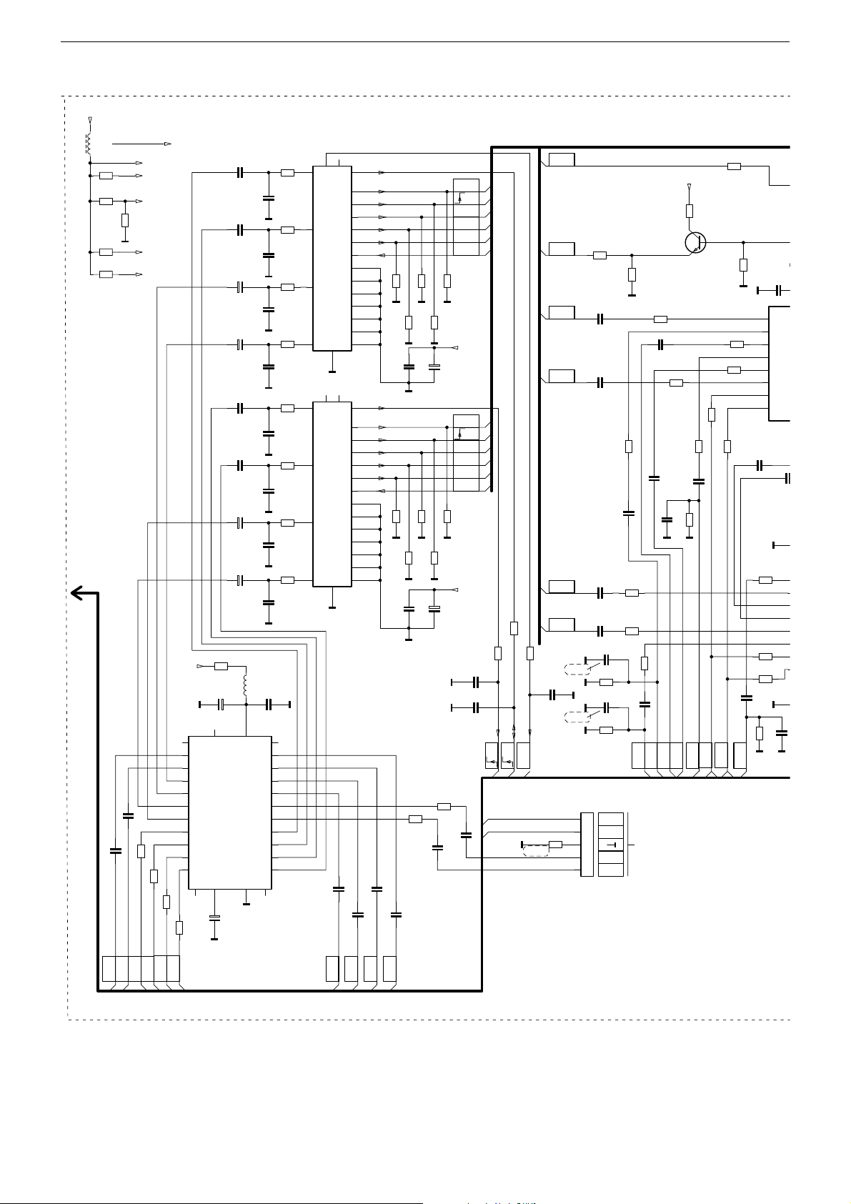
GRUNDIG Service DIGI 100
0
T
C
0
C
3
150p
u
3
C
1
4
V
Signal-Baustein Teil 3 / Signal Module Part 3 295042622300
+Q
C
L43311
10u
CR43312
3,3
CR43313
2,7k
CR43316
3,3
CR43317
3,3
CC43162
AUDIO-L
siehe CR33407
+Q/B0
+Q/B1
+Q/B2
4,7k
CR43314
V
+Q/B3
+Q/B4
4,7u
CC43163
4,7u
CR43163
CR43164
OUT
OUT
INT3
INT3
L_AV3
AUDIO-R
47
R-AV3
-3,3V
47
180
CR43166
CR43167
SDA1
SCL1
CC43111
4,7u
CC43113
4,7u
C43116
+
22u/16V
C43118
+
22u/16V
CC43141
4,7u
CC43143
4,7u
C43146
+
22u/16V
C43148
+
22u/16V
CR43161
+Q
3,3
C43161
+
A
220u/16V
26
22
ADR VCC
NC NC
11
L-OUT1
12
R-OUT1
13
L-OUT2
14
R-OUT2
15
L-OUT3
16
TEA6420D
R-OUT3
17
L-OUT4
18
R-OUT4
27
SCL
28
CIC43160
SDA
21
+
C43166
22u/50V
180
A
L43161
3
GND
12
A
CC43112
CC43114
CC43117
CC43119
CC43142
CC43144
CC43147
CC43149
8,2u
CC43160
0,1u
L-IN1
R-IN1
L-IN2
R-IN2
L-IN3
R-IN3
L-IN4
R-IN4
L-IN5
R-IN5
NCNC
8
CR43111
A
CR43113
A
CR43116
A
CR43118
A
CR43141
A
CR43143
A
CR43146
A
CR43148
A
7
4
25
5
24
6
23
9
20
10
19
470
470p
470
470p
470
470p
470
470p
470
470p
470
470p
470
470p
470
470p
AV1
A
100
CR43133
MEGA
LOGIC
n.V.
47
CC43133
CR43175
VIDEO
OUT-AV2
VIDEO
CR43206
OUT-AV1
VIDEO
CC43211
IN-AV1
VIDEO
CC43214
IN-AV2
R
CC43237
AV2
R
CC43238
AV1
V
n.V.
V
V
220p
V
n.V.
V
5
4
3
0
2
1
ST-AV3
SIGNAL MODULE
MODULE SIGNAL
MODULO SEGNALE
MODULO DE SENAL
75
1u
1u
0,1u
0,1u
CC43215
150p
CR43215
75
CC43242
150p
CR43242
10k
OUT
R-AV3
OUT
L-AV
IN
L-AV3
IN
R-AV3
1k
CR43204
VV
CR43211
47
CC43212
1u
CR43214
47
47
CR43216
1u
CC43213
1u
CC43216
CR43237
47
CR43238
47
47
CR43241
CC43241
VIDEO
IN-AV3
CHROMA
TO ADAPTER BOART
ZUR ADAPTERPLATTE
CC43218
VVV
0,1u
TERR
FBAS
IN-AV3
SEITE / PAGE 3-6
150p
FBAS
10 12
6
2
1
3
6
2
1
3
A
LI
RI
RO
LO
LI
RI
RO
LO
US
AV1
VI
D
R
G
B
VO
M
PERIDEC1
MD
MV
MR
MG
MB
MA
4
A
10 12
US
AV2
VI
D
R
G
B
VO
M
PERIDEC1
MD
MV
MR
MG
MB
MA
4
A
4,7u
CC43167
CC43168
INT2
AUDIO-L
AUDIO-R
20
16
15
11
19
21
18
17
14
13
20
16
15
11
19
21
18
17
14
13
8
7
9
5
8
7
9
5
INT2
CC43171
4,7u
INT1
AUDIO-R
75
CR43121
V
CR43126
CC43127
75
CR43151
V
CR43156
CC43157
CR43173
4,7u
CC43172
INT1
AUDIO-L
75
CR43123
CR43122
V
75
CR43127
VV
+
10n
C43128
V
75
CR4315275CR43153
75
CR43157
V
V
+
10n
C43158
V
CR43174
47
47
CC43173
4,7u
U
OUT-AV1
V
75
47u/16V
U
OUT-AV2
VV
75
47u/16V
V
V
4,7u
VIDEO
IN-AV1
DATA
AV1
R
AV1
G
AV1
B
AV1
VIDEO
75
+Q/B3
VIDEO
IN-AV2
DATA
AV2
R
AV2
G
AV2
B
AV2
VIDEO
+Q/B4
CC43131
1n
CC43132
1n
CC43174
4,7u
CR43131
AV2
EURO-
U
CR43132
100
EURO-
U
CR43188
68
CT43190
BC848B
CR43221
47
CR43217
CC43217
75
0,1u
75
CR43202
CR43212
47
CR43213
47
180
180
CR43222
V
+Q/B3
CR43197
CR43218
CC43234
CAV
SAT
FBAS/V
CAV
SCL1
SDA1
CHROMA
29504-262.2300SIGNAL-BAUSTEIN
29504-262.2600
+Q/B1
4,7k
1
3
5
6
8
10
2
4
CC43187
1u
CR43234
47
CR43243
180
CR43244
180
0,1u
CR43236
V
+Q/B
CC4318
0,1u
IN1
IN2
IN3
IN4
IN5
IN6
SDA
SCL
CC4
+Q/B
V
V
75
CC43236
I
1
C
1
3
5
6
8
1
2
4
C
3 - 40
Page 75

GRUNDIG Service DIGI 100
ST-RGB-50
1
V
2
B
3
/B4
B1
3183
1u
1
2
3
IC43180
4
TEA6425
5
6
VIDEO
A
L
C43188
1u
/B1
CC43233
0,1u
1
3
5
6
8
10
2
4
CC33184
V
1n
150p
VCCP
SUB
7911
V
IN1
IN2
IN3
IN4
IN5
IN6
SDA
SCL
OUT0
DCTR-D
CR43186
68
1k
CR43187
V
C43181
+
220u/16V
CC43182
0,1u
20
OUT1
VCC
OUT2
OUT3
OUT4
OUT5
OUT6
OUT7
OUT8
GND
CR43185
V
9
VCCP
IC43230
TEA6425
CHROMA
SUB
7
CR43258
10k
V
19
18
17
16
15
14
13
12
4,7k
C43231
+
220u/16V
CC43232
0,1u
20
VCC
OUT1
OUT2
OUT3
OUT4
OUT5
OUT6
OUT7
OUT8
GND
11
CT43258
V
BC847BT
CR43259
V
CT43185
BC848B
V
19
18
17
16
15
14
13
12
10k
CR43260
V
CR43193
CR43196
CR43184
CR43189
V
V
+Q
2,2k
2,2k
2,2k
4,7k
V
4,7k
V
CR43200
CR43191
CR43194
0
VV
CR43245
2,2k
2,2k
CHROMA
CT43250
BC848B
4,7k
CR43246
V
47
CR43249
VIDEO
+Q/B3
CR43251
CR43256
V
CR43247
47
PIP
CHROMA
390
CR43252
CR43257
470
CC43257
V
47
CR43248
PIP
VIDEO
68
CT43255
BC857B
CR43253
2,2k
150p
CR43261
V
47
68
CT43260
BC847BT
4,7k
CR43262
CC43262
V
AV1
1k
270p
CR43263
B
+Q/B4
CR43264
V
220
U
U
180
CR43266
CT43265
BC857B
CT43270
BC857B
CR43321
SAT
DATA
U
G
AV1
G
AV2
B
AV1
B
AV2
R
AV1
R
AV2
DATA
DATA
R
AV2
B
AV2
AV1
AV2
68
1k
CC43291
16
CIC43290
74HCT4053
0,1u
CR43293
47
CR43294
47
CR43297
47
CR43301
47
CR43296
47
CR43298
47
+Q/B2
12
13
2
1
5
3
-3,3V
10n
+Q/B2
68
CR43267
+Q/B4
CR43271
CT43320
BC847BT
CR43283
47
CR43284
47
68
CR43272
68
CC43292
V
-3,3V
CR43328
12
13
2
1
5
3
1M
V
CC43321
16
CIC43280
74HCT4053
CC43282
CR43322
100k
2,2n
VV V
OUT0
DCTR-D
14
11
15
10
876
V
CC43281
0,1u
14
11
15
10
876
V
10n
+Q
100k
CR43323
CT43325
BC857BT
V
4
9
4
9
V
CC43326
V
CR43327
0,22u/10V
56k
DATA
U
100k
CR43303
V
DATA 2
U
CR43286
RGB
U
CR43292
10k
R
DATA
V
330
SAT
U
G
4
R
5
DATA
6
U
SAT
VIDEO
7
IN-AV3
G
B
VIDEO
IN-AV3
SEITE / PAGE 3-6
TO ADAPTER BOART
ZUR ADAPTERPLATTE
+Q/B0
4,7k
CR43235
+Q/B0
BC857B
CT43235
0
0
V
V
789
V
1
2
3
456
ST-AV3V
AV1
AV3
EURO-
CHROMA
EURO-
VIDEO
IN-AV3
IN-AV3
+Q/B0
U
U
VIDEO
CHROMA
OUT.AV3
OUT-AV3
Spannungstabelle / Table of Voltages
+80V +80V
+G +17V
+27.5V D-Amplifier (AC3)
+C +200V +H + 3.3V
+D +29V +K +13.6V
+F +5V -K -13.6V
+16V/TOS-Real Flat-CRT
/Thomson-CRT
-16V/TOS-Real Flat-CRT
/Thomson-CRT
+14,7V +14.7V +N +3.3V
-14,7V -14.7V +Q +8.5V
+M +16.5V +OEKO +13.5V
130902
Bei den in den Schaltplänen angegebenen Messwerten handelt es
sich um Näherungswerte!
The measured values given in the circuit diagrams are approximates!
3 - 41
Page 76
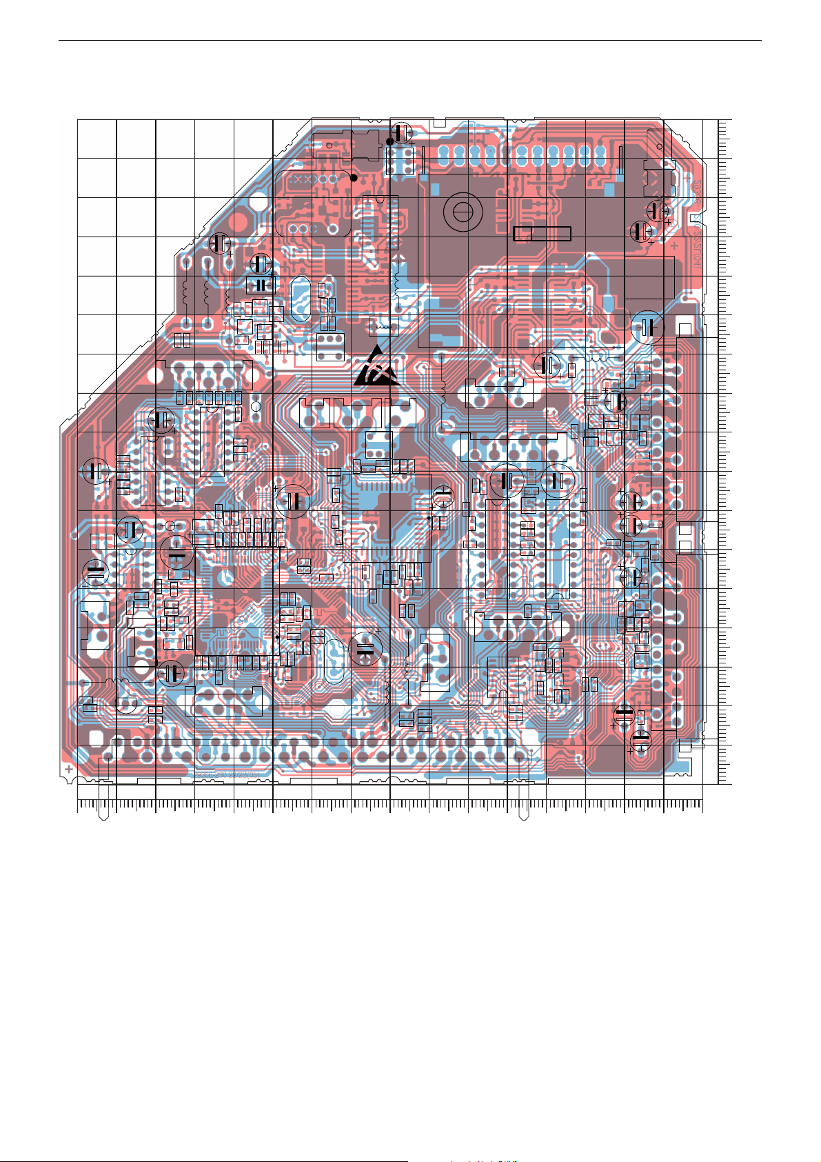
GRUNDIG Service DIGI 100
Signal-Baustein / Signal Module 295042622300
Bestückungsseite, Ansicht von oben / Component Side, Top View
C33402
C41002
C41012
1
C33404
17
R33111
41
IC41010
C33127
58
C32002
L32001
L31001
L32051
ST-DV1
17
IC33460
IC33430
814
40
41
C32048
C32042
8
ST-SPD
R41031
814
C33006
25
24
MESSERK.2
F32021
Q32034
F32081
2
1
F32016
ST-DV3
13
1
ST-DV4
L32092
1
F33277
C31006
11 1
SIGNALBAUSTEIN DD
1
2
0
51
9
8
3
2
4
4
3
5
7
6
MI-
29306-230.22/4B(03)
L32094
C43166
2
L43311
15
ST-AV3
ST-AV3V
19
C43181
1
C33251
IC43180
10
1120
11 20
L43161
C43231
10
C43116
C43158
IC43230
1
29504-
262.23
C43128
C43118
MESSERK.
C31004
C43161
AV1
C32033
202
202
170
160
150
140
130
120
21
110
100
90
80
1
70
60
21
50
ST-G_IN1
L33121
13
31
IC33015
42
43
ST-SAT
64
13
C33133
1
65
ST-I2S
1
80
6
Q33046
S2
C33003
L33251
L33001
17
4
ST-RGB-50
ST-DV2
1
1
2
1
C43148
AV2
1
C43146
40
30
20
10
0
Y
0102030405060708090100110120130140150160
X
3 - 42
Page 77

GRUNDIG Service DIGI 100
Signal-Baustein / Signal Module 295042622300
Koordinaten für die Bauteile der Bestückungsseite (Oberseite)
Coordinates of the Components on the Components Side (Top Side)
Pos.-Nr./ Koordinaten/
Pos. No. Coordinates
XY
C31004 13 146
C31006 78 166
C32002 125 138
C32033 17 141
C32042 114 127
C32048 114 133
C33003 87 35
C33006 106 72
C33127 135 60
C33133 137 28
C33251 68 73
C33402 156 80
C33404 139 93
C41002 148 65
C41012 156 54
C43116 19 66
C43118 19 72
Pos.-Nr./ Koordinaten/
Pos. No. Coordinates
XY
C43128 23 98
C43146 17 11
C43148 21 18
C43158 19 53
C43161 15 117
C43166 41 107
C43181 51 78
C43231 38 78
F32016 78 159
F32021 101 148
F32081 96 112
F33277 84 87
IC33015 149 20
IC33430 126 88
IC33460 142 80
IC41010 147 55
IC43180 53 60
Pos.-Nr./ Koordinaten/
Pos. No. Coordinates
XY
IC43230 38 60
L31001 133 126
L32001 122 124
L32051 127 126
L32092 83 117
L32094 79 128
L33001 82 23
L33121 151 26
L33251 76 30
L43161 28 109
L43311 68 100
MESSERK. 12 158
MESSERK.02
Q32034 104 124
Q33046 95 31
92 163
Pos.-Nr./ Koordinaten/
Pos. No. Coordinates
XY
R33111 137 66
R41031 115 97
S02 100 2
ST-AV03 53 100
ST-AV03V 49 86
ST-DV01 128 105
ST-DV02 69 31
ST-DV03 89 95
ST-DV04 78 95
ST-G_IN01 156 41
ST-I02S 124 21
ST-RGB-50 48 40
ST-SAT 144 36
ST-SPD 100 95
TUNER 41 137
3 - 43
Page 78

GRUNDIG Service DIGI 100
Signal-Baustein / Signal Module 295042622300
Bestückungsseite, Ansicht von oben / Component Side, Top View
170
160
CR33465
CC33473
CR33412
CR33470
CR33466
CR41003
CR33018
CR33016
CC33072
CR33072
CR33309
CR33308
CR33307
CR33471
CC33128
CC33131
CR41002
41
CC33261
CR33024
CC33024
CR33023
CC33026
CC33025
CC33027
CC32271
CR32272
CC32273
CR41008
CR41018
CC32272
64
CC33123
CC33134
CC33028
29306-230.22/4BS(04)
CT32077
CC32078
CR33303
40
65
CC33136
CR33121
CR33306
CR33304
CR33036
CR33034
CC33034
CC33036
CIC33150
CC33141
CC33144
CR32070
CR32078
CR33302
CR33437
CC33427
CR33432
CR33433
CR33032
CC33172
CC33032
CC33031
CC33182
CC33184
CT32070
CC32083
CC33162
25
CR33172
CR33162
CR33189
CR33184
CL33188
1
80
CR33181
CR33182
CT32063
CT32076
CC32086
CC32082
CC33152
CC33151
24
CC33143
CR33152
CC33186
CC32084
CR33151
CR33144
CC33121
CC33122
CR33187
CR33186
CC33187
CC32041
CR33042
CC33126
CR33138
CR33090
CR33097
CL33183
CC33188
CR33188
CR32065
CR32061
CR32069
CR33282
CR33281
CR33183
CC33183
CR32032
CC32032
CR33283
CR33139
1
CR33278
CC33281
CIC33250
CR33293
CF32019
CR33279
CR33276
CR33291
CR33292
CR43245
CR43249
CC33253
CC33252
CC33272
CR33272
CR33277
CR33284
CL33252
CC33273
CC33271
CR33286
CC33263
CR33273
CR43248
CR43247
CC43213
CC33262
CR43221
CC43212
CR43222
CR43212
CC43174
CR43211
CIC43290
CR43293
CR43294
1
CR43312
CT43235
CR43196
CR43194
CC43188
CC43187
CR43298
CR43323
CT43325
CR43235
CR43322
CR43327
CC43211
CR43316
CT43250
CC43241
CR43252
CC43214
CC43326CC33181
CC43321
CT43320
CR43321
CR43303
CR43161
CR43197
CR43251
CC43238
CR43238
CR43301
CR43256
CR43257
CR43317
CT43270
CR43271
CR43262
CR43297
CT43190
CR43253
CT43255
CR43266
CC43257
CR43121
CR43132
CT43185
CR43186
CR43206
CR43204
CC43117
CR43187
CR43272
CC43262
CR43261
CT43260
CR43264
CT43265
CC43147
CR43122
CR43126
CR43296
CR43188
CR43153
CR43263
150
140
130
120
110
100
90
80
70
60
50
40
30
20
10
3 - 44
0
Y
0102030405060708090100110120130140150160
X
Page 79

GRUNDIG Service DIGI 100
Signal-Baustein / Signal Module 295042622300
Koordinaten für die Chip-Bauteile der Bestückungsseite (Oberseite)
Coordinates of the Chip Components on the Components Side (Top Side)
Pos.-Nr./ Koordinaten/
Pos. No. Coordinates
XY
CC32032 96 118
CC32041 95 80
CC32078 119 114
CC32082 113 112
CC32083 115 112
CC32084 108 112
CC32086 110 112
CC32271 137 44
CC32272 134 42
CC32273 139 41
CC33024 136 50
CC33025 144 46
CC33026 140 47
CC33027 137 46
CC33028 148 45
CC33031 119 63
CC33032 121 63
CC33034 123 63
CC33036 125 63
CC33072 135 114
CC33121 106 47
CC33122 108 47
CC33123 132 36
CC33126 103 57
CC33128 129 66
CC33131 129 63
CC33134 130 31
CC33136 128 31
CC33141 124 31
CC33143 111 63
CC33144 125 27
CC33151 109 66
CC33152 112 66
CC33162 115 66
CC33172 117 66
Pos.-Nr./ Koordinaten/
Pos. No. Coordinates
XY
CC33181 136 36
CC33182 119 31
CC33183 99 37
CC33184 117 31
CC33186 111 29
CC33187 107 28
CC33188 102 35
CC33252 78 81
CC33253 80 81
CC33261 135 53
CC33262 67 67
CC33263 69 67
CC33271 74 55
CC33272 78 54
CC33273 76 55
CC33281 86 81
CC33427 119 88
CC33473 149 81
CC43117 13 67
CC43147 17 17
CC43174 51 105
CC43187 46 59
CC43188 46 61
CC43211 30 100
CC43212 62 70
CC43213 72 14
CC43214 40 46
CC43238 32 74
CC43241 34 90
CC43257 21 93
CC43262 16 43
CC43321 38 30
CC43326 38 33
CF32019 84 143
Pos.-Nr./ Koordinaten/
Pos. No. Coordinates
XY
CIC33150 120 47
CIC33250 82 68
CIC43290 52 27
CL33183 106 40
CL33188 106 38
CL33252 76 81
CR32032 96 123
CR32061 98 123
CR32065 98 126
CR32069 98 118
CR32070 117 121
CR32078 120 121
CR32272 137 41
CR33016 158 20
CR33018 159 22
CR33023 144 48
CR33024 140 51
CR33032 121 68
CR33034 123 68
CR33036 125 70
CR33042 95 78
CR33072 133 114
CR33090 102 44
CR33097 104 43
CR33121 126 31
CR33138 103 55
CR33139 97 53
CR33144 108 59
CR33151 109 63
CR33152 113 63
CR33162 115 63
CR33172 117 63
CR33181 113 31
CR33182 115 31
CR33183 99 39
Pos.-Nr./ Koordinaten/
Pos. No. Coordinates
XY
CR33184 107 42
CR33186 108 32
CR33187 106 32
CR33188 104 35
CR33189 107 44
CR33272 76 50
CR33273 74 50
CR33276 82 53
CR33277 80 53
CR33278 90 81
CR33279 83 82
CR33281 95 67
CR33282 95 74
CR33283 94 63
CR33284 78 44
CR33286 76 44
CR33291 84 52
CR33292 85 48
CR33293 87 54
CR33302 120 99
CR33303 127 99
CR33304 122 99
CR33306 125 99
CR33307 135 99
CR33308 132 99
CR33309 130 99
CR33412 149 79
CR33432 119 86
CR33433 119 84
CR33437 120 94
CR33465 149 83
CR33466 149 75
CR33470 149 77
CR33471 135 74
CR41002 152 62
Pos.-Nr./ Koordinaten/
Pos. No. Coordinates
XY
CR41003 157 62
CR41008 141 19
CR41018 141 16
CR43121 18 93
CR43122 16 98
CR43126 16 93
CR43132 16 84
CR43153 16 49
CR43161 35 106
CR43186 20 60
CR43187 16 56
CR43188 13 59
CR43194 46 64
CR43196 46 66
CR43197 25 102
CR43204 16 104
CR43206 16 107
CR43211 57 76
CR43212 61 61
CR43221 59 76
CR43222 60 67
CR43235 45 75
CR43238 32 68
CR43245 77 18
CR43247 72 16
CR43248 72 18
CR43249 77 15
CR43251 30 90
CR43252 30 88
CR43253 20 89
CR43256 24 94
CR43257 24 92
CR43261 15 41
CR43262 20 41
CR43263 18 41
Pos.-Nr./ Koordinaten/
Pos. No. Coordinates
XY
CR43264 16 35
CR43266 20 37
CR43271 22 41
CR43272 16 46
CR43293 49 19
CR43294 49 17
CR43296 16 89
CR43297 29 25
CR43298 46 44
CR43301 31 25
CR43303 36 23
CR43312 45 78
CR43316 30 98
CR43317 24 62
CR43321 38 23
CR43322 40 30
CR43323 43 35
CR43327 43 25
CT32063 110 120
CT32070 114 122
CT32076 113 116
CT32077 118 117
CT43185 17 60
CT43190 20 103
CT43235 46 71
CT43250 28 93
CT43255 24 89
CT43260 16 37
CT43265 16 32
CT43270 20 45
CT43320 38 27
CT43325 43 30
3 - 45
Page 80

GRUNDIG Service DIGI 100
Signal-Baustein / Signal Module 295042622300
Lötseite, Ansicht von unten / Solder Side, Bottom View
170
160
150
140
130
120
110
100
90
80
70
60
50
40
30
20
10
CC43119
CR43118
CR43113
CR43116
CR43157
CR43152
CR43156
CR43131
CR43141
CC43149
CC43144
CR43143
CR43148
CR32033
CR43111
CC43112
CC43131
CR43146
CR43123
CR43127
CC43157
CR32031
CC43143
CC43127
CC43111
CC43114
CR43244
CC43237
CR43151
CR43267
CC43142
CD32031
CC43160
CC43172
CC43168
CC43162
CC43163
CC43113
CC43236
CR43236
CC43141
CC32031
CC43232
CR43313
CC43234
CR43234
CR43283
CR43284
CL31007
CR31003
CR31012
CR31011
CR43241
CR43246
CR43314
CR43237
CR43243
CC32036
CC32035
CL31008
CC31003
CR43174
CR43292
1
CIC43280
CC43282
CC43102
CR31009
CL31005
CL31006
1
CIC43160
CC31001
CIC31010
CC31011
CC43242
CR43215
CD43258
CR43258
CR43259
CR43184
CC43233
CC43281
CR31002
CR31013
1
CR43164
CR43163
CC43182
CC43292
CR31008
CC43173
CR43242
CC43215
CR43185
CC43183
CR43286
CC31007
CR43167
CR43166
CC43171
CC43167
CR43173
CC43216
CR43216
CR43202
CR43193
CR43191
CR43189
CR43214
CR31005
CR31010
CC31005
CR43213
CC43291
CR43133
CC43133CC43132
CR32036
CR43217
CC43217
CR43218
CC43218
CC32044
CC32046
CC32093
CR33287
CC33287
CD32017
CD32016
CT32021
CR32037
CC32095
CC32092
CC33094
CC33089
CR32021
CC32033
CC32094
CR32092
CC33242
CR33089
CR32007 CR32006
CR32008
CD32014
CD32013
CD32012
CR32022
CR32046
CR32094
CC33243
CR33041
CC33035
CC33039
CR33126
CC30033
CC30034
CC33087
CR33001
CC33001
CC33002
CC33047
CC33048
CC33042
CR33096
CT32007
1
CIC32040
CC32061
CR32076
CR30034
CC33043
CT32012
CT32086
CR30033
CR33031
CC33037
CR33094
CR33013
CR33093
CT32009
CR32011
CR32012
CR32001
CR32042
CC32043
CC32034
CR30037
CC33086
CC33038
CL33093
CC32019
CR32002
CR32023
CR32073
CC41031
CR30038
CC33007
CC33009
CC33008
CIC33010
1
CR33091
CC33040
CR32019
CR32013
CR32003
CC32047
CC32062
CR33438
CR33439
CC33436
CC33431
CR33092
CR32079
CR32009
CR32004
CT32004
CR32067
CR32072
CR32062
CR33436
CR30036
CC30037
CC30036
CC33011
CC33012
CL33096
CR32068
CR32064
CR32086
CC33437
CR33435
CC33432
CR30039
CC30039
CR33101
CR33100
CC32001
CR32066
CR32077
CR33423
CC33422
CC33428
CR33431
CC30038
CC33469
CR33468
CR33081
CC33061
CR33071
CC33018
CR32071
CR32063
CC33426
CR33426
CC33071
CR33062
CR33061
CC33051
CR33051
CR33099
CR33095
CC33421
CR33427
CC33468
CC33062
CC33132
CC33023
CC33118
CC33119
CR33422
CR33425
CR33421
CC33429
CR33429
CR33428
CR33460
CC33081
CC33111
CC33052
CR33027
CR33052
CR32271
CR33017
CC33014
CC33016
CC33472
CR33469
CR41009
CR33463
CR33462
CC33466
CR33464
CR41001
CR41007
CC41007
CR41006
CC41009
CR33026
CC33030
CC33029
CC32274
CR33116
CC33116
CC33117
CR33117
CC33462
CC33461
CR33461
CC33101
CR33467
CR41011
CR33014
CR33406
CC33464
CR33409
CR41017
CC41017
CR41016
CR41019
CC41019
CR41013
CC33015
CR33407
CR33403
CR41012
29306-230.22/4LS(04)
0
Y
0
X
10 20 30 40 50 60 70 80 90 100 110 120 130 140 150 160
3 - 46
Page 81

GRUNDIG Service DIGI 100
Signal-Baustein / Signal Module 295042622300
Koordinaten für die Bauteile der Lötseite (Unterseite)
Coordinates of the components on the Solder Side (Bottom Side)
Pos.-Nr./ Koordinaten/
Pos. No. Coordinates
XY
CC30033 97 58
CC30034 97 55
CC30036 114 66
CC30037 114 70
CC30038 122 67
CC30039 117 63
CC31001 53 156
CC31003 44 165
CC31005 59 165
CC31007 58 156
CC31011 47 139
CC32001 124 136
CC32019 107 149
CC32031 29 156
CC32033 82 135
CC32034 108 123
CC32035 32 14
CC32036 34 14
CC32043 108 125
CC32044 82 131
CC32046 82 129
CC32047 108 131
CC32061 103 117
CC32062 111 120
CC32092 76 118
CC32093 74 119
CC32094 81 120
CC32095 76 121
CC32274 139 41
CC33001 88 41
CC33002 85 41
CC33007 106 74
CC33008 109 66
CC33009 109 69
CC33011 114 34
CC33012 114 32
CC33014 140 22
CC33015 148 25
CC33016 140 20
CC33018 125 46
CC33023 130 52
CC33029 139 43
CC33030 139 45
CC33035 97 63
CC33037 100 63
CC33038 101 60
CC33039 97 60
CC33040 107 18
CC33042 89 22
CC33043 93 36
CC33047 92 33
CC33048 92 31
CC33051 128 48
CC33052 133 49
CC33061 123 59
Pos.-Nr./ Koordinaten/
Pos. No. Coordinates
XY
CC33062 126 62
CC33071 128 66
CC33081 131 67
CC33086 103 67
CC33087 90 50
CC33089 78 30
CC33094 76 30
CC33101 142 79
CC33111 132 60
CC33116 139 37
CC33117 139 35
CC33118 135 37
CC33119 135 35
CC33132 130 60
CC33242 84 68
CC33243 87 68
CC33287 73 71
CC33421 127 91
CC33422 127 94
CC33426 127 86
CC33428 127 83
CC33429 134 87
CC33431 119 82
CC33432 118 78
CC33436 118 89
CC33437 119 86
CC33461 142 83
CC33462 142 86
CC33464 149 73
CC33466 142 73
CC33468 134 75
CC33469 131 73
CC33472 135 80
CC41007 140 55
CC41009 140 51
CC41017 148 58
CC41019 148 52
CC41031 109 83
CC43102 37 10
CC43111 21 91
CC43112 18 80
CC43113 24 91
CC43114 20 78
CC43119 16 77
CC43127 23 96
CC43131 17 30
CC43132 57 16
CC43133 65 16
CC43141 24 18
CC43142 20 24
CC43143 23 105
CC43144 16 21
CC43149 16 23
CC43157 19 53
CC43160 33 131
Pos.-Nr./ Koordinaten/
Pos. No. Coordinates
XY
CC43162 31 119
CC43163 31 116
CC43167 53 124
CC43168 33 124
CC43171 53 127
CC43172 33 128
CC43173 53 106
CC43182 53 72
CC43183 54 52
CC43215 52 81
CC43216 56 81
CC43217 62 57
CC43218 62 52
CC43232 38 70
CC43233 46 48
CC43234 29 49
CC43236 24 49
CC43237 25 55
CC43242 47 91
CC43281 47 32
CC43282 37 19
CC43291 59 29
CC43292 49 30
CD32012 93 146
CD32013 93 149
CD32014 93 152
CD32016 85 148
CD32017 85 151
CD32031 29 154
CD43258 45 63
CIC31010 49 145
CIC32040 95 128
CIC33010 107 47
CIC43160 42 122
CIC43280 40 27
CL31005 43 154
CL31006 40 154
CL31007 31 10
CL31008 34 10
CL33093 106 21
CL33096 113 29
CR30033 95 66
CR30034 94 72
CR30036 116 71
CR30037 100 78
CR30038 107 78
CR30039 117 66
CR31002 46 155
CR31003 35 156
CR31005 59 168
CR31008 53 167
CR31009 49 167
CR31010 59 167
Pos.-Nr./ Koordinaten/
Pos. No. Coordinates
XY
CR31011 40 146
CR31012 40 149
CR31013 51 153
CR32001 106 131
CR32002 108 134
CR32003 111 138
CR32004 109 141
CR32006 98 164
CR32007 92 164
CR32008 90 156
CR32009 109 143
CR32011 99 152
CR32012 99 150
CR32013 109 138
CR32019 109 149
CR32021 86 156
CR32022 84 135
CR32023 106 134
CR32031 25 156
CR32033 16 137
CR32036 74 125
CR32037 84 124
CR32042 108 127
CR32046 85 130
CR32062 113 112
CR32063 115 120
CR32064 118 120
CR32066 120 120
CR32067 113 124
CR32068 115 124
CR32071 113 120
CR32072 115 115
CR32073 113 115
CR32076 104 110
CR32077 120 115
CR32079 111 14
CR32086 118 115
CR32092 84 120
CR32094 84 122
CR32271 136 42
CR33001 90 41
CR33013 101 30
CR33014 142 21
CR33017 130 30
CR33026 139 47
CR33027 136 45
CR33031 100 65
CR33041 92 65
CR33051 128 46
CR33052 132 47
CR33061 123 56
CR33062 125 58
CR33071 120 58
CR33081 128 68
Pos.-Nr./ Koordinaten/
Pos. No. Coordinates
XY
CR33089 80 30
CR33091 108 28
CR33092 110 30
CR33093 104 18
CR33094 99 31
CR33095 128 30
CR33096 89 20
CR33099 122 38
CR33100 119 41
CR33101 118 58
CR33116 139 39
CR33117 139 33
CR33126 87 54
CR33287 71 71
CR33403 156 70
CR33406 153 77
CR33407 156 77
CR33409 153 70
CR33421 134 89
CR33422 133 94
CR33423 127 97
CR33425 134 91
CR33426 128 80
CR33427 133 81
CR33428 134 83
CR33429 134 85
CR33431 120 78
CR33435 119 84
CR33436 116 86
CR33438 119 93
CR33439 119 91
CR33460 134 73
CR33461 142 81
CR33462 143 89
CR33463 141 89
CR33464 142 70
CR33467 143 76
CR33468 131 71
CR33469 140 76
CR41001 140 59
CR41006 140 53
CR41007 140 57
CR41009 138 51
CR41011 148 50
CR41012 152 49
CR41013 152 45
CR41016 148 56
CR41017 148 60
CR41019 148 54
CR43111 18 82
CR43113 13 71
CR43116 13 69
CR43118 16 74
CR43123 15 107
Pos.-Nr./ Koordinaten/
Pos. No. Coordinates
XY
CR43127 15 101
CR43131 16 28
CR43133 61 16
CR43141 16 25
CR43143 16 19
CR43146 14 15
CR43148 16 17
CR43151 19 28
CR43152 17 38
CR43156 17 35
CR43157 17 40
CR43163 48 106
CR43164 49 106
CR43166 53 130
CR43167 53 132
CR43173 52 109
CR43174 37 104
CR43184 46 50
CR43185 53 61
CR43189 53 63
CR43191 53 65
CR43193 53 67
CR43202 53 69
CR43213 60 49
CR43214 58 46
CR43215 47 82
CR43216 58 77
CR43217 62 61
CR43218 62 55
CR43234 31 47
CR43236 27 48
CR43237 29 55
CR43241 36 81
CR43242 49 91
CR43243 29 53
CR43244 28 57
CR43246 39 68
CR43258 46 54
CR43259 46 52
CR43267 22 28
CR43283 32 31
CR43284 32 29
CR43286 48 18
CR43292 42 45
CR43313 29 63
CR43314 31 63
CT32004 115 136
CT32007 94 160
CT32009 100 160
CT32012 100 147
CT32021 81 145
CT32086 108 114
LF01 106 43
3 - 47
Page 82

GRUNDIG Service DIGI 100
u
2
0
1n
1
0
0
U
2
GNDCAP
Feature-Modul Teil 1 / Feature Module Part 1 295042033000
+F/5V
+Q/8V
+N/3,3V
+H/3,3V
VIDEO
CHROMA
SEITE / PAGE 3-26/27
TO CHASSIS
ZUM CHASSIS
U
CHROMA
PIP
VIDEO
PIP
+F1
0,1u
M
0,1u
n.v.
R70121
3,3k
0,1u
L70004
CT70015
BC848B
2,2k
CR70004
V1
M
M
CD70125
n.v.
CD70128
LL4148
CC70004
+Q1
+N1
n.v.
CC70081
CC70082
M
24156 89
CR70015
330
CR70005
V1 V1
CR70020
CR70025
CR70030
CR70035
V10
V1
CC70121
MM
CR70125
MMM
CR70128
M
S3
46
S3
45
CC70006
S3
43
S3
48
S3
47
CC70001
49
17
16
10
11
12
9
15
14
13
18
35
36
38
32
37
30
VIDEO
n.v.
M
n.v.
M
CR70010
1k
CR70014
V1
CC70043
CC70045
M
CC70009
M
n.V.
V1
M
R70045
n.v.
R70046
100
S3
S3
S3
S3
R
S3
G
S3
B
S3
DATA
S3
S3
S3
S3
S3
S3
S3
S3
VG
S3
SS
S3
REF
2,2
CR70006
CR70096
0
L70005
n.v.
CR70100
0
L70002
n.v.
CR70101
0
L70003
n.v.
+H1
n.v.
n.v.
n.v.
CC70083
CC70084
GND
F202004
F70011
+Q/B1
13
56
27p/5%
CC70011
8140-532-085
0
CC70020
0
CC70025
0
CC70030
0
CC70035
V10
n.v.
CC70034
CC70031
M
+F/B2
9,1k
CR70120
47n
100k
CR70123
470p
1k/2%
CD70126
CC70125
4,7k
MMM
CC70012
56p/5%
L70016
8
n.v.
V1
n.v.
V1
n.v.
V1
n.v.
V1
CHROMA
VIDEO
n.v.
+Q/B1
CR70126
n.v.
C70005
C70002
C70003
1,8u
PIP
PIP
CC70033
+
n.v.
n.v.
CC70007
+
0,1u
n.v.
CC70002
MM
+
n.v.
n.v.
CC70095
CC70003
V1
1314151617181920212223
OUTIN
12
11
CR70011
13
7
270p/5%
CC70014
V1
CR70021
0
L70021
18u
8137
V1 V1
8140-532-086
CR70031
0
L70031
18u
8137
V1V1
8140-532-086
n.V.
H
VGA
V
VGA
n.v.
RESET
U
BOX
VIDEO
2,2k
CR70001
2,2
n.v.
CC70094
CC70010
CR70012
100
1k
CC70013
V1
68p/5%
L70017
8
3,3u
V1 V1V1V1
8140-532-086
n.V.
CT80204
n.v.
MMMM
0,1u
CR70013
V1
V1
7
CC70015
CR70026
0
L70026
18u
8140-532-086
n.V.
CR70036
0
L70036
18u
8140-532-086
n.V.
100p
CC70467
V1
100pF
CC70465
V1
+F/B1_A
1k
CR80201
680
CR80204
BC857B
V1
siehe L70320
siehe L70301
siehe L70401
siehe L70251
siehe L70261
+Q/B1
V1 V1
820
CT70011
CC70205
BC858B
+F/B1
CR70016
1,1k/2%
CC70017
330p/5%
V1 V1V1
CR70022
V1 V1
8137
V1V1
CR70027
V1 V1
CR70032
V1 V1
8137
V1V1
CC70037
100
CR70465
220p
CC80204
.
VIDEO2
+F/B1_A
+F/B1
+F/B2
+F/B3
+Q/B1
+Q/B2
+N/B1
+N/B2
+N/B3
n.v.
L70205
n.v.
xx
560
C70244
560
C70245
560
56p
V1
+F/B1
M
CR70017
C70243
F
0,1u
F
0,1u
F
0,1u
CR70037
V1
CC70180
0,1u
C70206
C70240
F
0,68u
C70241
F
0,1u
1,1k/2%
47k
CR70244
2,2k
CR70182
0
CR70102
+
CC70022
CC70027
CC70032
1k
CR70180
CC70182
0
V1
V1
47n
CC70233
n.v.
CC70207
220u/10V
100p
100p
100p
CR70181
3k3
CIC70180
TL7705A
1234
+
0,1u
C70181
M
M
V1
C70232
CC70208
F
C70246
CR70245
V1
5678
M
CC70181
2,2u/50V
C70201
100u/10V
CC70202
CC70203
CC70204
+
47u/16V
n.v.
0,1u
150
CC70200
n.v.
+
100n
n.v.
n.v.
V1
CC70209
V1
+F/B1_A
0,1u
80
AISGND
78
VREF
77
GNDAI
100n
76
VSUPAI
75
VIN4
73
VIN2
71
CIN
72
VIN1
70
VOUT
8
NC
7
ASGF
3
R1
2
G1
1
B1
79
FB1IN
6
R2
5
G2
4
B2
74
VIN3
55
FSY/HC
CR70156
VGA
U
+F/B1
V1
VSUPF
VSUPPA
n.V.
L70201
CR70103
+
C70230
47u/16V
ISGND
I2CSEL
GNDPA
CC70234
47n
CC70235
n.v.
678
V1
0
V1
CC70231
VRT
CLK20
9
345
47n
FFOE
V1
GNDF
FFWE
FFRE
F_BLANK
10
1
3,3p
CC70228
Q70228
20,25MHz
ASGF
XTAL2
CIC70200
VPC3230
YCOEQ
FFIE
FFRSTW
CR70225
M
TV-MODE POSITION
11
15
CIC70150
74HCT4053
2
13
V1
PIP2
VIDEO
VIDEO2
MM
CC70229
VGAV
10k
14
.
3,3p
NC
XTAL1
TEST
M
CC70227
M
12
+F/B1
L70221
CLK5
RESQ
4.7n
CR70207
TV-BETRIEBSTELLUNG
+F/B1_A
16
CC70150
V1
n.v.
VSTBY
SDA
180
CR7015
0,1u
CC7
n.v.
C702
+
n.v.
CC70
0,1
CR7
1
585960616263646566676869
FPDAT
SCL
1314151617181920212223242526
180
CR70206
xx
CC70154
V
3 - 48
Page 83

GRUNDIG Service DIGI 100
7
VDDL2
VSSL1
4
2
M
P
CC70220
n.v.
70221
+
n.v.
C70222
0,1u
CR70221
10k
58
SCL
180
EB
GNDCAP
CC70236
0,22u
CC70237
n.v.
CC70238
n.v.
M
M
M
INTLC
CC70214
M
VSUPSY
VSUPCAD
910111213
n.v.
GNDD
M
CC70219
+N/B1
L70211
MM
515253
GNDC
GNDSY
VSUPLLC
VSUPD
MM
VS2
4546
VSUPC
VSUPY
GNDY
GNDLLC
AVO
LLC1
LLC2
MSY/HS
0,1u
C70218
n.v.
C70211
CC70212
Y7
Y6
Y5
Y4
Y3
Y2
Y1
Y0
C7
C6
C5
C4
C3
C2
C1
C0
VS
+
+
n.v.
0,1u
31
32
33
34
37
38
39
40
41
42
43
44
47
48
49
50
36
35
30
29
M
54
28
27
56
57
CR70230
0
L70218
n.v.
n.v.
M
M
0
CR70228
+N/B1
ST70281
FM1_14P
M
BLN
VS
MMM
n.v.
0,1u
CC70217
CC70216
10k
CR70028
CT70227
BC847B
n.v.
CD70227
+F/B1_A
1314
1112
910
78
56
34
12
C70215
3k3
LL1,5
F_BLANK
M
+
220u/10V
CR70224
0
+N/B1
CR70227
1k
CR70229
L70215
CR70223
+N/B1
0
CC70226
L70261
n.v.
L70251
+N/B1
xx
CC70281
xx
CC70282
CC70283
CC70284
CC70285
CC70286
Y7
Y6
Y5
Y4
Y3
Y2
Y1
Y0
C7
C6
C5
C4
C3
C2
C1
C0
F_BLANK
xx
xx
xx
xx
MM
CR70253
VS
Y1
Y3
Y5
Y7
0
+
C70251
an ST70281
Abblockkondens.
CC70262
100u/10V
BLN
Y0
Y2
Y4
Y6
LL1,5
+N/B1
10k
22p
10p
CC70225
CR70226
MM
M
C70261
+
n.v.
n.v.
CC70252
MM
U/RESET/BOX
M
M
n.v.
xx
xx
xx
xx
xx
xx
BLN
LL3
LL1,5
VS
RES3.3
SCL
SDA
+N/B3
+N/B2
CC70287
CC70288
CC70289
CC70290
CC70291
CC70292
LL1,5
+N/B3
SDA
SCL
VS
BLN
LL3
C0
C1
C2
C3
C4
C5
M
C6
C7
Y0
Y1
Y2
Y3
Y4
Y5
Y6
Y7
M
CR70298
0
CC70299
0,1u
CC70298
n.v.
VOUT
+N/B2
M
SCL
N.C.
M
CR70241
SDA
UVINS6
CR70242
0
SFCPR
UVINS7
0
SFCPO
VSSP3
LL1,5
VDDP5
CLKS
M
CC70241
M
VSSA3
VDDA3
VDDA2
VSSA2
CC70297
0,1u
0,1u
CLKM
YINS0
+N/B2
CC70242
M
CR70276
180
CR70275
180
N.C.
N.C.
109
N.C.
110
N.C.
111
N.C.
112
VINM
113
HINM
114
SYNCENM
115
VSSP5
M
116
UVINM0
117
UVINM1
118
UVINM2
119
UVINM3
120
UVINM4
121
UVINM5
122
VDDP4
123
UVINM6
124
UVINM7
125
YINM0
126
YINM1
127
YINM2
128
YINM3
129
VSSP4
M
130
N.C.
131
YINM4
132
YINM5
133
YINM6
134
YINM7
135
UVINS0
136
UVINS1
137
UVINS2
138
UVINS3
139
UVINS4
140
UVINS5
141
M
VDDP3
142
N.C.
143
N.C.
144
N.C.
N.C.
N.C.
123456789101112131415161718
M
MM
0,1u
CR702430CR70246
M
VSSP6
UVOUT0
YINS2
YINS1
0
SFCEN
N.C.
N.C.
YINS3
SFCDA
N.C.
UVOUT1
P-MQF
YINS4
M
CC70243
M
UVOUT2
CIC70
SDA9
N.C.
CC70296
n.v.
n.v.
919293949596979899100101102103104105106107108
N.C.
VDDL1
1k
0151
xx
n.V.
CR70152
47k
1n
CR70154
V1
SLICER
U
CC70445
M
100p
VS2
FBAS
CR70159
680
220p
CR70161
CC70162
CT70155
BC857B
V1
PIP
TXT
VIDEO
VIDEO
PIP2
SDA
SCL
SDA
SCL
LL1,5=27MHz
LL3=13.5MHz
FEATURE-MODUL REF/PLUS
3 - 49
Page 84

27
CR70323
2 2k/1%
5
5
N
C
VDDL1
M
GRUNDIG Service DIGI 100
CD70306
LL4148
CR70306
22k/1%
+F/B2
BLM11P600S
8104-982-315
VSUPD
HFLB
VERT-
CR70324
CR70326
CC70325
CL70320
BLM11A102
8104-982-314
470
CR70304
SENSE
CIC70300
DDP3310
VERSION F6
VERT+
EW
HOUT
68
CR70322
68
68
33n
CR70325
V10
CM0
V10
6,8k
16175152
RSW1
CM1
CR70303
+F/B2
FREQSEL
HCS
42121314821192091041116867
0
CC70320
M
CC70323
CC70248
M
n.v.
n.v.
0,1u
VSSE2
VDDE2
CC70247
UVOUT3
n.v.
N.C.
VDDP6
UVOUT4
MM
BLANK
VSSL3
VDDL3
VSSP7
UVOUT6
UVOUT5
INTERLACED
VOUT
N.C.
N.C.
CLKOUT
X1/CLKOUT
UVOUT7
UREF_I
RREF_I
.
.
70250
CC70246
MMM
VDDL2
A9415
FP-144
HINS
SYNCENS
YOUT5
YOUT6
VSSL4
VDDL4
YOUT7
YINS7
YINS6
YINS5
VSSP2
VDDP2
VDDE1
VSSL1
18 19 20 21 22 23 24 25 26 27 28 29 30 31 32 33 34 35 36
296
CC70295
MM
N.C.
M
CC70294
0,1u
n.v.
29504-203.2400
29504-203.2500
29504-203.3000
29504-203.4400
29504-203.4500
CC70293
n.v.
M
N.C.
N.C.
M
LL3
N.C.
HOUT
YOUT0
VSSP8
VDDP7
YOUT1
YOUT2
VSSA1
VDDA1
VSSA5
VDDA5
VSSA4
VDDV
IV_O
IVQ_O
VDDY
IY_O
IYQ_O
VDDU
IU_O
IUQ_O
TEST
RESET
YOUT3
VDDP1
VSSP1
YOUT4
VINS
N.C.
N.C.
N.C.
N.C.
73747576777879808182838485868788899091
72
71
70
69
X2
68
67
66
65
64
63
62
61
60
59
58
57
56
55
54
53
52
51
50
49
48
47
46
45
44
43
42
41
40
39
38
37
CR70247
0
M
M
0,1u
CC70257
M
n.v.
CC70258
M
0,1u
CC70267
+N/B2
CC70268
M
n.v.
CC70272
M
n.v.
M
n.v.
CC70277
MM
CC70275
+N/B3
+N/B2
+N/B2
Q70275
27MHz
27p
CC70274
M
CC70276
CR70273
0
4n7
V10
SDA
CL70322
M
GNDD
SCL
VPROT
8104-982-314 BLM11A102
CC70301
100n
CC70302
n.v.
PWM2
V10
CL70324
SAFETY
AC0
AC1
AC2
AC3
AC4
AC5
AC6
BLN2
VOUT
HOUT
CLKOUT
27p
MM
RES3.3
AY3
AC7
AY0
AY1
AY2
AY4
AY5
AY6
AY7
BLN2
8104-982-31600
BLM11B121SB
CLKOUT
U/RESET/BOX
VOUT
HOUT
AY7
AY6
AY5
AY4
AY3
AY2
AY1
AY0
AC7
AC6
AC5
AC4
AC3
AC2
AC1
AC0
CL70271
CR70319
220
CR70455
CC70455
61
Y7
60
Y6
59
Y5
58
Y4
57
Y3
56
Y2
55
Y1
54
Y0
50
C7
49
C6
48
C5
47
C4
46
C3
45
C2
44
C1
43
C0
4
FIFORRD
5
FIFORD
6
FIFOWR
7
FIFORWR
62
LLC1
+F/B2
xx
CC70271
M
1k
CC70309
56p
63
HS
53
LLC2
39
RESQ
64
VS
40
PWM1
3
VS2
10n
M
CL70321
BLM11A102
8104-982-314
M
HS2
CR70307
1
XTAL2 RSW2
6
33n
3 - 50
Page 85

GRUNDIG Service DIGI 100
33n
CC70320
CR70307
0
5
/B2
15
CT70305
BC857B
CD70305
LL4148
2,2k
CR70311
4,7k
CR70309
2,2k/1%
CR70310
CR70301
RSW2
XTAL2
MM
CR70323
0
5MHz
Q70320
27p
6,8k
VRD/BCS
VSUPO
VSUPP
FBLIN2
FBLIN1
XTAL1
CC70321
1k
ROUT
GOUT
BOUT
SVM
XREF
GNDM
GNDO
GNDP
BIN2
GIN2
RIN2
BIN1
GIN1
RIN1
TEST
386665
M
27p
CC70475
V10
24
25
26
23
22
29
18
28
27
1
2
37
36
35
34
33
32
31
30
33n
V10
BLM11A102
8104-982-314
CL70323
+F/B2
CC70410
CR70410
47
CR70420
47
CR70430
47
CR70302
10k/1%
CR70316
3,3k
0,1u
CC70303
V10
100n
CC70306
V10
100n
CC70310
M
CR70475
CT70410
BC847B
10n
V10
100p
+
4,7u/100V
V10
+F/B2
CC70308
6,8k
V10
CC70316
C70304
100n
C70331
F
0,1u
C70333
F
0,1u
C70334
F
0,1u
C70336
F
0,1u
390
CR70411
CR70413
C70309
V10V10
C70335
0
OSD
DATA
U
V10
470
V10
+
C70332
F
0,1u
F
0,1u
CR70341
220
R
CR70476
22
CR70416
CR70412
CC70418
CT70412
BC847B
1k
110
110
CR70414
CR70419
CR70417
V10
390
CR70421
CR70423
CT70420
BC847B
10n
V10
+F/B2
470
V10
390
CR70431
CR70433
CT70430
BC847B
+F/B2
CC70420
CC70430
10n
+F/B1
L70320
220u/10V
CR70342
OSDGOSDBOSDRPIPGPIPBPIP
22k
220
CR70343
220
CR70344
+F/B2
V10
10k
CR70477
0
DATA
U
n.v.
+F/B2
CR70345
PIP
2,2k
CR70474
CC70476
V10
6
5
3
2
CR70083
0
CR70346
n.v.
CIC70475
V10
75
100p
CT70415
BC857B
CR70424
470
V10
CR70461
3,9k
0
CR70470
+
LM358
+
-
CR70418
CR70422
1k
110
CR70427
CR70437
22k
CC70461
CR70463
CR70338
CR70336
CR70334
CR70332
CR70348
0
CR70347
100
8
4
+Q/B2
220
22
CT70422
BC847B
CR70429
CR70432
1k
CR70434
110
1n
CT70465
BC858B
1k
1k
620
620
CT70470
BC848B
+Q/B2
7
1
110
22
CT70432
BC847B
CR70439
CR70478
+Q/B1
CR70426
CC70428
CT70425
110
CC70460
0,1u
CC70464
1k
CR70337
1k
CR70335
620
CR70333
1k
CR70331
M
V10
470
75
100p
BC857B
CC70438
CR70436
CT70435
BC857B
10n
CC70471
1n
CR70471
150
R70477
100
R70480
100
R70481
100
L70402
0,1u
CC70402
CR70428
+Q/B2
75
100p
V10
CC70468
V10
CL70325
BLM11B601S
8104-982-31100
V10
CR70315
CR70314
CR70472
330
CR70473
M
+Q/B2
+
C70401
V10V10
+Q/B2
220
CR70438
10p
10k
10k
150
L70473
PERLE
CC70477
M
CC70480
M
CC70481
M
220u/16V
220
CR70464
10n
10n
10n
230902
100
CC70315
M
CC70314
M
+Q/B1
CC70403
10p
CC70404
1n
CC70482
M
V10
V10
V10
100n
100n
C
BCX
51-16
E
C
B
IC VON OBEN
IC TOP VIEW
IC VUES DE DESSOUS
IC VEDUTO DA SOPRA
IC VISTO DESDE ARRIBA
24 1
25
40
64
1
CIC70250
SDA9400
16
17
9
10
26
27 43
64 33
65
CIC80000
SDA6000
96
V10
V10
41
DF
S3
22p
B
9
8
G
7
6
R
5
ST-RGB
SW
4
VBL1
3
2
GM
1
39
TRAP
S3
40
ROT
S3
29
HOR.ZFH
S3
31
OWA
S3
33
VERT+
S3
34
VERT-
S3
01
02
03
04
05
06
07
08
09
10
11
12
TO CHASSIS
ZUM CHASSIS
13
14
15
16
17
18
19
20
21
22
23
24
25
26
27
28
29
SEITE / PAGE 3-70 SEITE / PAGE 3-26/27SEITE / PAGE 3-26/27
30
31
TO CRT PANEL
32
ZUR BILDROHRPLATTE
33
34
35
36
37
38
39
40
41
42
43
44
45
46
47
48
49
50
51
52
53
54
55
56
57
58
59
60
61
62
TO CHASSIS
ZUM CHASSIS
63
FEATURE MODUL
TXD
SCL
RXD
SDA
U_EURO AV1
U_EURO AV2
MEGALOGIC
ENA_SAT
U_DATA(FBL)
R
G
B
GND(VIDEO)
VIDEO PIP
CHROMA PIP
CHROMA
VIDEO
GND(VIDEO)
GND(AUDIO)
AUDIO-R VGA
AUDIO-L VGA
U_DVB
U_RGB
U_DATA 2
U_LAUF
U_RESET_MSP
DiSEqC
HOR_2FH
HOR_FH
OWA
VG
+VERT
-VERT
GND(ABL)
GND(ABL)
SS
I_BEAM
TRAP
ROT
DF
U_MUTE
+8V(+Q)
+5V(+F)
+5V(+F)
+3,3V(+N)
+3,3V(+N)
+3,3V(+H)
+OEKO ca.12V
GND(NT)
GND(NT)
GND(NT)
U_STAND_BY
U_COPY_MODE
IR
KB
LED gruen
LED rot
U_IDENT
U_ENTMAG
POWER OFF
BUS/BUSY
CIC70200
VPC323XD
168
CIC70300
DDP3310
C
BC848
849
E
B
8
6
6441
49
48
33
32
61
60
44
32
1
12897
Bei den in den Schaltplänen angegebenen Messwerten handelt es
sich um Näherungswerte!
The measured values given in the circuit diagrams are approximates!
3 - 51
Spannungstabelle / Table of Voltages
+80V +80V
+G +17V
+27.5V D-Amplifier (AC3)
+C +200V +H + 3.3V
+D +29V +K +13.6V
+F +5V -K -13.6V
+16V/TOS-Real Flat-CRT
/Thomson-CRT
-16V/TOS-Real Flat-CRT
/Thomson-CRT
+14,7V +14.7V +N +3.3V
-14,7V -14.7V +Q +8.5V
+M +16.5V +OEKO +13.5V
Page 86

GRUNDIG Service DIGI 100
910
J
Feature-Modul Teil 2 / Feature Module Part 2 295042033000
ENA
ENA
SAT
SAT
U
U
U
U
DISEQCDISEQC
U
U
MUTE
MUTE
+OEKO+OEKO
U
U
EURO
EURO
U
U
EURO
EURO
SDA
SDA
SCL
SCL
RxD
TxD
POWER
U
U
U
DATA 2
DATA 2
SEITE / PAGE 3-26/27
TO CHASSIS
ZUM CHASSIS
MEGA
LOGIC
U
STAND
U
LAUF
U
COPY
MODE
U
U
RESET
U
ENT_
U
U
U
IDENT
IDENT
IR
IR
KB
KB
BUS
BUSY
RGB
RGB
DVB
DVB
AV1
AV1
AV2
AV2
OFF
BY
LED
LED
MSP
MAG
100p
CT80004
BC848B
CT80008
BC848B
CT80009
BC848B
CR80026
CC80009
CC80016
CC80010
CC80031
2,2n
1k
MA
BC848B
CR80068
220
CR80041
CR80071
+Q1
CR80077
+H/UP2
V1
CC80030
100p
1n
CC80013
V10
V10
V10
CT80021
1k
CR80021
V1
V1
270
xx
M
82k
V1
BC858B
CT80022
BC848B
36k
100p
CC80012
V10
68k
CD80064
CT80041
+H/UP1
CC80032
M
CT80075
BC848B
+F1
CR80088
CR80098
V1
CR80001
100k
M
+OEKO
47p
470p
CR80032
68k
CT80034
BC848B
+OEKO
CR80063
CR80064
20k
LL4148
CC80068
100p
n.v.
CR70077
1k
100p
CT80080
BC858B
CC80081
1,2k
470
CR80097
CR80004
CR80007
CR80009
CR80022
CR80023
V1
V1
V1
M
CR80037
P10
CR80074
M
P11
CT80077
n.v.
V10
CR80082
0,1u
M
CR80087
10k
V1V1
M
10k
10k
10k
47k
10k
CR80033
100k
M
CC80064
CT80042
1k
22k
CR80089
10k
CR80099
47k
CR80067
+H/UP1
n.v.
V10
390
390
CR80006
47k
470p
CC80024
V1
CC80037
220p
M
100k
CR80072
CR80073
1k
CC80076
M
CR80081
+F1
+F1
+F1
+OEKO
10k
CR80024
+H/UP1
CT80033
BC858B
CR80036
1k
0,47u
M
CR80042
1k
CR80076
22k
1n
47k
M
CT80085
BC847B
V10
22k
CR80066
M
0
CT80090
BC847B
+H/UP1
ENA
SAT
U
U
DISEQC
U
MUTE
U
U
U
SDA
SCL
RxD
TxD
POWER
U
U
DATA 2
MEGAL.
D_IN
MEGAL.
D_OUT
U
STAND
U
LAUF
U
U
LED_G
U
LED_R
U
RESET
U
U
IDENT
U
U
EURO
IR
KB
BUS
BUSY
RGB
DVB
AV1
OUT
EURO
AV1
EURO
AV2
OFF
BY
COPY
MODE
MSP
ENTMAG
EURO
AV2
AV1
+Q1
U
SDA
SCL
U
+H/UP1
U
U
+H/UP1
U
U
U
+H/UP1
U
U
TxD
+H/UP1
RxD
U
U
+H/UP1
U
U
U
+H/UP1
U
CONTR.
U
DISEQC
+H/UP1
BUSY
U
MEGAL.
D_OUT
MEGAL.
D_IN
+H/UP1
U
U
P13
CR80188
n.v.
CD80101
LS4148
RESET
BOX
+F1
STAND
BY
IR
LAUF
POWER
OFF
VGA
RGB
DVB
COPY
MODE
LED_G
LED_R
AV1
OUT
SLICER
IDENT
DATA 2
ENA
SAT
MUTE
BUS
ENT-
MAG
CR80186
n.V.
KB
EURO
AV1
EURO
AV2
U/NOTUSED
CR80192
18k
CR80101
3k9
CT80105
BC858B
CR80105
+F1
10k
2k2
CR80106
CL80109
8104-982-314
2k2
CL80110
CR80111
8104-982-314
10k
CR80117
CR80118
xx
CR80128xxCR80127
10k
CR80138
CR80137
8,2k
CR80148
CR80147
xx
CR80157
CR80158
xx
CR80167
CR80168
xx
CR80176
10k
CR80177
CR80178
CR80187
n.V.
CR80193
18k
+H/UP1
10k
CR80119
CR80126
8k2
CR80136
xx
CR80146
xx
CR80156
xx
CR80166
CC80172
10k
CC80182
CNW80191
CR80196
M
+H1
CT80108
BSN20
G
S
+H/UP1
G
CR80112
SDD
CT80110
BSN20
CR80116
2,2k
M
39k
CNW80121
M
n.v.
CC80121
47k
MM M
n.v.
CC80131
xx
M
n.v.
CC80144
CC80142
10k
M
M
n.v.
CC80151
xx
n.v.
CC80161
xx
n.v.
n.v.
CC80174
n.v.
n.v.
CC80184
CNW80191
22k
CNW80191
22k
22k
560
V10
CC80103
+H/UP1
33k
470
CNW80121
CC80123
CNW80121
CNW80132
CC80133
CC80143
n.v.
n.v.
CNW80144
CNW80161
CC80153
CNW80161
CNW80161
CC80163
CNW80171
CNW80171
CC80173
CNW80181
CNW80181
CC80183
CC80191
CONTR.
U
100p
CR80103
33k
CR80107
CR80114
150
CC80114
M
470
n.v.
470
1k
n.v.
CNW80144
1k
CNW80144
1k
1k
1k
n.v.
1k
1k
n.v.
22k
22k
n.v.
1k
1k
n.v.
1n
CR80197
SCL2
10k
M
n.v.
CNW80121
470
n.v.
CC80122
CNW80132
1k
n.v.
CC80132
MMM
CNW80132
1k
CNW80132
1k
CNW80144
1k
10k
CR80152
MMM
CNW80161
1k
n.v.
CC80162
MMM
22k
CNW80171
22k
CNW80171
n.v.
CC80171
MMMM
1k
CNW80181
1k
CNW80181
n.v.
CC80181
MMMM
6,8k
CC80193
Masse zu Pin 110
MA
V1
MA
CC80208
n.v.
CVBS1B
+2,5/2
n.v.
n.v.
CC80210
XTAL1
VSS25/2
MA
33p
Q80205
6MHz
VDD25/2
.
TXT
SDA2
97
99
98
100
101
76
77
78
79
80
81
82
83
88
89
90
91
92
93
94
5
6
7
8
9
10
11
12
FBAS
VIDEO2
0
MA
CR80205
P6.2
P6.4
CR80203
n.v.
CC80201
CC80209
0
100n
CC80202
117 121 120 108 109 2 4 3
CVBS2
CVBS1A
P6.3
P6.5
0 = TV-on
P6.6
P3.2
P3.3
P3.4
0 = TV-off
P3.5
P3.6
P3.7
P3.8
P3.9
P3.10
P3.11
P3.12
P3.13
P3.15
P5.14
P5.15
P2.8
0 = TV-OK
P2.9
P2.10
P2.11
P2.12
P2.13
P2.14
P2.15
P5.3
P5.2
P5.1
P5.0
124 125 126 127 86 87 20 21 122 123 118 11
n.v.
CR80199
CC80271
n.v.
n.v.
CC80192
CR80198
n.v.
6,8k
CC80199
M
MMMMM
CC80207
CC80206
CR80206
VSS25/1
0,1u
CC80272
33p
100
XTAL2
VDD25/1
+2,5/1
M
CC80211
CR80208
0,1u
M
10k
U
RESET
M
+H/UP2
CR80212
n.v.
n.v.
CR80211
ST-
12
34
56
78
M
TDO
TMS
VSSA3
VDDA4
VSSA4
0,1u
CC80276
CC80273
n.v.
TDI
VDDA3
8
S3
24
S3
23
S3
M
28
S3
M
42
S3
50
S3
V1
5
S3
6
S3
4
S3
2
S3
3
S3
1
S3
62
S3
M
25
S3
S3
S3
53
S3
V1
M
7
S3
M
S3
S3
S3
M
58
G
S3
R
S3
S3
61
S3
M
60
S3
M
CC80005
CC80019
100p
100p
CC80025
100p
M
CC80007
CL80020
8104-982-314
CC80021
V1
0,1u
CC80008
100p
CC80015
220p
CC80011
100p
CC80020
51
52
M
CC80014
100p
CC80026
100p
CC80022
4,7n
54
26
55
100p
CC80027
59
CC80033
27
100p
CC80034
CR80078
100p
CC80035
M
100p
CC80029
CR80090
CC80006
47p
V10
P14
100p
CC80023
1k
CT80095
BC847B
100p
100p
CR80034
M
CT80068
M
100p
120k
56
S3
M
57
S3
63
S3
M
3 - 52
Page 87

GRUNDIG Service DIGI 100
CR80212
78
CR80266
CIC80241/37
0
CR80219
n.v.
1615
13 14
P6.0
+H/UP1
CR80213
3,3k
M
CC80214
P6.1
CR80214
n.v.
CR80210
CR80209
HS2
100
CR80217
HSYN
G
OSDROSD
CR80221
100
CR80218
R
100
CR80222
G
OSD
B
DATA
U
CR80223
100
DATA
M
P12
COR/RSTOUT
1k
CR80226
TMODE
CR80228
CR80227
P3.1
100
MSP
RESET
VS2
U
3,3k
n.v.
CR80215
100
CR80216
+H/UP1
10k
10k
VSYNC
+H/UP1
OSD
B
ET
n.v.
M
n.v.
M
CC80213
M
1
ST-JTAG
910
11 12
M
3 1 95 96 102 103 112 113 114 105 104 128 75 74
TDI
TCK
CIC80000
SDA6000
MQFP128
Spannungstabelle
Table of Voltages
+80V +80V
+C +200V
+D +29V
+F +5V
+14,7V +14.7V
-14,7V -14.7V
+G +17V
+27.5V D-Amplifier (AC3)
+M +16.5V
+H + 3.3V
+K +13.6V
+16V/TOS-Real Flat-CRT
/Thomson-CRT
-K -13.6V
-16V/TOS-Real Flat-CRT
/Thomson-CRT
+N +3.3V
+Q +8.5V
+OEKO +13.5V
VSS33/8
VDD33/8
CC80288
0,1u
CC80291
VDD33/1
VSSA1
VDDA2
VSSA2
VDDA3
119 115 116 111
n.v.
n.v.
CC80277
CC80278
MA
VDDA1
68110 32 31 42 41 53 52 61 60 69 107 106 14 13 85 84
VSS33/6
VDD33/6
VSS33/5
VDD33/5
VSS33/4
VDD33/4
VSS33/3
VDD33/3
VSS33/2
VDD33/2
+H/UP1
0,1u
CC80281
0,1u
CC80282
n.v.
CC80283
M
0,1u
CC80286
n.v.
CC80287
0,1u
3,3k
470
0,1u
3,3k
CR80231
5
6
470
CR80232
P3.0
A14/RAS
A15/CAS
A16/P4.0
A17/P4.1
A18/P4.2
A19/P4.3
A20/P4.4
CS3/P4.5
MEMCLK
CSSDRAM
CLKEN
CSROM
UDOM
RESET
VDD33/7
VSS33/1
CC80292
M
SDA
CIC80230
SCL
1234
55
D0
59
D1
65
D2
71
D3
70
D4
64
D5
58
D6
54
D7
57
D8
63
D9
67
D10
72
D11
66
D12
62
D13
56
D14
51
D15
37
A0
36
A1
35
A2
34
A3
33
A4
27
A5
26
A6
24
A7
23
A8
25
A9
28
A10
29
A11
30
A12
38
A13
39
40
22
19
18
17
16
15
8104-982-316
43
44
45
46
47
RD
48
49
LDOM
50
WR
73
VSS33/7
0,1u
CC80232
n.v.
8
VCC
n.v.
CL80256
CSSDRAM
CLKEN
CSROM
RESET_CPU
+H/UP1
CR80264
TEST
VSSA2A1A0
M
D0
D1
D2
D3
D4
D5
D6
D7
D8
D9
D10
D11
D12
D13
D14
D15
A0
A1
A2
A3
A4
A5
A6
A7
A8
A9
A10
A11
A12
A13
A14
A15
A16
A17
A18
A19
A20
CS3
RD
UDOM
LDOM
WR
CC80264
470
M
4,7n
M
CR80259
10k
CD80259
LS4148
RESET
U
7
(+3,3V/UP)
+H/UP1
MEMCLK
ST-PRG1
RESET
A16
A16
A17
A18
A19
A20
CS3
+H/UP2
+2,5/1
+2,5/2
+H/UP1
RESET
CC80257
M
M
1
2
3
4
5
6
7
8
9
10
CR80240
CR80250
CC80244
M
(Analog)
CC80254
1k
CR80268
n.v.
n.v.
CR80241
n.v.
CR80251
CC80234
0,1u
(Digital)
M
CC80250
0,1u
CR80238
1
n.v.
+H/UP2
CR80260
4k7
P4.0
n.v.
CR80243
4k7
n.v.
CR80252
CR80253
0,1u
CC80233
M
0
L80237
PERLE
0,1u
n.v.
CC80236
+H1
CIC80240
VOUT
KF25BD
2,5V-REGULATOR
234567
0,1u
CC80246
CC80247
MM
n.v.
CC80251
CC80252
MM
n.v.
CC80072
CC80071
M
RESET_FE
BUS
TxD
+H/UP1
n.v.
CR80244
n.v.
CR80254
CC80243
8
VIN
n.v.
CR80270
n.v.
n.v.
10n
CC80268
BUSY
RxD
BUS/OFF
n.v.
n.v.
CC80242
0,1u
0
CC80073
SAT
ENA
SCL
SDA
DISEQC
ST-TEST3
ST-TEST1
n.v.
CR80245
1
P4.0
2
P4.1
3
P4.2
4
P4.3
DEBUGGER
5
P4.4
P4.5
P-CS3
n.v.
CR80255
M
+F1+F1
(+5V F.)
STL45/4C
FEATURE-MODUL REF/PLUS
(+3,3V Stb)(+3,3V/Mem.)
n.v.
C80237
MMMM
M
NC
M
L80248
PERLE
L80253
n.v.
n.v.
CC80074
M
+
n.v.
230902
+H1
100u/10V
+
C80248
M
CC80075
100u/10V
4n7
29504-203.2400
29504-203.2500
29504-203.3000
29504-203.4400
29504-203.4500
CIC80251
LM809
GND
M
CR80257
2.2k
CIC80250
V6340/O
3
D
E
32
VDDRESET
1
+H/UP1
470
CR80258
21
1u
CC80258
M
M
Bei den in den Schaltplänen angegebenen Messwerten handelt es
sich um Näherungswerte!
The measured values given in the circuit diagrams are approximates!
3 - 53
Page 88

GRUNDIG Service DIGI 100
T
O
Feature-Modul Teil 3 / Feature Module Part 3 295042033000
D
D
D0
D1
D2
D3
D4
D5
D6
D7
D8
D9
D10
D11
D12
D13
D14
D15
CS3
RD
CSROM
WR
M
+H/UP1
CR82001
n.v.
CR82002
0
CR82005
n.v.
CC82005
n.v.
CR82003
10k
CC82001
37
VCC
FLASH
*
VSSVSS
+H/UP1
A0
25
A0
A1
24
A1
A2
23
A2
A3
22
A3
A4
21
A4
A5
20
A5
A6
19
A6
A7
18
A7
A8
8
A8
A9
7
A9
A10
6
A10
A11
5
A11
A12
A13
A14
A15
A16
A17
A18
A19
A20
BYTE
RESET
A12
4
A13
3
A14
2
A15
1
A16
48
A17
17
A18
16
A19
9
A20
10
+H/UP1
47
12
RESET_FE
D10
D11
D12
D13
D14
D15
CSROM
A20
+H/UP1
M
M
0,1u
13
NC
29
D0
31
D1
33
D2
35
D3
CIC82001
38
D4
40
D5
42
D6
TSOP48 SDIL
44
D7
30
D8
32
D9
34
D10
36
D11
39
D12
41
D13
43
D14
45
D15
26
CE
28
WR1
CR82004
OE
11
WE
15
BY
RY /
14
ACCWP
/
27 46
n.V.
M
D0
D1
D2
D3
D4
D5
D6
D7
D8
D9
RD
CR82022
CD82021
n.v.
CC82021
M
0,1u
14
Q0
16
Q1
18
Q2
20
Q3
23
Q4
25
Q5
27
Q6
29
Q7
15
Q8
17
Q9
19
Q10
21
Q11
24
Q12
26
Q13
28
Q14
30
Q15A-1
11
E
13
G
32
BYTE
VPP
n.V.
22
VCC
IC82021
EPROM
M27V160
n.v.
VSS
12
+H/UP1
M
VSS
31
A10
A11
A12
A13
A14
A15
A16
A17
A18
A19
10
A0
A1
A2
A3
A4
A5
A6
A7
A8
A9
A0
9
A1
8
A2
7
A3
6
A4
5
A5
4
A6
3
A7
41
A8
40
A9
39
A10
38
A11
37
A12
36
A13
35
A14
34
A15
33
A16
2
A17
1
A18
42
A19
ZUR BEDIENPLATTE
TO CONTROL BOARD
SEITE / PAGE 3-76
U
DATA
PIP
PIP
R
PIP
G
PIP
B
HS2
VS2
VGA
SDA
H
CR70098
100
SDA2
SCL2
V10
ST_I2
1
2
3
S
SCL
D0
D1
D2
D3
D4
D5
D6
D7
D8
D9
D10
D11
D12
D13
D14
D15
WR
LDOM
CSSDRAM
P-CSSDRAM
CR80265
CLKEN
n.v.
CR80266
UDOM
MEMCLK
+H/UP1
CR84041
xx
4
5
7
8
10
11
13
42
44
45
47
48
50
51
53
16
15
19
37
38
39
xx
CR84042
M
n.v.
CC84078
123
D0
D1
D2
D3
CIC82041
D4
D5
D6
TSOP54
D7
64MBIT
D8
D9
D10
HYB39S64160
D11
D12
D13
D14
D15
WR
LDOM
CSSDRAM
CLKEN
CLKSDRAM
UDOM
M
CC84079
SDRAM
100n
CC84047
+H/UP1
M
MMM
10n
n.v.
CC84046
9
A0
A1
A2
A3
A4
A5
A6
A7
A8
A9
A10
A11
A12
A13
RAS
CAS
NC
NC
+H/UP1
CC84044
14
M
10n
CC82043
27
M
n.v.
CC82042
43
M
0,1u
CC82041
49
M
0,1u
A0
23
A1
24
A2
25
A3
26
A4
29
A5
30
A6
31
A7
32
A8
33
A9
34
A10
22
A11
35
A12
20
A13
21
A14
18
A15
17
36
40
5452464128126
WR
CR82005/1
CR82031
100
M
CC80249
CC82031
0,1u
1
47p
2
5
EXOR
=1
3
M
n.v.
*
-203.2400
-203.2500
-203.3000
-203.4400
-203.4500
CIC82031
4
,**,xx, n.v. =
OPTION A
WR1
CR82005/2
NUR VORGESEHEN
ONLY IF REQUIRED
PREVU
SOLO PREVISIO
SOLAM PREVISTO PARA
CIC82001
16MBIT 29DL164
29798-113.xx
32MBIT 29DL323
29798-119.xx
32MBIT 29DL323
29798-123.xx
16MBIT 29DL164
29798-117.xx
32MBIT 29DL323
29798-121.xx
3 - 54
Page 89

GRUNDIG Service DIGI 100
T_I2S_5V
1
2
3
OPTION A
ST-PIP1
1
2
3
4
5
6
7
8
9
10
M
CC80306
M
CC80311
M
+F1
47p
CR80306
+F1
47p
CR80311
PIP / VGA
BAUSTEIN
SEITE / PAGE 3-29
G
2,2k
D
CR80308
n.v.
G
2,2k
D
CR80313
n.v.
CT80308
xx
CT80310
xx
BSN20
S
8104-982-314
BSN20
S
8104-982-314
CL80119
CL80120
ST-PIP2
1
2
3
4
5
6
7
8
9
10
33k
CR80307
33k
CR80312
10n
CC70096
V1 V1
+H/UP1
+H/UP1
V1 V1
100p
CC80018
10n
CC70097
SDA2
CC80017
V1
CR70097
+N/B1
+F/B1
100
SCL2
100p
V1
22
S3
21
S3
19
S3
CC70098
V1
470p
AUDIO-L
VGA
AUDIO-R
VGA
PIP
CHROMA
PIP
VIDEO
U
VGA
V
VGA
IR
29504-203.2400FEATURE-MODUL REF/PLUS
29504-203.2500
29504-203.3000
29504-203.4400
29504-203.4500
230902
Spannungstabelle
Table of Voltages
+80V +80V
+C +200V
+D +29V
+F +5V
+14,7V +14.7V
-14,7V -14.7V
+G +17V
+27.5V D-Amplifier (AC3)
+M +16.5V
+H + 3.3V
+K +13.6V
+16V/TOS-Real Flat-CRT
/Thomson-CRT
-K -13.6V
-16V/TOS-Real Flat-CRT
/Thomson-CRT
+N +3.3V
+Q +8.5V
+OEKO +13.5V
Bei den in den Schaltplänen angegebenen Messwerten handelt es
sich um Näherungswerte!
The measured values given in the circuit diagrams are approximates!
3 - 55
Page 90

0
0
10
20
30
40
50
60
70
80
90
100
110
120
130
140
150
160
10 20 30 40 50 60 70 80 90 100 110 120 130 140 150 160 170 180 190 200 210 220
Y
X
CT70410
CT70430
CT70432
CT70412
CT80022
CT80068
CT70227
CD70128
CD70125
CD70305
CD80101
CD80064
CD70306
CD80259
CD82021
CD70227
CD70126
CT80105
CT70415
CT80021
CT70435
CC70222
CC80201
CC80257
CC80246
CC70030
CC70015
CC70025
CC70321
CC70035
CC70011
CC70020
CC80252
CC70121
CC70402
CC70125
CC70014
CC70013
CC70012
CC70205
CC70216
CC70003
CC70276
CC70275
CC70277
CC70225
CC70271
CC70037
CC70032
CC70027
CC70262
CC70252
CC70017
CC80251
CC70097
CC70096
CC70315
CC70214
CC70022
CC70208
CC70227
CC70235
CC70209
CC70202
CC70203
CC70204
CC70229
CC70234
CC70212
CC70228
CC70207
CC70233
CC70231
CC70219
CC70217
CC70310
CC70475
CC70320
CC70314
CC70095
CC70237
CC70410
CC70238
CC70430
CC70323
CC70236
CC70325
CC70002
CC80283
CC80281
CC80282
CC80236
CC80286
CC80287
CC80288
CC80292
CC80291
CC80243
CC80277
CC80276
CC80271
CC80273
CC80278
CC80272
CC70094
CC80244
CC80232
CC80242
CC80064
CC80068
CC82001
CC80211
CC80234
CC80247
CC70007
CC70150
CC80250
CC70181
CC70467
CC70465
CC70220
CC70301
CIC80250
CC70034
CC70033
CC70031
CC70299
CC70246
CC70257
CC70247
CC70268
CC70272
CC70258
CC70294
CC70296
CC70248
CC70242
CC70243
CC70241
CC70293
CC70298
CC70267
CC70297
CC70274
CC70302
CC70295
CR70101
CC70182
CC80258
CC70098
CR70227
CR80212
CR70229
CR70028
CR80219
CR70031
CR70439
CR70030
CR70035
CR70128
CR80103
CR70431
CR70411
CR70413
CR70465
CR70120
CR80257
CR70011
CR70181
CR70025
CR70125
CR70016
CR70432
CR70015
CR70433
CR70020
CR70010
CR70017
CR70022
CR70027
CR70032
CR70037
CR70180
CR70226
CR70225
CR70221
CR70475
CR70338
CR70335
CR70334
CR70331
CR70314
CR70315
CR70123
CR80227
CR80066
CR80221
CR80218
CR80222
CR80223
CR80211
CR70156
CR70333
CR70437
CR70436
CR70414
CR70332
CR70434
CR70417
CR70014
CC70308
CR70307
CR70416
CR70275
CR70276
CR70323
CR70005
CR80022
CR70126
CR70325
CR70474
CR80105
CR80228
CR80231
CR80208
CR70341
CR80258
CR80067
CR80068
CR80023
CR80064
CR80063
CR80101
CR82004
CR82003
CR70026
CR70306
CR84041
CR84042
CR80021
CR82001
CR82002
CR70337
CR70336
CR80232
CR70151
CR80098
CR70311
CR70310
CR70309
CR80097
CR80088
CR80026
CR80087
CR70301
CR70304
CR80259
CR70478
CR70412
CR70097
CR80001
CR80201
CR70471
CR70472
CR70206
CR70470
CR70001
CR70228
CR70419
CR70326
CR70324
CR70322
CR70021
CR70223
CR70036
CR70455
CR70303
CR70247
CR70476
CR70083
CR70477
CR70273
CR70246
CR70243
CR70100
CR70298
CR70241
CR80266
CR70242
CC80024
CC80264
CC80007
CC80018
CC82041
CC80268
CC82042
CC70043
CC70281
CC70282
CC70283
CC70284
CC70285
CC70286
CC70287
CC70288
CC70289
CC70290
CC70291
CC70045
CC70445
CC70477
CC70480
CC70001
CC70006
CC70292
CC70009
CC80192
CC80191
CC80199
CC80193
CC80206
CC70438
CC70482
CC70418
CC70428
CC70455
CC70471
CC80207
CL80020
CC80015
CC70481
CC80019
CL70271
CC80012
CC80033
CC80026
CC80022
CC80009
CC80020
CC80103
CC80014
CC80016
CC80017
CC80011
CC80008
CC80010
CC80035
CC80023
CC80005
CC80029
CC80030
CC80025
CC80034
CC80006
CC80013
CC80027
CC80032
CR70182
CR80210
CR80072
CR80308
CR70077
CR80209
CR80313
CR80041
CR80042
CR80268
CR80264
CR80024
CR70154
CR80074
CR80112
CR80214
CR80206
CR80167
CR80107
CR80106
CR80188
CR80198
CR80176
CR80073
CR80197
CR80196
CR80148
CR80138
CR80146
CR80213
CR80111
CR80226
CR80168
CR80147
CR80116
CR80166
CR80187
CR80177
CR80186
CR80215
CR80126
CR80178
CR80244
CR70438
CR82022
CR80245
CR80243
CR80312
CR80311
CR80306
CR80307
CR80260
CR70418
CR70428
CR80255
CC80311
CC80306
CR70096
CR70102
CR70103
29306-231.24/4LS(01)
GRUNDIG Service DIGI 100
Feature-Modul / Feature Module 295042033000
Lötseite, Ansicht von unten / Solder Side, Bottom View
3 - 56
Page 91

GRUNDIG Service DIGI 100
Feature-Modul / Feature Module 295042033000
Koordinaten für die Bauteile der Lötseite (Unterseite)
Coordinates of the components on the Solder Side (Bottom Side)
Pos.-Nr./ Koordinaten/
Pos. No. Coordinates
XY
CC70001 168 17
CC70002 199 23
CC70003 209 32
CC70006 158 16
CC70007 208 23
CC70009 171 15
CC70011 30 30
CC70012 26 27
CC70013 21 40
CC70014 22 35
CC70015 25 45
CC70017 25 48
CC70020 14 22
CC70022 29 77
CC70025 21 18
CC70027 33 65
CC70030 31 13
CC70031 127 119
CC70032 30 66
CC70033 46 150
CC70034 108 150
CC70035 10 29
CC70037 9 42
CC70043 126 14
CC70045 135 5
CC70094 108 19
CC70095 78 18
CC70096 12 58
CC70097 10 49
CC70098 15 58
CC70121 129 33
CC70125 138 27
CC70150 13 79
CC70181 216 21
CC70182 216 14
CC70202 47 52
CC70203 43 52
CC70204 40 52
CC70205 38 25
CC70207 40 56
CC70208 43 56
CC70209 47 56
CC70212 65 47
CC70214 60 51
CC70216 69 51
CC70217 68 55
CC70219 56 58
CC70220 72 21
CC70222 53 52
CC70225 79 64
CC70227 59 58
CC70228 48 41
CC70229 53 41
CC70231 47 48
CC70233 45 61
CC70234 68 61
CC70235 68 63
CC70236 53 64
CC70237 50 64
CC70238 48 64
CC70241 91 44
CC70242 89 41
CC70243 100 42
CC70246 102 42
CC70247 104 42
CC70248 105 46
CC70252 107 37
CC70257 107 48
CC70258 107 50
CC70262 93 27
CC70267 107 53
Pos.-Nr./ Koordinaten/
Pos. No. Coordinates
XY
CC70268 107 55
CC70271 116 49
CC70272 107 57
CC70274 118 55
CC70275 117 40
CC70276 117 38
CC70277 109 62
CC70281 81 46
CC70282 73 48
CC70283 73 50
CC70284 73 53
CC70285 73 56
CC70286 73 58
CC70287 81 48
CC70288 81 51
CC70289 81 53
CC70290 81 56
CC70291 81 58
CC70292 73 61
CC70293 105 63
CC70294 102 63
CC70295 100 63
CC70296 97 63
CC70297 93 63
CC70298 88 59
CC70299 88 53
CC70301 128 56
CC70302 127 52
CC70308 140 52
CC70310 131 58
CC70314 139 19
CC70315 136 19
CC70320 126 68
CC70321 131 68
CC70323 144 37
CC70325 144 35
CC70402 177 50
CC70410 155 49
CC70418 164 69
CC70428 158 68
CC70430 167 47
CC70438 174 59
CC70445 17 117
CC70455 108 65
CC70465 14 85
CC70467 11 89
CC70471 134 38
CC70475 149 44
CC70477 120 5
CC70480 125 5
CC70481 130 5
CC70482 148 19
CC80005 63 14
CC80006 109 15
CC80007 149 13
CC80008 60 5
CC80009 56 15
CC80010 50 5
CC80011 43 7
CC80012 199 14
CC80013 206 7
CC80014 65 5
CC80015 41 9
CC80016 52 14
CC80017 96 5
CC80018 97 15
CC80019 106 5
CC80020 110 5
CC80022 113 15
CC80023 115 5
CC80024 21 140
Pos.-Nr./ Koordinaten/
Pos. No. Coordinates
XY
CC80025 117 15
CC80026 182 15
CC80027 181 5
CC80029 185 14
CC80030 185 5
CC80032 191 14
CC80033 191 5
CC80034 200 5
CC80035 195 14
CC80064 37 100
CC80068 29 106
CC80103 14 143
CC80191 69 84
CC80192 65 84
CC80193 62 84
CC80199 62 80
CC80201 66 77
CC80206 82 82
CC80207 76 81
CC80211 37 137
CC80232 94 117
CC80234 92 106
CC80236 112 125
CC80242 124 108
CC80243 136 102
CC80244 121 103
CC80246 76 105
CC80247 121 119
CC80250 15 112
CC80251 114 119
CC80252 116 119
CC80257 111 140
CC80258 119 138
CC80264 115 130
CC80268 112 133
CC80271 58 105
CC80272 85 94
CC80273 73 90
CC80276 71 90
CC80277 68 90
CC80278 65 90
CC80281 85 115
CC80282 80 111
CC80283 71 111
CC80286 88 109
CC80287 64 111
CC80288 62 101
CC80291 83 97
CC80292 78 89
CC80306 163 80
CC80311 159 84
CC82001 103 131
CC82041 54 124
CC82042 60 124
CD70125 132 25
CD70126 132 23
CD70128 125 25
CD70227 103 21
CD70305 149 62
CD70306 148 57
CD80064 27 109
CD80101 198 37
CD80259 124 128
CD82021 48 120
CIC80250 114 141
CL70271 119 47
CL70320 151 58
CL70324 126 56
CL80020 183 20
Pos.-Nr./ Koordinaten/
Pos. No. Coordinates
XY
CR70001 8 62
CR70005 22 27
CR70010 19 23
CR70011 19 49
CR70014 21 23
CR70015 26 25
CR70016 21 46
CR70017 25 50
CR70020 13 18
CR70021 10 24
CR70022 10 27
CR70025 21 10
CR70026 19 18
CR70027 16 18
CR70028 95 19
CR70030 34 16
CR70031 28 18
CR70032 25 18
CR70035 7 28
CR70036 9 40
CR70037 9 44
CR70077 105 108
CR70083 162 40
CR70096 162 23
CR70097 13 68
CR70100 172 24
CR70101 206 33
CR70102 38 34
CR70103 50 30
CR70120 131 39
CR70123 129 36
CR70125 139 23
CR70126 150 22
CR70128 126 23
CR70151 17 78
CR70154 114 94
CR70156 14 76
CR70180 213 18
CR70181 209 15
CR70182 201 18
CR70206 61 65
CR70221 60 42
CR70223 73 63
CR70225 68 42
CR70226 76 64
CR70227 98 20
CR70228 82 28
CR70229 110 35
CR70241 90 38
CR70242 90 33
CR70243 95 37
CR70246 96 33
CR70247 116 63
CR70253 107 42
CR70273 115 54
CR70275 87 47
CR70276 91 49
CR70298 84 42
CR70301 145 49
CR70303 127 40
CR70304 150 49
CR70306 152 54
CR70307 150 52
CR70309 145 58
CR70310 144 21
CR70311 149 65
CR70314 122 21
CR70315 117 24
CR70322 149 47
CR70323 144 25
CR70324 142 41
Pos.-Nr./ Koordinaten/
Pos. No. Coordinates
XY
CR70325 146 25
CR70326 145 41
CR70331 139 76
CR70332 145 72
CR70333 145 70
CR70334 145 68
CR70335 25 92
CR70336 25 85
CR70337 25 87
CR70338 25 90
CR70341 127 78
CR70411 163 53
CR70412 163 58
CR70413 155 53
CR70414 155 60
CR70416 163 62
CR70417 155 62
CR70418 168 69
CR70419 155 65
CR70428 160 70
CR70431 177 52
CR70432 180 55
CR70433 166 53
CR70434 167 58
CR70436 179 57
CR70437 166 62
CR70438 177 60
CR70439 166 64
CR70455 112 62
CR70465 17 81
CR70470 136 42
CR70471 134 36
CR70472 134 33
CR70474 135 45
CR70475 149 42
CR70476 169 40
CR70477 165 40
CR70478 169 38
CR80001 34 123
CR80021 10 136
CR80022 14 139
CR80023 8 138
CR80024 107 94
CR80026 7 134
CR80041 136 84
CR80042 134 84
CR80063 27 113
CR80064 33 110
CR80066 40 98
CR80067 33 101
CR80068 25 104
CR80072 102 97
CR80073 108 98
CR80074 107 93
CR80087 10 128
CR80088 10 126
CR80097 10 133
CR80098 10 131
CR80101 201 34
CR80103 196 50
CR80105 196 30
CR80106 98 79
CR80107 101 87
CR80111 98 77
CR80112 101 85
CR80116 85 86
CR80126 104 105
CR80138 90 93
CR80146 90 95
CR80147 90 97
CR80148 90 98
Pos.-Nr./ Koordinaten/
Pos. No. Coordinates
XY
CR80166 56 90
CR80167 54 90
CR80168 52 90
CR80176 48 90
CR80177 58 91
CR80178 48 93
CR80186 46 95
CR80187 44 95
CR80188 57 78
CR80196 63 80
CR80197 63 84
CR80198 67 84
CR80201 13 71
CR80206 79 81
CR80208 41 133
CR80209 65 99
CR80210 65 97
CR80211 32 137
CR80212 108 140
CR80213 90 91
CR80214 89 91
CR80215 98 90
CR80218 73 77
CR80219 26 137
CR80221 71 77
CR80222 69 77
CR80223 85 77
CR80226 57 80
CR80227 93 111
CR80228 90 115
CR80231 90 117
CR80232 91 111
CR80243 45 136
CR80244 46 117
CR80245 59 100
CR80255 57 100
CR80257 114 137
CR80258 121 134
CR80259 118 130
CR80260 43 105
CR80264 118 127
CR80266 43 128
CR80268 114 133
CR80270 79 106
CR80306 106 79
CR80307 101 83
CR80308 101 78
CR80311 106 81
CR80312 101 81
CR80313 105 83
CR82001 86 120
CR82002 83 122
CR82003 97 135
CR82004 97 138
CR82022 48 118
CR84041 63 120
CR84042 68 123
CT70227 91 21
CT70410 159 51
CT70412 159 57
CT70415 159 63
CT70430 170 51
CT70432 170 57
CT70435 170 63
CT80021 17 138
CT80022 17 132
CT80068 33 106
CT80105 203 39
3 - 57
Page 92

0
10
20
30
40
50
60
70
80
90
100
110
120
130
140
150
160
Y
0102030405060708090100110120130140150160170180190200210220
X
CIC70150
1
CR80204
CR80090
CR70316
CR70429
CR70006
CR70098
CR70159
CR70345
CR70348
CR70004
CR70347
CR70152
CR70346
CR80036
CR80033
CR80082
CR80037
CR80032
CR70245
CIC70150
CR70013
CR70244
CR80078
CR80077
CR80034
CR80081
CR70421
CR70422
CR70423
CR70463
CR70342
CR70343
CR70424
CR70426
CR70427
CR70344
CR70461
CR80099
CR80089
CR70473
CR70012
CR70302
CR70207
CR70161
CR70224
CR80203
CR80238
CC80209
CC80131
CC80171
CC80161
CC80163
CC80133
CC80132
CC80153
CC80144
CC80142
CC80121
CC80162
CC80181
CC80182
CC80184
CC80183
CC80172
CC80174
CC80151
CC80173
CC80122
CC80143
CC80214
CC80213
CC80076
CC80123
CC82005
CC80249
CC84078
CC80208
CC84044
CC84046
CC82043
CC80210
CC84079
CC84047
1
CT70420
CT70422
CT80034
CT80077
CT70470
CT70425
CT70015
CT70011
CT80004
CT80008
CT80075
CT80033
CT80009
CT80080
CT70305
CT70155
CT80085
CT80090
CT70465
CT80204
CT80095
CT80042
CT80041
1
1
CIC70180
1
1
1
CC80254
CC80073
CC80072
CC80071
CC80074
CC80075
1
CC70154
CC70306
CC70309
CC70303
CC80081
CC70010
CC80037
CC80031
CC80021
CC70180
CC70226
CC70420
CC70162
CC70200
CC80233
CC70460
CC70464
CC70403
CC70404
CR70464
CC70461
CC82021
CC80202
CC80204
CC70316
CC70476
CC82031
CC70004
CC80114
CNW80191
CNW80181
CNW80171
CNW80132
CNW80144
CNW80121
CNW80161
CT80110
CT80108
CT80308
CT80310
1
INC234
CR80216
CR80007
CR80217
CR80004
CR80158
CR80071
CR80128
CR80156
CR80006
CR80136
CR80193
CR80119
CR80114
CR80117
CR80009
CR80076
CR80157
CR80127
CR80118
CR80192
CR80250
CR80199
CR80252
CR80253
CR80251
CR80137
CR80240
CR80241
CR80254
CR70410
CR70420
CR82005
CR82031
CR70430
CR80265
CR70319
CR80152
CC70082
CC70084
CC70083
CC70081
INC270
CL70321
CL70322
CL80119
CL80109
CL80110
CL80120
CL80256
1
1
CL70323
CR70230
29306-231.24/4BS(01)
CIC82001
CIC80230
CIC80240
CIC82041
CIC80000
CIC70475
CIC70300
CIC70250
CIC70200
GRUNDIG Service DIGI 100
Feature-Modul / Feature Module 295042033000
Bestückungsseite, Ansicht von oben / Component Side, Top View
3 - 58
Page 93

GRUNDIG Service DIGI 100
Feature-Modul / Feature Module 295042033000
Koordinaten für die Chip-Bauteile der Bestückungsseite (Oberseite)
Coordinates of the Chip Components on the Components Side (Top Side)
Pos.-Nr./ Koordinaten/
Pos. No. Coordinates
XY
CC70004 191 49
CC70010 27 26
CC70081 188 56
CC70082 178 65
CC70083 167 76
CC70084 146 98
CC70154 23 82
CC70162 11 73
CC70180 212 18
CC70200 44 20
CC70226 77 65
CC70303 140 35
CC70306 143 36
CC70309 130 36
CC70316 152 52
CC70403 149 80
CC70404 148 84
CC70420 166 53
CC70460 167 48
CC70461 175 50
CC70464 172 57
CC70468 166 69
CC70476 173 39
CC80021 11 140
CC80031 123 83
CC80037 117 92
CC80071 91 110
CC80072 83 117
CC80073 77 117
CC80074 68 117
CC80075 56 113
CC80076 116 143
CC80081 137 93
CC80114 89 81
CC80121 95 108
CC80122 97 108
CC80123 99 108
Pos.-Nr./ Koordinaten/
Pos. No. Coordinates
XY
CC80131 101 108
CC80132 97 102
CC80133 98 102
CC80142 100 102
CC80143 102 102
CC80144 97 96
CC80151 99 96
CC80153 103 96
CC80161 97 90
CC80162 99 90
CC80163 101 90
CC80171 51 84
CC80172 49 84
CC80173 48 88
CC80174 48 90
CC80181 48 92
CC80182 48 94
CC80183 48 96
CC80184 50 96
CC80202 68 80
CC80204 27 63
CC80208 66 77
CC80209 71 78
CC80210 71 80
CC80213 92 86
CC80214 94 86
CC80233 140 96
CC80249 96 145
CC80254 56 103
CC82005 78 123
CC82021 100 124
CC82031 106 145
CC82043 74 145
CC84044 60 144
CC84046 56 144
CC84047 47 141
CC84078 48 144
Pos.-Nr./ Koordinaten/
Pos. No. Coordinates
XY
CC84079 61 120
CIC70150 15 82
CIC70180 213 13
CIC70200 58 54
CIC70250 99 53
CIC70300 134 51
CIC70475 167 40
CIC80000 74 100
CIC80230 97 116
CIC80240 126 106
CIC80251 120 134
CIC82001 88 135
CIC82031 102 146
CIC82041 62 135
CL70321 126 67
CL70322 122 67
CL70323 153 67
CL70325 171 61
CL80109 95 81
CL80110 97 80
CL80119 98 77
CL80120 102 77
CL80256 65 120
CNW80121 93 103
CNW80132 93 98
CNW80144 93 94
CNW80161 93 90
CNW80171 54 90
CNW80181 54 94
CNW80191 63 81
CR70004 25 26
CR70006 191 47
CR70012 19 51
CR70013 21 46
CR70098 15 116
Pos.-Nr./ Koordinaten/
Pos. No. Coordinates
XY
CR70152 16 88
CR70159 13 76
CR70161 14 73
CR70207 61 67
CR70224 73 64
CR70230 73 32
CR70244 11 90
CR70245 9 87
CR70302 151 48
CR70316 153 48
CR70319 127 34
CR70342 145 75
CR70343 145 71
CR70344 145 68
CR70345 25 92
CR70346 25 84
CR70347 25 87
CR70348 25 90
CR70410 152 45
CR70420 152 43
CR70421 158 58
CR70422 158 61
CR70423 158 56
CR70424 166 58
CR70426 158 63
CR70427 167 61
CR70429 167 63
CR70430 152 41
CR70461 175 53
CR70463 171 50
CR70464 173 60
CR70473 130 33
CR80004 97 73
CR80006 111 75
CR80007 91 73
CR80009 131 81
CR80032 123 87
Pos.-Nr./ Koordinaten/
Pos. No. Coordinates
XY
CR80033 125 87
CR80034 116 84
CR80036 116 88
CR80037 120 92
CR80071 107 102
CR80076 116 147
CR80077 141 89
CR80078 143 89
CR80081 134 93
CR80082 134 89
CR80089 10 128
CR80090 21 124
CR80099 10 131
CR80114 86 81
CR80117 105 111
CR80118 105 109
CR80119 105 107
CR80127 107 97
CR80128 107 96
CR80136 107 101
CR80137 107 99
CR80152 101 96
CR80156 107 94
CR80157 107 92
CR80158 107 90
CR80192 52 81
CR80193 50 81
CR80199 60 81
CR80203 68 82
CR80204 30 63
CR80205 71 81
CR80216 86 72
CR80217 89 73
CR80238 78 146
CR80240 96 122
CR80241 52 144
CR80250 48 103
Pos.-Nr./ Koordinaten/
Pos. No. Coordinates
XY
CR80251 47 107
CR80252 47 105
CR80253 49 101
CR80254 49 100
CR80265 71 124
CR82005 78 125
CR82031 99 146
CT70011 26 46
CT70015 21 26
CT70155 10 67
CT70305 152 71
CT70420 163 53
CT70422 163 58
CT70425 163 62
CT70465 171 54
CT70470 134 35
CT80004 100 73
CT80008 94 73
CT80009 128 81
CT80033 119 88
CT80034 119 84
CT80041 135 85
CT80042 131 85
CT80075 118 145
CT80077 118 80
CT80080 138 89
CT80085 10 125
CT80090 10 134
CT80095 16 124
CT80108 101 84
CT80110 105 84
CT80204 32 38
CT80308 101 80
CT80310 105 80
3 - 59
Page 94
GRUNDIG Service DIGI 100
0
10
20
30
40
50
60
70
80
90
100
110
120
130
140
150
160
Y
0102030405060708090100110120130140150160170180190200210220
X
C70003
C70002
C70005
C70401
C70251
C70181
C70211
C70221
C70230
C70232
C70218
C70215
C70309
C70304
C80248
C80237
C70261
L70003
L70005
L70002
L70004
L70205
L70320
L70473
L70201
L70261
CIC80000
L70251
L70211
L70221
L70218
L70215
L80237
L80253
L80248
Q80205
Q70275
Q70228
Q70320
F70011
1
ST-TEST1
C70241
C70245
C70244
C70243
C70246
C70240
9
3
24
15
0
7
84
5
2
3
6
1
1
2
15
16
ST-JTAG
CIC70200
L70017
L70016
C70201
C70206
MI-
C70336
C70334
C70335
C70333
C70332
C70331
CIC70475
CIC80230
CIC80240
CIC70300
110
ST-PIP1
110
ST-PIP2
CIC70150
1
MP80023
1
MP82022
1
MP82024
1
MP82023
1
MP82021
1
ST-TEST3
1
P-CS3
1
P-CSSDRAM
1
P13
1
P12
1
P11
1
P14
1
P10
121
22 42
IC82021
1
2
9
10
ST-PRG1
19
ST-RGB
CIC82001
1
2
63
62
S3
1
2
13
14
ST70281
R70477
R70121
R70045
R70046
R70481
R70480
CIC82031
CIC82041
CIC70250
L70031
L70021
L70036
L70026
1
3
S
T
_
I2
S
_
5V
L70402
29306-231.24/4B(01)
36
37
144
1
73
72
108
109
10
1
1
1
1
60
61
44
43
27
26
9
1
24
40
80
65
64
41
97
64
65
33
32
1
1
1
1
1
Feature-Modul / Feature Module 295042033000
Bestückungsseite, Ansicht von oben / Component Side, Top View
3 - 60
Page 95

GRUNDIG Service DIGI 100
Feature-Modul / Feature Module 295042033000
Koordinaten für die Chip-Bauteile der Bestückungsseite (Oberseite)
Coordinates of the Chip Components on the Components Side (Top Side)
Pos.-Nr./ Koordinaten/
Pos. No. Coordinates
XY
C70002 196 23
C70003 213 29
C70005 206 23
C70181 216 21
C70201 47 27
C70206 32 45
C70211 80 23
C70215 85 27
C70218 65 27
C70221 54 27
C70230 40 45
C70232 36 67
C70240 21 64
C70241 21 59
C70243 29 75
C70244 29 70
C70245 20 69
C70246 20 73
C70251 110 26
C70261 95 25
C70304 136 27
C70309 158 38
C70331 32 91
Pos.-Nr./ Koordinaten/
Pos. No. Coordinates
XY
C70332 32 88
C70333 32 84
C70334 139 68
C70335 139 71
C70336 139 75
C70401 181 47
C80237 133 104
C80248 118 104
F70011 15 37
IC82021 75 135
L70002 185 28
L70003 204 37
L70004 179 28
L70005 198 37
L70016 24 31
L70017 25 40
L70021 9 19
L70026 16 13
L70031 25 13
L70036 9 35
Pos.-Nr./ Koordinaten/
Pos. No. Coordinates
XY
L70201 40 31
L70205 35 31
L70211 75 23
L70215 91 22
L70218 71 23
L70221 59 23
L70251 105 21
L70261 101 21
L70320 162 26
L70402 170 28
L70473 120 22
L80237 126 117
L80248 121 117
L80253 116 117
P-CS03 56 99
P-CSSDRAM 48 1 10
P10 140 81
P11 143 83
P12 58 81
P13 60 78
P14 141 84
Q70228 51 37
Pos.-Nr./ Koordinaten/
Pos. No. Coordinates
XY
Q70275 120 35
Q70320 128 71
Q80205 79 79
R70045 132 22
R70046 124 22
R70121 128 22
R70477 150 22
R70480 142 22
R70481 146 22
S03 125 2
ST-JTAG 30 133
ST-PIP01 20 120
ST-PIP02 20 55
ST-PRG01 6 105
ST-RGB 26 151
ST-TEST03 54 121
ST-TEST01 53 103
ST70281 76 53
ST_I2S_5V 164 86
3 - 61
Page 96

GRUNDIG Service DIGI 100
C
C
C
8
k
0
C
C
C
C
D-Verstärker / D-Amplifier 295042041800
ZUM SIGNAL-BAUSTEIN
TO SIGNAL MODULE
VERS MODULE SIGNAL
AL MODULO SEGNALE
AL MODULO DE SENAL
SEITE / PAGE 3-39
ZUM SIGNAL-BAUSTEIN
TO SIGNAL MODULE
VERS MODULE SIGNAL
AL MODULO SEGNALE
AL MODULO DE SENAL
SEITE / PAGE 3-39
ZUM SIGNAL-BAUSTEIN
TO SIGNAL MODULE
VERS MODULE SIGNAL
AL MODULO SEGNALE
AL MODULO DE SENAL
SEITE / PAGE 3-38
ZUM SIGNAL-CHASSIS
TO SIGNAL CHASSIS
VERS CHASSIS SIGNAL
AL CHASSIS SEGNALE
AL CHASIS SENAL
SEITE / PAGE 3-28
SUB
LFE
DCTR
OUT1
DCTR-M
OUT0
DCTR-M
OUT1
+G/NF1
-G/NF1
U
+G/NF1
-G/NF1
SR
SL
+F
L
R
C
MUTE
ST-DV1
ST-DV2
ST-G_IN1
ST-TT1
100
100
100
100
4,7u/100V
0,1u
CR40451
C40452
CC40457
A
+G/NF1
-G/NF1
C40003
0,1u/50V
CR40452
2,2M
CD40452
+
1
STROBE
CIC40450
2
DATA
MC74HC4094
3
CLOCK
100p
+
100u/50V
BR40014
10k
CR40029
CR40006
100
MCL4148
15 16
8910
A
+G/1
-G/1
CR40009
10k
CR40010
10k
+F
CC40451
+G/10
NV1
-G/10
NV11
+G/1
-G/1
0,1u
4
5
6
7
14
13
12
11
10k
CR40008
12k
CR40007
12k
A
CR40462
CR40461
+G/12
Net-
NV2
connection
-G/11
NV12
Net-
connection
12
13
2
1
5
3
A
10k
A
connection
connection
R40021
1,2k
CIC40020
HEF4053
R40026
1,2k
10k
CR40464
CR40463
+G/14
Net-
-G/12
Net-
CD40022
6,2V
C40023
+
A
22u/50V
A
16
678
AA
C40028
+
22u/50V
CD40027
6,2V
CR40471
CR40472
CR40473
10k
CR40474
CR40476
10k
CR40477
CR40478
10k
10k
10k
CR40467
10k
10k
CR40466
CR40468
AAAAAA
+G/16
NV3
NV4
Net-
Net-
connection
connection
-G/13
NV13
NV14
Net-
Net-
connection
connection
14
11
15
10
4
9
A
A
10k
10k
10k
10k
10k
+G/18
NV5
NV15
A
A
A
connection
connection
C40029
+
4,7u/100V
10k
CR40005
10k
CR40004
A
C40030
+
4,7u/100V
CR40482
MCL4148
CD40482
4,7k
CR40481
CR40483
MCL4148
CD40481
CD40483
Net-
-G/15 -G/16
NV16
Net-
Net-
connection
4,7k
NV17
AA
CR40484
MCL4148
CD40484
4,7k
CR40486
CD40486
MCL4148
Net-
connection
4,7k
-G/17-G/14
4,7k
MCL4148
NV18
CR40061
CR40068
CR40116
CR40122
-G/18
NV19
Net-
connection
470
470
10k
10k
connection
CR40065
33k
CR40062
A
CR40069
A
CR40117
A
CR40123
A
-G/19
NV20
Net-
CC40062
0,33u
4,7k
CC40068
0,33u
4,7k
CC40116
0,33u
4,7k
CC40123
0,33u
4,7k
Net-
connection
A
A
F
C40061
A
CC40063
CC40066
33k
CR40112
F
C40113
A
CC40117
CC40122
0,47u/50V
1n
CC40064
1n
CC40067
0,47u/50V
1n
CC40118
1n
CC40121
CR40031
A
4,7k
CR40032
A
76
10
G=25
12
0,1u
13
0,1u
16
18
A
PREAMP1
PREAMP2
G=25
CR40071
4,7k
INTEGRATOR1
IC40030
TDA7490
INTEGRATOR2
CC40071
470p
-G/10
C40033
470p
+
CC40031
A
1000u/25V
CC40035
A
68k
L
R
CC40032
9
17
CC40072
CR40072
A
0,1u
470p
STAGE1
STAGE2
25 242322
470p
CR40073
CC40073
68k
+
C40074
PWM-
PWM-
6,8
0,1u
1000u/25V
-G/16
CR40082
68k
RE
LE
470p
470p
C40083
CC40081
+
A
1000u/25V
CC40085
A
0,1u
470p
CC40082
9
PWM-
STAGE1
PWM-
STAGE2
25 242322
17
6,8
470p
CC40127
CR40128
0,1u
CC40128
68k
CR40127
A
+
C40131
1000u/25V
AA
4,7k
CR40081
A
A
76
10
G=25
12
0,1u
13
0,1u
16
18
AA
PREAMP1
PREAMP2
G=25
CR40126
4,7k
INTEGRATOR1
IC40080
TDA7490
INTEGRATOR2
CC40126
CC40036
22n/50V
21
OSC
2019
CC40075
470u/35V
CC40086
22n/50V
21
OSC
2019
CC40039
C40034
470u/35V
CC40076
0,1u
CR40074
A
C40084
+
CC40132
0,1u
A
+
4
5
3
11
8
15
21
14
22n/50V
4
5
3
11
8
15
21
14
22n/50V
CR4
CR40077
+
C40077
2,2k
-G/11
AA
CR400
2,2k
CR40133
+
C40133
CR40131
2,2
130k
470u/35V
130k
470u/35V
2,2k
1
A
2
CR40015
3
4
CR40020
5
6
CR40025
7
8
CC40070
0,1u
CR40014
CR40019
100
CR40024
100
CR40030
100
n.V.
AA
A
1
A
A
A
A
A
+F
CC40001
CC40453
100p
CC40456
100p
CC40004
CR40001
100
CL40001
BLM41P
0,1u/50V
CL40002
BLM41P
0,1u
CR40453
10k
CR40456
10k
CR40457
10k
CC40005
AA
CC40002
2
3
4
1
2
3
1
2
3
4
5
6
7
8
9
3 - 62
Page 97

GRUNDIG Service DIGI 100
+
+
C40172
F
1
-G/12
CR40158
CC40158
R40167
CC40171
CR40171
-G/13
-G/18
CC40218
R40247
2,2k
CR40246
A
100
560p
2
1
2
560p
100
CR40218
2
1
CC40247
CR40247
-G/19
L40158
100
560p
2
CR40165
15u
CC40169
L40168
15u
L40218
33u
CC40225
560p
100
A
470
1n
A
+G/12
CC40173
A
1n
A
+G/18
L40247
33u
CC40249
A
CR40161
C40162
1n
C40221
OSC
2019
6,8
0,1u
CC40195
1000u/25V
OSC
2019
6,8
0,1u
CC40244
1000u/25V
C40154
470u/35V
CC40156
22n/50V
21
CC40198
0,1u
A
CR40213
2,2k
C40214
470u/35V
CC40216
22n/50V
21
CC40243
0,1u
A
+
+
CR40153
2,2k
4
5
3
11
8
15
21
14
CR40201
C40201
22n/50V
CR40197
4
5
3
11
8
15
21
14
CR40244
C40244
22n/50V
CR40242
+
-G/13
+
CC40159
CC40157
CC40164
CR40164
CR40168
130k
470u/35V
2,2k
CC40219
CC40217
CC40224
CR40224
CR40228
130k
470u/35V
-G/19
2,2k
A
A
15n
18n
22p
12k
100k
CC40168
18n
CC40167
15n
15n
18n
22p
22k
22k
CC40227
18n
CC40228
15n
56k
CR40157
A
CR40169
A
A
CR40202
CR40216
A
A
A
CR40227
CR40156
CC40163
330p
CR40163
22k
n.V.
0
CC40166
330p
CR40166
22k
56k
56k
CC40223
330p
CR40223
22k
n.V.
CR40229
0
CC40226
330p
CR40226
22k
56k
A
2,2k
2,2k
CR40174
A
AA
CR40217
A
A
MC
A
A
2,2k
A
A
MC
A
A
CR40152
68k
CI
CE
-G/12
470p
C40153
CC40151
+
A
1000u/25V
CC40155
A
o,1u
470p
CC40152
9
PWM-
STAGE1
PWM-
STAGE2
25 242322
17
470p
CR40196
CC40194
CC40196
68k
CR40194
A
+
C40197
AA
R40033
2,2k
CC40047
CR40047
130k
470u/35V
/11
A
CC40038
15n
CC40037
18n
22p
12k
CC40052
18n
CC40051
15n
56k
CR40037
A
CR40045
A
CR40052
-G/10
A
L40041
+G/10
L40054
15u
CR40044
15u
CC40044
A
A
CR40055
CC40057
A
470
1n
470
1n
A
CR40042
2200u/25V
F
C40042
A
A
CR40054
2200u/25V
F
C40054
470
C40043
+
0,47u/63V
470
C40056
+
0,47u/63V
A
100
2,2k
CR40038
CR40041
560p
CC40041
CC40046
330p
CR40046
22k
n.V.
0
CC40048
330p
CR40048
22k
56k
21
A
A
R40051
MC
1
A
A
21
560p
CC40053
100
2,2k
CR40078
CR40053
AA
-G/11
-G/10
CR40043
-G/10
-G/11
CR40056
-G/11
2,2k
CC40040
ST-LSL
2
1
CC40045
2,2k
CC40050
ST-LSR
2
1
CC40055
4,7k
CC40187
CC40189
CR40151
A
A
76
10
G=25
12
0,1u
13
0,1u
16
18
A
PREAMP1
PREAMP2
G=25
CR40193
4,7k
INTEGRATOR1
IC40150
TDA7490
INTEGRATOR2
CC40193
470p
CR40182
CR40183
470
CR40191
470
CC40184
0,33u
4,7k
CR40184
A
CC40191
0,33u
4,7k
CR40192
A
33k
F
C40182
0,47u/50V
A
1n
CC40186
A
1n
CC40188
A
1n
4OHM
A
1n
A
1n
4OHM
A
1n
-G/18
CR40212
68k
SUB-
SUB+
CC40211
A
A
CC40212
9
17
CC40238
CR40238
A
470p
C40213
+
1000u/25V
CC40215
0,1u
470p
PWM-
STAGE1
PWM-
STAGE2
25 242322
470p
CR40241
CC40241
68k
+
C40242
A
330p
330p
-G/16
AA
100
CR40091
2,2k
CR40089
560p
L40092
CC40091
21
A
A
22k
MC
A
A
22k
CR40134
A
15u
CC40098
A
R40098
+G/16
1
L40102
21
15u
560p
CC40102
100
2,2k
CC40106
CR40102
A
-G/17
n.V.
BR40095
L40095
21
4,7uH
1n
F
C40092
0,47u/63V
A
n.V.
BR40105
L40105
21
4,7uH
1n
F
C40103
0,47u/63V
AA
CR40092
A
2200u/25V
470
CR40103
C40093
2200u/25V
470
CR40095
C40104
+
CR40105
A
+
470
A
470
CR40231
10k
CC40231
4,7k
CR40232
A
0,33u
A
CC40232
CC40234
1n
0,33u
CR40435
F
C40435
A
CC40233
CC40236
33k
0,47u/50V
10
12
0,1u
13
0,1u
16
18
G=25
PREAMP1
PREAMP2
G=25
CR40236
4,7k
A
76
INTEGRATOR1
IC40210
TDA7490
INTEGRATOR2
CC40237
470p
40083
,2k
56k
CR40087
CC40087
CC40094
15n
CC40088
CR40094
18n
CC40096
A
n.V.
CR40099
22p
CR40096
CR40088
130k
470u/35V
2,2k
A
22k
33k
CC40101
18n
CC40099
15n
-G/17
A
A
56k
CR40101
0
CC40097
CR40097
3 - 63
Page 98

GRUNDIG Service DIGI 100
CC40249
1n
470
F
33k
0,47u/50V
1n
CC40293
CC40296
1n
C40173
+
2200u/25V
C40222
+
2200u/25V
CR40261
A
4,7k
CC40261
A
CR40262
A
68k
A
CC40262
INTEGRATOR1
SL
SR
INTEGRATOR2
CC40301
470p
9
17
CC40302
CR40302
76
10
G=25
12
PREAMP1
0,1u
13
IC40260
TDA7490
0,1u
16
PREAMP2
18
G=25
CR40301
A
4,7k
A
C40240
+
2200u/25V
-G/14
470p
C40263
1000u/25V
CC40265
470p
470p
CR40303
CC40303
68k
C40304
+
0,1u
STAGE1
STAGE2
25 242322212019
+
PWM-
PWM-
6,8
0,1u
CC40305
1000u/25V
A
OSC
CR40263
2,2k
C40264
470u/35V
CC40266
22n/50V
21
CC40306
0,1u
CR40304
A
+
4
5
3
11
8
15
14
CR40307
C40307
22n/50V
2,2k
-G/15
A
+
CC40269
CC40267
CC40274
33p
CR40274
12k
CC40277
CC40279
130k
470u/35V
15n
18n
18n
15n
2,2k
CR40308
A
CR40267
A
CR40279
A
CR40309
56k
CC40273
330p
CR40273
22k
n.V.
0
CC40276
330p
CR40276
22k
56k
AA
-G/14
2,2k
100
CR40266
CR40268
560p
L40271
CC40268
21
A
A
15u
CC40272
A
MC
R40283
A
A
+G/14
1
L40278
21
15u
560p
CC40278
CC40282
100
CR40278
A
-G/15
n.V.
BR40275
L40265
21
4,7uH
+
470
-G/15
A
+
CC40280
CC40100
CC40110
CR40271
CC40290
1n
A
-G/13
1n
1n
1n
-G/15
-G/16
-G/17
470
CR40275
A
2,2k
CR40282
2,2k
CR40093
2,2k
CR40104
ST-LS3
1
2
A
CC40170
1
2
3
4
6
5
4
3
2
1
1n
ST-LS2
ST-LS1
-G/15
-G/13
-G/14
-G/16
-G/17
1n
F
C40271
0,47u/63V
AA
21
1n
F
C40281
0,47u/63V
AA
-G/14
C40272
2200u/25V
n.V.
BR40285
L40285
4,7uH
CR40281
CC40230
C40282
2200u/25V
470
470
CR40284
A
-G/14
CR40272
2,2k
AA
2,2k
CR40173
1n
-G/13
-G/16
-G/17
1n
CC40250
AA
TTTT+
SR
SL
CE
SEITE / PAGE 3-82
PLACA DE TOMAS
C.I.PRISES
PIASTRA PRESE
SOCKET BOARD
BUCHSENPLATTE CLICK-FIT
R
L
-G/1
CR40011
+F
CC40013
A
n.V.
CR40012
1k
1k
2
7
4
5
10n
3
CIC41010
NE555
MC
6
CC40014
A
1
8
180p
A
CT40378
BC858B
CR40385
+
C40016
+F
4,7u/100V
A
+G/18
C40382
+
47u/25V
10k
CR40384
10k
CD40415
CR40381
+
C40381
A
MCL4148
10k
22u/50V
+
-G/12
A
CR40296
CR40297
A
CR40222
A
470
A
10k
CR40291
CC40291
0,33u
4,7k
CR40292
A
10k
CC40297
0,33u
4,7k
470
CR40249
A
A
CR40465
C40465
CC40292
CC40294
470
F
A
470
2,2k
CR40162
CR40161
CC40140
A
1n
ST-CI
C40161
1
+
2
-G/12
n.V.
BR40165
L40165
4,7uH
0,47u/63V
CR40208
0,47u/63V
F
0,47u/63V
A
1
CC40150
470
CR40175
A
22
CC40208
CC40209
A
CR40258
CC40258
CC40259
4OHM
1n
CR40172
22
CR40209
0,68u
0,68u
22
CR40259
A
0,68u
0,68u
A
470
470
CR40221
A
22
CR40248
2200u/25V
F
C40162
0,47u/63V
A
/12
21
1
1n
F
C40172
AA
1
1n
F
C40221
A
/18
247
1
3u
1n
C40248
A
AA
3 - 64
Page 99

GRUNDIG Service DIGI 100
D-VERSTAERKER 29504-204.1600
D AMPLIFIER
1
10k
CR40382
22u/50V
100k
C40321
+
22u/50V
C40331
+
22u/50V
C40341
+
22u/50V
C40351
+
22u/50V
C40261
+
22u/50V
C40371
+
22u/50V
CR40383
A
AMPL. D
CD40401
A2
A2
0,1u
A
M
0,1u
MCL4148
CC40401
33n
A1
M
CR40411
47
CR40412
47
D AMPL.
AMPL. D
CR40402
CD40411
CD40412
+
1k
C40403
CR40421
CR40422
+F
MCL4148
MCL4148
4,7u/100V
33
33
CD40413
CD40414
MM
CC40402
A1A1
MCL4148
CR40413
CR40414
MCL4148
0,1u
8
CC40421
CC40422
CC40423
47
47
CR40321
1k
CR40322
2,2k
CT40320
BC818-25
CR40326
2,2k
CT40325
BC818-25
CR40331
1k
CR40332
2,2k
CT40330
BC818-25
CR40336
2,2k
CT40335
BC818-25
CR40341
1k
CR40342
2,2k
CT40340
BC818-25
CR40346
2,2k
CT40345
BC818-25
CR40351
1k
CR40352
2,2k
CT40350
BC818-25
CR40356
2,2k
CT40355
BC818-25
CR40361
1k
CR40362
2,2k
CT40360
BC818-25
CR40366
2,2k
CT40465
BC818-25
CR40371
1k
CR40372
2,2k
CT40370
BC818-25
CR40376
2,2k
CT40375
BC818-25
47k
CR40323
A
CC40326
AA
CR40333
A
CC40336
AA
CR40343
A
CC40346
AA
CR40353
A
CC40356
CR40363
A
CC40366
CR40373
A
CC40376
AA
220
3,3n
220
3,3n
220
3,3n
220
3,3n
AA
220
3,3n
AA
220
3,3n
CC40324
CR40327
100
CC40334
CR40337
100
CC40344
CR40347
100
CC40354
CR40357
100
CC40364
CR40367
100
CC40374
CR40377
100
A
A
A
A
A
A
1n
1n
1n
1n
1n
1n
1k
CR40324
A
1k
CR40334
A
1k
CR40344
A
1k
CR40354
A
1k
CR40364
A
1k
CR40374
A
A
1T
2T
A
A
1T
1T
2T
2T
A
S
S
S
CC40375
BU-CINCH
AUDIO-L
AUDIO-R
BU-CINCH
BU-CINCH
R
0,1u
(CINCH)
CINCH
CINCH
CINCH
SURR.L
CINCH
SURR.R
CINCH
CENTER
CINCH
LFE
L40401
+F
10u
ZUM SIGNAL-BAUSTEIN
TO SIGNAL MODULE
VERS MODULE SIGNAL
AL MODULO SEGNALE
AL MODULO DE SENAL
SEITE / PAGE 3-39
ZUR BUCHSENPLATTE
TO SOCKET BOARD
ZU / TO ST-H1
SEITE / PAGE 3-80
ZUM SIGNAL-CHASSIS
TO SIGNAL CHASSIS
VERS CHASSIS SIGNAL
AL CHASSIS SEGNALE
AL CHASIS SENAL
SEITE / PAGE 3-26
ZUR BEDIENPLATTE
TO CONTROL BOARD
SEITE / PAGE 3-76
ZUR BEDIENPLATTE
TO CONTROL BOARD
SEITE / PAGE 3-76
1k
CR40407
REF
S/PD2
DOUT
DOUT
AUDIO-R
AUDIO-L
AUDIO-R
AUDIO-L
SCL2
CT40407
BC818-25
CR40408
A1
ST-DV3
ST-DV4
KH
KH
KH
KH
+M
2,2k
1
2
3
1
2
ST-H2
1
2
3
ST-H1
1
2
3
ST-M1
1
2
ST-I2C_5V-2
1
2
3
470
CR40401
CT40400
BC858B
CC40420
CC40415
A
-204.1800
654
7
A1
A2
5,6n
8,2n
5,6n
A2
A
A
BU-DI
321
1n
CC40404
CC40405
0,1u/50V
A
A1
BU-DA
18n
CC40406
A
BU1
3
R
2
L
1
A2
CC40425
A2
1n
CC40430
ST-WT
0,1u
1
M
2
3
4
5
6
M
310702
DIGITAL
DIGITAL
SDASDA2
SCL
IN
OUT
+M
ZUM WT2-MODUL
VERS MOD WT2
TO WT2-MODULE
AL MOD. WT2
AL MOD. WT2
CT40380
BC858B
CR40386
D40383
+F
1N4004
+
C40386
A
100k
1000u/16V
CR40387
22k
AENDERUNGEN VORBEHALTEN
SUBJECT TO ALTERNATE
SOURS RESERVE DE MODIFIC
CON RISERVA DI MODIFICA
RESERV. EL DEREC. DE MODIFIC.
Bei den in den Schaltplänen angegebenen Messwerten handelt es
sich um Näherungswerte!
The measured values given in the circuit diagrams are approximates!
3 - 65
Spannungstabelle
Table of Voltages
+80V +80V
+C +200V
+D +29V
+F +5V
+14,7V +14.7V
-14,7V -14.7V
+G +17V
+27.5V D-Amplifier (AC3)
+M +16.5V
+H + 3.3V
+K +13.6V
+16V/TOS-Real Flat-CRT
/Thomson-CRT
-K -13.6V
-16V/TOS-Real Flat-CRT
/Thomson-CRT
+N +3.3V
+Q +8.5V
+OEKO +13.5V
Page 100

GRUNDIG Service DIGI 100
0
10
20
30
40
50
60
70
80
90
100
110
120
130
140
150
160
170
Y
0102030405060708090100110120130140150160170180190200210220230240
X
BR111
BR117
BR158
C40030
BR126
BR124
MI-
1
2
3
4
5
6
7
8
9
0
51
2
3
4
BR110
C40264
C40386
C40154
C40307
C40133
C40244
C40084
C40034
C40077
C40214
C40201
C40271
C40092
C40281
C40042
C40054
C40172
C40162
C40103
C40403
C40381
C40028
C40023
C40261
C40341
C40321
C40371
C40351
C40331
C40016
BR176
C40263
C40304
C40131
C40083
C40242
C40213
C40074
C40153
C40197
C40033
C40003
13
ST-H2
13
ST-G_IN1
BR100
BR101
BR104
BR105
BR125
BR107
BR108
BR109
BR112
BR113
BR114
BR115
BR116
BR40285
BR40105
BR40095
BR40165
BR40275
L40095
L40105
L40285
L40265
L40165
R40051
R40098
R40247
R40283
R40167
L40401
ST-WT
1
6
ST-LS1
1
2
ST-CI
1
2
ST-LS3
D40383
L40247
L40218
BU1
BR118
BR119
BR120
BR121
BR122
BR123
1
2
ST-LSR
1
2
ST-LSL
BR134
1
9
ST-TT1
13
ST-DV3
1
4
ST-LS2
125
IC40030
125
IC40150
125
IC40210
125
IC40260
BU-DA
BR40014
C40382
C40029
BR145
BR178
BR174
BR307
BR308
BR309
BR304
BR306
BR305
BR303
L40168
BR301
BU-CINCH
BR127
BR128
BR129
BR130
BR106
13
ST-H1
C40240
C40104
C40093
C40272
C40173
C40161
C40222
C40056
C40043
C40282
BR132
BR133
BR135
BR136
BR137
BR138
BR139
BR140
BR141
BR142
BR143
BR144
BR146
BR147
BR148
BR149
BR150
BR151
BR152
BR153
BR154
BR156
BR157
BR103
BR159
BR160
BR161
BR162
BR163
BR164
BR165
BR302
BR167
BR168
BR169
BR170
BR171
BR184
BR173
BR155
BR175
BR177
C40061
BR179
BR180
L40102
BR182
BR172
L40092
1
8
ST-DV1
R40021
R40026
1
2
ST-DV4
C40452
1
4
ST-DV2
BR181
L40041
L40054
BR310
8
5
1
2
3
6
4
7
BU-DI
L40271
L40278
BR166
BR102
L40158
BR131
BR183
C40113
C40182
C40435
C40248
C40465
C40221
125
IC40080
1
2
ST-M1
13
ST-I2C_5V-2
29306-233.16/4B(07)
6.
2
5
3
1
6.
8
+
+
DURCHLAUFRICHTUNG
D-VERSTAERKER FUER DIGI 100
EL.KOMPL.29504-204.16
D-Verstärker / D-Amplifier 295042041800
Bestückungsseite, Ansicht von oben / Component Side, Top View
3 - 66
 Loading...