

Page 1
TV Service Manual
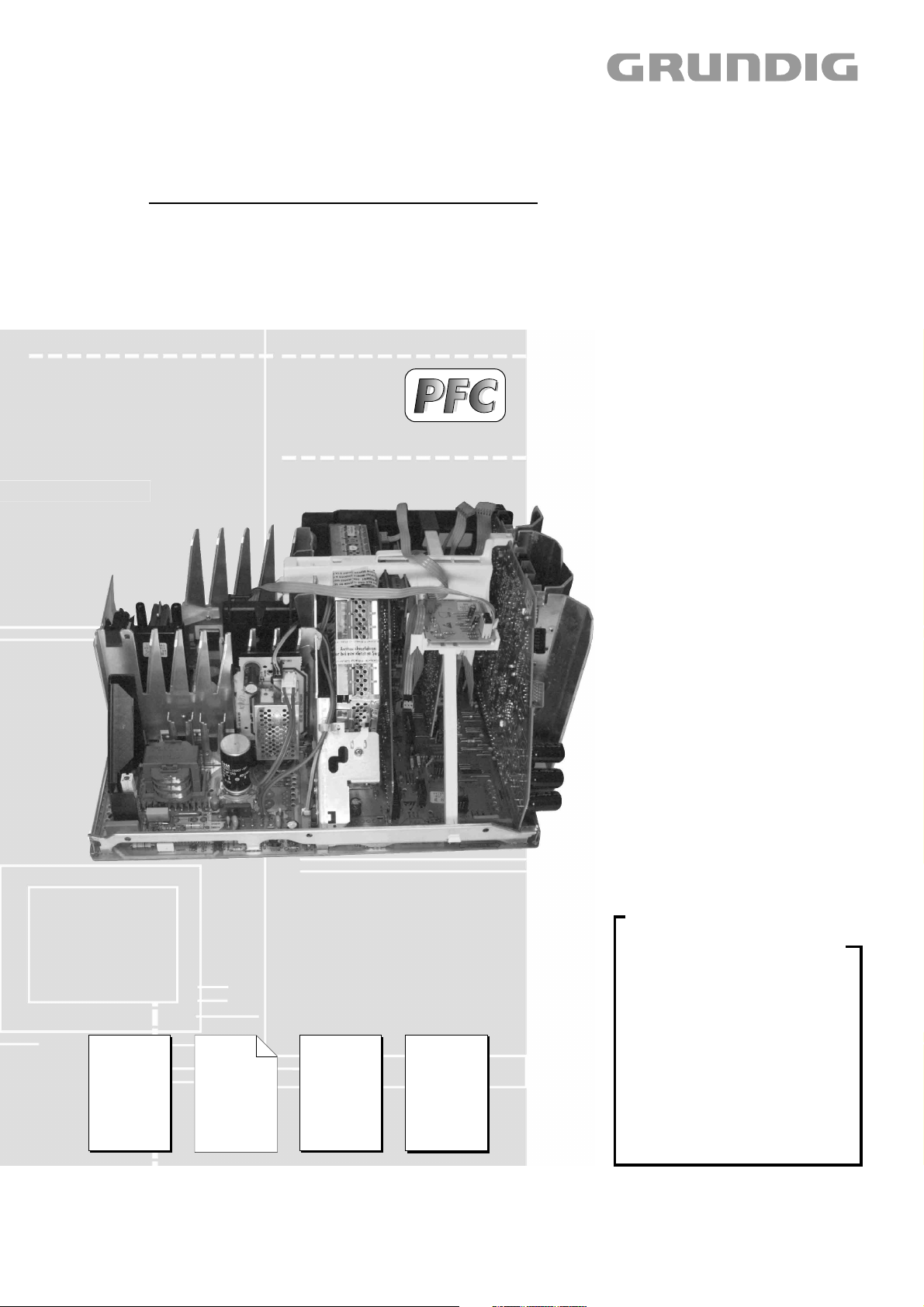
9. Ergänzung / Supplement 9
CUC 1931 Basic 3
ARGANTO 82 Flat
MFW 82 – 530/9 DVD
GCL8740, VNM
Zusätzlich erforderliche Unterlagen für den Komplettservice
Additionally required Service Documents for the Complete Service
Service
Manual
CUC 1832
CUC 1930/31
(Basic 3)
Materialnr./Part No.
720100249000
Materialnummer/Part Number 720100249900
Änderungen vorbehalten/Subject to alteration • Printed in Germany
E-BS-SA 17 0401
http://www.grundig.com
Ergänzung
Supplement
5
Materialnr./Part No.
720100249500
Service
Manual
Sicherheit
Safety
Materialnr./Part No.
720108000000
Service
Training
Basic 3
Materialnr./Part No.
Ķ 720103503700
ķ 720103503750
Grundig Service
Hotline Deutschland...
Technik:
TV
TV
SAT
VCR/LiveCam
HiFi/Audio
Car Audio
Telekommunikation
Planatron
Ersatzteil-Verkauf: ...Mo.-Fr. 8.00-19.00 Uhr
(8.00-22.00
...Mo.-Fr. 8.00-18.00 Uhr
0180/52318-41
0180/52318-49
0180/52318-48
0180/52318-42
0180/52318-43
0180/52318-44
0180/52318-45
Fax:
Telefon:
Fax:
0180/52318-51
0180/52318-99
Uhr)
0180/52318-40
0180/52318-50
Page 2

Allgemeiner Teil / General Section CUC 1931
Es gelten die Vorschriften und Sicherheitshinweise
gemäß dem Service Manual "Sicherheit", Materialnummer 720108000000, sowie zusätzlich die eventuell abweichenden, landesspezifischen Vorschriften!
PFC (Power Factor Correction)
Die PFC-Schaltung ist im Schaltplan Netz-Chassis mit "OPTION D"
gekennzeichnet.
Für die auf der Titelseite aufgeführten Chassis gilt das Service Manual
CUC 1832/1930/1931 (Basic 3).
Diese Ergänzung dokumentiert die Unterschiede bzw. zusätzlichen
Bestückungen der auf der Titelseite aufgeführten Geräte.
Grundlage für den Service sind:
–Service Manual CUC 1832/1930/1931 (Materialnummer 720100249000)
–5. Ergänzung CUC 1832/1931 (Materialnummer 720100249500)
–Service Manual "Sicherheit" (Materialnummer 720108000000)
Inhaltsverzeichnis
Seite
Hinweise ......................................................................................... 2
Modulauflistung – Service Manual mit Ergänzungen ...................... 3
Modulübersicht ................................................................................ 4
Technische Daten ........................................................................... 5
Ausbauhinweise .............................................................................. 6
Verdrahtungsplan-Tabelle ............................................................... 9
Verdrahtungsplan .......................................................................... 11
Chassisplatte ................................................................................ 15
Chassisplatte (vergrößert) ............................................................ 21
Oszillogramme (Chassis) .............................................................. 25
Netz-Chassis ................................................................................. 27
Signal-Chassis .............................................................................. 31
Feature Box 295042091300 ......................................................... 35
Signal-Baustein 295042620300 .................................................... 42
Standby Netzteil 293040508500 ................................................... 47
Bildrohrplatte 293051222900 ........................................................ 48
Dolby-Surround-Platte 295042041400 ......................................... 51
Buchsenplatte Click Fit ................................................................. 59
Fokussierungsplatte 293050253700 ............................................. 61
Adapterplatte ................................................................................. 62
EURO-AV-Buchsenplatte .............................................................. 63
DVD-Steuerplatte .......................................................................... 64
Ersatzteillisten ............................................................................... 65
The regulations and safety instructions shall be
valid as provided by the "Safety" Service Manual,
part number 720108000000, as well as the
respective national deviations.
PFC (Power Factor Correction)
The PFC circuit is marked with "OPTION D" in the circuit diagram
mains chassis.
The Service Manual CUC 1832/1930/1931 (Basic 3) applies to the
chassis specified on the front page.
This Manual describes the differences and the additionally fitted
components of the TV receivers specified on the front page.
Basic instructions for servicing are given in the:
–Service Manual CUC 1832/1930/1931 (Part number 720100249000)
–Supplement 5 CUC 1832/1931 (Part number 720100249500)
–Service Manual "Safety" (Part number 720108000000)
Table of Contents
Page
Notes ............................................................................................... 2
List of Modules – Service Manual with Supplements...................... 3
Module List ...................................................................................... 4
Technical Data ................................................................................ 5
Disassembly Instructions ................................................................ 6
Table of Wiring Diagram ................................................................. 9
Wiring Diagram ............................................................................. 11
Chassis Board ............................................................................... 15
Chassis Board (enlarged) ............................................................. 21
Oscillograms (Chassis) ................................................................. 25
Mains Chassis ............................................................................... 27
Chassis Signal .............................................................................. 31
Feature Box 295042091300 ......................................................... 35
Signal Module 295042620300 ...................................................... 42
Section Standby 293040508500 ................................................... 47
CRT Panel 293051222900 ........................................................... 48
Dolby-Surround Board 295042041400 ......................................... 51
Socket Board Click Fit ................................................................... 59
Focusing Board 293050253700 .................................................... 61
Adapter Board ............................................................................... 62
EURO-AV Socket Board ............................................................... 63
DVD Control Board ....................................................................... 64
Spare Parts Lists ........................................................................... 65
Hinweise
Wegen Veränderung des Schwerpunktes beim Abnehmen der
Rückwand bzw. Ausbau des Chassis oder Entfernen eines eventuell vorhandenen Standfußes ist das Gerät gegen Kippen zu
sichern.
Netzkabel
Diese Geräte dürfen nur mit dem Original-Netzanschlusskabel mit
integrierter Entstördrossel betrieben werden. Dieses Netzkabel verhindert Störungen aus dem Netz und ist Bestandteil der Geräte-
zulassung. Im Ersatzfall bestellen Sie bitte ausschließlich das Netzkabel laut Ersatzteilliste.
DOLBY-Hinweis
DOLBY und das Doppel-D-Symbol ij sind Warenzeichen der Dolby
Laboratories Licensing Corporation.
2 GRUNDIG Service
Notes
Because of the change of the centre of gravity when removing the
rear panel, the chassis or an existing stand, it is necessary to
protect the set from tipping.
Mains Cable
The TV receiver must only be operated with an original mains connecting
cable with an interference suppressor choke integrated in the mains
plug.This mains cable prevents interference from the mains supply and
is part of the product approval. For replacement please order exclusively
the mains connecting cable specified in the spare parts list.
DOLBY Hint
DOLBY and the double-D symbol ij are trademarks of Dolby
Laboratories Licensing Corporation.
Page 3
CUC 1931 Allgemeiner Teil / General Section
Modul
Module
720100249000 720100249500 720100249900
Chassisplatte
Chassis Board
29704007 . . . .
Seite / Page 3-1 Seite / Page 15
Signal-Baustein
Signal Module
295042620300 Seite / Page 42
295042031800
Seite / Page 17
Feature Box
295042091300 Seite / Page 35
Bildrohrplatte
CRT Panel
293051222900
Seite / Page 48
Fokussierungsplatte
Focusing Board
293050253700
Seite / Page 3-83 Seite / Page 61
293051291800
Seite / Page 28
Netzteil Standby
Mains Chassis Standby
293040508500
Seite / Page 47
Adapterplatte
Adapter Board
293051291200
Seite / Page 62
Netzschalterplatte
Mains Switch Board
293050870500
Seite / Page 25
Keyboard
295010838000
Seite / Page 3-67 Seite / Page 27
Dolby-Surround-Platte
Dolby-Surround Board
295042041400
Seite / Page 51
293051603700
Seite / Page 3-77 Seite / Page 63
Buchsenplatte Click Fit
Click Fit Socket Board
293051606000
Seite / Page 3-87 Seite / Page 15 Seite / Page 59
DVD-Steuerplatte
DVD Control Board
293051291700
Seite / Page 64
PIP-Baustein
PIP Module
295042060100
Seite / Page 3-94
SAT-Baustein
SAT Module
295042220100
Seite / Page 3-89
DVD:
DVD-Einheit kpl.
DVD Unit cpl.
296322560101
DVD-Modul kpl.
DVD Module cpl.
296383951201
Prozessor-Modul
Durch den Tausch des Prozessor-Moduls sind alle im NVM gespeicherten Daten (z.B. Abgleich, Sendereinstellungen) nicht mehr vorhanden.
Das Gerät muss mit den Mittelwerten / Notdatensatz (ROM-Daten)
geladen werden:
Nahbedientaste "P-" gedrückt halten und das Gerät mit dem Netz-
schalter einschalten.
Durch diesen Vorgang werden die Grunddaten aus dem EPROM
IC80070 in den NVM CIC80095 kopiert.
Der Software-Abgleich muss komplett durchgeführt werden (siehe
Service Manual Materialnummer 720100249000 / Kapitel 2 Abgleich).
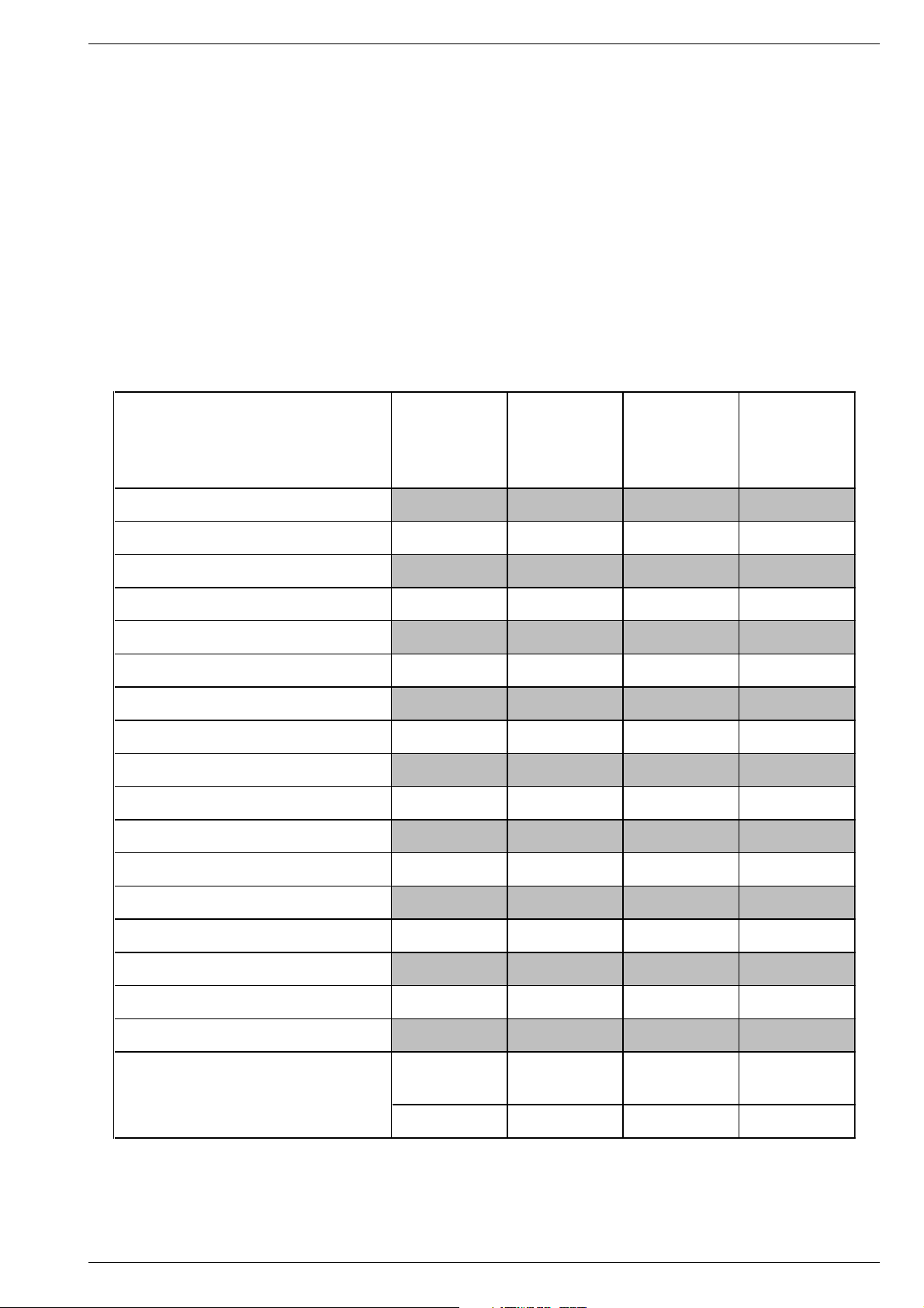
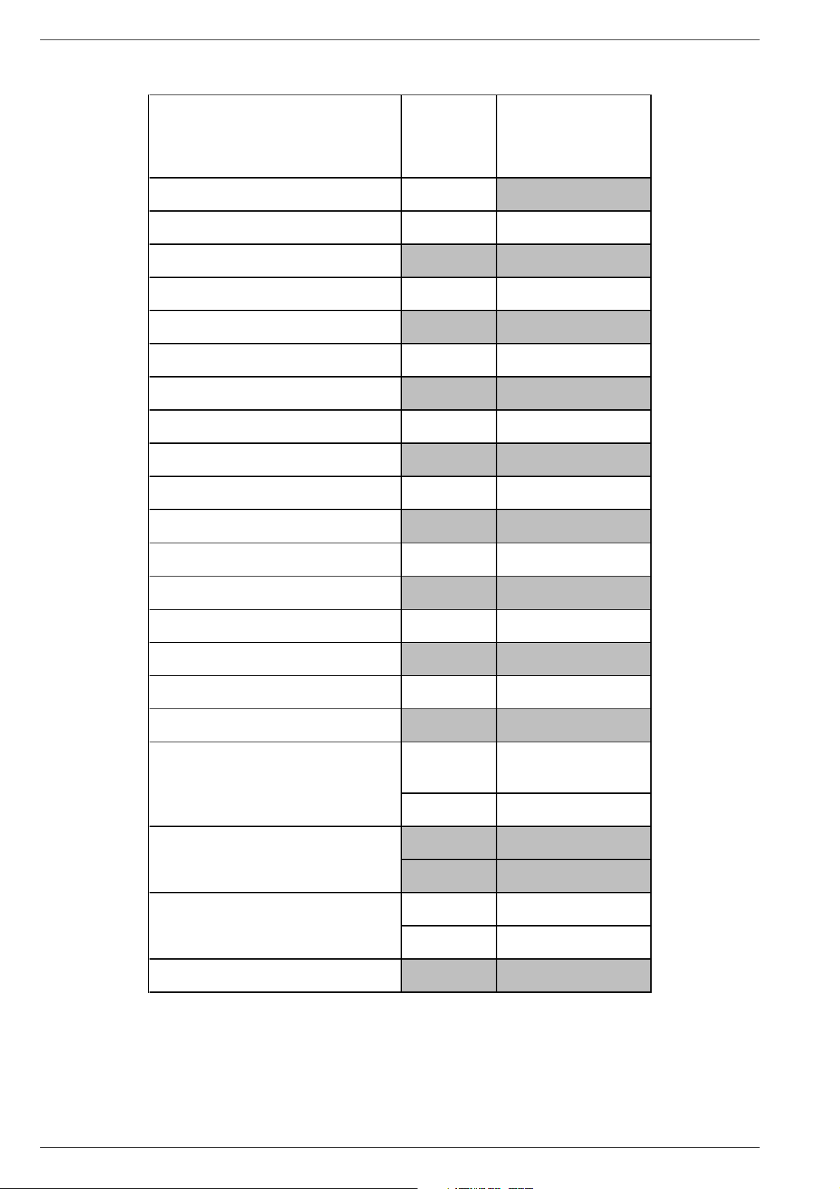
Modulauflistung – Service Manual mit Ergänzungen
List of Modules – Service Manual with Supplements
Materialnummer
Part Number
Prozessing Board
When changing the Processing Board, all data stored in the NVM (e.g.
adjustment, channels) are cancelled.
The television set has to be loaded with the default values/emergency
data set (ROM data):
Depress and hold the "P-" button down while switching the television
set on with the mains switch.
In doing so the default values are loaded from EPROM IC80070 into
NVM CIC80095.
The software has to be adjusted completely (see Service Manual, part
number 720100249000 / chapter 2, Adjustment).
Service Manual
CUC 1832 /
1930 / 1931
5. Ergänzung
Supplement 5
CUC 1930 / 1931
9. Ergänzung
Supplement 9
CUC 1931
Prozessor-Modul mit VGA
Processing Board with VGA
Rotations- und N/S-Trapezkorrekturplatte
Rotation and N/S Trapezium Correction Board
EURO-AV-Buchsenplatte
EURO-AV Socket Board
GRUNDIG Service 3
Service Manual
720100279100
Service Manual
720100279100
Page 4
Allgemeiner Teil / General Section CUC 1931
Modulübersicht / Module List
ARGANTO 82 Flat
Materialnummer
Part Number
MFW 82 – 530/9 DVD
(VNM)
CUC 1931
Bestell-Nummer
Order Number
Chassis-Nummer
Chassis Number
Tuner
Signal-Baustein
Signal Module
Prozessor-Modul mit VGA
Processing Board with VGA
Feature Box
Bildrohrplatte
CRT Panel
Fokussierungsplatte
Focusing Board
Rotations- und N/S-Trapezkorrekturplatte
Rotation and N/S Trapezium Correction Board
Netzteil Standby
Mains Chassis Standby
Adapterplatte
Adapter Board
Netzschalterplatte
Mains Switch Board
Keyboard
295043010100
295042620300
295042031800
295042091300
293051222900
293050253700
293051291800
293040508500
293051291200
293050870500
295010838000
GCL8740
297040073100
•
•
•
•
•
•
•
•
•
•
•
Dolby-Surround-Platte
Dolby-Surround Board
Euro-AV-Buchsenplatte
Euro-AV Socket Board
Buchsenplatte Click Fit
Click Fit Socket Board
DVD-Steuerplatte
DVD Control Board
DVD:
DVD-Einheit kpl.
DVD Unit cpl.
DVD-Modul kpl.
DVD Module cpl.
PIP 5 nachrüstbar
PIP 5 retrofittable
PIP 6 nachrüstbar
PIP 6 retrofittable
SAT-Baustein SER 300 nachrüstbar
SAT Module SER 300 retrofittable
SAT-Baustein SER 300a nachrüstbar
SAT Module SER 300a retrofittable
TP120DC 296420610600
295042041400
293051603700
293051606000
293051291700
296322560101
296383951201
GAE2000
GAE7300 ww / or
GAE3700
GAE9000 ww / or
•
•
•
•
•
•
•
•
•
4 GRUNDIG Service
Page 5
CUC 1931 Allgemeiner Teil / General Section
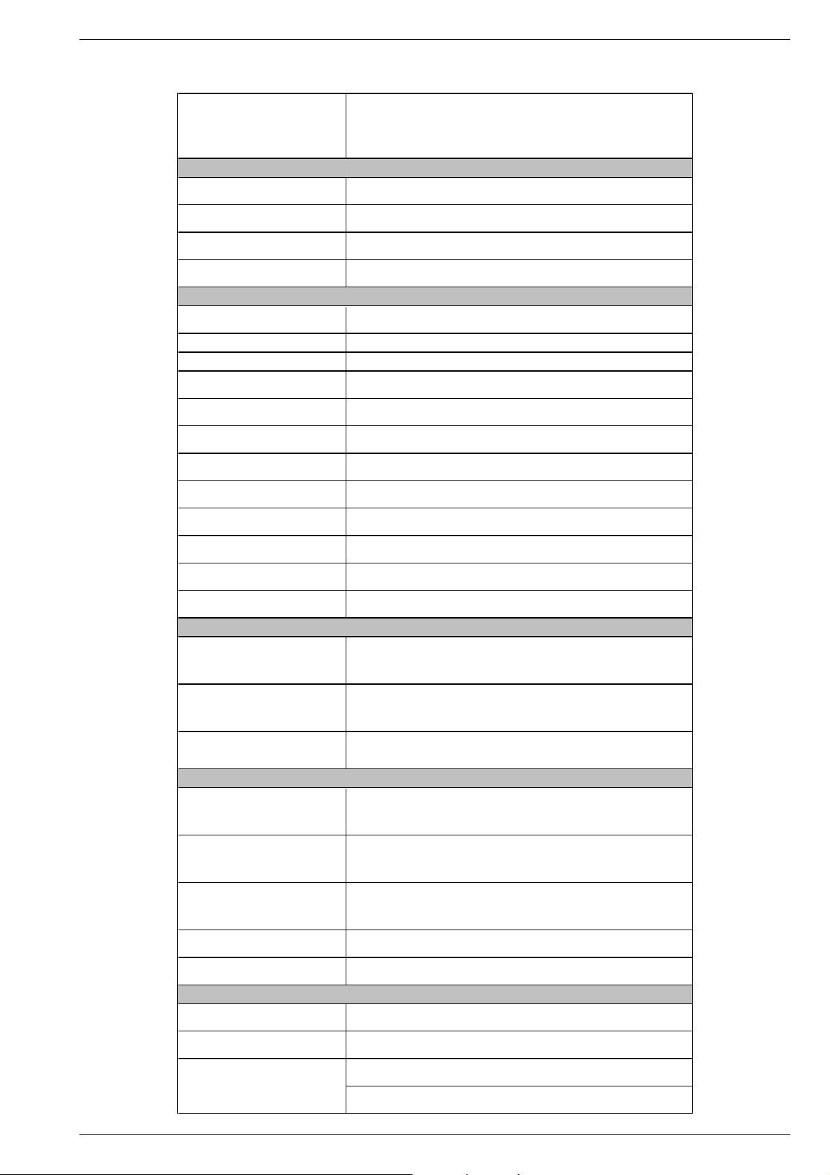
Technische Daten / Technical Data
ARGANTO 82 Flat
MFW 82 – 530/9 DVD
(VNM)
CUC 1931
Bildröhre / Picture Tube
Sichtbares Bild
Visible picture
Bildschirmdiagonale
Screen diagonal
Formatumschaltung
Format switching
Bildwechselfrequenz
Vertical frequency
Elektronik / Electronic
Programmspeicherplätze
Programme positions
TV Guide ja / yes
Easy dialog ja / yes
Tuner
TV-Normen
TV Standards
Stereo-Systeme
Stereo systems
Videotext
Teletext
Musikleistung mit DPL
Music power with DPL
Musikleistung ohne externe LS
Music power without external LS
PIP/Signalbaustein mit Splitter
PIP/Signal module with splitter
PIP/SAT
SAT
Anschlüsse Front / Connections Front
Kopfhörer
Headphones
Cinch-AV-Buchse
Cinch-AV socket
S-Video
Anschlüsse Rückwand / Connections Rear Panel
Euro AV 1 (schwarz/black)
Euro AV 2 (orange)
Euro AV 3 (blau/blue)
Standard VGA / 2 Cinch NF/in
Standard VGA / 2 Cinch AF/in
Cinch-NF-Buchsen Ausgang
Cinch-AF sockets output
Netzteil / Mains Stage
Netzspannung (Regelbereich)
Mains voltage (variable)
Netzfrequenz
Mains frequency
Leistungsaufnahme
Power consumption
Standby ca. 3W
4:3, Cinema Zoom (432 Zeilen/lines), Panorama Zoom, Format Automatic, 16:9,
automatische Umschaltung auf PALplus / automatic change to PALplus
(199 TV/SAT + 59 Radio + 5 AV bei Nachrüstung SAT / when retrofitted with SAT)
PLL Frequenz Synthesizer Tuning UHF/VHF, globale Pinbelegung
40W (4Ω) Subwoofer + 2x20W (4Ω) L/R + 20W (4Ω) center + 20W (2 x 8Ω) rear
FBAS Ein-/Ausgang, RGB Eingang, SBAS Ein-/Ausgang, Megalogic,
Datalink für VCR Fernbedienung, Decoder, 16:9 Erkennung / Pin 8)
datalink for VCR remote control, decoder capable, 16:9 detection / Pin 8)
16:9, 82cm (32") MEGATRON Flat, Real Flat,
Black Line S, CCS/TARAS, Invar, Philips/106°
PLL frequency synthesizer tuning UHF/VHF, global pinning
PAL, SECAM, NTSC 4.43MHz + 3.58MHz,
Deutsch A2 / German A2 (B/G/D/K)
Nicam 5.85 (BG, L) + 6.52MHz (I)
Megatext Level 2.5, VPS, 512 Seiten
Megatext level 2.5, VPS, 512 pages
Stereo 5-Kanal 120W / Stereo 5-channel 120W:
Stereo 3-Kanal 80W / Stereo 3-channel 80W:
40W Subwoofer + 2x20W L/R
nachrüstbar mit Modul SET PIP 5
retrofittable with Module SET PIP 5
nachrüstbar mit Modul SET PIP 6
retrofittable with Module SET PIP 6
nachrüstbar mit SAT-Baustein SER 300/SER 300a
retrofittable with SAT Module SER 300/SER 300a
Stereo 3,5mm Klinkenbuchse, Lautstärke regelbar,
individuelle Tonkanalwahl bei 2-Ton-Empfang
Stereo 3.5mm jack, adjustable volume,
individual channel selection with dual-sound broadcasts
4-polige Buchse Y-Chroma / in
4-pin socket Y-Chroma / in
Datalink für VCR Fernbedienung, Decoder, 16:9 / Pin 8
CCVS in-/output, RGB input, SCVS in-/output, Megalogic,
datalink for VCR remote control, decoder capable, 16:9 / Pin 8
DVD (FBAS Ein-/Ausgang, RGB Eingang, SBAS Eingang,
DVD (CCVS in-/output, RGB input, SCVS input,
FBAS Ein-/Ausgang, SBAS Ein-/Ausgang,
Datalink für VCR-Fernbedienung, 16:9 / Pin 8
CCVS in-/output, SCVS in-/output,
datalink for VCR remote control, 16:9 / Pin 8
Bildschirmauflösung / Screen resolution 640X480,
31,5kHz/60Hz, Textmode 31,5kHz/70Hz (AV 5 Position)
Audio Stereoausgang mit regelbarem oder konstantem Pegel
Audio stereo output with variable or constant level
76cm
100Hz
99 + 5 AV
B/G, L/L', I, DK/K', M
1x FBAS Video / in
1x CCVS Video / in
2x Audio / in
(AV 4 Position)
(AV 4 Position)
230V±15%
50 / 60Hz
ca. 170W
GRUNDIG Service 5
Page 6
Allgemeiner Teil / General Section CUC 1931
Ausbauhinweise
Vor dem Öffnen des Gehäuses zuerst den Netzstecker ziehen!
Leitungsverlegung
Bevor Sie die Leitungen und insbesondere die Masseleitungen lösen,
muss die Leitungsverlegung zu den einzelnen Baugruppen wie z.B.
Chassis, Netzschalterplatte, Bedieneinheit, Bildrohrplatte, Ablenkeinheit, Lautsprecher usw. beachtet werden.
Nach erfolgter Reparatur ist es notwendig, die Leitungsführung wieder
in den werkseitigen Zustand zu versetzen um eventuell spätere
Ausfälle oder Störungen zu vermeiden.
Öffnen des Gehäuses
- 8 Rückwandschrauben herausschrauben.
- Gehäuserückwand vorsichtig nach hinten abnehmen bis die
Subwoofer-Leitung gelöst werden kann.
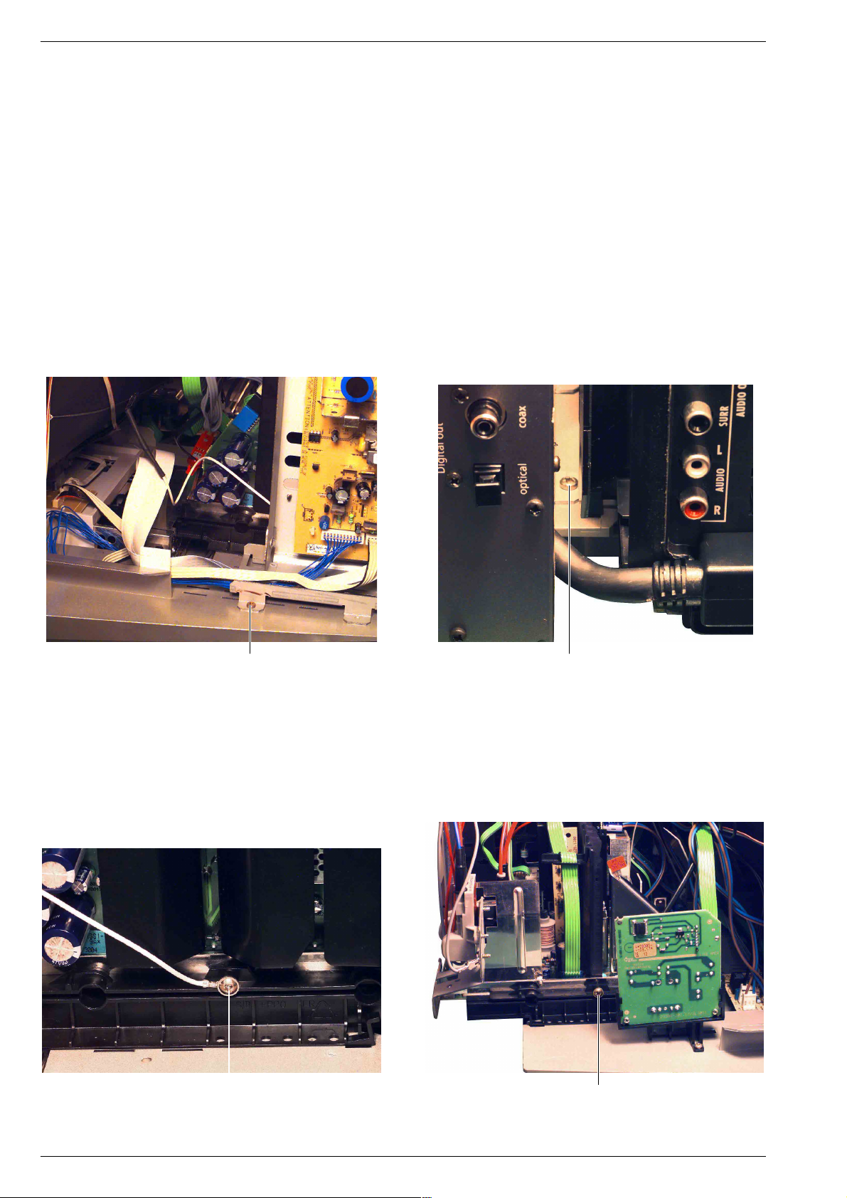
1. DVD-Einheit ausbauen
- 2 Schrauben A (Fig. 1, 2) herausschrauben und DVD-Einheit
entnehmen, gegebenenfalls Leitungen lösen.
Achtung: Leitungsverlegung beachten!
Disassembly Instructions
Before opening the cabinet disconnect the mains plug!
Wiring
Before disconnecting any leads and especially the earth connecting
leads observe the way they are routed to the individual assemblies like
the chassis, mains switch panel, keyboard control panel, picture tube
panel, deflection unit, loudspeaker and so on.
On completion of the repairs the leads must be laid out as originally
fitted at the factory to avoid later failures or disturbances.
Opening the cabinet
- Undo the 8 screws in the rear panel.
- Remove the rear panel carefully to the rear until the subwoofer lead
can be disengaged.
1. Removing the DVD unit
- Undo the 2 screws A (Fig. 1, 2) then remove the DVD unit.
Disconnect the leads if necessary.
Attention: observe the way the leads are routed!
Fig. 1 Fig. 2
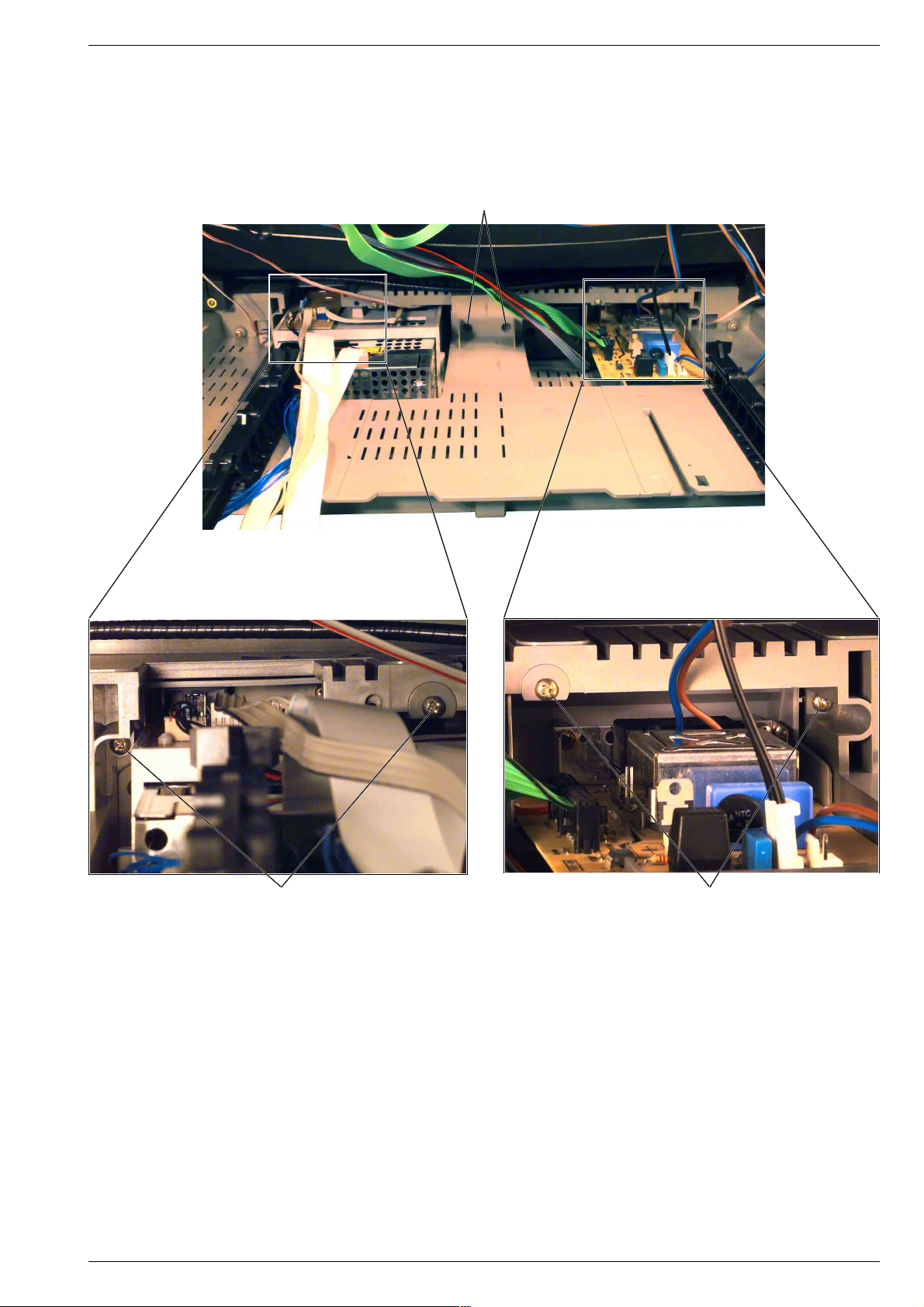
2. Chassis ausbauen
- DVD-Einheit ausbauen (Pkt. 1).
- 2 Schrauben B (Fig. 3, 4) herausschrauben und Chassis nach
hinten herrausziehen, gegebenenfalls Kabelbinder und Leitungen
lösen.
Achtung: Leitungsverlegung beachten!
A
2. Removing the chassis
- Remove the DVD unit (para 1).
- Undo the 2 screws B (Fig. 3, 4) then pull out the chassis to the rear.
If necessary undo the cable clamps and disconnect the leads.
Attention: observe the way the leads are routed!
A
Fig. 3 Fig. 4
6 GRUNDIG Service
B B
Page 7
Allgemeiner Teil / General SectionCUC 1931
3. Bedienungseinsatz ausbauen
- Chassis ausbauen (Pkt. 2).
- Kabelbinder und Leitungen lösen.
Achtung: Leitungsverlegung beachten!
- 6 Schrauben C (Fig. 5) herausschrauben und Bedienungseinsatz
nach vorne herausnehmen.
3. Removing the keyboard control unit
- Remove the chassis (para 2).
- Undo the cable clamps and disconnect the leads.
Attention: observe the way the leads are routed!
- Undo the 6 screws C (Fig. 5) and remove the control unit to the front.
C
Fig. 5
Fig. 5a Fig. 5b
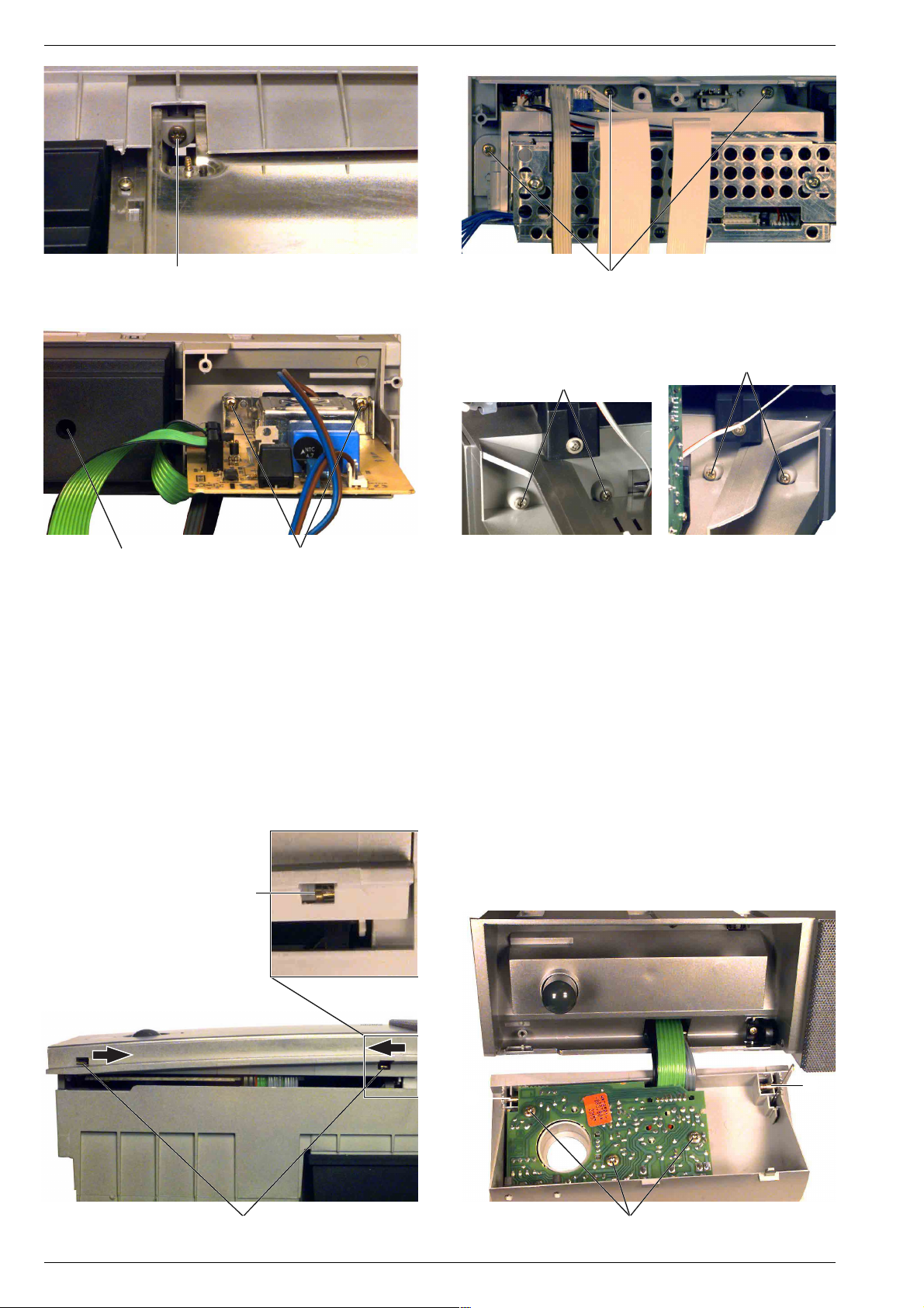
4. DVD-Laufwerk ausbauen
- Bedienungseinsatz ausbauen (Pkt. 3).
- Schraube D (Fig. 6) auf der Laufwerk-Unterseite herausschrauben.
- 3 Schrauben E (Fig. 7) herausschrauben und das DVD-Laufwerk
herausnehmen.
5. Netzschalterplatte ausbauen
- Chassis ausbauen (Pkt. 2).
- 2 Schrauben F (Fig. 8) herausschrauben und die Netzschalterplatte herausnehmen.
6. Center-Lautsprecher ausbauen
- Das eingeklebte Lautsprechergitter vorsichtig abnehmen.
- Lautsprecherschrauben herausschrauben und Lautsprecher vorsichtig herausnehmen.
Achtung: Kann der Lautsprecher wegen zu kurzem Lautsprecher-
kabel nicht angeschlossen werden, so muss der Bedienungseinsatz
ausgebaut werden (Pkt. 3). Danach die Schraube G (Fig. 8)
herausschrauben, Lautsprechergehäuse öffnen und Lautsprecher
anschließen.
C C
4. Removing the DVD drive mechanism
- Remove the control unit (para 3).
- Undo the screw D (Fig. 6) on the bottom of the drive mechanism.
- Undo the 3 screws E (Fig. 7) and remove the DVD drive
mechanism.
5. Removing the mains switch panel
- Remove the chassis (para 2).
- Undo the 2 screws F (Fig. 8) then remove the mains switch panel.
6. Removing the center loudspeaker
- Carefully remove the loudspeaker grille fixed with glue.
- Undo the loudspeaker screws then carefully remove the
loudspeaker.
Attention: if the loudspeaker cannot be conected as the loudspeaker
leads are too short, it is necessary to remove the control unit
(para 3). When this is done, undo the screw G (Fig. 8), open the
loudspeaker cabinet and then connect the loudspeaker.
GRUNDIG Service 7
Page 8
Allgemeiner Teil / General Section CUC 1931
Fig. 6
Fig. 8
7. Lautsprecher-Box links und rechts ausbauen
- Kabelbinder und Leitungen lösen.
- Je 2 Schrauben H
Box nach vorne herausnehmen.
Achtung: Leitungsverlegung beachten!
8. Bedienklappe und Keyboard ausbauen
- Bei Bedarf Kabelbinder und Leitungen lösen.
- 2 Bolzen I
nach unten klappen.
- 3 Schrauben J
nehmen.
Achtung: Leitungsverlegung beachten!
G F
(Fig. 11, 12)
D
(Fig. 9, 10)
(Fig. 12)
herausschrauben und Lautsprecher-
in Pfeilrichtung schieben und Bedienklappe
herausschrauben und Keyboard heraus-
Fig. 7
E
H
H
Fig. 9
7. Removing the left and right loudspeaker box
- Undo the cable clamps and disconnect the leads.
- Undo the 2 screws H
loudspeaker box to the front.
Attention: observe the way the leads are routed!
8. Removing the control panel flap and the keyboard
- If necessary undo the cable clamps and disconnect the leads.
- Slide the 2 bolts I
the control panel flap down.
- Undo the 3 screws J
Attention: observe the way the leads are routed!
(Fig. 9, 10)
(Fig. 11, 12)
(Fig. 12)
Fig. 10
on each box then remove the
in the direction of the arrow then tilt
and remove the keyboard.
I
I
I
Fig. 11
8 GRUNDIG Service
I
Fig. 12
J
Page 9

CUC 1931 Platinenabbildungen und Schaltpläne / Layout of the PCBs and Circuit Diagrams
Platinenabbildungen und Schaltpläne / Layout of PCBs and Circuit Diagrams
Verdrahtungsplan-Tabelle / Table of Wiring Diagram
PCB >
Bezeichnung
Name
Netzteilplatte (DVD)
Power Supply (DVD)
Netzteilplatte (DVD-Teil)
Power Supply (DVD Part)
Netzteilplatte (DVD-Teil)
Power Supply (DVD Part)
Eject-Platte (DVD-Teil)
Eject Board (DVD Part)
Eject-Platte (DVD-Teil)
Eject Board (DVD Part)
Eject-Platte (DVD-Teil)
Eject Board (DVD Part)
Jochanschlussplatte
Yoke Connecting Board
EURO-AV-Platte (DVD-Teil)
EURO-AV Board (DVD Part)
EURO-AV-Platte (DVD-Teil)
EURO-AV Board (DVD Part)
DVD-Laufwerk
DVD Drive Mechanism
DVD-Laufwerk
DVD Drive Mechanism
DVD-Laufwerk
DVD Drive Mechanism
DVD-Laufwerk
DVD Drive Mechanism
Netzbuchse
Mains Socket
Feature Box BU
Chassis-Platte
Chassis Board
Chassis-Platte
Chassis Board
Chassis-Platte
Chassis Board
Chassis-Platte
Chassis Board
Chassis-Platte
Chassis Board
Chassis-Platte
Chassis Board
Fokussierungsplatte
Focusing Board
IR-Platte (DVD-Teil)
IR Board (DVD Part)
Prozessor-Modul
Processing Board
Prozessor-Modul
Processing Board
Dolby-Surround-Platte
Dolby-Surround Board
Dolby-Surround-Platte
Dolby-Surround Board
Prozessor-Modul
Processing Board
SAT-Baustein 2 (mit 2 SAT-Bausteinen)
SAT Module 2 (with 2 SAT Modules)
SAT-Baustein (mit 1 SAT-Baustein)
SAT Module (with 1 SAT Module)
SAT-Baustein 1 (mit 2 SAT-Bausteinen)
SAT Module 1 (with 2 SAT Modules)
SAT-Baustein 2 (mit 2 SAT-Bausteinen)
SAT Module 2 (with 2 SAT Modules)
SAT-Baustein (mit 1 SAT-Baustein)
SAT Module (with 1 SAT Module)
SAT-Baustein 1 (mit 2 SAT-Bausteinen)
SAT Module 1 (with 2 SAT Modules)
EURO-AV-Buchsenplatte
EURO-AV Socket Board
EURO-AV-Buchsenplatte
EURO-AV Socket Board
Bildrohrplatte
CRT Panel
Buchsenplatte Click Fit
Click Fit Socket Board
Rotations- und N/S-Trapezkorrekturplatte
Rotation and N/S Trapezium Correction Board
Fokussierungsplatte
Focusing Board
DVD-Steuerplatte
DVD Control Board
Verbindung /
Steckplatz
Connection /
Plug-in Position
0101 <–> ST-DVD
0205 <–> 1600
0207 <–> 1002
1000 <–> 1501
1002 <–> 0207
1004 <–> ST-1004
1015 <–> ST-ZS1
1300 <–> 1603
1301 <–> 1604
1501 <–> 1000
1600 <–> 0205
1603 <–> 1300
1604 <–> 1301
230V <–> ST-NETZ2
BU1 <–> STL
BU1 <–> STL
BU2 <–> STL
BU2 <–> STL
BU2 <–> STL
DF1–3 <–> FSTIF02
FSTIF02 <–> DF1–3
ST-1004 <–> 1004
ST-AUX1 <–> ST-AUX1A
ST-AUX1 <–> ST-AUX1A
ST-AUX1 <–> ST-AUX1B
ST-AUX1 <–> ST-AUX1B
ST-AUX1A
ST-AUX1A
ST-AUX1A <–> ST-AUX1
ST-AUX1A <–> ST-AUX1
ST-AUX1B
ST-AUX1B <–> ST-AUX1
ST-AUX1B <–> ST-AUX1
ST-AV3
ST-AV3V
ST-BR
ST-CE
ST-DF2
ST-DFB <–> U / DYN FOC
ST-DVD <–> 0101
< PCB
Bezeichnung
Name
DVD-Steuerplatte
DVD Control Board
DVD-Laufwerk
DVD Drive Mechanism
Eject-Platte (DVD-Teil)
Eject Board (DVD Part)
DVD-Laufwerk
DVD Drive Mechanism
Netzteilplatte (DVD-Teil)
Power Supply (DVD Part)
IR-Platte (DVD-Teil)
IR Board (DVD Part)
Adapterplatte
Adapter Board
DVD-Laufwerk
DVD Drive Mechanism
DVD-Laufwerk
DVD Drive Mechanism
Eject-Platte (DVD-Teil)
Eject Board (DVD Part)
Netzteilplatte (DVD-Teil)
Power Supply (DVD Part)
EURO-AV-Platte (DVD-Teil)
EURO-AV Board (DVD Part)
EURO-AV-Platte (DVD-Teil)
EURO-AV Board (DVD Part)
Netzschalterplatte
Mains Switch Board
Chassis-Platte
Chassis Board
Signal-Baustein 295042620300
Signal Module 295042620300
SAT-Baustein 1 (mit 2 SAT-Bausteinen)
SAT Module 1 (with 2 SAT Modules)
PIP/Signal-Baustein 295042120200
PIP/Signal Module 295042120200
SAT-Baustein (mit 1 SAT-Baustein)
SAT Module (with 1 SAT Module)
SAT-Baustein 2 (mit 2 SAT-Bausteinen)
SAT Module 2 (with 2 SAT Modules)
Fokussierungsplatte
Focusing Board
Chassis-Platte
Chassis Board
Eject-Platte (DVD-Teil)
Eject Board (DVD Part)
SAT-Baustein (mit 1 SAT-Baustein)
SAT Module (with 1 SAT Module)
SAT-Baustein 1 (mit 2 SAT-Bausteinen)
SAT Module 1 (with 2 SAT Modules)
SAT-Baustein (mit 1 SAT-Baustein)
SAT Module (with 1 SAT Module)
SAT-Baustein 1 (mit 2 SAT-Bausteinen)
SAT Module 1 (with 2 SAT Modules)
Dolby-Surround-Platte
Dolby-Surround Board
nicht belegt
not used
Prozessor-Modul
Processing Board
Prozessor-Modul
Processing Board
nicht belegt
not used
Dolby-Surround-Platte
Dolby-Surround Board
Dolby-Surround-Platte
Dolby-Surround Board
Chassis-Platte
Chassis Board
Chassis-Platte
Chassis Board
Chassis-Platte
Chassis Board
Lautsprecher centre intern
Loudspeaker centre intern
Fokussierungsplatte
Focusing Board
Fokus-Block
Focus Block
Netzteilplatte (DVD)
Power Supply (DVD)
GRUNDIG Service 9
Page 10

Platinenabbildungen und Schaltpläne / Layout of the PCBs and Circuit Diagrams CUC 1931
PCB >
Bezeichnung
Name
Netzschalterplatte
Mains Switch Board
Chassis-Platte
Chassis Board
Bildrohrplatte
CRT Panel
Keyboard ST-H-AV
SAT-Baustein (mit 1 SAT-Baustein)
SAT Module (with 1 SAT Module)
SAT-Baustein 2 (mit 2 SAT-Bausteinen)
SAT Module 2 (with 2 SAT Modules)
SAT-Baustein 1 (mit 2 SAT-Bausteinen)
SAT Module 1 (with 2 SAT Modules)
Netzschalterplatte
Mains Switch Board
Netzschalterplatte
Mains Switch Board
Dolby-Surround-Platte
Dolby-Surround Board
Dolby-Surround-Platte
Dolby-Surround Board
Dolby-Surround-Platte
Dolby-Surround Board
Dolby-Surround-Platte
Dolby-Surround Board
DVD-Steuerplatte
DVD Control Board
Chassis-Platte
Chassis Board
Netzschalterplatte
Mains Switch Board
DVD-Steuerplatte
DVD Control Board
Netzschalterplatte
Mains Switch Board
Netzschalterplatte
Mains Switch Board
Prozessor-Modul
Processing Board
Prozessor-Modul
Processing Board
Prozessor-Modul
Processing Board
Prozessor-Modul
Processing Board
Prozessor-Modul
Processing Board
PIP-Baustein
PIP Module
PIP-Baustein
PIP Module
Bildrohrplatte
CRT Panel
Rotations- und N/S-Trapezkorrekturplatte
Rotation and N/S Trapezium Correction Board
Prozessor-Modul
Processing Board
Keyboard ST-SV1
Buchsenplatte Click Fit
Click Fit Socket Board
Standby Netzteil
Power Supply Standby
Standby Netzteil
Power Supply Standby
Prozessor-Modul
Processing Board
Chassis-Platte
Chassis Board
Adapterplatte
Adapter Board
Dolby-Surround-Platte
Dolby-Surround Board
Signal-Baustein 295042620300
Signal Module 295042620300
SAT-Baustein 1 (mit 2 SAT-Bausteinen)
SAT Module 1 (with 2 SAT Modules)
PIP/Signal-Baustein 295042120200
PIP/Signal Module 295042120200
SAT-Baustein (mit 1 SAT-Baustein)
SAT Module (with 1 SAT Module)
SAT-Baustein 2 (mit 2 SAT-Bausteinen)
SAT Module 2 (with 2 SAT Modules)
Bildrohrplatte
CRT Panel
Bildrohrplatte
CRT Panel
Chassis-Platte
Chassis Board
Verbindung /
Steckplatz
Connection /
Plug-in Position
ST-E
ST-GM <–> ST-GM1
ST-GM1 <–> ST-GM
ST-I2S1
ST-I2S1
ST-I2S1
ST-IR\KB <–> ST-IR-KB
ST-IR\KB2 Keyboard
ST-LS1
ST-LS2
ST-LSL
ST-LSR
ST-MDA
ST-NETZ1 <–> ST-NETZ2 A/B
ST-NETZ2 <–> 230V
ST-NETZ2 <–> ST-NETZ4
ST-NETZ2 A/B <–> ST-NETZ1
ST-NETZ4 <–> ST-NETZ2
ST-P1
ST-P2
ST-P3
ST-P4
ST-P5
ST-PI1
ST-PI2
ST-RGB
ST-ROT3
ST-S3
ST-TT1
ST-UB1 <–> UB1-1/2
ST-UB2
ST-UP1
ST-Z1–5
ST-ZS1 <–> 1015
STL
STL <–> BU1
STL <–> BU1
STL <–> BU2
STL <–> BU2
STL <–> BU2
U
FOC.
U
H.
UB1-1/2 <–> ST-UB1
< PCB
Bezeichnung
Name
Entmagnetisierung
Demagnetization
Bildrohrplatte
CRT Panel
Chassis-Platte
Chassis Board
Dolby-Surround-Platte
Dolby-Surround Board
Dolby-Surround-Platte
Dolby-Surround Board
nicht belegt
not used
Dolby-Surround-Platte
Dolby-Surround Board
Prozessor-Modul
Processing Board
Buchsenplatte Click Fit
Click Fit Socket Board
Buchsenplatte Click Fit
Click Fit Socket Board
Lautsprecher links
Loudspeaker left
Lautsprecher rechts
Loudspeaker right
Chassis-Platte
Chassis Board
Netzschalterplatte
Mains Switch Board
Netzbuchse
Mains Socket
Netzschalterplatte
Mains Switch Board
Chassis-Platte
Chassis Board
DVD-Steuerplatte
DVD Control Board
Chassis-Platte
Chassis Board
Chassis-Platte
Chassis Board
Chassis-Platte
Chassis Board
Chassis-Platte
Chassis Board
Chassis-Platte
Chassis Board
Chassis-Platte
Chassis Board
Chassis-Platte
Chassis Board
Chassis-Platte
Chassis Board
Rotationsspule
Rotation Coil
EURO-AV-Buchsenplatte
EURO-AV Socket Board
Chassis-Platte
Chassis Board
Lautsprecher sub intern
Loudspeaker sub intern
Chassis-Platte
Chassis Board
Chassis-Platte
Chassis Board
Rotations- und N/S-Trapezkorrekturplatte
Rotation and N/S Trapezium Correction Board
Adapterplatte
Adapter Board
Jochanschlussplatte
Yoke Connecting Board
Chassis-Platte
Chassis Board
Chassis-Platte
Chassis Board
Chassis-Platte
Chassis Board
Chassis-Platte
Chassis Board
Chassis-Platte
Chassis Board
Chassis-Platte
Chassis Board
Zeilentrafo
Line Transformer
Bildröhre
CRT
Standby Netzteil
Power Supply Standby
10 GRUNDIG Service
Page 11
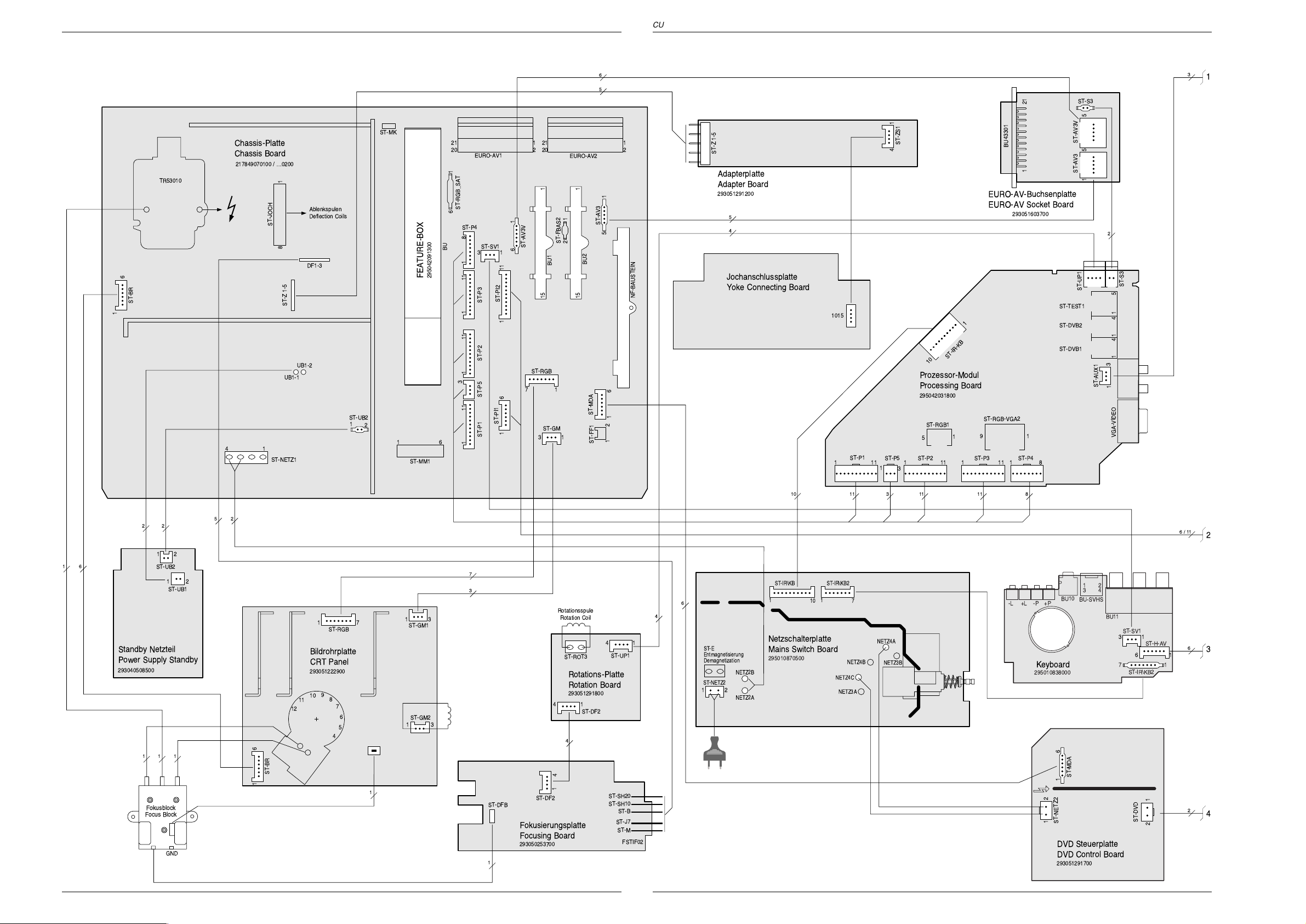
Verdrahtungsplan / Wiring Diagram
Platinenabbildungen und Schaltpläne / Layout of PCBs and Circuit Diagrams Platinenabbildungen und Schaltpläne / Layout of PCBs and Circuit DiagramsCUC 1931 CUC 1931
6
5
ST-S3
ST-MK
Chassis-Platte
Chassis Board
217849070100 / É0200
TR53010
6
ST-BR
1
ST-JOCH
14
ST-NETZ1
18
ST-Z 1-5
UB1-1
Ablenkspulen
Deflection Coils
DF1-3
UB1-2
ST-UB2
1
FEATURE-BOX
295042091300
2
61
ST-MM1
16
ST-RGB_SAT
ST-P4
BU
18
111
1
3
111 11
EURO-AV1
ST-SV1
ST-P3
ST-P2
ST-P5
ST-PI1
ST-P1
121
220
115
1
ST-AV3V
6
13
ST-PI2
111
16
ST-FBAS2
BU1
ST-RGB
17
ST-GM
13
EURO-AV2
115
12
BU2
121
220
ST-AV3
51
NF-BAUSTEIN
ST-MDA
16
21
ST-FF1
ST-Z 1-5
Adapterplatte
Adapter Board
293051291200
5
4
Jochanschlussplatte
Yoke Connecting Board
1015
ST-P1
ST-ZS1
41
ST-P5 ST-P2
111111
1
3
1
ST-IR-KB
10
Prozessor-Modul
Processing Board
295042031800
ST-RGB1
1
5
ST-P3
111
BU43301
121
EURO-AV-Buchsenplatte
EURO-AV Socket Board
293051603700
ST-RGB-VGA2
19
ST-P4
18
ST-AV3V
55
ST-AV3
1
ST-UP1
ST-TEST1
ST-DVB2
ST-DVB1
ST-AUX1
2
11
ST-S3
15
1414
3
1
VGA-VIDEO
3
1
10
2
12
61
ST-UB2
12
ST-UB1
Standby Netzteil
Power Supply Standby
293040508500
11 1
Fokusblock
Focus Block
GND
225
7
3
Rotationsspule
1
ST-DF2
Rotation Coil
ST-ROT3
Rotations-Platte
Rotation Board
293051291800
14
ST-DF2
4
4
ST-UP1
ST-SH20
ST-SH10
ST-B
ST-J7
ST-M
FSTIF02
14
17
ST-RGB
13
ST-GM1
Bildrohrplatte
CRT Panel
293051222900
9
10
8
11
12
61
ST-BR
7
6
5
4
1
ST-GM2
13
ST-DFB
Fokusierungsplatte
Focusing Board
293050253700
1
6
4
ST-E
Entmagnetisierung
Demagnetization
NETZ2B
ST-NETZ2
12
NETZ2A
ST-IR\KB
1
10
ST-IR\KB2
1
Netzschalterplatte
Mains Switch Board
295010870500
7
NETZ4B
NETZ4C
NETZ3A
3 111111
NETZ4A
NETZ3B
8
-P +P-L +L
Keyboard
295010838000
12
12
34
BU10
BU-SVHS
BU11
61
ST-MDA
ST-NETZ2
DVD Steuerplatte
DVD Control Board
293051291700
ST-SV1
3
7
1
ST-H-AV
ST-IR\KB2
ST-DVD
6/11
2
6
16
1
12
3
2
4
GRUNDIG Service GRUNDIG Service
11 12
Page 12
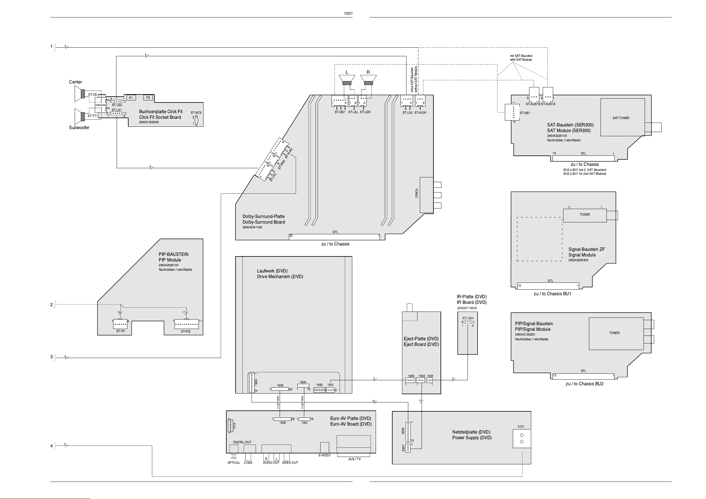
Platinenabbildungen und Schaltpläne / Layout of PCBs and Circuit Diagrams Platinenabbildungen und Schaltpläne / Layout of PCBs and Circuit Diagrams CUC 1931CUC 1931
3
1
4
LR
Center
Subwoofer
ST-CE
ST-TT1
14
ST-LS2
ST-LS1
16
P2
P1
Buchsenplatte Click Fit
Click Fit Socket Board
293051606000
ST-AC3
2
1
16
ST-I2S1
6
12
ST-LSL12ST-LSR
ohne SAT-Baustein
14
13
ST-LS2
ST-AUX1
without SAT Module
mit SAT-Baustein
with SAT Module
331
1
ST-AUX1B
ST-I2S1
6
1
ST-AUX1A
SAT-Baustein (SER300)
SAT Module (SER300)
295042220100
Nachrstbar / retrofittable
SAT-TUNER
1
3
ST-H-AV
1
6
6
ST-KH2
1
ST-LS1
CINCH
Dolby-Surround-Platte
Dolby-Surround Board
295042041400
STL
122
15
STL
zu / to Chassis
BU2 (+BU1 bei 2. SAT-Baustein)
BU2 (+BU1 for 2nd SAT Module)
11 1
TUNER
1
zu / to Chassis
Signal-Baustein ZF
PIP-BAUSTEIN
PIP Module
295042060100
Nachrstbar / retrofittable
2
6 11
16
ST-PI1
111
ST-PI2
Laufwerk (DVD)
Drive Mechanism (DVD)
Eject-Platte (DVD)
IR-Platte (DVD)
IR Board (DVD)
293050176500
ST-1004
31
15
STL
zu / to Chassis BU1
PIP/Signal-Baustein
PIP/Signal Module
295042120200
Nachrstbar / retrofittable
Signal Module
295042620300
1
TUNER
Eject Board (DVD)
6
3
1600
12 1
7
1410
1
2
4
DIGITAL OUT
OPTICAL COAX AUDIO OUT
1603
1
FLEXPRINT
1122 16
RL
13 14
22
VIDEO OUT
1604
1516
FLEXPRINT
13011300
1602 1501
Euro-AV Platte (DVD)
Euro-AV Board (DVD)
S-VIDEO
GRUNDIG Service GRUNDIG Service
AUX / TV
1000
5
12
1002 1004
11 1
4
112
0205
3
0101
Netzteilplatte (DVD)
15
STL
1
zu / to Chassis BU2
Power Supply (DVD)
1
0207
Page 13

CUC 1931 Platinenabbildungen und Schaltpläne / Layout of the PCBs and Circuit Diagrams
Chassisplatte
Koordinaten für die Bauteile der Lötseite (Unterseite)
Pos.-Nr./ Koordinaten/
Pos. No. Coordinates
XY
CBR100 210 133
CBR101 104 201
CBR102 99 149
CBR103 149 228
CBR104 84 193
CBR105 65 222
CBR106 153 149
CBR107 124 253
CBR108 28 211
CBR109 133 253
CBR110 62 246
CBR111 8 198
CBR113 89 201
CBR114 146 161
CBR115 79 148
CBR116 133 244
CBR117 79 150
CBR118 132 189
CBR119 133 249
CBR120 80 175
CBR121 80 177
CBR122 124 132
CBR123 153 184
CBR124 158 181
CBR125 120 193
CBR127 83 212
CBR128 79 145
CBR129 48 102
CBR130 98 201
CBR131 113 212
CBR132 35 200
CBR134 184 91
CBR135 40 98
CBR136 76 202
CBR137 77 196
CBR138 139 112
CBR139 138 213
CBR140 138 207
CC21203 328 163
CC21206 324 149
CC21221 192 164
CC21231 200 166
CC21233 354 133
CC32301 53 172
CC32321 54 149
CC34502 58 115
CC34503 61 115
CC34504 64 115
CC34507 68 127
CC34515 108 103
CC34517 81 90
CC34518 74 115
CC34519 72 115
CC34520 69 115
CC34521 78 89
CC34522 72 89
CC34523 62 88
CC34524 107 120
CC34525 103 120
CC34526 110 120
CC34541 78 125
CC34542 81 125
CC34543 84 125
CC43002 40 226
CC43003 87 229
CC43007 44 226
CC43008 84 229
CC43013 71 231
CC43018 76 231
CC43022 29 220
CC43023 27 231
Pos.-Nr./ Koordinaten/
Pos. No. Coordinates
XY
CC43025 136 251
CC43027 20 220
CC43028 24 231
CC43033 18 231
CC43038 22 246
CC43066 121 208
CC43079 93 176
CC43526 99 226
CC43538 113 206
CC43551 135 228
CC43553 76 215
CC43554 118 217
CC43556 85 163
CC43567 71 246
CC43572 90 189
CC43574 115 202
CC43576 103 172
CC43577 99 172
CC43587 118 245
CC43615 80 172
CC43617 109 177
CC43618 106 173
CC43651 135 226
CC43653 150 245
CC43667 99 210
CC43672 108 210
CC43674 95 201
CC43675 117 186
CC43676 105 210
CC46031 96 114
CC46032 102 114
CC46033 110 111
CC50001 194 184
CC50002 195 177
CC50004 160 184
CC50011 194 192
CC50013 181 176
CC50023 178 188
CC50024 196 170
CC60010 300 22
CC60014 288 10
CC60015 291 10
CC60016 301 13
CC60019 216 70
CC60021 222 74
CC60032 284 10
CC60046 285 28
CC61002 192 30
CC61003 192 25
CC61006 161 56
CC61007 179 66
CC61016 233 104
CC61021 32 81
CC61022 34 76
CC61023 200 106
CC61024 195 100
CC61028 196 114
CC61031 200 114
CC61038 222 124
CC61041 219 116
CC61051 182 95
CC61058 186 95
CC61302 225 13
CC61311 221 8
CC61312 232 15
CC65506 59 52
CC65507 59 61
CC65515 77 67
CC65517 70 56
CC65518 68 52
CC65519 78 56
Pos.-Nr./ Koordinaten/
Pos. No. Coordinates
CC65527 78 44
CC65528 83 63
CC65531 58 67
CC65532 83 67
CC70501 154 130
CC70502 136 178
CC70503 146 188
CC70506 152 136
CC70507 155 136
CC70508 152 195
CC70512 145 143
CC70513 145 148
CC70518 127 132
CC70528 149 53
CD21203 321 134
CD21206 332 175
CD21221 184 159
CD21222 184 166
CD21231 206 180
CD21232 206 172
CD34513 104 96
CD34517 86 94
CD43026 163 250
CD43541 125 215
CD43542 125 194
CD43651 135 222
CD52003 191 234
CD53019 338 228
CD55003 228 189
CD55004 222 201
CD58001 210 207
CD58004 211 202
CD58007 221 175
CD58011 228 174
CD58012 222 168
CD58021 210 191
CD58022 206 185
CD65506 48 53
CD65519 63 57
CD65528 67 57
CD70501 161 217
CD70506 157 161
CD70507 163 153
CD70517 158 134
CD70519 142 100
CD70521 138 47
CD70522 134 47
CD70523 150 61
CD70553 166 138
CIC43550 137 236
CIC43650 154 236
CL34521 76 94
CL34522 72 99
CL34523 67 94
CR21201 182 135
CR21202 324 140
CR21203 323 170
CR21206 326 173
CR21222 188 165
CR21223 194 164
CR21224 197 164
CR21226 181 159
CR21233 354 130
CR21234 342 130
CR32303 57 149
CR32321 42 155
CR32381 73 155
CR34509 52 103
CR34510 52 101
XY
Chassis Board
Coordinates of the Components on the Solder Side (Bottom Side)
Pos.-Nr./ Koordinaten/
Pos. No. Coordinates
XY
CR34511 98 99
CR34512 93 104
CR34513 98 103
CR34514 110 103
CR34515 110 98
CR34516 108 98
CR34517 79 99
CR34518 81 115
CR34519 79 115
CR34520 81 87
CR34521 76 99
CR34522 72 94
CR34523 67 99
CR34524 100 120
CR34525 87 113
CR34526 87 116
CR34541 80 135
CR34542 80 132
CR34543 80 129
CR34544 86 125
CR40501 11 94
CR40502 18 88
CR43002 49 245
CR43003 90 229
CR43004 38 245
CR43005 32 245
CR43008 81 229
CR43009 51 245
CR43010 153 251
CR43013 73 242
CR43014 160 251
CR43018 78 231
CR43019 155 251
CR43023 30 231
CR43024 159 228
CR43025 139 251
CR43028 21 229
CR43033 16 242
CR43038 22 243
CR43042 35 230
CR43043 156 245
CR43046 158 251
CR43047 153 245
CR43048 115 245
CR43051 93 229
CR43053 91 244
CR43056 98 244
CR43057 105 244
CR43058 111 244
CR43066 117 191
CR43067 99 223
CR43072 43 245
CR43075 137 219
CR43078 53 231
CR43079 93 180
CR43080 129 176
CR43081 36 211
CR43083 33 211
CR43526 105 225
CR43536 102 225
CR43537 117 212
CR43538 119 212
CR43541 133 196
CR43542 139 200
CR43543 125 221
CR43553 92 219
CR43554 113 217
CR43556 80 169
CR43568 63 242
CR43569 66 243
CR43572 99 177
Pos.-Nr./ Koordinaten/
Pos. No. Coordinates
XY
CR43573 96 173
CR43574 96 177
CR43576 101 177
CR43577 112 177
CR43578 104 177
CR43582 122 242
CR43583 121 232
CR43589 96 189
CR43590 93 189
CR43591 138 195
CR43592 98 189
CR43593 97 210
CR43594 101 189
CR43596 103 189
CR43597 106 189
CR43598 108 189
CR43599 111 189
CR43615 98 160
CR43617 110 168
CR43618 106 177
CR43651 126 225
CR43653 150 251
CR43675 119 186
CR43676 82 153
CR43677 76 210
CR43678 76 212
CR43679 102 210
CR46031 93 114
CR46032 99 114
CR46033 107 111
CR46034 111 116
CR46035 105 111
CR46036 109 107
CR50001 188 171
CR50002 195 174
CR50003 160 178
CR50004 163 184
CR55003 231 182
CR55006 235 214
CR55007 232 192
CR55011 234 195
CR55016 215 206
CR58004 217 197
CR58007 215 171
CR58011 236 177
CR58012 236 173
CR58013 219 183
CR58014 225 185
CR58015 220 194
CR58021 210 180
CR58022 206 175
CR60013 274 15
CR60015 294 10
CR60016 304 13
CR60031 269 19
CR60046 269 10
CR61003 181 26
CR61004 196 15
CR61007 176 67
CR61008 182 70
CR61009 175 63
CR61021 34 91
CR61022 35 81
CR61029 166 110
CR61032 170 99
CR61039 205 133
CR61042 227 123
CR61052 170 73
CR61059 171 86
CR61301 232 18
CR61302 240 18
Pos.-Nr./ Koordinaten/
Pos. No. Coordinates
XY
CR61303 239 10
CR61304 242 10
CR61306 246 7
CR61311 232 12
CR65500 101 135
CR65501 40 64
CR65502 38 58
CR65503 57 61
CR65504 53 61
CR65505 43 58
CR65506 57 52
CR65507 59 56
CR65508 57 56
CR65509 41 58
CR65510 49 58
CR65511 70 61
CR65515 74 67
CR65516 73 56
CR65517 81 56
CR65518 73 44
CR65519 75 56
CR65521 65 52
CR65526 63 52
CR65527 75 44
CR65528 80 67
CR65529 80 63
CR65536 80 50
CR70501 146 168
CR70502 183 170
CR70504 160 214
CR70506 158 152
CR70507 160 152
CR70508 156 152
CR70509 138 190
CR70510 138 193
CR70512 158 141
CR70513 161 143
CR70516 156 141
CR70518 130 132
CR70519 139 102
CR70522 141 50
CR70523 152 47
CR70524 147 61
CR70526 142 57
CR70527 149 47
CR70528 152 53
CR70551 169 143
CR70552 156 146
CR70553 166 143
CT21221 188 159
CT21233 349 122
CT32305 61 151
CT32320 56 166
CT43525 108 226
CT43535 108 220
CT43565 65 230
CT43580 122 246
CT43590 127 187
CT58012 211 197
CT61316 253 10
CT65501 105 136
CT65503 44 64
CT65504 42 51
CT65505 49 64
CT65506 53 53
CT65525 74 50
CT65530 76 62
CT70505 164 159
CT70520 137 53
CT70525 148 68
GRUNDIG Service 15
Page 14

Platinenabbildungen und Schaltpläne / Layout of the PCBs and Circuit Diagrams CUC 1931
Chassisplatte
Koordinaten für die Bauteile der Bestückungsseite (Oberseite)
Pos.-Nr./ Koordinaten/
Pos. No. Coordinates
XY
BR100 155 98
BR101 126 128
BR102 128 128
BR103 136 86
BR104 52 211
BR105 123 169
BR106 100 196
BR107 134 192
BR108 36 129
BR109 131 131
BR110 125 169
BR111 38 116
BR112 38 114
BR113 150 60
BR114 270 20
BR115 284 88
BR116 294 166
BR117 187 233
BR118 274 15
BR119 279 98
BR120 289 45
BR121 292 144
BR122 194 149
BR123 188 56
BR124 76 16
BR125 191 21
BR126 197 114
BR127 185 134
BR128 166 63
BR129 200 141
BR130 304 175
BR131 231 147
BR132 213 228
BR133 77 215
BR134 118 213
BR135 141 235
BR136 154 150
BR137 131 174
BR138 48 76
BR139 30 153
BR140 188 111
BR141 105 109
BR142 54 57
BR143 30 159
BR144 233 58
BR145 137 75
BR146 58 168
BR147 101 170
BR148 105 22
BR149 65 130
BR150 100 200
BR151 26 120
BR152 25 111
BR153 192 216
BR154 93 81
BR155 64 250
BR156 137 102
BR157 229 190
BR158 219 242
BR159 169 180
BR160 301 161
BR161 203 155
BR162 189 158
BR163 155 50
BR164 314 144
BR165 177 192
BR166 246 47
BR167 101 21
BR168 144 16
BR169 98 21
BR170 150 17
BR171 144 69
BR172 48 95
BR173 53 110
BR174 48 90
BR175 48 93
BR176 52 158
BR177 124 120
BR178 51 32
BR179 106 221
BR180 83 164
BR181 83 161
BR182 82 158
Pos.-Nr./ Koordinaten/
Pos. No. Coordinates
XY
BR183 134 210
BR184 56 224
BR185 59 224
BR186 154 171
BR187 38 197
BR188 36 197
BR189 157 101
BR190 82 191
BR191 28 107
BR192 81 133
BR193 101 80
BR194 98 80
BR195 122 231
BR197 129 156
BR198 133 126
BR199 61 226
BR200 150 95
BR201 128 247
BR202 136 140
BR203 102 151
BR204 247 166
BR205 206 164
BR206 165 172
BR207 165 175
BR208 177 218
BR209 266 161
BR210 206 150
BR211 210 127
BR212 353 158
BR213 174 191
BR214 153 221
BR215 290 127
BR216 194 120
BR217 173 150
BR218 175 170
BR219 177 173
BR220 159 206
BR221 197 100
BR222 254 107
BR223 192 123
BR224 160 72
BR225 175 151
BR226 169 133
BR227 32 165
BR228 139 224
BR229 31 143
BR230 31 138
BR231 129 150
BR232 135 83
BR233 31 140
BR234 30 162
BR235 153 245
BR236 160 191
BR237 123 72
BR238 96 80
BR239 334 237
BR240 167 42
BR243 109 62
BR244 335 61
BR245 46 30
BR246 169 15
BR247 43 88
BR248 43 85
BR249 22 58
BR250 42 29
BR251 36 80
BR252 286 160
BR253 35 30
BR254 206 180
BR255 23 179
BR256 69 225
BR257 8 234
BR258 138 65
BR259 268 126
BR260 260 142
BR21102 355 158
BR21202 304 131
BR60007 310 34
BR60014 279 18
BR60028 260 53
BR61062 238 151
BR61067 245 153
Pos.-Nr./ Koordinaten/
Pos. No. Coordinates
XY
BU01 69 173
BU02 46 173
C21202 324 131
C21212 335 162
C21231 300 137
C21232 345 174
C34501 82 96
C34506 67 124
C34509 95 93
C34510 89 96
C34511 96 104
C34521 61 99
C34522 61 95
C34523 61 91
C43012 26 223
C43017 34 223
C43032 12 220
C43037 15 228
C43081 31 200
C43083 23 199
C43566 69 240
C43573 115 200
C43586 99 229
C43673 85 200
C50012 198 189
C50014 196 202
C50026 200 173
C50027 171 204
C52001 205 211
C52002 168 231
C52003 174 225
C52004 175 238
C53006 283 210
C53007 265 210
C53009 291 210
C53011 308 242
C53012 251 230
C53013 235 220
C53016 326 249
C53017 353 240
C53018 338 236
C53019 344 236
C53071 271 228
C53072 244 228
C53073 255 204
C54001 351 201
C54002 353 180
C54011 316 163
C54012 314 147
C54021 304 153
C54022 297 150
C55003 228 196
C55004 218 204
C55011 234 183
C55012 238 189
C55013 235 197
C58001 215 197
C58004 219 167
C58011 231 174
C58012 229 182
C58013 224 174
C58014 222 183
C58021 216 189
C58023 211 169
C60001 266 64
C60002 303 8
C60006 333 51
C60007 338 24
C60009 334 71
C60011 303 20
C60012 316 20
C60013 281 10
C60018 286 39
C60023 254 33
C60024 213 41
C60026 254 51
C60027 241 50
C60028 249 75
C60029 206 38
C61002 170 33
C61004 201 15
C61008 169 58
Chassis Board
Coordinates of the Components on the Components Side (Top Side)
Pos.-Nr./ Koordinaten/
Pos. No. Coordinates
XY
C61014 302 110
C61015 232 104
C61016 317 88
C61017 333 141
C61018 335 130
C61021 267 109
C61022 207 104
C61026 268 116
C61027 267 136
C61032 167 91
C61036 237 127
C61037 211 136
C61042 166 117
C61052 167 67
C61056 311 111
C61057 288 135
C61061 255 134
C61062 227 134
C61063 242 136
C61064 222 149
C61066 255 138
C61301 242 14
C61317 164 21
C62021 249 28
C62022 214 26
C62048 349 109
C65533 64 66
C70509 164 221
C70511 161 165
C70516 164 142
C70527 150 43
CONTR 85 30
D21201 280 149
D21202 304 131
D21212 350 157
D32315 59 190
D50013 189 200
D52006 196 245
D53008 286 191
D53019 341 236
D53071 238 247
D53072 210 247
D54001 355 194
D54011 313 160
D54021 297 163
D55012 229 218
D60006 342 45
D60007 310 34
D60012 314 25
D60019 213 76
D60021 213 85
D60023 251 42
D61014 295 106
D61016 337 117
D61021 269 106
D61026 282 117
D61033 317 133
D61036 254 117
D61056 309 117
D61061 255 129
D61062 238 151
D61066 255 145
D61067 245 153
D61603 249 18
D70508 159 152
DF01 224 159
DF02 216 159
DF03 211 159
EUROAV01 99 245
EUROAV02 40 245
FEAT.BOX 145 163
IC34510 72 111
IC43080 22 211
IC43570 102 189
IC43670 98 210
IC50010 187 177
IC55010 231 206
IC58010 213 180
IC60010 290 19
IC61001 184 30
IC61006 184 65
Pos.-Nr./ Koordinaten/
Pos. No. Coordinates
XY
IC61030 199 118
IC61040 227 118
IC61050 184 102
IC61310 232 14
L34517 37 124
L53001 264 246
L53002 269 240
L53003 286 240
L53011 297 230
L53012 256 159
L53021 275 191
L53074 279 160
L55014 230 233
L60006 311 40
L60028 215 60
L61012 315 83
L61016 331 114
L61021 289 88
L61026 279 88
L61036 274 88
L61056 299 88
L61061 294 88
L61062 238 151
L61066 304 88
L61067 245 153
L70508 174 133
L70555 104 224
MI 62 32
NETZ01 220 38
NETZ02 227 38
NFBAUST. 13 134
OK60031 262 19
OK60046 262 10
R21101 354 215
R21102 354 158
R21103 350 215
R21211 346 158
R21212 344 167
R21213 342 155
R21214 328 163
R21216 238 173
R21221 191 152
R21227 177 149
R21231 196 152
R21232 200 157
R32315 43 23
R43082 27 170
R43566 84 223
R43581 118 228
R50007 161 199
R50008 165 199
R50026 168 190
R50027 170 189
R50028 170 156
R50029 166 159
R52001 206 198
R52003 168 240
R52005 191 231
R52006 205 240
R52007 294 246
R53002 270 236
R53003 285 236
R53008 292 195
R53011 300 235
R53012 252 181
R53016 260 179
R53021 281 179
R54001 348 191
R54011 309 155
R54021 300 175
R54022 323 154
R55002 251 169
R55004 224 201
R55012 223 201
R55014 226 218
R58001 215 215
R58002 221 223
R60001 322 11
R60002 281 30
R60003 338 58
R60006 322 38
Pos.-Nr./ Koordinaten/
Pos. No. Coordinates
XY
R60008 331 41
R60012 304 29
R60013 276 18
R60028 229 56
R61001 190 13
R61016 102 16
R61018 336 125
R61020 102 24
R61022 46 16
R61031 171 105
R61033 310 138
R61041 196 130
R61051 171 78
R61062 234 149
R61063 241 154
R61312 225 13
R61313 216 12
R61314 203 6
R61316 247 6
R61317 125 35
R62049 327 94
R65525 106 78
R70521 131 63
SH01 274 217
SH02 274 202
SH03 274 210
SH10 233 159
SH20 228 159
SI60001 266 53
SI60201 228 80
SI61016 247 105
SI61022 220 109
SI61026 295 113
SI61036 241 114
SI61056 311 102
SI61061 278 130
SI61066 278 142
STAV03 27 183
STAV03V 85 177
STBR 348 138
STFBAS02 53 181
STFF01 29 45
STGM 62 42
STJOCH 243 191
STMDA 29 65
STMK 170 250
STMM01 142 34
STMM02 249 124
STMM03 235 130
STNETZ01 231 31
STP01 117 51
STP02 117 98
STP03 117 138
STP04 117 168
STP05 117 75
STPI01 93 57
STPI02 93 138
STRGB 69 81
STRGB_SAT130 207
STSV01 103 164
STUB02 190 43
STZ01 255 146
STZ02 255 141
STZ03 255 136
STZ04 255 131
STZ05 255 126
T21211 323 163
T50028 185 148
T50029 185 208
T52003 184 237
T53001 280 246
T60006 336 65
TR52001 208 226
TR53010 321 206
TR60001 299 64
UB11 233 86
UB12 228 86
16 GRUNDIG Service
Page 15
Platinenabbildungen und Schaltpläne / Layout of PCBs and Circuit Diagrams Platinenabbildungen und Schaltpläne / Layout of PCBs and Circuit DiagramsCUC 1931 CUC 1931
BR229
1 15
BU1
17
ST-RGB
111
ST-P2
111
ST-P3
111
ST-P1
1
11
ST-PI2
121
220
EURO-AV2
121
220
EURO-AV1
1
2
43
42
FEATURE-BOX
R50029
BR100
BR101
BR102
BR103
BR104
BR105
BR106
BR107
BR108
BR109
BR110
BR111
BR112
R32315
SI61056
SI61061
SI61026
SI61066
SI61036
SI60201
SI60001
SI61022
SI61016
BR114
1 7
26
IC50010
BR116
BR117
C60018
C60007
C53072
C58011
C61301
C53018
C55012
C55003
C55011
C53019
C60013
D21212
13
ST-SV1
13
ST-GM
D60007
R21214
R61314
R61312
R61316
R53012
R55014
R52007
R21212
R55004
R21232
C55004
R21227
R21231
R61062
BR118
BR119
BR120
BR121
1
ST-Z5
1
ST-Z4
1
ST-Z3
1
ST-Z1
1
ST-Z2
R54021
R52001
R21103
R54022
BR122
BR123
R61001
R61313
R61041
R61051
R61031
13
46
87
TR52001
C60028
BR125
BR126
BR127
BR128
R52003
R61033
1
11
9
7
536
4
121314
1516171819
20
21
22
TR60001
R60028
R53011
R61018
R60012
R54001
R54011
C52003
63
12
L60028
D55012
D61603
R60008
R53016
R21221
L53012
R60006
R61063
112
13 24
IC43080
L53021
1
28 15
14
IC34510
D61033
D53008
D52006
D54001
D54011
L55014
C61037
BR210
R21211
R70521
R21213
D53019
D70508
13
ST-P5
BE
T50029
BE
T50028
C34522
C34523
C34521
C58012
BR129
BR130
BR131
BR132
BR178
C53012
L53074
C52004
C60002
R50008
R50007
R50026
BR236
BR228
BR258
BR200
BR113
BR259
BR60007
D60019
BR256
R50027
D60021
BR21202
BR21102
BR60028
BR134
BR135
BR136
BR137
BR138
BR139
C53011
C53013
C21231
L53002
L61036
L61056
L61066
L61061
L61026
L61021
L61016
L53003
L53001
L61012
C70509
C50026
C61004
C61032
C50012
C61317
C58014
C52002
C58001
C34509
C34510
C34501
C70511
C70516
C43566
C34511
C43586
C58004
C58013
C58023
C21202
C55013
C58021
C61052
C65533
C43573
C43083
C43037
C43032
C43017
C43012
C43081
C34506
C43673
C54012
D61016
D60006
D61056
D53072
D61036
D61026
D53071
BR257
BR245
MI-
MI
BR170
BR255
BR253
BR254
BR252
BR249
BR248
BR250
BR61062
L61067
D61067
1
1120
10
IC43670
1
1120
10
IC43570
1
6
ST-BR
1
6
ST-PI1
2
1
ST-FF1
L70555
L34517
BR182
BR188
12
ST-UB2
12
ST-FBAS2
BR140
BR61067
L70508
C61018
BR151
BR144
16
ST-RGB_SAT
16
ST-AV3V
BR141
BR260
BR148
BR146
BR115
BR177
C60009
BR152
D32315
BR237
R53003
D61062
BR243
1
6
ST-MDA
L61062
BR60014
1
SH10
R61317
R60013
R43082
R53008
R53002
R43566
NF-BAUSTEIN
BR150
BR133
BR155
1
8
ST-P4
BR156
BR157
BR158
BR159
BR160
BR161
BR162
BR163
BR164
BR165
BR166
BR167
BR168
BR169
BR147
BR171
BR172
BR173
BR174
BR175
BR176
BR179
BR247
BR181
BR183
BR239
BR184
BR185
BR186
BR187
BR231
BR145
BR189
BR191
BR238
BR192
BR193
BR194
BR195
BR197
BR199
BR198
BR201
BR202
BR203
BR204
BR205
BR206
BR207
BR208
BR209
1
SH20
BR211
BR212
BR213
BR214
BR215
BR216
BR217
BR218
BR219
BR220
BR221
BR222
BR223
BR224
BR225
BR226
BR234
ST-MK
BR233
BR227
BR190
BR232
BR230
BR143
BR235
1
UB1-1
1
SH1
1
SH3
1
DF-3
1
NETZ2
1
UB1-2
1
NETZ1
1
SH2
1
DF-1
1
DF-2
C54011
C60012
C54001
C60006
C61026
C54021
C60001
C60027
C60026
C61056
C61036
C61061
C61066
C61014
C61021
C60023
C60024
18
ST-JOCH
R21216
C53017
C53016
R60002
R60001
R50028
BE
T53001
13
46
OK60031
13
46
OK60046
-+
-+
D60023
14
58
IC61310
13
IC61001
13
IC61050
13
IC61040
13
IC61006
13
IC61030
R62049
R52006
R53021
R21101
R21102
R55012
D21202
41
58
IC55010
41
58
IC58010
R58001
R58002
C61016
C50027
L60006
D54021
D60012
TR53010
C60029
C70527
C53073
C53071
C60011
R61016
R61022
D61014
D61021
D61061
D61066
BR149
C62048
C53007
C53006
C53009
1
4
ST-NETZ1
C62022
C62021
C21232
C61015
C61022
C61008
C54002
C50014
C52001
C61057
C61027
C61062
C61002
C61063
C61042
C54022
C21212
C61017
C61064
R55002
EB
T52003
L53011
EC
T21211
BR246
17
814
IC60010
R52005
D50013
51
ST-AV3
BR180
1
ST-MM3
1
ST-MM2
6 1
ST-MM1
BR142
BR240
R61020
D21201
BR251
R65525
1 15
BU2
R43581
BR244
D
GS
BR124
BR154
BR153
R60003
T2AL
T2AL
T2,5AL
T2,5AL
T2,5AL
T3,15AL
T3,15AL
T100mAL
T2AL
29304-730.15/4B(10)
( )
\)\(
\)\(
\)\(
\)\(
LOETRICHTUNG
.
B
C
D
E
FG
H
I
K
L
M
A
0
0 10 20 30 40 50 60 70 80 90 100 110 120 130 140 150 160 170 180 190 200 210 220 230 240 250 260 270 280 290 300
310 320 330 340 350 360
10
20
30
40
50
60
70
80
90
100
110
120
130
140
150
160
170
180
190
200
210
220
230
240
250
260
X
Y
11
+N
R61051+BR61031
47 53
+H
R61001
+A
R61313
+F
R61041
65 63 62484956 5755 6160595864 8 91012
13.113.5 13.2 13.4 13.3
2815 16 1719 20L5307423 251827 24
26
29 30 31 515254 50383733
34 35
21 22
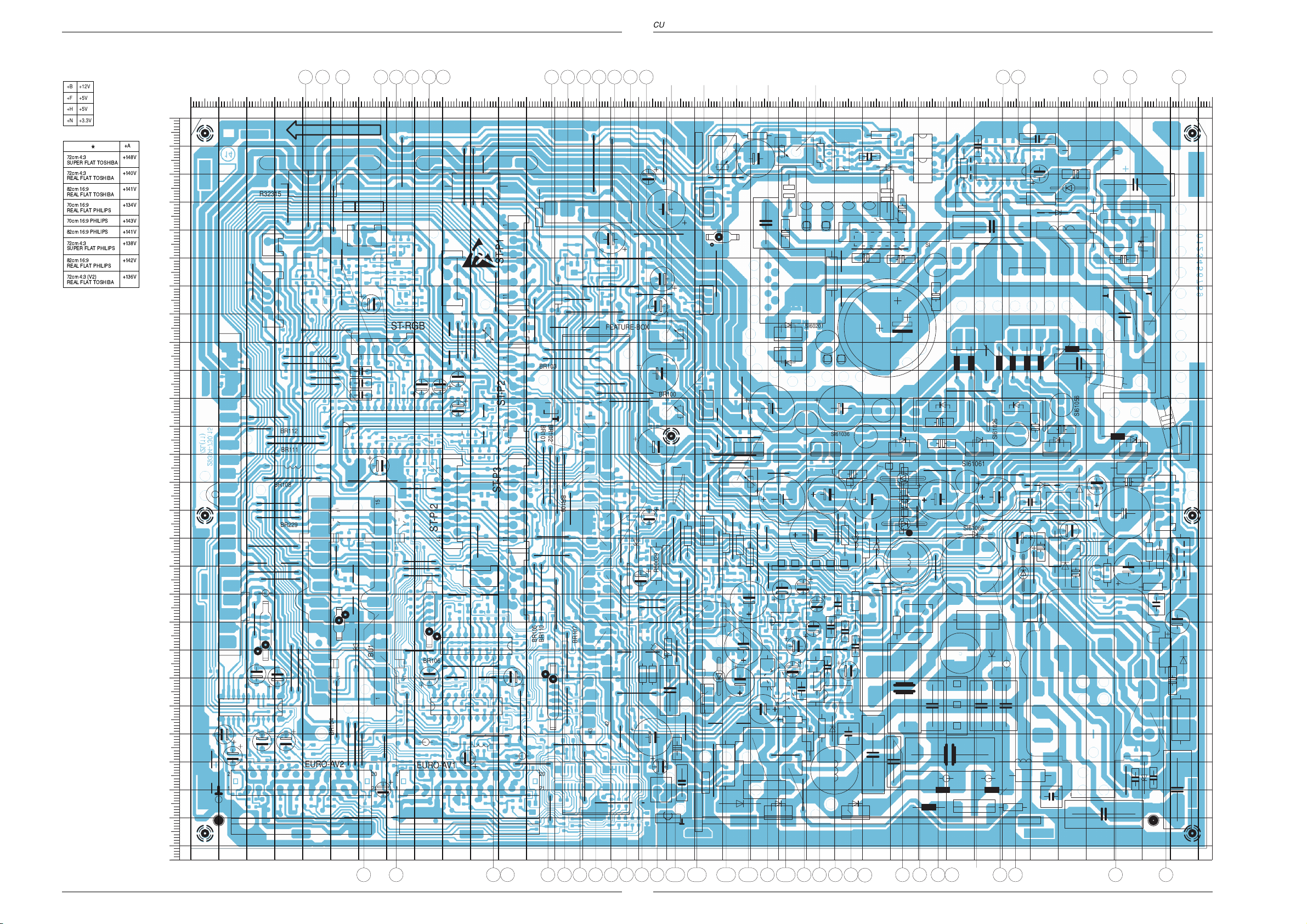
Chassisplatte / Chassis Board
+B +12V
+F
+5V
+H
+5V
+N
+3.3V
+148V
+140V
+141V
+134V
+143V
+141V
+138V
+142V
+136V
+A
*
72cm 4:3
SUPER FLAT TOSHIBA
72cm 4:3
REAL FLAT TOSHIBA
82cm 16:9
REAL FLAT TOSHIBA
70cm 16:9
REAL FLAT PHILIPS
70cm 16:9 PHILIPS
82cm 16:9 PHILIPS
72cm 4:3
SUPER FLAT PHILIPS
82cm 16:9
REAL FLAT PHILIPS
72cm 4:3 (V2)
REAL FLAT TOSHIBA
GRUNDIG Service GRUNDIG Service
17 18
Bestückungsseite, Ansicht von oben / Component Side, Top View
Page 16

Platinenabbildungen und Schaltpläne / Layout of PCBs and Circuit Diagrams Platinenabbildungen und Schaltpläne / Layout of PCBs and Circuit Diagrams CUC 1931CUC 1931
CR40502
CC43576
CC43007
CR65508
CR65506
CBR102
CBR103
CBR104
CBR105
CBR106
CBR107
CBR108
CR43083
CBR110
CBR111
CBR113
CBR114
CC43577
CBR115
CBR117
CBR118
CBR128
CBR119
CBR121
CC43615
CBR120
CC70518
CBR124
CBR125
CBR129
CBR127
CBR116
CBR130
CC43674
CBR132
CBR134
CBR135
CBR136
CC43022
1
CIC43550
1
CIC43650
CR34516
CR34514
CBR139
CC61311
CBR101
CD65528
CR65536
CR65502
CC50013
CR65505
CR61029
CR65521
CR65501
CR60016
CC60016
CR50001
CR61022
CR65511
CC34524
CC34523
CD65519
CR58007
CR60013
CR70523
CR61042
CR60046
CR55007
CR61009
CR61008
CR58012
CR61003
CR61306
CR61311
CR61021
CR70526
CR58013
CR32303
CR58022
CR55006
CR21206
CR21202
CR70527
CR61059
CR61004
CR65500
CR55011
CR61052
CR21224
CR21234
CR21223
CR21226
CC46032
CC65518
CR65528
CR65509
CR65526
CR65518
CC65517
CR65517
CR65519
CC65528
CR70501
CR65504
CR65529
CR65503
CR46034
CR43591
CR43593
CR43596
CR32381
CR34509
CR32321
CR65507
CC61022
CR43553
CR70502
CR70504
CR43592
CBR123
CR34521
CR43542
CR70516
CR43078
CR43526
CC43033
CR43019
CR43013
CR43046
CR43010
CR43005
CR43003
CR43009
CR34518
CC34520
CR34526
CR34543
CC34526
CR43537
CR34512
CC34517
CR34515
CR34513
CR34522
CR34525
CR34523
CR34520
CR34511
CR43568
CR34510
CR43066
CR43058
CR43057
CR43056
CR43618
CC43618
CR43075
CR43079
CR43578
CR43574
CR43554
CR43067
CBR122
CR43051
CR43048
CR43014
CR43047
CR70552
CR43597
CR70519
CR70513
CR70512
CR70507
CR70509
CC46033
CC50001
CR70553
CR43572
CR43569
CR70506
CC43013
CR43042
CR43038
CC43028
CC43025
CC43018
CR43024
CR43004
CR43598
CR43080
CR43583
CR43072
CR43590
CR70522
CR43043
CR43053
CR34517
CR43033
CR40501
CR43599
CR43594
CR70510
CR70508
CR43541
CR43589
CR43538
CR43536
CR34541
CC34543
CR34542
CR43543
CR43582
CR43677
CC43554
CC43675
CR43679
CR43653
CR43676
CR43573
CR61039
CR43081
CR43615
CR21233
CR50004
CR61032
CR55003
CR50003
CR58015
CR21203
CR21222
CC65527
CBR109
CR61303
CR61304
CR61302
CR61007
CR58004
CR61301
CR50002
CR58014
CR58011
CR55016
CR58021
CC70528
CR70524
CR70551
CC50011
CC21221
CC60046
CC61051
CC61302
CC61007
CC61003
CC50023
CC21231
CC50004
CC61024
CC61312
CC61006
CC61038
CC61031
CC21233
CC60014
CC32321
CC43556
CC34515
CC43079
CR65516
CC65532
CC65531
CC65519
CC70501
CC43526
CR43678
CC34502
CC43676
CC46031
CC43672
CC43667
CC43553
CC65515
CC65507
CC43587
CC43651
CC43567
CR46033
CR46031
CR46032
CR43025
CC34525
CC34521
CR34524
CC32301
CC34518
CC34507
CC34504
CC34503
CR43576
CC70508
CC70506
CR70528
CC70513
CC70512
CC70507
CC70502
CC70503
CC43066
CC43038
CC43023
CR43023
CR43028
CR43018
CR43008
CC43008
CC43572
CC43574
CC34519
CR34544
CR43675
CR70518
CR34519
CC43551
CC43538
CC43003
CC34541
CBR131
CC34542
CC43653
CC65506
CC61021
CC60032
CC61058
CC50002
CC60015
CC61002
CC61016
CC61041
CR21201
CC50024
CC61028
CC21206
CD21232
CD58011
CD58004
CD58001
CD58012
CD21221
CD55004
CD21206
CD21203
CD58021
CD70523
CD52003
CD53019
CD21231
CD21222
CD58022
CD70553
CD34513
CD34517
CD70507
CD70517
CD70506
CD70519
CD43541
CD70501
CD70522
CD70521
CD55003
CD58007
CD43026
CD43651
CD43542
CT65505
CT70525
CT43525
CT65530
CT43565
CT43590
CT43580
CT65501
CT43535
CT65525
CT65506
CT65504
CT65503
CT70505
CT32305
CT32320
CT58012
CT70520
CT61316
CT21221
CT21233
CC34522
CBR137
CBR140
CC21203
CC61023
CC60021
CR46036
CC60019
CC43027
CR43556
CR43617
CR43651
CR43577
CR65510
CR43002
CC43002
CR60031
CR46035
CR65527
CL34522
CL34523
CL34521
CR65515
CD65506
CR60015
CBR138
CC60010
CBR100
29304-730.15/4LS(10)
B
C
D
E
FG
H
I
K
L
M
A
Ausschnitt 1
Detail 1
Seite / Page 21-22
Ausschnitt 2
Detail 2
Seite / Page 23-24
0
0102030405060708090100110120130140150160170180190200210220230240250260270280290300
310320330340350360
10
20
30
40
50
60
70
80
90
100
110
120
130
140
150
160
170
180
190
200
210
220
230
240
250
260
X
Y
11 4753 656362 48 49 5657 5561 60 59 58 6489 10 12
13.1 13.513.213.413.3
28 1516
17 1920 2325 18
2724
26
29303151 52 5450 38 37 33
3435
21
22
Chassisplatte / Chassis Board
Lötseite, Ansicht von unten / Solder Side, Bottom View
19 20
GRUNDIG Service GRUNDIG Service
Page 17

Platinenabbildungen und Schaltpläne / Layout of PCBs and Circuit Diagrams Platinenabbildungen und Schaltpläne / Layout of PCBs and Circuit DiagramsCUC 1931 CUC 1931
Chassisplatte (vergrößert) Ausschnitt 1
Chassis Board (enlarged) Detail 1
CR61304
CC61312
CR61302
CC61016
CR61042
CR61311
CR61303
CR61301
CC60021
CC61041
CC61311
CC61302
CC60019
CC61038
CBR100
CR61004
CC61024
CC61023
CC61031
CR61039
CC61003
CC61002
CC61028
CR21201
CR61008
CBR134
CC61058
CR61003
CC61007
CR61007
CR61059
CC61051
CR61009
CR61052
CR61032
CR61029
CR70528
CC61006
CD70553
CR70523
CD70523
CT70525
CD70519
CC70501
CD70517
CC70507
Lötseite, Ansicht von unten
Solder Side, Bottom View
CD70522
CR70522
CR70524
CD70521
CT70520
CR70527
CC70528
CR70526
CR70519
CBR138
CC70506
CR70518
CR34514
CR46034
CC70518
CBR122
29304-730.15/4LS(10)
CD34513
CR34515
CR46036
CC46033
CR34516
CC34515
CR46033
CC34524
CC34526
CT65501
CR34511
CR34513
CR46035
CC46032
CR46032
CC34525
CR34524
CR65500
CC46031
CR65536
CR65517
CR65529
CC65528
CR34520
CD34517
CR34512
CR34525
CR34526
CR46031
CC65519
CR65528
CC65532
CC34517
CR34517
CR34518
CC34542
CC34543
CR34544
CR34541
5561 60 59 58 64
CR65518
CC65527
CR65527
CT65525
CR65526
CR65507
CC65506
CD65519
CC65507
CC34523
CC34504
CC34503
CR65506
CT65506
CR65508
CR65504
CR65503
CC65531
CR34510
CR34509
CC34502
CT65505
CR65519
CC65515
CR65515
CC34521
CL34521
CR34521
CR34519
CC34518
CC34541
CR34543
CR34542
CC65518
CC65517
CR65516
CR65511
CT65530
CC34522
CR34522
CL34522
CC34520
CC34519
CC34507
CR65521
CD65528
CL34523
CR34523
CT65504
CD65506
CR65505
CR65510
CT65503
CR61022
CBR135
CBR129
CR65509
CR65501
CR65502
CC61022
CR61021
CC61021
CR40502
CR40501
0102030405060708090100110120130140150160170180190200210220230240
X
Y
0
102030405060708090100110120130140
47 4849
37
GRUNDIG Service GRUNDIG Service
21 22
5657
Page 18
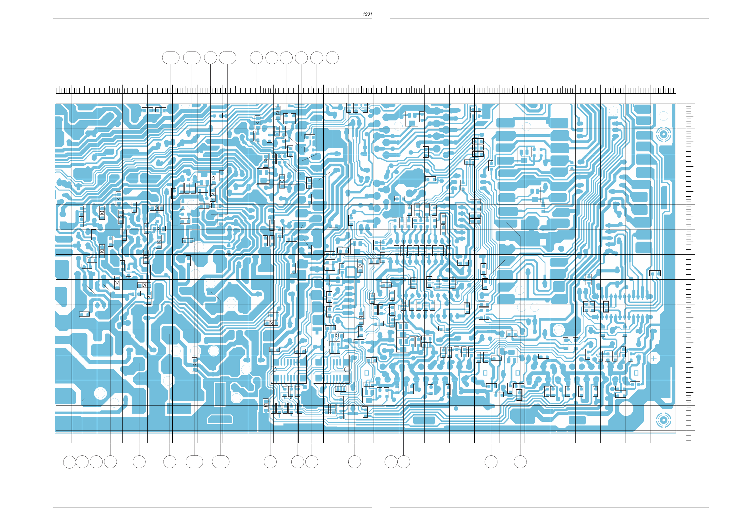
Platinenabbildungen und Schaltpläne / Layout of PCBs and Circuit Diagrams Platinenabbildungen und Schaltpläne / Layout of PCBs and Circuit Diagrams CUC 1931CUC 1931
Chassisplatte (vergrößert) Ausschnitt 2
Chassis Board (enlarged) Detail 2
13.4
CR58021
CD58021
CD58004
CD58001
CR55016
CR61039
CC21231
CD21232
CC50024
CD21231
CD58022
CT58012
CR58012
CR58011
CR55003
CR55007
CD55003
CR55011
CR55006
CD58011
CR58014
CD55004
CBR100
CD58012
CR58007
CR58022
CD58007
CR58013
CR58015
CR58004
13.3
CR21201
CR21224
CR21223
CR21222
CR50002
CC50002
CC50001
CC50011
CD52003
51 52
13.5
CR70551
CT21221
CR21226
CD21221
CC21221
CD21222
CR70502
CR50001
CC50013
CC50023
CD70517
CD70553
CD70507
CT70505
CD43026
53 656362
CR70513
CR70553
CR50003
CR50004
CR70504
CD70501
CR43024
CC70507
CR70516
CR70552
CR70512
CR70508
CR70506
CR70507
CD70506
CBR124
CC50004
CC70508
CBR103
1
CR43043
CR43047
CR43014
CR43019
CR43046
Lötseite, Ansicht von unten
Solder Side, Bottom View
38
CR70518
CC70506
CC70512
CC70513
CBR106
CBR114
CR70501
CC70502
CBR123
CR70510
CR43010
CR43653
CC70503
CR43591
CR43542
CBR140
CBR139
CR43075
CD43651
CC43651
CC43653
CBR118
CR70509
CIC43650
CBR116
CR43025
CC43025
CR43080
CT43590
CD43542
CR43541
CR43651
CC43551
1
CIC43550
CBR119
CBR107
CBR109
CBR122
CC70518
CR43617
CBR125
CC43066
CD43541
CR43538
CC43554
CR43543
CR43583
CR43582
CT43580
CR43577
CC43675
CR43675
CR43066
CC43574
CR43537
CT43525
CR43048
CC43587
CT65501
CR43618
CR43599
CR43598
CC43672
CC43676
CC43538
CBR131
CR43554
CR43058
CR65500
CBR102
CR43615
CC43576
CC43618
CR43578
CR43576
CR43597
CR43596
CR43594
CBR130
CBR101
CR43679
CC43667
CT43535
CR43067
CR43526
CR43536
CR43057
CC43577
CR43573
CR43574
CR43572
CR43590
CR43592
CR43589
CC43674
CR43593
CC43526
CR43056
CR43676
CC43556
CC43079
CR43079
CBR104
CC43572
CBR113
CBR127
CR43553
CC43003
CR43003
CR43051
CR43053
CR34541
CBR137
CR43008
CC43008
CR43013
CR34542
CBR128
CBR115
CBR117
CR32381
CR43556
CC43615
CBR120
CBR121
CBR136
CR43677
CR43678
CC43553
CC43018
CR43018
CC43567
CT32305
CBR105
CC43013
CT43565
CR43568
CR43569
CBR110
CR32303
CC32321
CT32320
CC32301
CC43007
CR43078
CR43009
CR32321
CR43072
CR43002
CBR132
CR43081
CC43022
CC43002
CR43042
CR43004
CBR108
CR43083
CC43023
CR43023
CR43038
CC43038
CR43005
CC43028
CR43028
CC43027
CC43033
CR43033
CBR111
0102030405060708090100110120130140150160170180190200210220230240
X
Y
130140150160170180190200210220230240250260
26
23 24
28 15162724
13.2
13.1
5450
33
GRUNDIG Service GRUNDIG Service
3435
293031
Page 19

Ľm
Bei Gerät "EIN" und Programmwechsel
With TV "ON" and changing the program
Oszillogramme Chassis / Oscillograms Chassis
Ǽ ǽ
Platinenabbildungen und Schaltpläne / Layout of PCBs and Circuit Diagrams Platinenabbildungen und Schaltpläne / Layout of PCBs and Circuit DiagramsCUC 1931 CUC 1931
Ŋm
Ŋɨ
˲y
S-VHS
Ľɨ
Ľx
Ľ~
Ľu
Ŋ˳
13.4
13.1
13.5
Ŋx Ŋ~
13.2
13.3
Ŋi Ŋv
Ŋy ˲m
Ń~
Ńy
Ľ{
Ń~Ńy
ıu
Ľi
ĽxĽ~
Ńx
ım ıɨ ı˳
mit Gittertestbild
with Grid pattern
ı{
ıi
ıv
Bild/Picture
˲ɨ ˲˳
Bild/Picture
˲i
GRUNDIG Service GRUNDIG Service
˲v
Bild/Picture
Zeile/Line
˲u
˲{
˲x ˲~
Zeile/Line
Zeile/Line
ıx
ľɨ
25 26
ı~ ıy ľm
ľu
ľ˳
mit Gittertestbild
with Grid pattern
ľ˳ľu
ľ{
ľi
Page 20

Platinenabbildungen und Schaltpläne / Layout of PCBs and Circuit Diagrams Platinenabbildungen und Schaltpläne / Layout of PCBs and Circuit Diagrams CUC 1931CUC 1931
B
C
7
CD70522
6
0
0
0
0
0
0
0
0
0
0
Netz-Chassis / Mains Chassis
SCL
SDA
2
M
1
M
ST-NETZ1
UB1-1
+
C60028
STANDBY-NETZTEIL 29304 050 8500
STANDBY MAINS SECTION
SECTEUR STANDBY
SEZIONE RETE STANDBY
SECTION DE RED STANDBY
SEITE / PAGE 47
UB1-2
P
T100mAL
SI60201
180k
CC60021
CC60019
D60021
100p/3kV
D60019
100p/3kV
STTA806DI
C60018
STTA806DI
F
10n/FKP1/1250V
*
/385V
R60028
PP
OPTION D
C60029
P
0,1u/MP3/400V_AC
F
C62021
/400V_AC
*
L60028
29201-711.97
D60023
B380/C2200
1n
C60023
13
SI60001
T2AL
*
BR60028
C60026
R60001
680k/2,5%
R60002
3M/2%
1n
K
C60001
P
F
C60002
P
CC60046
P
CC60016
1n
560p/2,5%
11
1n
1
1,5n
CR60016
P
PVC/
STAND-BY
ON-TIME
COMPERATOR
OFF-TIME
COMPERATOR
TDA16846
56k
P
P
6789
IC60010
F
C60013
LOGIK
P
10
P
*
ST-UB2
M
SYNC
56k
CR60013
P
ST-MK
1
2
45
BR60014
10n
CC60014
P
UB
ERROR
*
CR61022
100
CR61021
100
Massekontakt
8
2
13
R60006
10
14
CC60010
3
12
CR60015
P
n.V.
0,1u
CC61022
M
n.V.
0,1u
CC61021
M
*
C60007
P
33n/FKP1
T60006
9
2SK2699
G
D
S
2,2k
R60003
C60012
P
270p/2KV
+
D60012
0,1u
C60011
47u/40V
BYT53B
P
P
11
*
P
CC60015
P
22p
P
ST-NETZ1
A LA PLACA INTERRUPTOR RED
ALLA PIASTRA INTERR. DI RETE
VERS C.I. INTERR. SECTEUR
TO MAINS SWITCH BOARD
ZUR NETZSCHALTERPLATTE
SEITE / PAGE 25 (5. ERGNZUNG / SUPPLEMENT 5)
RED 230V
RETE 230V
SECTEUR 230V
MAINS 230V
NETZ 230V
/400V_AC
*
C60024
1n
F
C62022
NETZ1
NETZ2
PRIMAERMASSE / NICHT NETZGETRENNTES SCHALTUNGSTEIL
PRIMARY CHASSIS, NOTE / CIRCUT NOT MAINS ISOLATED
MASSE PRIMAIRE / CIRCUIT NON ISOLE DU SECTEUR
P
MASSA PRIMARIO / CIRCUITO NON SEPAR., DALA RETE
MASA PRIMARIA / SECTOUR DE COM. NO SEP. DE LA RED
AENDERUNGEN VORBEHALTEN
SUBJECT TO ALTERNATE
SOURS RESERVE DE MODIFIC
CON RISERVA DI MODIFICA
RESERV. EL DEREC. DE MODIFIC.
*
SF TOS 72cm 4:3
REAL FLAT TOS 72cm 4:3
REAL FLAT TOS 82cm 16:9
REAL FLAT PHI 70cm 16:9
CUC 1930 PHI 70cm 16:9
CUC 1931 PHI 82cm 16:9
SF PHI 72cm 4:3
REAL FLAT PHI 82cm 16:9
REAL FLAT TOS 72cm 4:3(V2) -680.07100136V
A68LBT696X99
A68LQP356X97
W76LPF350X97
W66ERF231X044
W66ERF331X044
W66ESF202X44
W76ESF231X44
A68ESF202X143
W76ERF231X044
W76ERF331X044
A68LTF356X96
C60027
BR
1n
K
C62048
CC60032
P
CR60031
P
1n
1,8k
OK60031
5
42
CN17F1
1
ZD13V/2%
+M
D61603
CR61302
1k
+H
OK60046
P
/400V_AC
*
M
CR60046
P
P
R62049
18k
+A
3,3/2W
148V
5,1/1W140V
141V
5,1/1W 4,7
4,7/1W134V
143V
141V
6,8/1W
6,8/1W
138V 6,2/1W 3,9k/2%
142V
4,7/1W
5
42
2,7M
M
R21214
R21213
10k
10k
10k
100k
10k
100k
10k
100k
10k
100k
100k
10k
100k
10k
CN17F1
CR21234
220
330
220
220
220
1
270
R61316
CT61316
MP
BC848B
CC5004CC5001
470p
470p
470p
470p
470p
470p
470p
470p
470p
1
IC61310
LM358N
C61301
CR61301
*
+
C61317
1u/100V
M
CR50001
CR50003
68k
75k
68k
68k
82k
82k
75k
68k
75k
M
4
8
+M
F
*
CC61312
R61317
10k
R50007
R50008
+
-
CC61302
0,1u
47n
1,5
3
2,4
2,4
1,5
2,2
1,5
3
2
TDA4173AF
TDA4173AF
TDA4173AF
TDA4173AF
TDA4173AF
TDA4173AF
TDA4173AF
TDA4173AF
27 28
ST-MDA
1
M
2
+M
3
4
5
6
ST-FF1
M
1
2
D60007
15k/7W
R60008
D60006
47
CR61306
1k
CR61304
M
*
10
MUR880
F
C60009
P
220
ZUR DVD-STEUERPLATTE
TO DVD CONTROL BOARD
SEITE / PAGE 64
ZUR ADATER-PLATTE
29305-160.61/.62
5
3
6
L60006
4
3,6u
/FKP1/1,6KV
*
7
9
P
+H
29201-
+F
+B
C60006
P
R60013
CR61303
10k
M
BR60007
100p
R60012
22k
M
R61312
2,2k
CR61311
CC61311
MM
47k
3,3n
22k
Min.
+A
R61313
15k
R61314
+A
NUR BEI REAL-FLAT/PHI
***
ONLY WITH
SEUL. POUR
SOLO CON
SOLO CON
IC50010
CC50013
0,1u
R50027R50026
1,5
1
0,1u
1,5
1,5
0,1u
1,5
0,1u
1,5
0,1u
1,5
1,5
1,5
GRUNDIG Service GRUNDIG Service
TR60001
19
20
21
22
13
15
16
8104-982-014
L61066
18
8104-982-014
C50027
0,1u
0,22u
0,1u
0,1u
0,1u
0,1u
0,1u
0,1u
0,1u
+M
+E1
+A
*
M
12
100p/FKP1/1,6KV
F
C61016
L61026
8104-982-014
L61036
12
8104-982-014
L61056
17
8104-982-014
14
M
L61061
R50029
+
n.V.
C61002
470u/40V
M
ST-MM3
+E
n.V.
M
M
M
R61020
4
XX
L61021
8104-982-014
L61012
8104-982-014
8104-982-014
M
SI61061
T2AL
M
L61016
SI61026
T2,5AL
SI61036
T2,5AL
SI61056
T2,5AL
ST-MM2
ST-MM1
1
2
3
4
5
6
BYT108-400
BYT108-400
BYT108-400
BYT108-400
BYT108-400
BYW172D
xx
C61021
100p
D61021
C61014
100p
D61014
C61026
100p
D61026
C61036
100p
D61036
C61056
100p
D61056
C61061
100p
D61061
+M
OPTION E
SI61066
T2AL
R52001 R52006
150
270
270
130
270
270
270
130
D61066
BYW172D
C61066
100p
ST-Z4
ST-Z1
ADAPTER-PLATTE
ADAPTER-BOARD
29305 129 1200
SEITE / PAGE 62
TR52001
6,8
-867.97
4,7
-867.97
4,7
-867.97
4,7
-869.97
6,8
-867.97
4,7
-867.97
4,7
-867.97
4,7
-869.97
4,7
-869.97
D61016
BYT08-1000
+
C61027
470u/40V
MMM
+
C61037
+
C61057
M
+
C61062
+
C61063
R52005
5,1
4,7
3,3
4,3
3,9
5,1 5,1
3,3 3,3
3,3 3,3
32
IC61001
IN OUT
LM317T
ADJUST
CR61003
1
0,1u
CC61002
M
CR61004
M
560
32
IC61006
IN OUT
0,1u
CC61006
M
SI61022
T3,15AL
SI61016
T3,15AL
R61001
LM317T
ADJUST
+
C61022
M
+
C61015
220
1
600u/63V
600u/63V
220/1%
CR61007
CR61008
M
CC61023
M
CC61016
CR61009
220/1%
270/1%
1k/1%
0,1u
0,1u
MM
1000u/63V
M
M
M
470u/40V
M
470u/40V
470u/40V
ST-Z3
ST-Z2
***
ST-ZS1
+
C61017
CC61028
0,1u
CR61029
1,8k/1%
CC61038
0,1u
CR61039
560
CC61058
0,1u
CR61059
**
n.V.
M
ST-Z5
1
4
100u/250V
100k
4,7n
R61018
C61018
MMM
M
32
IC61030
IN OUT
LM350
ADJUST
1
470
IC61040
IN OUT
LM350
ADJUST
1
220
IC61050
IN OUT
LM350
ADJUST
1
220
*
*
R61062
R61063
*
*
CR61032
220/1%
CR61042
220/1%
CR61052
220/1%
R61031
32
R61041
32
R61051
L61062
D61062
BR61062
L61067
D61067
BR61067
ZUR JOCHANSCHLUSSPLATTE
TR53010
5,1
4,3
3,3
0,25u 0,25u
0,3u 0,3u
0,3u
o,41u
0,41u
0,41u 0,41u
0,3u0,3u
0,25u
0,3u
0,3u
0,25u0,25u
-680.03
-680.03
-680.03
-680.05
-680.03
-680.03
-680.03
-680.03
0,3u 0,3u
CC61024
D61033
BA157
*
*
n.V.
R61022
0,1u
R61016
C53071
12n
13n
12,5n
13n
12n
12n
12n
CC61003
M M
CC61007
*
*
CC61031
CC61041
CC61051
M
0,1u
0,1u
R61033
100/4W
0,1u
0,1u
MMM
0,1u
M
C53073
0,68u
0,68u
0,68u
0,68u
0,68u
0,68u
0,56u
0,68u
0,68u
+
C61004
+
C61008
+
C61032
+
C61042
+
C61052
+
C61064
1000u/25V
220u/25V
MM
1000u/25V
MM
2200u/16V
100u/25V
M
*
M
859.64
859.6312n3,93,3
859.63
859.63
859.63
859.63
859.66
859.63
/15V
+OEKO
/5V
+H
+H
FEATURE-B.
CONT.8
+Q
/8,2-8,8V
+G
-G
+A
TABELLE
/29V
+D
/18,5V
+M
/12V
+B
/9V
+E
/5V
+F
+F
FEATURE-B.
CONT.9/10
+E1
+N
+N
FEATURE-B.
CONT.32/33
OPTION A
/14V
+K
(+13V)
(-13V)
-K
/14V
**
CR61059
OPTION A
+N
CD55003
4,3V/2%
3,9V/2%
4,3V/2%
3,9V/2%
4,3V/2%
4,3V/2%
3,9V/2%
3,9V/2%
3,9V/2%
OWA
CR55016
C
-103.41
-209.01
560
C55004
0,15u2,2
0,15u
VERT.
50
5153
*
CR50003
CR50001
CR50002
51k
CC50002
470p
13.3
2,7k
R55002
2,2k/2%
CR55003
FEATURE-BOX
-103.42
-209.02
-209.03
-209.05
CR55007
22n
82k
22n
82k
22n
82k
150k
22n
82k
22n
82k
22n
82k
150k
22n
82k
VERT.
220/1%
52
*
M
-K
R55004
CD55003
-103.44
-103.38
-209.04
-209.09
VG
CD21222
CD21221
M
M
13.2
CC50001
*
15k
CD55004
*
220
+3,3V+5V
R58002 CR58004L53074R21101 C53006 C53007R21103
3k/2%
3,6k/2%
4,3k/2%14,3n2,7
3,6k/2%
3,6k/2%
3,6k/2%
3,6k/2%
+F
R21227
LS4148
CR21226
LS4148
CR21222
-K
4.7k
CR50004
M
M
1000U/25V
1
7
XX
n.V.
CC50023
0,1u
CC50024
M M
F
C55004
LS4148
F
C55003
13k/2%
12k/2%3,9k/2%
12k/2%
13k/2%
12k/2%
12k/2%
12k/2%
12k/2%
13k/2%
5.6k
2,2k
51k
CC50011
0,1u
C50012
*
MM
2,2n
MMM
+A
+
C70527
12k
CR70527
CC70528
CT21221
BC848C
680
CR21224
M
+
28
CR55006
C58011
0,56u
0,47u
0,68u
0,68u
0,56u
0,56u
0,47u
0,68u859.616,8/1W
0,47u
+A
2,2u/350V
CR70523
33n
CR70528
MM
CC21221
CC50004
*
+K
CC50013
D50013
BYV28-200
2
IC50010
TDA4173AF
4
+
C50026
1000u/25V
7
8
1
3
12k
M
330k
CR70524
1k
33k
10n
CR21223
OPTION B
R50007
*
R50027
IC55010
TDA8145
CR58011
3,3k/2%
4,7k/2%2,2 STV9379A
2,7k/2%
1,2k/2%
1,2k/2%
1,2k/2%
1,2k/2%
1,2k/2%
2,7k/2%
+Q
LS4148
CD70523
CT70525
BC858C
R21221
47k
10k
*
M M
13.5
6
3
5
*
CR58012
1,5k/2%
1,5k/2%
1,5k/2%
1,5k/2%
1,5k/2%
1,2k/2%
1,5k/2%
1,5k/2%
1,2k/2%
R50008
C50014
R50026
CR55007
IB
UA
+
CR7052
R21231
*
220u/50V
13.4
*
C5002
/MKS4-1
*
*
2
4
M
TR60
-575.97
-578.97
-576.97
-583.97
-574.97
-574.97
-577.97
-576.97
-586.97
1k
33k
F
IC
UB
Page 21
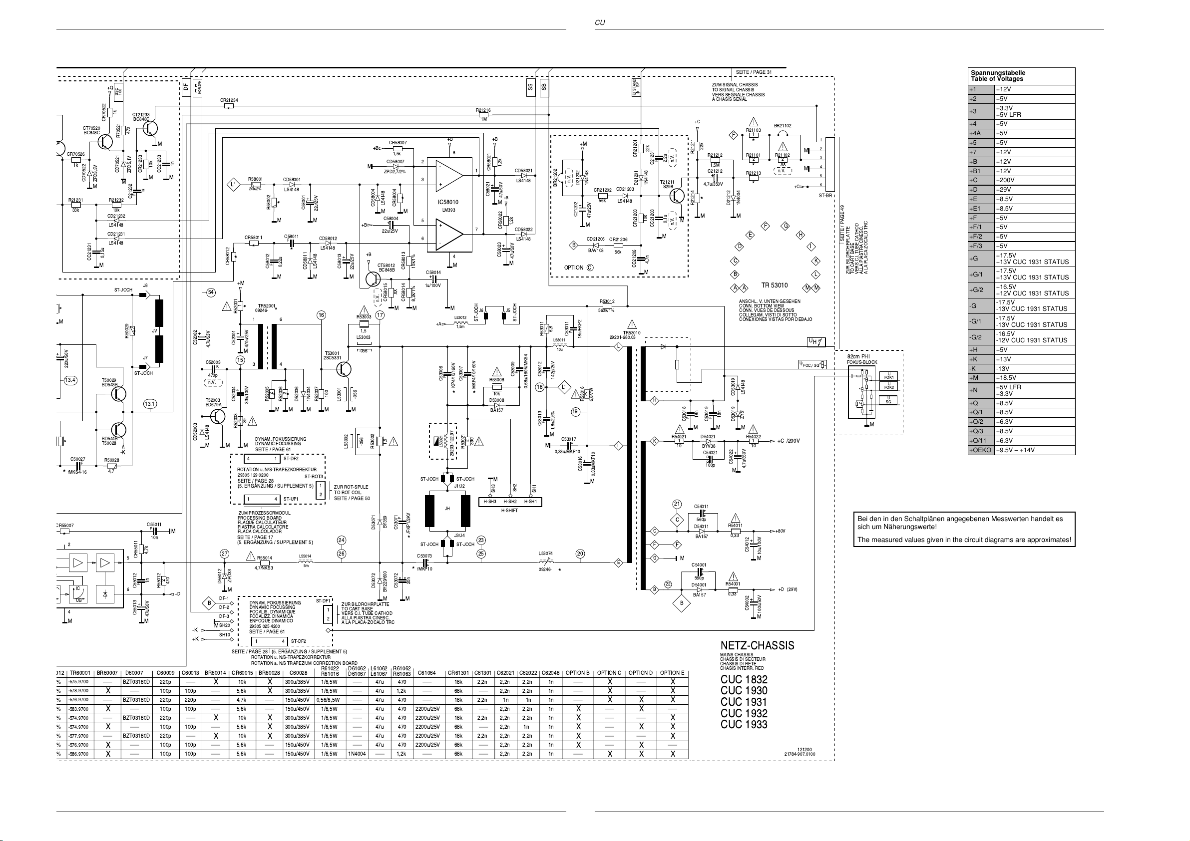
Platinenabbildungen und Schaltpläne / Layout of PCBs and Circuit Diagrams Platinenabbildungen und Schaltpläne / Layout of PCBs and Circuit DiagramsCUC 1931 CUC 1931
M
+
R55007
12
%
%
%
%
%
%
%
%
%
CR70526
R21231
33k
*
220u/50V
13.4
*
C50027
/MKS4-16
*
*
2
4
M
TR60001
-575.9700
-578.9700
-576.9700
-583.9700
-574.9700
-574.9700
-577.9700
-576.9700
-586.9700
1k
IC
UB
CD21203
LS4148
CR21206
56k
TR53010
29201-680.03
L
I
E
BY
STAND
U
CR21201
1N4148
D21201
10k
CR21203
CC21206
M
XX
X
XX
22k
C21231
CC21203
4,7n
H
K
C
F
G
B
F
+Q
SSC
100
1k
CT21233
BC848C
CR70522
CT70520
BC848C
CD70522
M
CC21231
ZPD3,3V
CD21232
CD21231
0,15u
M
T50029
BD543B
R21232
10k
LS4148
LS4148
ST-JOCH
470
R70521
CD70521
ZPD5,1V
M
C21232
R50029
CR21233
1u
F
J8
*
J7
ST-JOCH
10k
JV
13.1
BD544B
T50028
-K
R50028
F
4,7
C55011
F
10n
4,7k
CR55011
5
1n
F
C55012
6
+
C55013
47u/50V
M
D60007BR60007
C60009
BZT03180D
X
BZT03180D
X X
BZT03180D
X X
BZT03180D
X XXX
M
1n
CC21233
MM
M
2
470
R55012
+D
220p
220p
100p 100p
220p
100p 100p
220p
100p
100p
DF
100p100p
220p
100p
100p
HOR.2FH
+
C52002
CD52003
-K
+K
CR21234
*
R58001
LÔ
20k/2%
CR58011
*
*
CR58012
+M
54
1
*
R52001
1
+
C52001
4,7u/63V
C52003
470p
n.V.
T52003
BD679A
LS4148
K
470u/25V
M
15
34
F
C52004
33n/100V
39
R52003
MMM
4
ROTATION u. N/S-TRAPEZKORREKTUR
29305 129 0200
SEITE / PAGE 28
(5. ERGNZUNG / SUPPLEMENT 5)
1
ZUM PROZESSORMODUL
PROCESSING BOARD
PLAQUE CALCULATEUR
PIASTRA CALCOLATORE
PLACA CALCOLADOR
SEITE / PAGE 17
(5. ERGNZUNG / SUPPLEMENT 5)
27
ZPD33
D55012
M
DF-1
B
M
BR60014C60013
X
DYNAM. FOKUSSIERUNG
DYNAMIC FOCUSSING
DF-2
FOCALIS. DYNAMIQUE
FOCALIZZ. DINAMICA
DF-3
ENFOQUE DINAMICO
SH20
29305 025 4200
SEITE / PAGE 61
SH10
SEITE / PAGE 28 (5. ERGNZUNG / SUPPLEMENT 5)
ROTATION u. N/S-TRAPEZKORREKTUR
ROTATION a. N/S TRAPEZIUM CORRECTION BOARD
CR60015
10k
5,6k
4,7k
5,6k
10k
X
5,6k
10k
X
5,6k
5,6k
CD58001
LS4148
*
R58002
M M
C58011
F
0,22u
C58012
M
TR52001
09246-
*
6
2
*
R52006
R52005
M
DYNAM. FOKUSSIERUNG
DYNAMIC FOCUSSING
SEITE / PAGE 61
ST-DF2
1
ST-UP1
4
R55014
4,7/NKS3
4
1
BR60028 C60028 OPTION D
300u/385V
X
300u/385V
150u/450V
150u/450V
300u/385V
X
300u/385V
X
300u/385V
X
150u/450V
150u/450V
F
*
2
ST-DF2
*
+
C58001
22u/25V
CD58012
LS4148
LS4148
CD58011
M M
16 17
T53001
2SC5331
100
1N4004
D52006
R52007
ST-ROT3
1
ZUR ROT-SPULE
TO ROT COIL
2
SEITE / PAGE 50
L55014
5m
ST-DF1
1
2
R61022
R61016
1/6,5W
1/6,5W
0,56/6,5W
1/6,5W
1/6,5W
1/6,5W
1/6,5W
1/6,5W
1/6,5W
+B
M
CD58004
M
C58004
+B
22u/25V
+B
+
C58013
L53001
22u/25V
R53003
1,5
L53003
-056
-056
CT58012
BC848B
n.V.
MMMM
-056
L53002
R53002
D53071
24
26
D53072
ZUR BILDROHRPLATTE
TO CART BASE
VERS C.I. TUBE CATHOD
ALLA PIASTRA CINESC.
A LA PLACA-ZOCALO TRC
L61062
D61062
L61067
D61067
47u
47u
47u
47u
47u
47u
47u
47u
1N4004
CR58007
1,5k
CD58007
ZPD2,7/2%
LS4148
CR58004
+
XX
CR58015
M
1,5
BY359
C53071
C53072
BY229/600
R61062
R61063
470
1,2k
470
470
470
470
470
470
1,2k
2
3
*
M
5
6
10k/1%
CR58013
C58014
+
1u/100V
8,2k/1%
CR58014
F
/FKP1/2KV
*
ST-JOCH ST-JOCH
C53073
/MKP10
*
20n
MM
2200u/25V
2200u/25V
2200u/25V
2200u/25V
2200u/25V
8
-
+
IC58010
LM393
+
-
4
M
MM
L53012
+A
1,5m
F
C53006
KP4/10/160V
**
L53021
29203-122.97
ST-JOCHST-JOCH
J1/J2
JH
J3/J4
18k
68k
18k
68k
18k
68k
18k
68k
68k
R21216
1M
+B+B
1,2k
CR58021
+
C58021
M
R53008
10k
D53008
BA157
47u/50V
+B
1,2k
CR58022
+
C58023
M
CD58021
LS4148
CD58022
LS4148
47u/50V
ST-JOCH
C53009
F
C53007
2
R53021
390
1
7
J6 J5
ST-JOCH
MKP4/10/160V
M
SH2
SH3
H-SH3 H-SH1H-SH2
H-SHIFT
23
25
C61301CR61301 OPTION E
2,2n
2,2n
2,2n
1n
2,2n
2,2n 2,2n
2,2n
2,2n
2,2n
2,2n
2,2n
2,2n
2,2n 2,2n
SS
F
0,68u/160V/MKS4
18
SH1
L53074
09246-
2,2n
2,2n
1n
2,2n
1n
2,2n
2,2n
SB
R53011
F
C53012
F
C53013
M
M
C62048C62022C62021
1n
1n
1n
1n
1n
1n
1n
1n
1n
n.V.
BR21202
OPTION C
6,8
C53011
L53011
10u
142p/2kV
LÔ
1,8n/2,5%
C53017
0,33u/MKP10
*
B
F
19
X
X
X
X
+M
D21202
+
C21202
M
CD21206
18n/FKP2
R53016
C53016
20
1N4148
CR21202
56k
47u/25V
BAV103
R53012
560k/1%
6,8/7W
0,33uMKP10
M
OPTION COPTION BC61064
X
XX
2,2u
T21211
S298
0,1u
M
22
M
n.V. n.V.
R54021
1
10
21
C
F
M
B
X
X
X
X
X
X
R21211
R21214
F
C53018
M
C54011
D54011
C54001
560p
D54001
BA157
+C
M
18n
D54021
BYV38
560p
BA157
22k
4,7u/350V
C54021
SEITE / PAGE 31
ZUM SIGNAL CHASSIS
TO SIGNAL CHASSIS
VERS SEGNALE CHASSIS
A CHASIS SENAL
R21103
1
F
*
R21212
1,5M
C21212
+
R21101
2
*
R21213
*
*
D21212
1N4004
M
E
D
C
B
TR 53010
AA
ANSCHL. V. UNTEN GESEHEN
CONN. BOTTOM VIEW
CONN. VUES DE DESSOUS
COLLEGAM. VISTI DI SOTTO
CONEXIONES VISTAS POR DEBAJO
LS4148
CD53019
18n
F
C53019
100p
ZY51
D53019
M
M
R54022
1
10
+
C54022
4,7u/350V
M
R54011
0,33
+
C54012
10u/100V
M
R54001
0,33
+
C54002
100u/50V
M
NETZ-CHASSIS
MAINS CHASSIS
CHASSIS DI SECTEUR
CHASSIS DI RETE
CHASIS INTERR. RED
CUC 1832
CUC 1930
CUC 1931
CUC 1932
CUC 1933
BR21102
R21102
2
XX
n.V.
GF
/200V
+C
+80V
+D
(29V)
21784-907.0100
+C
M
M
H
MM
U
/
121200
Spannungstabelle
Table of Voltages
+1 +12V
+2 +5V
+3.3V
+3
+5V LFR
+4 +5V
1
2
3
4
5
6
ST-BR
+4A +5V
+5 +5V
+7 +12V
+B +12V
+B1 +12V
+C +200V
+D +29V
+E +8.5V
+E1 +8.5V
+F +5V
+F/1 +5V
I
SEITE / PAGE 49
K
A LA PLACA-ZOCALO TRC
ALLA PIASTRA CINESC.
VERS C.I. TUBE CATHOD
TO CART BASE
L
U
H
SG/FOC.
ZUR BILDROHRPLATTE
82cm PHI
FOKUS-BLOCK
FOK1
FOK2
SG
U
U
U
+F/2 +5V
+F/3 +5V
+17.5V
+G
+13V CUC 1931 STATUS
+17.5V
+G/1
+13V CUC 1931 STATUS
+16.5V
+G/2
+12V CUC 1931 STATUS
-17.5V
-G
-13V CUC 1931 STATUS
-17.5V
-G/1
-13V CUC 1931 STATUS
-16.5V
-G/2
-12V CUC 1931 STATUS
+H +5V
+K +13V
-K -13V
+M +18.5V
+5V LFR
+N
+3.3V
+Q +8.5V
+Q/1 +8.5V
M
+Q/2 +6.3V
+Q/3 +8.5V
+Q/11 +6.3V
+OEKO +9.5V – +14V
Bei den in den Schaltplänen angegebenen Messwerten handelt es
sich um Näherungswerte!
The measured values given in the circuit diagrams are approximates!
GRUNDIG Service GRUNDIG Service
29 30
Page 22

Platinenabbildungen und Schaltpläne / Layout of PCBs and Circuit Diagrams Platinenabbildungen und Schaltpläne / Layout of PCBs and Circuit Diagrams CUC 1931CUC 1931
M
C
4
CR43590
Signal-Chassis / Chassis Signal
+33V +M+B+F
1
11
SAT-BAUSTEIN
SAT. MODULE
MOD. SAT.
MOD. SATELITTE
SAT. MODULE
29504 222 0100
SERVICE MANUAL SEITE / PAGE 3-89
15
12
1
14 13
ST-AUX1A
ST-AUX1B
ST-I2S1
9
1
3
1
3
1
6
765432
10
AM
+A
4
+33V
12k
R32315
D32315
M A
1
ZPD33V2%
SIGNAL-BAUSTEIN
SIGNAL MODULE
MODULE SIGNAL
MOD.SIGNALE
MOD.SENAL
29504 262 0100
SEITE / PAGE 44
SAT-BAUSTEIN 2
15
SAT. MODULE
MOD. SAT.
MOD. SATELITTE
SAT. MODULE
29504 222 0100
SERVICE MANUAL SEITE / PAGE 3-89
12
CT32305
BC848B
CC32321
M
11
10n
+B+F
14 13
ST-AUX1A
ST-AUX1B
ST-I2S1
M
CT32320
BC848B
+M
765432
1
3
1
3
1
6
2930
SDA
CR32303
DISEQC1
321
ST-P5
SDA1
ST-IR-KB
M
U
DISEQC1
SCL1
10k
TERR
DISEQC1
10
n.V.
SCL
SDA
NETZ-CHASSIS
MAINS CHASSIS
CHASSIS DI SECTEUR
CHASSIS DI RETE
CHASIS INTERR. RED
SEITE / PAGE 30
ENA1
M
1
AFC
U
+B
+OEKO
2
+OEKO
FBAS1
+H
+B
+H
543
ST-P1
BY
STAND
U
M
SCL
1
SIGNAL-CHASSIS
CHASSIS SIGNAL
CHASSIS SEGNALE
CHASIS SENAL
CUC 1832
CUC 1930
CUC 1931
CR32381
8
M
680
ST-FBAS2
2
+B
1
CC43002
4,7u
CC43007
4,7u
C43012
+
22u/50V
M
C43017
R
L
IN
L
IN
R
PIP
11
R
22u/50V
CC43022
CC43027
22u/50V
22u/50V
PIP
DATA
U
220
CR65500
CT65501
PMBT2369
1
2
+
4,7u
4,7u
C43032
+
C43037
+
SEITE / PAGE 59
ST-AC3
+Q
6,8
R43082
C43083
+
100u/10V
3
100
CR43081
SDA
+Q
432
ENA1
22
IC43080
+
C43081
A
VCCADR
TEA6420
GND
12
22u/50V
9
10
11
12
13
14
15
16
23
24
L-OUT1
R-OUT1
L-OUT2
R-OUT2
L-OUT3
R-OUT3
L-OUT4
R-OUT4
SCL
SDA
100
M
6
5
ST-P2
+Q
SCL
4
9
8
7
OSD
R
DATA
SDA
U
PROZESSOR-PLATTE
PROCESSING BOARD
PLAQUE CALCULATEUR
PIASTRA CALCOLATORE
PLACA CALCOLADOR
L-IN1
R-IN1
L-IN2
R-IN2
L-IN3
R-IN3
L-IN4
R-IN4
L-IN5
R-IN5
A
10
OSDGOSD
11
B
OSD
4
21
5
20
6
19
7
18
8
17
INT2
AUDIO-R
VERT.2FV
1
CENTRE
INTERN
INTERN
INT2
INT1
INT1
AUDIO-L
AUDIO-R
AUDIO-L
V
VGAHVGA
+F
M
5
432
ST-P3
V
+F
VGAHVGA
VERT.2FV
29504 203 1800
SEITE / PAGE 17
(5. ERGNZUNG / SUPPLEMENT 5)
SUB
OUT
5
OUT
4
A
3
2
1
ST-AV3
B
R
PIPGPIP
CSY
-3,3V
6
9
8
7
10
VGA
G
B
DATA
CSY
-3,3V
U
BUCHSENPLATTE CLICK-FIT 29305 160 6000
SOCKET BOARD
C.I. PRISES
PIASTRA PRESE
PLACA DE TOMAS
ST-CE
1
2
ST-TT1
1
2
9
8
10
A
CR43083
1n
CC32301
100
CR32321
TON
AM
6
RESET
ENA2
MSP
INTERC
7
MUTE
U
FBAS2
U
9
8
11
10
TON
IR
BUS
SCL2
BUSY
U
ST-DVB ST-RGB1
7
AUDIO-L
1
U
AUDIO-R
AFC
ENA2
SCL
ST-VP1
CC43003
CC43008
CC43013
CC43018
CC43023
CC43028
CC43033
CC43038
M
ST-LS1
CR43003
470
470p
A
CR43008
470
470p
A
CR43013
220
1n
A
CR43018
220
1n
A
CR43023
470
470p
A
CR43028
470
470p
A
CR43033
220
1n
A
CR43038
220
1n
A
AV1
AV2
EURO
EURO
MEGA
LOGIC
U
U
12345
AV1
AV2
EURO
EURO
MEGA
LOGIC
U
U
1
U
6
4
6
2
1
3
6
2
1
3
RGB
ST-P4
RGB
U
n.V.
15/7
CHROMA
U
15/7
CHROMA
U
ST-TEST1
CUC 1932
CUC 1933
AENDERUNGEN VORBEHALTEN
SUBJECT TO ALTERNATE
SOURS RESERVE DE MODIFIC
CON RISERVA DI MODIFICA
RESERV. EL DEREC. DE MODIFIC.
1210
8
20
16
15
11
7
19
21
18
17
EURO-AV1
14
13
9
5
M
4
A
1210
8
20
16
15
11
7
19
21
18
17
EURO-AV2
14
13
100
9
CR43042
5
4
A
M
AV2
EURO-
U
TXT
FBAS
VIDEO
M
7
8
6
FBAS
55
TXT
FBAS
1
2
ST-AUX1
311111
MEGA
LOGIC
CR4300275CR43004
100
CR43051
AV1
EURO-
U
CR43067
M
75
75
CR43005
MM M
CC43066
75
+Q1
3,3
R43566
+
CR43569
ZUR KEYBOARD
TO KEYBOARD
SEITE / PAGE 27
(5. ERGNZUNG /
SUPPLEMENT 5)
5
AUDIO-R
4
5
1
1
11
CC43567
10n
CT43565
BC848B
1k
M
AUDIO-L
AUDIO-R
12
ST-AUX1
3
6
ST-LS1
4
ST-LS2ST-LS2
3
6
A
INT1
M
M
AUDIO-L
C43566
M
47u/16V
CR43568
75
11
BUCHSENPLATTE 29305 160 3700
SOCKET BOARD
C.I. PRISES
PIASTRA PRESE
PLACA DE TOMAS
SEITE / PAGE 63
ST-S3ST-S3
1
2
AM
INTERC
CR43066
75
M
47
75
CR4305375CR43056
M
M M
75
1u
CR43057
M
FBAS
1
VIDEO
2
M
S-VHS
3
CHROMA
ST-SV1
75
CC43556
CR43615
M
CR43556
6
ST-AV3VST-AV3
CC43615
CC43667
IN6
INT2
INT2
INT1
AUDIO-R
AUDIO-L
78910 1112 1314 15
20504 204 0300NF-BAUSTEIN
-G
SEITE / PAGE 51
1
6
ST-I2S1
10k
CR40502
M
1
6
+GA+F+Q
AF MODULE
MODULO BF
PIASTRA BF
MODULO BF
10k
CR40501
M
75
CR43058
CR43072
CR43617
0,1u
47
150p
M
1u
CC43676
IN8
SCL2
ST-H-AV
16 1718 19 20 21 22
M
CC43554
SDA
U
CR43009
47
CR43014
47
CR43019
47
CR43010
CC43553
CR43553
75
0,1u
47
CR43554
1u
RESET
DATA
VGA
CR43048
47
CR43046
47
CR43043
47
CR43047
47
47
0,1u
CR43078
47
CC43618
1u
CC43672
M
1
3
5
6
8
10
2
4
220
CR43677
220
CR43678
SCL
SDA
BY
MUTE
MSP
STAND
U
U
ST-LSL
ST-LSR
ST-TT
22
1
CT65503
BC848B
CR65501
10
CR65509
M
470
-3,3V
75
M
0,1u
IN1
IN2
IN3
IN4
IN5
IN6
SDA
SCL
1
2
1
M
CC43079
1u
CR43618
47
+Q1 +Q1
IC43670
TEA6425
+F
CR43653
CC43653
9
VCCP
SUB
7
+Q1
1k
47n
CR43079
47
C43673
+
100u/10V
CC43674
0,1u
20
VCC
OUT1
OUT2
OUT3
OUT4
OUT5
OUT6
OUT7
OUT8
GND
11
M
CR65505
1,8k
M
12
13
CC43617
19
18
17
16
15
14
13
12
OUT12
OSD
DATA
U
CR65502
CR43651
1k
CD43651
ZPD6,2V
2
1
5
3
150p
M
M
CR43679
Y
GM
CT65505
620
CT65504
PMBT2369
CIC43650
74HC4053
M
VIDEO
IN
CHROMA
IN
+Q1
FBAS
OUT
CHROMA
OUT
2,2k
PIP
IN6
CHROMA
+B
CR65503
BC858B
16
M
CC43651
0,1u
876
M
ST-AV3V
1,8k
M
+6,2V
M
14
11
15
10
4
9
1
2
3
4
5
6
CT43590
BC848B
CR43591
+B
CR65504
CD65506
LS4148
CR43676
47
33
330
M
4,7k
CR65510
M
+Q1
+Q1
CHROMA
1k
CT65506
BC848B
CR43574
47
CR43576
CC43576
FBAS2
CR65507
CR65508
CR65506
33
1M
47
CR43572
4,7u
CC43577
FBAS1
47
47
CR43577
4,7u
SDA
CC65507
68p
CC65506
100p
CD65519
LS4148
CD65528
LS4148
CC43572
M
1
3
5
6
8
10
2
4
220
CR43578
SCL
0,1u
IN1
IN2
IN3
IN4
IN5
IN6
SDA
SCL
220
+B
CR65526
2,2k
+6,2V
12
13
2
1
5
3
+Q1 +Q1
9
VCCP
IC43570
TEA6425
SUB
7
0
CR43573
M
M
CR65518
CC65519
CR65517
CIC43550
M
C43573
+
100u/10V
CC43574
0,1u
20
VCC
OUT1
OUT2
OUT3
OUT4
OUT5
OUT6
OUT7
OUT8
GND
11
M
CR43589
4,7k
10p
CR65519
1,5k
M
16
74HC
76
19
18
17
16
15
14
13
12
4,7k
M
PIP
VIDEO
CC65517
CC65518
820
CC65528
n.V.
1n
1n
31 32
GRUNDIG Service GRUNDIG Service
Page 23

Platinenabbildungen und Schaltpläne / Layout of PCBs and Circuit Diagrams Platinenabbildungen und Schaltpläne / Layout of PCBs and Circuit DiagramsCUC 1931 CUC 1931
1
5k
10p
+1 +12V
+2 +5V
+3
+3.3V
+5V LFR
+4 +5V
+4A +5V
+5 +5V
+7 +12V
+B +12V
+B1 +12V
+C +200V
+D +29V
+E +8.5V
+E1 +8.5V
+F +5V
+F/1 +5V
+F/2 +5V
+F/3 +5V
+G
+G/1
+G/2
-G
-G/1
-G/2
+H +5V
+K +13V
-K -13V
+M +18.5V
+N
+5V LFR
+3.3V
+Q +8.5V
+Q/1 +8.5V
+Q/2 +6.3V
+Q/3 +8.5V
+Q/11 +6.3V
+OEKO +9.5V – +14V
16
CIC43550
74HC4053
1
C43573
+
00u/10V
CC43574
0,1u
0
19
OUT1
18
OUT2
17
OUT3
16
OUT4
15
OUT5
14
OUT6
13
OUT7
12
OUT8
1
CR43589
M
VIDEO
CC65517
4,7k
CC65518
820
CR65519
,
n.V.
CC43551
0,1u
M
M
M
CR43590
4,7k
PIP
1n
1n
CC65528
876
M
CR65511
CR65516
CR65521
10p
M
14
11
15
10
4
9
4,7k
CR43675
TERR
U
5,1k
27k
27k
CR65529
CR65528
4,7k
CR43592
M
33k
CR43593
10n
CC43675
M
CC65515
820
1,5k
CR43543
220
CC43526
M
+Q4 +Q4
75
47n
CR43526
BC858B
CT43525
CR43080
18k
470
CR43536
CT43535
BC848B
470
CR43537
CR43538
2,2k
CC43538
MM
CR43075
4,7n
+Q1
18k
LS4148
CD43541
CR43541
CR43542
M
M
820
CD43542
M
18k
CR43582
1k
R43581
3,3
ZPD2,7V
CR43583
+
C43586
M
R
B
G
DATA
U
75
CT43580
BC848B
47u/16V
CC43587
SAT
ST-RGB_SAT
+Q4
10n
M
6
M
5
4
M
3
2
1
+B1
CR70551
CR70552
37
38
M
39
40
M
41
42
M
43
1M/1%
CR70553
270k/2%
CD70501
ZPD5,1V
6,8M
M
LS4148
BEAM
220p
Y
100
56
CR34525
CC34519
18
CR34518
M
CD70553
SB
220p
CC34525
CC34518
22n
C34501
1u/100V
0,1u
+
Y
-(B-Y)
100
-(R-Y)
100
4,7k
100
-(B-Y)
CR34524
CR43599
CC34524
M
75
M
I
100
-(R-Y)
220p
CC34526
M M
15
CR34526
62
CR34519
M M
CC34520
22n
IN6
4,7n
CR43594
M
2,2k
IN8
33
CR65515
CT65530
BC858B
1k
CR43596
M
CC65531
4,7k
FBAS
0,1u
TXT
4,7k
CR43597
M
34
35
VIDEO
CR43598
CC65532
MM
4,7k
M
15/7
CHROMA
U
0,1u
C65533
+
RGB
U
47u/25V
M
OUT12
M
55 56
CT65525
BC848C
33
CR65527
CC65527
M
CR65536
22
R65525
4,7n
+80V
M
8311-212-070
3
2
M
1
ST-GM
ZUR BILDROHRPLATTE
TO CART BASE
VERS C.I. TUBE CATHOD
ALLA PIASTRA CINESC.
A LA PLACA-ZOCALO TRC
SEITE / PAGE 49
+B
0,1u
+N
CC70502
MM
M M
4,7n
CC70503
M
0,1u
3332
CC70506
4,7n
CC70507
0,1u
1098
+B+F
L70508
M
M
035.97
09241-
CC70508
4,7n
C70509
+
1000u/25V
36
M
+H
LÔ
3,9k
CR70504
CC70501
31
REF
28 27
FEATURE-BOX
29504 103 4100
29504 103 4200
29504 209 1300
29504 209 1500
SEITE / PAGE 35
100
-(B-Y)
3,8V
4V
4V
1,7V
100
8
7
6
18
CR46032
M
CR46033
M
CC46033
M
3534
54321
7
37
33
27k
CR70502
CR70510
33
27k
CR70501
CR70509
100
VIDEO
-(R-Y)
CHROMA
+Q3
C34506
+
100u/10V
8,3V
CC34507
47n
5
Y
100
SSC
14 13 121110
57
180
180
68p
SSC
100
VERT.
M
M
M
Y
MATRIX
CC34502
CR46036
R
OSD
22n
0
VERT.
9
CC34503
CR46035
G
VG
OWA
VERT.2FV
Y
GM
SCL
64
220
CR34509
3V
28 2726
A
22n
0
OSD
2
IC
D
4321
0V5V5V5V0,7V
22n
CC34504
0
CR46034
B
OSD
CC70518
CR70519
CD70519
BY
STAND
U
OSD
DATA
U
12
10n
XX
n.V.
XX
I
BEAM
SDA
220
CR34510
2,8V
CR46031
180
CC46031
68p
CC46032
68p
30
545352515035494847
HOR.2FH
+Q3
1M
CR34511
3,3V
M
M
M
PIP
DATA
U
CR70518
SSC
+B1
11
26252423 222120
57
100
CC34541
R
PIP
CR70506
1,2k
CR70507
180k
CR70508
3,3k
14
4,7k
SCL
+
C34509
4,5V
22n
CC70512
CC70513
6263
SDA
+
C34511
1u/100V
M
CC34542
G
PIP
CD70506
181716
100p
100p
2,2u/100V
22n
CC34543
B
LS4148
6
13
15
19
29
31
M
M
V
MM
+
C34510
4,7V
PIP
VGA
171615
22n
CR34541
CR34543
CD70507
M
DF
CSY
CR34513
22k
1,5M
CR34512
M
4,7u/100V
19
COMP.ZAEHLERLIMITING
IC34510
TDA4780V3
CR34544
1k
CR34542
1k
1k
1k
LS4148
M
386556
H
M
VGA
CD34513
LS4148
25
3,3V
23
3,2V
21
3,3V
20
2,9V
22
2,7V
24
2,8V
SS
7,1V
CT70505
BC848B
D70508
C70516
27k
CR70516
LS4148
CD70517
SB
SB
9,1k
CR34514
CR34517
1,8k
C34521
F
0,22u
C34522
F
0,22u
C34523
F
0,22u
CR34521
100
CL34522
0_OHM
CR34523
100
C70511
1u/100V
M
ZPD15
+
4,7u/100V
5,6k
CR70512
M
270k
CR70513
M
CC34515
0,47u
CR34515
150k
CR34516
6,8k
7,5k(70cm PHI 16:9)
M
M
M
CL34521
CR34522
CL34523
M
+
CR43024
-K
4,7k
+Q
PIP-BAUSTEIN 29504 206 0100
PIP MODULE
MODULE PIP
MODULO PIP
MODULO PIP
SERVICE MANUAL SEITE / PAGE 3-94
ST-PI1
12345
6
3
2
1
M
SDA
+F
VERT.2FV
SSC
100
+33V
+Q
SCL
M
(70/82cm PHI 16:9)
+Q3
+B
(82cm PHI 16:9)
61
LS4148
CD34517
CC34517
CR34520
M
270p
100k
MM
27p
27p
0_OHM
100
0_OHM
M
CC34522
CC34523
27p
CC34521
60
59
58
+B
M
M
47n
10k
CC43025
CR43025
M
CD43026
M
M
L70555
8,2u
L34517
8,2u
ST-PI2
654
M
PIP
B
DATA
U
ZUR BILDROHRPLATTE
TO CRT PANEL
VERS C.I. TUBE CATHOD
ALLA PIASTRA CINESC.
A LA PLACA-ZOCALO TRC
SEITE / PAGE 49
ST-RGB
7
6
5
4
3
2
1
21784-907.0200
ZPD3,3V
M
PIPRPIPGPIP
SW
B
G
R
121200
987
-3,3V
+Q1
+Q3
M
VIDEO
10
PIP
CHROMA
Spannungstabelle
Table of Voltages
+17.5V
+13V CUC 1931 STATUS
+17.5V
+13V CUC 1931 STATUS
+16.5V
+12V CUC 1931 STATUS
11
PIP
-17.5V
-13V CUC 1931 STATUS
-17.5V
-13V CUC 1931 STATUS
-16.5V
-12V CUC 1931 STATUS
Bei den in den Schaltplänen angegebenen
Messwerten handelt es sich um Näherungswerte!
The measured values given in the circuit
diagrams are approximates!
GRUNDIG Service GRUNDIG Service
33 34
Page 24

Platinenabbildungen und Schaltpläne / Layout of PCBs and Circuit Diagrams Platinenabbildungen und Schaltpläne / Layout of PCBs and Circuit Diagrams CUC 1931CUC 1931
L
M
9
O
Feature Box 295042091300
9
VERS CHASSIS
TO CHASSIS
ZUM CHASSIS
AL TELAIO
AL CHASIS
SEITE / PAGE 33
+F/5V
+B/12V
+N/3,3V
+H/5V
VIDEO
CHROMA
R
50
G50
B50
U
DATA
SDA
SCL
VG
I
BEAM
SS
REF
10
36
32
33
n.V.
8
34
38
40
42
35
43
39
41
37
16
14
13
15
17
19
29
31
22
25
27
28
BU
09241 035 9700
BU
10nF
CC1339
M
BU
09241 035 9700
BU
BU
09241 035 9700
10nF
CC1338
M
BU
BU
BU
BU
A
BU
BU
BU
BU
BU
BU
BU
BU
BU
BU
BU
BU
BU
BU
M
L1401
BU
L1402
BU
L1403
BU
L1407
BU
L1353
L1351
L1357
n.V.
L1358
10u
10u
10u
10u
10u
CR2051
56
L1310
L1313
L1315
L1317
CR2050
+1
CR1415
CD1419
CR1414
M
CR1401
3,3k/5%
CR1402
330
CD1403
LS4148
CD1407
LS4148
+
C1353
+
C1354
A A
+
C1357
M
+
C1359
1k
1,5k
ZPD3,9V/2%
43/2%
0,1u
CC1356
220uF/16V
MM
0,1u
CC1352
220uF/25V
0,1u
CC1358
220uF/16V
M
0,1u
CC1359
100uF/35V
MM
CC1307
56p/5%
13
8
81405 320 8500
27p/5%
CC1306
A
CR1304
180
CR1305
180
CR1306
180
CR1307
330
BAR42
CD1418
+
C1415
10uF/50V
M
+4
10k/5%
CR1412
47n
CC1401
M
68n
CC1402
M
+4A
1k/2%
CR1403
MMM M
4,7k
CR1407
CC1340
M M
n.V.
L1306
1,8u
CC1403
10nF
L1361
L1362
7
CC1311
A
CC1313
A
CC1315
A
CC1317
A
0,1u
M
470p
/5V
+2
10nF
CC1341
CC1342
M
+1
+3A
+3B
+4
10nF
M
/12V
/3,3V
/3,3V
/5V
CC1343
10nF
M
CC1344
10nF
CC2049
M
CC1345
M
AA
GND
F202004
F2000
24156 89
CC1309
68p/5%
L1308
13
8
3,3u
81405 320 8600
270p/5%
CC1308
A A A
22p/5%
22p/5%
22p/5%
22p/5%
L1412
4,7u
220uF/16V
+
M
C1423
0,1u
M
CC1422
0,1u
CC1415
M
1,2V
CC1419
0,1u
M
2,5V
CC1417
4,0V
CR1408
M
0
CR1405
0
CD1406
M
CR1433
0
M
ZPD5,1V/2%
CC1407
M
CC1408
M
xx
CR1434
xx
27p
27p
CR1404
1314151617181920212223
OUTIN
12
11
7
330p/5%
CC1310
L1309
CC1312
L1311
CC1314
L1312
CC1316
L1314
CC1318
L1411
4,7u
+4A
M
24
25
18
14
SW2
11
32
15
CIC1410
34
33
S-DDC
12
27 28
SW1
26
2
Q1408
12MHz
3
394041
LD1117V33C
0,1u
10nF
CC1346
M
CR2056
A
CR2053
1,1k/2%
18u
xx
18u
xx
18u
xx
18u
xx
+4
L1421
9
17
*
10
M
IC1310
M
10nF
CC1347
M
CR2052
100
1k
18p/5%
18p/5%
18p/5%
18p/5%
38
16
1
CR1423
31
23
10nF
CC1348
M
0
43
13
19
42
44
37
36
35
30
1
4
5
6
7
8
29
20
22
21
23
CC2056
M
10nF
+1
CR2057
A
CR1303
M
M
0,1u
CC1349
M
1k
CT2057
BC858B
1,1k/2%
+4
L1423
220uF/16V
CC1421
CR1421
M
C2058
M
10nF
**
CC1304
A
CC1305
A
CC1319
A
CC1320
A
CC1325
A
C1427
+
CC1426
0,1u
+
xx
39p/5%
39p/5%
39p/5%
39p/5%
CC1428
100p/5%
CC1410
1,5n/5%
M
1,8k/2%
+3
10uF/50V
+4
+2
+3
+2
Chroma(Rot)
1k
CR1320
A
1k
CR1321
A
1k
CR1322
A
xx
CR1323
A
U TV VGA
M
M
M
1n
+3
LL1,5X
SDA
SCL
HS2/HVGA
VS2/VVGA
VBLK
SCC/100
HOR
OWA
V-OUT/POS
V-OUT/NEG
CC2057
A
C1367
F
0,68u
/3,3V
CR1311
100k
L1350
0,1u
+3
CC1330
M
+
C1350
L1352
L1360
100uH
CC1362
A
C1364
A
10uF/50V
CC1365
A
CC1366
A
Net-
0
CR1367
C1369
F
0,22u
C1312
F
0,22u
C1316
F
0,22u
CR1330
680
CIC1320
100n
TLC7733ID
1234
+
C1323
M
CC1354
100uF/35V
M
+
C1352
M
+
C1360
A
47n
+
3,3p
3,3p
M
LOE2
connection
A
C1368
F
0.22u
C1314
F
0,22u
RESN
5678
MM
2,2uF/50V
0,1u
CC1351
MM
CC1353
100uF/35V
M
CC1361
220uF/16V
A
LOE1
Q1365
20,25MHz
CR2063
M
150
0,1u
0,1u
0,1u
A
A
A
A
M
A
F
C1361
CR2062
4
31
36
57
M
66
3
1
2
67
58
68
5
6
7
8
9
59
65
64
61
63
62
60
0,22u
*
10 111213
VIN4
HC
16
M
10k
CR2060
CT2058
BC848B
OPTION A
CIC1350
*
SCL
SDA
CC1367
1n
+4
1,1k
CR2061
RES
5455 56
CR2069
CT2059
BC848B
M
2,2k
15
VVGA
VS
CL1377
CR2070
20
21
22
23
24
25
28
29
38
39
40
41
42
43
46
47
17
14
26
27
30
32
35
37
33
44
51
52
50
49
48
34
45
53
19
18
BLM21A121S
8104-982.333
2,2k
FEATURE-B
LL1,5=27MHz
LL3=13.5MHz
33 34
CR1371
+
100uF/35V
+
100uF/35V
+
220uF/16V
xx
xx
CC1371
CC1373
MM
CC1375
AA
0,1u
0.1u
0,1u
51
50
49
48
47
46
45
44
43
42
41
40
39
38
37
36
29
CIC1360
CIP3250
30
53
19
PADS
57
35
67
65
63
54
3132
55
CC1368
Y7
Y6
Y5
Y4
Y3
Y2
Y1
Y0
C7
C6
C5
C4
C3
C2
C1
C0
BLN0
CR1370
M
0
+2
L1370
C1370
L1372
M
M
+2
*
BR1350
CL1376
BLM21A121S
81049 823 3300
+3
CC2059
A
L1374
100u
0,1u
M M
C1372
C1374
R50
G50
B50
FS
LL3
CC1376
M
LL1,5
CC1377
M
xx
STELLUNG
TV-BETRIEB
9
10
11
14
15
678
M
345
CR2065
CIC2020
74HC4053
1
2
13
M
12
CR2025
+4
16
CR2020
0,1u
CC2020
M
M
0
59
+
C1377
2
3
4
5
6
7
8
9
10
D-Y7
11
D-Y6
12
D-Y5
13
D-Y4
14
D-Y3
15
D-Y2
16
D-Y1
17
D-Y0
20
D-U1HSÔ
C7
21
D-U0
C6
22
D-V1
C5
23
D-V0
C4
24
C3
25
C2
26
C1
27
C0
28
BLN
58
62
64
66
A
1
18
52
56
6061
68
M
A
M
1n
**
*
*
209 0300
209 0500
209 1300
0.1u
CC1378
10uF/50V
AA
+3B
+3A
LL3
LL1,5
VS
RESN
NUR VORGESEHEN
ONLY IF REQUIRED
PREVU
SOLO PREVISTO
SOLAM. PREVISTO PARA
CIC1350OPTION A
VPC3215A
VPC3211A
VPC3215A
VPC3211A
CC1692
M
CC2012
CR2016
M
SDA9362-2
SDA9362-2209 1500
0,1u
M
0
CIC1410
SDA9362
SDA9362
M
100uF/10V
M
M
M
M
0,1u
M
M
CC2010
0,1u
C2000
CC2001
0,1u
CC2002
0,1u
41
42
50
49
48
47
46
45
44
43
40
39
38
37
34
33
32
31
35
36
23
19
LL3
LL1,5
CC2021
+3A
+
1n
CIC2010
SDA9400
SDA9401
SDA9400
SDA9401
M M
M
51 5253
CIC2010
*
61
CR2020
0
0
20 2122
CR2062
2,2k
2,2k
54
**
27 2829 30
CC2018
M
2
55 5657 5859
Q2015
27MHz
27p
BR1350
+3B
100uF/10V
CC2014
CC2003
CC2019
C2004
+
0,1u
0,1u
MM
L2018
27p
VS2
M
M
M
63
64
1
3
4
5
6
7
10
11
12
13
14
15
16
17
18
24
25
M
9
8
M
62
C
8104
BL
26
60
xx
CC2017
35 36
GRUNDIG Service GRUNDIG Service
Page 25

Platinenabbildungen und Schaltpläne / Layout of PCBs and Circuit Diagrams Platinenabbildungen und Schaltpläne / Layout of PCBs and Circuit DiagramsCUC 1931 CUC 1931
RE-BOX
C2004
M
+
0uF/10V
C2014
M
0,1u
C2003
M
0,1u
63
64
1
3
4
5
6
7
10
11
12
13
14
15
16
17
18
24
25
M
9
8
M
62
CL2022
81049 823 3300
BLM21A121S
26
60
28
L2018
xx
27p
CC2017
VS2
29504 209 0300
29504 209 0500
29504 209 1300
29504 209 1500
0,1u
CC1690
M
0,1u
CC1688
M
xx
CC2022
M
xx
MM
+3B
+3B
BLN2
LL1,5X
HS2
+2
L1641
CT1506
+
42
26
33
CIC1640
SDA9280
DISPLAY
61 62
64
65
66
67
68
25
M
24
23
22
21
20
19
18
16
15
14
13
12
7
6
5
2
3
4
10 11
Y7
Y6
Y5
Y4
Y3
Y2
Y1
Y0
/C7
U1
/C6
U0
/C5
V1
/C4
V0
C3
C2
C1
C0
PROCESSOR
M
C1641
M
51
V
45
48
52
58
49
54
U
57
56
59
55
53
50
46
220uF/16V
CC1652
CC1653
CR1659
300/2%
CR1661
CC1623
M
0,1u
A
0,1u
A
11k/2%
CC1661
A
0,1u
+
C1651
A
+
C1656
A
CR1662
15k/1%
0,1u
CC1642
M
220uF/16V
220uF/16V
0,1u
L1651
L1656
L1662
10u
CC1644
M
CC1658
CC1657
CC1662
0,1u
A
A
CC1646
M
0,1u
0,1u
0,1u
C1663
CR1649
+2
+2
CR1658
+
0,1u
150/2%
A
150/2%
A
CD1663
100uF/35V
AAA
AA
CC1648
M
C1511
10uF/50V
CR1663
ZPD5,1V/2%
0,1u
1k
C1501
+
10uF/50V
+
CR1501
CR1502
CR1511
CR1512
+1
CR1521
A
CR1668
A
+2
150/2%
M
C1521
+
10uF/50V
CD1533
LS4148
CD1534
LS4148
HVGA
VVGA
SSC
HOR
CR1522
VBLK
+2
M
INPUT
GND
CR1674
SCL
Y
CC1674
39p
220
CR1681
47
44
35
34
27
17
9
8
1
CT1680
BC848B
CC1681
M
2,2k
CT1690
BC848B
CC1691
M
M
xx
xx
M
CR1671
6,8k/2%
xx
CC1672
CC1671
1,5n/5%
+2
10k
CR1682
M M
10k
CR1692
CT1681
BC848B
CR1683
M
CT1691
BC848B
CR1693
M
CR1684
47k
+2
CR1694
47k
2,2k
2,2k
MM
63
60
43
M
28
29
41
M
383940
CC1649
M
3031 32
M
1n
CR1691
2,2k
CC1673
39p
3637
CR1673
SDA
220
51k/2%
CT1501
BC849B
10k/2%
A
51K/2%
CT1511
BC849B
10k/2%
A
51k/2%
CT1521
BC849B
10k/2%
A
CD1532
LS4148
CD1530
LS4148
CR1503
CR1504
CR1513
CR1514
CR1523
CR1524
CR1561
2,2k
240/2%
CR1506
100/2%
CR1507
300/2%
180/2%
240/2%
CR1516
100/2%
CR1517
300/2%
180/2%
240/2%
CR1526
100/2%
CR1527
200/2%
180/2%
CR1532
CR1531
CR1541
100
100
4,7k
BCX51-16
BCX51-16
BCX51-16
CT1561
BC848B
CR1544
620
CT1516
CT1526
CT1541
BC848B
CR1562
56
CR1563
M
CR1543
M
560
330
CR1508
68/2%
CR1518
68/2%
CR1528
68/2%
L1563
CR1542
220
L1543
10u
BC848B
CT1545
CR1549
M
L1538
10u
+
C1509
A
CC1526
A
+2
10u
470
L1509
2,2u
220uF/25V
L1508
L1518
0,1u
L1532
10u
L1531
L1533
L1536
L1537
CR1546
220
CR1545
56
L1546
10u
L1544
10u
+7
+1
5
BU
-(R-Y)
100
6
BU
C
BCX
51-16
C
+7
BU-
Y/100
01
MASSE
02
-(B-Y)/100
AL TELAIO
AL CHASIS
03
04
-(R-Y)/100
05
06
VERT.2FV
07
08
09
10
11
12
13
14
15
16
17
18
19
20
21
22
23
24
25
SSC 100
26
27
28
29
HOR.2FH
30
31
32
33
34
35
36
37
MASSE ANALOG
38
39
MASSE ANALOG
40
41
MASSE ANALOG
42
43
MASSE
MASSE
+H (+4/5V)
+F (+2/5V)
+F (+2/5V)
MASSE
MASSE
MASSE
CSY
MASSE
OWA
DF
MASSE
MASSE
CHROMA
U
DATA
HVGA
VVGA
SCL
SDA
VG
V/AP
V/AN
IBEAM
SS
REF
+N (+3/5V)
+N (+3/5V)
FBAS
+B(+1/12V)
50
G50
B50
R50
1
11
12
1
16
17
10
26
27 43
3
BU
-(B-Y)
100
4
BU
+7
1
BU
Y
100
VERT.2FV
VVGA
CSY
DF
VVGA
HVGA
SSC
100
SEITE / PAGE 33
ZUM CHASSIS
VERS CHASSIS
TO CHASSIS
2
BU
7
BU
18
BU
21
BU
BU
12
BU
11
26
BU
+1
30
BU
HOR.2FH
C
EE
BB
IC VON OBEN
IC TOP VIEW
IC VUES DE DESSOUS
IC VEDUTO DA SOPRA
IC VISTO DESDE ARRIBA
44
CIC1410
SDA9362
64
CIC2010
SDA9400
168
CIC1350
CIC1360
CIC1640
BC848
849
VPC3215A
CIP3250
SDA9280
Spannungstabelle
Table of Voltages
+1 +12V
+2 +5V
+3.3V
+3
34
33
+5V LFR
+4 +5V
+4A +5V
+5 +5V
+7 +12V
+B +12V
+B1 +12V
+C +200V
+D +29V
23
22
49
48
33
32
61
60
+E +8.5V
+E1 +8.5V
+F +5V
+F/1 +5V
+F/2 +5V
+F/3 +5V
+17.5V
+G
+13V CUC 1931 STATUS
+17.5V
+G/1
+13V CUC 1931 STATUS
+16.5V
+G/2
+12V CUC 1931 STATUS
-17.5V
-G
-13V CUC 1931 STATUS
-17.5V
-G/1
-13V CUC 1931 STATUS
-16.5V
-G/2
-12V CUC 1931 STATUS
+H +5V
+K +13V
-K -13V
+M +18.5V
+5V LFR
+N
+3.3V
+Q +8.5V
+Q/1 +8.5V
+Q/2 +6.3V
+Q/3 +8.5V
44
+Q/11 +6.3V
+OEKO +9.5V – +14V
Bei den in den Schaltplänen angegebenen Messwerten handelt es
+1
sich um Näherungswerte!
The measured values given in the circuit diagrams are approximates!
20
BU
OWA
23
BU
V/AP
BU
24
V/AN
060300
GRUNDIG Service GRUNDIG Service
37 38
Page 26

Platinenabbildungen und Schaltpläne / Layout of PCBs and Circuit Diagrams Platinenabbildungen und Schaltpläne / Layout of PCBs and Circuit Diagrams CUC 1931CUC 1931
CT1526
CR2065
CR1673
CR1674
CR2063
CR2016
CR1367
CR2025
CC1644
CC1646
CC1674
CC1673
CC1422
CC1339
CC1346
CC2020
CC1378
CC1362
CC1415
CD1418
CC1672
CC1345
LOE2
CL1376
CC1330
34
23
12
1
CIC1410
CIC1360
CIC1350
CIC1640
CR1691
CT1506 CT1516
64
49
48 33
32
17
16
1
CIC2010
1
CIC1320
1
CIC2020
29304-686.42/4BS(03)
0
10
20
30
40
50
60
70
80
90
100
110
120
Y
0102030405060708090100110120130140150160170
X
Bestückungsseite, Ansicht von oben
Component Side, Top View
29304-686.42/4B(03)
1
C1369
L1309
42
43
L1312
L1350
C1350
C1316 C1312
C1314
L1311
L1313
L1315
L1310
C1360
1
C1323
L1308
C2058
L1352
LOE1
L1360
1
3
L1306
C1357
IC1310
C1352
C1368
F2000
C1367
C1364
C1370 C1372
L1370
Q1365
C1377
C1354
L1314
L1351
L1543
L1317
1
C1361
L1374
C1374
L1407
L1372
L1537
L1403
L1402
C2000
Q2015
BR1350
L1538
L1544
1
C1415
L1401
L1361
L1563
L1362
L1546
Q1408
23
L1531
C1641
C2004
L2018
1
L1411
1
L1412
L1533
L1641
1
L1536
L1358
L1532
C1427
L1421
C1423
L1423
L1508
L1518
C1359
2
1
C1656
C1521
BU
L1662
C1663
L1509
L1353L1357
L1656
L1651
C1501
C1353
C1651
C1509
Bestückungsseite, Ansicht von oben
Component Side, Top View
120
110
100
90
80
70
60
50
C1511
40
30
20
10
0
Y
Koordinaten für die Bauteile der Bestückungsseite (Oberseite)
Coordinates of the Components on the Components Side (Top Side)
BR1350 88 59
BU 85 2
C1312 121 47
C1314 125 47
C1316 130 47
C1323 160 36
C1350 129 101
C1352 141 101
C1353 11 16
C1354 109 34
C1357 161 16
C1359 38 29
C1360 161 60
C1361 97 57
C1364 140 46
C1367 151 47
C1368 154 38
C1369 134 47
Pos.-Nr./ Koordinaten/
Pos. No. Coordinates
XY
Pos.-Nr./ Koordinaten/
Pos. No. Coordinates
C1370 113 101
C1372 94 101
C1374 103 43
C1377 113 46
C1415 77 47
C1423 49 37
C1427 51 47
C1501 23 46
C1509 10 60
C1511 13 46
C1521 32 46
C1641 56 101
C1651 20 76
C1656 25 87
C1663 20 63
C2000 85 102
C2004 65 102
C2058 160 107
XY
Pos.-Nr./ Koordinaten/
Pos. No. Coordinates
F2000 144 29
IC1310 151 106
L1306 152 21
L1308 155 29
L1309 138 28
L1310 133 21
L1311 126 34
L1312 133 36
L1313 125 21
L1314 119 34
L1315 129 21
L1317 121 21
L1350 123 105
L1351 115 22
L1352 159 93
L1353 19 9
L1357 150 9
XY
Pos.-Nr./ Koordinaten/
Pos. No. Coordinates
L1358 51 23
L1360 159 74
L1361 79 105
L1362 71 105
L1370 119 105
L1372 101 105
L1374 101 49
L1401 81 22
L1402 94 22
L1403 102 22
L1407 106 22
L1411 66 22
L1412 62 22
L1421 42 42
L1423 38 43
L1508 31 21
L1509 21 54
L1518 31 18
L1531 70 22
XY
Pos.-Nr./ Koordinaten/
Pos. No. Coordinates
L1532 47 23
L1533 58 22
L1536 55 22
L1537 98 22
L1538 91 22
L1543 109 22
L1544 85 22
L1546 73 22
L1563 77 22
L1641 48 105
L1651 13 70
L1656 13 83
L1662 28 69
L2018 69 93
LOE01 158 84
Q1365 132 56
Q1408 62 56
Q2015 79 93
XY
0102030405060708090100110120130140150160170
X
Koordinaten für die Chip-Bauteile der Bestückungsseite (Oberseite)
Coordinates of the Chip Components on the Components Side (Top Side)
Pos.-Nr./ Koordinaten/
Pos. No. Coordinates
XY
CC1330 163 53
CC1339 44 15
CC1345 106 111
CC1346 83 111
CC1362 141 58
CC1378 121 65
CC1415 77 38
CC1422 55 42
CC1644 38 60
CC1646 42 92
CC1672 34 60
CC1673 45 59
CC1674 49 59
Pos.-Nr./ Koordinaten/
Pos. No. Coordinates
XY
CC2020 88 36
CD1418 78 56
CIC1320 161 46
CIC1350 138 74
CIC1360 105 75
CIC1410 65 42
CIC1640 48 76
CIC2010 77 76
CIC2020 89 43
CL1376 122 73
CR1367 149 56
Pos.-Nr./ Koordinaten/
Pos. No. Coordinates
XY
CR1673 48 55
CR1674 49 57
CR1691 77 33
CR2016 71 88
CR2025 94 36
CR2063 97 44
CR2065 84 49
CT1506 22 30
CT1516 14 30
CT1526 30 30
LOE02 154 67
39 40
GRUNDIG Service GRUNDIG Service
Page 27

Platinenabbildungen und Schaltpläne / Layout of PCBs and Circuit Diagrams Platinenabbildungen und Schaltpläne / Layout of PCBs and Circuit DiagramsCUC 1931 CUC 1931
F32041
BR2
R32057
BR23
BR15
F32051
F32052
F32053
C32047
BR17
F32109
F32132
F32124
C32008
C32003
C32041
C32039
C32057
BR12
BR14
BR25
BR10
C32088
BR5
BR4
BR3
3016
15
1
IC32010
BR19
F32111
11 1
TUNER
BR18
BR11
C32000
C32002
BR9
F32054
BR22
BR21
BR27
ZF-BECHER
C32058
C32044
BR20
BR24
BR13
BR32
BR8
15
1
BR7
BR28
BR26
BR16
F32101
BR30
BR6
F32043
R32033
L32124
L32003
L32109
L32001
29304-783.54/4B(06)
ZF-SIGNAL-BST
.
0
10
20
30
40
50
60
70
80
90
100
110
120
Y
0102030405060708090100110120130
X
RV
R32033
R32057
F32043
Lötseite, Ansicht von unten
Solder Side, Bottom View
120
110
100
90
80
CC1657
CC1658
CC1662
CD1663
70
60
50
40
30
CC1341
CR1512
CR1514
CC1526
CT1511
CR1658
CR1511
CR1513
CR1517
CR1518
CR1663
CR1649
CR1502
CT1501
CR1504
CR1516
CR1508
20
CC1356
10
0
Y
CC1340
CR1662
CR1661
CR1671
CC1671
CR1501
CR1503
CR1507
CC1661
CR1522
CT1521
CR1524
CR1506
CR1528
CC1653
CR1659
CC1652
CR1668
CR1527
CR1521
CR1523
CR1526
CC1359
CT1681
CR1684
CC1410
CR1404
CT1680
CR1682
CC1342
CC1642
CR1433
CR1681
CC1681
CR1683
CC1648
CC1407
CC1421
CR1421
CR1405
CD1534
CD1533
CC1623
CC1428
CR1531
CC1688
CC1649
CC1408
CR1414
CR1434
CR1423
CR1408
CR1532
CC2017
CC2022
CC1426
CC1417
CR1549
CD1530
CC2014
CL2022
CR1415
CD1419
CC1419
CD1532
CR1545
CR1561
CC2010
CC2018
CC2019
CC1690
CC2003
CC2001
CR1544
CT1545
CC2021
CC2012
CC1692
CC2002
CR2062
CR2070
CT2059
CR2020
CC1401
CC1402
CR1401
CR1412
CT1561 CT1541
CR1562
CR1694
CR1563
CC1343
CR1371
CC1373
CR2069
CR2061
CC2059
CT2058
CR1402
CR1407
CC1691
CT1690
CT1691
CR1693
CR1692
29304-686.42/4LS(03)
CR2060
CD1403
CD1407
CC1368
CC1403
CR1403
CD1406
CR1541
CC1371
CC1375
CC1352
CR1543
CR1542
CC1376
CC1377
CR1323
CC1325
CC1318
CR1307
CR1546
CL1377
CR1321
CC1319
CC1317
CC1344
CC1366
CC1313
CR1370
CR1322
CC1320
CC1314
CR1306
CR1305
CC1351
CC1354
CC1316
CR1304
CC1315
CC1365
CR2057
CR1320
CC1305
CR2050
CC1353
CC1312
CC1311
CC1367
CT2057
CR2056
CR2051
CC2049
CC1361
CR2052
CC1306
CC1338
CR2053
CC2056
CR1330
CC1304
CC1309
CC1349
CC1307
CC1358
Signal-Baustein / Signal Module 295042620300
Bestückungsseite, Ansicht von oben
Component Side, Top View
CC1347
CC1348
CC2057
CR1311
CR1303
CC1310
CC1308
0
X
10 20 30 40 50 60 70 80 90 100 110 120 130 140 150 160 170
Koordinaten für die Bauteile der Lötseite (Unterseite)
Coordinates of the Components on the Solder Side (Bottom Side)
Pos.-Nr./ Koordinaten/
Pos. No. Coordinates
XY
CC1304 150 37
CC1305 136 38
CC1306 148 15
CC1307 151 16
CC1308 158 24
CC1309 150 26
CC1310 159 29
CC1311 139 28
CC1312 136 30
CC1313 123 23
CC1314 124 31
CC1315 130 23
CC1316 133 33
CC1317 118 28
CC1318 117 37
CC1319 123 39
CC1320 130 38
CC1325 117 39
CC1338 147 9
CC1340 16 7
CC1341 8 67
CC1342 48 106
CC1343 89 106
CC1344 121 107
CC1347 163 105
CC1348 163 87
CC1349 162 21
CC1351 134 86
CC1352 112 35
CC1353 139 86
CC1354 135 68
CC1356 10 12
CC1358 162 19
CC1359 41 32
GRUNDIG Service GRUNDIG Service
Pos.-Nr./ Koordinaten/
Pos. No. Coordinates
CC1361 144 62
CC1365 136 59
CC1366 128 59
CC1367 144 73
CC1368 109 76
CC1371 112 78
CC1373 94 77
CC1375 109 67
CC1376 117 75
CC1377 118 70
CC1401 84 33
CC1402 90 33
CC1403 107 43
CC1407 59 53
CC1408 65 53
CC1410 52 47
CC1417 67 38
CC1419 69 38
CC1421 60 47
CC1426 65 43
CC1428 59 44
CC1526 10 53
CC1623 60 67
CC1642 49 67
CC1648 56 83
CC1649 63 69
CC1652 36 71
CC1653 33 87
CC1657 8 81
CC1658 8 73
CC1661 28 83
CC1662 17 66
CC1671 33 62
XY
Pos.-Nr./ Koordinaten/
Pos. No. Coordinates
XY
CC1681 54 25
CC1688 68 78
CC1690 77 78
CC1691 96 35
CC1692 81 74
CC2001 76 67
CC2002 81 68
CC2003 77 72
CC2010 82 100
CC2012 86 82
CC2014 68 100
CC2017 69 90
CC2018 82 89
CC2019 77 89
CC2021 90 85
CC2022 70 75
CC2049 148 107
CC2056 155 107
CC2057 159 76
CC2059 98 49
CD1403 101 35
CD1406 104 35
CD1407 102 23
CD1419 69 49
CD1530 65 21
CD1532 69 21
CD1533 55 20
CD1534 58 21
CD1663 14 65
CL1377 122 71
CL2022 73 82
CR1303 157 37
Pos.-Nr./ Koordinaten/
Pos. No. Coordinates
XY
CR1304 134 24
CR1305 126 24
CR1306 130 30
CR1307 120 32
CR1311 161 49
CR1320 136 41
CR1321 123 41
CR1322 130 41
CR1323 117 42
CR1330 157 51
CR1370 129 78
CR1371 99 86
CR1401 78 35
CR1402 92 33
CR1403 107 40
CR1404 54 37
CR1405 58 37
CR1407 98 32
CR1408 62 37
CR1412 81 35
CR1414 65 48
CR1415 69 54
CR1421 57 44
CR1423 65 37
CR1433 58 39
CR1434 62 41
CR1501 25 46
CR1502 19 46
CR1503 25 39
CR1504 20 34
CR1506 24 34
CR1507 23 32
CR1508 20 21
CR1511 15 46
Pos.-Nr./ Koordinaten/
Pos. No. Coordinates
XY
CR1512 10 46
CR1513 15 39
CR1514 10 34
CR1516 15 34
CR1517 13 32
CR1518 15 21
CR1521 35 46
CR1522 29 46
CR1523 35 39
CR1524 29 34
CR1526 33 34
CR1527 32 32
CR1528 30 21
CR1531 62 24
CR1532 62 22
CR1541 106 20
CR1542 111 22
CR1543 107 32
CR1544 75 32
CR1545 72 19
CR1546 114 26
CR1549 69 25
CR1561 75 35
CR1562 85 24
CR1563 79 20
CR1649 21 53
CR1658 16 49
CR1659 30 84
CR1661 23 79
CR1662 25 79
CR1663 17 61
CR1668 29 50
CR1671 33 64
CR1681 53 34
Pos.-Nr./ Koordinaten/
Pos. No. Coordinates
XY
CR1682 47 20
CR1683 51 22
CR1684 44 22
CR1692 90 20
CR1693 97 20
CR1694 87 22
CR2020 90 45
CR2050 138 20
CR2051 144 16
CR2052 144 44
CR2053 150 32
CR2056 145 42
CR2057 139 46
CR2060 99 43
CR2061 94 47
CR2062 86 46
CR2069 90 47
CR2070 82 49
CT1501 21 39
CT1511 11 39
CT1521 30 39
CT1541 107 23
CT1545 74 24
CT1561 81 24
CT1680 49 25
CT1681 43 26
CT1690 97 24
CT1691 91 24
CT2057 145 47
CT2058 95 43
CT2059 82 46
Koordinaten für die Bauteile der Bestückungsseite (Oberseite)
Coordinates of the Components on the Components Side (Top Side)
Pos.-Nr./ Koordinaten/
Pos. No. Coordinates
BR02 60 18
BR03 23 79
BR04 75 88
BR05 49 63
BR06 116 40
BR07 49 65
BR08 47 68
BR09 82 77
BR10 35 11
BR11 60 46
BR12 62 43
BR13 69 22
BR14 16 72
41 42
XY
Pos.-Nr./ Koordinaten/
Pos. No. Coordinates
XY
BR15 25 65
BR16 49 70
BR17 97 89
BR18 93 49
BR19 93 17
BR20 108 31
BR21 115 69
BR22 63 68
BR23 48 76
BR24 87 105
BR25 70 43
BR26 58 75
Pos.-Nr./ Koordinaten/
Pos. No. Coordinates
XY
BR27 61 69
BR28 23 67
BR30 98 102
BR32 31 23
C32000 115 57
C32002 33 76
C32003 10 74
C32008 110 28
C32039 42 100
C32041 104 37
C32044 91 69
C32047 108 44
C32057 105 52
Pos.-Nr./ Koordinaten/
Pos. No. Coordinates
XY
C32058 106 59
C32088 114 51
F32041 70 95
F32043 94 29
F32051 86 74
F32052 97 74
F32053 103 71
F32054 76 60
F32101 77 37
F32109 51 37
F32111 28 34
F32124 52 34
Pos.-Nr./ Koordinaten/
Pos. No. Coordinates
XY
F32132 73 19
IC32010 92 50
L32001 121 20
L32003 74 100
L32109 53 42
L32124 50 30
R32033 55 50
R32057 82 27
STL 82 1
TUNER 31 89
Page 28
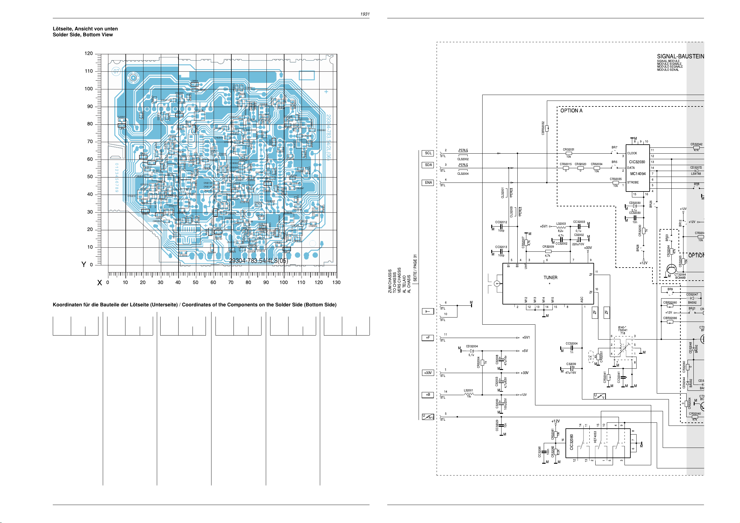
ZF
5,1v
CD32030
M
1
2
3
4
5
678
9
10
11
12
13
14
15
16
HEF4053
CIC32080
BC848B
CT32064
BF
CT3
5,1v
CD32004
0
CR320150CR32020
10k
CR32081
BR7
0
CR32054
0
CR32060
xx
CR32051
M
BR8
M
4
5
6
87
1
2
3
F32041
8140-*
BR5
BR26
BR23
BR28
BR12
BR9
BR21
STL
8,2k
CR32082
100n
CC32081
M M
M
BC
CT3
4,7k
CR32007
M
M
M
100p
CC32013
100p
CC32012
M
M
M
1k
CR32030
0,1u
CC32003
1n
CC32004
*
CBR32066
*
CBR32060
*
CBR32032
CR
10k
CR32065
10k
CR3204
M
47k
CR32040
10k
CR32031
10k
CR32034
10k
CR32035
47k
CR32042
47k
CR32064
C
*
CR32041
MC14094
STROBE
DATA
CLOCK
1615
14
13
12
11
1098
7
6
5
4
3
2
1
CIC32030
U
AFC
U
STL
STL
STL
STL
STL
STL
STL
STL
+33V
ZF
SCL
SDA
ENA
+F
+B
AGC
UHF
B3
B1
M15
M14
M13
M12
ZF
ZF
67
8
9
10
11
12 13 14 15 12
345
*
TUNER
BA592
CD32048
LS4148
CD32072
BA592
CD32047
BA592
CD32044
BA5
CD32
8,2u
L32003
15u
L32001
1k
CR32004
+
C32000
100u/25V
+
C32039
47u/16V
+
C32002
220u/10V
+
C32003
4,7u/63V
+
C32008
47u/16v
M
M
MM
M
M
M
M
M
M
M
M
M
M
M
M
M
10n
CC32030
*
CC32041
10n
CC32029
4,7n
CC32002
4,7k
CR32009
PERLE
CL32003
PERLE
CL32002
PERLE
CL32004
n.V.
PERLE
CL32001
+5V1
+5V1
+12V
+12V
+12V
+12V
+12V
+12V
+33V
+33V
+5V
SIGNAL-BAUSTEIN
OPTION A
OPTION
718
MODULO SENAL
MODULO SEGNALE
MODULE SIGNALE
SIGNAL MODULE
1
10
6
14
11
4
3
2
5
AL TELAIO
AL CHASIS
SEITE / PAGE 31
VERS CHASSIS
TO CHASSIS
ZUM CHASSIS
Platinenabbildungen und Schaltpläne / Layout of PCBs and Circuit Diagrams Platinenabbildungen und Schaltpläne / Layout of PCBs and Circuit Diagrams CUC 1931CUC 1931
Lötseite, Ansicht von unten
Solder Side, Bottom View
120
110
CBR14
100
CR32007
90
CL32001
80
CBR6
70
60
50
40
Koordinaten für die Bauteile der Lötseite (Unterseite) / Coordinates of the Components on the Solder Side (Bottom Side)
Pos.-Nr./ Koordinaten/
Pos. No. Coordinates
Y
30
20
10
0
0
X
10 20 30 40 50 60 70 80 90 100 110 120 130
Pos.-Nr./ Koordinaten/
Pos. No. Coordinates
XY
CBR04 96 19
CBR05 25 58
CBR06 8 80
CBR09 49 77
CBR10 91 46
CBR14 50 103
CBR15 102 9
CBR17 21 61
CBR20 59 19
CBR21 61 30
CBR22 30 29
CBR23 22 31
CBR24 63 19
CBR26 95 70
CBR29 41 85
CBR32032 34 25
CBR32060 83 90
CBR32066 95 93
CBR32067 89 74
CBR32068 88 22
CBR32069 78 37
CBR32070 42 31
CBR32238 104 16
CC32002 42 94
CC32003 46 95
CC32004 19 85
CC32012 34 85
CC32013 37 94
CC32029 71 9
CC32030 51 60
CC32032 95 53
CC32041 76 101
CC32042 94 49
CC32043 93 35
CC32044 80 69
CC32045 91 53
CC32047 103 47
CC32052 77 58
CC32053 81 56
CC32055 99 66
CC32056 104 62
CC32058 91 44
CC32081 47 26
CC32101 77 44
CC32102 78 37
CC32118 73 42
CC32124 28 39
CC32125 25 39
CC32132 105 49
CC32134 85 18
CC32136 79 23
CC32215 26 46
CC32216 26 43
CC32219 51 26
CC32238 83 10
CD32004 119 31
CD32030 47 59
CD32041 91 83
CD32042 87 83
CD32043 103 83
CD32044 108 78
CD32046 78 61
CD32047 83 90
CD32048 105 91
CD32071 75 50
43 44
CC32004
CBR17
CBR5
CR32212
CR32312
CC32215
CC32216
CT32215
CR32125
CBR23
XY
CC32125
CR32319
CT32114
CR32214
CR32200
CC32124
CBR22
CBR32032
CR32009
CC32013
CC32002
CL32003
CC32012
CBR29
CR32310
CR32030
CR32210
CR32031
CR32015
CR32020
CT32110
CR32034
CR32320
CT32211
CR32142
CT32113
CR32215
CR32120
CR32123
CR32216
CT32111
CR32219
CR32218
CR32081
CIC32080
CBR32070
1
CL32002
Pos.-Nr./ Koordinaten/
Pos. No. Coordinates
CD32072 61 65
CD32132 79 19
CD32133 88 22
CIC32030 50 68
CIC32080 46 18
CL32001 8 82
CL32002 43 7
CL32003 31 85
CL32004 60 10
CR32004 117 24
CR32007 27 94
CR32009 41 96
CR32015 30 60
CR32019 107 37
CR32020 36 64
CR32026 98 23
CR32027 96 44
CR32028 101 42
CR32029 99 17
CR32030 37 72
CR32031 37 68
CR32032 50 99
CR32033 82 50
CR32034 43 61
CR32035 56 59
CR32037 112 63
CR32038 91 57
CR32039 122 32
CR32040 115 69
CR32041 74 101
CR32042 73 76
CR32043 99 91
CR32032
CC32003
CT32108
CR32112
CBR9
CC32030
CD32030
CR32141
CR32101
CR32080
CT32101
CR32111
CR32103
CR32145
CT32112
CR32082
CC32081
CC32219
CR32108
CR32109
CBR20
CT32109
XY
CR32045
CD32072
CR32035
CT32104
CBR21
CT32216
CR32140
CL32004
CR32041
CC32041
CR32051
CR32055
CBR32060
CD32047
CT32043
CR32054
CT32062
CR32033
CC32101
CR32102
CC32136
CR32138
CC32238
CC32044
CC32053
CC32045
CR32058
CT32042
CC32042
CR32059
CD32133
CBR32068
CR32136
CR32137
CT32133
CD32042
CBR32067
CC32058
CR32073
CT32041
CR32042
CR32064
CT32045
CR32046
CR32104
CBR24
CR32119
CR32049
CR32050
CT32064
CD32046
CC32052
CR32065
CR32053
CR32052
CT32119
CD32071
CR32105
CC32118
CR32071
CR32107
CR32106
CC32102
CT32217
CR32133
CR32075
CR32217
CD32132
CC32134
CR32088
CR32131
CR32213
CC32029
29304-783.54/4LS(05)
Pos.-Nr./ Koordinaten/
Pos. No. Coordinates
XY
CR32044 109 74
CR32045 67 78
CR32046 65 54
CR32047 105 44
CR32048 108 34
CR32049 77 76
CR32050 74 70
CR32051 77 96
CR32052 76 53
CR32053 76 55
CR32054 79 92
CR32055 76 92
CR32058 86 34
CR32059 88 27
CR32060 103 80
CR32061 108 84
CR32062 99 94
CR32063 116 77
CR32064 68 73
CR32065 67 54
CR32071 72 39
CR32073 76 84
CR32075 66 30
CR32080 57 56
CR32081 40 24
CR32082 44 26
CR32086 113 54
CR32087 110 55
CR32088 79 15
CR32101 50 53
CR32102 82 42
CR32103 62 47
CR32062
CBR32066
CD32041
CBR26
CR32038
CC32032
CBR10
CC32043
CR32132
CBR4
CR32211
Pos.-Nr./ Koordinaten/
Pos. No. Coordinates
CR32043
CC32055
CR32027
CR32026
CD32043
CR32060
CC32056
CC32132
CR32028
CT32132
CR32029
CBR32238
CBR15
CD32048
CD32044
CT32044
CR32087
CC32047
CR32047
CR32048
CT32134
CR32135
CR32061
CR32044
CR32037
CR32019
CR32139
XY
CR32104 65 34
CR32105 74 45
CR32106 68 34
CR32107 69 39
CR32108 62 44
CR32109 62 42
CR32111 49 46
CR32112 47 80
CR32119 67 49
CR32120 36 43
CR32123 36 41
CR32125 21 37
CR32131 75 13
CR32132 93 17
CR32133 77 29
CR32135 108 15
CR32136 89 18
CR32137 82 15
CR32138 82 12
CR32139 112 24
CR32140 63 16
CR32141 43 56
CR32142 40 49
CR32145 43 41
CR32200 31 44
CR32210 35 68
CR32211 97 11
CR32212 23 54
CR32213 77 9
CR32214 31 46
CR32215 31 41
CR32216 31 39
CR32217 76 25
CT32061
CR32063
CR32040
CR32086
CR32039
CD32004
CR32004
Pos.-Nr./ Koordinaten/
Pos. No. Coordinates
CR32218 36 30
CR32219 34 30
CR32310 41 79
CR32312 23 50
CR32319 28 63
CR32320 31 56
CT32041 75 80
CT32042 82 74
CT32043 89 88
CT32044 110 69
CT32045 66 59
CT32061 113 80
CT32062 82 80
CT32064 76 65
CT32101 45 51
CT32104 65 39
CT32108 52 85
CT32109 45 46
CT32110 37 60
CT32111 37 37
CT32112 43 35
CT32113 35 48
CT32114 28 50
CT32119 67 44
CT32132 103 27
CT32133 88 12
CT32134 108 19
CT32211 37 55
CT32215 20 40
CT32216 63 24
CT32217 69 23
XY
GRUNDIG Service GRUNDIG Service
Page 29

10k
STEIN
CR32042
47k
CD32072
LS4148
BR8
M
+12V
CR32046
10k
OPTION B
CD32047
BA592
BR21
CR32061
CT32043
BF660
BA592
CD32048
0
CD32043
BA592
BA592
CT32044
BC848B
M
CR32054
CR32040
47k
29504 202 01
CR32049
47k
CT32042
BC848B
CR32043
1,8k
10k
M
CR32044
CR32037
22k
262 01
262 02
262 03
CT32062
BC848B
47k
M
CR32073
BR11
CR32045
CT32041
BC848B
M
10n
CC32044
M
0
CR32050
BA592
CD32046
CT32061
BC848B
M
CD32042
BA592
CD32041
BA592
F32052
14
M
2
F32053
1
2
+12V
10k
M
47k
CR32055
CR32063
G3957
3
M
L9460
3
M
INLAND
MULTI 8
MULTI 9 / PAL/PLUS
MULTI 9
+12V
1,8k
CR32062
F32054
3
M
CBR32067
n.V.
CC32055
xx
n.V.
CC32056
xx
10
*
M
M
*
M
BR25
CC32052
8
0
47k
5
4
5
CR32080
0
CT32045
BC858B
M
1
2
M
LS4148
CD32071
0,1u
4
5
F32051
1
CR32075
0
56k
CR32053
n.V.
2,7p
CC32053
*
4
52
3
M
56k
CR32052
26
27
29
30
1
2
4
5
CR32032
6,8k
CR32029
10k
Platinenabbildungen und Schaltpläne / Layout of PCBs and Circuit Diagrams Platinenabbildungen und Schaltpläne / Layout of PCBs and Circuit DiagramsCUC 1931 CUC 1931
1u
M
F
C32044
M
0,1u
CC32045
23 22
28
SIF
IC32010
VIF
AFC
*
+12V
M
17 161514
C32041
+
47u/16v
CR32048
15
87
FM
AMSIF
PLL
VIF/TUNER AGC NORM
9
12
M
4,7k
6
F
C32058
M
CR32033
2,7k
C32057
1u/50V
2524
+
*
M
3
R32033
M
RV
CR32039
56k
CR32038
M
CC32032
M
10n
+8,5V
CC32058
68k
-202.01
-262.02
Sachnr.8140-535-391
M
15p
CC32043
M
AFC
20 19 18
CR32058
6,2k
0,1u
M
R32057
+12V
*
F32043
7631
8
CC32042
0,1u
Ub
CR32059
*
IC32010
TDA6930S
TDA6932
TDA6930
TDA6930
TDA6930
10
21
11
13
+8,5V
*
w.w.
307
42
M
CC32047
4,7n
CR32047
150
CR32102
470
CR32027
33k
M
1u
M
CBR32032
CBR32060
CBR32066
CBR32067
R32057
CR32059
10k
10k
10k
CBR32069
CBR32068
CBR32070
00
0-262.01
CBR32068
CR32071
270
1,5k
2,2k
2,2k
2,2k
G3956
G3958M
K6262
K6262
C32057
1u/100V
1u/100V
1u/100V
F32041
531-351
534-451
534-451
534-451
F32051
G9251M
K9551M
K9551M
K9551M
CC32041CR32026
CR32041
0 0
10n
1,8k
0
1,8k
1,8k
10n
10n
*
+5V
OPTION E
OPTION C
M
0
CT32101
BC858B
M
470
CR32139
CR32131
CR32132
CR32087
CR32103
CR32108
M
4,7k
4,7k
47k
1k
2,7k
CR32101
270
270
CR32086
BR16
OPTION D
L32109
12u
F32109
TPS4,5MC
CR32109
*
BA592
CD32133
BA592
CD32132
CT32132
BC848B
M
10k
M
CR32112
47k
CR32210
47k
CR32111
M
C32088
0,47u
CT32108
BC848B
CT32110
BC848B
10
CR32088
M
CBR32238
F
47k
CR32310
CR32141
CT32109
BF660
L32124
10u
F32124
TPS5,5MB
M
1k
0
1n
CC32238
M
CR32319
M
CR32320
CT32211
BC848B
2,7k
2,2k
CR32142
0
CR32145
CT32112
BC858B
CBR32070
CC32132
1n
F
C32047
15k
CR32028
18k
CR32019
M
*
CR32026
M
CBR32069
*
BR27
CR32119
CC32102
+12V
47k
CT32119
BC848B
12p
CC32118
F32101
8141-112-405
43
6
6,8p
M
CR32071
CR32106
BR15
17
*
22k
CR32133
560
8
+12V
SFE4,5
F32132
2
CC32101
270
CT32104
BC858B
CR32107
M
CR32140
22p
CR32105
2,2k
CR32104
CR32109CR32107F32054
300
220
220
220
0
0
M
CT32111
BC848B
*
CR32216
0
1,5k
1,5k
1,5k
CC32134
1n
+12V
CC32219
CR32218
8141-811-360
560
CR32219
31
OPTION
CR32218
A,E,F
510
510
510
10k
CR32137
M
M
0,1u
*
F32111
76
M
M
CR32216
*
470
CR32123
M
CT32133
CR32136
10k
OPTION
B,C,D
BFS20
CT32216
BC858B
CR32120
29504-301.01
29504-301.01
29504-301.03
29504-301.01-262.03
CR32138
M
M
CC32124
68p
CR32215
1,5k
470
M
TUNER
220
CC32136
0,1u
M
OPTION F
CR32125
CC32125
CT32113
BC848B
+5V
CR32217
39
68p
CC32215
CR32214
CT32114
BC848B
CT32134
BC858B
2,7k
CT32217
BC848B
56p
1,8k
CR32135
CT32215
BC858B
CC32216
CR32200
CR32312
10k
CR32212
100k
10k
+5V1
CR32211
CR32213
47p
1,8k
STL
INTERC
9
STL
TER
U
12
SEITE / PAGE 31
AL TELAIO
AL CHASIS
VERS CHASSIS
TO CHASSIS
ZUM CHASSIS
100k
100k
STL
AM
8
STL
FBAS
7
M
221100
GRUNDIG Service GRUNDIG Service
45 46
Page 30

Platinenabbildungen und Schaltpläne / Layout of PCBs and Circuit Diagrams Platinenabbildungen und Schaltpläne / Layout of PCBs and Circuit Diagrams CUC 1931CUC 1931
C65011
1
2
ST-DF1
17
ST-RGB
BR100
R21117
BR101
R24072
6 1
2
34
R21106
R65007
D65021
3
1
T65015
3
1
T65025
13
ST-GM1
MK
R24002
R65011
R65012
R65027
R65017
R65022
R65023
R24032
R65021
R65026
D24011
R24076
1
23
4
D24037
R24077
12
11
109
8
7
6
5
4
C65017
R65013
D65011
R65008
CE
T65004
C65022
C65023
C65002
D24008
R65029
R65003
CE
T65005
CE
T65010
C65027
D24077
D24071
D24078
R24031
R24008
UG2
R24007
R24078
R24037
R24001
R24038
6
1
ST-BR
C21116
C24072
C24032
C24002
C21111
C65021
C24071
C24073
C24013
C24031
C24033
C24036
C24006
C24003
C24001
R21116
R24011
R21111
L21111
R24071
C24077
C24037
C24007
D24007
C65025
R65016
R65019
R65028
CE
T65003
R65002
R65004
C65026
BR102
L65023
C65008
R65006
R24073
R24033
R24003
91
IC24030
91
IC24070
91
IC24000
C24011
R24006
R24036
C21104
D24038
R65024
L65002
13
ST-GM2
D21111
MI-
4
3
2
15
0
9
8
7
6
5
4
3
2
1
31
29304-722.02/4B(02)
29305-122.29
L65019
Bildrohrplatte
1 273 4
56
SGFOC
Standby-Netzteil / Section Standby 293040508500
ST-UB1
2
AL TELAIO
ZUM CHASSIS
TO CHASSIS
VERS CHASSIS
AL CHASIS
1
P
SEITE / PAGE 27
2,2M
R60212
R60211
27k
1234
IC60220
TEA1501
R60216
P
5678
+
C60216
P
27
4,7u/100V
2,2
C60212
F
R60213
15n
P
PRIMAERMASSE / NICHT NETZGETRENNTES SCHALTUNGSTEIL
PRIMARY CHASSIS, NOTE / CIRCUT NOT MAINS ISOLATED
MASSE PRIMAIRE / CIRCUIT NON ISOLE DU SECTEUR
P
MASSA PRIMARIO / CIRCUITO NON SEPAR., DALA RETE
MASA PRIMARIA / SECTOUR DE COM. NO SEP. DE LA RED
BA159
D60218
D60216
BAV21
D60217
BZT03D180
P
Bildrohrplatte / CRT Panel 293051222900
Lötseite, Ansicht von unten
Solder Side, Bottom View
5
TR60220
29201
050 8200
7
4
3
8
2
9
050 8500
D61001
BYT53B
M
TR60220
**
617 9700
619 9700
+OEKO
+9.5V Ð +14V
+
C61001
470u/40V
M
ST-UB2
1
2
M
AL TELAIO
ZUM CHASSIS
TO CHASSIS
VERS CHASSIS
SEITE / PAGE 27
AL CHASIS
47 48
STAND-BY NETZTEIL 29304 050 8200
SECTION STANBY
SECTEUR STANDBY
SEZIONE RETE STANDBY
SECION DE RED STANDBY
050 8500
Bestückungsseite, Ansicht von oben
Component Side, Top View
C61001
D60216
R60213
C60212
29304-475.30/4B(00)
1
D61001
987
DURCHLAUFRICHTUNG
234
IC60220
R60216
C60216
2
ST-UB2
13
TR60220
5
R60212
14
85
D60218
R60211
170800
KEINE NETZTRENNUNG
D60217
GRUNDIG Service GRUNDIG Service
Page 31

Platinenabbildungen und Schaltpläne / Layout of PCBs and Circuit Diagrams Platinenabbildungen und Schaltpläne / Layout of PCBs and Circuit DiagramsCUC 1931 CUC 1931
ZUM ZEILENTRAFO
TO LINE TRANSFORMER
VERS TRANSF. ALIMENT
ALLO TRASF. DI RETE
AL TRANSF. DE LINEAS
NUR BEI 122 2400/2900
ONLY WITH
SEUL. POUR
SOLO NELLA VERS.
SOLO CON
ZUM DYNAMISCHEN FOK.
TO DYNAMIC FOCUSSING
VERS FOCALISATION DYNAMIQE
ALLA FOCALIZZIONE DINAMICA
AL ENFOQUE DYNAMICO
ST-DFB
SEITE / PAGE 61
ZUM SIGNAL-CHASSIS
TO SIGNAL CHASSIS
VERS CHASSIS SIGNAL
AL CHASSIS SEGNALE
AL CHASIS SENAL
SEITE / PAGE 34
ZUM NETZCHASSIS
TO MAINS CHASSIS
VERS CHASSIS DI SECTEUR
AL CHASSIS DI RETE
AL CHASIS INTERR. RED
SEITE / PAGE 30
DYN
U/
FOC
FOCUS-BLOCK
M1
ZUM SIGNAL-CHASSIS
TO SIGNAL CHASSIS
VERS CHASSIS SIGNAL
AL CHASSIS SEGNALE
AL CHASIS SENAL
SEITE / PAGE 33
ZUM NETZCHASSIS
TO MAINS CHASSIS
VERS CHASSIS DI SECTEUR
AL CHASSIS DI RETE
AL CHASIS INTERR. RED
SEITE / PAGE 30
R
G
B
+12V
SW
U
BSO
U
HEIZ.
LEUCHT-
U
PUNKT
+200V
DYN. FOC.
U
FOC.
FOKUS
2
FOKUS
1
U
SG
+80V
GM
U
H
BILDROHRPLATTE
CRT PANEL
C.I. TUBE CATHOD.
PIASTRA CINESC.
PLACA ZOCALO TRC
2,7k/2%
1
7
M
M
D24071
2
3
+12V
4
1N4148
2,7k/2%
6
5
4
3
2
1
ST-RGB
M
2,7k/2%
6
5
M1 M1
4
3
M1
2
ST-BR
ST-DF1
1
1
2
+
C21111
1u/250V
M
NUR BEI 122 2600/3000
ONLY WITH
SEUL. POUR
SOLO NELLA VERS.
SOLO CON
+12V
+80V
3
M
2
1
ST-GM1
AENDERUNGEN VORBEHALTEN
SUBJECT TO ALTERNATE
SOURS RESERVE DE MODIFIC
CON RISERVA DI MODIFICA
RESERV. EL DEREC. MODIFIC.
R65002
R65004
29305 122 2400 (82cm PHI 16:9)
29305 122 2600 (70cm PHI 16:9 / 72cm PHI)
29305 122 2900 (82cm PHI 16:9 REAL FLAT)
29305 122 3000 (72cm TOSH / 72cm TOSH REAL FLAT /82cm TOSH 16:9 REAL FLAT)
n.V.
C24001
xx
R24001
n.V.
C24031
xx
R24031
n.V.
C24071
xx
R24071
+200V
1k
1k
M
K
R24002
M
K
R24032
M
K
R24072
M
+12V
L65002
81049 820 1400
T65003
BC558B
T65004
BC548B
2,7k
2,7k
2,7k
+200V
C24002
0,1u
3
R24003
100k/2%
R24006
4,7k
R24036
4,7k
2,2k
D24011
R24011
+
C24011
M
47u/25V
ZPD3,3V
M
R24076
4,7k
R
1
K
0,1u
C24006
M
+200V
C24032
M
0,1u
3
G
R24033
100k/2%
K
C24036
1
0,1u
M
+200V
+200V
C24072
MM
0,1u
3
B
R24073
100k/2%
K
C24013
1
0,1u
M
NUR BEI 122 2600/3000
ONLY WITH
SEUL. POUR
SOLO NELLA VERS.
SOLO CON
L65023
+80V
81049 820 1400
0,1u
1k
R65008
F
C65008
M
M
+
C65002
R65003
1u/100V
1k
T65010
BC338/40
12
R65007
12
R65006
T65005
BC328/40
M
M
M
+12V
C24003
0,1u
2
6
IC24000
TDA6111N4
8
9
7
45
M
r
+12V
C24033
0,1u
2
6
IC24030
TDA6111N4
8
9
7
45
M
g
+12V
C24073
0,1u
2
6
IC24070
TDA6111N4
8
9
7
45
M
b
REGLER-EINHEIT
CONTROL UNIT
UNITE REGULATEUR
UNITAÔ REGOLATORI
UNIDAD DE REGULACION
+
C65022
C65023
0,1u/100V
M
C65021
4,7n/100V
4,7n
C65011
10u/100V
F
K
100
R24007
K
560p
F
C24037
K
560p
F
C24077
R65021
1N4148
D65021
R65011
1N4148
D65011
M
MM
M
FOC
4,7k
4,7k
560p
F
C24007
100
R24037
100
R24077
29201 361 0400
1,3k
R65022
68k
R65023
68k
R65012
1,2k
R65013
M
D24008
M
+200V
D24037
D24038
+200V
D24077
D24078
SG
BAV21
BAV21
BAV21
M
BAV21
BAV21
M
R65026
R65016
M
BAV21
D24007
R24008
1k
R24038
1k
R24078
1k
C21104
C21116
R65027
22
T65025
2SA1837
T65015
2SC4793
22
R65017
K
M
47
C65025
0,1u
47
+200V
7
R21106
1,5k
*
R21116
270
22n/MKP20
1n
F
C65027
F
C65017
5
M1
F
C65026
1n
122 2400
122 2600
122 2900
122 3000
XX
MM
*
4,7n/2kV
10n/1,5kV
4,7n/2kV
10n/1,5kV
L65019
2x470u
C21104
1
J
8
7
ZUM CHASSIS
TO CHASSIS
VERS CHASSIS
AL TELAIO
AL CHASIS
SEITE / PAGE 29
M1
8
6
11
7
9
10
5
12
1
15
2
BR-SOCKEL
V2BU015
BEI 82cm PH
WITH
POUR
NELLA VERS.
CON
8
6
11
7
9
10
5
1
2
44
ROTATIONS-SP.
6
6
5
4
3
2
1
ST-ROT3
ZUR ROTATIONS u.
N/S-TRAPEZKORREKTUR
SEITE / PAGE 28
(5. ERGNZUNG /
SUPPLEMENT 5)
M1
NUR BEI TOSH
ONLY WITH
SEUL. POUR
SOLO NELLA VERS.
SOLO CON
VERS C.I. DE FOCALISATION
TO DYN. FOCUSING
ZUR DYNAM. FOKUSSIERUNG
ALLA PIASTRA DI FOCALIZZAZIONE
A LA PLACA DE FOCALISACION
R21117
10
100
10
100
220
R65028
220
R65029
M
R21117
M1
ST-GM2
1
2
3
*
ENTF. BEI 122 2900
DELETED WITH
NÕEXISTE PAS POUR
MANCA CON
NO EXISTE EN
SEITE / PAGE 61
J
V
J
H
NUR BEI 72/82cm TOSH
ONLY WITH
SEUL. POUR
SOLO NELLA VERS.
SOLO CON
82cm PH
106
110
0
0
2
3
NUR BEI 72/82cm TOSH
ONLY WITH
SEUL. POUR
SOLO NELLA VERS.
SOLO CON
GM
3
11
22
ST-GM2
4
5
6
MM
220
220
R65019
R65024
MM
200400
NUR BEI 122 2900
ONLY WITH
SEUL. POUR
SOLO NELLA VERS.
SOLO CON
7
GRUNDIG Service GRUNDIG Service
49 50
Page 32
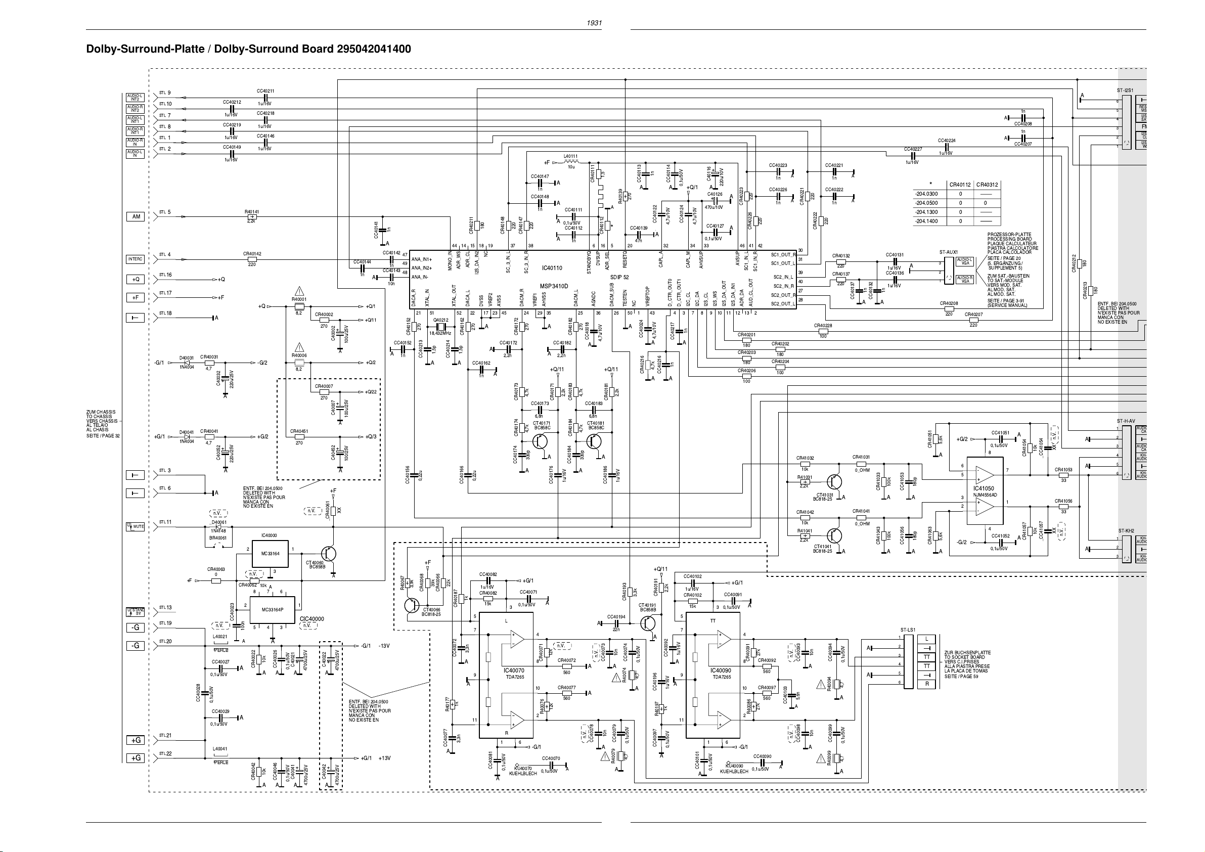
Platinenabbildungen und Schaltpläne / Layout of PCBs and Circuit Diagrams Platinenabbildungen und Schaltpläne / Layout of PCBs and Circuit Diagrams CUC 1931CUC 1931
O
O
S
S
S
T
S
L
S
S
O
O
O
O
M
Dolby-Surround-Platte / Dolby-Surround Board 295042041400
ZUM CHASSIS
TO CHASSIS
VERS CHASSIS
AL TELAIO
AL CHASIS
SEITE / PAGE 32
AUDIO-L
INT2
AUDIO-R
INT2
AUDIO-L
INT1
AUDIO-R
INT1
AUDIO-R
IN
AUDIO-L
IN
AM
INTERC
+Q
+F
U
MUTE
U
STAND
-G
-G
+G
+G
STL
-G/1
9
STL
10
STL
7
STL
8
STL
1
STL
2
STL
5
STL
4
STL
16
STL
17
STL
18
D40031
1N4004
CR40031
4,7
CC40212
1u/16V
CC40219
1u/16V
CC40149
1u/16V
+Q
+F
+
C40032
A
CR40041
D40041
+G/1
1N4004
4,7
+
C40052
STL
3
STL
6
STL
11
+F
STL
BY
13
STL
19
STL
20
STL
21
STL
22
_D40061
1N4148
BR40061
CR40063
0,1u/50V
CC40028
0,1u/50V
A
A
n.V.
0
n.V.
L40021
PERLE
CC40027
0,1u/50V
CC40029
L40041
PERLE
CC40211
1u/16V
CC40218
1u/16V
CC40146
1u/16V
R40141
2,2k
CR40142
220
+Q
-G/2
220u/25V
+G/2
220u/25V
ENTF. BEI 204.0500
DELETED WITH
NÕEXISTE PAS POUR
MANCA CON
NO EXISTE EN
IC40000
21
MC33164
n.V.
CR40062
10k
CC40023
100n
A
CR40022
A
R40001
8,2
R40006
8,2
CR40451
270
n.V.
CT40060
678
345
BC858B
12
CIC40000
n.V.
3
A
MC33164P
A
10k
AAA
CC40026
A
+
C40021
0,1u/50V
4700u/25V
A
CC40046
AAAAA
+
C40041
0,1u/50V
4700u/25V
10k
CR40042
CR40002
270
CR40007
270
C40022
C40042
+
C40002
A
+
C40007
A
+
C40452
A
+F
XX
_CR40061
A
+
4700u/25V
+
4700u/25V
CC40141
CC40142
CC40144
CC40143
1n
A
+Q/1
+Q/11
100u/25V
+Q/2
+Q/22
100u/25V
+Q/3
100/25V
-13V
-G/1
ENTF. BEI 204.0500
DELETED WITH
NÕEXISTE PAS POUR
MANCA CON
NO EXISTE EN
+13V
+G/1
L40111
+F
CC40147
CC40148
220
CR40148
37 38
SC_3_IN_L
2,2n
CR40147
SC_3_IN_R
DACM_R
270
CR40172
4,7k
CR40173
4,7k
CR40174
CC40174
220
VREF1
CC40173
6,8n
CT40171
BC858C
330p
1n
A
47
ANA_IN1+
49
1n
ANA_IN2+
48
ANA_IN-
10n
DACA_R
21 22 23 24 25 26 3412
270
CR40152
CC40152
A
1n
CC40213
XTAL_IN
Q40212
18,432MHz
1,5p
A
44
MONO_IN
CC40214
180
CR40211
14 15 16
18 19 20
NC
ADR_CL
ADR_WS
I2S_DA_IN2
DACA_L
XTAL_OUT
A
VREF2
DVSS
17
AAA
270
CR40162
A
1,5p
CC40162
A
1n
AVSS
45
CC40172
10u
A
1n
A
1n
CC40111
A
0,1u/50V
CC40112
A
1n
IC40110
MSP3410D
AHVSS
29
35 36
CR40182
CC40182
A
2,2n
+Q/11 +Q/11
2,2k
CR40171
CR40183
CR40184
A
CC40184
A
CC40156
0,22u
0,22u
CC40166
CC40176
1u/16V
DACM_L
270
CC40018
A
4,7k
CC40183
6,8n
CT40181
BC858C
4,7k
330p
A
1,5
CR40111
CR40112
DVSUP
ADR_SEL
STANDBYQ
AGNDC
4,7u/10V
CR40181
A
CC40186
R40139
A
*
56
SDIP 52
DACM_SUB
2,2k
1u/16V
+F
R40067
3,9k
39k
CR40068
CT40066
BC818-25
22k
CR40066
R40177
CC40077
A
CR40187
CC40072
A
1k
3,3n
1k
3,3n
5
7
9
11
CC40082
1u/16V
CR40082
15k
+G/1
CC40071
A
0,1u/50V
3
L TT
4
n.V.
12k
CR40071
CR40072
TDA7265
6
KU40070
KUEHLBLECH
8
10
2
0,1u/50V
12k
R40076
CC40070
560
CR40077
560
A
IC40070
R
1
CC40081
0,1u/50V
A
A
A
n.V.
A
n.V.
CC40073
CC40078
A
CC40194
22n
10n
10n
CC40079
R40079
A
1n
CC40113
A
270
CC40122
CC40139
A
47n
RESETQ
TESTENNCVREFTOP
5051 52
43
CC40024
4,7u/10V
A
4,7k
CC40216
CR40216
+Q/11
CR40191
3,3k
CR40193
CT40191
BC858B
A
CC40074
0,1u/50V
4,7
R40074
A
CC40196
R40197
0,1u/50V
CC40097
4,7
A
CC40114
0,1u/50V
A
4,7u/10V
32 3334
CAPL_A
D_CTR_OUT0
D_CTR_OUT1
CC40217
A
1n
AA
2,2k
5
7
1u/16V
CC40092
A
9
AA
1u/16V
1k
11
0,1u/50V
+
C40116
470u/10V
4,7u/10V
CC40127
0,1u/50V
AHVSUP
I2C_DA
CC40101
A
A
C40126
+
I2S_WS
I2S_CL
3
IC40090
TDA7265
1
0,1u/50V
KUEHLBLECH
220u/10V
A
A
I2S_DA_OUT
CC40091
0,1u/50V
6
KU40090
+Q/1
CC40124
CAPL_M
I2C_CL
7 8 9 10111213
1n
CC40102
1u/16V
CR40102
15k
AVSUP
I2S_DA_IN1
CR40201
CR40203
CR40206
+G/1
-G/1-G/1
CR40223
46
SC1_IN_L
ADR_DA
180
180
100
A
4
8
10
2
41 42
CR40091
CC40223
CC40226
220
220
CR40226
SC1_OUT_R
SC1_OUT_L
SC1_IN_R
SC2_OUT_R
SC2_OUT_L
AUD_CL_OUT
27k
CR40092
560
CR40097
560
27k
R40086
CC40090
0,1u/50V
1n
1n
SC2_IN_L
SC2_IN_R
CR40202
180
CR40204
100
A
A
A
n.V.n.V.
CC40103
CR40221
30
31
39
40
27
28
CR41032
10k
R41031
2,2k
CR41042
10k
R41041
2,2k
CC40093
5,6n
A
CC40098
220
CR40228
CT41031
BC818-25
CT41041
BC818-25
10n
AA
10n
A
CC40221
CC40222
220
CR40222
100
1n
1n
CR40132
CR40137
CC40094
R40094
CC40099
R40099
CC40227
1u/16V
A
A
-204.0300 0
-204.0500
-204.1300
-204.1400
CC40131
220
220
CC401371nCC40132
CR41031
0_OHM
A
CR41041
0_OHM
AA
0,1u/50V
4,7
1n
AAA
CR41033
CR41043
A
A
1u/16V
CC40136
1u/16V
100k
180p
CC41053
AA
100k
180p
CC41056
AA
ST-LS1
1
L
2
3
TT
4
TT
5
6
R
A
0,1u/50V
4,7
A
CC40224
1u/16V
CR40112
*
ST-AUX1
AUDIO-L
3
2
AUDIO-R
1
CR40208
220
+G/2
5,6k
CR41051
A
5,6k
-G/2
CR41063
ZUR BUCHSENPLATTE
TO SOCKET BOARD
VERS C.I.PRISES
ALLA PIASTRA PRESE
LA PLACA DE TOMAS
SEITE / PAGE 59
A
A
CR40312
00
0
0
PROZESSOR-PLATTE
PROCESSING BOARD
PLAQUE CALCULATEUR
PIASTRA CALCOLATORE
PLACA CALCOLADOR
SEITE / PAGE 20
VGA
(5. ERGNZUNG /
SUPPLEMENT 5)
ZUM SAT.-BAUSTEIN
TO SAT.-MODULE
VGA
VERS MOD. SAT.
AL MOD. SAT.
AL MOD. SAT.
SEITE / PAGE 3-91
(SERVICE MANUAL)
CR40207
220
CC41051
0,1u/50V
8
6
5
3
2
IC41050
NJM4556AD
7
-
+
1
+
-
4
CC41052
0,1u/50V
1n
CC40208
1n
CC40207
A
CR41054
A
CR41057
10k
_CC41054
10k
_CC41057
n.V.
XX
CR41053
33
CR41056
33
XX
n.V.
A
180
CR40212
CR40213
A
A
A
ST-I2S1
6
5
4
3
2
1
180
ENTF. BEI 204.0500
DELETED WITH
NÕEXISTE PAS POUR
MANCA CON
NO EXISTE EN
ST-H-AV
1
2
3
4
5
6
ST-KH2
1
2
3
AUDI
AUDI
AUDI
AUDI
AUDI
AUDI
RE
M
I2
SA
F
I2
C
I2
W
CA
CA
KH-
KH-
KH-
KH-
51 52
GRUNDIG Service GRUNDIG Service
Page 33

+1 +12V
+2 +5V
+3
+3.3V
+5V LFR
+4 +5V
+4A +5V
+5 +5V
+7 +12V
+B +12V
+B1 +12V
+C +200V
+D +29V
+E +8.5V
+E1 +8.5V
+F +5V
+F/1 +5V
+F/2 +5V
+F/3 +5V
+G
+G/1
+G/2
-G
-G/1
-G/2
+H +5V
+K +13V
-K -13V
+M +18.5V
+N
+5V LFR
+3.3V
+Q +8.5V
+Q/1 +8.5V
+Q/2 +6.3V
+Q/3 +8.5V
+Q/11 +6.3V
+OEKO +9.5V – +14V
T-I2S1
204.0500
WITH
PAS POUR
N
EEN
T-H-AV
ST-KH2
RESET
MSP
I2S
SAT
FM
I2S
CL
I2S
WS
AUDIO-L
CAV
AUDIO_R
CAV
KH-1
AUDIO-R
KH-1
AUDIO-L
KH-2
AUDIO-L
KH-2
AUDIO-R
ZUM SAT.-BAUSTEIN
TO SAT.-MODULE
VERS MOD. SAT.
AL MOD. SAT.
AL MOD. SAT.
SEITE / PAGE 3-91
(SERVICE MANUAL)
KEYBOARD
SEITE / PAGE 27
(5.ERGNZUNG /
SUPPLEMENT 5)
AC3-BAUSTEIN
AC3 MODULE
MODULO AC3
PIASTRA AC3
MODULO AC3
CR40453
+F
CT40453
CR40426
47k
BC858B
CR40461
CR40463
2,2k
A
CR40454
10k
10k
Platinenabbildungen und Schaltpläne / Layout of PCBs and Circuit Diagrams Platinenabbildungen und Schaltpläne / Layout of PCBs and Circuit DiagramsCUC 1931 CUC 1931
L40301
+F
10u
270
CR40307
CC40308
A
CC40301
A
SC_3_IN_R
DACC1_R
270
CR40411
0,1u/50V
CC40302
A
1n
IC40305
DPL3519A2
VREF1
AHVSS
29
35 36
A
CR40421
CC40421
AA
2,2n
CR40448
220
44
14 15 16
47
NC
49
NC
48
NC
XTAL_IN
DACC2_R
21 22 23 24 25 26 3412
CC40426
CC40431
2,2n
1n
A
270
CR40431
CC40321
Q40321
18,432MHz
1,5p
18 19 20
NC
NC
MONO_IN
I2S_DA_IN2
XTAL_OUT
DACC2_L
1,5p
CC40322
AA
I2S_DA_OUT2
VREF2
DVSS
AVSS
17
A
CC40411
37 38
SC_3_IN_L
45
2,2n
STANDBYQ
DACC1_L
270
CC40327
n.V.
CR40306
AGNDC
A
XX
CR40312
DVSUP
4,7u/10V
PERLE
L40302
*
56
ADR_SEL
SDIP 52
NC
47n
RESETQ
TESTEN
D_CTR_IN
5051 52
A
0
CR40305
A
VREFTOP
43
CC40331
A
+Q/22
+Q/22
4,7k
CC40413
CR40412
6,8n
CT40410
BC858C
4,7k
CR40414
330p
CC40414
AA AA
2,2k
CR40413
1u/16V
CC40417
CR40424
CC40424
CC40422
6,8n
CT40420
BC858C
4,7k
330p
4,7k
CR40422
CC40423
1u/16V
CR40423
CC40427
CR40417
1k
2,2k
1u/16V
CR40427
CC40314
32 3334
CAPL_C2
1n
CC40332
A
4,7u/10V
1k
+Q/2
CC40313
4,7u/10V
4,7u/10V
AHVSUP
CAPL_C1
I2C_DA
I2C_CL
D_CTR_IO1
D_CTR_IO0
78910111213
1n
CC40333
A
CR40336
100
CR40334
4,7k
CR40333
CC40432
0,22u
C40311
+
470u/10V
CC40312
0,1u/50V
I2S_CL
100
CR40337
A
CR40433
CR40434
+F
0,1u/50V
4,7
A
0,1u/50V
4,7
A
ST-LSL
1
2
A
ST-LSR
1
2
A
+F
R40478
39k
R40476
22k
CC40483
A
CC40484
A
A
3,3n
CR40458
4,7k
D40463
CT40460
BC818-25
D40467
39k
CT40455
BC848B
BAT42
BAT42
22k
CR40456
CR40464
2,2k
BAT42
D40462
A
BAT42
D40468
CT40465
BC818-25
A
CR40457
CR40465
2,2k
3,9k
100k
CR40466
A
CR40069
CT40473
4
8
10
2
-G/1
A
CR40467
R40472
CC40473
CC40460
0,1u/50V
BC848B
12k
CR40468
CR40471
12k
10n
A
n.V.
A
560
A
560
n.V.
A
CC40462
1u/16V
CR40462
15k
5
CC40465
7
1u/16V
3,3n
CC40463
A
9
A
CC40469
11
1u/16V
100k
A
CC40464
A
3,3n
L/CENTRE
IC40460
R/CENTRE
1
CC40466
A
+G/1
CC40461
0,1u/50V
3
TDA7265
6
KU40460
0,1u/50V
KUEHLBLECH
47k
CR40473
22k
CR40477
CR40475
AA
10n
CC40467
A
CT40475
BC848B
3,9k
CC40468
R40469
CC40474
R40474
C40303
+
220u/10V
CC40304
A
0,1u/50V
CC40306
1n
A
46
41 42
AVSUP
SC1_IN_L
I2S_DA_IN1
I2S_WS
NC
I2S_DA_OUT1
180
CR40338
180
120k
CR40432
4,7k
47k
A
CC40433
CR40437
A
+G/1
CC40482
1u/16V
5
CENTRE
7
3,3n
9
11
SURROUND
1
CC40486
A
AENDERUNGEN VORBEHALTEN
SUBJECT TO ALTERNATE
SOURS RESERVE DE MODIFIC
CON RISERVA DI MODIFICA
RESERV. EL DEREC. DE MODIFIC.
A
A
A
SC1_OUT_R
SC1_OUT_L
SC1_IN_R
SC2_IN_L
SC2_IN_R
SC2_OUT_R
SC2_OUT_L
AUD_CL_OUT
CR40436
4,7k
10n
6,8k
CC40481
0,1u/50V
3
IC40480
TDA7265
6
KU40480
0,1u/50V
KUEHLBLECH
CT40431
BC848B
CC40434
A
4
8
10
2
-G/1
30
31
39
40
27
28
330p
A
CR40487
CR40488
CR40491
CR40492
CC40493
A
CC40480
0,1u/50V
1u/16V
CC40341
CC40342
CR40438
12k
560
560
12k
10n
n.V.
47k
CR40439
CR40443
A
A
CR40446
1u/16V
CC40446
1k
10k
n.V.
CC40487
A
2,2k
CC40449
5 KANAL-DOLBY-SURROUND-PL. 29504 204 0300
CR40261
220
CR40263
220
2,2k
CR40449
1u/16V
1u/16V
DOLBY SURROUND BOARD
C. I. DOLBY SURROUND
PIASTRA DOLBY SURROUND
PLACA DOLBY SURROUND
47k
A
CR40293
D40270
+F
1N4004
-G/1
CR40292
+
C40271
A
CC40291
10u/6,3V
150k
CT40270
BC858B
220u/10V
CC40281
10u/6,3V
CR40273
100k
22k
CR40272
CR40297
2,2k
BC818-25
CR40298
2,2k
BC818-25
CR40277
2,2k
BC818-25
CR40278
2,2k
BC818-25
CT40290
CT40295
CT40275
CT40280
+Q/3
CT40441
BC858B
CR40441
CR40442
A
ENTF. BEI 204.0500
DELETED WITH
NÕEXISTE PAS POUR
MANCA CON
NO EXISTE EN
10n
CC40488
0,1u/50V
A
4,7
R40489
A
CC40494
0,1u/50V
4,7
R40494
A
2,2k
1,5k
A
C40321
+
10u/50V
ST-LS2
4
3
2
1
261000
CENTRE
SURR.
CR40322
220
CR40323
2,2k
CT40325
BC818-25
CR40326
2,2k
CT40330
BC818-25
ZUR BUCHSENPLATTE
TO SOCKET BOARD
VERS C.I.PRISES
ALLA PIASTRA PRESE
LA PLACA DE TOMAS
SEITE / PAGE 59
204 0500
204 1300
204 1400
220
CR40294
A
1,5n
CC40294
CR40296
AAA
220
CR40282
A
1,5n
CC40282
A
220
CR40324
CC40326
1,5n
CR40283
CR40327
AAA
AA A
CR40299
100
100k
CR40289
100
100k
CL40336
CL40334
CR40328
220
100k
STL
12
RESET
MSP
Spannungstabelle
Table of Voltages
+17.5V
+13V CUC 1931 STATUS
+17.5V
+13V CUC 1931 STATUS
+16.5V
+12V CUC 1931 STATUS
-17.5V
-13V CUC 1931 STATUS
-17.5V
-13V CUC 1931 STATUS
-16.5V
-12V CUC 1931 STATUS
STL
STL
CINCH
CINCH
CINCH
15
14
A
A
A
CINCH
AUDIO-L
CINCH
AUDIO-R
SDA
SCL
CINCH
SUROUND
ZUM CHASSIS
TO CHASSIS
VERS CHASSIS
AL TELAIO
AL CHASIS
SEITE / PAGE 32
Bei den in den Schaltplänen angegebenen Messwerten handelt es
sich um Näherungswerte!
The measured values given in the circuit diagrams are approximates!
GRUNDIG Service GRUNDIG Service
53 54
Page 34

Platinenabbildungen und Schaltpläne / Layout of PCBs and Circuit Diagrams Platinenabbildungen und Schaltpläne / Layout of PCBs and Circuit Diagrams CUC 1931CUC 1931
Bestückungsseite, Ansicht von oben
Component Side, Top View
ST-LS1
C40022
C40021
C40042
C40032
C40041
29306.233.02/4B(03)
NF-DPL-BASIC 3
EL.KOMPL.29504-204.03/..
1
ST-H-AV
ST-KH2
1
6
BR156
BR100
D40031
C40052
IC40000
L40041
1
3
R40099
R40094
BR168
D40041
31
6
BR186
BR187
BR188
BR140
BR116
BR117
BR122
BR121
BR161
R40086
BR185
IC40090
R40197
L40021
111
KU40090
1
ST-I2S1
IC41050
41
BR124
R41031
BR148
BR162
BR142
R40076
1
BR143
KU40070
R40079
BR101
1
R40006
BR113
C40311
58
BR109
BR107
C40303
BR182
R41041
Q40321
BR102
R40177
R40067
BR147
BR119
111
R40139
IC40070
R40074
BR110
BR166
R40001
BR157
_D40061
BR40061
2752
BR104
IC40110
BR181
1
6
ST-LSL
126
BR146
C40002
STL
BR158
BR152
BR159
BR149
1
2
BR127
BR118
ST-LSR
IC40305
BR154
1 26
27 52
BR128
BR172
BR153
2
BR108
Q40212
BR106
BR103
BR105
BR175
C40007
C40452
L40302
L40301
R40494
L40111
BR163
C40126
BR171
R40489
BR164
BR179
BR176
C40116
BR170
IC40480
R40141
BR141
111
122
1
KU40480
BR167
BR138
BR136
1
BR120
1
ST-LS2
BR129
BR130
BR135
BR180
BR183
BR112
D40468
BR126
BR134
BR132
BR131
R40472
IC40460
111
BR151
R40469
R40476
R40478
KU40460
BR111
BR178
BR184
BR133
BR125
BR137
BR115
BR177
BR165
R40474
13
BR155
4
C40321
D40462
D40463
D40270
D40467
BR169
BR174
BR123
BR114
CINCH
BR150
BR144
180
170
ST-AUX1
160
150
140
130
120
DURCHLAUFRICHTUNG BEIAUTOMATENBESTUECKUNG
C40271
110
100
90
80
70
60
50
40
30
20
10
0
Y
Koordinaten für die Bauteile der Bestückungsseite (Oberseite)
Coordinates of the Components on the Components Side (Top Side)
Pos.-Nr./ Koordinaten/
Pos. No. Coordinates
XY
BR100 190 63
BR101 146 11
BR102 109 95
BR103 83 84
BR104 109 68
BR105 83 44
BR106 86 101
BR107 113 114
BR108 86 130
BR109 113 138
BR110 126 31
BR111 41 24
BR112 43 120
BR113 113 151
BR114 15 83
BR115 35 66
BR116 173 61
BR117 169 61
BR118 96 21
BR119 128 65
BR120 45 24
BR121 167 31
BR122 167 39
BR123 15 86
BR124 138 124
BR125 29 113
BR126 45 117
BR127 93 21
BR128 89 21
BR129 38 149
BR130 43 144
BR131 36 89
BR132 34 102
BR133 29 116
BR134 31 105
BR135 40 146
BR136 54 119
BR137 29 110
BR138 54 139
BR140 171 106
BR141 64 145
BR142 126 95
BR143 134 51
BR144 24 30
BR146 90 40
BR147 120 66
BR148 126 102
BR149 96 95
BR150 29 35
BR151 44 55
BR152 98 100
BR153 78 166
BR154 86 116
BR155 24 165
BR156 190 75
Pos.-Nr./ Koordinaten/
Pos. No. Coordinates
XY
BR157 130 19
BR158 98 102
BR159 98 98
BR161 161 80
BR162 124 98
BR163 73 44
BR164 69 94
BR165 28 61
BR166 126 28
BR167 68 24
BR168 176 56
BR169 14 98
BR170 72 68
BR171 81 23
BR172 85 23
BR174 14 95
BR175 73 161
BR176 68 86
BR177 27 65
BR178 35 146
BR179 66 89
BR180 45 138
BR181 109 23
BR182 126 115
BR183 33 132
BR184 29 144
BR185 165 68
BR186 172 28
BR187 173 23
BR188 174 19
BR40061 121 16
C40002 103 28
C40007 75 149
C40021 221 44
C40022 209 60
C40032 203 44
C40041 209 26
C40042 231 26
C40052 191 46
C40116 77 77
C40126 77 35
C40271 13 113
C40303 119 121
C40311 117 145
C40321 25 155
C40452 72 130
CINCH 4 55
D40031 189 58
D40041 182 38
D40270 18 126
D40462 32 129
D40463 32 126
D40467 32 123
Pos.-Nr./ Koordinaten/
Pos. No. Coordinates
XY
D40468 32 121
IC40000 184 25
IC40070 136 69
IC40090 156 64
IC40110 96 68
IC40305 99 129
IC40460 43 69
IC40480 63 64
IC41050 133 139
KU40070 140 49
KU40090 152 83
KU40460 48 49
KU40480 59 83
L40021 164 15
L40041 189 6
L40111 80 66
L40301 74 116
L40302 83 126
Q40212 78 91
Q40321 117 107
R40001 115 16
R40006 126 152
R40067 117 84
R40074 127 41
R40076 138 84
R40079 133 39
R40086 158 76
R40094 180 73
R40099 175 78
R40139 116 55
R40141 71 24
R40177 124 88
R40197 165 43
R40469 39 48
R40472 39 84
R40474 34 50
R40476 30 41
R40478 37 38
R40489 69 105
R40494 74 102
R41031 127 111
R41041 127 108
STAUX01 16 167
STHAV 185 111
STI2S1 114 167
STKH02 195 97
STLS01 204 82
STLS02 33 167
STLSL 98 167
STLSR 86 167
STL 120 2
_D40061 121 16
55 56
GRUNDIG Service GRUNDIG Service
0102030405060708090100110120130140150160170180190200210220230240
X
Page 35

Platinenabbildungen und Schaltpläne / Layout of PCBs and Circuit Diagrams Platinenabbildungen und Schaltpläne / Layout of PCBs and Circuit DiagramsCUC 1931 CUC 1931
Lötseite, Ansicht von unten
Solder Side, Bottom View
180
170
CT40325
CR40324
160
150
140
130
120
110
100
90
80
70
60
50
40
30
CT40330
CR40326
CT40295
CT40275
CR40282
CT40280
CR40278
CT40270
CR40273
CR40327
CC40326
CR40296
CC40294
CC40282
CR40298
CR40328
CR40299
CR40283
CR40289
CR40294
CR40272
CR40293
CC40469
CR40322
CT40290
CR40277
CR40456
CR40292
CR40465
CR40466
CR40069
CC40465
CC40462
CR40323
CBR125
CR40297
CR40457
CT40455
CR40458
CR40464
CC40463
CC40466
CC40467
CBR100
CC40464
CC40473
CC40474
CC40468
CC40281
CC40291
CT40465
CBR124
CR40471
CR40462
CC40461
CBR103
CBR112
CR40467
CR40468
CR40477
CT40475
CC40131
CBR102
CR40438
CR40463
CR40461
CC40493
CR40492
CC40487
CC40460
CBR118
CC40449
CC40446
CC40417
CR40439
CT40460
CT40441
CT40453
CR40454
CC40488
CC40480
CR40417
CC40226
CC40427
CR40413
CR40453
CC40494
CBR104
CR40487
CR40488
CR40491
CC40484
CBR111
CC40136
CR40451
CR40423
CT40420
CT40410
CR40433
CT40431
CR40441
CBR126
CBR106
CT40473
CR40473
CC40486
CC40481
CR40427
CC40223
CC40132
CC40147
CC40148
CC40422
CR40424
CC40413
CC40414
CR40442
CC40434
CR40436
CBR119
CBR120
CC40483
CR40422
CC40424
CR40412
CR40414
CR40434
CR40432
CR40443
CBR107
CBR113
CC40213
CC40144
CR40142
CC40482
CR40148
CC40127
CC40137
CR40207
CR40208
CC40221
CC40207
CC40421
CC40411
CC40431
CR40437
CC40433
CR40312
CC40142
CR40226
CC40114
CR40137
CR40147
CR40222
CR40221
20
CC40149
CC40146
10
0
Y
0
X
10 20 30 40 50 60 70 80 90 100 110 120 130 140 150 160 170 180 190 200 210 220 230 240
CR40421
CR40411
CC40308
CC40432
CC40302
CR40338
CR40337
CR40336
CR40334
CBR110
CC40332
CR40306
CR40475
CR40333
CC40333
CC40113
CR40223
CC40141
CR40132
CC40024
CC40018
CC40122
CC40222
CC40208
CR40184
CC40183
CC40218
CBR101
CR40431
CR40307
CC40301
CBR121
CR40305
CC40214
CBR105
CC40143
CBR108
CR40111
CC40124
CR40193
CT40191
CR40007
CC40423
CR40448
CC40327
CC40426
CBR114
CC40322
CR40228
CC40139
CR40162
CC40194
CR40191
CR40212
CR40263
CR40261
CR40449
CR40446
CC40312
CC40314
CR40426
CBR122
CC40306
CBR116
CBR115
CC40217
CR40216
CC40216
CR40112
CBR109
CR40201
CC40112
CR40211
CC40111
CR40152
CC40172
CR40172
CC40182
CR40182
CR40183
CT40181
CC40184
CR40181
CC40219
CC40341
CC40304
CC40321
CR40206
CR40204
CR40203
CR40202
CC40176
CC40152
CC40162
CT40171
CR40002
CC40211
CBR117
CC40313
CC40331
CC40174
CR40173
CR40171
CC40224
CC40227
CC41051
CR40213
_CC41054
CC40342
CR40174
CC40173
CR41054
CR41032
CT40066
CC40082
CC40186
CC40081
CR41063
CC41031
CR41051
CC40166
CT41031
CC40072
CR40187
CC40071
CR40082
CC40074
CR40068
CR40066
CC41053
CR41033
CC40196
CL40334 CL40336
CC40212
CR41053
CC40077
CC40078
CC40073
CC40079
Koordinaten für die Bauteile der Lötseite (Unterseite) / Coordinates of the components on the Solder Side (Bottom Side)
Pos.-Nr./ Koordinaten/
Pos. No. Coordinates
XY
CBR100 31 148
CBR101 98 151
CBR102 52 136
CBR103 49 136
CBR104 62 74
CBR105 96 93
CBR106 74 116
CBR107 77 116
CBR108 95 81
CBR109 99 79
Pos.-Nr./ Koordinaten/
Pos. No. Coordinates
XY
CBR110 81 113
CBR111 65 41
CBR112 50 127
CBR113 83 95
CBR114 96 114
CBR115 99 111
CBR116 101 114
CBR117 117 21
CBR118 54 56
CBR119 82 102
Pos.-Nr./ Koordinaten/
Pos. No. Coordinates
XY
CBR120 82 99
CBR121 95 128
CBR122 100 128
CBR124 41 99
CBR125 28 148
CBR126 71 117
CBR127 150 16
CC40018 93 63
CC40023 189 26
CC40024 93 69
Pos.-Nr./ Koordinaten/
Pos. No. Coordinates
XY
CC40026 177 14
CC40027 158 10
CC40028 170 11
CC40029 178 5
CC40046 192 9
CC40070 148 52
CC40071 127 68
CC40072 125 73
CC40073 130 48
CC40074 131 44
Pos.-Nr./ Koordinaten/
Pos. No. Coordinates
XY
CC40077 132 81
CC40078 130 51
CC40079 136 43
CC40081 127 58
CC40082 123 69
CC40090 152 79
CC40091 170 61
CC40092 165 63
CC40093 158 83
CC40094 184 76
_CC41057
CC41052
CR41057
CR41056
CC41041
CC41056
CR41043
CR41042
CT41041
CC40156
CC40093
CR40072
CR40071
CR40092
CR40097
CC40103
CC40070
CC40090
CR40091
CR40077
_CR40061
CBR127
CC40027
Pos.-Nr./ Koordinaten/
Pos. No. Coordinates
XY
CC40097 165 56
CC40098 170 81
CC40099 175 81
CC40101 166 73
CC40102 170 65
CC40103 151 56
CC40111 107 63
CC40112 100 62
CC40113 91 78
CC40114 85 78
CC40098
CC40101
CC40092
CC40102
CC40091
CC40097
CC40028
Pos.-Nr./ Koordinaten/
Pos. No. Coordinates
CC40122 93 55
CC40124 93 59
CC40127 85 57
CC40131 52 33
CC40132 69 47
CC40136 57 33
CC40137 72 50
CC40139 100 56
CC40141 93 73
CC40142 84 82
CC40099
CR40102
CR40062
CR40063
CC40026
CR40022
CC40029
CC40094
CR40031
CR40041
CT40060
CC40023
CIC40000
1
CC40046
XY
CR40042
29306-233.02/4LS(04)
Pos.-Nr./ Koordinaten/
Pos. No. Coordinates
CC40143 92 84
CC40144 78 84
CC40146 66 10
CC40147 69 41
CC40148 69 38
CC40149 71 10
CC40152 113 61
CC40156 142 119
CC40162 113 58
CC40166 128 125
XY
Pos.-Nr./ Koordinaten/
Pos. No. Coordinates
XY
CC40172 109 50
CC40173 116 38
CC40174 114 47
CC40176 117 63
CC40182 104 41
CC40183 100 34
CC40184 105 35
CC40186 118 59
CC40194 100 48
CC40196 125 23
Pos.-Nr./ Koordinaten/
Pos. No. Coordinates
XY
CC40207 86 34
CC40208 82 40
CC40211 109 10
CC40212 114 10
CC40213 85 87
CC40214 91 89
CC40216 99 84
CC40217 99 90
CC40218 100 10
CC40219 105 10
CC40221 89 38
CC40222 93 47
CC40223 63 46
CC40224 131 163
CC40226 60 46
CC40227 131 159
CC40281 50 145
CC40282 9 44
CC40291 50 141
CC40294 8 59
CC40301 94 134
CC40302 88 134
CC40304 110 118
CC40306 104 118
CC40308 87 140
CC40312 104 140
CC40313 113 137
CC40314 113 141
CC40321 110 107
CC40322 104 107
CC40326 6 74
CC40327 102 135
CC40331 111 124
CC40332 82 110
CC40333 86 101
CC40341 117 130
CC40342 117 133
CC40411 83 144
CC40413 73 138
CC40414 74 134
CC40417 60 134
CC40421 83 147
CC40422 73 145
CC40423 99 142
CC40424 78 143
CC40426 103 122
CC40427 62 142
CC40431 83 140
CC40432 83 136
CC40433 85 129
CC40434 74 124
CC40446 57 138
CC40449 56 142
CC40460 49 56
CC40461 35 65
CC40462 32 70
CC40463 33 79
CC40464 32 84
CC40465 29 84
CC40466 35 61
CC40467 38 50
CC40468 40 44
CC40469 26 91
CC40473 39 57
CC40474 39 54
CC40480 56 87
CC40481 73 72
CC40482 77 70
CC40483 72 63
CC40484 64 53
CC40486 69 79
CC40487 59 67
CC40488 66 101
CC40493 57 74
CC40494 69 98
CC41031 128 132
CC41041 142 134
CC41051 128 146
CC41052 133 134
CC41053 133 131
CC41056 142 131
CIC40000 192 20
CL40334 133 14
CL40336 139 15
Pos.-Nr./ Koordinaten/
Pos. No. Coordinates
XY
CR40002 110 32
CR40007 100 154
CR40022 177 10
CR40031 189 55
CR40041 188 43
CR40042 192 12
CR40062 181 26
CR40063 177 23
CR40066 122 27
CR40068 122 30
CR40069 28 95
CR40071 141 69
CR40072 141 71
CR40077 141 74
CR40082 127 65
CR40091 151 67
CR40092 151 62
CR40097 151 59
CR40102 175 63
CR40111 94 77
CR40112 99 81
CR40132 84 65
CR40137 84 68
CR40142 79 80
CR40147 84 63
CR40148 84 61
CR40152 108 56
CR40162 108 54
CR40171 111 35
CR40172 109 47
CR40173 113 43
CR40174 116 41
CR40181 105 31
CR40182 108 44
CR40183 104 38
CR40184 99 37
CR40187 127 71
CR40191 100 31
CR40193 100 45
CR40201 99 77
CR40202 108 69
CR40203 108 72
CR40204 108 78
CR40206 108 80
CR40207 84 45
CR40208 84 43
CR40211 110 65
CR40212 116 155
CR40213 119 155
CR40216 99 87
CR40221 92 49
CR40222 92 52
CR40223 84 71
CR40226 84 73
CR40228 99 74
CR40261 103 149
CR40263 103 151
CR40272 15 127
CR40273 12 119
CR40277 16 141
CR40278 11 127
CR40282 13 135
CR40283 11 48
CR40289 12 44
CR40292 20 123
CR40293 16 111
CR40294 18 148
CR40296 8 62
CR40297 22 143
CR40298 18 144
CR40299 11 59
CR40305 94 104
CR40306 94 109
CR40307 96 141
CR40312 86 115
CR40322 21 155
CR40323 21 152
CR40324 9 160
CR40326 10 151
CR40327 7 78
CR40328 9 74
CR40333 82 105
CR40334 95 116
CR40336 95 119
CR40337 97 122
CR40338 95 125
Pos.-Nr./ Koordinaten/
Pos. No. Coordinates
XY
CR40411 87 146
CR40412 78 140
CR40413 62 139
CR40414 78 137
CR40417 59 53
CR40421 87 149
CR40422 78 146
CR40423 69 147
CR40424 73 142
CR40426 103 131
CR40427 73 67
CR40431 87 143
CR40432 80 129
CR40433 65 132
CR40434 79 133
CR40436 74 121
CR40437 79 125
CR40438 60 132
CR40439 61 129
CR40441 68 122
CR40442 74 127
CR40443 78 120
CR40446 103 144
CR40448 96 138
CR40449 103 147
CR40451 68 155
CR40453 60 117
CR40454 60 115
CR40456 19 126
CR40457 30 141
CR40458 22 132
CR40461 50 117
CR40462 35 70
CR40463 47 117
CR40464 24 128
CR40465 27 116
CR40466 28 98
CR40467 44 81
CR40468 44 79
CR40471 36 83
CR40473 78 106
CR40475 82 107
CR40477 54 53
CR40487 59 63
CR40488 58 60
CR40491 59 57
CR40492 57 72
CR41032 128 128
CR41033 133 127
CR41042 147 125
CR41043 142 128
CR41051 133 137
CR41053 133 146
CR41054 125 135
CR41056 147 139
CR41057 142 139
CR41063 133 140
CT40060 183 17
CT40066 126 79
CT40171 115 51
CT40181 110 40
CT40191 99 41
CT40270 14 123
CT40275 11 140
CT40280 11 132
CT40290 23 147
CT40295 12 147
CT40325 15 153
CT40330 9 156
CT40410 69 136
CT40420 67 141
CT40431 68 126
CT40441 62 125
CT40453 55 117
CT40455 23 136
CT40460 50 123
CT40465 43 120
CT40473 76 110
CT40475 54 48
CT41031 134 124
CT41041 141 124
_CC41054 125 138
_CC41057 142 142
_CR40061 144 19
GRUNDIG Service GRUNDIG Service
57 58
Page 36
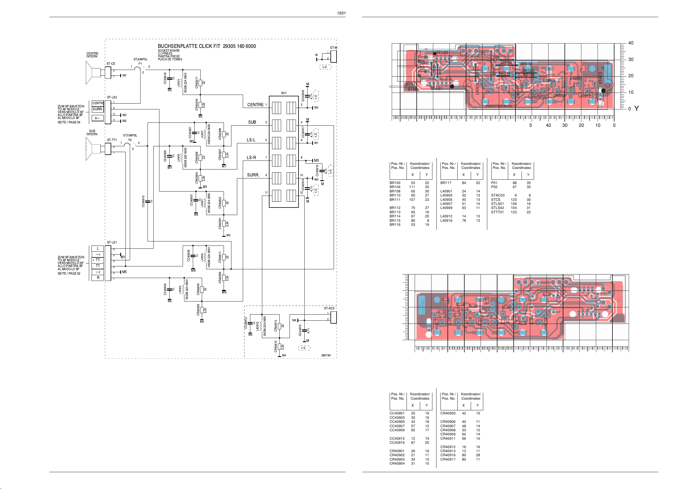
Platinenabbildungen und Schaltpläne / Layout of PCBs and Circuit Diagrams Platinenabbildungen und Schaltpläne / Layout of PCBs and Circuit Diagrams CUC 1931CUC 1931
BR108
BR104
BR111
BR114
BR112
BR116
BR100
BR110
P2
P1
14
ST-LS2
16
ST-LS1
1
2
ST-CE
1
2
ST-TT1
L40905
L40907
L40903
L40916
L40901
L40912
L40909
12
ST-AC3
BR117
12
11
2
1
ST-M
(04)29304-519.92/4B
0
10
20
30
40
Y
0102030405060708090100110120130
X
CR40906
CR40908
CR40907
CR40903
CR40904
CR40901
CR40902
CR40913
CR40912
CR40909
CR40911
CR40905
CR40917
CR40916
CC40907
CC40905
CC40903
CC40901
CC40912
CC40909
CC40914
CC40916
CC40915
CC40917
CC40913
CC40918
CC40910
29304-519.92/4LS(03)
0
10
20
30
40
Y
0
10 20 30 40 50 60 70 80 90 100 110 120 130
X
Buchsenplatte Click Fit / Socket Board Click Fit
BUCHSENPLATTE CLICK FIT 29305 160 6000
SOCKET BOARD
3
2
CC40910
C.I.PRISES
PIASTRA PRESE
PLACA DE TOMAS
CC40916
M2
CC40905
M1
1n
CC40903
M5
1n
L40916
09238 224 0600
1n
L40905
09238 224 0600
1n
L40903
09238 224 0600
ZUM NF-BAUSTEIN
TO AF MODULE
VERS MODULO BF
ALLO PIASTRA BF
AL MODULO BF
SEITE / PAGE 54
ZUM NF-BAUSTEIN
TO AF MODULE
VERS MODULO BF
ALLO PIASTRA BF
AL MODULO BF
SEITE / PAGE 52
CENTRE
INTERN
CENTRE
SURR.
SUB
INTERN
+
-
STJUMP3L
ST-CE
2
1
ST-LS2
1
2
3
4
ST-TT1
1
2
1
ST-LS1
L
6
5
TT
TT
R
M1
4
3
2
1
1
M2
M3
M2
STJUMP3L
P2
2
M5
P1
3
CR40917
CR40916
M5
CC40907
M1
CR40906
CR40905
CC40901
M3
1n
CC40909
M5
22
2,2k
1n
L40907
22
2,2k
M1
1n
L40901
L40909
22
CR40904
2,2k
CR40903
M5
09238 224 0600
09238 224 0600
09238 224 0600
22
CR40908
2,2k
CR40907
M1
22
CR40902
2,2k
CR40901
M3
22
CR40911
2,2k
CR40909
M5
CENTRE
SUB
LS-L
LS-R
SURR.
1n
CC40912
L40912
M4
ST-M
1
M
2
n.V.
M
BU1
12
34
56
78
910
11 12
4,7n
CC40918
M
4,7n
CC40917
CC40914
4,7n
M2
n.V. n.V.
M1
M5
CC40915
M3
n.V.
4,7n
n.V.
M
M
ST-AC3
1
2
09238 224 0600
22
CR40913
M4
4,7n
CC40913
M
n.V.
2,2k
CR40912
M4
280799
Bestückungsseite, Ansicht von oben
Component Side, Top View
Koordinaten für die Bauteile der Bestückungsseite (Oberseite)
Coordinates of the Components on the Components Side (Top Side)
Pos.-Nr./ Koordinaten/
Pos. No. Coordinates
XY
BR100 53 22
BR104 111 25
BR108 65 30
BR110 65 27
BR111 107 23
BR112 75 27
BR113 65 16
BR114 67 20
BR115 80 8
BR116 53 19
Pos.-Nr./ Koordinaten/
Pos. No. Coordinates
XY
BR117 84 22
L40901 24 14
L40903 32 13
L40905 40 13
L40907 51 14
L40909 63 11
L40912 14 13
L40916 78 13
Pos.-Nr./ Koordinaten/
Pos. No. Coordinates
XY
P01 88 35
P02 67 35
STAC03 9 8
STCE 123 30
STLS01 106 16
STLS02 104 31
STTT01 123 22
Lötseite, Ansicht von unten
Solder Side, Bottom View
59 60
Koordinaten für die Bauteile der Lötseite (Unterseite)
Coordinates of the Components on the Solder Side (Bottom Side)
Pos.-Nr./ Koordinaten/
Pos. No. Coordinates
XY
CC40901 25 19
CC40903 30 19
CC40905 42 18
CC40907 57 12
CC40909 65 17
CC40912 12 19
CC40916 87 25
CR40901 26 16
CR40902 21 11
CR40903 34 15
CR40904 31 10
GRUNDIG Service GRUNDIG Service
Pos.-Nr./ Koordinaten/
Pos. No. Coordinates
XY
CR40905 42 15
CR40906 40 11
CR40907 48 14
CR40908 53 12
CR40909 62 14
CR40911 66 10
CR40912 16 16
CR40913 13 11
CR40916 80 28
CR40917 80 11
Page 37

Fokussierungsplatte / Focusing Board 293050253700
Platinenabbildungen und Schaltpläne / Layout of PCBs and Circuit DiagramsCUC 1931
AL TELAIO
VERS CHASSIS
TO CHASSIS
ZUM CHASSIS
SEITE / PAGE 29
AL CHASIS
DF
-K
+K
FOKUSSIERUNGSPLATTE
FOCUSING BOARD
C.I. DE FOCALISATION
PIASTRA DI FOCALIZZ.
PLACA DE FOCALISACION
29305 025 3700 (70cm/82cm PHI 16:9 BASIC 3)
29305 025 3800 (72cm TOSH SF BASIC ++)
29305 025 4000 (82cm TOSH 16:9 RF BASIC 3)
29305 025 4100 (72cm TOSH SF BASIC ++)
29305 025 4200 (72cm TOSH SF/RF BASIC 3)
52A
FS64001
BAV21
D64014
1k
R64011
F
C64012
68n
52
1,5n/6kV
F
C64001
XX
C64003
n.V.
1,5n/6kV
C64002
F
OPTION A
*
025.3700
025.3800
025.4000
025.4100
FOKUS-UG2-REGLER
025.4200
F
OPTION A
-13V
+13V
FSTIF02
ST-M
1
FSTIF02
ST-B
B
3
FSTIF02
ST-J7
2
FSTIF02
ST-SH10
FSTIF02
ST-SH20
TR64001
29201-449.97
1
8
R64016
220
T64016
BC639
50
2,7k
R64017
5
4
3
6
D64013
F
BAV21
C64006
*
D64011
BAV21
/2000V/FKP1
D64012
BAV21
51
330
R64010
R64012
D64010
BZT03C68
OPTION B
470k
10k
R64003
OPTION B
ST-DFB
ST-DF1
45M
R64006
C64006
180p
165p
180p
165p
180p
ST-DF2
200900
1
2
1
1
1
2
dB
4
3
2
1
FOCUS-BLOCK
SEITE / PAGE 49
ZUR BILDROHRPLATTE
TO CART BASE
VERS C.I. TUBE CATHOD
ALLA PIASTRA CINESC.
A LA PLACA-ZOCALO TRC
-K
ZUR ROTATIONSPLATTE
TO ROTATION BOARD
DF
SEITE / PAGE 28
+K
(5. ERGNZUNG /
SUPPLEMENT 5)
Bestückungsseite, Ansicht von oben
Component Side, Top View
ST-DF1
R64003
11
ST-DFB
w.w.
MI-
R64006
FS64001
C64001C64002
C64003
4
ST-DF2
BR004
C64006
1
45
BR003
3
6
BR002
R64012
C64012
R64011
1
8
TR64001
29304-732.20/4B(01)
D64010
R64010
T64016
R64017
EB
D64012
D64014
D64013
D64011
BR001
9
ST-SH20
ST-SH10
R64016
ST-J7
BR005
ST-M
1
2
0
51
3
42
48
3
5
7
6
ST-B
GRUNDIG Service 61
Page 38
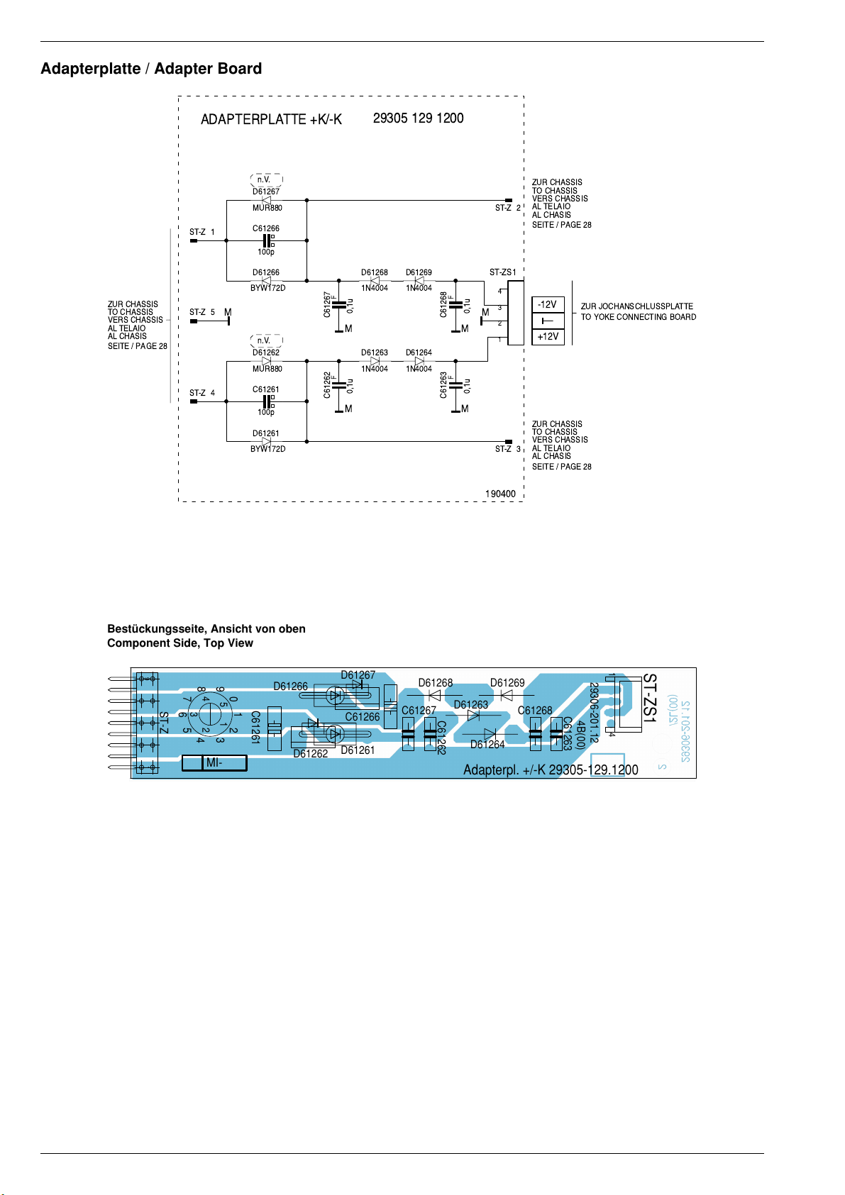
Platinenabbildungen und Schaltpläne / Layout of PCBs and Circuit Diagrams CUC 1931
Adapterplatte / Adapter Board
ZUR CHASSIS
TO CHASSIS
VERS CHASSIS
AL TELAIO
AL CHASIS
SEITE / PAGE 28
ADAPTERPLATTE +K/-K
n.V.
D61267
MUR880
C61266
1
ST-Z
100p
D61266
BYW172D
5
ST-Z
n.V.
D61262
MUR880
C61261
4
ST-Z
100p
D61261
BYW172D
29305 129 1200
ZUR CHASSIS
TO CHASSIS
VERS CHASSIS
AL TELAIO
2
ST-Z
AL CHASIS
SEITE / PAGE 28
D61268
1N4004
F
0,1u
C61267
D61263
1N4004
F
0,1u
C61262
MM
D61269
1N4004
D61264
1N4004
F
C61268
MM
F
C61263
0,1u
0,1u
ST-ZS1
4
3
MM
2
1
ST-Z
190400
-12V
+12V
ZUR CHASSIS
TO CHASSIS
VERS CHASSIS
AL TELAIO
3
AL CHASIS
SEITE / PAGE 28
ZUR JOCHANSCHLUSSPLATTE
TO YOKE CONNECTING BOARD
Bestückungsseite, Ansicht von oben
Component Side, Top View
9 1
ST-Z
9
8
7
6
5
0
4
3
15
2
2
4
3
MI-
1
D61266
C61261
D61262
D61267
C61266
D61261
D61268
C61267 C61268
C61262
D61269
D61263
D61264
Adapterpl. +/-K 29305-129.1200
29306-201.12
C61263
4B(00)
ST-ZS1
41
62 GRUNDIG Service
Page 39

EURO-AV-Buchsenplatte / EURO-AV Socket Board
Platinenabbildungen und Schaltpläne / Layout of PCBs and Circuit DiagramsCUC 1931
ZUM CHASSIS
TO CHASSIS
VERS CHASSIS
ALLO CHASSIS
AL CHASIS
SEITE/ PAGE 32
ST-AV3
R
IN
L
IN
L
OUT
R
OUT
EURO-AV-BUCHSENPLATTE 29305 160 3700
EURO-AV SOCKET BOARD
C.I.PAISES PERI-TV
PIASTRA PRESE EURO-AV
PLACA CONECTIONS EURO-AV
100
R43311
CR43321
n.V.
CR43324
R43327
75
CR43328
V
1
2
3
4
5
C43301
+
4,7u/100V
C43303
+
4,7u/100V
A
C43306
+
22u/50V
C43308
+
22u/50V
CR43301
470p
CC43302
A
R43304
470p
CC43304
A
CR43307
470p
CC43307
A
CR43309
470p
CC43309
A
470
470
470
470
1210
6
LI
2
RI
1
RO
3
LO
US
VI
D
R
G
B
VO
BU43301
PERIDEC1
M
MD
MV
MR
MG
MB
MA
4
8
20
16
15
11
7
19
21
18
17
14
13
9
5
A
XX
CC43321
75
V
1k
V
1u
+Q4
+Q4
+Q4 +Q4
75
CR43326
M
4,7k
CR43329
3,9k
CR43331
V
CT43331
BC858B
47n
CC43331
V
+Q4
CR43337
+Q4
CR43332
75
CT43337
BC848B
75
BC858B
CT43332
+Q4
CC43332
CC43322
CC43323
47n
V
n.V.
CR43334
470
0,1u
10n
V
ZUM
TO
PROCESSING BOARD
VERS
ALLO
AL
PLACA CALCOLADOR
SEITE / PAGE 20
(5. ERGNZUNG /
SUPPLEMENT 5)
D43316
1N4148
CR43322
3,3
+
C43323
100u/10V
V
470
CR43333
CT43333
BC848B
470
CR43336
V
PROZESSOR-PLATTE
PLAQUE CALCULATEUR
PIASTRA CALCOLATORE
ST-S3
U
EURO-
1
2
ST-AV3V
1
2
V
3
4
5
6
AV3
U
AV3
ZUM CHASSIS
TO CHASSIS
VERS CHASSIS
ALLO CHASSIS
AL CHASIS
SEITE/ PAGE 32
VIDEO
IN
CHROMA
IN
+Q1
FBAS
OUT
CHROMA
OUT
Bestückungsseite, Ansicht von oben
Component Side, Top View
21
20
BU43301
C43323
29304-519.42/4B(01)
R43327
2
1
C43303
R43304
R43311
C43301
C43308C43306
ST-S3
21
D43316
6
ST-AV3V
1
ST-AV3
15
68
CR43338
1k
CR43341
V
CT43339
BC848B
CR43339
75
Lötseite, Ansicht von unten
Solder Side, Bottom View
29304-519.42/4LS(00)
CC43322
CR43322
CBR101
CC43332
CT43332
CR43333
CT43333
CT43331
CR43329
CR43332
CR43334
CR43336
200499
CT43339
CC43307CC43304
CR43338 CR43337
CT43337
CC43302
CC43309
CC43321
CR43321
CR43341
CR43339
CR43331
CC43331
CR43326
CC43323
CR43328
CR43324
CR43301
CR43309
CR43307
GRUNDIG Service 63
Page 40
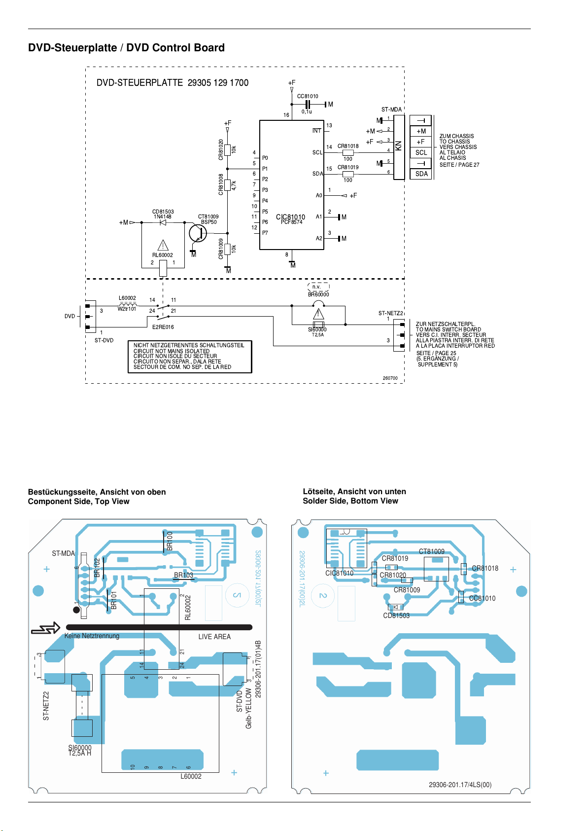
Platinenabbildungen und Schaltpläne / Layout of PCBs and Circuit Diagrams CUC 1931
DVD-Steuerplatte / DVD Control Board
DVD
DVD-STEUERPLATTE 29305 129 1700
+F
10k
CR81020
4,7k
CR81008
CD81503
3
1
ST-DVD
+M
L60002
W2tr101
1N4148
RL60002
2
E2RE016
NICHT NETZGETRENNTES SCHALTUNGSTEIL
CIRCUIT NOT MAINS ISOLATED
CIRCUIT NON ISOLE DU SECTEUR
CIRCUITO NON SEPAR., DALA RETE
SECTOUR DE COM. NO SEP. DE LA RED
CT81009
BSP50
M
1
10k
CR81009
M
1114
2124
10
11
12
4
5
6
7
9
P0
P1
P2
P3
P4
P5
P6
P7
+F
CC81010
16
CIC81010
PCF8574
8
M
0,1u
BR60000
SI60000
INT
SCL
SDA
A0
A1
A2
n.v.
!
T2,5A
M
13
14
15
1
2
3
CR81018
100
CR81019
100
+F
M
M
+M
+F
ST-MDA
1
M
2
3
4
5
M
6
ST-NETZ2
1
3
260700
+M
ZUM CHASSIS
TO CHASSIS
+F
SCL
VERS CHASSIS
AL TELAIO
AL CHASIS
SEITE / PAGE 27
KN
SDA
ZUR NETZSCHALTERPL.
TO MAINS SWITCH BOARD
VERS C.I. INTERR. SECTEUR
ALLA PIASTRA INTERR. DI RETE
A LA PLACA INTERRUPTOR RED
SEITE / PAGE 25
(5. ERGNZUNG /
SUPPLEMENT 5)
Bestückungsseite, Ansicht von oben
Component Side, Top View
ST-MDA
BR102
16
Keine Netztrennung
13
ST-NETZ2
SI60000
T2,5A H
BR101
11114
4
5
9
10
3
8
BR100
BR103
22124
2
7
L60002
RL60002
LIVE AREA
1
6
13
29306-201.17(01)4B
ST-DVD
Gelb-YELLOW
Lötseite, Ansicht von unten
Solder Side, Bottom View
1
CR81019
CIC81010
CR81020
CR81009
CD81503
CT81009
CR81018
CC81010
29306-201.17/4LS(00)
64 GRUNDIG Service
Page 41
GRUNDIG Service 65
ǵ
Ersatzteilliste
Spare Parts List
3 / 2001
ERSETZT AUSGABE 12/2000
SUBSTITUTE EDITION 12/2000
POS. NR. ABB. MATERIAL-NR. ANZ. BEZEICHNUNG DESCRIPTION
POS. NO. FIG. PART NUMBER QTY.
921963029200 ARGANTO 82 MFW 82-530/9 DVD ARGANTO 82 MFW 82-530/9 DVD
0200.000 296354130301 GEH-VORDERTEIL DRUCK KPL CABINET FRONT PART PRINT CPL
0201.000 191240256100 LAUTSPRECHER LOUDSPEAKER
0204.000 296322530301 GITTER KPL LAUTSPRECHER GRID CPL LOUDSPEAKER
0208.000 297006282301 ABDECKUNG BASIC 3 COVER BASIC 3
0210.000 296383290103 RAHMEN-OBERTEIL FRAME UPPER PART
0215.000 296383300103 2 RAHMEN-SEITENTEIL FRAME SIDE PART
0217.000 296088640102 5 SOCKELEINLAGE BASE INSERT
0218.000 296363270201 TASTENKNOPF NETZSCHALTER KEY POWER MAINS SWITCH
0225.000 296366530201 KLAPPE DRUCK KPL. BEDIENEINSATZ FLAP PRINT CPL CONTROL INSERT
0226.000 293033751001 SCHENKELFEDER KLAPPE LEG SPRING FLAP
0227.000 270332210100 DRUCKSCHNAEPPER KLAPPE PRESSURE CATCH FLAP
0228.000 296380231301 DAEMPFUNGSBLOCK KLAPPE DAMPING BLOCK FLAP
0230.000 296363260102 IR-FENSTER KLAPPE IR WINDOW FLAP
0231.000 296381710102 FOLIE ISOLIERUNG BRANDSCHUTZ FOIL INSULATION FIRE PROTECTION
0247.000 293031223101 EURO-AV-STECKER M.KABEL EURO-AV PLUG W.CABLE
0300.000 296363191201 GEH-RUECKTEIL KPL OFB CABINET REAR PART CPL SURF. TREATED
0310.000 296383530301 2 BOX KPL BOX CPL
0310.000 296352480103 2 BOX KPL BOX CPL
0317.000 296364568701 4 ABDECKUNG RUECKWAND COVER REAR PANEL
0320.000 291103020502 TYPENAUFKLEBER VNM TYPE LABEL SELF ADHESIVE VNM
0350.000 296363200103 2 ZWISCHENSTUECK INTERMEDIATE
0700.000 S 092461547502 ENTMAGNETISIERUNGS/ DEGAUSSING/
0740.000 296073090101 2 SPULENHALTER HOLDER COIL
0750.000 812612529600 4 EINSATZBUCHSE BILDROHR INSERT SOCKET PICTURE TUBE
0900.000 S 292014770100 FOKUS U.UG2-REGLER FOCUS AND UG2-ADJUSTMENT CONTROL
0910.000 S 292014760202 FOKUSLEITUNG M.TUELLE FOCUSING CABLE WITH GROMMET
0910.000 S 292014760102 2 FOKUSLEITUNG M.TUELLE FOCUSING CABLE WITH GROMMET
296322560101 X DVD-EINHEIT KPL. DVD UNIT CPL
296383951201 X DVD-MODUL KPL. DVD MODUL CPL
293051291700 STEUER PLATTE DVD BASIC 3 CONTROL BOARD DVD BASIC 3
0913.000 S 096211130206 SICHERUNGSHALTER SI60000 FUSE HOLDER SI60000
295010838000 KEYBOARD KEYBOARD
0923.000 293035220600 S-VHS-BUCHSE O.SCHALTER S-VHS-SOCKET W/O SWITCH
0924.000 293031685800 CINCH-BUCHSE 3-FACH FBAS/NF L,R CINCH SOCKET 3 FOLD FBAS/AF L,R
0925.000 293033904200 KOPFHOERERBUCHSE 3,5mm O.SCHALTER HEADPHONE SOCKET 3,5mm W/O SWITCH
0926.000 295017170100 LICHTLEITER LIGHT GUIDE
293051606000 BUCHSENPLATTE SOCKET BOARD
MATERIAL-NR. / PART NO.: 921963029200 BESTELL-NR. / ORDER NO.: GCL8740 TITANE
ARGANTO 82 FLAT MFW 82-530/9 DVD
VERSION NR./VERSION NO.: VNM
d©
TITANE TITANE
KEIN E-TEIL NO SPARE PART
RUECKWANDBEFESTIGUNG PIECE REAR PANEL FIXING
ROTATIONSSPULEN SET ROTATING COIL SET
KEIN E-TEIL NO SPARE PART
KEIN E-TEIL NO SPARE PART
KEIN E-TEIL NO SPARE PART
KEIN E-TEIL NO SPARE PART
KEIN E-TEIL NO SPARE PART
TV
POS. NR. ABB. MATERIAL-NR. ANZ. BEZEICHNUNG DESCRIPTION
POS. NO. FIG. PART NUMBER QTY.
0931.000 293033951101 FEDERKLEMME 12-FACH PUSH TERMINAL 12 FOLD
0932.000 293032750401 2 KONTAKTFEDER CONTACT SPRING
293051603700 BAUSTEIN EURO-AV MODULE EURO-AV
0941.000 293031197100 EURO-AV BUCHSENLEISTE 21-POL BL EURO-AV SOCKET STRIP 21 PIN BLUE
1100.000 S 830007603100 BILDROHR W 76 ERF231X044 PHILIPS PICTURE TUBE W 76 ERF231X044 PHILIPS
1200.000 S 292013601106 ANODENKAPPE M.HOCHSPANNUNGSKABEL ANODE CAP W.HIGH VOLTAGE CABLE
1300.000 296366550201 BEDIENUNGSEINSATZ DRUCK KPL CONTROL INSERT PRINT CPL
1311.000 297033571100 TASTSCHALTER PROGRAMM + KEY SWITCH PROGRAMME +
1312.000 297033571100 TASTSCHALTER PROGRAMM - KEY SWITCH PROGRAMME -
1313.000 297033571100 TASTSCHALTER LAUTSTAERKE + KEY SWITCH VOLUME +
1314.000 297033571100 TASTSCHALTER LAUTSTAERKE - KEY SWITCH VOLUME -
1382.000 296366480101 IR-FENSTER IR WINDOW
1800.000 S 295010870500 NETZSCHALTERPLATTE POWER SWITCH BOARD
1860.000 S 297032917105 NETZSCHALTER ECO O.WISCHER POWER SWITCH ECO W/O WIPER
1870.000 296363280203 TASTENSATZ PROGRAMM/LAUTSTAERKE KEY SET PROGRAMME/VOLUME
1890.000 S 096211130206 2 SICHERUNGSHALTER SI62001 FUSE HOLDER SI62001
2100.000 S 829099131600 NETZKABEL KPL MIT ENTSTOERDROSSEL POWER CABLE CPL W.INTERFERENCE CHOKE
2300.000 S 293051222900 X BILDROHRPLATTE PICTURE TUBE BOARD
2400.000 296420610600 TP 120 DC FERNBEDIENUNG TP 120 DC REMOTE CONTROL
2410.000 720086731000 DECKEL BATTERIE BATTERY LID
219639410200 BEDIENUNGSANLEITUNG D OPERATING INSTRUCTIONS D
219639410300 BEDIENUNGSANLEITUNG F/I OPERATING INSTRUCTIONS F/I
219639410400 BEDIENUNGSANLEITUNG GB/NL OPERATING INSTRUCTIONS GB/NL
219639410500 BEDIENUNGSANLEITUNG E/P OPERATING INSTRUCTIONS E/P
219639410600 BEDIENUNGSANLEITUNG DK/FIN OPERATING INSTRUCTIONS DK/FIN
219639410700 BEDIENUNGSANLEITUNG S/N OPERATING INSTRUCTIONS S/N
291202370101 BEDIENUNGSANLEITUNG TV-GUIDE OPERATING INSTRUCTIONS TV-GUIDE
720100249000 SERVICE MANUAL D/GB SERVICE MANUAL D/GB
720100249900 SERVICE MANUAL D/GB 9.ERGAENZUNG SERVICE MANUAL D/GB 9TH SUPPLEMENT
296560043301 MONTAGEZUBEHOER F.BILDROHR MOUNTING ACCESSORIES F.PICT. TUBE
297040073100 X CHASSIS-FS-STEREO BASIC 3 CHASSIS TV STEREO BASIC 3
d©
KEIN E-TEIL NO SPARE PART
KEIN E-TEIL NO SPARE PART
CUC 1931 CUC 1931
KEIN E-TEIL NO SPARE PART
X = SIEHE GESONDERTE E-LISTE X = SEE SEPARATE PARTS LIST
296354130301
191240256100
296363270201
296322530301
CUC 1931 Ersatzteillisten / Spare Parts Lists
ÄNDERUNGEN VORBEHALTEN / SUBJECT TO ALTERATION
ÄNDERUNGEN VORBEHALTEN / SUBJECT TO ALTERATION
Page 42

66 GRUNDIG Service
POS. NR. MATERIAL-NR. BEZEICHNUNG
POS. NO. PART NUMBER DESCRIPTION
C 22001 S 856373242500 FOKO KF #25 0,1UF 20% 250V
C 62001
C 62002 S 851179304700 FOKO MP3 0,47UF20%250V
D 81501 830921504500 DIODE 1N4148
GD 22003S 831001000800 TRIAC BTB08-600CW
L 62001 S 295008359700 ENTSTOER-DR 2X22MH
OK 22005S 830600024200 OPTOKOPPLER IL4216-X001
R 22001 S 831120001200 PTC #3 DUO
R 62001 876504914500 MSW SI 0414 1 MOHM 5% VDE
R 62002 S 831100501700 NTC 4,7 OHM 30%
SI 62001 S 831562250300 SI 5X20 T3,15A H 250V
T 81001 830320287500 TRANS 2SD1866TV2
T 81002 830320554800 TRANS BC548B/BC547B
CD 81503 833050414800 MELF DIODE MCL4148
CIC 81010 830581857400 SMD IC PCF 8574T
CT 81009 830119005000 SMD TRANS BSP50
RL60002 S 295007220100 RELAIS RT 444012
L 60002 S 292017049701 DROSSEL PFC B82991-S2601
SI 60000 S 831562150300 SI 5X20 T2,5A
CT 43331 830100385800 SMD TRANS BC858B/BC857B
CT 43332 830100385800 SMD TRANS BC858B/BC857B
CT 43333 830100484800 SMD TRANS BC848B/BC847B
CT 43337 830100484800 SMD TRANS BC848B/BC847B
CT 43339 830100484800 SMD TRANS BC848B/BC847B
D 43316 830921504500 DIODE 1N4148
R 43327 870001124600 KSW 0204 75 OHM 5%
T 44011 830320554800 TRANS BC548B/BC547B
C 84002 866820302300 ABBLOCK-C 0,1 UF 25V
D 85001 830997837100 LE-DIODE LUB371GK
IC 84001 830536753000 IC TFMS5300 STEHEND/TSOP
Es gelten die Vorschriften und Sicherheitshinweise
gemäß dem Service Manual "Sicherheit", Mat.-Nummer 720108000000, sowie zusätzlich die eventuell abweichenden, landesspezifischen Vorschriften!
295010870500 NETZSCHALTERPLATTE
POWER SWITCH BOARD
S 851179304700 FOKO MP3 0,47UF20%250V
INTERFERENCE CHOKE
OPTO COUPLER
293051291700 STEUER PLATTE DVD BASIC 3
293051603700 BAUSTEIN EURO-AV
295010838000 KEYBOARD
CONTROL BOARD DVD BASIC 3
MODULE EURO-AV
POS. NR. MATERIAL-NR. BEZEICHNUNG
POS. NO. PART NUMBER DESCRIPTION
293051606000 BUCHSENPLATTE
L 40901 092382240600 HF-DROSSEL
L 40903 092382240600 HF-DROSSEL
L 40905 092382240600 HF-DROSSEL
L 40907 092382240600 HF-DROSSEL
L 40909 092382240600 HF-DROSSEL
L 40916 092382240600 HF-DROSSEL
The regulations and safety instructions shall be valid
!
as provided by the "Safety" Service Manual, part
number 720108000000, as well as the respective
( ! )
national deviations.
ÄNDERUNGEN VORBEHALTEN / SUBJECT TO ALTERATION
SOCKET BOARD
ǵ
Ersatzteilliste
Spare Parts List
12 / 2000
POS. NR. ABB. MATERIAL-NR. ANZ. BEZEICHNUNG DESCRIPTION
POS. NO. FIG. PART NUMBER QTY.
297040073100 CHASSIS-FS-STEREO CHASSIS TV STEREO
0100.000 295042620300 X BAUSTEIN SIGNAL/ZF+TUNER MODULE SIGNAL/IF+TUNER
0247.000 293031196600 EURO-AV BUCHSENLEISTE 21-POL SW EURO-AV SOCKET STRIP 21 PIN BLACK
0247.000 293031196800 EURO-AV BUCHSENLEISTE 21-POL OR EURO-AV SOCKET STRIP 21 PIN ORANGE
0300.000 295042031800 X BAUSTEIN PROZESSOR MEGATEXT MODULE PROCESSOR MEGATEXT
0400.000 295042091300 X FEATURE-BOX BASIC 3 FEATURE BOX BASIC 3
0400.000 S 293040508500 NETZTEIL STAND BY POWER SUPPLY STAND BY
0450.000 297006321401 HALTER BAUSTEIN HOLDER MODULE
0450.000 297006131104 NETZTEILAUFNAHME HOLDER POWER SUPPLY
0500.000 295042041400 X BAUSTEIN NF-VERSTAERKER/5-KANAL MODULE AF AMPLIFIER 5-CHANNEL/
293051291200 ADAPTERPLATTE ADAPTER BOARD
293050253700 DYNAMISCHE FOKUSSIERUNGSPLATTE DYNAMIC FOCUSING BOARD
293051291800 ROTATIONSPLATTE ROTATION BOARD
2400.000 293031530107 2 MONTAGECLIP T53001/60006 MOUNTING CLIP T53001/60006
2430.000 293031531208 14 MONTAGECLIP D53071/53072/60006/ MOUNTING CLIP D53071/53072/60006/
2440.000 293031531605 MONTAGECLIP T52003 MOUNTING CLIP T52003
2455.000 293031561600 ISOLIERUNG D60019 ISOLATION D60019
2460.000 293031561700 ISOLIERUNG D60021 ISOLATION D60021
2465.000 293031561800 2 FOLIE WAERMELEITEND T60006/D60006 FOIL HEAT CONDUCTING T60006/D60006
2470.000 293031562000 10 FOLIE WAERMELEITEND IC50010/61001/ FOIL HEAT CONDUCTING IC50010/61001/
2480.000 293031562100 2 FOLIE WAERMELEITEND D53071/53072 FOIL HEAT CONDUCTING D53071/53072
2485.000 293031562301 FOLIE WAERMELEITEND T53001 FOIL HEAT CONDUCTING T53001
2490.000 293031562800 2 FOLIE WAERMELEITEND D60019/60021 FOIL HEAT CONDUCTING D60019/60021
POS. NR. MATERIAL-NR. BEZEICHNUNG
POS. NO. PART NUMBER DESCRIPTION
C 50012 845299614700 ELKO 1000UF 20% 25V
C 50026 845299614700 ELKO 1000UF 20% 25V
C 53012 851591160200 FOKO FKP1 142PF 2,5% 2000V
C 53071 851591171900 FOKO FKP1 0,012UF 3,5% 2000V
C 54021 865006704600 KERKO HV C 100PF 20% 1KV
C 60001 865008112500 KERKO HV C 1000PF 20% 1KV
C 60006 865006704600 KERKO HV C 100PF 20% 1KV
C 60009 851591103800 FOKO FKP1 100PF 10% 1600V
C 60012 865008111100 KERKO HV C 270PF 20% 2KV
C 60018 851591140300 FOKO FKP1 0,01UF 5% 1250V
d©
CUC 1931 CUC 1931
KEIN E-TEIL NO SPARE PART
EQUALIZER EQUALIZER
KEIN E-TEIL NO SPARE PART
KEIN E-TEIL NO SPARE PART
KEIN E-TEIL NO SPARE PART
61014/61016/D61021/61026/61036/IC60001/ 61014/61016/D61021/61026/61036/IC60001/
60006/IC61030/61040/T50028/50029 60006/IC61030/61040/T50028/50029
61006/61030/61040/T50028/50029/ 61006/61030/61040/T50028/50029/
D61014/61026/61036 D61014/61026/61036
X = SIEHE GESONDERTE E-LISTE X = SEE SEPARATE PARTS LIST
CHASSIS-FS-STEREO CUC 1931
CHASSIS-FS-STEREO CUC 1931
POS. NR. MATERIAL-NR. BEZEICHNUNG
POS. NO. PART NUMBER DESCRIPTION
C 60023 865008112500 KERKO HV C 1000PF 20% 1KV
C 60024 865008112500 KERKO HV C 1000PF 20% 1KV
C 60026 865008112500 KERKO HV C 1000PF 20% 1KV
C 60027 865008112500 KERKO HV C 1000PF 20% 1KV
C 60029 S 851179301800 MP3 0,1UF 20% 250V
C 61004 845299614700 ELKO 1000UF 20% 25V
C 61014 865006704600 KERKO HV C 100PF 20% 1KV
C 61015 845209705500 ELKO #16 600/680UF 63V
C 61016 851591103800 FOKO FKP1 100PF 10% 1600V
C 61021 865006704600 KERKO HV C 100PF 20% 1KV
ÄNDERUNGEN VORBEHALTEN / SUBJECT TO ALTERATION
MATERIAL-NR. / PART NO.: 297040073100
TV
Ersatzteillisten / Spare Parts Lists CUC 1931
Page 43

GRUNDIG Service 67
POS. NR. MATERIAL-NR. BEZEICHNUNG
POS. NO. PART NUMBER DESCRIPTION
POS. NR. MATERIAL-NR. BEZEICHNUNG
POS. NO. PART NUMBER DESCRIPTION
POS. NR. MATERIAL-NR. BEZEICHNUNG
POS. NO. PART NUMBER DESCRIPTION
POS. NR. MATERIAL-NR. BEZEICHNUNG
POS. NO. PART NUMBER DESCRIPTION
CUC 1931 Ersatzteillisten / Spare Parts Lists
C 61022 845209705500 ELKO #16 600/680UF 63V
C 61026 865006704600 KERKO HV C 100PF 20% 1KV
C 61032 845299614700 ELKO 1000UF 20% 25V
C 61036 865006704600 KERKO HV C 100PF 20% 1KV
C 61037 845209705700 ELKO 28 1000UF 63V
C 61042 845299610700 ELKO 2200UF 20% 16V
C 61064 845299615000 ELKO 2200UF 20% 25V
C 61261 865006704600 KERKO HV C 100PF 20% 1KV
C 61266 865006704600 KERKO HV C 100PF 20% 1KV
C 62021
S 866009823800 KERKO SI 2200PF 20% 400V
C 62022 S 866009823800 KERKO SI 2200PF 20% 400V
C 62048 S 866009823400 KERKO SI 1000PF 20% 400V
C 64006 851591160800 FOKO FKP1 180PF 0+10% 2000V
C 70509 845299614700 ELKO 1000UF 20% 25V
CD 21221 830953414900 MELF-DIODE LL4148
CD 21222 830953414900 MELF-DIODE LL4148
CD 21231 830953414900 MELF-DIODE LL4148
CD 21232 830953414900 MELF-DIODE LL4148
CD 34513 830953414900 MELF-DIODE LL4148
CD 34517 830953414900 MELF-DIODE LL4148
CD 43026 830945503300 MELF-Z DIODE 3,3C 0,5W
CD 43541 830953414900 MELF-DIODE LL4148
CD 43542 830945502700 MELF-Z DIODE 2,7C 0,5W
CD 43651 830945506200 MELF-Z DIODE 6,2C 0,5W
CD 52003 830953414900 MELF-DIODE LL4148
CD 53019 830953414900 MELF-DIODE LL4148
CD 55003 830945504000 MELF-Z DIODE 3,9B 0,5W
CD 55004 830953414900 MELF-DIODE LL4148
CD 58001 830953414900 MELF-DIODE LL4148
CD 58004 830953414900 MELF-DIODE LL4148
CD 58007 830945502800 MELF Z-DIODE 2,7B 0,5W
CD 58011 830953414900 MELF-DIODE LL4148
CD 58012 830953414900 MELF-DIODE LL4148
CD 58021 830953414900 MELF-DIODE LL4148
CD 58022 830953414900 MELF-DIODE LL4148
CD 65506 830953414900 MELF-DIODE LL4148
CD 65519 830953414900 MELF-DIODE LL4148
CD 65528 830953414900 MELF-DIODE LL4148
CD 70501 830945505200 MELF-Z DIODE 5,1B 0,5W
CD 70506 830953414900 MELF-DIODE LL4148
CD 70507 830953414900 MELF-DIODE LL4148
CD 70517 830953414900 MELF-DIODE LL4148
CD 70521 830945505200 MELF-Z DIODE 5,1B 0,5W
CD 70522 830945503300 MELF-Z DIODE 3,3C 0,5W
CD 70523 830953414900 MELF-DIODE LL4148
CD 70553 830953414900 MELF-DIODE LL4148
CIC43550 830578705300 SMD IC 74HC4053
CIC43650 830578705300 SMD IC 74HC4053
CIC64315 830576035800 SMD IC LM358M
CIC64330 830581409400 SMD IC MC14094BD
CL 64321 810498201200 SMD DAEMPF-PERLE
CT 21221 830100684800 SMD TRANS BC848C/BC847C
CT 21233 830100684800 SMD TRANS BC848C/BC847C
CT 32305 830100484800 SMD TRANS BC848B/BC847B
CT 32320 830100484800 SMD TRANS BC848B/BC847B
CT 43525 830100385800 SMD TRANS BC858B/BC857B
CT 43535 830100484800 SMD TRANS BC848B/BC847B
CT 43565 830100484800 SMD TRANS BC848B/BC847B
CT 43580 830100484800 SMD TRANS BC848B/BC847B
CT 43590 830100484800 SMD TRANS BC848B/BC847B
CT 58012 830100484800 SMD TRANS BC848B/BC847B
CT 61316 830100484800 SMD TRANS BC848B/BC847B
CT 64305 830100484800 SMD TRANS BC848B/BC847B
CT 64310 830100385800 SMD TRANS BC858B/BC857B
CT 64320 830100484800 SMD TRANS BC848B/BC847B
SMD DAMPING BEAD
CT 64325 830100385800 SMD TRANS BC858B/BC857B
CT 64331 830100484800 SMD TRANS BC848B/BC847B
CT 64332 830100484800 SMD TRANS BC848B/BC847B
CT 64333 830100484800 SMD TRANS BC848B/BC847B
CT 64334 830100385800 SMD TRANS BC858B/BC857B
CT 65501 830153426900 SMD TRANS PMBT2369/MMBT2
CT 65503 830100484800 SMD TRANS BC848B/BC847B
CT 65504 830153426900 SMD TRANS PMBT2369/MMBT2
CT 65505 830100385800 SMD TRANS BC858B/BC857B
CT 65506 830100484800 SMD TRANS BC848B/BC847B
CT 65525 830100684800 SMD TRANS BC848C/BC847C
CT 65530 830100385800 SMD TRANS BC858B/BC857B
CT 70505 830100484800 SMD TRANS BC848B/BC847B
CT 70520 830100684800 SMD TRANS BC848C/BC847C
CT 70525 830100685800 SMD TRANS BC858C/BC857C
D 21212 830921502000 DIODE 1N4004
D 32315 830970713500 Z DIODE 33B 0,5W
D 50013 830951628300 DIODE BYV28-200
D 52006 830921502000 DIODE 1N4004
D 53008 830920100500 DIODE BA157
D 53019 830970900300 Z DIODE ZY51
D 53071 830920435900 DIODE BY359 1500
D 53072 830920423000 DIODE BY229-600
D 54001 830920100500 DIODE BA157
D 54011 830920100500 DIODE BA157
D 54021 830951603800 DIODE BYV38
D 55012 830972033300 Z DIODE 33C 0,5W
D 60006 830982088000 DIODE MUR880
D 60012 830951675400 DIODE BYT53B
D 60019 830919780700 DIODE STTA806D
WW. 830919780600 DIODE STTA806DI
D 60021 830919780700 DIODE STTA806D
WW. 830919780600 DIODE STTA806DI
D 60023 830856052100 GLR B380C3700/2200
D 60216 830920002100 DIODE BAV21
D 60217 830920115900 DIODE BA159
D 60218 S 830966318000 Z-DIODE BZT03D180
D 61001 830951675400 DIODE BYT53B
D 61014 830951710800 DIODE BYT108-400
D 61016 830951679800 DIODE BYT08 P-1000
D 61021 830951710800 DIODE BYT108-400
D 61026 830951710800 DIODE BYT108-400
D 61033 830920100500 DIODE BA157
D 61036 830951710800 DIODE BYT108-400
D 61262 S 830951717200 DIODE BYW172D
D 61263 830921502000 DIODE 1N4004
D 61264 830921502000 DIODE 1N4004
D 61266 S 830951717200 DIODE BYW172D
D 61268 830921502000 DIODE 1N4004
D 61269 830921502000 DIODE 1N4004
D 61603 830972013100 Z DIODE 13B 0,5W
D 64010 830966306800 Z-DIODE BZT03D68
D 64011 830920002100 DIODE BAV21
D 64012 830920002100 DIODE BAV21
D 64013 830920002100 DIODE BAV21
D 64014 830920002100 DIODE BAV21
D 64305 830972011300 Z DIODE 12B 0,5W
D 64310 830972011300 Z DIODE 12B 0,5W
D 64315 830972005100 Z DIODE 5,1B 0,5W
D 70508 830972011600 Z-DIODE 15C 0,5W
FS 64001 S 293032300200 FUNKENSTRECKE 1,6KV
IC 34510 830533478000 IC TDA4780V3/V4
IC 43080 830536642000 IC TEA6420
IC 43570 830536642500 IC TEA6425
IC 43670 830536642500 IC TEA6425
IC 50010 830534417300 IC TDA4173AF
IC 55010 830533814500 IC TDA8145
ÄNDERUNGEN VORBEHALTEN / SUBJECT TO ALTERATION
IC 58010 830520439300 IC LM393P
IC 60010 830533464600 IC TDA16846
IC 60220 830536150100 IC TEA1501 N1
IC 61001 830520431700 IC LM317T
IC 61006 830520431700 IC LM317T
IC 61030 830520435000 IC LM350T
IC 61040 830520435000 IC LM350T
IC 61310 830520435700 IC LM358N
L 34517 814050574700 DR B 8,2UH 5%
L 53001 810498205600 FERRITPERLE HF70 BTL 3,5X
L 53002 810498205600 FERRITPERLE HF70 BTL 3,5X
L 53003 810498205600 FERRITPERLE HF70 BTL 3,5X
L 53011 814050524900 DR A AX-GA 10UH 10%
L 53012 092401140400 DROSSEL 1,5 MH/CHOKE
L 53021 292031229700 LINEARITAETSREGLER
L 53074 092468596100 BRUECKENSPULE M.KERN
L 55014 092458160100 O/W AUSKOPPELSPULE
L 60006 297017390800 DAEMPF-PERLE UV 930 30
L 60028 292017119700 SPEICHERDROSSEL
L 61012 810498201400 DAEMPF-PERLE 433003038102
L 61016 810498201400 DAEMPF-PERLE 433003038102
L 61021 810498201400 DAEMPF-PERLE 433003038102
L 61026 810498201400 DAEMPF-PERLE 433003038102
L 61036 810498201400 DAEMPF-PERLE 433003038102
L 61061 810498201400 DAEMPF-PERLE 433003038102
L 61062 814050506500 DR A AX-GA 47UH 5%
L 61066 810498201400 DAEMPF-PERLE 433003038102
L 61067 814050506500 DR A AX-GA 47UH 5%
L 70508 092410359700 STABKERNDROSSEL
L 70555 814050574700 DR B 8,2UH 5%
OK 60031S 830600001200 OPTOKOPPLER CNY17F1
OK 60046S 830600001200 OPTOKOPPLER CNY17F1
R 21103 S 870532122100 MOW 0411 6,8 OHM 5%
R 21212 870000754900 KSW 0207 1,5 MOHM 5%
R 21216 870001134500 KSW 0204 1 MOHM 5%
R 32315 S 870537009900 MOW 0922 12 KOHM 5%
R 43082 S 870111902100 KSW SI B 6,8 OHM 5%
R 43566 S 870042901300 KSW NB 0207 3,3 OHM 5%
R 43581 S 870042901300 KSW NB 0207 3,3 OHM 5%
R 50007 S 876632740900 MSW 0207 2,2 OHM 1%
R 50008 S 876632740900 MSW 0207 2,2 OHM 1%
R 50029 S 876635705200 MSW 0414 130 OHM 5%
R 52001 S 870532901700 MOW 0411 4,7 OHM 5%
R 52003 S 873023923900 DRW SI ST7 3W 39 OHM 5%
R 52005 S 870536901300 MOW 0617 3,3 OHM 5%
R 52006 S 870536901300 MOW 0617 3,3 OHM 5%
R 53002 S 876588600500 KSW 0207 1,5 OHM 5%
R 53003 S 876588600500 KSW 0207 1,5 OHM 5%
R 53008 S 870042909700 KSW NB 0207 10 KOHM 5%
R 53016 S 873028002100 DRW SI S11 7W 6,8 OHM 5%
R 53021 S 870536906300 MOW 0617 390 OHM 5%
R 54001 S 873500303300 DRW 0,75W 0,33 OHM 10%
R 54011 S 873500303300 DRW 0,75W 0,33 OHM 10%
Es gelten die Vorschriften und Sicherheitshinweise
gemäß dem Service Manual "Sicherheit", Mat.-Nummer 720108000000, sowie zusätzlich die eventuell abweichenden, landesspezifischen Vorschriften!
FERRITE BEAD
LINEARITY CONTROL
BRIDGECOIL W.CORE
E/W COUPLING COIL
DAMPING BEAD
STORAGE CHOKE
DAMPING BEAD
DAMPING BEAD
BAR CORE COIL
OPTO COUPLER
R 54021 S 870532902500 MOW 0411 10 OHM 5%
R 54022 S 870532902500 MOW 0411 10 OHM 5%
S 870536906500 MOW 0617 470 OHM 5%
R 55012
R 55014
S 870123081700 NKS 3 4,7 OHM 5%
R 58001 876509830400 MSW 0207 20 KOHM 2%
R 58002 876519808600 MSW 0207 3,6 KOHM 1%
R 60002 870006935600 KSW 0617 3 MOHM 2%
R 60008 S 873017930100 DRW 7 15 KOHM 10%
R 60212 S 876504915300 MSW SI 0414 2,2 MOHM VDE
R 61001 879005001700 ESTR.SK10-A 220 OHM LIN
R 61016 S 873229600100 DRW 6,5 1 OHM 10%
R 61022 S 873229600100 DRW 6,5 1 OHM 10%
R 61031 879005002500 ESTR.SK10-A 470 OHM LIN
R 61033 S 873014904900 DRW 4 100 OHM 5%
R 61041 879005001700 ESTR.SK10-A 220 OHM LIN
R 61313 879005005400 ESTR.SK10-A 22 KOHM LIN
R 62049 S 876634915500 MSW SI 0414 2,7 MOHM 5%
R 64307 S 870111903500 KSW SI B 27 OHM 5%
R 64308 S 870111903500 KSW SI B 27 OHM 5%
R 65525 S 831121207000 PTC C 890 A120-A70
SI 60001 S 831562006800 SI LOET T2A 250V
SI 60201 S 831560702600 SI LOET T100MA 250V
SI 61016 S 831562202500 SI LOET T3,15A 250V
SI 61022 S 831562202500 SI LOET T3,15A 250V
SI 61026 S 831562102700 SI LOET T2,5A 250V
SI 61036 S 831562102700 SI LOET T2,5A 250V
SI 61061 S 831562022500 SI LOET T2A 250V
SI 61066 S 831562022500 SI LOET T2A 250V
T 50028 830221054400 TRANS BD544B
T 50029 830221054300 TRANS BD543B
T 52003 830221068200 TRANS BD679A
T 53001 830262533100 TRANS 2SC5331
T 60006 830263829900 TRANS 2SK2699
T 64016 830328763900 TRANS BC639
TR 52001 S 092468699700 TRAFO TREIBER
TR 53010 S 292016800300 TRAFO DIODEN-SPLIT
TR 60001 S 292015769701 SPERRWANDLERTRAFO
TR 60220 S 292016199700 SPERRWANDLERTRAFO
TR 64001 S 292014499700 FOKUSSIERUNGSUEBERTRAGER
The regulations and safety instructions shall be valid
!
as provided by the "Safety" Service Manual, part
number 720108000000, as well as the respective
( ! )
national deviations.
ÄNDERUNGEN VORBEHALTEN / SUBJECT TO ALTERATION
TRANSFORMER DRIVER
TRANSFORMER DIODE SPLIT
B.O.TYPE CONVERTER
TRANSFORMER
293040508500
B.O.TYPE CONVERTER
TRANSFORMER
FOCUSING TRANSFORMER
Page 44

68 GRUNDIG Service
Ersatzteilliste
Spare Parts List
3 / 2000
POS. NR. ABB. MATERIAL-NR. ANZ. BEZEICHNUNG DESCRIPTION
POS. NO. FIG. PART NUMBER QTY.
ǵ
FEATURE-BOX BASIC 3
MATERIAL-NR. / PART NO.: 29504 209 1300
d©
29504 209 1300 FEATURE-BOX BASIC 3 FEATURE BOX BASIC 3
TV
POS. NR. MATERIAL-NR. BEZEICHNUNG
POS. NO. PART NUMBER DESCRIPTION
L 01544 81405 265 3400 DR 0411 10UH 10%
L 01546 81405 265 3400 DR 0411 10UH 10%
L 01563 81405 265 3400 DR 0411 10UH 10%
L 01641 81049 820 1400 DAEMPF-PERLE 433003038102
L 01651 81049 820 1400 DAEMPF-PERLE 433003038102
L 01656 81049 820 1400 DAEMPF-PERLE 433003038102
L 01662 81405 265 3400 DR 0411 10UH 10%
Q 01365 83824 422 0300 QUARZ #442-1 13C 20,25MHZ
Q 01408 83822 495 9700 QUARZ #330 2C 12MHZ
Q 02015 83823 362 7200 QUARZ #336-1 13C 27MHZ
DAMPING BEAD
POS. NR. MATERIAL-NR. BEZEICHNUNG
POS. NO. PART NUMBER DESCRIPTION
Ersatzteillisten / Spare Parts Lists CUC 1931
POS. NR. MATERIAL-NR. BEZEICHNUNG
POS. NO. PART NUMBER DESCRIPTION
CD 01403 83250 041 4800 SMD DIODE LS 4148
CD 01406 83094 550 5200 MELF-Z DIODE 5,1 B 0,5W
CD 01407 83250 041 4800 SMD DIODE LS 4148
CD 01418 83091 950 4200 SMD DIODE BAR42
CD 01419 83094 550 4000 MELF-Z DIODE 3,9 B 0,5W
CD 01530 83250 041 4800 SMD DIODE LS 4148
CD 01532 83250 041 4800 SMD DIODE LS 4148
CD 01533 83250 041 4800 SMD DIODE LS 4148
CD 01534 83250 041 4800 SMD DIODE LS 4148
CD 01663 83094 550 5200 MELF-Z DIODE 5,1 B 0,5W
CIC01320 83058 397 3300 SMD IC TLC7733ID
CIC01350 83059 932 1500 SMD IC VPC3215C-PT-B8
CIC01360 83059 732 5000 SMD IC CIP3250A-PS-B1
CIC01410 83059 493 6100 SMD IC SDA9362-2
CIC01640 83059 492 8200 SMD IC SDA9280-B22
CIC02010 83059 494 0000 SMD IC SDA9400
CIC02020 83057 870 5300 IC M74HC4053RM13TR
CL 01376 81049 823 3300 SMD DAEMPF-PERLE
CL 01377 81049 823 3300 SMD DAEMPF-PERLE
CL 02022 81049 823 3300 SMD DAEMPF-PERLE
CT 01501 83010 048 4900 SMD-TRANS BC 849 B
CT 01506 83011 660 5100 SMD-TRANS BCX 51-16
CT 01511 83010 048 4900 SMD-TRANS BC 849 B
CT 01516 83011 660 5100 SMD-TRANS BCX 51-16
CT 01521 83010 048 4900 SMD-TRANS BC 849 B
CT 01526 83011 660 5100 SMD-TRANS BCX 51-16
CT 01541 83010 048 4800 SMD TRANS BC848B/BC847B
CT 01545 83010 048 4800 SMD TRANS BC848B/BC847B
CT 01561 83010 048 4800 SMD TRANS BC848B/BC847B
CT 01680 83010 048 4800 SMD TRANS BC848B/BC847B
CT 01681 83010 048 4800 SMD TRANS BC848B/BC847B
CT 01690 83010 048 4800 SMD TRANS BC848B/BC847B
CT 01691 83010 048 4800 SMD TRANS BC848B/BC847B
CT 02057 83010 038 5800 SMD TRANS BC858B/BC857B
F 02000 81406 023 1900 FILTER 5X5 #319 4FACH
IC 01310 83052 631 1700 IC LD1117V33C 3,3V 2%
L 01306 81405 320 8500 SPULE 5X5 085 SIGN 532085
L 01308 81405 320 8600 SPULE 5X5 086 SIGN 532086
L 01309 81405 269 6600 DR S 18UH 5%
DAMPING BEAD
POS. NR. MATERIAL-NR. BEZEICHNUNG
POS. NO. PART NUMBER DESCRIPTION
L 01310 81049 820 1400 DAEMPF-PERLE 433003038102
L 01311 81405 269 6600 DR S 18UH 5%
L 01312 81405 269 6600 DR S 18UH 5%
L 01313 81049 820 1400 DAEMPF-PERLE 433003038102
L 01314 81405 269 6600 DR S 18UH 5%
L 01315 81049 820 1400 DAEMPF-PERLE 433003038102
L 01317 81049 820 1400 DAEMPF-PERLE 433003038102
L 01350 81049 820 1400 DAEMPF-PERLE 433003038102
L 01351 09241 035 9700 STABKERNDROSSEL
L 01352 81049 820 1400 DAEMPF-PERLE 433003038102
L 01353 09241 035 9700 STABKERNDROSSEL
L 01358 81405 265 3400 DR 0411 10UH 10%
L 01360 81405 258 9700 DR AX 0411-GA 100UH 5%
L 01361 81049 820 1400 DAEMPF-PERLE 433003038102
L 01362 81049 820 1400 DAEMPF-PERLE 433003038102
L 01370 81049 820 1400 DAEMPF-PERLE 433003038102
L 01372 81049 820 1400 DAEMPF-PERLE 433003038102
L 01374 81405 258 9700 DR AX 0411-GA 100UH 5%
L 01401 81405 265 3400 DR 0411 10UH 10%
L 01402 81405 265 3400 DR 0411 10UH 10%
L 01403 81405 265 3400 DR 0411 10UH 10%
L 01407 81405 265 3400 DR 0411 10UH 10%
L 01411 81405 265 3600 DR 0411 4,7UH 10%
L 01412 81405 265 3600 DR 0411 4,7UH 10%
L 01421 81049 820 1400 DAEMPF-PERLE 433003038102
L 01423 81049 820 1400 DAEMPF-PERLE 433003038102
L 01508 81049 820 1400 DAEMPF-PERLE 433003038102
L 01509 81405 258 2800 DR AX 0411-GA 2,2UH 10%
L 01518 81049 820 1400 DAEMPF-PERLE 433003038102
L 01531 81049 820 1400 DAEMPF-PERLE 433003038102
L 01532 81405 265 3400 DR 0411 10UH 10%
L 01533 81049 820 1400 DAEMPF-PERLE 433003038102
L 01536 81049 820 1400 DAEMPF-PERLE 433003038102
L 01537 81049 820 1400 DAEMPF-PERLE 433003038102
L 01538 81405 265 3400 DR 0411 10UH 10%
L 01543 81405 265 3400 DR 0411 10UH 10%
ÄNDERUNGEN VORBEHALTEN / SUBJECT TO ALTERATION
DAMPING BEAD
DAMPING BEAD
DAMPING BEAD
BAR CORE CHOKE
DAMPING BEAD
BAR CORE CHOKE1
DAMPING BEAD
DAMPING BEAD
DAMPING BEAD
DAMPING BEAD
Es gelten die Vorschriften und Sicherheitshinweise
gemäß dem Service Manual "Sicherheit", Mat.-Nummer 720108000000, sowie zusätzlich die eventuell abweichenden, landesspezifischen Vorschriften!
The regulations and safety instructions shall be valid
!
as provided by the "Safety" Service Manual, part
number 720108000000, as well as the respective
( ! )
national deviations.
ÄNDERUNGEN VORBEHALTEN / SUBJECT TO ALTERATION
Page 45

GRUNDIG Service 69
ǵ
ǵ
CUC 1931 Ersatzteillisten / Spare Parts Lists
Ersatzteilliste
Spare Parts List
3 / 2000
POS. NR. ABB. MATERIAL-NR. ANZ. BEZEICHNUNG DESCRIPTION
POS. NO. FIG. PART NUMBER QTY.
29504 262 0300 BAUSTEIN SIGNAL/ZF+TUNER/MULTI 9 MODULE SIGNAL/IF+TUNER/MULTI 9
0100.000 29504 301 0100 TUNER-GLOBAL (PLL) TUNER-GLOBAL (PLL)
POS. NR. MATERIAL-NR. BEZEICHNUNG
POS. NO. PART NUMBER DESCRIPTION
CD 32004 83094 550 5100 MELF-Z DIODE 5,1 C 0,5W
CD 32030 83094 550 5100 MELF-Z DIODE 5,1 C 0,5W
CD 32041 83094 015 9200 SMD DIODE BA592
CD 32042 83094 015 9200 SMD DIODE BA592
CD 32043 83094 015 9200 SMD DIODE BA592
CD 32044 83094 015 9200 SMD DIODE BA592
CD 32046 83094 015 9200 SMD DIODE BA592
CD 32047 83094 015 9200 SMD DIODE BA592
CD 32048 83094 015 9200 SMD DIODE BA592
CD 32071 83250 041 4800 SMD DIODE LS 4148
CD 32072 83250 041 4800 SMD DIODE LS 4148
CD 32132 83094 015 9200 SMD DIODE BA592
CD 32133 83094 015 9200 SMD DIODE BA592
CIC32030 83058 140 9400 SMD IC MC14094BD
CIC32080 83057 340 5300 SMD IC HEF4053BT
CL 32001 81049 820 1200 SMD DAEMPF-PERLE
CL 32003 81049 820 1200 SMD DAEMPF-PERLE
CT 32041 83010 048 4800 SMD TRANS BC848B/BC847B
CT 32042 83010 048 4800 SMD TRANS BC848B/BC847B
CT 32043 83011 305 5000 SMD TRANS BF550
CT 32044 83010 048 4800 SMD TRANS BC848B/BC847B
CT 32045 83010 038 5800 SMD TRANS BC858B/BC857B
CT 32061 83010 048 4800 SMD TRANS BC848B/BC847B
CT 32062 83010 048 4800 SMD TRANS BC848B/BC847B
CT 32064 83010 048 4800 SMD TRANS BC848B/BC847B
CT 32101 83010 038 5800 SMD TRANS BC858B/BC857B
CT 32104 83010 038 5800 SMD TRANS BC858B/BC857B
CT 32108 83010 048 4800 SMD TRANS BC848B/BC847B
CT 32109 83011 305 5000 SMD TRANS BF550
CT 32110 83010 048 4800 SMD TRANS BC848B/BC847B
CT 32111 83010 048 4800 SMD TRANS BC848B/BC847B
CT 32112 83010 038 5800 SMD TRANS BC858B/BC857B
CT 32113 83010 048 4800 SMD TRANS BC848B/BC847B
CT 32114 83010 048 4800 SMD TRANS BC848B/BC847B
CT 32119 83010 048 4800 SMD TRANS BC848B/BC847B
DAMPING BEAD
d©
BAUSTEIN SIGNAL ZF+TUNER /MULTI 9
MODULE SIGNAL/IF+TUNER/MULTI 9
POS. NR. MATERIAL-NR. BEZEICHNUNG
POS. NO. PART NUMBER DESCRIPTION
CT 32132 83010 048 4800 SMD TRANS BC848B/BC847B
CT 32133 83011 850 2000 SMD TRANS BFS20
CT 32134 83010 038 5800 SMD TRANS BC858B/BC857B
CT 32211 83010 048 4800 SMD TRANS BC848B/BC847B
CT 32215 83010 038 5800 SMD TRANS BC858B/BC857B
CT 32216 83010 038 5800 SMD TRANS BC858B/BC857B
CT 32217 83010 048 4800 SMD TRANS BC848B/BC847B
F 32041 81405 313 5100 SPULE 7X7 351 FARBE 718
F 32043 81405 353 9100 SPULE 7X7 #391 SIGN535391
F 32051 83190 095 5100 OFWFIL K9551M
F 32052 83190 039 5100 OFW G 3957 M
F 32053 83190 094 6000 OFW L 9460
F 32054 83190 062 6200 OFW K 6262 K
F 32101 81418 124 0500 FILTER 7X7 405 SIGN 11240
F 32101 81411 124 0500 FILTER 7X7 405 SIGN 11240
F 32109 86027 555 1500 KERTRAP #15 4,5MHZ
F 32111 81411 113 6000 FILTER 7X7 360 SIGN 11136
F 32111 81418 113 6000 FILTER 7X7 360 SIGN 11136
F 32124 86027 555 2100 CER.TRAP 21 TPS 5,5MHZ
F 32132 86022 220 2500 KERFIL #25 4,5MHZ
IC 32010 83053 369 3000 IC TDA6930S
L 32001 81405 253 4300 DR B AX-GA 15UH 10%
L 32003 81405 057 4700 DR B 8,2UH 5%
L 32109 81405 269 2600 DR N-GR 12UH 5%
L 32124 81405 260 3400 DR 0309 10UH 5%
R 32033 87920 021 4600 ESTR.S6 4,7 KOHM LIN
R 32057 87920 021 5100 ESTR.S6 10 KOHM LIN
MATERIAL-NR. / PART NO.: 29504 262 0300
TV
Ersatzteilliste
Spare Parts List
12 / 2000
POS. NR. ABB. MATERIAL-NR. ANZ. BEZEICHNUNG DESCRIPTION
POS. NO. FIG. PART NUMBER QTY.
295042031800 BAUSTEIN PROZESSOR MEGATEXT MODULE PROCESSOR MEGATEXT
0241.000 293031680900 CINCH-BUCHSE 2-FACH NF L,R CINCH SOCKET 2 FOLD AF L,R
0243.000 293031191800 D-SUB BUCHSENLEISTE 15-POL D-SUB SOCKET STRIP 15 PIN
POS. NR. MATERIAL-NR. BEZEICHNUNG
POS. NO. PART NUMBER DESCRIPTION
CIC46010 830594527500 SMD IC SDA5275-3P
CIC46020 830593160000 SMD IC MSM5116400D-60SJR1
CIC46215 830578705300 SMD IC 74HC4053
CIC46245 830577308600 SMD IC 74HCT86D/T3
CIC46250 830578612500 SMD IC 74HC125D/T3
CIC80010 830578709400 SMD IC 74HC4094
CIC80050 830582816100 SMD IC SAB-C161 RI-L16F
CIC80095 830596001700 SMD IC M24C16-MN1T
CIC80150 830595613200 SMD IC UM61256FS-15
CIC80220 830585328400 SMD IC 28F004S5-85
CT 46005 830100385800 SMD TRANS BC858B/BC857B
CT 80004 830100385800 SMD TRANS BC858B/BC857B
CT 80005 830100484800 SMD TRANS BC848B/BC847B
CT 80010 830100385800 SMD TRANS BC858B/BC857B
CT 80020 830100385800 SMD TRANS BC858B/BC857B
CT 80025 830100484800 SMD TRANS BC848B/BC847B
CT 80035 830100385800 SMD TRANS BC858B/BC857B
CT 80040 830100484800 SMD TRANS BC848B/BC847B
CT 80050 830100385800 SMD TRANS BC858B/BC857B
CT 80055 830100484800 SMD TRANS BC848B/BC847B
CT 80085 830100484800 SMD TRANS BC848B/BC847B
CT 80090 830100484800 SMD TRANS BC848B/BC847B
CT 80095 830100484800 SMD TRANS BC848B/BC847B
CT 80105 830100385800 SMD TRANS BC858B/BC857B
CT 80110 830100385800 SMD TRANS BC858B/BC857B
D 46201 830972005600 Z DIODE 5,6 C 0,5W
D 46202 830972005600 Z DIODE 5,6 C 0,5W
D 80002 830921504500 DIODE 1N4148
D 80003 830921504500 DIODE 1N4148
D 80108 830921504500 DIODE 1N4148
IC 80045 830521006400 IC MC33164P-5RP
IC 80070 297981040100 IC M27C160 PROG.KPL
L 46223 810498201400 DAEMPF-PERLE 433003038102
L 80040 810498201400 DAEMPF-PERLE 433003038102
d©
BAUSTEIN PROZESSOR MEGATEXT
MODULE PROCESSOR MEGATEXT
POS. NR. MATERIAL-NR. BEZEICHNUNG
POS. NO. PART NUMBER DESCRIPTION
L 80041 810498201400 DAEMPF-PERLE 433003038102
L 80042 810498201400 DAEMPF-PERLE 433003038102
Q 46001 860234116000 KERRES #160 20,48MHZ
Q 80067 860234114500 KERRES #145/2 16MHZ
MATERIAL-NR. / PART NO.: 295042031800
DAMPING BEAD
TV
Es gelten die Vorschriften und Sicherheitshinweise
gemäß dem Service Manual "Sicherheit", Mat.-Nummer 720108000000, sowie zusätzlich die eventuell abweichenden, landesspezifischen Vorschriften!
The regulations and safety instructions shall be valid
!
as provided by the "Safety" Service Manual, part
number 720108000000, as well as the respective
( ! )
national deviations.
ÄNDERUNGEN VORBEHALTEN / SUBJECT TO ALTERATION
Page 46

70 GRUNDIG Service
ǵ
Ersatzteillisten / Spare Parts Lists CUC 1931
ǵ
Ersatzteilliste
Spare Parts List
4 / 2000
POS. NR. ABB. MATERIAL-NR. ANZ. BEZEICHNUNG DESCRIPTION
POS. NO. FIG. PART NUMBER QTY.
29305 122 2900 BILDROHRPLATTE PICTURE TUBE BOARD
0800.000! 29303 758 0100 BILDROHRFASSUNG PICTURE TUBE SOCKET
2410.000 29303 153 0200 3 MONTAGECLIP IC24000/24030/24070 MOUNTING CLIP IC24000/24030/24070
POS. NR. MATERIAL-NR. BEZEICHNUNG
POS. NO. PART NUMBER DESCRIPTION
C 21104 85637 319 4700 FOKO MKS4 4700PF 10% 2000V
C 24003 86682 030 0200 ABBLOCK-C 0,022UF-GR 25V
C 24006 86682 030 2300 ABBLOCK-C 0,1 UF -GR 25V
C 24013 86682 030 2300 ABBLOCK-C 0,1 UF -GR 25V
C 24033 86682 030 0200 ABBLOCK-C 0,022UF-GR 25V
C 24036 86682 030 2300 ABBLOCK-C 0,1 UF -GR 25V
C 24073 86682 030 0200 ABBLOCK-C 0,022UF-GR 25V
D 24007 83092 000 2100 DIODE BAV21
D 24008 83092 000 2100 DIODE BAV21
D 24037 83092 000 2100 DIODE BAV21
D 24038 83092 000 2100 DIODE BAV21
D 24071 83092 150 4500 DIODE 1N4148
D 24077 83092 000 2100 DIODE BAV21
D 24078 83092 000 2100 DIODE BAV21
D 65011 83092 150 4500 DIODE 1N4148
D 65017 83092 150 4500 DIODE 1N4148
D 65021 83092 150 4500 DIODE 1N4148
D 65027 83092 150 4500 DIODE 1N4148
IC 24000 83053 361 1100 IC TDA 6111 N4
IC 24030 83053 361 1100 IC TDA 6111 N4
IC 24070 83053 361 1100 IC TDA 6111 N4
L 65002 81049 820 1400 DAEMPF-PERLE 433003038102
L 65019 81405 249 5000 ENTSTOER-DR 2X470UH B8279
L 65023 81049 820 1400 DAEMPF-PERLE 433003038102
R 21106 87024 010 7700 KMW 0411 1,5 KOHM 10%
R 21116 87024 010 5900 KMW 0411 270 OHM 5%
R 21117 87650 980 2500 MSW 0207 10 OHM 5%
R 24008 87024 010 7300 KMW 0411 1 KOHM 10%
R 24038 87024 010 7300 KMW 0411 1 KOHM 10%
R 24078 87024 010 7300 KMW 0411 1 KOHM 10%
R 65022 87000 112 7600 KSW 0204 1,3 KOHM 5%
DAMPING BEAD
INTERFERENCE COIL
DAMPING BEAD
d©
POS. NR. MATERIAL-NR. BEZEICHNUNG
POS. NO. PART NUMBER DESCRIPTION
T 65003 83032 055 5800 TRANS BC558B/BC557B
T 65004 83032 055 4800 TRANS BC548B/BC547B
T 65005 83032 753 2800 TRANS BC 328-40
T 65010 83032 753 3800 TRANS BC 338-40
T 65015 83026 247 9300 TRANS 2 SC 4793
T 65025 83026 118 3700 TRANS 2 SA 1837
BILDROHRPLATTE
PICTURE TUBE BOARD
MATERIAL-NR. / PART NO.: 29305 122 2900
TV
Ersatzteilliste
Spare Parts List
12 / 2000
POS. NR. ABB. MATERIAL-NR. ANZ. BEZEICHNUNG DESCRIPTION
POS. NO. FIG. PART NUMBER QTY.
295042041400 BAUSTEIN NF-VERSTAERKER MODULE AF AMPLIFIER
0241.000 293031682000 CINCH-BUCHSE 3-FACH CINCH SOCKET 3 FOLD
2400.000 293031530107 4 MONTAGECLIP MOUNTING CLIP
2490.000 293031563201 4 FOLIE WAERMELEITEND FOIL HEAT CONDUCTING
POS. NR. MATERIAL-NR. BEZEICHNUNG
POS. NO. PART NUMBER DESCRIPTION
C 40021 845299615500 ELKO 4700UF 20% 25V
C 40022 845299615500 ELKO 4700UF 20% 25V
C 40041 845299615500 ELKO 4700UF 20% 25V
C 40042 845299615500 ELKO 4700UF 20% 25V
CIC40000 830581316500 SMD IC MC33164D5-R2
CL 40334 810498233100 SMD DAEMPF-PERLE
CL 40336 810498233100 SMD DAEMPF-PERLE
CT 40060 830100385800 SMD TRANS BC858B/BC857B
CT 40066 830100581800 SMD TRANS BC818-25/BC817
CT 40171 830100685800 SMD TRANS BC858C/BC857C
CT 40181 830100685800 SMD TRANS BC858C/BC857C
CT 40191 830100385800 SMD TRANS BC858B/BC857B
CT 40270 830100385800 SMD TRANS BC858B/BC857B
CT 40275 830100581800 SMD TRANS BC818-25/BC817
CT 40280 830100581800 SMD TRANS BC818-25/BC817
CT 40290 830100581800 SMD TRANS BC818-25/BC817
CT 40295 830100581800 SMD TRANS BC818-25/BC817
CT 40325 830100581800 SMD TRANS BC818-25/BC817
CT 40330 830100581800 SMD TRANS BC818-25/BC817
CT 40410 830100685800 SMD TRANS BC858C/BC857C
CT 40420 830100685800 SMD TRANS BC858C/BC857C
CT 40431 830100484800 SMD TRANS BC848B/BC847B
CT 40441 830100385800 SMD TRANS BC858B/BC857B
CT 40453 830100385800 SMD TRANS BC858B/BC857B
CT 40455 830100484800 SMD TRANS BC848B/BC847B
CT 40460 830100581800 SMD TRANS BC818-25/BC817
CT 40465 830100581800 SMD TRANS BC818-25/BC817
CT 40473 830100484800 SMD TRANS BC848B/BC847B
CT 40475 830100484800 SMD TRANS BC848B/BC847B
CT 41031 830100581800 SMD TRANS BC818-25/BC817
CT 41041 830100581800 SMD TRANS BC818-25/BC817
D 40031 830921502000 DIODE 1N4004
BAUSTEIN NF-VERSTAERKER 5-KANAL/EQUALIZER
MODULE AF-AMPLIFIER 5-CHANNEL/EQUALIZER
MATERIAL-NR. / PART NO.: 295042041400
d©
5-KANAL/EQUALIZER 5-CHANNEL/EQUALIZER
IC40070/40090/40460/40480 IC40070/40090/40460/40480
IC40070/40090/40460/40480 IC40070/40090/40460/40480
POS. NR. MATERIAL-NR. BEZEICHNUNG
POS. NO. PART NUMBER DESCRIPTION
D 40041 830921502000 DIODE 1N4004
D 40270 830921502000 DIODE 1N4004
D 40462 830919854200 DIODE BAT42
D 40463 830919854200 DIODE BAT42
D 40467 830919854200 DIODE BAT42
D 40468 830919854200 DIODE BAT42
IC 40000 830521006500 IC MC33164P-5RP
SMD DAMPING BEAD
IC 40070 830533726500 IC TDA7265
IC 40090 830533726500 IC TDA7265
IC 40110 830543341100 IC MSP3410D-PO-C5
IC 40305 830514741900 IC DPL3519A-PO-A2
IC 40460 830533726500 IC TDA7265
IC 40480 830533726500 IC TDA7265
IC 41050 830529355600 IC RC4556NB
L 40021 810498201400 DAEMPF-PERLE 433003038102
L 40041 810498201400 DAEMPF-PERLE 43300303810
L 40111 814050524900 DR A AX-GA 10UH 10%
L 40301 814050524900 DR A AX-GA 10UH 10%
L 40302 810498201400 DAEMPF-PERLE 433003038102
Q 40212 838243918600 QUARZ #439-9 18,432MHZ
Q 40321 838243918600 QUARZ #439-9 18,432MHZ
R 40001 S 870111902300 KSW SI B 8,2 OHM 5%
R 40006 S 870111902300 KSW SI B 8,2 OHM 5%
R 40074 S 870111901700 KSW SI B 4,7 OHM 5%
R 40079 S 870111901700 KSW SI B 4,7 OHM 5%
R 40094 S 870111901700 KSW SI B 4,7 OHM 5%
R 40099 S 870111901700 KSW SI B 4,7 OHM 5%
R 40469 S 870111901700 KSW SI B 4,7 OHM 5%
R 40474 S 870111901700 KSW SI B 4,7 OHM 5%
R 40489 S 870111901700 KSW SI B 4,7 OHM 5%
R 40494 S 870111901700 KSW SI B 4,7 OHM 5%
DAMPING BEAD
DAMPING BEAD
TV
Es gelten die Vorschriften und Sicherheitshinweise
gemäß dem Service Manual "Sicherheit", Mat.-Nummer 720108000000, sowie zusätzlich die eventuell abweichenden, landesspezifischen Vorschriften!
The regulations and safety instructions shall be valid
!
as provided by the "Safety" Service Manual, part
number 720108000000, as well as the respective
( ! )
national deviations.
ÄNDERUNGEN VORBEHALTEN / SUBJECT TO ALTERATION
 Loading...