

Page 1
TV Service Manual
Service
Manual
Chassis E3
Davio 14
P 37-4501 FR/Text GBE2400
P 37-4501 Text GBE2100
P 37-4501 Text GBE6500
P 37-4501/5 Text GBE2300
Zusätzlich erforderliche Unterlagen für den Komplettservice
Additionally required Service Documents for the Complete Service
Sicherheit
Safety
Materialnr./Part No.
720108000001
Materialnummer / Part Number 720100527000
Änderungen vorbehalten / Subject to alteration
TCC 0307 HH • Prepared in Germany
http://www.grundig.com
Page 2

GRUNDIG Service Chassis E3
Es gelten die Vorschriften und Sicherheitshinweise
gemäß dem Service Manual "Sicherheit", Materialnummer 720108000001, sowie zusätzlich die eventuell abweichenden, landesspezifischen Vorschriften!
Inhaltsverzeichnis
Seite
Allgemeiner Teil .................................... 1-2…1-9
Chassisvarianten ...........................................................................1-2
Allgemeine Hinweise .....................................................................1-2
Sicherheitshinweise .......................................................................1-3
Technische Daten..........................................................................1-3
Bedienhinweise .............................................................................1-6
Service- und Sonderfunktionen .....................................................1-8
Abgleich .........................................................2-1
Platinenabbildungen
und Schaltpläne .................................. 3-1…3-16
Chassis XCL.190-02:
– Netzteil .......................................................................................
– Horizontal-Ablenkung ................................................................
– Vertikal-Ablenkung
– Hauptteil
– Schalter Front AV ......................................................................
– Leiterplatte XCL.190-02 .............................................................
Bildrohrplatte Y25.194 .................................................................3-15
Variantenliste ...............................................................................3-16
.....................................................................................3-4
.....................................................................3-3
3-1
3-2
3-7
3-8
The regulations and safety instructions shall be
valid as provided by the "Safety" Service Manual, part number 720108000001, as well as the
respective national deviations.
Table of Contents
Page
General Section .................................... 1-2…1-9
Chassis Variants............................................................................1-2
General Notes ...............................................................................1-2
Safety Advices ...............................................................................1-3
Technical Data...............................................................................1-3
Operating Hints..............................................................................1-7
Service and Special Functions ......................................................1-8
Adjustment .....................................................2-1
Layout of the PCBs
and Circuit Diagrams ......................... 3-1…3-16
Chassis XCL.190-02:
– Power Supply
– Horizontal Deflection
– Vertical Deflection ......................................................................
– Main Part ...................................................................................
– Front AV Switch .........................................................................
– PCB XCL.190-02 .......................................................................
CRT Board Y25.194 ....................................................................3-15
Variant List...................................................................................3-16
.............................................................................3-1
.................................................................3-2
3-3
3-4
3-7
3-8
Ersatzteillisten ...................................... 4-1…4-5
Allgemeiner Teil
Chassisvarianten
Einige Gerätetypen wurden sowohl mit Chassis E3 als auch mit
Chassis E1 produziert.
Für Chassis E1 sind das Service Manual Chassis E1 (720100512000)
sowie die Ergänzungen 1-4 (-2100, -2200, -2300, -2400) maßgebend.
Auf dem Typenschild (Geräterückseite) ist die Chassisbezeichnung
aufgedruckt.
Allgemeine Hinweise
Vor dem Öffnen des Gehäuses den Netzstecker ziehen!
Achtung: ESD-Vorschriften beachten
Leitungsverlegung
Bevor Sie die Leitungen und insbesondere die Masseleitungen lösen,
muss die Leitungsverlegung zu den einzelnen Baugruppen beachtet
werden.
Nach erfolgter Reparatur ist es notwendig, die Leitungsführung wieder
in den werkseitigen Zustand zu versetzen um evtl. spätere Ausfälle
oder Störungen zu vermeiden.
Durchführen von Messungen
Bei Messungen mit dem Oszilloskop an Halbleitern sollten Sie nur Tastköpfe mit 10:1 - Teiler verwenden. Außerdem ist zu beachten, dass
nach vorheriger Messung mit AC-Kopplung der Koppelkondensator
des Oszilloskops aufgeladen sein kann. Durch die Entladung über
das Messobjekt können Bauteile beschädigt werden.
Messwerte und Oszillogramme
Bei den in den Schaltplänen und Oszillogrammen angegebenen
Messwerten handelt es sich um Näherungswerte!
Spare Parts Lists .................................. 4-1…4-5
General Section
Chassis variants
Some types of sets are produced with chassis E3 as well as with
Chassis E1.
For chassis E1 Service Manual E1 (720100512000) as well as sup-
plements 1-4 (-2100, -2200, -2300, -2400) are standard.
Type of chassis is printed on the type label (rear side).
General Notes
Before opening the cabinet disconnect the mains plug!
Attention: Observe the ESD safety regulations
Wiring
Before disconnecting any leads and especially the earth connecting
leads observe the way they are routed to the individual assemblies.
On completion of the repairs the leads must be laid out as originally
fitted at the factory to avoid later failures or disturbances.
Carrying out Measurements
When making measurements on semi-conductors with an oscilloscope,
ensure that the test probe is set to 10:1 dividing factor. If the previous
measurement was made on AC input, please note that the coupling
capacitor in the oscilloscope will be charged. Discharge via the item
being checked can damage the components.
Measured Values and Oscillograms
The measured values given in the circuit diagrams and oscillograms
are approximates!
1 - 2
Page 3

Chassis E3GRUNDIG Service
Sicherheits-Hinweise
Die in den Fernsehgeräten auftretende Röntgenstrahlung entspricht
den Bestimmungen der Physikalisch-Technischen Bundesanstalt
vom 8. Januar 1987.
Die Hochspannung für die Bildröhre und die damit auftretende
Röntgenstrahlung ist abhängig von der exakten Einstellung der
Netz-teilspannung +B.
Nach jeder Reparatur im Netzteil oder in der Horizontalablenkung
ist die Hochspannung zu messen und gegebenenfalls einzustellen.
Schutzschaltungen im Gerät dürfen nur kurzzeitig außer Betrieb gesetzt werden, um Folgeschäden am Chassis oder an der Bildröhre
zu vermeiden.
Beim Austausch der Bildröhre dürfen nur die in den Ersatzteillisten
vorgeschriebenen Typen verwendet werden.
Netzkabel
Diese Geräte dürfen nur mit dem Original-Netzanschlusskabel mit
integrierter Entstördrossel betrieben werden. Dieses Netzkabel verhindert Störungen aus dem Netz und ist Bestandteil der Gerätezulassung. Im Ersatzfall bestellen Sie bitte ausschließlich das Netzkabel laut Ersatzteilliste.
Technische Daten / Technical Data
Davio 14
P37-4501 Text
CPF, CPE
Order Number
EAN
Colour
Destination
User manual languages
Remote Control
PICTURE
Size / Type
Real flat / Super flat
Deflection
100 Hz Picture-/32 kHz line frequency
Flicker free scanning (full frame memory)
Digital Color Transition Improv. (DCTI)
Digital Combfilter
Digital Luminance Transition Improv.(DLTI)
Picture Noise Reduction
SVM (Scan Velocity Moduladion)
Dynamic Focus
Preset picture modes
Tilt
Picture Formats
PIP (2 Tuner)
Multifold Tuner scan (Mosaic Picture)
PAT: Split screen (PICTURE + TEXT)
PAP: Double Window (PICTURE + PICTURE)
P2AT: Double window + TXT
POP: PICTURE on PICTURE
Picture freezing
Quick programme display
Zoom with point function
Auto 16:9 selection via Scart
GBE2100
GBE6500
40 13833-60218 7
40 13833-60483 9
D,A,I,E,P,B,CH,NL,DK,
FIN,N,S,TR
D,GB,F,I,NL,DK,
N,S,FIN,E,P
Safety Advices
The X-radiation developing in the sets conforms to the X-radiation
Regulations (January 8, 1987), issued by the Physikalisch-Technische Bundesanstalt (federal physiotechnical institution).
The high tension for the picture tube and thus the developing X-radiation depends on the precise adjustment of the +B power supply.
After every repair of the power supply unit or the horizontal deflection stage it is imperative that the EHT for the picture tube is checked and re-adjusted if necessary.
To avoid consequential damages to the chassis or the picture tube
the integrated protective circuits are allowed to be put out of operation only for a short time.
When replacing the picture tube use only the types specified in the
spare parts lists.
Mains cable
The TV receiver must only be operated with an original mains connecting cable with an interference suppressor choke integrated in
the mains plug.This mains cable prevents interference from the
mains supply and is part of the product approval. For replacement
please order exclusively the mains connecting cable specified in the
spare parts list.
Davio 14
P37-4501/5 Text
CPG
GBE2300
40 13833-60220 0
procon silber
CZ,H,HR,SI,PL
CZ,PL,SI
TP 160 C
37cm (14"), FST, (4:3)
\ / \
90°
\
\
\
\
\
\
\
\
\
\
4:3 / 16:9
\
\
\
\
\
\
\
[(with OK button)
\
[
Davio 14
P37-4501 FR/Text
CPH
GBE2400
40 13833-60221 7
F
F
1 - 3
Page 4

Chassis E3GRUNDIG Service
Automatic Color Standard Detection
Sharpness control
Blue Background
CHASSIS
TV-Chassis
Tuner
µ-Processor
Keyboard
ELECTRONIC
Stand by indicator
Manual & autom. labeling of prog.
Programmable off timer
Programmable on timer
Intelligent channel search (Zapping funct.)
Programme Edit
Intelligent Programme Switch
Auto switch off
Programme memory TV/AV (opt.)
Teletext/Fasttext/Toptext
Teletext options
Teletext SWAP
Childlock
Davio 14
P37-4501 Text
CPF, CPE
Davio 14
P37-4501/5 Text
CPG
\
[
[
E 3 (50 Hz)
PLL frequency synthesizer tuning
UOC
3 ± keys
for programme selection and volume
red LED
5 characters
[
\
[
[
\
[
100/AV
1 page / 1 page / \
\
\
[
Davio 14
P37-4501 FR/Text
CPH
Menue languages OSD (Version A)
SWAP (Recall function)
Service mode
Luxury packet
Hotel mode
TUNING
Autom. Tuning System with country selection
Frequency Based Auto Search
Automatic Micro-search
Automatic Programming
Manual fine tuning
Direct channel selection
PAL/SECAM/BG/DK/LL'
NTSC-Playback via Scart (3,58/4,43)
Cable TV / Hyperband (S1-S41)
AUDIO
Mono/Stereo/Nicam
AV Stereo
Virtual Dolby
Subwoofer
Dynamic Bass
DSP (Digital Sound Processor)
Balance Adjustment
AVL (Audio Volume Level)
D, GB, F,I,E,P,NL,GR,TR,DK,FIN,N,S,
26 Languages:
SI,PL,H,Cyr,RO,HR,CZ,SK,AL,BG,
MK,SER,HEB
\
[
\
[
[
[
[
\
[
[
[/\/[/\/\[/[/[/[/\
[
[
[ / \ / \
\
\
\
\
\
\
[
[/[/[/\/[
1 - 4
Page 5

Chassis E3GRUNDIG Service
PIP listening via Headphone.jack
Equalizer
Space Sound Effect
Audio mode
Audio amplifier without extern LS
Tweeter (2 way speaker system)
POWER SUPPLY / CABINET
Power voltage
Power switch
Power consumption
Cabinet (WxHxD, cm) / Weight
FRONT PANEL CONNECTIONS
Headphones
Cinch-AV socket
S-Video
REAR PANEL CONNECTIONS
Euro-AV-Socket AV1
Davio 14
P37-4501 Text
CPF, CPE
Davio 14
P37-4501/5 Text
CPG
\
\
\
\
2 W (RMS)
\
230V~, 50/60 Hz
[
28 W, standby 4 W
in accordance to
IEC 62087-2002
37,2 x 35,6 x 36,9 cm / approx. 9,4 kg
\
\
\
CVBS in-/output, RGB input,
S-Video input
Davio 14
P37-4501 FR/Text
CPH
Euro-AV Socket AV2
Euro-AV Socket AV3
S-Video
Audio out
Antenna for terrestial reception
Power supply plug
\
\
[ via Scart
\
1 x Coaxial-socket for TV-tuner-in,
according to DIN 45325
\
1 - 5
Page 6
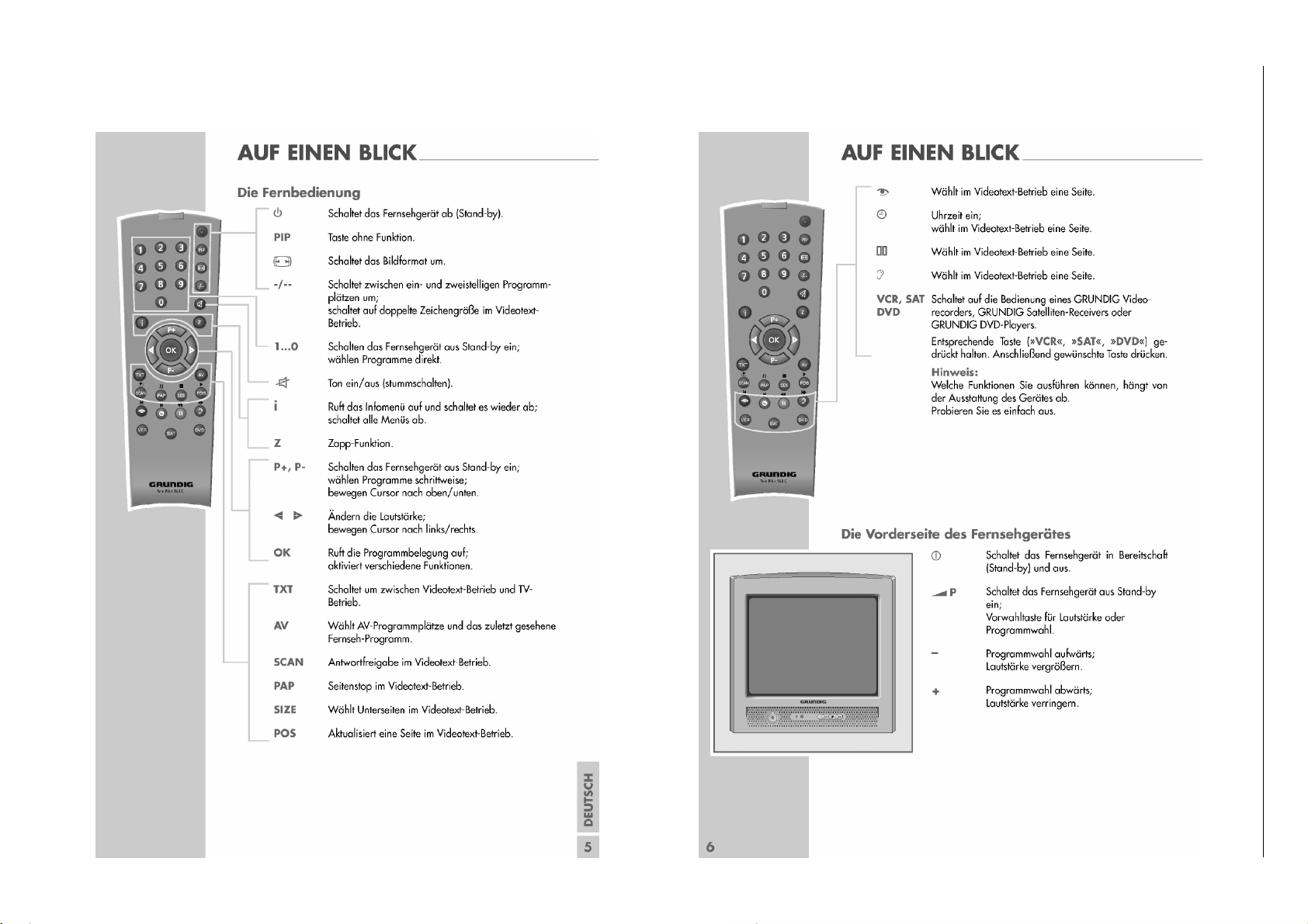
Bedienhinweise Dieses Kapitel enthält Auszüge aus der Bedienungsanleitung.
Weitergehende Informationen entnehmen Sie bitte der gerätespezifischen Bedienungsanleitung, deren Materialnummer Sie in der entsprechenden Ersatzteilliste finden.
1 - 6
Chassis E3GRUNDIG Service
Page 7

Operating Hints This chapter contains excerpts from the operating instructions.
For further particulars please refer to the appropriate user instructions the part number of which is indicated in the relevant spare parts list.
1 - 7
Chassis E3GRUNDIG Service
Page 8

Chassis E3GRUNDIG Service
)
)
)
j
Service- und Sonderfunktionen
Service Mode aktivieren: Taste "i" –> Service Code "8500".
Menü aufrufen: Taste "P+"/"P-" ->"OK".
Einstellung verändern: Taste "
Menü verlassen: Taste "i".
Service Mode beenden: Taste "TXT".
1. Grundeinstellwerte
Nachfolgende Tabelle zeigt alle typenbezogenen Grundeinstellungen im Service Mode. Alle mit * gekennzeichneten Werte müssen
zusätzlich nach Abgleich (Seite 2-1) eingestellt werden.
Menü
Menu
P+/P-
+
"OK"
OPTIONS
OPTIONS
Menüpunkt
Point of Menu
TUNER
AGC (UHF
AGC (VHF
AGC (LPRIME
TYPE
STANDBY
AV1 SVHS
AV2
SOUND
BG
TEXT
ON TIMER
FRONT KEY
BLUEBACK
AUTO WSS
CHILD LOCK
ZAPP
RC TYPE
SIMPLE HOTEL
MAX VOLUME
RGB IN
Ǹ / Ƿ" bzw. 1/3, 4/6.
P+/P-
Einstellung
Adjustment
Ǹ / Ƿ
(-10) 1 / 3 (+10)
(-100) 4 / 6 (+100)
Temic
Panasonic D44G3
Sharp or Alps (Samsung)
Philips
Panasonic DB2G3
*Wert/Value
*Wert/Value
*Wert/Value
ATS
LABEL
CUSTOMER MODE
FACTORY MODE
ON
OFF
ON
OFF
BG
I
BG+DK
BG+LL´
EUROPE
NEW ZELLAND
AUSTRALIA
FASTTEXT
NON-TEXT
ON
OFF
INT.PV-+
INT.-PV+
EXT.PV-+
EXT.-PV+
EXT.4 KEY
ON
OFF
ON
OFF
ON
OFF
ON
OFF
TP751C
TP160C
ON
OFF
Wert/Value
ON
OFF
Service and Special Functions
Start of the Service Mode: Via "i" –> Service Code "8500".
Call up the Menu: Button "P+"/"P-" ->"OK".
Adjustments: Button "
Break of the Menu: Button "i".
End the Service Mode: Button "TXT".
1. Basic Settings
The following table shows all type specific basic settings in the service mode. In addition all values marked with * must be adjusted according to adjustment (page 2-1).
Hinweis
Hint
abhängig von
Bestückung
depending on
mounting
e nach Fernbedienung
depending on RC
max. volume in hotel mode
Ǹ / Ƿ" bzw. 1/3, 4/6.
Gerät / Type of Set
Davio 14
P37-4501 Text
30
30
20
X
X
X
X
X
X
XXX
X
X
XXX
X
X
X
X
X
32
XXX
Davio 14
P37-4501/5 Text
30
30
20
X
XX
XX
XX
X
X
XX
XX
XX
XX
XX
XX
X
32
Davio 14
P37-4501 FR/Text
30
30
20
X
X
X
X
32
1 - 8
Page 9
Menü
(
)
)
Menu
P+/P-
+
"OK"
GEOMETRY
VIDEO
EE-
PROM
Menüpunkt
Point of Menu
VER. AMPLITUDE
VER. SHIFT
VER. SLOPE
S-CORRECTION
HOR. SHIFT
VER. AMP. 16:9
YC DELAY PAL
YC DELAY SECAM
YC DELAY NTSC
HOR. OSD POS.
VER. OSD POS.
OSD CON.
TXT CON.
TXT BRI.
PWL
CATH. DRV. LEV.
VERTICAL GUARD
PROTECTION
BLACK LEVEL R
BLACK LEVEL G
WHITE POINT R
WHITE POINT G
WHITE POINT B
SCREEN ADJ.
ADDRESS
DATA
EDIT
HEX
DATA (BINARY
P+/P-
Einstellung
Adjustment
Ǹ / Ƿ
(-10) 1 / 3 (+10)
(-100) 4 / 6 (+100)
*Wert/Value
*Wert/Value
*Wert/Value
*Wert/Value
*Wert/Value
*Wert/Value
Wert/Value
Wert/Value
Wert/Value
*Wert/Value
*Wert/Value
*Wert/Value
*Wert/Value
Wert/Value
Wert/Value
Wert/Value
Wert/Value
Wert/Value
Wert/Value
*Wert/Value
*Wert/Value
*Wert/Value
*Wert/Value
*Wert/Value
Hinweis
Hint
nicht ändern/do not change
nicht ändern/do not change
nicht ändern/do not change
nicht ändern/do not change
nicht ändern/do not change
nicht ändern/do not change
nicht ändern/do not change
nicht ändern/do not change
nicht ändern/do not change
Achtung! nur für Fertigung
Attention! Only for production
Gerät / Type of Set
Davio 14
P37-4501 Text
46
28
28
24
41
11
07
07
07
41
07
06
00
30
08
07
00
04
36
30
42
41
32
00
Davio 14
P37-4501/5 Text
46
28
28
24
41
11
07
07
07
41
07
06
00
30
08
07
00
04
36
30
42
41
32
00
Chassis E3GRUNDIG Service
Davio 14
P37-4501 FR/Text
46
28
28
24
41
11
07
07
07
41
07
06
00
30
08
07
00
04
36
30
42
41
32
00
ATS Reset
"–"-Taste (Minus) am Gerät gedrückt halten und mit der Fernbedienung auf Standby schalten. -> Beim nächsten Einschalten erscheint
das Menü "Sprache".
Austausch des IC101 oder IC103
Nach Austausch des IC101 oder IC103 müssen alle Einstellungen
im Service Mode nach Tabelle "Grundeinstellwerte" (Punkt 1) über-
prüft und gegebenenfalls durchgeführt werden.
Software-Versionsnummer
Die TV-Software-Versionsnummer wird im Service Menü angezeigt:
z.B. SE1.641G-A04
14/12/04
09:33:14
Hotel-Mode
Bei aktivierter Funktion ist die maximale Lautstärke begrenzt und
die Programmtabelle und Installation sind im MENU INFO nicht
mehr enthalten.
Aufruf: "
"SIMPLE HOTEL" –> Ǹ / Ƿ "ON".
Maximale Lautstärke: "
–>
i " –> "
8500
" –> P+ /
i " –> "
P+ / P–
"MAX VOL" –> Ǹ / Ƿ Wert 0…63.
P–
"OPTIONS" –> "OK" –> P+ /
8500
" –> P+ /
P–
"OPTIONS" –> "OK"
P–
ATS Reset
Hold "–" button (minus) on the TV set depressed while switching the
set to standby with the remote control. -> Menu "Language"
appears at the next "switch on".
Change of the IC101 or IC103
After changing the IC101 or IC103 all settings in the service mode
must be checked and if necessary be done according to the table
"Basic Settings" (point 1).
Software Version Number
The TV software version number is shown in the Service Menu:
e.g. SE1.641G-A04
14/12/04
09:33:14
Hotel Mode
Maximum volume is limited and there is no access to "Preset List"
and "Channel Settings" at activated hotel mode.
i " –> "
8500
Call up: "
"SIMPLE HOTEL" –> Ǹ / Ƿ "ON".
Maximum volume: "
P+ / P–
"MAX VOL" –> Ǹ / Ƿ Value 0…63.
" –> P+ /
i " –> "
8500
P–
"OPTIONS" –> "OK" –> P+ /
" –> P+ /
P–
"OPTIONS" –> "OK" –>
P–
1 - 9
Page 10

GRUNDIG Service Chassis E3
Abgleich
Messgeräte: Digitalvoltmeter, Farbbildgenerator.
Servicearbeiten nach Austausch bzw. Reparatur:
– Netzteil: Abgleich 1, 3
– Tuner / ZF: Abgleich 2
– IC103 (EEPROM): Abgleich 2, 4, 5
– Bildröhre: Abgleich 3, 5
– Bildrohrplatte: Abgleich 3, 5
– Ablenkung: Abgleich 4
1. Spannung B+
– Digitalvoltmeter: D609 Kathode
– Programm: AV
– Helligkeit auf Minimum
– Spannung B+ mit P601 entsprechend der Bildröhre einstellen
(siehe Variantenliste Seite 3-16).
2. AGC
– Service Mode aufrufen: Taste " i " drücken –> "8500" eingeben.
– Service Menü OPTIONS mit den Tasten P+ / P- anwählen und mit
OK aufrufen.
– AGC (UHF) mit den Tasten P+ / P- anwählen.
Mit den Tasten Ǹ / Ƿ Wert auf 30 einstellen.
– AGC (VHF) mit den Tasten P+ / P- anwählen.
Mit den Tasten Ǹ / Ƿ Wert auf 30 einstellen.
– AGC (LPRIME) mit den Tasten P+ / P- anwählen.
Mit den Tasten Ǹ / Ƿ Wert auf 20 einstellen.
– Service Mode beenden: Taste "TXT" drücken.
3. Screen
– Service Mode aufrufen: Taste " i " drücken –> "8500" eingeben.
– BLUEBLACK im Service Menü OPTIONS mit den Tasten P+ / P-
anwählen und mit den Tasten Ǹ / Ƿ auf OFF stellen. Taste " i "
drücken (zurück zu Hauptmenü).
– SCREEN ADJ im Service Menü VIDEO mit den Tasten P+ / P-
anwählen und mit den Tasten Ǹ / Ƿ auf 40 stellen. Taste OK drücken
-> horizontale Linie erscheint.
– SCREEN -Regler am Dioden-Splitt-Trafo TR501 so einstellen, dass
die Linie gerade sichtbar ist.
– Service Mode beenden: Taste "TXT" drücken.
4. Geometrie
– Geometrie-Testbild einspeisen.
– Service Mode aufrufen: Taste " i " drücken –> "8500" eingeben.
– Service Menü GEOMETRY mit den Tasten P+ / P- anwählen und mit
OK aufrufen.
– Mit den Tasten P+ / P- die gewünsche Bildgeometrie-Abgleich-
funktion aufrufen und mit den Tasten Ǹ / Ƿ die Geometrie einstellen:
– Bildhöhe VER.AMPLITUDE.
– Bildposition vertikal VER.SHIFT.
– Bildmitte vertikal VER.SLOPE. Die untere Bildhälfte ist ausge-
blendet. Den Bildinhalt so einstellen, dass die Mittelline gerade
nicht mehr sichtbar ist.
– Bildlinearität vertikal S-CORRECTION.
– Bildposition horizontal HOR.SHIFT.
– Bildhöhe für 16:9 Bild VER.AMP. 16:9.
– Bildposition OSD-Menü HOR.OSD.POS und VER.OSD.POS.
– Bildkontrast OSD-Menü OSD CON.
– Bildkontrast Videotext TXT CON.
– Service Mode beenden: Taste "TXT" drücken.
5. Weißabgleich / Cut off
– Weiß-Bild einspeisen.
– Service Mode aufrufen: Taste " i " drücken –> "8500" eingeben.
– Service Menü Video mit den Tasten P+ / P- anwählen und mit OK
aufrufen.
– BLACK LEVEL G mit den Tasten P+ / P- anwählen und mit den
Tasten Ǹ / Ƿ auf 30 stellen.
– WHITE POINT B mit den Tasten P+ / P- anwählen und mit den
Tasten Ǹ / Ƿ auf 32 stellen.
– WHITE POINT R und WHITE POINT G jeweils mit den Tasten
P+ / P- anwählen und mit den Tasten Ǹ / Ƿ so einstellen, dass das
Bild unbunt ist. Sollte sich der Weißwert nicht einstellen lassen,
Wert für WHITE POINT B und BLACK LEVEL G korrigieren.
– Service Mode beenden: Taste "TXT" drücken.
Adjustment
Measuring instruments: Digital voltmeter, colour video generator.
Service works after replacement or repair of the following modules:
– Power supply: adjustment 1, 3
– Tuner / IF: adjustment 2
– IC103 (EEPROM): adjustment 2, 4, 5
– CRT: adjustment 3, 5
– CRT panel: adjustment 3, 5
– Deflection: adjustment 4
1. Supply Voltage B+
– Digital voltmeter: D609 cathode.
– Programme: AV.
– Brightness control to minimum
– Adjust voltage B+ the values the CRT with P601 (see variant list
page 3-16).
2. AGC
– Start the Service Mode: press button " i " –> enter "8500".
– Select OPTIONS menu with buttons P+ / P- and enter with button
OK.
– Call up AGC (UHF) with buttons P+ / P-.
Adjust the value to 30 with buttons Ǹ / Ƿ.
– Call up AGC (VHF) with buttons P+ / P-.
Adjust the value to 30 with buttons Ǹ / Ƿ.
– Call up AGC (LPRIME) with buttons P+ / P-.
Adjust the value to 20 with buttons Ǹ / Ƿ.
– End the Service Mode: Press button "TXT".
3. Screen
– Start the Service Mode: press button " i " –> enter "8500".
– Select BLUEBLACK in service menu OPTIONS with buttons P+ / P-
and set to OFF with buttons Ǹ / Ƿ . Press button " i " (back to main
menu).
– Select SCREEN ADJ in service menu VIDEO with buttons P+ / P-
and set to 40 with buttons Ǹ / Ƿ . Press button OK -> horizontal line
appears.
– Adjust SCREEN control at TR501 so that the line is just visible.
– End the Service Mode: Press button "TXT".
4. Geometry
– Apply a geometry test pattern.
– Start the Service Mode: press button " i " –> enter "8500".
– Select GEOMETRY menu with buttons P+ / P- and enter with button
OK.
– Call up the geometry function with buttons P+ / P- and adjust the
geometry with buttons Ǹ / Ƿ:
– Vertical amplitude VER.AMPLITUDE
– Vertical shift VER.SHIFT.
– Vertical slope VER.SLOPE. The lower half part of the pattern is
blanked. Adjust picture so that the middle line of the pattern is cut.
– Vertical linearity S-CORRECTION.
– Horizontal shift HOR.SHIFT.
– Vertical amplitude for 16:9 pictures VER.AMP. 16:9.
– OSD position HOR.OSD.POS and VER.OSD.POS.
– OSD contrast OSD CON.
– Teletext contrast TXT CON.
– End the Service Mode: Press button "TXT".
5. White Balance / Cut off
– Apply a White Test pattern.
– Start the Service Mode: press button " i " –> enter "8500".
– Select Video menu with buttons P+ / P- and enter with button OK.
– Call up BLACK LEVEL G with buttons P+ / P- and set it to 30 with
buttons Ǹ / Ƿ.
– Call up WHITE POINT B with buttons P+ / P- and set it to 32 with
buttons Ǹ / Ƿ.
– Call up WHITE POINT R and WHITE POINT G with buttons P+ / P-
and adjust the values so that the picture becomes achromatic with
buttons Ǹ / Ƿ. If white balance can not be adjusted properly change
BLACK LEVEL G and WHITE POINT B value.
– End the Service Mode: Press button "TXT".
2 - 1
Page 11

Schaltpläne und Platinenabbildungen / Circuit Diagrams and Layout of PCBs
1
2
X601
MAINS
1
2
X602
DEGAUSS
L601
LINE FILTER
F601
T 3.15AH 250V
C621
330n/275V
C622
R605
C609
1n/1kV
C610
1n/1kV
D605
RF2007
D607
RF2007
D606
RF2007
D608
RF2007
_
R604
PTC
C608
10n/275V
C626
68u/400V
_
2
6
10
14
12
9
13
1
5
TR601
SMT
R608
68k 1.5W
C612
33n/630V
D610
RGP10J
C628
470p/2kV
R621
47R 1/4W
L604
47uH
D604
LL4148
C625
22u/50V
C605
10n
__
_ _ _
OTC
1
PCS
2
RZI
3
SRC
4
OCI
5
FC2
6
SYNC7PMO
8
REF
9
FC1
10
PVC
11
GND
12
OUT
13
VCC
14
IC601
TDA16846
R619
15k(47k)
R603
P601
2.2k
C617
56p
C616
560p
C620
2.2n
R613
33k
R616
1M 1W
R617
3.9M 1W
_ _
_
_
_
R612
_
_
C618
1.5n
_
_
C624
1u/50V
R618
39k (0R)
_ _
R622
4.7M 0.5W
_
D609
RGP15J
C613
220p/2kV
C614
47u/160V
R609
22k 1/4w
C606
10n
ZD601
33V
R623
0.1R
D612
RGP15J
C631
1000u/25V
OUT IN
GND
IC602
FAN1117AD33X (NCP1117DTARK)
C602
47n
C603
47n
C604
47n
C630
220u/16V
C633
47u/16V
3.3V
L602
50uH
C615
33u/160V
12.5V
*** siehe Variantenliste Seite 3-16
*** see variant list page 3-16
C629
2.2n/250V
1
2
HS601
SMPS HEATSINK
_
R614
470k 0.5W
R611
OR
R615
0R
C619
D611
RGP10D
C627
220p/2kV
C611
1n/1kV
_
R610
3.3k 1/4w
R620
6.8k
C623
100p
D603
1N4148
_
V601
S14K385
C632
47u/16V
R624
0.1R
B+ ***
***
***
***
***
***
B+
1W OPT.
33V
C634
47p
_
6V
R629
0R(27R)
C636
100n
_
T603
FQPF3N60FP
C635
2.2n/250V
CAB. 4B
45V
4
3
2
1
SW601
POWER SWITCH
R540
390%1
R541
240R%1
R542
3k3
C533
10n
4
1
2
3
5
1
2
3
4
5
Netzteil / Power Supply - XCL.190
GRUNDIG Service Chassis E3
3 - 1
Page 12

Horizontal - Ablenkung / Horizontal Deflection - XCL.190
FBISO
B+
R513
0,47R
T502
Table
R512
560R
C510
100u/16V
R514
47R
12.5V
C514
1
2
3
4
X502
HORIZONTAL
L503
H-LIN
C524
560p/500V
R529
470R 0.5W
C523
C521
4.7u/160V
R528
22k 0.5W
D510
BA157
R505
D514
BA157
D511
BA157
C526
100n/100V
R530
1k 1/4w
R511
8V
C529
100n/50V
R509
220k
1
2
3
X503
CRT
C527
47u/63V
C530
10u/250V
R526
2.2R 2W
R504
47k
T503
BC639
D513
BA157
C525
470u/25V
R506
270R
C522
D509
C503
10n
12.5V_DST
45V
D512
BA157
C528
470u/16V
T505
BC639
T504
BC639
ZD503
5.6V
ZD502
8.2V
R507
470R
R531
10R 1/4W
8V
5V
PROT
HOUT
EHTO
BCLIN
FBISO
T507
BC858
R532
220R
C532
2.2n
C502
100u/16V
R501
22R
C513
B+
PROTECTION
10V
D501
1N4148
C509
470n
R508
100k
R503
1k
R525
4.7k
T501
BC848
R502
10k
R527
33k
T506
BF423
C501
470n
D502
LL4148
C506
1n
C512
100u/16V
10V
C511
100u/16V
155V
D515
LL4148
C504
22u/50V
C505
22u/50V
R533
270R
R523
150k
R524
150k
4
5
1
2
3
L502
DRIVER_E1
R534
100K 1% 1/4W
ZD504
33V
C531
10n
R536
4.7k
R535
22K
PROTECTION
EHT
FOCUS
G2
10
4
6
3
2 8
1
9
5
7
11
11
TR501
DST E1
R539
100K
8V
CAB. 5A
CAB. 5B
CAB. 6B
CAB. 6A
CAB. 7A
CAB. 7B
1
2
HS501
HOT HEATSINK
*** siehe Variantenliste Seite 3-16
*** see variant list page 3-16
***
***
***
***
***
***
***
***
***
***
12
7
8
9
10
11
13
7
8
9
0
!
@
#
GRUNDIG Service Chassis E3
3 - 2
Page 13

GRUNDIG Service Chassis E3
R515
2.2k %1
R516
2.2k %1
R517
10k
C517
100u/35V
C515
100n/50V
C518
10u/63V
D507
LL4148
R519
R520
R521
R518
2.7k
R522
1.5R
C520
47n/63V
C519
1n/100V
R510
table ZD501
15V
INA
1
INB
2
GUARD
8
VGND
5
VP
3
VFB
6
OUTA
7
OUTB
4
FEEDB
9
IC501
TDA8357
45V
12.5V_DST
VGRD
VDRB
VDRA
C516
100n/50V
C507
2.2n
C508
2.2n
1
2
HS502
R537
10k
R538
10k
CAB. 4A
1
2
X501
VYOKE
*** siehe Variantenliste Seite 3-16
*** see variant list page 3-16
***
***
***
15
16
17
18
19
% ^ &
* (
Vertikal - Ablenkung / Vertical Deflection - XCL.190
3 - 3
Page 14

GRUNDIG Service Chassis E3
AGC
1
n.c.
2AS3
SCL4SDA
5
+5V6+5V
7
n.c.
8
+33V9IF1
10
IF2
11
GND4
15
GND3
14
GND2
13
GND1
12
TU101
TUNER
L102
10uH
C131
10u/63V
R157
12k
C118
47u/16V
5V
R117
100R
R114
3.3k
R118
100R
R121 100R
R122 3.3k
R167 100R
R166
100R
R107
3.3k
R108
3.3k
5V
C155
220n
C156
220n
C154
2.2n
C148
4.7n
R102
15k
C140
100n
C134
2.2u/50V
C174
4.7u/50V
C150
1n
C141
100n
R163
100R
R164
100R
C135
100u/16V
C139
100n
L103
10uH
8V
C133
1u/50V
R173 39k
R162
680R
R161
3.9k
R184
100k
C132
10u/63V
C149
3.3n
C138
10n
IF_IN
1
NC
2
C_AGC
3
C_REF
4
NC
5
AM_OUT
6
AM_IN
7
AF_OUT8EXT_IN
9
SWITCH
10
V_P2
11
MUTE
12
GND
13
V_P1
14
NC
15
IF_IN
16
IC104
TDA9830
C125
4.7u/16V
C124
4.7u/16V
T107
BC848
R150
47k
R153
2.2k
D102
BA682
R154
6.8k
C126
47u/16V
C127
47n
R303
15k
R302
1.8k
+INA
1
NC
2
-INA
3
GND
4
GND
5
OUTA
6
NC
7
VCC8NC
9
NC
10
OUTB
11
GND
12
GND
13
-INB
14
NC
15
+INB
16
IC301
TDA2822
C172
10n
C302
2.2n
R183
220R
R151
47k
R152
2.2k
C304
100n
L101
10uH
C305
100n
R155
100R
1
2
3
X301
SPEAKER
C307
220u/25V
C303
10n
12.5V
R306
4.7R 1.5W
1
2
3
4
5
F101K9656M
T301
BC848
C116
4.7u/50V
C306
10u/63V
R305
4.7R
R304
4.7R
D103
1N4148
C129
47p
C128
47p
R158
100R
R159
100R
C102
10n
C113
100p
C114
100p
R147
1k
R185
2.7k
C175
4.7n
C176
820p
T108
BC848
R186
390k
R149
1k
R188
270R
R187
680R
C177
22n
C151
1n
SW102
SELECT
SW101
VOL-
R126
1.5k
R125
680R
R110
1.5k
8V
8V
C110
1n
R140
100R
R144
47k
T111
BC848
T103
BC848
R148
1k
R182
2.2k
R146
1k
R145
1.5k
R137
10k
R143
47k T106
BC858
C117
1u/63V
C109
1n
8V
3.3V
33V
R160
100R
C103
10n
C121
47n
R127
10k
3.3V
C111
10n
R113
3.3k
R112
0R
R301
15k
SECAM AM
3.3V
AV_SEL
MUTE
STATUS
ONLINE
L/L'
VDRA
VDRB
R133
100R
R141
10k
PROT
SDA
SCL
C301
10n
L/L'
AM_OUT
IF
L/L'
IF
AM_OUT
L110
1uH
C101
10n
R101
3.3k
C308
470n
C104
10n
SCL
SDA
KEYB
C171
220n
8V
R103
100R
R104
3.3k
R105
100R
AOUT
MUTE
KEYB
1
2
3
5
4
F102
G1985M
R196
1k
R109
2.2k
3.3V
CAB. 2A CAB. 3A
R308
1M
HOTEL TV
1
2
3
4
5
6
7
8
9
10
11
12
13
14
15
16
17
18
19
20
21
22
23
24
25
26
27
28
29
30
31
32
R123
0R
20
16
15
)
%
^
Hauptteil / Main Part - XCL.190
3 - 4
Page 15

EHTO
BCLIN
HOUT
FBISO
VGRD
AOUT
C165
33p
C166
68p
C146
100n
C137
100u/16V
L108
10uH
3.3V
R119
100R
C144
100n
C143
100n
R215
180R
L104
10uH
R216
180R
L105
10uH
C136
100u/16V
R210
15k
R224
3.9k
R206
75R
3.3V
R205
75R
R204
75R
R207
75R
R170
100R
R168
100R
R169
100R
R142
10k
R180
47k
C168
100p
C206
220p
C160
47n
C161
47n
C159
47n
R124
100R
C152
1n
C162
47n
R172
100R
R174
390R
R176
100k
R177
27k
R165
1k
R171
100R
C142
100n
C153
1n
C145
100n
C167
100u/16V
L106
10uH
1
2
3
4
5
6
7
8
9
10
11
12
13
14
15
161820
21
19
17
SK201
SCART
8V
R178
27k
3.3V
R117
100R
R114
3.3k
R118
100R
R121 100R
R122 3.3k
R167 100R
R166
100R
R108
3.3k
GND
Audio_GND
C155
220n
C156
220n
C154
2.2n
C148
4.7n
C140
100n
C150
1n
C141
100n
C139
100n
R173 39k
C132
10u/63V
C116
4.7u/50V
R185
2.7k
C176
820p
T108
BC848
R186
390k
R188
270R
R187
680R
C151
1n
VS
OUT
GND
IC102
TSOP1838
R131
150R
C115
47u/16V
SW103
VOL+
SW102
SELECT
SW101
VOL-
R126
1.5k
R125
680R
R110
1.5k
D101
LED
3.3V
E0
1
E12E2
3
GND
4
SDA
5
SCL
6
MODE_WC
7
VCC
8
IC103
24C08AN 10SI-2.7
R115
3.3k
R116
3.3k
3.3V
C119
470n
8V
T109
BC848
R181
4.7R
R190
180R
C169
220p
R189
390R
L109
table
R191
470R
C170
47u/16V
R192
560R
D104
1N4148
R139
100R
3.3V
R160
100R
C103
10n
1
2
3
4
5
X103
KEYBOARD
3.3V
C163
47n
C164
1u/50V
C112
100p
T102
BC848
R130
2.7k
R129
150R
R128
100k
C111
10n
R113
3.3k
8V
1
2
3
4
5
6
X104
RGB
8V
C122
100n
3.3V
EHTO
BCLIN
HOUT
FBISO
VGRD
6V
R132
1k
ZD101
5.1V
R133
100R
AUDIO OUT
F103
TPSRA5M50B00-A0
R238 100R
R239 100R
R240
100R
D107
1N4148
D106
1N4148
D105
1N4148
AOUT
R103
100R
R104
3.3k
SDA1
SCL1
R105
100R
C201
10u/63V
R193
15k
3.3V
Q101
12MHz
R111
0R
R250
0R
C105
10uF/63V
R109
2.2k
3.3V
CAB. 2B
CAB. 3B
R223
100R
R220
100R
C210
100p
C204
100p
R106
100R
C106
100n
ZD102
3.9V
R120
270k
C107
47p
C108
47p
HOTEL TV
P1.2/INT0
64
P1.1/T0
63
P1.0/INT1
62
VDDP
61
RESET
60
XTALOUT
59
XTALIN
58
OSCGND
57
VDDC
56
VPE
55
VDDA
54
BO
53
GO
52
RO
51
BLKIN
50
IFVO/SVO
38
B2/UIN
48
BCLIN
49
G2/YIN
47
R2/VIN
46
INSSW2
45
AUDOUT/AMOUT
44
CHROMA
43
CVBS/Y
42
GND1
41
CVBSINT
40
VP1
39
PLLIF
37
EHTO
36
AUDEXT/QSSO/AMOUT
35
FBISO
34
HOUT
33
P1.3/T1
1
P1.6/SCL
2
P1.7/SDA
3
P2.0/TPMW
4
P3.0/ADC0/PWM0
5
P3.1/ADC1/PWM1
6
P3.2/ADC2/PWM2
7
P3.3/ADC3/PWM3
8
VSSC/P
9
P0.5
10
P0.6
11
VSSA
12
SECPLL
13
VP2
14
DECDIG
15
PH2LF
16
PH1LF
17
GND3
18
DECBG
19
AVL/EWD
20
VDRB
21
VDRA
22
IFIN1
23
IFIN2
24
IREF
25
VSC
26
TUNERAGC
27
AUDEEM/SIFIN1
28
DECSDEM/SIFIN2
29
GND2
30
SNDPLL/SIFAGC
31
AVL/SNDIF/REFO/AMOUT
32
IC101
TDA9345
R123
0R
R134
0R
C178
10n
R197
100K
R198
0R
CAB. 8
Tuner
6
12
17
13
26
23
21
22
24
25
6
@
#
&
¡ Mode: bei Suchlauf-Start
at start of station search
™ Mode: bei Suchlauf-Start
at start of station search
GRUNDIG Service Chassis E3
Hauptteil / Main Part - XCL.190
3 - 5
Page 16

GRUNDIG Service Chassis E3
R203
100R
C203
47u/16V
R215
180R
R216
180R
R202
100R
R217
1k
R218
1k
R211
15k
R212
15k
R224
3.9k
R208
75R
R201
2.2k
T203
BC848
R142
10k
R180
47k
C208
1n
C209
1n
C205
220p
C206
220p
C213
470p
C214
470p
R214
75R
1
2
3
4
5
6
7
8
9
10
11
12
13
14
15
161820
21
19
17
SK201
SCART
STATUS
C207
220p
GND
1
3
4
5
6
2
X101
SERVICE
C119
470n
L109
table
R191
470R
C170
47u/16V
R192
560R
J201
0R/NO_FAV
1
2
3
4
5
6
X104
RGB
8V
AUDIO IN
CVBS EXT
FBAS IN
F103
D107
1N4148
D106
1N4148
KEYB
SDA
SCL
SCL1
SDA1
8V
R236
47R
C201
10u/63V
R194
100R
R195
100R
R250
0R
CAB. 3B
R223
100R
R220
100R
C210
100p
C204
100p
CAB. 8
Tuner
26
23
24
25
¡ Mode: bei Suchlauf-Start
at start of station search
™ Mode: bei Suchlauf-Start
at start of station search
£ ≤
∞ §
Hauptteil / Main Part - XCL.190
3 - 6
Page 17

GRUNDIG Service Chassis E3
1
2
3
4
X201
C158
2.2u/50V
C215
2.2u/50V
Y1
1
Y0
2
Z1
3
ZOUT
4
Z0
5
EN
6
VEE
7
VSS
8
VDD
16
YOUT
15
XOUT
14
X1
13
X0
12
CONT_X
11
CONT_Y
10
CONT_Z
9
IC201 4053
T202
BC848
R233
4.7k
8VA
C217
10n
C216
2.2u/50V
R228
68k
4V
R229
68k
R209
75R
4V
C219
100n
8VA
R221
1k
T201
BC848
R222
1k
C218
4.7u/50V
R231
470R
C212
1n
R226
5.6k
C211
1n
R213
15k
FROM FRONT AV
R234
4.7k
R235
4.7k
C220
10u/63V
8VA
4V
R225
0R
8V
JUMPER
SCART/FRONT AV SWITCH
CVBSEXT
AV_SEL
AUDIO OUT
AUDIO IN
CVBS EXT
FBAS IN
R307
0R
8VA
Schalter Front AV / Front AV Switch - XCL.190
3 - 7
Page 18

GRUNDIG Service Chassis E3
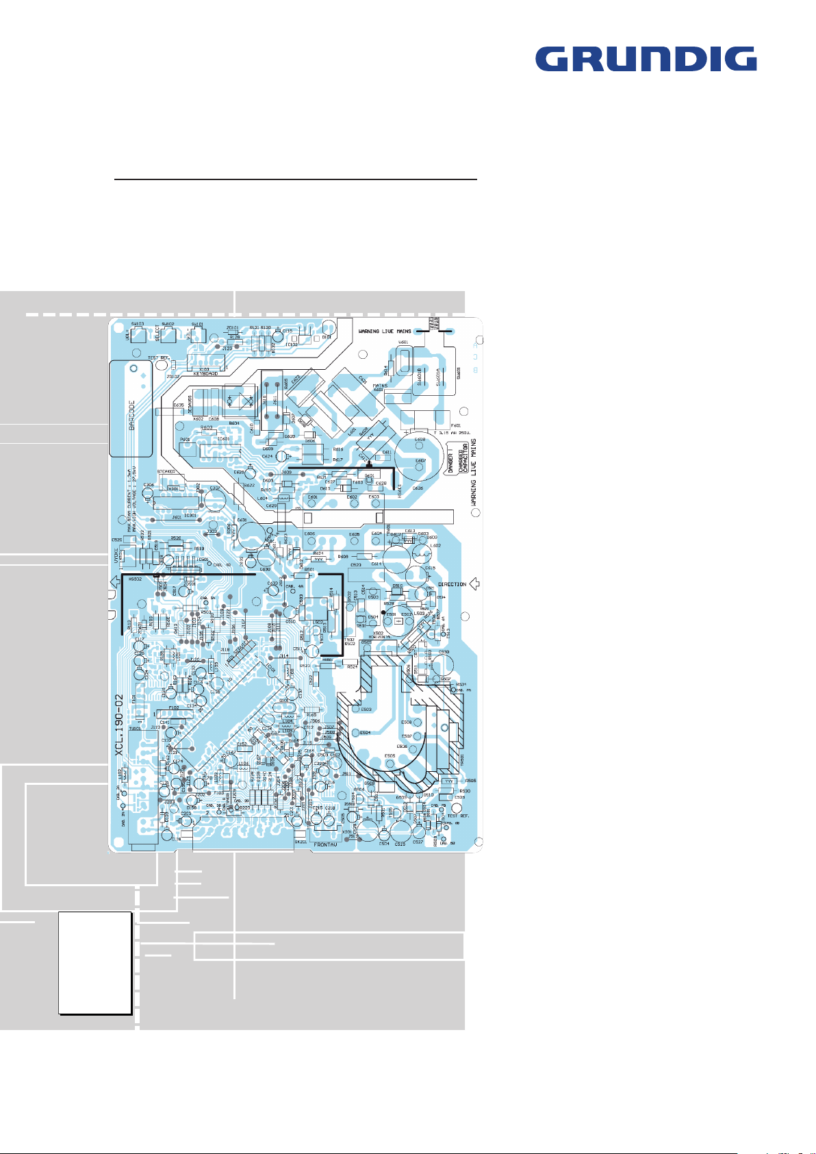
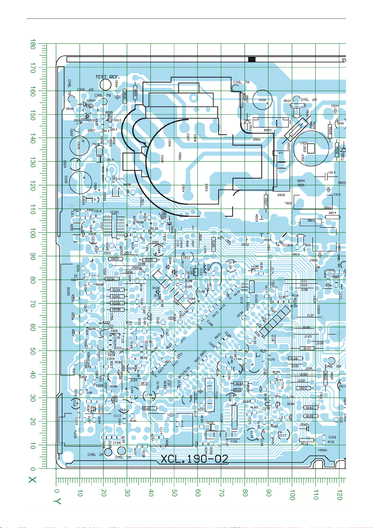
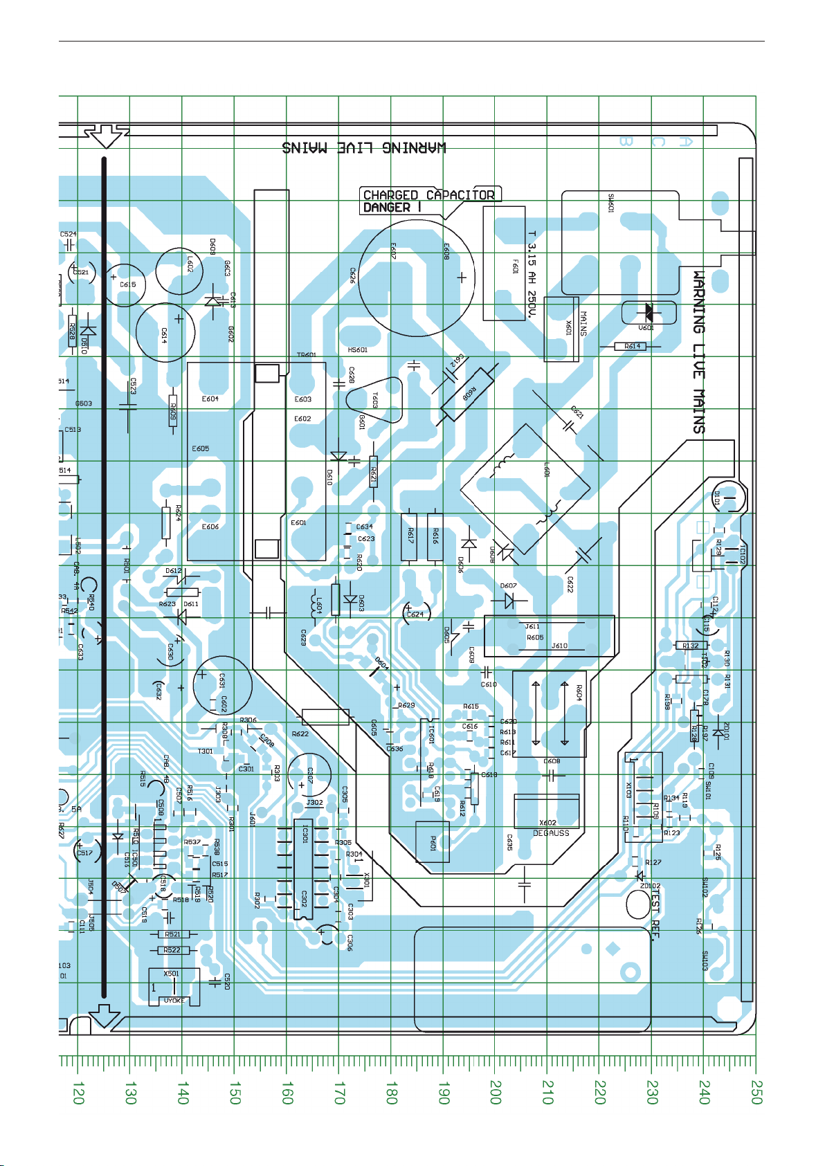
Leiterplatte / PCB XCL.190-02
Sicht auf Bestückungsseite / View on Component Side
3 - 8
Page 19

GRUNDIG Service Chassis E3
Leiterplatte / PCB - XCL.190-02 - Sicht auf Bestückungsseite / View on Component Side
3 - 9
Page 20

GRUNDIG Service Chassis E3
Leiterplatte / PCB - XCL.190-02 - Sicht auf Bestückungsseite / View on Component Side
3 - 10
Page 21
GRUNDIG Service Chassis E3
Leiterplatte / PCB - XCL.190-02 - Sicht auf Lötseite / View on solder side
3 - 11
Page 22
GRUNDIG Service Chassis E3
Leiterplatte / PCB - XCL.190-02 - Sicht auf Lötseite / View on solder side
3 - 12
Page 23
GRUNDIG Service Chassis E3
Leiterplatte / PCB - XCL.190-02 - Sicht auf Lötseite / View on solder side
3 - 13
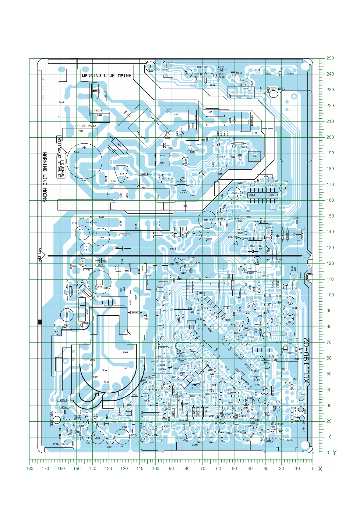
Page 24

GRUNDIG Service Chassis E3
Koordinaten für die Bauteile der Leiterplatte XCL.190-02 (* Bauteile der Lötseite)
Coordinates of the Components of PCB XCL.190-02 (* Components of Solder Side)
Pos.-Nr./ Koordinaten/
Pos. No. Coordinates
X Y
C101* 55 23
C102* 20 29
C103* 13 114
C104* 23 10
C105 32 32
C106* 62 61
C107* 53 51
C108* 51 49
C109* 50 240
C110* 19 51
C111* 21 119
C112* 83 241
C113* 22 29
C114* 13 45
C115 79 241
C116 42 76
C117 15 96
C118 28 8
C119* 72 81
C121* 11 61
C122* 87 62
C124 15 83
C125 15 90
C126 29 74
C127* 29 83
C128* 13 22
C129* 13 25
C131 26 29
C132 29 56
C133 43 84
C134 44 71
C135 51 79
C136 75 62
C137 86 74
C138* 39 55
C139* 56 72
C140* 43 73
C141 33 61
C142* 46 49
C143* 68 66
C144* 71 69
C145* 49 51
C146* 77 75
C148* 48 73
C149* 30 32
C150* 47 63
C151* 45 62
C152 64 49
C153* 44 43
C154* 52 69
C155* 51 78
C156* 54 70
C158 39 25
C159* 62 53
C160* 68 35
C161* 71 34
C162* 62 45
C163* 58 37
C164 93 43
C165* 83 67
C166* 76 67
C167 57 43
C168* 64 63
C169* 51 36
C170 43 32
C171* 23 82
C172* 47 88
C174 31 39
C175* 33 43
C176* 34 50
C177* 28 20
C178* 62 239
C201 88 15
C203 37 15
C204* 61 13
C205* 43 16
C206* 52 14
C207* 38 21
C208* 42 13
C209* 37 16
C210* 67 14
C211* 108 9
C212* 107 16
C213* 42 18
C214* 47 20
C215 97 16
C216 99 31
C217* 107 18
C218 103 15
C219* 101 38
C220 101 38
C301* 53 152
C302* 23 162
C303* 23 170
C304* 30 169
C305* 43 171
C306 19 168
C307 50 164
C308* 56 154
C501* 97 74
C502 106 42
Pos.-Nr./ Koordinaten/
Pos. No. Coordinates
X Y
C503 91 112
C504 129 8
C505 114 17
C506* 94 102
C507* 43 139
C508* 44 134
C509* 152 15
C510 85 112
C511 95 94
C512 90 56
C513 118 116
C514 124 115
C515* 33 143
C516* 37 129
C517 35 122
C518 28 137
C519 22 138
C520 10 146
C521 146 121
C522 97 81
C523 120 130
C524 152 118
C525 137 10
C526 158 26
C527 145 10
C528 121 10
C529* 146 23
C530 156 88
C531* 150 13
C532* 105 45
C533* 83 119
C602* 63 146
C603* 79 115
C604* 72 112
C605* 60 179
C606* 10 45
C608 50 210
C609 78 195
C610 70 198
C611 128 184
C612 126 191
C613 141 148
C614 135 137
C615 144 129
C616* 57 195
C617* 54 199
C618* 50 195
C619* 46 187
C620* 60 199
C621 117 214
C622 92 217
C623* 95 172
C624 81 185
C625 66 177
C626 145 185
C627 110 173
C628 125 170
C629 81 157
C630 74 138
C631 67 148
C632 67 136
C633 77 122
C634* 97 172
C635 29 206
C636* 57 180
CAB. 2A 7 22
CAB. 2B 60 21
CAB. 3A 8 28
CAB. 3B 52 19
CAB. 4A 86 122
CAB. 4B 47 135
CAB. 5A 46 117
CAB. 5B 157 7
CAB. 6A 157 102
CAB. 6B 158 12
CAB. 7A 161 76
CAB. 7B 156 20
CAB. 8 57 20
D101 103 245
D102* 18 66
D103 25 17
D104 86 47
D105 83 50
D106 75 43
D107 72 43
D501 149 13
D502* 99 97
D507* 29 130
D509 104 48
D510 135 122
D511 147 81
D512 123 24
D513 141 21
D514 145 21
D515* 131 18
D603 84 172
D604* 70 177
D605 76 192
D606 94 195
D607 83 203
D608 93 202
Pos.-Nr./ Koordinaten/
Pos. No. Coordinates
X Y
D609 141 146
D610 111 170
D611 80 140
D612 88 140
F101 14 71
F102 31 65
F103 55 33
F601 148 202
G501 118 109
G502 113 114
G503 124 122
G504 124 107
G505 121 96
G506 141 81
G507 153 81
G508 123 30
G509 141 27
G510 145 27
G601 122 173
G602 134 146
G603 147 146
IC101 56 64
IC102 92 246
IC103* 77 83
IC104* 22 76
IC201* 103 25
IC301 32 163
IC501 36 136
IC601 52 188
IC602* 71 117
J201 92 24
L101 31 92
L102 8 36
L103 48 87
L104 85 64
L105 83 59
L106 63 39
L108 84 84
L109 52 35
L110* 21 49
L502 97 114
L503 136 106
L601 105 206
L602 147 140
L604 82 166
P601 39 188
Q101 82 68
R101* 11 114
R102* 46 80
R103 51 106
R104* 69 83
R105 22 108
R106* 80 34
R107* 9 35
R108* 9 38
R109* 40 231
R110* 39 227
R111* 75 74
R112* 27 62
R113 12 106
R114* 73 89
R115* 71 100
R116* 74 98
R117* 71 93
R118* 66 91
R119* 42 236
R120* 100 41
R121* 64 90
R122* 64 80
R123* 41 234
R124 76 26
R125* 35 241
R126* 21 241
R127* 33 227
R128 59 238
R129* 97 243
R130 72 238
R131 68 238
R132 75 238
R133* 54 82
R134* 44 233
R137* 34 88
R139* 71 43
R140* 34 80
R141* 48 88
R142* 67 57
R143* 37 92
R144* 39 93
R145* 30 91
R146* 27 92
R147* 13 42
R148* 20 88
R149* 28 18
R150* 22 98
R151* 14 92
R152* 11 66
R153* 18 62
R154* 11 63
Pos.-Nr./ Koordinaten/
Pos. No. Coordinates
X Y
R155 27 92
R157* 21 12
R158* 13 20
R159* 13 27
R160 26 108
R161* 22 32
R162 26 40
R163 33 78
R164 36 78
R165 95 67
R166 47 102
R167* 62 87
R168* 80 52
R169* 77 53
R170* 82 54
R171* 99 70
R172* 48 36
R173* 40 57
R174* 46 46
R176* 49 39
R177* 42 42
R178* 44 35
R180* 73 55
R181* 45 30
R182* 20 92
R183* 24 84
R184* 21 16
R185* 33 46
R186* 29 16
R187* 29 14
R188* 33 22
R189* 52 33
R190* 53 36
R191* 60 31
R192* 59 35
R193* 83 87
R194* 71 98
R195* 71 95
R196* 29 22
R197* 60 239
R198* 64 235
R201* 85 12
R202* 36 13
R203 89 25
R204* 75 14
R205* 72 9
R206* 65 9
R207* 58 9
R208* 78 15
R209* 99 13
R210* 52 23
R211* 41 20
R212* 43 21
R213* 109 11
R214* 82 13
R215* 41 10
R216* 33 10
R217* 45 18
R218* 49 20
R220 59 19
R221* 99 33
R222* 61 40
R223* 60 19
R224* 54 23
R225 88 40
R226* 106 11
R228* 103 33
R229* 95 24
R231* 106 13
R233* 94 26
R234* 97 34
R235* 103 36
R236 80 24
R238 67 26
R239 70 26
R240 73 26
R250* 50 12
R301* 44 150
R302* 26 157
R303* 50 156
R304* 35 170
R305* 39 170
R306 59 150
R307* 93 19
R308* 58 150
R501 90 129
R502 143 102
R503 39 114
R504* 99 90
R505 159 33
R506* 142 19
R507* 123 22
R508 152 15
R509* 106 40
R510* 42 130
R511* 117 33
R512 93 102
R513 104 108
R514 107 117
R515* 44 132
R516* 43 142
3 - 14
Pos.-Nr./ Koordinaten/
Pos. No. Coordinates
X Y
R517* 31 143
R518* 25 137
R519 32 142
R520 32 145
R521 19 138
R522 16 138
R523 103 87
R524 113 89
R525* 145 20
R526 144 102
R527 154 103
R528 135 119
R529 143 116
R530 158 29
R531 127 19
R532* 105 48
R533* 139 21
R534 156 79
R535* 149 20
R536* 147 20
R537* 36 142
R538* 36 145
R539* 81 38
R540* 83 121
R541* 78 119
R542* 80 119
R603 47 196
R604 62 211
R605 77 211
R608 123 195
R609 120 138
R610 34 105
R611* 56 199
R612* 47 195
R613* 58 199
R614 132 226
R615* 62 195
R616 96 189
R617 96 184
R618* 51 186
R619 84 169
R620* 92 172
R621 108 177
R622 61 168
R623 85 140
R624 98 137
R629* 62 181
SK201 63 13
SW101 42 240
SW102 28 240
SW103 14 240
SW601 152 231
T102* 72 237
T103* 23 88
T106* 33 93
T107* 12 69
T108* 32 18
T109* 49 32
T111* 23 94
T201* 95 35
T202* 75 94
T203* 84 18
T301* 55 148
T501* 29 111
T502 115 109
T503 97 104
T504 117 25
T505 135 18
T506 151 102
T507* 102 46
T603 122 177
TR501 134 54
TR601 110 154
TU101 16 31
V601 139 230
X101 63 93
X103 46 229
X104 76 49
X201 102 9
X301 29 173
X501 9 139
X502 126 96
X503 146 91
X601 135 212
X602 43 210
ZD101 58 243
ZD102 31 228
ZD501 38 128
ZD502 115 20
ZD503* 114 14
ZD504 154 12
ZD601 17 106
Pos.-Nr./ Koordinaten/
Pos. No. Coordinates
X Y
Page 25
GRUNDIG Service Chassis E3
4
5
6
7 8
9
10
11
12
n.c.
G1
GREEN
G2
RED
HT
HT
BLUE
GND
GND
X703
CRT SOCKET
1
3
4
5
6
2
X701
RGB
crt
R702
C701
47p
T701
BF422
R710
15k
155V
R711
crt
C703 560p
R712
crt
R713
2.7k
8V_
D702 1N4148
C705
470p
T702
BF421
R714
1k
R703
C706
47p
T703
BF422
R715
15k
155V
R716
crt
C707 560p
R717
crt
R718
2.7k
8V_
D703
1N4148
C708
470p
T704
BF421
R719
1k
R704
220R
C709
47p
T705
BF422
R720
15k
155V
R721
crt
C710
560p
R722
crt
R723
2.7k
8V_
D704
1N4148
C711
470p
T706
BF421
R724
1k
8V_
R725
1.5K
R726
1.5K
R727
1.5K
C712
2.2n
C713
100n/250V
crt
155V
1
2
3
X702
CRT
CRT BOARD
G2
AQUA SMPS
R701
100R
R706
R707
R709
220R
C702
10u/250V
D701
1N4007
155V
Blue
Green
Red
Icatch
R728
100k 1/2W
L701
10uH
TUNER
crt
ZD701
8.2V
crt
to X104 p. 3-6
to X503 p. 3-3
*** siehe Variantenliste Seite 3-16
*** see variant list page 3-16
***
***
***
***
***
***
***
***
***
***
***
26
28
29
27
25
23
24
£
≤
∞
§
≥
•
ª
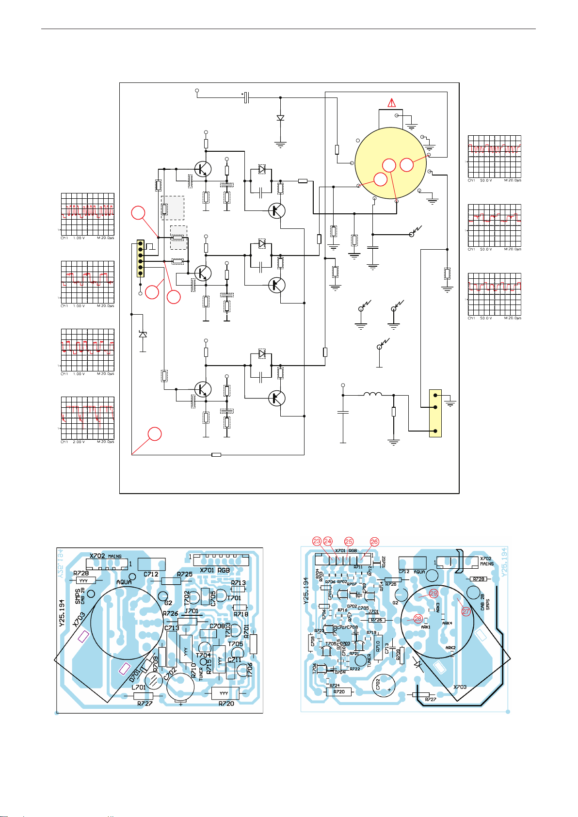
Bildrohrplatte / CRT Board - Y25.194
3 - 15
Sicht auf Lötseite / View on solder sideSicht auf Bestückungsseite / View on component side
Page 26

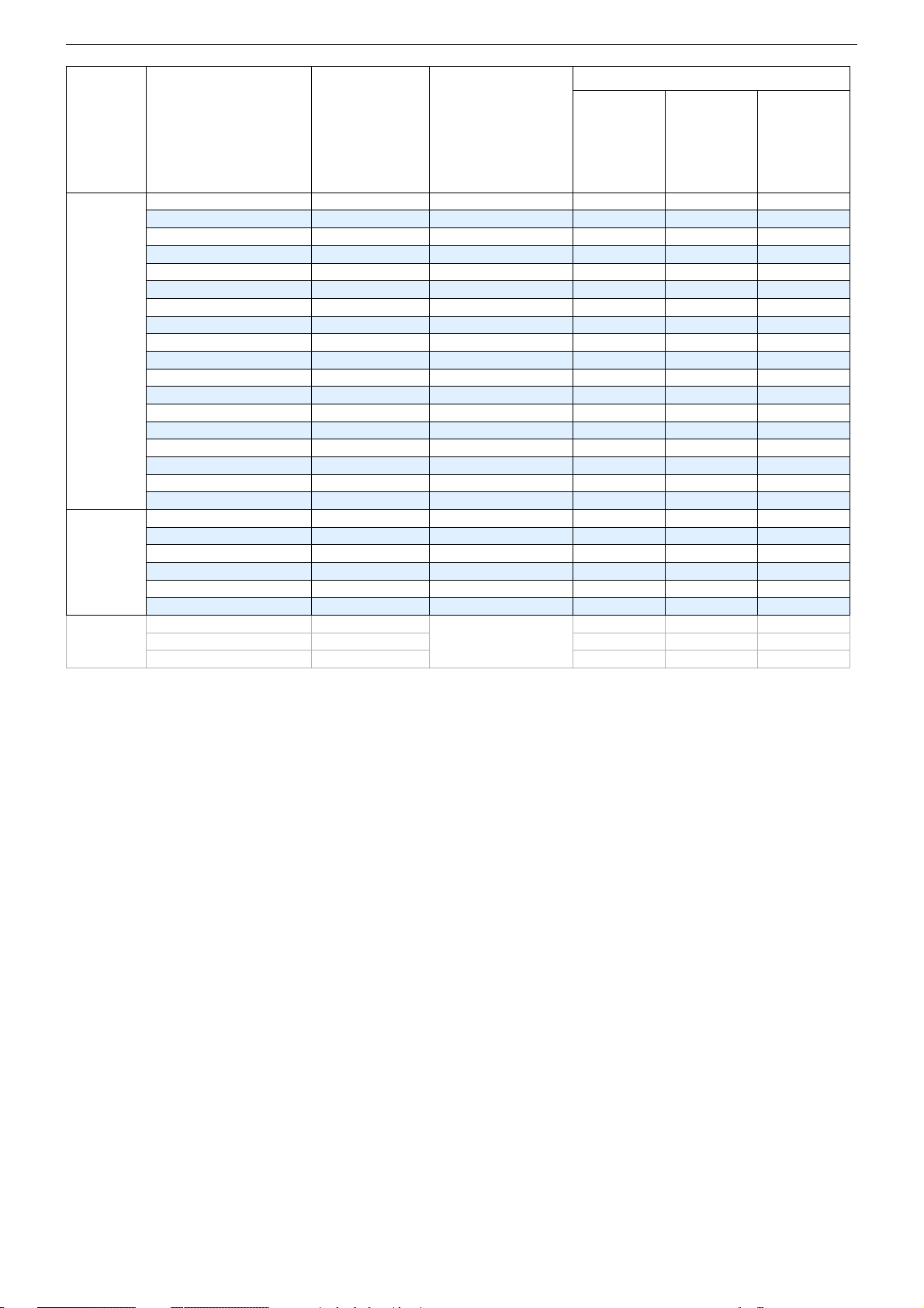
Variantenliste / Variant List
Bildröhre / CPT Größe/
A33EKC02X01
(LITVANYA / KARBON)
A34AGT13X38
(MALEZYA) WW
A34EAC01X06 DY-BRZ PH3 14"
A34EJL02X31
(BRASIL)
A34JXV70X223 N40
A34KPU02XXB
(ENDONEZYA)
A34KQW42X01
(MALEZ)
A34KQW42X02
(BREZILYA)
3 - 16
A34KVK120X07
A34LEX10X
A34LEX10X4DL
(PIGMENTED FOSFOR)
A34LRQ90X17 (VW)
(INDONESIA)
A36AKJ15X33(M) PF
MALEZYA
A36EKM71X01 P.FLAT
A36EKM74X31 P.FLAT
A36QDT351X01 P.FLAT SS1 15"
EK5 14"
CW2 14"
PH7 14"
TH2 14"
PH8 14"
SS2 14"
SS3 14"
HL1 14"
SM1 14"
SM2 14"
MT1 14
CW1
EK1
EK2 15"
Size
15"
15"
+B
C513 C514 C522 C523 C622
2KV 1.6KV
104V
105V
104V 220PF
105V
220PF
106V
105V
220PF 6.2NF
105V
104V
106V
104V
106V
107V
220PF
106V
105V
104V
105V
107V
105V
220PF
107V
108V
118V
105V
103V
105V
105V
103V
105V
105V
111V
115V
106V 220PF
108V
117V
220PF
500V
6.2NF
68PF
8.2NF
6.2NF
6.2NF
7.8NF 68PF
6.2NF
68PF7.8NF
6.2NF
6.2NF
7.8NF 68PF
6.2NF
6.2NF
68PF
7.5NF
6.2NF
6.8NF
7.8NF 68PF
6.8NF
6.8NF
68PF7.8NF
6.8NF
6.2NF 220PF
7.2NF 68PF
6.2NF
7.8NF 68PF
6.2NF
6.2NF
68PF
7.8NF
6.2NF
6.8NF 68PF
8.2NF
7.8NF
6.2NF
8.2NF
6.2NF
D509 L503
250V
275V
100NF
390NF
390NF
390NF
390NF
360NF
470NF
390NF
470NF
390NF
360NF
390NF 330NF
330NF
390NF
470NF
470NF
470NF
220NF
220NF
360NF
330NF
220NF 100NF 5V6
330NF
100NF
330NF
100NF
330NF
100NF
330NF
100NF
330NF
100NF
330NF
100NF
100NF
330NF
100NF
330NF
100NF
330NF
100NF
330NF
100NF
330NF
100NF
100NF
100NF
5V6
5V6 100UH
5V6
5V6
5V6
5V6 100UH
5V6
8V2 120UH
5V6 55UH
5V6 100UH
5V6 100UH
5V6 100UH
5V6
5V6
5V6
R505 R510 R511
1W
0.1W
0.22R
150K
0.1R
70UH
0.22R
1.2R
0.1R 120K
1.2R
1.5R
70UH
70UH
100UH
70UH
100UH
120UH
100UH
120UH
100UH
55UH
70UH
100UH
120UH
150K0.68R
1.5R
1.5R
0.68R 150K
1.5R
1.2R 150K
0.1R
180K
1.2R
150K
0.68R
0.47R 220K
0.68R
0.68R 220K
0.47R
270K
0.68R
220K
1.5R 150K
0.47R 220K
1.2R
0.1R 220K
0.68R
0.68R
220K
0.1R
0.68R
0.68R 150K 6.8K 5.6R
2.2R
220K
0.47R
0.47R 330K
0.22R
270K
0.68R
220K
R519 R520
1/16W 0.5W 0.5W
10K
6.8K
6.8K
6.8K 5.6R
6.8K 5.6R
7.5K
6.8K
7.5K
6.8K
10K 5.6R
6.8K
6.8K
7.5K
6.8K
6.8K
6.8K 4.7R
6.8K 4.7R
6.8K 4.7R
9.1K
7.5K
7.5K
8.2K
6.8K
4.7R
5.6R
5.6R
2.7R
5.6R
5.6R
3.3R
3.9R
4.7R
5.6R
4.7R
5.6R
5.6R
5.6R 330R
5.6R 330R
2.7R 330R
4.7R 330R
2.7R 330R
2.7R 330R
4.7R 330R
5.6R 330R
5.6R 330R
5.6R 330R
2.7R
1.8R
3.3R
3.9R
R521 R603 R603
0.25W
330R
330R
1W-STBY-
Version
0.25W
0.25W 5W 1/16W
8.2K
2.4K
8.2K
2.4K
7.5K
2.2K
2.4K
8.2K
2.4K
8.2K
7.5K
2.4K
8.2K
2.4K
8.2K
2.4K
7.5K
2.4K
7.5K
2.4K
8.2K
2.2K
2.4K
8.2K
2.2K
2.4K
8.2K
2.4K
8.2K
7.5K
2.4K
8.2K
7.5K
7.5K
2.4K
R702
R605
R703
220R
2.7R
2.7R
2.7R
2.7R
2.7R
2.7R
2.7R
2.7R
220R
2.7R
2.7R
2.7R
2.7R
2.7R
2.7R
220R
2.7R
2.7R
220R
2.7R
2.7R
2.7R 220R
R706
R711
R716
R721
R712
R717
R722
30R
30R
R707
1/16W 1/16W %1
220R
220R
220R
220R
220R
220R
220R
220R 560R
220R 560R
220R
220R
TR501 TR601 X703
040130R-E1/-T1
040130R-C1/-J1/-S1
040130R-E1/-T1
040130R-E1/-T1
040130R-C1/-J1/-S1
040130R-E1/-T1
040130R-E1/-T1
040130R-C1/-J1/-S1
040130R-E1/-T1
040130R-E1/-T1
040130R-C1/-J1/-S1
040130R-E1/-T1
040130R-E1/-T1
040130R-C1/-J1/-S1
040130R-E1/-T1
040130R-E1/-T1
040130R-C1/-J1/-S1
040130R-E1/-T1
040130R-E1/-T1
040130R-C1/-J1/-S1
040130R-E1/-T1
040130R-E1/-T1
040132R-E1/-E1
040130R-E1/-T1
040130R-C1/-J1/-S1
040130R-E1/-T1
040130R-E1/-T1
040130R-C1/-J1/-S1
040130R-E1/-T1
040130R-E1/-T1
040146R-C1/-J1
040146R-E1/-T2
040130R-E1/-T1
040130R-C1/-J1/-S1
040132R-E1
050130R-E1/-C1/-T2
050131R-E1/-T1
050130R-E1/-C1/-T2
050131R-E1/-T1
050130R-E1/-C1/-T2
050131R-E1/-T1
050130R-E1/-C1/-T2
050131R-E1/-T1
050130R-E1/-C1/-T2
050131R-E1/-T1
050130R-E1/-C1/-T2
050131R-E1/-T1
050130R-E1/-C1/-T2
050131R-E1/-T1
050130R-E1/-C1/-T2
050131R-E1/-T1
050146R-T2/
050147R-T1/
050130R-E1/-C1/-T2
050131R-E1/-T1
050130R-E1/-C1/-T2
050131R-E1/-T1
050130R-E1/-C1/-T2
050131R-E1/-T1
050146R-E1/-T2
050146R-E1/-T2
050147R-E1/-T1
050130R-E1/-C1/-T2 1077100
050146R-E1/-T2
050147R-E1/-T1
1077100
0989300
0989300
0989300
0989300
0989300
0989300
0989300
1077100
0989300
0989300
0989300
0989300
1077100
1077100
040130R-C1
040130R-E1
040130R-J1
040130R-S1
040130R-T1
040132R-E1
040146R-C1
040146R-E1
040146R-J1
040146R-T2
TR501 TR601
759551339400
759551231100
759551339500
759551339600
759551122000
759551231100
759551339700
759551076600
759551289800
050130R-E1
050130R-T2
050131R-E1
050131R-T1
050146R-E1
050146R-C1
050146R-T2
050147R-E1
050147R-T1
759551122100
759551230300
759551231400
759551230400
759551077000
759551346400
759551229900
759551230100
759551339800
759551231200
0989300
1077100
X703
759550989300
759551077100
Chassis E3GRUNDIG Service
Page 27

ǵ
GRUNDIG Service Chassis E3
ǵ
4 - 1
Ersatzteilliste
Spare Parts List
1 / 2007
POS. NR. ABB. MATERIAL-NR. ANZ. BEZEICHNUNG DESCRIPTION
POS. NO. FIG. PART NUMBER QTY.
GBE2400 DAVIO 14 P 37-4501 FR/TEXT DAVIO 14 P 37-4501 FR/TEXT
0001.000 759551208300 GEH.-VORDERTEIL SILBER FRONT CABINET SILVER
0002.000 759551334500 RUECKWAND SILBER BACK COVER
0007.000 759551113000 LAUTSPRECHER 3 W 16 OHM SPEAKER 3 W 16 OHM
0014.000 S 759550450200 NETZKABEL POWER CABLE
0015.000 759551076200 ADAPTER / STOESSEL PROG/VOL ADAPTOR / TAPPET PROG/VOL
0016.000 759551271600 KNOPF NETZ SILBER KNOB POWER SILVER
0018.000 759551208100 KNOPF PROG./VOL. SILBER KNOB PROG./VOL. SILVER
0020.000 BR CPT PH A34EAC01X06 DY-BRZ PICT. TUBE CPT PH A34EAC01X06 DY-BRZ
0025.000 S 275990193100 X LP-CHASSISMODUL E3 CHASSISBOARD E3
0027.000 720117132900 FERNBEDIENUNG TP160 C GRAU REMOTE CONTROL TP160 C GREY
0092.000 759551207900 KARTON CARTON
720117201100 BEDIENUNGSANLEITUNG F INSTRUCTION MANUAL F
720100527000 SERVICE MANUAL D/GB SERVICE MANUAL D/GB
720108000001 SICHERHEITSMANUAL D/GB/E/F/I SAFETY SERVICE MANUAL D/GB/E/F/I
d©
PRODUKTCODE CPH PRODUCT CODE CPH
KEIN E-TEIL NO SPARE PART
HINWEIS! NOTE!
IM DEFEKTFALL DER BILDROEHRE IN THE EVENT OF A DEFECTIVE PICTURE
NEHMEN SIE KONTAKT MIT UNSERER TUBE PLEASE CONTACT YOUR SERVICE
HOTLINE AUF
KEIN E-TEIL NO SPARE PART
X = SIEHE GESONDERTE E-LISTE X = SEE SEPARATE PARTS LIST
DAVIO 14 P 37-4501 FT/TEXT
BESTELL-NR. / ORDER NO.: GBE2400 (CPH)
TV
Ersatzteilliste
Spare Parts List
1 / 2007
POS. NR. ABB. MATERIAL-NR. ANZ. BEZEICHNUNG DESCRIPTION
POS. NO. FIG. PART NUMBER QTY.
GBE2100 DAVIO 14 P 37-4501 TEXT DAVIO 14 P 37-4501 TEXT
0001.000 759551208300 GEH.-VORDERTEIL SILBER FRONT CABINET SILVER
0002.000 759551334500 RUECKWAND SILBER BACK COVER
0007.000 759551113000 LAUTSPRECHER 3 W 16 OHM SPEAKER 3 W 16 OHM
0014.000 S 759550450200 NETZKABEL M.DR.2,3M POWER CABLE
0016.000 759551271600 KNOPF NETZ SILBER KNOB POWER SILVER
0018.000 759551208100 KNOPF PROG./VOL. SILBER KNOB PROG./VOL. SILVER
0020.000 BR CPT PH A34EAC01X06 DY-BRZ PICT. TUBE CPT PH A34EAC01X06 DY-BRZ
0025.000 S 275990194000 X LP-CHASSISMODUL E3 CHASSISBOARD E3
0027.000 720117132900 FERNBEDIENUNG TP160 C GRAU REMOTE CONTROL TP160 C GREY
0092.000 759551207900 KARTON CARTON
720117200200 BEDIENUNGSANLEITUNG NL,E,P INSTRUCTION MANUAL NL,E,P
720117200300 BEDIENUNGSANLEITUNG D,GB,I INSTRUCTION MANUAL D,GB,I
720100527000 SERVICE MANUAL D/GB SERVICE MANUAL D/GB
720108000001 SICHERHEITSMANUAL D/GB/E/F/I SAFETY SERVICE MANUAL D/GB/E/F/I
d©
PRODUKTCODE CPF PRODUCT CODE CPF
KEIN E-TEIL NO SPARE PART
HINWEIS! NOTE!
IM DEFEKTFALL DER BILDROEHRE IN THE EVENT OF A DEFECTIVE PICTURE
NEHMEN SIE KONTAKT MIT UNSERER TUBE PLEASE CONTACT YOUR SERVICE
HOTLINE AUF
KEIN E-TEIL NO SPARE PART
X = SIEHE GESONDERTE E-LISTE X = SEE SEPARATE PARTS LIST
DAVIO 14 P 37-4501 TEXT
MATERIAL-NR. / PART NO.: 720126022900
BESTELL-NR. / ORDER NO.: GBE2100 (CPF)
TV
ÄNDERUNGEN VORBEHALTEN / SUBJECT TO ALTERATION
ÄNDERUNGEN VORBEHALTEN / SUBJECT TO ALTERATION
Page 28

ǵ
GRUNDIG Service Chassis E3
ǵ
4 - 2
Ersatzteilliste
Spare Parts List
2 / 2007
POS. NR. ABB. MATERIAL-NR. ANZ. BEZEICHNUNG DESCRIPTION
POS. NO. FIG. PART NUMBER QTY.
GBE6500 DAVIO 14 P 37-4501 TEXT DAVIO 14 P 37-4501 TEXT
0001.000 759551208300 GEH.-VORDERTEIL SILBER FRONT CABINET SILVER
0002.000 759551334500 RUECKWAND SILBER BACK COVER
0007.000 759551113000 LAUTSPRECHER 3 W 16 OHM SPEAKER 3 W 16 OHM
0015.000 S 759550450200 NETZKABEL M.DR.2,3M POWER CABLE
0016.000 759551271600 KNOPF NETZ SILBER KNOB POWER SILVER
0017.000 759551076200 ADAPTER / STOESSEL PROG/VOL ADAPTOR / TAPPET PROG/VOL
0018.000 759551208100 KNOPF PROG./VOL. SILBER KNOB PROG./VOL. SILVER
0020.000 S BR. CPT PH A34EAC01X06 DY-BRZ PT. CPT CPT PH A34EAC01X06 DY-BRZ
0025.000 S 275990194000 X LP-CHASSISMODUL E3 CHASSISBOARD E3
0027.000 720117132900 FERNBEDIENUNG TP160 C GRAU REMOTE CONTROL TP160 C GREY
0092.000 759551207900 KARTON CARTON
720117200200 BEDIENUNGSANLEITUNG NL,E,P INSTRUCTION MANUAL NL,E,P
720117200300 BEDIENUNGSANLEITUNG D,GB,I INSTRUCTION MANUAL D,GB,I
720110527000 SERVICE MANUAL D/GB SEVICE MANUAL D/GB
720108000001 SICHERHEITSMANUAL D/GB/E/F/I SAFETY SERVICE MANUAL D/GB/E/F/I
d©
PRODUKTCODE CPE PRODUCT CODE CPE
KEIN E-TEIL NO SPARE PART
HINWEIS! NOTE!
IM DEFEKTFALL DER BILDROEHRE IN THE EVENT OF A DEFECTIVE PICTURE
NEHMEN SIE KONTAKT MIT UNSERER TUBE PLEASE CONTACT YOUR SERVICE
HOTLINE AUF
KEIN E-TEIL NO SPARE PART
X = SIEHE GESONDERTE E-LISTE X = SEE SEPARATE PARTS LIST
DAVIO 14 P 37-4501 TEXT
BESTELL-NR. / ORDER NO.: GBE6500 (CPE)
TV
Ersatzteilliste
Spare Parts List
2 / 2007
POS. NR. ABB. MATERIAL-NR. ANZ. BEZEICHNUNG DESCRIPTION
POS. NO. FIG. PART NUMBER QTY.
GBE2300 DAVIO 14 P 37-4501/5 TEXT DAVIO 14 P 37-4501/5 TEXT
0001.000 759551208300 GEH.-VORDERTEIL SILBER FRONT CABINET SILVER
0002.000 759551338500 RUECKWAND SILBER BACK COVER SILVER
0007.000 759551113000 LAUTSPRECHER 3 W 16 OHM SPEAKER 3 W 16 OHM
0014.000 S 759551197200 NETZSCHALTER SDKVA30100 POWER SWITCH SDKVA30100
0015.000 S 759550450200 NETZKABEL M.DR.2,3M POWER CABLE
0016.000 759551271600 KNOPF NETZ SILBER KNOB POWER SILVER
0017.000 759551076200 PROGR./VOL. STOESSEL PROGR./VOL. ADAPTER
0018.000 759551208100 KNOPF PROG./VOL. SILBER KNOB PROG./VOL. SILVER
0020.000 BR CPT PH A34EAC01X06 DY-BRZ PICT. TUBE CPT PH A34EAC01X06 DY-BRZ
0025.000 S 275990194900 X LP-CHASSISMODUL E3 CHASSISBOARD E3
0027.000 720117132900 FERNBEDIENUNG TP160 C SILBER REMOTE CONTROL TP160 C SILVER
0090.000 759551250500 POLSTER OBEN CUSHION TOP
0091.000 759551250600 POLSTER UNTEN CUSHION BOTTOM
0092.000 759551207900 KARTON CARTON
720117200500 BEDIENUNGSANLEITUNG PL/CZ/SI/H INSTRUCTION MANUAL PL/CZ/SI/H
720117200600 BEDIENUNGSANLEITUNG PL/CZ/SI INSTRUCTION MANUAL PL/CZ/SI
720100527000 SERVICE MANUAL D/GB SERVICE MANUAL D/GB
720108000001 SICHERHEITSMANUAL D/GB/E/F/I SAFETY SERVICE MANUAL D/GB/E/F/I
d©
PRODUKTCODE CPG PRODUCT CODE CPG
KEIN E-TEIL NO SPARE PART
HINWEIS! NOTE!
IM DEFEKTFALL DER BILDROEHRE IN THE EVENT OF A DEFECTIVE PICTURE
NEHMEN SIE KONTAKT MIT UNSERER TUBE PLEASE CONTACT YOUR SERVICE
HOTLINE AUF
KEIN E-TEIL NO SPARE PART
X = SIEHE GESONDERTE E-LISTE X = SEE SEPARATE PARTS LIST
DAVIO 14 P 37-4501/5 TEXT
MATERIAL-NR. / PART NO.: 720126022800
BESTELL-NR. / ORDER NO.: GBE2300 (CPG)
TV
ÄNDERUNGEN VORBEHALTEN / SUBJECT TO ALTERATION
ÄNDERUNGEN VORBEHALTEN / SUBJECT TO ALTERATION
Page 29

4 - 3
ǵ
Ersatzteilliste
Spare Parts List
2 / 2007
POS. NR. ABB. MATERIAL-NR. ANZ. BEZEICHNUNG DESCRIPTION
POS. NO. FIG. PART NUMBER QTY.
275990193100 LP-CHASSISMODUL E3 CHASSISBOARD E3
POS. NR. MATERIAL-NR. BEZEICHNUNG
POS. NO. PART NUMBER DESCRIPTION
C 514 S 759551116500 KONDENS. 6.2NF 1.6KV 3.5%
C 621 S 759551164100 KONDENS. 330 NF 275 VAC
C 622 S 759550982100 KONDENS. 100 NF/275 V AC
C 629 S 759880450800 KONDENS. 2.2NF 20% 250V
C 635 S 759550965300 KONDENS 220PF M 250VAC R:10
D 101 759551076900 LED L-513LR1D
D 102 759880116200 DIODE BA 682 *GV470SVPT
D 103 833021514800 1N4148 MELF DIODE
D 105 833021514800 1N4148 MELF DIODE
D 106 833021514800 1N4148 MELF DIODE
D 107 833021514800 1N4148 MELF DIODE
D 502 830953414900 MELF-DIODE LL 4148 TFK/ITT
D 507 830953414900 MELF-DIODE LL 4148 TFK/ITT
D 510 759902002100 DIODE BA 157
D 511 759902002100 DIODE BA 157
D 512 759902002100 DIODE BA 157
D 513 759902002100 DIODE BA 157
D 514 759902002100 DIODE BA 157
D 515 830953414900 MELF-DIODE LL 4148 TFK/ITT
D 605 725511823600 DIODE RF2007 I0
D 606 725511823600 DIODE RF2007 I0
D 607 725511823600 DIODE RF2007 I0
D 608 725511823600 DIODE RF2007 I0
D 609 759551132300 DIODE RGP 15 K
D 610 830956550700 DIODE RGP10J/1N4937 MOT/GP
D 611 830956550700 DIODE RGP10J/1N4937 MOT/GP
D 701 830921512700 1N4007 -GA DIODE
D 702 830953414900 MELF-DIODE LL 4148 TFK/ITT
D 703 830953414900 MELF-DIODE LL 4148 TFK/ITT
D 704 830953414900 MELF-DIODE LL 4148 TFK/ITT
F 101 759550921100 FILTER OFW K9656M
F 102 831900198400 OFWFIL G1985M
F 103 759550946000 FILTER SER TPSRD5M50W00-AO
F 601 S 759550922700 SICHERUNG 3.15AT
IC 101 720086716900 IC TDA 9345-N3 GRUNDIG 1 PA
IC 102 759551331100 TSOP38238T VISHAY IR-EMPFAE
IC 103 759550542200 SMD IC M24C08N SC2.7
IC 104 759550459100 IC TDA9830
IC 301 759551271800 IC AN17827A DIP16
IC 501 759551112300 IC TDA 8357 J
IC 601 759550975500 IC TDA 16846
IC 602 759551050800 IC NCP 1117 DT 33 RK
d©
KEIN E-TEIL NO SPARE PART
POS. NR. MATERIAL-NR. BEZEICHNUNG
POS. NO. PART NUMBER DESCRIPTION
J 506 814052636100 DR 0411 10UH 5% AV619 -AMMO
L 101 759862006100 DR 0309 10UH 4-253T-15020 *
L 102 759862006100 DR 0309 10UH 4-253T-15020 *
L 103 759862006100 DR 0309 10UH 4-253T-15020 *
L 104 759862006100 DR 0309 10UH 4-253T-15020 *
L 105 759862006100 DR 0309 10UH 4-253T-15020 *
L 106 759862006100 DR 0309 10UH 4-253T-15020 *
L 108 759862006100 DR 0309 10UH 4-253T-15020 *
L 109 759862006100 DR 0309 10UH 4-253T-15020 *
L 110 759550541900 SMD SPULE 1UH K0805
L 502 759551077200 TRAFO
L 503 759550451100 SPULE H-LIN 70UH
L 601 S 759551022000 FILTER 27 MH
L 602 759550451800 SPULE 50UH
L 604 759862006100 DR 0309 10UH 4-253T-15020 *
L 701 759510229600 WIDERSTAND 47OHM 5% 0,5W *D
P 601 759550453100 REGLER 2,2KOHM
Q 101 759880293900 QUARZ 12,0 MHZ 30PF HC49/U4
R 306 S 759881121900 SICH.WIDERST. 4.7OHM J 1.5W
R 505 S 759550542800 WIDERST 1,2 OHM J 1W
R 604 S 759551292800 PTC 9 OHM/2P-3CYLCE
R 614 S 759550933500 WIDERST. 1M 0.5W
R 622 S 759550452600 WIDERST 4,7MOHM1/2W
R 623 S 759550452700 WIDERST 0,1OHM0,4W
SK 201 759551101700 SCART BUCHSE
SW 101 759550451400 TASTSCHALTER
SW 102 759550451400 TASTSCHALTER
SW 103 759550451400 TASTSCHALTER
SW 601 S 759550450300 NETZSCHALTER
T 102 830100484800 SMD TRANS BC848B/ BC847B P
T 103 830100484800 SMD TRANS BC848B/ BC847B P
T 106 830100685700 SMD-TRANS.BC 857 C
T 107 830100484800 SMD TRANS BC848B/ BC847B P
T 108 830100484800 SMD TRANS BC848B/ BC847B P
T 109 830100484800 SMD TRANS BC848B/ BC847B P
T 111 830100484800 SMD TRANS BC848B/ BC847B P
T 203 830100484800 SMD TRANS BC848B/ BC847B P
T 301 830100484800 SMD TRANS BC848B/ BC847B P
T 502 759551112500 TRANS 2 SD 2586
ÄNDERUNGEN VORBEHALTEN / SUBJECT TO ALTERATION
LP-CHASSISMODUL E3
CHASSISBOARD E3
MATERIAL-NR. / PART NO.: 275990193100
TV
POS. NR. MATERIAL-NR. BEZEICHNUNG
POS. NO. PART NUMBER DESCRIPTION
T 503 759551077600 TRANS TRN BC639
T 504 759551077600 TRANS TRN BC639
T 505 759551077600 TRANS TRN BC639
T 507 830100685700 SMD-TRANS.BC 857 C
T 603 759551113100 2SK3567 TRANSISTOR
T 701 759880586100 TRANS. 2 SC 2482 C
T 702 759551013200 TRANS BF 421
T 703 759880586100 TRANS. 2 SC 2482 C
T 704 759551013200 TRANS BF 421
T 705 759880586100 TRANS. 2 SC 2482 C
T 706 759551013200 TRANS BF 421
TR 501
S 759551337300 TRAFO FBT 14/MS EL/1142.516
TR 601 S 759551122100 TRAFO SMPS 14" EL/2414.003
TU 101 759551271900 TUNER ASM PLL CTF5541
X 502 S 759551154400 STECKER 4 POL.
X 602 759551153000 STECKER 2 POL.
X 703 S 759550989300 BILDROEHRENSOCKEL
ZD 101 759550923500 DIODE ZPD5.1
ZD 102 830970700100 Z DIODE ZPD 3,9
ZD 501 830970755500 Z DIODE ZPD 15 ITT/BZX 55 C
ZD 502 830972008200 Z DIODE 8,2 C 0,5W
ZD 503 759550970900 CHIP DIODE BZT55C5V6-GS08
ZD 601 759550923600 BZX55C33 DIODE
ZD 701 759551168600 DIODE-CHIP BZX384-C8V2 300M
Es gelten die Vorschriften und Sicherheitshinweise
gemäß dem Service Manual "Sicherheit", Mat.-Nummer 720108000001, sowie zusätzlich die eventuell abweichenden, landesspezifischen Vorschriften!
POS. NR. MATERIAL-NR. BEZEICHNUNG
POS. NO. PART NUMBER DESCRIPTION
The regulations and safety instructions shall be valid
!
as provided by the "Safety" Service Manual, part
number 720108000001, as well as the respective
( ! )
national deviations.
ÄNDERUNGEN VORBEHALTEN / SUBJECT TO ALTERATION
GRUNDIG Service Chassis E3
Page 30

ǵ
Ersatzteilliste
Spare Parts List
2 / 2007
POS. NR. ABB. MATERIAL-NR. ANZ. BEZEICHNUNG DESCRIPTION
POS. NO. FIG. PART NUMBER QTY.
275990194000 LP-CHASSISMODUL E3 CHASSISBOARD E3
POS. NR. MATERIAL-NR. BEZEICHNUNG
POS. NO. PART NUMBER DESCRIPTION
d©
KEIN E-TEIL NO SPARE PART
POS. NR. MATERIAL-NR. BEZEICHNUNG
POS. NO. PART NUMBER DESCRIPTION
LP-CHASSISMODUL E3
CHASSISBOARD E3
MATERIAL-NR. / PART NO.: 275990194000
TV
POS. NR. MATERIAL-NR. BEZEICHNUNG
POS. NO. PART NUMBER DESCRIPTION
T 705 759880586100 TRANS. 2 SC 2482 C
T 706 759551013200 TRANS BF 421
TR 501
S 759551337300 TRAFO FBT 14/MS EL/1142.516
TR 601 S 759551122100 TRAFO SMPS 14" EL/2414.003
TU 101 759551271900 TUNER ASM PLL CTF5541 (SHOR
X 502 S 759551154400 STECKER 4 POL.
X 602 S 759551153000 STECKER 2 POL.
X 703 S 759550989300 BILDROEHRENSOCKEL
ZD 101 759550923500 DIODE ZPD5.1
ZD 102 830970700100 Z DIODE ZPD 3,9
ZD 501 830970755500 Z DIODE ZPD 15 ITT/BZX 55 C
ZD 502 830972008200 Z DIODE 8,2 C 0,5W
ZD 503 759550970900 CHIP DIODE BZT55C5V6-GS08
ZD 601 759550923600 BZX55C33 DIODE
ZD 701 759551168600 DIODE-CHIP BZX384-C8V2 300M
POS. NR. MATERIAL-NR. BEZEICHNUNG
POS. NO. PART NUMBER DESCRIPTION
GRUNDIG Service Chassis E3
4 - 4
C 514 S 759551116500 KONDENS. 6.2NF 1.6KV 3.5%
C 621 S 759551164100 KONDENS. 330 NF 275 VAC
C 622 S 759550982100 KONDENS. 100 NF/275 V AC
C 629 S 759880450800 KONDENS. 2.2NF 20% 250V
C 635 S 759550965300 KONDENS 220PF M 250VAC R:10
D 101 759551076900 LED L-513LR1D
D 105 833021514800 1N4148 MELF DIODE
D 106 833021514800 1N4148 MELF DIODE
D 107 833021514800 1N4148 MELF DIODE
D 502 830953414900 MELF-DIODE LL 4148 TFK/ITT
D 507 830953414900 MELF-DIODE LL 4148 TFK/ITT
D 510 759902002100 DIODE BA 157
D 511 759902002100 DIODE BA 157
D 512 759902002100 DIODE BA 157
D 513 759902002100 DIODE BA 157
D 514 759902002100 DIODE BA 157
D 515 830953414900 MELF-DIODE LL 4148 TFK/ITT
D 605 725511823600 DIODE RF2007 I0
D 606 725511823600 DIODE RF2007 I0
D 607 725511823600 DIODE RF2007 I0
D 608 725511823600 DIODE RF2007 I0
D 609 759551132300 DIODE RGP 15 K
D 610 830956550700 DIODE RGP10J/1N4937 MOT/GP
D 611 830956550700 DIODE RGP10J/1N4937 MOT/GP
D 701 830921512700 1N4007 -GA DIODE
D 702 830953414900 MELF-DIODE LL 4148 TFK/ITT
D 703 830953414900 MELF-DIODE LL 4148 TFK/ITT
D 704 830953414900 MELF-DIODE LL 4148 TFK/ITT
F 102 831900198400 OFWFIL G1985M
F 103 759550946000 FILTER SER TPSRD5M50W00-AO
F 601 S 759550922700 SICHERUNG 3.15AT
IC 101 720086716900 IC TDA 9345-N3 GRUNDIG 1 PA
IC 102 759551331100 TSOP38238T VISHAY IR-EMPFAE
IC 103 759550542200 SMD IC M24C08N SC2.7
IC 301 759551271800 IC AN17827A DIP16
IC 501 759551112300 IC TDA 8357 J
IC 601 759550975500 IC TDA 16846
IC 602 759551050800 IC NCP 1117 DT 33 RK
J 506 814052636100 DR 0411 10UH 5% AV619 -AMMO
L 102 759862006100 DR 0309 10UH 4-253T-15020
L 103 759862006100 DR 0309 10UH 4-253T-15020
L 104 759862006100 DR 0309 10UH 4-253T-15020
L 105 759862006100 DR 0309 10UH 4-253T-15020
L 106 759862006100 DR 0309 10UH 4-253T-15020
L 108 759862006100 DR 0309 10UH 4-253T-15020
L 109 759862006100 DR 0309 10UH 4-253T-15020
L 110 759550541900 SMD SPULE 1UH K0805
L 502 759551077200 TRAFO
L 503 759550451100 SPULE H-LIN 70UH
L 601 S 759551022000 FILTER 27 MH
L 602 759550451800 SPULE 50UH
L 604 759862006100 DR 0309 10UH 4-253T-15020
L 701 759510229600 WIDERSTAND 47OHM 5% 0,5W
P 601 759550453100 REGLER 2,2KOHM
Q 101 759880293900 QUARZ 12,0 MHZ 30PF HC49/U4
R 306 S 759881121900 SICH.WIDERST. 4.7OHM J 1.5W
R 505 S 759550542800 WIDERST 1,2 OHM J 1W
R 604 S 759551292800 PTC 9 OHM/2P-3CYLCE
R 614 S 759550933500 WIDERST. 1M 0.5W
R 622 S 759550452600 WIDERST 4,7MOHM1/2W
R 623 S 759550452700 WIDERST 0,1OHM0,4W
SK 201 759551101700 SCART BUCHSE
SW 101 759550451400 TASTSCHALTER
SW 102 759550451400 TASTSCHALTER
SW 103 759550451400 TASTSCHALTER
SW 601 S 759550450300 NETZSCHALTER
T 102 830100484800 SMD TRANS BC848B/ BC847B P
T 108 830100484800 SMD TRANS BC848B/ BC847B P
T 109 830100484800 SMD TRANS BC848B/ BC847B P
T 203 830100484800 SMD TRANS BC848B/ BC847B P
T 301 830100484800 SMD TRANS BC848B/ BC847B P
T 502 759551112500 TRANS 2 SD 2586
T 503 759551077600 TRANS TRN BC639
T 504 759551077600 TRANS TRN BC639
T 505 759551077600 TRANS TRN BC639
T 507 830100685700 SMD-TRANS.BC 857 C
T 603 759551113100 2SK3567 TRANSISTOR
T 701 759880586100 TRANS. 2 SC 2482 C
T 702 759551013200 TRANS BF 421
T 703 759880586100 TRANS. 2 SC 2482 C
T 704 759551013200 TRANS BF 421
ÄNDERUNGEN VORBEHALTEN / SUBJECT TO ALTERATION
Es gelten die Vorschriften und Sicherheitshinweise
gemäß dem Service Manual "Sicherheit", Mat.-Nummer 720108000001, sowie zusätzlich die eventuell abweichenden, landesspezifischen Vorschriften!
The regulations and safety instructions shall be valid
!
as provided by the "Safety" Service Manual, part
number 720108000001, as well as the respective
( ! )
national deviations.
ÄNDERUNGEN VORBEHALTEN / SUBJECT TO ALTERATION
Page 31

ǵ
Ersatzteilliste
Spare Parts List
2 / 2007
POS. NR. ABB. MATERIAL-NR. ANZ. BEZEICHNUNG DESCRIPTION
POS. NO. FIG. PART NUMBER QTY.
275990194900 LP-CHASSISMODUL E3 CHASSISBOARD E3
POS. NR. MATERIAL-NR. BEZEICHNUNG
POS. NO. PART NUMBER DESCRIPTION
d©
KEIN -TEIL NO SPARE PART
POS. NR. MATERIAL-NR. BEZEICHNUNG
POS. NO. PART NUMBER DESCRIPTION
LP-CHASSISMODUL E3
CHASSISBOARD E3
MATERIAL-NR. / PART NO.: 275990194900
TV
POS. NR. MATERIAL-NR. BEZEICHNUNG
POS. NO. PART NUMBER DESCRIPTION
T 705 759880586100 TRANS. 2 SC 2482 C
T 706 759551013200 TRANS BF 421
TR 501
S 759551337300 TRAFO FBT 14/MS EL/1142.516
TR 601 S 759551122100 TRAFO SMPS 14" EL/2414.003
TU 101 759551271900 TUNER ASM PLL CTF5541 (SHOR
X 502 S 759551154400 STECKER 4 POL.
X 602 759551153000 STECKER 2 POL.
X 703 S 759550989300 BILDROEHRENSOCKEL
ZD 101 759550923500 DIODE ZPD5.1
ZD 102 830970700100 Z DIODE ZPD 3,9
ZD 501 830970755500 Z DIODE ZPD 15 ITT/BZX 55 C
ZD 502 830972008200 Z DIODE 8,2 C 0,5W
ZD 503 759550970900 CHIP DIODE BZT55C5V6-GS08
ZD 601 759550923600 BZX55C33 DIODE
ZD 701 759551168600 DIODE-CHIP BZX384-C8V2 300M
POS. NR. MATERIAL-NR. BEZEICHNUNG
POS. NO. PART NUMBER DESCRIPTION
GRUNDIG Service Chassis E3
4 - 5
C 514 S 759551116500 KONDENS. 6.2NF 1.6KV 3.5%
C 621 S 759551164100 KONDENS. 330 NF 275 VAC
C 622 S 759550982100 KONDENS. 100 NF/275 V AC
C 629 S 759880450800 KONDENS. 2.2NF 20% 250V
C 635 S 759550965300 KONDENS 220PF M 250VAC R:10
D 101 759551076900 LED L-513LR1D
D 105 833021514800 1N4148 MELF DIODE
D 106 833021514800 1N4148 MELF DIODE
D 107 833021514800 1N4148 MELF DIODE
D 502 830953414900 MELF-DIODE LL 4148 TFK/ITT
D 507 830953414900 MELF-DIODE LL 4148 TFK/ITT
D 510 759902002100 DIODE BA 157
D 511 759902002100 DIODE BA 157
D 512 759902002100 DIODE BA 157
D 513 759902002100 DIODE BA 157
D 514 759902002100 DIODE BA 157
D 515 830953414900 MELF-DIODE LL 4148 TFK/ITT
D 605 725511823600 DIODE RF2007 I0
D 606 725511823600 DIODE RF2007 I0
D 607 725511823600 DIODE RF2007 I0
D 608 725511823600 DIODE RF2007 I0
D 609 759551132300 DIODE RGP 15 K
D 610 830956550700 DIODE RGP10J/1N4937 MOT/GP
D 611 830956550700 DIODE RGP10J/1N4937 MOT/GP
D 701 830921512700 1N4007 -GA DIODE
D 702 830953414900 MELF-DIODE LL 4148 TFK/ITT
D 703 830953414900 MELF-DIODE LL 4148 TFK/ITT
D 704 830953414900 MELF-DIODE LL 4148 TFK/ITT
F 102 759550951700 FILTER OFW K2966M
F 103 759550951800 FILTER TPT02B
F 601 S 759550922700 SICHERUNG 3.15AT
IC 101 720086716900 IC TDA 9345-N3 GRUNDIG 1 PA
IC 102 759551331100 TSOP38238T VISHAY IR-EMPFAE
IC 103 759550542200 SMD IC M24C08N SC2.7
IC 301 759551271800 IC AN17827A DIP16
IC 501 759551112300 IC TDA 8357 J
IC 601 759550975500 IC TDA 16846
IC 602 759551050800 IC NCP 1117 DT 33 RK
J 506 814052636100 DR 0411 10UH 5% AV619 -AMMO
L 102 759862006100 DR 0309 10UH 4-253T-15020
L 103 759862006100 DR 0309 10UH 4-253T-15020
L 104 759862006100 DR 0309 10UH 4-253T-15020
L 105 759862006100 DR 0309 10UH 4-253T-15020
L 106 759862006100 DR 0309 10UH 4-253T-15020
L 108 759862006100 DR 0309 10UH 4-253T-15020
L 109 759550924000 SPULE 4.7UH
L 110 759550541900 SMD SPULE 1UH K0805
L 502 759551077200 TRAFO
L 503 759550451100 SPULE H-LIN 70UH
L 601 S 759551022000 FILTER 27 MH
L 602 759550451800 SPULE 50UH
L 604 759862006100 DR 0309 10UH 4-253T-15020
L 701 759510229600 WIDERSTAND 47OHM 5% 0,5W
P 601 759550453100 REGLER 2,2KOHM
Q 101 759880293900 QUARZ 12,0 MHZ 30PF HC49/U4
R 306 S 759881121900 SICH.WIDERST. 4.7OHM J 1.5W
R 505 S 759550542800 WIDERST 1,2 OHM J 1W
R 604 S 759551292800 PTC 9 OHM/2P-3CYLCE
R 614 S 759550933500 WIDERST. 1M 0.5W
R 622 S 759550452600 WIDERST 4,7MOHM1/2W
R 623 S 759550452700 WIDERST 0,1OHM0,4W
SK 201 759551101700 SCART BUCHSE
SW 101 759550451400 TASTSCHALTER
SW 102 759550451400 TASTSCHALTER
SW 103 759550451400 TASTSCHALTER
SW 601 S 759550450300 NETZSCHALTER
T 102 830100484800 SMD TRANS BC848B/ BC847B P
T 108 830100484800 SMD TRANS BC848B/ BC847B P
T 109 830100484800 SMD TRANS BC848B/ BC847B P
T 203 830100484800 SMD TRANS BC848B/ BC847B P
T 301 830100484800 SMD TRANS BC848B/ BC847B P
T 502 759551112500 TRANS 2 SD 2586
T 503 759551077600 TRANS TRN BC639
T 504 759551077600 TRANS TRN BC639
T 505 759551077600 TRANS TRN BC639
T 507 830100685700 SMD-TRANS.BC 857 C
T 603 759551113100 2SK3567 TRANSISTOR
T 701 759880586100 TRANS. 2 SC 2482 C
T 702 759551013200 TRANS BF 421
T 703 759880586100 TRANS. 2 SC 2482 C
T 704 759551013200 TRANS BF 421
ÄNDERUNGEN VORBEHALTEN / SUBJECT TO ALTERATION
Es gelten die Vorschriften und Sicherheitshinweise
gemäß dem Service Manual "Sicherheit", Mat.-Nummer 720108000001, sowie zusätzlich die eventuell abweichenden, landesspezifischen Vorschriften!
The regulations and safety instructions shall be valid
!
as provided by the "Safety" Service Manual, part
number 720108000001, as well as the respective
( ! )
national deviations.
ÄNDERUNGEN VORBEHALTEN / SUBJECT TO ALTERATION
 Loading...