

Grundig BE-Remote Service Manual Supplement [en, de]
SAT Service Manual
1. Ergänzung / Supplement 1
Bedieneinheit
BE-REMOTE
für
STC 1200
STC 332
STC 316
RS 232
Zusätzlich erforderliche Unterlagen für den Komplettservice
Additionally required Service Documents for the Complete Service
Service
Manual
Bedieneinheit
BE-Plus
Materialnr./Part No.
720100306000
Materialnummer/Part Number 720100306100
Änderungen vorbehalten/Subject to alteration • Printed in Germany
E-BS-SA18 0701
http://www.grundig.com
MULTI
Service
Manual
Sicherheit
Safety
Materialnr./Part No.
720108000000
Grundig Service
Hotline Deutschland...
Technik:
TV
TV
SAT
VCR/LiveCam
HiFi/Audio
Car Audio
Telekommunikation
Planatron
Ersatzteil-Verkauf: ...Mo.-Fr. 8.00-19.00 Uhr
(8.00-22.00 Uhr)
...Mo.-Fr. 8.00-18.00 Uhr
Fax:
Telefon:
Fax:
0180/52318-41
0180/52318-49
0180/52318-48
0180/52318-42
0180/52318-43
0180/52318-44
0180/52318-45
0180/52318-51
0180/52318-99
0180/52318-40
0180/52318-50
Allgemeiner Teil / General Section BE-REMOTE
Es gelten die Vorschriften und Sicherheitshinweise gemäß dem Service Manual "Sicherheit",
Materialnummer 720108000000, sowie zusätzlich die eventuell abweichenden, landesspezifischen Vorschriften!
Die Bedieneinheit BE-REMOTE ist eine Weiterentwicklung der Bedieneinheit BE-PLUS mit der Möglichkeit, die Software von einer
2. Bedieneinheit zu übertragen ("Mastermode"). Unterscheidungsmerkmal: gelbe LED (BE-PLUS grüne LED).
Grundlage für den Service sind:
– Service Manual BE-PLUS (Materialnummer 720100306000)
– Service Manual "Sicherheit" (Materialnummer 720108000000)
Inhaltsverzeichnis
Seite
Allgemeiner Teil ............................................... 2
Softwarestand ................................................................................. 2
Softwarestand abfragen .................................................................. 2
Software-Programmierung über PC ................................................ 2
Software-Programmierung mit 2. Bedienteil ("Mastermode") ......... 3
IC80010 (Speicher) ......................................................................... 3
Platinenabbildungen .................................. 3…6
und Schaltpläne
Bedieneinheit .................................................................................. 3
The regulations and safety instructions shall be
valid as provided by the "Safety" Service Manual,
part number 720108000000, as well as the
respective national deviations.
The control unit BE-REMOTE is an further development of the control
unit BE-Plus with the possibility to copy the software from a 2nd control
unit ("Mastermode"). Distinguishing mark: yellow LED (BE-PLUS
green LED).
Basic instructions for servicing are given in the:
– Service Manual BE-PLUS (Part number 720100306000)
– Service Manual "Safety" (Part number 720108000000)
Table of Contents
Page
General Section ................................................ 2
Software Version ............................................................................. 2
Calling up the Software Version ...................................................... 2
Software Programming via PC........................................................ 2
Software Programming via 2nd Control Unit ("Mastermode") ......... 3
IC80010 (memory) .......................................................................... 3
Layout of the PCB ...................................... 3…6
and Circuit Diagrams
Control Unit ..................................................................................... 3
Ersatzteilliste .................................................... 7
Allgemeiner Teil
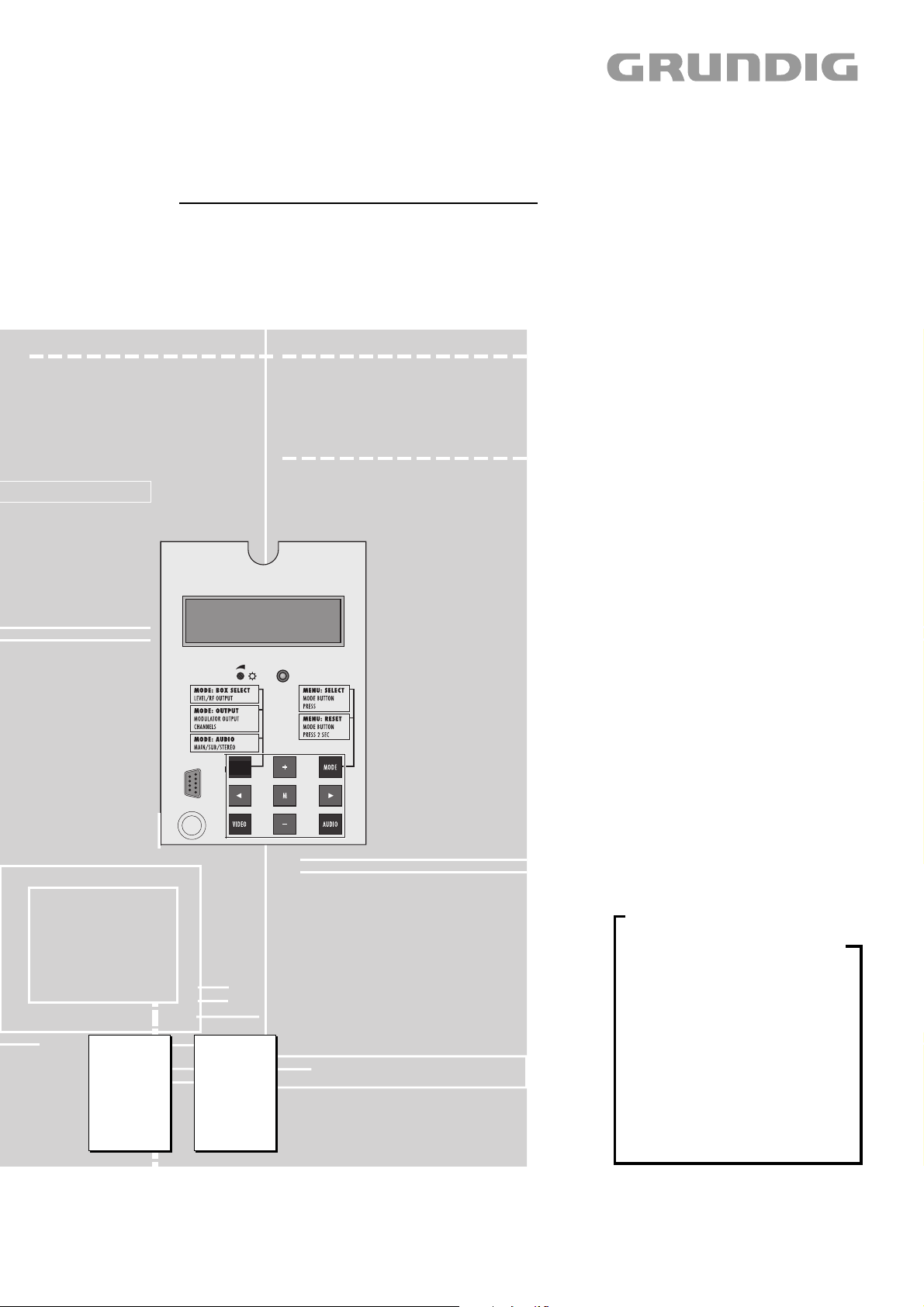
Softwarestand
15 Minuten nach der letzten Bedienung wird der Softwarestand im
Display angezeigt.
Softwarestand abfragen
-Für ca. 5sec. zwei beliebige Tasten (z.B. "Mode" und "Multi")
gleichzeitig drücken.
Im Display wird der Softwarestand angezeigt.
z.B. BE-Remote V.16
Software-Programmierung über PC
- Benötigt wird ein Computer mit Win 95 / 98 / 2000 / NT
- Geräte-Software
- Update-Software
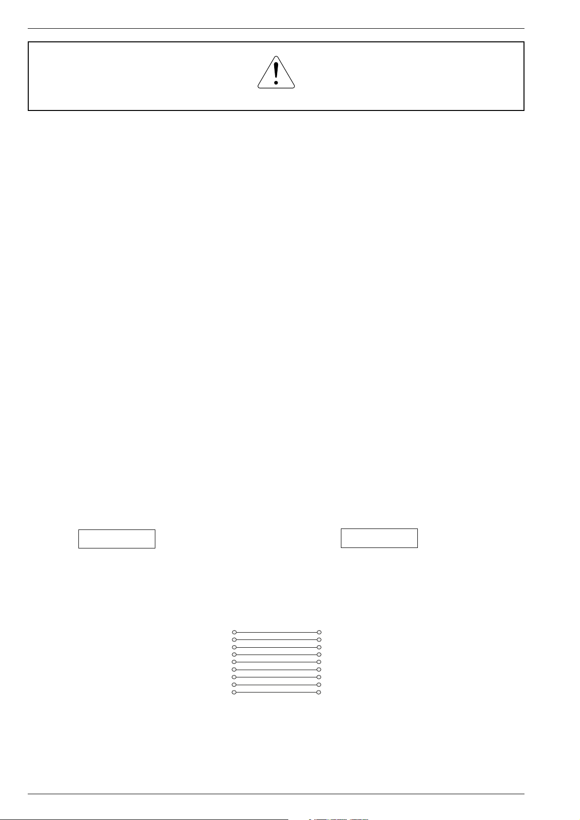
- Kabel mit 9-poligem Sub-D-Stecker auf 9-polige Sub-D-Buchse
(handelsüblich)
1
2
STC
9-pol. Sub-D-Stecker
9-pin Sub-D plug
3
4
5
6
7
8
99
Spare Parts List ................................................ 7
General Section
Software Version
The software version is shown in the display after 15 minutes without
operation.
Calling up the Software Version
- Press any two keys for about 5 seconds (e.g. "Mode" and "Multi") at
the same time.
The software version is shown in the display.
e.g. BE-Remote V.16
Software Programming via PC
- You need: a computer with Win 95 / 98 / 2000 / NT
- the device software
- the update software
- a cable with 9-pin Sub-D plug to 9-pin Sub-D socket
(commercial standard)
1
2
3
PC
4
9-pol. Sub-D-Buchse
5
9-pin Sub-D socket
6
7
8
- Die 9-polige Sub-D-Buchse der STC über handelsübliches Kabel
mit dem 9-poligen Sub-D-Stecker des PC verbinden.
- Stecker des Netzkabels der Kopfstation in Netzsteckdose stecken.
- Update-Software starten.
Bedienung siehe On-Line-Hilfe.
Hinweis:
Mit der Update Software können unter Punkt "Einstelldaten lesen" die
Daten aus der Kopfstation ausgelesen werden.
2 GRUNDIG Service
- Connect the 9-pin Sub-D socket on the STC via a commercial cable
with the 9-pin Sub-D plug on the PC.
- Connect the mains cable plug of the head station with a wall outlet.
- Run the update software.
See the online help for the steps to follow.
Hint:
It is possible to read out the data via the function "Einstelldaten lesen“
of the update software.
 Loading...