


POWERMAX Q2 PROJECT
GF CHASSIS
SERVICE MANUAL

CONTENTS
---------------------------------------------------------------------------------------------------------------
5 REVISION LIST
7 PRODUCT SPECIFICATIONS
7 Technical specifications
10 Functional specifications
11 Superior specifications
15 PACKAGE CONTENT
15 Standard accessories
15 Optional accessories
16 Connection/Preparation
17 Connections of the television
18 Control elements on the television
18 Multi-function switch
19 Remote control - main functions
20 SETTINGS
20 Settings for connecting to the home net-
work
20 Tuning television channels
21 Initial set-up
25 PICTURE / SOUND SETTINGS
25 Picture settings
27 Sound settings
29 ELECTRONIC TV GUIDE
29 Logging on to "RoviGuide™"
29 Electronic TV guide in offline mode
30 Electronic TV guide in online mode
30 Main page
31 Connecting external data medium
32 USB recording settings
33 "Pausing" Time shift programs
34 "Pausing" time shift programs
35 USB OPERATION
35 Recording Programs
36 Program setting for recording
37 Editing the timer
37 Deleting the timer
38 Playback
38 Deleting programs from the recorded files
menu
39 File formats
40 Connecting external data medium
40 Disconnect the data medium before
removing the external data medium.
41 File browser
41 Settings in the USB set-up menu
42 Basic Playback functions
43 Additional playback functions
45 SMART INTER@CTIVE TV 4.0+
45 SMART Inter@ctive TV 4.0+ internet ap-
plications
45 USB keyboard and mouse
45 Introduction to Smart Inter@ctive TV
47 Smart Inter@ctive TV 4.0+ home page
47 Navigating the main menu
47 Playback and other options in the ap-
plications
Smart Inter@ctive TV 4.0 browser main
menu
49 Web browser menu
49 Web browser application
50 USING AN EXTERNAL DEVICE
50 DIGI LINK
50 Digi Link connection functions of the TV
51 Device Control
52 High resolution – HD ready
52 Connection options
53 Connecting an external device
54 Using a DVD recorder, DVD player, video
recorder or set-top box
54 Headphones
55 Hi-fi system
56 Playing audio signal with the Hi-Fi system
57 WIRED SCREEN SHARE (MHL)
57 What is MHL?
57 Connecting a mobile device
57 Choosing the channel position for a
mobile device
58 WIRELESS SCREEN SHARE (LIVE-
SHARE)
58 What is LIVESHARE?
58 Screen share with Liveshare connection
59 OPERATION WITH COMMON IN-
TERFACE
59 What is common interface?
59 Inserting the CA module
59 Access control for CA module and smart
2

CONTENTS
---------------------------------------------------------------------------------------------------------------
cards
60 NETWORK SETUP
60 Network connection
60 Wired network
61 Wired network settings
63 Wireless network
63 Wireless network settings
67 Changing the TV Name
68 Searching for all satellite-connected digi-
tal television stations automatically
Searching for satellite-connected digital
television stations manually
69 Antenna settings for digital satellite chan-
nels and searching for channels automatically
Antenna settings for digital satellite chan-
nels and searching for channels automatically with SCR system
70 Connecting the television to a "hidden"
network
71 DETAILED CHANNEL SET-
TINGS
71 Searching for all satellite-connected digi-
tal television stations automatically
72 Searching for satellite-connected digital
television stations manually
73 Antenna settings for digital satellite chan-
nels and searching for channels automatically
74 Antenna settings for digital satellite chan-
nels and searching for channels automatically with SCR system
75 Antenna settings for digital satellite chan-
nels and searching for channels automatically with DiSEqC 1.0/1.1
77 Motorized antenna settings
(DiSEqC 1.2)
78 Searching for television channels from the
cable provider automatically
79 Searching for television channels from the
cable provider manually
79 Searching for digital terrestrial TV chan-
nels automatically
80 Searching for digital terrestrial TV chan-
nels manually
80 Auto service update
81 Tuning analog television
channels
82 Changing stored analog
channels
84 Displaying signal information
85 GENERAL OPERATING PRINCIPLE
OF THE TV
85 Block Diagram
86 General Operating Principle of the Chas-
sis
86 DC Power Stage
88 OPERATING PRINCIPLES OF CIR-
CUIT COMPONENTS
88 IC100 Main integrated circuit (IC-SMD
MSD95M0D BGA TRY)
88 IC200,201,202,203 DDR3 RAM (IIC-
SMD K4B4G1646E-BCNB FBGA T&R)
88 IC608 EMMC flash (IC-SMD THGBMB-
G5D1KBAIL P-WFBGA T&R)
89 IC1000 Audio and headphone amplifier
(IC-SMD TAS5739MDPHPR QFP)
89 IC1302 DC-DC converter(IC-SMD TPS-
562200DDCR SOT23-6 T&R)
89 IC902,IC904 DC-DC converter(IC-SMD
TPS562200DDCR SOT23-6 T&R)
90 IC903 Step-down DC/DC converter(IC-
SMD XC6222B181ER-G USP-6C T&R)
90 IC704 Step-down converter(IC-SMD
XC6222B181ER-G USP-6C T&R )
90 IC301 Step-down converter (IC-SMD
TPS2065CDBVR SOT23-5 T&R )
90 IC1200 System reset integrated circuit
(IC-SMD APX812-29UG-7 SOT143 T&R)
91 IC706 Analog-digital tuner integrated
circuit (IC-SMD Si2151-A10-GMR)
91 IC702 Satellite tuner integrated circuit(IC-
SMD RDA16110SW QFN40 T&R)
91 IC705 LNB regulator(IC-SMD LNBH26L-
SPQR QFN T&R)
91 IC700,701 Demodulator IC(, IC-SMD
SI21692-C55-GMR QFN T&R)
92 SERVICE MENU SETTINGS
92 System configuration
93 Source configuration
93 TV configuration
3

CONTENTS
95 Cloner configuration
Acoustic management
Software version
96 Approved logos
97 CUSTOMER SETTINGS
101 SCHEMATIC IMAGES OF THE CHAS-
SIS
101 Chassis DC socket
101 VCC DDR
103 Terrestrial tuner
103 Satellite tuner
104 USB
105 FAILURE/ERROR ANALYSES
105 Sound available but no picture, and back
lights illuminated
107 Sound available but no picture, and back
lights not illuminated
109 No sound
111 SOFTWARE UPDATE
111 Updating TV Software by means of USB
memory
111 Updating software and boot from the user
menu
112 Updating the panel file
112 Locations where required keys are stored
113 TeraTerm usage
114 HOTEL TV SETUP
115 GLOSSARY
---------------------------------------------------------------------------------------------------------------
4

REVISION LIST
Version Revision Date Responsible Department
1 SEK draft issued 28.09.2016 TV Design Application
---------------------------------------------------------------------------------------------------
5

SAFETY
-------------------------------------------------------------------------------------------------------------------------
WARNING
Injuries caused by falling TV set
Never set up the TV on unstable places. Otherwise the TV can tip over and cause injuries and
fatalities. Observe the following precautions
especially to protect children from such negative
incidents:
7
Make sure that the stand or other furniture you
will place the television on is robust enough to
carry the television.
7
Make sure that the TV set does not protrude
beyond the dimensions of the furniture on
which it is resting.
7
Do not place the television on furniture such as
cupboard, sideboard, bookshelf that tends to
tip over. In obligatory cases, such bearers must
be fixed onto the wall or suchlike structures so
that the television does not tip over.
7
There must be no cover, lace, cloth, tulle or
similar items between the television and the
stand/furniture you have placed the television
on.
7
Observe the aforementioned warnings when
you displace the television.
WARNING
Panels used in LED panel televisions are quite
sensitive in electrical and physical aspects.
Therefore the following warnings should be
observed.
7
Panel surface is quite sensitive and can be
damaged easily. Take care to avoid scratches
on the panel surface. When you need to lay
down the panel, place it on a floor that will
not cause damages. Besides, do not use rough
materials when touching or wiping the panel.
7
Keep the panel surface clean. Put on rubber
gloves when touching the panel surface. To
clean the surface, use a mild cleaning agent
that does not get electrified.
7
Keep the LED module away from water. Spilling water on or in the panel causes electrical
damage on the panel. It should be wiped dry,
if needed.
7
Avoid sudden temperature and humidity
changes. Sudden changes of temperature and
humidity may harm the panel.
7
High temperature and humidity shortens the
lifecycle of the panel. LED panels are not suitable for use under high temperature and humidity conditions. The user should observe the
specified temperature and humidity values.
7
Keep it away from harmful (corrosive) gases.
Corrosive gases damage chemical and electronic structure of the LED panel.
7
Static electricity flow may damage the panel.
LED module contains materials sensitive to
static electricity such as CMOS, etc. The body
should be grounded before touching the
panel. Also, you should not touch connector
areas with bare hands.
7
The same image should not stay on the screen
for prolonged times. Keeping the same image
on the screen for a long time may lead image
retention and the panel may get damaged.
Therefore the TV should be turned off when
not in use and the image should be changed
at certain intervals when displaying still images.
6

PRODUCT SPECIFICATIONS
--------------------------------------------------------------
Technical specifications
Specification Eternity Crystal
Energy Class A/B
Display Size 40",49",55"" 40",43",49",55"
HD Ready NO NO
Full HD NO NO
Ultra HD YES YES
Full HD 50 Hz YES YES
Full HD 100Hz NO NO
Sound output 2X15W @ 8 ohm ohm 2X15W @ 8 ohm
Onboard Sub-woofer NO NO
Standby power consumption <0.5W
Power input (V/Hz.) 220-240V ~ 50-60Hz
Rosh Limits Pb (Lead) / Hg (Mercury) Pb, complies with RoHS Directive / 0
mg
Scart input Standard
Sound/Video RCA input Via Scart
S-Video socket Via Scart
HDMI input 1-2-3 HDMI 2.0
YPBPR input Via Scart
VGA input NO
PC audio input NO
Line Out Via Headphones
Headphone Socket Standard
Optics Out Standard
Languages Support for 27 different languages
Diseqc Standard Diseqc 1.2
Broadcasting Systems DVB-T2/C/S2
Digital Program memory TV/
Radio
USB Film formats .3gp, .mp3, .m4a, .aac, .mov, divx (4/5/6.x), .mpg, .vob, .dat, .ts,
.avi, .mp4, .mkv, .trp, .div, H264 (L4.0), H264 (L4.1), HEVC
USB Subtitle formats SRT, SSA, ASS, SMI, .txt
(Analog/DVB-T/DVB-C/DVB-S2)
100 / 1000 / 1000 / 6000
7
ENGLISH

PRODUCT SPECIFICATIONS
USB Picture formats .jpg, .jpe, .bmp, .png,
MEMC YES YES
3D NO NO
Integrated WiFi & Bluetooth YES YES
WiFi Ready WiFi Ready / Integrated WiFi
+ BT
Appstore (download-removeupdate, move, add favorite)
Inter@ctive Cloud (Dropbox) YES YES
DLNA YES YES
ROVI Smart TV Guide (Web
EPG)
Web Browser YES YES
AppPip YES YES
HBB TV 1.2.1 ( 1.5 ) YES YES
HEVC
Wi-di (other than Widi ready
products)
Live Share (Widi & Miracast) YES (RX only (Receiver)) YES (RX only (Receiver))
Interactive Hotel TV YES YES
VoD - Maxdome/Netflix/
Amazon Prime*
Online Software Update YES YES
OSD Type Grundig/Beko/Arçelik/OEM Grundig/Beko/Arçelik/OEM
Easy-to-Use User Interface YES YES
Remote Control TS1 - TS2 - TS3 - TS4 TS3 - TS4
Easy-to-Use Remote Control OPTION OPTION
W8, IPhone/IPad, Android
remote control
CI+ CI+ 1.3 (Double) CI+ 1.3 (Double)
DTS YES YES
Dolby MS11 YES YES
PVR OPTION OPTION
MHL YES YES
Dual Watch NO NO
YES YES
YES YES
YES (Tuner, Internet, USB) YES (Tuner, Internet, USB)
NO NO
YES YES
YES YES
--------------------------------------------------------------
Integrated WiFi + BT
8
ENGLISH

PRODUCT SPECIFICATIONS
Zero boot NO NO
STR NO NO
Panel stand-by during music YES YES
PIP YES YES
Capture & Share YES YES
Gesture Control NO NO
Voice Recognition NO NO
Baby Watch NO NO
Easy sign-in YES YES
Easy Search YES YES
Simple Hotel TV YES YES
Front Time Display NO NO
--------------------------------------------------------------
9
ENGLISH

PRODUCT SPECIFICATIONS
Functional specifications
GF chassis project has been designed as a
continuation of the existing KR/KP connected
TV concept and it offers price benefits while
preserving the currently supported features.
It is planned to use 40", 49", 55" Eternity panels and 40", 43", 49", 55" Crystal panels in the
project.
All applications in the current Grundig Smart
Apps market will be supported in the GF project
as well.
GF chassis will be able to provide Miracast
feature RX (one-sided). Thanks to Miracast RX
feature it will be possible to transfer the picture
on compatible devices (laptop, mobile phone,
tablet, etc.) to the TV wirelessly. The picture on
compatible devices can be transmitted to the TV
screen with the MHL feature as well.
The user interface design introduced with KP
project will also be available on the GF project.
A single design will be used for all brands in
the project. In this design, the logos with bigger sizes and FHD resolution are displayed in
certain groups and as colored. Thus a more
user-friendly interface has been adopted for the
operations to be performed on the TV. Additionally, when the logos in the menu are hovered, a
balloon help indicating what is the hovered logo
for is displayed.
Besides these features, GF chassis supports
both analog and digital broadcasts. As already
known, digital broadcasts are divided into 3
categories as follows: (DVB-T/DVB-T2: Digital
video Broadcasting Terrestrial), digital cable
broadcasting (DVB-C: Digital video broadcasting cable) and digital satellite broadcasting
(DVB-S2: Digital video broadcasting satellite).
Our GF chassis televisions support DVB-T/C,
DVB-T2 and DVB-S2 broadcasting. Digital
receiver unit of the product processes signals
coming from digital transmitters and converts
them into audio and video of superior quality. It
enables you to access video, music and photo
files and play these media.
In our country, DVB-T2 (Digital Terrestrial Broadcasting) has been tested by TRT in 3 metropolitan cities, but private broadcasting companies
have not started DVB-T broadcasting yet. DVB-C
(Digital Cable Broadcasting) has been started
over the cable TV network called "Teledünya".
DVB-T broadcasting supports MPEG2 and
MPEG4 standards. Our GF chassis products
support MPEG4 broadcasting.
To summarize, our GF chassis products support
the following features:
7
Features supported by KR/KP chassis.
7
Decryption of UHD, FHD and HEVC broad-
casts
7
HEVC 60Hz support on all sources
7
Bluetooth features for compatible devices
7
HBB TV
7
DLNA DMP-DMR
7
Wired/Wireless internet connection
7
Open browser support and overlay
7
Embedded WiFi support
7
Miracast feature
7
WAKE ON LAN
7
Remote EPG and USB Recording 3.0 (Viewing
and recording EPG data through application
introduced for KY-KT chassis)
7
TV and radio division in program menu/channel list
7
Faster opening time compared to KY-KT
7
Compatible with TS1-TS2-TS3-TS4, iPhone/
iPad RC, Android RC and new RC design
7
Unicable solution in DVB-S/S2 broadcasts
7
Using different sources during recording
7
More user-friendly USB menu (such as viewing
all files, deleting all files in bulk)
7
Compatible with new 2015 designs
7
DTS support
7
Sub-woofer option
7
Sub-woofer analog output (Line-out)
7
Dolby 2+1/5+1
--------------------------------------------------------------
10

PRODUCT SPECIFICATIONS
Special features
Under this topic, you can learn about the outstanding features that our GF chassis products
incorporate and also descriptions of these
features.
SMART inter@ctive TV 4.0 internet applications
SMART Inter@ctive TV 4.0 interactive applications provide your television with Internet services and pages.
These applications have been designed in compatibility with the television.
With SMART Inter@ctive TV 4.0 feature you can
run many local and global internet applications.
Thanks to Grundig Application Store, you can
find various applications that you may use on
your Grundig TV. You can download various
applications from Grundig Application Store.
These applications include video, picture, music,
social networking, news and sports applications,
weather forecast applications and some specific
applications.
--------------------------------------------------------------
Arçelik TV Remote control mobile application
Your TV supports remote control
feature for Apple iPhone/iPad and
Android phones. Depending on the
features of your mobile device, you
can control your TV through your mobile device
by downloading ARCELİK TV Remote application from the operation system store for free.
Your smart phone and TV must be connected to
the same network in order to use this feature.
11

PRODUCT SPECIFICATIONS
--------------------------------------------------------------
DLNA (Home Network)
Digital Living Network Alliance (DLNA) is an asso-
ciation established by the
leading companies of consumer electronics,
mobile and Personal Computer industries. Its
objective is to ensure that all electronic devices
which are manufactured by different companies
and used in home networks are manufactured
within certain standards and comply with each
other. Thus users can benefit from their different
brand devices in home network smoothly and
without interruption. The alliance companies can
develop their products in line with these standards or make desired changes.
You can easily access Video, music and image
files on the server through the DLNA menu of
your television. You can share your video, music
and image files through devices such as PC, mobile phone or NAS (Network Attached Storage)
that function as DMS (Digital Media Server)
compatible with DLNA.
HBB TV (Hybrid Broadcast Broadband)
Hbb TV (Hybrid Broadcast
Broadband TV) can be
translated into Turkish as
hybrid, integrated broadcasting and internet TV. Hbb TV allows broadcasters to share internet applications of desired
contents (Weather forecast, EPG, video sharing…) with the user over internet. HbbTV provides next-generation interactive teletext broadcast with its modern structure, content and high
definition (HD) images and videos. To receive
HbbTV broadcast, your television must be connected to Internet. This new service is currently
offered on TRT HD and TRT1 HD channels as a
feature. The service provided by TRT
includes a detailed program summary, news
and videos on demand specific to TRT besides
the graphically re-engineered teletext with high
definition images. This feature can only be used
in countries where the service is provided. HBB
TV application is a standard feature on GF chassis products.
SCR (Single Channel Router) Technology
(Unicable)
GF chassis products
support SCR (Single
Channel Router)
feature.
The fact that the
number of channels which can be
received from satellite is very high and
therefore the bandwidth of the signals
is very wide makes
carrying these signals from the satellite dish to the house difficult.
In addition to that, the increased use of digital
video recording (DVR) devices complicates this
problem more. For example, signals received
with four polarities as vertical/horizontal,
lower/upper band are controlled by commands
from the device to the LNB and only broadcasts
with selected polarities are sent. However, it is
not possible to watch a broadcast while the user
is recording a broadcast (DVR) with the same
polarity. In this case, it is required to lay more
than one cable from the dish to the house and
set up a complicated structure.
SCR (Single Channel Router) technology provides a "single cable" solution for the difficulties
described above. Multi-cable situation that is
required by double tuner STB receivers with
PVR and for the distribution of signals to multiple
receivers can be solved by a “single cable” with
this system.
SCR (Single Channel Router) system is an
integrated solution that includes software and
hardware aspects. SCR LNB should be used
with TVs, satellite receivers or digital recorders
compliant with this system. This feature is provided by software in the device that the LNB shall
12

PRODUCT SPECIFICATIONS
--------------------------------------------------------------
be connected, and there is no need to make a
modification in the hardware of the device.
USB Recording Feature (USB-PVR)
This feature allows you to record digital television channels (DVB–T/T2, DVB–C and DVB-S2)
on an external USB disk and play these records
on the disk at a later time. Recording programs
to view them later can only be realized with digital television stations. Recording and playing
programs, as well as time shift function can only
be available by using an external data medium
(hard drive or USB stick). The data medium must
have a capacity of 2 GB minimum.
It is possible to record a channel to USB-PVR or
to a hard disk simultaneously while watching
the other channel out of 2 channels at the same
transponder frequency in DVB-C and DVB-T,
DVB-S broadcasts. Also, it is possible to change
the source from USB or DLNA sources without
interrupting the record while recording.
Switching to permanent recording;
When the permanent recording option is set to
on, the TV starts recording the current program
to the time shifting memory. Average recording
time for this memory is 60 minutes.
- You can pause and restart or rewind/forward
the record whenever you want.
- The live broadcast can be viewed with around
60 minutes delay and you can rewind or forward the record within this period.
and DVD player, STB or video recorder and
control such equipment with the remote control
of the television. This feature must also be supported by the device you will connect it.
Operating with Common Interface (CI+)
Common Interface (CI) is only used in DVB
receivers. Scrambled channels can only be
viewed with a CA module suitable for the encoding system and the corresponding smart
card. The television set is equipped with a Common Interface slot into which CA modules from
various providers can be inserted. The service
provider's smart card must be inserted into the
CA module to enable the scrambled channels
you want to view.
Miracast and Liveshare
Wireless transfer of broadcast to compatible
devices (miracast compatible laptop, cellular
phone, tablet, etc.) is possible thanks to this
feature. Thus it is possible to transfer the picture
on compatible devices (laptop, mobile phone,
tablet, etc.) to the TV wirelessly.
DIGI LINK and HDMI CEC Feature
Our products with GF chassis are equipped with
HDMI CEC feature. This feature utilizes CEC
(Consumer Electronics Control) protocol. CEC
feature allows you to make an HDMI connection between your TV and DVD player, satellite
receiver or video recorder and control such
equipment with the remote control of the television. This feature must also be supported by the
device you will connect it. You television supports the following functions.
Your television is equipped with DIGI LINK
feature. This feature utilizes CEC (Consumer
Electronics Control) protocol. CEC allows you
to make an HDMI connection between your TV
Liveshare is a wireless technology featured with
an Android operating system and used to reflect
the screen of your mobile device -which supports this feature- to your television supporting
Liveshare. Using this technology, you can share
your device's content, present a slide show or
play a game on a larger screen.
13

PRODUCT SPECIFICATIONS
--------------------------------------------------------------
Full HD, User Friendly Menu Structure
The user-friendly new UI structure provided with
KP chassis has been kept in the new GF chassis
as well.
The aims of this structure are;
7
Impressiveness: To create a quality experience
with animations and design,
7
Themeability: To create special designs for
our brands and to create distinctiveness among
them,
7
Accessibility: To create designs that can easily
be used by everyone of all age groups as well
as offering ease of use in our all interfaces.
High Efficiency Video Coding (HEVC)
It is a video compression
standard created as a result
of a mutual study by ISO/IEC
MPEG (Moving Picture Experts Group) and ITU-T VCEG (Video Coding
Experts Group). It is a coding technology offering the same quality image with a higher compression rate and a lower bandwidth in comparison to H264/avc, which is the previous
standard.
HEVC standard is mostly used for UHD videos
and it supports videos up to 8K. However, since
it is an efficient method and it particularly allows using the bandwidth effectively in DVB-T2
broadcasts, it has started to be used in FHD
broadcasts as well. With GF chassis, for the first
time HEVC will be supported for FHD on one of
our non-UHD televisions.
Web Browser (Open Web Browser)
Open web browser software enables users
to open HTML or more advanced pages on
network providers. GF chassis incorporates a
"Web Browser". Thus, as in computers or mobile
phones, all internet pages can be accessed by
entering the URL address. Browser does not
support Flash. For this reason, on some web
pages, applications requiring flash player will
not function.
Electronic TV Guide
The Electronic TV guide
(RoviGuideTM) has two operation
modes, namely online and offline.
In the offline mode, you can only see channel
data which the station provider has made
available.
A lot of content such as program information,
channel logos, information about actors/
actresses, pictures, fragments, etc. can be
received via the Internet connection in the online
mode. Additionally, through using artist, series
or film names, it is possible to perform search
among TV programs.
14
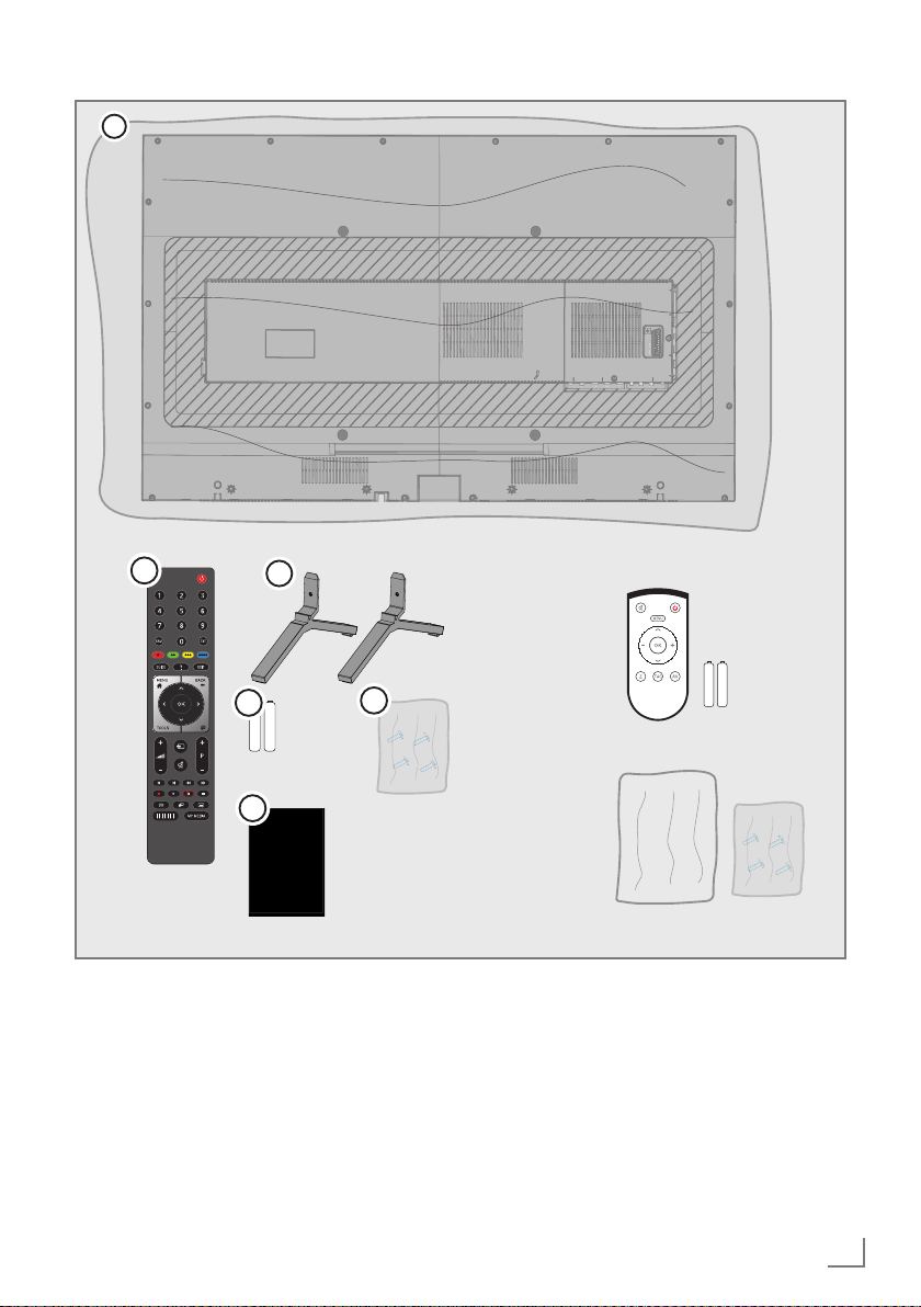
PACKAGE CONTENT
1
-----------------------------------------------------------------------------------
V
AV VH
HM
A
HM
B
u A
A
A
3
2
4
5
6
Standard accessories
1 Television
2 Stand
3 Remote control
4 Battery for remote control
5 Screws and installation instructions for the
stand
6 User manual
Optional accessories
Easy-to-Use Remote Control
Battery for Easy-to-Use Remote Control
Cleaning cloth
15
PRODUCT INSTALLATION
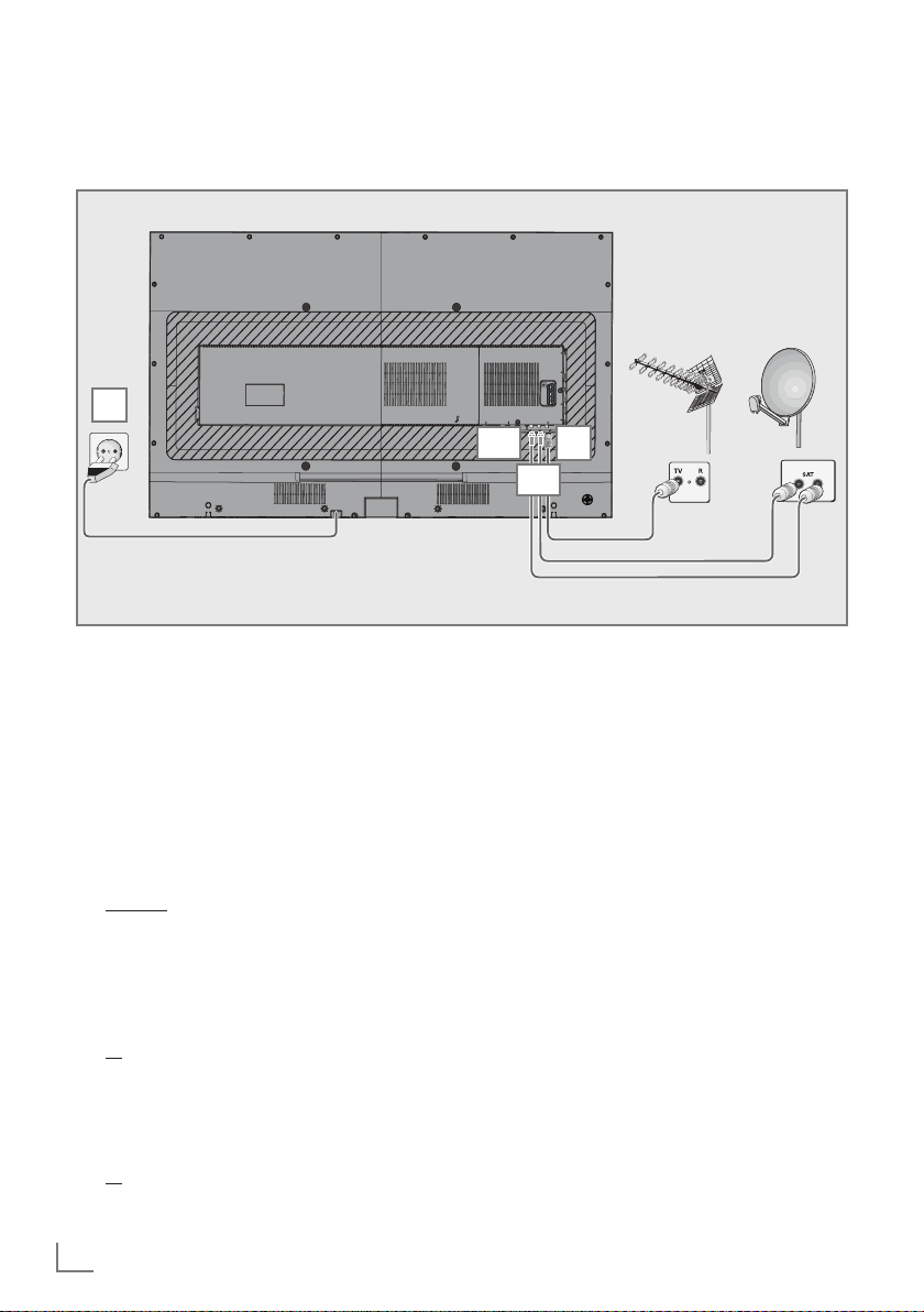
Connection/Preparation
Connecting the antenna and the power cable
-------------------------------------------------------------------
3
1a For digital satellite channels (DVB-S),
connect the satellite antenna cable to the
SATELLITE MAIN antenna socket on the
television set;
1b Two digital satellite signals (DVB-S) are
required to use PIP function and advanced
recording function for TV programs. Connect the second digital satellite signal from
the same switch or LNB to SATELLITE SUB
antenna sockets.
and /or
2a For terrestrial digital stations (DVB-T), con-
nect the rooftop or indoor antenna (passive
or active indoor antenna with its own power
supply) to the ANT IN antenna socket on
the television set;
or
For digital stations of the cable TV network
2b
(DVB-C) plug the antenna cable into the
antenna socket ANT IN on the television
set;
or
For analog stations, plug the antenna cable
2c
into ANT IN socket on the television set.
16
V SV S
1a
2
1b
Note:
7
When connecting an indoor antenna you
may have to try it out at different positions
until you get the best reception.
3 Plug the power cable into the wall socket.
Note:
7
Only plug the device into the mains socket
after you have connected the external
devices and the antenna.
7
Do not use an adapter plug or an extension
cable which does not meet the applicable
safety standards. Do not make changes on
the power cable.
PRODUCT INSTALLATION
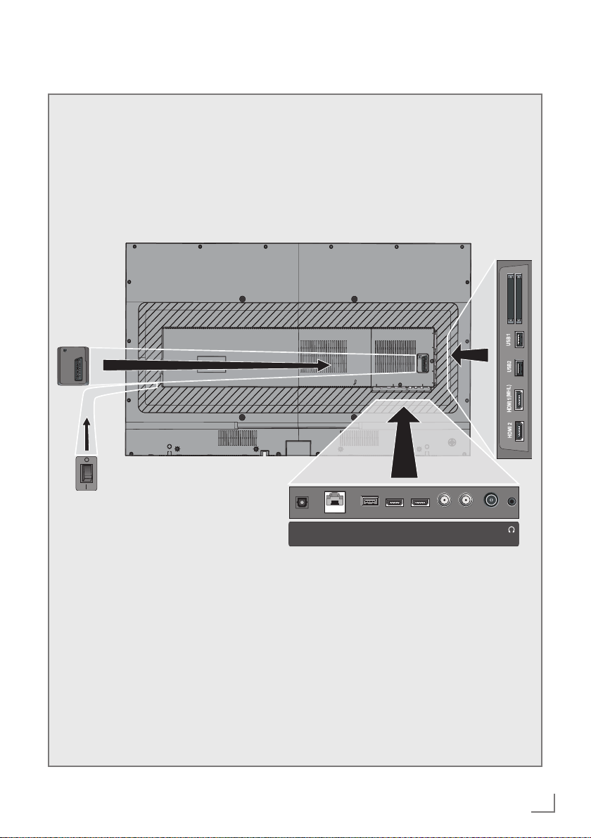
Connections of the television
ERVCE
AV S VHS
-------------------------------------------------------------------
CI
AV SVHS
Optic Out
USB3 HDMI4
HDMI3LAN
(ARC)
SATELLITE
13/18V max500mA
(MAN) (SUB)
ANT IN
5V max50mA
17
PRODUCT INSTALLATION
-------------------------------------------------------------------
SCART / S-VHS / COMPONENT
Scart audio / video input
(CVBS signal, RGB signal);
S-Video audio / video
input (with Scart-S-VHS
converter);
Component, audio / video
input (with Scart - YPbPr
converter.
SERVICE
is for service purposes.
Optic Out Optics sound output.
LAN Network cable connection
socket.
USB3
USB socket for external
data medium and PVR function;
Wireless keyboard, mouse
socket.
HDMI socket, audio/video
HDMI3
signal input (HDMI).
HDMI4 (ARC) HDMI socket, audio/video
signal input (HDMI).
SATELLITE MAIN Satellite antenna socket.
SATELLITE SUB Second satellite signal
socket
Antenna socket.
ANT IN
U Headphone connection
(3.5 mm jack);
External audio output (with
headphone-RCA converter)
CI1 Common interface slot.
CI2 Common interface slot.
USB1 USB Hard disk socket for
external data medium and
PVR function;
Wireless keyboard, mouse
socket.
USB Hard disk socket for
USB2
HDMI1 (MHL)
external data medium and
PVR function;
Wireless keyboard, mouse
socket.
HDMI socket, audio/video
signal input (HDMI).
HDMI2 HDMI socket, audio/video
signal input (HDMI).
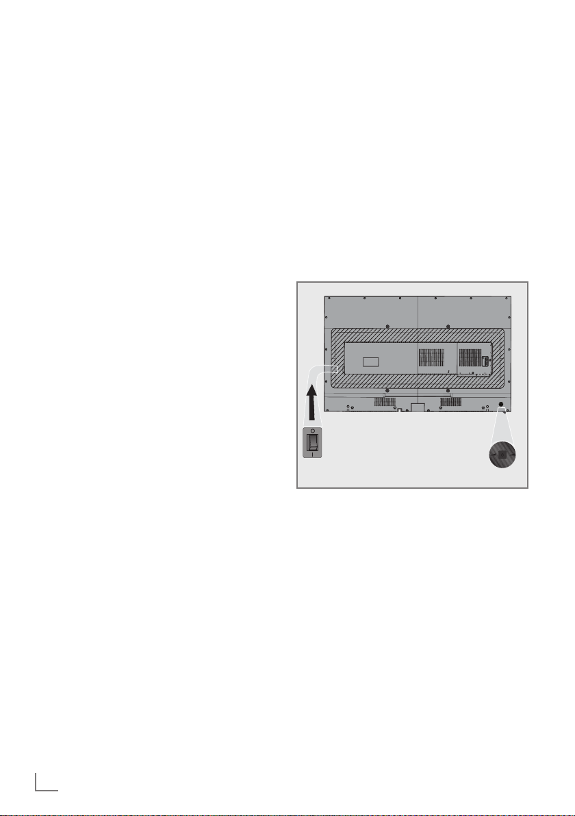
Control elements on the television
O/I Power button, used to
switch the TV to standby
mode and turn the TV off.
Note:
7
There must not be any obstacle around the
power switch for you to access it easily.
Multi-function switch
P+
+ -
P-
Switching on the television
1 Press the multi-function switch.
Switching the television to standby
mode
1 Press the multi-function switch.
2 Select "Stand by".
3 Press.
Adjusting the volume or changing the
channel
1 Press the multi-function switch.
2 Select the required function.
3 Press.
4 Thus the selected function is performed.
18

PRODUCT INSTALLATION
Remote control - main functions
-------------------------------------------------------------------
Switches the television on
from standby mode; selects
channels directly.
Selects the channel list
(»ALL«, »FAV1« to »FAV4«).
Opens the electronic TV
guide
Displays information.
Opens the menu.
Opens the channel list.
Opens Tools menu.
Adjusts the volume.
Turns audio on/off (mute).
Record, playback,
pause or
stop (digital
television channels only).
Turns on/off the television
set (stand-by).
Switches between teletext
and TV modes.
HbbTV functions help screen.
Exits menus and applications.
Zapping function
switches the menus back one
menu level.
Opens MyApps menu.
Signal source.
Switches the television on
from standby mode;
selects the stations step by
step
Previous, Next,
Forward, Backward;
Double Character in Teletext
Mode, Update, Freeze, Responds.
Opens Netflix application.
Cursor Control
Moves the cursor up and down
in menus.
Moves the cursor to the left/
right in menus.
Opens the channel list;
activates various functions.
Chooses subtitles.
Opens Media Player menu.
Chooses audio channel.
19

SETTINGS
------------------------------------------------------------------------------------------------------------------
The television is fitted with an "installation assistant", which guides you step by step through the
basic settings.
The user can use the dialogue window on the
screen to perform settings that seem complex
and data inputs in a simple way that will be
understood by anybody.
Pages and dialogue items appear on the screen,
which identify the subsequent and likely operating steps.
To support this, you will also see the required
button symbols of the remote control.
Detailed basic settings:
– language selection
– country selection;
– user mode selection;
– network configuration (if required);
– Station settings (DVB-S, DVB-T, DVB-C and
analog channels).
Settings for connecting to the
home network
Connect your television to the home network
based on the home network connection:
– via a LAN connection or
– via WLAN without cable
There are two options with LAN connection:
Auto connection,
all data regarding connection settings (»IP Ad-
dress«, »Netmask«, »Gateway« and »DNS«)
are obtained from the modem automatically.
Manual connection,
all data regarding connection settings (»IP Ad-
dress«, »Netmask«, »Gateway« and »DNS«)
must be configured manually.
There are various options when using WLAN:
Auto connection,
all data regarding connection settings (»IP Ad-
dress«, »Netmask«, »Gateway« and »DNS«)
are obtained from the modem automatically.
Depending on the router, you can use the fol-
lowing options:
– Option "WPS-PBC" (Push Button Configura-
tion);
– Connection with a WPS PIN;
– Connecting by entering the network pass-
word.
Manual connection,
all data regarding connection settings (»IP Ad-
dress«, »Netmask«, »Gateway« and »DNS«)
must be configured manually.
Tuning television channels
Depending on the type of the antenna connected, you can determine which television channels
you would like to search.
DVB-S – Tunes digital satellite television chan-
nels.
You have two options for this search:
– basic installation which pre-sets a standard
selection, e.g. The satellite Astra 19.2°
East; you only need to start the scanning;
– professional installation, which allows you
to make all required settings and set parameters for your receiver's system.
DVB-C – Tunes digital cable television chan-
nels.
DVB-T
– Tunes digital terrestrial television chan-
nels.
20

SETTINGS
------------------------------------------------------------------------------------------------------------------
Initial set-up
1 Switch the television set to standby using the
power switch O/I.
2 Switch on the television in standby mode
with »8«, »1…0«, »P+« or »P–«.
– The Menu Language selection menu ap-
pears when the television is switched on
for the first time.
Smart Inter@ctive 4 0
Please select your desired menu language
Menu Language
Česky Dansk Deutsch Engl sh Español
Hrvatski taliano Magyar Neder
Pyccкий Româneşte Slovenščina Eesti Suomi Svenska Бългaрски
Slovenčina Letuviu Türkçe
lands
3 Select the menu language with »<«, »>«,
»V« or »Λ« and press »OK« to confirm.
– »Welcome« menu appears.
4 Gradual set-up will be performed to use the
television. Press »OK« to start the set-up.
5 Use »<«, »>«, »V« or »Λ« to select the
country in which the television is going to be
used and press »OK« to confirm.
– When »User Mode« appears, select
»Home Mode«.
6 Confirm »Home Mode« option with »OK«;
or
Select »Enhanced« with »V« or »Λ« and
confirm with »OK«.
– »Home Mode« contains preconfigured
TV settings that provide energy savings
conforming EUP.
Eλληvıκά
Français
Norsk Polski Português
– »Enhanced« – if you will use the televi-
sion for a demo presentation, enhanced
picture and sound settings are used in this
mode. Enhanced mode consumes more
energy.
7 Select »Stand« or »Wall-mounted« with »V«
or »Λ«.
Note:
7
Choosing the location of the television is
important for automatic sound setting.
8 Press »OK« to confirm »Next«.
– »Summary« menu will be displayed.
9 Press »
« (blue) to proceed to the next
step.
– »Accessories« menu will be displayed.
10 Perform the settings in this menu if an acces-
sory used for the television is connected to
the television.
Press »V« or »Λ« to select the accessory
and adjust with »<«, »>«.
11 Press »
« (blue) to proceed to the next
step.
Notes:
7
If you wish to connect your television to the
home network,
– continue at point 12 for an automatic LAN
connection, or
– continue at point 16 for an automatic
WLAN connection.
Note:
7
If connecting to a home network is not
necessary, skip the use setting »
« (blue).
Continue setting at point 23 28 or 33.
21

SETTINGS
------------------------------------------------------------------------------------------------------------------
Connecting to the home network with a
LAN cable
12 Select »Wired« with »V« or »Λ« and
confirm with »OK«.
13 Select »Connect« with »« (Red) to establish
modem connection.
– »Connecting ... Please wait« message
will be displayed, and if the connection
is established »Connection To Gateway:
Success«, »Internet Connection: Success«
message will be displayed.
14 Press »« (green) to make sure that the
settings have been made and the local
network and internet connection have been
established.
– »Testing ... Please wait« message will
be displayed, and if the connection is
established »Connection To Gateway:
Success«, »Internet Connection: Success«
message will be displayed.
15 Press »
Setup« menu.
Auto connection by inputting the network password
16 Select »Wireless« with »V« or »Λ« and
confirm with »OK«.
17 Use »<« or »>« to select »Yes« for »Do you
want to turn on Wi-Fi?« and confirm with
»OK«.
18 Select the »Select Access Point« with »V«
or »Λ« and press »OK« to confirm.
– »Select Access Point« menu will be dis-
played and available wireless networks
will be scanned and displayed in the
menu.
« (blue) to switch to »Source
19 Select the network that you want to con-
nect with »V« or »Λ« and press »OK« to
confirm.
– Wireless connection password screen will
be displayed.
20 Select the required character with »<«, »>«,
»V« or »Λ« and move to the next character with »OK«.
– Using »Shift« ➡ »OK«, you can switch
between upper-case letters / numbers and
lower-case letters / special characters.
– Select »Del« to delete the character
entered and press »OK« to confirm.
21 Confirm the password with »« (green).
– »Connecting ... Please wait« message
will be displayed, and if the connection
is established »Connection To Gateway:
Success« message will be displayed.
22 Press »« (green) to make sure that the
settings have been made and the local
network and internet connection have been
established.
– »Testing ... Please wait« message will
be displayed, and if the connection is
established »Connection To Gateway:
Success«, »Internet Connection: Success«
message will be displayed.
23 Press »
Setup« menu.
« (blue) to switch to »Source
22

SETTINGS
------------------------------------------------------------------------------------------------------------------
Searching television channels with satellite signal (DVB-S/S2)
24 Select »Satellite« with »V« or »Λ« and
confirm with »OK«.
– Türksat Satellite is preset to 42 ° East.
25 Select »Standard Mode« with »V« or »Λ«
and confirm with »OK«.
26 Press »
« (blue) for the next page.
Notes:
7
Select »Channel Type«.
Press »V« or »Λ« to select whether you
want to search for only digital channels
(Digital) or only radio channels (Radio) or
both (Digital + Radio) and press »OK« to
select and mark or unmark the »Digital«
and/or »Radio« items.
7
Select Scan Mode.
To select whether you want to scan free digi-
tal television channels (Free), only encrypted
digital television channels (Scrambled) or
both (Free + Scrambled), press »V« or
»Λ« and press »OK« to select and mark
or unmark the »Free« and/or »Scrambled«
elements.
27 Press »« (Red) to start scanning.
– »Automatic Channel Search« menu will
appear and TV channels scanning will
start.
– The scan is complete as soon as »Search
is completed!« appears.
28 Select the »Channel Editor« with »OK«.
Tuning digital cable television channels
(DVB-C)
29 Select »Cable« with »V« or »Λ« and
confirm with »OK«.
30 Select »Scan Type« with »V« or »Λ«.
Select »Quick« or »Full« with »<« or »>«.
– »Quick« scanning function tunes the
channels according to the cable operator
information in the broadcasting signal.
– »Full« scan function scans the entire fre-
quency range selected. With this search
option, searching can take a long time.
This search type is recommended. Some
cable providers do not support »Quick«
scan.
Note:
7
You can speed up the search. To do this,
frequency and network ID information are
required. You may get this data from your
cable operator or find it in Internet forums.
31 Press »
« (blue) for the next page.
Note:
7
Select Channel Type. Press »V« or »Λ« to
select whether you want to scan only digital
channels (Digital), only Analog channels
(Analog) or both (Digital + Analog) and
press »OK« to select and mark or unmark
the »Digital« and »Analog« elements.
32 Press »« (Red) to start scanning.
– »Automatic Channel Search« menu will
appear and TV channels scanning will
start.
– The scan is complete as soon as »Search
is completed!« appears.
33 Select the »Channel Editor« with »OK«.
23

SETTINGS
------------------------------------------------------------------------------------------------------------------
Tuning terrestrial digital television
channels (DVB-T/T2)
34 Select »Air« (Antenna) with »V« or »Λ«
and confirm with »OK«.
Important:
7
Air (antenna) power supply (5V ) may
only be switched on if the antenna is an
active indoor antenna with a signal amplifier
and is not already supplied with a voltage
via a mains plug (or similar supply).
Otherwise you may cause a short circuit
and irreparably damage your antenna.
35 Select »Active Antenna Power« with »V«
or »Λ«.
Switch on the antenna power supply for the
antenna with »<« or »>« (»On«).
36 Select »Next Page« with »V« or »Λ« and
press »OK« to confirm.
Note:
7
Select Channel Type. Press »<« or »>« to
select whether you want to search for only
digital channels (Digital), only Analog channels (Analog) or both (Digital + Analog)
and press »OK« to select and mark or
unmark the »Digital« and »Analog« items.
37 Press »« (Red) to start scanning.
– »Automatic Channel Search« menu will
appear and TV channels scanning will
start.
– The scan is complete as soon as »Search
is completed!« appears.
38 Select the »Channel Editor« with »OK«.
24

PICTURE / SOUND SETTINGS
---------------------------------------------------------
Picture settings
1 Open the menu with »MENU«.
2 Select »Settings« with »<«, »>«, »V« or
»Λ and confirm with »OK«.
3 Confirm the menu item »Picture« with »V«.
– »Picture« menu is now activated.
Settings > Picture
P cture
Picture Format 16 9
Picture Mode Natural
Backlight Eco
Advanced
Restore Default Display Settings
Change Area Select ExitBack
Broadcast TimerNetwork Parental
4 Select the desired line/function with »V« or
»Λ« and press»OK« to confirm.
Select the option with »<« or »>« and press
»BACK
to return to »Picture Settings«
«
<
menu.
Note:
7
Other settings are available under »Advanced«.
5 Press »V« to select »Advanced« and con-
firm with »OK«.
6 Select the desired line/function with »V« or
»Λ« and press»OK« to confirm.
Select the value/option with »<« or »>«
and press »OK« to confirm.
Press »BACK
to return to »Picture Set-
«
<
tings« menu.
7 Press »EXIT« to finish the setting.
Thu
XX XXX XXXX
BACK EXIT
Enhanced picture settings
"Enhanced picture settings" are found in primary
digital picture. However, these should only be
used when necessary when the picture quality
and transmission are excellent. They may well
improve the display with poor material, but may
adversely affect the display where transmission
and picture quality are excellent.
7
»Vibrant Colour« – Increases the color
contrast and the contrast adjustment. This
setting is mostly too strong for use with nor-
mal pictures and should only be used where
necessary (low or off). Otherwise, nuances
in the picture can be suppressed.
7
»Gamma« – This setting determines which
brightness value should be displayed for
which digital transmission value. Most
records are transferred in 2.2 gamma value
(All Windows computers and newer MAC
based computers operate on this value
while older MAC systems and transfers with-
out color profiles operate on 1.8 gamma
value).
7
»Dynamic Contrast« – This function dynami-
cally and optimally adjusts the contrast for
the respective picture content by analyzing
images and then altering this depending
on a change in contrast. This increase in
the contrast however may also reduce the
visible brightness levels in the picture.
7
»Perfect Clear« – Improves the general im-
age by means of a gentle blue hue (giving
the appearance of greater sharpness) and
improves the black level by setting it entirely
to black from a specific shade of back.
This reduces visible grey values in the dark
areas of the picture.
7
»Film mode« detects and processes feature
films automatically for all channel sources.
This means that you get the optimum picture
at all times.
This functions in 480i, 576i and 1080i
modes in TV playback and for other channel
sources.
If the »Film mode« is switched on for pro-
grams without a feature film signal, minor
problems such as picture freeze, defective
subtitles or fine lines in the picture may occur.
25

PICTURE / SOUND SETTINGS
7
»Sharpness« – Reduces the visible "snowy"
areas by displaying the picture a little more
sharply and creating a slight blurring. It
should therefore be used minimally provided that a good picture material is present.
7
»Noise Reduction« – Reduces the visible
"snowy" areas by displaying the picture a
little more sharply and creating a slight blurring. It should therefore be used minimally
provided that a good picture material is
present.
7
»Block Noise Reduction« – This function
can only be selected with digital receiver
sources and AV pre-sets. It reduces any interference from artefacts (pixel blocks) from
digital programs due to MPEG compression
(such as from DVB-T receivers and lower
transmission rates or DVD players).
Restore Factory Defaults
1 In »Picture« menu, select »Restore Default
Display Settings« with »V« and press »OK«
to confirm.
2 Press »Yes« to confirm the security query;
or
select »No« and press »OK« to cancel.
3 Press »EXIT« to finish the setting.
Ending the settings
1 Press »EXIT« to end the setting and quit the
menu.
---------------------------------------------------------
26

PICTURE / SOUND SETTINGS
---------------------------------------------------------
Sound settings
1 Open the menu with »MENU«.
2 Select »Settings« with »<«, »>«, »V« or
»Λ and confirm with »OK«.
3 Select the menu item »Sound« with »>« or
»<« and press »V« to confirm.
– »Sound« menu is now activated.
Settings > Sound
Pictu e
Sound Mode Natural
Night Mode Off
Bluetooth Off
Select Bluetooth Device
Advanced
Restore Default Display Settings
Change Area Select ExitBack
Broadcast TimerSound NetworkTV Parental
Note:
7
Additional operations are explained in the
following sections.
Sound Mode
1 Select »Sound Mode« with »V« or »Λ«.
2 Press »<« or »>« to select »Standard
Mode« or »User«.
DTS Studio Sound™
DTS Studio Sound is an advanced surround
audio solution suite that accurately extracts and
places audio cues for deep surround experience
over the TVs' built-in speakers. To complete the
audio experience, post processing and psychoacoustic techniques are implemented to provide
3D audio rendering to match 3D video content,
for bass and dialogue enhancement and to deliver consistent and level volume across content.
DTS Studio Sound Technology is supported in
Film, Natural, Speech and Music settings.
1 Select »Sound Mode« with »V« or »Λ«.
2 Use »<« or »>« to select »Film« »Natural«,
»Speech« or »Music«.
Thu
XX XXX XXXX
BACK EXIT
Night Mode
Night Mode prevents sound fluctuations and
volume increases.
1 Select »Night Mode« with »V« or »Λ«.
2 Activate (»On«) or deactivate the night
mode by pressing »<« or »>«.
Notes:
7
»Night Mode« will be active in the menu is
»DTS« is selected in »Sound Mode«.
7
Other settings are found under »Ad-
vanced«. Select »Advanced« with »V« or
»Λ« and press »OK« to confirm.
Turning Bluetooth on/off and connecting to an external sub-woofer
The Bluetooth feature sends audio signal of the
television to the sub-woofer.
The television sends signals only to Bluetooth
compatible devices.
1 Turn on sub-woofer and start pairing. (Refer
to the sub-woofer's user manual for pairing).
2 Use »V« or »Λ« to select »Bluetooth« and
press »<« or »>« to confirm.
– Wireless audio device will start. The sub-
woofer will appear in the menu after a short
time.
3 After the sub-woofer has been found, con-
firm with »OK«.
– The name of the subwoofer will be dis-
played in »Sound« menu.
See http://patents.dts.com for DTS patents. Manufactured under license from DTS Licensing Limited. DTS and
the Symbol as well as DTS and the Symbol used together are registered trademarks. DTS Studio Sound is
a trademark of DTS, Inc. © DTS, Inc. All rights reserved.
See http://patents.dts.com for DTS patents. Manufactured under license from DTS Licensing Limited. DTS
and the Symbol as well as DTS and the Symbol used
together are registered trademarks. DTS 2.0+Digital
Out is a trademark of DTS, Inc. © DTS, Inc. All rights
reserved.
27

PICTURE / SOUND SETTINGS
---------------------------------------------------------
Note:
7
For pairing, select »Select Bluetooth Device«
with »V« or »Λ« and press »OK« to confirm. Save the subwoofer with »« (red).
4 Press »EXIT« to finish the setting.
TV location
Choosing the location of the television with this
feature is important for the automatic sound
setting.
1 Select »Advanced« with »V« or »Λ« and
press »OK« to confirm.
2 Select »TV Location« with »V« or »Λ«.
3 Select »Stand« or »Wall-mounted« with »<«
or »>«.
Stereo/dual channel
If the device receives two channel programs,
e.g. a film with the original sound on sound
channel B (display: »Dual II«) and the dubbed
version on sound channel A (display: »Dual I«),
you can select the desired sound channel.
1 Select »Advanced« with »V« or »Λ« and
press »OK« to confirm.
2 Select »Sound Type« with »V« or »Λ« and
adjust with »<« or »>«.
Equalizer
Equalizer offers a sound setting that you can
create.
Equalizer is active in the menu when »Sound
Mode« is selected as »User«.
1 Select »Advanced« with »V« or »Λ« and
press »OK« to confirm.
2 Select »Equalizer« with »V « or »Λ« and
press »OK« to confirm.
– »Equalizer« menu will open.
3 It is active in »120Hz« frequency band.
Adjust the preferred value by using »<« or
»>«.
4 Select the next frequency band with »V« or
»Λ« to repeat the adjustment procedure.
5 Press »BACK <« to save the setting.
Auto volume
Television channels broadcast at different volumes. Automatic Volume Limiting (AVL) function
enables the volume to be kept the same when
you switch between channels.
1 Select »Advanced« with »V« or »Λ« in the
Sound menu and press »OK« to confirm.
2 Select »AVL« with »V« or »Λ« and then
select »On« with »<« or »>«.
Note:
7
AVL is active in the menu when »Sound
Mode« is selected as »User« or »Standard
Mode«.
Restore factory defaults
1 In »Sound« menu, select »Restore Default
Sound Settings« with »V« and press »OK«
to confirm.
2 Press »Yes« to confirm the security query;
or
select »No« and press »OK« to cancel.
3 Press »EXIT« to finish the setting.
Ending the settings
1 Press »EXIT« to end the setting and quit the
menu.
28

ELECTRONIC TV GUIDE
---------------------------------------------------------------------------
The Electronic TV guide (RoviGuideTM) has two
operation modes, namely online and offline.
In the offline mode, you can only see channel
data which the station provider has made
available.
A lot of content can be received via the Internet
connection in the online mode such as, program
information, channel logos, information about
players, pictures, fragments, etc.
Logging on to "RoviGuide™"
When opening the channel guide for the first
time, you must accept Terms and Conditions
so that you can fully access the customized
functionality of the TV guide.
Note:
7
The TV guide will only work with basic
information if you do not accept Terms and
Conditions.
1 Press »GUIDE« to start Electronic TV guide.
– »Terms and Conditions« will be displayed.
2 Use »V« to display Terms and Conditions,
select »I Agree« and confirm with »OK«.
The Electronic TV guide in offline
mode
In the offline mode, the electronic program
guide offers an overview of all programs that
will be broadcast in the next week (for digital
stations only).
1 Press »GUIDE« to start Electronic TV guide.
– A message will appear.
Notes:
7
Not all stations provide a detailed TV
guide.
7
Many broadcasters supply their daily
program but not the detailed descriptions.
7
There are broadcasters which do not
provide any information at all.
2 Select »Continue« with »V« and press
»OK« to confirm.
– The programs of the first 5 channels
(in the order of the Channel Editor) will be
displayed.
3 Select the channel with »V« or »Λ«.
– Information about the actual program will
be displayed in the selected television
channel.
Note:
7
Press »P+« or »P-« to skip 5 channels each
time.
4 Switch to the information section about the
current program using »OK«.
Notes:
7
To display a small image of the program,
select »Watch« with »>« and confirm with
»OK«.
7
The selected program can be stored (if an
external data medium is connected). To do
this, select »Store« with »>« and confirm
with »OK«. Confirm the image with »OK«.
7
To add the selected program to the
reminder timer, select »Set Reminder« with
»>« and confirm with »OK«. Confirm the
image with »OK«.
5 Return to the program overview with
»BACK
<
«.
6 Press »>« to select information on the next
program and press »<« to return to the
information for the current program.
Note:
7
Refer to the user guide on the screen for
additional options.
7 Press »EXIT« to close the channel guide.
29

ELECTRONIC TV GUIDE
---------------------------------------------------------------------------
The Electronic TV guide in online
mode
In the online mode, two other search criteria are
available as well as a range of information.
You can search for different topics using
»Browse«.
Use the »Search« function to enter a search item
and suggestions will appear on the right side of
the screen.
Note:
7
The basic functions are the same as in the
"Offline mode".
1 Press »GUIDE« to start Electronic TV guide.
– »Electronic TV guide« will be displayed.
2 Press »<« once to display the upper menu.
– »TV Listings« option is marked.
Homepage
The homepage provides quick access to
specially tailored content.
1 To return to the overview, press »<« and
then press »Λ« to select »Homepage« and
confirm with »OK«.
– A program list will be displayed.
2 Select the required program with »V«,
»Λ«, »<« or »>« and press »OK« to view
the information.
3 Return to the TV Lists with »« (red).
"Browse" search parameter
1 Select »Browse« with »V« or »Λ« and
press »OK« to confirm.
– A program list will be displayed.
2 Press »<« and select the search parameter
with »V« or »Λ« and press »OK« to
confirm.
– Search results will be displayed on the
screen.
3 Select the required program with »V«,
»Λ«, »<« or »>« and press »OK« to view
the information.
Note:
7
Select additional information with »V«,
»Λ«, »<« or »>« and press »OK« to
confirm.
4 Return to the TV Lists with »« (red).
"Search" search parameter
1 Select »Search« with »V« or »Λ« and
press »OK« to confirm.
– An entry field will appear.
2 Select the first character/digit of the
required search item with »V« or »Λ« and
press »OK« to move to the next position.
– The search results for the first character/
digit will be displayed on the screen.
3 Select the other characters/digits of the
required search item with »V« or »Λ« and
press »OK« to confirm.
Notes:
7
The last character/digit can be deleted with
»BACK
7
You can open additional search options
<
«.
with »« (green).
4 Press »>« to switch to the search item.
5 Select the required program with »V« or
»Λ« and select information/options with
»>«.
6 Return to the TV Lists with »« (red).
30

USB RECORDING
-------------------------------------------------------------------------------------------
Connecting external data medium
Notes:
7
It is advised to switch the television to standby mode before connecting the External
Data medium.
7
Before disconnecting the external data
medium, first of all, the television must be
switched to standby mode. Otherwise, may
can be damaged.
7
There are three USB inputs on the television,
namely »USB1«, »USB2« and »USB 3«.
USB1
and USB2 inputs are intended for
USB devices that require additional power
(e.g. external hard disk).
Notes:
7
USB3 port of the TV supports 500 mA
current according to the USB standard.
Devices that consume more power such as
external hard disks can only be connected
to the USB1 and USB2 interface of the
television.
7
If you are using a power cable for the external hard disk that you have connected to
the »USB1« and »USB2« USB interface,
then the power cable of the external hard
disk must also be unplugged when the TV is
turned off.
7
You must not disconnect the USB Device
from the TV while a file on the USB Device
is being read by the TV.
1 Plug the external hard disk to USB1 or
USB2 interface of the television;
or
plug the memory stick into the USB3 inter-
face of the television.
31

USB RECORDING
-------------------------------------------------------------------------------------------
USB recording settings
Selecting the menu
1 Open the menu with »MENU«.
2 Select »Records« with »V«, »Λ«, »<« or
»>« and confirm with »OK«.
– »Media Player« menu will be displayed.
3 Select »PVR« with »V« or »Λ« and press
»OK« to confirm.
– Content will be displayed.
4 Press »TOOLS«.
– »Media Options« menu will be displayed.
Media Player > PVR
Channel 1
Media Options
View Mode Auto Fit
Auto Preview On
Slide Show
Interval
Disk Manage
ment
5
Note:
7
Additional operations are explained in the
following sections.
Removing the external data medium
1 In the »Disk Management« menu, select
»Safely Remove Disk« with »V« or »Λ«
and press »OK« to confirm.
Note:
7
The disk can now be safely removed from
the socket.
XX XXX XXXX
Thu
Back
BACK
Selecting external data medium
If there are more than one external data medium
connected to the television, select one of them.
1 In the »Disk Management« menu select
»Disk« with »V« or »Λ« and press »OK«
to confirm.
2 Select the external data medium with »V«
or »Λ« and press »OK« to confirm.
3 Return with »BACK <« or press »EXIT« to
finish settings.
Selecting a partition on the external
data medium
If there are more than one partitions on the
external data medium, select one of them.
1 In the »Disk Management« menu, select
»Partition« with »V« or »Λ« and press
»OK« to confirm.
2 Select the desired partition with »V« or
»Λ« and press »OK« to confirm.
3 Return with »BACK <« or press »EXIT« to
finish settings.
Testing external data medium
You can test the external data medium to see if it
is suitable for functions.
1 In the »Disk Management« menu select
»Disk« with »V« or »Λ«. If there are more
than one external data medium, select the
desired data medium with »V« or »Λ«.
2 Select »Partition« with »V« or »Λ«. If there
are more than one partition, select the
desired partition with »V« or »Λ«.
3 Select »Check Disk« with »V« or »Λ« and
press »OK« to confirm.
– Disk information will be displayed.
4 Return with »BACK <« or press »EXIT« to
finish settings.
32

USB RECORDING
-------------------------------------------------------------------------------------------
Formatting the partition
1 In the »Disk Management« menu, select
»Format Partition« with »V« or »Λ« and
press »OK« to confirm.
2 Select »Yes« with »<« or »>« to confirm the
deleting process;
or
select »No« and press »OK« to cancel.
3 Return with »BACK <« or press »EXIT« to
end the setting.
Switching to continuous recording
When the permanent recording option is set to
on, the TV starts recording the current program
to the time shifting memory. Average recording
time for this memory is 60 minutes.
1 Open the menu with »MENU«.
2 Use »V«, »Λ«, »<« or »>« to select »Set-
tings« and confirm with »OK«.
3 Select »TV« with »>« or »<.
4 Select »Advanced« with »V« or »Λ« and
press »OK« to confirm.
5 Press »V« or »Λ« to select »Permanent
Timeshift« and press »<« or »>« to turn it to
»On« position.
6 Press »EXIT« to finish the setting.
"Pausing" time shift programs
You can pause a program that you are watching. This is a useful function. For instance, if the
phone rings when you are watching a movie,
you can pause the movie and resume it after the
call without missing anything.
The freeze-frame image of the last scene will be
displayed on the screen and the time shift will
be stored in the external data medium.
In the Time shift mode, you can only record as
much as the free memory in the external data
medium.
You can record 60 minutes maximum in the current broadcast.
Note:
7
Use an external USB hard disk for an uninterrupted "Permanent Time Shift".
1 Press »!« during the broadcast.
– The television image will be paused and
the delay time will be displayed.
2 Press »8!« to resume the broadcast.
– The system will continue to record the
broadcast while you are watching it.
Note:
7
The following functions can be used in Time
Shift mode.
– Fast rewind, press »3« several times for
the desired speed;
– Fast forward, press »4« several times for
the desired speed;
– Press »!« to pause.
3 Press »7« to quit the time shift function.
– »Live Broadcast« will appear.
- Images in "Time shift memory" will be
deleted.
33

USB RECORDING
-------------------------------------------------------------------------------------------
Formatting the partition
1 In the »Disk Management« menu, select
»Format Partition« with »V« or »Λ« and
press »OK« to confirm.
2 Select »Yes« with »<« or »>« to confirm the
deleting process;
or
select »No« and press »OK« to cancel.
3 Return with »BACK <« or press »EXIT« to
end the setting.
Switching to permanent timeshift
When the permanent recording option is set to
on, the TV starts recording the current program
to the time shifting memory. Average recording
time for this memory is 60 minutes.
1 Open the menu with »MENU«.
2 Use »V«, »Λ«, »<« or »>« to select »Set-
tings« and confirm with »OK«.
3 Select »TV« with »>« or »<.
4 Select »Advanced« with »V« or »Λ« and
press »OK« to confirm.
5 Press »V« or »Λ« to select »Permanent
Timeshift« and press »<« or »>« to turn it to
»On« position.
6 Press »EXIT« to finish the setting.
"Pausing" time shift programs
You can pause a program that you are watching. This is a useful function. For instance, if the
phone rings when you are watching a movie,
you can pause the movie and resume it after the
call without missing anything.
The freeze-frame image of the last scene will be
displayed on the screen and the time shift will
be stored in the external data medium.
In the Time shift mode, you can only record as
much as the free memory in the external data
medium.
You can record 60 minutes maximum in the current broadcast.
Note:
7
Use an external USB hard disk for an uninterrupted "Permanent Time Shift".
1 Press »!« during the broadcast.
– The television image will be paused and
the delay time will be displayed.
2 Press »8!« to resume the broadcast.
– The system will continue to record the
broadcast while you are watching it.
Note:
7
The following functions can be used in Time
Shift mode.
– Fast rewind, press »3« several times for
the desired speed;
– Fast forward, press »4« several times for
the desired speed;
– Press »!« to pause.
3 Press »7« to quit the time shift function.
– »Live Broadcast« will appear.
- Images in "Time shift memory" will be
deleted.
34

USB OPERATION
--------------------------------------------------------------------------------------------
Recording Programs
You can record a TV channel while watching
another TV channel at the same time. Data for
these programs are stored in the external data
medium and the archive is managed via the
television.
You can record digital terrestrial (DVB-T), digital
cable (DVB-C) and digital satellite (DVB-S) channels and watch a different TV channel at the
same time.
Note:
7
If you want to watch a different TV program
while recording digital satellite (DVB-S)
programs, you need to connect a second
satellite cable to SATELLITE SUB input.
A memory of 44 MB to 110 MB is required for
a 1 minute recording.
Other recordings in the archive can be watched
while a program is being recorded.
It is not possible to switch between DVB-T and
DVB-C channels.
One-touch program recording
1 Select the channel with »1…0« or »P+«,
»P–« and press » « to start recording.
– Recording information will be displayed:
Recording symbol, channel name, program time and recording time.
– This information will disappear shortly.
2 Press »7« to end recording.
3 Use »<« or »>« to select »Yes«;
or
select »No« and press »OK« to cancel.
Notes:
7
When recording is complete, it will automatically be stored in the external data
medium.
7
If you remove the external data medium
during recording, then the recording will be
cancelled automatically and no data will
be recorded into the external data medium.
Recording a program from the channel
list
1 Press »OK« to open the channel list.
2 Select a channel with »<« or »>« and press
»OK« to confirm.
3 Press »EXIT« to exit the channel list.
4 Press » « to start recording.
– Recording information will be displayed:
Recording symbol, channel name, program time and recording time.
– These information will disappear after a
short while. Recording symbol and the
recording time will appear on the lower
right corner of the screen.
5 Press »7« to end recording.
6 Use »<« or »>« to select »Yes«;
or
select »No« and press »OK« to cancel.
35

USB OPERATION
--------------------------------------------------------------------------------------------
Program setting for recording
... with electronic program guide
Electronic program guide data can be used for
recording.
A total of 25 EPG reminders and/or recorders
can be set in total.
1 Press »GUIDE« to open the electronic
program guide (EPG).
2 Select the desired channel with »V« or
»Λ«.
– Information about the actual TV program
will be displayed.
3 Press »<« or »>« to select the TV program
you want to record.
4 Press »OK« to add broadcasts to the timer.
– Information for the TV program to be
recorded will be displayed.
5 Select »Record« with »>« and press »OK«
to confirm.
– Recording data range will be displayed.
6 Press »OK« to confirm.
7 Press »EXIT« to end the settings.
Notes:
7
Open the menu with »MENU« if the
recording data will be modified. Select the
»Schedule List« menu with »V«, »Λ«, »<«
or »>« and confirm with »OK«. Press »«
(green), modify the data and save it with
»
« (blue).
7
A warning will be displayed before the
timer recording starts and it will count down
for 10 seconds to allow you to switch to
the channel. At the end of 10 seconds,
the channel to be recorded will appear
automatically.
7
If the timer recording starts during playback, playback will stop. If you do not select
»Yes« in the warning prompt, recording
will start automatically at the end of the
countdown.
7
Note specific to UPC customers: While the
program is being recorded, part of the previous or the next program may be included in
the recording because of Programme Guide
errors. In such cases, keep in mind that the
highest family protection level will apply to
the whole recording if one or more of those
programs has/have family protection.
Setting the delay/follow-up time
You can change the recording time set with the
electronic TV guide with this function.
If you think that a program will start a few minutes earlier or will end several minutes later, you
can "add" up to 60 minutes to this time.
1 Open the menu with »MENU«.
2 Select »Schedule List« with »V«, »Λ«, »<«
or »>« and confirm with »OK«.
3 Confirm »Padding Time« with »
« (blue).
4 Change the start time with »<« or »>«.
5 Use »V« to switch to the »End« line and
change the end time with »<« or »>«.
6 Use »V« to press »Save« to save the set-
ting.
7 Press »EXIT« to end the settings.
36

USB OPERATION
--------------------------------------------------------------------------------------------
... by entering the information manually
25 TV programs can be preset for timer recording or for the reminder.
1 Press »GUIDE« to open the electronic
program guide (EPG).
2 Press < button successively. Menu will be
displayed on the left side of the screen.
3 Select »Record Manually« with »V« or
»Λ« and press »OK« to confirm.
– »Channel« will be marked.
Note:
7
If you want to use reminder function, select
»Manual Reminder«.
4 Confirm »Channel« with »OK«. Press »V«
or »Λ« to select the channel you wish to
record and confirm with »OK«.
5 Select »Date« with »V« or »Λ« and con-
firm with »OK«. Press »V« or »Λ« to select
the date you wish to perform the recording
and confirm with »OK«.
6 Confirm »Start Time« with »OK« and enter
the start time with »1…0«. (hours:minutes).
7 Confirm »End Time« with »OK« and enter
the end time with »1…0«. (hours:minutes).
8 Confirm »Repeat Record« with »OK«. Press
»V« or »Λ« to make a selection (»Once«,
»Weekly« or »Every Day«).
9 Select »Save Record« with »V« and confirm
with »OK«.
– Recording time range will be displayed.
10 Press »OK« to confirm.
– Recording timer is now programmed.
11 Press »EXIT« to exit the menu.
Notes:
7
A warning will be displayed before the timer
recording starts and it will count down for
10 seconds to allow you to switch to the
channel. At the end of 10 seconds, the channel to be recorded will appear automatically.
Editing the timer
You can edit programmed timers.
1 Open the menu with »MENU«.
2 Select »Schedule List« with »V«, »Λ«, »<«
or »>« and confirm with »OK«.
– The »Schedule List« will be displayed.
3 Press »V« or »Λ« to select the program
title to be edited and press »« (green) to
edit it.
4 Press »V« or »Λ« to select the items you
want to edit and modify them with »1…0«
and »<« or »>«.
5 Press »
– The timer will be changed.
6 Press »EXIT« to finish the setting.
« (blue) to save the changes.
Deleting a timer
You can delete programmed timers.
1 Open the menu with »MENU«.
2 Select »Schedule List« with »V«, »Λ«, »<«
or »>« and confirm with »OK«.
– The »Schedule List« will be displayed.
3 Select the title of the program to be deleted
with »V« or »Λ« and delete the timer with
»
« (yellow) button.
– Timer is now deleted.
4 Select »Yes« with »<« or »>« to confirm the
deleting process;
or
select »Cancel« and press »OK« to cancel.
5 Press »EXIT« to finish the setting.
37

USB OPERATION
--------------------------------------------------------------------------------------------
Playback
Recorded programs (started either manually or
using the timer function) are all stored in the external data medium. You can display an archive
in the external data medium from the »Media
Player« menu.
Selecting a broadcast from the recorded files list
1 Open the menu with »MENU«.
2 Select »Records« with »V«, »Λ«, »<« or
»>« and confirm with »OK«.
– »Media Player« menu will be displayed.
3 Press »V« or Λ« to select »PVR« and con-
firm with »OK«.
– Recorded files will be displayed.
4 Press »V« or »Λ« to select the broadcast
you want to play and press »8« to start
playing.
5 Press »7« to end playing.
– The TV will return to the media player
menu.
Forward/reverse picture search
1 Press »4« repeatedly to select the playback
speed (2x, 4x, 8x, 16x or 32x) during
playback.
or
press »3« repeatedly to select the play-
back speed (2x, 4x, 8x, 16x or 32x) during
playback.
Playback during a recording
You can either watch the current programme
that is being recorded or a previously recorded
program while recording takes place.
1 Select the channel with »1…0« or »P+«,
»P–
« and press » « to start recording.
2 Press »« (red) button to display PVR
content.
3 Press »V« or »Λ« to select the program
you want to watch and press »8« to start
playing.
4 Press »7« to stop playing.
5 Press »7« to stop recording.
6 Select »Yes« with »<« or »>« to confirm the
operation;
or
select »No« and press »OK« to cancel.
Deleting broadcasts from the
recorded files menu
You can delete recorded broadcasts from the
Recorded Files list.
1 Open the menu with »MENU«.
2 Select »Records« with »V«, »Λ«, »<« or
»>« and confirm with »OK«.
– »Media Player« menu will be displayed.
3 Select »PVR« with »V« or »Λ« and press
»OK« to confirm.
– Recorded files will be displayed.
4 Select the broadcasts to be deleted with
»V« or »Λ«.
5 Press »« (red) to delete the broadcast.
6 Use »<« or »>« to select »OK« and press
»OK« to confirm the operation.
7 Press »EXIT« to end the settings.
38

USB OPERATION
--------------------------------------------------------------------------------------------
File formats
Your television can be operated via the USB
input with the following file formats:
Video data
Video compression / decompression (codec) is
intended for decreasing the storage area without sacrificing the picture quality.
Your TV allows you to play compressed video
data with XVID, H.264/MPEG-4 AVC(L4.1, Ref.
Frames:4), MPEG-4, MPEG-2, MPEG-1, MJPEG,
MOV standards.
File extensions supported by the device: ".avi",
"mkv", ".mp4", ".ts", ".mov", ".mpg", ".dat",
".vob", ".divx". In addition to video data, these
files also contain audio data compressed and
"packaged" by using MP3, AAC or Dolby Digital.
Format (codec) information is embedded within
the file content and may differ depending on the
file extension. ".avi", ".mkv" or ".divx" files containing divx codec cannot be played.
Audio data
Your television can play audio data coded with
MP3, AAC standards.
MP3 stands for MPEG-1 Audio Level 3 and is
based on the MPEG-1 standard developed by
MPEG (Motion Picture Expert Group).
AAC indicates the Advanced Audio Coding and
has been developed by MPEG. AAC provides
higher audio quality with the same data rate (bit
rate).
WMA (Windows Media Audio) is a compression standard developed by Microsoft for audio
data.
These formats enable audio files to be saved on
storage devices with a sound quality similar to
that of a CD.
File extensions supported by your device:
".mp3", ".mp2", ".wma", ".m4a", ".aac", ".wav"
MP3 files can be organized into folders and
sub-folders similar to the files on a computer.
Picture data
Your television can display picture data in JPEG,
PNG and BMP formats.
JPEG stands for Joint Picture Experts Group. This
process is intended to compress picture files.
PNG and BMP standards are intended to compress picture data without loss.
Picture files can be saved in a data storage
medium together with other file types.
Such files can be organized as folders and
subfolders.
39

USB OPERATION
--------------------------------------------------------------------------------------------
Connecting external data medium
It is advised to switch the television to stand-by
mode before connecting the External Data medium. Connect the device and then switch the
television on again.
Before disconnecting the data medium, first of
all, the television must be switched to standby,
otherwise files may get damaged.
Notes:
7
»USB3« port of the TV supports 500 mA
current according to USB standard. Devices
that consume more power such as external
hard disks can only be connected to the
»USB1« and »USB2« interface of the
television.
7
To get higher efficiency from your external
devices supporting USB 3.0, it is recommended to connect them to »USB1«
interface of the TV.
7
If you are using a power cable for the
external hard disk that you have connected
to the »USB1« and »USB2« USB interface,
then the power cable of the external hard
disk must also be unplugged when the TV is
turned off.
7
You must not disconnect the USB Device
from the TV while a file on the USB Device
is being read by the TV.
A bi-directional data transfer as defined for
ITE (Information Technology Equipment)
devices in EN 55022/EN 55024 is not
possible.
7
USB transfer is not an operating mode by
itself. It is only an additional function.
1 Connect the »USB1« and »USB2« USB
interface of the television and the corre-
sponding data output socket on the external
data device (external hard drive, digital
camera, card reader or MP3 player) using
a USB cable;
or
plug the memory stick into the »USB3«
interface of the television.
Removing the external data medium
Disconnect the data medium before removing the external data
medium.
1 Open the menu with »MENU«.
2 Select »Media Center« with »V«, »Λ«,
»<« or »>« and confirm with »OK«.
3 Select »Safely Remove Disk« with »« (red).
4 Remove the data medium from the socket.
40

USB OPERATION
--------------------------------------------------------------------------------------------
File browser
The file browser displays the video, audio and
picture data that the external data medium
provides.
If a data medium contains different file formats,
you can deactivate data (Video file, Audio file,
Picture file) you do not need for the playback
using a filter function.
The main menu of the file browser
2
3
Media Player > DISK1
All Film Music
Film
Music
Photo
Film avi
Film str
Music mp3
Select All
+ P ay ist
TOOLS
Media Options
4
Play
Nav gat on Between
tems
5
1 Preview.
2 Data type.
3 Name of the data medium.
4 Folders in the data medium.
5 Menu navigation.
XX XXX XXXX
Filter Type
1
Thu
BACK
Settings in the USB set-up menu
Selecting the menu
1 Open the menu with »MENU«.
2 Select »Media Center« with »V«, »Λ«,
»<« or »>« and confirm with »OK«.
3 Select the external data medium with »V«
or »Λ« and press »OK« to confirm.
4 Select »Media Options« with »TOOLS«.
5 Select »Disk Management« with »V« or
»Λ« and press »OK« to confirm.
Note:
7
Additional operations are explained in the
following sections.
Selecting the screen mode
1 Select »View Mode« with »V« or »Λ«.
2 Press »<« or »>« to select the function.
Back
Note:
7
View Mode cannot be change while 3D
mode is active.
3 Press »EXIT« to finish the setting.
Switching to auto preview
If the auto preview is switched on, you can see
the selected file in the main menu of the file
browser.
1 Select »Auto Preview« with »V« or »Λ«.
2 Press »<« or »>« to switch the function
»On«.
3 Press »EXIT« to finish the setting.
41

USB OPERATION
--------------------------------------------------------------------------------------------
Selecting the display duration of the
slide show
1 Select »Slide Show Interval« with »V« or
»Λ«.
2 Select the time (3, 5, 10 seconds) with »<«
or »>«.
3 Press »EXIT« to finish the setting.
Subtitle settings
If the film you watch has subtitles, you can turn
on and off this subtitle, change its size or color.
1 Under »Media Options« menu, use »V«
or »Λ« to select »Auto Subtitle Selection«,
»Subtitle Size« or »Subtitle Color«.
2 Adjust with »<« or »>«.
3 Press »EXIT« to finish the setting.
Note:
7
These adjustments can only be made for external subtitle files. These adjustments cannot
be made in subtitles combined with the film.
Play basic functions
1 Open the menu with »MENU«.
2 Select »Media Center« with »V«, »Λ«,
»<« or »>« and confirm with »OK«.
– »Media Player« menu will be displayed.
3 Select the external data medium with »V«
or »Λ« and press »OK« to confirm.
– Media Player menu of the selected exter-
nal data medium will be displayed.
Note:
7
If the content of the external data medium
cannot not displayed, press »
to refresh.
4 Select the desired filter type (All, Film, Music
or Photo) with »<« or »>«.
5 Select the folder with »V« or »Λ« and
press »OK« to confirm.
– A list of sub-directories will appear.
Note:
7
Go back to the previous folder with »BACK
«.
<
6 Select the track or picture with »V« or »Λ«
and press »8« to start playing.
Notes:
7
When playing picture data, press »?« to
view information about the resolution and
the size.
7
For playing MP3 or WMA data, information on the album, track and singer, if any, is
displayed on the left side of the menu.
7
When playing picture data, press »?« to
switch on the control panel.
7 Press »!« to pause playing.
8 Press »8« to resume playing.
9 Press »7« to end playing.
– The file browser will be displayed.
« (yellow)
42

USB OPERATION
--------------------------------------------------------------------------------------------
Notes:
7
It is possible that some files that are sup-
ported in USB mode do not operate due to
some problems that may arise depending
on how such files are created (compression)
although they contain the supported file
extension.
7
If there are more than one audio sources
(audio stream) in the video files that are
being played, then you can switch between
the audio sources with the » « while the
file is being played in full screen mode.
7
Films you will be watching from the film
file only supports subtitles with .srt, .sub,
.ass, .ssa, .smi format. Names of the subtitle
and film files must be the same. Otherwise,
subtitle can not be displayed.
In films which you will watch in 3D mode
only external subtitle is supported. Internal
subtitles in some movies appear correct if
they are compatible with 3D format. If they
are not compatible, a blurry image will appear on screen.
Additional playing functions
Depending on the file formats used, the following additional functions are possible.
Selecting chapters in files
(only supported video files)
1 During playing, select the next chapter with
»>«.
2 During playing, select the previous chapter
with »<«.
Selecting titles in files
(only supported video files)
1 During playing, select the next title with
»Λ«.
2 During playing, select the previous title with
»V«.
Playing selected tracks
Plays marked tracks only.
1 Select the desired track with »V«, »Λ« and
highlight it with »
2 Select the other desired track with »V«,
»Λ« and highlight it with »
3 Press »8« to start playing.
4 Press »7« to end playing.
Note:
7
To remove the highlighting, select the track
with »V« or »Λ« and unmark with »
(yellow).
« (yellow).
« (yellow).
«
Selecting a track or picture in steps
(SKIP)
1 During playback, select the next track/pic-
ture you want with »6«.
2 Select the previous track/picture with »5«.
– Playback begins with the track or picture
you have selected.
43

USB OPERATION
--------------------------------------------------------------------------------------------
Moving to desired time in video files
1 Press »OK« during playing.
2 Enter the time that you want to move to with
»1...0« and confirm with »OK«.
Moving to desired time in audio files
1 Press »
back.
2 Enter the time that you want to move to with
»1...0« and confirm with »OK«.
« (yellow) button during play-
Forward search
(only video and audio files)
You can select different speeds (2x, 4x, 8x 16x
and 32x faster, forward and backward).
1 During playback, you can select the play-
back speed by pressing »3« or »4«.
2 Press »8« to resume playing.
Rotating a picture
(only picture files)
Pictures can be rotated by 90°.
1 During playback, switch on the control
panel with »OK«.
2 For » « selection, use »<« or »>« to
select »OK«.
– The picture will rotate 90° clockwise.
Repeat functions
– »One«, the selected track is repeated
once;
– »Sequence«, selected tracks are repeated
consecutively;
– »Random«, selected tracks are repeated
in a mixed order;
– »None«, repetition off.
1 Press »8« to start playing.
2 During playback, switch on the control
panel with »OK«.
3 For » « selection, press »<« or »>« and
confirm with »OK«.
– The repeat function will change.
Changing the image for initial screen
and radio screen saver
You can change the image for initial screen and
radio screen saver.
1 In file browser menu, select the image you
want to set with »V« and »Λ«, and press
»« (red).
2 Select »Initial Screen Image« to change the
image for initial screen;
or
Select »Radio Screen Saver Image« to
change the image for radio screen saver
and press »OK« to confirm.
Notes:
7
Selected image must be in JPG format with
a resolution of 1920x1080 pixels and its
file size must not be greater than 5Mb.
7
To restore the images, see section on Restore Selected Images on page <?>.
44

SMART INTER@CTIVE TV 4.0+
7
SMART Inter@ctive TV 4.0+ internet applications
SMART Inter@ctive TV 4.0+ interactive applications provide your television with Internet
services and pages.
These applications have been designed in accordance with your television.
With SMART Inter@ctive TV 4.0+ feature you
can run many local and global internet applications. These applications include video, picture,
music, social networking applications, news and
sports applications, weather forecast applications and some specific applications.
Notes:
7
Availability of SMART Inter@ctive TV 4.0+,
inter@ctive applications may vary from one
country to the other.
7
For applications other than the ones in
Grundig Smart Apps, SMART Inter@ctive
TV 4.0+ cannot download and save files,
cannot upload files to a web site or cannot
install add-ins except Login pages of some
applications.
7
Grundig, under no circumstances, shall be
responsible for the content and the quality
of content offered by the content providers.
7
Local and global internet applications provided through your SMART Inter@ctive TV
4.0+ comes with your TV within the framework of special limited duration agreements
entered into with the application owners.
Application owners may update, modify,
restrict or entirely remove those applications
with their own decision. Grundig cannot be
held responsible for such changes.
7
Grundig reserves the right to make all
changes such as modifications, restrictions, extensions, transfers and removals on
internet applications provided through your
SMART Inter@ctive TV 4.0+.
In Login process of some applications, it
may be required to connect to the web
page of the related application. Subject
web pages may contain links not related
to Login process. When connecting those
links, TV may access open web and view
contents that are not supported by your TV.
As you are on open web, your TV cannot
control those unsupported contents or cannot be held responsible for them.
USB keyboard and mouse
You can connect a keyboard or mouse to both
sockets USB1, USB2 or socket USB3 to use in
the Web browser. Keyboards and mice requiring special drivers are not supported.
Introduction to Smart Inter@ctive
TV
1 Open the menu with »MENU«.
2 Select »Application Center« with »<« or
»>« and press »OK« to confirm.
– »Inter@ctive Applications« menu will be
displayed. During initial login, general
terms and conditions for users will be
displayed.
3 Select "I Agree" with »V« and press »OK«
to confirm.
– SMART inter@ctive TV 4.0+ home page
will be displayed in a short while.
Notes:
7
If you press »@« when no menu is open on
the screen, you can access »Media Center«
menu.
7
If you attempt to start Inter@ctive applica-
tions without a cable or wireless adapter
connected, the related warning will be displayed on the screen. If your wired or wireless adapter is connected but you cannot
receive IP or internet is not connected, the
Inter@ctive applications cannot be started.
In this case, check the Network connection
settings. See. page <?> or 63.
--------------------------------------------------------
45

SMART INTER@CTIVE TV 4.0+
--------------------------------------------------------
Selecting internet applications
1 Press »@« to open »My Apps« menu.
– SMART inter@ctive TV 4.0+ home page
will be displayed.
SMART Inter@ctive TV 40+
Featured
abc
Most Popular
abc
New Applications
abc
Navigation Select
abc
abc
abc
Enter he Sea ch Key
abc
abc
abc
abc
abc
abc
Settings Legal not ce
abc
abc
abc
All appica ions
abc
abc
abc
abc
abc
abc
abc
abc
abc
Exit
2 Select the required application with »V«,
»Λ«, »<« or »>« and press »OK« to
confirm.
– Main menu of the application will be
displayed after a short while.
Notes:
7
When you attempt to start any application
without a cable or wireless network connection, the related warning will be displayed
on the screen.
7
Applications will not start if you do could
not receive an IP even or you do not have
internet access even if your cable is connected or you are connected to a wireless
network. In this case, check the Network
connection settings. See page <?> or 63.
Displaying all applications
Applications displayed on SMART inter@ctive
TV 4.0+ home page are just a few of the applications that can run on the television. You
can display and select other applications in »All
Applications«.
1 Press »@« to open »My Apps« menu.
2 Select »All Applications« with »V«, »Λ«,
»<« or »>« and press »OK« to confirm.
– »All Applications« menu will be displayed.
Searching internet applications
You can search applications by application
name.
1 Select the search bar with »V«, »Λ«, »<«
or »>« while you are in the »Home Page«
or »All Applications« menu and press »OK«
to confirm.
– Virtual keyboard will be displayed.
Notes on data entry:
7
Press »« (green) to select keyboard
language.
7
Data are entered with the virtual keyboard.
Select required characters/numbers and
confirm with »OK«.
7
For upper/lower case, select »Shift« and
confirm with »OK«.
7
Press »« (red) to switch to mobile key-
board.
7
Press »
character/number. Press »
« (blue) to delete the last
« (yellow) to
delete all characters.
7
When entry is complete, use »V«, »Λ«,
»<« or »>« to select »<« and confirm with
»OK«.
Virtual keyboard will be displayed.
2 Enter the name of the application you want
to search by using the virtual keyboard.
– Application will be displayed after short
while if it is available.
46

SMART INTER@CTIVE TV 4.0+
Smart Inter@ctive TV 4.0+ home page
1 Applications.
2 All Applications.
3 Search bar.
4 Exit.
Featured
Most Popular
abc
SMART Inter@ctive TV 4.0+
1
3
abc
abc
Enter the Search Key
--------------------------------------------------------
All applications
2
abc
abc
abc
abc
abc
abc
New Applications
abc
Navigation Select
abc
abc
Navigating in the main menu
1 On the SMART inter@ctive TV 4.0+ home
page, select the required application with
»V«, »Λ«, »<« and »>« and press »OK«
to confirm.
– Main menu of the application will be
displayed after a short while.
2 Usage of application mostly depends on
application’s own structure. Follow the notes
on the screen.
Playing and other options in the
applications
Note:
7
Some applications do not support all playing options, and playing options may vary
among different applications.
1 »8« starting playback in the applications;
2 »!« pausing playback in the applications;
3 »7« stopping playback in the applications;
4 In the applications, press »3« or »4« to
start image search.
5 In the applications, press »5« or »6« but-
ton to skip forward/backward.
6 »V«, »Λ«, »<«, »>« allows sliding the
navigation keys in the applications and
virtual keyboard.
abc
abc
Settings Legal notice
abc
abc
abc
abc
abc
abc
abc
abc
4
7 Press »OK« to confirm the selections in
virtual keyboard and applications.
8 »1…0« »« (red), »« (green), »
(yellow), »
« (blue) selects/activates
various functions in applications.
9 »@« switches off the application and
switches back to »My Apps« menu.
10 »EXIT« switches off the application and
switches back to the last broadcast source
you were in.
abc
abc
Exit
«
47

SMART INTER@CTIVE TV 4.0+
--------------------------------------------------------
Uninstalling internet applications
1 Use »V«, »Λ«, »<« or »>« to select the
application that you want to uninstall.
2 Press »« (green) to activate the tools
menu, use »<« or »>« to select »Uninstall«
option and confirm with »OK«.
– A warning message is displayed.
3 Confirm »Uninstall« option with »OK«.
or
to cancel the uninstallation process select
»Cancel« with »<« or »>« and press »OK«.
4 Press »OK« to finish the process.
Rating internet applications
You can rate applications installed on your TV
individually.
1 Under »My Apps« menu, press »« (red),
select the category with »<« or »>« and
confirm with »OK«.
2 Select the application you want to rate in
»My Apps« menu with »V«, »Λ«, »<« or
»>«.
3 Press »« (green) to activate the tools
menu, use »<« or »>« to select »Rate« option and confirm with »OK«.
4 Press »Λ« once and select the rating with
»<« or »>«.
To save application rating, select »Rate«
with »V« and press »OK« to confirm.
5 Press »OK« to finish the process.
Fav« option and confirm with »OK«.
– »★« will be marked and the application
will be added to favorites.
Sorting internet applications
You can change the order of the applications
according to your preference.
1 Under »My Apps« menu, press »« (red)
and use »<« or »>« to select »All Applica-
tions« and confirm with »OK«.
2 Select the application you want to move in
»My Apps« menu with »V«, »Λ«, »<« or
»>«.
3 Press »« (green) to activate the tools
menu, use »<« or »>« to select »Move«
option and confirm with »OK«.
4 Select the new position you would like to
move the application with »V«, »Λ«, »<«
or »>« and confirm with »OK«.
Smart Inter@ctive TV 4.0 browser main menu
1 Applications.
2 Application store
button.
3 Search bar.
4 Categories menu.
5 Tools menu.
6 Exit.
Adding Internet applications to favorites
You can add frequently used Internet applications to favorites and collect these under »Favorites« heading under categories.
1 Under »My Apps« menu, press »« (red),
select the category with »<« or »>« and
confirm with »OK«.
2 Select the application you want to add to
favorites in »My Apps« menu with »V«,
»Λ«, »<« or »>«.
3 Press »« (green) to activate the tools
menu, use »<« or »>« to select »Add to
48

WEB BROWSER
Web browser menu
3 4 5 7 8 9 10 11 12 13 14 156
http://www grundig de
grundig.com
-------------------------------------------------------------------------------------------------
2
1
Zoom Out Zoom In Page Down Navigation Operation Menu Tool Bar
1 Menu controls.
2 Active tab.
3 Previous page.
4 Next page.
5 Refresh.
6 New tab.
7 Address bar.
8 Content search.
9 Favorites.
10 Home page.
11 Settings.
12 History.
13 Search in Web.
14 Zoom.
15 Close Web browser.
16 Close tab.
Web browser application
Web browser allows you to navigate the Internet.
1 Open the menu with »MENU«.
2 Select »Web Browser« with »V«, »Λ«, »<«
or »>« and confirm with »OK«.
– Web Browser will be displayed.
3 Select URL entry area with »Λ« or »V«
and press »OK« to confirm.
– Virtual keyboard will be displayed.
4 Enter the address and select »Enter« and
confirm with »OK« .
Notes:
7
Other functions are explained on the
screen.
7
You may connect a keyboard or mouse to
both USB (HDD) and USB1 sockets to use
in the Web browser. Keyboards requiring
special drivers are not supported.
16
49

USING AN EXTERNAL DEVICE
-------------------------------------------------------
DIGI LINK
Your television is equipped
with DIGI LINK feature. This
feature utilizes CEC (Consumer
Electronics Control) protocol.
CEC allows you to make an
HDMI connection between your TV and DVD
player, STB or video recorder and control such
equipment with the remote control of the television. This feature must also be supported by the
device you will connect it.
You television supports the following functions.
For detailed information about this function,
read the user manual of the external device.
Digi Link connection functions of
the TV
Switching on the external device in
standby mode
If you switch on your external device (e.g. DVD
player) in standby mode, your television will
also be switched on in standby and switch to the
HDMI source that the external device is connected to.
Depending on the features of the external
device (e.g. AV receiver) it can start and your
television can remain in stand-by mode.
Switching off the external device from
standby mode
After switching your television to standby, your
external device (e.g. DVD player) will also
switch to standby if it is switched on.
DIGI LINK is always active on your television.
Refer to the user manual of your external device
to learn how to activate this feature on it.
Searching and selecting the active external device
You can connect up to 11 devices that support
DIGILINK to this television.
1 Open the tools menu with »TOOLS«.
2 Select »Digilink« with »V« or »Λ« and
press »OK« to confirm.
– Connected devices will be displayed in
»Device List« menu.
3 Press »« to start searching.
4 Select the device that you want to control
with »V« or »Λ« and mark it with »OK«.
– If the selected device is connected to a
different source than the current one, you
will automatically switch to the source to
which the device is connected.
Selecting the HDMI source from the
television
When you switch on your external device (e.g.
DVD player), your television will switch to the
HDMI source that the external device is connected to. (your television must be switched on).
Selecting the menu language
When you select menu language on your TV,
menu language of the external device will
change as well. (If your DVD player supports).
50

USING EXTERNAL DEVICES
---------------------------------------------------------------
Device Control
You can determine how the remote control of
your television will control the external device.
1 Press » « and use <« or »>« to select
either one from »HDMI1« to »HDMI4« and
then confirm with »OK«.
2 Open the menu with »MENU«.
3 Use »V«, »Λ«, »<« or »>« to select »Set-
tings« and confirm with »OK«.
4 Select »TV« with »>« or »<« and press »V«
to confirm.
– »Source« menu will be displayed.
Settings > Source
Pictu e
Device
Remote Behavior No
Put device into standby
Enhanced 4K Support On
Change Area Back
Source TimerSound NetworkTV Parental
5 Select the »Remote Behavior« line with »V«
or »Λ«.
6 Press »<« or »>« to select control type.
(»Pass-Through«, »Deck« or »Zap«).
Notes:
7
»Pass-Through« is included in the menu as
an option that can be selected in every
device type. »Deck« and »Tuner Control«
options change depending on the external
device connected.
7
Apply trial and error method to determine
the functions of the remote control buttons
for the selected control type.
7
Refer to the user manual of the DIGILINK
compatible device for its functions.
7 Press »EXIT« to finish the setting.
XX XXX XXXX
Thu
Switching the device to standby
This option switches the connected external
device to standby.
1 Press » « and use <« or »>« to select
either one from »HDMI1« to »HDMI4« and
then confirm with »OK«.
2 Open the menu with »MENU«.
3 Use »V«, »Λ«, »<« or »>« to select »Set-
tings« and confirm with »OK«.
4 Select »Source« with »>« or »<« and press
»V« to confirm.
– »Source« menu will be displayed.
5 Select »Put device into standby« with »V«
or »Λ« and press »OK« to confirm.
– The connected external device will switch
off.
51

USING EXTERNAL DEVICES
---------------------------------------------------------------
High resolution – HD Ready
Your television can
play high-definition
television signals
(HDTV).
You can connect the
input sources (HDTV
set-top box or High
Definition DVD player) to the »HDMI« socket
(digital HDTV signal).
This ensures that you can view digital HDTV programs, even if they are copy-protected (HDCP
High Bandwidth Digital Content Protection).
Connection options
7
The television socket(s) you connect your
external devices to depends/depend on the
sockets the external device is equipped with
and the signals available.
7
Note that with many external devices
the resolution of the video signal must be
adapted to the input sockets on the television (check the external device’s instruction
manual). You can find out which values you
need to set by referring to the guidelines in
the section about connection options.
7
Do not connect any other device while
the device is switched on. Switch off other
devices as well before connecting it.
7
Only plug the device into the mains socket
after you have connected the external
device.
CI
52
S RVCE
AV S VHS
Optic Out
USB3 HDMI4
V VHS
( )
SATELLITE
HDMI3LAN
(ARC)
(MAIN) (SUB)
13/18V max500mA
ANT IN
5V max50mA

USING EXTERNAL DEVICES
---------------------------------------------------------------
Connecting an external device
With a digital audio/video signal
7
Suitable devices: Digital satellite receiver,
game console, BluRay player, DVD player/
recorder, set-top box, notebook, PC.
7
Video signal: digital image; definition: standard 576p; HDTV 720p, 1080i, 1080p.
7
Audio signal: digital sound (stereo, multichannel compression, uncompressed).
7
»HDMI1«, »HDMI2«, »HDMI3«, »HDMI4«
channel position.
1 Connect the HDMI1 (MHL), HDMI2,
HDMI3, HDMI4 (ARC) socket on the TV
to the corresponding HDMI socket on the
external device using a standard HDMI
cable (digital video and audio signal).
Ultra HD (4K) solution of incompatibility
issues
There might be no sound if you connect an old
HDMI player (such as a Blu-ray player) to your
TV. The reason for this is an incompatibility problem due to different HDMI standards between
the HDMI player and the TV.
1 Press »MENU« to open the menu.
2 Press »V«, »Λ«, »<« or »>« to select »Set-
tings« and confirm with »OK«.
3 Select "Source" with >« or »<« and confirm
with »V«.
– »Source« menu will be activated.
4 Select »Advanced 4K support« with »V«
or »Λ«.
5 Close "Advanced 4K Support" with »<« or
»>« (»Off«).
With an analog video signal (progressive)
7
Suitable devices: DVD player/recorder,
games console.
7
Video signal: YUV; definition: standard 576p;
HDTV 720p, 1080i, 1080p.
7
Audio signal: stereo, analog.
7
Channel position »Component«.
1 Connect SCART / S-VHS / COMPO-
NENT
sockets on the television to the corresponding sockets on the external device
using SCART - COMPONENT cables
(audio and video signal).
Using Euro/AV socket
7
Suitable devices: Digital satellite receiver,
DVD player/recorder, set-top box, game console, video recorder, decoder.
7
Video signal: CVBS/RGB.
7
Audio signal: stereo, analog.
7
Channel position »SCART«.
1 Connect SCART / S-VHS / COMPO-
NENT
inlet on the television to the corresponding socket on the external device
using EURO/AV cable (video and audio
signal).
53

USING EXTERNAL DEVICES
---------------------------------------------------------------
Selecting Scart volume adjustment
1 Open the menu with »MENU«.
2 Use »V«, »Λ«, »<« or »>« to select »Set-
tings« and confirm with »OK«.
3 Select the menu item »Sound« with »>« or
»<« and press »V« to confirm.
– »Sound« menu will be displayed.
4 Select »Advanced« with »V« or »Λ« and
press »OK« to confirm.
5 Select »Scart Output« with »V« or »Λ«.
6 Select »Fixed« or »Adjustable« with »<« or
»>«.
Note:
7
»Scart Volume« becomes active when »Adjustable« is selected in the menu.
7 Select »Scart Volume« with »V« or »Λ«
and adjust the volume with »<« or »>«.
8 Press »EXIT« to finish the setting.
In S-Video signal
7
Suitable devices: DVD player/recorder, video
recorder, camera recorder, notebook, PCs.
7
Video signal: Y/C.
7
Audio signal: stereo, analog.
7
Channel position »S-VHS«.
1 Connect the SCART / S-VHS / COM-
PONENT
socket on the television to the
corresponding socket on the external device
using EURO/AV cable (video and audio
signal).
Using a DVD recorder, DVD player, video recorder or set-top box
1 Switch on the video recorder, DVD player
or set-top box and select the function you
wish to use.
2 Press » « and use »<« or »>« to select
input signal (»SCART«, »S-VHS«, »HDMI1«
(MHL), »HDMI2«, »HDMI3«, "HDMI4
(ARC)" or »COMPONENT«) and press
»OK« to confirm.
Headphones
Connecting headphones
1 Plug the headphone jack (3.5 mm ø jack
plug) into the headphone socket of the
television.
Selecting the sound setting for the
headphones
1 Open the menu with »MENU«.
2 Use »V«, »Λ«, »<« or »>« to select »Set-
tings« and confirm with »OK«.
3 Select the menu item »Sound« with »>« or
»<« and press »V« to confirm.
– »Sound« menu will be displayed.
4 Select »Advanced« with »V« or »Λ« and
press »OK« to confirm.
5 Select »Headphone Volume« with »V« or
»Λ«.
6 Adjust the volume with »<« or »>«.
7 Press »EXIT« to finish the setting.
Note:
7
Prolonged listening at loud volumes with the
headphones may damage your hearing.
54
Manufactured under license from Dolby Laboratories.
Dolby and double D symbols are trademarks of Dolby
Laboratories.

USING EXTERNAL DEVICES
---------------------------------------------------------------
Hi-fi system
Connecting digital multi-channel amplifier/AV receiver
1 Connect the HDMI4 (ARC) (HDMI 1.4
Audio Return Channel) socket to the relevant
socket on the HDMI ARC compliant Digital
multichannel amplifier / AV receiver with a
standard HDMI cable (digital audio signal);
or
2 Connect the Optic Out socket on the televi-
sion to the corresponding socket on the AV
receiver using a standard optic digital cable
(digital audio signal).
Important:
7
Do not use an HDMI cable longer than 5m
for HDMI ARC connection.
Apply HDMI ARC feature on the device
and enable HDMI ARC feature
1 Switch on the multi-channel amplifier or the
AV receiver. Player must be turned on if a
Blu-Ray player is connected to AV receiver.
2 Open the tools menu with »TOOLS«.
3 Select »Digilink« with »V« or »Λ« and
press »OK« to confirm.
– Audio device connected to the »HDMI4
(ARC)« source in the »Device List« menu
will be displayed in the list.
4 Start device search with »
– Audio device connected to the »HDMI4
(ARC)
« source will be displayed in the
list.
5 Select the device with »V« or »Λ« and
press »OK« to confirm.
Notes:
7
If the audio system also has a playing function (e.g. Home theatre system including
DVD player function), two devices will be
listed on the HDMI CEC list. The first one is
the player, and the second one is the audio
player.
7
If a Blu-ray Player is connected to the AV
receiver, please remove the Disk from the
Player during registration.
« (blue).
6 Open the menu with »MENU«.
7 Use »V«, »Λ«, »<« or »>« to select »Set-
tings« and confirm with »OK«.
8 Select the menu item »Sound« with »>« or
»<« and press »V« to confirm.
– »Sound« menu will be displayed.
9 Select »Advanced« with »V« or »Λ« and
press »OK« to confirm.
10 Select »ARC« with »V« or »Λ«.
11 Press »<« or »>« to select »On«.
Notes:
7
Internal speakers of the television will switch
off automatically.
7
You can adjust the volume of the AV receiver with the remote control of the television.
7
To disable HDMI ARC function, press »<«
or »>« and select »Off«.
7
The ARC function will be deactivated while
switching off the television and the internal
speakers are active again.
12 Press »EXIT« to finish the setting.
55

USING EXTERNAL DEVICES
Playing the audio signal with
the Hi-Fi system
1 Connect the socket U on the television and
the corresponding socket on the Hi-Fi system
/ AV receiver using an adapter cable.
Note:
7
When this function is activated, the Hi-Fi
system / AV receiver (connected to socket
U) transmits the audio signal.
2 Open the menu with »MENU«.
3 Use »V«, »Λ«, »<« or »>« to select »Set-
tings« and confirm with »OK«.
4 Select the menu item »Sound« with »>« or
»<« and press »V« to confirm.
– »Sound« menu will be displayed.
5 Press »V« to select »Advanced« and con-
firm with »OK«.
6 Select »Audio Out« with »V«.
7 Select »Fixed« or »Adjustable« with »<« or
»>«.
Notes:
7
If you select »Adjustable«, the volume can
be adjusted in the menu option » Audio Out
Volume«.
7
If you want to get the audio output only
from the Hi-Fi system/AV receiver, use »<«
or »>« to select »Off« under »TV Speaker«.
8 Press »EXIT« to finish the setting.
---------------------------------------------------------------
56

WIRED SCREEN SHARE (MHL)
A
What is MHL?
7
Your television supports MHL connection (Mobile High Definition Connection) thanks to an
MHL cable or MHL adapter.
7
MHL connection allows you to share your
mobile device screen with the television by
connecting your mobile device to the television by means of an MHL cable.
7
MHL can only be used through HDMI1
(MHL)
socket on your TV and only with a
mobile device that supports MHL feature.
--------------------------------------------------------
Connecting a mobile device
1 Connect HDMI1 (MHL) socket on your
television with the corresponding socket of
the mobile device by using an MHL cable or
an HDMI adapter.
Selecting the channel position
for a mobile device
1 Press » « and use »<« or »>« to select
input signal »HDMI1«, then confirm with
»OK«.
– Screen image of your mobile device will
be displayed on the television.
Note:
7
To find out if your mobile device supports
MHL connection or not, please visit the
website of the manufacturer.
57

WIRELESS SCREEN SHARE (LIVESHARE)
---------------------------
What is LIVESHARE?
7
Liveshare is a wireless technology featured
with an Android operating system and used to
reflect the screen of your mobile device -which
supports this feature- to your television supporting Liveshare. Using this technology, you can
share your device's content, present a slide
show or play your favorite game on a larger
screen.
Screen share with Liveshare connection
1 Open the menu with »MENU«.
2 Select »Screen Share« with »V«, »Λ«, »<«
or »>« and confirm with »OK«.
– »Liveshare« menu will be displayed.
3 Start Liveshare application from your laptop
or mobile device and select your television.
– Liveshare will begin in a short while and
the screen image of your laptop or mobile
device will be reflected on the television.
4 Press »EXIT« to end the Liveshare applica-
tion.
Note:
7
To find out if your laptop or mobile device
supports Liveshare feature or not, please
visit the website of the manufacturer.
58

OPERATION WITH COMMON INTERFACE
AV S HS
---------------------
What is common interface?
7
Common Interface (CI) is an interface for DVB
receivers.
7
Scrambled stations can only be viewed with a
CA module suitable for the encoding system
and the corresponding smart card.
7
The television set is equipped with a Common
Interface slot into which CA modules from
various providers can be inserted.
7
You can insert the provider’s smart card into
the CA module in order to enable the encrypted stations you want to see.
Inserting the CA module
Note:
7
Switch off the appliance before inserting
the CA module in »CI1« or »CI2« slot.
1 Insert the smart card into the CA module.
2 Insert the CA module together with the
smart card into the »CI1« or »CI2« slot on
the television.
Note:
7
To see which CA module is in the Common Interface slot, go to »CA - Module«
submenu.
7
When you insert a CA module into the CI
slot on the television for the first time, wait
for a few minutes until the television registers
the CA module.
Access control for the CA module
and smart cards
1 Open the menu with »MENU«.
2 Use »V«, »Λ«, »<« or »>« to select »Set-
tings« and confirm with »OK«.
3 Select »Source« with »>« or »<« and press
»V« to confirm.
– »Source« menu will be displayed.
4 Press »V« to select »Advanced« and con-
firm with »OK«.
5 Use »Λ« or »V« to select »CA–Module
1« or »CA–Module 2« and confirm with
»OK«.
Notes:
7
This menu provides operating instructions
and, after you've entered your PIN code,
it allows you to access the channels of the
Paid TV provider.
7
Other settings are described in the manuals
for your CA module and smart card.
7
CA is not supported in some countries and
regions. Please consult your authorized
dealer.
6 Press »EXIT« to finish the setting.
59

NETWORK SETUP
-------------------------------------------------------------------------------------------
To use "SMART inter@ctive TV 4.0+" and "Operation with Digital Media Server" functions,
you must connect the television to your home
network with internet access and log on.
SMART inter@ctive TV 4.0+ is a depot where
you can find various applications that you may
use on your Grundig TV. These applications
include video, picture, music, social networking applications, news and sports applications,
weather forecast applications and some specific
applications.
Your TV supports the remote control feature for
Apple iPhones and Android phones. Depending
on the features of your phone, you can control
your TV via your phone after downloading the
free »GRUNDIG TV Remote« application from
Apple App Store or Google Play (Android
Market).
Network connection
You can establish a wired or wireless connection
between your television and the local network.
If you want to use a wired network connection,
please start with the instructions provided on this
page:
If you use a wireless network connection, please
follow the instructions in the "Wireless network
connection" section on page 63.
Note:
7
The following chapter explains how to con-
nect to the home network, if you did not do
it during the "initial setup".
Wired network
Wired network connection
1 Connect the output of the external modem
to LAN socket with Cat 5 cable.
Note:
7
Connection cables are not provide with the
product.
60

NETWORK SETUP
-------------------------------------------------------------------------------------------
Wired network configuration
There are two ways to perform wired network
configuration.
A
Auto connection,
all data regarding connection settings (»IP
Address«, »Netmask«, »Gateway« and
»DNS«) are obtained from the modem
automatically.
Manual connection,
B
all data regarding connection settings (»IP
Address«, »Netmask«, »Gateway« and
»DNS«) must be configured manually.
Auto Connection
Most home networks are Dynamic Networks.
If you have a dynamic network, you must use a
DSL modem that supports DHCP. Modems and
IP servers that support DHCP obtain the »DNS«
values required for »IP Address«, »Netmask«,
»Gateway« and internet access automatically,
thus you are not required to enter those values
manually.
1 Open the menu with »MENU«.
2 Use »V«, »Λ«, »<« or »>« to select »Set-
tings« and confirm with »OK«.
3 Select »Network« with »>« or »<« and
press »V« to confirm.
Thu
XX XXX XXXX
6 Select »Network Configuration« with »V«
or »Λ« and select »Auto« with »<« or »>«.
7 Press »« (red) to select »Connect« option to
establish the modem connection.
– »Connecting ... Please wait« message
will be displayed, and if the connection
is established »Connection To Gateway:
Success« message will be displayed.
8 Press »« (green) to make sure that the
settings have been made and the local
network and internet connection have been
established.
– »Testing ... Please wait« message will
be displayed, and if the connection is
established »Connection To Gateway:
Success«, »Internet Connection: Success«
message will be displayed.
9 Press »EXIT« to end the settings.
Note:
7
If you do not have a dynamic network,
follow the instructions in manual connection
section.
Pictu e
Change Connection Type Wired
Network Configuration Auto
Advanced
Test Connect on
Source TimerSound Network Parental
Change AreaConnect
Select Back
BACK
4 Confirm »Change Connection Type« with
»OK«.
5 Select »Wired« with »V« or »Λ« and
confirm with »OK«.
61

NETWORK SETUP
-------------------------------------------------------------------------------------------
Manual connection
Certain networks require a Static IP address. If
your network requires a Static IP Address, you
must enter »IP Address«, »Netmask«, »Gateway« and »DNS« values manually. You can
get »IP Address«, »Netmask«, »Gateway« and
»DNS« values (ISS) from your Internet Service
Provider.
1 Open the menu with »MENU«.
2 Use »V«, »Λ«, »<« or »>« to select »Set-
tings« and confirm with »OK«.
3 Select »Network« with »>« or »<« and
press »V« to confirm.
4 Confirm »Change Connection Type« with
»OK«.
5 Select »Wired« with »V« or »Λ« and
confirm with »OK«.
6 Select »Network Configuration« with »V«
and select »Manual« with »<« or »>«.
7 Press »V« to select »Advanced« and con-
firm with »OK«.
– »IP Address«, »DNS«, »Netmask« and
»Gateway« options are now enabled.
Settings > Network
Pictu e
Change Connection Type Wired
Network Configuration Manual
IP Address 192 168 000 200
DNS 192 168 000 254
Netmask 255 255 255 200
Gateway 192 168 000 254
Test Connect on
Source TimerSound NetworkTV Parental
Change AreaConnect
Input Mode
XX XXX XXXX
BACK
Thu
Close Advanced
EXIT
12 Press »« (red) to select »Connect« option to
establish the modem connection.
– »Connecting ... Please wait« message will
be displayed, and if the connection is successful, Connection to Gateway: Success«
message will be displayed.
13 Press »« (green) to make sure that the
settings have been made and the local
network and internet connection have been
established.
– »Testing ... Please wait« message will
be displayed, and if the connection is
successful, Connection to Gateway:
Success«, »Internet Connection: Success«
message will be displayed.
14 Press »EXIT« to end the settings.
Exit
8 Select »IP Address« with »V«.
Enter the IP address with »1…0«.
9 Select »DNS« with »V«.
Enter the IP address with »1…0«.
10 Select »Netmask« with »V«.
Enter Netmask address with »1…0«.
11 Select »Gateway« with »V«.
Enter Gateway address with »1…0«.
62

NETWORK SETUP
-------------------------------------------------------------------------------------------
Wireless network
Wireless network connection
V SV S
1 Television is equipped with a built-in Wire-
less WiFi Adapter to connect to wireless
networks.
Notes:
7
Wireless LAN adapter supports IEEE
802.11B/G and N communication
protocols. We recommend you to use IEEE
802.11N protocol to obtain the best perfor-
mance in wireless HD video playing.
7
If you use a modem that supports IEEE
802.11B/G, video playback performance
may be poor when compared to a modem
that supports IEEE 802.11N since the data
transfer rate of IEEE 802.11B/G protocol
is lower.
7
Please note that video playback perfor-
mance in a DLNA application on a wireless
local network and in a SMART Inter@ctive
TV 4.0+ application on a network with
internet connection depends on the number
of users on the network as it is the case in
every wireless network.
7
It is recommended to switch off the equip-
ment that are not in use in home network in
order to avoid unnecessary network traffic.
7
Placing the modem or wireless network
sharer on an elevated location will increase
the wireless connection reception strength.
7
Wireless connection reception strength may
vary depending on the type of the modem
and the distance between the modem and
television.
Wireless network configuration
You have several ways to connect your TV to
your home network.
A Auto connection,
all data regarding connection settings (»IP
Address«, »Netmask«, »Gateway« and
»DNS«) are obtained from the modem
automatically.
Depending on the router, you can use the
following options:
– Option "WPS-PBC" (Push Button Configu-
ration);
– Connection with a WPS PIN;
– Connecting by entering the network pass-
word.
Manual connection,
B
all data regarding connection settings (»IP
Address«, »Netmask«, »Gateway« and
»DNS«) must be configured manually.
63

NETWORK SETUP
-------------------------------------------------------------------------------------------
Technical requirements
Most home networks are Dynamic Networks.
If you have a dynamic network, you must use a
DSL modem that supports DHCP. Modems and
IP servers that support DHCP obtain the »DNS«
values required for »IP Address«, »Netmask«,
»Gateway« and internet access automatically,
thus you are not required to enter those values
manually.
Wireless WPS network connection by
pressing a button
1 Open the menu with »MENU«.
2 Use »V«, »Λ«, »<« or »>« to select »Set-
tings« and confirm with »OK«.
3 Select »Network« with »>« or »<« and
press »V« to confirm.
– »Network configuration« menu will be
displayed.
4 Confirm »Change Connection Type« with
»OK«.
5 Select »Wireless WPS« with »V« or »Λ«
and confirm with »OK«.
– WiFi warning screen will be displayed.
6 Select »Yes« with »<« or »>« and confirm
WiFi with »OK«.
7 Select »WPS Type« with »V« and select
»Push Button« with »<« or »>«.
Settings > Network
Pictu e
Change Connection Type Wireless WPS
WiFi On
WPS Type Push Button
Select Access Point N/A
Network Configuration Auto
Advanced
Test Connection
Source TimerSound NetworkTV Parental
Change AreaConnect
Input Mode
XX XXX XXXX
Thu
ExitBack
EXITBACK
8 Press »« (red) to select »Connect« option to
establish the modem connection.
– »Push the WPS button on your Access
Point« message will be displayed.
9 Push the WPS button on your router.
10 To continue after pressing the WPS button
on the access point, press »<« or »>« to
select »Continue« and confirm with »OK«.
– The message "Connection to Gateway:
Success" will be displayed.
11 Press »« (green) to make sure that the
network connection has been established
with the settings made.
– »Testing ... Please wait« message will
be displayed, and if the connection is
established »Connection To Gateway:
Success«, »Internet Connection: Success«
message will be displayed.
12 Press »EXIT« to finish the setting.
Wireless WPS network connection with
PIN
1 Open the menu with »MENU«.
2 Use »V«, »Λ«, »<« or »>« to select »Set-
tings« and confirm with »OK«.
3 Select »Network« with »>« or »<« and
press »V« to confirm.
– »Network configuration« menu will be
displayed.
4 Confirm »Change Connection Type« with
»OK«.
5 Select »Wireless WPS« with »V« or »Λ«
and confirm with »OK«.
– WiFi warning screen will be displayed.
6 Select »Yes« with »<« or »>« and confirm
WiFi with »OK«.
7 Select »WPS Type« with »V« and select
»Push Button« with »<« or »>«.
Settings > Network
P cture
Change Connection Type Wireless WPS
WiFi On
WPS Type PIN
Select Access Point N/A
Network Configuration Auto
Advanced
Test Connect on
Connect
Sou ce TimerSound NetworkTV Parental
Change Area
Input Mode
XX XXX XXXX
BACK
Thu
Ex tBack
EXIT
64

NETWORK SETUP
-------------------------------------------------------------------------------------------
1 Press »« (red) to select »Connect« option to
establish the modem connection.
– »Push the WPS button on your Access
Point« message will be displayed.
2 Select »Select Access Point« with »V« or
»Λ« and press »OK« to confirm.
– WPS-supported wireless networks avail-
able will be scanned to be displayed in
the »Select Access Point« menu.
3 Select the network that you want to connect
to with »V« or »Λ« and press »OK« to
confirm.
– A 8-digit pin code will be displayed in the
Wireless WPS menu.
Note:
7
See the manual of your router to learn how
to enter PIN using a computer.
4 Use a computer to enter the PIN to the
router (e.g. AVM FRITZ! Box: menu item
WLAN Settings ... WPS) and save.
Note:
7
The 8-digit PIN code produced by the
television must be entered in the modem
interface in 2 minutes, otherwise the will be
disconnected from the modem.
5 Press »<« or »>« to select »Continue« and
confirm with »OK«.
– The message "Connection to Gateway:
Success" will be displayed.
6 Press »« (green) to make sure that the
settings have been made and the local
network and internet connection have been
established.
– »Testing ... Please wait« message will
be displayed, and if the connection is
established »Connection To Gateway:
Success«, »Internet Connection: Success«
messages and MAC address will be
displayed.
7 Press »EXIT« to finish the setting.
Auto connection by inputting the network password
If your router does not support "WPS-PBC” or
WPS PIN input, use this method to connect.
1 Open the menu with »MENU«.
2 Confirm »Settings« with »OK«.
3 Press »>« or »<« to select »Network Con-
figuration« and confirm with »OK«.
– »Network configuration« menu will be
displayed.
Settings > Network
P cture Sou ce TimerSound NetworkTV
Change Connection Type Wireless
Network Configuration Auto
Advanced
Test Connect on
Change AreaConnect
Select Back
BACK
4 Confirm »Change Connection Type« with
»OK«.
5 Select »Wireless« with »V« or »Λ« and
confirm with »OK«.
– WiFi warning screen will be displayed.
6 Select »Yes« with »<« or »>« and confirm
WiFi with »OK«.
7 Select »Select Access Point« with »V« or
»Λ« and press »OK« to confirm.
– Wireless networks available will be
scanned to be displayed in the »Select
Access Point« menu.
8 Select the network that you want to con-
nect with »V« or »Λ« and press »OK« to
confirm.
– Wireless connection password screen will
be displayed.
Note:
7
For the TV to discover the wireless modem
on the network, the network name should
support ASCII characters.
65

NETWORK SETUP
-------------------------------------------------------------------------------------------
1 Select the required character with »V«,
»Λ«, »<« or »>« and move to the next
character with »OK«.
– Using »Shift« ➡ »OK«, you can switch
between uppercase letters/numbers and
lowercase letters/special characters.
– Select »Del« to delete the character
entered and press »OK« to confirm.
2 Confirm the password with »« (green).
– »Connecting ... Please wait« message
will be displayed, and if the connection
is established »Connection To Gateway:
Success« message will be displayed.
3 Press »« (green) to make sure that the
settings have been made and the local
network and internet connection have been
established.
– »Testing ... Please wait« message will
be displayed, and if the connection is
established »Connection To Gateway:
Success«, »Internet Connection: Success«
message will be displayed.
4 Press »EXIT« to finish the setting.
Note:
7
If you do not have a dynamic network,
follow the instructions in manual connection
section.
Manual connection
Certain networks require a Static IP address. If
your network requires a Static IP Address, you
must enter »IP Address«, »Netmask«, »Gateway« and »DNS« values manually. You can
get »IP Address«, »Netmask«, »Gateway« and
»DNS« values (ISS) from your Internet Service
Provider.
1 Open the menu with »MENU«.
2 Use »V«, »Λ«, »<« or »>« to select »Set-
tings« and confirm with »OK«.
3 Select »Network« with »>« or »<« and
press »V« to confirm.
– »Network configuration« menu will be
displayed.
4 Confirm »Change Connection Type« with
»OK«.
5 Select »Wireless« with »V« or »Λ« and
confirm with »OK«.
– WiFi warning screen will be displayed.
6 Select »Yes« with »<« or »>« and confirm
WiFi with »OK«.
7 Select »Network Configuration« with »V«
or »Λ« and select »Manual« with »<« or
»>«.
– »IP Address«, »DNS«, »Netmask« and
»Gateway« options are now enabled.
66
Settings > Network
P cture Sou ce TimerSound NetworkTV
Change Connection Type Wireless
WiFi Manual
Select Access Point N/A
Network Configuration Manual
IP Address 000 000 000 000
DNS 000 000 000 000
Test Connection
Change AreaConnect
Input Mode
BACK
8 Select »IP Address« with »V«.
Enter the IP address with »1…0«.
9 Select »DNS« with »V«.
Enter DNS address with »1…0«.
Close Advanced
Ex t
EXIT

NETWORK SETUP
-------------------------------------------------------------------------------------------
1 Select »Netmask« with »V«.
Enter Netmask address with »1…0«.
2 Select »Gateway« with »V«.
Enter Gateway address with »1…0«.
3 Select »Select Access Point« with »V« or
»Λ« and press »OK« to confirm.
– Wireless networks available will be
scanned to be displayed in the »Select
Access Point« menu.
4 Select the network that you want to connect
to with »V« or »Λ« and press »OK« to
confirm.
– Wireless connection password screen will
be displayed.
Note:
7
For the TV to discover the wireless modem
on the network, the network name should
support ASCII characters.
5 Select the required character with »V«,
»Λ«, »<« or »>« and move to the next
character with »OK«.
– Using »Shift« ➡ »OK«, you can switch
between uppercase letters/numbers and
lowercase letters/special characters.
– Select »Del« to delete the character
entered and press »OK« to confirm.
6 Confirm the password with »« (green).
– »Connecting ... Please wait« message
will be displayed, and if the connection
is established »Connection To Gateway:
Success« message will be displayed.
7 Press »« (green) to make sure that the
settings have been made and the local
network and internet connection have been
established.
– »Testing ... Please wait« message will
be displayed, and if the connection is
established »Connection To Gateway:
Success«, »Internet Connection: Success«
message will be displayed.
8 Press »EXIT« to finish the setting.
Changing the TV Name
The name "Inter@ctive TV" is assigned at the
factory to ensure that your TV can be identified
in the network. You can change this name.
1 Open the menu with »MENU«.
2 Use »V«, »Λ«, »<« or »>« to select »Set-
tings« and confirm with »OK«.
3 Select »TV« with »<« or »>« and press
»OK« to confirm.
4 Select »About« with »V« and press »OK«
to confirm.
5 Select »TV Name« with »V« and press
»OK« to confirm.
6 To delete the current name step by step,
press »« (red).
7 Select the required character with »V«,
»Λ«, »<« or »>« and move to the next
character with »OK«.
– Using »Shift« ➡ »OK«, you can switch
between uppercase letters/numbers and
lowercase letters/special characters.
– Select »Del« to delete the character
entered and press »OK« to confirm.
8 Confirm the new name by pressing »«
(green).
9 Press »EXIT« to finish the setting.
67

DETAILED CHANNEL SETTINGS
----------------------------------------------------
Searching for all satellite-connected digital television stations
automatically
New satellite channels are added or satellite
data are changed frequently. Therefore, we
recommend you to run auto search function from
time to time.
All transponders are scanned for new channels.
1 Open the menu with »MENU«.
2 Use »V«, »Λ«, »<« or »>« to select »Set-
tings« and confirm with »OK«.
3 Select »Source« with »>« or »<« and press
»V« to confirm.
– »Source Setup« menu will be displayed.
Settings > Source
Pictu e
Automatic Channel Search
Manual Channel Search
Channel Editor
Advanced Settings
Change Area
Source TimerSound NetworkTV Parental
Input Mode
4 Select »Automatic Channel Search« with
»V« or »Λ« and press »OK« to confirm.
– Menu will be displayed.
5 Select »Satellite« with »V« or »Λ« and
confirm with »OK«.
6 Select the vendor with »V« or »Λ« and
confirm with »OK«.
7 Select »Continue« with »
8 Select the Channel Type.
Press »V« or »Λ« to select whether you
want to search for only digital channels
(Digital) or only radio channels (Radio) or
both (Digital + Radio) and press »OK« to
select and mark or unmark the »Digital«
and/or »Radio« items.
9 Select Scan Mode.
To select whether you want to scan free digi-
tal television channels (Free), only encrypted digital television channels (Scrambled)
or both (Free + Scrambled), press »V« or
Thu
XX XXX XXXX
BACK
« (blue).
ExitBack
EXIT
»Λ« and press »OK« to select and mark
or unmark the »Free« and/or »Scrambled«
elements.
10 Press »« (Red) to start scanning.
Notes:
7
When updating via the same satellites a
security query is displayed at the beginning
of the search.
7
To store them in the previously stored channels list, select »Yes« with »<« or »>«;
or
select »No« to delete the channels and
press »OK« to confirm.
– The »Digital Search« menu will appear
and the search for TV channels will begin.
– The search is complete as soon as
»Search is completed!« appears.
Note:
7
The search can be terminated with »EXIT«.
11 Press »
« (yellow) to switch to the Chan-
nel Editor;
or
Press »EXIT« to end the setting.
Searching for satellite-connected
digital television channels manually
If a certain channel cannot be found through
auto search, you can search it manually by
means of the manual search function. You must
enter all parameters of the channel correctly.
You can obtain the current transponder information from teletext page, satellite TV magazines
or internet.
1 Open the menu with »MENU«.
2 Use »V«, »Λ«, »<« or »>« to select »Set-
tings« and confirm with »OK«.
3 Select »Source« with »>« or »<« and press
»V« to confirm.
– »Source Setup« menu will be displayed.
4 Select »Manual Channel Search« with »V«
and press »OK« to confirm.
5 Select »Satellite« with »V« or »Λ« and
confirm with »OK«.
68

DETAILED CHANNEL SETTINGS
----------------------------------------------------
6 Use »V« or »Λ« to select the necessary
elements.
Service Type
Press »<« or »>« to select whether you
want to search for only television channels
(DTV), only radio channels (Radio) or both
(Radio+TV).
Scan Type
Press »<« or »>« to select whether you
want to search for only free digital television
channels (Free), only scrambled digital television channels (Scrambled) or both (Free +
Scrambled).
Transponder
Enter the channel frequency as a 5-digit
number with »1...0«.
Symbol Rate
Enter the channel symbol rate as a 5-digit
number with »1...0«.
Polarization
Select the channel polarization as »Horizontal« or »Vertical« with »<« or »>«.
Network Search
Select the network search as »On« or »Off«
with »<«or »>«.
7 Press »« (Red) to start searching.
– The »Digital Search« menu will appear
and the search for TV channels will begin.
Note:
7
The search can be terminated with »EXIT«.
8 Press »EXIT« to finish the setting.
Antenna settings for digital satellite channels and searching for
channels automatically
Notes:
7
The following description about LNB settings provides substantial information about
satellite systems. Consult your specialist
dealer.
1 Open the menu with »MENU«.
2 Use »V«, »Λ«, »<« or »>« to select »Set-
tings« and confirm with »OK«.
3 Select »Source« with »>« or »<« and press
»V« to confirm.
– »Source Setup« menu will be displayed.
4 Select »Manual Channel Search« with »V«
or »Λ« and press »OK« to confirm.
5 Select »Satellite« with »V« or »Λ« and
confirm with »OK«.
6 Select »Standard Mode« with »V« or »Λ«
and confirm with »OK«.
7 Select »Antenna Settings« with »V« or »Λ«
and confirm with »OK«.
– »Antenna Settings« menu will be dis-
played.
8 Select the required elements with »V«,
»Λ«.
Satellite
Press »OK« and use »<«, »>«, »V« or
»Λ« to pick the satellite you wish to get
the digital stations from and press »OK« to
confirm.
LNB Type
Press »OK« and use »<« or »>« to select
the LNB type used in the satellite system and
press »« (green) to confirm.
LNB Power
Set the LNB power to »Off« or set it to
»13/18V« or »14/19V« depending on the
LNB type by using »<« or »>«.
LNB selection
Select only the required »DiSEqC 1.0« or
»DiSEqC 1.1« option.
9 Press »
« (blue) to exit antenna settings.
69

DETAILED CHANNEL SETTINGS
7
10 Select the Channel Type.
Press »V« or »Λ« to select whether you
want to search for only digital channels
(Digital) or only radio channels (Radio) or
both (Digital + Radio) and press »OK« to
select and mark or unmark the »Digital«
and/or »Radio« items.
11 Select Scan Mode.
To select whether you want to scan free digi-
tal television channels (Free), only encrypted digital television channels (Scrambled)
or both (Free + Scrambled), press »V« or
»Λ« and press »OK« to select and mark
or unmark the »Free« and/or »Scrambled«
elements.
12 Press »« (Red) to start scanning.
Notes:
7
When updating via the same satellites a
security query is displayed at the beginning
of the search.
7
To store them in the previously stored channels list, select »Yes« with »<« or »>«;
or
select »No« to delete the channels and
press »OK« to confirm.
– The »Digital Search« menu will appear
and the search for TV channels will begin.
– The search is complete as soon as
»Search is completed!« appears.
Note:
7
The search can be terminated with »EXIT«.
13 Press »
« (yellow) to switch to the Chan-
nel Editor;
or
Press »EXIT« to end the setting.
Antenna settings for digital satellite channels and searching for
channels automatically with SCR
system
Notes:
7
Your TV supports SCR system (Single Channel Router). SCR (Single Channel Router
- EN 50494).
LNB settings described in the following section require significant expertise on satellite
systems. Consult your authorized dealer
about this matter.
1 Open the menu with »MENU«.
2 Use »V«, »Λ«, »<« or »>« to select »Set-
tings« and confirm with »OK«.
3 Select »Source« with »>« or »<« and press
»V« to confirm.
– »Source Setup« menu will be displayed.
4 Select »Auto Channel Search« with »V«
and press »OK« to confirm.
5 Select »Satellite« with »V« or »Λ« and
confirm with »OK«.
6 Select »Standard Mode« with »V« or »Λ«
and confirm with »OK«.
7 Select »Antenna Settings« with »V« or »Λ«
and confirm with »OK«.
– »Antenna Settings« menu will be dis-
played.
8 Select the required elements with »V«,
»Λ«.
Satellite
Press »OK« and use »<«, »>«, »V« or
»Λ« to pick the satellite you wish to get
the digital stations from and press »OK« to
confirm.
LNB Type
If your antenna system incorporates a single
cable router multi-switch, use »Grundig
SCR« option. Press »OK« or select »Grundig
SCR« with »<« or »>«.
Select »LNB-Frequency High« with »V«
and enter the frequency with »1...0« as a
five-digit number.
Select »LNB-Frequency Low« with »V« and
enter the frequency with »1...0« as a fivedigit number.
Press »« (green) to confirm the selection.
LNB selection
Select only the required »DiSEqC 1.0« or
»DiSEqC 1.1« option.
LNB Selection
Depending on the LNB number, press »<«
or »>«.
If only 1 LNB is used, select »1/2« and if
----------------------------------------------------
70

DETAILED CHANNEL SETTINGS
two LNBs are used, select the required option (»1/2« or »2/2«).
User Band
Using »<« or »>«, select the antenna socket
used.
UB Frequency (MHz)
Using »1...0«, enter the required frequency
for the selected antenna socket.
Notes:
7
Use installation equipment supported / suggested by your SCR Switch.
7
Other users / receivers connected to the
system may be affected if the specified user
band number and frequency is changed
during installation.
7
User band and User band frequency is
specified on the SCR switch used; and each
user / receiver must select a specified user
band and user band frequency.
7
With SCR satellite system, auto search by
several users / receivers at the same time
may cause problems.
9 Press »
10 Select the Channel Type.
Press »V« or »Λ« to select whether you
want to search for only digital channels
(Digital) or only radio channels (Radio) or
both (Digital + Radio) and press »OK« to
select and mark or unmark the »Digital«
and/or »Radio« items.
« (blue) to exit antenna settings.
----------------------------------------------------
71

NETWORK SETUP
-------------------------------------------------------------------------------------------
Connecting the TV to a "hidden"
network
Even if the SSID (Service Set Identifier) of the
router is not visible, you can connect your TV to
this network.
1 Open the menu with »MENU«.
2 Use »V«, »Λ«, »<« or »>« to select »Set-
tings« and confirm with »OK«.
3 Select »Network« with »>« or »<« and
press »V« to confirm.
– »Network configuration« menu will be
displayed.
4 Select »Select Access Point« with »V« or
»Λ« and press »OK« to confirm.
– »Select Access Point« menu will be dis-
played and available wireless networks
will be scanned and displayed in the
menu.
5 Press »« (red).
– »Add Network« menu will be displayed.
6 Select »Access Point Name« with »V« or
»Λ«
and press »OK« to confirm.
– A menu for entering the SSID will be
displayed.
Note:
7
For the TV to discover the wireless modem
on the network, the network name should
support ASCII characters.
7 Select the required character with »V«,
»Λ«, »<« or »>« and move to the next
character with »OK«.
– Using »Shift« ➡ »OK«, you can switch
between uppercase letters/numbers and
lowercase letters/special characters.
– Select »Del« to delete the character
entered and press »OK« to confirm.
8 Confirm SSID by pressing »« (green).
9 Select »Security Type« with »V« and select
the required option as »WPA2« with »<«
or »>«.
10 Confirm the setting with »▯« (red).
– The network is now in the »Select Access
Point« menu.
11 Select the network with »V« or »Λ« and
press »OK« to confirm.
– Wireless connection password screen will
be displayed.
12 Select the required character with »V«,
»Λ«, »<« or »>« and move to the next
character with »OK«.
– Using »Shift« ➡ »OK«, you can switch
between uppercase letters/numbers and
lowercase letters/special characters.
– Select »Del« to delete the character
entered and press »OK« to confirm.
13 Confirm the password by pressing »«
(green).
– »Connecting ... Please wait« message will
be displayed.
14 Press »« (green) to make sure that the
network connection has been established
with the settings made.
– »Testing ... Please wait« message will
be displayed, and if the connection is
established »Connection To Gateway:
Success«, »Internet Connection: Success«
messages and MAC address will be
displayed.
15 Press »EXIT« to finish the setting.
72

DETAILED CHANNEL SETTINGS
----------------------------------------------------
Searching for all satellite-connected digital television stations
automatically
New satellite channels are added or satellite
data are changed frequently. Therefore, we
recommend you to run auto search function from
time to time.
All transponders are scanned for new channels.
1 Open the menu with »MENU«.
2 Use »V«, »Λ«, »<« or »>« to select »Set-
tings« and confirm with »OK«.
3 Select »Source« with »>« or »<« and press
»V« to confirm.
– »Source« menu will be displayed.
Settings > Source
Pictu e
Automatic Channel Search
Manual Channel Search
Channel Editor
Advanced Settings
SourceSound Network Parental
Input Mode
4 Select »Automatic Channel Search« with
»V« or »Λ« and press »OK« to confirm.
– Menu will be displayed.
5 Select »Satellite« with »V« or »Λ« and
confirm with »OK«.
6 Select the vendor with »V« or »Λ« and
confirm with »OK«.
7 Select »Continue« with »
8 Select the Channel Type.
Press »V« or »Λ« to select whether you
want to search for only digital channels
(Digital) or only radio channels (Radio) or
both (Digital + Radio) and press »OK« to
select and mark or unmark the »Digital«
and/or »Radio« items.
Thu
XX XXX XXXX
BACK
« (blue).
ExitBack
EXIT
9 Select Scan Mode.
To select whether you want to scan free digi-
tal television channels (Free), only encrypted digital television channels (Scrambled)
or both (Free + Scrambled), press »V« or
»Λ« and press »OK« to select and mark
or unmark the »Free« and/or »Scrambled«
elements.
10 Press »« (Red) to start scanning.
Notes:
7
When updating via the same satellites a
security query is displayed at the beginning
of the search.
7
To store them in the previously stored channels list, select »Yes« with »<« or »>«;
or
select »No« to delete the channels and
press »OK« to confirm.
– The »Digital Search« menu will appear
and the search for TV channels will begin.
– The search is complete as soon as
»Search is completed!« appears.
Note:
7
The search can be terminated with »EXIT«.
11 Press »
« (yellow) to switch to the Chan-
nel Editor;
or
Press »EXIT« to end the setting.
73

DETAILED CHANNEL SETTINGS
----------------------------------------------------
Searching for satellite-connected
digital television channels manually
If a certain channel cannot be found through
auto search, you can search it manually by
means of the manual search function. You must
enter all parameters of the channel correctly.
You can obtain the current transponder information from teletext page, satellite TV magazines
or internet.
1 Open the menu with »MENU«.
2 Use »V«, »Λ«, »<« or »>« to select »Set-
tings« and confirm with »OK«.
3 Select »Source« with »>« or »<« and press
»V« to confirm.
– »Source« menu will be displayed.
4 Select »Manual Channel Search« with »V«
and press »OK« to confirm.
5 Select »Satellite« with »V« or »Λ« and
confirm with »OK«.
6 Use »V« or »Λ« to select the necessary
elements.
Service Type
Press »<« or »>« to select whether you
want to search for only television channels
(DTV), only radio channels (Radio) or both
(Radio+TV).
Scan Type
Press »<« or »>« to select whether you
want to search for only free digital television
channels (Free), only scrambled digital television channels (Scrambled) or both (Free +
Scrambled).
Transponder
Enter the channel frequency as a 5-digit
number with »1...0«.
Symbol Rate
Enter the channel symbol rate as a 5-digit
number with »1...0«.
Polarization
Select the channel polarization as »Horizontal« or »Vertical« with »<« or »>«.
Network Search
Select the network search as »On« or »Off«
with »<«or »>«.
7 Press »« (Red) to start searching.
– The »Digital Search« menu will appear
and the search for TV channels will begin.
Note:
7
The search can be terminated with »EXIT«.
8 Press »EXIT« to finish the setting.
74

DETAILED CHANNEL SETTINGS
----------------------------------------------------
Antenna settings for digital satellite channels and searching for
channels automatically
Notes:
7
The following description about LNB settings provides substantial information about
satellite systems. Consult your specialist
dealer.
1 Open the menu with »MENU«.
2 Use »V«, »Λ«, »<« or »>« to select »Set-
tings« and confirm with »OK«.
3 Select »Source« with »>« or »<« and press
»V« to confirm.
– »Source« menu will be displayed.
4 Select »Automatic Channel Search« with
»V« or »Λ« and press »OK« to confirm.
5 Select »Satellite« with »V« or »Λ« and
confirm with »OK«.
6 Select »Standard Mode« with »V« or »Λ«
and confirm with »OK«.
7 Select »Antenna Settings« with »V« or »Λ«
and confirm with »OK«.
– »Antenna Settings« menu will be dis-
played.
8 Select the required elements with »V«,
»Λ«.
Satellite
Press »OK« and use »<«, »>«, »V« or
»Λ« to pick the satellite you wish to get
the digital stations from and press »OK« to
confirm.
LNB Type
Press »OK« and use »<« or »>« to select
the LNB type used in the satellite system and
press »« (green) to confirm.
LNB Power
Set the LNB power to »Off« or set it to
»13/18V« or »14/19V« depending on the
LNB type by using »<« or »>«.
LNB selection
Select only the required »DiSEqC 1.0« or
»DiSEqC 1.1« option.
9 Press »
« (blue) to exit antenna settings.
10 Select the Channel Type.
Press »V« or »Λ« to select whether you
want to search for only digital channels
(Digital) or only radio channels (Radio) or
both (Digital + Radio) and press »OK« to
select and mark or unmark the »Digital«
and/or »Radio« items.
11 Select Scan Mode.
To select whether you want to scan free digi-
tal television channels (Free), only encrypt-
ed digital television channels (Scrambled)
or both (Free + Scrambled), press »V« or
»Λ« and press »OK« to select and mark
or unmark the »Free« and/or »Scrambled«
elements.
12 Press »« (Red) to start scanning.
Notes:
7
When updating via the same satellites a
security query is displayed at the beginning
of the search.
7
To store them in the previously stored channels list, select »Yes« with »<« or »>«;
or
select »No« to delete the channels and
press »OK« to confirm.
– The »Digital Search« menu will appear
and the search for TV channels will begin.
– The search is complete as soon as
»Search is completed!« appears.
Note:
7
The search can be terminated with »EXIT«.
13 Press »
« (yellow) to switch to the Chan-
nel Editor;
or
Press »EXIT« to end the setting.
75

DETAILED CHANNEL SETTINGS
----------------------------------------------------
Antenna settings for digital satellite channels and searching for
channels automatically with SCR
system
Notes:
7
Your TV supports SCR system (Single Channel Router). SCR (Single Channel Router
- EN 50494).
7
LNB settings described in the following section require significant expertise on satellite
systems. Contact your authorized dealer
about this matter.
1 Open the menu with »MENU«.
2 Use »V«, »Λ«, »<« or »>« to select »Set-
tings« and confirm with »OK«.
3 Select »Source« with »>« or »<« and press
»V« to confirm.
– »Source« menu will be displayed.
4 Select »Auto Channel Search« with »V«
and press »OK« to confirm.
5 Select »Satellite« with »V« or »Λ« and
confirm with »OK«.
6 Select »Standard Mode« with »V« or »Λ«
and confirm with »OK«.
7 Select »Antenna Settings« with »V« or »Λ«
and confirm with »OK«.
– »Antenna Settings« menu will be dis-
played.
8 Select the required elements with »V«,
»Λ«.
Satellite
Press »OK« and use »<«, »>«, »V« or
»Λ« to pick the satellite you wish to get
the digital stations from and press »OK« to
confirm.
LNB Type
If your antenna system incorporates a single
cable router multi-switch, use »Grundig
SCR« option. Press »OK« or select »Grundig
SCR« with »<« or »>«.
Select »LNB-Frequency High« with »V«
and enter the frequency with »1...0« as a
five-digit number.
Select »LNB-Frequency Low« with »V« and
enter the frequency with »1...0« as a fivedigit number.
Press »« (green) to confirm the selection.
LNB Selection
Depending on the LNB number, press »<«
or »>«.
If only 1 LNB is used, select »1/2« and if
two LNBs are used, select the required option (»1/2« or »2/2«).
User Band
Using »<« or »>«, select the antenna socket
used.
UB Frequency (MHz)
Using »1...0«, enter the required frequency
for the selected antenna socket.
User Band (Sub)
Using »<« or »>«, select the antenna socket
used for the second satellite signal.
UB Frequency (MHz) (Sub)
Use »1...0« to enter the antenna socket
frequency selected for the second satellite
signal.
Notes:
7
Use installation equipment supported / suggested by your SCR Switch.
7
Other users / receivers connected to the
system may be affected if the specified user
band number and frequency is changed
during installation.
7
User band and User band frequency is
specified on the SCR switch used; and each
user / receiver must select a specified user
band and user band frequency.
7
With SCR satellite system, auto search by
several users / receivers at the same time
may cause problems.
9 Press »
« (blue) to exit antenna settings.
76

DETAILED CHANNEL SETTINGS
----------------------------------------------------
1 Select the Channel Type.
Press »V« or »Λ« to select whether you
want to search for only digital channels
(Digital) or only radio channels (Radio) or
both (Digital + Radio) and press »OK« to
select and mark or unmark the »Digital«
and/or »Radio« items.
2 Select Scan Mode.
To select whether you want to scan free digi-
tal television channels (Free), only encrypted digital television channels (Scrambled)
or both (Free + Scrambled), press »V« or
»Λ« and press »OK« to select and mark
or unmark the »Free« and/or »Scrambled«
elements.
3 Press »« (Red) to start scanning.
Notes:
7
When updating via the same satellites a
security query is displayed at the beginning
of the search.
7
To store them in the previously stored channels list, select »Yes« with »<« or »>«;
or
select »No« to delete the channels and
press »OK« to confirm.
– The »Digital Search« menu will appear
and the search for TV channels will begin.
– The search is complete as soon as
»Search is completed!« appears.
Note:
7
The search can be terminated with »EXIT«.
4 Press »
« (yellow) to switch to the Chan-
nel Editor;
or
Press »EXIT« to end the setting.
Antenna settings for digital satellite channels and searching for
channels automatically with DiSEqC 1.0/1.1
Note:
7
LNB settings described in the following section require significant expertise on satellite
systems. Contact your authorized dealer
about this matter.
1 Open the menu with »MENU«.
2 Use »V«, »Λ«, »<« or »>« to select »Set-
tings« and confirm with »OK«.
3 Select »Source« with »>« or »<« and press
»V« to confirm.
– »Source« menu will be displayed.
4 Select »Auto Channel Search« with »V«
and press »OK« to confirm.
5 Select »Satellite« with »V« or »Λ« and
confirm with »OK«.
6 Select »Standard Mode« with »V« or »Λ«
and confirm with »OK«.
7 Select »Antenna Settings« with »V« or »Λ«
and confirm with »OK«.
– »Antenna Settings« menu will be dis-
played.
8 Select the required elements with »V«,
»Λ«.
Satellite
Press »OK« and use »<«, »>«, »V« or
»Λ« to pick the satellite you wish to get
the digital stations from and press »OK« to
confirm.
LNB Type
Press »OK« and use »<« or »>« to select
the LNB type used in the satellite system and
press »« (green) to confirm.
LNB Power
Set the LNB power to »Off« or set it to
»13/18V« or »14/19V« depending on the
LNB type by using »<« or »>«.
77

DETAILED CHANNEL SETTINGS
----------------------------------------------------
LNB Selection
see DiSEqC mode.
DISEqC Mode
Based on the number of current satellite
systems, select »Off«, »DiSEqC 1.0« or
»DiSEqC 1.1« with »<« or »>«.
- »Off«: For satellite systems with single
antenna.
- »DiSEqC 1.0« switch allows for receiving
from four satellites maximum at a time.
- Under »LNB selection«, use »<« or »> to
select »1/4«, »2/4«, »3/4« or »4/4« for
the satellite that corresponds to the relevant
DiSEqC positions.
- » DiSEqC 1.1« switch allows for receiving
from sixteen satellites maximum at a time.
Under »LNB selection«, use »<« or »>« to
select between »1/16« and »16/16« for
the satellite that corresponds to the relevant
DiSEqC positions.
1 Press »
« (blue) to exit antenna settings.
2 Select the Channel Type.
Press »V« or »Λ« to select whether you
want to search for only digital channels
(Digital) or only radio channels (Radio) or
both (Digital + Radio) and press »OK« to
select and mark or unmark the »Digital«
and/or »Radio« items.
3 Select Scan Mode.
To select whether you want to scan free digi-
tal television channels (Free), only encrypted digital television channels (Scrambled)
or both (Free + Scrambled), press »V« or
»Λ« and press »OK« to select and mark
or unmark the »Free« and/or »Scrambled«
elements.
4 Press »« (Red) to start scanning.
Notes:
7
When updating via the same satellites a
security query is displayed at the beginning
of the search.
7
To store them in the previously stored channels list, select »Yes« with »<« or »>«;
or
select »No« to delete the channels and
press »OK« to confirm.
– The »Digital Search« menu will appear
and the search for TV channels will begin.
– The search is complete as soon as
»Search is completed!« appears.
Note:
7
The search can be terminated with »EXIT«.
5 Press »
« (yellow) to switch to the Chan-
nel Editor;
or
Press »EXIT« to end the setting.
78

DETAILED CHANNEL SETTINGS
----------------------------------------------------
Motorized antenna settings
(DiSEqC 1.2)
Note:
7
LNB settings described in the following section require significant expertise on satellite
systems. Contact your authorized dealer
about this matter.
Your television supports DiSEqC 1.2 motorized
satellite systems. This feature allows you to control the satellite through your television.
Adjust the satellite antenna position for each
satellite. These settings can be stored and the
antenna can be moved to a preset position.
1 Open the menu with »MENU«.
2 Use »V«, »Λ«, »<« or »>« to select »Set-
tings« and confirm with »OK«.
3 Select »Source« with »>« or »<« and press
»V« to confirm.
– »Source« menu will be displayed.
4 Select »Automatic Channel Search« with
»V« or »Λ« and press »OK« to confirm.
5 Select »Satellite« with »V« or »Λ« and
confirm with »OK«.
6 Confirm »Antenna Settings« with »
(blue).
– »Antenna Settings« menu will be dis-
played.
7 Select »DiSEqC Mode« with »V« or »Λ«
and select »DiSEqC1.2« with »<« or »>«.
– The line »DiSEqC 1.2 SETTINGS« is now
active.
8 Use »V« or »Λ« to select »DiSEqC 1.2
SETTINGS« and confirm with »OK«.
– »DiSEqC 1.2 SETTINGS« menu will be
displayed.
9 Select the required elements with »V«,
»Λ«.
«
Moving Mode
Select the Moving mode as »Discrete« or
»Continuous« with »<« or »>«.
– »Discrete«: Moves the antenna to the west
or east for the determined step size.
– »Continuous«: Moves the antenna to the
west or east continuously.
Step Size
Using »<« or »>«, select the number of
steps the antenna has to rotate. »Step Size«
is active when »Moving Mode« is selected
as »Discrete«.
Move Motor
Adjusts the antenna for the selected satellite.
Set the antenna to »West« with »<« and to
»East« with »>«.
– »Store Position«: Stores antenna's current
position. Maximum 50 positions can be
stored. Select the setting with » «(red),
select storing position with <« or »>« and
confirm with »« (green) button.
– »Go To Stored Position«: Rotates the
antenna to the previously stored satellite position. Select the setting with »«
(green), select the predefined position
with »<« or »>« and confirm with »«
(green). Antenna will move to the stored
position.
Limit Position
Sets the limit position which the antenna will
be able to move and allows the antenna
to move within the determined limits. Using
»<«, specify a limit position in »West« and
using »>«, specify a limit position in »East«.
Reset DiSEqC 1.2 Limit
Resets the limit positions set for the antenna.
10 Press »EXIT« to finish the setting.
79

DETAILED CHANNEL SETTINGS
----------------------------------------------------
Searching for television channels from the cable provider automatically
1 Open the menu with »MENU«.
2 Use »V«, »Λ«, »<« or »>« to select »Set-
tings« and confirm with »OK«.
3 Select »Source« with »>« or »<« and press
»V« to confirm.
4 Select »Automatic Channel Search« with
»V« or »Λ« and press »OK« to confirm.
5 Select »Cable« with »V« or »Λ« and
confirm with »OK«.
– »Automatic Channel Search« menu will
be displayed.
Settings > Source > Automatic Channel Search
Picture
Scan Type Quick
Frequency Auto
Network ID Auto
Continue Change Mode Back
6 Select »Scan Type« with »Λ« or »V« and
select »Quick« or »Full« scan type with »<«
or »>«.
– »Quick« scanning function tunes the
channels according to the cable operator
information in the broadcasting signal.
»Network ID« performs the installation
that is suitable to your network. Network
ID must definitely be entered if known. If
you do not know the Network ID, please
select »Auto« for »Frequency« and »Network ID«.
– If scanning cannot be performed with the
»Quick« option, select »Full«. All current
channels will be tuned and stored in »Full«
scanning. This scanning process may take
a long time. This option is recommended if
your cable carrier does not support quick
scanning function.
Thu
XX XXX XXXX
TimerNetworkTV Parental
BACK
Note:
7
You can speed up the search. To do this,
frequency and network ID information are
required. You may get this data from your
cable operator or find it in Internet forums.
7 Select »Continue« with »
« (blue).
Note:
7
Select whether to search for digital or
analog TV channels. To do this, press »V«
or »Λ« to select »Digital« or »Analog« and
unmark or mark the "little tick" with »OK«.
8 Press »« (Red) to start searching.
Notes:
7
When updating via the same satellites a
security query is displayed at the beginning
of the search.
7
To store them in the previously stored channels list, select »Yes« with »<« or »>«;
or
select »No« to delete the channels and
press »OK« to confirm.
– The »Digital Search« menu will appear
and the search for TV channels will begin.
– The search is complete as soon as
»Search is completed!« appears.
Note:
7
The search can be terminated with »EXIT«.
9 Press »
« (yellow) to switch to Channel
Editor;
or
Press »EXIT« to end the setting.
80

DETAILED CHANNEL SETTINGS
----------------------------------------------------
Searching for television channels from the cable provider
manually
1 Open the menu with »MENU«.
2 Use »V«, »Λ«, »<« or »>« to select »Set-
tings« and confirm with »OK«.
3 Select »Source« with »>« or »<« and press
»V« to confirm.
4 Select »Manual Channel Search« with »V«
or »Λ« and press »OK« to confirm.
5 Select »Cable« with »V« or »Λ« and
confirm with »OK«.
6 Select whether to search for digital or ana-
log TV channels.
To do this, press »V« or »Λ« to select
»Digital« or »Analog« option and confirm
with »OK«.
7 Under »Frequency (MHz)«, enter the
frequency (4-digit) directly with »1...0«; the
search will start.
– The search is finished when the channels
found appear in the list.
8 Press »EXIT« to finish the setting.
Searching for digital terrestrial
TV channels automatically
1 Open the menu with »MENU«.
2 Use »V«, »Λ«, »<« or »>« to select »Set-
tings« and confirm with »OK«.
3 Select »Source« with »>« or »<« and press
»V« to confirm.
4 Press »V« to select »Advanced« and con-
firm with »OK«.
5 Select »Active Antenna Power« with »V«.
Switch on the antenna power supply for the
antenna with »<« or »>« (»On«).
Important:
7
Air (antenna) power supply (5V ) may only
be switched on if the antenna is an active
indoor antenna with a signal amplifier and
is not already supplied with a voltage via
a mains plug (or similar supply). Otherwise
you may cause a short circuit and irreparably damage your antenna.
6 Select »Automatic Channel Search« with
»Λ« and press »OK« to confirm.
7 Select »Air« (Antenna) with »V« or »Λ«
and confirm with »OK«.
8 Select whether to search for digital or ana-
log TV channels.
To do this, press »V« or »Λ« to select
»Digital« or »Analog« and unmark or mark
the "little tick" with »OK«.
9 Press »« (Red) to start searching.
Note:
7
The search can be terminated with »EXIT«.
10 Press »
Editor;
or
Press »EXIT« to end the setting.
« (yellow) to switch to Channel
81

DETAILED CHANNEL SETTINGS
----------------------------------------------------
Searching for digital terrestrial
TV channels manually
1 Open the menu with »MENU«.
2 Use »V«, »Λ«, »<« or »>« to select »Set-
tings« and confirm with »OK«.
3 Select »Source« with »>« or »<« and press
»V« to confirm.
4 Press »V« to select »Advanced« and con-
firm with »OK«.
5 Select »Active Antenna Power« with »V«.
Switch on the antenna power supply for the
antenna with »<« or »>« (»On«).
Important:
7
Air (antenna) power supply (5V ) may only
be switched on if the antenna is an active
indoor antenna with a signal amplifier and
is not already supplied with a voltage via
a mains plug (or similar supply). Otherwise
you may cause a short circuit and irreparably damage your antenna.
6 Select »Manual Channel Search« with »Λ«
and press »OK« to confirm.
7 Select »Air« (Antenna) with »V« or »Λ«
and confirm with »OK«.
8 Select whether to search for digital or ana-
log TV channels.
To do this, press »V« or »Λ« to select
»Digital« or »Analog« option and confirm
with »OK«.
– »Manual Channel Search« menu will be
displayed.
9 Enter frequency (3-digit) directly with
»1...0« and confirm with »«.
– Scanning will start.
– The search is finished when the channels
found appear in the list.
10 Press »EXIT« to finish the setting.
Auto service update
If this function is activated, possible changes of
network operators are updated automatically.
The television must be switched to the stand-by
mode.
This update affects all types of reception - terrestrial, cable and satellite.
1 Open the menu with »MENU«.
2 Use »V«, »Λ«, »<« or »>« to select »Set-
tings« and confirm with »OK«.
3 Select »Source« with »>« or »<« and press
»V« to confirm.
– »Source« menu will be displayed.
4 Select »Advanced« with »V« or »Λ« and
press »OK« to confirm.
5 Use »V« or »Λ« to select »Auto Service
Update« and use »<« or »>« (»On«) to
select automatic update.
6 Press »EXIT« to finish the setting.
82

DETAILED CHANNEL SETTINGS
----------------------------------------------------
Tuning analog television
stations
This setting is only necessary if you cannot receive any digital channels and you have not carried out an analog search during initial set-up.
The television channel can be set directly or
using the search.
Tuning all analog television channels
Analog television stations are listed in the channel list after the digital television stations.
Note:
7
Plug the rooftop antenna cable (for analog
television stations) into the ANT IN socket
on the television.
1 Open the menu with »MENU«.
2 Use »V«, »Λ«, »<« or »>« to select »Set-
tings« and confirm with »OK«.
3 Select »Source« with »>« or »<« and press
»V« to confirm.
– »Source« menu will be displayed.
4 Select »Automatic Channel Search« with
»V« or »Λ« and press »OK« to confirm.
5 Select »Antenna« or »Cable« with »V« or
»Λ« and confirm the source you are receiv-
ing analog broadcast from by pressing
»OK«.
6 Select »Digital« with »V« or »Λ« and press
»OK« to remove the small tick.
7 Press »« (Red) to start searching.
Notes:
7
After starting the scan, a security query will
appear. Press »OK« to confirm the »Yes«
option.
– All of your channel and favorites lists in
the channel list will be deleted and compiled again.
– »Analog Search« menu will appear,
and the search for TV channels will start.
Depending on the number of television
channels received, this can easily take a
few minutes.
– The search is complete as soon as
»Search is completed!« appears.
Note:
7
The search can be ended prematurely with
»EXIT«.
8 Press »
Editor;
or
Press »EXIT« to end the setting.
« (yellow) to switch to Channel
Tuning analog television channels by
entering the channel numbers
1 Open the menu with »MENU«.
2 Use »V«, »Λ«, »<« or »>« to select »Set-
tings« and confirm with »OK«.
3 Select »Source« with »>« or »<« and press
»V« to confirm.
– »Source« menu will be displayed.
4 Select »Manual Channel Search« with »V«
or »Λ« and press »OK« to confirm.
5 Select »Antenna« or »Cable« with »V« or
»Λ« and confirm the source you are receiv-
ing analog broadcast from by pressing
»OK«.
6 Select »Analog« with »V« or »Λ« and
confirm with »OK«.
– Menu will be displayed.
83

DETAILED CHANNEL SETTINGS
----------------------------------------------------
1 Select »Program No« with »V« or »Λ«
and press »<«, »>« or »1…0« to select the
pre-setting.
2 Using »V« or »Λ«, select »Band«. To select
either »S« (special channel) or »C« (channel) press »<« or »>«.
3 Select the channel with »V« or »Λ«. To
enter the channel number step by step, press
»<« or »>« or enter it directly with »1…0«
or
Start the auto scan with »« (green) or
»
« (yellow).
Notes:
7
The current system will be displayed under
»System«. If there are problems in terms of
color and picture, select »System« with »V«
or »Λ. Select the required setting with »<«
or »>«.
7
When fine tuning is required, select »Fine
Tuning« with »V« or »Λ« and tune with
»<« or »>«.
4 To save the setting, press »
« (blue).
Note:
7
To set other television channels, repeat
steps from 7 to 10.
5 Press »EXIT« to finish the setting.
Changing stored analog
channels
If channels were stored with the auto channel
search during the tuning of the television channels, you can delete them. You can also change
or enter the name of a channel and skip a channel.
Selecting channel lists
1 Open the menu with »MENU«.
2 Use »V«, »Λ«, »<« or »>« to select »Set-
tings« and confirm with »OK«.
3 Select »Source« with »>« or »<« and press
»V« to confirm.
4 Select »Channel Editor« with »V« or »Λ«
and press »OK« to confirm.
– »Channel Editor« menu will be displayed.
Note:
7
Additional operations are explained in the
following sections.
Deleting channels
1 In the »Channel Editor« menu, select the
channel or channels you want to delete with
»V«, »Λ«, »<« or »>«, and highlight the
television channel by pressing »OK«.
–Channel will be marked with »➡«.
Note:
7
If several TV channels are to be deleted,
press »V «, »Λ«, »<« or »>« to select
them and mark each one with »OK«.
2 Confirm »Tools« with »
3 Select »Delete« with »V « or »Λ« and
press »OK« to confirm.
4 Select »Yes« with »<« or »>« to confirm the
deleting process;
or
select »No« to cancel and press »OK« to
confirm.
5 Press »EXIT« to close the menu.
« (yellow).
84

DETAILED CHANNEL SETTINGS
----------------------------------------------------
Entering analog channel names (8 characters maximum)
1 In the »Channel Editor« menu, select the
channel you want to rename with »V«,
»Λ«, »<« or »>«, and highlight it by pressing »OK«.
–Channel will be marked with »➡«.
2 Confirm »Tools« with »
« (yellow).
3 Select »Rename« with »V « or »Λ« and
press »OK« to confirm.
4 Delete the current channel name, press »«
(red).
5 Select the required character with »V«,
»Λ«, »<« or »>« and move to the next
character with »OK«.
– Using »Shift« ➡ »OK«, you can switch
between uppercase letters/numbers and
lowercase letters/special characters.
– Select »Del« to delete the character
entered and press »OK« to confirm.
6 Confirm with »« (green).
Note:
7
To enter other channel names, repeat steps
1 to 6 .
Creating a list of favorites - analog
channels
You can select your favorite channels and save
them in up to four lists (FAV1 to FAV4).
1 In the »Channel Editor« menu, select the
channel or channels you want to add to the
favorites list with »V«, »Λ«, »<« or »>«,
and highlight the television channel with
»OK«.
–Channel will be marked with »➡«.
2 Confirm »Tools« with »
« (yellow).
3 Select »Add To Fav.« with »V « or »Λ«
and press »OK« to confirm.
–»Add to Fav.« menu will be displayed.
4 Select the favorite list you want to add the
selected channels with »V « or »Λ« and
store with »OK«.
– Channels are marked with »➡«, »➡«,
»➡« or »➡« in Channel Editor.
– You can add the same channel in more
than one favorites list.
– Each favorite list can contain up to 255
channels.
Notes:
7
You can delete channels from the favorites
list. Press »
« (yellow), select the favorites
list where the channel is found with »V« or
»Λ« and press »OK« to confirm. Select the
channel or channels you want to delete with
»V«, »Λ«, »<« or »>«, and highlight the
channel by pressing »OK«.
Press »
« (yellow) and select »Remove
from Fav.« with »V« or »Λ« and confirm
with »OK«. The channel you have selected
is now deleted from the favorites list.
7
When a channel stored in the favorite
channel list is deleted, channel sort in the
favorite list is updated.
5 Press »EXIT« to close the menu.
85

DETAILED CHANNEL SETTINGS
Displaying signal information
(only for digital television channels)
1 Open the menu with »MENU«.
2 Use »V«, »Λ«, »<« or »>« to select »Set-
tings« and confirm with »OK«.
3 Select »Source« with »>« or »<« and press
»V« to confirm.
– »Source« menu will be displayed.
4 Select »Advanced« with »V« or »Λ« and
press »OK« to confirm.
5 Select »Signal Information« with »V« or
»Λ and press »OK« to confirm.
– »Signal Information« menu will be dis-
played.
Notes:
7
Signal information changes depending on
the current source.
7
Signal information will be shown on the left
of the menu. The more »Frequency« and
»Signal Strength« bar stretches to the right,
the more signal you have.
7
The signal level not only depends on your
receiver system, but also on the channel
which is currently active. Remember this
when aligning your antenna using the
signal level display.
6 Press »EXIT« to close the menu.
----------------------------------------------------
86

GENERAL OPERATING PRINCIPLE OF THE TV
Block Diagram
-----------
87

GENERAL OPERATING PRINCIPLE OF THE TV
-----------
General Operating Principle of
Chassis
No external IC is used in URSA mainboard in
GF chassis products in contrast to KR chassis
and it is combined with the main integrated
circuit.
As seen in block diagram, twin-triple tuner support is offered. Two satellite tuners and a single
tuner that can receive two different DVB-T/T2/C
broadcasts at the same time are used. These
broadcasts are sent to the main IC via a single
demodulator. Signals received from all audio
and video sources provide input to the main
integrated circuit. Image is sent to the panel
with LVDS/Vby1 lines from the main integrated
circuit after it has been processed. Likewise, the
sound is sent to the sound amplifier after being
processed. 6 DDR3 RAM is used for main the IC
and MEMC circuit's processes.
While performing these processes, the main
integrated circuit reads software installed on
flash and key data. There is not an SPI Flash
where boot software is stored or a system EEPROM where key data is stored. All these are
88
transferred to eMMC flash and main IC. These
two main integrated circuits must be checked if
key data or boot software are considered faulty.
RAMs are used for the processes performed
within the integrated circuit.
Surely, the system should be supplied power in
5V, 3.3V, 1.5V, 1.8V, 1.25V and 1.15V, which is
required for these processes.
DC Power Stage
Chassis and supply unit should be connected
via S900 connector. In GF-chassis products,
only 5V is fed from the supply unit (PSU) in
Stand-By mode (+5V2_ST). 12V and 24V supplies are switched on by the control of main
integrated circuit when television is going out of
Stand-By for Eternity panels.
On S900 connector, 3 main control signals
are sent to the power supply. The first signal is
"POWER_SW"; it is sent to the power source
from 10th pin of S900 connector. It switches
on 12V for Eternity cabinets and 12V and 24V
voltages for Eternity cabinets in the "ON" status.
The 2nd signal is "BL_CTRLX"; it switches panel's

GENERAL OPERATING PRINCIPLE OF THE TV
-----------
back-lights on or off. This signal is sent from the
14th pin of S900 connector to the power supply
and from there, to panel inverter; the rear lights
are switched on if this is higher (3.3V). The 3rd
signal is "BRI_ADJ"; it is sent from the 13th pin of
S900 connector to supply unit, and from there
to panel inverter. BRI_ADJX signal represents
DIMMING in our previous chassis; it determines
the brightness level of back-light depending on
the value set in the user menu. When BRI_ADJX
is high (3.3V) maximum brightness level is
reached. This signal can be a square wave or a
DC value according to the panels using PWM
dimming and DC dimming.
In Stand-By, only +5V2_ST and VCC3V3-ST
voltages act on the chassis. As you can see in
the electrical diagrams of KT, These voltages are
used in core voltage supplies of various modules
and ICs in GF. In Stand-By mode, integrated
circuits and regulators remain off as long as
possible to ensure lower power consumption. In
GF-chassis products, Stand-By power consumption is below 0.5W.
"POWER_SW" signal sent from the main IC
makes the device exit the Stand-By mode. With
POWER_SW; PSU’s 12V and 24V voltages are
activated, Power_SW control signal and other
voltages will be activated on the chassis.
DDR3 RAM and the main IC is supplied with
VCC1V5 voltage, Ursa and the main IC is supplied with VCC1V18 voltage, tuners, LNB IC,
audio amplifier, nand flash, the main IC, I2C
pull-ups, RESET IC are supplied with VCC3V3,
Ursa, LedART cabinets are supplied with 12V
VCC1V8 voltage, while for Eternity cabinets the
audio amplifier is supplied with 24V VCC_AUDIO voltage.
89

OPERATING PRINCIPLES OF THE CIRCUIT COMPONENTS
- -
IC100 Main integrated (IC-SMD
MSD95M0D BGA TRY)
Main integrated circuit IC100's specifications:
UHD and FHD support, digital (DVB-T/T2/C)
and analog broadcasting demodulator, USB
recording feature, Broadcast and A/V decoder
(NTSC/PAL/SECAM), Full HD 50Hz support,
MPEG-2 and MPEG-4 support, 32-Bit Linux
based processor, Audio and subwoofer processor and interface, 1 USB 2.0, 2 USB 3.0, 4
HDMI, 6 DDR3 RAM, HEVC H.265 support.
Main integrated circuit collects and processes
data coming from all inputs and sends audio
and video output to the speaker over amplifier and to the panel over LVDS, Vby1 line.
This integrated circuit has more than 500 legs.
Special equipment is required for installation
and removal. Therefore, these integrated circuits
are designed with very low error ratios. If you
suspect any error with main IC on TV, firstly
supplies of this IC should be checked. There are
5 input supplies as 1.5V, 1.1V, 1.0V and 3.3V.
Extremely low or high ratings of these supplies
might cause image freezing, some sources' not
functioning or losing the picture completely.
Besides, the problem might be originated in
software, flash, crystal or RAM. If there is a
problem, we cannot be sure that it is originated
in IC before checking it out.
While turning the TV on, main IC switches on
the system by reading the flash and turns on the
power supply by switching the "POWER_SWX"
signal to high. Then, panel signals "BRI_ADJX"
(Sets backlight brightness), "TCON_ON" (turns
on Panel TCON board, panel supply) and
"BL_CTRLX" (turns on backlight) turn on panel
backlight and the image appears on TV.
IC200,201,202,203 DDR3 RAM
(IIC-SMD K4B4G1646E-BCNB FBGA T&R)
RAM is the place where the main integrated
circuit performs the processes such as decoding, encoding, image and video resolution in all
applications. Similar to a calculator, it constantly
carries out the processes to ensure the operation of TV. RAM supplies should be carefully
checked. Fluctuations in RAM supplies may
cause various errors. Sudden rise or fall of RAM
supply might freeze the television and cause
picture lagging.
IC608 EMMC flash (IC-SMD THGBM-
BG5D1KBAIL P-WFBGA T&R)
IC608 Flash memory is where the system
operating software is installed. System software
starts to operate as soon as TV is turned on.
This software installed in the flash controls all TV
functions.
90

OPERATING PRINCIPLES OF THE CIRCUIT COMPONENTS
If any problem occurs in the flash integrated
circuit, the chassis will not function because the
software in the chassis does not start. As soon
as the chassis is energized, LED located on the
front panel will start flashing. This means that
main IC has read and started the software. IF
LED is constantly illuminated but not flashing,
and the chassis is not turned on even though it
is energized, this means either software was not
read due to a problem in flash IC or it could not
be started due to a problem in main IC.
Keys such as HDCP, CI are stored in E-MMC
flash in TVs with GF chassis. This is why it is not
recommended to completely delete the flash.
IC1000 Audio and headphone
amplifier
QFP)
The integrated circuit of audio amplifier amplifies digital audio data coming from main IC to
the desired level and sends it out.
(IC-SMD TAS5739MDPHPR
The integrated circuit of audio amplifier amplifies digital audio data coming from main IC to
the desired level and sends it out. Gf chassis volume output is 2x15W. For its all products, audio
out power is 15 W (8 ohm). As is the case with
KR chassis, there is not a separate circuit for the
headphone socket. Headphone amplifier is in
the audio IC. IC1000 audio amp. is supplied by
24V VCC_AUDIO voltage.
IC1302 DC-DC converter (IC-SMD
TPS562200DDCR SOT23-6 T&R)
IC1302 is the converter that converts 12 Volt
input to Vcc3v3_u (3.3 Volt). Vcc3v3_u supply
supplies flash and some main integrated circuit
lines.
IC902,IC904 DC-DC converter (IC-
SMD TPS562200DDCR SOT23-6 T&R)
IC902 is the converter that converts VCC-ST
Voltage to 1.5 Volt. DDR RAM is supplied from
here. When 1.5 V output fails, led is lit in a
single position and TV does not start.
91

OPERATING PRINCIPLES OF THE CIRCUIT COMPONENTS
SMD XC6222B181ER-G USP-6C T&R )
IC704 is step-down converters that allow to
IC904 is the Step-down converter that allows
to obtain VCC3_3V-ST from 5V. IC's to be
supplied when TV is off and Main IC supply is
made from here. Output of this integrated circuit
output is active when TV is in stand-by.
When IC output is faulty, chassis does not carry
out any operations. Led is not lit. No log is received.
IC903 Step-down DC/DC converter
T&R)
IC903 is step-down converters that allow to
obtain VCC1.8V from VCC3V3. EMMC flash
feed is provided from this integrated circuit.
(IC-SMD XC6222B181ER-G USP-6C
obtain VCC1.8V from +VCC3V3. Tuner IC is
supplied from here.
IC909 IC604 IC606 Current Limited power distribution switch
SMD XC8107AC05MR-G SOT23-5 T&R)
These ICs are used for voltage switching and
current limiting.
VCC3V3_FE voltage is obtained from VCC3V3ST with IC500 and this voltage is used as the
supply to the tuner ICs. If this voltage is not present, no digital broadcasts will be received.
(IC-
IC704 Step-down converter (IC-
92

OPERATING PRINCIPLES OF THE CIRCUIT COMPONENTS
IC706 Analog-digital tuner integration
IC706 Analog-digital tuner IC has two different blocks. It communicates with Main IC using
I2C protocol. Thus, it locks into two set channels. Tuner 1 block in IC is used for analog
broadcast and CVBS mark is sent to Main IC by
demodulation. Both tuner blocks can be used for
digital broadcasts. IF signal of desired channel
is sent to demodulator IC. IC700 is supplied by
3.3V_FET.
(IC-SMD Si2151-A10-GMR)
IC705 LNB regulator (IC-SMD LNB-
H26LSPQR QFN T&R)
This integrated circuit adjusts LNB voltage according to the data received from IC through
I2C line. High band-low band, vertical-horizontal selection, DiSEqC selection are all done according to the data this integrated circuit sends
to LNB. It is supplied 12 V power.
IC702 Satellite Tuner (IC-SMD
RDA16110SW QFN40 T&R)
IC702 satellite tuner IC obtains inter frequency
signal of digital broadcast, similar to the tuner
in our chassis; filters this carrier frequency from
other frequencies and sends video and audio
data on it to the demodulator after loading IF
on inter-frequency. DVB-S2 compatible tuner
also enables viewing HD broadcast from the
satellite. It operates with 3.3V supply. And its
outputs are directly sent to the demodulator.
IC700,701 Demodulator IC (, IC-
SMD SI21692-C55-GMR QFN T&R)
IC700,7 01 DVB-T,T2,C,S,S2 is dual demodula-
tor (decoder) IC. Digital broadcasts selected
from digital tuner (Terrestrial and Cable) and
satellite tuner CIs provide input for demodulator CI. There are two different demodulator
block in CI. Demodulator integrated circuit
receives video and audio data loaded on the
carrier frequency and this data is separated
from the carrier frequency and converted
to the form required for transmission to the
main IC. For the efficient transmission of the
signal, digital image is sent to the main integrated circuit as transport stream.
3

SERVICE MENU SETTINGS
-------------------------------------------------------------------
To enter service menu, just like in the previously
launched products, we press menu button of the
remote control and enter 9, 3, 0, 1 or 8, 5, 0, 0.
As the chassis improvement and development
works go on throughout the production, service
menu items may vary according to the software
version. The following explanations are service
menu settings of the current version.
System Configuration
This menu contains general settings of the system. Press OK button on the remote control to
access this menu.
7
TV MODE tab contains "Factory" and "Customer" options. It is used to perform factory
controls and settings more efficiently and faster.
On the TVs delivered to the customer, this setting
is absolutely selected as "Customer". Otherwise,
it will lead to customer complaints such as "TV
automatically turns on after power failures" or
"different functions operate from the remote
control".
7
HDCP VERIFY: It must be checked whether the
HDCP key is installed during factory controls.
HDCP key stands for “High Bandwidth Content
Protection Key”. This key is used to prevent
copying of data on digital sources such as DVD
or blue-ray. With HDCP, video data is transmitted from the source to the receiver as encrypted.
Therefore, to watch HDCP encrypted DVDs or
blue-ray, HDCP key should have been loaded
on TV. On the products with HDCP installed,
SUCCESS message is included.
7
DEBUG MODE is the feature, which is used to
track software modifications made on TV during
R&D stage. This setting must be "Off" on TVs
delivered to the customer.
7
PLUG PLAY (Demo Mode): A navigation key is
pressed after having completed all settings and
checks in the factory. Later, "Please wait" message appears; and when you see the message
"DONE", the device should be unplugged and
plugged again. With this process, television will
be set to its initial values before delivery. It will
be proper to set Plug&Play tab after service.
After pressing right key on the tab, the flash will
be installed with factory defaults. TV can be
shipped to the customer after this setting. Please
note that any warning is not displayed or you
do not have to exit the menu while Plug&Play is
getting activated. You should be careful not to
take the device into Plug&Play mode by mistake.
7
HOTEL tab should be set to "On" with the
products for which the Basic Hotel TV feature
is desired; and it should be set to "Off" in other
products. When the hotel model is "On", certain
features designed for the hotel use are activated; the user cannot change the channels set by
the service, for example, or the volume cannot
be increased more than a certain level.
7
CI KEY VERIFY indicates whether the CI Key
was installed. This menu cannot be changed.
This option should appear as "Pass" in the products with CI Plus feature. CI Key is the keyword
on the card which is inserted to decrypt the
broadcasting. This menu is a control indicator
and changes automatically. This keyword is
installed during TV production and it becomes a
kind of ID for your TV when watching encrypted
channels. GF-chassis products support CI+
feature. Launched in 2008, it is a new encryption standard developed with the collaboration
of consumer electronics and scrambled digital
broadcasting companies. It was possible to
copy the programs after decoding process;
however, now they cannot be copied because
IC that comes with CI Plus has a key. In this
system, broadcasting is initially decoded on CI
card. The broadcasting transmitted to the main
IC from the CI card is also encrypted and it is
decoded with CI Key, which is a factory setting
and different for each TV. Thus, there will be no
free encrypted broadcasting on the bare line
and encrypted broadcasting cannot be copied.
94

SERVICE MENU SETTINGS
CI+ feature is standard in all the products with
GF chassis.
7
PANEL ENERGY CLASS header is used for
selecting the energy class of the product. Product is set to specifications in the factory. Panel
brightness levels available in the NAND Flash
are used according to the product energy class.
7
RECOVERY MODE is used for R&D test purposes, here ON must be selected.
-------------------------------------------------------------------
Source Configuration
This menu can be accessed by pressing 2,3,5,6
on the remote control. The settings under source
configuration tab determine which sources will
be on and which ones will be off depending on
customer demands. PC source cannot be selected in gf-chassis products as they do not have
VGA connector.
TV Configuration
This menu contains configuration settings of
TV. We may select amongst the menus that are
being used and to be used on TV. These settings differ from the "System Configuration". This
menu contains the changes which the user can
directly observe.
To enter this menu, you should go to "TV configuration" from the service menu and enter the
numbers 2, 3, 5, 6 in sequence.
7
OSD Selection menu has "Grundig", "Beko",
"Arçelik" and "OEM" selection. For Grundig
products, "Grundig" is selected. Menu images
vary according to selected brand.
7
GRFset1 (USB RECORDING): This indicates
the television's status of USB recording. In GFchassis products, it is selected ON by default. It
will be off in Non-pvr products.
7
The Remote Control: GRUNDIG and other
OSD can support several different models of remote controls and all those models can be seen
under the menu. Selection of remote control may
vary according to the customer demand.
7
Operator Selection: Approved operators are
selected as "Avail" and others as "Navail".
7
Keypad: This item indicates the type of the keypad incorporated in the chassis. 3Button+1STD
is selected by default in the GF-chassis products.
7
7 Segment Display: This is the LED indicator
that mechanically displays the time on the front
panel. In GF-chassis products, it is set to OFF.
7
CEC: This feature allows you to make an
HDMI connection between your TV and DVD
player, satellite receiver or video recorder and
control such equipment with the remote control
of the television. In products with GF-chassis,
CEC feature is available as standard.
95

SERVICE MENU SETTINGS
7
Speaker Output Power: Allows selecting
speaker output power. Speaker volume output
power must be selected as "15W@8ohm".
Subwoofer Output Power: Carries out sub-woofer volume output.
-------------------------------------------------------------------
chassis products, audio output power should be
selected “OFF” by standard.
7
Hidev Mono (Enhancing high audio deviation): HIDEV MONO is a feature developed to
prevent imbalances that may occur on sound
carrier signals due to high audio deviation in the
country. It is ON for domestic products and OFF
for the products sold abroad.
7
Optical Out (Digital Optical Audio Output):
This feature is generally used to input digital
audio to devices such as amplifier, DVD and etc.
Optical out must be set to ON by default in GF
chassis products.
7
Sports Mode: This has been developed for the
TVs with Grundig sports feature. It is switched to
"Off" in GF chassis products.
7
EPG Padding Time: It can be set to the early
start or delayed end during pvr set-up, according to the program on epg table. It must be off
in non-pvr products.
7
BISS Key: This is developed for decryption
when broadcast is scrambled over satellite without using modules. It should be selected "On"
for GF-chassis products.
7
Voice Recognition RC: This is for remote control operated by voice recognition.
7
HbbTV: This enables HBBtv feature. It should
be switched to "On" by standard in GF-chassis
products.
7
Power LED Brightness Low: This is the value
that adjusts LED brightness when TV is On. It
must be set to "8" in GF chassis products.
7
Power LED Brightness High: This is the value
that adjusts LED brightness when TV is off. It is
set as "23" in GF products.
7
Permanent Timeshift: This turns continuous
recording on or off up to 60 minutes.
96

SERVICE MENU SETTINGS
7
WiDi: It must be set to off as certification tests
are still in progress.
7
Jitter Immunity: This is added for test purposes.
It must be set to off.
7
Uart Enable: It must be set to Off as it is used
for internal tests.
7
APP PIP: It must be set to "Off" till the tests are
finalized.
7
Screen Capture allows to capture and then
share the screen image in the live broadcast. It
should be set to "On".
7
DTS Cert Mod must be set to "Off" till tests are
finalised.
7
Bluetooth provides wireless communication
with sound systems with Bluetooth feature. It
must be set to On.
7
Ambient Light Sensor, adjusts back-light level
in the TVs by controlling ambient light amount. It
must be set to "Off" in GF-chassis products.
7
Weather Widget activates the weather forecast application.
7
Bubble Help, it activates the help option in the
user menu.
7
KocSistem Mode: It must be set to Off.
7
ShopMode Type: It allows to select the shop
mode image vertically or horizontally.
7
Custom Boot/Screen Saver Image enables to
boot the TV with any picture defined by the user.
It must be set to "Off".
-------------------------------------------------------------------
Cloner Configuration (Cloning
feature configuration)
This menu is used to copy your selections, channel lists, user options, satellite settings and service menu settings on TV and move them to
another TV. Particularly, when installing TV at
the user's home, this feature will save us time as
we will not have to tune satellite channels anew.
Cloning can be done from any TV with the same
chassis. To enter this menu, you need to go to
"Cloner configuration" from the service menu
and enter the numbers 4, 6, 5, 8 in sequence.
7
Copy selects what and to where you want to
copy. TV to USB copies the configuration on
TV to the USB. USB to TV transfers previously
prepared channel list, user and satellite settings
to TV.
7
Copy Item; this is the name of configuration to
be copied.
"My Channel List" allows you to copy the
channel and favorite lists created on the TV to a
USB stick or transfer a previously copied list to
the TV from the USB stick.
"My Satellite List" allows you to copy
the transponder list stored on the TV to a USB
stick or transfer a previously copied list to the TV
from the USB stick.
"Channel Set.", "Service Set." and "User Set."
are used to copy the user and service menu
settings on the TV to a USB stick or transfer
the settings on the USB stick to a TV. While the
installation is performed by the service agents,
these settings must not be transferred to the
television.
97

SERVICE MENU SETTINGS
Approved Logos
This refers to logos and approved countries that will
be on the screen when SHOP MODE is selected in
the product.
The tab includes "Country Approvals" and "Feature
Approvals".
Other Menus
Other menus are closed to services as they are used
for R&D studies in the factory.
7
Start Cloning option starts the cloning process.
Whereas TV to USB takes little time, USB to TV
causes a short interruption of TV imaging. When
TV automatically restarts after installation, its
means cloning is completed.
-------------------------------------------------------------------
WARNING
When cloning, you should ensure that both
product codes are the same. If the cloning will
be carried out for two products having the same
product code, during both TV to USB cloning
and USB to TV cloning, "ALL" should be selected
as Copy item. When cloning between different
product codes, only "My Channel List" section
should be copied. After copying, picture settings
of TV may show some differences. TV should be
delivered to the customer after those settings are
checked. On User menu, go to "Source Setup"
(without selecting). Press the keys 4, 6, 5, 8; and
cloning menu will be displayed.
Acoustic management
This feature is used to create the best sound
performance suitable for the cabinet. Bass/
98

CUSTOMER SETTINGS
------------------------------------------------------------------------------
Customer settings vary depending on the product code and model. In GF-chassis products,
many of the features are selected ON by DEFAULT.
The values of each feature are shown in the next
column of the table. The values of optional features are stated in VTF (Version Demand Form)
depending on the customer’s demand.
Customer settings are not changed when software or bootcode is installed.
!! If flash IC is required to be changed in GF-
DIVISION FEATURES SETUP VALUE TO BE SELECTED
TV Mode Standard Customer
HDCP Verify Standard Success
Debug Mode Standard Off
Plug Play Standard Off
TION
SYSTEM CONFIGURA-
SOURCE CONFIGURATION
Hotel Optional
CI Key Verify Standard Success
Panel Energy Class Optional Must be set according to VTF.
Recovery Mode Standard On
AC Direct On Standard Off
ATV Standard Avail
Antenna Standard Avail
Cable Standard Avail
Satellite Optional
USB Standard Avail
HDMI1 Standard Avail
HDMI2 Standard Avail
HDMI3 Standard Avail
HDMI4 Standard Navail
AV1 Standard Avail
Component Standard Avail
S-VHS Standard Avail
chassis products for any reason at the service
center, relevant settings should be performed
in service menu by re-checking the tables below and VTF of the product before delivery to
the customer because the values in the tables
below will take default values on software in
accordance with the product size (screen) and
features!!
Note: Following settings may vary according to
software versions.
Must be set according to VTF.
Must be set according to VTF.
99

CUSTOMER SETTINGS
OSD Selection Optional Must be set according to VTF.
GRFSet1 Optional Must be set according to VTF.
Remote Control Optional Must be set according to VTF.
Operator Selection (Fransat) Standard Avail
Operator Selection (Turksat
Fast)
Operator Selection (D-Smart) Standard Navail
Operator Selection (UPC) Standard Navail
Operator Selection (YouSee) Standard Navail
Operator Selection (Canal
Digital)
Operator Selection (Cable
Ready)
Operator Selection (Ziggo) Standard Navail
Operator Selection (Com
Hem)
TV CONFIGURATION
Operator Selection (Astra
Fast)
Operator Selection (Sky) Standard Avail
Operator Selection (Digiturk) Standard Avail
Operator Selection (Stofa) Standard Navail
Keypad Optional
7 Segment Display Standard Off
CEC Standard On
Speaker Output Power It must be set to 15W@8ohm.
Subwoofer Output Power Optional Off
Hidev Mono Optional Must be set according to
------------------------------------------------------------------------------
It must be set to "On" in products with PVR and "Off" in
products with Non-PVR.
Standard Navail
Standard Navail
Standard Navail
Standard Navail
Standard Navail
Must be set according to VTF.
VTF. "On" must be selected in
domestic and "Off" must be
selected in foreign products.
100
 Loading...