

Page 1
TV Service Manual
Chassis PE-5
AGANTO 40
RPW 102-6410/8 Top
GBC0400
AGANTO 43
RPW 102-6410/8 Top
GBC3100
Zusätzlich erforderliche Unterlagen für den Komplettservice
Additionally required Service Documents for the Complete Service
Service
Manual
Sicherheit
Safety
Materialnr./Part No.
720108000001
Materialnummer/Part Number 720100486000
Änderungen vorbehalten/Subject to alteration
H-S43 0305 • Printed in Germany
http://www.grundig.com
Page 2
GRUNDIG Service Chassis PE-5
Es gelten die Vorschriften und Sicherheitshinweise
gemäß dem Service Manual "Sicherheit", Materialnummer 720108000001, sowie zusätzlich die eventuell abweichenden, landesspezifischen Vorschriften!
D
Inhaltsverzeichnis
Seite
Allgemeiner Teil ................................... 1-2…1-8
Allgemeine Hinweise .................................................................... 1-2
Technische Daten ........................................................................ 1-3
Bedienhinweise ............................................................................ 1-4
Service- und Sonderfunktionen .................................................... 1-6
Abgleich ................................................ 2-1…2-2
Platinenabbildungen
und Schaltpläne ................................. 3-1…3-42
Netzteil - JUT7.820.081 ............................................................... 3-1
Haupt-Platte - JUT7.820.083 ....................................................... 3-4
AV-Platte - JUT7.820.084 .......................................................... 3-10
Digital-Platte - JUT7.820.085 ..................................................... 3-13
Konvergenz Variante 1:
- Sensor-Platte - JUT7.820.098 ................................................. 3-23
- Covering-Platte - JUT7.820.071 .............................................. 3-24
Konvergenz Variante 2:
- Konvergenz-Platte - JUT7.820.203 ......................................... 3-27
Scan-Platte - JUT7.820.082 ....................................................... 3-30
Videotext-Platte - JUT7.820.087 ................................................ 3-36
Y-R-Platte - JUT7.820.182 ......................................................... 3-38
VM-Verstärker-Platte (R) - JUT7.820.151 .................................. 3-38
Y-G-Platte - JUT7.820.183 ........................................................ 3-39
VM-Verstärker-Platte (G) - JUT7.820.152 ................................. 3-39
Y-B-Platte - JUT7.820.184 ......................................................... 3-40
VM-Verstärker-Platte (B) - JUT7.820.153 .................................. 3-40
IR-Platte - JUT7.820.091 ........................................................... 3-41
CAV-Platte - JUT7.820.237 ....................................................... 3-41
Keyboard - JUT7.820.185 .......................................................... 3-42
LED-Platte - JUT7.820.186 ........................................................ 3-42
The regulations and safety instructions shall be valid
as provided by the "Safety" Service Manual, part
number 720108000001, as well as the respective
national deviations.
GB
Table of Contents
Page
General Section .................................... 1-2…1-8
General Notes .............................................................................. 1-2
Technical Data ............................................................................. 1-3
Operating Hints (only German) .................................................... 1-4
Service and Special Functions..................................................... 1-6
Adjustment ........................................... 2-1…2-2
Layout of the PCBs
and Circuit Diagrams ......................... 3-1…3-42
Mains Unit - JUT7.820.081 .......................................................... 3-1
Main PCB - JUT7.820.083 ........................................................... 3-4
AV PCB - JUT7.820.084 ............................................................ 3-10
Digital PCB - JUT7.820.085 ....................................................... 3-13
Convergence Variant 1:
- Sensor PCB - JUT7.820.098 ................................................... 3-23
- Covering PCB - JUT7.820.071 ................................................ 3-24
Convergence Variant 2:
- Convergence PCB - JUT7.820.203 ......................................... 3-27
Scanning PCB - JUT7.820.082 .................................................. 3-30
Teletext PCB - JUT7.820.087 .................................................... 3-36
Y-R PCB - JUT7.820.182 .......................................................... 3-38
VM Amplifier PCB (R) - JUT7.820.151 ...................................... 3-38
Y-G PCB - JUT7.820.183.......................................................... 3-39
VM Amplifier PCB (G) - JUT7.820.152 ...................................... 3-39
Y-B PCB - JUT7.820.184 .......................................................... 3-40
VM Amplifier PCB (B) - JUT7.820.153 ....................................... 3-40
Remote PCB - JUT7.820.091 .................................................... 3-41
CAV PCB - JUT7.820.237 ......................................................... 3-41
Keyboard - JUT7.820.185 .......................................................... 3-42
LED PCB - JUT7.820.186 .......................................................... 3-42
Explosionszeichnung und
Ersatzteillisten ...................................... 4-1…4-5
Allgemeiner Teil
Allgemeine Hinweise
Vor dem Öffnen des Gehäuses zuerst den Netzstecker ziehen!
Achtung: ESD-Vorschriften beachten
Leitungsverlegung
Bevor Sie die Leitungen und insbesondere die Masseleitungen lösen,
muss die Leitungsverlegung zu den einzelnen Baugruppen beachtet
werden. Nach erfolgter Reparatur ist es notwendig, die Leitungsführung wieder in den werkseitigen Zustand zu versetzen um evtl.
spätere Ausfälle oder Störungen zu vermeiden.
Durchführen von Messungen
Bei Messungen mit dem Oszilloskop an Halbleitern sollten Sie nur
Tastköpfe mit 10:1 - Teiler verwenden. Außerdem ist zu beachten,
dass nach vorheriger Messung mit AC-Kopplung der Koppelkondensator des Oszilloskops aufgeladen sein kann. Durch die Entladung
über das Messobjekt können Bauteile beschädigt werden.
Messwerte
Bei den in den Schaltplänen angegebenen Messwerten handelt es
sich um Näherungswerte!
Exploded View and
Spare Parts Lists .................................. 4-1…4-5
General Section
General Notes
Before opening the cabinet disconnect the mains plug!
Attention: Observe the ESD safety regulations
Wiring
Before disconnecting any leads and especially the earth connecting
leads observe the way they are routed to the individual assemblies like
the chassis, mains switch panel, keyboard control panel, picture tube
panel, deflection unit, loudspeaker and so on. On completion of the
repairs the leads must be laid out as originally fitted at the factory to
avoid later failures or disturbances.
Carrying out Measurements
When making measurements on semi-conductors with an oscilloscope, ensure that the test probe is set to 10:1 dividing factor. If the
previous measurement was made on AC input, please note that the
coupling capacitor in the oscilloscope will be charged. Discharge via
the item being checked can damage the components.
Measured Values
The measured values given in the circuit diagrams are approximates!
1 - 2
Page 3
Technische Daten / Technical Data
Chassis PE-5GRUNDIG Service
Bild
Bildröhre
Bildschirmdiagonale / sichtbares Bild
4 verschiedene Formatumschaltungen
Geschwindigkeitsmodulation (SVM) / Dynamischer Focus
100-Hertz-Technik/ Digital-Reference-Technik
Erhöhte Farbcontourschärfe (CTI)
Bildschärfeeinstellung / Kammfilter
Electronic
Automatische Senderprogrammierung ATS
Multibildanzeige (Mosaic Picture)
PAT – geteilter Bildschirm (Bild/Text)
Bild-im-Bild (2-Tuner-PIP)
PAP – geteilter Bildschirm (Bild/Bild)
2
AT – Bild/Bild und Text gleichzeitig
P
Zahlenschloss
Programm-Speicherplätze TV / AV
Videotext / Seiten-Speicher
TV-Standard
Infrarot-Fernbedienung
Ton
Stereo-/Zweikanalton-Empfang
Musikleistung / Sinusleistung
Stereo wide
Kopfhörer-Lautstärke getrennt regelbar
Kopfhörer-Tonkanalwahl bei Zweikanalton
Lautsprecher
Anschlüsse / Buchsen
S-Video-Eingang (Hosiden) für Camera-Recorder
Euro-AV-Buchse / davon S-Video tauglich
Cinch-AV für Camera-Recorder / Kopfhörer-Buchse
Audio-Stereo-Ausgang für HiFi-Anlage
Netzteil
Spannung (Regelbereich), Frequenz 50/60 Hz
Leistungsaufnahme im TV-Betrieb / Standby
Gewicht ca. kg
Abmessungen ca. (Breite x Höhe x Tiefe)
Technische Angaben ohne Gewähr.
ARGANTO 40
RPW 102-6410/8 TOP
Rückprojektion
102 / 102 (16:9)
cm
•
–
•/•
•
•/•
•
–
–
•
–
–
•
99 / 6
•/ 100
BG, I, DK/K', L/L', PAL, SECAM
über AV: NTSC 4.43 + 3.58 MHz.
A2 für B/G/D/K, Nicam 5.58 MHz
(BG, L) + 6.52 MHz (I)
RC 40 C
•/•
2-Kanal 22 / 14
Watt
•
–
–
2 Breitband frontal
• (vorne + hinten)
3x / 1
• (seitlich + hinten) /• (Ø 3,5 mm)
•
220 - 240
V~
230 / 1
Watt
48
ca. kg
94 x 90 x 49
ca. cm
ARGANTO 43
RP 110-6410/8 TOP
Rückprojektion
110 / 110 (4:3)
•
–
•/•
•
•/•
•
–
–
•
–
–
•
99 / 6
•/ 100
BG, I, DK/K', L/L', PAL, SECAM
über AV: NTSC 4.43 + 3.58 MHz.
A2 für B/G/D/K, Nicam 5.58 MHz
(BG, L) + 6.52 MHz (I)
RC 40 C
•/•
2-Kanal 22 / 14
•
–
–
2 Breitband frontal
• (vorne + hinten)
3x / 1
• (seitlich + hinten) /• (Ø 3,5 mm)
•
220 - 240
230 / 1
48
104,5 x 121,0 x 65,0
1 - 3
Page 4
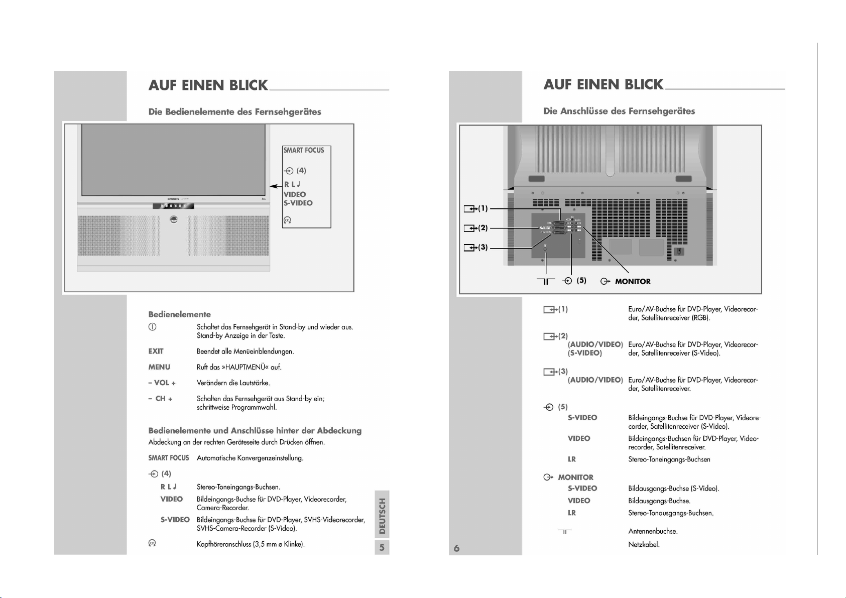
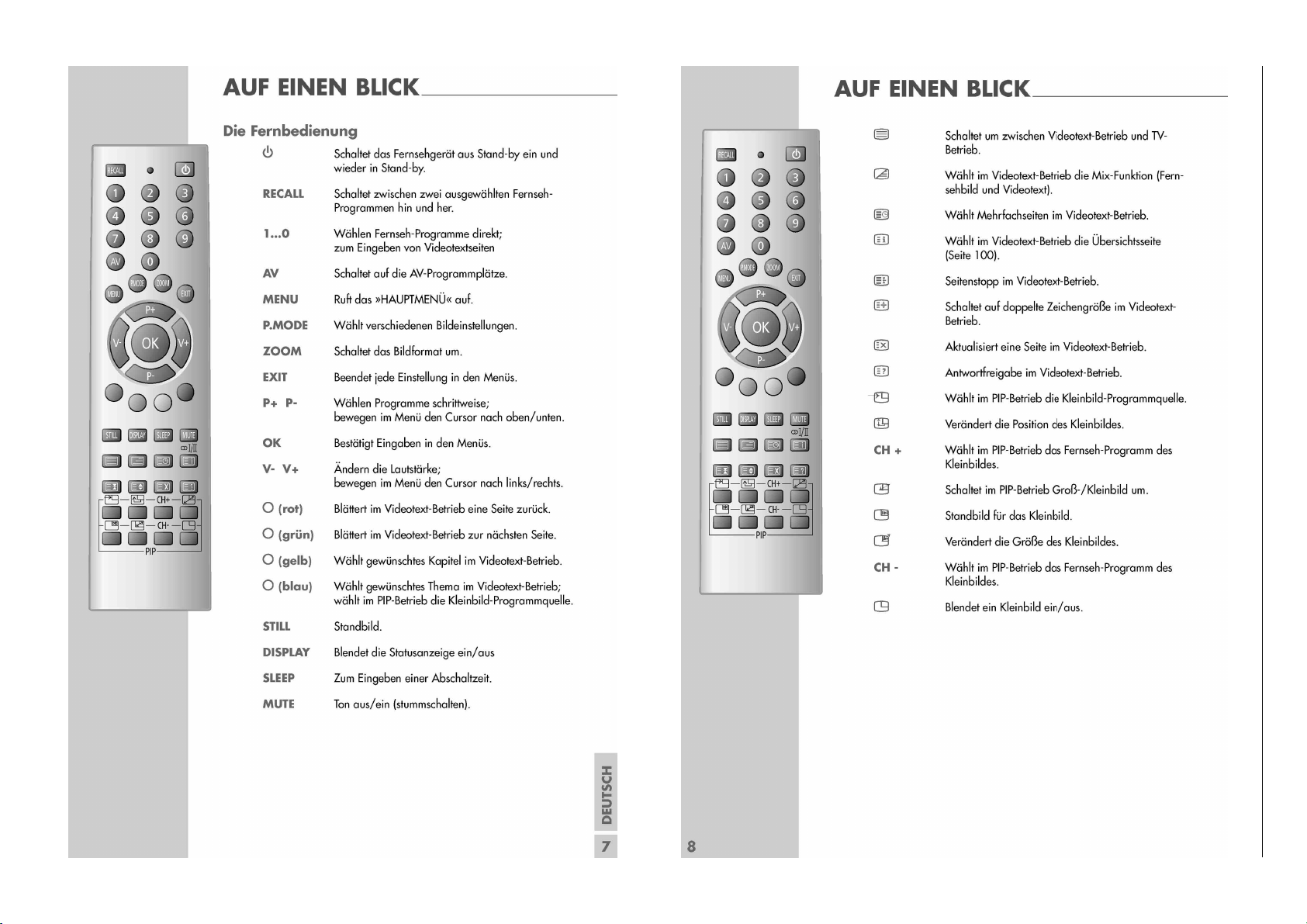
Bedienhinweise Dieses Kapitel enthält Auszüge aus der Bedienungsanleitung.
Weitergehende Informationen entnehmen Sie bitte der gerätespezifischen Bedienungsanleitung, deren Materialnummer Sie in der entsprechenden Ersatzteilliste finden.
1 - 4
Chassis PE-5GRUNDIG Service
Page 5
1 - 5
Chassis PE-5GRUNDIG Service
Page 6

Chassis PE-5GRUNDIG Service
Service- und Sonderfunktionen
Nicht beschriebene Einstellwerte sind werkseitig abgeglichen
und dürfen im Servicefall nicht verstellt werden!
Tastenfunktionen
P+/P- Menü-Zeile (Menüpunkt) wählen
V+/V- Wert ändern
Service-Mode aktivieren
– Lautstärke auf "0" reduzieren.
– Taste "MUTE" drücken und gedrückt halten. Wenn das Mute-Zei-
chen am Bildschirm gelb wird, zusätzlich Taste "MENU" (Nahbedientaste) drücken.
Am Bildschirm wird die Softwareversion angezeigt z.B.: "S-Mode
PE5 - M - V4.04 04-01-29"
Mit der Taste "MENU" können die einzelnen Menüs aufgerufen werden.
Einstellungen speichern
– Taste "RECALL" drücken.
Service-Mode beenden
– Taste "STILL" drücken.
Menupunkt / Parameter Item
[MENU 01]
V-AMP (Frame)
V-SHIFT (Frame Center)
V- LINEARITY (Frame Linearity)
S-COR (Frame S Adjust)
V-DF- PHASE (Frame Dynamic Focus Phase)
V-DF- AMP (Frame Dynamic Focus Breadth)
EW-WIDTH (Horizontal)
H-SHIFT (Horizontal Center)
EW-PARAW (Pincushion Distortion)
EW-TRAP (Trapezium Distortion)
ONLY ENG
OP 16-9
OSD-XPOS
[MENU 02]
DRIVE-R
DRIVE-B
R- CUT
G- CUT
B- CUT
BUS STOP ON( Bus switch)
FIRST POWER ON( Default)
SUB BRIGHT (Side Brightness)
Y-DELAY(PAL Y Delay)
SECAM-Y-DELAY(SECAM Y Delay)
NTSC-Y-DELAY (NTSC Y Delay)
VSM-PHASE
VSM-MAX
BBK-OFFSET
[MENU 03]
bright
Contrast
Color
OSD-XPOS
AD9883-V
AD9883-Y
AD9883-U
PW-58
PW-5C
PAL-59
PAL-5D
NTSC-59
NTSC-5D
Einstellwert / Default Value
Arganto 40 Arganto 43
24
87
21
32
4
7
31
52
12
44
OFF OFF
0FH
1EH
DBH
60H
B0H
OFF
OFF
16
8
0
0
5
04H
50H
80 50
90
50
28H
6FH
42H
6AH
80H
F7H
11H
6DH
10H
59H
Service and Special Functions
Settings not mentioned in this description are pre-set at the
factory and must not be readjusted in the case of repair!
Functions of the Buttons
P+/P- Call up te dialogue line (point of menu)
V+/V- Changing the settings
Calling up the Service Mode
– Reduce the volume to "0".
– Press button "MUTE" and hold depressed. Additionally press but-
ton "MENU" (on the TV) when the mute sign on the screen is going to be yellow. The software version is shown on the screen
e.g. "S-Mode PE5 - M - V4.04 04-01-29"
The different menus can be called up with button "MENU".
Store the Settings
– Press button "RECALL".
Exit the Service Mode
– Press button "STILL".
Bemerkung /Remark
56
76
15
30
4
7
32
59
16
57
OFF
28H
12H
26H
BDH
60H
BCH
OFF
OFF
26
8
0
0
5
04H
50H
50
50
28H
7EH
51H
7EH
8H
F7H
11H
6DH
10H
59H
siehe Geometrie-Einstellungen/see geometry adjustments
siehe Geometrie-Einstellungen/see geometry adjustments
siehe Geometrie-Einstellungen/see geometry adjustments
siehe Geometrie-Einstellungen/see geometry adjustments
Vorgabe Wert / default value
Vorgabe Wert / default value
siehe Geometrie-Einstellungen/see geometry adjustments
siehe Geometrie-Einstellungen/see geometry adjustments
siehe Geometrie-Einstellungen/see geometry adjustments
siehe Geometrie-Einstellungen/see geometry adjustments
Vorgabe Wert / default value
Vorgabe Wert / default value
Vorgabe Wert / default value
siehe Weißwert-Einstellungen/see white level adjustment
siehe Weißwert-Einstellungen/see white level adjustment
siehe Schwarzwert-Einstellungen/see black level adjustment
siehe Schwarzwert-Einstellungen/see black level adjustment
siehe Schwarzwert-Einstellungen/see black level adjustment
Vorgabe Wert / default value
Vorgabe Wert / default value
Vorgabe Wert / default value
Vorgabe Wert / default value
Vorgabe Wert / default value
Vorgabe Wert / default value
Vorgabe Wert / default value
Vorgabe Wert / default value
Vorgabe Wert / default value
Vorgabe Wert / default value
Vorgabe Wert / default value
Vorgabe Wert / default value
Vorgabe Wert / default value
Vorgabe Wert / default value
Vorgabe Wert / default value
Vorgabe Wert / default value
Vorgabe Wert / default value
Vorgabe Wert / default value
Vorgabe Wert / default value
Vorgabe Wert / default value
Vorgabe Wert / default value
Vorgabe Wert / default value
1 - 6
Page 7
Chassis PE-5GRUNDIG Service
Abgleich
Nicht beschriebene Einstellwerte sind werkseitig abgeglichen
und dürfen im Servicefall nicht verstellt werden!
Alle Einstellungen in betriebswarmem Zustand durchführen.
Tastenfunktionen
P+/P- Menü-Zeile (Menüpunkt) wählen
V+/V- Wert ändern
Service-Mode aktivieren
– Lautstärke auf "0" reduzieren.
– Taste "MUTE" drücken und gedrückt halten. Wenn das Mute-Zei-
chen am Bildschirm gelb wird, zusätzlich Taste "MENU" (Nahbedientaste) drücken. Mit Taste "MENU" können die einzelnen Menüs aufgerufen werden.
Einstellungen speichern
– Taste "RECALL" drücken.
Service-Mode beenden
– Taste "STILL" drücken.
Geometrie-Einstellungen
Grobeinstellung:
- Geometrie-Testbild einspeisen.
- Grün ist Referenz.
- Service-Mode aktivieren.
- Menü 01 mit Taste "MENU" auswählen
- Geometriewerte nach Testbild einstellen.
Feineinstellung:
- Service-Mode aktivieren.
- Taste drücken -> Gittertestbild wird eingeblendet.
- Taste AV 2x drücken -> Anzeige "Fine".
- Mit Taste grünes Gitter auswählen.
- Mit Taste "Grün" grünen Cursor auswählen (nur grüne Farbe abgleichen!).
- Mit Tasten P+,V+, P-, V- die abzugleichende Stelle auswählen
(konzentrisch von innen nach aussen).
- Mit Taste (Taste PIP-Standbild) Einstellpunkt aktivieren (Cursor wird weiß).
- Mit Tasten P+,V+, P-, V- gerade Gitterlinien einstellen.
-
Mit Taste Einstellpunkt deaktivieren (Cursor in Abgleichfarbe).
- Alle nötigen Abgleichpunkte (jeweils nur Grün) einstellen. Auch
Abgleichpunkte, die ausserhalb des sichtbaren Bildbereichs liegen können eingestellt werden.
- Mit Taste "Recall" speichern.
- Mit Taste "EXIT" zurück in den Service-Mode.
Weißwert-Einstellung
- Weiß-Bild einspeisen.
- Service-Mode aktivieren.
- Menü 02 mit Taste "MENU" auswählen
- DRIVE-R und DRIVE-B so einstellen, dass das Bild unbunt ist.
Schwarzwert-Einstellung
- Schwarz-Bild einspeisen.
- Service-Mode aktivieren.
- Menü 02 mit Taste "MENU" auswählen
- R-CUT, G-CUT und B-CUT so einstellen, dass das Bild unbunt ist.
Konvergenz-Einstellungen
Vor dem Konvergenzabgleich muss gegebenenfalls die GeometrieEinstellung durchgeführt werden.
- Taste "SMART FOCUS" (seitlich rechts am Gerät unter der Klappe) drücken. -> Automatischer Abgleich.
- Service-Mode aktivieren.
- Taste drücken -> Gittertestbild wird eingeblendet.
- Taste AV 2x drücken -> Anzeige "Fine"
- Mit Taste "Grün" die Farbe auswählen die abgeglichen werden
soll (nur rote und blaue Farbe abgleichen!).
- Mit Tasten P+, V+, P-, V- die abzugleichende Stelle auswählen
(konzentrisch von innen nach aussen).
- Mit Taste (Taste links unten auf Fernbedienung) Einstellpunkt aktivieren (Cursor wird weiß).
- Mit Tasten P+, V+, P-, V- die Linien zur Deckung bringen.
- Mit Taste Einstellpunkt deaktivieren (Cursor in Abgleichfarbe).
- Alle nötigen Abgleichpunkte (jeweils für Rot und Blau) einstellen.
Auch die Abgleichpunkte, die ausserhalb des sichtbaren Bildbereichs liegen können eingestellt werden.
- Mit Taste "Recall" speichern.
- Mit Taste "EXIT" zurück in den Service-Mode.
Adjustment
Settings not mentioned in this description are pre-set at the
factory and must not be readjusted in the case of repair!
All adjustment must be done at operating temperature.
Functions of the Buttons
P+/P- Call up te dialogue line (point of menu)
V+/V- Changing the settings
Calling up the Service Mode
– Reduce the volume to "0".
– Press button "MUTE" and hold depressed. Additionally press but-
ton "MENU" (on the TV) when the mute sign on the screen is going to be yellow. The different menus can be called up with button
"MENU".
Store the Settings
– Press button "RECALL".
Exit the Service Mode
– Press button "STILL".
Geometry Adjustments
Preadjustment:
- Feed in a geometry test pattern.
- Green is reference.
- Start service mode.
- Select menu 01 with button "MENU".
- Adjust all geometry values according to the test pattern.
Fine adjustment:
- Start service mode.
- Press button -> white grid pattern appears.
- Press button AV twice -> "Fine" is displayed.
- With button select the green grid.
- With button "Grün" select a green cursor (only green color has to
be adjusted!).
- With buttons P+,V+, P-, V- select the adjustable position (concentrical from the centre to the borders).
- With button (button PIP freece image) activate the adjustment point (cursor becomes white).
- With buttons P+,V+, P-, V- adjust for straight grid lines.
- With button deactivate the adjustment point (cursor becomes adjusting color).
- Adjust all necessary points (only green color). Adjusting points
outside the viewable area can also be adjusted.
- Store adjustments with button "Recall".
- With button "EXIT" switch back to service mode.
White Level Adjustment
- Feed in a white pattern.
- Start service mode.
- Select menu 02 with button "MENU".
- Adjust DRIVE-R and DRIVE-B for an achromatic picture.
Black Level Adjustment
- Feed in a black pattern.
- Start service mode.
- Select menu 02 with button "MENU".
Adjust R-CUT, G-CUT and B-CUT for an achromatic picture.
-
Convergence Adjustment
If neccessary geometry adjustment should be done before convercence adjustment.
- Press button "SMART FOCUS" (at right side of the set under a
flap). -> Automatic adjustment.
- Start service mode.
- Press button -> white grid pattern appears.
- Press button AV twice -> "Fine" is displayed.
- With "Green" button the color which should be adjusted can be
selected (only red and blue color must be adjusted!).
- With buttons P+, V+, P-, V- select the adjustable position (concentrical from the centre to the borders).
- With button (button PIP freece image) activate the adjustment point (cursor becomes white).
- With buttons P+, V+, P-, V- bring the lines on top of each other.
- With button deactivate the adjustment point (cursor becomes adjusting color).
- Adjust all necessary points (each for red and blue color). Adjusting points outside the viewable area can also be adjusted.
- Store adjustments with button "Recall".
- With button "EXIT" switch back to service mode.
2 - 1
Page 8
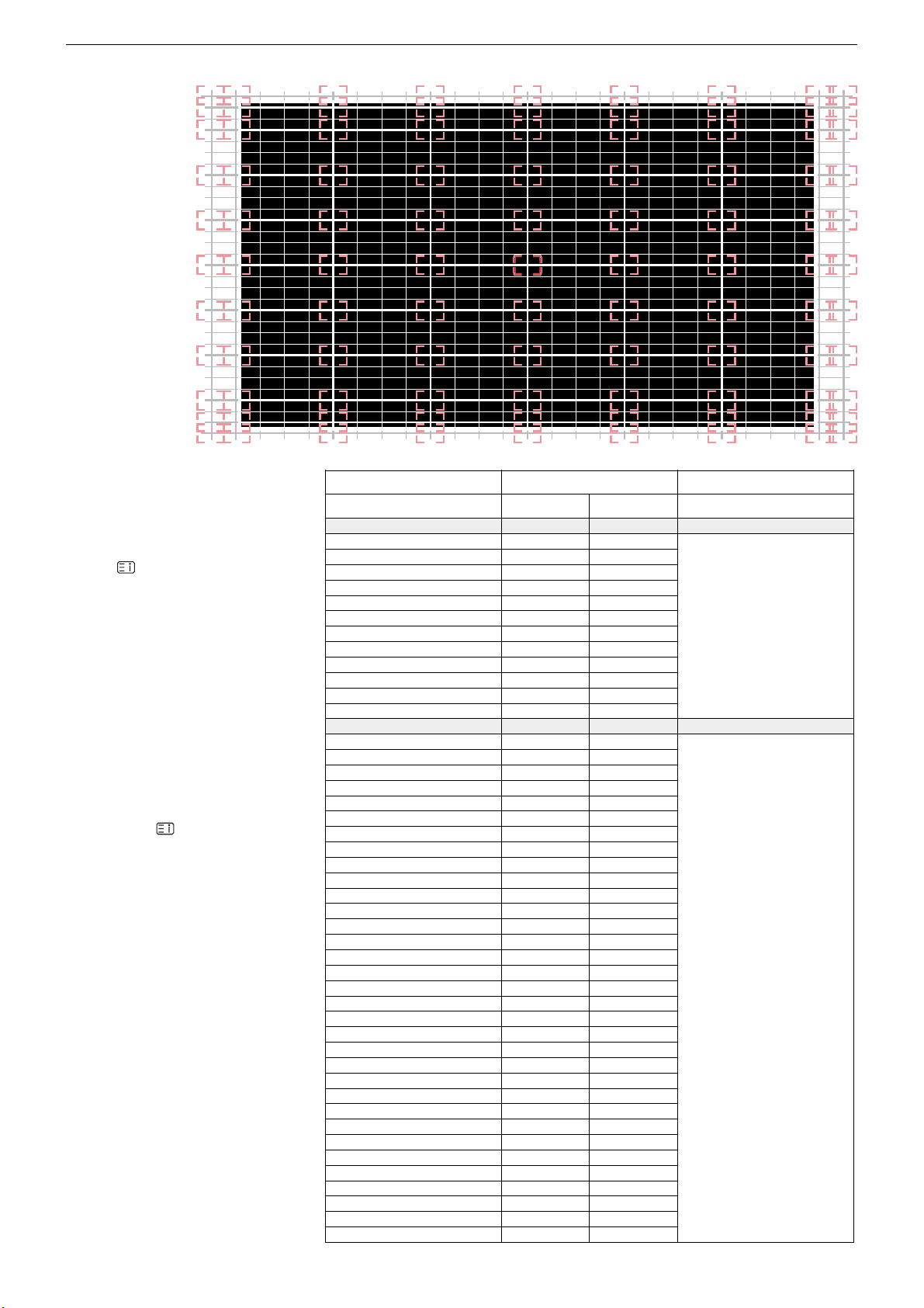
Konvergenztestbild
schwarz:
sichtbarer Bildbereich
rot:
aktueller Cursor
rosa:
Abgleichpositionen
grau:
Abgleichlinien ausserhalb
des sichtbaren Bereichs
Convergence
test pattern
black:
viewable pattern area
red:
current cursor
pink:
adjustment positions
grey:
adjustment lines out of
the viewable pattern area
Chassis PE-5GRUNDIG Service
Einstellwerte "PHASE"/"COARSE"
Nebenstehende Menüpunkte sind werkseitig abgeglichen und dürfen nicht verstellt
werden. Im Servicefall müssen nebenstehende Werte eingestellt werden.
- Service-Mode aktivieren.
- Taste drücken -> Gittertestbild wird
eingeblendet. Menü "PHASE" ist aktiv.
- Mit Tasten P+ oder P- Menüpunkt auswählen
- Mit Tasten V+ oder V- Werte ändern.
- Taste "AV" einmal drücken. Menü
"COARSE" ist aktive.
- Mit Tasten P+ oder P- Menüpunkt auswählen
- Mit Tasten V+ oder V- Werte ändern.
Parameter "PHASE"/"COARSE"
Beneth parameter items are pre-set at the
factory and must not be readjusted. In case
of repair beneth default values must be adjusted.
- Start Service Mode.
- Press button -> grid pattern appears.
Menu "PHASE" is activated.
- Press button P+ or P- to select the menu
item.
- Press button V+ or V- to change the values.
- Press button "AV" once. Menu "COARSE"
is activated.
- Press button P+ or P- to select the menu
item.
- Press button V+ or V- to change the values.
Menupunkt / Parameter Item
[PHASE]
VBLK04V
VBLK04P
V10FSET
DAC2P
DAC1P
COARSEP
FINEP
TPOPH
STARTLIN
V1CNTUP
TPOPV
V1DLY
[COARSE]
V1H2BV
V1H1BV
V1BV
H1BV
DCBV
V2H2BH
V2H1BH
V1BH
H2BH
H1BH
DCBH
V1H2GV
V1H1GV
V1GV
H1GV
DCGV
V2H2GH
V2H1GH
V1GH
H2GH
H1GH
DCGH
V1H2RV
V1H1RV
V1RV
H1RV
DCRV
V2H2RH
V2H1RH
V1RH
H2RH
H1RH
DCRH
Einstellwert / Default Value
Arganto 40 Arganto 43
0000H
0000H
0000H
0000H
0000H
0F14H
045CH
0079H
0020H
0346H
0009H
0000H
0000H
0000H
0000H
0000H
0000H
0000H
045CH
0078H
0020H
0346H
0009H
0001H
032DH 02D3H
00C8H
0064H
03EEH
03F0H
0000H
0000H
03F6H
02C9H
0046H
0099H
0341H
000AH
006EH
000CH
03DCH
0000H
0000H
03FEH
0000H
0000H
03E9H
0337H
03AFH
0078H
0002H
03F8H
0000H
0000H
03EDH
00F0H
03EBH
039AH
00A0H
0050H
03FEH
03DCH
0014H
03F5H
0000H
0283H
0013H
00EAH
02B5H
0000H
0064H
03FEH
03E4H
0000H
03F5H
03FFH
0000H
03FFH
0001H
034BH
035FH
003CH
0000H
03E7H
03D7H
03EBH
0000H
01A4H
0033H
0340H
Bemerkung /Remark
Vorgabe Wert / default value
Vorgabe Wert / default value
2 - 2
Page 9
GRUNDIG Service Chassis PE-5
Platinenabbildungen und Schaltpläne / Layout of PCBs and Circuit Diagrams
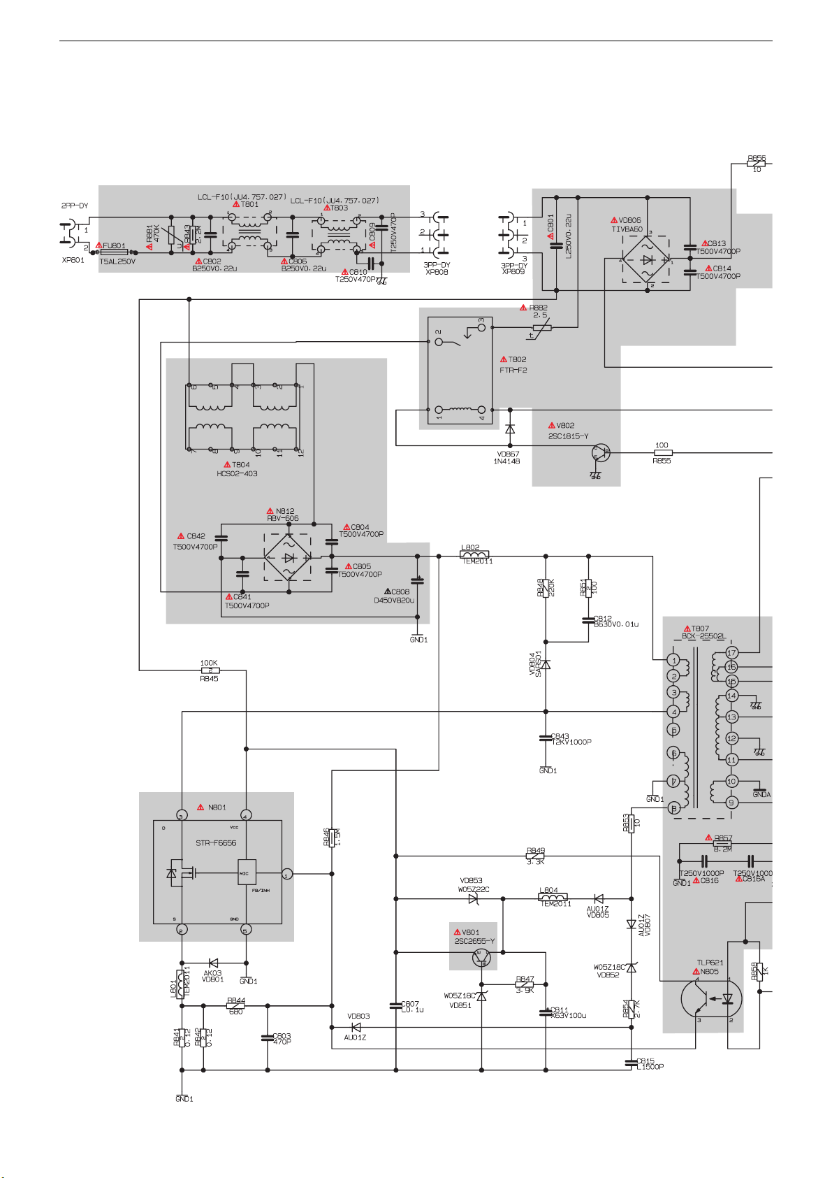
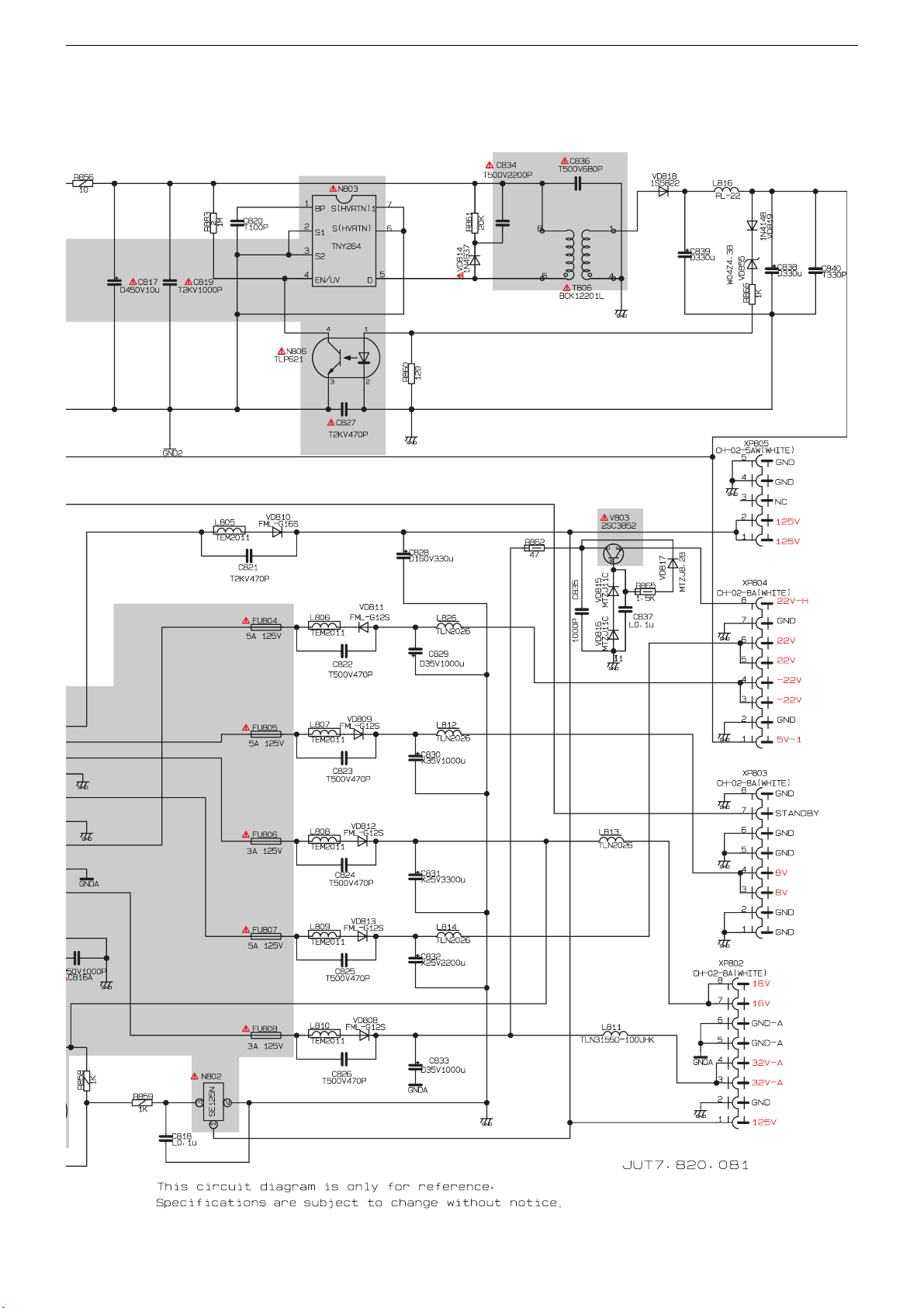
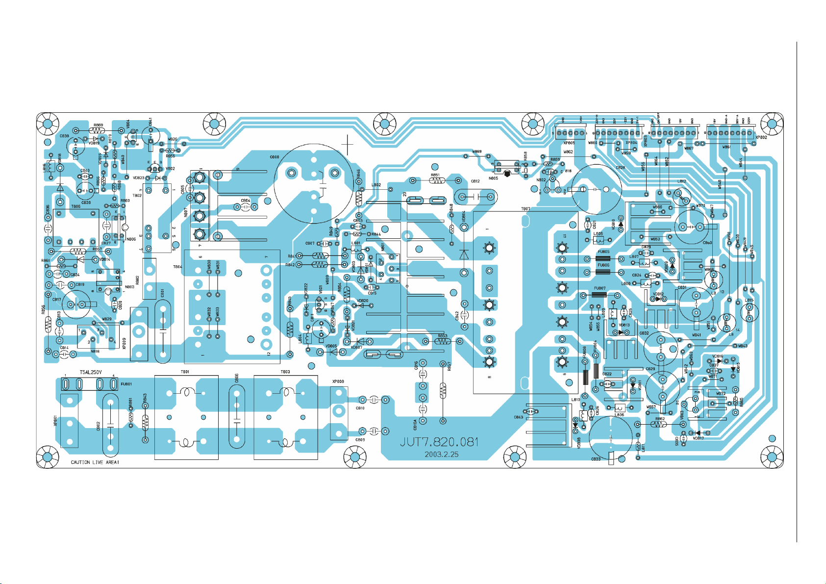
Netzteil / Mains Unit - JUT7.820.081
3 - 1
Page 10
GRUNDIG Service Chassis PE-5
Netzteil / Mains Unit - JUT7.820.081
to XP304
Scanning PCB
P. 3-32
to XP303
Scanning PCB
P. 3-32
to XP302
Scanning PCB
P. 3-32
3 - 2
PE-5 CHASSIS (2)
2003.7.5
to XP301
Scanning PCB
P. 3-32
Page 11
Netzteil / Mains Unit - JUT7.820.081
3 - 3
GRUNDIG Service Chassis PE-5
Page 12
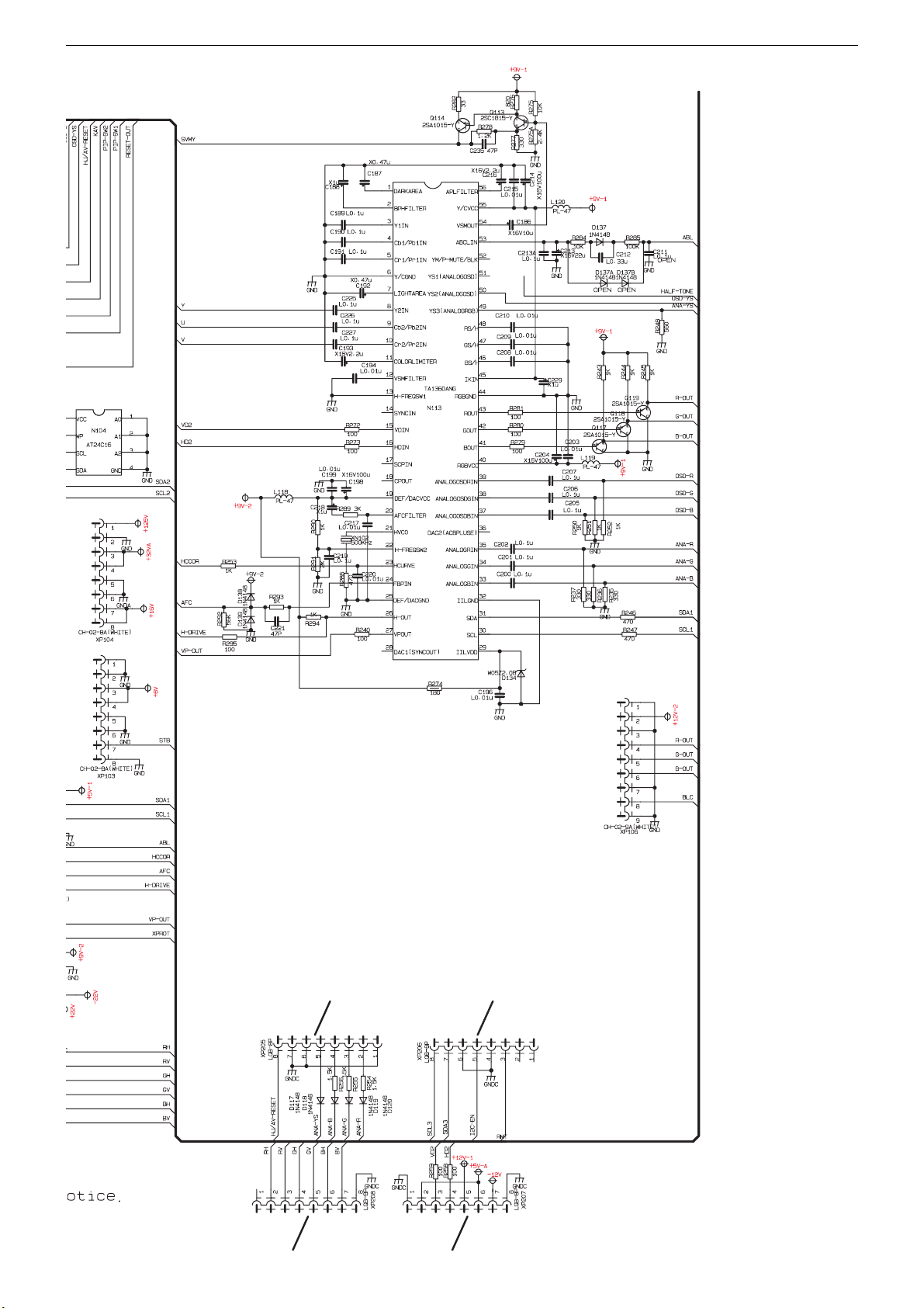
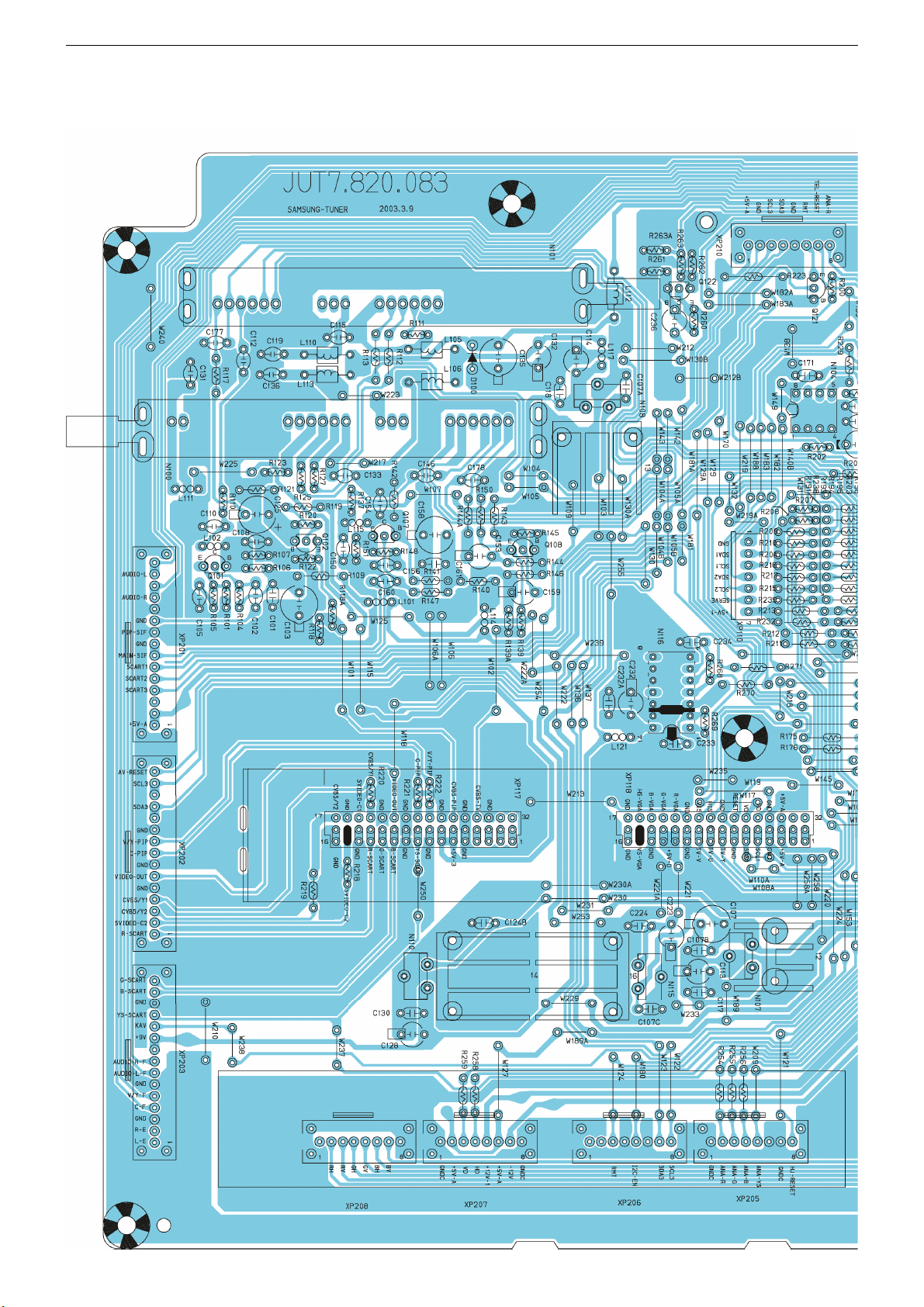
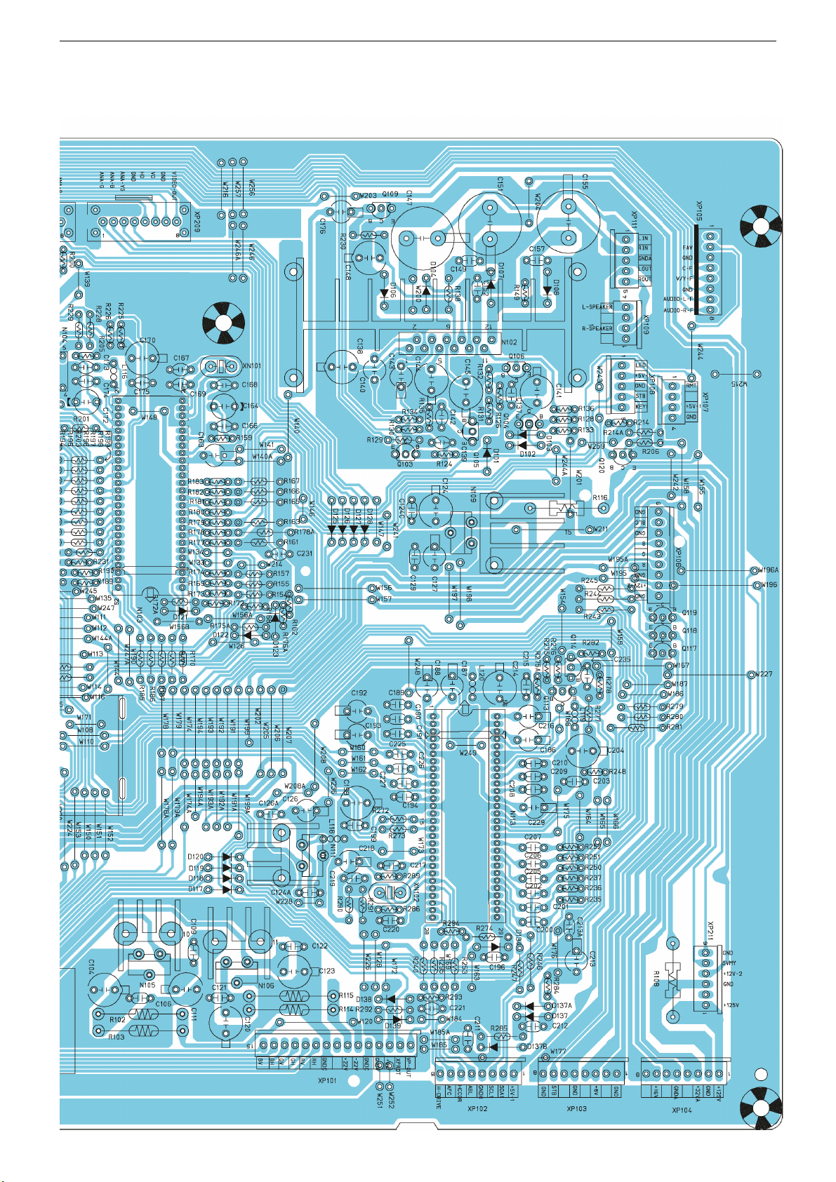
GRUNDIG Service Chassis PE-5
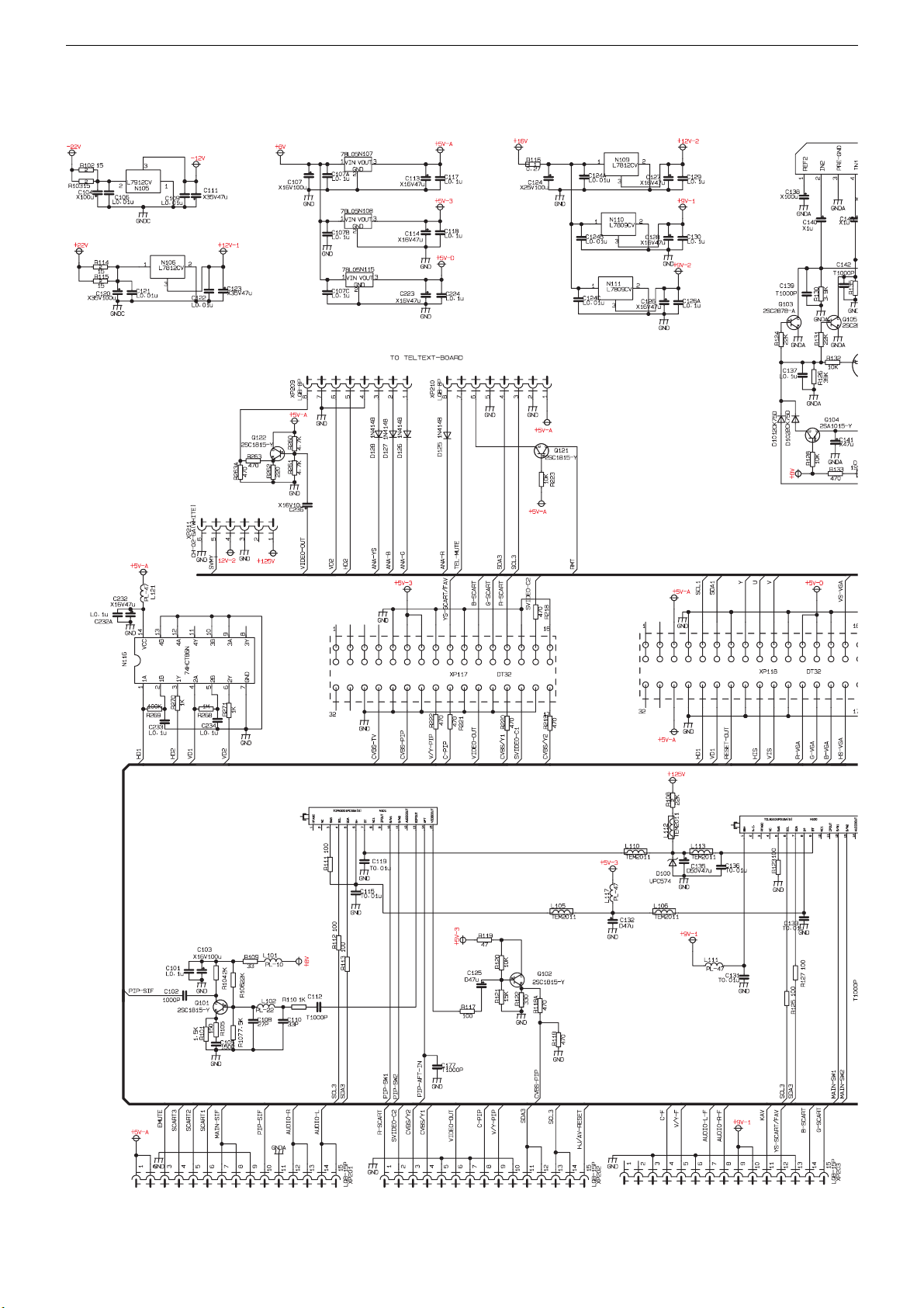
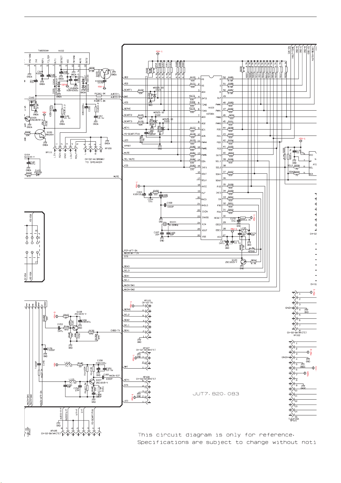
Haupt-Platte / Main PCB - JUT7.820.083
P. 3-36 P. 3-36
to XGP03
VM (G) PCB
P. 3-39
to XP500
Digital PCB
P. 3-16
to XP501
Digital PCB
P. 3-16
to XP901
AV PCB
P. 3-10
3 - 4
to XP902
AV PCB
P. 3-10
to XP903
AV PCB
P. 3-10
Page 13
GRUNDIG Service Chassis PE-5
Haupt-Platte / Main PCB - JUT7.820.083
to XP206k
CAV PCB
P. 3-41
to XP01
Remote PCB
P. 3-41
to XP318
Scan PCB
P. 3-30
to XP316
Scan PCB
P. 3-32
to XP317
Scan PCB
P. 3-32
to XP203k
CAV PCB
P. 3-41
to XP206k
K PCB
P. 3-42
3 - 5
PE-5 CHASSIS (4)
2003.7.5
to XP319
Scan PCB
P. 3-30
Page 14
GRUNDIG Service Chassis PE-5
3
3
3
3
Haupt-Platte / Main PCB - JUT7.820.083
to XP304
Scanning PCB
P. 3-32
16
CB
2
17
CB
2
to XSC01
Covering PCB
P. 3-24
to XSC02
Convergence PCB
P. 3-27
to XSC02
Covering PCB
P. 3-24
to XSC03
Convergence PCB
P. 3-27
to XGP01
Y-G PCB
P. 3-39
to XSC04
Covering PCB
P. 3-25
to XSC05
Convergence PCB
P. 3-27
to XSC03
Covering PCB
P. 3-24/25
to XSC03
Convergence PCB
P. 3-27
3 - 6
Page 15
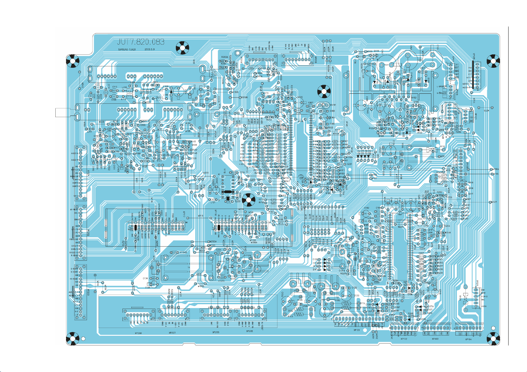
Haupt-Platte / Main PCB - JUT7.820.083
3 - 7
GRUNDIG Service Chassis PE-5
Page 16
GRUNDIG Service Chassis PE-5
Haupt-Platte / Main PCB - JUT7.820.083
3 - 8
Page 17
GRUNDIG Service Chassis PE-5
Haupt-Platte / Main PCB - JUT7.820.083
3 - 9
Page 18

GRUNDIG Service Chassis PE-5
AV-Platte / AV PCB - JUT7.820.084
to XP201 Main PCB P. 3-4to XP202 Main PCB P. 3-4
to XP203
Main PCB
P. 3-4
PE-5 CHASSIS (1)
2003.7.5
3 - 10
Page 19

GRUNDIG Service Chassis PE-5
AV-Platte / AV PCB - JUT7.820.084
3 - 11
Page 20

GRUNDIG Service Chassis PE-5
AV-Platte / AV PCB - JUT7.820.084
3 - 12
Page 21

Digital-Platte / Digital PCB - JUT7.820.085 (1)
COMBFI~1.SCH
BIAS
1
VRT
2
VDD1
3
TESTI1
4
VSS2
5
YCIN
7
VRB
6
TEST
8
KILLE R
9
TESTI2
10
VDD3
11
VSS3
12
VDD2
13
TESTI3
14
SCL
15
SDA
16
MODE1
17
TESTOUT
18
FSC
19
VDD4
20
VSS4
21
FIL
22
PD
23
VB2
24
YOUT
25
VSS1
26
VB1
28
COUT
27
N516
TC90A69F
C691
0.47uF/50V
C682
0.01uF
C721
0.01F
C683
0.01uF
C684
0.01uF
L518
100uH
C719
100uF/10V
C526
0.1uF
5V-CD
C699
47uF/10V
C528
0.1uF
C700
47uF/10V
C529
0.1uF
L519
100uH
5V-CD
L520
100uH
L521
100uH
R571
100
R572
100
SDA
SCL
SCL1
SDA
R629
510
L524
27uH
C723
15pF
C724
33pF
C696
10pF
R628
1.5K
C689
0.01uF
V516
MMBT3904
R533
12K
R627
5.6K
R564
1K
R626
2K
V515
MMBT3904
5V-CD
R563
1K
C688
0.01uF
C720
100uF/10V
C687
0.01uF
L522
100uH
5V-CD
C722
680pF
C527
0.1uF
R620
330
C686
0.01uF
C685
0.01uF
R621
820
R623
820
R622
820
R624
820
COMB_C
COMB_Y
COMB_C
COMB_Y
CVBS_OUT
CVBS_OUT
FSC_OUT
FSC_OUT
VSS
VSS AGND
R557
100
Dac1
R597
10k
R598
10k
5V-CD
R592
470
V514
MMBT3904
C718
10uF/16V
R593
470
R625
10k
5V-CD
3 - 13
GRUNDIG Service Chassis PE-5
Page 22

COLORD~1.SCH
C695
10pF
C694
2.2uF/50V
X501
16.200MHZ
L516
100uH
C511
0.1uF
C512
0.1uF
C510
0.1uF
C678
0.01uF
R599
3.9K
C693
0.022uF
C690
0.47uF/50V
R600
27K
C679
0.01uF
C698
47uF/10V
C513
0.1uF
C516
0.1uF
5V-CD
L523
330uH
C505
10uF/10V
C681
0.01uF
5V-CD
SCART_R
SCART_G
SCART_B
R603 75
R604 75
R605
75
C523
0.1uF
C524
0.1uF
C525
0.1uF
SCART_YS
R602
75
R568
100
R569
100
R570
100
PIP_FS
PIP_V
PIP_U
PIP_Y
C519
0.1uF
C518
0.1uF
C517
0.1uF
R608
0
R567
100
TV-HS
R566
100
TV-VS
R606
220
R607
220
SDA
SCL
SCL
SDA
C701
4.7uF/10V
C514
0.1uF
C515
0.1uF
C697
47uF/10V
C680
0.01uF
L517
100uH
5V-CD
TV-Y
TV-Cb
TV-Cr
DEC_VS
DEC_HS
+
C692
10uF/16V
R595
10k
R596
10k
R601
75
VIDEO_OUT
VIDEO_OUT
5V-CD
R589
470
TV-VS
TV-HS
SCART_R
SCART_G
SCART_B
SCART_YS
PIP_Y
PIP_U
PIP_V
PIP_FS
TV-Y
TV-Cb
TV-Cr
SYN C- I N
2
CVBS-OUT
3
Vs
4
COMB Y-IN
5
D-VDD
6
COMB C-IN/FORCED-S
7
D-GND
8
Hs
9
SCP
10
Yvi-out
11
Sync-Vcc
12
SCL
13
SDA
14
YS3(RGB1-in)
15
Sync-GND
16
Cr1-in
17
Cb1-in
18
Y1-in
19
CLP-fil
20
Y-out
21
Cb-out
22
Cr-out
23
YS1(YCbCr2-in)
24
B1-in
25
G1-in
26
R1-in
27
Y/C GND
28
Cr2-in
29
Cb2-in
30
Y2-in
31
Y/C Vcc
32
B2-in
33
G2-in
34
R2-in
35
YS2/YM(RGB2-in)
36
FIL
37
X'TAL
38
C3-IN
39
APC-FIL
40
CVBS/Y3-IN
41
ADDRESS
42
C2-IN
43
CVBS2/Y2-IN
44
COMB SYS
45
Fsc-OUT
46
AFC-FIL
47
C1-IN
48
CVBS/Y1-IN
1
N514
TB1274AF
CVBS_OU T
CVBS_OUT
COMB_Y
COMB_C
COMB_Y
COMB_C
FSC_OUT
FSC_OUT
C677
0.01uF
R590
470
R588
470
R587
470
R586
470
R591
470
COMB_TV
CVBS/Y_2
SVIDEO_C2
CVBS/Y_1
SVIDEO_C1
COMB_TV
CVBS/Y_2
SVIDEO_C2
CVBS/Y_1
SVIDEO_C1
C521
0.1uF
C520
0.1uF
C522
0.1uF
YCbCr_Cr
YCbCr_Cb
YCbCr_Y
YCbCr_Cr
YCbCr_Cb
YCbCr_Y
V513
MMBT3904
Digital-Platte / Digital PCB - JUT7.820.085 (2)
GRUNDIG Service Chassis PE-5
3 - 14
Page 23

PIP.SCH
XIN
1
XQ
2
HSP
3
VSP
4
SDA
5
VDD
7
SCL
6
VSS
8
I2C
9
INT
10
IN1
11
IN2
12
IN3
13
FSW
14
SEL
15
OUT3
16
OUT2
17
OUT1
18
VDDA2
19
VSSA2
20
VREFH
21
VDDA1
22
VSSA1
23
CVBS3
24
VREFL
25
CVBS2
26
CVBS1
28
VREFM
27
N515
SDA9489
X502
20.25MHz
C705
27pF
C706
27pF
R615
100
R612
100
DEC_HS
DEC_VS
R613
100
R614
100
SDA
SCL
+
C551
10uF/10V
C707
10nF
L512
10uH
+3.3VP
R514
330
PIP_V
PIP_Y
PIP_U
PIP_FS
+
C553
10uF/10V
C712
10nF
L514
10uH
+
C717
1uF/50V
C711
10nF
L513
10uH
+
C552
10uF/10V
C710
10nF
+3.3VP
+3.3VP
+
C716
1uF/50V
C709 10nF
+
C715
1uF/50V
C708 10nF
CVBS_PIP
V/Y_PIP
C_PIP
C702
10nF
C703
10nF
C704
10nF
R609
75
R610
75
R611
75
SDA
SCL
DEC_VS
DEC_HS
C642
0.1uF
C643
0.1uF
C644
0.1uF
R616
100
PIP_FS
R562
1K
R619
150
5V-CD
V507
MMBT3906
R561
1K
R618
150
5V-CD
V506
MMBT3906
R560
1K
R617
150
5V-CD
V505
MMBT3906
CVBS_PIP
V/Y_PIP
C_PIP
PIP_V
PIP_Y
PIP_U
C713
10nF
+
C555
10uF/10V
C714
10nF
+3.3VP
+
C554
10uF/10V
IN
3
ADJ/GND
1
OUT
2
TAB/OUT
4
N506
AMS1117-3.3
5V-CD
Digital-Platte / Digital PCB - JUT7.820.085 (3)
3 - 15
GRUNDIG Service Chassis PE-5
Page 24

Digital-Platte / Digital PCB - JUT7.820.085 (4)
BROADP~1.SCH
HD
VD
RESET
HiS
GND
VGA_R
5V-A
5V-3
AGND
DAC1
SCART_Ys
5V-3
5V-A
GND
GND
1
2
3
4
5
6
7
8
9
10
11
12
13
14
15
16
17
18
19
20
21
22
23
24
25
26
27
28
XP500
HEADER 14X2
1
2
3
4
5
6
7
8
9
10
11
12
13
14
15
16
17
18
19
20
21
22
23
24
25
26
27
28
XP501
HEADER 16X2
DAC2
CVBS_PIP
AGND
VGA_B
AGND
AGND
C_PIP
AGND
SCART_B
AGND
ViS
VGA_Hs
AGND
V/Y_PIP
COMB_TV
AGND
GND GND
VGA_G
V
GND
5V-D
Y
SVIDEO_C2
GND
VGA_Vs
Digital Board Interface
SCL
SDA
GND
U
5V-D
AGND
SCART_G
SCART_R
AGND
VIDEO_OUT
AGND
CVBS/Y_1
AGND
CVBS/Y_2
SVIDEO_C1
L502
FB
C654
0.1uF
+
C646
10uF/10V
5V-D1
C651
0.1uF
L504
FB
C656
0.1uF
+
C649
10uF/10V
5V-CD
C655
0.1uF
+
C657
100uF/16V
L503
FB
C653
0.1uF
+
C647
10uF/10V
5V-A1
C652
0.1uF
+
C658
100uF/16V
+
C645
10uF/10V
+
C648
10uF/10V
5V-A
5V-D
5V-3
GND
YPbPr_Y
Pr/Cr
Pb/Cb
GND
GND
1
2
3
4
5
6
XP502
HEADER 6
5V-A1
5V-A1
5V-A1
5V-A1
5V-A1
5V-A1
2
1
3
D510
BAV99L
2
1
3
D511
BAV99L
2
1
3
D512
BAV99L
2
1
3
D501
BAV99L
2
1
3
D502
BAV99L
2
1
3
D503
BAV99L
R537
75
R538
75
R539
75
R534
75
R535
75
R536
75
R540
0
R541
0
R542
0
5V-A1
2
1
3
D504
BAV99L
5V-A1
2
1
3
D505
BAV99L
5V-3
2
1
3
D507
BAV99L
5V-3
2
1
3
D508
BAV99L
5V-3
2
1
3
D509
BAV99L
5V-3
2
1
3
D506
BAV99L
+
C536
10uF/10V
+
C537
10uF/10V
+
C538
10uF/10V
R527
12k
R521
15k
R518
4.7K
V502
MMBT3906
5V-A1
R528
12k
R522
15k
R519
4.7K
V503
MMBT3906
5V-A1
R529
12k
R523
15k
R520
4.7K
V504
MMBT3906
5V-A1
YCbCr_Cr
YCbCr_Cb
YCbCr_Y
YCbCr_Cr
YCbCr_Cb
YCbCr_Y
to XP117
Main PCB
P. 3-4
to XP118
Main PCB
P. 3-4
GRUNDIG Service Chassis PE-5
3 - 16
Page 25

Digital-Platte / Digital PCB - JUT7.820.085 (5)
Vout0
Uout0
Yout0
Yout0
Uout0
Vout0
YUV Cannel Buffer
L511
10uH
C671
0.1uF
+
C650
10uF/10V
5V-A1
Y
U
V
Y
U
V
R583
240
R530
12k
R524
15k
R573
47
V510
MMBT3904
C502
10uF/10V
R576
270
C674
39
C672
0.1uF
R585
470
R531
12k
R525
15k
R574
47
V511
MMBT3904
C503
10uF/10V
5V-BUF
5V-BUF
C673
0.1uF
R584
240
R532
12k
R526
15k
R575
47
V512
MMBT3904
C504
10uF/10V
R577
270
R594
240
C675
39
C676
39
5V-BUF
R578
0#
R579
0#
R580
0#
R581
0#
R582
0#
TV-Cb
TV-Cr
TV-Y
TV-HS
TV-VS
ADC_HS
ADC_VS
ADC_G/Y
ADC_B/U
ADC_R/V
GRUNDIG Service Chassis PE-5
3 - 17
Page 26

Digital-Platte / Digital PCB - JUT7.820.085 (6)
IN
3
ADJ/GND
1
OUT
2
TAB/OUT
4
N505
AMS1117-3.3
C582
0.1uF
+
C539
10uF/10V
L505
FB
5V-D1
+2.5V
L508
10uH
C659
100pF
+
C543
10uF/10V
+2.5VD
+
C542
10uF/10V
C586
0.1uF
C660
100pF
+2.5VA
C588
0.1uF
L509
10uH
C661
100pF
+3.3VA
C591
0.1uF
L506
FB
C662
100pF
+
C547
10uF/10V
+3.3VD
C592
0.1uF
L507
FB
C663
100pF
+
C548
10uF/10V
+3.3VM
C615
0.1uF
+3.3V
C590
0.1uF
+
C545
10uF/10V
+2.5VD
+3.3VD
C613
0.1uF
+3.3VD
C623
0.1uF
C622
0.1uF
C620
0.1uF
+2.5VA
C614
0.1uF
C618
0.1uF
C617
0.1uF
C616
0.1uF
+3.3VA
L515
4.7uH
C593
0.1uF
C634
0.1uF
+3.3VD
C594
0.1uF
+2.5V
VDD
5
VDD
34
VDD
93
VDD
123
VDD
140
VDD
175
VDD
205
VDD
235
PVDD
14
PVDD
29
PVDD
42
PVDD
54
PVDD
69
PVDD
80
PVDD
90
PVDD
101
PVDD
109
PVDD
120
PVDD
131
PVDD
143
PVD D
180
PVD D
208
PVD D
216
PVDD
224
PVD D
230
PVD D
237
PVDD
243
PVD D
249
NC
194
DPAVDD
197
DPDVDD
199
PVD D
200
MPDVDD
58
MPAVDD
60
NC
63
PVD D
64
AVD33B
151
AVD33G
154
AVD33R
157
PVD D
165
ADGVDD
166
ADDVDD
149
ADAV DD
163
VSS
19
VSS
49
VSS
77
VSS
134
VSS
187
VSS
219
VSS
251
VSS
112
PVSS
10
PVSS
24
PVSS
39
PVSS
46
PVSS
65
PVSS
74
PVSS
85
PVSS
96
PVSS
105
PVSS
115
PVSS
126
PVSS
137
PVSS
171
PVSS
189
PVSS
202
PVSS
212
PVSS
222
PVSS
228
PVSS
233
PVSS
240
PVSS
246
NC
195
DPAVSS
196
DPDVSS
198
PVSS
193
MPDVSS
59
MPAVSS
61
NC
62
PVSS
57
AVS33B
152
AVS33G
155
AVS33R
158
PVSS
147
ADDVSS
148
ADAV SS
164
ADGVSS
167
PVDD
256
PVSS
253
N511C
PW1235
VISTA - 2
+2.5VD
C595
0.1uF
+2.5VD
C597
0.1uF
+2.5VD
C599
0.1uF
+2.5VD
C601
0.1uF
+2.5VD
C604
0.1uF
+2.5VD
C606
0.1uF
+2.5VD
C608
0.1uF
+2.5VD
C610
0.1uF
+3.3VD
C596
0.1uF
+3.3VD
C598
0.1uF
+3.3VD
C600
0.1uF
+3.3VD
C602
0.1uF
+3.3VD
C603
0.1uF
+3.3VD
C605
0.1uF
+3.3VD
C607
0.1uF
+3.3VD
C609
0.1uF
+3.3VD
C611
0.1uF
+3.3VD
C612
0.1uF
+3.3VD
C624
0.1uF
+3.3VD
C625
0.1uF
+3.3VD
C626
0.1uF
+3.3VD
C627
0.1uF
+3.3VD
C628
0.1uF
+3.3VD
C629
0.1uF
+3.3VD
C630
0.1uF
+3.3VD
C631
0.1uF
+3.3VD
C632
0.1uF
+3.3VD
C633
0.1uF
+
C540
10uF/10V
C584
0.1uF
5V-A1
Vin
3
ADJ
1
+Vout
2
N510
AMS1085CD-2.5
IN
3
ADJ/GND
1
OUT
2
TAB/OUT
4
N509
AMS1117-2.5
C583
0.1uF
5V-A1
C585
0.1uF
+
C541
10uF/10V
IN
3
ADJ/GND
1
OUT
2
TAB/OUT
4
N512
AMS1085CD-3.3
C589
0.1uF
+
C544
10uF/10V
C587
0.1uF
5V-D1
+3.3VD
L510
10uH
C621
0.1uF
+2.5V
+
C546
10uF/10V
C619
0.1uF
GRUNDIG Service Chassis PE-5
3 - 18
Page 27

Digital-Platte / Digital PCB - JUT7.820.085 (7)
PW1230~2.SCH
A0
23
A1
24
A2
25
A3
26
A4
29
A5
30
A6
31
A7
32
A8
33
A9
34
A10
22
A11
35
BA0
20
BA1
21
WE
16
CAS
17
RAS
18
CS
19
LDQM
15
UDQM
39
CLK
38
CKE
37
DQ0
2
DQ1
4
DQ2
5
DQ3
7
DQ4
8
DQ5
10
DQ6
11
DQ7
13
DQ8
42
DQ9
44
DQ10
45
DQ11
47
DQ12
48
DQ13
50
DQ14
51
DQ15
53
VDDQ3VDDQ
9
VDD
1
VDD
14
VDD
27
VDDQ
43
VDDQ
49
VSSQ
6
VSSQ
12
VSS
28
VSS
41
VSSQ
46
VSSQ
52
VSS
54
NC
36
NC
40
N513
HY57V641620HG
+3.3VM
MA0
MA1
MA2
MA3
MA4
MA5
MA6
MA7
MA8
MA9
MA10
MA11
MA12
MA13
MA[13:0]
MA[13:0]
MD0
MD1
MD2
MD3
MD4
MD5
MD6
MD7
MD8
MD9
MD10
MD11
MD12
MD13
MD14
MD15
MD[15:0]
MD[15:0]
+3.3VM
MWE
MCAS
MRAS
MCLK
MCLKFB
MCLKFB
MCLK
MRAS
MCAS
MWE
C635
0.1uF
C636
0.1uF
C637
0.1uF
C638
0.1uF
+3.3VM
+3.3VM
+3.3VM
+3.3VM
R565
100
C639
0.1uF
C640
0.1uF
C641
0.1uF
+3.3VM
+3.3VM
+3.3VM
3 - 19
GRUNDIG Service Chassis PE-5
Page 28

Digital-Platte / Digital PCB - JUT7.820.085 (8)
AD9883.sch
AVD1
26
AVD2
27
AVD3
39
AVD442AVD5
45
AVD6
46
AVD7
51
AVD8
52
AVD9
59
AVD10
62
VDD1
11
VDD222VDD3
23
VDD578VDD4
69
VDD6
79
PVD 1
34
PVD 2
35
GND1
1
GND2
10
GND3
20
GND4
21
GND5
24
GND6
25
GND7
28
GND8
32
GND9
36
GND10
40
GND11
41
GND12
44
GND13
47
GND14
50
GND15
53
GND16
60
GND17
61
GND18
63
GND19
68
GND20
80
RED0
77
RED1
76
RED2
75
RED3
74
RED4
73
RED5
72
RED6
71
RED7
70
GREEN0
9
GREEN1
8
GREEN2
7
GREEN3
6
GREEN4
5
GREEN5
4
GREEN6
3
GREEN7
2
BLUE0
19
BLUE1
18
BLUE2
17
BLUE3
16
BLUE4
15
BLUE5
14
BLUE6
13
BLUE7
12
DATACK
67
HSOUT
66
SOGOUT
65
VSOUT
64
FILT
33
SDA
57
SCL
56
A0
55
CLAMP
38
COAST
29
RAIN
54
GAIN
48
SOG IN
49
BAIN
43
HSYNC
30
VSYNC
31
MIDSCV
37
REFBYP
58
N507
AD9883A - 110MSPS
IN
3
ADJ/GND
1
OUT
2
TAB/OUT
4
N502
AMS1117-3.3
+
C530
22uF/16V
AVDD
+
C533
10uF/10V
5V-A1
IN
3
ADJ/GND
1
OUT
2
TAB/OUT
4
N503
AMS1117-3.3
+
C531
22uF/16V
PVDD
+
C534
10uF/10V
5V-A1
AVDD
VDD
PVDD
R509
2.7K
C557
8.2nF,16V,5%
C556
82nF,16V,5%
PVDD
GFILT
R506
680
R507
680
SDA
SCL
SDA
SCL
C558 47nF
C559 47nF
C561 1nF
C560 47nF
R503
47
R504
47
R505
47
C563
0.1uF
C562
0.1uF
RHS
RVS
GCLK
ADV[7:0]
ADY[7:0]
ADU7:0]
ADV0
ADV1
ADV2
ADV3
ADV4
ADV5
ADV6
ADV7
ADY0
ADY1
ADY2
ADY3
ADY4
ADY5
ADY6
ADY7
ADU0
ADU1
ADU2
ADU3
ADU4
ADU5
ADU6
ADU7
AVDD
C564
0.1uF
AVDD
C565
0.1uF
AVDD
C566
0.1uF
AVDD
C567
0.1uF
AVDD
C568
0.1uF
AVDD
C569
0.1uF
VDD
C574
0.1uF
VDD
C575
0.1uF
VDD
C576
0.1uF
VDD
C577
0.1uF
VDD
C578
0.1uF
AVDD
C570
0.1uF
PVDD
C580
0.1uF
PVDD
C581
0.1uF
GCLK
RHS
RVS
ADU[7:0]
ADY[7:0]
ADV[7:0]
IN
3
ADJ/GND
1
OUT
2
TAB/OUT
4
N504
AMS1117-3.3
+
C532
22uF/16V
VDD
+
C535
10uF/10V
5V-A1
R508
10K
R510
1k
R511
1k
RP500
47x4
R513
330
R512
330
HiS
ViS
HiS
ViS
S1A
2
S2A
3
S1B
5
S2B
6
S1C
11
S2C
10
S1D
14
S2D
13
IN
1
EN
15
GND
8
VCC
16
DA
4
DB
7
DC
9
DD
12
N500
PI5V330*
S
1
1I0
2
1I1
3
1Y
4
2I0
5
2I1
6
2Y
7
GND
8
3Y
9
3I1
10
3I0
11
4Y
12
4I1
13
4I0
14
E
15
VCC
16
N508
74HC157*
L500
FB*
C500
10uF/10V*
C506
0.1uF*
5V-A1
VGA_R
VGA_G
VGA_B
Dac1
L501
4.7uH*
C501
10uF/10V*
C509
0.1uF*
5V-A1
TV-HS
TV-VS
VGA_VS
VGA_HS
VGA_HS
VGA_VS
TV-VS
TV-HS
C508
0.1uF
VGA_R
VGA_B
VGA_G
Dac1
ADC_HS
ADC_VS
ADC_R/V
ADC_G/Y
ADC_B/U
S1A
2
S2A
3
S1B
5
S2B
6
S1C
11
S2C
10
S1D
14
S2D
13
IN
1
EN
15
GND
8
VCC
16
DA
4
DB
7
DC
9
DD
12
N501
PI5V330*
TV-Y
TV-Cb
TV-Cr
TV-Cr
TV-Cb
TV-Y
Dac2
C507
0.1uF*
Dac2
YPbPr_Y
Pb/Cb
Pr/Cr
Pr/Cr
Pb/Cb
YPbPr_Y
R515
#
Dac1 Dac2 Signal Channel Sync Channel
00
1X
10
TV TV
YPbPr/YCbCr X
VGA VGA
*
5V-A1
2
1
3
D500
BAV99L*
R517
4.7K
V501
MMBT3906
5V-A1
R516
4.7K
V500
MMBT3906
5V-A1
AVDD
C571
0.1uF
AVDD
C572
0.1uF
AVDD
C573
0.1uF
C579
0.1uF
VDD
R500
75
R501
75
R502
75
GRUNDIG Service Chassis PE-5
3 - 20
Page 29

Digital-Platte / Digital PCB - JUT7.820.085 (9)
PW1230~1.SCH
MD0
MD1
MD2
MD3
MD4
MD5
MD6
MD7
MD8
MD9
MD10
MD11
MD12
MD13
MD14
MD15
MD[15:0]
MD[15:0]
MA0
MA1
MA2
MA3
MA4
MA5
MA6
MA7
MA8
MA9
MA10
MA11
MA12
MA13
MA[13:0]
MA[13:0]
MWE
MCAS
MRAS
MRAS
MCAS
MWE
MCLK
MCLKFB
MCLKFB
MCLK
X500
10.0MHz
C667
22pF
C668
22pF
R543
2.2M
+3.3VD
R545
100
R546
100
SCL
SDA
SCL
SDA
RESET
RESET
R544
10K
+
C550
10uF/10V
+3.3VD
R549
100
R552
150
R553
150
R554
150
Vout0
Yout0
Uout0
R550
2.2K
+
C549
10uF/10V
C665
0.1uF
+3.3VA
C664
0.1uF
ADV[7:0]
ADY[7:0]
ADU[7:0]
ADU[7:0]
ADY[7:0]
ADV[7:0]
RHS
RVS
GCLK
RHS
RVS
GCLK
AD9883 YUV 4:4:4 INPUT
VD
HD
VD
HD
VB0
1
VB1
2
VB2
3
VB3
4
VB4
6
VB5
7
VB6
8
VB7
9
SVHS
11
SVVS
12
SVCLK
13
VG0
15
VG1
16
VG2
17
VG3
18
VG4
20
VG5
21
VG6
22
VG7
23
PVCLK
25
CREF
26
PVVS
27
PVHS
28
VR0
30
VR2
32
VR1
31
VR3
33
VR4
35
VR5
36
VR6
37
VR7
38
XTAL I
40
XTAL O
41
I2CA1
43
I2CA2
44
SCL
45
SDA
47
TDO
48
TCK
50
TDI
51
TMS
52
TRSTn
53
RESETn
55
TEST
56
MCUCMD
192
MCUCS
190
MCUWR
191
MCURDY
188
MCUD7
186
MCUD6
185
MCUD5
184
MCUD4
183
MCUD3
182
MCUD2
181
MCUD1
179
MCUD0
178
MCUA7
177
MCUA6
176
MCUA5
174
MCUA4
173
MCUA1
169
MCUA3
172
MCUA2
170
MCUA0
168
VREFOUT
162
VREFIN
161
COMP
160
RSET
159
ADR
156
ADG
153
ADB
150
CGMS
146
DEN
145
TESTCLK
144
DR7
142
DR6
141
DR5
139
DR4
138
DR3
136
DR2
135
DR1
133
DR0
132
DG6
129
DG7
130
N511A
PW1235
DGHS
66
DGVS
67
DGCLK
68
DGB0
70
DGB1
71
DGB2
72
DGB3
73
DGB4
75
DGB5
76
DGB6
78
DGB7
79
DGG0
81
DGG1
82
DGG2
83
DGG3
84
DGG4
86
DGG5
87
DGG6
88
DGG7
89
DGR0
91
DGR1
92
DGR2
94
DGR3
95
DGR4
97
DGR5
98
DGR6
99
DGR7
100
DCLK
102
DVS
103
DHS
104
DENG
106
DENB
107
DENR
108
DB0
110
DB1
111
DB2
113
DB3
114
DB4
116
DB5
117
DB6
118
DB7
119
DG0
121
DG1
122
DG2
124
DG3
125
DG4
127
DG5
128
MD0
255
MD1
252
MD2
248
MD3
245
MD4
242
MD5
239
MD6
236
MD7
232
MD8
231
MD9
234
MD10
238
MD11
241
MD12
244
MD13
247
MD14
250
MD15
254
MCLK
229
MWE
227
MCAS
226
MRAS
225
MCLKFB
223
MA0
213
MA1
210
MA2
207
MA3
204
MA4
203
MA5
206
MA6
209
MA7
211
MA8
214
MA12
221
MA9
217
MA10
215
MA11
220
MA13
218
MUE
201
N511B
PW1235
Vout0
Yout0
Uout0
RP501
100x4
RP502
100x4
RP504
100x4
RP503
100x4
RP505
100x4
RP506
100x4
R547
100
R548
100
R551
#
C666
0.1uF
R558
1K
V508
MMBT3904
R559
1K
V509
MMBT3904
5V-A1
5V-A1
R555
100
R556
100
C669
100p
C670
100p
GRUNDIG Service Chassis PE-5
3 - 21
Page 30

Digital-Platte / Digital PCB - JUT7.820.085
3 - 22
GRUNDIG Service Chassis PE-5
Page 31

GRUNDIG Service Chassis PE-5
Konvergenz Variante 1 / Convergence Variant 1
Sensor Platte + Covering-Platte / Sensor PCB + Covering PCB - JUT7.820.098 + JUT7.820.071
JUT7.820.098
to XSC05
Covering PCB
P. 3-25
to Sensors
3 - 23
Page 32

GRUNDIG Service Chassis PE-5
Konvergenz Variante 1 / Convergence Variant 1
Sensor Platte + Covering-Platte / Sensor PCB + Covering PCB - JUT7.820.098 + JUT7.820.071
PE-5 CHASSIS (5)
2003.7.5
to XP205
Main PCB
P. 3-6
Main PCB
3 - 24
to XP206
P. 3-6
to XP207
Main PCB
P. 3-6
Page 33

GRUNDIG Service Chassis PE-5
Konvergenz Variante 1 / Convergence Variant 1
Sensor Platte + Covering-Platte / Sensor PCB + Covering PCB - JUT7.820.098 + JUT7.820.071
to XP208
Main PCB
P. 3-6
3 - 25
to XSC01
Sensor PCB
P. 3-23
Page 34

GRUNDIG Service Chassis PE-5
Konvergenz Variante 1 / Convergence Variant 1
Sensor Platte + Covering-Platte / Sensor PCB + Covering PCB - JUT7.820.098 + JUT7.820.071
JUT7.820.071
3 - 26
Page 35

GRUNDIG Service Chassis PE-5
Konvergenz Variante 2 / Convergence Variant 2
Konvergenz-Platte / Convergence PCB - JUT7.820.203
to Sensors
to XP205
Main PCB
P. 3-6
3 - 27
to XP206
Main PCB
P. 3-6
to XP207Main PCB
P. 3-6
to XP208Main PCB
P. 3-6
Page 36

GRUNDIG Service Chassis PE-5
Konvergenz Variante 2 / Convergence Variant 2
Konvergenz-Platte / Convergence PCB - JUT7.820.203
3 - 28
Page 37

GRUNDIG Service Chassis PE-5
Konvergenz Variante 2 / Convergence Variant 2
Konvergenz-Platte / Convergence PCB - JUT7.820.203
3 - 29
Page 38

GRUNDIG Service Chassis PE-5
Scan-Platte / Scanning PCB - JUT7.820.082
PE-5 CHASSIS (3)
2003.7.5
to XP101 Main PCB P. 3-5
to XP102 Main PCB P. 3-5
3 - 30
Page 39

GRUNDIG Service Chassis PE-5
B
Scan-Platte / Scanning PCB - JUT7.820.082
to XP104 Main PC
3 - 31
Page 40

GRUNDIG Service Chassis PE-5
in PCB P. 3-6 to XP103 Main PCB P. 3-6
Scan-Platte / Scanning PCB - JUT7.820.082
to XP803 Power PCB P. 3-2to XP802 Power PCB P. 3-2to XP804 Power PCB P. 3-2to XP805 Power PCB P. 3-2 to XPR02 Y-R PCB P. 3-38
3 - 32
Page 41

GRUNDIG Service Chassis PE-5
Scan-Platte / Scanning PCB - JUT7.820.082
3 - 33
Page 42

GRUNDIG Service Chassis PE-5
Scan-Platte / Scanning PCB - JUT7.820.082
3 - 34
Page 43

GRUNDIG Service Chassis PE-5
Scan-Platte / Scanning PCB - JUT7.820.082
3 - 35
Page 44

X1
4.00MHz
C2
22pF
C1
22pF
GST
C7
100nF
CVBS
SDA
SCL
R6
10K
5VST
MMU0
1
MMU3
2
ADDR10
3
DSN
4
ADDR11
5
ADDR9
6
ADDR8
7
RWN
8
GNDM
9
VDDM
10
OSCIN
11
OSCOUT
12
ADDR13
13
ADDR14
14
MMU1
15
MMU2
16
MMU4
17
MMU5
18
P3.7/CSO/RESETO
19
P3.6/ASN
20
P3.5
21
P3.4
22
P5.1/SDI/SDO/INT4
23
P5.0/SCK/INT2
24
P2.0/INT7
25
P2.3/INT6/VSO1
26
P2.4/NMI
27
P0.2/AIN4
28
P0.1
29
P0.0
30
P4.7/PWM7/EXTRG/INT3/STOUT
31
P4.6/PWM6
32
P4.5/PWM5
33
VDD
34
GND
35
P2.1/INT5/AIN1
36
P2.2/INT0/AIN2
37
P2.5/INT4/AIN3/VSO2
38
P4.4/PWM4
39
P4.3/PWM3/TSLU
40
P4.2/PWM2
41
P4.1/PWM1
42
P4.0/PWM0
43FB44
B
45
G
46
R
47
RESET
54
MCFM
55
JTRST0
56
VSYNC
48
HSYNC/CSYNC
49
WSCR50WSCF
51
VDDA
52
PXFM
53
TXCF
57
CVBSO
58
TEST0
59
CVBS2
60
CVBS161GNDA
62
DAT3
63
DAT4
64
DAT5
65
DAT6
66
DAT7
67
DAT2
68
DAT1
69
DAT0
70
ADDR0
71
ADDR1
72
ADDR2
73
ADDR3
74
ADDR4
75
ADDR5
76
ADDR6
77
ADDR7
78
ADDR12
79
ADDR15
80
U1
ST92R195
C3
4.7uF
GST
A16
2
A15
3
A12
4
A7
5
A6
6
A5
7
A4
8
A3
9
A2
10
A1
11
A0
12
DQ0
13
DQ1
14
DQ2
15
W
31
A14
29
A13
28
A8
27
A9
26
A11
25
G
24
A10
23
E
22
DQ7
21
DQ6
20
DQ5
19
DQ4
18
DQ3
17
U4
M29F010B 70P1
A17
1
A16
2
A15
31
A12
4
A7
5
A6
6
A5
7
A4
8
A3
9
A2
10
A1
11
A0
12
DQ0
13
DQ1
14
DQ2
15
DQ3
17
DQ4
18
DQ5
19
DQ6
20
DQ7
21
E
22
A10
23
G
24
A11
25
A9
26
A8
27
A13
28
A14
3
A18
30
W
29
U2
M68AF511AL 55MC1
A17
1
A16
2
A15
31
A12
4
A7
5
A6
6
A5
7
A4
8
A3
9
A2
10
A1
11
A0
12
DQ0
13
DQ1
14
DQ2
15
DQ3
17
DQ4
18
DQ5
19
DQ6
20
DQ7
21
E
22
A10
23
G
24
A11
25
A9
26
A8
27
A13
28
A14
3
A18
30
W
29
U3
M68AF511AL 55MC1
C9
100nF
C5
4.7uF
GST
C19
2.2nF
R7
5.6K
C18
22pF
C16
4.7nF
R8
5.6K
C17
22pF
C15
4.7nF
GST
R9
15K
1
2
4
5
6
U6A
M74HC20M1R
3
4
U5B
M74HC04M1R
13
12
10
9
8
U6B
M74HC20M1R
1
2
U5A
M74HC04M1R
A19
A19
A20
A20
A21
A21
A21
VCC
GND
GND
GND
A12
A0
A1
A2
A3
A4
A5
A6
A7
A15
A8
A9
A10
A11
A13
A14
A16
A17
A18
A19
A20
A21
RWN
RWN
RWN
DSN
D0
D1
D2
D3
D4
D5
D6
D7
C13
82pF
C14
470nF
GST
GST
A0
A1
A2
A3
A4
A5
A6
A7
A8
A9
A10
A11
A12
A13
A14
A15
A16
A17
A18
D0
D1
D2
D3
D4
D5
D6
D7
A0
A1
A2
A3
A4
A5
A6
A7
A8
A9
A10
A11
A12
A13
A14
A15
A16
A17
A18
D0
D1
D2
D3
D4
D5
D6
D7
A0
A1
A2
A3
A4
A5
A6
A7
A8
A9
A10
A11
A12
A13
A14
A15
A16
D0
D1
D2
D3
D4
D5
D6
D7
L1
10uH
5VST
L3
10uH
5VST
D1
1N4148
D2
1N4148
VSYNC
HSYNC
RGBY
C10
100nF
C6
4.7uF
GST
5VST
L4
10uH
D3
1N4148
C12
10uF
GST
R2 100
R1
100
C8
100nF
C4
4.7uF
GND
5VST
L2
10uH
VCC
C11
10nF
1
2
3
4
5
6
7
8
J1
CON8
1
2
3
4
5
6
7
8
J2
CON8
RGBY
5VST
GND
SCL
SDA
GND
REMOTE
TEL_MUTE
R
G
B
Y
GND
HSYNC
VSYNC
GND
CVBS
GST
GND
TO RAM/ROM/LOGIC
REMOTE
TEL_MUTE
R3 100
GND
C20
10nF
C21
10nF
Q1
C1815
R4
10K
GND
R5
0
A0
1
A1
2
A2
3
GND
4
SDA
5
SCL
6
WC
7
VCC
8
U7
24C01
SDA0
SCL0
R10
10K
R11
10K
GND
GND
5VST
SDA0
SCL0
GND
C22
100nF
GND
VSYNC
to XP209
Main PCB
P. 3-4
to XP210
Main PCB
P. 3-4
Videotext-Platte / Teletext PCB - JUT7.820.087
3 - 36
GRUNDIG Service Chassis PE-5
Page 45

Videotext-Platte / Teletext PCB - JUT7.820.087
3 - 37
GRUNDIG Service Chassis PE-5
Page 46

Y-R-Platte, VM-Verstärker-Platte (R) / Y-R PCB, VM Amplifier PCB (R) - JUT7.820.182, JUT7.820.151
151
PE-5 CHASSIS
2003.7.5
from XGP04 VM (G) Board P. 3-39
to XGP03
Y-G PCB
P. 3-39
to XP305
Scan PCB
P. 3-32
3 - 38
GRUNDIG Service Chassis PE-5
Page 47

PE-5 CHASSIS
to XP106 Main PCB P. 3-6
to XPB01 Y-B PCB P. 3-40to XPR01 Y-R PCB P. 3-38
Y-G-Platte, VM-Verstärker-Platte (G) / Y-G PCB, VM Amplifier PCB (G) - JUT7.820.183, JUT7.820.152
152
PE-5 CHASSIS
2003.7.5
to XP211 Main PCB P. 3-4
to XBP04 VM (B) PCB
P. 3-40
to XRP04 VM (R) PCB
P. 3-38
3 - 39
GRUNDIG Service Chassis PE-5
Page 48

153
PE-5 CHASSIS
2003.7.5
from XGP05 VM(G) PCB P. 3-39
Y-B-Platte, VM-Verstärker-Platte (B) / Y-B PCB, VM Amplifier PCB (B) - JUT7.820.184, JUT7.820.153
to XGP02
Y-GPCB
P. 3-39
3 - 40
GRUNDIG Service Chassis PE-5
Page 49

GRUNDIG Service Chassis PE-5
CAVSB
LK02
LK03
RK26
KABSB
KEAR
XP206K
WK01
ROUT
LOUT
GND
RIN
LIN
RK24
RK23
RK25
FOR 43EP90/38EP91/40EP11W
IR-Platte / Remote PCB - JUT7.820.091
JUT7.820.091
PE-5 CHASSIS
2003.7.5
to XP107 Main PCB P. 3-5
CAV-Platte / CAV PCB - JUT7.820.237
to XP105
Main PCB
P. 3-5
to XP111
Main PCB
P. 3-5
3 - 41
Page 50

GRUNDIG Service Chassis PE-5
Keyboard - JUT7.820.185
to XP108
Main PCB
P. 3-5
LED-Platte / LED PCB - JUT7.820.186
3 - 42
Page 51

Explosionszeichnung und Ersatzteilliste / Exploded View and Spare Parts List
3
7
$
#
@
GRUNDIG Service Chassis PE-5
2
4 - 1
!
‹
ª
≥
•
6
%
4
¡
§
&
^
6
4
1
Page 52

ǵ
GRUNDIG Service Chassis PE-5
ǵ
4 - 2
Ersatzteilliste
Spare Parts List
9 / 2004
ERSETZT AUSGABE 7/2004
SUBSTITUTE EDITION 7/2004
POS. NR. ABB. MATERIAL-NR. ANZ. BEZEICHNUNG DESCRIPTION
POS. NO. FIG. PART NUMBER QTY.
720116007200 ARGANTO 40 RPW 102-6410/8 TOP ARGANTO 40 RPW 102-6410/8 TOP
0001.000 759550996400 FRONTABDECKUNG FRONT COVER
0002.000 759550998700 RAHMEN FRAME
0003.000 759550996600 RUECKWAND REAR COVER
0004.000 759550996000 LAUTSPRECHER A KPL. SPEAKER A ASSY
0005.000 759550996200 LAUTSPRECHER B KPL. SPEAKER B ASSY
0006.000 759550996300 LAUTSPRECHER C KPL. SPEAKER C ASSY
0007.000 759550996500 REFLEKTOR REFLECTOR
0010.000 759550996700 SEITEN AV-BOX SIDE AV-BOX
0011.000 759550996800 RUECKWAND UNTEN REAR COVER LOWER
0012.000 S 759550996900 PROJEKTIONSROEHRE R PROJECTION TUBE R
0013.000 S 759550997000 PROJEKTIONSROEHRE G PROJECTION TUBE G
0014.000 S 759550997100 PROJEKTIONSROEHRE B PROJECTION TUBE B
0015.000 S 759550997200 BILDROHRPLATTE R PICTURE TUBE R
0016.000 S 759550997300 BILDROHRPLATTE G PICTURE TUBE G
0017.000 S 759550997400 BILDROHRPLATTE B PICTURE TUBE B
0018.000 759550997500 X LP-NETZTEILMODUL POWER SUPPLY BOARD
0019.000 759550997600 X LP-HAUPTMODUL LP-MAINBAORD
0020.000 759550997700 X LP-SCANMODUL SCAN BOARD
0021.000 759550997800 LP-FERNBEDIENMODUL REMOTE CONTROLBOARD
0022.000 759550997900 X LP-COVERINGMODUL COVERING BOARD
0023.000 759550998000 X LP-AV-MODUL AV-BOARD
0024.000 759550998100 X LP-TEXTMODUL TEXT-BOARD
0025.000 759550998200 LP-SENSOR SENSOR BOARD
0026.000 759550998400 LP-NETZENDSTUFE B POWER AMP B
0027.000 759550998500 LP-NETZENDSTUFE G POWER AMP G
0028.000 759550998600 LP-NETZENDSTUFE R POWER AMP R
0029.000 759550998300 RAHMEN AV-MODUL FRAME AV BOARD
0030.000 S 759551025000 KAPPE HOCHSPANNUNG HIGH VOLTAGE CAP
0031.000 S 759551025100 HOCHSPANNUNGSKABEL HIGH VOLTAGE CABLE
0032.000 S 759551024500 NETZSCHALTER POWER SWITCH
0033.000 S 759551024600 NETZKABEL POWER CABLE
0034.000 759550999700 LP-CAV-PLATTE CAV BOARD
0035.000 759550999800 LP-BEDIENMODUL CONTROL BOARD
0036.000 759550999900 SENSOREN SATZ SENSOR SET
0039.000 759551122300 LP-DIGITALMODUL DIGITAL BOARD
0040.000 720117135400 FERNBEDIENUNG RC 40C REMOTE CONTROL RC 40C
720117071500 BEDIENUNGSANLEITUNG D INSTRUCTION MANUAL D
720100486000 SERVICE MANUAL D/GB SERVICE MANUAL D/GB
d©
KEIN E-TEIL NO SPARE PART
X = SIEHE GESONDERTE E-LISTE X = SEE SEPARATE PARTS LIST
ARGANTO 40 RPW 102-6410/8 TOP
MATERIAL-NR. / PART NO.: 720116007200
BESTELL-NR. / ORDER NO.: GBC0400
TV
Ersatzteilliste
Spare Parts List
10 / 2004
POS. NR. ABB. MATERIAL-NR. ANZ. BEZEICHNUNG DESCRIPTION
POS. NO. FIG. PART NUMBER QTY.
720126008700 ARGANTO 43 RP 110-6410/8 TOP ARGANTO 43 RP 110-6410/8 TOP
0001.000 759551055300 FRONTABDECKUNG FRONT COVER
0002.000 759551055400 RAHMEN FRAME
0003.000 759551055600 RUECKWAND REAR COVER
0004.000 759550996000 TIEFTONLAUTSPRECHER SUBWOOFER
0006.000 759550996300 HOCHTONLAUTSPRECHER TWEETER
0007.000 759551055700 SPIEGEL MIRROR
0010.000 759551056100 SEITEN AV-BOX SIDE AV-BOX
0011.000 759551055500 RUCKWANDABDECKUNG UNTEN REARCOVER LOWER
0012.000 S 759551055800 PROJEKTIONSROHRE R PROJECTIONSTUBE R
0013.000 S 759551055900 PROJEKTIONSROHRE G PROJECTIONSTUBE G
0014.000 S 759551056000 PROJEKTIONSROHRE B PROJECTIONSTUBE B
0015.000 S 759550997200 BILDROHRPLATTE R PICTURE TUBE R
0016.000 S 759550997300 BILDROHRPLATTE G PICTURE TUBE G
0017.000 S 759550997400 BILDROHRPLATTE B PICTURE TUBE B
0018.000 759550997500 X LP-NETZTEILMODUL POWER SUPPLY BOARD
0019.000 759550997600 X LP-HAUPTMODUL MAIN BAORD
0020.000 759550997700 X LP-SCANMODUL SCAN BOARD
0021.000 759550997800 LP-IR EMPFÄNGER REMOTE BOARD
0022.000 759550997900 X LP-COVERINGMODUL COVERING BOARD
0023.000 759550998000 X LP-AV-MODUL AV-BOARD
0024.000 759550998100 X LP-TEXTMODUL TEXT-BOARD
0025.000 759550998200 LP-SENSOR SENSOR BOARD
0026.000 759550998400 LP-NETZENDSTUFE B POWER AMP B
0027.000 759550998500 LP-NETZENDSTUFE G POWER AMP G
0028.000 759550998600 LP-NETZENDSTUFE R POWER AMP R
0029.000 759550998300 RAHMEN AV-MODUL FRAME AV BOARD
0030.000 720117135400 FERNBEDIENUNG RC 40C REMOTE CONTROL RC 40C
0031.000 S 759551058500 NETZANSCHLUSSKABEL POWER CORD
0032.000 S 759551030100 NETZSCHALTER POWER SWITCH
0033.000 759551058300 FOKUSREGLEREINHEIT FOCUS ASSEMBLY
0034.000 759550999700 LP-CAV-PLATTE CAV BOARD
0035.000 759550999800 LP-BEDIENMODUL CONTROL BOARD
0036.000 759550999900 SENSOREN SATZ SENSOR SET
0037.000 S 759551025000 KAPPE HOCHSPANNUNG HIGH VOLTAGE CAP
0038.000 S 759551025100 HOCHSPANNUNGSKABEL HIGH VOLTAGE CABLE
0039.000 759551122300 LP-DIGITALMODUL DIGITAL BOARD
720117079500 BEDIENUNGSANLEITUNG D/GB/P INSTRUCTION MANUAL D/GB/P
720100486000 SERVICE MANUAL D/GB SERVICE MANUAL D/GB
ARGANTO 43 RP 110-6410/8 TOP
MATERIAL-NR. / PART NO.: 720126008700
BESTELL-NR. / ORDER NO.: GBC3100
d©
KEIN E-TEIL NO SPARE PART
X = SIEHE GESONDERTE E-LISTE X = SEE SEPARATE PARTS LIST
TV
Es gelten die Vorschriften und Sicherheitshinweise
gemäß dem Service Manual "Sicherheit", Mat.-Nummer 720108000001, sowie zusätzlich die eventuell abweichenden, landesspezifischen Vorschriften!
The regulations and safety instructions shall be valid
!
as provided by the "Safety" Service Manual, part
number 720108000001, as well as the respective
( ! )
national deviations.
ÄNDERUNGEN VORBEHALTEN / SUBJECT TO ALTERATION
Page 53

ǵ
GRUNDIG Service Chassis PE-5
ǵ
4 - 3
Ersatzteilliste
Spare Parts List
8 / 2004
MATERIAL-NR. / PART NO.: 759550998000
POS. NR. ABB. MATERIAL-NR. ANZ. BEZEICHNUNG DESCRIPTION
POS. NO. FIG. PART NUMBER QTY.
759550998000 LP-AV-MODUL AV-BOARD
POS. NR. MATERIAL-NR. BEZEICHNUNG
POS. NO. PART NUMBER DESCRIPTION
N 901 830536641500 IC TEA6415B/ TEA6415C
N 902 759551024300 IC MSP 3413G-B3
N 903 759551024200 IC HEF4052BP
SC 1 759551024400 EURO-AV BUCHSE
SC 2 759551024400 EURO-AV BUCHSE
SC 3 759551024400 EURO-AV BUCHSE
d©
POS. NR. MATERIAL-NR. BEZEICHNUNG
POS. NO. PART NUMBER DESCRIPTION
TV
LP-AV-MODUL
AV BOARD
Ersatzteilliste
Spare Parts List
8 / 2004
POS. NR. ABB. MATERIAL-NR. ANZ. BEZEICHNUNG DESCRIPTION
POS. NO. FIG. PART NUMBER QTY.
759550997900 LP-COVERINGMODUL COVERING BOARD
POS. NR. MATERIAL-NR. BEZEICHNUNG
POS. NO. PART NUMBER DESCRIPTION
NC 01 759551023300 IC MC68HC908LD64
NC 02 759551023400 IC CM021AF
NC 03 759551023200 IC M24C64-BN6
NC 04 759551023200 IC M24C64-BN6
NC 05 759551023100 IC LF33ABDT
NC 06 759551023100 IC LF33ABDT
NC 07 759551023100 IC LF33ABDT
NC 08 759551023500 IC CD0031AM
NC 09 759540155700 IC MC 78M05CT
NC 11 759551023000 IC UPC4570G2-E1
NC 12 759551023000 IC UPC4570G2-E1
NC 13 759551023000 IC UPC4570G2-E1
NC 14 759551023000 IC UPC4570G2-E1
NC 15 759551023000 IC UPC4570G2-E1
NC 16 759551023000 IC UPC4570G2-E1
NC 17 759551023000 IC UPC4570G2-E1
VC 04 759551013600 TRIODE RN1204
d©
POS. NR. MATERIAL-NR. BEZEICHNUNG
POS. NO. PART NUMBER DESCRIPTION
LP-COVERINGMODUL
COVERING BOARD
MATERIAL-NR. / PART NO.: 759550997900
TV
Es gelten die Vorschriften und Sicherheitshinweise
gemäß dem Service Manual "Sicherheit", Mat.-Nummer 720108000001, sowie zusätzlich die eventuell abweichenden, landesspezifischen Vorschriften!
The regulations and safety instructions shall be valid
!
as provided by the "Safety" Service Manual, part
number 720108000001, as well as the respective
( ! )
national deviations.
ÄNDERUNGEN VORBEHALTEN / SUBJECT TO ALTERATION
Page 54

ǵ
GRUNDIG Service Chassis PE-5
ǵ
4 - 4
Ersatzteilliste
Spare Parts List
8 / 2004
MATERIAL-NR. / PART NO.: 759550997600
POS. NR. ABB. MATERIAL-NR. ANZ. BEZEICHNUNG DESCRIPTION
POS. NO. FIG. PART NUMBER QTY.
759550997600 LP-HAUPTMODUL MAINBAORD
POS. NR. MATERIAL-NR. BEZEICHNUNG
POS. NO. PART NUMBER DESCRIPTION
D 100 759550702400 IC CW574CS
D 121 759551013500 Z-DIODE 5.1 B
D 122 759551013500 Z-DIODE 5.1 B
D 123 759551013500 Z-DIODE 5.1 B
D 134 759551013400 Z-DIODE 2.0 B
N 100 759551013900 TUNER TCLW310PD18A(S)
N 101 759551014000 TUNER TCPW3001PC18B(S)
N 102 759551014100 IC TA8200AH
N 103 759551014200 IC M37281-EKPS
N 104 759551014300 IC AT24C16
N 105 759551014400 IC L 7912 CV
N 106 830520571200 IC L7812CV SGS
N 107 759527012100 IC L 7805 CV
N 108 759527012100 IC L 7805 CV
N 109 830520571200 IC L7812CV SGS
N 110 759527012100 IC L 7805 CV
N 111 830511270900 IC MC7809CT/ L7809CV
N 113 759551014500 IC TA1360ANG
N 115 759527012100 IC L 7805 CV
N 116 830518208600 IC 74HCT86N PHI
Q 106 759551013600 TRIODE RN1204
Q 109 759551013600 TRIODE RN1204
XN 101 759551013700 QUARZ 8.00 MHZ
XN 102 759551013800 QUARZ CSBLA503KECZF30
d©
POS. NR. MATERIAL-NR. BEZEICHNUNG
POS. NO. PART NUMBER DESCRIPTION
TV
LP-HAUPTMODUL
MAINBOARD
Ersatzteilliste
Spare Parts List
8 / 2004
POS. NR. ABB. MATERIAL-NR. ANZ. BEZEICHNUNG DESCRIPTION
POS. NO. FIG. PART NUMBER QTY.
759550997500 LP-NETZTEILMODUL POWER SUPPLY BOARD
POS. NR. MATERIAL-NR. BEZEICHNUNG
POS. NO. PART NUMBER DESCRIPTION
FU 801 S 759551018700SICHERUNG 5 A 250 V
FU 804 S 759551017200SICHERUNG 5 A / 125 V
FU 805 S 759551017200SICHERUNG 5 A / 125 V
FU 806 S 759551017100SICHERUNG 3 A 125 V
FU 807 S 759551017200SICHERUNG 5 A / 125 V
FU 808 S 759551017100SICHERUNG 3 A 125 V
N 801 S 759551019400IC STR-F6658B
N 805 759551019500 IC SE125N
N 806 S 759540417100OPTOKOPPLER PC817B
N 816 759551019900 IC T1VBA60
R 843 S 759551016400GLASWIDERSTAND VR37225J
R 856 759551016900DRAHTWIDERSTAND 10 OHM 2W
R 857 S 759551016600GLASWIDERSTAND VR68825J
R 881 S 759551016800VTR-WIDERSTAND 232259553816
R 882 S 759551017000THERMISTOR S364/2.5/M
T 801 S 759551018800FILTER 4757030
T 802 S 759551019000RELAIS FTR-H2AL005T
T 803 S 759551018900FILTER B4757123
T 804 S 759551019100FILTER ST 9052
T 806 S 759551019200TRAFO NETZ BCK-12201L
T 807 S 759551019300TRAFO NETZ BCK-25504L
d©
POS. NR. MATERIAL-NR. BEZEICHNUNG
POS. NO. PART NUMBER DESCRIPTION
V 801 759507016200TRANS.2 SC 2655 Y
V 802 759872087900TRANS 2SC1815BL
V 803 759551018600TRANS 2SC3852
VD 801 759551018000DIODE AK03
VD 803 759813077800DIODE AU 01 Z
VD 804 759551018300Z-DIODE SARS01
VD 805 759813077800DIODE AU 01 Z
VD 807 759813077800DIODE AU 01 Z
VD 808 759551018400DIODE FML-G12S
VD 809 759551018400DIODE FML-G12S
VD 810 759551018500DIODE FML-G16S
VD 811 759551018400DIODE FML-G12S
VD 812 759551018400DIODE FML-G12S
VD 813 759551018400DIODE FML-G12S
VD 814 759551018200DIODE IN4937
VD 815 759551017700Z-DIODE 12 A
VD 816 759551017700Z-DIODE 12 A
VD 818 830922034000DIODE 1N5822
VD 820 759551017900Z-DIODE 18 C
VD 821 759551017900Z-DIODE 18 C
VD 822 759551018100Z-DIODE 22 C
VD 855 759551017500Z-DIODE 4.3 B
LP-NETZTEILMODUL
POWER SUPPLY BOARD
MATERIAL-NR. / PART NO.: 759550997500
TV
Es gelten die Vorschriften und Sicherheitshinweise
gemäß dem Service Manual "Sicherheit", Mat.-Nummer 720108000001, sowie zusätzlich die eventuell abweichenden, landesspezifischen Vorschriften!
The regulations and safety instructions shall be valid
!
as provided by the "Safety" Service Manual, part
number 720108000001, as well as the respective
( ! )
national deviations.
ÄNDERUNGEN VORBEHALTEN / SUBJECT TO ALTERATION
Page 55

ǵ
GRUNDIG Service Chassis PE-5
ǵ
4 - 5
Ersatzteilliste
Spare Parts List
8 / 2004
MATERIAL-NR. / PART NO.: 759550997700
POS. NR. ABB. MATERIAL-NR. ANZ. BEZEICHNUNG DESCRIPTION
POS. NO. FIG. PART NUMBER QTY.
759550997700 LP-SCANMODUL SCAN BOARD
POS. NR. MATERIAL-NR. BEZEICHNUNG
POS. NO. PART NUMBER DESCRIPTION
N 301 759551015800 IC LA7846N
N 303 759551016000 IC STK392-560
N 304 759551016100 IC TA 1317N
N 305 759500021100 IC TCA 0372 DP 1
N 315 759551015900 HOCHVOLTBOX
T 301 759551015500 TREIBER TRAFO 4739039
T 302 759551015700 TRAFO 4739036
T 303 S 759551015600 TRAFO FBT BSD70A
V 302 759873613100 TRANS.2 SC 2235 Y STC 2 235
V 303 759551015200 TRIODE 2 SC 2235-O
V 304 759765040000 TRANS.2 SB 688
V 305 759551015300 TRIODE 2 SC5144
V 306 759873569100 TRANS 2SC1815Y
V 307 759873613100 TRANS.2 SC 2235 Y STC 2 235
V 308 759873569100 TRANS 2SC1815Y
V 309 759551015400 TRANS 2SC4686A
V 311 759873569100 TRANS 2SC1815Y
V 312 759873569100 TRANS 2SC1815Y
V 314 759835800000 TRANS.2 SA 1015 GR VS2SA101
V 315 759835800000 TRANS.2 SA 1015 GR VS2SA101
V 315A 759550923700 TRANS TRN BF423
V 316 759873569100 TRANS 2SC1815Y
V 316A 759873569100 TRANS 2SC1815Y
V 317 759550233200 TRANS TL 431 C
VD 302 759880592900 DIODE EU 2 A
VD 305 759551015000 DIODE ERC20-06
VD 306 759551015100 DIODE 5V UZ52
VD 309 759880592900 DIODE EU 2 A
VD 312 759880592900 DIODE EU 2 A
VD 313 759880592900 DIODE EU 2 A
VD 314 759880654500 Z-DIODE MTZJ3.6B
VD 315 830972010900 Z DIODE 11 B 0,5W
VD 315A 759880654500 Z-DIODE MTZJ3.6B
VD 316 759880654500 Z-DIODE MTZJ3.6B
VD 317 759880592900 DIODE EU 2 A
VD 319 759551014800 DIODE TVR-1B
d©
POS. NR. MATERIAL-NR. BEZEICHNUNG
POS. NO. PART NUMBER DESCRIPTION
VD 321 759551014900 DIODE 2CZRU2
VD 322A 759880654500 Z-DIODE MTZJ3.6B
VD 323 759880654500 Z-DIODE MTZJ3.6B
VD 325 759551014600 Z-DIODE 3.9B
VD 327 759540423200 Z-DIODE MTZ 5.6 B
VD 328 830972010900 Z DIODE 11 B 0,5W
VD 329 759540423200 Z-DIODE MTZ 5.6 B
VD 330 759540423200 Z-DIODE MTZ 5.6 B
VD 331 759551013500 Z-DIODE 5.1 B
VD 399 830972033000 Z-DIODE 30 B 0,5W
TV
LP-SCANMODUL
SCAN BOARD
Ersatzteilliste
Spare Parts List
8 / 2004
MATERIAL-NR. / PART NO.: 759550998100
POS. NR. ABB. MATERIAL-NR. ANZ. BEZEICHNUNG DESCRIPTION
POS. NO. FIG. PART NUMBER QTY.
759550998100 LP-TEXTMODUL TEXT-BOARD
POS. NR. MATERIAL-NR. BEZEICHNUNG
POS. NO. PART NUMBER DESCRIPTION
Q 1 759550522900 SMD TRANS MMBT3904 SOT-23
U 1 759551023600 IC ST92R195
U 2 759551023700 IC M68AF511AL
U 3 759551023800 IC M27C1001-10F1
U 5 759551023900 IC M74HC04MIR
U 6 759551023900 IC M74HC04MIR
U 7 759551024000 IC 24 C 02 N
U 8 759551024000 IC 24 C 02 N
X 1 759880599600 QUARZ 16,0 MHZ
X 2 759550921200 QUARZ 4 MHZ
d©
POS. NR. MATERIAL-NR. BEZEICHNUNG
POS. NO. PART NUMBER DESCRIPTION
TV
LP-TEXTMODUL
TEXT BOARD
Es gelten die Vorschriften und Sicherheitshinweise
gemäß dem Service Manual "Sicherheit", Mat.-Nummer 720108000001, sowie zusätzlich die eventuell abweichenden, landesspezifischen Vorschriften!
The regulations and safety instructions shall be valid
!
as provided by the "Safety" Service Manual, part
number 720108000001, as well as the respective
( ! )
national deviations.
ÄNDERUNGEN VORBEHALTEN / SUBJECT TO ALTERATION
 Loading...