

Page 1
TV Service Manual
1. Ergänzung / Supplement 1
ARGANTO 23
LW 60-6410 TOP
GMK9100
Zusätzlich erforderliche Unterlagen für den Komplettservice
Additionally required Service Documents for the Complete Service
Service
Manual
Sicherheit
Safety
Materialnr./Part No.
720108000001
Materialnummer/Part Number 720100485000
Änderungen vorbehalten/Subject to alteration • Printed in Germany …
H-S43 0804 • 8002/8012 oUKIRL, 8003/8013 oD, 8005/8015
http://www.grundig.com
NUR FÜR INTERNEN GEBRAUCH
FOR INTERNAL USE ONLY
Page 2
GRUNDIG Service ARGANTO 23 LW 60-6410 TOP
Es gelten die Vorschriften und Sicherheitshinweise
gemäß dem Service Manual "Sicherheit", Materialnummer 720108000001, sowie zusätzlich die eventuell abweichenden, landesspezifischen Vorschriften!
Inhaltsverzeichnis
Seite
Allgemeiner Teil ................................... 1-2…1-6
Allgemeine Hinweise .................................................................... 1-2
Technische Daten ........................................................................ 1-3
Mögliche Auflösungen PC-Eingang ............................................. 1-3
Service- und Sonderfunktionen .................................................... 1-4
Fehlersuchdiagram ...................................................................... 1-5
Platinenabbildungen
und Schaltpläne ................................. 2-1…2-16
Blockschaltplan ............................................................................ 2-1
Netzteil ......................................................................................... 2-2
Hauptplatte ................................................................................... 2-3
– Teil 1 VGA Interface ................................................................. 2-3
– Teil 2 YPrPb Interface .............................................................. 2-4
– Teil 3 Audio Interface ............................................................... 2-5
– Teil 4 Scart Interface ................................................................ 2-6
– Teil 5 MPU Interface ................................................................ 2-7
– Teil 6 Panel Interface ............................................................... 2-8
– Teil 7 Power Interface .............................................................. 2-9
– Teil 8 Videotext ...................................................................... 2-10
– Teil 9 Video Interface ............................................................. 2-11
– Teil 10 Scaler ......................................................................... 2-12
Scart-Platte ................................................................................ 2-16
Tuner-Platte ............................................................................... 2-17
The regulations and safety instructions shall be valid
as provided by the "Safety" Service Manual, part
number 720108000001, as well as the respective
national deviations.
Table of Contents
Page
General Section .................................... 1-2…1-8
General Notes .............................................................................. 1-2
Technical Data ............................................................................. 1-3
Possible Resolutions of PC Input ................................................. 1-3
Service and Special Funtions ...................................................... 1-4
Fault Finding Diagram .................................................................. 1-7
Layout of PCBs
and Circuit Diagrams ......................... 2-1…2-16
Block Diagram .............................................................................. 2-1
Power Supply ............................................................................... 2-2
Main Board ................................................................................... 2-3
– Part 1 VGA Interface ................................................................ 2-3
– Part 2 YPrPb Interface ............................................................. 2-4
– Part 3 Audio Interface .............................................................. 2-5
– Part 4 Scart Interface ............................................................... 2-6
– Part 5 MPU Interface ................................................................ 2-7
– Part 6 Panel Interface .............................................................. 2-8
– Part 7 Power Interface ............................................................. 2-9
– Part 8 Videotext...................................................................... 2-10
– Part 9 Video Interface ............................................................ 2-11
– Part 10 Scaler ........................................................................ 2-12
Scart PCB .................................................................................. 2-16
Tuner PCB ................................................................................. 2-17
Explosionszeichnung
und Ersatzteilliste ................................ 3-1…3-2
Explosionszeichnung ................................................................... 3-1
Ersatzteilliste ................................................................................ 3-2
Allgemeiner Teil
Allgemeine Hinweise
Vor dem Öffnen des Gehäuses den Netzstecker ziehen!
Achtung: ESD-Vorschriften beachten
Leitungsverlegung
Bevor Sie die Leitungen und insbesondere die Masseleitungen lösen,
muss die Leitungsverlegung zu den einzelnen Baugruppen beachtet
werden.
Nach erfolgter Reparatur ist es notwendig, die Leitungsführung wieder
in den werkseitigen Zustand zu versetzen um evtl. spätere Ausfälle
oder Störungen zu vermeiden.
Durchführen von Messungen
Bei Messungen mit dem Oszilloskop an Halbleitern sollten Sie nur
Tastköpfe mit 10:1 - Teiler verwenden. Außerdem ist zu beachten,
dass nach vorheriger Messung mit AC-Kopplung der Koppelkondensator des Oszilloskops aufgeladen sein kann. Durch die Entladung
über das Messobjekt können Bauteile beschädigt werden.
Messwerte und Oszillogramme
Bei den in den Schaltplänen und Oszillogrammen angegebenen
Messwerten handelt es sich um Näherungswerte!
Exploded View
and Spare Parts List ............................ 3-1…3-2
Exploded View ............................................................................. 3-1
Spare Parts List ........................................................................... 3-2
General Section
General Notes
Before opening the cabinet disconnect the mains plug!
Attention: Observe the ESD safety regulations
Wiring
Before disconnecting any leads and especially the earth connecting
leads observe the way they are routed to the individual assemblies.
On completion of the repairs the leads must be laid out as originally
fitted at the factory to avoid later failures or disturbances.
Carrying out Measurements
When making measurements on semi-conductors with an oscilloscope, ensure that the test probe is set to 10:1 dividing factor. If the
previous measurement was made on AC input, please note that the
coupling capacitor in the oscilloscope will be charged. Discharge via
the item being checked can damage the components.
Measured Values and Oscillograms
The measured values given in the circuit diagrams and oscillograms
are approximates!
1 - 2
Page 3
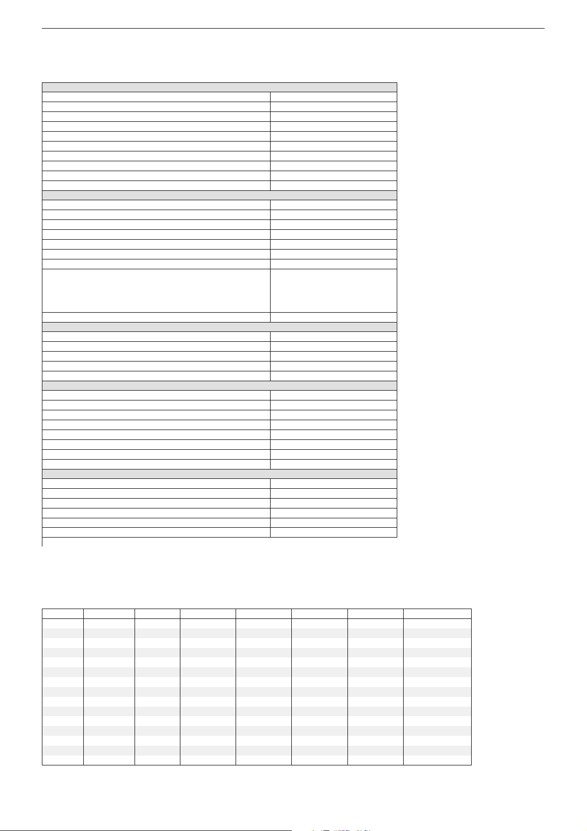
Technische Daten / Technical Data
(I)
q
y
y
Bild
Display
Bildschirmdiagonale / sichtbares Bild
Bildseitenverhältnis 16:9 (Breitbild-Format)
4 verschiedene Formatumschaltungen
Ansprechzeit
Kontrast-Verhältnis
Blickwinkel
Leuchtdichte des Panels
Auflösung max.
Bildschärfeeinstellung / Kammfilter
Electronic
Intelligentes Bedienkonzept (OSD)
Autom. Senderprogrammierung ATS euro plus
Bild-im-Bild (1-Tuner-PIP)
PIP-Text
On timer / Sleep timer
Programm-Speicherplätze TV / AV
Videotext / Seiten-Speicher
TV-Standard
Infrarot-Fernbedienung
Ton
Stereo-/Zweikanalton-Empfang
Musikleistung / Sinusleistung
Kopfhörer-Lautstärke getrennt regelbar
Kopfhörer-Tonkanalwahl bei Zweikanalton
Lautsprecher
Anschlüsse / Buchsen
S-Video-Eingang (Hosiden)
Euro-AV-Buchse / davon RGB und S-Video tauglich
Wireless-AV-Buchse
Cinch-AV-Buchsen
Kopfhörer-Buchse (Ø 3,5 mm)
YUV-Buchsen (Progressive Scan)
VGA für PC
Drahtlose Bild- und Tonübertragung nachrüstbar
Netzteil
Spannung (Regelbereich), Frequenz 50/60 Hz
Netzteil integriert
Leistungsaufnahme im TV-Betrieb / Standby
Gewicht
Abmessungen ca. (Breite x Höhe x Tiefe)
Zubehör (im Lieferumfang)
Technische Angaben ohne Gewähr.
ca. cm
ca. ms
ca.
ca.
ca. cd/m
pixel
ca. Watt
V~
ca. Watt
ca. kg
ca. cm
ARGANTO 23 LW 60-6410 TopGRUNDIG Service
ARGANTO 23
LW 60-6410 TOP
Activ Matrix TFT-LC-Display
58 / 58
•
•
25
400 : 1
170 vertikal, 170 horizontal
450
WXGA 1280 x 1024
–/•
•
•
•
•
–/•
99 / 5
•/10
BG, I, DK/K’, L/L’. PAL, SECAM
über AV: NTSC 4,43 + 3,58 MHz.
A2 für B/G/D/K/I,
Nicam 5,85 MHz (BG, L)
+ 6,52 MHz
•
•/•
2 Kanal 14 / 10
–
–
2 Breitband frontal
•
1x / 1x
–
•
•
•
• (Multisync WUXGA)
Modul WT-AV 1
100-240
•
120 / < 15
10,5
68 x 43 x 9,5 (21 mit Fuß)
VGA-Monitor-Kabel
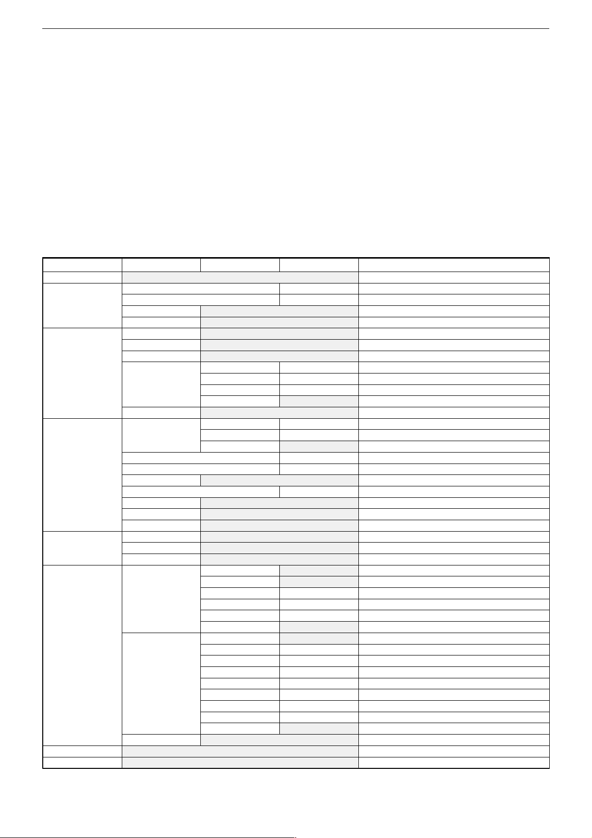
Mögliche Auflösungen PC-Eingang / Possible Resolutions of PC Input
Mode No.
1
2
3
4
5
6
7
8
9
10
11
12
13
14
15
Mode Name Resolution
VGA 70Hz
VGA 60Hz
VGA 72Hz
VGA 75Hz
SVGA 56Hz
SVGA 60Hz
SVGA 72Hz
SVGA 75Hz
XGA 60Hz
XGA 70Hz
XGA 75Hz
MAC VGA
MAC VGA
US Text
640 x 350
640 x 480
640 x 480
640 x 480
800 x 600
800 x 600
800 x 600
800 x 600
1024 x 768
1024 x 768
1024 x 768
640 x 480
832 x 624
720 x 400
WXGA 60Hz 1280 x768
. (kHz) V.Freq. (Hz)
H.Fre
31,469
31,469
37,861
37,5
35,16
37,879
48,077
46,875
48,363
56,476
60,023
35,0
49,550
31,469
70,087
59,469
72,81
75,0
56,25
60,317
72,188
75,0
60,004
70,069
75,029
66,667
74,550
70,087
H. Polarit
+
-
-
+
+
+
+
-
+
-
-
-
47,733 60,042 - -
1 - 3
V. Polarit
-
-
-
+
+
+
+
-
+
-
+
Pixel/CLK (MHZ)
25,175
25,175
31,5
31,5
36,0
40,0
50,0
49,5
65,0
75,0
78,75
30,24
57,283
28,322
80
Page 4
ARGANTO 23 LW 60-6410 TopGRUNDIG Service
Service- und Sonderfunktionen
Tastenfunktionen
MENU
P–
P+/
ǸǸ
ǸǸ
/ Ƿ Wert ändern
Service-Mode aktivieren
– Tast e "
"POWER" auf der Fernbedienung einschalten.
– Service Menü ("Menu Screen") mit Taste "
dienung aufrufen.
Service-Mode beenden
– Gerät ausschalten.
Software-Versionsnummer
Im Service Menü wird jeweils in der untersten Zeile die Versionsnummer angezeigt.
Menu Screen
Auto Image Adjust
Contrast/Brightness
Colour
Image
Menu Setup
Advance Adjust TP67XX Deinterlace Off
Recall All
Exit
- Aufrufen des Service Menü ("Menu Screen")
- Menü-Punkt aktivieren
Menü-Zeile (Menüpunkt) wählen
MENU
" am Gerät gedrückt halten und Gerät mit der Taste
MENU
" auf der Fernbe-
Sub menu 1 Sub menu 2
Brightness
Contrast
D-Brightness
Exit
Cool
Neutral
Warm
User Colour Red
Green
Blue
Exit
Exit
H./V.Position H. Position
V. Position
Exit
H. Pase
Fine Tune
Noise
Sharpness
Black Level
Luma Sharp Adj.
Exit
OSD Position
Edit Name
Exit
Deinterlace On
PCLK dphase
SHFCLK
UCLK
Exit
ADC Advance Tune
ADC Offset R
ADC Offset G
ADC Offset B
ADC Gain R
ADC Gain G
ADC Gain B
Charge Pump
Exit
Exit
Service and Special Funktions
Functions of the buttons
MENU
P+/P–
ǸǸ
ǸǸ
/ Ƿ Changing the settings
Calling up the Service Mode
– Hold button "
set with button "POWER" on the remote control.
– Activate the Service Menu ("Menu Screen") with button "
of the remote control.
Exit the Service Mode
– Switch off the set.
Software Version Number
The software version number is shown in each lowest line of the
service menu.
Value Description
-50…+50
0…100 Contrast for all Modes
0…63
0…63
0…63 Colour temperature "Blue" for PC Mode
0…100
0…100 V. Position for PC Mode
0…100
0…100
-7…+7
0…63
0…7
0…7 Adjust UCLK for scaler
0…63
0…63
0…63
0…63
0…63
0…63
0…7
- Call up the Service Menu ("Menu Screen")
- Activate menu point.
Call up te dialogue line (point of menu)
MENU
" at the set depressed while switching on the
Auto Image Adjust for PC Mode
Brightness for all Modes
Brightness for Video Mode
Back to Menu Screen
Colour temperature "Cool" for PC Mode
Colour temperature "Neutral" for PC Mode
Colour temperature "Warm" for PC Mode
Colour temperature "Red" for PC Mode
Colour temperature "Green" for PC Mode
Back to Sub menu 1
Back to Menu Screen
H. Position for PC Mode
Back to Sub menu 1
H. Wide for PC Mode
Frequency for PC Mode
no Function
Sharpness for all Modes
Black Level for Video Mode
no Function
Back to Menu Screen
no Function
no Function
Back to Menu Screen
Close deinterlace for scaler
Open deinterlace for scaler
Adjust PCLK for scaler
Adjust SHFCLK for scaler
Back to Sub menu 1
no Function
Black level colour for HDTV Mode
Black level colour for HDTV Mode
Black level colour for HDTV Mode
White level colour for HDTV Mode
White level colour for HDTV Mode
White level colour for HDTV Mode
Phase of A/D decoder for HDTV Mode
Back to Sub menu 1
Back to Menu Screen
Reset for the original setting
Exit Service Mode
MENU
"
1 - 4
Page 5

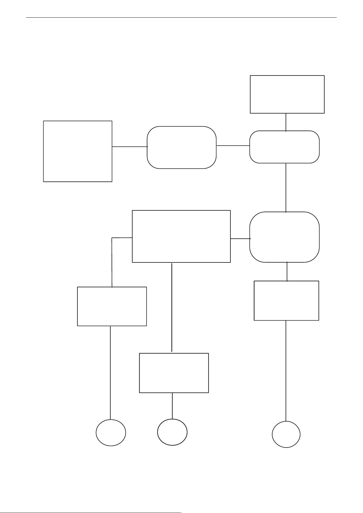
Fehlersuchdiagram
Backlight & LEDs
leuchten nicht
Sind Spannungen an
P803#10 = 5V &
P803#4 = 24V?
(Netzteil)
S. 2-2
ja
nein
Netzteil prüfen
ARGANTO 23 LW 60-6410 TopGRUNDIG Service
Ist Spannung an
L139 = 24V?
(Hauptplatte)
S. 2-9
ja
Ist Spannung an
L140 = 5V?
(Hauptplatte)
S. 2-9
ja
Ist Spannung an
I016#2 = 3,3V?
S. 2-9
ja
Ist Spannung an
I015#2 = 2,5V?
S. 2-9
nein
nein
Steckverbindungen
P803 & P019
prüfen
Steckverbindungen
P803 & P019
prüfen
nein
I016 prüfen
nein
I015 prüfen
ja
Steckverbindungen
P601 (von LED-Platte zu P015)
und P802A ( von Inverter zu P802)
prüfen.
S. 2-2/2-18
1 - 5
Page 6
ARGANTO 23 LW 60-6410 TopGRUNDIG Service
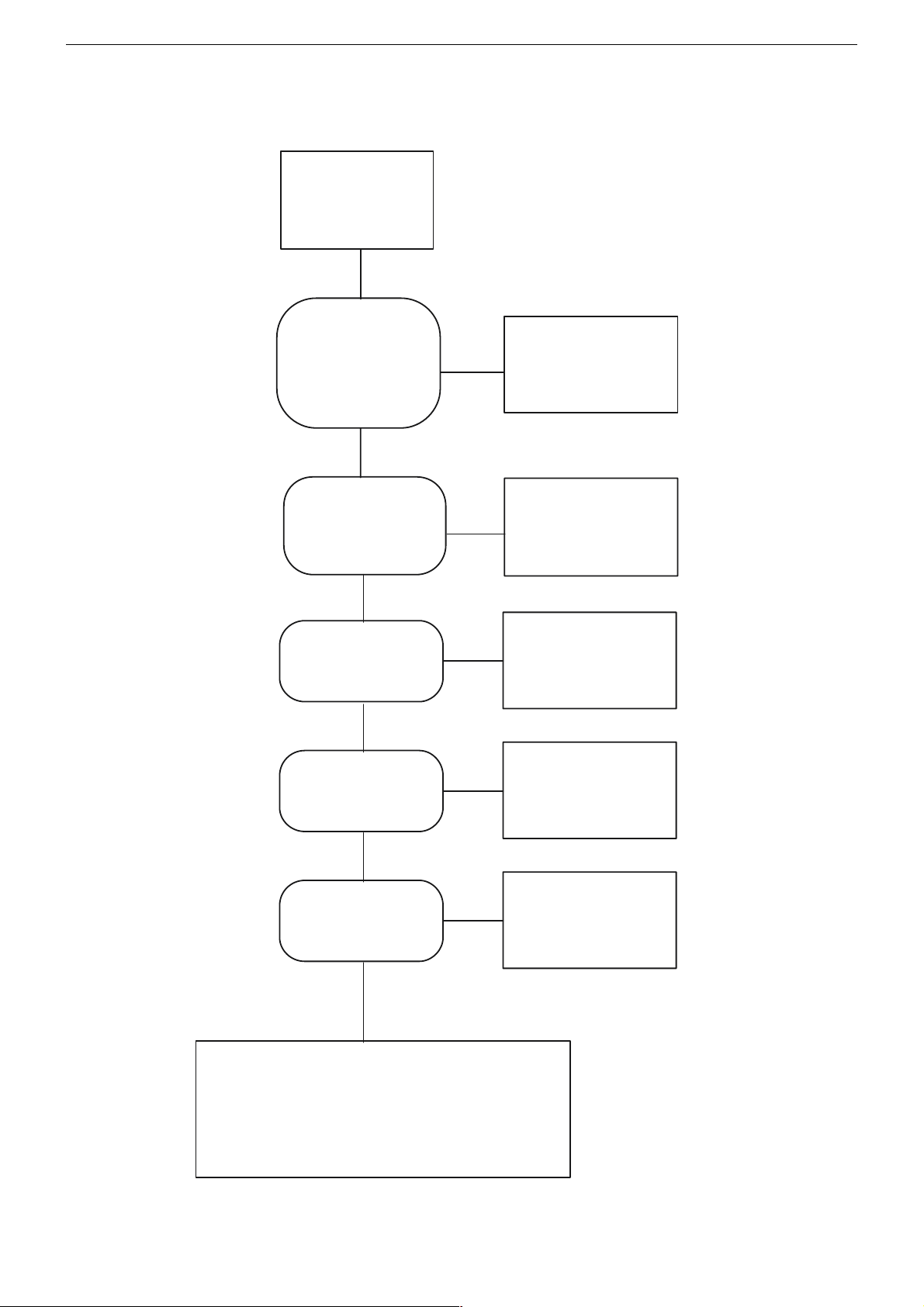
V901 (Panel mit Inverter)
und
I019 (Scaler)
prüfen
Gerät
funktioniert
I012 (MCU)
hängt sich zeitweise auf
Immer noch
kein
Backlight
Steckverbinder
P802 & P802A
(von Netzteil
zum Inverter)
prüfen
Gerät ausschalten
und vom Netz trennen,
um I012 (MCU) zu resetten.
Gerät
funktioniert
nicht
Grün
nein
Kein Backlight, aber
LED leuchtet
In welcher Farbe
leuchtet die LED?
Rot
PC-Mode
und
Energiesparmodus ein?
ja
PC starten
damit H. und V. Sync.
vorhanden sind
I012 (MCU)
prüfen
Ende Ende
1 - 6
Ende
Page 7
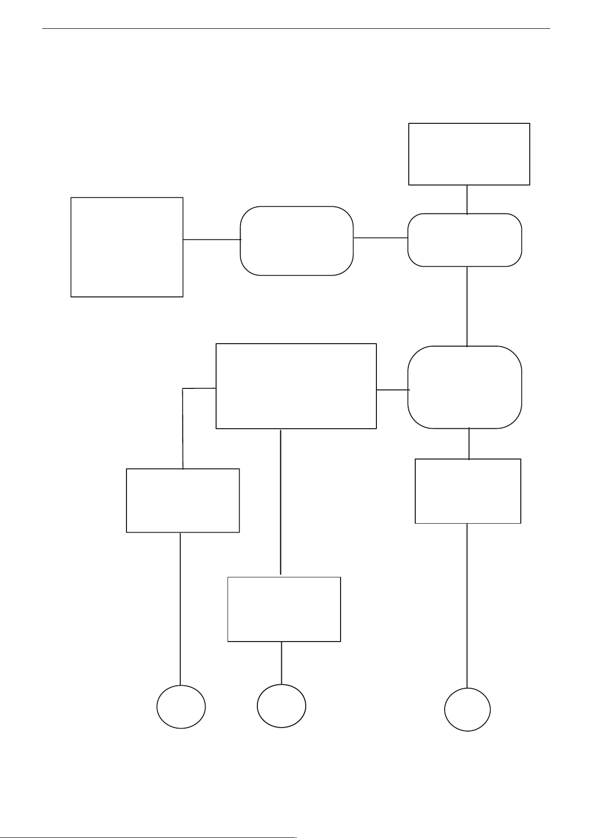
Fault Finding Diagram
ARGANTO 23 LW 60-6410 TopGRUNDIG Service
No Backlight
&
No LED
Is the Voltage of
P803#10 = 5V &
P803#4 = 24V?
(on Power Module)
P. 2-2
Yes
Is the Voltage of
L139 = 24V?
(on Main Board)
P.2-9
Yes
Is the Voltage of
L140 = 5V?
(on Main Board)
P.2-9
No
Check PB0112V
(Power Module)
No
Check connectors
P803 & P019
No
Check connectors
P803 & P019
Yes
Is the Voltage of
No
I016#2 = 3.3V?
P. 2-9
Yes
Is the Voltage of
No
I015#2 = 2.5V?
P. 2-9
Yes
Check and Re-plug wires
P601 (from LED Board to P015)
and P802A (from Inverter to P802).
P. 2-2/2-18
Check I016
Check I015
1 - 7
Page 8
ARGANTO 23 LW 60-6410 TopGRUNDIG Service
Check
U901 (Inverter)
and
I019 (Scaler)
Picture
shows
Still no
Backlight
Check & Re-plug
P802 & P802 A
(from Power to Inverter)
Press POWER key &
Re-plug AC Power Cord
to reset I012 (MCU)
Still no
Picture
Green
No
No Backlight
but
LED lights up
Which Colour
does LED light?
Red
Is it entering into
Power Saving on
PC mode?
Yes
Yes
I012 (MCU)
hangs
temporarily
End
Check
I012 (MCU)
End
End
Restart Signal to
ensure H./V. sync.
are not absent
End
1 - 8
Page 9
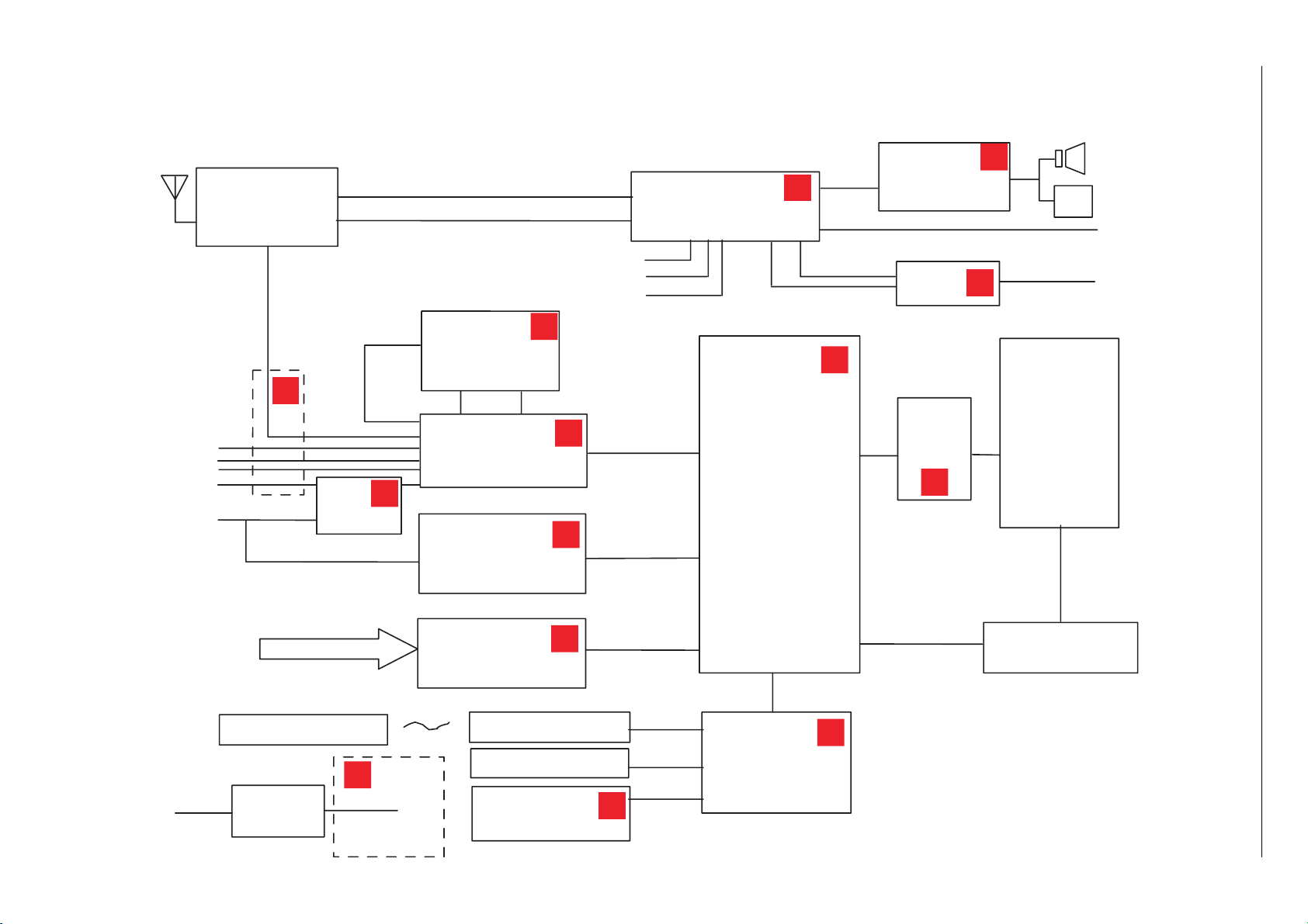
Schaltpläne und Platinenabbildungen / Circuit Diagrams and Layout of the PCBs
PC VGA
Interlace
I010
P15V330
Component
Scart-Video
Video
S-Video
Scart-RGB
Progressive
Video
5W + 5W
Speaker
Headphone Jack
Scart Audio Out
Line-out (RCA)
AC Input
100~240V
50 / 60Hz
~
+ 24V
+ 5V
+ 2.5V
+ 3.3V
I001
ADC
AD9883-140
I019
Scaler
TP6760
LCD
Panel
16:9
I012
MCU
WE78162Ep
(SyncMOS)
Key Pad
INVERTER
I013
EEPROM: 24C16
Power
Module
LED & IR Pad
Remote Control
8 bit
I006
ADC
AD9883-110
24 bit Port B
24 bit Port A
I044
4:1
Audio Processor
MSP3410G
I021
Audio Amp.
LA4282
Scart Audio
Video/S-V/ Component Audio
PC Audio
Mono TV Audio
UT01
TV – Tuner
FQ1216 MK3
SIF
I011
TT Decorder
SAA5264PS
I018
Decorder
SAA7118E
I014
LVDS
I034
P15V330
Component
Audio Out
1
10
9
9
8
7
6
5
5
4
3
3
3
2
Blockschaltplan / Blockdiagram
GRUNDIG Service ARGANTO 23 LW 60-6410 Top
2 - 1
Page 10

Netzteil / Power Supply
L1
-+
BD1
R12
R1
CY5
C6
D16
R32
R15
R33
D9
L2
C42
C10
C12
C13
R36
R38
C19
C17
C28
R53
R54
R34
C21
R56
R72
R55
C29
R73
3
5
8
4.
1
6
2
7
U2
LF2
R8
R9
CY3
CY4
C11
C23
R37
+24V
+24V
+5V
C5
U6
D3
Q1
R74
R79
R75
D15
R4
R6
R5
R30
R26
R27
D48
R23
R78
C3
R77
D1
D6
D7
Q2
R3
R22
R21
C14
R28
C1
L3
C4
D2
C16
C15
R80
R82
R2
R81
Q5
Q9
4
3
1
2
U4
R68
R69
C36
D17
+
C26
D8
R48
C34
R52
R31
R50
D12
T1
R51
C27
T2
R25
4
7
8
3
2
6
1
5
IC1
6841
+15V
R90
C9
R92 R93
C43
Q17
Q18
2
1
6
8
7
5
4
3
IC2
1
2
3
4
5
6
7
8
9
10
11
12
13
14
15
16
17
18
19
20
21
22
23
24
25
26
27
28
29
30
P804
1
2
3
4
5
6
7
8
9
10
11
12
13
14
15
16
17
18
19
20
P803
DVD0
FPBACK
+24V
+5V
PWSAVE
GND_TU
MPX
MSCL
21F
MSDA
TUNER_OUT
GND_TU
MSC L
TUNER_OUT
21F
MPX
MSDA
PW_SAVE
GND
1
2
P805
GND_TU
TUNER_OUT
1
2
3
4
5
6
7
8
P802
+24V
DVD0
FPBACK
R67
R70
R71
C31
ZD5
ZD4
4
3
1
2
U3
Q4
R44
R45
Q8
R41
R42
R43
C25
Q7
ZD1
D22
+5V
+24V
+24V
D18
R97
R85
NTC1
CY1
R18
N
FG
L
F1
R19
VAR1
CY2
CX
1
L4
CX2
LF1
LF3
R102
R103
R95
GRUNDIG Service ARGANTO 23 LW 60-6410 Top
2 - 2
Page 11

Hauptplatte Teil 1 / Main Board Part 1
100µH
1
VGA Interface
2 - 3
GRUNDIG Service ARGANTO 23 LW 60-6410 Top
Page 12

Hauptplatte Teil 2 / Main Board Part 2
2
YPrPb Interface
2 - 4
GRUNDIG Service ARGANTO 23 LW 60-6410 Top
Page 13

Hauptplatte Teil 3 / Main Board Part 3
3
Audio Interface
2 - 5
GRUNDIG Service ARGANTO 23 LW 60-6410 Top
Page 14

Hauptplatte Teil 4 / Main Board Part 4
4
1
1
Scartplatte Interface
2 - 6
GRUNDIG Service ARGANTO 23 LW 60-6410 Top
Page 15

Hauptplatte Teil 5 / Main Board Part 5
5V
5V
5V
5V
5V
5V
5V
5V
5V
5V
Modify [C]…330P
5
MPU Interface
GRUNDIG Service ARGANTO 23 LW 60-6410 Top
2 - 7
Page 16

Hauptplatte Teil 6 / Main Board Part 6
5V
5V
3.3V
17" + 30" NC
23" NC
6
4
5
6
7
8
9
0
4
5
6
7
8
9
0
Panel Interface
GRUNDIG Service ARGANTO 23 LW 60-6410 Top
2 - 8
Page 17

Hauptplatte Teil 7 / Main Board Part 7
0,01µF(NC)
0,01µF(NC)
0,01µF(NC)
0,01µF(NC)
0,01µF(NC)
0,01µF(NC)
C217
C216
C221
C186
C184
C185
R249
1K
R248
1K
L139
P+24V
5V
PW_5V
0
L140
0
L141
0
7
Power Interface
2 - 9
GRUNDIG Service ARGANTO 23 LW 60-6410 Top
Page 18

Hauptplatte Teil 8 / Main Board Part 8
delete: IO25
add: R075 R076 - - 3/8
8
Videotext
2 - 10
GRUNDIG Service ARGANTO 23 LW 60-6410 Top
Page 19

Hauptplatte Teil 9
9
2
3
2
3
Main Board Part 9
Video Interface
2 - 11
GRUNDIG Service ARGANTO 23 LW 60-6410 Top
Page 20

Hauptplatte Teil 10 / Main Board Part 10
10
3
!
$
@
#
3
!
@
#
$
Scaler
2 - 12
GRUNDIG Service ARGANTO 23 LW 60-6410 Top
Page 21

Hauptplatte PCB / Main Board PCB
2 - 13
GRUNDIG Service ARGANTO 23 LW 60-6410 Top
Page 22

GRUNDIG Service ARGANTO 23 LW 60-6410 Top
Hauptplatte PCB / Main Board PCB
2 - 14
Page 23

GRUNDIG Service ARGANTO 23 LW 60-6410 Top
Hauptplatte PCB / Main Board PCB
2 - 15
Page 24

GRUNDIG Service ARGANTO 23 LW 60-6410 Top
Scart-Platte / Scart PCB
L802
HB-1T1608-601JT
L804
HB-1T1608-601JT
L801
HB-1T1608-601JT
L803
HB-1T1608-601JT
L812
L813
L814
L815
L816
L817
HB-1T1608-601JT
HB-1T1608-601JT
HB-1T1608-601JT
HB-1T1608-601JT
HB-1T1608-601JT
HB-1T1608-601JT
L805
HB-1T1608-601JT
L809
L810
L811
HB-1T1608-601JT
HB-1T1608-601JT
HB-1T1608-601JT
HB-1T1608-601JT
HB-1T1608-601JT
L807
L808
L806
HB-1T1608-601JT
2 - 16
Page 25

GRUNDIG Service ARGANTO 23 LW 60-6410 Top
Tuner-Platte / Tuner PCB
2 - 17
Page 26

GRUNDIG Service ARGANTO 23 LW 60-6410 Top
Bedienteil, IR-Emplänger / Control Board, IR Receiver
2 - 18
Page 27

Explosionszeichnung und Ersatzteilliste
Exploded View and Spare Parts List
GRUNDIG Service ARGANTO 23 LW 60-6410 Top
2
$
3
3 - 1
1
&
6
4
0
%
Page 28

ǵ
GRUNDIG Service ARGANTO 23 LW 60-6410 Top
3 - 2
Ersatzteilliste
Spare Parts List
7 / 2004
POS. NR. ABB. MATERIAL-NR. ANZ. BEZEICHNUNG DESCRIPTION
POS. NO. FIG. PART NUMBER QTY.
720126004400 ARGANTO 23 LW 60-6410 TOP ARGANTO 23 LW 60-6410 TOP
0001.000 759550555100 GEHAEUSEVORDERTEIL FRONT COVER
0002.000 759550555200 RUECKTEIL REAR CASE
0003.000 S 275990123700 LP-CHASSISMODUL LP-CHASSISBOARD
0004.000 S 275991020200 LP-NETZTEILMODUL POWER SUPPLY BOARD
0006.000 275990123900 LP-TUNERMODUL LP-TUNERBOARD
0009.000 720117134200 FERNBEDIENUNG REMOTE CONTROL
0010.000 S 759550555300 23" LCD-DISPLAY 23" LCD-DISPLAY
0012.000 759550554900 SIGNALKABEL SIGNAL CABLE
0013.000 759550554500 IC MCU 128 KB IC MCU 128 KB
0014.000 275990033900 LP-BEDIENMODUL LP-CONROLBOARD
0015.000 275990062000 LP-I/O-MODUL LP- I/O-BOARD
0017.000 275990123800 LP-IR-MODUL LP-IR-BOARD
720117024500 BEDIENUNGSANLEITUNG D/GB/F/I/NL/PL INSTRUCTION MANUAL D/GB/F/I/NL/PL
720117024600 BEDIENUNGSANLEITUNG DK/S/FIN/N/E/P INSTRUCTION MANUAL DK/S/FIN/N/E/P
720100485000 SERVICE MANUAL D/GB SERVICE MANUAL D/GB
NUR FÜR INTERNEN GEBRAUCH
FOR INTERNAL USE ONLY
ARGANTO 23 LW 60-6410 TOP
MATERIAL-NR. / PART NO.: 720126004400
BESTELL-NR. / ORDER NO.: GMK9100
d©
KEIN E-TEIL NO SPARE PART
BEI DISPLAYDEFEKT WITH DISPLAY DEFECTIVE
ERFOLGT GERAETETAUSCH TAKEN PLACE EXCHANGE SET
TV
Es gelten die Vorschriften und Sicherheitshinweise
gemäß dem Service Manual "Sicherheit", Mat.-Nummer 720108000001, sowie zusätzlich die eventuell abweichenden, landesspezifischen Vorschriften!
The regulations and safety instructions shall be valid
!
as provided by the "Safety" Service Manual, part
number 720108000001, as well as the respective
( ! )
national deviations.
ÄNDERUNGEN VORBEHALTEN / SUBJECT TO ALTERATION
 Loading...