

Page 1
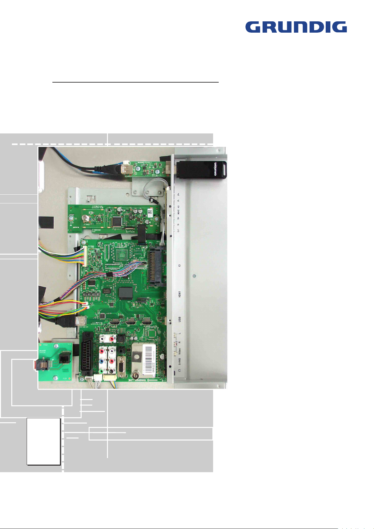
TV Service Manual
Chassis TX
40 VLE 8190 S WEB
Fine Arts
40 S WEB
46 S 3D WEB
55 3D WEB
GBJ7140, GBJ7240
GBJ7146, GBJ7246
New York
40 S WEB
46 3D WEB
55 3D WEB
GBJ8440
GBJ7155
GBJ9140
GBJ9146
GBJ9155
Zusätzlich erforderliche Unterlagen für den Komplettservice
Additionally required Service Documents for the Complete Service
Service
Manual
Sicherheit
Safety
Materialnr./Part No.
720108000001
Materialnummer / Part Number 720100556000
Änderungen vorbehalten / Subject to alteration
TCC 1011 MP • Prepared in Germany
http://www.grundig.com
Page 2
GRUNDIG Service Chassis TX
Es gelten die Vorschriften und Sicherheitshinweise gemäß dem Service Manual "Sicherheit", Materialnummer
720108000001, sowie zusätzlich die eventuell abweichenden, landesspezifischen Vorschriften!
Inhaltsverzeichnis
Allgemeiner Teil
Allgemeine Hinweise .....................................................................1-2
Spezial-Funktionen
Geräte- und Display-Varianten
Technische Daten
Bedienhinweise
Service- und Sonderfunktionen
.................................. 1-2…1-32
........................................................................1-3
......................................................1-3
..........................................................................1-5
.............................................................................1-8
...................................................1-32
Seite
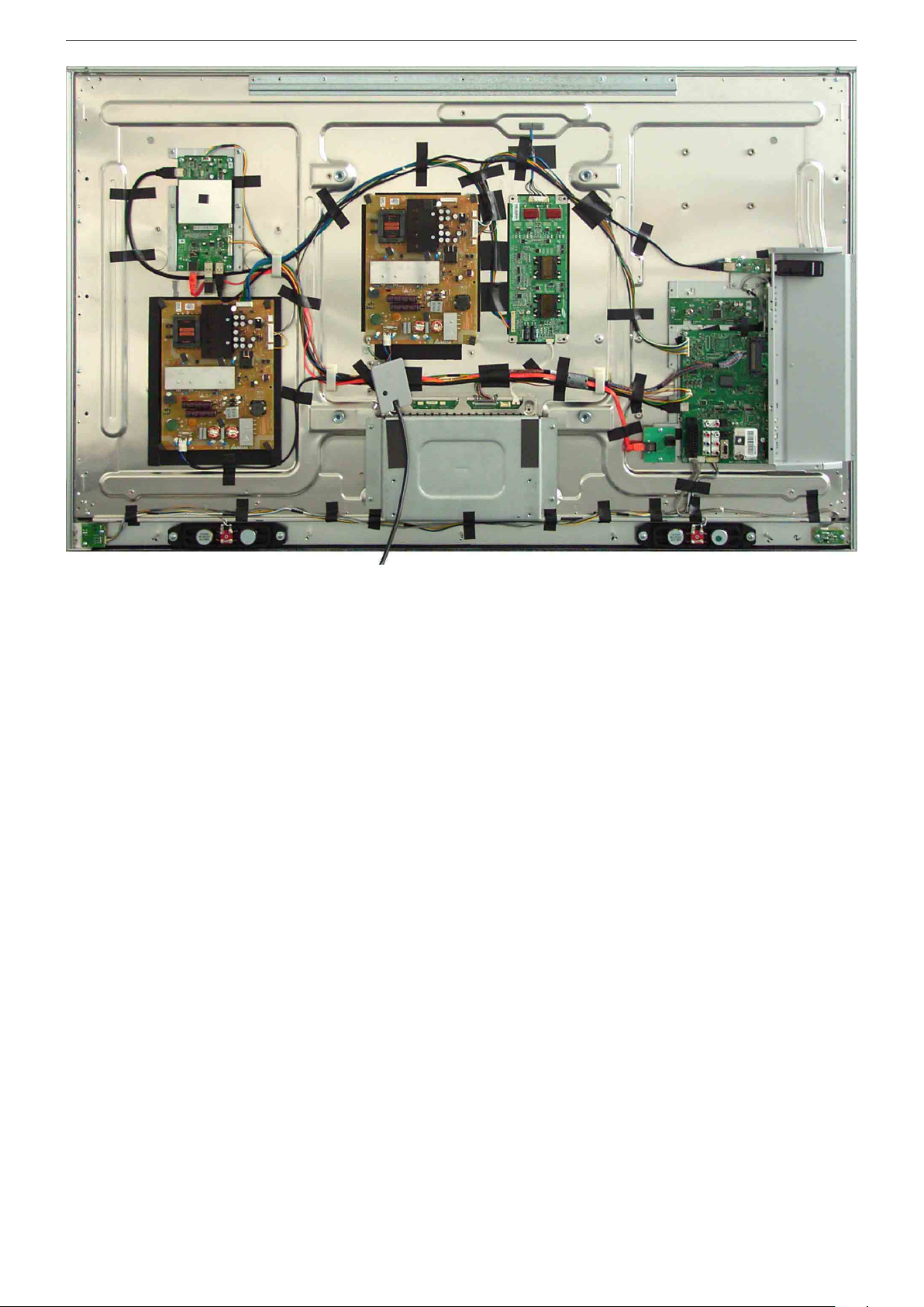
Platinenabbildungen
und Schaltpläne
Chassisplatte VMX190R-1 ............................................................2-1
– Blockschaltplan ..........................................................................2-9
– Netzteil .................................................................................... 2-10
– HDMI........................................................................................2-11
– SCART, VGA ............................................................................2-12
– AV, USB ...................................................................................2-14
– PCMCIA- & SAT-Interface ........................................................2-15
– Tuner ........................................................................................ 2-15
– Scaler.......................................................................................2-16
– Scaler-RAM .............................................................................2-19
– FRC .........................................................................................2-20
– Verstärker .................................................................................2-22
SAT-Baustein
Netzteil DPS-202CP
IR-/LED-Platten
Keyboards....................................................................................2-29
Ethernet Adapter
USB-Platte
Emitter-Platten
...............................................................................2-23
...................................................................................2-30
.............................................................................2-30
.................................. 2-1…2-30
....................................................................2-26
...........................................................................2-29
.........................................................................2-29
The regulations and safety instructions shall be valid
as provided by the "Safety" Service Manual, part
number 720108000001, as well as the respective
national deviations.
Table of Contents
General Section
General Notes ...............................................................................1-2
Special Functions
Product and Display Variants
Technical Data
Operating Hints
Service and Special Functions
...............................................................................1-5
.................................. 1-2…1-32
..........................................................................1-3
.........................................................1-3
............................................................................1-20
....................................................1-32
Page
Layout of the PCBs
and Circuit Diagrams
Chassis Board VMX190R-1 ...........................................................2-1
– Block Circuit Diagram ................................................................2-9
– Power Supply ..........................................................................2-10
– HDMI........................................................................................2-11
– SCART, VGA ............................................................................2-12
– AV, USB ...................................................................................2-14
– PCMCIA & SAT Interface .........................................................2-15
– Tuner ........................................................................................ 2-15
– Scaler.......................................................................................2-16
– Scaler-RAM .............................................................................2-19
– FRC .........................................................................................2-20
– Amplifier ...................................................................................2-22
SAT Board
Power Supply DPS-202CP
IR / LED Boards ..........................................................................2-29
Keyboards....................................................................................2-29
Ethernet Adapter
USB Board...................................................................................2-30
Emitter Boards
...................................................................................2-23
.........................................................................2-29
.............................................................................2-30
......................... 2-1…2-30
..........................................................2-26
Ersatzteillisten ...................................... 3-1…3-6
Allgemeiner Teil
Allgemeine Hinweise
Vor dem Öffnen des Gehäuses den Netzstecker ziehen!
Achtung: ESD-Vorschriften beachten
Leitungsverlegung
Bevor Sie die Leitungen und insbesondere die Masseleitungen lösen, ist
die Leitungs ver legung zu den einzelnen Baugruppen zu beachten.
Nach erfolgter Reparatur ist es notwendig, die Leitungsführung wieder
in den werkseitigen Zustand zu versetzen um evtl. spätere Ausfälle
oder Störungen zu vermeiden.
Durchführen von Messungen
Bei Messungen mit dem Oszilloskop an Halb leitern sollten Sie nur
Tast köpfe mit 10:1 - Tei ler verwen den. Außerdem ist zu beachten, dass
nach vorheriger Messung mit AC-Kopp lung der Koppelkondensator
des Oszillo skops auf geladen sein kann. Durch die Ent ladung über das
Messobjekt können Bau teile beschä digt werden.
Messwerte und Oszillogramme
Bei den in den Schaltplänen und Oszillogrammen angegebenen
Messwerten handelt es sich um Näherungswerte!
Austausch der Chassisplatte
Nach Austausch der Chassisplatte müssen alle Einstellungen im
Service Mode nach Tabelle "Grundeinstellwerte" (Punkt 1 im Kapitel
"Service- und Sonderfunktionen" auf Seite 1-32) eingestellt werden.
Spare Parts Lists .................................. 3-1…3-6
General Section
General Notes
Before opening the cabinet disconnect the mains plug!
Attention: Observe the ESD safety regulations
Wiring
Before disconnecting any leads and especially the earth connecting
leads observe the way they are routed to the individual assemblies.
On completion of the repairs the leads must be laid out as originally
fitted at the factory to avoid later failures or disturbances.
Carrying out Measurements
When making measurements on semi-con duc tors with an oscillo scope,
ensure that the test probe is set to 10:1 dividing factor. If the previous
measurement was made on AC input, please note that the coupling
capacitor in the oscilloscope will be charged. Discharge via the item
being checked can damage the components.
Measured Values and Oscillograms
The measured values given in the circuit diagrams and oscillograms
are approximates!
Change of the Chassis Board
After changing the chassis board all settings in the service mode must
be done according to the table "Basic Settings" (point 1 in chapter
"Service and Special Functions" on page 1-32).
1 - 2
Page 3
GRUNDIG Service Chassis TX
Spezial-Funktionen
Kindersicherung
Mit der Master-Pin 2356 kann die Einstellung der persönlichen Pin
geändert werden.
Hotel-Mode
Bei aktiviertem Hotel-Mode ist die maximale Lautstärke begrenzt und
das Menü "
Aufruf: i –> 8500 –> 4 "System Configuration" –> 0 (OK) –> 43
"Hotel" –> 1 2 "Ein".
Hotel-Mode temporär ausschalten
Bei dieser Funktion ist der Hotel-Mode bis zum nächsten Ausschalten
(Standby) des Gerätes deaktiviert.
Aufruf: i –> 4658 –> 43
In dem zusätzlich erscheinenden Menü HOTEL-TV-EINSTELLUNGEN
sind folgende Einstellungen möglich:
– Maximale Lautstärke
– Einschaltlautstärke
– Erstes Einschalten (Standby / Einschalten)
Cloning-Funktion
Mit dieser Funktion können folgende Daten auf den extern angeschlossenen USB-Speicher gesichert und zurück kopiert werden:
–
Channel/Video Set.
–
Service Set.
–
User Set.
–
ALLES
Daten auf USB-Stick kopieren:
Leeren USB-Speicher anschließen –> i –> 8500 –> 43 "Cloner Configuration"–> 4658 –> 4 "Kopieren" –> 1 2 TV to USB –> 4 "Copy Item"
–> 1 2 Channel/Video Set., Service Set., User Set oder ALLES –> 4
"Start Cloning" –> starten mit 2 –> am Ende wird "Success" angezeigt.
Daten von USB-Stick in das Gerät zurück speichern:
Gegebenenfalls Hotel-Mode kurzzeitig ausschalten (s.o.) –> USB-Stick
anschließen –> i –> 8500 –> 43 "Cloner Configuration"–> 4658 –>
4 "Kopieren" –> 1 2 USB to TV –> 4 "Copy Item" –> 1 2 Channel/
Video Set., Service Set., User Set oder ALLES –> 4 "Start Cloning"
–> starten mit 2 –> am Ende wird "Success" angezeigt.
INSTALLATION
Geräte-Einstellwerte der Service- und Sonder-
Kundenspezifische Einstellungen.
Für den Servicefall: sollte die defekte Chassis-
" ist nicht mehr vorhanden.
Programmtabellen und Einstellungen der Si-
gnalquellen - diese sind auch übertragbar auf
ein weiteres Gerät gleicher Serie.
Funktionen ohne Display-Einstellwerte.
platte noch so weit funktionieren, können alle
Einstellwerte gespeichert werden um diese
dann in die neue Chassisplatte zu übertragen.
Special Functions
Parental Control
The personal pin can be changed with master pin 2356.
Hotel Mode
Maximum volume is limited and Menu "
at activated hotel mode.
Call up: i –> 8500 –> 4 "System Configuration" –> 0 (OK) –> 43
"Hotel" –> 1 2
Switching off the Hotel Mode temporarily
At this function the activated hotel mode is deactivated until the set
is switched off (standby).
Call up: i –> 4658 –> 1 2
Following adjustment are available in the additionally menu HOTEL
TV SETTINGS:
– Maximum Volume
– Start-Up Volume
– First Power (Standby / Power On)
Cloning Function
It is possible to copy following data to an external USB stick and back
to TV set:
–
Channel/Video Set.
–
Service Set.
–
User Set.
–
ALL
In case of service: If the defective chassis
Copy data to USB stick:
Connect empty USB memory –> i –> 8500 –> 43 "Cloner Configuration"–> 4658 –> 4 "Copy" –> 1 2 TV to USB –> 4 "Copy Item" –>
1 2 Channel/Video Set., Service Set., User Set or ALL –> 4 "Start
Cloning" –> start with 2 –> "Success" is showing at the end.
Copy data from USB stick into TV set:
If necessary switch off Hotel Mode temporarily (see above) –> i –>
8500 –> 43 "Cloner Configuration"–> 4658 –> 4 "Copy" –> 1 2
USB to TV –> 4 "Copy Item" –> 1 2 Channel/Video Set., Service
Set., User Set or ALL –> 4 "Start Cloning" –> start with 2 "Success"
is showing at the end.
"AVAIL".
Programme tables and settings of signal
sources - they are transferable into further TV
set of same version.
TV adjustments of service and special func-
tions without panel values.
User settings.
board are still operate, it is possible to save all
adjustments / settings and copy into new chassis board.
SOURCE SETUP
" is no available
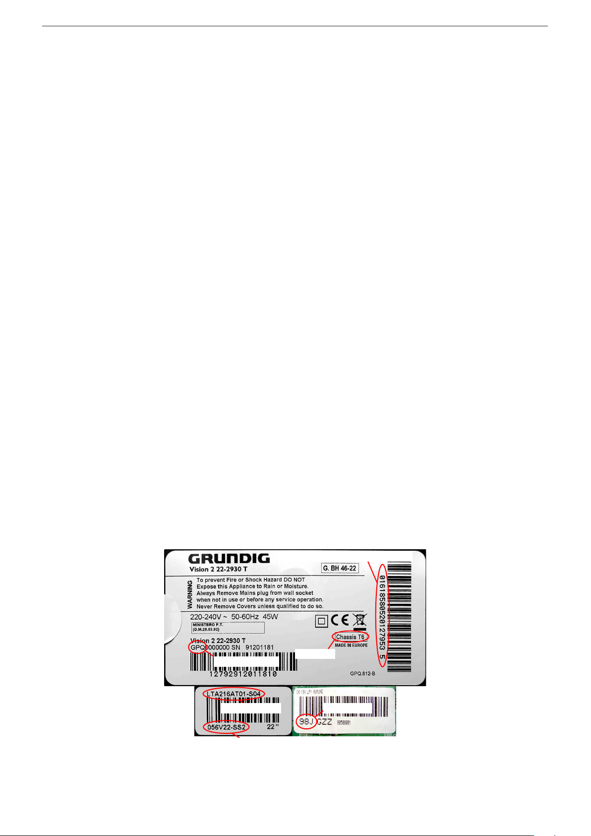
Geräte- und Display-Varianten
Display- und Product Code
Je nach Verfügbarkeit werden
Displays verschiedener Hersteller eingebaut. Dies führt zu
unterschiedlichen Chassis-Bestückungen, sowie zu Änderungen
in der Software. Bei Ersatzteilbestellungen und SoftwareUpdates achten Sie bitte auf das
eingebaute Display, sowie auf den
"Product Code". Angaben dazu
finden Sie auf der Geräterückseite. Sollte in der Ersatzteilliste
des Service Manuals Ihr "Product
Code" oder Ihre Display-Variante
nicht aufgeführt sein, können
Sie eine aktualisierte Version auf
dem GRUNDIG Service-Portal
"http://service.grundig.de" finden.
Überprüfen Sie vor PlatinenTausch, ob die Aufkleber der
Platinen identisch sind (z.B. PCB
Code).
Product Code
Display Type
Display Code
Product and Display Variants
Serialnummer / Serial Number
Chassis
PCB Code
Display- und Product Code
Depending on availability displays
of different manufacturer are built
in. This results in different chassis
mountings as well as a different
software. On spare parts orders
as well as software updates take
care of the fitted display as well as
of the "Product Code". Therefore
you can find information on the
labels on the rear side. If your
"Product Code" or display variant is not mentioned in the spare
parts list of the service manual,
please look for a current version
at the GRUNDIG service portal
"http://service.grundig.de".
Before changing any board please
check whether the labels on the
boards are identical (eg. PCB
Code).
1 - 3
Page 4
GRUNDIG Service Chassis TX
Fine Arts 55 3D WEB
1 - 4
Page 5
Technische Daten / Technical Data
40 VLE 8190 S WEB Fine Arts 40 S WEB Fine Arts 46 3D WEB Fine Arts 55 3D WEB New York 40 S WEB New York 46 3D WEB New York 55 3D WEB
Order No.
Destination
Approbations
IM-Languages
IM-Languages 2
Remote control
EAN
Color
DISPLAY
Panel
Backlight
3D
Wide-screen format
Response time
Brightness
Contrast ratio (Panel)
Dynamic contrast plus
Viewing angle vertical/horizontal, ca. °
Physical display resolution max. pixel
PICTURE
Motion Picture Improvement
Motion Adaptive Deinterlacing
Natural view HD Reference
Full HD
24p
HD ready 1080p
Line Flicker Reduction
Digital Color Transition Improv. (DCTI)
Digital Combfilter
Digital Luminance Transition Improv. (DLTI)
Picture Noise Reduction
Preset picture modes
Aspect ratios (Format switching)
Blackline detection
PIP
Multifold Tuner scan (Mosaic Picture)
PAT: Split screen (PICTURE + TEXT)
PAP: Double Window (PICT. + PICT.)
P²AT: Double Window + TXT
POP: PICTURE on PICTURE
Picture freezing
Zoom with point function
Auto 16:9 selection via Scart
Sharpness control
Blue Background
CHASSIS
TV-Chassis
Progressive
Tuner
Scaler
Keyboard
ELECTRONIC
DLNA
Stand by indicator
EPG (Electronic Programme Guide)
Easy Dialog
Megalogic
Manual & autom. labeling of prog.
Programmable off timer
Programmable on timer
Intelligent channel search (Zapping funct.)
Programme Edit
Intelligent Programme Switch
Programme memory TV/AV (opt.)
Teletext/Fasttext/Toptext
Teletext options
Childlock
Menue languages OSD
OSD-style
Service mode
Game mode
Hotel mode
Digi Link (HDMI CEC 1.3)
NETWORK APPLICATIONS
Connected Tv Applications
Wireless
Youtube
Flickr
Acetrax VOD
vTuner Internet Radio
vTuner WEB TV Service
Canal Olay VOD DLNA DMP 1.5
Supported Audio Formats
Supported Video Formats
Supported Picture Formats
Container
GBJ8440
D, A
GBJ7140/GBJ7240
D, A - Nordic Countries
GBJ7146/GBJ7246
D, A
GBJ7155
D, A
GBJ9140/GBJ9240
D, A
GBJ9146
D, A
CE
D,G B
CE
D,G B
TP3 &
Comfort Remote (Black)
NO, DK, SE, FI,
DE, HR, EL
TP3 &
Comfort Remote (White)
CE
D,G B
CE
D,G B
TP5 &
Comfort Remote(White)
TP5 &
Comfort Remote(White)
CE
D,G B
CE
D,G B
TP3 &
Comfort Remote (White)
TP5 &
Comfort Remote(White)
40 13833-62635 0
glossy black
Silver/ Black
40" / 102cm 40" / 102cm
LED
LED
ca. 6ms
ca. 6ms
Silver/ Black
40 13833-62464 6
Silver
46" / 117cm 55" / 140cm
Silver/ Black
40 13833-62483 7
Silver
40" / 102cm 46" / 117cm
LED
LED
ca. 6ms
ca. 8ms
LED
LED
ca. 6ms
ca. 6ms
ca. 450cd/m2
5.000:1
ca. 450cd/m2
5.000:1
Dynamic Contrast Plus
178/ 178
1.000.000:1
178/ 178
WUXGA 1920 x 1080
(full HD 100Hz)
WUXGA 1920 x 1080
(full HD 100Hz)
at frame rate 100Hz
(Motion Blur Reduction)
3D DeInterlacer
at frame rate 100Hz
(Motion Blur Reduction)
3D DeInterlacer
ca. 450cd/m2
5.000:1
ca. 450cd/m2
4.000:1
1.000.000:1
178/ 178
1.000.000:1
178/ 178
ca. 450cd/m2
5.000:1
ca. 450cd/m2
5.000:1
1.000.000:1
178/ 178
1.000.000:1
178/ 178
WUXGA 1920 x 1080
(full HD 200Hz)
WUXGA 1920 x 1080
(full HD 200Hz)
at frame rate 200Hz
(Motion Blur Reduction)
3D DeInterlacer
at frame rate 200Hz
(Motion Blur Reduction)
3D DeInterlacer
WUXGA 1920 x 1080
(full HD 100Hz)
WUXGA 1920 x 1080
(full HD 200Hz)
at frame rate 100Hz
(Motion Blur Reduction)
3D DeInterlacer
at frame rate 200Hz
(Motion Blur Reduction)
3D DeInterlacer
3D
3D
3D
3D
3D
3D
user, vivid, natural, movie, sports
Auto (WSS), 4:3 / 16:9 / 14:9 / LetterBox / Subtitle / Panorama
TX
TX
PLL frequency synthesizer tuning
Sapphire 3+ Sapphire 3+
6 keys: menue, ± for programme, ± for volume, source
blue LED
blue LED
TX
TX
Sapphire 3+ Sapphire 3+
TX
TX
Sapphire 3+ Sapphire 3+
blue LED
blue LED
blue LED
blue LED
7 days via DVB-T and DVB-C
100 Analog / 400 Digital / AV
/ /
1000 pages
/ /
1000 pages
24 languages, D, GB, F, I, E, P, NL, DK, S, FIN, N, TR, GR, PL, CZ, SK, SLO, H, RUS, RO, BG, HR, LT, EE
Grundig look
Grundig look
/ /
1000 pages
/ /
1000 pages
/ /
1000 pages
/ /
1000 pages
Grundig look
Grundig look
Grundig look
Grundig look
presets (user changeable) for sound and picture in HDMI-, Component- and PC-mode
Simple hotel mode possible via service adjustment
via USB Donglevia USB Dongle
via USB Donglevia USB Dongle
via USB Donglevia USB Dongle
Germany, Austria, Swiss, Italy and France only.
PCM, WMA, MP3, AAC
WMV, MPEG, MPEG4-ASP, MPEG4-AVC, XVID, DIVX 5, MPE-4, WMV3
JPEG, GIF, BMP, PNG
ASF, AVI, MPEG, MP4, MKV
GBJ9155
D, A
CE
D,G B
TP5 &
Comfort Remote(White)
40 13833-62485 1
Silver
55" / 140cm
LED
ca. 8ms
ca. 450cd/m2
4.000:1
1.000.000:1
178/ 178
WUXGA 1920 x 1080
(full HD 200Hz)
NV!
at frame rate 200Hz
(Motion Blur Reduction)
3D DeInterlacer
3D
TX
Sapphire 3+
blue LED
/ /
1000 pages
Grundig look
via USB Dongle
Chassis TXGRUNDIG Service
1 - 5
Page 6
40 VLE 8190 S WEB Fine Arts 40 S WEB Fine Arts 46 3D WEB Fine Arts 55 3D WEB New York 40 S WEB New York 46 3D WEB New York 55 3D WEB
TUNING
Autom. Tuning System with country sel.
Frequency Based Auto Search
Automatic Micro-search
Automatic Programming
Manual fine tuning
Direct channel selection
Direct frequency selection
PAL/SECAM/BG/DK/I/L'/L
NTSC-Playback via Scart (3,58/4,43)
Cable TV / Hyperband (S1-S41)
AUDIO
Mono/Stereo/Nicam
AV Stereo
Loudspeaker
SRS
Dolby digital
Virtual Dolby
Magic Fidelity Sound System
Soundprojector
Matched Sound Delay (Lip synchronous)
Subwoofer
DSP (Digital Sound Processor)
Balance Adjustment
AVL (Audio Volume Level)
PIP listening via Headphone.jack
Equalizer
Space Sound Effect
Audio mode
Audio amplifier
USB part
Screen saver
Recording
Divx + HD
File browser
Video file resolution (max.)
Supported files
Supported subtitles
DVB reception
Fully compliant to
Autmatic/manual channel search
EPG (SI based)
- 8 Day Electronic Programme Guide
- now/next
- scheduled
- Exdended Event Info
- Short Event Info
TV/Radio programmes
OSD languages
Parental control
Teletext VBI insertion
VPS - VBI insertion
Programme table
Factory station list
Embedded Conditional Access
Common Interface
CI +
Smart Card Reader
DVB-T Front end
Tuner inputs (Hyperband)
Input frequency (MHz) / Loop through
Input level / Impedance
Modulation
FEC
Hierarchical modulation
DVB-S2 Front end
Input frequency range
Signal level
Demodulation
Input symbol rate
DiseqC 1.2 support
LNB power & Polarization
FEC MODE
DVB-C Front end
Input frequency (MHz)
Imput level / Impedance
Demodulation / Symbol rate Ms/s
Video Decoder
MPEG profiles
Resolution
OSD colors
Picture formats
Audio Decoder
Profiles
AC 3 Decoding
AC 3 Output
Modes
full automatic sorting full automatic sorting
For cable tuning can be done by entering the frequency (MHz) in digital search menu
full automatic sorting full automatic sorting
full automatic sorting full automatic sorting
/ /
/ /
2 wide band at the front side
/ /
/ /
/ /
/ /
5 Band
5 Band
cinema, music, sport, speech, user
2 x 10/20W nominal/music power (R/L)
5 Band
5 Band
5 Band
5 Band
1920 x 1080
1920 x 1080
.mp3, .m4a, .aac, .jpg, .bmp, .png, .mov, .mpg, .mpe, .vob, .dat, .trp, .ts, .avi, .mp4, .mkv, H264(L4.0)
SRT, SSA, ASS, SMI, Video SUB
EN 300 744 & revided NorDig II spec (regarding DVB-T front end performance)
1920 x 1080
1920 x 1080
1920 x 1080
1920 x 1080
full automatic sorting
/ /
5 Band
1920 x 1080
/ - ATS type sorting & LCN type sorting
If broadcasted
If broadcasted
If broadcasted
If broadcasted
If broadcasted
400
If broadcasted
400
If broadcasted
If broadcasted
If broadcasted
If broadcasted
If broadcasted
400
If broadcasted
400
If broadcasted
If broadcasted
If broadcasted
If broadcasted
If broadcasted
400
If broadcasted
400
20 Languages: D, GB, F,I,E,NL,TR,DK,FIN,N,S,SI,PL,H,RUS,RO,HR,CZ,SK,BG,SER
or decoding
PDC based
or decoding
PDC based
full automatic sorting
full automatic sorting
or decoding
PDC based
or decoding
PDC based
or decoding
PDC based
or decoding
PDC based
full automatic sorting
full automatic sorting
full automatic sortingfull automatic sorting
If broadcasted
If broadcasted
If broadcasted
400
or decoding
PDC based
full automatic sorting
1
1
177 - 862 VHF & UHF /
-80 to 20dBm / 75Ω-80 to 20dBm / 75
Ω
COFDM 2/8 QPSK 16/64 QAM
1/2, 2/3, 3/4, 5/6, 7/8 1/2, 2/3, 3/4, 5/6, 7/8
1
1
1
1
-80 to 20dBm / 75
Ω
-80 to 20dBm / 75
Ω
1/2, 2/3, 3/4, 5/6, 7/8 1/2, 2/3, 3/4, 5/6, 7/8
-80 to 20dBm / 75
Ω
-80 to 20dBm / 75
Ω
1/2, 2/3, 3/4, 5/6, 7/8 1/2, 2/3, 3/4, 5/6, 7/8
Hierarchical - non hierarchical
950MHz to 2150MHz
-25 to -80dBm (Only for DVB-S) -25 to -70dBm (Only for DVB-S2)
950MHz to 2150MHz
QPSK, 8PSK
1 - 45Msps for DVB-S, 5 - 30Msps for DVB-S2
QPSK, 8PSK
13/18V Selection Horizontal / Vertical - 22KHz generation - Overload Protection
950MHz to 2150MHz 950MHz to 2150MHz 950MHz to 2150MHz 950MHz to 2150MHz
QPSK, 8PSK QPSK, 8PSK
QPSK, 8PSK QPSK, 8PSK
1
-80 to 20dBm / 75
Ω
1/2, 2/3, 3/4, 5/6, 7/8
950MHz to 2150MHz
QPSK, 8PSK
Auto - QPSK-S: 1/2, 2/3, 3/4, 3/5, 5/6, 8/9, 9/10 - QPSK-S2: 1/2, 2/3, 3/4, 3/5, 4/5, 5/6, 8/9, 9/10 - 8PSK: 2/3, 3/4, 3/5, 5/6, 8/9, 9/10
47 - 862 VHF & UHF
47 - 70dbµV / 75
Ω
47 - 862 VHF & UHF
47 - 70dbµV / 75
Ω
QAM 16/32/64/128/256 demodulation support (EN 300 429) 4.0...7.2 Msymbols/s
MP@ML, MP@HL, MPEG4 AVC H.264 HP@L4.0
576i, 576p, 720p, 1080i, 1080p
47 - 862 VHF & UHF
47 - 70dbµV / 75
Ω
47 - 862 VHF & UHF
47 - 70dbµV / 75
Ω
47 - 862 VHF & UHF
47 - 70dbµV / 75
Ω
47 - 862 VHF & UHF
47 - 70dbµV / 75
Ω
Fitting to TV-OSD
4:3, 16:9, pan scan, letter box
Fitting to TV-OSD
MPEG4, MPEG 1 layer I & II
SP/DIF
SP/DIF
Mono, Dual Mono, Stereo, Joint Stereo
Fitting to TV-OSD Fitting to TV-OSD
Fitting to TV-OSD Fitting to TV-OSD
SP/DIF
SP/DIF
SP/DIF
SP/DIF
47 - 862 VHF & UHF
47 - 70dbµV / 75
Ω
Fitting to TV-OSD
SP/DIF
Chassis TXGRUNDIG Service
1 - 6
Page 7
40 VLE 8190 S WEB Fine Arts 40 S WEB Fine Arts 46 3D WEB Fine Arts 55 3D WEB New York 40 S WEB New York 46 3D WEB New York 55 3D WEB
Software
Service information processing
DVB subtitling
Over air download (OTA)
Navigator
API
Last station memory
Favourite mode
Timer / Sleep timer
Clock
Volume
Mute function
Swap function
POWER SUPPLY / CABINET
Power voltage
Range of regulation
Power switch
Integrated supply
Plug-in AC adaptor
Power consumption
Cabinet (WxHxD, cm)
Cabinet with stand (WxHxD, cm)
Weight
FRONT PANEL CONNECTIONS
HDMI
Headphones
Cinch-AV socket
S-Video
REAR PANEL CONNECTIONS
Euro-AV-Socket AV1
Euro-AV Socket AV2
Euro-AV Socket AV3
S-Video
Camera-AV
Wireless
YUV input / progressive
PC-input
PC-Audio in
DVI
HDMI
HD ready including HDCP
Common Interface
Headphones
Digital Audio out coaxial (SPDIF)
Digital Audio out optical (SPDIF)
Video out
Audio out
USB
Antenna for terrestrial reception
DC-connector
Power supply plug
SUPPLIED ACCESSORIES
3D Glasses
Wi-Fi Dongle
Remote control (incl. battery)
Power cord
Cables
Instruction manual
Circuit diagram
Wall fixture
Warning sticker in rear panel
Stand
Warranty info
Dynamic PMT
Dynamic PMT
DVB enhanced profile
via menu
DVB enhanced profile
via menu
from stand-by, as TVfrom stand-by, as TV
4x free
4x free
Dynamic PMT
Dynamic PMT
DVB enhanced profile
via menu
DVB enhanced profile
via menu
Dynamic PMT
Dynamic PMT
DVB enhanced profile
via menu
DVB enhanced profile
via menu
from stand-by, as TVfrom stand-by, as TV
4x free
4x free
from stand-by, as TVfrom stand-by, as TV
4x free
4x free
230V, 50Hz; in accordance to IEC 65
140V - 265V
Tact switch
140V - 265V
Tact switch
140V - 265V
Tact switch
140V - 265V
Tact switch
140V - 265V
Tact switch
140V - 265V
Tact switch
Dynamic PMT
DVB enhanced profile
via menu
from stand-by, as TV
4x free
140V - 265V
Tact switch
107W, standby 0.49W
in accordance to IEC
62087-2002
96.9 x 61.8 x 4,3cm
96.9 x 67.0 x 22.4cm
ca. 22.0kg
107W, standby 0.49W
in accordance to IEC
62087-2002
96.9 x 61.8 x 4.3cm
96.9 x 67.0 x 22.4cm
ca. 22.0kg
150W, standby 0.48W
in accordance to IEC
62087-2002
110.4x69.8x3.9cm
110.4x75.9x24.4cm
ca. 27kg
180W, standby 0.5W
in accordance to IEC
62087-2002
129.7x80.8x4.2cm
129.7x86.6x31.4cm
ca. 35kg
107W, standby 0.49W
in accordance to IEC
62087-2002
96.9x61.8x4.3cm
96.9x67.0x22.4cm
ca. 22.0kg
150W, standby 0.48W
in accordance to IEC
62087-2002
110.4x69.8x3.9cm
110.4x75.9x24.4cm
ca. 27kg
Full wired
Full wired
Hosiden
Hosiden
3x Cinch socket in
3x Cinch socket in
Full wired
Full wired
Full wired
Full wired
Hosiden
Hosiden
3x Cinch socket in
3x Cinch socket in
Hosiden
Hosiden
3x Cinch socket in
3x Cinch socket in
180W, standby 0.5W
in accordance to IEC
62087-2002
129.7x80.8x4.2cm
129.7x86.6x31.4cm
ca. 35kg
Full wired
Hosiden
3x Cinch socket in
Video-in: 3 x Cinch,
Audio-in: 2 x Cinch
WXGA
Video-in: 3 x Cinch,
Audio-in: 2 x Cinch
WXGA
4x
via HDMI
4x
via HDMI
1 slot
3.5mm jack
1 slot
3.5mm jack
Video-in: 3 x Cinch,
Audio-in: 2 x Cinch
WXGA
Video-in: 3 x Cinch,
Audio-in: 2 x Cinch
WXGA
Video-in: 3 x Cinch,
Audio-in: 2 x Cinch
WXGA
Video-in: 3 x Cinch,
Audio-in: 2 x Cinch
WXGA
4x
via HDMI
4x
via HDMI
1 slot
3.5mm jack
1 slot
3.5mm jack
4x
via HDMI
4x
via HDMI
1 slot
3.5mm jack
1 slot
3.5mm jack
2 x USB 2.0
1 x Coaxial-socket for
TV-tuner-in, according to
DIN 45325
2 x USB 2.0
1 x Coaxial-socket for
TV-tuner-in, according to
DIN 45325
2 x USB 2.0
1 x Coaxial-socket for
TV-tuner-in, according to
DIN 45325
2 x USB 2.0
1 x Coaxial-socket for
TV-tuner-in, according to
DIN 45325
2 x USB 2.0
1 x Coaxial-socket for
TV-tuner-in, according to
DIN 45325
2 x USB 2.0
1 x Coaxial-socket for
TV-tuner-in, according to
DIN 45325
Video-in: 3 x Cinch,
Audio-in: 2 x Cinch
WXGA
4x
via HDMI
1 slot
3.5mm jack
2 x USB 2.0
1 x Coaxial-socket for
TV-tuner-in, according to
DIN 45325
TP 3 black &
Comfort Remote
TP 3 black &
Comfort Remote
grounded
grounded
x 1 x 1
TP 5 Silver &
Comfort Remote
TP 5 Silver &
Comfort Remote
x 1
TP 3 black &
Comfort Remote
TP 5 Silver &
Comfort Remote
grounded
grounded
grounded
grounded
Prepared for VESA MIS-F 400 x 400
swivel type glass standswivel type glass stand
swivel type glass standswivel type glass stand
swivel type glass standswivel type glass stand
x 1
TP 5 Silver &
Comfort Remote
grounded
swivel type glass stand
Chassis TXGRUNDIG Service
1 - 7
Chassis TXGRUNDIG Service
1 - 7
Page 8
Bedienhinweise Dieses Kapitel enthält Auszüge aus der Bedienungsanleitung. Weitergehende Informationen entnehmen Sie bitte der gerätespezifischen Bedienungsanleitung, die Sie unter www.grundig.de, Menüpunkt Downloads/Bedienungsanlei-
tungen herunterladen können.
Chassis SXGRUNDIG Service
1 - 8
Chassis TXGRUNDIG Service
1 - 8
11
DEUTSCH
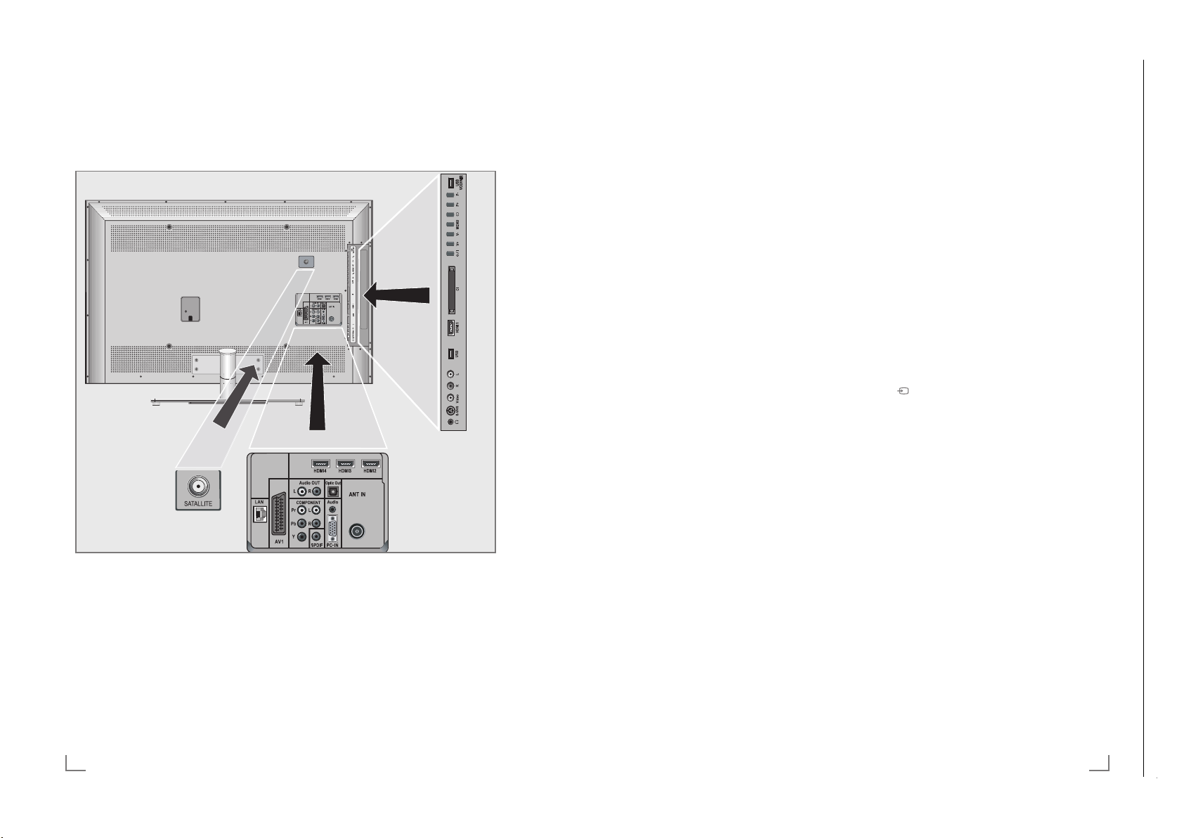
AUF EINEN BLICK
-------------------------------------------------------------------------------------------------------------
Optic Out Buchse für Tonsignal-
Ausgang (optisch) für
PCM/AC3-Signale.
Zum Anschluss digitaler AVVerstärker oder AV-Receiver.
Audio Buchse für Tonsignal-
Eingang für PC
.
PC-IN VGA-Buchse, Bildsignal-Ein-
gang für PC
.
ANT IN Antennenbuchse für
D
VB-T, DVB-C und
analoge Antenne.
HDMI2 HDMI-Buchse, Ton-/Bild-
signal-Eingang.
HDMI3 HDMI-Buchse, Ton-/Bild-
signal-Eingang.
HDMI4 HDMI-Buchse, Ton-/Bild-
signal-Eingang.
U Kopfhörerbuchse
(3,5-mm-Klinkenstecker).
S-VHS Bildsignal-Buchse für
S-Video-Camer
arecorder.
Video Bildsignal-Buchse für
Camer
arecorder.
L R Tonsignal-Buchse für
Camer
arecorder.
USB USB-Buchse für externe
Datenträger und
PVR-Funktion.
HDMI1 HDMI-Buchse, Ton-/Bild-
signal-Eingang.
CI Common Interface-
S
teckplatz.
8/I Schaltet das Fernsehgerät
ein und wieder in Bereitschaft (Stand-by).
Nur durch Ziehen des
Netzsteckers wird das
Fernsehgerät vom Stromnetz
getrennt.
V– V+ Verändern die Lautstärke;
w
ählen Funktion im Menü.
MENU Ruft das Menü auf.
Menüoptionen mit »P+«
oder »P–« wählen.
F
unktion mit »V+« oder
»V–« aktivieren.
F
unktion mit »V+« oder
»V–« bestätigen.
Menü mit »MENU« abschalten.
Ruft die Vorauswahl für AV-
Programmplätze auf.
Auswählen innerhalb des
Menüs mit »P+« oder »P–«,
bes
tätigen mit »V+« oder
»V–«.
P– P+ Zum Einschalten des
F
ernsehgerätes aus
Stand-by;
wählen schrittweise das
Programm;
wählen Funktion im Menü.
USB-VOD-WIFI USB-Buchse zum Anschluss
e
xterner Datenträger für die
Funktion Connected TV;
zum Anschließen eines WiFi
USB Dongle.
AUF EINEN BLICK
-------------------------------------------------------------------------------------------------------------
Die Anschlüsse des Fernsehgerätes
SATALLITE Antennenbuchse für die
LAN Buchse zum Anschließen
AV1 Euro/AV-Buchse
AUDIO OUT L R Buchsen für Tonsignal-
Satellitenantenne (DVB-S).
an das Heimnetzw
LAN-Kabel.
(FB
AS-Signal, RGB-Signal).
Ausgang.
erk über
COMPONENT
Y Pb Pr Buchsen für Bildsignal-Ein-
L R Buchsen für Tonsignal-
SPDIF Buchse für Tonsignal-
gang (YUV-Signal).
Eingang (YUV-Signal).
Ausgang (k
PCM/AC3-Signale.
Zum Anschluss digitaler AVVerstärker oder AV-Receiver.
oaxial) für
DEUTSCH10
Page 9
Chassis SXGRUNDIG Service
1 - 9
AUF EINEN BLICK
Chassis SXGRUNDIG Service
1 - 9
13
DEUTSCH
AUF EINEN BLICK
-------------------------------------------------------------------------------------------------------------
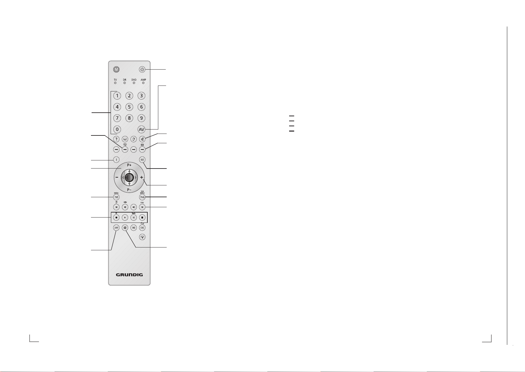
Die Fernbedienung –
alle Funktionen
? Blendet Informationen über das
Fernseh-Programm ein.
y W
ählt unterschiedliche Untertitel (nur
bei digitalen Fernseh-Programmen).
d
Wählt unterschiedliche Audiosprachen (nur bei digitalen
Fernseh-Programmen).
(rot),
Wählen Seiten im Videotext.
(grün)
Wählen/aktivieren unterschiedliche
(gelb)
Funktionen in den Menüs.
(blau)
LIST
Ruft das Menü »PRnP-Archiv« auf.
3D Schaltet die 3D-Funktion ein/aus.
CEC Ruft die »HDMI-Geräteliste« auf;
wählt die Wiederholungsfunktion im
Dateimanager.
TXT Schaltet im Betriebsmodus „Connec-
ted T
V” von den verschiedenen Optionen zum Menü »CONNECTED TV«
zurück.
y
Startet die Aufnahme
(
nur bei digitalen Fernseh-Program-
men
, die Aufnahme erfolgt auf einem
externen Datenträger).
8 Startet die Wiedergabe einer
Sendung vom externen Datenträger;
wiederholt eine aufgenommene
Sendung;
startet die Wiedergabe von Mediendaten im Betriebsmodus „Connected
TV”.
! Standbild, wenn kein externer
Datenträger angeschlossen ist;
Wiedergabe-Pause;
Timeshift-Betrieb
(nur bei digitalen Fernseh-Programmen und wenn ein externer Datenträger angeschlossen ist);
Schaltet auf Wiedergabe/Pause
beim Abspielen von Mediendaten im
Betriebsmodus „Connected TV”.
7 Beendet die Wiedergabe einer
Sendung vom externen Datenträger;
beendet die Aufnahme oder die
Wiedergabe im Timeshift-Betrieb.
Teilt die Bildanzeige im Videotext;
beendet die Wiedergabe von Mediendaten im Betriebsmodus „Connected TV”.
5 Wählt unterschiedliche Ton-
ein s
tellungen;
schaltet im Videotext auf doppelte
Zeichengröße;
wählt im Dateimanager den
nächsten Titel/das nächste Bild.
6 Wählt unterschiedliche Bild-
eins
tellungen;
aktualisiert eine Videotextseite;
wählt im Dateimanager den vorherigen Titel/das vorherige Bild.
m
Stoppt das Umblättern von Seiten
im Videotext;
startet im Dateimanager den
schnellen Rücklauf.
, Wählt die Programmliste (»Alle Pro-
gramme«, »FAV 1« bis »FAV 4«);
deckt Antworten im Videotext auf;
startet im Dateimanager den
schnellen Vorlauf.
R Schaltet die T
astenbeleuchtung ein.
Die Tastenbeleuchtung wird nach
kurzer Zeit automatisch abgeschaltet.
M
Schaltet um, zur Bedienung eines
– GRUNDIG Digitalempfängers,
– GRUNDIG-Digitalempfängers
mit Festplatte (PDR),
– GRUNDIG-DVD-Players,
– GRUNDIG-DVD-Recorders oder
GRUNDIG-AV-Receivers um.
»M« drücken bis die Anzeigen »DVB«,
»DVD« oder »AMP« aufleuchtet, dann
die gewünschte Auswahl treffen.
Wird etwa 10 Sekunden lang
keine Taste gedrückt, schaltet die
Fern bedienung wieder auf Fernsehbetrieb (»TV«).
Die Vorprogrammierung können Sie
ändern, siehe Seite 78.
Chassis TXGRUNDIG Service
1 - 9
Die Fernbedienung – Hauptfunktionen
Eınschalten aus Stand-by;
Programme wählen –
direkt.
Vergrößert das Bild
Hauptmenü aufrufen.
Eınschalten aus Stand-by;
Pr
ogramme wählen –
schrittweise.
Umschalten zwischen
Videotext- und TV-Betrieb.
Aufnahme, Wiedergabe,
Pause und Beenden einer
Sendung (nur digitale
Fernseh-Programme) auf/
von einem externen Datenträger.
Ruft das Menü »PRnPArchiv« auf.
Cursorsteuerung
V Λ
Bewegen den Cursor in den
Menüs nach oben und unten.
<
>
Bewegen den Cursor in den
Menüs nach links und rechts.
O Ruft die Programmliste auf;
aktiviert verschiedene
Funktionen.
DEUTSCH12
-------------------------------------------------------------------------------------------------------------
Ausschalten (Stand-by).
Menü für AV-Programmplätze
und USB-Eıngang aufrufen.
Anschließend mit »
oder »Λ« wählen und mit »O«
bestätıgen.
Beendet die Funktion
Connected TV.
Ton ein und ausschalten.
Auswahlmenü zum Umschalten
der Bildformate aufrufen.
Anschließend mit »
wählen und mit »O« bestätigen.
Zapp-Funktion;
in den Menüs eine Menü-ebene
zurückschalten.
Lautstärke ändern.
Elektronischen Programm-führer
aufrufen.
Ruft die Programmtabelle und
die Favoritenlisten (1 bis 4) auf.
Startet die Funktion
Connected TV
V
«, »<«, »>«
« oder »>«
<
Page 10
Chassis SXGRUNDIG Service
1 - 10
3D - FUNKTION
Chassis SXGRUNDIG Service
1 - 10
27
DEUTSCH
3D - FUNKTION
--------------------------------------------------------------------------------------------------------------------
Wiedergabe von 3D Filmen
Hinweise:
7
Die 3D-Funktion wird über die Programm-
quellen »DVB-T«, »DVB-C«, »DVB-S« und
»DLNA« unterstützt oder von externen Geräten, die an den Buchsen »HDMI«, »YPb-
Pr«, »VGA« oder »USB« angeschlossen
sind.
7
An den Buchsen »HDMI«, »YPbPr« und
»VGA« ist die Wiedergabe von 3D Filmen nur in den Auflösungen „1280x720p
50/60 Hz”, „1920x1080i 50/60 Hz” und
„1920x1080p 24/30, 50/60 Hz” möglich.
7
Das 3D Erlebnis ist abhängig vom Format
und von Besonderheiten des Filmes (Auflösung, Schärfe, usw.), der abgespielt werden
soll.
7
Wenn die 3D Funktion bei einer 2D Sen-
dung aktiviert ist, kann das Bild verschwommen erscheinen – mit oder ohne 3D Brille.
7
Der 3D Effekt kann sich verringern, wenn
Sie beim Betrachten einer 3D Sendung
eine Leuchtstofflampe eingeschaltet haben.
Reduzieren Sie in diesem Fall die Helligkeit
oder schalten Sie die Leuchtstofflampe aus.
7
Bei folgenden Funktionen schaltet sich das
Fernsehgerät von 3D-Modus auf 2D-Modus: Anzeige der Programmtabelle oder
EPG-Informationen, der Programmplatz
wird gewechselt oder die Programmquelle
wird umgeschaltet, am Ende der Wiedergabe eines 3D Filmes, die Wiedergabe des
nächsten Filmes über USB oder vom Archiv
wird gestartet.
1 Das Menü »Signalquelle auswählen« mit
»AV« anwählen.
2 Die gewünschte Signalquelle (digitale Pro-
gr
amme oder geeignete Buchsen) die den
3D Film liefert mit »
<
«, »>«, »V« oder »Λ«
wählen und mit »O« bestätigen.
3 Die 3D-Funktion mit »3D« auswählen – ent-
w
eder »Side by Side« oder »Top Bottom«,
dies ist abhängig vom 3D Film – und mit »O«
bestätigen.
– »Side by Side«, Anzeige von zwei Bildern
nebeneinander.
– »Top Bottom«, Anzeige von zwei Bildern
untereinander.
– »Frame Packing«: Anzeige von zwei Voll-
bildern hintereinander.
Hinweis:
7
Die Option »Frame Packing« wird in der 3D
Auswahl nur angezeigt, wenn der 3D Film
über die Buchse »HDMI« im Format HDMI
1.4 zur Verfügung steht.
Die Optionen »Side by Side« and »Top Bot-
tom« werden in diesem Fall nicht angezeigt.
4 3D-Funktion ausschalten, dazu mit »3D« die
Option »Of
f« wählen und mit »O« bestäti-
gen.
Formate, die durch HDMI 1.4 unterstützt werden
Mit dem Standard HDMI 1.4 kann Ihr Fernsehgerät das 3D-Format erkennen und wiedergeben.
Die Aufstellung zeigt die unterstützten Formate:
Für 3D Bluray Filme
Frame
P
acking
1080p @
23,98/24Hz
Für 3D
Spiele
Frame
P
acking
720p @
50 oder
59,94/60Hz
Für 3D
Filme von
den Programmanbietern
Side by Side
Hor
izontal
1080i @
50 oder
59,94/60Hz
Top and
Bottom
720p @
50 oder
59,94/60Hz
1080p @
23,97/24Hz
Hinweis:
7
Weitere Informationen zum Gebrauch, der
Reinigung usw. der 3D Brille entnehmen Sie
bitte der Bedienungsanleitung der GRUNDIG AS-3D G Brille
7
Die Buchse »HDMI4« unterstützt nicht den
Standard HDMI 1.4.
Chassis SXGRUNDIG Service
1 - 10
Chassis TXGRUNDIG Service
1 - 10
--------------------------------------------------------------------------------------------------------------------
Wichtige Informationen zur
3D-Funktion
7
Halten Sie einen ausreichenden Betrach-
tungsabstand zum Fernsehgerät ein. Der
optimale Abstand beträgt das dreifache der
Höhe des Bildschirms. Wenn Sie 3D-Filme
über einen längeren Zeitraum aus kurzer
Distanz ansehen, kann das die Sehkraft beeinträchtigen.
7
Nutzen Sie die 3D-Funktion nie länger als
max. 3 Stunden ohne Unterbrechung.
7
Beaufsichtigen Sie während der Wieder-
gabe einer 3D Sendung unbedingt Kinder,
um gesundheitliche Schäden zu vermeiden.
Kinder unter 6 Jahren sollten 3D Sendungen
nicht ansehen, da deren räumliches Sehvermögen noch nicht vollständig ausgeprägt ist
7
Längeres Betrachten eines 3D-Filmes mit
einer 3D-Shutter-Brille kann zu Kopfschmerzen oder Erschöpfung führen. Beenden Sie
die Wiedergabe, wenn Sie Kopfschmerzen
oder ein Schwindelgefühl bekommen oder
wenn Sie sich unwohl fühlen.
7
Nutzen Sie die 3D-Funktion nicht, wenn Sie
Angstzustände haben, schläfrig oder übermüdet sind.
7
Wenn Sie oder ein Familienangehöriger
unter Epilepsie leiden, sollten Sie Ihren Arzt
befragen, bevor Sie die 3D-Filme ansehen.
7
Wenn Sie beim Betrachten von 3D-Filmen
unter eine Beeinträchtigung des Sehvermögens feststellen, ein Schwindelgefühl bekommen, Augenschmerzen, Muskelkrämpfe, Übelkeit oder Konzentrationsschwäch
verspüren, müssen Sie umgehend die 3DFunktion beenden.
7
3D Bilder können den Betrachter erschre-
cken. Wir raten vor allem älteren Menschen,
Schwangeren und Personen mit schwerwiegenden physischen Beschwerden von der
Benutzung ab.
7
Benutzen Sie die 3D Brille nicht für andere
Zwecke wie z.B. als Sonnen- oder Schutzbrille, dies kann Ihr Sehvermögen beeinträchtigen.
DEUTSCH26
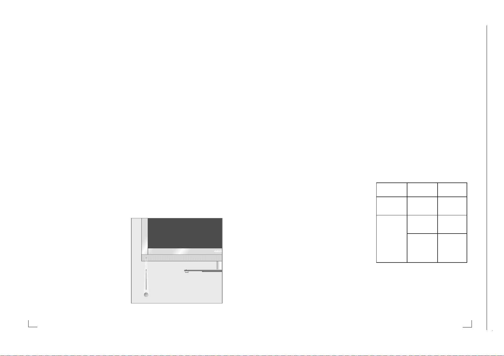
3D-Funktion vorbereiten
Mit Ihrem Grundig Fernsehgerät und der Grundig 3D-Shutter-Brille erleben Sie im Wohnzimmer 3D Filme wie im Kino.
Dieses Fernsehgerät verwendet die neueste LEDTechnologie um Ihnen das bestmögliche 3D Erlebnis anzubieten.
Um die 3D Welt zu erleben, müssen Sie lediglich
die Grundig 3D Brille aufsetzen, die im Lieferumfang enthalten ist.
Hinweise:
7
Im Lieferumfang des Fernsehgerätes ist eine
GRUNDIG AS-3D G Brille enthalten.
7
Benutzen Sie nur die GRUNDIG AS-3D G
Brille. Verwenden Sie keine 3D Brillen anderer Hersteller.
7
GRUNDIG AS-3D G Brillen können Sie
auch separat kaufen. Bitte fragen Sie Ihren
Fachhändler.
7
Der Infrarotsender ist links unten am Fernseh-
gerät angebracht. Das Signal wird in einem
Winkel vom 90° horizontal und 40° vertikal gesendet.
Für eine fehlerfreie Kommunikation zwischen
Fernsehgerät und 3D Brille dürfen sich keine
Gegenstände zwischen dem Infrarotsender
am Fernsehgerät und der 3D Brille befinden.
Page 11
Chassis SXGRUNDIG Service
1 - 11
CONNECTED TV UND HEIMNETZWERK
Chassis SXGRUNDIG Service
1 - 11
29
DEUTSCH
Hinweis:
7
Setzen Sie die Einstellung mit Kapitel „Die
automatische Anmeldung” oder „Die manuelle Anmeldung” fort.
LAN-Verbindung installieren
Sie haben zwei Möglichkeiten, Ihr Fernsehgerät
am Heimnetzwerk anzumelden.
A Die automatische Anmeldung,
dabei werden alle notwendigen Einstellungen (»IP Adresse«, »Netzmaske«, »Gateway« und »DNS«) vom Router automatisch
vergeben.
B Die manuelle Anmeldung,
hier müssen alle notwendigen Einstellungen
(»IP Adresse«, »Netzmaske«, »Gateway«
und »DNS«) von Hand eingegeben werden
Die automatische Anmeldung
Die meisten Heimnetze sind dynamisch. Wenn
Sie ein dynamisches Netzwerk verwenden, benötigen Sie einen DSL Router, der DHCP unterstützt. Wenn das Fernsehgerät an das gleiche
Heimnetzwerk angeschlossen wird, werden die
Daten für IP Adresse, Netzwerkmaske und Gateway vom DSL Router automatisch zugewiesen.
Hinweis:
7
Wenn die IP Adresse nicht automatisch vergeben wird, setzen Sie die Einstellung im
Kapitel „Die manuelle Anmeldung” fort.
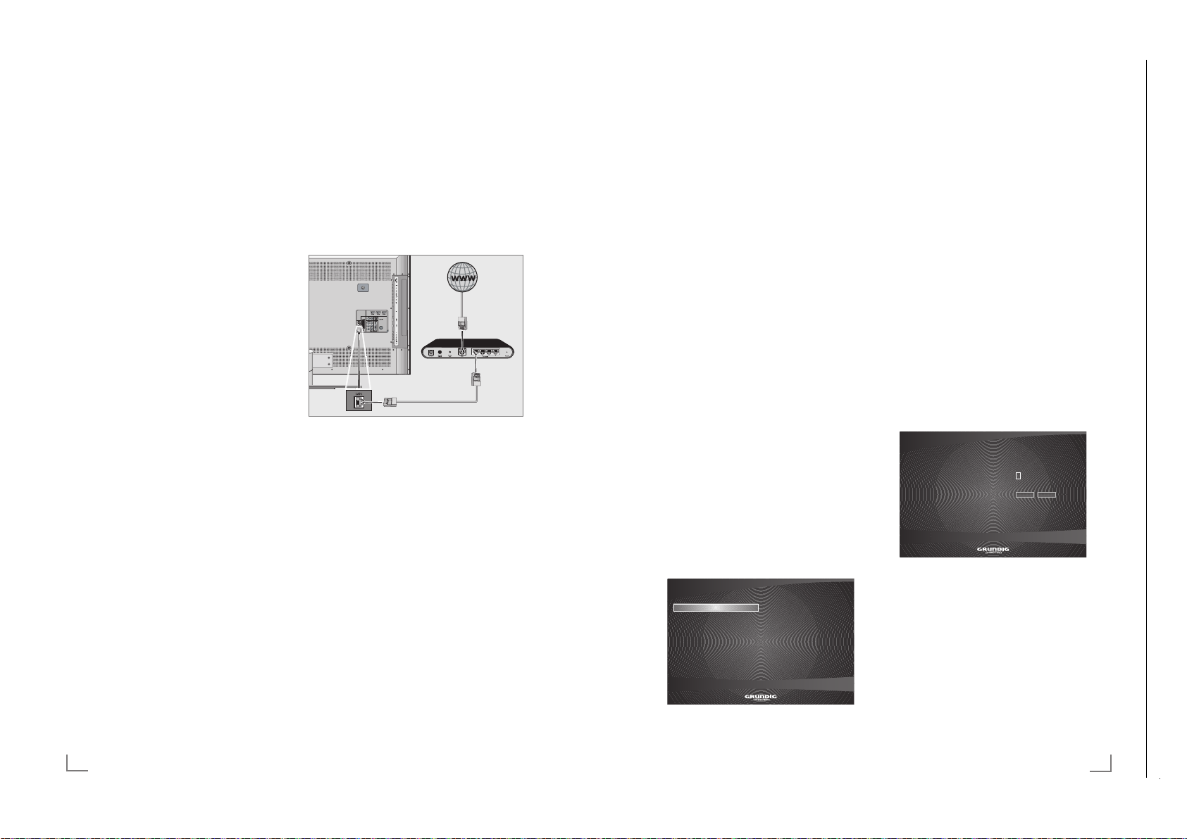
1 Zeile »Netzwerk« mit »
V
« oder »Λ« wählen
und mit »O« bestätigen.
– Das Menü »Konfiguration > Netzwerk«
wird eingeblendet.
.RQILJXUDWLRQ!1HW]ZHUN
$XWRPDWLVFK
.DEHOORV 0DQXHOO
9HUELQGXQJVWHVW 5HSDULHUHQ
9HUNDEHOW
2 Zeile »Verkabelt« mit »V« oder »Λ« wählen
und bestätigen, dazu »O« zweimal drücken.
3 Wenn das Fernsehgerät erfolgreich ange-
meldet wur
de, wird die Download Bit Rate
automatisch getestet.
Diese Meldung mit »O« bestätigen.
4 Einstellung beenden, dazu »
x« zweimal
drücken.
Die manuelle Anmeldung
Verschieden Heimnetzwerke benötigen eine Statische IP Adresse, in diesem Fall müssen Sie die
Zugangsdaten für »IP Adresse«, »Netzmaske«,
»Gateway« und »DNS« von Hand eingeben.
Die Zugangsdaten erhalten Sie vom Administrator Ihres Netzwerkes.
1 Zeile »Netzwerk« mit »
V
« oder »Λ« wählen
und mit »O« bestätigen.
– Das Menü »Konfiguration > Netzwerk«
wird eingeblendet.
2 Die Zeile »Verkabelt« mit »
V
« oder »Λ«
wählen und mit »O« bestätigen.
3 Die Zeile »Manuell« mit »
V
« oder »Λ« wäh-
len und mit »O« bestätigen.
– Das Menü »IP-Adresse« wird eingeblendet.
.RQILJXUDWLRQ!1HW]ZHUN
,3$GGUHVV
.DEHOORV
9HUELQGXQJVWHVW
9HUNDEHOW
$EEUHFKHQ
:HLWHU
4 IP Adresse eingeben:
Die erste Eingabestelle mit »O« aktivieren
und danach mit »
V
« oder »Λ« die benötigte
Ziffer eingeben.
Die nächste Eingabestelle mit »
>
« wählen
und mit »O« aktivieren.
Eingabe für alle Ziffern wiederholen.
Die Schaltfläche »Weiter« mit »
V
« oder »Λ«
wählen und mit »O« bestätigen.
CONNECTED TV UND HEIMNETZWERK
----------------------------------
Chassis SXGRUNDIG Service
1 - 11
Chassis SXGRUNDIG Service
1 - 11
Chassis TXGRUNDIG Service
1 - 11
----------------------------------
Was bietet Ihnen „ Connected TV”
Die Plattform „CONNECTED TV” Ihres Fernsehgerätes bieten Ihnen den Zugang zum Internet.
Wenn Ihr Fernsehgerät an Ihrem Heimnetzwerk
mit Internetzugang angeschlossen ist, können Sie
Videos von YouTube betrachten, Bilder von Flickr
ansehen und viele Internet Fernseh- und Radioprogramme verfolgen.
Ausserdem steht Ihnen der Video On Demand
Service von Acetrax zur Verfügung. Hier können
Sie Ihre Wunschfilme bequem von zu Hause aussuchen und dann ausleihen oder kaufen.
Ausgeliehene Filme können Sie innerhalb von
24 Stunden ansehen – so oft Sie wollen; gekaufte Filme können Sie ohne Einschränkung
verwenden.
Der Acetrax Service wird nur in einigen Ländern
angeboten. Mehr Informationen erhalten Sie
unter www.acetrax.com.
Fernsehgerät am Heimnetzwerk
anschließen und anmelden
Sie können Ihr Fernsehgerät über eine LAN-Verbindung oder ohne Kabel über WLAN mit dem
Heimnetzwerk verbinden.
Wenn Sie eine LAN-Verbindung verwenden,
lesen Sie im Kapitel „LAN-Verbindung zum
Heimnetzwerk” auf dieser Seite weiter;
wenn Sie WLAN benutzen wollen, folgen Sie
der Beschreibung im Kapitel „WLAN-Verbindung zum Heimnetzwerk” ab Seite 30.
LAN-Verbindung zum Heimnetzwerk
LAN-Kabel anschließen
1 Ausgangsbuchse des Routers mit handels-
üblichen LAN-Kabel an die Buchse »LAN« des
Fernsehgerätes anschließen.
Hinweis:
7
Das LAN-Kabel ist nicht im Lieferumfang ent-
halten.
Grundeinstellungen
1 Fernsehgerät mit »8«, »1…0« oder »P+«
oder »P-« aus Stand-by einschalten.
2 Menü mit »i« aufrufen.
3 Menüpunkt »CONNECTED TV« mit »
oder »
Λ
– Das Menü »CONNECTED TV« wird einge-
4 Die Option »Connected TV öffnen« mit »O«
– Das Menü »Language« wird eingeblendet.
5 Gewünschte Menüsprache mit »
– Das Menü »Country« wird ein geblendet.
6 Das Land, in dem das Fernsehgerät betrieben
– Das Menü »Information« wird eingeblendet.
7 Einstellungen mit »O« bestätigen.
– Das Menü »Konfiguration« wird eingeblen-
« wählen und mit »O« bestätigen.
blendet.
aktivieren.
»
Λ
« wählen und mit »O« be stätigen.
wird, mit »
be stätigen.
V
det.
V
« oder
« oder »Λ« wählen und mit »O«
V
«
DEUTSCH28
Page 12
Chassis SXGRUNDIG Service
1 - 12
CONNECTED TV UND HEIMNETZWERK
Chassis SXGRUNDIG Service
1 - 12
31
DEUTSCH
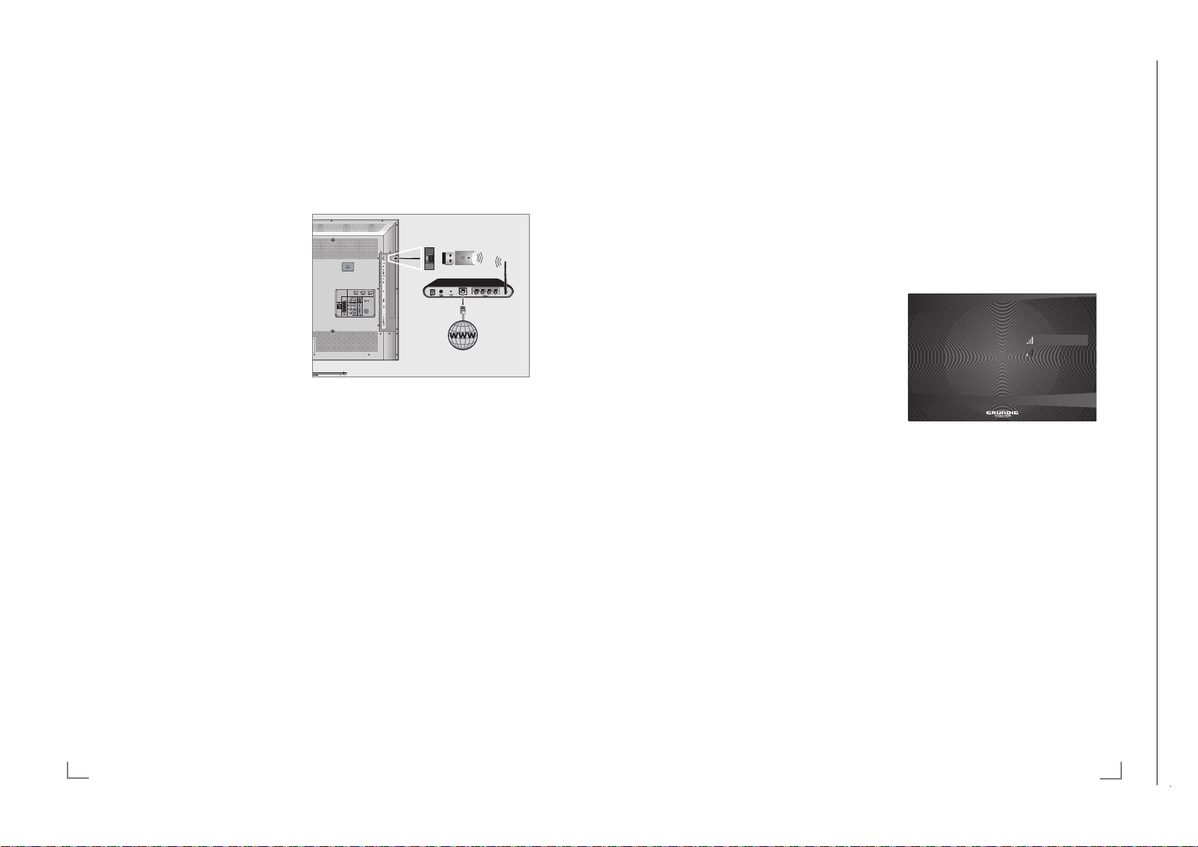
7
Stellen Sie den Router an einer erhöhten Position auf, um die Empfangsqualität des WiFi
USB Dongles zu verbessern.
7
Die Empfangsqualität beim drahtlosen Betrieb
ist abhängig vom Router und dem Abstand
zwischen Router und Fernsehgerät.
7
Der Router muss seinen Netzwerknamen
(SSID) sichtbar übertragen, um den drahtlosen Betrieb zwischen Router und Fernsehgerät zu gewährleisten.
7
Wenn das Fernsehgerät über einen WiFi
USB Dongle an das Heimnetzwerk angeschlossen wurde, kann es unter Umständen
zu einer schlechten Bildqualität („Ruckeln”)
kommen.
Die Ursache kann ein zu schwaches WiFi-
Signal sein, das durch die Abschirmung des
Fernsehgerätes weiter verringert werden kann.
Schließen Sie den WiFi USB Dongle über ein
USB Verlängerungskabel an das Fernsehgerät
an und positionieren Sie den WiFi USB Dongle
seitlich neben dem Fernsehgerät.
Grundeinstellungen
1 Fernsehgerät mit »8«, »1…0« oder »P+«
oder »P-« aus Stand-by einschalten.
2 Menü mit »i« aufrufen.
3 Menüpunkt »CONNECTED TV« mit »
V
«
oder »
Λ
« wählen und mit »O« bestätigen.
– Das Menü »CONNECTED TV« wird einge-
blendet.
4 Die Option »Connected TV öffnen« mit »O«
aktivieren.
– Das Menü »Language« wird eingeblendet.
5 Gewünschte Menüsprache mit »
V
« oder
»
Λ
« wählen und mit »O« be stätigen.
– Das Menü »Country« wird ein geblendet.
6 Das Land, in dem das Fernsehgerät betrieben
wird, mit »
V
« oder »Λ« wählen und mit »O«
be stätigen.
– Das Menü »Information« wird eingeblendet.
7 Einstellungen mit »O« bestätigen.
– Das Menü »Konfiguration« wird eingeblendet.
Hinweis:
7
Setzen Sie die Einstellung mit dem nächsten
Kapitel fort.
CONNECTED TV UND HEIMNETZWERK
----------------------------------
Anmeldung am Router für den
WLAN-Betrieb
Die meisten Heimnetze sind dynamisch. Wenn
Sie ein dynamisches Netzwerk verwenden, benötigen Sie einen DSL Router, der DHCP unterstützt. Wenn das Fernsehgerät an das gleiche
Heimnetzwerk angeschlossen wird, werden die
Daten für IP Adresse, Netzwerkmaske und Gateway vom DSL Router automatisch zugewiesen.
1 Zeile »Netzwerk« mit »
V
« oder »Λ« wählen
und mit »O« bestätigen.
– Das Menü »Konfiguration > Netzwerk«
wird eingeblendet.
.RQILJXUDWLRQ!1HW]ZHUN
=XJDQJVSXQNW
.DEHOORV
9HUELQGXQJVWHVW
9HUNDEHOW
JXHVW*HVLFKHUW:(3
JXHVW2IIHQ
2 Zeile »Kabellos« mit »V« oder »Λ« wählen
und mit »O« bestätigen.
– Die Meldung »Suche...« wird eingeblen-
det, die vorhandenen Netzwerke werden
gesucht und dann angezeigt.
3 Das gewünschte Netzwerk mit »
V
« oder
»
Λ
« wählen und mit »O« bestätigen.
– Ein Menü für die Eingabe des Passwortes
wird eingeblendet.
4 Das erste Zeichen/Ziffer des benötigten
Passwortes mit »
V
«, »Λ«, »<« und »>« wäh-
len und mit »O« bestätigen.
Eingabe für alle Zeichen/Ziffern wieder-
holen.
Hinweise:
7
Werden Großbuchstaben benötigt, die
Schaltfläche »A,a« wählen und mit »O«
bes
tätigen.
7
Soll ein Zeichen/eine Ziffer gelöscht wer-
den, die Schaltfläche »
I
« wählen und mit
»O« bestätigen.
Chassis SXGRUNDIG Service
1 - 12
Chassis SXGRUNDIG Service
1 - 12
Chassis SXGRUNDIG Service
1 - 12
Chassis TXGRUNDIG Service
1 - 12
----------------------------------
5 Subnetzmaske (Netzwerkmaske) eingeben:
Die erste Eingabestelle mit »
mit »O« aktivieren.
Die erste Ziffer mit »
und mit »O« bestätigen.
Die nächste Eingabestelle mit »
und mit »O« aktivieren.
Eingabe für alle Ziffern wiederholen.
Die Schaltfläche »Weiter« mit »
wählen und mit »O« bestätigen.
6 Gateway IP eingeben:
Die erste Eingabestelle mit »
mit »O« aktivieren.
Die erste Ziffer mit »
und mit »O« bestätigen.
Die nächste Eingabestelle mit »
und mit »O« aktivieren.
Eingabe für alle Ziffern wiederholen.
Die Schaltfläche »Weiter« mit »
wählen und mit »O« bestätigen.
7 DNS (Domain Name System) eingeben:
Die erste Eingabestelle mit »
mit »O« aktivieren.
Die erste Ziffer mit »
und mit »O« bestätigen.
Die nächste Eingabestelle mit »
und mit »O« aktivieren.
Eingabe für alle Ziffern wiederholen.
8 Die Schaltfläche »OK« mit »
wählen und mit »O« bestätigen.
– »Versuch mit dem festen Netzwerk zu ver-
binden.« wird angezeigt, die Anmeldung
erfolgt und das Ergebniss vom Verbindungstest wird eingeblendet.
9 Wenn das Fernsehgerät erfolgreich ange-
meldet wur
de, wird die Download Bit Rate
automatisch gestestet.
Diese Meldung mit »O« bestätigen.
10 Einstellung mit »
x« beenden.
Hinweis:
7
Informationen wie die »MAC-Addresse«,
»IP-Addresse«, »Netzmaske« und »DNS«
werden im Menü »Konfiguration« angezeigt.
11 »
x« noch einmal drücken, das Menü
»CONNECTED TV« wird eingeblendet.
Λ
« wählen und
V
« oder »Λ« eingeben
« wählen
>
V
« oder »Λ«
Λ
« wählen und
V
« oder »Λ« eingeben
« wählen
>
V
« oder »Λ«
Λ
« wählen und
V
« oder »Λ« eingeben
« wählen
>
V
« oder »Λ«
DEUTSCH30
WLAN-Verbindung zum Heimnetzwerk
WiFi USB Dongle anschließen
1 Den Grundig WiFi USB Dongle an die Buchse
»USB-VOD-WiFi«« des Fernsehgerätes anschließen.
Hinweise:
7
Der Grundig WiFi USB Dongle unterstützt
das Datenübertragungsprotokoll nach IEEE
802.11B/G und N.
Um beste Bildqualität bei HD Videowieder-
gabe zu erhalten, empfehlen wir – wenn
vom Router unterstützt – den Standard IEEE
802.11N zu verwenden.
7
Wenn Sie einen Router verwenden, der den
Standard IEEE 802.11B/G unterstützt, kann
die Qualität der Videowiedergabe, verglichen zum Standard IEEE 802.11N, geringer
sein. Die Ursache ist die geringere Datentransferrate des Standards IEEE 802.11B/G
7
Der Grundig WiFi USB Dongle muss direkt
an die Buchse »USB-VOD-WiFi« des Fernsehgerätes angeschlosen werden.
Der Anschluss über einen USB Hub wird
nicht unterstützt.
7
Die Wiedergabequalität beim Betrieb mit
der CONNECTED TV Funktion ist davon
abhängig, wieviele Benutzer das kabellose
Heimnetz gleichzeitig nutzen.
7
Wir empfehlen, während des Betriebes mit der
CONNECTED TV Funktion andere Geräte im
Heimnetzwerk abzuschalten, um unnötigen
Datenverkehr zu vermeiden.
Page 13
Chassis SXGRUNDIG Service
1 - 13
CONNECTED TV UND HEIMNETZWERK
Chassis SXGRUNDIG Service
1 - 13
33
DEUTSCH
CONNECTED TV UND HEIMNETZWERK
----------------------------------
Lizenzinformationen abrufen
1 Im Menü »Konfiguration« die Zeile »War-
tung« mit »
V
« oder »Λ« wählen und mit
»O« bestätigen.
– Das Menü »Konfiguration > Wartung«
wird angezeigt.
2 Zeile »Legale Informationen« mit »
V
« oder
»
Λ
« wählen und mit »O« bestätigen.
– Die Lizenzinformationen werden einge-
blendet.
3 Text mit »
V
« oder »Λ« nach unten oder
oben scrollen.
4 Informationen abschalten, dazu »
x« zwei-
mal drücken.
Internes oder externes Speichermedium formatieren
Hinweis:
7
Wenn der externe Datenträger, der an
Buchse »USB-VOD-WiFi« angeschlossen
wurde, die Dateisysteme EXT3, EXT2, FAT16
oder FAT32 nicht unterstützt, können keine
Daten gespeichert oder abgespielt werden.
Nach dem ersten Anschließen eines exter-
nen Datenträgers empfehlen wir, diesen
zu formatieren. Der Datenträger bekommt
dann das Dateisystem EXT3.
1 Im Menü »Konfiguration« die Zeile »War-
tung« mit »
V
« oder »Λ« wählen und mit
»O« bestätigen.
– Das Menü »Konfiguration > Wartung«
wird angezeigt.
2 Zeile »Speicherformat« mit »
V
« oder »Λ«
wählen und mit »O« bestätigen.
– Angaben über den internen Speicher und
– wenn angeschlossen – über die externen Festplatte werden angezeigt.
3 Das Speichermedium, das formatiert werden
soll, mit »
V
« oder »Λ« wählen und mit »O«
bestätigen.
– Ein Warnhinweis wird eingeblendet.
Speicherort für Downloads mit der
VOD Funktion wählen
Wenn Sie Filme über die VOD Funktion (Video
on demand service) herunterladen wollen, steht
Ihnen dafür ein 4 Gb Speicher – integriert in das
Fernsehgerät – zur Verfügung.
Reicht dieser interne Speicher nicht aus, können
Sie auch eine externe Festplatte als Ziel des
Downloads verwenden.
Hinweis:
7
Da der Grundig WiFi USB Dongle und
der externe Datenträger an die gleiche
Buchse angeschlossen werden, muß die
Verbindung zum Heimnetzwerk über eine
LAN-Verbindung hergestellt werden, wenn
Sie einen externen Datenträger verwenden
wollen.
1 Im Menü »Konfiguration« die Zeile »VOD«
mit »
V
« oder »Λ« wählen und mit »O« be-
stätigen.
– Das Menü »Konfiguration > VOD« wird
angezeigt.
2 Mit »O« zur Übersicht der verfügbaren Da-
tentr
äger schalten.
Den gewünschten Datenträger mit »
V
« oder
»
Λ
« wählen und mit »O« bestätigen.
3 Einstellung beenden, dazu »
x« zweimal
drücken.
Informationen anzeigen
Sie können Informationen über Ihr Gerät und die
Verbindung zum Heimnetzwerk anzeigen lassen.
1 Im Menü »Konfiguration« die Zeile »War-
tung« mit »
V
« oder »Λ« wählen und mit
»O« bestätigen.
– Das Menü »Konfiguration > Wartung«
wird angezeigt.
2 Zeile »Information« mit »
V
« oder »Λ« wäh-
len.
– Informationen über Ihr Gerät und die Ver-
bindung zum Heimnetzwerk werden angezeigt.
3 Informationen abschalten, dazu »
x« zwei-
mal drücken.
Chassis SXGRUNDIG Service
1 - 13
Chassis SXGRUNDIG Service
1 - 13
Chassis SXGRUNDIG Service
1 - 13
Chassis SXGRUNDIG Service
1 - 13
Chassis TXGRUNDIG Service
1 - 13
----------------------------------
5 Zum Bestätigen des Passwortes die Schalt-
fläche »OK« mit »
wählen und mit »O« bestätigen.
V
«, »Λ«, »<« oder »>«
Hinweis:
7
Wenn Sie WEP Verschlüsselung verwen-
den, können mehrere Passworte vergeben werden (Haupt- und Gästepasswort).
Das Fernsehgerät kann am Heimnetzwerk nur
mit dem Hauptpasswort angemeldet werden.
7
Damit das Fernsehgerät sich in das
Heimnetzwerk anmelden kann, muss der
Netzwerkname (SSID) ausschließlich ASCII
Zeichen beinhalten.
6 Passwort bestätigen, dazu mit »
die Schaltfläche »OK« wählen und mit »O«
« oder »>«
<
bestätigen.
7 Wenn die Meldung »Netzstatus: verbunden«
eingeblendet wird, »O« zum Bestätigen drücken.
8 Wenn das Fernsehgerät erfolgreich ange-
meldet wurde, wird die Download Bit Rate
automatisch gestestet.
Diese Meldung mit »O« bestätigen.
Hinweis:
7
Informationen wie die »MAC-Addresse«, »IP-
Addresse«, »Netzmaske« und »DNS« werden im Menü »Konfiguration« angezeigt.
9 Einstellung mit »
Verbindungstest zum Heimnetzwerk
x« beenden.
Nach erfolgreicher Anmeldung am Heimnetzwerk können Sie mit der Funktion »Verbindungstest« die Qualität der Download Bitrate für HD
und SD Filme kontrollieren.
1 Menüpunkt »Konfiguration« mit »
»
Λ
« wählen und mit »O« bestätigen.
2 Zeile »Netzwerk« mit »
V
« oder »Λ« wählen
und mit »O« bestätigen.
3 Zeile »Verbindungstest« mit »
wählen und mit »O« bestätigen.
V
« oder »Λ«
– Die Meldung »Test wird durchgeführt« wird
angezeigt und Sie erhalten Informationen
über die Qualität der Download Bitrate für
HD und SD Filme.
DEUTSCH32
V
« oder
4 Information mit »O« abschalten.
5 Verbindungstest beenden, dazu »
mal drücken.
Einstellungen für Connected TV
Das Menü Konfiguration anwählen
1 Im Menü »CONNECTED TV« den Menü-
punkt »Konfiguration« mit »
len und mit »O« bestätigen.
– Das Menü »Konfiguration« wird angezeigt.
.RQILJXUDWLRQ
1HW]ZHUN
%HQXW]HULQWHUIDFH
9'2
:DUWXQJ
Hinweise:
7
Die Einstellungen sind in den folgenden Ka-
piteln beschrieben.
7
Das jeweilige Untermenü kann mit »x«
abgeschaltet werden.
Menüsprache ändern
1 Im Menü »Konfiguration« die Zeile »Benutzer-
interface« mit »
»O« bestätigen.
– Das Menü »Konfiguration > Benutzerinter-
face« wird angezeigt.
2 Mit »O« die Sprachwahl aktivieren, die ge-
wünschte Spr
len und mit »O« bestätigen.
– Eine Meldung wird angezeigt.
3 Die Schaltfläche »OK« mit »
wählen und mit »O« bestätigen.
– Das System wird initialisiert und die Menüs
werden in der gewählten Sprache angezeigt.
Hinweis:
7
Soll die Sprache nicht geändert werden,
die Schaltfläche »Abbrechen« mit »
»
« wählen und mit »O« bestätigen.
>
« oder »>« wäh-
<
:DUWXQJGHV*HUlWV
V
« oder »Λ« wählen und mit
ache mit »
V
« oder »Λ« wäh-
« oder »>«
<
x« zwei-
« oder
<
Page 14

Chassis SXGRUNDIG Service
1 - 14
CONNECTED TV UND HEIMNETZWERK
Chassis SXGRUNDIG Service
1 - 14
35
DEUTSCH
CONNECTED TV UND HEIMNETZWERK
----------------------------------
Software Update durchführen
Dieses Software Update ist nur für die Connected TV Funktion.
1 Im Menü »Konfiguration« die Zeile »War-
tung« mit »
V
« oder »Λ« wählen und mit
»O« bestätigen.
– Das Menü »Konfiguration > Wartung«
wird angezeigt.
2 Zeile »Firmware-Update« mit »
V
« oder »Λ«
wählen und mit »O« bestätigen.
– Die aktuelle Version wird angezeigt.
3 Die Schaltfläche »Online« oder »Lokal« mit
»
<
« oder »>« wählen und mit »O« bestäti-
gen.
. – » Online«: Die Suche nach neuer Software
und die Aktualisierung wird über das Internet durchgeführt.
– »Lokal«: Die Aktualisierung wird über ei-
nen externen Datenträger durchgeführt
Hinweise:
7
Nach dem Update wird die Connected TV
Funktion neu initialisiert.
7
Melden Sie das Fernsehgerät wieder bei
Ihrem Heimnetzwerk an, siehe Kapitel
„LAN-Verbindung zum Heimnetzwerk” oder
„WLAN-Verbindung zum Heimnetzwerk”
auf Seite 29 oder 30.
Chassis SXGRUNDIG Service
1 - 14
Chassis SXGRUNDIG Service
1 - 14
Chassis SXGRUNDIG Service
1 - 14
Chassis SXGRUNDIG Service
1 - 14
Chassis SXGRUNDIG Service
1 - 14
Chassis TXGRUNDIG Service
1 - 14
----------------------------------
4 Formatieren bestätigen, dazu die Schaltflä-
che »OK« mit »
»O« bestätigen.
« oder »>« wählen und mit
<
– Der Vorgang kann einige Zeit in Anspruch
nehmen.
– Wenn die Formatierung beendet ist, wird
eine Meldung eingeblendet.
Hinweis:
7
Wenn ein externer Datenträger am Fernseh-
gerät angeschlossen ist, darf dieser während des Formatierens nicht entfernt werden.
5 Formatieren mit »O« beenden.
6 Einstellung beenden, dazu »
drücken.
Externen Datenträger abmelden
und entfernen
Benutzen Sie diese Funktion, wenn Sie Ihren
externen Datenträger sicher von der Buchse
»USB-VOD-WIFI« entfernen wollen.
1 Im Menü »Konfiguration« die Zeile »War-
tung« mit »
»O« bestätigen
– Das Menü »Konfiguration > Wartung« wird
2 Zeile »Datenträger entfernen« mit »
»
Λ
– Der externe Datenträger wird rechts am
3 Den externen Datenträger mit »O« abmel-
den und A
gen
V
« oder »Λ« wählen und mit
angezeigt.
« wählen und mit »O« bestätigen..
Bildschirm angezeigt.
bmeldevorgang mit »O« bestäti-
x« zweimal
V
« oder
4 Den externen Datenträger von Buchse
»USB-VOD-WIFI« abziehen.
5 Einstellung beenden, dazu »
x« zweimal
drücken.
Note:
7
Wird bei der Abmeldung die Meldung »Auf
dem externen USB-Speicher wurde ein
Connected TV Funktion auf
Werkseinstellungen zurücksetzen
Hinweise:
7
Diese Reset-Funktion löscht alle Filme, die Sie
auf Ihren internen Speicher geladen haben.
7
Wenn ein externer Datenträger am Fernseh-
gerät angeschlossen ist, darf dieser während der Reset-Funktion nicht entfernt werden. Es kann dabei zum Verlust von Daten
kommen.
1 Im Menü »Konfiguration« die Zeile »War-
tung« mit »
»O« bestätigen.
– Das Menü »Konfiguration > Wartung«
wird angezeigt.
2 Zeile »Werkseinstellungen« mit »
»
Λ
« wählen und mit »O« bestätigen.
– Eine Warnmeldung wird eingeblendet.
3 Werkseinstellung aktivieren, dazu die Schalt-
fläche »OK« mit »
mit »O« bestätigen.
– Diese Funktion kann einige Minuten in An-
spruch nehmen.
– Alle gespeicherten Filme werden gelöscht,
die Connected TV Funktion wird neu initialisiert und das Menü »Language« wird
eingeblendet.
4 Gewünschte Menüsprache mit »
»
Λ
« wählen und mit »O« be stätigen.
– Das Menü »Country« wird ein geblendet.
5 Das Land, in dem das Fernsehgerät betrieben
wird, mit »
be stätigen.
Hinweis:
7
Melden Sie das Fernsehgerät wieder bei
V
Ihrem Heimnetzwerk an, siehe Kapitel
„LAN-Verbindung zum Heimnetzwerk” oder
„WLAN-Verbindung zum Heimnetzwerk”
auf Seite 29 oder 30.
Fehler wurde entdeckt. Bitte entfernen und
überprüfen Sie das Gerät.« eingeblendet,
kann der Datenträger beschädigt sein.
Datenträger abziehen und am PC überprüfen.
Die Meldung mit »O« abschalten.
V
« oder »Λ« wählen und mit
V
« oder
« oder »>« wählen und
<
V
« oder
« oder »Λ« wählen und mit »O«
DEUTSCH34
Page 15
Chassis SXGRUNDIG Service
1 - 15
USB-RECORDING
Chassis SXGRUNDIG Service
1 - 15
45
DEUTSCH
USB-RECORDING
--------------------------------------------------------------------------------------------------------------
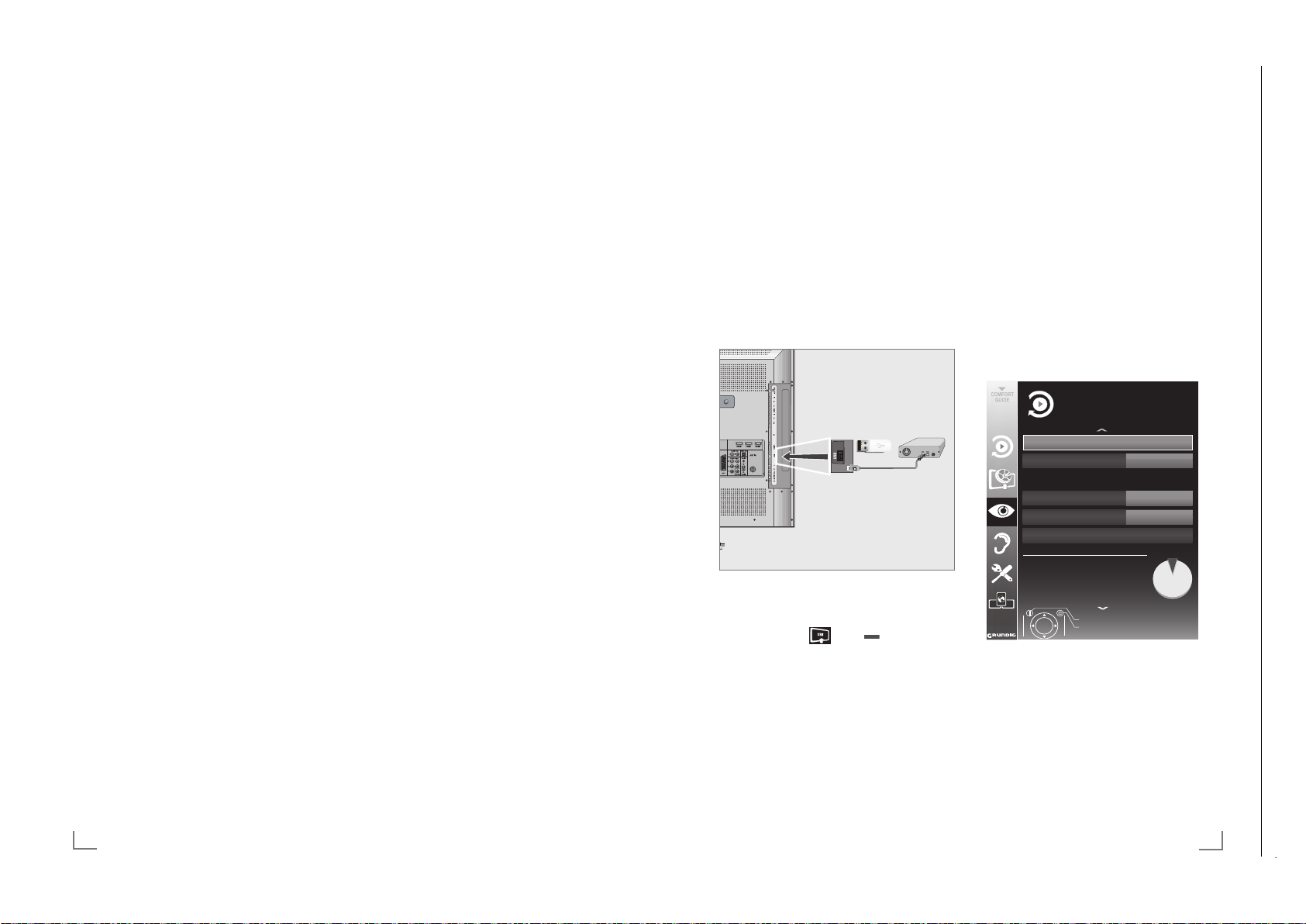
Externe Datenträger anschließen
Hinweise:
7
Vor dem Anschließen des externen Datenträgers schalten Sie das Fernsehgerät mit
»8«
in Bereitschaft (Stand-by). Erst nach
dem Anschließen schalten Sie das Fernsehgerät wieder ein.
7
Vor dem Entfernen des externen Datenträgers muss das Fernsehgerät grund sätzlich
auf Stand-by geschaltet werden, damit es
nicht zu Datenverlusten kommt.
7
An die Buchse »USB« des Fernsehgerätes
kann ein USB-Memory Stick oder eine Festplatte angeschlossen werden.
1 USB-Memory Stick oder externe Festplatte
an die Buchse »USB« des Fernsehgerätes
anschließen.
2 Die Anzeige »
« mit » « (grün) bestäti-
gen.
– Diese Anzeige wird nur beim erstmaligen
Anschließen eines Datenträgers eingeblendet.
– Der Dateimanager wird angezeigt.
Hinweise:
7
Die Buchse »USB« liefert eine Stromver-
sorgung von 500 mA für den externen Datenträger gemäß USB Spezifikation.
7
Externe Datenträger dürfen nicht vom Fern-
sehgerät getrennt werden, während auf Dateien des Datenträgers zugegriffen wird.
Einstellungen für USB Recording
Menü anwählen
1 Menü mit »i« aufrufen.
2 Zeile »USB RECORDING« mit »
V
« oder
»
Λ
« wählen und mit »O« bestätigen.
– Das Menü »USB RECORDING« wird ein-
geblendet.
35Q3$UFKLY
3DUWLWLRQ
&
'DWHQWUlJHU
$XWR9RUVFKDX
86%
(LQ
'DWHQWUlJHUSUIHQ
%HHQGHQ
=XUFN
86%5(&25',1*
'DWHQWUlJHUYHUZDOWXQJ
*HQXW]WH.DSD]LWlW
*HQXW]W0%
*HVDPW0%
5HVWOLFKH6'$XIQDKPH]HLW
PLQ
5HVWOLFKH+'$XIQDKPH]HLW PLQ
Chassis SXGRUNDIG Service
1 - 15
Chassis SXGRUNDIG Service
1 - 15
Chassis SXGRUNDIG Service
1 - 15
Chassis SXGRUNDIG Service
1 - 15
Chassis SXGRUNDIG Service
1 - 15
Chassis SXGRUNDIG Service
1 - 15
Chassis TXGRUNDIG Service
1 - 15
--------------------------------------------------------------------------------------------------------------
Informationen zur Aufnahme
und Wiedergabe von Fernsehsendungen
Q
Die Aufnahme und die Wiedergabe von
Fernsehsendungen sind nur mit digitalen Fernseh-Programmen (DVB-S, DVB-T und DVB-C)
möglich.
Q
Welche digitalen Fernseh-Programme (DVB-S,
DVB-T und DVB-C) Sie aufnehmen und wiedergeben können, kann auch vom jeweiligen Programmanbieter abhängig sein.
Q
Die Aufnahme und die Wiedergabe von
Sendungen sowie die Funktion TimeShift
können nur mit einem externen Datenträger
(Festplatte oder USB-Stick) durchgeführt wer-
den.
Der Datenträger sollte eine Mindestspeicher-
kapazität von 2 GB haben.
Q
Aufnahmen sind mit den meisten auf dem
Markt verfügbaren Datenträgern möglich.
Der Betrieb kann jedoch nicht für alle Daten-
träger garantiert werden.
Q
Wurde eine Sendung auf dem externen Da-
tenträger aufgezeichnet, kann diese nur auf
Ihrem Fernsehgerät wiedergegeben werden.
Die Wiedergabe dieser Sendungen mit anderen Geräten ist nicht möglich.
Q
Wenn Sie Ihr Fernsehgerät zur Reparatur
geben und Hardwarekomponenten ausgetauscht werden mussten, können möglicherweise die Aufnahmen mit dem reparierten
Gerät nicht mehr wiedergegeben werden.
Q
Der Empfang des Programmanbieters SKY ist in
Deutschland zur Zeit nur mit einer geeigneten
Settop-Box möglich.
Q
Grundig übernimmt keine Haftung für den
eventuellen Verlust gespeicherter Daten auf
dem externen Datenträger.
Mögliche Einschränkungen
bei dem Betrieb mit externen
Datenträger
Abhängig vom jeweiligen Programmanbieter
kann es bei einigen Fernseh-Programmen zu verschiedenen Einschränkung der Funktionen kommen.
Auf diese Einschränkungen hat
GRUNDIG keinen Einfluß!
Q
Die Aufnahme einer Sendung auf den externen
Datenträger kann durch den Programmanbieter unterbunden werden. Wird die Meldung
»URI* geschützt! Aufnahme eingeschränkt«
am Bildschirm eingeblendet, so ist durch den
Programmanbieter Aufnahme oder Timeshift
eingeschränkt (Aufnahme einmal möglich)
oder unterbunden (Aufnahme nicht möglich).
Q
Wurde eine Sendung auf das Archiv des
externen Datenträgers aufgezeichnet und gespeichert, kann die Wiedergabe der Sendung
eingeschränkt sein.
Der Programmanbieter kann Ihnen gestatten, diese Sendung einmal oder mehrmals
an zusehen, es ist auch möglich, dass die
Sendung nur für einen gewissen Zeitraum zur
Verfügung steht.
Q
Sendungen die jugendgeschützt sind, ver-
langen unmittelbar vor dem Start der Aufnahme die Eingabe einer PIN-Nummer. Erfolgt
diese Autorisierung nicht, darf die Aufnahme
nicht starten.
Q
Das Überspielen einer Sendung von einem
digitalen Fernseh-Programm auf einen Video-/
oder DVD-Recorder über die Buchse »AV 1«
(Analoges Bild-/Tonsignal) kann ebenfalls
vom Programmanbieter eingeschränkt werden.
Vorausgesetzt, Ihr Gerät unterstützt diese
Überspielfunktion.
* URI = User right information (Urheberrechtliche
Informationen).
DEUTSCH44
Page 16

Chassis SXGRUNDIG Service
1 - 16
USB-RECORDING
Chassis SXGRUNDIG Service
1 - 16
47
DEUTSCH
USB-RECORDING
--------------------------------------------------------------------------------------------------------------
Timeshift –
Sendungen „anhalten″
Die aktuelle Sendung kann „angehalten” werden. Dies ist eine nützliche Funktion, wenn z.B.
während eines Spielfilmes das Telefon läutet,
und Sie die Fortsetzung des Films nicht verpassen möchten.
Am Bildschirm erscheint ein Standbild der letzten
Szene, die Sendung wird im „Time Shift-Speicher”
des externen Datenträgers gespeichert
Im Timeshift-Betrieb können Sie max. 10 Minuten
der aktuellen Sendung aufnehmen.
1 Aktuelle Sendung mit »
!« anhalten.
– Das Bild wird eingefroren, der Zeitversatz
und die restliche Aufnahmezeit werden angezeigt.
2 Sendung mit »
8« fortsetzen.
–
Die Sendung wird weiterhin aufgezeichnet.
Hinweis:
7
Die folgenden Funktionen sind während des
Timeshift-Betriebs möglich:
–
Zurückspulen, dazu »m« je nach Ge-
schwindigkeit mehrmals drücken (das
Bild ist während des Rückspulens eingefroren);
–
Vorwärtsspulen, dazu »,« je nach Ge-
schwindigkeit mehrmals drücken;
–
Pause mit »!« anwählen.
3 Timeshift-Funktion mit »
7« beenden.
– Die Meldung »Livesendung« wird einge-
blendet, Sie sehen die aktuelle Sendung
ohne Zeitversatz.
– Die Szenen im „Time Shift-Speicher” sind
gelöscht.
Sendungen aufnehmen
Sie können Sendungen aufnehmen. Die Daten
dieser Sendungen werden auf einem externen
Datenträger gespeichert, die Verwaltung dieses
Archivs erfolgt durch das Fernsehgerät.
Für die Aufnahme gelten folgende Richtwerte:
Die Aufnahmezeit für hochauflösende Sendungen (HD) beträgt 7 Minuten bei einem Speicherplatz von 1 GB, für Standardsendungen
26 Minuten.
Während der Aufnahme können Sie vom Archiv
eine andere Sendung wiedergeben.
Ein Wechseln des Programmplatzes ist nicht
möglich.
Sofortaufnahme einer Sendung
1
Fernseh-Programm mit »1…0« oder »P+«,
»P–« wählen und Aufnahme mit »
« starten.
– Informationen zur Aufnahme werden ein-
geblendet: Das Aufnahmesymbol, der Programmname, die Sendung, die Aufnahmezeit und der noch zur Verfügung stehende
Speicherplatz.
– Nach kurzer Zeit werden diese Informatio-
nen abgeschaltet, nur das Aufnahmesymbol blinkt oben links auf dem Bildschirm..
2 Aufnahme mit »
7« beenden.
Hinweise:
7
Nach Abschluss der Aufnahme wird die Auf-
zeichnung automatisch auf dem externen
Datenträger gespeichert.
7
Das Menü »Aufgenommene Dateien«
mit den archivierten Sendungen kann mit
»LIST« aufgerufen werden.
7
Wird der externe Datenträger während der
Aufnahme von der USB-Buchse getrennt,
wird die Aufnahme automatisch abgebrochen und nicht gespeichert.
7
Aufnahmen, die auf FAT32-formatierten Fest-
platten gespeichert wurden, spielen Sie im
USB-Modus ab.
Chassis SXGRUNDIG Service
1 - 16
Chassis SXGRUNDIG Service
1 - 16
Chassis SXGRUNDIG Service
1 - 16
Chassis SXGRUNDIG Service
1 - 16
Chassis SXGRUNDIG Service
1 - 16
Chassis SXGRUNDIG Service
1 - 16
Chassis SXGRUNDIG Service
1 - 16
Chassis TXGRUNDIG Service
1 - 16
--------------------------------------------------------------------------------------------------------------
Automatische Vorschau einschalten
Ist die automatische Vorschau eingeschaltet,
wird eine Vorschau der ausgewählten Datei im
Dateimanager angezeigt.
1 Zeile »Auto-Vorschau« mit »
wählen.
2 Funktion mit »
« oder »>« einschalten (»Ein«).
<
3 Einstellung mit »i« beenden.
Externe Datenmedien auswählen
Wenn mehrere externe Datenträger an das Fernsehgerät angeschlossen sind, können Sie den
gewünschten Datenträger auswählen.
1
Zeile »Datenträger« mit »V« oder »Λ«
wählen.
2 Gewünschten Datenträger (»USB HDD«
oder »USB«) mit »
3 Einstellung mit »i« beenden.
Partition des externen Datenträgers
wählen
Wenn der externe Datenträger über mehrere
Partitionen verfügt, wählen Sie die gewünschte
aus.
1 Zeile »Partition« mit »
2 Gewünschte Partition mit »
len.
3 Einstellung mit »i« beenden.
« oder »>« wählen.
<
V
« oder »Λ« wählen.
V
« oder »>« wäh-
<
Externe Datenträger prüfen
Sie können externe Datenträger einer Prüfung
unterziehen und so herausfinden, ob sich diese
für die gewünschte Funktionalität eignen.
« oder »Λ«
1 Zeile »Datenträger« mit »
len. Wenn mehrere Datenträger angeschlossen sind, den gewünschten Datenträger mit
»
« oder »>« wählen.
<
2 Zeile »Partition« mit »
Wenn mehrere Partitionen vorhanden sind,
die gewünschte Partition mit »
wählen.
3 Zeile »Datenträger prüfen« mit »
»
Λ
« wählen und mit »O« bestätigen.
– Informationen zum Datenträger werden
angezeigt.
4 Einstellung mit »i« beenden.
V
« oder »Λ« wäh-
V
« oder »Λ« wählen.
« oder »>«
<
V
« oder
DEUTSCH46
Page 17

Chassis SXGRUNDIG Service
1 - 17
USB-RECORDING
Chassis SXGRUNDIG Service
1 - 17
49
DEUTSCH
USB-RECORDING
--------------------------------------------------------------------------------------------------------------
... durch manuelle Dateneingabe
Sie können 25 Sendungen für die Timer-Aufnahme programmieren
1
Programminformationen mit »TV-G« ein-
blenden.
– Der Elektronische Programmführer wird
eingeblendet.
2 Menü »TIMER ERSTELLEN« aufrufen, dazu
zw
eimal »
« (gelb) drücken.
3 Zeile »Typ« mit »
V
« oder »Λ« wählen und
mit »
<
« oder »>« die Option »Aufnahme«
wählen.
4 Zeile »Programm« mit »
V
« oder »Λ« wählen
und das gewünschte Programm mit »
<
« oder
»
>
« wählen.
5 Zeile »Modus« mit »
V
« oder »Λ« wählen
und den gewünschten Modus (»Einmal«,
»Täglich« oder »Wöchentl.«) mit »
<
« oder
»
>
« wählen.
6 Zeile »Start« (Beginn der Aufnahme) mit »
V
«
oder »
Λ
« wählen und Datum/Uhrzeit mit
»1…0« eingeben.
7 Zeile »Ende« (Ende der Aufnahme) mit »
V
«
oder »
Λ
« wählen und Datum/Uhrzeit mit
»1…0« eingeben.
8 Daten mit »
« (grün) speichern.
– Die Sendung ist programmiert.
9 Menü mit »i« abschalten.
Hinweise:
7
Vor dem Beginn der Timeraufnahme erscheint
eine Warnmeldung mit einem 20-Sekunden
Countdown. Sie können auf das pro grammierte Fernseh-Programm umschalten.
7
Sollte der Beginn der Timeraufnahme bei
laufender Wiedergabe erreicht werden,
wird die Wiedergabe nicht unterbrochen:
Die Aufnahme erfolgt automatisch im Hintergrund, sofern Sie bei der Meldung des
Timercountdowns nicht »Ja« wählen.
Aufnahmedaten im Timermenü
ändern
Sie können die Daten von programmierten Sendungen ändern.
1 Timermenü anwählen, dazu nacheinan-
der »TV-G«, »
« (gelb) und » « (blau)
drücken.
–
Das Menü »TIMERLISTE« wird ein-
geblendet.
2 Titel der Sendung die geändert werden soll
mit »
V
« oder »Λ« wählen und Timerplatz mit
»
« (grün) aktivieren.
– Das Eingabemenü wird eingeblendet.
3 Gewünschte Option mit »
V
« oder »Λ« wäh-
len und Daten mit »1…0« und »<« oder »>«
ändern.
4 Änderungen mit »
« (grün) speichern.
– Der Timer wurde geändert.
5 Menü mit »i« abschalten.
Timer löschen
Sie können programmierte Timer löschen.
1
Timermenü anwählen, dazu nacheinander
»TV-G«, »
« (gelb) und » « (blau)
drücken.
–
Das Menü »TIMERLISTE« wird einge-
blendet.
2 Titel der Sendung die gelöscht werden soll
mit »
V
« oder »Λ« wählen und Timerplatz mit
»
« (gelb) löschen.
3 Menü mit »i« abschalten.
Chassis SXGRUNDIG Service
1 - 17
Chassis SXGRUNDIG Service
1 - 17
Chassis SXGRUNDIG Service
1 - 17
Chassis SXGRUNDIG Service
1 - 17
Chassis SXGRUNDIG Service
1 - 17
Chassis SXGRUNDIG Service
1 - 17
Chassis SXGRUNDIG Service
1 - 17
Chassis SXGRUNDIG Service
1 - 17
Chassis TXGRUNDIG Service
1 - 17
--------------------------------------------------------------------------------------------------------------
Aufnahme einer Sendung aus der
Programmliste
1 »PROGRAMMLISTE« mit »O« aufrufen.
Das gewünschte Fernseh-Programm mit
2
»V«, »Λ«, »<« oder »>«
»O« be stätigen.
3 Programmliste mit »i« abschalten.
4 Aufnahme mit »
– Informationen zur Aufnahme werden ein-
geblendet: Das Aufnahmesymbol, der Programmname, die Sendung, die Aufnahmezeit und der noch zur Verfügung stehende
Speicherplatz.
– Nach kurzer Zeit werden diese Informatio-
nen abgeschaltet, nur das Aufnahmesymbol blinkt unten rechts auf dem Bildschirm
und die Aufnahmedauer wird während der
Aufnahme angezeigt.
5 Aufnahme mit »
wählen und mit
« starten.
7« beenden.
Sendungen für die Aufnahme
programmieren ...
... mit dem elektronischen
Programmführer
Sie können die Daten für die gewünschte Sendung vom Elektronischen Programmführer (TVGuide) übernehmen.
25 Sendungen können für die Timer-Aufnahme
oder als Erinnerung programmiert werden.
1
– Der Elektronische Programmführer wird
2 Das gewünschte Fernseh-Programm mit »
3 Zu den Programminformationen der aktuel-
4 Die gewünschte Sendung mit »
5 Gewählte Sendung mit »
– Hinter dem Namen der Sendung wird das
6 Menü mit »i« abschalten.
Programminformationen mit »TV-G« ein-
blenden.
eingeblendet.
oder »Λ« wählen.
len Sendung mit »
« umschalten.
>
V
wählen.
Symbol »
« eingeblendet, die Daten wur-
« bestätigen.
den in den Timer übernommen.
Hinweis:
7
Sollen die Aufnahmedaten geändert werden, mit » « (gelb) und » « (blau) zur
»TIMERLISTE« schalten, »
cken, die Daten ändern und mit » « (grün)
« (grün) drü-
speichern.
Hinweise:
7
Vor dem Beginn der Timeraufnahme erscheint eine Warnmeldung mit einem 20-Sekunden Countdown. Sie können auf das
programmierte Fernseh-Programm umschalten.
7
Sollte der Beginn der Timeraufnahme bei
laufender Wiedergabe erreicht werden,
wird die Wiedergabe nicht unterbrochen:
Die Aufnahme erfolgt automatisch im Hintergrund, sofern Sie bei der Meldung des
Timercountdowns nicht »Ja« wählen.
V
« oder »Λ«
«
DEUTSCH48
Page 18

Chassis SXGRUNDIG Service
1 - 18
USB-RECORDING
Chassis SXGRUNDIG Service
1 - 18
DEUTSCH60
KOMFORTFUNKTIONEN
------------------------------------------------------------------------------------
PIN-Code ändern
Sie können statt des Werkscodes »1234« einen
persönlichen PIN-Code eingeben. Notieren Sie
sich bitte Ihren persönlichen PIN-Code.
1
Zeile »PIN ändern« mit »V« oder »Λ« wählen
und mit »O« bestätigen.
2 Aktuellen PIN-Code 1 2 3 4 mit »1 ... 0«
eingeben.
3 Persönlichen neuen PIN-Code mit »1 ... 0«
vierstellig eingeben.
4 Persönlichen neuen PIN-Code mit »1 ... 0«
noch einmal eingeben.
5 Einstellung mit »i« beenden.
Fernseh-Programme sperren
Sie können einzelne Fernseh-Programme mit
einem persönlichen PIN-Code sperren, zum
Beispiel Programme, die sich nicht für Kinder
eignen.
1 Menü mit »i« aufrufen.
2 Menü »INSTALLATION« mit »
V
« oder »Λ«
wählen und mit »O« bestätigen.
3 Zeile »Programmtabelle« mit »
V
« oder »Λ«
wählen und mit »O« bestätigen.
– Das Menü »PROGRAMMTABELLE« wird
eingeblendet.
4
Im Menü »PROGRAMMTABELLE« mit »
«
(gelb) zur »LISTENVERWALTUNG« umschalten.
5 Das zu sperrende Programm mit »
V
« oder
»
Λ
« auswählen.
6 Mit »
<
« oder »>« die Spalte »Sperre«, an-
wählen und das Programm mit »O« sperren.
7 PIN-Code »1234« mit »1 ... 0« eingeben.
– Das Programm wird mit »« markiert.
Hinweis:
7
Zum Aufheben der Sperre das Programm mit
»
V
« oder »Λ« wieder anwählen, mit »O«
bestätigen und danach den PIN-Code 1 2
3 4 mit »1 ... 0« eingeben.
Software aktualisieren
(nur bei digitalen Programmen)
1 Im Menü »EINSTELLUNGEN« die Zeile
»Nach Updates suchen« mit »
V
« oder »Λ«
wählen und mit »O« bestätigen.
– Neue Software wird gesucht und – sofern
vorhanden – installiert.
Hinweis:
7
Wenn automatisch nach Softwareaktuali-
sierungen gesucht werden soll, die Zeile
»Auto-Update« mit »
V
« oder »Λ« wählen
und mit »
<
« oder »>« die Option »Ein«
wählen.
– Die Software wird automatisch aktualisiert,
sofern dies möglich ist.
2 Einstellung mit »i« beenden.
Fernsehgerät auf die Werkseinstellungen zurücksetzen
Mit dieser Funktion löschen Sie die Programmtabellen und alle persönlichen Einstellungen.
1
Im Menü »EINSTELLUNEN« die Zeile
»Werkseinstellungen« mit »
V
« oder »Λ«
wählen und mit »O« bestätigen.
2 Warnmeldung mit » « (grün) bestätigen.
– Das Menü »INSTALLATION« wird ein-
geblendet.
3 Einstellungen mit Kapitel „Erstinstallation und
Fernseh-Programme einstellen“ auf Seite 14
fortsetzen.
Chassis SXGRUNDIG Service
1 - 18
Chassis SXGRUNDIG Service
1 - 18
Chassis SXGRUNDIG Service
1 - 18
Chassis SXGRUNDIG Service
1 - 18
Chassis SXGRUNDIG Service
1 - 18
Chassis SXGRUNDIG Service
1 - 18
Chassis SXGRUNDIG Service
1 - 18
Chassis SXGRUNDIG Service
1 - 18
Chassis SXGRUNDIG Service
1 - 18
Chassis TXGRUNDIG Service
1 - 18
Hinweis – Kindersicherung:
Mit dem PIN-Code 2356 können Sie die Einstellungen ändern.
--------------------------------------------------------------------------------------------------------------
Wiedergabe
Die aufgezeichneten Sendungen – ob von Hand
gestartet oder mit der Timer-Funktion – werden
auf dem externen Datenträger gespeichert.
Das Archiv des externen Datenträgers kann mit
»LIST« aufgerufen werden.
Sendung aus dem Archiv
auswählen
1 Menü »Aufgenommene Dateien« mit »LIST«
aufrufen.
– Das Menü wird eingeblendet.
2 Gewünschte Sendung mit »
wählen und Wiedergabe mit »
3 Wiedergabe mit »
7« beenden.
– Das Fernsehgerät schaltet auf das aktuelle
Fernseh-Programm um.
Bildsuche vorwärts/rückwärts
1 Während der Wiedergabe mit »,« die Ge-
schwindigkeit vorwärts (2x, 4x, 8x oder 16x)
anwählen;
oder
während der Wiedergabe mit »
schwindigkeit rückwärts (2x, 4x, 8x or 16x)
anwählen (das Bild ist während des Rückspu-
lens eingefroren).
Einen Szene wiederholen (A-B)
Sie können den Start- und Endpunkt einer Szene
markieren. Diese Szene wird dann ständig wiederholt.
1 Startpunkt A markieren, dazu während der
Wiedergabe »
Szene drücken.
– Diese Szene ist als Startpunkt A markiert.
2 Endpunkt B markieren, dazu während der
Wiedergabe »
Szene noch einmal drücken.
– Diese Szene ist als Endpunkt B markiert.
8« an der gewünschten
8« an der gewünschten
– Das Fernsehgerät wiederholt die Sendung
zwischen diesen beiden Punkten.
3 Wiederhol-Funktion mit »
7« beenden.
DEUTSCH50
V
« oder »Λ«
8« starten.
m« die Ge-
Wiedergabe während einer
Aufnahme
Sie können entweder das aktuelle Fernseh-Programm sehen, das gerade aufgenommen wird,
oder ein vorher aufgenommenes Fernseh-Programm während eine Aufnahme läuft.
1 Fernseh-Programm, das aufgezeichnet wer-
den soll, mit »1…0« oder »P+«, »P–«
wählen und Aufnahme mit »
2
Menü »Aufgenommene Sendungen« mit
»
LIST
« auf rufen. Gewünschte Sendung mit
»
V
« oder »Λ« wählen und Wiedergabe mit
»
8
« starten.
– Die Aufnahme wird im Hintergrund fort-
gesetzt.
3 Wiedergabe mit »
4 Aufnahme mit »
7« beenden.
7« beenden.
Sendungen in der Aufnahmeliste
löschen
Sie können Sendungen aus der Aufnahmeliste
löschen.
1 Menü
– Das Menü wird eingeblendet.
2 Sendung die gelöscht werden soll mit »
3 Sendung mit »
4
Hinweis:
7
5 Menü mit »i« abschalten.
»Aufgenommene Sendungen«
»LIST« aufrufen.
oder »
Λ
« wählen.
« (blau) löschen.
Sicherheitsabfrage mit » « (grün) bestätigen.
Sendungen im Menü »Aufgenommene Sendungen«, die gerade aufgenommen oder
wieder gegeben werden, können nicht gelöscht werden.
« starten.
mit
V
«
Page 19
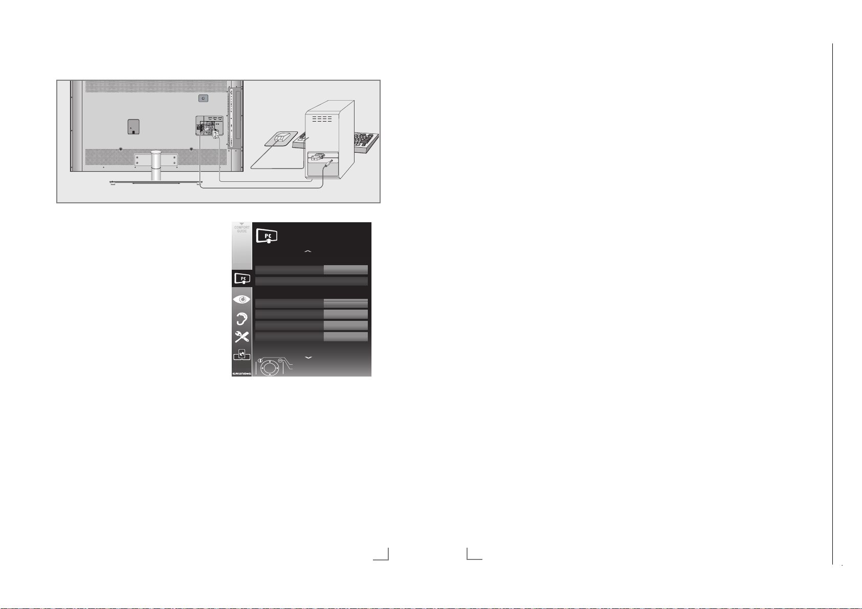
Chassis SXGRUNDIG Service
1 - 19
BETRIEB ALS PC-MONITOR
Chassis SXGRUNDIG Service
1 - 19
DEUTSCH78
INFORMATIONEN
-----------------------------------------------------------------------------------------------------------
Signalinformationen anzeigen
(nur bei digitalen Programmen)
1 Menü mit »i« aufrufen.
2 Zeile »INSTALLATION« mit »
V
« oder »Λ«
wählen und mit »O« bestätigen.
3 Zeile »Signalinformation« mit »
V
« oder »Λ«
wählen und mit »O« bestätigen.
– Informationen zu Programm, Netzwerk,
Modulation, Symbolrate, Qualität und
Signalstärke werden angezeigt.
Hinweise:
7
Die Signalinformation wechselt je nach
aktueller Signalquelle.
7
Im unteren Bereich des Menüs werden die
Signaleigenschaften dargestellt. Je weiter
die Balken für »Qualität« und »Signalstärke«
nach rechts ausschlagen, desto besser ist
das empfangene Signal.
7
Der Signalpegel hängt nicht nur von Ihrer
Empfangsanlage, sondern auch von dem
gerade aktiven Kanal ab. Beachten Sie dies,
wenn Sie anhand der Signalstärkeanzeige
die Ausrichtung Ihrer Antenne kontrollieren!
4 Menü mit »
i« abschalten.
Vorprogrammierung der
Fernbedienung für andere
GRUNDİG Geräte
7
»DVB« ist zur Bedienung eines GRUNDIG-
Digital-Receivers (Fernbedienebene 1) vorprogrammiert.
7
»DVD« ist zur Bedienung eines GRUNDIG-
DVD-Players vorprogrammiert.
7
»AMP« ist zur Bedienung eines GRUNDIG-
AV-Receivers vorprogrammiert.
7
Welche Funktionen Sie ausführen können,
hängt von der Ausstattung des Gerätes ab.
Probieren Sie es einfach aus.
Vorprogrammierung der Fernbedienung ändern
1 »M« drücken und gedrückt halten und
gleichzeitig die drei Ziffern des entsprechenden Codes eingeben:
»1«, »2«, »3« für GRUNDIG-DVD-Player.
»4«, »5«, »6« für GRUNDIG-DVD-
Recorder.
»1«, »4«, »7« für GRUNDIG-Digital-
Receiver (Fernbedienungsebene 1).
»2«, »5«, »8« für GRUNDIG-Digital-
Receiver (Fernbedienungsebene 2).
»3«, »6«, »9« für GRUNDIG-Digital-
Receiver mit Festplatte (PDR).
Chassis SXGRUNDIG Service
1 - 19
Chassis SXGRUNDIG Service
1 - 19
Chassis SXGRUNDIG Service
1 - 19
Chassis SXGRUNDIG Service
1 - 19
Chassis SXGRUNDIG Service
1 - 19
Chassis SXGRUNDIG Service
1 - 19
Chassis SXGRUNDIG Service
1 - 19
Chassis SXGRUNDIG Service
1 - 19
Chassis SXGRUNDIG Service
1 - 19
Chassis SXGRUNDIG Service
1 - 19
Chassis TXGRUNDIG Service
1 - 19
-----------------------------------------------------------------------------
PC anschließen
1 Buchse »PC-IN« des Fernsehgerätes und die
entsprechende Buchse des PCs mit einem
VGA Kabel verbinden (Bildsignal).
2 Buchse »PC Audio« des Fernsehgerätes
und die entspr
echenden Buchse des PCs mit
geeignetem Kabel verbinden (Tonsignal).
Hinweis:
7
Passen Sie bitte Ihren PC an den Monitor
an (Bild schirm auflösung z.B. 1280 x 768,
Bildfrequenz z.B 60 Hz).
Programmplatz für den PC
anwählen
1 »AV« drücken, mit »V«, »Λ«, »<« oder »>«
den Programmplatz »PC« wählen und mit
»O« bestätigen.
Einstellungen zum PC-Betrieb
1 Menü mit »i« aufrufen.
2 Menüpunkt »INSTALLATION« mit »
»
Λ
« wählen und mit »O« bestädigen.
–
Das Menü »INSTALLATION« wird eingeblendet.
3 Gewünschte Funktion oder Einstellung mit
»
V
« oder »Λ« wählen, anschließend mit
»
V
«, »Λ« oder »<«, »>« ausführen.
Die Möglichkeiten:
V
« oder
»Auto Position«, zur automatischen An-
–
passung an den PC.
– »Autopositionmodus«, die Option »Ein«,
wählen, wenn die Anpassungen im PCModus automatisch ausgeführt werden
sollen.
– »Position«, zum Anpassen der horizontalen
und vertikalen Bildposition.
»Größe«, zum Einstellen der Taktfre quenz.
–
– »Phase«, zum Beseitigen von Flackern,
unscharfer Darstellung und horizontal
störenden Linien.
4 Einstellung mit »
,167$//$7,21
6LJQDOTXHOOH
$XWR3RVLWLRQ
(UZHLWHUWH(LQVWHOOXQJHQ
$XWRSRVLWLRQPRGXV
3RVLWLRQ
*U|H
3KDVH
%HHQGHQ
=XUFN
i« beenden.
+9
3&
(LQ
DEUTSCH
67
Page 20
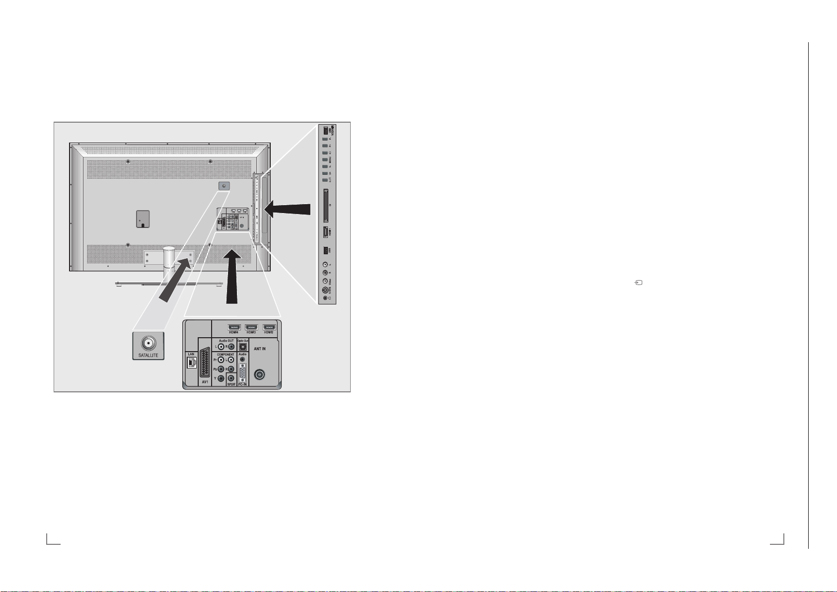
Operating Hints This chapter contains excerpts from the operating instructions. For further particulars please refer to the appropriate user instructions which can be downloaded by www.grundig.com, submenu Downloads/Manuals.
Chassis TXGRUNDIG Service
1 - 20
11
ENGLISH
OVERVIEW
------------------------------------------------------------------------------------------------------------------------------------
Audio Soc ket for audio
input for a PC.
PC-IN VGA socket, video input
for PC
.
ANT IN Antenna socket for a DVB-T,
D
VB-C and analogue
antenna.
HDMI2 HDMI socket,
audio/video input.
HDMI3 HDMI socket,
audio/video input.
HDMI4 HDMI socket,
audio/video input.
U Headphone jack (3.5 mm
jack plug).
S-VHS Video socket for
S-Video camcor
der.
Video Video socket for
camcor
der.
L R Audio socket for
camcor
der.
USB USB socket for external
data media and
PVR
function.
HDMI1 HDMI socket,
audio/video input.
CI Common Interface Slot.
8/I Switches the television on
and back into standby
mode.
The only way to disconnect
the
television from the mains
supply
is to pull the plug.
V– V+ Adjusts the volume;
selects menu functions.
MENU Opens the menu.
Select a menu option wit
h
»P+« or »P–«.
Activ
ate the function with
»V+« or »V–«.
Conf
irm the function with
»V+« or »V–«.
Pr
ess »MENU« to quit the
menu.
Opens the pre-selection for
AV channels.
In the menu, press »P+« or
»P–« to select and press
»V+« or »V–« to confirm.
P– P+ Switches the television on
fr
om standby;
selects channels in steps;
selects function in the menu.
USB-VOD-WIFI USB socket for connecting
an e
xternal data medium for
the Connected TV function;
to connect a WiFi USB
Dongle.
OVERVIEW
------------------------------------------------------------------------------------------------------------------------------------
Connections on the television set
SATELLITE Antenna socket for the
LAN Network cable connection
AV1 SC ART socket (FBAS signal,
AUDIO OUT L R Sockets for audio output.
COMPONENT
Y Pb Pr Soc kets for video input
L R Sockets for audio input
satellite antenna (DVB-S).
et.
sock
R
GB signal).
(YUV signal).
(YUV signal).
SPDIF Socket for audio output
Optic Out Socket for audio output
(coaxial) for PCM/AC3
signals.
For connecting digital AV
amplifiers or AV receivers.
(optical) for PCM/AC3
signals.
For connecting digital AV
amplifiers or AV receivers.
10
ENGLISH
Page 21
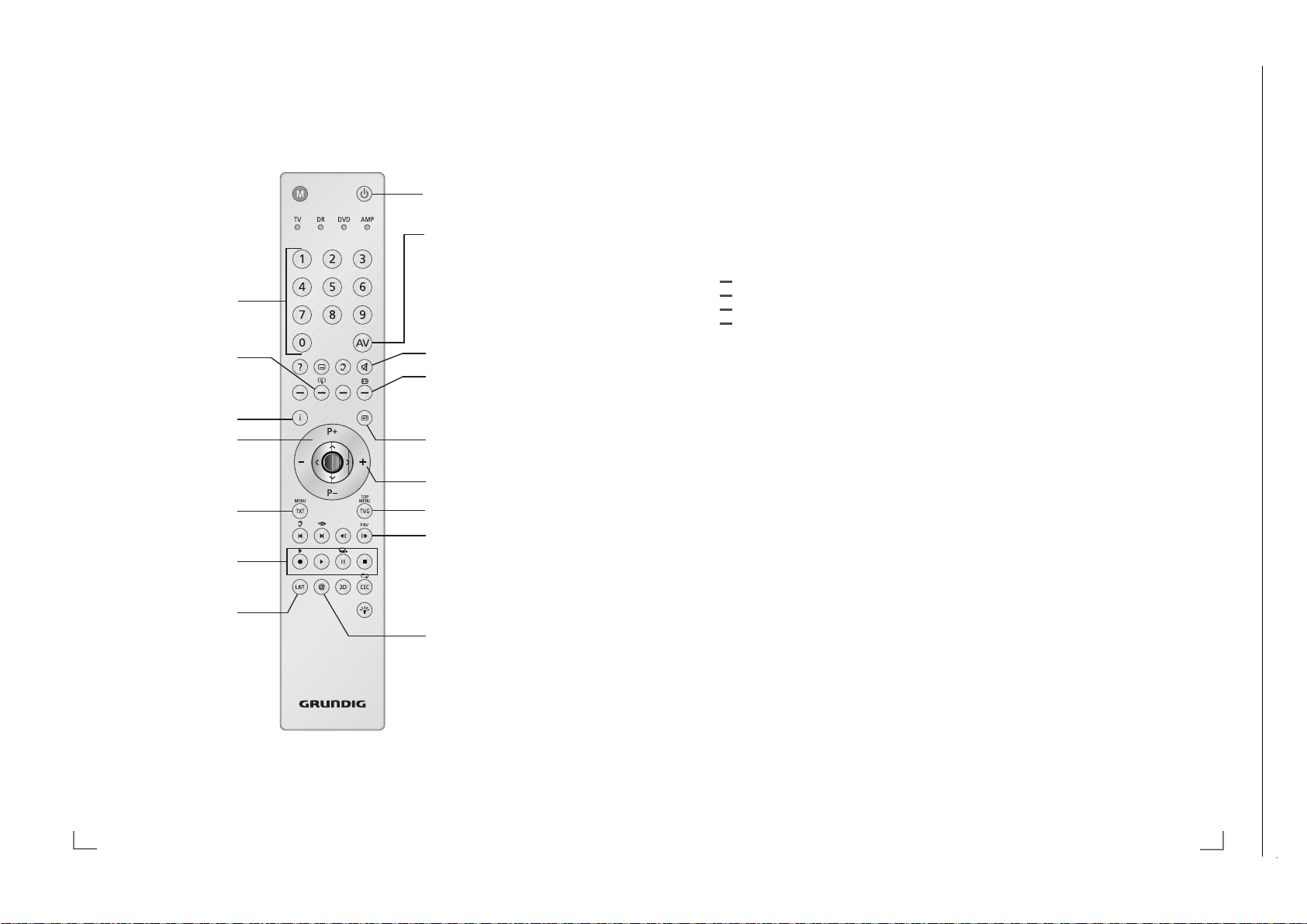
Chassis SXGRUNDIG Service
1 - 21
OVERVIEW
Chassis SXGRUNDIG Service
1 - 21
13
ENGLISH
OVERVIEW
------------------------------------------------------------------------------------------------------------------------------------
The remote control –
All functions
? Displays information about the
television channel.
y
Selects different subtitles
(only for digital television channels)
d
Selects different audio languages
(only for digital television channels)
(red)
Selects pages in teletext;
(green)
Selects/activates various functions in
(yellow)
the menus.
(blue)
LIST
Opens the »PRnP« menu.
3D Switches 3D mode on/off.
CEC
Opens the »HDMI CEC Device List«;
selects the repeat function in the
file browser.
y
Starts the recording (
only for digital
television channels
, the recording is
made on an external data medium).
8 Starts playing a programme from an
external data medium;
Repeats a recorded programme.
! Freeze frame, if no external data
medium is connected;
Playback pause;
Time shift mode (only for digital
television channels and when an external data medium is connected).
7 Ends playback of a programme from
an external data medium;
Ends a recording or
playback in time shift mode.
Splits the screen in teletext.
5 Selects different audio settings;
Switches to double character size in
teletext;
Selects the next title/next picture in
the file browser.
6 Selects different picture settings;
Refreshes a teletext page;
Selects the previous track/previous
picture in the file browser.
m Stops scrolling through pages in
teletext;
Starts a fast reverse search in the
file browser.
, Selects the channel list ( »All«, »FAV
1« to »FAV 4«);
Reveals answers in teletext;
Starts a fast forward search in the
file browser.
R Switch on button lighting. The light-
ing switches of
f automatically after a
short time.
M Switches over to operate a
– GRUNDIG digital receiver,
– GRUNDIG digital receiver with
hard disk (PDR),
– GRUNDIG DVD player.
– GRUNDIG DVD recorder or
GRUNDIG AV receiver.
Press »M« until the displays »DVB«,
»DVD« or »AMP« lights up.
Then make the selection.
If you do not press a button within
10 seconds, the remote control
returns to television mode (»TV«).
You can change this programming,
see page 78.
Chassis SXGRUNDIG Service
1 - 21
Chassis TXGRUNDIG Service
1 - 21
The remote control – Main functions
------------------------------------------------------------------------------------------------------------------------------------
Switches on from standby;
Selects channel – directly.
Enlarges the picture.
Opens the main menu.
Switches on from standby;
Selects channel – in s
Switches between
telete
xt and TV mode.
R
ecord, play, pause and
stop. (only digital television
channels).
Opens the »PRnP« menu.
Moving the cursor
V Λ
Moves the cursor up and
down in the menus.
<
>
Moves the cursor to the left
and right in the menus.
O Opens the channel list;
activates various functions.
teps.
Switches off (Standby)
Opens menu for AV channels
and USB input.
Then select using »
»>« or »Λ« and press »O«
to confirm.
Finished the
Connected TV function.
Muting
Opens the selection menu to
change picture formats.
Then select with »
and press »O« to confirm.
Zapping function;
switches back one menu
vel in the menus.
le
Adjusts the volume.
Opens the electronic TV guide.
Selects the channel list ( »All«,
»FAV 1« to »FAV 4«).
Start the
Connected TV function.
V
«, »<«,
« or »>«
<
12
ENGLISH
Page 22

Chassis SXGRUNDIG Service
1 - 22
3D FUNCTION
Chassis SXGRUNDIG Service
1 - 22
27
ENGLISH
3D FUNCTION
-------------------------------------------------------------------------------------------------------------------------
Watching 3D films
Notes:
7
The 3D function is supported using the »DVB-
T«, »DVB-C«, »DVB-S« and »DLNA« chan-
nel sources or external devices connected to
the »HDMI«, »YPbPr«, »VGA« or »USB«
inputs.
7
With »HDMI«, »YPbPr« and »VGA« inputs,
3D mode is only possible with resolutions at
»1280x720p 50/60 Hz«, »1920x1080i
50/60 Hz« and »1920x1080p 24/30,
50/60 Hz«.
7
The 3D experience depends on the format
and features of the movie (resolution,
sharpness etc.) being played.
7
If 3D mode is activated for a picture which
is not in 3D, the picture on the screen may
appear blurry both with or without the 3D
glasses.
7
The 3D effect may degrade if you watch
3D images under fluorescent light. In such
cases, either reduce the light or turn off the
lamp.
7
Your TV will switch from 3D mode to 2D
mode for the following: if the program table
or EPG information is displayed, the channel
or the source are changed, playback of a
3D film is completed or the next film starts to
play in USB or PVR mode.
1 Open the »Select Source« menu with »AV«.
2 Select the source (digital channel or suitable
input) t
hat will be played in 3D with »
<
«,
»
>
«, »V« or »Λ« and confirm with »O«.
3 Select the 3D mode with »3D« as »Side by
Side« or »Top Bottom« in accordance with
the content to be played and confirm with
»O«.
– »Side by Side«: Displays one image next
to the other.
– »Top Bottom«: Displays one image below
the other.
– »Frame Packing«: Right and left images on
the TV are displayed in turn.
Note:
7
Frame Packing appears in the 3D menu only
if a video signal is sent to the »HDMI« input
in HDMI 1.4 format. The »Side by Side«
and »Top Bottom« options do not appear.
4 Turn off the 3D function by setting it to »Off«
with the »3D« button and confirm with »O«.
Formats supported by HDMI 1.4
With HDMI 1.4, your TV can recognise and
play 3D content.
The formats supported are shown in the following table.
For Bluray films
Frame Packing 1080p @
23.98/24Hz
For 3D
games
Frame Packing 720p @ 50 or
59.94/60Hz
For 3D
films from
broadcasters
Side by Side
Horizontal
1080i @ 50 or
59.94/60Hz
Top and
Bottom
720p @ 50 or
59.94/60Hz
1080p @
23.97/24Hz
Note:
7
Refer to the user manual of the Grundig AS-
3D G glasses for further information about
usage, cleaning and care of the glasses.
7
»HDMI4« input does not support HDMI1.4
3D.
Chassis SXGRUNDIG Service
1 - 22
Chassis SXGRUNDIG Service
1 - 22
Chassis TXGRUNDIG Service
1 - 22
-------------------------------------------------------------------------------------------------------------------------
Important information about the
3D function
7
Keep a sufficient distance from the television.
The optimum distance is three times the
height of the screen. Watching 3D films from
a close distance for a long time could impair
your vision.
7
Never use the 3D function for longer than
3 hours without a break.
7
It is essential that you supervise children
watching a 3D programme to prevent damage to their health. Children under 6 years
should not watch 3D content because their
spatial vision is not yet completely developed.
7
Watching 3D movies with 3D shutter glasses
for long durations may cause headaches or
fatigue. Stop watching if you get a headache, feel dizzy or generally unwell.
7
Do not use the 3D function if you are anx-
ious, sleepy or overtired.
7
If you or a member of your family suffers
with epilepsy, you should consult your doctor before watching 3D films.
7
If, when watching a 3D film, your vision
becomes impaired, you feel dizzy or nauseous, your eyes hurt, you have muscle
spasms or have difficulty in concentrating,
you must stop watching immediately.
7
3D images can startle the viewer. We rec-
ommend that elderly persons, pregnant
women and persons with serious physical
complaints avoid watching 3D content.
7
Do not use the 3D glasses for other purpos-
es, for example as sunglasses or protective
glasses, as this may impair your sight.
26
ENGLISH
Preparing the 3D function
Your Grundig television and 3D shutter glasses
can provide the reality of the cinema when you
watch 3D movies in your home.
This TV uses state-of-the-art LED technology to
give you the best experience 3D has to offer.
To join 3D world, you just need to put on the
Grundig 3D glasses supplied with your television.
Notes:
7
One pair of GRUNDIG AS-3D G glasses is
supplied together with the product.
7
Only use the GRUNDIG AS-3D G glasses.
Do not use 3D glasses from other manufacturers.
7
Grundig AS-3D G glasses are also sold
separately. Please contact your dealer.
7
The infrared transmitter is located at the
lower left corner of the television and emits
the signals at 90° horizontally and 40°
vertically.
It may not be possible to obtain 3D effects
when there is an obstacle between the infrared transmitter and the glasses.
Page 23

Chassis SXGRUNDIG Service
1 - 23
CONNECTED TV AND HOME NETWORK
Chassis SXGRUNDIG Service
1 - 23
29
ENGLISH
Wired network settings
There are two ways of making the wired network
settings.
A Automatic wired network connection,
all connection settings (»IP Address«, »Net-
mask«, »Gateway« and »DNS«) are obtained from modem automatically.
B Manual wired network connection,
all connection settings (»IP Address«, »Netmask«, »Gateway« and »DNS«) must be
configured manually.
Automatic wired network
connection
Most of the home networks are Dynamic. If you
have a dynamic network, you must use a DSL
modem that supports DHCP. A Television connected to the same network with a Modem or
IP sharer that support DHCP obtains the »DNS«
values that are required for »IP Address«, »Netmask«, »Gateway« and internet access automatically, and thus you are not required to enter
those values manually.
Note:
7
If you do not have a dynamic network, follow
the instructions in "Manual wired network
connection" section.
1 Select the line »Network« with »
V
« or »Λ«
and press »O« to confirm.
– The »Settings > Network« menu appears.
6HWWLQJV!1HWZRUN
$XWRPDWLF
:LUHOHVV 0DQXDO
&RQQHFWLRQWHVW 5HSDLU
:LUHG
2 Select the line »Wired« with »V« or »Λ« and
press »O« twice.
3 After your device is connected to the net-
w
ork, the download bit rate is tested auto-
matically.
Confirm this message by pressing »O«.
4 Press »Z« twice to end the setting.
Manual wired network connection
Certain networks require Static IP address. If
your network requires a Static IP address, you
must enter the »IP Address«, »Subnet mask«,
»Gateway« and »DNS« values manually. You
can obtain your »IP Address«, »Subnet mask«,
»Gateway« and »DNS« values from your Internet Service Provider (ISP) or copy them from a
computer connected to the same network by displaying its network settings.
1 Select the line »Network« with »
V
« or »Λ«
and press »O« to confirm.
– The »Settings > Network« menu appears.
2 Select the line »Wired« with »
V
« or »Λ« and
press »O« to confirm.
3 Select the option »Manual« with »
V
« or »Λ«
and press »O« to confirm.
– The »IP address« submenu appears.
6HWWLQJV!1HWZRUN
,3DGGUHVV
:LUHOHVV
&RQQHFWLRQWHVW
:LUHG
&DQFHO 1H[W
4 Enter the »IP address«:
Activate the first input position by pressing
»O« and select the first number with »
V
« or
»
Λ
«.
Select the next digit position with »
>
« and
press »O« to activate.
Repeat the procedure for all characters.
Select the push button »Next« with »
V
« or
»
Λ
« and press »O« to confirm.
CONNECTED TV AND HOME NETWORK
------------------------------
Chassis SXGRUNDIG Service
1 - 23
Chassis SXGRUNDIG Service
1 - 23
Chassis SXGRUNDIG Service
1 - 23
Chassis TXGRUNDIG Service
1 - 23
------------------------------
What is connected TV
Connected TV feature provides your TV the Internet services and pages when it is connected
to the Internet.
You can view YouTube, the popular video sharing environment, and Flickr, the popular photo
sharing environment.
And you can watch TV and listen to radio
through Internet.
With VOD (Video on demand) service, you
can buy or rent movies from video shop and
store them in the TV memory or an external
USB data storage that is connected to the TV.
If you have rented the stored movies than you
can watch them during the rental period on your
television.
If you have purchased them, you can watch
them anytime you want.
This feature is only available in countries where
the service is provided.
Network connection
You can establish a wired or wireless connection
between your television and the local network.
If you want use a wired network connection,
start with the instructions on this page;
if you use a wireless network connection, follow
the instructions in section "Wireless network", on
page 30.
28
ENGLISH
Wired network
Wired network connection
1 Connect the output of external modem to the
»LAN« socket with Cat 5 cable.
Note:
7
Connection cables are not supplied.
Initial setup
1 Switch on the television set from standby with
»
8«, »1…0« or »P+« or »P-«.
2 Open the menu with »i«.
3 Select the menu item »CONNECTED TV«
with »
V
– The line »Open Connected TV« appears.
4 Confirm the option »Open Connected TV«
– The »Language« menu appears.
5 Select the menu language with »
6 Select the country with »
– The Info menu appears.
7 Confirm the initial network setup configura-
– The »Settings« menu appears.
Note:
7
« or »Λ« and press »O« to confirm.
with »O«.
and press »O« to confirm.
– The »Country« menu appears.
press »O« to confirm.
tion with »O«.
Follow the instructions in section "Automatic
wired network connection" or "Manual
wired network connection".
V
V
« or »Λ«
« or »Λ« and
Page 24

Chassis SXGRUNDIG Service
1 - 24
CONNECTED TV AND HOME NETWORK
Chassis SXGRUNDIG Service
1 - 24
31
ENGLISH
7
It is recommended to switch off the equipment that are not in use in home network in
order to avoid unnecessary network traffic.
7
Placing the modem or wireless network shar-
er on an elevated location will increase the
wireless connection reception strength.
7
Wireless connection reception strength may
vary depending on the type of the modem,
the distance between the modem and television and the distance between the device
used as a DMS for DLNA application and
the modem.
7
Modem must be transmitting its SSID in order
to establish a wireless connection. Television
can not connect to a network without SSID.
7
When a network connection is established
with the wireless USB network, the connection may be weak depending on the
strength of the wireless network in the area.
Extending the wireless USB device to a position that can see the modem with a USB
extension cable will increase the wireless
network performance.
Initial setup
1 Switch on the television set from standby with
»
8«, »1…0« or »P+« or »P-«.
2 Open the menu with »i«.
3 Select the menu item »CONNECTED TV«
with »
V
« or »Λ« and press »O« to confirm.
– The line »Open Connected TV« appears.
4 Confirm the option »Open Connected TV«
wit
h »O«.
– The »Language« menu appears.
5 Select the menu language with »
V
« or »Λ«
and press »O« to confirm.
– The »Country« menu appears.
6 Select the country with »
V
« or »Λ« and
press »O« to confirm.
– The Info menu appears.
7 Confirm the initial network setup configura-
tion with »O«.
– The »Settings« menu appears.
CONNECTED TV AND HOME NETWORK
------------------------------
Wireless network settings
Most of the home networks are Dynamic. If you
have a dynamic network, you must use a DSL
modem that supports DHCP. A Television connected to the same network with a Modem or
IP sharer that support DHCP obtains the »DNS«
values that are required for »IP Address«, »Netmask«, »Gateway« and internet access automatically, and thus you are not required to enter
those values manually.
1 Select the line »Network« with »
V
« or »Λ«
and press »O« to confirm.
– The »Settings > Network« menu appears.
6HWWLQJV!1HWZRUN
$FFHVV3RLQW
:LUHOHVV
&RQQHFWLRQWHVW
:LUHG
JXHVW6HFXUHG:3$
JXHVW2Q
2 Select the line »Wireless« with »V« or »Λ«
and press »O« to confirm.
– The message »Scanning...« is displayed
and the wireless networks that are found
appears.
3 Select the network you want to connect with
»
V
« or »Λ« and press »O« to confirm.
– Wireless connection password menu is dis-
played.
4 Select the first required character with »
V
«,
»
Λ
«, »<« and »>« and press »O« to confirm.
Repeat the procedure for all characters.
Notes:
7
Select the push button »A,a« for upper
case/lower case and press »O« to confirm.
7
For canceling a character, select the push
button »
I
« and press »O« to confirm.
5 For entering the password, select the push
button »OK« wit
h »
V
«, »Λ«, »<« and »>«
and press »O« to confirm.
Chassis SXGRUNDIG Service
1 - 24
Chassis SXGRUNDIG Service
1 - 24
Chassis SXGRUNDIG Service
1 - 24
Chassis SXGRUNDIG Service
1 - 24
Chassis TXGRUNDIG Service
1 - 24
------------------------------
5 Enter the »Subnet Mask«:
Select the first input position by pressing »
and press »O« to activate.
Select the first number by pressing »
»
Λ
«.
Select the next digit position by pressing »
and press »O« to activate.
Repeat the procedure for all characters.
Select the push button »Next« with »
»
Λ
« and press »O« to confirm.
6 Enter the »Gateway«:
Select the first input position by pressing »
and press »O« to activate.
Select the first number by pressing »
»
Λ
«.
Select the next digit position by pressing »
and press »O« to activate.
Repeat the procedure for all characters.
Select the push button »Next« with »
»
Λ
« and press »O« to confirm.
7 Enter the »DNS« (Domain Name System):
Select the first input position by pressing »
and press »O« to activate.
Select the first number by pressing »
»
Λ
«.
Select the next digit position by pressing »
and press »O« to activate.
Repeat the procedure for all characters.
8 Select the push button »OK« with »
»
Λ
« and press »O« to confirm.
– »Attempting to connect to the wired net-
work« message is displayed, the network
connection is made and the result of the
download test is displayed.
9 After your device is connected to the net-
w
ork, the download bit rate is tested auto-
matically.
Confirm this message by pressing »O«.
10 Press »Z« to end the setting.
Note:
7
Connection info such as »MAC Address«,
»IP Address«, »Netmask« and »DNS« can
be see in the »Settings« menu.
11 Press »Z« again to switch to the
ONNECTED TV« main menu.
»C
30
ENGLISH
V
V
V
V
V
V
Wireless network
Λ
«
Wireless network connection
« or
1 Connect the GRUNDIG WiFi USB Dongle to
the »USB-VOD-WiFi« socket.
«
>
« or
Λ
«
« or
«
>
« or
Notes:
Λ
«
7
« or
«
>
« or
The GRUNDIG WiFi USB Dongle supports
IEEE 802.11 B/G and N communication
protocols. We recommend you to use IEEE
802.11N protocol to obtain the best performance in HD video playback.
7
If you use a modem that supports IEEE 802.
11B/G, video playback performance may
be poor when compared to a modem that
supports IEEE 802.11N since the data
transfer rate of IEEE 802.11B/G protocol
is lower.
7
The GRUNDIG WiFi USB Dongle must directly be connected to »USB-VOD-WiFi«
et; USB Hub is not supported.
sock
7
Please note that video playback performance in a DLNA application on a wireless
local network and in a Connected TV application on a network with internet connection depends on the number of users on the
network as it is the case in every wireless
network.
Page 25

Chassis SXGRUNDIG Service
1 - 25
CONNECTED TV AND HOME NETWORK
Chassis SXGRUNDIG Service
1 - 25
33
ENGLISH
CONNECTED TV AND HOME NETWORK
------------------------------
Legal information
You can display legal information about the
Connected TV feature.
1 In the »Settings« menu, select the line »Main-
tenance« with »
V
« or »Λ« and press »O« to
confirm.
– The »Settings > Maintenance« menu is dis-
played.
2 Select the line »Legal information« with »
V
«
or »
Λ
« and confirm with »O«.
– Informations appears on the right side of
the menu.
3 Scroll through the informations with »
V
« or
»
Λ
«.
4 Press »Z« thrice to end the setting and switch
return to the »CONNECTED TV« main menu.
Formatting the VOD storage
medium
Note:
7
If external hard disk or memory stick to be con-
nected to »USB-VOD-WiFi« socket does not
support one of the file formats EXT3, EXT2,
FAT16 or FAT32, read/write cannot be done.
It is recommended to format external hard disc
or memory stick through the television or to
use another USB memory. If the external hard
disc or memory stick is formatted through television’s »USB-VOD-WiFi« socket, the disc
for
mat will become EXT3 after formatting
1 In the »Settings« menu, select the line »Main-
tenance« with »
V
« or »Λ« and press »O« to
confirm.
– The »Settings > Maintenance« menu is dis-
played.
2 Select the line »Storage format« with »
V
« or
»
Λ
« and confirm with »O«.
– The Internal memory of your device and
the USB external storage device (if con-
nected) appears on the right side of the
menu.
3 Select the memory to be formatted with »
V
«
or »
Λ
« and confirm with »O«.
– A warning message is displayed.
Selecting download device for VOD
Your TV is equipped with a 4 Gb internal memory for the files that you will download with VOD
(Video on demand service). If this memory is not
sufficient, you can connect an external USB storage device to the TV and select the download
device.
Note:
7
Since the wireless network adapter and external memory uses the same USB socket,
wireless network feature cannot be used
when an USB external storage device is
connected.
1 In the »Settings« menu, select the line »VOD«
wit
h »
V
« or »Λ« and press »O« to confirm.
– The »Settings > VOD« menu is displayed.
2 Press »O« to scroll to the device selection, se-
lect the download device with »
V
« or »Λ«
and confirm with »O«.
3 Press »Z« twice to end the setting and switch
return to the »CONNECTED TV« main menu.
Device info
You can display information about your device.
1 In the »Settings« menu, select the line »Main-
tenance« with »
V
« or »Λ« and press »O« to
confirm.
– The »Settings > Maintenance« menu is dis-
played.
2 Select the line »Information« with »
V
« or
»
Λ
«.
– Information about your device such as
»Product ID«, »Version«, »LAN MAC« and
»WLAN MAC« appears on the right side
of the menu.
3 Press »Z« twice to end the setting and switch
r
eturn to the »CONNECTED TV« main menu.
Chassis SXGRUNDIG Service
1 - 25
Chassis SXGRUNDIG Service
1 - 25
Chassis SXGRUNDIG Service
1 - 25
Chassis SXGRUNDIG Service
1 - 25
Chassis SXGRUNDIG Service
1 - 25
Chassis TXGRUNDIG Service
1 - 25
------------------------------
Note:
7
In WEP encryption system, more than one
network password can be assigned to the
network. Your television can connect the
network only with the password in level one.
7
For TV to discover the wireless modem on
the network, the network name should
support ASCII characters.
6 In the »Confirmation« menu, press »
to select the push button »OK« and press
»O« to confirm.
– »Attempting to connect to the wireless net-
work: Guest« message is displayed.
7 When »Your VOD is now connected« is dis-
played, press »O« to confirm.
– The Network connection is established and
the download test is displayed.
8 After your device is connected to the net-
work, the download bit rate is tested automatically.
Confirm this message by pressing »O«.
Note:
7
Connection info such as »MAC Address«,
»IP Address«, »Netmask« and »DNS« can
be see in the »Settings« menu.
9 Press »Z« to end the setting.
« or »>«
<
Connection test
After the network connection is established, you
can display the current performance of your internet line by performing a download test.
1 Select the menu item »Settings« with »
»
« and press »O« to confirm.
>
2 Select the line »Network« with »
and press »O« to confirm.
3 Select the line »Connection test« with »
»
Λ
« and press »O« to confirm.
– »Test in progress...« message is displayed
and Info screen contains information such
as »Download bitrate quality of a HR movie: Good«, »Download bitrate quality of a
SD movie: Good«.
4 Press »O« to close the screen
5 Press »Z« twice to end the test.
<
V
« or »Λ«
V
Settings for Connected TV
Opening the Settings menu
1 In the »CONNECTED TV« main menu, select
the menu item »Settings« with »
press »O« to confirm.
– The »Settings« menu appears.
6HWWLQJV
« or
« or
1HWZRUN
8VHULQWHUIDFH GHYLFH
9'2
0DLQWHQDQFH
Notes:
7
Additional settings are explained in the fol-
lowing sections.
7
You can leave the submenus by pressing
»Z«.
Changing the menu language
1 In the »Settings« menu, select the line »User
interface« with »
to confirm.
– The »Settings > User interface« menu is dis-
played.
2 Press »O« to scroll to the language selection,
– A message appears.
3 Select the push button »OK« with »
– Connected TV restarts with the selected
he required language with »
select t
»
Λ
« and press »O« to confirm.
and press »O« to confirm.
language.
Note:
7
If you dont want to change the language,
select the push button »Cancel« with »<« or
»
« and press »O« to confirm.
>
32
ENGLISH
« or »>« and
<
$OORZWKHPDLQWHQDQFHRIWKH
V
« or »Λ« and press »O«
V
« or »>«
<
« or
Page 26

Chassis SXGRUNDIG Service
1 - 26
CONNECTED TV AND HOME NETWORK
Chassis SXGRUNDIG Service
1 - 26
35
ENGLISH
CONNECTED TV AND HOME NETWORK
------------------------------
Updating software
(only for Connected TV functions)
1 In the »Settings« menu, select the line »Main-
tenance« with »
V
« or »Λ« and press »O« to
confirm.
– The »Settings > Maintenance« menu is dis-
played.
2 Select the line »Firmware Update« with »
V
«
or »
Λ
« and press »O« to confirm.
– The current version is displayed.
3 Select the push button »Online« or »Locally«
wit
h »
<
« or »>« and press »O« to confirm.
. – » Online«: Searches for and installs the new
software from Internet.
– »Locally«: Installs the new software from
USB external device (this application is
valid for services).
Notes:
7
When the update is completed, Connected
TV is restarted.
7
Continue with the settings in the chapters
”Wired network” or ”Wireless network” on
page 29 or 30.
Chassis SXGRUNDIG Service
1 - 26
Chassis SXGRUNDIG Service
1 - 26
Chassis SXGRUNDIG Service
1 - 26
Chassis SXGRUNDIG Service
1 - 26
Chassis SXGRUNDIG Service
1 - 26
Chassis SXGRUNDIG Service
1 - 26
Chassis TXGRUNDIG Service
1 - 26
------------------------------
4 In the warning screen, press »<« or »>« to
select the push button »OK« and confirm with
»O«.
– Formatting can take a few time.
– When formatting is complete, a warning
message is displayed.
Note:
7
If an external storage device is connected
to television during formatting process, it
should not be disconnected to avoid data
loss in external storage device.
5 Press »O« to end the formatting.
6 Press »Z« twice to end the setting and switch
eturn to the »CONNECTED TV« main menu.
r
Log out and removing the VOD
storage medium
You may safely remove USB external storage medium from the »USB-VOD-WiFi« socket..
1 In the »Settings« menu, select the line »Main-
tenance« wit
confirm.
– The »Settings > Maintenance« menu is dis-
played.
2 Select the line »Remove the storage« with
»
V
– On the right side of menu, connected USB
external storage medium is displayed.
h »
V
« or »Λ« and press »O« to
« or »Λ« and confirm with »O«.
3 Log out the USB device by pressing »O« and
irm the process with »O«.
conf
4 Remove the USB device connected to
»USB-VOD-WiFi« socket.
5 Press »Z« twice to end the setting and switch
r
eturn to the »CONNECTED TV« main menu.
Resetting the Connecting TV to its
original status
Notes:
7
The reset function will delete all files downloaded with VOD.
7
If an external storage device is connected to
television during resetting process, it should
not be disconnected to avoid data loss in
external storage device.
1 In the »Settings« menu, select the line »Main-
tenance« wit
confirm.
– The »Settings > Maintenance« menu is dis-
played.
2 Select the line »Factory reset« with »
»
Λ
« and confirm with »O«.
– A warning message is displayed.
3 Start the Factory reset, press »
select the push button »OK« and confirm with
»O«.
– This operation can take a few minutes.
– All information will be deleted, Connected
TV will be restarted and the Language
selection will be displayed.
4 Select the menu language with »
and press »O« to confirm.
– The »Country« menu appears.
5 Select the country with »
press »O« twice to confirm.
– Connected TV is restarted.
Note:
7
Continue with the settings in the chapters
”Wired network” or ”Wireless network” on
page 29 or 30.
Note:
7
If USB external storage medium has any
problem, the warning "Error in your USB
external storage device. Please remove and
check the device.” is displayed. Confirm the
message with »O« and check USB external
storage medium in a computer.
h »
V
« or »Λ« and press »O« to
<
V
« or »Λ« and
V
« or
« or »>« to
V
« or »Λ«
34
ENGLISH
Page 27

Chassis SXGRUNDIG Service
1 - 27
USB RECORDING
Chassis SXGRUNDIG Service
1 - 27
45
ENGLISH
USB RECORDING
--------------------------------------------------------------------------------------------------------------
Connecting external data media
Notes:
7
Before connecting the data medium, switch
the television to standby with
»8«
. Connect
the device and then switch the television on
again.
7
Before removing the external data medium,
the television must be switched to standby,
so that no data loss occurs.
7
You can connect a memory stick or external
hard disk to the »USB« socket on television.
1 Connect the external hard disk to the
»USB« USB interface of the television.
2 »Confirm the »
« display with «
(green).
– This display is only shown when connect-
ing the data medium for the first time.
– The file browser appears.
Notes:
7
»USB« interface of the television supports
500mA current according to the USB
standard. Devices such as external hard
disk and etc. that consume more power can
only be connected to the »USB« interface
of the television.
7
If you are using a power cable for the
external hard disk that you have connected
to the »USB« interface, then the power
cable of the external hard disk must also be
unplugged when the TV is turned off.
7
You must not disconnect the USB Device
from the TV while a file on the USB Device is
being read by the TV.
Settings for USB recording
Selecting the menu
1 Open the menu with »i«.
2 Select the line »USB RECORDING« with
»
V
« or »Λ« and press »O« to confirm.
– The »USB RECORDING« menu appears.
35Q3
3DUWLWLRQ
&
'LVN
$XWR3UHYLHZ
86%
2Q
&KHFN'LVN
([LW
%DFN
86%5(&25',1*
0DQDJHGDWDPHGLXP
&DSDFLW\8VHG
8VHG0%
7RWDO0%
5HPDLQLQJ6'UHFRUGLQJWLPH PLQ
5HPDLQLQJ+'UHFRUGLQJWLPH PLQ
Chassis SXGRUNDIG Service
1 - 27
Chassis SXGRUNDIG Service
1 - 27
Chassis SXGRUNDIG Service
1 - 27
Chassis SXGRUNDIG Service
1 - 27
Chassis SXGRUNDIG Service
1 - 27
Chassis SXGRUNDIG Service
1 - 27
Chassis SXGRUNDIG Service
1 - 27
Chassis TXGRUNDIG Service
1 - 27
--------------------------------------------------------------------------------------------------------------
Information on recording and
playing television programmes
Q
Recording and playback of television pro-
grammes is only possible with digital television
channels (DVB-S, DVB-T and DVB-C).
Q
The digital television channels (DVB-S, DVB-T
and DVB-C) you are able to record and playback also depends on the broadcaster.
Q
Recording and playback of programmes,
as well as the time shift function, can only be
carried out using an external data medium
(hard drive or USB stick). The data medium
should have a minimum storage capacity
of 2 GB.
Q
Recordings can be made with most data media
on the market. However, we cannot guarantee
operation for all data media.
Q
If a programme was recorded on an external
data medium, it can only be played back on
your television set. The playback of these pro-
grammes is not possible on other devices.
Q
If you send your television to be repaired and
hardware components need to be replaced,
you might not be able to play the recordings
again on the repaired television.
Q
Reception for SKY broadcasting service is cur-
rently only possible with a suitable set-top box.
Q
Grundig does not accept liability for any loss
of saved data on an external data medium.
Possible limitations when using
an external data medium
Depending on the broadcaster, you may experience various restrictions on some of the functions
from some television channels.
GRUNDIG has no influence on
these restrictions.
Q
Recording a programme on the external data
medium can be disabled by the broadcaster.
If the message »URI* protected! PVR function
is blocked« appears on the screen, then recording or timeshift is restricted (one recording
possible) or disabled (recording not possible)
by the broadcaster.
* URI = User right information (Copyright in-
formation).
Q
If you record and save a programme on the
archive of an external data medium, playback
can be restricted.
The broadcaster can allow you to view this
programme one or more times, but it may only
be available for a certain period of time.
Q
Programmes not suitable for minors will require
the input of a PIN number immediately before
recording starts. If this authorisation is not
given, the recording may not start.
Q
Copying a programme from a digital television
channel onto a video or DVD recorder using
the »AV 1« socket (analogue picture/
sound signal) can also be restricted by the
broadcaster. Prerequisite is that your device
supports the copying function.
44
ENGLISH
Page 28

Chassis SXGRUNDIG Service
1 - 28
USB RECORDING
Chassis SXGRUNDIG Service
1 - 28
47
ENGLISH
USB RECORDING
--------------------------------------------------------------------------------------------------------------
Recording programmes
You can record programmes. The data for these
programmes is recorded on an external data
medium and this archive is administered via the
television.
The following approximate values apply for recording:
Recording time for high-definition programmes
(HD) is 7 minutes with 1 GB of memory,
for standard programmes it is 26 minutes.
While recording, you can watch another programme from the archive.
You cannot change presets.
One-touch programme recording
1 Select the television channel to be recorded
with » »1…0« or »P+«, »P–« and press
»
« to start the recording.
– Information on the recording is displayed:
the recording symbol, the channel name,
the programme, the recording time and the
available memory space.
– After a short time this information disap-
pears; only the recording symbol flashes
on the top left of the screen.
2 End the recording with »
7«.
Notes:
7
After the recording is complete, the recording will be automatically saved on the external data medium.
7
The »RECORDED FILES« menu, with the archived programmes, can be opened with
»LIST«.
7
If the external data medium is disconnected
from the USB socket during recording, the
recording will be stopped automatically
and will not be saved.
7
Play your recordings, that you have recorded with your FAT32 formatted HDDs, in USB
mode.
Recording a programme from the
channel list
1 Open the »CHANNEL LIST« with »O«.
2 Select a television channel with »
V
«, »Λ«,
»
<
« or »>« and press »O« to confirm.
3 Press »
i« to exit the channel list.
4 Press »
« to start recording.
– Information on the recording is displayed:
the recording symbol, the channel name,
the programme, the recording time and the
available memory space.
– After a short time this information disap-
pears; only the recording symbol flashes
on the bottom right of the screen and the
recording time is displayed.
5 Press »
7« to stop recording.
Chassis SXGRUNDIG Service
1 - 28
Chassis SXGRUNDIG Service
1 - 28
Chassis SXGRUNDIG Service
1 - 28
Chassis SXGRUNDIG Service
1 - 28
Chassis SXGRUNDIG Service
1 - 28
Chassis SXGRUNDIG Service
1 - 28
Chassis SXGRUNDIG Service
1 - 28
Chassis SXGRUNDIG Service
1 - 28
Chassis TXGRUNDIG Service
1 - 28
--------------------------------------------------------------------------------------------------------------
Switching on automatic preview
If the automatic preview is switched on, a preview of the selected file appears in the file
browser.
1 Select the line »Auto Preview« with »
»
Λ
«.
2 Switch on the function with »
<
3 Press »i« to end the setting.
Selecting a partition on the external
data medium
If the external data medium features several partitions, select the partition you would like to use.
1 Select the line »Partition« with »
2 Select the partition you wish to use with »
or »
«.
>
3 Press »i« to end the setting.
Testing the external data medium
You can subject external data media to a test
and establish whether they are suitable for the
chosen functionality.
1 Select the line »Disk« with »
several data media are connected, select the
preferred data medium with »
2 Select the line »Partition« with »
If several partitions are available, select the
partition you wish to use with »
3 Select the line »Check Disk« with »
»
Λ
–
Information on the data medium is dis-
« and press »O« to confirm.
played.
4 Press »i« to end the setting.
« or »>« (»On«).
V
V
« or »>«.
<
<
″Pausing” time shift
programmes
You can pause the programme you are watching. This is a useful function, for example if the
V
« or »Λ«.
« or »Λ«. If
V
« or »Λ«.
« or »>«.
V
telephone rings while you are watching a film
« or
and you do not want to miss anything.
A freeze-frame display of the last scene appears
on the screen and the programme is recorded
in the time shift memory of the external data
medium.
In time shift mode you can record a maximum of
10 minutes of the current programme.
1 Press »
– The picture is frozen, the time shift and the
«
<
2 Press »
–
!« to pause the current programme.
remaining recording time are displayed.
8« to resume the programme.
The programme will continue to be
recorded.
Note:
7
The following functions are possible when in
time shift mode:
–
Rewind, press »m« several times accord-
ing to speed (the picture freezes while
rewinding);
–
Fast forward, press »,« several times
according to speed;
–
Select pause with »!«.
3 Press »
7« to quit the time shift function.
– The message »Live programme« appears,
« or
and you will see the current programme
without time shift.
– The scenes in the “time shift memory” are
deleted.
46
ENGLISH
Page 29

Chassis SXGRUNDIG Service
1 - 29
USB RECORDING
Chassis SXGRUNDIG Service
1 - 29
49
ENGLISH
USB RECORDING
--------------------------------------------------------------------------------------------------------------
Editing recording data in the
timer menu
You can edit the data for programmed timer
recordings.
1
Select the timer menu by pressing »TV-G«,
»
« (yellow) and » « (blue) in succession.
– The
»SCHEDULED EVENTS«
menu ap-
pears.
2
Select the title of the programme to be
changed with »
V
« or »Λ« and activate the
timer position with »
« (green).
– The input menu is displayed.
3
Select the required option with »V« or
»
Λ
« and edit the data with »1…0« and
»
<
« or »>«.
4 Save the changes with » « (green).
– The timer has been changed.
5 Press »i« to close the menu.
Deleting a timer
You can delete programmed timer recordings.
1
Select the timer menu by pressing »TV-G«,
»
« (yellow) and » « (blue) in succession.
– The
»SCHEDULED EVENTS«
menu ap-
pears.
2
Select the title of the programme to be deleted
with »
V
« or »Λ« and delete the timer position
with »
« (yellow).
3 Press »i« to close the menu.
Playback
The recorded programmes – whether started
manually or using the timer function – are stored
on the external data medium. You can open the
archive on the external data medium by pressing
»LIST«.
Selecting a programme from
the archive
1
Open the »Recorded Event« menu with
»
LIST
«.
– The menu appears.
2 Select the programme of your choice with
»
V
« or »Λ« and start playback with »8«.
3 Press »
7« to end playback.
– The television switches over to the current
television channel.
Forward/reverse picture search
1 During playback, select the fast forward
speed (2x, 4x, 8x or 16x) with »
,«;
or
During playback, select the rewind speed
(2x, 4x, 8x or 16x) with »
m« (the picture
freezes when rewinding).
Repeating a scene (A-B)
You can mark the starting and ending point of a
scene. The scene is then repeated continuously.
1 Mark the starting point A by pressing »
8« at
the required scene during playback.
–
This scene is marked as the starting
point A.
2 Mark the end point B by pressing »8« once
again at the required scene during playback.
– This scene is marked as the end point B.
– The television repeats the programme be-
tween these two points.
3 Quit the repeat function with »
7«.
Chassis SXGRUNDIG Service
1 - 29
Chassis SXGRUNDIG Service
1 - 29
Chassis SXGRUNDIG Service
1 - 29
Chassis SXGRUNDIG Service
1 - 29
Chassis SXGRUNDIG Service
1 - 29
Chassis SXGRUNDIG Service
1 - 29
Chassis SXGRUNDIG Service
1 - 29
Chassis SXGRUNDIG Service
1 - 29
Chassis SXGRUNDIG Service
1 - 29
Chassis TXGRUNDIG Service
1 - 29
--------------------------------------------------------------------------------------------------------------
Presetting programmes to be
recorded
... using the electronic TV guide
You can use data from the electronic TV guide
for recording.
25 programmes can be preset for the timer
recording or as a reminder.
1
Press »TV-G« to display channel information.
– The electronic TV guide appears.
2
Select the preferred channel with »V«
or »Λ«.
3 Switch to the information about the current
programme with »
4 Select the programme of your choice with
»
V
« or »Λ«.
5 Confirm the programme with »
– The symbol »
of the programme, and the data has been
added to the timer.
Note:
7
If the data for the recording is to be changed,
use » « (yellow) and » « (blue) to switch
to the »SCHEDULED EVENTS«, press »
(green), change the data and save it with
» « (green).
6 Press »i« to exit the menu.
Notes:
7
Before the timer recording begins, a warning message appears with a 20-second
countdown. You can switch over to the programmed television channel.
7
If the timer recording starts during playback,
playback is not interrupted: Recording takes
place automatically in the background as
long as you do not select »Yes« when the
timer countdown message is shown.
«.
>
« appears after the name
... by manual data entry
You can preset up to 25 programmes for timer
recording.
1
Press »TV-G« to display channel information.
«.
– The electronic TV guide appears.
2 Open the »MAKE SCHEDULE« menu by
essing »
pr
« (yellow) twice.
3 Select the line »Type« with »
and select the option »Recording« with »
or »
«.
>
4 Select the line »Channel« with »
and select the channel with »
5 Select the line »Mode« with »
select the preferred mode (»Once«, »Every
Day« or »Weekly«) with »
6 Select the line »Start« (Start recording) with
»
V
« or »Λ« and enter the date/time with
»1…0«.
7 Select the line »End« (Stop recording) with
»
V
« or »Λ« and enter the date/time with
»1…0«.
8 Save the data with »
«
– The programme is preset.
« (green).
9 Press »i« to exit the menu.
Notes:
7
Before the timer recording begins, a warning message appears with a 20-second
countdown. You can switch over to the programmed television channel.
7
If the timer recording starts during playback,
playback is not interrupted: recording takes
place automatically in the background as
long as you do not select »Yes« when the
timer countdown message is shown.
« or »>«.
<
V
« or »Λ« and
« or »>«.
<
V
« or »Λ«
V
« or »Λ«
«
<
48
ENGLISH
Page 30

Chassis SXGRUNDIG Service
1 - 30
USB RECORDING
Chassis SXGRUNDIG Service
1 - 30
ENGLISH
60
CONVENIENCE FUNCTIONS
------------------------------------------------------------------------
Changing the PIN code
You can also enter a personal PIN code instead
of the default code »1234«. Please take note of
your own PIN code.
1 Select »Set PIN« with »
V
« or »Λ« and press
»O« to confirm.
2
Enter the current PIN code 1 2 3 4 with
»1 ... 0«.
3
Enter your new four digit PIN code with
»1 ... 0«.
4
Enter your new four digit PIN code with
»1 ... 0« again.
5 Press »i« to end the setting.
Locking television channels
You can lock individual television channels, for
example channels unsuitable for children, using
a personal PIN code.
1 Open the menu with »i«.
2 Select the »SOURCE SETUP« menu with »
V
«
or »
Λ
« and press »O« to confirm.
3 Select the line »Program Table« with »
V
« or
»
Λ
« and press »O« to confirm.
– The »PROGRAM TABLE« menu is dis-
played.
4
In the »PROGRAM TABLE« menu, switch
over to the list view with »
« (yellow).
5 Select the channel to be locked with »
V
«
or »
Λ
«.
6 Select the column »Lock« with »
<
« or »>«
and press »O« to lock the channel.
7 Enter the PIN code »1234« with »1 ... 0«.
– The channel is marked using »«.
Note:
7
To remove the lock, select the channel again
with »
V
« or »Λ«, press »O« to confirm
and then enter the PIN code 1 2 3 4 using
»1 ... 0«.
Updating software
(for digital channels only)
1 In the »SETTINGS« menu, select the line
»Check F
or Updates updates« with »
V
« or
»
Λ
« and press »O« to confirm.
– A search for new software will be made
and – if available – it will be installed.
Note:
7
If a search for software updates should be
made automatically, select the line »Automatic OAD« with »
V
« or »Λ« and use »<«
or »
>
« to select the option »On«.
– The software will be updated automati-
cally as far as possible.
2 Press »i« to end the setting.
Restoring the television to the
default settings
This function allows you to delete the channel
lists and all custom settings.
1 In the »SETTINGS« menu, select the line
»Restore Factory Defaults« with »
V
« or »Λ«
and press »O« to confirm.
2 Press »
« (green) to confirm the warning
message.
– The »Source Setup« menu appears.
3 Continue the settings with the chapter “Initial
set-up and tuning television channels” on
page 14.
Chassis SXGRUNDIG Service
1 - 30
Chassis SXGRUNDIG Service
1 - 30
Chassis SXGRUNDIG Service
1 - 30
Chassis SXGRUNDIG Service
1 - 30
Chassis SXGRUNDIG Service
1 - 30
Chassis SXGRUNDIG Service
1 - 30
Chassis SXGRUNDIG Service
1 - 30
Chassis SXGRUNDIG Service
1 - 30
Chassis SXGRUNDIG Service
1 - 30
Chassis SXGRUNDIG Service
1 - 30
Chassis TXGRUNDIG Service
1 - 30
Note – Parental control:
Instead of the PIN Code 2356, you can enter a new personal code.
--------------------------------------------------------------------------------------------------------------
Playback during a recording
During a recording, you can either watch the
programme you are currently recording or watch
a different one that you have already recorded.
1 Select the channel to be recorded with
»1…0« or »P+«, »P–« and press »
start the recording.
2 Select the
ing »LIST«. Select the programme you want
with »
playback.
–
3 Press »7« to end playback.
4 Press »
Deleting programmes in the
»Recorded Event«
V
« or »Λ« and press »8« to start
The recording continues in the background.
7« to stop recording.
recording list
You can delete programmes from the recording list.
1
Open the »Recorded Event« menu with »
– The menu appears.
2 Select the programme to be deleted with
V
« or »Λ«.
»
3 Press
4
Note:
7
5 Press »i« to close the menu.
(blue) to delete the programme.
Confirm the security query with » «
(green).
You cannot delete programmes in the
»Recorded Event«
being recorded or played back.
menu which are currently
menu by press-
LIST
« to
«.
50
ENGLISH
Page 31

Chassis SXGRUNDIG Service
1 - 31
PC MONITOR MODE
Chassis SXGRUNDIG Service
1 - 31
ENGLISH
78
INFORMATION
---------------------------------------------------------------------------------------------------------------------
Displaying signal information
(for digital channels only)
1 Open the menu with »i«.
2 Select the line »SOURCE SETUP« with »
V
«
or »
Λ
« and press »O« to confirm.
3 Select the line »Signal Information« with
»
V
« or »Λ« and press »O« to confirm.
– Information on the channel, network,
modulation, symbol rate, quality and
signal strength is displayed.
Notes:
7
The signal information changes in ac cord-
ance with the current input source.
7
The signal properties are displayed in the
lower section of the menu. The further the
bars for »Quality« and »Signal Strenght«
extend to the right, the better the reception
signal.
7
The signal level not only depends on your
receiver system, but also on the channel
which is currently active. Remember this
when aligning your antenna based upon
the signal level display.
4 Press »
i« to close the menu.
Pre-programming the remote
control for other GRUNDIG
devices
7
»DVB« has been pre-programmed for op er-
ating a GRUNDIG digital receiver (remote
control level 1).
7
»DVD« has been pre-programmed for oper-
ating a GRUNDIG DVD player.
7
»AMP« has been pre-programmed for oper-
ating a GRUNDIG AV receiver.
7
The functions available depend on the
model of the device you are using. Just try
it out.
Changing the pre-programming
of the remote control
1 Press and hold »M« and simultaneously
enter the three numbers of the corre sponding
code:
»1«, »2«, »3« for a GRUNDIG DVD player.
»4«, »5«, »6« for a GRUNDIG DVD recorder.
»1«, »4«, »7« for a GRUNDIG digital
receiver (remote control level 1).
»2«, »5«, »8« for a GRUNDIG digital
receiver (remote control level 2).
»3«, »6«, »9« for a GRUNDIG digital
receiver with a hard disk (PDR).
Chassis SXGRUNDIG Service
1 - 31
Chassis SXGRUNDIG Service
1 - 31
Chassis SXGRUNDIG Service
1 - 31
Chassis SXGRUNDIG Service
1 - 31
Chassis SXGRUNDIG Service
1 - 31
Chassis SXGRUNDIG Service
1 - 31
Chassis SXGRUNDIG Service
1 - 31
Chassis SXGRUNDIG Service
1 - 31
Chassis SXGRUNDIG Service
1 - 31
Chassis SXGRUNDIG Service
1 - 31
Chassis SXGRUNDIG Service
1 - 31
Chassis TXGRUNDIG Service
1 - 31
---------------------------------------------------------------------------------------------------
Connecting a PC
1 Connect the »PC-IN« socket on the television
to the corresponding socket on the PC using
a VGA cable (video signal).
2 Connect the »PC Audio« socket on the tel-
e
vision to the corresponding socket on the
PC using a suitable cable (audio signal).
Note:
7
Adjust your PC to the monitor (for example,
picture resolution 1280 x 768, picture frequency 60 Hz).
Selecting presets for the PC
1 Press »AV« and use »V«, »Λ«, »<« or »>«
to select the preset »PC« and press »O« to
confirm.
Settings for PC mode
1 Open the menu with »i«.
2 Select the »SOURCE SETUP« menu item with
V
« or »Λ« and press »O« to confirm.
»
– The »SOURCE SETUP« menu appears.
3 Select the function or setting with »
»
Λ
«, and then use »V«, »Λ« or »<«, »>« to
implement it.
6285&(6(783
6RXUFH
$XWR$MXVW
([WHQGHGVHWWLQJV
$MXVW
$XWR
3RVLWLRQ
6L]H
3KDVH
0RGH
Options:
»Auto Ajust« for automatic PC configura-
–
tion.
– »Auto
Ajust
Mode«, select the option
»On« if the configuration should be implemented automatically in PC mode.
V
– »Position« to configure the horizontal and
« or
vertical picture position.
– »Size« to set the cycle frequency.
– »Phase« to eliminate flicker, unfocused
pictures or horizontal interference.
4 Press »
i« to end the setting.
3&
2Q
+9
([LW
%DFN
ENGLISH
67
Page 32

Chassis TXGRUNDIG Service
1 - 32
Service- und Sonderfunktionen
Tastenfunktionen
i
Aufrufen/Beenden des COMFORT GUIDE /
Beenden des Service Mode
3333 4444Menü-Zeile (Menüpunkt) wählen
(OK)
Aufrufen der Menüs
1111 22
22
Wert ändern
Z
Untermenü: Zurück zum Hauptmenü
Service-Mode aktivieren
– Taste
i
(Info) drücken.
– Zahlenfolge 8500 eingeben.
Service-Mode beenden
– Taste
i
drücken.
1. Grundeinstellwerte
Service and Special Functions
Functions of the buttons
i
Call up/exit the COMFORT GUIDE /
exit the Service Mode
3333 4444Call up the dialogue line (point of menu)
(OK)
Call up the Menus
1111 2222 Changing the settings
Z
Submenu: Back to main menu
Calling up the Service Mode
– Press button
i
(Info).
– Enter the code number 8500.
Exit the Service Mode
– Press button
i
.
1. Basic Settings
40 VLE 8190 S
WEB
Fine Arts 40 S
WEB
Fine Arts 46 S
3D WEB
Fine Arts 55
3D WEB
New York 40 S
WEB
New York 46
3D WEB
New York 55
3D WEB
System Configuration
TV Mode
Customer
Factory
HDCP Verify
Debug Mode
On/Off
Plug Play
On
Off
ATS
SRS
On/Off
On/Off
Blue Back
Teletext
On/Off
None/Top/Fast/
Fast Top
Panorama
Hotel
On/Off
On/Off
Mirror
CI PLUS
On/Off
On/Off
Source Configuration
Code 2356
CI Key
CI Key Verify
Product
ATV
Air
Avail/Navail
Avail/Navail
Cable
Satellite
Avail/Navail
Avail/Navail
USBPCAvail/Navail
Avail/Navail
HDMI1
HDMI2
Avail/Navail
Avail/Navail
HDMI3
HDMI4
Avail/Navail
Avail/Navail
AV
Scart
Avail/Navail
Avail/Navail
Component
S-VHS
Avail/Navail
Avail/Navail
TV Configuration
Code 2356
Tuner
OSD Selection
Grundig
USB Recording
Remote Control
On/Off
Keypad
L
Normal/TouchPad/
Joystick
On/Off
MEMC
7 Segment Display
On/Off
On/Off
Eco TV
Line Out
On/Off
On/Off
Headphone
Shop Mode
On/Off
On/Off
Sports Mode
Cabin Option
On/Off
1
Speaker Out Power
Subwoofer Output
3, 5, 7, 10, 15 Watt
Woofer 1, 2, 3/Off
EMC Adjustments
Code 2356
EPG Padding Time
AGC VHF
On/Off
0…15
AGC SECAM VHF
AGC UHF
0…15
0…15
AGC SECAM UHF
AGC LPrime
0…15
0…15
Satellite IF Settings
SSC Configuration
Menü
Menu
3333 44
44
Menüpunkt
Point of Menu
0
(OK)
Einstellung
Adjustment
1111 22
22
XXX
X
prüft HDCP im EEPROM / verifies HDCP in EEPROM
Off
Off
ATS Reset: Netz ein –> Automatischer Sendersuchlauf Power on –> automatic programme search
X
X
Off
Off
X
X
OnOnOn
On
On
Fast Top
On
Fast Top
OnOnOn
On
On
Fast Top
On
Fast Top
On
OffOnOff
entsprechend dem Bild einstellen / adjust dependent of the picture
On
On
On
OffOnOff
On
On
Product
prüft CI Key / verifies CI Key
Product
Avail
Avail
Avail
Avail
Product
Product
Avail
Avail
Avail
Avail
Avail
Avail
Avail
Avail
Avail
Avail
Avail
Avail
Avail
Avail
Avail
Avail
Avail
Avail
Avail
Avail
Avail
Avail
Avail
Avail
Avail
Avail
Avail
Avail
Avail
Avail
Avail
Avail
Avail
Avail
Avail
Avail
Avail
Avail
Avail
Avail
Avail
Avail
Avail
Avail
Avail
Avail
Avail
Avail
Avail
Avail
Avail
Avail
Eingebauten Tuner wählen / Select used tuner
Grundig
Grundig
On
Fernbedienung wählen / Select used remote control
On
Grundig
Grundig
On
On
Normal
On
Normal
On
On
OffOnOff
Normal
On
Normal
On
On
OffOnOff
OnOnOn
On
On
OffOnOff
OnOnOn
On
On
OffOnOff
Off1Off
1
10 Watt
Off
10 Watt
Off
Off1Off
1
10 Watt
Off
10 Watt
Off
On9On
9
101010
10
On9On
9
101010
10
10101010101010
10
XXX
Off
Off
X
X
Off
X
OnOnOn
On
On
Fast Top
On
Fast Top
On
On
On
Fast Top
On
OffOnOff
On
On
On
Off
On
Product
Product
Avail
Avail
Avail
Avail
Product
Avail
Avail
Avail
Avail
Avail
Avail
Avail
Avail
Avail
Avail
Avail
Avail
Avail
Avail
Avail
Avail
Avail
Avail
Avail
Avail
Avail
Avail
Avail
Avail
Avail
Avail
Avail
Avail
Avail
Avail
Avail
Avail
Avail
Avail
Avail
Avail
Avail
Avail
Grundig
Grundig
On
On
Grundig
On
Normal
On
Normal
On
On
OffOnOff
Normal
On
On
Off
OnOnOn
On
On
OffOnOff
On
On
On
Off
Off1Off
1
10 Watt
Off
10 Watt
Off
Off
1
10 Watt
Off
On9On
9
101010
10
On
9
10
10
1010101010
10
Alle weiteren Menüs werden über die Gerätesoftware programmiert und dürfen nicht verstellt werden.
All other menus are programmed by the software of the set and must not be adjusted.
2. Software-Versionsnummer
Die Software-Versionsnummer wird unten im Menü Einstellungen
und im Service Menü angezeigt.
z.B.: SXGRAW.-.-.F.3D.V07.001.00
2. Software Version Number
The software version number is shown on the lower part of the options menu and the service menu.
e.g.: SXGRAW.-.-.F.3D.V07.001.00
Page 33

GRUNDIG Service Chassis TX
Platinenabbildungen und Schaltpläne / Layout of PCBs and Circuit Diagrams
Chassisplatte / Chassis Board VMX190R-1
POS. X Y POS. X Y POS. X Y POS. X Y POS. X Y POS. X Y POS. X Y POS. X Y
C1 T 96 47
C2 T 80 9
C3 T 109 18
C4 T 80 13
C5 T 57 14
C6 T 80 37
C9 T 83 37
C26 T 83 12
C29 T 83 11
C46 T 74 11
C48 T 78 13
C49 T 75 6
C63 T 49 28
C64 T 47 28
C67 T 45 16
C69 T 45 18
C70 T 45 20
C71 T 52 28
C72 T 50 28
C74 T 80 11
C83 T 84 6
C84 T 45 24
C85 T 45 22
C110 T 7 20
C111 T 9 21
C112 T 9 20
C200 T 21 160
C201 T 20 158
C202 T 21 158
C203 T 20 160
C204 T 23 151
C205 T 39 135
C206 T 34 136
C207 T 31 136
C208 T 40 155
C209 T 37 156
C210 T 45 146
C211 T 45 148
C212 T 45 149
C213 T 45 150
C214 T 37 136
C215 T 37 137
C216 T 42 146
C217 T 29 138
C218 T 29 156
C219 T 34 156
C220 T 21 142
C221 T 21 147
C222 T 21 154
C223 T 35 156
C224 T 42 145
C225 T 28 138
C226 T 30 156
C227 T 23 139
C228 T 20 154
C229 T 23 154
C230 T 25 136
C231 T 45 141
C232 T 45 143
C233 T 45 144
C234 T 45 145
C235 T 45 139
C236 T 45 140
C237 T 42 150
C238 T 27 156
C239 T 23 141
C300 T 18 200
C301 T 40 101
C302 T 11 170
C303 T 16 200
C304 T 40 100
C305 T 15 180
C306 T 21 182
C307 T 20 208
C308 T 34 92
C309 T 21 205
C310 T 21 194
C311 T 21 190
C312 T 81 116
C313 T 120 51
C314 T 81 115
C315 T 12 174
C316 T 20 172
C317 T 59 98
C318 T 13 171
C319 T 36 96
C320 T 59 97
C323 T 48 103
C324 T 19 175
C325 T 17 174
C400 T 8 61
C401 T 68 108
C402 T 84 214
C403 T 58 105
C404 T 73 214
C405 T 109 66
C406 T 99 89
C407 T 55 101
C408 T 99 72
C409 T 103 89
C410 T 96 72
C411 T 97 72
C412 T 84 212
C413 T 90 62
C414 T 90 54
C415 T 82 60
C416 T 66 59
C417 T 64 105
C418 T 66 55
C419 T 66 54
C420 T 66 58
C421 T 66 61
C422 T 100 98
C423 T 82 54
C424 T 82 58
C425 T 82 56
C426 T 82 53
C427 T 103 72
C428 T 97 89
C429 T 101 89
C430 T 101 72
C431 T 94 64
C432 T 66 7
C433 T 105 88
C435 T 9 42
C437 T 94 62
C439 T 94 59
C451 T 90 61
C456 T 109 73
C457 T 82 48
C463 T 95 65
C464 T 64 99
C465 T 62 99
C467 T 57 102
C470 T 100 102
C471 T 71 214
C479 T 73 144
C480 T 91 105
C482 T 51 102
C485 T 50 104
C490 T 115 157
C492 T 76 214
C493 T 76 212
C494 T 82 212
C495 T 120 153
C500 T 16 39
C501 T 13 39
C502 T 39 39
C503 T 14 22
C504 T 6 39
C505 T 58 9
C506 T 48 12
C507 T 43 15
C600 T 56 124
C601 T 19 97
C603 T 117 121
C604 T 103 115
C605 T 117 119
C606 T 102 124
C607 T 76 125
C608 T 105 127
C609 T 117 116
C700 T 114 157
C701 T 120 157
C702 T 74 160
C703 T 116 172
C704 T 118 169
C705 T 118 175
C706 T 116 182
C707 T 122 179
C708 T 117 161
C709 T 120 196
C710 T 117 166
C711 T 120 186
C712 T 118 187
C713 T 119 199
C714 T 122 196
C715 T 122 189
C716 T 120 167
C717 T 69 156
C718 T 71 156
C719 T 69 163
C720 T 71 163
C721 T 71 160
C722 T 69 160
C723 T 66 194
C724 T 69 200
C725 T 67 197
C726 T 69 194
C727 T 92 140
C728 T 111 140
C729 T 100 146
C730 T 80 141
C731 T 116 147
C732 T 78 141
C733 T 92 143
C734 T 111 144
C735 T 66 177
C736 T 80 139
C737 T 114 147
C738 T 78 139
C739 T 10 173
C740 T 118 192
C741 T 10 178
C742 T 117 192
C743 T 114 195
C744 T 115 192
C745 T 15 186
C746 T 16 190
C747 T 118 185
C748 T 115 187
C749 T 116 185
C750 T 15 193
C751 T 16 195
C752 T 108 163
C753 T 112 163
C754 T 11 152
C755 T 106 163
C756 T 11 148
C757 T 95 162
C758 T 11 144
C759 T 11 157
C760 T 94 163
C761 T 89 163
C762 T 11 160
C763 T 104 163
C764 T 11 165
C765 T 102 163
C766 T 97 163
C767 T 76 163
C768 T 16 131
C769 T 115 182
C770 T 21 126
C771 T 108 140
C772 T 108 143
C773 T 96 143
C774 T 80 145
C775 T 107 145
C776 T 96 140
C777 T 80 143
C778 T 91 146
C779 T 100 136
C780 T 116 175
C781 T 116 169
C782 T 67 201
C783 T 66 197
C784 T 67 194
C785 T 80 163
C786 T 127 104
C787 T 116 143
C788 T 80 161
C789 T 24 120
C790 T 93 136
C791 T 19 121
C792 T 23 126
C793 T 14 131
C800 T 69 147
C803 T 133 93
C804 T 131 60
C805 T 119 76
C806 T 135 63
C807 T 123 60
C808 T 78 145
C809 T 133 76
C810 T 125 55
C811 T 120 93
C812 T 126 79
C813 T 125 58
C814 T 135 80
C815 T 118 63
C816 T 78 143
C817 T 138 70
C818 T 57 154
C819 T 16 207
C820 T 14 210
C821 T 116 93
C822 T 58 148
C823 T 63 154
C824 T 138 67
C825 T 124 93
C826 T 14 201
C827 T 17 204
C828 T 138 77
C829 T 138 74
C830 T 65 148
C831 T 130 60
C832 T 128 60
C833 T 116 90
C834 T 124 90
C835 T 118 80
C836 T 137 90
C837 T 129 90
C838 T 137 93
C839 T 129 93
C840 T 120 90
C841 T 133 90
C842 T 127 60
C843 T 126 60
C900 T 126 29
C901 T 128 26
C902 T 131 35
C903 T 103 54
C904 T 115 52
C905 T 114 40
C906 T 130 19
C907 T 115 36
C908 T 113 23
C909 T 120 37
C910 T 127 41
C911 T 118 19
C912 T 118 33
C913 T 35 104
C914 T 124 47
C915 T 120 28
C916 T 120 26
C917 T 120 30
C918 T 111 38
C919 T 29 99
C920 T 99 51
C921 T 111 13
C922 T 113 13
C923 T 113 58
C924 T 118 51
C925 T 97 51
C926 T 93 51
C927 T 95 51
C928 T 31 104
C929 T 20 113
C930 T 116 43
C931 T 55 32
C932 T 19 116
C933 T 106 61
C934 T 130 33
C935 T 127 37
C937 T 124 44
C938 T 102 62
C939 T 128 28
D300 T 40 93
D600 T 52 124
D601 T 78 129
D602 T 39 122
D603 T 36 122
D604 T 13 86
D605 T 21 94
D606 T 13 83
D607 T 64 122
D608 T 61 122
D612 T 43 122
D613 T 41 123
D614 T 70 123
D615 T 54 127
D618 T 12 95
D619 T 13 90
D620 T 25 94
D700 T 119 179
D701 T 122 182
D702 T 122 176
D703 T 122 172
D704 T 121 157
D705 T 122 167
D706 T 119 189
D707 T 122 191
D708 T 120 199
D709 T 122 193
D710 T 71 192
D711 T 71 194
D712 T 71 197
D713 T 71 200
D714 T 71 186
D715 T 71 184
D716 T 71 161
D717 T 69 161
D718 T 71 189
D719 T 71 188
D720 T 67 181
D721 T 9 179
D722 T 114 197
D723 T 15 190
D724 T 114 189
D725 T 15 197
D726 T 113 163
D727 T 11 147
D728 T 93 163
D729 T 11 163
D730 T 101 163
D731 T 82 163
D732 T 15 123
D734 T 91 136
D735 T 109 145
D736 T 92 146
D800 T 103 132
D801 T 110 135
D900 T 121 17
D901 T 121 19
D902 T 121 15
D910 T 114 48
F500 T 58 7
F501 T 43 12
F900 T 130 23
F901 T 116 8
IC1 T 80 24
IC2 T 55 20
IC3 T 74 8
IC101 T 9 30
IC200 T 32 147
IC201 T 44 155
IC202 T 45 155
IC300 T 18 202
IC400 T 74 54
IC401 T 103 80
IC402 T 73 84
IC403 T 95 102
IC404 T 9 30
IC407 T 117 153
IC408 T 12 58
IC501 T 12 20
IC502 T 9 39
IC600 T 54 119
IC601 T 15 103
IC602 T 80 121
IC604 T 109 120
IC700 T 68 172
IC701 T 22 122
IC702 T 128 101
IC703 T 101 141
IC704 T 77 161
IC800 T 126 68
IC801 T 133 43
IC900 T 115 28
IC901 T 127 46
IC902 T 108 56
IC903 T 20 115
IC904 T 32 101
IC905 T 125 27
IC907 T 117 48
L4 T 83 9
L5 T 77 12
L7 T 44 27
L103 T 7 18
L200 T 37 134
L201 T 26 138
L202 T 23 137
L203 T 21 156
L204 T 20 156
L205 T 26 156
L206 T 23 140
L207 T 24 156
L208 T 26 135
L210 T 43 135
L300 T 14 170
2 - 1
L301 T 19 186
L303 T 21 209
L304 T 34 96
L305 T 42 99
L400 T 106 65
L401 T 93 56
L402 T 102 101
L403 T 90 56
L404 T 90 59
L408 T 100 65
L412 T 49 102
L414 T 56 106
L415 T 55 105
L418 T 84 211
L419 T 53 105
L500 T 6 43
L501 T 43 12
L502 T 58 7
L503 T 57 98
L600 T 121 116
L601 T 119 117
L700 T 116 161
L701 T 18 127
L702 T 126 104
L703 T 73 160
L800 T 137 63
L801 T 116 86
L802 T 123 86
L803 T 15 207
L804 T 15 204
L805 T 137 86
L806 T 139 63
L807 T 130 86
L808 T 60 148
L809 T 63 148
L900 T 131 39
L901 T 131 33
L902 T 130 27
L903 T 127 35
L904 T 130 21
L905 T 115 19
L906 T 121 34
L907 T 119 23
L908 T 119 40
L910 T 99 62
L911 T 81 7
L912 T 99 56
L913 T 116 8
L914 T 128 30
L915 T 131 37
Q901 T 112 6
R1 T 77 44
R2 T 98 6
R3 T 67 6
R4 T 87 47
R5 T 53 14
R6 T 80 39
R7 T 70 8
R8 T 70 9
R9 T 54 14
R11 T 75 44
R12 T 70 6
R13 T 82 37
R15 T 77 45
R17 T 88 37
R18 T 96 6
R19 T 76 40
R22 T 95 6
R25 T 122 139
R27 T 70 143
R29 T 21 192
R32 T 64 23
R33 T 67 21
R35 T 64 19
R36 T 64 22
R37 T 67 20
R38 T 74 39
R39 T 67 14
R40 T 64 18
R41 T 67 12
R42 T 66 11
R43 T 21 193
R44 T 63 99
R45 T 43 20
R46 T 89 134
R51 T 55 14
R57 T 75 45
R58 T 69 39
R59 T 68 37
R60 T 60 38
R61 T 69 36
R62 T 57 38
R63 T 55 38
R64 T 53 38
R65 T 51 38
R68 T 69 6
R69 T 49 38
R72 T 47 38
R75 T 97 8
R76 T 99 8
R77 T 88 12
R78 T 90 12
R79 T 62 32
R80 T 64 32
R82 T 92 47
R83 T 90 47
R85 T 45 25
R87 T 44 22
R88 T 83 8
R89 T 93 47
R91 T 89 47
R92 T 95 9
R94 T 95 10
R97 T 84 37
R134 T 76 42
R193 T 8 42
R200 T 28 158
R201 T 21 162
R202 T 30 158
R203 T 20 162
R204 T 41 150
R205 T 32 156
R206 T 23 143
R207 T 23 144
R208 T 23 152
R209 T 31 137
R210 T 38 156
R211 T 21 152
R212 T 20 152
R213 T 42 140
R214 T 29 135
R215 T 42 137
R216 T 32 136
R217 T 33 136
R230 T 33 137
R300 T 18 197
R301 T 38 96
R302 T 37 96
R303 T 40 96
R305 T 35 92
R306 T 21 174
R307 T 18 193
R308 T 18 192
R309 T 17 210
R310 T 48 105
R311 T 18 199
R312 T 20 169
R313 T 16 210
R314 T 18 210
R315 T 46 105
R316 T 18 212
R318 T 14 214
R319 T 20 202
R320 T 118 52
R321 T 20 167
R322 T 14 212
R323 T 20 203
R324 T 120 52
R325 T 42 101
R326 T 11 42
R327 T 20 170
R328 T 116 45
R329 T 20 197
R330 T 18 196
R331 T 20 195
R332 T 11 168
R333 T 12 170
R334 T 14 168
R335 T 15 171
R336 T 12 175
R337 T 11 171
R343 T 17 175
R344 T 19 174
R400 T 71 209
R401 T 8 58
R402 T 10 64
R403 T 90 99
R406 T 11 64
R407 T 67 7
R409 T 106 98
R410 T 63 101
R412 T 88 67
R413 T 91 66
R414 T 81 67
R415 T 90 88
R416 T 43 70
R417 T 43 71
R418 T 82 67
R419 T 90 89
R420 T 89 65
R421 T 55 99
R422 T 55 97
R423 T 103 86
R424 T 80 55
R425 T 72 64
R426 T 93 79
R427 T 80 53
R428 T 90 79
R429 T 83 62
R430 T 90 82
R431 T 90 83
R432 T 105 86
R433 T 90 80
R434 T 73 67
R435 T 74 67
R436 T 76 64
R437 T 75 64
R440 T 96 90
R441 T 31 9
R443 T 66 48
R444 T 80 54
R445 T 104 86
R449 T 90 105
R452 T 39 43
R453 T 39 44
R454 T 116 157
R455 T 52 100
R457 T 52 99
R459 T 39 46
R479 T 76 211
R480 T 71 64
R481 T 79 211
R482 T 90 78
R486 T 116 149
R496 T 95 96
R500 T 39 66
R501 T 39 57
R502 T 39 59
R503 T 39 62
R504 T 43 18
R505 T 43 16
R506 T 39 47
R507 T 14 39
R508 T 39 40
R509 T 39 35
R510 T 39 20
R511 T 39 25
R512 T 39 23
R513 T 15 19
R514 T 11 22
R515 T 34 9
R516 T 121 151
R517 T 36 9
R518 T 121 147
R519 T 39 34
R520 T 120 151
R523 T 104 98
R524 T 39 71
R525 T 39 58
R532 T 12 66
R533 T 82 211
R534 T 74 214
R535 T 74 213
R536 T 6 58
R538 T 14 66
R540 T 79 213
R543 T 93 96
R547 T 70 209
R548 T 94 96
R551 T 97 96
R600 T 16 97
R601 T 56 123
R602 T 78 126
R603 T 46 118
R604 T 76 120
R605 T 46 119
R606 T 76 123
R608 T 59 146
R609 T 48 119
R610 T 48 118
Page 34

GRUNDIG Service Chassis TX
POS. X Y POS. X Y POS. X Y POS. X Y POS. X Y POS. X Y POS. X Y POS. X Y
R611 T 76 124
R612 T 76 121
R613 T 14 97
R614 T 13 97
R615 T 13 95
R616 T 14 95
R617 T 15 92
R619 T 18 92
R620 T 114 111
R624 T 117 111
R628 T 102 127
R629 T 23 102
R630 T 123 123
R631 T 117 122
R632 T 117 124
R633 T 113 111
R634 T 120 122
R635 T 122 121
R636 T 116 111
R637 T 46 121
R638 T 72 124
R639 T 115 111
R640 T 76 127
R641 T 49 123
R642 T 117 112
R643 T 26 98
R644 T 117 114
R645 T 21 102
R646 T 25 102
R647 T 85 134
R648 T 22 102
R649 T 20 99
R650 T 20 102
R651 T 48 121
R652 T 17 92
R653 T 74 125
R654 T 100 115
R655 T 101 115
R656 T 98 124
R657 T 100 124
R658 T 98 125
R659 T 102 126
R660 T 76 129
R662 T 19 92
R663 T 97 115
R666 T 49 125
R700 T 118 157
R701 T 119 157
R702 T 79 163
R703 T 118 172
R704 T 120 179
R705 T 118 179
R706 T 120 182
R707 T 120 176
R708 T 120 172
R709 T 122 169
R710 T 119 160
R711 T 119 162
R712 T 122 198
R713 T 120 189
R714 T 119 165
R715 T 120 165
R716 T 119 167
R717 T 118 199
R718 T 118 189
R719 T 122 165
R720 T 69 162
R721 T 103 145
R722 T 71 162
R723 T 105 145
R724 T 71 158
R725 T 69 158
R726 T 70 194
R727 T 70 197
R728 T 70 200
R729 T 104 145
R730 T 89 136
R731 T 82 141
R732 T 95 143
R733 T 69 189
R734 T 112 140
R735 T 69 187
R736 T 116 146
R737 T 76 141
R738 T 70 189
R739 T 70 187
R740 T 90 144
R741 T 106 140
R742 T 82 145
R743 T 69 180
R744 T 71 180
R745 T 117 35
R746 T 119 35
R747 T 82 139
R748 T 95 140
R749 T 70 177
R750 T 71 177
R751 T 71 182
R752 T 112 144
R753 T 67 177
R754 T 67 186
R755 T 114 146
R756 T 76 139
R757 T 69 177
R758 T 97 145
R759 T 106 143
R760 T 82 143
R761 T 10 175
R762 T 117 195
R763 T 10 177
R764 T 115 195
R765 T 115 197
R766 T 114 192
R767 T 15 188
R768 T 16 188
R769 T 116 187
R770 T 115 189
R771 T 115 185
R772 T 15 195
R773 T 16 197
R774 T 110 163
R775 T 111 163
R776 T 105 162
R777 T 11 146
R778 T 108 145
R779 T 11 150
R780 T 90 163
R782 T 91 163
R783 T 11 164
R784 T 90 141
R785 T 11 161
R786 T 98 163
R787 T 99 145
R788 T 100 163
R789 T 102 145
R790 T 90 146
R791 T 77 163
R792 T 109 140
R794 T 70 166
R795 T 18 121
R796 T 74 141
R797 T 109 143
R798 T 74 139
R799 T 94 143
R800 T 121 80
R801 T 123 58
R802 T 132 60
R803 T 76 145
R804 T 125 57
R805 T 76 143
R806 T 94 140
R807 T 132 57
R808 T 14 120
R809 T 125 100
R810 T 129 95
R811 T 13 120
R812 T 107 133
R813 T 137 95
R814 T 120 169
R815 T 120 143
R816 T 124 95
R817 T 116 95
R818 T 71 145
R819 T 19 123
R820 T 113 135
R821 T 59 157
R822 T 56 148
R823 T 65 157
R824 T 71 147
R825 T 17 207
R826 T 16 204
R827 T 66 148
R828 T 114 143
R829 T 131 57
R830 T 74 145
R831 T 120 60
R832 T 133 60
R833 T 138 45
R834 T 132 80
R835 T 139 46
R836 T 87 140
R837 T 137 46
R838 T 133 47
R839 T 136 45
R840 T 74 143
R841 T 135 46
R842 T 132 47
R900 T 29 97
R901 T 29 102
R902 T 126 43
R903 T 125 29
R904 T 128 32
R905 T 111 45
R906 T 125 37
R907 T 124 39
R908 T 36 101
R909 T 114 55
R910 T 113 35
R911 T 113 36
R912 T 125 50
R913 T 51 31
R914 T 52 31
R915 T 129 42
R916 T 24 7
R917 T 117 53
R918 T 129 50
R919 T 113 33
R920 T 111 12
R921 T 117 55
R922 T 45 32
R923 T 124 23
R924 T 128 39
R925 T 112 9
R926 T 121 48
R927 T 27 101
R928 T 114 53
R929 T 120 47
R930 T 35 98
R931 T 23 117
R932 T 114 43
R934 T 120 49
R935 T 25 7
R936 T 116 51
R937 T 111 51
R939 T 44 32
R940 T 122 47
R941 T 114 41
R942 T 113 51
R943 T 118 45
R944 T 23 9
R945 T 23 7
R946 T 24 9
R947 T 27 7
R948 T 47 32
RP1 T 39 76
RP2 T 67 28
RP3 T 64 10
RP4 T 39 73
RP5 T 13 64
RP6 T 43 78
RP8 T 67 24
RP9 T 67 17
RP10 T 64 26
RP11 T 64 15
RP12 T 61 28
RP13 T 61 9
RP14 T 58 29
RP15 T 86 37
RP16 T 90 37
RP17 T 93 35
RP18 T 92 31
RP19 T 95 29
RP20 T 92 27
RP21 T 96 24
RP22 T 93 22
RP23 T 96 20
RP24 T 94 17
RP25 T 96 15
RP26 T 94 13
RP27 T 86 12
RP28 T 39 18
RP29 T 128 56
RP200 T 15 47
RP201 T 42 143
RP202 T 42 148
RP203 T 15 43
RP204 T 15 50
RP400 T 70 67
RP401 T 93 77
RP402 T 68 64
RP403 T 93 74
RP404 T 78 67
RP405 T 93 84
RP406 T 80 64
RP407 T 93 87
RP408 T 39 28
RP409 T 39 32
RP410 T 39 52
RP411 T 39 55
RP412 T 39 49
RP413 T 39 37
RP414 T 86 67
RP415 T 84 64
RP416 T 60 70
RP417 T 58 70
RP418 T 57 74
RP419 T 58 77
RP420 T 59 80
RP421 T 57 81
RP422 T 90 96
RP425 T 100 95
RP426 T 93 91
RP427 T 90 93
RP428 T 64 64
RP429 T 93 70
RP430 T 63 67
RP431 T 90 69
RP432 T 90 73
RP433 T 66 67
RP438 T 121 204
RP600 T 60 144
RP601 T 53 138
S1 T 94 42
S2 T 103 20
S3 T 17 8
S400 T 97 212
S402 T 97 212
S403 T 56 41
S404 T 58 44
S500 T 29 68
S501 T 48 7
S600 T 64 129
S601 T 39 129
S602 T 4 87
S604 T 141 127
S605 T 88 129
S700 T 131 176
S701 T 74 170
S702 T 78 195
S703 T -0 192
S704 T 8 162
S705 T 10 126
S706 T 8 148
S707 T 100 153
S708 T 8 176
S709 T 136 100
S710 T 93 185
S711 T 106 185
S712 T 79 152
S713 T 126 213
S714 T 131 176
S715 T 128 213
S800 T 115 207
S801 T 2 205
S802 T 136 53
S900 T 138 27
S901 T 5 5
S902 T 128 15
S903 T 140 5
S904 T 132 106
S905 T 140 215
S906 T 5 215
S907 T 53 37
SAW300 T 43 92
SAW301 T 43 97
T2 T 120 139
T3 T 68 145
T4 T 63 6
T300 T 21 212
T301 T 111 41
T302 T 16 213
T303 T 37 93
T304 T 21 200
T305 T 14 174
T400 T 71 212
T500 T 35 6
T501 T 119 148
T600 T 23 99
T601 T 74 128
T602 T 17 94
T604 T 47 123
T605 T 67 165
T606 T 57 142
T607 T 53 141
T700 T 121 162
T701 T 115 140
T702 T 87 145
T703 T 115 138
T704 T 87 142
T705 T 97 135
T800 T 68 151
T801 T 71 151
T802 T 106 135
T900 T 125 34
T901 T 27 9
T902 T 111 16
T903 T 131 31
T905 T 117 40
T909 T 111 48
T910 T 121 45
TP1 B 81 13
TP2 B 77 15
TP3 B 47 29
TP4 B 84 12
TP5 B 48 25
TP6 B 81 29
TP7 B 79 18
TP8 B 84 39
TP9 B 86 39
TP10 B 85 42
TP11 B 128 53
TP12 B 87 42
TP13 B 89 37
TP14 B 90 39
TP15 B 91 42
TP16 B 92 39
TP17 B 92 37
TP18 B 94 37
TP19 B 94 39
TP20 B 96 39
TP21 B 96 37
TP22 B 98 37
TP23 B 99 39
TP24 B 99 42
TP25 B 54 30
TP26 B 101 37
TP27 B 100 44
TP28 B 101 39
TP29 B 101 46
TP30 B 102 42
TP31 B 103 46
TP32 B 103 39
TP33 B 103 44
TP34 B 101 30
TP35 B 101 28
TP36 B 98 28
TP37 B 76 44
TP38 B 98 26
TP39 B 101 26
TP40 B 103 25
TP41 B 98 24
TP42 B 101 24
TP43 B 103 22
TP44 B 103 20
TP45 B 98 20
TP46 B 98 18
TP47 B 101 18
TP48 B 103 17
TP49 B 98 15
TP50 B 101 15
TP51 B 103 14
TP52 B 105 14
TP53 B 101 13
TP54 B 105 12
TP55 B 103 12
TP56 B 109 12
TP57 B 101 10
TP58 B 109 10
TP59 B 81 19
TP60 B 82 17
TP61 B 84 19
TP62 B 85 17
TP63 B 102 67
TP64 B 75 47
TP65 B 16 115
TP66 B 91 44
TP67 B 72 47
TP68 B 82 47
TP69 B 84 24
TP70 B 93 9
TP71 B 75 28
TP72 B 117 149
TP73 B 87 45
TP74 B 139 78
TP75 B 118 93
TP76 B 121 93
TP77 B 134 93
TP78 B 132 93
TP79 B 12 209
TP80 B 14 88
TP81 B 7 208
TP82 B 16 22
TP83 B 6 39
TP84 B 19 39
TP85 B 91 10
TP86 B 30 138
TP87 B 37 132
TP88 B 24 138
TP89 B 28 140
TP90 B 119 122
TP91 B 122 120
TP92 B 33 140
TP93 B 25 178
TP94 B 51 167
TP95 B 25 207
TP96 B 45 23
TP97 B 113 123
TP98 B 111 121
TP99 B 102 127
TP100 B 104 115
TP101 B 115 118
TP102 B 94 125
TP103 B 105 123
TP104 B 108 121
TP105 B 33 77
TP106 B 43 125
TP107 B 50 120
TP108 B 43 122
TP109 B 43 118
TP110 B 75 120
TP111 B 39 134
TP112 B 23 145
TP113 B 74 127
TP114 B 75 125
TP115 B 74 130
TP116 B 74 132
TP117 B 13 99
TP118 B 42 134
TP119 B 82 84
TP120 B 11 61
TP121 B 19 138
TP122 B 19 140
TP123 B 37 129
TP124 B 81 124
TP125 B 16 100
TP126 B 49 116
TP127 B 13 91
TP128 B 17 94
TP129 B 17 89
TP130 B 13 95
TP131 B 11 97
TP132 B 54 118
TP133 B 56 122
TP134 B 63 42
TP135 B 72 41
TP136 B 61 40
TP137 B 75 41
TP138 B 71 37
TP139 B 75 39
TP140 B 70 35
TP141 B 73 37
TP142 B 68 38
TP143 B 58 39
TP144 B 63 39
TP145 B 135 40
TP146 B 127 37
TP147 B 56 39
TP148 B 56 42
TP149 B 54 40
TP150 B 108 16
TP151 B 74 34
TP152 B 74 31
TP153 B 54 48
TP154 B 123 93
TP155 B 128 24
TP156 B 51 47
TP157 B 50 39
TP158 B 137 22
TP159 B 39 7
TP160 B 50 35
TP161 B 126 13
TP162 B 52 43
TP163 B 49 43
TP164 B 59 43
TP165 B 57 44
TP166 B 68 61
TP167 B 67 45
TP168 B 91 55
TP169 B 116 35
TP170 B 130 33
TP171 B 33 107
TP172 B 93 56
TP173 B 128 211
TP174 B 118 41
TP175 B 48 73
TP176 B 91 63
TP177 B 99 102
TP178 B 98 67
TP179 B 88 66
TP180 B 96 103
TP181 B 96 105
TP182 B 95 98
TP183 B 93 98
TP184 B 91 96
TP185 B 93 67
TP186 B 95 100
TP187 B 59 101
TP189 B 104 102
TP190 B 29 156
TP191 B 84 215
TP192 B 84 213
TP193 B 72 44
TP194 B 93 211
TP195 B 130 211
TP196 B 25 11
TP197 B 87 215
TP198 B 74 209
TP199 B 65 203
TP200 B 15 12
TP201 B 79 213
TP202 B 12 15
TP203 B 111 147
TP204 B 76 213
TP205 B 136 188
TP206 B 47 31
TP207 B 118 157
TP208 B 104 141
TP209 B 136 169
TP210 B 135 161
TP211 B 136 176
TP212 B 119 181
TP213 B 136 184
TP214 B 42 186
TP215 B 83 33
TP216 B 136 191
TP217 B 122 193
TP218 B 127 197
TP219 B 121 189
TP220 B 72 170
TP221 B 79 176
TP222 B 105 149
TP223 B 61 207
TP224 B 73 184
TP225 B 65 199
TP226 B 34 102
TP227 B 69 198
TP228 B 69 195
TP229 B 67 187
TP230 B 65 184
TP231 B 92 152
TP232 B 119 72
TP233 B 64 173
TP234 B 70 178
TP235 B 73 178
TP236 B 73 182
TP237 B 83 195
TP238 B 83 192
TP239 B 65 178
TP240 B 14 122
TP241 B 68 178
TP242 B 8 174
TP243 B 107 200
TP244 B 133 18
TP245 B 111 32
TP246 B 11 186
TP247 B 111 188
TP248 B 10 192
TP249 B 107 170
TP250 B 10 148
TP251 B 89 173
TP252 B 8 159
TP253 B 89 183
TP254 B 98 180
TP255 B 89 198
TP256 B 14 130
TP257 B 27 154
TP258 B 137 93
TP259 B 24 155
TP260 B 14 127
TP261 B 23 142
TP262 B 14 125
TP263 B 26 140
TP264 B 18 121
TP265 B 18 124
TP266 B 95 132
TP267 B 134 99
TP268 B 127 101
TP269 B 136 102
TP270 B 122 44
TP271 B 35 6
TP272 B 33 8
TP273 B 49 32
TP274 B 139 126
TP275 B 110 61
TP276 B 66 133
TP277 B 38 153
TP278 B 124 211
TP281 B 133 32
TP282 B 132 30
TP283 B 133 28
TP284 B 131 27
TU300 T 23 206
TU302 T 23 206
U10 T 89 8
X1 T 80 41
X200 T 21 144
X400 T 61 102
T: Koordinaten für die Bauteile der Bestückungsseite / Coordinates of the Components on the component side
B: Koordinaten für die Bauteile der Lötseite / Coordinates of the Components on the solder side
2 - 2
Page 35

220
1R
GRUNDIG Service Chassis TX
Chassisplatte / Chassis Board VMX190R-1 Ansicht von der Bestückungsseite / View of Component Side
MODUL
3D
S715
1
1
1
417C517C707C307D907R917R D709
C716 R707 D708
D705 D702 D707
R715 R8 14 R708 R704 R706 R713
1
D704
R516
3
R518
R25 D701 R712
R630
R634
R635
L600
IC702
R809
R816
C825
C834
27
L802
C807
R831
R801
C813
R804
R912
R926
R940
C937 C9 14
R907
L906
T900
1
1
IC905
R923
L907
D901
S902
0.1W
0.1W
CONNECTOR
L807
C812
C843
C810
IC901
R902
R906
R903
C786
L702
1
C842
RP29
R918
1
C910
C935
L903
R904
L914
C900
C939
BOARD
S713
1
1
R810
C839 C803
R834 C814
1
C831
C832
R829
R915
L900
R924
L915
C902
L901
C934
T903 C804
L902
C901
F900
L904
C906
S604
1
19
36 37
DLNA
C841C837
C809
C806
36
238R208R
R807
1
10
R841
R842
IC801R838
1
Trigger
Trigger
1
14
FID2
S905
FID3
S714
LABEL11
S700
SCART
HDMI_DLNA
S904
S709
R813
C838
C836
L805
C828
C829
C817
C824
L800
L806
4
S802
R835R837
R833R839
4
S900
3
S903
DLNA_PWR
V-0
VMX190R-1
SUB W CONNECTOR
POWER CONNECTOR
VGA
S702
RP414
RP15
RP27
SPDIF OUT
S710
RED
R836
R730
R420
R4
R46
R412
U10
8
C761
1
R740
1
R784
RP422
RP427
R419
R415
R431
R430
R433
R428
R482
RP432
RP431
C413
C451
L404
L403
C414
R91
R17
R77
R780
R782
D728
D736
R790
C733
C727
D734
C480 C778
R449
R403
RP426
RP407
RP405
R426
RP401
RP403
RP429
R413
C431
C437
C439
C926
R82
R83
RP16
RP18
RP20
RP22
RP24
RP26
R78
L401 R543
RP17
KEYBOARD
2
S400
S402
5
1
1
COMPONENT AUDIO IN
R786
C422
RP425
S707
R787
C779
IC403
C406
C752C755
C765
R788
D730
C763
R776
C729
R721
R723
C775
R729
R789
R759
1
R741
IC703
T802
R812
D800
R628
C608
R659
C606
R654
R655
C604
C470
L402
R409
R523
C429
C409
C433
R432
544R324R
C760
C766
C757
R758
R732
C773
R799
R748
C776
R806
1
C790
T705
S605
HDMI
R658
19
R656 R657
R663
1
R551
R548
R496
R440
C428
1
C411
C410
C408
C430
C427
C463
L408
L400
C938
L910
C933
1
L912
C903
C925
C920
S1
LVDS
C1
R89
40
39
S2
LVDS
162
RP19
RP21
RP23
RP25
R94
R92R925
R75
R2
1
R18
R22 C927
40
39
R76
SPEAKER
S800
RP438
C713
R765
C709
R764
C743 D722
R762
C742
C740
R766
C744
D724
D706
C711
C747 R717
C749
C769 C748 R7 70R771
007D417R117R
C705
C780
S711
C703 967R607C187C
C704 R703 R705 C712 R718
C753
R774
R775
D726
WHT
L700
C708 C7 10
R710 R716
T700
C701
R701
C490
C700
R700
1
C495
R520
IC407
R486 R454
1
C731C737
T501
R736R755
R778
C787
R752
C734
R828
R815
C728
IC401
1
T301
T902
R734
1
T703
R820
1
R633
L801
R909
R928 R917
R932
R941
C905
R911
R910
R919
IC900
C908
C922
R620
C923
D910
1
1
T701
T2
R632
R631
C603
C605
L601
C609
R644
IC604
R642
R624
R636
R639
R817
C811
C821
C840
C833
C835
R800
C805
18
IC800
23 24 25 26
19
C815
R921
R324
R320C904
C924R936R942
C313
R934
IC907
R929
1
R943R328
C930
T910
T905
L908
C909
C907
R746
R745
C912
1
C917
C915
C916
C911
L905
D900
D902
L913
F901
C772
R797
C771
D801
C456
C405 R792 D735
2
IC902
R937
T909
R905
C918
1
C3
C921
R920
1
Q901
TRANSPORT LINE
R210
C219
C223
C208
1
C213
R204
C237
C212
RP202
C211
IC201
C210
C216
C224 C234
C233
1
RP201
C232
C231
R213 C236
IC200
C235
C215R209 R230
R215
C214
R217
C206
L210
C205
L200
1
D603 C209
S601
HDMI
19
R666R641
T604
D613
D612
D602
R651
R637
R609
R605
R610
R603
TU302
TU300
C782
C783
C723
IC700
T605
28
R821
R822
T606
C823
C822
RP600
1
1
R823
L808
L809
C830
R608
D607
D608
IC600
C818
1
IC202
T607
1
1
RP601
D615
C600
D600
R601
C735
1
1
R827
T3
C725
C784
R754
D720
R753
1
C719
R720
D717
C722
R725
T800
C800
S600
HDMI
C471
T400
400
R547
R728
C724
R726 R7 27
R738R739
D715 D713D7 10
R743
R744 817D917D157R057R217D417DD71
R749
R794
C720
R722
D716
C721
R724
C717 337R757RR735C726
C718
T801
R824
1
R818
R27
19
D614
C492
R534
C404
R535
C493
R479
PC AUDIO IN
S701
C767
L703
IC704
1
R803
C479
C816
R805
R840
C732
R737
R796R798 R830 C702
C738
R756
R660
T601
R640
C607
R653
R611
R638
R606
R612
R604
R791
1
C808
R481
R702 R540
C788
C774 R742
C777 R760
C730 R731
C736 R747
R602 D601
1
C402
C412C494
L418R533
D731
C785
OPTICAL
S712
R647
1
C312
C314
T702
T704
IC602
210
200
190
180
170
160
150
140
130
120
S906
HEADPHONE
S801
S708
S704
S706
S705
USB
LABEL10
S703
S-VIDEO
C305
D721
C741
R763
R761
C739
R337
C764
R783
D729
R785
C762
R779
C756
D727
R777
C758
T302
1
FID4
R318R322
T300
R313
R314 R316
C820
R309
L303
11
C307
L803
C819R826
C309
C827 R825
IC300
L804
R323
R319
C826
1
C300
T304
C303
R311R300
923R133R
R773
R330
C751
R772D725
C310
R43
R307
R308
C746R768
D723 C750
R767
C745
L301
R343C324
R336
R344C325
C315
T305
R335
C318
L300
R333
C302
R334
R332
RIGHT
C201
SIDE AUDIO
C228
C754 C759
X200
LEFT
SIDE AU DIO
C793
C768
L701
1
D732
R808
C932
5
R29
C311
6
9
R306
C316
R327
R312
R321
10
R201
R203
C200
C203R212
C202
R202
R200
L203 C306
L207
L205
L204
C229
C222
R208
R211
C204
C221
R207
R206
C220
C239
1
L206
C227
L202
C792
R819
197C597R
C789
IC903
1
C929
R205
C226
C218
C238
L201
C217
C225
C230
R216
C207
L208
R214
1
IC701
R931
110
IC601
1
C913C928
1
R901
R645 C770
R646
R650
R648
R629
100
R614 R811
S602
HDMI
90
80
R613
T602
D618
R616
R615
19
R617
R652
R619
D619
D604
D606
1
R927
C919
R649
T600
R643
C601
R662
D605
D620
S500
PCMCIA
R900
70
R532
R538
RP5
R402
R406
IC408
60
C400
R401
R536
1
C504 L500
IC502
L103
RP204
RP200
RP203
R193
R326
C435
C501
C500 R600
R507
1
C503
R514
C111
1
C110
C112
R513
IC501
FID1
1
R945 R944
S3
KEYBOARD
T901
R946R916
R935
R947
50
40
1
30
1
IC101
IC404
20
10
S901
0
Y
0102030405060708090 100 110 120 130 140
X
C301
R325
R908
C304
L305
1
R301
C319
R303
R302
1
T303
R305
D300
RP1
RP4
R524
R500
R503
R502
R525
R501
RP411
RP410
RP412
R506
R459
S404
R453
S403
R452
R508
C502
RP413
R509
R519
S907
RP409
RP408
R511
R512
R510
RP28
1
SATELLITE MODUL
8
11
SAW301
SAW300
RP6
R417
R416
1
1
39
40
R922
R939
L7
R85
C84
C85
R87
R45C70
C69
R504
C67
R505
C507
L501F501
2
1
S501
12 13 14
R930
L304
IC904
C308
R517R515R441
T500
7
C485
R310
R315
C482
C323
L412
R455
R457
R72R69 R65R64
R913
C63
C72
C64R948
IC2
C506
22
L414
C403L415
L419
1
C467
C407
R421R422
C317
L503
C320
RP421
RP420
RP419
RP418
RP417
R63R62
C931
LVDS
R914
RP14
C71
R51
C5
R5R9
C505
F500L5 02
21
X400
R60
RP12
C401
C417
R410
R44
C464
C465
IC402
17
1516
RP416
RP430
RP433
RP400
R480
RP428
RP402
C421
1
C416
C420
C418
C419
IC400
R443
51
51
1
R58
R59
2
1
R79
R80
IC1
RP2
RP10
1
RP8
R32
R36
R33
R37
R35
R40
RP9
RP11
R39
R41
R42
RP3
RP13
R8
R7
1
R407
C432
R12
R68 R61
R3
IC3
T4
19
1
R418
R414
R434
R435
RP404
R437
R436
RP406
R425
R57R15
R11
R134
R38
C46
C49
R1
R19
X1
C48
L5
C74
C2
1
RP415
R429
C415
18
C424
C425
444R724R
R424
C423
C426
C457
2
1
20 21 22
1
R6
C6
C9
R13
R97
C4
C26
C29
L4
R88
L911
C83
2 - 3
Page 36

GRUNDIG Service Chassis TX
90
1
1
1
1
1
1
HDMI
19
R614
R619
1
R649
R643
R900
IC904
C308
L304
C319
R301
R303
R315
R310
L503
R44
C464
1R
C480
R496
C428
R551
C406
C429
C409
C433
R409
1
C786
S904
D618
R615
R650
R648
R629
R908
C323
L412
C407
C467
R617
T602
T600
R930
C913C928
C304
R457
R455
C482
C485
C320
C317
C403L415
L414
RP407
R415
RP427
RP422
C422
R432
C833
C821
R817
C834
C825
R816
IC702
C841C837
C839 C803
R810
C836
C838
R813
S602
R662
R652
C601
R613
C919
R927
R305
T303
R302
1
C301
L305
R325
L419
C465
R421R4 22
IC402
R410
C417
C401
1
R419
RP426
R548
R449
RP425
R523
R809
L702
S709
D605
R616
R645
D620
R646
R901
C470
IC403
D604
D619
D300
SAW300
X400
544R324R
R440
L402
C840
C811
IC601
SAW301
V-0
DLNA
R403
DLNA_P
27
Y
0102030405060708090 100 110 120 130 140
X
Chassisplatte / Chassis Board VMX190R-1 Ansicht von der Bestückungsseite / View of Component Side
S905
FID3
S713
BOARD
MODUL
1
3D
S715
1
1
LABEL11
S714
RP438
C713
SPEAKER
S800
1
S402
S400
6
5
2
KEYBOARD
1
8
L418R533
C412C494
C402
R481
C493
R479
C492
R535
R534
C404
C471
400
T400
R547
TU302
TU300
R728
C724
C782
TRANSPORT LINE
11
L303
R314 R316
R309
R313
C820
HEADPHONE
210
C309
T304
R319
C307
R323
IC300
1
C300
R311R300
C827 R825
L803
C819R826
C303
L804
C826
S-VIDEO
S703
S801
200
220
T300
T302
1
R318R322
FID4
S906
417C517C707C307D907R917R D709
R765
SPDIF OUT
923R133R
R330
R773
SCART
S700
WR
HDMI_DLNA
1
S604
3
1
D705 D702 D707
C716 R707 D708
C703 967R607C187C
R715 R814 R708 R704 R706 R713
C704 R703 R705 C712 R718
C752C755
C709
R762
R764
C743 D722
C711
D706
C740
C742
C744
R766
D724
007D417R117R
C747 R717
C749
C769 C748 R770R771
C705
C780
S711
COMPONENT AUDIO IN
S708
D720
D721
180
S710
PC AUDIO IN
S701
R744 817D917D157R057R217D417DD71
R749
R743
R753
C735
C720
R794
C719
1
IC700
T605
9
R343 C324
R336
R761
C741
R763
10
R306
R321
C316
R312
R327
R344C325
T305
R335
L300
R334
C318
R333
C315
C302
R332
R337
C739
R783
C764
S704
170
S702
VGA
D715 D713D710
R738R739
R726 R727
C725
C784
C723
C783
5
R43
C310
C751
R772D7 25
R754
6
R29
C311
R307
R308
L301
C746R768
R767
D723 C7 50
C745
C305
190
D726
C753
R775
R774
R776
C763
C765
D730
R788
R786
C766
C757
C760
D728
R782
R780
C761
D731
C785
R702 R540
R791
C767
D716
R722
D717
R720
1
28
R201
R203
R785
D729
R710 R716
T700
C708 C710
L700
WHT
S707
S712
OPTICAL
C788
1
L703
C721
R724
R725
C722
R823
R821
C818
R202
R200
C200
C202
C203R212
C201
RIGHT
SIDE AUDIO
C762
160
D704
C701
R701
R700
C490
C700
R518
R516
C495
R520
1
T501
R486 R4 54
1
C731C737
R736R755
IC407
D736
RED
IC704
1
C718
C717 337R757RR735C726
R210
C223
C219
R205
C226
C218
C238
L205
L207
L203 C306
L204
R824
T801
1
C208
C229
C222
C228
1
C800
T800
1
R827
C830
L809
L808
C823
C822
R822
IC202
1
IC201
C211
C210
C213
C212
C237
R204
C216
RP202
R208
C204
R211
C221
X200
LEFT
C754 C759
D727
C756
R777
R779
S706
150
R25 D701 R712
R815
1
T2
T701
1
C787
R828
R752
C734
R778
C775
R723
R729
R721
R789
C729
R787
R758
C778
C733
R790
1
R740
T702
C774 R742
C808
C816
R803
C479
R818
T3
R608
RP600
C233
C224 C234
RP201
1
R207
R206
SIDE AU DIO
C758
C773
R732
R799
C777 R760
R805
R840
R27
1
T607
C232
T703
1
R820
R734
C728
R797
R792 D735
D801
C771
C772
R741
R759
1
C776
R748
R806
C727
R784
1
C730 R731
C732
R737
R796R798 R830 C702
1
C231
R213 C236
C239
L206
1
C220
140
R812
T802
IC703
D800
C779
S605
HDMI
T705
1
C790
D734
R46
R730
R836
T704
R647
C736 R747
C738
R756
S600
R660
T601
HDMI
T606
RP601
S601
HDMI
C235
L210
R215
C205
IC200
L200
C215R209 R230
C214
C206
R217
R216
C207
C217
R214
C225
L201
L208
C230
C227
L202
C768
C793
USB
S705
130
19
36 37
R630
R635
L600
R634
C603
R631
R632
1
L601
C609
C605
R624
R636
R642
R644
R639
IC604
R620
R633
C608
R628
R659
C606
R658
R656 R657
C604
R655
R654
R663
19
1
R602 D601
R640
R611
R606
C607
R653
R638
D614
19
1
R601
C600
D615
D600
R666R641
T604
19
D613
1
1
C792
C770
R819
L701
1
IC602
C312
C314
1
R612
R604
D607
D608
IC600
1
R651
R610
R609
R605
R637
R603
D612
D602
D603 C209
IC701
197C597R
D732
C789
R811
120
R931
C929
IC903
1
C932
R808
LABEL10
110
2 - 4
Page 37

GRUNDIG Service Chassis TX
36 37
Chassisplatte / Chassis Board VMX190R-1 Ansicht von der Bestückungsseite / View of Component Side
R624
R636
R639
R620
R633
110
DLNA_PWR
S904
S709
DLNA
1
1
1
C786
L702
R809
IC702
R409
R523
L402
C470
IC403
RP425
C422
1
C480
R449
R403
RP422
1
C401
C417
X400
C403L415
L414
L419
C485
R310
R315
IC402
C464
R410
R44
C465
1
C317
C320
L503
C467
R421R4 22
C407
R455
R457
C482
L412
C323
SAW301
L305
R325
1
R303
C301
C304
R301
R302
C319
R908
R930
C913C928
R900
1
C919
R901
R927
R643
R646
R629
R648
T600
R645
R649
R650
1
IC601
C601
R613
R614
HDMI
S602
100
V-0
C828
C836
C838
R813
C841C837
R810
C839 C803
R816
C834
C825
C811
C840
C821
R817
C833
C409
C429
C406
C428
R551
R496
R440
R548
RP426
R419
RP427
SAW300
1
T303
D300
R305
L304
C308
IC904
D620
D605
R662
R619
R652
T602
R616
R617
R615
D618
D619
19
90
L805
C809
R834 C814
C812
L807
27
L802
R800
C805
C835
L801
C433
544R324R
R432
1
RP407
R415
R426
RP405
RP401
R428
R482
R433
R431
R430
1516
17
RP420
RP419
RP421
RP6
RP1
S500
D606
D604
1
80
VMX190R-1
L806
C817
C829
1
18
IC800
IC401
C456
C427
C430
C408
C411
C410
RP429
RP403
RP432
RP416
RP417
RP418
R416
R417
RP4
R524
L800
C824
C806
238R208R
36
C831
C832
C842
C843
C813
R801
C807
R831
19
23 24 25 26
C815
2
C405
IC902
L400
C933
C938
L910
L408
C463
C431
C439
C437
R413
C413
C451
RP431
R412
RP414
R418
R414
RP404
R435
R434
RP400
RP433
RP430
L404
R420
18
RP415
R429
C415
C424
RP406
R436
R437
R425
R480
RP402
1
C421
C420
C416
RP428
R500
R503
R525
R502
S802
4
1
R807
R804
C923
1
R501
R829
RP29
L401 R543
L403
C425
C810
R921
R909
C423
444R724R
R424
C418
RP411
10
R918
IC901
R912
C313
R324
C924R936R9 42
R320C904
R928 R917
1
R937
C903
C920
C925
L912
C926
C414
C426
C419
RP410
SUB W CONNECTOR
R835R837
R833R839
R841
1
IC801R838
R842
R915
1
R902
C937 C914
R926
R940
T910
R934
R929
1
IC907
R943R328
C930
D910
R932
R905
T909
40
LVDS
S1
C1
R89
R82
R83
R91
R4
2
C457
20 21 22
1
R1
R134
R11
R57R15
51
51
IC400
R443
1
1
S404
S403
R453
R452
R459
R506
RP412
4
Tr igger
T903 C804
L901
C902
L915
L900
R924
L903
C935
C910
R906
R907
L906
L908
C909
R746
R745
T905
C907
R941
C905
R911
R919
R910
T301
C918
L902
C934
C912
C901
R904
L914
C939
C900
R903
1
1
T900
C915
C916
C917
1
IC900
1
2
39
S2
LVDS
1
RP19
RP17
RP18
1
40
S907
R80
R79
LVDS
C931
RP409
RP20
IC1
RP2
RP10
1
RP12
RP14
C71
R914
R913
C72
C63
C64R948
R922
L7
R939
R85
R511
RP408
RP16
R17
RP15
R97
C9
1
R13
C6
R6
X1
R19
R38
R58
R59
2
1
R60
R63R62
R72R69 R65R64
39
R519
R508
R509
C502
RP413
PCMCIA
C500 R600
RP200
R538
RP5
R532
R406
R402
R401
C400
R536
IC408
70
60
RP204
1
50
R507
RP203
C501
1
R326
C435
R193
C504 L500
IC502
1
1
40
30
POWER CONNECTOR
S900
3
Tr igger
F900
L904
S902
R923
IC905
L907
D901
C908
C906
0.1W
C911
L905
C3
14
1
CONNECTOR
0.1W
F901
L913
D902
D900
C922
T902
C921
R920
40
S903
FID2
Q901
1
39
R76
R2
R75
RP21
RP22
RP8
R32
R36
RP25
RP23
RP26
RP24
C4
C48
R33
R39
RP9
R37
R35
R40
RP11
C5
R51
R5R9
IC2
C85
C67
C69
R87
C84
IC101
IC404
R504
R505
R45C70
C507
R512
R510
RP28
R513
C503
IC501
R514
1
C111
C112
C110
L103
20
R18
R22 C927
R92R925
R94
1
R78
R77
RP27
C26
C74
L5
C46
R41
U10
C83
L4
C29
R88
L911
C2
1
C49
IC3
R12
R8
R7
R68 R61
R3
R407
C432
R42
RP3
RP13
19
T4
1
F500L5 02
C505
21
22
C506
S501
L501F501
1
2
R517R515R441
T901
R946R916
12 13 14
SATELLITE MODUL
11
1
8
T500
7
R947
R935
R945 R944
KEYBOARD
S3
1
FID1
S901
0102030405060708090 100 110 120 130 140
X
0
10
Y
2 - 5
Page 38

GRUNDIG Service Chassis TX
Chassisplatte / Chassis Board VMX190R-1 Ansicht von der Lötseite / View of Solder Side
1
TP195
TP173
TP278
TP197
TP194
TP204
TP201
TP192
1
TP243
TP218
TP216
TP205
TP211TP213
TP20
9
TP210
TP274
TP217
TP247
TP212
TP249
TP207
TP72
TP208
TP99
TP97
TP90
TP104
TP101
TP100
TP255
TP237
TP238
TP253
TP221
TP251
TP231
TP266
TP102
TP124
TRANSPORT LINE
TP198
1
TP224
TP236
TP235
TP220
TP116
TP115
TP113
TP114
TP110
TP223
TP199
TP225
TP227TP228
TP229
TP230
TP239
TP234
TP241
TP233
TP276
TP79
TP95
TP214
TP93
TP94
TP190
TP257
TP277
TP118
TP111
TP87
TP123
TP133
TP132
TP106
TP108
TP107
TP109
TP126
TP259
TP112
TP92
TP261
TP263
TP89
TP88
TP86
TP264TP265
TP81
TP248
TP246
TP242
TP252
TP250
TP260
TP240TP262TP256
TP65
220
210
200
190
180
170
160
150
140
130
120
1
TP269
TP268
TP267
V-0
TP78
TP77
TP258
TP154
TP76TP219
TP75
TP181
TP180
TP189
TP177
TP186
TP182
TP184
TP187
1
1
VMX190R-1
TP119
TP74
TP232
TP185TP183
TP178TP254
TP63
TP275
TP11
TP31
TP150
TP56
TP54TP52TP103TP222
TP58
TP29
TP27
TP24
TP30
TP23
TP32 TP19
TP28 TP20
TP26
TP43
TP45TP22
TP44
TP46TP41TP38TP36
TP47TP42TP39TP35TP34
TP48TP40TP33
TP49
TP50
TP51
TP55
TP53
TP57
TP270TP91
TP145
TP146
TP170
TP281
TP282
TP283
TP284
TP158
TP155
TP244
1
TP174
TP169
TP245TP98TP203
TP161
TP179
TP176TP168
TP68
TP73
TP66
TP12
TP15
TP9
TP16 TP14
TP18
TP17
TP21
TP13
TP85
TP70TP172
TP37
TP10
TP8
TP215
TP6
TP69
TP59
TP61
TP7
TP60
TP62
TP2
TP4TP191
TP1
TP137TP135
TP139
TP141
TP151
TP152
TP71
TP166
TP67TP64
TP167
TP193
TP138
TP142
TP140
TP165
TP164
TP134
TP136
TP143
TP144
TP175
TP153
TP156
TP163
TP162
TP148
TP149
TP147
TP157
TP160
TP273
TP206
TP25
TP3
TP5
TP96
TP171
TP226
TP105
TP272
TP159
TP271
TP125
TP117
TP131
TP130
TP128
TP127
TP129
TP80
TP120
TP84TP121TP122
TP82
TP196
TP83
TP202
TP200
1
110
100
90
80
70
60
50
40
30
20
10
2 - 6
0
Y
X
0102030405060708090100110120130140
Page 39

GRUNDIG Service Chassis TX
120
130
TP240TP262TP256
TP65
TP264TP265
TP133
TP110
TP114
TP115
TP124
TP103TP222
TP104
TP98TP203
TP97
TP90
TP91
TP260
TP132
TP113
TP99
TP109
TP108
TP106
TP107
TP123
TP126
TP102
TP100
TP101
TP274
Chassisplatte / Chassis Board VMX190R-1 Ansicht von der Lötseite / View of Solder Side
VMX190R-1
TP158
TP283
TP244
1
TP161
TP150
TP58
TP56
TP54TP52
TP44
TP51
TP55
TP53
TP50
TP57
TP49
TP70TP172
TP85
TP4
TP1
TP159
TP43
TP48TP40TP33
TP47TP42TP39TP35TP34
TP45TP22
TP46TP41TP38TP36
TP69
TP62
TP61
TP60
TP59
TP7
TP2
TP96
TP281
TP282
TP284
TP155
TP5
TP170
TP245
TP215
TP6
TP71
TP152
TP151
TP25
TP273
TP206
TP3
TP145
TP146
TP270
TP174
TP169
TP32 TP19
TP26
TP28 TP20
TP21
TP18
TP16 TP14
TP17
TP13
TP9
TP8
TP139
TP141
TP138
TP140
TP142
TP144
TP136
TP143
TP147
TP160
TP157
TP31
TP30
TP29
TP27
TP24
TP23
TP15
TP66
TP12
TP73
TP10
TP68
TP37
TP137TP135
TP67TP64
TP193
TP167
TP134
TP164
TP165
TP148
TP153
TP149
TP156
TP162
TP163
TP74
TP11
TP232
TP275
TP63
TP178
TP185TP183
TP176TP168
TP179
TP119
TP166
TP175
TP258
TP77
TP78
TP76
TP75
1
V-0
TP154
TP184
TP269
TP267
1
TP268
TP189
TP177
TP180
TP182
TP181
TP186
TP187
1
0102030405060708090100110120130140
X
TP271
TP272
TP196
TP84
TP200
1
0
Y
10
TP82
TP202
TP83
20
30
40
50
TP120
60
70
TP105
TP128
TP129
TP80
TP130
TP127
80
90
TP226
TP171
110
TP125
TP117
TP131
100
2 - 7
Page 40

GRUNDIG Service Chassis TX
220
0
10
20
30
40
50
60
70
80
90
100
110
120
130
Y
0102030405060708090100110120130140
X
TP2
TP1
TP6
1
TP202
TP117
TP240TP262TP256
TP125
TP65
TP264TP265
TP84TP121TP122
TP271
TP5
TP273
TP175
TP162
TP149
TP148
TP147
TP133
TP143
TP110
TP114
TP115
TP7
TP59
TP124
TP60
TP62
TP10
TP12
TP179
TP66
TP184
TP70TP172
TP185TP183
TP186
TP182
TP178TP254
TP24
TP23
TP57
TP47TP42TP39TP35TP34
TP63
TP55
TP51
TP48TP40TP33
TP54TP52TP103TP222
TP104
TP58
TP245TP98TP203
TP97
TP75
TP90
TP270TP91
TP155
TP268
1
TP78
TP267
TP145
TP260
TP82
TP226
TP3
TP25
TP132
TP167
TP166
TP138
TP113
TP73
TP176TP168
TP177
TP99
TP31
TP56
TP275
TP154
TP161
TP146
TP11
TP26
9
TP158
TP74
TP120
TP131
TP128
1
1
TP109
TP108
TP106
TP160
TP156
TP107
TP152
TP151
TP141
TP139
TP137TP135
TP193
TP67TP64
TP61
TP215
TP68
TP119
TP13
TP16 TP14
TP15
TP53
TP50
TP49
TP26
TP28 TP20
TP29
TP284
TP282
TP83
1
TP129
TP196
TP272
TP171
TP123
TP159
TP96
TP206
TP163
TP157
TP126
TP165
TP164
TP136
TP187
TP140
TP142
TP71
TP37
TP69
TP8
TP9
TP85
TP102
TP46TP41TP38TP36
TP27
TP181
TP150
TP100
TP169
TP174
TP76TP219
TP244
TP283
TP170
TP281
TP77
TP200
TP105
TP4TP191
TP18
TP17
TP45TP22
TP21
TP180
TP189
TP101
V-0
TP274
TP80
TP130
TP134
TP153
TP32 TP19
TP30
TP232
TP258
TP127
TP144
TP44
TP43
VMX190R-1
Chassisplatte / Chassis Board VMX190R-1 Ansicht von der Lötseite / View of Solder Side
TP274
TP210
TP91
TP90
TP101
TP97
TP98TP203
TP65
TP104
TP100
TP103TP222
TP110
TP133
TP132
TP107
TP126
TP109
TP108
TP264TP265
TP240TP262TP256
TP102
TP124
TP114
TP106
TP99
TP266
TP113
TP115
TP123
TP260
TP208
TP116
TP276
TP111
TP87
TP118
TP92
TP86
TP89
TP263
TP88
TP121TP122
TP72
TP261
TP112
TP250
TP207
TP231
TP277
TP190
TP257
TP259
TP252
TP209
TP94
TP211TP213
TP212
TP249
TP254
TP251
TP221
TP220
TP235
TP234
TP241
TP239
TP233
TP93
TP242
TP205
TP216
TP217
TP219
TP247
TP253
TP238
TP224
TP236
TP229
TP230
TP214
TP246
TP248
TP195
TP218
TP173
1
TP278
1
TP243
TP194
TP255
TP237
1
TP227TP228
TP225
TP198
TP199
TP223
TP95
TP79
TP81
TP197
TP191
TP192
TP201
TP204
TRANSPORT LINE
110
120
130
140
150
160
170
180
190
200
210
2 - 8
Page 41

Chassisplatte – Blockschaltplan / Chassis Board – Block Circuit Diagram
GRUNDIG Service Chassis TX
2 - 9
DVB T/C/T2*
Tuner - ALPS
I2C address at C0
VCC5V
I2CT
DVB S2
Satellite
tuner
I2C address:C0h
LNB supply
and control
I2C address:14h
PC-RGB & AUDIO
FULL SCART
YPrPb & Audio
VCC3.3V VCC1.2V_T2
DVB T/C/T2*
I2C address:D8 T/T2
I2C address:DC C
I2C address:D0h
DVB S2
I2C_S
IF
TS_D0..7
I2C
V_SAW
S_SAW
TS_OUT
I2C
TS_OUT
I2C
VCC3.3V-ST
HDMI1
HDMI2
VIF
SIF
DIF
RGB/CVBS
USB2.0
E2PROM1
I2C address at A4
Panel data
RESET
HDMI
HDMI
32kbit
Power
POWER_SW
VCC3.3V
S3+ System Block Diagram (DVB T/C/S2/T2)
+5V2_ST
VCC3.3V-ST VCC1.8V VCC1.8V
DDR2
up to 64MX16bitup to 64MX16bit
8/10bit LVDS/ 8bit TTL
VCC3.3V
TS0_D0..7
TS1_D0..7
DDR2
DDR2
DDR2
VCC3.3V
VCC2V5
VCC1.8V
VCC1.2V
VCC3.3V-ST
TS_IN
TS_OUT
Parallel Flash*
up to 1Gbit NAND
SPI Flash
8Mbit
I2C
S3+
I2C
UART
+12V
PCMCIA
PCMCIA/CI
50/60Hz
CCFL / LED
+5V2_ST
SPI Flash
8Mbit
VCC3.3V
LVDS / TTL
100/120Hz
CCFL / LED
FRC/MEMC*
DDR2
up to 64MX16bit
+1.9MVDD
VCC3.3V
VCC1.8V
VCC1.2V
DC-DC
DC-DC
DC-DC*
POWER_SW
LDO
VCC1.2V+12V
VCC3.3V-ST
VCC5V
+12V
VCC1.2V_T2
LDO
LDO
LDO
POK1
POK
POWER_SW
VCC1.2V_T2
VCC3.3V
VCC2V5
VCC1.8V
+1.9MVDD
IR, LED & Keyboard
+24V
+12V
VCC3.3V
USB
+5V2_ST
HDMI3
HDMI4
HDMI_DLNA
HDMI
HDMI
HDMI
PS331
I2S
I2C-SCL
I2C-SDA
VCC3.3V-HDMI
DSP Audio Amp.
I2C address at 38
COAX
Speaker
8 Ohm 10W
Headphone
Line Out
OPTIC
MODE
DVB T/C
DVB S2/T2
TS0_D0..7 TS1_D0..7
-
-
-
TS_D0..7 TS1_D0..7
ScrambledNot Scrambled
IN
OUT
Hi ZIN IN
TS_D0..7TS_D0..7
Hi ZHi Z
OUTOUT
Page 42

Chassisplatte – Netzteil, LVDS / Chassis Board – Power Supply, LVDS
IC905
74LVC1G32GW
1
5
VCC
2
4 3
GND
GND
R904
10k
GND
5
1 6
GND
R911
2.2K %1
L907
3u3
10uF 6.3V X7R
L912
3u3
NR6045T3R0N
R928
5.36K %1
BC847BDW1T1_A
3
5
T909B
4
+12V
+12V
Panel_ON-P1
Hi: Off
Lo: On
VCC3.3V
C939
100nF
GND
BRI_ADJ-PWM2
8642
7531
TP175
T903
BC848B
TP189
VCC3.3V-ST
R906
7531
10k
8642
R907
2
47k
T900B
BC847BDW1T1_A
TP169
C915
GND
6
2
1
F901
miniSMDC260F/16
L913
120R/100MHz/3A
4.7uF/16V
VCC3.3V-ST
Panel_ON-P1
BRI_ADJ-PWM2
VBLCTRL-P2
C916
10uF 6.3V X7R
C926
10uF 6.3V X7R
C904
100p
GND
VCC3.3V-ST
R905
8642
10k
POWER_SW
!
C922
GND
BIT/FR_SEL/3D_Sel
VBLCTRL-P2
Hi: Off
Lo: On
POWER_SW
POWER_SW
Hi: ON
Lo: OFF
no FRC:max 1000mA
with FRC:max 1500mA
VCC3.3V-ST
L906
120R/100MHz
C917
10uF 6.3V X7R
no FRC:max 1200mA
with FRC: 2200mA
with FRC and DVBT2: 3200mA
C925
C927
10uF 6.3V X7R
10uF 6.3V X7R
7531
Panel Power
C921
1uF/16V X7R
7531
8642
3
TP11
5
4
10uF 6.3V X7R
R920
22k
R925
10k
2
VCC1.2V
2 - 10
S904
1
2
3
4
DLNA PWR
S900
P1
P2
P3
P4
P5
P6
P7
P8
P9
P10
P11
P12
P13
P14
P15
P16
POWER
+5V2_ST_L
+12V
ON/OFF
T910A
3
BC847BDW1T1_A
4
R931
7531
10k
1
2
3
4
5
6
7
8
9
10
11
12
13
14
15
16
GND
S902
P1
P2
P3
0.1W
D901
PMEG2020EH
100n/16V X7R
+12V
10u 16V
R929
5
47k
R940
100k
T910B
BC847BDW1T1_A
VCC3.3V
8642
GND
+12V
GND
+5V2_ST_L
L915 120R
TP281
L914 SBY1005
TP282
TP283
L903 SBY1005
TP284
+12V_ST
1
R923 NC/0R
2
3
GND
D900
PMEG2020EH
C911
L910
120R/100MHz
C933
GND
+12V
R926
10k
R934
180k*
6
2
1
GND
Pd=50mW
C932
1uF 10V
Trigger
4
TP145
TP158
TP161
D902
PMEG2020EH
120R/100MHz
GND
C938
10u 16V
R328
R943
4k7
VCC5V
IC903
XC6221
4
3
Trigger
L905
4.7uF 16V
10k
Vn
CE
GND
Power
L900 120R
L901 SBY1005
L902 120R
L904 120R
!
3
C912
GND
R936
27k
D910
BAV99
2
3
TS3431ILT
GND
Vout
GND
5
F900
5A
1
C924
470pF
1
IC907
3
1
2
1uF/16V X7R
POWER_SW
0,1W Option
R745
26.1K
R746
15.4K
R942
NC
2
200mA
VCC5V+5V2_ST
C929
1uF 6.3V
BRI_200Hz
+5V2_ST
C902
R919
5K36 %1
R324
30.9K %1
TP146
GND
GND
R937
10K
GND
VCC3.3V-ST
P24V
GND
1
2
3
R320
C313
100nF
R941
22k
1uF/6V3
BRI_200Hz
+12V
TP155
C901
100nF/
50V
GND
VCC3.3V-ST
IC900
VIN_A
INH (EN)
VFB
AGND4SYNC
ST1S10
VCC1.2V
C923
1uF 16V
2.7K %1
VCC3.3V
L908 *
C905
TP159
C906
1uF/16V X7R
VIN_SW
1
VIN
5
INH (EN)
7
VCC
GND8FB
IC902
MP8708
1
PGND
SW
9
GND
VCC1.2V
32
T905
DMP2215L
R932
1K
T301
BC848B
R903
C900
1K
470nF
C935
9
TP174
GND
GND
C930
1uF 6.3V
TP270
C934
+5V2_ST
L: SMPS OFF
H: SMPS ON
T900A
4 3
GND
BC847BDW1T1_A
1
C908
10u 16V
GND
2
C903
4
100n
2
3
6
R921
780R
BC847BDW1T1_A
T909A
POK1
C918
NC/100n
GND
VCC3.3V-ST
1nF
GND
C907 4.7nF
R910
15K %1
R909
26K1 %1
R917
8k2 1%
GND GND
GND
C900 - Only for Analog Dimmimng
ON/OFF
1nF
8
7
6
5
BST
SW
SW
GND
VCC3.3V
GND
GND
TP170
C909
10uF 6.3V X7R
TP172
C920
T902
1
PMV65XP
6
1
GND
T901
BC848B
GND
50Hz: 1000mA
100Hz LED: 2000mA
32
Q901
BC847BDW1T1
+5V2_ST
R9441kR945
TP196
R946
NC/0R
R947
47k
VCC3.3V
1
2
VCC_Panel
10K
R134 *
R916 1K
R935 *
R913 1K *
R914
GND
Soft Start
TP206
BIT/FR_SEL
0R
SYNC
Sync Block
Comp
Burst
Control
+–
OSC
Thermal
Shut Down
REF
VFB INH
8/10 bit LVDS PANEL
R1_RXOC-
R0_RXOC+
G7_RXO3-
G6_RXO3+
G3_RXE0G2_RXE0+
G1_RXE1G0_RXE1+
B7_RXE2B6_RXE2+
B5_RXEC-
B4_RXEC+
B3_RXE3B2_RXE3+
B1_RXE4B0_RXE4+
G5_RXO4-
G4_RXO4+
3D_SYNC
DCR
BIT/FR_SEL
BIT_SEL: H-10bit
BIT_SEL: L-8bit
VESA
TP167
VESA: L-VESA
VESA: H-JEIDA
V
IN_A
MOSEFET
Control
Logic
Shut Down
DCR: H-ON
DCR: L-OFF
VESA
AGND
R0_RXOC+
G7_RXO3G6_RXO3+
DCR
G3_RXE0G2_RXE0+
G1_RXE1G0_RXE1+
B7_RXE2B6_RXE2+
B5_RXECB4_RXEC+
B3_RXE3B2_RXE3+
B1_RXE4B0_RXE4+
G5_RXO4G4_RXO4+
3D_SYNC
BIT/FR_SEL
VCC1.2V
I_SEN
Driver
Driver
ST1S10
TP134
TP136
TP138
TP140
TP143
TP147
TP148
TP149
TP151
TP152
TP153
TP156
TP157
TP160
TP162
TP163
TP164
TP165
VCC3.3V-ST
R901
100K
POK1
+
–
+
–
R915
10k
+5V2_ST
V
PGND
VCC3.3V-ST
R902
100k
R927
470R
R900
100R
1uF/16V X7R
IN_SW
R-sense
PMOS
NMOS
GND
112
334
556
778
9910
111112
131314
151516
171718
191920
212122
232324
252526
272728
292930
313132
333334
353536
373738
393940
GND
C928
SW
41
S907
40pLVDS
41
2
TP135
4
TP137
6
TP139
8
TP141
10
TP142
12
TP144
14
16
18
20
22
24
26
28
30
32
34
36
38
40
42
LVDS I/F
42
30P - 8bit LVDS
40p - 10bit LVDS or 8bit with DCR
+5V2_ST
R924
470R
1
2
3
4
Pd=450mW
C910
1uF/16V X7R
C937
1uF/16V X7R
1
2
3
4
Pd=160mW
C919
1uF/16V X7R
IN
EN
VCC
PG
R7_RXO0-R1_RXOCR6_RXO0+
R5_RXO1R4_RXO1+
R3_RXO2R2_RXO2+
VESA
TP154
R948
100R
R922 100R
R939 100R
VCC1.8V
IC901
IN
OUT
IN
OUT
PG
FB
VCC
SS
EN5GND
PAD
AP7173
GND
VCC2V5
IC904
IN
OUT
IN
OUT
PG
FB
VCC
SS
EN5GND
PAD
AP7173
GND
Gate
Driver
TP150
BIT/FR_SEL/3D_Sel
AP7173
R7_RXO0-
R6_RXO0+
R5_RXO1-
R4_RXO1+
R3_RXO2-
R2_RXO2+
VCC_Panel
C931
1uF
GND
Main_Check
I2C-SCL-PNL
I2C-SDA-PNL
max 300mA
VCC1.8V
TP168
10
9
R912
8
6.8K 1%
7
6
VCC1.8V = 0,8 x (1 + R912/R918)
10
9
8
7
6
GND
R918
5.36K 1%
max 200mA
VCC2V5
TP171
R908
12k 1%
GND
R930
5.36K 1%
Current Limit and
Thermal Shutdown
+
-
-
0.72V
+
C914
10uF/6.3V X7R
C913
10uF/6.3V X7R
0.8V
I2C-SDA-PNL
I2C-SCL-PNL
OUT
SS
FB
GND
TP271
TP272
VCC_Panel
I2C-SDA
I2C-SCL
VESA
R452
NC/100R
R453
NC/100R
B2_RXE3+
B3_RXE3-
B4_RXEC+
B5_RXEC-
B6_RXE2+
B7_RXE2G0_RXE1+
G1_RXE1G2_RXE0+
G3_RXE0-
G6_RXO3+
G7_RXO3-
R0_RXOC+
R1_RXOC-
R2_RXO2+
R3_RXO2R4_RXO1+
R5_RXO1R6_RXO0+
R7_RXO0-
GND
I2C-SDA
DMN2004DWK
I2C-SCL
NC/DMN2004DWK
S403S404
056F32-SS18
056F37-AU20
056F37-AU23
056F37-AU26
056F32-AU41
056F32-AU45
S403
1
P1
2
P2
3
P3
4
P4
5
P5
6
P6
7
P7
8
P8
9
P9
10
P10
11
P11
12
P12
13
P13
14
P14
15
P15
16
P16
17
P17
18
P18
19
P19
20
P20
21
P21
22
P22
23
P23
24
P24
25
P25
26
P26
27
P27
28
P28
29
P29
30
P30
31
P31
32
P32
33
P33
34
P34
35
P35
36
P36
37
P37
38
P38
39
P39
40
P40
41
P41
42
P42
43
P43
44
P44
45
P45
46
P46
47
P47
48
P48
49
P49
50
P50
51
P51
53
52
GND
R515
0R
6 1
R517
0R
3 4
2
5
C507
*
VCC_Panel
BIT/FR_SEL
VESA
T500A
T500B
GND
056F32-LP15
056F37-LP21
056F42-AU16T
056F42-AU17
056F42-AU19056F37-AU28
056F42-LP19
B0_RXE4+
B1_RXE4B2_RXE3+
B3_RXE3-
B4_RXEC+
B5_RXEC-
B6_RXE2+
B7_RXE2G0_RXE1+
G1_RXE1G2_RXE0+
G3_RXE0-
G4_RXO4+
G5_RXO4G6_RXO3+
G7_RXO3-
R0_RXOC+
R1_RXOC-
R2_RXO2+
R3_RXO2R4_RXO1+
R5_RXO1R6_RXO0+
R7_RXO0-
GND
I2C-SDA-PNL
I2C-SCL-PNL
R504
10K
R505
4.7K
S404
1
2
3
4
5
6
7
8
9
10
11
12
13
14
15
16
17
18
19
20
21
22
23
24
25
26
27
28
29
30
31
32
33
34
35
36
37
38
39
40
41
42
43
44
45
46
47
48
49
50
51
VCC_Panel
GRUNDIG Service Chassis TX
P1
P2
P3
P4
P5
P6
P7
P8
P9
P10
P11
P12
P13
P14
P15
P16
P17
P18
P19
P20
P21
P22
P23
P24
P25
P26
P27
P28
P29
P30
P31
P32
P33
P34
P35
P36
P37
P38
P39
P40
P41
P42
P43
P44
P45
P46
P47
P48
P49
P50
P51
53
52
Page 43

GRUNDIG Service Chassis TX
D600
D612 IP4281CZ10/2
Chassisplatte / Chassis Board – HDMI
HP_DETECT
5V
CEC_GND
SDA
SCL
N.C.
CEC
CLK-
GND_CLK
CLK+
RX0-
GND0
RX0+
RX1-
GND1
RX1+
RX2-
GND2
RX2+
21
22
20
GND
HP_DETECT
5V
CEC_GND
SDA
SCL
N.C.
CEC
CLK-
GND_CLK
CLK+
RX0-
GND0
RX0+
RX1-
GND1
RX1+
RX2-
GND2
RX2+
20
21
22
GND
S600
GND
23
HP_DETECT
5V
CEC_GND
SDA
SCL
N.C.
CEC
CLK-
GND_CLK
CLK+
RX0-
GND0
RX0+
RX1-
GND1
RX1+
RX2-
GND2
RX2+
HDMI
20
21 22
GND
For CEC Leakage Protect
HDMI0-CEC
HDMI1-CEC
HDMI2-CEC
HDMIA-CEC
GND
23
HP_DETECT
5V
CEC_GND
SDA
SCL
N.C.
CEC
CLK-
GND_CLK
CLK+
RX0GND0
RX0+
RX1GND1
RX1+
RX2GND2
RX2+
20
21 22
GND
HP_DETECT
5V
CEC_GND
SDA
SCL
N.C.
CEC
CLK-
GND_CLK
CLK+
RX0GND0
RX0+
RX1-
GND1
RX1+
RX2GND2
RX2+
20
21
22
GND
S605
S601
19
18
17
16
15
14
13
12
11
10
9
8
7
6
5
4
3
2
1
HDMI2
19
18
17
16
15
14
13
12
11
10
9
8
7
6
5
4
3
2
1
HDMI3
S602
19
18
17
16
15
14
13
12
11
10
9
8
7
6
5
4
3
2
1
HDMI1
R645 0R
R648 0R
R650 0R
R629 0R
S604
19
18
17
16
15
14
13
12
11
10
9
8
7
6
5
4
3
2
1
HDMI_dlna
19
18
17
16
15
14
13
TP123
12
11
10
9
8
7
6
5
4
3
2
1
HDMI4
GND
GND
GND
GND
GND
GND
GND
GND
GND
GND
GND
GND
GND
GND
GND
GND
GND
GND
GND
GND
GND
GND
GND
GND
GND
TP106
TP107
TP108
TP109
TP111
GND
TP113
TP114
TP115
TP116
TP118
GND
TP127
TP128
TP129
TP130
TP131
GND
R646 0R
R649 (200R)
HDMIB_5V
HDMIB_HPDIN
HDMIB_5V
HDMIB-SDA
HDMIB-SCL
HDMIB-CEC
HDMIB-CLKN
HDMIB-CLKP
HDMIB-RX0N
HDMIB-RX0P
HDMIB-RX1N
HDMIB-RX1P
HDMIB-RX2N
HDMIB-RX2P
HDMIA_5V
HDMIA_HPDIN
HDMIA_5V
HDMIA-SDA
HDMIA-SCL
HDMIA-CEC
HDMIA-CLKN
HDMIA-CLKP
HDMIA-RX0N
HDMIA-RX0P
HDMIA-RX1N
HDMIA-RX1P
HDMIA-RX2N
HDMIA-RX2P
HDMI0_HPDIN
HDMI0_5V
HDMI0-SDA
HDMI0-SCL
HDMI0-CEC
HDMI0-CLKN
HDMI0-CLKP
HDMI0-RX0N
HDMI0-RX0P
HDMI0-RX1N
HDMI0-RX1P
HDMI0-RX2N
HDMI0-RX2P
D613
PESD5V0S1BL
D615
PESD5V0S1BL
D618
PESD5V0S1BL
T600
(2N7002)
TP90
R631
10K
TP97
TP99
R657
10K
TP103
HDMI1_HPDIN
HDMI1_5V
HDMI1-SDA
HDMI1-SCL
HDMI1-CEC
HDMI1-CLKN
HDMI1-CLKP
HDMI1-RX0N
HDMI1-RX0P
HDMI1-RX1N
HDMI1-RX1P
HDMI1-RX2N
HDMI1-RX2P
HDMI2_HPDIN
HDMI2_5V
HDMI2-SDA
HDMI2-SCL
HDMI2-CEC
HDMI2-CLKN
HDMI2-CLKP
HDMI2-RX0N
HDMI2-RX0P
HDMI2-RX1N
HDMI2-RX1P
HDMI2-RX2N
HDMI2-RX2P
3 2
1
VCC5V
R632
10K
TP91
TP98
R656
10K
TP102
TP104
HDMI0-SDA
HDMI0-SCL
HDMI0-CLKN
HDMI0-CLKP
HDMI0-RX0N
HDMI0-RX0P
HDMI0-RX1N
HDMI0-RX1P
HDMI0-RX2N
HDMI0-RX2P
HDMI1-SDA
HDMI1-SCL
HDMI1-CLKN
HDMI1-CLKP
HDMI1-RX0N
HDMI1-RX0P
HDMI1-RX1N
HDMI1-RX1P
HDMI1-RX2N
HDMI1-RX2P
HDMI2-SDA
HDMI2-SCL
HDMI2-CLKN
HDMI2-CLKP
HDMI2-RX0N
HDMI2-RX0P
HDMI2-RX1N
HDMI2-RX1P
HDMI2-RX2N
HDMI2-RX2P
R643
(27K%1)
R647
200R
GND
R630
10K
R634 36K
R635 1k
VCC3.3V-HDMI
R658
1K
HDMI-CEC
R659
36K
HDMI2-HPDIN
HDMI2-5V
HDMI2-SDA
HDMI2-SCL
HDMI2-CLKN
HDMI2-CLKP
HDMI2-RX0N
HDMI2-RX0P
HDMI2-RX1N
HDMI2-RX1P
HDMI2-RX2N
HDMI2-RX2P
BAS40-05-V
HDMI-CEC
TP266
GND
VCC3.3V-HDMI
1
HDMI0-HPDIN
2
HDMI0-5V
3
4
HDMI0-SDA
HDMI0-SCL
GND GND
D602
IP4281CZ10
1
HDMI0-CLKN
2
HDMI0-CLKP
3
4
HDMI0-RX0N
HDMI0-RX0P
GND GND
D603
IP4281CZ10
1
HDMI0-RX1N
2
HDMI0-RX1P
3
4
HDMI0-RX2N
HDMI0-RX2P
GND GND
D614 IP4281CZ10/2
1
HDMI1-HPDIN
2
HDMI1-5V
3
4
HDMI1-SDA
HDMI1-SCL
GND GND
D607
IP4281CZ10
1
HDMI1-CLKN
2
HDMI1-CLKP
3
4
HDMI1-RX0N
HDMI1-RX0P
GND GND
D608
IP4281CZ10
1
HDMI1-RX1N
2
HDMI1-RX1P
3
4
HDMI1-RX2N
HDMI1-RX2P HDMI1-RX2P
GND GND
D619
IP4281CZ10
1
IN1
2
IN2
3
GND
4
IN3
IN45OUT4
GND GND
D604
IP4281CZ10
1
IN1
2
IN2
3
GND
4
IN3
IN45OUT4
GND GND
D606
IP4281CZ10
1
IN1
2
IN2
3
GND
4
IN3
IN45OUT4
GND GND
VCC3.3V-ST
D620
C603
VCC3.3V-HDMI
2.2uF 6v3
GND
10
11
12
13
14
15
16
64
63
CEXT
1
HPD2
2
SDA2
3
SCL2
4
B21
5
A21
6
POW2
7
B22
8
A22
9
GND1
B23
A23
VCC1
B24
A24
POW1
HPD1
I2C_RST17SDA118SCL119B11
IN1
OUT1
IN2
OUT2
GND
GND
IN3
OUT3
IN45OUT4
IN1
OUT1
IN2
OUT2
GND
GND
IN3
OUT3
IN45OUT4
IN1
OUT1
IN2
OUT2
GND
GND
IN3
OUT3
IN45OUT4
IN1
OUT1
IN2
OUT2
GND
GND
IN3
OUT3
IN45OUT4
IN1
OUT1
IN2
OUT2
GND
GND
IN3
OUT3
IN45OUT4
IN1
OUT1
IN2
OUT2
GND
GND
IN3
OUT3
IN45OUT4
OUT1
OUT2
GND
OUT3
OUT1
OUT2
GND
OUT3
OUT1
OUT2
GND
OUT3
HDMIA_5V
61
60
62
B34
A34
VCC4
20
10
HDMI0-HPDIN
9
HDMI0-5V
8
7
HDMI0-SDA
6
HDMI0-SCL
10
HDMI0-CLKN
9
HDMI0-CLKP
8
7
HDMI0-RX0N
6
HDMI0-RX0P
10
HDMI0-RX1N
9
HDMI0-RX1P
8
7
HDMI0-RX2N
6
HDMI0-RX2P
10
HDMI1-HPDIN
9
HDMI1-5V
8
7
HDMI1-SDA
6
HDMI1-SCL
10
HDMI1-CLKN
9
HDMI1-CLKP
8
7
HDMI1-RX0N
6
HDMI1-RX0P
10
HDMI1-RX1N
9
HDMI1-RX1P
8
7
HDMI1-RX2N
6
10
HDMI2-HPDIN
9
HDMI2-5V
8
7
HDMI2-SDA
6
HDMI2-SCL
10
HDMI2-CLKN
9
HDMI2-CLKP
8
7
HDMI2-RX0N
6
HDMI2-RX0P
10
HDMI2-RX1N
9
HDMI2-RX1P
8
7
HDMI2-RX2N
6
HDMI2-RX2P
HDMI0_5V HDMI2_5V HDMI1_5V
R651
R628
100k
100k
GND
54
58
57
GND4
B1223A1224GND2
GND
52
53
55
56
B32
B31
A31
A32
SCL3
POW3
NC28B1429A14
B1326A13
27
25
A33
A1121VCC2
59
B33
22
2 - 11
51
30
GND
50
SDA3
31
TP133
GND
TP112
GND
R652
100k
GND
49
HPD3
POW_SINK
POWDN
REXT
32
GND
R663
500R %1
IC600
24C02
1
2
3
I2C address at A0
IC602
24C02
1
2
3
I2C address at A0
SDA_SINK
SCL_SINK
HPD_SINK
GND3
VCC3
I2C_ADDR
SCL_CTL
SDA_CTL
A0
VCC
A1
WP
A2
SCL
GND4SDA
A0
VCC
A1
WP
A2
SCL
GND4SDA
IC601
24C02
1
2
3
TP
TP119
I2C address at A0
GND
R653
100k
IC604
PS331
48
47
46
Z1
45
Y1
44
43
Z2
42
Y2
41
40
Z3
39
Y3
38
37
Z4
36
Y4
35
34
33
T607A
BC847BDW1T1_A
EDID_WP Control Option
8
7
6
5
8
7
6
5
HDMI1_HPDIN
A0
VCC
A1
WP
A2
SCL
GND4SDA
VCC3.3V-HDMI
R636 100R
R639 100R
GND
VCC3.3V-HDMI
T605A
BC847BDW1T1_A
HDMI1_WP
T606A
BC847BDW1T1_A
HDMI0_WP
GND
R601
R609
NC
2.2K
TP126
HDMI0_HPDIN
T604
BC848B
R602
R611
NC
2.2K
TP124
HDMI1_5V
T601
BC848B
GND
8
7
6
5
TP100
C604
100nF
GND
R620
2.2K
R633
4.7K
R642 100R
R644 100R
R654 NC
R655 10K
I2C address at ...
HDMI3-HPDIN
GND
4 3
GND
5
4 3
GND
3
5
4
EE_WP
R610
2.2K
R605 100R
HDMI0_WP
HDMI0_5V
R637
1K
GND
R612
2.2K
R606 100R
HDMI1_WP
R638
1k
R600
NC
TP125
HDMI2_HPDIN
T602
BC848B
C605
100nF
R624
2.2K
GNDAddr es select
HDMI3-HPDIN
5
GND
EE_WP
TP132
100nF
GND
R603
100R
R666
47k
TP110
C607
100nF
GND
R604
100R
R660
47k
R613
2.2K
R616 100R
HDMI2_WP
HDMI2_5V
R617
1k
GND
C606
100nF
VCC3.3V-HDMI
HDMI3-SDA
HDMI3-SCL
HDMI3-CLKN
HDMI3-CLKP
HDMI3-HPDIN
HDMI3-RX0N
HDMI3-RX0P
HDMI3-RX1N
HDMI3-RX1P
HDMI3-RX2N
HDMI3-RX2P
I2C-SCL
I2C-SDA
VCC3.3V-HDMI
2
RP600
8642
RP601
8642
100k
BAT54C
C600
R641
10K
D601
BAT54C
HDMI1-SCL
HDMI1-SDA
R640
10K
TP117
R614
2.2K
GND
R615
R662
47k
C608
100nF
6
T605B
BC847BDW1T1_A
1
GND
100k
7531
7531
HDMI1-HPDIN
C601
100nF
100R
TP101
C609
1uF
I2C-SCL
I2C-SDA
VGA_WP
2
1 6
GND
2
GND
HDMI0_5V
VCC5V
HDMI0-SCL
HDMI0-SDA
HDMI0-HPDIN
HDMI1_5V
VCC5V
HDMI1-SCL
HDMI1-SDA
HDMIB_5VHDMIB_5V
D605
BAT54C
R619
10K
HDMI2-HPDIN
L600
NC/300R/100MHz
L601
300R/100MHz
VGA_WP
HDMI2_WP
T606B
BC847BDW1T1_A
R608
10k
T607B
BC847BDW1T1_A
1 6
HDMI2_5V
VCC5V
HDMI2-SCL
HDMI2-SDA
VCC3.3V-ST
VCC3.3V
VCC3.3V
Page 44

GRUNDIG Service Chassis TX
Chassisplatte / Chassis Board – SCART, VGA
VCOM0R454 47R
Full SCART
S714
S700
SCART
SCART
21
21
20
20
19
19
18
18
17
17
16
16
15
15
14
14
13
13
12
12
11
11
10
10
9
9
8
8
7
7
6
6
5
5
4
4
3
3
2
2
1
1
SCART1-CVBS_IN
SC1_CVBSO
SCART_FB_SUB
SCART1_RED
SCART1_GREEN
SCART_MODE
SCART1_BLUE
SCART1-Lin
TP214
TP215
SC1_Lout
SCART1-Rin
SC1_Rout
GND
TP207
D704
PESD5V0S1BL
GND
C701
NC/330pF
TP210
D705
PESD5V0S1BL
R701
75R %1
GNDGND
TP217
D709
PESD5V0S1BL
R700
47R
TP216
D707
PESD5V0S1BL
GND
TP208
R709
150R
%1
C714
220pF
R814
150R %1
GND
R712
10K
R713
10K
PESD5V0S1BL
GND
TP212
D706
R704 10K
C707
47pF
GND
C700
47nF
GND GND GND GND
TP218
TP219
C715
220pF
C479
100nF
C490
47nF
SC1_CVBS-IN
SC1_Lout
SC1_Rout
SC1-VSYNC
SC1_CVBSO
R705
2.7K
PESD5V0S1BL
D708
PESD5V0S1BL
R717
12K
AUCOM
D700
VCOM0
AUCOM
SC1_CVBS-IN
SC1_Lout
SC1_Rout
SC1-VSYNC
TP213
D701
PESD5V0S1BL
R718
12K
R706
75R %1
D702
PESD5V0S1BL
C713
560pF
GNDGNDGNDGND
C712
560pF
TP211
C711
C709
2.2uF
2.2uF
R707
75R %1
D703
PESD5V0S1BL
TP209
SC1-Rin
SC1-Lin
GND
R708
75R %1
SC1-Rin
SC1-Lin
C704
100nF
C705
100nF
C706
100nF
C769 100nF
C780 100nF
C781 100nF
GND
R703
470R
C703
1nF
SC1-B-
SC1-G-
SC1-R-
SC1-C
SC1-R+
SC1-G+
SC1-HSYNC
SC1-B+
SC1-B-
SC1-G-
SC1-R-
SC1-C
SC1-R+
SC1-G+
SC1-HSYNC
SC1-B+
VGA Audio
CON_EARPHONE_JACK_ZUANBAO
S701
LEFT
RIGHT
GND
VGA
PESD5V0S1BL
TP238
D719
GND GND
PESD5V0S1BL
TP224
TP237
D718
GND GND
PESD5V0S1BL
S702
DSUB-15
11
12
13
14
15
D715
D714
PESD5V0S1BL
TP220
TP221
C719
33pF
TP223
GND GND
1
6
2
7
3
8
4
9
5
10
17
16
TP232
TP
GND
R739
R738
NC/10K
NC/2.4K
GNDGND
TP240
R720
47K
R722
47K
C720
33pF
R
G
B
TP229
TP230
D710
PESD5V0S1BL
DDC_SCL_D
DDC_SDA_D
VGA-HSYNC
VGA-VSYNC
C735
100nF
GND
R724
56K
1
2
3
C721
33pF
VGA5V
IC700
24C02
A0
A1
A2
GND4SDA
VCC
100R
PC_Audio-AUL
PC_Audio-AUR
VGA_SOG
VGA_RIN+
VGA_GIN+
VGA_BIN+
VGA_RIN-
VGA_GIN-
VGA_BIN-
TP236
TP233
UART-TX
UART-RX
VGA_HSYNC
VGA_VSYNC
PC_Audio-AUL
PC_Audio-AUR
VGA_SOG
VGA_RIN+
VGA_GIN+
VGA_BIN+
VGA_RIN-
VGA_GIN-
VGA_BIN-
UART-TX
UART-RX
VGA_HSYNC
VGA_VSYNC
C717 2.2uF
C718 2.2uF
R725
56K
C722
D716
33pF
PESD5V0S1BL
GND
TP225
TP227
TP228
D713
D712
D711
GND
PESD5V0S1BL
TP239
8
TP241
7
WP
6
SCL
5
PESD5V0S1BL
PESD5V0S1BL
D720
R753
NC
BAT54C
R757 10K
R749 100R
R750 100R
VGA_WP
GND
GND
VCC5V
R726
75R
%1
R743
4.7K
TP234
VGA_WP
D717
PESD5V0S1BL
R727
75R
%1
GND
VGA-RX
R744
4.7K
TP235
VGA-TX
R728
75R
%1
C723 100nF
C724 100nF
C725 100nF
C726 100nF
C782 100nF
C783 100nF
C784 100nF
R751
R754 100R
R733 510R
R735 510R
2 - 12
Page 45

GRUNDIG Service Chassis TX
Chassisplatte / Chassis Board – SCART, VGA
L700
VCC5V
SC1_CVBS_OUT
AU_DAC0_L
AU_DAC0_R
VCC3.3V-ST
VCC3.3V
MUTE_S
ScOffMute
300R/100MHz
AU_DAC0_L
AU_DAC0_R
R815
10k
MUTE_S
ScOffMute
AU_DAC2_L
AU_DAC2_R
GND
SC1_CVBS_OUT
R737
1k
R796
220K
R756
1k
R798
220K
8642
7531
R803
1k
R830
220K
R805
1k
R840
220K
C708
R711
1uF 10V
47K
C710
10uF 6.3V
R714
27K
GND GND
GND
GND
4 3
T2B
5
BC847BPDW1T1
R25
1k
6
T2A
2
BC847BPDW1T1
1
GND
C808
1nF
GND
C816
1nF
GND
C729
4.7uF 10V
C732
1nF
C738
1nF
MUTE_SC
R710
470R
43
61
2
5
T700
BC847BPDW1T1
R715
75R
R719
75R
GND
R721 22k
R731
C730
1uF
8.2k
R723 47k
R747
C736
1uF
8.2k
R729 47k
R742
C774
1uF
8.2k
R758 47k
MUTE-POP_HP
R760
C777
1uF
8.2k
R787 47k
R789
22k
(R792,797,799, 806 - option for LM324DTBR2)
GNDGND
R716
75R %1
IC703A
TL084ACP
C773 100pF
10
MUTE-POP_HP
13
12
SC1_CVBSO
C716
47pF
C771 100pF
R741
56k
4
2
-
3
+
11
GND
C772 100pF
R759
56k
IC703B
6
-
5
+
R732
56k
IC703C
9
-
+
C776 100pF
R748
56k
IC703D
-
+
1
R792
NC/4.7K
7
R797
NC/4.7K
8
R799
NC/4.7k
14
R806
NC/4.7K
GND
GND
GND
GND
C734
4.7uF 10V
C733
4.7uF 10V
C727
4.7uF 10V
C728
R734
4.7uF 10V
MUTE_SC
T705A
BC847BDW1T1_A
4 3
5
1 6
C779
4.7uF 16V
GND
820R
R752
820R
7531
C787
NC/100nF
GND
R740
820R
7531
R836
4.7K
R784
820R
T705B
BC847BDW1T1_A
2
C790
4.7uF 16V
GND
8642
R828
4.7K
BC847BDW1T1
8642
R46
10R
GND
T701A
BC847BDW1T1_A
T702A
5
T702B
BC847BDW1T1
2
NC/BC847BDW1T1
+12V
R730
100K
D734
NC/BZX384 C8V2 SOD323
5
4 3
BC847BDW1T1_A
6
2
T701B
1
BC847BDW1T1_A
BC847BDW1T1_A
T704A
NC/BC847BDW1T1
43
5
4 3
1
6
2
6
1
T704B
GND
43
T703A
1
6
GND
T703B
TP222
R778
33K
TP231
R790
33K
5
GND
2
C775
1nF
PESD5V0S1BL
C778
1nF
PESD5V0S1BL
R736
33K
R755
33K
GND
D735
D736
SC1_Lout
C731
4.7nF
SC1_Rout
C737
4.7nF
SC1_Lout
LineLout
LineRout
TP226
SC1_Rout
S707
4
3
2
1
CON_RCA2
Dragoncity: RS229A-03
2 - 13
Page 46

Chassisplatte / Chassis Board – AV, USB
fl
‡
GRUNDIG Service Chassis TX
2 - 14
S703
2 1
S-VIDEO-Jack
S706
1
RCA_L
WHITE
2
S704
1
RCA_R
RED
2
S708
1
RCA_V
2
GND
Y (Green)
Pb (Blue)
Pr (Red)
S711
CON_CHINCH
S710
Left(White)
Right(Red)
SPDIF
(Black)
CON_CHINCH
IC701
+5V2_ST
AP2151
5
C789
4
100nF
GND
VCC5V
R795
TP264
100K
C791
100nF
GND
Driver
Thermal
Sense
Current
Sense
Current
Limit
AP2141, AP2151
AP2161, AP2171
Deglitch
IN
UVLO
EN
OUT
FLG
GND
Vin
EN
1
2
3
4
5
6
1
2
3
4
5
6
SIDE_L
SIDE_R
SIDE_V
GND
GND
2
GND
R819
1K
Fault
GND
34
Y_EDISC_EDIS
R782
56K
R788
56K
S705
5
6
D722
PESD5V0S1BL
D724
PESD5V0S1BL
D726
PESD5V0S1BL
VBUS
DD+
GND
SHELL
SHELL
USB0_DM
USB0_DP
R762
470R
R764
47R
R766
47R
R769
47R
R771
47R
R774
47R
R776
47R
C760
33pF
C765
33pF
USB0_DM
USB0_DP
5
7
6
GND
Y-IN
Pb-IN
Pr-IN
COMP_LIN
COMP_RIN
TP254
SPDIFOUT
L701
C792
6.8uH
10uF 10V
1
Vout
3
C770
10uF 10V
GND GND
GND
TP265
TP256
C768
10uF
10V
Y-IN
Y
Pb-IN
Pb
Pr-IN
Pr
COMP_LIN
COMP_RIN
GND
VBUS0
R765
75R %1
R770
75R %1
R775
75R %1
C793
10uF 10V
TP260
GND
GND
GND
TP251
TP253
VBUS0
TP243
TP245
TP247
TP249
R780
47K
C761
33pF
R786
47K
C766
33pF
R808 4.7R
R811 4.7R
TP262
3
2
D732
PRTR5V0U2X
1
4
GND
C743
10pF
C748
10pF
C753
10pF
GND
VCC
GND
TP258
GND
GND
DD+
C740
1nF
C742
47nF
C744
47nF
C747
47nF
C749
47nF
C752
47nF
C755
47nF
C757
2.2uF
D728
PESD5V0S1BL
C763
2.2uF
D730
PESD5V0S1BL
SOY_YUV
RGB1_Y+
RGB1_Y-
RGB1_PB+
RGB1_PB-
RGB1_PR+
RGB1_PR-
COMP_ALIN
COMP_ARIN
SOY_YUV
RGB1_Y+
RGB1_Y-
RGB1_PB+
RGB1_PB-
RGB1_PR+
RGB1_PR-
COMP_ALIN
COMP_ARIN
SPDIF_OUT
IRIN
UART2-TX
UART2-RX
D721
PESD5V0S1BL
D723
PESD5V0S1BL
D725
PESD5V0S1BL
5
43
GND
TP267
R74908R
TP268
TP269
8642
C756
33pF
C762
33pF
C767
100nF
C786
100nF
GND
L702
IR_CTRL
UART_RX_DLNAUART2-TX
R761
47R
R767
47R
R772
47R
C702
100nF
SBY1005
D727
PESD5V0S1BL
L703
SBY1005
R791
220R
UART_RX_DLNA
HDMIB_5V
SIDE_V RCA_CVBS_IN
CVBS
SIDE_Y
SIDE_C
SIDE_C
TP250
SIDE_L
TP252
SIDE_R
SPDIF_OUT
Hi: Stop
Lo: Pass
IR_CTRL
IRIN
UART2-RX
R794
100R
R763
75R %1
R768
75R %1
R773
75R %1
R777
47K
C758
33pF
R783
47K
C764
33pF
C788
10pF
GND
GND
GND
GND
GND
TP242
C741
10pF
TP244
TP246
C746
10pF
TP248
C751
10pF
R779
56K
GND
R785
56K
GND
1
2
74LVC1G32GW
GND
1
VCC
2
GND
IC702
74LVC1G32GW
7531
VCC
GND
IC704
5
43
C739
47nF
C745
47nF
C750
47nF
C754
2.2uF
C759
2.2uF
D729
PESD5V0S1BL
GND
VCC3.3V
RCA_CVBS_IN
YIN_1+SIDE_Y
YIN_1+
CIN_1+
CIN_1+
RCA_AU_IN_1L
RCA_AU_IN_1L
RCA_AU_IN_1R
RCA_AU_IN_1R
S712
DLT11B0
1
IN
2
Vcc
3
VCC3.3V
GND
GND
TP255
R702
120R
DLNA BOARD COMMUNICATION
GND
GND
C785
NC/10pF
1
2
3
SPDIFOUT
D731
PESD5V0S1BL
S709
P1
P2
P3
DLNA_Comm.
4
SHIELD
36
37
SHIELD
5
WEB mode: press any key on RC
WEB mode: press any key on RC
Page 47

GRUNDIG Service Chassis TX
Chassisplatte / Chassis Board – PCMCIA & SAT Interface
PCM_CD1_N
PCM_CD2_N
PCM_CD1_N
TS_MDO3
TS_MDO4
PCM_D7
TS_MDO5
TS_MDO6
TS_MDO7
TS_MOCLK
PCM_WAIT_N
C502
10pF
PCM_PWR_CTL
R514
R513
10k
10k
74LVC1G32GW
1
2
GND
8642
R503 4*33R
R525 33R
R501 33R
VCC-PCMCIA
R519
10k
R508
33R@100MHz
R509
33R
TS_MOSTART
TS_MOVAL
GND
TS_MDO0
TS_MDO1
TS_MDO2
PCM_CD2_N
+5V2_ST
PCM_PWR_CTL
Hi: On
Lo: Off
IC501
GND
5
VCC
43
GND
TP82
xPCM_D7_
7531
PCM_IORD_N
PCM_IOWR_N
TS_MISYNC
TS_MDI0
TS_MDI1
TS_MDI2
TS_MDI3
VCC-PCMCIA
TS_MDI4
TS_MDI5
TS_MDI6
TS_MDI7
MOCLK
PCM_RESET
CI_PCM_WAIT_N
PCM_REG_N
8642
R511 4*33R
R510 33R
PCMCIA_VCCIN
L500
300R/100MHz
C504
100nF
GND
R193100k
C503
10nF
PCM_CD_N
7531
GND
5
TP83
4
C435
100nF
GND
IC502
AP2171
Vin
EN
VCC3.3V
35
36
37
38
39
40
41
42
43
44
45
46
47
48
49
50
51
52
53
54
55
56
57
58
59
60
61
62
63
64
65
66
67
68
GND
2
GND
R326
1k
Vout
Fault
S500
PCMCIA CONN
GND
CD1#
MDO3
MDO4
MDO5
MDO6
MDO7
CE2#
VS1#
IORD#
IOWR#
MISTRT
MDI0
MDI1
MDI2
MDI3
VCC
VPP2
MDI4
MDI5
MDI6
MDI7
MOCLK
RESET
WAIT#
INPACK
REG#
MOVAL
MOSTART
MDO0
MDO1
MDO2
CD2#
GND
72
1
3
GND
D3
D4
D5
D6
D7
CE1#
A10
OE#
A11
A9
A8
A13
A14
WE#
READY
VCC
VPP1
MIVAL
MICLK
A12
A7
A6
A5
A4
A3
A2
A1
A0
D0
D1
D2
WP
GND
SHIELD71SHIELD
SHIELD69SHIELD
70
GND
VCC-PCMCIA
TP84
C501
100nF
GND
xPCM_D3_
xPCM_D4_
xPCM_D5_
xPCM_D6_
1
2
3
4
5
6
7
8
9
10
11
12
13
14
15
16
17
18
19
20
21
22
23
24
25
26
27
28
29
30
31
32
33
34
GND
IN
EN
R500
7531
4*33R
xPCM_D3_
xPCM_D4_
xPCM_D5_
xPCM_D6_
xPCM_D7_
PCM_CE_N
PCM_A10
PCM_OE_N
PCM_A11
PCM_A9
PCM_A8
PCM_A13
PCM_A14
PCM_WE_N
CI_PCM_IRQA_N
TS_MIVALID
TS_MICLK
PCM_A12
PCM_A7
PCM_A6
PCM_A5
PCM_A4
PCM_A3
PCM_A2
PCM_A1
PCM_A0
xPCM_D0
xPCM_D1
xPCM_D2
UVLO
Driver
Thermal
Sense
8642
33R
8642
R506
PCM_D3
PCM_D4
PCM_D5
PCM_D6
C500
1uF 10V
R512
4*33R
Current
Sense
Current
Limit
PCM_IRQA_N
GND
PCM_D1
7531
PCM_D0
PCM_D2
AP2141, AP2151
AP2161, AP2171
VCC-PCMCIA
R507
100K
GND
Deglitch
PCM_A[14..0]
PCM_D[7..0]
PCM_CD_N
PCM_RESET
PCM_WAIT_N
PCM_REG_N
PCM_OE_N
PCM_WE_N
PCM_IORD_N
PCM_IOWR_N
PCM_CE_N
PCM_IRQA_N
GND
26
25
24
23
PCM_A[14..0]
PCM_D[7..0]
PCM_CD_N
PCM_RESET
PCM_WAIT_N
PCM_REG_N
PCM_OE_N
PCM_WE_N
PCM_IORD_N
PCM_IOWR_N
PCM_CE_N
PCM_IRQA_N
picoSMDC100S
S501
22
22
21
21
20
20
19
19
18
18
17
17
16
16
15
15
14
14
13
13
12
12
11
11
10
10
9
9
8
8
7
7
GND
6
6
5
GND
5
4
4
26
3
3
25
2
2
24
1
1
23
CON_FFC_22P_YY-0960-VT
OUT
FLG
GND
F500
!
100n 10V
TS_MDI0
TS_MDI1
TS_MDI2
TS_MDI3
TS_MDI4
TS_MDI5
TS_MDI6
TS_MDI7
TS_MICLK
TS_MISYNC
TS_MIVALID
I2C-SCL
I2C-SDA
+5V2_ST
C505
TS_MICLK
TS_MISYNC
TS_MIVALID
TS_MDI[0..7]
TS_MOCLK
TS_MOSTART
TS_MOVAL
TS_MDO[7..0]
L502
120R/100MHz
+12V
L501
120R/
100MHz
C506
100n 25V
GND
14
13
11
I2C-SCL
I2C-SDA
F501
miniSMDC150F/16
12
TS_MICLK
TS_MISYNC
TS_MIVALID
TS_MDI[0..7]
TS_MOCLK
TS_MOSTART
TS_MOVAL
TS_MDO[7..0]
!
7
8
5
6
7
8
Chassisplatte / Chassis Board – Tuner
TU300
VCC5V
+5V2_ST
RFAGCM
R309
R313
R314
3K3
R322
51K
NC/47k
10R
R319
L301
22UH 0.47A
053008R
470uF 16V
10R
BC807-40
GND
T300
C305
5V_T
5V_T
43
L303
SBY1005
R316
1K
T304
NC/BC848B
R329
NC/100k
NC/220K
TP
GND
5
R331
THOMSON
TP94
C306
100nF
C307
1uF
GND
GND
5 6
RAG
RAG
APW
APW
CAS
CAS
2
2
1
1
3
3
GND
Ant_PWR
TP95
C309
100nF
T302
BC847BPDW1T1
61
2
RF_MON
TU302
ALPS
SCL
SCL
4
4
TU_SCL
RF_MON
5V
5V
33V( 4MHz)
33V( 4MHz)
SDA
SDA
7
7
6
6
5
5
TU_SDA
C310
47pF
GND
R318
47k
15
15
14
14
GND
GND
GND
GND
9 10
IAG
IAG
IFA
IFA
9
9
8
8
TP93
AIF
R307
R308
R29
R43
Y
Z
GND
13
13
10
10
C311
47pF
GND
12
12
GND
GND
GND
GND
IF1
IF1
IF2
IF2
11
11
R321 47R
R312 47R
R203 51R*
R201 51R*
R306 51R
100R
100R
4.7K
4.7K
R323
100
RFAGCM
TP96
ANTPOWER: L- OFF, H- ON
74LVC1G66
1
2
3
IF_AGC
C316
100nF
IF_AGC
A_IF
I2CT2_SCL
I2CT2_SDA
I2CT_SCL
I2CT_SDA
VCC3.3V-ST
1
VCC
2
GND
IC300
74LVC1G66GW
GND
ANTPOWER
V
5
CC
E
4
R327
100R
GND GND
GND
D_IF+
D_IF-
DT2_IF+
DT2_IF-
I2CT2_SCL
I2CT2_SDA
I2CT_SCL
I2CT_SDA
C300
22nF
5
43
IFAGC_T2
R310
C323
22nF
D_IF+
D_IF-
DT2_IF+
DT2_IF-
R311
10K
VCC5V
C303
10nF
GND
RF_AGC_CTRL
L- DVBT
H-Analog Tuner
5V_T
R315
1k
10k
DVBT2
5V_T
GND
RF_AGC_CTRL
IFAGC_T2
IFAGC
Non DVB-T2
DVBT2
R300
10K
RFAGC
R330
NC
RFAGC
A_IF
5V_T
AIF
C304
10nF
C301
10nF
C324
10nF
GND
T303
BC848B
R332
0R
R325
R301
6.8K
R303
2.2K
NC
C302
10nF
R343
0R
R302
D300
BA591
GND GND
L305
1uH
GND
R333
1.5K
C318
10nF
GND
C325 NC/100nF
R337
820R
GND
2.2K
2
R305
4.7K
2
R335
270R
1
C319
100nF
GND
SAW300
3
HDAF389A7 (K9656M)
GND
C308
10nF
SAW301
3
HDVF389A1DC (K3958M)
GND
L300
1uH
3
T305
BF799W
2
R336
68R
L304
4.7uH
51
4
SIF_CTRL
51
4
R334
NC/680R
R344
5V_T
SIFP
SIFP
SIFM
SIFM
SIF_CTRL
VIFP
VIFP
VIFM
VIFM
VIF SAW driver
A_IF
0R
10nF
C315
9 Mode: ATV
0 Mode: DTV
! Mode: SAT
@ Mode: SAT
# Mode: SAT
2 - 15
$ Mode: SAT
Page 48

GRUNDIG Service Chassis TX
3
Chassisplatte / Chassis Board – Scaler
DDR-SDRAM Block
A_MDATA[15..0]
A_MADR[12..0]
HDMI Block
HDMI0-RX0P
HDMI0-RX0N
HDMI0-RX1P
HDMI0-RX1N
HDMI0-RX2P
HDMI0-RX2N
HDMI0-CLKP
HDMI0-CLKN
HDMI0-HPDIN
HDMI0-SCL
HDMI0-SDA
HDMI1-RX0P
HDMI1-RX0N
HDMI1-RX1P
HDMI1-RX1N
HDMI1-RX2P
HDMI1-RX2N
HDMI1-CLKP
HDMI1-CLKN
HDMI1-HPDIN
HDMI1-SCL
HDMI1-SDA
LVDS Block
R7_RXO0R6_RXO0+
R5_RXO1R4_RXO1+
R3_RXO2R2_RXO2+
R1_RXOCR0_RXOC+
G7_RXO3G6_RXO3+
G5_RXO4G4_RXO4+
G3_RXE0G2_RXE0+
G1_RXE1G0_RXE1+
B7_RXE2B6_RXE2+
B5_RXECB4_RXEC+
B3_RXE3B2_RXE3+
B1_RXE4B0_RXE4+
PCMCIA
PCM_RESET
PCM_WAIT_N
PCM_REG_N
PCM_WE_N
PCM_IORD_N
PCM_IOWR_N
PCM_IRQA_N
PCM_A[14..0]
PCM_D[7..0]
TS_MISYNC
TS_MIVALID
TS_MDI[0..7]
Ethernet
ET_TX_EN-E
ET_TX_CLK-E
Audio Block
SC1-Lin
SC1-Rin
PC_Audio-AUR
PC_Audio-AUL
COMP_ALIN
COMP_RLIN
RCA_AU_IN_1L
RCA_AU_IN_1R
AUCOM
EAR_AU_OUT_L
EAR_AU_OUT_R
GPIO
BRI_ADJ-PWM2
VBLCTRL-P2
MDDR_VREF
A_MCLK
A_MCLKZ
A_CKE
A_WEZ
A_CASZ
A_RASZ
A_BA0
A_BA1
A_ODT
A_DQS0M
A_DQS0P
A_DQS1M
A_DQS1P
A_DQM0
A_DQM1
A_BA2
PCM_CD_N
PCM_OE_N
PCM_CE_N
TS_MICLK
ET_COL-E
ET_TXD0-E
ET_TXD1-E
ET_RXD0-E
ET_RXD1-E
ET_MDC-E
ET_MDIO-E
SPDIF_OUT
AU_DAC0_L
AU_DAC0_R
AU_DAC2_L
AU_DAC2_R
I2C-SCL
I2C-SDA
UART-TX
UART-RX
UART2-TX
UART2-RX
IR_CTRL
IRIN
ANTPOWER
POWER_SW
Panel_ON-P1
MDDR_VREF
A_MCLK
A_MCLKZ
A_CKE
A_WEZ
A_CASZ
A_RASZ
A_BA0
A_BA1
A_ODT
A_DQS0M
A_DQS0P
A_DQS1M
A_DQS1P
A_DQM0
A_DQM1
A_MDATA[15..0]
A_MADR[12..0]
A_BA2
HDMI0-RX0P
HDMI0-RX0N
HDMI0-RX1P
HDMI0-RX1N
HDMI0-RX2P
HDMI0-RX2N
HDMI0-CLKP
HDMI0-CLKN
HDMI0-HPDIN
HDMI0-SCL
HDMI0-SDA
HDMI1-RX0P
HDMI1-RX0N
HDMI1-RX1P
HDMI1-RX1N
HDMI1-RX2P
HDMI1-RX2N
HDMI1-CLKP
HDMI1-CLKN
HDMI1-HPDIN
HDMI1-SCL
HDMI1-SDA
R7_RXO0R6_RXO0+
R5_RXO1-
R4_RXO1+
R3_RXO2R2_RXO2+
R1_RXOCR0_RXOC+
G7_RXO3G6_RXO3+
G5_RXO4G4_RXO4+
G3_RXE0G2_RXE0+
G1_RXE1G0_RXE1+
B7_RXE2B6_RXE2+
B5_RXECB4_RXEC+
B3_RXE3B2_RXE3+
B1_RXE4B0_RXE4+
PCM_CD_N
PCM_RESET
PCM_WAIT_N
PCM_REG_N
PCM_OE_N
PCM_WE_N
PCM_IORD_N
PCM_IOWR_N
PCM_CE_N
PCM_IRQA_N
PCM_A[14..0]
PCM_D[7..0]
TS_MICLK
TS_MISYNC
TS_MIVALID
TS_MDI[0..7]
ET_COL-E
ET_TXD0-E
ET_TXD1-E
ET_TX_EN-E
ET_TX_CLK-E
ET_RXD0-E
ET_RXD1-E
ET_MDC-E
ET_MDIO-E
SC1-Lin
SC1-Rin
PC_Audio-AUR
PC_Audio-AUL
COMP_ALIN
COMP_RLIN
RCA_AU_IN_1L
RCA_AU_IN_1R
AUCOM
SPDIF_OUT
AU_DAC0_L
AU_DAC0_R
EAR_AU_OUT_L
EAR_AU_OUT_R
AU_DAC2_L
AU_DAC2_R
I2C-SCL
I2C-SDA
UART-TX
UART-RX
UART2-TX
UART2-RX
IR_CTRL
IRIN
ANTPOWER
POWER_SW
BRI_ADJ-PWM2
Panel_ON-P1
VBLCTRL-P2
B_MDATA[15..0]
B_MADR[12..0]
HDMI2-RX0P
HDMI2-RX0N
HDMI2-RX1P
HDMI2-RX1N
HDMI2-RX2P
HDMI2-RX2N
HDMI2-CLKP
HDMI2-CLKN
HDMI2-HPDIN
HDMI2-SCL
HDMI2-SDA
HDMI3-RX0P
HDMI3-RX0N
HDMI3-RX1P
HDMI3-RX1N
HDMI3-RX2P
HDMI3-RX2N
HDMI3-CLKP
HDMI3-CLKN
HDMI3-HPDIN
HDMI3-SCL
HDMI3-SDA
HDMI-CEC
Video Block
Scart in
VGA Sync
VGA in
S-VHS in
COMP in
Transport Stream
USB Block
Analog RF
SIFM
SIFP
VIFM
VIFP
D_IF+
D_IF-
RF_AGC_CTRL
RF_MON
EE_WP
I2C / UART
R441 100R/NC
B_MCLK
B_MCLKZ
B_CKE
B_WEZ
B_CASZ
B_RASZ
B_BA0
B_BA1
B_ODT
B_DQS0M
B_DQS0P
B_DQS1M
B_DQS1P
B_DQM0
B_DQ
B_BA2
IFAGC
RFAGC
I2CT_SCL
I2CT_SDA
SIF_CTRL
B_MCLK
B_MCLKZ
B_CKE
B_WEZ
B_CASZ
B_RASZ
B_BA0
B_BA1
B_ODT
B_DQS0M
B_DQS0P
B_DQS1M
B_DQS1P
B_DQM0
B_DQM1
M1
B_MDATA[15..0]
B_MADR[12..0]
B_BA2
HDMI2-RX0P
HDMI2-RX0N
HDMI2-RX1P
HDMI2-RX1N
HDMI2-RX2P
HDMI2-RX2N
HDMI2-CLKP
HDMI2-CLKN
HDMI2-HPDIN
HDMI2-SCL
HDMI2-SDA
HDMI3-RX0P
HDMI3-RX0N
HDMI3-RX1P
HDMI3-RX1N
HDMI3-RX2P
HDMI3-RX2N
HDMI3-CLKP
HDMI3-CLKN
HDMI3-HPDIN
HDMI3-SCL
HDMI3-SDA
HDMI-CEC
SC1_CVBS-IN
SC1-HSYNC
SC1-VSYNC
SC1-C
SC1-B+
SC1-G+
SC1-R+
SC1-BSC1-GSC1-RVCOM0
VGA_SOG
VGA_HSYNC
VGA_VSYNC
VGA_RIN+
VGA_GIN+
VGA_BIN+
VGA_RINVGA_GINVGA_BIN-
RCA_CVBS_IN
YIN_1+
CIN_1+
TV_CVBS+
TV-
SC1_CVBS_OUT
SOY_YUV
RGB1_Y+
RGB1_YRGB1_PB+
RGB1_PBRGB1_PR+
RGB1_PR-
TS_MICLK
TS_MISYNC
TS_MIVALID
TS_MDI0
TS_MDO[7..0]
TS_MOCLK
TS_MOSTART
TS_MOVAL
USB0_DP
USB0_DM
USB0_DM1
USB0_DP1
SIFM
SIFP
VIFM
VIFP
D_IF+
D_IFIFAGC
RFAGC
I2CT_SCL
I2CT_SDA
SIF_CTRL
RF_AGC_CTRL
EE_WP
BRI_ADJ-PWM2_C
SC1_CVBS-IN
SC1-HSYNC
SC1-VSYNC
SC1-C
SC1-B+
SC1-G+
SC1-R+
SC1-BSC1-GSC1-RVCOM0
VGA_SOG
VGA_HSYNC
VGA_VSYNC
VGA_RIN+
VGA_GIN+
VGA_BIN+
VGA_RINVGA_GINVGA_BIN-
RCA_CVBS_IN
YIN_1+
CIN_1+
TV_CVBS+
TV-
SC1_CVBS_OUT
SOY_YUV
RGB1_Y+
RGB1_YRGB1_PB+
RGB1_PBRGB1_PR+
RGB1_PR-
TS_MICLK
TS_MISYNC
TS_MIVALID
TS_MDI0
TS_MDO[7..0]
TS_MOCLK
TS_MOSTART
TS_MOVAL
USB0_DP
USB0_DM
USB0_DM1
USB0_DP1
R403
100R/NC
VCC3.3V-ST
VCC3.3V-ST
VCC1.2V
VCC1.2V
C-NOM_FRNOM_FR
MUTE-POP
MUTE_S
AMP_STB
PCM_PWR_CTL
BIT/FR_SEL
I2S_MCK
I2S_BCK
Audio_RESET
TUN_RESET
VCC3.3V-STBY
L402
FB/60R
L401
FB/60R
GND
IC Configuration Selection
(PWM0)
(PWM1) ANTPOWER
Key Pad
S400
P10
P9
P8
P7
P6
P5
P4
P3
P2
P1
KEYBOARD
EEPROM (Panel data)
1
2
3
GND
Boot Loader SPI Flash
VCC3.3V-Flash
*100MHz, No any VIA hole!
MUTE-POP
MUTE_S
AMP_STB
PCM_PWR_CTL
I2S_MCK
I2S_WS
I2S_WS
I2S_BCK
I2S_SD
I2S_SD
Audio_RESET
TUN_RESET
TP177
C470
2.2uF
GND
TP185
C437
10uF
RF_AGC_CTRL
+5V2_ST_
+5V2_ST
10
9
8
7
6
5
4
3
2
1
TP205
R401
4K7
IC408
24C32
A0
VCC
A1
WP
A2
SCL
GND4SDA
I2C address at A4
FLASH-WPN
SPI_SDI
SPI_SCK
SPI_SDO
SPI_CSN_0
R543
4.7K
R548
TP186
4.7K
RP425 100R
VCC3.3V
VCC3.3V
VDDC
C439
C431
10uF
1uF
8642
RP28
10K
7531
GND
TP200
TP202
2
1
3
P2
P3
P1
S3
CON3
R402
4.7K
8
7
TP120
6
5
R406
NC
GND
TP181
TP182
TP183
SPI_CSN_0
SPI_SDO
FLASH-WPN
R551
NC
GND
R443NC/100R
8642
R409 100R
R523 100R
L408
FB/60R
TP
TP194
C412
47pF
EE_PWR
C400
100nF
RP5100R
7531
TP180
1
2
3
7531
VCC2V5
GND
VCC2V5
VCC2V5
8642
7531
S402
SMD Keyboard
P22P33P4
P1
1
GND
TP191
TP197
C402
47pF
R538
GND
3.3K
R496 0R
47R
IC403
CE#
SO
WP#
VSS4SI
EN25F80
VDD33
TP178
C463
2.2uF
GND
L414
FB/60R
L415
FB/60R
L419
FB/60R
I2S_MCK
I2S_BCK
I2S_SD
RP29
10K
P6
P5
4
6
5
L418FB600
C471
47pF
47pF
R532
3.3K
TP105
8642
RP422
8642
VDD
HOLD#
SCK
BIT/FR_SEL_CBIT/FR_SEL
AUMCK_OUT
AUWS_OUT
AUBCK_OUT
AUSD_OUT
RESET_OUT
VCC1.8V AVDD_DDR
L404
FB/60R
VCC1.8V
AVDD25_PGA
PGA_VCOM
AVDD2P5
TP187
C467
10uF
CLOCK/3D_Tx
3D_SYNC
I2C-SCL
I2C-SDA
CLOCK OPTION
R74
8 642
7531
VCC3.3V
EE_WP
I2C-SCL
I2C-SDA
SPI Flash
FLASH_WPN-C
SPI-SDI
SPI-SCK
SPI-SDO
SPI-CS0N
VCC3.3V-ST
VCC3.3V-Flash
8
7
6
5
TP184
C494
47pF
SPI_SCK
SPI_SDI
C404
R536
0R
7531
GND
045R
GND
3D_SYNC
I2C-SCL
I2C-SDA
GND
RESET
+5V2_ST
GND
C403
100nF
C407
100nF
TP193
TP37
R533
R534
10K
4.7K
TP192
TP204
C492
47pF
R516*R518
R520
5
*
BC847BDW1T1
R449
0R
C480
100nF
TP176
C451
10uF
C464
20pF
7531
RP438 100R
VCC3.3V-ST
TP201
TP for Reset
TP72
22K
2
3
T501A
4
C413
100nF
X400
1 3
24MHz
CL=20pF ; C0max=5pF
8642
R535
1K
IRIN
LED
SAR0
SAR1
C493
47pF
IC407
1
RESET
GND
3
MR
APX812
T501B
1 6
BC847BDW1T1
GND
Vcc
Vref
AVDD_DDR
R413
1K 1%
MDDR_VREF
TP179
C456
100nF
R420
1K 1%
GNDGND
R44
R410
1M
0R
24
System XTAL
C465
20pF
GNDGND
TP278
+5V2_ST
S713
1
TP173
2
TP195
3
4
GND
HTV 7SEG
VCC3.3V-ST
R547
47k
TP199
TP198
R479
R481
1K
470R
GND
VCC3.3V-ST
C495
100nF
4
GND
Vcc
R486
2
System-RST
1
TP203
100R
GND
Driver
Delay
Circuit
APX811/812
MR
Power on (trigger: +12V_ST)
S715
1
2
3
4
5
3D_Tx
LED_R
R400
10k
T400
BC848B
3
C457
1nF
XTALOXTALI
P1
P2
P3
P4
P5
RESET
2 - 16
Page 49

GRUNDIG Service Chassis TX
Chassisplatte / Chassis Board – Scaler
IC402A
MSD3717JX_BGA20.2x20.2
DDR2
A_MRESETZ
B_MRESETZ
A_MADR0
A_MADR1
A_MADR2
A_MADR3
A_MADR4
A_MADR5
A_MADR6
A_MADR7
A_MADR8
A_MADR9
A_MADR10
A_MADR11
A_MADR12
A_MADR13
A_MCASZ
A_MRASZ
A_MWEZ
A_MCKE
A_MODT
A_MBADR0
A_MBADR1
A_MBADR2
A_MDQL0
A_MDQL1
A_MDQL2
A_MDQL3
A_MDQL4
A_MDQL5
A_MDQL6
A_MDQL7
A_MDQU0
A_MDQU1
A_MDQU2
A_MDQU3
A_MDQU4
A_MDQU5
A_MDQU6
A_MDQU7
A_MDQML
A_MDQMU
A_MDQSL
A_MDQSLZ
A_MDQSU
A_MDQSUZ
A_MCLK
A_MCLKZ
B_MADR0
B_MADR1
B_MADR2
B_MADR3
B_MADR4
B_MADR5
B_MADR6
B_MADR7
B_MADR8
B_MADR9
B_MADR10
B_MADR11
B_MADR12
B_MADR13
B_MCASZ
B_MRASZ
B_MWEZ
B_MCKE
B_MODT
B_MBADR0
B_MBADR1
B_MBADR2
B_MDQL0
B_MDQL1
B_MDQL2
B_MDQL3
B_MDQL4
B_MDQL5
B_MDQL6
B_MDQL7
B_MDQU0
B_MDQU1
B_MDQU2
B_MDQU3
B_MDQU4
B_MDQU5
B_MDQU6
B_MDQU7
B_MDQML
B_MDQMU
B_MDQSL
B_MDQSLZ
B_MDQSU
B_MDQSUZ
B_MCLK
B_MCLKZ
MVREF
C9
B22
B8
A23
A8
B23
C8
A24
A7
B24
C23
B7
C24
B25
A25
B9
C10
A20
C21
B10
B21
A21
C22
A12
B19
B12
C20
B20
A11
C19
C13
C14
C18
B13
B18
A18
A13
A17
B14
A16
B17
B16
A15
C15
B15
B11
A10
F25
Y24
F24
AB23
F23
AA24
E24
AB24
E23
D25
AA23
D24
AB25
C25
D23
G24
G25
W23
W24
H24
Y23
W25
Y25
K23
U24
J24
V23
V24
J25
U25
K24
L25
T24
L24
U23
T25
L23
R25
M24
P25
R24
P24
N25
M25
N24
J23
H25
D22
A_MADR0
A_MADR1
A_MADR2
A_MADR3
A_MADR4
A_MADR5
A_MADR6
A_MADR7
A_MADR8
A_MADR9
A_MADR10
A_MADR11
A_MADR12
A_CASZ
A_RASZ
A_WEZ
A_CKE
A_ODT
A_BA0
A_BA1
A_BA2
A_MDATA0
A_MDATA1
A_MDATA2
A_MDATA3
A_MDATA4
A_MDATA5
A_MDATA6
A_MDATA7
A_MDATA8
A_MDATA9
A_MDATA10
A_MDATA11
A_MDATA12
A_MDATA13
A_MDATA14
A_MDATA15
A_DQM0
A_DQM1
A_DQS0P
A_DQS0M
A_DQS1P
A_DQS1M
A_MCLK
A_MCLKZ
B_MADR0
B_MADR1
B_MADR2
B_MADR3
B_MADR4
B_MADR5
B_MADR6
B_MADR7
B_MADR8
B_MADR9
B_MADR10
B_MADR11
B_MADR12
B_CASZ
B_RASZ
B_WEZ
B_CKE
B_ODT
B_BA0
B_BA1
B_BA2
B_MDATA0
B_MDATA1
B_MDATA2
B_MDATA3
B_MDATA4
B_MDATA5
B_MDATA6
B_MDATA7
B_MDATA8
B_MDATA9
B_MDATA10
B_MDATA11
B_MDATA12
B_MDATA13
B_MDATA14
B_MDATA15
B_DQM0
B_DQM1
B_DQS0P
B_DQS0M
B_DQS1P
B_DQS1M
B_MCLK
B_MCLKZ
MDDR_VREF
IC402B
MSD3717JX_BGA20.2x20.2
HDMI
RGB
CVBS_IN
S-Video
CVBS_OUT
HOTPLUGA
DDCDA_CK
DDCDA_DA
RXACKP
RXACKN
RXA0P
RXA0N
RXA1P
RXA1N
RXA2P
RXA2N
HOTPLUGB
DDCDB_CK
DDCDB_DA
RXBCKP
RXBCKN
RXB0P
RXB0N
RXB1P
RXB1N
RXB2P
RXB2N
HOTPLUGC
DDCDC_CK
DDCDC_DA
RXCCKP
RXCCKN
RXC0P
RXC0N
RXC1P
RXC1N
RXC2P
RXC2N
HOTPLUGD
DDCDD_CK
DDCDD_DA
RXDCKP
RXDCKN
RXD0P
RXD0N
RXD1P
RXD1N
RXD2P
RXD2N
HSYNC0
VSYNC0
RIN0P
RIN0M
BIN0P
BIN0M
SOGIN0
GIN0P
GIN0M
HSYNC1
VSYNC1
RIN1P
RIN1M
BIN1P
BIN1M
SOGIN1
GIN1P
GIN1M
HSYNC2
RIN2P
RIN2M
BIN2P
BIN2M
SOGIN2
GIN2P
GIN2M
CVBS0P
CVBS1P
VCOM
Y0(CVBS2P)
C0(CVBS3P)
Y1(CVBS4P)
C1(CVBS5P)
CVBS_OUT
CVBS_OUT1
CEC
J6
M5
L5
M6
G2
G1
H2
G3
J2
H3
J3
J1
L6
K4
K5
D2
D1
E2
D3
F2
E3
F3
F1
AD5
AC6
AD6
AD7
AC7
AC8
AE7
AD8
AE8
AD9
AC9
K6
J5
J4
A2
B3
B2
A1
C2
B1
C3
C1
N5
P6
K1
K2
K3
L2
L3
M2
M1
P5
R6
P3
R2
M3
N1
N2
N3
P2
R5
R1
R3
U2
U3
T1
T2
T3
Y3
Y2
W1
V3
V1
V2
W3
W2
AA3
HDMI-CEC
HDMI0-HPDIN
HDMI0-SCL
HDMI0-SDA
HDMI0-CLKP
HDMI0-CLKN
HDMI0-RX0P
HDMI0-RX0N
HDMI0-RX1P
HDMI0-RX1N
HDMI0-RX2P
HDMI0-RX2N
HDMI1-HPDIN
HDMI1-SCL
HDMI1-SDA
HDMI1-CLKP
HDMI1-CLKN
HDMI1-RX0P
HDMI1-RX0N
HDMI1-RX1P
HDMI1-RX1N
HDMI1-RX2P
HDMI1-RX2N
HDMI2-HPDIN
HDMI2-SCL
HDMI2-SDA
HDMI2-CLKP
HDMI2-CLKN
HDMI2-RX0P
HDMI2-RX0N
HDMI2-RX1P
HDMI2-RX1N
HDMI2-RX2P
HDMI2-RX2N
HDMI3-HPDIN
HDMI3-SCL
HDMI3-SDA
HDMI3-CLKP
HDMI3-CLKN
HDMI3-RX0P
HDMI3-RX0N
HDMI3-RX1P
HDMI3-RX1N
HDMI3-RX2P
HDMI3-RX2N
VGA_HSYNC
VGA_VSYNC
VGA_RIN+
VGA_RINVGA_BIN+
VGA_BIN-
VGA_SOG
VGA_GIN+
VGA_GIN-
SC1-VSYNC
RGB1_PR+
RGB1_PRRGB1_PB+
RGB1_PB-
SOY_YUV
RGB1_Y+
RGB1_Y-
SC1-R+
SC1-RSC1-B+
SC1-B-
SC1-G+
SC1-G-
SC1_CVBS-IN
RCA_CVBS_IN
VCOM0
YIN_1+
CIN_1+
C401 100nF
SC1-C
SC1_CVBS_OUT
C417 NC/100nF
GND
IC402E
MSD3717JX_BGA20.2x20.2
Crystal
SPI Flash
SPI_CSZ0
USB0_DP
USB0_DM
USB
USB1_DP
USB1_DM
GPIO_PM[8]
SAR
PWM
GPIO_PM[0]/INT0
GPIO_PM[1]/UART1_TX
GPIO_PM[12]
GPIO_PM[4]/POWER_ON/OFF
GPIO_PM[5]/UART1_RX
GPIO_PM[6]/SPI_CSZ1
GPIO_PM[10]/SPI_CS2
R6_RXO0-
R7_RXO0+
R4_RXO1-
R5_RXO1+
R2_RXO2R3_RXO2+
R0_RXOC-
R1_RXOC+
G6_RXO3G7_RXO3+
G4_RXO4G5_RXO4+
LVDS
G2_RXE0G3_RXE0+
G0_RXE1G1_RXE1+
B6_RXE2-
B7_RXE2+
B4_RXECB5_RXEC+
B2_RXE3-
B3_RXE3+
B0_RXE4-
B1_RXE4+
DDCR_CK
MI2C
DDCR_DA
DDCA_CLK
UART
IC402C
MSD3717JX_BGA20.2x20.2
AUDIO
Line-In
Line-Out
MIC-Phone
SPDIF
I2S-In
I2S-Out
DDCA_DA
UART_TX2/GPIO149
UART_RX2/GPIO147
GND_EFUSE
AUOUTR0
AUOUTL0
EARPHONE_OUTR
EARPHONE_OUTL
AUOUTR2
AUOUTL2
MIC_DETIN
SPDIF_IN/GPIO145
SPDIF_OUT/GPIO178
I2S_IN_WS/GPIO174
I2S_IN_BCK/GPIO175
I2S_IN_SD/GPIO176
I2S_OUT_WS/GPIO180
I2S_OUT_MCK
I2S_OUT_BCK
I2S_OUT_SD
RESET
XTALO
XTALI
SPI_DI
SPI_DO
SPI_CK
SAR4
SAR0
SAR1
SAR2
SAR3
PWM0
PWM1
PWM2
PWM3
TESTPIN
AUR0
AUL0
AUR1
AUL1
AUR2
AUL2
AUR3
AUL3
AUR4
AUL4
MICIN
MICCM
AUCOM
AUVAG
AUVRP
AUVRM
IRIN
N4
AB1
AB2
B5
B6
C7
C6
B4
A4
AD10
AC10
C5
A5
G5
G4
F4
H6
H5
AC25
AC24
AC23
AB22
E4
W9
F5
D8
Y9
D5
E5
AD25
AE25
AD24
AE24
AD23
AE23
AD22
AE22
AC22
AD21
AC21
AD20
AE20
AC20
AE19
AD19
AC19
AD18
AC18
AD17
AE17
AC17
AE16
AD16
AA22
Y22
M4
N6
Y10
AA10
D12
G12
T6
R4
T5
T4
U5
U6
V5
V6
W6
V4
AB6
AB5
AA1
AA2
AB7
AA7
W5
W4
Y4
AA6
AC4
AC3
AB4
AB10
Y5
A3
AA9
D4
Y8
W8
AA8
AB8
System-RST
XTALO
XTALI
SPI-SDI
SPI-SDO
SPI-SCK
USB0_DP1
USB0_DM1
USB0_DP
USB0_DM
EE_WP
BIT/FR_SEL_C
SAR0
SAR1
RF_MON-C
SC1-HSYNC
IRIN
RF_AGC_CTRL
ANTPOWER
BRI_ADJ-PWM2_C
VBLCTRL-P2
MUTE_S
Panel_ON-P1
FLASH_WPN-C
POWER_SW
LED_R
SPI-CS0N
PCM_PWR_CTL
R6-RXO0R7-RXO0+
R4-RXO1R5-RXO1+
R2-RXO2R3-RXO2+
R0-RXOCR1-RXOC+
G6-RXO3G7-RXO3+
G4-RXO4G5-RXO4+
G2-RXE0G3-RXE0+
G0-RXE1G1-RXE1+
B6-RXE2B7-RXE2+
B4-RXECB5-RXEC+
B2-RXE3B3-RXE3+
B0-RXE4B1-RXE4+
R416
R417
GND
PC_Audio-AUR
PC_Audio-AUL
COMP_ARIN
COMP_ALIN
RCA_AU_IN_1R
RCA_AU_IN_1L
SC1-Rin
SC1-Lin
AU_DAC0_R
AU_DAC0_L
EAR_AU_OUT_R
EAR_AU_OUT_L
AU_DAC2_R
AU_DAC2_L
AUCOM
AUVAG
AUVRP
AUVRM
SPDIF_OUT
RESET_OUT
AMP_STB
MUTE-POP
AUWS_OUT
AUMCK_OUT
AUBCK_OUT
AUSD_OUT
100R
100R
GND
(PWM0)
(PWM1)
I2C-SCL
I2C-SDA
UART-RX
UART-TX
UART2-TX
UART2-RX
C312
100nF
R6-RXO0R7-RXO0+
R4-RXO1R5-RXO1+
R2-RXO2R3-RXO2+
R0-RXOCR1-RXOC+
G6-RXO3G7-RXO3+
G4-RXO4G5-RXO4+
G2-RXE0G3-RXE0+
G0-RXE1G1-RXE1+
B6-RXE2B7-RXE2+
B4-RXECB5-RXEC+
B2-RXE3B3-RXE3+
B0-RXE4B1-RXE4+
C314
100nF
GND
RP416 47R
7531
7531
7531
7531
7531
7531
8642
8642
8642
8642
8642
8642
RP417 47R
RP418 47R
RP419 47R
RP420 47R
RP421 47R
R7_RXO0R6_RXO0+
R5_RXO1R4_RXO1+
R3_RXO2R2_RXO2+
R1_RXOCR0_RXOC+
G7_RXO3G6_RXO3+
G5_RXO4G4_RXO4+
G3_RXE0G2_RXE0+
G1_RXE1G0_RXE1+
B7_RXE2B6_RXE2+
B5_RXECB4_RXEC+
B3_RXE3B2_RXE3+
B1_RXE4B0_RXE4+
%
^
&
15
16
17
2 - 17
Page 50

GRUNDIG Service Chassis TX
Chassisplatte / Chassis Board – Scaler
IC402D
MSD3717JX_BGA20.2x20.2
Ethernet
100BASE-TX
NAND_CEZ/PF_CE0Z/GPIO137
NAND_CLE/PF_CE1Z/GPIO138
NAND FLASH
PCMCIA
NAND_REZ/PF_OEZ/GPIO139
NAND_RBZ/PF_RBZ/GPIO142
NAND_WEZ/PF_WEZ/GPIO140
NAND_WPZ/PF_AD15/GPIO136
Parallel TS
(IN)
Parallel TS
(IN/OUT)
PCM_IRQA_N/CI_INT/GPIO105
PCM_WAIT_N/CI_WACK/GPIO100
PCM_IORD_N/CI_RD/GPIO111
PCM_IOWR_N/CI_WR/GPIO109
PCM_REG_N/CI_CLK/GPIO123
PCMADR[0]/CI_A[0]/NAND_D0/GPIO125
PCMADR[1]/CI_A[1]/NAND_D1/GPIO124
PCMADR[2]/CI_A[2]/NAND_D2/GPIO122
PCMADR[3]/CI_A[3]/NAND_D3/GPIO121
PCMADR[4]/CI_A[4]/NAND_D4/GPIO99
PCMADR[5]/CI_A[5]/NAND_D5/GPIO101
PCMADR[6]/CI_A[6]/NAND_D6/GPIO102
PCMADR[7]/CI_A[7]/NAND_D7/GPIO103
PCMADR[10]/CI_A[10]/GPIO114
PCMADR[11]/CI_A[11]/GPIO112
PCMADR[12]/CI_A[12]/GPIO104
PCMADR[13]/CI_A[13]/GPIO107
PCMADR[14]/CI_A[14]/GPIO106
PCMDATA[0]/CI_DATA[0]/GPIO126
PCMDATA[1]/CI_DATA[1]/GPIO127
PCMDATA[2]/CI_DATA[2]/GPIO128
PCMDATA[3]/CI_DATA[3]/GPIO120
PCMDATA[4]/CI_DATA[4]/GPIO119
PCMDATA[5]/CI_DATA[5]/GPIO118
PCMDATA[6]/CI_DATA[6]/GPIO117
PCMDATA[7]/CI_DATA[7]/GPIO116
Front-End
PF_ALE
PF_ALE
PF_OEZ
PF_OEZ
PF_CE0Z
PF_CE0Z
PF_CE1Z
PF_CE1Z
PF_WEZ
PF_WEZ
F_RBZ
F_RBZ
PF_AD15
PF_AD15
F_RBZ
PF_OEZ
PF_CE0Z
PF_CE1Z
PF_ALE
PF_WEZ
PF_AD15
512Mbit NAND FLASH
ET_MDC/GPIO172
ET_MDIO/GPIO173
ET_REFCLK/GPIO169
ET_TXEN/GPIO168
ET_TXD0/GPIO167
ET_TXD1/GPIO166
ET_CRS/GPIO165
ET_RXD0/GPIO170
ET_RXD1/GPIO171
NAND_ALE/PF_ALE/GPIO141
TS0_CLK/GPIO87
TS0_VLD/GPIO85
TS0_SYNC/GPIO86
TS0_D0/GPIO77
TS0_D1/GPIO78
TS0_D2/GPIO79
TS0_D3/GPIO80
TS0_D4/GPIO81
TS0_D5/GPIO82
TS0_D6/GPIO83
TS0_D7/GPIO84
TS1_CLK/GPIO98
TS1_VLD/GPIO96
TS1_SYNC/GPIO97
TS1_D0/GPIO88
TS1_D1/GPIO89
TS1_D2/GPIO90
TS1_D3/GPIO91
TS1_D4/GPIO92
TS1_D5/GPIO93
TS1_D6/GPIO94
TS1_D7/GPIO95
PCM_OE_N/GPIO113
PCM_CE_N/CI_CS/GPIO115
CI_RST/GPIO129
CI_CD_N/GPIO130
PCMADR[8]/CI_A[8]/GPIO108
PCMADR[9]/CI_A[9]/GPIO110
VSYNC/TGPIO0
TUNER_SCL/TGPIO2
TUNER_SDA/TGPIO3
RFAGC/TAGC
NC1
D2
NC2
D5
NC3
D6
NC4
D7
NC5
E2
NC6
E3
C7
D3
C5
NC7
E4
NC8
E5
J5
C4
NC9
G7
NC10
E6
D4
C3
C6
C2
E7
NC11
F2
NC12
NC13
F3
F4
NC14
F5
NC15
PCM_WE_N
DIFP
DIFM
VIFP
VIFM
SIFP
SIFM
IF_AGC
IC101
NAND512W3A2DZD6F
NC
NC
NC
NC
NC
NC
R/B
RE
CE
NC
NC
VDD
VSS
NC
NC
CLE
ALE
WE
WP
NC
NC
NC
NC
NC
DUA1DU
A8
NC16
NC17
D7
E8
G6
F6
E7
F7
F8
D6
E6
AC11
AB11
AE11
Y11
AE10
AD11
AC12
U19
T20
R19
P19
P21
P22
Y12
AA13
AB14
AA15
AC15
W19
AA21
AA18
Y18
AA19
AA20
Y19
Y21
W20
V20
W21
Y20
U20
AA16
AA17
AC16
AB20
T19
Y15
U21
N21
AD14
AE14
AC14
AB13
AD13
AE13
AC13
AD12
AB17
AB16
AD15
Y16
V19
Y17
AB19
R20
P20
N20
AA11
AA12
Y13
Y14
AA14
AC1
AE4
AD4
AD1
AE1
AE2
AD2
AD3
AE3
AC5
AE5
VCC3.3V
DU
B8
NC18
NC19
DUL1DU
L8
NC20
ET_MDC-E
ET_MDIO-E
ET_TX_CLK-E
ET_TX_EN-E
ET_TXD0-E
ET_TXD1-E
ET_COL-E
ET_RXD0-E
ET_RXD1-E
PF_CE0Z
PF_CE1Z
PF_ALE
PF_OEZ
F_RBZ
PF_WEZ
PF_AD15
TS_MOCLK
TS_MOVAL
TS_MOSTART
TS_MDO0
TS_MDO1
TS_MDO2
TS_MDO3
TS_MDO4
TS_MDO5
TS_MDO6
TS_MDO7
TS1-CLK
TS1-VLD
TS1-SYNC
TS1-D0
TS1-D1
TS1-D2
TS1-D3
TS1-D4
TS1-D5
TS1-D6
TS1-D7
PCM-IRQA
PCM-WAIT
PCM-IORD
PCM-IOWR
PCM-OE
PCM-WE
PCM-REG
PCM-CE
PCM-RST
PCM-CD
PCM-A0
PCM-A1
PCM-A2
PCM-A3
PCM-A4
PCM-A5
PCM-A6
PCM-A7
PCM-A8
PCM-A9
PCM-A10
PCM-A11
PCM-A12
PCM-A13
PCM-A14
PCM_D0
PCM_D1
PCM_D2
PCM_D3
PCM_D4
PCM_D5
PCM_D6
PCM_D7
SIF_CTRL
I2CT_SCL
I2CT_SDA
C317 100nF
VIFP
VIFM
SIFP
SIFM
IFAGC
RFAGC
L103
FB/60R
1uF 6.3V
NC
NC
NC
NC
D7
D6
D5
D4
NC
NC
VSS
VDD
VSS
NC
NC
NC
D3
D2
D1
D0
NC
NC
NC
NC
DU
DU
M1
M8
NC21
NC22
C110
FLH_3.3V
GND
J4
J2
H6
H5
J7
K6
J6
K5
H4
H2
K2
H7
K7
G6
G5
G4
K4
K3
J3
H3
G3
G2
F7
F6
NC35
NC34
NC33
NC32
NC31
NC30
NC29
NC28
NC27
NC26
NC25
NC24
NC23
C111
100nF
PCM_A7
PCM_A6
PCM_A5
PCM_A4
FLH_3.3VFLH_3.3V
GNDGND
PCM_A3
PCM_A2
PCM_A1
PCM_A0
C112
100nF
R421
NC/0R
FLH_3.3VFLH_3.3V
TS1-D7
TS1-D6
TS1-D5
TS1-D4
TS1-CLK
TS1-VLD
TS1-D3
TS1-D2
TS1-D1
TS1-D0
TS1-SYNC
PCM_A0
PCM_A1
PCM_A2
PCM_A3
PCM_CD_N
PCM_REG_N
PCM_A7
PCM_WAIT_N
PCM_A10
PCM_OE_N
PCM_IORD_N
PCM_A11
PCM_A14
PCM_WE_N
PCM_IRQA_N
PCM_A6
PCM_A5
PCM_RESET
PCM_A4
PCM_A12
PCM_CE_N
PCM_IOWR_N
PCM_A9
PCM_A8
PCM_A13
L503
NC*
GND
RP6
8642
RP1
8642
RP4
8642
R524 33R
RP408 47R
7531
RP409 47R
7531
RP411
7531
RP412
7531
RP413
7531
R459 33R
R502 33R
7531
47R
RP410
0 Mode: DTV
R455 0R
R457 0R
R422
NC/0R
C482
10uF
C485
4.7uF
L412
SBY1005
GND
NC1
NC2
NC3
NC4
NC5
NC6
F_RBZ
PF_OEZ
PF_CE0Z
FLH_3.3V
GND
PF_CE1Z
PF_ALE
PF_WEZ
PF_AD15
NC7
NC8
NC9
NC10
NC11
NC12
NC13
NC14
NC15
FLH_3.3V
1Gbit NAND FLASH (option)
33R
7531
33R
7531
33R
7531
8642
8642
47R
8642
47R
8642
47R
8642
8642
D_IF+
-FI_DFn001023C
AUVRM
AUVRP
AUVAG
TS_MDI7
TS_MDI6
TS_MDI5
TS_MDI4
TS_MICLK
TS_MIVALID
TS_MDI3
TS_MDI2
TS_MDI1
TS_MDI0
TS_MISYNC
PCM-A0
PCM-A1
PCM-A2
PCM-A3
PCM-CD
PCM-REG
PCM-A7
PCM-WAIT
PCM-A10
PCM-OE
PCM-IORD
PCM-A11
PCM-A14
PCM-WE
PCM-IRQA
PCM-A6
PCM-A5
PCM-RST
PCM-A4
PCM-A12
PCM-CE
PCM-IOWR
PCM-A9
PCM-A8
PCM-A13
D3
D6
D7
D8
E3
E4
C8
D4
C6
E5
E6
J6
C5
G8
E7
D5
C4
C7
C3
E8
F3
F4
F5
F6
NC
NC
NC
NC
NC
NC
R/B
RE
CE
NC
NC
VDD
VSS
NC
NC
CLE
AL
WE
WP
NC
NC
NC
NC
NC
10
GNDGND
GNDGND
A1
A10DUB1DUB10DUL1DUL10DUM1DUM10
DU
DU
DU
DUB9DUL2DUL9DUM2DU
DU
A9
A2
NC16
NC17
NC18
NC19
IC402F
MSD3717JX_BGA20.2x20.2
AC2
GND
AB3
GND
AA4
GND
AA5
GND
Y6
GND
R7
GND
T7
GND
U7
GND
V7
GND
W7
GND
Y7
GND
J11
GND
K11
GND
L11
GND
M11
GND
N11
GND
P11
GND
R11
GND
T11
GND
U11
GND
V11
GND
Normal Power
F12
GND
H12
GND
J12
GND
K12
GND
L12
GND
M12
GND
N12
GND
P12
GND
R12
GND
T12
GND
U12
GND
V12
GND
D13
GND
E13
GND
F13
GND
G13
GND
H13
GND
J13
GND
K13
GND
L13
GND
M13
GND
N13
GND
P13
GND
R13
GND
T13
GND
U13
GND
V13
GND
D14
GND
E14
GND
F14
GND
G14
GND
H14
GND
Stand-by Power
J14
GND
K14
GND
L14
GND
M14
GND
N14
GND
P14
GND
R14
GND
T14
GND
U14
GND
V14
GND
D15
GND
E15
GND
F15
GND
G15
GND
H15
GND
M15
GND
N15
GND
P15
GND
R15
GND
T15
GND
U15
GND
V15
GND
C16
GND
D16
GND
E16
GND
F16
GND
G16
GND
L16
GND
M16
GND
N16
GND
P16
GND
R16
GND
T16
GND
U16
GND
V16
GND
C17
GND
D17
GND
E17
GND
F17
GND
K17
GND
L17
GND
M17
GND
N17
GND
P17
GND
R17
GND
T17
GND
U17
GND
V17
GND
J18
GND
K18
GND
L18
GND
M18
GND
N18
GND
P18
GND
R18
GND
T18
GND
U18
GND
V18
GND
J19
GND
K19
GND
L19
GND
M19
GND
N19
GND
GND GND
IC404
NAND1G_VFBGA63
NC35
J5
NC
NC34
J3
NC
NC33
H7
NC
NC32
H6
NC
J8
PCM_A7
K7
PCM_A6
J7
PCM_A5
K6
PCM_A4
NC31
H5
NC30
H3
K3
H8
FLH_3.3V
K8
GND
NC29
G7
NC28
G6
NC27
G5
K5
PCM_A3
K4
PCM_A2
J4
PCM_A1
H4
PCM_A0
NC26
G4
NC25
G3
NC24
F8
NC23
F7
NC20
D7
D6
D5
D4
NC
NC
VSS
VDD
VSS
NC
NC
NC
D3
D2
D1
D0
NC
NC
NC
NC
M9
NC21
NC22
VDDC_1.2V
VDDC_1.2V
VDDC_1.2V
VDDC_1.2V
VDDC_1.2V
VDDC_1.2V
VDDC_1.2V
VDDC_1.2V
VDDC_1.2V
VDDC_1.2V
VDDC_1.2V
VDDC_1.2V
AVDD1P2_1.2V
DVDD_1.2V
DVDD_1.2V
AVDD_DDR_1.8V
AVDD_DDR_1.8V
AVDD_DDR_1.8V
AVDD_DDR_1.8V
AVDD_DDR_1.8V
AVDD_DDR_1.8V
AVDD_DDR_1.8V
AVDD_DDR_1.8V
AVDD_AU_2.5V
AVDD_ADC_2.5V
AVDD_ADC_2.5V
AVDD_REF_DEMOD_2.5V
AVDD_MOD_2.5V
AVDD_PGA_2.5V
AVSS_PGA
VDDP_3.3V
VDDP_3.3V
AVDD_MEMPLL_LPLL_3.3V
AVDD_AU_3.3V
AVDD_EAR_3.3V
AVDD_ADC_3.3V
AVDD_DVI_NODIE_3.3V
AVDD_DVI_NODIE_3.3V
AVDD_DVI_NODIE_3.3V
AVDD_DVI_NODIE_3.3V
AVDD_DMPLL_3.3V
DVDD_NODIE_1.2V
FLH_3.3V
GND
GND
GND
GND
GND
GND
GND
GND
GND
GND
GND
GND
GND
GND
GND
GND
GND
GND
GND
GND
GND
GND
GND
GND
GND
GND
GND
K15
K16
J16
J17
H19
H18
G18
G19
G20
F19
F20
E19
E20
L15
H20
H17
E21
E22
F21
F22
G22
G23
H22
H23
P9
N8
P8
N9
P10
M9
M10
PGA_VCOM
G17
F18
E18
J15
H16
L9
H11
J10
K10
K9
L10
E12
DVDD_NODIE_1.2V
V10
U10
T10
R10
V9
U9
T9
R9
V8
U8
T8
R8
N23
M23
N22
M22
L22
K22
J22
M21
L21
K21
J21
M20
L20
K20
J20
VDDC
1.2V2.5V3.3V_ST.BY
AVDD_DDR
1.8V
AVDD2P5
AVDD25_PGA
VDD33
3.3V
VCC3.3V-STBY
C422
1uF
GND
2 - 18
Page 51

Chassisplatte / Chassis Board – Scaler-RAM
J9
R1
E1
M9
VDD
VDD
VDD
WE
CS
ODT
RASK7CAS
J7
L8
L7
K3
K9
B_CASZ_
B_WEZ_
B_RASZ_
B_ODT_
GNDGND GNDGND
C410
100nF
C419
100nF
2 - 19
VCC1.8V
L400
60@100
L403
60@100
R414
22R
R418 22R
R424
56R
C405
10uF
C414
10uF
GND
C426
10nF
150R
R427
56R
C406
100nF
C415
100nF
R444
B_MADR0_
B_MADR1_
B_MADR2_
B_MADR3_
B_MADR4_
B_MADR5_
B_MADR6_
B_MADR7_
B_MADR8_
B_MADR9_
B_MADR10_
B_MADR11_
B_MADR12_
B_BA0_
B_BA1_
B_BA2_
M1_CLK+B_MCLK
M1_CLK-B_MCLKZ
B_CKE_
C408
100nF
C416
100nF
M8
A0
M3
A1
M7
A2
N2
A3
N8
A4
N3
A5
N7
A6
P2
A7
P8
A8
P3
A9
M2
A10
P7
A11
R2
A12
L2
BA0
L3
BA1
L1
BA2
J8
CK
K8
CK
K2
CKE
C409
100nF
C418
100nF
A1
A9
C3
VDD
VDD
VDDQ
VDDQC1VDDQC7VDDQ
IC400
HYB18TC256160BF-2.5
VSSQ
VSSQ
VSSQ
VSSQ
VSSDL
B2
B8
D2
D8
C411
100nF
C420
100nF
C9
VDDQG1VDDQG3VDDQ
VDDQ
VSSQE7VSSQF2VSSQ
F8
H8
C427
100nF
C421
100nF
G7
VSSQH2VSSQ
E9
VDDQG9VDDQ
VSSQ
J3
A7
C428
100nF
C423
100nF
GRUNDIG Service Chassis TX
DDR18V_ADDR18V_B
MDDR_VREF
J2
J1
F7
B-DQS0P
LDQS
E8
LDQS
LDM
DQ10
DQ11
DQ12
DQ13
DQ14
DQ15
UDQS
UDQS
UDM
C429
100nF
C424
100nF
DQ0
DQ1
DQ2
DQ3
DQ4
DQ5
DQ6
DQ7
DQ8
DQ9
F3
G8
G2
H7
H3
H1
H9
F1
F9
C8
C2
D7
D3
D1
D9
B1
B9
B7
A8
B3
DDR18V_A
GND
DDR18V_B
TP166
GND
B-DQS0M
B-MDATA0
B-MDATA1
B-MDATA2
B-MDATA3
B-MDATA4
B-MDATA5
B-MDATA6
B-MDATA7
B-MDATA8
B-MDATA9
B-MDATA10
B-MDATA11
B-MDATA12
B-MDATA13
B-MDATA14
B-MDATA15
B-DQS1P
B-DQS1M
C430
100nF
C425
100nF
R425 56R
R480 56R
A-DQS0P
A-DQS0M
A-DQS1P
A-DQS1M
A-MDATA11
A-MDATA12
A-MDATA9
A-MDATA14
A-MDATA4
A-MDATA3
A-MDATA1
A-MDATA6
A-MDATA15
A-MDATA8
A-MDATA10
A-MDATA13
A-MDATA7
A-MDATA0
A-MDATA2
A-MDATA5
A_MADR11
A_MADR8
A_MADR6
A_MADR4
A_MADR2
A_MADR0
A_WEZ
A_BA1
A_BA0
A_BA2
A_MADR1
A_MADR10
A_MADR5
A_MADR3
A_MADR9
A_MADR7
A_MADR12
B_DQM0
B_DQM1
R428 47R
R433 47R
R430 47R
R431 47R
RP401 47R
8642
RP403 47R
8642
RP405 47R
8642
RP407 47R
8642
RP427 47R
7531
RP426 47R
7531
RP432 47R
7531
RP429 47R
7531
RP431 47R
7531
R440 47R_TDO_ATDO_A
7531
7531
7531
7531
8642
8642
8642
8642
8642
A_MCLK
A_MCLKZ
A_DQS0P
A_DQS0M
A_DQS1P
A_DQS1M
A_MDATA11
A_MDATA12
A_MDATA9
A_MDATA14
A_MDATA4
A_MDATA3
A_MDATA1
A_MDATA6
A_MDATA15
A_MDATA8
A_MDATA10
A_MDATA13
A_MDATA7
A_MDATA0
A_MDATA2
A_MDATA5
A_MADR11_
A_MADR8_
A_MADR6_
A_MADR4_
A_MADR2_
A_MADR0_
A_RASZ_A_RASZ
A_WEZ_
A_CKE_A_CKE
A_BA1_
A_BA0_
A_BA2_
A_MADR1_
A_MADR10_
A_MADR5_
A_MADR3_
A_MADR9_
A_MADR7_
A_MADR12_
R415
22R
R419
22R
R423
56R
GND
_ZSAC_AZSAC_A
VREF
VDDL
VSS
VSS
VSS
VSSN1VSS
P9
E3
A3
150R
R432
56R
C433
10nF
B_MADR11
B_MADR8
B_MADR6
B_MADR4
B_MADR2
B_MADR0
B_CASZ
B_RASZ
B_WEZ
B_CKE
B_BA1
B_BA0
B_BA2
B_MADR1
B_MADR10
B_MADR5
B_MADR3
B_MADR7
B_MADR12
B_MADR9
R445
B-DQS0P
B-DQS0M
B-DQS1P
B-DQS1M
B-MDATA11
B-MDATA12
B-MDATA9
B-MDATA14
B-MDATA4
B-MDATA3
B-MDATA1
B-MDATA6
B-MDATA15
B-MDATA8
B-MDATA10
B-MDATA13
B-MDATA7
B-MDATA0
B-MDATA2
B-MDATA5
A_MADR0_
A_MADR1_
A_MADR2_
A_MADR3_
A_MADR4_
A_MADR5_
A_MADR6_
A_MADR7_
A_MADR8_
A_MADR9_
A_MADR10_
A_MADR11_
A_MADR12_
A_BA0_
A_BA1_
A_BA2_
M0_CLK+
M0_CLK-
A_CKE_
M8
M3
M7
N2
N8
N3
N7
P2
P8
P3
M2
P7
R2
L2
L3
L1
J8
K8
K2
R434 47R
R435 47R
R436 47R
R437 47R
RP400 47R
7531
8642
RP402 47R
7531
8642
RP404 47R
7531
8642
RP406 47R
7531
8642
RP41447R
7531
8642
RP41547R
7531
8642
RP43347R
7531
8642
RP42847R
7531
8642
RP43047R
7531
R429 47R_TDO_BTDO_B
R412 47R
8642
A0
A1
A2
A3
A4
A5
A6
A7
A8
A9
A10
A11
A12
BA0
BA1
BA2
CK
CK
CKE
RASK7CASL7WE
A_RASZ_
A_CASZ_
K3
A_WEZ_
R1
J9
M9
VDD
VDD
CS
ODT
L8
K9
A_ODT_
B_DQS0P
B_DQS0M
B_DQS1P
B_DQS1M
B_MDATA11
B_MDATA12
B_MDATA9
B_MDATA14
B_MDATA4
B_MDATA3
B_MDATA1
B_MDATA6
B_MDATA15
B_MDATA8
B_MDATA10
B_MDATA13
B_MDATA7
B_MDATA0
B_MDATA2
B_MDATA5
B_MADR11_
B_MADR8_
B_MADR6_
B_MADR4_
B_MADR2_
B_MADR0_
B_CASZ_
B_RASZ_
B_WEZ_
B_CKE_
B_BA1_
B_BA0_
B_BA2_
B_MADR1_
B_MADR10_
B_MADR5_
B_MADR3_
B_MADR7_
B_MADR12_
B_MADR9_
A1
A9
E1
C1
VDD
VDD
VDD
VDDQ
HYB18TC256160BF-2.5
VSSDL
VSSQB8VSSQ
J7
B2
C3
C7
VDDQ
VDDQ
IC401
VSSQD2VSSQ
D8
18
C9
VDDQ
VDDQ
VSSQE7VSSQ
F2
VDDQG1VDDQ
VSSQ
F8
G3
VSSQ
H8
G9
VDDQG7VDDQ
VSSQ
VSSQ
H2
A7
E9
J3
J1
VDDQ
VSS
N1
MDDR_VREF
J2
VDDL
VSS
P9
VREF
VSS
E3
F7
A-DQS0P
LDQS
E8
A-DQS0M
LDQS
F3
LDM
G8
DQ0
G2
DQ1
H7
DQ2
H3
DQ3
H1
DQ4
H9
DQ5
F1
DQ6
F9
DQ7
C8
DQ8
C2
DQ9
D7
DQ10
D3
DQ11
D1
DQ12
D9
DQ13
B1
DQ14
B9
DQ15
B7
UDQS
A8
UDQS
B3
UDM
VSS
VSS
A3
iPCB Rule
iPCB Rule1
iPCB Rule
iPCB Rule
A-MDATA0
A-MDATA1
A-MDATA2
A-MDATA3
A-MDATA4
A-MDATA5
A-MDATA6
A-MDATA7
A-MDATA8
A-MDATA9
A-MDATA10
A-MDATA11
A-MDATA12
A-MDATA13
A-MDATA14
A-MDATA15
A-DQS1P
A-DQS1M
B_BA2
A_BA2
MDDR_VREF
A_MCLK
A_MCLKZ
A_CKE
A_WEZ
A_CASZ
A_RASZ
A_BA0
A_BA1
A_ODT
A_DQS0M
A_DQS0P
A_DQS1M
A_DQS1P
A_DQM0
A_DQM1
A_MDATA[15..0]
A_MADR[12..0]
B_MCLK
B_MCLKZ
B_CKE
B_WEZ
B_CASZ
B_RASZ
B_BA0
B_BA1
B_ODT
B_DQS0M
B_DQS0P
B_DQS1M
B_DQS1P
B_DQM0
B_DQM1
B_MDATA[15..0]
B_MADR[12..0]
R426 56R
R482 56R
MDDR_VREF
A_MDATA[15..0]
B_MDATA[15..0]
B_BA2
A_BA2
A_MCLK
A_MCLKZ
A_CKE
A_WEZ
A_CASZ
A_RASZ
A_BA0
A_BA1
A_ODT
A_DQS0M
A_DQS0P
A_DQS1M
A_DQS1P
A_DQM0
A_DQM1
A_MADR[12..0]
B_MCLK
B_MCLKZ
B_CKE
B_WEZ
B_CASZ
B_RASZ
B_BA0
B_BA1
B_ODT
B_DQS0M
B_DQS0P
B_DQS1M
B_DQS1P
B_DQM0
B_DQM1
B_MADR[12..0]
A_DQM0
A_DQM1
*
Page 52

Chassisplatte / Chassis Board – FRC
IC1C BGA URSA3
2 - 20
Scaler
LVDS Input
BRI_ADJ-PWM2
I2C-SDA
I2C-SCL
R7_RXO0-
R6_RXO0+
R5_RXO1-
R4_RXO1+
R3_RXO2-
R2_RXO2+
R1_RXOC-
R0_RXOC+
G7_RXO3-
G6_RXO3+
G5_RXO4-
G4_RXO4+
G3_RXE0-
G2_RXE0+
G1_RXE1-
G0_RXE1+
B7_RXE2B6_RXE2+
B5_RXEC-
B4_RXEC+
B3_RXE3B2_RXE3+
B1_RXE4B0_RXE4+
G2_RXE0+
G3_RXE0G0_RXE1+
G1_RXE1B6_RXE2+
B7_RXE2B4_RXEC+
B5_RXECB2_RXE3+
B3_RXE3B0_RXE4+
B1_RXE4-
R6_RXO0+
R7_RXO0R4_RXO1+
R5_RXO1R2_RXO2+
R3_RXO2R0_RXOC+
R1_RXOCG6_RXO3+
G7_RXO3G4_RXO4+
G5_RXO4-
BRI_ADJ-PWM2
I2C-SDA
I2C-SCL
R7_RXO0R6_RXO0+
R5_RXO1R4_RXO1+
R3_RXO2R2_RXO2+
R1_RXOCR0_RXOC+
G7_RXO3G6_RXO3+
G5_RXO4G4_RXO4+
G3_RXE0G2_RXE0+
G1_RXE1G0_RXE1+
B7_RXE2B6_RXE2+
B5_RXECB4_RXEC+
B3_RXE3B2_RXE3+
B1_RXE4B0_RXE4+
A4
B4
C3
C4
B3
A3
A2
B2
C1
C2
B1
A1
A8
B8
C7
C8
B7
A7
A6
B6
C5
C6
B5
A5
R2 100R UPWM0
R1 NC/100R I2CS_SDA
R11NC/100R
IC1B BGA URSA3
RE0P
RE0N
RE1P
RE1N
RE2P
RE2N
RECKP
RECKN
RE3P
RE3N
RE4P
RE4N
RO0P
RO0N
RO1P
RO1N
RO2P
RO2N
ROCKP
ROCKN
RO3P
RO3N
RO4P
RO4N
MOD_GPIO0/TCON15/CLKP_F/HS
MOD_GPIO1/TCON14/CLKN_F/VS
LVDS in & LVDS/mini-LVDS/RSDS/TTL out
MOD_GPIO3/TCON6/CLKN_S/LCK
I2CS_SCL
R6_RXO0+
R19100R
R38100R
R58100R
R0_RXOC+
R59100R
R60100R
G4_RXO4+
R61100R
R62100R
R63100R
B6_RXE2+
R64100R
B4_RXEC+
R65100R
B2_RXE3+
R69100R
R72100R
A0P/RLV0P/R0P_F/R[9]
A0M/RLV0N/R0N_F/R[8]
A1P/RLV1P/R1P_F/R[7]
A1M/RLV1N/R1N_F/R[6]
A2P/RLV2P/R2P_F/R[5]
A2M/RLV2N/R2N_F/R[4]
ACKP/RLV3P/R3P_F/R[3]
ACKM/RLV3N/R3N_F/R[2]
A3P/RLV4P/G0P_F/R[1]
A3M/RLV4N/G0N_F/R0
A4P/RLV5P/G1P_F/G[9]
A4M/RLV5N/G1N_F/G[8]
B0P/RLV6P/G2P_F/G[7]
B0M/RLV6N/G2N_F/G[6]
B1P/RLV7P/G3P_F/G[5]
B1M/RLV7N/G3N_F/G[4]
B2P/RLV8P/B0P_F/G[3]
B2M/RLV8N/BON_F/G[2]
BCKP/TCON13/B1P_F/G[1]
BCKM/TCON12/B1N_F/G[0]
B3P/TCON11/B2P_F/B[9]
B3M/TCON10/B2N_F/B[8]
B4P/TCON9/B3P_F/B[7]
B4M/TCON8/B3N_F/B[6]
C0P/LLV0P/R0P_S/B[5]
C0M/LLV0N/R0N_S/B[4]
C1P/LLV1P/R1P_S/B[3]
C1M/LLV1N/R1N_S/B[2]
C2P/LLV2P/R2P_S/B[1]
C2M/LLV2N/R2N_S/B[0]
CCKP/LLV3P/R3P_S
CCKM/LLV3N/R3N_S
C3P/LLV4P/G0P_S
C3M/LLV4N/G0N_S
C4P/LLV5P/G1P_S
C4M/LLV5N/G1N_S
D0P/LLV6P/G2P_S
D0M/LLV6N/G2N_S
D1P/LLV7P/G3P_S
D1M/LLV7N/G3N_S
MOD_GPIO2/TCON7/CLKP_S/DE
D2P/LLV8P/B0P_S
D2M/LLV8N/B0N_S
DCKP/TCON5/B1P_S
DCKM/TCON4/B1N_S
D3P/TCON3/B2P_S
D3M/TCON2/B2N_S
D4P/TCON1/B3P_S
D4M/TCON0/B3N_S
R7_RXO0R5_RXO1-R4_RXO1+
R1_RXOC-
G5_RXO4-
B7_RXE2B5_RXECB3_RXE3-
B1_RXE4-B0_RXE4+
B14
A14
C14
C15
A15
B15
B16
A16
A17
B17
C16
C17
D16
D17
D15
E15
E17
E16
F16
F17
F15
G15
G17
G16
H16
H17
H15
J15
J17
J16
K16
K17
K15
L15
L17
L16
M16
M17
M15
N15
N17
N16
P16
P17
P15
R15
R17
R16
T16
T17
T15
U17
-2OXR_3R+2OXR_2R
-3OXR_7G+3OXR_6G
-0EXR_3G+0EXR_2G
-1EXR_1G+1EXR_0G
ACKP
ACKM
DCKP
DCKM
A0P
A0M
A1P
A1M
A2P
A2M
A3P
A3M
A4P
A4M
B0P
B0M
B1P
B1M
B2P
B2M
BCKP
BCKM
B3P
B3M
B4P
B4M
C0P
C0M
C1P
C1M
C2P
C2M
CCKP
CCKM
C3P
C3M
C4P
C4M
D0P
D0M
D1P
D1M
D2P
D2M
D3P
D3M
D4P
D4M
A12
A7
A9
A3
A5
A10
A1
BA2
BA0
BA1
CKE
WEZ
CASZ
RASZ
ODT
A4
A2
A0
A11
A8
A6
CLK
CLKZ
A0P
A0M
A1P
A1M
A2P
A2M
ACKP
ACKM
A3P
A3M
A4P
A4M
B0P
B0M
B1P
B1M
B2P
B2M
BCKP
BCKM
B3P
B3M
B4P
B4M
C0P
C0M
C1P
C1M
C2P
C2M
CCKP
CCKM
C3P
C3M
C4P
C4M
D0P
D0M
D1P
D1M
D2P
D2M
DCKP
DCKM
D3P
D3M
D4P
D4M
E1
E2
E3
F1
F2
F3
G1
G2
G3
H1
H2
H3
J1
R4
T4
U4
R5
T5
U5
R6
T6
U6
U1
U2
IC1ABGA URSA3
DDR3_BA2/DDR2_A12
DDR3_A0/DDR2_NC
DDR3_A2/DDR2_A7
DDR3_A9/DDR2_A9
DDR3_RESET/DDR2_A3
DDR3_A7/DDR2_A5
DDR3_A5/DDR2_A10
DDR3_A3/DDR2_A1
DDR3_BA0/DDR2_BA2
DDR3_WEZ/DDR2_BA0
DDR3_ODT/DDR2_BA1
DDR3_CASZ/DDR2_CKE
DDR3_RASZ/DDR2_WEZ
DDR3_A4/DDR2_CASZ
DDR3_CKE/DDR2_RASZ
DDR3_BA1/DDR2_ODT
DDR3_A11/DDR2_A4
DDR3_A8/DDR2_A2
DDR3_A6/DDR2_A0
DDR3_A10/DDR2_A11
DDR3_A12/DDR2_A8
DDR3_A1/DDR2_A6
DDR3_MCLK/DDR2_MCLK
DDR3_MCLKZ/DDR2_MCLKZ
R7451PR
7531
8642
R7461PR
7531
8642
R7471PR
7531
8642
R7481PR
7531
8642
R7491PR
7531
8642
R7402PR
7531
8642
R7412PR
7531
8642
R7422PR
7531
8642
R7432PR
7531
8642
R7442PR
7531
8642
R7452PR
7531
8642
R7462PR
7531
8642
A0+A0+A0+A0+A0+A0+A0+A0+A0+A0+A0+A0+
A0-A0-A0-A0-A0-A0-A0-A0-A0-A0-A0-A0-A0-A0-A0-A0-A0-A0-A0-A0-A0-A0-A0-A0A1+A1+A1+
A1-A1-A1-A1-A1-A1-A1-A1-A1-A1A2+A2+A2+A2+A2+A2+A2+A2+A2+A2+
A2-A2-A2-A2-A2-A2-A2-A2-A2-A2ACK+ACK+ACK+ACK+ACK+ACK+ACK+ACK+ACK+ACK+
ACK-ACK-ACK-ACK-ACK-ACK-ACK-ACK-ACK-ACKA3+A3+A3+
A3-A3-A3-A3-A3-A3-A3-A3-A3-A3A4+A4+A4+A4+A4+A4+A4+A4+A4+A4+
A4-A4-A4-A4-A4-A4-A4-A4-A4-A4-
B0+B0+B0+B0+B0+B0+B0+B0+B0+B0+
B0-B0-
B0-B0-B0-B0-B0-B0-B0-B0B1+B1+B1+B1+B1+B1+B1+B1+B1+B1+
B1-B1-B1-B1-B1-B1-B1-B1-B1-B1B2+B2+B2+
B2-B2-B2-B2-B2-B2-B2-B2-B2-B2BCK+BCK+BCK+BCK+BCK+BCK+BCK+BCK+BCK+BCK+
BCK-BCK-BCKB3+B3+B3+
B3-B3-B3B4+B4+B4+
B4-B4-B4-B4-B4-B4-B4-B4-B4-B4-
C0+C0+C0 +C0 +C0+C0+C0+C0+C0+C0+
C0-C0-C0-C0-C0-C0-C0-C0-C0-C0C1+C1+C1 +C1+C1+C1+C1+C1+C1+C1+
C1-C1-C1C2+C2+C2 +C2 +C2+C2+C2+C2+C2+C2+
C2-C2-C2-C2-C2-C2-C2-C2-C2-C2CC
CCK-CCK-CCKC3+C3+C3 +
C3-C3-C3C4+C4+C4 +C4+C4+C4+C4+C4+C4+C4+
C4-C4-C4-C4-C4-C4-C4-C4-C4-C4-
D0+D0+D0 +D0 +D0+D0+D0+D0+D0+D0+
D0-D0-D0-D0-D0-D0-D0-D0-D0-D0D1+D1+D1 +D1+D1+D1+D1+D1+D1+D1+
D1-D1-D1D2+D2+D2 +
D2-D2-D2DCK+DCK+DCK+DCK+DCK+DCK+DCK+DCK+DCK+DCK+
DCK-DCK-DCKD3+D3+D3 +D3 +D3+D3+D3+D3+D3+D3+
D3-D3-D3-D3-D3-D3-D3-D3-D3-D3D4+D4+D4 +
D4-D4-D4-
K+CCK+CCK+
DDR2_DQ4/DDR3_DQ4
DDR2_DQ3/DDR3_DQ6
DDR2_DQ1/DDR3_DQ2
DDR2_DQ6/DDR3_DQ0
DDR2_DQ11/DDR3_DQM1
DDR2_DQ12/DDR3_DQ11
DDR2_DQ9/DDR3_DQ13
DDR2_DQ14/DDR3_DQ9
DDR2_DQM1/DDR3_DQ15
DDR2_DQM0/DDR3_NC
DDR2_DQS0/DDR3_DQS0
DDR2_DQSB0/DDR3_DQSB0
DDR2_DQS1/DDR3_DQS1
DDR2-16 & DDR3-16
DDR2_DQSB1/DDR3_DQSB1
DDR2_DQ15/DDR3_DQ12
DDR2_DQ8/DDR3_DQ8
DDR2_DQ10/DDR3_DQ14
DDR2_DQ13/DDR3_DQ10
DDR2_DQ7/DDR3_DQM0
DDR2_DQ0/DDR3_DQ1
DDR2_DQ2/DDR3_DQ3
DDR2_DQ5/DDR3_DQ7
DDR2_NC/DDR3_DQ5
10 bit 100Hz LVDS PANEL
A0+
20
A0A1+
21
A1A2+
A2ACK+
ACK-
22
A3+
A3A4+
A4-
B0+
B0B1+
B1B2+
B2BCK+
BCKB3+
B3B4+
B4-
C0+
C0-
4 LVDS Output
C1+
C1C2+
C2CCK+
CCKC3+
C3C4+
C4-
D0+
D0D1+
D1D2+
D2DCK+
DCKD3+
D3D4+
D4-
A0+
A0A1+
A1A2+
A2ACK+
ACKA3+
A3A4+
A4B0+
B0B1+
B1B2+
B2-
C0+
C0C1+
C1C2+
C2CCK+
CCKC3+
C3C4+
C4D0+
D0D1+
D1D2+
D2-
TP8
TP9
TP10
TP12
TP13
TP14
TP15
TP16
TP17
TP18
TP19
TP20
TP21
TP22
TP23
TP24
TP26
TP28
TP30
TP32
LVDS I/F
TP34
TP35
TP36
TP38
TP39
TP40
TP41
TP42
TP43
TP44
TP45
TP46
TP47
TP48
TP49
TP50
TP51
TP53
TP55
TP57
LVDS I/F
GRUNDIG Service Chassis TX
OP_SYNC_L
LTD_DA1_L
LTD_DE_L
LTD_CLK_L
LTD_DA0_L
LTD_DA1_R
LTD_DE_R
LTD_DA0_R
8642
E0M
E1M
E2M
E3M
E0P
E1P
E2P
E3P
TP70
U7
T7
R7
U8
T8
R8
U9
T9
R9
U10
T10
R10
P7
N8
U15
T14
U14
R13
T13
U13
R12
T12
U12
R11
T11
U11
P9
N10
U16
B13
A13
A10
B10
C11
D11
B11
A11
A12
B12
7531
R94
10K/NC
GND
TP85
TP6
UAVDD_PLL
UAVDD_MEMPLL
UAVDD_LVDS
UAVDD_DDR
U10
1
CE#
2
SO
3
WP#
VSS4SI
EN25F80
UVDDC
UAVDD_VB1
UAVDD
UVDDP
VDD
HOLD#
SCK
F6
F7
G7
G6
G5
H6
H5
J6
J5
F10
F8
F9
M10
M11
K5
K6
G11
F11
F12
M6
G12
H12
J12
K12
L5
L6
L7
L8
M7
M8
8
7
6
5
IC1D BGA URSA3
VDDC
VDDC
VDDC
VDDC
VDDC
VDDC
VDDC
VDDC
VDDC
AVDD_VB1
AVDD
AVDD
VDDP
VDDP
VDDP
VDDP
VDDP
AVDD_PLL
AVDD_PLL
AVDD_MEMPLL
AVDD_LVDS
AVDD_LVDS
AVDD_LVDS
AVDD_LVDS
AVDD_DDR
AVDD_DDR
AVDD_DDR
AVDD_DDR
AVDD_DDR
AVDD_DDR
VCC3.3V
TP63
C83
R88
100nF
10K
GND
C10
VSS
C12
VSS
J4
VSS
N4
VSS
P6
VSS
G8
VSS
G9
VSS
G10
VSS
H7
VSS
H8
VSS
H9
VSS
H10
VSS
H11
VSS
J7
VSS
J8
VSS
J9
VSS
J10
VSS
J11
VSS
K7
VSS
K8
VSS
K9
VSS
K10
VSS
K11
VSS
L9
VSS
L10
VSS
L11
VSS
M9
VSS
GND
M14
U3_RESET
X12O
TP65TP69
TP71
TP68
R97820R
GND
R4 0R
VESA1
BIT_SEL1
GND
TP25
B4B4+
B3-BCK+
B3+BCK-
GND
D4D4+
D3-DCK+
D3+DCK-
X12I
I2CS_SDA
I2CS_SCL
UGPIO8
UPWM0
UPWM1
UGPIO1
UART_RX_URSA
UART_TX_URSA
USPI_CZ
USPI_CK
USPI_DI
USPI_DO
BIT_SEL1_C
BRI_200Hz
VCC_Panel
C1
1uF 16V
GND
VCC_Panel
C3
1uF 16V
GND
J2
DQ4
J3
DQ3
K1
DQ1
K2
DQ6
K3
DQ11
L1
DQ12
L2
DQ9
L3
DQ14
M1
DQM1
M2
DQM0
M3
DQS0
N1
DQSB0
N2
DQS1
DQSB1
DQ15
DQ8
DQ10
DQ13
DQ7
DQ0
DQ2
DQ5
112
334
556
778
9910
111112
131314
151516
171718
191920
212122
232324
252526
272728
292930
313132
333334
353536
373738
393940
112
334
556
778
9910
111112
131314
151516
171718
191920
212122
232324
252526
272728
292930
313132
333334
353536
373738
393940
GND
GND
GND
GND
VCC5V
GND
41
S1
40pLVDS
41
2
4
6
8
10
12
14
16
18
20
22
24
26
28
30
32
34
TP27
36
TP29
38
TP31
40
TP33
42
42
41
S2
40pLVDS
41
2
4
6
8
10
12
14
16
18
20
22
24
26
28
30
32
34
TP52
36
TP54
38
TP56
40
TP58
42
42
N3
P1
P2
P3
R1
R2
R3
T1
T2
T3
RESET
A9
XTALO
B9
XTALI
D1
I2CS_SDA
D2
I2CS_SCL
C9
I2CM_SDA
D9
I2CM_SCL
D3
GPIO[8]
P14
PWM0
R14
PWM1
J13
GPIO[1]
K14
GPIO[0]
D4
GPIO[9]
N14
SPI_CZ
P13
SPI_CK
N12
SPI_DI
N13
SPI_DO
H14
GPIO[2]
G13
GPIO[3]
F14
GPIO[4]
E13
GPIO[5]
E4
GPIO[10]
D5
GPIO[12]
D7
GPIO[13]
F4
GPIO[14]
C13
REXT
L13
TESTPIN
BRI_200Hz
USPI_DI
USPI_CK
USPI_DO
USPI_CZ
) ¡ ™
VCC3.3V
M_S_PIF_CS
M_S_PIF_FC
M_S_PIF_CLK
M_S_PIF_DA0
M_S_PIF_DA1
SOFT_RST_L
PLL_LOCK_L
I2CM_SDA2_L
I2CM_SCL2_L
S_M_PIF_CS
S_M_PIF_FC
S_M_PIF_CLK
S_M_PIF_DA0
S_M_PIF_DA1
SOFT_RST_R
OP_SYNC_R
PLL_LOCK_R
LTD_CLK_R
I2CM_SDA2_R
I2CM_SCL2_R
LPLL_OUTCLK
LPLL_FBCLK
LPLL_REFIN
RP27 47R
TP59
TP60
TP61
TP62
R92
10K
Page 53

Chassisplatte / Chassis Board – FRC
2 - 21
VCC1.2V
VCC3.3V
max 200mA
UAVDD UVDDPUAVDD_ PLL
L4
60R@100MHz
TP4
VCC1.2V
L911
120R/100MHz
10uF 6.3V
max 700mA
AVDD_VB1
UVDDC
TP1
C74
C4
C2
X7R
1uF
100nF
GND
DM2 DM2
DM2
G1
A9
J1
M9
R1
E1
A1
J9
UDM
Vdd
Vdd
LDM
LDQS
LDQS#
UDQS
UDQS#
DQ11
DQ12
DQ9
DQ14
DQ6
DQ1
DQ3
DQ4
BA1
BA0
A1
A10
A5
A9
A12
A7
A3
RFU
RFU
RFU
Vdd
123789
VddNC Vss
DQ14 VssQ UDM
VddQ DQ9VddQ
DQ12 VssQ DQ11
VddNC Vss
DQ6VssQLDM
VddQ DQ1VddQ
DQ4VssQDQ3
VddL Vref Vss
RFUBA0 BA1
VssA3A5
VddA12 RFU
NCA2Vss
NC
NC
E2
R8
A3
4M X 16bit X 4BK
C6
22pF
B3
F3
F7
E8
B7
A8
D3
D1
C2
B1
F1
G2
H3
H1
L3
L2
M3
A1_
M2
A10_
N3
A5_
P3
A9_
R2
A12_
P2
A7_
N2
A3_
R7
L1
BA2_
R3
IC2
HYB18TC256160BF-2.5
X12OX12I
R13
1K
DQM1
R3247R
DQM0
R3647R
R3347R
DQS0
DQSB0
R3747R
R3547R
DQS1
DQSB1
R4047R
RP847R
DQ11
7531
7531
RP10 47R
47R
7531
7531
X1
1 3
12MHz
8642
8642
8642
8642
R6
1M
24
A5_
A10_
A1_
A12_
A7_
A9_
A3_
_2AB2AB
DQ12
DQ9
DQ14
DQ6
DQ1
DQ3
DQ4
BA1_
BA0_ UCASZ
RP12
A5
A10
A1
RP14 47R
A12
A7
A9
A3
C9
22pF
GNDGND
UPWM0
UPWM1
UGPIO8
UGPIO1
BIT_SEL: H-10bit
BIT_SEL: L-8bit
VESA: L-VESA
VESA: H-JEIDA
VCC3.3V
GND
R82
*
R17*
R89
*
TP66
R83
*
*
R91
TP73
VESA1
BIT_SEL1
BIT_SEL1_C
JEIDA
Vdd
Vdd
CKEWE#
A10A1
A7 A9
Vss
Vss
Vss
J3
E3
N1
GND
Mode Selection
C1
VddL
VddQ
A
B
C
D
E
F
G
H
J
K
L
M
N
P
R
VssQ
Vss
P9
B2
A7
R7510K
R76NC
R7710K
R78NC
R7910K
R80NC
R1810K
R22NC
VddQ
VssQ
G7
E9
C9
C7
C3
G3
VddQ
VddQ
VddQ
VddQ
VddQ
VddQ
VssQ UDQS#VddQ
UDQSVssQDQ15
VddQ DQ8VddQ
DQ10 VssQ DQ13
VssQ LDQS#VddQ
LDQS VssQ DQ7
VddQ DQ0VddQ
DQ2VssQDQ5
VssDLCKVdd
RAS# CK#ODT
CAS# CS#
A2 A0 Vdd
A6 A4
A11 A8
RFUNC
VssQ
VssQ
VssQ
VssQ
VssQ
VssQ
F8
F2
E7
B8
D8
D2
H2
GND
UVDDP
GND
VddQ
Vss
VssQ
G9
VddQ
VssQ
H8
C26
10uF 6.3V
X7R
Vref
CKE
CLK
CLK#
DQ15
DQ8
DQ10
DQ13
DQ7
DQ0
DQ2
DQ5
ODT
RAS#
CS#
CAS#
A11
WE#
VssDL
J7
+1.9MVDD
GND
A0
A2
A4
A6
A8
J2
K2
J8
K8
B9
C8
D7
D9
F9
G8
H7
H9
K9
K7
L8
L7
M8
M7
N8
N7
P8
P7
K3
R85
10K
C85
R87
10K
100nF
UAVDD_LVDS
C29
100nF
GND
UMVREF
UCKE
RP947R
7531
8642
RP11 47R
7531
8642
R4222R
URASZ
R450R
A0_
A2_
A4_
A6_
A8_
A11_
UWEZ
A4_
A6_
A8_
A11_
BA0
CKE
WEZ
RASZ
CASZ
A0
A2
C84
100nF
UMVREF
UAVDD_MEMPLL
R9
GND
RP13 47 R
7531
RP247R
7531
8642
RP347R
7531
Debug port with UART0
I2CS_SDA
I2CS_SCL
150R
DQ15
DQ8
DQ10
DQ13
DQ7
DQ0
DQ2
DQ5
ODT
A4
A6
A8
8642
A11
BA0_
UCKE
UWEZ
URASZ
8642
UCASZ
A0_
A2_
R15NC/22R
R57NC/22R
VCC3.3V
C49
1uF
GND
_1AB1AB
R5
56R
GND
R3922R
R4122R
R51
56R
C5
10nF
19
R12
10k
R68
100k
R407
10k
1
2
7
Pd=450mW
TP64
TP67
IC3
IN
IN
PG
EN8GND
MP20045
CLK
CLKZ
C432
1uF
T4A
BC847BDW1T1_A
5
4 3
2
3
OUT
4
OUT
5
FB
6
PAD
GND
R8 10k
GND
(
VCC3.3V
R3
1K
TP7
T4B
BC847BDW1T1_A
1 6
GND
0R/FB0603
U3_RESET
(High - Reset)
max 300mA
+1.9MVDD
R7
2,4k
L7
L5
60R@100MHz
TP5
C46
10uF 6.3V X7R
GND
C67
100nF
VIN
UVLO BG
EN
PG
UAVDD_DDR
TP2
C48
100nF
DDR2 Power Supply
TP3
C69
100nF
PG
comparator
C70
100nF
1.23V
LPF
C71
100nF
MP20045
C72
100nF
EA
C63
100nF
DM2+1.9MVDD
GND
C64
100nF
GRUNDIG Service Chassis TX
VOUT
FB
GND
Page 54

Chassisplatte – Verstärker / Chassis Board – Amplifier
4
2 - 22
7
8
£
≤
∞
§
23
24
25
26
8
7
MUTE-POP
AMP_STB
I2S_MCK
I2S_BCK
I2S_WS
I2S_SD
I2C-SDA
I2C-SCL
I2S_MCK
I2S_BCK
I2S_WS
I2S_SD
I2C-SDA
I2C-SCL
VCC3.3V
R818
10k
MUTE-POP
AMP_STB
I2S_MCK
I2S_BCK
I2S_WS
I2S_SD
I2C-SDA
I2C-SCL
I2S_MCK
I2S_BCK
I2S_WS
I2S_SD
VCC3.3V
I2C-SDA
I2C-SCL
8642
7531
S802
FFC
FOR 55"
C831
22pF
T3B
4 3
2
5
6
T3A
BC847BPDW1T1
1
GND
GND
C832
C842
C843
22pF
22pF
22pF
GND
01
02
03
04
05
06
07
08
09
10
CHS
CHS
12
11
GND
MUTE-POP_HP
BC847BPDW1T1
MUTE-Off_HP
R27
1k
R831
10K
GND
R801
2.2R
C807
100nF
R802 100R
R832 100R
VCC3.3V
MUTE-POP_HP
GND
R804
2.2K
C810
4.7nF
C815
100nF
GND
C813
680pF
R807
10k
C804
10nF
EAR_AU_OUT_R
EAR_AU_OUT_L
VCC3.3V
GND
ScOffMute
C806
1uF
GND
ScOffMute
I2S
DSP
Equalizer
Tones
Volumes
Bass
STA335BW
IC800
19
EAPD/OUT4B
20
TWARN/OUT4A
21
VDD_DIG
22
GND_DIG
23
PWRDN
24
VDD_PLL
25
FILTER_PLL
26
PLL_GND
27
XTI
28
BICKI
29
LRCKI
30
SDI
31
RESET
32
INT_LINE
33
SDA
34
SCL
35
GND_DIG
36
VDD_DIG
37
GND_EXP
STA335BW
VCC3.3V
MUTE-Off_HP
EAR_AU_OUT_R
EAR_AU_OUT_L
MUTE-POP_HP
DDX
R820
2.7K
I2C
POWERCONT
PROTECTION
Current/Thermal
LOGIC
REGULATORS
OUT3A/DDX3A
OUT3B/DDX3B
R829
NC/1K
2
1
2
1
L808
10uH
C822
1uF
R822
470R
L809
10uH
C830
1uF
R827
470R
BIAS
CONFIG
VDD_REG
GND_REG
VCC_REG
VSS_REG
TEST MODE
GND_SUB
D800
BAT54C
D801
BAT54C
GND
GND
OUT1A
GND1
VCC1
OUT1B
OUT2A
VCC2
GND2
OUT2B
3
3
CH
1A
CH
1B
CH
2A
CH
1B
18
17
16
15
14
13
12
11
10
9
8
7
6
5
4
3
2
SA
1
Audio_RESET
GND
C818
100uF 6.3V
C823
100uF 6.3V
C800
NC/100nF
GND
GND
4
T802
BC847B
7531
R824
4.7K
Audio_RESET
28
8642
For SLIPS or LED panel:
C817,824,828, 829 - 16V X7R
For old models CCFL
C817,824,828, 829 - 35V X7R
C817
10u 35V
GND
C805
100nF
C809
100nF
C812
1uF 35V
GND
R812
10k
7531
8642
ZTL431AFFTA
R821 10R
T800A
BC847BDW1T1_A
R823 10R
T800B
BC847BDW1T1_A
TP74
IC801
C824
10u 35V
GND
330pF
330pF
R838
*
5
2
C835
C814
3 1
C828
10u 35V
GND
R839
1.2k %1
2
4 3
1 6
C829
10u 35V
GND
R800 100R
7531
27
7531
R834 100R
R842
2K 1%
T801A
BC847BDW1T1_A
43
5
GND
T801B
BC847BDW1T1_A
16
2
GND
8642
8642
R833
R835
R837
R841
R825
10K
R826
10K
NR6045T220M
NR6045T220M
NR6045T220M
NR6045T220M
330R %1
10K
10K
10K
GND
GND
L806
120R/100MHz/3A
for SLIPS or LED panel
L800
120R/100MHz/3A
R817
6.2R
L801
L802
L805
L807
R813
6.2R
+5V2_ST
P24V
+12V
+12V
300R/100MHz
C819
1nF
300R/100MHz
C827
1nF
+12V_ST
P24V
C821
100nF
C833
100nF
TP76
TP77
C836
100nF
C838
100nF
GND
Power on (trigger: +5V2_ST)
L803
TP79
C820
100pF
GND
L804
TP81
C826
100pF
GND
GND
HPR
HPL
C825
100nF
C834
100nF
SP_RIGHT+
SP_RIGHT-
SP_LEFT-
SP_LEFT+
C837
100nF
C839
100nF
≥
R816
6.2R
C803
220n 50V X7R
R810
6.2R
•
C811
220n 50V X7R
RIGHT
LEFT
GND
TP80
GND
C840
220n 50V X7R
TP75
TP78
C841
220n 50V X7R
TO SPEAKER
S801
Right
Left
GND
Headphone
S800
1
2
3
4
SPEAKER
GRUNDIG Service Chassis TX
Page 55

SAT-Baustein / Board VEV195R
01
3C
Ansicht von der Bestückungsseite / View of Component Side
FID3
40
30
M2
SH1
L11
C83
C81
L9
20
10
FID4
0
Y
0102030405060708090 100 110 120 13
X
2 - 23
Ansicht von der Lötseite / View of Solder Side
VEV195R-3
7
8
EC2
SATELLITE
21
S1
22
C35
C33
+
17
R14
C32
C29
D3
C27
D2
EC1
1
1
2
T2
R45
R48
C31
R42
R22
R18
R17
R15
9
IC2
D4
1
25
R20
+
+
EC3
121113 14
21
S3
22
29
L4
C301C37
L2
C28
L3
C76
30
31
1
2
C44
R36
R29
R35
C64
C71
R34
C52
C56
C72
C66
R9
R44
R27
C60
R26
R10
R43
R11
R13
L5
IC3
C69
R12
TP19
75
C58
R33
C46
IC6
65
97
C61
C49
D5
EC4
TP20
R31
R30
C45
C50
C67
C65
C55
C70
33
C51
C54
C74
R47
R46
R28
C15
C63
C53
C16
C17
C40
C18
1
C62
C26
C48
C7
IC5
C47
C41
C42
C43
L7
C38
1
C39
R16
+
R24
R23
IC4
TP6
TP2
TP13
TP15
TP21
TP3
TP4
TP1
34
35
C24
R19C34
R21
R25
C36
TP17
SH2
R7
R6
R5
R4
C25
TP8
33
C13
C14
C12
TP14
TP5
C11
C7
TP9
17
R37
C57
C5
V-0
VEV195R-3
C10
C22
C23C2C20
9
IC1
R38
R39
C78
1
C84
R3
C6
25
1
R2
R1
X1
C4
C1
C3
32
TP12
TP11
TP10
C59
C21
L6
R41R40
C79C68
1
T1
C8
C77
C9
L1
C19
D1
COAX_F
J1
TP7
TP16
TP18
T: Bestückungsseite / Component Side
B: Lötseite / Solder Side
GRUNDIG Service Chassis TX
POS. X Y POS. X Y POS. X Y
C1 T 101 17
C2 T 99 17
C3 T 95 15
FID2
C4 T 93 17
C5 T 92 14
C6 T 102 21
C7 T 89 19
C8 T 109 30
C9 T 107 23
40
30
20
10
0
Y
X
0102030405060708090100110120130140
C10 T 100 29
C11 T 89 23
C12 T 89 21
C13 T 89 26
C14 T 89 25
C15 T 83 26
C16 T 83 25
C17 T 83 23
C18 T 83 21
C19 T 107 19
C20 T 98 29
C21 T 104 13
C22 T 94 29
C23 T 96 29
C24 T 84 17
C25 T 86 17
C26 T 82 17
C27 T 31 17
C28 T 44 11
C29 T 28 22
C30 T 49 15
C31 T 33 31
C32 T 26 25
C33 T 27 28
C34 T 81 11
C35 T 30 29
C36 T 85 6
C37 T 52 15
C38 T 77 11
C39 T 71 10
C40 T 79 22
C41 T 73 15
C42 T 70 15
C43 T 74 15
C44 T 57 33
C45 T 67 38
C46 T 63 38
C47 T 68 16
C48 T 64 16
C49 T 63 16
C50 T 68 38
C51 T 79 33
C52 T 57 26
C53 T 79 26
C54 T 79 32
C55 T 70 38
C56 T 57 24
C57 T 90 16
C58 T 61 38
C59 T 105 30
C60 T 57 17
C61 T 61 16
C62 T 79 20
C63 T 81 27
C64 T 51 28
C65 T 75 38
L10
C82
L8
C80
M1
FID1
LEGEND
40
C66 T 57 21
C67 T 73 38
C68 T 105 25
C69 T 58 9
C70 T 74 38
C71 T 57 27
C72 T 57 23
C73 T 66 16
C74 T 79 31
C75 T 66 38
C76 T 46 8
C77 T 109 25
C78 T 102 24
C79 T 107 25
C80 T 132 21
C81 T 14 24
C82 T 136 28
C83 T 8 30
C84 T 103 23
D1 T 109 13
D2 T 25 17
D3 T 25 21
D4 T 41 20
D5 T 64 13
EC1 T 31 11
EC2 T 20 28
EC3 T 39 11
EC4 T 63 8
IC1 T 97 22
IC2 T 34 23
IC3 T 51 9
IC4 T 79 8
IC5 T 68 27
IC6 T 58 38
J1 T 115 23
L1 T 109 22
L2 T 46 14
L3 T 43 8
L4 T 46 20
L5 T 56 9
L6 T 107 30
L7 T 82 14
L8 T 132 22
L9 T 14 22
L10 T 138 28
L11 T 6 30
R1 T 101 18
R2 T 102 20
R3 T 102 22
R4 T 86 21
R5 T 86 23
R6 T 86 25
R7 T 86 26
R9 T 52 20
R10 T 54 15
R11 T 54 14
R12 T 54 6
R13 T 53 12
R14 T 28 25
R15 T 33 29
R16 T 74 9
R17 T 38 29
R18 T 37 29
R19 T 85 11
R20 T 35 17
R21 T 85 10
R22 T 35 29
R23 T 74 6
R24 T 74 7
R25 T 85 8
R26 T 57 16
R27 T 57 18
R28 T 79 27
R29 T 57 29
R30 T 65 38
R31 T 71 39
R33 T 62 38
R34 T 53 26
R35 T 53 29
R36 T 53 32
R37 T 92 17
R38 T 103 26
R39 T 103 25
R40 T 105 26
R41 T 107 26
R42 T 35 30
R43 T 57 14
R44 T 57 19
R45 T 35 33
R46 T 79 28
R47 T 79 29
R48 T 38 31
S1 T 28 37
S3 T 48 37
T1 T 105 23
T2 T 38 33
TP1 B 58 11
TP2 B 62 38
TP3 B 66 16
TP4 B 69 12
TP5 B 52 16
TP6 B 58 39
TP7 B 23 42
TP8 B 54 38
TP9 B 51 38
TP10 B 42 32
TP11 B 39 33
TP12 B 38 35
TP13 B 60 31
TP14 B 51 22
TP15 B 79 26
TP16 B 22 14
TP17 B 56 19
TP18 B 15 17
TP19 B 84 16
TP20 B 77 37
TP21 B 60 27
X1 T 96 17
Page 56

SAT-Baustein / Board
V
V
2 - 24
ISEL TTX
LX
LX
LNBH23
EN
Rsense
Rsense
VSEL
VSEL
PWM Controller
P-GND
P-GND
VoRX
VoRX
CTRLV
VoTX
VoTX
EXTM
EXTM
DSQIN
DSQIN
Vup
Vup
TTX
ITEST
Linear Post-reg
+Modulator
+Protections
+Diagnostics
22KHz
Oscill.
VOUT Control
DETIN
DETIN
DSQOUT
DSQOUT
C24
10n
+12V
1
2
3
4
5
+
EC2
100uF 35V
DISEQC_OUT
J1
COAX_F
LNB_RF1
LNB_RF1
3V3TUNER 3V3RF1
PBY160808T-301Y-S
SDASCL
ADDR
ADDR
VSEL
VSEL
TTX
TTX
I²C interface
TEN
I²C Diagnostics
22KHz Tone
22KHz Tone
Amp. Diagn.
Amp. Diagn.
22KHz Tone
22KHz Tone
Freq. Detector
Freq. Detector
A-GND
A-GND
LNBTVS3-220U
L7
C26
22UF/6.3V
BypVccVcc-BypVccVcc-
BypVccVcc-ISEL TTX
Preregulator
+U.V.lockout
+P.ON reset
D1
L
EN
ª
3V3TUNER
SBY100505T-102Y-N
75ohm Microtrip line
C77
1p
27nH/800mA
C19
1n
TP19
C25
100p
EC3
100uF 35V
D4
STPS130A
L4
NR6045T220M
SDA
SCL
R42-> STV0903 CONTROL
R22-> I2C CONTROL
SDA
SCL
C32
100n
29
GND
R17100
R18100
R42
NC/0R
C21
100p
100uF 35V
+
L1
EC1
GND
R14
100R
+
R22
100
C9
27pF
GND
C27
470NF/25V
GND
C33
220nF
C8
1uF
shielding area
27
4
19
18
14
12
6
9
10
1
NC
Vup
LX
VCC
VCC-L
TTX
DSQIN
SDA
SCL
ADDR
L6
C59
100nF
C68
NC
C79
NC
8
NC2NC3NC7NC
R39
0R
R40
3.3K
T1
BFG425W
2
R41
3.3K
NC16NC17NC23NC24NC25NC
A-GND
P-GND5RSV
20
29
GND
0.2mm x 20mm
NO mid layer
R38
47R
41
E1
3
3V3RF1
3V3RF1
IC2LNBH23L
26
NC31NC32NC
VORX
VOTX
EXTM
PDC
BYP
ISEL
Read :0x15
C2
12p
4
X1
1
R2
AGC1_RF
C10
100n
GND
GND
C35
220nF
0R
1
2
3
4
5
6
7
8
C20
100n
LNB_RF1
5V_ST.BY
3V3TUNER
+12V
XtalCMD
AGC
GNDIna
RFin
RFgnd
VCCIna
RFout
VCCIt
D3
BAT54C
C6
10p
C78
R3 0R
3.3pF
3V3RF1
C84
2.2pF
C23
100n
33
D2
GS1M
21
TP16
C29
220n
22
C31
47n
R15
1.5k
13
11
15
28
R20
22K
GND
R1 1K
C3
12p
3
2
32
30
29
31
33
Xtalin
Xtalout
Xtalinn
GNDEx
GNDIt9GNDmix10SCL12SDA13VCCdig14GNDdig15AS
VCCmix
11
LNB_RF1
R16
NC/10k
R2310k
R24
2.2k
27
28
VCCsyn
GNDsyn
25
VCCvco
GNDvco26GNDvco
16
VCCbb
GNDbb
NC
NC
Qp
Qn
In
Ip
1
2
3
4
C38
1uF 10V
C57
22UF/6.3V
3V3TUNER
R372.2R
24
23
22
21
20
19
18
17
IC1
STV6110A
3V3RF1
C22
100n
IN
OUT
IN
OUT
PG
VCC
EN5GND
PAD
FB
IC4
AP7173
Pd=0,6W
º ¤ ‹ › fi
3V3RF1
5V_ST.BY
SS
GND
10
9
8
7
6
GND
AGC1_RF
C1 100p
C5
100n
L3
220@100MHz
C28
1n
C36
1n
2mS delay
TP17
C4
100n
C7
100n
C13
10p
3V3RF1
3V3RF1
GND
R21
2.7k 1%
R25
1K 1%
C14
10p
C76
22uF/10V
3V3TUNER
R19
470R
R12
1k
C11
10p
4
5
6
3V3TUNER
C12
10p
VDD_1V0
IC3
ST1S06PUR
VIN_B
VIN_A
EN
GND
max 360mA
C34
GND
GND
7
22u/6.3V X7R
R4 100R
R5 100R
R6 100R
R7 100R
30
SW
FB
RF_IN
AGC
GND
XTAL_IN
XTAL_OUT
L2
3
NR4018T3R3M
2
1
VO/FB
IN
EN
VCC
PG
Amplifier
C15
10p
GND
ST1S06
REF
Soft Start
Gate
Driver
PLL, dividers
C16
10p
R10
12K%1
R11
47K%1
R13
1K
Thermal Shutdown
AP7173
DC offset compensation
C18
C17
10p
10p
TP15
C37
22UF/6.3V
GND GND
IN_A
MOSEFET
Control
Logic
OSC
Shut Down
INH
Current Limit and
+
-
-
+
AGC_1
XTAL_D
STV6110A
2
C bus interface
I
IP_1
IM_1
QM_1
QP_1
SDAT_1
SCLT_1
1V0_SENSER9 560R
TP14
0.8V
0.72V
C30
22UF/6.3V
+
I_SEN
–
+
–
OUT
SS
FB
GND
AGC_1
XTAL_D
IP_1
IM_1
QM_1
QP_1
SDAT_1
SCLT_1
1V0_SENSE
max 600mA
IN_SW
R-sense
GND
RF_OUT
IP
IN
QP
QN
SCL
SDA
35
34
VDD_1V0
GRUNDIG Service Chassis TX
32
33
SW
Page 57

SAT-Baustein / Board
⁄
7
8
2 - 25
! Mode: SAT
@ Mode: SAT
# Mode: SAT
$ Mode: SAT
V
CC
V
COMPARE
RST
(1)
MR
DEBOUNCE
33
35
34
VDD_1V0
VDD_1V0
3V3TUNER
L5
NC/100NH/340mA
Power on (trigger: +5V2_ST)
STM809/810/811/812
t
rec
Generator
3V3
D5
TP1
GS1M
GND
TP6
IC6
3
STM809S/(STM809T)
Vcc
RESET
GND_1
1
GND
IP_1
IP_1
IM_1
IM_1
QM_1
QM_1
QP_1
QP_1
AGC_1
AGC_1
SDAT_1
SDAT_1
SCLT_1
SCLT_1
C66
C65
100n
10n
GND
3V3
C69
C70
1u
100n
GND
(2)
RST
2V5A
VDD_1V0
2
TP13
C39
1u
3V3TUNER
RST_809
TP2
RESET
3V3
GND
C67
100n
C71
10n
31
C40
100n
C58
100n
VDD_1V0
R464,7k
R474,7k
R281K
DISEQC_OUT
C63
33n
VDD_1V0
C72
100n
TP4 TP5
C42
C41
100n
100n
AGND Cut out area
GND
2V5A
C62
100n
TP20
3V3
GND
C73
C74
10n
100n
C43
100n
10
11
12
13
14
15
16
17
18
19
20
21
22
23
24
25
26
27
28
29
30
31
32
Read :D1
2V5A
1
2
3
4
5
6
7
8
9
C75
10n
C44
100n
GND
GND
GNDA
VDDA1V0
VDDA1V0
GNDA
VDDA2V5
GNDA
QP
QN
VDDA2V5
GNDA
IN
IP
VDDA2V5
GNDA
VDD1V0
AGCRF
VDD1V0
SDAT
SCLT
DISEQCOUT
VDD3V3
VDD1V0
TDI
TDO
VDD1V0
TCK
TRSTN
VDD1V0
TMS
GPIO12
VDD1V0
GPIO11
GND
VDD_1V0
VDD_1V0
C46
C45
10n
IC5
128
DISEQCIN
VDD1V0
Slug
33
129
C47
100n
10n
32
XTAL_D
126
125
121
127
123
122
124
120
GNDA
GNDA
XTALI
XTALO
VDDA2V5
VDDA2V5
DISEQCIN2/FSKRX_IN
VDD1V0
COMP0
GPIO10
VDD3V3
GPIO9
GPIO8
VDD1V0
34
38
35
37
39
41
36
40
R31120K
GND
3V3
119
N/C
N/C
VDD1V0
COMP1
42
C48
100n
XTAL_D
118
117
116
N/C
GNDA
VDDA2V5
EXPOSED PAD
STV0903
VDD1V0
GPIO743GPIO6
45
44
C49
10n
114
115
113
N/C
GNDA
VDDA2V5
GPIO4
GPIO5
VDD1V0
47
46
48
112
110
111
N/C
VDD1V0
GPIO3
GPIO2
49
51
50
1V0_SENSE
C50
100n
TP3
107
106
109
108
N/C
N/C
VDD1V0
DISEQCOUT2/FSKTX_OUT
VDD1V0
VDD1V053VDD3V3
VS
54
52
55
3V3
1V0_SENSE
C51
10n
105
VDD3V3
GPIO13
56
C52
100n
104
103
102
CLKI
CLKI2
VDD1V0
VDD1V0
VDD1V0
CS1
STDBY58DIRCLK59CS060VDD1V0
57
R300R
GND
GND
101
100
GPIO1
CLKOUT27
61
RST
C53
10n
99
97
98
SDA
VDD1V0
CLKOUT
RESETB
D0
64
63
62
RST_809
R33
100
RST
¤ ‹ › fi
SCL
VDD3V3
VDD1V0
VDD3V3
VDD1V0
VDD1V0
VDD1V0
VDD3V3
ERROR
VDD1V0
VDD3V3
STROUT
VDD1V0
VDD1V0
VDD1V0
D1
DPN
AGCRF
[IN, IP]
[QN, QP]
XTALI
XTALO
SCL, SDA
SDAT, SCLT
DISEQCIN
DISEQCOUT
FSKRX_IN
FSKRX_OUT
GPIO[13:1]
CLKOUT
STROUT
SDA
SCL
TS1_D/P
TS1_STR_OUT
TS1_CLK_OUT
TS1_D7
TS1_D6
TS1_D5
TS1_D4
TS1_D3
TS1_D2
TS1_D1
TS1_D0
TAP
D[7:0]
DPN
ERROR
GND
TS1_D[0..7]
C54
C55
VDD_1V0
C60
NC/47PF
96
95
94
93
92
91
90
89
88
87
86
85
84
83
82
81
80
79
78
77
76
75
74
73
72
71
70
69
68
67
66
65
C56
10n
100n
3V3
R434,7k
R444,7k
R26 100R
R27 100R
C61
NC/47PF
GND
3V3
VDD_1V0
TP21
GND
R34 47X4
R29 47R
R35 47X4
R36 47X4
7531
7531
7531
GND
8642
8642
8642
100n
3V3
N/C
N/C
N/C
N/C
N/C
N/C
N/C
N/C
N/C
N/C
D7
D6
D5
D4
D3
D2
SDA
SCL
TS1_D/P
TS1_STR_OUT
TS1_CLK_OUT
C64
6.8PF
Dual
8-bit ADC
Clock generation
Slave I2C
manager
DiSEqCTM 2.0
manager
FSK manager
JTAG
boundary
scan
STV0903
TP7
GND
7
TP18
GND
TS1_D[0..7]
10n
C80
10n
C82
L8
220@100MHz
L10
220@100MHz
ASIC controller
power
managementand
GPIO
switch matrix
Transport
stream
manager
FIFO Line 1
S3
1
1
23
2
2
24
3
3
25
4
4
26
5
5
6
6
7
7
8
8
9
9
10
10
11
11
12
12
13
13
14
14
15
15
16
16
17
17
18
18
19
19
20
20
21
21
22
22
CON_FFC_22P_YY-0960-VT
S1
1
1
23
2
2
24
3
3
25
4
4
26
5
5
6
6
7
7
8
8
9
9
10
10
11
11
12
12
13
13
14
14
15
15
16
16
17
17
18
18
19
19
20
20
21
21
22
22
CON_FFC_22P_YY-0960-VT
M1
MONTAJ DELIGIM2MONTAJ DELIGI
GND_2 GND_ 3
14
13
12
11
GND_2GND
23
24
25
26
8
23
24
25
26
IO and
RF AGC
Multi-standard demodulator
Carrier
recovery
loop
Lock indicator and
monitoring
DVBS2 FEC
LDPC decoder
BCH decoder
DVBS2 de-framing
CRC checker
5V_ST.BY
TP8
+12V
TP9
TS1_D0
TS1_D1
TS1_D2
TS1_D3
TS1_D4
TS1_D5
TS1_D6
TS1_D7
TS1_CLK_OUT
TS1_STR_OUT
TS1_D/P
GND
SCL_S
SDA_S
5V_ST.BY
+12V
TS1_D0
TS1_D1
TS1_D2
TS1_D3
TS1_D4
TS1_D5
TS1_D6
TS1_D7
TS1_CLK_OUT
TS1_STR_OUT
TS1_D/P
GND
SCL_S
SDA_S
Multi roll-off
nyquist and
interpolation
filters
Timing
recovery
loop
5V_ST.BY
R45NC
6 1
R48NC
3 4
GND
DVBS2
pilots
processor
and framing
Echo
concealment
equalizer
CNR
estimator
Demapper
Legacy FEC
Viterbi decoder
Inner de-interleaver
Reed-solomon decoder
Energy descrambler
+
EC4
100uF 6.3V
TP10
SCL
T2A
DMN2004DWK
2
3V3
TP11
T2B
SDA
5
3V3
TP12
10n
C81
10n
C83
L9
220@100MHz
L11
220@100MHz
GND_3GN D
SCL
SDA
GRUNDIG Service Chassis TX
Page 58

Netzteil / Power Supply DPS-202CP Ansicht von der Bestückungsseite / View of Component Side
2 - 26
GRUNDIG Service Chassis TX
Page 59

Netzteil / Power Supply DPS-202CP Ansicht von der Bestückungsseite / View of Component Side
2 - 27
GRUNDIG Service Chassis TX
Page 60

Netzteil / Power Supply DPS-202CP
GRUNDIG Service Chassis TX
2 - 28
1
2
3
CN1
F1
COLD
COLD
R806
Q800
R801R802
CY1
CY2
R821
R803 R804
R605
Q802
R822
Z1
NTC1
C823
R1
R825
R818
R813
R606
L
N
FL1
CX1
CX2
COLD
R814
C803
R820
C811
C804
R817
R621 IC601
R607
C805C806
R610
COLD
FL2
BD1
CX3
CY4
CY3
IC801
C807
R819
R622
C810
R809
R808
R811
C801
C802
L800
D804
R807
PRIMARY
C615
HOT
C808
Q601
Q603
SECONDARY
COLD
R708R709
C621
C623
C622
R707
R723
Q710
R721
C715
R758
R720
C714
FB241
R240C
R240F
R240B
R759
R762
Q712
R763
Q723
C705
C245
R765 R767
C704
R768
CN5
CN2
C710
R711
T601
R712
R716
R722
ZD710
R715
C125
ZD711
R719
R714
C126
IC711
C713
C127
NTC701
D703
R710
IC710
D241A
D241B
R713
R718
D713
1
2
C128
PC902
1/2
R717
R240H
Q711
R764
R240A
5
D120
C120
C123
C121
R120A
L120
R120B
C122
R120C
R120E
R120D
FB121
CN3
C124
R120F
CN4
C957
D806
D805
FB803FB804
C800
1
2
C813
Q801
R823
R816
R601
3
D601
R603
R604
D602
R602
R613
R608
R620
R609
4
ZD606
4
5
6
C601
R912 R910R911
D904
R611
C909
C901
ZD904
ZD902
C602
Q905
R907R908
R913
R909
C908
C604
C610
PC601
1/2
4
R906
PC902
3
1/2
Q902
Q903
C606
Q904
C607
C906
R612
C608
C609
IC901
4
PC901
3
1/2
ZD903
R914
R905
R915
C907
D604
C612
C611
C613
6
FB900
ZD901
R903
R904
C903
C905
D903
Q901
C904
ZD905
D902
C603
D901
FB902
R916R917
T901
CY5
FB901
C950 C951
R951
D950
,
,
R961
1
R954
PC901
R955
2
1/2
C956
C954
C955
IC951
L951
C951B
C951A
C951C
R952R953
CP1 CP2
R969
R968
FB951
Q911
R938
R957
C953
C951D
D925
R956
C924
Q922
R960
R504
R505
R963
R962 R966
R508
FB952
C910
R516
C958
C509
R515
R514
C503
R507
C129
1
2
IC502
D502
C508
R509
PC601
1/2
D501
C501
Page 61

GRUNDIG Service Chassis TX
IR1
IR-/LED-Platte / Board VAK192-01
Ansicht von der Bestückungsseite
View of Component Side
Ansicht von der Lötseite
View of Solder Side
S1
CON5
150R
R1
R2
C1
150R
5
P5
P4
P3
P2
P1
10uF/16V
4
3
GND
2
1
GND
GND
R4
270R
GND
OUT
GND
Vs
C2
+
10uF/10V
R3
470R
GND
IR1
1
OUT
2
GND
3
VS
TSOP38438
D1
LED/WHITE
IR-Empfänger / Receiver VDM192-01
Ansicht von der Lötseite / View of Solder Side
Keyboard VDM191
Ansicht von der Lötseite / View of Solder Side
Keyboard XGA191
Ansicht von der Bestückungsseite / View of Component Side
CN1
CON7
CN1
CON3
R1 150R
R2 150R
7
P7
LED_A
6
P6
IR_OUT
5
P5
4
P4
VCC
3
P3
LED_A
2
P2
LED_K
1
P1
P3
P2
P1
GND
R3 270R
GND
3
2
1
STAND BY
S1
C1
10uF/6.3V
GND
D1
L-C150KRCT
R4
470R
GND
R1
180RR2330R
P+S2P-
4
3
2
1
IR_TSOP35436
GND
D2
L-C150KRCT
S3
OUT
VS
GND/NC
GND
GND
C2
10uF/6.3V
R3
470RR41K
MN
S4
R5
3K9
V+
S5
TV/AV
V-
S7
S6
Ansicht von der Lötseite / View of Solder Side
CN1
CON8_Y8
R6 150R
R7
8
150R
GND
R11
0R
STAND BY
S1
7
6
5
4
3
2
1
Ethernet Adapter VMX196
Ansicht von der Bestückungsseite / View of Component Side
GND
R10
0R
R1
180R
P+S2P-
C1
10uF/16V
GND
R8
270R
R9
470R
GND
R2
330RR3470RR41K
MNS4V+S5V-
S3
GND
OUT
GND
VS
IR1
OUT
GND
VS
TSOP38238T
D1
LED
R5
3K9
TV/AV
S7
S6
S1
10
CH_GND
GND19GND1
TDCT
RD+
RDCT
1
TD+
4
2
TD-
3
5
6
RD-
7
NC
8
S2
1
TD+
4
TDCT
2
TD-
3
RD+
5
RDCT
6
RD-
7
NC
8
CH_GND
GND1
9
2 - 29
Page 62

GRUNDIG Service Chassis TX
USB-Platte / Board VMX195R-2
Ansicht von der Bestückungsseite / View of Component Side
R5
+12V
PBY160808T-301Y-S
Tp1
2
P2
1
CON1
P1
GND
C3
1u/16V X7R
GND
+12V
1
2
C4
4u7
3
R2
180R
R3
10K %1
GND
L1
120R/100MHz
IC1
VIN_A
INH (EN)
VFB
VIN_SW
AGND4SYNC
ST1S10
GND
PGND
S1
SHELL
SHELL
GND
D+
D-
VBUS
C2
10u
8
7
SW
6
5
9
GND
6
5
GND
D+
D-
VCC
VCC3.3V-ST
R1
56K %1
L2
4.7uH
V1 V2 V3
Tp5 Tp6
C1
4n7
120R/100MHz
C6
C7
22u
22u
GND
Tp4
Tp3
Tp2
5V
R4
NC
L3
C8
22u
IC2AP2171
5
Vin
C5
+
NC
Vout
4
EN
Fault
GND
2
GND
S2
6
SHELL
5
SHELL
GND
GND
D+
D+
D-
D-
VCC
Poly
VBUS
L4
6.8uH
1
3
C9
GND
C10
22u
22u
GND
5V
Emitter-Platte / Board VEV193-03
Ansicht von der Bestückungsseite
View of Component Side
Emitter-Platte / Board VEV193-04
Ansicht von der Bestückungsseite
View of Component Side
Ansicht von der Lötseite
View of Solder Side
Ansicht von der Lötseite
View of Solder Side
S1
P1
P2
P3
P4
P5
EMITTER
S1
P1
P2
P3
P4
P5
EMITTER
S2
P1
P2
P3
CON3
TP7
Led
Led
+5V2_ST
1
2
3
4
5
1
2
3
4
5
1
2
3
I2C-SCL
I2C-SDA
TP5
R4 1k
+5V2_ST
TP7
I2C-SCL
I2C-SDA
R4 1k
TP5
100R
TP6
R1
R2
*0R
R5
*0R
TP8
R6
10k
R1
100R
*0R
R2
*0R
R5
1
TP6
TP8
R6
10k
TP1
Vsync from TV
Led
C3
47pF
I2C_SCL
I2C_SDA
T1
32
Vsync from TV
C3
47pF
T1
1
Reset
I2C_SCL
I2C_SDA
IC1
1
1
PB5
VCC
PB5
VCC
2
2
PB3
PB2
PB3
PB2
3
3
PB4
PB1
PB4
PB1
4
4
GND
PB0
GND
PB0
IC2ATtiny25
ATtiny25
R7 NC
D1
R3 4,7R
Paralight
TP1
Reset
Led
32
1
1
2
2
3
3
4
4
D1
Paralight
PB5
PB5
PB3
PB3
PB4
PB4
GND
GND
ATtiny25
IC1
VCC
VCC
R7 NC
R3 4,7R
L1
120R/100MHz
C1
8
8
100nF
7
7
SCK
6
6
MISO
5
MOSI
5
C2
4.7uF 10V
L1
120R/100MHz
C1
100nF
8
8
TP2
SCK
7
7
PB2
PB2
TP3
MISO
6
6
PB1
PB1
TP4
5
5
MOSI
PB0
PB0
IC2ATti ny25
C2
4.7uF 10V
2 - 30
Page 63

ǵ
GRUNDIG Service
ǵ
3 - 1
Ersatzteilliste
Spare Parts List
5 / 2011
POS. NR. ABB. MATERIAL-NR. ANZ. BEZEICHNUNG DESCRIPTION
POS. NO. FIG. PART NUMBER QTY.
GBJ8440 40 VLE 8190 S WEB 40 VLE 8190 S WEB
0001.000 759551558300 GEH.- VORDERTEIL SCHWARZ FRONT CABINET BLACK
0002.000 759551602600 RUECKWAND SCHWARZ BACK COVER BLACK
0005.000 759551558500 STANDFUSS SCHWARZ STANDFOOT BLACK
0006.000 759551574100 STANDFUSS ZWISCHENSTUECK STAND FOOT MIDDLEPART
0007.000 759551544600 KNOPF PROG./VOL./STD-BY SCHWARZ KNOB PROG./VOL./STD-BY SCHWARZ
0015.000 759551556900 LAUTSPRECHER KOMPLETT LOUDSPEAKER ASSY
0018.000 759551516900 KABEL DISPLAY-LVDS 500MM CABLE DISPLAY-LVDS 500MM
0019.000 759551550100 LVDS-KABEL 41 PIN 40 LED PANEL LVDS-CABLE 41 PIN 40 LED PANEL
0020.000 S 759551587800 LCD-DISPLAY SS LTA400HF16-E01 LCD-DISPLAY SS LTA400HF16-E01
0021.000 759551599600 INVERTERKABEL 400 MM INVERTERCABLE 400 MM
0022.000 S 759551343100 NETZKABEL 180CM POWER CABLE 180CM
0023.000 S 275990311200 LP-NETZTEILMODUL 175W 40-46 SL POWER BOARD 175W 40-46 SLIM PS
0025.000 S 275991140800 X LP-CHASSISMODUL TX (JSD) CHASSIS BOARD TX (JSD)
0027.000 720117144800 FERNBEDIENUNG TP3 REMOTE CONTROL TP3
0028.000 720117145300 FERNBEDIENUNG TP EASY SCHWARZ REMOTE CONTROL TP EASY BLACK
0030.000 759551057800 TASTSCHALTER KEY SWITCH
0032.000 759551544900 IR-EMPFAENGER TSOP35436TT IR-RECEIVER TSOP35436TT
0033.000 759551549100 LED-SMD 1206 BLAU 250MCD 3.3V LED-SMD 1206 BLUE 250MCD 3.3V
0036.000 S 759551583800 LP-SAT MODUL SH-DVB-S2 (VKK) LP-SAT BOARD SH-DVB-S2 (VKK)
0037.000 759551600600 FLACHBANDKABEL 22 PIN SAT-MODU CABLE FFC 22 PIN SAT-MODUL
0050.000 759551601800 AWOX MODUL AWOX MODUL
0051.000 759551601900 ETHERNET MODUL ETHERNET MODUL
0055.000 759551602000 USB-MODUL USB-MODUL
0056.000 759551602100 USB-STICK 4 GB USB FLASH DRIVE 4 GB
0090.000 759551529300 KARTON 40" CARTON 40"
0091.000 759551551000 KARTON UNTERTEIL CARTON DOWNPART
0092.000 759551557200 POLSTER OBEN CUSHION TOP
0093.000 759551557300 POLSTER UNTEN CUSHION BOTTOM
720100055600 SERVICE MANUAL D/GB SERVICE MANUAL D/GB
720108000001 SICHERHEITSMANUAL D/GB/E/F/I SAFETY SERVICE MANUAL D/GB/E/F/I
d©
PRODUKTCODE JWE PRODUCT CODE JWE
KEIN E-TEIL NO SPARE PART
Hinweis:
Sollte in dieser Ersatzteilliste Ihr "Product
Code" oder Ihre Display-Variante nicht
aufgeführt sein, finden Sie eine aktualisierte Version auf dem GRUNDIG Service-Portal "http://service.grundig.de".
DIE BEDIENUNGSANLEITUNG KOENNEN THE INSTRUCTION MANUAL CAN BE
SIE IM INTERNET UNTER FOLGENDER DOWNLOADED FROM THE INTERNET
ADRESSE ABRUFEN: WWW.GRUNDIG.DE UNDER THE FOLLOWING ADDRESS:
MENU: DOWNLOADS WWW.GRUNDIG.DE MENU: DOWNLOADS
X = SIEHE GESONDERTE E-LISTE X = SEE SEPARATE PARTS LIST
40 VLE 8190S WEB
BESTELL-NR. / ORDER NO.: GBJ8440 (JWE)
Note:
If your "Product Code" or display variant is
not mentioned in the spare parts list, please
look for a current version at the GRUNDIG
service portal "http://service.grundig.de".
TV
Ersatzteilliste
Spare Parts List
5 / 2011
POS. NR. ABB. MATERIAL-NR. ANZ. BEZEICHNUNG DESCRIPTION
POS. NO. FIG. PART NUMBER QTY.
GBJ7140 FINE ARTS 40 S WEB SILVER FINE ARTS 40 S WEB
0001.000 759551588800 GEH.- VORDERTEIL SILBER FRONT CABINET SILVER
0002.000 759551602500 RUECKWAND SILBER BACK COVER SILVER
0005.000 759551568600 SCHWENKFUSS SILBER STAND SWIVEL SILVER
0007.000 759551543600 KNOPF PROG./VOL./STD-BY SILBER KNOB PROG./VOL./STD-BY SILVER
0014.000 759551531700 LAUTSPRECHERGITTER SILBER SPEAKER GRILL SILVER
0015.000 759551529500 LAUTSPRECHER KOMPLETT SPEAKER COMPLETE
0018.000 759551516900 KABEL DISPLAY-LVDS 500MM CABLE DISPLAY-LVDS 500MM
0019.000 759551550100 LVDS-KABEL 41 PIN 40 LED PANEL LVDS-CABLE 41 PIN 40 LED PANEL
0020.000 S 759551587800 LCD-DISPLAY SS LTA400HF16-E01 LCD-DISPLAY SS LTA400HF16-E01
0021.000 759551599600 INVERTERKABEL 400 MM INVERTERCABLE 400 MM
0022.000 S 759551529200 NETZKABEL 2000MM CABLE POWER 2000MM
0023.000 S 275990311200 LP-NETZTEILMODUL 175W 40-46 SL POWER BOARD 175W 40-46 SLIM PS
0025.000 S 275991140700 X LP-CHASSISMODUL TX (7T2) CHASSIS BOARD TX (7T2)
0027.000 759551601700 FERNBEDIENUNG TP5 SILBER REMOTE CONTROL TP5 SILVER
0028.000 720117145400 FERNBEDIENUNG TP EASY WEISS REMOTE CONTROL TP EASY WHITE
0030.000 759550451400 TASTSCHALTER KEY SWITCH
0032.000 759551504200 IR-EMPFAENGER TSOP38438 IR RECEIVER TSOP38438
0033.000 759551541500 LED BLAU 5MM 3,5 V LED BLUE 5MM 3,5 V
0036.000 S 759551583800 LP-SAT MODUL SH-DVB-S2 (VKK) LP-SAT BOARD SH-DVB-S2 (VKK)
0037.000 759551600600 FLACHBANDKABEL 22 PIN SAT-MODU CABLE FFC 22 PIN SAT-MODUL
0050.000 759551601800 AWOX MODUL AWOX MODUL
0051.000 759551601900 ETHERNET MODUL ETHERNET MODUL
0055.000 759551602000 USB-MODUL USB-MODUL
0056.000 759551602100 USB-STICK 4 GB USB FLASH DRIVE 4 GB
0090.000 759551529300 KARTON 40" CARTON 40"
0091.000 759551551000 KARTON UNTERTEIL CARTON DOWNPART
0092.000 759551529400 POLSTER OBEN CUSHION TOP
0093.000 759551531600 POLSTER UNTEN CUSHION BOTTOM
720100055600 SERVICE MANUAL D/GB SERVICE MANUAL D/GB
720108000001 SICHERHEITSMANUAL D/GB/E/F/I SAFETY SERVICE MANUAL D/GB/E/F/I
d©
PRODUKTCODE LPW PRODUCT CODE JPW
KEIN E-TEIL NO SPARE PART
Hinweis:
Sollte in dieser Ersatzteilliste Ihr "Product
Code" oder Ihre Display-Variante nicht
aufgeführt sein, finden Sie eine aktualisierte Version auf dem GRUNDIG Service-Portal "http://service.grundig.de".
DIE BEDIENUNGSANLEITUNG KOENNEN THE INSTRUCTION MANUAL CAN BE
SIE IM INTERNET UNTER FOLGENDER DOWNLOADED FROM THE INTERNET
ADRESSE ABRUFEN: WWW.GRUNDIG.DE UNDER THE FOLLOWING ADDRESS:
MENU: DOWNLOADS WWW.GRUNDIG.DE MENU: DOWNLOADS
X = SIEHE GESONDERTE E-LISTE X = SEE SEPARATE PARTS LIST
FINE ARTS 40 S WEB
BESTELL-NR. / ORDER NO.: GBJ7140 (JPW)
Note:
If your "Product Code" or display variant is
not mentioned in the spare parts list, please
look for a current version at the GRUNDIG
service portal "http://service.grundig.de".
TV
Es gelten die Vorschriften und Sicherheitshinweise
gemäß dem Service Manual "Sicherheit", Mat.-Nummer 720108000001, sowie zusätzlich die eventuell abweichenden, landesspezifischen Vorschriften!
The regulations and safety instructions shall be valid
!
as provided by the "Safety" Service Manual, part
number 720108000001, as well as the respective
( ! )
national deviations.
ÄNDERUNGEN VORBEHALTEN / SUBJECT TO ALTERATION
Chassis TX
Page 64

ǵ
GRUNDIG Service
ǵ
3 - 2
Ersatzteilliste
Spare Parts List
5 / 2011
POS. NR. ABB. MATERIAL-NR. ANZ. BEZEICHNUNG DESCRIPTION
POS. NO. FIG. PART NUMBER QTY.
GBJ7240 FINE ARTS 40 S WEB BLACK FINE ARTS 40 S WEB
0001.000 759551528900 GEH.- VORDERTEIL SCHWARZ FRONT CABINET BLACK
0002.000 759551602700 RUECKWAND SCHWARZ BACK COVER BLACK
0005.000 759551568700 SCHWENKFUSS SCHWARZ STAND SWIVEL BLACK
0007.000 759551542500 KNOPF PROG./VOL./STD-BY SCHWARZ KNOB PROG./VOL./STD-BY BLACK
0014.000 759551534300 LAUTSPRECHER ABDECKUNG SCHWARZ SPEAKER COVER BLACK
0015.000 759551529500 LAUTSPRECHER KOMPLETT SPEAKER COMPLETE
0018.000 759551516900 KABEL DISPLAY-LVDS 500MM CABLE DISPLAY-LVDS 500MM
0019.000 759551550100 LVDS-KABEL 41 PIN 40 LED PANEL LVDS-CABLE 41 PIN 40 LED PANEL
0020.000 S 759551587800 LCD-DISPLAY SS LTA400HF16-E01 LCD-DISPLAY SS LTA400HF16-E01
0021.000 759551599600 INVERTERKABEL 400 MM INVERTERCABLE 400 MM
0022.000 S 759551529200 NETZKABEL 2000MM CABLE POWER 2000MM
0023.000 S 275990311200 LP-NETZTEILMODUL 175W 40-46 SL POWER BOARD 175W 40-46 SLIM PS
0025.000 S 275991140700 X LP-CHASSISMODUL TX (7T2) CHASSIS BOARD TX (7T2)
0027.000 759551601700 FERNBEDIENUNG TP5 SILBER REMOTE CONTROL TP5 SILVER
0028.000 720117145300 FERNBEDIENUNG TP EASY SCHWARZ REMOTE CONTROL TP EASY BLACK
0030.000 759550451400 TASTSCHALTER KEY SWITCH
0032.000 759551504200 IR-EMPFAENGER TSOP38438 IR RECEIVER TSOP38438
0033.000 759551541500 LED BLAU 5MM 3,5 V LED BLUE 5MM 3,5 V
0036.000 S 759551583800 LP-SAT MODUL SH-DVB-S2 (VKK) LP-SAT BOARD SH-DVB-S2 (VKK)
0037.000 759551600600 FLACHBANDKABEL 22 PIN SAT-MODU CABLE FFC 22 PIN SAT-MODUL
0050.000 759551601800 AWOX MODUL AWOX MODUL
0051.000 759551601900 ETHERNET MODUL ETHERNET MODUL
0055.000 759551602000 USB-MODUL USB-MODUL
0056.000 759551602100 USB-STICK 4 GB USB FLASH DRIVE 4 GB
0090.000 759551529300 KARTON 40" CARTON 40"
0091.000 759551551000 KARTON UNTERTEIL CARTON DOWNPART
0092.000 759551529400 POLSTER OBEN CUSHION TOP
0093.000 759551531600 POLSTER UNTEN CUSHION BOTTOM
720100055600 SERVICE MANUAL D/GB SERVICE MANUAL D/GB
720108000001 SICHERHEITSMANUAL D/GB/E/F/I SAFETY SERVICE MANUAL D/GB/E/F/I
d©
PRODUKTCODE LPX PRODUCT CODE JPX
KEIN E-TEIL NO SPARE PART
Hinweis:
Sollte in dieser Ersatzteilliste Ihr "Product
Code" oder Ihre Display-Variante nicht
aufgeführt sein, finden Sie eine aktualisierte Version auf dem GRUNDIG Service-Portal "http://service.grundig.de".
DIE BEDIENUNGSANLEITUNG KOENNEN THE INSTRUCTION MANUAL CAN BE
SIE IM INTERNET UNTER FOLGENDER DOWNLOADED FROM THE INTERNET
ADRESSE ABRUFEN: WWW.GRUNDIG.DE UNDER THE FOLLOWING ADDRESS:
MENU: DOWNLOADS WWW.GRUNDIG.DE MENU: DOWNLOADS
X = SIEHE GESONDERTE E-LISTE X = SEE SEPARATE PARTS LIST
FINE ARTS 40 S WEB
BESTELL-NR. / ORDER NO.: GBJ7240 (JPX)
Note:
If your "Product Code" or display variant is
not mentioned in the spare parts list, please
look for a current version at the GRUNDIG
service portal "http://service.grundig.de".
TV
Ersatzteilliste
Spare Parts List
5 / 2011
POS. NR. ABB. MATERIAL-NR. ANZ. BEZEICHNUNG DESCRIPTION
POS. NO. FIG. PART NUMBER QTY.
GBJ7146 FINE ARTS 46 3D WEB FINE ARTS 46 3D WEB
0001.000 759551601500 GEH.- VORDERTEIL SILBER FRONT CABINET SILVER
0002.000 759551601600 RUECKWAND SILBER BACK COVER SILVER
0005.000 759551547400 SCHWENKFUSS SILBER STAND SWIVEL SILVER
0007.000 759551543600 KNOPF PROG./VOL./STD-BY SILBER KNOB PROG./VOL./STD-BY SILVER
0015.000 759551542700 LAUTSPRECHER KOMPLETT SPEAKER ASSY
0019.000 759551593400 KABEL DISPLAY-LVDS 500MM CABLE DISPLAY-LVDS 500 MM
0020.000
S 759551601300 LCD-DISPLAY SS LTA460HQ08-001B LCD-DISPLAY SS LTA460HQ08-001B
0021.000 759551599700 INVERTERKABEL 300 MM INVERTERCABLE 300 MM
0022.000 S 759551529200 NETZKABEL 2000MM CABLE POWER 2000MM
0023.000 S 275990311200 LP-NETZTEILMODUL 175W 40-46 SL POWER BOARD 175W 40-46 SLIM PS
0025.000 S 275991140500 X LP-CHASSISMODUL TX (JQB) CHASSIS BOARD TX (JQB)
0027.000 759551601700 FERNBEDIENUNG TP5 SILBER REMOTE CONTROL TP5 SILVER
0028.000 720117145400 FERNBEDIENUNG TP EASY WEISS REMOTE CONTROL TP EASY WHITE
0030.000 759550451400 TASTSCHALTER KEY SWITCH
0032.000 759551504200 IR-EMPFAENGER TSOP38438 IR RECEIVER TSOP38438
0033.000 759551541500 LED BLAU 5MM 3,5 V LED BLUE 5MM 3,5 V
0034.000 759551599400 3D-EMITTER MODUL 3D-EMITTER MODUL
0036.000 S 759551583800 LP-SAT MODUL SH-DVB-S2 (VKK) LP-SAT BOARD SH-DVB-S2 (VKK)
0037.000 759551600600 FLACHBANDKABEL 22 PIN SAT-MODU CABLE FFC 22 PIN SAT-MODUL
0050.000 759551601800 AWOX MODUL AWOX MODUL
0051.000 759551601900 ETHERNET MODUL ETHERNET MODUL
0055.000 759551602000 USB-MODUL USB-MODUL
0056.000 759551602100 USB-STICK 4 GB USB FLASH DRIVE 4 GB
0090.000 759551542900 KARTON LED 46" CARTON LED 46"
0091.000 759551543100 POLSTER OBEN CUSHION TOP
0092.000 759551543100 POLSTER OBEN CUSHION TOP
720100055600 SERVICE MANUAL D/GB SERVICE MANUAL D/GB
720108000001 SICHERHEITSMANUAL D/GB/E/F/I SAFETY SERVICE MANUAL D/GB/E/F/I
d©
PRODUKTCODE JPY PRODUCT CODE JPY
KEIN E-TEIL NO SPARE PART
Hinweis:
Sollte in dieser Ersatzteilliste Ihr "Product
Code" oder Ihre Display-Variante nicht
aufgeführt sein, finden Sie eine aktualisierte Version auf dem GRUNDIG Service-Portal "http://service.grundig.de".
DIE BEDIENUNGSANLEITUNG KOENNEN THE INSTRUCTION MANUAL CAN BE
SIE IM INTERNET UNTER FOLGENDER DOWNLOADED FROM THE INTERNET
ADRESSE ABRUFEN: WWW.GRUNDIG.DE UNDER THE FOLLOWING ADDRESS:
MENU: DOWNLOADS WWW.GRUNDIG.DE MENU: DOWNLOADS
X = SIEHE GESONDERTE E-LISTE X = SEE SEPARATE PARTS LIST
FINE ARTS 46 3D WEB
BESTELL-NR. / ORDER NO.: GBJ7146 (JPY)
Note:
If your "Product Code" or display variant is
not mentioned in the spare parts list, please
look for a current version at the GRUNDIG
service portal "http://service.grundig.de".
TV
Es gelten die Vorschriften und Sicherheitshinweise
gemäß dem Service Manual "Sicherheit", Mat.-Nummer 720108000001, sowie zusätzlich die eventuell abweichenden, landesspezifischen Vorschriften!
The regulations and safety instructions shall be valid
!
as provided by the "Safety" Service Manual, part
number 720108000001, as well as the respective
( ! )
national deviations.
ÄNDERUNGEN VORBEHALTEN / SUBJECT TO ALTERATION
Chassis TX
Page 65

ǵ
GRUNDIG Service
ǵ
3 - 3
Ersatzteilliste
Spare Parts List
5 / 2011
POS. NR. ABB. MATERIAL-NR. ANZ. BEZEICHNUNG DESCRIPTION
POS. NO. FIG. PART NUMBER QTY.
GBJ7246 FINE ARTS 46 3D WEB FINE ARTS 46 3D WEB
0001.000 759551601200 GEH.- VORDERTEIL SCHWARZ FRONT CABINET BLACK
0002.000 759551602800 RUECKWAND SCHWARZ BACK COVER BLACK
0005.000 759551542400 SCHWENKFUSS SCHWARZ STAND SWIVEL BLACK
0007.000 759551542500 KNOPF PROG./VOL./STD-BY SCHWARZ KNOB PROG./VOL./STD-BY BLACK
0015.000 759551542700 LAUTSPRECHER KOMPLETT SPEAKER ASSY
0019.000 759551593400 KABEL DISPLAY-LVDS 500MM CABLE DISPLAY-LVDS 500 MM
0020.000
S 759551601300 LCD-DISPLAY SS LTA460HQ08-001B LCD-DISPLAY SS LTA460HQ08-001B
0021.000 759551599700 INVERTERKABEL 300 MM INVERTERCABLE 300 MM
0022.000 759551529200 NETZKABEL 2000MM CABLE POWER 2000MM
0023.000 S 275990311200 LP-NETZTEILMODUL 175W 40-46 SL POWER BOARD 175W 40-46 SLIM PS
0025.000 S 275991140500 X LP-CHASSISMODUL TX (JQB) CHASSIS BOARD TX (JQB)
0027.000 S 759551601700 FERNBEDIENUNG TP5 SILBER REMOTE CONTROL TP5 SILVER
0028.000 720117145300 FERNBEDIENUNG TP EASY SCHWARZ REMOTE CONTROL TP EASY BLACK
0030.000 759550451400 TASTSCHALTER KEY SWITCH
0032.000 759551504200 IR-EMPFAENGER TSOP38438 IR RECEIVER TSOP38438
0033.000 759551541500 LED BLAU 5MM 3,5 V LED BLUE 5MM 3,5 V
0034.000 759551599400 3D-EMITTER MODUL 3D-EMITTER MODUL
0036.000 S 759551583800 LP-SAT MODUL SH-DVB-S2 (VKK) LP-SAT BOARD SH-DVB-S2 (VKK)
0037.000 759551600600 FLACHBANDKABEL 22 PIN SAT-MODU CABLE FFC 22 PIN SAT-MODUL
0050.000 759551601800 AWOX MODUL AWOX MODUL
0051.000 759551601900 ETHERNET MODUL ETHERNET MODUL
0055.000 759551602000 USB-MODUL USB-MODUL
0056.000 759551602100 USB-STICK 4 GB USB FLASH DRIVE 4 GB
0090.000 759551542900 KARTON LED 46" CARTON LED 46"
0091.000 759551543100 POLSTER OBEN CUSHION TOP
0092.000 759551543100 POLSTER OBEN CUSHION TOP
720100055600 SERVICE MANUAL D/GB SERVICE MANUAL D/GB
720108000001 SICHERHEITSMANUAL D/GB/E/F/I SAFETY SERVICE MANUAL D/GB/E/F/I
d©
PRODUKTCODE JPZ PRODUCT CODE JPZ
KEIN E-TEIL NO SPARE PART
Hinweis:
Sollte in dieser Ersatzteilliste Ihr "Product
Code" oder Ihre Display-Variante nicht
aufgeführt sein, finden Sie eine aktualisierte Version auf dem GRUNDIG Service-Portal "http://service.grundig.de".
DIE BEDIENUNGSANLEITUNG KOENNEN THE INSTRUCTION MANUAL CAN BE
SIE IM INTERNET UNTER FOLGENDER DOWNLOADED FROM THE INTERNET
ADRESSE ABRUFEN: WWW.GRUNDIG.DE UNDER THE FOLLOWING ADDRESS:
MENU: DOWNLOADS WWW.GRUNDIG.DE MENU: DOWNLOADS
X = SIEHE GESONDERTE E-LISTE X = SEE SEPARATE PARTS LIST
FINE ARTS 46 3D WEB
BESTELL-NR. / ORDER NO.: GBJ7246 (JPZ)
Note:
If your "Product Code" or display variant is
not mentioned in the spare parts list, please
look for a current version at the GRUNDIG
service portal "http://service.grundig.de".
TV
Ersatzteilliste
Spare Parts List
5 / 2011
POS. NR. ABB. MATERIAL-NR. ANZ. BEZEICHNUNG DESCRIPTION
POS. NO. FIG. PART NUMBER QTY.
GBJ7155 FINE ARTS 55 3D WEB FINE ARTS 55 3D WEB
0001.000 759551602200 GEH.- VORDERTEIL SILBER FRONT CABINET SILVER
0002.000 759551602300 RUECKWAND SILBER BACK COVER SILVER
0005.000 759551602400 SCHWENKFUSS SILBER STAND SWIVEL SILVER
0007.000 759551550800 KNOPF PRG./ON-OFF SILBER KNOB PRG./ON-OFF SILVER
0015.000 759551593300 LAUTSPRECHER KPL. SPEAKER CPL.
0019.000 759551593400 KABEL DISPLAY-LVDS 500MM CABLE DISPLAY-LVDS 500 MM
0020.000
S 759551593200 LCD-DISPLAY SS LTA550HQ06-C02 LCD-DISPLAY SS LTA550HQ06-C02
0021.000 759551599800 INVERTERKABEL 750 MM INVERTERCABLE 750 MM
0022.000 S 759551593500 NETZKABEL POWER CORD
0023.000 S 275990312100 LP-NETZTEILMODUL DPS-202CPA 3D POWER BOARD DPS-202CPA 3D
0025.000 S 275991140600 X LP-CHASSISMODUL TX (JSF) CHASSIS BOARD TX (JSF)
0027.000 759551601700 FERNBEDIENUNG TP5 SILBER REMOTE CONTROL TP5 SILVER
0028.000 720117145400 FERNBEDIENUNG TP EASY WEISS REMOTE CONTROL TP EASY WHITE
0030.000 759551057800 TASTSCHALTER KEY SWITCH
0032.000 759551504200 IR-EMPFAENGER TSOP38438 IR RECEIVER TSOP38438
0033.000 759551541500 LED BLAU 5MM 3,5 V LED BLUE 5MM 3,5 V
0034.000 759551599400 3D-EMITTER MODUL 3D-EMITTER MODUL
0036.000 S 759551583800 LP-SAT MODUL SH-DVB-S2 (VKK) LP-SAT BOARD SH-DVB-S2 (VKK)
0037.000 759551600600 FLACHBANDKABEL 22 PIN SAT-MODU CABLE FFC 22 PIN SAT-MODUL
0050.000 759551601800 AWOX MODUL AWOX MODUL
0051.000 759551601900 ETHERNET MODUL ETHERNET MODUL
0055.000 759551602000 USB-MODUL USB-MODUL
0056.000 759551602100 USB-STICK 4 GB USB FLASH DRIVE 4 GB
0090.000 759551593600 KARTON 55" LED CARTON 55" LED
0091.000 759551593700 POLSTER OBEN LINKS CUSHION TOP LEFT
0092.000 759551593800 POLSTER OBEN MITTE CUSHION TOP MIDDLE PART
0093.000 759551599000 POLSTER OBEN RECHTS CUSHION TOP RIGHT
0094.000 759551599100 POLSTER BODEN LINKS CUSHION BOTTOM LEFT
0095.000 759551599200 POLSTER BODEN MITTE CUSHION BOTTOM MIDDLE PART
0096.000 759551599300 POLSTER BODEN RECHTS CUSHION BOTTOM RIGHT
720100055600 SERVICE MANUAL D/GB SERVICE MANUAL D/GB
720108000001 SICHERHEITSMANUAL D/GB/E/F/I SAFETY SERVICE MANUAL D/GB/E/F/I
d©
PRODUKTCODE JTS PRODUCT CODE JTS
KEIN E-TEIL NO SPARE PART
Hinweis:
Sollte in dieser Ersatzteilliste Ihr "Product
Code" oder Ihre Display-Variante nicht
aufgeführt sein, finden Sie eine aktualisierte Version auf dem GRUNDIG Service-Portal "http://service.grundig.de".
DIE BEDIENUNGSANLEITUNG KOENNEN THE INSTRUCTION MANUAL CAN BE
SIE IM INTERNET UNTER FOLGENDER DOWNLOADED FROM THE INTERNET
ADRESSE ABRUFEN: WWW.GRUNDIG.DE UNDER THE FOLLOWING ADDRESS:
MENU: DOWNLOADS WWW.GRUNDIG.DE MENU: DOWNLOADS
X = SIEHE GESONDERTE E-LISTE X = SEE SEPARATE PARTS LIST
FINE ARTS 55 3D WEB
BESTELL-NR. / ORDER NO.: GBJ7155 (JTS)
Note:
If your "Product Code" or display variant is
not mentioned in the spare parts list, please
look for a current version at the GRUNDIG
service portal "http://service.grundig.de".
TV
Es gelten die Vorschriften und Sicherheitshinweise
gemäß dem Service Manual "Sicherheit", Mat.-Nummer 720108000001, sowie zusätzlich die eventuell abweichenden, landesspezifischen Vorschriften!
The regulations and safety instructions shall be valid
!
as provided by the "Safety" Service Manual, part
number 720108000001, as well as the respective
( ! )
national deviations.
ÄNDERUNGEN VORBEHALTEN / SUBJECT TO ALTERATION
Chassis TX
Page 66

ǵ
GRUNDIG Service
ǵ
3 - 4
Ersatzteilliste
Spare Parts List
5 / 2011
POS. NR. ABB. MATERIAL-NR. ANZ. BEZEICHNUNG DESCRIPTION
POS. NO. FIG. PART NUMBER QTY.
GBJ9140 NEW YORK 40 S WEB NEW YORK 40 S WEB
0001.000 759551588800 GEH.- VORDERTEIL SILBER FRONT CABINET SILVER
0002.000 759551602500 RUECKWAND SILBER BACK COVER SILVER
0005.000 759551568200 SCHWENKFUSS SILBER STAND SWIVEL SILVER
0007.000 759551543600 KNOPF PROG./VOL./STD-BY SILBER KNOB PROG./VOL./STD-BY SILVER
0014.000 759551531700 LAUTSPRECHERGITTER SILBER SPEAKER GRILL SILVER
0015.000 759551529500 LAUTSPRECHER KOMPLETT SPEAKER COMPLETE
0018.000 759551516900 KABEL DISPLAY-LVDS 500MM CABLE DISPLAY-LVDS 500MM
0019.000 759551550100 LVDS-KABEL 41 PIN 40 LED PANEL LVDS-CABLE 41 PIN 40 LED PANEL
0020.000 S 759551587800 LCD-DISPLAY SS LTA400HF16-E01 LCD-DISPLAY SS LTA400HF16-E01
0021.000 759551599600 INVERTERKABEL 400 MM INVERTERCABLE 400 MM
0022.000 S 759551529200 NETZKABEL 2000MM CABLE POWER 2000MM
0023.000 S 275990311200 LP-NETZTEILMODUL 175W 40-46 SL POWER BOARD 175W 40-46 SLIM PS
0025.000 S 275991140700 X LP-CHASSISMODUL TX (7T2) CHASSIS BOARD TX (7T2)
0027.000 759551601700 FERNBEDIENUNG TP5 SILBER REMOTE CONTROL TP5 SILVER
0028.000 720117145400 FERNBEDIENUNG TP EASY WEISS REMOTE CONTROL TP EASY WHITE
0030.000 759550451400 TASTSCHALTER KEY SWITCH
0032.000 759551504200 IR-EMPFAENGER TSOP38438 IR RECEIVER TSOP38438
0033.000 759551541500 LED BLAU 5MM 3,5 V LED BLUE 5MM 3,5 V
0036.000 S 759551583800 LP-SAT MODUL SH-DVB-S2 (VKK) LP-SAT BOARD SH-DVB-S2 (VKK)
0037.000 759551600600 FLACHBANDKABEL 22 PIN SAT-MODU CABLE FFC 22 PIN SAT-MODUL
0050.000 759551601800 AWOX MODUL AWOX MODUL
0051.000 759551601900 ETHERNET MODUL ETHERNET MODUL
0055.000 759551602000 USB-MODUL USB-MODUL
0056.000 759551602100 USB-STICK 4 GB USB FLASH DRIVE 4 GB
0090.000 759551529300 KARTON 40" CARTON 40"
0091.000 759551551000 KARTON UNTERTEIL CARTON DOWNPART
0092.000 759551529400 POLSTER OBEN CUSHION TOP
0093.000 759551531600 POLSTER UNTEN CUSHION BOTTOM
720100055600 SERVICE MANUAL D/GB SERVICE MANUAL D/GB
720108000001 SICHERHEITSMANUAL D/GB/E/F/I SAFETY SERVICE MANUAL D/GB/E/F/I
d©
PRODUKTCODE JQA PRODUCT CODE JQA
KEIN E-TEIL NO SPARE PART
Hinweis:
Sollte in dieser Ersatzteilliste Ihr "Product
Code" oder Ihre Display-Variante nicht
aufgeführt sein, finden Sie eine aktualisierte Version auf dem GRUNDIG Service-Portal "http://service.grundig.de".
DIE BEDIENUNGSANLEITUNG KOENNEN THE INSTRUCTION MANUAL CAN BE
SIE IM INTERNET UNTER FOLGENDER DOWNLOADED FROM THE INTERNET
ADRESSE ABRUFEN: WWW.GRUNDIG.DE UNDER THE FOLLOWING ADDRESS:
MENU: DOWNLOADS WWW.GRUNDIG.DE MENU: DOWNLOADS
X = SIEHE GESONDERTE E-LISTE X = SEE SEPARATE PARTS LIST
NEW YORK 40 S WEB
BESTELL-NR. / ORDER NO.: GBJ9140 (JQA)
Note:
If your "Product Code" or display variant is
not mentioned in the spare parts list, please
look for a current version at the GRUNDIG
service portal "http://service.grundig.de".
TV
Ersatzteilliste
Spare Parts List
5 / 2011
POS. NR. ABB. MATERIAL-NR. ANZ. BEZEICHNUNG DESCRIPTION
POS. NO. FIG. PART NUMBER QTY.
GBJ9146 NEW YORK 46 3D WEB NEW YORK 46 3D WEB
0001.000 759551601500 GEH.- VORDERTEIL SILBER FRONT CABINET SILVER
0002.000 759551601600 RUECKWAND SILBER BACK COVER SILVER
0005.000 759551568400 STANDFUSS SILBER STAND FOOT SILVER
0007.000 759551543600 KNOPF PROG./VOL./STD-BY SILBER KNOB PROG./VOL./STD-BY SILVER
0015.000 759551542700 LAUTSPRECHER KOMPLETT SPEAKER ASSY
0019.000 759551593400 KABEL DISPLAY-LVDS 500MM CABLE DISPLAY-LVDS 500 MM
0020.000
S 759551601300 LCD-DISPLAY SS LTA460HQ08-001B LCD-DISPLAY SS LTA460HQ08-001B
0021.000 759551599700 INVERTERKABEL 300 MM INVERTERCABLE 300 MM
0022.000 S 759551529200 NETZKABEL 2000MM CABLE POWER 2000MM
0023.000 S 275990311200 LP-NETZTEILMODUL 175W 40-46 SL POWER BOARD 175W 40-46 SLIM PS
0025.000 S 275991140500 X LP-CHASSISMODUL TX (JQB) CHASSIS BOARD TX (JQB)
0027.000 759551601700 FERNBEDIENUNG TP5 SILBER REMOTE CONTROL TP5 SILVER
0028.000 720117145400 FERNBEDIENUNG TP EASY WEISS REMOTE CONTROL TP EASY WHITE
0030.000 759550451400 TASTSCHALTER KEY SWITCH
0032.000 759551504200 IR-EMPFAENGER TSOP38438 IR RECEIVER TSOP38438
0033.000 759551541500 LED BLAU 5MM 3,5 V LED BLUE 5MM 3,5 V
0034.000 759551599400 3D-EMITTER MODUL 3D-EMITTER MODUL
0036.000 S 759551583800 LP-SAT MODUL SH-DVB-S2 (VKK) LP-SAT BOARD SH-DVB-S2 (VKK)
0037.000 759551600600 FLACHBANDKABEL 22 PIN SAT-MODUL CABLE FFC 22 PIN SAT-MODUL
0050.000 759551601800 AWOX MODUL AWOX MODUL
0051.000 759551601900 ETHERNET MODUL ETHERNET MODUL
0055.000 759551602000 USB-MODUL USB-MODUL
0056.000 759551602100 USB-STICK 4 GB USB FLASH DRIVE 4 GB
0090.000 759551542900 KARTON LED 46" CARTON LED 46"
0091.000 759551543100 POLSTER OBEN CUSHION TOP
0092.000 759551543100 POLSTER OBEN CUSHION TOP
720100055600 SERVICE MANUAL D/GB SERVICE MANUAL D/GB
720108000001 SICHERHEITSMANUAL D/GB/E/F/I SAFETY SERVICE MANUAL D/GB/E/F/I
d©
PRODUKTCODE JQB PRODUCT CODE JQB
KEIN E-TEIL NO SPARE PART
Hinweis:
Sollte in dieser Ersatzteilliste Ihr "Product
Code" oder Ihre Display-Variante nicht
aufgeführt sein, finden Sie eine aktualisierte Version auf dem GRUNDIG Service-Portal "http://service.grundig.de".
DIE BEDIENUNGSANLEITUNG KOENNEN THE INSTRUCTION MANUAL CAN BE
SIE IM INTERNET UNTER FOLGENDER DOWNLOADED FROM THE INTERNET
ADRESSE ABRUFEN: WWW.GRUNDIG.DE UNDER THE FOLLOWING ADDRESS:
MENU: DOWNLOADS WWW.GRUNDIG.DE MENU: DOWNLOADS
X = SIEHE GESONDERTE E-LISTE X = SEE SEPARATE PARTS LIST
NEW YORK 46 3D WEB
BESTELL-NR. / ORDER NO.: GBJ9146 (JQB)
Note:
If your "Product Code" or display variant is
not mentioned in the spare parts list, please
look for a current version at the GRUNDIG
service portal "http://service.grundig.de".
TV
Es gelten die Vorschriften und Sicherheitshinweise
gemäß dem Service Manual "Sicherheit", Mat.-Nummer 720108000001, sowie zusätzlich die eventuell abweichenden, landesspezifischen Vorschriften!
The regulations and safety instructions shall be valid
!
as provided by the "Safety" Service Manual, part
number 720108000001, as well as the respective
( ! )
national deviations.
ÄNDERUNGEN VORBEHALTEN / SUBJECT TO ALTERATION
Chassis TX
Page 67

Ersatzteilliste
Spare Parts List
GRUNDIG Service
ǵ
TV
3 - 5
5 / 2011
POS. NR. ABB. MATERIAL-NR. ANZ. BEZEICHNUNG DESCRIPTION
POS. NO. FIG. PART NUMBER QTY.
GBJ9155 NEW YORK 55 3D WEB NEW YORK 55 3D WEB
0001.000 759551602200 GEH.- VORDERTEIL SILBER FRONT CABINET SILVER
0002.000 759551602300 RUECKWAND SILBER BACK COVER SILVER
0005.000 759551602400 SCHWENKFUSS SILBER STAND SWIVEL SILVER
0007.000 759551550800 KNOPF PRG./ON-OFF SILBER KNOB PRG./ON-OFF SILVER
0015.000 759551593300 LAUTSPRECHER KPL. SPEAKER CPL.
0019.000 759551593400 KABEL DISPLAY-LVDS 500MM CABLE DISPLAY-LVDS 500 MM
0020.000
S 759551593200 LCD-DISPLAY SS LTA550HQ06-C02 LCD-DISPLAY SS LTA550HQ06-C02
0021.000 759551599800 INVERTERKABEL 750 MM INVERTERCABLE 750 MM
0022.000 S 759551593500 NETZKABEL POWER CORD
0023.000 S 275990312100 LP-NETZTEILMODUL DPS-202CPA 3D POWER BOARD DPS-202CPA 3D
0025.000 S 275991140600 X LP-CHASSISMODUL TX (JSF) CHASSIS BOARD TX (JSF)
0027.000 759551601700 FERNBEDIENUNG TP5 SILBER REMOTE CONTROL TP5 SILVER
0028.000 720117145400 FERNBEDIENUNG TP EASY WEISS REMOTE CONTROL TP EASY WHITE
0030.000 759551057800 TASTSCHALTER KEY SWITCH
0032.000 759551504200 IR-EMPFAENGER TSOP38438 IR RECEIVER TSOP38438
0033.000 759551541500 LED BLAU 5MM 3,5 V LED BLUE 5MM 3,5 V
0034.000 759551599400 3D-EMITTER MODUL 3D-EMITTER MODUL
0036.000 S 759551583800 LP-SAT MODUL SH-DVB-S2 (VKK) LP-SAT BOARD SH-DVB-S2 (VKK)
0037.000 759551600600 FLACHBANDKABEL 22 PIN SAT-MODU CABLE FFC 22 PIN SAT-MODUL
0050.000 759551601800 AWOX MODUL AWOX MODUL
0051.000 759551601900 ETHERNET MODUL ETHERNET MODUL
0055.000 759551602000 USB-MODUL USB-MODUL
0056.000 759551602100 USB-STICK 4 GB USB FLASH DRIVE 4 GB
0090.000 759551593600 KARTON 55" LED CARTON 55" LED
0091.000 759551593700 POLSTER OBEN LINKS CUSHION TOP LEFT
0092.000 759551593800 POLSTER OBEN MITTE CUSHION TOP MIDDLE PART
0093.000 759551599000 POLSTER OBEN RECHTS CUSHION TOP RIGHT
0094.000 759551599100 POLSTER BODEN LINKS CUSHION BOTTOM LEFT
0095.000 759551599200 POLSTER BODEN MITTE CUSHION BOTTOM MIDDLE PART
0096.000 759551599300 POLSTER BODEN RECHTS CUSHION BOTTOM RIGHT
720100055600 SERVICE MANUAL D/GB SERVICE MANUAL D/GB
720108000001 SICHERHEITSMANUAL D/GB/E/F/I SAFETY SERVICE MANUAL D/GB/E/F/I
d©
PRODUKTCODE JQC PRODUCT CODE JQC
KEIN E-TEIL NO SPARE PART
Hinweis:
Sollte in dieser Ersatzteilliste Ihr "Product
Code" oder Ihre Display-Variante nicht
aufgeführt sein, finden Sie eine aktualisierte Version auf dem GRUNDIG Service-Portal "http://service.grundig.de".
DIE BEDIENUNGSANLEITUNG KOENNEN THE INSTRUCTION MANUAL CAN BE
SIE IM INTERNET UNTER FOLGENDER DOWNLOADED FROM THE INTERNET
ADRESSE ABRUFEN: WWW.GRUNDIG.DE UNDER THE FOLLOWING ADDRESS:
MENU: DOWNLOADS WWW.GRUNDIG.DE MENU: DOWNLOADS
X = SIEHE GESONDERTE E-LISTE X = SEE SEPARATE PARTS LIST
NWE YORK 55 3D WEB
BESTELL-NR. / ORDER NO.: GBJ9155 (JQC)
Note:
If your "Product Code" or display variant is
not mentioned in the spare parts list, please
look for a current version at the GRUNDIG
service portal "http://service.grundig.de".
Es gelten die Vorschriften und Sicherheitshinweise
gemäß dem Service Manual "Sicherheit", Mat.-Nummer 720108000001, sowie zusätzlich die eventuell abweichenden, landesspezifischen Vorschriften!
The regulations and safety instructions shall be valid
!
as provided by the "Safety" Service Manual, part
number 720108000001, as well as the respective
( ! )
national deviations.
ÄNDERUNGEN VORBEHALTEN / SUBJECT TO ALTERATION
Chassis TX
Page 68

JQB JSF 7T2 JSD
Pos.
D900
Part Number
759551497600
Description
DIODE STKY-SMD PMEG2020EH 2A 20V SOD123F
Chassis TX:
D901
D910
IC1
IC2
759551497600
759530510400
DIODE STKY-SMD PMEG2020EH 2A 20V SOD123F
DIODE BAV 99
759551560400
759551560500
IC-SMD MST7339P-LF
IC-SMD W971GG6JB-25
IC3
IC300
IC400
IC401
759551560600
759551468300
IC-SMD MP20045DQ-LF-Z
IC-SMD 74LVC1G66GW 165 TSSOP5 T&R
759551560700
759551560700
IC-SMD W971GG6JB-18
IC-SMD W971GG6JB-18
IC402
IC407
IC408
IC501
759551560800
759551561000
IC-SMD MSD3717JX-LF-UG
IC-SMD APX812-29UG-7
759551500500
759551498600
IC-SMD R1EX24032ASAS0A#S0 SO8 T&R
IC-SMD NC7SZ08P5X SOT353 T&R
IC502
IC600
IC601
IC602
759551502800
759551500700
IC-SMD AP2171WG-7 SOT23-5
IC-SMD R1EX24008ASAS0A#S0 SO8 T&R
759551500700
759551500700
IC-SMD R1EX24008ASAS0A#S0 SO8 T&R
IC-SMD R1EX24008ASAS0A#S0 SO8 T&R
IC604
IC700
IC701
IC702
759551502700
759551500700
IC-SMD PS331TQFP64G-A0
IC-SMD R1EX24008ASAS0A#S0 SO8 T&R
759551469100
759551282700
IC-SMD STMPS2171STR SOT23-5 T&R
IC-CHIP NL17SZ32DFT2 G SOT353 T&R
IC703
IC704
IC800
IC801
759551521100
759551282700
IC-SMD TL084CPWR
IC-CHIP NL17SZ32DFT2 G SOT353 T&R
759551527500
759551434500
IC-SMD STA335BW13TR
IC-SMD ZTL431AFFTA SOT23F T&R
IC900
IC901
IC902
IC903
759551469300
759551480500
IC-SMD ST1S10PUR DFN8 T&R
IC-SMD AP7173FNG-7 DFN3030-10 T&R
759551561100
759551590200
IC-SMD MP8708EN-LF-Z
IC-SMD XC6221B502GR-G
IC904
IC905
L4
L300
759551480500
759551282700
IC-SMD AP7173FNG-7 DFN3030-10 T&R
IC-CHIP NL17SZ32DFT2 G SOT353 T&R
759551562500
759550541900
SMD SPULE 22UH M 1.9A
SMD SPULE 1UH K0805
L301
L304
L305
L701
759551562300
759551562400
SMD SPULE 22UH M 0.47A
SMD SPULE 1UH
759550541900
759551561200
SMD SPULE 1UH K0805
SMD SPULE 6.8UH 0.87A
L801
L802
L805
L807
759551562500
759551562500
SMD SPULE 22UH M 1.9A
SMD SPULE 22UH M 1.9A
759551562500
759551562500
SMD SPULE 22UH M 1.9A
SMD SPULE 22UH M 1.9A
L808
L809
L907
L912
759551562600
759551562600
SMD SPULE 10UH M 200MA
SMD SPULE 10UH M 200MA
759551561300
759551561400
SMD SPULE 3.3UH M 2A
SMD SPULE 3UH %30 5A
Q901
S500
S600
759551098300
759551435100
TRANS BC847BDW1T1
PCMCIA SINGLE BUCHSE KURZ
759551514200
759551501100
HDMI BUCHSE
CONN-SMD HDMI E110001-139 VERT. T&R CAP
S601
S602
S604
759551514200
759551501100
HDMI BUCHSE
CONN-SMD HDMI E110001-139 VERT. T&R CAP
759551498700
759551498700
CON.500254-1927 MOLEX HDMI
CON.500254-1927 MOLEX HDMI
S605
S700
S701
759551514200
759551501100
HDMI BUCHSE
CONN-SMD HDMI E110001-139 VERT. T&R CAP
759551501400
759551501200
EURO-AV-Buchse CS-102A-EN
KOPFHOERERBU. EJ328-3 DIK 3.5MM STEREO
S702
S705
S712
S801
759551501300
759551561500
BUCHSE VGA (DSUB15) 48203-9073 DIK
CONN. USB-001-A HORIZONTAL
759551561700
759551175900
CONN. OPT JACK TOSLINK-TX
BUCHSE KOPFHOERER STEREO
SAW300
SAW301
T2
T3
759551500100
759551500200
FILTER SAW HDAF389A7DC SIP5DC
FILTER SAW HDVF389A1DC (OFW K3953M)
759551098200
759551098200
TRANS BC847BPDW1T
TRANS BC847BPDW1T
T4
T302
T305
T501
759551098300
759551098200
TRANS BC847BDW1T1
TRANS BC847BPDW1T
759551098100
759551098300
TRANS BF799W
TRANS BC847BDW1T1
T605
T606
T607
T700
759551098300
759551098300
TRANS BC847BDW1T1
TRANS BC847BDW1T1
759551098300
759551098200
TRANS BC847BDW1T1
TRANS BC847BPDW1T
T701
T702
T703
T704
759551098300
759551098300
TRANS BC847BDW1T1
TRANS BC847BDW1T1
759551098300
759551098300
TRANS BC847BDW1T1
TRANS BC847BDW1T1
T705
T800
T801
T900
759551098300
759551098300
TRANS BC847BDW1T1
TRANS BC847BDW1T1
759551098300
759551098300
TRANS BC847BDW1T1
TRANS BC847BDW1T1
T902
T905
T909
TU302
759551388500
759551501600
TRANS-CHIP PMV65XP P-CH
TRANS-SMD DMP2215L-7 20V 2.7A P-CH SOT23
759551098300
759551561800
TRANS BC847BDW1T1
TUNER HYB TDAG4-D01A ALPS
U10
X1
X400
759551551200
759551561900
IC-SMD W25Q80BVSSIG
QUARZ-CHIP 12MHZ
759551562100 QUARZ-CHIP 24MHZ
PCB Code:
275991140500
X
275991140600X275991140700
X
X
X
X
X
X
X
X
X
X
X
X
X
X
X
X
X
X
X
X
X
X
X
X
X
X
X
X
X
X
X
X
X
X
X
X
X
X
X
X
X
X
X
X
X
X
X
X
X
X
X
X
X
X
X
X
X
X
X
X
X
X
X
X
X
X
X
X
X
X
X
X
X
X
X
X
X
X
X
X
X
X
X
X
X
X
X
X
XX
X
X
X
X
X
X
X
X
X
X
X
X
X
X
X
X
X
X
X
X
X
X
X
X
X
X
X
X
X
X
X
X
X
X
X
X
X
X
X
X
X
X
X
XX
X
X
X
XX
X
X
X
X
X
X
X
XX
X
X
X
X
X
X
X
X
X
X
X
X
X
X
X
X
X
X
X
X
X
X
X
X
X
X
X
X
X
X
X
X
X
X
X
X
X
X
X
X
X
X
X
X
X
X
X
X
X
X
X
X
X
X
X
X
X
X
X
X
X
X
X
X
X
X
X
X
X
X
X
X
X
X
X
X
X
X
X
X
X
X
X
X
X
X
X
X
X
XX
275991140800
X
X
X
X
X
X
X
X
X
X
X
X
X
X
X
X
X
X
X
X
X
X
X
X
X
X
X
X
X
X
X
X
X
X
X
X
X
X
X
X
X
X
X
X
X
X
X
X
X
X
X
X
X
X
X
X
X
X
X
X
X
X
X
X
X
X
X
X
X
X
X
X
X
X
X
X
X
X
X
X
X
X
X
X
Chassis SUGRUNDIG Service
Chassis TXGRUNDIG Service
Ersatzteilliste / Spare Parts List
05 / 2011
3 - 6
3 - 6
TV
LP-CHASSISMODUL / CHASSIS BOARD TX
 Loading...