

Page 1
TV Service Manual
Service
Manual
Chassis DH
Vision 2
22-2830 T DVD GBH3022
19-2830 T DVD GBH3019
Zusätzlich erforderliche Unterlagen für den Komplettservice
Additionally required Service Documents for the Complete Service
Sicherheit
Safety
Materialnr./Part No.
720108000001
Materialnummer / Part Number 720100543000
Änderungen vorbehalten / Subject to alteration
TCC 0409 HH • Prepared in Germany
http://www.grundig.com
NUR FÜR INTERNEN GEBRAUCH
FOR INTERNAL USE ONLY
Page 2

GRUNDIG Service Chassis DH
Es gelten die Vorschriften und Sicherheitshinweise
gemäß dem Service Manual "Sicherheit", Materialnummer 720108000001, sowie zusätzlich die eventuell abweichenden, landesspezifischen Vorschriften!
Inhaltsverzeichnis
Seite
Allgemeiner Teil .................................. 1-2…1-17
Allgemeine Hinweise .....................................................................1-2
Geräte- und Display-Varianten ......................................................1-3
Ausbauhinweise ............................................................................1-4
Technische Daten ..........................................................................1-5
Bedienhinweise .............................................................................1-8
Service- und Sonderfunktionen ...................................................1-14
Platinenabbildungen
und Schaltpläne .................................. 2-1…2-28
Chassisplatte XZT190R-6:
- Netzteil ........................................................................................2-1
- DVD/DMP-Interface.....................................................................2-2
- AV / HDMI / VGA .........................................................................2-3
- Tuner ...........................................................................................2-4
- COFDM Demodulator..................................................................2-5
- IDTV MPEG Decoder & CPU ......................................................2-6
- Common Interface .......................................................................2-8
- Verstärker ....................................................................................2-9
- Scaler ........................................................................................2-10
- Leiterplatte.................................................................................2-11
Netzteil-Platte YLP193 ................................................................2-19
Inverter-Platte YLP192 ................................................................2-21
Keyboard YAS192 .......................................................................2-22
DVD .............................................................................................2-23
The regulations and safety instructions shall be
valid as provided by the "Safety" Service Manual, part number 720108000001, as well as the
respective national deviations.
Table of Contents
Page
General Section .................................. 1-2…1-17
General Notes ...............................................................................1-2
Product and Display Variants ........................................................1-3
Disassembling Hints ......................................................................1-4
Technical Data...............................................................................1-5
Operating Hints............................................................................1-11
Service and Special Functions ....................................................1-14
Layout of the PCBs
and Circuit Diagrams ......................... 2-1…2-28
Chassis Board XZT190R-6:
- Power Supply ..............................................................................2-1
- DVD/DMP-Interface.....................................................................2-2
- AV / HDMI / VGA .........................................................................2-3
- Tuner ...........................................................................................2-4
- COFDM Demodulator..................................................................2-5
- IDTV MPEG Decoder & CPU ......................................................2-6
- Common Interface .......................................................................2-8
- Amplifier ......................................................................................2-9
- Scaler ........................................................................................2-10
- PCB ...........................................................................................2-11
Power Supply Board YLP193 ......................................................2-19
Inverter Board YLP192 ................................................................2-21
Keyboard YAS192 .......................................................................2-22
DVD .............................................................................................2-23
Ersatzteillisten ...................................... 3-1…3-3
Allgemeiner Teil
Allgemeine Hinweise
Vor dem Öffnen des Gehäuses den Netzstecker ziehen!
Achtung: ESD-Vorschriften beachten
Leitungsverlegung
Bevor Sie die Leitungen und insbesondere die Masseleitungen lösen,
muss die Leitungsverlegung zu den einzelnen Baugruppen beachtet
werden.
Nach erfolgter Reparatur ist es notwendig, die Leitungsführung wieder
in den werkseitigen Zustand zu versetzen um evtl. spätere Ausfälle
oder Störungen zu vermeiden.
Durchführen von Messungen
Bei Messungen mit dem Oszilloskop an Halbleitern sollten Sie nur Tastköpfe mit 10:1 - Teiler verwenden. Außerdem ist zu beachten, dass
nach vorheriger Messung mit AC-Kopplung der Koppelkondensator
des Oszilloskops aufgeladen sein kann. Durch die Entladung über
das Messobjekt können Bauteile beschädigt werden.
Messwerte und Oszillogramme
Bei den in den Schaltplänen und Oszillogrammen angegebenen
Messwerten handelt es sich um Näherungswerte!
Austausch von Speicher oder Chassisplatte
Bei Austausch der Speicher oder der Chassisplatte müssen alle gerätespezifischen Parameter überprüft und gegebenenfalls eingestellt
werden (siehe Service- und Sonderfunktionen, Seite 1-14).
Reset Kindersicherung
Mit folgenden Master-Kennwörtern bekommen Sie Zugriff zum Ändern
verlorener Kennwörter:
Digital TV: 2005
DVD: 1369
Spare Parts Lists .................................. 3-1…3-3
General Section
General Notes
Before opening the cabinet disconnect the mains plug!
Attention: Observe the ESD safety regulations
Wiring
Before disconnecting any leads and especially the earth connecting
leads observe the way they are routed to the individual assemblies.
On completion of the repairs the leads must be laid out as originally
fitted at the factory to avoid later failures or disturbances.
Carrying out Measurements
When making measurements on semi-conductors with an oscilloscope,
ensure that the test probe is set to 10:1 dividing factor. If the previous
measurement was made on AC input, please note that the coupling
capacitor in the oscilloscope will be charged. Discharge via the item
being checked can damage the components.
Measured Values and Oscillograms
The measured values given in the circuit diagrams and oscillograms
are approximates!
Exchange of Software or Chassis
After changing the memory or the chassis all device-specific parameters must be checked and if necessary setuped (see part Service and
Special Functions, page 1-14).
Reset Parental Control
Following Master Passwords wil get access to change a lost password:
Digital TV: 2005
DVD: 1369
1 - 2
Page 3
GRUNDIG Service Chassis DH
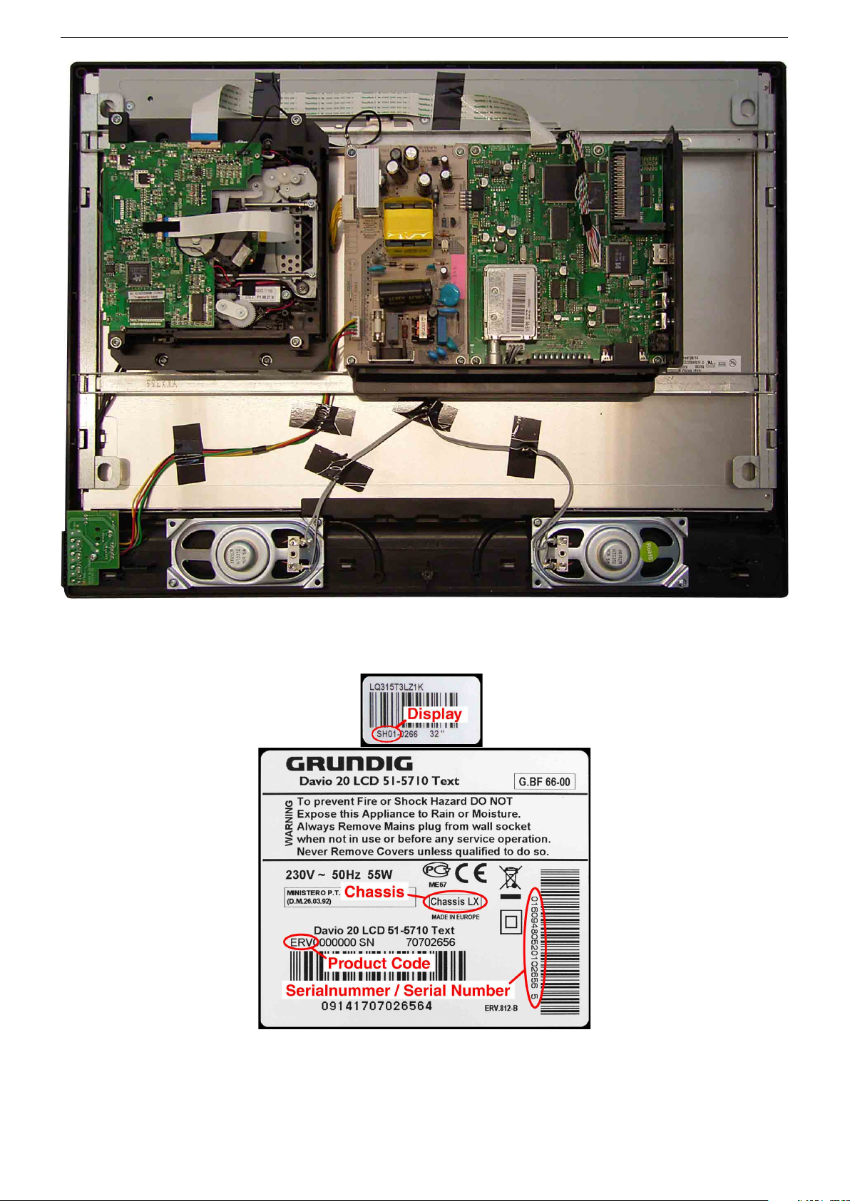
Geräte- und Display-Varianten
Display- und Product Code
Je nach Verfügbarkeit werden
Displays verschiedener Hersteller eingebaut. Dies führt zu unterschiedlichen Chassis-Bestückungen, sowie zu Änderungen in der
Software. Bei Ersatzteilbestellungen und Software-Updates achten Sie bitte auf das eingebaute
Display, sowie auf den "Product
Code". Angaben dazu finden
Sie auf der Geräterückseite.
Sollte in der Ersatzteilliste des
Service Manuals Ihr "Product
Code" oder Ihre Display-Variante
nicht aufgeführt sein, können Sie
eine aktualisierte Version auf
dem GRUNDIG Service-Portal
"http://service.grundig.de" finden.
Überprüfen Sie vor Austausch der
Hauptplatte, ob die Aufkleber der
Platinen identisch sind.
Product and Display Variants
Display- und Product Code
Depending on availability displays
of different manufacturer are built
in. This results in different chassis
mountings as well as a different
software. On spare parts orders
as well as software updates take
care of the fitted display as well as
of the "Product Code". Therefore
you can find information on the
labels on the rear side. If your
"Product Code" or display variant is not mentioned in the spare
parts list of the service manual,
please look for a current version
at the GRUNDIG service portal
"http://service.grundig.de".
Before changing the main board
please check whether the labels
on the boards are identical.
1 - 3
Page 4
GRUNDIG Service Chassis DH
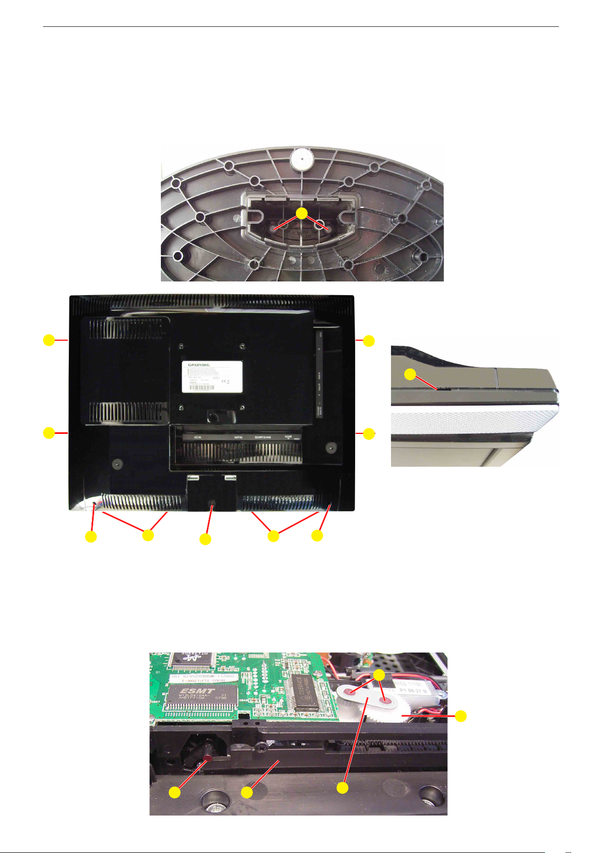
Ausbauhinweise
Rückwand abnehmen
- 2 Schrauben
entfernen.
- Schraube
- 2 Rastnasen
- 8 Rastnasen
- Rückwand nach oben klappen und abnehmen.
A im Gerätefuß (Fig. 1) herausschrauben und Fuß
B (Fig. 2) herausschrauben.
C (Fig. 2) ausrasten.
D (Fig. 2, 3) ausrasten.
Fig. 1
D
Disassembling Hints
Removing the Rear Cabinet
- Undo 2 screws
stand.
- Undo screw
- Disengage 2 latches
- Disengage 8 latches
- Fold up and remove the rear panel.
A fitted in the stand (Fig. 1) and remove the
B (Fig. 2).
C (Fig. 2).
D (Fig. 2, 3).
A
D
Fig. 3
D
Fig. 2
C
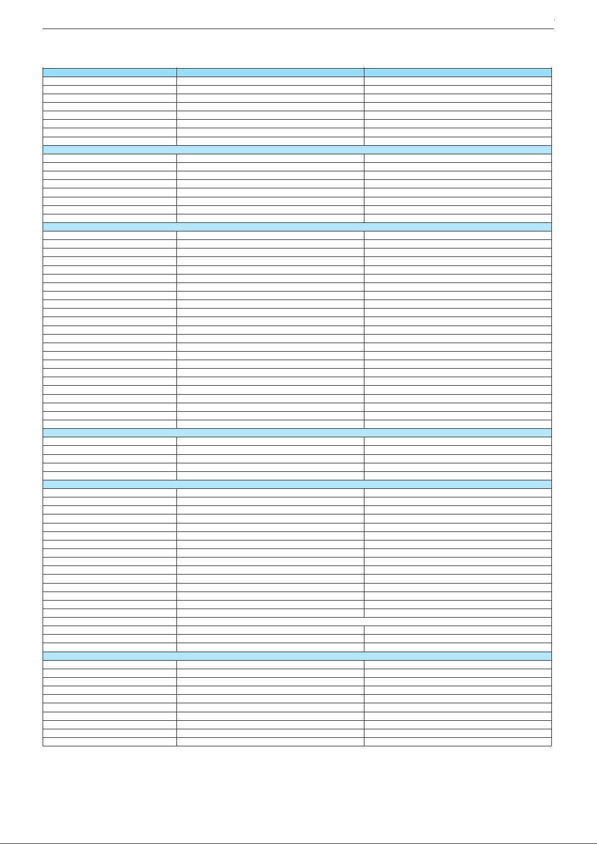
DVD aus Laufwerk entfernen (Fig. 4)
- 2 Schrauben
fernen. Zahnstange H wird auf Grundstellung zurückgezogen.
- Hebel
wird.
- DVD vorsichtig entfernen.
E herausschrauben, Halter F und Zahnrad G ent-
I so in Mittelstellung halten, dass die DVD nicht blockiert
D
B
D
D
D
C
Removing a DVD from the DVD mechanism (Fig. 4)
- Undo 2 screws
rack H will be pulled backwards to its home position.
- Position lever
blocked.
- Carefully remove the DVD.
E and remove holder F and gear wheel G. Gear
I to center position so that the DVD is no longer
Fig. 4
I H
E
G
F
1 - 4
Page 5
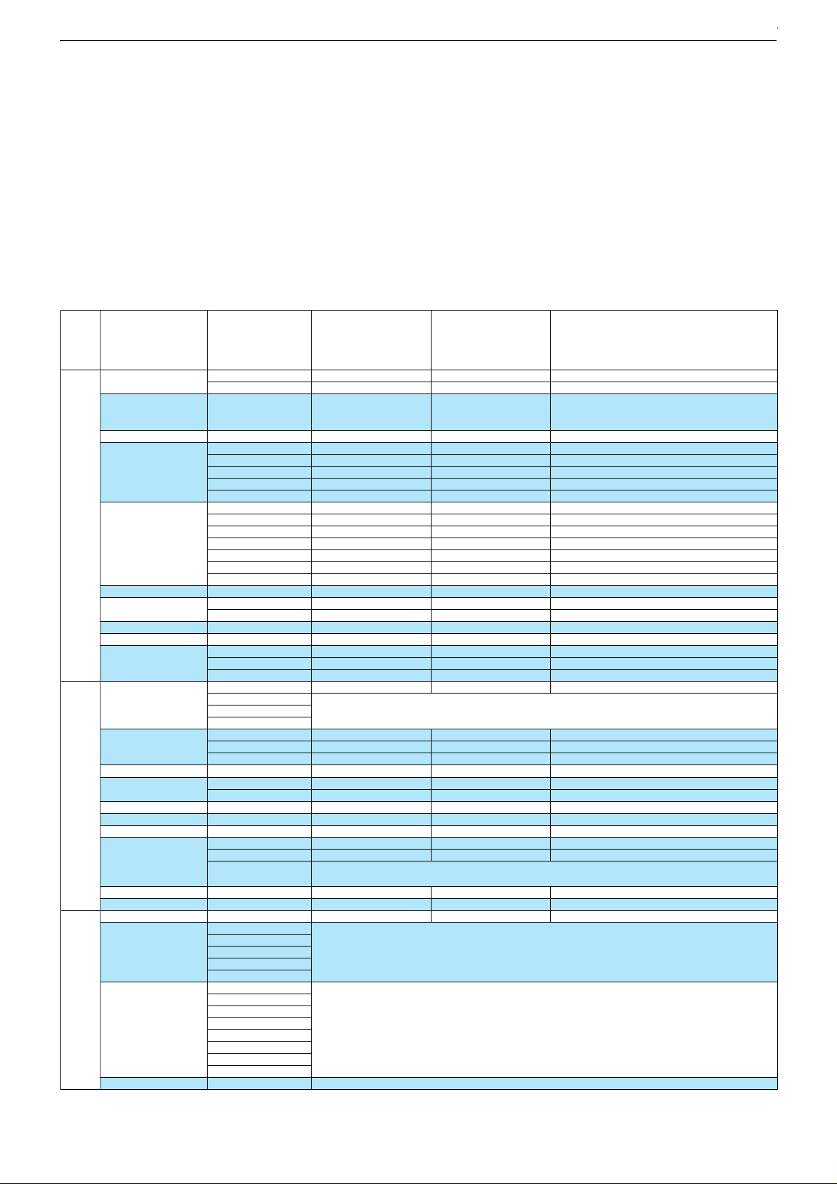
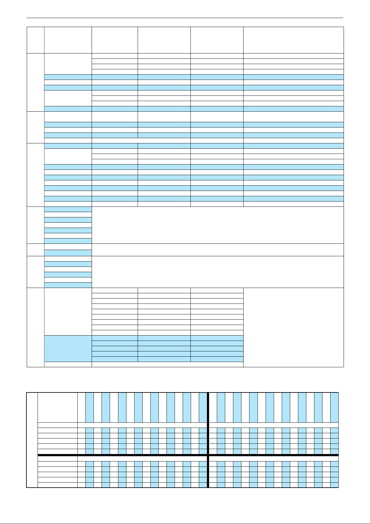
Technische Daten / Technical Data
Chassis SH/SMGRUNDIG Service
Chassis SH/SMGRUNDIG Service
Chassis DHGRUNDIG Service
Order No.
Product Code
Destination
Approbations
IM-Languages
Remote control
EAN
Color
DISPLAY
Panel
Display-Manufacturer
Wide-sreen format
Response time
Brightness
Contrast ratio (Panel) approx.
Viewing angle vertical / horizontal (ca.)
Physical display resolution max. pixel
PICTURE
Motion Compensation
Motion Adaptive Deinterlacing
Natural view HD Reference
Full HD
Line Flicker Reduction
Digital Color Transition Improv. (DCTI)
Digital Combfilter
Digital Luminance Transition Improv. (DLTI)
Picture Noise Reduction
Preset picture modes
Aspect ratios (Format switching)
Blackline detection
PIP
Multifold Tuner scan (Mosaic Picture)
PAT: Split screen (PICTURE + TEXT)
PAP: Double Window (PICTURE + PICTURE)
P2AT: Double Window + TXT
POP: PICTURE on PICTURE
Picture freezing
Zoom with point function
Auto 16:9 selection via Scart
Sharpness control
Blue Background
CHASSIS
TV-Chassis
Progressive
Tuner
Scaler
Keyboard
ELECTRONIC
Stand by indicator
EPG (Electronic Programme Guide)
Easy Dialog
Megalogic
Manual & autom. labeling of prog.
Programmable off timer
Programmable on timer
Intelligent channel search (Zapping funct.)
Programme Edit
Intelligent Programme Switch
Auto switch off
Programme memory TV/AV (opt.)
Teletext/Fasttext/Toptext
Teletext options
Childlock
Menue languages OSD
OSD-style
Service mode
Hotel mode
TUNING
Autom. Tuning System with country selection
Frequency Based Auto Search
Automatic Micro-search
Automatic Programming
Manual fine tuning
Direct channel selection
Direct frequency selection
TV-Norm
NTSC-Playback via Scart (3.58/4.43)
Cable TV / Hyperband (S1-S41)
Vision 2 19-2830 T DVD Vision 2 22-2830 T DVD
G.BH 30-19
Y3R, BLQ
All NSOs
CE,I
D,GB,I,DK,N,S,FIN,E,P
RC 22
40 13833-61683 2
glossy black/silver
G.BH 30-22
Y3S, GBN
All NSOs
CE,I
D,GB,I,DK,N,S,FIN,E,P
RC 22
40 13833-61684 9
glossy black/silver
19" / 49cm Active Matrix TFT-LC-Display 22" / 56cm Active Matrix TFT-LC-Display
BOE
[
ca. 5ms
ca. 300cd/m2
800:1
160° / 160°
AUO
[
ca. 5ms
ca. 300cd/m2
1.000:1
160° / 160°
WXGA 1440 x 900 WSXGA 1680 x 1050
\
2D DeInterlacer
\
\
\
[
[
(2D)
[
[
[
Auto WSS, 4:3 / 14:9 / 16:9 / Letterbox / Subtitle
\
\
\
\
\
\
\
\
\
[
[
[ [
DH
PLL frequency synthesizer tuning
\
MSTAR Maria 5
Auto WSS, 4:3 / 14:9 / 16:9 / Letterbox / Subtitle
PLL frequency synthesizer tuning
\
2D DeInterlacer
\
\
\
[
[
(2D)
[
[
[
\
\
\
\
\
\
\
\
\
[
[
DH
\
MSTAR Maria 5
4 Volume/Programm, ± keys, stand-by 4 Volume/Programm, ± keys, stand-by
blue LED
\
\
\
[
sleep timer
\
\
[
\
\
100 / 5
[
/ [ /
\
8 pages
\
blue LED
\
\
\
[
sleep timer
\
\
[
\
\
100 / 5
[
/ [ /
\
8 pages
\
23 Languages: D, GB, F,I,E,P,NL,GR,TR,DK,FIN,N,S,SI,PL,H,RUS,BG,RO,HR,CZ,SK,SER
OEM-style with Grundig look
[
OEM-style with Grundig look
[
Simple hotel mode possible via service adjustment Simple hotel mode possible via service adjustment
full automatic sorting
[
[
\
[
[
\
PAL/SECAM/BG/DK/I/L'/L
[
[
full automatic sorting
[
[
\
[
[
\
PAL/SECAM/BG/DK/I/L'/L
[
[
1 - 5
1 - 5
1 - 5
Page 6
Chassis SH/SMGRUNDIG Service
Chassis DHGRUNDIG Service
AUDIO
Mono/Stereo/Nicam
AV Stereo
Loudspeaker
SRS
Virtual Dolby
Magic Fidelity Sound System
Matched Sound Delay (Lip synchronous)
Subwoofer
Dynamic Bass
DSP (Digital Sound Processor)
Balance Adjustment
AVL (Audio Volume Level)
PIP listening via Headphone.jack
Equalizer
Space Sound Effect
Audio mode
Audio amplifier
USB
Supported files
File browser
Supported subtitles
Screen saver
DVD
Supported subtitles
Supported files
SVCD
CD-R/+R/-RW/+RW
DVD-R/+R/-RW/+RW
Dolby Digital
DVB reception
DVB-T/S/C
Fully compliant to
Autmatic/manual channel search
EPG (SI based)
- 7 Day Electronic Programme Guide
- now/next
- scheduled
- Exdended Event Info
- Short Event Info
TV/Radio programmes
OSD languages
Parental control
Teletext VBI insertion
VPS - VBI insertion
Programme table
Factory station list
DVB-T Front end
Tuner inputs (Hyperband)
Input frequency (MHz) / Loop through
Input level / Impedance
Modulation
FEC
Hierarchical modulation
Activ antenna support
Embedded Conditional Access
Common Interface
Smart Card Reader
Video Decoder
MPEG profiles
Data rate
Resolution
OSD colors
Picture formats
Audio Decoder
Profiles
AC 3 Decoding
AC 3 Output
Modes
Processor
CPU
RAM
Flash
Software
Service information processing
DVB subtitling
Over air download (OTA)
Navigator
API
Last station memory
Favourite mode
Timer / Sleep timer
Clock
Volume
Mute function
Swap function
Vision 2 19-2830 T DVD Vision 2 22-2830 T DVD
[
/ \ /
\[
[
2 wide band at the front side
\
\
\
\
\
\
\
\
[
\
\
[
\
2x 2.5W (RMS)
/ \ /
\
[
2 wide band at the front side
\
\
\
\
\
\
\
\
[
\
\
[
\
2x 3W (RMS)
MP3, WMA, JPG, MPG, AVI, DivX (3, 4, 5, 6x), Xvid MP3, WMA, JPG, MPG, AVI, DivX (3, 4, 5, 6x), Xvid
[
[
Micro DVD (.sub, .txt), SUbRip (.srt), SAMi (.smi, .sami), Power DivX (.psb), Sub-Station-Alpha (.ssa), Advanced Sub-Station-Alpha (.ass), TMPlayer (.txt)
[ [
Micro DVD (.sub, .txt), SUbRip (.srt), SAMi (.smi, .sami), Sub-Station-Alpha (.ssa), Advanced Sub-Station-Alpha (.ass)
MP3, WMA, JPG, MPG, AVI, Xvid MP3, WMA, JPG, MPG, AVI, Xvid
[
[
[
[
[
[
[
[
retrofitting possible via Scart socket retrofitting possible via Scart socket
EN 300 744 & revided NorDig II spec (regarding DVB-T front end performance)
ATS type sorting & LCN type sorting ATS type sorting & LCN type sorting
[
[
[
If broadcasted
If broadcasted
If broadcasted
899
[
[
[
If broadcasted
If broadcasted
If broadcasted
899
21 Languages: D, GB, F ,I ,E, NL,TR, DK, FIN, N, S, SI, PL, H, RUS, RO, HR, CZ, SK, BG, SER
\
[
PDC based
full automatic sorting
\
[
1
177 - 862 VHF & UHF /
-84,1 dBm to -35 dBm (at 16 QAM 2/3) / 75 Ohm
COFDM 2/8 QPSK 16/64 QAM
\
-84,1 dBm to -35 dBm (at 16 QAM 2/3) / 75 Ohm
COFDM 2/8 QPSK 16/64 QAM
1/2, 2/3, 3/4, 5/6, 7/8
\
[
\
Depends on Terracom approval, implemented according to EN 50221 specification;
Other possible modules - not tested yet: Conax CAM 2.01, 3.03, 4.0 Eurocam - Viaccess V1.20, Professional made by Aston - Irdeto Ver 2.05 (CI), SE
4.60 Ver 2.06 (CI) - Aston Crypt V 1.03, made by Aston - Nageravision 1.2 SCM 2.30 - Crypto Works by Philips - Alpha Crypt - NDS Video guard CI
\ \
Tested modul: Viaccess 1.4 red Label (Sweden);
\
[
PDC based
full automatic sorting
\
[
1
177 - 862 VHF & UHF /
1/2, 2/3, 3/4, 5/6, 7/8
\
[
\
\
MP@ML MP@ML
Up to 15 Mbit/sec.
720 x 576
Fitting to TV-OSD
4:3, 16:9, pan scan, letter box
Up to 15 Mbit/sec.
720 x 576
Fitting to TV-OSD
4:3, 16:9, pan scan, letter box
MPEG 2 layer I & II MPEG 2 layer I & II
\
\
\
\
Mono, Dual Mono, Stereo, Joint Stereo Mono, Dual Mono, Stereo, Joint Stereo
32MB
32MB
32MB
32MB
2MB 2MB
Dynamic PMT
[
DVB enhanced profile
via menu
\
from stand-by, as TV
4x free
\
\
\
[
[
Dynamic PMT
[
DVB enhanced profile
via menu
\
from stand-by, as TV
4x free
\
\
\
[
[
1 - 6
1 - 6
Page 7
Chassis SH/SMGRUNDIG Service
Chassis SH/SMGRUNDIG Service
Chassis SH/SMGRUNDIG Service
Chassis DHGRUNDIG Service
POWER SUPPLY / CABINET
Power voltage
Range of regulation
Power switch
Integrated supply
Plug-in AC adaptor
Power consumption
Cabinet (WxHxD, cm) / Weight
REAR PANEL CONNECTIONS
Euro-AV Socket AV1
Euro-AV Socket AV2
Euro-AV Socket AV3
S-Video
Camera-AV
Wireless
YUV input / progressive
PC-input
PC-Audio in
DVI
HDMI
HD ready including HDCP
Common Interface
USB
Headphones
Digital Audio out coaxial (SPDIF)
Video out
Audio out
Antenna for terrestrial reception
DC-connector
Power supply plug
SUPPLIED ACCESSORIES
Remote control (incl. battery)
Power cord
Cables
Instruction manual
Circuit diagram
Wall fixture
Stand
Vision 2 19-2830 T DVD Vision 2 22-2830 T DVD
230V, 50Hz; in accordance to IEC 65 230V, 50Hz; in accordance to IEC 65
140V - 265V
Tact switch
[
\
45W, standby 1W in accordance to IEC 62087-2002
46.6 x 38.9 x 7.2cm (17.8cm with stand) / ca. 4.1kg
55W, standby 1W
51.8 x 42.0 x 6.7cm (16.0cm with stand) / ca. 4.7kg
140V - 265V
Tact switch
[
\
in accordance to IEC 62087-2002
Full wired Full wired
\
\
\
2x Audio, 1x Video
\
via VGA
WXGA
[
\
1x
via HDMI
1 slot
USB 2.0
\
\
\
\
Coaxial-socket for TV-tuner-in, according to DIN 45325
\
[
Coaxial-socket for TV-tuner-in, according to DIN 45325
\
\
\
2x Audio, 1x Video
\
via VGA
WXGA
[
\
1x
via HDMI
1 slot
USB 2.0
\
\
\
\
\
[
RC 22 incl. 2x Battery AAA size RC 22 incl. 2x Battery AAA size
[
\
[
[
Prepared for VESA standard adaptor 75 x 75
[
Prepared for VESA standard adaptor 75 x 75
[
\
[
[
[
, tilting function
1 - 7
1 - 7
1 - 7
1 - 7
Page 8

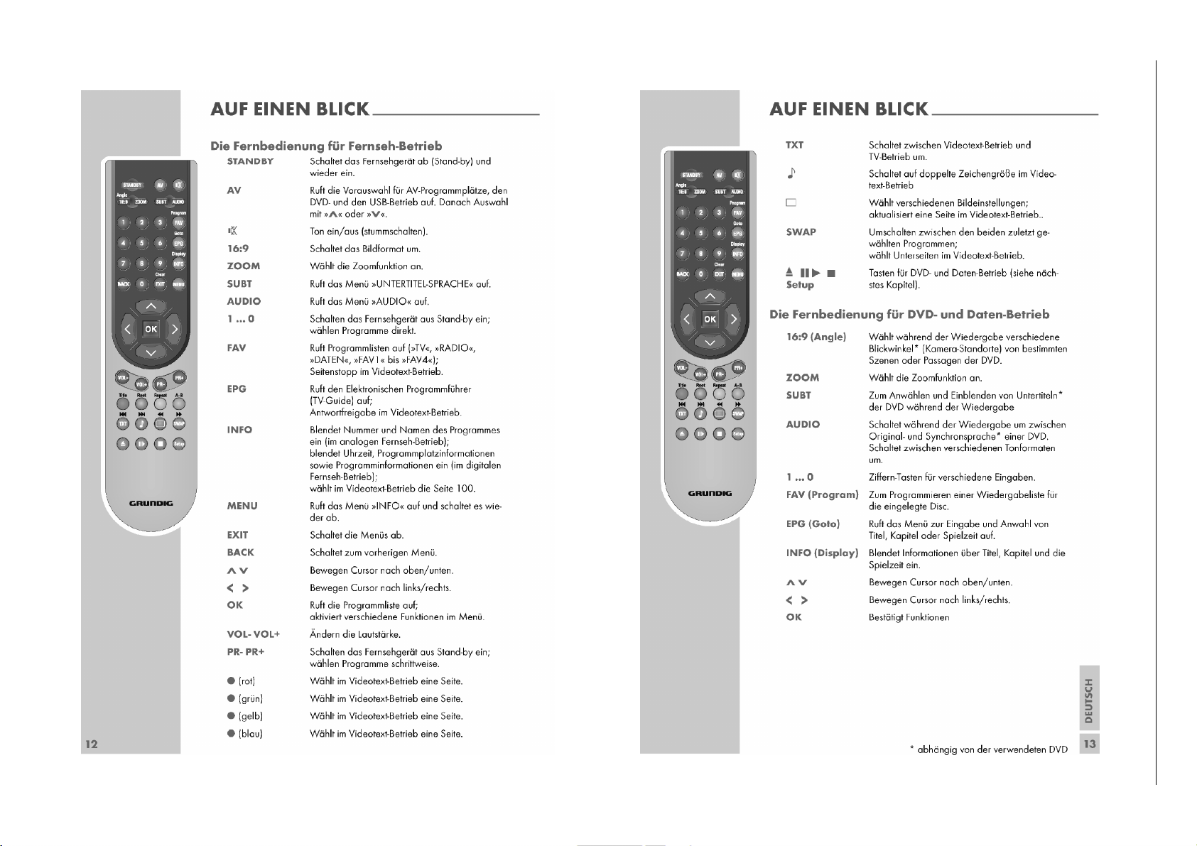
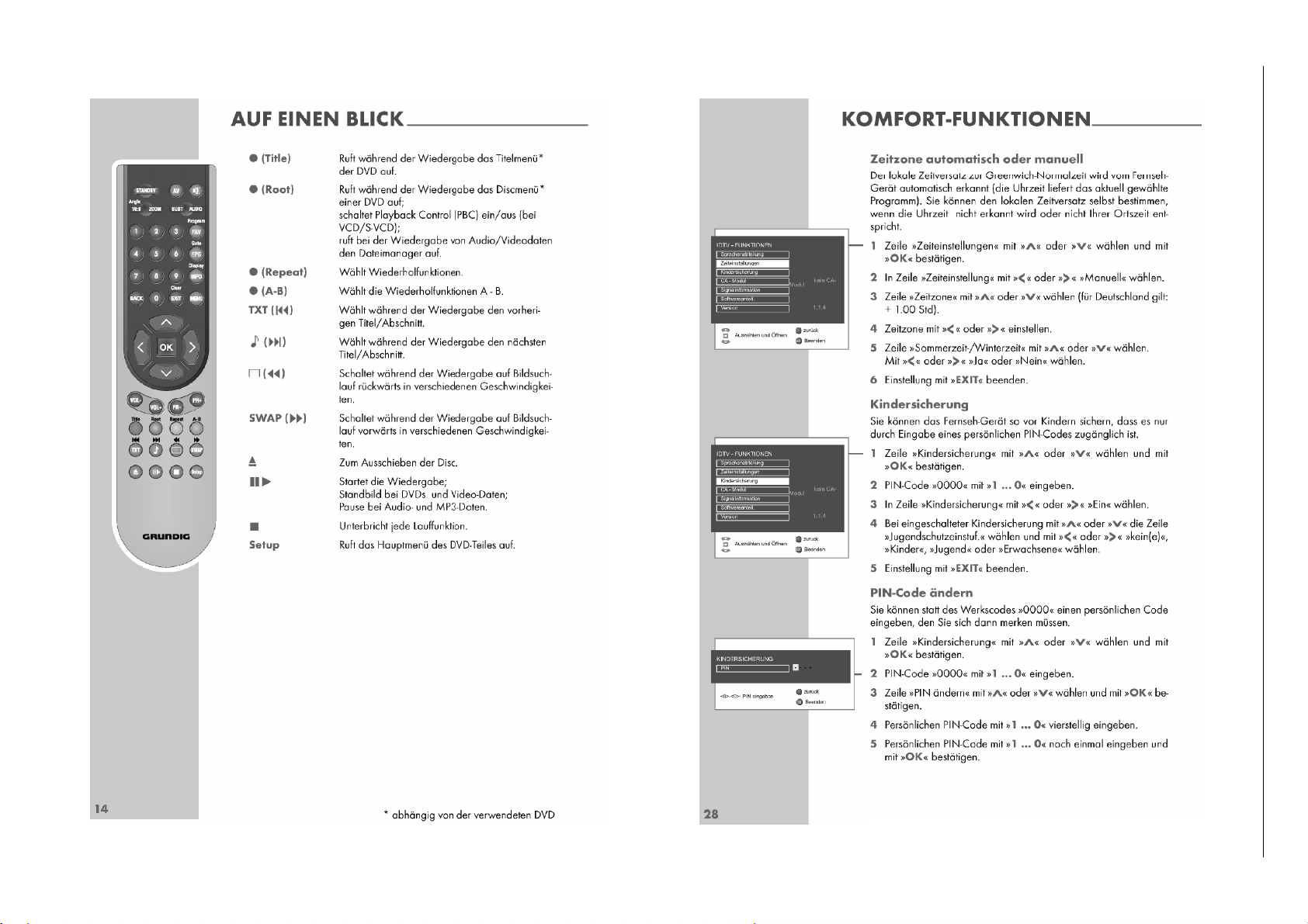
Bedienhinweise Dieses Kapitel enthält Auszüge aus der Bedienungsanleitung. Weitergehende Informationen entnehmen Sie bitte der gerätespezifischen Bedienungsanleitung, die Sie unter
www.grundig.de, Menüpunkt Downloads/Bedienungsanleitungen herunterladen können.
1 - 8
1 - 8
Chassis SH/SMGRUNDIG Service
Chassis DHGRUNDIG Service
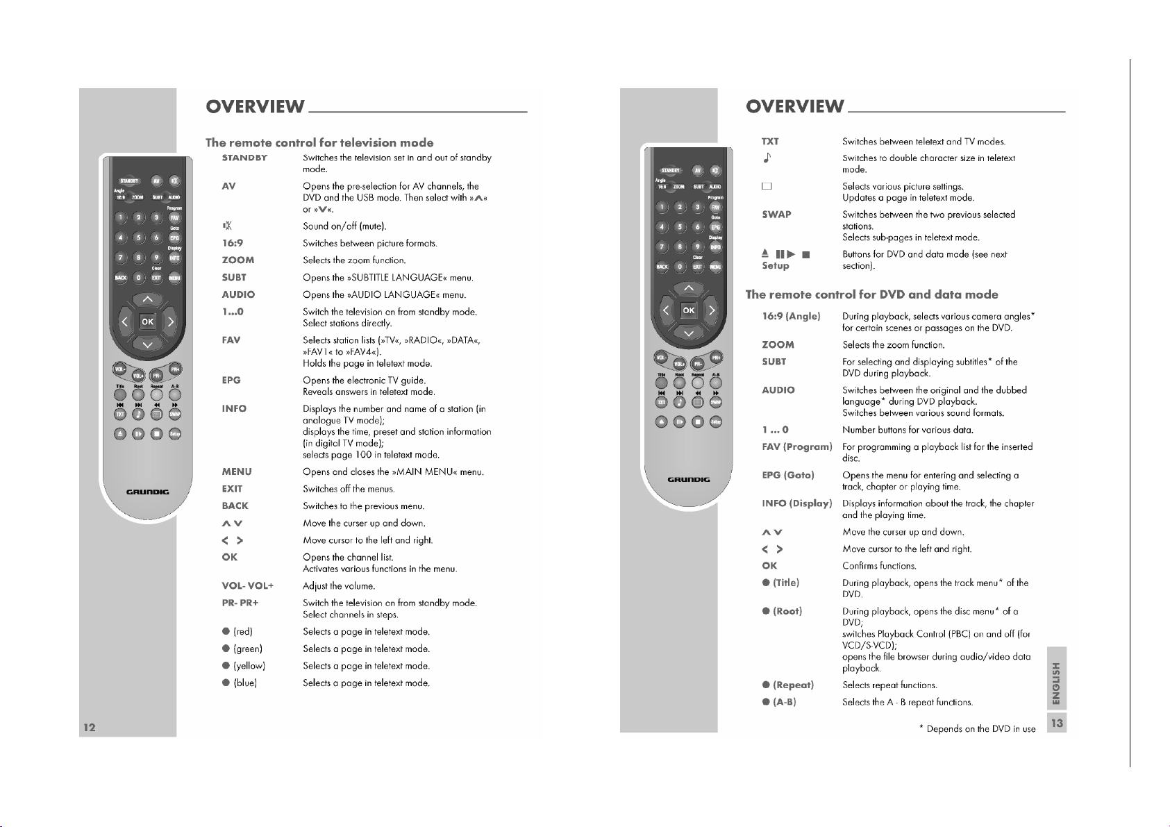
Page 9
1 - 9
1 - 9
1 - 9
Chassis SH/SMGRUNDIG Service
Chassis SH/SMGRUNDIG Service
Chassis DHGRUNDIG Service
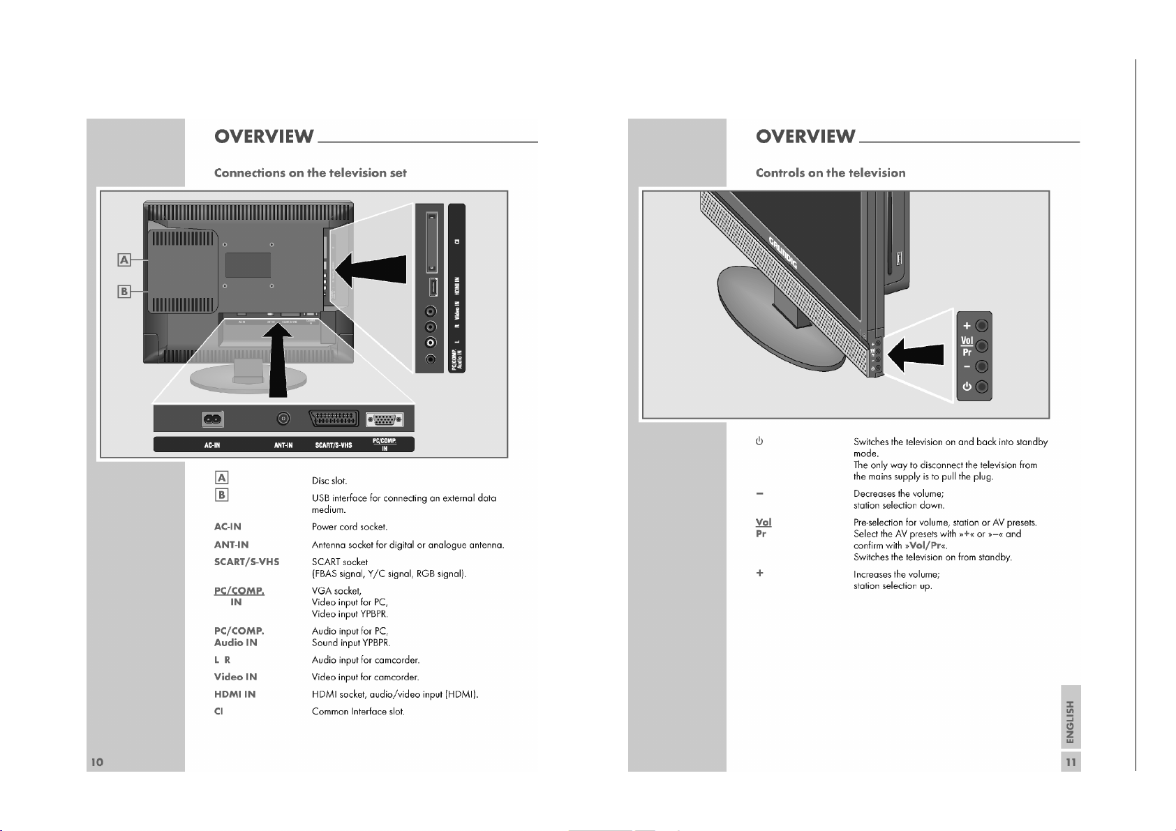
Page 10
1 - 10
1 - 10
Chassis SH/SMGRUNDIG Service
Chassis DHGRUNDIG Service
Hinweis – Kindersicherung:
Mit dem PIN-Code 2005 können Sie die Einstellungen ändern.
Page 11
Operating Hints This chapter contains excerpts from the operating instructions.
For further particulars please refer to the appropriate user instructions which can be downloaded by www.grundig.com, submenu Downloads/Manuals.
1 - 11
Chassis DHGRUNDIG Service
Page 12
1 - 12
1 - 12
1 - 12
Chassis SH/SMGRUNDIG Service
Chassis SH/SMGRUNDIG Service
Chassis DHGRUNDIG Service
Page 13
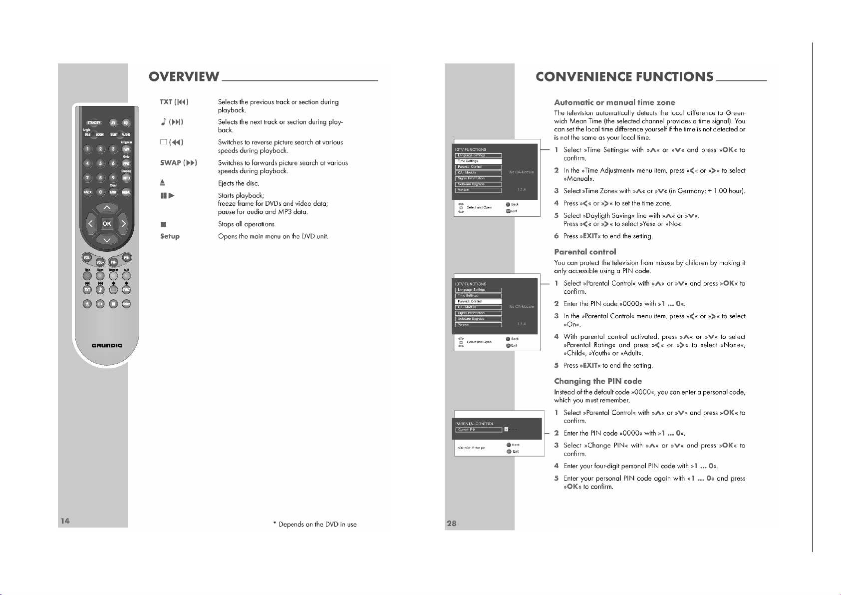
1 - 13
1 - 13
1 - 13
Note – Parental control:
General PIN Code 2005 gives access to enter a new personal
code.
Chassis SH/SMGRUNDIG Service
Chassis SH/SMGRUNDIG Service
Chassis DHGRUNDIG Service
Page 14
prog
g
Chassis L5C-26"…32"GRUNDIG Service
Chassis DHGRUNDIG Service
Service- und Sonderfunktionen
Tastenfunktionen
MENU
3333 4444,
1111 22
MENU
EXIT
Service-Mode aktivieren
– Tast e "
– Zahlenfolge "
Service-Mode beenden
– Tast e "
1. Grundeinstellwerte
Die Grundeinstellwerte im Service Mode sind in der Tabelle enthalten.
Menü
Menu
Aufrufen des Dialog Centers / Menü verlassen
1…9
Menü-Zeile (Menüpunkt) wählen
22
Aufrufen des Menüs, Wert ändern
Menü verlassen
Beenden des Service Mode
MENU
" (INFO) drücken.
8500
" eingeben.
EXIT
" drücken.
Menüpunkt
Point of Menu
44
44
3333 44
0…9
1. OPTIONS I2. OPTIONS II3. VIDEO
3333 44
0…9
1. STANDBY
2. PLUG N PLAY
3. ACT.ANTEN IN MENU
4. TXT TYPE
5. TXT TABLE
6. PROTECTION
7. POWER UP
8. RECALL LAST AV
9. MONITOR FEATURES
0. KEYPAD TYPE
1. LOGO
2. OSD LANGUAGE
3. OSD SIZE
4. CURSER KEYS
5. GAME MODE
6. CLOCK DISPLAY
7. HOTEL HEADPHONE
8. HOTEL TV
9. VOLUME LIMIT
0. HDMI DDC UPDATE
1. BLUEBACK
2. WHITE BALANCE
3. ADC ADJUST
DIMMING 0…255 Maximale Intensität der Hintergrundbeleuchtung einstellen / Set intensity of backlight to maximum
Einstellung
Adjustment
22
1111 22
CUSTOMER
FACTORY
ON/OFF
YES/NO
DEFAULT
FASTEXT
TOPTEXT
FASTEXT TOPTEXT
NO
AUTO
WEST
EAST
CYRILLIC
GREEK
ARABIC
PERSIAN
ON/OFF
LAST STATE
STANDBY
ON/OFF
YES/NO
1 KEY
4 KEY
7 KEY
GRUNDIG
POLAROID
OBL
OEM
GROUP A
GROUP B
GROUP C
X1/X2
VOL-PROG FUNCTION
ONLY CURSER
ON/OFF
ON/OFF
ON/OFF
OFF
SIMPLE
LOCATEL
0…50
ON/OFF
ON/OFF
1. SOURCE TYPE
2. COLOUR TEMP.
3. R GAIN
4. G GAIN
5. B GAIN
1. ADC SOURCE
2. AUTO CALIBRATION
3. R GAIN
4. G GAIN
5. B GAIN
6. R OFFSET
7. G OFFSET
8. B OFFSET
Vision 2 19-2830 T DVD Vision 2 22-2830 T DVD
XX
OFF
YES
XX
XX
ON
X
ON ON
YES YES
XX
X
Nach Auswahl dieserEinstellungen ist der Zugang zum Service Menü nur über die Codezahl 9301 möglich.
After selecting one of these settings, access to the service menu is only possible via code 9301.
XX
X2 X2
XX
OFF
OFF
OFF
X
Nach Anwahl von "LOCATEL" im Service Menu 6. "SOURCE" die Einstellungen "DIGITAL" und "DVD" prüfen.
Check the settin
siehe Punkt 3
see point 3
siehe Punkt 4
see point 4
s "DIGITAL" and "DVD" in service menu 6. "SOURCE" after selecting "LOCATEL".
50
OFF
ON
Service and Special Functions
Functions of the buttons
MENU
3333 4444,
1111 22
MENU
EXIT
Calling up the Service Mode
– Press button "
– Enter the code number "
Exit the Service Mode
– Press button "
1. Basic Settings
The table shows all basic specific settings in the service mode.
Call up the Dialog Center / close down the Menu
1…9
Call up the dialogue line (point of menu)
22
Call up the Menus, Changing the settings
Close down the Menu
Exit the Service Mode
MENU
" (MAIN MENU).
8500
".
EXIT
".
ATS Reset (ON)
OFF
YES
ON
X
X
OFF
OFF
OFF
X siehe Punkt 8 / see point 8
50
OFF
ON
Netz ein –> Automatischer Sendersuchlauf
Power on –> automatic
siehe Punkt 8 / see point 8
Hinweis
Hint
ramme search
1 - 14
1 - 14
Page 15
Chassis DHGRUNDIG Service
Menü
Menu
44
3333 44
0…9
4. AUDIO5. TUNING6. SOURCE7. PRESET
8.
NVM
9. INFO0. USER DEFAULTS
Menüpunkt
Point of Menu
44
3333 44
0…9
1. BG
2. DK
3. I
4. L
5. AUDIO POWER2W2.5W
6. AUTO MUTE
1. ATS SORTING
2. AGC VHF
3. AGC UHF
4. AGC L PRIME
5. TUNER TYPE
1. ANALOG
2. DIGITAL
3. DVD
4. USB
5. SCART
6. SCART-SVHS
7. AV
8. HDMI
9. YPBPR
0. PC
1. USER
2. PROGRAMME TABLE
3. PC MODES
4. WHITE BALANCE
5. ADC
6. SERVICE
7. ALL
NVM ADDR. HEX
EDIT
NVM DATA HEX
EEPROM
TUNER
IF
AUDIO
DTV
HDCP KEY
DEFAULT SETTINGS 1
DEFAULT SETTINGS 2
DEFAULT SETTINGS 3 siehe Punkt 2 / see point 2 (Default Settings 3)
Einstellung
Adjustment
22
1111 22
EU
NEW
AUS
OFF
ON/OFF
ON/OFF
ON/OFF
3W
ON/OFF
ON/OFF
0…31
0…31
0…31
Eingebauten Tuner wählen / Select used tuner
YES/NO
EUROPE
UK
NO
YES/NO
YES/NO
YES/NO
YES/NO
YES/NO
YES/NO
YES/NO
YES/NO
Achtung: Kunden- und Gerätespezifische Einstellwerte werden gelöscht und mit Grundwerten geladen.
Attention: Erases the customer and set specific values and loads the default values.
siehe Punkt 9
see point 9
Prüft über das Bus-System die Kommunikation mit den jeweiligen Komponenten.
Checks the communication to the components via the bus system.
1. VOLUME
2. BASS
3. TREBLE
4. BALANCE
5. SOUND MODE
6. RED
7. GREEN
8. BLUE
9. ACTIVE ANTENNA
1. IF SOURCE IS
2. PICTURE MODE
3. COLOUR TEMP.
4. DNR
5. CCE
Vision 2 19-2830 T DVD Vision 2 22-2830 T DVD
XX
ON ON
ON
ON
X
ON
ON
14
14
14
YES YES
XX
YES YES
NO
YES
YES
YES
YES
YES
YES YES
16
15
15
25
NORMAL
128
128
128
OFF
ANALOG
RICH
NORMAL
LOW
ON
ON
ON
X
ON
ON
14
14
14
NO
YES
YES
YES
YES
YES
16
15
15
25
NORMAL
128
128
128
OFF
ANALOG
RICH
NORMAL
LOW
ON
Programmsortierung bei Programmsuchlauf
Programme sorting at autoprogramme operation
Diese Grundeinstellwerte wirken sich nur aus wenn Sie
die Grundwerte USER laden.
The user default settings are only activ when you load
the presets USER.
(siehe / see 7. PRESET –> 1. USER).
Hinweis
Hint
2. Default Settings 3 2. Default Settings 3
1. SOURCE TYPE
TUNER 50HZ
CVBS 50HZ
SVHS 50HZ
RGB 50HZ
DIGITAL
DVD
HDMI SD
YPBPR SD
PC
TUNER 60 HZ
CVBS 60HZ
SVHS 60HZ
RGB 60HZ
HDMI/DVI
HDMI HD
YPBPR HD
TUNER 50HZ
CVBS 50HZ
16
124
138
50
SVHS 50HZ
120 120
96
12196121
501650
16
114
114
140
130
16150161
50
45 45
2. IF PICT. MODE IS
3. BRIGHTNESS
4. CONTRAST
5. COLOUR
6. TINT
7. SHARPNESS5028
2. IF PICT. MODE IS NATURAL
DEFAULT SETTINGS 3
3. BRIGHTNESS
4. CONTRAST
5. COLOUR
6. TINT
7. SHARPNESS 28
130 128 118 118 118
124
124
122
116
129
28
118
122
50
122
129
129
502850
28
118
118
116
122
12950129
50
28 28
128
130
124
128
50
128
502850
128
124
12850129
28 28
114 110
126
114
128
128
502850
28
114
110
114
126
12850128
50
28 28
USER
114 112
114
128
502850
114
114
12850128
28 28
101
128
28
112
101
50
130 128
124
124
128
128
502850
28
130
128
124
124
12850128
50
28 28
118 118
122
116
129
129
502850
28
118
118
122
116
12950129
50
28 28
110 110
126
128
502850
110
126
12850128
28 28
1 - 15
126
128
28
110
126
50
114
114
128
50
28
114
114
128
50
28
132 130
96
12096120
501650
126
142
16050160
45 45
RGB 50HZ
DIGITAL
DVD
120 123
96
12196120
501650
16
114
106
140
125
16150161
50
45 61
HDMI SD
SOFT
123 123
96
12096120
501650
16
126
116
142
128
16050161
50
61 61
YPBPR SD
PC
115 132
88
12096120
501650
16
RICH
120
126
106
142
16050160
50
61 45
TUNER 60 HZ
CVBS 60HZ
SVHS 60HZ
130 120
120 123
96
96
12096121
12196120
501650
501650
16
124
114
114
138
140
130
16050161
16150160
50
45 45
45 61
RGB 60HZ
HDMI/DVI
HDMI HD
123 123
96
12096120
501650
16
126
126
142
142
16050161
50
61 61
YPBPR HD
16
116
128
50
Page 16

Chassis DHGRUNDIG Service
3. Weißabgleich (WHITE BALANCE)
Für alle Eingangssignale sind die Farbtemperaturen NORMAL,
WARM und COOL getrennt einstellbar.
– Weiss-Testbild am gewünschten Eingang einspeisen und diese
Quelle mit den Tasten "
– Tast e "
MENU
" (INFO) drücken und Zahlenfolge "
– Grundwerte laden: Tasten
mit Taste "
– Tasten
BACK"
3
und
2 nacheinander drücken.
– Signalquelle "SOURCE TYPE" mit den Tasten
– Ta st e 2 drücken und mit den Tasten
AV" 3333 4444 anwählen.
7 ,4
beenden.
8500
und
2222 nacheinander drücken und
" eingeben.
1111 2222 wählen.
1111 2222 die gewünschte Farb-
temperatur wählen.
3
– Mit den Tasten
ander anwählen und mit den Tasten
"R GAIN", 4 "G GAIN" und 5 "B GAIN" nachein-
1111 2222 nach Testbild abglei-
chen.
4. Analog-Digital-Wandler (ADC ADJUST)
Für die Eingangssignale SCART-RGB, PC und YPBPR ist der Analog-Digital-Wandler getrennt einstellbar.
– Grautreppen-Testbild am gewünschten Eingang einspeisen und
diese Quelle mit den Tasten "
– Tast e "
MENU
" (INFO) drücken und Zahlenfolge "
AV" 3333 4444 anwählen.
8500
" eingeben.
– Tasten 3 und 3 nacheinander drücken.
– Signalquelle "ADC SOURCE" mit den Tasten
– Ta st e 2 drücken und mit der Taste
2222 den automatischen Abgleich
1111 2222 wählen.
starten.
– Gegebenenfalls das Grautreppen-Testbild unbunt nachgleichen.
Dazu mit den Tasten 3…8 die Menüzeilen "RGB GAIN" und "RGB
OFFSET" anwählen und jeweils mit den Tasten
1111 2222 abgleichen.
5. Austausch der Hauptplatte oder des IC201
Nach dem Austausch der Hauptplatte oder des IC201 sind die
Grundeinstellwerte im Service Mode entsprechend der Tabelle zu
prüfen.
6. Software-Versionsnummern
6.1 Geräte-Software
Die Software-Versionsnummer der Gerätesoftware wird unten im
Service-Menü angezeigt, z.B.:
SW VERSION : SDH22W-AU2-T64-S0 GRUNDIG
6.2 DVB-T-Software
AV
– Tast e "
– "DIGITAL" mit den Tasten
" drücken.
3333 4444
anwählen und mit der Taste "OK"
bestätigen.
MENU
– Tast e "
– "SONDERFUNKTIONEN" mit den Tasten
der Taste "
– "DIGITALE FUNKTIONEN" mit den Tasten
mit der Taste
– Zahlenfolge "
" (INFO) drücken.
3333 4444
OK
" bestätigen.
anwählen und mit
3333 4444 auswählen und
2222 aufrufen.
9301
" eingeben. Anschließend werden alle geräte-
spezifischen Versionsnummern angezeigt.
EXIT
– Zum Beenden der Anzeige die Taste "
" drücken
7. Programmsuchlauf
– Tast e "AV" drücken.
3333 4444
– "DIGITAL" oder "ANALOG" mit den Tasten
anwählen und mit
der Taste "OK" bestätigen.
– Tast e "
– "SUCHEN / ABSTIMMUNG" mit den Tasten
MENU
" (INFO) drücken.
3333 4444
anwählen und
mit der Taste "OK" bestätigen.
– "PROGRAMMSUCHLAUF" (analog) / "AUTOMATISCHE SU-
3333 4444
CHE" (digital) mit den Tasten
"
OK
" bestätigen.
– Gewünschtes Land mit den Tasten
anwählen und mit der Taste
3333 4444
1111 2222 auswählen und mit
der Taste "OK" bestätigen.
Das automatische Sendersuchsystem stoppt bei jedem empfangswürdigen Sender (AFC und Koinzidenz) und speichert automatisch die entsprechenden Senderdaten mit dem jeweiligen
Standard. Danach wird der Suchlauf fortgesetzt.
MENU
– Zum Abbrechen des Suchlaufes die Taste "
EXIT
" (digital) drücken.
"
" (analog) /
3. White Balance
The colour temperatures NORMAL, WARM and COOL are adjustable for all input signals.
– Fit in a white test pattern at the desired input and select it with
8500
".
AV" 3333 4444.
MENU
" (MAIN MENU) and enter the code number
7 ,4
and
BACK
".
3
and 2 step by step.
2
and adjust the white balance with buttons
3
"R GAIN", 4 "G GAIN" und 5 "B GAIN" step
1111 2222
2222 step by step and con-
22
1111 22
.
according to test pattern.
1111 2222.
buttons "
– Press button "
"
– Load Presets: Press the buttons
firm it with button "
– Press the buttons
– Select SOURCE TYPE with buttons
– Press button
– Select with buttons
by step and adjust with buttons
4. Analogue Digital Converter (ADC ADJUST)
The analogue digital converter is seperately adjustable for the input
signals SCART-RGB, PC and YPBPR.
– Fit in a grey scale test pattern at the desired input and select it
with buttons "AV"
– Press button "
"
8500
".
3333 4444.
MENU
" (MAIN MENU) and enter the code number
– Press the buttons 3 and 3 step by step.
– Select "ADC SOURCE" with buttons
– Press button 2 and
2222 to start the automatic adjustment.
1111 2222.
– If necessary, readjust to an achromatic grey scale test pattern.
Select the menu lines "RGB GAIN" and "RGB OFFSET" with buttons
3…8
and adjust with buttons
1111 2222.
5. Change of the Main Board or IC201
After changing the Main Board or IC201 all basic settings in the service mode must be checked according to the table.
6. Software Version Numbers
6.1 TV Software
The software version number of the TV software is shown on the lower part of the service menu, e.g.:
SW VERSION : SDH22W-AU2-T64-S0 GRUNDIG
6.2 DVB-T Software
AV
– Press button "
– Select "DIGITAL" with the buttons
".
3333 4444 and confirm with button
"OK".
– Press button "
– Select "FEATURES" with the buttons
MENU
" (MAIN MENU).
3333 4444 and confirm with button
"OK".
– Select "DIGITAL FEATURES" with the buttons
with button
– Enter the code number "
2222.
9301
". All version numbers of the TV set
3333 4444 and call up
are shown on the screen.
– Pressing the button "
EXIT
" closes the software report.
7. Programme Search
AV
– Press button "
– Select "DIGITAL" or "ANALOG" with the buttons
".
3333 4444 and confirm
with button "OK".
– Press button "
– Select "SETUP" with the buttons
MENU
" (MAIN MENU).
3333 4444 and confirm with button
"OK".
– Select "AUTOPROGRAM" (analogue) / "AUTO SEARCH" (digital)
3333 4444
with the buttons
– Select the required Country with the buttons
and confirm with button "OK".
3333 4444
1111 2222 and confirm
with button "OK".
The auto programme system stops at every station of acceptable
reception quality (AFC and coincidence) and stores the station
data and the respective standard automatically. The system then
continues searching.
– Pressing the button "
" (analogue) / "
EXIT
" (digital) button
MENU
stops the programme search.
1 - 16
Page 17

Chassis DHGRUNDIG Service
8. Hotel-Mode
Bei aktivierter Funktion ist die maximale Lautstärke begrenzt und
"PROGRAMM BELEGUNG" sowie "SUCHEN/ABSTIMMUNG" sind
im INFO MENU nicht mehr anwählbar.
Hotel-Mode aktivieren:
MENU
–> "
8500
" –> 2"OPTION II" –> 8 "HOTEL TV" –>
22
"SIMPLE". Wird versehentlich die 3. Einstellmöglichkeit "LOCATEL"
angewählt, sind DVB-T und der DVD Player deaktiviert. Zum reaktivieren im Service Unter-Menü "SOURCE" die Einstellung "DIGITAL"
mit
2222 auf "EUROPE" und "DVD" mit
Hotel-Mode deaktivieren:
MENU
–> "
8500
" –> 2"OPTION II" –> 8 "HOTEL TV" –>
Maximale Lautstärke:
MENU
–> "
8500
" –> 2"OPTION II" –> 9 "VOLUME LIMIT" –>
2222 auf "YES" stellen.
1111 "OFF".
1111 22
Wert 0…50.
9. NVM EDIT
Diese Funktion ist ausschließlich für die Entwicklung und darf nur
nach besonderer Aufforderung verwendet werden. Bei falschen Eingaben sind die Gerätefunktionen nicht mehr gewährleistet.
8. Hotel Mode
Maximum volume is limited and there is no access to "PROGRAM
TABLE" and "SETUP" of the main menu at activated hotel mode.
Activate Hotel Mode:
22
MENU
–> "
8500
22
"SIMPLE". If - accidentally - the third possible setting "LOCATEL" is
" –> 2"OPTION II" –> 8 "HOTEL TV" –>
22
selected, DVB-T and the DVD player are deactivated. To reactivate
both in the service submenu "SOURCE" set "DIGITAL" to "EUROPE" and "DVD" to "YES" by button
Deactivate Hotel-Mode:
MENU
–> "
8500
Maximum volume:
MENU
–> "
22
–>
8500
1111 2222 Wert 0…50.
" –> 2"OPTION II" –> 8 "HOTEL TV" –>
" –> 2"OPTION II" –>
2222.
11
11
"OFF".
22
111122
–> 9 "VOLUME LIMIT"
9. NVM EDIT
This function is only for development and is only allowed to use by
special demand. Any incorrect settings may cause a defectiv set.
1 - 17
Page 18

1 2
L301 NC
32
T300
PMV65XP
C305
1uF
C301
NC
1 2
L300 60R/100Mhz
R304
10K
R312
NC
C300
100nF
R305
(22K)
VCC5V
VCC3.3V
VDDD
GND
GND
VCC3.3V
VDDDCTRL
VBLCTRL
BRIGHTNESS
VDDDCTRL-Hi: VDDD = ON
VDDDCTRL-Lo: VDDD = OFF
D300
STPS340U
C309
4.7uF/16V
C313
22uF/6.3V
VCC3.3V
GND
C310
22uF/6.3V
C318
1uF
+5V
+5V
C306
NC
VCC2.5V
Vcc2.5V
VCC3.3V
GND
R317
100R
R318
NC
C311
100nF
C307
2.2uF/6.3V
ADJ
1
VOUT
2
VIN
3
TAB
4
IC300
NCP1117DTARK
VCC1.5V
GND
GND
VDD9V
STANDBY
R309
4.7K
GND
VCC5V
R310
4.7K
1 2
L302 NC/15"
VDD12V
GND
R306
2.2K
112
2
334
4
556
6
778
8
9910
10
S302
POWER
VDD12V
GND
KEY0
IR_INT
LED
KEYPAD&POWER
DIM
BL ON/OFF
R308
1K
VCC3.3V
R314
(4.7K)
VCC3.3V
GND
+5V
C323
22uF/6.3V
GND
VCC5V
C308
1uF
VCC1.2VVCC3.3V
R316
0R
VCC5V
R320
120R
R321
22R
Vcc1.5V
Vcc1.2V
R325
330R
GND
Vcc3.3V
C302
10uF
C304
1uF/16V
GNDGND
R327
2k
GND
C317
1uF
GND
STANDBY: L-ST.BY, H-Power ON
VDD12V_A,VDD9V
R324
22k
GND
STANDBY
VDD12V
STANDBY: L-ST.BY, H-Power ON
1
32
T308
PMV65XP
VDD12V_A
C217
220uF/16V
GND
R332
NC
VDD12V
L304
120R/100Mhz
L305
NR3015T1RON
C319
NC
GND
VCC3.3V
L302
VCC5V2
L306
VDDD
5V PANEL 3.3V PANEL
350mA120mA(+350mA)
450mA
1A for >19"W
C314
22uF/6.3V
C312
100nF
ADJ
1
VOUT
2
VIN
3
TAB
4
IC303
NCP1117DTARK
GNDGND
1,5A for <19"W
C316
22N
C315
100nF
C320
NC
GND
GND
R334
7.5K
R322
10K%1
R319
15K%1
GND
R333
2.7K%1
C321
10nF
C322
NC
GND
GND
L303
10uH
BS
1
VIN
2
OUT
3
GND
4
FB
5
COMP
6
EN
7
SS
8
GND
9
IC304
MP1593/CAT7106
GND
GND
C324
220uF/16V
GND
ADJ
1
VOUT
2
VIN
3
TAB
4
IC302
NCP1117DTARK
GND
R340
(33k)
R339
(220K)
VDD12V
C325
NC
GND
C617
22uF/6.3V
30V_PWM
GND
D306
GND GNDGND
21
3
D301
BAV99
GND
+33V
21
3
D302
BAV99
VDD12V
30V_PWM
C327
22nF
C326
22nF
C329
220nF/50V
C330
220nF/50V
C328
220nF/50V
R300
1k
R301
100k
Only for IDTV
Only For Analog
1
3 2
T306
PMV56XN
VCC2.5V
Pd=0.4W
300mA
50mA
1
1
2
2
334
4
5
5
6
6
T303
PBLS4003D
VCC3.3V
R303
680R
VCC3.3V_D
R302
NC
+5V
1
32
T301
2N7002
1
32
T302
2N7002
1
3
2
T304
2N7002
1
3
2
T309
2N7002
1
1
2
2
334
4
5
5
6
6
T305
PBLS4003D
R311
680R
R307
NC
VCC3.3V
200mA
R313
NC
VCC5V
VCC3.3V_D
+33V
C303
NC
2
3
1
IC301
ZTL431AFFTA
VCC5V2
GND
C331
1uF/16V
GND
+0.6A for DMP
1
1
2
2
334
4
5
5
6
6
T307
PBLS4003D
VCC1.2V
+5V
50mA
VCC1.2V_D
VCC1.2V_D
R328
NC
R329
680R
1 2
L306 60R/100Mhz
VCC5V2
GND
L307
NR3015T1RON
C332
22uF/6.3V
C333
1uF
GND
C334
22uF/6.3V
GND
C335
10nF
C336
10nF
GND
GND
H300
H301
H302
MONTAGE HOLE
H303
GND
MONTAGE HOLE
MONTAGE HOLE
MONTAGE HOLE
1
1
MP1593
3A, 28V, 385KHz
STEP-DOWN CONVERTER
LOCKOUT
COMPARATOR
ERROR
AMPLIFIER
FREQUENCY
FOLDBACK
COMPARATOR
INTERNAL
REGULATORS
1.8V
SLOPE
COMP
CLK
CURRENT
COMPARATOR
CURRENT
SENSE
AMPLIFIER
SHUTDOWN
COMPARATOR
SS
8
COMP
6
IN
2
EN
7
GND
4
OSCILLATOR
40/385KHz
SRQ
SW
3
BS
M1
M2
1
5V
+
Q
0.7V
+
+
2.3V/
2.6V
+
1.22V0.7V
+
+
FB
5
--
--
--
--
--
--
1
Platinenabbildungen und Schaltpläne / Layout of PCBs and Circuit Diagrams
Chassis – Netzteil / Power Supply
GRUNDIG Service Chassis DH
2 - 1
Page 19

1B
1
1C
2
2B
3
2C
4
3B
5
3C
6
4B
7
4C8GND
9
4A
10
3A
11
2A
12
1A
13
S
14
OE_N
15
VCC
16
IC800
STMAV340
1
2
3
4
5
6
7
8
9
10
11
12
13
14
15
16
032953R
S800
CON16
DMP_Pb
DMP_Pr
DMP_AL_IN/OUT
DMP_AR_IN/OUT
IR_INT
VCC5V
DMP_SEL
DMP_SEL: L- DMP, H- IDTV
DMP_AL_IN/OUT
DMP_AR_IN/OUT
IR_INT
C801
1uF
GND
GND
R800
10k
RX
TX
NC/0R
R802
NC/0R
C800
1uF
C802
1uF
GND GND
SW_R+
SW_B+
No DMP
R804
0R
R803
0R
RX_MST
TX_MST
DVD OFF
RX_DMP
TX_DMP
C803
100nF
R805
10K
R809
10K
DMP 600mA
Power for DMP/DVD
DMP_Y
R807
75
R806
75
R808
75
GND
D_G
D_R
D_B
SW_G+
X0
12
X1
13
Y1
1
Y0
2
A
11
Z0
5
Z1
3
Z
4
EN
6
B
10
C
9
X
14
Y
15
VDD
16
VEE
7
VSS
8
IC801
MC14053BDTR2
GND
GND
VCC3.3V
VCC3.3V
L803 60R/100Mhz
L802 60R/100Mhz
L801
60R/100Mhz
VDD12V_A
UART_SW
DVD 15mA
R801
10K
UART_SW: L-DMP, H-IDTV
VCC3.3V
VCC3.3V
VCC5V2
VDD12V_A
C804
NC
GND
1
32
T800
PMV56XN
DMP_Y
DMP_Pb
DMP_Pr
L800
60R/100Mhz
DVD900mA
DVD
L800L801
DMP 500mA
1
32
T801
PMV56XN
1
3
2
T802
2N7002
DMP
T800T801
NC
NC NC
No
Yes
Yes Yes
Yes
C805
NC
GND
GND
DVD_5VDVD_5V
L804
NC/60R/100Mhz
L805
60R/100Mhz
VCC5V
C431
100nF
C437
100nF
C441
100nF
R811
0R
R810
0R
36
37
38
39
40
‚
fl
‡
°
·
Chassis – DVD/DMP-Interface
2 - 2
GRUNDIG Service Chassis DH
Page 20

GRUNDIG Service Chassis DH
D_RXD
SC_CVBS1
D_HS
D_VS
D_SCL
D_G+
D_TXD
D_SDA
D_R+
D_B+
SC_G+
D_R+
D_B+
D_G+
R417
10K
R420
0R
R432
1.5K
C415
100pF
R444
4.7K
C433
22pF
R401
75R
C417
NC
R405
0R
NC1
1
NC2
2
NC3
3
GND4SDA
5
SCL
6
VCLK
7
VCC
8
IC401
24C02
C407
NC
R435
0R
C412
NC
C400
100nF
C429
100nF
C434
100nF
R411
75R
1
6
2
7
3
8
4
9
5
11
12
13
14
15
10
16
17
S402
VGA
C432
100nF
C401
47p
R442
4.7K
R448
NC
R439
75R
R436
0R
R402
75R
R408
75R
C430
100nF
C411
100nF
C406
100nF
R423
75R
R400
0R
3
1
2
D401
BAV70
R438
60R/100MHz
R443
4.7K
R419
2.7K
C435
22pF
C416
100nF
R414
0R
R434
1.5K
R433
470R
R416
75R
GND
GND
GND
GND
GND
GND GND
VGA5V
GND
GND
GND
GND
GND
VGA5V VCC5V
VSYNCIN
VIDEO_SEL
RGB_SEL
SOG HSYNCIN
SC_LI
SCL_TXD
SC_RI
B_INP
R_INP
G_INM
G_INP
DSUB_RGB IN
SCART
IN
SC_CVBS_OUT
SC_B+
SC_R+
R447
75R
C439 100nF
C436
100nF
R446
60R/100MHz
R441
60R/100MHz
R445
75R
GND
GND
SC_LO
SC_RO
SDA_RXD
SC_RO
SC_LO
SC_CVBS_OUT
R413
100R
R412
100R
TX_Scart
RX_Scart
R440
NC
R437
NC
2
4
6
8
10
12
14
16
18
20
1
3
5
7
9
11
13
15
17
19
21
22
23
S400
SCART
GND
R431
75R
SC_CVBS_OUT
+5V
L400
0R
C428
47p
C427
NC
GNDGND
C419
1uF
GND
R425
1R
CVBS_OUT
RX2+
1
GND2
2
RX2-
3
RX1+
4
GND1
5
RX1-
6
RX0+
7
GND0
8
RX0-
9
CLK+
10
GND_CLK
11
CLK-
12
CEC
13
N.C.
14
SCL
15
SDA
16
CEC_GND
17
5V
18
HP_DETECT
19
20
2122
23
S403
HDMI
GND
GND
GND
GND
GND
GND
GND
HDMI_RX2+
HDMI_RX2-
HDMI_RX1-
HDMI_RX0+
HDMI_RX1+
HDMI_RX0-
HDMI_CLK+
HDMI_CLK-
HDMI_SDA
HDMI_SCL
HDMI_5V
HDMI_DET
R406
4.7K
NC1
1
NC2
2
NC3
3
GND4SDA
5
SCL
6
VCLK
7
VCC
8
IC400
24C02
C402
100nF
R403
4.7K
R415
NC
3
1
2
D404
BAV70
R404
4.7K
GND
GND
HDMI_5V
VCC5V
GND
HPDCTRL
R421
1K
R422
10K
VCC3.3V
GND
HDMI_WP
2
61
5
43
T607
BC847BPDW1T1
R643
56K
R645
39K
R644
470R
R647
470R
R646
470R
GND GND
C660
1uF
IN1
1
IN2
2
GND
3
IN3
4
IN45OUT4
6
OUT3
7
GND
3
OUT2
9
OUT1
10
D405 Rclamp0524P
GND
GND
IN1
1
IN2
2
GND
3
IN3
4
IN45OUT4
6
OUT3
7
GND
3
OUT2
9
OUT1
10
D406 Rclamp0524P
C404
100nF
R457
470R
SC_C
R449
100R
R450
100R
HDMI_SCL
HDMI_SDA
GND
D410
CDS3C16GTH
GND
D409
CDS3C16GTH
GND
D408
CDS3C16GTH
R451
100R
R452
100R
for only IDTV
C408 100nF
R_INM
C409
100nF
B_INM
1
32
T401
2N7002
1
32
T400
2N7002
SC_R
SC_G
SC_B
CVBS1_SC
HDMI_WP
GND
1
32
T402
2N7002
D_G+
D_R+
D_B+
No DMP
VGA
SW_G+
SW_R+
SW_B+
D_G
D_R
D_B
Chassis – AV / HDMI / VGA
2 - 3
Page 21

Chassis – Tuner
R111
100R
R112
100R
C118
47pF
C117
47pF
+5V
T100
BC807-40
R110
10R
T101
BC858B
R113
10R
R115
1K
GND
L103
60R/100Mhz
Hybrid Tuner
1
C115
1uF
GND
C120
100nF
VCC5V
R118
10K
VCC5V
RF_AGC_A
C116
1nF
IFAGC
IFD2
IFD1
SDAT
SCLT
IF_TV
GND
R114
1K
APW
1
RAG
2
CAS3SCL4SDA533V(
4MHz)
65V7
IFA
8
IAG
9
IF2
10
IF1
11
GND
12
GND
13
GND
14
GND
15
TU100
DTT75412
SCL_5V
SDA_5V
SDA_5V
IF_TV
SCL_5V
RF_AGC_A
R120
100R
L100
4.7uH
C101
220uF/16V
R105
330R
C108 22pF
C104
220nF
DGND
7
TOP
9
VIF1
1
VIF2
2
REF
15
NC(5)/VAG C(6)
16
DEEM
5
SCL
11
OUT1
3
NC
13
AUD_OUT8SDA
10
FMPLL
4
TAGC
14
AFD
6
SIOMAD
12
CVBS
17
AGND
18
VPLL
19
VPP
20
AFC
21
OUT2
22
SIF123SIF2
24
IC101
TDA9885(6)TS/V3
R116
NC
R103
6.8K
R104
100K
C102
1.5nF
R108
2.2K
D101
BA591
R101
22k
L104
1uH
R100
12K
C121
390pF
C100
100nF
C107
10nF
C119
10nF
C122
470nF
R121
5.6K
C123
10nF
C106
470nF
R102
1K
R119
100R
+5V
GND
GND
GND
GND
GND
GND
GND GND
GND
R107
1K
R109
1K
GND
MONO_AUD
C114
100nF
C109
100nF
C105
NC
C111
NC
L101
0R
C110
NC
GND
CVBS1_TM
CVBS1_TP
SDA_5V
SCL_5V
D100
SOT23
GND
4MHz
4MHz
L102
(33uH)
C112
100nF
C113
220uF/16V
GND
A/D
A/D: L- Analog, H- Digital
ANTPOWER: L- OFF, H- ON
C103
33uF/10V
GND
R106
0R
T103
BC848B
R138
220k
GND
C150
10nF
R139
680k
R137
2.2K
R719
1K
R720
1K
GND
PROT1
R721
3.3K
R722
51K
GND
R189
10K
GND
C151
(220uF/16V)
GND
L110
NR3015T1RON
R140
(0R)
GND
X0
12
X1
13
Y1
1
Y0
2
A
11
Z0
5
Z1
3
Z
4
EN
6
B
10
C
9
X
14
Y
15
VDD
16
VEE
7
VSS
8
IC100
MC14053BDTR2
C149
10nF
R136
1K
GND
APW
1
RAG2CAS3SCL4SDA
5
33V(
4MHz)
65V7
IFA8IAG
9
IF2
10
IF1
11
GND
12
GND
13
GND14GND
15
TU101
NXP
GND
R150
0R
R151
0R
R152
0R
R153
1K
R155
0R
IF_TV
11
X101
4MHz
C152
22pF
9
+33V
R154
0R
7
6
Only For Analog (TU301)
Only For Analog (TU301)
For Analog/Digital Hybrid Tuner (TU100/TU101)
A
GNDGNDGNDGNDGNDGNDGND
SAW
ING3OUT1
8
OUT2
7
IN
2
GND1GNDGND
SAW101
K9656L
GNDGNDGNDGNDGNDGNDGND
SAW
ING3OUT1
8
OUT2
7
IN
2
GND1GNDGND
SAW100
K3958L
R141
0R/IDTV
1
32
T102
2N7002
ANTPOWER
1
GND
AnalogTuner
AGC
1
NC1
2
AS
3
SCL
4
SDA
5
5V( 4MHz)
6
5V
7
NC2
8
33V
9
NC310IFout
11
GND12GND
13
GND
14
GND
15
TU301
ENV57K23G3F
SAW101
SAW100
BG/DK BG/DK/I/L/L'
I
-
K2982M-J1956M
K9656M
K3953M
TDA9885TS/V3 TDA9885TS/V3
TDA9886TS/V3
IC101
A
4 5
4 5
4 5
8
5
10
4
5
4
9
DIGITAL VCO CONTROL
AFC DETECTOR
RC VCO
VIF-PLL
VIF-AGC
TUNER AGC
SUPPLY
SIF-AGC
AUDIO PROCESSING
AND SWITCHES
NARROW-BAND
FM-PLL DEMODULATOR
SINGLE REFERENCE QSS MIXER
INTERCARRIER MIXER
AND AM DEMODULATOR
SOUND CARRIER
TRAPS
4.5 to 6.5 MHz
TAGC
C
AGC(neg)
C
BL
VAGC
(1)
TOP
14 (15)
VPLL
19 (21)
)32( 12)61( 51
)7
1(
61
)
8(
9
4 (2)10 (9)
11 (10)
12 (11)18 (20)20 (22)
2 (31)
1 (30)
(18) 17
(7) 8
(3) 5
(4) 6
REF AFC
AUD
CVBS
SIOMAD
SDA DGNDSCL
MAD
V
P
C
AGC
(6, 12, 13, 14, 17,
19, 25, 28, 29, 32)
13
n.c.
AGND
7 (5)
OUTPUT
PORTS
I2C-BUS TRANSCEIVER
22 (24)
3 (1)
LLPMF2PO1PO
DEEM
AFD
VIF2
VIF1
24 (27)
23 (26)
SIF2
SIF1
TDA9885
TDA9886
(1) Not connected for TDA9885.
4
5
8
9
0
2 - 4
GRUNDIG Service Chassis DH
Page 22

GRUNDIG Service Chassis DH
GND
3V3A_DIG_FE
GND
3V3D_DIG_FE
GND
1V2D_DIG_FE
C134
1uF
C136
100nF
C140
100nF
C141
100nF
C142
100nF
C139
100nF
C145
100nF
C138
1uF
C144
1uF
C146
100nF
L107
60R/100Mhz
L108
60R/100Mhz
L109
60R/100Mhz
1V2A_DIG_FE
GND
C148
100nF
C147
100nF
GND
CXD1976
GND
COFDM Demodulator
R134
1K
R129
4.7K
R130
4.7K
R133
100R
R131
100R
C132
1nF
C131
1nF
C143
NC
C135
470nF
X100
20.48MHz
GND
R124
100R
R125
2.2M
C126
47pF
C127
47pF
GND GND GND GNDGND GND
GND
GND
GND
GND
GND
R126
10k
R127 10k
GND
GND
GND
GND
C133
100nF
C128
100nF
GND
GND
GND
GND
GND
1V2A_DIG_FE
1V2D_DIG_FE
1V2D_DIG_FE
1V2D_DIG_FE
1V2D_DIG_FE
1V2D_DIG_FE
3V3D_DIG_FE
3V3D_DIG_FE
3V3D_DIG_FE
3V3A_DIG_FE
3V3A_DIG_FE
3V3D_DIG_FE
C130
82pF
C129
82pF
L105
470nH
TS_DATA[0..7]
TS_DATA0
TS_DATA1
TS_DATA2
TS_DATA3
TS_DATA4
TS_DATA5
TS_DATA6
TS_DATA7
TS_DATA[0..7]
TS_CLK
TS_CLK
TS_VALID
TS_VALID
TS_START
TS_START
RESET
IFAGC
SDA_COFDM
SCL_COFDM
SDAT
SCLT
IFD1
IFD2
1
3
5
7 8
6
4
2
R128
4*47R
1
3
5
7 8
6
4
2
R132
4*47R
1
3
5
7 8
6
4
2
R135
4*47R
+5V
VCC1.2V_D
SDA_MD
SCL_MD
GND
VCC3.3V_D
C137
10uF
294126R
RF_IFAGC_Q
1
IFAGC_I
2
CVSS
3
CVDD
4
INTRPTN5RESETN6TSERR7TSSYNC8TSVALID9TSCLK10DVSS11DVDD12TSDATA0
13
TSDATA1
14
CVDD
15
CVSS
16
TSDATA2
17
TSDATA3
18
TSDATA4
19
TSDATA5
20
TSDATA6
21
TSDATA7
22
DVSS
23
DVDD
24
SCL
25
SDA
26
CVDD
27
CVSS
28
TCLK
29
TDO
30
TDI
31
TMS
32
TESTMOD E
33
TRSTN
34A035
DVDD
36
DVSS
37
CVSS
38
CVDD
39
OSCN
40
XVDD
41
XTALI
42
XTALO
43
XVSS
44
DIVDD
45
DIVSS
46
PADVSS
47
PADVDD
48
AINP_Q
49
AINM_Q
50
AVDD
51
AVSS
52
GUARD_Q
53
DAREFP
54
DAREFM
55
GUARD_I
56
AINM_I
57
AIN_I
58
AVSS
59
AVDD
60
REFIN
61
REFOUT
62
TUNERDAT
63
TUNERCLK
64
IC102
CXD1968BR
L106
60R/100Mhz
7
14
3
13
12
11
3
power on (trigger: +12V)
7
!
@
#
$
Chassis – COFDM Demodulator
2 - 5
Page 23

GRUNDIG Service Chassis DH
CI_DIR
3V3D_CI
GND
GND
CI_IORD
FOEB
GCS0B
3V3D_IO
GND
3V3A_VDAC
VCC3.3V_D
2V5D_MIO
2V5D_RAM
GND
VCC2.5V
1V5D
GND
1V5D_VDAC
GND
1V5A_PLL
GND
VCC1.5V
EMMA_CVBS
GND GND
1
2
3
GND
VCC
453566R
IC600A
SN74LVC00APWR
4
5
6
IC600B
SN74LVC00APWR
10
9
8
IC600C
SN74LVC00APWR
12
13
11
IC600D
SN74LVC00APWR
C603
2.2uF/6.3V
C604
2.2uF
C605
100nF
C606
100nF
C607
100nF
C608
100nF
C609
100nF
C616
100nF
C615
100nF
C614
100nF
C610
2.2uF/6.3V
C611
2.2uF
C612
100nF
C613
100nF
C634
100nF
C633
1uF
C637
1uF
C624
100nF
C623
2.2uF/6.3V
C622
100nF
C621
100nF
C619
100nF
C620
100nF
C618
2.2uF/6.3V
C630
100nF
C629
100nF
C627
100nF
C628
100nF
C626
1uF
C625
1uF
L600
60R/100Mhz
L601
60R/100Mhz
L603
10uH
L602
60R/100Mhz
L604
60R/100Mhz
L607
10uH
L605
10uH
L608
5.6uH
R627
390R
C639
47pF
C640
47pF
C600
100nF
GND
GND
CI_DIR
TS_SW#TS_SW
#TS_SW
GND GND
L609
5.6uH
R634
390R
R633
390R
C644
47pF
C645
47pF
GND GND
L611
5.6uH
R636
390R
R635
390R
C651
47pF
C652
47pF
EMMA_Y
EMMA_C
SDATA
1
SCLK
2
LRCK
3
MCLK4OUTR
5
GND
6
VCC
7
OUTL
8
IC607
CS4334
GND
R642
1k
C658
3.3nF
R648
270K
VCC5V
R649
270K
GND
R641
1k
C657
3.3nF
C654
1uF
L612
60R/100Mhz
MPEG_C
MPEG_Y
C649
100nF
C650
10nF
MPEG_CVBS
L_D
R_D
MPEG_ABCK
MPEG_ADO
MPEG_ALRCK
MPEG_AMCK
1
32
T605
2N7002
R628
390R
1A1
4
OE1
1
2Y1
5
GND
10
1A3
8
2Y0
3
1A2
6
2A3
11
2Y2
7
VCC
20
2A1
15
2A2
13
1Y2
14
1Y1
16
1Y0
18
2A0
17
1A0
2
2Y3
9
OE2
19
1Y3
12
IC606
TC74LCX244FT
AUWS
MCKO
AUSCK
AUSD
GND
VCC3.3V_D
GND
C653
1uF
A/D
AUSD
AUSCK
AUWS
MCKO
VCC3.3V_D
GND
R650
10K
A/D: L- HDMI, H- MPEG
C643
100nF
R639
0R
R640
NC
GND
For analog only
1
3
5
7 8
6
4
2
RP613
4*47R
26
27
28
17
16
18
15
19
20
21
22
23
!
@
#
$
2
power on (trigger: +12V)
6
7
%
^
&
*
(
)
¡
™
£
≥
§
•
LRCK
3
SDATA
1
DEM/SCLK
2
MCLK
4
VA+
AOUTL
8
AOUTR
5
Serial Input
Interface
Interpolator
Interpolator
De-emphasis
Modulator
ΔΣ
Modulator
DAC
DAC
Voltage Reference
Analog
Low-Pass
Filter
Analog
Low-Pass
Filter
7
AGND
6
ΔΣ
CS4334/5/6/7/8/9
Chassis – IDTV MPEG Decoder & CPU
2 - 6
Page 24

GND
VCC3.3V_D
GND
SCL_MD
SDA_MD
PPORT0
1
PPORT1
2
PPORT2
3
PPORT3
4
PPORT4
5
PPORT5
6
PPORT6
7
PPORT7
8
PPORT8
9
PPORT9
10
GND
11
VDD1
13
PPORT10
14
PPORT11
15
RDATA0
16
RDATA1
17
RDATA2
18
RDATA3
19
RDATA4
20
RDATA5
21
RDATA6
22
RDATA7
23
RDATA8
24
RDATA9
25
RDATA10
26
RDATA12
30
VDD3
27
GND
28
RDATA11
29
RDATA13
31
RDATA14
32
RDATA15
33
RADD0
34
RADD1
35
RADD2
36
RADD3
37
RADD4
38
RADD5
39
RADD6
40
RADD7
41
GND
42
VDD1
44
RADD8
45
RADD9
46
RADD10
47
RADD11
48
RADD12
49
RADD13
50
RADD14
51
RADD15
52
VDD3
53
GND
54
RADD1655RADD1756RADD1857RADD1958RADD2059RADD2160RADD2261FOEB
62
FWEB63FCS0B
64
GCS0B65AMCK66GND67VDD169ABCK70ATX71ADO72ALRCK
73
GRDYB
74
TEST75VAY76AGND2[0]77AVDD2[0]78VACVBS79AGND1[0]80AVDD1[0]
81
RSET0
82
REF0
83
DGND[0]84DVDD[0]85VAPR86AGND2[1]87AVDD2[1]88VAPB
89
AGND1[1]
90
AVDD1[1]91RSET192REF193DGND[1]94DVDD[1]96PPORT12
97
PPORT13
98
PPORT1499PPORT15
100
PPORT16
101
PPORT17
102
PPORT18
103
PPORT19
104
PPORT20
105
PPORT21
106
PPORT22
107
PPORT23
108
VDD3
109
GND
110
PPORT24
111
PPORT25
112
PPORT26
113
PPORT27
114
PPORT28
115
PPORT29
116
SDA0
117
SCL0
118
PPORT30
119
PPORT31
120
PPORT32
121
PPORT33
122
PPORT34
123
PPORT35
124
PPORT36
125
PPORT37
126
PPORT38
127
PPORT39
128
PPORT40
129
PPORT41
130
PPORT42
131
PPORT43
132
PPORT44
133
VDD1
134
AVDD0
136
AGND0
135
CLK27IN
137
GND
138
VDD3
140
PWMOUT
141
RSTOUT
142
RSTSWB
143
NMI
144
RXD1B
145
TXD1B
146
JTDI
147
JTDO
148
JTMS
149
JTCK
150
JTRST
151
GND2
152
VDD2
153
DQ15
154
DQ14
155
DQ13
156
DQ12
157
DQ11
158
DQ10
159
VDD2
160
GND
161
GND2
163
DQ9
165
DQ8
166
DQS1/UDQ S
167
DVREF
168
DQM1/UD QM
169
DCLKB
170
DCLK/CLK
171
DCKE/CKE
172
DADD12
173
DADD11
174
VDD2
175
GND
176
VDD1
177
DADD9
178
DADD8
179
DADD7
180
DADD6
181
DADD5
182
DADD4
183
GND2
184
VDD2
186
DADD3
187
DADD2
188
DADD1
189
DADD0
190
DADD10
191
DBA1
192
DBA0
193
GND2
194
VDD2
195
DCSB
196
DRASB
197
DCASB
198
DWEB
199
DQM0
200
DQS0
201
DQ7
202
DQ6
203
DQ5
204
VDD2
205
GND
206
VDD1
207
DQ4
208
DQ3
209
DQ2
210
DQ1
211
DQ0
212
VDD2
213
GND2
214
GND
215
VDD3
216
GND
12
GND
43
GND
68
DGND[1]
95
GND
139
GND
162
GND2
164
GND2
185
IC602
UPD61111-GM100
GND GND GND GND GND
GND
GND
GND
GND
GND
1V5D
3V3D_IO
GND
GND
1V5D
3V3D_IO
GND
GND
1V5D
GND GND
GND
GND
1V5D_VDAC
1V5D_VDAC
1V5D
1V5D1V5D
1V5A_PLL
3V3A_VDAC
3V3A_VDAC
3V3D_IO
3V3D_IO
2V5D_MIO
2V5D_MIO
2V5D_MIO
2V5D_MIO2V5D_MIO
2V5D_MIO
2V5D_MIO
SCL_MD
SDA_MD
ID_TS_ERROR
RDATA0
RDATA1
RDATA2
RDATA3
RDATA4
RDATA5
RDATA6
RDATA7
RDATA8
RDATA9
RDATA10
RDATA11
RDATA12
RDATA13
RDATA14
RDATA15
RADDRESS0
RADDRESS1
RADDRESS2
RADDRESS3
RADDRESS4
RADDRESS5
RADDRESS6
RADDRESS7
RADDRESS8
RADDRESS9
RADDRESS10
RADDRESS11
RADDRESS12
RADDRESS13
RADDRESS14
RADDRESS15
RADDRESS16
RADDRESS17
RADDRESS18
RADDRESS19
RADDRESS20
RADDRESS21
GND
27MHZ_PWM
27MHZ
SMI_AD D0
SMI_AD D10
SMI_AD D1
SMI_AD D2
SMI_AD D4
SMI_AD D5
SMI_AD D6
SMI_AD D7
SMI_AD D8
SMI_AD D9
SMI_AD D11
SMI_AD D12
SMI_AD D3
SMI_ADD[0..12]
SMI_D15
SMI_D14
SMI_D13
SMI_D12
SMI_D11
SMI_D10
SMI_D9
SMI_D8
to FLASH & CI B uffer
FOEB
FWEB
FCSB0
GCS0B
SMI_D QM0
SMI_DW EB
SMI_DC ASB
SMI_DR ASB
SMI_CS B
SMI_DB A0
SMI_DB A1
GND
GND
GND
3V3A_VDAC
SMI_D[ 0..15]
RESET
GND
GND
VDD
1
DQ0
2
VDDQ
3
DQ1
4
DQ2
5
VSSQ
6
DQ3
7
DQ4
8
VDDQ
9
DQ5
10
DQ6
11
VSSQ
12
DQ7
13
NC
14
VDDQ
15
LDQS
16
NC
17
VDD
18
NC
19
LDM
20
WE
21
CAS
22
RAS
23
CS
24
NC
25
BA0
26
BA1
27
AP/A10
28
A0
29
A1
30
A2
31
A3
32
VDD
33
VSS
34
A4
35
A5
36
A6
37
A7
38
A8
39
A9
40
A11
41
NC
42
NC
43
CKE
44
CK
45
CK
46
UDM
47
VSS
48
VREF
49
NC
50
UDQS
51
VSSQ
52
NC
53
DQ8
54
VDDQ
55
DQ9
56
DQ10
57
VSSQ
58
DQ11
59
DQ12
60
VDDQ
61
DQ13
62
DQ14
63
VSSQ
64
DQ15
65
VSS
66
IC601
EDD2516AMTA-6B-E
SMI_ADD0
SMI_ADD10
SMI_ADD1
SMI_ADD2
SMI_ADD4
SMI_ADD5
SMI_ADD6
SMI_ADD7
SMI_ADD8
SMI_ADD9
SMI_ADD11
SMI_ADD3
SMI_DBA0
SMI_DBA1
GND
2V5D_RAM
SMI_D15
SMI_D14
SMI_D13
SMI_D12
SMI_D11
SMI_D10
SMI_D9
SMI_D8
SMI_D0
SMI_D1
SMI_D2
SMI_D3
SMI_D4
SMI_D5
SMI_D6
SMI_D7
GND
GND
GND2V5D_RAM
2V5D_RAM
GND
GND
2V5D_RAM
2V5D_RAM
2V5D_RAM
2V5D_RAM
2V5D_RAM
GND
GND
SMI_DCASB
SMI_DRASB
SMI_AD D[0..12]
SMI_DQM0
SMI_DWEB
SMI_CSB
SMI_DQ S0
SMI_DQS0
SMI_CK E
SMI_CL K
SMI_DC LKB
SMI_D QM1
SMI_CKE
SMI_DCLKB
SMI_DQM1
1V25D
1V25D
SMI_UDQS
SMI_UDQS
MPEG_ABCK
MPEG_ADO
MPEG_ALRCK
CI_RESET
CI_REG
DDRRAM
1V25D
EMMA_ CVBS
EMMA_ Y
EMMA_ C
EMMA2LL
MPEG DECODER&CPU
GRDYB
2V5D_MIO
GND GND
VCC3.3V_D
3V3D_IO
CI_IOWR
CI_IORD
ID_TS_DATA0
ID_TS_DATA1
ID_TS_DATA3
ID_TS_DATA2
ID_TS_DATA4
ID_TS_DATA5
ID_TS_DATA7
ID_TS_DATA6
ID_TS_CLK
ID_TS_SYNC
ID_TS_VALID
RESET_OUT
CI_CD2
CI_CD1
CI_VS1
CI_IREQ
VCC3.3V_D
VCC3.3V_D
Hyper Terminal
TXD1B
RXD1B
GND
SMI_ADD12
SMI_CLK
SMI_D0
SMI_D1
SMI_D2
SMI_D3
SMI_D4
SMI_D5
SMI_D6
SMI_D7
1 2
3 4
5 6
7 8
9 10
S600
JTAG
3V3D_IO
FWEB
GND
*optional
CI_INPACK
X600
27MHz
GND GND
GND
GND
27MHZ
27MHZ_PWM
VCC3.3V_D
GND
RESET_OUT
VCC
8
WP
7
SCL
6
SDA
5
A0
1
A1
2
A2
3
GND
4
IC605
24C64
R638
100R
R637
100R
C648
100nF
R620
10K
R622
47R
C636
100nF
C635
100nF
R613
10K
R608 0R
R606
4.7K
R607
47R
R609 4.7K
R618
4.7K
R617
4.7K
R626
910R
R625
910R
R623
10K
R632
150R
R631
220R
C641
100nF
R605
10K
R602
47R
R604
47R
R600
10K
R601
10K
C601
100nF
C602
100nF
C632
12pF
C631
12pF
RESET
RADDRESS22
EMI_SW
TS_SW
ID_TS_DATA[0..7]
RDATA[0..15]
RADDRESS[0..22]
TXD1B
RXD1B
TS_SW
EMI_SW
SCL_MD
SDA_MD
CI_CD2
CI_REG
CI_INPACK
CI_RESET
CI_IOWR
CI_IORD
CI_IREQ
CI_CD1
CI_VS1
GRDYB
FWEB
FOEB
GCS0B
FCSB0
RADDRESS22
1
357 8
642
RP601
4*47R
1
357
864
2
RP602
4*47R
1
357 8
642
RP603
4*47R
1
357 8
6
4
2
RP604
4*47R
135
7
864
2
RP600
4*47R
135
7
864
2
RP605
4*47R
1
357
864
2
RP606
4*47R
135
7
864
2
RP607
4*47R
1
3
5
7 8
6
4
2
RP608 4*47R
1
3
5
7 8
6
4
2
RP609
4*47R
1
3
5
7 8
6
4
2
RP610
4*47R
TX_Scart
RXD0B
R616
10K
RX_Scart
1
32
T602
2N7002
VCC3.3V_D
R619
10K
1
32
T601
2N7002
VCC3.3V_D
RXD0B
TXD0B
TXD0B
L606 60R/100Mhz
VCC3.3V_D
1
3
5
7 8
6
4
2
RP612
4*47R
R614 47R
R615 47R
SDA_COFDM
SCL_COFDM
TXD1B
RXD1B
GND
RESET_DVB
MPEG_AMCK
RESET_DVB
RESET_DVB: L-Normal, H-Reset
GND
RX_MST
TX_MST
R621
100R
R629
100R
RX_Scart
TX_Scart
C638
100nF
GND
X1
1
NC
2
VIN
3
GND4CLK
5
VDD
6
#PD
7
X2
8
IC603
ICS7150
C642
1uF
1
357
864
2
RP611
4*47R
VCC3.3V_D
STANDBY: L-ST.BY, H-PowerON
R603
100R
L610
60R/100Mhz
1
32
T603
2N7002
1
32
T604
2N7002
R611
10K
R624
10K
VCC3.3V_D
R630
47R
R610
NC
13
12
11
14
15
16
17
18
6
7
2
Chassis – IDTV MPEG Decoder & CPU
GRUNDIG Service Chassis DH
2 - 7
Page 25

Chassis – Common Interface
RDATA0
RDATA1
RDATA2
RDATA3
RDATA4
RDATA5
RDATA6
RDATA7
RDATA8
RDATA9
RDATA10
RDATA11
RDATA12
RDATA13
RDATA14
RDATA15
RDATA[0..15]
GND
3V3D_FLASH
FCSB0
RADDRESS1
RADDRESS2
RADDRESS3
RADDRESS4
RADDRESS5
RADDRESS6
RADDRESS7
RADDRESS8
RADDRESS9
RADDRESS10
RADDRESS11
RADDRESS12
RADDRESS13
RADDRESS14
RADDRESS15
RADDRESS[0..22]
RADDRESS16
RADDRESS17
RADDRESS18
RADDRESS19
RADDRESS21
1A1
4
OE1
1
2Y1
5
GND
10
1A3
8
2Y0
3
1A2
6
2A3
11
2Y2
7
VCC
20
2A1
15
2A2
13
1Y2141Y1
16
1Y0
18
2A0
17
1A0
2
2Y3
9
OE2
19
1Y3
12
IC701
TC74LCX244FT
1A1
4
OE1
1
2Y1
5
GND
10
1A3
8
2Y0
3
1A2
6
2A3
11
2Y2
7
VCC
20
2A1
15
2A2
13
1Y2
14
1Y1161Y0
18
2A0
17
1A0
2
2Y3
9
OE2
19
1Y3
12
IC703
TC74LCX244FT
EMI_SW
EMI_SW
GND GND
3V3D_CI
RADDRESS 0
RDATA0
3V3D_FLASH
RDATA1
RDATA2
RDATA3
RDATA4
RDATA5
RDATA6
RDATA7
RDATA8
RDATA9
RDATA10
RDATA11
RDATA12
RDATA13
RDATA14
RDATA15
GND
VCC_CI
VCC_CI
3V3D_CI
RADDRESS 1
RADDRESS 2
RADDRESS 3
RADDRESS 4
RADDRESS 5
RADDRESS 6
RADDRESS 7
RADDRESS 8
RADDRESS 9
RADDRESS 10
RADDRESS 11
RADDRESS 12
RADDRESS 13
RADDRESS 14
A2
4
DIR
1
A3
5
GND
10
A6
8
A1
3
A4
6
B7
11
A5
7
VCC
20
B315B513B4
14
B216B0
18
B1
17
A0
2
A7
9
OE
19
B6
12
IC702
TC74LCX245FT
RDATA8
RDATA10
RDATA11
RDATA12
RDATA13
RDATA14
RDATA15
RDATA9
RDATA[0..15]
3V3D_CI
GND
CI_DATA0
CI_DATA1
CI_DATA2
CI_DATA3
CI_DATA4
CI_DATA5
CI_DATA6
CI_DATA7
EMI_SW
CI_ADDRE SS0
CI_ADDRE SS1
CI_ADDRE SS2
CI_ADDRE SS3
CI_ADDRE SS4
CI_ADDRE SS5
CI_ADDRE SS6
CI_ADDRE SS7
CI_ADDRE SS8
CI_ADDRE SS9
CI_ADDRES S10
CI_ADDRE SS11
CI_ADDRES S12
CI_ADDRES S13
CI_ADDRES S14
244 244 245
GRDYB
CIRESET
IORD#
IOWR#
OE#
WE#
REG#
CE1#
WAIT#
WAIT#
CI_CD1
CI_CD2
CI_VS1
CI_IREQ
3V3D_CI
SINGLE CI CONNECTOR
TS_DATA[0..7]
TS_DATA0
TS_DATA1
TS_DATA2
TS_DATA3
TS_DATA5
TS_DATA6
TS_DATA7
TS_DATA4
TS_CI_DATA7
TS_CLK
TS_VALID
TS_START
1A1
4
OE1
1
2Y1
5
GND
10
1A3
8
2Y0
3
1A2
6
2A3
11
2Y2
7
VCC
20
2A1
15
2A2
13
1Y2
14
1Y1
16
1Y0
18
2A0
17
1A0
2
2Y3
9
OE2
19
1Y3
12
IC705
TC74LCX244FT
GND 3V3D_CI
244
TS_CLK
TS_START
TS_VALID
TS_CI_CLK
TS_CI_SYN C
TS_CI_VALID
TS_SW
5VD_CI
N.C.
5VD_CI
N.C.
EMI BUS Address & Data Bus
FOEB
GND GND
GND
A15
1
A14
2
A13
3
A12
4
A11
5
A10
6
A9
7
A8
8
A21
9
A20
10
WE
11
RESET
12
VPP
13
WP
14
A19
15
A18
16
A17
17
A7
18
A6
19
A5
20
A4
21
A3
22
A2
23
A1
24
A0
25
CE
26
GND
27
OE
28
Q0
29
Q8
30
Q1
31
Q9
32
Q2
33
Q10
34
Q3
35
Q11
36
VCC
37
Q4
38
Q12
39
Q5
40
Q13
41
Q6
42
Q14
43
Q7
44
Q15
45
GND
46
VCCQ
47
A16
48
453230R
IC700
AT49BV162AT-70TU
RADDRESS20
FLASH
3V3D_FLASH
STRAP Pin Settings
GND
FWEB
RADDRESS20
From CI Socket
3V3D_CI
INPACK#
MICLK
20
MISTRT46MIVAL
19
MDI047MDI1
48
MDI2
49
MDI350MDI4
53
MDI554MDI6
55
MDI7
56
MOCLK
57
MOSTRT63MOVAL62MDO064MDO165MDO266MDO3
37
MDO4
38
MDO539MDO640MDO7
41
IO_REG#
61
CE1#
7
CE2#
42
OE#
9
WE#
15
IORD#
44
IOWR#
45
INPACK#
60
IREQ#
16
GND468GND3
35
GND11GND2
34
D030D1
31
D232D3
2D43
D5
4
D6
5
D76A029A1
28
A227A3
26A425
A524A623A8
12
A7
22
A9
11
A108A1110A1221A13
13
A14
14
CD1#36CD2#67VS1#43WAIT#
59
VPP1
18
RESET
58
IOIS16#
33
VCC2
51
VPP2
52
VCC1
17
GND5
71
GND6
72
GND
69
GND
70
S700
SINGLE_PCMCIA_SOCKET
From Front End
TS_SW
GND
3V3D_CI
TS_DATA0
TS_DATA1
TS_DATA2
TS_DATA3
TS_DATA4
TS_DATA5
TS_DATA6
TS_DATA7
TS_DATA[0..7]
ID_TS_DATA0
ID_TS_DATA1
ID_TS_DATA3
ID_TS_DATA2
ID_TS_DATA4
ID_TS_DATA5
ID_TS_DATA7
ID_TS_DATA6
ID_TS_DATA[0..7]
ID_TS_CLK
ID_TS_SYNC
ID_TS_VALID
to MPEG Decoder Ts Input
FOEB
FWEB
GND
OE#
WE#
CI_RESET
CIRESETCI_REG
REG#
CI_IOWR
CI_IORD
IORD#
IOWR#
CE1#
GCS0B
EMI_SW
3V3D_CI
INPACK#
CI_INPACK
5VD_CI
GND
3V3D_FLASH
3V3D_CI
GND
GND
VCC3.3V_D
GND
CI_DIR
R701
100R
R705
NC
R702
100R
R704
22K
R707
22K
R706
22k
R708
22K
C709
1uF
R710
10K
R717
10K
R716
10K
R715
10K
R714
10K
C711
100nF
C708
100nF
C707
100nF
C706
1uF
C703
1uF
C704
1uF
L702
60R/100Mhz
L700
60R/100Mhz
L701
60R/100Mhz
R711
R712
10K
R709
10K
C701
100nF
C702
100nF
C700
100nF
R700
10K
R703 NC
RADDRESS22
VCC_CI
VCC_CI
GND
RESET
RADDRESS22
TS_DATA[0..7]
TS_SW
ID_TS_DATA[0..7]
FCSB0
CI_DIR
EMI_SW
RDATA[0..15]
CI_IREQ
CI_CD1
CI_VS1
CI_CD2
CI_REG
CI_INPACK
CI_RESET
CI_IOWR
CI_IORD
FWEB
FOEB
GCS0B
RADDRESS[0..22]
RADDRESS[0..22]
C705
10uF/10V
VCC5V
R713
10K
GND
EMI_SW
TS_DATA[0..7]
1
3 2
T700
PMV56XN
TS_CI_DATA[0..7]
TS_CI_DATA[0..7]
CI_ADDRES S13
CI_ADDRES S14
CI_ADDRES S12
CI_ADDRES S11
CI_ADDRES S10
CI_ADDRES S9
CI_ADDRES S8
CI_ADDRES S7
CI_ADDRES S6
CI_ADDRES S5
CI_ADDRES S4
CI_ADDRES S3
CI_ADDRES S2
CI_ADDRES S1
CI_ADDRES S0
CI_DATA7
CI_DATA6
CI_DATA5
CI_DATA4
CI_DATA3
CI_DATA2
CI_DATA1
CI_DATA0
A2
4
DIR
1
A3
5
GND
10
A6
8
A1
3
A4
6
B7
11
A5
7
VCC
20
B3
15
B5
13
B4
14
B2
16
B0
18
B1
17
A0
2
A7
9
OE
19
B6
12
IC704
TC74LCX245FT
A2
4
DIR
1
A3
5
GND
10
A6
8
A1
3
A4
6
B7
11
A5
7
VCC
20
B3
15
B5
13
B4
14
B2
16
B0
18
B1
17
A0
2
A7
9
OE
19
B6
12
IC706
TC74LCX245FT
A2
4
DIR
1
A3
5
GND
10
A6
8
A1
3
A4
6
B7
11
A5
7
VCC
20
B3
15
B5
13
B4
14
B2
16
B0
18
B1
17
A0
2
A7
9
OE
19
B6
12
IC707
TC74LCX245FT
CI_CD1
CI_CD2
CI_VS1
CI_IREQ
TS_CI_DATA6
TS_CI_DATA5
TS_CI_DATA4
TS_CI_DATA3
TS_CI_DATA2
TS_CI_DATA1
TS_CI_DATA0
TS_CI_CLK
TS_CI_SYNC
TS_CI_VALID
TS_CI_DATA7
TS_CI_DATA6
TS_CI_DATA5
TS_CI_DATA4
TS_CI_DATA3
TS_CI_DATA2
TS_CI_DATA1
TS_CI_DATA0
#TS_SW
ID_TS_DATA0
ID_TS_DATA1
ID_TS_DATA3
ID_TS_DATA2
ID_TS_DATA4
ID_TS_DATA5
ID_TS_DATA7
ID_TS_DATA6
ID_TS_CLK
ID_TS_SYNC
ID_TS_VALID
#TS_SW
GND
3V3D_CI
C712
100nF
3V3D_CI
TS_CI_DATA[0..7]
TS_CI_DATA[0..7]
#TS_SW
245
245
245
GND
RDATA[0..15]
RADDRESS[0..22]
EMI_SW: L- VCC_CI is ON, H- VCC_CI is OFF
From Front End
#TS_SW is inverted TS_SW
TS_SW: L-TS from CI; H-TS from Front End
RESET
R724
10K
GND
R723
10K
VCC_CI
PROT2
R728
22K
R729
22K
R730
22K
R731
22K
R732
22K
R733
22K
R734
22K
R735
22K
R736
22K
R727
22K
R726
22K
R725
22K
1
3
2
T701
2N7002
VDD12V_A
R718 0R
10K
11
14
12
13
11
14
12
13
!
@
#
$
GRUNDIG Service Chassis DH
2 - 8
Page 26

C514 2.2uF
C512 2.2uF
C507
(220uF/16V)
R501
8.2K
C508
100nF
R505
8.2K
VDD12V_A
R504 1K
C504
8.2nF
R502
1K
C515
220pF
R500
1K
C519
220pF
C509
100nF
C503
220pF
C524
8.2nF
R503 1K
C511
220pF
VDD9V
GND
GND GND
GND
C500
470nF
C513
470nF
C516
470nF
C510
470nF
GND
RIGHT
LEFT
GND
Right
Left
GND
S503
PC Audio / HPout
L+
L-
R-
R+
1
2
S502
RCA_R
1
2
S501
RCA_L
SC_LI
SC_RI
RED
WHITE
R512
1K
C525
220pF
C528
220pF
R506
1K
GND GND
C527
470nF
GND
C523
470nF
R507
100R
R508
100R
GND
L500
120R/100Mhz
GND
L501
300R/100MHz
L502
300R/100MHz
L503
300R/100MHz
L504
300R/100MHz
GND1SDA2SCL
3
CEXT
4
VCC
5
SWOUT
6
RSOUT
7
LSOUT
8
PSEUDO9BASSR210BASSR111TRER12BASSL2
13
BASSL1
14
TREL
15
MVOLINL
16
MVOLINR
17
IGROUT
18
IGLOUT
19
INATTR
20
AGCOUTR
21
INATTL
22
AGCOUTL
23
CAGC2
24
CAGC1
25
INL4
26
INR4
27
INL3
28
INR3
29
INL2
30
INR2
31
INL1
32
INR1
33
INL6/LL OUT2
34
INR6/RLOUT2
35
INL5/LL OUT1
36
INR5/RLOUT1
37
TONEROUT
38
HVOLINR
39
RHPUT
40
LHOUT
41
HVOLINL
42
TONELOUT
43
REFIN
44
IC500
R2A15905FP
C502
2.2uF
C517
2.2uF
GND
GND
C501
68nF
C505
68nF
C520
68nF
C518
68nF
GNDGND
C526
10uF/10 V
GND
C506
100uF/16V
GND
C529
470nFC530
470nF
SCL_5V
SDA_5V
C522
1uF
R185
1K
R188
470R
R178
1K
R509
10K
MUTE
NC
1
NC
2
NC
3
VCC
4
IN
5
SGND
6
VC
7
NC
8
NC
9
NC10NC
11
NC
12
NC
13
OUT+
14
PGND
15
NC
16
OUT-
17
NC
18
NC
19
NC
20
IC502
TDA7056AT
GNDGND
NC
1
NC
2
NC
3
VCC
4
IN
5
SGND
6
VC
7
NC
8
NC
9
NC10NC
11
NC
12
NC
13
OUT+
14
PGND
15
NC
16
OUT-
17
NC
18
NC
19
NC
20
IC503
TDA7056AT
GNDGND
GNDGND MUTE< 0.3V - Mute
MUTE> 0.3V - demute
L+
L-
R+
R-
C521
100nF
GND
P1
1
P2
2
S505
R_SPK
P1
1
P2
2
S504
L_SPK
1
2
3
4
S506
SPK
L+
LRR+
R407
1k
R410
1k
MONO_AUD
L_D
R_D
SC_LO
R428
330R
R430
330R
SC_RO
C413
4.7uF
C425
1nF
C426
1nF
C424
1nF
GND GND GND
C423
1nF
GND
C405
4.7uF
C540
15nF
GND
GND
C533 2.2uF
C531
2.2uF
C538
1uF
C539
33uF/10 V
GND
GND
R510
1M
GND
C534 2.2uF
C532
2.2uF
C535
220nF
GND
GND
C536
470nF
C537
470nF
1
2
S401
RCA_V
GND
CVBS_VIDEO IN
YELLOW
R426
75R
R429
75R
C420
100nF
R427
0R
C421
47p
GND
CVBS2_FAV
C541
220uF/16V
GND
MODE
1
SVR
2
IN+
3
IN-4OUT-
5
VCC
6
GND
7
OUT+
8
IC501
TDA8541/TPA4861/LM4861/TS4871
VCC5V2
C545
1uF
GNDGND
C544
100uF/16V
GND
C547
47uf/16V
R518
10K
R517
56K
GND
Audio_HTV
STANDBY
GND
1
3
2
T502
2N7002/NC
C546
1uF
GND
Only for TDA8541
R519
330K
VCC5V2
Hotel TV
GND
R516
0R
C542
220nF
Hotel TV
C555
220nF
Audio_HTV
C548
1uF
GND
C549
NC
C550
DMP/DVD
2.2uF
C551
2.2uF
DMP_AL_IN/OUT
DMP_AR_IN/OUT
R511
2.2K
R513
1.8K
C543
2.2uF
GND
C552
2.2uF
R514
2.2K
R515
1.8K
GND
-HP_HTV
+HP_HTV
-HP_HTV
+HP_HTV
T503
BC848B
T501
BC848B
R521
47K
R520
10K
R522 220R
GND
R523
3.3K
GND
L505
120R/100Mhz
C554
220pF
C553
220pF
GND GND
D500
3SA
303857R
S503
R506/R512
R516
C513/C527
C542
PC Audio IN
1k
0R
470nF
NC
HPout
0R
NC
NC
2.2uF
23
10
24
5 4
25
Chassis – Verstärker / Amplifier
4
5
0
≤
∞
£
GRUNDIG Service Chassis DH
2 - 9
Page 27

LVB1M
LVB0P
LVBCKM
LVB1P
LVB2M
LVB2P
LVBCKP
LVB0M
LVACKM
LVA3M
LVA3P
LVA2M
LVA2P
LVACKP
LVA0M
LVB3P
LVA1M
LVA0P
LVA1P
LVB3M
SDA_RXD
SCL_TXD
SDO
CSN
SDI
SCK
SDA_5V
SCL_5V
C212
100nF
X200
12MHz
C219
1uF
C210
100nF
C206
1uF
C204
100nF
C211
100nF
C213
100nF
A0
1
A1
2
A2
3
GND4SDA
5
SCL
6
WP
7
VCC
8
IC201
24C32
C209
100nF
C201
39pF
R210
4.7K
R211
4.7K
C214
100nF
R205
NC/4.7K
C202
1uF
C205
1uF
C203
1uF
C215
100nF
C207
1uF
CE#
1
SO
2
WP#
3
VSS4SI
5
SCK
6
HOLD#
7
VDD
8
IC202
PMC25LV020
C200
39pF
R200
1M
MST7286A
SAR1
44
TESTIN
69
RESET
70
GND
71
RX2P
9
HOTPLUG
10
DDCD_DA
12
DDCD_CK
13
RX1P
7
RX2N
8
REFP
16
REFM
17
BIN1P
18
SOGIN1
19
GIN1P
20
RIN1P
21
GIN0P
25
BIN0M
22
CVBS1P
36
BIN0P
23
VCOM1
37
AVDD_33
5
VCOM039CVBS_OUT40AVDD_3341GND42SAR043VSYNC0
46
CPV/GPIO 164GPIO0
63
SDO59TXD1
62
VDDP47MCKO
48
AMUTE
49
AUWS50AUSCK51AUSD
52
SPDIFO
53
PWM1D54PWM2D55VDDC
56
REXT
11
SCK57SDI
58
SCL
67
CS_POR
68
BOUT0/LVA3M/LV6N_S/B3N_S
72
BOUT1/LVA3P/LV6P_S/B3P_S
73
BOUT2/LVACKM/LV5N_S/B2N_S
74
BOUT3/LVACKP/LV5P_S/B2P_S
75
BOUT6/LVA1M/LV3N_S/G3N_S
80
BOUT7/LVA1P/LV3P_S/G3P_S
81
BOUT4/LVA2M/LV4N_S/B1N_S
76
BOUT5/LVA2P/LV4P_S/B1P_S
77
GPIO26/G2N_S
82
GPIO25/G2P_S
83
GPIO24/G1N_S
84
GPIO23/G1P_S
85
GOUT0/LVA0M/LV2N_S/R3N_S
86
GOUT1/LVA0P/LV2P_S/R3P_S
87
GOUT2/LVB3M/LV1N_S/R2N_S
88
GOUT3/LVB3P/LV1P_S/R2P_S
89
GOUT4/LVBCKM/LV0N_S/R1N_S
90
GOUT5/LVBCKP/LV0P_S/R1P_S
91
VDDP
92
GOUT6/LVB2M/LV6N_F/B3N_F
93
RX0P
4
GOUT7/LVB2P/LV6P_F/B3P_F
94
ROUT0/LVB1M/LV5N_F/B2N_F
95
ROUT1/LVB1P/LV5P_F/B2P_F
96
ROUT2/LVB0M/LV4N_F/B1N_F
97
ROUT3/LVB0P/LV4P_F/B1P_F
98
GPIO30/CLKN_F
99
VD_CLK/GPIO29/CLKP_F
100
ROUT4/LV3N_F/G3N_F
101
ROUT5/LV3P_F/G3P_F
102
VD6/GPIO1 2/LV0N_F/R1N_F
111
CSN60RXD1
61
INT
65
SDA
66
GPIO28/CLKN_S
78
VD0/GPIO2 0/G2N_F
103
VD1/GPIO19/G2 P_F
104
VD2/GPIO1 8/G1N_F
105
VD3/GPIO1 7/G1P_F
106
ROUT6/LV2N_F /R3N_F
107
ROUT7/LV2P_F /R3P_F
108
GND
116
VD7/GPIO11/LV0P_ F/R1P_F
112
GPIO27/CLKP_S
79
HSYNCO/T P
117
VDDP
113
VSYNCO/P OL
118
DEO/STH_F
119
CLKO/STV
120
VSYNC1
121
VDD_12
124
XTALOUT
125
VD5/GPIO1 3/LV1P_F/R2P_F
110
XTALIN
126
AVDD_MPLL
127
RXCKN
128
RXCKP
1
RX0N
3
SOGIN0
26
RIN0M
27
RIN0P
28
AVDD_33
29
GND
30
HSYNC0
31
CVBS5P
32
CVBS4P
33
CVBS3P
34
CVBS0P
38
GND
2
CVBS2P
35
RX1N
6
HSYNC1
14
VCLAMP
15
GIN0M
24
SAR2
45
AVDD_LPLL
114
VDDC
115
VDDP
123
GPIO9/OE
122
VD4/GPIO1 4/LV1N_F/R2N_F
109
IC200
MST7286A
C223
1uF
R206
2.2K
R201
390R
R207
2.2K
C221
1uF
VDDP
VCC5V
GND
GND
AVDD_LPLL
GND
AVDD_MPLL
VDDP
AVDD_33
AVDD_33
VDDC
VCC3.3V
GND
GND
VDDC
GND
GND
GND
GND
AVDD_12
GND
LVA1M
LVA3M
LVA3P
LVACKM
LVACKP
LVA2M
LVA2P
LVA1P
LVA0M
LVA0P
LVB3M
LVB3P
LVBCKM
LVBCKP
LVB2M
LVB2P
LVB1M
LVB1P
LVB0M
LVB0P
VSYNCIN
SOG
CVBS1_TP
CVBS1_TM
CVBS2_FAV
SCL_TXD
HSYNCIN
VDDDCTRL
A/D
MUTE
STANDBY
RGB_SEL
VIDEO_SEL
G_INM
B_INM
R_INP
B_INP
R_INM
G_INP
BRIGHTNESS
VBLCTRL
RESET_DVB
L209
60R/100Mhz
L206
60R/100Mhz
L205
60R/100Mhz
L215
60R/100Mhz
L211
60R/100Mhz
L214
NC
L212
60R/100Mhz
L207
60R/100Mhz
VDDC
AVDD_DVI
AVDD_12
AVDD_LPLL
AVDD_MPLL
VDDP
AVDD_33
VCC1.2V
VCC3.3V
GND
GND
GND
GND
AVDD_DVI
GND
SDA_RXD
VCC5V
GND
GND
1
3
5
7 8
6
4
2
RP200
4*47R
1
3
5
7 8
6
4
2
RP201
4*47R
1
3
5
7 8
6
4
2
RP202
4*47R
1
3
5
7 8
6
4
2
RP203
4*47R
1
3
5
7 8
6
4
2
RP204
4*47R
1
3
5
78
6
4
2
RP207
4*100R
L216
60R/100MHz/NC
L213
60R/100Mhz
LED
KEY0
IR_INT
SCL_5V
SDA_5V
RX
TX
IR_INT
STANDBY: L: ST.BY, H: PowerON
RESET_DVB: L: Normal, H: Reset
A/D: L: Anlog, H: Digital
MUTE: L: Mute, H: Demute
FE_ST_BY: L: COFDM ST.BY, H: COFDM ON
VIDEO_SEL 0…0.54V: RF
0.98…1.63V: Scart16:9
1.95…2.6V: Scart4:3
RGB_SEL 0...0.4V: SCART CVBS
1...3V: SCART RGB
418mA
4mA
7mA
65mA
65mA
PROT1
ANTPOWER
C224
1uF
R203
33R
PROT2
VCC5V
1
3
5
78
6
4
2
RP205
4*47R
AUWS
MCKO
AUSCK
AUSD
HDMI_RX2+
HDMI_RX2-
HDMI_RX1-
HDMI_RX0+
HDMI_RX1+
HDMI_RX0-
HDMI_CLK+
HDMI_CLK-
HDMI_SDA
HDMI_SCL
HDMI_CEC
HPDCTRL
HDMI_CEC
SDA_5V
SCL_5V
SCL_5V
SDA_5V
RESET_M
HPDCTRL
HDMI_WP
AVDD_DVI
C403
100nF
GND
HDMI_CLK-
HDMI_CLK+
HDMI_RX0-
HDMI_RX0+
HDMI_RX1-
HDMI_RX1+
HDMI_RX2-
HDMI_RX2+
HDMI_SDA
HDMI_SCL
HDMI
SCARTVGA or COMP
A.Tuner
CVBS_OUT
AUSD
AUSCK
AUWS
MCKO
C208
100nF
GND
VCC3.3V
Vcc
3
GND_1
1
RESET
2
IC203
MAX810STRG
GND
RESET_M
SC_C
SC_R
SC_B
SC_G
CVBS1_SC
MPEG_C
MPEG_Y
MPEG_CVBS
R202
NC
VCC5V
DMP_SEL
UART_SW
VCC3.3V
5V tol.
5V tol.
5V tol.
5V tol.
5V tol.
5V tol.
5V tol.
for VGA
R208
R209
1
2
3
4
S200
CLOCK
R214
NC
R215
NC
VDD12V
GND
R212
NC
R213
NC
HOTEL TV OPTION
SCL_5V
SDA_5V
for IDTV
RX
TX
C216
47pF
GND
C1+
1
V+
2
C1-
3
C2+
4
C2-
5
V-
6
T2out
7
R2in8R2out
9
T2in
10
T1in
11
R1out
12
R1in
13
T1out
14
GND
15
VCC
16
IC204
MAX232ACSE
VCC5V
C226
100nF
C225
100nF
C222
100nF
C220
1uF
C218
1uF
GND
GND
GND
RX
TX
1
3 2
T200
2N7002
R221
4.7K
VDD12V
GND
MH2
MH1
2
3
4
1
5
6
S201
MOLEX PLUG-6
R219
NC
R218
NC
R217
NC
R216
NC
R204
0R
VCC5V2
Otrum-> 1-NC; 2-GND; 3-RX; 4-TX; 5-IR; 6-NC
Locatel-> 1-NC; 2-GND; 3-RX; 4-5V; 5-TX; 6-IR
OtrumLocatel
IR_INT
DMP_SEL
R222
4.7K
R220
NC
C227
10nF
GND
C228
22pF
GND
R223
1k
R224
1k
VCC5V
L201
60R/100MHz/NC
L200
60R/100MHz/NC
VCC5V
LVDS 2-CH I/F
LVDS I/F
LVA1M
LVA3M
LVA3P
LVACKM
LVACKP
LVA2M
LVA2P
LVA1P
LVA0M
LVA0P
LVB3M
LVB3P
LVBCKM
LVBCKP
LVB2M
LVB2P
LVB1M
LVB1P
LVB0M
LVB0P
P1
1
P2
2
P3
3
P4
4
P5
5
P6
6
P7
7
P8
8
P9
9
P10
10
P11
11
P12
12
P13
13
P14
14
P15
15
P16
16
P17
17
P18
18
P19
19
P20
20
P21
21
P22
22
P23
23
P24
24
P25
25
P26
26
P27
27
P28
28
P29
29
P30
30
P31
31
P32
32
S300
LVDS
GND
GND
GND
VDDD
100R
100R
28
27
26
9
5 22
21
20
19
4
5 4
6
2
29
30
31
Chassis – Scaler
2
power on (trigger: +12V)
4
5
6
9
(
)
¡
™
§
≥
•
ª
º
⁄
GRUNDIG Service Chassis DH
2 - 10
Page 28

GRUNDIG Service Chassis DH
Chassis - Leiterplatte / PCB XZT190R-6
Ansicht auf die Bestückungsseite /
View on Component Side
2 - 11
Page 29

Chassis - Leiterplatte / PCB XZT190R-6
Ansicht auf die Bestückungsseite (vergrößert) /
View on Component Side (enlarged)
2 - 12
GRUNDIG Service Chassis DH
Page 30

Chassis - Leiterplatte / PCB XZT190R-6
Ansicht auf die Bestückungsseite (vergrößert) /
View on Component Side (enlarged)
2 - 13
GRUNDIG Service Chassis DH
Page 31

GRUNDIG Service Chassis DH
Chassis - Leiterplatte / PCB XZT190R-6
Ansicht auf die Lötseite /
View on Solder Side
2 - 14
Page 32

Chassis - Leiterplatte / PCB XZT190R-6
Ansicht auf die Lötseite (vergrößert) /
View on Solder Side (enlarged)
2 - 15
GRUNDIG Service Chassis DH
Page 33

Chassis - Leiterplatte / PCB XZT190R-6
Ansicht auf die Lötseite (vergrößert) /
View on Solder Side (enlarged)
2 - 16
GRUNDIG Service Chassis DH
Page 34

GRUNDIG Service Chassis DH
Koordinaten für die Bauteile der Chassisplatte XZT190R-6 (* Bauteile der Lötseite)
Coordinates of the Components of Chassis Board XZT190R-6 (* components of Solder Side)
Pos.-Nr./ Koordinaten/
Pos. No. Coordinates
X Y
Pos.-Nr./ Koordinaten/
Pos. No. Coordinates
X Y
Pos.-Nr./ Koordinaten/
Pos. No. Coordinates
X Y
Pos.-Nr./ Koordinaten/
Pos. No. Coordinates
X Y
Pos.-Nr./ Koordinaten/
Pos. No. Coordinates
X Y
Pos.-Nr./ Koordinaten/
Pos. No. Coordinates
X Y
C100 48 64
C101 67 70
C102 46 61
C103 35 74
C104 44 64
C105 41 61
C106 41 64
C107* 60 75
C108* 43 82
C109 41 58
C110 43 58
C111 43 61
C112 49 82
C113 94 106
C114 44 58
C115 24 82
C116 27 82
C117* 35 82
C118* 37 82
C119 47 79
C120* 38 82
C121 46 79
C122 44 82
C123 46 82
C126 77 92
C127 82 92
C128 72 83
C129 66 82
C130 66 80
C131 63 83
C132 61 83
C133* 76 78
C134 75 92
C135 81 72
C136 72 79
C137 95 97
C138* 83 85
C139* 80 85
C140* 82 78
C141* 85 82
C142* 76 87
C143* 80 72
C144* 79 91
C145* 83 91
C146* 80 78
C147* 88 84
C148* 86 76
C149 56 83
C150* 50 63
C151 96 113
C152 39 64
C200 56 23
C201 56 15
C202* 70 22
C203* 69 34
C204* 86 35
C205 61 26
C206 64 22
C207 81 20
C208 86 60
C209 91 28
C210 61 28
C211 76 20
C212* 75 19
C213 74 20
C214* 71 38
C215 91 25
C216 89 42
C217 128 125
C218* 155 60
C219 61 34
C220* 155 63
C221* 92 22
C222* 153 60
C223 49 14
C224 61 32
C225* 153 56
C226* 155 56
C227 93 26
C228* 91 34
C300* 79 56
C301 79 58
C302 109 125
C303 119 117
C304 107 130
C305 119 122
C306 112 111
C307 142 101
C308 58 35
C309 133 129
C310 152 120
C311 150 120
C312 57 35
C313 145 120
C314 52 40
C315 146 132
C316 133 118
C317* 32 38
C318* 37 52
C319 112 116
C320 146 130
C321 146 127
C322 146 125
C323 144 111
C324 139 108
C325* 39 38
C326 133 115
C327 133 117
C328 126 111
C329 126 118
C330 126 114
C331 109 130
C332* 77 56
C333 98 93
C334 145 118
C335* 123 122
C336* 120 130
C400* 15 57
C401* 15 65
C402 91 15
C403* 18 85
C404* 79 20
C405 28 21
C406* 18 65
C407* 18 69
C408* 20 19
C409* 26 19
C411* 77 23
C412* 18 73
C413 28 19
C415* 18 81
C416* 19 77
C417* 17 77
C419 15 65
C420 64 11
C421 62 11
C423* 18 89
C424* 18 93
C425* 13 93
C426* 13 89
C427 19 57
C428 15 58
C429* 82 20
C430* 18 29
C431* 18 12
C432* 23 19
C433* 20 42
C434* 10 49
C435* 17 42
C436* 18 25
C437* 16 12
C439* 18 32
C441* 14 12
C500 15 71
C501 47 42
C502 35 45
C503 15 74
C504 38 46
C505 47 40
C506 41 51
C507 83 124
C508* 47 101
C509 47 34
C510 15 77
C511 15 79
C512 47 37
C513 27 36
C514 47 35
C515 33 12
C516 42 11
C517 35 46
C518 41 46
C519 43 11
C520 39 46
C521* 80 101
C522 87 104
C523 32 15
C524 44 46
C525 30 12
C526 45 26
C527 27 34
C528 26 12
C529 27 39
C530 27 37
C531 31 46
C532 41 26
C533 32 46
C534 39 26
C535 47 32
C536 27 32
C537 27 31
C538 29 46
C539 31 51
C540 47 39
C541 90 124
C542 49 19
C543* 45 101
C544 37 19
C545* 43 11
C546* 38 19
C547 43 20
C548* 30 17
C549* 43 15
C550 34 26
C551 32 26
C552* 78 101
C553* 8 13
C554* 25 12
C555 47 19
C600* 122 13
C601* 101 78
C602* 118 82
C603* 122 80
C604* 124 80
C605* 121 69
C606* 121 76
C607* 121 72
C608* 121 65
C609* 121 62
C610* 114 67
C611* 97 75
C612* 99 78
C613* 98 69
C614* 95 67
C615* 101 69
C616* 99 75
C617 109 109
C618* 115 62
C619* 127 80
C620* 136 62
C621* 130 62
C622* 140 82
C623* 140 74
C624* 140 70
C625* 140 66
C626* 117 64
C627* 123 62
C628* 135 62
C629* 118 76
C630* 131 80
C631* 136 88
C632* 134 93
C633* 143 73
C634* 140 78
C635* 124 86
C636* 124 90
C637* 129 80
C638 105 94
C639 148 7
C640 144 5
C641* 143 76
C642* 141 88
C643 141 7
C644 148 13
C645 141 15
C648 92 89
C649 141 13
C650 141 11
C651 148 9
C652 141 9
C653 113 17
C654* 103 26
C657* 102 23
C658* 102 19
C660 21 61
C700* 108 54
C701* 136 8
C702* 94 46
C703* 124 39
C704* 126 26
C705* 138 25
C706* 111 48
C707* 111 43
C708* 124 43
C709* 123 19
C711* 101 56
C712* 142 47
C800 151 94
C801 23 17
C802 150 90
C803 150 71
C804* 153 94
C805 143 97
D100 29 73
D101 59 69
D300 138 122
D301 129 118
D302 129 114
D306 129 111
D401 23 49
D404 88 14
D405 82 12
D406 79 12
D408* 78 9
D409* 75 9
D410 69 10
D500 96 130
IC100 35 80
IC101 44 72
IC102 82 82
2 - 17
IC200 77 31
IC201 53 13
IC202* 97 27
IC203 86 55
IC204 153 56
IC300 148 103
IC301 112 108
IC302 56 42
IC303* 34 44
IC304 139 128
IC400* 97 12
IC401* 15 49
IC500 37 36
IC501* 38 14
IC502* 45 110
IC503* 78 110
IC600 134 12
IC601 102 72
IC602 130 71
IC603* 132 88
IC605 91 95
IC606 117 12
IC607* 112 20
IC700 121 48
IC701 141 50
IC702 105 43
IC703 141 42
IC704 97 52
IC705 105 54
IC706 97 43
IC707 125 12
IC800 19 20
IC801 154 66
L100 67 77
L101 39 60
L103 24 79
L104* 57 75
L105 68 81
L106 74 92
L107 86 92
L108* 75 91
L109* 77 91
L110 91 117
L111 85 113
L200* 82 128
L201* 79 128
L205 58 31
L206 58 28
L207 64 20
L209 91 23
L211* 68 22
L212 59 31
L213 47 14
L214 61 38
L215 61 37
L216* 92 18
L300 105 125
L301 104 125
L302 95 89
L303 139 116
L304 133 124
L305 145 115
L306 98 97
L307 79 62
L400 15 57
L500 96 127
L501* 17 98
L502* 16 102
L503* 16 111
L504* 14 111
L505 37 12
L600* 111 82
L601* 97 78
L602* 112 60
L603 137 96
L604* 118 60
L605 138 87
L606* 122 90
L607 132 87
L608 144 7
L609 144 15
L610 95 93
L611 144 11
L612* 105 26
L700* 136 20
L701* 112 56
L702* 110 56
L800 149 94
L801 148 90
L802 23 20
L803 149 71
L804* 115 128
L805* 117 128
R100 29 70
R101* 56 63
R102 29 76
R103* 59 63
R104 29 78
R105 46 64
R106* 52 82
R107 43 64
R108* 58 63
R109 44 61
R110 72 58
R111 41 82
R112 30 82
R113 72 60
R114 28 82
R115 68 58
R116* 62 75
R118* 41 82
R119 43 79
R120 41 79
R121 47 82
R124 79 92
R125 80 92
R126* 85 91
R127 87 92
R128 88 72
R129 72 73
R130 72 74
R131 72 78
R132 85 72
R133 72 76
R134 79 72
R135 83 72
R136 57 83
R137* 56 68
R138* 52 63
R139* 54 63
R140* 31 82
R141* 43 71
R150 36 79
R151 35 82
R152* 60 82
R153 54 83
R154 43 82
R155 29 80
R178* 42 101
R185 78 102
R188 87 103
R189 44 79
R200 56 19
R201* 71 22
R202 86 58
R203 58 26
R204* 111 8
R205* 88 21
R206* 22 39
R207* 22 46
Page 35

GRUNDIG Service Chassis DH
Koordinaten für die Bauteile der Chassisplatte XZT190R-6 (* Bauteile der Lötseite)
Coordinates of the Components of Chassis Board XZT190R-6 (* components of Solder Side)
Pos.-Nr./ Koordinaten/
Pos. No. Coordinates
X Y
Pos.-Nr./ Koordinaten/
Pos. No. Coordinates
X Y
Pos.-Nr./ Koordinaten/
Pos. No. Coordinates
X Y
Pos.-Nr./ Koordinaten/
Pos. No. Coordinates
X Y
Pos.-Nr./ Koordinaten/
Pos. No. Coordinates
X Y
R208 53 19
R209 54 19
R210 52 22
R211 52 23
R212 22 75
R213 22 77
R214 153 51
R215 153 53
R216* 113 8
R217* 115 8
R218* 116 8
R219* 118 8
R220* 89 27
R221* 99 18
R222* 90 21
R223* 154 69
R224* 156 69
R300 133 113
R301 133 111
R302 133 105
R303 128 108
R304 79 60
R305 82 60
R306 82 58
R307 102 122
R308 109 116
R309 116 122
R310 117 122
R311 104 122
R312 121 122
R313 116 112
R314 107 122
R316 107 109
R317 112 114
R318 116 111
R319 146 122
R320 142 103
R321 142 104
R322 143 123
R324 102 125
R325* 34 38
R327* 37 38
R328 78 69
R329 77 72
R332 112 112
R333 146 124
R334 146 129
R339 132 133
R340 132 132
R400* 13 57
R401* 15 61
R402* 13 61
R403 91 13
R404 91 18
R405* 15 69
R406 91 17
R407 29 26
R408* 13 69
R410 29 27
R411* 13 65
R412* 13 85
R413* 15 85
R414* 15 73
R415 91 12
R416* 13 73
R417* 13 81
R419* 16 81
R420* 15 77
R421 67 10
R422 64 18
R423* 13 77
R425 19 67
R426 61 11
R427 59 11
R428* 15 89
R429 57 11
R430* 15 93
R431 19 58
R432* 22 42
R433* 82 23
R434* 18 42
R435* 18 38
R436* 18 46
R437* 20 46
R438 19 20
R439* 16 29
R440* 17 38
R441 18 20
R442* 18 51
R443* 20 51
R444* 22 51
R445* 16 25
R446 21 20
R447* 16 32
R448* 8 48
R449 88 18
R450 88 17
R451 85 18
R452 85 17
R457* 79 23
R500 15 72
R501 47 44
R502 15 80
R503 32 12
R504 45 11
R505 43 46
R506 28 12
R507 47 30
R508 51 19
R509 87 106
R510 27 41
R511* 44 97
R512 25 12
R513* 47 97
R514* 78 98
R515* 80 98
R516* 15 6
R517* 44 15
R518* 47 15
R519* 28 17
R520 77 107
R521 74 107
R522 84 104
R523 72 105
R600* 114 82
R601* 116 82
R602* 104 76
R603* 105 80
R604* 109 70
R605* 115 56
R606* 133 99
R607 123 88
R608* 129 96
R609* 126 80
R610* 122 86
R611* 139 99
R613* 126 86
R614 92 83
R615 92 84
R616 112 94
R617* 119 88
R618* 117 88
R619 108 94
R620 135 96
R621* 137 99
R622 133 96
R623* 137 66
R624* 141 99
R625* 137 70
R626* 137 74
R627 141 5
R628 148 5
R629* 142 99
R630 129 89
R631* 138 88
R632* 139 88
R633 144 13
R634 148 15
R635 144 9
R636 148 11
R637 92 88
R638 92 86
R639* 102 12
R640* 104 12
R641* 104 19
R642* 104 23
R643 15 63
R644 19 65
R645 15 62
R646 19 60
R647 15 60
R648* 105 23
R649* 105 19
R650* 102 16
R700* 133 20
R701* 131 48
R702* 127 46
R703* 127 49
R704* 120 43
R705* 133 48
R706* 122 43
R707* 124 62
R708* 114 52
R709* 114 28
R710* 125 19
R711* 138 20
R712* 141 20
R713* 134 20
R714* 112 27
R715* 143 20
R716* 127 20
R717* 129 20
R718* 124 51
R719 23 82
R720 23 79
R721 76 58
R722 76 60
R723* 119 19
R724* 117 19
R725* 121 51
R726* 113 43
R727* 112 52
R728* 133 62
R729* 117 43
R730* 119 43
R731* 132 62
R732* 115 43
R733* 113 48
R734* 129 62
R735* 127 62
R736* 126 62
R800* 147 74
R801 21 14
R802* 99 86
R803 146 86
R804 148 86
R805 141 97
R806* 153 86
R807* 153 81
R808* 153 90
R809 140 97
R810* 141 103
R811* 139 103
RP200 71 42
RP201 73 42
RP202 76 42
RP203 80 42
RP204 83 42
RP205 91 30
RP207 91 34
RP600 114 71
RP601 98 63
RP602 108 62
RP603 111 64
RP604 114 68
RP605 114 74
RP606 114 76
RP607 111 81
RP608 107 82
RP609 102 82
RP610 126 88
RP611 123 91
RP612 146 65
RP613 118 12
S200 76 131
S201 106 9
S300 80 48
S302 117 129
S400 8 73
S401 59 4
S402 11 29
S403 79 5
S501 31 4
S502 45 4
S503 17 6
S504 13 99
S505 13 106
S506 13 104
S600 122 97
S700 125 20
S800 154 84
SAW100 56 75
SAW101 56 64
T100 72 55
T101 76 55
T102 68 55
T103* 53 68
T200* 94 20
T300 79 55
T301 83 55
T302 113 121
T303 131 108
T304 110 121
T305 102 118
T306 119 108
T307 73 70
T308 99 125
T309 99 122
T400 91 7
T401 64 15
T402 25 52
T501 79 105
T502* 34 19
T503 75 105
T601 112 91
T602 108 91
T603 130 96
T604 105 91
T605* 107 12
T607 19 63
T700* 135 25
T701* 130 25
T800* 150 93
T801 146 97
T802* 128 103
TU100 44 105
TU101 44 105
TU301 44 105
2 - 18
X100 80 97
X101 35 64
X200 60 19
X600 137 91
Page 36

Netzteil-Platte / Power Supply Board YLP193
1
2 3
IC2004
TL431CLP
IC2003
TCET1100
VDD12V
R2020
3K6
R2019
33K
R2025
1.5K %1
R2021
12K
R20171KR2018
3K3
C2025
47n
GND
GND
+5V5
+12V+12V
C2014
100nF
GND
L2001
10uH 3A
253128R
C2003
1000uF 16V
C2002
100nF
GND
+12V
+5V5
112
2
334
4
556
6
778
8
9910
10
S2003
Header2X5
VDD12V
VCC5V
GND
KEY0
IR_INT
LED0
DIM
BL ON/OFF
5
1
6
4
8
9
12
11
7
10
TR2001
SMTTRAFO _ ETD29/16/10
C2001
NC/1n
C2020
NC/1n
R2014
NC/22R
GND
VCC5V
GND
R2002
1k
1
2 3
IC2001
TL431CLP
R2007
2.2k
R2013
2.2K
D2002
UF4007F
C2019
22uF 50V
C2015
100uF 400V
1
2
4
3
L2005
10mH,0.7A
R2004
68K 2W
C2005
2n2F 2kV
2
1
4
3
S2002
220VAC / TK79A
F2001
FUSE 2.5AT/255V
R2011
47R
C2011220nF 275V
R2010
2.7K %1
C2024
1nF
C2022
2.2nF 250V
C2017
100nF 275V
Ilimit
6
NC
5
Vfb
4
GND
2
Vcc
3
Drain
1
IC2002
FSCM0465-D2-PAK-6L
C2021
220pF 250V
C2008
220pF 250V
D2004
DI156S
C2023
1nF
201114R
C2009
100p 1kV
+5V5
LOW ESR
C2018
470uF 16V
J2009
Jumper
J2008
Jumper
1
2 3
T2001
STD17NF03LT4
C2056
10uF 16V
GND
C205722nF/1kV
FB2001
FB
FB2010FB
R2076
470K
R2060
22K
R2061
1.5K %1
253128R
C2080
1000uF 16V
GND
253128R
C2081
1000uF 16V
GND
FB
Vc
OUT
J2022
Jumper
J2014
Jumper
R2086
470K
D2026
LL4148
L2011
10uH
FB2011
FB
C2087
100n
GND
D2027
SB560
P1
1
P2
2
P3
3
P4
4
P5
5
S2001
CON5
KEY0
IR_INT
LED0
GND
VCC5V
R2022 15
R2023 15
R2024 15
C2026
22p
C2027
22p
GND
IR
LED_RED
ST_BY
KEY_DRL
3V3
P1
1
P2
2
P3
3
P4
4
P5
5
P6
6
P8
8
P7
7
S2011
CON8
GND
GND
GND
R2085
0R
C2082
C?
R2107
1M
L2007
*
C2091
10nF/1.5kV
R2104
NC/22R
2
3
1
D2030
MBRT3010N
C2096
100nF
ZD2000
1SMA5922
R2000
22R
R2006
100R
Jumper
J2043
Jumper
J2040
1
2
3
4
5
6
7
8
S2000
12505WR-10
12V
12V
12V
GND
GND
GND
DIM
ON/OFF
+12V
J2039
Jumper
J2001
Jumper
J2000
Jumper
J2002
Jumper
J2003
Jumper J2006
Jumper
J2007
Jumper
+12V
1
2
3
4
HS2006
+12V
GND
+12V
+12V
R2026 0R
FB2012
FB
J2042
Jumper
32
¤
FSCM0465R
8V/12V
3 1
2
4
Vref
Internal
Bias
SQQ
R
OSC
VCCV
CC
I
DELAY
I
FB
V
SD
TSD
Vovp
V
CC
SQQ
R
R
2.5R
Vcc Good
V
CC
Drain
FB
GND
Gate
Driver
VCC Good
0.3/0.5V
LEB
PWM
Soft start
+
-
6
I_limit
Freq.
Modulation
VCC UV Reset
0.3K
5
N.C.
GRUNDIG Service Chassis DH
2 - 19
Page 37

GRUNDIG Service Chassis DH
Netzteil-Platte / Power Supply Board YLP193
Ansicht auf Bestückungsseite / View on Component Side
Ansicht auf Lötseite / View on Solder Side
2 - 20
Page 38

Inverter-Platte / Inverter Board YLP192
1
2
3
4
5
6
7
8
S5
12505WR-10
C22
1000uF 35V
OLP
1
OLR
2
ENA
3
S_S
4
GND
5
REF
6
ADIM
7
BDIM
8
EA_IN
9
EA_OUT10BCT
11
RT
12
CT
13
OUTD
14
OUTC
15
PGND
16
VIN
17
OUTA
18
OUTB
19
RT1
20
U1
FAN7314
C5
220pF
C1
0.22uF
C2
1uF
C26
1nF
C3
4.7nF
C14
12nF
C7
22uF
12
V
R24
10K
C28
10nF
R4
22K
C21
10nF
R2
56K
R3
11K
DIM
C10
15pF
R7
0
R8
100K
R9
15K
R15
7.5K
C31
10nF
OLR
R14
100K
R1
330K
C9
1uF
3
1
2
D1
BAV56
OLP
REF
3
1
2
D11
BAV56
3
1
2
D10
BAV56
R23
10K
OLP2
C20
2.2nF
R22
10K
OLP1
C19
2.2nF
R21
10K
OLP4
C17
2.2nF
R20
10K
OLP3
C18
2.2nF
R6
82K
RT
R25
10K
OUTB
OUTA
C6
1uF
C4
4.7nF
R5
27K
RT
C8
22uF
1
2
S1
CCFL
1
2
S2
CCFL
3
1
2
D4
BAV70
3
1
2
D6
BAV99
R26
1K
C30
12nF
C11
15pF
R13
1K
OLR
R17
1K
3
1
2
D7
BAV99
R16
1K
OLP2OLP1
C29
12nF
C12
15pF
1
2
S3
CCFL
1
2
S4
CCFL
3
1
2
D3
BAV70
3
1
2
D8
BAV99
R12
1K
C15
12nF
C13
15pF
R11
1K
R18
1K
FB
3
1
2
D9
BAV99
R19
1K
OLP4OLP3
C25
1uF
C27
1uF
1
2
3
4
5
6 7
8
9
TR1
INVERTER TRANSFORMER
1
2
3
4
5
6 7
8
9
TR2
INVERTER TRANSFORMER
T1
KST2222
REF
J13
Jumper
J4
Jumper
J5
Jumper
J9 Jumper
J10 Jumper
J11 Jumper
C47
22uF
C48
22uF
R40
0R
R41
0R
R42
0R
R43
0R
OLR
REF
REF
12V
12V
12V
GND
GND
GND
DIM
ON/OFF HIGH VOLTAGE
HIGH VOLTAGE
HIGH VOLTAGE
HIGH VOLTAGE
J12
Jumper
J15
Jumper
C51
10nF
J20
0R
FS1
T 4AH 250V
1
2 3
T3
FDD4141
1
23
T7
FDD8778
T6
BC807-40
T2
BC807-40
T5
BC817-40
T9
BC817-40
R10
10R
C16
1uF
R27
2.7k
R28
2.7k
J
3
Ju
m
pe
r
J17
Jumper
J16
Jumper
J18
Jump
e
r
R29
10K
J19
Jumper
J22J21
J2
0
J6
0
J8
0
J14
0
J1
0
J7
0
33
34
34
34
34
35
FAN7314
BDIM
S_S
EA_OUT
OSCILLATOR
RT
Error Amp.
EA_IN
6µA
-
+
CT
max. 2V
min. 0.5V
ADIM
OUTB
OUTA
OUTC
OUTD
-
+
V
IN
2.5V
REF
ENA
UVLO 5V
UVLO
REF
BCT
+
-
max. 2V
min. 0.5V
OLR
-
+
2V
-
+
1.4V
S
olr
Q
Q
SET
CLR
S
R
UVLO
OLP
-
+
PGND
S
burst
Voltage
Reference
&
Internal
Bias
V
IN
1.4µA
UVLO
Output
Driver
Output
Control
Logic
AGND
S
olr
105µA
S
burst
85µA
Output
Driver
+
+
-
2.4V
Va+α
V
OLP
V
OLP
+α
2.5V 1.5V
RT1
M
RT1
Striking
Logic
OLP
S_S
2.65V
‹
›
fi
GRUNDIG Service Chassis DH
2 - 21
Page 39

GRUNDIG Service Chassis DH
P1
1
P2
2
P3
3
P4
4
P5
5
CN1
KEYBOARD
R3
1K
R4
470R
1
2
3
IR1
R2
150R
R1
150R
GND GND
GND
Out
Vs
GND
GND
GND
KEY_5V
+
C1
10uF/10V
D1
LED
S1
P+
S2
P-
S3
MN
S4
V+
R5 R6 R7
TSOP39238T
270R 470R 1K
Inverter-Platte / Inverter Board YLP192
Ansicht auf Bestückungsseite / View on Component Side
Ansicht auf Lötseite / View on Solder Side
Keyboard YAS192
Ansicht von der Bestückungsseite
View of Component Side
Ansicht von der Lötseite
View of Solder Side
2 - 22
Page 40

URST#
RESET Circuit
POWER I/F
RFV33
IR
URST#
URST#
V33
V33
IRIN
IRIN
URST#
V33
DV33
VCC
V33
DV33
RFV33
89L_3V3
DV33
V18
+12V
VCCVCC_5V
DV33
CB11
0.1uF
CB49
0.1uF
+
CE5
47uF/16v
CB58
0.1uF
+
CE25
100uF/10v
+
CE27
10uF/16v
CB50
0.1uF
CB16
0.1uF
TP41
CB14
0.1uF
+
EC3
220uF/10V
U13
AZ1117
SOT-223
1
23
4
GND
OUTIN
OUT
+
CE1
47uF/16v
DC5
L1 22uH
C3
1uF
L29
FB
+
CE6
47uF/16v
CB13
0.1uF
D2
1N4148
L5
FB
J11
1
2
3
4
5
L8 NC
L7
FB
+
EC1
100uF/16V
+
CE28
100uF/16v
CB15
0.1uF
+
CE3
220uF/10v
CB59
0.1uF
CB2
0.1uF
CB1
0.1uF
R183
1k
TP1
+
CE24
10uF/16v
VCC_12V
TP7
R8
10k
L26 NC
D16 1N4148
+
EC2
100uF/16V
U33
AZ1117
SOT-223
1
23
4
GN
D
OUTIN
OUT
DVD
DVD - Power
GRUNDIG Service Chassis DH
2 - 23
Page 41

GRUNDIG Service Chassis DH
1
5
A/a
F
14
16
7
D/d
F-
22
Vcc
Chip Decap.
13
CD/DVD SW
CD-LD
Default
VR-CD
4
RF
23
C/c
NC
T+
6
15
2
SANYO HD6x
21
E
12
Vc(Vref)
RS-232
F+
GND-PD
24
17
MD
B/b
HFM
10
T-
RF Reference
GND-LD
18 VR-DVD
8
NC
DVD-LD
SERVO RF DeCAP.
19
3
11
20
9
C
FOO
OPO
TRO
VSCK
ALF
GPI O10 TXD
F+
RX D VD
FMSO
SP_A
SP-
138 9_OP +
TRSO
AVCC 1
E
V1P4
UP1 _7
V20
D
LDO 2
TX DV D
LDO 1
RXDGPI O9
MDI2
FOSO
IOA
MDI1
B
VSDA
89L _3V3
AVCC 1
T+
LD- DVD
A
DMSO
RFV1 8-2
RFV1 8-1
F-
F
UP1 _6
OPO
IOA
DMO
T-
FMO
RFO
V20
RFVD D3
E
XI
D
LDO 2
V18
V18
F
RFVD D3
OP-
C
LDO 1
A
B
XO
AADV DD
RFV1 8-2
V1P4
AVDD3 3
VSDA
IRIN
VSCK
VSTB
VCC
89L _3V3
V18
RFV3 3
RFV3 3
DV3 3
89L _3V3
V18
VCC
DV3 3
89L _3V3
89L _3V3
V18
R43 1 00k
L19
FB
R58 0
L16
FB
R52 0
R26 0
C18
0.1 uF
Q3
2SK3 018
CB2 5
0.1 uF
CB2 8
0.1 uF
Q5
855 0
R56 0
C22
10u F/16v
C20 N C
D4
BAT5 4C
C5
0.1 uF
C19
4.7 uF
CB3 2
0.1 uF
CB2 4
0.1 uF
R55 4.7
C8
680 0pF
C11
0.1 uF
TOP
HA1
HEAD ER 24 SMD0.5 BOT
1
2
3
4
5
6
7
8
9
10
11
12
13
14
15
16
17
18
19
20
21
22
23
24
C21 NC
C26
330 pF
R29 0
CB2 7
0.1 uF
Q4
855 0
C9
0.1 uF
C25
NC
Q1
2N3 904
CB3 0 0. 1uF
R22 1 0k
+
CE1 4
220 uF/10 v
R60 1 8k
R49 5 .1k
R57 0
C29
0.0 15uF
C28
0.1 uF
R41 1 00k
R32 0
CB1 9 0 .1uF
L17
FB
CB3 6
0.1 uF
CB3 4
0.1 uF
C24
10u F/16v
R34 1 0k
+
CE1 2
47u F/16v
L14 FB
R62 1 0k
CB3 3
0.1 uF
R50 0
CB2 0 0 .1uF
R27 1 0k
+
CE1 9
47u F/16v
R36 1 0k
R59 2 0k
L18
FB
L11 FB
R61 1 5k
+
CE1 3
47u F/16v
C27
330 pF
R54 4.7
L15 FB
CB3 5
0.1 uF
L12
FB
R44 1 5k
CB2 9
0.1 uF
J3
4x1 W/ HOUSI NG
1
2
3
4
Q2
2SK3 018
+
CE1 8
47u F/16v
C4
1uF
CB3 1
0.1 uF
R23
1
+
CE1 7
100 uF/16 v
C23 NC
DVD - MPEG/Processor
2 - 24
Page 42

GRUNDIG Service Chassis DH
VIDEO I/F
AUDIO I/F
S-FLASH
DRAM I/F
MEMORY CARD
SERVO I/F
USB I/F
GPI O12
STBY
AR
FOSO
V_G
SL-
SF_D I
F-
MA[0 ..11]
GPI O21
CAS#
ADAC VDD
FG
SDD 0GPI O10
TRSO
USB_ DM
SL+
SF_C K
ALS
URS T#
XI
DQM [0..1]
BA1
V1P4
V_R
SD_ CMDGPI O9
F+
SF_D O
GPI O3
BA0
APLL VDD3
T+
ARS
DMSO
RAS#
CVBS _OUT
GPI O7
GPI O4
V_B
T-
DQ[ 0..15 ]
SD_ CLKGPI O8
GPI O20
ARF
FMSO
SP_A
USB_ DP
GPI O13
AL
WE#
SF_C S
SP-
DCL K
GPI O6
GPI O11
ALS
V_R
O
P
-
MA7
MA6
SF_C
S
DA
CV
DD3
RFV
18-
1
MA2
UP1 _6
DAC VDD3
AADV DD
MDI1
RFVD D3
ARF
A
DAC V
D
D
G
P
IO1 9
A
P
L
L
VDD 3
MA3
V1P4
DQ
8
D
Q5
E
MA5
I
RI
N
GPI O
4
XI
ALF
AR
D
GPI O11
GPI O13
MA11
DQ1 2
TRO
LDO 2
MA0
DQ2D
Q
1
F
FS
BA1
MA1
DQ1 0
UP1 _7
FOO
MDI2
MA8
S
F_DI
MA4
RAS#
GPI
O
6
GPI O8
GPI O10
MA9
DQM 1
DQ9
S
F
_CK
USB_ DP
G
PIO
2
1
A
V
CM
C
WE#
BA0
GPI O9
DQ
1
1
DMO
LDO 1
RF
O
V_B
A
MA10
DQ0
USB_ V18
IOA
FMO
DAC VDD3DACVDD 3
V_G
G
P
I
O
2
0
DQ1 4
GP
I
O3
A
L
B
GPI O12
DQ1
3
DQ1 5
D
Q4
XO
XO
A
RS
DCL K
DQ7
D
Q
3
USB_ DM
V20
RFV1 8-2
GPI O7
C
VB
S
_O
UT
CAS#
DQ6
URS T#
STBY
DAC VDD3
VREF
13
8
9
_O P+
DQM
0
S
F
_
D
O
FG
USB_ V33
AVDD3 3
DQ[ 0..15 ]
DCL K
CAS#
CVBS _OUT
WE#
F-
T-
SF_C S
RAS#
SF_D O
SF_D I
URS T#
FMSO
V1P4
FOSO
SL+
V_B
F+
T+
TRO UT
SF_C K
AR
STBY
DMSO
USB_ DM
V_G
BA1
TRSO
SP-
SL-
A_MU TE
SD_ CMD
TRO PEN
USB_ DP
AL
TRIN
ASPD IF
V_R
KEY_ IN2
SP_A
MS_C LK
KEY_ IN1
DISC DET
SDD 0
SD_ CLK
MA[0 ..11]
TRCL OSE
KEY_ IN3
DQM [0..1 ]
BA0
LIMI T
SW3
89L _3V3
89L _3V3
89L _3V3
V18
89L _3V3
89L _3V3
V18
V18
L19
FB
R53 0
+
C
E
16 1 0
0
uF/1
6
v
R19 2 0
C1
0
0.1 uF
+
CE1 1
10u F/16v
120 6
CB2 8
0.1 uF
L9 FB
C22
10u F/16v
C16
220 pF
C13
10u F
/
16v
C19
4.7 uF
R30
560
C7
22p F
CB2 7
0.1 uF
C15
1uF
R21 10 0k
C12
0.
1
u
F
C6
22p F
TP30
R49 5 .1k
MT1389L/K
LQFP 128
V1.0
Desktop
U4
MT13 89L/K /SMD
LQ FP128- 0.4
5
6
7
8
9
10
11
12
14
15
16
17
18
19
20
21
22
23
24
25
26
27
28
29
30
31
32
333436373839404142
4344
45
4647
48
49
5
1
52
53
50
5556
5
7
54
58596162636064
65
66
67
69
70
94
90
93
92
91
89
88
8413
35
86
79
85
83
82
81
80
78
77
76
75
74
68
73
72
71
4
3
2
1
128127
126
125
124
1
2
3
118
117116
111110109
108
1071
0
6
1
0
5
104103
102
1
01
100999897
96
95
87
112
113
122121
1
20
119
115
114
RFE
RFF
AVDD 18
AVDD 33
XTAL I
XTAL O
AGN D
V20
REXT
MDI1
MDI2
LDO 1
LDO 2
AVDD 33
DMO
FMO
TRAY_ OPEN
TRAY_ CLOS E
TRO
FOO
FG / GPIO2
USB_ DP
USB_ DM
USB_ V33
USB_ GND
PAD_ VRT
USB_ V18
GPI O3
/ I
NT#
GPI O4
S
F_CS
_
SF_D O
S
F
_
DI
S
F_CK
UP1 _6 / S CL
U
P
1_7
/ S
DA
ICE
P
RS
T
#
IR
RD0
R
D
1RD2
R
D
3
R
D4
RD5RD6
R
D7
DVD D3
3
DQM0RD15RD
1
4
DVD D18
RD1 3
RD1 2
RD11RD1 0
RD9
DVSS 33
RD8
DQM 1
RCL K
RA1 1
RA9
RA8
GPI O13
DVD D18
SPDI F / GPI O12
GPI O11
GPI O10
GPI O9
GPI O8
DVD D33V14
GPI O
6
RA3
DVSS 18
RA2
RA1
RA0
RA1 0
BA1
BA0
RAS#
CAS#
RWE #
RA4
DVD D33
RA5
RA6
RA7
RFD
RFC
RFB
RFA
RFH / O P
I
NN
RFG / OP INP
RFIN
/
O
POU
T
RFIP
A
GND 18
A
V
D
D18
A
L
/
G
P
I
O1
A
V
CM
A
R
/ G P
I
O0
A
P
LLC A
P
A
PLL V
D
D
AADV DD
AKI
N1
/ G
P
IO
21
/ A
u
dio _M
ut
e
A
DVC M
/
GPI O20
A
KI
N
2
/ G P
IO
1
9 /
A
ud
i
o
_M
ute
A
ADVS
SRB
G
DA
C
VDD A
DAC VDDB
CVBS
D
ACVS
S
C
FS
VREF
DAC VDDC
GPI O7 / C KE
A
DAC V
SS
2
ADAC VSS
1
ADAC V
DD2
ADAC VD
D1
ALF / G PIO
ALS / G PI
O
AR
S
/
G
P
I
O
ARF / G P
I
O
L10 FB
L17
FB
C24
10u F/16v
CB2 2
0.1 uF
C14 1
500 p
F
C17
0.1 uF
TP11
+
C
E
15220
u
F/
10v
L18
FB
TP9
CB2 1
0.1 uF
TP8
CB2 3
0.1 uF
R44 1 5k
TP18
Y1
27M Hz
CB2 9
0.1 uF
CB2
6
0
.1u F
R19 3 0
TP15
L13 FB
C23 NC
DVD - MPEG/Processor
2 - 25
Page 43

S-FLASH
4M/8M b it
S-FLA SH
DRAMI/F
SDRAM
512Kx16BITx2Ba nks
SERVOI/F
DQ3
SDCKE
DQ[0..15]
MA4
DQ15
SP-
MA0
BA0
DQM1
DCLK
DQ5
MA8
WE# DWE#
SP_A
MA6
SF_CS
TRIN
BA1 DBA1
DQ5
MA8
MA10
DQM0
SDCKE
DQ1
DQ4
TROPEN
DQ7
V1P4
DBA1
DQM[0..1]
MA0
DWE#
DQ12
DQM1
TROUT
DQ10
SF_CK
SL+
SF_CK
T-
DQ14
DRAS#RAS#
SF_DO
FOSO
DQ2
DQ15
DQ13
SDCLK
DCLK SDCLK
TRSO
DQ13
DQ6
DQ8
MA[0..11]
DCS#
DCS#
DQM0
DQ4
DQ11
SL-
DQ3
MA6
DRAS#
SF_CS
WE#
DBA0
STBY
SF_CS
MA3
DQ7
MA11
DCAS#
DQ0
DWE#
DMSO
DCAS#
DQ14
SF_DO
DCS#
MA2MA3
DISCDET
DQ8
DQ11
CAS#
DQ6
F-
FMSO
DQ12
DBA0BA0
MA7
DRAS#
DQ10
SDCKE
MA5
BA1
F+
MA1
MA9
DCAS#CAS#
MA2
MA5
SF_DI
DQ0
SF_DI
MA7
DQ1
T+
RAS#
DQ9
DQ9
TRCLOSE
DQ2
DBA0
SD33
SDCLK
MA1
MA9
MA10
MA4
V1P4
SP+
F+
F-
SP-SL+
T+
FOSOSTBY
SL-
DMSO
TRSO
FMSO
V1P4
T-
LIMIT
SW3
SLSL+
LIMIT
LED2
LED1
LDLD+
SP+
SP_A
LD+
TROPEN
SW3
LED2
LED1DISCDET
TROUT
TRIN
TRCLOSE
LD-
SP-
TRIN
DISCDET
SF_DI
STBY
SLSL+
T-
TRCLOSE
FMSO
BA1
T+
DMSO
DQM[0..1]
RAS#
BA0
MA[0..11]
CAS#
SF_CK
DCLK
F-
TROUT
SF_CS
SF_DO
WE#
DQ[0..15]
SP_A
TRSO
TROPEN
FOSO
V1P4
F+
LIMIT
SW3
MO_VCC
SD33
DV33
SD33
SD33
SD33
SD33
DV33
DV33
DV33
VCC
DV33
SD33
SD33
MO_VCCMO_VCC
MO_VCC
DV33
DV33
DV33
DV33
DV33
CB47
0.1uF
R210
10k
D21
C71
150P
L20 FB
R201 22
R238 47
C35
0.1uF
TP57
C68 0.1uF
C70 390pF
R237 1K
CB52
0.1uF
CB44
0.1uF
R231
4.7K
R73
4K7
R203 75
R207
10k
U14
CD5954
1
9
10
12
3
2
15
7
14
13
21
19
20
24
27
6
4
5
28
8
11
17
18
16
23
22
25
26
2930
VINFC
PVCC1
PGND
VOSL+
CF2
CF1
VOTK+
VNFFC
VOFC+
VOFC-
PVCC2
PGND
VNFTK
CTK2
BIAS
VOSL
VINSL+
VINSL-
STBY
VCC
VOSL-
VOLD+
VOLD-
VOTK-
VINLD
PREGND
CTK1
VINTK
G1G2
J12
CON12
1
2
3
4
R91 10k
+
CE23
220uF/10v
Q23
8050
R235
4.7k
R198
1
R232
4.7K
+
CE20
220uF/10v
CB41
0.1uF
TP60
R205 1k
TP32
CB46
0.1uF
R89 10k
TP55
Q24
8050
U6
ESMT M12L16161A-7
1
2
3
4
5
6
7
8
9
10
11
12
1314
15
16
17
18
19
20
21
22
23
24
25
26
27
28
29
30
31
32
33
34
35
36
37
38
39
40
41
42
43
44
45
46
47
48
49
50
VCC
DQ0
DQ1
VSSQ
DQ2
DQ3
VCCQ
DQ4
DQ5
VSSQ
DQ6
DQ7
VCCQDQML
WE
CAS
RAS
CS
BA/A11
A10
A0
A1
A2
A3
VCC
VSS
A4
A5
A6
A7
A8
A9
NC
CKE
CLK
DQMHNCVCCQ
DQ8
DQ9
VSSQ
DQ10
DQ11
VCCQ
DQ12
DQ13
VSSQ
DQ14
DQ15
VSS
R86 10k
D20
R72
4K7
D18
1N4148
R209 20k
R197
1
R196
1
TP31
R224 150
R76 150
CB43
0.1uF
U12
ESMT M12L64164A/N.C
1
2
4
12
5
7
9
8
10
46
11
13
15
16
17
18
19
35
22
23
24
25
26
14
41
29
30
31
32
33
34
36
37
38
39
40
43
42
44
52
45
47
49
48
50
51
53
54
20
21
3
6
27
28
VCC
DQ0
DQ1
VSSQ
DQ2
DQ3
VCCQ
DQ4
DQ5
VSSQ
DQ6
DQ7
DQML
WE
CAS
RAS
CS
A11
A10/AP
A0
A1
A2
A3
VCC
VSS
A4
A5
A6
A7
A8
A9
NC
CKE
CLK
DQMH
NC
VCCQ
DQ8
DQ9
VSSQ
DQ10
DQ11
VCCQ
DQ12
DQ13
DQ14
DQ15
VSS
BA0/A13
BA1/A12
VCCQ
VSSQ
VCC
VSS
R204 1k
Q21
2N8550
CB48
0.1uF
C69 390pF
R236
NC
TP61
D19 1N4148
R206 20k
R199
1
R234
30K
R185 10k
Q22
2N8550
Q25
T3906
TP58
CB45
0.1uF
TP59
U7
AT25FS040/EN25F80
1
2
3
4 5
6
7
8
CE#
SO
WP#
VSS SI
SCK
HOLD#
VDD
CB38
0.1uF
R90 10k
R92 NC/10K
C72
150P
CB37
0.1uF
J5
1
2
3
4
5
6
CB51
0.1uF
R233
30K
TP56
R239
100K
R87 33
J13
CON12
1
2
3
R202 75
CB42
0.1uF
R200 22
R208
20k
DVD - Memory/Servo
GRUNDIG Service Chassis DH
2 - 26
Page 44

GRUNDIG Service Chassis DH
AUDIO_L
AUDIO_R
MUTE
MUTE
MUTE
A+12V
AL
A_MUTE
AR
+12V
A+12V
VCC
A+12V
A+12V
+12V
+
EC6
10uF/16V
+
-
U10B
4558-SOP8
5
6
7
8
4
Q16
T3906
C39
0.01uF
R97 30K
R107
10K
C36
150P
R108 1K
R113 30K
R104 10K
C41
150P
Q15
T3906
+
EC7
10uF/16V
+
EC8
47uF/16V
Q19
T3904
R111 10K
D7
5V1
C37
2000P
+
EC9
10uF/16V
R105 10
R146 4K7
R103
NC/22K
R128 22K
R141 10K
C42
2000P
R114
NC/22K
+
EC15
100uF/16V
R99 10K R101 1K
+
EC10
10uF/16V
R143 1K
R127 1K
R110 10K
Q17
T3906
R106 100K
Q11
KTC8050
R100 10K
CP2
0.1uF
R133
10K
R102 1K
R112 1K
R126 10K
+
CP1
47uF/16V
Q12
KTC8050
+
-
U10A
4558-SOP8
3
2
1
8
4
AUDIO I/F
VIDEO I/F
CVBS_OUT
R/V_OUT
V_G
ASPDIF
V_R
B/U_OUT
V_B
CVBSO
V_R
CVBSO
V_B
V_G
CVBS_OUT
G/Y_OUT
COAXIAL
G/Y_OUT
B/U_OUT
R/V_OUT
AUDIO_L
AUDIO_R
IR
TXDVD
RX DVD
CVBS_OUT
ASPDIF
V_G
V_R
V_B
COAXIAL
DV33
DV33
DV33
DV33
VCC_5V
C64
100pF
D10
BAV99
R165
75 1%
D11
BAV99
C65
100pF
C59
100pF
C66
100pF
TP49
L22
1.8uH
C60
100pF
L25
1.8uH
VCC_12V
TP50
R160
75 1%
J8
1
2
3
4
5
6
7
8
9
10
11
12
13
14
15
16
D9
BAV99
j10
D8
BAV99
TP51
j9
C57
100pF
L24
1.8uH
TP48
j7
R175
75
C58
100pF
j6
R172
75 1%
L23
1.8uH
C67
100pF
38
36
37
39
40
fl
‡
°
·
‚
DVD - Audio/Video
2 - 27
Page 45

GRUNDIG Service Chassis DH
SD AND MMC MS
MEMORY CARD
USB
SDD0
CARD33
SDD0
MS_D0
SDD3
MS_D2
INS
USBVCC
INS
CARD33
MS_D1
SDD1
MS_D0
SDD1
CARD33
MS_D0
MS_D1
SDD3
SD_CD
INS
SD_CD
SD_CLK
USBVCC
MS_CLK
SDD2
USB_DP
MS_D2
MS_D3
MS_D3
V33
SD_CMD
SDD2
USB_DP
SD_CLK
USB_DM
SD_CMD
SDD0
MS_CLK
SD_CLK
SDD0
SD_CMD
BS
USB_DP
USB_DM
SD_CMD
MS_CLK
MS33
USB_DP
USB_DM
USB_DM
V33
SD_CLK
USB_DP
SDD0
USB_DM
SD_CMD
MS_CLK
V33
CARD33
VCC
VCC
DV33
R247 10K
Q26
2N3904
R251 NC/10K
F1
1A
R225 0
R248 NC/10K
J1
1
2
3
4
5
6
7
8
9
10
R240 10K
R259
15K
R226 0
R161 10
+
EC19
220uF/10V
C81
NC
R258
15K
R228 0
4:GND
3:D+
2:D1:VCC
1
3
3
4
P1
USB TYPEA
3
2
1
4
5
6
R243 10K
R227 0
R252 33
L28 FB
CON1
3IN1_CARD
1
2
3
4
5
6
23
22
21
20
19
18
7
8
9
10
11
12
17
16
15
14
13
CD_SD
WP-SD
DAT1-SD
DAT0_SD
WP GND-SD
VSS_SD
CD/GND-SD
DAT2-SD
VSS
CD/DAT3-SD
VCC
SCLK
VSS
BS
CLK-SD
DATA1
SDIO/DATA0
VDD-SD
CMD-SD
DATA3
INS
VSS-SD
DATA2
R241 68
R249 NC/10K
R253 33
C79
NC
R244 10K
R245 10K
R242 10K
R246 10K
+
EC20
47uF/16v
R250 NC/10K
CB57
0.1uF
DVD - USB
2 - 28
Page 46

ǵ
GRUNDIG Service Chassis DH
ǵ
3 - 1
Ersatzteilliste
Spare Parts List
3 / 2009
POS. NR. ABB. MATERIAL-NR. ANZ. BEZEICHNUNG DESCRIPTION
POS. NO. FIG. PART NUMBER QTY.
GBH3019 VISION 2 19-2830 T DVD VISION 2 19-2830 T DVD
0001.000 759551453000 GEH.-VORDERTEIL SCHWARZ FRONT CABINET BLACK
0002.000 759551479000 RUECKWAND SCHWARZ BACK COVER BLACK
0007.000 759551399900 LAUTSPRECHER 16 OHM 5/7W 48X108 SPEAKER 16 OHM 5/7W 48X108
S 759551439700 LCD DISPLAY SAMSUNG LTM190M2-L LCD DISPLAY SAMSUNG LTM190M2-L
0010.000
0011.000
S 275991057400 LP-INVERTERMODUL INVERTORBOARD
0012.000
S 759551478900 DVD-LAUFWERK DL-08HJ-00-020E+S DVD-LOADER DL-08HJ-00-020E+SW
0015.000
S 759551350200 NETZKABEL 150 CM POWER CABLE 150 CM
0016.000 759551452800 KNOPF PROG./ON-OFFSCHWARZ KNOB PROG./ON-OFF BLACK
0019.000 759551453100 FUSS SCHWARZ FOOT BLACK
0021.000 759551392000 KABEL DISPLAY-LVDS CABLE DISPLAY-LVDS
S 275991057700 X LP-CHASSISMODUL DH(YPP) CHASSISBOARD DH(YPP)
0025.000
0027.000 720117145100 FERNBEDIENUNG RC22 SILBER/SCHW REMOTE CONTROL RC22 SILVER/BLA
0030.000 275990228500 LP-TT/IR/LED MODUL 19W SH LP5 TT/IR/LED BOARD 19W SH5
S 275990307800 LP-NETZTEILMODUL SMPS POWER BOARD SMPS
0070.000
0090.000 759551479100 POLSTER OBEN CUSHION TOP
0091.000 759551479200 POLSTER BODEN CUSHION BOTTOM
0092.000 759551479400 KARTON CARTON
720100543000 SERVICE MANUAL D/GB SERVICE MANUAL D/GB
720108000001 SICHERHEITSMANUAL D/GB/E/F/I SAFETY SERVICE MANUAL D/GB/E/F/I
NUR FÜR INTERNEN GEBRAUCH
FOR INTERNAL USE ONLY
VISION 2 19-2830 T DVD
BESTELL-NR. / ORDER NO.: GBH3019 (BLQ)
d©
PRODUKTCODE BLQ, Y3R PRODUCT CODE BLQ, Y3R
KEIN E-TEIL NO SPARE PART
Hinweis:
Sollte in dieser Ersatzteilliste Ihr "Product
Code" oder Ihre Display-Variante nicht
aufgeführt sein, finden Sie eine aktualisierte Version auf dem GRUNDIG Service-Portal "http://service.grundig.de".
DIE BEDIENUNGSANLEITUNG KOENNEN THE INSTRUCTION MANUAL CAN BE
SIE IM INTERNET UNTER FOLGENDER DOWNLOADED FROM THE INTERNET
ADRESSE ABRUFEN: WWW.GRUNDIG.DE UNDER THE FOLLOWING ADDRESS:
MENU: DOWNLOADS WWW.GRUNDIG.COM MENU: DOWNLOADS
X = SIEHE GESONDERTE E-LISTE X = SEE SEPARATE PARTS LIST
Note:
If your "Product Code" or display variant is
not mentioned in the spare parts list, please
look for a current version at the GRUNDIG
service portal "http://service.grundig.de".
TV
Ersatzteilliste
Spare Parts List
3 / 2009
POS. NR. ABB. MATERIAL-NR. ANZ. BEZEICHNUNG DESCRIPTION
POS. NO. FIG. PART NUMBER QTY.
GBH3022 VISION 2 22-2830 T DVD VISION 2 22-2830 T DVD
0001.000 759551478800 GEH.-VORDERTEIL SCHWARZ FRONT CABINET BLACK
0002.000 759551478400 RUECKWAND SCHWARZ BACK COVER BLACK
0007.000 759551399900 LAUTSPRECHER 5/7 W 16 OHM 48X10 LOUDSPEAKER 5/7 W 16 OHM 48X10
S 759551478400 LCD-DISPLAY LTM220M1-L01-RTB LCD-DISPLAY LTM220M1-L01-RTB
0010.000
0010.000
S 759551466000 LCD-DISPLAY LC220WE1-TLE1* LCD-DISPLAY LC220WE1-TLE1*
0011.000
S 275991057400 LP-INVERTERMODUL INVERTORBOARD
0012.000
S 759551478900 DVD-LAUFWERK DL-08HJ-00-020E+SW DVD-LOADER DL-08HJ-00-020E+SW
0015.000
S 759551350200 NETZKABEL 150 CM POWER CABLE 150 CM
0016.000 759551452800 KNOPF PROG./ON-OFFSCHWARZ KNOB PROG./ON-OFF BLACK
0019.000 759551422600 FUSS SCHWARZ FOOT BLACK
0021.000 759551392000 KABEL DISPLAY-LVDS CABLE DISPLAY-LVDS
S 275991057500 X LP-CHASSISMODUL DH(GBN) CHASSISBOARD DH(GBN)
0025.000
0025.000
S 275991057600 X LP-CHASSISMODUL DH(Y3S)* CHASSISBOARD DH(Y3S)*
0027.000 720117145100 FERNBEDIENUNG RC22 SILBER/SCHWARZ REMOTE CONTROL RC22 SILVER/BLACK
0030.000 275990228400 LP-TT/IR/LED MODUL 22W LP6 TT/IR/LED BOARD 22W LP6
S 275990307800 LP-NETZTEILMODUL SMPS POWER BOARD SMPS
0070.000
0090.000 759551478500 POLSTER OBEN CUSHION TOP
0091.000 759551478600 POLSTER BODEN CUSHION BOTTOM
0092.000 759551478700 KARTON CARTON
720100543000 SERVICE MANUAL D/GB SERVICE MANUAL D/GB
720108000001 SICHERHEITSMANUAL D/GB/E/F/I SAFETY SERVICE MANUAL D/GB/E/F/I
NUR FÜR INTERNEN GEBRAUCH
FOR INTERNAL USE ONLY
VISION 2 22-2830 T DVD
BESTELL-NR. / ORDER NO.: GBH3022 (GBN)
d©
PRODUKTCODE GBN, Y3S PRODUCT CODE GBN, Y3S
KEIN E-TEIL NO SPARE PART
Hinweis:
Sollte in dieser Ersatzteilliste Ihr "Product
Code" oder Ihre Display-Variante nicht
aufgeführt sein, finden Sie eine aktualisierte Version auf dem GRUNDIG Service-Portal "http://service.grundig.de".
DIE BEDIENUNGSANLEITUNG KOENNEN THE INSTRUCTION MANUAL CAN BE
SIE IM INTERNET UNTER FOLGENDER DOWNLOADED FROM THE INTERNET
ADRESSE ABRUFEN: WWW.GRUNDIG.DE UNDER THE FOLLOWING ADDRESS:
MENU: DOWNLOADS WWW.GRUNDIG.COM MENU: DOWNLOADS
X = SIEHE GESONDERTE E-LISTE X = SEE SEPARATE PARTS LIST
Note:
If your "Product Code" or display variant is
not mentioned in the spare parts list, please
look for a current version at the GRUNDIG
service portal "http://service.grundig.de".
TV
Es gelten die Vorschriften und Sicherheitshinweise
gemäß dem Service Manual "Sicherheit", Mat.-Nummer 720108000001, sowie zusätzlich die eventuell abweichenden, landesspezifischen Vorschriften!
The regulations and safety instructions shall be valid
!
as provided by the "Safety" Service Manual, part
number 720108000001, as well as the respective
( ! )
national deviations.
ÄNDERUNGEN VORBEHALTEN / SUBJECT TO ALTERATION
Page 47

ǵ
GRUNDIG Service Chassis DH
ǵ
3 - 2
Ersatzteilliste
Spare Parts List
3 / 2009
POS. NR. ABB. MATERIAL-NR. ANZ. BEZEICHNUNG DESCRIPTION
POS. NO. FIG. PART NUMBER QTY.
S
275991057500 LP-CHASSISMODUL DH CHASSISBOARD DH
POS. NR. MATERIAL-NR. BEZEICHNUNG
POS. NO. PART NUMBER DESCRIPTION
D 100 759551241900 DIODE CHIP IMBD4148
D 300 759551098600 DIODE STPS340U
IC 100 759551407700 IC-CHIP CD4053PWR
IC 101 759551375700 IC-CHIP TDA9886TS/V4 (SSOP
IC 102 759551427300 IC CHIP CXD1968BR COFDM DEM
IC 200 759551434400 IC-SMD MST7286-LF LQFP128
IC 201 759551468800 IC-CHIP CAT24C32WI-GT3 SOIC
IC 203 759551268200 IC-CHIP MAX810STRG SOT23 RE
IC 300 759551411000 IC-CHIP NCP1117STAT3G SOTIC 301 759551434500 IC-SMD ZTL431AFFTA SOT23F T
IC 302 759551411000 IC-CHIP NCP1117STAT3G SOTIC 303 759551411000 IC-CHIP NCP1117STAT3G SOTIC 304 759551242700 IC MP1593DN-LF-Z DC-DC
IC 400 759551467300 IC -CHIP M24C02 - WMN6TP (2
IC 401 759551467300 IC -CHIP M24C02 - WMN6TP (2
IC 500 759551434600 IC-SMD R2A15905FP#U00Z LQFP
IC 502 759550454100 SMD IC TDA7056AT
IC 503 759550454100 SMD IC TDA7056AT
IC 600 759551434700 IC-CHIP SN74LVC00APWR TSSOP
IC 601 759551414700 IC-SMD EDD2516AETA-6B-E TSO
IC 602 759551434800 IC-CHIP UPD611115GM-104-UEV
IC 603 759551434900 IC-CHIP ICS7150MLFT SO-8
IC 605 759551467400 IC-CHIP CAT24C64WI-GT3 (CAT
IC 606 759551435000 IC-CHIP 74LCX244 TSSOP20 T&
IC 607 759551268400 IC-CHIP CS4334-KSZR SO8
IC 701 759551435000 IC-CHIP 74LCX244 TSSOP20 T&
IC 702 759551438000 IC-CHIP 74LCX245 TSSOP20 T&
IC 703 759551435000 IC-CHIP 74LCX244 TSSOP20 T&
IC 704 759551438000 IC-CHIP 74LCX245 TSSOP20 T&
IC 705 759551435000 IC-CHIP 74LCX244 TSSOP20 T&
IC 706 759551438000 IC-CHIP 74LCX245 TSSOP20 T&
IC 707 759551438000 IC-CHIP 74LCX245 TSSOP20 T&
IC 800 759551477200 IC-CHIP STMAV340TTR TSSOP16
IC 801 759551407700 IC-CHIP CD4053PWR
L 603 759550975200 SPULE 10 UH
L 605 759550975200 SPULE 10 UH
L 607 759550975200 SPULE 10 UH
S 400 759551101700 SCART BUCHSE
S 402 759551313000 BUCHSE VGA B10B
NUR FÜR INTERNEN GEBRAUCH
FOR INTERNAL USE ONLY
LP-CHASSISMODUL DH
CHASSISBOARD DH
MATERIAL-NR. / PART NO.: 275991057500
d©
POS. NR. MATERIAL-NR. BEZEICHNUNG
POS. NO. PART NUMBER DESCRIPTION
S 503 759551411500 KOPFHOERERBUCHSE
S 700 759551435100 PCMCIA SINGLE BUCHSE KURZ
T 102 759550973400 TRANS 2N002
T 103 830100484800 SMD TRANS BC848B/ BC847B P
T 200 759550973400 TRANS 2N002
T 300 759551388500 TRANS-CHIP PMV65XP P-CH
T 301 759550973400 TRANS 2N002
T 302 759550973400 TRANS 2N002
T 303 759551407300 TRANS-CHIP PBLS4003D SOT457
T 304 759550973400 TRANS 2N002
T 305 759551407300 TRANS-CHIP PBLS4003D SOT457
T 306 759551388000 TRANS-CHIP PMV56XN N-CH
T 307 759551407300 TRANS-CHIP PBLS4003D SOT457
T 308 759551388500 TRANS-CHIP PMV65XP P-CH
T 309 759550973400 TRANS 2N002
T 400 759550973400 TRANS 2N002
T 401 759550973400 TRANS 2N002
T 402 759550973400 TRANS 2N002
T 501 830100484800 SMD TRANS BC848B/ BC847B P
T 503 830100484800 SMD TRANS BC848B/ BC847B P
T 601 759550973400 TRANS 2N002
T 602 759550973400 TRANS 2N002
T 603 759550973400 TRANS 2N002
T 604 759550973400 TRANS 2N002
T 605 759550973400 TRANS 2N002
T 607 759551098200 TRANS BC847BPDW1T
T 700 759551388000 TRANS-CHIP PMV56XN N-CH
T 701 759550973400 TRANS 2N002
T 800 759551388000 TRANS-CHIP PMV56XN N-CH
TU 100 759551435200 TUNER HYBRID DTT75412
X 100 759551435300 QUARZ-CHIP GOLLEDGE20.48MHZ
X 200 759551388300 QUARZ 12 MHZ CL=30PF/30PPM
X 600 759551435400 QUARZ-CHIP 27MHZ SMU4-18-50
TV
Ersatzteilliste
Spare Parts List
3 / 2009
POS. NR. ABB. MATERIAL-NR. ANZ. BEZEICHNUNG DESCRIPTION
POS. NO. FIG. PART NUMBER QTY.
S
275991057600 LP-CHASSISMODUL DH CHASSISBOARD DH
POS. NR. MATERIAL-NR. BEZEICHNUNG
POS. NO. PART NUMBER DESCRIPTION
D 100 759551241900 DIODE CHIP IMBD4148
D 300 759551098600 DIODE STPS340U
IC 100 759551407700 IC-CHIP CD4053PWR
IC 101 759551375700 IC-CHIP TDA9886TS/V4 (SSOP
IC 102 759551427300 IC CHIP CXD1968BR COFDM DEM
IC 200 759551434400 IC-SMD MST7286-LF LQFP128
IC 201 759551468800 IC-CHIP CAT24C32WI-GT3 SOIC
IC 202 720086732900 SW/IC SDH22W_LP3_T63_S0
IC 203 759551268200 IC-CHIP MAX810STRG SOT23 RE
IC 300 759551411000 IC-CHIP NCP1117STAT3G SOTIC 301 759551434500 IC-SMD ZTL431AFFTA SOT23F T
IC 302 759551411000 IC-CHIP NCP1117STAT3G SOTIC 303 759551411000 IC-CHIP NCP1117STAT3G SOTIC 304 759551242700 IC MP1593DN-LF-Z DC-DC
IC 400 759551467300 IC -CHIP M24C02 - WMN6TP (2
IC 401 759551467300 IC -CHIP M24C02 - WMN6TP (2
IC 500 759551434600 IC-SMD R2A15905FP#U00Z LQFP
IC 502 759550454100 SMD IC TDA7056AT
IC 503 759550454100 SMD IC TDA7056AT
IC 600 759551434700 IC-CHIP SN74LVC00APWR TSSOP
IC 601 759551414700 IC-SMD EDD2516AETA-6B-E TSO
IC 602 759551434800 IC-CHIP UPD611115GM-104-UEV
IC 603 759551434900 IC-CHIP ICS7150MLFT SO-8
IC 605 759551467400 IC-CHIP CAT24C64WI-GT3 (CAT
IC 606 759551435000 IC-CHIP 74LCX244 TSSOP20 T&
IC 607 759551268400 IC-CHIP CS4334-KSZR SO8
IC 700 720086733100 SW/IC APP4.10_SW1.1.42
IC 701 759551435000 IC-CHIP 74LCX244 TSSOP20 T&
IC 702 759551438000 IC-CHIP 74LCX245 TSSOP20 T&
IC 703 759551435000 IC-CHIP 74LCX244 TSSOP20 T&
IC 704 759551438000 IC-CHIP 74LCX245 TSSOP20 T&
IC 705 759551435000 IC-CHIP 74LCX244 TSSOP20 T&
IC 706 759551438000 IC-CHIP 74LCX245 TSSOP20 T&
IC 707 759551438000 IC-CHIP 74LCX245 TSSOP20 T&
IC 800 759551477200 IC-CHIP STMAV340TTR TSSOP16
IC 801 759551407700 IC-CHIP CD4053PWR
L 603 759550975200 SPULE 10 UH
L 605 759550975200 SPULE 10 UH
L 607 759550975200 SPULE 10 UH
NUR FÜR INTERNEN GEBRAUCH
FOR INTERNAL USE ONLY
LP-CHASSISMODUL DH
CHASSISBOARD DH
MATERIAL-NR. / PART NO.: 275991057600
d©
POS. NR. MATERIAL-NR. BEZEICHNUNG
POS. NO. PART NUMBER DESCRIPTION
S 400 759551101700 SCART BUCHSE
S 402 759551313000 BUCHSE VGA B10B
S 503 759551411500 KOPFHOERERBUCHSE
S 700 759551435100 PCMCIA SINGLE BUCHSE KURZ
T 102 759550973400 TRANS 2N002
T 103 830100484800 SMD TRANS BC848B/ BC847B P
T 200 759550973400 TRANS 2N002
T 300 759551388500 TRANS-CHIP PMV65XP P-CH
T 301 759550973400 TRANS 2N002
T 302 759550973400 TRANS 2N002
T 303 759551407300 TRANS-CHIP PBLS4003D SOT457
T 304 759550973400 TRANS 2N002
T 305 759551407300 TRANS-CHIP PBLS4003D SOT457
T 306 759551388000 TRANS-CHIP PMV56XN N-CH
T 307 759551407300 TRANS-CHIP PBLS4003D SOT457
T 308 759551388500 TRANS-CHIP PMV65XP P-CH
T 309 759550973400 TRANS 2N002
T 400 759550973400 TRANS 2N002
T 401 759550973400 TRANS 2N002
T 402 759550973400 TRANS 2N002
T 501 830100484800 SMD TRANS BC848B/ BC847B P
T 503 830100484800 SMD TRANS BC848B/ BC847B P
T 601 759550973400 TRANS 2N002
T 602 759550973400 TRANS 2N002
T 603 759550973400 TRANS 2N002
T 604 759550973400 TRANS 2N002
T 605 759550973400 TRANS 2N002
T 607 759551098200 TRANS BC847BPDW1T
T 700 759551388000 TRANS-CHIP PMV56XN N-CH
T 701 759550973400 TRANS 2N002
T 800 759551388000 TRANS-CHIP PMV56XN N-CH
TU 100 759551435200 TUNER HYBRID DTT75412
X 100 759551435300 QUARZ-CHIP GOLLEDGE20.48MHZ
X 200 759551388300 QUARZ 12 MHZ CL=30PF/30PPM
X 600 759551435400 QUARZ-CHIP 27MHZ SMU4-18-50
TV
Es gelten die Vorschriften und Sicherheitshinweise
gemäß dem Service Manual "Sicherheit", Mat.-Nummer 720108000001, sowie zusätzlich die eventuell abweichenden, landesspezifischen Vorschriften!
The regulations and safety instructions shall be valid
!
as provided by the "Safety" Service Manual, part
number 720108000001, as well as the respective
( ! )
national deviations.
ÄNDERUNGEN VORBEHALTEN / SUBJECT TO ALTERATION
Page 48

ǵ
GRUNDIG Service Chassis DH
3 - 3
Ersatzteilliste
Spare Parts List
3 / 2009
POS. NR. ABB. MATERIAL-NR. ANZ. BEZEICHNUNG DESCRIPTION
POS. NO. FIG. PART NUMBER QTY.
S
275991057700 LP-CHASSISMODUL DH CHASSISBOARD DH
POS. NR. MATERIAL-NR. BEZEICHNUNG
POS. NO. PART NUMBER DESCRIPTION
D 100 759551241900 DIODE CHIP IMBD4148
D 300 759551098600 DIODE STPS340U
IC 100 759551407700 IC-CHIP CD4053PWR
IC 101 759551375700 IC-CHIP TDA9886TS/V4 (SSOP
IC 102 759551427300 IC CHIP CXD1968BR COFDM DEM
IC 200 759551434400 IC-SMD MST7286-LF LQFP128
IC 201 759551468800 IC-CHIP CAT24C32WI-GT3 SOIC
IC 202 720086729800 SW/IC SDH19W_SS5_T63_S0
IC 203 759551268200 IC-CHIP MAX810STRG SOT23 RE
IC 300 759551411000 IC-CHIP NCP1117STAT3G SOTIC 301 759551434500 IC-SMD ZTL431AFFTA SOT23F T
IC 302 759551411000 IC-CHIP NCP1117STAT3G SOTIC 303 759551411000 IC-CHIP NCP1117STAT3G SOTIC 304 759551242700 IC MP1593DN-LF-Z DC-DC
IC 400 759551467300 IC -CHIP M24C02 - WMN6TP (2
IC 401 759551467300 IC -CHIP M24C02 - WMN6TP (2
IC 500 759551434600 IC-SMD R2A15905FP#U00Z LQFP
IC 502 759550454100 SMD IC TDA7056AT
IC 503 759550454100 SMD IC TDA7056AT
IC 600 759551434700 IC-CHIP SN74LVC00APWR TSSOP
IC 601 759551414700 IC-SMD EDD2516AETA-6B-E TSO
IC 602 759551434800 IC-CHIP UPD611115GM-104-UEV
IC 603 759551434900 IC-CHIP ICS7150MLFT SO-8
IC 605 759551467400 IC-CHIP CAT24C64WI-GT3 (CAT
IC 606 759551435000 IC-CHIP 74LCX244 TSSOP20 T&
IC 607 759551268400 IC-CHIP CS4334-KSZR SO8
IC 700 720086733100 SW/IC APP4.10_SW1.1.42
IC 701 759551435000 IC-CHIP 74LCX244 TSSOP20 T&
IC 702 759551438000 IC-CHIP 74LCX245 TSSOP20 T&
IC 703 759551435000 IC-CHIP 74LCX244 TSSOP20 T&
IC 704 759551438000 IC-CHIP 74LCX245 TSSOP20 T&
IC 705 759551435000 IC-CHIP 74LCX244 TSSOP20 T&
IC 706 759551438000 IC-CHIP 74LCX245 TSSOP20 T&
IC 707 759551438000 IC-CHIP 74LCX245 TSSOP20 T&
IC 800 759551477200 IC-CHIP STMAV340TTR TSSOP16
IC 801 759551407700 IC-CHIP CD4053PWR
L 603 759550975200 SPULE 10 UH
L 605 759550975200 SPULE 10 UH
L 607 759550975200 SPULE 10 UH
NUR FÜR INTERNEN GEBRAUCH
FOR INTERNAL USE ONLY
LP-CHASSISMODUL DH
CHASSISBOARD DH
MATERIAL-NR. / PART NO.: 275991057700
d©
POS. NR. MATERIAL-NR. BEZEICHNUNG
POS. NO. PART NUMBER DESCRIPTION
S 400 759551101700 SCART BUCHSE
S 402 759551313000 BUCHSE VGA B10B
S 503 759551411500 KOPFHOERERBUCHSE
S 700 759551435100 PCMCIA SINGLE BUCHSE KURZ
T 102 759550973400 TRANS 2N002
T 103 830100484800 SMD TRANS BC848B/ BC847B P
T 200 759550973400 TRANS 2N002
T 300 759551388500 TRANS-CHIP PMV65XP P-CH
T 301 759550973400 TRANS 2N002
T 302 759550973400 TRANS 2N002
T 303 759551407300 TRANS-CHIP PBLS4003D SOT457
T 304 759550973400 TRANS 2N002
T 305 759551407300 TRANS-CHIP PBLS4003D SOT457
T 306 759551388000 TRANS-CHIP PMV56XN N-CH
T 307 759551407300 TRANS-CHIP PBLS4003D SOT457
T 308 759551388500 TRANS-CHIP PMV65XP P-CH
T 309 759550973400 TRANS 2N002
T 400 759550973400 TRANS 2N002
T 401 759550973400 TRANS 2N002
T 402 759550973400 TRANS 2N002
T 501 830100484800 SMD TRANS BC848B/ BC847B P
T 503 830100484800 SMD TRANS BC848B/ BC847B P
T 601 759550973400 TRANS 2N002
T 602 759550973400 TRANS 2N002
T 603 759550973400 TRANS 2N002
T 604 759550973400 TRANS 2N002
T 605 759550973400 TRANS 2N002
T 607 759551098200 TRANS BC847BPDW1T
T 700 759551388000 TRANS-CHIP PMV56XN N-CH
T 701 759550973400 TRANS 2N002
T 800 759551388000 TRANS-CHIP PMV56XN N-CH
TU 100 759551435200 TUNER HYBRID DTT75412
X 100 759551435300 QUARZ-CHIP GOLLEDGE20.48MHZ
X 200 759551388300 QUARZ 12 MHZ CL=30PF/30PPM
X 600 759551435400 QUARZ-CHIP 27MHZ SMU4-18-50
TV
Es gelten die Vorschriften und Sicherheitshinweise
gemäß dem Service Manual "Sicherheit", Mat.-Nummer 720108000001, sowie zusätzlich die eventuell abweichenden, landesspezifischen Vorschriften!
The regulations and safety instructions shall be valid
!
as provided by the "Safety" Service Manual, part
number 720108000001, as well as the respective
( ! )
national deviations.
ÄNDERUNGEN VORBEHALTEN / SUBJECT TO ALTERATION
 Loading...