

Page 1
GRUNDFOS DATA BOOKLET
MAGNA, UPE
Series 2000 circulator pumps
Page 2
Contents
Product data
MAGNA/UPE 3
Duty range 3
Characteristic features 3
Benefits 3
Applications 3
Heating systems 3
Pumped liquids 3
Type key 4
Performance range, MAGNA (D), UPE(D) 4
Product range
Product range 5
Pump selection 6
Pump size 6
Operating conditions 6
Communication 6
Control mode 6
Operating conditions
Operating conditions 7
General recommendations 7
Liquid temperature 7
Ambient conditions 7
Maximum operating pressure 7
Minimum inlet pressure 7
Electrical data 8
Sound pressure level 8
Functions
Functions 9
Control modes (factory setting) 10
AUTOADAPT 10
Proportional-pressure control 10
Additional control and operating modes 11
Constant-pressure control 11
Constant-curve duty 11
Max. or min. curve duty 11
Automatic night-time duty 11
Additional operating modes of twin-head pumps 11
Readings and settings on the pump 12
Communication 12
Digital input 13
Digital output 13
Analog input 14
Bus communication via GENIbus 14
Bus communication via LON 15
Functions of expansion modules 15
Installation
Mechanical installation 18
Electrical connection 18
Cables 18
Wiring diagram, single-phase 19
Wiring diagram, three-phase 19
Additional protection 19
Single-phase MAGNA 20
Single-phase UPE 20
Three-phase UPE(D) 20
Examples of connections 21
Curve conditions
Curve conditions 22
Technical data
23
Accessories
Base plates 51
Adapter flanges 51
Counter flanges for pumps with cast-iron
pump housing 51
Counter flanges for pumps with bronze
pump housing 51
Blanking flanges 51
Union and valve kits 52
Union kits 52
Valve kits 52
Insulation kits 52
Expansion modules for MAGNA
25-60, 32-60, 25-100, 32-100,
40-100(D), 50-100 53
GENI module 53
Relay module 54
Expansion modules for MAGNA (D) 50-60,
65-60, 32-120, 40-120, 50-120, 65-120 55
GENI module 55
LON module 55
Expansion modules for single-phase UPE 56
Fault signal module MC 40/60 56
Bus module MB 40/60 56
R100 57
PMU 2000 57
PCU 2000 57
G10-LON interface 57
Prefilter 57
Order data
Construction
Motor and electronic controller 16
Pump connections 16
Surface treatment 16
Material specification 17
MAGNA/UPE, cast iron 58
MAGNA, stainless steel 58
UPE, bronze 58
Further product documentation
WebCAPS 59
WinCAPS 60
2
Page 3
Product data
MAGNA, UPE
MAGNA and UPE
The MAGNA/UPE ranges of circulator pumps are
specially designed for
• heating systems up to 2100 kW (Δt = 20 °C) and
• domestic hot-water systems (stainless-steel or
bronze pump housing). Aicondition systems (+2°C)
up to 350 kW (Δt 6°C) (MAGNA only).
Duty range
Data MAGNA UPE
Maximum flow, Q
Maximum head, H 13 m 10.5 m
Maximum system pressure 10 bar 10 bar
Liquid temperature +2 °C to +110 °C +15 °C to +110 °C
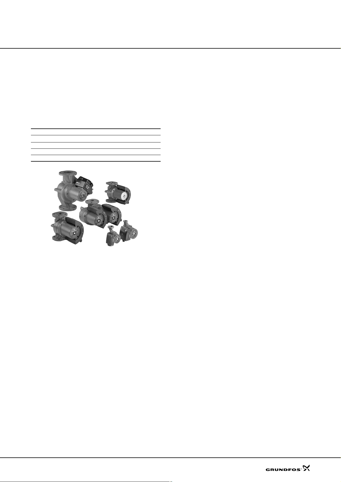
Fig. 1 MAGNA/UPE pump ranges
3
38 m
/h 90 m3/h
Characteristic features
•AUTOADAPT
• proportional-pressure duty
• constant-pressure duty
• constant-curve duty
• max. or min. curve duty
• parallel connection of pumps with PMU 2000
• no external motor protection required.
Benefits
• low noise level
• safe selection
• simple installation
• low energy consumption, all MAGNA pumps are
energy class "A"
• in addition to this, the AUTO
energy savings for MAGNA pumps
• long life and no maintenance
• external control and monitoring enabled via
expansion modules.
ADAPT function ensures
Applications
Heating systems
• Main pump
• Mixing loops
• Heating surfaces.
Aircondition surfaces (MAGNA only)
The MAGNA/UPE circulator pumps are designed for
circulating liquids in heating systems with variable flows
where it is desirable to optimise the setting of the pump
duty point. The pumps are also suitable for domestic
hot-water systems.
To ensure correct operation, it is important that the
sizing range of the system falls within the duty range of
the pump.
The MAGNA/UPE is especially suitable for installation
in existing systems where the differential pressure of
the pump is too high in periods with reduced flow
demand. The pump is also suitable for new systems
where automatic adjustment of pump head to actual
flow demand is required without using expensive
bypass valves or the like.
Furthermore, the pump is suitable for application in
systems with hot-water priority as an external contact
GR6460
can immediately force the pump to operate according to
the max. curve.
Pumped liquids
Thin, clean, non-aggressive and non-explosive liquids,
not containing any solid particles, fibres or mineral oil.
If the pump is installed in a heating system, the water
should meet the requirements of accepted standards
on water quality in heating systems, e.g. the German
standard VDI 2035.
In domestic hot-water systems, the pump should be
used only for water with a degree of hardness lower
than approx. 14 °dH. The pump must not be used for
the transfer of inflammable liquids such as diesel oil
and petrol.
If the pump is not used during periods of frost,
necessary steps must be taken to prevent frost bursts.
Additives with a density and/or kinematic viscosity
higher than those/ that of water will reduce the hydraulic
performance.
Whether a pump is suitable for a particular liquid,
depends on a number of factors of which the most
important are lime content, pH value, temperature and
content of solvents, oils, etc.
3
Page 4
Product data
Type key
MAGNA (D), UPE(D)
Example UP E D 80 -120 (F) (N) 280
Type range
UPE(D):
MAGNA (D):
Electronic control
Twin-head pump
Nominal diameter of
suction and discharge ports (DN)
Maximum head [dm]
Flange connection
N: Single-head pump housing of stainless steel
B: Single-head pump housing of bronze
A: Pump housing with air separator
Port-to-port [mm]
MAGNA, UPE
Performance range, MAGNA (D) and UPE(D)
H
p
[m]
[kPa]
13
12
M
100100
1010
90
80
70
60
50
40
30
20
MAGNA 50-100
MAGNA (D) 40-100
8
MAGNA 32-100
MAGNA 25-100
7
6
5
4
3
U
P
2
E
1
5
U
P
-
4
0
,
2
5
-
4
0
MAGNA 32-60
E
2
5
-
6
0
,
3
2
-
6
,
3
2
-
4
0
MAGNA (D) 40-120
MAGNA (D) 32-120
MAGNA 25-60
0
A
G
N
A
M
A
(
D
)
5
0
-
1
2
0
M
G
N
A
A
(
D
)
5
0
-
6
0
U
P
E
(
D
)
8
0
-
1
2
0
M
A
G
N
A
(
G
D
N
)
A
6
5
(
-
D
1
)
2
6
0
5
-
6
0
U
P
E
(
D
)
1
0
0
-
6
0
1010
1
1 2 3 4 6 8 1010 15 20 30 40 60 80 100100
Q [m³/h]
11 2 3 4 5 6 7 8 9 1010 20
Q [l/s]
TM03 1852 1106
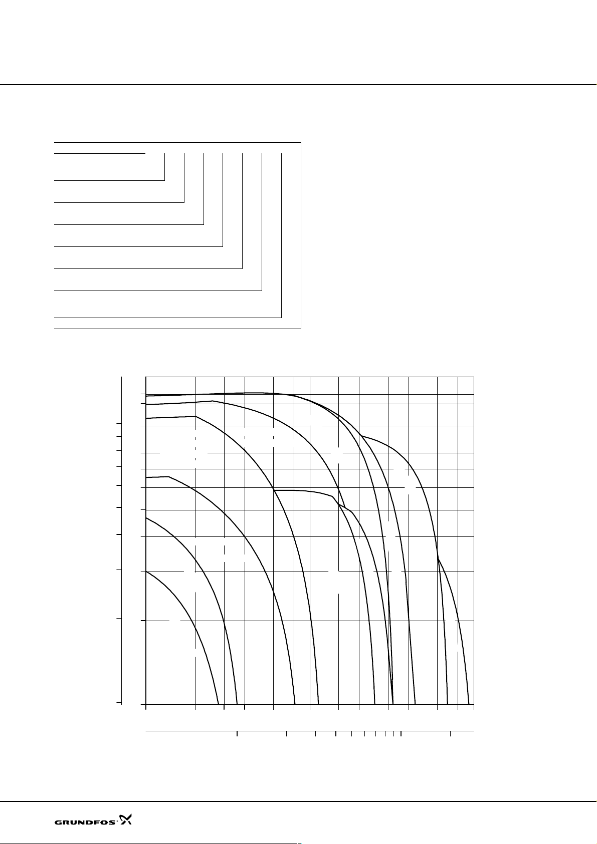
Fig. 2 Performance range
4
Page 5

Product range
Product range
MAGNA, UPE
Pump type
MAGNA 25-60 z 180 z
MAGNA 32-60 z 180 z
MAGNA 25-100 z 180 z
MAGNA 32-100 (N) z 180 z
MAGNA 32-100 F z 220 z
MAGNA (D) 40-100 F z 220 z
MAGNA 50-100 F z 240 z
UPE 15-40 z 130 z
UPE 25-40 (B) z 180 z
UPE 25-40 A z 180 z
UPE 32-40 z 180 z
UPE 25-60 (B) z
UPE 25-60 A z 180 z
UPE 32-60 z 180 z
MAGNA (D) 32-120 F (N) z 220 z
MAGNA (D) 40-120 F (N) z 250 z
MAGNA (D) 50-60 F (N) z 280 z
MAGNA (D) 65-60 F (N) z 340 z
MAGNA (D) 50-120 F (N) z 280 z
MAGNA (D) 65-120 F (N) z 340 z
UPE(D) 80-120 F (B) z 360 zz
UPE(D) 100-60 F (B) z 450 zz
Supply voltage
1 x 230-240 V 3 x 400-415 V 1" 1 1/2" 2" PN 6/PN 10 PN 6 PN 10
Port-to-port length
[mm]
130 z
180 z
Pipe connection Flange connection
5
Page 6
Product range
MAGNA, UPE
Pump selection
Pump size
Selection of pump size should be based on
• required maximum flow and
• maximum head loss in the system.
Operating conditions
It should be checked whether the operating conditions
are fulfilled, i.e.
• liquid temperature and ambient conditions
• minimum inlet pressure
• maximum operating pressure.
Communication
The requirements for external control or monitoring of
the pump should be considered, such as access to
• speed control of pump or change of setpoint
• reading of pump data
• start/stop, fault indication or forced control to
max. or min. curve.
Note: The communication options depend on the pump
type.
Control mode
In general, Grundfos recommends
• the factory setting which is suitable for most
installations
• proportional-pressure control in systems with
relatively great head losses
• constant-pressure control in systems with relatively
small head losses.
Head
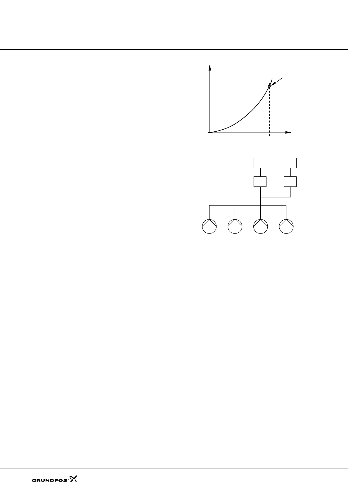
Duty point
Flow
Fig. 3 Performance curve
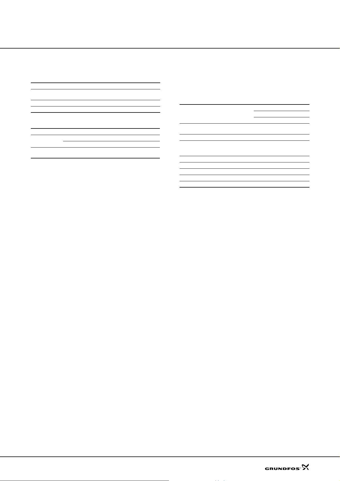
BMS
PMU
MAGNA/UPE
Fig. 4 Building management system with four pumps
in parallel controlled via a PMU 2000 and
a PCU 2000
PCU
TM02 2040 3301TM02 2044 3301
6
Page 7
Operating conditions
MAGNA, UPE
Operating conditions
General recommendations
MAGNA/UPE
Water in heating
systems
Domestic hot water Degree of hardness up to 14 °dH
Water containing glycol Viscosity ≤ 10 mm
Liquid temperature
Application Time MAGNA UPE
General
Domestic hot-
water systems
Short periods +110 °C +110 °C
Continuously +2 °C to +95 °C +15 °C to +95 °C
Continuously +2 °C to +60 °C +15 °C to +60 °C
To avoid condensation in the terminal box and the
stator, the liquid temperature must always be higher
than the ambient temperature.
Ambient conditions
Ambient temperature
during operation: 0 °C to +40 °C
Ambient temperature
during storage/transport: –40 °C to +60 °C
Relative air humidity: Maximum 95 %.
Water quality according to local standards
such as the German standard VDI 2035
2
/s
Maximum operating pressure
10 bar.
Minimum inlet pressure
The following relative minimum pressures must be
available at the pump inlet during opera tion:
Liquid temperature
Pump type
MAGNA 25-60, 25-100, 32-60, 32-100,
40-100(D), 50-100
UPE 15-40, 25-40, 25-60, 32-60, 32-40 0.05 0.28 –
MAGNA (D) 32-120 F
MAGNA (D) 40-120 F
MAGNA (D) 50-60 F
MAGNA (D) 50-120 F 0.40 0.70 –
MAGNA (D) 65-60 F 0.15 0.45 –
MAGNA (D) 65-120 F 0.90 1.20 –
UPE(D) 80-120 F 1.60 1.90 –
UPE(D) 100-60 F 0.95 1.25 –
Note: Actual inlet pressure + pump pressure against a
closed valve must be lower than the maximum
permissible system pressure.
75 °C 90 °C 95 °C
Inlet pressure [bar]
0.1 – 0.35
0.15 0.45 –
7
Page 8

Operating conditions
Electrical data
MAGNA/UPE
MAGNA, UPE
Pump type
Enclosure class IP 44 (IEC 85) IP 44 (IEC 85) IP 42 IP 42
Insulation class FFHH
External start/stop
input
Setpoint signals
Signal output
Bus input
Supply voltage
Earth leakage current
EMC EN 61800-3.
Expansion module
Single-phase MAGNA
25-60, 25-100, 32-60,
32-100, 40-100(D), 50-100
External potential-free
switch.
Screened cable.
Maximum contact load:
5 V, 10 mA.
GENI module GENI module MC 40/60
Internal potential-free
changeover contact.
Screened cable.
Maximum contact load:
250 VAC, 2 A.
Minimum contact load:
5 VDC, 1 mA.
GENI module
LON via GENIbus and
G10 modules
1 x 230-240 V – 10 %/+ 6 %,
50/60 Hz, PE
The pump requires no external motor protection.
I
< 3.5 mA
leak
The leakage currents are measured in accordance with EN 60355-1.
Single-phase MAGNA (D)
32-120, 40-120, 50-60,
50-120, 65-60, 65-120
External potential-free switch.
Screened cable.
Maximum contact load:
5 V, 10 mA.
Internal potential-free
changeover contact.
Screened cable.
Maximum contact load:
250 VAC, 2 A.
Minimum contact load:
5 VDC, 1 mA.
GENI module
LON module
1 x 230-240 V – 10 %/+ 6 %,
50/60 Hz, PE
Single-phase
UPE
MC 40/60
MB 40/60
MB 40/60
MC 40/60
MB 40/60 Grundfos GENIbus protocol.
1 x 230-240 V – 10 %/+ 6 %,
50 Hz, PE
Three-phase
UPE(D)
External potential-free switch.
Screened cable.
Maximum contact load:
5 V, 2.7 mA.
• Max. and min. curve input
External potential-free switch.
Screened cable.
Maximum contact load:
5 V, 2.7 mA.
• Input for analog 0-10 V
signal
External signal: 0-10 VDC.
Maximum contact load: 1 mA.
Internal potential-free changeover contact.
Screened cable.
Maximum contact load:
250 VAC, 2 A.
Minimum contact load:
5 VDC, 1 mA.
Screened cable.
Lead cross section:
0.25 - 1 mm
Maximum cable length: 1200 m.
3 x 400-415 V ± 10 %, 50 Hz, PE
2
.
Sound pressure level
Pump type
Sound pressure level ≤ 54 dB(A) ≤ 54 dB(A) ≤ 43 dB(A) ≤ 54 dB(A)
Single-phase MAGNA
25-60, 25-100, 32-60,
32-100, 40-100(D), 50-100
Single-phase MAGNA (D)
32-120, 40-120, 50-60,
50-120, 65-60, 65-120
Single-phase
UPE
Three-phase
UPE(D)
8
Page 9
Functions
Functions
MAGNA, UPE
Single-phase MAGNA
25-60, 25-100, 32-60,
32-100, 40-100(D), 50-100
Control modes (factory setting)
AUTO
ADAPT z z
Proportional-pressure control zz
Additional control and operating modes
Proportional-pressure control zzzz
Constant-pressure control zzzz
Constant-curve duty zzzz
Max. or min. curve duty zzz
Automatic night-time duty zz
Additional operating modes of twin-head pumps
Alternating operation z z z
Standby operation zz z
Readings and settings on the pump
Operating indication zzzz
Flow indication zz
Setpoint zzzz
Control mode zzzz
Fault indication zzzz
Communication
Wireless remote control, R100 zzzz
External digital input/output z
External analog input z
Bus via GENIbus protocol, RS-485 z
Bus via LonTalk
z Function incorporated.
Expansion module required.
G10-LON interface required.
Not recommended for aircondition systems.
®
protocol, FTT 10
Single-phase MAGNA (D)
32-120, 40-120, 50-60,
50-120, 65-60, 65-120
Single-phase
UPE
Three-phase
UPE(D)
9
Page 10
Functions
MAGNA, UPE
Control modes (factory setting)
The pumps have been factory-set to
•AUTO
• proportional-pressure control (UPE).
The setpoint is factory-set to half of the maximum pump
head.
The factory setting is suitable for most installations.
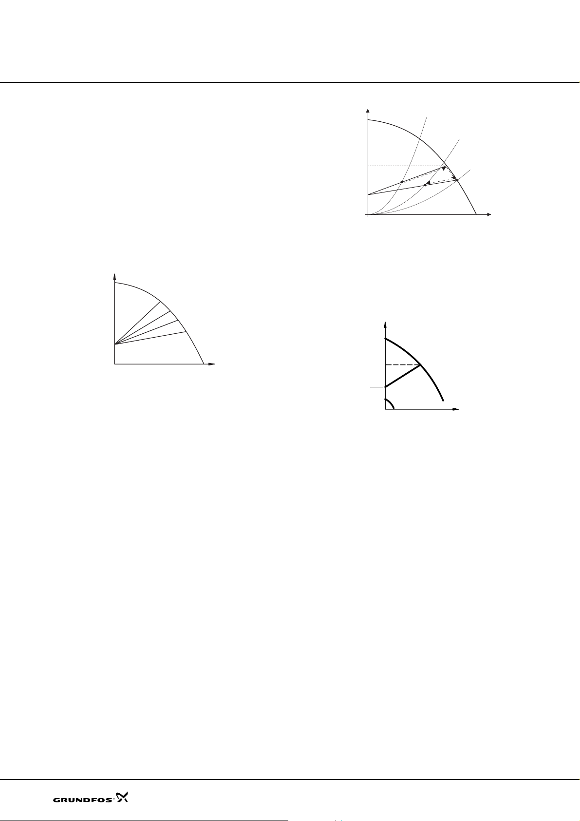
AUTO
During operation, the pump automatically reduces the
factory-set setpoint and adjusts it to the actual system
characteristic.
Note: Manual setting of the setpoint is not possible.
When the control mode AUTO
activated, the pump will start at H
50 % of its maximum head, and then adjust its
performance to A
When the pump registers a lower pressure on the max.
curve, A
selects a correspondingly lower control curve, H
If the radiator valves close, the pump adjusts its
performance to A3.
ADAPT (MAGNA).
ADAPT
H
1.5
0
0
Fig. 5
AUTOADAPT control
ADAPT has been
set1
, see fig. 6.
1
, the AUTOADAPT function automatically
2
Q
, corresponding to
.
set2
H
H
max.
H
H
fac.
H
auto_min
Fig. 6 AUTO
ADAPT
A
1
A
3
set1
H
set2
A
2
Q
TM03 1071 4005
Proportional-pressure control
The pump head is changed continuously in accordance
with the flow demand in the system.
The head against a closed valve is half the setpoint.
H
H
TM02 0826 0904
Fig. 7
The proportional-pressure control is recommended in
systems with relatively great head losses.
set
H
set
2
Proportional-pressure control
Q
TM00 4488 0995
10
A1: Original duty point.
: Lower registered pressure on the
A
2
max. curve.
A3: New duty point after AUTOADAPT control.
: Original setpoint setting.
H
set1
: New setpoint after AUTOADAPT control.
H
set2
: MAGNA xx-60: 3.5 m.
H
fac.
MAGNA xx-100: 5.5 m.
H
auto_min
: A fixed value of 1.5 m.
The AUTOADAPT control mode is a form of proportionalpressure control where the control curves have a fixed
origin, H
auto_min
The AUTO
.
ADAPT control mode is developed specificly
for heating applications and not recommended for aircondition systems.
Page 11
Functions
MAGNA, UPE
Additional control and operating modes
Grundfos offers additional control and operating modes
to meet specific demands.
The functions available depend on the pump type and
the expansion module chosen, see overview of
functions on page 9.
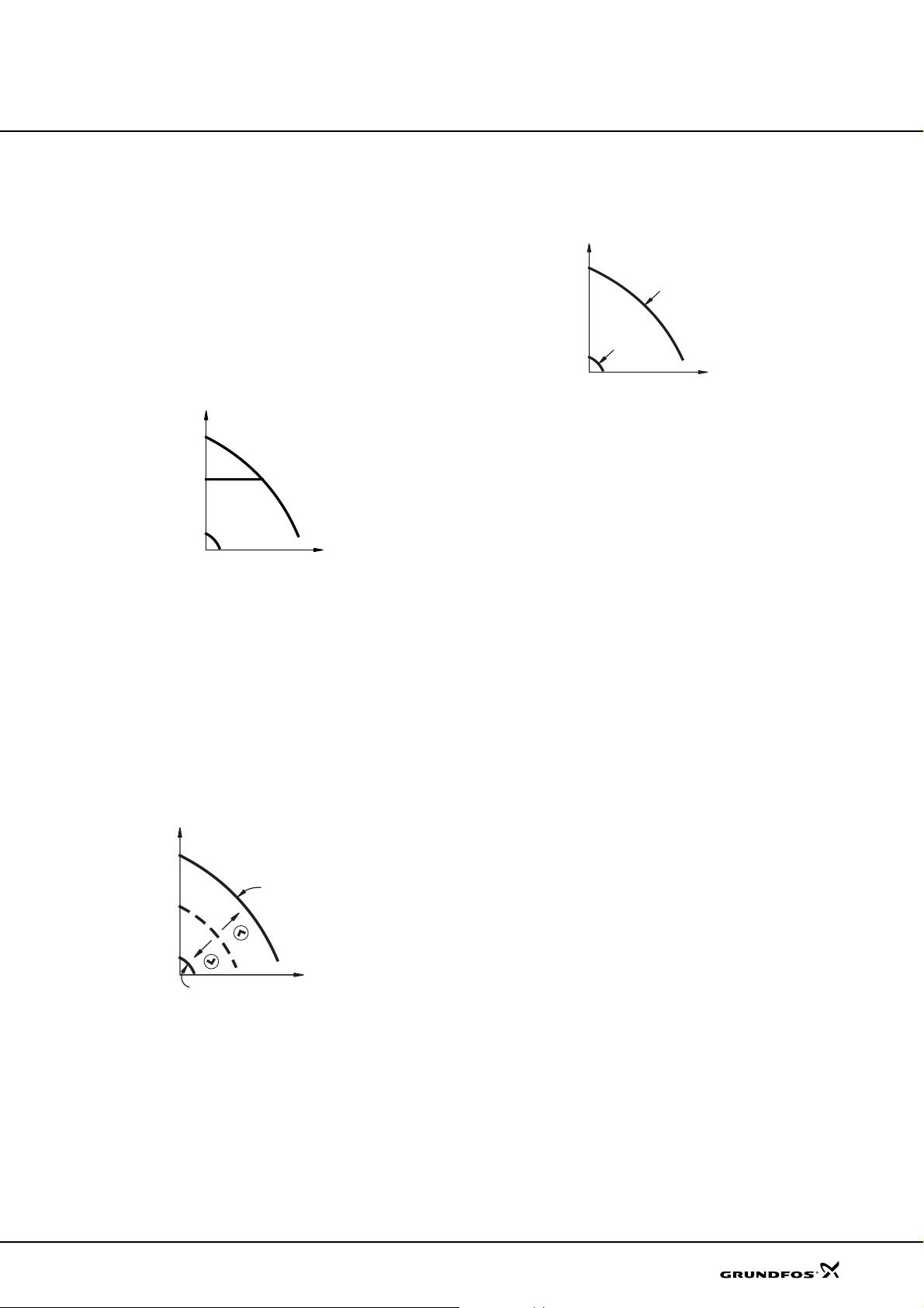
Constant-pressure control
The pump head is kept constant, independent of the
water requirement.
H
H
set
Q
Fig. 8 Constant-pressure control
The constant-pressure control is recommended in
systems with relatively small head losses.
Constant-curve duty
Requires the use of an R100 remote control.
The pump can be set to operate according to a constant
curve like an uncontrolled pump.
If an external controller is installed, the pump is able to
change from one constant curve to another, depending
on the value of the external signal.
H
Max. or min. curve duty
The pump can be set to operate according to the max.
or min. curve, like an uncontrolled pump.
H
Max.
Min.
Q
Fig. 10
Max. or min. curves
The max. curve mode can be used in periods in which
a maximum flow is required. This operating mode is for
instance suitable for hot-water priority.
The min. curve mode can be used in periods in which
a minimum flow is required. This operating mode is for
instance suitable for manual night-time duty.
TM00 4489 0995
Automatic night-time duty
When automatic night-time duty has been selected, the
pump will change automatically between normal duty
and night-time duty. Changeover between normal duty
and night-time duty takes place as a result of the flowpipe temperature measured by an integrated
temperature sensor.
The automatic changeover to night-time duty takes
place when the temperature sensor registers a flowpipe temperature drop of more than 10-15 °C within
approx. 2 hours. The required temperature drop is a
minimum of 0.1 °C/min.
Changeover to normal duty takes place without a time
lag when the temperature has increased by approx.
10 °C.
TM00 5547 4596
Fig. 9
Constant-curve duty
Min.
Max.
Additional operating modes of twin-head pumps
The following operating modes are available for twinhead pumps:
Alternating operation
Q
TM03 0551 0205
Pump operation alternates every 24 hours. If the duty
pump stops due to a fault, the other pump will start.
Standby operation
One pump is operating continuously. In order to prevent
seizing-up, the other pump will start at a fixed frequency
(every 24 hours) and run for a short period. If the duty
pump stops due to a fault, the other pump will start.
11
Page 12
Functions
MAGNA, UPE
Readings and settings on the pump
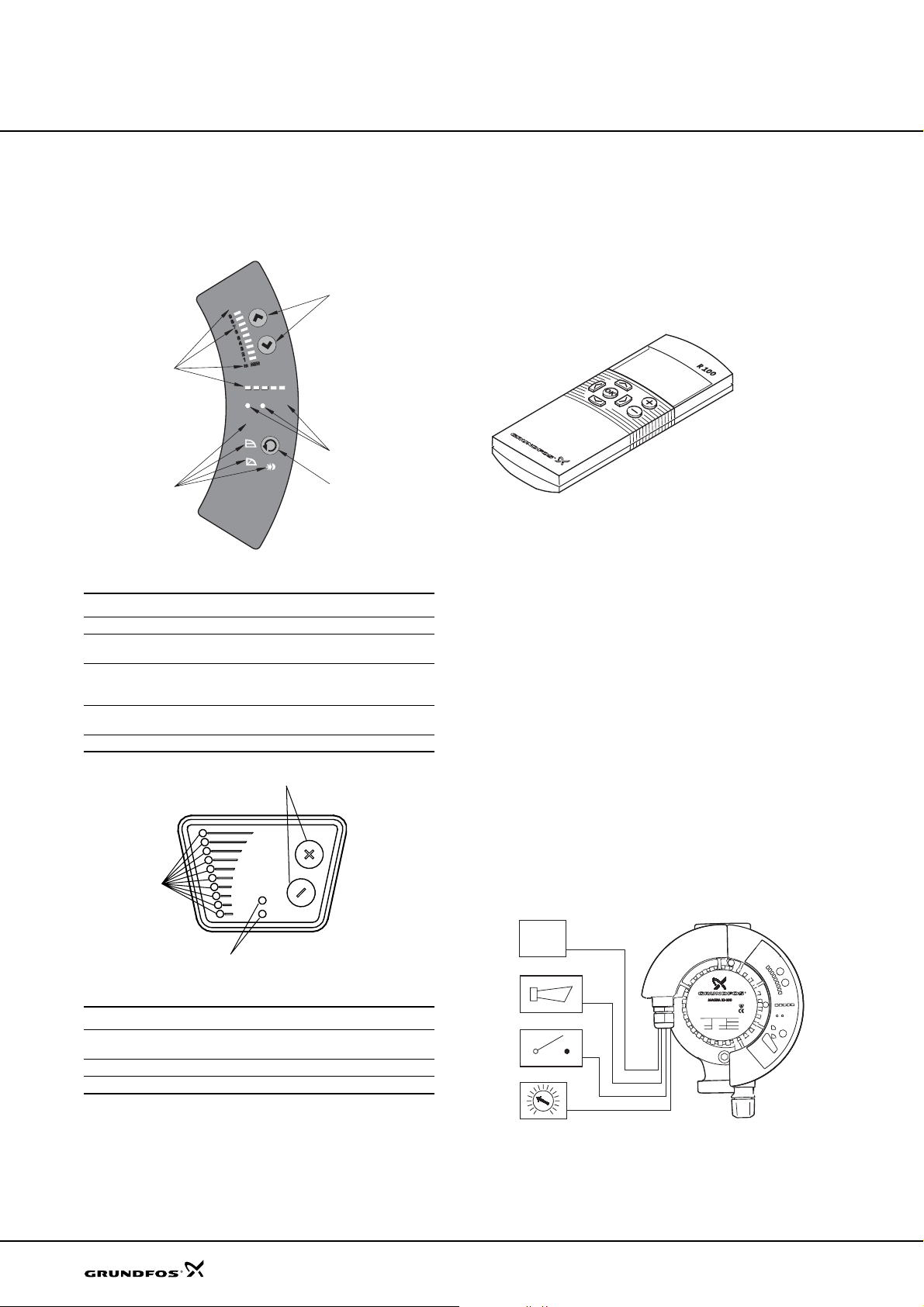
The control panel on the pump control box/terminal box
incorporates the basic functions for readings and
settings.
MAX
5
STOP
m3/h
AUTO
100%
EXT
ADAPT
4
Fig. 11
Pos. Description
1 Buttons for setting of head
2
3
4
5 Light fields for indication of head, flow and operating mode
MAGNA control panel
• Indicator lights for operating and fault indication and
• symbol for indication of external control
Button for selection of control mode:
AUTOADAPT, proportional pressure, constant pressure and
automatic night-time duty
Light symbols for indication of control mode and night-time
duty
1
2
1
2
3
Communication
Depending on pump type, MAGNA/UPE enables
communication via
• wireless remote control, R100
• connection to an external alarm device
• digital input/output
• analog input.
TM00 4498 2802
Fig. 13
TM03 0379 5004
MAGNA/UPE is designed for wireless communication
with the Grundfos R100 remote control.
The R100 offers additional possibilities of setting a nd
status displays for the pump.
The R100 can be used for the following functions:
• reading of operating data
• reading of fault indications
• setting of control mode
• setting of 0.1 m head increments
• selection of external setpoint signal
• allocation of pump number making it possible to
distinguish between pumps in connection with
parallel operation via bus
• selection of function for digital input.
The MAGNA/UPE has various inputs and outputs for
external signals for forced-control functions. Some
functions may require an expansion module.
R100 remote control
12
3
Fig. 12 UPE control panel
Pos. Description
Buttons for start/stop of the pump, setting of setpoint, control
1
mode, min. and max. curve
2 Light fields for indication of control mode and setpoint
3 Indicator lights for operating and fault indication
Grundfos GENIbus
TM00 4431 0603
TM03 3040 0106
Fig. 14
MAGNA with expansion module
Page 13
Functions
Q
Q
Q
Q
MAGNA, UPE
Digital input
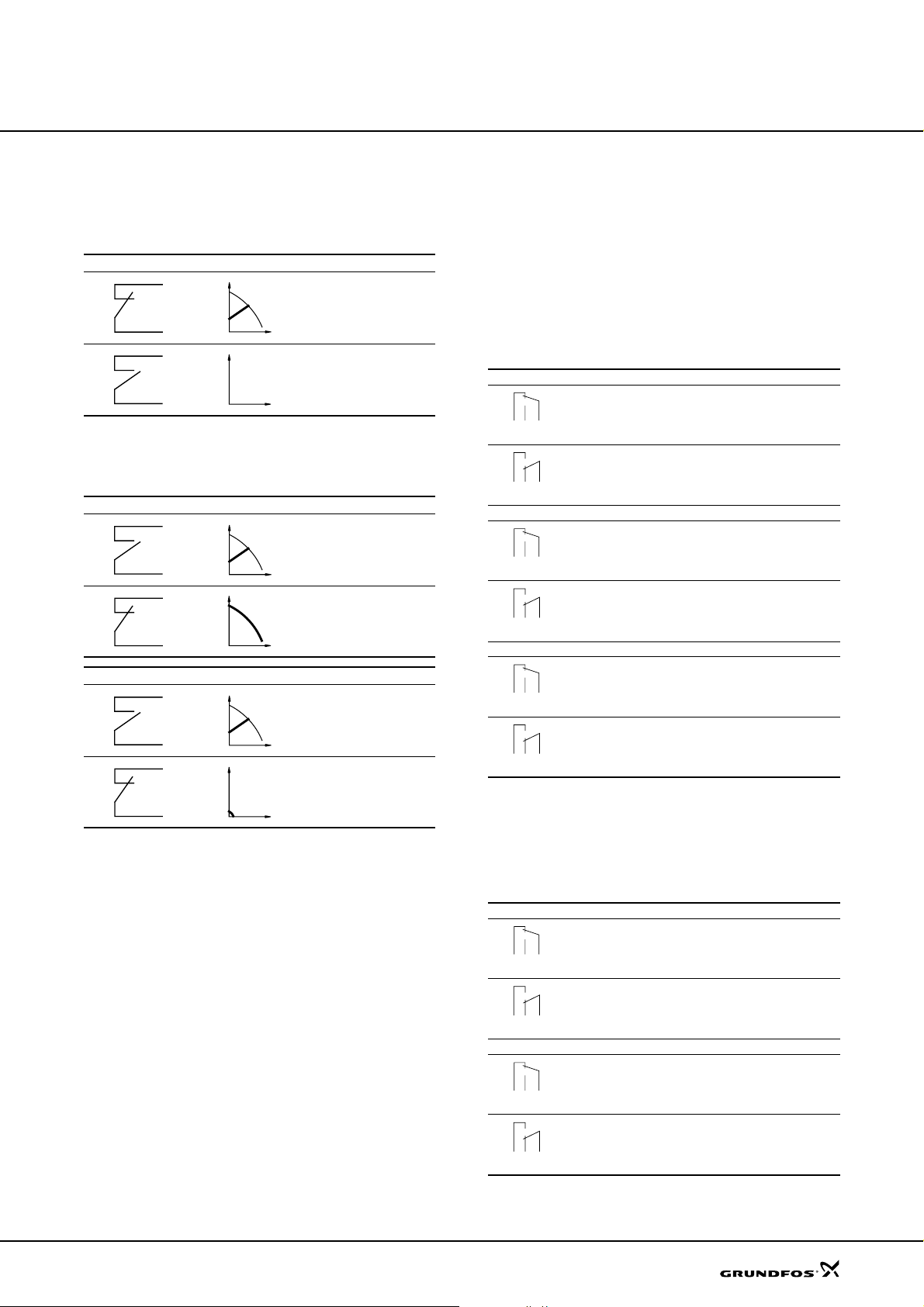
External start/stop
The pump can be started or stopped via the digital
input.
Start/stop
H
Normal duty
H
Stop
External forced max. or min curve
The pump can be forced to operate on the max. or min
curve via the digital input.
Max. curve
H
Normal duty
H
Max. curve
Q
Min. curve
H
Normal duty
H
Min. curve
Q
The function of the digital input is selected with the
R100 remote control.
Digital output
The pump incorporates a signal relay with a potentialfree changeover contact for external fault indication.
MAGNA 25-60, 25-100, 32-60, 32-100, 40-100, 50-100
The function of the signal relay can be changed from
"Fault" to "Operating" or "Ready" mode with the R100.
These pumps require expansion modules.
The functions of the signal relay are as shown in the
table below:
Signal relay Fault signal
Not activated:
132
NC NO C
132
NC NO C
12 3
NC NO C
Signal relay Operating signal
132
NC NO C
132
NC NO C
12 3
NC NO C
Signal relay Ready signal
132
NC NO C
132
NC NO C
12 3
NC NO C
MAGNA 32-120, 40-120, 50-60, 50-120, 65-60, 65-120
The function of the signal relay can be changed from
"Fault" to "Operating" mode with the R100.
The functions of the signal relay are as shown in the
table below:
• The electricity supply has been switched off.
• The pump has not registered a fault.
Activated:
• The pump has registered a fault.
Not activated:
• The pump has been set to stop.
• The pump has registered a fault and is unable to
run.
Activated:
• The pump is running.
• The pump has registered a fault, but is able to run.
Not activated:
• The pump has been set to stop.
• The pump has registered a fault and is unable to
run.
Activated:
• The pump is ready to run or is running.
Signal relay Fault signal
Not activated:
132
NC NO C
132
NC NO C
12 3
NC NO C
Signal relay Operating signal
132
NC NO C
132
NC NO C
12 3
NC NO C
• The electricity supply has been switched off.
• The pump has not registered a fault.
Activated:
• The pump has registered a fault.
Not activated:
• The pump has been set to stop.
• The pump has registered a fault and is unable to
run.
Activated:
• The pump is running.
• The pump has registered a fault, but is able to run.
13
Page 14
Functions
MAGNA, UPE
Analog input
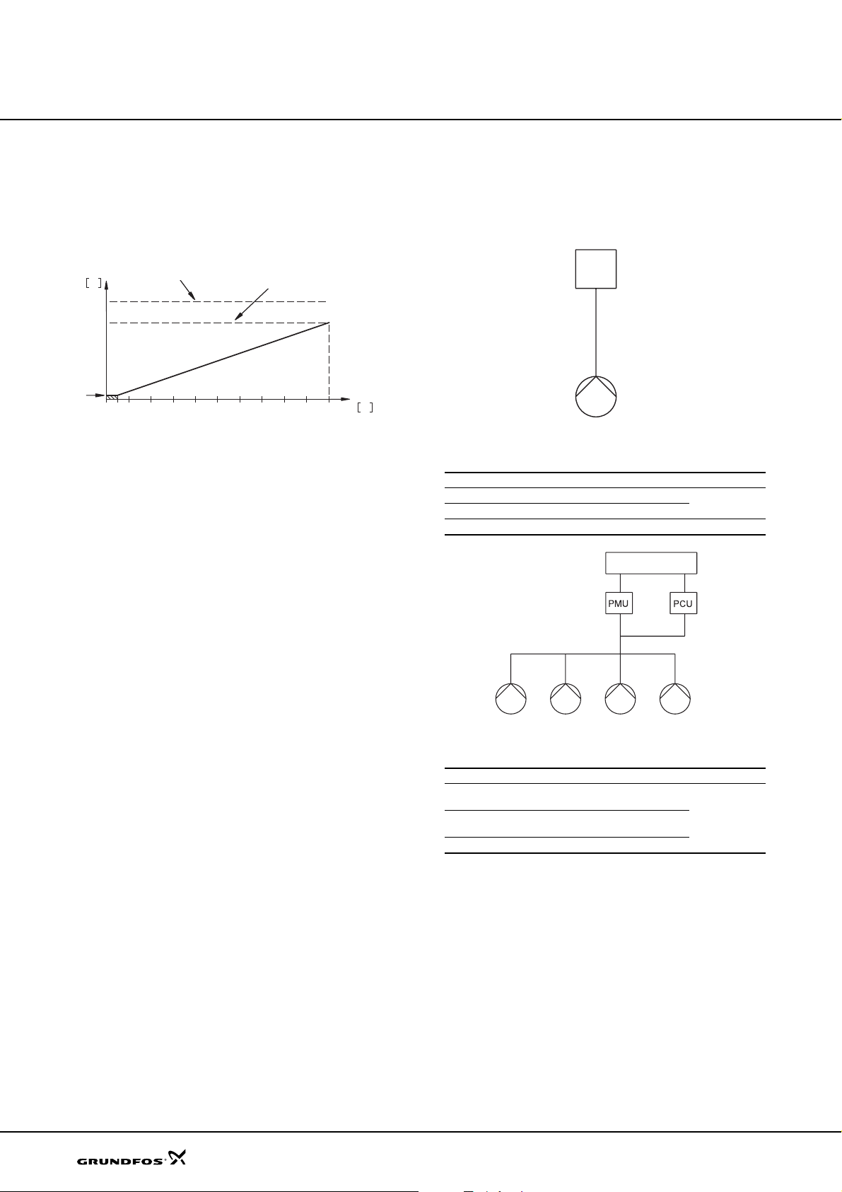
External analog control
Requires an expansion module.
Control of setpoint or speed via an extern al 0-10 V
signal.
mVH
Min. curve
0
Fig. 15
Max. curve
Example of 0-10 V control
The analog input enables the following con trol modes:
In constant-curve mode, the pump is able to change
from one constant curve to another depending on the
value of the external signal.
The internal controller is inactive in this mode.
In pressure control mode, the setpoint can be set
externally within the range from the setpoint to the min.
curve.
The internal controller is active in this mode.
Setpoint/constant curve
7654321
89
10
U
Bus communication via GENIbus
The bus enables control and monitoring of the pumps
from a GRUNDFOS Pump Management System 2000,
to a building management system (BMS) or another
external control system.
TM00 5550 0904
MAGNA/UPE
Fig. 16
Pump type Requires See section
MAGNA GENI module
UPE, single-phase MB 40/60 module
UPE, three-phase ––
Example of single-pump operation
Accessories
BMS
TM03 2394 4005
At an input voltage lower than 0.5 V, the pump will
operate according to the min. curve.
MAGNA/UPE
Fig. 17 Example of pumps operating in parallel
Pump type Requires See section
MAGNA
UPE, single-phase
UPE, three-phase • PMU 2000 or PCU 2000
• GENI module
• PMU 2000 or PCU 2000
• MB 40/60 module
• PMU 2000 or PCU 2000
Accessories
TM03 2395 4005
14
Page 15
Functions
MAGNA, UPE
Bus communication via LON
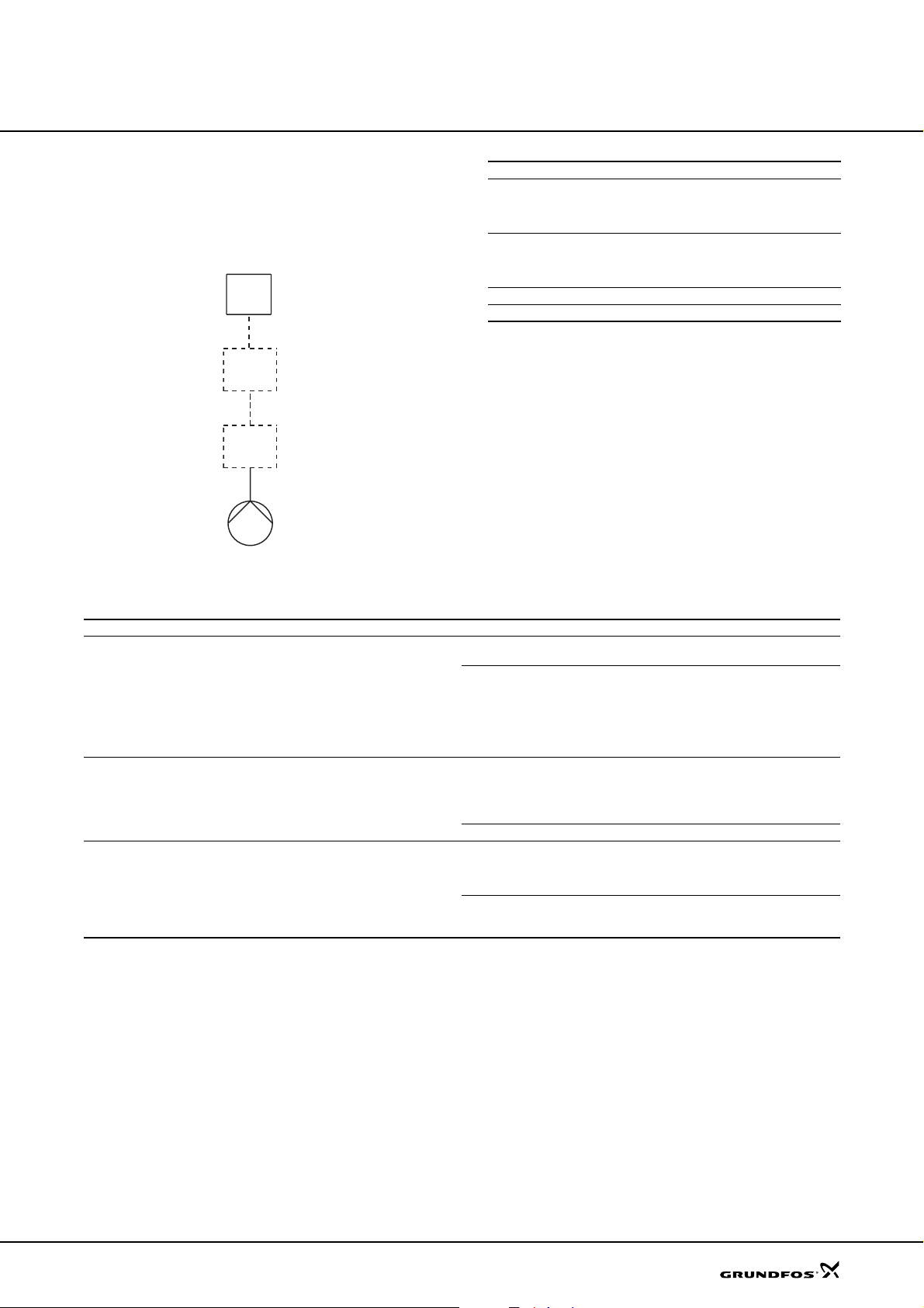
Via the bus input, the pump can be connected to a
network based on LonWorks
linked to other units based on this communication
standard.
Fig. 18
Example of single-pump operation
BMS
G10-LON
Expansion
module
®
technology, and thus be
Functions of expansion modules
Pump type GENI module LON module G10-LON
MAGNA
25-60, 32-60, 25-100,
32-100, 40-100(D),
50-100
MAGNA (D)
50-60, 65-60, 32-120,
40-120, 50-120,
65-120
UPE, single-phase z
UPE, three-phase z
TM03 3041 0106
zz
z
Pump type Inputs/outputs incorporated With expansion module Function
Relay module
MAGNA
25-60, 25-100, 32-60,
32-100, 40-100, 50-100
MAGNA (D)
32-120, 40-120, 50-60,
50-120, 65-60, 65-120
UPE, single-phase –
–
Start/stop
Signal relay
GENI module
GENI module
LON module LonTalk
MC 40/60
MB 40/60
0-10 V analog input
Twin-head pump control
0-10 V analog indput
Twin-head pump control
0-10 V analog input
Start/stop
Signal relay
Start/stop
Max. curve
Min. curve
GENIbus
Signal relay
Max. curve
Min. curve
GENIbus
®
protocol, FTT10
Start/stop
Max. curve
Min. curve
Start/stop
Max. curve
Min. curve
15
Page 16
Construction
The MAGNA/UPE is of the canned-rotor type, i.e. pump
and motor form an integral unit without shaft seal and
with only two gaskets for sealing. The bearings a re
lubricated by the pumped liquid.
The pump is characterised by
• controller integrated in the terminal box
• control panel on the terminal box
• terminal box prepared for optional modules
• differential-pressure and temperature detection
• cast-iron, stainless-steel or bronze or pump housing
• twin-head versions
• air separator pump housing, types UPE 25-40 A and
UPE 25-60 A
• no external motor protection required.
Motor and electronic controller
The single-phase MAGNA motor is a 4- or 8-pole,
synchronous, permanent-magnet motor (PM motor).
This motor type is characterised by higher efficiency
than a conventional asynchronous squirrel-cage motor.
MAGNA, UPE
Pump speed is controlled by an integrated frequency
converter.
The single-phase UPE motor is a 2-pole,
asynchronous squirrel-cage motor with radio noise filter
to VDE 0875 . The terminal bo x and the moto r-pump
unit have been tested in accordance with VDE 0700.
The terminal box incorporates a controller. The pump
speed is calculated via a built-in induction coil on the
stator winding.
The three-phase UPE motor is a 2-pole, asynchronous
squirrel-cage motor with integrated frequency
converter.
A differential-pressure and temperature sensor forms
an integral unit. The sensor is located inside the pump
housing in a channel between suction and discharge
sides. Twin-head pumps have two sensors.
Pump connections
Threaded pump connections to ISO 228/1.
Flange dimensions to ISO 7005-2/BS4504.
Surface treatment
The pumps are wet-varnished.
Colour: NCS40-50R.
16
Page 17
Construction
MAGNA, UPE
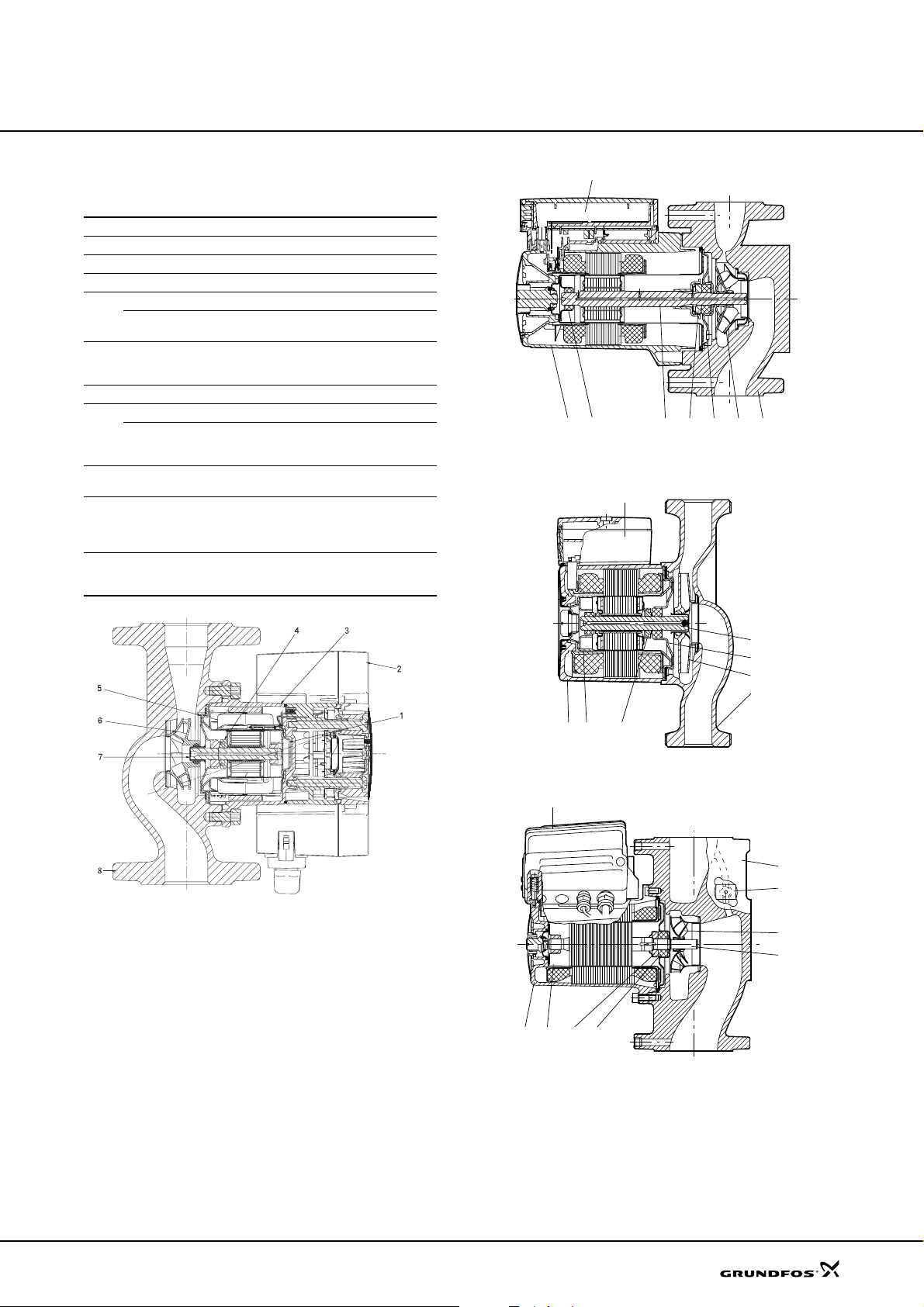
Material specification
MAGNA/UPE
Pos. Component Material EN/DIN
1 Terminal box Aluminium/composite
2 Stator housing Aluminium AlSi 10Cu
O-rings EPDM rubber
Outer bearing ring Aluminium oxide Al
3
Rotor can Stainless steel
4Shaft
5 Thrust bearing Carbon MY 106
Bearing plate Stainless steel 1.4301
6
Inner bearing ring
7 Impeller
8 Pump housing
Differential-pressure
9
and temperature sensor
Stainless steel or
tungsten carbide or
aluminium oxide
Aluminium oxide Al
or
silicium carbide SiO
Stainless steel or
composite
Cast iron
EN-GJL150/-200/-250,
bronze or stainless
steel
Composite PES
2
2O3
1.4301 or
2O3
1.4401
1
765432 8
Fig. 20 MAGNA 32-120, 40-120, 50-60, 50-120, 65-60
and 65-120
1
TM02 1256 0801TM02 1257 3801TM02 1258 0603
Fig. 19
MAGNA 25-60, 25-100, 32-60, 32-100, 40-100
and 50-100
4
6
7
8
325
Fig. 21 UPE 15-40, 25-40, 32-40, 25-60 and 32-60
1
TM03 1955 3405
2
3
6
5
8
9
7
4
Fig. 22 UPE 80-120 and 100-60
17
Page 18
Installation
MAGNA, UPE
Mechanical installation
MAGNA/UPE is for indoor installation. The pump must
be installed with horizontal motor shaft.
The pump may be installed in horizon tal as we ll as
vertical pipes.
Arrows on the pump housing indicate the liqui d flo w
direction through the pump. The liquid flow direction
can be horizontal or vertical, depending on the terminal
box position.
The terminal box can be turned to various positions,
depending on pump type. This is described in the
installation and operating instructions.
The pump must be installed in such a way that strain
from the pipework is not transferred to the pump
housing.
The pump may be suspended direct in the pipes,
provided the pipework can support the pump. If not, the
pump must be installed on a mounting bracket or base
plate.
To ensure cooling of motor and electronics, the
following must be observed:
• Place the pump in such a way that sufficient cooling
is ensured.
• The temperature of the cooling air must not exceed
40 °C.
Electrical connection
The electrical connection and protection should be
carried out in accordance with local regulations.
• The pump must be connected to an external mains
switch.
• The pump must always be correctly earthed.
• The pump requires no external motor protection.
The motor incorporates thermal protection against
slow overloading and blocking (IEC 34-11: TP 211).
• When the pump is switched on via the mains, the
pump will start after approx. 5 seconds.
Note: The number of starts and stops via the mains
supply must not exceed 4 times per hour.
The pump mains connection must be made as shown in
the diagrams on the following pages.
Cables
Use screened cables (0.25-1.5 mm2) for external on/off
switch, digital input, sensor and setpoint signals.
• All cables used must be heat-resistant up to at least
+85 °C.
• All cables used must be installed in accordance with
EN 60204-1.
18
Page 19
Installation
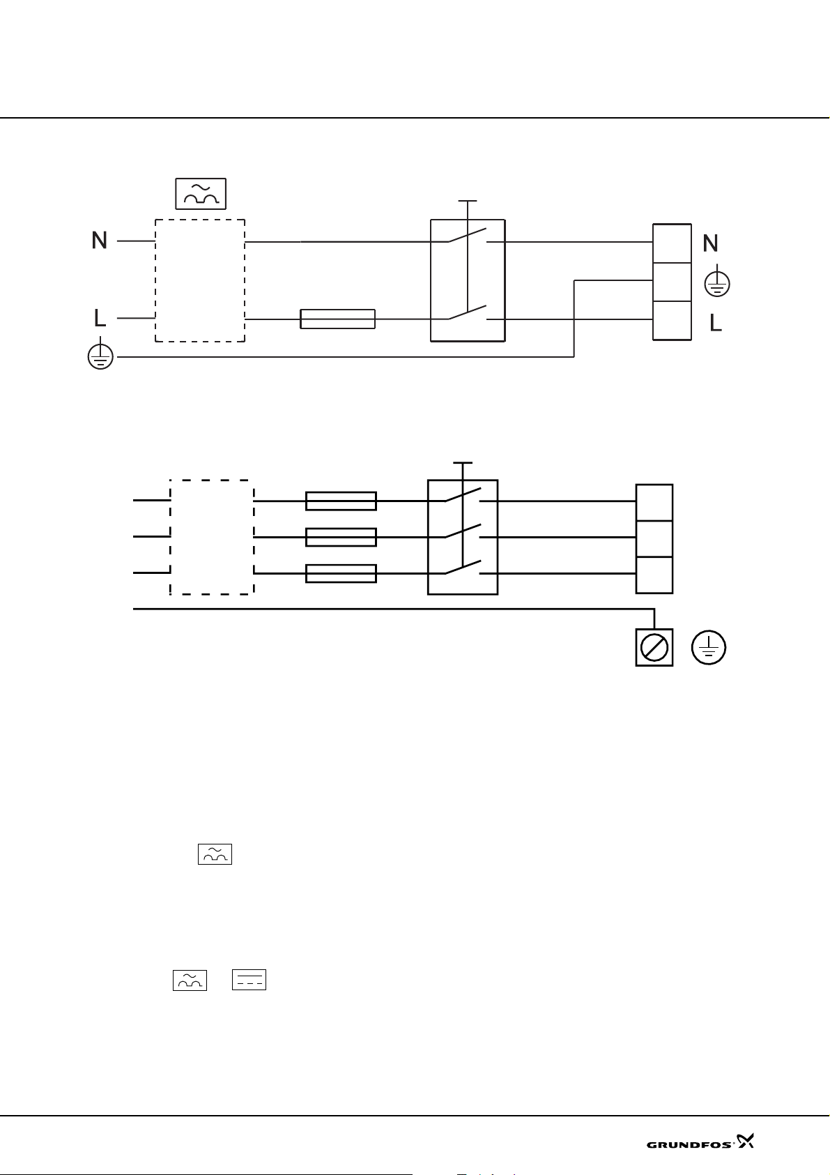
Wiring diagram, single-phase
ELCB
Fig. 23 1 x 230-240 V –10 %/+6 %, 50/60 Hz
Wiring diagram, three-phase
MAGNA, UPE
External switch
Max. 10 A/16 A
TM03 2397 4005
External switch
Max. 16 A
L1
L2
ELCB
L3
PE
Fig. 24 3 x 400-415 V ±10 %, 50/60 Hz
Additional protection
If the pump is connected to an electric installation
where an earth-leakage circuit breaker (ELCB) is used
as an additional protection, the earth-leakage circuit
breaker must be marked with the following symbols.
Single-phase
L1
L2
L3
TM00 9270 4696
The earth-leakage circuit breaker must trip out when
earth fault currents with DC content (pulsating DC)
occur.
Three-phase
The earth-leakage circuit breaker must trip out when
earth fault currents with DC content (pulsating DC) and
smooth DC earth fault currents occur.
19
Page 20
Installation
MAGNA, UPE
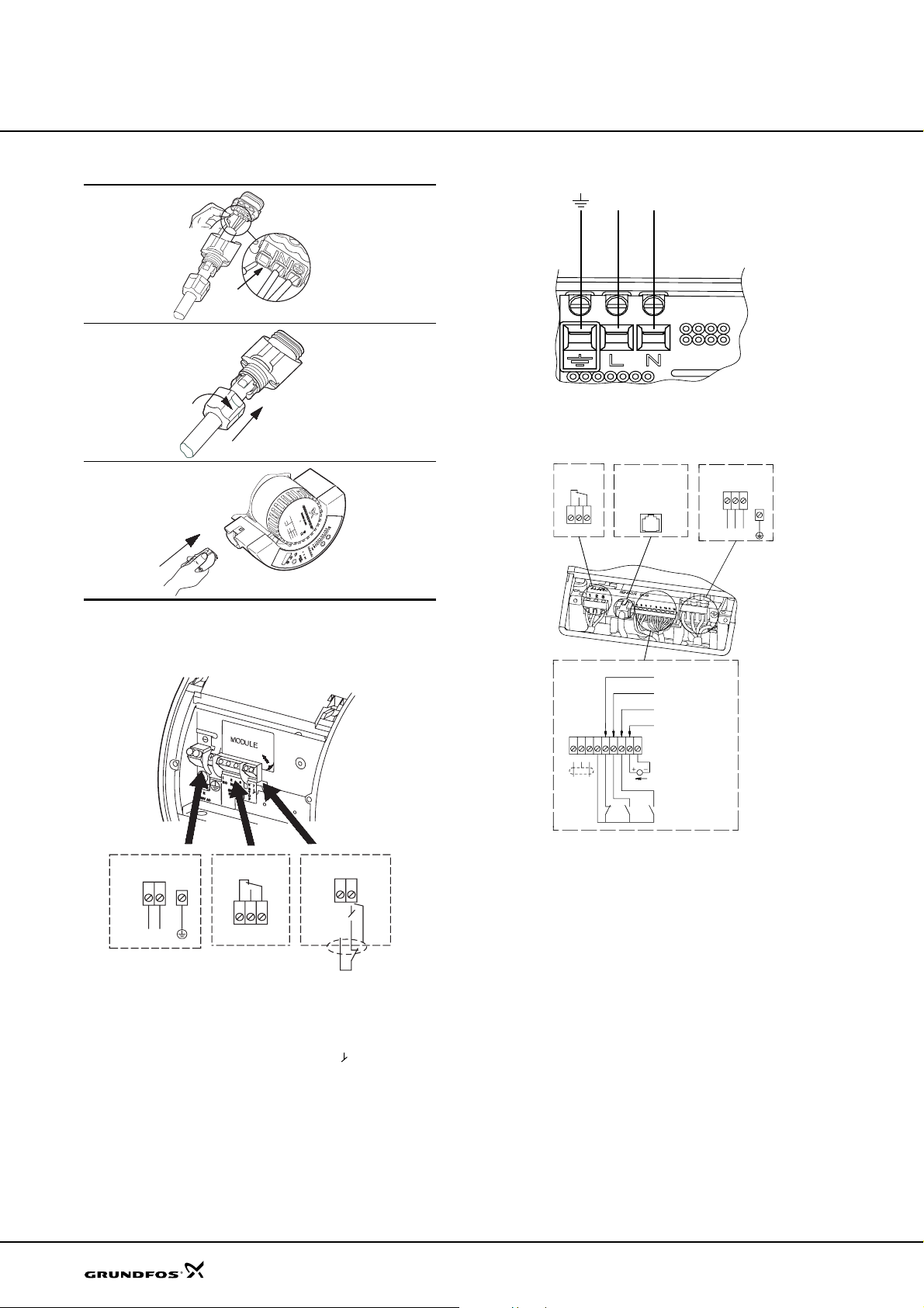
Single-phase MAGNA
1
2
3
Fig. 25 MAGNA 25-60, 25-100, 32-60, 32-100,
40-100(D), 50-100, mains connection with
Alpha power plug
Single-phase UPE
NL
TM03 0899 0705
TM00 4449 3399
Fig. 27 Single-phase UPE mains connection
TM03 0902 0705
TM03 0520 0105
Three-phase UPE(D)
213
Differential
pressure and
temperature
sensor
Signal
output
NCNO C
Mains
connection
L2
L3
L1
Mains
connection
L
N
Signal output
21 3
NC NOC
Start/stop
78
S
T
O
P
Potential-free relay input
Fig. 26 MAGNA 32-120, 40-120, 50-120, 65-120, 50-60,
65-60, mains connection
Note: If no external on/off switch is connected, the
connection across terminals STOP and should be
maintained.
Start/stop
Min. curve
(night-time duty)
Max. curve
Analog 0-10 V
987101112
DC 0-10 V
input
TM00 9120 3301
546
AYB
Fig. 28 Three-phase UPE(D) mains connection
Single-head pumps are connected a s shown above.
• If no external on/off switch is connected, the
connection across terminals 7 and 8 should be
maintained.
• If the 0-10 V input is used (terminals 11 and 12),
TM02 0235 1007
there must be a connection across terminals
7 and 9 (input for min. curve must be closed).
Twin-head pumps
Both pumps must be connected to the mains.
• A possible external controller is to be connected to
the master pump (terminals 7 to 12).
• If the twin-head pump is to be connected to a
PMU 2000 o r PCU 20 00, it must be set to single pump operation.
The bus connection between master and slave
pumps can be removed. Both master and slave
pumps must be connected to the bus system.
20
Page 21
Installation
Examples of connections
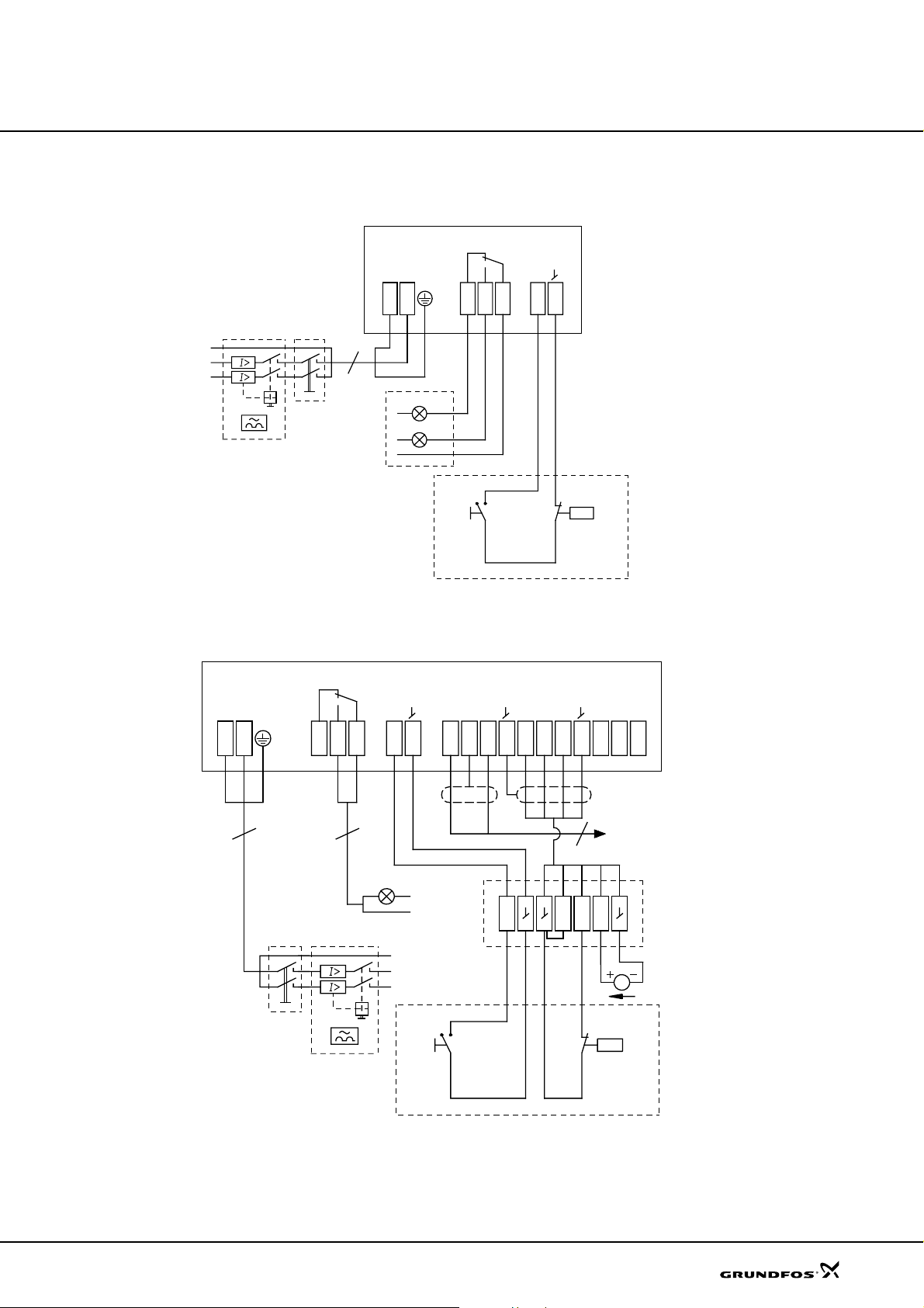
Connection to external controllers
Mains connection
Operation
Alarm
LN
NCNO C
Stop
S
T
O
P
32187
Start
MAGNA, UPE
Dry-running protection
Fig. 29
Example of MAGNA pump
Connection to external controllers
LN
S
T
NCNOC
O
P
MIN
MAX
10 V
XQZBYA
1 2 3 8 7 4 5 6 7 9 101112212223
Alarm
MIN
10 V
Mains connection
STOP
Stop
Start
MAX
GENIbus
Setpoint setting
DC 0-10 V
Frost protection
TM02 1322 3601
Fig. 30 Example of MAGNA pump with GENI module
TM02 1323 5101
21
Page 22
Curve conditions
Curve conditions
The guidelines below apply to the performance curve s
on pages 23 to 50:
•The bold parts of the curves show the
recommended performance range.
• Test liquid: Airless water.
• All curves show average values and should not be
used as guarantee curves. If a stated minimum
performance is required, individual measurements
must be made.
• MAGNA (D) and UPE(D) have been tested at 60 °C.
The conversion between head H [m] and pressure
[kPa] has been made for water at 60 °C
(ρ = 983.2 kg/m
e.g. hot water, the discharge pressure is
proportional to the density.
The pumps should not be used at a minimum flow rate
lying outside the areas indicated by the bold-faced
curves due to danger of pump overheating .
Note: Within MAGNA's performance range, the
constant- and proportional-pressure curves can be set
in steps of 1 m head on the control panel and 0.1 m
head with the R100.
3
). For liquids with other densities,
MAGNA, UPE
22
Page 23
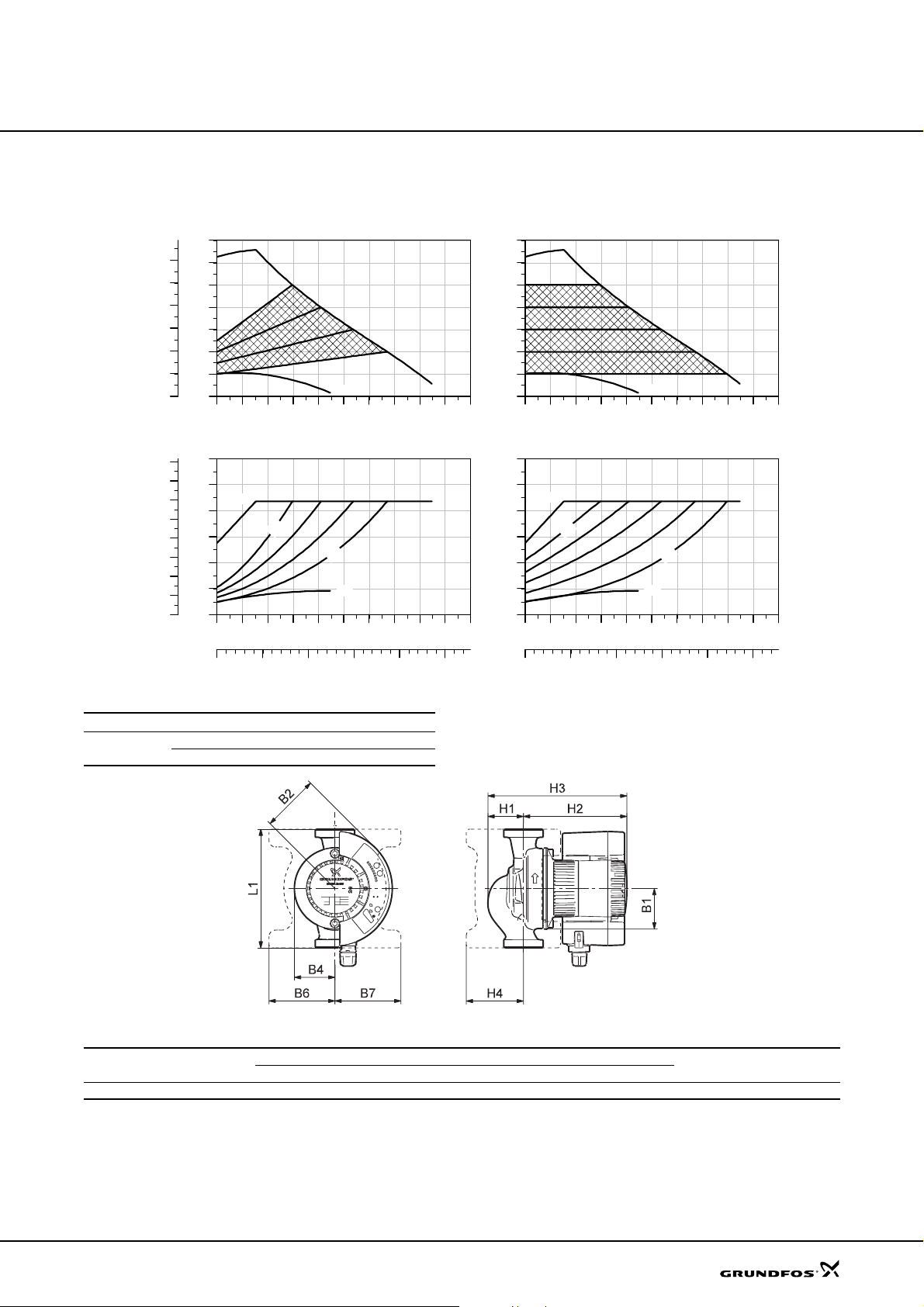
Technical data
MAGNA 25-60
MAGNA 25-60
[kPa]
P1
[hp]
0.16
0.14
0.12
0.10
0.08
0.06
0.04
0.02
0.00
H
p
[m]
7
60
6
50
5
40
4
30
3
20
2
10
1
0
0
0 1 2 3 4 5 6 7 8 Q [m³/h]
P1
[W]
120
100
MAX
80
60
40
20
0
0 1 2 3 4 5 6 7 8 Q [m³/h]
Proportional pressure Constant pressure
MAX
MIN
m
5
m
2
MIN
H
[m]
7
6
5
4
3
2
1
0
0 1 2 3 4 5 6 7 8 Q [m³/h]
P1
[W]
120
100
MAX
80
60
40
20
0
0 1 2 3 4 5 6 7 8 Q [m³/h]
MAX
MIN
m
5
m
1
MIN
0.0 0.5 1.0 1.5 2.0 Q [l/s]
0.0 0.5 1.0 1.5 2.0 Q [l/s]
Electrical data
Un [V] P1 [W] I
1 x 230-240 V
Min. 10 0.09
Max. 85 0.60
1/1
[A]
Dimensions and weights
Pump type
MAGNA 25-60 180 62 87 62 100 100 54 157 211 85 25 1 1/2 5.3 0.012
L1 B1 B2 B4 B6 B7 H1 H2 H3 H4 D1 G Gross
Dimensions [mm] Weight [kg]
Ship. vol.
[m
TM03 1469 2205
TM03 1234 1405
3
]
23
Page 24
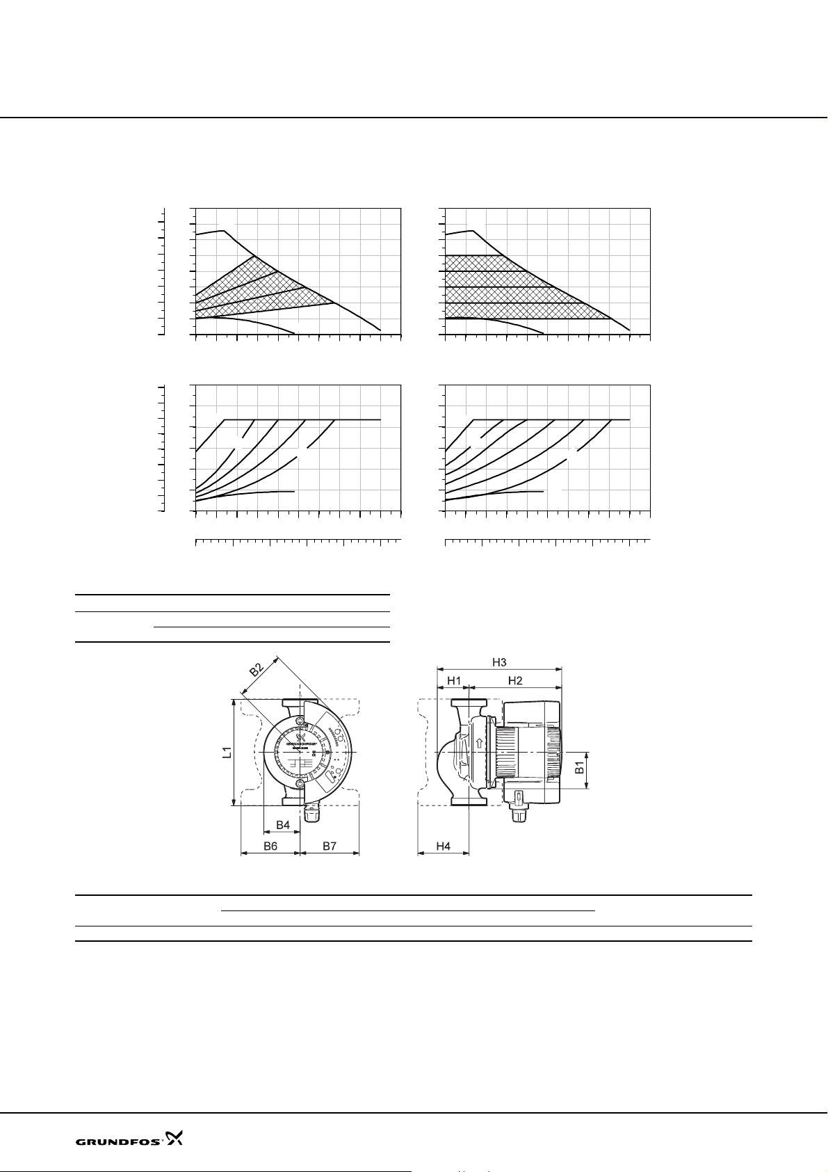
Technical data
MAGNA 32-60 (N)
MAGNA 32-60
[kPa]
70
60
50
40
30
20
10
P1
[hp]
0.16
0.14
0.12
0.10
0.08
0.06
0.04
0.02
0.00
H
p
[m]
8
7
6
5
4
3
2
1
0
0
0 1 2 3 4 5 6 7 8 Q [m³/h]
P1
[W]
120
100
MAX
80
60
40
20
0
0 1 2 3 4 5 6 7 8 Q [m³/h]
0.0 0.5 1.0 1.5 2.0 Q [l/s]
Proportional pressure Constant pressure
MAX
m
5
Electrical data
Un [V] P1 [W] I
1 x 230-240 V
Min. 10 0.09
Max. 85 0.6
MIN
H
[m]
8
7
MAX
6
5
4
3
2
1
0
0 1 2 3 4 5 6 7 8 Q [m³/h]
P1
[W]
120
100
MAX
80
m
2
MIN
[A]
1/1
60
40
20
0
m
5
0 1 2 3 4 5 6 7 8 Q [m³/h]
0.0 0.5 1.0 1.5 2.0 Q [l/s]
MAGNA 50-60 F is also available with stainless-steel
MIN
MIN
m
1
TM03 1848 3205
housing, type N.
24
Dimensions and weights
Pump type
PN 6 / PN 10
L1 B1 B2 B4 B6 B 7 H1 H2 H3 H4 D1 G Gross
Dimensions [mm] Weight [kg]
MAGNA 32-60 180 62 87 62 100 100 54 157 211 85 32 2 5.5 0.012
Ship. vol.
[m
TM03 1234 1405
3
]
Page 25
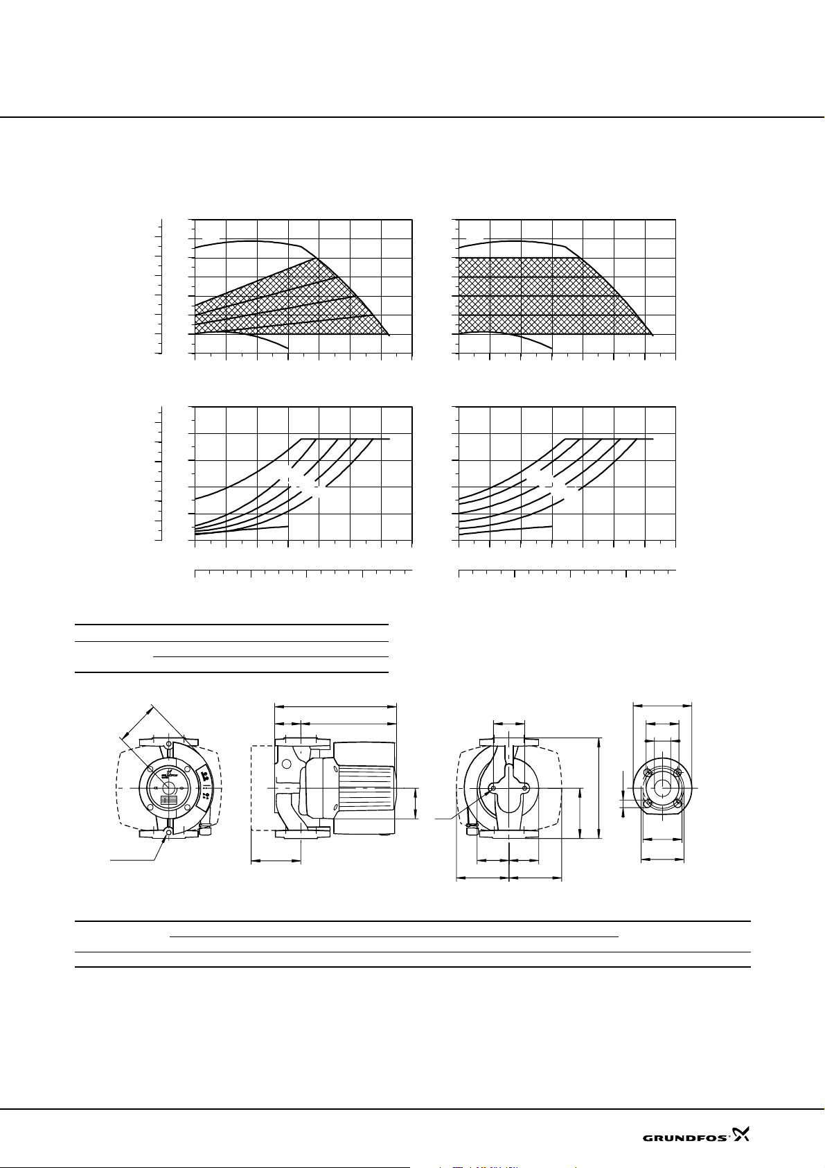
Technical data
MAGNA 50-60 F
MAGNA 50-60 F
p
[kPa]
60
50
40
30
20
10
P1
[hp]
0.6
0.5
0.4
0.3
0.2
0.1
0.0
H
[m]
7
6
5
4
3
2
1
0
0
0 4 8 12 16 20 Q [m³/h]
P1
[W]
500
400
300
200
100
0
0 4 8 12 16 20 Q [m³/h]
0 2 4 6 Q [l/s]
Proportional pressure Constant pressure
MAX
MIN
MAX
Electrical data
Un [V] P1 [W] I
1 x 230-240 V
Min. 25 0.17
Max. 400 1.7
H
[m]
7
MAX
6
5
4
3
2
1
MIN
0
0 4 8 12 16 20 Q [m³/h]
P1
[W]
500
400
m
5
m
4
m
3
m
2
MIN
[A]
1/1
300
MAX
200
100
0
0 4 8 12 16 20 Q [m³/h]
0 2 4 6 Q [l/s]
m
5
m
4
m
3
m
2
MIN
MAGNA 50-60 F is also available with stainless-steel
TM02 1912 2204
housing, type N.
D4
D2
B2
H3
H2H1
B5
D1
D5
L1
B1
M
L3
D3
Rp 1/4
H4
B4 B3
D3
B6 B7
Dimensions and weights
Pump type
PN 6 / PN 10
L1 L3 B1 B2 B3 B4 B5 B6 B7 H1 H2 H3 H4 D1 D2 D3 D4 D5 M Net Gross
Dimensions [mm] Weights [kg]
MAGNA 50-60 F 280 140 77 115 84 98 96 130 130 78 245 325 128 50 102 110/125 165 14/19 M12 18.5 20.5 0.043
Ship. vol.
[m
TM02 0239 5101
3
]
25
Page 26
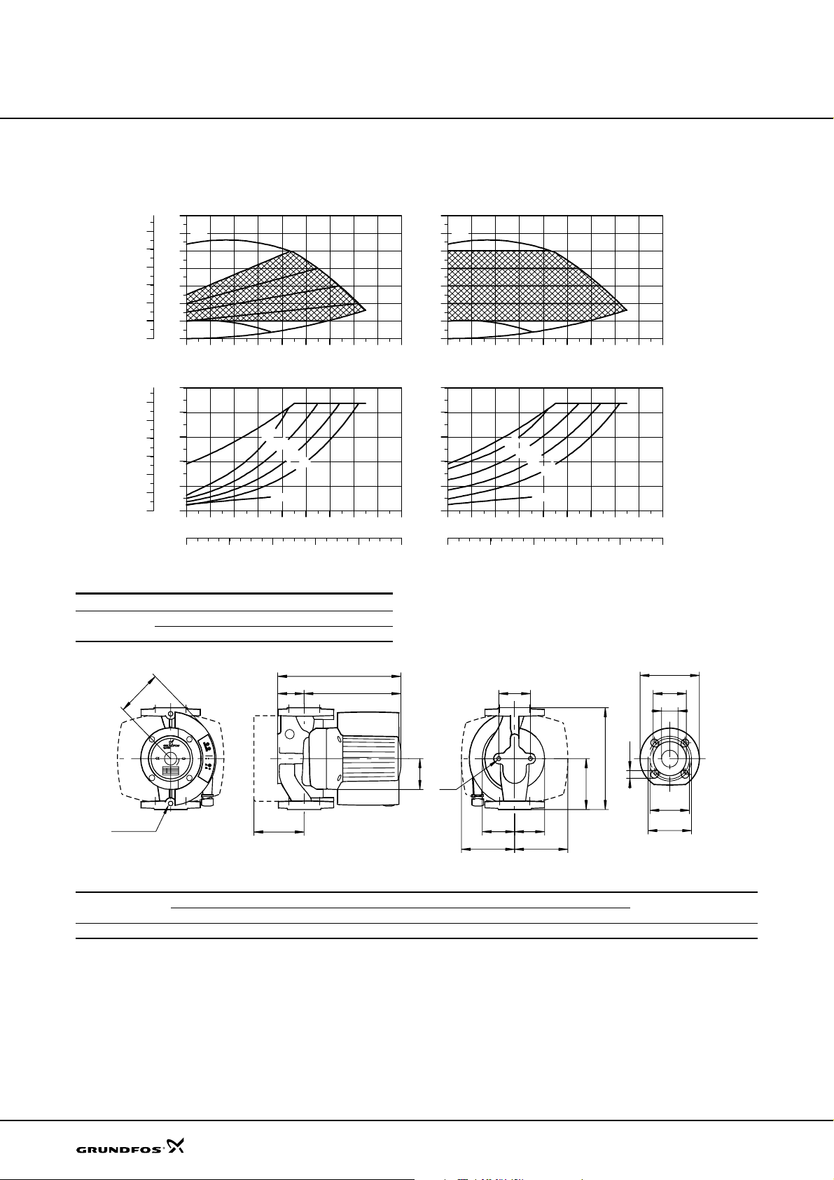
Technical data
MAGNA 65-60 F
H
[kPa]
60
50
40
30
20
10
P1
[hp]
0.6
0.5
0.4
0.3
0.2
0.1
0.0
p
[m]
7
6
MAX
5
4
3
2
1
MIN
0
0
0 4 8 12 16 20 24 28 Q [m³/h]
P1
[W]
500
400
300
MAX
200
100
0
0 4 8 12 16 20 24 28 Q [m³/h]
Proportional pressure Constant pressure
m
5
MIN
MAGNA 65-60 F
H
[m]
7
6
MAX
5
4
3
2
1
MIN
0
0 4 8 12 16 20 24 28 Q [m³/h]
P1
[W]
500
400
m
4
m
3
m
2
300
MAX
200
100
0
0 4 8 12 16 20 24 28 Q [m³/h]
m
5
m
4
m
3
m
2
MIN
0 2 4 6 8 Q [l/s]
0 2 4 6 8 Q [l/s]
Electrical data
Un [V] P1 [W] I
1 x 230-240 V
Min. 25 0.17
Max. 450 2.0
B2
Rp 1/4
H4
H3
1/1
[A]
MAGNA 65-60 F is also available with stainless-steel
housing, type N.
D4
H2H1
B5
L1
B1
M
L3
B4 B3
B6 B7
D2
D1
D5
D3
D3
Dimensions and weights
Pump type
PN 6 / PN 10
L1 L3 B1 B2 B3 B4 B5 B6 B7 H1 H2 H3 H4 D1 D2 D3 D4 D5 M Net Gross
Dimensions [mm] Weights [kg]
MAGNA 65-60 F 340 170 77 115 88 104 96 145 145 82 255 335 128 65 119 130/145 185 14/19 M12 22 24 0.043
Ship. vol.
[m
TM02 1913 2204
TM02 0239 5101
3
]
26
Page 27
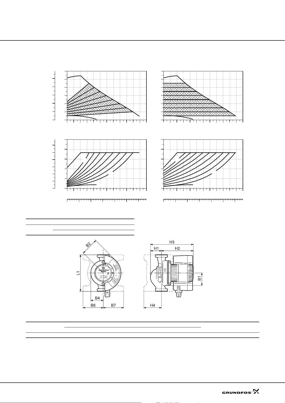
Technical data
MAGNA 25-100
MAGNA 25-100
[kPa]
100
P1
[hp]
0.30
0.25
0.20
0.15
0.10
0.05
0.00
H
p
[m]
12
10
80
8
60
6
40
4
20
2
0
0
0 1 2 3 4 5 6 7 8 9 Q [m³/h]
P1
[W]
250
200
MAX
150
100
50
0
0 1 2 3 4 5 6 7 8 9 Q [m³/h]
Proportional pressure Constant pressure
MAX
MIN
m
9
m
2
MIN
H
[m]
12
10
8
6
4
2
0
0 1 2 3 4 5 6 7 8 9 Q [m³/h]
P1
[W]
250
200
MAX
150
100
50
0
0 1 2 3 4 5 6 7 8 9 Q [m³/h]
MAX
MIN
m
9
MIN
m
1
0.0 0.5 1.0 1.5 2.0 2.5 Q [l/s]
0.0 0.5 1.0 1.5 2.0 2.5 Q [l/s]
Electrical data
Un [V] P1 [W] I
1 x 230-240 V
Min. 10 0.09
Max. 185 1.25
1/1
[A]
Dimensions and weights
Pump type
MAGNA 25-100 180 62 87 62 100 100 545 157 211 85 25 1 1/2 5.4 0.012
L1 B1 B2 B4 B6 B7 H1 H2 H3 H4 D1 G Gross
Dimensions [mm] Weight [kg]
Ship. vol.
[m
TM03 1470 2205
TM03 1234 1405
3
]
27
Page 28
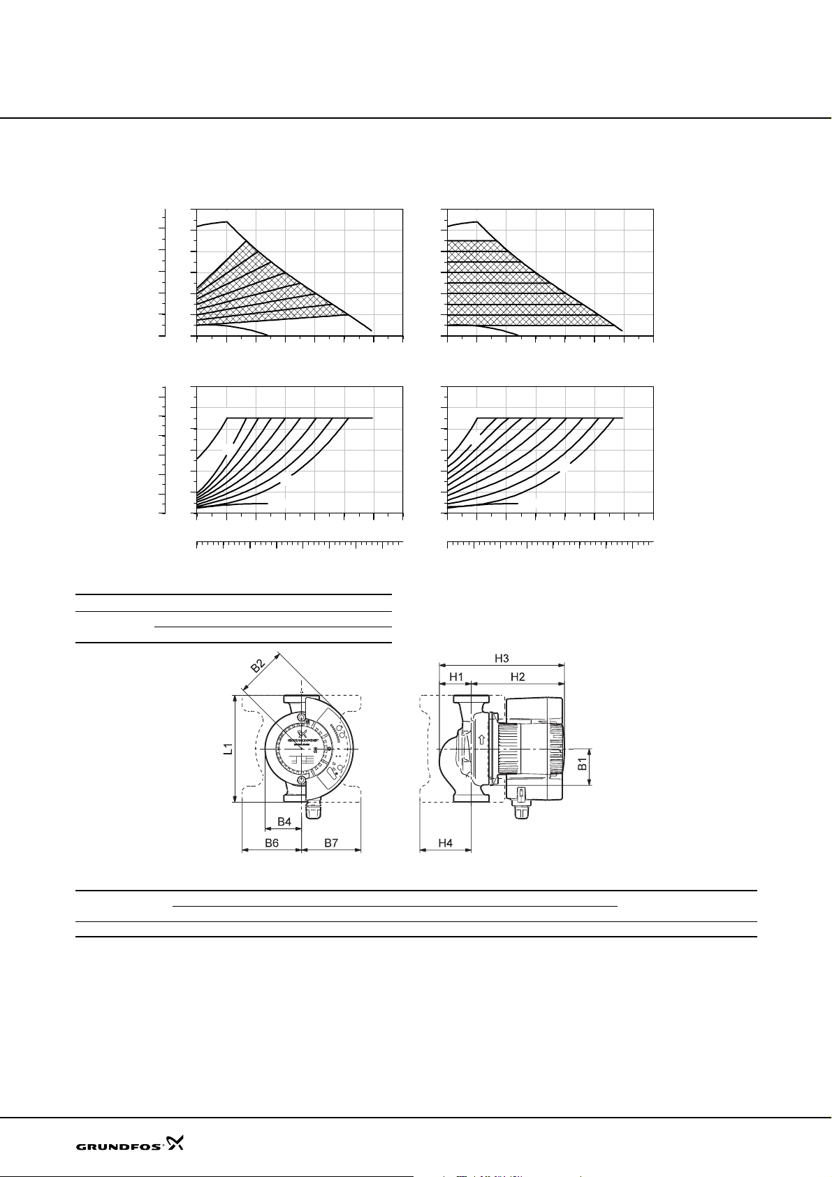
Technical data
MAGNA 32-100 (N)
MAGNA 32-100 (N)
[kPa]
100
80
60
40
20
P1
[hp]
0.30
0.25
0.20
0.15
0.10
0.05
0.00
H
p
[m]
12
MAX
10
8
6
4
2
0
0
0 2 4 6 8 10 Q [m³/h]
P1
[W]
240
200
160
120
MAX
80
40
0
0 2 4 6 8 10 Q [m³/h]
0.0 0.5 1.0 1.5 2.0 2.5 3.0 Q [l/s]
Proportional pressure Constant pressure
MIN
m
9
2
MIN
Electrical data
Un [V] P1 [W] I
1 x 230-240 V
Min. 10 0.1
Max. 180 1.23
H
[m]
12
MAX
10
8
6
4
2
0
0 2 4 6 8 10 Q [m³/h]
P1
[W]
240
200
160
120
m
[A]
1/1
MAX
m
9
80
40
0
0 2 4 6 8 10 Q [m³/h]
0.0 0.5 1.0 1.5 2.0 2.5 3.0 Q [l/s]
MAGNA 32-100 is also available with stainless-ste el
MIN
MIN
m
1
TM03 1849 3205
housing, type N.
28
Dimensions and weights
Pump type
L1 B1 B2 B4 B6 B7 H1 H 2 H3 H4 D1 G Gross
Dimensions [mm] Weights [kg]
MAGNA 32-100 (N) 180 62 87 62 100 100 54 157 211 8 5 32 2 5.6 6.0 (N) 0.012
Ship. vol.
[m
TM03 1234 1405
3
]
Page 29
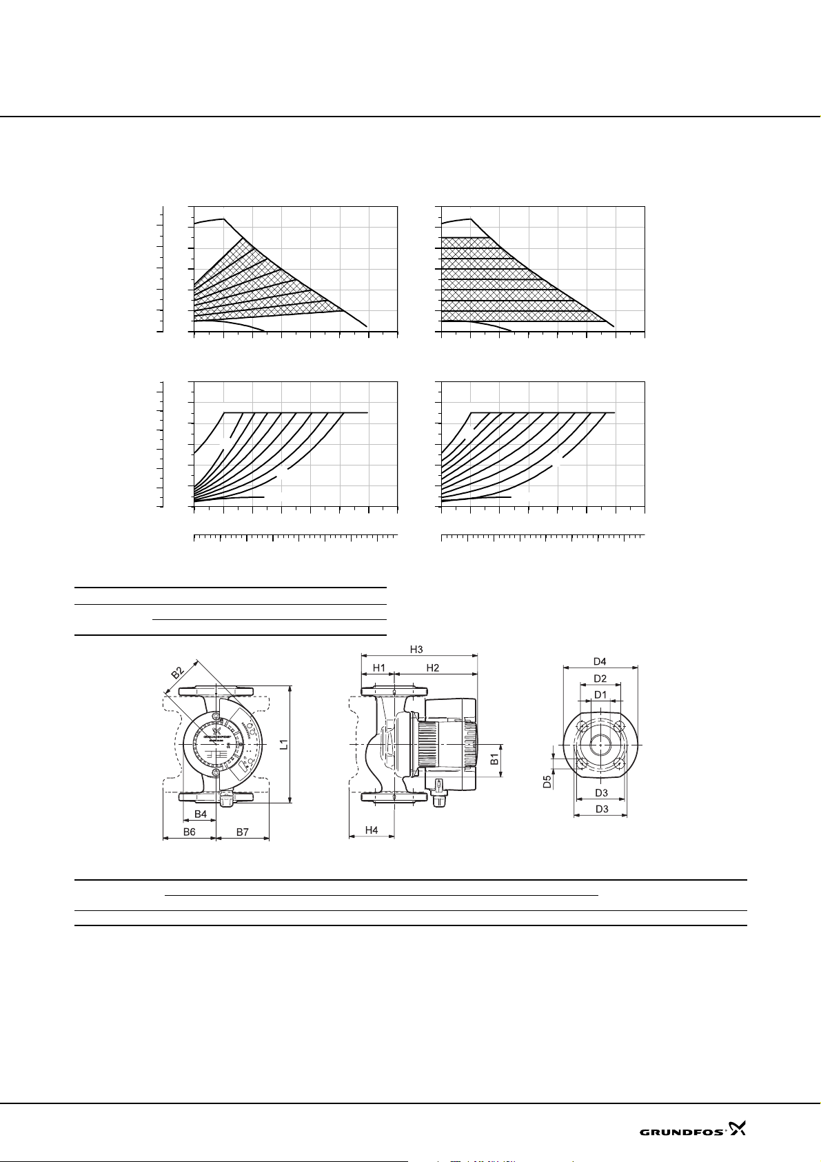
Technical data
MAGNA 32-100 F
MAGNA 32-100 F
[kPa]
100
80
60
40
20
P1
[hp]
0.30
0.25
0.20
0.15
0.10
0.05
0.00
H
p
[m]
12
10
8
6
4
2
0
0
0 2 4 6 8 10 Q [m³/h]
P1
[W]
240
200
160
120
80
40
0
0 2 4 6 8 10 Q [m³/h]
0.0 0.5 1.0 1.5 2.0 2.5 3.0 Q [l/s]
Proportional pressure Constant pressure
MAX
MIN
MAX
m
9
2
MIN
Electrical data
Un [V] P1 [W] I
1 x 230-240 V
Min. 10 0.1
Max. 180 1.23
H
[m]
12
MAX
10
8
6
4
2
0
0 2 4 6 8 10 Q [m³/h]
P1
[W]
240
200
160
120
m
[A]
1/1
MAX
m
9
80
40
0
0 2 4 6 8 10 Q [m³/h]
0.0 0.5 1.0 1.5 2.0 2.5 3.0 Q [l/s]
MIN
MIN
m
1
TM03 1849 3205
Dimensions and weights
Pump type
L1 B1 B2 B4 B6 B7 H1 H2 H3 H4 D1 D2 D3 D4 D5 PN Gross
Dimensions [mm] Weight [kg]
MAGNA 32-100 F 220 62 87 62 100 100 54 157 211 85 32 76 90/100 140 19 6/10 8.2 0.014
Ship. vol.
[m
TM03 1233 1405
3
]
29
Page 30
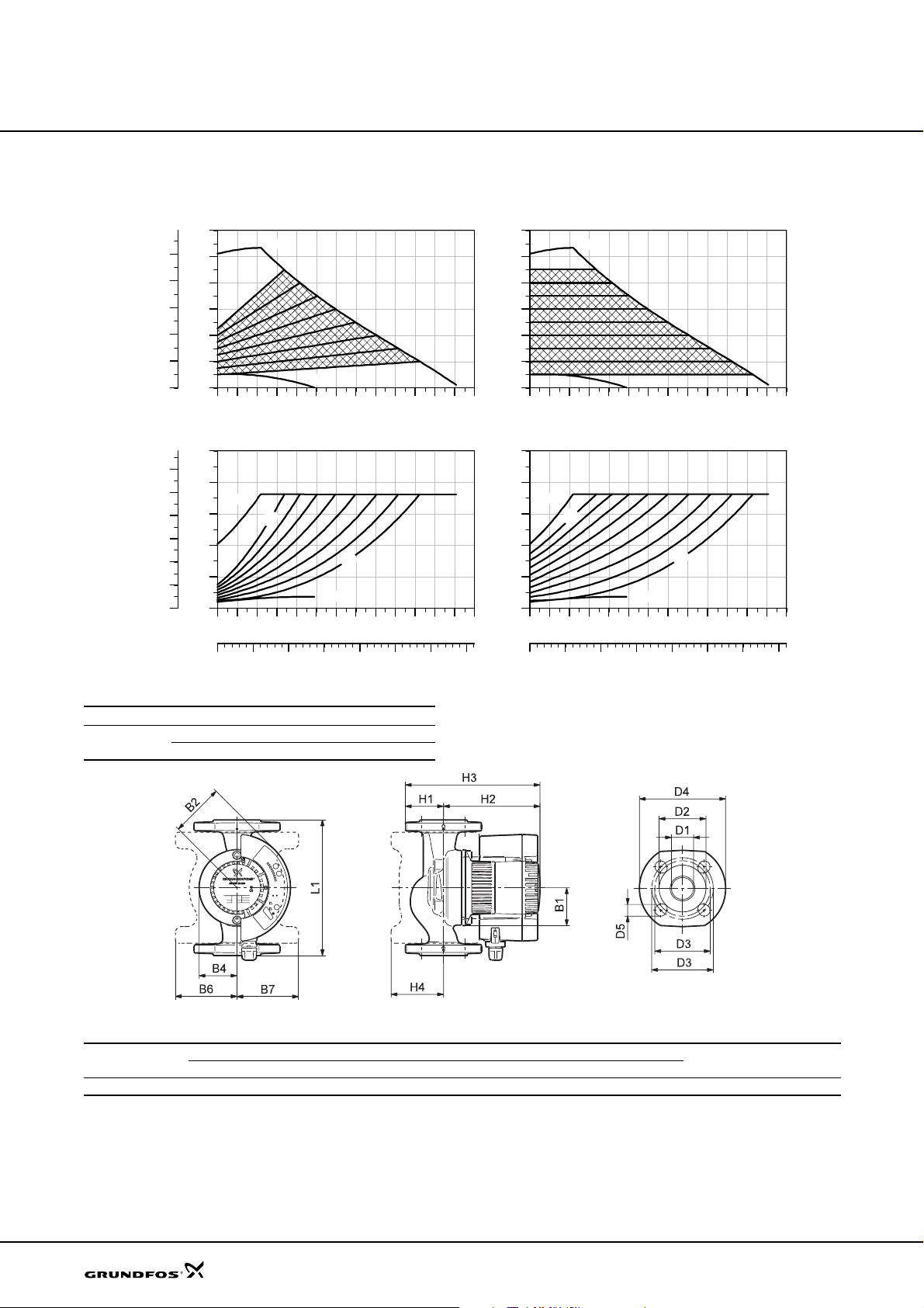
Technical data
MAGNA 40-100 F
MAGNA 40-100 F
[kPa]
100
P1
[hp]
0.30
0.25
0.20
0.15
0.10
0.05
0.00
H
p
[m]
12
10
80
8
60
6
40
4
20
2
0
0
0 1 2 3 4 5 6 7 8 9 10 Q [m³/h]
P1
[W]
250
200
MAX
150
100
50
0
0 1 2 3 4 5 6 7 8 9 10 Q [m³/h]
Proportional pressure Constant pressure
MAX
MIN
m
9
m
2
MIN
H
[m]
12
10
8
6
4
2
0
0 1 2 3 4 5 6 7 8 9 10 Q [m³/h]
P1
[W]
250
200
150
100
50
0
0 1 2 3 4 5 6 7 8 9 10 Q [m³/h]
MAX
MIN
MAX
9 m
MIN
m
1
0.0 0.5 1.0 1.5 2.0 2.5 3.0 Q [l/s]
0.0 0.5 1.0 1.5 2.0 2.5 3.0 Q [l/s]
Electrical data
Un [V] P1 [W] I
1 x 230-240 V
Min. 10 0.09
Max. 180 1.26
1/1
[A]
Dimensions and weights
Pump type
MAGNA 40-100 F 220 62 87 62 100 100 62 157 219 85 40 84 100/110 150 19 6/10 8.3 0.014
L1 B1 B2 B4 B6 B7 H1 H2 H3 H4 D1 D2 D3 D4 D5 PN Gross
Dimensions [mm] Weight [kg]
Ship. vol.
[m
TM03 1566 2305
TM03 1233 1405
3
]
30
Page 31
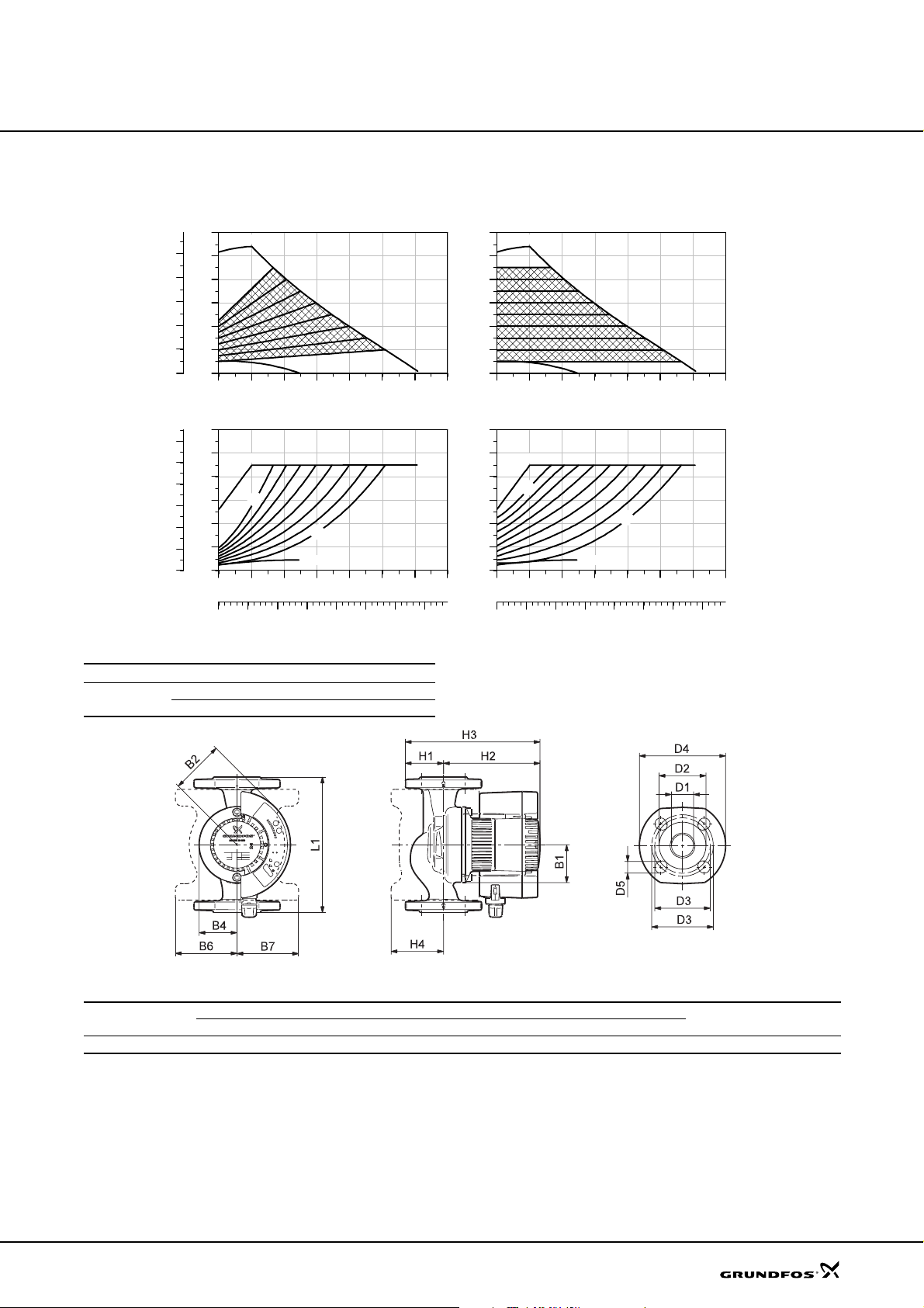
Technical data
MAGNA 50-100 F
MAGNA 50-100 F
[kPa]
100
80
60
40
20
P1
[hp]
0.30
0.25
0.20
0.15
0.10
0.05
0.00
H
p
[m]
12
10
8
6
4
2
0
0
0 2 4 6 8 10 Q [m³/h]
P1
[W]
240
200
160
120
80
40
0
0 2 4 6 8 10 Q [m³/h]
0.0 0.5 1.0 1.5 2.0 2.5 3.0 Q [l/s]
Proportional pressure Constant pressure
MAX
MIN
MAX
m
9
2
MIN
Electrical data
Un [V] P1 [W] I
1 x 230-240 V
Min. 10 0.1
Max. 180 1.26
H
[m]
12
MAX
10
8
6
4
2
0
0 2 4 6 8 10 Q [m³/h]
P1
[W]
240
200
160
120
m
[A]
1/1
MAX
m
9
80
40
0
0 2 4 6 8 10 Q [m³/h]
0.0 0.5 1.0 1.5 2.0 2.5 3.0 Q [l/s]
MIN
MIN
m
1
TM03 1850 3205
Dimensions and weights
Pump type
L1 B1 B2 B4 B6 B7 H1 H2 H3 H4 D1 D2 D3 D4 D5 PN Gross
Dimensions [mm] Weight [kg]
MAGNA 50-100 F 240 62 87 62 104 104 73 1637 140 88 50 99 100/125 165 19 6/10 10.2 0.017
Ship. vol.
[m
TM03 1233 1405
3
]
31
Page 32
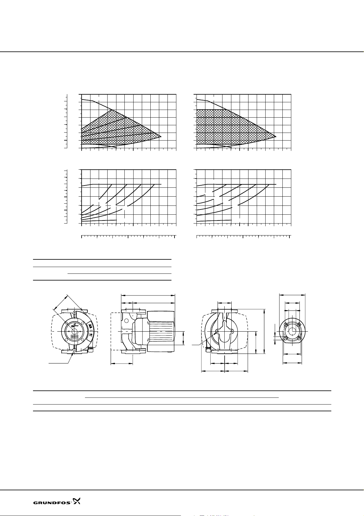
Technical data
MAGNA 32-120 F
H
[kPa]
120
100
80
60
40
20
P1
[hp]
0.8
0.7
0.6
0.5
0.4
0.3
0.2
0.1
0.0
p
[m]
14
12
10
8
6
4
2
MIN
0
0
0 2 4 6 8 10 12 14 16 18Q [m³/h]
P1
[W]
600
500
400
300
200
100
0
0 2 4 6 8 10 12 14 16 Q [m³/h]
Proportional pressure Constant pressure
MAX
MAX
m
0
1
m
m
8
6
MIN
MAGNA 32-120 F
H
[m]
14
12
10
8
6
4
2
0
P1
[W]
600
500
400
300
m
4
200
100
0
MAX
MIN
0 2 4 6 8 10 12 14 16 Q [m³/h]
MAX
m
0
1
m
8
m
6
m
4
MIN
0 2 4 6 8 10 12 14 16 Q [m³/h]
0 1 2 3 4 5 Q [l/s]
0 1 2 3 4 5 Q [l/s]
Electrical data
Un [V] P1 [W] I
1 x 230-240 V
Min. 25 0.17
Max. 430 1.8
B2
Rp 1/4
H4
H3
1/1
[A]
MAGNA 32-120 F is also available with stainless-steel
housing, type N.
D4
H2H1
B5
L1
B1
M
L3
B4 B3
B6 B7
D2
D1
D5
D3
D3
Dimensions and weights
Pump type
PN 6 / PN 10
L1 L3 B1 B2 B3 B4 B5 B6 B7 H 1 H2 H3 H4 D1 D2 D3 D4 D5 M Net Gross
Dimensions [mm] Weights [kg]
MAGNA 32-120 F 220 110 77 115 75 76 96 110 110 68 245 310 86 32 76 90/100 140 14/19 M12 15 17 0.034
Ship. vol.
[m
TM02 1910 2204
TM02 0239 5101
3
]
32
Page 33
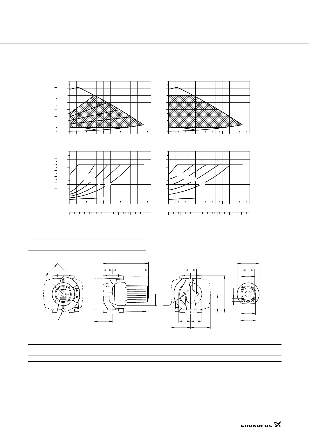
Technical data
MAGNA 40-120 F
MAGNA 40-120 F
p
[kPa]
120
100
80
60
40
20
0
P1
[hp]
0.8
0.7
0.6
0.5
0.4
0.3
0.2
0.1
0.0
H
[m]
14
12
10
8
6
4
2
MIN
0
0 2 4 6 8 10 12 14 16 18 Q [m³/h]
P1
[W]
600
500
400
300
200
100
0
0 2 4 6 8 10 12 14 16 18 Q [m³/h]
0 1 2 3 4 5 6Q [l/s]
Proportional pressure Constant pressure
MAX
MAX
m
0
1
m
8
m
6
MIN
Electrical data
Un [V] P1 [W] I
1 x 230-240 V
Min. 25 0.17
Max. 450 2.0
H
[m]
14
12
10
8
6
4
0
P1
[W]
600
500
400
300
m
4
[A]
1/1
200
100
0
MAX
2
MIN
0 2 4 6 8 10 12 14 16 18 Q [m³/h]
MAX
m
0
1
m
8
m
6
m
4
MIN
0 2 4 6 8 10 12 14 16 18 Q [m³/h]
0 1 2 3 4 5 6Q [l/s]
MAGNA 40-120 F is also available with stainless-steel
TM02 1911 2204
housing, type N.
D4
D2
B2
H3
H2H1
B5
D1
D5
L1
B1
M
L3
D3
Rp 1/4
H4
B4 B3
D3
B6 B7
Dimensions and weights
Pump type
PN 6 / PN 10
L1 L 3 B1 B2 B3 B4 B5 B6 B7 H1 H2 H3 H4 D1 D2 D3 D4 D5 M Net Gross
Dimensions [mm] Weights [kg]
MAGNA 40-120 F 250 125 77 115 75 80 96 115 115 65 266 310 102 40 84 100/110 150 14/19 M12 15.5 17.5 0.034
Ship. vol.
[m
TM02 0239 5101
3
]
33
Page 34
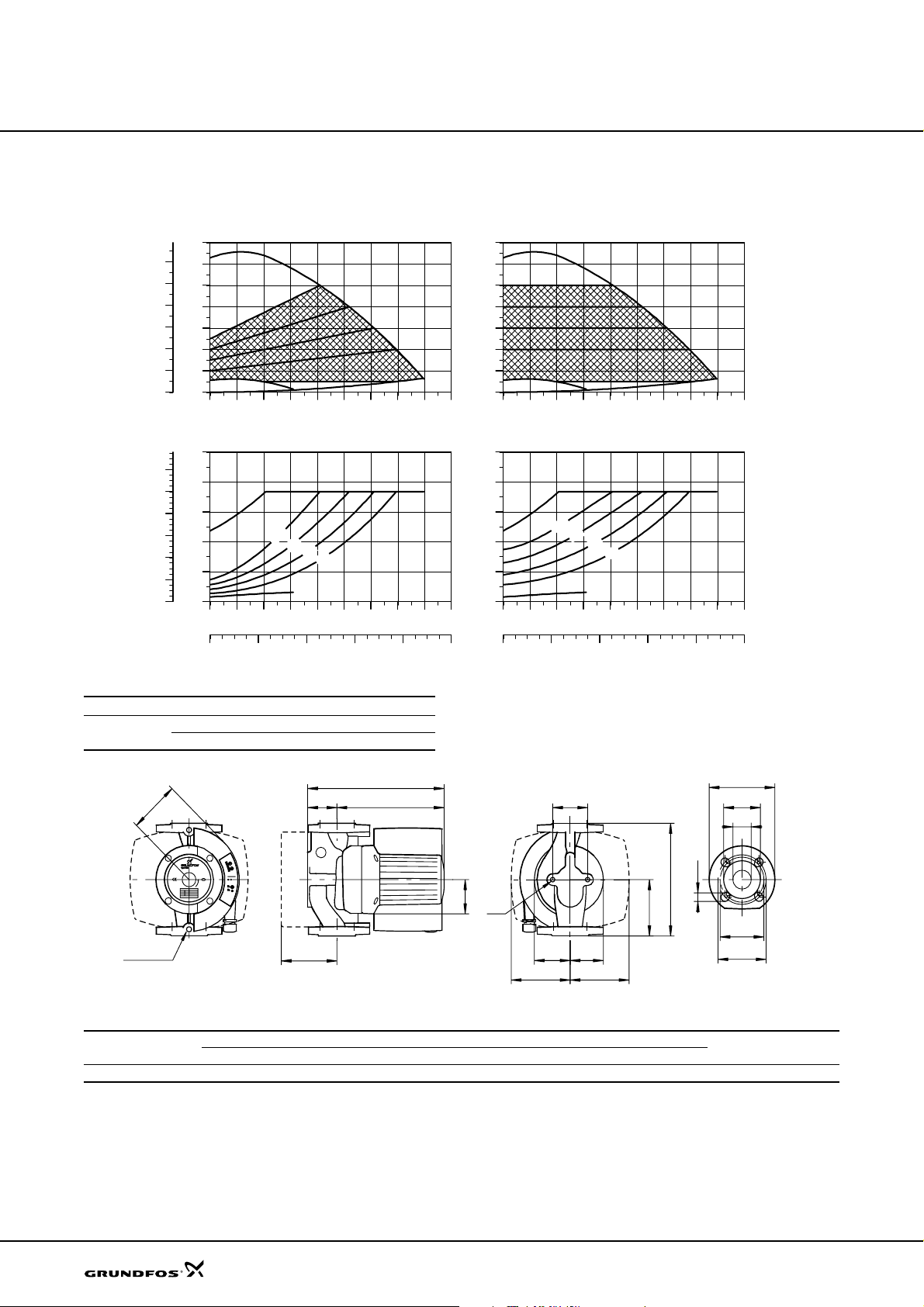
Technical data
MAGNA 50-120 F
MAGNA 50-120 F
p
[kPa]
120
100
80
60
40
20
P1
[hp]
1.2
1.0
0.8
0.6
0.4
0.2
0.0
H
[m]
14
12
10
8
6
4
2
MIN
0
0
0 4 8 12 16 20 24 28 Q [m³/h]
P1
[W]
1000
800
MAX
600
400
200
0
0 4 8 12 16 20 24 28 Q [m³/h]
0 2 4 6 8 Q [l/s]
Proportional pressure Constant pressure
MAX
m
0
1
m
8
m
6
MIN
Electrical data
Un [V] P1 [W] I
1 x 230-240 V
Min. 35 0.28
Max. 800 3.5
H
[m]
14
12
10
8
6
4
2
MIN
0
0 4 8 12 16 20 24 28 Q [m³/h]
P1
[W]
1000
800
MAX
600
400
m
4
[A]
1/1
200
0
0 4 8 12 16 20 24 28 Q [m³/h]
0 2 4 6 8 Q [l/s]
MAGNA 50-120 F is also available with stainless-steel
MAX
m
0
1
m
8
m
6
m
4
MIN
TM02 8814 2204
housing, type N.
D4
D2
B2
H3
H2H1
B5
D1
D5
L1
B1
M
L3
D3
Rp 1/4
H4
B4 B3
D3
B6 B7
Dimensions and weights
Pump type
PN 6 / PN 10
L1 L3 B1 B2 B3 B4 B5 B6 B7 H1 H2 H3 H4 D1 D2 D3 D4 D5 M Net Gross
Dimensions [mm] Weights [kg]
MAGNA 50-120 F 280 140 77 125 84 98 96 130 130 78 245 325 128 50 102 110/125 165 14/19 M12 22 24 0.043
Ship. vol.
[m
TM02 0239 5101
3
]
34
Page 35
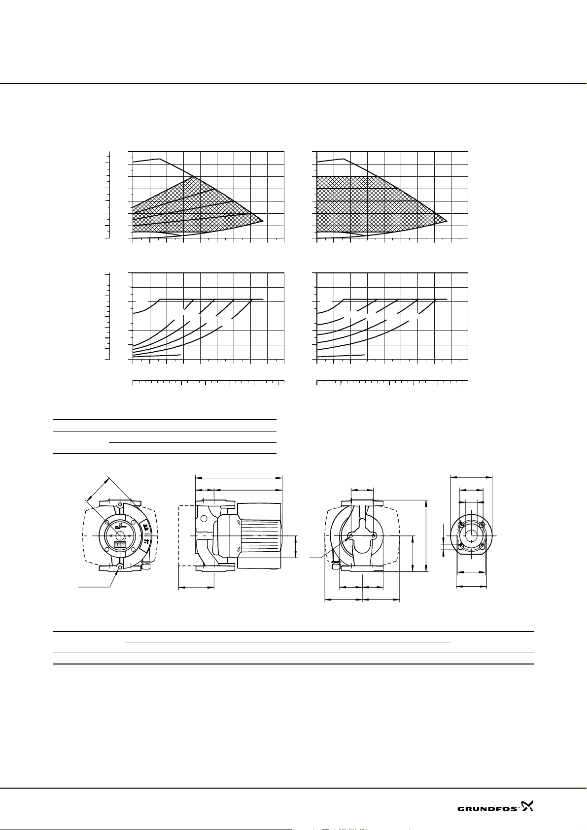
Technical data
MAGNA 65-120 F
H
p
[kPa]
120
100
80
60
40
20
P1
[hp]
1.6
1.4
1.2
1.0
0.8
0.6
0.4
0.2
0.0
[m]
14
MAX
12
10
8
6
4
2
MIN
0
0
0 5 10 15 20 25 30 35
P1
[W]
1200
1000
800
MAX
600
400
200
0
0 5 10 15 20 25 30 35
Proportional pressure Constant pressure
m
0
m
1
8
MIN
MAGNA 65-120 F
H
[m]
14
MAX
12
10
8
6
4
2
MIN
0
Q [m³/h]
m
m
6
4
Q [m³/h]
0 5 10 15 20 25 30 35
P1
[W]
1200
1000
800
MAX
600
400
200
0
0 5 10 15 20 25 30 35 Q [m³/h]
m
0
1
8
MIN
m
6
m
m
4
Q [m³/h]
0 2 4 6 8 10 Q [l/s]
0 2 4 6 8 10 Q [l/s]
Electrical data
Un [V] P1 [W] I
1 x 230-240 V
Min. 35 0.28
Max. 900 3.9
B2
Rp 1/4
H4
H3
1/1
[A]
MAGNA 65-120 F is also available with stainless-steel
housing, type N.
D4
H2H1
B5
L1
B1
M
L3
B4 B3
B6 B7
D2
D1
D5
D3
D3
Dimensions and weights
Pump type
PN 6 / PN 10
L1 L3 B1 B2 B3 B4 B5 B6 B7 H1 H2 H3 H4 D1 D2 D3 D4 D5 M Net Gross
Dimensions [mm] Weights [kg]
MAGNA 65-120 F 340 170 77 125 88 104 96 145 145 82 255 335 128 65 119 130/145 185 14/19 M12 25.5 27.5 0.043
Ship. vol.
[m
TM02 8815 2204
TM02 0239 5101
3
]
35
Page 36
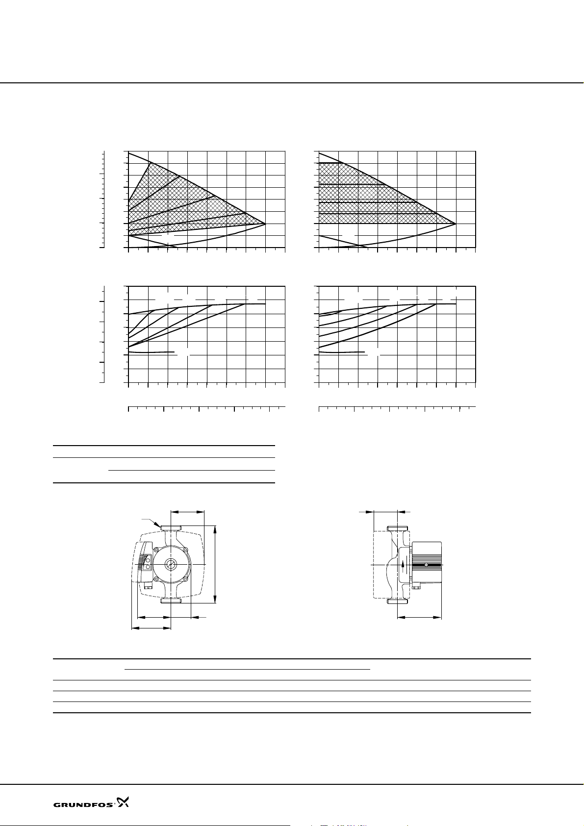
Technical data
UPE 15-40, UPE 25-40, UPE 32-40
UPE 15-40, UPE 25-40, UPE 32-40
[kPa]
[hp]
0.08
0.06
0.04
0.02
0.00
P1
H
p
[m]
4.0
3.5
30
3.0
2.5
20
2.0
1.5
10
1.0
0.5
0.0
0
0.0 0.4 0.8 1.2 1.6 2.0 2.4 Q [m³/h]
P1
[W]
70
60
50
40
30
20
10
0
0.0 0.4 0.8 1.2 1.6 2.0 2.4 Q [m³/h]
0.0 0.2 0.4 0.6 Q [l/s]
Proportional pressure Constant pressure
MAX
MIN
3 m
3.5 m
MIN
Electrical data
Un [V] P1 [W] I
1 x 230-240 V
Min. 20 0.18
Max. 60 0.26
2.2 m
1/1
1.4 m
[A]
MAX
H
[m]
4.0
3.5
3.0
2.5
2.0
1.5
1.0
0.5
0.0
0.0 0.4 0.8 1.2 1.6 2.0 2.4 Q [m³/h]
P1
[W]
70
60
50
40
30
20
10
0
0.0 0.4 0.8 1.2 1.6 2.0 2.4 Q [m³/h]
0.0 0.2 0.4 0.6 Q [l/s]
MAX
MIN
3.5 m
MIN
2.7 m
1.8 m
1.4 m
MAX
UPE 25-40 is also available with bronze housing,
type B.
TM01 0595 2002
G
B4
H3
L1
B1
B2
H2
B3
Dimensions and weights
Pump type
UPE 15-40 130 85 47 105 77 102 57 1 3.0 3.8 0.0061
UPE 25-40 180 85 47 105 77 102 57 1 1/2 3.0 3.8 0.0061
UPE 32-40 180 85 47 105 77 102 57 2 2.7 3.5 0.0061
Weights of bronze versions are approx. 10 % higher.
L1 B1 B2 B3 B4 H2 H3 G Net Gros s
Dimensions [mm] Weights [kg]
Ship. vol.
[m
TM02 4361 0702
3
]
36
Page 37
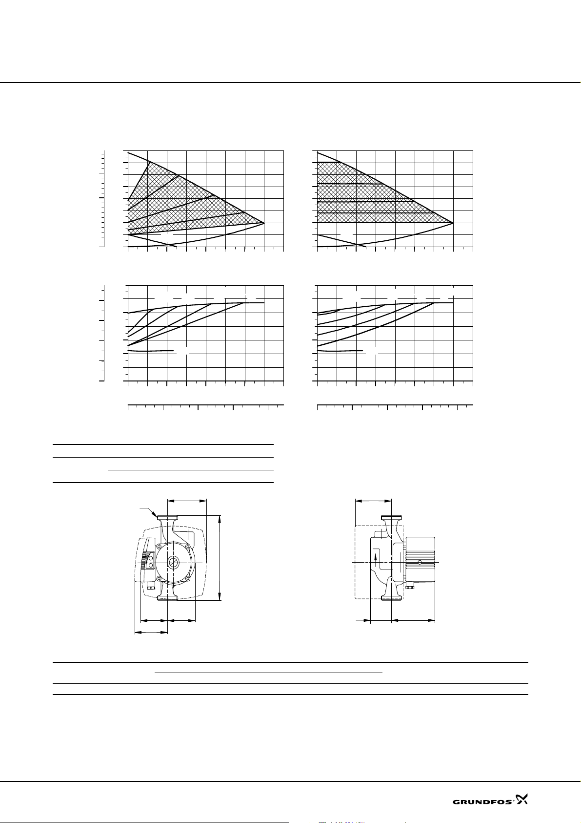
Technical data
UPE 25-40 A
UPE 25-40 A
[kPa]
[hp]
0.08
0.06
0.04
0.02
0.00
P1
H
p
[m]
4.0
3.5
30
3.0
2.5
20
2.0
1.5
10
1.0
0.5
0.0
0
0.0 0.4 0.8 1.2 1.6 2.0 2.4 Q [m³/h]
P1
[W]
70
60
50
40
30
20
10
0
0.0 0.4 0.8 1.2 1.6 2.0 2.4 Q [m³/h]
Proportional pressure
MAX
MIN
3 m
3.5 m
MIN
2.2 m
1.4 m
MAX
H
[m]
4.0
3.5
3.0
2.5
2.0
1.5
1.0
0.5
0.0
0.0 0.4 0.8 1.2 1.6 2.0 2.4 Q [m³/h]
P1
[W]
70
60
50
40
30
20
10
0
0.0 0.4 0.8 1.2 1.6 2.0 2.4 Q [m³/h]
Constant pressure
MAX
MIN
3.5 m
MIN
2.7 m
1.8 m
1.4 m
MAX
0.0 0.2 0.4 0.6 Q [l/s]
0.0 0.2 0.4 0.6 Q [l/s]
Electrical data
Un [V] P1 [W] I
1 x 230-240 V
Min. 20 0.18
Max. 60 0.26
G
B1
B4
B2
B3
L1
1/1
[A]
H3
H1
H2
Dimensions and weights
Pump type
UPE 25-40 A 180 72 65 91 92 49 112 80 1 1/2 3.5 4.3 0.0061
L1 B1 B2 B3 B4 H1 H2 H3 G Net Gross
Dimensions [mm] Weights [kg]
Ship. vol.
[m
TM01 0595 2002
TM00 4472 3402
3
]
37
Page 38
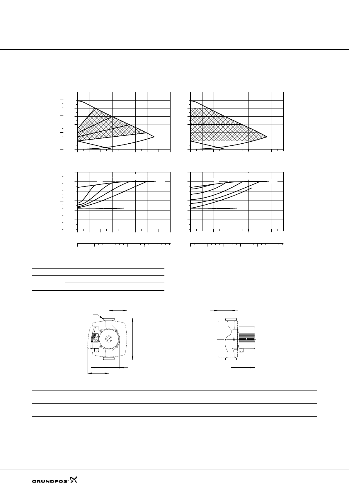
Technical data
UPE 25-60, UPE 32-60
UPE 25-60, UPE 32-60
[kPa]
60
40
20
P1
[hp]
0.16
0.12
0.08
0.04
0.00
H
p
[m]
7
MAX
6
5
4
3
2
1
0
0
0.0 0.5 1.0 1.5 2.0 2.5 3.0
P1
[W]
120
100
80
60
40
20
0
0.0 0.5 1.0 1.5 2.0 2.5 3.0 Q [m³/h]
Proportional pressure
MIN
4 m
5 m
MIN
3 m
2 m
Q [m³/h]
MAX
H
[m]
7
MAX
6
5
4
3
2
1
0
0.0 0.5 1.0 1.5 2.0 2.5 3.0
P1
[W]
120
100
80
60
40
20
0
0.0 0.5 1.0 1.5 2.0 2.5 3.0 Q [m³/h]
Constant pressure
MIN
4 m
5 m
MIN
3 m
1 m
2 m
Q [m³/h]
MAX
0.0 0.2 0.4 0.6 0.8 Q [l/s]
0.0 0.2 0.4 0.6 0.8 Q [l/s]
Electrical data
Un [V] P1 [W] I
1 x 230-240 V
Min. 40 0.28
Max. 100 0.44
G
B1
B4
B2
B3
L1
1/1
[A]
UPE 25-60 is also available with bronze housing,
type B.
H3
H2
Dimensions and weights
Pump type
UPE 25-60
UPE 32-60 180 85 47 105 77 102 57 2 2.7 3.1 0.0061
Weights of bronze versions are approx. 10 % higher.
L1 B1 B2 B3 B4 H2 H3 G Net Gros s
130 85 47 105 77 102 57 1 1/2 2.4 2.6 0.0061
180 85 47 105 77 102 57 1 1/2 2.6 3.0 0.0061
Dimensions [mm] Weights [kg]
Ship. vol.
[m
TM00 4545 2002
TM02 4361 0702
3
]
38
Page 39
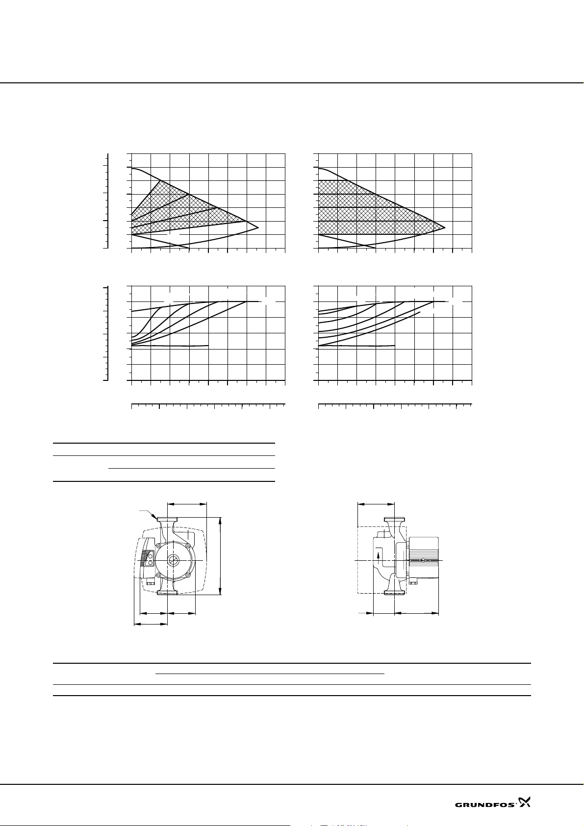
Technical data
UPE 25-60 A
UPE 25-60 A
Proportional pressure
MIN
4 m
5 m
[kPa]
[hp]
0.16
0.12
0.08
0.04
0.00
60
40
20
P1
H
p
[m]
7
MAX
6
5
4
3
2
1
0
0
0.0 0.5 1.0 1.5 2.0 2.5 3.0
P1
[W]
120
100
80
60
40
20
0
0.0 0.5 1.0 1.5 2.0 2.5 3.0 Q [m³/h]
0.0 0.2 0.4 0.6 0.8 Q [l/s]
Electrical data
Un [V] P1 [W] I
1 x 230-240 V
Min. 40 0.28
Max. 100 0.44
MIN
3 m
1/1
2 m
[A]
Q [m³/h]
MAX
H
[m]
7
MAX
6
5
4
3
2
1
0
0.0 0.5 1.0 1.5 2.0 2.5 3.0
P1
[W]
120
100
80
60
40
20
0
0.0 0.5 1.0 1.5 2.0 2.5 3.0 Q [m³/h]
0.0 0.2 0.4 0.6 0.8 Q [l/s]
Constant pressure
MIN
4 m
5 m
MIN
3 m
2 m
1 m
Q [m³/h]
MAX
TM00 4545 2002
G
B4
H3
L1
B1
B2
H1
H2
B3
Dimensions and weights
Pump type
UPE 25-60 A 180 72 65 91 92 49 112 80 1 1/2 3.6 4.0 0.0061
L1 B1 B2 B3 B4 H1 H2 H3 G Net Gross
Dimensions [mm] Weights [kg]
Ship. vol.
[m
TM00 4472 3402
3
]
39
Page 40
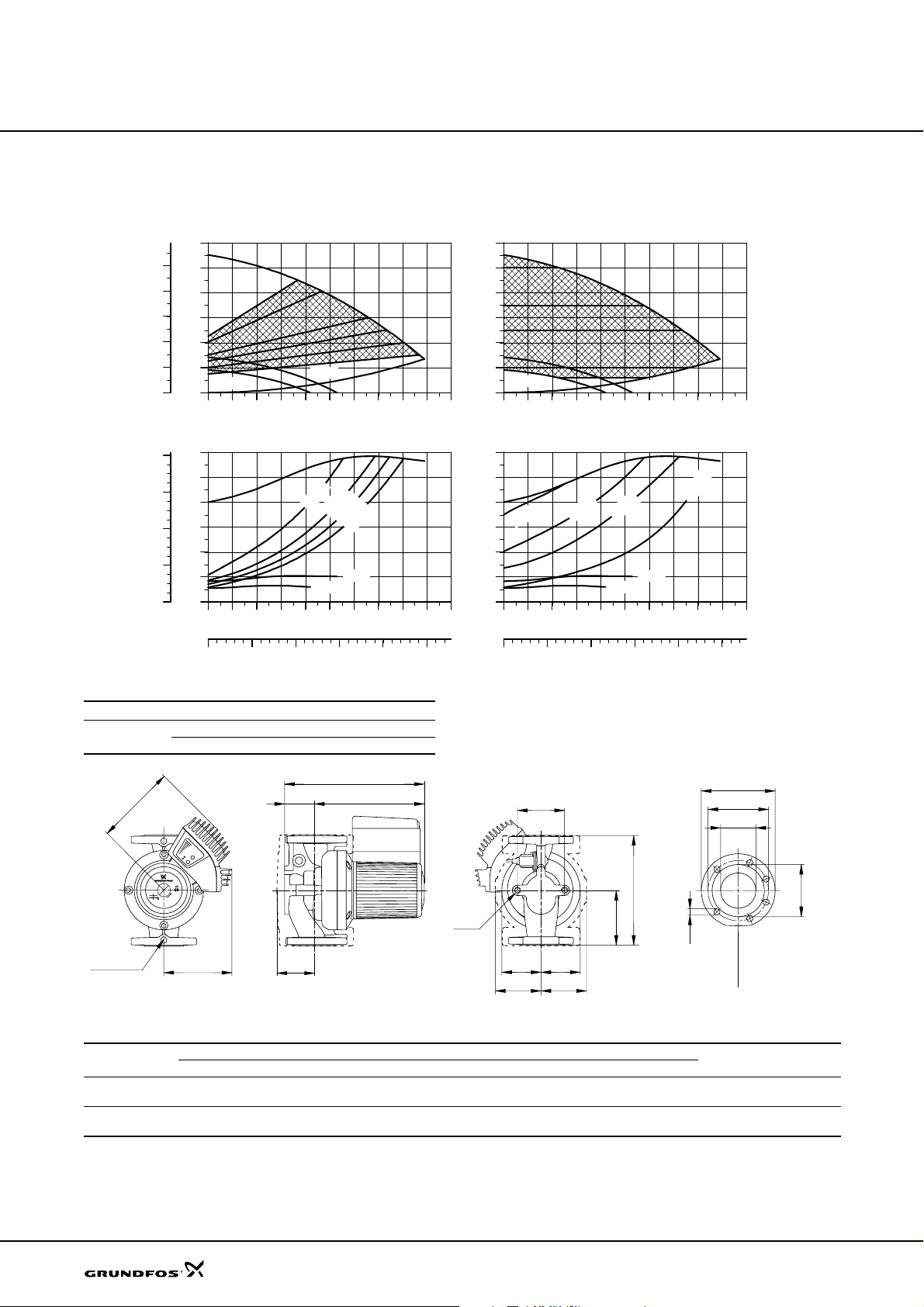
Technical data
UPE 100-60 F
UPE 100-60 F
p
[kPa]
50
40
30
20
10
P1
[hp]
1.6
1.2
0.8
0.4
0.0
H
[m]
6
5
4
3
2
1
MIN 1
0
0
0 10 20 30 40 50 60 70 80 Q [m³/h]
P1
[W]
1200
1000
800
600
400
200
0
0 10 20 30 40 50 60 70 80 Q [m³/h]
0 5 10 15 20 Q [l/s]
Proportional pressure
MAX
MIN 2
4.0 m
Electrical data
Un [V] P1 [W] I
3 x 400-415 V
Min. 110 0.27
Max. 1160 2.13
3.0 m
MIN 1
2.5 m
2.0 m
MIN 2
1/1
[A]
MAX
H
[m]
6
5
4
3
2
1
MIN 1
0
0 10 20 30 40 50 60 70 80 Q [m³/h]
P1
[W]
1200
1000
800
5.0 m
600
400
200
0
0 10 20 30 40 50 60 70 80 Q [m³/h]
0 5 10 15 20 Q [l/s]
Constant pressure
MAX
3.5 m
2.5 m
MIN 1
MIN 2
MAX
1.0 m
MIN 2
UPE 100-60 F is also available with bronze housing,
type B.
TM00 9410 2002
H1
H4
Rp 1/4
B2
B1
Dimensions and weights
Pump type
UPE 100-60 F
(PN 6)
UPE 100-60 F
(PN 10)
Weights of bronze versions are approx. 10 % higher.
L1 L2 L3 B1 B2 B4 B5 B7 B8 B9 H1 H2 H3 H4 D1 D2 D3 D4 D5 M Net Gross
450 – 225 170 205 175 125 200 217 173 122 313 435 186 100 158 170 220 19 M16 51.7 53.9 0 .071
450 – 225 170 205 175 125 200 217 173 122 313 435 186 100 158 180 220 19 M16 49.2 51.4 0 .071
H3
H2
B7
L1
M
L3
D5
B5
B4
B8
B9
Dimensions [mm] Weights [kg]
PN 6
D4
D3
D1
PN 10
D2
Ship. vol.
3
[m
]
TM02 0697 5000
40
Page 41
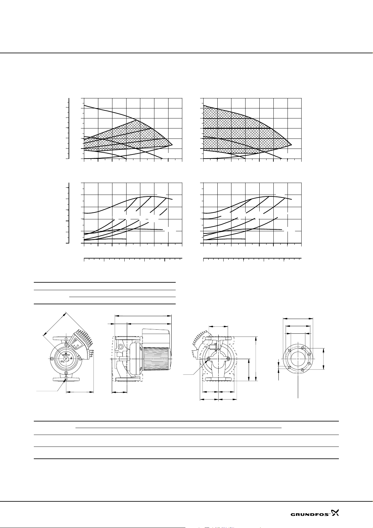
Technical data
UPE 80-120 F
UPE 80-120 F
p
[kPa]
100
80
60
40
20
P1
[hp]
2.5
2.0
1.5
1.0
0.5
0.0
H
[m]
12
MAX
10
8
6
4
2
0
0
0 10 20 30 40 50 Q [m³/h]
P1
[W]
2000
1600
1200
800
400
0
0 10 20 30 40 50 Q [m³/h]
Proportional pressure
MIN 1
7.5 m
6.0 m
4.0 m
MIN 1
MAX
2.5 m
MIN 2
MIN 2
H
[m]
12
MAX
10
8
6
4
2
MIN 1
0
0 10 20 30 40 50 Q [m³/h]
P1
[W]
2000
1600
1200
800
400
0
0 10 20 30 40 50 Q [m³/h]
Constant pressure
8 m
6 m
MIN 1
4 m
MIN 2
MAX
2 m
MIN 2
0 4 8 12 16 Q [l/s]
Electrical data
Un [V] P1 [W] I
3 x 400-415 V
B2
Rp 1/4
Min. 110 0.27
Max. 1550 2.56
H1
B1
H4
Dimensions and weights
Pump type
UPE 80-120 F
(PN 6)
UPE 80-120 F
(PN 10)
Weights of bronze versions are approx. 10 % higher.
L1 L2 L3 B1 B2 B4 B5 B7 B8 B9 H1 H2 H3 H4 D1 D2 D 3 D4 D5 M Net Gross
360 – 180 170 205 125 100 160 180 152 97 294 391 160 80 138 150 200 19 M16 41.7 43.3 0.043
360 – 180 170 205 125 100 160 180 152 97 294 391 160 80 138 160 200 19 M16 40.2 41.8 0.043
H3
0 4 8 12 16 Q [l/s]
1/1
[A]
UPE 80-120 F is also available with bronze housing,
type B.
H2
B7
L1
M
L3
D5
B5
B4
B8
B9
Dimensions [mm] Weights [kg]
PN 6
D4
D3
D1
PN 10
D2
Ship. vol.
3
[m
]
TM00 9409 2002
TM02 0697 5000
41
Page 42
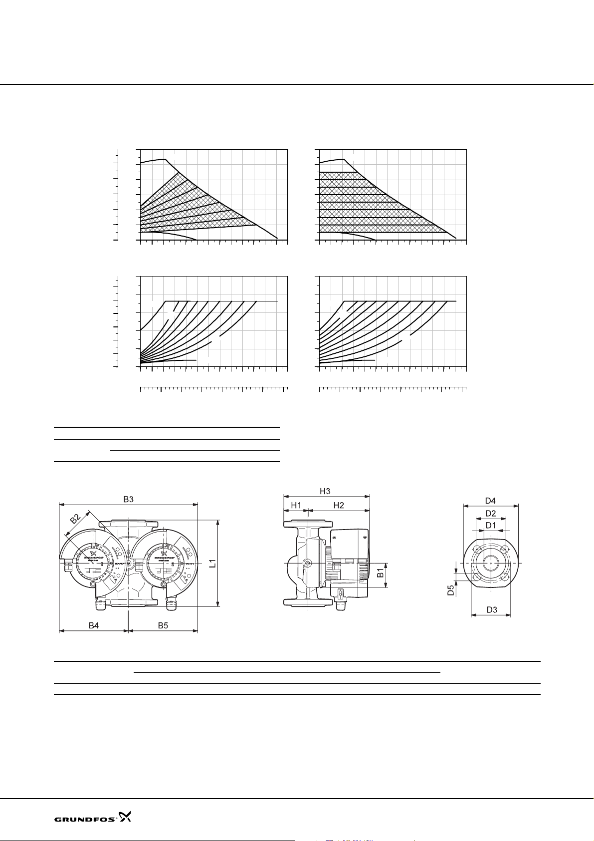
Technical data
MAGNA D 40-100 F
MAGNA D 40-100 F
[kPa]
100
80
60
40
20
P1
[hp]
0.30
0.25
0.20
0.15
0.10
0.05
0.00
H
p
[m]
12
10
8
6
4
2
0
0
0 1 2 3 4 5 6 7 8 9 10 Q [m³/h]
P1
[W]
250
200
MAX
150
100
50
0
0 1 2 3 4 5 6 7 8 9 10 Q [m³/h]
0.0 0.5 1.0 1.5 2.0 2.5 3.0 Q [l/s]
Proportional pressure
MAX
MIN
m
9
MIN
Electrical data
Un [V] P1 [W] I
1 x 230-240 V
Min. 10 0.09
Max. 180 1.26
H
[m]
12
10
8
6
4
2
0
0 1 2 3 4 5 6 7 8 9 10 Q [m³/h]
P1
[W]
250
200
MAX
150
m
2
[A]
1/1
100
50
0
0 1 2 3 4 5 6 7 8 9 10 Q [m³/h]
0.0 0.5 1.0 1.5 2.0 2.5 3.0 Q [l/s]
Curves and electrical data apply to one operating
Constant pressure
MAX
9 m
MIN
MIN
m
1
TM031566 2305
pump head.
42
Dimensions and weights
Pump type
PN 6 / PN 10
L1 B1 B2 B3 B4 B5 H1 H2 H3 D1 D 2 D 3 D4 D5 PN Gross
Dimensions [mm] Weight [kg]
MAGNA D 40-100 F 220 62 87 354 177 177 62 157 219 40 84 100/110 150 19 6/10 16.3 0.030
Ship. vol.
[m
TM03 1024 1405
3
]
Page 43
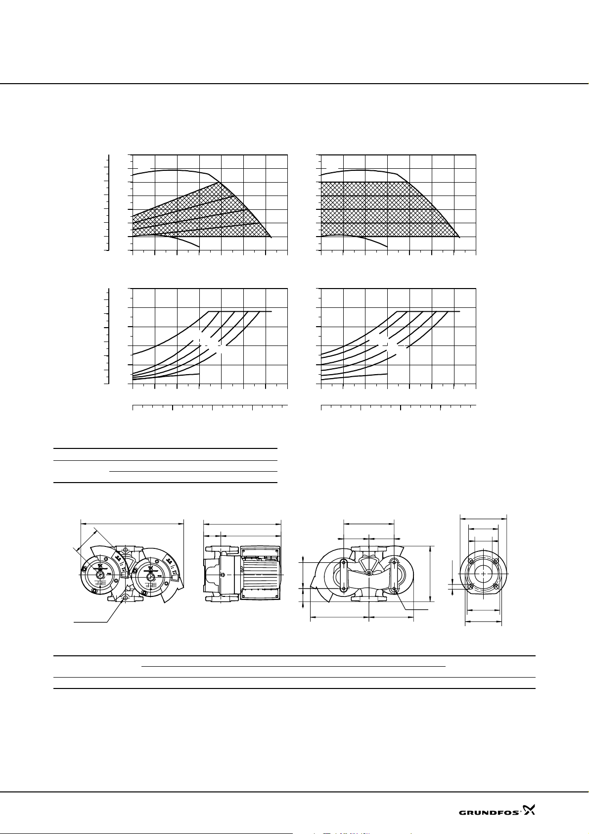
Technical data
MAGNA D 50-60 F
MAGNA D 50-60 F
p
[kPa]
[m]
H
Proportional pressure
7
60
50
40
30
20
10
0
MAX
6
5
4
3
2
1
MIN
0
0 4 8 12 16 20 Q [m³/h]
P1
P1
[W]
[hp]
500
0.6
400
0.5
300
0.4
0.3
200
MAX
m
5
0.2
100
0.1
0
0.0
0 4 8 12 16 20 Q [m³/h]
0 2 4 6 Q [l/s]
Electrical data
Un [V] P1 [W] I
1 x 230-240 V
Min. 25 0.17
Max. 400 1.7
4
MIN
Constant pressure
[m]
H
7
MAX
6
5
4
3
2
1
MIN
0
0 4 8 12 16 20 Q [m³/h]
P1
[W]
500
400
300
m
m
3
m
2
200
MAX
m
5
m
4
m
3
m
2
100
MIN
0
0 4 8 12 16 20 Q [m³/h]
1/1
[A]
0 2 4 6 Q [l/s]
Curves and electrical data apply to one operating
TM02 1912 2204
pump head.
D4
D2
D1
D5
D3
D3
B1
Rp1/4
B3
H3
H1 H2
B7
B6B6
L2
L3
B5B4
L1
M
Dimensions and weights
Pump type
PN 6 / PN 10
L1 L2 L3 B1 B3 B4 B5 B6 B7 H1 H2 H3 D1 D2 D3 D4 D5 M Net Gross
Dimensions [mm] Weights [kg]
MAGNA D 50-60 F 280 126 60 115 485 270 215 120 240 88 234 322 50 102 110/125 165 14/19 M12 36 43.5 0.13
Ship. vol.
[m
TM02 0790 2601
3
]
43
Page 44
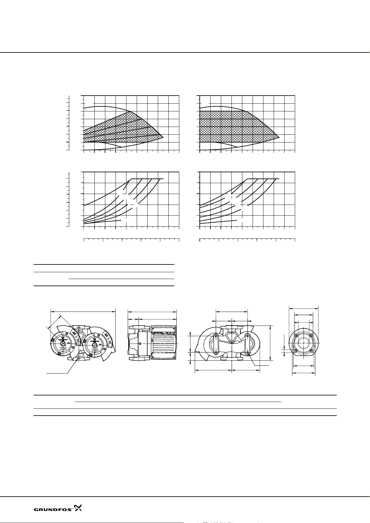
Technical data
MAGNA D 65-60 F
MAGNA D 65-60 F
p
[kPa]
60
50
40
30
20
10
P1
[hp]
0.6
0.5
0.4
0.3
0.2
0.1
0.0
H
[m]
7
6
MAX
5
4
3
2
1
MIN
0
0
0 4 8 12 16 20 24 28 Q [m³/h]
P1
[W]
500
400
300
MAX
200
100
0
0 4 8 12 16 20 24 28 Q [m³/h]
0 2 4 6 8 Q [l/s]
Proportional pressure Constant pressure
m
5
4
MIN
Electrical data
Un [V] P1 [W] I
1 x 230-240 V
Min. 25 0.17
Max. 450 2.0
H
[m]
7
6
MAX
5
4
3
2
1
MIN
0
0 4 8 12 16 20 24 28 Q [m³/h]
P1
[W]
500
400
m
m
3
m
2
[A]
1/1
300
MAX
200
100
0
0 4 8 12 16 20 24 28 Q [m³/h]
0 2 4 6 8 Q [l/s]
Curves and electrical data apply to one operating
m
5
m
4
m
3
m
2
MIN
TM02 1913 2204
pump head.
D4
D2
D1
D5
D3
D3
B1
Rp1/4
B3
H3
H1 H2
B7
B6B6
L2
L3
B5B4
L1
M
Dimensions and weights
Pump type
PN 6 / PN 10
L1 L2 L3 B1 B3 B4 B5 B6 B7 H1 H2 H3 D1 D2 D3 D4 D5 M Net Gross
Dimensions [mm] Weights [kg]
MAGNA D 65-60 F 340 126 60 115 480 270 215 120 240 88 242 330 65 119 130/145 185 14/19 M12 42 49 0.13
Ship. vol.
[m
TM02 0790 2601
3
]
44
Page 45
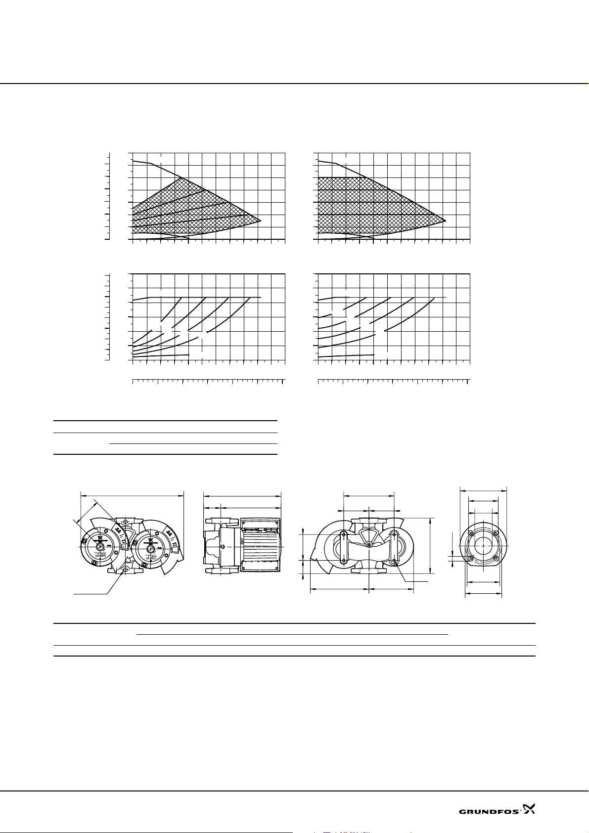
Technical data
MAGNA D 32-120 F
MAGNA D 32-120 F
p
[kPa]
120
100
80
60
40
20
P1
[hp]
0.8
0.7
0.6
0.5
0.4
0.3
0.2
0.1
0.0
H
[m]
14
12
10
8
6
4
2
MIN
0
0
0 2 4 6 8 10 12 14 16 18Q [m³/h]
P1
[W]
600
500
400
300
200
100
0
0 2 4 6 8 10 12 14 16 Q [m³/h]
0 1 2 3 4 5 Q [l/s]
Proportional pressure
MAX
MAX
m
0
1
m
m
8
6
MIN
4
Electrical data
Un [V] P1 [W] I
1 x 230-240 V
Min. 25 0.17
Max. 430 1.8
MAX
MAX
m
0
m
8
Constant pressure
m
6
m
4
MIN
TM02 1910 2204
H
[m]
14
12
10
8
6
4
2
MIN
0
0 2 4 6 8 10 12 14 16 Q [m³/h]
P1
[W]
600
500
400
300
m
[A]
1/1
200
100
1
0
0 2 4 6 8 10 12 14 16 Q [m³/h]
0 1 2 3 4 5 Q [l/s]
Curves and electrical data apply to one operating
pump head.
D4
D2
D1
D5
D3
D3
B1
Rp1/4
B3
H3
H1 H2
B7
B6B6
L2
L3
B5B4
L1
M
Dimensions and weights
Pump type
PN 6 / PN 10
L1 L2 L3 B1 B3 B4 B5 B6 B7 H1 H2 H3 D1 D2 D3 D4 D5 M Net Gross
Dimensions [mm] Weights [kg]
MAGNA-D 32-120 F 220 103 52 115 465 260 190 100 200 85 240 325 32 76 90/100 140 14/19 M12 38 43 0.057
Ship. vol.
[m
TM02 0790 2601
3
]
45
Page 46
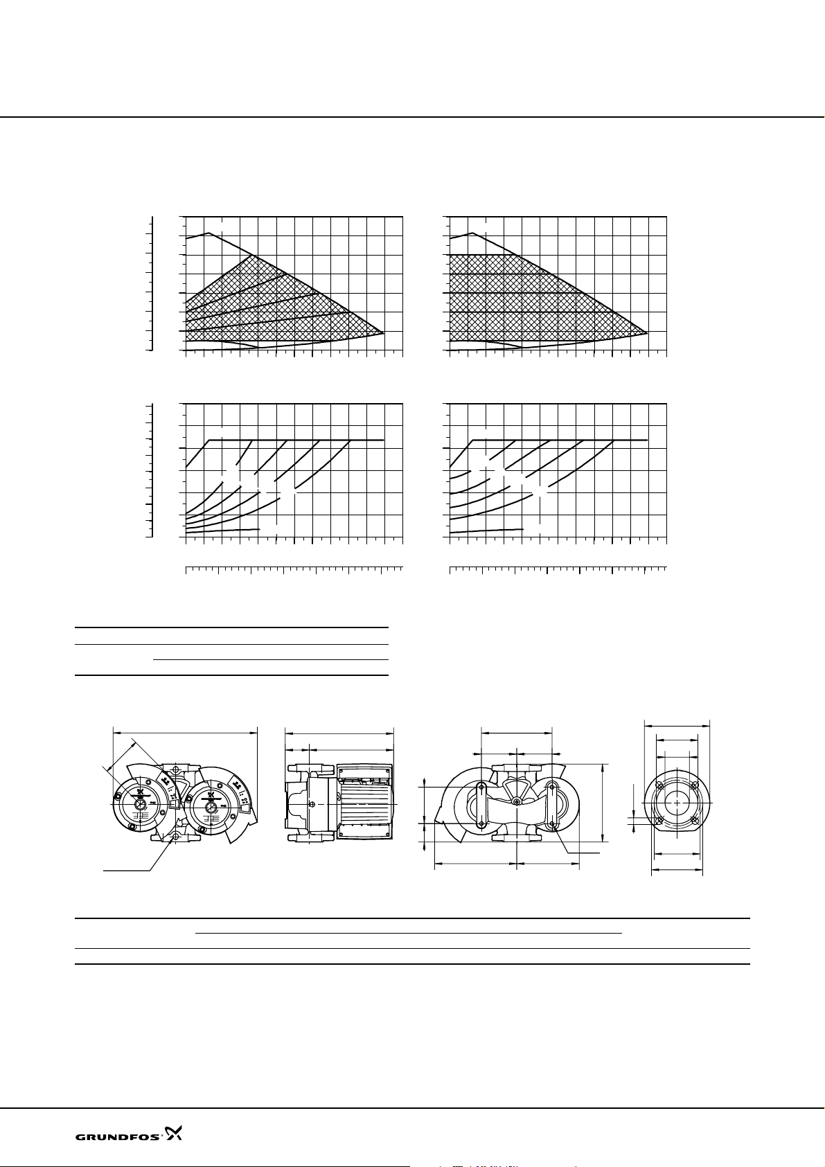
Technical data
MAGNA D 40-120 F
MAGNA D 40-120 F
p
[kPa]
120
100
80
60
40
20
H
[m]
14
12
10
8
6
4
2
MIN
0
0
Proportional pressure
MAX
0 2 4 6 8 10 12 14 16 18 Q [m³/h]
P1
P1
[W]
[hp]
600
0.8
0.7
0.6
0.5
0.4
0.3
0.2
0.1
0.0
500
400
300
200
100
0
MAX
m
0
1
m
8
m
6
MIN
0 2 4 6 8 10 12 14 16 18 Q [m³/h]
0 1 2 3 4 5 6Q [l/s]
Electrical data
Un [V] P1 [W] I
1 x 230-240 V
Min. 25 0.17
Max. 450 2.0
Constant pressure
MAX
[m]
H
14
12
10
8
6
4
2
MIN
0
0 2 4 6 8 10 12 14 16 18 Q [m³/h]
P1
[W]
600
500
MAX
400
m
0
1
300
m
4
200
m
8
m
6
m
4
100
0
MIN
0 2 4 6 8 10 12 14 16 18 Q [m³/h]
1/1
[A]
0 1 2 3 4 5 6Q [l/s]
Curves and electrical data apply to one operating
TM02 1911 2204
pump head.
D4
D2
D1
D5
D3
D3
B1
Rp1/4
B3
H3
H1 H2
B7
B6B6
L2
L3
B5B4
L1
M
Dimensions and weights
Pump type
PN 6 / PN 10
L1 L2 L3 B1 B3 B4 B5 B6 B7 H1 H2 H3 D1 D2 D 3 D4 D5 M Net Gross
Dimensions [mm] Weights [kg]
MAGNA D 40-120 F 250 125 45 115 465 2 60 187 100 200 87 234 321 40 84 100/110 150 14/19 M12 40 45 0.057
Ship. vol.
[m
TM02 0790 2601
3
]
46
Page 47
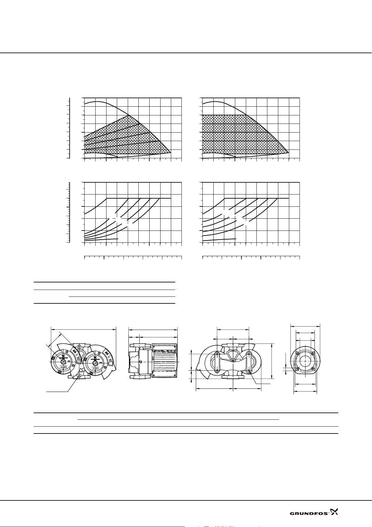
Technical data
MAGNA D 50-120 F
MAGNA D 50-120 F
p
[kPa]
120
100
80
60
40
20
P1
[hp]
1.2
1.0
0.8
0.6
0.4
0.2
0.0
H
[m]
14
12
10
8
6
4
2
0
0
0 4 8 12 16 20 24 28 Q [m³/h]
P1
[W]
1000
800
600
400
200
0
0 4 8 12 16 20 24 28 Q [m³/h]
0 2 4 6 8 Q [l/s]
Proportional pressure
MIN
MAX
MAX
m
0
1
m
8
m
6
MIN
Electrical data
Un [V] P1 [W] I
1 x 230-240 V
Min. 35 0.28
Max. 800 3.5
H
[m]
14
12
10
8
6
4
2
MIN
0
0 4 8 12 16 20 24 28 Q [m³/h]
P1
[W]
1000
800
MAX
600
400
m
4
[A]
1/1
200
0
0 4 8 12 16 20 24 28 Q [m³/h]
0 2 4 6 8 Q [l/s]
Curves and electrical data apply to one operating
Constant pressure
MAX
m
0
1
m
8
m
6
m
4
MIN
TM02 8814 2204
pump head.
D4
D2
D1
D5
D3
D3
B1
Rp1/4
B3
H3
H1 H2
B7
B6B6
L2
L3
B5B4
L1
M
Dimensions and weights
Pump type
PN 6 / PN 10
L1 L2 L3 B1 B3 B4 B5 B6 B 7 H1 H2 H3 D1 D2 D3 D4 D5 M Net Gross
Dimensions [mm] Weights [kg]
MAGNA D 50-120 F 280 126 60 125 490 275 215 120 240 88 234 322 50 102 110/125 165 14/19 M12 43 50.5 0.13
Ship. vol.
[m
TM02 0790 2601
3
]
47
Page 48
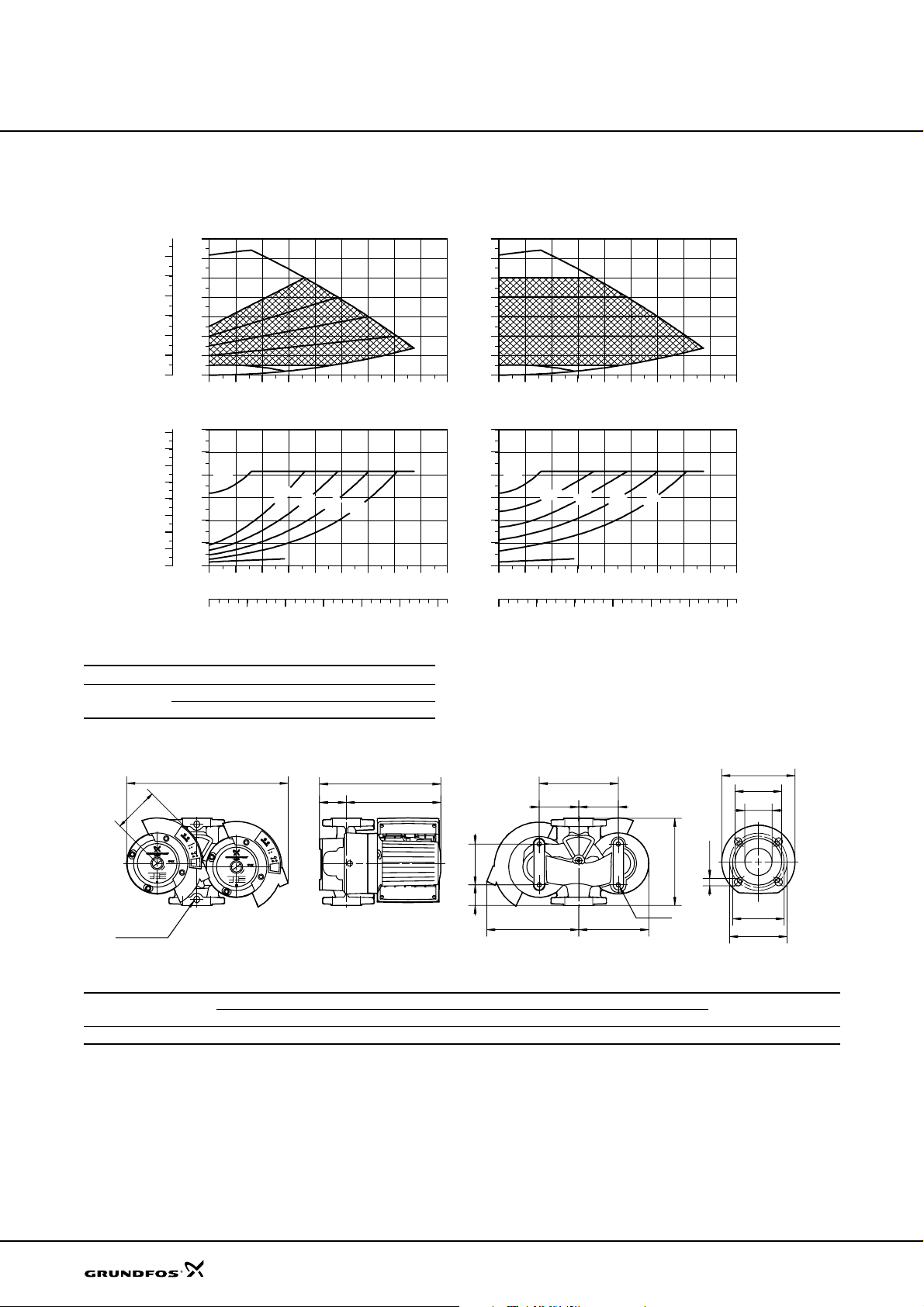
Technical data
MAGNA D 65-120 F
MAGNA D 65-120 F
p
[kPa]
120
100
80
60
40
20
P1
[hp]
1.6
1.4
1.2
1.0
0.8
0.6
0.4
0.2
0.0
H
[m]
14
MAX
12
10
8
6
4
2
MIN
0
0
0 5 10 15 20 25 30 35
P1
[W]
1200
1000
800
MAX
600
400
200
0
0 5 10 15 20 25 30 35
0 2 4 6 8 10 Q [l/s]
Proportional pressure
m
0
m
1
8
MIN
Electrical data
Un [V] P1 [W] I
1 x 230-240 V
Min. 35 0.28
Max. 900 3.9
H
[m]
14
MAX
12
10
8
6
4
2
MIN
0
Q [m³/h]
m
m
6
4
Q [m³/h]
[A]
1/1
0 5 10 15 20 25 30 35
P1
[W]
1200
1000
800
MAX
600
400
200
0
0 5 10 15 20 25 30 35 Q [m³/h]
0 2 4 6 8 10 Q [l/s]
Curves and electrical data apply to one operating
Constant pressure
m
m
0
1
8
MIN
Q [m³/h]
m
m
6
4
TM02 8815 2204
pump head.
D4
D2
D1
D5
D3
D3
B1
Rp1/4
B3
H3
H1 H2
B7
B6B6
L2
L3
B5B4
L1
M
Dimensions and weights
Pump type
PN 6 / PN 10
L1 L2 L 3 B1 B3 B4 B5 B6 B7 H1 H2 H3 D1 D2 D3 D 4 D5 M Net Gross
Dimensions [mm] Weights [kg]
MAGNA D 65-120 F 340 126 60 125 490 275 215 120 240 88 242 330 65 119 130/145 185 14/19 M12 49 56 0.13
Ship. vol.
[m
TM02 0790 2601
3
]
48
Page 49
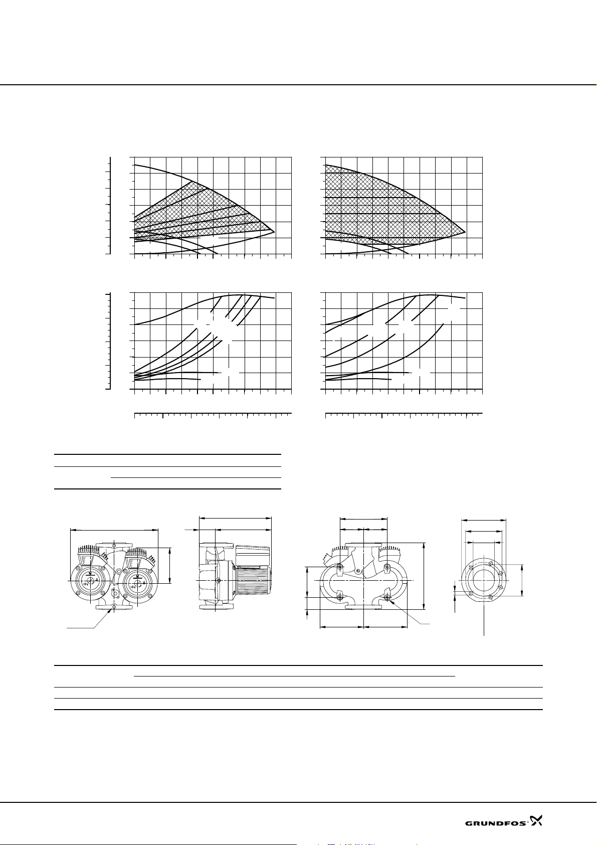
Technical data
UPED 100-60 F
UPED 100-60 F
p
[kPa]
50
40
30
20
10
P1
[hp]
1.6
1.2
0.8
0.4
0.0
H
[m]
6
5
4
3
2
1
0
0
0 10 20 30 40 50 60 70 80 Q [m³/h]
P1
[W]
1200
1000
800
600
400
200
0
0 10 20 30 40 50 60 70 80 Q [m³/h]
0 5 10 15 20 Q [l/s]
Proportional pressure
MAX
MIN 1
MIN 2
4.0 m
Electrical data
Un [V] P1 [W] I
3 x 400-415 V
Min. 110 0.27
Max. 1160 2.13
3.0 m
MIN 1
2.5 m
2.0 m
MIN 2
1/1
[A]
MAX
H
[m]
6
5
4
3
2
1
MIN 1
0
0 10 20 30 40 50 60 70 80 Q [m³/h]
P1
[W]
1200
1000
800
5.0 m
600
400
200
0
0 10 20 30 40 50 60 70 80 Q [m³/h]
0 5 10 15 20 Q [l/s]
Constant pressure
MAX
2.5 m
3.5 m
MIN 1
MIN 2
MAX
1.0 m
MIN 2
Curves and electrical data apply to one operating
pump head.
TM00 9410 2002
B3
H1
H3
H2
B6
B7
B6
D4
D3
D1
B2
Rp 1/4
L2
L3
B4
B5
L1
D5
M
PN 6
D2
PN 10
Dimensions and weights
Pump type
UPED 1 00-60 F (PN 6) 450 221 83 – 205 595 280 315 140 280 122 313 435 100 158 170 220 19 M16 92.4 96.4 0.112
UPED 1 00-60 F (PN 10) 450 221 83 – 205 595 280 315 140 280 122 313 435 100 158 180 220 19 M16 91.9 95.9 0.112
L1 L2 L3 B1 B2 B3 B4 B5 B6 B7 H1 H2 H3 D1 D2 D3 D4 D5 M Net Gr oss
Dimensions [mm] Weights [kg]
Ship. vol.
[m
TM02 0695 5000
3
]
49
Page 50
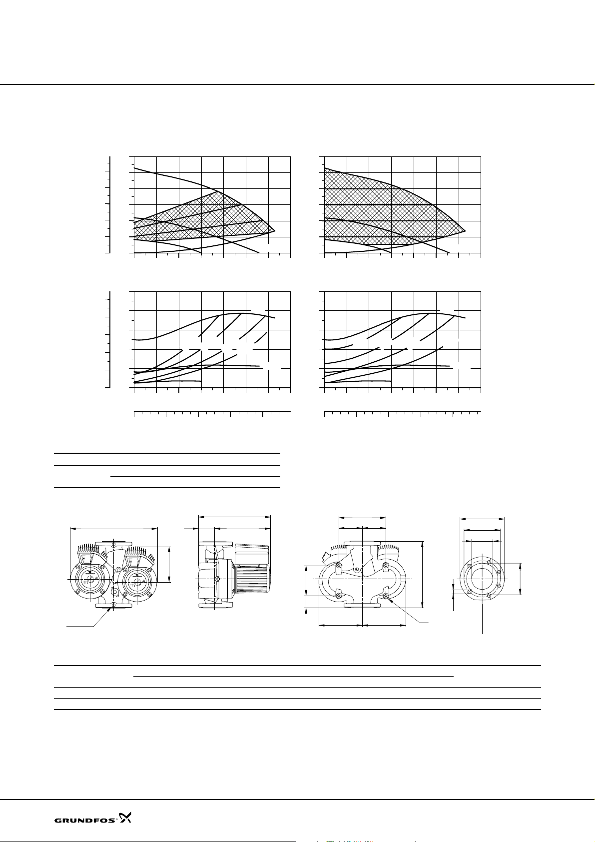
Technical data
UPED 80-120 F
UPED 80-120 F
p
[kPa]
100
80
60
40
20
P1
[hp]
2.5
2.0
1.5
1.0
0.5
0.0
H
[m]
12
MAX
10
8
6
4
2
0
0
0 10 20 30 40 50 Q [m³/h]
P1
[W]
2000
1600
1200
800
400
0
0 10 20 30 40 50 Q [m³/h]
Proportional pressure
MIN 1
7.5 m
6.0 m
4.0 m
2.5 m
MIN 1
MAX
MIN 2
MIN 2
H
[m]
12
MAX
10
8
6
4
2
MIN 1
0
0 10 20 30 40 50 Q [m³/h]
P1
[W]
2000
1600
1200
800
400
0
0 10 20 30 40 50 Q [m³/h]
Constant pressure
8 m
6 m
MIN 1
4 m
MIN 2
MAX
2 m
MIN 2
0 4 8 12 16 Q [l/s]
0 4 8 12 16 Q [l/s]
Electrical data
Un [V] P1 [W] I
3 x 400-415 V
Min. 110 0.27
Max. 1550 2.56
B3
H1
B2
Rp 1/4
H3
H2
1/1
[A]
Curves and electrical data apply to one operating
pump head.
L2
L3
B4
B6
B7
B6
B5
L1
M
D5
PN 6
D4
D3
D1
PN 10
D2
Dimensions and weights
Pump type
UPED 8 0-120 F (PN 6) 360 173 53 – 205 460 225 235 120 240 97 294 391 80 138 150 200 19 M16 65.4 69.4 1.112
UPED 8 0-120 F (PN 10) 360 173 53 – 205 460 225 235 120 240 97 294 391 80 138 160 200 19 M16 64.9 68.9 0.12
L1 L2 L3 B1 B2 B3 B4 B5 B6 B7 H1 H2 H3 D1 D2 D3 D4 D5 M Net Gross
Dimensions [mm] Weights [kg]
Ship. vol.
[m
TM00 9409 2002
TM02 0695 5000
3
]
50
Page 51
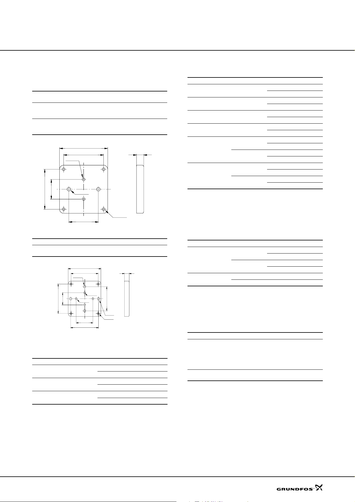
Accessories
MAGNA, UPE
Base plates
Base plates including hexagon screws are available on
request.
Pump type
MAGNA 50-60 F, 65-60 F
MAGNA 32-120 F, 50-120 F
MAGNA 40-120 F, 65-120 F
MAGNA 32-120 FN, 40-120 FN
MAGNA 50-60 FN, 65-60 FN
MAGNA 50-120 FN, 65-120 FN
235
195
2xø14
96
195
2xø18
144
Fig. 31
Pump type Hexagon screws Product number
UPE 100-60 F
UPE 80-120 F
Base plate for MAGNA
235
195
2xø18
80
195
2xø14
120
200
Hexagon
screws
2 x M12 x 20 mm 495035
2 x M12 x 20 mm 485031
Product number
35
4xø14
2 x M16 x 30 mm 96405914
35
2xø14
160
2xø18
4xø14
Fig. 32 Base plate for UPE
Adapter flanges
Pump type Pressure stage Size Product number
MAGNA 32 PN 10
MAGNA 40 PN 10
MAGNA 50 PN 10
Rp: Flange with internal thread (ISO seal thre ad).
mm: Flange for welding/soldering.
Rp 1 1/4 539703
32 mm 539704
Rp 1 1/2 539701
40 mm 539702
Rp 2 549801
50 mm 549802
Counter flanges for pumps with cast-iron pump housing
Pump type Pressure stage Size Product number
MAGNA, UPE(D) 32 PN 10
MAGNA, UPE(D) 40
MAGNA, UPE(D) 50 PN 10
MAGNA, UPE(D) 65 PN 10
UPE(D) 80
UPE(D) 100
PN 10
PN 16
PN 6
PN 10
PN 6
PN 10
Rp 1 1/4 539703
32 mm 539704
Rp 1 1/2 539701
40 mm 539702
Rp 2 549801
50 mm 549802
Rp 2 1/2 559801
65 mm 559802
Rp 3 569902
80 mm 569901
Rp 3 569802
80 mm 569801
Rp 4 579901
100 mm 579902
Rp 4 579801
100 mm 579802
One set consists of two flanges including gaskets and
bolts.
Counter flanges according to ISO 7005-1.
TM00 3755 5097
Counter flanges for pumps with bronze pump housing
Pump type Pressure stage Size Product number
PN 6
UPE 80
PN 10
UPE 100
PN 6 Rp 4 96405737
PN 10 Rp 4 96405738
One set consists of two flanges including gaskets and
bolts.
Counter flanges according to ISO 7005-1.
TM00 9835 0497
Blanking flanges
Pump type Product number
MAGNA (D) 32-120 F
MAGNA (D) 40-120 F
MAGNA (D) 50-60 F
MAGNA (D) 50- 120 F
MAGNA (D) 65-60 F
MAGNA (D) 65-120 F
UPED 80-120 F
UPED 100-60 F
Rp 3 96405735
80 mm 569911
Rp 3 569812
80 mm 569811
545048
565055
51
Page 52
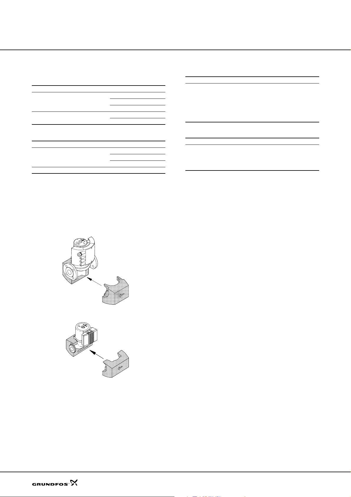
Accessories
MAGNA, UPE
Union and valve kits
Union kits
Pump type Pressure stage Size Product number
Rp 3/4 529921
MAGNA/UPE 25 PN 10
MAGNA/UPE 32 PN 10
Rp 1 529922
Rp 1 1/4 529724
Rp 1 509921
Rp 1 1/4 509922
Valve kits
Pump type Pressure stage Size Product number
Rp 3/4 519805
MAGNA/UPE 25 PN 10
MAGNA/UPE 32 PN 10 Rp 1 1/4 505539
Rp 1 519806
Rp 1 1/4 519807
Insulation kits
MAGNA/UPE single-head pumps can be fitted with
insulating shells. A kit consists of two shells.
All MAGNA are all delivered with insulating shell s for
heating applications. Insulation shells are optional for
UPE pumps.
Insulating shells for aircondition applications
Pump type Product number
MAGNA 32-120 F 96515226
MAGNA 40-120 F 96515227
MAGNA 50 - 60 F 96515228
MAGNA 50-120 F 96515228
MAGNA 65 - 60 F 96515229
MAGNA 65-120 F 96515229
Insulating shells for UPE
Pump type Product number
UPE 15 - 4 0 , 25-40, 32- 4 0, 25-60, 32 - 60 505821
UPE 25- 4 0 A, 2 5- 6 0 A 505822
UPE 80-120 F 96434645
UPE 100-60 F 96434646
Fig. 1
Fitting the insulating shells to a MAGNA pump
Fig. 2 Fitting the insulating shells to a UPE pump
TM02 1135 0501TM00 4509 3494
52
Page 53

Accessories
MAGNA, UPE
Expansion modules for MAGNA 25-60, 32-60, 25-100, 32-100, 40-100(D), 50-100
MAGNA pumps can be fitted with an expansion module
enabling communication via external signals (signal
transmitters).
Two types of expansion module are available:
•GENI module
• Relay module.
Product Product number
GENI module 96236335
Relay m od u l e 96236336
GENI module
The GENI module offers the following functions:
External start/stop
The GENI module incorporates a digital input for an
external contact. The pump can be started and stopped
via this input.
When started, the pump will operate with the setpoint
set on the control panel or with the R100.
External forced control
The GENI module incorporates inputs for external
signals for the forced-control functions:
• Max. curve duty
• Min. curve duty.
External analog 0-10 V control
The GENI module has an input for an external
0-10 VDC analog signal transmitter. Via this input, the
pump can be controlled by an external controller if the
pump has been set to one of the following control
modes:
• Constant curve
The external analog signal will control the pump
curve within the range from the min. curve to the
constant curve selected according to the
characteristic.
• Proportional- or constant-pressure control
The external analog signal will control the setpoint
for the pump head between the setpoint
corresponding to the min. curve and the setpoint
selected according to the characteristic.
Fault, ready and operating indication via signal relay
The function of the signal relay can be set with the
R100.
Possible functions:
•Fault
• Ready
• Operation.
Fault indication
The signal relay is activated in case of
• Pump blocked
• Internal fault
• Undervoltage.
Ready indication
The signal relay is active when the pump is in operation
or ready for operation.
Operating indication
The signal relay is active as long as the pump is
operating. If the pump is stopped on the control panel,
with the R100 or because of a fault, the signal relay is
deactivated and consequently gives a signal to an
external control system, e.g. a building management
system.
Control of twin-head pumps
When fitted with two GENI modules, a twin-head pump
functions fully automatically.
A GENI module must be mounted on the control box of
each pump head and the modules must be connected
using a cable.
Both pump heads must be connected to the electricity
supply.
Bus communication via GENIbus
The GENI module enables serial communication via an
RS-485 input. The communication is carried out
according to the Grundfos bus protocol, GENIbus, and
enables connection to the GRUNDFOS Pump
Management System 2000, a building management
system or another type of external control system.
Via the bus signal, it is possible to set pump operating
parameters, such as desired setpoint, temperature
influence, operating mode, etc.
At the same time, the pump can provide status
information about important parameters, such as actual
head, actual flow, power input, fault indications, etc.
Inputs for max. and min.
curves and start/stop
Input for analog 0-10 V
signal
Input for control of twinhead pumps
Bus input
Output for signal relay
External potential-free contact.
Contact load: 5 V, 1 mA.
Screened cable.
Loop resistance: Maximum 130 Ω.
External signal: 0-10 VDC.
Maximum load: 1 mA.
Screened cable.
Screened cable.
Wire cross section: 0.25 - 1 mm
Cable length: Maximum 1 m.
Grundfos GENIbus protocol, RS-485.
Screened cable.
Wire cross section: 0.25 - 1 mm
Cable length: Maximum 1200 m.
Potential-free changeover contact.
400 VAC, 6 A AC1.
30 VDC, 6 A.
2
.
2
.
53
Page 54
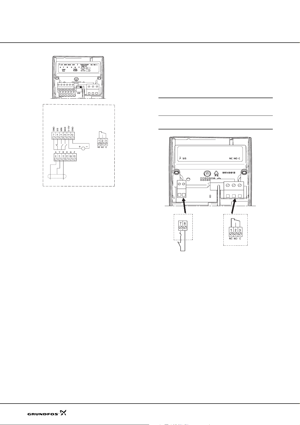
Accessories
MAGNA, UPE
Operating indication
The signal relay is active as long as the pump is
operating. If the pump is stopped on the control panel,
with the R100 or because of a fault, the signal relay is
deactivated and consequently gives a signal to an
external control system, e.g. a building management
system.
External potential-free contact.
Input for start/stop
Output for signal relay
Contact load: 5 V, 1 mA.
Screened cable.
Loop resistance: Maximum 130 Ω.
Potential-free changeover contact.
400 VAC, 6 A AC1.
30 VDC, 6 A.
Fig. 3 Connection of GENI module
Relay module
The relay module offers the following functions:
External start/stop
The relay module incorporates a digital input for an
external contact. The pump can be started and stopped
via this input.
When started, the pump will operate with the setpoint
set on the control panel or with the R100.
Fault, ready and operating indication via signal relay
The function of the signal relay can be set with the
R100.
Possible functions:
•Fault
• Ready
• Operation.
Fault indication
The signal relay is activated in case of
• Pump blocked
• Internal fault
• Undervoltage.
TM03 0878 0905
TM03 0877 0705
Fig. 4
Connection of relay module
54
Ready indication
The signal relay is active when the pump is in operation
or ready for operation.
Page 55
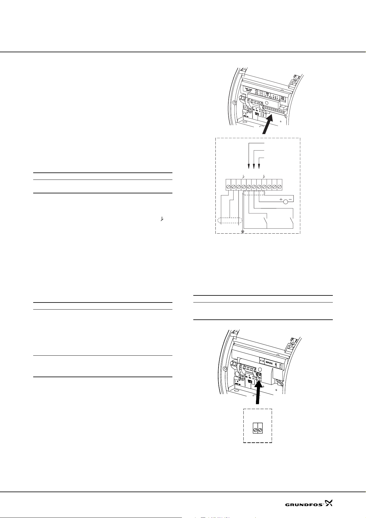
Accessories
Expansion modules for MAGNA (D) 50-60, 65-60, 32-120, 40-120, 50-120, 65-120
MAGNA pumps can be fitted with an expansion module
enabling communication via external signals (signal
transmitters).
Two types of expansion module are available:
•GENI module
• LON module.
The expansion module is fitted by opening the terminal
box cover and placing the module inside the terminal
box.
MAGNA, UPE
Product Product number
GENI module 605945
LON mod u le 605809
GENI module
The GENI module has an input for an external 0-10
VDC analog signal transmitter (terminal 10 V and ).
Via this input, the pump can be controlled by an
external controller if the pump has been set to one of
the following control modes:
• Constant curve
• Proportional- or constant-pressure control.
The GENI module also incorporates inputs for external
signals for the forced-control functions:
• Max. curve duty
• Min. curve duty.
Input signals
• Max. and min. curve input
External potential-free switch.
Maximum contact load: 5 V, 1 mA.
Screened cable.
Setpoint signals
Bus input
Maximum loop resistance: 130 Ω.
• Input for analog 0-10 V signal
External signal: 0-10 VDC.
Maximum load: 0.1 mA.
Screened cable.
Grundfos GENIbus protocol, RS-485.
Screened cable.
Lead cross section: 0.25 - 1 mm
Maximum cable length: 1200 m.
2
.
XQZBYA
MIN
MAX
4
5 6 7 9 10 1112 212223
Fig. 5
Connection of GENI module
10 V
LON module
The LON module offers the possibility of connecting the
pump to a LonWorks
data transmission between a network and the MAGNA
pump.
Input signals
Bus input
®
network. The module is used for
®
LonTalk
Non-screened, twisted-pair cable.
Lead cross section: 0.25 - 1 mm
protocol, FTT 10.
2
.
TM02 0236 1007
Fig. 6
Connection of LON module
BA
TM02 0237 0904
55
Page 56
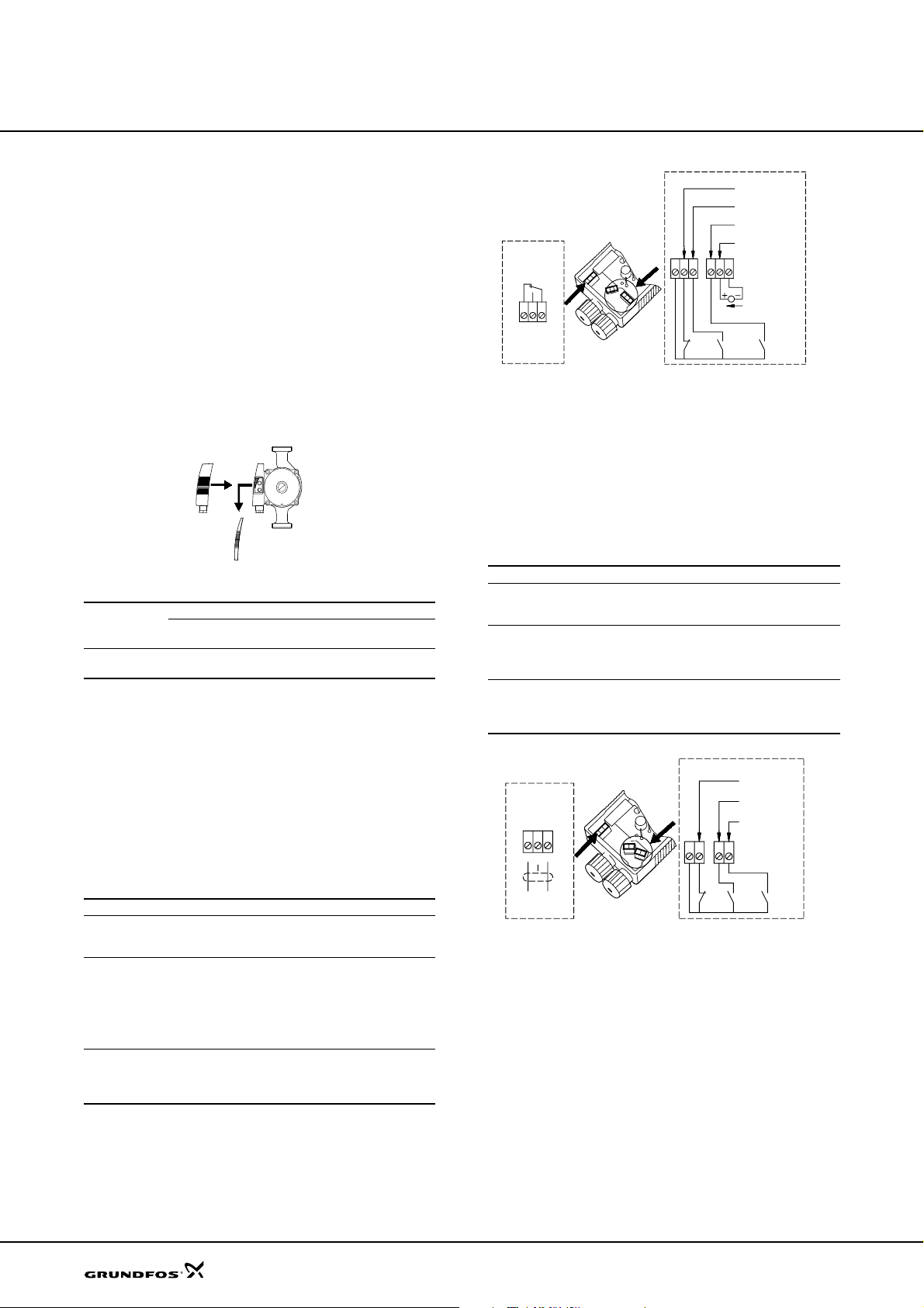
Accessories
Expansion modules for single-phase UPE
UPE single-phase pumps can be fitted with an
expansion module.
Two types of expansion module are available:
• Fault signal module (MC 40/60)
• Bus module (MB 40/60).
The expansion module is fitted to the terminal box by
removing the existing terminal box cover and fitting the
new cover incorporating the module to the terminal box.
The new cover increases the height of the terminal box
by approx. 20 mm.
Fig. 7
Fitting a module to a UPE pump
Pump type
UPE xx-40 (A)
UPE xx-60 (A)
Fault signal module MC 40/60
Via an internal relay, the fault signal module gives
access to a potential-free fault signal.
In addition to this fault signal output, the module has
four inputs for external signals for
• start/stop of pump
• max. curve duty
• min. curve duty (night-time duty)
• analog 0-10 V input.
Input and output signals
External start/
stop input
Setpoint signals
Signal output
Fault signal module Bus module
Type
MC 40/60 605663 MB 40/60 605518
External potential-free switch.
Screened cable.
Maximum contact load: 5 V, 2.7 mA.
• Max. and min. curve input
External potential-free switch.
Screened cable.
Maximum contact load: 5 V, 2.7 mA.
• Input for analog 0-10 V signal
External signal: 0-10 VDC.
Maximum contact load: 0.1 mA.
Internal potential-free changeover contact.
Screened cable.
Maximum contact load: 250 VAC, 2 A.
Minimum contact load: 5 VDC, 1 mA.
Product
number
Type
Product
number
MAGNA, UPE
Start/stop
Min. curve
(night-time duty)
Max. curve
Analog 0-10 V
Fault signal
213
NC
NOC
Fig. 8
87
Connection of MC 40/60
9
Stop
12
11
10
DC 0-10 V
Min. Max.
input
TM02 2050 3301
Bus module MB 40/60
The bus module enables serial communication with the
pump via an RS-485 input. In addition to the bus input,
the bus module has three inputs for external signals for
• start/stop of pump
• max. curve duty
TM00 4463 3494
• min. curve duty (night-time duty).
Input signals
External start/
stop input
Setpoint signals
Bus input
Bus signal
456
Fig. 9
External potential-free switch.
Screened cable.
Maximum contact load: 5 V, 2.7 mA.
Max. and min. curve input
External potential-free switch.
Screened cable.
Maximum contact load: 5 V, 2.7 mA.
Grundfos GENIbus protocol, RS-485.
Screened cable.
Lead cross section: 0.25 - 1 mm
Maximum Cable length: 1200 m.
BYA
Connection of MB 40/60
78
Stop Min.
10
9
2
.
Start/stop
Min. curve
(night-time
duty)
Max. curve
Max.
TM02 2052 3301
56
Page 57
Accessories
R100
The R100 is designed for wireless communication with
the pump. The 100 communicates with the pump via
infra-red light.
MAGNA, UPE
Product
R100 625333
Product
number
PMU 2000
The PMU 2000 is used for communication via bus,
enabling
• parallel connection of up to eight pumps
• cascade control
• central reading out of various status information.
Product Description
PMU 200 0 , I P 4 2 Max. 8 p u m ps 62572847
PMU 200 0 , I P 0 0 Max. 8 p u m ps 62572837
Product
number
PCU 2000
The PCU 2000 is used for communication via bus,
enabling
• fault indication for each pump
• external setpoint influence
• start/stop of system.
Product Description
PCU 200 0 , I P 4 2 Max. 2 pu m ps 62552241
PCU 200 0 , I P 0 0 Max. 2 pu m ps 62552231
PCU 200 0 , I P 4 2 Max. 4 pu m ps 62552441
PCU 200 0 , I P 0 0 Max. 4 pu m ps 62552431
Expansion modules For 2 pumps 62500211
Product
number
G10-LON interface
The G10-LON interface is used in connection with data
transmission between a LonWorks
electronically controlled Grundfos pumps applying the
Grundfos GENIbus protocol.
Product
G10-LO N interface 605726
®
network and
Product
number
Prefilter
A prefilter must be installed if classification of the UPE
pump to overvoltage property class 1 or 2 in accordance
with VDE 0160/12.90 is required.
Three-phase UPE pumps require three prefilters.
Product
Prefilter 62582200
Product
number
57
Page 58
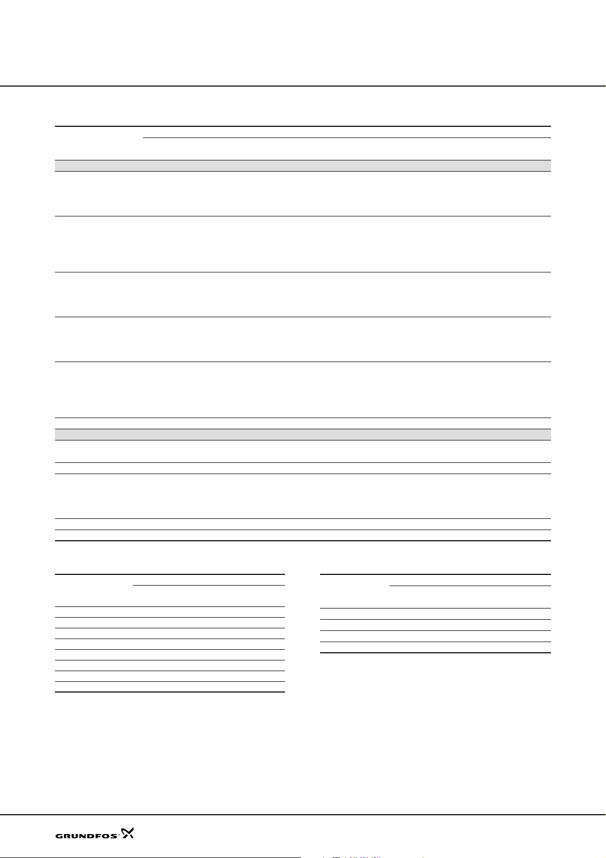
Order data
MAGNA, UPE
MAGNA/UPE, cast iron
Product number
Pump type
1" 1 1/2” 2" PN 6/PN 10 PN 6 PN 10
Single-head pumps
MAGNA 2 5 - 60 – 96281022 – – – –
MAGNA 3 2 - 60 – – 96281023 – – –
MAGNA 5 0 - 60 F – – – 96513627 – –
MAGNA 6 5 - 60 F – – – 96513628 – –
MAGNA 2 5 - 100 – 96281015 – – – –
MAGNA 32-100 – – 96281016 – – –
MAGNA 32-100 F – – – 96281018 – –
MAGNA 40-100 F – – – 96281019 – –
MAGNA 50-100 F – – – 96281020 – –
MAGNA 32-120 F – – – 96513625 – –
MAGNA 40-120 F – – – 96513626 – –
MAGNA 50-120 F – – – 96504872 – –
MAGNA 65-120 F – – – 96504873 – –
UPE 15- 4 0 59504519 – – – – –
UPE 25- 4 0 – 59544092 – – – –
UPE 32- 4 0 – – 59584406 – – –
UPE 25- 4 0 A – 59544094 – – – –
UPE 25- 6 0 1 3 0 – 59526544 – – – –
UPE 25- 6 0 1 8 0 – 59546574 – – – –
UPE 32- 6 0 – – 59586505 – – –
UPE 25- 6 0 A – 59566507 – – – –
UPE 100-60 F – – – – 96402616 96402618
UPE 80- 1 20 F – – – – 96402442 96402443
Twin-head pumps
MAGNA D 50-60 F – – – 96513641 – –
MAGNA D 65-60 F – – – 96513642 – –
MAGNA D 40-100 F – – – 96281021 – –
MAGNA D 32-120 F – – – 96513629 – –
MAGNA D 40-120 F – – – 96513640 – –
MAGNA D 50-120 F – – – 96504874 – –
MAGNA D 65-120 F – – – 96504875 – –
UPED 100-60 F – – – – 96405833 96405834
UPED 80-120 F – – – – 96403133 96403134
Pipe connection Flange connection
58
MAGNA, stainless steel UPE, bronze
Product number
Pump type
MAGNA 3 2 - 60 N 96700323 –
MAGNA 32-100 N 96281017 –
MAGNA 32-120 FN – 96513643
MAGNA 40-120 FN – 96513644
MAGNA 5 0 - 60 FN – 96513645
MAGNA 6 5 - 60 FN – 96513646
MAGNA 50-120 FN – 96504876
MAGNA 65-120 FN – 96504877
Pipe connection Flange connection
G 2 PN 6/PN 10
Pump type
UPE 25- 4 0 B 59544093 – –
UPE 25- 6 0 B 59736517 – –
UPE 80-120 F B – 96405829 96402446
UPE 100-60 F B – 96405830 96405832
Product number
Pipe connection Flange conn ection
1 1/2" PN 6 PN 10
Page 59
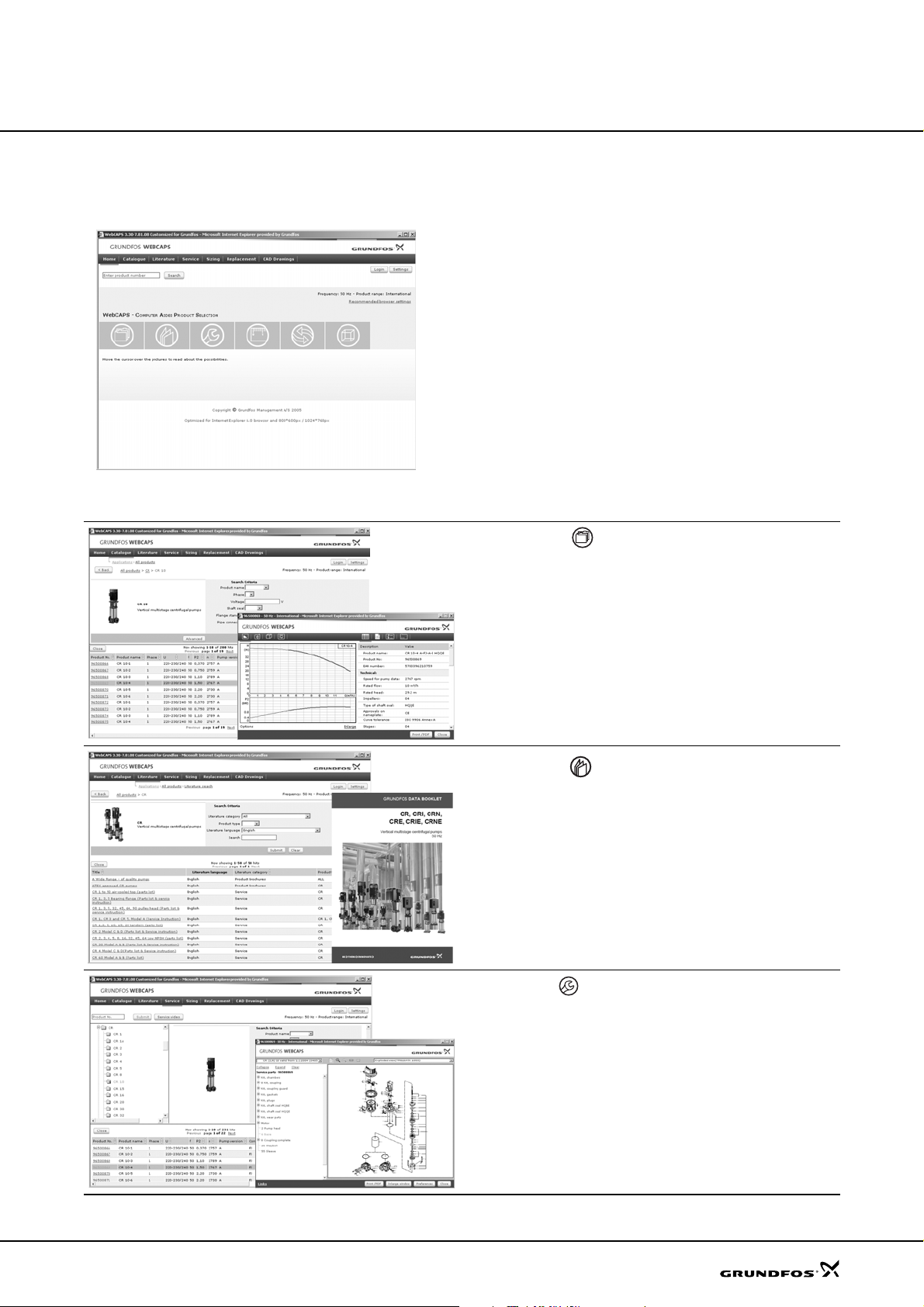
Further product documentation
WebCAPS
MAGNA, UPE
WebCAPS is a Web-based Computer Aide d Product
Selection program available on www.grundfos.com.
WebCAPS contains detailed information on more than
185,000 Grundfos products in more than 20 languages.
In WebCAPS, all information is divided into 6 sections:
• Catalogue
• Literature
• Service
• Sizing
• Replacement
• CAD drawings.
Catalogue
This section is based on fields of application and pump types, and
contains
• technical data
• curves (QH, Eta, P1, P2, etc) which can be adapted to the density and viscosity of the pumped liquid and show the number of
pumps in operation
• product photos
• dimensional drawings
• wiring diagrams
• quotation texts, etc.
Literature
In this section you can access all the latest documents of a given
pump, such as
• data booklets
• installation and operating instructions
• service documentation, such as Service kit catalogue and
Service kit instructions
• quick guides
• product brochures.
Service
This section contains an easy-to-use interactive service catalogue.
Here you can find and identify service parts of both existing and discontinued Grundfos pumps.
Furthermore, this section contains service videos showing you how
to replace service parts.
59
Page 60
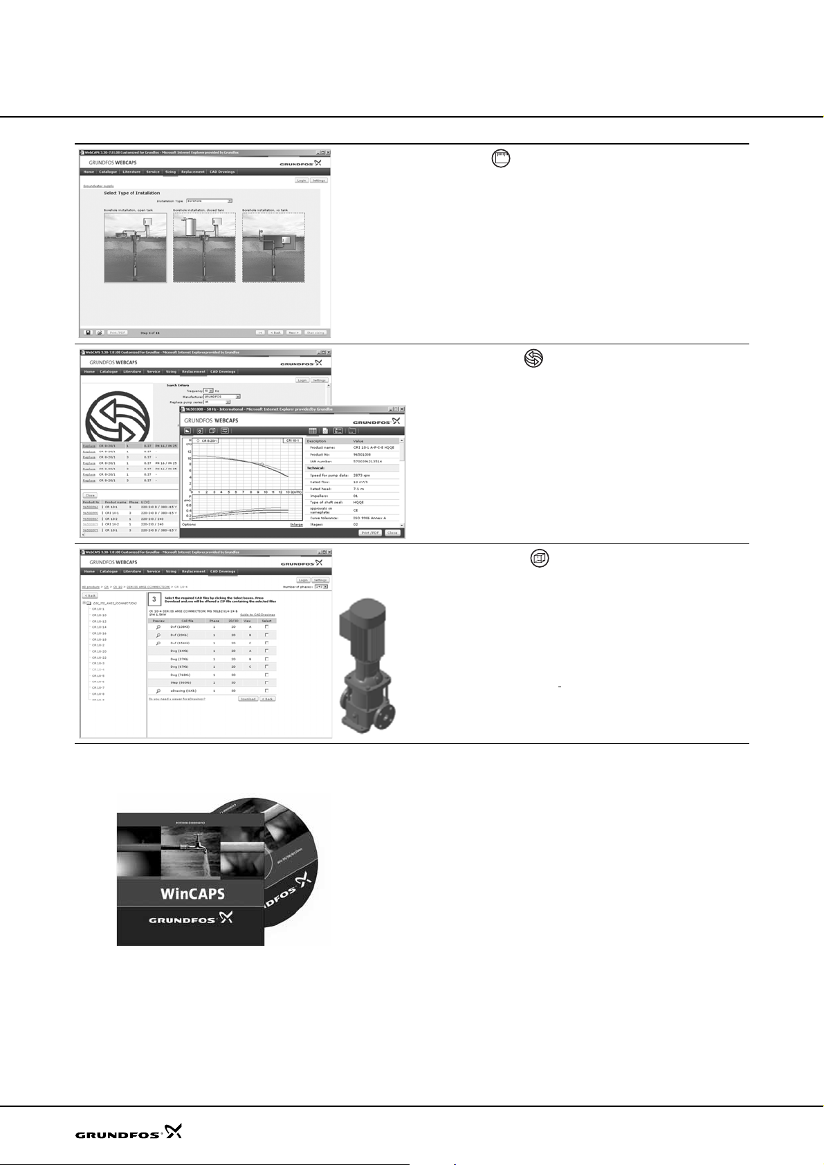
Further product
documentation
MAGNA, UPE
01
Sizing
This section is based on different fields of application and installation examples, and gives easy step-by-step instructions in how to
• select the most suitable and efficient pump for your installation
• carry out advanced calculations based on energy consumption,
payback periods, load profiles, life cycle costs, etc.
• analyse your selected pump via the built-in life cycle cost tool
• determine the flow velocity in wastewater applications, etc.
Replacement
In this section you find a guide to selecting and comparing replacement data of an installed pump in order to replace the pump with a
more efficient Grundfos pump.
The section contains replacement data of a wide range of pumps
produced by other manufacturers than Grundfos.
Based on an easy step-by-step guide, you can compare Grundfos
pumps with the one you have installed on your site. When you have
specified the installed pump, the guide will suggest a number of
Grundfos pumps which can improve both comfort and efficiency.
WinCAPS
CAD drawings
In this section it is possible to download 2-dimensional (2D) and 3dimensional (3D) CAD drawings of most Grundfos pumps.
These formats are available in WebCAPS:
2-dimensional drawings:
• .dxf, wireframe drawings
• .dwg, wireframe drawings.
3-dimensional drawings:
• .dwg, wireframe drawings (without surfaces)
• .stp, solid drawings (with surfaces)
• .eprt, E-drawings.
WinCAPS is a Windows-based Computer Aided
Product Selection program containing detailed information on more than 185,000 Grundfos products in more
than 20 languages.
The program contains the same features and functions
as WebCAPS, but is an ideal solution if no Internet
connection is available.
WinCAPS is available on CD-ROM and updated once a
year.
60
Fig. 10 WinCAPS CD-ROM
Page 61
616263
Page 62
Page 63
Page 64

Being responsible is our foundation
Thinking ahead makes it possible
Innovation is the essence
V7089107
Repl. V7089107 0606
0807
GB
GRUNDFOS A/S . DK-8850 Bjerringbro . Denmark
Telephone: +45 87 50 14 00
www.grundfos.com
Subject to alterations.
 Loading...