

Page 1

GRUNDFOS INSTRUCTIONS
75
+
FM
SL1 and SLV pumps
1.5 - 15 hp, 60 Hz
Installation and operating instructions
Page 2

2
Page 3

SL1 and SLV pumps
1.5 - 15 hp, 60 Hz
Installation and operating instructions 4
Instrucciones de instalación y funcionamiento 30
Notice d'installation et de fonctionnement 58
3
Page 4

LIMITED WARRANTY
Products man ufactu red by GR UNDFOS P UMP S CO RPOR ATION (Grundfos) are warrante d
to the original user only to be free of defects in material and workmanship for a period of
24 months from date of installation, but not more t ha n 30 mon ths fr om da te of man uf actu re .
Grundfos' liabilit y under this warra nty sha ll be limite d to repair ing or replaci ng at Gr undfo s'
option, without charge, F.O.B. Grundfos' factory or authorized service station, any product
of Grundfos' manufacture. Grundfo s will not be liable for a ny costs of removal, installation,
transportation, or any other charges which may arise in connection with a warranty claim.
Products which are sold but not manufactured by Grundfos are subject to the warranty
provided by the manufacturer of said products and not by Grundfos' warran ty. Grundfos will
not be liable for damage or wear to products caused by abnormal operating conditions,
accident, abuse, misu se, unauth orized al teration or rep air, or if the product w as not inst all ed
in accordance with Grundfos' printed installation and operating instructions.
To obtain service under this warranty, the defective product must be returned to the
distributor or dealer of Grundfos' products from which it was purchased together with proof
of purchase and installation date, failure date, and supporting installation data. Unless
otherwise provided, the distributor or dealer will contact Grundfos or an authorized service
station for instruction s. Any defectiv e produc t to be returne d to Grundfos or a service st ation
must be sent freight prepaid; documentation supporting the warranty claim and/or a Return
Material Authorization must be included if so instructed.
GRUNDFOS WILL NOT BE LIABLE FOR ANY INCIDENTAL OR CONSEQUENTIAL
DAMAGES, LOSSES, OR EXPENSES ARISING FROM INSTALLATION, USE, OR ANY
OTHER CAUSES. THERE ARE NO EXPRESS OR IMPLIED WARRANTIES, INCLUDING
MERCHANTABILITY OR FITNESS FOR A PARTICULAR PURPOSE, WHICH EXTEND
BEYOND THOSE WARRANTIES DESCRIBED OR REFERRED TO ABOVE.
Some jurisdictions do not allow the exclusion or limitation of incidental or consequential
damages and some jurisdictions do not allow limit actions on how long implied warranties
may last. Therefore, the above limit ati ons or exclu sions m ay not app ly to you . This warran ty
gives you specific legal rights and you may also have other rights which vary from
jurisdiction to jurisdiction.
4
Page 5
Original installation and operating instructions.
Caution
Note
FM
1. Symbols used in this document
CONTENTS
1. Symbols used in this document
2. General description
2.1 Product drawing 6
2.2 Control and monitoring 6
2.3 Applications 6
2.4 Pump selection 6
2.5 Operating conditions 7
3. Delivery and handling
3.1 Transportation 8
3.2 Storage 8
4. Identification
4.1 Nameplate 8
4.2 Type key 9
5. Approvals
5.1 Approval standard s 10
5.2 Explanation to FM approval 10
6. Safety
6.1 Potentially explosive env ironm ents 11
7. Installation
7.1 Submerged installation on auto -cou pling 12
7.2 Free-standing submerged ins tallation o n rin g stand 13
8. Electrical connection
8.1 Wiring diagrams 15
8.2 Pump controllers 18
8.3 Thermal switch, Pt1000 and thermistor 19
8.4 WIO sensor (water-in-oil sensor) 19
8.5 Moisture switch 19
8.6 IO 111 20
8.7 Frequency convert er oper atio n (VFD ) 20
9. Start-up
9.1 General start-up procedure 21
9.2 Operating modes 22
9.3 Direction of rotation 22
10. Maintenance and service
10.1 Inspection 23
10.2 Dismantling the pump 23
10.3 Asse mb ling th e pum p 24
10.4 Oil quantities 25
10.5 Service kits 26
10.6 Contami nate d pumps 26
11. Fault finding
12. Technical data
13. Disposal
10
10
11
14
21
22
27
28
29
Warning
5
5
8
8
If these safety inst ructio ns ar e not obser ved, it
may result in personal injury!
Warning
If these instructions are not observed, it may lead
to electric shock with consequent risk of serious
personal injury or death.
Warning
These instruction s must b e ob served for
explosion-proof pumps. It is advisable also to
follow these instructions for standard pumps.
If these safety inst ructio ns ar e not obser ved, it
may result in malfunction or damage to the
equipment.
Notes or instructio ns tha t make the jo b easi er
and ensure safe operation.
2. General description
This booklet include s inst ruc tions for installa tion, o peratio n an d
maintenance of Grundfos SL1 and SLV submersible sewage and
wastewater pumps with motors of 1.5 to 15 hp (1.1 to 11 kW).
Grundfos SL1 and SLV sewage pum ps ar e de signed for pumping
domestic and indu str ial sew age and wa stewat er.
Two types of pumps are available:
• SL1 sewage pumps with single-cha nnel im peller
• SLV sewage pumps with Vortex impeller.
The pumps can be ins talled on an aut o-coupli ng s ystem or stand
freely on the bott om of a tan k.
Grundfos SL1 and S LV pumps are designed wit h sin gle-chan ne l
and free-flow impel ler, respective ly, to ensure reliable and
optimum operation .
The booklet also include s spe cific in str ucti ons for the explo si onproof pumps.
Warning
Prior to installation, read these installation and
operating instructions. Installation and operation
must comply with local regulations and accepted
codes of good practice.
Warning
The use of this product requires experience with
and knowledge of the product.
Persons with reduced physical, sensory or
mental capabilities must not use this product,
unless they are under supervision or have been
instructed in the use of the product by a person
responsible for their safety.
Children must not use or play with this product.
5
Page 6
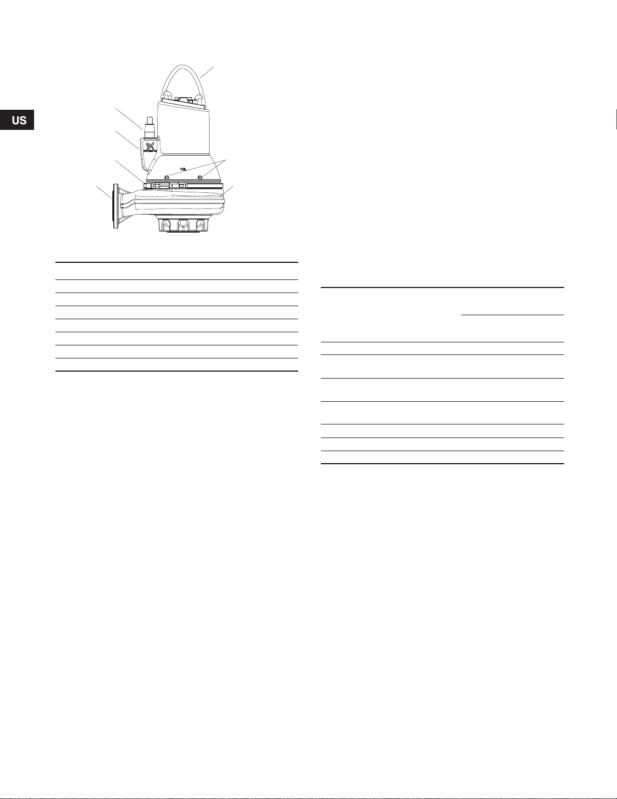
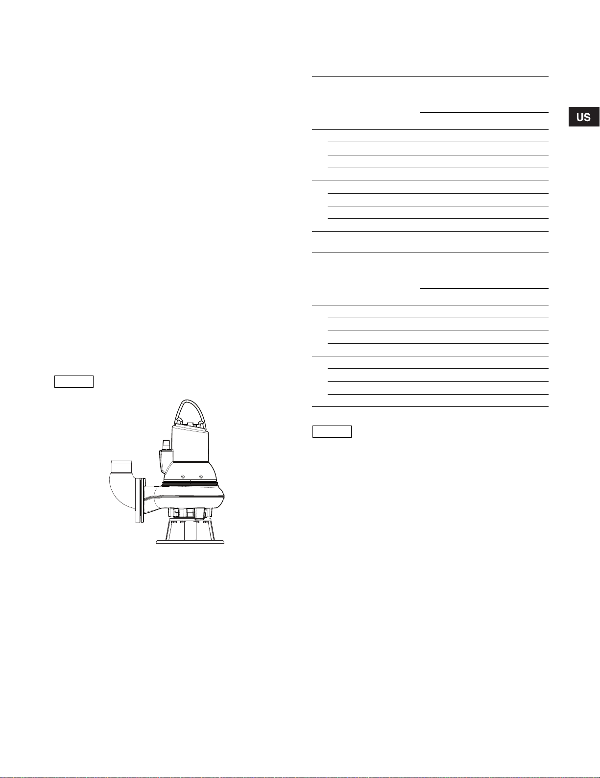
2.1 Product drawing
1
5
2
6
4
3
7
Fig. 1 SL1 pump
Pos. Description
1 Lifting bracket
2 Nameplate
3 Oil screws
4 Discharge flange
5 Cable plug
6 Clamp
7 Pump housing
For further info rmatio n on dimen sions , wei ghts and co mpon en ts,
see pages 86 and 94.
2.2 Control and monit oring
The pumps can be co ntro lled via the G rund fos Dedic ated
Controls, DC or DCD.
Pumps with sensor ar e supp lied to geth er with a n IO 111 which
can receive sig na ls from the foll owi ng tr ansm itter s:
• water-in-oil-sensor ( WIO sens or) in th e pu mp
• moisture sensor in the motor
• temperature sensor in t he stator win din gs
• winding resistance sensor in the motor.
For further in f orm at ion , se e i nst al l at ion an d o pera ti n g ins t ruct io n s
for the specific sensor.
2.3 Applications
SL1 and SLV pumps are designed for pump ing these liq uid s:
• large quantities of drainage and surf ace water
• domestic wastewater with disc harge from toile ts
• wastewater with a high content of fibres (vor tex imp elle r)
• municipal and commercial sewage a nd was tewat er.
SL1 and SLV pumps are ideal in the following loc ations:
• public buildings
• recidential housing
• industries
• garages
• multi-storey car parks
• vehicle washing tunnels
• restaurants.
The compact design m akes the p umps suitab le for bo th
temporary and pe rma nen t installa tion.
TM04 2648 2808
2.4 Pump selection
The table below shows wh ich pu mp ve rsion to se lect for a
number of liquids:
Impeller type: 1 = single-chann el imp eller, V = free-flow impeller.
Pump passage
Pumped liquid
Drainage water 1 V 1 / V 1 / V
Domestic wastewat er witho ut
discharge from toilets
Domestic wastewat er with
discharge from toilets
Wastewater with a high conten t of
fibres
Industrial wastewater 1 / V 1 / V
Wastewater with gaseous slu dge 1 / V 1 / V
Municipal wastewater 1 / V 1 / V
[Inch (mm)]
2
2.5
(50)
(65)3(80)4(100)
1 V 1 / V 1 / V
VVV
1 / V 1 / V
6
Page 7

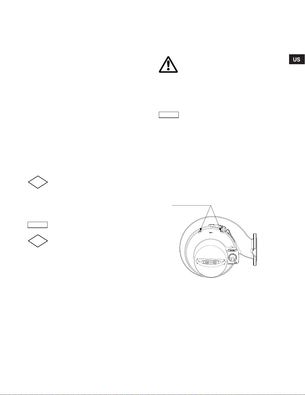
2.5 Operating conditions
S1 operation
S3 operation
FM
FM
Note
Caution
The Grundfos SL 1 and S LV pumps are suitable for th e follo wing
operating situations :
• S1 operation (continuous operation), th e pu mp mu st a lways
be covered by the pu m ped liqu id to t he top of the mot or.
See fig. 2.
• S3 operation (intermittent operation) , the pu mp must alwa ys
be covered by the pu m ped liqu id up t o the top of the c abl e
entry. See fig. 2.
For further info rmatio n ab out S1 a nd S3 o per ation, see s ection
9.2 Operat ing mo des.
Fig. 2 Stop levels
Density and viscosity of pumped liquid
When pumping liqu ids wit h a density and/or a kinematic viscos it y
higher than that of wa t er, use motors w ith correspondingly h ighe r
outputs.
Pumping liquids with high content of solids, fibres etc.
This procedure applies only to vortex impellers.
In very tough applications, and in applications with high content of
solids, fibres, etc. it is advisable to rotate the impeller backwards
a few seconds, before or after each pump cycle.
Do not rotate the impeller in single-channel
impeller pumps backwards.
Flow velocity
It is advisable to keep a minim um f low v elocity to avoid
sedimentations in the pip ing sy stem . Recom men ded flow
velocities:
- in vertical pipes: 2.3 ft/s (0.7 m/s)
- in horizontal pipes: 3.3 ft/s (1.0 m/s)
Installation depth
Maximum 65 ft (20 m) be low liqui d lev el.
Maximum solids s ize
From 2" to 4" (50 to 10 0 mm), depen ding on p ump s ize.
Operating mode
TM04 2649 2808
Maximum 30 s tarts per ho ur.
pH value
SL1 and SLV pumps in permanent installation s can be u sed for
pumping liquids wi th a pH va lue between 4 an d 10.
Liquid temperature
32 °F to +104 °F (0 °C to + 40 °C).
For short perio ds (m axim um 3 m inut es) a temp eratur e of u p to
+140 °F (+60 °C) is permissible ( non-FM versions only).
Warning
Explosion-proof pumps must never pump liquids
of a temperature hi gher than +104 °F (+40 °C).
Ambient temperature
Warning
For explosion-proof pumps, the ambient
temperature on t he inst allat ion site must b e in
the range from -4 °F t o + 104 °F (-20 °C t o +40 °C).
For explosion-proof pumps with WIO sensor, the
ambient temper atu re at the ins talla tion s ite m ust
be in the range from 32 °F to +104 °F
(0 °C to +40 °C).
For non-explosi on proo f pum ps, the ambie nt tem perat ure may
exceed +104 °F (+40 °C) f or a s hort per iod (m ax. 3 m inut es).
7
Page 8

5
4
1
3
6
7
9
10
8
13
11
16
18
15
19
20
23
17
22
24
21
25
12
14
2
3. Delivery and handling
The pump may be tr anspo rte d and sto re d in a vert ical or
horizontal position . Ma ke su re that it ca nno t roll or fall over.
3.1 Transportation
All lifting equipment m ust be r ated for the purpo se and ch ecke d
for damage before any attempts to lift the pump. The lifting
equipment ratin g mus t und er n o circ ums tances be exce ede d.
The pump weight is stated on the pump nameplate.
Warning
Always lift the pump by its lifting bracket or by
means of a fork-lift truck if the pump is fixed on a
pallet. Never lift the pump by means of the motor
cable or the hose/pipe.
4. Identification
4.1 Nameplate
The nameplate states the o peratin g da ta and app rova ls app lyin g
to the pump. The nameplate is fitted to the side of the stator
housing close to the cable e ntry.
Fix the extra nam eplate s upplie d with the pu mp to the cab le en d
in the control box.
3.2 Storage
During long period s of stor age, the pum p mus t be prot ecte d
against moisture and heat.
Storage temperature: -22 °F to +140 °F (- 30 °C to +60 °C)
Warning
If the pumps are sto r ed f o r mo r e th a n o ne year or
it takes a long time before it is put into operation
after the installation, the impeller must be turned
at least once a month.
If the pump has bee n in use , the oil should be cha nged be fore
storage.
After a long period of st orage , the pu mp sh ould be inspec ted
before it is put into operation. Make sure that the impeller can
rotate freely. Pay special attention to the co nditi on of the sh aft
seal, O-rings, oi l and the c abl e entry.
Fig. 3 N amepl ate
Pos. Description
1 FM marking
2 Thermal protected
3 Type designation
4 Serial number
5 Production code (year/week)
6 Maximum ambient tem pera ture
7 Maximum head
8 Maximum flow rate
9 Rated input/output power
10 Ra ted voltage, D
11 Rated voltage, Y
12 Fre qu ency
13 Co untry o f produc tion
14 CSA mark
15 F M ma rk
16 E nclos ure clas s to IE C
17 Maximum installation depth
18 P ower fa ctor
19 Nu mber of pha ses
20 Ra ted spe ed
21 S ervice f actor
22 Full lo ad curr ent, D
23 Full lo ad curr ent, Y
24 Ins ulati on class
25 Weight without cab le
TM04 4187 0909
8
Page 9

4.2 Type key
The pump can be ide ntified by me ans of the type des ignat ion s tated on t he pum p nam eplat e. See se ction 4.1 Nameplate.
Code Example SL 1. 30 .A30. 55. A. Ex. 4. 6. 0H A. Q.
Pump type:
SL
Grundfos wastew ater pum p/s ewag e pu mp
Impeller type:
1
Single-channel impe ller
V
Free-flow impeller ( SuperVortex)
Pump passage. Code numbe r fr om typ e key / 10 [i nch]:
20
2" (50 mm)
25
2.5" (65 m m)
30
3" (80 mm)
40
4" (100 mm)
Pump discharge (d ischa rge po rt in in ch es):
A25
Ansi 2.5" (DN65 )
A30
Ansi 3" (DN80)
A40
Ansi 4" (DN100)
A60
Ansi 6" (DN150)
Motor power. Code number from type key / 10 [hp]
55
5.5 hp = 4.0 kW
Accessories:
[-]
Standard
A
Sensor
Pump version:
[-]
Non-explosion-pro of
Ex
Explosion-proof
Number of poles:
2
2-pole
4
4-pole
Frequency:
6
60 Hz
Voltage and starting method:
0J
3 x 208-230V Δ DOL, (60 Hz)
1J
3 x 208-230V Δ / 460V Y, (60 Hz)
1H
3 x 460V Δ Y/D, (6 0 Hz)
0L
3 x 575V Δ DOL, (60 Hz )
1L
3 x 575V Δ Y/D, (6 0 Hz)
Product generation:
A
1st generation
B
2nd generation
C
3rd generation
Material variant:
[-]
Cast iron impeller, volute and stator housing
Q
Stainless steel impeller
9
Page 10

5. Approvals
Note
FM
Note
Note
Caution
Caution
Caution
Caution
The SL1 and SLV pumps have been approved by CSA and FM, and the explosion-proof versions hold an FM type examination certif ic at e
no.: 3035318.
5.1 Approval standards
These pumps have been app rove d by CS A and FM acc ordi ng to U L778, C22.2 n o. 108 and F M 360 0, FM 3615 an d FM 361 5.80 .
5.2 Explanation to FM approval
The SL1 and SLV pumps have the follo wing ex plos ion p rotec tion clas sif icat ion: Cl ass I, Div ision 1, Gro ups C and D, T4, T3, IP68 .
Standards Code Description
Class I = Explosive atmosphere is caus ed by g as or v apour s.
FM 3600
FM 3615
FM 3615.80
Division 1 = Area classi fica tion
Groups C and D = Classification of gases
T4/T3 = Maximum surface temper atu re is 275 °F (1 35 °C) and 3 92 °F (200 °C)
IP68 = Enclosure class acco rding t o IEC 6 0529.
6. Safety
Warning
Pump installation in tanks must be carried out by
specially trained persons.
Work in or near tanks must be carried out
according to local regulations.
Warning
Persons must not enter the installation area
when the atmospher e is ex plosi ve.
Warning
It must be possible to lock the mains switch in
position 0. Type and requirements as specified in
National Electrical Code and all local codes.
For safety reas on s, all w ork in tanks mu st be super vise d by a
person outside the pump ta nk.
It is advisable to make all maintan ce an d serv ice
jobs when the pump is placed outside the tank.
Tanks for submer sible s ewage and wast ewat er pu mps ma y
contain sewage or wa stew ater wit h to xic an d/or disea se-cau sin g
substances. Therefor e, all per sons involv ed m ust wear
appropriate pers onal pr ote ctive eq uipm ent an d clothi ng, an d all
work on and near the pu mp m ust b e carr ied out u nde r stric t
observance of the hy giene r egu lations in force .
Warning
Make sure that the liftin g br ack et is ti ght ened
before attempting to lift the pump. Tighten if
necessary. Carelessness during lifting or
transportation may cause injury to personnel or
damage to the pump.
The following warnings and notes also appear in a label
(delivered with the pump) . Pla ce th e labe l near t he co ntro l
box.
Warning
To reduce risk of electric shock, see installation
and operating instructions for guidance in proper
installation.
Warning
To reduce risk of electric shock, install only on a
circuit protected by a ground-fault circuit
interrupter (GFCI).
Acceptable for indoor and outdoor use.
Submersible pump.
Provide suitable motor protection based on the
electrical ratings.
Enclosure type 3.
This pump has been tested with water only.
Use wih approved motor protective circuit
breaker matching motor input in full-load
amperes with overloa d el ement (s) se lected or
adjusted in accorda nce with con trol inst ructio ns.
Warning
Risk of electric shoc k. Do not remo ve cab le an d
strain relief. Do not connect conduit to pump.
Warning
Risk of electric shock
This pump has not been approved for use in
swimming pools or marine areas.
10
Page 11
6.1 Potentially expl osiv e en vironmen ts
FM
FM
FM
Caution
Note
Caution
Use explosion-pr oof pum ps for a pplica tions in p oten tially
explosive envi ronm ents. Se e sec tion 5.2.
Warning
SL1 and SLV pumps must under no
circumstances pump combustible liquids.
Warning
The classification of the i nstall atio n site mus t be
approved by the local fire-fighting authorities in
each individual case .
Special conditions for safe use of SL1 and SLV
explosion-proof pumps:
1. Make sure the mo istu re sw itch es and th erma l
switches are connected in the same circuit but
have separate alarm outputs (motor stop) in case
of high humidity or high temperature in the motor.
2. Bolts used for replac emen t mu st be class A2- 70
or better according to EN/ISO 3506-1.
3. Contact the manufacturer for information on the
dimensions of the flameproof joints.
4. The level of pump ed liquid must be co ntro lled by
two level switches connected to the moto r control
circuit. The minimu m le vel de pen ds on the
installation type and is specified in these
installation and operat ing ins truct ions .
5. Make sure the perm anently attache d cable is
suitably mechanically pro tec t ed and term i na te d in
a suitable terminal boar d plac ed outside t he
potentially explosive area.
6. The sewage pumps have an ambient temperature
range of -4 °F to +104 °F (-20 °C to +40 °C) and a
maximum process temper atu re of +104 °F
(+40 °C). The mininmum ambient tem perature for
a pump with a water-in-oil sensor is 32 °F (0 °C).
7. The thermal protection in the stator windings has
a nominal switch temperature of 302 °F (150 °C)
and must guarant ee the d isc onne ctio n of the
power supply; th e powe r supp ly m ust be res et
manually.
8. The control unit mu st pro tect t he W IO sensor
against short circuit cur re nt of the supply to which
it is connected. T he ma xi mum curr ent fro m th e
control unit must be limited to 35 0 mA.
7. Installation
Warning
During installation, always support the pump by
means of lifting chains or place it in hor izontal
position to secure stability.
Prior to installation, make sure the tank bottom is
even.
Warning
Before beginning the installation, switch off the
power supply and lock the mains switch in
position 0.
Any external voltage connected to the pump must
be switched off before working on the pump.
Before beginn ing installat ion pr oced ures , carry out th ese ch eck s:
• Does the pump correspond to ord er?
• Is the pump suitable for the supp ly volta ge and f requ ency
available at the installatio n sit e?
• Are accessories and other eq uipme nt un dama ged?
Further details concerning accessories can be
found in the product guide SL1, SLV pumps on
www.grundfos.com.
Fix the extra nam eplate s upplie d with the pu mp to the cab le en d
in the control box.
All safety regulations must be observed at the installation site,
e.g. the use of blow ers for fre sh-a ir supp ly to th e tank.
Prior to installation, check the o il level in th e oil ch amber.
See section 10. Maintenance and service.
Warning
Do not put your hands or any tool into the pump
suction or discharge port after the pump has
been connected to the power supply, unless the
pump has been switched off by removing the
fuses or switching off the mains switch. It must
be ensured that the power supply cannot be
accidentally switche d o n.
We recommend to alwa ys us e Grund fos
accessories to avoid malfunctions due to
incorrect installation.
Warning
Only use the lifting bracket for lifting the pump.
Do not use it to hold the pump when in operation.
Installation types
The SL1 and SLV pumps are designe d for two in stallation typ es:
• submerged installation on auto-coupling
• free-standing submerged installat ion on ring stand.
11
Page 12
7.1 Submerged installation on auto -coupli ng
Caution
Caution
Note
Note
FM
Pumps for perm anent installation ca n b e i nstalled on a stationary
auto-coupling guide rail system. The auto-coupling system
facilitates mainte nance and se rv ice as t he pum p can easily be
lifted out of the tank. See fig. 4.
Warning
Before beginning installation procedures, make
sure that the atmos ph ere in the tan k is not
potentially explosive.
Make sure that the pipework is installed without
the use of undue force. No loads from the
pipework weight must be carried by the pump.
We recommend the use of loose flanges to ease
the installation and to avoid pipe tension at
flanges and bolts.
Do not use elastic elements or bellows in the
pipework; these elements should never be used
as a means to align th e pipe work .
Proceed as follows :
1. Drill mounting holes for the guid e rail br acket on the inside of
the tank and fasten the g uide rail br acke t pro visionall y w ith
two screws.
2. Place the auto-coup ling bas e unit on th e botto m of th e tank.
Use a plumb line to establis h the corr ect p osition ing. Fa ste n
the auto-coupling with ex pansion bol ts, If the botto m of th e
tank is uneven, the auto-coupling base unit must be supported
so that it is level when b eing fas tene d.
3. Assemble the discharge pipe in accordance with the generally
accepted procedu res an d w ithout expos ing th e pipe t o
distortion or tension.
4. Place the guide rails on the auto-coupling base unit and adjust
the length of the rails ac cura tely to the g uide rail br acke t at
the top of the tank.
5. Unscrew the pro visio nally f asten ed g uide ra il br acke t. In sert
the upper guide rai l brac ket in to the g uid e rails . Fast en t he
guide rail bracket on the ins id e of the tank.
The guide rails must not have any axial play as
this would cause noise during pump operation.
6. Clean out debris from the tank b efore low eri ng the pu mp int o
the tank.
7. Fit the guide claw to the discharge port of the pump.
8. Slide the guide claw of the pum p b etween t he gui de rails and
lower the pump into th e tank by mean s of a ch ain secu red to
the lifting bracket of the pum p. Wh en the pump reaches the
auto-coupling base unit, the pump w ill autom atically conn ect
tightly.
9. Hang up the end of th e chain on a sui table hoo k a t the top o f
the tank and in such a wa y tha t the c hai n cann ot co me int o
contact with the pump ho using.
10.Adjust th e length of the motor c able by coiling it up on a r eli ef
fitting to ensure that the cable is not damaged during
operation. Fasten th e r elief fitting to a suitable hook at th e t op
of the tank. Make sure tha t the c ables are not s harply bent or
pinched.
11.Connect the motor cable.
The free end of the cable must not be submerged,
as water may pen etrat e into the ca bl e.
TM04 2650 2808
Fig. 4 Sub merg ed insta llatio n on auto coupli ng
12
Page 13
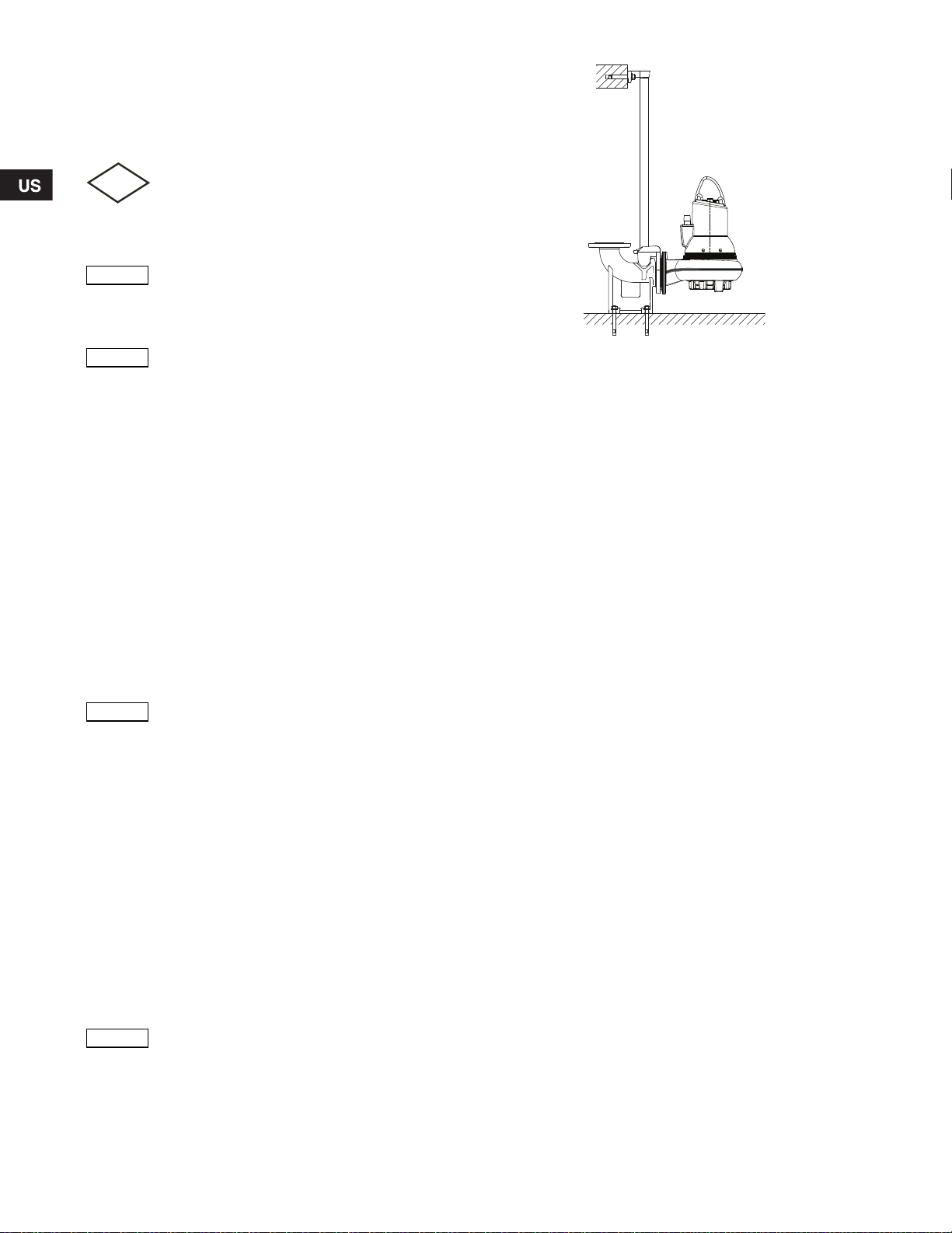
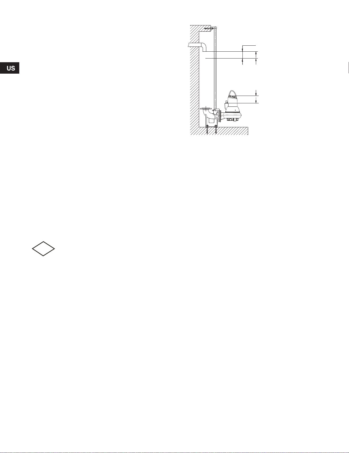
7.2 Free-standing submerged installation on ring stand
Note
Caution
Pumps for free-standin g s ubme rged in stallatio n c an stand fre ely
on the bottom of the tank. The pump must be installed on a ring
stand. See fig. 5.
The ring stand is availa ble as a n acce sso ry.
In order to facilitate service on the pump , fit a flexible un ion or
coupling to the elb ow o n the d ischa rge po rt f or eas y se paratio n.
If a hose is used, make s ure t hat th e hose doe s not buck le and
that the inside diam eter of the hose m atche s tha t of th e pum p
discharge port.
If a rigid pipe is used, fit the union or co upling, non-return v alv e
and isolating valve in the order mentioned, when viewed from the
pump.
If the pump is installed in muddy conditions or on uneven ground,
support the pump on br icks or a sim ilar s uppor t.
Proceed as follows :
1. Fit a 90 ° elbow to the pump disch arge p ort a nd con nect the
discharge pipe/hose .
2. Lower the pump into the liquid by means of a chain secured to
the lifting bracket of the pump. We recommend to place the
pump on a plane, solid foundation. Make sure that the pump is
hanging from the chai n and not the cable. Make sure that the
pump is standing se cure ly.
3. Hang up the end of the c hain on a suitabl e hook at the top of
the tank and in such a way that the c hain c annot c ome int o
contact with the pump hous ing.
4. Adjust the length of the motor cable by coiling it up on a relief
fitting to ensure that the cable is not damaged during operation.
Fasten the relief fitting to a suitable hook at the top of the tank.
Make sure that the cable is not sharply bent or pinched.
5. Connect the motor cable.
The free end of the cable must not be submerged,
as water may pen etrat e into the ca bl e.
7.3 Tightening torques for su ctio n and d ischa rge
flanges
Grade 4.6 (5) ga lvani zed st eel screw s an d nuts
Specified tightening torques
DN DC Screw
2½" 5½" 4xM16 50 (70) 45 (60)
3" 6" 8xM16 50 (70) 45 (60)
4" 7½" 8xM 16 50 (70) 45 (60)
Suction
6" 9½" 8x M20 100 (140) 90 (120 )
2½" 5½" 4x5/8" UNC 50 (70) 45 (60)
3" 6" 8x5/8" UNC 50 (70) 45 (60)
4" 7½" 8x5/8" UNC 50 (70 ) 45 (60)
Discharge
6" 9½" 8x3/4" UNC 90 (120) 80 (100)
Grade A2.50 (AISI 304) steel screws and nuts
DN DC Screw
2½" 5½" 4xM16 - 45(60)
3" 6" 8xM16 - 45( 60 )
4" 7½" 8xM 16 - 45(60)
Suction
6" 9½" 8xM 20 - 90(120)
2½" 5½" 4x 5/8" U NC - 45(60)
3" 6" 8x5/8" UNC - 45(60)
4" 7½" 8x5/8" UNC - 45(60)
Discharge
6" 9½" 8x3/4 UNC - 80(100)
rounded off by +/- 5
[ft.lbs (Nm)]
Slightly oiled Well lubricated
Specified tightening torques
rounded off by +/- 5
[ft.lbs (Nm)]
Slightly oiled Well lubricated
Fig. 5 Fr ee-stand ing sub mer ged ins tallation o n a ring stand
The gasket must be a full face, reinforced paper
gasket like Klingersil C4300 . If sof ter gask et
material is used, torques must be reconsidered.
TM04 2651 2808
13
Page 14
8. Electrical connection
Caution
Caution
FM
FM
FM
Warning
Connect the pump to an external mains switch
which ensures all-pole disconnection with a
contact separation according to National
Electrical Code and all local codes.
It must be possible to lock the mains switch in
position 0. Type and requirements as specified in
National Electrical Code and all local codes.
The electrical connection must be carried out in
accordance with lo cal reg ulat ions.
Warning
The pumps must be connected to a control box
with a motor protection relay with IEC trip class
10 or 15.
Warning
Pumps for hazardous locations must be
connected to a control box with a motor
protection relay with I EC tri p clas s 10.
See “Motor protection wiring diagram” on
page 17.
Warning
Do not install Grundfos control boxes, pump
controllers, Ex barriers and the free end of the
power cable in potentially explosive
environments.
The classification of the i nstall atio n site mus t be
approved by the local fire-fighting authorities in
each individual case .
On explosion-proof pumps, make sure that an
external earth lead is connected to the external
earth terminal on the pump using a secure cable
clamp. Clean the s urface of th e exte rnal ea rth
connection and mount the cable clamp.
The earth lead must be minimum AWG 12 type
RHH, RHW, RHW-2 or similar, rated for 600 V and
min. 194 °F (90 °C), yellow /gree n.
Make sure that the earth co nnect ion i s prot ected
from corrosion.
Make sure that all protective equipment has been
connected correctly.
Float switches us ed in po tenti al ly explo sive
environments must be approved for this
application. They must be connected to the
Grundfos Dedicated Controls, DC or DCD, via an
intrinsically safe barrier to ensure a safe circuit.
The mains supply voltage and frequency are marked on the pump
nameplate. The voltage tolerance must be within - 10 %/+ 10 % of
the rated voltage. Make sure that the motor is suitable for the
power supply available at the in stallation site .
As standard, all pumps are supplied with 33 ft (10 m) cable and a
free cable end.
Pumps without sensor must be connected to:
• a control box with motor-prot ecti ve cir cuit br ea ker, such as a
Grundfos DC, DCD pump controller
Pumps with sensor mus t be con nected to:
• a Grundfos IO 111
• a control box with motor-prot ecti ve cir cuit br ea ker, such as a
Grundfos DC, DCD pump controller
Warning
Before installation and the first start-up of the
pump, check the condition of the cable visually to
avoid short circuits.
Warning
If the supply cable is damaged, it must be
replaced by the manufacturer, its service agent or
similarly qualified persons.
Set the motor-pr otec tive circ uit br eake r to t he
rated current of the pump + 15% Service factor.
The rated current is stated on the pump
nameplate.
If the pump has an Ex mark on the nameplate,
make sure that the pump i s conn ected in
accordance with th e ins truct ions given i n this
booklet.
14
Page 15
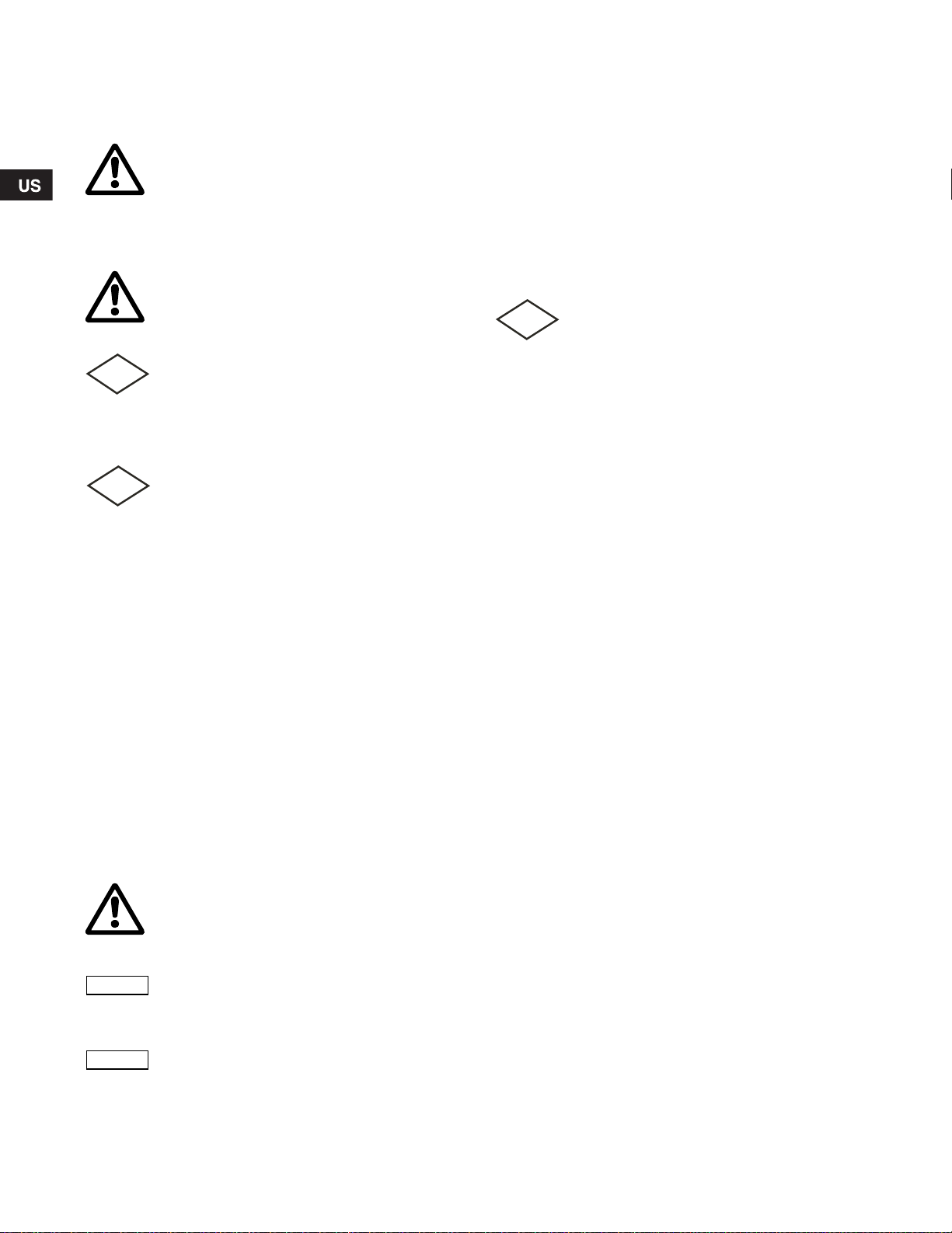
8.1 Wiring diagrams
Standard version
Thermal switches
CSA approved
Ex. version
Thermal switch and moisture switc h
CSA and FM appr oved
Sensor version
Thermal switch and PT1000 resistor
Moisture switch and water -in-oil se nsor
CSA approved, wi th/witho ut F M app rova l
The pumps are supp lied via eithe r a 7-w ire cable o r a 10-w ir e cable . Se e fig. 6 for wiring diag ram s for 7- wire c able co nne ction or figs. 7,
8 and 9 for wiring diag ram s for 10-wir e cabl e conn ec tion. Fo r fur ther inf orm atio n, se e the insta llatio n and op erat ing ins tru ctions for the
selected control box or pump controller.
Fig. 6 Wiring diagram, 7-wire cable, DOL
TM04 6689 0710
15
Page 16
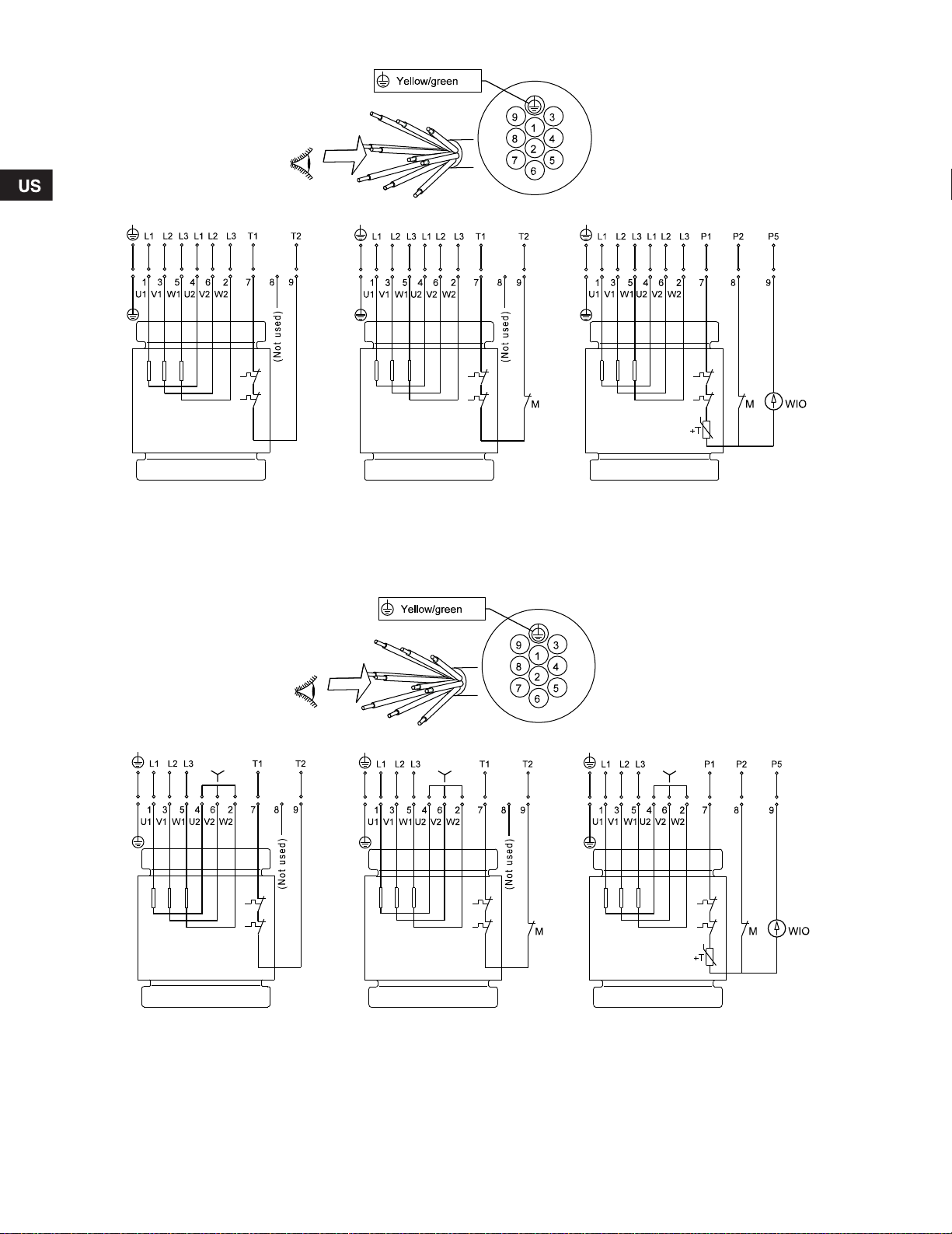
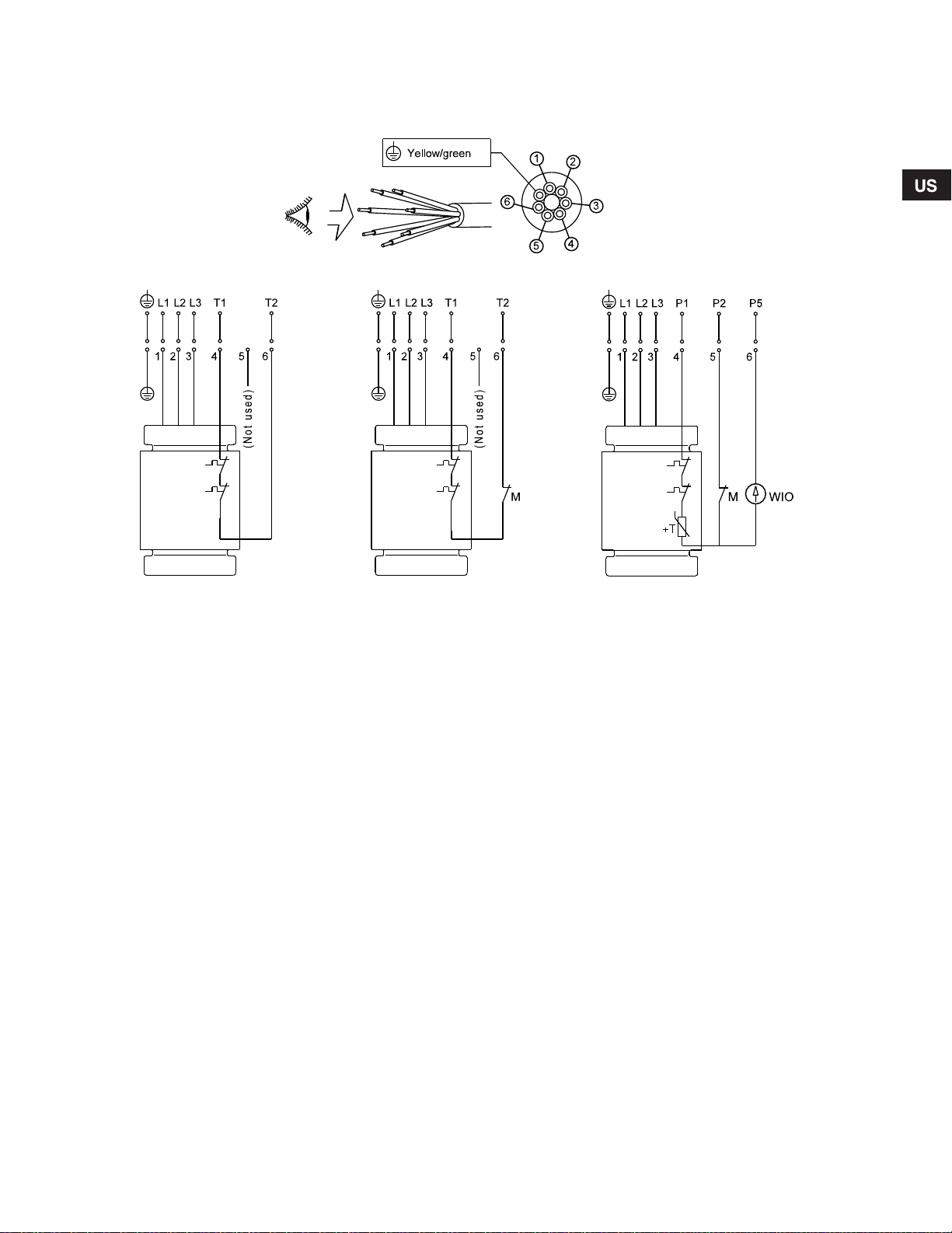
Fig. 7 Wir ing dia gram , 10-wir e cabl e, Star / Delta (Y/D)
Standard version
Thermal switches
CSA approved
Ex. version
Thermal switch and moisture switch
CSA and FM approved
Sensor version
Thermal switch an d PT100 0 res isto r
Moisture switch and water-in-oil sensor
CSA approved, with/wi thou t FM ap prov al
Standard version
Thermal switches
CSA approved
Ex. version
Thermal switch and m oisture sw itch
CSA and FM appro ve d
Sensor version
Thermal switch and PT10 00 resist or
Moisture switch and water- in-oil sensor
CSA approved, with/ wit hout FM app roval
TM04 6690 0710
Fig. 8 Wir ing dia gram , 10-wir e cabl e, Star connected (Y )
16
TM04 6691 0710
Page 17
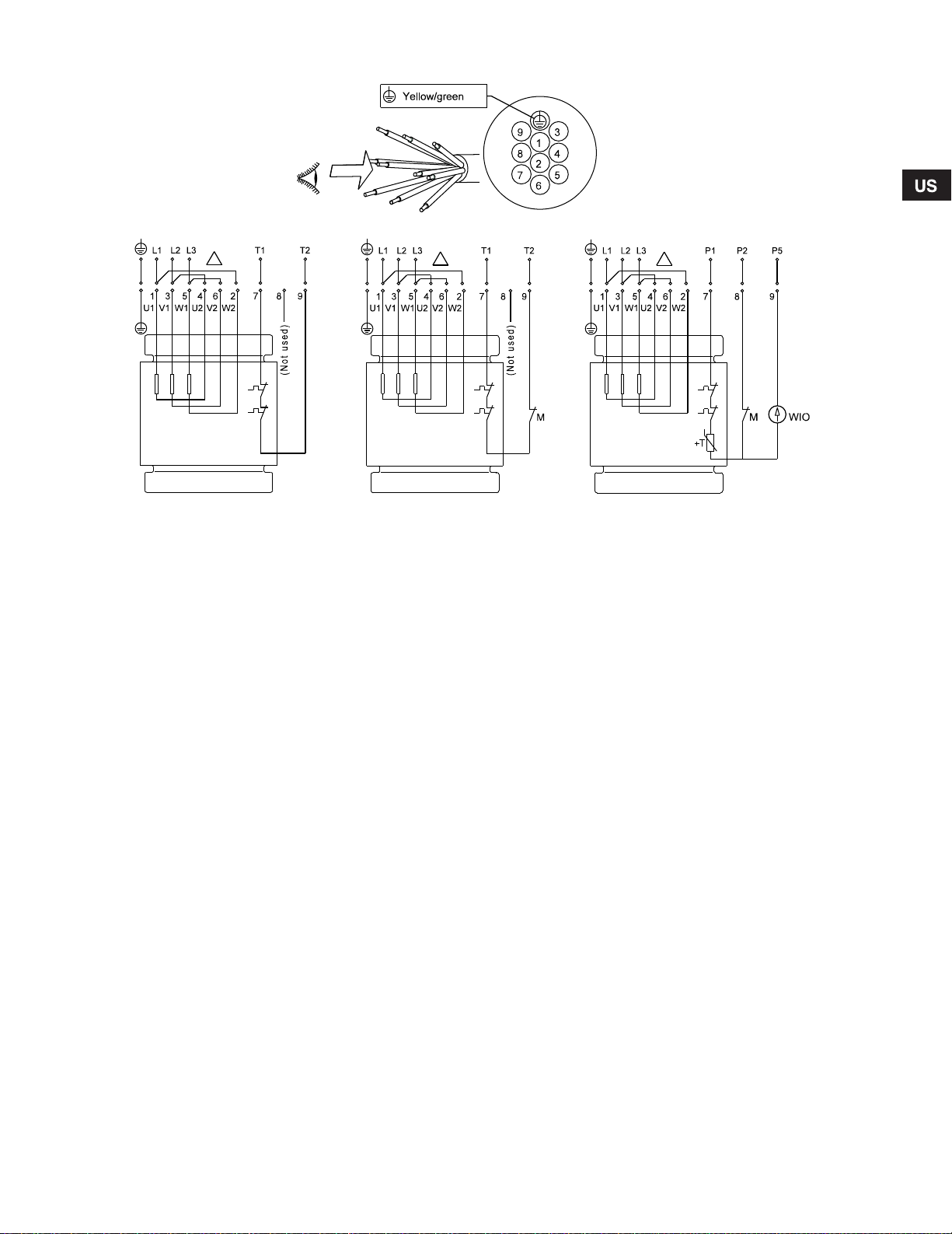
Fig. 9 Wir ing dia gram , 10-wir e cabl e, De lta conn ected ( D)
Standard version
Thermal switches
CSA approved
Ex. version
Thermal switch and moisture switc h
CSA and FM appr oved
Sensor version
Thermal switch and PT1 000 resis tor
Moisture switch and water-in -oil se nsor
CSA approved, with /with out FM appro va l
TM04 6692 0710
Fig. 10 Motor protec tion wiring diagra m
TM04 7168 1710
17
Page 18
8.2 Pump contro lle rs
FM
Start
Stop S1 operation
Alarm
Min. 4 Inch (100 mm)
Stop S3 operation
SL1 and SLV pumps can be connected to a se parate Gru ndfos
Dedicated Contr ols for level c ontrol. Dedic ated Co ntro ls are
available as accessories:
• type DC for one-pump installation s
• type DCD for two-pump install ation s.
The Dedicated Co ntro ls syste m starts/s tops the SL1 an d SLV
pumps by means of one of the following transmitters:
• float switches
• pressure sensors
• ultrasonic sensors.
Furthermore, it is possible to control the water level by both float
switches and an an alo g pressu re sens or or u ltrason ic sensor.
Optionally, the controller can co ntrol a m ixer. The Dedica ted
Controls system c an be ex tend ed wit h an IO 111 module per
pump (for SL1 an d SLV pumps with built-in sens or).
When installing the level switc hes, ob serve the follow ing poi nts:
• To prevent air intake and vibration s in stall the stop level
switch in such a way that the pump is stopped before the
liquid level is lowere d below the top of the c able ent ry.
• In tanks with one pump, install the start level switch in such a
way that the pump is started a t the requ ire d level ; how ever,
the pump must alway s be starte d befo re the liq uid level
reaches the bottom inlet pipe to the tank.
• In tanks with two pumps, the start level switc h for pump 2
must start the pump before the liquid level reache s the bottom
inlet pipe to the tank, and the start level switch for pump 1
must start this pump correspondingly earlier.
• If installed, always install the high-level alarm switch about
4" (100 mm) above the s tart lev el switc h; how ever, the alarm
must always be given b efor e the liqu id lev el rea ches t he
bottom inlet pipe to the tank.
For further inform atio n, see t he ins tallation a nd o peratin g
instructions for the pump controller selected.
Warning
The pump must not run dry.
An additional level switch must be installed to
ensure that the pump is stopped in c ase the stop
level switch is not operating.
The pump must be stopped when the liquid level
reaches the top of the cable entry.
Float switches us ed in po tenti al ly explo sive
environments must be approved for this
application. They must be connected to the
Grundfos Dedicated controls, DC or DCD, via an
intrinsically safe barrier to ensure a safe circuit.
TM04 2654 2808
Fig. 11 Start and stop levels
Make sure that the effe ctive vo lume of the tank doe s no t beco me
so low that the numb er of starts per hou r e xcee ds th e max imum
permissible nu mber. See section 9 .2 Operating modes .
18
Page 19
8.3 Thermal switch, Pt100 0 and th ermisto r
FM
FM
Note
Caution
All SL1 and SLV pumps have thermal prot ectio n incor pora ted in
the stator windings.
Pumps without sensor
Pumps without se ns or hav e a th erma l sw itch .
Via the pump controller s afety c ir cu it, the thermal switch will stop
the pump by break ing t he circui t in ca se of over tem peratu re
(approx. 302 °F (150 °C)). The ther mal switc h will reclo se the
circuit after cooling.
The maximum oper ating curr ent o f the ther mal s witch is 0.5 A at
500 V A C an d cos ϕ 0.6. The switch must be able to break a coil in
the supply circui t.
Pumps with sensor
Pumps with sensor have eithe r a the rma l sw itch and a P t100 0
sensor or a thermis tor (P TC) in t he win ding s, depe ndi ng on t he
installation site.
Via the pump controller safety circuit, the thermal switch or the
thermistor will stop the pu mp by br eakin g the circu it in case of
overtemperatur e (approx. 302 °F ( 150 °C). The thermal switch or
the thermistor will reclose the c ircu it after cooling.
The maximum op erat ing cu rrent of bo th the Pt1 000 and the
thermistor is 1 mA at 2 4 VDC.
Non-explosion-proof pumps
When closing the circ uit after co oling, the th erma l protec tion can
restart the pump auto matic ally vi a the c ontrol ler.
Explosion-proof pumps
Warning
The thermal protection of explosion-proof pumps
must not restart the pump automatically. This
ensures protection against overtemperature in
potentially explosive environments. In pumps
with sensor this is done by removing the shortcircuit between terminals R1 and R2 in the IO 111.
See Electrical data in the IO 111 installation and
operating instructions.
Warning
The separate motor-protective circuit breaker/
control box must not be installed in potentially
explosive environm ents.
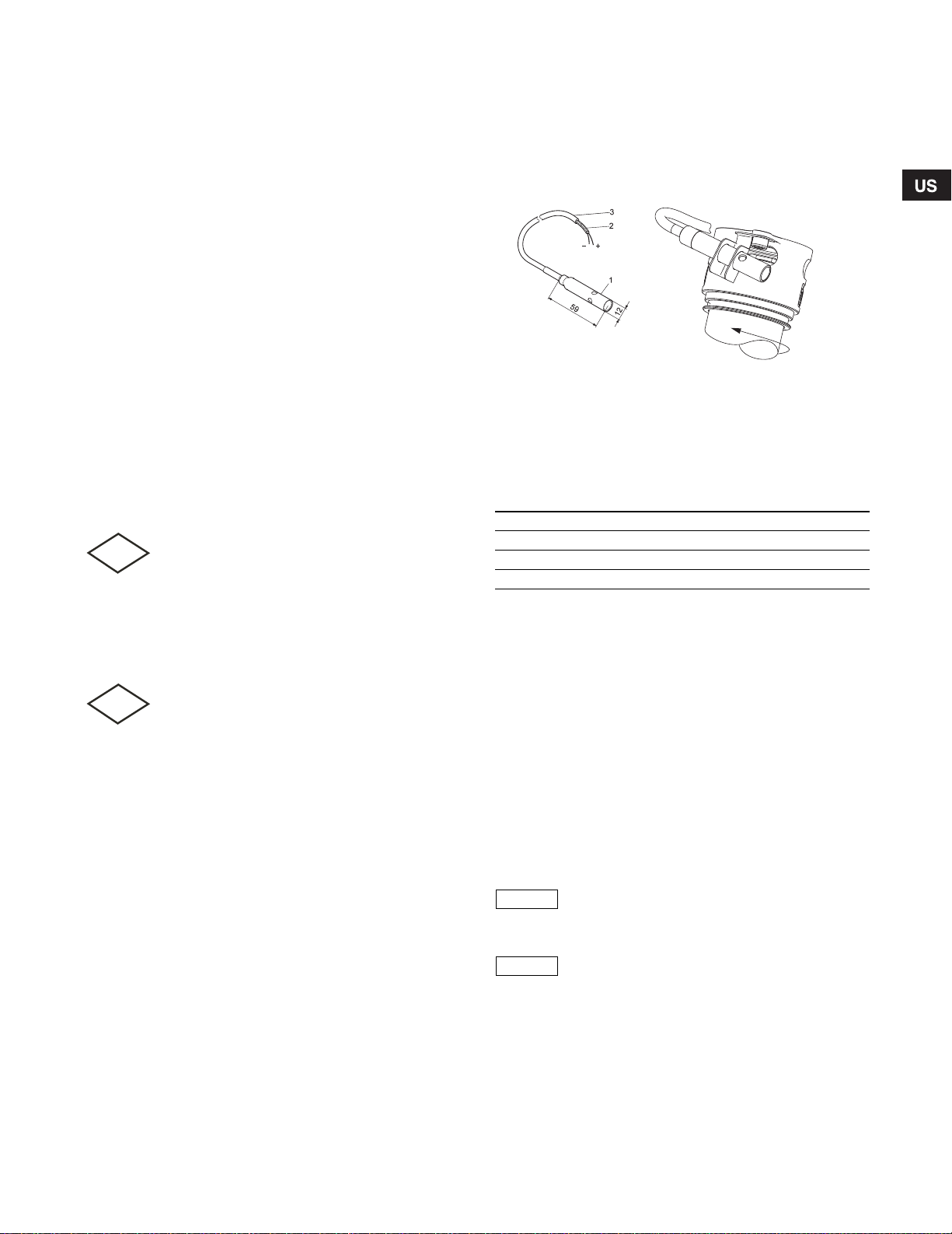
8.4 WIO sensor (water-in-oil sensor )
The WIO sensor measures the water content in the oil and
converts the value into an analo g c urrent signa l. The t wo se nsor
leads are for power supp ly a nd for c arry ing th e si gnal to t he
IO 111. The sensor measur es the w ater conten t from 0 to 2 0 %.
sIt also sends a sig nal i f the wa ter con tent is outside the no rma l
range (warning), or if the re is a ir in th e oil cha mber (alar m). The
sensor is fitte d in a s tai nles s s te el tube for mechan ica l protection.
TM04 5238 2909/ TM03 1164 1105
Fig. 12 WIO sensor
8.4.1 Fitting the WI O sen sor
Fit the sensor next to one of t he shaft se al openin gs. See fig. 12.
The sensor must be tilted into the motor’s direction of rotation to
ensure that oil is led into the sensor. Make sure that the sensor is
submerged in the oil.
8.4.2 Technical data
Input voltage: 12-24 VDC
Output current: 3.4 - 22 mA
Power input: 0.6 W
Ambient temperat ure: 32 to 15 8 °F (0 to 70 °C)
See also the installati on and o peratin g ins truct ions for IO 111 on
www.grundfos.com.
8.5 Moisture switch
All FM approved moto rs ar e fitt ed wit h a moist ure swit ch as
standard, with the moisture switch being connected via the supply
cable. See 8. Electrical connection. The moisture switch must be
connected to a separate circuit breaker.
The moisture switch is positioned in the bottom of the motor. If there
is moisture in the motor, the switch will break the circuit and send a
signal to the IO 111.
The moisture switc h is non -rev ersin g and m ust be r ep laced a fter
use.
On sensor motors the moisture switc h is connected in ser ies wit h
the thermal switch an d con nect ed to th e mon itori ng cab le, and it
must be connected to the safety circuit of the separate pump
controller. See section 8. Electrical connect ion.
There is no moisture switch in CSA versions
without sensor.
The motor-protective circuit breaker of the pump
controller must include a circuit which
automatically disconnects the power supply in
case the protective circuit for t he pum p is
opened.
19
Page 20
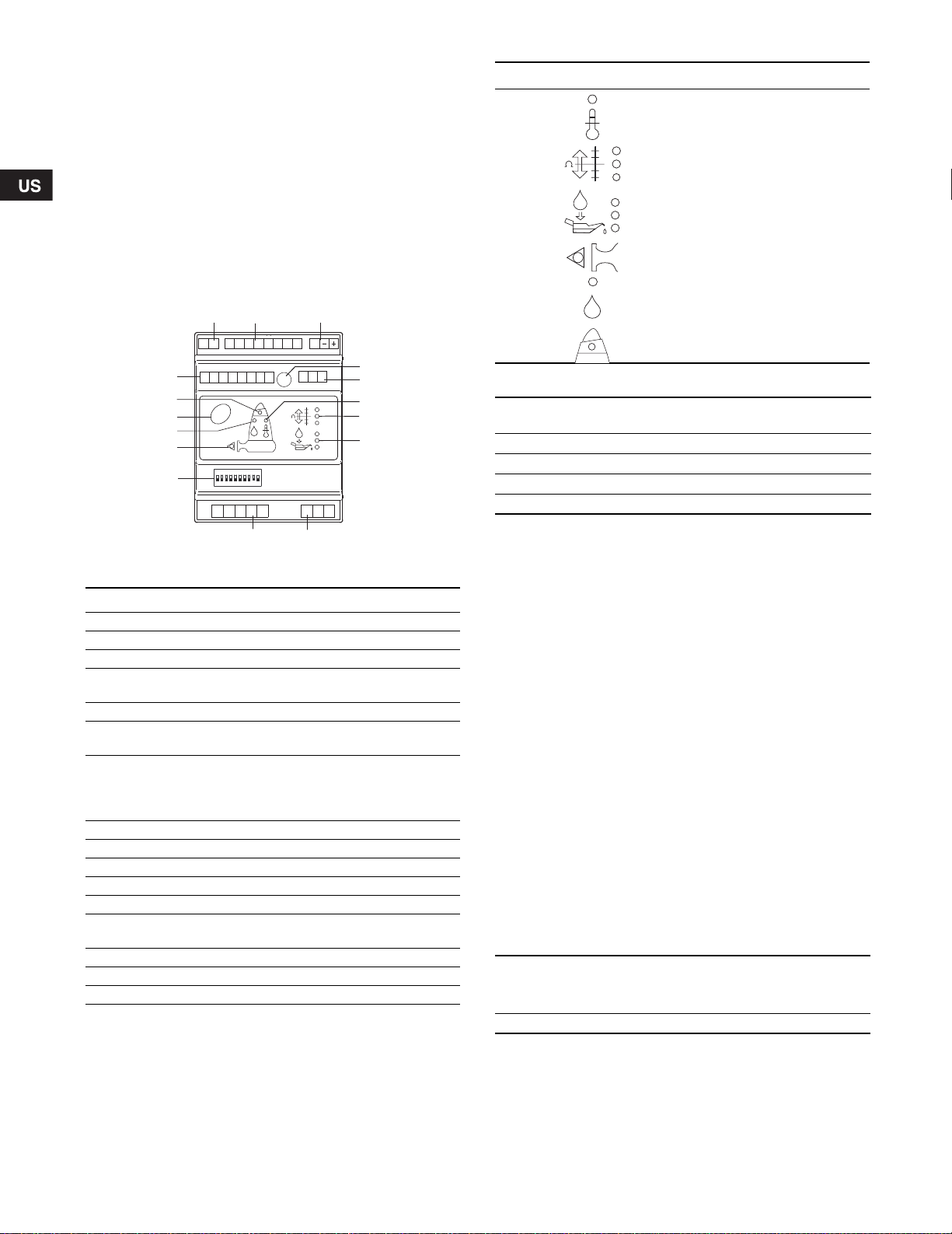
8.6 IO 111
Reset
PET1 T2
G1 A1 G2 A2 K1 K2 R1 R2
D1D2 D3D4 D5 D6 D7 D8
P1 P2 P3 P4 P5
AYB
I1 I2 I3
ON DIP
12345678910
12 3
910
4
5
6
7
8
11
12
15
16
13
14
The IO 111 forms interface betw een a Grund fos sew ag e or
wastewater pump with an alog an d digital sen sors and t he pum p
controller. The most importa nt se nsor data are indica ted on the
front panel.
One pump can be conn ec ted to a n IO 111.
Together with the sensors, the IO 111 forms a galvanic separation
between the motor voltag e in the pump and th e contr oller
connected.
IO 111 can distinguish between two categories of fault:
•Alarm: The pump stops. The fault is serious, such as too
high motor t em perature.
•Warning: The pump does not stop. The fault is not serious,
such as too much water in the oil.
Pos. Symbol Description
6 Stator temperature
7 Stator insulation resistance
8 Water in oil chamber
12 Pump running
13 Moisture in motor
15 Pump fault
8.6.1 Technical data
Fig. 13 IO 111
Pos. Description
1 Terminal for alarm relay
2 Terminal for analog and digital inputs and outpu ts
3 Terminal for supply voltage (24 VAC/24 VDC)
Potentiometer for setting the warn ing limit of stator
4
insulation resistance
5 Terminal for RS485
Red indicator light. Alar m in ca se of too h igh m oto r
6
temperature.
Indicator lights for s tator insula tion r esista nce.
Green = ok.
7
Yellow = warnin g.
Red = alarm.
8 Indicator lights for measurement of water in oil
9 Terminal for measurement of stator insul ation resi stance
10 Terminal for connection of pump se nsor s
11 DIP sw itch fo r configuration
12 Green indicator light. On when th e pu mp is r unning .
Red indicator light. On in case of mois ture in the moto r
13
(alarm).
14 Button for reset of alarm
15 Yellow indicator light. On in case of pum p fa ult (war nin g).
16 Terminal for digital outputs
20
Supply voltage:
24 VAC - 10 %/+ 10 %, 50 and 60 Hz
24 VDC - 10 %/+ 10 %
Input current: Min. 0.5 A; max. 8 A
Power input: Max. 5 W
Ambient temperature: -13 °F to 149 °F (-25 °C to +65 °C)
Enclosure class: IP20
For further information, see installation and operating instructions
TM03 0691 0505
for IO 111.
8.7 Frequency converter ope rat ion (V FD )
In principle, all thre e-ph ase m otor s can be con nected to a
frequency conv ert er.
However, frequency converter opera tion w ill often ex pose the
motor insulati on s y st e m to a heavier load and cause the m ot or t o
be more noisy tha n usua l due to harm on ic frequ enc y cu rrents
caused by voltage peak s.
In addition, larg e motor s driven via a freque ncy c on verter wil l be
loaded by bearing curr ents.
For frequency co nv erter o perat ion, pleas e obse rv e the fo llowi ng
information:
Requirements must be ful filled .
Recommendations ought to be fulfille d.
Consequences sh oul d be con sider ed.
8.7.1 Requirements
• The thermal protection of the mot or m ust be c onnec ted .
• Peak voltage and dU/dt must be in accordanc e with the table
below. The values stated are maximum value s supp lied to the
motor terminals. The c ab le infl uence has no t been taken int o
account. See the frequency converter data sheet regarding the
actual values and the cable influence on t h e peak voltage and
dU/dt.
Maximum repeti tive p eak
voltage
(V)
850 2000
• If the pump is an FM-approv ed pum p, check if the FM
certificate of the spec ific pump allows the use o f a freq uenc y
converter.
• Set the frequency converter U/f ratio according to the motor data.
• Local regulations/standards mu st be fulfille d.
Maximum dU/dt
U
400 V
N
(V/μ sec.)
Page 21

8.7.2 Recommen datio ns
FM
Note
Caution
Before installing a frequen cy conv erter, calculate the lowes t
allowable frequency in the installation in order to avoid zero flow.
• Do not reduce the motor s peed t o less than 30 % of rated
speed.
• Keep the flow velocity above 1 m/sec.
• Let the pump run at rated speed at least once a day in order to
prevent sedimentation in the p iping sy stem .
• Do not exceed the frequency ind ica ted o n the nam eplat e.
In this case there is risk of mot or ov erload .
• Keep the motor cable as sh ort as p ossib le. The pea k voltage
will increas e wit h the length of the mo tor cab le. Se e dat a shee t
for the frequency con vert er us ed.
• Use input and output filters on th e fre quenc y con verter.
See data sheet for t he f reque ncy c onve rter us ed .
• Use screened motor cable if there is a risk that electrical noise
can disturb other ele ctr ical equ ipme nt. See da ta shee t for the
frequency conve rte r used .
8.7.3 Consequences
When operating th e pu mp via a fre quenc y con vert er, please be
aware of th es e poss ble consequence s :
• The locked-rotor torque will be lower. How much lower wi ll
depend on the frequ ency co nv erter t ype. S ee th e installati on
and operating instructions for the frequency converter used for
information on the lo cked -rot or torq ue availab le.
• The working condition of bear ings an d shaft seal may be
affected. The possible effect will depe nd on the a pplica tion.
The actual effect cann ot be pre dict ed.
• The acoustic noise level may incre ase. Se e the installa tion
and operating instructions for the frequency converter used for
advice as to how to reduce the acoustic noise.
9.1 General start-up procedure
This procedure appli es to new installa tions as well as after
service inspection s if start -up takes place som e tim e after th e
pump was placed in the tank.
1. Remove the fuses an d ch eck that the im p eller can r otate
freely. Turn the impeller by hand.
Warning
The impeller can have sharp edges - wear
protective gloves.
2. Check the condition of t he oil in the oil cham ber. See also
section 10 .1 I nspec tion .
3. Check that the sys tem, bolts, gask ets, pipe wo rk and valve s
etc. are in correc t co nditio n.
4. Mount the pump in the system.
5. Switch on the power su pply.
6. Check whether the monito rin g units, if us ed, are ope ra ting
satisfactorily.
7. For pumps with sensor, switch on the IO 111 and check that
there are no alarms or w ar nings . See sectio n 8.6 IO 111.
8. Check the setting of ai r be lls, flo at sw itches or elec trode s.
9. Check the direction of rotation. See section 9.3 Direc tio n of
rotation.
10.Ope n the isol ating va lves, if f itted.
11.Check that the liquid level is above the motor for S1 operation
and above the cable en try for S3 o per ation. See fi g. 11. If the
minimum level is n ot re ached do not start t he pum p.
12.Start the pump an d let th e pump run briefl y, and check if the
liquid level is falling.
13.Obs erve if the dis cha rge pr essu re an d inpu t curre nt ar e
normal. If not there mig ht be air tr apped ins ide the pu mp .
9. Start-up
Warning
Before starting work on the pump, make sure that
the fuses have been removed or the mains switch
has been switched off. It must be ensured that
the power supply cannot be accidentally
switched on.
Make sure that all protective equipment has been
connected correctly.
The pump must not run dry.
Warning
The pump must not be started if the atmosphere
in the tank is potentially explosive.
Warning
It may lead to personal injuries or death to open
the clamp while the pump is operating.
Trapped air can be removed from the pump
housing by tilting the pump by means of the
lifting chain when the pump is in operation.
In case of abnormal noise or vibrations from the
pump, other pump failure or power supply failure
or water supply failure, stop the pump
immediately. Do not attempt to restart the pump
until the cause of the fault has been found and
the fault corrected.
After one week of operation or after replacement of the shaft seal,
check the conditio n of the oil in th e cham ber. For pumps with out
sensor, this is done by taking a sample of the o il, Se e sec tion
10. Maintenance and service for procedure.
Every time the pump has been removed from the tank, go through
the above procedure whe n starting u p ag ain.
21
Page 22

9.2 Operating modes
Note
Operation
Stop
6 min.4 min.
10 min.
P
t
P
t
Operation
Stop
FM
The pumps are desig ned f or int ermi ttent ope ra tion (S 3).
When com pletely s ub merg ed, the pumps c an also op erate
continuously (S1).
S3, intermittent operation:
Operating mode S3 m ean s th at wit hin 10 minutes the pu mp m us t
be in operation for 4 minu tes a nd stop ped for 6 minutes .
See fig. 14.
In this operating mod e, the p ump is partly subm erged in the
pumped liquid, i.e . the liqu id leve l re aches at minim um t he t op of
the cable entry on the stator hous ing . See fig. 2.
Fig. 14 S3, intermittent operation
S1, continuous operation:
In this operating mod e, the p ump c an oper ate con tinu ously
without being stopp ed fo r cool ing. See fig. 15. Bein g com pletely
submerged, the pu mp is sufficien tly c ooled b y the surr oundin g
liquid. See fig. 2.
Fig. 15 S1, continuo us ope ration
9.3 Direction of rotation
The pump may be started for a very short period
without being submerged to check the direction
of rotation.
Check the direct ion of rotatio n be fore star ting up the pump .
An arrow on the stator housing indicates the correct direction of
rotation. Correct dir ection o f rotation is cloc kwis e when v iew ed
from above.
Checking the direction of rotation
The direction of ro tation sh oul d be che cked in the followi ng way
every time the pump is connected to a new installation.
Procedure
1. Let the pump hang from a lifting dev ic e, e.g. the hoist used for
lowering the pump into the tank.
2. Start and stop the pump while obse rving the m ovem ent (jerk)
of the pump. If conn ected c orrec tly, the pump will rotate
clockwise, i.e. it will jerk counter- clockw ise. See fig. 16 .
3. If the direction of r otatio n is wr ong, interchange any t wo of the
phases in the power supply ca ble . See f ig. 6, 7 o r 8, 9.
TM04 4527 1509
Fig. 16 Jerk direction
10. Maintenance and service
Warning
During maintenance and service, including
transportation to service workshop, always
support the pump by means of lifting chains or
place it in horizontal position to secure stability.
Warning
Maintenance work on explosion-proof pumps must
be carried out by FM approved service centres.
However, this does not apply to the hydraulic
TM04 4528 1509
Before carrying out maintenance and servic e, it m us t b e ensured
that the pump has b een th orou ghly flus hed wit h cle an wat er.
Rinse the pump parts in wate r afte r disman tling .
components, such as pump housing, impeller, etc.
Warning
The cable must only be replaced by Grundfos or
a service workshop authorized by Grundfos.
Warning
Before starting work on the pump, make sure that
the fuses have been removed or the mains switch
has been switched off. It mus t be en sured tha t
the power supply cannot be accidentally
switched on.
Make sure that all protective equipment has been
connected correctly.
Warning
Before starting work on the pump, make sure that
the mains switch has been locked in position 0.
All rotating parts must have stopped moving.
TM04 2657 2808
22
Page 23
10.1 Inspection
Note
FM
FM
Note
Oil filling/venting
Pumps running no rmal o perat ion s hould be inspe cted ever y
3000 operating hours or at least once a year. If the pumped liquid
is very muddy or sandy, inspect the pump at shorter intervals.
Check the following p oints:
• Power consumption
See pump nameplate.
• Oil level and oil condition
When the pump is new or after replacement of the shaft seal,
check the oil level and water content after one week of operation.
If there is more than 20 % extra liquid (water) in the oil chamber,
the shaft seal is defective. The oil should be changed after
3000 operating hours or once a year.
Use Shell Ondina 917 oil or similar type.
See section 10.2.1 Oil change.
• Cable entry
Make sure that the cable entry is watertight (visual inspection)
and that the cable is not sh arply bent and/o r pinc hed.
• Pump parts
Check impeller, pump housing, etc. for possible wear.
Replace defect ive parts.
See section 10.2.2 Remo ving the pump housin g and im peller .
• Ball bearings
Check the shaft for no isy or heavy operation (tu rn the shaft by
hand). Replace defec tive ba ll bea rings .
A general overhaul of t he pum p is usua lly requir ed in c ase of
defective ball be arings or poor motor f un cti o n. T hi s work must
be carried out by Gru nd fos or a s ervi ce wor ksho p aut horized
by Grundfos.
Warning
Defective bearings may reduce the explosion
protection.
• O-rings and similar parts
During service/repl acem ent, it m ust be e ns ured tha t the
grooves for the O- rings as wel l as the seal face s h ave be en
cleaned before the new parts are fitted. Grease O-rings and
recesses bef ore asse mb ly.
10.2 Dismantling th e pump
10.2.1 Oil change
After 3000 operating hou rs or once a year, change the oil in t he
oil chamber as de scribe d be low.
If the shaft seal has be en rep laced , th e oil mu st be chang ed.
Warning
When loosening the screws of the oil chamber,
note that pressure may have built up in the
chamber. Do not remove the screw s unt il the
pressure has been f ully reli eved.
Draining of oil
1. Place the pump on a plane surface with one oil screw poin t ing
downwards.
2. Place a suitable container (approx. 1 litre), for instance made
of transparent plastic ma ter ial, un der the o il scr ew.
Used oil must be disposed of in accordance with
local regulations.
3. Remove the lower oil scre w.
4. Remove the upper o il scre w.
If the pump has been in ope ration for a lo ng p eriod of time , if
the oil is drained off shortly after the pump has been stopped,
and if the oil is greyish white like milk, it co ntains water. If the
oil contains more than 20 % water, it is an indication that the
shaft seal is defective and must be re placed . If the sh aft seal
is not replaced, the motor w ill be damag ed .
If the quantity of oil is sma ller than the q uantit y stated in
section 10.4 Oil quantities, t he s haft seal i s defec tive.
5. Clean the faces for the gaskets for oil screws.
Filling with oil
1. Turn the pump so that the oil filling holes are place d oppo site
to each other, pointing upwards.
Do not reuse rubber parts.
Warning
Explosion-proof pumps must be checked by an
FM approved servic e cen tre on ce a yea r.
TM04 6477 0410
Fig. 17 Oil filling holes
2. Pour oil into the chamber.
For oil quantity, see section 10.4 Oil qua ntities.
3. Fit the oil screws with new gaskets.
23
Page 24
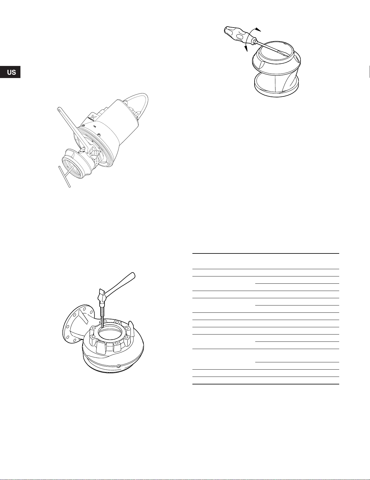
10.2.2 Removing the pump housing and impeller
For position num bers , se e pages 94 and 95.
Procedure
1. Loosen the clamp ( pos. 92) .
2. Remove the screw us ing yo ur fin gers .
3. Remove the pump housing (pos. 50) by inserting two screwdrivers between the stator ho using and th e pum p hous ing.
4. Remove the screw (p os. 188 a). H old th e impe ller with a str ap
wrench.
Fig. 18 Removing the im peller
5. Loosen the impeller (po s. 4 9) wit h a light blo w on the edge .
Pull it off.
6. Remove the key (pos . 9a) and the s pring for im peller
(pos. 157).
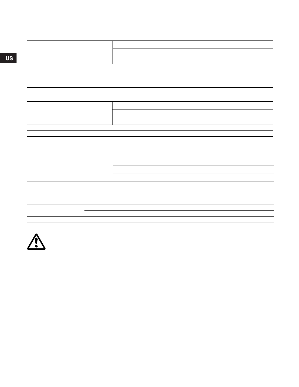
10.2.3 Removing t he se al ring an d we ar ring
Procedure
1. Turn the pump housing upside -dow n.
2. Knock the seal ring (p os. 4 6) out of the pump hou sing us ing a
punch.
Fig. 19 Removing th e seal ring
3. Clean the pump hous ing whe re the se al r ing was fitted.
4. Remove the wear ri ng (pos . 49 c) us ing a sc rewd riv er.
Fig. 20 Removing th e wear ring
5. Clean the impeller where the wear ring wa s fitted.
10.2.4 Removing t he sha ft seal
Procedure
1. Remove the screws (po s. 188) .
2. Remove the cover for o il ch ambe r (pos . 58 ) using a puller.
3. Remove the screws (po s. 186) .
4. Remove the shaft seal (p os. 105) using the pu ller.
5. Remove the O-ring (pos . 15 3b).
Procedure (pump with sensor)
1. Remove the screws (po s. 188) .
TM04 6477 0410TM02 8420 5103
2. Remove the cover for o il ch ambe r (pos . 58 ) using a puller.
3. Remove the screws (po s. 186) .
4. Remove the sensor (pos . 521 ) and h olde r (pos. 522) from the
shaft seal.
5. Remove the shaft seal (p os. 105) using the pu ller.
6. Remove the O-ring (pos . 15 3b).
10.3 Assembling the pump
10.3.1 Tightening torques and lubricants
Desig-
Pos.
nation
Quantity Dim.
92a Screw 1 8.85 ± 1.5 (12 ±2)
118a Screw 2
M8 14.75 ± 1.5 (20 ±2)
M10 22. 15 ± 2.2 (3 0 ±3)
174 Screw 1 2.95 ± 0.74 (4 ±1)
181 Union nut 1
7-pole 3 6.88 ± 3. 7 (50 ± 5)
10-pole 55.32 ± 3 .7 (75 ± 5)
186 Screw 2 5.2 + 1.5-0 (7 +2-0)
182 Screw 4 14.75 ± 1. 5 (20 ± 2)
187 Screw 4 14.75 ± 1. 5 (20 ± 2)
188 Screw 2
188a Screw 2
M8 14.75 ± 1.5 (20 ±2)
M10 22. 13 ± 2.2 (3 0 ±3)
M10
M12 55. 32 ± 3.7 (7 5 ±5)
193 Screw 2 11.8 ± 1.5 (16 ±2)
O-rings All Rocol
Rocol Sapphire Aq ua-S il, pro duct nu mber RM29 24 (1 k g).
Shell Ondina 917, pro du ct num ber 960 01442 (1 l)
Torque
[ft-lb (Nm)]
36.88 + 3.7- 0
(50 +5-0)
TM02 8422 5103
Lubri-
cant
24
Page 25

10.3.2 Fitting t he sha ft seal
Note
Procedure
1. Fit and lubricate the O- ring (p os. 153b) with oi l.
2. Slide the shaft seal (pos. 105) gent ly ove r the sh aft.
3. Fit and tighten the sc rews (pos . 186).
4. Fit and lubricate th e O-rin g (p os. 107 ) in the c over fo r oil
chamber (pos. 58 ) with oil.
5. Fit the cover for o il cham ber.
6. Fit and tighten the sc rews (pos . 188).
Procedure (pump with sensor)
1. Fit and lubricate the O- ring (p os. 153b) with oi l.
2. Slide the shaft seal (pos. 105) gent ly ove r the sh aft.
3. Fit the holder (pos. 522) and s ens or (po s. 521) with one of the
screws (pos. 186).
4. Fit the second screw and tighten both screws (pos. 186).
5. Fit and lubricate th e O-rin g (p os. 107 ) in the c over fo r oil
chamber (pos. 58 ) with oil.
6. Check that the sensor is positioned c or rec t ly, see 8.4.1 Fit tin g
the WIO sens or a nd fig. 12. This is of spec ial importanc e in
horizontal pumps.
7. Fit the cover for o il cham ber.
8. Fit and tighten the sc rews (pos . 188).
10.3.3 Fitting the seal ring and wear ring
Procedure
1. Lubricate the seal rin g (p os. 46) with soapy water.
2. Place the seal ring in the pu mp ho using .
3. Knock the seal ring hom e in the pump h ousin g using a pu nch
or a wooden block.
10.3.4 Fitting the impeller and pump housing
Procedure
1. Fit the spring (pos. 15 7) and the k ey (po s. 9a).
Keep the key in position while the impeller is fitted.
2. Fit the impeller (pos . 49).
3. Fit the washer (p os. 66) and the scr ew (pos. 18 8a ).
4. Tighten the screw (pos. 188a) to 55 ft-lb (75 Nm). Hold the
impeller with the str ap wren ch.
5. Mark the position of the pi n on the pu mp hou si ng.
6. Mark the position of the pi n ho le on th e oil ch ambe r.
7. Fit and lubricate the O -ring (p os. 3 7) with oi l.
8. Fit the stator housing in the pum p hous ing (po s. 50 ).
9. Fit the clamp (pos. 92 ).
10.Tighten the s crew to 6 ft-lb (8 N m ).
11.Che ck tha t the im pe ller rotat es free ly and w ithou t dra g.
10.4 Oil quantities
The table shows the qu antity of oil in t he oil ch ambe r of S L1 and
SLV pumps. Oil type: Shell Ondina 917.
2-pole
4-pole
Power
[hp (kW)]
3.0 (2.2) 20.3 (0.6)
4.0 (3.0) 20.3 (0.6)
5.5 (4.0) 33.8 (1.0)
8.0 (6.0) 33.8 (1.0)
10.0 (7.5) 33.8 (1.0)
12.5 (9.2) 40.6 (1.2)
15.0 (11) 40.6 (1.2)
1.5 (1.1) 20.3 (0.6)
1.8 (1.3) 20.3 (0.6)
2.0 (1.5) 20.3 (0.6)
3.0 (2.2) 20.3 (0.6)
4.0 (3.0) 33.8 (1.0)
5.5 (4.0) 33.8 (1.0)
7.5 (5.5) 33.8 (1.0)
10.0 (7.5) 40.6 (1.2)
Oil quantity
[oz (l])
Fig. 21 Fitting the seal ring
4. Place the wear ring (po s. 49c) on th e impe ller.
5. Knock the wear ring ho me us ing a wo oden blo ck.
Fig. 22 Fitting the wear rin g
Used oil must be disposed of in accordance with
TM02 8421 5103TM02 8423 5103
local regulations.
25
Page 26
10.5 Service kits
Note
The following ser vice kits are availa ble for al l SL1, SLV pumps and can be orde red as re quired
10.5.1 Impeller fitting kit
2-pole: 3.0 - 5.5 hp (2.2 - 4.0 kW) 8.0 - 15.0 hp ( 6.0 - 11 kW )
Pos. Descr iptio n
9a Key 1 1
66 Washer 1 1
157 Corrugated spring 1 1
188a Screw 1 1
10.5.2 Wear ring kit (SL1)
Pos. Description
46 Seal ring 1 1 1
49c Wear ring 1 1 1
10.5.3 Shaft seal kit
Pos. Description
105 Shaft seal cartridge 1 1
4.3 x 0.12 inch (110 x 3 mm) 1
107 O-ring
153b O-ri ng
157 Corrugated spring 1 1
For position num bers , se e pages 94 and 95.
Warning
The cable must only be replaced by Grundfos or
a service workshop authorized by Grundfos.
For service parts not show n in the above table, cons ult
www.grundfos.com WebCAPS, Service.
Examples of se rvic e parts:
• cable
• pump housing
• impeller
• bearings
• shaft/rotor
•clamp
•stator
• motor complete, both standard a nd FM .
5.3 x 0.12 inch (134.5 x 3 mm) 1 1
6.3 x 0.12 inch (160 x 3 mm) 1
0.67 x 0.09 inch (1 7.0 x 2. 4 mm ) 1
1.1 x 0.08 inch (28 x 2 mm) 1
4-pole: 1.5 - 3.0 hp (1.1 - 2.2 kW) 4.0 - 10.0 hp (3.0 - 7.5 kW )
Kit no: 96102365 96102366
Free passage: 2" ( ∅ 50) 3" ( ∅ 80) 4 " ( ∅ 100)
Rubber type: NBR NBR NBR
Kit no: 96102362 96102363 96102364
2-pole: 3.0 - 5.5 hp (2.2 - 4.0 kW) 8.0 - 15.0 hp (6.0 - 11 kW)
4-pole: 1.5 - 3.0 hp (1.1 - 2.2 kW) 4.0 - 10.0 hp (3.0 - 7.5 kW)
Rubber type: NBR NBR
Kit no: 96102360 96102361
10.6 Contaminated pumps
If a pump has been used for a liquid which is
injurious to health or toxic, the pump will be
classified as conta minat ed.
If Grundfos is requested to service the pump, Grundfos must be
contacted with details about the pum ped liq uid, e tc. befo re th e
pump is returned for service. Otherwise Grundfos can refuse to
accept the pump for service.
Possible costs of re tur ning t he pum p are t o be paid by the
customer.
However, any application for se rvice (n o matt er to who m it may
be made) must incl ude d etails abou t the pum p ed liquid if the
pump has been used for liq uids w hich ar e injur ious to he alth or
toxic.
Before a pump is returned, it must be cleaned in the best possible
way before it is ret urned .
Service instru ctio n and se rvic e vide o ca n be foun d on
www.grundfos.com.
26
Page 27

11. Fault finding
FM
Note
Warning
Before attempting to diagnose any fault, make sure that the fuses have been removed or the mains switch has been
switched off. It must be ensured that the power supply cannot be accidentally switched on.
All rotating parts must have stopped moving.
Warning
All regulations applying to pumps installed in potentially explosive environments must be observed.
It must be ensured that no work is carried out in potentially explosive atmosphere.
For pumps with sensor, start fault finding by checking the status on the IO 111 front panel.
See installation and operating instructions for IO 111.
Fault Cause Remedy
1. Motor does not
start.
Fuses blow or
motor-protecti ve
circuit breaker
trips out
immediately.
Caution: Do not
start again!
2. Pump operates,
but motorprotective circ uit
breaker trips out
after a short while.
3. The thermal switch
of the pump trips
out after a short
while.
4. Pump operates at
below-standard
performance and
power
consumption.
5. Pump operates,
but gives no liquid.
6. High power
consumption
(SLV).
7. Noisy operation
and excessive
vibrations (SL1).
8. Pump clogged. a) T he liqui d co ntai ns larg e pa rticle s. Select a pump with a la rger size o f passa ge.
* Applies only to pum ps w ith sens or and with IO 111.
a) Supply failur e; short-circuit; earth- leak age fault in
cable or motor w inding.
b) Fuses blow du e to us e of w rong ty pe of fuse . Fit fuses of the correc t type .
c) Impeller blocked by impurities. Clean the impeller.
d) Air bells, float switc hes or electr odes o ut of
adjustment or defe ctive.
e) Moisture in the stat or ho using (alar m).*
The IO 111 interrup ts the suppl y volt age.
f) The WIO sensor is not covered by oil (alarm).*
The IO 111 interrup ts the suppl y volt age.
g) *Stator insula tion res ista nce too low. Reset ala rm on IO 111. See installation and ope rati ng
a) Low setting of thermal relay in motor-protec tive
circuit breake r.
b) Increased cur rent cons umptio n du e to large
voltage drop.
c) Impeller blocked by impurit ies. Incre ase d cur rent
consumption in all thr ee phas es.
d) Wrong direction of rotation. Check the direction of rotation and possibly interchange
a) Too high liquid temperature. Reduce the liquid temperature.
b) Too high visc osity o f the pum ped li quid . Dilute the pumped liquid.
c) Wrong electrical connectio n. (I f the pump is sta r-
connected to a delta connection, the result will be
very low undervo ltage ).
a) Impeller bloc ked by impu ritie s. Clean the impeller.
b) Wrong directi on of rot ation.
a) Discharge va lve close d or blo cked . Check the d ischa rge v alve an d poss ibl y open and/o r
b) Non-return valve block ed. Clean the non-retur n valv e.
c) Air in pump. Vent the pump.
a) Wrong direction of rotation. Check the direction of rotation and possibly interchange
b) Impeller bloc ked by impu ritie s. Clean the impeller.
a) Wrong direction of rotation. Check the direction of rotation and possibly interchange
b) Impeller bloc ked by impu ritie s. Clean the impeller.
b) A float layer has formed on the surface of the liquid. I nstall a mixer i n the tank.
Have the cable and m oto r che cked and repaired by a
qualified electricia n.
Readjust or replac e the air bells, float switche s or
electrodes.
Replace the O-rin gs , th e sh aft seal and moisture sw itch.
Check, and possibly repla ce, the sh aft seal, fill up with
oil and reset the I O 111.
instructions for IO 111.
Set the relay in accordance with the sp ecification s on
the nameplate.
Measure the voltage between two moto r phases.
Tolerance: -10 %/+ 6 %. Reestablish corr ect volt ag e supp ly.
Clean the impeller.
any two of the phase s in t he inco mi ng sup ply ca ble.
See section 9. 3 D irec tion o f rotation.
Check and corr ect the ele ctr ical in stallation .
Check the direction of rotation and poss bly interchange
any two of the phase s in t he inco mi ng sup ply ca ble.
See section 9. 3 D irec tion o f rotation.
clean it.
any two of the phase s in t he inco mi ng sup ply ca ble.
See section 9. 3 D irec tion o f rotation.
any two of the phase s in t he inco mi ng sup ply ca ble.
See section 9. 3 D irec tion o f rotation.
27
Page 28

12. Technical data
Supply voltage
• 3 x 208 V - 10 %/+ 10 %, 60 Hz
• 3 x 230 V - 10 %/+ 10 %, 60 Hz
• 3 x 380 V - 10 %/+ 10 %, 60 Hz
• 3 x 460 V - 10 %/+ 10 %, 60 Hz
• 3 x 575 V - 10 %/+ 10 %, 60 Hz
Enclosure class
IP68. According to IEC 60529.
Insulation class
H (356 °F (180 °C)).
Operating pressure
All pump housings h ave a c ast iron A NSI 10 d isc harg e flan ge.
Dimensions
Discharge flange s are A NSI 2.5" , ANSI 3", ANS I 4" or A NSI 6".
2-pole motor Cable connection
Pump curves
Pump curves ar e availa ble via the in tern et on
www.grundfos.com.
The curves are to be c onsid ered as a g uide. T hey mus t not be
used as guarante e cu rves.
Test curves for the s upplied pum p are availa ble on re qu est.
It must be ensure d tha t the pu mp does n ot op era te outsid e the
recommended ope rat ing ran ge dur ing n ormal op era tion .
Pump noise emission < 70 dBA
• Sound power measurements were c arried ou t acc ordin g to
ISO 3743.
• Sound power was calculated at a distan ce of 1 m etre
accord in g to ISO 11203.
The sound pressur e level o f th e pump is lo wer tha n the li mi ting
values stated in the E C Coun cil D irecti ve 200 6/42 /EC rel ating to
machinery.
Power P
[hp (kW)]
2
Power P
[hp (kW)]
1
Voltage
[V]
Starti ng method
Thermal
protection
Cable cross-section
[AWG (mm²)]
Conductors/pins
3.0 (2.2) 3.9 (2.8) 3 x 460 Y/D Thermal switch 14 (2.5) 10/10
3.0 (2.2) 3.9 (2.8) 3 x 575 Y/D Thermal switch 14 (2.5) 10/10
3.0 (2.2) 3.9 (2.8) 3 x 208-230 / 3 x 460 Dual voltage (DOL) Thermal switch 14 (2. 5 ) 10/10
4.0 (3.0) 3.9 (3.8) 3 x 460 Y/D Therm al switch 14 (2. 5) 10/10
4.0 (3.0) 3.9 (3.8) 3 x 575 Y/D Therm al switch 14 (2. 5) 10/10
4.0 (3.0) 3.9 (3.8) 3 x 208-230 / 3 x 460 Dual voltage (DOL) Thermal switch 1 4 (2.5 ) 10/10
5.5 (4.0) 6.6 (4.9) 3 x 460 Y/D Therm al switch 14 (2. 5) 10/10
5.5 (4.0) 6.6 (4.9) 3 x 575 Y/D Therm al switch 14 (2. 5) 10/10
5.5 (4.0) 6.6 (4.9) 3 x 208-230 / 3 x 460 Dual voltage (DOL) Thermal switch 1 4 (2.5 ) 10/10
7.5 (5.5) 8.6 (6.4) 3 x 460 Y/D Therm al switch 14 (2. 5) 10/10
7.5 (5.5) 8.6 (6.4) 3 x 575 Y/D Therm al switch 14 (2. 5) 10/10
7.5 (5.5) 8.6 (6.4) 3 x 208-230 / 3 x 460 Dual voltage (DOL) Thermal switch 1 4 (2.5 ) 10/10
8.0 (6.0) 9.4 (7.0) 3 x 460 Y/D Therm al switch 14 (2. 5) 10/10
8.0 (6.0) 9.4 (7.0) 3 x 575 Y/D Therm al switch 14 (2. 5) 10/10
8.0 (6.0) 9.4 (7.0) 3 x 208-230 / 3 x 460 Dual voltage (DOL) Thermal switch 1 4 (2.5 ) 10/10
10 (7.5) 11.7 (8.7) 3 x 460 Y/D Thermal switch 14 (2.5 ) 10/10
10 (7.5) 11.7 (8.7) 3 x 575 Y/D Thermal switch 14 (2.5 ) 10/10
10 (7.5) 11.7 (8.7) 3 x 208-230 / 3 x 460 Dual voltage (DOL) Thermal switch 14 (2.5) 10/10
12.5 (9.2) 14.1 (10.5) 3 x 460 Y/D Thermal switch 14 (2.5) 10/10
12.5 (9.2) 14.1 (10.5) 3 x 575 Y/D Thermal switch 14 (2.5) 10/10
12.5 (9.2) 14.1 (10.5) 3 x 208-230 / 3 x 460 Dual voltage (DOL) Therm al switch 14 (2. 5 ) 10/10
15 (11) 16.9 (12.6) 3 x 460 Y/D Thermal switch 14 (2.5) 10/10
15 (11) 16.9 (12.6) 3 x 575 Y/D Thermal switch 14 (2.5) 10/10
15 (11) 16.9 (12.6) 3 x 208-230 / 3 x 460 Dual voltage (DOL) Thermal switch 14 (2 .5) 10/10
The resistance in the supply cable depends on the cable diameter.
Resistance per metre of cable: AWG 16 (1.5 mm
Resistance per metre of cable: AWG 14 (2.5 mm
2
) = 0.013 OHM - CSA/FM
2
) = 0.00830 OHM - CSA/FM
28
Page 29

4-pole motor Cable connection
Subject to alterations.
Power P
[hp (kW)]
2
Power P
[hp (kW)]
1
Voltage
[V]
Starting method
Thermal
protection
Cable cross-section
2
]
[mm
Conductors/
pins
1.5 (1.1) 2.0 (1.5) 3 x 575 Y/D Thermal switch 16 (1.5) 10/10
1.5 (1.1) 2.0 (1.5) 3 x 575 DOL Thermal switch 16 (1.5) 7/7
1.5 (1.1) 2.0 (1.5) 3 x 208-230 DOL Thermal switch 16 (1.5) 7/7
1.5 (1.1) 2.0 (1.5) 3 x 208-230 / 3 x 460 Dual voltage (DOL) Thermal switch 14 (2.5) 10/10
1.8 (1.3) 2.3 (1.7) 3 x 575 Y/D Thermal switch 16 (1.5) 10/10
1.8 (1.3) 2.3 (1.7) 3 x 575 DOL Thermal switch 16 (1.5) 7/7
1.8 (1.3) 2.3 (1.7) 3 x 208-230 DOL Thermal switch 16 (1.5) 7/7
1.8 (1.3) 2.3 (1.7) 3 x 208-230 / 3 x 460 Dual voltage (DOL) Thermal switch 14 (2.5) 10/10
2.0 (1.5) 2.5 (1.9) 3 x 575 Y/D Thermal switch 16 (1.5) 10/10
2.0 (1.5) 2.5 (1.9) 3 x 575 DOL Thermal switch 16 (1.5) 7/7
2.0 (1.5) 2.5 (1.9) 3 x 208-230 DOL Thermal switch 16 (1.5) 7/7
2.0 (1.5) 2.5 (1.9) 3 x 208-230 / 3 x 460 Dual voltage (DOL) Thermal switch 14 (2.5) 10/10
3.0 (2.2) 3.6 (2.7) 3 x 460 Y/D Thermal switch 14 (2.5) 10/10
3.0 (2.2) 3.6 (2.7) 3 x 575 Y/D Thermal switch 14 (2.5) 10/10
3.0 (2.2) 3.6 (2.7) 3 x 208-230 / 3 x 460 Dual voltage (DOL) Thermal switch 14 (2.5) 10/10
3.0 (2.2) 3.6 (2.7) 3 x 460 Y/D Thermal switch 14 (2.5) 10/10
3.0 (2.2) 3.6 (2.7) 3 x 575 Y/D Thermal switch 14 (2.5) 10/10
3.0 (2.2) 3.6 (2.7) 3 x 208-230 / 3 x 460 Dual voltage (DOL) Thermal switch 14 (2.5) 10/10
4.0 (3.0) 4.9 (3.7) 3 x 460 Y/D Thermal switch 14 (2.5) 10/10
4.0 (3.0) 4.9 (3.7) 3 x 575 Y/D Thermal switch 14 (2.5) 10/10
4.0 (3.0) 4.9 (3.7) 3 x 208-230 / 3 x 460 Dual voltage (DOL) Thermal switch 14 (2.5) 10/10
5.5 (4.0) 6.6 (4.9) 3 x 460 Y/D Thermal switch 14 (2.5) 10/10
5.5 (4.0) 6.6 (4.9) 3 x 575 Y/D Thermal switch 14 (2.5) 10/10
5.5 (4.0) 6.6 (4.9) 3 x 208-230 / 3 x 460 Dual voltage (DOL) Thermal switch 14 (2.5) 10/10
7.5 (5.5) 8.6 (6.4) 3 x 460 Y/D Thermal switch 14 (2.5) 10/10
7.5 (5.5) 8.6 (6.4) 3 x 575 Y/D Thermal switch 14 (2.5) 10/10
7.5 (5.5) 8.6 (6.4) 3 x 208-230 / 3 x 460 Dual voltage (DOL) Thermal switch 14 (2.5) 10/10
8 (6.0) 9.4 (7.0) 3 x 460 Y/D Thermal switch 14 (2.5) 10/10
8 (6.0) 9.4 (7.0) 3 x 575 Y/D Thermal switch 14 (2.5) 10/10
8 (6.0) 9.4 (7.0) 3 x 208-230 / 3 x 460 Dual voltage (DOL) Thermal switch 14 (2.5) 10/10
10 (7.5) 11.5 (8.6) 3 x 460 Y/D Thermal switch 14 ( 2.5) 10/10
10 (7.5) 11.5 (8.6) 3 x 575 Y/D Thermal switch 14 ( 2.5) 10/10
10 (7.5) 11.5 (8.6) 3 x 208-230 / 3 x 460 Dual voltage (DOL) Thermal switch 14 (2.5) 10/10
The resistance in the supply cable depends on the cable diameter.
Resistance per metre of cable: AWG 16 (1.5 mm
Resistance per metre of cable: AWG 14 (2.5 mm
2
) = 0.013 OHM - CSA/FM
2
) = 0.00830 OHM - CSA/FM
13. Disposal
This product or parts of it mu st be dispos ed of in a n
environmentally s ound wa y:
1. Use the public or private was te colle ction s ervice.
2. If this is not possible . con tact the ne are st Grun dfos com pany
or service works hop.
29
Page 30

GARANTÍA LIMITADA
GRUNDFOS PUMPS CORPORATION (Grundfos) garantiza exclusivamente al usuario original que los productos fabricados por dicha empresa se encontrarán libres de defectos de
materiales y mano de obra durante un periodo de 24 meses a partir de la fecha de instalación, sin superar en ningún caso los 30 meses a partir de la fecha de fabricación. La responsabilidad de Gr undfos en el ámbito de esta garantía se lim i t ará a la repar ación o sustitución, a decisión de Grundfos, de forma gratuita y debiendo el comprador correr con los
gastos de transporte hasta la fábrica o centro de servicio autorizada de Grundfos, de cualquier producto fabricado por Grundfos. Grundfos no se hará responsable de ningún costo
derivado de la retirada , la instalación o el transporte del producto ni de cualq ui er otr o ga sto
que pudiera surgir en relación con una reclamación en garantía. Aquellos productos comercializados por Grundfos que no hayan sido fabricados por dicha empresa se encontrarán
sujetos a la garantía pr opor cio nada por el fabricante del producto correspo ndi ente y no a la
garantía de Grundfos. Grundfos no se responsabilizará de aquellos daños o deterioros que
sufran los productos como consecuencia de condiciones de funcionamiento anómalas,
accidentes, abusos, usos indebidos, alteraciones o reparaciones no autorizadas o instalaciones no real izadas de ac uerdo c on las instru ccio nes im presa s de ins talación y func ionamiento de Grundfos.
Si desea recibir asistencia al amparo de esta garantía, deberá devolver el producto defectuoso al distribuidor o proveedor de productos Grundfos al que lo haya adquirido, adjuntando con el mismo una prueba de compra, así como las fechas de instalación y avería y
los datos relacionados con la instalación. A menos que se indique de otro modo, el distribuidor o proveedor se pondrá en contacto con Grundfos o con un centro de servicio autorizado para solicitar instrucciones. Cualquier producto defectuoso que deba ser devuelto a
Grundfos o a un centro de servicio deberá enviarse a portes pagados, incluyendo la documentación relaci onada c on la re clam ación e n gar antía y/o una A utoriz ació n de de voluc ión
de material, si así se solicita.
GRUNDFOS NO SE HARÁ RESPONSABLE DE NINGÚN DAÑO, PÉRDIDA O GASTO
ACCIDENTAL O RESULTANTE DERIVADO DE INSTALACIONES, USOS O CUALQUIER
OTRA CAUSA. NO EXISTEN GARANTÍAS EXPRESAS O IMPLÍCITAS, INCLUYENDO
AQUÉLLAS DE COMERCIABILIDAD O IDONEIDAD PARA UN FIN DETERMINADO, QUE
AMPLÍEN LAS GARANT ÍA S QUE SE DESCRIBEN O A LA S QUE SE HACE REFERENC IA
EN EL PÁRRAFO ANTERIOR.
Algunas jurisdicciones no admiten la exclusión o limitación de los daños accidentales o
resultantes; otras no admiten las acciones de limitación relacionadas con la duración de
una garantía implícita. Por tanto, es posible que las limitaciones o exclusiones anteriores
no le sean de aplicación. Es ta garantía le confier e dere chos legal es especí ficos. Es po sible
que disponga de otros derechos en virtud de su jurisdicción.
30
Page 31

CONTENIDO 1. Símbolos utilizados en este documento
Precaución
Nota
1. Símbolos utilizados en este documento
2. Descripción general
2.1 Esquema de la bom ba 32
2.2 Control y su pervi sió n 32
2.3 Aplicaciones 32
2.4 Selección de una bomba 32
2.5 Condicione s de f uncio namie nto 33
3. Entr ega y manipu la ción
3.1 Transporte 34
3.2 Almacenamien to 34
4. Ident ific aci ón
4.1 Placa de datos 34
4.2 Nomencla tura 35
5. Homologaciones
5.1 Normas d e ho molog ac ión 36
5.2 Explicación de la hom ologa ci ón FM 36
6. Seguridad
6.1 Entornos p otencia lmen te ex plosivos 37
7. Instalación
7.1 Instalación sum ergid a c on aco plami ento autom át ico 38
7.2 Instalación sumergida en posición libre con soporte de
anillo
8. Conexión eléctrica
8.1 Diagramas de ca bleado 41
8.2 Reguladore s d e bom beo 44
8.3 Interruptor térmico, sensor Pt1000 y termistor 44
8.4 Sensor WIO (sensor de agua en aceite) 45
8.5 Interruptor de hume dad 45
8.6 IO 111 46
8.7 Funcionamiento del convertidor de frecuencia (VFD) 46
9. Puesta en march a
9.1 Procedim ient o gene ra l de arr anque 48
9.2 Modos de fun ciona miento 48
9.3 Sentido de giro 49
10. Mantenimiento y reparación
10.1 Inspección 50
10.2 Desmontaje de la bomba 50
10.3 Montaje de la bomba 51
10.4 Cantid ade s de ac eite 52
10.5 Kits de mantenimiento 53
10.6 Bombas contaminadas 53
11. Solución de problemas
12. Datos té cnic os
13. Eliminación
31
31
34
34
36
36
37
39
40
47
49
54
55
57
Aviso
¡Si estas instrucciones no son observadas puede
tener como resultado daños personales!
¡Si estas instrucciones de seguridad no son
observadas puede tener como resultado daños
para los equipos!
Notas o instrucciones que hacen el trabajo más
sencillo garantizando un funcionamiento seguro.
2. Descripción general
Este l br o cont iene las instru cciones de instalac ión, func ionamiento y mantenim ien to de las bomba s sum ergi bles de agu as
negras y residuales SL1 y S LV de Grundfos equipadas co n motores de 1,5 a 15 CV (1 ,1 a 11 kW). Las bom bas de agu as neg ras
SL1 y SLV han sido diseñadas para el bombeo de aguas negras y
residuales en el ámbito doméstico e industrial.
Existen dos tipos de bom ba s disp onibles :
• Bombas de aguas negras SL1 co n impu lsor m onoc an al
• Bombas de aguas negras SLV con impuls or vó rtex .
Las bombas s e pueden instalar en sistemas de a co plamiento
automático o pue de n desc an sar lib re ment e en el f ondo de un
depósito.
Las bombas SL 1 y SLV de Grundfos cuenta n, re spec tiva me nte,
con un impulsor monoc anal y un imp ulsor de paso lib re, amb os
destinados a gara ntizar un fun ciona mi ento ópt imo y fiabl e.
Este libro incluye también instrucciones específicas para bombas
a prueba de explosió n.
Advertencia
Leer estas instruccio nes d e ins talaci ón y f uncio -
namiento antes de realizar la instalación. La instalación y el funcionamiento deben cumplir con
las normativas loca les en vi gor.
Advertencia
The use of this product requires experience with
and knowledge of the product.
Persons with reduced physical, sensory or
mental capabilities must not use this product,
unless they are under supervision or have been
instructed in the use of the product by a person
responsible for their safety.
Children must not use or play with this product.
31
Page 32

2.1 Esquema de la bomb a
1
5
2
6
4
3
7
Fig. 1 Bomba SL1
2.3 Aplicaciones
Las bombas SL1 y SLV han sido diseñada s para bo mb ear los
siguientes líquidos:
• grandes volúmenes de aguas drenad as y d e supe rfic ie
• aguas residuales domésticas co n des carga de inod oro s
• aguas residuales con un alto con tenid o de fi bras ( impu lso r
vórtex)
• aguas negras y residuales m unicipale s y co merc ia les.
El uso de las bombas SL1 y SLV resulta ideal en los sig uient es
lugares:
• edificios públicos
• bloques de viviendas
• empresas industriales
• garajes
• aparcamientos de varias plan tas
• túneles de lavado de automóviles
• restaurantes.
TM04 2648 2808
Su diseño compacto hace estas bombas aptas tanto para su instalación temporal como perma nent e.
Pos. Descripción
1 Soporte de elevaci ón
2 Placa de datos
3 Tornillos del depósito de aceite
4 Brida de descarga
5 Clavija de cable
6 Brida de fijación
7 Carcasa de la bomba
Si desea obtener información acerca de las dimensiones de la
bomba, su peso y sus componentes, consulte las páginas
94 y 95.
2.2 Control y supervisión
Las bombas se pueden co ntrolar por m edio de lo s s istem as de
control dedicado de Grun dfos DC y DCD.
Las bombas con se nsor est án equipad as co n un dis posit ivo
IO 111, capaz de recibir seña les de lo s sigu ien tes tran sm isor es:
• sensor de agua en aceite (se nsor W IO ) en la bo mba
• sensor de humedad en el motor
• sensor de temperatura en los bobina dos de l estát or
• sensor de resistencia de bobin ado en e l mo tor.
Si desea obtener m á s info rma ción c onsulte las ins tru ccion es de
instalación y funciona mien to del senso r esp ecífic o.
2.4 Selección de una bomba
La tabla siguiente indica la versión adecuada de la bomba en función del tipo de líqui do:
Tipo de impulsor: 1 = impulso r mon ocana l, V = imp ulsor de paso
libre.
Paso de la bomba
Líquido bombeado
Aguas drenadas 1 V 1 / V 1 / V
Aguas residuales domésticas sin
descarga de inodor os
Aguas residuales domésticas con
descarga de inodor os
Aguas residuales con un alto conte-
nido de fibras
Aguas residua les indu strial es 1 / V 1 / V
Aguas residuales con lodo gaseoso 1 / V 1 / V
Aguas residua les mu nicipales 1 / V 1 / V
[Pulgadas (mm)]
2
2.5
(50)
(65)3(80)4(100)
1 V 1 / V 1 / V
1 / V 1 / V
VVV
32
Page 33

2.5 Condiciones de funci onam ient o
Modo de funcionaModo de funciona-
FM
FM
Nota
Precaución
Las bombas SL 1 y SLV de Grundfos so n adec uad as en la s
siguientes situaciones de funcionamiento:
• En el modo de funcionamiento S1 (funcionamiento continuo),
la bomba debe enco ntra rse s iemp re cub ier ta por el líquid o
bombeado hasta la parte s upe rior del motor. Consulte la fig. 2.
• En el modo de funcionamiento S3 (funcionamiento interm itente), la bomba deb e en cont rars e siem pre cubi erta por e l
líquido bombeado hasta la parte superior de la entrada de
cable. Consulte la fig. 2.
Si desea obtener m ás in form a ción acer ca de los mo dos de funcionamiento S1 y S 3, cons ulte la secc ión 9.2 Modos de funciona-
miento.
Fig. 2 N iveles de paro
Densidad y viscosidad del líquido bombeado
Si se bombea n lí quid os con una densidad y/o viscosidad c inemática superior a la del agua, use motores de potencia proporcionalmente superior.
Bombeo de líquidos con un alto contenido de sólidos,
fibras, etc.
Este procedimiento es válido sólo para impulsores vórtex.
En aplicaciones muy exigen tes , así com o en aq uel las que presenten un alto contenido de sólidos, fibras, etc. es aconsejable
poner en march a el imp ulsor en sen tido in vers o dura nte v arios
segundos antes d e ini ciar un ciclo de bo mbeo .
No haga funcionar los impulsores monocanal en
sentido inverso.
Velocidad de caudal
Es aconsejable m inimizar la veloc idad d el caud al para evitar la
acumulación de se dimen tos en el sis tema de tube rías. Velocidades de caudal recom enda das:
- para tuberías verticales:2.3 ft/s (0.7 m/s)
- para tuberías horizontales:3.3 ft/s (1.0 m/s)
Profundidad de instalación
Máximo: 65 ft (20 m) por de ba jo del niv el de lí quido.
Tamaño máximo de los sólidos
Entre 2" y 4" (50 y 100 mm) , depen dien do del tama ño d e la
bomba.
TM04 2649 2808
Modo de funcionamiento
Máximo: 30 arra nques por ho ra .
Valor de pH
Las bombas SL1 y SLV de instalación perma ne nte se pu ede n
usar para bombea r líquido s con u n valor de pH ent re 4 y 1 0.
Temperatura del líquido
32 °F a +104 °F (0 °C a + 40 °C).
Durante peri odo s co rt os de t iem po (c on u n má ximo de 3 mi nut os)
es admisible el ascens o de la t emp eratur a hasta +14 0 °F
(+60 °C) (en t odas la s ver sione s e xcep to en la FM).
Advertencia
Las bombas a prueba de explosión no deben
bombear líquidos a una temperatura superior a
+104 °F (+40 °C) en ningún caso.
Temperatura ambiente
Advertencia
En el caso de las bombas a prueba de explosión,
la temperatura ambiente en el lugar de instalación debe encontrarse comprendida entre -4 °F y
+104 °F (-20 °C y +40 °C).
En el caso de las bombas a prueba de explosión
equipadas con sensor WIO, la temperatura
ambiente en el lugar de inst alac ión d ebe en contrarse comprendida entre 3 2 °F y +104 °F (0 °C y
+40 °C).
La temperatura ambiente de aquellas bombas que no sean a
prueba de explosión puede sup erar los +104 °F (40 ºC ) dura nte
un periodo corto de tiem po (m áx. 3 minu tos) .
33
Page 34

5
4
1
3
6
7
9
10
8
13
11
16
18
15
19
20
23
17
22
24
21
25
12
14
2
3. Entrega y manipulación
La bomba se pued e tra nspor tar y alma c enar en posic ión ve rtic al
u horizontal. Asegúr ese de que no pued a roda r ni ca erse.
3.1 Transporte
Todos los equipos de ele va ción d eberá n tene r la ca lifica ción s uficiente; deberá com prob arse que no pr esen ten ning ún tip o de
daños antes de rea lizar cu alqu ier inten to de elevació n de la
bomba. La calificació n de los equ ipos de elevació n no deber á
excederse bajo nin gun a circ unstan cia. E l peso d e la
bomba figura en su placa de datos.
Advertencia
Al elevar la bomba, hágalo siempre por medio del
soporte de elevación, o bien con una carretilla
elevadora si se encu en tra fij ada a una p aleta . No
eleve nunca la bomba por medio del cable del
motor o la manguera/tubería.
4. Identificación
4.1 Placa de datos
La placa de datos co ntie ne los d atos de funcion amien to y h omo logaciones co rr espondientes a la bo mba. Dicha placa s e e ncuentra instalada en el lateral d e la car casa del e stá tor, junto a la
entrada de cable.
Coloque la placa de datos adici ona l sum inistra da con la bo mba
en el extremo del c able de la ca ja de co ntro l.
3.2 Almacenamiento
La bomba debe pr oteg erse d e la hum ed ad y el calo r s i va a pe rmanecer almace nada du ra nte un period o largo de tie mpo.
Temperatura de almacen amien to: -2 2 °F a +1 40 °F
(-30 °C a +60 °C)
Advertencia
Si la bomba permanece almacenada durante más
de un año o no está pensado ponerla en funcionamiento después de su instalación, deberá
girarse el impulsor al menos una vez al mes.
Si la bomba se encue ntr a en uso, deb erá ca mb iars e el ace ite
antes del almacenamiento.
Después de un perio do d e alma cenam ient o prol ongado , deb erá
inspeccionarse la bomb a an tes de po ne rla en fun cio nami ento .
Asegúrese de que el im pulso r pu eda gir ar libr emen te. Pr est e
especial atención a las cond icione s d el sello del eje, las jun tas
tóricas, el aceite y la entr ada de c ab le.
Fig. 3 Plac a de da tos
Pos. Descripción
1 Marcado FM
2 Protección térmica
3 Denominación de tipo
4 Número de serie
5 Código de fabricació n (año /sema na)
6 Temperatura ambiente m áxim a
7 Altura máxima
8 Caudal máximo
9 Potencia de entrada/s ali da nom inal
10 Voltaje nominal, D
11 Voltaje nominal, Y
12 Frecuencia
13 País de fabricación
14 Marca CSA
15 F M ma rk
16 Ca tego ría de ais lamie nto s egún la norm a IEC
17 P rofundi dad máxi ma de insta lación
18 Fac tor de p oten cia
19 Nú me ro de fa ses
20 Velocidad nom inal
21 Fac tor de s ervicio
22 Corriente de carga completa, D
23 Corriente de carga completa, Y
24 Ca tego ría de ais lamie nto
25 P eso sin c able
TM04 4187 0909
34
Page 35

4.2 Nomenclatura
La bomba se puede ide ntif icar por medio de la denom inaci ón de t ipo indic ada en su pla ca de datos . Con sulte la s ecc ión 4.1 Placa de
datos.
Código Ejemplo SL 1. 30 .A30. 55. A. Ex. 4. 6. 0H A. Q.
Tipo de bomba:
SL
Bomba Grundfos para agu as re sidual es/a guas negra s
Tipo de impulsor:
1
Impulsor monoca nal
V
Impulsor de paso libre (Sup erVortex)
Paso de la bomba. Có dig o de la cl ave de tipo / 10 [p ulgada s]:
20
2" (50 mm)
25
2.5" (65 m m)
30
3" (80 mm)
40
4" (100 mm)
Descarga de la bom ba (p uert o de des carg a en pulgad as):
A25
Ansi 2.5"(DN65 )
A30
Ansi 3" (DN80)
A40
Ansi 4" (DN100)
A60
Ansi 6" (DN150)
Potencia del motor. Código de la clave de tipo / 10 [CV]
55
5.5 hp = 4.0 kW
Accesorios:
[-]
Estándar
A
Sensor
Versión de la bomba:
[-]
Normal
Ex
A prueba de explosión
Número de polos:
2
2 polos
4
4 polos
Frecuencia:
6
60 Hz
Voltaje y método de arranque:
0J
3 x 208-230V Δ DOL, (60 Hz)
1J
3 x 208-230V Δ / 460V Y, (60 Hz)
1H
3 x 460V Δ Y/D, (6 0 Hz)
0L
3 x 575V Δ DOL, (60 Hz )
1L
3 x 575V Δ Y/D, (6 0 Hz)
Generación del producto:
A
1ª generación
B
2ª generación
C
3ª generación
Variante de material:
[-]
Impulsor, voluta y carcasa del estátor en hierro fundido
Q
Impulsor de acero inoxid abl e
35
Page 36

5. Homologaciones
Nota
FM
Nota
Nota
Precaución
Precaución
Precaución
Precaución
Las bombas SL1 y S LV han recibido las homolo gac iones CSA y F M, mien tras qu e su s versi ones a p rueba de ex plosió n osten tan el cer tificado de examen de tipo F M núm ero: 30 35318 .
5.1 Normas de homologaci ón
Estas bombas han rec ibi do las h omolo ga ciones CSA y FM de acuer do co n las norm as UL 778, C22.2 n. º 108 y FM 36 00, F M 36 15 y
FM 3615.80.
5.2 Explicación de la hom olog ación FM
Las bombas SL 1 y SLV cuentan con los s iguient es ti pos d e prot ecc ión co ntra explos iones : Cla se I, D ivisi ón 1, G rupo s C y D, T4 , T3,
IP68.
Normas Código Descripción
Clase I = Atmósferas explosivas causadas por gases o vapores.
FM 3600
FM 3615
FM 3615.80
División 1 = Clasificación d e zo na.
Grupos C y D. = Clasificaci ón de l os ga se s.
T4/T3 = La temperatura máxima que admite la superficie es de 275 °F (135 °C) y 392 °F (200 °C).
IP68 = Categoría de ai sla miento de a cuer do con la norm a IEC 60 52 9.
6. Seguridad
Advertencia
La instalación de la bomba en depósitos debe ser
llevada a cabo por personal debidamente capacitado.
Las actividades qu e se ll even a cabo en el in terior de un depósito o en sus proximidades deben
ser realizadas de acuerdo con las normas
locales.
Advertencia
Debe impedirse el paso a la zona de instalación
si la atmósfera es exp losiva .
Advertencia
Debe ser posible bloquear el interruptor de
encendido en la posición 0. El tipo y los requisitos del bloqueo deberán satisfacer los establecidos por el Código Eléctrico Nacional y cualquier
otro código local aplicable.
Por motivos de seg ur idad, to das la s act ivida des qu e se llev en a
cabo en el interior d e un depós ito de berán ser s uperv isada s po r
una persona que se e ncuen tre fuera de l mism o.
Es aconsejable efect uar todas l as tare as de mantenimiento y reparación de la bomba fuera del
depósito.
Los depósitos dest inado s a la sum ersió n de bomba s de ag uas
negras y residuale s podr ían cont ener a guas n egr as y res idu ales
con sustancias t óxica s y/ o perju dicial es para la sal ud. Por tanto,
todas las personas implicadas deberán utilizar equipos y prendas
de protección pers onal, y todos los trab ajos r ealiza dos sobr e la
bomba o en sus pr oximida de s debe rán llevars e a cabo re spetando estrictamente las no rmas de higi ene en vigo r.
Advertencia
Asegúrese de que el soporte de elevación se
encuentre bien s ujeto ante s de i nten tar ele var la
bomba. Apriételo si es necesario. Los descuidos
durante la elevación o el transporte podrían derivar en lesiones personales o daños a la bomba.
Las siguientes ad vert encia s y notas aparecen también en
una etiqueta (suministrada con la bomba). Coloque la etiqueta cerca de la caja de control.
Advertencia
Riesgo de descarga eléctrica. No desconecte el
cable ni retire el pren sacabl es. No cone cte con ductos a la bomba.
Advertencia
Riesgo de descarga eléctrica
Esta bomba no ha sido homologada para su uso
en piscinas o zonas marítima s.
Advertencia
A fin de reducir el riesgo de descarga eléctrica,
estudie las instrucci one s de in sta lación y funci onamiento y lleve a cabo la instalación de manera
adecuada.
Advertencia
A fin de reducir el riesgo de descarga eléctrica,
realice la instalación únicamente empleando circuitos protegidos por un interruptor de circuito
de fallos de conexión a tierra (GFCI).
Este equipo es apto para el uso interior y exterior.
Bomba sumergible.
Provea al motor de una protección acorde con
los niveles eléctr icos.
Categoría de aislamiento 3.
Esta bomba ha sido evaluada para su uso exclusivo con agua.
Instale un interruptor diferencial homologado
para la protección del motor que resulte adecuado para el consumo de corriente de carga
completa d el mismo, con lo s elementos d e sobrecarga seleccionados o ajustados de acuerdo con
las instrucciones de control.
36
Page 37

6.1 Entornos potencial ment e exp losi vos
FM
FM
FM
Precaución
Nota
Precaución
Use bombas a prueb a de ex plosió n en ent orn os poten cialm ente
explosivos. Consulte la sección 5.2.
Advertencia
Las bombas SL1 y SLV no deberán bombear
líquidos combustibles bajo ninguna
circunstancia.
Advertencia
La clasificación del lugar de instalación debe
haber sido homologada por las autoridades
locales de lucha contra incendios en cada caso
concreto.
Condiciones especiales para el uso seguro de las
bombas a prueba de explosión SL1 y SLV:
1. Asegúrese de que los interruptores de humedad y
térmicos estén conectados al mismo cir cu it o pero
dispongan de salid as de a larm a (parada de
motor) independientes en caso de alta humedad o
temperatura del mot or elev ada.
2. Los pernos de repuesto deberán ser de categoría
A2-70 o superior, de acuerdo con la norma EN/
ISO 3506-1.
3. Póngase en contacto co n el fab rican te si desea
obtener información acerca de las dimensiones
de las juntas a prueba de llam a s.
4. El nivel del líquido bo mb eado de be contro larse
por medio de dos in terr upto res de nive l co nectados al circuito de cont rol d el motor. El nivel
mínimo dependerá de l tipo d e instalac ión (se
especifica en estas instrucciones de instalación y
funcionamiento ).
5. Asegúrese de q ue los c ables dest inado s a la
conexión perm anente dispongan de la debida
protección mecáni ca y term inen en u na p laca de
terminales adecuad a, si tuad a fuera d e la zon a
potencialmente ex plosiva.
6. Las bombas de agua s ne gras deben fu nciona r a
una temperatura am bi ente co mp rendi da e ntre
-4 °F y +104 °F (-20 °C y +40 °C) y a una temp eratura máxima de procesado de +104 °F (+40 °C).
La temperatura ambiente mínima que admiten las
bombas equipadas co n un sen sor d e agua e n
aceite es de 32 °F (0 °C).
7. La temperatura nomin al de conm utación de la
protección térmica de los bobinados del estátor
es de 302 °F (1 50 °C) ; as i mi smo , el d isp os i ti vo de
protección debe g arant izar la desc onex ión de la
fuente de alimentación (el suministro eléctrico
deberá restablecer se m anualm ent e).
8. La unidad de control debe proteger el sensor WIO
frente a la corriente d e co rto circu ito que pu ed a
generar la fuente a la que s e en cuen tre con ec tada. La corriente m áxim a proc edente d e la u nidad de control debe limi tarse a 350 mA .
7. Instalación
Advertencia
A lo largo de la instalación, mantenga la bomba
sujeta permanentemente por medio de cadenas
de elevación o colóquela en posición horizontal
para garantizar su estabilidad.
Asegúrese de que el fondo del depósito sea uniforme antes de llevar a cabo la instalación.
Advertencia
Antes de comenzar la instalación, desconecte la
fuente de alimentación y bloquee el interruptor de
encendido en la posición 0.
Todos los voltajes externo s cone ctado s a la
bomba deberán desactivarse antes de trabajar
sobre ella.
Responda a las si guient es pr eguntas a ntes de pone r e n mar cha
cualquier procedim ient o de ins talación:
• ¿Coincide la bomba con la informac ión del ped ido?
• ¿Es apta la bomba para el voltaje y la frecuen ci a de l a red de
suministro eléctr ico dis ponible en e l lugar d e ins talación?
• ¿Ha resultado dañado algún accesor io o artí culo durante el
transporte?
Si desea obtener in forma ción acerc a de lo s acc esorios, consulte las guías de las bombas SL1 o
SLV, disponibles para su de sca rga a tra vés de la
dirección www.grundfos.com.
Coloque la placa de datos adici ona l sum inistra da con la bo mba
en el extremo del c able de la ca ja de co ntro l.
Recuerde que el lugar de insta lación debe s atis facer todos los
requisitos de segur idad ex igidos por las norm as ap licable s
(como, por ejem plo, e l uso de vent ilador es para e l su minis tro d e
aire fresco al d epósi to).
Compruebe el nivel d e aceit e de la cáma ra de ac eite antes d e la
instalación. Consulte la sección 10. M ante nimie nto y repar ación.
Advertencia
No introduzca las manos ni ninguna herramienta
en los puertos de succión o descarga de la
bomba después de haberla conectado a la fuente
de alimentación, a m enos que se haya apaga do
retirando los fusibles o apagando el interruptor
de encendido. Debe garantizarse que la fuente de
alimentación no pueda encenderse accidentalmente.
Se recomienda el uso de accesorios Grundfos
para evitar los fallos de funcionamiento derivados de una instalación incorrecta.
Advertencia
Utilice el soporte d e elevac ión únicam ent e par a
elevar la bomba. No lo use para sostener la
bomba mientras se encue ntr e en f uncio nam ient o.
Tipos de instalación
Las bombas SL1 y S LV han sido diseñad as para dos tipos de instalació n:
• instalación sumergida con acopla mi ento automá tico
• instalación sumergida en posición libr e con s opor te de anillo .
37
Page 38

7.1 Instalación sumergida con acop lami ento
Precaución
Precaución
Nota
FM
Nota
automático
Las bombas de insta lación perm anent e debe n instal arse sobre
un sistema de rieles de guía con acoplamiento automático estacionario. El sistema de acoplamiento automático facilita el mantenimiento y la reparac ión de la bom ba, al ha ce r más senc illa su
extracción del de pósito . Cons ulte la f ig. 4.
Advertencia
Antes de iniciar el procedimiento de instalación,
asegúrese de que la atmósfera del depósito no
sea potencialment e expl osiva .
Asimismo, asegúrese de que las tuberías estén
instaladas sin sufri r tensio ne s innec esari as. L a
bomba no debe soportar ninguna carga impuesta
por las tuberías. Se recomienda el uso de bridas
holgadas para facilitar la instalación y evitar que
las tuberías ejerzan tensión sobre las bridas y
pernos.
No instale accesor ios el ástico s n i fuell es en l as
tuberías; dichos elementos nunca deben utilizarse como medio para facilitar la alineación.
Siga las instrucc iones desc ri tas a cont inuac ión :
1. Taladre los orificios d e monta je del s oport e de los rieles de
guía desde el interior del depósito y fije el soporte provisionalmente usando dos tornillos.
2. Coloque la base de acop lamien to au tomát ico en el fondo d el
depósito. Use una plom ada para dete rmina r la pos ición
correcta. F je la base de acoplam ient o auto mátic o por m e dio
de pernos de expansión. S i el fon do del de pósit o no es uniforme, la base deberá soportarse de tal modo que quede
nivelada al fijar la.
3. Monte la tubería de descarga aplicando prácticas generalmente aceptadas y sin s ome terla a dist orsi ón ni te nsión .
4. Coloque los rieles d e guía so br e la bas e de ac oplam iento
automático y ajuste con precisión su longitud al soporte por la
parte superior del de pó sito.
5. Desatornille el soporte de los rieles de guía f jado provisional mente. Inserte el soporte superior de los rieles de guía en los
rieles de guía. Fije el s oporte de los r iele s de guía desde el
interior del depósito.
Los rieles de guía no deben presentar juego
axial. Ello provocaría ruidos durante el funcionamiento de la bomba.
6. Limpie bien el depósito antes de introducir en él la bomba.
7. Instale la uñeta de anclaje en el pu ert o de des carga de la
bomba.
8. Inserte la uñeta de ancl aje de la b omba entr e los ri eles de
guía e introduzca la bomba en el depósito por medio de cade nas sujetas al soporte de eleva ción de la bom ba. C uando la
bomba alcance la base de acoplamiento automático se
conectará automática y firmemente.
9. Cuelgue el extremo de la caden a de un ganc ho ins talado al
efecto en la parte super ior del depós ito para evitar que la
cadena entre en con tacto co n la ca rcasa de la bomb a.
10.Ajuste la longitud del cable del moto r enrollándolo en un accesorio de sujeción par a evitar que resu lte dañ ado du ra nte el
funcionamiento. Fije el acce s orio de sujec ión a un g ancho
adecuado situado en la parte s upe rior del depó sito . Aseg úrese de que los cab les no f orm en do blec es abr upto s ni que den aprisionados.
11.Conecte el cable del motor.
El extremo libre del cable no debe quedar sumergido; el agua podría penetrar en el cable.
TM04 2650 2808
Fig. 4 Ins talación s umer gid a con a copla mient o aut omá tico
38
Page 39

7.2 Instalación sumergida en posi ción libre con
Nota
Precaución
soporte de anillo
Las bombas de instalación sumergida en posición l bre pueden
descansar libremen te en el fond o del de pósit o. No ob stante,
deben instalarse sobre un s oporte de anillo . Consu lte la fig. 5.
El soporte de anillo está dis ponibl e como acc esorio.
Para facilitar el ma nten imien to de la bomb a, ins tale una unión o
acoplamiento flex ible en el codo de l pu erto de d esca rga que
haga más sencilla la separación .
Si se usa una manguera, asegúrese de que no su fra def orm aciones y que su diám etr o interio r coin cid a con e l del pue rto d e
descarga de la bom ba.
Si se usa una tubería rígida, instale la unión o acoplamiento, la
válvula de retenc ión y la vál vula de co rte por e ste orden ( partiendo de la bomb a).
Si instala la bomba so bre un sue lo emb ar rado o inestable, apóyela sobre ladrillos u otr o sopo rte sim ilar.
Siga las instrucc iones desc ri tas a cont inuac ión :
1. Instale un codo de 90° en el puerto de descarga de la bomba y
conecte la tubería o la m angue ra de des carga .
2. Sumerja la bomba en e l líqui do por m edio d e una c adena
fijada al soporte de el evación de la bomb a. Se re co miend a
colocar la bomba sob re una platafor ma plan a y só lida . Aseg úrese de que la bomba cuelgue de la cadena y no del cable.
Compruebe que la b omba se h aya as entado f irmem ent e.
3. Cuelgue el extremo de la caden a de un ganc ho ins talado al
efecto en la parte superior del dep ósit o para ev itar que la
cadena entre en con tacto co n la car casa de la bo mba.
4. Ajuste la longitud de l c able del motor enrollándolo en un acce-
sorio de sujeción para ev itar qu e resu lte da ñado du ra nte e l
funcionamiento. F je el accesor io de su jec ión a un ganch o
adecuado situado en la parte super ior del depós ito. As egúrese de que los cab les no f orm en dob lec es ab rupt os ni qu eden aprisionados.
5. Conecte el cable del motor.
El extremo libre del cable no debe quedar sumergido; el agua podría penetrar en el cable.
7.3 Pares de apriete d e las brida s de succi ón y
descarga
Tornillos y tuercas de acero galvanizado de calidad 4,6 (5)
Los pares de apriet e
indicados han sido
redondeados aplicando una
DN DC Tor-nillo
2½" 5½" 4xM16 50 (70) 45 (60)
3" 6" 8xM16 50 (70) 45 (60)
4" 7½" 8xM 16 50 (70) 45 (60)
Succión
6" 9½" 8x M20 100 (140) 90 (120 )
2½" 5½" 4x5/8" UNC 50 (70) 45 (60)
3" 6" 8x5/8" UNC 50 (70) 45 (60)
4" 7½" 8x5/8" UNC 50 (70 ) 45 (60)
Descarga
6" 9½" 8x3/4" UNC 90 (120) 80 (100)
Tornillos y tuercas de acero de calidad A2.50 (AISI 304)
DN DC Tor-nillo
2½" 5½" 4xM16 - 45(60)
3" 6" 8xM16 - 45( 60 )
4" 7½" 8xM 16 - 45(60)
Succión
6" 9½" 8xM 20 - 90(120)
2½" 5½" 4x 5/8" U NC - 45(60)
3" 6" 8x5/8" UNC - 45(60)
4" 7½" 8x5/8" UNC - 45(60)
Descarga
6" 9½" 8x3/4 UNC - 80(100)
tolerancia de +/- 5
[ft.lbs (Nm)]
Ligeramente
engrasado
Los pares de apriet e
indicados han sido
redondeados aplicando una
tolerancia de +/- 5
[ft.lbs (Nm)]
Ligeramente
engrasado
Bien
lubricado
Bien
lubricado
Fig. 5 Instalación sumergida en posición libre con soporte de
anillo
La junta debe ser de sección completa y estar
fabricada en cartón reforzado (de tipo Klingersil
C4300). El uso de un material de junta más
blando obligará a reconsiderar los pares de
apriete.
TM04 2651 2808
39
Page 40

8. Conexión eléctrica
FM
FM
Precaución
Precaución
FM
Advertencia
Conecte la bomba a un interruptor de encendido
externo que garantice la desconexión de todos
los polos y cuya separación entre contactos
satisfaga los requisitos del Código Eléctrico
Nacional y cualquier otro código local aplicable.
Debe ser posible bloquear el interruptor de
encendido en la posición 0. El tipo y los requisitos del bloqueo deberán satisfacer los establecidos por el Código Eléctrico Nacional y cualquier
otro código local aplicable.
La conexión eléctrica debe ejecutarse de acuerdo
con las normas loca les.
Advertencia
Las bombas deben conectarse a una caja de con-
trol dotada de un relé de protección de motor con
categoría de disp aro IEC 10 o 15.
Advertencia
Las bombas destinadas a su instalación en luga-
res peligrosos deben conectarse a una caja de
control dotada de un relé de protección de motor
con categoría de disparo IEC 10.
Consulte la fig. 10 pagina 43
Advertencia
No instale cajas de control Grundfos, reguladores
de bombeo, barreras de protección contra explosión ni el extremo libre del cable de alimentación
en entornos potencialmente explosivos.
La clasificación del lugar de instalación debe haber
sido homologada por las autoridades locales de
lucha contra incendios en cada caso concreto.
En el caso de bombas a prueba de explosión,
debe conectarse un conductor de tierra externo
al terminal de tierra externo de la bomba por
medio de una abrazadera de seguridad para
cables. Limpie la superficie de la conexión de tierra externa y monte la abrazadera para cables.
El conductor de tierra deberá ser de calibre AWG
12 o superior y tipo RHH, RHW, RHW-2 o similar,
admitir un voltaje de 600 V, soportar temperaturas de hasta 194 °F (90 °C) y ser de colores amarillo/verde.
Asegúrese de que la conexión a tierra disponga
de protección contra la corrosión.
Asegúrese de que todos los equipos de protección se encuentren cone ctad os co rrect amen te.
Los interruptores de flotador destinados al uso
en entornos potencialmente explosivos deben
haber sido homologados para tal aplicación. Asimismo, deben conectarse a los sistemas de control dedicado DC o DCD de Grundfos por medio
de una barrera intrínsecamente segura que
garantice la seguridad del circuito.
Configure el interruptor de protección del motor
a la corriente nominal de la bomba + 15% Factor
de servicio. La corriente nominal aparece indicada en la placa de datos de la bomba.
Si la placa de datos de la bomba ostenta el distintivo Ex, asegúrese de conectar la bomba de
acuerdo con las inst rucc iones de est e manu al.
El voltaje y la frecuencia de suministro eléctrico aparecen indicados en la placa de da tos de la bomba . La t olera ncia d e vo ltaje
equivale a un -10 %/+10 % del voltaje nominal. Asegúrese de que
el motor sea apto par a la s c ar acterísticas de la red de s uministro
eléctrico dispon ible en el luga r de ins talació n.
Todas las bombas inc luyen de ser ie un cable de 33 ft (10 m) co n
un extremo libre.
Las bombas sin sensor deben conectarse a:
• una caja de control equipada con un int erru ptor d e protec ción
de motor, como los reguladores de bom beo D C o D CD de
Grundfos.
Las bombas con sensor deben conectarse a:
• un dispositivo IO 111 de Grundfos,
• una caja de control equipada con un int erru ptor d e protec ción
de motor, como los reguladores de bom beo D C o D CD de
Grundfos.
Advertencia
Antes de la instalación y el primer arranque de la
bomba, compruebe visualmente las condiciones
del cable para evitar la aparición de
cortocircuitos.
Advertencia
Si el cable de alimentación resulta dañado,
deberá ser sustituido por el fabricante, su agente
de reparación o personal de cualificación similar.
40
Page 41

8.1 Diagramas de cableado
Versión estándar
Interr up to re s té rm i co s
Homologación CSA
Versió n Ex .
Interruptor térmi co y de hume dad
Homologaciones CSA y FM
Versión con sensor
Interruptor térmico y resistencia PT1000
Interruptor de hu me dad y s en sor d e agua e n aceit e
Homologación CS A, co n/s in hom ologac ión F M
La alimentación de las bomb as se lleva a c abo por medi o de un cabl e de 7 o 10 co nduct ore s. Cons ulte la fig. 6 s i desea cons ultar el
diagrama de c a b leado del cable de 7 conductores o la s fi gs . 7, 8 y 9 si desea consul tar el d i ag rama de cablead o d el cable de 10 c ond uc tores. Si desea obt ener más inform ación , con sulte las instru c ciones de instala ción y funcion ami ento de la ca ja de co ntr ol o el reg ula dor
de bombeo selec ciona do.
Fig. 6 D iagrama de cabl ead o del ca ble de 7 c on ductor es, DO L
TM04 6689 0710
41
Page 42

Fig. 7 D iagram a de c ablead o de l cable de 10 cond ucto res, c one xión e n est rella/t riáng ulo (Y /D)
Versión estándar
Interruptores térmicos
Homologación CSA
Versió n E x.
Interruptor térmico y de humedad
Homologaciones C SA y FM
Versión con sensor
Interruptor térmico y resistencia PT1000
Interruptor de humedad y sensor de agua en aceite
Homologación CSA , con/ sin hom olog ación FM
Versión estándar
Interruptores térmicos
Homologación CSA
Versión Ex.
Interruptor térmico y de humedad
Homologaciones CS A y FM
Versión con sensor
Interruptor tér mi co y r esist en cia P T10 00
Interruptor de hum edad y sen sor de agu a en ac eite
Homologación CS A, co n/s in ho molog ación FM
TM04 6690 0710
Fig. 8 D iagram a de c ablead o de l cable de 10 cond ucto res, cone xión e n es trella ( Y)
42
TM04 6691 0710
Page 43

Fig. 9 D iagram a de c ablead o de l cable de 10 cond ucto res, c one xión e n triá ngulo ( D)
Versión estándar
Interruptores térmicos
Homologación CSA
Versió n Ex .
Interruptor térmico y de humedad
Homologaciones CS A y FM
Versión con sensor
Interruptor térmico y resistencia PT1000
Interruptor de hum e dad y sensor de agua en aceite
Homologación CSA , con/ sin hom olog ación FM
TM04 6692 0710
Fig. 10 Motor protec tion wiring diagra m
TM04 7168 1710
43
Page 44

8.2 Reguladores de bombeo
FM
Arranque
Paro en el modo de
funcionamiento S 1
Alarma
Mín. 4" (100 mm)
Paro en el modo de
funcionamiento S 3
Las bombas SL1 y SLV se pueden conectar a sistemas de control
dedicado Grun dfos de stin ado s al co ntro l de ni vel. Lo s si stem as
de control dedicado están disponibles como accesorios en los
siguientes tipos:
• tipo DC, apto para instalaciones de una bomb a,
• tipo DCD, apto para instalaciones de do s b omba s.
Los sistemas de co ntro l de dicad o ponen en mar cha y detie nen
las bombas SL1 y SLV por medio de uno de los siguientes transmisores:
• interruptores de flotador,
• sensores de presión,
• sensores ultrasónicos.
También es posible co ntro lar el niv el de ag ua agr upando un inte-
rruptor de flotador y un senso r de pr esión o un inter rupt or de flotador y un sensor ultr asóni co .
Opcionalmente , el regu lado r pued e cont rola r tamb ién un m ezcl ador. Los sistemas de control d edicad o pu eden e quiparse co n un
módulo IO 111 por bomba (sólo para bom bas SL1 y SLV con sensor integrado).
Durante la instalación d e inte rrupto res d e nivel, r espete las
siguientes indicaciones:
• A fin de evitar la penetración de aire y la apar ición de vibraciones, instale el interruptor de nivel de paro de tal modo que
la bomba se detenga antes de que el líquido descienda por
debajo de la parte super ior de la entrada de c able.
• En depósitos con una bomba , instale el interruptor de nivel
de arranque de tal modo que la bomba se po ng a en ma rcha
al alcanzar el depósit o el niv el des eado ( recue rde qu e la
bomba debe ponerse siempre en marcha antes de que el nivel
de líquido alcance la par te infer ior de la tube ría de en trad a al
depósito).
• En depósitos con dos bombas, e l interruptor de nivel de
arranque de la bomba 2 debe poner e n mar cha la b omba
antes de que el nivel de líquid o alca nce la par te infer ior de la
tubería de entrada a l dep ósito, m ien tras qu e el int errup tor de
nivel de arranq ue de la bomba 1 debe poner en marcha dicha
bomba con l a anterioridad q ue c orresponda.
• Si está prevista su instalación, instale siem pre el interruptor
de alarma de nivel alto unas 4" (100 mm) por encim a del
interruptor de nivel d e arranque (recuerd e qu e la alarma debe
activarse antes de que el líquido alcance la parte inferior de la
tubería de entrada a l dep ósito) .
Si desea obtene r má s info rma ción, cons ulte las ins trucc ion es de
instalación y funciona mien to del regula dor de b ombe o selec cionado.
Advertencia
La bomba no debe funcionar en seco.
Deberá instalarse un interruptor de nivel adicio-
nal que garantice el paro de la bomba en caso de
que el interruptor de nivel de parada no funcione.
La bomba debe detenerse cuando el nivel de
líquido alcance la parte superior de la entrada de
cable.
Los interruptores de flotador destinados al uso
en entornos potencialmente explosivos deben
haber sido homologados para tal aplicación. Asimismo, deben conectarse a los sistemas de control dedicado DC o DCD de Grundfos por medio
de una barrera intrínsecamente segura que
garantice la seguridad del circuito.
TM04 2654 2808
Fig. 11 Niveles de a rranq ue y paro
Asegúrese de que e l vo lumen efic az del d epósi to no a lcanc e un
nivel tan bajo que provoque que el número de arranques por hora
supere el valor máximo admisible. Consulte la sección 9.2 Modos
de funcionamiento.
8.3 Interruptor térmi co, senso r Pt1 000 y ter mist or
T odas las bombas SL1 y SLV cuentan con una protección térmica
incorporada en lo s bobi nad os del e stá tor.
Bombas sin sensor
Las bombas sin sens or disp on en de un inter rupto r térm ico.
Por medio del circ uito d e segu rid ad del re gu lador d e bo mbeo , el
interruptor térm ico puede detener la bom b a interrumpiendo el c ir cuito en caso de ex ceso de te mper atur a (aprox imad am ente 302
°F (150 °C)). El interruptor térmico volverá a cerrar el circuito una
vez que se haya refr ige rado la bomba .
La corriente máxima de funcionamiento del interruptor térmico es
de 0,5 A a 500 VAC y cos ϕ 0,6. El inter rupto r debe p ode r interrumpir una bobina del circuito de alimentación.
Bombas con sensor
Las bombas con se nsor dispon en en lo s bo binad os de un interruptor térmico y un sens or Pt10 00 o un term isto r (PT C), depe ndiendo del lugar de in stalación .
Por medio del circ uito d e segu rid ad del re gu lador d e bo mbeo , el
interruptor térm ico o e l termis tor puede n de tener la b om ba int errumpiendo e l circuito en caso de exce so de temperatur a (aproximadamente 302 °F (150 °C)). El interruptor térmico o el termistor
volverán a cerrar el circ ui to una vez q ue se ha ya refr igera do la
bomba.
La corriente máxi ma de funcion am iento del se nsor Pt1 000 y e l
termistor es de 1 mA a 24 VDC.
Bombas normales
Una vez refriger ada la bo m ba y ce rrad o de nue vo el circ uito, el
dispositivo de pro tec ción t érm ica pue de volve r a pone r e n marcha la bomba autom áticam ent e por m edio d el re gulado r.
44
Page 45

Bombas a prueba de explosión
FM
FM
Nota
Precaución
Advertencia
El dispositivo de protección térmica de las bom-
bas a prueba de explosión no debe poder volver
a arrancar la bomba a utom áti camen te. E llo
garantiza la protecci ón con tra excesos de t empe ratura en entornos po tenc ialme nte exp los ivos.
En bombas con sensor, puede conseguirse eliminando el cortocircuito entre los terminales R1 y
R2 del dispositivo IO 111. Consulte los datos
eléctricos en las in strucc ion es de ins tal ación y
funcionamiento del dispositivo IO 111.
Advertencia
No deben instalarse interruptores de protección
de motor/cajas de control independientes en
entornos potencial men te explo sivo s.
8.4 Sensor WIO (sensor de ag ua e n ace ite)
El sensor WIO perm ite me dir el c onte nido de a gua en e l aceit e y
convertir dicho v alor en una s eña l de corriente a nalógica. Los
dos conductores del sensor re aliz an funciones de a lim entación y
transmiten la seña l al dispo sitiv o IO 111. El sensor mide el contenido de agua entre el 0 % y 20 % . También envía una señal si el
contenido de agua s up era el in terv alo nor mal ( adve rten cia) o si
existe aire en la cámara de aceite (alarma). El sensor está instalado en un tubo de ace ro inox idable que le prop orcio na pro tección mecánica.
8.5 Interruptor de humed ad
Todos los motores con homologación FM cuentan con un interruptor de humedad d e s erie cone ctado a trav és de l cable d e ali mentación. Consulte la s ec c ión 8. Conexión eléctric a. El interruptor de humedad deb e cone ctars e a un int err upto r difere nc ial
independiente.
El interruptor de humedad se encuentra en la parte inferior del
motor. Si existe humedad en el motor, el interruptor interrumpe el
circuito y envía una señal al dispositivo IO 111.
No se trata de un componente reversible y debe sustituirse tras
su activación.
En los motores con sensor, el interruptor de hum ed ad se encuentra conectado en serie al interruptor térmico y al cable de control,
y debe conectarse al circ uito d e segu ridad d el regu lad or de bo mbeo independient e. Cons ulte la secc ió n 8. Conexión eléctric a.
Las versiones con homologación CSA sin sensor
no disponen de interruptor de humedad.
El interruptor de protección de motor con el que
está equipado el regulador de bombeo debe
incluir un circuito que d esco nect e au tom áticamente la fuente de alimentación en caso de que
se abra el circuito protector de la bomba.
Fig. 12 Sensor WIO
8.4.1 Instalación del se nsor W IO
Instale el sensor junt o a una d e las ab ert uras d el sello del e je.
Consulte la fig. 12. El sensor debe quedar inclinado según el sentido de giro del motor para garantizar que el aceite penetre en él.
Asegúrese de qu e el se nsor se sume rja en e l aceit e.
8.4.2 Datos té cnico s
Voltaje de entrada: 12-24 VDC
Corriente de salid a: 3.4 - 22 mA
Potencia de entrad a: 0.6 W
Temperatura ambiente : 32 a 158 °F (0 a 70 °C)
Consulte también la s inst ruc cione s de ins talación y func ionamiento del dispositiv o IO 111, disponibles para su descarga a través de la dirección www.grundfos.com .
TM04 5238 2909/ TM03 1164 1105
45
Page 46

8.6 IO 111
Reset
PET1 T2
G1 A1 G2 A2 K1 K2 R1 R2
D1D2 D3D4 D5 D6 D7 D8
P1 P2 P3 P4 P5
AYB
I1 I2 I3
ON DIP
12345678910
12 3
910
4
5
6
7
8
11
12
15
16
13
14
La función del dispositivo IO 111 es actuar como interfaz entre
una bomba de aguas negras o residuales Grundfos equipada con
sensores analógic os y digitales y el re gula dor de bomb eo. Lo s
datos más importantes proporcionados por los sensores se indican en el panel delantero.
El dispositivo IO 111 admite la conexión de una bomba.
Junto con los sen sore s, el d ispos itivo I O 111 forma una separa-
ción galvánica entre el voltaje del motor de la bomba y el regulador conectado.
El dispositivo I O 111 puede distinguir dos categorías de ave ría:
•Alarma: La bomba se detiene. La aver ía es gra v e (por
ejemplo, un exceso de temperatura del motor).
•Adverte n cia: La bomba no s e det iene. La ave ría no es grav e
(por ejemplo, un nivel demasiado alto de agua en
aceite).
Pos. Símbolo Descripció n
6 Temperatura del estátor
7 R esiste ncia d e aislam iento d el est átor
8 A gua en la cám ara de aceite
12 Bomba en func ionam ient o
13 Humedad en el m oto r
15 Bomba averiad a
8.6.1 Datos té cnicos
Fig. 13 IO 111
Pos. Descripción
1 Terminal de relé de alarma.
2 Terminal de entradas y salidas analó gicas y digita les.
3 Terminal de voltaje de alimentación (24 VAC/24 VDC).
Potenciómetro para configurar el límite de advertencia de
4
la resistencia de aislam ient o del es táto r.
5 Terminal RS485.
Indicador luminoso de c olor r ojo. A larm a en ca so de
6
exceso de temp erat ura de l mo tor.
Indicadores lumino so s de re si sten cia de ais lamien to de l
estátor.
7
Verde = correcto.
Amarillo = advertencia.
Rojo = alarma.
8 Indicad ores lumino sos d e la m edida de a gua en a ceit e.
Terminal de medida de la resis ten cia de a isl amien to de l
9
estátor.
10 Terminal de conexión de los sen so res de la bo m ba.
11 Inter ruptor DIP d e config urac ión.
Indicador luminoso de colo r ve rde. E ncen dido du ran te el
12
funcionamiento de l a bomb a.
Indicador luminoso de c olor r ojo. Enc en dido en caso de
13
humedad en el motor (alarma).
14 Botón de restablecimie nto de alarm a.
15
Indicador luminoso de c olor am arill o. En cend ido e n cas o
de avería de la bomba (advertencia).
16 Terminal de salidas digitales.
46
Voltaje de alimentación:
24 VAC - 10 %/+ 10 %, 50 y 60 Hz
24 VDC - 10 %/+ 10 %
Corriente de entr ada: Mínim o: 0,5 A ; má xi mo: 8 A
Potencia de entr ada: Máximo : 5 W
Temperatura ambiente : -13 °F a 149 °F (-25 °C a +65 °C)
Categoría de aisla-
miento:
IP20
Si desea obtener m ás inf orm ació n, co nsulte las ins trucc ione s de
instalación y funci onam iento del disp osit ivo IO 111.
TM03 0691 0505
8.7 Funcionamiento del con ver tid or de frecuen cia
(VFD)
En principio, tod os los moto res trifásic os se pue den co nectar a
un convertidor de frecue ncia.
Sin embargo, es frecuente que el uso de este tipo de dispositivos
someta el sistema de aislamiento del motor a una carga mayor y
provoque que el motor ha ga más ru ido de lo nor mal com o res ultado de las corrientes de fr ecuen cias armó nicas gener adas p or
los picos de voltaje.
Por otra parte, los m oto res gr andes cont rola dos po r un conv ertidor de frecuencia sufren la carga provocada por las corrientes de
cojinete.
Tenga en cuenta los siguientes aspectos en relación con el uso
de un convertidor de fr ecuen cia:
Deben cumplirs e los r equis itos.
Deben respetarse las r ecom endac iones .
Deben contempla rse las c onsec uenc ias.
Page 47

8.7.1 Requisitos
FM
• El dispositivo de protección té rmic a del m otor deb e perm an ecer conectado.
• Los valores de voltaje de p ico y dU /dt de ben se r in ferio res a
los indicados a continuación, correspondientes a valores
máximos medidos en los t erm inales del motor. La influenci a
del cable no se ha co nsiderad o. Co nsult e la hoj a de esp ecif icaciones del con vert idor d e fre cuenc ia si de se a cono ce r los
valores reales y la in fluencia del cab le e n el voltaje de pico y
dU/dt.
Voltaje de pico repetitivo
máximo
(V)
850 2000
• Si la bomba cuenta con la homolog ación FM, c onsul te en el
certificado FM de la bo mb a si es posible el uso de un conv er t idor de frecuencia.
• Configure la relación U/f del convertidor de frecuencia de
acuerdo con las especificaciones del motor.
• Respete los reglamento s y no rmas loc al es.
8.7.2 Recomenda ciones
Antes de instalar un conver tido r de frecue ncia, calcu le la mín ima
frecuencia que adm ite la in stalación para evita r el flujo nu lo.
• No reduzca la velocidad del motor por debajo del 30 % de la
velocidad nominal.
• Mantenga la velocidad de fluj o po r encim a de 1 m /seg.
• Permita que la bomba funcione a la v eloci dad nomin al al
menos una vez al día para e vitar la ac umula ción de se dimen tos en el sistema de tuberías.
• No supere la frecuencia indic ada en la placa de dat os. Si
lo hace, el moto r po dría su frir una so brec arga.
• Minimice la longitud del cable del motor. El voltaje de pico
aumentará de manera propo rcion al a la longit ud del c able.
Consulte la hoja de car acter ísticas del co nv ertidor elegido .
• Instale filtros a la entrada y la sal ida del c onve rtido r de fre cuencia. Consulte la hoja de características del convertidor de
frecuencia elegido.
• Use un cable de motor apantalla do si ca be la po sib ilidad d e
que el ruido eléctrico ge ner e int e rf er encias en los demás equipos eléctricos. Con sulte la hoja de carac terís ticas del con vertidor elegido.
dU/dt máximo
400 V
U
N
(V/μ sec.)
8.7.3 Consecuenc ias
El uso de una bom ba en co njun to con un conv ert idor d e fre cuencia podría tener las cons ecuen cias descr itas a con tinua ción:
• El par de rotor bloqueado será meno r (en q ué gra do depe nderá del tipo de convertidor de frecuencia). Consulte las instrucciones de instalación y funcionamiento del convertidor de
frecuencia elegido si dese a ob tener in form ació n acer ca de
cómo afectará al par de roto r bloqu ead o.
• Podrían verse afectadas las condi ciones de fu ncion amien to
de los cojinetes y el s ello del eje. Lo s e fecto s pos ibles d epe nderán de la aplicación (no es posible predecir cuáles serán los
efectos reales).
• El nivel de ruido acústico podría au mentar. Consulte las ins trucciones de instalación y funcionamiento del convertidor de
frecuencia elegido si dese a ob tener s ug erencias acer ca de la
reducción del ruido ac úst ico.
9. Puesta en marcha
Advertencia
Antes de comenzar a trabaj ar con la bomb a, ase -
gúrese de haber retirado los fusibles o apagado
el interruptor de encendido. Debe garantizarse
que la fuente de alimentación no pueda encenderse accidentalmen te.
Asegúrese de que todos los equipos de protección se encuentr en con ect ados c orre ctame nte .
La bomba no debe funcionar en seco.
Advertencia
La bomba no debe ponerse en marcha si la
atmósfera del depósito es potencialmente explosiva.
Advertencia
Abrir la abrazadera mientras la bomba se encuen-
tra en funcionamiento podría derivar en lesiones
personales o la muerte.
47
Page 48

9.1 Procedimiento gener al de arr anque
Nota
Precaución
Funcionamiento
Paro
6 min.4 min.
10 min.
P
t
P
t
Funcionamien to
Paro
Este procedimiento deb e aplic arse tanto al llev ar a ca bo una instalación nueva co mo de spués de un a ins pecc ión de m an tenimiento si el arranq ue tie ne luga r tiem po de sp ués de que la
bomba se introduzca en el depósito.
1. Retire los fusibles y comp ru ebe que el impu lso r pued a girar
l bremen te. Para ello, gíre lo con la ma no.
Advertencia
Los bordes del impulsor podrían estar afilados;
use guantes p ro t ectores.
2. Compruebe el estado d el aceit e alm acen ado en la cá mara de
aceite. Consulte también la s ecc ión 10.1 Inspección.
3. Compruebe que el sistema, los pernos, las juntas, las tuberías
y válvulas, etc. s e encu entr en en c ond icione s adec ua das.
4. Monte la bomba en el sis tema.
5. Conecte la fuente de a limen tación.
6. Si están instaladas, compruebe que las unidades de control
funcionen corr ec tament e.
7. Si se trata de una bomba con sensor, encienda el dispositivo
IO 111 y compruebe que no existan alarmas ni advertencias
activas. Consulte la sec ción 8.6 IO 111.
8. Compruebe los ca ptores de nivel en forma de c ampana , los
interruptores de flotador y los ele ctrod os.
9. Compruebe el sentido de giro. Consulte la sección 9.3 Sentido
de giro.
10.Abra las válvulas de corte si se encuentran instaladas.
11.En el modo de funcionamie nto S 1, com prueb e que el líquid o
cubra el motor; en el modo de funcionamiento S3, compruebe
que el líquido cubra la entrada de cable. Consulte la fig. 11. Si
el líquido no alcanza el n ive l mínim o, no arran que la b omba .
12.Arranqu e la bom ba y perm ita que funcion e br evemen te; com pruebe si el nivel de líquido desc iende.
13.Observe s i la pre sión de desc arga y la corrie nte d e entrad a
son normales. Si no lo son, e s po sible que hay a en trado a ire
en la bomba.
9.2 Modos de funcionamiento
Las bombas han sido diseñadas para el funcionamiento intermitente (S3). No obstan te, también pueden funcio nar de form a
continua (S1) si se encuentran totalmente sumergidas.
Modo de funcionamiento S3, intermitente:
De acuerdo con el modo de funcionamiento S3, de cada 10 minutos, la bomba estará funcionando 4 minutos y detenida 6 minutos.
Consulte la fig. 14.
En este modo de fun cionamie nto, la bomba deb e enc ontrar se
parcialmente sumergida en el líquido bombeado (es decir, el nivel
de líquido debe alcanzar al menos la parte superior de la entrada
de cable de la carc asa d el estát or). C onsul te la fig. 2.
TM04 4527 1509
Fig. 14 Modo de funcionamiento S3, intermitente
Modo de funcionamiento S1, continuo:
En este modo de funcionamiento, la bomba se mantiene constantemente activa s in det eners e para re frig erar se. C onsul te la fig.
15. Al estar completame nte sum ergid a, la b omba obtiene la refr igeración necesar ia del líqu ido q ue la ro dea. Consu lte la fig . 2.
TM04 4528 1509
Fig. 15 Modo de func ionam ient o S1, co ntin uo
El aire atrapado se p uede e xtrae r de la ca rcasa
de la bomba inclinándola por medio de la cadena
de elevación mient ras se encue ntr e en f uncion amiento.
Si la bomba genera ruidos o vibraciones anormales o la bomba, la fuente de alimentación o la
toma de agua sufren alguna anomalía, detenga
inmediatamente la bomba. No trate de volver a
arrancar la bomba hasta que se haya determinado y corregido la causa de la avería.
Después de una sem ana de func ionam ient o o tras sustit uir el
sello del eje, comp ruebe las con dicion es de l aceite a lma cena do
en la cámara (si se trata de un a bo mba sin s en sor, puede
hacerse tomando un a mue stra de aceit e; cons ulte la s ecció n
10. Mantenimie nto y reparac ión si desea obtener información
acerca de dicho procedimiento).
Lleve a cabo el pro cedim ient o desc rit o ante riorm ent e cad a ve z
que se disponga a poner en marcha la bomba tras haberla
extraído del depós ito.
48
Page 49

9.3 Sentido de giro
Nota
FM
10. Mantenimiento y reparación
Es posible poner en marcha la bomba muy
brevemente sin llega r a sum erg irla con e l fin de
comprobar el sentido de giro.
Compruebe el se ntido de g iro ante s de pon er en m arc ha la
bomba.
La flecha impresa so bre la c arc asa de l estát or indic a el se ntido
de giro correcto. El sentido de giro correcto es hacia la derecha al
observar la bomba desde arriba.
Comprobación del sentido de giro
El sentido de giro de be com pro bar se de la siguie nte m ane ra
cada vez que se co necte la bomba a un a nuev a instalaci ón.
Procedimiento
1. Cuelgue la bomba de un di sp ositivo de e levac ión (po r ejem -
plo, la grúa utilizada para introd ucir la bomb a en el de pósito) .
2. Arranque y detenga la bomba mientras observa el movimiento
(tirón) de la bomba. S i est á cone ctada co rre ctamente , la
bomba girará hac ia la d erec ha (es de cir, el tirón se pro ducir á
hacia la izquierda). Consulte la fig. 16.
3. Si el sentido de giro no es corre cto, interca mbie d os cu ales-
quiera de las fases d el cabl e de alim entación . Cons ulte las
figs. 6 y 7 o 8 y 9.
Advertencia
Sostenga la bomba por medio de cadenas de ele-
vación o colóquela en posición horizontal para
garantizar su estabilidad durante la realización
de tareas de mantenimiento y reparación (también durante el transporte hasta el taller de reparación).
Advertencia
El mantenimiento de las bombas a prueba de
explosión deberá ser llevado a cabo por un centro
de asistencia que cuente con la homologación FM.
Lo anterior no es aplicable a los componentes
hidráulicos, como la carcasa de la bomba, el impulsor, etc.
Advertencia
El cable sólo debe ser sustituido por Grundfos o
un taller de reparación autorizado.
Advertencia
Antes de comenzar a trabaj ar con la bomb a, ase -
gúrese de haber retirado los fusibles o apagado
el interruptor de encendido. Debe garantizarse
que la fuente de alimentación no pueda encenderse accidentalmen te.
Asegúrese de que todos los equipos de protección se encuentr en con ect ados c orre ctame nte .
Fig. 16 Sentido del tirón
Advertencia
Asegúrese de que el interruptor de encendido se
encuentre bloqueado en la posición 0 antes de
comenzar a trabajar con la b omb a.
Todas las piezas giratorias deben haberse detenido.
Antes de realizar una tarea de mantenimiento o reparación, debe
llevarse a cabo un lavado intensivo de la bomba con agua limpia.
Enjuague en agua los com pone ntes de la bo mba de spué s d e
desmontarla.
TM04 2657 2808
49
Page 50

10.1 Inspección
Nota
FM
FM
Nota
Reposición de aceit e/ven tilac ión
Las bombas sujetas a regím ene s de funcion amien to nor male s
deben inspecci onars e cada 300 0 ho ra s de func ionam ie nto o al
menos una vez al añ o. Si el líqu ido bom beado co ntien e lodo o
arena, la inspec ción de la bomba de ber á tener lugar con m ás f re cuencia.
Compruebe los sig uientes punt os:
• Consumo de potencia
Consulte la placa de da tos de la bomb a.
• Nivel y estado del aceite
Si la bomba es nueva o se ha sustituido el sello del eje, compruebe el nivel de aceite y el contenido de agua después de una
semana de funcionamiento. Si la cámara de aceite contiene más
de un 20 % de líquido (agua), es posible que el sello del eje esté
defectuoso. El aceite debe cambiarse cada 3000 horas de funcionamiento o una vez al año.
Utilice el aceite Shell Ondina 917 u otro equivalente.
Consulte la sección 10.2.1 Cambio del aceite.
• Entrada de cable
Asegúrese de que la e ntra da de c able se a estan ca (in spec ción visual) y de que el cable n o for me dob leces abru ptos ni
quede aprisionado.
• Componentes de la bomba
Compruebe si el impulsor, la carcasa de la bomba, etc. se han
deteriorado. Sust ituya las piezas defe ctuos as.
Consulte la sección 10.2.2 Desmontaje de la carc asa de la
bomba y el impulso r.
• Cojinetes de bolas
Compruebe si el eje no g ira con libe rtad o hace ru ido (gír elo
con la mano). Sus tituya los co jine tes de bo las defect uos os.
Si los cojinetes de bo las es tán d efect uoso s o el moto r no fun ciona correctamen te, suele ser ne ce sario llev ar a ca bo una
puesta a punto general de la bomb a. S olicite di ch a tarea a
Grundfos o a un taller de repar ación auto rizad o.
Advertencia
Los cojinetes defectuosos podrían reducir el
nivel de protección contra explosión.
• Juntas tóricas y piezas simi lare s
Durante la realización de op er ac iones de reparaci ón/ s us t itución, debe compr obarse que los surc os de las juntas tóricas y
las caras de los sellos se en cu ent r en lim pios antes de instalar
piezas nuevas. Engr ase la s ju ntas tór icas y las ca vi dades
antes de volver a montar la bomba .
10.2 Desmontaje de la bomba
10.2.1 Cambio del aceite
Cambie el aceite alm acen ado en la cá mar a de ace ite cad a 30 00
horas de funciona mi ento o una ve z a l año sig uie ndo los pasos
descritos a continua ció n.
El aceite debe cambia rse s iemp re que se sus tituy a el sel lo del
eje.
Advertencia
Extreme la precaución al aflojar los tornillos de la
cámara de aceite; podría haberse acumulado presión en su interior. No retire los tornillos hasta
que la presión se haya liberado completamente.
Drenaje del aceit e
1. Coloque la bomba sobr e una s uperf icie p lana co n uno de los
tornillos del aceite orientado h acia ab ajo.
2. Sitúe un contenedor ade cuado (de apr oxim adam ent e 1 litro y
fabricado, por ejemp lo, en m ater ial plás tico transpar ente),
bajo el tornillo del aceite .
El aceite usado debe eliminarse respetando las
normas locales.
3. Retire el tornillo inferior del aceite.
4. Retire el tornillo superior del aceite.
Si la bomba ha perman ecido en fun cio nami ento durante un
periodo prolongad o de tiem po y, al drenar el aceite poc o después de que se haya det enid o, és te pres enta un colo r bl anco
grisáceo y tiene un aspecto lechoso, se deberá a que contiene
agua. Si el aceite cont iene m ás de un 20 % d e agua, es s íntoma de que el sello del eje e stá d efect uoso y debe s er su stituido. Si el sello del ej e no se sus tituy e, el mo tor p odrí a resu ltar dañado.
Si la cantidad de aceite es infer ior a la in dicad a en la s ección
10.4 Cantidades de ac eite, se de berá a que el se llo d el eje
está defectuoso.
5. Limpie las superficies de unió n de los to rnillo s del ac eite.
Reposición del aceite
1. Gire la bomba de modo que los orif icios de r epos ició n de
aceite queden enfrenta dos y orienta dos ha cia ar riba.
No reutilice las piezas de caucho.
Advertencia
Las bombas a prueba de explosión deben ser
revisadas por un centro de asistencia técnica
con homologación FM al menos una vez al año.
50
TM04 6477 0410
Fig. 17 Orificios de repo si ción de aceit e
2. Deposite aceite en la cámar a.
Si desea conocer la c antidad de a ceite qu e de be introd ucir,
consulte la s ec ción 10.4 Cantida des de aceit e.
3. Instale los tornillos del aceite equipán dolos c onjun tas nuevas.
Page 51

10.2.2 Desmontaje de la carcasa de la bomba y el impulsor
Las ilustraciones a las que hacen referencia los números de posición se encuentr an en las págin as 94 y 95.
Procedimiento
1. Afloje la abrazader a (pos . 92) .
2. Retire el tornillo con los dedos .
3. Retire la carcasa de la bomba (pos. 50) insertando dos destornilladores entre la carcasa del estátor y la carcasa de la
bomba.
4. Retire el tornillo (pos. 188a). Sostenga el impulsor usando una
llave de correa.
Fig. 18 Desmontaje del im pulsor
5. Afloje el impulsor (pos . 49) golpeá ndolo s uave ment e por el
borde. Tire de él hacia fuera.
6. Extraiga la llave (p os. 9a ) y el res ort e del im pulso r (pos . 157).
10.2.3 Desmontaje del anillo de cierre y el anillo de desgaste
Procedimiento
1. Dé la vuelta a la carcasa de la bom b a.
2. Golpee el anillo de cierre (pos. 46) c on un pu nzón para
extraerlo de la carcasa de la bomba.
Fig. 20 Desmontaje de l anillo de desga ste
5. Limpie el punto del impulsor en el que se encontraba instalado
el anillo de desgaste.
10.2.4 Desmontaje del sello del eje
Procedimiento
1. Retire los tornillos (pos. 188).
2. Retire la cubierta de la cámara de aceite (pos. 58) usando una
herramienta de extrac ción.
3. Retire los tornillos (pos. 186).
4. Retire el sello del eje (p os. 1 05) us ando la herra mien ta de
extracción.
5. Retire la junta tórica (pos. 153 b).
Procedimiento (bomba con sensor)
TM04 6477 0410TM02 8420 5103
1. Retire los tornillos (pos. 188).
2. Retire la cubierta de la cámara de aceite (pos. 58) usando una
herramienta de extrac ción.
3. Retire los tornillos (pos. 186).
4. Retire el sensor (pos. 521) y el soporte (pos. 522) del sello del
eje.
5. Retire el sello del eje (p os. 1 05) us ando la herra mien ta de
extracción.
6. Retire la junta tórica (pos. 153 b).
10.3 Montaje de la bomba
10.3.1 Pares de apriete y lubricantes
TM02 8422 5103
Fig. 19 Desmontaje del anil lo de cierr e
3. Limpie el punto de la carcasa de la bomba en el que se encontraba instalado el anillo de c ierre .
4. Retire el anillo de desgaste (pos. 49c ) usando un
destornillador.
Pos.
Designa-
ción
Canti-
dad
Dim.
Par de apriete
[ft-lb (Nm)]
92a Tornillo 1 8.85 ± 1.5 (12 ±2)
118a Tornillo 2
M8 14.75 ± 1.5 (20 ±2)
M10 22. 15 ± 2.2 (3 0 ±3)
174 Tornillo 1 2.95 ± 0.74 (4 ±1)
7 polos 36.88 ± 3.7 (50 ±5)
1
10
55.32 ± 3.7 (75 ±5)
polos
181
Tuerca de
unión
186 Tornillo 2 5.2 + 1.5-0 (7 +2-0)
182 Tornillo 4 14.75 ± 1. 5 (20 ± 2)
187 Tornillo 4 14.75 ± 1. 5 (20 ± 2)
188 Tornillo 2
188a Tornillo 2
M8 14.75 ± 1.5 (20 ±2)
M10 22. 13 ± 2.2 (3 0 ±3)
M10
36.88 + 3.7-0
(50 +5-0)
M12 55. 32 ± 3.7 (7 5 ±5)
193 Tornillo 2 11.8 ± 1.5 (16 ±2)
Juntas
tóricas
Todas Rocol
Rocol Sapphire Aq ua- Sil, ref ere ncia RM 2924 (1 kg).
Shell Ondina 917, refere nc ia 96001 442 (1 l)
Lubri-
cante
51
Page 52

10.3.2 Montaje del sello del eje
Nota
Procedimiento
1. Instale las juntas tóricas (pos. 153b) y lubríquelas con aceite.
2. Introduzca el se llo del eje (pos. 105) con c uidado en e l eje.
3. Instale y apriete los tornillos (po s. 186).
4. Instale las juntas tóricas (pos. 107) en la cubierta de la
cámara de aceite (pos . 58) y lubrí quelas con a ceite.
5. Instale la cubierta de la cámara de aceite.
6. Instale y apriete los tornillos (po s. 188).
Procedimiento (bomba con sensor)
1. Instale las juntas tóricas (pos. 153b) y lubríquelas con aceite.
2. Introduzca el se llo del eje (pos. 105) con c uidado en e l eje.
3. Instale el soporte (p os. 522) y el sens or (p os. 521) y sujételo s
con uno de los tornillos (pos . 186).
4. Instale el segundo torni llo y ap riete ambos tornillos (pos. 186).
5. Instale las juntas tóricas (pos. 107) en la cubierta de la
cámara de aceite (pos . 58) y lubrí quelas con a ceite.
6. Compruebe que el s enso r se en cu entre en la po sició n
correcta (consulte la sección 8.4.1 Instalación del sens or WIO
y la fig. 12). Este paso cobr a esp ecial im p ortancia en el cas o
de las bombas horizo ntales .
7. Instale la cubierta de la cámara de aceite.
8. Instale y apriete los tornillos (po s. 188).
10.3.3 Montaje del anillo de cierre y el anillo de desgaste
Procedimiento
1. Lubrique el anillo de cier re (po s. 46) con agu a jabon osa.
2. Coloque el anillo de cierre en la carcasa de la bomba.
3. Golpee el anillo de cierr e para introd ucirl o en la car casa de la
bomba usando un p unzón o un b loque d e mad era .
Fig. 21 Montaje del anillo de cier re
4. Coloque el anillo de des gaste (pos. 49c ) en el impu lso r.
5. Golpee el anillo de desgaste us ando u n bloqu e de ma dera
para introducirlo en su compartimento.
10.3.4 Montaje del impulsor y la carcasa de la bomba
Procedimiento
1. Instale el resorte (pos. 157) y la llav e (pos . 9a) .
Sostenga la llave mientras coloca el im puls or.
2. Instale el impulsor (pos. 49).
3. Instale la arandela (pos. 6 6) y el tor nil lo (pos . 188 a).
4. Apriete el tornillo (pos. 188a) aplica ndo un par de apriete d e
55 ft-lb (75 Nm). Soste nga el impu lsor u sando una llave d e
correa.
5. Marque la posición del pasad or en la ca rcasa de la bo mba.
6. Marque la posición del or ificio del pasador en la cám ara d e
aceite.
7. Instale la junta tórica (pos. 37) y lubríquela con aceite.
8. Instale la carcasa del es tátor en la ca rc asa d e la bom ba
(pos. 50).
9. Instale la abrazadera (p os. 92) .
10.Apriete el tornillo aplicando un par de apriete de 6 ft-lb (8 Nm).
11.Compruebe que el impulsor pueda girar libremente sin atascarse.
10.4 Cantidades de ace ite
La tabla muestra las c antidade s d e aceite pre sentes en la
cámara de aceite de las bombas SL1 y SLV. Tipo de aceite: Shell
Ondina 917.
TM02 8421 5103TM02 8423 5103
2 polos
4 polos
Potencia
[hp (kW)]
3.0 (2.2) 20.3 (0.6)
4.0 (3.0) 20.3 (0.6)
5.5 (4.0) 33.8 (1.0)
8.0 (6.0) 33.8 (1.0)
10.0 (7.5) 33.8 (1.0)
12.5 (9.2) 40.6 (1.2)
15.0 (11) 40.6 (1.2)
1.5 (1.1) 20.3 (0.6)
1.8 (1.3) 20.3 (0.6)
2.0 (1.5) 20.3 (0.6)
3.0 (2.2) 20.3 (0.6)
4.0 (3.0) 33.8 (1.0)
5.5 (4.0) 33.8 (1.0)
7.5 (5.5) 33.8 (1.0)
10.0 (7.5) 40.6 (1.2)
El aceite usado debe eliminarse respetando las
normas locales.
Cantidad de aceite
[oz (l])
Fig. 22 Montaje del anillo de d esgaste
52
Page 53

10.5 Kits de mantenimiento
Nota
Los siguientes ki ts de ma nten imien to es tán d ispon ible s bajo p edi do para toda s la s bom ba s SL1 y S LV.
10.5.1 Kit de instalación de impulsor
2 polos: 3.0 - 5.5 hp (2.2 - 4.0 kW ) 8. 0 - 15. 0 hp (6. 0 - 11 kW )
Pos. Descr ipci ón
9a Llave 1 1
66 Arandela 1 1
157 Anillo ondulado 1 1
188a Tornillo 1 1
10.5.2 Kit de anillo de desgaste (SL1)
Pos. Descripción
46 Anillo de cierre 1 1 1
49c Anillo de desgaste 1 1 1
10.5.3 Kit de sello del eje
Pos. Descripción
105 Cartuch o de sello d el eje 1 1
4.3 x 0.12 inch (110 x 3 mm) 1
107 Junta tórica
153b Jun ta tórica
157 Anillo on dulado 1 1
Las ilustraciones a las que hacen referencia los números de posición se encuentran en las páginas 94 y 95.
Advertencia
El cable sólo debe ser sustituido por Grundfos o
un taller de reparación autorizado.
Si la pieza de r ep ues t o qu e dese a co nseg uir no s e c ita en la t abl a
anterior, acceda al servicio WebC APS a travé s de la d ire cció n
www.grundfos.com.
Ejemplos de piezas de rep uesto :
•Cable
• Carcasa de la bomba
• Impulsor
• Cojinetes
• Eje/rotor
• Abrazadera
• Estátor
• Motor completo (estánda r y FM).
5.3 x 0.12 inch (134.5 x 3 mm) 1 1
6.3 x 0.12 inch (160 x 3 mm) 1
0,67 x 0,09 pulgada s (17,0 x
2,4 mm)
1,1 x 0,08 pulgadas (28 x 2 mm) 1
4 polos: 1,5 - 3,0 CV (1,1 - 2,2 kW) 4.0 - 10.0 hp (3.0 - 7.5 kW)
N.º de kit: 96102365 96102366
Paso libre: 2" (?50) 3" (?80) 4" (?100)
Tipo de caucho: NBR NBR NBR
N.º de kit: 96102362 96102363 96102364
2 polos: 3.0 - 5.5 hp (2.2 - 4.0 kW) 8.0 - 15.0 hp (6.0 - 11 kW)
4 polos: 1,5 - 3,0 CV (1,1 - 2,2 kW) 4.0 - 10.0 hp (3.0 - 7.5 kW)
Tipo de caucho: NBR NBR
N.º de kit: 961023 60 96102361
1
10.6 Bombas contaminadas
Si una bomba se utiliza para bombear líquidos
perjudiciales para l a salu d o tóx ico s, se cl asi ficará como contami nada.
Si se solicita a Grundfos la inspección de la bomba, deberán
enviarse los detalles re lacion ad os con el líquido bomb ead o, etc.
antes de enviar la bomba para su inspecc ión. De lo co ntra rio,
Grundfos podría re ch azar la inspe cción de la bom ba.
Los posibles gastos de trans port e de la bomba para su d evolución correrán po r cue nta del clien te.
No obstante, todas las solicitudes de reparación (independientemente de a quién vay an dir igidas ) debe rá n inclui r los de talles
acerca del líquido bombeado si la bomba se ha utilizado con
líquidos perjudiciales para la salud o tóxicos .
Limpie bien la bomba a ntes de dev olverla.
Encontrará ins truc cion es y v ídeo s acerc a de la reparac ió n en el
sitio web www.grundfos.com.
53
Page 54

11. Solución de problemas
FM
Nota
Advertencia
Antes de intentar diagnosticar una falla, asegúrese de haber retirado los fusibles y apagado el interruptor de
encendido. Debe garantizarse que la fuente de alimentación no pueda encenderse accidentalmente.
Todas las piezas giratorias deben haberse detenido.
Advertencia
Deben respetarse t odas la s norm as ap licabl es a bo mbas i nsta ladas en ent orno s poten ci almen te explo sivo s.
No debe llevarse a ca bo ning un a activi da d en una at m ósfera potenc ialme nte explos iva.
En el caso de las bombas con sensor, inicie el proceso de solución de problemas consultando el estado del panel
delantero del dispositivo IO 111.
Consulte las instrucciones de instalación y funcionamiento del dispositivo IO 111.
Problema Causa Solución
1. El motor no
arranca.
Los fusibles se
funden o el interruptor de protección del motor se
activa inmedi atamente.
Precaución: ¡No
arranque de nuevo
el motor!
2. La bomba funciona, pero el interruptor de protección del motor se
dispara después
de un corto
periodo de tiempo.
3. El interruptor térmico de la bomba
se dispara des pués de un corto
periodo de tiempo.
4. El rendimiento de
la bomba y el consumo de energía
son inferiores al
nivel estándar.
5. La bomba funciona, pero no
entrega líquido.
a) Fallo de alimentación; cortocircuito; avería por fugas
a tierra en el cable o el bobin ado del mo tor.
b) Fusibles fundidos debido al uso de un tipo de fusible
incorrecto.
c) El impulsor está bloqueado debido a la existencia de
impurezas.
d) Los captore s de niv el en for ma de c amp ana, inte-
rruptores de flot ador o electr odo s está n de sajus tados o defectuoso s.
e) La carcasa de l estát or pre senta h umed ad (ala rma) .*
El dispositivo IO 111 inte rr umpe la fuent e de vo ltaje .
f) El sensor W IO no est á cub ierto de ace ite (a larm a).*
El dispositivo IO 111 inte rr umpe la fuent e de vo ltaje .
g) * La resistencia de ai slam iento del e stá tor e s dema-
siado baja.
a) El relé térmic o del in terr upt or de pr otecc ión del
motor se ha configur ado a un nivel m uy ba jo.
b) Mayor consu mo de co rriente deb ido a una gran
caída de voltaje.
c) El impulsor está bloqueado debido a la existencia de
impurezas. Mayor consu mo de corr iente en las t res
fases.
d) Sentido de gir o incor recto . Compruebe el sent ido de g iro y, si es posible, inter-
a) La temperatur a de l líquido e s dem asiad o alta . Reduzca la temperatura del líquid o.
b) La viscosidad del líq uido bo mbea do e s demas iad o
alta.
c) La conexión eléctrica no se ha llevad o a cab o
correctamente. (Si la bomba se encuentra conectada en estrella a una co nexió n en triángu lo, el
resultado será un de fect o de te nsión muy r edu cido) .
a) El impulsor está bloqueado debido a la existencia de
impurezas.
b) Sentido de gir o incorre cto.
a) La válvula de desc arga es tá cer rada o bloque ada . Compruebe la vá lvula d e desc arga y, si es posible,
b) La válvula de ret enc ión está bloque ada . Limpie la válvula de r etenció n.
c) Hay aire en la bomba. Ventile la bomba.
Solicite a un electricista cualifica do la ins pecció n y
reparación del cable y el m otor.
Instale fusibles del tipo correcto.
Limpie el impulsor.
Vuelva a ajustar o sustituya los capto res de nivel e n
forma de campana, los interruptores de flotador o los
electrodos.
Cambie las juntas tóric as, el s ello del eje y el in terruptor de humedad.
Compruebe y, si es posible, sustituya el sello del eje,
reponga el aceite y restablez ca el d ispos itivo I O 111.
Restablezca la alarma en el dis positiv o IO 111. Consulte las instruccion es de in stalación y funci onamiento del dispositivo IO 111.
Configure el relé de acuer do con las espec ificac iones que figuran en la placa d e datos .
Mida el voltaje entre las dos fase s del motor.
Tolerancia: -10 %/+6 %. Restablezca l a fuente de vo lt aj e
correcta.
Limpie el impulsor.
cambie dos fase s cual es quiera del cable d e alime ntación de entrada.
Consulte la sección 9.3 Sentido de giro.
Diluya el líquido bom beado .
Compruebe y corr ija la ins talación e léct rica.
Limpie el impulsor.
Compruebe el sentido de giro y, si es posible, inter-
cambie dos fase s cual es quiera del cable d e alime ntación de entrada.
Consulte la sección 9.3 Sentido de giro.
ábrala y/o límpi ela.
54
Page 55

6. El consumo de
energía es demasiado alto (SLV).
7. La bomba hace
ruido y vibra exce sivamente durante
su funcionamiento
(SL1).
8. La bomba está
atascada.
* Aplicable única me nte a bom b as con sens or y di spos itivo IO 111.
a) El sentido de g iro es inco rrec to. Compruebe el sentido de giro y, si es posible,
b) El impulsor está bloqueado debido a la existencia de
impurezas.
a) El sentido de g iro es inco rrec to. Compruebe el sentido de giro y, si es posible, inter -
b) El impulsor está bloqueado debido a la existencia de
impurezas.
a) El líquido contie ne partícul as gra ndes. Seleccione una bomba con un tamañ o de paso
b) Se ha formado una capa flotante en la superficie del
líquido.
12. Datos técnicos
Voltaje de aliment ació n
• 3 x 208 V - 10 %/+ 10 %, 60 Hz
• 3 x 230 V - 10 %/+ 10 %, 60 Hz
• 3 x 380 V - 10 %/+ 10 %, 60 Hz
• 3 x 460 V - 10 %/+ 10 %, 60 Hz
• 3 x 575 V - 10 %/+ 10 %, 60 Hz
Categoría de aislamiento
IP68. De acuerdo c on la no rma IE C 60 529.
Categoría de aislamiento
H (356 °F (180 °C)).
Presión de funcionamiento
T odas las carcasas de bomba disponen de una brida de descarga
ANSI 10 fabricada en h ierro fundi do.
Dimensiones
Las dimensiones de las brid as de des car ga son A NSI 2,5", ANS I
3", ANSI 4" y ANSI 6".
Curvas de las bombas
Las curvas de las bom bas e stá n dispo nibles para su de scar ga a
través de Internet por m edio de la dirección www.grundfos.com.
Las curvas de ben co nsider ars e una gu ía. No debe n utili zars e
como curvas garan tiza das.
Las curvas de pr ueb a correspondientes a la bomba suminist ra da
están disponibles prev ia solicitud .
Debe garantizars e q ue la bom ba no exce da lo s límit es de func ionamiento recom endad os duran te su funcion amien to no rmal .
Emisión de ruido de la bomba < 70 dBA
• Las medidas de potencia s onora han sido r ealiza das de
acuerdo con la nor ma I SO 374 3.
• La potencia sonora ha sido calcu lada a un a di stanci a de 1
metro, conforme con la norma ISO 11203.
El nivel de presión s onora de la bomba no sup era el lím ite e stablecido por la D irectiva del Con se jo de la CE 2006/42/CE acerca
de las máquinas.
intercambie d os fase s cua lesqu iera de l ca ble de
alimentación de en trada.
Consulte la sección 9.3 Sentido de giro.
Limpie el impulsor.
cambie dos fase s cual es quiera del cable d e alime ntación de entrada.
Consulte la sección 9.3 Sentido de giro.
Limpie el impulsor.
mayor.
Instale un mezcla dor en el dep ósito.
55
Page 56

Motor de 2 polos Conexión de cable
Potencia
P
[hp (kW)]
Potencia
2
P
1
[hp (kW)]
Voltaje
[V]
Método de arranqu e
3.0 (2.2) 3.9 (2.8) 3 x 460 Y/D
3.0 (2.2) 3.9 (2.8) 3 x 575 Y/D
3.0 ( 2.2) 3.9 (2.8) 3 x 208-230 / 3 x 460 Voltaje dual (DOL)
4.0 (3.0) 3.9 (3.8) 3 x 460 Y/D
4.0 (3.0) 3.9 (3.8) 3 x 575 Y/D
4.0 (3.0) 3.9 (3.8) 3 x 208-230 / 3 x 460 Voltaje dual (DOL)
5.5 (4.0) 6.6 (4.9) 3 x 460 Y/D
5.5 (4.0) 6.6 (4.9) 3 x 575 Y/D
5.5 (4.0) 6.6 (4.9) 3 x 208-230 / 3 x 460 Voltaje dual (DOL)
7.5 (5.5) 8.6 (6.4) 3 x 460 Y/D
7.5 (5.5) 8.6 (6.4) 3 x 575 Y/D
7.5 (5.5) 8.6 (6.4) 3 x 208-230 / 3 x 460 Voltaje dual (DOL)
8.0 (6.0) 9.4 (7.0) 3 x 460 Y/D
8.0 (6.0) 9.4 (7.0) 3 x 575 Y/D
8.0 (6.0) 9.4 (7.0) 3 x 208-230 / 3 x 460 Voltaje dual (DOL)
10 (7.5) 11.7 (8.7) 3 x 460 Y/D
10 (7.5) 11.7 (8.7) 3 x 575 Y/D
10 (7.5) 11.7 (8.7) 3 x 208-230 / 3 x 460 Voltaje dual (DOL)
12.5 (9.2) 14.1 (10.5) 3 x 460 Y/D
12.5 (9.2) 14.1 (10.5) 3 x 575 Y/D
12.5 (9.2) 14.1 (10.5) 3 x 208-230 / 3 x 460 Voltaje dual (DOL)
15 (11) 16.9 (12.6) 3 x 460 Y/D
15 (11) 16.9 (12.6) 3 x 575 Y/D
15 (11) 16.9 (12.6) 3 x 208-230 / 3 x 460 Voltaje dual (DOL)
La resistencia del cable de alimentación depende de su diámetro.
2
Resistencia por metro de cable: AWG 16 (1,5 mm
Resistencia por metro de cable: AWG 14 (2,5 mm
) = 0,013 OHM - CSA/FM
2
) = 0,00830 OHM - CSA/FM
Protección
térmica
Interruptor
térmico
Interruptor
térmico
Interruptor
térmico
Interruptor
térmico
Interruptor
térmico
Interruptor
térmico
Interruptor
térmico
Interruptor
térmico
Interruptor
térmico
Interruptor
térmico
Interruptor
térmico
Interruptor
térmico
Interruptor
térmico
Interruptor
térmico
Interruptor
térmico
Interruptor
térmico
Interruptor
térmico
Interruptor
térmico
Interruptor
térmico
Interruptor
térmico
Interruptor
térmico
Interruptor
térmico
Interruptor
térmico
terrupt
In
or
térmico
Sección del cable
[AWG (mm²)]
Conductores/patillas
14 (2. 5) 10/10
14 (2. 5) 10/10
14 (2. 5) 10/10
14 (2. 5) 10/10
14 (2. 5) 10/10
14 (2. 5) 10/10
14 (2. 5) 10/10
14 (2. 5) 10/10
14 (2. 5) 10/10
14 (2. 5) 10/10
14 (2. 5) 10/10
14 (2. 5) 10/10
14 (2. 5) 10/10
14 (2. 5) 10/10
14 (2. 5) 10/10
14 (2. 5) 10/10
14 (2. 5) 10/10
14 (2. 5) 10/10
14 (2. 5) 10/10
14 (2. 5) 10/10
14 (2. 5) 10/10
14 (2. 5) 10/10
14 (2. 5) 10/10
14 (2. 5) 10/10
56
Page 57

Motor de 4 polos Conexión de cable
Nos reservam os el der echo a mo dificac ion es.
Potencia
P
[hp (kW)]
Potencia
2
P
1
[hp (kW)]
Voltaje
[V]
Método de
arranque
Protección
térmica
Sección del cable
2
]
[mm
Conductores/
patillas
1.5 (1.1) 2.0 (1.5) 3 x 575 Y/D Interruptor térmico 16 (1.5) 10/10
1.5 (1.1) 2.0 (1.5) 3 x 575 DOL Interruptor térmico 16 (1.5) 7/7
1.5 (1.1) 2.0 (1.5) 3 x 208-230 DOL Interruptor térmico 16 (1.5) 7/7
1.5 (1.1) 2.0 (1.5) 3 x 208-230 / 3 x 460 Voltaje dual (DOL) Interruptor térmico 14 (2.5) 10/10
1.8 (1.3) 2.3 (1.7) 3 x 575 Y/D Interruptor térmico 16 (1.5) 10/10
1.8 (1.3) 2.3 (1.7) 3 x 575 DOL Interruptor térmico 16 (1.5) 7/7
1.8 (1.3) 2.3 (1.7) 3 x 208-230 DOL Interruptor térmico 16 (1.5) 7/7
1.8 (1.3) 2.3 (1.7) 3 x 208-230 / 3 x 460 Voltaje dual (DOL) Interruptor térmico 14 (2.5) 10/10
2.0 (1.5) 2.5 (1.9) 3 x 575 Y/D Interruptor térmico 16 (1.5) 10/10
2.0 (1.5) 2.5 (1.9) 3 x 575 DOL Interruptor térmico 16 (1.5) 7/7
2.0 (1.5) 2.5 (1.9) 3 x 208-230 DOL Interruptor térmico 16 (1.5) 7/7
2.0 (1.5) 2.5 (1.9) 3 x 208-230 / 3 x 460 Voltaje dual (DOL) Interruptor térmico 14 (2.5) 10/10
3.0 (2.2) 3.6 (2.7) 3 x 460 Y/D Interruptor térmico 14 (2.5) 10/10
3.0 (2.2) 3.6 (2.7) 3 x 575 Y/D Interruptor térmico 14 (2.5) 10/10
3.0 (2.2) 3.6 (2.7) 3 x 208-230 / 3 x 460 Voltaje dual (DOL) Interruptor térmico 14 (2.5) 10/10
3.0 (2.2) 3.6 (2.7) 3 x 460 Y/D Interruptor térmico 14 (2.5) 10/10
3.0 (2.2) 3.6 (2.7) 3 x 575 Y/D Interruptor térmico 14 (2.5) 10/10
3.0 (2.2) 3.6 (2.7) 3 x 208-230 / 3 x 460 Voltaje dual (DOL) Interruptor térmico 14 (2.5) 10/10
4.0 (3.0) 4.9 (3.7) 3 x 460 Y/D Interruptor térmico 14 (2.5) 10/10
4.0 (3.0) 4.9 (3.7) 3 x 575 Y/D Interruptor térmico 14 (2.5) 10/10
4.0 (3.0) 4.9 (3.7) 3 x 208-230 / 3 x 460 Voltaje dual (DOL) Interruptor térmico 14 (2.5) 10/10
5.5 (4.0) 6.6 (4.9) 3 x 460 Y/D Interruptor térmico 14 (2.5) 10/10
5.5 (4.0) 6.6 (4.9) 3 x 575 Y/D Interruptor térmico 14 (2.5) 10/10
5.5 (4.0) 6.6 (4.9) 3 x 208-230 / 3 x 460 Voltaje dual (DOL) Interruptor térmico 14 (2.5) 10/10
7.5 (5.5) 8.6 (6.4) 3 x 460 Y/D Interruptor térmico 14 (2.5) 10/10
7.5 (5.5) 8.6 (6.4) 3 x 575 Y/D Interruptor térmico 14 (2.5) 10/10
7.5 (5.5) 8.6 (6.4) 3 x 208-230 / 3 x 460 Voltaje dual (DOL) Interruptor térmico 14 (2.5) 10/10
8 (6.0) 9.4 (7.0) 3 x 460 Y/D Interruptor térmico 14 (2.5) 10/10
8 (6.0) 9.4 (7.0) 3 x 575 Y/D Interruptor térmico 14 (2.5) 10/10
8 (6.0) 9.4 (7.0) 3 x 208-230 / 3 x 460 Voltaje dual (DOL) Interruptor térmico 14 (2.5) 10/10
10 (7.5) 11.5 (8.6) 3 x 460 Y/D Interruptor térmico 14 (2.5) 10/10
10 (7.5) 11.5 (8.6) 3 x 575 Y/D Interruptor térmico 14 (2.5) 10/10
10 (7.5) 11.5 (8.6) 3 x 208-230 / 3 x 460 Voltaje dual (DOL) Interruptor térmico 14 (2.5) 10/10
La resistencia del cable de alimentación depende de su diámetro.
Resistencia por metro de cable: AWG 16 (1,5 mm
Resistencia por metro de cable: AWG 14 (2,5 mm
2
) = 0,013 OHM - CSA/FM
2
) = 0,00830 OHM - CSA/FM
13. Eliminación
La eliminación de este producto o partes de él debe realizarse de
forma respetuos a con e l medio ambie nte:
1. Utilizar el servicio local, público o privado, de recogida de residuos.
2. Si esto no es posible, contactar con la compañía o servicio
técnico Grundfos m ás ce rcano .
57
Page 58

GARANTIE LIMITÉE
Les produits fabriqués par GRUNDFOS PUMPS CORPORATION (Grundfos) sont garantis,
uniquement pour l' util is ate ur ini tia l, e xemp ts de d é fau ts de ma téri au x et d e fa bri cat io n pou r
une période de 24 mois à compter de la date d'installation, mais au plus 30 mois à compter
de la date de fabrica tion . Da ns le ca dre de cette gara ntie, la respo nsab ilité de Grundf os se
limite à la réparati on ou au rem placem ent , à la co nvena nce de Grun dfo s, sans fra is, F OB
de l'usine Grundfos ou d'un atelier de maintenance autorisé, de tout produit de fabrication
Grundfos. Grundfos n'assume aucune respo nsabilié quant aux frais de dépose , d'installation, de transport ou toute autre charge pouvant survenir en relation avec une déclaration
de sinistre. Les produits vendus mais non fabriqués par Grundfos sont couverts par la
garantie fournie par le fabricant des dits produits et non par la garantie de Grundfos. Grun dfos n'est responsable ni des dommages ni de l'usure des produits causés par des conditions d'exploitation anormales, un accident, un abus, une mauvaise utilisation, une altération ou une réparation non autorisée, ni d'une utilisation du produit non conforme aux
notices d'installation et de fonctionnement imprimées de Grundfos.
Pour obtenir un servi ce cou vert par cette garant ie, le pr odui t déf ectue ux doit être re nvo yé
au distributeur ou au revendeur de produits Grundfos chez qui il a été acheté, accompagné
de la preuve d'achat, la date d'installation, la date du dysfonctionnement ainsi que les données concernant l'installation. Sauf disposition contraire, le distributeur ou le revendeur
contactera Grundfos ou un atelier de maintenance autorisé pour obtenir des instructions.
Tout produit défectueux renvoyé à Grundfos ou à un atelier de maintenance doit être expédié port payé; la documentation relative à la déclaration de sinistre et/ou à une autorisation
de retour de matériel doit être jointe si requis.
GRUNDFOS NE SERA PAS TENU RESPONSABLE DES DOMMAGES ACCESSOIRES
OU INDIRECTS, DES PERTES OU FRAIS RÉSULTANT DE L'INSTALLATION, D E L'UTILISATION OU DE TOUTE AUTRE CAUSE. IL N'EXISTE AUCUNE GARANTIE, EXPLICITE
NI IMPLICITE, Y COMPRIS LA QUALITÉ MARCHANDE OU L'ADÉQUATION POUR UN
USAGE PARTICULIER, EN DEHORS DES GARANTIES DÉCRITES OU MENTIONNÉES
CI-DESSUS.
Certaines juridictions n'autorisent pas l'exclusion ou la limitation des dommages secondaires ou subséquents et certaines juridictions n'autorisent pas les limitations sur la durée
des garanties implicites. Il se peut donc que les limitations ou exclusions mentionnées cidessus ne soient pas applicables dans votre cas. Cette garantie vous donne des droits
légaux spécifiques. Il se p eut que vous ayez également d' aut res droits qui varien t d'u ne jur i diction à l'au tre.
58
Page 59

SOMMAIRE 1. Symboles utilisés dans cette notice
Precaución
Nota
FM
1. Symboles utilisés dans cette notice
2. Description générale
2.1 Schéma du prod uit 60
2.2 Commande et sur veillan ce 60
2.3 Applications 60
2.4 Sélection pompe 60
2.5 Conditions de fonction nem ent 61
3. Livraison et manutention
3.1 Transport 62
3.2 Stockage 62
4. Identification
4.1 Plaque signalétique 62
4.2 Désignation 63
5. Approbations
5.1 Normes d 'homo loga tion 64
5.2 Explications concernant l'homologation FM 64
6. Sécurité
6.1 Environnemen ts potentie lleme nt ex plosifs 65
7. Installation
7.1 Installation imm erg ée sur acco upl emen t autom atiq ue 66
7.2 Installation immergée autonome sur socle circulaire 67
8. Raccordement électrique
8.1 Schémas de câbla ge 69
8.2 Régulateu rs pomp e 72
8.3 Thermorupteur, Pt1000 et thermistance 73
8.4 Capteur W IO (ea u dans l'huile) 73
8.5 Commutateur hygrosensible 73
8.6 IO 111 74
8.7 Fonctionn emen t du conv ertis seur d e fré quenc e (VFD ) 75
9. Démarra ge
9.1 Procédu re géné ra le de dém arr age 76
9.2 Modes de fonctionnement 76
9.3 Sens de ro tation 77
10. Maintenan ce et ent retien
10.1 Inspection 78
10.2 Démontage de la pompe 78
10.3 Montage de la pom pe 79
10.4 Quantité s d’hui le 80
10.5 Kits de maintenance 81
10.6 Pompes contaminées 81
11. Détection de défauts de fonctionnement
12. Caractéristiques techniques
13. Mise au rebut
59
59
62
62
64
64
65
67
75
77
82
83
85
Avertissement
Si ces instructions de sécurité ne sont pas obser-
vées, il peut en résul ter des do mma ges
corporels !
Avertissement
Le non respect de ces instructions peut provo-
quer un choc électrique pouvant entraîner de
graves brûlures ou même la mort.
Avertissement
Ces instructions doivent être observées pour les
pompes anti-dé flag ratio n. Il es t au ssi reco mmandé de suivre ces instructions pour les
pompes standard.
Si ces instruction s ne sont pas re specté es , cela
peut entraîner un dysfonctionnement ou des
dégâts sur le maté riel !
Ces instructions rendent le travail plus facile et
assurent un fonctionnement fiable.
2. Description générale
Cette notice comprend des instructions d'installation, de fonction nement et de maintenance pour les pompes immergées Grundfos
SL1 et SLV de relevage des eaux u sées et les pom p es pou r les
eaux usées équi pées d e mo teurs de 1. 5 à 15 CV (1.1 à 11 kW).
Les pompes Grundfos SL1 et SLV sont conçues pour le pompage
des eaux usées domestiques et industrielles.
Deux types de pompe so nt dispo nib les :
• Pompes de relevage des eaux usées SL1 ave c rou e mono canal
• Pompes de relevage des eaux usées SLV avec roue vort ex.
Les pompes sont co nçues pour une ins tallation s ur un s ystèm e
d'accouplemen t autom ati que ou e n au tono me au fo nd d 'une
fosse.
Les pompes Grundfos SL1 et SLV sont respectivement équipées
d’une roue monoc anal et d'une ro ue à éco ulem ent lib re per mettant d’assurer un fonctionnement fiable et optimal.
Cette notice com prend éga lemen t des instru ctio ns partic ulières
sur les pompes anti- déf lagratio n.
Avertissement
Avant d'entamer les opérations d'installation,
étudier avec attenti on la p résent e not ice d'i nstallation et de fonctionnement. L'installation et le
fonctionnement doivent être conformes aux
réglementations locales et faire l'objet d'une
bonne utilisation.
Avertissement
L'utilisation de ce produit réclame une certaine
expérience et connaissance du produit.
Toute personne ayant des capacités physiques,
sensorielles ou mentales réduites n'est pas
autorisée à utiliser ce produit, à moins qu'elle
ne soit surveill ée ou qu 'el le ait été form ée à
l'utilisation du produit par une personne
responsable de sa sécurité.
Les enfants ne sont pas autorisés à utiliser
ce produit ni à jouer avec.
59
Page 60

2.1 Schéma du produit
1
5
2
6
4
3
7
Fig. 1 Pompe SL1
Pos. Description
1 Ferrure de levage
2 Plaque signalétique
3 Vis de purge
4 Bride de refouleme nt
5 Fiche pour câble
6 Collier de serrage
7 Corps de pompe
Pour plus d'inform ati ons s ur les d im ensio ns, po ids et c ompo sants, voir pages 94 et 95.
2.2 Commande et surveill ance
Les pompes peu vent êt re co mm and ées par le s com man des s pécialisées Grundfos, DC ou DCD.
Les pompes à capteur sont fournies avec un IO 111 pouvant recevoir les signaux de s éme tteur s suiv ants :
• capteur eau dans l'huile (capt eur W IO ) dans la po mpe
• capteur humidité dans le mot eur
• capteur de température dans le s e nroule ments du stato r
• capteur de résistance d'e nroule ment dans le mote ur.
Pour plus d'inform ati ons, vo ir la notice d 'installa tion et de fon c-
tionnement du capteur spécifique.
2.3 Applications
Les pompes SL1 et SLV sont conçues pour le p ompage d es
liquides suivants :
• eau de drainage et de surface en grandes quantités
• eaux usées domestiques av ec éc oulem ent des sa nitaire s
• eaux usées à teneur en fibres élevée ( roue v ortex )
• eaux usées provenant des collec tivité s et des commer ces .
Les pompes SL1 et SLV sont particulièrem ent b ien adap tées
dans les emplacem ents suivan ts :
• bâtiments publics
• logements résidentiels
• industries
• garages
• stationnements à plusieurs niveaux
• stations de lavage de véhicules
• restaurants.
TM04 2648 2808
La conception compac te de ces po mpes perm et un e installat ion
temporaire ou per mane nte.
2.4 Sélection pompe
Le tableau ci-dessous indique le modèle de pompe à sélectionner
pour certains liquide s.
Type de roue : 1 = roue monocanal , V = roue à écou lemen t libr e.
Passage pompe
Liquide pompé
Eaux de drainage 1 V 1 / V 1 / V
Eaux usées domestiques sans
écoulement des sanitaires
Eaux usées domest iques avec
écoulement des sanitaires
Eaux usées à teneur en fib res éle-
vée
Eaux usées industrielles 1 / V 1 / V
Eaux usées avec bou es gazeu ses 1 / V 1 / V
Eaux usées municipales 1 / V 1 / V
[Pouce (mm)]
2
2.5
(50)
(65)3(80)4(100)
1 V 1 / V 1 / V
VVV
1 / V 1 / V
60
Page 61

2.5 Conditions de fonc tio nneme nt
Fonctionneme nt S1
Fonctionneme nt S3
FM
FM
Nota
Precaución
Les pompes Gru ndfo s SL1 et SLV ont conçues pour les co nd itions d'exploitation s uivan tes :
• fonctionnement S1 (en continu). La pompe doit toujours être
recouverte par le li quide p ompé , jusq u'a u dess us du mote ur.
Voir f ig. 2.
• fonctionnement S3 (intermittent). La pompe doit toujours être
couverte par le liquide p ompé jusqu'e n haut de l'en trée du
câble. Voir fig. 2.
Pour plus d'inform ati ons sur le fonc tion neme nt de S1 et S3 , voir
paragr. 9.2 Modes de fonctionnem ent .
Fig. 2 N iveaux d'arr êt
Densité et viscosité du liquide pompé
Pour le pompage de liquides à densité ou à viscosité cinématique
supérieure à celle de l’ea u, utiliser des mote urs av ec sortie s correspondantes plu s élev ées.
Pompage de liqu ides à ten eu r élevée en sol ides , fibres , etc .
Cette procédure s'applique uniquement aux
roues vortex.
Dans des applica tions t rès difficile s et d ans les applic ations à
haute teneur en solides, fibre s, etc., il est conse illé de faire pi voter la roue en ar rière quelques sec ondes, avant ou ap rès chaque
cycle de la pompe.
Ne pas faire pivoter en arrière la roue dans les
pompes à roue monocanal.
Vitesse d'écou lemen t
Il est conseillé de ma inte nir une vitess e d'éco ulem ent minim a le
pour éviter les sédim entation s dans la tu yaut erie. Vit esses
d'écoulement recommandées :
- conduites verticales :2.3 ft/s (0.7 m/s)
- conduites horizontales :3.3 ft/s (1.0 m/s)
Profondeur d’installation
Maximum 65 pi (20 m) en dessous du niveau du liquide.
Dimension maximale des solides
De 2" à 4" (50 à 100 mm ), selo n la taille de la pom pe.
TM04 2649 2808
Mode de fonctionnement
Maximum 30 dé ma rrag es par heu re .
Valeur du pH
Les pompes SL1 et SLV dans les installations perm anen tes p euvent être utilisées pour le po mpage de liquides avec un pH e ntre
4 et 10.
Température du liquide
32 °F à +104 °F (0 °C à + 40 °C).
Pendant de courte s pé riode s (m aximu m 3 m in.) , la tem pératu re
peut atteindre +140 °F (+60 °C) (modèles non FM uniquement).
Avertissement
Les pompes anti-déflagration ne doivent jamais
pomper de liquides dont la température est supérieure à +104 °F (+40 °C).
Température ambiante
Avertissement
Pour les pompes anti-déflagration, la tempéra-
ture ambiante sur le si te d 'inst allat ion doi t se
situer entre -4 °F et +104 °F (-20 °C et +40 °C) .
Pour les pompes anti-déflagration avec capteur
WIO, la température ambiante sur le site de l'installation doit se situ e r en t re 32 °F e t +10 4 °F (0 °C
et +40 °C).
Pour les pompes non anti-déflagration, la température ambiante
peut dépasser +104 °F ( +40 °C) p end ant une c ourte p ériode
(max. 3 minutes).
61
Page 62

5
4
1
3
6
7
9
10
8
13
11
16
18
15
19
20
23
17
22
24
21
25
12
14
2
3. Livraison et manutention
La pompe peut être t rans portée et sto ckée en p osition v ertica le
ou horizontale. S'ass urer qu'e lle n e risq ue pas de r ouler n i de
tomber.
3.1 Transport
L'équipement de levag e doit être co nfor me, et son éta t vérif ié
avant de tent er de so ule ve r l a po mp e. L' équ i peme nt de l evag e n e
doit en aucun cas s ou lever une ch arg e plus impor tante que cel le
prescrite. Le p oids de la pom pe est ind iqu é sur s a plaqu e sign alétique.
Avertissement
Toujours soulever la pompe par son support de
levage ou au moyen d'un chariot à fourche si la
pompe se trouve sur une palette. Ne jamais lever
la pompe avec le câble du moteur, la tuyauterie
ou le flexible.
4. Identification
4.1 Plaque signaléti que
La plaque signalétique indique les données de fonctionnement et
les certifications q ui s'app liqu ent à la po mp e. La plaq ue signalé tique est fixée sur le c orps du mot eur, près de l'entré e du câ ble.
Fixer la plaque s ignalé tique su pplém entaire , four nie ave c la
pompe, à l'extrémi té du câb le dans le boî tier de c omm ande.
3.2 Stockage
Pendant les longue s pér iod es de st ocka ge, la pompe doit ê tre
protégée contre l'h umidité et la chale ur.
Température de stock age : -22 °F à +140 °F (- 30 °C à +6 0 °C)
Avertissement
Si la pompe est stockée pendant plus d'un an ou
pendant une longue période de non-utilisation
après installation, la roue doit être tournée au
moins une fois par mois.
Si la pompe a déjà fonctionné, l’huile doit être remplacée avant le
stockage.
Après un stockag e pr olongé , la po mp e doit êt re ins pectée av ant
d'être mise en ser vice . S’a ssurer que la roue tour ne libre ment .
Vérifier surtout la g arnit ure m écan ique, les joints tor iques , l'huil e
et l'entrée d u c âble.
Fig. 3 Plaq ue sign alé tique
Pos. Description
1 Marquage FM
2 Protégé thermiquement
3 Désignation du type
4 Numéro de série
5 Code de production (ann ée /sema ine)
6 Température ambiante m axim ale
7 Hauteur maximale
8 Débit maximal
9 Puissance nominale en trée /sortie
10 Tension nominale, D
11 Tension nominale , Y
12 Fré qu ence
13 P ays d e produ ctio n
14 M arque CSA
15 F M ma rk
16 Indi ce de prot ectio n se lon IE C
17 P rofonde ur ma xi male d ’installa tion
18 Fac teu r de puis sanc e
19 No mbre de p hases
20 Vitess e nom ina le
21 Fa cteu r de mainten an ce
22 Co urant de ple ine cha rge, D
23 Co urant de ple ine cha rge, Y
24 Cla sse d 'isolat ion
25 P oids sans câble
TM04 4187 0909
62
Page 63

4.2 Désignation
La pompe peut être id entif iée au moye n de la dési gna tion in diquée sur la plaq ue sign alé tique. Voir paragr. 4.1 Plaque signalétiq ue.
Code Exemple SL 1. 30 . A30. 55. A . Ex. 4. 6. 0H A. Q.
Type de pompe :
SL
Pompe d'eaux usées /pomp e d'eau x d'égo uts Gru ndfo s
Type de roue :
1
Roue monocanal
V
Roue à écoulement lib re (SuperVortex)
Passage pompe. Num éro d e co de sel on dés ignat ion / 1 0 [po] :
20
2" (50 mm)
25
2.5" (65 m m)
30
3" (80 mm)
40
4" (100 mm)
Refoulement pompe ( po rt refoule m ent en po uces ) :
A25
Ansi 2.5"(DN65 )
A30
Ansi 3" (DN80)
A40
Ansi 4" (DN100)
A60
Ansi 6" (DN150)
Puissance moteur. Numéro de c ode se lon dés ignat ion / 10 [ CV]
55
5.5 hp = 4.0 kW
Accessoires :
[-]
Standard
A
Capteur
Modèle de pompe :
[-]
Non anti-déflagra tion
Ex
Anti-déflagration
Nombre de pôles :
2
2 pôles
4
4 pôles
Fréquence :
6
60 Hz
Tension et type de démarrage :
0J
3 x 208-230V Δ DOL, (60 Hz)
1J
3 x 208-230V Δ / 460V Y, (60 Hz)
1H
3 x 460V Δ Y/D, (6 0 Hz)
0L
3 x 575V Δ DOL, (60 Hz )
1L
3 x 575V Δ Y/D, (6 0 Hz)
Génération du produit :
A
1ère génération
B
2ème génération
C
3ème génération
Variante matériel :
[-]
Roue, volute et corps s tator en fonte
Q
Roue en acier inoxydable
63
Page 64

5. Approbations
Nota
FM
Nota
Nota
Precaución
Precaución
Precaución
Precaución
Les pompes SL1 et SLV ont été homolog uées par CSA et FM. Le s mo dèles a nti- déflagr ation détie nnent un ce rtific at de contrôle ty pe
FM nº : 3035318.
5.1 Normes d'homologati on
Ces pompes ont été homo loguée s par C SA et FM confo rmém ent à UL778 , C22 .2 nº 10 8 et FM 3600, FM 361 5 et FM 3615. 80.
5.2 Explications con cernant l' homol ogat ion FM
La classification d e protection contre la dé fl agr at io n des pompes SL1 et SLV est la suivante : c las s e I , div is ion 1, groupes C et D, T4, T3,
IP68.
Normes Code De scription
Classe I = A tmos phère exp losive po ur caus e de gaz ou de vape urs.
FM 3600
FM 3615
FM 3615.80
Division 1 = Classification z one
Groupes C et D = Classification des g az
T4/T3 = La température maxim ale en su rface e st de 275 °F (13 5 °C) et 392 °F (2 00 °C ).
IP68 = Indice de protection conforme à IEC 60529.
6. Sécurité
Avertissement
L'installation de pompes dans les fosses doit être
réalisée par un personnel qualifié.
Le travail effectué à proximité ou dans les fosses
doit être accompli conformément aux réglementations lo cales.
Avertissement
Personne ne doit pénétrer dans la zone d'installa-
tion si l'atmosphère est explosive.
Avertissement
On doit pouvoir verrouiller l'interrupteur d'ali-
mentation secteur en position 0. Type et exigences spécifiées selon le Code national de
l'électricité et tous les codes locaux.
Par mesure de séc ur it é, tout e int er vention doit être surveillée par
une personne situ ée e n dehor s de la fosse d e la p ompe .
Il est recommandé d'effectuer la maintenance et
l'entretien lorsque la pompe est à l'extérie ur de la
fosse.
Les fosses conçu es pou r les po m pes imm ergée s p our les eaux
usées peuvent cont enir des ea ux usé es av ec des élé ments
toxiques ou risqu ant d e caus er des mala dies. A ussi, t out es les
personnes travaill ant sur les pom pes o u à proxim ité d oiven t porter des vêteme nts et des éq uip emen ts de prot ection indiv iduels
appropriés et doivent strictement respecter les règles d’hygiène
en vigueur.
Avertissement
S'assurer que le support de levage est bien serré
avant de tenter de soulever la pompe. Serrer si
nécessaire. Toute négligenc e pen dan t le levag e
ou le transport peut entraîner des dommages corporels ou des dégâts matériels de la pompe.
Les avertisseme nts et remarques suivants figure nt aussi sur
une étiquette (fournie avec la pompe). Placer l'étiquette près
du boîtier de commande.
Avertissement
Risque d'électrocution
Cette pompe n'est pas homologuée pour une uti-
lisation en piscines ou dans les zones marines.
Avertissement
Pour réduire le risque d'électrocution, voir la
notice d'installation et de fonctionnement pour
connaître le mode d'installation approprié.
Avertissement
Pour réduire le risque d'électrocution, brancher
uniquement sur un circuit protégé par un disjoncteur de fuite à la terre (GFCI).
Convient pour une utilisation en intérieur et en
extérieur.
Pompe immergée .
Prévoir une protection moteur appropriée, basée
sur les caractéristi que s éle ctri ques.
Type de protection 3.
Cette pompe a été t estée uniq uem ent avec de
l'eau.
Utiliser un disjoncteur de protection moteur
homologué, correspondant à la puissance
moteur absorbée a vec ampè re s à pleine charg e,
avec élément(s) de surcharge sélectionné(s) ou
ajusté(s) conformément aux instructions de commande.
Avertissement
Risque d'électrocution. Ne pas retirer le câble et
le réducteur de tension. Ne pas raccorder la
conduite à la pompe.
64
Page 65
6.1 Environnements potentiellement expl osif s
FM
FM
FM
Precaución
Nota
Precaución
Utiliser des pompes anti-dé flagratio n pour les app lication s dans
les environnemen ts potentie lleme nt ex plosifs . Voir paragr. 5.2.
Avertissement
Les pompes SL1 et SLV ne doivent en auc un ca s
pomper des liquides combustibles.
Avertissement
La classification du site d'installation doit être
homologuée, au cas par cas, par les autorités
locales de protection incendie.
Conditions spéciales pour l'utilisation sécurisée
des pompes anti-déflagration SL1 and SLV.
1. S'assurer que l es commutateurs d 'humidité et les
thermorupteu rs so nt co nne cté s dans le mêm e cir cuit, avec des sort ies d'al arme séparée s (ar rêt
moteur) en cas de fort e hum idité ou de haute température dans le moteur.
2. Les boulons utilisés pour le remplacement doivent
être de catégorie A2-70 ou plus, selon la norme
EN/ISO 3506-1.
3. Contacter le fabricant pour plus d'informations sur
les dimensions des joints étanches aux flammes.
4. Le niveau du liquide pom pé doit être c omm andé
par deux commutateur s de niv eau conn ectés au
circuit de command e du m oteur. Le niveau minimal dépend du type d 'installation . Il est s pécifié
dans la notice d'installat ion et de fonc tion neme nt.
5. S'assurer que le câble attaché en permanence est
correctement pr otégé m écan iqu emen t et corre ctement raccordé à la bo îte à bo rn es situ ée à
l'extérieur de la zone potentiellement explosive.
6. Les pompes pour les ea ux us ées on t une p lage
de température ambiante située entre -4 °F et
+104 °F (-20 °C et +40 °C) et un e t em pé ra tur e de
traitement maximale de +104 °F (+40 °C). La température ambiante minim ale pou r un e pom pe
avec capteur d'eau da ns l'hu ile est de 32 °F
(0 °C).
7. La protection thermique dans les enroulements du
stator a une températ ure de commuta tion nom inale de 302 °F (150 °C) g ara ntiss ant la décon nexion de l'alimentation élec trique ; la réi nitialisa tion de l'alimentation est manuelle.
8. L'unité de commande doit pr otéger le capt eur
d'eau dans l'huile contre les courts-circuits de l'alimentation auquel il est connecté. Le courant électrique max. de l'unité de commande doit être
limité à 350 mA.
7. Installation
Avertissement
Pendant l'installation, toujours maintenir la
pompe au moyen d'une chaîne de levage ou la
placer en position horizontale pour assurer une
bonne stabilité.
Avant de comme ncer l' insta llati on, s' ass urer de
la régularité du sol de la fosse.
Avertissement
Avant l'installation, mettre hors tension et ver-
rouiller l'interrupteur secteur en position 0.
Tous les branchements externes sur la pompe
doivent être mis hors tension avant toute intervention sur la pompe.
Avant de commenc er l'ins tallat ion, e ffectue r les v éri fica tion s
suivantes :
• Est-ce que la pompe corresp ond à la c omm ande?
• Est-ce que la pompe est adaptée à la tension d'alimentation et
à la fréquence dispo nibles sur le sit e d'ins tallation?
• Les accessoires et autres équipements sont-ils endommag é s ?
Pour plus de détails concernant les accessoires,
consulter les informations produit pour les
pompes SL1, SLV, sur le site Internet www.grundfos.com.
Fixer la plaque s ignalé tique supplé m entaire , four nie ave c la
pompe, à l'extrémi té du câb le dans le boî tier de c omm ande.
Toutes les règles de sécurité doivent être respectées sur le site
d'installation, par exemple l'utilis ation de turbine s de ve ntilation
pour l'aération de la f oss e.
Avant de procéder à l'installation, contrôler le niveau d'huile dans
la chambre à huile. Voir paragr. 10. Maintenance et entr etie n .
Avertissement
Ne pas mettre les mains ni aucun outil dans l'ori-
fice d'aspiration ou de refoulement de la pompe,
une fois celle-ci bran ché e à l'al iment ation électrique, sauf si la pompe est mise hors tension en
retirant les fusibles ou en débranchant l'alimentation secteur. S'assurer que l'alimentation électrique ne puisse pas être en clen chée a ccid entellement.
Nous recommandons de toujours utiliser les
accessoires Grundfos pour éviter tout dysfonctionnement dû à une installation incorrecte.
Avertissement
Pour le levage de la pompe, utiliser uniquement le
support de levage. Ne pas l'utiliser pour maintenir
la pompe quand elle fonctionne.
Types d’installation
Les pompes SL1 et SLV sont conçues pour de ux type s d'ins tallations :
• installation immergée sur acco uplem ent a utomat ique
• installation immergée autonome sur socle circulaire.
65
Page 66

7.1 Installation immergée sur accoup lemen t
Precaución
Precaución
Nota
FM
Nota
automatique
Les pompes pour in stallat ions fixes pe uvent être m on tées s ur un
système stationn aire d’ acco uple ment a utom atiq ue ave c rail d e
guidage. Le système d'ac coup lemen t automa tique facilite la
maintenance et l'entretien puisqu'il est facile de soulever la
pompe pour la sortir de la fosse. Voir fig. 4.
Avertissement
Avant de comm en c er l'installation, s' ass u rer que
l'atmosphère dans la fosse n'est pas potentiellement explosive.
S'assurer que la tuyauterie est installée sans être
soumise à des tensions excessives. La tuyauterie
ne doit exercer aucune charge sur la pompe.
L'utilisation de brides tournantes est conseillée
pour faciliter l'installation et éviter une tension
de la tuyauterie sur les brides et boulons.
Ne pas utiliser d'éléments élastiques ni de soufflets dans la tuyauterie; ces éléments ne doivent
jamais être utilisés pour aligner la tuyauterie.
Procédure :
1. Percer des trous de montag e pour le supp ort d u rail de guidage dans la fosse et fixer le s upport du rail de guidage provisoirement avec de ux vis .
2. Placer le module d'ac coup lemen t autom ati que au fon d de la
fosse. Utiliser un fil à plomb pour établir le po sitionnem ent
correct. Fixer l'a ccou pleme nt au tom atiqu e avec des b oulo ns
extensibles. Si le fond de la fosse es t irrég ulier, le module de
base de l'accoupleme nt au tomat ique do it être so uten u de
manière à rester de nivea u lor s du s errag e.
3. Assembler la tuyaute rie de r efou lemen t co nform émen t aux
procédures en vi gueur, sans expos er la tuy au terie à d es te nsions ou à des distor sions .
4. Introduire les rai ls de gu idag e sur l e modu le de ba se de
l'accouplement auto mat ique et ré gle r la long ueur d es rails
selon le support d u rail de guid age en hau t de la fos se.
5. Dévisser le support du rail de guidage attaché provisoirement.
Introduire le supp ort de rail de guid age su périeu r dans les
rails de guidage. Fixer le supp ort du r ail de guidag e à l'int érieur de la fosse.
Les rails de guidage ne doivent pas avoir de jeu
axial. Cela risque de provoquer du bruit pendant
le fonctionnement de la pompe.
6. Nettoyer tous les débr is de la fosse avant d'y fair e desc endr e
la pompe.
7. Fixer la fourche de gu idage s ur l’ori fice de r efou leme nt de la
pompe.
8. Faire coulisser la fo urche de g uidage de la pomp e entr e les
rails de guidage et descendre la pompe dans la fosse grâce à
une chaîne attachée au suppo rt de lev age de la pom pe.
Lorsque la pompe atte int le mod ule de bas e de l'ac coupl ement automatique, el le s e racc orde auto matiqu ement .
9. Accrocher le bout de la chaîne à un crochet situé en haut de la
fosse pour qu’elle n’e ntre pas en co ntact avec le corps de
pompe.
10.Régler la lon gue ur du c âble m oteu r en l’en ro ulant su r un support pour éviter de l'endommager pendant l'opération. Fixer le
support de câble à un cr ochet en hau t de la fosse. S'as sur er
que les câbles ne so nt ni p liés ni p incés .
11.Raccorder le câble moteur.
L'extrémité libre du câble ne doit pas être immergée, pour éviter que l'eau ne pénètre dans le
câble.
TM04 2650 2808
Fig. 4 Ins tallation imme rg ée sur acco uplem ent a utoma tique
66
Page 67

7.2 Installation immergée autono me sur socle
Nota
Precaución
circulaire
Les pompes conç ues po ur u ne ins tallation im mer gée autono me
peuvent être posées sur le sol de la fosse. Installer la pompe sur
un socle circulair e. Voir fig. 5.
Le socle circulair e est dis ponible en o ption.
Pour faciliter la maint enan ce de la pom pe, mont er un racc ord
union ou un accoupleme nt flexible sur le coude de l'orifice d e
refoulement pour faciliter la séparation.
Si un flexible est utilisé, s’assurer qu’il n’est pas enro ulé et que
son diamètre int érieu r corr espo nd à celui d e l'orif ice de refoulement de la pompe.
Si une conduite rigide est utilisée, installer le raccord union ou
l'accouplemen t, le cla pet an ti-ret our e t la va nne d'is olat ion dan s
l'ordre indiqué, vu de la pompe.
Si la pompe est ins tallée su r de la b oue ou u n so l irrég ulie r, placer la pompe sur des briques ou sur un support similaire.
Procédure :
1. Raccorder un co ude à 90 ° su r le por t de re foul emen t de la
pompe et le fixer à la co nduite de refo ule ment.
2. Faire descendre la pom pe da ns le liqu ide avec une chaî ne
fixée à la ferrure de levage de la po mpe. Il est co nseillé de
placer la pompe sur une surface plane et solide. S'assurer que
la pompe est suspe ndue pa r la ch aîne et non par l e c â b l e.
S'assurer que la pompe est bien fixée.
3. Accrocher le bout de la chaîne à un crochet situé en haut de la
fosse pour qu’elle n’e ntr e pas en contact av ec le c orps de
pompe.
4. Régler la longueur d u câble mo teur en l’ enrou lan t sur un s up-
port pour éviter de l'endommager pendant l'o pér at ion. Fixer le
support de câble à un cr oche t en ha ut de la fosse . S’ass urer
que le câble n’est ni plié ni pincé .
5. Raccorder le câb le mote ur.
L'extrémité libre du câble ne doit pas être immergée, pour éviter que l'eau ne pénètre dans le
câble.
7.3 Couples de serrage pour bri des d'asp irati on e t d e
refoulement
Vis et écrous en acie r gal vani sé, qua lité 4,6 (5)
Couples de serrage
spécifiés, arrondis à +/- 5
DN DC Vis
Légèrement
2½" 5½" 4xM16 50 (70) 45 (60)
3" 6" 8xM16 50 (70) 45 (60)
4" 7½" 8xM 16 50 (70) 45 (60)
Aspiration
6" 9½" 8x M20 100 (140) 90 (120 )
2½" 5½" 4x5/8" UNC 50 (70) 45 (60)
3" 6" 8x5/8" UNC 50 (70) 45 (60)
4" 7½" 8x5/8" UNC 50 (70 ) 45 (60)
6" 9½" 8x3/4" UNC 90 (120) 80 (100)
Refoulement
Vis et écrous en acier, qualité A2.50 (AISI 304)
DN DC Vis
Légèrement
2½" 5½" 4xM16 - 45(60)
3" 6" 8xM16 - 45( 60 )
4" 7½" 8xM 16 - 45(60)
Aspiration
6" 9½" 8xM 20 - 90(120)
2½" 5½" 4x 5/8" U NC - 45(60)
3" 6" 8x5/8" UNC - 4 5(60 )
4" 7½" 8x5/8" UNC - 45(60)
6" 9½" 8x3/4 UNC - 80(100)
Refoulement
[pi-lb (Nm)]
lubrifié
Couples de serrage
spécifiés, arrondis à +/- 5
[pi-lb (Nm)]
lubrifié
Bien lubrifié
Bien lubrifié
Fig. 5 Ins tallation im merg ée aut onom e sur socle cir culair e
Le joint doit être à face pleine, renforcé par un
joint papier de type Klingersil C4300. Si le
matériau utilisé pour le joint est plus mou, les
couples doivent être réexaminés.
8. Raccordement électrique
Avertissement
Raccorder la pompe à un interrupteur de secteur
externe qui assure la déconnexion de tous les
pôles avec une séparation de contact conformé-
TM04 2651 2808
ment au Code national de l'électricité et à tous les
codes locaux.
On doit pouvoir verrouiller l'interrupteur d'alimentation secteur e n po sition 0. Type et exi gences spécifiées selon le Code national de
l'électricité et tous les codes locaux.
Le branchement électrique doit être effectué
conformément aux réglementations locales.
Avertissement
Les pompes doivent être raccordées à un boîtier
de commande avec un relais de protection
moteur avec déclenchement IEC classe 10 ou 15.
67
Page 68

Avertissement
Precaución
Precaución
FM
FM
FM
Les pompes situées en zone dangereuse doivent
être raccordées à un boîtier de commande avec
un relais de protection moteur avec déclenchement IEC classe 10.
Voir fig. 10
Avertissement
Ne pas installer de boîtiers de commande Grund-
fos, de régulateurs de pompe, de barrières Ex ni
d'extrémité libre du câb le d'a limen tat ion en en vi ronnement potentiellement explosif.
La classification du site d'installation doit être
homologuée, au cas par cas, par les autorités
locales de protection incendie.
Contrôler, sur les pompes anti-déflagration,
qu'un conducteur à la terre externe est bien raccordé à la borne terre externe située sur la
pompe en utilisant un presse-étoupe sécurisé.
Nettoyer la surfac e de la c onn exion à la te rre
externe et monter le presse-étoupe.
Le conducteur à la terre doit être au minimum de
calibre AWG 12 type RHH, RHW, RHW-2 ou similaire, à tension nominale de 600 V, min. 194 °F
(90 °C), jaune/vert.
S'assurer que le racco rdem ent à la te rre est protégé contre la corrosion.
S'assurer que tous les équipements de protection ont été correct emen t bran ch és.
Les commutateurs à flotteur utilisés dans des
environnements potentiellement explosifs doivent être homologués pour cette application. Ils
doivent être racco rdés au x rég ulat eurs sp écial isés Grundfos, DC ou DCD, par l’intermédiaire
d'une barrière de sécurité intrinsèque permettant
d’assurer la sécurit é du circ uit.
Avertissement
Avant l'installation et la première mise en service
de la pompe, vérifier l'état du câble pour éviter les
courts-circuits.
Avertissement
Si le câble d'alimentation est endommagé, il doit
être remplacé par le fabricant, son agent de maintenance ou du personnel qualifié et agréé.
Régler le disjoncteur de protection moteur selon
le courant nominal de la pompe + 15% Facteur de
maintenance. Le courant nominal est indiqué sur
la plaque signalétique de la pompe.
Si la pompe a un marquage Ex sur la plaque
signalétique, s'assurer que la pompe est raccordée conformément à la notice d'installation et de
fonctionnement.
La tension d’alimen tation secte ur e t la fré quenc e sont indiqu ées
sur la plaque signalét ique de la pom pe. La toléra nce de tens ion
doit être comprise en tre -10 % /+10 % de la t ensio n nom inale.
S'assurer que le mot eu r es t adapté à l'alimentation électr iqu e dis ponible sur le site d'ins tallation.
Toutes les pompes sont livr ées d e séri e avec 33 p i (10 m ) de
câble avec une extré mité nu e.
Les pompes sans capteur doivent être branchées à :
• un boîtier de commande av ec dis jonct eur m ote ur, tel qu'un
régulateur de pompe DC, DCD Grundfos
Les pompes à capteur doivent être branchées à :
• un dispositif Grundfos IO 111
• un boîtier de commande av ec dis jonct eur m ote ur, tel qu'un
régulateur de pompe DC, DCD Grundfos
68
Page 69

8.1 Schémas de câblage
Modèle standard
Thermorupteurs
Homologués CSA
Modèle Ex.
Thermorupteur et commutateur hygrosensible
Homologués CSA et FM
Modèle capteur
Thermorupteur et ré si stance PT 1000
Commutateur hygrosen sib le et cap teur d'eau da ns l'hu il
Homologués CS A ave c/san s hom olo gation F M
Les pompes sont fournie s a vec un câble à 7 fils ou u n câ ble à 10 fils. Voir fig. 6 pour les sc hém as de c âblage des br anch em ents de
câbles à 7 fils ou fig. 7, 8 et 9 p our les sché mas de c âb lage des bran chem ents de câble s à 10 f ils. Po ur d'au tres inf orm atio ns, voir la
notice d’installation e t de fon ctio nnem ent du boîtie r de co mma nde ou du ré gulat eur de pomp e sélec tion né.
Fig. 6 Sc héma de câbl age, câble à 7 fils, D OL
TM04 6689 0710
69
Page 70

Fig. 7 Sc hém a de câblage, câble à 10 f ils , Star / D elta (Y/D)
Modèle standard
Thermorupteu rs
Homologués CSA
Modèle Ex.
Thermorupteur et commutateu r
hygrosens ble
Homologués CSA e t FM
Modèle capteur
Thermorupteu r et rés istanc e PT10 00
Commutateur hyg rose nsible et ca pteu r d'eau dans l'h uile
Homologués CSA avec /sans homo loga tion FM
Modèle standard
Thermorupteurs
Homologués CSA
Modèle Ex.
Thermorupteur et com mutate ur
hygrosensible
Homologués CSA et FM
Modèle capteur
Thermorupteu r et r ésis tance P T1000
Commutateur hygrosensible et capteur d'eau dans l'huile
Homologués CSA avec /sans homol oga tion FM
TM04 6690 0710
Fig. 8 Sc héma de câbl age, câble à 10 fils, Star branché (Y)
70
TM04 6691 0710
Page 71

Fig. 9 Sc héma de câbl age, câble à 10 fils, Delta branc hé (D)
Modèle standard
Thermorupteurs
Homologués CSA
Modèle Ex.
Thermorupteu r et c omm utateur
hygrosensble
Homologués CSA et FM
Modèle capteur
Thermorupteu r et r ésista nce P T100 0
Commutateur hygrosen si ble et cap teur d'eau d ans l'hu ile
Homologués CSA avec/s ans h omolo gatio n FM
TM04 6692 0710
Fig. 10 Motor protec tion wiring diagra m
TM04 7168 1710
71
Page 72

8.2 Régulateurs pompe
FM
Marche
Arrêt fonctionnement
S1
Alarme
Min. 4 pouces (100 mm )
Arrêt fonctionnement
S3
Les pompes SL 1 et SLV peuvent être b ranch ées à d es régula teurs de pompe s pécial isé s Grun dfos , ve ndus s éparém ent , pour
la régulation du n iveau. Les régula teur s spé cialis és so nt des
accessoires :
• de type DC pour installations à une pompe
• de type DCD pour installations à de ux pom pes .
Les modules de rég ulation s pécia lisés permet tent de déma rrer/
arrêter les pomp es SL 1 et S LV grâce à l'un des tran sme tteur s
suiva n ts :
• commutateurs à flotteur
• capteurs de pression
• capteurs ultrasoniques.
Il est en outre possible de réguler le niveau d'eau à la fois par des
commutateurs à flotteur et un capt eur de pr ession an alo gique ou
un capteur ultrasonique.
En option, le régulateu r peut com mand er un a gitateur. Le système de régulatio n spé cialis é pe ut être com plété par un mo dule
IO 111 par pompe (pour les pom pes S L1 et SLV avec capteur
intégré).
Lors de l'installation des c omm utateurs de niv eau, observ er le s
points suivants.
• Pour empêcher toute pénétration d'air et toute vibration, installer le commutateur de niveau d'arrêt de façon à ce que la
pompe s'arrête av ant q ue le liqu ide n 'atteig ne la pa rtie sup érieure de l'entrée du c âble.
• Dans les fosses contenant une pomp e, ins taller le commuta-
teur de niveau de démarrage de façon à ce que la pompe
démarre au nivea u requ is; c epend ant la pom pe doi t toujou rs
démarrer avant q ue le liqu ide n 'atteig ne la co ndu ite d' aspiration inférieure de la fosse.
• Dans les fosses contenant deux pompes, le commutateur de
niveau de démarrage de la pompe 2 doit démarrer la pomp e
avant que le liquide n'att eigne la cond uite d 'aspirat ion infé rieure de la foss e, et le c om mutateur de niveau de démarrage
de la pompe 1 doit dé marrer la po mpe u n peu av ant .
• Le cas échéant, toujours installe r le com mutateur d'a larm e
de niveau haut à environ à 4" (100 mm ) au-d essu s d u com mutateurr de niveau de d émar rage; c epend ant, l'a larm e doit
toujours se déclench er ava nt qu e le liquid e n'a tteign e la
conduite d'aspiratio n infé rieure de la fosse .
Pour d'autres info rmat ions , voir la n otic e d'insta llation et de f onctionnement du régulateur de pompe sélectionné.
Avertissement
La pompe ne doit pas fonctionner à sec.
Un commutateur de niveau supplémentaire doit
être installé pour assurer l’arrêt de la pompe si le
commutateur de niveau d’arrêt ne fonctionne
pas.
La pompe doit s'arrêter avant que le niveau du
liquide atteigne le haut de l'entrée du câble.
Les commutateurs à flotteur utilisés dans des
environnements potentiellement explosifs doivent être homologués pour cette application. Ils
doivent être racco rdés au x rég ulat eurs sp écial isés Grundfos, DC ou DCD, par l’intermédiaire
d'une barrière de sécurité intrinsèque permettant
d’assurer la sécurit é du circ uit.
TM04 2654 2808
Fig. 11 Niveaux dé marr age et arrê t
Veiller à ce que le volume utile de la fosse ne baisse pas au point
de déclencher un nom bre de démarrages par heure dépassant le
nombre maximum admissible. Voir paragr. 9.2Modes de fonc-
tionnement.
72
Page 73

8.3 Thermorupteur, Pt1000 et thermistance
FM
FM
Nota
Precaución
Toutes les pompes SL 1 et SLV sont équipées d’u ne pro tectio n
thermique intég rée da ns les enroul em ents du sta tor.
Pompes sans cap t eu r
Les pompes sans capteur sont éq uip ées d'u n the rmorup teur.
Par l'entremise du circuit de sécurité du régulateur de pompe, le
thermorupteur arrête la pompe en disjonctant le circuit, en cas de
température excessive (environ 302 °F (150 °C)). Le thermorupteur referme le cir cuit après re froi disse ment.
Le courant de fonctionnement maximal du thermorupteur est de
0.5 A à 500 VCA et cos ϕ 0.6. Le commutateur doit pouvo ir effec-
tuer la coupure d'u ne b obine da ns le c ircuit d'alim entatio n.
Pompes à capteur
Les pompes à ca pteur s on t équi pées d 'un th ermo ru pteu r et d'u n
capteur Pt1000 ou d'un e ther mistanc e (PT C) dan s les en ro ulements, en fonction du site d'installation.
Par l'entremise du circuit de sécurité du régulateur de pompe, le
thermorupteu r ou la t herm istance a rrête la pom pe en disjonc tant
le circuit, en cas de tem pérat ure e xces sive (env iro n 302 °F
(150 °C)). Le t herm orupt eur ou la th ermis tance re ferme le ci rcuit
après refroidissement.
Le courant de fonctio nnem ent m aximal d u Pt 1000 et de la the rmistance est de 1 mA à 24 VC C.
Pompes non anti-déflagration
Lors de la fermeture du circuit après refroidissement, la protection thermique pe ut re déma rrer la po mpe a utomat ique me nt au
moyen du régula teur.
Pompes anti - d éf l ag ration
Avertissement
La protection thermique des pompes anti-défla-
gration ne doit pas redémarrer la pompe automatiquement. Ceci permet d'assurer une protection
contre les températ ures exces sive s dans les
environnements potentiellement explosifs. Dans
les pompes à capte ur, ceci est effectué en élim inant le court-circuit entre les bornes R1 et R2
dans le IO 111. Voir Données électriques dans la
notice d'installation et de fonctionnement du IO
111.
Avertissement
Le disjoncteur/boîtier de commande séparé pour
la protection moteur ne doit pas être installé
dans un environnement potentiellement explosif.
8.4 Capteur WIO (eau dan s l' hui le)
Le capteur WIO mesure la quantité d'eau dans l'huile et convertit
la valeur en un sign al de co urant analo giq ue. Les deux c onduc teurs du capteu r serve nt à l'al imenta tion él ectriq ue et à la trans mission du signal à l'IO 11 1. Le capteur mesure la teneur en eau,
de 0 à 20 %. Il envoie aus si un signal si la teneur en eau se situe
hors de la plage normale (avertissement) ou si de l'air est présent
dans la chambre à huile (alarme). Le capteur est installé dans un
tube en acier inoxyda ble pou r protec tion mécaniq ue .
TM04 5238 2909/ TM03 1164 1105
Fig. 12 Capteur WIO
8.4.1 Montage du capteu r WIO
Monter le capteur p ro che de l'une des ou vertur es de la ga rnit ure
mécanique. Voir fig. 12. Le capte ur doit êt re in cliné d ans le s ens
de rotation du moteur pour permettre à l'huile de s'écouler dans le
capteur. S'assurer que le capteur est comp lète ment imm ergé
dans l'huile.
8.4.2 Caractéristiques techniques
Tension d'entrée : 12-24 VDC
Courant de sort ie : 3.4 - 22 mA
Entrée puissance : 0.6 W
Température ambiant e : 32 à 158 °F (0 à 70 °C)
Voir aussi la notice d'installatio n et d e f on ct io nnement de l'IO 111
sur le site Internet www.grundfos.com.
8.5 Commutateur hygrosensible
Tous les moteurs h omolo gué s FM s ont m unis d e s érie d'u n com mutateur hygrosensib le, le c omm utateur hy gros ensib le étant
connecté par le câble d'alim entation. Voir 8. Racco rdem ent é lec-
trique. Le commutateur hy grosens ib le doit êt re rac cor dé à un
coupe-circuit sépar é.
Le commutateur hygrosensible se trouve sur le fond du mote ur. En
cas d'humidité dans le moteur, le commutateur disjoncte le circuit et
transmet un signal au IO 111.
Le commutateur hygrosensible est sans inversion et doit être
remplacé aprè s util isat ion.
Sur les moteurs à capt eur, le commutateu r hygr osens ible es t rac cordé en série au thermorupteur et raccordé au câble de contrôle.
Il doit être raccordé au circuit de sécurité du régulateur de pompe
séparé. Voir paragr. 8. Rac cordem ent électr ique.
Il n'y a pas de commutateur d'humidité dans les
modèles CSA sans ca pteu r.
Le coupe-circuit de protection moteur du régulateur de pompe doit comporter un circuit coupant
automatiquement l'alimentation électrique en cas
d'ouverture du circuit de protection de pompe.
73
Page 74

8.6 IO 111
Reset
PET1 T2
G1 A1 G2 A2 K1 K2 R1 R2
D1D2 D3D4 D5 D6 D7 D8
P1 P2 P3 P4 P5
AYB
I1 I2 I3
ON DIP
12345678910
12 3
910
4
5
6
7
8
11
12
15
16
13
14
Le dispositif IO 111 sert d'interface entre une pompe po ur les
eaux usées Grun dfos éq uip ée de ca pteu rs an alo giques et nu mériques et le régulate ur de la p ompe . Les donné es les plus im portantes du capteur sont ind iqu ées s ur le panne au ava nt.
Une pompe peut être branchée au IO 111.
Avec les capteurs , le IO 111 forme une séparation galvanique
entre la tension du moteur de pompe et le régulateur branché.
Le IO 111 peut reconnaître deu x catég ories de d éfau ts de fonc -
tionnement :
•Alarme : Arrêt de la pomp e. Le déf aut de f onctio nnem ent
est important. Température moteur trop élev ée ,
par ex.
•Avertissemen t : La pompe ne s'arrête pas. Le défaut de fonc-
tionnement n'est pas im portant. Trop d'eau d ans
l'huile, par ex.
Pos. Symbole Description
6 Température stator
7 Résistance d'isolement du stator
8 Eau dans chambre à h uile
12 Pompe en march e
13 Humidité dans mot eur
15 Défaut de fonctionnem ent pompe
8.6.1 Caractéristiques techniques
Fig. 13 IO 111
Pos. Description
1 Borne relais d'alarme
2 Borne d'e ntrées et de sor ties an alog iques et numé riques
3 Borne tension d'alimentation (24 VCA/24 VCC)
Potentiomètre pour le réglage de la limite d'avertissement
4
de la résistance d 'is olem ent du stator
5 Borne po ur RS 485
Voyant lumineux rouge. Alarm e en ca s de tempér atu re
6
moteur trop élevée.
Voyants lumineux pour résistance d'isoleme nt du stator.
Vert = o k .
7
Jaune = avertissem ent.
Rouge = alarme.
8 Voyants lumineux pour mesure eau dans l'huile
9 Borne mes ure de résis tance d'is oleme nt du stato r
10 Borne branchement des capteur s de p omp e
11 Commuta teur DI P pou r con figurat ion
12 Voyant lumineux vert. Allumé si la po mpe f onct ionne .
Voyant lumineux rouge. Allumé e n c as d'humidité dans le
13
moteur (alarme).
14 Touche de réinitialisation de l'alarme
Voyant lumineux jaune. Allum é en ca s d e défa ut de fonc-
15
tionnement de la pompe (avertissement).
16 Borne sorties numér iqu es
74
Tension d'alimentation:
24 VCA - 10 %/+ 10 %, 50 et 6 0 Hz
24 VDC - 10 %/+ 10 %
Courant d'entrée : Min. 0.5 A; ma x. 8 A
Entrée puissance : Max. 5 W
Température ambiante : -13 °F à 149 °F (-25 °C à +65 °C)
Indice de protect ion : IP20
Pour d'autres informations, voir la notice d'installation et de fonctionnement du IO 111.
TM03 0691 0505
Page 75

8.7 Fonctionnement du con ver tis seur de fr équence
FM
(VFD)
En principe, tou s les m ote urs t ripha sé s peuv ent être branc hé s à
un convertisseur de fréqu ence.
Cependant, un fonc tion neme nt av ec co nver tisseu r de fréque nce
expose souvent le s ystèm e d'iso latio n du mo teur à une c harge
plus lourde. Du fait des courants à fréquence harmonique causés
par les pics de tension, le bruit du moteur est alo rs s upérieur à la
normale.
De plus, les moteurs puissants entraînés par un con ve rt is se ur de
fréquence sont char gés par de s coura nts d'ap pui.
Observer les info rmatio ns su iva ntes po ur le fonct ionne me nt du
convertisseur de fréq uence .
Les spécification s do ivent ê tre res pectée s.
Les recomma ndat ions do ivent être suivies .
Les conséquen ces d oivent être pris es en com p te.
8.7.1 Spécificati ons
• La protection thermique du m oteu r doit êt re branc hée.
• La tension de pic et dU/dt doivent être conformes au tableau
ci-dessous. Les valeurs indiquées sont des valeurs maximales
fournies aux bornes m ote ur. L'influence du c âble n'a pas été
prise en compte. Voir la fich e de données du convertis seur de
fréquence concerna nt les v aleurs réelle s e t l'influe nce du
câble sur la tension de pi c et d U/dt.
Tension de pic répétitive
maximale
(V)
850 2000
• Si la pompe est homologuée F M, véri fier s i le cert ificat FM de
la pompe en question autorise l'utilisation d'un convertisseur
de fréquence.
• Régler le rapport U/f du convertisseur de fréquence selon les
données du moteur.
• Respecter les normes et réglementations locales.
dU/dt maximum
400 V
U
N
(V/μ sec.)
8.7.2 Recommand atio ns
Avant d'installer un co nver tiss eur de fréq uence , ca lcu ler la f réquence la plus basse admissible dans l'insta llati o n af in d ' év iter le
débit zéro.
• Ne pas réduire la vitesse du moteur à moins de 30 % de la
vitesse nominale.
• Maintenir la vitesse du flux au -des su s de 1 m /se c.
• Laisser la pompe tourner à la vit ess e nomin ale au moi ns une
fois par jour afin d ' em pê cher la sédimentatio n dans la tuyaute rie.
• Ne pas dépasser la fréquence indiquée sur la plaqu e sign alétique. Faute de quoi, il y a risq ue d e surc harg e du mo teur.
• Maintenir le câble mote ur le pl u s co ur t po ss ibl e. La ten sio n p ic
augmente avec la longu eur du c âb le du m oteur. Voir données
du convertisseur de fr équence utilisé.
• Utiliser les filtres d'entrée et de so rtie du co nverti sseu r de fréquence. Voir données du convertisseur de fréq uence utilis é.
• Utiliser un câble moteur blindé s i le brui t élec trique r isque de
perturber tout autre équ ipem ent él ectriqu e. Voir données du
convertisseur d e fré quenc e utili sé.
8.7.3 Conséquen ces
Lors du fonctionne me nt de la pomp e par l'e ntrem ise d'u n co nver tisseur de fréquen ce , prendr e e n com pte le s con séque nc es su ivantes éventuelles.
• Le couple rotor bloqué sera inf érie ur. La réduction du coupl e
dépend du type de con vertis seur de fréqu en ce. C onsu lter la
notice d'installation et de fonc tionn emen t du conv erti sseur de
fréquence utilisé pour toute information sur le co upl e r otor bloqué dispon ble.
• Les conditions de fonctionneme nt de s palie rs et de la ga rniture mécanique peu vent êt re affect ées. L'e ffet dépe nd de
l'application. L'effet réel n'es t pas prév isible .
• Le niveau sonore peut augmen ter. Consulter la no tice d'ins tallation et de fonctionnem ent du con vertis seur de fréqu ence utilisé pour toute informa tion c once rnant la réduc tion du nive au
sonore.
9. Démarrage
Avertissement
Avant d'effectuer des t ravau x sur l a pom pe,
s’assurer que les fusibles ont été retirés ou que
l'interrupteur sect eur a été mis hors t ension .
S'assurer que l'alimentation électrique ne peut
pas être enclenché e accid entel lemen t.
S'assurer que tous les équipements de protection ont été correct ement branc hés .
La pompe ne doit pas fonctionner à sec.
Avertissement
La pompe ne doit pas être démarrée en cas d'atmosphère potentiellement explosive dans la fosse.
Avertissement
L'ouverture du collier de serrage lorsque la
pompe est en marche peut entraîner des blessures ou la mort.
75
Page 76

9.1 Procédure générale de démar rage
Nota
Precaución
Fonctionne-
ment
Arrêt
6 min.4 min.
10 min.
P
t
P
t
Fonctionnement
Arrêt
Cette procédure s 'appliqu e aux nou velles ins tallation s ai nsi
qu'après les inspec tion s de main tena nce si la mise en ser vice a
lieu quelque temps apr ès que la pom pe a été pl ac ée dans la
fosse.
1. Retirer les fusibl es et vé rifie r que la r oue pe ut to urne r librement. Faire tourner la ro ue m anue lleme nt.
Avertissement
La roue peut comporter des bords tranchants.
Porter des gants de protection.
2. Vérifier l'état de l'huile dans la cham bre à huile. Voir aussi
parag r. 10.1 Inspection.
3. Vérifier le bon état du sys tème, des b oulons , des joints, de la
tuyauterie, des soupapes, etc.
4. Monter la pompe dan s le sy st ème.
5. Mettre sous tension.
6. Vérifier si les unités de surveillanc e, si elles s ont utilisé es,
fonctionnent de faç on sa tisf aisa nte.
7. P our les p om pes ave c ca pteur, mettre sous tens ion le
IO 111 et vérifier qu'il n'y a pas d'alarmes ni d'a ve rt is s em ents.
Voir paragr. 8.6 IO 111.
8. Vérifier le réglage d es dét ecteu rs de niv eau en fo rme de
cloche, des comm utateur s à fl otteur ou des élect rode s.
9. Vérifier le sens de r otation. Voir paragr. 9.3 Sens d e rotation.
10.Ouvrir les soupape s d'iso lem ent, si elles sont ins tallées .
11.Vérifier que le niveau du liquide se situe au-dessus du m oteur
pour fonctionnement de S1 et au-dessus de l'entrée du câble
pour fonctionnement de S3. Voir fig. 11. Si le niveau minimal
n'est pas atteint, ne pas déma rrer la po mpe.
12.Démarre r la pomp e et la la isse r fon ctio nne r brièv eme nt. Vé rifier si le niveau du liquid e bais se.
13.Vérifier s i la pres si on de re foule ment e t le co urant d'ent rée
sont normaux. Si tel n'est pas le cas, il se peut que de l'air soit
retenu à l'intérieur de la pompe.
L'air retenu peut êt re libéré en in clinan t le co rps
de pompe avec la chaîne de levage, pendant que
la pompe fonctionne.
9.2 Modes de fonctionnement
Les pompes sont conç ues po ur un f onctio nne ment in term itten t
(S3). Une foisles pompes complètement immergées, elles peuvent aussi fonction ner en c on tinu (S1).
S3, fonctionnement intermittent :
Le mode de fonctionnement S3 signifie que p endant 10 minut es ,
la pompe fonctio nne 4 m inute s et s'ar rê te 6 min utes .
Voir fig. 14.
Dans ce mode de fonc tionn emen t, la pom pe es t en partie im mer gée dans le liquide pompé. Le liquide atteint au minimum la partie
supérieure de l'ent rée du câble s ur le cor ps du stator. Voir fig. 2.
TM04 4527 1509
Fig. 14 S3, fonctionnement intermittent
S1, fonctionnement en continu :
Dans ce mode de fo nctionn emen t, la pom pe pe ut fonc tion ner en
continu sans être arrêtée pour refroidissement. Voir fig. 15. La
pompe étant complèt eme nt im merg ée, e lle est su ffisamm ent
refroidie par le liquide e nviro nna nt. Voir fig. 2.
TM04 4528 1509
Fig. 15 S1, fonctio nnem ent en continu
En cas de bruit anormal, de vibrations, de défaut
de fonctionnement, de panne de courant ou
d'arrêt de l'aliment ation e n eau , arrêt er im méd iatement la pompe. Ne jamais tenter de redémarrer
la pompe avant l'identification et la correction du
défaut de fonctionnement.
Après une semaine de fonctionnement ou après le remplacement
de la garniture mécan iqu e, vérif ier l’é tat de l’hui le dans la
chambre. Pour les pompes sans capteur, ceci est effectué par
prélèvement d'un échan tillon d'hu ile. Pou r la procé dure, voir
paragr. 10. Maintenance et entr etie n.
Chaque fois que la pomp e a é té re tirée de la fos se, suivr e la pro cédure ci-dessus lors du redémarrage.
76
Page 77

9.3 Sens de rotation
Nota
FM
10. Maintenance et entretien
La pompe peut être démarrée brièvement sans
être immergée, pour vérifier le sens de rotation.
Vérifier le sens de ro tation av ant le démar rage de la pom pe.
Une flèche sur le c orps du s tator indi que le s ens co rrec t de rota-
tion. Le sens de r otation co rr ect es t le se ns hor aire, vu du dessus.
Vérification du sens de rotation
Le sens de rotation doit êtr e vér ifié com me su it, ch aqu e fois qu e
la pompe est racc ordé e à un e nouv elle ins tallation .
Procédure
1. Laisser la pompe suspendue à un disposit if de levage, par ex.
le treuil utilisé pour descend re la po mpe da ns la fos se.
2. Démarrer et arrêter la po mpe tout en observant le mouveme nt
(secousse) de la po mpe. Si la po mpe e st bran ch ée cor recte ment, la rotation est en sens horair e, avec sec ouss e en sen s
anti-horaire. Voir fig. 16.
3. Si le sens de rotation est in corr ect , inve rser deux des pha se s
du câble d'alimentatio n électr ique. Voir fig. 6, 7 ou 8, 9.
Avertissement
Pendant toute intervention de maintenance et
d'entretien et lors du transport jusqu'à un atelier
de réparation, toujours maintenir la pompe au
moyen d'une chaîne de levage ou la placer en
position horizontale pour assurer une bonne stabilité.
Avertissement
Les travaux de maintenance sur les pompes anti-
déflagration doivent être effectués par un atelier de
maintenance homologué FM.
Cependant, cela ne s'applique pas aux composants
hydrauliques tels que le corps de pompe, la roue,
etc.
Avertissement
Tout éventuel remplacement du câble doit être
effectué par Grundfos ou un atelier de maintenance agréé.
Avertissement
Avant d'effectuer des t ravau x sur l a pom pe,
s’assurer que les fusibles ont été retirés ou que
l'interrupteur sect eur a été mis hors t ension .
S'assurer que l'alimentation électrique ne peut
pas être enclenché e accid entel lemen t.
S'assurer que tous les équipements de protection ont été correct ement branc hés .
Fig. 16 Sens de secousse
Avertissement
Avant d'intervenir sur la pompe, s'assurer que
l'interrupteur principal a été verrouillé en position 0.
Toutes les pièces rotative s doive nt êt re arrê té es.
Avant de réaliser la ma intena nce et l'ent retien, s'as sure r que la
TM04 2657 2808
pompe a été complèt emen t rin cée à l'e au clai re. Apr ès le dé montage, rincer les pièces de la pom pe ave c de l’ea u.
77
Page 78

10.1 Inspection
Nota
FM
FM
Nota
Remplissage d’h uile/év acua tion de l'air
En fonctionnemen t nor mal, les po mpes doive nt être inspe cté es
toutes les 3000 h eur es de fo nctionn em ent ou au mo ins un e fois
par an. Si le liquide pom pé est trè s boue ux ou s ablon neu x, inspecter la pompe pl us sou vent .
Vérifier les points suivants :
• Consommation électrique
Voir plaque signalétique de la pompe.
• Condition et niveau d'huile
Si la pompe est neuve ou après remplacement de la garniture
mécanique, vérifier le niveau d'huile et la teneur en eau après
une semaine de fonctionnement. S'il y a plus de 20 % de liquide
supplémentaire (eau) dans la chambre à huile, la garniture mécanique est défectueuse. L'huile doit être remplacée après
3000 heures de fonctionnement ou une fois par an.
Utiliser de l’huile Shell Ondina 917 ou similaire.
Voir paragr. 10.2.1 Remplacement de l’huile.
• Entrée de câble
S’assurer que l'e ntré e de câ ble est étanc he (in spec tion
visuelle) et que le câ ble n ’est ni pli é ni p incé.
• Pièces de pompe
Vérifier l'état d'usure de la ro ue, du corps de pomp e, et c.
Remplacer les piè ces d éfectue uses .
Voir paragr. 10.2.2 Démontage de la roue et du c orps de
pompe.
• Roulements à billes
Vérifier que l'arbre ne fait pas de bruit ou qu'il tourne librement
(le faire tourner à la main ). Re mplac er les ro uleme nts à billes
défectueux.
Une révision géné ral e de la po mp e est no rm alem ent né ces saire si les roulements à billes sont défectueux ou si le moteur
fonctionne mal. Cette intervention peut être effectuée par
Grundfos ou un ateli er de m aint enanc e agré é.
Avertissement
Des roulements défectueux peuvent réduire la
protection anti-déflagration.
• Joints toriques et pièces simi lair es
Lors de la maintenan ce ou du rem place me nt, s’a ssu rer que
les gorges des join ts toriqu es et au tres su rfa ces d ’étanch éité
ont été nettoyées avant la mise en place des nouvelles pièces.
Lubrifer les joints tori ques e t les évideme nts ava nt l'ass emblage.
10.2 Démontage de la pompe
10.2.1 Remplacement de l’huile
Après 3000 heures de fonc tionn emen t ou a u moins un e fois par
an, il faut remplac er l’huil e da ns la ch ambr e à hu ile se lon la
méthode décrit e ci-d esso us.
Si la garniture méc aniqu e est remp lacée , il fa ut auss i chan ge r
l’huile.
Avertissement
Lors du dévissage de s vis de la cha mbre à hui le,
noter que la chambre peut être sous pression. Ne
pas retirer les vis avan t qu e la pre ssion n'ai t
complètement chuté.
Vidange d'huile
1. Installer la pompe sur une surface plane ave c l’ une des vis de
purge positionnée v ers le bas.
2. Placer un récipient approprié, par ex. en plastique transparent
(environ 1 litre), sous la vi s de pur ge.
L’huile usagée doit être éliminée conformément
aux réglementatio ns loca les.
3. Retirer la vis de purg e inférie ur e.
4. Retirer la vis de purg e supé rieur e.
Si la pompe fonctionne depuis longtemps, si l'huil e es t purgée
juste après l'arrêt de la pom pe et si l'hu ile e st gris ée et laiteuse, cette dernièr e con tient de l'ea u. Si l' huile co ntie nt plu s
de 20 % d'eau, la garniture mécanique est défectueuse et doit
être remplacée. Si la gar nitu re mé caniq ue n 'est pas re mp lacée, le moteur se ra endo mm agé.
Si la quantité d’huile est inférie ure à c elle ind iqué e au paragraphe 10.4 Quantités d’huile, la ga rn iture m écani que es t
défectueuse.
5. Nettoyer les surfaces des joints des vis de purge.
Remplissage d’huile
1. Placer la pompe de façon à ce que les orifices de remplissage
d’huile pointent vers le haut à l’oppos é l’un d e l’aut re.
Ne pas réutiliser les pièces de caoutchouc.
Avertissement
Les pompes anti-déflagration doivent être
contrôlées une fois par an, par un atelier de maintenance homologué FM.
78
TM04 6477 0410
Fig. 17 Orifices de remplissage d’huile
2. Verser l’huile dans la chambre.
Pour la quantité d’huile , voir para gr. 10.4 Quantités d’huile.
3. Monter les vis de purg e avec de nou ve aux join ts.
Page 79

10.2.2 Démontage de la roue et du corps de pompe
Pour les numéros de pos ition , voir pages 94 et 95.
Procédure
1. Desserrer le collier de s erra ge (po s. 92).
2. Retirer la vis ma nuelle me nt.
3. Retirer le corps de pompe (pos. 50) en insérant deux tournevis
entre le corps de sta tor e t le co rps de po m pe.
4. Retirer la vis (pos. 188a). Maintenir la roue à l’aide d’une clé à
sangle.
Fig. 18 Démontage de la roue
5. Libérer la roue (p os . 49 ) d'un léger coup sur le bor d. La ret ir er.
6. Retirer la clavette (pos. 9a) et le ressort de la roue (pos. 157).
10.2.3 Démontage de la bague d’étanchéité et de la bague
d’usure
Procédure
1. Mettre le corps de pompe à l’envers.
2. Retirer la bague d’ étanch éité ( pos. 46) du co rps de po mp e à
l’aide d’un poinçon.
Fig. 20 Démontage de la bague d’usure
5. Nettoyer la roue à l’emplacement de la bague d’usure.
10.2.4 Démontage de la garniture mécanique
Procédure
1. Retirer les vis (pos. 188) .
2. Retirer le couvercle d e la cha mbre à huile ( pos. 58) à l'a ide
d'un extracteur.
3. Retirer les vis (pos. 186) .
4. Retirer la garniture méc aniqu e (p os. 105 ) à l'ai de d'un
extracteur.
5. Retirer le joint torique (p os. 153b) .
TM04 6477 0410TM02 8420 5103
Procédure (pompe avec capteur)
1. Retirer les vis (pos. 188) .
2. Retirer le couvercle d e la cha mbre à huile ( pos. 58) à l'a ide
d'un extracteur.
3. Retirer les vis (pos. 186) .
4. Retirer le capteur (p os. 521) et le sièg e ( pos. 522 ) d e la
garniture mécanique.
5. Retirer la garniture méc aniqu e (p os. 105 ) à l'ai de d'un
extracteur.
6. Retirer le joint torique (p os. 153b) .
10.3 Montage de la pompe
10.3.1 Couples de serrage et lubrifiants
TM02 8422 5103
Fig. 19 Démontage de la bague d’étanchéité
3. Nettoyer le corps de pomp e à l’em pla ceme nt de la bague
d’étanchéité.
4. Retirer la bague d' usure (pos . 49c ) à l'aide d'u n tourne vis.
Pos.
Désigna-
tion
Quantité Dim.
Couple
[ft-lb (Nm)]
92a Vis 1 8.85 ± 1.5 (12 ±2)
118a Vis 2
M8 14.75 ± 1.5 (20 ±2)
M10 22. 15 ± 2.2 (3 0 ±3)
174 Vis 1 2.95 ± 0.74 (4 ±1)
7 pôles 36.88 ± 3.7 (50 ±5)
1
10
55.32 ± 3.7 (75 ±5)
pôles
181
Écrou
union
186 Vis 2 5.2 + 1.5-0 (7 +2-0)
182 Vis 4 14.75 ± 1.5 (20 ± 2)
187 Vis 4 14.75 ± 1.5 (20 ± 2)
188 Vis 2
188a Vis 2
M8 14.75 ± 1.5 (20 ±2)
M10 22. 13 ± 2.2 (3 0 ±3)
M10
36.88 + 3.7-0
(50 +5-0)
M12 55. 32 ± 3.7 (7 5 ±5)
193 Vis 2 11.8 ± 1.5 (16 ±2)
Joints
toriques
Toutes Rocol
Rocol Sapphire Aq ua- Sil, nº RM292 4 (1 kg ).
Shell Ondina 917, nº 960014 42 (1 l)
Lubri-
fiant
79
Page 80

10.3.2 Mise en place de la garniture mécanique
Nota
Procédure
1. Monter et lubrifier le join t toriq ue (po s. 15 3b) av ec de l'huile.
2. Glisser doucement la garniture mécanique (pos. 105) sur
l'arbre.
3. Monter et serrer le s vis ( pos. 186) .
4. Monter et lubrifier le joint torique (pos. 107) sur le couvercle
de la chambre à huile (p os. 58) avec de l'huile .
5. Monter le couvercle de la cha mbr e à huile.
6. Monter et serrer le s vis ( pos. 188) .
Procédure (pompe avec capteur)
1. Monter et lubrifier le join t toriq ue (po s. 15 3b) av ec de l'huile.
2. Glisser doucement la garniture mécanique (pos. 105) sur
l'arbre.
3. Monter le siège (pos. 52 2) et le capte ur (po s. 52 1) avec l' une
des vis (pos. 186) .
4. Monter la seconde vis et serr er les de ux vis (p os. 186) .
5. Monter et lubrifier le joint torique (pos. 107) sur le couvercle
de la chambre à huile (p os. 58) avec de l'huile .
6. Vérifier que le capt eur e st cor rectem e nt position né , voi r
8.4.1 Montage du ca pteu r WIO et fig. 12. Ceci est particulièrement important pour les pompes horizontales.
7. Monter le couvercle de la cha mbr e à huile.
8. Monter et serrer le s vis ( pos. 188) .
10.3.3 Montage de la bague d’étanchéité et de la bague
d’usure
Procédure
1. Lubrifier la bague d'étanc héité (p os . 46) ave c de l'e au savon neuse.
2. Placer la bague d'étanché ité da ns l e corps d e pom pe.
3. Mettre en place la bague d’ét anchéité dans le corps de pompe
à l’aide d’un poinçon o u d’un blo c de bo is.
TM02 8423 5103
Fig. 22 Montage de la bag ue d’us ure
10.3.4 Montage de la roue et du corps de pompe
Procédure
1. Monter le ressort (po s. 157) et la cl avett e (pos . 9a).
Maintenir la clavett e en pos ition pen da nt le mon tage de la
roue.
2. Installer la roue (pos. 49) .
3. Installer la rondelle (pos. 66) et la v is (po s. 18 8a).
4. Serrer la vis (pos. 188a) à 55 lb-pi (75 Nm). Maintenir la roue à
l’aide de la clé à sangle.
5. Repérer la position de la goupille s ur le c orps de pom pe.
6. Repérer la position de l’orifice de goupille sur la cham bre à
huile.
7. Monter et lubrifier le joint to rique (pos. 37 ) a vec de l'hu ile.
8. Monter le corps de stator dans le cor ps de pom pe (po s. 50 ).
9. Installer le collier de serrage ( pos. 92).
10.Serrer la vis à 6 lb-p i (8 Nm).
11.S’assurer que la roue tou rne libr emen t et sa ns résistan ce.
10.4 Quantités d’hu ile
Le tableau indique la quantité d'huile dans la chambre à huile des
pompes SL1 et SLV. Type d'huile : Shell Ondina 917.
Fig. 21 Montage de la bag ue d’étanc héité
4. Placer la bague d'u sure (po s. 49 c) su r la roue.
5. Mettre en place la bagu e d’us ure à l’a ide d’un bloc de bois.
TM02 8421 5103
2 pôles
4 pôles
Puissance
[hp (kW)]
Quantité d'huile
[oz (l])
3.0 (2.2) 20.3 (0.6)
4.0 (3.0) 20.3 (0.6)
5.5 (4.0) 33.8 (1.0)
8.0 (6.0) 33.8 (1.0)
10.0 (7.5) 33.8 (1.0)
12.5 (9.2) 40.6 (1.2)
15.0 (11) 40.6 (1.2)
1.5 (1.1) 20.3 (0.6)
1.8 (1.3) 20.3 (0.6)
2.0 (1.5) 20.3 (0.6)
3.0 (2.2) 20.3 (0.6)
4.0 (3.0) 33.8 (1.0)
5.5 (4.0) 33.8 (1.0)
7.5 (5.5) 33.8 (1.0)
10.0 (7.5) 40.6 (1.2)
L’huile usagée doit être éliminée conformément
aux réglementatio ns loca les.
80
Page 81

10.5 Kits de maintenance
Nota
Les kits de maintenance suivants sont disponibles pour toutes les pompes SL1, SLV et peuvent être commandés au besoin.
10.5.1 Kit roue
2 pôles : 3.0 - 5.5 hp (2.2 - 4.0 kW) 8.0 - 15.0 hp (6.0 - 11 kW)
Pos. Descr iptio n
9a Clavette 1 1
66 Rondelle 1 1
157 Ressort ondulé 1 1
188a Vis 1 1
10.5.2 Kit bague d'usure (SL1)
Pos. Description
46 Bague d’étanchéité 1 1 1
49c Bague d’usu re 1 1 1
10.5.3 Kit garniture mécanique
Pos. Description
105 Cartouc he garniture mécan iqu e 1 1
4.3 x 0.12 inch (110 x 3 mm) 1
107 Joint torique
153b Joint torique
157 Resso rt on dul é 1 1
Pour les numéros de pos ition , voir pages 94 et 95.
Avertissement
Tout éventuel remplacement du câble doit être
effectué par Grundfos ou un atelier de maintenance agréé.
Pour les pièces n’appa rais sant pas dans le tablea u ci -des sus,
veuillez consulter le site www.grundfos.com WebCAPS, Service.
Exemple de pièces détachée s :
• câble
• corps de pompe
•roue
• paliers
• arbre/rotor
• collier
•stator
• moteur complet, standard e t FM.
5.3 x 0.12 inch (134.5 x 3 mm) 1 1
6.3 x 0.12 inch (160 x 3 mm) 1
0.67 x 0.09 pouce (17.0 x 2.4 mm) 1
1.1 x 0.08 pouce (2 8 x 2 m m) 1
4 pôles : 1.5 - 3.0 CV (1.1 - 2.2 kW) 4.0 - 10.0 hp (3.0 - 7.5 kW)
Nº kit : 96102365 96102366
Passage libre : 2" (?50) 3" (?80) 4" (?100)
Type de
caoutchouc :
Nº kit : 96102362 96 10236 3 96102364
2 pôles : 3.0 - 5.5 hp (2.2 - 4.0 kW) 8.0 - 15.0 hp ( 6.0 - 11 kW )
4 pôles : 1.5 - 3.0 CV (1.1 - 2.2 kW) 4.0 - 10.0 hp (3.0 - 7.5 kW)
Type de
caoutchouc :
Nº kit : 96102360 96102361
NBR NBR NBR
NBR NBR
10.6 Pompes contaminées
Si une pompe a été utilisée avec un liquide dangereux pour la santé ou toxique, la pompe sera
classée comme conta miné e.
S’il est demandé à Gr undfos de répar er la po mp e, la soc iété doit
être informée pré cis ém e nt du liquide pompé, etc. avan t r etour de
la pompe. Faute de q uoi , Grun dfos peut refuse r d e répa rer ce tte
pompe.
Le coût éventuel du r envoi de la pom pe es t à la char ge du c lien t.
Toute demande de service après -ve nte ( quelle q u’el le soit) d oit
inclure des détails co ncernan t le liqu ide pom pé dans le cas où la
pompe aurait fonctio nné avec des liqu ides d anger eux po ur la
santé ou toxiques.
La pompe doit être nettoyée le mieux possible avant tout retour
au fournisseur.
T outes les instructions et vidéos de maintenance sont disponibles
sur le site Internet www.grundfos.com.
81
Page 82

11. Détection de défauts de fonctionnement
FM
Nota
Avertissement
Avant de faire une recherche des défauts de fonctionnement, s’assurer que les fusibles ont été retirés ou que l’ali-
mentation secteur est hors tension. S'assurer que l'alimentation électrique ne peut pas être enclenchée accidentellement.
Toutes les pièces rotative s do ive nt être arrê tées.
Avertissement
Toutes les réglementations applicables aux pompes installées dans des environnements potentiellement explosifs
doivent être respe ctées .
Aucun travail ne doit pouvoir être effectué dans une atmosphère potentiellement explosive.
Pour les pompes avec capteur, commencer la recherche des défauts de fonctionnement en vérifiant l'état du panneau avant du IO 111.
Voir la notice d'installation et de fonctionnement du IO 111.
Défaut Cause Solution
1. Le moteur ne
démarre pas.
Les fusibles sautent ou le disjoncteur du circuit de
protection moteur
se déclench e
immédiatement.
Attention : ne pas
redémarrer!
2. La pompe fonctionne mais le disjoncteur du circuit
de protection
moteur se
déclenche après
un bref délai.
3. Le thermorupteur
de la pompe se
déclenche après
un bref délai.
4. La pompe fonctionne mais à
faible régime et
avec une consommation réduite.
5. La pompe fonctionne mais ne
fournit aucun
liquide.
a) Défaut de fonc tionnement de l'alimentati on; c our t -
circuit; défaut de fo nctionn em ent de f uite à la
terre du câble ou des enrou lemen ts m ote ur.
b) Fusibles grillés en ra ison de l'utilisatio n d'un mau -
vais type de fusibles .
c) Roue bloquée par des impuret és. Nettoyer la roue.
d) Détecteur s de niv eau en form e de c loche , com -
mutateurs à flotteur o u éle ctrod es ma l réglés ou
défectueux.
e) Humidité d ans le cor ps du s tator (alar me).*
Le dispositif IO 111 co upe la t ensio n d'alim ent a-
tion.
f) Le capteur WI O n'est pas c ouve rt d'huile
(alarme).*
Le dispositif IO 111 co upe la t ensio n d'alim ent a-
tion.
g) *La résistan ce d'isole ment du stat or est trop
faible.
a) Le relais ther mique du disjo nct eur du circuit de
protection moteur es t rég lé trop ba s.
b) Augmentation de la co nsomm atio n de cour ant en
raison d'une trop grande chute de tension.
c) Roue bloquée par des impuret és. A ug mentat ion
de la consommatio n de cou rant dans les trois
phases.
d) Mauvais sens de rot at ion. Vérifier le sens de ro tation et inver ser é ventue llem ent
a) Température du li quide tro p élev ée. Réduire la tempér ature du liqu ide.
b) Viscosité du liquide pompé trop élevée. Diluer le liquide pompé.
c) Raccordement électrique incorre ct. ( Si la pom pe
est connectée en é toile su r un e conn exion en
triangle, il en résulte u ne so us-ten sio n impo r-
tante).
a) Roue bloquée par des impu reté s. Nettoyer la roue.
b) Mauvais sens de rot at ion.
a) La soupape d e refoule ment est f ermée ou blo -
quée.
b) Le clapet ant i-retou r e st bloqu é. Nettoyer le clapet ant i-re tour.
c) Air dans la pompe. Évacuer l'air de la pompe.
Faire vérifier et réparer le câble et le moteur par un
électricien qualifié.
Mettre des fusib les adé qu ats.
Réajuster ou remplacer les détecteurs de niveau en
forme de cloche, les c omm utate urs à flo tte ur ou le s
électrodes.
Remplacer les joints toriques, la garniture mécanique et
le commutateur d' humid ité.
Vérifier et rempla ce r éven tuel lemen t la gar nitu re mé canique. Remplir d'huile et r éinitialis er le di spositif IO 111.
Réinitialiser l'alarme sur le IO 111. Voir la notice d'installation et de fonctionnement du IO 111.
Régler le relais se lon les indi cati ons fi gura nt su r la
plaque signalétique .
Mesurer la tension entre deux pha ses moteur.
Tolérance : -10 %/+ 6 %. Rétablir la bo nne ten sion d'ali mentation.
Nettoyer la roue.
deux des phases dans le câble d'alimentation en entrée.
Voir paragr. 9.3 Sens de rotatio n.
Vérifier et corriger l'i nstallati on élec trique.
Vérifier le sens de rotation et inverser éventuellement
deux des phases dans le câble d'alimentation en entrée.
Voir paragr. 9.3 Sens de rotatio n.
Vérifier la vanne de refoulement et l'ouvrir ou la nettoyer
le cas échéant.
82
Page 83

6. Consommation
électrique élevée
(SLV).
7. Fonctionnement
bruyant et vibrations excessives
(SL1).
8. Pompe encrassée. a) Le liquide contient de gros ses pa rtic ules . Sélectionn er une pom pe av ec une dimen sion d e pas-
*S'applique uniquement aux pompes avec capteur et IO 111.
a) Mauvais sens de rot at ion. Vérifier le sens de ro tation et inver ser é ventue llem ent
deux des phases dans le câble d'alimentation en entrée.
Voir paragr. 9.3 Sens de rotatio n.
b) Roue bloquée par des impu reté s. Nettoyer la roue.
a) Mauvais sens de rot at ion. Vérifier le sens de ro tation et inver ser é ventue llem ent
b) Roue bloquée par des impu reté s. Nettoyer la roue.
b) Une couche flottante s'est formée sur la surface du
liquide.
deux des phases dans le câble d'alimentation en entrée.
Voir paragr. 9.3 Sens de rotatio n.
sage plus grande.
Installer un agitateur d ans la fo ss e.
12. Caractéristiques techniques
Tension d'alimentation
• 3 x 208 V - 10 %/+ 10 %, 60 Hz
• 3 x 230 V - 10 %/+ 10 %, 60 Hz
• 3 x 380 V - 10 %/+ 10 %, 60 Hz
• 3 x 460 V - 10 %/+ 10 %, 60 Hz
• 3 x 575 V - 10 %/+ 10 %, 60 Hz
Indice de protection
IP68. Conforme à IEC 605 29.
Classe d'isolation
H (356 °F (180 °C)).
Pression de fonctionnement
Tous les corps de pompes ont une bride de refoulement en fonte
ANSI 10.
Dimensions
Les brides de refoule ment sont A NSI 2.5", ANSI 3", ANS I 4" ou
ANSI 6".
Courbes de pompes
Les courbes de pompes sont disponibles sur le site Internet
www.grundfos.com.
Ces courbes sont f ourn ies à tit re indic atif. E lles ne doiven t pas
être utilisées comm e des cou rbes g arantie s.
Des courbes tes tées po ur la pomp e fou rnie s ont di sponib les sur
demande.
S’assurer que la pom pe ne fonc tionn e pas en deh or s de la pla ge
de fonctionnement r ecom mand ée, p endan t le fonc tionnem ent
normal.
Émission sonore de la pompe < 70 dBA
• Les mesures de puissance son ore on t été effec tuées s elo n la
norme ISO 3743.
• La puissance sonore a été ca lcu lée à un e distan ce de 1 m ,
selon la norme ISO 11203.
Le niveau de pres sion s on ore de la pomp e es t infér ieur a ux
valeurs limites d éfini es par la di rect ive du Conse il euro pée n
2006/42/EC relative aux machines.
83
Page 84

Moteur 2 pôles Branchement câble
Puis-
sance P
[hp (kW)]
Puissance
2
[hp (kW)]
P
1
Tension
[V]
Méthode de
démarrage
Protection
thermique
Section câble
[AWG (mm²)]
Conducteurs/
fiches
3.0 (2.2) 3.9 (2.8) 3 x 460 Y/D Thermorupteur 14 (2.5) 10/10
3.0 (2.2) 3.9 (2.8) 3 x 575 Y/D Thermorupteur 14 (2.5) 10/10
3.0 (2.2) 3.9 (2.8) 3 x 208-230 / 3 x 460
Tension double
(DOL)
Thermorupteur 14 (2.5 ) 10/10
4.0 (3.0) 3.9 (3.8) 3 x 460 Y/D Thermorupteur 14 (2.5) 1 0/10
4.0 (3.0) 3.9 (3.8) 3 x 575 Y/D Thermorupteur 14 (2.5) 1 0/10
4.0 (3.0) 3.9 (3.8) 3 x 208-230 / 3 x 460
Tension double
(DOL)
Thermorupteur 14 (2.5 ) 10/10
5.5 (4.0) 6.6 (4.9) 3 x 460 Y/D Thermorupteur 14 (2.5) 1 0/10
5.5 (4.0) 6.6 (4.9) 3 x 575 Y/D Thermorupteur 14 (2.5) 1 0/10
5.5 (4.0) 6.6 (4.9) 3 x 208-230 / 3 x 460
Tension double
(DOL)
Thermorupteur 14 (2.5 ) 10/10
7.5 (5.5) 8.6 (6.4) 3 x 460 Y/D Thermorupteur 14 (2.5) 1 0/10
7.5 (5.5) 8.6 (6.4) 3 x 575 Y/D Thermorupteur 14 (2.5) 1 0/10
7.5 (5.5) 8.6 (6.4) 3 x 208-230 / 3 x 460
Tension double
(DOL)
Thermorupteur 14 (2.5 ) 10/10
8.0 (6.0) 9.4 (7.0) 3 x 460 Y/D Thermorupteur 14 (2.5) 1 0/10
8.0 (6.0) 9.4 (7.0) 3 x 575 Y/D Thermorupteur 14 (2.5) 1 0/10
8.0 (6.0) 9.4 (7.0) 3 x 208-230 / 3 x 460
Tension double
(DOL)
Thermorupteur 14 (2.5 ) 10/10
10 (7.5) 11.7 (8.7) 3 x 460 Y/D Thermorupteur 14 (2.5) 10/10
10 (7.5) 11.7 (8.7) 3 x 575 Y/D Thermorupteur 14 (2.5) 10/10
10 (7.5) 11.7 (8.7) 3 x 208-230 / 3 x 460
Tension double
(DOL)
Thermorupteur 14 (2.5 ) 10/10
12.5 (9.2) 14.1 (10.5) 3 x 460 Y/D Thermorupteur 14 (2.5) 10/10
12.5 (9.2) 14.1 (10.5) 3 x 575 Y/D Thermorupteur 14 (2.5) 10/10
12.5 (9.2) 14.1 (10.5) 3 x 208-230 / 3 x 460
Tension double
(DOL)
Thermorupteur 14 (2.5 ) 10/10
15 (11) 16.9 (12.6) 3 x 460 Y/D Thermorupteur 14 (2.5) 10/10
15 (11) 16.9 (12.6) 3 x 575 Y/D Thermorupteur 14 (2.5) 10/10
15 (11) 16.9 (12.6) 3 x 208-230 / 3 x 460
Tension double
(DOL)
Thermorupteur 14 (2.5 ) 10/10
La résistance du câble d’alimentation dépend du diamètre du câble.
2
Résistance par mètre de câble : AWG 16 (1.5 mm
Résistance par mètre de câble : AWG 14 (2.5 mm
) = 0.013 OHM - CSA/FM
2
) = 0.00830 OHM - CSA/FM
84
Page 85

Moteur 4 pôles Branchem e nt câble
Nous nous réservo ns tout dr oit de modific atio ns.
2
Puis-
sance P
[hp (kW)]
1
Tension
[V]
Méthode de démarrag e
Protection ther-
mique
Section câble
2
]
[mm
Conducteurs/
fiches
Puis-
sance P
[hp (kW)]
1.5 (1.1) 2.0 (1.5) 3 x 575 Y/D Thermorupteur 16 (1 .5) 10/10
1.5 (1.1) 2.0 (1.5) 3 x 575 DOL Thermorupteur 16 (1.5) 7/7
1.5 (1.1) 2.0 (1.5) 3 x 208-230 DOL Thermorupteur 16 (1. 5) 7/7
1.5 (1.1) 2.0 (1.5) 3 x 208-230 / 3 x 460 Tension double (DOL) Thermorupteur 14 ( 2.5) 10/10
1.8 (1.3) 2.3 (1.7) 3 x 575 Y/D Thermorupteur 16 (1 .5) 10/10
1.8 (1.3) 2.3 (1.7) 3 x 575 DOL Thermorupteur 16 (1.5) 7/7
1.8 (1.3) 2.3 (1.7) 3 x 208-230 DOL Thermorupteur 16 (1. 5) 7/7
1.8 (1.3) 2.3 (1.7) 3 x 208-230 / 3 x 460 Tension double (DOL) Thermorupteur 14 ( 2.5) 10/10
2.0 (1.5) 2.5 (1.9) 3 x 575 Y/D Thermorupteur 16 (1 .5) 10/10
2.0 (1.5) 2.5 (1.9) 3 x 575 DOL Thermorupteur 16 (1.5) 7/7
2.0 (1.5) 2.5 (1.9) 3 x 208-230 DOL Thermorupteur 16 (1. 5) 7/7
2.0 (1.5) 2.5 (1.9) 3 x 208-230 / 3 x 460 Tension double (DOL) Thermorupteur 14 ( 2.5) 10/10
3.0 (2.2) 3.6 (2.7) 3 x 460 Y/D Thermorupteur 14 (2 .5) 10/10
3.0 (2.2) 3.6 (2.7) 3 x 575 Y/D Thermorupteur 14 (2 .5) 10/10
3.0 (2.2) 3.6 (2.7) 3 x 208-230 / 3 x 460 Tension double (DOL) Thermorupteur 14 ( 2.5) 10/10
3.0 (2.2) 3.6 (2.7) 3 x 460 Y/D Thermorupteur 14 (2 .5) 10/10
3.0 (2.2) 3.6 (2.7) 3 x 575 Y/D Thermorupteur 14 (2 .5) 10/10
3.0 (2.2) 3.6 (2.7) 3 x 208-230 / 3 x 460 Tension double (DOL) Thermorupteur 14 ( 2.5) 10/10
4.0 (3.0) 4.9 (3.7) 3 x 460 Y/D Thermorupteur 14 (2 .5) 10/10
4.0 (3.0) 4.9 (3.7) 3 x 575 Y/D Thermorupteur 14 (2 .5) 10/10
4.0 (3.0) 4.9 (3.7) 3 x 208-230 / 3 x 460 Tension double (DOL) Thermorupteur 14 ( 2.5) 10/10
5.5 (4.0) 6.6 (4.9) 3 x 460 Y/D Thermorupteur 14 (2 .5) 10/10
5.5 (4.0) 6.6 (4.9) 3 x 575 Y/D Thermorupteur 14 (2 .5) 10/10
5.5 (4.0) 6.6 (4.9) 3 x 208-230 / 3 x 460 Tension double (DOL) Thermorupteur 14 ( 2.5) 10/10
7.5 (5.5) 8.6 (6.4) 3 x 460 Y/D Thermorupteur 14 (2 .5) 10/10
7.5 (5.5) 8.6 (6.4) 3 x 575 Y/D Thermorupteur 14 (2 .5) 10/10
7.5 (5.5) 8.6 (6.4) 3 x 208-230 / 3 x 460 Tension double (DOL) Thermorupteur 14 ( 2.5) 10/10
8 (6.0) 9.4 (7.0) 3 x 460 Y/D Thermoru pteur 14 ( 2.5) 10/10
8 (6.0) 9.4 (7.0) 3 x 575 Y/D Thermoru pteur 14 ( 2.5) 10/10
8 (6.0) 9.4 (7.0) 3 x 208-230 / 3 x 460 Tension double (DOL) Thermorupteur 14 (2.5) 10/10
10 (7.5) 11.5 (8.6) 3 x 460 Y/D Thermoru pteur 14 ( 2.5) 10/10
10 (7.5) 11.5 (8.6) 3 x 575 Y/D Thermoru pteur 14 ( 2.5) 10/10
10 (7.5) 11.5 (8.6) 3 x 208-230 / 3 x 460 Tension double (DOL) Thermorupteur 14 (2.5) 10/10
La résistance du câble d’alimentation dépend du diamètre du câble.
Résistance par mètre de câble : AWG 16 (1.5 mm
Résistance par mètre de câble : AWG 14 (2.5 mm
2
) = 0.013 OHM - CSA/FM
2
) = 0.00830 OHM - CSA/FM
13. Mise au rebut
Ce produit ou des parties de celui-ci doit être mis au rebut tout en
préservant l'env ir onnement :
1. Utiliser le service local public ou privé de collecte des déchets.
2. Si ce n'est pas possib le, en voye r c e prod uit à Gr undf os ou a u
réparateur agréé Grun dfos le plus proc he.
85
Page 86

Dimensions a nd wei ght s
Pumps without accessories
Pump type A C D E F H DN 1 Dc1 D1n-D∅ 1Dn2 Dc2 D2n-D∅ 2 Weight
[inch (mm)] - [inch (mm)] - [lb (kg)]
25.2
14.4
6.7
8.5
12.6
3.7
SL1.20.A25.30.2
SL1.20.A25.40.2
SL1.20.A25.55.2
SL1.20.A30.30.2
SL1.20.A30.40.2
SL1.20.A30.55.2
SL1.30.A30.20.4
SL1.30.A30.30.4
SL1.30.A30.40.4
SL1.30.A30.55.4
SL1.30.A30.75.4
SL1.30.A30.100. 4
SL1.30.A40.20.4
SL1.30.A40.30.4
(641)
25.2
(641)
26.7
(677)
25.2
(641)
25.2
(641)
26.7
(677)
26.9
(682)
26.
(682)
28.0
(711)
29.4
(748)
29.7
(755)
32.2
(818)
26.9
(682)
26.9
(682)
2½"
(366)
(171)
(216)
(321)
14.4
6.7
7.9
6.7
6.7
7.9
6.7
6.7
7.9
7.9
7.9
8.5
6.7
6.7
8.5
(216)
8.9
(227)
8.5
(216)
8.5
(216)
8.9
(227)
10.7
(272)
10.7
(272)
12.6
(319)
12.6
(319)
12.6
(319)
12.9
(328)
10.7
(272)
10.7
(272)
(321)
(379)
(321)
(321)
(379)
(347)
(347)
(397)
(397)
(397)
(423)
(347)
(347)
(366)
(171)
16.0
(407)
(200)
14.4
(366)
(171)
14.4
(366)
(171)
16.0
(407)
(200)
17.1
(435)
(171)
.1
9
17
(435)
(171)
19.9
(505)
(200)
19.9
(505)
(200)
19.9
(505)
(200)
20.9
(530)
(217)
17.1
(435)
(171)
17.1
(435)
(171)
12.6
14.9
12.6
12.6
14.9
13.7
13.7
15.6
15.6
15.6
16.7
13.7
13.7
(93)
3.7
(93)
3.7
(93)
3.9
(100
3.9
(100)
3.9
(100)
3.9
(100)
3.9
(100)
4.6
(118)
4.6
(118)
4.6
(118)
4.6
(118)
4.4
(112)
4.4
(112)
)
(65)
2½"
(65)
2½"
(65)
2½"
(65)
2½"
(65)
2½"
(65)
(100)
(100)
(100)
(100)
(100)
(100)
(100)
(100)
4"
4"
4"
4"
4"
4"
4"
4"
5½"
(139.7)
5½"
(139.7)
5½"
(139.7)
5½
"
(139.7)
5½"
(139.7)
5½"
(139.7)
7½"
(190.5)
7½"
(190.5)
7½"
(190.5)
7½"
(190.5)
7½"
(190.5)
7½"
(190.5)
7½"
(190.5)
7½"
(190.5)
4 x M16
4 x M16
4 x M16
4 x M16
4 x M16
4 x M16
8 x M16
8 x M16
8 x M16
8 x M16
8 x M16
8 x M16
8 x M16
8 x M16
2½"
(65)
2½"
(65)
2½"
(65)
3"
(80)
3"
(80)
3"
(80)
3"
(80)
3"
(80)
3"
(80)
3"
(80)
3"
0)
(8
3"
(80)
4"
(100)
4"
(100)
5½"
(139.7)
5½"
(139.7)
5½"
(139.7)
6"
(152.4)
6"
(152.4)
6"
(152.4)
6"
(152.4)
6"
(152.4)
6"
(152.4)
6"
(152.4)
6"
(152.
6"
(152.4)
7½"
(190.5)
7½"
(190.5)
4)
4x3/4"
(4x ∅ 19.1)
4x3/4"
(4x ∅ 19.1)
4x3/4"
(4x ∅ 19.1)
8x3/4"
(8x ∅ 19.1)
8x3/4"
(8x ∅ 19.1)
8x3/4"
(8x ∅ 19.1)
8x3/4"
(8x ∅ 19.1)
8x3/4"
(8x ∅ 19.1)
8x3/4"
(8x ∅ 19.1)
8x3/4"
(8x ∅ 19.1)
8x3/4"
(8x ∅ 19.1)
8x3/4"
(8x ∅ 19.1)
8x3/4"
(8x ∅ 19.1)
8x3/4"
(8x ∅ 19.1)
212.3
(96.3)
219.1
(99.38)
296.5
(134.49
214.1
(97.11)
220.9
(100.2)
298.3
(135.31
233.5
(105.91)
263.9
(119.7)
348.6
(158.12)
360.0
(163.29)
374.3
(169.78
477.5
(216.59)
235.7
(106.91)
266.1
(120.7)
TM04 2793 3008
86
Page 87

Pump type A C D E F H DN 1 Dc1 D1n-D∅ 1Dn2 Dc2 D2n-D∅ 2 Weight
[inch (mm)] - [inch (mm)] - [lb (kg)]
28.6
19.9
7.9
12.6
15.6
4.6
4"
SL1.30.A40.40.4
SL1.30.A40.55.4
SL1.30.A40.75.4
SL1.30.A40.100. 4
SL1.40.A40.55.4
SL1.40.A40.75.4
SL1.40.A40.100. 4
SL1.40.A60.55.4
SL1.40.A60.75.4
SL1.40.A60.100. 4
SLV.25.A25.30.2
SLV.25.A25.40.2
SLV.25.A25.55.2
SLV.25.A30.30.2
SLV.25.A30.40.2
SLV.25.A30.55.2
SLV.30.A30.15.4
SLV.30.A30.18.4
SLV.30.A30.20.4
SLV.30.A30.30.4
SLV.30.A30.55.4
SLV.30.A30.80.2
SLV.30.A30.100.2
SLV.30.A30.125.2
SLV.30.A30.150.2
SLV.30.A40.15.4
SLV.30.A40.18.4
SLV.30.A40.20.4
(726)
29.4
(748)
29.7
(755)
32.2
(818)
29.7
(754)
30.0
(762)
32.6
(827)
29.7
(755)
30.0
(762)
32.6
(827)
26.9
(684)
26.9
(684)
28.3
(718)
27.0
(685)
27.0
(685)
28.3
(718)
28.0
(711)
28.0
(711)
28.0
(711)
28.0
(711)
29.4
(748)
29.6
(751)
29.6
(751)
30.8
(782)
30.8
(782)
28.0
(711)
28.0
(711)
28.0
(711)
(505)
19.9
(505)
19.9
(505)
20.9
(530)
21.3
(541)
21.3
(541)
21.3
(541)
21.3
(541)
21.3
(541)
21.3
(541)
15.6
(396)
15.6
(396)
18.0
(456)
15.6
(397)
15.6
(397)
17.9
(455)
16.1
(409)
16.1
(409)
16.1
(409)
16.1
(409)
18.1
(460)
18.0
(456)
18.0
(456)
19.3
(489)
19.3
(489)
16.0
(407)
16.0
(407)
16.0
(407)
(200)
7.9
(200)
7.9
(200)
8.5
(217)
7.9
(200)
7.9
(200)
8.5
(217)
7.9
(200)
7.9
(200)
8.5
(217)
6.7
(171)
6.7
(171)
7.9
(200)
6.7
(171)
6.7
(171)
7.9
(200)
6.7
(171)
6.7
(171)
7
6.
(171)
6.7
(171)
7.9
(200)
7.9
(200)
7.9
(200)
8.5
(217)
8.5
(217)
6.7
(171)
6.7
(171)
6.7
(171)
(319)
12.6
(319)
12.6
(319)
12.9
(328)
12.6
(320)
12.6
(320)
12.3
(312)
12.
(320)
12.6
(320)
12.0
(306)
9.7
(246)
9.7
(246)
10.9
(276)
9.7
(247)
9.7
(247)
10.9
(276)
9.5
(241)
9.5
(241)
5
9.
(241)
9.5
(241)
10.5
(267)
10.9
(276)
10.9
(276)
11.5
(293)
11.5
(293)
9.5
(241)
9.5
(241)
9.5
(241)
4"
4"
4"
6"
6"
6"
6"
6"
6"
3"
3"
3"
3"
3"
3"
3"
3"
3"
3"
3"
3"
3"
3"
3"
3"
3"
3"
7½"
(190.5)
7½"
(190.5)
7½"
(190.5)
7½"
(190.5)
9½"
(241.3)
9½"
(241.3)
9½"
(241.3)
9½"
(241.3)
9½"
(241.3)
9½"
(241.3)
(152.4)
(152.4)
(152.4)
(152.4)
(152.
(152.4)
(152.4)
(152.4)
(152.4)
(152.4)
(152.4)
(152.4)
(152.4)
(152.4)
(152.4)
(152.4)
(152.4)
(152.4)
(397)
(118)
(100)
15.6
4.6
(397)
(118)
(100)
15.6
16.7
17.2
17.2
18.2
17.3
17.3
18.6
12.6
12.6
15.0
12.6
12.6
14.9
13.3
13.3
13.3
13.3
15.5
15.0
15.0
16.3
16.3
13.3
13.3
13.3
)
4.6
(118)
4.6
(118)
4.5
(115)
4.5
(115)
4.5
(115)
5.6
(143)
5.6
(143)
5.6
(143)
4.0
(102)
4.0
(102)
4.2
(106)
4.1
(103)
4.1
(103)
4.2
(106)
4.3
(109)
4.3
(109)
4.3
(109)
4.3
(109)
4.3
(109)
4.1
(104)
4.1
(104)
4.8
(123)
4.8
(123)
4.3
(109
4.3
(109)
4.3
(109)
)
(100)
(100)
(150)
(150)
(150)
(150)
(150)
(150)
(80)
(80)
(80)
(80)
(80)
(80)
(80)
(80)
(80)
(80)
(80)
(80)
(80)
(80)
(80)
(80)
(80)
(80)
(397)
(423)
(438)
(438)
(462)
6
(440)
(440)
(472)
(321)
(321)
(380)
(321)
(321)
(379)
(339)
(339)
(339)
(339)
(393)
(380)
(380)
(413)
(413)
(337
(337)
(337)
6"
6"
6"
6"
6"
6"
6"
6"
6"
6"
6"
6"
6"
6"
6"
6"
6"
6"
4)
8 x M16
8 x M16
8 x M16
8 x M16
8 x M20
8 x M20
8 x M20
8 x M20
8 x M20
8 x M20
8 x M16
8 x M16
8 x M16
8 x M16
8 x M16
8 x M16
8 x M16
8 x M16
8 x M16
8 x M16
8 x M16
8 x M16
8 x M16
8 x M16
8 x M16
8 x M16
8 x M16
8 x M16
(8 x M16)
4"
(100)
4"
(100)
4"
(100)
4"
00)
(1
4"
(100)
4"
(100)
4"
(100)
6"
(150)
6"
(150)
6"
(150)
2½"
(65)
2½"
(65)
2½"
(65)
3"
(80)
3"
(80)
3"
(80)
3"
(80)
3"
(80)
3"
(80)
3"
(80)
3"
(80)
3"
(80)
3"
(80)
3"
(80)
3"
(80)
4"
(100)
4"
(100)
4"
(100)
7½"
(190.5)
7½"
(190.5)
7½"
(190.5)
7½"
(
190.5)
7½"
(190.5)
7½"
(190.5)
7½"
(190.5)
9½"
(241.3)
9½"
(241.3)
9½"
(241.3)
5½"
(139.7)
5½"
(139.7)
5½"
(139.7)
6"
(152.4)
6"
(152.4)
6"
(152.4)
6"
(152.4)
6"
(152.4)
6"
(152.4)
6"
(152.4)
6"
(152.4)
6"
.4)
(152
6"
(152.4)
6"
(152.4)
6"
(152.4)
7½"
(190.5)
7½"
(190.5)
7½"
(190.5)
8x3/4"
(8x ∅ 19.1)
8x3/4"
(8x ∅ 19.1)
8x3/4"
(8x ∅ 19.1)
8x3/4"
(8x ∅ 19.1)
8x3/4"
(8x ∅ 19.1)
8x3/4"
(8x ∅ 19.1)
8x3/4"
(8x ∅ 19.1)
8x7/8"
(8x ∅ 22.2)
8x7/8"
(8x ∅ 22.2)
8x7/8"
(8x ∅ 22.2)
4x3/4"
(4x ∅ 19.1)
4x3/4"
(4x ∅ 19.1)
4x3/4"
(4x ∅ 19.1)
8x3/4"
(8x ∅ 19.1)
8x3/4"
(8x ∅ 19.1)
8x3/4"
(8x ∅ 19.1)
8x3/4"
(8xØ19.1)
8x3/4"
(8x ∅ 19.1)
8x3/4"
(8x ∅ 19.1)
8x3/4"
(8x ∅ 19.1)
8x3/4"
(8x ∅ 19.1)
8x3/
4"
(8x ∅ 19.1)
8x3/4"
(8x ∅ 19.1)
8x3/4"
(8x ∅ 19.1)
8x3/4"
(8x ∅ 19.1)
8x3/4"
(8x ∅ 19.1)
8x3/4"
(8x ∅ 19.1)
8x3/4"
(8x ∅ 19.1)
350.8
(159.12)
362.2
(164.29)
376.5
(170.78)
479.5
(217.5)
390.9
(177.31)
406.1
(184.2)
491.4
(222.9)
395.5
(179.4)
410.7
(186.29)
496.0
(224.98)
1.9
21
(96
.12)
218.7
(99.2)
298.9
(135.58)
214.3
(97.2)
221.1
(100.29)
300.0
(136.08)
226.9
(102.92)
227.7
(103.28)
226.0
(102.51)
253.1
(114.8)
309.3
(140.3)
347.2
(157.49)
348.3
(157.99)
441.6
(200.31)
442.0
(200.49)
229.1
(103.92)
227.7
(103.28)
228.2
(103.51)
87
Page 88

Pump type A C D E F H DN 1 Dc1 D1n-D∅ 1Dn2 Dc2 D2n-D∅ 2 Weight
[inch (mm)] - [inch (mm)] - [lb (kg)]
28.0
16.0
6.7
9.5
13.3
4.3
SLV.30.A40.30.4
SLV.30.A40.55.4
SLV.30.A40.80.2
SLV.30.A40.100.2
SLV.30.A40.125.2
SLV.30.A40.150.2
SLV.40.A40.40.4
.40.
A40.55.4
SLV
SLV.40.A40.75.4
SLV.40.A40.100.4
(711)
29.4
(748)
29.6
(751)
29.6
(751)
30.8
(782)
30.8
(782)
29.0
(737)
29.9
(759)
30.2
(766)
33.1
(842)
(407)
18.0
(458)
18.3
(466)
18.3
(466)
19.6
(499)
19.6
(499)
18.0
(457)
18.0
(457)
18.0
(457)
19.3
(490)
(171)
7.9
(200)
7.9
(200)
7.9
(200)
8.5
(217)
8.5
(217)
7.9
(200)
7.9
(200)
7.9
(200)
8.5
(217)
(241)
10.5
(267)
11.3
(286)
11.3
(286)
11.9
(303)
11.9
(303)
10.9
(277)
10.9
(277)
10.9
(277)
11.6
(294)
(337)
15.4
(391)
15.0
(380)
15.0
(380)
16.3
(413)
16.3
(413)
15.0
(380)
15.0
(380)
15.0
(380)
16.3
(413)
(109)
4.3
(109)
4.3
(108)
4.3
(108)
4.8
(123)
4.8
(123)
5.3
(134)
5.3
(134)
5.3
(134)
5.7
(145)
3"
(80)
3"
(80)
3"
(80)
3"
(80)
3"
(80)
3"
(80)
4"
(100)
4"
(100)
4"
(100)
4"
(100)
6"
(152.4)
6"
(152.4)
6"
(152.4)
6"
2.4)
(15
6"
(152.4)
6"
(152.4)
7½"
(190.5)
7½"
(190.5)
7½"
(190.5)
7½"
(190.5)
8 x M16
(8 x M16)
8 x M16
(8 x M16)
8 x M16
(8 x M16)
8 x M
16
(8 x M16)
8 x M16
(8 x M16)
8 x M16
(8 x M16)
8 x M16
(8 x M16)
8 x M16
(8 x M16)
8 x M16
(8 x M16)
8 x M16
(8 x M16)
4"
(100)
4"
(100)
4"
(100)
4"
(100)
4"
(100)
4"
(100)
4"
(100)
4"
(100)
4"
(100)
4"
(100)
7½"
(190.5)
7½"
(190.5)
7½"
(190.5)
7½"
(190.5)
7½"
(190.5)
7½"
(190.5)
7½"
(190.5)
7½"
(190.5)
7½"
(190.5)
7½"
(190.5)
8x3/4"
(8 x ∅ 19.1)
8x3/4"
(8 x ∅ 19.1)
8x3/4"
(8 x ∅ 19.1)
8x3/4"
(8 x ∅ 19.1)
8 x 3/4"
(8 x ∅ 19.1)
8x3/4"
(8 x ∅ 19.1)
8x3/4"
(8 x ∅ 19.1)
8x3/4"
(8 x ∅ 19.1)
8x3/4"
(8 x ∅ 19.1)
8x3/4"
(8 x ∅ 19.1)
311.5
(141.29)
255.1
(115.71)
349.2
(158.39)
349.7
(158.62)
443.1
(200.99)
443.8
(201.3)
316.1
(143.38)
325.4
(147.6)
339.5
(153.99)
433.2
(196.5)
88
Page 89

Pumps on ring stand
Pump type
SL1.20.A25.30 .2 30.4 (771) 13.3 (339) 5.1 (130) 12.8 (325) 10.6 (270) 19.3 (491) 2. 6 (65) 0.7 (18)
SL1.20.A25.40 .2 30.4 (771) 13.3 (339) 5.1 (130) 12.8 (325) 10.6 (270) 19.3 (491) 2. 6 (65) 0.7 (18)
SL1.20.A25.55 .2 31.8 (807) 13.4 (341) 5.1 (130) 12.8 (325) 10.6 (270) 20.4 (519) 2. 6 (65) 0.7 (18)
SL1.20.A30.30 .2 30.4 (771) 13.3 (339) 5.1 (130) 12.8 (325) 10.6 (270) 19.5 (496) 3. 1 (80) 0.7 (18)
SL1.20.A30.40 .2 30.4 (771) 13.3 (339) 5.1 (130) 12.8 (325) 10.6 (270) 19.5 (496) 3. 1 (80) 0.7 (18)
SL1.20.A30.55 .2 31.8 (807) 13.4 (341) 5.1 (130) 12.8 (325) 10.6 (270) 20.7 (525) 3. 1 (80) 0.7 (18)
SL1.30.A30.20.4 32.0 (812) 14.3 (364) 5.1 (130) 14.0 (355) 11.8 (300) 22.3 (567) 3.1 (80) 0.7 (19)
SL1.30.A30.30.4 32.0 (812) 14.3 (364) 5.1 (130) 14.0 (355) 11.8 (300) 22.3 (567) 3.1 (80) 0.7 (19)
SL1.30.A30.40.4 33.1 (841) 15.4 (390) 5.1 (130) 14.0 (355) 11.8 (300) 24.5 (623) 3.1 (80) 0.7 (19)
SL1.30.A30.55.4 34.6 (878) 15.4 (390) 5.1 (130) 14.0 (355) 11.8 (300) 24.5 (623) 3.1 (80) 0.7 (19)
SL1.30.A30.75.4 34.8 (885) 15.4 (390) 5.1 (130) 14.0 (355) 11.8 (300) 24.5 (623) 3.1 (80) 0.7 (19)
SL1.30.A30.100.4 37.3 (948) 15.4 (390) 5.1 (130) 14.0 (355) 11.8 (300) 25.5 (648) 3.1 (80) 0.7 (19)
SL1.30.A40.20.4 32.0 (812) 14.5 (369) 5.1 (130) 14.0 (355) 11.8 (300) 23.3 (591) 3.9 (100) 0.7 (19)
SL1.30.A40.30.4 32.0 (812) 14.5 (369) 5.1 (130) 14.0 (355) 11.8 (300) 23.3 (591) 3.9 (100) 0.7 (19)
SL1.30.A40.40.4 33.7 (856) 15.6 (395) 5.1 (130) 14.0 (355) 11.8 (300) 25.5 (647) 3.9 (100) 0.7 (19)
SL1.30.A40.55.4 34.6 (878) 15.6 (395) 5.1 (130) 14.0 (355) 11.8 (300) 25.5 (647) 3.9 (100) 0.7 (19)
SL1.30.A40.75.4 34.8 (885) 15.6 (395) 5.1 (130) 14.0 (355) 11.8 (300) 25.5 (647) 3.9 (100) 0.7 (19)
SL1.30.A40.100.4 37.3 (948) 15.6 (395) 5.1 (130) 14.0 (355) 11.8 (300) 26.5 (672) 3.9 (100) 0.7 (19)
SL1.40.A40.55 .4 37.0 (941 ) 17.5 (445) 7.3 (186) 17.7 (450) 15.7 (400) 28.0 (7 11) 3.9 (100) 0.9 (22 )
SL1.40.A40.75 .4 37.3 (948 ) 17.5 (445) 7.3 (186) 17.7 (450) 15.7 (400) 28.0 (7 11) 3.9 (100) 0.9 (22 )
SL1.40.A40.10 0.4 39.9 (1013) 17.5 (445) 7.3 (186) 17.7 (450) 15.7 (400) 27.8 (706) 3.9 (100) 0.9 (22)
SL1.40.A60.55 .4 37.0 (941) 21.9 (555) 7.3 (186) 17.7 (450) 15.7 (400) 31.8 (807) 5.9 (150) 0.9 (22)
SL1.40.A60.75 .4 37.3 (948) 21.9 (555) 7.3 (186) 17.7 (450) 15.7 (400) 31.8 (807) 5.9 (150) 0.9 (22)
SL1.40.A60.10 0.4 39.9 (1013) 21.9 (555) 7.3 (186) 17.7 (450) 15.7 (400) 31.6 (803) 5.9 (150) 0.9 (22)
SLV.25.A25.30.2 32.0 (812) 14.6 (372) 5.0 (128) 13.0 (330) 11.0 (280) 20.6 (524) 2.6 (65) 0.7 (18)
SLV.25.A25.40.2 32.0 (812) 14.6 (372) 5.0 (128) 13.0 (330) 11.0 (280) 20.6 (524) 2.6 (65) 0.7 (18)
V1
[inch (mm)]V2[inch (mm)]V3[inch (mm)]V4[inch (mm)]V5[inch (mm)]V6[inch (mm)]V7[inch (mm)]
V ∅
[inch (mm)]
TM04 2795 3008
89
Page 90

Pump type
SLV.25.A25.55.2 33.3 (846) 14.8 (376) 5.0 (128) 13.0 (330) 11.0 (280) 22.4 (568) 2.6 (65) 0.7 (18)
SLV.25.A30.30.2 32.0 (813) 14.7 (373) 5.0 (128) 13.0 (330) 11.0 (280) 20.9 (530) 3.1 (80) 0.7 (18)
SLV.25.A30.40.2 32.0 (813) 14.7 (373) 5.0 (128) 13.0 (330) 11.0 (280) 20.9 (530) 3.1 (80) 0.7 (18)
SLV.25.A30.55.2 33.3 (846) 14.8 (376) 5.0 (128) 13.0 (330) 11.0 (280) 22.6 (573) 3.1 (80) 0.7 (18)
SLV.30.A30.15.4 33.0 (839) 14.9 (379) 5.0 (128) 13.0 (330) 11.0 (280) 20.7 (527) 3.1 (80) 0.7 (18)
SLV.30.A30.18.4 33.0 (839) 14.9 (379) 5.0 (128) 13.0 (330) 11.0 (280) 20.7 (527) 3.1 (80) 0.7 (18)
SLV.30.A30.20.4 33.0 (839) 14.9 (379) 5.0 (128) 13.0 (330) 11.0 (280) 20.7 (527) 3.1 (80) 0.7 (18)
SLV.30.A30.150.2 35.8 (910) 15.5 (393) 5.0 (128) 13.0 (330) 11.0 (280) 23.9 (607) 3.1 (80) 0.7 (18)
SLV.30.A30.30.4 33.0 (839) 14.9 (379) 5.0 (128) 13.0 (330) 11.0 (280) 20.7 (527) 3.1 (80) 0.7 (18)
SLV.30.A30.55.4 34.5 (876) 14.9 (379) 5.0 (128) 13.0 (330) 11.0 (280) 22.8 (578) 3.1 (80) 0.7 (18)
SLV.30.A30.80.2 34.6 (879) 14.7 (374) 5.0 (128) 13.0 (330) 11.0 (280) 22.6 (574) 3.1 (80) 0.7 (18)
SLV.30.A30.100.2 34.6 (879) 14.7 (374) 5.0 (128) 13.0 (330) 11.0 (280) 22.6 (574) 3.1 (80) 0.7 (18)
SLV.30.A30.125.2 35.8 (910) 15.5 (393) 5.0 (128) 13.0 (330) 11.0 (280) 23.9 (607) 3.1 (80) 0.7 (18)
SLV.30.A40.15.4 33.1 (840) 13.9 (354) 5.0 (128) 13.0 (330) 11.0 (280) 21.6 (549) 3.9 (100) 0.7 (18)
SLV.30.A40.18.4 33.1 (840) 13.9 (354) 5.0 (128) 13.0 (330) 11.0 (280) 21.6 (549) 3.9 (100) 0.7 (18)
SLV.30.A40.20.4 33.1 (840) 13.9 (354) 5.0 (128) 13.0 (330) 11.0 (280) 21.6 (549) 3.9 (100) 0.7 (18)
SLV.30.A40.150.2 35.8 (910) 14.5 (368) 5.0 (128) 13.0 (330) 11.0 (280) 25.2 (641) 3.9 (100) 0.7 (18)
SLV.30.A40.30.4 33.1 (840) 13.9 (354) 5.0 (128) 13.0 (330) 11.0 (280) 21.6 (549) 3.9 (100) 0.7 (18)
SLV.30.A40.55.4 34.5 (876) 13.9 (354) 5.0 (128) 13.0 (330) 11.0 (280) 23.6 (600) 3.9 (100) 0.7 (18)
SLV.30.A40.80.2 34.6 (879) 13.9 (353) 5.0 (128) 13.0 (330) 11.0 (280) 23.5 (598) 3.9 (100) 0.7 (18)
SLV.30.A40.100.2 34.6 (879) 13.9 (353) 5.0 (128) 13.0 (330) 11.0 (280) 23.5 (598) 3.9 (100) 0.7 (18)
SLV.30.A40.125.2 35.8 (910) 14.5 (368) 5.0 (128) 13.0 (330) 11.0 (280) 25.2 (641) 3.9 (100) 0.7 (18)
SLV.40.A40.40.4 34.1 (867) 16.2 (411) 5.1 (130) 14.0 (355) 11.8 (300) 23.6 (599) 3.9 (100) 0.7 (19)
SLV.40.A40.55.4 35.0 (889) 16.2 (411) 5.1 (130) 14.0 (355) 11.8 (300) 23.6 (599) 3.9 (100) 0.7 (19)
SLV.40.A40.75.4 35.3 (896) 16.2 (411) 5.1 (130) 14.0 (355) 11.8 (300) 23.6 (599) 3.9 (100) 0.7 (19)
SLV.40.A40.100.4 38.3 (972) 16.6 (422) 5.1 (130) 14.0 (355) 11.8 (300) 24.9 (632) 3.9 (100) 0.7 (19)
V1
[inch (mm)]V2[inch (mm)]V3[inch (mm)]V4[inch (mm)]V5[inch (mm)]V6[inch (mm)]V7[inch (mm)]
V ∅
[inch (mm)]
90
Page 91

13.1 Pumps on auto coupling
Pump type
SL1.20.A25.30.2
SL1.20.A25.40.2
SL1.20.A25.55.2
SL1.20.A30.30.2
SL1.20.A30.40.2
SL1.20.A30.55.2
SL1.30.A30.20.4
SL1.30.A30.30.4
SL1.30.A30.40.4
SL1.30.A30.55.4
SL1.30.A30.75.4
SL1.30.A30.100. 4 8.7
Z2 Z3 Z4 Z6 Z7 Z8 Z9 Z10 Z11 Z12a Z14 Z15 Z16 ZDN1 ZM
8.3
(210)
8.3
(210)
8.3
(210)
8.7
(220)
8.7
(220)
8.7
(220)
8.7
(220)
8.7
(220)
8.7
(220)
8.7
(220)
8.7
220)
(
(220)
3.7
(95)
3.7
(95)
3.7
(95)
3.7
(95)
3.7
(95)
3.7
(95)
3.7
(95)
3.7
(95)
3.7
(95)
3.7
(95)
3.7
(
95)
3.7
(95)
5.5
(140)
5.5
(140)
5.5
(140)
6.3
(160)
6.3
(160)
6.3
(160)
6.3
(160)
6.3
(160)
6.3
(160)
6.3
(160)
6.3
(160)
6.3
(160)
[inch (mm)] - [inch (mm)] - [inch (mm)] -
27.6
20.2
14.3
3.2
(700)
27.6
(700)
29.2
(741)
28.3
(719)
28.3
(719)
29.9
(760)
31.0
(788)
31.0
(788)
33.8
(858)
33.8
(858)
33.8
(858)
34.8
(883)
(513)
20.2
(513)
21.8
(554)
20.7
(526)
20.7
(526)
22.3
(567)
23.4
(595)
23.4
(595)
26.2
(666)
26.2
(666)
26.2
(666)
27.2
(690)
(363)
14.3
(363)
14.8
(375)
14.8
(376)
14.8
(376)
15.2
(387)
17.0
(432)
17.0
(432)
18.9
(480)
18.9
(480)
18.9
(480)
19.3
(489)
0.059
(81)
3.2
0.059
(81)
3.2
0.059
(81)
3.2
0.059
(81)
3.2
0.059
(81)
3.2
0.059
(81)
3.2
0.059
(81)
3.2
0.059
(81)
3.2
0.059
(81)
3.2
0.059
(81)
3.2
0.059
(81)
3.2
0.059
(81)
(1.5)
(1.5)
(1.5)
(1.5)
(1.5)
(1.5)
(1.5)
(1.5)
(1.5)
(1.5)
(1.5)
(1.5)
29.13
(740)
29.13
(740)
30.47
(774)
30.47
(774)
30.47
(774)
31.81
(808)
31.1
(790)
31.1
(790)
31.22
(793)
32.68
(830)
32.95
(837)
35.43
(900)
3.9
(99)
3.9
(99)
3.8
(97)
5.2
(133)
5.2
(133)
5.2
(132)
4.3
(108
4.3
(108)
3.2
(82)
3.2
(82)
3.2
(82)
3.2
(82)
)
0.039
(1)
0.039
(1)
0.039
(1)
0.512
(13)
0.512
(13)
0.512
(13)
0.512
(13)
0.512
(13)
0.512
(13)
0.512
(13)
0.512
(13)
0.512
(13)
6.89
(175)
6.89
(175)
6.89
(175)
6.73
(171)
6.73
(171)
6.73
(171)
.73
6
(171)
6.73
(171)
6.73
(171)
6.73
(171)
6.73
(171)
6.73
(171)
10.5
(266)
10.5
(266)
10.5
(266)
13.6
(345)
13.6
(345)
13.6
(345)
13.6
(345)
13.6
(345)
13.6
(345)
13.6
(345)
13.6
(345)
13.6
(345)
2.6
(65)
2.6
(65)
2.6
(65)
2.6
(65)
2.6
(65)
2.6
(65)
3.9
(100)
3.9
(100)
3.9
(100)
3.9
(100)
3.9
(100)
3.9
(100)
4xM16
4xM16
4xM16
4xM16
4xM16
4xM16
4xM16
4xM16
4xM16
4xM16
4xM16
4xM16
TM04 2794 3008
91
Page 92

Pump type
SL1.30.A40.20.4
SL1.30.A40.30.4
SL1.30.A40.40.4
SL1.30.A40.55.4
SL1.30.A40.75.4
SL1.30.A40.100. 4 10.2
SL1.40.A40.55.4
SL1.40.A40.75.4
SL1.40.A40.100. 4 10.2
SL1.40.A60.55.4
SL1.40.A60.75.4
SL1.40.A60.100.4 11.8
SLV.25.A25.30.2
SLV.25.A25.40.2
.25.
A25.55.2
SLV
SLV.25.A30.30.2
SLV.25.A30.40.2
SLV.25.A30.55.2
SLV.30.A30.15.4
SLV.30.A30.18.4
SLV.30.A30.20.4
SLV.30.A30.150.2
SLV.30.A30.30.4
SLV.30.A30.55.4
SLV.30.A30.80.2
SLV.30.A30.100.2
SLV.30.A30.125.2
SLV.30.A40.15.4
Z2 Z3 Z4 Z6 Z7 Z8 Z9 Z10 Z11 Z12a Z14 Z15 Z16 ZDN1 ZM
10.2
(260)
10.2
(260)
10.2
(260)
10.2
(260)
10.2
(260)
(260)
10.2
(260)
10.2
(260)
(260)
11.8
(300)
11.8
(300)
(300)
8.3
(210)
8.3
(210)
8.3
(210)
8.7
(220)
8.7
(220)
8.7
(220)
8.7
(220)
8.7
(220)
8.7
(220)
8.7
(220)
8.7
(220)
8.7
(220)
8.7
(220)
8.7
(220)
8.7
(220)
10.2
(260)
4.3
(110)
4.3
(110)
4.3
(110)
4.3
(110)
4.3
(110)
4.3
(110)
4.3
(110)
3
4.
(110)
4.3
(110)
4.3
(110)
4.3
(110)
4.3
(110)
3.7
(95)
3.7
(95)
3.7
(95)
3.7
(95)
3.7
(95)
3.7
(95)
3.7
(95)
3.7
(95)
3.7
(95)
3.7
(95)
3.7
(95)
3.7
(95)
3.7
95)
(
3.7
(95)
3.7
(95)
4.3
(110)
10.6
(270)
10.6
(270)
10.6
(270)
10.6
(270)
10.6
(270)
10.6
(270)
10.6
(270)
10.6
(270)
10.6
(270)
13.4
(340)
13.4
(340)
13.4
(340)
5.5
(140)
5.5
(140)
5.5
(140)
6.3
(160)
6.3
(160)
6.3
(160)
6.3
(160)
6.3
(160)
6.3
(160)
6.3
(160)
6.3
(160)
6.3
(160)
6.3
(160)
6.3
(160)
6.3
(160)
10.6
(270)
[inch (mm)] - [inch (mm)] - [inch (mm)] -
34.6
25.7
19.3
4.3
(878)
34.6
(878)
37.3
(948)
37.3
(948)
37.3
(948)
38.3
(972)
38.7
(983)
38.7
(983)
38.7
(983)
43.0
(1093)
43.0
(1093)
43.0
(1093)
28.7
(730)
28.7
(730)
31.1
(790)
29.5
(750)
29.5
(750)
31.8
(808)
30.0
(762)
30.0
(762)
30.0
(762)
33.1
(842)
30.0
(762)
32.0
(813)
.9
31
(809)
31.9
(809)
33.1
(842)
33.5
(850)
(652)
25.7
(652)
28.4
(722)
28.4
(722)
28.4
(722)
29.4
(747)
29.8
(758)
29.8
(758)
29.8
(758)
30.7
(780)
30.7
(780)
30.7
(780)
21.4
(543)
21.4
(543)
23.8
(604)
21.9
(557)
21.9
(557)
24.3
(616)
22.4
(569)
22.4
(569)
22.4
(569)
25.6
(650)
22.4
(569)
24.4
(620)
24.3
(617)
24.3
(617)
25.6
(650)
24.6
(624)
(489)
19.3
(489)
21.1
(536)
21.1
(536)
21.1
(536)
21.5
(545)
21.1
(537)
21.1
(537)
20.8
(529)
22.0
(559)
22.0
(559)
21.5
(545)
15.5
(394)
15.5
(394)
16.7
(424)
16.1
(408)
16.1
(408)
17.2
(437)
15.8
(402)
15.8
(402)
15.8
(402)
17.9
(454)
15.8
(402)
16.9
(428)
17.2
(437)
17.2
(437)
17.9
(454)
18.0
(458)
(110)
4.3
(110)
4.3
(110)
4.3
(110)
4.3
(110)
4.3
(110)
4.3
(110)
4.3
(110)
4.3
(110)
4.3
(110)
4.3
(110)
4.3
(110)
3.2
(81)
3.2
(81)
3.2
(81)
3.2
(81)
3.2
(81)
3.2
(81)
3.2
(81)
3.2
(81)
3.2
(81)
3.2
(81)
3.2
(81)
3.2
(81)
3.2
(81)
3.2
(81)
3.2
(81)
4.3
0)
(11
0.079
0.079
0.079
0.
0.079
0.079
0.079
0.079
0.079
0.079
0.079
0.079
0.059
0.059
0.059
0.059
0.059
0.059
0.059
0.059
0.059
0.059
0.059
0.059
0.059
0.059
0.059
0.079
(2)
(2)
(2)
079
(2
(2)
(2)
(2)
(2)
(2)
(2)
(2)
(2)
(1.5)
(1.5)
(1.5)
(1.5)
(1.5)
(1.5)
(1.5)
(1.5)
(1.5)
(1.5)
(1.5)
(1.5)
(1.5)
(1.5)
(1.5)
(2
32.68
(830)
32.68
(830)
32.68
(830)
34
)
(870)
34.25
(870)
37.01
(940)
34.61
(879)
34.88
(886)
37.44
(951)
36.18
(919)
36
(9
39.02
(991)
29.41
(747)
29.41
(747)
30.63
(778)
30.79
(782)
30.79
(782)
31.97
(812)
31.57
(802)
31.57
(802)
31.57
(802)
31.57
(802)
32.64
(829)
33.35
(847)
33.35
(847)
33.78
(858)
33.78
(858)
33.15
)
(842)
.25
.46
26)
5.8
(148)
5.8
(148)
4.8
(122)
4.8
(122)
4.8
(122)
4.8
(122)
4.9
(125)
4.9
(125)
4.9
(125)
6.5
(164)
6.5
(164)
6.5
(164)
2.5
(63)
2.5
(63)
2.4
(60)
3.8
(97)
3.8
(97)
3.7
(94)
3.6
(91)
3.6
(91)
3.6
(91)
3.0
(77)
3.6
(91)
3.6
(91)
3.8
(96)
3.8
(96)
3.0
(77)
5.2
(131)
-
-
-
-
-
-
-
-
-
-
-
-
0.039
(1)
0.039
(1)
0.039
(1)
0.512
(13)
0.512
(13)
0.512
(13)
0.512
(13)
0.512
(13)
0.512
(13)
0.512
(13)
0.512
(13)
0.512
(13)
0.512
(13)
0.512
(13)
0.512
(13)
-
8.66
(220)
8.66
(220)
8.66
(220)
8.66
(220)
8.66
(220)
8.66
(220)
8.66
(220)
8.66
(220)
8.66
(220)
11.02
(280)
11.02
(280)
11.02
(280)
6.89
(175)
6.89
(175)
6.89
(175)
6.73
(171)
6.73
(171)
6.73
(171)
6.73
(171)
6.73
(171)
.73
6
(171)
6.73
(171)
6.73
(171)
6.73
(171)
6.73
(171)
6.73
(171)
6.73
(171)
8.66
(220)
16.3
(413)
16.3
(413)
16.3
(413)
16.3
(413)
16.3
(413)
16.3
(413)
16.3
(413)
16.3
(413)
16.3
(413)
17.7
(450)
17.7
(450)
17.7
(450)
10.5
(266)
10.5
(266)
10.5
(266)
13.6
(345)
13.6
(345)
13.6
(345)
13.6
(345)
13.6
(345)
.6
13
(345)
13.6
(345)
13.6
(345)
13.6
(345)
13.6
(345)
13.6
(345)
13.6
(345)
16.3
(413)
3.9
(100)
3.9
(100)
3.9
(100)
3.9
(100)
3.9
(100)
3.9
(100)
5.9
(150)
5.9
(150)
5.9
(150)
5.9
(150)
5.9
(150)
5.9
(150)
3.1
(80)
3.1
(80)
3.1
(80)
3.1
(80)
3.1
(80)
3.1
(80)
3.1
(80)
3.1
(80)
3.1
(80)
3.1
(80)
3.1
(80)
3.1
(80)
3.1
(80)
3.1
(80)
3.1
(80)
3.1
(80)
4xM16
4xM16
4xM16
4xM16
4xM16
4xM16
4xM16
4xM16
4xM16
4xM16
4xM16
4xM16
4xM16
4xM16
4xM16
4xM16
4xM16
4xM16
4xM16
4xM16
4xM16
4xM16
4xM16
4xM16
4xM16
4xM16
4xM16
4xM16
92
Page 93

Pump type
SLV.30.A40.18.4
SLV.30.A40.20.4
SLV.30.A40.150.2
SLV.30.A40.30.4
SLV.30.A40.55.4
SLV.30.A40.80.2
SLV.30.A40.100.2
0.A40.125.2
V.3
SL
SLV.40.A40.40.4
SLV.40.A40.55.4
SLV.40.A40.75.4
SLV.40.A40.100.4
Z2 Z3 Z4 Z6 Z7 Z8 Z9 Z10 Z11 Z12a Z14 Z15 Z16 ZDN1 ZM
[inch (mm)] - [inch (mm)] - [inch (mm)] -
10.2
4.3
10.6
33.5
24.6
18.0
4.3
(260)
10.2
(260)
10.2
(260)
10.2
(260)
10.2
(260)
10.2
(260)
10.2
(260)
10.2
(260)
10.2
(260)
10.2
(260)
10.2
(260)
10.2
(260)
(110)
4.3
(110)
4.3
(110)
4.3
(110)
4.3
(110)
4.3
(110)
4.3
(110)
4.3
(110)
4.3
(110)
4.3
(110)
4.3
(110)
4.3
(110)
(270)
10.6
(270)
10.6
(270)
10.6
(270)
10.6
(270)
10.6
(270)
10.6
(270)
10.6
(270)
10.6
(270)
10.6
(270)
10.6
(270)
10.6
(270)
(850)
33.5
(850)
37.1
(942)
33.5
(850)
35.5
(901)
35.8
(909)
35.8
(909)
37.1
(942)
35.4
(900)
35.4
(900)
35.4
(900)
36.7
(933)
(624)
24.6
(624)
28.2
(716)
24.6
(624)
26.6
(675)
26.9
(683)
26.9
(683)
28.2
(716)
26.5
(674)
26.5
(674)
26.5
(674)
27.8
(707)
(458)
18.0
(458)
20.5
(520)
18.0
(458)
19.1
(484)
19.8
(503)
19.8
(503)
20.5
(520)
19.4
(494)
19.4
(494)
19.4
(494)
20.1
(511)
(110)
4.3
(110)
4.3
(110)
4.3
(110)
4.3
(110)
4.3
(110)
4.3
(110)
4.3
(110)
4.3
(110)
4.3
(110)
4.3
0)
(11
4.3
(110)
0.079
0.079
0.079
0.
0.079
0.079
0.079
0.079
0.079
0.079
0.079
0.079
(2)
(2)
(2)
079
(2
(2)
(2)
(2)
(2)
(2)
(2)
(2
(2)
33.15
(842)
33.15
(842)
33.74
(857)
33
)
(842)
34.76
(883)
35.39
(899)
35.39
(899)
35.39
(899)
33.23
(844)
34.09
(866)
34.37
)
(873)
36.93
(938)
.15
5.2
(131)
5.2
(131)
4.6
(117)
5.2
(131)
4.3
(109)
5.2
(132)
5.2
(132)
4.6
(117)
4.2
(106)
4.2
(106)
4.2
(106)
3.7
(95)
8.66
(220)
8.66
(220)
8.66
(220)
8.66
(220)
8.66
(220)
8.66
(220)
8.66
(220)
8.66
(220)
8.66
(220)
8.66
(220)
8.66
(220)
8.66
(220)
16.3
(413)
16.3
(413)
16.3
(413)
16.3
(413)
16.3
(413)
16.3
(413)
16.3
(413)
16.3
(413)
16.3
(413)
16.3
(413)
16.3
(413)
16.3
(413)
-
-
-
-
-
-
-
-
-
-
-
-
3.1
(80)
3.1
(80)
3.1
(80)
3.1
(80)
3.1
(80)
3.1
(80)
3.1
(80)
3.1
(80)
3.9
(100)
3.9
(100)
3.9
(100)
3.9
(100)
4xM16
4xM16
4xM16
4xM16
4xM16
4xM16
4xM16
4xM16
4xM16
4xM16
4xM16
4xM16
93
Page 94

Exploded drawings
SL1
94
TM04 2778 2908
Page 95

SLV
TM04 2777 2605
95
Page 96

Page 97

Page 98

Page 99

U.S.A.
YEOMANS CHICAGO Corporation
3905 Enterprice Court
P.O. Box 6620
Aurora, IL 60598-0620
PH: +1-630-236-5500
FX: +1-630-236-5511
www.yccpump.com
PEERLESS Pump Company
2005 Dr. Martin Luther King Jr. St.
Indianapolis, IN 46202
PH: +1-317-925-9661
FX: +1-317-924-7388
www.peerlesspump.com
GRUNDFOS Pumps Corporation
17100 West 118th Terrace
Olathe, Kansas 66061
Phone: +1-913-227-3400
Telefax: +1-913-227-3500
www.grundfos.com
Canada
GRUNDFOS Canada Inc.
2941 Brighton Road
Oakville, Ontario
L6H 6C9
Phone: +1-905-829-9533
Telefax: +1-905-829-9512
México
Bombas GRUNDFOS de México
S.A. de C.V.
Boulevard TLC No. 15
Parque Industrial Stiva
Aeropuerto
Apodaca, N.L.C.P. 66600
Phone: +52-81-8144-4000
Telefax: +52-81-8144-4010
Page 100

Being responsible is our foundation
US
(61)
Thinking ahead makes it possible
Innovation is the essence
www.grundfos.com
The name Grundfos, the Grundfos logo, and the payoff Be–Think–Innovate are regi strated trademarks
owned by Grundfos Management A/S or Grundfos A/S, Denmark. All rights reserved worldwide.
 Loading...