

Grundfos SL1.80.80.15.4, SL1.50.65.40.2, SL1.50.80.22.2, SL1.50.80.30.2, SL1.50.80.40.2 Installation And Operating Instructions Manual
...Page 1

SL1 and SLV pumps
1.1 - 11 kW, 50 Hz
Installation and operating instructions
GRUNDFOS INSTRUCTIONS
Page 2

Declaration of conformity
Declaration of conformity
GB Declaration of Conformity
We Grundfos declare under our sole responsibility that the products
SL1 and SLV, to which this declaration relates, are in conformity with these
Council directives on the approximation of the laws of the EC member
states:
— Machinery Directive (2006/42/EC).
Standards used: EN 809:1998, EN 60204-1:2006.
— Low Voltage Directive (2006/95/EC).
Applicable when rated power is lower than 2.2 kW.
Standards used: EN 60335-1:2002, EN 60335-2-41:2003.
— EMC Directive (2004/108/EC).
For sensor versions the following standards are used:
EN 55014-1:2006, EN 55014-2:1997.
— Construction Products Directive (89/106/EEC).
Standards used: EN 12050-1:2001, EN 12050-2:2000.
— ATEX Directive (94/9/EC).
Standards used: EN 60079-0:2006, EN 60079-1:2007,
EN 13463-1:2001, EN 13463-5:2003.
For sensor versions the following standard is also used:
EN 60079-18:2004.
Applies only to products intended for use in potentially explosive
environments, II 2G, equipped with the separate ATEX approval plate
and EC-type examination certificate. Further information, see below.
This EC declaration of conformity is only valid when published as part of
the Grundfos installation and operating instructions (publication number
96771279 0213).
CZ Prohlášení o shodě
My firma Grundfos prohlašujeme na svou plnou odpovědnost, že výrobky
SL1 a SLV, na něž se toto prohlášení vztahuje, jsou v souladu
s ustanoveními směrnice Rady pro sblížení právních předpisů členských
států Evropského společenství v oblastech:
—Směrnice pro strojní zařízení (2006/42/ES).
Použité normy: EN 809:1998, EN 60204-1:2006.
—Směrnice pro nízkonapět
Je možno použít, pokud jmenovitý výkon je menší než 2,2 kW.
Použité normy: EN 60335-1:2002, EN 60335-2-41:2003.
—Směrnice pro elektromagnetickou kompatibilitu (EMC) (2004/108/ES).
Pro verze se snímačem jsou použity následující normy:
EN 55014-1:2006, EN 55014-2:1997.
—Směrnice o konstrukci výrobků (89/106/EWG).
Použité normy: EN 12050-1:2001, EN 12050-2:2000.
—Směrnice pro ATEX (94/9/ES).
Použité normy: EN 60079-0:2006, EN 60079-1:2007,
EN 13463-1:2001, EN 13463-5:2003.
Pro verze se snímačem je použita následující norma:
EN 60079-18:2004.
Platí pouze pro výrobky určené pro použití v potencionálně výbušném
prostředí, II 2G, opatřené samostatným typovým štítkem s označením
ATEX a certifikátem o zkoušce typu EG. Další informace jsou
uvedeny níže.
Toto ES prohlášení o shodě je platné pouze tehdy, pokud je zveřejněno
jako součást instalačních a provozních návodů Grundfos (publikace číslo
96771279 0213).
'ové aplikace (2006/95/ES).
BG Декларация за съответствие
Ние, фирма Grundfos, заявяваме с пълна отговорност, че продуктите
SL1 и SLV, за които се отнася настоящата декларация, отговарят на
следните указания на Съвета за уеднаквяване на правните
разпоредби на държавите членки на ЕС:
— Директива за машините (2006(2006/42/EC).
Приложени стандарти: EN 809:1998, EN 60204-1:2006.
— Директива за нисковолтови системи (2006/95/EC).
Приложим за помпи с номинална мощност по-нсика от 2,2 kW.
Приложени стандарти: EN 60335-1:2002, EN 60335-2-41:2003.
— Директива за електромагнитна съвместимост (2004/108/EC).
За версиите със сензор се използват следните стандарти:
EN 55014-1:2006, EN 55014-2:1997.
— Директива за строителни продукти (89/106/ЕИО).
Приложени стандарти: EN 12050-1:2001, EN 12050-2:2000.
— ATEX Директива (94/9/EC).
Pouћitй normy: EN 60079-0:2006, EN 60079-1:2007,
EN 13463-1:2001, EN 13463-5:2003.
За версиите със сензор се използват така също следните
стандарти: EN 60079-18:2004.
Приложими само за продукти, предназначени за използване в
потенциално взривоопасни среди, клас II 2G, доставени с
сертификат и ЕО Сертификат за изпитание. Сертификат за
изпитание.
Тази ЕС декларация за съответствие е валидна само когато е
публикувана като част от инструкциите за монтаж и експлоатация на
Grundfos (номер на публикацията 96771279 0213).
ATEX
DK Overensstemmelseserklæring
Vi, Grundfos, erklærer under ansvar at produkterne SL1 og SLV som
denne erklæring omhandler, er i overensstemmelse med disse af Rådets
direktiver om indbyrdes tilnærmelse til EF medlemsstaternes lovgivning:
— Maskindirektivet (2006/42/EF).
Anvendte standarder: EN 809:1998, EN 60204-1:2006.
— Lavspændingsdirektivet (2006/95/EF).
Gælder når mærkeeffekten er lavere end 2,2 kW.
Anvendte standarder: EN 60335-1:2002, EN 60335-2-41:2003.
— EMC-direktivet (2004/108/EF).
For versioner med sensor er disse standarder anvendt:
EN 55014-1:2006, EN 55014-2:1997.
— Byggevaredirektivet (89/106/EØF).
Anvendte standarder: EN 12050-1:2001, EN 12050-2:2000.
— ATEX-direktivet (94/9/EF).
Anvendte standarder: EN 60079-0:2006, EN 60079-1:2007,
EN 13463-1:2001, EN 13463-5:2003.
For versioner med sensor er denne standard også anvendt:
EN 60079-18:2004.
Gælder kun produkter til eksplosionsfarlige omgivelser, II 2G, med et
separat ATEX-godkendelsesskilt og EF-typeprøvningscertifikat.
Yderligere oplysninger, se nedenfor.
Denne EF-overensstemmelseserklæring er kun gyldig når den publiceres
som en del af Grundfos-monterings- og driftsinstruktionen (publikationsnummer 96771279 0213).
EC-type examination certificate No:
Notified body:
Manufacturer:
2
KEMA 08ATEX0125X.
KEMA Quality B.V. No 0344. Utrechtseweg 310, 6812 AR Arnhem, Netherlands.
Grundfos Management A/S, Poul Due Jensens Vej 7, 8850 Bjerringbro, Denmark.
Page 3

DE Konformitätserklärung
Wir, Grundfos, erklären in alleiniger Verantwortung, dass die Produkte
SL1 und SLV, auf die sich diese Erklärung bezieht, mit den folgenden
Richtlinien des Rates zur Angleichung der Rechtsvorschriften der
EU-Mitgliedsstaaten übereinstimmen:
— Maschinenrichtlinie (2006/42/EG).
Normen, die verwendet wurden: EN 809:1998, EN 60204-1:2006.
— Niederspannungsrichtlinie (2006/95/EG).
Nur anwendbar für Nennleistungen kleiner 2,2 kW.
Normen, die verwendet wurden:
EN 60335-1:2002, EN 60335-2-41:2003.
— EMV-Richtlinie (2004/108/EG).
Für die Sensorversionen werden folgende Normen verwendet:
EN 55014-1:2006, EN 55014-2:1997.
— Bauprodukterichtlinie (89/106/EWG).
Normen, die verwendet wurden:
EN 12050-1:2001, EN 12050-2:2000.
— ATEX-Richtlinie (94/9/EG).
Normen, die verwendet wurden: EN 60079-0:2006,
EN 60079-1:2007, EN 13463-1:2001, EN 13463-5:2003.
Für die Sensorversionen wird auch folgende Norm verwendet:
EN 60079-18:2004.
Gilt nur für Produkte, die für den Gebrauch in potentiell explosiver
Umgebung nach II 2G bestimmt und mit einem separaten
ATEX-Typenschild und einem EG-Prüfzeugnis ausgestattet sind.
Weitere Informationen, siehe unten.
Diese EG-Konformitätserklärung gilt nur, wenn sie in Verbindung mit der
Grundfos Montage- und Betriebsanleitung (Veröffentlichungsnummer
96771279 0213) veröffentlicht wird.
EE Vastavusdeklaratsioon
Meie, Grundfos, deklareerime enda ainuvastutusel, et tooted SL1 ja SLV,
mille kohta käesolev juhend käib, on vastavuses EÜ Nõukogu
direktiividega EMÜ liikmesriikide seaduste ühitamise kohta, mis käsitlevad:
— Masinate ohutus (2006/42/EC).
Kasutatud standardid: EN 809:1998, EN 60204-1:2006.
— Madalpinge direktiiv (2006/95/EC).
Kehtib, kui nominaalvõimsus on alla 2,2 kW.
Kasutatud standardid: EN 60335-1:2002, EN 60335-2-41:2003.
— Elektromagnetiline ühilduvus (EMC direktiiv) (2004/108/EC).
Anduriga versioonide korral kasutatakse standardeid:
EN 55014-1:2006, EN 55014-2:1997.
— Ehitustoodete direktiiv (89/106/EEC).
Kasutatud standardid: EN 12050-1:2001, EN 12050-2:2000.
— ATEX direktiiv (94/9/EC).
Kasutatud standardid: EN 60079-0:2006, EN 60079-1:2007,
EN 13463-1:2001, EN 13463-5:2003.
Anduriga versioonide korral kasutatakse ka standardi:
EN 60079-18:2004.
Kehtib ainult toodetele, mis on mõeldud kasutamiseks potentsiaalselt
plahvatusohtlikus keskkonnas, II 2G, varustatud eraldi ATEX
tunnustuse andmesildiga ja EC-tüüpi kontrollsertifikaadiga.
Täiendav info, vaata alla.
Käesolev EL-i vastavusdeklaratsioon kehtib ainult siis, kui see avaldatakse
Grundfosi paigaldus- ja kasutusjuhendi (avaldamisnumber 96771279
0213) osana.
Declaration of conformity
GR ∆ήλωση Συμμόρφωσης
Εμείς, η Grundfos, δηλώνουμε με αποκλειστικά δική μας ευθύνη ότι τα
προϊόντα SL1 και SLV στα οποία αναφέρεται η παρούσα δήλωση,
συμμορφώνονται με τις εξής Οδηγίες του Συμβουλίου περί προσέγγισης
των νομοθεσιών των κρατών μελών της ΕΕ:
— Οδηγία για μηχανήματα (2006/42/EC).
Πρότυπα που χρησιμοποιήθηκαν:
EN 809:1998, EN 60204-1:2006.
— Οδηγία χαμηλής τάσης (2006/95/EC).
Ισχύει για ονομαστική ισχύ μικρότερη από 2,2 kW.
Πρότυπα που χρησιμοποιήθηκαν:
EN 60335-1:2002, EN 60335-2-41:2003.
— Οδηγία Ηλεκτρομαγνητικής Συμβατότητας (EMC) (2004/108/EC).
Για αισθητήρες ακολουθούνται τα παρακάτω πρότυπα:
EN 55014-1:2006, EN 55014-2:1997.
— Οδηγία Παραγωγής Προϊόντων (89/106/EEC).
Πρότυπα που χρησιμοποιήθηκαν:
EN 12050-1:2001, EN 12050-2:2000.
— Οδηγία ATEX (94/9/EC).
Πρότυπα που χρησιμοποιήθηκαν: EN 60079-0:2006,
EN 60079-1:2007, EN 13463-1:2001, EN 13463-5:2003.
Για αισθητήρες ακολουθείται επίσης το παρακάτω πρότυπο:
EN 60079-18:2004.
Ισχύει μόνο για προϊόντα που απευθύνονται για χρήση σε δυνητικά
εκρηκτικά περιβάλλοντα, II 2G, εφοδιασμένα με τη χωριστή πινακίδα
έγκρισης ATEX
περισσότερες πληροφορίες, βλέπε κατωτέρω.
Αυτή η δήλωση συμμόρφωσης EC ισχύει μόνον όταν συνοδεύει τις οδηγίες
εγκατάστασης και λειτουργίας της Grundfos (κωδικός εντύπου 96771279
0213).
EC-type examination certificate No:
Notified body:
Manufacturer:
και πιστοποιητικό εξέτασης τύπου EC. Για
KEMA 08ATEX0125X.
KEMA Quality B.V. No 0344. Utrechtseweg 310, 6812 AR Arnhem, Netherlands.
Grundfos Management A/S, Poul Due Jensens Vej 7, 8850 Bjerringbro, Denmark.
ES Declaración de Conformidad
Nosotros Grundfos declaramos bajo nuestra entera responsabilidad que
los productos SL1 y SLV, a los cuales se refiere esta declaración, están
conformes con las Directivas del Consejo en la aproximación de las leyes
de las Estados Miembros del EM:
— Directiva de Maquinaria (2006/42/CE).
Normas aplicadas: EN 809:1998, EN 60204-1:2006.
— Directiva de Baja Tensión (2006/95/CE).
Aplicable cuando el índice de potencia es inferior a 2,2 kW.
Normas aplicadas: EN 60335-1:2002, EN 60335-2-41:2003.
— Directiva EMC (2004/108/CE).
Para las versiones del sensor se usan a siguientes normas:
EN 55014-1:2006, EN 55014-2:1997.
— La Directiva de Productos de Construccion (89/106/CEE).
Normas aplicadas: EN 12050-1:2001, EN 12050-2:2000.
— La Directiva ATEX (94/9/CE).
Normas aplicadas: EN 60079-0:2006, EN 60079-1:2007,
EN 13463-1:2001, EN 13463-5:2003.
Para las versiones del sensor también se usa la siguiente norma:
EN 60079-18:2004.
Se aplica sólo a productos concebidos para su utilización en entornos
potencialmente explosivos, II 2G, equipados con una placa
independiente de homologación ATEX y certificado de prueba tipo CE.
Para información adicional, ver más abajo.
Esta declaración CE de conformidad sólo es válida cuando se publique
como parte de las instrucciones de instalación y funcionamiento de
Grundfos (número de publicación 96771279 0213).
3
Page 4

Declaration of conformity
FR Déclaration de Conformité
Nous, Grundfos, déclarons sous notre seule responsabilité, que les
produits SL1 et SLV, auxquels se réfère cette déclaration, sont conformes
aux Directives du Conseil concernant le rapprochement des législations
des Etats membres CE relatives aux normes énoncées ci-dessous :
— Directive Machines (2006/42/CE).
Normes utlisées: EN 809:1998, EN 60204-1:2006.
— Directive Basse Tension (2006/95/CE).
Applicable lorsque la puissance nominale est inférieure à 2,2 kW.
Normes utlisées: EN 60335-1:2002, EN 60335-2-41:2003.
— Directive Compatibilité Electromagnétique CEM (2004/108/CE).
Pour les versions avec capteur, on utilise les normes suivantes :
EN 55014-1:2006, EN 55014-2:1997.
— Directive sur les produits de construction (89/106/CEE)
Normes utlisées : EN 12050-1:2001, EN 12050-2:2000.
— Directive ATEX (94/9/CE).
Normes utlisées: EN 60079-0:2006, EN 60079-1:2007,
EN 13463-1:2001, EN 13463-5:2003.
Pour les versions avec capteur, on utilise aussi la norme suivante :
EN 60079-18:2004.
S'applique uniquement aux pompes utilisées dans des
environnements potentiellement explosifs, II 2G, équipées d'une
plaque séparée avec norme ATEX et d'un certificat d'examination type
CE. Pour plus d'informations, voir ci-après.
Cette déclaration de conformité CE est uniquement valide lors de sa
publication dans la notice d'installation et de fonctionnement Grundfos
(numéro de publication 96771279 0213).
HR Izjava o usklađenosti
Mi, Grundfos, izjavljujemo pod vlastitom odgovornošću da je proizvod SL1 i
SLV, na koji se ova izjava odnosi, u skladu s direktivama ovog Vijeća o
usklađivanju zakona država članica EU:
— Direktiva za strojeve (2006/42/EZ).
Korištene norme: EN 809:1998, EN 60204-1:2006.
— Direktiva za niski napon (2006/95/EZ).
Primjenjuje se kada je nazivna snaga niža od 2,2 kW.
Korištene norme: EN 60335-1:2002, EN 60335-2-41:2003.
— Direktiva za elektromagnetsku kompatibilnost (2004/108/EZ).
Za verzije senzora korišteni su sljedeći standardi:
EN 55014-1:2006, EN 55014-2:1997.
— Uredba o konstrukciji proizvoda (89/106/EEZ).
Korištene norme: EN 12050-1:2001, EN 12050-2:2000.
— ATEX uredba (94/9/EZ).
Korištene norme: EN 60079-0:2006, EN 60079-1:2007,
EN 13463-1:2001, EN 13463-5:2003.
Za verzije senzora također je korišten sljedeći standard:
EN 60079-18:2004.
Odnosi se samo na proizvode namijenjene uporabi u potencijalno
eksplozivnom okružju, II 2G, opremljene s dodatnom ATEX pločicom i
certifikatom EZ o ispitivanju. Više informacija potražite niže u tekstu.
Ova EZ izjava o usklađnosti važeća je jedino kada je izdana kao dio
Grundfos montažnih i pogonskih uputa (broj izdanja 96771279 0213).
IT Dichiarazione di Conformità
Grundfos dichiara sotto la sua esclusiva responsabilità che i prodotti SL1 e
SLV, ai quali si riferisce questa dichiarazione, sono conformi alle seguenti
direttive del Consiglio riguardanti il riavvicinamento delle legislazioni degli
Stati membri CE:
— Direttiva Macchine (2006/42/CE).
Norme applicate: EN 809:1998, EN 60204-1:2006.
— Direttiva Bassa Tensione (2006/95/CE).
Applicabile quando la corrente nominale è inferiore a 2,2 kW.
Norme applicate: EN 60335-1:2002, EN 60335-2-41:2003.
— Direttiva EMC (2004/108/CE).
Per le versioni con sensori si usano le seguente norme:
EN 55014-1: 2006 e EN 55014-2: 1997.
— Direttiva Prodotti da Costruzione (89/106/CEE)
Norme applicate: EN 12050-1:2001, EN 12050-2:2000.
— Direttiva ATEX (94/9/CE).
Norme applicate: EN 60079-0:2006, EN 60079-1:2007,
EN 13463-1:2001, EN 13463-5:2003.
Per le versioni con sensori si usa anche la seguente norma:
EN 60079-18:2004.
Si riferisce solo ai prodotti per uso in ambienti potenzialmente
esplosivi EX II 2G, con targa di approvazone ATEX a parte e certificato
tipo CE. Per ulteriori informazioni, vedere oltre.
Questa dichiarazione di conformità CE è valida solo quando pubblicata
come parte delle istruzioni di installazione e funzionamento Grundfos
(pubblicazione numero 96771279 0213).
EC-type examination certificate No:
Notified body:
Manufacturer:
KEMA 08ATEX0125X.
KEMA Quality B.V. No 0344. Utrechtseweg 310, 6812 AR Arnhem, Netherlands.
Grundfos Management A/S, Poul Due Jensens Vej 7, 8850 Bjerringbro, Denmark.
KZ Сəйкестік туралы мəлімдеме
Біз, Grundfos компаниясы, барлық жауапкершілікпен, осы мəлімдемеге
қатысты болатын SL1 жəне SLV бұйымдары ЕО мүше елдерінің заң
шығарушы жарлықтарын үндестіру туралы мына Еуроодақ Кеңесінің
жарлықтарына сəйкес келетіндігін мəлімдейміз:
— Механикалық құрылғылар (2006/42/EC).
Қолданылған стандарттар: EN 809:1998, EN 60204-1:2006.
— Төмен Кернеулі Жабдық (2006/95/EC).
Номиналды қуаты 2,2 кВт-тан аз болғанда қолдануға жарамды.
Қолданылған стандарттар: EN 60335-1:2002, EN 60335-2-41:2003.
— Электр магнитті үйлесімділік (2004/108/EC).
Əр түрлі орындалатын датчиктер
қолданылады: EN 55014-1:2006, EN 55014-2:1997.
— Құрылыс материалдары мен конструкцияларға арналған
директива (89/106/EEC).
Қолданылған стандарттар: EN 12050-1:2001, EN 12050-2:2000.
— ATEX директивасы (94/9/EC).
Қолданылған стандарттар: EN 60079-0:2006, EN 60079-1:2007, EN
13463-1:2001, EN 13463-5:2003.
Датчик түрлері үшін келесі стандарт түрі де қолданылады:
EN 60079-18: 2004.
Шынында жарылыс қаупі ықтимал жағдайларда пайдалануға
рұқсат берілген, фирма тақтайшасында ATEX белгісі жəне ЕО
типтік тексеру сертификаты (куəлігі) бар Ex II 2GD бұйымдарына
ғана арналған. Толық ақпарат төменде берілген.
EO сəйкестік туралы мəлімдеме тек ғана Грундфос
Бұл
компаниясының орнату жəне пайдалану нұсқасының бөлімі ретінде
жарамды (баспаға шыққан нөмірі 96771279 0213).
үшін келесі стандарттар
4
Page 5

HU Megfelelőségi nyilatkozat
Mi, a Grundfos, egyedüli felelősséggel kijelentjük, hogy a SE1 és SEV
termékek, amelyekre jelen nyilatkozik vonatkozik, megfelelnek az Európai
Unió tagállamainak jogi irányelveit összehangoló tanács alábbi
előírásainak:
— Gépek (2006/42/EK).
Alkalmazott szabvány: EN 809:1998.
— Kisfeszültségű Direktíva (2006/95/EK).
Alkalmazott szabványok: EN 60335-1:2002, EN 60335-2-41:2003.
— EMC Direktíva (2004/108/EK).
Alkalmazott szabványok: EN 55014-1:2006, EN 55014-2:1997.
—Építőipari Termék Direktíva (89/106/EGK).
Alkalmazott szabványok: EN 12050-1:2001, EN 12050-2:2000.
— ATEX Direktíva (94/9/EK).
Alkalmazott szabványok: EN 60079-0:2006, EN 60079-1:2007,
EN 13463-1:2001, EN 13463-5:2003.
A szenzoros változatok esetén az alábbi szabvány is alkalmazandó:
EN 60079-18:2004.
Azon szivattyú típusokra vonatkozik, melyek potencionálisan
robbanásveszélyes környezetben telepíthetok, Ex II 2GD, és el vannak
látva egy további ATEX jelzésu adattáblával, valamint rendelkeznek EK
típusú vizsgálati bizonylattal is.
Ez az EK megfelelőségi nyilatkozat kizárólag akkor érvényes, ha Grundfos
telepítési és üzemeltetési utasítás (kiadvány szám 96771279 0213)
részeként kerül kiadásra.
NL Overeenkomstigheidsverklaring
Wij Grundfos verklaren geheel onder eigen verantwoordelijkheid dat de
producten SL1 en SLV waarop deze verklaring betrekking heeft, in
overeenstemming zijn met de Richtlijnen van de Raad in zake de
onderlinge aanpassing van de wetgeving van de EG Lidstaten betreffende:
— Machine Richtlijn (2006/42/EC).
Gebruikte normen: EN 809:1998, EN 60204-1:2006.
— Laagspannings Richtlijn (2006/95/EC).
Van toepassing wanneer het opgenomen vermogen lager is dan
2,2 kW.
Gebruikte normen: EN 60335-1:2002, EN 60335-2-41:2003.
— EMC Richtlijn (2004/108/EC).
Voor uitvoeringen met opnemers worden de volgende normen
gehanteerd: EN 55014-1:2006, EN 55014-2:1997.
— Bouwproducten Richtlijn (89/106/EEG).
Gebruikte normen: EN 12050-1:2001, EN 12050-2:2000.
— ATEX Richtlijn (94/9/EC).
Gebruikte normen: EN 60079-0:2006, EN 60079-1:2007,
EN 13463-1:2001, EN 13463-5:2003.
Voor uitvoeringen met opnemers wordt de volgende norm ook
gehanteerd: EN 60079-18:2004.
Is alleen van toepassing op pompen welke gebruikt worden in een
explosie gevaarlijke omgeving, II 2G, met een afzonderlijke ATEXgoedkeurings plaatje en EG-type onderzoekscertificaat. Voor verdere
informatie, zie onderstaand.
Deze EC overeenkomstigheidsverklaring is alleen geldig wanneer deze
gepubliceerd is als onderdeel van de Grundfos installatie- en
bedieningsinstructies (publicatienummer 96771279 0213).
Declaration of conformity
UA Свідчення про відповідність вимогам
Компанія Grundfos заявляє про свою виключну відповідальність за те,
що продукти SL1 та SLV, на які поширюється дана декларація,
відповідають таким рекомендаціям Ради з уніфікації правових норм
країн - членів ЕС:
— Механічні прилади (2006/42/ЕС).
Стандарти, що застосовувалися:
EN 809:1998, EN 60204-1:2006.
— Низька напруга (2006/95/EC).
Застосовується при потужності меншій ніж 2,2 кВт.
Стандарти, що застосовувалися: EN 60335-1: 2002,
EN 60335-2-41: 2003.
— Електромагнітна сумісність (2004/108/EC).
Для сенсорних
EN 55014-1:2006, EN 55014-2:1997.
— Директива з конструкції продукції (89/106/EEC).
Стандарти, що застосовувалися:
EN 12050-1:2001, EN 12050-2:2000.
— ATEX Директива (94/9/EC).
Стандарти, що застосовувалися: EN 60079-0:2006,
EN 60079-1:2007, EN 13463-1:2001, EN 13463-5:2003.
Для сенсорних версій застосовується також такий стандарт:
EN 60079-18:2004.
Застосовується тільки для обладнання, що встановлюється в
потенційно вибухонебезпечних зонах, II 2G, і зонах, оснащених
плитою-основою, схваленою ATEX та з сертифікатом ЕС. Більш
детальна інформація подається нижче.
декларація відповідності ЄС дійсна тільки в тому випадку, якщо
Ця
публікується як частина інструкцій Grundfos з монтажу та експлуатації
(номер публікації 96771279 0213).
EC-type examination certificate No:
Notified body:
Manufacturer:
версій застосовуються такі стандарти:
KEMA 08ATEX0125X.
KEMA Quality B.V. No 0344. Utrechtseweg 310, 6812 AR Arnhem, Netherlands.
Grundfos Management A/S, Poul Due Jensens Vej 7, 8850 Bjerringbro, Denmark.
PL Deklaracja zgodności
My, Grundfos, oświadczamy z pełną odpowiedzialnością, że nasze wyroby
SL1 oraz SLV, których deklaracja niniejsza dotyczy, są zgodne
z następującymi wytycznymi Rady d/s ujednolicenia przepisów prawnych
krajów członkowskich WE:
— Dyrektywa Maszynowa (2006/42/WE).
Zastosowane normy: EN 809:1998, EN 60204-1:2006.
— Dyrektywa Niskonapięciowa (LVD) (2006/95/WE).
Mają zastosowanie w przypadku, gdy moc znamionowa jest mniejsza
niż 2,2 kW.
Zastosowane normy: EN 60335-1:2002, EN 60335-2-41:2003.
— Dyrektywa EMC (2004/108/WE).
Różne wersje czujnika zostały wykonane wg następujących norm:
EN 55014-1:2006, EN 55014-2:1997.
— Dyrektywa wyrobów budowlanych (89/106/EWG).
Zastosowane normy: EN 12050-1:2001, EN 12050-2:2000.
— Dyrektywa ATEX (94/9/WE).
Zastosowane normy: EN 60079-0:2006, EN 60079-1:2007,
EN 13463-1:2001, EN 13463-5:2003.
Różne wersje czujnika zostały wykonane również wg następującej
normy: EN 60079-18:2004.
Dotyczy tylko produktów przeznaczonych do pracy w środowisku
potencjalnie zagrożonym wybuchem, II 2G, wyposażonych w odzielną
tabliczkę znamionową ATEX i certyfikat typu EG (examination
certyficate). Więcej informacji na ten temat, patrz poniżej.
Deklaracja zgodności WE jest ważna tylko i wyłącznie wtedy kiedy jest
opublikowana przez firmę Grundfos i umieszczona w instrukcji montażu i
eksploatacji (numer publikacji 96771279 0213).
5
Page 6

Declaration of conformity
PT Declaração de Conformidade
A Grundfos declara sob sua única responsabilidade que os produtos SL1 e
SLV, aos quais diz respeito esta declaração, estão em conformidade com
as seguintes Directivas do Conselho sobre a aproximação das legislações
dos Estados Membros da CE:
— Directiva Máquinas (2006/42/CE).
Normas utilizadas: EN 809:1998, EN 60204-1:2006.
— Directiva Baixa Tensão (2006/95/CE).
Aplicável quando a potência nominal é inferior a 2,2 kW.
Normas utilizadas: EN 60335-1:2002, EN 60335-2-41:2003.
— Directiva EMC (compatibilidade electromagnética) (2004/108/CE).
Para versões com sensor, as seguintes normas são utilizadas:
EN 55014-1:2006, EN 55014-2:1997.
— Directiva Produtos Construção (89/106/CEE).
Normas utilizadas: EN 12050-1:2001, EN 12050-2:2000.
— Directiva ATEX (94/9/CE).
Normas utilizadas: EN 60079-0:2006, EN 60079-1:2007,
EN 13463-1:2001, EN 13463-5:2003.
Para versões com sensor a seguinte norma é também utilizada:
EN 60079-18:2004.
Aplica-se apenas a produtos cuja utilização é em ambientes
potencialmente explosivos, II 2G, equipados com uma chapa de
aprovação ATEX e certificado tipo CE. Para mais informações
consulte abaixo.
Esta declaração de conformidade CE é apenas válida quando publicada
como parte das instruções de instalação e funcionamento Grundfos
(número de publicação 96771279 0213).
RU Декларация о соответствии
Мы, компания Grundfos, со всей ответственностью заявляем, что
изделия SL1 и SLV, к которым относится настоящая декларация,
соответствуют следующим Директивам Совета Евросоюза об
унификации законодательных предписаний стран-членов ЕС:
— Механические устройства (2006/42/ЕС).
Применявшиеся стандарты: EN 809:1998, EN 60204-1:2006.
— Низковольтное оборудование (2006/95/EC).
Применимо, если номинальная мощность меньше 2,2 кВт.
Применявшиеся стандарты:
EN 60335-1: 2002, EN 60335-2-41: 2003.
— Электромагнитная совместимость (2004/108/EC).
Для датчиков в различных исполнениях применяются
стандарты: EN 55014-1:2006, EN 55014-2:1997.
— Директива на строительные материалы и конструкции
(89/106/ЕЭС).
Применявшиеся стандарты: EN 12050-1:2001, EN 12050-2:2000.
— Директива ATEX (94/9/EC).
Применявшиеся стандарты: EN 60079-0:2006, EN 60079-1:2007,
EN 13463-1:2001, EN 13463-5:2003.
Для датчиков в различных исполнениях также применяется
следующий стандарт: EN 60079-18:2004.
Действительно только для изделий, разрешённых для
использования в потенциально взрывоопасных условиях, II 2G, с
маркировкой ATEX на фирменной табличке и Сертификатом
(свидетельством) типовой проверки ЕС. Подробная информация
представлена
Данная декларация о соответствии ЕС имеет силу только в случае
публикации в составе инструкции по монтажу и эксплуатации на
продукцию производства компании Grundfos (номер публикации
96771279 0213).
ниже.
следующие
RO Declaraţie de Conformitate
Noi, Grundfos, declarăm pe propria răspundere că produsele SL1 şi SLV,
la care se referă această declaraţie, sunt în conformitate cu aceste
Directive de Consiliu asupra armonizării legilor Statelor Membre CE:
— Directiva Utilaje (2006/42/CE).
Standarde utilizate: EN 809:1998, EN 60204-1:2006.
— Directiva Tensiune Joasă (2006/95/CE).
Aplicabil când puterea înregistrată este mai mică decât 2,2 kW.
Standarde utilizate: EN 60335-1:2002, EN 60335-2-41:2003.
— Directiva EMC (2004/108/CE).
Pentru variantele de senzor sunt utilizate următoarele standarde:
EN 55014-1:2006, EN 55014-2:1997.
— Directiva referitoare la produsele pentru construcţii (89/106/CEE).
Standarde utilizate: EN 12050-1:2001, EN 12050-2:2000.
— Directiva ATEX (94/9/EC).
Standarde utilizate: EN 60079-0:2006, EN 60079-1:2007,
EN 13463-1:2001, EN 13463-5:2003.
Pentru variantele de senzor este utilizat de asemenea următorul
standard: EN 60079-18:2004.
Se aplica doar produselor care se pot folosi în medii cu potential
explozibil, II 2G, si sunt contin placuta separata de certificare ATEX si
certificat de examinare de tip CE.Mai multe informaţii, vezi mai jos.
Această declarație de conformitate CE este valabilă numai când este
publicată ca parte a instrucțiunilor Grundfos de instalare și funcționare
(număr publicație 96771279 0213).
EC-type examination certificate No:
Notified body:
Manufacturer:
KEMA 08ATEX0125X.
KEMA Quality B.V. No 0344. Utrechtseweg 310, 6812 AR Arnhem, Netherlands.
Grundfos Management A/S, Poul Due Jensens Vej 7, 8850 Bjerringbro, Denmark.
SK Prehlásenie o konformite
My firma Grundfos prehlasujeme na svoju plnú zodpovednost', že výrobky
SL1 a SLV, na ktoré sa toto prehlásenie vzt
s ustanovením smernice Rady pre zblíženie právnych predpisov členských
štátov Európskeho spoločenstva v oblastiach:
— Smernica pre strojové zariadenie (2006/42/EC).
Použité normy: EN 809:1998, EN 60204-1:2006.
— Smernica pre nízkonapät
Je možné použit
Použité normy: EN 60335-1:2002, EN 60335-2-41:2003.
— Smernica pre elektromagnetickú kompatibilitu (2004/108/EC).
Pre verzie so snímačom sú použité nasledujúce normy:
EN 55014-1:2006, EN 55014-2:1997.
— Smernica o konštrukcií výrobkov (89/106/EWG).
Použité normy: EN 12050-1:2001, EN 12050-2:2000.
— Smernica pre ATEX (94/9/EC).
Použité normy: EN 60079-0:2006, EN 60079-1:2007,
EN 13463-1:2001, EN 13463-5:2003.
Pre verzie so snímačom je použitá aj nasledujúca norma:
EN 60079-18:2004.
Platí iba pre výrobky určené pre použitie v potenciálne výbušnom
prostredí, II 2G, vybavené samostatným typovým štítkom s označením
ATEX a certifikátom o skúške typu EG. Ďalšie informácie sú
uvedené nižšie.
Toto prehlásenie o konformite ES je platné iba vtedy, ak je zverejnené ako
súčasť montážnych a prevádzkových pokynov Grundfos (publikácia číslo
96771279 0213).
'ové aplikácie (2006/95/EC).
', pokiaľ je menovitý výkon menší než 2,2 kW.
'ahuje, sú v súlade
6
Page 7

SI Izjava o skladnosti
V Grundfosu s polno odgovornostjo izjavljamo, da so naši izdelki SL1 in
SLV, na katere se ta izjava nanaša, v skladu z naslednjimi direktivami
Sveta o približevanju zakonodaje za izenačevanje pravnih predpisov držav
članic ES:
— Direktiva o strojih (2006/42/ES).
Uporabljeni normi: EN 809:1998, EN 60204-1:2006.
— Direktiva o nizki napetosti (2006/95/ES).
Primerno, kadar je nominalna moč nižja od 2,2 kW.
Uporabljeni normi: EN 60335-1:2002, EN 60335-2-41:2003.
— Direktiva o elektromagnetni združljivosti (EMC) (2004/108/ES).
Za verzije senzorjev so uporabljeni naslednji standardi:
EN 55014-1:2006, EN 55014-2:1997.
— Direktiva konstruiranja proizvoda (89/106/EWG).
Uporabljeni normi: EN 12050-1:2001, EN 12050-2:2000.
— ATEX direktiva (94/9/ES).
Uporabljeni normi: EN 60079-0:2006, EN 60079-1:2007,
EN 13463-1:2001, EN 13463-5:2003.
Za verzije senzorjev je uporabljen sledeči standard:
EN 60079-18:2004.
Velja samo za proizvode namenjene uporabi v potencialno
eksplozivnih okoljih, II 2G, opremljene z dodatno tipsko ploščico z
ATEX odobritvijo in certifikatom EG o skladnosti tipa. Za več informacij
glejte spodaj.
ES izjava o skladnosti velja samo kadar je izdana kot del Grundfos
instalacije in navodil delovanja (publikacija številka 96771279 0213).
RS Deklaracija o konformitetu
Mi, Grundfos, izjavljujemo pod vlastitom odgovornošću da je proizvod SL1 i
SLV, na koji se ova izjava odnosi, u skladu sa direktivama Saveta za
usklađivanje zakona država članica EU:
— Direktiva za mašine (2006/42/EC).
Korišćeni standardi: EN 809:1998, EN 60204-1:2006.
— Direktiva niskog napona (2006/95/EC).
Primenljivo kada je nominalna snaga niža od 2,2 kW.
Korišćeni standardi: EN 60335-1:2002, EN 60335-2-41:2003.
— EMC direktiva (2004/108/EC).
Za verzije senzora korišćeni su sledeći standardi:
EN 55014-1:2006, EN 55014-2:1997.
— Direktiva o konstrukciji proizvoda (89/106/EWG).
Korišćeni standardi: EN 12050-1:2001, EN 12050-2:2000.
— ATEX direktiva (94/9/EC).
Korišćeni standardi: EN 60079-0:2006, EN 60079-1:2007,
EN 13463-1:2001, EN 13463-5:2003.
Za verzije senzora takođe je korišćen sledeći standard:
EN 60079-18:2004.
Primenjuje se samo na proizvode namenjene upotrebi u potencijalno
eksplozivnim okolinama, II 2G, opremljene sa dodatnom ATEX
pločicom i EG-tip ispitnim sertifikatom. Više informacija potražite u
tekstu dole.
Ova EC deklaracija o usaglašenosti važeća je jedino kada je izdata kao
deo Grundfos uputstava za instalaciju i rad (broj izdanja 96771279 0213).
Declaration of conformity
FI Vaatimustenmukaisuusvakuutus
Me, Grundfos, vakuutamme omalla vastuullamme, että tuotteet SL1 ja SLV,
joita tämä vakuutus koskee, ovat EY:n jäsenvaltioiden lainsäädännön
yhdenmukaistamiseen tähtäävien Euroopan neuvoston direktiivien
vaatimusten mukaisia seuraavasti:
— Konedirektiivi (2006/42/EY).
Sovellettavat standardit: EN 809:1998, EN 60204-1:2006.
— Pienjännitedirektiivi (2006/95/EY).
Koskee alle 2,2 kW nimellistehoa.
Sovellettavat standardit: EN 60335-1:2002, EN 60335-2-41:2003.
— EMC-direktiivi (2004/108/EY).
Anturiversioille sovelletaan seuraavia standardeja:
EN 55014-1:2006, EN 55014-2:1997.
— Rakennustuotedirektiivi (89/106/EY).
Sovellettavat standardit: EN 12050-1:2001, EN 12050-2:2000.
— ATEX-direktiivi (94/9/EY).
Sovellettavat standardit: EN 60079-0:2006, EN 60079-1:2007,
EN 13463-1:2001, EN 13463-5:2003.
Anturiversioille sovelletaan myös seuraavaa standardia:
EN 60079-18:2004.
Koskee vain tuotteita, jotka on tarkoitettu käytettäviksi mahdollisesti
räjähdysvaarallisissa ympäristöissä, II 2G, varustettuina erillisellä
ATEX-hyväksyntäkilvellä ja EY-tyyppitarkastustodistuksella.
Katso lisätietoja jäljempänä.
Tämä EY-vaatimustenmukaisuusvakuutus on voimassa vain, kun se
julkaistaan osana Grundfosin asennus- ja käyttöohjeita (julkaisun numero
96771279 0213).
EC-type examination certificate No:
Notified body:
Manufacturer:
KEMA 08ATEX0125X.
KEMA Quality B.V. No 0344. Utrechtseweg 310, 6812 AR Arnhem, Netherlands.
Grundfos Management A/S, Poul Due Jensens Vej 7, 8850 Bjerringbro, Denmark.
SE Försäkran om överensstämmelse
Vi, Grundfos, försäkrar under ansvar att produkterna SL1 och SLV, som
omfattas av denna försäkran, är i överensstämmelse med rådets direktiv
om inbördes närmande till EU-medlemsstaternas lagstiftning, avseende:
— Maskindirektivet (2006/42/EG).
Tillämpade standarder: EN 809: 1998 och EN 60204-1: 2006.
— Lågspänningsdirektivet (2006/95/EG).
Kan användas när märkeffekten är lägre än 2,2 kW.
Tillämpade standarder: EN 60335-1:2002, EN 60335-2-41:2003.
— EMC-direktivet (2004/108/EG).
För versioner med sensor används följande standarder:
EN 55014-1:2006, EN 55014-2:1997.
— Byggproduktdirektivet (89/106/EC).
Tillämpade standarder: EN 12050-1:2001, EN 12050-2:2000.
— ATEX-direktivet (94/9/EC).
Tillämpade standarder: EN 60079-0:2006, EN 60079-1:2007,
EN 13463-1:2001, EN 13463-5:2003.
För versioner med sensor används även följande standard:
EN 60079-18:2004.
Gäller endast produkter avsedda att användas i exposionsfarlig miljö,
II 2G, utrustade med separat ATEX-godkännandeskylt och EC-
typkontrollintyg. För ytterligare information, se nedan.
Denna EG-försäkran om överensstämmelse är endast giltig när den
publiceras som en del av Grundfos monterings- och driftsinstruktion
(publikation nummer 96771279 0213).
7
Page 8

Declaration of conformity
TR Uygunluk Bildirgesi
Grundfos olarak bu beyannameye konu olan SL1 ve SLV ürünlerinin,
AB Üyesi Ülkelerin kanunlarını birbirine yaklaştı rma üzerine Konsey
Direktifleriyle uyumlu olduğunun yalnızca bizim sorumluluğumuz altında
olduğunu beyan ederiz:
— Makineler Yönetmeliği (2006/42/EC).
Kullanılan standartlar: EN 809:1998, EN 60204-1:2006.
—Düşük Voltaj Yönetmeliği (2006/95/EC).
Nominal güç 2,2 kW'tan daha düşük olduğunda uygulanabilir.
Kullanılan standartlar: EN 60335-1:2002, EN 60335-2-41:2003.
— EMC Diretifi (2004/108/EC).
Sensörlü versiyonları için aşağıdaki standartlar kullanılır:
EN 55014-1:2006, EN 55014-2:1997.
—Yapı Ürünleri Yönergesi (89/106/EEC).
Kullanılan standartlar: EN 12050-1:2001, EN 12050-2:2000.
— ATEX Yönergesi (94/9/EC).
Kullanılan standartlar: EN 60079-0:2006, EN 60079-1:2007,
EN 13463-1:2001, EN 13463-5:2003.
Sensörlü versiyonları için aşağıdaki standart da kullanılır:
EN 60079-18:2004.
Potansiyel patlayıcı ortamlarda kullanılan, Örn. II 2G, uzere parcalı
olarak ATEX onay etiketi ve EC tip muayene sertifikası
verilebilmektedir. Ayrıntılı bilgi için, bkz. aşağı
İşbu EC uygunluk bildirgesi, yalnızca Grundfos kurulum ve çalıştırma
talimatlarının (basım numarası 96771279 0213) bir parçası olarak basıldığı
takdirde geçerlilik kazanmaktadır.
da.
CN 产品合格声明书
我们格兰富在我们的全权责任下声明,产品 SL1 和 SLV,即该合格证所指之
产品,符合欧共体使其成员国法律趋于一致的以下欧共理事会指令:
— 机械设备指令 (2006/42/EC)。
所用标准 : EN 809:1998, EN 60204-1:2006。
— 低电压指令 (2006/95/EC)。
所用标准 : EN 60335-1:2002, EN 60335-2-41:2003。
— 电磁兼容性指令 (2004/108/EC)。
传感器版采用下列标准:
EN 55014-1:2006, EN 55014-2:1997。
— 建筑产品指令 (89/106/EEC)。
所用标准 : EN 12050-1:2001, EN 12050-2: 2000。
— ATEX ( 欧洲防爆 ) 指令 (94/9/EC)。
所用标准 : EN 60079-0:2006, EN 60079-1:2007,
EN 13463-1:2001, EN 13463-5:2003.
传感器版同时采用以下标准:
EN 60079-18:2004.。
仅适用于计划在潜在性爆炸环境中使用、II 2G、并且自身附带有。
进一步信息请参见以下。
本EC合格性声明仅在作为格兰富安装与操作指导手册 (出版号96771279
0213)的一部分时有效。
Tatabánya, 1st October 2010
EC-type examination certificate No:
Notified body:
Manufacturer:
KEMA 08ATEX0125X.
KEMA Quality B.V. No 0344. Utrechtseweg 310, 6812 AR Arnhem, Netherlands.
Grundfos Management A/S, Poul Due Jensens Vej 7, 8850 Bjerringbro, Denmark.
Декларация о соответствии на территории РФ
Насосы серии SL1, SLV сертифицированы на соответствие
требованиям Техничес кого регламента о безопасности машин и
оборудования (Постановление правительства РФ от 15.09.2009
№753).
Сертификат соответствия:
№ C-DK.АИ30.B.02496, срок действия до 22.12.2016г.
Истра, 1 августа 2012 г.
Касаткина В. В.
Руководитель отдела качества,
экологии и охраны труда
ООО Грундфос Истра, Россия
143581, Московская область,
Истринский район,
дер. Лешково, д.188
Gábor Farkas
R&D Manager
Búzavirág u. 14 Ipari Park
2800 Tatabánya, Hungary
Person authorised to compile technical file and
empowered to sign the EC declaration of conformity.
8
Page 9

English (GB) Installation and operating instructions
Caution
Note
Original installation and operating instructions.
CONTENTS
1. Symbols used in this document
2. General description
2.1 Product drawing
2.2 Control and monitoring
2.3 Applications
2.4 Pump selection
2.5 Operating conditions
3. Delivery and handling
3.1 Transportation
3.2 Storage
4. Identification
4.1 Nameplate
4.2 Type key
5. Approvals
5.1 Approval standards
5.2 Explanation to Ex approval
6. Safety
6.1 Potentially explosive environments
7. Installation
7.1 Submerged installation on auto-coupling
7.2 Free-standing submerged installation on ring stand
8. Electrical connection
8.1 Wiring diagrams
8.2 Pump controllers
8.3 Thermal switch, Pt1000 and PTC thermistor
8.4 WIO sensor (water-in-oil sensor)
8.5 Moisture switch
8. 6 IO 111
8.7 IO 113
8.8 Frequency converter operation
9. Start-up
9.1 General start-up procedure
9.2 Operating modes
9.3 Direction of rotation
10. Maintenance and service
10.1 Inspection
10.2 Dismantling the pump
10.3 Assembling the pump
10.4 Oil quantities
10.5 Service kits
10.6 Contaminated pumps
11. Fault finding
12. Technical data
13. Disposal
Page
10
10
10
10
10
11
11
11
11
11
12
13
13
13
14
14
15
15
16
17
18
20
20
21
21
21
22
23
23
23
24
24
25
25
25
27
27
28
29
30
31
32
1. Symbols used in this document
Warnin g
If these safety instructions are not observed,
9
9
it may result in personal injury.
Warnin g
If these instructions are not observed, it may lead
to electric shock with consequent risk of serious
personal injury or death.
Warnin g
These instructions must be observed for
explosion-proof pumps. It is advisable also to
follow these instructions for standard pumps.
If these safety instructions are not observed,
it may result in malfunction or damage to the
equipment.
Notes or instructions that make the job easier
and ensure safe operation.
2. General description
This booklet includes instructions for installation, operation and
maintenance of Grundfos SL1 and SLV submersible sewage and
wastewater pumps with motors of 1.1 to 11 kW. Grundfos SL1
and SLV sewage and wastewater pumps are designed for
pumping domestic, municipal and industrial sewage and
wastewater.
Two types of pumps are available:
• SL1 sewage pumps with S-tube impeller
• SLV sewage pumps with SuperVortex, free-flow impeller.
The pumps can be installed on an auto-coupling system or stand
freely on the bottom of a tank.
Grundfos SL1 and SLV pumps are designed with an S-tube and
SuperVortex impeller, respectively, to ensure reliable and
optimum operation.
The booklet also includes specific instructions for the explosionproof pumps.
English (GB)
Warning
Prior to installation, read these installation and
operating instructions. Installation and operation
must comply with local regulations and accepted
codes of good practice.
Warning
The use of this product requires experience with
and knowledge of the product.
Persons with reduced physical, sensory or
mental capabilities must not use this product,
unless they are under supervision or have been
instructed in the use of the product by a person
responsible for their safety.
Children must not use or play with this product.
9
Page 10

2.1 Product drawing
1
5
2
6
4
3
7
S1 operation
S3 operation
English (GB)
2.4 Pump selection
The table below shows which pump version to select for a
number of liquids:
Impeller type: 1 = S-tube impeller, V = SuperVortex impeller.
Fig. 1 SL1 pump
Pos. Description
1 Lifting bracket
2Nameplate
3 Oil screws
4 Discharge flange
5 Cable plug
6Clamp
7 Pump housing
2.2 Control and monitoring
The pumps can be controlled via the Grundfos controllers
LC, LCD 107, LC, LCD 108, LC, LCD 110.
Pumps with sensor are supplied together with an IO 111 which
can receive signals from the following transmitters:
• water-in-oil-sensor (WIO sensor) in the pump
• moisture sensor in the motor
• temperature sensor in the stator windings
• winding resistance sensor in the motor.
For further information, see installation and operating instructions
for the specific sensor.
Pumped liquid
Drainage water 1 V 1 / V 1 / V
Domestic wastewater without
discharge from toilets
Domestic wastewater with
discharge from toilets
Wastewater with a high content of
fibres
Industrial wastewater 1 / V 1 / V
Wastewater with gaseous sludge 1 / V 1 / V
TM04 2648 2808
Municipal wastewater 1 / V 1 / V
Pump passage [mm]
50 65 80 100
1 V 1 / V 1 / V
VVV
2.5 Operating conditions
The Grundfos SL1 and SLV pumps are suitable for the following
operating situations:
• S1 operation (continuous operation), the pump must always
be covered by the pumped liquid to the top of the motor.
See fig. 2.
• S3 operation (intermittent operation), the pump must always
be covered by the pumped liquid up to the top of the cable
entry. See fig. 2.
For further information about S1 and S3 operation, see section
9.2 Operating modes.
1 / V 1 / V
2.3 Applications
SL1 and SLV pumps are designed for pumping these liquids:
• large quantities of drainage and surface water
• domestic wastewater with discharge from toilets
• wastewater with a high content of fibres
(SuperVortex impeller)
• municipal and commercial sewage and wastewater.
SL1 and SLV pumps are ideal for installation in locations such as:
• public buildings
• blocks of flats
• industries
• garages
• multi-storey car parks
• vehicle washing tunnels
• restaurants.
The compact design makes the pumps suitable for both
temporary and permanent installation.
Fig. 2 Stop levels
pH value
SL1 and SLV pumps in permanent installations can be used for
pumping liquids with the following pH values:
Pump
type
SL1/SLV Standard
SLV Q
1)
For fluctuating pH values, the range is pH 4 to 14.
Material
variant
Material pH value
Cast iron impeller and pump
housing
Stainless steel impeller and
cast iron pump housing
6.5 to 14
6 to 14
TM04 2649 2808
1)
1)
10
Page 11

Type:
Model:
P.c. IP68 m
Hmax:
Motor:
P1:
Qmax:
Tmax.:
n:
kg
min
kW
V
A
mmh/
3
C
kW
P2:
-1
Cos :
V
A
Hz Insul.class:
Weight:
Made in Tatabanya. Hungary
98085993
3
5
17
16
6
19
7
8
20
9
10
24
11
25
27
21
4
1
2
14
22
23
13
F
Liquid temperature
0 °C to + 40 °C.
For short periods (maximum 3 minutes) a temperature of up to
+60 °C is permissible (non-Ex versions only).
Warning
Explosion-proof pumps must never pump liquids
of a temperature higher than +40 °C.
Ambient temperature
Warning
For explosion-proof pumps, the ambient
temperature on the installation site must be in
the range from -20 °C to +40 °C.
For explosion-proof pumps with WIO sensor, the
ambient temperature at the installation site must
be in the range from 0 °C to +40 °C.
For non-explosion proof pumps, the ambient temperature may
exceed +40 °C for a short period (max. 3 minutes).
Density and viscosity of pumped liquid
When pumping liquids with a density and/or a kinematic viscosity
higher than that of water, use motors with correspondingly higher
outputs.
Flow velocity
It is advisable to keep a minimum flow velocity to avoid
sedimentations in the piping system. Recommended flow
velocities:
• in vertical pipes: 1.0 m/s
• in horizontal pipes: 0.7 m/s
Maximum solids size
From 50 to 100 mm, depending on pump size.
Operating mode
Maximum 20 starts per hour.
3. Delivery and handling
The pump may be transported and stored in a vertical or
horizontal position. Make sure that it cannot roll or fall over.
3.1 Transportation
All lifting equipment must be rated for the purpose and checked
for damage before any attempts to lift the pump. The lifting
equipment rating must under no circumstances be exceeded.
The pump weight is stated on the pump nameplate.
Warnin g
Always lift the pump by its lifting bracket or by
means of a fork-lift truck if the pump is fixed on a
pallet. Never lift the pump by means of the motor
cable or the hose/pipe.
3.2 Storage
During long periods of storage, the pump must be protected
against moisture and heat.
Storage temperature: -30 °C to +60 °C
Warnin g
If the pumps are stored for more than one year or
it takes a long time before it is put into operation
If the pump has been in use, the oil should be changed before
storage.
After a long period of storage, the pump should be inspected
before it is put into operation. Make sure that the impeller can
rotate freely. Pay special attention to the condition of the shaft
seal, O-rings, oil and the cable entry.
after the installation, the impeller must be turned
at least once a month.
4. Identification
4.1 Nameplate
The nameplate states the operating data and approvals applying
to the pump. The nameplate is fitted to the side of the motor
housing close to the cable entry.
Fix the extra nameplate supplied with the pump to the cable end
in the control cabinet.
Fig. 3 Nameplate
Pos. Description
1Ex mark
2 Type designation
3 Model number
4 Production code (year/wek)
5 Maximum head
6 Maximum installation depth
7 Number of phases
8 Rated voltage, D
9 Rated voltage, Y
10 Rated input power
11 Po wer fa ctor
13 Country of production
14 CE mark
16 Maximum liquid temperature
17 Maximum flow rate
19 Enclosure class to IEC
20 Rated speed
21 Frequency
22 Rated current, D
23 Rated current, Y
24 Shaft power
25 Insulation class
27 Weight without cable
11
English (GB)
TM04 3297 4108
Page 12

4.2 Type key
English (GB)
The pump can be identified by means of the type designation stated on the pump nameplate. See section 4.1 Nameplate.
Code Example SL V .80 .80 .40 .A .Ex .4 .5 .OD .Q
Pump type:
SL
Grundfos wastewater pump
Impeller type:
S-tube impeller
1
SuperVortex (free-flow) impeller
V
Free spherical passage:
50 mm
50
65 mm
65
80 mm
80
100
100
150
Blank
100 mm
Pump discharge:
DN 65
65
DN 80
80
DN 100
DN 150
Motor power, P2 (motor output power P2/10 [kW]):
4 kW
40
Sensor version:
Standard
Sensor version
A
Blank
Ex
2
4
50
0B
0D
1D
0E
1E
Blank
A
B
Blank
Q
Blank
Z
Pump version:
Non-explosion-proof pump (standard)
Explosion-proof pump
Number of poles:
2-pole
4-pole
Frequency:
50 Hz
Voltage and starting method:
3 x 400-415 V, direct-on-line starting
3 x 380-415 V, direct-on-line starting
3 x 380-415 V, star-delta starting
3 x 220-240 V, direct-on-line starting
3 x 220-240 V, star-delta starting
Generation:
1st generation
2nd generation
3rd generation
Pump materials:
Entire pump in cast iron
Cast iron pump with stainless steel impeller
Customisation:
Pump in standard range
Custom-built pump
12
Page 13

5. Approvals
The SL1 and SLV pumps have been tested by KEMA.
The explosion-proof versions hold two examination certificates:
• ATEX (EU): KEMA08ATEX0125X
• IECEX: IECEX KEM08.0039X
Both certificates have been issued by KEMA according to the
ATEX directive.
5.1 Approval standards
The standard variants are approved by LGA (notified body under
the Construction Products Directive) according to EN 12050-1 or
EN 12050-2 as specified on the pump nameplate.
5.2 Explanation to Ex approval
The SL1 and SLV pumps have the following explosion protection
classifications:
Direct drive pump, without sensor: CE 0344 II 2 G Ex c d IIB T4 X
Direct drive pump, with sensor: CE 0344 II 2 G Ex c d mb IIB T4 X
Pump driven by frequency converter, without sensor: CE 0344 II 2 G Ex c d IIB T3 X
Pump driven by frequency converter, with sensor: CE 0344 II 2 G Ex c d mb IIB T3 X
5.2.1 Europe
Directive/standard Code Description
CE 0344 =
ATEX
Harmonized
European standard
EN 60079-0
5.2.2 Australia
Explosion proof variants for Australia are approved as Ex d IIB T3/T4 X Gb or Ex d mb T3/T4 X Gb.
II =
2=
G = Explosive atmosphere caused by gases or vapours.
Ex = The equipment conforms to harmonized European standard.
c Constructional safety according to EN 13463-5:2003 and EN 13463-1:2001.
d = Flameproof enclosure according to EN 60079-1:2007.
mb = Encapsulation according to EN 60079-18:2004.
II = Suitable for use in explosive atmospheres (not mines).
B = Classification of gases, see EN 60079-0:2006, Annex A. Gas group B includes gas group A.
T4/T3 = Maximum surface temperature is 135 °C / 200 °C according to EN 60079-0:2006.
X
CE marking of conformity according to the ATEX directive 94/9/EC, Annex X.
0344 is the number of the notified body which has certified the quality system for ATEX
= Marking of explosion protection.
Equipment group according to the ATEX directive, Annex II, point 2.2, defining the requirements
applicable to the equipment in this group.
Equipment category according to the ATEX directive, Annex II, point 2.2, defining the requirements
applicable to the equipment in this category.
The letter X in the certificate number indicates that the equipment is subject to special conditions for
safe use. The conditions are mentioned in the certificate and the installation and operating
instructions.
English (GB)
.
Standard Code Description
Ex = Area classification according to AS 2430.1.
d = Flameproof enclosure according to IEC 60079-1:2007.
mb = Encapsulation according to IEC 60079-18:2004.
II = Suitable for use in explosive atmospheres (not mines).
IEC 60079-0 and
IEC 60079-1
B = Classification of gases, see IEC 60079-0:2004, Annex A. Gas group B includes gas group A.
T4/T3 = Maximum surface temperature is 135 °C / 200 °C according to IEC 60079-0:2006.
The letter X in the certificate number indicates that the equipment is subject to special conditions for
X
Gb = Equipment protection level.
safe use. The conditions are mentioned in the certificate and the installation and operating
instructions.
13
Page 14

6. Safety
Note
English (GB)
Warning
Pump installation in tanks must be carried out by
specially trained persons.
Work in or near tanks must be carried out
according to local regulations.
6.1 Potentially explosive environments
Use explosion-proof pumps for applications in potentially
explosive environments. See section 5.2.
Warnin g
SL1 and SLV pumps must under no
circumstances pump combustible liquids.
Warning
Persons must not enter the installation area
when the atmosphere is explosive.
Warning
It must be possible to lock the mains switch in
position 0. Type and requirements as specified in
EN 60204-1, 5.3.2.
For safety reasons, all work in tanks must be supervised by a
person outside the pump tank.
It is advisable to make all maintenance and
service jobs when the pump is placed outside the
tank.
Tanks for submersible sewage and wastewater pumps may
contain sewage or wastewater with toxic and/or disease-causing
substances. Therefore, all persons involved must wear
appropriate personal protective equipment and clothing, and all
work on and near the pump must be carried out under strict
observance of the hygiene regulations in force.
Warnin g
Make sure that the lifting bracket is tightened
before attempting to lift the pump. Tighten if
necessary. Carelessness during lifting or
transportation may cause injury to personnel or
damage to the pump.
Warnin g
The classification of the installation site must be
approved by the local fire-fighting authorities in
each individual case.
Special conditions for safe use of SL1 and SLV
explosion-proof pumps:
1. Make sure the moisture switch and thermal
switches are connected in the same circuit but
have separate alarm outputs (motor stop) in case
of high humidity or high temperature in the motor.
2. Bolts used for replacement must be class A2-70
or better according to EN/ISO 3506-1.
3. Contact the manufacturer for information on the
dimensions of the flameproof joints.
4. The level of pumped liquid must be controlled by
two level switches connected to the motor control
circuit. The minimum level depends on the
installation type and is specified in these
installation and operating instructions.
5. Make sure the permanently attached cable is
suitably mechanically protected and terminated in
a suitable terminal board placed outside the
potentially explosive area.
6. The sewage pumps have an ambient temperature
range of -20 °C to +40 °C and a maximum
process temperature of +40 °C. The minimum
ambient temperature for a pump with a
water-in-oil sensor is 0 °C.
7. The thermal protection in the stator windings has
a nominal switch temperature of 150 °C and must
guarantee the disconnection of the power supply;
the power supply must be reset manually.
8. The control unit must protect the WIO sensor
against short circuit current of the supply to which
it is connected. The maximum current from the
control unit must be limited to 350 mA.
14
Page 15

7. Installation
Caution
Note
Caution
Caution
Caution
Prior to installation, make sure the tank bottom is
even.
Warning
Before beginning the installation, switch off the
power supply and lock the mains switch in
position 0 with a padlock to ensure that the
power supply cannot be accidentally switched
on.
Any external voltage connected to the pump must
be switched off before working on the pump.
Before beginning installation procedures, carry out these checks:
• Does the pump correspond to order?
• Is the pump suitable for the supply voltage and frequency
available at the installation site?
• Are accessories and other equipment undamaged?
Further details concerning accessories can be
found in the data booklet on SL1, SLV pumps on
www.grundfos.com.
Fix the extra nameplate supplied with the pump to the cable end
in the control cabinet.
All safety regulations must be observed at the installation site,
e.g. the use of blowers for fresh-air supply to the tank.
Prior to installation, check the oil level in the oil chamber.
See section 10. Maintenance and service.
Warnin g
Do not put your hands or any tool into the pump
suction or discharge port after the pump has
been connected to the power supply, unless the
pump has been switched off by removing the
fuses or switching off the mains switch. It must
be ensured that the power supply cannot be
accidentally switched on.
We recommend to always use Grundfos
accessories to avoid malfunctions due to
incorrect installation.
7.1 Submerged installation on auto-coupling
Pumps for permanent installation can be installed on a stationary
auto-coupling guide rail system. The auto-coupling system
facilitates maintenance and service as the pump can easily be
lifted out of the tank.
Warnin g
Before beginning installation procedures, make
sure that the atmosphere in the tank is not
potentially explosive.
Make sure that the pipework is installed without
the use of undue force. No loads from the
pipework weight must be carried by the pump.
We recommend the use of loose flanges to ease
the installation and to avoid pipe tension at
flanges and bolts.
Do not use elastic elements or bellows in the
pipework; these elements should never be used
as a means to align the pipework.
Proceed as follows:
1. Drill mounting holes for the guide rail bracket on the inside of
the tank and fasten the guide rail bracket provisionally with
two screws.
2. Place the auto-coupling base unit on the bottom of the tank.
Use a plumb line to establish the correct positioning.
Fasten the auto-coupling with expansion bolts. If the bottom of
the tank is uneven, the auto-coupling base unit must be
supported so that it is level when being fastened.
3. Assemble the discharge pipe in accordance with the generally
accepted procedures and without exposing the pipe to
distortion or tension.
4. Place the guide rails on the auto-coupling base unit and adjust
the length of the rails accurately to the guide rail bracket at
the top of the tank.
5. Unscrew the provisionally fastened guide rail bracket.
Insert the upper guide rail bracket into the guide rails.
Fasten the guide rail bracket on the inside of the tank.
English (GB)
Warnin g
Only use the lifting bracket for lifting the pump.
Do not use it to hold the pump when in operation.
Installation types
The SL1 and SLV pumps are designed for two installation types:
• submerged installation on auto-coupling
• free-standing submerged installation on ring stand.
15
Page 16

English (GB)
Note
Note
Note
The guide rails must not have any axial play as
this would cause noise during pump operation.
6. Clean out debris from the tank before lowering the pump into
the tank.
7. Fit the guide claw to the discharge port of the pump.
8. Slide the guide claw of the pump between the guide rails and
lower the pump into the tank by means of a chain secured to
the lifting bracket of the pump. When the pump reaches the
auto-coupling base unit, the pump will automatically connect
tightly.
9. Hang up the end of the chain on a suitable hook at the top of
the tank and in such a way that the chain cannot come into
contact with the pump housing.
10. Adjust the length of the motor cable by coiling it up on a relief
fitting to ensure that the cable is not damaged during
operation. Fasten the relief fitting to a suitable hook at the top
of the tank. Make sure that the cables are not sharply bent or
pinched.
11. Connect the motor cable.
The free end of the cable must not be submerged,
as water may penetrate through the cable into the
motor.
7.2 Free-standing submerged installation on ring stand
Pumps for free-standing submerged installation can stand freely
on the bottom of the tank. The pump must be installed on a ring
stand. See fig. 5.
The ring stand is available as an accessory.
In order to facilitate service on the pump, fit a flexible union or
coupling to the elbow on the discharge port for easy separation.
If a hose is used, make sure that the hose does not buckle and
that the inside diameter of the hose matches that of the pump
discharge port.
If a rigid pipe is used, fit the union or coupling, non-return valve
and isolating valve in the order mentioned, when viewed from the
pump.
If the pump is installed in muddy conditions or on uneven ground,
support the pump on bricks or a similar support.
Proceed as follows:
1. Fit a 90 ° elbow to the pump discharge port and connect the
discharge pipe/hose.
2. Lower the pump into the liquid by means of a chain secured to
the lifting bracket of the pump. We recommend to place the
pump on a plane, solid foundation. Make sure that the pump is
hanging from the chain and not the cable. Make sure that the
pump is standing securely.
3. Hang up the end of the chain on a suitable hook at the top of
the tank and in such a way that the chain cannot come into
contact with the pump housing.
4. Adjust the length of the motor cable by coiling it up on a relief
fitting to ensure that the cable is not damaged during
operation. Fasten the relief fitting to a suitable hook at the top
of the tank. Make sure that the cable is not sharply bent or
pinched.
5. Connect the motor cable.
The free end of the cable must not be submerged,
as water may penetrate through the cable into the
motor.
Fig. 4 Submerged installation on auto-coupling
TM04 2650 2808
TM04 2651 2808
Fig. 5 Free-standing submerged installation on a ring stand
16
Page 17

8. Electrical connection
Caution
Caution
Caution
Warning
The pump must not run dry.
An additional level switch must be installed to
ensure that the pump is stopped in case the stop
level switch is not operating.
Warnin g
Connect the pump to an external mains switch
which ensures all-pole disconnection with a
contact separation according to
EN 60204-1, 5.3.2.
It must be possible to lock the mains switch in
position 0. Type and requirements as specified in
EN 60204-1, 5.3.2.
The electrical connection must be carried out in
accordance with local regulations.
Warnin g
The pumps must be connected to a control box
with a motor protection relay with IEC trip class
10 or 15.
Warnin g
Pumps for hazardous locations must be
connected to a control box with a motor
protection relay with IEC trip class 10.
Warning
Do not install Grundfos control boxes, pump
controllers, Ex barriers and the free end of the
power cable in potentially explosive
environments.
The classification of the installation site must be
approved by the local fire-fighting authorities in
each individual case.
On explosion-proof pumps, make sure that an
external earth conductor is connected to the
external earth terminal on the pump using a
secure cable clamp. Clean the surface of the
external earth connection and mount the cable
clamp.
The cross section of the earth conductor must be
at least 4 mm
yellow/green.
Make sure that the earth connection is protected
from corrosion.
Make sure that all protective equipment has been
connected correctly.
Float switches used in potentially explosive
environments must be approved for this
application. They must be connected to the
Grundfos LC, LCD 108 pump controller via the
intrinsically safe LC-Ex4 barrier to ensure a safe
circuit.
Warnin g
If the supply cable is damaged, it must be
replaced by the manufacturer, i ts service a gent or
similarly qualified persons.
2
, e.g. type H07 V2-K (PVT 90 °)
The supply voltage and frequency are marked on the pump
nameplate. The voltage tolerance must be within - 10 %/+ 10 % of
the rated voltage. Make sure that the motor is suitable for the
power supply available at the installation site.
All pumps are supplied with 10 m cable and a free cable end,
except for pumps for Australia which have 15 m cable.
Pumps without sensor must be connected to one of these two
controller types:
• a control box with motor-protective circuit breaker, such as a
Grundfos CU 100 control box
• a Grundfos LC, LCD 107, LC, LCD 108 or LC, LCD 110 pump
controller.
Pumps with sensor must be connected to a Grundfos IO 111
and one of these two controller types:
• a control box with motor-protective circuit breaker, such as a
Grundfos CU 100 control box
• a Grundfos LC, LCD 107, LC, LCD 108 or LC, LCD 110 pump
controller.
Warning
Before installation and the first start-up of the
pump, check the condition of the cable visually to
avoid short circuits.
Pumps with WIO sensor
For safe installation and operation of pumps equipped with a WIO
sensor, we recommend to install an RC filter between the power
contactor and the pump.
If an RC filter is installed to avoid any kind of
transients in the installation, the RC filter must be
installed between the power contactor and the
pump.
Please note that the following aspects may cause problems in
case of transients in the power supply system:
• Motor power:
– The bigger the motor, the higher the transients.
• Length of motor cable:
– Where power and signal conductors are running in parallel
close to each other, the risk of transients causing
interference between power and signal conductors will
increase with the length of the cable.
• Switchboard layout:
– Power and signal conductors must be physically separated
as much as possible. Close installation can cause
interference in case of transients.
• Supply network "stiffness":
– If a transformer station is located close to the installation,
the supply network may be "stiff" and transient levels will be
higher.
If combinations of the above aspects are present, it may be
necessary to install RC filters for pumps with WIO sensors to
protect against transients.
Transients can be completely eliminated if soft starters are used.
But be aware that soft starters and variable speed drives have
other EMC-related issues that must be taken into consideration.
For more information, see section 8.8 Frequency converter
operation
English (GB)
Set the motor-protective circuit breaker to the
rated current of the pump. The rated current is
stated on the pump nameplate.
If the pump has an Ex mark on the nameplate,
make sure that the pump is connected in
accordance with the instructions given in this
booklet.
17
Page 18

8.1 Wiring diagrams
Standard version
Thermal switches*
Sensor version
Thermal switch, Pt1000 resistor,
moisture switch and water-in-oil sensor
Sensor version
Thermal switch, PTC thermistor*,
moisture switch and water-in-oil sensor
Yellow/green
Not used
* Pumps from 4 kW and up sold in Australia/New Zealand are fitted with a PTC thermistor.
Yellow/green
Standard version
Thermal switches*
Sensor version
Thermal switch, Pt1000 resistor,
moisture switch and water-in-oil sensor
Sensor version
Thermal switch, PTC thermistor*,
moisture switch and water-in-oil sensor
* Pumps from 4 kW and up sold in Australia/New Zealand are fitted with a PTC thermistor.
English (GB)
Fig. 6 Wiring diagram, 7-core cable, DOL
TM04 6884 0710
Fig. 7 Wiring diagram, 10-core cable, star/delta (Y/D)
18
TM04 6885 0710
Page 19

Fig. 8 Wiring diagram, 10-core cable, star-connected (Y)
Yellow/green
Standard version
Thermal switches*
Sensor version
Thermal switch, Pt1000 resistor,
moisture switch and water-in-oil sensor
Sensor version
Thermal switch, PTC thermistor*,
moisture switch and water-in-oil sensor
* Pumps from 4 kW and up sold in Australia/New Zealand are fitted with a PTC thermistor.
English (GB)
TM04 6886 0710
Fig. 9 Wiring diagram, 10-core cable, delta-connected (D)
To find out whether the pump is fitted with a thermal switch or a
PTC thermistor, measure the motor winding resistance.
See table below.
Without cable
Thermal switch < 50 mΩ < 320 mΩ < 390 mΩ
PTC thermistor > 100 mΩ > 370 mΩ > 440 mΩ
With 10 m
cable
With 15 m
cable
TM04 6887 0710
19
Page 20

8.2 Pump controllers
Start
Stop S1 operation
Alarm
Min. 10 cm
Stop S3 operation
English (GB)
The following LC and LCD pump controllers are available for level
control:
LC controllers are for one-pump-installations and LCD controllers
are for two-pump installations.
• LC 107 and LCD 107 with air bells
• LC 108 and LCD 108 with float switches
• LC 110 and LCD 110 with electrodes.
In the following description, "level switches" can be air bells, float
switches or electrodes, depending on the pump controller
selected.
The LC controller is fitted with two or three level switches:
One for start and the other for stop of pump. The third level
switch, which is optional, is for high-level alarm.
The LCD controller is fitted with three or four level switches:
One for common stop and two for start of the pumps. The fourth
level switch, which is optional, is for high-level alarm.
When installing the level switches, observe the following points:
• To prevent air intake and vibrations install the stop level
switch in such a way that the pump is stopped before the
liquid level is lowered below the top of the cable entry.
• In tanks with one pump, install the start level switch in such a
way that the pump is started at the required level; however,
the pump must always be started before the liquid level
reaches the bottom inlet pipe to the tank.
• In tanks with two pumps, the start level switch for pump 2
must start the pump before the liquid level reaches the bottom
inlet pipe to the tank, and the start level switch for pump 1
must start this pump correspondingly earlier.
• If installed, always install the high-level alarm switch about
10 cm above the start level switch; however, the alarm must
always be given before the liquid level reaches the bottom
inlet pipe to the tank.
For further information, see the installation and operating
instructions for the pump controller selected.
Warning
Float switches used in potentially explosive
environments must be approved for this
application. They must be connected to the
Grundfos LC, LCD 108 pump controller via the
intrinsically safe LC-Ex4 barrier to ensure a safe
circuit.
8.3 Thermal switch, Pt1000 and PTC thermistor
All SL1 and SLV pumps have thermal protection incorporated in
the stator windings.
Pumps without sensor
Pumps without sensor have a thermal switch or a PTC thermistor.
Via the pump controller safety circuit, the thermal switch will stop
the pump by breaking the circuit in case of overtemperature
(approx. 150 °C). The thermal switch will reclose the circuit after
cooling. For pumps equipped with a PTC thermistor, connect the
thermistor to either the PTC relay or the I/O module to break the
circuit at 150 °C.
The maximum operating current of the thermal switch is 0.5 A at
500 VAC and cos φ 0.6. The switch must be able to break a coil in
the supply circuit.
Pumps with sensor
Pumps with sensor have either a thermal switch and a Pt1000
sensor or a PTC thermistor in the windings, depending on the
installation site.
Via the pump controller safety circuit, the thermal switch or the
thermistor will stop the pump by breaking the circuit in case of
overtemperature (approx. 150 °C). The thermal switch or the
thermistor will reclose the circuit after cooling.
The maximum operating current of both the Pt1000 and the
thermistor is 1 mA at 24 VDC.
Non-explosion-proof pumps
When closing the circuit after cooling, the thermal protection can
restart the pump automatically via the controller. Pumps from
4 kW and up sold in Australia/New Zealand are fitted with a PTC
thermistor.
Explosion-proof pumps
Warnin g
The thermal protection of explosion-proof pumps
must not restart the pump automatically.
This ensures protection against overtemperature
in potentially explosive environments. In pumps
with sensor this is done by removing the shortcircuit between terminals R1 and R2 in the IO 11 1.
See Electrical data in the IO 111 installation and
operating instructions.
Warnin g
The separate motor-protective circuit breaker/
control box must not be installed in potentially
explosive environments.
Fig. 10 Start and stop levels
Make sure that the effective volume of the tank does not become
so low that the number of starts per hour exceeds the maximum
permissible number. See section 9.2 Operating modes.
20
TM04 2654 2808
Page 21

8.4 WIO sensor (water-in-oil sensor)
Caution
The WIO sensor measures the water content in the oil and
converts the value into an analogue current signal. The two
sensor conductors are for power supply and for carrying the
signal to the IO 111. The sensor measures the water content from
0 to 20 %. It also sends a signal if the water content is outside the
normal range (warning), or if there is air in the oil chamber
(alarm). The sensor is fitted in a stainless steel tube for
mechanical protection.
12 3
G1 A1 G2 A2 K1 K2 R1 R2
D1 D2 D3 D4 D5 D6 D7 D8
16
15
14
13
12
11
Reset
ON DIP
12345678910
PET1 T2
AYB
4
5
6
7
8
English (GB)
Fig. 11 WIO sensor
8.4.1 Fitting the WIO sensor
Fit the sensor next to one of the shaft seal openings. See fig. 11.
The sensor must be tilted into the motor's direction of rotation to
ensure that oil is led into the sensor. Make sure that the sensor is
submerged in the oil.
8.4.2 Technical data
Input voltage: 12-24 VDC
Output current: 3.4 - 22 mA
Power input: 0.6 W
Ambient temperature: 0 to 70 °C
See also the installation and operating instructions for IO 111 on
www.grundfos.com.
8.5 Moisture switch
The moisture switch is positioned in the bottom of the motor.
If there is moisture in the motor, the switch will break the circuit
and send a signal to the IO 111.
The moisture switch is non-reversing and must be replaced after
use.
The moisture switch is connected in series with the thermal
switch and connected to the monitoring cable, and it must be
connected to the safety circuit of the separate pump controller.
See section 8. Electrical connection.
Fig. 12 IO 111
Pos. Description
TM04 5238 2909 - TM03 1164 1105
1 Terminal for alarm relay
2 Terminal for analog and digital inputs and outputs
3 Terminal for supply voltage (24 VAC / 24 VDC)
4
5 Terminal for RS485
6
7
8 Indicator lights for measurement of water in oil
9 Terminal for measurement of stator insulation resistance
10 Terminal for connection of pump sensors
11 DIP switch for configuration
12 Green indicator light. On when the pump is running.
13
14 Button for reset of alarm
15 Yellow indicator light. On in case of pump fault (warning).
16 Terminal for digital outputs
Pos. Symbol Description
P1 P2 P3 P4 P5
I1 I2 I3
910
Potentiometer for setting the warning limit of stator
insulation resistance
Red indicator light. Alarm in case of too high motor
temperature.
Indicator lights for stator insulation resistance.
Green = ok.
Yellow = warning.
Red = alarm.
Red indicator light. On in case of moisture in the motor
(alarm).
TM03 0691 0505
The motor-protective circuit breaker of the pump
controller must include a circuit which
automatically disconnects the power supply in
case the protective circuit for the pump is
opened.
8.6 IO 111
• The IO 111 forms interface between a Grundfos sewage or
wastewater pump with analogue and digital sensors and the
pump controller. The most important sensor data are indicated
on the front panel.
One pump can be connected to an IO 111.
Together with the sensors, the IO 111 forms a galvanic separation
between the motor voltage in the pump and the controller
connected.
IO 111 can distinguish between two categories of fault:
• Alarm: The pump stops. The fault is serious, such as too
high motor temperature.
• Warning: The pump does not stop. The fault is not serious,
such as too much water in the oil.
6 Stator temperature
7 Stator insulation resistance
8 Water in oil chamber
12 Pump running
13 Moisture in motor
15 Pump fault
21
Page 22

8.6.1 Technical data
PET1 T2
G1 A1 G2 A2 K1 K2 R1 R2
D1 D2 D3 D4 D5 D6 D7 D8
P1 P2 P3 P4 P5
AYB
I1 I2 I3
ON DIP
12345678910
11 12
12 3
4
5
6
7
8
9
1011
12
13
14
16
15
17
English (GB)
Supply voltage:
24 VAC - 10 %/+ 10 %, 50 and 60 Hz
24 VDC - 10 %/+ 10 %
Input current: Min. 0.5 A; max. 8 A
Power input: Max. 5 W
Ambient temperature: -25 °C to +65 °C
Enclosure class: IP20
For further information, see installation and operating instructions
for IO 111.
8.7 IO 113
IO 113 provides an interface between a Grundfos wastewater
pump equipped with sensors and the pump controller(s).
The most important sensor status information is indicated on the
front panel.
One pump can be connected to one IO 113 module.
Together with the sensors, the IO 113 provides a galvanic
isolation between the motor voltage in the pump and the
connected controller(s).
IO 113 can do the following as standard:
• Protect the pump against overheating.
• Monitor the status of these items:
– motor winding temperature
– leakage (WIO/WIA)
– moisture in pump.
• Measure the stator insulation resistance.
• Stop the pump in case of alarm.
• Remotely monitor the pump via RS-485 communication
(Modbus or GENIbus).
• Control the pump via a frequency converter.
Warning
The IO 113 must not be used for purposes other
than those specified above.
Fig. 13 IO 113 module
Pos. Description
1 Terminals for alarm relay
2 Terminals for analog and digital inputs and outputs
3 Terminals for supply voltage
Potentiometer for setting the warning limit of stator
4
insulation resistance
5 Terminals for RS-485 for GENIbus or Modbus
6 Indicator light for moisture measurement
7 Indicator light for stator insulation resistance
8 Indicator light for leakage (WIO/WIA)
9 Indicator light for vibration in pump
Terminals for measurement of stator insulation
10
resistance
11 Terminals for connection of pump sensors
12 DIP switch for configuration
13 Indicator light for motor temperature
14 Button for resetting alarms
15 Indicator light for motor running
16 Indicator light for service
17 Terminals for digital outputs
TM05 1881 3811
22
Page 23

8.8 Frequency converter operation
Note
Caution
All SL1/SLV pump types are designed for frequency converter
operation to keep the energy consumption at a minimum.
For frequency converter operation, please observe the following
information:
Requirements must be fulfilled.
Recommendations ought to be fulfilled.
Consequences should be considered.
8.8.1 Requirements
• The thermal protection of the motor must be connected.
• Peak voltage and dU/dt must be in accordance with the table
below. The values stated are maximum values supplied to the
motor terminals. The cable influence has not been taken into
account. See the frequency converter data sheet regarding the
actual values and the cable influence on the peak voltage and
dU/dt.
Maximum repetitive peak
voltage
[V]
850 2000
• If the pump is an Ex-approved pump, check if the Ex certificate
of the specific pump allows the use of a frequency converter.
• Set the frequency converter U/f ratio according to the motor
data.
• Local regulations/standards must be fulfilled.
8.8.2 Recommendations
Before installing a frequency converter, calculate the lowest
allowable frequency in the installation in order to avoid zero flow.
• Keep the flow velocity above 1 m/sec.
• Let the pump run at rated speed at least once a day in order to
prevent sedimentation in the piping system.
• Do not exceed the frequency indicated on the nameplate.
In this case there is risk of motor overload.
• Keep the motor cable as short as possible. The peak voltage
will increase with the length of the motor cable. See data sheet
for the frequency converter used.
• Use input and output filters on the frequency converter.
See data sheet for the frequency converter used.
• Use screened motor cable if there is a risk that electrical noise
can disturb other electrical equipment. See data sheet for the
frequency converter used.
8.8.3 Consequences
When operating the pump via a frequency converter, please be
aware of these possible consequences:
• The locked-rotor torque will be lower. How much lower will
depend on the frequency converter type. See the installation
and operating instructions for the frequency converter used for
information on the locked-rotor torque available.
• The working condition of bearings and shaft seal may be
affected. The possible effect will depend on the application.
The actual effect cannot be predicted.
• The acoustic noise level may increase. See the installation
and operating instructions for the frequency converter used for
advice as to how to reduce the acoustic noise.
Maximum dU/dt
U
400 V
N
[V/μ sec.]
9. Start-up
Warnin g
Before starting work on the pump, make sure that
the fuses have been removed or the mains switch
has been switched off. It must be ensured that
the power supply cannot be accidentally
switched on.
Make sure that all protective equipment has been
connected correctly.
The pump must not run dry.
Warnin g
The pump must not be started if the atmosphere
in the tank is potentially explosive.
Warnin g
It may lead to personal injuries or death to open
the clamp while the pump is operating.
9.1 General start-up procedure
This procedure applies to new installations as well as after
service inspections if start-up takes place some time after the
pump was placed in the tank.
1. Remove the fuses and check that the impeller can rotate
freely. Turn the impeller by hand.
Warnin g
The impeller can have sharp edges - wear
protective gloves.
2. Check the condition of the oil in the oil chamber. See also
section 10.1 Inspection.
3. Check that the system, bolts, gaskets, pipework and valves
etc. are in correct condition.
4. Mount the pump in the system.
5. Switch on the power supply.
6. Check whether the monitoring units, if used, are operating
satisfactorily.
7. For pumps with sensor, switch on the IO 111 and check that
there are no alarms or warnings. See section 8.6 IO 111.
8. Check the setting of air bells, float switches or electrodes.
9. Check the direction of rotation. See section 9.3 Direction of
rotation.
10. Open the isolating valves, if fitted.
11. Check that the liquid level is above the motor for S1 operation
and above the cable entry for S3 operation. See fig. 10. If the
minimum level is not reached do not start the pump.
12. Start the pump and let the pump run briefly, and check if the
liquid level is falling.
13. Observe if the discharge pressure and input current are
normal. If not there might be air trapped inside the pump.
Trapped air can be removed from the pump
housing by tilting the pump by means of the
lifting chain when the pump is in operation.
In case of abnormal noise or vibrations from the
pump, other pump failure or power supply failure
or water supply failure, stop the pump
immediately. Do not attempt to restart the pump
until the cause of the fault has been found and
the fault corrected.
After one week of operation or after replacement of the shaft seal,
check the condition of the oil in the chamber. For pumps without
sensor, this is done by taking a sample of the oil. See section
10. Maintenance and service for procedure.
Every time the pump has been removed from the tank, go through
the above procedure when starting up again.
English (GB)
23
Page 24
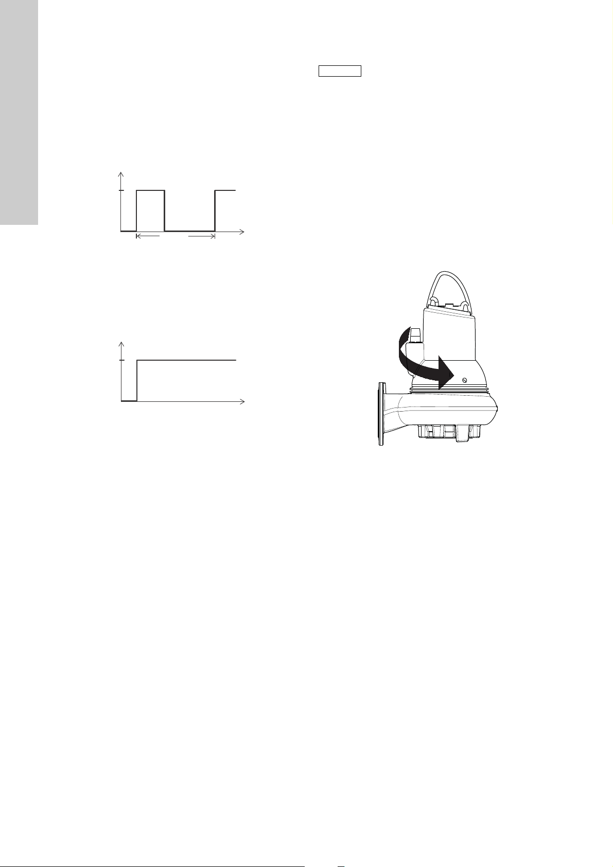
9.2 Operating modes
Operation
Stop
6 min.4 min.
10 min.
P
t
P
t
Operation
Stop
Note
English (GB)
The pumps are designed for intermittent operation (S3).
When completely submerged, the pumps can also operate
continuously (S1).
S3, intermittent operation:
Operating mode S3 means that within 10 minutes the pump must
be in operation for 4 minutes and stopped for 6 minutes.
See fig. 14.
In this operating mode, the pump is partly submerged in the
pumped liquid, i.e. the liquid level reaches at minimum the top of
the cable entry on the motor housing. See fig. 2.
Fig. 14 S3, intermittent operation
S1, continuous operation:
In this operating mode, the pump can operate continuously
without being stopped for cooling. See fig. 15. Being completely
submerged, the pump is sufficiently cooled by the surrounding
liquid. See fig. 2.
9.3 Direction of rotation
The pump may be started for a very short period
without being submerged to check the direction
of rotation.
Check the direction of rotation before starting up the pump.
An arrow on the motor housing indicates the correct direction of
rotation. Correct direction of rotation is clockwise when viewed
from above.
Checking the direction of rotation
The direction of rotation should be checked in the following way
every time the pump is connected to a new installation.
Procedure
1. Let the pump hang from a lifting device, e.g. the hoist used for
lowering the pump into the tank.
2. Start and stop the pump while observing the movement (jerk)
of the pump. If connected correctly, the pump will rotate
clockwise, i.e. it will jerk counter-clockwise. See fig. 16.
TM04 4527 1509TM04 4528 1509
3. If the direction of rotation is wrong, interchange any two of the
phases in the power supply cable. See fig. 6 or 8.
Fig. 15 S1, continuous operation
TM04 2657 2808
Fig. 16 Jerk direction
24
Page 25

10. Maintenance and service
Note
Note
Warning
Before starting work on the pump, make sure that
the fuses have been removed or the mains switch
has been switched off. It must be ensured that
the power supply cannot be accidentally
switched on.
Make sure that all protective equipment has been
connected correctly.
Warning
Before starting work on the pump, make sure that
the mains switch has been locked in position 0.
All rotating parts must have stopped moving.
Warning
Maintenance work on explosion-proof pumps
must be carried out by Grundfos or a service
workshop authorized by Grundfos.
However, this does not apply to the hydraulic
components, such as pump housing, impeller,
etc.
Warning
The cable must only be replaced by Grundfos or
a service workshop authorized by Grundfos.
Before carrying out maintenance and service, it must be ensured
that the pump has been thoroughly flushed with clean water.
Rinse the pump parts in water after dismantling.
10.1 Inspection
Pumps running normal operation should be inspected every
3000 operating hours or at least once a year. If the pumped liquid
is very muddy or sandy, inspect the pump at shorter intervals.
Check the following points:
• Power consumption
See pump nameplate.
• Oil level and oil condition
When the pump is new or after replacement of the shaft seal,
check the oil level and water content after one week of
operation. If there is more than 20 % extra liquid (water) in the
oil chamber, the shaft seal is defective. The oil should be
changed after 3000 operating hours or once a year.
Use Shell Ondina 919 oil or similar type.
See section 10.2.1 O il change.
• Cable entry
Make sure that the cable entry is watertight (visual inspection)
and that the cable is not sharply bent and/or pinched.
• Pump parts
Check impeller, pump housing, etc. for possible wear.
Replace defective parts.
See section 10.2.2 Removing the pump housing and impeller.
• Ball bearings
Check the shaft for noisy or heavy operation (turn the shaft by
hand). Replace defective ball bearings.
A general overhaul of the pump is usually required in case of
defective ball bearings or poor motor function. This work must
be carried out by Grundfos or a service workshop authorized
by Grundfos.
Warnin g
Defective bearings may reduce the Ex safety.
• O-rings and similar parts
During service/replacement, it must be ensured that the
grooves for the O-rings as well as the seal faces have been
cleaned before the new parts are fitted.
Used rubber parts must not be reused.
Warnin g
Explosion-proof pumps must be checked by an
authorized Ex workshop once a year.
10.2 Dismantling the pump
10.2.1 Oil change
After 3000 operating hours or once a year, change the oil in the
oil chamber as described below.
If the shaft seal has been replaced, the oil must be changed.
Warnin g
When loosening the screws of the oil chamber,
note that pressure may have built up in the
chamber. Do not remove the screws until the
pressure has been fully relieved.
Draining of oil
1. Place the pump on a plane surface with one oil screw pointing
downwards.
2. Place a suitable container (approx. 1 litre), for instance made
of transparent plastic material, under the oil screw.
Used oil must be disposed of in accordance with
local regulations.
3. Remove the lower oil screw.
4. Remove the upper oil screw.
If the pump has been in operation for a long period of time, if
the oil is drained off shortly after the pump has been stopped,
and if the oil is greyish white like milk, it contains water. If the
oil contains more than 20 % water, it is an indication that the
shaft seal is defective and must be replaced. If the shaft seal
is not replaced, the motor will be damaged.
If the quantity of oil is smaller than the quantity stated in
section 10.4 Oil quantities, the shaft seal is defective.
5. Clean the faces for the gaskets for oil screws.
English (GB)
25
Page 26

Filling with oil
Oil filling/venting
English (GB)
1. Turn the pump so that the oil filling holes are placed opposite
to each other, pointing upwards.
Fig. 17 Oil filling holes
2. Pour oil into the chamber.
For oil quantity, see section 10.4 Oil quantities.
3. Fit the oil screws with new gaskets.
10.2.2 Removing the pump housing and impeller
For position numbers, see pages 39 and 40.
Procedure
1. Loosen the clamp (pos. 92).
2. Remove the screw (pos. 92a) using your fingers.
3. Remove the pump housing (pos. 50) by inserting two
screwdrivers between the sleeve and the pump housing.
4. Remove the screw (pos. 188a). Hold the impeller with a strap
wrench.
10.2.3 Removing the seal ring and wear ring Procedure
1. Turn the pump housing upside-down.
2. Knock the seal ring (pos. 46) out of the pump housing using a
punch.
TM04 6477 0410TM04 6476 0410
TM02 8420 5103TM02 8422 5103
Fig. 19 Removing the seal ring
3. Clean the pump housing where the seal ring was fitted.
4. Remove the wear ring (pos. 49c) using a screwdriver.
Fig. 18 Removing the impeller
5. Loosen the impeller (pos. 49) with a light blow on the edge.
Pull it off.
6. Remove the key (pos. 9a) and the spring for impeller
(pos. 157).
Fig. 20 Removing the wear ring
5. Clean the impeller where the wear ring was fitted.
10.2.4 Removing the shaft seal Procedure
1. Remove the screws (pos. 188).
2. Remove the cover for oil chamber (pos. 58) using a puller.
3. Remove the screws (pos. 186).
4. Remove the shaft seal (pos. 105) using the puller.
5. Remove the O-ring (pos. 153b).
Procedure (pump with sensor)
1. Remove the screws (pos. 188).
2. Remove the cover for oil chamber (pos. 58) using a puller.
3. Remove the screws (pos. 186).
4. Remove the sensor (pos. 521) and holder (pos. 522) from the
shaft seal.
5. Remove the shaft seal (pos. 105) using the puller.
6. Remove the O-ring (pos. 153b).
26
Page 27

10.3 Assembling the pump
Note
10.3.1 Fitting the shaft seal Procedure
1. Fit and lubricate the O-ring (pos. 153b) with oil.
2. Slide the shaft seal (pos. 105) gently over the shaft.
3. Fit and tighten the screws (pos. 186).
4. Fit and lubricate the O-ring (pos. 107) in the cover for oil
chamber (pos. 58) with oil.
5. Fit the cover for oil chamber.
6. Fit and tighten the screws (pos. 188).
Procedure (pump with sensor)
1. Fit and lubricate the O-ring (pos. 153b) with oil.
2. Slide the shaft seal (pos. 105) gently over the shaft.
3. Fit the holder (pos. 522) and sensor (pos. 521) with one of the
screws (pos. 186).
4. Fit the second screw and tighten both screws (pos. 186).
5. Fit and lubricate the O-ring (pos. 107) in the cover for oil
chamber (pos. 58) with oil.
6. Check that the sensor is positioned correctly, see section
8.4.1 Fitting the WIO sensor and fig. 11. This is of special
importance in horizontal pumps.
7. Fit the cover for oil chamber.
8. Fit and tighten the screws (pos. 188).
10.3.2 Fitting the seal ring and wear ring
Procedure
1. Lubricate the seal ring (pos. 46) with soapy water.
2. Place the seal ring in the pump housing.
3. Knock the seal ring home in the pump housing using a punch
or a wooden block.
10.3.3 Fitting the impeller and pump housing Procedure
1. Fit the spring (pos. 157) and the key (pos. 9a).
Keep the key in position while the impeller is fitted.
2. Fit the impeller (pos. 49).
3. Fit the washer (pos. 66) and the screw (pos. 188a).
4. Tighten the screw (pos. 188a) to 75 Nm. Hold the impeller
with the strap wrench.
5. Mark the position of the pin on the pump housing.
6. Mark the position of the pin hole on the oil chamber.
7. Fit and lubricate the O-ring (pos. 37) with oil.
8. Fit the pump part in the pump housing (pos. 50).
9. Fit the clamp (pos. 92).
10. Tighten the screw (pos. 92a) to 12 Nm.
11. Check that the impeller rotates freely and without drag.
10.4 Oil quantities
The table shows the quantity of oil in the oil chamber of SL1 and
SLV pumps. Oil type: Shell Ondina 919.
2-pole
4-pole
Power
[kW]
2.2 0.6
3.0 0.6
4.0 1.0
6.0 1.0
7.5 1.0
9.2 1.2
11. 0 1 .2
1.1 0.6
1.3 0.6
1.5 0.6
2.2 0.6
3.0 1.0
4.0 1.0
5.5 1.0
7.5 1.2
Oil quantity
[l]
English (GB)
Fig. 21 Fitting the seal ring
4. Place the wear ring (pos. 49c) on the impeller.
5. Knock the wear ring home using a wooden block.
Fig. 22 Fitting the wear ring
Used oil must be disposed of in accordance with
local regulations.
TM02 8421 5103TM02 8423 5103
27
Page 28

10.5 Service kits
English (GB)
The following service kits are available for all SL1, SLV pumps and can be ordered as required.
10.5.1 SuperVortex impeller
Free passage 65 80 65 80 100
Pos. Description
49Impeller 1111111
Pos. Description
49Impeller 111111
10.5.2 S-tube impeller
Pos. Description
49Impeller 1111111
Wear ring for
49c
impeller
2-pole 2.2 3.0 3.0 4.0
4-pole 2.2 3.0 4
Cast iron 96886437 96812794 96886439 96886439 96886453 96886441 -
Stainless steel - 97759200 - - 97759206 - 97759201
Free passage 100 100 80 100 80 80
2-pole
4-pole 4.0 5.5 6.0 7.5 7.5 9.2 11
Cast iron 96886456 96882380 96812823 96812827 96882475 96812831 96812654
Stainless steel 97759207 97759208 97759202 97759203 97759209 97759204 97759205
SL1.50 SL1.50 SL1.50 SL1.80 SL1.80 SL1.80 SL1.80
2-pole 2.2 3.0 4.0
4-pole 1.5 2.2 3.0 4.0
98166759 98166760 98166771 98166772 98166773 98166774 98166775
1111111
65.40 /
80.40
80.40
SL1.80 SL1.80 SL1.100 SL1.100 SL1.100
Pos. Description
49 Impeller 1 1 1 1
Wear ring for
49c
impeller
10.5.3 Impeller fitting kit
Pos. Description
9a Key 1 1
66 Washer 1 1
157 Corrugated spring 1 1
188a Screw 1 1
10.5.4 Wear ring kit (SL1)
Pos. Description
46 Seal ring 1 1 1
49c Wear ring 1 1 1
2-pole
4-pole 5.5 7.5 4.0 5.5 7.5
98166776 98166777 98166778 98166779 98166780
11 11
2-pole: 2.2 - 4.0 kW 6.0 - 11 kW
4-pole: 1.1 - 2.2 kW 3.0 - 7.5 kW
Kit no: 96102365 96102366
Free passage: ∅50 ∅80 ∅100
Rubber type: NBR NBR NBR
Kit no: 96102362 96102363 96102364
28
Page 29

10.5.5 Shaft seal kit
Note
Note
2-pole: 2.2 - 4.0 kW 6.0 - 11 kW
Pos. Description
105 Shaft seal cartridge 1 1
110 x 3 1
107 O-ring
153b O-ring
157 Corrugated spring 1 1
For position numbers, see pages 39 and 40.
A possible replacement of the cable must be
carried out by Grundfos or a service workshop
authorized by Grundfos.
For service parts not shown in the above table, consult
www.grundfos.com WebCAPS, Service.
Examples of service parts:
•Cable
• pump housing
•impeller
• bearings
• shaft/rotor
•clamp
•stator
• motor complete, both standard and Ex.
134.5 x 3 1 1
160 x 3 1
17.0 x 2.4 1
28 x 2 1
4-pole: 1.1 - 2.2 kW 3.0 - 7.5 kW
Rubber type: NBR NBR
Kit no: 96102360 96102361
English (GB)
10.6 Contaminated pumps
If a pump has been used for a liquid which is
injurious to health or toxic, the pump will be
classified as contaminated.
If Grundfos is requested to service the pump, Grundfos must be
contacted with details about the pumped liquid, etc. before the
pump is returned for service. Otherwise Grundfos can refuse to
accept the pump for service.
Possible costs of returning the pump are to be paid by the
customer.
However, any application for service (no matter to whom it may
be made) must include details about the pumped liquid if the
pump has been used for liquids which are injurious to health or
toxic.
Before a pump is returned, it must be cleaned in the best possible
way before it is returned.
Service instruction and service video can be found on
www.grundfos.com.
29
Page 30

11. Fault finding
Note
English (GB)
Fault Cause Remedy
1. Motor does not start.
Fuses blow or motor-protective
circuit breaker trips out
immediately.
Caution: Do not start again!
2. Pump operates, but motorprotective circuit breaker trips
out after a short while.
3. The thermal switch of the pump
trips out after a short while.
4. Pump operates at belowstandard performance and
power consumption.
5. Pump operates, but gives no
liquid.
6. High power consumption
(SLV).
7. Noisy operation and excessive
vibrations (SL1).
8. Pump clogged. a) The liquid contains large particles. Select a pump with a larger size of passage.
Warning
Before attempting to diagnose any fault, make sure that the fuses have been removed or the mains switch has been
switched off. It must be ensured that the power supply cannot be accidentally switched on.
All rotating parts must have stopped moving.
Warning
All regulations applying to pumps installed in potentially explosive environments must be observed.
It must be ensured that no work is carried out in potentially explosive atmosphere.
For pumps with sensor, start fault finding by checking the status on the IO 111 front panel.
See installation and operating instructions for IO 111.
a) Supply failure; short-circuit; earth-leakage
fault in cable or motor winding.
b) Fuses blow due to use of wrong type of fuse. Fit fuses of the correct type.
c) Impeller blocked by impurities. Clean the impeller.
d) Air bells, float switches or electrodes out of
adjustment or defective.
e) Moisture in the stator housing (alarm).
The IO 111 interrupts the supply voltage.*
f) The WIO sensor is not covered by oil (alarm).
The IO 111 interrupts the supply voltage.*
g) Stator insulation resistance too low.* Reset alarm on IO 111, see installation and
a) Low setting of thermal relay in motor-
protective circuit breaker.
b) Increased current consumption due to large
voltage drop.
c) Impeller blocked by impurities.
Increased current consumption in all three
phases.
d) Wrong direction of rotation. Check the direction of rotation and possibly
a) Too high liquid temperature. Reduce the liquid temperature.
b) Too high viscosity of the pumped liquid. Dilute the pumped liquid.
c) Wrong electrical connection. (If the pump is
star-connected to a delta connection, the
result will be very low undervoltage).
a) Impeller blocked by impurities. Clean the impeller.
b) Wrong direction of rotation.
a) Discharge valve closed or blocked. Check the discharge valve and possibly open
b) Non-return valve blocked. Clean the non-return valve.
c) Air in pump. Vent the pump.
a) Wrong direction of rotation. Check the direction of rotation and possibly
b) Impeller blocked by impurities. Clean the impeller.
a) Wrong direction of rotation. Check the direction of rotation and possibly
b) Impeller blocked by impurities. Clean the impeller.
b) A float layer has formed on the surface of
the liquid.
Have the cable and motor checked and repaired
by a qualified electrician.
Readjust or replace the air bells, float switches
or electrodes.
Replace the O-rings, the shaft seal and moisture
switch.
Check, and possibly replace, the shaft seal, fill
up with oil and reset the IO 111.
operating instructions for IO 111.
Set the relay in accordance with the
specifications on the nameplate.
Measure the voltage between two motor phases.
Tolerance: - 10 %/+ 6 %. Reestablish correct
voltage supply.
Clean the impeller.
interchange any two of the phases in the
incoming supply cable. See section
9.3 Direction of rotation.
Check and correct the electrical installation.
Check the direction of rotation and possibly
interchange any two of the phases in the
incoming supply cable. See section
9.3 Direction of rotation.
and/or clean it.
interchange any two of the phases in the
incoming supply cable. See section
9.3 Direction of rotation.
interchange any two of the phases in the
incoming supply cable. See section
9.3 Direction of rotation.
Install a mixer in the tank.
* Applies only to pumps with sensor and with IO 111.
30
Page 31

12. Technical data
Supply voltage
• 3 x 380-415 V - 10 %/+ 10 %, 50 Hz
• 3 x 400-415 V - 10 %/+ 10 %, 50 Hz
Enclosure class
IP68. According to IEC 60529.
Insulation class
F (155 °C).
Operating pressure
All pump housings have a cast iron PN 10 discharge flange.
Dimensions
Discharge flanges are DN 65, DN 80, DN 100 or DN 150
according to EN 1092-2.
Pump curves
Pump curves are available via the internet on
www.grundfos.com.
The curves are to be considered as a guide. They must not be
used as guarantee curves.
Test curves for the supplied pump are available on request.
It must be ensured that the pump does not operate outside the
recommended operating range during normal operation.
Pump noise emission < 70 dB(A)
• Sound power measurements were carried out according to
ISO 3743.
• Sound power was calculated at a distance of 1 metre
according to ISO 11203.
The sound pressure level of the pump is lower than the limiting
values stated in the EC Council Directive 2006/42/EC relating to
machinery.
English (GB)
2-pole motor Cable connection
Power P
[kW]
Power P
2
[kW]
Voltage
1
[V]
Starting
method
Thermal protection
Cable cross section
[mm
2
]
2.2 2.8 3 x 380-415 DOL Thermal switch 1.5 7/7
2.2 2.8 3 x 380-415 Y/D Thermal switch 1.5 10/10
2.2 2.8 3 x 400-415 DOL Thermal switch 1.5 7/7
3 3.8 3 x 380-415 DOL Thermal switch 1.5 7/7
3 3.8 3 x 380-415 Y/D Thermal switch 1.5 10/10
3 3.8 3 x 400-415 DOL Thermal switch 1.5 7/7
4 4.8 3 x 380-415 Y/D Thermal switch 2.5 10/10
4 4.8 3 x 400-415 DOL Thermistor 2.5 7/10
6.0 7.1 3 x 380-415 Y/D Thermal switch 2.5 10/10
6.0 7.1 3 x 400-415 DOL Thermistor 2.5 7/10
7.5 8.9 3 x 380-415 Y/D Thermal switch 2.5 10/10
7.5 8.9 3 x 400-415 DOL Thermistor 2.5 7/10
9.2 10.5 3 x 380-415 Y/D Thermal switch 2.5 10/10
9.2 10.5 3 x 400-415 DOL Thermistor 2.5 7/10
11 12.6 3 x 380-415 Y/D Thermal switch 2.5 10/10
11 12.6 3 x 400-415 DOL Thermistor 2.5 7/10
The supply cable resistance depends on the cable diameter.
2
Resistance per running metre of cable: 1.5 mm
Resistance per running metre of cable: 2.5 mm
= 0.012 Ω.
2
= 0.007 Ω.
Conductors/plug
pins
31
Page 32

English (GB)
Power P
[kW]
Power P
2
1
[kW]
4-pole motor Cable connection
Voltage
[V]
1.1 1.5 3 x 380-415 DOL Thermal switch 1.5 7/7
1.1 1.5 3 x 400-415 DOL Thermal switch 1.5 7/7
1.3 1.8 3 x 380-415 DOL Thermal switch 1.5 7/7
1.3 1.8 3 x 400-415 DOL Thermal switch 1.5 7/7
1.5 2.1 3 x 380-415 DOL Thermal switch 1.5 7/7
1.5 2.1 3 x 400-415 DOL Thermal switch 1.5 7/7
2.2 2.9 3 x 380-415 DOL Thermal switch 1.5 7/7
2.2 2.9 3 x 380-415 Y/D Thermal switch 1.5 10/10
2.2 2.9 3 x 400-415 DOL Thermal switch 1.5 7/7
3 3.7 3 x 380-415 DOL Thermal switch 1.5 7/7
3 3.7 3 x 380-415 Y/D Thermal switch 1.5 10/10
3 3.7 3 x 400-415 DOL Thermal switch 2.5 7/7
4 4.9 3 x 380-415 Y/D Thermal switch 2.5 10/10
4 4.9 3 x 400-415 DOL Thermistor 2.5 7/10
5.5 6.5 3 x 380-415 Y/D Thermal switch 2.5 10/10
5.5 6.5 3 x 400-415 DOL Thermistor 2.5 7/10
7.5 9.0 3 x 380-415 Y/D Thermal switch 2.5 10/10
7.5 9.0 3 x 400-415 DOL Thermistor 2.5 7/10
The supply cable resistance depends on the cable diameter.
Resistance per running metre of cable: 1.5 mm
Resistance per running metre of cable: 2.5 mm
Starting method Thermal protection
2
= 0.012 Ω.
2
= 0.007 Ω.
Cable cross section
[mm
2
]
Conductors /
plug pins
13. Disposal
This product or parts of it must be disposed of in an
environmentally sound way:
1. Use the public or private waste collection service.
2. If this is not possible, contact the nearest Grundfos company
or service workshop.
Subject to alterations.
32
Page 33

Appendix 1
14. Dimensions and weights
14.1 Pumps without accessories
Appendix
Pump type A C D E F H DN1 Dc1 D1n-D∅1 DN2 Dc2 D2n-D∅2
SL1.50.65.22.2 641 366 171 216 321 93 65 145 4 x M16 65 145 4 x 18 86
SL1.50.65.30.2 641 366 171 216 321 93 65 145 4 x M16 65 145 4 x 18 89
SL1.50.65.40.2 677 407 200 227 379 93 65 145 4 x M16 65 145 4 x 18 115
SL1.50.80.22.2 641 366 171 216 321 100 65 145 4 x M16 80 160 8 x 18 87
SL1.50.80.30.2 641 366 171 216 321 100 65 145 4 x M16 80 160 8 x 18 90
SL1.50.80.40.2 677 407 200 227 379 100 65 145 4 x M16 80 160 8 x 18 116
SL1.80.80.15.4 682 435 171 272 347 100 100 180 8 x M16 80 160 8 x 18 95
SL1.80.80.22.4 682 435 171 272 347 100 100 180 8 x M16 80 160 8 x 18 107
SL1.80.80.30.4 711 505 200 319 397 118 100 180 8 x M16 80 160 8 x 18 137
SL1.80.80.40.4 748 505 200 319 397 118 100 180 8 x M16 80 160 8 x 18 142
SL1.80.80.55.4 755 505 200 319 397 118 100 180 8 x M16 80 160 8 x 18 149
SL1.80.80.75.4 818 530 217 328 423 118 100 180 8 x M16 80 160 8 x 18 193
SL1.80.100.15.4 682 435 171 272 347 112 100 180 8 x M16 100 180 8 x 19 96
SL1.80.100.22.4 682 435 171 272 347 112 100 180 8 x M16 100 180 8 x 19 108
SL1.80.100.30.4 726 505 200 319 397 118 100 180 8 x M16 100 180 8 x 19 139
SL1.80.100.40.4 748 505 200 319 397 118 100 180 8 x M16 100 180 8 x 19 143
SL1.80.100.55.4 755 505 200 319 397 118 100 180 8 x M16 100 180 8 x 19 150
SL1.80.100.75.4 818 530 217 328 423 118 100 180 8 x M16 100 180 8 x 19 194
SL1.100.100.40.4 754 541 200 320 438 115 150 240 8 x M20 100 180 8 x 22 155
SL1.100.100.55.4 762 541 200 320 438 115 150 240 8 x M20 100 180 8 x 22 161
SL1.100.100.75.4 827 541 217 312 462 115 150 240 8 x M20 100 180 8 x 22 202
SL1.100.150.40.4 755 541 200 320 440 143 150 240 8 x M20 150 240 8 x 22 157
SL1.100.150.40.4 755 541 200 320 440 143 150 240 8 x M20 150 240 8 x 22 157
SL1.100.150.55.4 762 541 200 320 440 143 150 240 8 x M20 150 240 8 x 22 163
SL1.100.150.75.4 827 541 217 306 472 143 150 240 8 x M20 150 240 8 x 22 204
SLV.65.65.22.2 684 396 171 246 321 102 80 160 8 x M16 65 145 4 x 18 88
SLV.65.65.30.2 684 396 171 246 321 102 80 160 8 x M16 65 145 4 x 18 91
SLV.65.65.40.2 718 456 200 276 380 106 80 160 8 x M16 65 145 4 x 18 117
SLV.65.80.22.2 685 397 171 247 321 103 80 160 8 x M16 80 160 8 x 18 89
Weight
[kg]
TM04 2793 3008
33
Page 34

Appendix
Pump type A C D E F H DN1 Dc1 D1n-D∅1 DN2 Dc2 D2n-D∅2
SLV.65.80.30.2 685 397 171 247 321 103 80 160 8 x M16 80 160 8 x 18 92
SLV.65.80.40.2 718 455 200 276 379 106 80 160 8 x M16 80 160 8 x 18 117
SLV.80.80.11.4 711 409 171 241 339 109 80 160 8 x M16 80 160 8 x 18 94
SLV.80.80.13.4 711 409 171 241 339 109 80 160 8 x M16 80 160 8 x 18 94
SLV.80.80.15.4 711 409 171 241 339 109 80 160 8 x M16 80 160 8 x 18 94
SLV.80.80.110.2 782 489 217 293 413 123 80 160 8 x M16 80 160 8 x 18 183
SLV.80.80.22.4 711 409 171 241 339 109 80 160 8 x M16 80 160 8 x 18 106
SLV.80.80.40.4 748 460 200 267 393 109 80 160 8 x M16 80 160 8 x 18 134
SLV.80.80.60.2 751 456 200 276 380 104 80 160 8 x M16 80 160 8 x 18 140
SLV.80.80.75.2 751 456 200 276 380 104 80 160 8 x M16 80 160 8 x 18 140
SLV.80.80.92.2 782 489 217 293 413 123 80 160 8 x M16 80 160 8 x 18 183
SLV.80.100.11.4 711 407 171 241 337 109 80 160 8 x M16 100 180 8 x 18 95
SLV.80.100.13.4 711 407 171 241 337 109 80 160 8 x M16 100 180 8 x 18 95
SLV.80.100.15.4 711 407 171 241 337 109 80 160 8 x M16 100 180 8 x 18 95
SLV.80.100.110.2 782 499 217 303 413 123 80 160 8 x M16 100 180 8 x 18 184
SLV.80.100.22.4 711 407 171 241 337 109 80 160 8 x M16 100 180 8 x 18 107
SLV.80.100.40.4 748 458 200 267 391 109 80 160 8 x M16 100 180 8 x 18 135
SLV.80.100.60.2 751 466 200 286 380 108 80 160 8 x M16 100 180 8 x 18 141
SLV.80.100.75.2 751 466 200 286 380 108 80 160 8 x M16 100 180 8 x 18 141
SLV.80.100.92.2 782 499 217 303 413 123 80 160 8 x M16 100 180 8 x 18 184
SLV.100.100.30.4 737 457 200 277 380 134 100 180 8 x M16 100 160 8 x 18 125
SLV.100.100.40.4 759 457 200 277 380 134 100 180 8 x M16 100 160 8 x 18 130
SLV.100.100.55.4 766 457 200 277 380 134 100 180 8 x M16 100 160 8 x 18 136
SLV.100.100.75.4 842 490 217 294 413 145 100 180 8 x M16 100 180 8 x 22 179
Weight
[kg]
34
Page 35

14.2 Pumps with ring stand
Appendix
Pump type V1 V2 V3 V4 V5 V6 V7 V∅
SL1.50.65.22.2 771 339 130 325 270 491 65 18
L1.50.65.30.2 771 339 130 325 270 491 65 18
SL1.50.65.40.2 807 341 130 325 270 519 65 18
SL1.50.80.22.2 771 339 130 325 270 496 80 18
SL1.50.80.30.2 771 339 130 325 270 496 80 18
SL1.50.80.40.2 807 341 130 325 270 525 80 18
SL1.80.80.15.4 812 364 130 355 300 567 80 19
SL1.80.80.22.4 812 364 130 355 300 567 80 19
SL1.80.80.30.4 841 390 130 355 300 623 80 19
SL1.80.80.40.4 878 390 130 355 300 623 80 19
SL1.80.80.55.4 885 390 130 355 300 623 80 19
SL1.80.80.75.4 948 390 130 355 300 648 80 19
SL1.80.100.15.4 812 369 130 355 300 591 100 19
SL1.80.100.22.4 812 369 130 355 300 591 100 19
SL1.80.100.30.4 856 395 130 355 300 647 100 19
SL1.80.100.40.4 878 395 130 355 300 647 100 19
SL1.80.100.55.4 885 395 130 355 300 647 100 19
SL1.80.100.75.4 948 395 130 355 300 672 100 19
SL1.100.100.40.4 941 445 186 450 400 711 100 22
SL1.100.100.55.4 948 445 186 450 400 711 100 22
SL1.100.100.75.4 1.013 445 186 450 400 706 100 22
SL1.100.150.40.4 941 555 186 450 400 807 150 22
SL1.100.150.40.4 941 555 186 450 400 807 150 22
SL1.100.150.55.4 948 555 186 450 400 807 150 22
SL1.100.150.75.4 1.013 555 186 450 400 803 150 22
SLV.65.65.22.2 812 372 128 330 280 524 65 18
SLV.65.65.30.2 812 372 128 330 280 524 65 18
SLV.65.65.40.2 846 376 128 330 280 568 65 18
SLV.65.80.22.2 813 373 128 330 280 530 80 18
SLV.65.80.30.2 813 373 128 330 280 530 80 18
SLV.65.80.40.2 846 376 128 330 280 573 80 18
SLV.80.80.11.4 839 379 128 330 280 527 80 18
TM04 2795 3008
35
Page 36

Appendix
Pump type V1 V2 V3 V4 V5 V6 V7 V∅
SLV.80.80.13.4 839 379 128 330 280 527 80 18
SLV.80.80.15.4 839 379 128 330 280 527 80 18
SLV.80.80.110.2 910 393 128 330 280 607 80 18
SLV.80.80.22.4 839 379 128 330 280 527 80 18
SLV.80.80.40.4 876 379 128 330 280 578 80 18
SLV.80.80.60.2 879 374 128 330 280 574 80 18
SLV.80.80.75.2 879 374 128 330 280 574 80 18
SLV.80.80.92.2 910 393 128 330 280 607 80 18
SLV.80.100.11.4 840 354 128 330 280 549 100 18
SLV.80.100.13.4 840 354 128 330 280 549 100 18
SLV.80.100.15.4 840 354 128 330 280 549 100 18
SLV.80.100.110.2 910 368 128 330 280 641 100 18
SLV.80.100.22.4 840 354 128 330 280 549 100 18
SLV.80.100.40.4 876 354 128 330 280 600 100 18
SLV.80.100.60.2 879 353 128 330 280 598 100 18
SLV.80.100.75.2 879 353 128 330 280 598 100 18
SLV.80.100.92.2 910 368 128 330 280 641 100 18
SLV.100.100.30.4 867 411 130 355 300 599 100 19
SLV.100.100.40.4 889 411 130 355 300 599 100 19
SLV.100.100.55.4 896 411 130 355 300 599 100 19
SLV.100.100.75.4 972 422 130 355 300 632 100 19
36
Page 37

14.3 Pumps on auto coupling
Appendix
Z10
Pump type Z2 Z3 Z4 Z6 Z7 Z8 Z9
SL1.50.65.22.2 210 95 140 700 513 363 81 1.5 740 99 1 175 266 145 65 4 x M16
L1.50.65.30.2 210 95 140 700 513 363 81 1.5 740 99 1 175 266 145 65 4 x M16
SL1.50.65.40.2 210 95 140 741 554 375 81 1.5 775 97 1 175 266 145 65 4 x M16
SL1.50.80.22.2 220 95 160 719 526 376 81 1.5 774 133 13 171 345 145 65 4 x M16
SL1.50.80.30.2 220 95 160 719 526 376 81 1.5 774 133 13 171 345 145 65 4 x M16
SL1.50.80.40.2 220 95 160 760 567 387 81 1.5 808 132 13 171 345 145 65 4 x M16
SL1.80.80.15.4 220 95 160 788 595 432 81 1.5 790 108 13 171 345 180 100 4 x M16
SL1.80.80.22.4 220 95 160 788 595 432 81 1.5 790 108 13 171 345 180 100 4 x M16
SL1.80.80.30.4 220 95 160 858 666 480 81 1.5 793 82 13 171 345 180 100 4 x M16
SL1.80.80.40.4 220 95 160 858 666 480 81 1.5 830 82 13 171 345 180 100 4 x M16
SL1.80.80.55.4 220 95 160 858 666 480 81 1.5 837 82 13 171 345 180 100 4 x M16
SL1.80.80.75.4 220 95 160 883 690 489 81 1.5 900 82 13 171 345 180 100 4 x M16
SL1.80.100.15.4 260 110 270 878 652 489 110 2.0 830 148 0 220 413 180 100 4 x M16
SL1.80.100.22.4 260 110 270 878 652 489 110 2.0 830 148 0 220 413 180 100 4 x M16
SL1.80.100.30.4 260 110 270 948 722 536 110 2.0 848 122 0 220 413 180 100 4 x M16
SL1.80.100.40.4 260 110 270 948 722 536 110 2.0 870 122 0 220 413 180 100 4 x M16
SL1.80.100.55.4 260 110 270 948 722 536 110 2.0 877 122 0 220 413 180 100 4 x M16
SL1.80.100.75.4 260 110 270 972 747 545 110 2.0 940 122 0 220 413 180 100 4 x M16
SL1.100.100.40.4 260 110 270 983 758 537 110 2.0 880 125 0 220 413 240 150 4 x M16
SL1.100.100.55.4 260 110 270 983 758 537 110 2.0 886 125 0 220 413 240 150 4 x M16
SL1.100.100.75.4 260 110 270 983 758 529 110 2.0 951 125 0 220 413 240 150 4 x M16
SL1.100.150.40.4 300 110 280 1,093 780 559 110 2.0 919 164 0 280 450 240 150 4 x M16
SL1.100.150.40.4 300 110 280 1,093 780 559 110 2.0 919 164 0 280 450 240 150 4 x M16
SL1.100.150.55.4 300 110 280 1,093 780 559 110 2.0 926 164 0 280 450 240 150 4 x M16
SL1.100.150.75.4 300 110 280 1,093 780 545 110 2.0 990 164 0 280 450 240 150 4 x M16
SLV.65.65.22.2 210 95 140 730 543 394 81 1.5 747 63 1 175 266 160 80 4 x M16
SLV.65.65.30.2 210 95 140 730 543 394 81 1.5 747 63 1 175 266 160 80 4 x M16
SLV.65.65.40.2 210 95 140 790 604 424 81 1.5 778 60 1 175 266 160 80 4 x M16
Z11 Z12a Z14 Z15 Z16 Dc1 DN1 ZM
["]
TM04 2794 3008
37
Page 38

Appendix
Pump type Z2 Z3 Z4 Z6 Z7 Z8 Z9
SLV.65.80.22.2 220 95 160 750 557 408 81 1.5 782 97 13 171 345 160 80 4 x M16
SLV.65.80.30.2 220 95 160 750 557 408 81 1.5 782 97 13 171 345 160 80 4 x M16
SLV.65.80.40.2 220 95 160 808 616 437 81 1.5 812 94 13 171 345 160 80 4 x M16
SLV.80.80.11.4 220 95 160 762 569 402 81 1.5 802 91 13 171 345 160 80 4 x M16
SLV.80.80.13.4 220 95 160 762 569 402 81 1.5 802 91 13 171 345 160 80 4 x M16
SLV.80.80.15.4 220 95 160 762 569 402 81 1.5 802 91 13 171 345 160 80 4 x M16
SLV.80.80.110.2 220 95 160 842 650 454 81 1.5 859 77 13 171 345 160 80 4 x M16
SLV.80.80.22.4 220 95 160 762 569 402 81 1.5 802 91 13 171 345 160 80 4 x M16
SLV.80.80.40.4 220 95 160 813 620 428 81 1.5 840 91 13 171 345 160 80 4 x M16
SLV.80.80.60.2 220 95 160 809 617 437 81 1.5 847 96 13 171 345 160 80 4 x M16
SLV.80.80.75.2 220 95 160 809 617 437 81 1.5 847 96 13 171 345 160 80 4 x M16
SLV.80.80.92.2 220 95 160 842 650 454 81 1.5 859 77 13 171 345 160 80 4 x M16
SLV.80.100.11.4 260 110 270 850 624 458 110 2.0 842 131 0 220 413 160 80 4 x M16
SLV.80.100.13.4 260 110 270 850 624 458 110 2.0 842 131 0 220 413 160 80 4 x M16
SLV.80.100.15.4 260 110 270 850 624 458 110 2.0 842 131 0 220 413 160 80 4 x M16
SLV.80.100.110.2 260 110 270 942 716 520 110 2.0 899 117 0 220 413 160 80 4 x M16
SLV.80.100.22.4 260 110 270 850 624 458 110 2.0 842 131 0 220 413 160 80 4 x M16
SLV.80.100.40.4 260 110 270 901 675 484 110 2.0 857 109 0 220 413 160 80 4 x M16
SLV.80.100.60.2 260 110 270 909 683 503 110 2.0 883 132 0 220 413 160 80 4 x M16
SLV.80.100.75.2 260 110 270 909 683 503 110 2.0 883 132 0 220 413 160 80 4 x M16
SLV.80.100.92.2 260 110 270 942 716 520 110 2.0 899 117 0 220 413 160 80 4 x M16
SLV.100.100.30.4 260 110 270 900 674 494 110 2.0 844 106 0 220 413 180 100 4 x M16
SLV.100.100.40.4 260 110 270 900 674 494 110 2.0 865 106 0 220 413 180 100 4 x M16
SLV.100.100.55.4 260 110 270 900 674 494 110 2.0 873 106 0 220 413 180 100 4 x M16
SLV.100.100.75.4 260 110 270 933 707 511 110 2.0 938 95 0 220 413 180 100 4 x M16
Z10
Z11 Z12a Z14 Z15 Z16 Dc1 DN1 ZM
["]
38
Page 39

15. Exploded drawings
SLV
Appendix
39
TM04 2777 2605
Page 40

Appendix
SL1
TM04 2778 0904
40
Page 41

41
Page 42

Grundfos companies
Argentina
Bombas GRUNDFOS de Argentina S.A.
Ruta Panamericana km. 37.500 Centro
Industrial Garin
1619 Garín Pcia. de B.A.
Phone: +54-3327 414 444
Telefax: +54-3327 45 3190
Australia
GRUNDFOS Pumps Pty. Ltd.
P.O. Box 2040
Regency Park
South Australia 5942
Phone: +61-8-8461-4611
Telefax: +61-8-8340 0155
Austria
GRUNDFOS Pumpen Vertrieb Ges.m.b.H.
Grundfosstraße 2
A-5082 Grödig/Salzburg
Tel.: +43-6246-883-0
Telefax: +43-6246-883-30
Belgium
N.V. GRUNDFOS Bellux S.A.
Boomsesteenweg 81-83
B-2630 Aartselaar
Tél.: +32-3-870 7300
Télécopie: +32-3-870 7301
Belarus
Представительство ГРУНДФОС в
Минске
220125, Минск
ул. Шафарнянская, 11, оф. 56
Тел.: +7 (375 17) 286 39 72, 286 39 73
Факс: +7 (375 17) 286 39 71
E-mail: minsk@grundfos.com
Bosnia/Herzegovina
GRUNDFOS Sarajevo
Trg Heroja 16,
BiH-71000 Sarajevo
Phone: +387 33 713 290
Telefax: +387 33 659 079
e-mail: grundfos@bih.net.ba
Brazil
BOMBAS GRUNDFOS DO BRASIL
Av. Humberto de Alencar Castelo Branco,
630
CEP 09850 - 300
São Bernardo do Campo - SP
Phone: +55-11 4393 5533
Telefax: +55-11 4343 5015
Bulgaria
Grundfos Bulgaria EOOD
Slatina District
Iztochna Tangenta street no. 100
BG - 1592 Sofia
Tel. +359 2 49 22 200
Fax. +359 2 49 22 201
email: bulgaria@grundfos.bg
Canada
GRUNDFOS Canada Inc.
2941 Brighton Road
Oakville, Ontario
L6H 6C9
Phone: +1-905 829 9533
Telefax: +1-905 829 9512
China
GRUNDFOS Pumps (Shanghai) Co. Ltd.
50/F Maxdo Center No. 8 XingYi Rd.
Hongqiao development Zone
Shanghai 200336
PRC
Phone: +86 21 612 252 22
Telefax: +86 21 612 253 33
Croatia
GRUNDFOS CROATIA d.o.o.
Cebini 37, Buzin
HR-10010 Zagreb
Phone: +385 1 6595 400
Telefax: +385 1 6595 499
www.grundfos.hr
Czech Republic
GRUNDFOS s.r.o.
Čajkovského 21
779 00 Olomouc
Phone: +420-585-716 111
Telefax: +420-585-716 299
Denmark
GRUNDFOS DK A/S
Martin Bachs Vej 3
DK-8850 Bjerringbro
Tlf.: +45-87 50 50 50
Telefax: +45-87 50 51 51
E-mail: info_GDK@grundfos.com
www.grundfos.com/DK
Estonia
GRUNDFOS Pumps Eesti OÜ
Peterburi tee 92G
11415 Tallinn
Tel: + 372 606 1690
Fax: + 372 606 1691
Finland
OY GRUNDFOS Pumput AB
Mestarintie 11
FIN-01730 Vantaa
Phone: +358-(0)207 889 900
Telefax: +358-(0)207 889 550
France
Pompes GRUNDFOS Distribution S.A.
Parc d’Activités de Chesnes
57, rue de Malacombe
F-38290 St. Quentin Fallavier (Lyon)
Tél.: +33-4 74 82 15 15
Télécopie: +33-4 74 94 10 51
Germany
GRUNDFOS GMBH
Schlüterstr. 33
40699 Erkrath
Tel.: +49-(0) 211 929 69-0
Telefax: +49-(0) 211 929 69-3799
e-mail: infoservice@grundfos.de
Service in Deutschland:
e-mail: kundendienst@grundfos.de
HILGE GmbH & Co. KG
Hilgestrasse 37-47
55292 Bodenheim/Rhein
Germany
Tel.: +49 6135 75-0
Telefax: +49 6135 1737
e-mail: hilge@hilge.de
Greece
GRUNDFOS Hellas A.E.B.E.
20th km. Athinon-Markopoulou Av.
P.O. B ox 7 1
GR-19002 Peania
Phone: +0030-210-66 83 400
Telefax: +0030-210-66 46 273
Hong Kong
GRUNDFOS Pumps (Hong Kong) Ltd.
Unit 1, Ground floor
Siu Wai Industrial Centre
29-33 Wing Hong Street &
68 King Lam Street, Cheung Sha Wan
Kowloon
Phone: +852-27861706 / 27861741
Telefax: +852-27858664
Hungary
GRUNDFOS Hungária Kft.
Park u. 8
H-2045 Törökbálint,
Phone: +36-23 511 110
Telefax: +36-23 511 111
India
GRUNDFOS Pumps India Private Limited
118 Old Mahabalipuram Road
Thoraipakkam
Chennai 600 096
Phone: +91-44 2496 6800
Indonesia
PT GRUNDFOS Pompa
Jl. Rawa Sumur III, Blok III / CC-1
Kawasan Industri, Pulogadung
Jakarta 13930
Phone: +62-21-460 6909
Telefax: +62-21-460 6910 / 460 6901
Ireland
GRUNDFOS (Ireland) Ltd.
Unit A, Merrywell Business Park
Ballymount Road Lower
Dublin 12
Phone: +353-1-4089 800
Telefax: +353-1-4089 830
Italy
GRUNDFOS Pompe Italia S.r.l.
Via Gran Sasso 4
I-20060 Truccazzano (Milano)
Tel.: +39-02-95838112
Telefax: +39-02-95309290 / 95838461
Japan
GRUNDFOS Pumps K.K.
Gotanda Metalion Bldg., 5F,
5-21-15, Higashi-gotanda
Shiagawa-ku, Tokyo
141-0022 Japan
Phone: +81 35 448 1391
Telefax: +81 35 448 9619
Korea
GRUNDFOS Pumps Korea Ltd.
6th Floor, Aju Building 679-5
Yeoksam-dong, Kangnam-ku, 135-916
Seoul, Korea
Phone: +82-2-5317 600
Telefax: +82-2-5633 725
Latvia
SIA GRUNDFOS Pumps Latvia
Deglava biznesa centrs
Augusta Deglava ielā 60, LV-1035, Rīga,
Tālr.: + 371 714 9640, 7 149 641
Fakss: + 371 914 9646
Lithuania
GRUNDFOS Pumps UAB
Smolensko g. 6
LT-03201 Vilnius
Tel: + 370 52 395 430
Fax: + 370 52 395 431
Malaysia
GRUNDFOS Pumps Sdn. Bhd.
7 Jalan Peguam U1/25
Glenmarie Industrial Park
40150 Shah Alam
Selangor
Phone: +60-3-5569 2922
Telefax: +60-3-5569 2866
Mexico
Bombas GRUNDFOS de México S.A. de
C.V.
Boulevard TLC No. 15
Parque Industrial Stiva Aeropuerto
Apodaca, N.L. 66600
Phone: +52-81-8144 4000
Telefax: +52-81-8144 4010
Netherlands
GRUNDFOS Netherlands
Velu we zoom 35
1326 AE Almere
Postbus 22015
1302 CA ALMERE
Tel.: +31-88-478 6336
Telefax: +31-88-478 6332
E-mail: info_gnl@grundfos.com
New Zealand
GRUNDFOS Pumps NZ Ltd.
17 Beatrice Tinsley Crescent
North Harbour Industrial Estate
Albany, Auckland
Phone: +64-9-415 3240
Telefax: +64-9-415 3250
Norway
GRUNDFOS Pumper A/S
Strømsveien 344
Postboks 235, Leirdal
N-1011 Oslo
Tlf.: +47-22 90 47 00
Telefax: +47-22 32 21 50
Poland
GRUNDFOS Pompy Sp. z o.o.
ul. Klonowa 23
Baranowo k. Poznania
PL-62-081 Przeźmierowo
Tel: (+48-61) 650 13 00
Fax: (+48-61) 650 13 50
Portugal
Bombas GRUNDFOS Portugal, S.A.
Rua Calvet de Magalhães, 241
Apartado 1079
P-2770-153 Paço de Arcos
Tel.: +351-21-440 76 00
Telefax: +351-21-440 76 90
Romania
GRUNDFOS Pompe România SRL
Bd. Biruintei, nr 103
Pantelimon county Ilfov
Phone: +40 21 200 4100
Telefax: +40 21 200 4101
E-mail: romania@grundfos.ro
Russia
ООО Грундф ос
Россия, 109544 Москва, ул. Школьная
39
Тел. (+7) 495 737 30 00, 564 88 00
Факс (+7) 495 737 75 36, 564 88 11
E-mail grundfos.moscow@grundfos.com
Serbia
GRUNDFOS Predstavništvo Beograd
Dr. Milutina Ivkovića 2a/29
YU-11000 Beograd
Phone: +381 11 26 47 877 / 11 26 47 496
Telefax: +381 11 26 48 340
Singapore
GRUNDFOS (Singapore) Pte. Ltd.
25 Jalan Tukang
Singapore 619264
Phone: +65-6681 9688
Telefax: +65-6681 9689
Slovenia
GRUNDFOS d.o.o.
Šlandrova 8b, SI-1231 Ljubljana-Črnuče
Phone: +386 1 568 0610
Telefax: +386 1 568 0619
E-mail: slovenia@grundfos.si
South Africa
GRUNDFOS (PTY) LTD
Corner Mountjoy and George Allen Roads
Wilbart Ext. 2
Bedfordview 2008
Phone: (+27) 11 579 4800
Fax: (+27) 11 455 6066
E-mail: lsmart@grundfos.com
Spain
Bombas GRUNDFOS España S.A.
Camino de la Fuentecilla, s/n
E-28110 Algete (Madrid)
Tel.: +34-91-848 8800
Telefax: +34-91-628 0465
Sweden
GRUNDFOS AB
Box 333 (Lunnagårdsgatan 6)
431 24 Mölndal
Tel.: +46 31 332 23 000
Telefax: +46 31 331 94 60
Switzerland
GRUNDFOS Pumpen AG
Bruggacherstrasse 10
CH-8117 Fällanden/ZH
Tel.: +41-1-806 8111
Telefax: +41-1-806 8115
Taiwan
GRUNDFOS Pumps (Taiwan) Ltd.
7 Floor, 219 Min-Chuan Road
Taichung, Taiwan, R.O.C.
Phone: +886-4-2305 0868
Telefax: +886-4-2305 0878
Thailand
GRUNDFOS (Thailand) Ltd.
92 Chaloem Phrakiat Rama 9 Road,
Dokmai, Pravej, Bangkok 10250
Phone: +66-2-725 8999
Telefax: +66-2-725 8998
Turkey
GRUNDFOS POMPA San. ve Tic. Ltd. Sti.
Gebze Organize Sanayi Bölgesi
Ihsan dede Caddesi,
2. yol 200. Sokak No. 204
41490 Gebze/ Kocaeli
Phone: +90 - 262-679 7979
Telefax: +90 - 262-679 7905
E-mail: satis@grundfos.com
Ukraine
ТОВ ГРУНДФОС УКРАЇНА
01010 Київ, Вул. Московська 8б,
Тел.:(+38 044) 390 40 50
Фах.: (+38 044) 390 40 59
E-mail: ukraine@grundfos.com
United Arab Emirates
GRUNDFOS Gulf Distribution
P.O. Box 16768
Jebel Ali Free Zone
Dubai
Phone: +971 4 8815 166
Telefax: +971 4 8815 136
United Kingdom
GRUNDFOS Pumps Ltd.
Grovebury Road
Leighton Buzzard/Beds. LU7 4TL
Phone: +44-1525-850000
Telefax: +44-1525-850011
U.S.A.
GRUNDFOS Pumps Corporation
17100 West 118th Terrace
Olathe, Kansas 66061
Phone: +1-913-227-3400
Telefax: +1-913-227-3500
Uzbekistan
Grundfos Tashkent, Uzbekistan The Representative Office of Grundfos Kazakhstan in
Uzbekistan
38a, Oybek street, Tashkent
Телефон: (+998) 71 150 3290 / 71 150
3291
Факс: (+998) 71 150 3292
Addresses Revised 06.05.2013
Page 43

Appendix 2
English (GB)
Installation and operating instructions, correction sheet 3
Correction to installation and operating instructions for Grundfos SL1 and SLV pumps. Part number 96771279.
This EU declaration of performance applies as from May 15 2013.
GB:
EU declaration of performance in accordance with Annex III
of Regulation (EU) No 305/2011
(Construction Product Regulation)
1. Unique identification code of the product type:
– EN 12050-1 or EN 12050-2 (SL1.50).
2. Type, batch or serial number or any other element allowing
identification of the construction product as required pursuant to
Article 11(4):
– SL1, SLV pumps marked with EN 12050-1 or EN 12050-2 (SL1.50)
on the nameplate.
3. Intended use or uses of the construction product, in accordance with
the applicable harmonised technical specification, as foreseen by the
manufacturer:
– Pumps for pumping of wastewater containing faecal matter marked
with EN 12050-1 on the nameplate.
– SL1.50 pumps for pumping of faecal-free wastewater marked with
EN 12050-2 on the nameplate.
4. Name, registered trade name or registered trade mark and contact
address of the manufacturer as required pursuant to Article 11(5):
– Grundfos Holding A/S
Poul Due Jensens Vej 7
8850 Bjerringbro
Denmark.
5. NOT RELEVANT.
6. System or systems of assessment and verification of constancy of
performance of the construction product as set out in Annex V:
–System 3.
7. In case of the declaration of performance concerning a construction
product covered by a harmonised standard:
– TÜV Rheinland LGA Products GmbH, identification number: 0197.
Performed test according to EN 12050-1 or EN 12050-2 (SL1.50)
under system 3.
(description of the third party tasks as set out in Annex V)
– Certificate number: LGA-Certificate No 7381115. Type-tested and
monitored.
8. NOT RELEVANT.
9. Declared performance:
The products covered by this declaration of performance are in
compliance with the essential characteristics and the performance
requirements as described in the following:
– Standards used: EN 12050-1:2001 or EN 12050-2:2000 (SL1.50).
10. The performance of the product identified in points 1 and 2 is in
conformity with the declared performance in point 9.
BG:
Декларация на ЕC за изпълнение съгласно Анекс III на
регламент (ЕС) № 305/2011
(Регламент за строителните продукти)
1. Уникален идентификационен код на типа продукт:
– EN 12050-1 или EN 12050-2 (SL1.50).
2. Типов, партиден или сериен номер на всеки друг елемент,
позволяващ идентификация на строителния продукт, изисквана
съгласно Член 11(4):
– Помпи SL1, SLV, означени с EN 12050-1 или EN 12050-2 (SL1.50)
на табелата с данни.
3. Употреба или употреби по предназначение на строителния
продукт, в съответствие с приложимата хармонизирана
техническа спецификация, както
– Помпи за изпомпване на отпадни води, съдържащи фекални
вещества, означени с EN 12050-1 на табелата с данни.
– Помпи SL1.50 за изпомпване на отпадни води без фекални
вещества, означени с EN 12050-2 на табелата с данни.
4. Име, запазено търговско име или запазена търговска марка и
адрес за контакт на производителя, както
Член 11(5):
– Grundfos Holding A/S
Poul Due Jensens Vej 7
8850 Bjerringbro
Дания.
5. НЕ СЕ ОТНАСЯ ЗА СЛУЧАЯ.
6. Система или системи за оценка и проверка на устойчивостта на
изпълнението на строителния продукт, както е изложено в Анекс
V:
– Система 3.
7. В случай на декларация за изпълнение, отнасяща се за
строителен продукт, който попада в обсега на хармонизиран
стандарт:
– TÜV Rheinland LGA Products GmbH, идентификационен номер:
0197.
Изпълнен тест в съответствие с EN 12050-1 или EN 12050-2
(SL1.50) съгласно система 3.
(описание на задачи на трети лица, както е изложено в Анекс V)
– Номер на сертификат: LGA сертификат № 7381115. Тест ван за
тип и наблюдаван.
8. НЕ СЕ ОТНАСЯ ЗА СЛУЧАЯ.
9. Декларирано изпълнение:
Продуктите, предмет на тази декларация за изпълнение, са
съответствие с основните характеристики и изисквания за
изпълнение, описани по-долу:
– Приложени стандарти: EN 12050-1:2001 или EN 12050-2:2000.
10. Изпълнението на продукта, посочен в точки 1 и 2, е в
съответствие с декларираното изпълнение в точка 9.
е предвидено от производителя:
се изисква съгласно
Appendix
в
43
Page 44

Appendix
CZ:
Prohlášení o vlastnostech EU v souladu s Dodatkem III
předpisu (EU) č. 305/2011
(Předpis pro stavební výrobky)
DK:
EU-ydeevnedeklaration i henhold til bilag III af forordning
(EU) nr. 305/2011
(Byggevareforordningen)
1. Jedinečný identifikační kód typu výrobku:
– EN 12050-1 nebo EN 12050-2 (SL1.50).
2. Typ, dávka nebo výrobní číslo nebo jakýkoliv prvek umožňující
identifikaci stavebního výrobku podle požadavku Článku 11(4):
– Čerpadla SL1, SLV s označením EN 12050-1 nebo EN 12050-2
(SL1.50) na typovém štítku.
3. Zamýšlená použití stavebního výrobku v souladu s příslušnou
harmonizovanou technickou specifikací výrobce:
– Čerpací stanice odpadních vod s fekáliemi s označením EN
12050-1 na typovém štítku.
– Čerpací stanice SL1.50 odpadních vod s fekáliemi s označením EN
12050-2 na typovém štítku.
4. Název, registrovaný obchodní název nebo registrovaná ochranná
známka a kontaktní adresa výrobce podle požadavku Článku 11(5):
– Grundfos Holding A/S
Poul Due Jensens Vej 7
8850 Bjerringbro
Dánsko.
5. NESOUVISÍ.
6. Systém nebo systémy posuzování a ověřování stálosti vlastností
stavebního výrobku podle ustanovení Dodatku V:
–Systém 3.
7. V případě prohlášení o vlastnostech stavebního výrobku zahrnutého
v harmonizované normě:
– TÜV Rheinland LGA Products GmbH, identifikační číslo: 0197.
Proveden test podle EN 12050-1 nebo EN 12050-2 (SL1.50) v
systému 3.
(popis úkolů třetí strany podle ustanovení Dodatku V)
– Číslo certifikátu: Certifikát LGA č. 7381115. Typ testován a
monitorován.
8. NESOUVISÍ.
9. Prohlašované vlastnosti:
Výrobky uvedené v tomto Prohlášení o vlastnostech jsou v souladu
se základními charakteristikami a požadavky na vlastnosti, jak je
popsáno níže:
– Použité normy: EN 12050-1:2001 nebo EN 12050-2:2000 (SL1.50).
10. Vlastnosti výrobku uvedeného v bodech 1 a 2 v souladu s
prohlašovanými vlastnostmi v bodě 9.
1. Varetypens unikke identifikationskode:
– EN 12050-1 eller EN 12050-2 (SL1.50).
2. Type-, parti- eller serienummer eller en anden form for angivelse ved
hjælp af hvilken byggevaren kan identificeres som krævet i henhold til
artikel 11, stk. 4:
– SL1-, SLV-pumper der er mærket med EN 12050-1 eller EN 12050-2
(SL1.50) på typeskiltet.
3. Byggevarens tilsigtede anvendelse eller anvendelser i
overensstemmelse med den gældende harmoniserede tekniske
specifikation som påtænkt af fabrikanten:
– Pumper til pumpning af spildevand med fækalier der er mærket med
EN 12050-1 på typeskiltet.
– SL1.50-pumper til pumpning af fækaliefrit spildevand der er mærket
med EN 12050-2 på typeskiltet.
4. Fabrikantens navn, registrerede firmabetegnelse eller registrerede
varemærke og kontaktadresse som krævet i henhold til artikel 11, stk.
5:
– Grundfos Holding A/S
Poul Due Jensens Vej 7
8850 Bjerringbro
Danmark.
5. IKKE RELEVANT.
6. Systemet eller systemerne til vurdering og kontrol af at byggevarens
ydeevne er konstant, jf. bilag V:
–System 3.
7. Hvis ydeevnedeklarationen vedrører en byggevare der er omfattet af
en harmoniseret standard:
– TÜV Rheinland LGA Products GmbH, identifikationsnummer: 0197.
Udført test i henhold til EN 12050-1 eller EN 12050-2 (SL1.50) efter
system 3
(beskrivelse af tredjepartsopgaverne, jf. bilag V).
– Certifikatnummer: LGA-certifikat nr. 7381115. Typetestet og
overvåget.
8. IKKE RELEVANT.
9. Deklareret ydeevne:
De produkter der er omfattet af denne ydeevnedeklaration, er i
overensstemmelse med de væsentlige egenskaber og ydelseskrav
der er beskrevet i følgende:
– Anvendte standarder: EN 12050-1:2001 eller EN 12050-2:2000
(SL1.50).
10. Ydeevnen for den byggevare der er anført i punkt 1 og 2, er i
overensstemmelse med den deklarerede ydeevne i punkt 9.
44
Page 45

DE:
EU-Leistungserklärung gemäß Anhang III der Verordnung
(EU) Nr. 305/2011
(Bauprodukte-Verordnung)
1. Einmalige Kennnummer des Produkttyps:
– EN 12050-1 oder EN 12050-2 (SL1.50).
2. Typ, Charge, Seriennummer oder jedes andere Element, das eine
Identifizierung des Bauprodukts erlaubt, wie in Artikel 11 (4)
vorgeschrieben.
– SL1-, SLV-Pumpen, auf dem Typenschild mit EN 12050-1 oder EN
12050-2 (SL1.50) gekennzeichnet.
3. Verwendungszweck oder Verwendungszwecke des Bauprodukts,
gemäß den geltenden harmonisierten technischen Spezifikationen,
wie vom Hersteller vorgesehen:
– Pumpen für die Förderung von fäkalienhaltigem Abwasser, auf dem
Typenschild mit EN 12050-1 gekennzeichnet.
– SL1.50-Pumpen für die Förderung von fäkalienfreiem Abwasser,
auf dem Typenschild mit EN 12050-2 gekennzeichnet.
4. es Warenzeichen und Kontaktanschrift des Herstellers, wie in Artikel
11(5) vorgeschrieben.
– Grundfos Holding A/S
Poul Due Jensens Vej 7
8850 Bjerringbro
Dänemark
5. NICHT RELEVANT.
6. System oder Systeme zur Bewertung und Überprüfung der
Leistungsbeständigkeit des Bauprodukts gemäß Anhang V:
–System 3.
7. Bei der Leistungserklärung bezüglich eines von einer harmonisierten
Norm erfassten Bauprodukts:
– TÜV Rheinland LGA Products GmbH, Kennnummer: 0197.
Vorgenommene Prüfung gemäß EN 12050-1 oder EN 12050-2
(SL1.50) unter Anwendung von System 3.
(Beschreibung der Aufgaben von unabhängigen Dritten gemäß
Anhang V)
– Zertifikatnummer: LGA-Zertifikatnr. 7381115. Typgeprüft und
überwacht.
8. NICHT RELEVANT.
9. Erklärte Leistung:
Die von dieser Leistungserklärung erfassten Produkte entsprechen
den grundlegenden Charakteristika und Leistungsanforderungen, wie
im Folgenden beschrieben:
– Angewendete Normen: EN 12050-1:2001 oder EN 12050-2:2000
(SL12.50).
10. Die Leistung des in Punkt 1 und 2 genannten Produkts entspricht der
in Punkt 9 erklärten Leistung.
EE:
EU toimivusdeklaratsioon on kooskõlas EU normatiivi nr.
305/2011 Lisa III
(Ehitustoote normid)
1. Toote tüübi ainulaadne identifiseerimis kood:
– EN 12050-1 või EN 12050-2 (SL1.50).
2. Tüübi-, partii- või tootenumber või mõni teine element mis võimaldab
kindlaks teha, et ehitustoode vastab artikli 11(4):
– SL1, SLV pumpadel on andmeplaadil märgistus EN 12050-1 või EN
12050-2 (SL1.50).
3. Ehitustooted on ettenähtud kasutamiseks vastavalt tootja poolt
etteantud kasutusaladel järgides tehnilisi ettekirjutusi.
– Andmeplaadil märgitud EN 12050-1 pumbad on mõeldud fekaale
sisaldava heitvee pumpamiseks.
– Andmeplaadil märgitud EN 12050-2 (SL1.50) pumplad on mõeldud
fekaale mittesisaldava heitvee pumpamiseks.
4. Nimetus, registreeritud kaubamärk või registreeritud kaubamärk ja
kontaktaadress tootjafirmast peavad olema vastavuses Artikkel 11(5):
– Grundfos Holding A/S
Poul Due Jensens Vej 7
8850 Bjerringbro
Taani.
5. POLE OLULINE.
6. Süsteemi või süsteemi hindamine ja kinnitamine püsiva jõudlusega
ehitustooteks nagu on kirjas Lisa V:
– Süsteem 3.
7. Toimivusdeklaratsioon järgib ehitustoodete standarditest:
– TÜV Rheinland LGA Products GmbH, indentifitseerimis number:
0197.
Testitud vastavalt EN 12050-1 või EN 12050-2 (SL1.50) järgi
süsteem 3.
(kolmandate osapoolte ülesanded nagu on kirjas Lisa V)
– Sertifikaadi number: LGA-Sertifikaadi Nr 7381115. Tüüptestitud ja
jälgitud.
8. POLE OLULINE.
9. Avaldatud jõudlus:
Toode, mille kohta antud toimivusdeklaratsioon kehtib, on vastavuses
põhiomadustega ja jõudlus vajadustega nagu järgnevalt kirjutatud:
– Kasutatud standardid: EN 12050-1:2001 või EN 12050-2:2000
(SL1.50).
10. Toote tuvastatud jõudlus punktides 1 ja 2 on vastavuses
toimivusdeklaratsiooni punkti 9.
Appendix
45
Page 46

Appendix
GR:
∆ήλωση απόδοσης ΕE σύμφωνα με το Παράρτημα ΙΙΙ του
1. Μοναδικός κωδικός ταυτοποίησης του τύπου του προϊόντος:
2. Αριθμός τύπου, παρτίδας ή σειράς ή οποιοδήποτε άλλο στοιχείο
3. Προτεινόμενη χρήση ή χρήσεις του προϊόντος του τομέα δομικών
4. Όνομα, εμπορική επωνυμία ή σήμα κατατεθέν και διεύθυνση
5. ΜΗ ΣΧΕΤΙΚΟ.
6. Σύστημα ή συστήματα αξιολόγησης και επαλήθευσης της
7. Σε περίπτωση δήλωσης απόδοσης που αφορά προϊόν του τομέα
8. ΜΗ ΣΧΕΤΙΚΟ.
9. ∆ηλωθείσα απόδοση:
10. Η απόδοση του προϊόντος που ταυτοποιήθηκε στα σημεία 1 και 2
Κανονισμού (ΕΕ) Αρ. 305/2011
(Κανονισμός για Προϊόντα του Τομέα ∆ομικών
Κατασκευών)
– EN 12050-1 ή EN 12050-2 (SL1.50).
επιτρέπει την ταυτοποίηση του προϊόντος του τομέα των δομικών
κατασκευών όπως απαιτείται δυνάμει του Άρθρου 11(4):
– Αντλίες SL1, SLV με σήμανση EN 12050-1 ή EN 12050-2 (SL1.50)
στην πινακίδα.
κατασκευών,
προδιαγραφή, όπως προβλέπεται από τον κατασκευαστή:
– Αντλίες για άντληση ακάθαρτων υδάτων που περιέχουν
περιττώματα με σήμανση EN 12050-1 στην πινακίδα.
– Αντλίες SL1.50 για άντληση ακάθαρτων υδάτων χωρίς περιττώματα
με σήμανση EN 12050-2 στην πινακίδα.
επικοινωνίας του κατασκευαστή όπως απαιτείται δυνάμει
11( 5):
– Grundfos Holding A/S
Poul Due Jensens Vej 7
8850 Bjerringbro
∆ανία.
σταθερότητας της απόδοσης του προϊόντος του τομέα δομικών
κατασκευών όπως καθορίζεται στο Παράρτημα V:
– Σύστημα 3.
δομικών κατασκευών το οποίο καλύπτεται από ?εναρμονισμένο
πρότυπο:
– TÜV Rheinland LGA Products GmbH, αριθμός ταυτοποίησης: 0197.
∆ιενήργησε δοκιμή
(SL1.50) βάσει του συστήματος 3.
(περιγραφή των καθηκόντων του τρίτου μέρους όπως καθορίζονται
στο Παράρτημα V)
– Αριθμός πιστοποιητικού: Πιστοποιητικό LGA Αρ. 7381115. Έχει
υποβληθεί σε δοκιμή τύπου και παρακολουθείται.
Τα προϊόντα που καλύπτονται από την παρούσα δήλωση απόδοσης
συμμορφώνονται με τα ουσιώδη χαρακτηριστικά και τις
απόδοσης όπως περιγράφεται στα ακόλουθα:
– Πρότυπα που χρησιμοποιήθηκαν: EN 12050-1:2001 ή EN
12050-2:2000 (SL1.50).
συμμορφώνεται με τη δηλωθείσα απόδοση στο σημείο 9.
σύμφωνα με την ισχύουσα εναρμονισμένη τεχνική
του Άρθρου
σύμφωνα με τα EN 12050-1 ή EN 12050-2
απαιτήσεις
ES:
Declaración UE de prestaciones conforme al Anexo III del
Reglamento (UE) n.º 305/2011
(Reglamento de productos de construcción)
1. Código de identificación único del tipo de producto:
– EN 12050-1 o EN 12050-2 (SL1.50).
2. Tipo, lote o número de serie, o cualquier otro elemento que facilite la
identificación del producto de construcción de acuerdo con los
requisitos establecidos en el Artículo 11(4):
– Bombas SL1, SLV en cuya placa de características figure la norma
EN 12050-1 o EN 12050-2 (SL1.50).
3. Uso o usos previstos del producto de construcción, conforme a la
especificación técnica armonizada correspondiente, según lo previsto
por el fabricante:
– Bombas para el bombeo de aguas residuales que contengan
materia fecal en cuya placa de características figure la norma EN
12050-1.
– Bombas SL1.50 para el bombeo de aguas residuales que
contengan materia fecal en cuya placa de características figure la
norma EN 12050-2.
4. Nombre, nombre comercial registrado o marca comercial registrada y
domicilio de contacto del fabricante de acuerdo con los requisitos
establecidos en el Artículo 11(5):
– Grundfos Holding A/S
Poul Due Jensens Vej 7
8850 Bjerringbro
Dinamarca.
5. NO CORRESPONDE.
6. Sistema o sistemas de evaluación y verificación de la continuidad de
las prestaciones del producto de construcción, de acuerdo con lo
establecido en el Anexo V.
– Sistema 3.
7. Si la declaración de prestaciones concierne a un producto de
construcción cubierto por una norma armonizada:
– TÜV Rheinland LGA Products GmbH, número de identificación:
0197.
Ensayo ejecutado según las normas EN 12050-1 o EN 12050-2
(SL1.50), sistema 3.
(Descripción de las tareas de las que deben responsabilizarse otras
partes de acuerdo con lo establecido en el Anexo V).
– Número de certificado: Certificado LGA n.º 7381115. Tipo sometido
a ensayo y monitorizado.
8. NO CORRESPONDE.
9. Prestaciones declaradas:
Los productos que cubre esta declaración de prestaciones satisfacen
las características fundamentales y requisitos en materia de
prestaciones descritos en:
– Normas aplicadas: EN 12050-1:2001 o EN 12050-2:2000 (SL1.50).
10. Las prestaciones del producto indicado en los puntos 1 y 2 cumplen
lo declarado en el punto 9.
46
Page 47

FR:
Déclaration des performances UE conformément à
l'Annexe III du Règlement (UE) n° 305/2011
(Règlement Produits de Construction)
1. Code d'identification unique du type de produit :
– EN 12050-1 ou EN 12050-2 (SL1.50).
2. Numéro de type, de lot ou de série ou tout autre élément permettant
l'identification du produit de construction comme l'exige
l'Article 11(4) :
– Pompes SL1, SLV marquées EN 12050-1 ou EN 12050-2 (SL1.50)
sur la plaque signalétique.
3. Usage(s) prévu(s) du produit de construction conformément à la spécification technique harmonisée applicable comme indiqué par le
fabricant :
– Pompe pour la collecte des effluents contenant des matières
fécales marquées EN 12050-1 sur la plaque signalétique.
– Pompe SL1.50 pour la collecte des effluents exempts de matières
fécales marquées EN 12050-2 sur la plaque signalétique.
4. Nom, nom de commerce déposé ou marque commerciale déposée et
adresse du fabricant comme l'exige l'Article 11(5) :
– Grundfos Holding A/S
Poul Due Jensens Vej 7
8850 Bjerringbro
Danemark.
5. NON APPLICABLE.
6. Système ou systèmes d'attestation et de vérification de la constance
des performances du produit de construction comme stipulé dans
l'Annexe V :
–Système 3.
7. En cas de déclaration des performances d'un produit de construction
couvert par une norme harmonisée :
– TÜV Rheinland LGA Products GmbH, numéro d'identification :
0197.
Test effectué conformément aux normes EN 12050-1 ou EN
12050-2 (SL1.50) selon le système 3.
(description des tâches de tierce partie comme stipulé dans
l'Annexe V)
– Numéro de certificat : Certificat LGA n° 7381115. Contrôlé et
homologué.
8. NON APPLICABLE.
9. Performances déclarées :
Les produits couverts par cette déclaration des performances sont
conformes aux caractéristiques essentielles et aux exigences de
performances décrites par la suite :
– Normes utilisées : EN 12050-1:2001 ou EN 12050-2:2000 (SL1.50).
10. Les performances du produit identifié aux points 1 et 2 sont
conformes aux performances déclarées au point 9.
HR:
Izjava EU o izjavi u skladu s aneksom III uredbe (EU) br.
305/2011
(Uredba za građevinske proizvode)
1. Jedinstveni identifikacijski kod vrste proizvoda:
– EN 12050-1 ili EN 12050-2 (SL1.50).
2. Vrsta, broj serije, serijski broj ili bilo koji drugi element koji omogućuje
identificiranje građevinskog proizvoda u skladu sa člankom 11(4):
– SL1, SLV crpke označene s EN 12050-1 ili EN 12050-2 (SL1.50) na
natpisnoj pločici.
3. Namjena ili uporabe građevinskog proizvoda u skladu s primjenjivim
harmoniziranim tehničkim specifikacijama, kao što je predvidio
proizvođač:
– Crpke za ispumpavanje otpadnih voda s fekalijama, označene s EN
12050-1 na natpisnoj pločici.
– SL1.50 crpke za ispumpavanje otpadnih voda bez fekalija,
označene s EN 12050-2 na natpisnoj pločici.
4. Naziv, registrirani trgovački naziv ili registrirani zaštitni znak i adresa
za kontaktiranje proizvođača u skladu sa člankom 11(5):
– Grundfos Holding A/S
Poul Due Jensens Vej 7
8850 Bjerringbro
Danska.
5. NIJE RELEVANTNO.
6. Procjena jednog ili više sustava i provjera stalnosti rada građevinskog
proizvoda, kao što je određeno aneksom V:
– Sustav 3.
7. U slučaju izjave o izvedbi za građevinski proizvod pokriven
harmoniziranim standardom:
– TÜV Rheinland LGA Products GmbH, identifikacijski broj: 0197.
Izvršite ispitivanje u skladu s EN 12050-1 ili EN 12050-2 (SL1.50) u
okviru sustava 3.
(Opis zadataka trećih strana, kao što je definirano aneksom V)
– Broj certifikata: Br. LGA certifikata 7381115. Ispitana vrsta i
nadzirano.
8. NIJE RELEVANTNO.
9. Izjavljena izvedba:
Proizvodi obuhvaćeni ovom izjavom o izvedbi u skladu su s osnovnim
karakteristikama i zahtjevima za izvedbu, kao što je definirano u
nastavku:
– Uporabljeni standardi: EN 12050-1:2001 ili EN 12050-2:2000
(SL1.50).
10. Izvedba proizvoda identificirana u točkama 1 i 2 u skladu je s
izjavljenom izvedbom u točki 9.
Appendix
47
Page 48

Appendix
IT:
Dichiarazione UE di prestazioni in conformità all'all. III del
Regolamento (UE) n. 305/2011
(regolamento sui prodotti da costruzione)
KZ:
305/2011 ережесінің (ЕО) III қосымшасына сай ЕO
өнімділік туралы декларациясы
(Құрылыс өнімдері туралы ереже)
1. Codice identificativo esclusivo del tipo di prodotto:
– EN 12050-1 oppure EN 12050-2 (SL1.50).
2. Tipo, lotto o numero di serie o qualsiasi altro elemento che consenta
l'identificazione del prodotto da costruzione come necessario
secondo l'art. 11(4):
– Pompe SL1, SLV, marcate con EN 12050-1 oppure EN 12050-2
(SL1.50) sulla targa dei dati identificativi.
3. Utilizzo o utilizzi previsti del prodotto da costruzione, in accordo alla
specifica tecnica armonizzata pertinente, come previsto dal
fabbricante:
– Pompe per il pompaggio di acque reflue contenenti materie fecali,
marcate con EN 12050-1 sulla targa dei dati identificativi.
– Pompe SL1.50 per il pompaggio di acque reflue non contenenti
materiali fecali, marcate con EN 12050-2 sulla targa dei dati
identificativi.
4. Denominazione, denominazione commerciale registrata o marchio
registrato e indirizzo di contatto del fabbricante secondo l'art. 11(5):
– Grundfos Holding A/S
Poul Due Jensens Vej 7
8850 Bjerringbro
Danimarca.
5. NON RILEVANTE.
6. Sistema o sistemi di valutazione e verifica della costanza delle
prestazioni del prodotto da costruzione come definito sub all. V:
– Sistema 3.
7. In caso di dichiarazione di prestazioni concernente un prodotto da
costruzione conforme a una norma armonizzata:
– TÜV Rheinland LGA Products GmbH, numero d'identificazione:
0197.
Test eseguito secondo EN 12050-1 oppure EN 12050-2 (SL1.50)
con il sistema 3.
(descrizione delle mansioni di terzi come definito sub all. V)
– Numero certificato: N. certificato LGA 7381115. Testato per il tipo e
monitorato.
8. NON RILEVANTE.
9. Prestazioni dichiarate:
I prodotti coperti dalla presente dichiarazione di prestazione sono
conformi alle caratteristiche essenziali ed ai requisiti di prestazioni
descritti dove segue:
– Norme applicate: EN 12050-1:2001 oppure EN 12050-2:2000
(SL1.50).
10. Le prestazioni del prodotto identificato ai punti 1 e 2 sono conformi
alle prestazioni dichiarate al punto 9.
1. Өнім түрінің бірегей идентификациялық коды:
– EN 12050-1 немесе EN 12050-2 (SL1.50).
2. Түр, бума, сериялық нөмір немесе құрылыс өнімін 11(4)
тармағына сай талап етілетіндей құрылыс өнімін
идентификациялауға мүмкіндік беретін кез келген басқа элемент:
– Зауыттық тақтайшасында EN 12050-1 немесе EN 12050-2
(SL1.50) деп белгіленген SL1, SLV сораптары.
3. Құрылыс өнімін мақсатты пайдалану немесе пайдалану өндіруші
көздегендей тиісті үйлестірілген техникалық сипаттамаларға сай:
– Зауыттық тақтайшасында EN 12050-1
қамтитын ағынды суды айдамалауға арналған сораптар.
– Зауыттық тақтайшасында EN 12050-2 (SL1.50) деп белгіленген
нəжіс жоқ ағынды суды айдамалауға арналған сораптар.
4. 11(5) тармаққа сай талап етілетіндей атау, тіркелген сауда атауы
немесе тіркелген сауда белгісі жəне байланыс мекенжайы:
– Grundfos Holding A/S
Poul Due Jensens Vej 7
8850 Bjerringbro
Дания.
5. ТИІСТІ ЕМЕС.
6. V қосымшасында белгіленгендей жүйені немесе жүйелерді
бағалау жəне құрылыс өнімінің
тексеру:
–3-жүйе.
7. Құрылыс өніміне қатысты өнімділік туралы декларация
үйлестірілген стандартпен қамтылған болса:
– TÜV Rheinland LGA Products GmbH, идентификациялық нөмір:
0197.
EN 12050-1 немесе EN 12050-2 (SL1.50) стандартына сай
3-жүйесімен сынақ орындалған.
(V қосымшасында белгіленгендей үшінші тарап
тапсырмаларының сипаттамасы)
– Сертификат нөмірі LGA-сертификатының нөмірі: 7381115.
Сыналған жəне бақыланған түр.
8. ТИІСТІ ЕМЕС.
9. Жарияланған өнімділік:
Осы өнімділік туралы декларациямен қамтылған өнімдер
сипатталғандай маңызды сипаттамалар жəне өнімділік туралы
талаптарға сай:
– Қолданылған стандарттар: EN 12050-1:2001 немесе EN
12050-2:2000 (SL1.50).
10. 1 жəне 2 бөлімдерінде көрсетілген өнім өнімділігі 9-бөлімде
жарияланған өнімділікке сай.
деп белгіленген нəжісті
өнімділігінің тұрақтылығын
төменде
48
Page 49

HU:
EU teljesítménynyilatkozat a 305/2011 számú EU rendelet
III. mellékletének megfelelően
(Építési termék rendelet)
1. A terméktípus egyedi azonosító kódja:
– EN 12050-1 vagy EN 12050-2 (SL1.50).
2. Típus, adag, sorozatszám, vagy bármilyen más olyan elem, amely
lehetővé teszi az építési terméknek a 11. cikk (4) bekezdése alapján
megkövetelt azonosítását:
– SL1, SLV szivattyúk, EN 12050-1 vagy EN 12050-2 (SL1.50)
jelöléssel az adattáblán.
3. Az építési termék tervezett felhasználása vagy felhasználásai, a
vonatkozó harmonizált műszaki előírásoknak megfelelően, a gyártó
szándéka szerint:
– Fekáliatartalmú szennyvíz szivattyúzására szolgáló szivattyúk, EN
12050-1 jelöléssel az adattáblán.
– Fekáliamentes szennyvíz szivattyúzására szolgáló SL1.50
szivattyúk, EN 12050-2 jelöléssel az adattáblán.
4. A gyártó neve, védjegye, bejegyzett kereskedelmi neve és értesítési
címe a 11. cikk (5) bekezdése alapján megkövetelt módon:
– Grundfos Holding A/S
Poul Due Jensens Vej 7
8850 Bjerringbro
Dánia.
5. NEM RELEVÁNS.
6. Az építési termék teljesítmény állandóságának értékelésére és
ellenőrzésére vonatkozó rendszer vagy rendszerek, az V.
mellékeltben meghatározott módon:
– 3-as rendszer.
7. Olyan építési termékre vonatkozó teljesítménynyilatkozat esetén,
amelyre kiterjed egy harmonizált szabvány:
– TÜV Rheinland LGA Products GmbH, azonosító szám: 0197.
Az EN 12050-1 vagy EN 12050-2 (SL1.50) szerint elvégzett teszt, a
3-as rendszer keretében.
(harmadik fél feladatainak leírása az V. mellékletben meghatározott
módon)
– Tanúsítvány száma: LGA-Tanúsítvány száma 7381115.
Típustesztelve és felügyelve.
8. NEM RELEVÁNS.
9. Megadott teljesítmény:
Azok a termékek, amelyekre ez a teljesítménynyilatkozat vonatkozik,
rendelkeznek azokkal az alapvető jellemzőkkel és kielégítik azokat a
teljesítményre vonatkozó követelményeket, amelyeket alább
ismertetünk:
– Alkalmazott szabványok: EN 12050-1:2001 vagy EN 12050-2:2000
(SL1.50).
10. Az 1-es és 2-es pontban azonosított termék teljesítménye
összhangban van a 9. pontban megadott teljesítménnyel.
NL:
Prestatieverklaring van EU in overeenstemming met Bijlage
III van verordening (EU) nr. 305/2011
(Bouwproductenverordening)
1. Unieke identificatiecode van het producttype:
– EN 12050-1 of EN 12050-2 (SL1.50).
2. Type-, batch- of serienummer of enig ander element dat identificatie
van het bouwproduct mogelijk maakt zoals vereist conform artikel
11(4):
– SL1, SLV pompen gemarkeerd met EN 12050-1 of EN 12050-2
(SL1.50) op het typeplaatje.
3. Beoogde toepassing of toepassingen van het bouwproduct, in
overeenstemming met de van toepassing zijnde geharmoniseerde
technische specificatie, zoals voorzien door de fabrikant:
– Pompen voor het verpompen van afvalwater dat fecale materie
bevat gemarkeerd met EN 12050-1 op het typeplaatje.
– SL1.50 pompen voor het verpompen van afvalwater dat geen fecale
materie bevat gemarkeerd met EN 12050-2 op het typeplaatje.
4. Naam, gedeponeerde handelsnaam of gedeponeerd handelsmerk en
contactadres van de fabrikant zoals vereist conform artikel 11(5):
– Grundfos Holding A/S
Poul Due Jensens Vej 7
8850 Bjerringbro
Denemarken.
5. NIET RELEVANT.
6. Systeem of systemen voor beoordeling en verificatie van
constantheid van prestaties van het bouwproduct zoals beschreven in
Bijlage V:
– Systeem 3.
7. In het geval van de prestatieverklaring voor een bouwproduct dat
onder een geharmoniseerde norm valt:
– TÜV Rheinland LGA Products GmbH, identificatienummer: 0197.
Uitgevoerde test conform EN 12050-1 of EN 12050-2 (SL1.50)
onder systeem 3.
(beschrijving van de externe taken zoals beschreven in Bijlage V)
– Certificaatnummer: LGA-certificaatnr. 7381115. Type getest en
bewaakt.
8. NIET RELEVANT.
9. Verklaarde prestatie:
De producten die vallen onder deze prestatieverklaring zijn in overeenstemming met de essentiële eigenschappen en de prestatievereisten zoals beschreven in het volgende:
– Gebruikte normen: EN 12050-1:2001 of EN 12050-2:2000 (SL1.50).
10. De prestaties van het product dat is geïdentificeerd in punten 1 en 2
zijn in overeenstemming met de verklaarde prestaties in punt 9.
Appendix
49
Page 50

Appendix
UA:
Декларація ЄС щодо технічних характеристик згідно з
1. Код однозначної ідентифікації типу продукту:
2. Тип, номер партії, номер серії або інший параметр, що дозволяє
3. Цільове використання продукту для встановлення в будівлях
4. Назва, зареєстроване торгове ім'я або зареєстрована торгова
5. НЕ ЗАСТОСОВУЄТЬСЯ.
6. Система або системи оцінки і перевірки постійності
7. Якщо декларація щодо робочих характеристик стосується
8. НЕ ЗАСТОСОВУЄТЬСЯ.
9. Зазначені технічні характеристики:
10. Технічні характеристики продукту, вказані у пунктах 1 і 2,
Додатком III Регламенту (ЄС) № 305/2011
(Регламент на конструкційні будівничі матеріали і
продукцію)
– EN 12050-1 або EN 12050-2 (SL1.50).
ідентифікувати продукт для встановлення в будівлях згідно Статті
11( 4):
– Насоси SL1, SLV мають на фірмовій табличці позначення EN
12050-1 або EN 12050-2 (SL1.50).
згідно застосовних погоджених технічних умов, зазначених
виробником:
– Насоси для
позначення EN 12050-1 на фірмовій табличці.
– Насоси SL1.50 для перекачування стічних вод без фекалій
мають позначення EN 12050-2 на фірмовій табличці.
марка та контактна адреса виробника згідно Статті 11(5):
– Grundfos Holding A/S
Poul Due Jensens Vej 7
8850 Bjerringbro
Данія.
характеристик продукту для встановлення в будівлях згідно
Додатку V:
– Система 3.
продукту для встановлення в будівлях, що підпадає під
узгоджений стандарт:
– TÜV Rheinland LGA Products GmbH, ідентифікаційний номер:
0197.
Перевірка виконана згідно EN 12050-1 або EN 12050-2 (SL1.50)
за системою 3.
(опис завдань третьої сторони відповідно до Додатку V)
– Номер свідоцтва: LGA-Свідоцтво № 7381115. Перевірка типу
контроль пройдені.
Продукти, що підпадають під цю декларацію, відповідають
основним характеристикам і вимогам до робочих характеристик,
зазначеним нижче:
– Стандарти, що застосовувалися: EN 12050-1:2001 або EN
12050-2:2000 (SL1.50).
відповідають зазначеним технічним характеристикам з пункту 9.
перекачування стічних вод з фекаліями мають
робочих
і
PL:
Deklaracja właściwości użytkowych UE według załącznika
III do dyrektywy (UE) nr 305/2011
w/s wprowadzania do obrotu wyrobów budowlanych
1. Niepowtarzalny kod identyfikacyjny typu wyrobu:
– EN 12050-1 lub EN 12050-2 (SL1.50).
2. Numer typu, partii lub serii lub jakikolwiek inny element umożliwiający
identyfikację wyrobu budowlanego, wymagany zgodnie z art. 11 ust.
4:
– Pompy SL1, SLV oznaczone na tabliczce znamionowej kodem EN
12050-1 lub EN 12050-2 (SL1.50).
3. Przewidziane przez producenta zamierzone zastosowanie lub
zastosowania wyrobu budowlanego zgodnie z mającą zastosowanie
zharmonizowaną specyfikacją techniczną:
– Pompy do pompowania ścieków zawierających fekalia, oznaczone
na tabliczce znamionowej kodem EN 12050-1.
– Pompy SL1.50 do pompowania ścieków bez zawartości fekaliów,
oznaczone na tabliczce znamionowej kodem EN 12050-2.
4. Nazwa, zastrzeżona nazwa handlowa lub zastrzeżony znak towarowy
oraz adres kontaktowy producenta, wymagany zgodnie z art. 11 ust.
5:
– Grundfos Holding A/S
Poul Due Jensens Vej 7
8850 Bjerringbro
Dania.
5. NIE DOTYCZY.
6. System lub systemy oceny i weryfikacji stałości właściwości
użytkowych wyrobu budowlanego określone w załączniku V:
–System 3.
7. W przypadku deklaracji właściwości użytkowych dotyczącej wyrobu
budowlanego objętego normą zharmonizowaną:
– Jednostka certyfikująca TÜV Rheinland LGA Products GmbH,
numer identyfikacyjny: 0197.
przeprowadziła badanie określone w EN 12050-1 lub EN 12050-2
(SL1.50), w systemie 3 i wydała certyfikat
(opis zadań strony trzeciej, określonych w załączniku V)
– Nr certyfikatu: certyfikat LGA nr 7381115 (certyfikat badania typu i
stałości właściwości użytkowych).
8. NIE DOTYCZY.
9. Deklarowane właściwości użytkowe:
Wyroby, których dotyczy niniejsza deklaracja właściwości użytkowych
są zgodne z zasadniczymi charakterystykami i wymaganiami
określonymi w następujących normach:
– Zastosowane normy: EN 12050-1:2001 lub EN 12050-2:2000
(SL1.50).
10. Właściwości użytkowe wyrobu określone w pkt 1 i 2 są zgodne z
właściwościami użytkowymi deklarowanymi w pkt 9.
50
Page 51

PT:
Declaração de desempenho UE, em conformidade com o
Anexo III do Regulamento (UE) N.º 305/2011
(Regulamento de Produtos da Construção)
1. Código de identificação exclusivo do tipo de produto:
– EN 12050-1 ou EN 12050-2 (SL1.50).
2. Tipo, lote ou número de série ou qualquer outro elemento que
permita a identificação do produto de construção, em conformidade
com o Artigo 11(4):
– Bombas SL1, SLV com a indicação EN 12050-1 ou EN 12050-2
(SL1.50) na chapa de características.
3. Utilização ou utilizações prevista(s) do produto de construção, em
conformidade com a especificação técnica harmonizada aplicável,
conforme previsto pelo fabricante:
– Bombas para bombeamento de águas residuais com conteúdo de
matéria fecal com a indicação EN 12050-1 na chapa de
características.
– Bombas SL1.50 para bombeamento de águas residuais sem
matéria fecal com a indicação EN 12050-2 na chapa de
características.
4. Nome, nome comercial registado ou marca registada e endereço de
contacto do fabricante, em conformidade com o Artigo 11(5):
– Grundfos Holding A/S
Poul Due Jensens Vej 7
8850 Bjerringbro
Dinamarca.
5. NÃO RELEVANTE.
6. Sistema ou sistemas de avaliação e verificação da regularidade do
desempenho do produto de construção, conforme definido no Anexo
V:
– Sistema 3.
7. Em caso de declaração de desempenho referente a um produto de
construção abrangido por uma norma harmonizada:
– TÜV Rheinland LGA Products GmbH, número de identificação:
0197.
Teste realizado em conformidade com EN 12050-1 ou EN 12050-2
(SL1.50) ao abrigo do sistema 3.
(descrição das tarefas de partes terceiras, conforme definido no
Anexo V)
– Número do certificado: Certificado LGA N.º 7381115. Testado e
monitorizado.
8. NÃO RELEVANTE.
9. Desempenho declarado:
Os produtos abrangidos por esta declaração de desempenho
cumprem as características essenciais e os requisitos de
desempenho conforme descritos em:
– Normas utilizadas: EN 12050-1:2001 ou EN 12050-2:2000
(SL1.50).
10. O desempenho do produto identificado nos pontos 1 e 2 encontra-se
em conformidade com o desempenho declarado no ponto 9.
RO:
Declarație UE de performanță în conformitate cu anexa III a
Regulamentului (UE) nr 305/2011
(reglementare privind produsele pentru construcţii)
1. Cod unic de identificare a tipului de produs:
– EN 12050-1 sau EN 12050-2 (SL1.50).
2. Tipul, lotul sau seria, sau orice alt element care permite identificarea
produsului pentru construcții după cum este necesar în conformitate
cu articolul 11 (4):
– Pompe SL1, SLV marcate cu EN 12050-1 sau EN 12050-2 (SL1.50)
pe placa de identificare.
3. Utilizarea sau utilizările preconizate ale produsului pentru construcții,
în conformitate cu specificația tehnică armonizată aplicabilă, astfel
cum este prevăzut de către producător:
– Pompe pentru pomparea apei uzate conținând materii fecale,
marcate cu EN 12050-1 pe placa de identificare.
– Pompe SL1.50 pentru pomparea apei uzate fără materii fecale,
marcate cu EN 12050-2 pe placa de identificare.
4. înregistrată și adresa de contact a fabricantului cerute conform cu
articolului 11 (5):
– Grundfos Holding A/S
Poul Due Jensens Vej 7
8850 Bjerringbro
Danemarca.
5. NU ESTE RELEVANT.
6. Sistemul sau sistemele de evaluare și verificare a constanței
performanței produsului pentru construcții astfel cum este prevăzut în
anexa V:
– Sistemul 3.
7. În cazul declarației de performanță pentru un produs pentru
construcții specificat într-un standard armonizat:
– TÜV Rheinland LGA Products GmbH, număr de identificare: 0197.
Test efectuat conform EN 12050-1 sau EN 12050-2 (SL1.50) potrivit
sistemului 3.
(descrierea sarcinilor terței părți așa cum este prevăzut în anexa V)
–Numărul certificatului: LGA-Certificat nr. 7381115. Tip testat și
monitorizat.
8. NU ESTE RELEVANT.
9. Performanță declarată
Produsele specificate de această declarație de performanță sunt în
conformitate cu caracteristicile esențiale și cerințele de performanță
descrise în cele ce urmează:
– Standarde utilizate: EN 12050-1:2001 sau EN 12050-2:2000
(SL1.50).
10. Performanța produsului identificat la punctele 1 și 2 este în
conformitate cu performanța declarată la punctul 9.
:
Appendix
51
Page 52

Appendix
SK:
Vyhlásenie o parametroch EU v súlade s prílohou III
nariadenia (EÚ) č. 305/2011
(Nariadenie o stavebných výrobkoch)
SI:
Izjava EU o delovanju v skladu z Dodatkom III Uredbe (EU)
št. 305/2011
(uredba o gradbenih proizvodih)
1. Jedinečný identifikačný kód typu výrobku:
– EN 12050-1 alebo EN 12050-2 (SL1.50).
2. Typ, číslo výrobnej dávky alebo sériové číslo, alebo akýkoľvek iný
prvok umožňujúci identifikáciu stavebného výrobku, ako sa vyžaduje
podľa článku 11 ods. 4:
– Čerpadlá SL1, SLV s označením EN 12050-1 alebo EN 12050-2
(SL1.50) na typovom štítku.
3. Zamýšľané použitia stavebného výrobku, ktoré uvádza výrobca, v
súlade s uplatniteľnou harmonizovanou technickou špecifikáciou:
– Čerpadlá určené na čerpanie splaškov s obsahom fekálií s
označením EN 12050-1 na typovom štítku.
– Čerpadlá SL1.50 určené na čerpanie splaškov bez obsahu fekálií s
označením EN 12050-2 na typovom štítku.
4. Názov, registrovaný obchodný názov alebo registrovaná obchodná
značka a kontaktná adresa výrobcu podľa požiadaviek článku 11,
ods. 5:
– Grundfos Holding A/S
Poul Due Jensens Vej 7
8850 Bjerringbro
Dánsko.
5. NEVZŤAHUJE SA.
6. Systém alebo systémy posudzovania a overovania nemennosti
parametrov stavebného výrobku podľa ustanovení prílohy V:
–Systém 3.
7. V prípade vyhlásenia o parametroch týkajúceho sa stavebného
výrobku, na ktorý sa vzťahuje harmonizovaná norma:
– TÜV Rheinland LGA Products GmbH, identifikačné číslo: 0197.
Vykonal skúšku podľa EN 12050-1 alebo EN 12050-2 (SL1.50) v
systéme 3.
(popis úloh tretej strany, ako sa uvádzajú v prílohe V)
– Číslo certifikátu: Certifikát LGA č. 7381115. Typovo skúšaný a
monitorovaný.
8. NEVZŤ
9. Deklarované parametre:
10. Parametre výrobku uvedené v bodoch 1 a 2 sú v zhode s
AHUJE SA.
Výrobky, na ktoré sa vzťahuje toto vyhlásenie o parametroch,
vyhovujú podstatnými vlastnosťami a parametrami nasledovne:
– Použité normy: EN 12050-1:2001 alebo EN 12050-2:2000 (SL1.50).
deklarovanými parametrami v bode 9.
1. Edinstvena identifikacijska koda za tip izdelka:
– EN 12050-1 ali EN 12050-2 (SL1.50).
2. Tip, serijska številka ali kateri koli drug element, ki dovoljuje
identifikacijo gradbenega proizvoda, kot to zahteva člen 11(4):
– Črpalke SL1, SLV z oznako EN 12050-1 ali EN 12050-2 (SL1.50) na
tipski ploščici.
3. Predvidena uporaba gradbenega proizvoda v skladu z veljavnimi
harmoniziranimi tehničnimi specifikacijami, kot jo predvideva
proizvajalec:
– Črpalke za črpanje odpadne vode, ki vsebuje fekalije, z oznako EN
12050-1 na tipski ploščici.
– Črpalke SL1.50 za črpanje odpadne vode, ki ne vsebuje fekalij, z
oznako EN 12050-2 na tipski ploščici.
4. Ime, registrirano trgovsko ime ali registrirana blagovna znamka in
naslov proizvajalca, kot zahteva člen 11(5):
– Grundfos Holding A/S
Poul Due Jensens Vej 7
8850 Bjerringbro
Danska.
5. NI POMEMBNO.
6. Sistem ali sistemi ocenjevanja in preverjanja stalnosti delovanja
gradbenega proizvoda, kot je opredeljeno v Dodatku V:
–Sistem 3.
7. Če izjavo o delovanju gradbenega proizvoda pokriva harmonizirani
standard:
– TÜV Rheinland LGA Products GmbH, identifikacijska številka: 0197.
Test izveden v skladu z EN 12050-1 ali EN 12050-2 (SL1.50) v
sklopu sistema 3.
(opis nalog tretje osebe, kot to določa Dodatek V)
– Številka certifikata: Certifikat LGA št. 7381115. Testirano glede tipa
in nadzorovano.
8. NI POMEMBNO.
9. Deklarirano delovanje:
Proizvodi, ki jih krije ta izjava o delovanju, so skladni z bistvenimi
lastnostmi in zahtevami delovanja, kot je opisano v nadaljevanju:
– Uporabljeni standardi: EN 12050-1:2001 ali EN 12050-2:2000
(SL1.50).
10. Delovanje proizvoda, identificiranega pod točkama 1 in 2, je skladno z
deklariranim delovanjem pod točko 9.
52
Page 53

RS:
EU deklaracija o performansama u skladu sa Aneksom III
propisa (EU) br. 305/2011
(propis o konstrukciji proizvoda)
1. Jedinstvena identifikaciona šifra tipa proizvoda:
– EN 12050-1 ili EN 12050-2 (SL1.50).
2. Tip, serija ili serijski broj ili neki drugi element koji omogućava
identifikaciju konstrukcije proizvoda, kako je propisano shodno Članu
11( 4):
– Pumpe SL1, SLV označene su sa EN 12050-1 ili EN 12050-2
(SL1.50) na natpisnoj pločici.
3. Predviđena namena ili predviđene namene konstruisanog proizvoda
u skladu sa važećim i usklađenim tehničkim specifikacijama, kako je
predvideo proizvođač:
– Pumpe za pumpanje otpadnih voda sa fekalnim materijama na
natpisnoj pločici imaju oznaku EN 12050-1.
– Pumpe SL1.50 za pumpanje otpadnih voda bez fekalnih materija na
natpisnoj pločici imaju oznaku EN 12050-2.
4. Naziv, registrovana trgovačka marka ili registrovani zaštitni znak i
kontakt adresa proizvođača kako je propisano na osnovu Člana
11( 5):
– Grundfos Holding A/S
Poul Due Jensens Vej 7
8850 Bjerringbro
Danska.
5. NIJE RELEVANTNO.
6. Sistem ili sistemi za procenu i verifikaciju konstantnosti performansi
konstruisanog proizvoda, kako je predviđeno u Aneksu V:
–Sistem 3.
7. U slučaju deklaracije o performansama koja se odnosi na
konstruisani proizvod koji je obuhvaćen usklađenim standardom:
– TÜV Rheinland LGA Products GmbH, identifikacioni broj: 0197.
Izvršeno ispitivanje u skladu sa EN 12050-1 ili EN 12050-2 (SL1.50)
na osnovu sistema 3
(opis zadataka treće strane kako je opisano u Aneksu V).
– Broj sertifikata: LGA-sertifikat br. 7381115. Ispitivanje i praćenje
tipa.
8. NIJE RELEVANTNO.
9. Deklarisane performanse:
Proizvodi koji su obuhvaćeni ovom deklaracijom o performansama
usklađeni su sa osnovnim karakteristikama i zahtevima za
performansama, kako je nadalje opisano:
–Korišćeni standardi: EN 12050-1:2001 ili EN 12050-2:2000
(SL1.50).
10. Performanse proizvoda identifikovanog u tačkama 1 i 2 u saglasnosti
su s deklarisanim performansama u tački 9.
FI:
EU-suoritustasoilmoitus laadittu asetuksen 305/2011/EU
liitteen III mukaisesti
(Rakennustuoteasetus)
1. Tuotetyypin yksilöllinen tunniste:
– EN 12050-1 tai EN 12050-2 (SL1.50).
2. Tyyppi-, erä- tai sarjanumero tai muu merkintä, jonka ansiosta
rakennustuotteet voidaan tunnistaa, kuten 11 artiklan 4 kohdassa
edellytetään:
– SL1-, SLV-pumput, joiden arvokilvessä on merkintä EN 12050-1 tai
EN 12050-2 (SL1.50).
3. Valmistajan ennakoima, sovellettavan yhdenmukaistetun teknisen
eritelmän mukainen rakennustuotteen aiottu käyttötarkoitus tai
-tarkoitukset:
– Pumput ulosteperäistä materiaalia sisältävien jätevesien
pumppaukseen. Arvokilvessä on merkintä EN 12050-1.
– SL1.50 pumput sellaisten jätevesien pumppaukseen, jotka eivät
sisällä ulosteperäistä materiaalia. Arvokilvessä on merkintä EN
12050-2.
4. Valmistajan nimi, rekisteröity kauppanimi tai tavaramerkki sekä osoite,
josta valmistajaan saa yhteyden, kuten 11 artiklan 5 kohdassa
edellytetään:
– Grundfos Holding A/S
Poul Due Jensens Vej 7
8850 Bjerringbro
Tanska.
5. EI TARVITA.
6. Rakennustuotteen suoritustason pysyvyyden arviointi- ja
varmennusjärjestelmä(t) liitteen V mukaisesti:
– Järjestelmä 3.
7. Kun kyse on yhdenmukaistetun standardin piiriin kuuluvan
rakennustuotteen suoritustasoilmoituksesta:
– TÜV Rheinland LGA Products GmbH, tunnistenumero: 0197.
Testaus suoritettu standardien EN 12050-1 tai EN 12050-2 (SL1.50)
ja järjestelmän 3 mukaisesti.
(Liitteessä V esitettyjä kolmannen osapuolen tehtävien kuvauksia
noudattaen.)
– Sertifikaatin numero: LGA-sertifikaatti nro 7381115. Tyyppitestattu
ja valvottu.
8. EI TARVITA.
9. Ilmoitetut suoritustasot:
Tähän suoritustasoilmoitukseen kuuluvien tuotteiden
perusominaisuudet ja suoritustasovaatimukset:
– Sovellettavat standardit: EN 12050-1:2001 tai EN 12050-2:2000
(SL1.50).
10. Kohdissa 1 ja 2 yksilöidyn tuotteen suoritustasot ovat kohdassa 9
ilmoitettujen suoritustasojen mukaiset.
Appendix
53
Page 54

Appendix
SE:
EU prestandadeklaration enligt bilaga III till förordning (EU)
nr 305/2011
(byggproduktförordningen)
TR:
305/2011 sayılı AB Yönetmeliği Ek III'e uygun olarak
performans beyanı
(İnşaat Ürünü Yönetmeliği)
1. Produkttypens unika identifikationskod:
– EN 12050-1 eller EN 12050-2 (SL1.50).
2. Typ-, parti- eller serienummer eller någon annan beteckning som
möjliggör identifiering av byggprodukter i enlighet med artikel 11.4:
– SL1-, SLV-pumpar märkta med EN 12050-1 eller EN 12050-2
(SL1.50) på typskylten.
3. Byggproduktens avsedda användning eller användningar i enlighet
med den tillämpliga, harmoniserade tekniska specifikationen, såsom
förutsett av tillverkaren:
– Pumpar för pumpning av avloppsvatten innehållande fekalier
märkta med EN 12050-1 på typskylten.
– SL1.50-pumpar för pumpning av fekaliefritt avloppsvatten märkta
med EN 12050-2 på typskylten.
4. Tillverkarens namn, registrerade företagsnamn eller registrerade
varumärke samt kontaktadress enligt vad som krävs i artikel 11.5:
– Grundfos Holding A/S
Poul Due Jensens Vej 7
8850 Bjerringbro
Danmark.
5. EJ TILLÄMPLIGT.
6. Systemet eller systemen för bedömning och fortlöpande kontroll av
byggproduktens prestanda enligt bilaga V:
–System 3.
7. För det fall att prestandadeklarationen avser en byggprodukt som
omfattas av en harmoniserad standard:
– TÜV Rheinland LGA Products GmbH, identifikationsnummer: 0197.
Utförde provning enligt EN 12050-1 eller EN 12050-2 (SL1.50)
under system 3.
(beskrivning av tredje parts uppgifter såsom de anges i bilaga V)
– Certifikat nummer: LGA-certifikat nr 7381115. Typprovad och
övervakad.
8. EJ TILLÄMPLIGT.
9. Angiven prestanda:
Produkterna som omfattas av denna prestandadeklaration
överensstämmer med de väsentliga egenskaperna och
prestandakraven i följande:
– Tillämpade standarder: EN 12050-1:2001 eller EN 12050-2:2000
(SL1.50).
10. Prestandan för den produkt som anges i punkterna 1 och 2
överensstämmer med den prestanda som anges i punkt 9.
CN:
根據法規 (EU) 第 305/2011 號附錄 III 之 EU 性能聲明
(營建產品法規)
1. Ürün tipi özel tanımlama kodu:
– EN 12050-1 veya EN 12050-2 (SL1.50).
2. Gereken şekil inşaat ürününün Madde 11(4)'e göre tanımlanmasına
izin veren tip, parti, seri numarası veya başka bir öğe:
– Etiketinde EN 12050-1 veya EN 12050-2 (SL1.50) ifadesi yer alan
SL1, SLV pompaları.
3. Üretici tarafı ndan öngörülen biçimde ilgili uyumlu teknik özelliklere
uygun olarak inşaat ürününün amaçlanan kullanımı ve kullanımları:
–Dışkı içeren atık suların pompalanmasına yönelik, etiketinde EN
12050-1 bilgisi bulunan pompalar.
–Dışkı içermeyen atık suları n pompalanmasına yönelik, etiketinde EN
12050-2 bilgisi bulunan SL1.50 pompalar.
4. Madde 11(5)'e göre gereken şekilde üreticinin adı, tescilli ticari adı
veya tescilli ticari markası ve iletişim adresi:
– Grundfos Holding A/S
Poul Due Jensens Vej 7
8850 Bjerringbro
Danimarka.
5. İLGİLİ DEĞİL.
6. Ek V'te belirtilen şekilde inşaat ürününün performansının tutarlılığ
değerlendirilmesi ve doğrulanmasına yönelik sistem veya sistemler:
–Sistem 3.
7. Uyumlu bir standart kapsamındaki bir inşaat ürünüyle ilgili performans
beyanı durumunda:
– TÜV Rheinland LGA Products GmbH, tanımlama numarası: 0197.
EN 12050-1 veya EN 12050-2 (SL1.50)'e göre sistem 3 altında
gerçekleştirilen test.
(Ek V'te belirtilen şekilde üçüncü taraf işlemlerin açıklaması )
– Sertifika numarası: LGA Sertifika No. 7381115. Tip test edilmiş ve
izlenmiştir.
8. İLGİLİ DEĞİL.
9. Beyan edilen performans:
Bu performans beyanı kapsamına giren ürünler, aşağı da belirtilen
şekilde temel özelliklere ve performans gereksinimlerine uygundur:
–Kullanılan standartlar: EN 12050-1:2001 veya EN 12050-2:2000
(SL1.50).
10. 1. ve 2. noktalarda belirtilen ürünün performansı, 9. noktada beyan
edilen performansa uygundur.
ının
1. 產品型式之唯一識別碼
– EN 12050-1 或 EN 12050-2 (SL1.50)。
2. 根據第 11 (4) 條規定之型式、批次或序號,或任何其他可識別營建產品
的元素:
– SL1, SLV 泵浦於銘牌上標註 EN 12050-1 或 EN 12050-2 (SL1.50)。
3. 依照可適用之調合技術規格,如製造商所預期的目的性使用或使用於營
建產品:
– 用於抽取內含排泄物之廢水的泵浦,於銘牌上標註 EN 12050-1。
– 用於抽取不含排泄物之廢水的泵浦,於銘牌上標註 EN 12050-2
(SL1.50)。
4. 根據第 11 (5) 條規定之製造商的名稱、註冊商號或註冊商標及聯絡地
址:
– Grundfos Holding A/S
Poul Due Jensens Vej 7
8850 Bjerringbro
丹麥。
5. 不相關。
6. 附錄 V 制定之營建產品性能穩定性評估與驗證系統:
– 系統 3。
7. 若性能聲明與調和標準涵蓋之營建產品相關:
– TÜV Rheinland LGA 產品 GmbH,識別號: 0197.
根據 EN 12050-1 或 EN 12050-2 (SL1.50) 以系統 3 進行的測試。
( 附錄 V 制定之第三方工作說明 )
– 證書號碼: LGA 證書號碼 7381115。 型式測試與監測。
8. 不相關。
9. 聲明之性能:
本性能聲明涵蓋之產品符合如下所述之基本特性及性能需求:
– 採用之標準: EN 12050-1:2001 或 EN 12050-2:2000 (SL1.50)。
10. 於第 1 點與第 2 點識別之產品性能符合第 9 點所述之性能聲明。
54
Page 55

EU declaration of performance reference number: 96771279.
98484577 0513
ECM: 1115352
Tatabánya, 15th May 2013
Jannek Uldal Christesen
GRUNDFOS Manufacturing Ltd.
Manager
Búzavirág u. 14
Ipari Park
Tatabánya, 2800 Hungary
Appendix
55
Page 56

96771279 0413
EC M: 11117 89
www.grundfos.com
The name Grundfos, the Grundfos logo, and be think innovate are registered trademarks owned by Grundfos Holding A/S or Grundfos A/S, Denmark. All rights reserved worldwide. © Copyright Grundfos Holding A/S
 Loading...