

Page 1

SE, SL, 9-30 kW
Installation and operating instructions
GRUNDFOS INSTRUCTIONS
Page 2

English (GB) Installation and operating instructions
Caution
Note
English (GB)
Original installation and operating instructions.
CONTENTS
1. General warning
2. Symbols used in this document
3. General description
3.1 Applications
3.2 Operating conditions
3.3 Sound pressure level
3.4 Motor liquid
4. Delivery and handling
4.1 Transportation and storage
4.2 Lifting points
5. Identification
5.1 Nameplate
5.2 Type key
6. Safety
6.1 Potentially explosive environments
7. Approvals
7.1 Explanation of Ex approval
8. Installation
8.1 Installation types
8.2 Permanent, vertical, submerged installation in a pit
8.3 Permanent, vertical/horizontal, dry installation in a
pump room
8.4 Temporary, vertical, submerged installation in a pit
8.5 Pump controllers
9. Electrical connection
9.1 Sensors
9.2 Thermal switches
9.3 Moisture and leakage switches
9.4 Thermistors
9.5 Frequency converter operation
9.6 Cable data
10. Startup
11. Maintenance and service
11.1 Checking and changing the motor liquid
11.2 Inspection and adjustment of impeller clearance
11.3 Explosion-proof SE, SL pumps, 9-30 kW
11.4 Contaminated pumps
12. Fault finding
13. Sensor overview
14. Disposal
1. General warning
Warning
Prior to installation, read these installation and
operating instructions. Installation and operation
must comply with local regulations and accepted
codes of good practice.
Page
10
10
11
11
12
12
12
13
13
14
14
15
15
16
18
18
18
19
20
20
2. Symbols used in this document
Warnin g
2
2
2
2
3
4
4
4
4
5
5
5
6
7
7
8
8
9
9
If these safety instructions are not observed,
it may result in personal injury.
Warnin g
If these instructions are not observed, it may lead
to electric shock with consequent risk of serious
personal injury or death.
Warnin g
The surface of the product may be so hot that
it may cause burns or personal injury.
Warnin g
These instructions must be observed for
explosion-proof pumps. We advise you to also
follow these instructions for standard pumps.
Warnin g
The sound pressure level is so high that hearing
protection must be used.
If these safety instructions are not observed,
it may result in malfunction or damage to the
equipment.
Notes or instructions that make the job easier
and ensure safe operation.
3. General description
This booklet includes instructions for installation, operation and
maintenance of submerged and dry-installed Grundfos sewage
and wastewater SE, SL pumps, fitted with motors of 9 to 30 kW.
The booklet also includes specific instructions for the
explosion-proof pumps. See section 6.1 Potentially explosive
environments.
3.1 Applications
SE, SL pumps, 9-30 kW, are designed primarily for pumping the
following liquids:
• raw sewage with short and long fibres as well as particles in
municipal and industrial wastewater systems
• sludge with dry-solids content of up to 3 % for pumps with
S-tube impellers and up to 5 % for pumps with SuperVortex
impellers.
• surface water
• industrial wastewater with fibrous material
• domestic wastewater with toilet waste
• unscreened sewage in municipal pumping stations or inlet
pumping stations to the wastewater treatment plant.
Secondarily, the pumps can also be used for pumping raw water.
Depending on the application, the pumps can be used in
submerged or dry, horizontal or vertical installations.
Maximum solids size is 75-160 mm, depending on pressure
range.
2
Page 3

3.1.1 Potentially explosive environments
Note
Note
Use the explosion-proof SE, SL pumps, 9-30 kW, in potentially
explosive environments. See section 6.1.1 Ex certification and
classification.
The explosion classification of the pump is II 2 G
Ex bcd II B T4 Gb (ATEX) or Ex d II B T4 Gb
(IECEX). If the pump is used with a frequency
converter, the temperature class is T3.
The installation must be approved by the local
authorities in each individual case.
3.2 Operating conditions
pH value
Pumps in permanent installations can cope with the following pH
values:
Material variant Installation pH value
Standard
1)
Cast iron impeller, pump housing and motor top.
2)
Stainless steel impeller. Cast iron pump housing and motor
1)
2)
Q
3)
S
4)
R
5)
D
Dry and submerged 6-14
Dry and submerged 6-14
Submerged 5.5 - 14
Dry 1-14
Dry and submerged 1-14
Dry and submerged 0-14
top.
3)
Stainless steel impeller and pump housing. Cast iron motor
top. Material variant S is available on request.
4)
Entire pump of stainless steel.
5)
Stainless steel pump according to EN 1.4517/1.4539. Material
variant D is available on request.
6)
For fluctuating pH values, the range is pH 4 to 14.
Liquid temperature
0-40 °C.
For short periods (maximum 3 minutes), a temperature of up to
60 °C is permissible (non-Ex versions only).
Warning
Explosion-proof pumps must never pump liquids
of a temperature higher than 40 °C.
Ambient temperature
Warning
For explosion-proof pumps, the ambient
temperature on the installation site must be in
the range 0-40 °C.
For non-explosion proof pumps, the ambient temperature may
exceed 40 °C for a short period (maximum 3 minutes).
Density and viscosity of pumped liquid
When pumping liquids with a density and/or a kinematic viscosity
higher than that of water, use motors with correspondingly higher
outputs.
6)
6)
6)
Flow velocity
We advise you to keep a minimum flow velocity to avoid
sedimentation in the piping system. Recommended flow
velocities:
• in vertical pipes: 0.7 m/s
• in horizontal pipes: 1.0 m/s.
Installation depth
Maximum 20 m below liquid level.
Maximum solids size
From 75 to 160 mm, depending on pump size.
3.2.1 Operating mode
The pumps are designed for continuous operation or for
intermittent operation. Maximum number of starts per hour is 20.
3.2.2 Enclosure class
IP68.
3.2.3 Level of pumped liquid
Warning
Do not let the pump run dry.
Install an additional level switch to ensure that
the pump is stopped in case the stop level switch
is not working.
The level of pumped liquid must be controlled by
level switches connected to the motor control
circuit. The minimum level depends on the
installation type and is specified in these
installation and operating instructions.
For a short period of time the pump may be used
to pump down the water level to remove the float
layer. For explosion-proof pumps, do not go
below the stop levels shown in fig. 1.
Installation
type
Description
Installation and
accessories
Permanent
Sewage pump without
S
cooling jacket for
submerged installation.
installation on auto
coupling
Temporary
installation on ring
stand.
Permanent
C
jacket for submerged
installation.
Sewage pump with cooling
installation on auto
coupling.
Temporary
installation on ring
stand.
Sewage pump with cooling
D
jacket for dry, vertical
installation.
Sewage pump with cooling
H
jacket for dry, horizontal
installation.
Base-stand
installation.
Base-plate
installation.
Base stand for
horizontal
installation.
English (GB)
Warning
The pump must not be used to pump explosive,
flammable or combustible liquids.
3
Page 4

To ensure adequate cooling of the motor during operation, the
Liquid levels for installation
types S and C:
S1 operation and Ex
pumps, installation
type S
Installation type C
Caution
English (GB)
following minimum requirements must be met:
• Installation type S
For S1 operation (continuous operation), the pump must
always be covered by the pumped liquid to the top of the
motor.
Warnin g
SE, SL pumps without cooling jacket, installation
type S, must always be fully submerged in the
pumped liquid to be Ex protected.
• Installation type C
The pump housing must always be covered by the pumped
liquid.
Fig. 1 Liquid level
• Installation types D and H
No special requirements.
3.3 Sound pressure level
Warnin g
Depending on the installation type, the sound
pressure level of the pump can be higher than 70
dB(A).
Use hearing protection when working nearby
such an installation in operation.
3.4 Motor liquid
The motor is factory-filled with Grundfos motor liquid SML3 which
is frost-proof down to -20 °C. The motor liquid helps to transfer
the heat generated by the motor to the cooling chamber and on to
the pumped liquid passing on the outside of the pump.
4. Delivery and handling
The pump is supplied from the factory in proper packing in which
it should remain until it is to be installed. Make sure that the pump
cannot roll or fall over.
4.1 Transportation and storage
All lifting equipment must be rated for the purpose and checked
for damage before any attempt to lift the pump. The lifting
equipment rating must under no circumstances be exceeded. The
pump weight is stated on the pump nameplate.
Warnin g
Pumps with suction flange DN 100 or DN 150
(pressure ranges S and H) in upright position do
not fulfil the stability requirement of standard EN
809 (stable when tilted to an angle of 10 degrees).
Use a service stand to support the pump.
Product number for service stand:
Suction flange size DN 100: 98669229.
Suction flange size DN 150: 98669251.
Warning
Always lift the pump by its lifting bracket or by
means of a fork-lift truck, never by means of the
motor cable or the hose/pipe.
Do not remove the insulation from the free end of
the power supply cable until the electrical
connection is to be made. Whether insulated or
not, the free cable end must never be exposed to
moisture or water. Non-compliance with this may
TM05 2535 0212
For long periods of storage, the pump must be protected against
moisture and heat.
Transportation and storage temperature: -20 - +60 °C.
After a long period of storage, the pump should be inspected
before it is put into operation. Make sure that the impeller can
rotate freely. Pay special attention to the condition of the shaft
seals and the cable entry.
cause damage to the motor.
Warning
If the pump is stored for more than one year or it
will be a long time before it is put into operation
after the installation, the impeller must be turned
at least once a month.
4
Page 5

Note
Front
Middle
CE0344
II2G
Ta = -20°C to +40°C
FM14ATEX0002X
Ex bcd llB T4. T3 Gb
Type: SL1.110.200.245.4.
52M.S.EX.61G
Model: 9817500500000001
P.c. 1140
IP68 20 m
Hmax:
Motor:
P1:
Qmax:
Tmax.:
42
n:
kg
3
min
380-480
660-690 30-29
kW
V
A
60
m
27
565 m h/
3
40 c
kW
P2: 24.5
1777
-1
&RVij
0.80
V
A52-41
Hz Insul.class: H
Weight: 334
Made in Tatabanya. Hungary
~
98838806
4
8
12
13
15
11
10
14
20
18
22
16
17
19
25
27
24
9
1
5
2
3
6
7
26
21
23
4.2 Lifting points
4.2.1 Installation types S, C and D
When lifting the pump, use the right lifting point to keep the pump
balanced. SE, SL pumps installation types S, C and D are
equipped with two lifting points which ensure that the pump can
be lifted in a safe manner. See fig. 2 and table below to find the
correct lifting point.
Fig. 2 Lifting points, installation types S, C and D
Discharge flange size Lifting point
DN 80 Middle
DN 100 Middle
DN 150 Middle
DN 200 Front
DN 250 Front
DN 300 Front
4.2.2 Installation type H
Installation type H can be lifted by a hole in the flange and the
front lifting point. See fig. 3.
Fig. 3 Lifting points, installation type H
Always handle the pump by means of the correct
lifting points.
5. Identification
5.1 Nameplate
All pumps can be identified by means of the nameplate on the
motor top cover. See fig. 4.
Fig. 4 Pump nameplate
Pos. Description
1 Approvals
TM05 2684 0312
TM05 3449 1312
2 EU explosion-proof motor Ex-symbol
3 Explosion protection certificate No.
4 Ex description
5 Ambient temperature
6 Pump type designation
7 Pump type designation (line 2)
8 Model number
9 Production code, year/week
10 Enclosure class
11 Maximum installation depth
12 Maximum head
13 Maximum flow rate
14 Number of phases
15 Maximum liquid temperature
16 Rated power input P1
17 Rated power output P2
18 Rated speed
19 Cos φ, 1/1-load
20 Rated voltage I
21 Rated current I
22 Rated voltage II
23 Rated current II
24 Frequency
25 Insulation class
26 Approval
27 Weight
English (GB)
TM05 2533 1715
5
Page 6

5.2 Type key
English (GB)
Code Example SL 1 .110 .200 .245 .4 .52 M .S .EX .6 1G
SE
SL
1
2
V
[ ]
A
B
2
4
6
S
H
M
L
E
Pump type:
Sewage pump with cooling jacket
Sewage pump without cooling jacket
Impeller type:
S-tube impeller
Dual S-tube impeller
SuperVortex (free-flow) impeller
Pump free passage:
Maximum solids size [mm]
Pump discharge:
Nominal diameter of pump discharge port [mm]
Output power, P2:
P2 (100 W)
Sensor version:
Standard pump / standard Ex pump
Sensor version 1 / sensor version 1, Ex pump
Sensor version 2 / sensor version 2, Ex pump
Number of poles:
2-pole motor
4-pole motor
6-pole motor
Frame size:
Frame size of pump
Pressure range:
Super-high pressure
High pressure
Medium pressure
Low pressure
Extra-low pressure
Installation:
Submersible installation - without cooling jacket
S
Submersible installation - with cooling jacket
C
Dry installation, vertical
D
Dry installation, horizontal.
H
Material code for impeller, pump and motor housing:
Cast iron pump housing; cast iron impeller; cast iron motor housing
[ ]
Cast iron pump housing; 1.4408 impeller; cast iron motor housing
Q
1.4408 pump housing; 1.4408 impeller; cast iron motor housing
S
1.4408 pump housing; 1.4408 impeller; 1.4408 motor housing
R
1.4517 pump housing; duplex steel impeller; 1.4539 motor housing
D
Pump version:
Pump without Atex approval
N
Pump with Atex approval
Ex
Frequency:
5 = 50 Hz
5
6 = 60 Hz
6
Voltage:
Standard version:
1D
1E
1N
1F
1G
Standard version:
1M
1P
Thermal protection:
Thermal switches
[ ]
Thermistor
PTC
Z Custom-built products
50 Hz
380-415D
220-240D
500-550D
60 Hz
220-227D
380-480D
500-600D
208-230D
660-690Y
380-450Y
380-480Y
660-690Y
440-480Y
6
Page 7

6. Safety
Warnin g
Pump installation in pits must be carried out by
specially trained persons.
Warnin g
Persons must not enter the installation area when
the atmosphere is explosive.
Warnin g
Do not open the pump if the ambient atmosphere
is explosive or dusty.
Warnin g
It must be possible to lock the mains switch in
position 0. Type and requirements as specified in
EN 60204-1, 5.3.2.
For safety reasons, all work in pits must be supervised by a
person outside the pit.
Pits for submersible sewage and wastewater pumps contain
sewage and wastewater with toxic and/or disease-causing
substances. Therefore, all persons involved must wear
appropriate personal protective equipment and clothing, and all
work on and near the pump must be carried out under strict
observance of the hygiene regulations in force.
Warnin g
Make sure that the lifting bracket is tightened
before attempting to lift the pump. Tighten if
necessary. Carelessness during lifting or
transportation may cause injury to personnel or
damage to the pump.
Warnin g
For some installation types, the surface
temperature may be up to 90 °C.
6.1 Potentially explosive environments
Use explosion-proof pumps for applications in potentially
explosive environments. See section 7.1 E xplanation of Ex
approval.
Warnin g
The pump must not be used to pump explosive,
flammable or combustible liquids.
Warnin g
The classification of the installation site must be
approved by the local fire-fighting authorities in
each individual case.
Special conditions for safe use of SE, SL pumps,
9-30 kW Ex:
1. Make sure the moisture switches and thermal
switches are connected in two separate circuits
and have separate alarm outputs (motor stop) in
case of high humidity or high temperature in the
motor.
2. Screws used for replacement must be class
A4-80 or A2-80 according to EN/ISO 3506-1.
3. Consult the motor manufacturer if you require
dimensional information on the flame path gaps.
Note: In case of repairs always use original
service parts from the manufacturer as this will
ensure correct dimensions of flame path gaps.
4. During operation the cooling jacket, when fitted,
must be filled with cooling liquid.
5. The level of pumped liquid must be controlled by
level switches connected to the motor control
circuit. The minimum level depends on the
installation type and is specified in these
installation and operating instructions.
6. Dry running is not allowed.
7. Make sure the permanently attached cable is
suitably mechanically protected and terminated in
a suitable terminal board.
8. Do not expose ethylene propylene rubber
insulated cables to direct sun light for extended
periods of time.
9. Due to possible electrostatic discharge, do not
handle ethylene propylene rubber insulated
cables when the atmosphere is explosive.
10.When the motor is installed with a converter, the
temperature code of the installation will be T3.
When the motor is installed without a converter,
the temperature code of the installation will be
T4.
6.1.1 Ex certification and classification
Direct drive, 50 or 60 Hz: CE 0344 II 2 G Ex bcd IIB T4 Gb.
Frequency converter drive: CE 0344 II 2 G Ex bcd IIB T3 Gb.
Explosion-proof pumps have been approved by FM Approvals in
conformity with the essential health and safety requirements
relating to the design and construction of equipment intended for
use in potentially explosive atmospheres given in Annex II to the
Council Directive 94/9/EC (ATEX).
English (GB)
7
Page 8

7. Approvals
English (GB)
The explosion-proof versions have been approved by FM Approvals according to ATEX directive and IEC standards.
7.1 Explanation of Ex approval
The SE, SL 9-30 kW pumps have the following explosion protection classification:
CE 0344 II2 G Ex b c d IIB T4, T3 Gb IP68
Directive/standard Code Description
CE marking of conformity according to the ATEX directive 94/9/EC, Annex X.
0344 is the number of the notified body which has certified the quality system for ATEX
= Marking of explosion protection
Equipment group according to the ATEX directive, Annex II, point 2.2, defining the requirements
applicable to the equipment in this group
Equipment category according to the ATEX directive, Annex II, point 2.2, defining the requirements
applicable to the equipment in this category
T3 = maximum surface temperature of the motor is 200 °C according to EN 60079-0:2012
T4 = maximum surface temperature of the motor is 135 °C according to EN 60079-0:2012
The letter X in the certificate number indicates that the equipment is subject to special conditions for
safe use. The conditions are mentioned in the certificate and the installation and operating
instructions.
ATE X
Harmonized
European standard
EN 60079-0 and EN
60079-1
CE 0344 =
II =
2=
G = Explosive atmospheres caused by gases, vapours or mists
Ex = The equipment conforms to harmonized European standard
b = Control of ignition source according to EN 13463-6:2005 and EN 13463-1:2009
c = Constructional safety according to EN 13463-5:2011 and EN 13463-1:2009
d = Flame-proof enclosure according to EN 60079-1:2007
II = Suitable for use in explosive atmospheres (not mines)
B = Classification of gases, see EN 60079-0:2006, Annex A. Gas group B includes gas group A.
T4/T3 =
IP68 = Enclosure class according to IEC 60529
X=
.
8
Page 9

8. Installation
Caution
Note
Liquid level for
installation type C
Liquid level for
installation type S
and Ex pumps
Warnin g
During installation, always support the pump by
means of lifting chains or place it in horizontal
position to ensure stability.
Warnin g
Before beginning the installation, switch off the
power supply and lock the mains switch in
position 0.
Any external voltage connected to the pump must
be switched off before working on the pump.
The extra nameplate supplied with the pump should be fixed at
the installation site.
All safety regulations must be observed at the installation site, for
instance the use of blowers for fresh-air supply to the pit.
Warnin g
Do not put your hands or any tool into the pump
suction or discharge port after the pump has
been connected to the power supply, unless the
pump has been switched off by removing the
fuses or switching off the mains switch. Make
sure that the power supply cannot be accidentally
switched on.
The free end of the cable must not be submerged
as water may penetrate through the cable into the
motor.
Make sure that the pipework is installed without
the use of undue force. No loads from the
pipework weight must be carried by the pump.
We recommend that you use loose flanges to
ease the installation and to avoid pipe tension at
the flanges.
Permanent, vertical installation in a pit
The pump can easily be pulled out of and lowered into the pit via
the guide rails. See fig. 5. The liquid level can be set lower for
installation type C than for type S. See fig. 1.
Installation types S and C on auto coupling
English (GB)
TM05 2535 0212
Fig. 5 Submerged installation on auto coupling
Permanent, vertical installation in a pump room
Fasten the pump to the suction and discharge pipes by means of
flange connections. Pumps with DN 250 or DN 300 flanges must
be installed on a concrete foundation. See fig. 6 below to the
right.
Installation type D
8.1 Installation types
SE, SL pumps, 9-30 kW are designed for these installation types:
• permanent, vertical, submerged installation in a pit, type S and
C, on auto coupling
• permanent, vertical, dry installation in a pump room, type D,
on base stand or base plate
• temporary, vertical, submerged installation in a pit, type S and
C, on base plate
• permanent, horizontal, dry installation in a pump room, type H.
Figures 5 to 8 show the installation types.
TM05 2536 0212 - TM05 2537 0212
Fig. 6 Dry, vertical installation on base stand (left) and base
plate on two concrete pedestals (right)
Temporary, vertical installation in a pit
The liquid level can be set lower for type C than for type S. See
fig. 7.
Installation types S and C, temporary installation
TM05 2538 0212
Fig. 7 Submerged, temporary installation
9
Page 10

Permanent, horizontal installation in a pump room
Note
Note
Note
Note
Note
Note
English (GB)
Fasten the pump to the suction and discharge pipes by means of
flange connections. See fig. 8.
Installation type H
Fig. 8 Dry, horizontal installation with base stand and bracket
8.2 Permanent, vertical, submerged installation in a pit
Pumps for permanent, vertical installation in a pit can be installed
on a stationary auto coupling and operated completely or partially
submerged in the pumped liquid.
Make sure that the pipework is installed without
the use of undue force. No loads from the
pipework weight must be carried by the pump.
We recommend that you use loose flanges to
ease the installation and to avoid pipe tension at
the flanges.
Do not use elastic elements or bellows in the
pipework; these elements should never be used
as a means to align the pipework.
In some installations, a plinth is required beneath
the auto coupling to ensure correct installation of
the pump. This should be considered during the
design of the installation.
Proceed as follows:
1. Drill mounting holes for the guide-rail bracket on the inside of
the pit and fasten the guide-rail bracket provisionally with two
screws.
2. Place the auto-coupling base unit on the bottom of the pit.
Use a plumb line to establish the correct positioning. Fasten
the auto coupling with expansion bolts. If the bottom of the pit
is uneven, the auto-coupling base unit must be supported so
that it is level when being fastened.
3. Assemble the discharge pipe in accordance with the generally
accepted procedures and without exposing the pipe to
distortion or tension.
4. Place the guide rails on the auto-coupling base unit and adjust
the length of the rails accurately to the guide-rail bracket at
the top of the pit.
5. Unscrew the provisionally fastened guide-rail bracket. Insert
the expansion dowels into the holes. Fasten the guide-rail
bracket on the inside of the pit. Tighten the bolts in the
expansion dowels.
The guide rails must not have any axial play as
this would cause noise during pump operation.
6. Clean out debris from the pit before lowering the pump into
the pit.
7. Fit the guide claw to the pump.
8. Slide the guide claw of the pump between the guide rails and
lower the pump into the pit by means of a chain secured to the
lifting bracket of the pump. When the pump reaches the
auto-coupling base unit, the pump will automatically connect
tightly.
9. Hang up the end of the chain on a suitable hook at the top of
the pit and in such a way that the chain cannot come into
contact with the pump housing.
10. Adjust the length of the motor cable by coiling it up on a relief
fitting to ensure that the cable is not damaged during
operation. Fasten the relief fitting to a suitable hook at the top
of the pit. Make sure that the cables are not sharply bent or
pinched.
11. Connect the motor cable and the control cable, if any.
TM05 2539 0212
The free end of the cable must not be submerged,
as water may penetrate through the cable into the
motor.
8.2.1 Size of anchor bolts in bottom or plinth
Auto-coupling
base unit
Anchor bolts
Pull-out strength,
single bolt
DN 80/100 4 x M16 10.0 kN
DN 100 4 x M16 10.0 kN
DN 150 4 x M16 10.0 kN
DN 200 4 x M24 10.0 kN
DN 250 4 x M24 10.0 kN
DN 300 4 x M24 12.0 kN
The strengths given above are without safety
factor. Required safety factor may depend on the
materials and the method used for anchoring.
8.3 Permanent, vertical/horizontal, dry installation in a
pump room
Pumps in dry installation are installed permanently in a pump
room.
The pump motor is enclosed in a watertight cooling jacket and will
not be damaged if the installation site is flooded with water.
Proceed as follows:
1. Mark and drill mounting holes in the concrete floor/concrete
foundation.
2. Fit the bracket or base stand to the pump.
3. Fasten the pump with expansion bolts.
4. Check that the pump is vertical/horizontal.
In order to facilitate service on the pump, we recommend that you
use isolating valves on either side of the pump.
5. Fit the suction and discharge pipes and isolating valves, if
used, and ensure that the pump is not stressed by the
pipework.
6. Adjust the length of the motor cable by coiling it up on a relief
fitting to ensure that the cable is not damaged during
operation. Fasten the relief fitting to a suitable hook. Make
sure that the cables are not sharply bent or pinched.
7. Connect the motor cable and the control cable, if any.
[kN]
10
Page 11

Installation type D
Note
Caution
Caution
Reducer of the eccentric type
≥ 0.2 m
and H
--5.0 kN
The strengths given above are without safety
factor. Required safety factor may depend on the
materials and the method used for anchoring.
We recommend that you use a reducer between
the suction pipe and the pump in horizontal
installations. The reducer must be of the
eccentric type and must be installed so that the
straight edge is upwards. This will prevent the
accumulation of air in the suction pipe and
eliminate the risk of interruption of operation.
See fig. 9.
Fig. 9 Eccentric reducer in horizontal installation
Anchor bolts
Pull-out strength,
single bolt
[kN]
8.4 Temporary, vertical, submerged installation in a pit
Proceed as follows:
1. Fit the ring stand to the pump suction flange.
2. Fit a 90 ° elbow to the pump discharge port and connect the
discharge pipe/hose.
If a hose is used, make sure that the hose does not buckle
and that the inside diameter matches that of the discharge
port.
3. Lower the pump into the liquid by means of a chain secured to
the lifting bracket of the pump. We recommend that you place
the pump on a plane, solid foundation.
During lowering, make sure that the pump is
hanging from the chain and not the cable.
4. When the pump is placed firmly on the bottom of the pit,
attach the end of the chain to a suitable hook at the top of the
pit and in such a way that the chain cannot come into contact
with the pump housing.
5. Adjust the length of the motor cable by coiling it up on a relief
fitting to ensure that the cable is not damaged during
operation. Fasten the relief fitting to a suitable hook. Make
sure that the cables are not sharply bent or pinched.
6. Connect the motor cable and the control cable, if any.
8.5 Pump controllers
SE, SL pumps, 9-30 kW, can be connected to one of the following
Grundfos pump controllers for level control. The controllers are
available as accessories.
• Type LC for one-pump installations
• Type LCD for two-pump installations
• Grundfos Dedicated Controls for one to six pumps.
Depending on the type of controller used, different types of level
control equipment can be used:
The LC controller is fitted with two or three level switches. Two
for start and stop of the pump. The third level switch, which is
optional, is for high-level alarm.
The LCD controller is fitted with three or four level switches. One
for common stop and two for start of the pumps. The fourth level
switch, which is optional, is for high-level alarm.
Grundfos Dedicated Controls is a control system designed for
installation in either commercial buildings or network pumping
stations with up to six pumps. Advanced control and data
communication is also possible with the Grundfos Dedicated
Controls system.
The Dedicated Controls system consists of the following
components:
• CU 361 control unit
• IO 351B module (general I/O module)
• IO 113 protection module (optional).
The Dedicated Controls system starts/stops the wastewater
pumps by means of the following devices:
TM05 2540 0212
• float switches
• analogue pressure sensors
• ultrasonic sensors.
Furthermore, it is possible to control the liquid level by combining
float switches with an analogue pressure sensor. Two additional
safety float switches can be installed in the Dedicated Controls
system for high-level and dry-running alarm.
When installing the level switches, please observe the following
points:
• To prevent air intake and vibrations in submerged pumps, fit
the stop level switch in such a way that the pump is stopped
before the liquid level is lowered below the top of the pump
housing. As a principal rule for pumps in dry installation, the
lowest stop level must be at least 20 cm above the opening of
the suction pipe. See fig. 9.
• Install the start level switch in such a way that the pump is
started at the required level; however, the pump must always
be started before the liquid level reaches the bottom inlet pipe
to the pit.
• If used, always install the high-level alarm switch about 10 cm
above the start level switch; however, alarm must always be
given before the liquid level reaches the bottom inlet pipe to
the pit.
Warnin g
The pump controller must not be installed in
potentially explosive atmospheres.
English (GB)
Warning
Do not let the pump run dry.
Install an additional level switch to ensure that
the pump is stopped in case the stop level switch
is not working.
11
Page 12

9. Electrical connection
Note
Caution
English (GB)
Warnin g
The pump must be connected to an external
mains switch with a contact separation according
to EN 60204-1, 5.3.2.
The electrical connection must be carried out in
accordance with local regulations.
The supply voltage and frequency are marked on the pump
nameplate.
The voltage tolerance at the motor terminals must be within - 10
%/+ 10 % of the rated voltage.
Make sure that the motor is suitable for the power supply
available at the installation site.
The motor is effectively earthed via the power cable and
pipework.
9.1 Sensors
SE, SL pumps, 9-30 kW, can be equipped with a variety of
switches and sensors for protection. The specification table
below shows which switch and sensor types can be used for
which pump types.
The wiring diagrams of the various types of switch and sensor
appear from fig. 16 to fig. 22 in section 13. Sensor overview.
Warnin g
Maintenance and service work on
explosion-proof pumps must be carried out by
Grundfos or a service workshop authorised by
Grundfos.
The pump must be connected to a motor-protective circuit
breaker.
Warnin g
Before installation and the first startup of the
pump, check the condition of the cable visually to
avoid short circuits.
The most commonly used startup methods are these:
• direct-on-line starting (DOL). See appendix, fig. 2.
• star-delta starting (Y/D). See appendix, fig. 1.
• soft start.
The pump can even be started via a frequency converter
according to the frequency converter manufacturer's
specifications. See section 9.5 Frequency converter operation.
The selection of suitable starting method depends on several
considerations on usage and mains supply conditions.
When using star-delta starting, it is important to
keep switching transient time to a minimum to
avoid high transient torques. We recommend that
you use a time relay with a switching time of
maximum 50 ms or according to the starter
manufacturer's specifications.
Standard pump
Sensor pump, version 1
Sensor pump, version 2
Standard Ex pump
Sensor pump, version 1 Ex
Sensor pump, version 2 Ex
Thermal switches/ PTC ●●●●●●
Moisture switch, top ●●●●●●
Leakage switch ●●●●●●
Pt1000 in stator winding ●● ●●
Pt1000 in upper bearing ●●
Pt1000 in lower bearing ●●
PVS3 vibration sensor ●●
SM 113 ●●●
IO 113 ●●●
Switch and sensor specification table.
9.2 Thermal switches
Three bimetallic thermal switches are built into the stator
windings, and they will open in case of overtemperature.
The supply voltage to the thermal switches must be 12-230 VAC.
The thermal switches are connected to the control cable, and
must be connected to the safety circuit of the separate pump
controller.
The motor-protective circuit breaker of the pump
controller must include a circuit which
automatically disconnects the power supply in
case the protective circuit for the pump is
opened.
Warning
The installer/user must install an automatic
circuit breaker which disconnects the power
supply in case the thermal switches or the
moisture switches are not working.
12
Page 13

9.3 Moisture and leakage switches
Note
Non-Ex version:
There is one moisture switch and one leakage switch mounted in
a non-Ex pump. The moisture switch is placed in the top cover
and the leakage switch is placed in the chamber above the shaft
seal. See appendix, fig. 3, section C-C and E-E.
Ex version:
There is one moisture switch and one leakage switch mounted in
an Ex pump. The moisture switch is placed in the top cover and
the leakage switch is placed in the stator housing. See appendix,
fig. 3, section C-C and D-D.
All switches in both non-Ex and Ex versions are hardwired from
the pump to IO 113. If moisture or a leakage is detected, they will
break an electric circuit. This will generate both a hardware and a
software alarm in IO 113, and the alarm relay will open.
Moisture and leakage switches are motor protection devices,
which protect the motor from damage due to moisture or water
ingress. The switches are of a non-reversing type and must be
replaced after they have been released.
The moisture and leakage switches are connected in a separate
circuit and to the control cable. See section 9. Electrical
connection. They are also to be connected to the safety circuit of
the separate pump controller.
9.4 Thermistors
Thermistors are available as an accessory or as an FPV (Factory
Product Variant) option.
The thermistors can be used as motor protection devices to
monitor stator temperature in stead of thermal switches and must
be connected to the thermistor relay in the control cabinet.
The operating voltage of PTC thermistors is 2.5 - 7.5 V.
Checking after installation of pumps
1. Using a multimeter, check whether the circuit resistance is
lower than 150 Ω per thermistor.
2. Using a multimeter, check whether the insulation between
circuit and stator housing is outside the scale (not measurable
).
3. Carry out a similar measurement at the end of the power
supply cable.
9.4.1 Pt1000 temperature sensor
The Pt1000 temperature sensor is available as an accessory or
as an FPV (Factory Product Variant) option.
The Pt1000 sensor is primarily used for the monitoring of bearing
temperature, but it can also be used in the stator.
In case of overheating caused by wear, lack of lubricant, etc., the
Pt1000 sensor will trip an alarm and disconnect the power supply
at a preset temperature.
The bearing temperature monitoring is only
available as an option.
The sensor resistance is this:
• 1000 Ω at 0 °C
• 1385 Ω at 100 °C
• approx. 1078 Ω at room temperature.
The following temperature limits are used for SE, SL, pumps 9-30
kW:
• 90 °C: warning for high bearing temperature
• 130 °C: pump stop caused by high bearing temperature
• 150 °C: pump stop caused by high stator temperature.
Warnin g
In Ex-approved pumps the maximum acceptable
alarm temperature in bearing sensors is 100 °C
for the lower bearing (shaft end) and 120 °C for
the upper bearing.
Checking after installation of pump
1. Using a multimeter, check whether the resistance at room
temperature (20 °C) is approx. 1078 Ω.
2. Using a multimeter, check whether the insulation between
circuit and stator housing is outside the scale (not measurable
).
3. Carry out similar measurements at the end of the power
supply cable.
During pump check, the Pt1000 sensor must be connected to a
recording device.
9.4.2 Pump vibration sensor (PVS 3)
The PVS 3 sensor monitors the vibration level of the pump in
order to protect the pump and the pipe system against damage.
A change in the vibration level is an indication of an abnormal
situation. The reason for this can be a clogged impeller, worn
bearings, closed discharge valve, etc. indicating that a service
inspection should be carried out before the pump or the pipe
system is damaged
9.4.3 SM 113
SM 113 is used for collecting and transferring sensor data. SM
113 works together with IO 113 through power line
communication using the Grundfos GENIbus protocol.
SM 113 collects data from the following devices:
• 3 current sensors, 4-20 mA
• 3 Pt1000 thermal sensors
• 1 thermistor circuit (3 sensors in series)
• 1 digital input.
9.4.4 IO 113
IO 113 forms the interface between a Grundfos sewage and
wastewater pump with analogue and digital sensors and the
pump controller. The most important sensor data are indicated on
the front panel.
One pump can be connected to IO 113.
Together with the sensors, IO 113 forms a galvanic separation
between the motor voltage in the pump and the controller
connected.
IO 113 enables the following functions:
• protection of the pump against overtemperature
• monitoring the sensors for analogue measurement of the
following:
– motor temperature
– pump vibrations
– stator insulation resistance
– bearing temperature
– moisture in motor.
• stopping the pump in case of alarm
• remotely monitoring the pump via RS485 communication
(Modbus or GENIbus).
English (GB)
13
Page 14

9.4.5 Measurement of insulation resistance
Note
English (GB)
IO 113 measures the insulation resistance between a stator
winding and earth:
• resistance above 10 MΩ = ok
• resistance between 10 MΩ and 1 MΩ = warning
• resistance below 1 MΩ = alarm.
9.5 Frequency converter operation
In principle, all three-phase motors can be connected to a
frequency converter.
However, frequency converter operation will often expose the
motor insulation system to a heavier load and cause the motor to
be more noisy than usual due to eddy currents caused by voltage
peaks.
In addition, large motors driven via a frequency converter will be
loaded by bearing currents.
For frequency converter operation, please observe the following
information:
• Requirements must be fulfilled.
• Recommendations ought to be fulfilled.
• Consequences should be considered.
9.5.1 Requirements
• The thermal protection of the motor must be connected.
• Peak voltage and dU/dt must be in accordance with the table
below. The values stated are maximum values supplied to the
motor terminals. The cable influence has not been taken into
account. See the frequency converter data sheet regarding the
actual values and the cable influence on the peak voltage and
dU/dt.
Maximum repetitive peak
voltage
[V]
850 2000
• If the pump is an Ex-approved pump, check if the Ex certificate
of the specific pump allows the use of a frequency converter.
• Set the frequency converter U/f ratio according to the motor
data.
• Local regulations/standards must be fulfilled.
9.5.2 Recommendations
Before installing a frequency converter, calculate the lowest
allowable frequency in the installation in order to avoid zero flow.
• Do not reduce the motor speed (S1) to less than 30 Hz.
• Keep the flow velocity above 1 m/sec.
• Let the pump run at rated speed at least once a day in order to
prevent sedimentation in the piping system.
• Do not exceed the frequency indicated on the nameplate as
this may cause motor overload.
• Keep the motor cable as short as possible. The peak voltage
will increase with the length of the motor cable. See data sheet
for the frequency converter used.
• Use input and output filters on the frequency converter. See
data sheet for the frequency converter used.
• Use a screened motor cable if there is a risk that electrical
noise may disturb other electrical equipment. See data sheet
for the frequency converter used.
Maximum dU/dt U
[V/μ sec.]
400 V
N
9.5.3 Consequences
When operating the pump via a frequency converter, please be
aware of these possible consequences:
• The locked-rotor torque will be lower. How much lower will
depend on the frequency converter type. See the installation
and operating instructions for the frequency converter used for
information on the locked-rotor torque available.
• The working condition of bearings and shaft seal may be
affected. The possible effect will depend on the application.
The actual effect cannot be predicted.
• The acoustic noise level may increase. See the installation
and operating instructions for the frequency converter used for
advice as to how to reduce the acoustic noise.
9.6 Cable data
Standard H07RN-F
SE, SL
pump
range
[kW]
9-30
EMC
SE, SL
pump
range
[kW]
9-30
Cable type
2
[mm
]
[mm]
min. max.
7 x 4 + 5 x 1.5 21.0 23.0 12.0
7 x 6 + 5 x 1.5 23.8 26.8 13.0
7 x 10 + 5 x 1.5 24.5 27.5 14.0
Outer cable diameter
Cable type
[mm
Outer cable diameter
[mm]
2
] min. max. [cm]
3 x 6 + 5 x 1 24.5 27.5 14
3 x 10 + 5 x 1 24.7 27.7 14
3 x 16 + 5 x 1 24.9 27.9 14
The minimum size of the earth conductor must be
equal to or bigger than that of the phase
conductor.
Warnin g
The top cover of explosion-proof pumps is
provided with an external earth terminal to
ensure the connection to earth. The electrical
installation must include an external connection
from this terminal to earth. The earth conductor
must fulfil all electrical safety regulations in
force.
Warning
Before installation and the first startup of the
pump, check the condition of the cable visually to
avoid short circuits.
Minimum
bending
radius
[cm]
Minimum
bending
radius
14
Page 15

10. Startup
Caution
Note
Note
11. Maintenance and service
Warnin g
Before manual starting or changeover to
automatic control, make sure that no persons are
working on or near the pump.
Warnin g
Before the first startup and after a long standstill
period, make sure that the pump has been filled
with pumped liquid.
Proceed as follows:
1. Remove the fuses or switch the mains switch to off.
2. Check the motor liquid level in the cooling chamber. See
section 11.1 Checking and changing the motor liquid.
3. Check whether the impeller can rotate freely.
4. Check whether the monitoring units, if used, are operating
satisfactorily.
5. For pumps in submerged installation, make sure that the
pump is submerged in the liquid.
6. For pumps in dry installation, make sure that there is liquid in
the pit from which the supply of pumped liquid comes.
Warning
Make sure that the pump has been filled with
pumped liquid.
Pumps in dry installation must be vented via the
vent hole in the pump housing.
Dry running is not allowed.
7. Open the isolating valves, if fitted.
8. Check whether the system has been filled with liquid and
vented.
9. Check the setting of the level switches.
10. Start the pump and check the pump operation for abnormal
noise or vibrations.
In case of abnormal noise or vibrations from the
pump or liquid supply failure, stop the pump
immediately. Do not attempt to restart the pump
until the cause of the fault has been found and
the fault corrected.
11. After startup, the actual pump duty point must be established
as accurately as possible so that it can be checked whether
the operating conditions are as desired.
The pump may only be started for a very short
period without being submerged for checking of
direction of rotation.
The operation of the pump should always take place in
accordance with established routines with scheduled checks of
pump monitoring equipment and accessories (valves, etc.). Make
sure that the pump and equipment settings cannot be changed by
unauthorised persons.
Warnin g
Pumps with suction flange DN 100 or DN 150
(pressure ranges S and H) in upright position do
not fulfil the stability requirement of standard EN
809 (stable when tilted to an angle of 10 degrees).
Use a service stand to support the pump.
Product number for service stand:
Suction flange size DN 100: 98669229.
Suction flange size DN 150: 98669251.
Warnin g
During maintenance and service, including
transportation to service workshop, always
support the pump by means of lifting chains or
place it in horizontal position to ensure stability.
Warnin g
Before starting work on the pump, make sure that
the fuses have been removed or the mains switch
has been switched to off. It must be ensured that
the power supply cannot be accidentally
switched on. All rotating parts must have
stopped moving.
Warnin g
The maintenance and service work on
explosion-proof pumps must be carried out by
Grundfos or a service workshop authorised by
Grundfos.
Warnin g
Do not open the pump if the ambient atmosphere
is explosive or dusty.
Maintenance and service must be carried out by specially trained
persons.
Before carrying out maintenance and service, make sure that the
pump has been thoroughly flushed with clean water. Rinse the
pump parts in water after dismantling.
Pumps running normal operation should be inspected every 2000
operating hours or at least once a year. If the pumped liquid is
very muddy or sandy, the pump should be inspected every 1000
operating hours or every six months.
The following points should be checked:
• power consumption
• motor liquid level.
When the pump is new or after replacement of the shaft seals,
check the motor liquid level and its water content after one week
of operation. If the motor liquid level has dropped, the shaft seal
may be defective. See section 11.1 Checking and changing the
motor liquid.
Dispose of the motor liquid in accordance with
local regulations.
English (GB)
Number of poles
2 12.8 4.5
4 12.8 4.5
6 14.1 5.4
Quantity of motor liquid
SE
[litres]
[litres]
SL
15
Page 16

• Cable entry
Caution
Caution
Note
Note
English (GB)
Make sure that the cable entry is waterproof and that the
cables are not sharply bent or pinched.
See section 9.6 Cable data.
• Impeller clearance
Check the impeller clearance. See section 11.2 Inspection and
adjustment of impeller clearance.
• Pump parts
Check the pump housing, etc. for possible wear.
Replace defective parts.
• Ball bearings
Check the shaft for noisy or heavy operation (turn the shaft by
hand). Replace defective ball bearings. A general overhaul of
the pump is usually required in case of defective ball bearings
or poor motor function. This work must be carried out by an
authorised service workshop.
Warning
The ball bearings must be replaced at least every
36,000 operating hours.
11.1 Checking and changing the motor liquid
Clean the outside of the pump at regular intervals
in order to retain the heat conductivity.
Change the motor liquid every four years to
prevent oxidation.
11.1.2 Pump without cooling jacket (SL pumps)
The shaft seal housing has two plugs as shown in figs 10 and 11.
Plug A is for checking the level of motor liquid and for filling motor
liquid into the shaft seal housing.
Plug B is for draining motor liquid from the shaft seal housing.
TM05 2768 0612TM05 2768 0612
Fig. 10 Checking motor liquid level, pump in vertical
installation
Warning
Lack of motor liquid may cause overheating and
damage of the mechanical seals.
Warning
Use cooling liquid SML3 for motor cooling.
Cooling liquids with lower specific heat capacity
than SML3 may cause overheating of the motor.
11.1.1 Checking the motor liquid
It is possible to check the ingress level of pumped liquid into the
motor liquid. Use a refractometer (product no. 98676968) which
will show the refractive index in percent of ingress.
Liquid ingress refractive index in %:
0 %: -30 °C.
5 %: -27 °C.
10 %: -25 °C.
15 %: -23 °C.
20 %: -22 °C.
If the refractive index is higher than -22 °C, change the motor
liquid.
We recommend that you do not exceed this level of refractive
index in order to ensure that the shaft seal and the bearings are
in the best possible condition for reliable operation. For further
information, see service instruction for SE, SL pumps.
Fig. 11 Checking motor liquid level, pump in horizontal
installation
There must be minimum of 10 % air in the seal
housing due to thermal expansion of the motor
liquid during operation.
The motor liquid level can be checked by removing plug A either
in vertical or horizontal position. See figs 10 and 11.
Draining motor liquid
Place a container under the pump to collect all the drained-off
motor liquid. Tip the pump to a horizontal position so that plug B
is pointing downwards. See fig. 11. Due to possible pressure
build-up in the shaft seal housing, open plug A cautiously and
then remove plug B. Allow all the motor liquid to drain from the
housing into the container.
Warnin g
When loosening plug A of the shaft seal housing,
note that pressure may have built up inside the
chamber. Do not remove the plug until the
pressure has been fully relieved.
Used motor liquid must be disposed of in
accordance with local regulations.
16
Page 17

Filling motor liquid, pump in vertical installation:
D
AA
C
D
C
C
C
A-A
While the pump is standing vertically, fill the shaft seal housing
with motor liquid through hole A until the motor liquid level
reaches hole B. See fig. 10. Replace the O-rings, insert the plugs
and tighten securely.
Filling motor liquid, pump in horizontal installation:
Place the pump horizontally with plug B mounted and pointing
downwards. Fill the shaft seal housing with motor liquid through
hole A until the motor liquid reaches the level according to fig. 11.
Replace the O-ring, insert plug A and tighten securely.
11.1.3 Pump with cooling jacket (SE pumps)
The cooling system has four plugs as shown in figs 12, 13 and
14.
Plug A is used for filling motor liquid when the pump is in vertical
position.
Plug B is used for checking the liquid level when the cooling
system is being filled when the pump is in vertical position.
Plug D is used for draining the motor liquid.
Plug C is used both for checking the level of motor liquid and for
filling motor liquid when pump is in horizontal position.
Warnin g
When loosening plug B or C to check the liquid
level, note that pressure may have built up in the
cooling system. Do not remove the plug until the
pressure has been fully relieved.
Draining motor liquid
Tip the pump to horizontal position so that plug D is pointing
downwards. See fig. 14. Place a container under the pump to
collect all the drained-off motor liquid. Due to possible pressure
build-up in the cooling system, open plug C cautiously and then
remove plug D. Allow all the motor liquid to drain from the
housing into the container.
Replace the O-ring, insert plug D and tighten securely.
Filling motor liquid, pump in vertical installation
While the pump is in vertical position, remove plug B so that air
inside the pump can escape, fill the shaft seal housing with motor
liquid through hole A until the motor liquid reaches the level
indicated in fig. 12. Replace the O-rings, insert the plugs and
tighten securely.
Filling motor liquid, pump in horizontal installation
Place the pump in horizontal position with plug D mounted and
pointing downwards. Fill the shaft seal housing with motor liquid
through hole C until the motor liquid reaches the level indicated in
fig. 14. Replace the O-ring, insert plug C and tighten securely.
English (GB)
Fig. 12 SE pump, motor liquid level, top view
Fig. 13 SE pump, bottom view
TM05 2779 0512
Fig. 14 SE pump, sectional horizontal view
TM05 2774 0512TM05 2775 0512
17
Page 18
11.2 Inspection and adjustment of impeller clearance
X
Fastening screw Fastening screw
Set screw
English (GB)
Warnin g
Check impeller clearance every time service is
carried out to prevent hot surfaces in the
hydraulic parts.
Pressure range
E = Extra-low pressure 0.9 ± 0.1
L = Low pressure 0.9 ± 0.1
M = Medium pressure 0.6 ± 0.1
H = High pressure 0.6 ± 0.1
S = Super-high pressure 0.5 ± 0.1
Impeller clearance table
Warning
Before inspection, make sure that the motor is
switched off and that the mains switch is locked
in position 0.
The impeller clearance of installation types S and C can be
inspected directly through the pump inlet.
Installation types D and H can be inspected and adjusted with the
pump installed on the base stand and connected to the pipework.
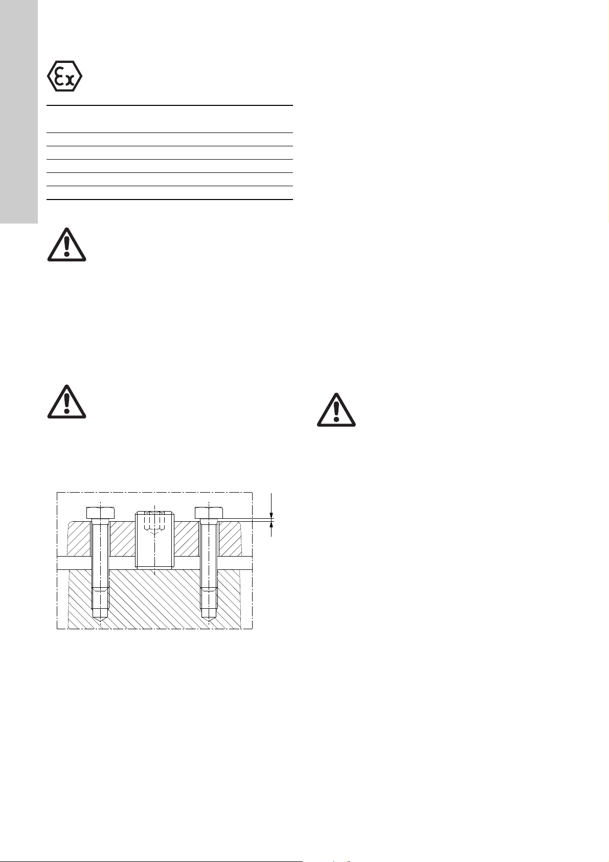
11.2.1 Adjustment of impeller clearance
1. Loosen the set screws by two full turns each.
2. Close the impeller clearance by lightly tightening the fastening
screws diagonally until the impeller touches the pump
housing.
Warning
Do not use too much force when tightening the
fastening screws as this may damage the
bearings.
3. Loosen the fastening screws to make the correct gap under
the heads of the fastening screws. See fig. 15, and use the
clearance stated in the impeller clearance table above.
4. Tighten the set screws tightly. Torque: See service instruction.
5. Tighten the fastening screws diagonally.
Impeller clearance X
[mm]
11.3 Explosion-proof SE, SL pumps, 9-30 kW
Overhauled and repaired explosion-proof pumps are marked with
a repair plate giving the following information:
• the repair symbol R
• name or registered trade mark of the repairing workshop
• workshop reference number relating to the repair
• date of overhaul or repair.
In the event of subsequent repairs, the existing plate should be
replaced by a new updated plate and earlier markings must be
recorded.
The repairing workshop must keep records of performed
overhauls and repairs together with records of all previous
overhauls, repairs and possible modifications. Copies of the
repairing workshop's detailed records should be filed by the
owner or operator together with the original type certificate of the
explosion-proof pump in question.
11.3.1 Motor cable
Use only cables which are approved by the manufacturer and
suitable for the cable entry as to diameter, number of leads,
conductor cross section and sheath material.
11.3.2 Cable entry
Use only Ex cable entry parts corresponding to the cable
diameter. The corresponding cable dimension marking is
stamped on the inlet or the cable entry.
11.3.3 Spare parts
Damaged motor parts, such as top cover and cable entry, should
always be replaced by new and approved parts. Motor parts must
not be reconditioned by machining, re-tapping, welding, etc.
11.4 Contaminated pumps
Warnin g
If a pump has been used for a liquid which is
injurious to health or toxic, the pump will be
classified as contaminated.
If Grundfos is requested to service the pump, Grundfos must be
contacted with details about the pumped liquid, etc. before the
pump is returned for service. Otherwise Grundfos can refuse to
accept the pump for service.
Possible costs of returning the pump are to be paid by the
customer.
However, any application for service (no matter to whom it may
be made) must include details about the pumped liquid if the
pump has been used for liquids which are injurious to health or
toxic.
Fig. 15 Impeller clearance adjustment
18
TM05 1916 3911
Page 19

12. Fault finding
Warnin g
Before attempting to diagnose any fault, make
sure that the fuses have been removed or the
mains switch has been switched off. Make sure
that the power supply cannot be accidentally
switched on. All rotating parts must have stopped
moving.
Read and observe the safety instructions in
section 6. Safety.
Fault Cause Remedy
1. Pump does not start or
stops without visible
cause.
2. Pump does not start or
stops. The control panel
of the controller indicates
that the motor-protective
circuit breaker or
protection equipment has
tripped out.
3. Pump runs, but does not
deliver the rated flow.
4. Pump starts, but stops
immediately.
5. Pump vibrating or
emitting excessive noise.
6. Low motor liquid level. a) Upper mechanical seal leaking. Contact an authorised service workshop.
a) No power supply. Reestablish power supply. Start the pump
manually and check contactor operation.
a) Missing phase. Reestablish all phases.
b) Pump momentarily overloaded. If the fault does not disappear automatically, find
the cause and remedy the fault.
c) Impeller clogged by impurities. Clean impeller as required.
d) Motor protective circuit breaker not set correctly. Set the motor-protective circuit breaker as
required according to rated current.
e) Thermal switches tripped out. Insufficient motor
cooling.
f) Moisture switch in motor tripped out. Contact an authorised service workshop.
g) Motor cable defective. Contact an authorised service workshop.
h) Fluctuating voltage. Reestablish correct voltage supply. Permissible
a) Wrong direction of rotation. Interchange two phases to the motor.
b) Impeller loose or worn. Tighten or replace the impeller.
c) Pump or pipework blocked by impurities. Clean as required.
d) Pump head too high. Measure the differential pressure and compare
e) Valves closed or blocked.
Non-return valve not operating.
f) Air in pump or suction pipe. Vent the pump and suction pipe. Increase the
g) Pumped liquid too dense. Dilute the liquid.
h) Pump not properly connected to auto coupling. Pump down the liquid level in pit. Lift out the
i) Leakage in pipe work. Repair the pipe work.
j) Pump pit flushing system inadvertently activated. Check function and repair as required.
a) Clogged pump causes motor-protective circuit
breaker to trip out.
b) Overheated motor causes thermal switches to trip
out.
c) Level switch out of adjustment or defective. Clean or set level switch or replace as required.
a) Pump partly clogged by impurities. Clean the pump.
b) Wrong direction of rotation. Interchange two phases to the motor.
c) Pump operates outside specified operating range. Reestablish proper operating conditions.
d) Pump defective. Repair the pump or contact an authorised
e) Pump not properly connected to auto coupling. Pump down the liquid level in pit. Lift out the
f) Pump cavitates. Clean the suction pipe.
g) Impeller not in balance. Contact an authorised service workshop.
h) Base stand, auto coupling, ring stand or guide rails
not installed correctly.
Reestablish motor cooling.
deviation is - 10 %/+ 10 %.
the value with the pump curve. Remove the
blockage in the discharge pipe.
Clean or replace valves as required.
stop level in the pit.
pump and relocate the pump on the auto
coupling.
Clean the pump.
Allow pump to cool. Clean the pump.
workshop, if necessary.
pump and relocate the pump on the auto
coupling.
Install the components correctly.
English (GB)
19
Page 20

13. Sensor overview
Thermal switches
Moisture-/leakage switch
t+ t+ t+
P1
P2
P3
P4
P5
PTC thermistors
Moisture-/leakage switch
Thermal switches
Moisture-/leakage switch
t+ t+ t+
P1
P2
P3
P4
P5
+t
。
PTC thermistors
Moisture-/leakage switch
Thermal switches
Moisture-/leakage switch
SM 113
4..20 mA
Thermal switches
Moisture-/leakage switch
t+ t+ t+
P1
P2
P3
P4
P5
SM 113
4..20 mA
PTC thermistors
Moisture-/leakage switch
English (GB)
Fig. 16 Standard version with thermal switches
TM05 2692 0412TM05 2693 0412
TM05 2687 0412TM05 2688 0412TM05 2690 0412TM05 2691 0412TM05 2689 0412
Fig. 21 Sensor version 2 (thermal switches), version 1 Ex and
version 2 Ex
Fig. 17 Standard version with PTC sensors
Fig. 18 Sensor version 1
Fig. 19 Sensor 1 (PTC)
Fig. 22 Sensor version 2 (PTC), version 1 Ex and version 2 Ex
Switch and sensor overview
Standard pump
Sensor pump, version 1
Sensor pump, version 2
Standard Ex pump
Sensor pump, version 1 Ex
Sensor pump, version 2 Ex
Thermal switches/ PTC ●●●●●●
Moisture switch, top ●●●●●●
Leakage switch ●●●
Leakage switch, stator housing ●●●
Pt1000 in stator winding ●● ●●
Pt1000 in upper bearing ●●
Pt1000 in lower bearing ●●
PVS3 vibration sensor ●●
SM 113 ●●●
IO 113 ●●●
14. Disposal
This product or parts of it must be disposed of in an
environmentally sound way:
1. Use the public or private waste collection service.
2. If this is not possible, contact the nearest Grundfos company
or service workshop.
Fig. 20 Standard version Ex pump
20
Subject to alterations.
Page 21

Appendix 1
1. Wiring diagrams Appendix
Fig. 1 12-wire
Fig. 2 8-wire
TM05 2695 0412TM05 2694 0412
21
Page 22

Appendix
C-C
D-D
E-E
Fig. 3 Sensor positions
TM05 4342 2112
22
Page 23

Declaration of conformity 2
GB: EC declaration of conformity
We Grundfos declare under our sole responsibility that the products SE,
SL, 9-30 kW, to which this declaration relates, are in conformity with these
Council directives on the approximation of the laws of the EC member
states:
CZ: ES prohlášení o shodě
My firma Grundfos prohlašujeme na svou plnou odpovědnost, že výrobky
SE, SL, 9-30 kW, na něž se toto prohlášení vztahuje, jsou v souladu
s ustanoveními směrnice Rady pro sblížení právních předpisů členských
států Evropského společenství v oblastech:
DE: EG-Konformitätserklärung
Wir, Grundfos, erklären in alleiniger Verantwortung, dass die Produkte SE,
SL, 9-30 kW, auf die sich diese Erklärung bezieht, mit den folgenden
Richtlinien des Rates zur Angleichung der Rechtsvorschriften der
EU-Mitgliedsstaaten übereinstimmen:
GR: ∆ήλωση συμμόρφωσης EC
Εμείς, η Grundfos, δηλώνουμε με αποκλειστικά δική μας ευθύνη ότι
τα προϊόντα SE, SL, 9-30 kW στα οποία αναφέρεται η παρούσα δήλωση,
συμμορφώνονται με τις εξής Οδηγίες του Συμβουλίου περί προσέγγισης
των νομοθεσιών των κρατών μελών της ΕΕ:
FR: Déclaration de conformité CE
Nous, Grundfos, déclarons sous notre seule responsabilité, que les
produits SE, SL, 9-30 kW, auxquels se réfère cette déclaration, sont
conformes aux Directives du Conseil concernant le rapprochement
des législations des Etats membres CE relatives aux normes énoncées
ci-dessous :
IT: Dichiarazione di conformità CE
Grundfos dichiara sotto la sua esclusiva responsabilità che i prodotti SE,
SL, 9-30 kW, ai quali si riferisce questa dichiarazione, sono conformi alle
seguenti direttive del Consiglio riguardanti il riavvicinamento delle
legislazioni degli Stati membri CE:
BG: EC декларация за съответствие
Ние, фирма Grundfos, заявяваме с пълна отговорност, че продуктите
SE, SL, 9-30 kW, за които се отнася настоящата декларация, отговарят
на следните указания на Съвета за уеднаквяване на правните
разпоредби на държавите членки на ЕС:
DK: EF-overensstemmelseserklæring
Vi, Grundfos, erklærer under ansvar at produkterne SE, SL, 9-30 kW, som
denne erklæring omhandler, er i overensstemmelse med disse af Rådets
direktiver om indbyrdes tilnærmelse til EF-medlemsstaternes lovgivning:
EE: EL vastavusdeklaratsioon
Meie, Grundfos, deklareerime enda ainuvastutusel, et tooted SE, SL,
9-30 kW, mille kohta käesolev juhend käib, on vastavuses EÜ Nõukogu
direktiividega EMÜ liikmesriikide seaduste ühitamise kohta, mis käsitlevad:
ES: Declaración CE de conformidad
Nosotros, Grundfos, declaramos bajo nuestra entera responsabilidad que
los productos SE, SL, 9-30 kW, a los cuales se refiere esta declaración,
están conformes con las Directivas del Consejo en la aproximación de las
leyes de las Estados Miembros del EM:
HR: EZ izjava o usklađenosti
Mi, Grundfos, izjavljujemo pod vlastitom odgovornošću da je proizvod SE,
SL, 9-30 kW, na koji se ova izjava odnosi, u skladu s direktivama ovog
Vijeća o usklađivanju zakona država članica EU:
LV: EK atbilstības deklarācija
Sabiedrība GRUNDFOS ar pilnu atbildību dara zināmu, ka produkti SE, SL,
9-30 kW, uz kuriem attiecas šis paziņojums, atbilst šādām Padomes
direktīvām par tuvināšanos EK dalībvalstu likumdošanas normām:
Declaration of conformity
LT: EB atitikties deklaracija
Mes, Grundfos, su visa atsakomybe pareiškiame, kad gaminiai SE, SL,
9-30 kW, kuriems skirta ši deklaracija, atitinka šias Tarybos Direktyvas dėl
Europos Ekonominės Bendrijos šalių narių įstatymų suderinimo:
NL: EC overeenkomstigheidsverklaring
Wij, Grundfos, verklaren geheel onder eigen verantwoordelijkheid dat
de producten SE, SL, 9-30 kW waarop deze verklaring betrekking heeft,
in overeenstemming zijn met de Richtlijnen van de Raad in zake de
onderlinge aanpassing van de wetgeving van de EG Lidstaten betreffende:
PL: Deklaracja zgodności WE
My, Grundfos, oświadczamy z pełną odpowiedzialnością, że nasze wyroby
SE, SL, 9-30 kW, których deklaracja niniejsza dotyczy, są zgodne
z następującymi wytycznymi Rady d/s ujednolicenia przepisów prawnych
krajów członkowskich WE:
RO: Declaraţie de conformitate CE
Noi, Grundfos, declarăm pe propria răspundere că produsele SE, SL, 9-30
kW, la care se referă această declaraţie, sunt în conformitate cu aceste
Directive de Consiliu asupra armonizării legilor Statelor Membre CE:
SI: ES izjava o skladnosti
V Grundfosu s polno odgovornostjo izjavljamo, da so naši izdelki SE, SL,
9-30 kW, na katere se ta izjava nanaša, v skladu z naslednjimi direktivami
Sveta o približevanju zakonodaje za izenačevanje pravnih predpisov držav
članic ES:
FI: EY-vaatimustenmukaisuusvakuutus
Me, Grundfos, vakuutamme omalla vastuullamme, että tuotteet SE, SL,
9-30 kW, joita tämä vakuutus koskee, ovat EY:n jäsenvaltioiden
lainsäädännön yhdenmukaistamiseen tähtäävien Euroopan neuvoston
direktiivien vaatimusten mukaisia seuraavasti:
HU: EK megfelelőségi nyilatkozat
Mi, a Grundfos, egyedüli felelősséggel kijelentjük, hogy a SE, SL, 9-30 kW
termékek, amelyekre jelen nyilatkozik vonatkozik, megfelelnek az Európai
Unió tagállamainak jogi irányelveit összehangoló tanács alábbi
előírásainak:
UA: Декларація відповідності ЄС
Компанія Grundfos заявляє про свою виключну відповідальність за те,
що продукти SE, SL, 9-30 kW, на які поширюється дана декларація,
відповідають таким рекомендаціям Ради з уніфікації правових норм
країн - членів ЄС:
PT: Declaração de conformidade CE
A Grundfos declara sob sua única responsabilidade que os produtos SE,
SL, 9-30 kW, aos quais diz respeito esta declaração, estão em
conformidade com as seguintes Directivas do Conselho sobre
a aproximação das legislações dos Estados Membros da CE:
SK: Prehlásenie o konformite ES
My firma Grundfos prehlasujeme na svoju plnú zodpovednost', že výrobky
SE, SL, 9-30 kW, na ktoré sa toto prehlásenie vzt'ahuje, sú v súlade
s ustanovením smernice Rady pre zblíženie právnych predpisov členských
štátov Európskeho spoločenstva v oblastiach:
RS: EC deklaracija o konformitetu
Mi, Grundfos, izjavljujemo pod vlastitom odgovornošću da je proizvod SE,
SL, 9-30 kW, na koji se ova izjava odnosi, u skladu sa direktivama Saveta
za usklađivanje zakona država članica EU:
SE: EG-försäkran om överensstämmelse
Vi, Grundfos, försäkrar under ansvar att produkterna SE, SL, 9-30 kW, som
omfattas av denna försäkran, är i överensstämmelse med rådets direktiv
om inbördes närmande till EU-medlemsstaternas lagstiftning, avseende:
TR: EC uygunluk bildirgesi
Grundfos olarak bu beyannameye konu olan SE, SL, 9-30 kW ürünlerinin,
AB Üyesi Ülkelerin kanunlarını birbirine yaklaştı rma üzerine Konsey
Direktifleriyle uyumlu olduğunun yalnızca bizim sorumluluğumuz altında
olduğunu beyan ederiz:
23
Page 24

Declaration of conformity
— Machinery Directive (2006/42/EC)
Standard used: EN 809:1998 + A1:2009
— Low Voltage Directive (2006/95/EC)
Standard used: EN 60204-1:2006.
— EMC Directive (2004/108/EC)
— ATEX Directive (94/9/EC)
Applies only to products intended for use in potentially explosive
environments, Ex II 2G. The Ex classification is given on the upper part
of the nameplate and in EC-type examination certificate.
Further information, see below.
This EC declaration of conformity is only valid when published as part of the
Grundfos installation and operating instructions (publication number
98142266 0515).
Bjerringbro, 1 st January 2014
empowered to sign the EC declaration of conformity.
Notified body: FM Approvals No 1725. 1151 Boston-Providence Turnpike, P.O.Box 9102 Norwood, MA 02062 USA.
Manufacturer: GRUNDFOS Manufacturing Ltd., Búzavirág u. 14, Ipari Park, Tatabánya, 2800 Hungary.
Jan Strandgaard
Director
D&E Europe
GRUNDFOS Holding A/S
Poul Due Jensens Vej 7
8850 Bjerringbro, Denmark
Person authorised to compile technical file and
Range Certificate No Standards used
SE, SL 9-30 kW FM 14ATEX0002X EN 60079-0:2012, EN 60079-1:2007, EN 13463-1:2009, EN 13463-5:2011,
IECEx FMG 14.0003X IEC 60079-0:2011, EN 60079-1:2007
EN 13463-6:2005
24
Page 25

Argentina
Bombas GRUNDFOS de Argentina S.A.
Ruta Panamericana km. 37.500 Centro
Industrial Garin
1619 Garín Pcia. de B.A.
Phone: +54-3327 414 444
Telefax: +54-3327 45 3190
Australia
GRUNDFOS Pumps Pty. Ltd.
P.O. Box 2040
Regency Park
South Australia 5942
Phone: +61-8-8461-4611
Telefax: +61-8-8340 0155
Austria
GRUNDFOS Pumpen Vertrieb Ges.m.b.H.
Grundfosstraße 2
A-5082 Grödig/Salzburg
Tel.: +43-6246-883-0
Telefax: +43-6246-883-30
Belgium
N.V. GRUNDFOS Bellux S.A.
Boomsesteenweg 81-83
B-2630 Aartselaar
Tél.: +32-3-870 7300
Télécopie: +32-3-870 7301
Belarus
Представительство ГРУНДФОС в
Минске
220125, Минск
ул. Шафарнянская, 11, оф. 56, БЦ
«Порт»
Тел.: +7 (375 17) 286 39 72/73
Факс: +7 (375 17) 286 39 71
E-mail: minsk@grundfos.com
Bosna and Herzegovina
GRUNDFOS Sarajevo
Zmaja od Bosne 7-7A,
BH-71000 Sarajevo
Phone: +387 33 592 480
Telefax: +387 33 590 465
www.ba.grundfos.com
e-mail: grundfos@bih.net.ba
Brazil
BOMBAS GRUNDFOS DO BRASIL
Av. Humberto de Alencar Castelo Branco,
630
CEP 09850 - 300
São Bernardo do Campo - SP
Phone: +55-11 4393 5533
Telefax: +55-11 4343 5015
Bulgaria
Grundfos Bulgaria EOOD
Slatina District
Iztochna Tangenta street no. 100
BG - 1592 Sofia
Tel. +359 2 49 22 200
Fax. +359 2 49 22 201
email: bulgaria@grundfos.bg
Canada
GRUNDFOS Canada Inc.
2941 Brighton Road
Oakville, Ontario
L6H 6C9
Phone: +1-905 829 9533
Telefax: +1-905 829 9512
China
GRUNDFOS Pumps (Shanghai) Co. Ltd.
10F The Hub, No. 33 Suhong Road
Minhang District
Shanghai 201106
PRC
Phone: +86 21 612 252 22
Telefax: +86 21 612 253 33
Croatia
GRUNDFOS CROATIA d.o.o.
Buzinski prilaz 38, Buzin
HR-10010 Zagreb
Phone: +385 1 6595 400
Telefax: +385 1 6595 499
www.hr.grundfos.com
Czech Republic
GRUNDFOS s.r.o.
Čajkovského 21
779 00 Olomouc
Phone: +420-585-716 111
Telefax: +420-585-716 299
Denmark
GRUNDFOS DK A/S
Martin Bachs Vej 3
DK-8850 Bjerringbro
Tlf.: +45-87 50 50 50
Telefax: +45-87 50 51 51
E-mail: info_GDK@grundfos.com
www.grundfos.com/DK
Estonia
GRUNDFOS Pumps Eesti OÜ
Peterburi tee 92G
11415 Tallinn
Tel: + 372 606 1690
Fax: + 372 606 1691
Finland
OY GRUNDFOS Pumput AB
Mestarintie 11
FIN-01730 Vantaa
Phone: +358-(0)207 889 900
Telefax: +358-(0)207 889 550
France
Pompes GRUNDFOS Distribution S.A.
Parc d’Activités de Chesnes
57, rue de Malacombe
F-38290 St. Quentin Fallavier (Lyon)
Tél.: +33-4 74 82 15 15
Télécopie: +33-4 74 94 10 51
Germany
GRUNDFOS GMBH
Schlüterstr. 33
40699 Erkrath
Tel.: +49-(0) 211 929 69-0
Telefax: +49-(0) 211 929 69-3799
e-mail: infoservice@grundfos.de
Service in Deutschland:
e-mail: kundendienst@grundfos.de
HILGE GmbH & Co. KG
Hilgestrasse 37-47
55292 Bodenheim/Rhein
Germany
Tel.: +49 6135 75-0
Telefax: +49 6135 1737
e-mail: hilge@hilge.de
Greece
GRUNDFOS Hellas A.E.B.E.
20th km. Athinon-Markopoulou Av.
P.O . B o x 7 1
GR-19002 Peania
Phone: +0030-210-66 83 400
Telefax: +0030-210-66 46 273
Hong Kong
GRUNDFOS Pumps (Hong Kong) Ltd.
Unit 1, Ground floor
Siu Wai Industrial Centre
29-33 Wing Hong Street &
68 King Lam Street, Cheung Sha Wan
Kowloon
Phone: +852-27861706 / 27861741
Telefax: +852-27858664
Hungary
GRUNDFOS Hungária Kft.
Park u. 8
H-2045 Törökbálint,
Phone: +36-23 511 110
Telefax: +36-23 511 111
India
GRUNDFOS Pumps India Private Limited
118 Old Mahabalipuram Road
Thoraipakkam
Chennai 600 096
Phone: +91-44 2496 6800
Indonesia
PT GRUNDFOS Pompa
Jl. Rawa Sumur III, Blok III / CC-1
Kawasan Industri, Pulogadung
Jakarta 13930
Phone: +62-21-460 6909
Telefax: +62-21-460 6910 / 460 6901
Ireland
GRUNDFOS (Ireland) Ltd.
Unit A, Merrywell Business Park
Ballymount Road Lower
Dublin 12
Phone: +353-1-4089 800
Telefax: +353-1-4089 830
Italy
GRUNDFOS Pompe Italia S.r.l.
Via Gran Sasso 4
I-20060 Truccazzano (Milano)
Tel.: +39-02-95838112
Telefax: +39-02-95309290 / 95838461
Japan
GRUNDFOS Pumps K.K.
Gotanda Metalion Bldg., 5F,
5-21-15, Higashi-gotanda
Shiagawa-ku, Tokyo
141-0022 Japan
Phone: +81 35 448 1391
Telefax: +81 35 448 9619
Korea
GRUNDFOS Pumps Korea Ltd.
6th Floor, Aju Building 679-5
Yeoksam-dong, Kangnam-ku, 135-916
Seoul, Korea
Phone: +82-2-5317 600
Telefax: +82-2-5633 725
Latvia
SIA GRUNDFOS Pumps Latvia
Deglava biznesa centrs
Augusta Deglava ielā 60, LV-1035, Rīga,
Tālr.: + 371 714 9640, 7 149 641
Fakss: + 371 914 9646
Lithuania
GRUNDFOS Pumps UAB
Smolensko g. 6
LT-03201 Vilnius
Tel: + 370 52 395 430
Fax: + 370 52 395 431
Malaysia
GRUNDFOS Pumps Sdn. Bhd.
7 Jalan Peguam U1/25
Glenmarie Industrial Park
40150 Shah Alam
Selangor
Phone: +60-3-5569 2922
Telefax: +60-3-5569 2866
Mexico
Bombas GRUNDFOS de México S.A. de
C.V.
Boulevard TLC No. 15
Parque Industrial Stiva Aeropuerto
Apodaca, N.L. 66600
Phone: +52-81-8144 4000
Telefax: +52-81-8144 4010
Netherlands
GRUNDFOS Netherlands
Velu we zo om 35
1326 AE Almere
Postbus 22015
1302 CA ALMERE
Tel.: +31-88-478 6336
Telefax: +31-88-478 6332
E-mail: info_gnl@grundfos.com
New Zealand
GRUNDFOS Pumps NZ Ltd.
17 Beatrice Tinsley Crescent
North Harbour Industrial Estate
Albany, Auckland
Phone: +64-9-415 3240
Telefax: +64-9-415 3250
Norway
GRUNDFOS Pumper A/S
Strømsveien 344
Postboks 235, Leirdal
N-1011 Oslo
Tlf.: +47-22 90 47 00
Telefax: +47-22 32 21 50
Poland
GRUNDFOS Pompy Sp. z o.o.
ul. Klonowa 23
Baranowo k. Poznania
PL-62-081 Przeźmierowo
Tel: (+48-61) 650 13 00
Fax: (+48-61) 650 13 50
Portugal
Bombas GRUNDFOS Portugal, S.A.
Rua Calvet de Magalhães, 241
Apartado 1079
P-2770-153 Paço de Arcos
Tel.: +351-21-440 76 00
Telefax: +351-21-440 76 90
Romania
GRUNDFOS Pompe România SRL
Bd. Biruintei, nr 103
Pantelimon county Ilfov
Phone: +40 21 200 4100
Telefax: +40 21 200 4101
E-mail: romania@grundfos.ro
Russia
ООО Грундф ос Россия
109544, г. Москва, ул. Школьная, 39-41,
стр. 1
Тел. (+7) 495 564-88-00 (495) 737-30-00
Факс (+7) 495 564 88 11
E-mail grundfos.moscow@grundfos.com
Serbia
Grundfos Srbija d.o.o.
Omladinskih brigada 90b
11070 Novi Beograd
Phone: +381 11 2258 740
Telefax: +381 11 2281 769
www.rs.grundfos.com
Singapore
GRUNDFOS (Singapore) Pte. Ltd.
25 Jalan Tukang
Singapore 619264
Phone: +65-6681 9688
Telefax: +65-6681 9689
Slovakia
GRUNDFOS s.r.o.
Prievozská 4D
821 09 BRATISLAVA
Phona: +421 2 5020 1426
sk.grundfos.com
Slovenia
GRUNDFOS d.o.o.
Šlandrova 8b, SI-1231 Ljubljana-Črnuče
Phone: +386 31 718 808
Telefax: +386 (0)1 5680 619
E-mail: slovenia@grundfos.si
South Africa
GRUNDFOS (PTY) LTD
Corner Mountjoy and George Allen Roads
Wilbart Ext. 2
Bedfordview 2008
Phone: (+27) 11 579 4800
Fax: (+27) 11 455 6066
E-mail: lsmart@grundfos.com
Spain
Bombas GRUNDFOS España S.A.
Camino de la Fuentecilla, s/n
E-28110 Algete (Madrid)
Tel.: +34-91-848 8800
Telefax: +34-91-628 0465
Sweden
GRUNDFOS AB
Box 333 (Lunnagårdsgatan 6)
431 24 Mölndal
Tel.: +46 31 332 23 000
Telefax: +46 31 331 94 60
Switzerland
GRUNDFOS Pumpen AG
Bruggacherstrasse 10
CH-8117 Fällanden/ZH
Tel.: +41-44-806 8111
Telefax: +41-44-806 8115
Taiwan
GRUNDFOS Pumps (Taiwan) Ltd.
7 Floor, 219 Min-Chuan Road
Taichung, Taiwan, R.O.C.
Phone: +886-4-2305 0868
Telefax: +886-4-2305 0878
Thailand
GRUNDFOS (Thailand) Ltd.
92 Chaloem Phrakiat Rama 9 Road,
Dokmai, Pravej, Bangkok 10250
Phone: +66-2-725 8999
Telefax: +66-2-725 8998
Turkey
GRUNDFOS POMPA San. ve Tic. Ltd. Sti.
Gebze Organize Sanayi Bölgesi
Ihsan dede Caddesi,
2. yol 200. Sokak No. 204
41490 Gebze/ Kocaeli
Phone: +90 - 262-679 7979
Telefax: +90 - 262-679 7905
E-mail: satis@grundfos.com
Ukraine
Бізнес Центр Європа
Столичне шосе, 103
м. Київ, 03131, Україна
Телефон : (+38 044) 237 04 00
Факс.: (+38 044) 237 04 01
E-mail: ukraine@grundfos.com
United Arab Emirates
GRUNDFOS Gulf Distribution
P.O. Box 16768
Jebel Ali Free Zone
Dubai
Phone: +971 4 8815 166
Telefax: +971 4 8815 136
United Kingdom
GRUNDFOS Pumps Ltd.
Grovebury Road
Leighton Buzzard/Beds. LU7 4TL
Phone: +44-1525-850000
Telefax: +44-1525-850011
U.S.A.
GRUNDFOS Pumps Corporation
17100 West 118th Terrace
Olathe, Kansas 66061
Phone: +1-913-227-3400
Telefax: +1-913-227-3500
Uzbekistan
Grundfos Tashkent, Uzbekistan The
Representative Office of Grundfos
Kazakhstan in Uzbekistan
38a, Oybek street, Tashkent
Телефон: (+998) 71 150 3290 / 71 150
3291
Факс: (+998) 71 150 3292
Addresses Revised 10.03.2015
Grundfos companies
Page 26

98142266 0515
ECM: 1159048
www.grundfos.com
The name Grundfos, the Grundfos logo, and be think innovate are registered trademarks owned by Grundfos Holding A/S or Grundfos A/S, Denmark. All rights reserved worldwide. © Copyright Grundfos Holding A/S
 Loading...