

Page 1

SEG AUTOADAPT
Service instructions
GRUNDFOS INSTRUCTIONS
Page 2

Content
1. Symbols used in this document....................................................................................... 4
2. Identification......................................................................................................................4
2.1 Nameplate ........................................................................................................................................4
2.2 Type key...........................................................................................................................................5
3. Service tools...................................................................................................................... 5
3.1 Special tools .....................................................................................................................................5
3.2 Standard tools ..................................................................................................................................6
3.3 Torque tools .....................................................................................................................................6
4. Tightening torques, lubricants and oil ............................................................................. 6
4.1 Tightening torques ............................................................................................................................6
4.2 Lubricants.........................................................................................................................................6
4.3 Oil.....................................................................................................................................................6
5. Dismantling and assembly ............................................................................................... 6
5.1 Position numbers ..............................................................................................................................6
5.2 Before dismantling ............................................................................................................................7
5.3 Before assembly ...............................................................................................................................7
5.4 During assembly ...............................................................................................................................7
5.5 After assembly..................................................................................................................................7
6. Cleaning the pump housing ............................................................................................. 7
7. Grinder system .................................................................................................................. 7
7.1 Dismantling.......................................................................................................................................7
7.2 Assembly..........................................................................................................................................8
8. Impeller.............................................................................................................................. 8
8.1 Dismantling.......................................................................................................................................8
8.2 Assembly..........................................................................................................................................9
9. Oil....................................................................................................................................... 9
9.1 Oil change ........................................................................................................................................9
9.2 Draining of oil ...................................................................................................................................9
9.3 Oil filling............................................................................................................................................9
10. Shaft seal......................................................................................................................... 10
10.1 Dismantling, 0.9 - 1.5 kW................................................................................................................10
10.2 Assembly, 0.9 - 1.5 kW ...................................................................................................................10
10.3 Dismantling, 2.6 - 4 kW...................................................................................................................11
10.4 Assembly, 2.6 - 4 kW......................................................................................................................11
11. Bearings .......................................................................................................................... 12
11.1 Dismantling.....................................................................................................................................12
11.2 Assembly........................................................................................................................................12
12. Electronic unit................................................................................................................. 13
12.1 Dismantling.....................................................................................................................................13
12.2 Assembly........................................................................................................................................14
13. Run capacitor (single-phase pumps)............................................................................. 14
13.1 Dismantling.....................................................................................................................................14
13.2 Assembly........................................................................................................................................14
14. Dry-running sensor......................................................................................................... 14
14.1 Dismantling.....................................................................................................................................14
14.2 Assembly........................................................................................................................................14
15. Level sensor.................................................................................................................... 15
15.1 Dismantling.....................................................................................................................................15
15.2 Assembly........................................................................................................................................15
16. Cable plug........................................................................................................................ 15
16.1 Dismantling.....................................................................................................................................15
16.2 Assembly........................................................................................................................................15
2 / 20
Page 3

17. Supply scable.................................................................................................................. 16
17.1 Dismantling.....................................................................................................................................16
17.2 Assembly........................................................................................................................................16
18. Replacing the electronic unit.......................................................................................... 17
19. Exploded views ...............................................................................................................18
20. Fault finding .................................................................................................................... 19
3 / 20
Page 4

1. Symbols used in this do cument
Caution
Note
Note
Àß56
Made in Tatabánya, Hungary
Type:
96770195
Model:
P.c. Auto Adapt
IP68
Hmax: m Qmax:
P1: kW
l/s
m
kW
A
P2:
Weight: Tmax: °C
Insul.class:
kg
n: Cos φmin
-1
opr.:: μF Hz
~
1
2
3
4
5
6
7
8
9
10
11
12
13
14
15
16
17
18
19
20
21
22
23
24
Warning
If these safety instruct ions are no t o bser ved, it may re sult in per son al inju ry!
Warning
These instructions must be obse rved f or explosio n-p roof p umps. It is adv isabl e al so t o foll ow
these instructions fo r stan dard pu mps.
If these safety instruct ions ar e not o bser ved, it may re sult in malf unc tio n or d amage to the
equipment!
Notes or instructions that mak e th e job e asier an d ensur e saf e o perati on.
2. Identification
This section shows the nameplate, type key and the codes that can appear in the variant code.
As codes can be combined, a code p osit ion may cont ain mor e than one code (o ne le tter) .
2.1 Nameplate
The nameplate states the operating data and approvals applying to the pump. It is fixed to the side of the stator
housing opposite to the electronic unit.
The additional nameplate supplied with the pump can be fixed close to the pit.
TM04 4459 1309
Fig. 1 Nameplate
Pos. Description Pos. Description
1 Type designation 13 Weight without cable
2 Product number 14 Run capacitor
3 CE mark 15 EN approval
4 ATEX certificate * 16 Ex mark *
5 IEC Ex mark * 17 Maximum installation depth
6 IEC Ex certificate * 18 Maximum flow rate
7 Production code (year and week) 19 Output power
8 Enclosure class to IEC 20 Rated current
9 Maximum head 21 Power factor
10 Rated input power 22 Maximum liquid temperature
11 Number of phases 23 Frequency
12 Rated speed 24 Insulation class
* Only explosion-proof pumps.
4 / 10
Page 5

2.2 Type key
Code Example SE G .40 .11 E .Ex .2 .1 5 02
Type range
SE
G
40
11
Blank
E
Blank
Ex
2
1
Blank
5
02
0B
Blank
A
B
Blank
Grundfos sewage pumps
Impeller type
Grinder system in the pump inlet
Pump outlet
Nominal diameter of pump discharge port [mm]
Output power, P2
P2 = code number from type designation/10 kW
Equipment in pump
Standard
Electronic version with AUTO
Pump version
Non-explosion-proof pump (standard)
Explosion-proof pump
Number of poles
2 poles, n = 3000 min
Number of phases
Single-phase motor
Three-phase motor
Mains frequency
50 Hz
Supply voltage and starting method
230 V, direct-on line starting
400-415 V, direct-on-line starting
Generation
First generation
Second generation
Third generation, etc.
The pumps belonging to the individual generations differ in design, but are similar in terms of power rating.
Materials in pump
Standard materials in pump
-1
, 50 Hz
ADAPT functions
3. Service tools
ABCD
EFGH
IJKL
3.1 Special tools
Pos. Designation For pos. Description
A Puller 49 M24 x 1.5 SV2097
B Spanner for cable nut 181 95043464
Product
number
5 /20
Page 6

3.2 Standard tools
Pos. Designation For pos. Description
C Tool for shaft seal 172 *
D Bit holder D 1/4" SV2011
E Bits kit 188a M8 - 6 mm SV2010
F Screwdrivers Straight slot -
G Punch 44, 49 ∅ 10 -
H Ring/open-end spanner 68 24 mm SV0122
I Hexagon head driver 188a M8 - 6 mm SV0297
J Bearing heater 153, 154 Induction heater -
* Pos. C is included in the shaft seal kit for 0.9 to 1.5 kW pumps.
Product
number
3.3 Torque tools
Pos. Designation For pos. Description
K Torque wrench J 4-20 Nm SV0292
L Ratchet insert tool H 9 x 12 - > 1/2" SV0295
Product
number
4. Tightening torques, lubricants and oil
4.1 Tightening torques
Pos. Designation Dimensions Material Torque [Nm]
161f Screw for capacitor plate M5 x 10 Galvanised steel 3
188a Screw for end cover M10 x 30 A2-70 35
188a Screw for grinder ring M8 x 25 A2-80 16
188a Screw for grinder head M8 x 25 A2-80 20
188a Screw for lifting bracket M8 x 25 A2-80 16
188a Screw for seal ring retainer M8 x 25 A2-80 16
188a Screw for oil chamber M8 x 25 A2-80 16
193 Filling screw M12 x 20 A2-70 16
199 Union nut for cable plug M48 x 1.5 EN 1.4408 30
285b Set screw for dry-running sensor M6 x 18 ISO 898 5
287c Set screw for level sensor M6 x 18 ISO 898 5
Screw for earth lead M5 x 10 Galvanised steel 3
161 Capacitor M8 Galvanised steel 5
4.2 Lubricants
Designation Quantity [kg] Type Product number
O-ring grease 1 Rocol Sapphire Aqua-Sil RM2924
4.3 Oil
Designation Quantity [l] Type Product number
Oil 1 Shell Ondina 917 96001442
5. Dismantling and assemb ly
Warning
Service and dismantling of ele ctr ical part s and repla cement of bea rings must onl y be carri ed
out by Grundfos or an aut hor ised ser vic e worksho p.
5.1 Position numbers
Position numbers of pump parts (digits) refer to exploded views, sectional drawings and parts lists; position
numbers of tools (letters) refer to section 3. Service tools.
6 / 10
Page 7

5.2 Before dismantling
• Disconnect the power supply to the pump.
• Disconnect the power cable in accordance with local regulations.
5.3 Before assembly
• Clean and check all parts.
• Replace defective parts by new parts.
• Order the necessary service kits.
• Always replace gaskets and O-rings when the pump is serviced.
5.4 During assembly
• Lubricate and tighten bolts and nuts according to section 4. Tightening torques, lubricants and oil.
5.5 After assembly
• Test the pump according to test specification No 96076172.
6. Cleaning the pum p housi ng
Warnin g
Beware of the sharp edges on t he impeller, grinder head a nd g rinder ring .
1. Place the pump upside down in a vice (soft jaws). Tighten on lifting bracket (pos. 190).
2. Loosen clamp (pos. 92) holding pump housing (pos. 50) and stator housing (pos. 55) together.
3. Lift pump housing (pos. 50) off stator housing (pos. 55).
4. Remove clamp (pos. 92).
5. Clean the pump housing and the impeller. Grind the surfaces slightly with emery cloth, if necessary.
6. Fit clamp (pos. 92) loosely on stator housing (pos. 55).
7. Lubricate O-ring (pos. 37). See section 4.2 Lubricants.
8. Carefully lower pump housing (pos. 50) down over grinder head (pos. 45) and impeller (pos. 49). Turn the
pump housing so that it engages with the guide pin. The pump discharge must point in the opposite direction
as the electronic unit.
9. Tighten clamp (pos. 92).
10.Check that the grinder head rotates freely and noiselessly.
7. Grinder system
Warnin g
Beware of the sharp edges on t he impeller, grinder head a nd g rinder ring .
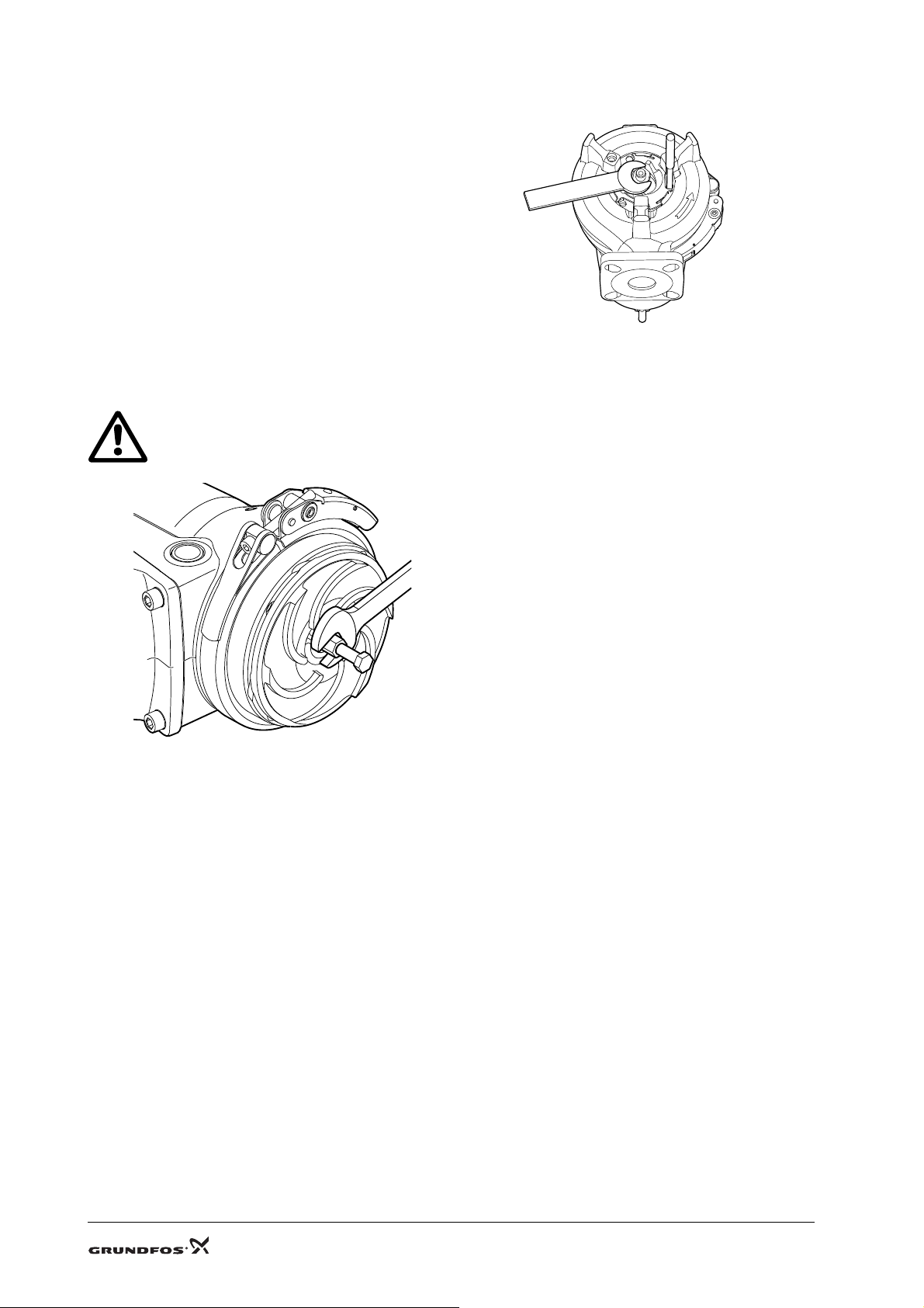
7.1 Dismantling
1. Remove bolt (pos. 188a) in one of the pump feet.
2. Loosen grinder ring (pos. 44) by knocking/turning 15
to 20 ° clockwise.
3. Carefully prise grinder ring (pos. 44) out of the pump
housing with a screwdriver.
Make sure that the grinder ring does not get stuck
against the grinder head!
4. Insert punch (pos. G) into the hole in the pump
housing to hold the impeller.
5. Remove bolt (pos. 188a) in the shaft end and lock
ring (pos. 66).
6. Remove grinder head (pos. 45).
TM04 4480 1509
7 /20
Page 8
7.2 Assembly
1. Fit grinder head (pos. 45). The dogs on the back of
the grinder head must engage with the impeller
holes (pos. 49).
2. Tighten bolt (pos. 188a) in the shaft end. Do not
forget the lock washer.
3. Fit grinder ring (pos. 44).
4. Turn grinder ring (pos. 44) 15 to 20 ° anti-clockwise
until it is tightened.
5. Check that the grinder ring does not touch the
grinder head.
6. Fit and tighten bolt (pos. 188a) in one of the pump
feet. See section 4.1 Tightening torques.
7. Check that the grinder head rotates freely and
noiselessly.
8. Impeller
Warning
Beware of the sharp edges on t he impel ler.
TM04 4481 1509
TM04 6969 1810
Fig. 2 Removing the impeller
8.1 Dismantling
1. Remove the grinder system. See section 7.1 Dismantling.
2. Remove adjusting nut (pos. 68).
3. Fit a puller (pos. A) on the impeller.
4. Loosen the clamp and remove the pump housing.
5. Pull impeller (pos. 49) off the shaft using a puller (pos. A).
6. Remove key (pos. 9a) from the shaft.
7. Clean shaft and key.
8 / 10
Page 9

8.2 Assembly
Note
Note
1. Lubricate key and shaft. See section 4.2 Lubricants.
2. Fit key and impeller. The impeller blades must point away from the stator housing.
3. Fit clamp (pos. 92) loosely on stator housing (pos. 55).
4. Fit adjusting nut (pos. 68) in the impeller.
5. Lubricate O-ring (pos. 37). See section 4.2 Lubricants.
6. Lower pump housing (pos. 50) down over impeller (pos. 49). Turn the pump housing so that it engages with
the guide pin. The pump discharge must point in the opposite direction as the electronic unit.
7. Tighten clamp (pos. 92).
8. Tighten adjusting screw (pos. 68) until impeller (pos. 49) touches the pump housing.
9. Slacken the adjusting nut (pos. 68) by 1/4 turn. The impeller should now be able to rotate freely.
10.Fit the grinder system. See section 7.2 Assembly.
9. Oil
9.1 Oil change
The oil in the oil chamber should be changed at least once a year or after 3000 operating hours. (The number of
operating hours can read by means of a CIU XX2 and an R100 remote control.)
If the oil contains m ore th an 20 % o f wat er, the shaft seal may be d efec tive.
If the shaft seal is replaced, the oil mu st be ch anged . Check the oil af ter one week of oper ation.
Warnin g
When slackening the scre ws of th e oi l chamber, note that p ressur e may have bui lt up in t he
chamber. Do not remove the screws until the pre ssure h as be en f ully r eli eved.
9.2 Draining of oil
1. Remove both oil screws (pos. 193) to allow the oil to drain from the chamber into a container.
2. Lay the pump on the side and turn it to empty the oil chamber.
3. Check the oil for impurities.
4. Clean the pump of spilled oil.
Oil, gaskets and metal par ts must be dis posed of in accorda nce wi th local r egul ati ons.
9.3 Oil filling
1. Pour new oil into the oil chamber. See fig. 3. See table below.
TM04 6970 1810
Fig. 3 Oil filling
Pump
[kW]
0.9 - 1.5 0.17
2.6 - 4.0 0.42
Oil
[l]
Type
Shell Ondina 917
2. Fit and tighten the two oil screws (pos. 193). See section 4.1 Tightening torques.
3. Clean the pump of spilled oil.
9 /20
Page 10

10. Shaft seal
10.1 Dismantling, 0.9 - 1.5 kW
1. Drain the oil. See section 9.2 Draining of oil.
2. Remove the two bolts (pos. 188a) in seal ring retainer (pos. 58) and fit them into the extractor holes.
3. Remove the retainer by means of the two bolts. Cross-tighten the bolts to ensure an even pull.
4. Remove the rotating shaft seal part with two angle screwdrivers. Insert the screwdriver tips behind the shaft
seal.
TM04 6971 1810TM04 6972 1810
Fig. 4 Removing the shaft seal, 0.9 - 1.5 kW
5. Check the shaft where the secondary seal touches the shaft. If there signs of wear, replace the shaft.
6. Carefully loosen bush (pos. 103) from the bearing using two screwdrivers with straight slot and pull it off the
shaft using two angle screwdrivers.
10.2 Assembly, 0.9 - 1.5 kW
1. Check and clean the oil chamber.
2. Fit tool (pos. C) on the shaft.
3. Check O-ring (pos. 102) in bush (pos. 103).
4. Lubricate the shaft end and journal. See section 4.2 Lubricants.
5. Fit bush (pos. 103) and press it home with a piece of pipe.
6. Lubricate O-ring (pos. 107) of the shaft seal. See section 4.2 Lubricants.
7. Fit shaft seal (pos. 105a) with tool (pos. C) from the shaft seal kit.
Fig. 5 Fitting the shaft seal
8. Tighten the two bolts (pos. 188a) in seal ring retainer (pos. 58). See section 4.1 Tightening torques.
9. Fit key and impeller (see section 8.2), grinder head (see section 7.2) and fill the oil chamber with oil (see
section 9.3).
10.Check that the grinder head rotates freely and noiselessly.
10 / 10
Page 11

10.3 Dismantling, 2.6 - 4 kW
1. Remove key (pos. 9a) from the shaft.
2. Remove lock ring (pos. 112).
3. Remove the two bolts in seal ring retainer (pos. 58) and fit them in the extractor holes.
4. Remove seal ring retainer (pos. 58).
5. Insert an angle screwdriver behind the shaft seal and pull the shaft seal off the shaft.
6. Remove O-ring (pos. 102) from the shaft.
7. Remove spacer ring (pos. 153b).
10.4 Assembly, 2.6 - 4 kW.
1. Clean spacer ring (pos. 153b) and its contact surface on the bearing.
2. Fit the distance ring against the bearing.
3. Fit O-ring (pos. 102) in the groove of the shaft. See section 4.2 Lubricants.
4. Fit the shaft seal. The "ears" of the seal must point towards the bearing. The projection of the shaft seal must
engage with the keyway in the shaft.
5. Fit O-ring (pos. 107) in seal ring retainer. See section 4.2 Lubricants.
6. Fit seal ring retainer (pos. 58). Cross-tighten the retainer to ensure that the shaft seal is in the correct position.
7. Press back the shaft seal using a piece of pipe and fit lock ring (pos. 112a) on the shaft. Check that the lock
ring is fitted correctly in the groove.
8. Fit key and impeller (see section 8.2), grinder head (see section 7.2) and fill the oil chamber with oil (see
section 9.3).
9. Check that the grinder head rotates freely and noiselessly.
Fig. 6 Fitting the shaft seal, 2.6 - 4 kW
TM04 7130 1810
11 /20
Page 12

11. Bearings
Warning
Replacement of bearings of E x pu mps must only be car ried ou t b y Gr undfos or a se rvice
workshop authorised by Grundfos .
11.1 Dismantling
1. Remove the grinder system (see section 7.1), drain oil (see section 9.2) and remove the shaft seal (see
section 10.1).
2. Remove the four bolts in the oil chamber (pos. 155).
3. Remove the oil chamber with rotor shaft (pos. 172) and bearings (pos. 153).
4. Refit bolt (pos. 188a) in the shaft end to protect the shaft end thread.
5. Press the shaft out of the bearing in the oil chamber using a hydraulic press.
6. Remove N-end bearing (pos. 154) from the shaft with a puller.
11.2 Assembly
Fig. 7 Fitting the bearing in the
oil chamber
TM04 6984 1810
Fig. 8 Position of oil chamber
on rotor shaft
TM04 6974 1810
Fig. 9 Fitting the oil chamber
on the rotor shaft
1. Clean the bearing surface of the oil chamber, and heat the oil chamber to approx. 100 °C using a bearing
heater (pos. J).
2. Fit the cold bearing (pos. 153) into the heated oil chamber (pos. 155) and let the oil chamber cool. See fig. 7.
3. Place the shaft in a vertical position and place the oil chamber on the shaft. See fig. 8.
4. Press the bearing and oil chamber home on the shaft using a piece of pipe and a hydraulic press. Press only
on the inner bearing ring. See fig. 8.
TM04 6975 1810
12 / 10
Page 13

12. Electronic unit
Caution
12.1 Dismantling
1. Clean the pump around the electronic unit to protect the electronic parts from dirt when opening the electronic
unit.
2. Lay the pump on the side with the level sensor upwards. See fig. 10.
3. Remove the four bolts (pos. 188a) and place the electronic unit next to the pump.
Take care not to disconnect wires.
TM04 6976 1810TM04 6977 1810TM04 6978 1810
Fig. 10 Correct opening of electronic unit
4. Place the electronic unit on a block or similar support. See fig. 11.
Fig. 11 Electronic unit on block
5. Place the pump in a vertical position. See fig. 12.
Fig. 12 Pump in vertical position
6. Remove O-ring (pos. 90b) from the electronic unit.
7. Clean the contact surfaces of the stator housing and the electronic unit, and the O-ring groove.
13 /20
Page 14

12.2 Assembly
Caution
1. Lubricate O-ring (pos. 90b) and the contact surfaces of the stator housing and electronic unit. See section
4.2 Lubricants.
2. Fit the O-ring in the stator housing.
3. Place the wires in the hollow space and fit the electronic unit on the stator housing.
Take care that the wires are not pinc hed bet we en the s tat or hou sing and ele ctroni c un it.
4. Tighten the four bolts (pos. 188a). See section 4.1 Tightening torques.
5. Connect the supply cable. See section 17.2 Assembly.
13. Run capacitor (single-phas e pumps)
13.1 Dismantling
1. Open the electronic unit. See section 12.1 Dismantling.
2. Disconnect the capacitor wire from the electronic unit.
3. Remove the Pt1000 plug from the PC board.
4. Remove the earth lead from bracket (pos. 161c).
5. Remove the capacitor bracket with capacitor from the stator housing.
13.2 Assembly
1. Fix the capacitor wire on the PC board.
2. Fit the earth lead on the new bracket.
3. Fit the new Pt1000 sensor.
4. Fit the electronic unit. See section 12.2 Assembly.
14. Dry-running sen sor
14.1 Dismantling
1. Open the electronic unit. See section 12.1 Dismantling.
2. Remove the sensor wire from the PC board.
3. Remove set screw (pos. 285b).
4. Press the sensor out of the stator housing with a screwdriver. The sensor must not be reused.
5. Clean the sensor hole.
14.2 Assembly
1. Lubricate and fit O-rings (pos. 285a). See section 4.2 Lubricants.
2. Lubricate the sensor hole. See section 4.2 Lubricants.
3. Press the sensor home in the stator housing.
4. Connect the sensor wire to the PC board.
5. Fit a new set screw. See section 4.1 Tightening torques.
6. Fit the electronic unit. See section 12.2 Assembly.
14 / 10
Page 15

15. Level sensor
Caution
15.1 Dismantling
1. Open the electronic unit. See section 12.1 Dismantling.
2. Remove the sensor wire from the PC board.
3. Remove set screw (pos. 287c).
4. Press the sensor out of the electronic unit.
5. Clean the sensor hole.
15.2 Assembly
1. Lubricate and fit O-ring (pos. 287b). See section 4.2 Lubricants.
2. Lubricate the sensor hole. See section 4.2 Lubricants.
3. Press the sensor home in the electronic unit.
4. Connect the sensor wire to the PC board.
5. Fit a new set screw. See section 4.1 Tightening torques.
6. Fit the electronic unit. See section 12.2 Assembly.
16. Cable plug
16.1 Dismantling
1. Open the electronic unit. See section 12.1 Dismantling.
2. Remove the earth lead screw and the washer.
3. Remove the two plugs from the electronic unit.
4. Press in the three barbs and press the cable plug out of the electronic unit.
5. Clean the cable entry.
16.2 Assembly
1. Press the cable plug into the cable entry.
Take care not to damage the three bar bs .
2. Check that three barbs have engaged with the electronic unit.
3. Connect the two plugs to the PC board.
4. Fix the earth lead with the screw. Do not forget to fit the washer.
5. Fit the electronic unit. See section 12.2 Assembly. Do not forget to fit O-ring (pos. 26a) for the cable plug.
15 /20
Page 16

17. Supply scable
17.1 Dismantling
1. Slacken union nut (pos. 199) anti-clockwise with hook spanner (pos. B).
2. Insert two screwdrivers into the groove and prise the supply cable out of the cable entry. See fig. 13.
TM04 6983 1810
Fig. 13 Removing the supply cable
3. If the cable is to be reused, the flash path gap and plastic pin on the supply cable must not be damaged when
the cable is removed.
4. Check the cable for damage.
5. Remove O-ring (pos. 26a) from the cable entry, for instance with a pair of pincers.
6. Remove O-ring (pos. 198) from the supply cable and clean the groove.
7. If a new supply cable is not fitted, the cable entry must be covered to protect the cable entry from dirt.
17.2 Assembly
1. Clean the cable entry, union nut and supply cable.
2. Lubricate O-ring (pos. 198) and fit it on the supply cable.
3. Fit O-ring (pos. 26a) at the bottom of the cable entry.
4. Insert the supply cable into the cable entry. The pin must engage with the cable plug.
5. Lubricate union nut (pos. 199). See section 4.2 Lubricants.
6. Hold the supply cable with one hand and tighten the union nut with a hook spanner (pos. B).
16 / 10
Page 17

18. Replacing the e lectron ic unit
Caution
Caution
1. Open the electronic unit. See section 12. Electronic unit.
2. Remove the wires of the dry-running sensor, Pt1000 sensor and capacitor (single-phase pumps) as well as
the earth lead.
3. Cut the motor leads between the electronic unit and the stator housing in the middle.
4. Remove the level sensor (see section 15.) and cable plug (see section 16.) from the old electronic unit and fit
them in the new one.
5. Remove approximately 60 mm of the insulating sheath of the cable from the new electronic unit so that
approximately 75 mm of the three leads are stripped.
6. Cut away 5, 30 and 55 mm of the three leads from the electronic unit and from the stator housing so that the
joints are displaced from each other. See fig. 14. If for instance 5 mm of the red lead from the electronic unit
are cut away, 55 mm of the red lead from the stator housing must be cut away.
7. Strip the three leads from the electronic unit and from the stator housing with a cable stripper.
Do not use side-cutt ing plie rs , as th ere is a r isk of pull ing th e le ads o ut of the sta tor h ousi ng.
8. Pull a new 16 mm insulation sheath over the original insulating sheath of the motor leads. See fig. 15.
9. Pinch connectors on the three leads with a crimping tool.
The leads must be connect ed so t hat the col ours f rom th e el ectr onic un it and th e stator
housing match.
10.Grab the leads on each side of the connector and pull a little to check the joints.
11.Carefully pull the new insulating sheath over the joints and fix it with a cable clip.
TM04 6979 1810
Fig. 14 Leads with connectors Fig. 15 Insulating sheath on the three leads
12.Connect the wires from the dry-running sensor, Pt1000 sensor and capacitor (single-phase pumps) as well as
the earth lead.
13.Fit the electronic unit. See section 17.2 Assembly.
TM04 6980 1810
17 /20
Page 18

19. Exploded views
Fig. 16 SEG, 0.9 - 1.5 kW
TM04 4486 2210
18 / 10
Page 19

Fig. 17 SEG, 2.6 - 4 kW
Subject to alterations.
20. Fault finding
Warnin g
Remove all fuses, or switch off th e main swit ch befo re fau lt cor rectio n. Make su re th at t he
power supply cannot be acciden tal ly s witch ed on.
All rotating parts must h ave s top ped moving.
Warnin g
All regulations applying to pumps installed in potentially explosive environments must be observed.
No work must be carried out in potent iall y exp losi ve atmosp her e.
Fault Cause Remedy
Motor does not start.
Supply failure; short-circuit; earth-leakage fault in
cable or motor winding.
19 /20
Have the cable and motor checked and
repaired by a qualified electrician.
TM04 5062 2109
Page 20

Argentina
Bombas GRUNDFOS de Argentina S.A.
Ruta Panamericana km. 37.500 Lote 34A
1619 - Garin
Pcia. de Buenos Aires
Phone: +54-3327 414 444
Telefax: +54-3327 411 111
Australia
GRUNDFOS Pumps Pty. Ltd.
P.O. Box 2040
Regency Park
South Australia 5942
Phone: +61-8-8461-4611
Telefax: +61-8-8340 0155
Austria
GRUNDFOS Pumpen Vertrieb Ges.m.b.H.
Grundfosstraße 2
A-5082 Grödig/Salzburg
Tel.: +43-6246-883-0
Telefax: +43-6246-883-30
Belgium
N.V. GRUNDFOS Bellux S.A.
Boomsesteenweg 81-83
B-2630 Aartselaar
Tél.: +32-3-870 7300
Télécopie: +32-3-870 7301
Belorussia
Представительство ГРУНДФОС в
Минске
220123, Минск,
ул. В. Хоружей, 22, оф. 1105
Тел.: +(37517) 233 97 65,
Факс: +(37517) 233 97 69
E-mail: grundfos_minsk@mail.ru
Bosnia/Herzegovina
GRUNDFOS Sarajevo
Trg Heroja 16,
BiH-71000 Sarajevo
Phone: +387 33 713 290
Telefax: +387 33 659 079
e-mail: grundfos@bih.net.ba
Brazil
BOMBAS GRUNDFOS DO BRASIL
Av. Humberto de Alencar Castelo Branco,
630
CEP 09850 - 300
São Bernardo do Campo - SP
Phone: +55-11 4393 5533
Telefax: +55-11 4343 5015
Bulgaria
Grundfos Bulgaria EOOD
Slatina District
Iztochna Tangenta street no. 100
BG - 1592 Sofia
Tel. +359 2 49 22 200
Fax. +359 2 49 22 201
email: bulgaria@grundfos.bg
Canada
GRUNDFOS Canada Inc.
2941 Brighton Road
Oakville, Ontario
L6H 6C9
Phone: +1-905 829 9533
Telefax: +1-905 829 9512
China
GRUNDFOS Pumps (Shanghai) Co. Ltd.
50/F Maxdo Center No. 8 XingYi Rd.
Hongqiao development Zone
Shanghai 200336
PRC
Phone: +86-021-612 252 22
Telefax: +86-021-612 253 33
Croatia
GRUNDFOS CROATIA d.o.o.
Cebini 37, Buzin
HR-10010 Zagreb
Phone: +385 1 6595 400
Telefax: +385 1 6595 499
www.grundfos.hr
Czech Republic
GRUNDFOS s.r.o.
Čajkovského 21
779 00 Olomouc
Phone: +420-585-716 111
Telefax: +420-585-716 299
Denmark
GRUNDFOS DK A/S
Martin Bachs Vej 3
DK-8850 Bjerringbro
Tlf.: +45-87 50 50 50
Telefax: +45-87 50 51 51
E-mail: info_GDK@grundfos.com
www.grundfos.com/DK
Estonia
GRUNDFOS Pumps Eesti OÜ
Peterburi tee 92G
11415 Tallinn
Tel: + 372 606 1690
Fax: + 372 606 1691
Finland
OY GRUNDFOS Pumput AB
Mestarintie 11
FIN-01730 Vantaa
Phone: +358-3066 5650
Telefax: +358-3066 56550
France
Pompes GRUNDFOS Distribution S.A.
Parc d’Activités de Chesnes
57, rue de Malacombe
F-38290 St. Quentin Fallavier (Lyon)
Tél.: +33-4 74 82 15 15
Télécopie: +33-4 74 94 10 51
Germany
GRUNDFOS GMBH
Schlüterstr. 33
40699 Erkrath
Tel.: +49-(0) 211 929 69-0
Telefax: +49-(0) 211 929 69-3799
e-mail: infoservice@grundfos.de
Service in Deutschland:
e-mail: kundendienst@grundfos.de
Greece
GRUNDFOS Hellas A.E.B.E.
20th km. Athinon-Markopoulou Av.
P.O . B o x 71
GR-19002 Peania
Phone: +0030-210-66 83 400
Telefax: +0030-210-66 46 273
Hong Kong
GRUNDFOS Pumps (Hong Kong) Ltd.
Unit 1, Ground floor
Siu Wai Industrial Centre
29-33 Wing Hong Street &
68 King Lam Street, Cheung Sha Wan
Kowloon
Phone: +852-27861706 / 27861741
Telefax: +852-27858664
Hungary
GRUNDFOS Hungária Kft.
Park u. 8
H-2045 Törökbálint,
Phone: +36-23 511 110
Telefax: +36-23 511 111
India
GRUNDFOS Pumps India Private Limited
118 Old Mahabalipuram Road
Thoraipakkam
Chennai 600 096
Phone: +91-44 2496 6800
Indonesi a
PT GRUNDFOS Pompa
Jl. Rawa Sumur III, Blok III / CC-1
Kawasan Industri, Pulogadung
Jakarta 13930
Phone: +62-21-460 6909
Telefax: +62-21-460 6910 / 460 6901
Ireland
GRUNDFOS (Ireland) Ltd.
Unit A, Merrywell Business Park
Ballymount Road Lower
Dublin 12
Phone: +353-1-4089 800
Telefax: +353-1-4089 830
Italy
GRUNDFOS Pompe Italia S.r.l.
Via Gran Sasso 4
I-20060 Truccazzano (Milano)
Tel.: +39-02-95838112
Telefax: +39-02-95309290 / 95838461
Japan
GRUNDFOS Pumps K.K.
Gotanda Metalion Bldg., 5F,
5-21-15, Higashi-gotanda
Shiagawa-ku, Tokyo
141-0022 Japan
Phone: +81 35 448 1391
Telefax: +81 35 448 9619
Korea
GRUNDFOS Pumps Korea Ltd.
6th Floor, Aju Building 679-5
Yeoksam-dong, Kangnam-ku, 135-916
Seoul, Korea
Phone: +82-2-5317 600
Telefax: +82-2-5633 725
Latvia
SIA GRUNDFOS Pumps Latvia
Deglava biznesa centrs
Augusta Deglava ielā 60, LV-1035, Rīga,
Tālr.: + 371 714 9640, 7 149 641
Fakss: + 371 914 9646
Lithuania
GRUNDFOS Pumps UAB
Smolensko g. 6
LT-03201 Vilnius
Tel: + 370 52 395 430
Fax: + 370 52 395 431
Malaysia
GRUNDFOS Pumps Sdn. Bhd.
7 Jalan Peguam U1/25
Glenmarie Industrial Park
40150 Shah Alam
Selangor
Phone: +60-3-5569 2922
Telefax: +60-3-5569 2866
México
Bombas GRUNDFOS de México S.A. de
C.V.
Boulevard TLC No. 15
Parque Industrial Stiva Aeropuerto
Apodaca, N.L. 66600
Phone: +52-81-8144 4000
Telefax: +52-81-8144 4010
Netherlands
GRUNDFOS Netherlands
Veluwezoom 35
1326 AE Almere
Postbus 22015
1302 CA ALMERE
Tel.: +31-88-478 6336
Telefax: +31-88-478 6332
e-mail: info_gnl@grundfos.com
New Zealand
GRUNDFOS Pumps NZ Ltd.
17 Beatrice Tinsley Crescent
North Harbour Industrial Estate
Albany, Auckland
Phone: +64-9-415 3240
Telefax: +64-9-415 3250
Norway
GRUNDFOS Pumper A/S
Strømsveien 344
Postboks 235, Leirdal
N-1011 Oslo
Tlf.: +47-22 90 47 00
Telefax: +47-22 32 21 50
Poland
GRUNDFOS Pompy Sp. z o.o.
ul. Klonowa 23
Baranowo k. Poznania
PL-62-081 Przeźmierowo
Tel: (+48-61) 650 13 00
Fax: (+48-61) 650 13 50
Portugal
Bombas GRUNDFOS Portugal, S.A.
Rua Calvet de Magalhães, 241
Apartado 1079
P-2770-153 Paço de Arcos
Tel.: +351-21-440 76 00
Telefax: +351-21-440 76 90
România
GRUNDFOS Pompe România SRL
Bd. Biruintei, nr 103
Pantelimon county Ilfov
Phone: +40 21 200 4100
Telefax: +40 21 200 4101
E-mail: romania@grundfos.ro
Russia
ООО Грундф ос
Росси я, 109544 Москва, ул. Школьная
39
Тел. (+7) 495 737 30 00, 564 88 00
Факс (+7) 495 737 75 36, 564 88 11
E-mail grundfos.moscow@grundfos.com
Serbia
GRUNDFOS Predstavništvo Beograd
Dr. Milutina Ivkovića 2a/29
YU-11000 Beograd
Phone: +381 11 26 47 877 / 11 26 47 496
Telefax: +381 11 26 48 340
Singapore
GRUNDFOS (Singapore) Pte. Ltd.
24 Tuas West Road
Jurong Town
Singapore 638381
Phone: +65-6865 1222
Telefax: +65-6861 8402
Slovenia
GRUNDFOS d.o.o.
Šlandrova 8b, SI-1231 Ljubljana-Črnuče
Phone: +386 1 568 0610
Telefax: +386 1 568 0619
E-mail: slovenia@grundfos.si
South Africa
Corner Mountjoy and George Allen Roads
Wilbart Ext. 2
Bedfordview 2008
Phone: (+27) 11 579 4800
Fax: (+27) 11 455 6066
E-mail: lsmart@grundfos.com
Spain
Bombas GRUNDFOS España S.A.
Camino de la Fuentecilla, s/n
E-28110 Algete (Madrid)
Tel.: +34-91-848 8800
Telefax: +34-91-628 0465
Sweden
GRUNDFOS AB
Box 333 (Lunnagårdsgatan 6)
431 24 Mölndal
Tel.: +46(0)771-32 23 00
Telefax: +46(0)31-331 94 60
Switzerland
GRUNDFOS Pumpen AG
Bruggacherstrasse 10
CH-8117 Fällanden/ZH
Tel.: +41-1-806 8111
Telefax: +41-1-806 8115
Taiwan
GRUNDFOS Pumps (Taiwan) Ltd.
7 Floor, 219 Min-Chuan Road
Taichung, Taiwan, R.O.C.
Phone: +886-4-2305 0868
Telefax: +886-4-2305 0878
Thailand
GRUNDFOS (Thailand) Ltd.
92 Chaloem Phrakiat Rama 9 Road,
Dokmai, Pravej, Bangkok 10250
Phone: +66-2-725 8999
Telefax: +66-2-725 8998
Turkey
GRUNDFOS POMPA San. ve Tic. Ltd. Sti.
Gebze Organize Sanayi Bölgesi
Ihsan dede Caddesi,
2. yol 200. Sokak No. 204
41490 Gebze/ Kocaeli
Phone: +90 - 262-679 7979
Telefax: +90 - 262-679 7905
E-mail: satis@grundfos.com
Ukraine
ТОВ ГРУНДФОС УКРАЇНА
01010 Київ, Вул. Московська 8б,
Тел.:(+38 044) 390 40 50
Фах.: (+38 044) 390 40 59
E-mail: ukraine@grundfos.com
United Arab Emirates
GRUNDFOS Gulf Distribution
P.O. Box 16768
Jebel Ali Free Zone
Dubai
Phone: +971-4- 8815 166
Telefax: +971-4-8815 136
United Kingdom
GRUNDFOS Pumps Ltd.
Grovebury Road
Leighton Buzzard/Beds. LU7 8TL
Phone: +44-1525-850000
Telefax: +44-1525-850011
U.S.A.
GRUNDFOS Pumps Corporation
17100 West 118th Terrace
Olathe, Kansas 66061
Phone: +1-913-227-3400
Telefax: +1-913-227-3500
Usbekistan
Представительство ГРУНДФОС в
Ташкенте
700000 Ташкент ул.Усма на Носира 1-й
тупик 5
Теле фо н: (3712) 55-68-15
Факс: (3712) 53-36-35
Addresses revised 11.06.2010
97727298 0710
GB
20 / 20
20
 Loading...