

Page 1

SCALA
Service instructions
GRUNDFOS INSTRUCTIONS
Page 2

English (GB)
2
English (GB) Service instructions
Original service instructions
CONTENTS
Page
1. Symbols used in this document
The text accompanying the three hazard symbols DANGER,
WARNING and CAUTION is structured in the following way:
2. Identification
2.1 Nameplate
Fig. 1 Example of nameplate
1. Symbols used in this document
2
2. Identification
2
2.1 Nameplate
2
2.2 Type key
3
3. Service tools
4
3.1 Standard tools
4
4. Lubricants
4
5. Dismantling and assembly
5
5.1 General information
5
5.2 Removing the control box cover
5
5.3 Removing the pressure tank
5
5.4 Removing the chamber stack
7
5.5 Removing the shaft seal
7
6. Fitting the shaft seal
7
6.1 Fitting the chamber stack
8
6.2 Fitting the pressure tank
8
6.3 Fitting the control box cover
9
7. Fault finding the product
10
7.1 Grundfos Eye operating indications
10
7.2 Fault resetting
10
7.3 Fault finding chart
11
8. Exploded view
13
DANGER
Indicates a hazardous situation which, if not avoided,
will result in death or serious personal injury.
WARNING
Indicates a hazardous situation which, if not avoided,
could result in death or serious personal injury.
CAUTION
Indicates a hazardous situation which, if not avoided,
could result in minor or moderate personal injury.
If these instructions are not observed, it may result in
malfunction or damage to the equipment.
SIGNAL WORD
Description of hazard
Consequence of ignoring the warning.
- Action to avoid the hazard.
TM06 4340 2015
Pos. Description
1 Type designation
2 Product number
3 Serial number
4 Production code, year and week
5 Maximum head
6 Minimum head
7 Rated head
8 Rated flow rate
9 Maximum ambient temperature
10 IP class
11 Maximum operation pressure
12 Maximum liquid temperature
13 Minimum and maximum rated power
14 Model
15 Voltage and frequency
16 Approvals
17 Minimum and maximum rated current
DK-8850 Bjerringbro, Denmark
SCALA2 3-45 AKCHDE
Model A
200-240V 50/60Hz
Made in Serbia
P/N 99999999
S/N
P/C 1519
H
max
Hmin
Hnom
Qnom
45 m
16 m
27 m
3
m /h
3
45
C/
55
C
Tamb.max
IPX4D
I(A)
Min.
Max.
P1(W)
0.01
2.8 550
2
T
liq.max/Psyst.max:
1MPa
NRP XXX-XXX-XXXXXX
PCS XXXXX.XX.XX 04-6292.2.41-2003
LSPr-022-IDN
1
2
3
4
5
6
7
8
9
10
11
13
14
15
16
17
12
Page 3

English (GB)
3
2.2 Type key
SCALA2 3 -45 A K C H D E
Type range
SCALA1 Economy
SCALA2 Comfort
Rated flow rate
[m
3
/h]
Maximum head
[m]
Material code
A: Standard
Supply voltage
K: 1 x 200-240 V, 50/60 Hz
M: 1 x 208-230 V, 60 Hz
V: 1 x 115 V, 60 Hz
W: 1 x 100-115 V, 50/60 Hz
Motor
C: High-efficiency motor with frequency converter
Power supply cable and plug
A: Cable with plug, IEC type I, AS/NZS3112, 2 m
B: Cable with plug, IEC type B, NEMA 5-15P, 6 ft
C: Cable with plug, IEC, type E&F, CEE7/7, 2 m
D: Cable without plug, 2 m
G: Cable with plug, IEC type G, BS1363, 2 m
H: Cable with plug, IEC type I, IRAM 2073, 2 m
J: Cable with plug, NEMA 6-15P, 6 ft
Controller
D: Integrated frequency converter
Thread
A: R 1" EN 1.4308
C: NPT 1" EN 1.4308
E: R 1" composite material
F: NPT 1" composite material
Page 4

English (GB)
4
3. Service tools
3.1 Standard tools
Standard tools
4. Lubricants
If nothing else is specified, all O-rings are to be lubricated with
Rocol Sapphire Aqua-Sil.
ABCD
EF
Pos. Range Designation Description Part number
A All Torx screwdriver - -
B All Torque screwdriver 1-6 Nm SV0438
C All Bits kit 5 mm hexagon SV2010
D All Needle-nose pliers - -
E All Ring/open-end spanner M89 - 13 mm SV0055
F Flat-blade screwdriver - -
Product Product number
Rocol Sapphire Aqua-Sil, 1 kg RM2924
Castrol Optimol Paste White T, 0.5 kg V6001176
Page 5

English (GB)
5
5. Dismantling and assembly
5.1 General information
5.1.1 Before dismantl ing
• Disconnect the power supply to the motor.
• Remove the power cable in accordance with local regulations.
• Open a tap to release the pressure in the pipe system.
• Gradually loosen the non-return valve (65a) to release the
pressure in the pump.
• Remove the drain plug (7) to drain the pump.
5.1.2 Before assembly
• Always replace gaskets and O-rings when you overhaul the
pump.
• Clean and check all parts.
• Replace defective parts.
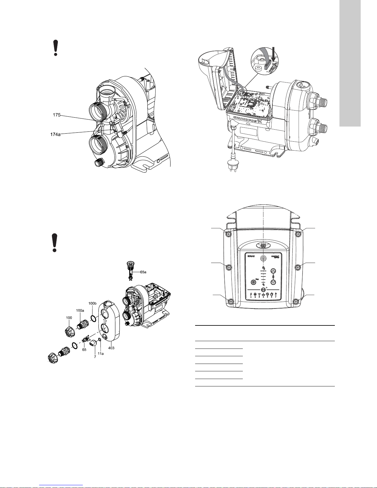
5.2 Removing the control box cover
1. Remove the six pan-head torx screws in the cover (164a).
2. Carefully lift off the control box cover and disconnect the HMI
plug.
Fig. 2 Removing the control box cover
Fig. 3 Disconnecting the HMI plug
5.3 Removing the pressure tank
1. Slowly unscrew the non-return valve (65a) to release any
pressure in the pump.
2. Remove the drain plug (7).
3. Remove the union nut (100) by turning it counterclockwise by
hand.
4. Pull out the nipples (100a).
5. Pull out the non- return valve (65) from the inlet.
6. Remove the O-rings from the nipples, valves and plugs.
7. Carefully remove the pump cover (403) using a flat-blade
screwdriver.
Fig. 4 Removing the cover
DANGER
Electric shock
Death or serious personal injury
- Before starting any work on the product, make
sure that the power supply has been switched off
and that it cannot be accidentally switched on.
Always use an antistatic service kit when handling
electronic components. This will prevent static
electricity from damaging components.
TM06 5151 3915TM06 5282 4315
To avoid damage to the connection part, insert the
flat-blade screwdriver in the top slots and pop the
cover loose by moving the screwdriver handle
towards the pump body. See fig. 4.
TM06 7639 3816 - TM0 67640 3816 - TM06 7641 3816
Page 6

English (GB)
6
Fig. 5 Removing the nipples and the cover
8. Remove the retaining clip (175) for the sensor and remove the
sensor (174a).
9. Remove the sensor (174a).
Fig. 6 Sensor and retaining clip
10. Remove the screws (26) that hold the connection part. Note
that one of the screws holds the earth connection bracket
(173c) and washer.
11. Remove the connection part and the pressure tank.
12. Remove the seal ring (44a).
Fig. 7 Removing the connection part
13. Remove the self-priming valve (10) and O-ring (37).
Fig. 8 Self-priming valve and O-ring for connections part
TM06 5150 3915TM06 5152 3915
TM06 5149 3915TM06 5153 3915
Page 7

English (GB)
7
14. Unscrew the pressure tank (42) counterclockwise and remove
the gasket for the tank (42a).
Fig. 9 Removing the pressure tank
5.4 Removing the chamber stack
1. Remove the plug (169) on nameplate to access the shaft end.
2. Remove the locking nut (67) and the washer (66). Hold the
shaft with a screwdriver in the shaft end.
Fig. 10 Loosening the locking nut for the chamber stack
3. Remove the chamber stack.
Fig. 11 Chamber stack and shaft seal
5.5 Removing the shaft seal
1. Remove the rotating shaft seal face (104).
2. Remove the stationary seat (103) using a needle-noise pliers.
Fig. 12 Removing the stationary shaft seal
6. Fitting the shaft seal
1. Fit the stationary seat (103) with the O-ring (102) against the
pump housing.
Fig. 13 Shaft seal complete
2. Fit the rotating shaft seal face (104).
Fig. 14 Fitting the shaft seal and the chamber stack
TM06 5154 3915TM06 5155 3915TM06 5170 3915
TM06 5169 3915
TM06 5341 4415
Do not touch the ceramic faces of the shaft seal.
TM06 5170 3915
112
108
104
103
102
107
111a
111
Page 8

English (GB)
8
6.1 Fitting the chamber stack
1. Fit the impellers (49), the seal (45) and the chambers (4). Fit
the seal ring (44a) last.
2. Fit the washer (66) and the locking nut (67) and tighten it to 5
Nm. Hold the shaft end using a screwdriver.
Fig. 15 Tightening the nut of the chamber stack
6.2 Fitting the pressure tank
1. Fit the flat gasket (42a) and screw the pressure tank (42) on to
the connection part (2) by hand.
Fig. 16 Fitting the pressure tank
2. Fit the self-priming valve (10) and the O-ring (37).
Fig. 17 Fitting the self-priming valve and the O-ring
3. Check that the self-priming valve is fitted correctly.
Fig. 18 Correct position of the self-priming valve
4. Fit the connection part to the pump housing. Note that one
screw holds the earth connection bracket and the washer.
5. Cross-tighten the screws according to table below.
Fig. 19 Fitting the connection part
TM06 5158 3915TM06 5154 3915TM06 5153 3915
TM06 5149 3915
Sequence
Torque
[Nm]
1
3 ± 0.5
2
3
4
5
6
Page 9
English (GB)
9
6. Fit the sensor (174a) and fasten it by means of the retaining
clip (175).
Fig. 20 Sensor and retaining clip
7. Press the pump cover back onto the pump housing.
8. Fit new O-rings to the valves, nipples and plugs.
9. Fit the inlet valve in the connection part.
10. Press the nipples into the connection part, fit the union nuts
and tighten them by hand.
11. Fit the drain plug (7) and the non-return valve (65a).
Fig. 21 Fitting the nipples and the cover
6.3 Fitting the control box cover
1. Connect the HMI plug and place the control box cover on the
pump.
Fig. 22 Connecting the HMI plug
2. Cross-tighten the six pan-head torx screws according to the
table below.
Fig. 23 Tightening sequence
Check that the rubber sensor pocket is are seated
correctly.
TM06 5152 3915
Always tighten plastic nuts and plugs by hand so as
not to break the material.
TM06 5150 3915
TM06 5150 3915TM06 4959 0516
Sequence
Torque
[Nm]
1
2 ± 0.25
2
3
4
5
6
3 - 6 3 - 6
2 - 5 2 - 5
1 - 4 1 - 4
Page 10

English (GB)
10
7. Fault finding the product
7.1 Grundfos Eye operating indications
7.2 Fault resetting
You can reset a fault indication in one of the following ways:
• When you have eliminated the fault cause, reset the pump
manually by pressing the button. The pump then reverts to
normal duty.
• If the fault disappears by itself, the pump attempts to reset
automatically and the fault indication disappears if automatic
reset is successful and provided that you have enabled "Auto
reset" in the service menu.
Grundfos Eye Indication Description
No lights are on.
The power is off.
The pump is not running.
Two opposite green indicator lights running in the
direction of rotation of the pump.
The power is on.
The pump is running.
Two opposite green indicator lights at a 45 °
angle is the icon used throughout this document
for pump running.
The power is on.
The pump is running.
Two opposite green indicator lights permanently
on.
The power is on.
The pump is not running.
Two opposite red indicator lights flashing
simultaneously.
Alarm.
The pump has stopped.
Two opposite red indicator lights is the icon used
throughout this document for pump stopped.
Alarm.
The pump has stopped.
Page 11

English (GB)
11
7.3 Fault finding chart
DANGER
Electric shock
Death or serious personal injury
- Before starting any work on the product, make
sure that the power supply has been switched off
and that it cannot be accidentally switched on.
Fault
Grundfos Eye
Indicator light
Automatic reset
Cause Remedy
1. The pump is not
running.
- - Power supply failure.
Switch on the power supply.
Check the cables and cable
connections for defects and loose
connections and check for blown
fuses in the electrical installation.
Yes
The power supply is out of the
prescribed voltage range.
Check the power supply and the
pump nameplate. Reestablish the
power supply within the prescribed
voltage range.
No The shaft seal has seized up.
Remove the end cover plug and
deblock the shaft seal by turning the
shaft by means of a screwdriver.
No The pump is blocked by impurities.
Contact Grundfos Service if the
problem persists.
Yes Dry running.
Check the water source, and prime
the pump.
No
The maximum runtime has been
exceeded.
Check the installation for leakage and
reset the alarm.
No
The internal non-return valve is
defective or blocked in completely or
partly open position.
Clean, repair or replace the
non-return valve.
2. The pump is
running.
-
Leakage from the pipes, or the
non-return valve is not properly
closed due to impurities.
Check and repair the pipes, or clean,
repair or replace the non-return valve.
- Small continuous consumption.
Check the taps and reconsider the
usage pattern (ice machines, water
evaporators for air-conditioning, etc.).
-
The temperature is below the freezing
point.
Consider protecting the pump and the
installation against frost.
3. Pump performance
is insufficient.
- - The pump inlet pressure is too low.
Check the inlet conditions of the
pump.
- The pump is undersized.
Replace the pump with a bigger
pump.
--
The inlet pipe, the inlet strainer or the
pump is partly blocked by impurities.
Clean the inlet pipe or the pump.
- - Leakage in the inlet pipe. Repair the inlet pipe.
- - Air in the inlet pipe or the pump.
Prime the inlet pipe and the pump.
Check the inlet conditions of the
pump.
--
The required outlet pressure is too
low for the installation.
Increase the pressure setting (arrow
up).
Yes
The maximum temperature has been
exceeded and the pump is running at
reduced performance.
Check the cooling conditions. Protect
the pump against direct sunlight or
any nearby heat sources.
Page 12

English (GB)
12
4. System
overpressure.
Yes
The setpoint has been set too high.
The difference between the outlet
pressure and the inlet pressure must
not exceed 4 bar (58 psi).
Example: If the required outlet
pressure is 5 bar (73 psi), the
minimum inlet pressure must be 1 bar
(14.5 psi).
Reduce the setpoint to 4 bar (58 psi)
plus positive inlet pressure.
Yes
The maximum pressure has been
exceeded and the inlet pressure is
higher than 6 bar, 0.6 MPa (85 psi)
Check the inlet conditions.
Yes
The maximum pressure has been
exceeded. Equipment elsewhere in
the system causes a high pressure at
the pump (e.g. water heater or
defective safety equipment).
Check the installation.
5. You can reset the
pump, but the
pump runs only for
a few seconds.
Yes Dry running or water shortage.
Check the water source, and prime
the pump.
Yes
The inlet pipe is blocked by
impurities.
Clean the inlet pipe.
Yes
The foot or non-return valve is
blocked in closed position.
Clean, repair or replace the foot or
non-return valve.
Yes Leakage in the inlet pipe. Repair the inlet pipe.
Yes Air in the inlet pipe or the pump.
Prime the inlet pipe and the pump.
Check the inlet conditions of the
pump.
6. You can reset the
pump, but the
pump starts
repeatedly,
immediately after
stopping.
No
The internal non-return valve is
defective or blocked in completely or
partly open position.
Clean, repair or replace the
non-return valve.
No
The tank precharge pressure is not
correct.
Adjust the tank precharge pressure to
70 % of the required outlet pressure.
Fault
Grundfos Eye
Indicator light
Automatic reset
Cause Remedy
Page 13

English (GB)
13
8. Exploded view
Fig. 24 Exploded view
TM06 4966 3615
Page 14

English (GB)
14
Position number list
Subject to alterations.
Pos. Description
2 Connection part
4Chamber
7 Drain plug
10 Self-priming valve
11a O-ring
26 Screw
26c Lock washer
37 O-ring
42 Tank complete
42a Flat gasket
44 Inlet part
44a Seal ring
45 Seal
49 Impeller
65 Non-return valve, inlet
65a Non-return valve, outlet
66 Washer
67 Locking nut
100 Union nut
100a Nipple
100b O-ring
102 O-ring
103 Stationary seat
104 Rotating seal face
105 Shaft seal complete
107 O-ring
108 Spring
111 Seal driver
111a Washer
112 Seal driver
164 Control box cover
164a Pan-head torx screw
169 Plug
173 Double-end stud bolt
173a Lock washer
173b Hexagon nut
173c Earth connection bracket
173d O-ring
174a Sensor complete
175 Retaining clip
180 Combined pump and stator housing
403 Pump cover
Page 15

Grundfos companies
Argentina
Bombas GRUNDFOS de Argentina S.A.
Ruta Panamericana km. 37.500 Centro
Industrial Garin
1619 Garín Pcia. de B.A.
Phone: +54-3327 414 444
Telefax: +54-3327 45 3190
Australia
GRUNDFOS Pumps Pty. Ltd.
P.O. Box 2040
Regency Park
South Australia 5942
Phone: +61-8-8461-4611
Telefax: +61-8-8340 0155
Austria
GRUNDFOS Pumpen Vertrieb Ges.m.b.H.
Grundfosstraße 2
A-5082 Grödig/Salzburg
Tel.: +43-6246-883-0
Telefax: +43-6246-883-30
Belgium
N.V. GRUNDFOS Bellux S.A.
Boomsesteenweg 81-83
B-2630 Aartselaar
Tél.: +32-3-870 7300
Télécopie: +32-3-870 7301
Belarus
Представительство ГРУНДФОС в
Минске
220125, Минск
ул. Шафарнянская, 11, оф. 56, БЦ
«Порт»
Тел.: +7 (375 17) 286 39 72/73
Факс: +7 (375 17) 286 39 71
E-mail: minsk@grundfos.com
Bosnia and Herzegovina
GRUNDFOS Sarajevo
Zmaja od Bosne 7-7A,
BH-71000 Sarajevo
Phone: +387 33 592 480
Telefax: +387 33 590 465
www.ba.grundfos.com
e-mail: grundfos@bih.net.ba
Brazil
BOMBAS GRUNDFOS DO BRASIL
Av. Humberto de Alencar Castelo Branco,
630
CEP 09850 - 300
São Bernardo do Campo - SP
Phone: +55-11 4393 5533
Telefax: +55-11 4343 5015
Bulgaria
Grundfos Bulgaria EOOD
Slatina District
Iztochna Tangenta street no. 100
BG - 1592 Sofia
Tel. +359 2 49 22 200
Fax. +359 2 49 22 201
email: bulgaria@grundfos.bg
Canada
GRUNDFOS Canada Inc.
2941 Brighton Road
Oakville, Ontario
L6H 6C9
Phone: +1-905 829 9533
Telefax: +1-905 829 9512
China
GRUNDFOS Pumps (Shanghai) Co. Ltd.
10F The Hub, No. 33 Suhong Road
Minhang District
Shanghai 201106
PRC
Phone: +86 21 612 252 22
Telefax: +86 21 612 253 33
Croatia
GRUNDFOS CROATIA d.o.o.
Buzinski prilaz 38, Buzin
HR-10010 Zagreb
Phone: +385 1 6595 400
Telefax: +385 1 6595 499
www.hr.grundfos.com
GRUNDFOS Sales Czechia and
Slovakia s.r.o.
Čajkovského 21
779 00 Olomouc
Phone: +420-585-716 111
Denmark
GRUNDFOS DK A/S
Martin Bachs Vej 3
DK-8850 Bjerringbro
Tlf.: +45-87 50 50 50
Telefax: +45-87 50 51 51
E-mail: info_GDK@grundfos.com
www.grundfos.com/DK
Estonia
GRUNDFOS Pumps Eesti OÜ
Peterburi tee 92G
11415 Tallinn
Tel: + 372 606 1690
Fax: + 372 606 1691
Finland
OY GRUNDFOS Pumput AB
Trukkikuja 1
FI-01360 Vantaa
Phone: +358-(0) 207 889 500
France
Pompes GRUNDFOS Distribution S.A.
Parc d’Activités de Chesnes
57, rue de Malacombe
F-38290 St. Quentin Fallavier (Lyon)
Tél.: +33-4 74 82 15 15
Télécopie: +33-4 74 94 10 51
Germany
GRUNDFOS GMBH
Schlüterstr. 33
40699 Erkrath
Tel.: +49-(0) 211 929 69-0
Telefax: +49-(0) 211 929 69-3799
e-mail: infoservice@grundfos.de
Service in Deutschland:
e-mail: kundendienst@grundfos.de
Greece
GRUNDFOS Hellas A.E.B.E.
20th km. Athinon-Markopoulou Av.
P.O. Bo x 7 1
GR-19002 Peania
Phone: +0030-210-66 83 400
Telefax: +0030-210-66 46 273
Hong Kong
GRUNDFOS Pumps (Hong Kong) Ltd.
Unit 1, Ground floor
Siu Wai Industrial Centre
29-33 Wing Hong Street &
68 King Lam Street, Cheung Sha Wan
Kowloon
Phone: +852-27861706 / 27861741
Telefax: +852-27858664
Hungary
GRUNDFOS Hungária Kft.
Park u. 8
H-2045 Törökbálint,
Phone: +36-23 511 110
Telefax: +36-23 511 111
India
GRUNDFOS Pumps India Private Limited
118 Old Mahabalipuram Road
Thoraipakkam
Chennai 600 096
Phone: +91-44 2496 6800
Indonesia
PT. GRUNDFOS POMPA
Graha Intirub Lt. 2 & 3
Jln. Cililitan Besar No.454. Makasar,
Jakarta Timur
ID-Jakarta 13650
Phone: +62 21-469-51900
Telefax: +62 21-460 6910 / 460 6901
Ireland
GRUNDFOS (Ireland) Ltd.
Unit A, Merrywell Business Park
Ballymount Road Lower
Dublin 12
Phone: +353-1-4089 800
Telefax: +353-1-4089 830
Italy
GRUNDFOS Pompe Italia S.r.l.
Via Gran Sasso 4
I-20060 Truccazzano (Milano)
Tel.: +39-02-95838112
Telefax: +39-02-95309290 / 95838461
Japan
GRUNDFOS Pumps K.K.
1-2-3, Shin-Miyakoda, Kita-ku,
Hamamatsu
431-2103 Japan
Phone: +81 53 428 4760
Telefax: +81 53 428 5005
Korea
GRUNDFOS Pumps Korea Ltd.
6th Floor, Aju Building 679-5
Yeoksam-dong, Kangnam-ku, 135-916
Seoul, Korea
Phone: +82-2-5317 600
Telefax: +82-2-5633 725
Latvia
SIA GRUNDFOS Pumps Latvia
Deglava biznesa centrs
Augusta Deglava ielā 60, LV-1035, Rīga,
Tālr.: + 371 714 9640, 7 149 641
Fakss: + 371 914 9646
Lithuania
GRUNDFOS Pumps UAB
Smolensko g. 6
LT-03201 Vilnius
Tel: + 370 52 395 430
Fax: + 370 52 395 431
Malaysia
GRUNDFOS Pumps Sdn. Bhd.
7 Jalan Peguam U1/25
Glenmarie Industrial Park
40150 Shah Alam
Selangor
Phone: +60-3-5569 2922
Telefax: +60-3-5569 2866
Mexico
Bombas GRUNDFOS de México S.A. de
C.V.
Boulevard TLC No. 15
Parque Industrial Stiva Aeropuerto
Apodaca, N.L. 66600
Phone: +52-81-8144 4000
Telefax: +52-81-8144 4010
Netherlands
GRUNDFOS Netherlands
Velu wezoom 3 5
1326 AE Almere
Postbus 22015
1302 CA ALMERE
Tel.: +31-88-478 6336
Telefax: +31-88-478 6332
E-mail: info_gnl@grundfos.com
New Zealand
GRUNDFOS Pumps NZ Ltd.
17 Beatrice Tinsley Crescent
North Harbour Industrial Estate
Albany, Auckland
Phone: +64-9-415 3240
Telefax: +64-9-415 3250
Norway
GRUNDFOS Pumper A/S
Strømsveien 344
Postboks 235, Leirdal
N-1011 Oslo
Tlf.: +47-22 90 47 00
Telefax: +47-22 32 21 50
Poland
GRUNDFOS Pompy Sp. z o.o.
ul. Klonowa 23
Baranowo k. Poznania
PL-62-081 Przeźmierowo
Tel: (+48-61) 650 13 00
Fax: (+48-61) 650 13 50
Portugal
Bombas GRUNDFOS Portugal, S.A.
Rua Calvet de Magalhães, 241
Apartado 1079
P-2770-153 Paço de Arcos
Tel.: +351-21-440 76 00
Telefax: +351-21-440 76 90
Romania
GRUNDFOS Pompe România SRL
Bd. Biruintei, nr 103
Pantelimon county Ilfov
Phone: +40 21 200 4100
Telefax: +40 21 200 4101
E-mail: romania@grundfos.ro
Russia
ООО Грун дфос Россия
109544, г. Москва, ул. Школьная, 39-41,
стр. 1
Тел. (+7) 495 564-88-00 (495) 737-30-00
Факс (+7) 495 564 88 11
E-mail grundfos.moscow@grundfos.com
Serbia
Grundfos Srbija d.o.o.
Omladinskih brigada 90b
11070 Novi Beograd
Phone: +381 11 2258 740
Telefax: +381 11 2281 769
www.rs.grundfos.com
Singapore
GRUNDFOS (Singapore) Pte. Ltd.
25 Jalan Tukang
Singapore 619264
Phone: +65-6681 9688
Telefax: +65-6681 9689
Slovakia
GRUNDFOS s.r.o.
Prievozská 4D
821 09 BRATISLAVA
Phona: +421 2 5020 1426
sk.grundfos.com
Slovenia
GRUNDFOS LJUBLJANA, d.o.o.
Leskoškova 9e, 1122 Ljubljana
Phone: +386 (0) 1 568 06 10
Telefax: +386 (0)1 568 06 19
E-mail: tehnika-si@grundfos.com
South Africa
GRUNDFOS (PTY) LTD
Corner Mountjoy and George Allen Roads
Wilbart Ext. 2
Bedfordview 2008
Phone: (+27) 11 579 4800
Fax: (+27) 11 455 6066
E-mail: lsmart@grundfos.com
Spain
Bombas GRUNDFOS España S.A.
Camino de la Fuentecilla, s/n
E-28110 Algete (Madrid)
Tel.: +34-91-848 8800
Telefax: +34-91-628 0465
Sweden
GRUNDFOS AB
Box 333 (Lunnagårdsgatan 6)
431 24 Mölndal
Tel.: +46 31 332 23 000
Telefax: +46 31 331 94 60
Switzerland
GRUNDFOS Pumpen AG
Bruggacherstrasse 10
CH-8117 Fällanden/ZH
Tel.: +41-44-806 8111
Telefax: +41-44-806 8115
Taiwan
GRUNDFOS Pumps (Taiwan) Ltd.
7 Floor, 219 Min-Chuan Road
Taichung, Taiwan, R.O.C.
Phone: +886-4-2305 0868
Telefax: +886-4-2305 0878
Thailand
GRUNDFOS (Thailand) Ltd.
92 Chaloem Phrakiat Rama 9 Road,
Dokmai, Pravej, Bangkok 10250
Phone: +66-2-725 8999
Telefax: +66-2-725 8998
Turkey
GRUNDFOS POMPA San. ve Tic. Ltd. Sti.
Gebze Organize Sanayi Bölgesi
Ihsan dede Caddesi,
2. yol 200. Sokak No. 204
41490 Gebze/ Kocaeli
Phone: +90 - 262-679 7979
Telefax: +90 - 262-679 7905
E-mail: satis@grundfos.com
Ukraine
Бізнес Центр Європа
Столичне шосе, 103
м. Київ, 03131, Україна
Телеф он: (+38 044) 237 04 00
Факс.: (+38 044) 237 04 01
E-mail: ukraine@grundfos.com
United Arab Emirates
GRUNDFOS Gulf Distribution
P.O. Box 16768
Jebel Ali Free Zone
Dubai
Phone: +971 4 8815 166
Telefax: +971 4 8815 136
United Kingdom
GRUNDFOS Pumps Ltd.
Grovebury Road
Leighton Buzzard/Beds. LU7 4TL
Phone: +44-1525-850000
Telefax: +44-1525-850011
U.S.A.
GRUNDFOS Pumps Corporation
17100 West 118th Terrace
Olathe, Kansas 66061
Phone: +1-913-227-3400
Telefax: +1-913-227-3500
Uzbekistan
Grundfos Tashkent, Uzbekistan The Representative Office of Grundfos Kazakhstan in
Uzbekistan
38a, Oybek street, Tashkent
Телефон: (+998) 71 150 3290 / 71 150
3291
Факс: (+998) 71 150 3292
Addresses Revised 02.09.2016
Page 16

98979478 1116
ECM: 1197159
The name Grundfos, the Grundfos logo, and be think innovate are registered trademarks owned by Grundfos Holding A/S or Grundfos A/S, Denmark. All rights reserved worldwide. © Copyright Grundfos Holding A/S
www.grundfos.com
 Loading...