

Grundfos MAGNA3 32-40 (N), MAGNA3 25-100 (N), MAGNA3 25-40 (N), MAGNA3 25-80 (N), MAGNA3 32-60 (N) Installation And Operating Instructions Manual
...Page 1

MAGNA3
Installation and operating instructions
GRUNDFOS INSTRUCTIONS
Page 2
English (GB) Installation and operating instructions
English (GB)
Original installation and operating instructions
CONTENTS
These installation and operating instructions describe MAGNA3.
Sections 1-5 give the information necessary to be able to unpack,
install and start up the product in a safe way.
Sections 6-13 give important information about the product, as
well as information on service, fault finding and disposal of the
product.
Page
1. General information
1.1 Symbols used in this document
1.2 Safety symbols on the pump
2. Receiving the product
2.1 Inspecting the product
2.2 Scope of delivery
2.3 Lifting the pump
3. Installing the product
3.1 Location
3.2 Tools
3.3 Mechanical installation
3.4 Positioning the pump
3.5 Control box positions
3.6 Pump head position
3.7 Changing the control box position
3.8 Electrical installation
3.9 Connecting the power supply
4. Starting up the product
4.1 Single-head pump
4.2 Twin-head pump
5. Storing and handling the product
5.1 Frost protection
6. Product introduction
6.1 Applications
6.2 Pumped liquids
6.3 Identification
6.4 Model type
6.5 Radio communication
6.6 Insulating shells
6.7 Non-return valve
7. Control functions
7.1 Overview of settings
7.2 External connections
7.3 Input and output communication
7.4 Priority of settings
8. Setting the product
8.1 Operating the product
8.2 "+RPH" menu
8.3 Menu overview
8.4 6WDWXV menu
8.5 "2SHUDWLQJVWDWXV"
8.6 "6HWWLQJV" menu
8.7 Setting values for control modes
8.8 "$VVLVW" menu
8.9 External setpoint influence
8.10 Flow estimation accuracy
8.11 Pump heads in twin-head pumps
8.12 "'HVFULSWLRQRIFRQWUROPRGH"
8.13 "$VVLVWHGIDXOWDGYLFH"
8.14 Wireless GENIair
9. Servicing the product
9.1 Differential-pressure and temperature sensor
9.2 External sensor condition
10. Fault finding the product
10.1 Grundfos Eye operating indications
10.2 Fault finding
11. Accessories
11.1 Grundfos GO
11.2 Communication interface module, CIM
12
12
13
13
13
13
13
13
14
15
15
15
15
16
16
17
18
18
21
23
23
24
26
26
26
33
38
41
41
41
42
42
42
43
43
43
44
44
45
47
47
47
11.3 Counterflanges
11.4 External sensors
11.5 Cable for sensors
11.6 Blanking flange
11.7 Insulating kits for air-conditioning and cooling systems
12. Technical data
12.1 Sensor specifications
13. Disposing of the product
Prior to installation, read this document and the quick
2
2
3
3
3
3
4
4
4
4
5
5
6
6
1. General information
7
8
1.1 Symbols used in this document
9
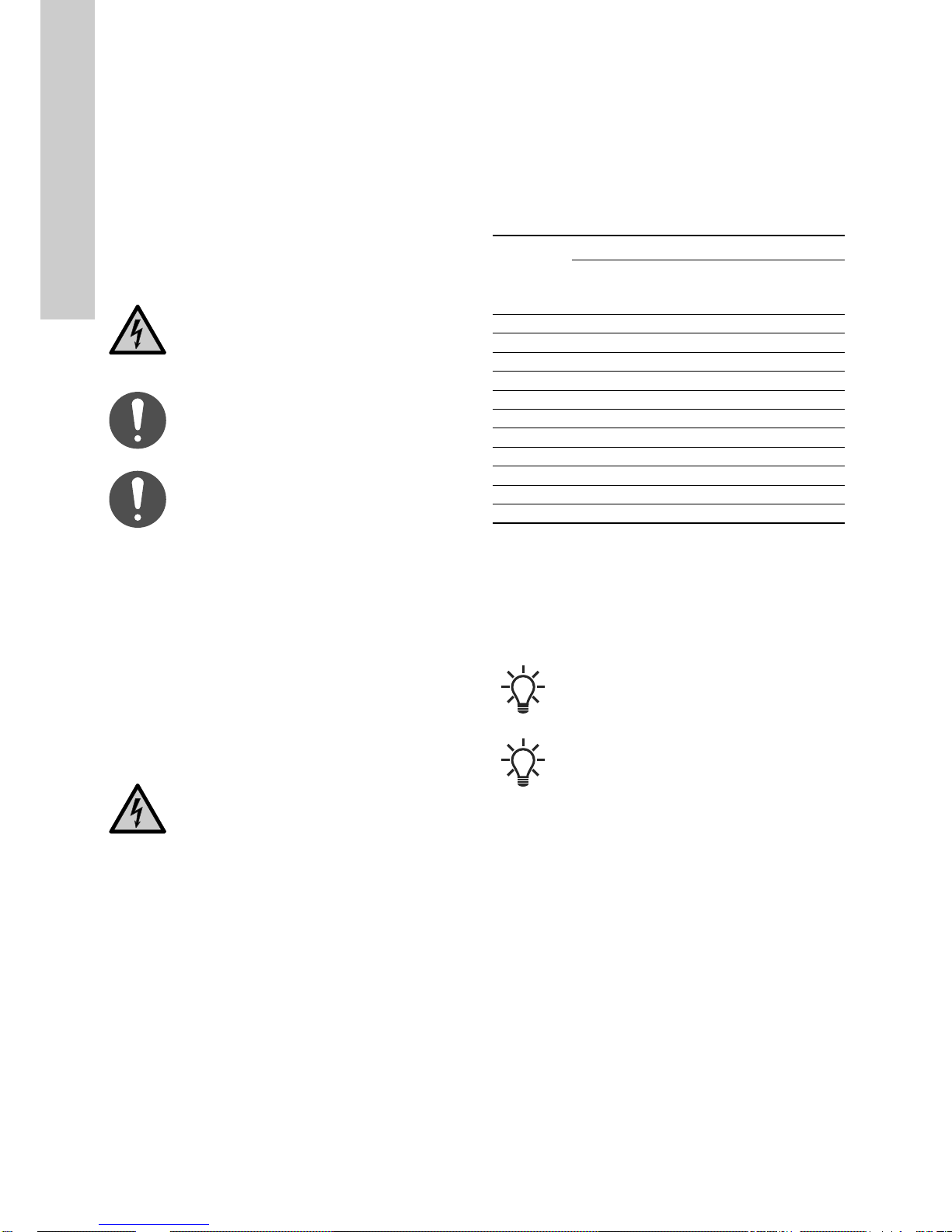
The text accompanying the three hazard symbols DANGER,
WARNING and CAUTION is structured in the following way:
guide. Installation and operation must comply with
local regulations and accepted codes of good
practice.
This appliance can be used by children aged from 8
years and above and persons with reduced physical,
sensory or mental capabilities or lack of experience
and knowledge if they have been given supervision
or instruction concerning use of the appliance in a
safe way and understand the hazards involved.
Children shall not play with the appliance. Cleaning
and user maintenance shall not be made by children
without supervision.
DANGER
Indicates a hazardous situation which, if not avoided,
will result in death or serious personal injury.
WARNING
Indicates a hazardous situation which, if not avoided,
could result in death or serious personal injury.
CAUTION
Indicates a hazardous situation which, if not avoided,
could result in minor or moderate personal injury.
SIGNAL WORD
Description of hazard
Consequence of ignoring the warning.
- Action to avoid the hazard.
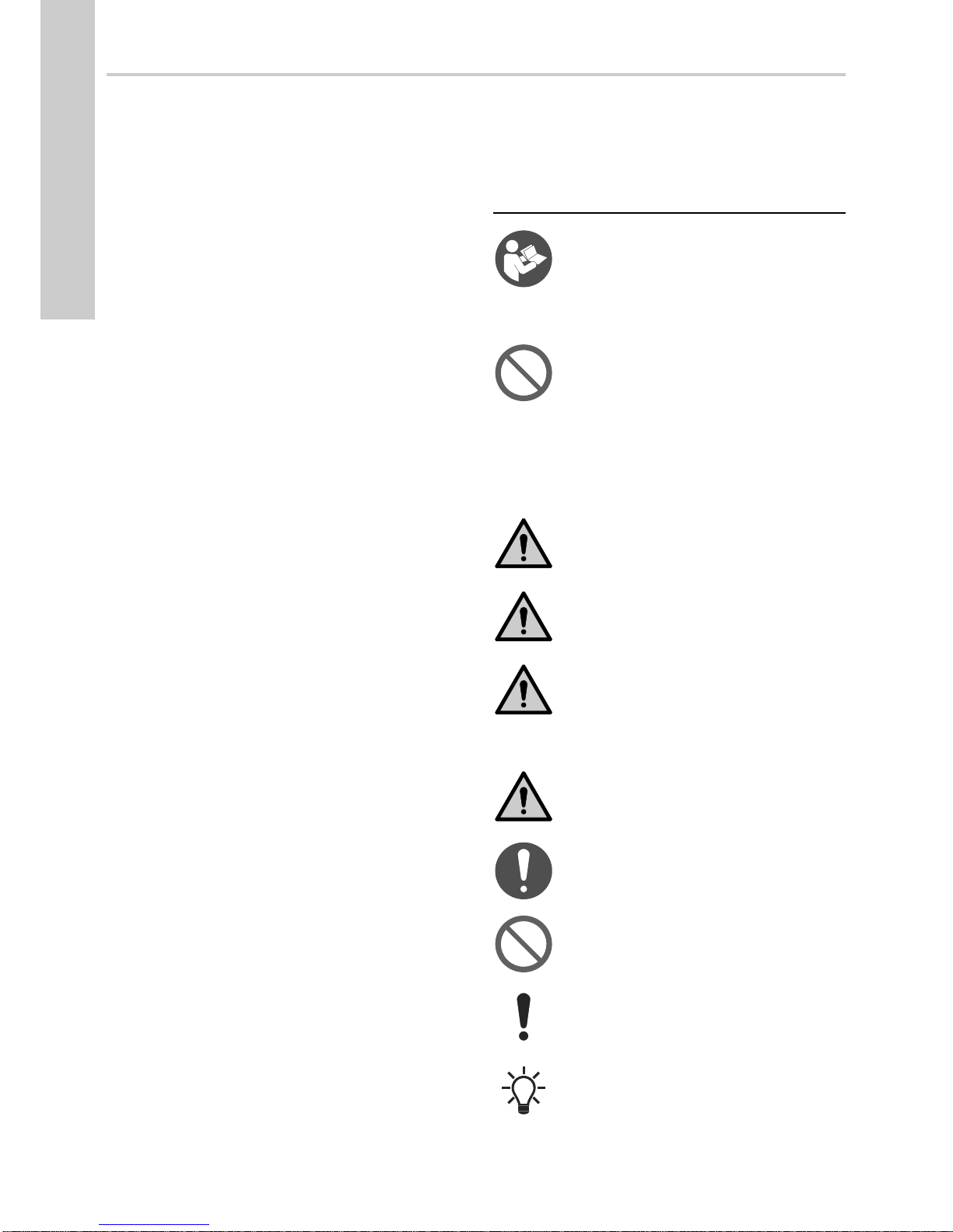
A blue or grey circle with a white graphical symbol
indicates that an action must be taken.
A red or grey circle with a diagonal bar, possibly with
a black graphical symbol, indicates that an action
must not be taken or must be stopped.
If these instructions are not observed, it may result in
malfunction or damage to the equipment.
Notes or instructions that make the work easier and
ensure safe operation.
52
52
52
53
53
53
54
54
2
Page 3

1.2 Safety symbols on the pump
Check the position of the clamp before you tighten
the clamp. Incorrect position of the clamp will cause
leakage from the pump and damage the hydraulic
parts in the pump head.
Fit and tighten the screw that holds the clamp to 8
8Nm!
Nm ± 1 Nm.
Do not apply more torque than specified even though
water is dripping from the clamp. The condensed
water is most likely coming from the drain hole under
the clamp.
2. Receiving the product
2.1 Inspecting the product
Check that the product received is in accordance with the order.
Check that the voltage and frequency of the product match the
voltage and frequency of the installation site. See section
6.3.1 Nameplate.
Pumps tested with water containing anticorrosive
additives are taped on the inlet and outlet ports to
prevent residual test water from leaking into the
packaging. Remove the tape before installing the
pump.
2.2.2 Plug-connected twin-head pump
English (GB)
TM06 7225 3216TM05 8159 2013TM06 6791 2316
Fig. 2 Plug-connected twin-head pump
The box contains the following items:
• MAGNA3 pump
•gaskets
•quick guide
• safety instructions
• two ALPHA plugs.
2.2.3 Terminal-connected single-head pump
2.2 Scope of delivery
2.2.1 Plug-connected single-head pump
Fig. 1 Plug-connected single-head pump
The box contains the following items:
• MAGNA3 pump
• insulating shells
•gaskets
• quick guide
• safety instructions
• one ALPHA plug.
Fig. 3 Terminal-connected single-head pump
The box contains the following items:
• MAGNA3 pump
• insulating shells
•gaskets
•quick guide
TM06 7224 3216
• safety instructions
• box with terminal and cable glands.
2.2.4 Terminal-connected twin-head pump
Fig. 4 Terminal-connected twin-head pump
The box contains the following items:
• MAGNA3 pump
•gaskets
•quick guide
• safety instructions
• two boxes with terminals and cable glands.
3
Page 4
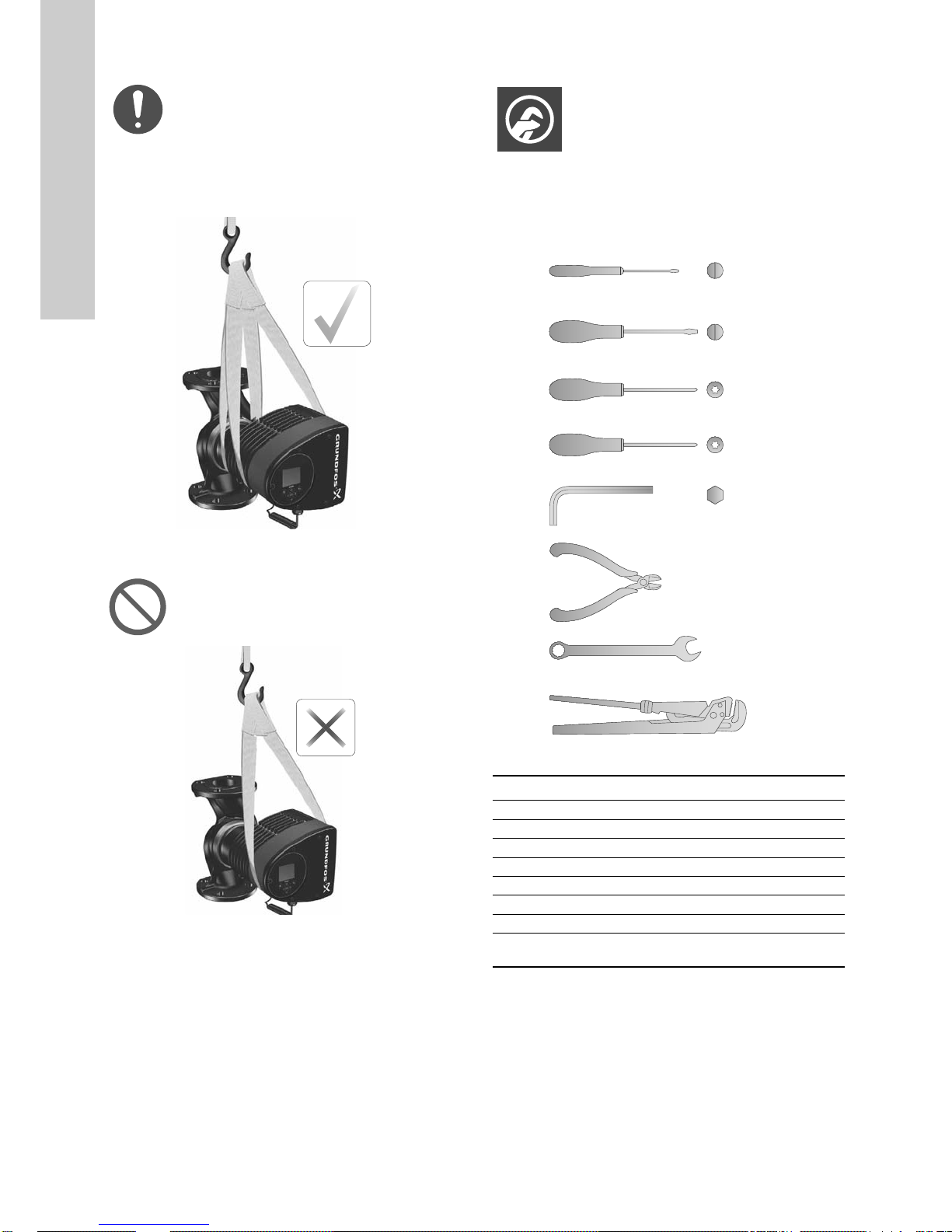
2.3 Lifting the pump
0.6 x 3.5
1.2 x 8.0
English (GB)
Observe local regulations concerning limits for
manual lifting or handling.
Always lift directly on the pump head or the cooling fins when
handling the pump. See fig. 5.
For large pumps, it may be necessary to use lifting equipment.
Position the lifting straps as illustrated in fig. 5.
3. Installing the product
3.1 Location
The pump is designed for indoor installation.
3.2 Tools
1
2
Fig. 5 Correct lifting of pump
Do not lift the pump head by the control box, i.e. the
red area of the pump. See fig. 6.
Fig. 6 Incorrect lifting of pump
3
4
5
TM05 5820 3216
6
7
8
Fig. 7 Recommended tools
Pos. Tool Size
1 Screwdriver, straight slot 0.6 x 3.5 mm
2 Screwdriver, straight slot 1.2 x 8.0 mm
3 Screwdriver, torx bit TX10
4 Screwdriver, torx bit TX20
5 Hexagon key 5.0 mm
TM05 5821 3216
6 Side cutter
7 Open-end spanner Depending on DN size
8 Pipe wrench
TX10
TX20
5.0
TM05 6472 4712
Only used for pumps
with unions
4
Page 5

3.3 Mechanical installation
The pump range includes both flanged and threaded versions.
These installation and operating instructions apply to both
versions, but give a general description of flanged versions. If the
versions differ, the threaded version will be described separately.
Install the pump so that it is not stressed by the pipes. For
maximum permissible forces and moments for pipe connections
acting on the pump flanges or threaded connections, see page
59.
You can suspend the pump directly in the pipes, provided that the
pipes support the pump.
Twin-head pumps are prepared for installation on a mounting
bracket or base plate. The pump housing has a M12 thread.
To ensure adequate cooling of motor and electronics, observe the
following requirements:
• Position the pump in such a way that sufficient cooling is
ensured.
• The ambient temperature must not exceed 40 °C.
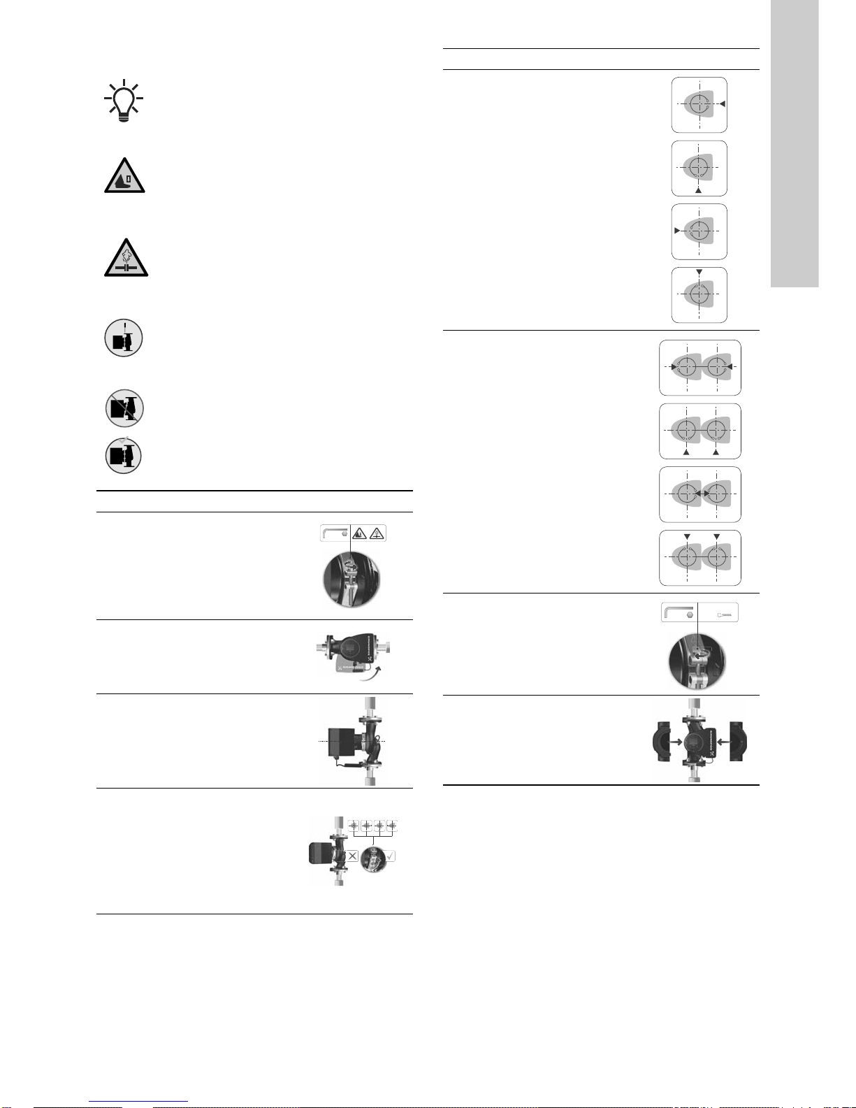
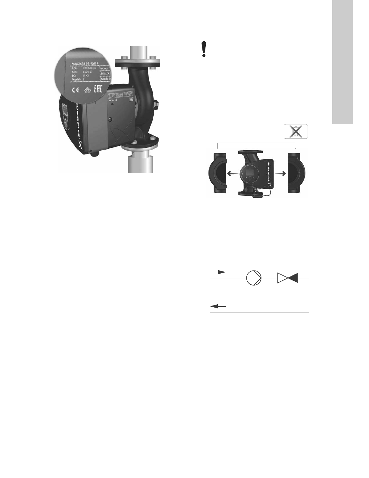
Step Action Illustration
Arrows on the pump housing
indicate the flow direction
through the pump. The flow
1
direction can be horizontal or
vertical, depending on the
control box position.
3.4 Positioning the pump
Always install the pump with horizontal motor shaft.
• Pump installed correctly in a vertical pipe. See fig. 8, pos. A.
• Pump installed correctly in a horizontal pipe. See fig. 8, pos. B.
• Do not install the pump with vertical motor shaft. See fig. 8,
pos. C and D.
BA
DC
Fig. 8 Pump installed with horizontal motor shaft
English (GB)
TM05 2866 3216
Close the isolating valves
and make sure that the
system is not pressurised
2
during the installation of the
pump.
Mount the pump with gaskets
3
in the pipes.
Flanged version:
Fit bolts and nuts. Use the
right size of bolts according
to system pressure.
For further information about
4
torques, see page 59.
Threaded version:
Tighten the union nuts.
TM05 2862 3216 - TM05 8456 3216
TM05 2863 3216
TM05 2864 3216
TM05 2865 3216 - TM05 8455 3216
5
Page 6

3.5 Control box positions
English (GB)
To ensure adequate cooling, make sure that the control box is in
horizontal position with the Grundfos logo in vertical position. See
fig. 9.
3.6 Pump head position
If you remove the pump head before installing the pump in the
pipes, pay special attention when fitting the pump head to the
pump housing:
1. Visually check that the floating ring in the sealing system is
centred. See figures 11 and 12.
2. Gently lower the pump head with rotor shaft and impeller into
the pump housing.
3. Make sure that the contact face of the pump housing and that
of the pump head are in contact before you tighten the clamp.
See fig. 13.
TM05 6650 3216TM05 665132162
Fig. 11 Correctly centred sealing system
Fig. 9 Pump with control box in horizontal position
Fit twin-head pumps installed in horizontal pipes
with an automatic vent, Rp 1/4, in the upper part of
the pump housing. See fig. 10.
Fig. 10 Automatic vent
TM05 2915 3216
Fig. 12 Incorrectly centred sealing system
Observe the position of the clamp before you
tighten it. Incorrect position of the clamp will cause
leakage from the pump and damage the hydraulic
TM05 6061 3216
parts in the pump head. See fig. 13.
6
TM05 5837 3216
Fig. 13 Fitting the pump head to the pump housing
Page 7
3.7 Changing the control box position
The warning symbol on the clamp holding the pump
head and pump housing together indicates that there
is a risk of personal injury. See specific warnings
below.
CAUTION
Crushing of feet
Minor or moderate personal injury
- Do not drop the pump head when loosening the
clamp.
CAUTION
Pressurised system
Minor or moderate personal injury
- Pay special attention to any escaping vapour
when loosening the clamp.
Step Action Illustration
Single-head pump.
Position the clamp so that the
gap points towards the arrow.
4a
It can be in position 3, 6, 9 or
12 o'clock.
English (GB)
Fit and tighten the screw that holds the clamp to 8
8Nm!
Nm ± 1 Nm. Do not apply more torque than specified
even though water is dripping from the clamp. The
condensed water is most likely coming from the drain
hole under the clamp.
Check the position of the clamp before you tighten
the clamp. Incorrect position of the clamp will cause
leakage from the pump and damage the hydraulic
parts in the pump head.
Step Action Illustration
Loosen the screw in the
clamp that holds the pump
5.0
head and pump housing
together.
1
If you loosen the screw too
much, the pump head will be
completely disconnected
from the pump housing.
Carefully turn the pump head
to the desired position.
If the pump head is stuck,
2
loosen it with a light blow of a
rubber mallet.
Place the control box in
horizontal position so that the
Grundfos logo is in vertical
3
position. The motor shaft
must be in horizontal
position.
TM05 2918 3216
Twin-head pump.
Position the clamps so that
the gaps point towards the
4b
arrows.
They can be in position 3, 6,
9 or 12 o'clock.
TM05 2917 3216
TM05 2867 3216
Fit and tighten the screw that
holds the clamp to 8 Nm ± 1
Nm.
5
Do not retighten the screw if
8 Nm5.0
condensed water is dripping
TM05 2868 3216
from the clamp.
TM05 2872 0612
Fit the insulating shells.
The insulating shells for
pumps in air-conditioning and
6
cooling systems must be
ordered separately.
TM05 2869 3216
TM05 2874 3216
Due to the drain hole in the
stator housing, position the
4
gap of the clamp as shown in
step 4a or 4b.
TM05 2870 0612
7
Page 8
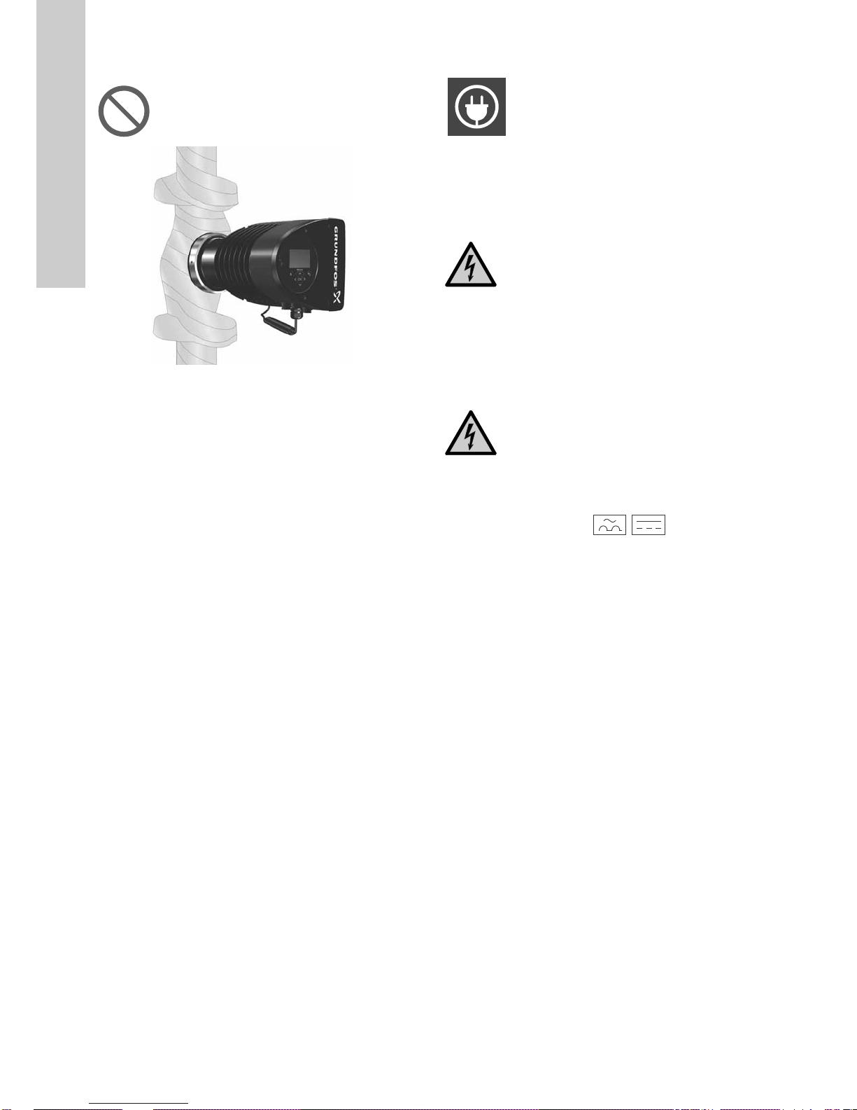
As an alternative to insulating shells, you can insulate the pump
English (GB)
housing and pipes as illustrated in fig. 14.
Do not insulate the control box or cover the control
panel.
Fig. 14 Insulating the pump housing and pipe
3.8 Electrical installation
Carry out the electrical connection and protection according to
local regulations.
Check that the supply voltage and frequency correspond to the
values stated on the nameplate.
WARNING
Electric shock
Death or serious personal injury
- Before starting any work on the product, make
sure that the power supply has been switched off.
Lock the main switch in position 0. Type and
requirements as specified in EN 60204-1, 5.3.2.
WARNING
TM05 2889 3216
Electric shock
Death or serious personal injury
- Connect the pump to an external main switch
with a minimum contact gap of 3 mm in all poles.
- Use earthing or neutralisation for protection
against indirect contact.
- If the pump is connected to an electric
installation where an electrical circuit breaker
(voltage sensing ELCB, residual-current device
RCD or residual-current circuit device RCCB) is
used as an additional protection, this circuit
breaker must be marked with the first or both of
the symbols shown below:
• Make sure that the pump is connected to an external main
switch.
• The pump requires no external motor protection.
• The motor incorporates thermal protection against slow
overloading and blocking (IEC 34-11: TP 211).
• When switched on via the power supply, the pump starts after
approximately 5 seconds.
3.8.1 Supply voltage
1 x 230 V ± 10 %, 50/60 Hz, PE.
The voltage tolerances are intended for mains-voltage variations.
Do not use the voltage tolerances for running pumps at other
voltages than those stated on the nameplate.
8
Page 9

3.9 Connecting the power supply
7 mm
20 mm
Min. Ø 7 mm
Max. Ø 14 mm
Terminal-connected versions
Step Action Illustration
Step Action Illustration
Remove the front
cover from the
control box.
1
Do not remove the
screws from the
cover.
Locate the power
supply plug and
cable gland in the
2
small cardboard box
supplied with the
pump.
Connect the cable
3
gland to the control
box.
Insert the power
supply plug into the
7
male plug in the
English (GB)
pump control box.
TM05 2875 3416
TM05 2881 3416
Tighten the cable
8
gland.
TM05 2876 3416
TM05 2877 3416
Fit the front cover.
TM05 2882 3416
Pull the power
4
supply cable through
the cable gland.
Strip the cable
5
conductors as
illustrated.
Connect the cable
6
conductors to the
power supply plug.
TM05 2878 3416
TM05 2879 3416
TM05 2880 3416
9
Page 10

Plug-connected versions
17 mm
12 mm
7 mm
Ø 5.5 - 10 mm
Max. 1.5 mm
2
Click
Click
English (GB)
Assembling the plug
Step Action Illustration
Step Action Illustration
Fit the cable gland
and plug cover to
the cable. Strip the
1
cable conductors
as illustrated.
Connect the cable
2
conductors to the
power supply plug.
Bend the cable
with the cable
3
conductors
pointing upwards.
7
TM05 5538 3216
Disassembling the plug
Step Action Illustration
TM05 5539 3812
TM05 5540 3812
1
2
Insert the power
supply plug into
the male plug in
the pump control
box.
Click
TM05 8454 2313
Loosen the cable
gland and remove
it from the plug.
TM05 5545 3812
Pull off the plug
cover while
pressing on both
sides.
Pull out the
conductor guide
4
plate and throw it
away.
Click the plug
5
cover onto the
power supply plug.
Screw the cable
6
gland onto the
power supply plug.
10
TM05 5546 3812
Max 0.8 x 4
Loosen the cable
conductors one by
TM05 5541 3812
one by pressing a
3
screwdriver gently
into the terminal
clip.
x 3
TM05 5547 3812
TM05 5542 3812
The plug has now
been removed
4
from the power
supply plug.
TM05 5543 3812
TM05 5548 3812
Page 11
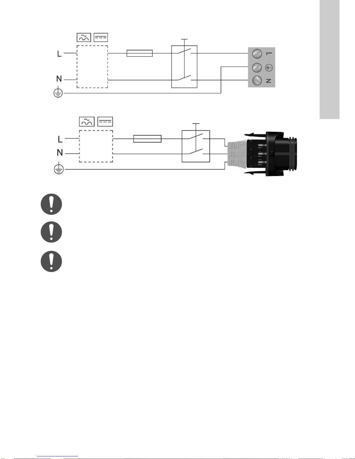
3.9.1 Connection diagram
External switch
Fuse
RCD/RCCB
Fig. 15 Example of terminal-connected motor with main switch, backup fuse and additional protection
External switch
Fuse
RCD/RCCB
Fig. 16 Example of plug-connected motor with main switch, backup fuse and additional protection
Make sure that the fuse is dimensioned according to
the nameplate and local legislation.
English (GB)
TM03 2397 3216
TM05 5277 3712
Connect all cables in accordance with local
regulations.
Make sure that all cables are heat-resistant up to 75
°C.
Install all cables in accordance with EN 60204-1 and
EN 50174-2:2000.
11
Page 12

4. Starting up the product
English (GB)
4.1 Single-head pump
The number of starts and stops via the power
supply must not exceed four times per hour.
Do not start the pump until the system has been filled with liquid
and vented. Furthermore, the required minimum inlet pressure
must be available at the pump inlet. See section 12. Technical
data.
The pump is self-venting through the system, and the system
must be vented at the highest point.
Step Action Illustration
Switch on the power supply to the pump.
1
The pump starts in "AUTO
approximately 5 seconds.
ADAPT
1/On
" mode after
0/Off
TM05 2884 0612
Control panel at first startup.
2
After a few seconds, the pump display changes to the
startup guide.
The startup guide guides you through the general settings
of the pump, such as language, date and time.
3
If you do not touch the buttons on the control panel for 15
minutes, the display goes into sleep mode. When you
touch a button, the "+RPH" display appears.
When you have made the general settings, select the
desired control mode or let the pump run in AUTO
4
mode.
For additional settings, see section 7. Control functions.
ADAPT
TM05 2885 3216
TM05 2886 3216
TM05 2887 3216
12
Page 13

4.2 Twin-head pump
6. Product introduction
Fig. 17 MAGNA3 D
Check that the second pump head is connected to
the power supply.
If you have not connected the second pump head to the power
supply, warning 77 appears in the display. See fig. 18.
Connect the second pump head, and restart the pump.
Fig. 18 Warning 77
5. Storing and handling the product
5.1 Frost protection
If the pump is not used during periods of frost, take
the necessary steps to prevent frost bursts.
MAGNA3 is a complete range of circulator pumps with integrated
controller enabling adjustment of pump performance to the actual
system requirements. In many systems, this reduces the power
TM05 8894 2813
consumption considerably, reduces noise from thermostatic
radiator valves and similar fittings and improves the control of the
system.
You can set the desired head on the control panel.
6.1 Applications
The pump is designed for circulating liquids in the following
systems:
• heating systems
• domestic hot-water systems
• air-conditioning and cooling systems.
You can also use the pump in the following systems:
• ground-source heat-pump systems
• solar-heating systems.
6.2 Pumped liquids
The pump is suitable for thin, clean, non-aggressive and
non-explosive liquids, not containing solid particles or fibres that
may attack the pump mechanically or chemically.
In heating systems, the water must meet the requirements of
accepted standards on water quality in heating systems, for
example the German standard VDI 2035.
2.1.5.1.0.0 6WDWXV
The pumps are also suitable for domestic hot-water systems.
Observe local legislation regarding pump housing
material.
We strongly recommend that you use stainless-steel pumps in
domestic hot-water applications to avoid corrosion.
In domestic hot-water systems, we recommend that you use the
pump only for water with a degree of hardness lower than
approximately 14 °dH.
In domestic hot-water systems, we recommend that you keep the
liquid temperature below 65 °C to eliminate the risk of lime
precipitation.
English (GB)
Do not pump aggressive liquids.
Do not pump flammable, combustible or explosive
liquids.
13
Page 14

6.2.1 Glycol
English (GB)
You can use the pump for pumping water-ethylene-glycol
mixtures up to 50 %.
Example of a water-ethylene-glycol mixture:
Maximum viscosity: 50 cSt ~ 50 % water / 50 % ethylene-glycol
mixture at -10 °C.
The pump has a power-limiting function that protects it against
overload.
The pumping of water-ethylene-glycol mixtures affects the
maximum curve and reduces the performance, depending on the
water-ethylene-glycol mixture and the liquid temperature.
To prevent the ethylene-glycol mixture from degrading, avoid
temperatures exceeding the rated liquid temperature and
minimise the operating time at high temperatures.
Clean and flush the system before you add the ethylene-glycol
mixture.
To prevent corrosion or lime precipitation, check and maintain the
ethylene-glycol mixture regularly. If further dilution of the supplied
ethylene-glycol is required, follow the glycol supplier's
instructions.
Additives with a density and/or kinematic viscosity
higher than those/that of water reduce the hydraulic
performance
Fig. 19 Pumped liquids, threaded version
6.3 Identification
6.3.1 Nameplate
Fig. 20 Example of nameplate
Pos. Description
1Product name
2Model
3 Production code, PC, year and week*
4 Serial number
5 Product number
6 Country of manufacture
7 Enclosure class
8 Energy Efficiency Index, EEI
9 Part, according to EEI
10 Temperature class
11 Minimum current [A]
12 Maximum current [A]
13 Minimum power [W]
14 Maximum power [W]
15 Maximum system pressure
16 Voltage [V] and frequency [Hz]
17 QR code
18 CE mark and approvals
19 Manufacturer's name and address
TM05 8457 2313
* Example of production code: 1326. The pump was produced in
week 26, 2013.
TM05 5981 4312
14
TM06 6692 3216
Fig. 21 Production code on packaging
Page 15
6.4 Model type
These installation and operating instructions cover all models.
The model version is stated on the nameplate. See fig. 22.
Fig. 22 Model type on the product
You can see the different model versions in the MAGNA3 data
booklet.
6.5 Radio communication
The radio part of this product is a class 1 device and can be used
anywhere in the EU member states without restrictions.
Intended use
This pump incorporates a radio for remote control.
The pump can communicate with Grundfos GO and with other
MAGNA3 pumps of the same type via the built-in radio.
6.6 Insulating shells
Insulating shells are available for single-head pumps only.
Limit the heat loss from the pump housing and
pipes.
English (GB)
Reduce the heat loss by insulating the pump housing and the
pipes. See figures 23 and 14.
• Insulating shells for pumps in heating systems are supplied
with the pump.
• Insulating shells for pumps in air-conditioning and cooling
systems, down to -10 °C, must be ordered separately. See
section 11.7 Insulating kits for air-conditioning and cooling
systems.
The fitting of insulating shells increases the pump dimensions.
TM05 8798 3216
TM05 2859 3216TM05 3055 0912
Fig. 23 Insulating shells
Pumps for heating systems are factory-fitted with insulating
shells. Remove the insulating shells before installing the pump.
6.7 Non-return valve
If a non-return valve is fitted in the pipe system, make sure that
the set minimum outlet pressure of the pump is always higher
than the closing pressure of the valve. See fig. 24. This is
especially important in proportional-pressure control mode with
reduced head at low flow.
Fig. 24 Non-return valve
15
Page 16

7. Control functions
6HWSRLQW
2SHUDWLQJPRGH
&RQWUROPRGH
&RQWUROOHUVHWWLQJV
)/2:/,0,7
$XWRPDWLF1LJKW6HWEDFN
$QDORJ,QSXW
5HOD\RXWSXWV
6HWSRLQWLQIOXHQFH
%XVFRPPXQLFDWLRQ
)RUFHGORFDOPRGH
*HQHUDOVHWWLQJV
0XOWLSXPSV\VWHP
English (GB)
7.1 Overview of settings
You can make all settings on the pump control panel or with Grundfos GO.
Menu Submenu Further information
"
"
"
"
"
"
"
"
"
"
"
"
"
" See section 8.6.1 "
" See section 8.6.2 "
•"1RUPDO"
•"6WRS"
•"0LQ"
•"0D["
" See section 8.6.3 "
•"$872$'$37" See section "
•")/2:$'$37" See section "
•"3URSSUHVV" See section "
•"&RQVWSUHVV" See section "
•"&RQVWWHPS" See section "
•"'LIIHUHQWLDOWHPS" See section "
•"&RQVWDQWFXUYH" See section "
"
" See section 8.6.5 "
" See section 8.6.6 "
" See section 8.6.7 "
" See section 8.6.8 "
" See section 8.7 Setting values for control modes.
" See section 8.7.2 "
" See section "
" See section 8.7.3 "
" •"6HWGDWHDQGWLPH" See section "
•"&RQWUROOHUJDLQ.S"
•"&RQWUROLQWHJUDFWLRQWLPH7L"
•"6HW)/2:/,0,7"
•"1RWDFWLYH"
•"$FWLYH"
•")XQFWLRQRIDQDORJLQSXW" See section "
•"8QLW"
•"6HQVRUUDQJHPLQYDOXH"
•"6HQVRUUDQJHPD[YDOXH"
•"(OHFWULFDOVLJQDO"
•"5HOD\RXWSXW"
•"5HOD\RXWSXW"
•"([WHUQDOVHWSRLQWIXQFWLRQ" See section "
•"7HPSHUDWXUHLQIOXHQFH" See section "
•"3XPSQXPEHU" See section "
•"(QDEOH"
•"'LVDEOH"
•"/DQJXDJH" See section "
•"8QLWV" See section "
•"(QDEOHGLVDEOHVHWWLQJV" See section "
•"$ODUPDQGZDUQLQJVHWWLQJV" See section "
•"'HOHWHKLVWRU\" See section "
•"'HILQH+RPHGLVSOD\" See section "
•"'LVSOD\EULJKWQHVV" See section "
•"5HWXUQWRIDFWRU\VHWWLQJV" See section "
•"5XQVWDUWXSJXLGH" See section "
$872$'$37
)/2:$'$37
3URSSUHVV
&RQVWSUHVV
&RQVWWHPS
'LIIHUHQWLDOWHPS
&RQVWDQWFXUYH
See section 8.6.4 "
)XQFWLRQRIDQDORJLQSXW
([WHUQDOVHWSRLQWIXQFWLRQ
7HPSHUDWXUHLQIOXHQFH
3XPSQXPEHU
)RUFHGORFDOPRGH
/DQJXDJH
6HWGDWHDQGWLPH
8QLWV
(QDEOHGLVDEOHVHWWLQJV
$ODUPDQGZDUQLQJVHWWLQJV
'HOHWHKLVWRU\
'HILQH+RPHGLVSOD\
'LVSOD\EULJKWQHVV
5HWXUQWRIDFWRU\VHWWLQJV
5XQVWDUWXSJXLGH
6HWSRLQW
".
2SHUDWLQJPRGH
&RQWUROPRGH
".
".
&RQWUROOHUVHWWLQJV
)/2:/,0,7
".
".
".
".
".
".
".
".
".
$XWRPDWLF1LJKW6HWEDFN
$QDORJ,QSXW
5HOD\RXWSXWV
%XVFRPPXQLFDWLRQ
*HQHUDOVHWWLQJV
".
".
".
".
".
".
".
".
"
".
".
".
".
"
".
".
".
".
".
".
16
Page 17

7.2 External connections
Max.
250 V AC
2 A AC1
Min.
5 V DC
20 mA
Max.
24 V DC
22 mA
0 - 10 V DC
4 - 20 mA
I
NC N0 C
Pos. 3
24V
Vcc
Vcc
Pos. 2
M
A
IN
Signal
Signal
M
S/S
I
English (GB)
Pos. 1
LN
Fig. 25 Wiring diagram, terminal-connected versions
Fig. 26 Wiring diagram, plug-connected versions
TM05 6060 2313 - TM05 3343 2313
TM05 8539 2413
17
Page 18
The connection terminals of plug-connected versions differ from
English (GB)
those of terminal-connected versions, but they have the same
function and connection options.
Concerning demands on signal wires and signal transmitters, see
section 12. Technical data.
Use screened cables for external on-off switch, digital input,
sensor and setpoint signals.
Connect screened cables to the earth connection as follows:
• Terminal-connected versions:
Connect the cable screen to earth via the digital-input
terminal. See fig. 25.
• Plug-connected versions:
Connect the cable screen to earth via cable clamp. See fig.
26.
WARNING
Electric shock
Minor or moderate personal injury
- Separate wires connected to supply terminals,
outputs NC, NO, C and start-stop input from each
other and from the supply by reinforced insulation.
Make sure that all cables are heat-resistant up to
75 °C.
Install all cables in accordance with EN 60204-1
and EN 50174-2:2000.
Connect all cables in accordance with local
regulations.
7.3 Input and output communication
• Relay outputs
Alarm, ready and operating indication via signal relay.
• Digital input
– Start and stop (S/S)
– Minimum curve (MI)
– Maximum curve (MA).
• Analog input
0-10 V or 4-20 mA control signal.
To be used for external control of the pump or as sensor input
for the control of the external setpoint.
The 24-V supply from pump to sensor is optional and is
normally used when an external supply is not available.
WARNING
Electric shock
Death or serious personal injury
- Separate input voltages from external equipment
from live parts by reinforced insulation.
7.4 Priority of settings
The external forced-control signals influence the settings
available on the pump control panel or with Grundfos GO.
However, you can always set the pump to maximum-curve duty or
stop the pump on the control panel or with Grundfos GO.
If two or more functions are enabled at the same time, the pump
operates according to the setting with the highest priority.
The priority of the settings is as shown in the table below.
Example: If the pump has been forced to stop via an external
signal, the control panel or Grundfos GO can only set the pump to
maximum curve.
Possible settings
Priority
1"Stop"
2"Max. curve"
3"Stop"
4 "Stop"
5 "Max. curve"
6"Min. curve"
7"Start"
8"Max. curve"
9 "Min. curve"
10 "Min. curve"
11 "Star t"
7.4.1 Relay outputs
See fig. 25, pos. 1.
The pump has two signal relays with a potential-free changeover
contact for external fault indication.
You can set the function of the signal relay to "$ODUP", "5HDG\" or
"2SHUDWLRQ" on the control panel or with Grundfos GO.
The relays can be used for outputs up to 250 V and 2 A.
Control panel
or Grundfos
GO
Warnings do not activate the alarm relay.
Use C and NC for fault signals as this enables serial
connections of more relays and detection of signal
cable defects.
External
signals
Bus signal
18
Page 19

NC NO C NC NO C
Operation
Alarm
Relay 1 Relay 2
132
NC NO C
12 3
NC NO C
132
NC NO C
12 3
NC NO C
132
NC NO C
12 3
NC NO C
S/S
Q
H
S/S
Q
H
Fig. 27 Relay output
Contact symbol Function
NC Normally closed
NO Normally open
CCommon
The functions of the signal relays appear from the table below:
Signal relay Alarm signal
Not activated:
132
NC NO C
• The power supply has been switched off.
• The pump has not registered a fault.
7.4.2 Digital inputs
See fig. 25, pos. 2.
You can use the digital input for external control of start-stop or
forced maximum or minimum curve.
If no external on-off switch is connected, the jumper between
terminals start-stop (S/S) and frame ( ) must be maintained. This
connection is the factory setting.
M
M
S/S
A
I
TM05 3338 1212
On-off timer
Start-stop
English (GB)
Activated:
• The pump has registered a fault.
Signal relay Ready signal
Not activated:
132
NC NO C
• The pump has registered a fault and is
unable to run.
• The power supply has been switched off.
Activated:
• The pump has been set to stop, but is ready
to run.
• The pump is running.
Signal relay Operating signal
132
NC NO C
Not activated:
• The power supply has been switched off.
Activated:
• The pump is running.
Factory settings of relays:
Relay Function
1 Operating signal
2 Alarm signal
Fig. 28 Digital input
Contact symbol Function
M
A
M
I
Maximum curve
100 % speed
Minimum curve
S/S Start-stop
Frame connection
External start-stop
You can start and stop the pump via the digital input.
Start-stop
Normal duty
Factory setting with jumper
between start-stop and .
Stop
TM05 3339 1212
19
Page 20

Externally forced maximum or minimum curve
M
A
M
A
Q
H
M
I
Q
H
M
I
Q
H
24V IN
24V
BMS
PLC
English (GB)
You can force the pump to operate on the maximum or minimum
curve via the digital input.
Maximum curve
H
Normal duty
Q
Maximum curve
Minimum curve
Normal duty
In order to optimise the pump performance, you can use external
sensors in the following cases:
Function or control mode Sensor type
Heat energy monitor Temperature sensor
Constant temperature Temperature sensor
Proportional pressure Pressure sensor
1
Vcc
Signal
2
Minimum curve
Select the function of the digital input on the pump control panel
or with Grundfos GO.
7.4.3 Analog input
See fig. 25, pos. 3.
You can use the analog input for the connection of an external
sensor for measuring temperature or pressure. See fig. 31.
You can use sensor types with 0-10 V or 4-20 mA signal.
You can also use the analog input for an external signal for the
control from a building management system or similar control
system. See fig. 32.
• When the input is used for the heat energy monitor, install a
temperature sensor in the return pipe.
• If the pump is installed in the return pipe of the system, install
the sensor in the flow pipe.
• If the constant-temperature control mode has been enabled
and the pump is installed in the flow pipe of the system, install
the sensor in the return pipe.
• If the pump is installed in the return pipe of the system, you
can use the internal temperature sensor.
You can change the sensor type, 0-10 V or 4-20 mA, on the
control panel or with Grundfos GO.
24V
24V
I
N
I
N
Fig. 31 Examples of external sensors
Pos. Sensor type
Combined temperature and pressure sensor,
1
Grundfos type RPI T2.
1/2" connection and 4-20 mA signal.
Pressure sensor, Grundfos type RPI.
2
1/2" connection and 4-20 mA signal.
For further details, see section 11.4 External sensors.
Fig. 32 Examples of external signal for the control via BMS or
PLC
TMTM06 7237 3416
TM05 2888 0612
Vcc
sensor
sensor
signal
signal
Vcc
Fig. 29 Analog input for external sensor, 0-10 V
24V
Vcc
sensor
I
signal
N
I
Fig. 30 Analog input for external sensor, 4-20 mA
20
TM05 3221 0612TM05 2948 0612
Page 21

8. Setting the product
H
Q
H
Q
H
Q
H
set
H
set
2
H
Q
H
Q
System application
Recommended for most heating systems, especially in systems with relatively large pressure losses in the
distribution pipes. See the description under proportional pressure.
In replacement situations where the proportional-pressure duty point is unknown.
The duty point has to be within the AUTO
adjusts to the actual system characteristic.
operating range. During operation, the pump automatically
ADAPT
This setting ensures minimum energy consumption and noise level from valves, which reduces operating costs
and increases comfort.
The FLOW
This control mode is suitable for systems where you want a maximum flow limit, FLOW
continuously monitors and adjusts the flow, thus ensuring that the selected FLOW
control mode is a combination of AUTO
ADAPT
ADAPT
and FLOW
LIMIT
.
LIMIT
is not exceeded.
LIMIT
. The pump
Recommended for main pumps in boiler applications where a steady flow through the boiler is required. No extra
energy is used for pumping too much liquid into the system.
In systems with mixing loops, you can use the control mode to control the flow in each loop.
Benefits:
• Enough water for all loops at peak load conditions if you have set each loop to the right maximum flow.
• The dimensioned flow for each zone, required heat energy, is determined by the flow from the pump. You can
set this value in the FLOW
control mode without the use of throttling valves.
ADAPT
• When the flow is set lower than the balancing valve setting, the pump ramps down instead of losing energy by
pumping against a balancing valve.
• Cooling surfaces in air-conditioning systems can operate at high pressure and low flow.
Recommended in systems with relatively large pressure losses in the distribution pipes and in air-conditioning
and cooling systems.
• Two-pipe heating systems with thermostatic valves and the following:
– very long distribution pipes
– strongly throttled balancing valves
– differential-pressure regulators
– large pressure losses in those parts of the system through which the total quantity of water flows, for
example boiler, heat exchanger and distribution pipe up to the first branching.
• Primary circuit pumps in systems with large pressure losses in the primary circuit.
• Air-conditioning systems with the following:
– heat exchangers, fan coils
– cooling ceilings
– cooling surfaces.
Recommended in systems with relatively small pressure losses in the distribution pipes.
• Two-pipe heating systems with thermostatic valves and the following:
– sized for natural circulation
– small pressure losses in those parts of the system through which the total quantity of water flows, for
example boiler, heat exchanger and distribution pipe up to the first branching or modified to a high
differential temperature between flow pipe and return pipe, for example district heating.
• Underfloor heating systems with thermostatic valves.
• One-pipe heating systems with thermostatic valves or pipe balancing valves.
• Primary circuit pumps in systems with small pressure losses in the primary circuit.
In heating systems with a fixed system characteristic, for example domestic hot-water systems, it may be
relevant to control the pump according to a constant return-pipe temperature.
You can use FLOW
with advantage to control the maximum circulation flow.
LIMIT
Select this control
mode
AUTO
ADAPT
FLOW
ADAPT
Proportional
pressure
Constant pressure
Constant
temperature
H
English (GB)
Select this control mode if the pump performance is to be controlled according to a differential temperature in the
system where the pump is installed.
This control mode requires an external temperature sensor in addition to the internal one.
Q
Differential
temperature
˂t
21
Page 22

English (GB)
H
Q
System application
If an external controller is installed, the pump is able to change from one constant curve to another, depending
on the value of the external signal.
You can also set the pump to operate according to the maximum or minimum curve, like an uncontrolled pump:
• Use the maximum-curve mode in periods in which a maximum flow is required. This operating mode is for
instance suitable for hot-water priority.
• Use the minimum-curve mode in periods in which a minimum flow is required. This operating mode is for
instance suitable for manual night setback if you do not want automatic night setback.
In systems with pumps connected in parallel.
The multipump function enables the control of two to four single-head pumps connected in parallel and twin-head
pumps without the use of external controllers. See section 8.8.3 "
system communicate with each other via the wireless GENIair connection.
0XOWLSXPSVHWXS
". The pumps in a multipump
Select this control
mode
Constant curve
"$VVLVW" menu
"0XOWLSXPSVHWXS"
22
Page 23

8.1 Operating the product
+RPH
6WDWXV
6HWWLQJV
$VVLVW
+RPH
+RPH
CAUTION
Hot surface
Minor or moderate personal injury
- At high liquid temperatures, the pump housing may
be so hot that only the control panel should be
touched to avoid burns.
Fig. 33 Control panel
8.2 "
Navigation
"+RPH"
Press to go to the "+RPH" menu.
"
• Shortcut to control mode settings
• Shortcut to setpoint settings
• "Estimated flow rate"
•"+HDG".
Navigate in the display with or and change between the two
shortcuts with or .
You can define the +RPH display. See section "
GLVSOD\
8.2.1 "Home" display icons
TM05 3820 1612
Symbol Description
" menu
" menu, factory setting
'HILQH+RPH
".
English (GB)
Undef-010
Button Function
Goes to the "+RPH" menu.
Returns to the previous display.
Navigates between main menus, displays and
digits.
When the menu is changed, the display always
shows the top display of the new menu.
Navigates between submenus.
Saves changed values, resets alarms and expands
the value field.
8.1.1 Menu structure
The pump incorporates a startup guide which is started at the first
startup. After the startup guide, the four main menus appear in
the display. See section 7. Control functions.
"
"
This menu shows up to four user-defined parameters with
shortcuts or a graphical illustration of a performance curve. See
section 8.2 "
This menu shows the status of the pump and system as well as
warnings and alarms. See section 8.4
"
This menu gives access to all setting parameters. You can make
a detailed setting of the pump in this menu. See section
8.6 "
"
This menu enables assisted pump setup, provides a short
description of the control modes and offers fault advice. See
section 8.8 "
+RPH
" menu.
You cannot make settings in this menu.
"
6HWWLQJV
" menu.
"
$VVLVW
" menu.
6WDWXV
menu.
Automatic night setback function is enabled.
Settings are locked. You cannot adjust settings
from the display.
The pump is in remote mode, for example from
fieldbus.
The multipump system is active.
Master pump in a multipump system.
Slave pump in a multipump system.
Forced local mode is active.
You cannot set the pump to remote mode, for
example from fieldbus.
23
Page 24

8.3 Menu overview
6WDWXV
6HWWLQJV
$VVLVW
English (GB)
"2SHUDWLQJVWDWXV""6HWSRLQW""$VVLVWHGSXPSVHWXS"
"2SHUDWLQJPRGHIURP""2SHUDWLQJPRGH""6HWWLQJRISXPS"
"&RQWUROPRGH""1RUPDO""6HWWLQJRIGDWHDQGWLPH"
"3XPSSHUIRUPDQFH""6WRS""'DWHIRUPDWGDWHDQGWLPH"
"0D[FXUYHDQGGXW\SRLQW""0LQ""'DWHRQO\"
"5HVXOWLQJVHWSRLQW""0D[""7LPHRQO\"
"/LTXLGWHPSHUDWXUH""&RQWUROPRGH""0XOWLSXPSVHWXS"
"6SHHG""$872$'$37""6HWXSDQDORJLQSXW"
"2SHUDWLQJKRXUV"")/2:$'$37""'HVFULSWLRQRIFRQWUROPRGH"
"3RZHUDQGHQHUJ\FRQVXPSWLRQ""3URSSUHVV""$872$'$37"
"3RZHUFRQVXPSWLRQ""&RQVWSUHVV"")/2:$'$37"
"(QHUJ\FRQVXPSWLRQ""&RQVWWHPS""3URSSUHVV"
":DUQLQJDQGDODUP""'LIIWHPS""&RQVWSUHVV"
"$FWXDOZDUQLQJRUDODUP""&RQVWDQWFXUYH
":DUQLQJORJ
"$ODUPORJ""&RQWUROLQWHJUDFWLRQWLPH7L""$VVLVWHGIDXOWDGYLFH"
"+HDWHQHUJ\PRQLWRU""(QDEOH)/2:/,0,7IXQFWLRQ""3XPSFRPPXQLFDWLRQIDXOW"
"+HDWSRZHU""6HW)/2:/,0,7"",QWHUQDOIDXOW"
"+HDWHQHUJ\""$XWRPDWLF1LJKW6HWEDFN"",QWHUQDOVHQVRUIDXOW"
"(VWLPDWHGIORZUDWH""$QDORJ,QSXW""'U\UXQQLQJ"
"9ROXPH"")XQFWLRQRIDQDORJLQSXW"")RUFHGSXPSLQJ"
"+RXUVFRXQWHU""8QLW""8QGHUYROWDJH"
"7HPSHUDWXUH""6HQVRUUDQJHPLQYDOXH""2YHUYROWDJH"
"7HPSHUDWXUH""6HQVRUUDQJHPD[YDOXH""+LJKPRWRUWHPSHUDWXUH"
"'LIIHUHQWLDOWHPS""(OHFWULFDOVLJQDO""([WHUQDOVHQVRUIDXOW"
"2SHUDWLQJORJ""5HOD\RXWSXWV""+LJKOLTXLGWHPSHUDWXUH"
"2SHUDWLQJKRXUV""5HOD\RXWSXW""
"7UHQGGDWD""5HOD\RXWSXW"
")LWWHGPRGXOHV""([WHUQDOVHWSRLQWIXQFWLRQ"
"'DWHDQGWLPH""7HPSHUDWXUHLQIOXHQFH"
"'DWH""%XVFRPPXQLFDWLRQ"
"7LPH""3XPSQXPEHU"
"3XPSLGHQWLILFDWLRQ"")RUFHGORFDOPRGH"
"0XOWLSXPSV\VWHP""(QDEOH"
"2SHUDWLQJVWDWXV""'LVDEOH"
"6\VWHPSHUIRUPDQFH""6HWGDWHDQGWLPH"
"3RZHUDQGHQHUJ\FRQVXPSWLRQ""6HWWLPH
"2WKHUSXPSPXOWLSXPSV\V""&XVWRPLVHGXQLWV"
"2WKHUSXPSPXOWLSXPSV\V""3UHVVXUH"
""&RQWUROOHUVHWWLQJV (not model A)" "'LIIHUHQWLDOWHPS"
":DUQLQJORJ 1 to 5" "&RQWUROOHUJDLQ.S""&RQVWDQWFXUYH"
"$ODUPORJ 1 to 5" ")/2:/,0,7""%ORFNHGSXPS"
"'XW\SRLQWRYHUWLPH""1RWDFWLYH"
"'VKRZLQJ4+W""5HDG\"
"'VKRZLQJ47W""$ODUP"
"'VKRZLQJ43W""2SHUDWLRQ"
"'VKRZLQJ73W""6HWSRLQWLQIOXHQFH"
"2SHUDWLQJPRGHIURP""*HQHUDOVHWWLQJV"
"&RQWUROPRGH""/DQJXDJH"
"'XW\SRLQW""6HOHFWGDWHIRUPDW"
"5HVXOWLQJVHWSRLQW""6HWGDWH"
"6\VWHPLGHQWLILFDWLRQ""6HOHFWWLPHIRUPDW
"3RZHUFRQVXPSWLRQ""8QLWV"
"(QHUJ\FRQVXPSWLRQ""6,RU86XQLWV"
"
""
""&RQVWWHPS"
"
"
"'LIIHUHQWLDOSUHVVXUH"
"+HDG"
"/HYHO"
"
&RPPIDXOWWZLQKHDGSXPS"
24
Page 25

")ORZUDWH"
"9ROXPH"
"7HPSHUDWXUH"
"'LIIHUHQWLDOWHPS"
"(OHFWULFDOSRZHU"
"(OHFWULFDOHQHUJ\"
"+HDWSRZHU"
"+HDWHQHUJ\"
"(QDEOHGLVDEOHVHWWLQJV"
"$ODUPDQGZDUQLQJVHWWLQJV"
"'U\UXQQLQJ"
",QWHUQDOVHQVRUIDXOW"
",QWHUQDOIDXOW"
"'HOHWHKLVWRU\"
"'HOHWHRSHUDWLQJORJ"
"'HOHWHKHDWHQHUJ\GDWD"
"'HOHWHHQHUJ\FRQVXPSWLRQ"
"'HILQH+RPHGLVSOD\"
"6HOHFW+RPHGLVSOD\W\SH"
"/LVWRIGDWD"
"*UDSKLFDOLOOXVWUDWLRQ"
"'HILQH+RPHGLVSOD\FRQWHQWV"
"/LVWRIGDWD"
"*UDSKLFDOLOOXVWUDWLRQ"
"'LVSOD\EULJKWQHVV"
"%ULJKWQHVV"
"5HWXUQWRIDFWRU\VHWWLQJV"
"5XQVWDUWXSJXLGH"
English (GB)
25
Page 26

8.4
6WDWXV
6WDWXV
2SHUDWLQJVWDWXV
6HWWLQJV
6HWWLQJV
6HWSRLQW
6HWSRLQW
English (GB)
menu
8.6 "
" menu
Navigation
"+RPH" > 6WDWXV
Press and go to the 6WDWXV menu with .
menu
This menu offers the following status information:
•"2SHUDWLQJVWDWXV"
•"3XPSSHUIRUPDQFH"
•"3RZHUDQGHQHUJ\FRQVXPSWLRQ"
•":DUQLQJDQGDODUP"
•"+HDWHQHUJ\PRQLWRU"
•"2SHUDWLQJORJ"
•")LWWHGPRGXOHV"
•"'DWHDQGWLPH"
•"3XPSLGHQWLILFDWLRQ"
•"0XOWLSXPSV\VWHP".
Navigate between the submenus with or .
8.5 "
"
2.1.0.0.0.0 6WDWXV
Navigation
"+RPH" > "6HWWLQJV"
Press and go to the "6HWWLQJV" menu with .
"
This menu offers the following setting options:
•"6HWSRLQW"
•"2SHUDWLQJPRGH"
•"&RQWUROPRGH"
•"&RQWUROOHUVHWWLQJV", not model A
•")/2:/,0,7"
•"$XWRPDWLF1LJKW6HWEDFN"
•"$QDORJ,QSXW"
•"5HOD\RXWSXWV"
•"6HWSRLQWLQIOXHQFH"
•"%XVFRPPXQLFDWLRQ"
•"*HQHUDOVHWWLQJV".
Navigate between the submenus with or .
8.6.1 "
" menu
"
3.1.0.0.0.0 6HWWLQJV3.1.1.0.0.0 6HWSRLQW
Navigation
"+RPH" > 6WDWXV > "2SHUDWLQJVWDWXV"
"2SHUDWLQJVWDWXV"
•"2SHUDWLQJPRGHIURP"
•"&RQWUROPRGH".
This example shows that the pump runs in normal operation in a
multipump system.
The status in the submenus gives information about the pump
settings and other operational parameters.
Navigate between the submenus with or .
2.1.1.0.0.0 Operating mode
Navigation
"+RPH" > "6HWWLQJV" > "6HWSRLQW"
"
Set the setpoint so that it matches the system.
Setting:
1. Press [OK].
2. Select digit with and and adjust with or .
3. Press [OK] to save.
A too high setting may result in noise in the system whereas a too
low setting may result in insufficient heating or cooling in the
system.
"
Control mode Measuring unit
Proportional pressure m, ft
Constant pressure m, ft
Constant temperature °C, °F, K
Constant curve %
26
Page 27
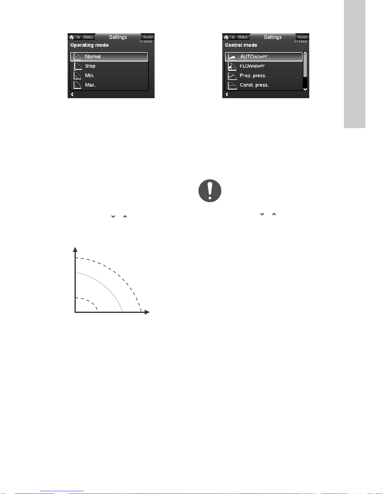
8.6.2 "
2SHUDWLQJPRGH
2SHUDWLQJPRGH
&RQWUROPRGH
&RQWUROPRGH
H
Q
"
8.6.3 "
"
English (GB)
Navigation
"+RPH" > "6HWWLQJV" > "2SHUDWLQJPRGH"
"
"
•"1RUPDO"
The pump runs according to the selected control mode.
•"6WRS"
The pump stops.
•"0LQ"
Use the minimum-curve mode in periods in which a minimum
flow is required. This operating mode is for instance suitable
for manual night setback if you do not want to use automatic
night setback.
•"0D["
Use the maximum-curve mode in periods in which a maximum
flow is required. This operating mode is for instance suitable
for systems with hot-water priority.
Setting:
1. Select operating mode with or .
2. Press [OK] to save.
You can set the pump to operate according to the maximum or
minimum curve, like an uncontrolled pump. See fig. 34.
0D[
3.1.2.0.0.0 2SHUDWLQ JPRGH
Navigation
"+RPH" > "6HWWLQJV" > "&RQWUROPRGH"
"
"
•"$872$'$37"
•")/2:$'$37"
•"3URSSUHVV" (proportional pressure)
•"&RQVWSUHVV" (constant pressure)
•"&RQVWWHPS" (constant temperature)
•"'LIIHUHQWLDOWHPS" (differential temperature)
•"&RQVWDQWFXUYH".
Set the operating mode to "1RUPDO" before you
enable a control mode.
Setting:
1. Select control mode with or .
2. Press [OK] to enable the control mode.
You can change the setpoint for all control modes, except
AUTO
"6HWWLQJV" when you have selected the desired control mode.
ADAPT
and FLOW
, in the "6HWSRLQW" submenu under
ADAPT
You can combine all control modes, except "&RQVWDQWFXUYH", with
automatic night setback. See section 8.6.6 "
6HWEDFN
".
You can also combine the FLOW
control modes mentioned above. See section
8.6.5 "
)/2:/,0,7
".
LIMIT
$XWRPDWLF1LJKW
function with the last five
3.1.3.0.0.0 &RQWUROPRGH
0LQ
TM05 2446 5111
Fig. 34 Maximum and minimum curves
27
Page 28

"
$872$'$37
)/2:$'$37
3URSSUHVV
&RQVWSUHVV
H
Q
H
auto_min
H
fac
A
1
A
3
A
2
H
set1
H
set2
H
Q
Q
max
90 %
Q
max
25 %
H
auto_min
H
fac
Q
fac
H
Q
H
set
H
set
2
H
Q
English (GB)
The AUTO
performance according to the actual system characteristic.
"
control mode continuously adapts the pump
ADAPT
Manual setting of the setpoint is not possible.
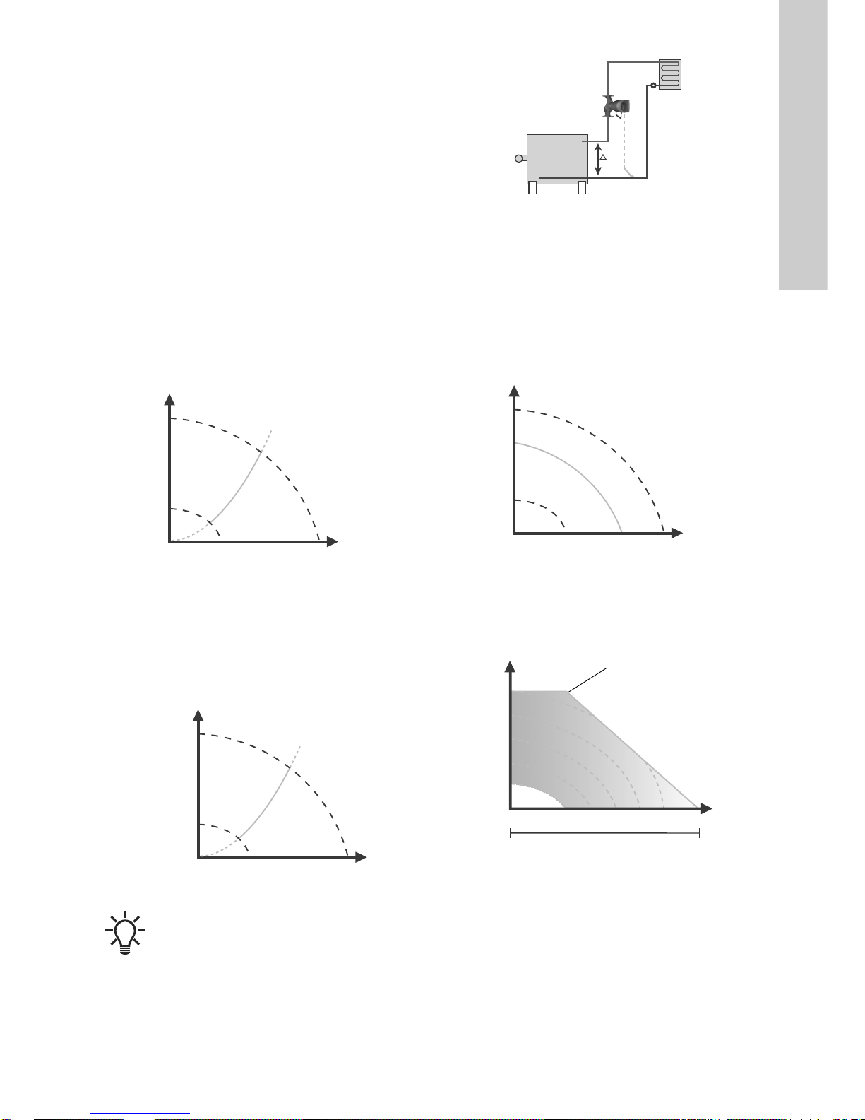
Fig. 35 AUTO
When the AUTO
starts with the factory setting, H
corresponding to approximately 55 % of its maximum head, and
then adjust its performance to A
ADAPT
control mode has been enabled, the pump
ADAPT
is equal to H
fac
. See fig. 35.
1
When the pump registers a lower head on the maximum curve,
A
, the AUTO
2
correspondingly lower control curve, H
system close, the pump adjusts its performance to A
function automatically selects a
ADAPT
. If the valves in the
set2
A1: Original duty point.
A
: Lower registered head on the maximum curve.
2
A
: New duty point after AUTO
3
: Original setpoint setting.
H
set1
H
: New setpoint after AUTO
set2
H
: See section 8.7 Setting values for control modes.
fac.
H
The AUTO
control where the control curves have a fixed origin, H
The AUTO
for heating systems and we do not recommended that you use it
: A fixed value of 1.5 m.
auto_min
control mode is a form of proportional-pressure
ADAPT
control mode has been developed specifically
ADAPT
ADAPT
ADAPT
control.
for air-conditioning and cooling systems.
To r e s et A U T O
"
When you select FLOW
ensures that the flow never exceeds the entered FLOW
ADAPT
"
, see section "
, the pump runs AUTO
ADAPT
5HWXUQWRIDFWRU\VHWWLQJV
value.
The setting range for the FLOW
maximum flow rate of the pump.
The factory setting of the FLOW
AUTO
36.
Do not set the FLOW
factory setting meets the maximum curve. See fig.
ADAPT
lower than the dimensioned duty point.
LIMIT
is 25 to 90 % of the
LIMIT
is the flow where the
LIMIT
,
set1
3
control.
ADAPT
.
auto_min
LIMIT
.
".
and
"
"
The head is reduced at decreasing flow demand and increased at
rising flow demand. See fig. 37.
You can set the setpoint with an accuracy of 0.1 metre. The head
against a closed valve is the setpoint.
TM05 2452 1312
Fig. 37 Proportional pressure
"
"
We recommend this control mode if the pump is to deliver a
constant pressure, independently of the flow in the system. See
fig. 38.
Fig. 38 Constant pressure
TM05 2448 1212TM05 2449 0312
Setting range
Fig. 36 FLOW
28
ADAPT
TM05 3334 1212
Page 29
"
&RQVWWHPS
'LIIHUHQWLDOWHPS
&RQVWDQWFXUYH
H
Q
H
Q
t
H
Q
Q
This control mode ensures a constant temperature. Constant
temperature is a comfort control mode that you can use in
domestic hot-water systems to control the flow to maintain a fixed
temperature in the system. See fig. 39. When you use this control
mode, do not install any balancing valves in the system.
If the pump is installed in the flow pipe, install a temperature
sensor in the return pipe of the system. Install the sensor as close
as possible to the consumer for example a radiator or heat
exchanger.
We recommend that you install the pump in the flow pipe.
If the pump is installed in the return pipe of the system, you can
use the internal temperature sensor. In this case, install the pump
as close as possible to the consumer for example a radiator or
heat exchanger.
The constant-temperature control mode also reduces the risk of
bacterial growth in the system, for example legionella.
Sensor range:
• minimum -10 °C
• maximum 130 °C.
To ensure that the pump is able to control the temperature, we
recommend that you set the sensor range between -5 and +125
°C.
"
Fig. 41 Differential temperature
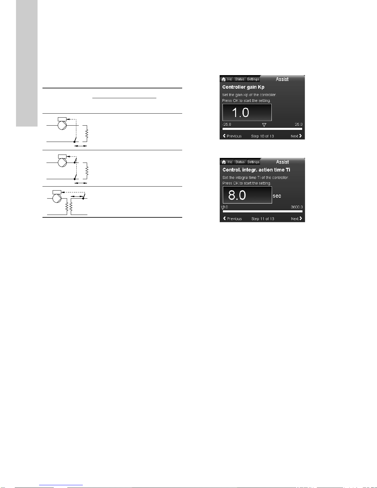
The controller constants, that is the gain, K
are factory-set to gain is equal to 1 and integral time is equal to 8
seconds. In some cases, you must change the settings
depending on the application and controlled parameter. See
section 8.6.4 "
"
You can set the pump to operate according to a constant curve,
like an uncontrolled pump. See fig. 42.
You can set the desired speed in % of maximum speed in the
range from minimum to 100 %.
&RQWUROOHUVHWWLQJV
"
".
and integral time,Ti,
p,
English (GB)
TM05 8236 2113TM05 2446 0312TM05 4266 2212
Fig. 39 Constant temperature
"
This control mode ensures a constant differential-temperature
drop across heating and cooling systems.
The differential-temperature control mode is available from model
B. The model version is stated on the nameplate. See fig. 22.
In this control mode, the pump maintains a constant differential
temperature between the pump and the external sensor. See
figures 40 and 41.
Fig. 40 Differential temperature
"
˂t
It is necessary to install an external temperature
sensor.
TM05 2451 5111TM05 2451 5111
Fig. 42 Constant curve
If you have set the pump speed in the range between minimum
and maximum, the power and pressure are limited when the
pump is running on the maximum curve. This means that the
maximum performance can be achieved at a speed lower than
100 %. See fig. 43.
H
Limited maximum curve
70%
50%
30%
Min.
Speed setting from min. to 100 %
Fig. 43 Power and pressure limitations influencing the
maximum curve
90%
29
Page 30
8.6.4 "
&RQWUROOHUVHWWLQJV
t
L2 [m]
˂t
L2 [m]
3)
L2 [m]
t
English (GB)
"
A change of the gain and integral-time values affects all control
modes. If you change the control mode to another control mode,
change the gain and integral-time values to the factory settings.
Factory settings for all other control modes:
The gain, K
The integral time, T
, is equal to 1.
p
, is equal to 8.
i
The table below shows the suggested controller settings:
If you use a built-in temperature sensor as one of the sensors,
you must install the pump as close as possible to the consumer.
K
p
System/application
Heating
system
Cooling
1)
system
Guidelines for setting of PI controller
For most applications, the factory setting of the controller
constants, gain and integral time, ensures optimum pump
operation. However, in some applications an adjustment of the
controller may be required.
You find the setpoint displayed in figures 44 and 45. For further
information about setup, see the "$VVLVW" menu in section
$VVLVWHGSXPSVHWXS
8.8.1 "
T
2)
i
".
0.5 - 0.5
10 + 5
(L
10 + 5
- 0.5
(L
0.5 - 0.5 30 + 5L
1)
In heating systems, an increase in pump performance results
in a rise in temperature at the sensor.
2)
In cooling systems, an increase in pump performance results
in a drop in temperature at the sensor.
3)
Built-in temperature sensor.
L1: Distance in metres between pump and consumer.
L2: Distance in metres between consumer and sensor.
1
1
+ L2)
+ L2)
undef-079undef-080
Fig. 44 "&RQWUROOHUJDLQ.S"
2
Fig. 45 "&RQWUROLQWHJUDFWLRQWLPH7L"
Proceed as follows:
1. Increase the gain until the motor becomes unstable. Instability
can be seen by observing if the measured value starts to
fluctuate. Furthermore, instability is audible as the motor
starts hunting up and down.
Some systems, such as temperature controls, are
slow-reacting, meaning that it may be several minutes before
the motor becomes unstable.
2. Set the gain to half the value of the value which made the
motor unstable.
3. Reduce the integral time until the motor becomes unstable.
4. Set the integral time to twice the value which made the motor
unstable.
Rules of thumb
If the controller is too slow-reacting, increase the gain.
If the controller is hunting or unstable, dampen the system by
reducing the gain or increasing the integral time.
Model A:
Use Grundfos GO to change the controller constants, gain and
integral time. You can only set positive values.
Model B and C:
Change the control settings by means of the display or Grundfos
GO. You can set both positive and negative values.
30
Page 31
8.6.5 "
)/2:/,0,7
$XWRPDWLF1LJKW6HWEDFN
$XWRPDWLF1LJKW6HWEDFN
H
Q
Q
max
Q
limit
90 %
Q
max
25 %
"
8.6.6 "
"
English (GB)
LIMIT
3.1.5.0.0.0 FLOW
Navigation
"+RPH" > "6HWWLQJV" > ")/2:/,0,7"
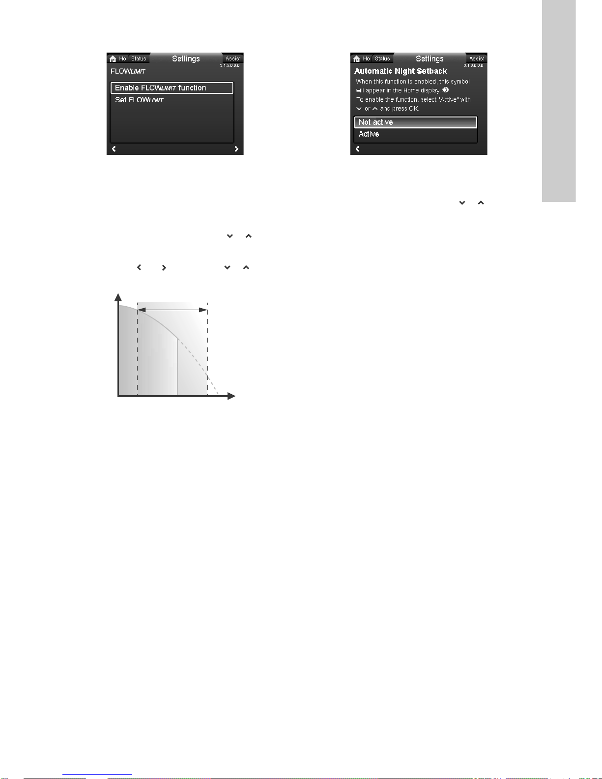
"FLOW
LIMIT
"
•"(QDEOH)/2:/,0,7IXQFWLRQ"
•"6HW)/2:/,0,7".
Setting:
1. To enable the function, select "$FWLYH" with or and press
[OK].
2. To set the FLOW
, press [OK].
LIMIT
3. Select digit with and and adjust with or .
4. Press [OK] to save.
Setting range
TM05 2445 1212
Fig. 46 FLOW
You can combine the FLOW
control modes:
LIMIT
function with the following
LIMIT
•"3URSSUHVV"
•"&RQVWSUHVV"
•"&RQVWWHPS"
•"&RQVWDQWFXUYH".
A flow-limiting function ensures that the flow never exceeds the
entered FLOW
The setting range for FLOW
pump.
The factory setting of the FLOW
AUTO
ADAPT
36.
value.
LIMIT
factory setting meets the maximum curve. See fig.
is 25 to 90 % of the Q
LIMIT
is the flow where the
LIMIT
max
of the
Navigation
"+RPH" > "6HWWLQJV" > "$XWRPDWLF1LJKW6HWEDFN"
"
"
To enable the function, select "$FWLYH" with or and press
[OK].
Once you have enabled automatic night setback, the pump
automatically changes between normal duty and night setback,
i.e. duty at low demand. The changeover depends on the
flow-pipe temperature.
The pump automatically changes over to night setback when the
built-in sensor registers a flow-pipe temperature drop of more
than 10 to 15 °C within approximately two hours. The temperature
drop must be at least 0.1 °C/min.
Changeover to normal duty takes place without a time lag when
the temperature has increased by approximately 10 °C.
You cannot enable automatic night setback when the pump is in
constant-curve mode.
3.1.6.0.0.0 $XWRPDWLF1LJKW6HWEDFN
31
Page 32

8.6.7 "
$QDORJ,QSXW
$QDORJ,QSXW
)XQFWLRQRIDQDORJLQSXW
5HOD\RXWSXWV
5HOD\RXWSXWV
English (GB)
"
In this menu, you can set an analog input such as a temperature
sensor to activate the heat-energy-monitor function. See fig. 57.
Navigation
"+RPH" > "6HWWLQJV" > "$QDORJ,QSXW"
"
"
•")XQFWLRQRIDQDORJLQSXW"
•"8QLW"
•"6HQVRUUDQJHPLQYDOXH"
•"6HQVRUUDQJHPD[YDOXH"
•"(OHFWULFDOVLJQDO".
"
"
Choose the function of input, for example heat energy monitor as
in the example below.
Navigation
"+RPH" > "6HWWLQJV" > "$QDORJ,QSXW" > ")XQFWLRQRIDQDORJLQSXW"
•"1RWDFWLYH"
•"'LIIHUHQWLDOSUHVVXUHFRQWURO"
•"&RQVWDQWWHPSHUDWXUHFRQWURO"
•"'LIIHUHQWLDOSUHVVXUHFRQWURO"
•"+HDWHQHUJ\PRQLWRU"
•"([WHUQDOVHWSRLQWLQIOXHQFH"
Setting:
1. Select function mode with or .
2. Press [OK] to enable the function mode.
When you have selected the function of the input, specify the
sensor parameters by filling in the right values in unit, sensor
range, etc.
You can also set the analog input via the "Assist" menu where a
wizard guides you through each step of the configuration. See
8.8.5 "
6HWXSDQDORJLQSXW
".
8.6.8 "
"
Navigation
"+RPH" > "6HWWLQJV" > "5HOD\RXWSXWV"
3.1.7.0.0.0 Analog input3.1.7.1.0.0 Function of input
"
"
•"5HOD\RXWSXW"
•"5HOD\RXWSXW".
You can set the relay outputs to the following:
•"1RWDFWLYH"
•"5HDG\"
•"$ODUP"
•"2SHUDWLRQ".
The pump incorporates two signal relays for a potential-free
alarm signal, ready signal and operating signal. For further
information, see section 7.4.1 Relay outputs.
Set the function of the signal relays, alarm signal (factory setting),
ready signal and operating signal on the pump control panel.
The output is electrically separated from the rest of the controller.
The signal relay is operated as follows:
•"1RWDFWLYH"
The signal relay is deactivated.
•"5HDG\"
The signal relay is active when the pump is running or has
been set to stop, but is ready to run.
•"$ODUP"
The signal relay is activated together with the red indicator
light on the pump.
•"2SHUDWLRQ"
The signal relay is activated together with the green indicator
light on the pump.
3.1.12.0.0.0 5HOD\RXWSXWV
32
Page 33

8.7 Setting values for control modes
The setting values for FLOW
as percent of maximum flow, but you must enter the value in m
in the "6HWWLQJV" menu.
The maximum flow is a theoretical value corresponding to H is
equal to 0. The actual maximum flow is dependent on the system
characteristics.
ADAPT
and FLOW
are indicated
LIMIT
3
/h
English (GB)
Pump type
AUTO
ADAPT
H
fac
[m] [m
max
3
/h] [m3/h] [m3/h]
Q
fac
Q
FLOW
ADAPT
and FLOW
Q
LIMIT
max
MAGNA3 25-40 (N) 2.5 8 3.7 7.2
MAGNA3 25-60 (N) 3.5 10 5.0 9.0
MAGNA3 25-80 (N) 4.5 11 5.5 9.9
MAGNA3 25-100 (N) 5.5 12 6.1 10.8
MAGNA3 25-120 (N) 6.5 13 6.2 11.7
MAGNA3 (D) 32-40 (F) (N) 2.5 9 5.0 8.1
MAGNA3 (D) 32-60 (F) (N) 3.5 11 5.9 9.9
MAGNA3 (D) 32-80 (F) (N) 4.5 12 6.4 10.8
MAGNA3 (D) 32-100 (F) (N) 5.5 13 6.7 11.7
MAGNA3 32-120 (N) 6.5 13 6.2 11.7
MAGNA3 (D) 32-120 F (N) 6.5 23 12.0 20.7
MAGNA3 (D) 40-40 F (N) 2.5 16 7.5 14.4
MAGNA3 (D) 40-60 F (N) 3.5 19 10.5 17.1
MAGNA3 (D) 40-80 F (N) 4.5 22 13.0 19.8
MAGNA3 (D) 40-100 F (N) 5.5 24 15.0 21.6
MAGNA3 (D) 40-120 F (N) 6.5 29 16.0 26.1
MAGNA3 (D) 40-150 F (N) 8.0 32 18.0 28.8
MAGNA3 (D) 40-180 F (N) 9.5 32 15.0 28.8
MAGNA3 (D) 50-40 F (N) 2.5 22 13.0 19.8
MAGNA3 (D) 50-60 F (N) 3.5 29 17.0 26.1
MAGNA3 (D) 50-80 F (N) 4.5 31 17.0 27.9
MAGNA3 (D) 50-100 F (N) 5.5 34 18.0 30.6
MAGNA3 (D) 50-120 F (N) 6.5 39 19.0 35.1
MAGNA3 (D) 50-150 F (N) 8.0 42 20.0 37.8
MAGNA3 (D) 50-180 F (N) 9.5 45 19.0 40.5
MAGNA3 (D) 65-40 F (N) 2.5 33 18.0 29.7
MAGNA3 (D) 65-60 F (N) 3.5 40 24.0 36
MAGNA3 (D) 65-80 F (N) 4.5 45 25.0 40.5
MAGNA3 (D) 65-100 F (N) 5.5 48 26.0 43.2
MAGNA3 (D) 65-120 F (N) 6.5 52 30.0 46.8
MAGNA3 (D) 65-150 F (N) 8.0 61 40.0 54.9
MAGNA3 (D) 80-40 F 2.5 49 32.0 44.1
MAGNA3 (D) 80-60 F 3.5 58 37.0 52.2
MAGNA3 (D) 80-80 F 4.5 66 40.0 59.4
MAGNA3 (D) 80-100 F 5.5 69 47.0 62.1
MAGNA3 (D) 80-120 F 6.5 74 48.0 66.6
MAGNA3 (D) 100-40 F 2.5 55 40.0 49.5
MAGNA3 (D) 100-60 F 3.5 63 43.0 56.7
MAGNA3 (D) 100-80 F 4.5 73 50.0 65.7
MAGNA3 (D) 100-100 F 5.5 79 52.0 71.1
MAGNA3 (D) 100-120 F 6.5 85 57.0 76.5
The duty ranges for proportional-pressure and constant-pressure
control appear from the data sheets in the MAGNA3 data booklet.
In constant-curve duty, you can control the pump from minimum
to 100 %. The range of control depends on the minimum speed,
power and pressure limits of the pump.
90 %
33
Page 34

8.7.1 "
6HWSRLQWLQIOXHQFH
6HWSRLQWLQIOXHQFH
([WHUQDOVHWSRLQWIXQFWLRQ
7HPSHUDWXUHLQIOXHQFH
rpm
V
Min.
02
Max.
10
H
T [°C]
30 %
20 50 80
100 %
H
actual
T
actual
H
Q
English (GB)
"
Navigation
"+RPH" > "6HWWLQJV" > "6HWSRLQWLQIOXHQFH"
"
"
•"([WHUQDOVHWSRLQWIXQFWLRQ"
•"7HPSHUDWXUHLQIOXHQFH".
"
"
An external 0-10 V or 4-20 mA signal controls the pump speed in
a range from minimum to 100 % in a linear function. See fig. 47.
Range
4-20 mA [0-100 %]
0-10 V [0-100 %]
Control
0-20 % e.g. 0-2 V Setpoint is equal to minimum.
20-100 % e.g. 2-10 V
Setpoint is equal from
minimum to setpoint.
If the analog input is set to external setpoint influence, the
external setpoint function is automatically activated with "/LQHDU
ZLWK0,1". See section 7.4.3 Analog input.
Fig. 47 "([WHUQDOVHWSRLQWIXQFWLRQ", 0-10 V
The range of control depends on the minimum speed, power and
pressure limits of the pump.
You can configure the analog input to an external setpoint
function in "6HWWLQJV" or in the "$VVLVW" menu. See section
7.4.3 Analog input.
"
"
When this function is enabled in proportional- or
constant-pressure control mode, the setpoint for head is reduced
according to the liquid temperature.
You can set the temperature influence to function at liquid
temperatures below 80 or 50 °C. These temperature limits are
called T
which is equal to 100 %, according to the characteristics below.
3.1.15.0.0.0 6HWSRLQWLQIOXHQFH
. The setpoint is reduced in relation to the head set
max.
Fig. 48 "7HPSHUDWXUHLQIOXHQFH"
In the above example, T
selected. The actual liquid temperature, T
setpoint for head to be reduced from 100 % to H
, which is equal to 80 °C, has been
max.
, causes the
actual
actual
The temperature influence function requires the following:
• proportional-pressure, constant-pressure or constant-curve
control mode
• pump installed in flow pipe
• system with flow-pipe temperature control.
Temperature influence is suitable for the following systems:
• Systems with variable flows for example two-pipe heating
systems, in which the enabling of the temperature influence
function ensures a further reduction of the pump performance
in periods with small heating demands and consequently a
reduced flow-pipe temperature.
• Systems with almost constant flows, for example one-pipe
heating systems and underfloor heating systems, in which
variable heating demands cannot be registered as changes in
the head as is the case with two-pipe heating systems. In such
systems, you can only adjust the pump performance by
enabling the temperature influence function.
Selection of maximum temperature
In systems with a dimensioned flow-pipe temperature:
• Up to and including 55 °C, select a maximum temperature
TM05 3219 1212
equal to 50 °C.
• Above 55 °C, select a maximum temperature
equal to 80 °C.
You cannot use the temperature influence function in
air-conditioning and cooling systems.
TM05 3022 1212
.
34
3.1.15.10.0 ([WHUQDOVHWSRLQWIXQFWLRQ
Page 35

8.7.2 "
%XVFRPPXQLFDWLRQ
3XPSQXPEHU
3XPSQXPEHU
)RUFHGORFDOPRGH
)RUFHGORFDOPRGH
*HQHUDOVHWWLQJV
/DQJXDJH
/DQJXDJH
"
Navigation
"+RPH" > "6HWWLQJV" > "%XVFRPPXQLFDWLRQ"
"Bus communication"
•"3XPSQXPEHU"
•")RUFHGORFDOPRGH"
"
"
Navigation
"+RPH" > "6HWWLQJV" > "%XVFRPPXQLFDWLRQ" > "3XPSQXPEHU"
"
"
You can allocate a unique number to the pump. This makes it
possible to distinguish between pumps in connection with bus
communication.
"
"
You can temporarily override remote commands from a building
management systems to make local settings. Once you have
disabled "
)RUFHGORFDOPRGH", the pump reconnects to the
network when it receives a remote command from the building
management system.
Navigation
"+RPH" > "6HWWLQJV" > "%XVFRPPXQLFDWLRQ" > ")RUFHGORFDO
PRGH"
"
"
•"(QDEOH"
•"'LVDEOH".
8.7.3 "
"
3.1.18.0.0.0 Bus communication
"
"
Navigation
"+RPH" > "6HWWLQJV" > "*HQHUDOVHWWLQJV" > "/DQJXDJH"
"
"
The display can be shown in any of the following languages:
• Bulgarian
• Croatian
• Czech
• Danish
•Dutch
• English
• Estonian
•Finnish
•French
•German
•Greek
3.1.18.1.0.0 3XPSQXPEHU
• Hungarian
• Italian
• Japanese
•Korean
• Latvian
• Lithuanian
• Polish
• Portuguese
• Romanian
• Russian
• Serbian
• Simplified Chinese
•Slovak
• Slovenian
•Spanish
•Swedish
•Turkish
• Ukrainian.
Measuring units are automatically changed according to the
selected language.
Setting:
1. Select language with and .
3.1.18.2.0.0 Forced local mode
2. Press [OK] to enable the language.
English (GB)
3.1.19.1.0.0 /DQJXDJ H
35
Page 36

"
6HWGDWHDQGWLPH
6HWGDWHDQGWLPH
6HOHFWGDWHIRUPDW
6HOHFWWLPHIRUPDW
8QLWV
8QLWV
(QDEOHGLVDEOHVHWWLQJV
(QDEOHGLVDEOHVHWWLQJV
English (GB)
"
Navigation
"+RPH" > "6HWWLQJV" > "*HQHUDOVHWWLQJV" > "6HWGDWHDQGWLPH"
"
"
•"6HOHFWGDWHIRUPDW"
•"6HWGDWH"
•"6HOHFWWLPHIRUPDW"
•"6HWWLPH".
Set the real-time clock in this menu.
"
"
•"<<<<00''"
•"''00<<<<"
•"00''<<<<".
Setting:
1. Select "6HWGDWH".
2. Press [OK].
3. Select digit with and and adjust with or .
4. Press [OK] to save.
"
"
•"++00KRXUFORFN"
•"++00DPSPKRXUFORFN".
Setting:
1. Select "6HWWLPH".
2. Press [OK].
3. Select digit with and and adjust with or .
4. Press [OK] to save.
"
"
In this menu you can select between SI and US units. The setting
can be made generally for all parameters or customised for each
individual parameter.
•"3UHVVXUH"
•"'LIIHUHQWLDOSUHVVXUH"
•"+HDG"
•"/HYHO"
•")ORZUDWH"
•"9ROXPH"
•"7HPSHUDWXUH"
•"'LIIHUHQWLDOWHPS"
3.1.19.2.0.0 6HWGDWHDQGWLPH3.1.19.3.0.0 8QLWV
•"3RZHU"
•"(QHUJ\".
Setting:
1. Select parameter and press [OK].
2. Select unit with or .
3. Press [OK].
If you have selected 6,RU86XQLWV, the customised units are
reset.
"
"
Navigation
"+RPH" > "6HWWLQJV" > "*HQHUDOVHWWLQJV" > "(QDEOHGLVDEOH
VHWWLQJV"
"
"
In this display, you can disable the possibility of making settings .
Select "'LVDEOH" with or and press [OK].
The pump is now locked for settings. Only the "+RPH" display is
available.
To unlock the pump and allow settings, press and
simultaneously for at least 5 seconds or enable the settings again
in the menu.
3.1.19.4.0.0 (QDEOHGLVDEOHVHWWLQJV
Navigation
"+RPH" > "6HWWLQJV" > "*HQHUDOVHWWLQJV" > "8QLWV"
"
"
•"6,RU86XQLWV"
•"&XVWRPLVHGXQLWV".
36
Page 37

"
$ODUPDQGZDUQLQJVHWWLQJV
+RPH
6HWWLQJV
*HQHUDOVHWWLQJV
$ODUPDQGZDUQLQJ
VHWWLQJV
'U\UXQQLQJ
,QWHUQDOVHQVRUIDXOW
,QWHUQDOIDXOW
'HOHWHKLVWRU\
'HOHWHKLVWRU\
'HILQH+RPHGLVSOD\
6HOHFW+RPHGLVSOD\W\SH
'HILQH+RPHGLVSOD\FRQWHQWV
"
Navigation
"
" > "
"
" > "
" > "
"Settings"
•"'U\UXQQLQJ"
•",QWHUQDOVHQVRUIDXOW"
•",QWHUQDOIDXOW"
"
"
•"(QDEOH"
•"'LVDEOH"
The dry running detection is disabled by default on all pumps
from production code 1529. The production code is on the
nameplate. Enable the dry-running function, if there is a risk of
dry running.
"
"
•"(QDEOH"
•"'LVDEOH"
In case of a sensor problem related to the quality of the liquid, the
pump is able to continue operation with satisfactory performance
in most situations. In such situations, you can disable ",QWHUQDO
VHQVRUIDXOW".
"
"
•"(QDEOH"
•"'LVDEOH"
If the real-time clock is out of order, for example due to a dead
battery, a warning is shown. You can disable the warning.
"
"
"
"
•"'HOHWHRSHUDWLQJORJ"
•"'HOHWHKHDWHQHUJ\GDWD"
•"'HOHWHHQHUJ\FRQVXPSWLRQ".
In this menu, you can delete data from the pump, for example if
the pump is moved to another system or if new data are required
due to changes to the system.
Setting:
1. Select submenu and press [OK].
2. Select "<HV" with or and press [OK] or press to
cancel.
3.1.19.12.0.0 Alarm and warning settings
"
"
Navigation
"+RPH" > "6HWWLQJV" > "*HQHUDOVHWWLQJV" > "'HILQH+RPHGLVSOD\"
"'HILQH+RPHGLVSOD\"
•"6HOHFW+RPHGLVSOD\W\SH"
•"'HILQH+RPHGLVSOD\FRQWHQWV".
In this menu, you can set the +RPH display to show up to four
user-set parameters or a graphical illustration of a performance
curve.
"
"
1. Select "/LVWRIGDWD" or "*UDSKLFDOLOOXVWUDWLRQ" with or .
2. Press [OK] to save.
To specify the contents, go to "'HILQH+RPHGLVSOD\FRQWHQWV".
"
"
1. To set "/LVWRIGDWD", press [OK]. A list of parameters appears
in the display.
2. Select or deselect with [OK].
The selected parameters are shown below. The arrow indicates
that the parameter links to the "6HWWLQJV" menu and works as a
shortcut for quick settings.
English (GB)
3.1.19.6.0.0 'HILQH+RPHGLVSOD\'HILQH+RPHGLVSOD\FRQW HQWV
Navigation
"+RPH" > "6HWWLQJV" > "*HQHUDOVHWWLQJV" > "'HOHWHKLVWRU\"
3.1.19.5.0.0 'HOHWHKLVWRU\
1. To set "*UDSKLFDOLOOXVWUDWLRQ", press [OK].
2. Select the desired curve.
3. Press [OK] to save.
37
Page 38

"
'LVSOD\EULJKWQHVV
%ULJKWQHVV
5HWXUQWRIDFWRU\VHWWLQJV
5HWXUQWRIDFWRU\VHWWLQJV
5XQVWDUWXSJXLGH
5XQVWDUWXSJXLGH
$VVLVW
$VVLVW
$VVLVWHGSXPSVHWXS
6HWWLQJRIGDWHDQGWLPH
English (GB)
"
8.8 "
" menu
Navigation
"+RPH" > "6HWWLQJV" > "*HQHUDOVHWWLQJV" > "'LVSOD\EULJKWQHVV"
"
1. Press [OK].
2. Set brightness with and .
3. Press [OK] to save.
"
Navigation
"+RPH" > "6HWWLQJV" > "*HQHUDOVHWWLQJV" > "5HWXUQWRIDFWRU\
VHWWLQJV"
"
You can recall the factory settings and overwrite the current
settings. All user settings in the "6HWWLQJV" and "$VVLVW" menus are
set back to the factory settings. This also includes language,
units, setup of analog input, multipump function, etc.
To overwrite the current settings with the factory settings, select
"<HV" with or and press [OK].
"
"
"
"
"
3.1.19.7.1.0 %ULJKWQHVV3.1.19.10.1.0 5HWXUQWRIDFWRU\VHWWLQJV3.1.19.11.0.0 5XQVWDUWXSJXLGH
Navigation
"+RPH" > "$VVLVW"
Press and go to the "$VVLVW" menu with .
"
" menu
This menu offers the following:
•"$VVLVWHGSXPSVHWXS"
•"6HWWLQJRIGDWHDQGWLPH"
•"0XOWLSXPSVHWXS"
•"6HWXSDQDORJLQSXW"
•"'HVFULSWLRQRIFRQWUROPRGH"
•"$VVLVWHGIDXOWDGYLFH".
The "$VVLVW" menu guides the user through the setting of the
pump. In each submenu, there is a guide that guides the user
through the setting of the pump.
8.8.1 "
This menu guides you through a complete pump setup, starting
with a presentation of the control modes and ending with the
setpoint setting.
8.8.2 "
See section "
6HWGDWHDQGWLPH
"
"
".
$VVLVW
Navigation
"+RPH" > "6HWWLQJV" > "*HQHUDOVHWWLQJV" > "5XQVWDUWXSJXLGH"
"
The startup guide automatically starts when you start the pump
for the first time.
You can always run the startup guide later via this menu. The
startup guide guides the user through the general settings of the
pump, such as language, date and time.
To run the startup guide, select "<HV" with or and press
[OK].
"
38
Page 39

8.8.3 "
0XOWLSXPSVHWXS
$OWHUQDWLQJRSHUDWLRQ
%DFNXSRSHUDWLRQ
I is defined as master.
"
Navigation
"+RPH" > "$VVLVW" > "0XOWLSXPSVHWXS"
1. Follow the step-by-step guide to complete the multipump
setup.
2. Check the entered values.
3. Press [OK] to confirm and enable the settings.
Multipump function
The multipump function enables the control of single-head pumps
connected in parallel and twin-head pumps without the use of
external controllers. The pumps in a multipump system
communicate with each other via the wireless GENIair
connection.
Pump system:
• Twin-head pump.
• Two single-head pumps connected in parallel. The pumps
must be of the same type and size. Each pump requires a
non-return valve in series with the pump.
You can set a multipump system from a selected pump, which will
then be the master pump.
Check the nameplate to identify the master pump. See fig. 52.
XXXXXXXXXXXXXXXXXXXXXXXX
P/N: XXXXXXXX
IP XXX TF XXX
S/N: XXXXXXXX
((,;;;3DUW;
PC: XXXX
Made in Germany
Model: X
Grundfos Holding A/S, DK - 8850 Bjerringbro, Denmark
Undef-083 Select multi pump functionTM067498 3516TM06 7499 3516TM06 7500 3516
1 [W] MPa
I1 [A] P
0LQ
;;;
XXXX
0D[
;;
XXXX;;;
Fig. 52 Identify the master pump on a twin-head pump
"
"
Fig. 53 "$OWHUQDWLQJRSHUDWLRQ"
Alternating operation functions as a duty-standby operating mode
and is possible with two pumps of same size and type connected
in parallel. The main purpose of the function is to ensure an even
amount of running hours and to ensure that the standby pump
takes over if the running pump stops due to an alarm.
"
"
English (GB)
TM06 6890 2516TM06 7501 3516TM06 7502 3516
Fig. 49 Single-head pumps connected in parallel
Check the display to identify the master pump in a multipump
system. See fig. 50 and "Home" display icons.
Fig. 50 Identify the master pump in a multipump system
A twin-head pump is set to multipump function from factory. Here
pump head I is defined as master pump.
Fig. 51 Twin-head pumps
Fig. 54 "%DFNXSRSHUDWLRQ"
Backup operation is possible with two pumps of same size and
type connected in parallel. Each pump requires a non-return
valve in series with the pump.
One pump is running continuously. The backup pump is operated
for a short time each day to prevent seizing up. If the duty pump
stops due to a fault, the backup pump starts automatically.
39
Page 40

"
&DVFDGHRSHUDWLRQ
1RPXOWLSXPSIXQFWLRQ
6HWXSDQDORJLQSXW
+HDWHQHUJ\PRQLWRU
English (GB)
Fig. 55 "&DVFDGHRSHUDWLRQ"
Cascade operation ensures that the pump performance is
automatically adapted to the consumption by switching pumps on
or off. The system thus runs as energy-efficiently as possible with
a constant pressure and a limited number of pumps.
When a twin-head pump is running in constant-pressure control
mode, the second pump starts at 90 % of the maximum
performance. The second pump stops automatically when it is no
longer needed to fulfil the system demand. If both pumps are
running, they run at the same speed.
Pump system:
• Set the control mode to "&RQVWSUHVV" or "&RQVWDQWFXUYH".
"
Fig. 56 "1RPXOWLSXPSIXQFWLRQ"
The pumps run as single-head pumps.
8.8.4 External connections in a multipump systems
The following external connections need only to be fitted to the
master pump:
• analog input
• digital input
• communication interface module, CIM.
If you want to monitor a slave pump, mount a communication
interface module on the slave pump too.
Set the following on both the master and slave pump:
• Relays
From model B. Configure on both master and slave pump.
• Operating mode, control mode and setpoint
These modes are system parameters and they are shared
between the two pumps.
• Heat energy monitor
The heat energy monitor works on the system level.
Therefore, both pumps display the heat energy for the system,
not for the individual pump.
"
"
8.8.5 "
This menu guides you through the setup of the analog inputs, for
example a temperature sensor input to a heat energy monitor.
TM06 7498 3516TM06 7503 3516
Navigation
"+RPH" > "$VVLVW" > "6HWXSDQDORJLQSXW"
1. To enable the sensor input, select "+HDWHQHUJ\PRQLWRU" with
or and press [OK].
2. Follow the step-by-step guide to complete the sensor-input
setup. Start with the unit display and end with the summary
display.
3. Check the entered values.
4. Press [OK] to confirm and enable the settings.
8.8.6 "
The heat energy monitor is a monitoring function that calculates
the heat energy consumption within a system. The built-in flow
estimation needed for the calculation has an inaccuracy of ± 10 %
of the maximum flow. Also, the temperature measurements
needed for the calculation have some inaccuracy depending on
the sensor type. Therefore, you cannot use the heat energy value
for billing purposes. However, the value is perfect for optimisation
purposes in order to prevent excessive energy costs caused by
system imbalances.
The heat energy monitor requires an additional temperature
sensor installed in the flow pipe or return pipe depending on
where the pump is installed.
"
"
kWh
+HDWHQHUJ\PRQLWRU
undef-147TM05 5367 3612
40
t
F
t
R
Fig. 57 MAGNA3 with built-in heat energy monitor
Page 41

"
+HDWHQHUJ\
+HDWHQHUJ\
H
Q
Max.
Min.
Qmax
H
Q
Right pump head
Left pump head
"
Navigation
"+RPH" > 6WDWXV > "+HDWHQHUJ\PRQLWRU" > "+HDWHQHUJ\"
"
"
You can measure both heating and cooling in the same system. If
a system is used for both heating and cooling, two counters are
automatically shown in the display.
The time stamp of the date indicates the latest use of the specific
counter.
The value of "latest year (2)" represents the last 52 consecutive
weeks where the pump has been supplied with power. The user
can reset the value manually.
8.9 External setpoint influence
External setpoint influence is typically used to control the speed
according to a setpoint by means of a 0-10 V signal.
Follow the step-by-step guide to complete the sensor input setup.
Start with the unit display and end with the summary display.
1. Check the entered values.
2. Press [OK] to confirm and enable the settings.
3. Return to the "6HWWLQJV" menu and find "([WHUQDOVHWSRLQW
IXQFWLRQ".
4. Choose "/LQHDUZLWK0,1" function. See section "
VHWSRLQWIXQFWLRQ
".
([WHUQDO
Example:
2.1.6.2.0.0 Heat energy
Fig. 58 Q
1. MAGNA3 65-60 has a Q
Typically 5 % accuracy means 2 m
m
2. This accuracy is valid for the entire QH area. If the pump
indicates 10 m
3. The flow rate can be from 8-12 m
max
of 40 m3/h.
max
3
/h.
3
/h, the measurement is 10 +/- 2 m3/h.
3
/h inaccuracy of Q
3
/h.
The use of a mixture of water and ethylene-glycol mixture will
decrease the accuracy.
If the flow is less than 10 % of Q
, the display shows a low flow.
max
8.11 Pump heads in twin-head pumps
The twin-head pump housing has a flap valve on the outlet side.
The flap valve seals off the port of the idle pump housing to
prevent the pumped liquid from running back to the inlet side. See
fig. 59. Due to the flap valve there is a difference in the hydraulic
between the two pump heads. See fig. 60.
max
English (GB)
TM05 2448 5111TM06 1565 2514TM06 1566 2514
+/- 2
8.10 Flow estimation accuracy
The internal sensor estimates the difference in pressure between
the inlet and outlet port of the pump. The measurement is not a
direct differential-pressure measurement, but by knowing the
hydraulic design of the pump, you can estimate the differential
pressure across the pump. The speed and power give a direct
estimation of the actual duty point at which the pump is running.
The calculated flow rate has an accuracy specified as +/- xx % of
Q
. The less flow through the pump, the less accurate the
max
reading will be. See also section 8.8.6 "
+HDWHQHUJ\PRQLWRU
".
Fig. 59 Twin-head pump housing with flap valve
Fig. 60 Hydraulic difference between the two pump heads
41
Page 42

The table below shows the flow accuracy of the complete
'HVFULSWLRQRIFRQWUROPRGH
$VVLVWHGIDXOWDGYLFH
English (GB)
MAGNA3 range. The typical accuracy is displayed along with the
worst-case value.
Single-head pumps and left-side pump
Q
Pump type
MAGNA3 25-40 (N) 8 0.4 0.8 - MAGNA3 25-60 (N) 10 0.5 1.0 - MAGNA3 25-80 (N) 11 0.55 1.1 - MAGNA3 25-100 (N) 12 0.6 1.2 - MAGNA3 25-120 (N) 13 0.65 1.3 - MAGNA3 (D) 32-40 (F) (N) 9 0.45 0.9 0.63 1.08
MAGNA3 (D) 32-60 (F) (N) 11 0.55 1.1 0.77 1.32
MAGNA3 (D) 32-80 (F) (N) 12 0.6 1.2 0.84 1.44
MAGNA3 (D) 32-100 (F) (N) 13 0.65 1.3 0.91 1.56
MAGNA3 32-120 (N) 13 0.65 1.3 - MAGNA3 (D) 32-120 F (N) 23 1.15 2.3 1.61 2.76
MAGNA3 (D) 40-40 F (N) 16 1.3 1.6 1.12 1.92
MAGNA3 (D) 40-60 F (N) 19 1.45 1.9 1.33 2.28
MAGNA3 (D) 40-80 F (N) 22 1.1 2.2 1.54 2.64
MAGNA3 (D) 40-100 F (N) 24 1.2 2.4 1.68 2.88
MAGNA3 (D) 40-120 F (N) 29 1.45 2.9 2.03 3.48
MAGNA3 (D) 40-150 F (N) 32 1.6 3.2 2.24 3.84
MAGNA3 (D) 40-180 F (N) 32 1.6 3.2 2.24 3.84
MAGNA3 (D) 50-40 F (N) 22 1.1 2.2 1.54 2.64
MAGNA3 (D) 50-60 F (N) 29 1.45 2.9 2.03 3.48
MAGNA3 (D) 50-80 F (N) 31 1.55 3.1 2.17 3.72
MAGNA3 (D) 50-100 F (N) 34 1.7 3.4 2.38 4.08
MAGNA3 (D) 50-120 F (N) 39 1.95 3.9 2.73 4.68
MAGNA3 (D) 50-150 F (N) 42 2.1 4.2 2.94 5.04
MAGNA3 (D) 50-180 F (N) 45 2.25 4.5 3.15 5.40
MAGNA3 (D) 65-40 F (N) 33 1.65 3.3 2.31 3.96
MAGNA3 (D) 65-60 F (N) 40 2.0 4.0 2.80 4.80
MAGNA3 (D) 65-80 F (N) 45 2.25 4.5 3.15 5.40
MAGNA3 (D) 65-100 F (N) 48 4.4 4.8 3.36 5.76
MAGNA3 (D) 65-120 F (N) 52 2.6 5.2 3.64 6.24
MAGNA3 (D) 65-150 F (N) 61 3.05 6.1 4.27 7.32
MAGNA3 (D) 80-40 F 49 2.45 4.9 3.43 5.88
MAGNA3 (D) 80-60 F 58 2.9 5.8 4.06 6.96
MAGNA3 (D) 80-80 F 66 3.3 6.6 4.62 7.92
MAGNA3 (D) 80-100 F 69 3.45 6.9 4.83 8.28
MAGNA3 (D) 80-120 F 74 3.7 7.4 5.18 8.88
MAGNA3 (D) 100-40 F 55 2.75 5.5 3.85 6.60
MAGNA3 (D) 100-60 F 63 3.15 6.3 4.41 7.56
MAGNA3 (D) 100-80 F 73 3.65 7.3 5.11 8.76
MAGNA3 (D) 100-100 F 79 3.95 7.9 5.53 9.48
MAGNA3 (D) 100-120 F 85 4.25 8.5 5.95 10.20
max
3
[m
/h] [m3/h] [m3/h] [m3/h] [m3/h]
head of twin-head pumps
5 % typical 10 % worst case 7 % typical 12 % worst case
Right-side pump head of twin-head
pumps
8.12 "
This menu describes the possible control modes.
8.13 "
This menu gives guidance and corrective actions in case of pump
failures.
"
"
42
8.14 Wireless GENIair
The pump is designed for multipump connection via the wireless
GENIair connection. The built-in wireless GENIair module
enables communication between pumps and with Grundfos GO
without the use of add-on modules:
• Multipump function.
See section 9. Servicing the product.
• Grundfos GO.
See section 11.1 Grundfos GO.
Page 43
9. Servicing the product
Before dismantling
WARNING
Electric shock
Death or serious personal injury.
- Make sure that other pumps or sources do not
force flow through the pump even if the pump is
stopped. This will cause the motor to act like a
generator, resulting in voltage on the pump.
WARNING
Electric shock
Death or serious personal injury.
- Switch off the power supply for at least 3 minutes
before you start any work on the product.
- Lock the main switch in position 0. Type and
requirements as specified in EN 60204-1, 5.3.2.
9.1 Differential-pressure and temperature sensor
The pump incorporates a differential-pressure and temperature
sensor. The sensor is located in the pump housing in a channel
between the inlet and outlet ports. The sensors of twin-head
pumps are connected to the same channel and the pumps
therefore register the same differential pressure and temperature.
Via a cable, the sensor sends an electrical signal for the
differential pressure across the pump and for the liquid
temperature to the controller in the control box.
If the sensor fails, the pump continues using the last
measurement from the sensor and operate based on this. In
earlier software versions, model A, the pump runs at maximum
speed in case of a sensor fault.
When the fault has been corrected, the pump continues operating
according to the parameters set.
The differential-pressure and temperature sensor offers
substantial benefits:
• direct feedback on the pump display
• complete pump control
• measurement of the pump load for precise and optimum
control resulting in higher energy efficiency.
English (GB)
9.2 External sensor condition
In case of missing sensor signal:
• Pumps produced before week 4, 2016: The pump runs at
maximum speed.
• Pumps produced after week 4, 2016: The pump runs at 50 %
of the nominal speed.
43
Page 44

10. Fault finding the product
English (GB)
10.1 Grundfos Eye operating indications
Grundfos Eye Indication Cause
No lights are on.
Two opposite green indicator lights running in the
direction of rotation of the pump.
Two opposite green indicator lights are
permanently on.
One yellow indicator light running in the direction
of rotation of the pump.
One yellow indicator light is permanently on.
Two opposite red indicator lights flashing
simultaneously.
The power is off.
The pump is not running.
The power is on.
The pump is running.
The power is on.
The pump is not running.
Warning.
The pump is running.
Warning.
The pump has stopped.
Alarm.
The pump has stopped.
One green indicator light in the middle is
permanently on in addition to another indication.
Signals from Grundfos Eye
The operating condition of the pump is indicated by Grundfos Eye
on the control panel when it communicates with a remote control.
Indication Description Grundfos Eye
The green indicator light in the
middle flashes quickly four times.
The green indicator light in the
middle flashes continuously.
The green indicator light in the
middle is permanently on.
This is a feedback signal which the pump gives in
order to ensure identification of itself.
Grundfos GO or another pump is trying to
communicate with the pump. Press [OK] on the pump
control panel to allow communication.
Remote control with Grundfos GO via radio. The
pump is communicating with Grundfos GO via radio
connection.
Remote-controlled.
The pump is currently being accessed by
Grundfos GO.
44
Page 45

10.2 Fault finding
Reset a fault indication in one of the following ways:
• When you have eliminated the fault cause, the pump reverts to
normal duty.
• If the fault disappears by itself, the fault indication is
automatically reset.
• The fault cause is stored in the pump alarm log.
CAUTION
Pressurised system
Minor or moderate personal injury
- Before dismantling the pump, drain the system or
close the isolating valve on either side of the
pump. The pumped liquid may be scalding hot and
under high pressure
If the power supply cable is damaged, it must be
replaced by the manufacturer, the manufacturer's
service partner or a similarly qualified person.
WARNING
Electric shock
Death or serious personal injury.
- Switch off the power supply for at least 3 minutes
before you start any work on the product. Lock the
main switch in position 0. Type and requirements
as specified in EN 60204-1, 5.3.2.
WARNING
Electric shock
Death or serious personal injury.
- Make sure that other pumps or sources do not
force flow through the pump even if the pump is
stopped.
English (GB)
45
Page 46

English (GB)
Warning and alarm codes Fault
"3XPSFRPPXQLFDWLRQIDXOW"
(10)
"Alarm"
")RUFHGSXPSLQJ" (29)
"Alarm"
"8QGHUYROWDJH" (40, 75)
"Alarm"
"%ORFNHGSXPS" (51)
"Alarm"
"'U\UXQQLQJ" (57)
"Alarm"
"High motor temperature" (64)
"Alarm"
"Internal fault" (72 and 155)
"Alarm"
",QWHUQDOIDXOW" (84 and 157)
"Warning"
"2YHUYROWDJH" (74)
"Alarm"
"Communication fault, twin-head
pump" (77)
"Warning"
",QWHUQDOVHQVRUIDXOW" (88)
"Warning"
"([WHUQDOVHQVRUIDXOW" (93)
"Warning"
Automatic reset
and restart
Communication fault between
different parts of the
electronics.
Other pumps or sources force
flow through the pump even if
the pump is stopped and
switched off.
The supply voltage to the pump
is too low.
The pump is blocked. <HV
No water at the pump inlet or
the water contains too much air.
The temperature in the stator
windings is too high.
Internal fault in the pump
electronics.
Irregularities in the voltage
supply can cause alarm 72.
Fault in the pump electronics. -
The supply voltage to the pump
is too high.
The communication between
pump heads was disturbed or
broken.
The pump is receiving a signal
from the internal sensor which
is outside the normal range.
The pump is receiving a signal
from the external sensor which
is outside the normal range.
<HV
<HV
<HV
1R
1R Replace the pump, or contact Grundfos Service.
<HV
<HV
-
-
-
Corrective actions
Replace the pump, or contact Grundfos Service.
Check if the pump is running in turbine
operation. See code (29) ")RUFHGSXPSLQJ".
Switch off the pump on the main switch. If the
light in Grundfos Eye is on, the pump is running
in forced-pumping mode.
Check the system for defective non-return
valves and replace the valves, if necessary.
Check the system for correct position of
non-return valves, etc.
Make sure that the power supply is within the
specified range.
Dismantle the pump, and remove any foreign
matter or impurities preventing the pump from
rotating.
Prime and vent the pump before a new startup.
Check that the pump is operating correctly. If
not, replace the pump, or contact Grundfos
Service.
There might be turbine flow in the application
that forces a flow through the pump.
Check if the sensor is blocked by sediments.
This can occur if the media is impure.
Replace the pump, or contact Grundfos Service.
Check if turbine operation is present in the
application.
Replace the pump, or contact Grundfos Service.
Make sure that the power supply is within the
specified range.
Make sure that the second pump head is
powered on or connected to the power supply.
Make sure that the plug and cable are
connected correctly in the sensor. The sensor is
located on the back of the pump housing.
Replace the sensor, or contact Grundfos
Service.
Does the electrical signal set (0-10 V or 4-20
mA) match the sensor output signal?
If not, change the setting of the analog input, or
replace the sensor with one that matches the
setup.
Check the sensor cable for damage.
Check the cable connection at the pump and at
the sensor. Correct the connection, if required.
See section 9.1 Differential-pressure and
temperature sensor.
The sensor has been removed, but the analog
input has not been disabled.
Replace the sensor, or contact Grundfos
Service.
Warnings do not activate the alarm relay.
46
Page 47

11. Accessories
11.1 Grundfos GO
The pump is designed for wireless radio or infrared
communication with Grundfos GO. Grundfos GO enables setting
of functions and gives access to status overviews, technical
product information and actual operating parameters.
The radio communication between the pump and
Grundfos GO is encrypted to protect against misuse.
11.2 Communication interface module, CIM
The pump can communicate via the wireless GENIair connection
or a communication module.
This enables the pump to communicate with other pumps and
with different types of network solutions.
The Grundfos communication interface modules enable the pump
to connect to standard fieldbus networks.
English (GB)
Grundfos GO is available in Apple App Store and Google Play.
Grundfos GO replaces the Grundfos R100 remote control. This
means that all products supported by R100 are now supported by
Grundfos GO.
You can use Grundfos GO for the following:
• Reading of operating data.
• Reading of warning and alarm indications.
• Setting of control mode.
• Setting of setpoint.
• Selection of external setpoint signal.
• Allocation of pump number to distinguish between pumps that
are connected via GENIbus.
• Selection of function for digital input.
• Generation of reports in PDF.
• Assist function.
• Multipump setup.
• Display of relevant documentation.
For function and connection to the pump, see separate
installation and operating instructions for the desired type of
Grundfos GO setup.
TM05 2710 0612
Fig. 61 Building management system, BMS, with four pumps
connected in parallel
A communication interface module is an add-on communication
interface module.
The communication interface module enables data transmission
between the pump and an external system, for example a
building management system or SCADA system.
The communication interface module communicates via fieldbus
protocols.
A gateway is a device that facilitates the transfer of
data between two different networks based on
different communication protocols.
The following communication interface modules are available:
Module Fieldbus protocol Product number
CIM 050 GENIbus 96824631
CIM 100 LonWorks 96824797
CIM 150 PROFIBUS DP 96824793
CIM 200 Modbus RTU 96824796
CIM 250 GSM/GPRS 96824795
CIM 270 GRM 96898815
CIM 300 BACnet MS/TP 96893770
CIM 500 Ethernet 98301408
47
Page 48

11.2.1 Description of communication interface modules
English (GB)
Module
Fieldbus
protocol
CIM 050
Description Functions
CIM 100
CIM 150
CIM 200
CIM 250
GENIbus
TM06 7238 3416
LonWorks
TM06 7279 3416
PROFIBUS DP
TM06 7280 3416
Modbus RTU
TM06 7281 3416
GSM/GPRS
TM06 7282 3416
CIM 050 is a Grundfos communication
interface module used for
communication with a GENIbus
network.
CIM 100 is a Grundfos communication
interface module used for
communication with a LonWorks
network.
CIM 150 is a Grundfos communication
interface module used for
communication with a PROFIBUS
network.
CIM 200 is a Grundfos communication
interface module used for
communication with a Modbus RTU
network.
CIM 250 is a Grundfos communication
interface module used for GSM or
GPRS communication.
CIM 250 is used to communicate via a
GSM network.
CIM 050 has terminals for the GENIbus
connection.
CIM 100 has terminals for the LonWorks
connection.
Two LEDs are used to indicate the actual
status of the CIM 100 communication.
One LED is used for indication of correct
connection to the pump, and the other is
used to indicate LonWorks communication
status.
CIM 150 has terminals for the PROFIBUS
DP connection.
DIP switches are used to set line
termination.
Two hexadecimal rotary switches are used
to set the PROFIBUS DP address.
Two LEDs are used to indicate the actual
status of the CIM 150 communication.
One LED is used for indication of correct
connection to the pump, and the other is
used to indicate PROFIBUS communication
status.
CIM 200 has terminals for the Modbus
connection.
DIP switches are used to select parity and
stop bits, to select transmission speed and
to set line termination.
Two hexadecimal rotary switches are used
to set the Modbus address.
Two LEDs are used to indicate the actual
status of the CIM 200 communication.
One LED is used for indication of correct
connection to the pump, and the other is
used to indicate Modbus communication
status.
CIM 250 has a SIM-card slot and an SMA
connection to the GSM antenna.
The CIM 250 also has an internal backup
battery. Two LEDs are used to indicate the
actual status of the CIM 250
communication. One LED is used for
indication of correct connection to the pump,
and the other is used to indicate
GSM/GPRS communication status.
Note: The SIM card is not supplied with the
CIM 250. The SIM card from the service
provider must support data/fax service to
use call service from PC Tool or SCADA.
The SIM card from the service provider
must support GPRS service to use ethernet
service from PC Tool or SCADA.
48
Page 49

Module
CIM 270
CIM 300
CIM 500
Fieldbus
protocol
Grundfos Remote
Management
TM06 7282 3416
BACnet MS/TP
TM06 7281 3416
Ethernet
TM06 7283 3416
Description Functions
With CIM 270 you have wireless access to
your account anywhere, anytime when you
CIM 270 is a Grundfos GSM or GPRS
modem used for communication with a
Grundfos Remote Management
system.
It requires a GSM antenna, a SIM card
and a contract with Grundfos.
have an internet connection, for example via
a smartphone, tablet PC, laptop or
computer. Warnings and alarms can be sent
by e-mail or SMS to your mobile phone or
computer. You will get a complete status
overview of the entire Grundfos Remote
Management system. It allows you to plan
maintenance and service based on actual
operating data.
CIM 300 has terminals for the BACnet
MS/TP connection.
DIP switches are used to set transmission
speed and line termination and to select the
CIM 300 is a Grundfos communication
interface module used for
communication with a BACnet MS/TP
network.
custom Device Object Instance Number.
Two hexadecimal rotary switches are used
to set the BACnet address.
Two LEDs are used to indicate the actual
status of the CIM 300 communication.
One LED is used for indication of correct
connection to the pump, and the other is
used to indicate BACnet communication
status.
CIM 500 is a Grundfos communication
interface module used for data
transmission between an industrial
ethernet network and a Grundfos
product.
CIM 500 supports various industrial
ethernet protocols:
• PROFINET
•Modbus TCP
CIM 500 supports various industrial ethernet
protocols. CIM 500 is configured via the
built-in web server, using a standard web
browser on a PC.
See the specific functional profile on the
DVD-ROM supplied with the Grundfos CIM
module.
• BACnet/IP
• EtherNet/IP
English (GB)
49
Page 50

11.2.2 Installing a communication interface module
English (GB)
WARNING
Electric shock
Death or serious personal injury.
- Make sure that other pumps or sources do not
force flow through the pump even if the pump is
stopped. This will cause the motor to act like a
generator, resulting in voltage on the pump.
Step Action Illustration
Terminal-connected versions:
1
Remove the front cover from the control box.
WARNING
Electric shock
Death or serious personal injury.
- Switch off the power supply for at least 3 minutes
before you start any work on the product. Make
sure that the power supply cannot be accidentally
switched on.
- It must be possible to lock the main switch in
position 0. Type and requirements as specified in
EN 60204-1, 5.3.2.
TM05 2875 3416
Plug-connected versions:
2
Open the front cover.
3 Unscrew the earth connection.
Fit the communication interface module as illustrated and
4
click it on.
TM05 8458 3416
TM06 6907 3416
50
TM05 2914 3416
Page 51

Step Action Illustration
Tighten the screw holding the communication interface
5
module and secure the earth connection.
For connection to fieldbus networks, see the installation
6
and operating instructions for the desired communication
interface module.
English (GB)
TM05 2912 3416
TM05 2913 3416
11.2.3 Grundfos Remote Management
Grundfos Remote Management is an easy-to-install, low-cost
solution for wireless monitoring and management of Grundfos
products. It is based on a centrally hosted database and a web
server with wireless data collection via GSM or GPRS modem.
The system only requires an internet connection, a web browser,
a Grundfos Remote Management modem and an antenna as well
as a contract with Grundfos allowing you to monitor and manage
Grundfos pump systems.
You have wireless access to your account anywhere, anytime
when you have an internet connection, for example via a mobile
device. Warnings and alarms can be sent by email or SMS to
your mobile device.
Application Description
Product
number
Grundfos Remote Management
CIM 270
Requires a contract with
96898815
Grundfos and a SIM card.
Antenna for use on top of metal
GSM antenna for
roof-mounting
cabinets.
Vandal-proof.
2-metre cable.
97631956
Quad band for global use.
Antenna for general-purpose
application, for example inside
GSM antenna for
desk-mounting
plastic cabinets.
To be fixed with the
double-adhesive tape supplied.
97631957
4-metre cable.
Quad band for global use.
For Grundfos Remote Management contract, contact your local
Grundfos company.
11.2.4 Reuse of communication interface modules
You can reuse a communication interface module in a CIU unit
used together with Grundfos MAGNA Series 2000 in MAGNA3.
Before you use the CIM module in the pump, reconfigure the
module. Contact your nearest Grundfos company.
TM05 2911 1312
Fig. 62 Reuse of communication interface module
51
Page 52

11.3 Counterflanges
English (GB)
Counterflange kits consist of two flanges, two gaskets and bolts
and nuts, making it possible to install the pump in any pipework.
See MAGNA3 data booklet, Accessories section, for the right
dimension and product number.
11.4 External sensors
11.4.1 Temperature sensor
Sensor Type
Combined pressure and
temperature sensor
11.4.2 Pressure sensor
Sensor Type Supplier
Pressure sensor RPI Grundfos
RPI T2 0-16 -10 to +120 4-20 0-10 G 1/2 98355521
Measuring
range
[bar]
Measuring
range
[bar]
0 - 0.6
0 - 1.0 97748908
0 - 1.6 97748909
0 - 2.5 97748910
0 - 4.0 97748921
0 - 6.0 97748922
0-12 97748923
0-16 97748924
11.5 Cable for sensors
Description
Screened cable 2.0 98374260
Screened cable 5.0 98374271
Length
[m]
Product number
Measuring
range
[°C]
Sensor output
[mA]
4-20 12-30 G 1/2
Transmitter
output
[mA]
Power supply
[VDC]
Power supply
[VDC]
Process connection
Process
connection
Product
number
Product
number
97748907
52
Page 53
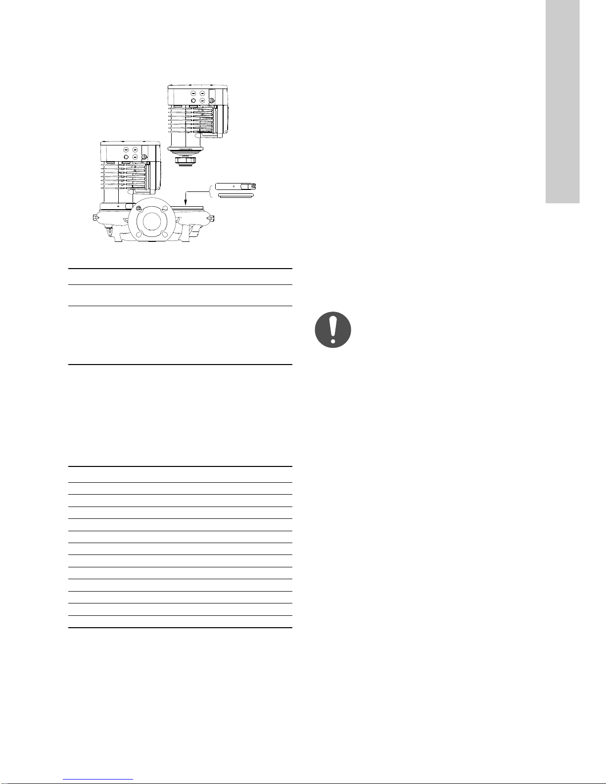
11.6 Blanking flange
A blanking flange is used to blank off the opening when one of the
pump heads of a twin-head pump is removed for service to
enable uninterrupted operation of the other pump. See fig. 63.
Fig. 63 Position of blanking flange
Pump type Product number
MAGNA3 32-40/60/80/100 (F)
MAGNA3 40-40/60 F
MAGNA3 32-120 F
MAGNA3 40-/80/100/120/150/180 F
MAGNA3 50-40/60/80/100/120/150/180 F
MAGNA3 65-40/60/80/100/120/150 F
MAGNA3 80-40/60/80/100/120 F
MAGNA3 100-40/60/80/100/120 F
98159373
98159372
11.7 Insulating kits for air-conditioning and cooling
systems
You can fit single-head pumps for air-conditioning and cooling
systems with insulating shells. A kit consists of two shells made
of polyurethane and a self-adhesive seal to ensure tight
assembly.
The dimensions of the insulating shells for pumps in
air-conditioning and cooling systems differ from those of the
insulating shells for pumps in heating systems.
Pump type Product number
MAGNA3 25-40/60/80/100/120 (N) 98354534
MAGNA3 32-40/60/80/100/120 (N) 98354535
MAGNA3 32-40/60/80/100 F (N) 98354536
MAGNA3 32-120 F (N) 98063287
MAGNA3 40-40/60 F (N) 98354537
MAGNA3 40-80/100 F (N) 98063288
MAGNA3 40-120/150/180 F (N) 98145675
MAGNA3 50-40/60/80 F (N) 98063289
MAGNA3 50-100/120/150/180 F (N) 98145676
MAGNA3 65-40/60/80/100/120/150 F (N) 96913593
MAGNA3 80-40/60/80/100/120 F 98134265
MAGNA3 100-40/60/80/100/120 F 96913589
Insulating shells for single-head pumps for heating systems are
supplied with the pump.
12. Technical data
Supply voltage
1 x 230 V ± 10 %, 50/60 Hz, PE.
Motor protection
The pump requires no external motor protection.
Enclosure class
IPX4D (EN 60529).
Insulation class
F.
Relative air humidity
Maximum 95 %.
Ambient temperature
0 to +40 °C.
During transport: -40 to +70 °C.
Temperature class
TF110 (EN 60335-2-51).
Liquid temperature
TM05 5994 4312
Continuously: -10 to +110 °C.
Stainless-steel pumps in domestic hot-water systems:
In domestic hot-water systems, we recommend that you keep the
liquid temperature below 65 °C to eliminate the risk of lime
precipitation.
System pressure
The actual inlet pressure and the pump pressure
against a closed valve must be lower than the
maximum permissible system pressure.
The maximum permissible system pressure is stated on the pump
nameplate:
PN 6: 6 bar / 0.6 MPa
PN 10: 10 bar / 1.0 MPa
PN 16: 16 bar / 1.6 MPa.
Test pressure
The pumps can withstand test pressures as indicated in EN
60335-2-51. See below.
• PN 6: 7.2 bar
• PN 10: 12 bar
• PN 6/10: 12 bar
• PN 16: 19.2 bar.
During normal operation, do not use the pump at higher
pressures than those stated on the nameplate.
The pressure test has been made with water containing
anticorrosive additives at a temperature of 20 °C.
English (GB)
53
Page 54

Minimum inlet pressure
English (GB)
The following relative minimum inlet pressure must be available
at the pump inlet during operation to avoid cavitation noise and
damage to the pump bearings.
The values in the table below apply to single-head
pumps and twin-head pumps in single-head
operation.
Liquid temperature
MAGNA3
DN
25-40/60/80/100/100 0.10 / 0.01 0.35 / 0.04 1.0 / 0.10
32-40/60/80/100/120 0.10 / 0.01 0.35 / 0.04 1.0 / 0.10
32-120 F 0.10 / 0.01 0.50 / 0.05 1.1 / 0.11
40-40/60 F 0.10 / 0.01 0.35 / 0.04 1.0 / 0.10
40-80/100 F 0.10 / 0.01 0.50 / 0.05 1.1 / 0.11
40-120/150/180 F 0.10 / 0.01 0.40 / 0.04 1.0 / 0.10
50-40/60/80 F 0.10 / 0.01 0.10 / 0.01 0.7 / 0.07
50-100 F 0.10 / 0.01 0.50 / 0.05 1.1 / 0.11
50-120 F 0.10 / 0.01 0.40 / 0.04 1.0 / 0.10
50-150/180 F 0.20 / 0.02 0.60 / 0.06 1.2 / 0.12
65-40/60/80/100 F 0.20 / 0.02 0.60 / 0.06 1.2 / 0.12
65-120 F 0.10 / 0.01 0.50 / 0.05 1.1 / 0.11
65-150 F 0.40 / 0.04 0.80 / 0.08 1.2 / 0.12
80-40/60/80/100/120 F 0.50 / 0.05 0.90 / 0.09 1.5 / 0.15
100-40/60/80/100/120 F 0.50 / 0.05 0.90 / 0.09 1.5 / 0.15
In the case of cascade operation, the required relative inlet
pressure must be increased by 0.1 bar / 0.01 MPa compared to
the stated values for single-head pumps or twin-head pumps in
single-head operation.
The relative minimum inlet pressures apply to pumps installed up
to 300 metres above sea level. For altitudes above 300 metres,
the required relative inlet pressure must be increased by 0.01 bar
/ 0.001 MPa per 100 metres altitude. The MAGNA3 pump is only
approved for an altitude of 2000 metres above sea level.
Sound pressure level
The sound pressure level of the pump is lower than 43 dB(A).
Leakage current
The mains filter will cause a leakage current to earth during
operation. The leakage current is less than 3.5 mA.
Consumption when the pump is stopped
4 to 10 W, depending on activity, such as reading the display, use
of Grundfos GO, interaction with modules.
4 W when the pump is stopped and there is no activity.
Input and output communication
External potential-free contact.
Two digital inputs
Analog input
Two relay outputs
24 VDC supply
Contact load: 5 V, 10 mA.
Screened cable.
Loop resistance: Maximum 130 ˖.
4-20 mA, load: 150 ˖.
0-10 VDC, load: Greater than 10 k˖.
Internal potential-free changeover contact.
Maximum load: 250 V, 2 A, AC1.
Minimum load: 5 VDC, 20 mA.
Screened cable, depending on signal level.
Maximum load: 22 mA
Capacitive load: Less than 470 ˩F
75 °C 95 °C 110 °C
Inlet pressure
[bar] / [MPa]
Power factor
The terminal-connected versions have built-in an active power
factor correction which gives a cos ij from 0.98 to 0.99.
The plug-connected versions have built-in passive PFC, with coil
and resistors which ensures that the current drawn from the grid
is in phase with the voltage. The current is approximately
sinusoidal which gives a cos ij from 0.55 to 0.98.
12.1 Sensor specifications
12.1.1 Temperature
Temperature range during operation Accuracy
-10 to +35 °C ± 4 °C
+35 to +90 °C ± 2 °C
+90 to +110 °C ± 4 °C
13. Disposing of the product
This product has been designed with focus on the disposal and
recycling of materials. The following average disposal values
apply to all variants of pumps:
• 85 % recycling
• 10 % incineration
• 5 % depositing.
Dispose of this product or parts of it in an environmentally sound
way according to local regulations.
For further information see the end-of-life information on
www.Grundfos.com.
Subject to alterations.
54
Page 55

Appendix 1
Dimensions
Fig. 1 Dimensions, single-head pumps, threaded versions
Appendix
TM05 7938 2013
Pump type
MAGNA3 25-40 (N) 180 158 190 58 111 69 90 113 54 185 239 71 25 1 1/2
MAGNA3 25-60 (N) 180 158 190 58 111 69 90 113 54 185 239 71 25 1 1/2
MAGNA3 25-80 (N) 180 158 190 58 111 69 90 113 54 185 239 71 25 1 1/2
MAGNA3 25-100 (N) 180 158 190 58 111 69 90 113 54 185 239 71 25 1 1/2
MAGNA3 25-120 (N) 180 158 190 58 111 69 90 113 54 185 239 71 25 1 1/2
MAGNA3 32-40 (N) 180 158 190 58 111 69 90 113 54 185 239 71 32 2
MAGNA3 32-60 (N) 180 158 190 58 111 69 90 113 54 185 239 71 32 2
MAGNA3 32-80 (N) 180 158 190 58 111 69 90 113 54 185 239 71 32 2
MAGNA3 32-100 (N) 180 158 190 58 111 69 90 113 54 185 239 71 32 2
MAGNA3 32-120 (N) 180 158 190 58 111 69 90 113 54 185 239 71 32 2
L1 L5 L6 B1 B2 B4 B6 B7 H1 H2 H3 H4 D1 G
Dimensions [mm]
Fig. 2 Dimensions, single-head pumps, flanged versions
Pump type
MAGNA3 32-40 F (N) 220 158 220 58 111 69 100 110 65 185 250 82 32 76 90/100 140 14/19
MAGNA3 32-60 F (N) 220 158 220 58 111 69 100 110 65 185 250 82 32 76 90/100 140 14/19
MAGNA3 32-80 F (N) 220 158 220 58 111 69 100 110 65 185 250 82 32 76 90/100 140 14/19
MAGNA3 32-100 F (N) 220 158 220 58 111 69 100 110 65 185 250 82 32 76 90/100 140 14/19
MAGNA3 40-40 F (N) 220 158 220 58 111 69 105 105 65 199 264 83 40 84 100/110 150 14/19
MAGNA3 40-60 F (N) 220 158 220 58 111 69 105 105 65 199 264 83 40 84 100/110 150 14/19
L1 L5 L6 B1 B2 B4 B6 B7 H1 H2 H3 H4 D1 D2 D3 D4 D5
Dimensions [mm]
TM05 7938 2013
55
Page 56

Appendix
Fig. 3 Dimensions, single-head pumps, flanged versions
Pump type
MAGNA3 32-120 F (N) 220 204 84 164 73 106 116 65 301 366 86 32 76 90/100 140 14/19
MAGNA3 40-80 F (N) 220 204 84 164 73 106 128 65 304 369 83 40 84 100/110 150 14/19
MAGNA3 40-100 F (N) 220 204 84 164 73 106 128 65 304 369 83 40 84 100/110 150 14/19
MAGNA3 40-120 F (N) 250 204 84 164 73 106 128 65 304 369 83 40 84 100/110 150 14/19
MAGNA3 40-150 F (N) 250 204 84 164 73 106 128 65 304 369 83 40 84 100/110 150 14/19
MAGNA3 40-180 F (N) 250 204 84 164 73 106 128 65 304 369 83 40 84 100/110 150 14/19
MAGNA3 50-40 F (N) 240 204 84 164 73 127 127 71 304 374 97 50 102 110/125 165 14/19
MAGNA3 50-60 F (N) 240 204 84 164 73 127 127 71 304 374 97 50 102 110/125 165 14/19
MAGNA3 50-80 F (N) 240 204 84 164 73 127 127 71 304 374 97 50 102 110/125 165 14/19
MAGNA3 50-100 F (N) 280 204 84 164 73 127 127 72 304 376 97 50 102 110/125 165 14/19
MAGNA3 50-120 F (N) 280 204 84 164 73 127 127 72 304 376 97 50 102 110/125 165 14/19
MAGNA3 50-150 F (N) 280 204 84 164 73 127 127 72 304 376 97 50 102 110/125 165 14/19
MAGNA3 50-180 F (N) 280 204 84 164 73 127 127 72 304 376 97 50 102 110/125 165 14/19
MAGNA3 65-40 F (N) 340 204 84 164 73 133 133 74 312 386 94 65 119 130/145 185 14/19
MAGNA3 65-60 F (N) 340 204 84 164 73 133 133 74 312 386 94 65 119 130/145 185 14/19
MAGNA3 65-80 F (N) 340 204 84 164 73 133 133 74 312 386 94 65 119 130/145 185 14/19
MAGNA3 65-100 F (N) 340 204 84 164 73 133 133 74 312 386 94 65 119 130/145 185 14/19
MAGNA3 65-120 F (N) 340 204 84 164 73 133 133 74 312 386 94 65 119 130/145 185 14/19
MAGNA3 65-150 F (N) 340 204 84 164 73 133 133 74 312 386 94 65 119 130/145 185 14/19
MAGNA3 80-40 F 360 204 84 164 73 163 163 96 318 413 115 80 128 150/160 200 19
MAGNA3 80-60 F 360 204 84 164 73 163 163 96 318 413 115 80 128 150/160 200 19
MAGNA3 80-80 F 360 204 84 164 73 163 163 96 318 413 115 80 128 150/160 200 19
MAGNA3 80-100 F 360 204 84 164 73 163 163 96 318 413 115 80 128 150/160 200 19
MAGNA3 80-120 F 360 204 84 164 73 163 163 96 318 413 115 80 128 150/160 200 19
MAGNA3 100-40 F 450 204 84 164 73 178 178 103 330 433 120 100 160 170 220 19
MAGNA3 100-60 F 450 204 84 164 73 178 178 103 330 433 120 100 160 170 220 19
MAGNA3 100-80 F 450 204 84 164 73 178 178 103 330 433 120 100 160 170 220 19
MAGNA3 100-100 F 450 204 84 164 73 178 178 103 330 433 120 100 160 170 220 19
MAGNA3 100-120 F 450 204 84 164 73 178 178 103 330 433 120 100 160 170 220 19
L1 L 5 B1 B2 B4 B6 B7 H1 H2 H3 H4 D1 D2 D3 D4 D5
Dimensions [mm]
TM05 5291 2013
56
Page 57

Fig. 4 Dimensions, twin-head pumps, threaded versions
Appendix
TM05 7939 2013
Pump type
L1 L5 L7 B1 B3 B4 B5 H1 H2 H3 D1 G M3
Dimensions [mm]
MAGNA3 D 32-40 180 158 35 58 400 179 221 54 185 239 32 2 1/4
MAGNA3 D 32-60 180 158 35 58 400 179 221 54 185 239 32 2 1/4
MAGNA3 D 32-80 180 158 35 58 400 179 221 54 185 239 32 2 1/4
MAGNA3 D 32-100 180 158 35 58 400 179 221 54 185 239 32 2 1/4
Fig. 5 Dimensions, twin-head pumps, flanged versions
Pump type
L1 L2 L3 L4 L5 L7 B1 B3 B4 B5 B6 B7 H1 H2 H3 D1 D2 D3 D4 D5 M M3
MAGNA3 D 32-40 F 220 73 120 85 158 35 58 400 179 221 130 260 69 185 254 32 76 90/100 140 14/19 M12 Rp 1/4
MAGNA3 D 32-60 F 220 73 120 85 158 35 58 400 179 221 130 260 69 185 254 32 76 90/100 140 14/19 M12 Rp 1/4
MAGNA3 D 32-80 F 220 73 120 85 158 35 58 400 179 221 130 260 69 185 254 32 76 90/100 140 14/19 M12 Rp 1/4
MAGNA3 D 32-100 F 220 73 120 85 158 35 58 400 179 221 130 260 69 185 254 32 76 90/100 140 14/19 M12 Rp 1/4
MAGNA3 D 32-120 F 220 97 90 50 204 50 84 502 210 294 130 260 68 300 368 32 76 90/100 140 14/19 M12 Rp 1/4
MAGNA3 D 40-40 F 220 53 140 60 158 15 58 452 211 241 130 260 76 199 275 40 84 100/110 150 14/19 M12 Rp1/4
MAGNA3 D 40-60 F 220 53 140 60 158 15 58 452 211 241 130 260 76 199 275 40 84 100/110 150 14/19 M12 Rp1/4
MAGNA3 D 40-80 F 220 53 140 60 204 15 84 502 210 294 130 260 76 303 379 40 84 100/110 150 14/19 M12 Rp 1/4
MAGNA3 D 40-100 F 220 53 140 60 204 15 84 502 210 294 130 260 76 303 379 40 84 100/110 150 14/19 M12 Rp 1/4
MAGNA3 D 50-40 F 240 48 160 45 204 45 84 515 221 294 130 260 75 304 379 50 102 110/125 165 14/19 M12 Rp 1/4
MAGNA3 D 50-60 F 240 48 160 45 204 45 84 515 221 294 130 260 75 304 379 50 102 110/125 165 14/19 M12 Rp 1/4
MAGNA3 D 50-80 F 240 48 160 45 204 45 84 515 221 294 130 260 75 304 379 50 102 110/125 165 14/19 M12 Rp 1/4
Dimensions [mm]
TM05 5294 3612
57
Page 58
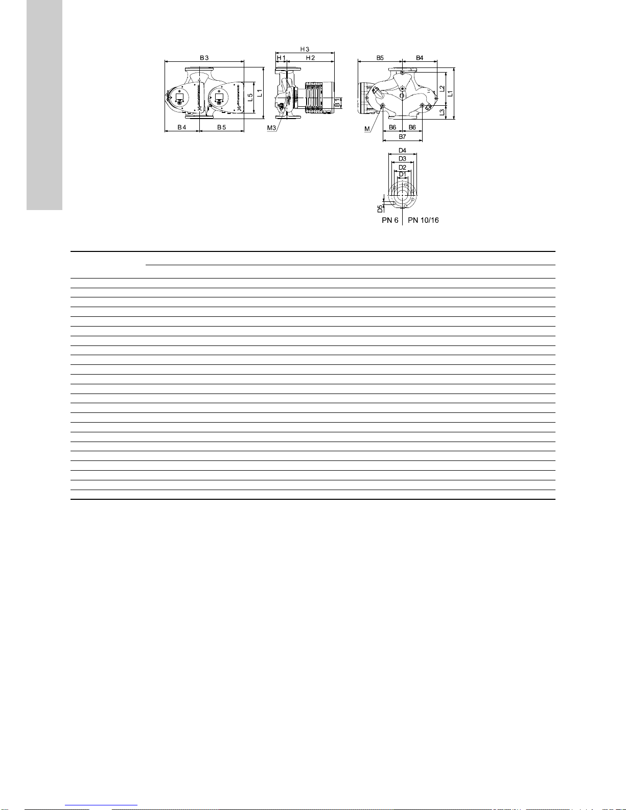
Appendix
Fig. 6 Dimensions, twin-head pumps
TM05 5366 2013
Pump type
MAGNA3 D 40-120 F 250 58 155 75 204 84 512 220 294 130 260 69 303 372 40 84 100/110 150 14/19 M12 Rp 1/4
MAGNA3 D 40-150 F 250 58 155 75 204 84 512 220 294 130 260 69 303 372 40 84 100/110 150 14/19 M12 Rp 1/4
MAGNA3 D 40-180 F 250 58 155 75 204 84 512 220 294 130 260 69 303 372 40 84 100/110 150 14/19 M12 Rp 1/4
MAGNA3 D 50-100 F 280 175 75 75 204 84 517 223 294 130 260 75 304 379 50 102 110/125 165 14/19 M12 Rp 1/4
MAGNA3 D 50-120 F 280 175 75 75 204 84 517 223 294 130 260 75 304 379 50 102 110/125 165 14/19 M12 Rp 1/4
MAGNA3 D 50-150 F 280 175 75 75 204 84 517 223 294 130 260 75 304 379 50 102 110/125 165 14/19 M12 Rp 1/4
MAGNA3 D 50-180 F 280 175 75 75 204 84 517 223 294 130 260 75 304 379 50 102 110/125 165 14/19 M12 Rp 1/4
MAGNA3 D 65-40 F 340 218 92 92 204 84 522 228 294 130 260 77 312 389 65 119 130/145 185 14/19 M12 Rp 1/4
MAGNA3 D 65-60 F 340 218 92 92 204 84 522 228 294 130 260 77 312 389 65 119 130/145 185 14/19 M12 Rp 1/4
MAGNA3 D 65-80 F 340 218 92 92 204 84 522 228 294 130 260 77 312 389 65 119 130/145 185 14/19 M12 Rp 1/4
MAGNA3 D 65-100 F 340 218 92 92 204 84 522 228 294 130 260 77 312 389 65 119 130/145 185 14/19 M12 Rp 1/4
MAGNA3 D 65-120 F 340 218 92 92 204 84 522 228 294 130 260 77 312 389 65 119 130/145 185 14/19 M12 Rp 1/4
MAGNA3 D 65-150 F 340 218 92 92 204 84 522 228 294 130 260 77 312 389 65 119 130/145 185 14/19 M12 Rp 1/4
MAGNA3 D 80-40 F 360 218 102 102 204 84 538 244 294 130 260 97 318 415 80 128 150/160 200 19 M12 Rp 1/4
MAGNA3 D 80-60 F 360 218 102 102 204 84 538 244 294 130 260 97 318 415 80 128 150/160 200 19 M12 Rp 1/4
MAGNA3 D 80-80 F 360 218 102 102 204 84 538 244 294 130 260 97 318 415 80 128 150/160 200 19 M12 Rp 1/4
MAGNA3 D 80-100 F 360 218 102 102 204 84 538 244 294 130 260 97 318 415 80 128 150/160 200 19 M12 Rp 1/4
MAGNA3 D 80-120 F 360 218 102 102 204 84 538 244 294 130 260 97 318 415 80 128 150/160 200 19 M12 Rp 1/4
MAGNA3 D 100-40 F 450 243 147 147 204 84 551 252 299 135 270 103 330 434 100 160 170 220 19 M12 Rp 1/4
MAGNA3 D 100-60 F 450 243 147 147 204 84 551 252 299 135 270 103 330 434 100 160 170 220 19 M12 Rp 1/4
MAGNA3 D 100-80 F 450 243 147 147 204 84 551 252 299 135 270 103 330 434 100 160 170 220 19 M12 Rp 1/4
MAGNA3 D 100-100 F 450 243 147 147 204 84 551 252 299 135 270 103 330 434 100 160 170 220 19 M12 Rp 1/4
MAGNA3 D 100-120 F 450 243 147 147 204 84 551 252 299 135 270 103 330 434 100 160 170 220 19 M12 Rp 1/4
L1 L2 L3 L4 L5 B1 B3 B4 B5 B6 B7 H1 H2 H3 D1 D2 D3 D4 D5 M M3
Dimensions [mm]
58
Page 59

1. Flange forces and moments
ː
ː
Maximum permissible forces and moments from the pipe connections acting on the pump flanges or threaded connections are indicated
in fig. 7.
Fig. 7 Forces and moments from the pipe connections acting on the pump flanges or threaded connections
Appendix
TM05 5639 4012
Force
[N]
Diameter DN Fy Fz Fx
25* 350 425 375 650 300 350 450 650
32* 425 525 450 825 375 425 550 800
40 500 625 550 975 450 525 650 950
50 675 825 750 1300 500 575 700 1025
65 850 1050 925 1650 550 600 750 1100
80 1025 1250 1125 1975 575 650 800 1175
100 1350 1675 1500 2625 625 725 875 1300
* The values also apply to pumps with threaded connection.
The above values apply to cast-iron versions. For stainless-steel versions, the values can be multiplied by two according to the
ISO 5199 standard.
Fb My Mz Mx
Moment
[Nm]
2. Tightening torques for bolts
Recommended tightening torques for bolts used in flanged
connections:
Bolt dimension Torque
M12 27 Nm
M16 66 Nm
Mb
59
Page 60

60
Page 61

Argentina
Bombas GRUNDFOS de Argentina S.A.
Ruta Panamericana km. 37.500 Centro
Industrial Garin
1619 Garín Pcia. de B.A.
Phone: +54-3327 414 444
Telefax: +54-3327 45 3190
Australia
GRUNDFOS Pumps Pty. Ltd.
P.O. Box 2040
Regency Park
South Australia 5942
Phone: +61-8-8461-4611
Telefax: +61-8-8340 0155
Austria
GRUNDFOS Pumpen Vertrieb Ges.m.b.H.
Grundfosstraße 2
A-5082 Grödig/Salzburg
Tel.: +43-6246-883-0
Telefax: +43-6246-883-30
Belgium
N.V. GRUNDFOS Bellux S.A.
Boomsesteenweg 81-83
B-2630 Aartselaar
Tél.: +32-3-870 7300
Télécopie: +32-3-870 7301
Belarus
ɉɪɟɞɫɬɚɜɢɬɟɥɶɫɬɜɨ ȽɊɍɇȾɎɈɋ ɜ
Ɇɢɧɫɤɟ
220125, Ɇɢɧɫɤ
ɭɥ. ɒɚɮɚɪɧɹɧɫɤɚɹ, 11, ɨɮ. 56, Ȼɐ
«ɉɨɪɬ»
Ɍɟɥ.: +7 (375 17) 286 39 72/73
Ɏɚɤɫ: +7 (375 17) 286 39 71
E-mail: minsk@grundfos.com
Bosnia and Herzegovina
GRUNDFOS Sarajevo
Zmaja od Bosne 7-7A,
BH-71000 Sarajevo
Phone: +387 33 592 480
Telefax: +387 33 590 465
www.ba.grundfos.com
e-mail: grundfos@bih.net.ba
Brazil
BOMBAS GRUNDFOS DO BRASIL
Av. Humberto de Alencar Castelo Branco,
630
CEP 09850 - 300
São Bernardo do Campo - SP
Phone: +55-11 4393 5533
Telefax: +55-11 4343 5015
Bulgaria
Grundfos Bulgaria EOOD
Slatina District
Iztochna Tangenta street no. 100
BG - 1592 Sofia
Tel. +359 2 49 22 200
Fax. +359 2 49 22 201
email: bulgaria@grundfos.bg
Canada
GRUNDFOS Canada Inc.
2941 Brighton Road
Oakville, Ontario
L6H 6C9
Phone: +1-905 829 9533
Telefax: +1-905 829 9512
China
GRUNDFOS Pumps (Shanghai) Co. Ltd.
10F The Hub, No. 33 Suhong Road
Minhang District
Shanghai 201106
PRC
Phone: +86 21 612 252 22
Telefax: +86 21 612 253 33
COLOMBIA
GRUNDFOS Colombia S.A.S.
Km 1.5 vía Siberia-Cota Conj. Potrero
Chico,
Parque Empresarial Arcos de Cota Bod.
1A.
Cota, Cundinamarca
Phone: +57(1)-2913444
Telefax: +57(1)-8764586
Croatia
GRUNDFOS CROATIA d.o.o.
Buzinski prilaz 38, Buzin
HR-10010 Zagreb
Phone: +385 1 6595 400
Telefax: +385 1 6595 499
www.hr.grundfos.com
GRUNDFOS Sales Czechia and
Slovakia s.r.o.
ýajkovského 21
779 00 Olomouc
Phone: +420-585-716 111
Denmark
GRUNDFOS DK A/S
Martin Bachs Vej 3
DK-8850 Bjerringbro
Tlf.: +45-87 50 50 50
Telefax: +45-87 50 51 51
E-mail: info_GDK@grundfos.com
www.grundfos.com/DK
Estonia
GRUNDFOS Pumps Eesti OÜ
Peterburi tee 92G
11415 Tallinn
Tel: + 372 606 1690
Fax: + 372 606 1691
Finland
OY GRUNDFOS Pumput AB
Trukkikuja 1
FI-01360 Vantaa
Phone: +358-(0) 207 889 500
France
Pompes GRUNDFOS Distribution S.A.
Parc d’Activités de Chesnes
57, rue de Malacombe
F-38290 St. Quentin Fallavier (Lyon)
Tél.: +33-4 74 82 15 15
Télécopie: +33-4 74 94 10 51
Germany
GRUNDFOS GMBH
Schlüterstr. 33
40699 Erkrath
Tel.: +49-(0) 211 929 69-0
Telefax: +49-(0) 211 929 69-3799
e-mail: infoservice@grundfos.de
Service in Deutschland:
e-mail: kundendienst@grundfos.de
Greece
GRUNDFOS Hellas A.E.B.E.
20th km. Athinon-Markopoulou Av.
P.O. B o x 7 1
GR-19002 Peania
Phone: +0030-210-66 83 400
Telefax: +0030-210-66 46 273
Hong Kong
GRUNDFOS Pumps (Hong Kong) Ltd.
Unit 1, Ground floor
Siu Wai Industrial Centre
29-33 Wing Hong Street &
68 King Lam Street, Cheung Sha Wan
Kowloon
Phone: +852-27861706 / 27861741
Telefax: +852-27858664
Hungary
GRUNDFOS Hungária Kft.
Park u. 8
H-2045 Törökbálint,
Phone: +36-23 511 110
Telefax: +36-23 511 111
India
GRUNDFOS Pumps India Private Limited
118 Old Mahabalipuram Road
Thoraipakkam
Chennai 600 096
Phone: +91-44 2496 6800
Indonesia
PT. GRUNDFOS POMPA
Graha Intirub Lt. 2 & 3
Jln. Cililitan Besar No.454. Makasar,
Jakarta Timur
ID-Jakarta 13650
Phone: +62 21-469-51900
Telefax: +62 21-460 6910 / 460 6901
Ireland
GRUNDFOS (Ireland) Ltd.
Unit A, Merrywell Business Park
Ballymount Road Lower
Dublin 12
Phone: +353-1-4089 800
Telefax: +353-1-4089 830
Italy
GRUNDFOS Pompe Italia S.r.l.
Via Gran Sasso 4
I-20060 Truccazzano (Milano)
Tel.: +39-02-95838112
Telefax: +39-02-95309290 / 95838461
Japan
GRUNDFOS Pumps K.K.
1-2-3, Shin-Miyakoda, Kita-ku,
Hamamatsu
431-2103 Japan
Phone: +81 53 428 4760
Telefax: +81 53 428 5005
Korea
GRUNDFOS Pumps Korea Ltd.
6th Floor, Aju Building 679-5
Yeoksam-dong, Kangnam-ku, 135-916
Seoul, Korea
Phone: +82-2-5317 600
Telefax: +82-2-5633 725
Latvia
SIA GRUNDFOS Pumps Latvia
Deglava biznesa centrs
Augusta Deglava ielƗ 60, LV-1035, RƯga,
TƗlr.: + 371 714 9640, 7 149 641
Fakss: + 371 914 9646
Lithuania
GRUNDFOS Pumps UAB
Smolensko g. 6
LT-03201 Vilnius
Tel: + 370 52 395 430
Fax: + 370 52 395 431
Malaysia
GRUNDFOS Pumps Sdn. Bhd.
7 Jalan Peguam U1/25
Glenmarie Industrial Park
40150 Shah Alam
Selangor
Phone: +60-3-5569 2922
Telefax: +60-3-5569 2866
Mexico
Bombas GRUNDFOS de México S.A. de
C.V.
Boulevard TLC No. 15
Parque Industrial Stiva Aeropuerto
Apodaca, N.L. 66600
Phone: +52-81-8144 4000
Telefax: +52-81-8144 4010
Netherlands
GRUNDFOS Netherlands
Velu we zo om 3 5
1326 AE Almere
Postbus 22015
1302 CA ALMERE
Tel.: +31-88-478 6336
Telefax: +31-88-478 6332
E-mail: info_gnl@grundfos.com
New Zealand
GRUNDFOS Pumps NZ Ltd.
17 Beatrice Tinsley Crescent
North Harbour Industrial Estate
Albany, Auckland
Phone: +64-9-415 3240
Telefax: +64-9-415 3250
Norway
GRUNDFOS Pumper A/S
Strømsveien 344
Postboks 235, Leirdal
N-1011 Oslo
Tlf.: +47-22 90 47 00
Telefax: +47-22 32 21 50
Poland
GRUNDFOS Pompy Sp. z o.o.
ul. Klonowa 23
Baranowo k. Poznania
PL-62-081 PrzeĨmierowo
Tel: (+48-61) 650 13 00
Fax: (+48-61) 650 13 50
Portugal
Bombas GRUNDFOS Portugal, S.A.
Rua Calvet de Magalhães, 241
Apartado 1079
P-2770-153 Paço de Arcos
Tel.: +351-21-440 76 00
Telefax: +351-21-440 76 90
Romania
GRUNDFOS Pompe România SRL
Bd. Biruintei, nr 103
Pantelimon county Ilfov
Phone: +40 21 200 4100
Telefax: +40 21 200 4101
E-mail: romania@grundfos.ro
Russia
ɈɈɈ Ƚɪɭɧ ɞɮ ɨɫ Ɋɨɫɫɢɹ
109544, ɝ. Ɇɨɫɤɜɚ, ɭɥ. ɒɤɨɥɶɧɚɹ, 39-41,
ɫɬɪ. 1
Ɍɟɥ. (+7) 495 564-88-00 (495) 737-30-00
Ɏɚɤɫ (+7) 495 564 88 11
E-mail grundfos.moscow@grundfos.com
Serbia
Grundfos Srbija d.o.o.
Omladinskih brigada 90b
11070 Novi Beograd
Phone: +381 11 2258 740
Telefax: +381 11 2281 769
www.rs.grundfos.com
Singapore
GRUNDFOS (Singapore) Pte. Ltd.
25 Jalan Tukang
Singapore 619264
Phone: +65-6681 9688
Telefax: +65-6681 9689
Slovakia
GRUNDFOS s.r.o.
Prievozská 4D
821 09 BRATISLAVA
Phona: +421 2 5020 1426
sk.grundfos.com
Slovenia
GRUNDFOS LJUBLJANA, d.o.o.
Leskoškova 9e, 1122 Ljubljana
Phone: +386 (0) 1 568 06 10
Telefax: +386 (0)1 568 06 19
E-mail: tehnika-si@grundfos.com
South Africa
GRUNDFOS (PTY) LTD
Corner Mountjoy and George Allen Roads
Wilbart Ext. 2
Bedfordview 2008
Phone: (+27) 11 579 4800
Fax: (+27) 11 455 6066
E-mail: lsmart@grundfos.com
Spain
Bombas GRUNDFOS España S.A.
Camino de la Fuentecilla, s/n
E-28110 Algete (Madrid)
Tel.: +34-91-848 8800
Telefax: +34-91-628 0465
Sweden
GRUNDFOS AB
Box 333 (Lunnagårdsgatan 6)
431 24 Mölndal
Tel.: +46 31 332 23 000
Telefax: +46 31 331 94 60
Switzerland
GRUNDFOS Pumpen AG
Bruggacherstrasse 10
CH-8117 Fällanden/ZH
Tel.: +41-44-806 8111
Telefax: +41-44-806 8115
Taiwan
GRUNDFOS Pumps (Taiwan) Ltd.
7 Floor, 219 Min-Chuan Road
Taichung, Taiwan, R.O.C.
Phone: +886-4-2305 0868
Telefax: +886-4-2305 0878
Thailand
GRUNDFOS (Thailand) Ltd.
92 Chaloem Phrakiat Rama 9 Road,
Dokmai, Pravej, Bangkok 10250
Phone: +66-2-725 8999
Telefax: +66-2-725 8998
Turkey
GRUNDFOS POMPA San. ve Tic. Ltd. Sti.
Gebze Organize Sanayi Bölgesi
Ihsan dede Caddesi,
2. yol 200. Sokak No. 204
41490 Gebze/ Kocaeli
Phone: +90 - 262-679 7979
Telefax: +90 - 262-679 7905
E-mail: satis@grundfos.com
Ukraine
Ȼɿɡɧɟɫ ɐɟɧɬɪ ȯɜɪɨɩɚ
ɋɬɨɥɢɱɧɟ ɲɨɫɟ, 103
ɦ. Ʉɢʀɜ, 03131, ɍɤɪɚʀɧɚ
Ɍɟɥɟɮ ɨɧ: (+38 044) 237 04 00
Ɏɚɤɫ.: (+38 044) 237 04 01
E-mail: ukraine@grundfos.com
United Arab Emirates
GRUNDFOS Gulf Distribution
P.O. Box 16768
Jebel Ali Free Zone
Dubai
Phone: +971 4 8815 166
Telefax: +971 4 8815 136
United Kingdom
GRUNDFOS Pumps Ltd.
Grovebury Road
Leighton Buzzard/Beds. LU7 4TL
Phone: +44-1525-850000
Telefax: +44-1525-850011
U.S.A.
GRUNDFOS Pumps Corporation
17100 West 118th Terrace
Olathe, Kansas 66061
Phone: +1-913-227-3400
Telefax: +1-913-227-3500
Uzbekistan
Grundfos Tashkent, Uzbekistan The
Representative Office of Grundfos
Kazakhstan in Uzbekistan
38a, Oybek street, Tashkent
Ɍɟɥɟɮɨɧ: (+998) 71 150 3290 / 71 150
3291
Ɏɚɤɫ: (+998) 71 150 3292
Addresses Revised 05.12.2016
Grundfos companies
Page 62

98091805 1216
ECM: 1199282
www.grundfos.com
7KHQDPH*UXQGIRVWKH*UXQGIRVORJRDQGbe think innovateDUHUHJLVWHUHGWUDGHPDUNVRZQHGE\*UXQGIRV+ROGLQJ$6RU*UXQGIRV$6'HQPDUN$OOULJKWVUHVHUYHGZRUOGZLGH k&RS\ULJKW*UXQGIRV+ROGLQJ$6
 Loading...