

Grundfos MAGNA1 25-60 N, MAGNA1 25-40 N, MAGNA1 25-80 N, MAGNA1 25-100 N, MAGNA1 25-120 N Installation And Operating Instructions Manual
...
New MAGNA1
Model C
Installation and operating instructions
GRUNDFOS INSTRUCTIONS

English (GB) Installation and operating instructions
English (GB)
Original installation and operating instructions
These installation and operating instructions describe New
MAGNA1 model C.
Sections 1-5 give the information necessary to be able to unpack,
install and start up the product in a safe way.
Sections 6-11 give important information about the product, as
well as information on service, fault finding and disposal of the
product.
CONTENTS
Page
1. General information
1.1 Hazard statements
1.2 Notes
1.3 Symbols on the product
2. Receiving the product
2.1 Inspecting the product
2.2 Scope of delivery
2.3 Lifting the product
3. Installing the product
3.1 Location
3.2 Tools
3.3 Insulating shells
3.4 Mechanical installation
3.5 Electrical connection
4. Starting up the product
4.1 Single-head pump
4.2 Twin-head pump
4.3 Pairing and unpairing twin-head pumps
5. Handling and storing the product
6. Product introduction
6.1 Product description
6.2 Intended use
6.3 Pumped liquids
6.4 Identification
6.5 Radio communication
6.6 Non-return valve
6.7 Closed valve operation
6.8 Accessories
7. Control functions
7.1 Proportional-pressure curve (PP1, PP2 or PP3)
7.2 Constant-pressure curve (CP1, CP2 or CP3)
7.3 Constant curve (I, II or III)
7.4 Overview of the control functions
7.5 Selecting control function
8. Setting the product
8.1 Operating panel
8.2 Setting the control function
8.3 Connecting the pump to Grundfos GO Remote
8.4 Communication, control and monitoring
9. Fault finding the product
9.1 Grundfos Eye operating status
9.2 Resetting a fault indication
9.3 Reading out warning and alarm codes in Grundfos GO
Remote
9.4 Fault finding table
9.5 Warning 77, twin-head pump
10. Technical data
11. Disposing of the product
10
15
15
16
16
17
17
17
17
17
18
18
18
19
19
20
20
20
20
21
22
23
23
23
25
27
28
28
29
29
30
31
32
33
This appliance can be used by children aged from 8
years and above and persons with reduced physical,
sensory or mental capabilities or lack of experience
and knowledge if they have been given supervision
or instruction concerning use of the appliance in a
safe way and understand the hazards involved.
Children shall not play with the appliance. Cleaning
and user maintenance shall not be made by children
without supervision.
1. General information
2
1.1 Hazard statements
2
The symbols and hazard statements below may appear in
3
Grundfos installation and operating instructions, safety
3
instructions and service instructions.
3
3
3
4
5
5
5
5
6
The text accompanying the three hazard symbols DANGER,
WARNING and CAUTION is structured in the following way:
The hazard statements are structured in the following way:
DANGER
Indicates a hazardous situation which, if not avoided,
will result in death or serious personal injury.
WARNING
Indicates a hazardous situation which, if not avoided,
could result in death or serious personal injury.
CAUTION
Indicates a hazardous situation which, if not avoided,
could result in minor or moderate personal injury.
SIGNAL WORD
Description of hazard
Consequence of ignoring the warning.
- Action to avoid the hazard.
Read this document and the quick guide before
installing the product. Installation and operation must
comply with local regulations and accepted codes of
good practice.
2

1.2 Notes
8Nm!
The symbols and notes below may appear in Grundfos
installation and operating instructions, safety instructions and
service instructions.
Observe these instructions for explosion-proof
products.
A blue or grey circle with a white graphical symbol
indicates that an action must be taken.
A red or grey circle with a diagonal bar, possibly with
a black graphical symbol, indicates that an action
must not be taken or must be stopped.
If these instructions are not observed, it may result in
malfunction or damage to the equipment.
2. Receiving the product
2.1 Inspecting the product
Check that the product is in accordance with the order.
Check that the voltage and frequency of the product match the
voltage and frequency of the installation site. See section
6.4.1 Nameplate.
Pumps tested with water containing anticorrosive
additives are taped on the inlet and outlet ports to
prevent residual test water from leaking into the
packaging. Remove the tape before installing the
pump.
2.2 Scope of delivery
2.2.1 Plug-connected single-head pump
English (GB)
Tips and advice that make the work easier.
1.3 Symbols on the product
Check the position of the clamp before you tighten
the clamp. Incorrect position of the clamp will cause
leakage from the pump and damage the hydraulic
parts in the pump head.
Fit and tighten the screw holding the clamp to 8 Nm ±
1 Nm.
Do not apply more torque than specified even though
water is dripping from the clamp. The condensed
water is most likely coming from the drain hole under
the clamp.
TM05 5508 3016TM06 7222 3016
Fig. 1 Plug-connected single-head pump
The box contains the following items:
• MAGNA1 pump
• insulating shells
•gaskets
•quick guide
• safety instructions
• one ALPHA plug.
2.2.2 Plug-connected twin-head pump
Fig. 2 Plug-connected twin-head pump
The box contains the following items:
• MAGNA1 pump
•gaskets
•quick guide
• safety instructions
• two ALPHA plugs.
3

2.2.3 Terminal-connected single-head pump
English (GB)
Fig. 3 Terminal-connected single-head pump
The box contains the following items:
• MAGNA1 pump
• insulating shells
•gaskets
• quick guide
• safety instructions
• box with terminal and cable glands.
2.2.4 Terminal-connected twin-head pump
2.3 Lifting the product
Observe local regulations concerning limits for
manual lifting or handling.
Always lift directly on the pump head or the cooling fins when
handling the pump. See fig. 5.
For large pumps, it may be necessary to use lifting equipment.
Position the lifting straps as illustrated in fig. 5.
TM06 7223 3016TM06 6741 3016
Fig. 4 Terminal-connected twin-head pump
The box contains the following items:
• MAGNA1 pump
•gaskets
• quick guide
• safety instructions
• two boxes with terminal and cable glands.
TM05 5819 3016
Fig. 5 Correct lifting of the pump
Do not lift the pump head by the control box, i.e. the
red area of the pump. See fig. 6.
TM06 7219 3016
Fig. 6 Incorrect lifting of the pump
4

3. Installing the product
0.6 x 3.5
5.0
1.2 x 8.0
TX20
TX10
1
2
3
4
5
6
7
3.1 Location
The pump is designed for indoor installation.
Always install the pump in an dry environment where it will not be
exposed to drops or splashes, for example water, from
surrounding equipment or structures.
As the pump contains stainless-steel parts, it is important that it is
not installed directly in environments, such as:
Indoor swimming pools where the pump would be exposed to the
ambient environment of the pool.
Locations with direct and continuous exposure to a marine
atmosphere.
In rooms where hydrochloric acid (HCl) can form acidic aerosols
escaping from, for example, open tanks or frequently opened or
vented containers.
The above applications do not disqualify for installation of
MAGNA1. However, it is important that the pump is not installed
directly in these environments.
To ensure adequate cooling of the motor and electronics, observe
the following requirements:
• Position the pump in such a way that sufficient cooling is
ensured.
• The ambient temperature must not exceed 40 °C.
3.2 Tools
3.3 Insulating shells
Insulating shells limit the heat loss from the pump housing and
pipes. Insulating shells are available for single-head pumps only.
3.3.1 Heating systems
Insulating shells increase the pump dimensions.
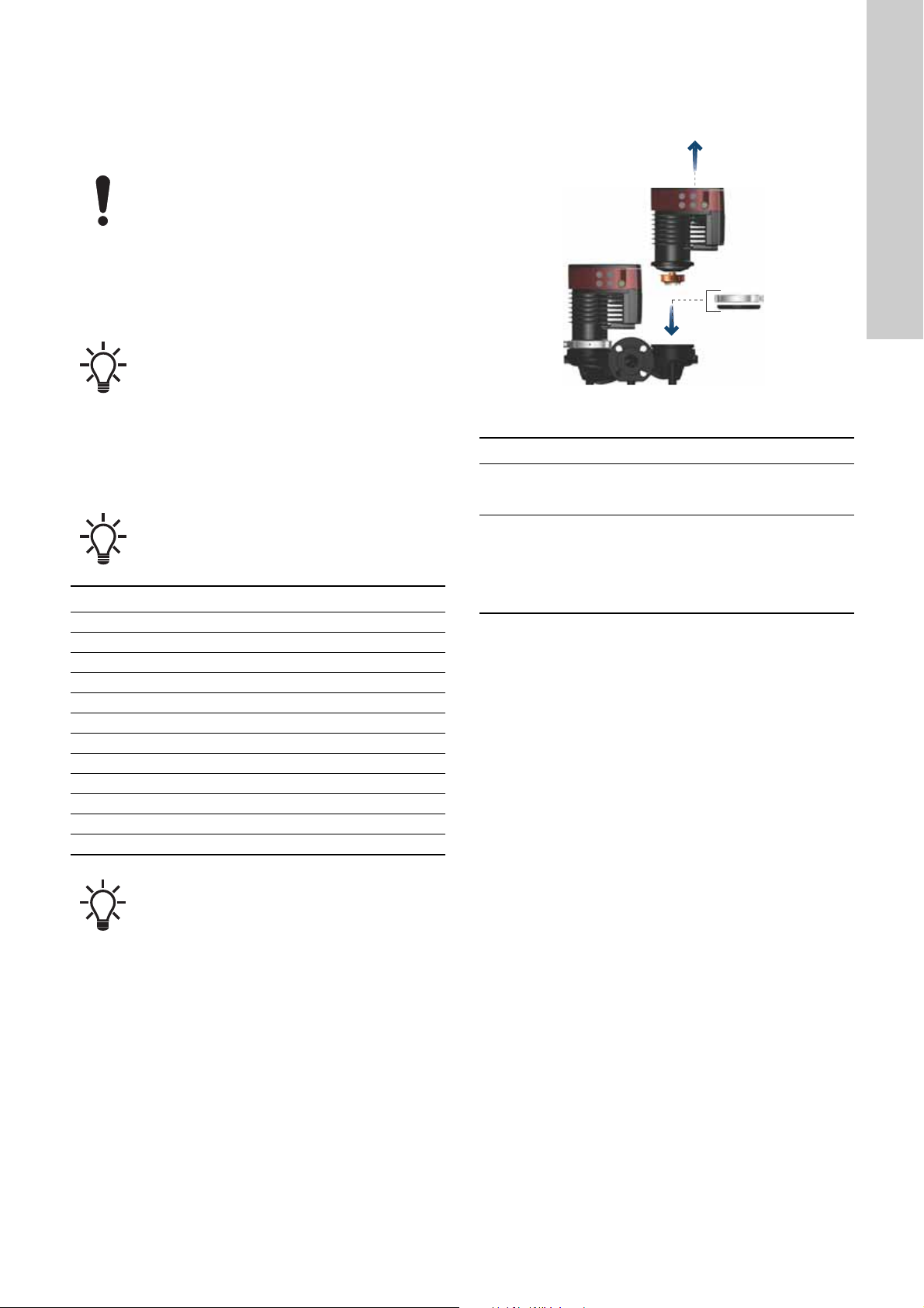
Insulating shells for pumps in heating systems are factory-fitted
with the pump. Remove the insulating shells before you install the
pump. See fig. 8.
Fig. 8 Removing insulating shells from the pump
English (GB)
TM05 5512 3016
Fig. 7 Recommended tools
3.3.2 Cooling systems
Insulating shells for pumps in air-conditioning and cooling
systems, down to -10 °C, are available as accessories and must
be ordered separately. See section 6.8.2 Insulating kits for
air-conditioning and cooling systems.
3.3.3 Insulating the pump
As an alternative to insulating shells, you can insulate the pump
housing and pipes as illustrated in fig. 9.
Do not insulate the control box or cover the operating
panel.
TM05 6472 4712
Pos. Tool Size
1 Screwdriver, straight slot 0.6 x 3.5 mm
2 Screwdriver, straight slot 1.2 x 8.0 mm
3 Screwdriver, torx bit TX10
4 Screwdriver, torx bit TX20
5 Hexagon key 5.0 mm
6 Side cutter
7 Open-end spanner Depending on DN size
TM05 5549 3016
Fig. 9 Insulation of the pump housing and pipe
5

3.4 Mechanical installation
English (GB)
Install the pump so that it is not stressed by the pipes. For
maximum permissible forces and moments from pipe connections
acting on the pump flanges, see page 40.
You can suspend the pump directly in the pipes, provided that the
pipes support the pump.
Twin-head pumps are prepared for installation on a mounting
bracket or base plate.
Step Action Illustration
Arrows on the pump housing indicate the
liquid flow direction through the pump. The
liquid flow direction can be horizontal or
1
vertical, depending on the control-box
position.
Close the isolating valves and make sure
2
that the system is not pressurised during
installation of the pump.
TM05 5513 3812
3 Mount the pump with gaskets in the pipes.
Flanged version:
Fit the bolts, washers and nuts. Use the
correct size of bolts according to the system
4
pressure.
For further information about torques, see
page 40.
TM06 8040 0317
TM05 5515 3812
TM05 5516 3816 TM05 5517 3812
6

3.4.1 Pump positions
A B
C D
Always install the pump with horizontal motor shaft.
• Pump installed correctly in a vertical pipe. See fig. 10, pos. A.
• Pump installed correctly in a horizontal pipe. See fig. 10, pos.
B.
• Do not install the pump with vertical motor shaft. See fig. 10,
pos. C and D.
Fig. 10 Pump installed with horizontal motor shaft
3.4.2 Control box positions
To ensure adequate cooling, make sure that the control box is in
horizontal position with the Grundfos logo in vertical position. See
fig. 11.
English (GB)
TM05 5518 3016
TM05 5522 3016
Fig. 11 Pump with the control box in horizontal position
Twin-head pumps installed in horizontal pipes can be
fitted with an automatic vent, Rp 1/4" thread, in the
upper part of the pump housing if no venting valve is
installed in the system. See fig. 12.
Fig. 12 Automatic vent
TM05 6062 3016
7

3.4.3 Pump head position
English (GB)
If you remove the pump head before installing the pump in the
pipes, pay special attention when fitting the pump head to the
pump housing:
1. Visually check that the floating ring in the sealing system is
centred. See figs 13 and 14.
2. Gently lower the pump head with the rotor shaft and impeller
into the pump housing.
3. Make sure that the contact face of the pump housing and that
of the pump head are in contact before you tighten the clamp.
See fig. 15.
Fig. 13 Correctly centred sealing system
Check the position of the clamp before you tighten it.
Incorrect position of the clamp will cause leakage
from the pump and damage the hydraulic parts in the
pump head. See fig. 15.
TM05 5837 3016
Fig. 15 Fitting the pump head to the pump housing
TM05 6650 3016TM05 6651 3016
Fig. 14 Incorrectly centred sealing system
8

3.4.4 Changing the control box position
8Nm!
5.0
8 Nm5.0
The warning symbol on the clamp holding the pump
head and pump housing together indicates that there
is a risk of personal injury. See specific warnings
below.
CAUTION
Pressurised system
Minor or moderate personal injury
- Pay special attention to any escaping vapour
when loosening the clamp.
CAUTION
Crushing of feet
Minor or moderate personal injury
- Do not drop the pump head when loosening the
clamp.
Fit and tighten the screw holding the clamp to 8 Nm ±
1 Nm. Do not apply more torque than specified even
though water is dripping from the clamp. The
condensed water is most likely coming from the drain
hole under the clamp.
Step Action Illustration
Due to the drain
hole in the stator
housing, position
4
the gap of the
clamp as shown in
step 4a or 4b.
Single-head
pump:
Position the clamp
so that the gap
points towards the
4a
arrow.
It can be in position
3, 6, 9 or 12
o'clock.
English (GB)
TM05 2870 3016
Check the position of the clamp before you tighten
the clamp. Incorrect position of the clamp will cause
leakage from the pump and damage the hydraulic
parts in the pump head.
Step Action Illustration
Loosen the screw
in the clamp that
holds the pump
head and pump
housing together. If
you loosen the
1
screw too much,
the pump head will
be completely
disconnected from
the pump housing.
Carefully, turn the
pump head to the
desired position.
If the pump head is
2
stuck, loosen it with
a light blow of a
rubber mallet.
Place the control
box in horizontal
position so that the
Grundfos logo is in
3
vertical position.
The motor shaft
must be in
horizontal position.
TM05 2918 3016
Twin-head pump:
Position the clamps
so that the gaps
point towards the
4b
arrows.
They can be in
position 3, 6, 9 or
12 o'clock.
TM05 2917 3016
Fit and tighten the
screw holding the
clamp to 8 ± 1 Nm.
TM05 2867 3016
Do not retighten
5
the screw if
condensed water is
dripping from the
clamp.
TM05 2872 3016
Fit the insulating
TM05 5526 3016
shells.
Insulating shells for
pumps in
6
air-conditioning
and cooling
systems must be
ordered separately.
TM05 5529 3016
TM05 5527 3016
9

3.5 Electrical connection
English (GB)
Carry out the electrical connection and protection according to
local regulations.
Check that the supply voltage and frequency correspond to the
values stated on the nameplate.
WARNING
Electric shock
Death or serious personal injury
- Lock the main switch in position 0. Type and
requirements as specified in EN 60204-1, 5.3.2.
WARNING
Electric shock
Death or serious personal injury
- Connect the pump to an external main switch with
a minimum contact gap of 3 mm in all poles.
- Use earthing or neutralisation for protection
against indirect contact.
- If the pump is connected to an electric installation
where an electrical circuit breaker, that is a
voltage sensing ELCB, residual-current device
RCD or residual-current circuit device RCCB, is
used as an additional protection, this circuit
breaker must be marked with the first or both of
the symbols shown below:
• Make sure that the pump is connected to an external main
switch.
• The pump requires no external motor protection.
• The motor incorporates thermal protection against slow
overloading and blocking.
• When switched on via the power supply, the pump starts after
approximately 5 seconds.
3.5.1 Supply voltage
1 x 230 V ± 10 %, 50/60 Hz, PE.
The voltage tolerances are intended for mains-voltage variations.
Do not use the voltage tolerances for running pumps at other
voltages than those stated on the nameplate.
10

3.5.2 Wiring diagrams
External switch
Fuse
RCD/RCCB
L
N
L
N
External switch
Fuse
RCD/RCCB
CNC S/S
S/S CNC
12
Fig. 16 Example of a plug-connected motor with a main switch, backup fuse and additional protection
Fig. 17 Example of a mains-connected motor with a main switch, backup fuse and additional protection
English (GB)
TM05 5277 3016
TM06 8503 0817
Fig. 18 Connection to external control
Pos. Description
1 Plug-connected versions
2 Terminal-connected versions
WARNING
Electric shock
Minor or moderate personal injury
- Separate wires connected to supply terminals,
outputs NC, C and start-stop input from each other
and from the supply by means of reinforced
insulation.
TM06 9106 4517 - TM06 8060 0717
Make sure that the fuse is dimensioned according to
the nameplate and local regulations.
Connect all cables in accordance with local
regulations.
Make sure that all cables are heat-resistant up to 75
°C.
Install all cables in accordance with EN 60204-1 and
EN 50174-2:2000.
11

3.5.3 Connection to the power supply, plug-connected
17 mm
12 mm
7 mm
Ø 5.5 - 10 mm
Max. 1.5 mm
2
Click
Click
Click
x 3
Max 0.8 x 4
English (GB)
versions
Step Action Illustration
Step Action Illustration
Fit the cable gland
and plug cover to
the cable. Strip the
1
cable conductors
as illustrated.
Connect the cable
2
conductors to the
power supply plug.
Bend the cable
with the cable
3
conductors
pointing upwards.
7
TM05 5538 3216
Disassembling the plug
Step Action Illustration
TM05 5539 3812
TM05 5540 3812
1
2
Insert the power
supply plug into
the male plug in
the pump control
box.
TM07 1417 1618
Loosen the cable
gland and remove
it from the plug.
TM05 5545 3812
Pull off the plug
cover while
pressing on both
sides.
Pull out the
conductor guide
4
plate and throw it
away.
Click the plug
5
cover onto the
power supply plug.
Screw the cable
6
gland onto the
power supply plug.
TM05 5546 3812
Loosen the cable
TM05 5541 3812
conductors one by
one by pressing a
3
screwdriver gently
into the terminal
clip.
TM05 5547 3812
TM05 5542 3812
The plug has now
been removed
4
from the power
supply plug.
TM05 5543 3812
TM05 5548 3812
12

3.5.4 Connection to the power supply, terminal-connected
1 x 230 V
7 mm
20 mm
7 mm
25 mm
Min. Ø 7 mm
Max. Ø 14 mm
version
Step Action Illustration
Step Action Illustration
Remove the
front cover from
the control box.
1
Do not remove
the screws from
the cover.
Locate the
power supply
plug and cable
gland in the
2
small cardboard
box supplied
with the pump.
Connect the
3
cable gland to
the control box.
Connect the
cable
conductors to
6
English (GB)
the power
supply plug.
TM05 5530 3016
TM06 8053 0717
Insert the power
supply plug into
7
the male plug in
the control box.
TM06 8049 0717
TM06 8054 0717
Tighten the
cable gland.
8
Refit the front
cover.
TM06 8050 0717
Pull the power
4
cable through
the cable gland.
Strip the cable
5
conductors as
illustrated.
TM06 8061 0717
TM06 8051 0717
TM06 8052 0717
13

3.5.5 Connecting the digital input 3.5.6 Connecting the fault relay output
English (GB)
Step Action Illustration
Remove the front
cover from the
control box.
1
Do not remove the
screws from the
cover.
Locate the digital
2
input terminal
connector.
Pull the cable
through a cable
gland, M16, and
connect the cable
conductors to the
digital input
terminal
connector.
3
See section
8.4.1 Digital input
(Start/Stop) for
instructions on
how to connect
the cable to the
terminal.
Step Action Illustration
Remove the front
cover from the
control box.
1
Do not remove the
screws from the
cover.
TM05 5530 3016
Locate the fault
2
relay output cover
and remove it.
Pull the cable
TM06 8017 8517 0817
through a cable
gland, M16, and
connect the cable
conductors to the
fault relay output
terminal
connector.
3
See section
8.4.2 Fault relay
output for
instructions on
how to connect
the cable to the
terminal.
TM06 8516 0817
TM05 5530 3016
TM06 8056 0817
TM06 8057 0817
Refit the front
4
cover to the
control box.
Refit the fault
4
relay output cover.
TM06 8058 0717
TM06 8059 0717
Refit the front
5
cover to the
control box.
TM06 8059 0717
14

4. Starting up the product
1 x 230 V ± 10 %
ϝ0/60 Hz
1 / On
0 / Off
4.1 Single-head pump
In order to protect the electronics, the number of
starts and stops must not exceed four times per
hour.
Do not start the pump until the system has been filled with liquid
and vented. Furthermore, the required minimum inlet pressure
must be available at the pump inlet. See section 10. Technical
data.
The pump is self-venting through the system, and the system
must be vented at the highest point.
Step Action Illustration
English (GB)
1
Switch on the power supply to the pump.
The pump starts after approximately 5 seconds.
2 Operating panel at first startup.
The pump has been factory-set to the intermediate
proportional-pressure curve.
3
Select the control mode according to the system
application by pressing the button . See section
7. Control functions and 8. Setting the product.
TM07 0033 3917
TM05 5551 3016
TM05 5551 3016
15

4.2 Twin-head pump
5 sec.
=
5 sec.
=
English (GB)
4.3.2 Unpairing
Step Action Illustration
Make sure that both pump heads are powered on.
The pumps are paired from factory. When switching on the power
supply, the heads will establish connection, which is indicated by
a green light in the centre of Grundfos Eye. Please allow
approximately 5 seconds for this to happen.
If one of the pump heads is turned off, the pump with power will
show a yellow indicator light, warning 77, see section 9. Fault
finding the product. In that case, power up the switched off pump.
Once both pumps are on, the pumps will establish connection and
the warning deactivates.
See sections 8.4.1 Digital input (Start/Stop), 8.4.2 Fault relay
output and 8.4.3 Twin-head pump function for additional
twin-head pump setup options.
4.3 Pairing and unpairing twin-head pumps
The pumps are paired from factory, however, it can be useful to
know how to pair the system e.g. for service purposes.
The pumps can also be unpaired.
When you have paired the pumps, you must wait 10
seconds before unpairing.
4.3.1 Pairing
The master pump head is the one from which you
initiate the pairing.
Push and hold the
button on any of
the two pump
1
heads for 5
seconds.
The light in the
centre of Grundfos
Eye will disappear.
2
The system has
been deactivated.
TM06 8521 1017
TM06 8522 1017
Step Action Illustration
Push and hold the
button on the
pump you wish to
assign as the
master pump for 5
1
seconds.
The centre of
Grundfos Eye on
both pumps will
begin to flash.
Push the button
on the other pump
2
to assign this as
the slave pump.
The centre of both
Grundfos Eye
indicator lights are
alight and
3
constant.
The two pumps
are now paired.
TM06 8524 1017
TM06 8525 1017
16
TM06 8527 1017

5. Handling and storing the product
Max. 95 % RH
IPX4D
If the pump is not used during periods of frost, add
antifreeze or let the pump run in regular intervals to
prevent frost bursts.
Observe local regulations concerning limits for
manual lifting or handling.
Always lift directly on the pump head or the cooling fins when
handling the pump. For large pumps, it may be necessary to use
lifting equipment. See section 2.3 Lifting the product.
6. Product introduction
6.1 Product description
Grundfos MAGNA1 is a complete range of circulator pumps with
integrated controller enabling adjustment of pump performance to
the actual system requirements. In many systems, this reduces
the power consumption considerably, reduces noise from
thermostatic radiator valves and similar fittings and improves the
control of the system.
You can set the desired head on the operating panel.
6.2 Intended use
The pump is designed for circulating liquids in the following
systems:
• heating systems
• domestic hot-water systems
• air-conditioning and cooling systems.
You can also use the pump in the following systems:
• ground-source heat-pump systems
• solar-heating systems.
6.3.1 Glycol
You can use the pump for pumping water-ethylene-glycol
mixtures up to 50 %.
Example of a water-ethylene-glycol mixture:
Maximum viscosity: 50 cSt ~ 50 % water and 50 % glycol mixture
at -10 °C.
The pump has a power-limiting function that protects it against
overload.
The pumping of glycol mixtures affects the maximum curve and
reduces the performance, depending on the
water-ethylene-glycol mixture and the liquid temperature.
To prevent the glycol mixture from degrading, avoid temperatures
exceeding the rated liquid temperature and minimise the
operating time at high temperatures.
Clean and flush the system before you add the glycol mixture.
To prevent corrosion or lime precipitation, maintain the glycol
mixture regularly. If further dilution of the supplied glycol is
required, follow the glycol supplier's instructions.
Additives with a density or kinematic viscosity higher
than water reduces the hydraulic performance.
English (GB)
6.3 Pumped liquids
The pump is suitable for thin, clean, non-aggressive and
non-explosive liquids, not containing solid particles or fibres that
may attack the pump mechanically or chemically.
In heating systems, the water must meet the requirements of
accepted standards on water quality in heating systems, for
example the German standard VDI 2035.
The pump is also suitable for domestic hot-water systems.
We strongly recommend that you use stainless-steel pumps in
domestic hot-water applications to avoid corrosion.
In domestic hot-water systems, we recommend that you use the
pump only for water with a degree of hardness lower than
approximately 14 °dH.
In domestic hot-water systems, we recommend that you keep the
liquid temperature below 65 °C to eliminate the risk of lime
precipitation.
TM06 8055 0717
Fig. 19 Pumped liquids
Observe local regulations regarding pump-housing
material.
Do not pump aggressive liquids.
Do not pump flammable, combustible or explosive
liquids.
17

6.4 Identification
English (GB)
6.4.1 Nameplate
Fig. 20 Example of a nameplate
Pos. Description
1 Product name
2 Model
3 Production code, PC, year and week*
4 Serial number
5 Product number
6 Country of manufacture
7 Enclosure class
8 Energy Efficiency Index, EEI
9 Part, according to EEI
10 Temperature class
11 Minimum current [A]
12 Maximum current [A]
13 Minimum power [W]
14 Maximum power [W]
15 Maximum system pressure
16 Voltage [V] and frequency [Hz]
17 QR code
18 CE mark and approvals
19 Manufacturer's name and address
* Example of production code: 1326. The pump was produced in
week 26, 2013.
6.4.2 Type key
Code Example MAGNA1 D 80 -120 (F) (N) 360
Type range
MAGNA1
D Twin-head pump
Nominal diameter (DN) of inlet
and outlet ports [mm]
TM05 5561 3812
Maximum head
[dm]
Pipe connection
Threaded
Flange
F
Pump housing material
Cast iron
Stainless steel
N
Port-to-port length [mm]
6.5 Radio communication
MAGNA1 single-head pumps are designed for infrared
communication (IR) with Grundfos GO Remote, while MAGNA1
twin-head pumps can also communicate via radio.
6.6 Non-return valve
If a non-return valve is fitted in the pipe system, ensure that the
set minimum outlet pressure of the pump is always higher than
the closing pressure of the valve. See fig. 22. This is especially
important in proportional-pressure control mode with reduced
head at a low flow rate.
Fig. 22 Non-return valve
TM05 3055 0912
Fig. 21 Production code on the packaging
18
TM06 6692 2216
6.7 Closed valve operation
MAGNA1 pumps can operate at any speed against a closed valve
for several days without damage to the pump. However, Grundfos
recommends to operate at the lowest possible speed curve to
minimize energy losses. There are no minimum flow
requirements.
Do not close inlet and outlet valves simultaneously,
always keep one open when the pump is running.
Media- and ambient temperatures must never
exceed the specified temperature range.
6.8 Accessories
6.8.1 Insulating shells for heating systems
Insulating shells are available for single-head pumps only and are
supplied with the pump.
Insulating shells increase the pump dimensions.
6.8.2 Insulating kits for air-conditioning and cooling systems
Insulating shells for pumps in air-conditioning and cooling
systems, down to -10 °C, are available as accessories and must
be ordered separately. A kit consists of two shells made of
polyurethane and a self-adhesive seal to ensure tight assembly.
Insulating shells increase the pump dimensions. The
dimensions of the insulating shells for pumps in
air-conditioning and cooling systems differ from
those of the insulating shells for pumps in heating
systems.
Pump type Product number
MAGNA1 25-40/60/80/100/120 (N) 98538852
MAGNA1 32-40/60/80/100/120 (N) 98538853
MAGNA1 32-40/60/80/100 F (N) 98538854
MAGNA1 32-120 F (N) 98164595
MAGNA1 40-40/60 F (N) 98538855
MAGNA1 40-80/100 F (N) 98164597
MAGNA1 40-120/150/180 F (N) 98164598
MAGNA1 50-60/80 F (N) 98164599
MAGNA1 50-100/120/150/180 F (N) 98164600
MAGNA1 65-40/60/80/100/120/150 F (N) 98538839
MAGNA1 80-60/80/100/120 F 98538851
MAGNA1 100-40/60/80/100/120 F 98164611
6.8.3 Blanking flanges
A blanking flange is used to blank off the opening when one of the
pump heads of a twin-head pump is removed for service to
enable uninterrupted operation of the other pump.
Fig. 23 Position of a blanking flange
Pump type Product number
MAGNA1 D 25-40/60/80/100/120
MAGNA1 D 32-40/60/80/100 (F)
MAGNA1 D 40-40/60 F
MAGNA1 D 32-120 F
MAGNA1 D 40-80/100/120/150/180 F
MAGNA1 D 50-60/80/100/120/150/180 F
MAGNA1 D 65-40/60/80/100/120/150 F
MAGNA1 D 80-60/80/100/120 F
MAGNA1 D 100-40/60/80/100/120 F
6.8.4 Counterflanges
Counterflange kits consist of two flanges, two gaskets and bolts
and nuts, making it possible to install the pump in any pipes. See
New MAGNA1 model C data booklet, Accessories section, for the
right dimension and product number.
98159373
98159372
English (GB)
TM06 8518 0817
The insulating kit also fits stainless-steel versions
(N).
19

6.8.5 Grundfos GO Remote
PP3
PP2
PP1
Q
H
Q
H
CP3
CP2
CP1
Q
H
English (GB)
MAGNA1 single-head pumps are designed for infrared
communication (IR) with Grundfos GO Remote, while MAGNA1
twin-head pumps can also communicate via radio.
The radio communication between the pump and
Grundfos GO Remote is encrypted to protect against
misuse.
In order to communicate with Grundfos GO Remote via infrared,
you need an add-on module. Two variants are available as
described in the following.
MI 204
MI 204 is an add-on module with built-in infrared and radio
communication. You can use MI 204 in conjunction with an Apple
iPhone or iPod with Lightning connector.
Fig. 24 MI 204
Supplied with the product:
• Grundfos MI 204
• sleeve
• quick guide
• charger cable.
MI 301
MI 301 is a module with built-in infrared and radio
communication. Use MI 301 in conjunction with an Android or
iOS-based smart device with a Bluetooth connection. MI 301 has
a rechargeable Li-ion battery and must be charged separately.
7. Control functions
Factory setting: Intermediate proportional-pressure
curve, referred to as PP2.
7.1 Proportional-pressure curve (PP1, PP2 or PP3)
Proportional-pressure control adjusts the pump performance to
the actual flow rate demand in the system, but the pump
performance follows the selected performance curve, PP1, PP2
or PP3. See fig. 26 where PP2 has been selected.
Fig. 26 Three proportional-pressure curves and settings
TM05 7704 1513TM05 3890 1712
The selection of the right proportional-pressure setting depends
on the characteristics of the system in question and the actual
flow rate demand.
For further information, see section 7.4 Overview of the control
functions and 7.5 Selecting control function.
7.2 Constant-pressure curve (CP1, CP2 or CP3)
Constant-pressure control adjusts the pump performance to the
actual flow rate demand in the system, but the pump performance
follows the selected performance curve, CP1, CP2 or CP3. See
fig. 27 where CP1 has been selected.
TM05 5555 3812TM05 5556 3812TM05 5557 3812
Fig. 27 Three constant-pressure curves and settings
Fig. 25 MI 301
The selection of the right constant-pressure setting depends on
the characteristics of the system in question and the actual flow
Supplied with the product:
• Grundfos MI 301
• battery charger
• quick guide.
Product numbers
Grundfos GO variant Product number
Grundfos MI 204 98424092
rate demand.
For further information, see section 7.4 Overview of the control
functions and 7.5 Selecting control function.
7.3 Constant curve (I, II or III)
At constant-curve operation, the pump runs at a constant speed,
independently of the actual flow rate demand in the system. The
pump performance follows the selected performance curve, I, II
or III. See fig. 28 where II has been selected.
Grundfos MI 301 98046408
Together with the Grundfos GO module, you will need to
download the Grundfos GO Remote app, which is available in
Apple App Store and Google Play.
For function and connection to the pump, see the separate
installation and operating instructions for the desired type of
Grundfos GO setup.
Fig. 28 Three constant-curve settings
The selection of the right constant-curve setting depends on the
characteristics of the system in question.
For further information, see section 7.4 Overview of the control
functions and 7.5 Selecting control function.
20

7.4 Overview of the control functions
Q
III
II
I
H
PP3
CP3
CP2
PP1
CP1
PP2
English (GB)
Fig. 29 Control function in relation to system requirements
Setting Pump curve Function
PP1
PP2
PP3
CP1
CP2
CP3
III Speed III
II Speed II
I Speed I
Lowest proportional-pressure
curve
Intermediate
proportional-pressure curve
Highest
proportional-pressure curve
Lowest constant-pressure
curve
Intermediate
constant-pressure curve
Highest constant-pressure
curve
The duty point of the pump will move up or down on the lowest proportional-pressure curve,
depending on the flow rate demand.
The head is reduced at falling flow rate demand and increased at rising flow rate demand.
The duty point of the pump will move up or down on the intermediate proportional-pressure
curve, depending on the flow rate demand.
The head is reduced at falling flow rate demand and increased at rising flow rate demand.
The duty point of the pump will move up or down on the highest proportional-pressure curve,
depending on the flow rate demand.
The head is reduced at falling flow rate demand and increased at rising flow rate demand.
The duty point of the pump will move out or in on the lowest constant-pressure curve,
depending on the flow rate demand in the system.
The head is kept constant, irrespective of the flow rate demand.
The duty point of the pump will move out or in on the intermediate constant-pressure curve,
depending on the flow rate demand in the system.
The head is kept constant, irrespective of the flow rate demand.
The duty point of the pump will move out or in on the highest constant-pressure curve,
depending on the flow rate demand in the system.
The head is kept constant, irrespective of the flow rate demand.
The pump runs on a constant curve which means that it runs at a constant speed.
At speed III, the pump is set to run on the maximum curve under all operating conditions.
You obtain quick venting of the pump by setting the pump to speed III for a short period.
The pump runs on a constant curve which means that it runs at a constant speed.
At speed II, the pump is set to run on the intermediate curve under all operating conditions.
The pump runs on a constant curve which means that it runs at a constant speed.
At speed I, the pump is set to run on the minimum curve under all operating conditions.
TM05 2778 3617
21

7.5 Selecting control function
Q
H
Q
H
Q
H
English (GB)
System application Select this control mode
Systems with relatively large pressure losses in the distribution pipes and in air-conditioning and cooling
systems.
• Two-pipe heating systems with thermostatic valves and the following:
– very long distribution pipes
– strongly throttled pipe-balancing valves
– differential-pressure regulators
– large pressure losses in those parts of the system through which the total quantity of water flows, for
example a boiler, a heat exchanger and a distribution pipe up to the first branching.
• Primary circuit pumps in systems with large pressure losses in the primary circuit.
• Air-conditioning systems with the following:
– heat exchangers, fan coils
– cooling ceilings
– cooling surfaces.
Systems with relatively small pressure losses in the distribution pipes.
• Two-pipe heating systems with thermostatic valves and the following:
– dimensioning for natural circulation
– small pressure losses in those parts of the system through which the total quantity of water flows,
for example a boiler, a heat exchanger and a distribution pipe up to the first branching or modified to
a high differential temperature between the flow pipe and the return pipe, for example district
heating.
• Underfloor heating systems with thermostatic valves.
• One-pipe heating systems with thermostatic valves or pipe-balancing valves.
• Primary circuit pumps in systems with small pressure losses in the primary circuit.
Operation according to the maximum or minimum curve, like an uncontrolled pump:
• Use the maximum-curve mode in periods in which a maximum flow rate is required. This operating
mode is for instance suitable for hot-water priority in domestic hot-water systems.
• Use the minimum-curve mode in periods in which a minimum flow rate is required.
Proportional pressure
Constant pressure
Constant curve
22

8. Setting the product
1
3
4
2
5
8.1 Operating panel
CAUTION
Hot surface
Minor or moderate personal injury
- To avoid burns only touch the operating panel.
Fig. 30 Operating panel
8.2 Setting the control function
The pump has nine control functions, see section 7. Control
functions. Select the control function by pressing the push-button
on the operating panel, see fig. 30, pos. 5. The control function is
indicated by eight different light fields in the display.
Button
presses
0
1
2
3
4
TM06 9078 3617
5
Active light fields Description
Intermediate
proportional-pressure
curve, referred to as
PP2, factory setting
Highest
proportional-pressure
curve, referred to as PP3
Lowest
constant-pressure curve,
referred to as CP1
Intermediate
constant-pressure curve,
referred to as CP2
Highest
constant-pressure curve,
referred to as CP3
Constant curve III
English (GB)
The operating panel on the pump comprises the following:
Pos. Description
Infrared receiver for Grundfos GO.
1
Plug-connected versions.
Grundfos Eye.
2
See section 9.1 Grundfos Eye operating status.
Infrared receiver for Grundfos GO.
3
Terminal-connected versions.
LEDs indicate the control function.
4
See section 8.2 Setting the control function.
5 Push-button for selection of a control function.
6
7
8
Constant curve II
Constant curve I
Lowest
proportional-pressure
curve, referred to as PP1
23

8.2.1 Adjusting the proportional pressure using Grundfos GO
English (GB)
Remote
The setpoint of the proportional-pressure curve can be adjusted
using Grundfos GO Remote.
Adjusting the proportional pressure is only possible
in proportional pressure mode.
Step Action Illustration
Choose
"Settings" in the
Grundfos GO
1
Remote
dashboard.
Step Action Illustration
Use the arrows
on the top right
of the screen, or
slide the
setpoint
3
indicator up and
down to adjust
the setpoint.
Press "OK".
When the pump
receives the
setpoint from
Grundfos GO
Remote, the
proportional-pre
4
ssure symbol on
the pump lights
TM06 8584 0817
up - none of the
level indicators
lights up.
For instructions on how to connect the pump to Grundfos GO
Remote, see section 8.3 Connecting the pump to Grundfos GO
Remote.
TM06 8582 0817
Choose
"Setpoint" in the
2
"Settings"
menu.
TM06 8583 0817
24

8.3 Connecting the pump to Grundfos GO Remote
IR
Plug-connected versions
Terminal-connected
versions
Min. 30 cm
IR
Max. 15 °
Max. 15 °
3
2
5
6
7
1
4
MAGNA1 single-head pumps are designed for infrared
communication (IR) with Grundfos GO Remote, while MAGNA1
twin-head pumps can also communicate via radio.
Before connecting to Grundfos GO Remote
To use Grundfos GO Remote together with MAGNA1 make sure
to have the following ready:
• For IR communication: A Grundfos GO add-on module, which
is available as an accessory. See section 6.8.5 Grundfos GO
Remote. See the separate installation and operating
instructions for the desired type of Grundfos GO setup.
• The Grundfos GO Remote app downloaded to your smart
device. Grundfos GO Remote is available in Apple App Store
and Google Play.
Connecting to Grundfos GO Remote
To connect to Grundfos GO Remote, do as follows:
1. For IR communication: Establish a connection between the
Grundfos GO add-on module and your smart device. See the
separate installation and operating instructions.
2. Open the Grundfos GO Remote app and select either IR or
radio communication depending on the pump type and chosen
communication method. Make sure to point Grundfos GO at
the receiver placed left or right to Grundfos Eye depending on
your pump model. See fig. 31.
8.3.1 Using Grundfos GO Remote
English (GB)
TM06 8584 0817
Fig. 32 Grundfos GO Remote dashboard
Pos. Description
1 Information about the connected product.
Grundfos Eye reflecting the current operating status of
2
the pump.
In a multipump system: Icon indicating if Grundfos GO
3
is connected to the master or slave pump.
When connected to a single pump: The field is empty.
4 The actual, measured head (pressure).
5 The power consumption of the pump.
Main menu. See section 8.3.2 "Status" menu,
6
8.3.3 "Settings" menu and 8.3.4 "Alarms and warnings"
menu.
"Disconnect": Disconnects Grundfos GO from the
TM06 9081 3617TM06 7653 0718
pump.
"Refresh": Retrieves current data from the pump.
7
"Reports": Wizard creating a report with the pump's
current operating status and settings.
"Help": Guides you through the app.
When using Grundfos GO in a multipump setup and
choosing "system view", Grundfos Eye, pos. 2, fig.
32, will indicate the system's operating status and not
the status of the pump itself. See section
9.1.1 Multipump system operating indications.
Fig. 31 Establishing a connection between Grundfos GO and
MAGNA1 via infrared communication
25

8.3.2 "Status" menu
1
3
2
English (GB)
The "Status" menu gives an overview of the pump's current
operating status. To access the menu, connect the pump to
Grundfos GO. See section 4.3 Pairing and unpairing twin-head
pumps, and choose the "Status" menu from the dashboard.
8.3.3 "Settings" menu
The "Settings" menu allows you to:
• Adjust the proportional pressure, see section 8.2.1 Adjusting
the proportional pressure using Grundfos GO Remote for
instructions.
• Configure the Warning 77 relay setting, see section
9.5.1 Activating and deactivating the fault relay for
instructions.
Fig. 33 "Status" menu
Pos. Description
The accumulated energy consumption. This cannot be
1
reset.
The amount of time the product has been operating.
2
This is an accumulated value that cannot be reset.
The total number of times the pump has been started
3
since installation.
status menu 1 - status menu 2
Fig. 34 "Settings" menu
8.3.4 "Alarms and warnings" menu
This menu lets you read out alarm codes and text. A log history of
previous alarms and warnings is also available.
Fig. 35 "Alarms and warnings" menu with alarm
TM06 8583 0817
Alarm_Warning
For more information on warnings and alarms, see section
9. Fault finding the product.
You can also reach the menu by tapping Grundfos
Eye on the dashboard, see pos. 2, fig. 32.
26
8.4 Communication, control and monitoring
S/S
Q
H
S/S
Q
H
XXXXXXXXXXXXXXXXXXXXXXXX
P/N: XXXXXXXX
S/N: XXXXXXXX
PC: XXXX
Model: X
IP XXX TF XXX
Grundfos Holding A/S, DK - 8850 Bjerringbro, Denmark
((,;;;3DUW;
Made in Germany
0LQ
0D[
;;;
;;
XXXX
XXXX;;;
I1 [A] P
1 [W] MPa
12
NC C
12
NC C
MAGNA1 enables external control and monitoring via the
Start/Stop input, see section 8.4.1 Digital input (Start/Stop), and
the fault relay output, see section 8.4.2 Fault relay output, on
both single and twin-head pumps. In addition, the wireless
communication feature in twin-head pumps lets you use the pump
without an external controller, see section 8.4.3 Twin-head pump
function.
8.4.1 Digital input (Start/Stop)
To use the digital input, connect the control wires to terminals
Start/Stop (S/S) and frame ( ).
If no external on and off switch is connected,
maintain the jumper between terminals Start/Stop
(S/S) and frame ( ).This connection is the factory
setting.
A
Fig. 36 Digital input in the control box
A: Plug-connected versions
B: Terminal-connected versions
Contact symbol Function
S/S Start/Stop
B
Frame connection
Cable shield
Digital input on twin-head pumps
The Start/Stop input operates on system level, meaning that if the
master pump head receives a stop signal, the system stops.
As a main rule the digital input is only effective on the master,
which is why it is important to know which pump is assigned as
the master, see fig. 37.
Fig. 37 Identifying the master pump head on the nameplate
For redundancy purposes, the digital input can be used
concurrent on the slave pump head. However, as long as the
master is powered up, the input on the slave will be ignored. In
the event of power loss on the master, the digital input of the
slave will take over. When the master pump head is back on, the
master takes over and controls the slave.
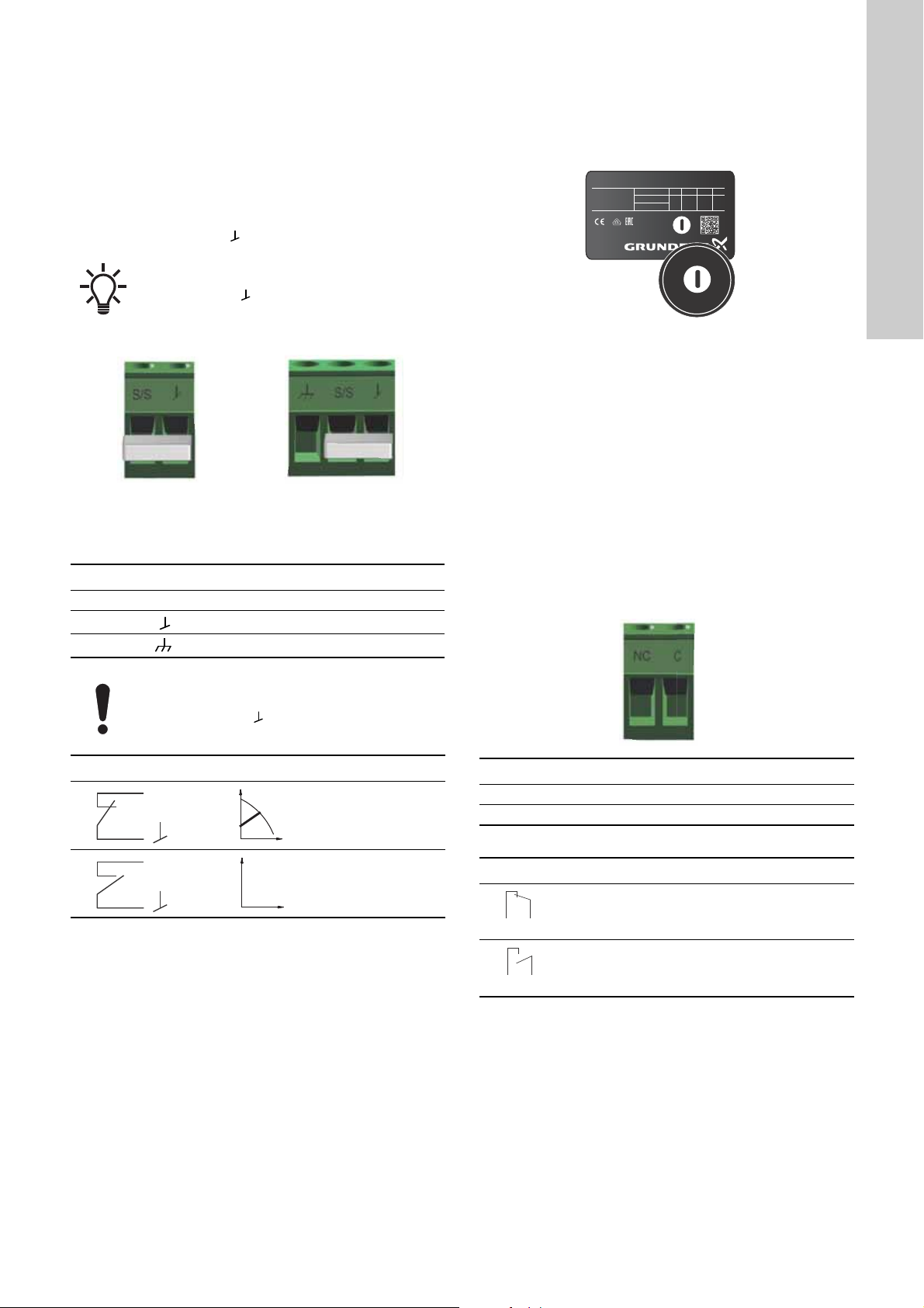
8.4.2 Fault relay output
It is possible to use the relay output as part of a control strategy
TM06 9107 4617 - TM06 9080 3617
or for monitoring. For example, if the pump experiences a fault,
the fault relay sends a signal to the controller, which will
subsequently trigger further events depending on your chosen
strategy. In order to use the fault relay output, follow the
instructions in fig. 38.
The relay can be used for outputs up to 250 V and 2 A.
Factory settings of the relay:
English (GB)
TM06 8063 0817TM06 9107 4617
Plug-connected versions, pos. A, fig. 36:
When using a shielded cable, connect the shield in
the frame terminal ( ) together with the frame
connection cord.
Start/Stop
Normal duty
Stop
For instructions on how to connect to the Start/Stop input, see
section 3.5.5 Connecting the digital input.
Contact symbol Function
NC Normally closed
C Common
The functions of the fault relay are as shown in the table:
Fault relay Alarm signal
Not activated:
• The power supply has been switched off.
• The pump has not registered a fault.
Activated:
• The pump has registered a fault or there is a
wirebreak.
Fig. 38 Fault relay output table
For instructions on how to connect to the fault relay output, see
section 3.5.6 Connecting the fault relay output.
Fault relay output in twin-head pumps
The fault relay output on each pump head operates
independently, meaning that if a fault occurs in one of the pumps
its respective relay is triggered.
27

8.4.3 Twin-head pump function
English (GB)
The twin-head pump function allows you to use twin-head pumps
without an external controller, as the two pump heads
communicate via wireless connection.
Operating mode
The pumps are operating in alternating mode, meaning that only
one pump is running at a time. The two pumps change from one
pump to the other every 24 hours with a tolerance of ± 0,5 % per
day.
To control the twin-head pump via the digital Start/Stop input, see
section 8.4.1 Digital input (Start/Stop).
To monitor the twin-head pump via the fault relay output, see
section 3.5.6 Connecting the fault relay output.
9. Fault finding the product
9.1 Grundfos Eye operating status
Grundfos Eye is on when you switch on the power supply.
Grundfos Eye is an indicator light providing information about the
actual pump status. A fault is indicated by a yellow or red
indicator light in Grundfos Eye on the operating panel and in
Grundfos GO Remote.
The indicator light flashes in different sequences and provides
information about the following:
Grundfos Eye Indication Cause Operational state
No lights are on. The power is off. The pump is not running.
Two opposite green indicator lights
running in the direction of rotation of the
pump.
Two opposite green indicator lights are
permanently on.
One yellow indicator light running in the
direction of rotation of the pump.
One yellow indicator light is permanently
on.
Two opposite red indicator lights flashing
simultaneously.
If the pump impeller is rotated, for example when
filling the pump with water, sufficient energy may be
generated to light up the operating panel even if the
power supply has been switched off.
The power is on. The pump is running.
The power is on. The pump has stopped.
Warning. See section 9. Fault
finding the product.
Warning. See section 9. Fault
finding the product.
Alarm. See section 9. Fault
finding the product.
The pump is running.
The pump has stopped.
The pump has stopped.
28

9.1.1 Multipump system operating indications
B
A
When connecting Grundfos GO Remote to a multipump setup
and choosing "system view", Grundfos GO Remote will indicate
the system's operating status and not the status of the pump
itself. Therefore the indicator light in Grundfos GO Remote might
differ from the indicator light shown on the pump's operating
panel. See the table below.
Grundfos Eye,
master pump
Green Green Green
Green or yellow Yellow or red Yellow
Yellow or red Green or yellow Yellow
Red Red Red
Grundfos Eye,
slave pump
Grundfos Eye,
Grundfos GO
Remote
9.2 Resetting a fault indication
To reset a fault indication, eliminate the fault cause, see section
9.4 Fault finding table, and reset the pump by pressing the button
on the pump. If the pump does not revert to normal duty, the fault
cause is not eliminated.
If the fault disappears by itself, the fault indication is automatically
reset.
A fault can also be reset by using Grundfos GO Remote. See
section 9.3 Reading out warning and alarm codes in Grundfos
GO Remote.
CAUTION
Pressurised system
Minor or moderate personal injury
- Before dismantling the pump, drain the system or
close the isolating valve on either side of the
pump. The pumped liquid may be scalding hot and
under high pressure.
WARNING
Electric shock
Death or serious personal injury
- Switch off the power supply for at least 3 minutes
before you start any work on the product. Lock the
main switch in position 0. Type and requirements
as specified in EN 60204-1, 5.3.2.
WARNING
Electric shock
Death or serious personal injury
- Make sure that other pumps or sources do not
force flow through the pump even if the pump is
stopped.
If the power cable is damaged, it must be replaced
by the manufacturer, the manufacturer's service
partner or a similarly qualified person.
9.3 Reading out warning and alarm codes in Grundfos GO Remote
To read out alarm codes and text, connect the pump to Grundfos
GO Remote and navigate to the "Alarms and warnings" menu.
Grundfos Eye in the dashboard indicates the warning or alarm.
Step Action Illustration
A. Select the
"Alarms and
warnings" menu
from the
dashboard,
1
B. You can also
reach the menu by
tapping Grundfos
Eye.
The "Alarms and
warnings" menu
shows the current
alarm code and
text. A log history
of previous alarms
and warnings is
also available.
2
When the fault is
corrected, reset
the alarm by
pressing the
"Reset alarm"
button.
When connecting Grundfos GO to one of the pumps
of a twin-head pump, Grundfos GO reads out alarm
codes and texts for that pump. If you want to see
alarms and warnings for the other pump, connect to
this instead.
An overview of warnings and alarms is also available in section
9.4 Fault finding table.
For instructions on how to connect the pump to Grundfos GO, see
section 8.3 Connecting the pump to Grundfos GO Remote.
English (GB)
Dashboard_With_Alarm
Alarm_Warning
29

9.4 Fault finding table
English (GB)
Warning and alarm
codes
"Pump communication
fault" (10)
Alarm
"Forced pumping" (29)
Alarm
"Undervoltage" (40, 75)
Alarm
"Blocked pump" (51)
Alarm
High motor temperature
(64)
Alarm
Internal fault (72 and
155)
Alarm
"Overvoltage" (74)
Alarm
Comm. fault, twin-head
pump (77)
Warning
Internal fault (84 and
85)
Warning
Fault
Communication fault between
different parts of the
electronics.
Other pumps or sources force
flow through the pump even if
the pump is stopped and
switched off.
The supply voltage to the
pump is too low.
The pump is blocked. Yes
The temperature in the stator
windings is too high.
Internal fault in the pump
electronics.
Irregularities in the voltage
supply can cause alarm 72.
The supply voltage to the
pump is too high.
The communication between
pump heads was disturbed or
broken.
Fault in the pump electronics. - Contact Grundfos Service, or replace the pump.
Automatic reset
and restart?
Yes
Yes
Yes
No Contact Grundfos Service, or replace the pump.
Yes
Yes
-
Corrective actions
Replace the pump, or contact Grundfos Service.
Check if the pump is running in turbine operation. See code
(29) "Forced pumping".
Switch off the pump on the main switch. If the light in
Grundfos Eye is on, the pump is running in forced-pumping
mode.
Check the system for defective non-return valves and
replace the valves, if necessary.
Check the system for correct position of non-return valves.
Make sure that the power supply is within the specified
range.
Dismantle the pump, and remove any foreign matter or
impurities preventing the pump from rotating. Check the
water quality to eliminate the risk of lime precipitation.
There might be turbine flow in the application that forces a
flow through the pump.
Contact Grundfos Service, or replace the pump.
Make sure that the power supply is within the specified
range.
Make sure that the second pump head is powered on or
connected to the power supply.
30

9.5 Warning 77, twin-head pump
A yellow Grundfos Eye in a twin-head pump system often means
that the two heads have lost connection to each other, warning
77. This is often intermittent and caused by external disturbance,
or because one of the heads has lost power.
The warning is shown immediately and triggers the fault relay
after one hour. If communication is re-established, the warning is
automatically reset.
9.5.1 Activating and deactivating the fault relay
It is possible to choose whether warning 77 should trigger the
fault relay or not. This is done in Grundfos GO. For instructions
on how to connect the pump to Grundfos GO, see section
8.3 Connecting the pump to Grundfos GO Remote.
Step Action Illustration
Choose
"Settings" in the
Grundfos GO
1
Remote
dashboard.
Step Action Illustration
By default the
fault relay
setting is
activated.
To disable the
3
setting, choose
"Do not activate
relay".
Press "OK".
English (GB)
MAGNA1_warning77
Choose
2
"Warning 77
relay settings".
TM06 8584 0817
TM06 8583 0817
31

10. Technical data
English (GB)
Supply voltage
1 x 230 V ± 10 %, 50/60 Hz, PE.
Motor protection
The pump requires no external motor protection.
Enclosure class
IPX4D (EN 60529).
Insulation class
F.
Relative humidity
Maximum 95 %.
Ambient temperature
0 to 40 °C.
During transport: -40 to +70 °C.
Temperature class
TF110 (EN 60335-2-51).
Liquid temperature
Continuously: -10 to +110 °C.
Stainless steel pumps in domestic hot-water systems:
In domestic hot-water systems, we recommend that you keep the
liquid temperature below 65 °C to eliminate the risk of lime
precipitation.
Maximum system pressure
The actual inlet pressure and the pump pressure
against a closed valve must be lower than the
maximum permissible system pressure.
The maximum permissible system pressure is stated on the pump
nameplate:
PN 6: 6 bar or 0.6 MPa
PN 10: 10 bar or 1.0 MPa
PN 16: 16 bar or 1.6 MPa.
Test pressure
The pumps can withstand test pressures as indicated in EN
60335-2-51.
• PN 6: 7.2 bar
• PN 10: 12 bar
• PN 6/10: 12 bar
• PN 16: 19.2 bar.
During normal operation, do not use the pump at higher
pressures than those stated on the nameplate. See fig. 20.
The pressure test has been made with water containing
anti-corrosive additives at a temperature of 20 °C.
Minimum inlet pressure
The following relative minimum inlet pressure must be available
at the pump inlet during operation to avoid cavitation noise and
damage to the pump bearings.
The values in the table below apply to single-head
pumps and twin-head pumps in single-head
operation.
Liquid temperature
Single-head pumps
DN
25-40/60/80/100/120 0.10 / 0.01 0.35 / 0.035 1.0 / 0.10
32-40/60/80/100/120 0.10 / 0.01 0.35 / 0.035 1.0 / 0.10
32-120 F 0.10 / 0.01 0.20 / 0.020 0.7 / 0.07
40-40/60 F 0.10 / 0.01 0.35 / 0.035 1.0 / 0.10
40-80/100/120/150/180 F 0.10 / 0.01 0.50 / 0.05 1.0 / 0.10
50-60/80 F 0.10 / 0.01 0.40 / 0.04 1.0 / 0.10
50-100/120 F 0.10 / 0.01 0.50 / 0.05 1.0 / 0.10
50-150/180 F 0.70 / 0.07 1.20 / 0.12 1.7 / 0.17
65-40/60/80/100/120/150 F 0.70 / 0.07 1.20 / 0.12 1.7 / 0.17
80-60/80/100/120 F 0.50 / 0.05 1.00 / 0.10 1.5 / 0.15
100-40/60/80/100/120 F 0.70 / 0.07 1.20 / 0.12 1.7 / 0.17
In the case of twin-head operation, increase the required relative
inlet pressure by 0.1 bar or 0.01 MPa compared to the stated
values for single-head pumps or twin-head pumps in single-head
operation.
The relative minimum inlet pressures apply to pumps installed up
to 300 metres above sea level. For altitudes above 300 metres,
increase the required relative inlet pressure by 0.01 bar or 0.001
MPa per 100 metres altitude. The pump is only approved for an
altitude of maximum 2000 metres above sea level.
Sound pressure level
The sound pressure level of the pump is dependent on the power
consumption. Levels are determined in accordance with ISO
3745 and ISO 11203, method Q2.
Pump size Max. dB(A)
25-40/60/80/100/120
32-40/60/80/100/120
40-40/60
50-40
32-120 F
40-80/100
50-60/80
65-40/60
80-40
40-120/150/180
50-100/120/150/180
65-80/100/120
80-60/80
100-40/60
65-150
80-100/120
100-80/100/120
Leakage current
The mains filter will cause a leakage current to earth during
operation. The leakage current is less than 3.5 mA.
Power factor
The terminal-connected versions have a built-in active
power-factor correction which gives a cos φ from 0.98 to 0.99.
The plug-connected versions have a built-in passive power-factor
correction with coil and resistors which ensure that the current
drawn from the grid is in phase with the voltage and that the
current is approximately sinusoidal which gives a cos φ from 0.55
to 0.98.
75 °C 95 °C 110 °C
Inlet pressure
[bar] / [MPa]
39
45
50
55
32

11. Disposing of the product
This product has been designed with focus on the disposal and
recycling of materials. The following average disposal values
apply to all variants of MAGNA1 pumps:
• 85 % recycling
• 10 % incineration
• 5 % depositing.
Dispose of this product or parts of it in an environmentally sound
way according to local regulations.
See also end-of-life information on
www.grundfos.com/product-recycling.
WARNING
Magnetic field
Death or serious personal injury
- Persons with pacemakers disassembling this
product must exercise care when handling the
magnetic materials embedded in the rotor.
English (GB)
33

Appendix
D1
G
L6
L1
B6
B4
L5
B7
B2
H3
H2
B1
H1
H4
B1
G
D1
L5
B3 H3
H1
L1
L7
B5 B4H2
M3
Appendix 1
1. Dimensions, threaded versions
Fig. 1 Single-head pump dimensions, threaded version
TM06 9948 3717
Pump type
Dimensions [mm] [inch]
L1 L5 L6 B1 B2 B4 B6 B7 H1 H2 H3 H4 D1 G
MAGNA1 25-40 (N) 180 158 190 58 111 69 90 113 54 142 196 71 25 1 1/2
MAGNA1 25-60 (N) 180 158 190 58 111 69 90 113 54 142 196 71 25 1 1/2
MAGNA1 25-80 (N) 180 158 190 58 111 69 90 113 54 142 196 71 25 1 1/2
MAGNA1 25-100 (N) 180 158 190 58 111 69 90 113 54 142 196 71 25 1 1/2
MAGNA1 25-120 (N) 180 158 190 58 111 69 90 113 54 142 196 71 25 1 1/2
MAGNA1 32-40 (N) 180 158 190 58 111 69 90 113 54 142 196 71 32 2
MAGNA1 32-60 (N) 180 158 190 58 111 69 90 113 54 142 196 71 32 2
MAGNA1 32-80 (N) 180 158 190 58 111 69 90 113 54 142 196 71 32 2
MAGNA1 32-100 (N) 180 158 190 58 111 69 90 113 54 142 196 71 32 2
MAGNA1 32-120 (N) 180 158 190 58 111 69 90 113 54 142 196 71 32 2
Fig. 2 Twin-head pump dimensions, threaded version
34
TM07 0068 4117

2. Dimensions, flanged versions
D4
D2
D1
B1
H1 H2
H3
H4B4
B6 B7
L5
L6
L1
B2
D5
D3
D3
Pump type
Dimensions [mm] [inch]
L1 L5 L7 B1 B3 B4 B5 H1 H2 H3 D1 G M3
MAGNA1 D 32-40 180 158 35 58 400 179 221 54 142 196 32 2 1/4
MAGNA1 D 32-60 180 158 35 58 400 179 221 54 142 196 32 2 1/4
MAGNA1 D 32-80 180 158 35 58 400 179 221 54 142 196 32 2 1/4
MAGNA1 D 32-100 180 158 35 58 400 179 221 54 142 196 32 2 1/4
Fig. 3 Single-head pump dimensions, plug-connected versions, flanged version
Appendix
TM07 0067 4117
Pump type
Dimensions [mm]
L1 L5 L6 B1 B2 B4 B6 B7 H1 H2 H3 H4 D1 D2 D3 D4 D5
MAGNA1 32-40 F (N) 220 158 220 58 111 69 100 110 65 142 207 82 32 76 90/100 140 14/19
MAGNA1 32-60 F (N) 220 158 220 58 111 69 100 110 65 142 207 82 32 76 90/100 140 14/19
MAGNA1 32-80 F (N) 220 158 220 58 111 69 100 110 65 142 207 82 32 76 90/100 140 14/19
MAGNA1 32-100 F (N) 220 158 220 58 111 69 100 110 65 142 207 82 32 76 90/100 140 14/19
MAGNA1 40-40 F (N) 220 158 220 58 111 69 105 105 65 156 221 83 40 84 100/110 150 14/19
MAGNA1 40-60 F (N) 220 158 220 58 111 69 105 105 65 156 221 83 40 84 100/110 150 14/19
35

Appendix
B2
L5
L1
L6
B4
B6 B7
H4
H1
B1
H2
H3
D4
D2
D3
D5
D1
PN 6
PN 10/16
Fig. 4 Single-head pump dimensions, terminal-connected versions, flanged version
TM05 5276 3512
Pump type
Dimensions [mm]
L1 L5 L6 B1 B2 B4 B6 B7 H1 H2 H3 H4 D1 D2 D3 D4 D5
MAGNA1 32-120 F (N) 220 204 216 84 164 73 106 116 65 301 366 86 32 76 90/100 140 14/19
MAGNA1 40-80 F (N) 220 204 220 84 164 73 106 128 65 304 369 83 40 84 100/110 150 14/19
MAGNA1 40-100 F (N) 220 204 220 84 164 73 106 128 65 304 369 83 40 84 100/110 150 14/19
MAGNA1 40-120 F (N) 250 204 220 84 164 73 106 128 65 304 369 83 40 84 100/110 150 14/19
MAGNA1 40-150 F (N) 250 204 220 84 164 73 106 128 65 304 369 83 40 84 100/110 150 14/19
MAGNA1 40-180 F (N) 250 204 220 84 164 73 106 128 65 304 369 83 40 84 100/110 150 14/19
MAGNA1 50-60 F (N) 240 204 240 84 164 73 127 127 71 304 374 97 50 102 110/125 165 14/19
MAGNA1 50-80 F (N) 240 204 240 84 164 73 127 127 71 304 374 97 50 102 110/125 165 14/19
MAGNA1 50-100 F (N) 280 204 240 84 164 73 127 127 72 304 376 97 50 102 110/125 165 14/19
MAGNA1 50-120 F (N) 280 204 240 84 164 73 127 127 72 304 376 97 50 102 110/125 165 14/19
MAGNA1 50-150 F (N) 280 204 240 84 164 73 127 127 72 304 376 97 50 102 110/125 165 14/19
MAGNA1 50-180 F (N) 280 204 240 84 164 73 127 127 72 304 376 97 50 102 110/125 165 14/19
MAGNA1 65-40 F (N) 340 204 296 84 164 73 133 133 74 312 386 94 65 119 130/145 185 14/19
MAGNA1 65-60 F (N) 340 204 296 84 164 73 133 133 74 312 386 94 65 119 130/145 185 14/19
MAGNA1 65-80 F (N) 340 204 296 84 164 73 133 133 74 312 386 94 65 119 130/145 185 14/19
MAGNA1 65-100 F (N) 340 204 296 84 164 73 133 133 74 312 386 94 65 119 130/145 185 14/19
MAGNA1 65-120 F (N) 340 204 296 84 164 73 133 133 74 312 386 94 65 119 130/145 185 14/19
MAGNA1 65-150 F (N) 340 204 296 84 164 73 133 133 74 312 386 94 65 119 130/145 185 14/19
MAGNA1 80-60 F 360 204 310 84 164 73 163 163 96 318 413 115 80 128 150/160 200 19
MAGNA1 80-80 F 360 204 310 84 164 73 163 163 96 318 413 115 80 128 150/160 200 19
MAGNA1 80-100 F 360 204 310 84 164 73 163 163 96 318 413 115 80 128 150/160 200 19
MAGNA1 80-120 F 360 204 310 84 164 73 163 163 96 318 413 115 80 128 150/160 200 19
MAGNA1 100-40 F 450 204 396 84 164 73 178 178 103 330 433 120 100 160 170 220 19
MAGNA1 100-60 F 450 204 396 84 164 73 178 178 103 330 433 120 100 160 170 220 19
MAGNA1 100-80 F 450 204 396 84 164 73 178 178 103 330 433 120 100 160 170 220 19
MAGNA1 100-100 F 450 204 396 84 164 73 178 178 103 330 433 120 100 160 170 220 19
MAGNA1 100-120 F 450 204 396 84 164 73 178 178 103 330 433 120 100 160 170 220 19
36

Fig. 5 Twin-head pump dimensions, plug-connected versions, flanged version
L5
H3
L1
B6 B6
B7
D2
D4
D5
D3
D3
M3
M
L4
L2L3
B3 H1 B5 B4H2
B1
D1
L7
D4
Appendix
TM07 0069 4117
Pump type
MAGNA1 D
32-40 F
MAGNA1 D
32-60 F
MAGNA1 D
32-80 F
MAGNA1 D
40-40 F
MAGNA1 D
40-60 F
MAGNA1 D
40-80 F
Dimensions [mm]
L1 L2 L3 L4 L5 L7 B1 B3 B4 B5 B6 B7 H1 H2 H3 D1 D2 D3 D4 D5 M
220 73 120 85 158 35 58 400 179 221 130 260 69 142 211 32 76 90/100 140 14/19 12
220 73 120 85 158 35 58 400 179 221 130 260 69 142 211 32 76 90/100 140 14/19 12
220 73 120 85 158 35 58 400 179 221 130 260 69 142 211 32 76 90/100 140 14/19 12
220 53 140 60 158 15 58 452 211 241 130 260 76 156 232 40 84 100/110 150 14/19 12
220 53 140 60 158 15 58 452 211 241 130 260 76 156 232 40 84 100/110 150 14/19 12
220 53 140 60 204 15 84 502 210 294 130 260 76 303 379 40 84 100/110 150 14/19 12
37

Appendix
Fig. 6 Twin-head pump dimensions, terminal-connected versions, flanged version
TM05 5275 3512
Pump type
MAGNA1 D
32-120 F
MAGNA1 D
40-80 F
MAGNA1 D
40-100 F
MAGNA1 D
40-120 F
MAGNA1 D
40-150 F
MAGNA1 D
40-180 F
MAGNA1 D
50-40 F
MAGNA1 D
50-60 F
MAGNA1 D
50-80 F
MAGNA1 D
50-100 F
MAGNA1 D
50-120 F
MAGNA1 D
50-150 F
MAGNA1 D
50-180 F
MAGNA1 D
65-40 F
MAGNA1 D
65-60 F
MAGNA1 D
65-80 F
MAGNA1 D
65-100 F
MAGNA1 D
65-120 F
MAGNA1 D
65-150 F
MAGNA1 D
80-40 F
MAGNA1 D
80-60 F
MAGNA1 D
80-80 F
Dimensions [mm]
L1 L2 L3 L4 L5 L7 B1 B3 B4 B5 B6 B7 H1 H2 H3 D1 D2 D3 D4 D5 M
220 97 90 50 204 50 84 502 210 294 130 260 68 300 368 32 76 90/100 140 14/19 12
220 53 140 60 204 15 84 502 210 294 130 260 76 303 379 40 84 100/110 150 14/19 12
220 53 140 60 204 15 84 502 210 294 130 260 76 303 379 40 84 100/110 150 14/19 12
250 58 155 75 204 0 84 512 220 294 130 260 69 303 372 40 84 100/110 150 14/19 12
250 58 155 75 204 0 84 512 220 294 130 260 69 303 372 40 84 100/110 150 14/19 12
250 58 155 75 204 0 84 512 220 294 130 260 69 303 372 40 84 100/110 150 14/19 12
240 48 160 45 204 45 84 515 221 294 130 260 75 304 379 50 102 110/125 165 14/19 12
240 48 160 45 204 45 84 515 221 294 130 260 75 304 379 50 102 110/125 165 14/19 12
240 48 160 45 204 45 84 515 221 294 130 260 75 304 379 50 102 110/125 165 14/19 12
280 175 75 75 204 0 84 517 223 294 130 260 75 304 379 50 102 110/125 165 14/19 12
280 175 75 75 204 0 84 517 223 294 130 260 75 304 379 50 102 110/125 165 14/19 12
280 175 75 75 204 0 84 517 223 294 130 260 75 304 379 50 102 110/125 165 14/19 12
280 175 75 75 204 0 84 517 223 294 130 260 75 304 379 50 102 110/125 165 14/19 12
340 218 92 92 204 0 84 522 228 294 130 260 77 312 389 65 119 130/145 185 14/19 12
340 218 92 92 204 0 84 522 228 294 130 260 77 312 389 65 119 130/145 185 14/19 12
340 218 92 92 204 0 84 522 228 294 130 260 77 312 389 65 119 130/145 185 14/19 12
340 218 92 92 204 0 84 522 228 294 130 260 77 312 389 65 119 130/145 185 14/19 12
340 218 92 92 204 0 84 522 228 294 130 260 77 312 389 65 119 130/145 185 14/19 12
340 218 92 92 204 0 84 522 228 294 130 260 77 312 389 65 119 130/145 185 14/19 12
360 218 102 102 204 0 84 538 244 294 130 260 97 318 415 80 128 150/160 200 19 12
360 218 102 102 204 0 84 538 244 294 130 260 97 318 415 80 128 150/160 200 19 12
360 218 102 102 204 0 84 538 244 294 130 260 97 318 415 80 128 150/160 200 19 12
38

Pump type
MAGNA1 D
80-100 F
MAGNA1 D
80-120 F
MAGNA1 D
100-40 F
MAGNA1 D
100-60 F
MAGNA1 D
100-80 F
MAGNA1 D
100-100 F
MAGNA1 D
100-120 F
Dimensions [mm]
L1 L2 L3 L4 L5 L7 B1 B3 B4 B5 B6 B7 H1 H2 H3 D1 D2 D3 D4 D5 M
360 218 102 102 204 0 84 538 244 294 130 260 97 318 415 80 128 150/160 200 19 12
360 218 102 102 204 0 84 538 244 294 130 260 97 318 415 80 128 150/160 200 19 12
450 243 147 147 204 0 84 551 252 299 135 270 103 330 434 100 160 170 220 19 12
450 243 147 147 204 0 84 551 252 299 135 270 103 330 434 100 160 170 220 19 12
450 243 147 147 204 0 84 551 252 299 135 270 103 330 434 100 160 170 220 19 12
450 243 147 147 204 0 84 551 252 299 135 270 103 330 434 100 160 170 220 19 12
450 243 147 147 204 0 84 551 252 299 135 270 103 330 434 100 160 170 220 19 12
M3: Rp 1/4 for a vent valve is available on all twinhead pumps.
Appendix
39

Appendix
3. Forces and moments
Maximum permissible forces and moments from the pipe
connections acting on the pump flanges are indicated in fig 7.
Fig. 7 Forces and moments from the pipe connections acting on the pump flanges
TM05 5639 4012
Force
[N]
Diameter DN Fy Fz Fx ΣFb My Mz Mx ΣMb
25* 350 425 375 650 300 350 450 650
32* 425 525 450 825 375 425 550 800
40 500 625 550 975 450 525 650 950
50 675 825 750 1300 500 575 700 1025
65 850 1050 925 1650 550 600 750 1100
80 1025 1250 1125 1975 575 650 800 1175
100 1350 1675 1500 2625 625 725 875 1300
* The values also apply to pumps with threaded connection.
The above values apply to cast-iron versions. For stainless-steel
versions, the values can be multiplied by two according to the
ISO 5199 standard.
Moment
[Nm]
4. Tightening torques for bolts
Recommended tightening torques for bolts used in flanged
connections:
Bolt dimension Torque
M12 27 Nm
M16 66 Nm
40

Argentina
Bombas GRUNDFOS de Argentina S.A.
Ruta Panamericana km. 37.500 Centro
Industrial Garin
1619 Garín Pcia. de B.A.
Phone: +54-3327 414 444
Telefax: +54-3327 45 3190
Australia
GRUNDFOS Pumps Pty. Ltd.
P.O. Box 2040
Regency Park
South Australia 5942
Phone: +61-8-8461-4611
Telefax: +61-8-8340 0155
Austria
GRUNDFOS Pumpen Vertrieb Ges.m.b.H.
Grundfosstraße 2
A-5082 Grödig/Salzburg
Tel.: +43-6246-883-0
Telefax: +43-6246-883-30
Belgium
N.V. GRUNDFOS Bellux S.A.
Boomsesteenweg 81-83
B-2630 Aartselaar
Tél.: +32-3-870 7300
Télécopie: +32-3-870 7301
Belarus
Представительство ГРУНДФОС в
Минске
220125, Минск
ул. Шафарнянская, 11, оф. 56, БЦ
«Порт»
Тел.: +7 (375 17) 286 39 72/73
Факс: +7 (375 17) 286 39 71
E-mail: minsk@grundfos.com
Bosnia and Herzegovina
GRUNDFOS Sarajevo
Zmaja od Bosne 7-7A,
BH-71000 Sarajevo
Phone: +387 33 592 480
Telefax: +387 33 590 465
www.ba.grundfos.com
e-mail: grundfos@bih.net.ba
Brazil
BOMBAS GRUNDFOS DO BRASIL
Av. Humberto de Alencar Castelo Branco,
630
CEP 09850 - 300
São Bernardo do Campo - SP
Phone: +55-11 4393 5533
Telefax: +55-11 4343 5015
Bulgaria
Grundfos Bulgaria EOOD
Slatina District
Iztochna Tangenta street no. 100
BG - 1592 Sofia
Tel. +359 2 49 22 200
Fax. +359 2 49 22 201
email: bulgaria@grundfos.bg
Canada
GRUNDFOS Canada Inc.
2941 Brighton Road
Oakville, Ontario
L6H 6C9
Phone: +1-905 829 9533
Telefax: +1-905 829 9512
China
GRUNDFOS Pumps (Shanghai) Co. Ltd.
10F The Hub, No. 33 Suhong Road
Minhang District
Shanghai 201106
PRC
Phone: +86 21 612 252 22
Telefax: +86 21 612 253 33
COLOMBIA
GRUNDFOS Colombia S.A.S.
Km 1.5 vía Siberia-Cota Conj. Potrero
Chico,
Parque Empresarial Arcos de Cota Bod.
1A.
Cota, Cundinamarca
Phone: +57(1)-2913444
Telefax: +57(1)-8764586
Croatia
GRUNDFOS CROATIA d.o.o.
Buzinski prilaz 38, Buzin
HR-10010 Zagreb
Phone: +385 1 6595 400
Telefax: +385 1 6595 499
www.hr.grundfos.com
GRUNDFOS Sales Czechia and
Slovakia s.r.o.
Čajkovského 21
779 00 Olomouc
Phone: +420-585-716 111
Denmark
GRUNDFOS DK A/S
Martin Bachs Vej 3
DK-8850 Bjerringbro
Tlf.: +45-87 50 50 50
Telefax: +45-87 50 51 51
E-mail: info_GDK@grundfos.com
www.grundfos.com/DK
Estonia
GRUNDFOS Pumps Eesti OÜ
Peterburi tee 92G
11415 Tallinn
Tel: + 372 606 1690
Fax: + 372 606 1691
Finland
OY GRUNDFOS Pumput AB
Trukkikuja 1
FI-01360 Vantaa
Phone: +358-(0) 207 889 500
France
Pompes GRUNDFOS Distribution S.A.
Parc d’Activités de Chesnes
57, rue de Malacombe
F-38290 St. Quentin Fallavier (Lyon)
Tél.: +33-4 74 82 15 15
Télécopie: +33-4 74 94 10 51
Germany
GRUNDFOS GMBH
Schlüterstr. 33
40699 Erkrath
Tel.: +49-(0) 211 929 69-0
Telefax: +49-(0) 211 929 69-3799
e-mail: infoservice@grundfos.de
Service in Deutschland:
e-mail: kundendienst@grundfos.de
Greece
GRUNDFOS Hellas A.E.B.E.
20th km. Athinon-Markopoulou Av.
P.O. B ox 7 1
GR-19002 Peania
Phone: +0030-210-66 83 400
Telefax: +0030-210-66 46 273
Hong Kong
GRUNDFOS Pumps (Hong Kong) Ltd.
Unit 1, Ground floor
Siu Wai Industrial Centre
29-33 Wing Hong Street &
68 King Lam Street, Cheung Sha Wan
Kowloon
Phone: +852-27861706 / 27861741
Telefax: +852-27858664
Hungary
GRUNDFOS Hungária Kft.
Tópark u. 8
H-2045 Törökbálint,
Phone: +36-23 511 110
Telefax: +36-23 511 111
India
GRUNDFOS Pumps India Private Limited
118 Old Mahabalipuram Road
Thoraipakkam
Chennai 600 096
Phone: +91-44 2496 6800
Indonesia
PT. GRUNDFOS POMPA
Graha Intirub Lt. 2 & 3
Jln. Cililitan Besar No.454. Makasar,
Jakarta Timur
ID-Jakarta 13650
Phone: +62 21-469-51900
Telefax: +62 21-460 6910 / 460 6901
Ireland
GRUNDFOS (Ireland) Ltd.
Unit A, Merrywell Business Park
Ballymount Road Lower
Dublin 12
Phone: +353-1-4089 800
Telefax: +353-1-4089 830
Italy
GRUNDFOS Pompe Italia S.r.l.
Via Gran Sasso 4
I-20060 Truccazzano (Milano)
Tel.: +39-02-95838112
Telefax: +39-02-95309290 / 95838461
Japan
GRUNDFOS Pumps K.K.
1-2-3, Shin-Miyakoda, Kita-ku,
Hamamatsu
431-2103 Japan
Phone: +81 53 428 4760
Telefax: +81 53 428 5005
Korea
GRUNDFOS Pumps Korea Ltd.
6th Floor, Aju Building 679-5
Yeoksam-dong, Kangnam-ku, 135-916
Seoul, Korea
Phone: +82-2-5317 600
Telefax: +82-2-5633 725
Latvia
SIA GRUNDFOS Pumps Latvia
Deglava biznesa centrs
Augusta Deglava ielā 60, LV-1035, Rīga,
Tālr.: + 371 714 9640, 7 149 641
Fakss: + 371 914 9646
Lithuania
GRUNDFOS Pumps UAB
Smolensko g. 6
LT-03201 Vilnius
Tel: + 370 52 395 430
Fax: + 370 52 395 431
Malaysia
GRUNDFOS Pumps Sdn. Bhd.
7 Jalan Peguam U1/25
Glenmarie Industrial Park
40150 Shah Alam
Selangor
Phone: +60-3-5569 2922
Telefax: +60-3-5569 2866
Mexico
Bombas GRUNDFOS de México S.A. de
C.V.
Boulevard TLC No. 15
Parque Industrial Stiva Aeropuerto
Apodaca, N.L. 66600
Phone: +52-81-8144 4000
Telefax: +52-81-8144 4010
Netherlands
GRUNDFOS Netherlands
Velu we zo om 35
1326 AE Almere
Postbus 22015
1302 CA ALMERE
Tel.: +31-88-478 6336
Telefax: +31-88-478 6332
E-mail: info_gnl@grundfos.com
New Zealand
GRUNDFOS Pumps NZ Ltd.
17 Beatrice Tinsley Crescent
North Harbour Industrial Estate
Albany, Auckland
Phone: +64-9-415 3240
Telefax: +64-9-415 3250
Norway
GRUNDFOS Pumper A/S
Strømsveien 344
Postboks 235, Leirdal
N-1011 Oslo
Tlf.: +47-22 90 47 00
Telefax: +47-22 32 21 50
Poland
GRUNDFOS Pompy Sp. z o.o.
ul. Klonowa 23
Baranowo k. Poznania
PL-62-081 Przeźmierowo
Tel: (+48-61) 650 13 00
Fax: (+48-61) 650 13 50
Portugal
Bombas GRUNDFOS Portugal, S.A.
Rua Calvet de Magalhães, 241
Apartado 1079
P-2770-153 Paço de Arcos
Tel.: +351-21-440 76 00
Telefax: +351-21-440 76 90
Romania
GRUNDFOS Pompe România SRL
Bd. Biruintei, nr 103
Pantelimon county Ilfov
Phone: +40 21 200 4100
Telefax: +40 21 200 4101
E-mail: romania@grundfos.ro
Russia
ООО Грундф ос Россия
ул. Школьная, 39-41
Москва, RU-109544, Russia
Тел. (+7) 495 564-88-00 (495) 737-30-00
Факс (+7) 495 564 8811
E-mail grundfos.moscow@grundfos.com
Serbia
Grundfos Srbija d.o.o.
Omladinskih brigada 90b
11070 Novi Beograd
Phone: +381 11 2258 740
Telefax: +381 11 2281 769
www.rs.grundfos.com
Singapore
GRUNDFOS (Singapore) Pte. Ltd.
25 Jalan Tukang
Singapore 619264
Phone: +65-6681 9688
Telefax: +65-6681 9689
Slovakia
GRUNDFOS s.r.o.
Prievozská 4D
821 09 BRATISLAVA
Phona: +421 2 5020 1426
sk.grundfos.com
Slovenia
GRUNDFOS LJUBLJANA, d.o.o.
Leskoškova 9e, 1122 Ljubljana
Phone: +386 (0) 1 568 06 10
Telefax: +386 (0)1 568 06 19
E-mail: tehnika-si@grundfos.com
South Africa
GRUNDFOS (PTY) LTD
Corner Mountjoy and George Allen Roads
Wilbart Ext. 2
Bedfordview 2008
Phone: (+27) 11 579 4800
Fax: (+27) 11 455 6066
E-mail: lsmart@grundfos.com
Spain
Bombas GRUNDFOS España S.A.
Camino de la Fuentecilla, s/n
E-28110 Algete (Madrid)
Tel.: +34-91-848 8800
Telefax: +34-91-628 0465
Sweden
GRUNDFOS AB
Box 333 (Lunnagårdsgatan 6)
431 24 Mölndal
Tel.: +46 31 332 23 000
Telefax: +46 31 331 94 60
Switzerland
GRUNDFOS Pumpen AG
Bruggacherstrasse 10
CH-8117 Fällanden/ZH
Tel.: +41-44-806 8111
Telefax: +41-44-806 8115
Taiwan
GRUNDFOS Pumps (Taiwan) Ltd.
7 Floor, 219 Min-Chuan Road
Taichung, Taiwan, R.O.C.
Phone: +886-4-2305 0868
Telefax: +886-4-2305 0878
Thailand
GRUNDFOS (Thailand) Ltd.
92 Chaloem Phrakiat Rama 9 Road,
Dokmai, Pravej, Bangkok 10250
Phone: +66-2-725 8999
Telefax: +66-2-725 8998
Turkey
GRUNDFOS POMPA San. ve Tic. Ltd. Sti.
Gebze Organize Sanayi Bölgesi
Ihsan dede Caddesi,
2. yol 200. Sokak No. 204
41490 Gebze/ Kocaeli
Phone: +90 - 262-679 7979
Telefax: +90 - 262-679 7905
E-mail: satis@grundfos.com
Ukraine
Бізнес Центр Європа
Столичне шосе, 103
м. Київ, 03131, Україна
Телефон: (+38 044) 237 04 00
Факс.: (+38 044) 237 04 01
E-mail: ukraine@grundfos.com
United Arab Emirates
GRUNDFOS Gulf Distribution
P.O. Box 16768
Jebel Ali Free Zone
Dubai
Phone: +971 4 8815 166
Telefax: +971 4 8815 136
United Kingdom
GRUNDFOS Pumps Ltd.
Grovebury Road
Leighton Buzzard/Beds. LU7 4TL
Phone: +44-1525-850000
Telefax: +44-1525-850011
U.S.A.
GRUNDFOS Pumps Corporation
17100 West 118th Terrace
Olathe, Kansas 66061
Phone: +1-913-227-3400
Telefax: +1-913-227-3500
Uzbekistan
Grundfos Tashkent, Uzbekistan The
Representative Office of Grundfos
Kazakhstan in Uzbekistan
38a, Oybek street, Tashkent
Телефон: (+998) 71 150 3290 / 71 150
3291
Факс: (+998) 71 150 3292
Addresses Revised 14.03.2018
Grundfos companies

99209952 0618
ECM: 1226130
www.grundfos.com
The name Grundfos, the Grundfos logo, and be think innovate are registered trademarks owned by Grundfos Holding A/S or Grundfos A/S, Denmark. All rights reserved worldwide. © Copyright Grundfos Holding A/S
 Loading...