

Grundfos MAGNA1 25-60, MAGNA1 25-100, MAGNA1 32-40, MAGNA1 25-120, MAGNA1 32-60 Installation And Operating Instructions Manual
...Page 1

MAGNA1
Installation and operating instructions
GRUNDFOS INSTRUCTIONS
Page 2

Declaration of conformity
Declaration of conformity
GB: EC declaration of conformity
We, Grundfos, declare under our sole responsibility that the products
MAGNA1, to which this declaration relates, are in conformity with these
Council directives on the approximation of the laws of the EC member
states:
— Machinery Directive (2006/42/EC).
Standard used: EN 809:1998.
— Low Voltage Directive (2006/95/EC).
Standards used: EN 60335-2-51:2003 and
EN 60950-1:2006/A12:2011.
— EMC Directive (2004/108/EC).
Standards used: EN 55014-1:2006, EN 55014-2:1998,
EN 61800-3-3:2008 and EN 61000-3-2:2006.
— Ecodesign Directive (2009/125/EC).
Circulators:
Commission Regulation Nos 641/2009 and 622/2012.
Applies only to circulators marked with the energy efficiency index
EEI. See the pump nameplate.
Standards used: EN 16297-1:2012 and EN 16297-2:2012.
This EC declaration of conformity is only valid when published as part of
the Grundfos installation and operating instructions (publication number
98091804 0113).
CZ: ES prohlášení o shodě
My firma Grundfos prohlašujeme na svou plnou odpovědnost, že výrobky
MAGNA1, na něž se toto prohlášení vztahuje, jsou v souladu s
ustanoveními směrnice Rady pro sblížení právních předpisů členských
států Evropského společenství v oblastech:
—Směrnice pro strojní zařízení (2006/42/ES).
Použitá norma: EN 809:1998.
—Směrnice pro nízkonapět’ové aplikace (2006/95/ES).
Použité normy: EN 60335-2-51:2003 a EN 60950-1:2006/A12:2011.
—Směrnice pro elektromagnetickou kompatibilitu (EMC)
(2004/108/ES).
Použité normy: EN 55014-1:2006, EN 55014-2:1998,
EN 61800-3-3:2008 a EN 61000-3-2:2006.
—Směrnice o požadavcích na ekodesign (2009/125/ES).
Oběhová čerpadla:
Nařízení Komise č. 641/2009 a 622/2012.
Platí pouze pro oběhová čerpadla s vyznačeným indexem
energetické účinnosti EEI. Viz typový štítek čerpadla.
Použité normy: EN 16297-1:2012 a EN 16297-2:2012.
Toto ES prohlášení o shodě je platné pouze tehdy, pokud je zveřejněno
jako součást instalačních a provozních návodů Grundfos (publikace číslo
98091804 0113).
DE: EG-Konformitätserklärung
Wir, Grundfos, erklären in alleiniger Verantwortung, dass die Produkte
MAGNA1, auf die sich diese Erklärung bezieht, mit den folgenden
Richtlinien des Rates zur Angleichung der Rechtsvorschriften der
EU-Mitgliedsstaaten übereinstimmen:
— Maschinenrichtlinie (2006/42/EG).
Norm, die verwendet wurde: EN 809:1998.
— Niederspannungsrichtlinie (2006/95/EG).
Normen, die verwendet wurden: EN 60335-2-51:2003 und
EN 60950-1:2006/A12:2011.
— EMV-Richtlinie (2004/108/EG).
Normen, die verwendet wurden: EN 55014-1:2006,
EN 55014-2:1998, EN 61800-3-3:2008 und EN 61000-3-2:2006.
— Ökodesign-Richtlinie (2009/125/EG).
Umwälzpumpen:
Verordnung der EU-Kommission Nr. 641/2009 und 622/2012.
Gilt nur für Umwälzpumpen, bei denen das Kennzeichen EEI auf
dem Typenschild aufgeführt ist. EEI steht für Energieeffizienzindex.
Normen, die verwendet wurden: EN 16297-1:2012 und
EN 16297-2:2012.
Diese EG-Konformitätserklärung gilt nur, wenn sie in Verbindung mit der
Grundfos Montage- und Betriebsanleitung (Veröffentlichungsnummer
98091804 0113) veröffentlicht wird.
BG: EC декларация за съответствие
Ние, фирма Grundfos, заявяваме с пълна отговорност, че продуктите
MAGNA1, за които се отнася настоящата декларация, отговарят на
следните указания на Съвета за уеднаквяване на правните
разпоредби на държавите членки на ЕС:
— Директива за машините (2006/42/EC).
Приложен стандарт: EN 809:1998.
— Директива за нисковолтови системи (2006/95/EC).
Приложени стандарти: EN 60335-2-51:2003 и
EN 60950-1:2006/A12:2011.
— Директива за електромагнитна съвместимост (2004/108/EC).
Приложени стандарти: EN 55014-1:2006, EN 55014-2:1998,
EN 61800-3-3:2008 и EN 61000-3-2:2006.
— Директива за екодизайн (2009/125/EC).
Циркулатори:
Наредба No 641/2009 и 622/2012 на Европейската комисия.
Прилага се само за циркулатори, маркирани с индекс за
енергийна ефективност EEI. Вижте табелата с данни на
помпата.
Приложени стандарти: EN 16297-1:2012 и EN 16297-2:2012.
Тази ЕС декларация за съответствие е валидна само когато е
публикувана като част от инструкциите за монтаж и експлоатация на
Grundfos (номер на публикацията 98091804 0113).
DK: EF-overensstemmelseserklæring
Vi, Grundfos, erklærer under ansvar at produkterne MAGNA1 som denne
erklæring omhandler, er i overensstemmelse med disse af Rådets
direktiver om indbyrdes tilnærmelse til EF-medlemsstaternes lovgivning:
— Maskindirektivet (2006/42/EF).
Anvendt standard: EN 809:1998.
— Lavspændingsdirektivet (2006/95/EF).
Anvendte standarder: EN 60335-2-51:2003 og
EN 60950-1:2006/A12:2011.
— EMC-direktivet (2004/108/EF).
Anvendte standarder: EN 55014-1:2006, EN 55014-2:1998,
EN 61800-3-3:2008 og EN 61000-3-2:2006.
— Ecodesigndirektivet (2009/125/EF).
Cirkulationspumper:
Kommissionens forordning nr. 641/2009 og 622/2012.
Gælder kun cirkulationspumper der er mærket med
energieffektivitetsindeks EEI. Se pumpens typeskilt.
Anvendte standarder: EN 16297-1:2012 og EN 16297-2:2012.
Denne EF-overensstemmelseserklæring er kun gyldig når den publiceres
som en del af Grundfos-monterings- og driftsinstruktionen (publikationsnummer 98091804 0113).
EE: EL vastavusdeklaratsioon
Meie, Grundfos, deklareerime enda ainuvastutusel, et tooted MAGNA1,
mille kohta käesolev juhend käib, on vastavuses EÜ Nõukogu
direktiividega EMÜ liikmesriikide seaduste ühitamise kohta, mis
käsitlevad:
— Masinate ohutus (2006/42/EC).
Kasutatud standard: EN 809:1998.
— Madalpinge direktiiv (2006/95/EC).
Kasutatud standardid: EN 60335-2-51:2003 ja
EN 60950-1:2006/A12:2011.
— Elektromagnetiline ühilduvus (EMC direktiiv) (2004/108/EC).
Kasutatud standardid: EN 55014-1:2006, EN 55014-2:1998,
EN 61800-3-3:2008 ja EN 61000-3-2:2006.
— Ökodisaini direktiiv (2009/125/EC).
Ringluspumbad:
Komisjoni määrus nr 641/2009 ja 622/2012.
Rakendub ainult ringluspumpadele, mis on tähistatud
energiatõhususe märgistusega EEI. Vt pumba andmeplaati.
Kasutatud standardid: EN 16297-1:2012 ja EN 16297-2:2012.
Käesolev EL-i vastavusdeklaratsioon kehtib ainult siis, kui see
avaldatakse Grundfosi paigaldus- ja kasutusjuhendi (avaldamisnumber
98091804 0113) osana.
2
Page 3

GR: ∆ήλωση συμμόρφωσης EC
Εμείς, η Grundfos, δηλώνουμε με αποκλειστικά δική μας ευθύνη ότι
τα προϊόντα MAGNA1 στα οποία αναφέρεται η παρούσα δήλωση,
συμμορφώνονται με τις εξής Οδηγίες του Συμβουλίου περί προσέγγισης
των νομοθεσιών των κρατών μελών της ΕΕ:
— Οδηγία για μηχανήματα (2006/42/EC).
Πρότυπο που χρησιμοποιήθηκε: EN 809:1998.
— Οδηγία χαμηλής τάσης (2006/95/EC).
Πρότυπα που χρησιμοποιήθηκαν: EN 60335-2-51:2003 και
EN 60950-1:2006/A12:2011.
— Οδηγία Ηλεκτρομαγνητικής Συμβατότητας (EMC) (2004/108/EC).
— Οδηγία Οικολογικού Σχεδιασμού (2009/125/ΕC).
Αυτή η δήλωση συμμόρφωσης EC ισχύει μόνον όταν συνοδεύει τις
οδηγίες εγκατάστασης και λειτουργίας της Grundfos (κωδικός εντύπου
98091804 0113).
που χρησιμοποιήθηκαν: EN 55014-1:2006,
Πρότυπα
EN 55014-2:1998, EN 61800-3-3:2008 και EN 61000-3-2:2006.
Κυκλοφορητές:
Κανονισμός Αρ. 641/2009 και 622/2012 της Επιτροπής.
Ισχύει μόνο για κυκλοφορητές που φέρουν τον δείκτη ενεργειακής
απόδοσης EEI. Βλέπε πινακίδα κυκλοφορητή.
Πρότυπα που χρησιμοποιήθηκαν: EN 16297-1:2012 και
EN 16297-2:2012.
FR: Déclaration de conformité CE
Nous, Grundfos, déclarons sous notre seule responsabilité, que
les produits MAGNA1, auxquels se réfère cette déclaration, sont
conformes aux Directives du Conseil concernant le rapprochement des
législations des Etats membres CE relatives aux normes énoncées
ci-dessous:
— Directive Machines (2006/42/CE).
Norme utilisée: EN 809:1998.
— Directive Basse Tension (2006/95/CE).
Normes utilisées: EN 60335-2-51:2003 et
EN 60950-1:2006/A12:2011.
— Directive Compatibilité Electromagnétique CEM (2004/108/CE).
Normes utilisées: EN 55014-1:2006, EN 55014-2:1998,
EN 61800-3-3:2008 et EN 61000-3-2:2006.
— Directive sur l'éco-conception (2009/125/CE).
Circulateurs:
Règlement de la Commission Nº 641/2009 et 622/2012.
S'applique uniquement aux circulateurs marqués de l'indice de
performance énergétique EEI. Voir plaque signalétique du
circulateur.
Normes utilisées: EN 16297-1:2012 et EN 16297-2:2012.
Cette déclaration de conformité CE est uniquement valide lors de sa
publication dans la notice d'installation et de fonctionnement Grundfos
(numéro de publication 98091804 0113).
IT: Dichiarazione di conformità CE
Grundfos dichiara sotto la sua esclusiva responsabilità che i prodotti
MAGNA1, ai quali si riferisce questa dichiarazione, sono conformi alle
seguenti direttive del Consiglio riguardanti il riavvicinamento delle
legislazioni degli Stati membri CE:
— Direttiva Macchine (2006/42/CE).
Norma applicata: EN 809:1998.
— Direttiva Bassa Tensione (2006/95/CE).
Norme applicate: EN 60335-2-51:2003 e
EN 60950-1:2006/A12:2011.
— Direttiva EMC (2004/108/CE).
Norme applicate: EN 55014-1:2006, EN 55014-2:1998,
EN 61800-3-3:2008 e EN 61000-3-2:2006.
— Direttiva Ecodesign (2009/125/CE).
Circolatori:
Regolamento della Commissione N. 641/2009 e 622/2012.
Applicabile solo ai circolatori dotati di indice di efficienza EEI. Vedi la
targhetta identificativa del circolatore.
Norme applicate: EN 16297-1:2012 e EN 16297-2:2012.
Questa dichiarazione di conformità CE è valida solo quando pubblicata
come parte delle istruzioni di installazione e funzionamento Grundfos
(pubblicazione numero 98091804 0113).
ES: Declaración CE de conformidad
Nosotros, Grundfos, declaramos bajo nuestra entera responsabilidad
que los productos MAGNA1, a los cuales se refiere esta declaración,
están conformes con las Directivas del Consejo en la aproximación de
las leyes de las Estados Miembros del EM:
— Directiva de Maquinaria (2006/42/CE).
Norma aplicada: EN 809:1998.
— Directiva de Baja Tensión (2006/95/CE).
Normas aplicadas: EN 60335-2-51:2003 y
EN 60950-1:2006/A12:2011.
— Directiva EMC (2004/108/CE).
Normas aplicadas: EN 55014-1:2006, EN 55014-2:1998,
EN 61800-3-3:2008 y EN 61000-3-2:2006.
— Directiva sobre diseño ecológico (2009/125/CE).
Bombas circuladoras:
Reglamento de la Comisión nº 641/2009 y 622/2012.
Aplicable únicamente a las bombas circuladoras marcadas con
el índice de eficiencia energética IEE. Véase la placa de
características.
Normas aplicadas: EN 16297-1:2012 y EN 16297-2:2012.
Esta declaración CE de conformidad sólo es válida cuando se publique
como parte de las instrucciones de instalación y funcionamiento de
Grundfos (número de publicación 98091804 0113).
HR: EZ izjava o usklađenosti
Mi, Grundfos, izjavljujemo pod vlastitom odgovornošću da je proizvod
MAGNA1, na koji se ova izjava odnosi, u skladu s direktivama ovog
Vijeća o usklađivanju zakona država članica EU:
— Direktiva za strojeve (2006/42/EZ).
Korištena norma: EN 809:1998.
— Direktiva za niski napon (2006/95/EZ).
Korištene norme: EN 60335-2-51:2003 i
EN 60950-1:2006/A12:2011.
— Direktiva za elektromagnetsku kompatibilnost (2004/108/EZ).
Korištene norme: EN 55014-1:2006, EN 55014-2:1998,
EN 61800-3-3:2008 i EN 61000-3-2:2006.
— Direktiva o ekološkoj izvedbi (2009/125/EZ).
Optočne crpke:
Regulativa komisije br. 641/2009 i 622/2012.
Odnosi se samo na optočne crpke označene indeksom energetske
učinkovitosti EEI. Pogledajte natpisnu pločicu crpke.
Korištene norme: EN 16297-1:2012 i EN 16297-2:2012.
Ova EZ izjava o usklađnosti važeća je jedino kada je izdana kao dio
Grundfos montažnih i pogonskih uputa (broj izdanja 98091804 0113).
LV: EK pa z i ņojums par atbilstību prasībām
Sabiedrība GRUNDFOS ar pilnu atbildību dara zināmu, ka produkti
MAGNA1, uz kuriem attiecas šis paziņojums, atbilst šādām Padomes
direktīvām par tuvināšanos EK dalībvalstu likumdošanas normām:
—Mašīnbūves direktīva (2006/42/EK).
Piemērotais standarts: EN 809:1998.
— Zema sprieguma direktīva (2006/95/EK).
Piemērotie standarti: EN 60335-2-51:2003 un
EN 60950-1:2006/A12:2011.
— Elektromagnētiskās saderības direktīva (2004/108/EK).
Piemērotie standarti: EN 55014-1:2006, EN 55014-2:1998,
EN 61800-3-3:2008 un EN 61000-3-2:2006.
— Ekodizaina direktīva (2009/125/EK).
Cirkulācijas sūkņi:
Komisijas Regula Nr. 641/2009 un 622/2012.
Attiecas tikai uz tādiem cirkulācijas sūkņiem, kuriem ir
energoefektivitātes indeksa EEI marķējums. Sk. sūkņa pases datu
plāksnītē.
Piemērotie standarti: EN 16297-1:2012 un EN 16297-2:2012.
Šī EK atbilstības deklarācija ir derī
no GRUNDFOS uzstādīšanas un ekspluatācijas instrukcijām
(publikācijas numurs 98091804 0113).
ga vienīgi tad, ja ir publicēta kā daļa
Declaration of conformity
3
Page 4

Declaration of conformity
LT: EB atitikties deklaracija
Mes, Grundfos, su visa atsakomybe pareiškiame, kad gaminiai MAGNA1,
kuriems skirta ši deklaracija, atitinka šias Tarybos Direktyvas dėl Europos
Ekonominės Bendrijos šalių narių įstatymų suderinimo:
—Mašinų direktyva (2006/42/EB).
Taikomas standartas: EN 809:1998.
—Žemų įtampų direktyva (2006/95/EB).
Taikomi standartai: EN 60335-2-51:2003 ir
EN 60950-1:2006/A12:2011.
— EMS direktyva (2004/108/EB).
Taikomi standartai: EN 55014-1:2006, EN 55014-2:1998,
EN 61800-3-3:2008 ir EN 61000-3-2:2006.
— Ekologinio projektavimo direktyva (2009/125/EB).
Cirkuliaciniai siurbliai:
Komisijos reglamentas Nr. 641/2009 ir 622/2012.
Galioja tik cirkuliaciniams siurbliams, pažymėtiems energijos
efektyvumo indeksu EEI. Žr. siurblio vardinę plokštelę.
Taikomi standartai: EN 16297-1:2012 ir EN 16297-2:2012.
Ši EB atitikties deklaracija galioja tik tuo atveju, kai yra pateikta kaip
"Grundfos" įrengimo ir naudojimo instrukcijos (leidinio numeris 98091804
0113) dalis.
NL: EC overeenkomstigheidsverklaring
Wij, Grundfos, verklaren geheel onder eigen verantwoordelijkheid dat de
producten MAGNA1 waarop deze verklaring betrekking heeft,
in overeenstemming zijn met de Richtlijnen van de Raad in zake de
onderlinge aanpassing van de wetgeving van de EG Lidstaten
betreffende:
— Machine Richtlijn (2006/42/EC).
Gebruikte norm: EN 809:1998.
— Laagspannings Richtlijn (2006/95/EC).
Gebruikte normen: EN 60335-2-51:2003 en
EN 60950-1:2006/A12:2011.
— EMC Richtlijn (2004/108/EC).
Gebruikte normen: EN 55014-1:2006, EN 55014-2:1998,
EN 61800-3-3:2008 en EN 61000-3-2:2006.
— Ecodesign Richtlijn (2009/125/EC).
Circulatiepompen:
Verordening van de Commissie nr. 641/2009 en 622/2012.
Alleen van toepassing op circulatiepompen gemarkeerd met de
energie efficiëntie index EEI. Zie het typeplaatje van de pomp.
Gebruikte normen: EN 16297-1:2012 en EN 16297-2:2012.
Deze EC overeenkomstigheidsverklaring is alleen geldig wanneer deze
gepubliceerd is als onderdeel van de Grundfos installatie- en
bedieningsinstructies (publicatienummer 98091804 0113).
PL: Deklaracja zgodności WE
My, Grundfos, oświadczamy z pełną odpowiedzialnością, że nasze
wyroby MAGNA1, których deklaracja niniejsza dotyczy, są zgodne
z następującymi wytycznymi Rady d/s ujednolicenia przepisów prawnych
krajów członkowskich WE:
— Dyrektywa Maszynowa (2006/42/WE).
Zastosowana norma: EN 809:1998.
— Dyrektywa Niskonapięciowa (LVD) (2006/95/WE).
Zastosowane normy: EN 60335-2-51:2003 oraz
EN 60950-1:2006/A12:2011.
— Dyrektywa EMC (2004/108/WE).
Zastosowane normy: EN 55014-1:2006, EN 55014-2:1998,
EN 61800-3-3:2008 oraz EN 61000-3-2:2006.
— Dyrektywa Ekoprojektowa (2009/125/WE).
Pompy obiegowe:
Rozporządzenie Komisji (WE) Nr 641/2009 oraz 622/2012.
Dotyczy tylko pomp obiegowych oznaczonych sprawnością
energetyczną EEI. Patrz tabliczka znamionowa na pompie.
Zastosowane normy: EN 16297-1:2012 oraz EN 16297-2:2012.
Deklaracja zgodności WE jest ważna tylko i wyłącznie wtedy kiedy jest
opublikowana przez firmę Grundfos i umieszczona w instrukcji montażu i
eksploatacji (numer publikacji 98091804 0113).
HU: EK megfelelőségi nyilatkozat
Mi, a Grundfos, egyedüli felelősséggel kijelentjük, hogy a MAGNA1
termékek, amelyekre jelen nyilatkozik vonatkozik, megfelelnek az
Európai Unió tagállamainak jogi irányelveit összehangoló tanács alábbi
előírásainak:
— Gépek (2006/42/EK).
Alkalmazott szabvány: EN 809:1998.
— Kisfeszültségű Direktíva (2006/95/EK).
Alkalmazott szabványok: EN 60335-2-51:2003 és
EN 60950-1:2006/A12:2011.
— EMC Direktíva (2004/108/EK).
Alkalmazott szabványok: EN 55014-1:2006, EN 55014-2:1998,
EN 61800-3-3:2008 és EN 61000-3-2:2006.
— Környezetbarát tervezésre vonatkozó irányelv (2009/125/EK).
Keringető szivattyúk:
Az Európai Bizottság 641/2009 és 622/2012. számú rendelete.
Kizárólag azokra a keringető szivattyúkra vonatkozik, amelyek
adattábláján szerepel az EEI. energiahatékonysági index.
Alkalmazott szabványok: EN 16297-1:2012 és
EN 16297-2:2012.
Ez az EK megfelelőségi nyilatkozat kizárólag akkor érvényes, ha
Grundfos telepítési és üzemeltetési utasítás (kiadvány szám 98091804
0113) részeként kerül kiadásra.
UA: Декларація відповідності ЄС
Компанія Grundfos заявляє про свою виключну відповідальність за
те, що продукти MAGNA1, на які поширюється дана декларація,
відповідають таким рекомендаціям Ради з уніфікації правових норм
країн - членів ЄС:
— Механічні прилади (2006/42/ЄС).
Стандарти, що застосовувалися: EN 809:1998.
— Низька напруга (2006/95/ЄС).
Стандарти, що застосовувалися: EN 60335-2-51:2003 та
EN 60950-1:2006/A12:2011.
— Електромагнітна сумісність (2004/108/ЄС).
Стандарти, що застосовувалися: EN 55014-1:2006,
EN 55014-2:1998, EN 61800-3-3:2008 та EN 61000-3-2:2006.
— Директива з
Циркулятори:
Регламент Комісії № 641/2009 та 622/2012.
Застосовується тільки для циркуляторів, позначених індексом
енергоефективності EEI. Див. заводську табличку на насосі.
Стандарти, що застосовувалися: EN 16297-1:2012 та
EN 16297-2:2012.
Ця декларація відповідності ЄС дійсна тільки в тому випадку, якщо
публікується як частина інструкцій Grundfos з монтажу та
експлуатації (номер публікації 98091804 0113).
екодизайну (2009/125/ЄС).
PT: Declaração de conformidade CE
A Grundfos declara sob sua única responsabilidade que os produtos
MAGNA1, aos quais diz respeito esta declaração, estão em
conformidade com as seguintes Directivas do Conselho sobre
a aproximação das legislações dos Estados Membros da CE:
— Directiva Máquinas (2006/42/CE).
Norma utilizada: EN 809:1998.
— Directiva Baixa Tensão (2006/95/CE).
Normas utilizadas: EN 60335-2-51:2003 e
EN 60950-1:2006/A12:2011.
— Directiva EMC (compatibilidade electromagnética) (2004/108/CE).
Normas utilizadas: EN 55014-1:2006, EN 55014-2:1998,
EN 61800-3-3:2008 e EN 61000-3-2:2006.
— Directiva de Concepção Ecológica (2009/125/CE).
Circuladores:
Disposição Regulamentar da Comissão n.º 641/2009 e 622/2012.
Aplica-se apenas a circuladores marcados com o Índice de
Eficiência Energética EEI. Ver chapa de características do
circulador.
Normas utilizadas: EN 16297-1:2012 e EN 16297-2:2012.
Esta declaração de conformidade CE é apenas válida quando publicada
como parte das instruções de instalação e funcionamento Grundfos
(número de publicação 98091804 0113).
4
Page 5

RU: Декларация о соответствии ЕС
Мы, компания Grundfos, со всей ответственностью заявляем, что
изделия MAGNA1, к которым относится настоящая декларация,
соответствуют следующим Директивам Совета Евросоюза об
унификации законодательных предписаний стран-членов ЕС:
— Механические устройства (2006/42/ЕС).
Применявшийся стандарт: EN 809:1998.
— Низковольтное оборудование (2006/95/EC).
Применявшиеся стандарты: EN 60335-2-51:2003 и
EN 60950-1:2006/A12:2011.
— Электромагнитная совместимость (2004/108/EC).
Применявшиеся стандарты: EN 55014-1:2006,
EN 55014-2:1998, EN 61800-3-3:2008 и EN 61000-3-2:2006.
— Директива по экологическому проектированию
энергопотребляющей продукции (2009/125/EC).
Циркуляционные насосы
Постановление Комиссии № 641/2009 и 622/2012.
Применяется только по отношению к циркуляционным насосам,
промаркированным и имеющим индекс энергоэффективности
EEI. См. фирменную табличку насоса.
Применявшиеся стандарты: EN 16297-1:2012 и
EN 16297-2:2012.
Данная декларация о соответствии ЕС имеет силу только в случае
публикации в составе инструкции по монтажу и эксплуатации на
продукцию производства компании Grundfos (номер публикации
98091804 0113).
:
SK: Prehlásenie o konformite ES
My firma Grundfos prehlasujeme na svoju plnú zodpovednost’, že výrobky
MAGNA1, na ktoré sa toto prehlásenie vzt’ahuje, sú v súlade s
ustanovením smernice Rady pre zblíženie právnych predpisov členských
štátov Európskeho spoločenstva v oblastiach:
— Smernica pre strojové zariadenie (2006/42/ES).
Použitá norma: EN 809:1998.
— Smernica pre nízkonapät’ové aplikácie (2006/95/ES).
Použité normy: EN 60335-2-51:2003 a EN 60950-1:2006/A12:2011.
— Smernica pre elektromagnetickú kompatibilitu (2004/108/ES).
Použité normy: EN 55014-1:2006, EN 55014-2:1998,
EN 61800-3-3:2008 a EN 61000-3-2:2006.
— Smernica o ekodizajne (2009/125/ES).
Obehové čerpadlá:
Nariadenie Komisie č 641/2009 a 622/2012.
Platí iba pre obehové čerpadlá s vyznačeným indexom energetickej
účinnosti EEI. Viď typový štítok čerpadla.
Použité normy: EN 16297-1:2012 a EN 16297-2:2012.
Toto prehlásenie o konformite ES je platné iba vtedy, ak je zverejnené
ako súčasť montážnych a prevádzkových pokynov Grundfos (publikácia
číslo 98091804 0113).
RS: EC deklaracija o usaglašenosti
Mi, Grundfos, izjavljujemo pod vlastitom odgovornošću da je proizvod
MAGNA1, na koji se ova izjava odnosi, u skladu sa direktivama Saveta
za usklađivanje zakona država članica EU:
— Direktiva za mašine (2006/42/EC).
Korišćen standard: EN 809:1998.
— Direktiva niskog napona (2006/95/EC).
Korišćeni standardi: EN 60335-2-51:2003 i
EN 60950-1:2006/A12:2011.
— EMC direktiva (2004/108/EC).
Korišćeni standardi: EN 55014-1:2006, EN 55014-2:1998,
EN 61800-3-3:2008 i EN 61000-3-2:2006.
— Direktiva o ekološkom projektovanju (2009/125/EC).
Cirkulacione pumpe:
Propis Komisije br. 641/2009 i 622/2012.
Odnosi se samo na cirkulacione pumpe označene indeksom
energetske efikasnosti EEI. Pogledajte natpisnu pločicu pumpe.
Korišćeni standardi: EN 16297-1:2012 i EN 16297-2:2012.
Ova EC deklaracija o usaglašenosti važeća je jedino kada je izdata kao
deo Grundfos uputstava za instalaciju i rad (broj izdanja 98091804 0113).
RO: Declaraţie de conformitate CE
Noi, Grundfos, declarăm pe propria răspundere că produsele MAGNA1,
la care se referă această declaraţie, sunt în conformitate cu aceste
Directive de Consiliu asupra armonizării legilor Statelor Membre CE:
— Directiva Utilaje (2006/42/CE).
Standard utilizat: EN 809:1998.
— Directiva Tensiune Joasă (2006/95/CE).
Standarde utilizate: EN 60335-2-51:2003 şi
EN 60950-1:2006/A12:2011.
— Directiva EMC (2004/108/CE).
Standarde utilizate: EN 55014-1:2006, EN 55014-2:1998,
EN 61800-3-3:2008 şi EN 61000-3-2:2006.
— Directiva Ecodesign (2009/125/CE).
Circulatorii:
Regulamentul Comisiei nr. 641/2009 şi 622/2012.
Se aplică numai pompelor de circulație marcate cu indexul de
eficiență energetică EEI. Vezi plăcuța de identificare a pompei.
Standarde utilizate: EN 16297-1:2012 şi EN 16297-2:2012.
Această declarație de conformitate CE este valabilă numai când este
publicată ca parte a instrucțiunilor Grundfos de instalare şi utilizare
(număr publicație 98091804 0113).
SI: ES izjava o skladnosti
V Grundfosu s polno odgovornostjo izjavljamo, da so naši izdelki
MAGNA1, na katere se ta izjava nanaša, v skladu z naslednjimi
direktivami Sveta o približevanju zakonodaje za izenačevanje pravnih
predpisov držav članic ES:
— Direktiva o strojih (2006/42/ES).
Uporabljena norma: EN 809:1998.
— Direktiva o nizki napetosti (2006/95/ES).
Uporabljeni normi: EN 60335-2-51:2003 in
EN 60950-1:2006/A12:2011.
— Direktiva o elektromagnetni združljivosti (EMC) (2004/108/ES).
Uporabljeni normi: EN 55014-1:2006, EN 55014-2:1998,
EN 61800-3-3:2008 in EN 61000-3-2:2006.
— Eco-design direktiva (2009/125/ES).
Črpalke:
Uredba Komisije št. 641/2009 in 622/2012.
Velja samo za obtočne črpalke označene z indeksom energetske
učinkovitosti EEI. Poglejte napisno ploščico črpalke.
Uporabljeni normi: EN 16297-1:2012 in EN 16297-2:2012.
ES izjava o skladnosti velja samo kadar je izdana kot del Grundfos
instalacije in navodil delovanja (publikacija številka 98091804 0113).
FI: EY-vaatimustenmukaisuusvakuutus
Me, Grundfos, vakuutamme omalla vastuullamme, että tuotteet
MAGNA1, joita tämä vakuutus koskee, ovat EY:n jäsenvaltioiden
lainsäädännön yhdenmukaistamiseen tähtäävien Euroopan neuvoston
direktiivien vaatimusten mukaisia seuraavasti:
— Konedirektiivi (2006/42/EY).
Sovellettu standardi: EN 809:1998.
— Pienjännitedirektiivi (2006/95/EY).
Sovellettavat standardit: EN 60335-2-51:2003 ja
EN 60950-1:2006/A12:2011.
— EMC-direktiivi (2004/108/EY).
Sovellettavat standardit: EN 55014-1:2006, EN 55014-2:1998,
EN 61800-3-3:2008 ja EN 61000-3-2:2006.
— Ekologista suunnittelua koskeva direktiivi (2009/125/EY).
Kiertovesipumput:
Komission asetus (EY) N:o 641/2009 ja 622/2012.
Koskee vain kiertovesipumppuja, jotka on merkitty
energiatehokkuusindeksillä EEI. Ks. pumpun tyyppikilpi.
Sovellettavat standardit: EN 16297-1:2012 ja EN 16297-2:2012.
Tämä EY-vaatimustenmukaisuusvakuutus on voimassa vain, kun se
julkaistaan osana Grundfosin asennus- ja käyttöohjeita (julkaisun numero
98091804 0113).
Declaration of conformity
5
Page 6

Declaration of conformity
Àß56
SE: EG-försäkran om överensstämmelse
Vi, Grundfos, försäkrar under ansvar att produkterna MAGNA1, som
omfattas av denna försäkran, är i överensstämmelse med rådets direktiv
om inbördes närmande till EU-medlemsstaternas lagstiftning, avseende:
— Maskindirektivet (2006/42/EG).
Tillämpad standard: EN 809:1998.
— Lågspänningsdirektivet (2006/95/EG).
Tillämpade standarder: EN 60335-2-51:2003 och
EN 60950-1:2006/A12:2011.
— EMC-direktivet (2004/108/EG).
Tillämpade standarder: EN 55014-1:2006, EN 55014-2:1998,
EN 61800-3-3:2008 och EN 61000-3-2:2006.
— Ekodesigndirektivet (2009/125/EG).
Cirkulationspumpar:
Kommissionens förordning nr 641/2009 och 622/2012.
Gäller endast cirkulationspumpar märkta med
energieffektivitetsindex EEI. Se pumpens typskylt.
Tillämpade standarder: EN 16297-1:2012 och EN 16297-2:2012.
Denna EG-försäkran om överensstämmelse är endast giltig när den
publiceras som en del av Grundfos monterings- och driftsinstruktion
(publikation nummer 98091804 0113).
CN: EC 产品合格声明书
我们格兰富在我们的全权责任下声明,产品 MAGNA1,即该合格证所指之
产品,符合欧共体使其成员国法律趋于一致的以下欧共理事会指令:
— 机械设备指令 (2006/42/EC)。
所用标准 : EN 809:1998。
— 低电压指令 (2006/95/EC)。
所用标准 : EN 60335-2-51:2003 和 EN 60950-1:2006/A12:2011。
— 电磁兼容性指令 (2004/108/EC)。
所用标准 : EN 55014-1:2006, EN 55014-2:1998, EN 61800-3-3:2008
和 EN 61000-3-2:2006。
— 生态化设计指令 (2009/125/EC)。
循环泵:
委员会规定第 641/2009 和 622/2012 号。
仅适用于具有节能指标 (EEI)标志的循环泵。 见水泵铭牌。
所用标准 : EN 16297-1:2012 和 EN 16297-2:2012。
本EC合格性声明仅在作为格兰富安装与操作指导手册 (出版号98091804
0113)的一部分时有效。
KO: EC 적합성 선언
Grundfos 에서는 자사의 단독 책임에 따라 이 선언과 관련된 MAGNA1 제
품이 EC 회원국 법률에 기반한 다음 이사회 지침을 준수함을 선언합니다:
– 기계류 지침 (2006/42/EC).
사용된 표준 : EN 809:1998.
– 저전압 지침 (2006/95/EC).
사용된 표준 : EN 60335-2-51:2003 및
EN 60950-1:2006/A12:2011.
– EMC 지침 (2004/108/EC).
사용된 표준 : EN 55014-1:2006, EN 55014-2:1998,
EN 61800-3-3:2008 및 EN 61000-3-2:2006.
– 에코디자인 지침 (2009/125/EC).
순환 펌프 :
위원회 규정 번호 641/2009 및 622/2012.
순환펌프에의 적용은 에너지 효율 지수 EEI. 를 획득 한 경우 가능하며
, EEI 정보는 펌프 명판을 참고하시기 바랍니다.
사용된 표준 : EN 16297-1:2012 및 EN 16297-2:2012.
본 EC 인증은 그런포스에서 인쇄 배포한 설치 가이드 및 작업 매뉴얼에 포
함되어 발행되었을 경우에만 유효합니다 (발행 번호 98091804 0113).
TR: EC uygunluk bildirgesi
Grundfos olarak bu beyannameye konu olan MAGNA1 ürünlerinin, AB
Üyesi Ülkelerin kanunlarını birbirine yaklaştırma üzerine Konsey
Direktifleriyle uyumlu olduğunun yalnızca bizim sorumluluğumuz altında
olduğunu beyan ederiz:
— Makineler Yönetmeliği (2006/42/EC).
Kullanılan standart: EN 809:1998.
—Düşük Voltaj Yönetmeliği (2006/95/EC).
Kullanılan standartlar: EN 60335-2-51:2003 ve
EN 60950-1:2006/A12:2011.
— EMC Diretifi (2004/108/EC).
Kullanılan standartlar: EN 55014-1:2006, EN 55014-2:1998,
EN 61800-3-3:2008 ve EN 61000-3-2:2006.
— Çevreye duyarlı tasarım (Ecodesign) Yönetmeliği (2009/125/EC).
Sirkülasyon pompaları:
641/2009 ve 622/2012 sayılı Komisyon Yönetmeliği.
Yal nızca enerji verimlilik endeksi (EEI) ile işaretlenen sirkülasyon
pompaları için geçerlidir. Pompa üzerindeki bilgi etiketine bakın.
Kullanılan standartlar: EN 16297-1:2012 ve EN 16297-2:2012.
İşbu EC uygunluk bildirgesi, yalnızca Grundfos kurulum ve çalıştırma
talimatlarının (bası m numarası 98091804 0113) bir parçası olarak
basıldığı takdirde geçerlilik kazanmaktad
ır.
JP: EC 適合宣言
Grundfosは、 そ の責任の下 に 、 MAGNA1製品がEC加盟諸国の法規に関
連す る、 以下の評議会指令 に適合している こと を宣言します :
‒ 機械指令 (2006/42/EC)。
適用規格 :EN809:1998。
‒ 低電圧指令 (2006/95/EC)。
適用規格 :EN60335-2-51:2003およびEN60950-1:2006/A12:2011。
‒ EMC指令 (2004/108/EC)。
適用規格 :EN55014-1:2006,EN55014-2:1998,EN61800-3-3:2008
お よびEN61000-3-2:2006。
‒ エコデザイン指令 (2009/125/EC)。
循環ポ ン プ :
委員会規定No641/2009および622/2012。
エネルギー効率指数EEI. ( ポンプ銘板参照 ) のマ ーク付き循環ポンプ
のみに適用。
適用規格 :EN16297-1:2012およびEN16297-2:2012。
こ のEC適合宣言は、 グル ン ド フォス取扱説明書 (出版番号98091804
0113) の一部に 掲載される場合のみ有効 です。
Bjerringbro, 7th December 2012
Jan Strandgaard
Technical Director
Grundfos Holding A/S
Poul Due Jensens Vej 7
8850 Bjerringbro, Denmark
Person authorised to compile technical file and
empowered to sign the EC declaration of conformity.
Декларация о соответствии на территории РФ
Насосы серии MAGNA1 сертифицированы в системе ГОСТ Р.
Сертификат соответствия:
№ РОСС DK.АЯ56.B43661, срок действия до 24.04.2014 г.
Истра, 1 октября 2012 г.
Касаткина В. В.
Руководитель отдела качества,
экологии и охраны труда
ООО Грундфос Истра, Россия
143581, Московская область,
Истринский район,
дер. Лешково, д.188
6
Page 7

English (GB) Installation and operating instructions
Caution
Note
Original installation and operating instructions.
CONTENTS
1. Symbols used in this document
2. General information
2.1 Applications
2.2 Pumped liquids
2.3 Operating conditions
2.4 Frost protection
2.5 Insulating shells
2.6 Non-return valve
2.7 Nameplate
2.8 Tools
3. Mechanical installation
3.1 Lifting the pump
3.2 Installing the pump
3.3 Positioning
3.4 Control box positions
3.5 Changing the control box position
4. Electrical installation
4.1 Supply voltage
4.2 Connection to the power supply
4.3 ALPHA-plug version
4.4 Connection diagrams
5. First start-up
6. Settings
7. Control panel
7.1 Elements on the control panel
7.2 Grundfos Eye
7.3 Light fields indicating the pump setting
8. Overview of settings
8.1 Pump setting
9. Selection of control mode
10. Fault finding
10.1 Grundfos Eye operating status
10.2 Resetting of fault indications
11. Accessories
11.1 Insulating kits for air-conditioning and cooling systems
11.2 Blanking flanges
11.3 Counter flanges
11.4 Adapter for various port-to-port lengths
12. Technical data
13. Disposal
Page
10
10
11
11
11
12
12
13
14
14
14
15
16
17
18
18
18
18
18
19
20
21
22
22
22
23
23
23
24
27
30
30
1. Symbols used in this document
Warnin g
If these safety instructions are not observed,
7
8
8
8
9
9
9
9
it may result in personal injury.
Warnin g
If these instructions are not observed, it may lead
to electric shock with consequent risk of serious
personal injury or death.
Warnin g
The surface of the product may be so hot that it
may cause burns or personal injury.
Warnin g
Risk of dropping objects which may cause
personal injury.
Warnin g
Escaping vapour involves the risk of personal
injury.
If these safety instructions are not observed,
it may result in malfunction or damage to the
equipment.
Notes or instructions that make the job easier
and ensure safe operation.
English (GB)
Warning
Prior to installation, read these installation and
operating instructions. Installation and operation
must comply with local regulations and accepted
codes of good practice.
Warning
The use of this product requires experience with
and knowledge of the product.
Persons with reduced physical, sensory or
mental capabilities must not use this product,
unless they are under supervision or have been
instructed in the use of the product by a person
responsible for their safety.
Children must not use or play with this product.
7
Page 8

2. General information
Note
English (GB)
The Grundfos MAGNA1 is a complete range of circulator pumps
with integrated controller enabling adjustment of pump
performance to the actual system requirements. In many
systems, this will reduce the power consumption considerably,
reduce noise from thermostatic radiator valves and similar fittings
and improve the control of the system.
The desired head can be set on the pump control panel.
2.1 Applications
The Grundfos MAGNA1 is designed for circulating liquids in the
following systems:
• heating systems
• air-conditioning and cooling systems.
The pump can also be used in the following systems:
• ground source heat pump systems
• solar-heating systems.
2.2 Pumped liquids
The pump is suitable for thin, clean, non-aggressive and
non-explosive liquids, not containing solid particles or fibres that
may attack the pump mechanically or chemically.
In heating systems, the water should meet the requirements of
accepted standards on water quality in heating systems, for
example the German standard VDI 2035.
2.2.1 Glycol
The pump can be used for pumping water/glycol mixtures up to
50 %.
Example of a water/ethylene glycol mixture:
Maximum viscosity: 50 cSt ~ 50 % water/50 % ethylene glycol
mixture at -10 °C.
The pump has a power-limiting function that protects against
overload.
The pumping of glycol mixtures will affect the max. curve and
reduce the performance, depending on the water/ethylene glycol
mixture and the liquid temperature.
To prevent the ethylene glycol mixture from degrading, avoid
temperatures exceeding the rated liquid temperature and
minimise the operating time at high temperatures.
It is important to clean and flush the system before the ethylene
glycol mixture is added.
To prevent corrosion or lime precipitation, check and maintain the
ethylene glycol mixture regularly. If further dilution of the supplied
ethylene glycol is required, follow the glycol supplier's
instructions.
Additives with a density and/or kinematic
viscosity higher than those/that of water will
reduce the hydraulic performance.
TM05 5509 3812TM05 5510 3812
Fig. 1 Pumped liquids (flanged version)
Fig. 2 Pumped liquids (threaded version)
Warning
Do not use the pump for flammable liquids, such
as diesel oil and petrol.
Warning
Do not use the pump for aggressive liquids, such
as acids and seawater.
8
Page 9

2.3 Operating conditions
Caution
Note
1
2
3
4
Note
Note
Fig. 3 Operating conditions
2.3.1 Liquid temperature
See fig. 3, pos. 1.
Continuously: -10 to +110 °C.
2.3.2 System pressure
See fig. 3, pos. 2.
The maximum permissible system pressure is stated on the pump
nameplate. See fig. 6.
2.3.3 Test pressure
The pumps can withstand test pressures as indicated in
EN 60335-2-51. See below.
• PN 6: 7.2 bar
• PN 10: 12 bar
• PN 6/10: 12 bar
• PN 16: 19.2 bar.
During normal operation, the pump should not be used at higher
pressures than those stated on the nameplate. See fig. 6.
Pumps tested with water containing anti-corrosive additives are
taped on the suction and discharge ports to prevent residual test
water from leaking into the packaging. Remove the tape before
installing the pump.
The pressure test has been made with water containing
anti-corrosive additives at a temperature of +20 °C.
2.3.4 Ambient temperature
See fig. 3, pos. 3.
0 to +40 °C.
The control box is air-cooled. Therefore, it is important that the
maximum permissible ambient temperature is not exceeded
during operation.
During transport: -30 to +55 °C.
2.3.5 Sound pressure level
See fig. 3, pos. 4.
The sound pressure level of the pump is lower than 43 dB(A).
2.5 Insulating shells
Insulating shells are available for single-head pumps only.
Limit the heat loss from the pump housing and
pipework.
The heat loss from the pump and pipework can be reduced by
insulating the pump housing and the pipework. See fig. 4.
• Insulating shells for pumps in heating systems are supplied
with the pump.
• Insulating shells for pumps in air-conditioning and cooling
systems (down to -10 °C) are available as accessories and
must be ordered separately. See section 11.1 Insulating kits
for air-conditioning and cooling systems.
The fitting of insulating shells will increase the pump dimensions.
Pumps for heating systems are factory-fitted with
insulating shells. Remove the insulating shells
TM05 5511 3812
before installing the pump.
Fig. 4 Insulating shells
2.6 Non-return valve
If a non-return valve is fitted in the pipe system (fig. 5), ensure
that the set minimum discharge pressure of the pump is always
higher than the closing pressure of the valve. This is especially
important in proportional-pressure control mode (reduced head at
low flow). The first non-return valve is included in the pump
setting as the minimum setpoint is 1.0 metre.
Fig. 5 Non-return valve
English (GB)
TM05 5512 3812TM05 3055 0912
2.4 Frost protection
If the pump is not used during periods of frost,
necessary steps must be taken to prevent frost
bursts.
Additives with a density and/or kinematic
viscosity higher than those/that of water will
reduce the hydraulic performance.
9
Page 10

2.7 Nameplate
1.2 x 8.0 TX200.6 x 3.5 5.0
1
2
3
4
5
6
7
English (GB)
The pump nameplate provides the following information:
Fig. 6 Example of nameplate
Pos. Description
1 Product name
2 Model
3 Production code (year and week)
4 Serial number
5 Product number
6 Country of manufacture
7 Enclosure class
8 Energy Efficiency Index (EEI)
9 Part (according to EEI)
10 Temperature class
11 Minimum current [A]
12 Maximum current [A]
13 Minimum power [W]
14 Maximum power [W]
15 Maximum system pressure
16 Voltage [V] and frequency [Hz]
17 QR (Quick Response) code
18 CE mark and approvals
TM05 5561 3812
2.8 Tools
Fig. 7 Recommended tools
Pos. Tool Size
1 Screwdriver, straight slot 1.2 x 8.0 mm
2 Screwdriver, straight slot 0.6 x 3.5 mm
3 Screwdriver, torx bit TX20
4 Hexagon key 5.0 mm
5 Open-end spanner Depending on DN size
6 Side cutter
7 Pipe wrench
Only used for pumps with
unions
TM05 6472 4712
10
Page 11

3. Mechanical installation
Caution
3.1 Lifting the pump
Warning
Observe local regulations setting limits for
manual lifting or handling.
Always lift directly on the pump head or the cooling fins when
handling the pump. See fig. 8.
For large pumps, it may be ncessary to use lifting equipment.
Position the lifting straps as illustrated in fig. 8.
3.2 Installing the pump
The MAGNA1 is designed for indoor installation.
The MAGNA1 pump range includes both flanged and threaded
versions. These installation and operating instructions apply to
both versions, but give a general description of flanged versions.
If the versions differ, the threaded version will be described
separately.
The pump must be installed in such a way that it is not stressed
by the pipework. The maximum permissible forces and moments
from pipe connections acting on the pump flanges or threaded
connections can be found on page 34.
The pump may be suspended direct in the pipes, provided that
the pipework can support the pump.
Twin-head pumps are prepared for installation on a mounting
bracket or base plate (pump housing with M12 thread).
To ensure adequate cooling of motor and electronics, observe the
following requirements:
• Position the pump in such a way that sufficient cooling is
ensured.
• The ambient temperature must not exceed +40 °C.
Step Action Illustration
English (GB)
Fig. 8 Correct lifting of pump
Do not lift the pump head by the control box
(red area of the pump). See fig. 9.
Arrows on the pump housing
indicate the liquid flow direction
through the pump. The liquid
1
flow direction can be horizontal
TM05 5513 3812TM05 5514 3812
or vertical, depending on the
control box position.
TM05 5819 4112
Mount the pump with gaskets in
2
the pipework.
TM05 5515 3812
Flanged version:
Fit bolts and nuts. Use the right
size of bolts according to system
pressure.
For recommended tightening
torque for the bolts used in the
3
TM05 5516 3816 TM05 5517 3812
flanged connection,
see page 34.
Threaded version:
Tighten the union nuts.
TM05 5819 4112
Fig. 9 Incorrect lifting of pump
11
Page 12
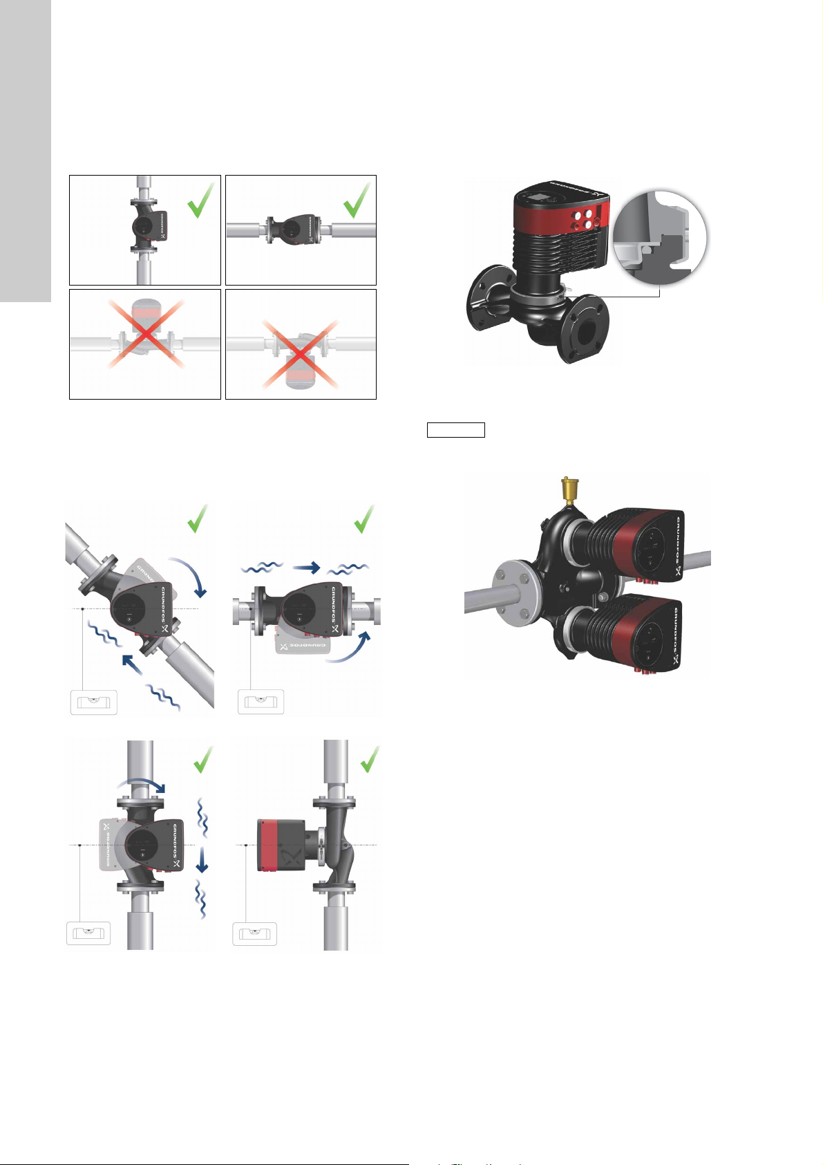
3.3 Positioning
AB
CD
Caution
English (GB)
Always install the pump with horizontal motor shaft.
• Pump installed correctly in a vertical pipe. See fig. 10, pos. A.
• Pump installed correctly in a horizontal pipe. See fig. 10,
pos. B.
• Do not install the pump with vertical motor shaft. See fig. 10,
pos. C and D.
Fig. 10 Pump installed with horizontal motor shaft
3.4 Control box positions
To ensure adequate cooling, the control box must be in horizontal
position with the Grundfos logo in vertical position. See fig. 11.
If the pump head is removed before the pump is installed in the
pipework, pay special attention when fitting the pump head to the
pump housing:
1. Gently lower the pump head with rotor shaft and impeller into
the pump housing.
2. Make sure that the contact face of the pump housing and that
of the pump head are in contact before the clamp is tighened.
See fig. 12.
TM05 5837 4112
Fig. 12 Fitting the pump head to the pump housing
TM05 5518 3812
Twin-head pumps installed in horizontal pipes
must be fitted with an automatic air vent (Rp 1/4)
in the upper part of the pump housing.
See fig. 13.
TM05 5519 3812
TM05 5521 3812
Fig. 11 Pump with control box in horizontal position
TM05 6062 4412
Fig. 13 Automatic air vent
TM05 5520 3812
TM05 5522 3812
12
Page 13

3.5 Changing the control box position
Caution
Warning
The warning symbol on the clamp holding the
pump head and pump housing together indicates
that there is a risk of personal injury . See speci fic
warnings below.
Warning
When loosening the clamp, do not drop the pump
head.
Twin-head pump.
Position the clamps so that the
gaps point towards the arrows.
4c
They can be in position 3 or
9o’clock.
English (GB)
TM05 2917 0612 - TM05 2873 0612
Warning
Risk of escaping vapour.
Step Action Illustration
Loosen the screw in the clamp
holding the pump head and
pump housing together.
Warn ing: If the screw is
1
loosened too much, the pump
head will be completely
disconnected from the pump
housing.
Carefully rotate the pump head
to the desired position.
If the pump head is stuck,
2
loosen it with a light blow of a
rubber mallet.
Place the control box in
horizontal position so that the
Grundfos logo is in vertical
3
position. The motor shaft must
be horizontal.
Due to the drain hole in the
stator housing, position the gap
4
of the clamp as shown in step
4a, 4b, 4c, 4d or 4e.
Twin-head pump.
Note: The gap of the clamp can
also be in position 6 o’clock for
the following pump sizes:
4d
• DN 65
• DN 80
• DN 100.
TM05 2897 1912
Threaded single-head pump.
4e
The gap of the clamp can be in
position 3, 6, 9 or 12 o’clock.
TM05 2867 0612
TM05 5528 3812
Fit and tighten the screw
TM05 5526 3812
holding the clamp to 8 ± 1 Nm.
Note: Do not retighten the
5
screw if condensed water is
dripping from the clamp.
TM05 2872 0612
Fit the insulating shells.
TM05 5527 3812
Note: Insulating shells for
pumps in air-conditioning and
6
cooling systems must be
ordered separately.
TM05 5529 3812
Do not insulate the control box or cover the
control panel.
Flanged single-head pump.
Position the clamp so that the
gap points towards the arrow.
4a
It can be in position 3 or
9o’clock.
Flanged single-head pump.
Note: The gap of the clamp can
also be in position 6 o’clock for
the following pump sizes:
4b
• DN 65
• DN 80
• DN 100.
TM05 2870 0612
TM05 2918 0612 - TM05 2871 0612
TM05 5549 3812
Fig. 14 Insulation of pump housing and pipework
TM05 2899 1912
13
Page 14

4. Electrical installation
Note
English (GB)
Carry out the electrical connection and protection according to
local regulations.
Check that the supply voltage and frequency correspond to the
values stated on the nameplate.
Warning
Switch off the power supply before making
connections.
Warning
The pump must be connected to an external
mains switch with a minimum contact gap of
3 mm in all poles.
Earthing or neutralisation must be used for
protection against indirect contact.
If the pump is connected to an electric
installation where an earth leakage circuit
breaker (ELCB) is used as an additional
protection, this circuit breaker must trip when
earth fault currents with DC content (pulsating
DC) occur.
The earth leakage circuit breaker must be marked
with the first or both of the symbols shown
below:
Connect the cable
3
gland to the
control box.
Pull the power
supply cable
4
through the cable
gland.
Strip the cable
5
conductors as
illustrated.
TM05 5532 3812
TM05 5533 3812
• The pump must be connected to an external mains switch.
• The pump requires no external motor protection.
• The motor incorporates thermal protection against slow
overloading and blocking.
• When switched on via the power supply, the pump will start
pumping after approx. 5 seconds.
The number of starts and stops via the power
supply must not exceed four times per hour.
4.1 Supply voltage
1 x 230 V ± 10 %, 50/60 Hz, PE.
The voltage tolerances are intended for mains voltage variations.
They should not be used for running pumps at other voltages than
those stated on the nameplate.
4.2 Connection to the power supply
Step Action Illustration
Remove the front
cover from the
control box.
Note: Do not
1
remove the
screws from the
cover.
Locate the power
supply plug and
cable gland in the
2
small paper bag
supplied with the
pump.
TM05 5534 3812
Connect the cable
6
conductors to the
power supply plug.
TM05 5535 3812
Insert the power
supply plug into
the male plug in
7
the pump control
box.
TM05 5536 3812
TM05 5530 3812
Tighten the cable
gland.
8
Refit the front
cover.
TM05 5537 3812
TM05 5531 3812
14
Page 15

4.3 ALPHA-plug version
Max. 1.5 mm
2
12 mm
∅5.5 - 10 mm
7 mm
17 mm
4.3.1 Assembling the plug
Step Action Illustration
Fit the cable gland
and plug cover to
the cable.
1
Strip the cable
conductors as
illustrated.
Connect the cable
conductors to the
2
power supply
plug.
Bend the cable
with the cable
3
conductors
pointing upwards.
Insert the power
supply plug into
the male plug in
7
the pump control
box.
TM05 5538 3812
4.3.2 Disassembling the plug
Step Action Illustration
Loosen the cable
1
TM05 5539 3812
gland and remove
it from the plug.
English (GB)
TM05 5544 3812
TM05 5545 3812
4
5
6
Pull out the
conductor guide
plate and throw it
away.
Click the plug
cover onto the
power supply
plug.
Screw the cable
gland onto the
power supply
plug.
Pull off the plug
cover while
2
TM05 5540 3812
pressing on both
sides.
TM05 5546 3812
Loosen the cable
conductors one by
one by pressing a
TM05 5541 3812
3
screwdriver gently
into the terminal
clip.
TM05 5547 3812
TM05 5542 3812
The plug has now
been removed
4
from the power
supply plug.
TM05 5543 3812
TM05 5548 3812
15
Page 16

4.4 Connection diagrams
External switch
Fuse
(min. 10 A, time lag)
ELCB
External switch
Fuse
(min. 10 A, time lag)
ELCB
Note
English (GB)
Fig. 15 Example of terminal connection, 1 x 230 V ± 10 %, 50/60 Hz, PE
Fig. 16 Example of ALPHA plug connection, 1 x 230 V ± 10 %, 50/60 Hz, PE
TM03 2397 3712TM05 5277 3712
All cables used must be connected in accordance
with local regulations.
16
Page 17

5. First start-up
Caution
Do not start the pump until the system has been filled with liquid
and vented. Furthermore, the required minimum inlet pressure
must be available at the pump inlet. See section 12. Technical
data.
The system cannot be vented through the pump. The pump is
self-venting.
The discharge valve must be opened immediately
after start-up of the pump. Otherwise the
temperature of the pumped liquid may become
too high and cause damage to the equipment.
Step Action Illustration
English (GB)
1
Note: When switched on, the pump will start after approx.
5 seconds.
2 Control panel at first start-up.
The pump has been factory-set to the intermediate
Switch on the power supply to the pump.
3
proportional-pressure curve.
Select the control mode according to the system
application.
TM05 5550 3812
TM05 5551 3812
TM05 5551 3812
17
Page 18

6. Settings
Note
Note
1
2
3
English (GB)
7. Control panel
7.3 Light fields indicating the pump setting
The pump has nine optional performance settings which can be
selected with the push-button. See fig. 17, pos. 3.
The pump setting is indicated by eight light fields in the display.
See fig. 17, pos. 2.
7.1 Elements on the control panel
Fig. 17 Control panel
The control panel on the pump comprises the following:
Pos. Description
Grundfos Eye operating status.
1
See section 7.2 Grundfos Eye.
Eight light fields indicating the pump setting.
2
See section 7.3 Light fields indicating the pump
setting.
3 Push-button for selection of pump setting.
7.2 Grundfos Eye
The Grundfos Eye is on when the power supply has been
switched on. See fig. 17, pos. 1.
The Grundfos Eye is an indicator light providing information about
the actual pump status.
The indicator light will flash in different sequences and provide
information about the following:
• power on/off
• pump alarms.
The function of the Grundfos Eye is described in section
10.1 Grundfos Eye operating status.
Faults preventing the pump from operating
properly (for example blocked rotor) are
indicated by the Grundfos Eye. See section
10.1 Grundfos Eye operating status.
If a fault is indicated, correct the fault and reset the pump by
switching the power supply off and on.
TM05 5553 3812
Fig. 18 Factory setting, PP2
Button
presses
0
Active light fields Description
Intermediate
proportional-pressure
curve, referred to as PP2
1
Highest
proportional-pressure
curve, referred to as PP3
2
TM05 5552 3812
3
Lowest
constant-pressure curve,
referred to as CP1
Intermediate
constant-pressure curve,
referred to as CP2
4
Highest
constant-pressure curve,
referred to as CP3
5
6
7
8
Constant curve/constant
speed III
Constant curve/constant
speed II
Constant curve/constant
speed I
Lowest
proportional-pressure
curve, referred to as PP1
If the pump impeller is rotated, for example when
filling the pump with water, sufficient energy can
be generated to light up the control panel even if
the power supply has been switched off.
18
Page 19

8. Overview of settings
III
II
I
H
PP3
CP3
CP2
PP1
CP1
PP2
Q
English (GB)
Fig. 19 Pump setting in relation to pump performance
Setting Pump curve Function
Lowest
PP1
PP2
PP3
CP1
CP2
CP3
III Speed III
II Speed II
I Speed I
proportional-pressure
curve
Intermediate
proportional-pressure
curve
Highest
proportional-pressure
curve
Lowest constant-pressure
curve
Intermediate
constant-pressure curve
Highest
constant-pressure curve
The duty point of the pump will move up or down on the lowest proportional-pressure curve,
depending on the heat demand. See fig. 19.
The head (pressure) is reduced at falling heat demand and increased at rising heat demand.
The duty point of the pump will move up or down on the intermediate proportional-pressure
curve, depending on the heat demand. See fig. 19.
The head (pressure) is reduced at falling heat demand and increased at rising heat demand.
The duty point of the pump will move up or down on the highest proportional-pressure curve,
depending on the heat demand. See fig. 19.
The head (pressure) is reduced at falling heat demand and increased at rising heat demand.
The duty point of the pump will move out or in on the lowest constant-pressure curve,
depending on the heat demand in the system. See fig. 19.
The head (pressure) is kept constant, irrespective of the heat demand.
The duty point of the pump will move out or in on the intermediate constant-pressure curve,
depending on the heat demand in the system. See fig. 19.
The head (pressure) is kept constant, irrespective of the heat demand.
The duty point of the pump will move out or in on the highest constant-pressure curve,
depending on the heat demand in the system. See fig. 19.
The head (pressure) is kept constant, irrespective of the heat demand.
The pump runs on a constant curve which means that it runs at a constant speed.
In speed III, the pump is set to run on the max. curve under all operating conditions.
See fig. 19.
Quick venting of the pump can be obtained by setting the pump to speed III for a short
period.
The pump runs on a constant curve which means that it runs at a constant speed.
In speed II, the pump is set to run on the intermediate curve under all operating conditions.
See fig. 19.
The pump runs on a constant curve which means that it runs at a constant speed.
In speed I, the pump is set to run on the min. curve under all operating conditions.
See fig. 19.
TM05 2777 0512
19
Page 20

8.1 Pump setting
Q
H
PP3
PP2
PP1
Q
H
Q
H
CP3
CP2
CP1
Q
H
English (GB)
Constant curve/constant speed (I, II or III)
At constant-curve/constant-speed operation, the pump runs at a
constant speed, independent of the actual flow demand in the
system. The pump performance follows the selected performance
curve, I, II or III. See fig. 23 where II has been selected.
See section 9. Selection of control mode for further information.
Fig. 20 Selection of pump setting for system type
Factory setting: Intermediate proportional-pressure curve,
referred to as PP2.
Proportional-pressure curve (PP1, PP2 or PP3)
Proportional-pressure control adjusts the pump performance to
the actual heat demand in the system, but the pump performance
follows the selected performance curve, PP1, PP2 or PP3.
See fig. 21 where PP2 has been selected. See section
9. Selection of control mode for further information.
Fig. 21 Three proportional-pressure curves/settings
The selection of the right proportional-pressure setting depends
on the characteristics of the heating system in question and the
actual heat demand.
Constant-pressure curve (CP1, CP2 or CP3)
Constant-pressure control adjusts the pump performance to the
actual heat demand in the system, but the pump performance
follows the selected performance curve, CP1, CP2 or CP3.
See fig. 22 where CP1 has been selected.
See section 9. Selection of control mode for further information.
TM05 5554 3812TM05 5555 3812TM05 5556 3812
Fig. 23 Three constant-curve/constant-speed settings
The selection of the right constant-curve/constant-speed setting
depends on the characteristics of the heating system in question.
TM05 5557 3812
Fig. 22 Three constant-pressure curves/settings
The selection of the right constant-pressure setting depends on
the characteristics of the heating system in question and the
actual heat demand.
20
Page 21

9. Selection of control mode
Q
H
Q
H
Q
H
System application Select this control mode
In systems with relatively large pressure losses in the distribution pipes and in air-conditioning and cooling
systems.
• Two-pipe heating systems with thermostatic valves and
– very long distribution pipes
– strongly throttled pipe balancing valves
– differential-pressure regulators
– large pressure losses in those parts of the system through which the total quantity of water flows
(for example boiler, heat exchanger and distribution pipe up to the first branching).
• Primary circuit pumps in systems with large pressure losses in the primary circuit.
• Air-conditioning systems with
– heat exchangers (fan coils)
– cooling ceilings
– cooling surfaces.
In systems with relatively small pressure losses in the distribution pipes.
• Two-pipe heating systems with thermostatic valves and
– dimensioned for natural circulation
– small pressure losses in those parts of the system through which the total quantity of water flows
(for example boiler, heat exchanger and distribution pipe up to the first branching) or
– modified to a high differential temperature between flow pipe and return pipe
(for example district heating).
• Underfloor heating systems with thermostatic valves.
• One-pipe heating systems with thermostatic valves or pipe balancing valves.
• Primary circuit pumps in systems with small pressure losses in the primary circuit.
The pump can also be set to operate according to the max. or min. curve, like an uncontrolled pump:
• The max. curve mode can be used in periods in which a maximum flow is required. This operating
mode is for instance suitable for hot-water priority.
• The min. curve mode can be used in periods in which a minimum flow is required. This operating
mode is for instance suitable for manual night setback.
Proportional pressure
Constant pressure
Constant curve
English (GB)
21
Page 22

10. Fault finding
Caution
English (GB)
Warning
Before dismantling the pump, drain the system or close the isolating valve on either side of the pump. The pumped
liquid may be scalding hot and under high pressure.
10.1 Grundfos Eye operating status
Grundfos Eye Indication Cause
No lights on.
Two opposite green indicator lights running in the
direction of rotation of the pump.
Two opposite red indicator lights flashing
simultaneously.
Power off.
Pump not running.
Power on.
Pump running.
Alarm.
Pump stopped.
10.2 Resetting of fault indications
A fault indication can be reset in one of the following ways:
• When the fault cause has been eliminated, the pump will revert to normal duty.
• If the fault disappears by itself, the fault indication will automatically be reset.
Fault
Other pumps or sources force flow through
the pump even if the pump is stopped. There
will be light in the display even if the power
supply has been switched off.
Supply voltage to the pump too low. Yes Check that the power supply is within the specified range.
The pump is blocked. No
No water at the pump inlet or the water
contains too much air.
Internal fault in the pump electronics. Yes
Supply voltage to the pump too high. Yes Check that the power supply is within the specified range.
Automatic reset and
restart?
Yes
No
Corrective actions
Check the system for defective non-return valves and replace,
if necessary.
Check the system for correct position of non-return valves,
etc.
Dismantle the pump, and remove any foreign matter or
impurities preventing the pump from rotating.
Prime and vent the pump before a new start-up. Check that
the pump is operating correctly. If not, replace the pump, or
call GRUNDFOS SERVICE for assistance.
Replace the pump, or call GRUNDFOS SERVICE for
assistance.
If the power supply cable is damaged, it must be replaced by the manufacturer, the manufacturer’s service partner or
a similarly qualified person.
22
Page 23

11. Accessories
Note
11.1 Insulating kits for air-conditioning and cooling systems
Single-head pumps for air-conditioning and cooling systems can
be fitted with insulating shells. A kit consists of two shells made of
polyurethane (PUR) and a self-adhesive seal to ensure tight
assembly.
The dimensions of the insulating shells for
pumps in air-conditioning and cooling systems
differ from those of the insulating shells for
pumps in heating systems.
Pump type Product number
MAGNA1 25-40/60/80/100/120 98354534
MAGNA1 32-40/60/80/100 98354535
MAGNA1 32-40/60/80/100 F 98354536
MAGNA1 32-120 F 98063287
MAGNA1 40-40/60 F 98354537
MAGNA1 40-80/100 F 98063288
MAGNA1 40-120/150/180 F 98145675
MAGNA1 50-40/60/80 F 98063289
MAGNA1 50-100/120/150/180 F 98145676
MAGNA1 65-40/60/80/100/120/150 F 96913593
MAGNA1 80-40/60/80/100/120 F 98134265
MAGNA1 100-40/60/80/100/120 F 96913589
English (GB)
11.2 Blanking flanges
A blanking flange is used to blank off the opening when one of the
pumps of a twin-head pump is removed for service to enable
uninterrupted operation of the other pump.
Fig. 24 Position of blanking flange
Pump type Product number
MAGNA1 25-40/60/80/100/120
MAGNA1 32-40/60/80/100 (F)
MAGNA1 40-40/60 F
MAGNA1 32-120 F
MAGNA1 40-/80/100/120/150/180 F
MAGNA1 50-40/60/80/100/120/150/180 F
MAGNA1 65-40/60/80/100/120/150 F
MAGNA1 80-40/60/80/100/120 F
MAGNA1 100-40/60/80/100/120 F
98159373
98159372
TM05 5525 3812
23
Page 24

11.3 Counter flanges
ø19
ø140
ø100
ø78
Rp 1
¼
Threaded For welding
ø19
ø150
ø110
ø88
Rp 1
½
Threaded For welding
ø19
ø165
ø125
ø102
Rp 2
Threaded For welding
ø19
ø185
ø145
ø122
Rp 2½
Threaded For welding
Threaded For welding
English (GB)
Cast-iron pumps
A counter-flange kit consists of two stainless-steel flanges, two gaskets of asbestos-free material IT 200 and the required number of bolts
and nuts.
Counter flange Pump type Description
Threaded 10 bar Rp 1 1/4 539703
For welding 10 bar
MAGNA1
DN 32
Threaded 16 bar Rp 1 1/4 539703
TM03 0478 5204
For welding 16 bar
Threaded 10 bar Rp 1 1/2 539701
For welding 10 bar
MAGNA1
DN 40
Threaded 16 bar Rp 1 1/2 539701
TM03 0479 5204
For welding 16 bar
Threaded 10 bar Rp 2 549801
For welding 10 bar
MAGNA1
DN 50
Threaded 16 bar Rp 2 549801
Rated pressure
(EN 1092-2)
Pipework
connection
32 mm,
nominal
32 mm,
nominal
40 mm,
nominal
40 mm,
nominal
50 mm,
nominal
Product
number
539704
539704
539702
539702
549802
Rp 3
ø19
ø138
ø160
ø200
TM03 0480 5204
MAGNA1
TM03 0481 5204
MAGNA1
TM03 0482 5204
DN 65
DN 80
For welding 16 bar
50 mm,
nominal
549802
Threaded 10 bar Rp 2 1/2 559801
For welding 10 bar
65 mm,
nominal
559802
Threaded 16 bar Rp 2 1/2 559801
For welding 16 bar
65 mm,
nominal
559802
Threaded 6 bar Rp 3 569902
For welding 6 bar
80 mm,
nominal
569901
Threaded 10 bar Rp 3 569802
For welding 10 bar
80 mm,
nominal
569801
Threaded 16 bar Rp 3 569802
For welding 16 bar
80 mm,
nominal
569801
24
Page 25

Counter flange Pump type Description
Threaded For welding
ø19
ø140
ø100
ø78
Rp 1
¼
Threaded For welding
ø19
ø150
ø110
ø88
Rp 1
½
Threaded For welding
ø19
ø165
ø125
ø102
Rp 2
Threaded For welding
ø19
ø185
ø145
ø122
Rp 2½
Threaded For welding
Threaded 6 bar Rp 4 579901
Rated pressure
(EN 1092-2)
Pipework
connection
Product
number
Rp 4
ø19
For welding 6 bar
100 mm,
nominal
579902
Threaded 10 bar Rp 4 579801
MAGNA1
ø158
ø180
ø220
TM03 0483 5204
DN 100
For welding 10 bar
Threaded 16 bar Rp 4 579801
For welding 16 bar
100 mm,
nominal
100 mm,
nominal
579802
579802
Stainless-steel pumps
A counter-flange kit consists of two bronze flanges, two gaskets of asbestos-free material IT 200 and the required number of bolts and
nuts.
Counter flange Pump type Description
Rated pressure
(EN 1092-2)
Pipework
connection
Product
number
Threaded 10 bar Rp 1 1/4 96427029
MAGNA1
For welding 10 bar
32 mm,
nominal
96427030
DN 32
Threaded 16 bar Rp 1 1/4 96427029
English (GB)
TM03 0478 5204
MAGNA1
TM03 0479 5204
MAGNA1
TM03 0480 5204
MAGNA1
TM03 0481 5204
DN 40
DN 50
DN 65
For welding 16 bar
32 mm,
nominal
96427030
Threaded 10 bar Rp 1 1/2 539711
For welding 10 bar
40 mm,
nominal
539712
Threaded 16 bar Rp 1 1/2 539711
For welding 16 bar
40 mm,
nominal
539712
Threaded 10 bar Rp 2 549811
For welding 10 bar
50 mm,
nominal
549812
Threaded 10 bar Rp 2 1/2 559811
For welding 10 bar
65 mm,
nominal
559812
25
Page 26

English (GB)
ø19
ø200
ø160
ø138
Rp 3
Threaded For welding
Threaded For welding
Counter flange Pump type Description
Threaded 6 bar Rp 3 96405735
Rated pressure
(EN 1092-2)
Pipework
connection
Product
number
Rp 4
ø19
ø158
ø180
ø220
MAGNA1
TM03 0482 5204
MAGNA1
TM03 0485 5204
DN 80
DN 100
For welding 6 bar
80 mm,
nominal
569911
Threaded 10 bar Rp 3 569812
For welding 10 bar
80 mm,
nominal
569811
Threaded 6 bar Rp 4 96405737
Threaded 10 bar Rp 4 96405738
26
Page 27

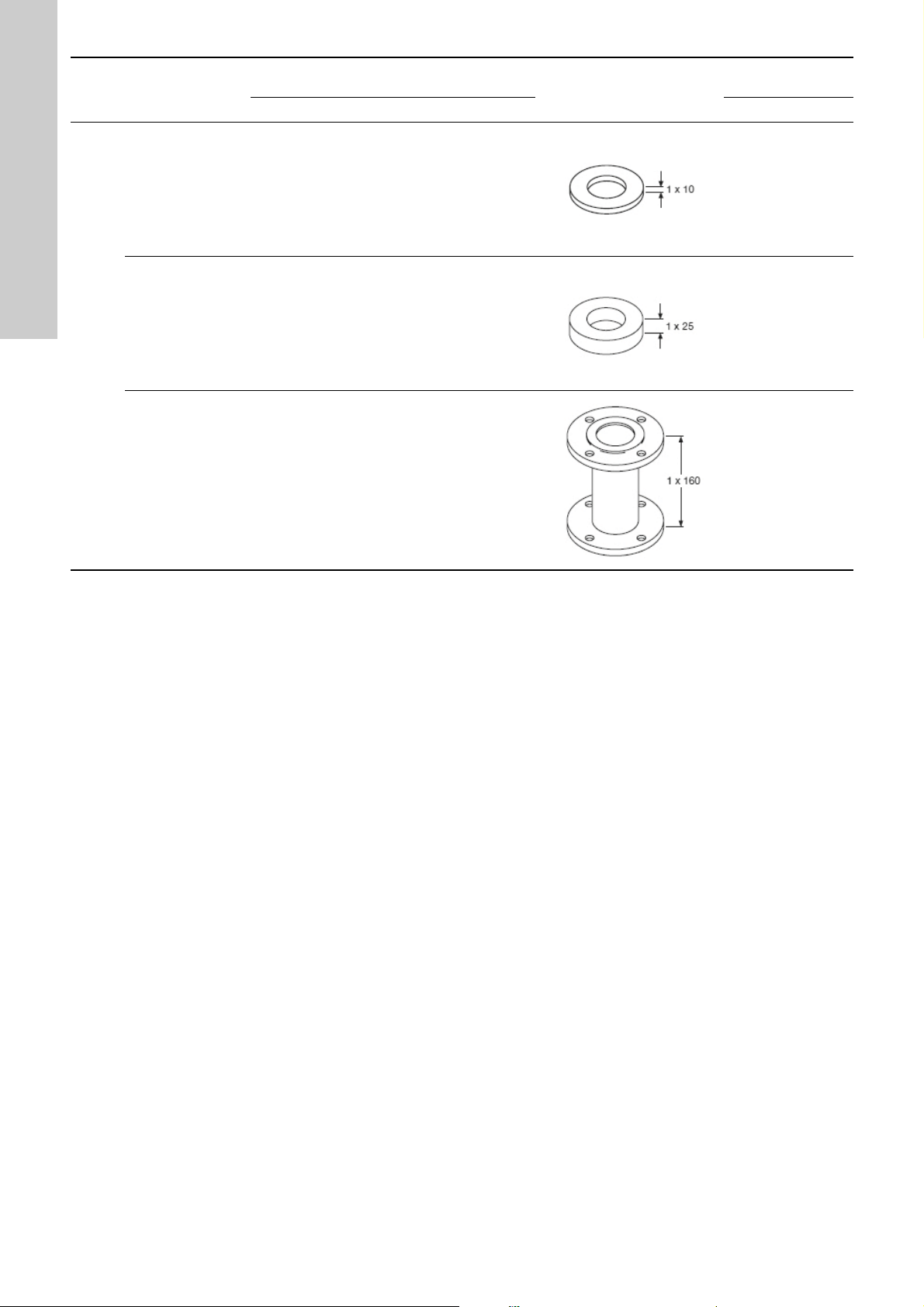
11.4 Adapter for various port-to-port lengths
DN Type
A40-30 1 x 30 - - - -
40
A40-70 1 x 70 - - 100 110
A50-10 1 x 10 90 102 - 125
Height
[mm]
Diameter
[mm]
Pitch circle diameter
[mm]
Adapter
Product number
PN 6 PN 10 PN 6 PN 10 PN 6 PN 10
96281076 96608515
TM05 4372 2212
539921 539721
TM05 4373 2212
549921 549821
TM05 4374 2212
English (GB)
A50-20 1 x 20 90 102 - -
50
A50-40 1 x 40 - - - -
A50-50 1 x 50 90 102 - -
A50-60 1 x 60 - - 110 125
549922 549822
TM05 4375 2212
96281077 96608516
TM05 4376 2212
549923 549823
TM05 4377 2212
549924 549824
TM05 4378 2212
27
Page 28
English (GB)
DN Type
Height
[mm]
Diameter
[mm]
Pitch circle diameter
[mm]
Adapter
Product number
PN 6 PN 10 PN 6 PN 10 PN 6 PN 10
A65-10 1 x 10 110 122 - -
A65-25 1 x 25 110 122 - -
65
A65-160 1 x 160 - - 130 145
559921 559821
TM05 4379 2212
559922 559822
TM05 4380 2212
559923 559823
TM05 4381 2212
28
Page 29

DN Type
A80-10 1 x 10 127 138 150 160
Height
[mm]
Diameter
[mm]
Pitch circle diameter
[mm]
Adapter
Product number
PN 6 PN 10 PN 6 PN 10 PN 6 PN 10
569921 569821
TM05 4382 2212
English (GB)
A80-15 1 x 15 127 138 - -
A80-20 1 x 20 127 138 - -
A80-25 1 x 25 127 138 - -
80
A80-40 1 x 40 127 138 - -
569922 569822
TM05 4383 2212
569923 569823
TM05 4384 2212
569924 569824
TM05 4385 2212
569925 569825
A80-50 1 x 50 127 138 - -
A80-140 1 x 140 - - 150 160
100 A100-50 2 x 25 - - - -
TM05 4386 2212
569926 569826
TM05 4387 2212
569927 569827
TM05 4388 2212
96545610 96545610
TM05 4389 2212
29
Page 30

12. Technical data
Note
Note
English (GB)
Supply voltage
1 x 230 V ± 10 %, 50/60 Hz, PE.
Motor protection
The pump requires no external motor protection.
Enclosure class
IPX4D (EN 60529).
Insulation class
F.
Relative air humidity
Maximum 95 %.
Ambient temperature
0 to +40 °C.
During transport: -30 to +55 °C.
Temperature class
TF110 (EN 60335-2-51).
Liquid temperature
Continuously: -10 to +110 °C.
System pressure
The maximum permissible system pressure is stated on the pump
nameplate:
PN 6: 6 bar / 0.6 MPa
PN 10: 10 bar / 1.0 MPa
PN 16: 16 bar / 1.6 MPa.
Minimum inlet pressure
The following relative minimum inlet pressure must be available
at the pump inlet during operation to avoid cavitation noise and
damage to the pump bearings.
The relative minimum inlet pressures apply to pumps installed up
to 300 metres above sea level. For altitudes above 300 metres,
the required relative inlet pressure must be increased by
0.01 bar / 0.001 MPa per 100 metres altitude. The MAGNA1
pump is only approved for an altitude of 2000 metres above sea
level.
EMC (electromagnetic compatibility)
EN 55014-1:2006, EN 55014-2:1998, EN 61800-3-3:2008 and
EN 61000-3-2:2006.
Sound pressure level
The sound pressure level of the pump is lower than 43 dB(A).
Leakage current
The pump mains filter will cause a discharge current to earth
during operation. I
Power factor
The MAGNA1 has a built-in PFC (Power Factor Control) which
gives a cos φ from 0.98 to 0.99, i.e. very close to 1.
leakage
< 3.5 mA.
13. Disposal
This product has been designed with focus on the disposal and
recycling of materials. The following average disposal values
apply to all variants of Grundfos MAGNA1 pumps:
• 85 % recycling
• 10 % incineration
• 5 % depositing.
This product or parts of it must be disposed of in an
environmentally sound way according to local regulations.
Subject to alterations.
The values in the table below apply to
single-head pumps and twin-head pumps in
single-head operation.
Liquid temperature
Single-head pumps
DN
25-40/60/80/100/120 0.10 / 0.01 0.35 / 0.035 1.0 / 0.10
32-40/60/80/100 0.10 / 0.01 0.35 / 0.035 1.0 / 0.10
32-120 0.90 / 0.09 1.30 / 0.13 1.9 / 0.19
40-40/60 0.10 / 0.01 0.35 / 0.035 1.0 / 0.10
40-80/100 0.10 / 0.01 0.50 / 0.05 1.0 / 0.10
40-120/150/180 0.10 / 0.01 0.50 / 0.05 1.0 / 0.10
50-40/60/80 0.10 / 0.01 0.40 / 0.04 1.0 / 0.10
50-100 0.10 / 0.01 0.50 / 0.05 1.0 / 0.10
50-120 0.10 / 0.01 0.50 / 0.05 1.0 / 0.10
50-150/180 0.70 / 0.07 1.20 / 0.12 1.7 / 0.17
65-40/60/80/100 0.70 / 0.07 1.20 / 0.12 1.7 / 0.17
65-120 0.70 / 0.07 1.20 / 0.12 1.7 / 0.17
65-150 0.70 / 0.07 1.20 / 0.12 1.7 / 0.17
80-40/60/80/100/120 0.50 / 0.05 1.00 / 0.10 1.5 / 0.15
100-40/60/80/100/120 0.70 / 0.07 1.20 / 0.12 1.7 / 0.17
In the case of twin-head operation, the required relative inlet
pressure must be increased by 0.1 bar / 0.01 MPa compared to
the stated values for single-head pumps or twin-head pumps in
single-head operation.
The actual inlet pressure plus pump pressure
against a closed valve must be lower than the
maximum permissible system pressure.
75 °C 95 °C 110 °C
Inlet pressure
[bar] / [MPa]
30
Page 31

Appendix 1
14. Dimensions
Fig. 25 Single-head pump dimensions (threaded version)
Appendix
TM05 5142 3512
Pump type
MAGNA1 25-40 180 158 190 58 111 69 90 113 54 142 196 71 25 1 1/2
MAGNA1 25-60 180 158 190 58 111 69 90 113 54 142 196 71 25 1 1/2
MAGNA1 25-80 180 158 190 58 111 69 90 113 54 142 196 71 25 1 1/2
MAGNA1 25-100 180 158 190 58 111 69 90 113 54 142 196 71 25 1 1/2
MAGNA1 25-120 180 158 190 58 111 69 90 113 54 142 196 71 25 1 1/2
MAGNA1 32-40 180 158 190 58 111 69 90 113 54 142 196 71 32 2
MAGNA1 32-60 180 158 190 58 111 69 90 113 54 142 196 71 32 2
MAGNA1 32-80 180 158 190 58 111 69 90 113 54 142 196 71 32 2
MAGNA1 32-100 180 158 190 58 111 69 90 113 54 142 196 71 32 2
L1 L5 L6 B1 B2 B4 B6 B7 H1 H2 H3 H4 D1 G
Dimensions [mm] (inch)
Fig. 26 Twin-head pump dimensions (threaded version)
Pump type
L1 L5 L7 B1 B3 B4 B5 H1 H2 H3 D1 G M3
MAGNA1 D 32-40 180 158 35 58 400 179 221 54 142 196 32 2 1/4
MAGNA1 D 32-60 180 158 35 58 400 179 221 54 142 196 32 2 1/4
MAGNA1 D 32-80 180 158 35 58 400 179 221 54 142 196 32 2 1/4
MAGNA1 D 32-100 180 158 35 58 400 179 221 54 142 196 32 2 1/4
Dimensions [mm] [inch]
TM05 5201 3512
31
Page 32

Appendix
15. Dimensions
Fig. 27 Single pump dimensions (flanged version)
TM05 5276 3512
Pump type
L1 L5 L6 B1 B2 B4 B6 B7 H1 H2 H3 H4 D1 D2 D3 D4 D5
MAGNA1 32-40 F 220 158 220 58 111 69 100 110 65 142 207 82 32 76 90/100 140 14/19
MAGNA1 32-60 F 220 158 220 58 111 69 100 110 65 142 207 82 32 76 90/100 140 14/19
MAGNA1 32-80 F 220 158 220 58 111 69 100 110 65 142 207 82 32 76 90/100 140 14/19
MAGNA1 32-100 F 220 158 220 58 111 69 100 110 65 142 207 82 32 76 90/100 140 14/19
MAGNA1 32-120 F 220 204 216 84 164 73 106 116 65 301 366 86 32 76 90/100 140 14/19
MAGNA1 40-40 F 220 158 220 58 111 69 105 105 65 156 221 83 40 84 100/110 150 14/19
MAGNA1 40-60 F 220 158 220 58 111 69 105 105 65 156 221 83 40 84 100/110 150 14/19
MAGNA1 40-80 F 220 204 220 84 164 73 106 128 65 304 369 83 40 84 100/110 150 14/19
MAGNA1 40-100 F 220 204 220 84 164 73 106 128 65 304 369 83 40 84 100/110 150 14/19
MAGNA1 40-120 F 250 204 220 84 164 73 106 128 65 304 369 83 40 84 100/110 150 14/19
MAGNA1 40-150 F 250 204 220 84 164 73 106 128 65 304 369 83 40 84 100/110 150 14/19
MAGNA1 40-180 F 250 204 220 84 164 73 106 128 65 304 369 83 40 84 100/110 150 14/19
MAGNA1 50-40 F 240 204 240 84 164 73 127 127 71 304 374 97 50 102 110/125 165 14/19
MAGNA1 50-60 F 240 204 240 84 164 73 127 127 71 304 374 97 50 102 110/125 165 14/19
MAGNA1 50-80 F 240 204 240 84 164 73 127 127 71 304 374 97 50 102 110/125 165 14/19
MAGNA1 50-100 F 280 204 240 84 164 73 127 127 72 304 376 97 50 102 110/125 165 14/19
MAGNA1 50-120 F 280 204 240 84 164 73 127 127 72 304 376 97 50 102 110/125 165 14/19
MAGNA1 50-150 F 280 204 240 84 164 73 127 127 72 304 376 97 50 102 110/125 165 14/19
MAGNA1 50-180 F 280 204 240 84 164 73 127 127 72 304 376 97 50 102 110/125 165 14/19
MAGNA1 65-40 F 340 204 296 84 164 73 133 133 74 312 386 94 65 119 130/145 185 14/19
MAGNA1 65-60 F 340 204 296 84 164 73 133 133 74 312 386 94 65 119 130/145 185 14/19
MAGNA1 65-80 F 340 204 296 84 164 73 133 133 74 312 386 94 65 119 130/145 185 14/19
MAGNA1 65-100 F 340 204 296 84 164 73 133 133 74 312 386 94 65 119 130/145 185 14/19
MAGNA1 65-120 F 340 204 296 84 164 73 133 133 74 312 386 94 65 119 130/145 185 14/19
MAGNA1 65-150 F 340 204 296 84 164 73 133 133 74 312 386 94 65 119 130/145 185 14/19
MAGNA1 80-40 F 360 204 310 84 164 73 163 163 96 318 413 115 80 128 150/160 200 19
MAGNA1 80-60 F 360 204 310 84 164 73 163 163 96 318 413 115 80 128 150/160 200 19
MAGNA1 80-80 F 360 204 310 84 164 73 163 163 96 318 413 115 80 128 150/160 200 19
MAGNA1 80-100 F 360 204 310 84 164 73 163 163 96 318 413 115 80 128 150/160 200 19
MAGNA1 80-120 F 360 204 310 84 164 73 163 163 96 318 413 115 80 128 150/160 200 19
MAGNA1 100-40 F 450 204 396 84 164 73 178 178 103 330 433 120 100 160 170 220 19
MAGNA1 100-60 F 450 204 396 84 164 73 178 178 103 330 433 120 100 160 170 220 19
MAGNA1 100-80 F 450 204 396 84 164 73 178 178 103 330 433 120 100 160 170 220 19
MAGNA1 100-100 F 450 204 396 84 164 73 178 178 103 330 433 120 100 160 170 220 19
MAGNA1 100-120 F 450 204 396 84 164 73 178 178 103 330 433 120 100 160 170 220 19
Dimensions [mm]
32
Page 33

Fig. 28 Twin-head pump dimensions (flanged version)
Note
Appendix
TM05 5275 3512
Pump type
MAGNA1 D 32-40 F 220 73 120 85 158 35 58 400 179 221 130 260 69 142 211 32 76 90/100 140 14/19 12
MAGNA1 D 32-60 F 220 73 120 85 158 35 58 400 179 221 130 260 69 142 211 32 76 90/100 140 14/19 12
MAGNA1 D 32-80 F 220 73 120 85 158 35 58 400 179 221 130 260 69 142 211 32 76 90/100 140 14/19 12
MAGNA1 D 32-100 F 220 73 120 85 158 35 58 400 179 221 130 260 69 142 211 32 76 90/100 140 14/19 12
MAGNA1 D 32-120 F 220 97 90 50 204 50 84 502 210 294 130 260 68 300 368 32 76 90/100 140 14/19 12
MAGNA1 D 40-40 F 220 53 140 60 158 15 58 452 211 241 130 260 76 156 232 40 84 100/110 150 14/19 12
MAGNA1 D 40-60 F 220 53 140 60 158 15 58 452 211 241 130 260 76 156 232 40 84 100/110 150 14/19 12
MAGNA1 D 40-80 F 220 53 140 60 204 15 84 502 210 294 130 260 76 303 379 40 84 100/110 150 14/19 12
MAGNA1 D 40-100 F 220 53 140 60 204 15 84 502 210 294 130 260 76 303 379 40 84 100/110 150 14/19 12
MAGNA1 D 40-120 F 250 58 155 75 204 0 84 512 220 294 130 260 69 303 372 40 84 100/110 150 14/19 12
MAGNA1 D 40-150 F 250 58 155 75 204 0 84 512 220 294 130 260 69 303 372 40 84 100/110 150 14/19 12
MAGNA1 D 40-180 F 250 58 155 75 204 0 84 512 220 294 130 260 69 303 372 40 84 100/110 150 14/19 12
MAGNA1 D 50-40 F 240 48 160 45 204 45 84 515 221 294 130 260 75 304 379 50 102 110/125 165 14/19 12
MAGNA1 D 50-60 F 240 48 160 45 204 45 84 515 221 294 130 260 75 304 379 50 102 110/125 165 14/19 12
MAGNA1 D 50-80 F 240 48 160 45 204 45 84 515 221 294 130 260 75 304 379 50 102 110/125 165 14/19 12
MAGNA1 D 50-100 F 280 175 75 75 204 0 84 517 223 294 130 260 75 304 379 50 102 110/125 165 14/19 12
MAGNA1 D 50-120 F 280 175 75 75 204 0 84 517 223 294 130 260 75 304 379 50 102 110/125 165 14/19 12
MAGNA1 D 50-150 F 280 175 75 75 204 0 84 517 223 294 130 260 75 304 379 50 102 110/125 165 14/19 12
MAGNA1 D 50-180 F 280 175 75 75 204 0 84 517 223 294 130 260 75 304 379 50 102 110/125 165 14/19 12
MAGNA1 D 65-40 F 340 218 92 92 204 0 84 522 228 294 130 260 77 312 389 65 119 130/145 185 14/19 12
MAGNA1 D 65-60 F 340 218 92 92 204 0 84 522 228 294 130 260 77 312 389 65 119 130/145 185 14/19 12
MAGNA1 D 65-80 F 340 218 92 92 204 0 84 522 228 294 130 260 77 312 389 65 119 130/145 185 14/19 12
MAGNA1 D 65-100 F 340 218 92 92 204 0 84 522 228 294 130 260 77 312 389 65 119 130/145 185 14/19 12
MAGNA1 D 65-120 F 340 218 92 92 204 0 84 522 228 294 130 260 77 312 389 65 119 130/145 185 14/19 12
MAGNA1 D 65-150 F 340 218 92 92 204 0 84 522 228 294 130 260 77 312 389 65 119 130/145 185 14/19 12
MAGNA1 D 80-40 F 360 218 102 102 204 0 84 538 244 294 130 260 97 318 415 80 128 150/160 200 19 12
MAGNA1 D 80-60 F 360 218 102 102 204 0 84 538 244 294 130 260 97 318 415 80 128 150/160 200 19 12
MAGNA1 D 80-80 F 360 218 102 102 204 0 84 538 244 294 130 260 97 318 415 80 128 150/160 200 19 12
MAGNA1 D 80-100 F 360 218 102 102 204 0 84 538 244 294 130 260 97 318 415 80 128 150/160 200 19 12
MAGNA1 D 80-120 F 360 218 102 102 204 0 84 538 244 294 130 260 97 318 415 80 128 150/160 200 19 12
MAGNA1 D 100-40 F 450 243 147 147 204 0 84 551 252 299 135 270 103 330 434 100 160 170 220 19 12
MAGNA1 D 100-60 F 450 243 147 147 204 0 84 551 252 299 135 270 103 330 434 100 160 170 220 19 12
MAGNA1 D 100-80 F 450 243 147 147 204 0 84 551 252 299 135 270 103 330 434 100 160 170 220 19 12
MAGNA1 D 100-100 F 450 243 147 147 204 0 84 551 252 299 135 270 103 330 434 100 160 170 220 19 12
MAGNA1 D 100-120 F 450 243 147 147 204 0 84 551 252 299 135 270 103 330 434 100 160 170 220 19 12
L1 L2 L3 L4 L5 L7 B1 B3 B4 B5 B6 B7 H1 H2 H3 D1 D2 D3 D4 D5 M
Dimensions [mm]
M3: Rp 1/4 for air vent available on all twin-head
pumps.
33
Page 34

Appendix
16. Forces and moments
Maximum permissible forces and moments from the pipe connections acting on the pump flanges or threaded connections are indicated
in fig 29.
Fig. 29 Forces and moments from the pipe connections acting on the pump flanges or threaded connections
TM05 5639 4012
Force
[N]
Diameter DN Fy Fz Fx ΣFb My Mz Mx ΣMb
25* 350 425 375 650 300 350 450 650
32* 425 525 450 825 375 425 550 800
40 500 625 550 975 450 525 650 950
50 675 825 750 1300 500 575 700 1025
65 850 1050 925 1650 550 600 750 1100
80 1025 1250 1125 1975 575 650 800 1175
100 1350 1675 1500 2625 625 725 875 1300
* The values also apply to pumps with threaded connection.
The above values apply to cast-iron versions. For stainless-steel versions, the values can be multiplied by two according to the
ISO 5199 standard.
Moment
[Nm]
17. Tightening torques for bolts
Recommended tightening torques for bolts used in flanged
connections:
Bolt dimension Torque
M12 27 Nm
M16 66 Nm
34
Page 35

Argentina
Bombas GRUNDFOS de Argentina S.A.
Ruta Panamericana, ramal Campana Centro Industrial Garín - Esq. Haendel y
Mozart
AR-1619 Garín Pcia. de Buenos Aires
Pcia. de Buenos Aires
Phone: +54-3327 414 444
Telefax: +54-3327 45 3190
Australia
GRUNDFOS Pumps Pty. Ltd.
P.O. Box 2040
Regency Park
South Australia 5942
Phone: +61-8-8461-4611
Telefax: +61-8-8340 0155
Austria
GRUNDFOS Pumpen Vertrieb Ges.m.b.H.
Grundfosstraße 2
A-5082 Grödig/Salzburg
Tel.: +43-6246-883-0
Telefax: +43-6246-883-30
Belgium
N.V. GRUNDFOS Bellux S.A.
Boomsesteenweg 81-83
B-2630 Aartselaar
Tél.: +32-3-870 7300
Télécopie: +32-3-870 7301
Belarus
Представительство ГРУНДФОС в
Минске
220125, Минск
ул. Шафарнянская, 11, оф. 56
Тел.: +7 (375 17) 286 39 72, 286 39 73
Факс: +7 (375 17) 286 39 71
E-mail: minsk@grundfos.com
Bosnia/Herzegovina
GRUNDFOS Sarajevo
Trg Heroja 16,
BiH-71000 Sarajevo
Phone: +387 33 713 290
Telefax: +387 33 659 079
e-mail: grundfos@bih.net.ba
Brazil
BOMBAS GRUNDFOS DO BRASIL
Av. Humberto de Alencar Castelo Branco,
630
CEP 09850 - 300
São Bernardo do Campo - SP
Phone: +55-11 4393 5533
Telefax: +55-11 4343 5015
Bulgaria
Grundfos Bulgaria EOOD
Slatina District
Iztochna Tangenta street no. 100
BG - 1592 Sofia
Tel. +359 2 49 22 200
Fax. +359 2 49 22 201
email: bulgaria@grundfos.bg
Canada
GRUNDFOS Canada Inc.
2941 Brighton Road
Oakville, Ontario
L6H 6C9
Phone: +1-905 829 9533
Telefax: +1-905 829 9512
China
GRUNDFOS Pumps (Shanghai) Co. Ltd.
50/F Maxdo Center No. 8 XingYi Rd.
Hongqiao development Zone
Shanghai 200336
PRC
Phone: +86 21 612 252 22
Telefax: +86 21 612 253 33
Croatia
GRUNDFOS CROATIA d.o.o.
Cebini 37, Buzin
HR-10010 Zagreb
Phone: +385 1 6595 400
Telefax: +385 1 6595 499
www.grundfos.hr
Czech Republic
GRUNDFOS s.r.o.
Čajkovského 21
779 00 Olomouc
Phone: +420-585-716 111
Telefax: +420-585-716 299
Denmark
GRUNDFOS DK A/S
Martin Bachs Vej 3
DK-8850 Bjerringbro
Tlf.: +45-87 50 50 50
Telefax: +45-87 50 51 51
E-mail: info_GDK@grundfos.com
www.grundfos.com/DK
Estonia
GRUNDFOS Pumps Eesti OÜ
Peterburi tee 92G
11415 Tallinn
Tel: + 372 606 1690
Fax: + 372 606 1691
Finland
OY GRUNDFOS Pumput AB
Mestarintie 11
FIN-01730 Vantaa
Phone: +358-3066 5650
Telefax: +358-3066 56550
France
Pompes GRUNDFOS Distribution S.A.
Parc d’Activités de Chesnes
57, rue de Malacombe
F-38290 St. Quentin Fallavier (Lyon)
Tél.: +33-4 74 82 15 15
Télécopie: +33-4 74 94 10 51
Germany
GRUNDFOS GMBH
Schlüterstr. 33
40699 Erkrath
Tel.: +49-(0) 211 929 69-0
Telefax: +49-(0) 211 929 69-3799
e-mail: infoservice@grundfos.de
Service in Deutschland:
e-mail: kundendienst@grundfos.de
HILGE GmbH & Co. KG
Hilgestrasse 37-47
55292 Bodenheim/Rhein
Germany
Tel.: +49 6135 75-0
Telefax: +49 6135 1737
e-mail: hilge@hilge.de
Greece
GRUNDFOS Hellas A.E.B.E.
20th km. Athinon-Markopoulou Av.
P.O. B ox 7 1
GR-19002 Peania
Phone: +0030-210-66 83 400
Telefax: +0030-210-66 46 273
Hong Kong
GRUNDFOS Pumps (Hong Kong) Ltd.
Unit 1, Ground floor
Siu Wai Industrial Centre
29-33 Wing Hong Street &
68 King Lam Street, Cheung Sha Wan
Kowloon
Phone: +852-27861706 / 27861741
Telefax: +852-27858664
Hungary
GRUNDFOS Hungária Kft.
Park u. 8
H-2045 Törökbálint,
Phone: +36-23 511 110
Telefax: +36-23 511 111
India
GRUNDFOS Pumps India Private Limited
118 Old Mahabalipuram Road
Thoraipakkam
Chennai 600 096
Phone: +91-44 2496 6800
Indonesia
PT GRUNDFOS Pompa
Jl. Rawa Sumur III, Blok III / CC-1
Kawasan Industri, Pulogadung
Jakarta 13930
Phone: +62-21-460 6909
Telefax: +62-21-460 6910 / 460 6901
Ireland
GRUNDFOS (Ireland) Ltd.
Unit A, Merrywell Business Park
Ballymount Road Lower
Dublin 12
Phone: +353-1-4089 800
Telefax: +353-1-4089 830
Italy
GRUNDFOS Pompe Italia S.r.l.
Via Gran Sasso 4
I-20060 Truccazzano (Milano)
Tel.: +39-02-95838112
Telefax: +39-02-95309290 / 95838461
Japan
GRUNDFOS Pumps K.K.
Gotanda Metalion Bldg., 5F,
5-21-15, Higashi-gotanda
Shiagawa-ku, Tokyo
141-0022 Japan
Phone: +81 35 448 1391
Telefax: +81 35 448 9619
Korea
GRUNDFOS Pumps Korea Ltd.
6th Floor, Aju Building 679-5
Yeoksam-dong, Kangnam-ku, 135-916
Seoul, Korea
Phone: +82-2-5317 600
Telefax: +82-2-5633 725
Latvia
SIA GRUNDFOS Pumps Latvia
Deglava biznesa centrs
Augusta Deglava ielā 60, LV-1035, Rīga,
Tālr.: + 371 714 9640, 7 149 641
Fakss: + 371 914 9646
Lithuania
GRUNDFOS Pumps UAB
Smolensko g. 6
LT-03201 Vilnius
Tel: + 370 52 395 430
Fax: + 370 52 395 431
Malaysia
GRUNDFOS Pumps Sdn. Bhd.
7 Jalan Peguam U1/25
Glenmarie Industrial Park
40150 Shah Alam
Selangor
Phone: +60-3-5569 2922
Telefax: +60-3-5569 2866
Mexico
Bombas GRUNDFOS de México S.A. de
C.V.
Boulevard TLC No. 15
Parque Industrial Stiva Aeropuerto
Apodaca, N.L. 66600
Phone: +52-81-8144 4000
Telefax: +52-81-8144 4010
Netherlands
GRUNDFOS Netherlands
Velu we zoom 35
1326 AE Almere
Postbus 22015
1302 CA ALMERE
Tel.: +31-88-478 6336
Telefax: +31-88-478 6332
E-mail: info_gnl@grundfos.com
New Zealand
GRUNDFOS Pumps NZ Ltd.
17 Beatrice Tinsley Crescent
North Harbour Industrial Estate
Albany, Auckland
Phone: +64-9-415 3240
Telefax: +64-9-415 3250
Norway
GRUNDFOS Pumper A/S
Strømsveien 344
Postboks 235, Leirdal
N-1011 Oslo
Tlf.: +47-22 90 47 00
Telefax: +47-22 32 21 50
Poland
GRUNDFOS Pompy Sp. z o.o.
ul. Klonowa 23
Baranowo k. Poznania
PL-62-081 Przeźmierowo
Tel: (+48-61) 650 13 00
Fax: (+48-61) 650 13 50
Portugal
Bombas GRUNDFOS Portugal, S.A.
Rua Calvet de Magalhães, 241
Apartado 1079
P-2770-153 Paço de Arcos
Tel.: +351-21-440 76 00
Telefax: +351-21-440 76 90
Romania
GRUNDFOS Pompe România SRL
Bd. Biruintei, nr 103
Pantelimon county Ilfov
Phone: +40 21 200 4100
Telefax: +40 21 200 4101
E-mail: romania@grundfos.ro
Russia
ООО Грундф ос
Россия, 109544 Москва, ул. Школьная
39
Тел. (+7) 495 737 30 00, 564 88 00
Факс (+7) 495 737 75 36, 564 88 11
E-mail grundfos.moscow@grundfos.com
Serbia
GRUNDFOS Predstavništvo Beograd
Dr. Milutina Ivkovića 2a/29
YU-11000 Beograd
Phone: +381 11 26 47 877 / 11 26 47 496
Telefax: +381 11 26 48 340
Singapore
GRUNDFOS (Singapore) Pte. Ltd.
25 Jalan Tukang
Singapore 619264
Phone: +65-6681 9688
Telefax: +65-6681 9689
Slovenia
GRUNDFOS d.o.o.
Šlandrova 8b, SI-1231 Ljubljana-Črnuče
Phone: +386 1 568 0610
Telefax: +386 1 568 0619
E-mail: slovenia@grundfos.si
South Africa
GRUNDFOS (PTY) LTD
Corner Mountjoy and George Allen Roads
Wilbart Ext. 2
Bedfordview 2008
Phone: (+27) 11 579 4800
Fax: (+27) 11 455 6066
E-mail: lsmart@grundfos.com
Spain
Bombas GRUNDFOS España S.A.
Camino de la Fuentecilla, s/n
E-28110 Algete (Madrid)
Tel.: +34-91-848 8800
Telefax: +34-91-628 0465
Sweden
GRUNDFOS AB
Box 333 (Lunnagårdsgatan 6)
431 24 Mölndal
Tel.: +46 31 332 23 000
Telefax: +46 31 331 94 60
Switzerland
GRUNDFOS Pumpen AG
Bruggacherstrasse 10
CH-8117 Fällanden/ZH
Tel.: +41-1-806 8111
Telefax: +41-1-806 8115
Taiwan
GRUNDFOS Pumps (Taiwan) Ltd.
7 Floor, 219 Min-Chuan Road
Taichung, Taiwan, R.O.C.
Phone: +886-4-2305 0868
Telefax: +886-4-2305 0878
Thailand
GRUNDFOS (Thailand) Ltd.
92 Chaloem Phrakiat Rama 9 Road,
Dokmai, Pravej, Bangkok 10250
Phone: +66-2-725 8999
Telefax: +66-2-725 8998
Turkey
GRUNDFOS POMPA San. ve Tic. Ltd. Sti.
Gebze Organize Sanayi Bölgesi
Ihsan dede Caddesi,
2. yol 200. Sokak No. 204
41490 Gebze/ Kocaeli
Phone: +90 - 262-679 7979
Telefax: +90 - 262-679 7905
E-mail: satis@grundfos.com
Ukraine
ТОВ ГРУНДФОС УКРАЇНА
01010 Київ, Вул. Московська 8б,
Тел.:(+38 044) 390 40 50
Фах.: (+38 044) 390 40 59
E-mail: ukraine@grundfos.com
United Arab Emirates
GRUNDFOS Gulf Distribution
P.O. Box 16768
Jebel Ali Free Zone
Dubai
Phone: +971 4 8815 166
Telefax: +971 4 8815 136
United Kingdom
GRUNDFOS Pumps Ltd.
Grovebury Road
Leighton Buzzard/Beds. LU7 4TL
Phone: +44-1525-850000
Telefax: +44-1525-850011
U.S.A.
GRUNDFOS Pumps Corporation
17100 West 118th Terrace
Olathe, Kansas 66061
Phone: +1-913-227-3400
Telefax: +1-913-227-3500
Uzbekistan
Представительство ГРУНДФОС в
Ташкенте
700000 Ташкент ул.Ус ма на Носира 1-й
тупик 5
Телефон: (3712) 55-68-15
Факс: (3712) 53-36-35
Revised 10.12.2012
Grundfos companies
Page 36

98091804 0113
ECM: 1108026
www.grundfos.com
The name Grundfos, the Grundfos logo, and be think innovate are registered trademarks owned by Grundfos Holding A/S or Grundfos A/S, Denmark. All rights reserved worldwide. © Copyright Grundfos Holding A/S
 Loading...