

Page 1

Grundfos ALPHA
3191277
GRUNDFOS INSTRUCTIONS
Installation and operatin g instructi on s
Page 2

LIMITED WARRANTY
Products manufactured by GRUNDFOS PUMPS CORPORATION (Grundfos) are
warranted to the original user only to be free of defects in material and workmanship
for a period of 36 months from date o f manu facture. Grundfos' liability un der this
warranty shall be limited to repairing or replacing at Grundfos' option, without
charge, F.O.B. Grundfos' factory or authorized service station, any product of
Grundfos' manufacture. Grundfos will not be liable for any costs of removal,
installation, transportation, or any other charges which may arise in connection with
a warranty claim. Products which are sold but not manufactured b y Grundfos are
subject to the warranty provided by the manufacturer of said products and not by
Grundfos' warranty. Grundfos will not be liable for damage or wear to products
caused by abnormal operating co ndition s, accident, a buse, misuse, u nauthorized
alteration or repair, or if the product was not installed in accordance with Grundfos'
printed installation and operating instructions.
To obtain service under this warranty , the defective product must be returned to the
distributor or dealer of Grundfos' products from which it was pu rchased togeth er
with proof of purchase and installation date, failure date, and supporting installation
data. Unless otherwise provided, the distributor or dealer will contact Grundfos or
an authorized service station for instructions. Any defective produ ct to be returned
to Grundfos or a service station must be sent freight prepaid; documentation
supporting the warranty claim and/or a Return Material Authorization must be
included if so instructed.
GRUNDFOS WILL NOT BE LIABLE FOR ANY INCIDENTAL OR
CONSEQUENTIAL DAMAGES, LOSSES, OR EXPENSES ARISING FROM
INST ALLATION, USE, OR ANY OTHER CAUSES. THERE ARE NO EXPRESS OR
IMPLIED WARRANTIES, INCLUDING MERCHANTABILITY OR FITNESS FOR A
PARTICULAR PURPOSE, WHICH EXTEND BEYOND THOSE WARRANTIES
DESCRIBED OR REFERRED TO ABOVE.
Some jurisdictions do not allow the exclusion or limitation of incidental or
consequential damages and some jurisdictions do not allow limi t actions on how
long implied warranties may last. Therefore, the above limitations or exclusions may
not apply to you. This warranty gives you specific legal rights and you may also
have other rights which vary from jurisdiction to jurisdiction .
2
Page 3

3
Grundfos ALPHA
Installation and operat ing instructions 4
Notice d’installation et d’entretien 11
Instrucciones de instalación y funcionamiento 19
Page 4

4
Original installation and operating
instructions.
CONTENTS
Page
1. General
Grundfos Alpha is suitable for systems with
constant or variable flows where it is desirable to
optimize the setting of the pump duty point .
2. Shipment inspection
Examine the components carefully to make sure
no damage has occurred to the pump during
shipment. Care should be taken to ensure the
pump is NOT dropped or mishandled.Check to
see that these are included:
• One Grundfos Alpha pump
• One line cord or terminal box
• Two gaskets
• One installation and operating instructions
• One check valve
• One "Check Valve Installed" sticker
3. Pumped liquids
Grundfos Alpha is designed for pumping clean,
thin, non-aggressive and non-explosive liquids,
not containing solid particles, fibers or mineral oil.
For glycol usage as well as additional liquid
information see Section 10. Fault finding.
4. Pump installation
When making piping connections, be sure to
follow piping manufactures recommendations
and all code requirements for piping material.
• System should be properly flushed of debris
before pump installation.
• Insert check valve only if required; see fig. 1.
• Arrows on the pump housing indicate the
liquid flow direction through the pump.
• Install the pump with the motor shaft
horizontal; see fig. 2.
• Fit the two gaskets supplied to pump ends.
Fig. 1 Check valve installation
Fig. 2 Installation positions
1. General
4
2. Shipment inspection
4
3. Pumped liquids
4
4. Pump installation
4
5. Changing the power head position
5
6. Electrical installation
5
6.1 For line cord models
5
6.2 Terminal box models
6
7. Nameplate
6
8. Control display
6
9. Performance* and operation mode
selection
7
10. Fault finding
8
11. Disposal
8
12. Technical data
9
12.1 Approvals
10
13. Quick install tips
10
Warning
Prior to installation, read these
installation and operating
instructions. Installation and
operation must comply with
national, state, and local regulations
and accepted codes of good
practice.
Warning
The pump must not be used for the
transfer of flammable liquids such
as diesel oil, gasoline, and similar
liquids.
Pump not for pool or marine use.
Warning
Do not energize pump until properly
installed.
Risk of electric shock — this pump
has not been investigated for use in
swimming pool or marine areas.
TM 3422 4408TM04 3417 4408
Page 5

5
5. Changing the power head
position
The power head orientation change should be
made before filling the system with fluid.
Pump liquid may be scalding hot and under high
pressure.
The power head can be rotated in steps of 90°.
Review fig. 3 for possible/permissible positions.
Only use orientations C and D for CSA
Enclosure Type 2.
Fig. 3 Changing the power head position
Procedure:
1. If fluid is present, drain system fluid from
pump or isolate system fluid from pump.
2. Loosen 4mm screws and turn the pump head
to desired position; see fig. 3.
3. Insert and cross-tighten the screws to 7 ft-lbs
torque.
6. Electrical installation
All electrical work should be performed by a
qualified electrician in accordance with the latest
edition of the National Electric Code and state,
local codes and regulations.
• The motor of Grundfos Alpha is protected by
the electronics in the control box and requires
no external motor protection.
• Check that the supply voltage and frequency
correspond to the values stated on the pump.
• Only connect the pump to the mains with the
line cord or through the terminal box supplied;
see fig. 4 and 5.
• Do not modify and only use cord set supplied
• Lights on the control panel indicate electrical
supply has been switched on.
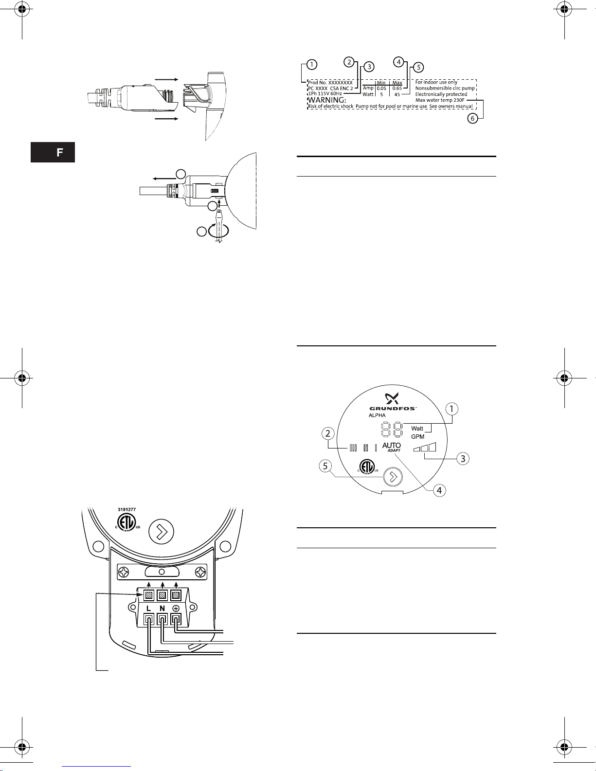
6.1 For line cord models
Follow procedure outlined in fig. 4.
Fig. 4 Connecting and removing power plug
for line cord models
Warning
Before starting any work on this
circulator, make sure electrical
supply has been switched off and
that it cannot be accidentally
switched on.
TM04 3418 1010
Power head
orientation A
Power head
orientation B
Power head
orientation C
Power head
orientation D
Warning
Risk of electrical shock - This pump
is supplied with a grounding
conductor and grounding-type
attachment plug. To reduce the risk
of electric shock, be certain that it is
connected only to a properly
grounded, grounding-type
receptacle in accordance with the
National Electric Code and any state,
local governing codes and
regulations.
TM04 3420 1010
1
2
3
Insert line cord plug onto pump
(side view).
To remove cord plug from pump:
(Bottom view)
1. Insert 1/8 in. flat blade
screwdriver into slot.
2. Rotate screwdriver.
3. Pull cord to remove.
Page 6

6
6.2 Terminal box models
Wiring procedure:
1. Loosen terminal box screw from terminal box
cover.
2. Utilize either conduit port for wiring entrance.
3. Gently push open wiring terminal levers
(L-N-G) for wiring installation.
4. Slide terminal box cover over terminal box
body.
5. Tighten terminal box screw Phillips #1
(5 in-lbs).
6. Apply power.
7. Lights on the control panel indicate electrical
supply has been switched on.
Fig. 5 Terminal box wiring, 1 x 115V
7. Nameplate
Fig. 6 Nameplate
8. Control display
Fig. 7 Control display
TM04 7035 1410
Black
White
Green
Wiring terminal levers
TM04 3419 1410
Pos. D escription
1 Product Number
2 Production Code:
• 1st and 2nd figures = year
• 3rd and 4th figures = week
3Voltage (V):
4 Rated current (A):
• Min.: Minimum Current (A)
• Max.: Maximum Current (A)
5 Input power (W):
• Min.: Minimum Power (W)
• Max.: Maximum Power (W)
6 Max. fluid temperature (F)
TM04 3421 1010
Pos. Description
1 LED showing Watt or flow indicator
2 LED indicating fixed speed
3 LED indicating constant pressure
4 LED AutoADAPT
5
Push-button for selection of pump
setting
Page 7

7
9. Performance* and operation mode selectio n
*Hydraulic performance without check valve
TM04 6882 1110
AUTOADAPT
Operating range
(maximum - minimum)
Pos. Description
• Push-button for selection of pump setting
• Every time the push-button is pressed, the circulator setting is changed
III
High Fixed Speed
• Runs at a constant speed and consequently on a constant curve. In Speed III, the pump is
set on the maximum curve under all operating conditions. Quick Vent of the pump can be
obtained by setting the pump to Speed III for a short period.
II
Medium Fixed Speed
• Runs at a constant speed and consequently on a constant curve. In Speed II, the pump is
set on the medium curve under all operating conditions.
I
Low Fixed Speed
• Runs at a constant speed and consequently on a constant curve. In Speed I, the pump is set
on the minimum curve under all operating conditions.
Constant Pressure I
• The duty point of the pump will move left and right along the lowest constant-pressure curve
depending on water demand in the system. The pump head (pressure) is kept constant,
irrespective of the water demand.
Constant Pressure II
• The duty point of the pump will move left and right along the middle constant-pressure curve
depending on water demand in the system. The pump head (pressure) is kept constant,
irrespective of the water demand.
Constant Pressure III
• The duty point of the pump will move left and right along the highest constant-pressure
curve depending on water demand in the system. The pump head (pressure) is kept
constant, irrespective of the water demand.
AutoADAPT (Factory Setting)
• This function controls the pump performance automatically within the defined performance
range (shaded area). AutoADAPT will adjust the pump performance to system demands
over time.
Page 8

8
10. Fault finding
11. Disposal
This product or parts of it must be disposed of in
an environmentally sound way; please use the
public or private waste collection service.
Warning
Before starting any work on this circulator, make sure electrical supply has been
switched off and that it cannot be accidentally switched on.
Pump liquid may be scalding hot and under high pressure.
Fault Control panel Remedy
1. The pump does not run LED off Check power supply (voltage) and
circuit breaker.
Check zone control; voltage, control
options, and thermostat.
Check all power connections.
Damaged circulator / replace.
LED on Check that the electricity supply falls
within the specified range.
Impeller blocked by impurities.
"
___ ___"
Requires turning power OFF and back
On to pump.
2. Noise in the system LED on Install air eliminator.
Reduce the pump speed.
Fluid velocities to high; reduce pump
speed.
Emitter or piping expanding.
3. Noise in the pump LED on Let the circulator run, will vent over time.
Increase the inlet pressure or check the
air volume in the expansion tank, if
installed.
No fluid (dry running).
Damaged circulator / replace.
4. Insufficient heat LED on Increase circulator speed or con stant
pressure.
Circulator in proper operating mode.
Check for air; piping, zone(s) and
emitter(s).
Check thermostat(s).
Check all valving.
Heat emitter large enough.
Check direction of flow.
Check water temperature from boiler
and boiler functions.
Check proper sizing of circulator.
Check ΔT calculation.
Page 9

9
12. Technical data
Supply voltage:
1x115V +/-10 %, 60Hz.
Motor protection:
The pump requires no external motor
protection.
Enclosure class:
Indoor use only, IP42.
CSA Enclosure Type 2.
Insulation class:
F.
Relative air humidity:
Maximum 95 %.
Maximum discharge pressure:
150 psi (10.34 bar).
Inlet pressure:
Sound pressure level:
43 dB (A).
Ambient temperature:
+32 °F (0 °C) to +104 °F (+40 °C).
Liquid temperature:
+36 °F (+2 °C) to +230 °F (+110 °C).
To avoid condensation in the control box and
stator, the liquid temperature must always be
higher than the ambient temperature.
Maximum glycol concentrations:
50 % glycol @ 36 °F (2 °C).
Hydraulic performance change can be expected.
Watt readings:
Accuracy +/-1 Watt.
Flow indicator:
Provides a relative indication of flow — should
not be used in lieu of a flow meter.
Check valve:
Use of check valve may reduce pump
hydraulic performance (up to -10%).
Use check valve in parallel pumping
applications.
Curve conditions:
Test liquid: Airless water.
Curves apply to a density of 983.2 kg/m
3
and a
liquid temperature of +140 °F (+60 °C).
All curves show average values and should
not be used as guarantee curves. If a specific
minimum performance is required, individual
measurements must be made.
Curves apply to a kinematic viscosity of 0.474
cSt.
Approximate power usage:
Liquid temperature Min. inlet pressure
167 °F (75 °C) 0.75 psi (0.05 bar)
194 °F (90 °C) 4.06 psi (0.28 bar)
230 °F (110 °C) 15.7 psi (1.08 bar)
Ambient
temperature
[°F (°C)]
Liquid temperature
Min. [°F (°C)] Max. [°F (°C)]
+32 °F
(0 °C)
+36 °F
(+2 °C)
+230 °F
(+110 °C)
+50 °F
(+10 °C)
+50 °F
(+10 °C)
+230 °F
(+110 °C)
+68 °F
(+20 °C)
+68 °F
(+20 °C)
+230 °F
(+110 °C)
+86 °F
(+30 °C)
+86 °F
(+30 °C)
+230 °F
(+110 °C)
+95 °F
(+35 °C)
+95 °F
(+35 °C)
+194 °F
(+90 °C)
+104 °F
(+40 °C)
+104 °F
(+40 °C)
+158 °F
(+70 °C)
Caution
In domestic hot-water system, it is
recommended to keep the liquid
temperature below +149 °F (+65 °C)
to eliminate the risk of lime
precipitation.
Speed setting Min. Max.
High fixed speed III 39W 45W
Medium fixed speed II 15W 30W
Low fixed speed I 5W 8W
Constant pressure 8W 45W
Constant pressure 14W 45W
Constant pressure 22W 45W
AutoADAPT 5W 45W
Page 10

10
12.1 Approvals
FCC Sections:
Section 15.19 (a) 3:
This device complies with Part 15 of the FCC
Rules. Operation is subject to the following two
conditions: (1) this device may not cause harmful
interference, and (2) this device must accept any
interference received, including interference that
may cause undesired operation.
Section 15.21:
Any changes or modifications to this equipment
not expressly approved by the party responsible
for compliance could void the user's authority to
operate this equipment.
Section 15.105 (b):
NOTE: This equipment has been tested and
found to comply with the limits for a Class B
digital device, pursuant to Part 15 of the FCC
Rules. These limits are designed to provide
reasonable protection against harmful
interference in a residential installation. This
equipment generates, uses, and can radiate
radio frequency energy and, if not installed and
used in accordance with the instructions, may
cause harmful interference to radio
communications. However, there is no guarantee
that interference will not occur in a particular
installation. If this equipment does cause harmful
interference to radio or television reception,
which can be determined by turning the
equipment off and on, the user is encouraged to
try to correct the interference by one or more of
the following measures;
• Reorient or relocated the receiving antenna.
• Increase the separation between the
equipment and receiver.
• Connect the equipment into an outlet on a
circuit different from that to which the receiver
is connected.
• Consult the dealer or an experienced radio/TV
technician for help.
Canadian EMC Standard:
ICES-003
This Class B digital apparatus complies with
Canadian ICES-003.
13. Quick install tips
1. To insure proper air venting of your system,
place Alpha in Fixed Speed III mode until all
air has been removed. Isolating zones during
this process will ensure proper air removal.
2. For balancing manifold zone(s) applications,
utilizing Constant Pressure mode 1 or 2 and
only one zone at a time during balancing will
ensure proper flow rate to each zone.
3. Always review your boiler minimum flow
rate requirements if utilizing Alpha as a
primary pump. Select one of the fixed spe ed
modes for boiler primary pump applications.
4. In general, for maximum energy savings and
comfort level, start with the AutoADAPT™
mode.
5. You may change hydraulic selection while
pumping. No permanent damage will occur. In
fact, Grundfos encourages testing the various
hydraulic modes with your hydronic system to
ensure maximum energy savings and comfort
level.
6. Zone panel control applications — when there
is a call for heat and power has been sent to
the Alpha pump, the Alpha will remember and
restart from the last duty point and hydraulic
mode.
3191277
Subject to alterations.
Page 11

11
GARANTIE LIMITÉE
Les produits fabriqués par GRUNDFOS PUMPS CORPORATION (Grundfos)
sont garantis à l'acheteur initial contre tous défauts de matériaux et vices de
fabrication pendant une période de 36 mois à comp ter d e la date de fabricati on.
La responsabilité de Grundfos au titre de la présente garantie est limitée à la
réparation ou au remplacement de tout produit fabriqué par Grundfos, à la
discrétion de ce dernier, sans frais, franco à bord de l'usine de Grundfos ou d'un
centre de service autorisé. Grundfos ne sera pas tenu responsable des frais
associés à l'enlèvement, à l'installation ou au tra nsport, ou de toute autre
dépense relative à une demande au titre de la garantie. Les produits vendus par
Grundfos mais qui ne sont pas fabriqués par ce dernier sont soumis à la garantie
proposée par le fabricant et ne sont pas couverts par la garantie de Grundfos.
Grundfos ne sera pas tenu responsable des dégâts ou de l'usure des produits
causés par une utilisation anormale, un accident, un abus, un mauvais emploi,
une modification ou une réparation non autorisée, ou si le produit n'a pas été
installé conformément aux instructions d'installation et d'utilisation de Grundfo s.
Pour obtenir un service au titre de la présente garantie, le produit défectueux doit
être renvoyé au distributeur ou au détaillant des produits Grundfos auprès duquel
il a été acheté, et il doit être accompagné d'une preuve d'ach at et de la date de
l'installation et de la défaillance, ainsi que des pièces justificatives relative s à
l'installation. Saut indication contraire, le distributeu r ou le détaillant entrera en
contact avec Grundfos ou avec un centre de service autorisé po ur connaître la
marche à suivre. Tout produit défectueux doit être renvoyé fret payé d'avance à
Grundfos ou à un centre de service; les documents justifiant la demande au titre
de la garantie et l'autorisation de renvoi du produit doivent être inclus suivant les
instructions.
GRUNDFOS NE SERA PAS TENU RESPONSABLE DES DOMMAGES
ACCESSOIRES OU CONSÉCUTIFS, DES PERTES OU DES DÉPENSES
DÉCOULANT DE L'INST ALLATION OU DE L'UTILISA TION DU PRODUIT OU DE
TOUTE AUTRE CAUSE. AUCUNE GARANTIE EXPRESSE OU IMPLICITE, Y
COMPRIS LES GARANTIES DE QUALITÉ MARCHANDE OU D'ADAPTATION À
UN USAGE PARTICULIER, N'EST FORMULÉE AU-DELÀ DES GARANTIES
DÉCRITES OU MENTIONNÉES CI-DESSUS.
Certaines juridictions n'autorisent pas les exclusions ou les limitations des
dommages accessoires ou consécutifs, et d'autres juridictions ne permettent pas
de limitations relatives à la durée des garanties implicites. Par conséquent, il se
peut que les limitations ou les exclusions ci-dessus ne s'appliquent pas à votre
cas. La présente garantie vous accorde des droits spécifiques, et il se peut que
vous ayez d'autres droits pouvant varier d'une juridiction à l'autre.
Page 12

12
Instructions originales d'installation et
d'utilisation.
CONTENU
Page
1. Généralités
Grundfos Alpha est adaptée aux systèmes à
débit constant ou variable et sert à optimiser le
réglage du point de fonctionnement de la pompe.
2. Inspection de l'envoi
Examinez les composants attentivement pour
vous assurer que la pompe n'a pas été abîmée
pendant le transport. Prenez soin de NE PAS
échapper la pompe et de la manipuler
adéquatement. Vérifiez que les éléments
suivants ont été inclus :
• Une pompe Grundfos Alpha
• Un cordon d'alimentation ou une boîte de
connexion
• Deux joints d'étanchéité
• Un exemplaire des instructions d'installation et
d'utilisation
• Un clapet anti-retour
• Un autocollant indiquant «clapet anti-retour
installé»
3. Liqu ides pompés
Grundfos Alpha est conçue pour pomper des
liquides propres, clairs, non agressifs et non
explosifs, exempts de particules solides, de fibres
ou d'huile minérale.
4. Installation de la pompe
Lorsque vous procédez au raccordement des
tuyaux, assurez-vous de suivre les
recommandations du fabricant des tuyaux et
de respecter toutes les exigences des codes
relatifs aux matériaux de canalisation.
• Il est nécessaire d'éliminer tous les résidus
pouvant se trouver dans le système avant
l'installation de la pompe.
• Installez uniquement le clapet anti-retour en
cas de besoin; se reporter au schéma 1.
• Les flèches situées sur la structure de la
pompe indiquent la direction du débit du
liquide passant à travers la pompe.
• Installez la pompe en orientant l'axe du
moteur de façon horizontale; se reporter au
schéma 2.
• Posez sur les extrémités de la pompe les deux
joints d'étanchéité fournis.
Fig. 1 Installation du clapet anti-retour
1. Généralités
12
2. Inspection de l'envoi
12
3. Liquides pompés
12
4. Installation de la pompe
12
5. Modification de la position de la tête
de pompe
13
5.1 Procédure:
13
6. Installation électrique
13
6.1 Modèles à cordon d'alimentation
14
6.2 Modèles à boîte de connexion
14
7. Plaque signalétique
14
8. Affichage des commandes
14
9. Sélection des modes de
performance* et de fonctionnement
15
10. Dépannage
16
11. Mise au rebut
16
12. Données techniques
17
13. Astuces d'installation
18
Avertissement
Lisez les présentes instructions
d'installation et d'utilisation avant
toute installation. L'installation et le
fonctionnement doivent répondre à
l'ensemble des règlements
nationaux, provinciaux et locaux et
des codes de bonne pratique
acceptés.
Avertissement
La pompe ne doit pas être utilisée
pour transférer des liquides
inflammables tels que le carburant
diesel, l'essence et les liquides
similaires.
La pompe n'est pas destinée à une
utilisation dans une piscine ou en
milieu marin.
Ne mettez pas la pompe sous
tension avant qu'elle ne soit installée
de façon adéquate.
Risque de choc électrique: cette
pompe n'a pas été évaluée pour une
utilisation dans une piscine ou en
milieu marin.
TM 3422 4408
Page 13

13
Fig. 2 Positions d'installation
5. Modification de la position de la
tête de pompe
La modification de l'orientation de la tête de
pompe doit être effectuée avant de remplir le
système de liquide.
Il se peut que le liquide de la pompe soit bouillant
et sous haute pression.
La tête de pompe peut être tournée par paliers de
90 º.
Consultez le schéma 3 pour connaître les
positions possibles et acceptables.
Utilisez uniquement les positions C et D pour
les boîtiers CSA de type 2.
Fig. 3 Modification de la position de la tête
de pompe de commande
5.1 Procédure:
1. En cas de présence de liquide, faites couler le
fluide du système hors de la pompe ou isolez
celui-ci de la pompe.
2. Desserrez les vis de 4 mm et tournez la tête
de la pompe sur la position désirée; se
reporter au schéma 3.
3. Remettre les vis 4mm en place et reserrez en
diagonale à 7 livres-pieds.
6. Installation électrique
Tous les travaux électriques doivent être
effectués par un électricien professionnel
conformément à la dernière édition du Code
national de l'électricité et aux codes et
règlements municipaux et des États.
• Le moteur de la pompe Grundfos Alpha est
protégé par les composants électroniques du
boîtier de commande et ne nécessite pas de
protection externe.
• Vérifiez que la tension et la fréquence de
l'alimentation correspondent aux valeurs
indiquées sur la pompe.
• Reliez uniquement la pompe au réseau
électrique au moyen du cordon d'alimentation
ou de la boîte de connexion fournis; voir
schéma 4 et 5.
• N'apportez pas de modifications et utilisez
uniquement le jeu de cordons fourni
• Les voyants du panneau de commande
indiquent que l'alimentation électrique est
établit.
TM04 3417 4408
Avertissement
Avant de commencer à travailler sur
ce circulateur, assurez-vous que
l'alimentation électrique est coupée
et qu'elle ne peut pas être rétablie
par accident.
TM04 3418 1010
Position A
Position B
Position C
Position D
Avertissement
Risque de choc électrique –
Cette pompe est fournie avec un
conducteur de terre et une fiche de
branchement de type mise à la terre.
Pour réduire le risque de choc
électrique, assurez-vous qu'elle
n'est branchée que dans une prise
de type mise à la terre correctement
mise à la terre conformément au
Code national de l'électricité et à
tout code et règlement provincial et
local.
Page 14
14
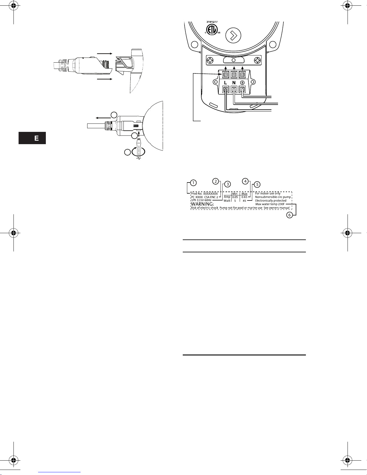
6.1 Modèles à cordon d'alimentation
Fig. 4 Branchement et débranchement de la
fiche pour les modèles à cordon
d'alimentation
6.2 Modèles à boîte de connexion
Procédure de câblage:
1. Dévissez la vis de la boîte de conn exio n du
couvercle de la boîte de connexion.
2. Utilisez l'un ou l'autre port de conduit pour
l'entrée des câbles.
3. Ouvrez soigneusement les leviers terminaux
(L-N-G) pour l'installation du câblage.
4. Glissez le couvercle de la boîte de connexion
au-dessus du cadre de la boîte de connexion.
5. Serrez la vis Ph illips n° 1 de la b oîte de
connexion (5 lb-po).
6. Rétablir l’alimentation électrique.
7. Les voyants du panneau de commande
indiquent que l'alimentation électrique est
établit.
Fig. 5 Câblage de la boîte de connexion,
1 x 115 V
7. Plaque signalétique
Fig. 6 Plaque signalétique
8. Affichage des commandes
Fig. 7 Affichage des commandes
TM04 3420 1010
TM04 7035 1410
1
2
3
Insérez le cordon d'alimentation dans
la pompe (vue de profil)
Pour débrancher la fiche du cordon
de la pompe (vue du dessous)
1. Insérez un tournevis
plat de 1/8 po dans
la fente
2. Faites tourner le tournevis
3. Tirez sur le cordon pour l'enlever
Vert
Blanc
Noir
Leviers terminaux de câblage
TM04 3419 4408
Pos. D escripción
1 Numéro de produit:
2 Code de production:
•1
er
et 2e chiffres = année
•3
e
et 4e chiffres = semaine
3 Tension (V):
4 Courant nominal (A):
• Min.: courant minimal (A)
• Max.: courant maximal (A)
5 Alimentation d'entrée (W) :
• Min.: puissance minimale (W)
• Max.: puissance maximale (W)
6 Température max. du fluide (ºF)
TM04 3421 1010
Pos. Descripción
1 Indicateur DEL des watts ou du débit
2 DEL indiquant la vitesse fixe
3 DEL indiquant la pression constante
4 DEL de la fonction AutoADAPT
5
Bouton-poussoir de sélection du
réglage de la pompe
Page 15

15
9. Sélection des modes de performanc e* et de fonctionne ment
*Performance hydraulique sans le clapet anti-retour
TM04 6882 1110
AUTO
ADAPT
Gamme de fonctionnement
(Maximale - Minimale)
Pos. Descripción
• Bouton-poussoir de sélection du réglage de la pompe
• Chaque fois que vous appuyez sur le bouton, le réglage du circulateur change.
III
Vitesse fixe élevée
Fonctionne à vitesse constante et conséquemment sur une courbe fixe. En mode de vitesse
III, la pompe est réglée sur une courbe maximale pour toutes les conditions de
fonctionnement. Une purge rapide de la pompe peut être effectuée en réglant celle-ci sur le
mode de vitesse III pendant un court instant.
II
Vitesse fixe moyenne
Fonctionne à vitesse constante et conséquemment sur une courbe fixe. En mode de vitesse II,
la pompe est réglée sur une courbe moyenn e pour toutes les conditions de fonctionneme nt.
I
Vitesse fixe basse
Fonctionne à vitesse constante et conséquemment sur une courbe fixe. En mode de vitesse I,
la pompe est réglée sur une courbe minimale pour toutes les conditions de fonctionnement.
Pression constante I
Le point de consigne se déplacera de gauche à droite en suivant la plus basse courbe de
pression constante en fonction de la quantité d'eau requise par le système. La tête de la
pompe (pression) demeure constante, quelle que soit la demande en eau.
Pression constante II
Le point de consigne se déplacera de gauche à droite en suivant la courbe médium de
pression constante en fonction de la quantité d'eau requise par le système. La tête de la
pompe (pression) demeure constante, quelle que soit la demande en eau.
Pression constante III
Le point de consigne se déplacera de gauche à droite en suivant la courbe supérieur de
pression constante en fonction de la quantité d'eau requise par le sytème. La tête de la pompe
(pression) demeure constante, quelle que soit la demande en eau.
Fonction AutoADAPT (réglage en usine)
Ce mode contrôle la performance de la po mpe aut omatiquem ent à l'intérie ur de l a fourchette
de rendement établie (partie ombrée). AutoADAPT ajuste la performance de la pompe en
fonction des demandes du système au fil du temps.
Page 16

16
10. Dépannage
11. Mise au rebut
Ce produit ou ses composants doivent être
éliminés dans le respect de l'environnement;
veuillez recourir aux services publics ou privés de
récupération des déchets.
Avertissement
Avant de commencer à travailler sur ce circulateur, assurez-vous que l'alimentation
électrique est coupée et qu'elle ne peut pas être rétablie par accident.
Il se peut que le liquide de la pompe soit bouillant et sous haute pression.
Défaillance Panneau de commande Solution
1. La pompe ne fonctionne
pas
DEL éteinte Vérifiez l'alimentation électrique
(tension) et le disjoncteur.
Vérifiez la commande des zones, la
tension, les options de commande et le
thermostat.
Vérifiez l'ensemble des raccords
d’alimentation électrique.
Circulateur endommagé: à remplacer.
DEL allumée Vérifiez que l'alimentation électrique se
situe dans l'échelle indiquée.
Tête de pompe bloquée par des
impuretés.
"
___ ___"
Pour lancer le pompage, il faut couper
l'alimentation et la rétablir.
2. Bruit dans le système DEL allumée Installez le purgeur d'air.
Réduisez la vitesse de la pompe.
Vitesse du fluide trop élevée; réduisez la
vitesse de la pompe.
Émetteur ou tuyau s'agrandissant.
3. Bruit dans la pompe DEL allumée Laissez le circulateur fonctionner, l'air
s'évacuera au fil du temps.
Augmenter la pression d'entrée ou
vérifiez le volume d'air dans le réservoir
d'expansion si celui-ci est installé.
Aucun fluide (écoulement sec).
Circulateur endommagé: à remplacer.
4. Chaleur insuffisante DEL allumée Augmentez la vitesse du circulateur ou
la pression constante.
Circulateur en mode de fonctionnement
adéquat.
Vérifiez la présence d'air, les tuyaux, les
zones et les émetteurs.
Vérifiez le(s) thermostat(s).
Vérifiez toutes les soupapes.
Vérifiez que l'émetteur de chaleur est
suffisamment grand.
Vérifiez la direction du débit.
Vérifiez la température de l'eau à partir
du chauffe-eau et vérifiez les fonctions
de ce dernier.
Vérifiez que le format du circulateur est
approprié.
Vérifiez le calcul du ΔT.
Page 17

17
12. Données techniques
Tension de l'alimentation:
1 × 115 V ± 10 %, 60 Hz.
Protection du moteur:
La pompe ne nécessite pas de protection
externe du moteur.
Classification du boîtier:
Usage à l'intérieur uniquement, IP42.
Boîtier CSA de type 2.
Classification de l'isolant électrique:
F.
Humidité relative de l'air:
95 % maximum.
Pression d'opération maximum:
150 psi (10,34 bars).
Pression d'entrée:
Niveau de pression sonore:
43 dB (A).
Température ambiante :
De +32 °F (0 °C) à +104 °F (+40 °C).
Température du liquide :
De +36 °F (2 °C) à +230 °F (+110 °C).
Pour éviter toute condensation dans le boîtier de
commande et dans le stator, la température du
liquide doit toujours être supérieure à la
température de l'air.
Concentrations maximum de glycol:
50 % de glycol à 36 °F (2 °C).
Des changements de la performance
hydraulique peuvent se produire.
Relevé des watts:
Précision +/-1 watt.
Indicateur de débit:
Fournit une indication relative du débit – ne
doit pas remplacer un débitmètre.
Clapet anti-retour:
L'utilisation d'un clapet anti-retour peut réduire
les performances du système hydraulique de
la pompe (jusqu'à -10 %).
Utilisez le clapet anti-retour en même temps
que d'autres fonctions de pompage.
Conditions de la courbe:
Liquide d'essai: eau sans air.
Les courbes s'appliquent à une densité de
983,2 kg/m3 et à une température du liquide
de +140 °F (+60 °C).
Toutes les courbes indiquent des valeurs
moyennes et leur précision ne doit pas être
considérée comme étant garantie. En cas de
besoin d'une performance minimale
spécifique, il faut effectuer un relevé
individuel.
Les courbes s'appliquent à une viscosité
cinématique de 0,474 cSt.
Consommation électrique approximative :
Température
du liquide
Pression d'entrée
minimale
167 °F (75 °C) 0,75 psi (0,05 bar)
194 °F (90 °C) 4,06 psi (0,28 bar)
230 °F (110 °C) 15,7 psi (1,08 bar)
Température
ambiante
[°F (°C)]
Température du liquide
Min. [°F (°C)] Max. [°F (°C)]
+32 °F
(0 °C)
+36 °F
(+2 °C)
+230 °F
(+110 °C)
+50 °F
(+10 °C)
+50 °F
(+10 °C)
+230 °F
(+110 °C)
+68 °F
(+20 °C)
+68 °F
(+20 °C)
+230 °F
(+110 °C)
+86 °F
(+30 °C)
+86 °F
(+30 °C)
+230 °F
(+110 °C)
+95 °F
(+35 °C)
+95 °F
(+35 °C)
+194 °F
(+90 °C)
+104 °F
(+40 °C)
+104 °F
(+40 °C)
+158 °F
(+70 °C)
Dans les réseaux de distribution
d'eau domestique, il est
recommandé de maintenir la
température du liquide en dessous
de +149 °F (+65 °C) afin d'éviter tout
risque de précipitation de minéraux.
Réglage de la
vitesse
Mín. Máx.
Vitesse fixe élevée III 39W 45W
Vitesse fixe
moyenne
II 15 W 30W
Vitesse fixe faible I 5W 8W
Pression constante 8W 45W
Pression constante 14W 45W
Pression constante 22W 45W
Fonction
AutoADAPT
5W 45W
Page 18

18
Approbations:
Articles de la FCC:
Article 15.19 (a) 3:
Ce dispositif est conforme à la partie 15 du
règlement de la FCC. Le fonctionnement est
soumis aux deux conditions suivantes : (1) ce
dispositif ne doit pas causer d'interférence
préjudiciable, et (2) ce dispositif doit accepter
toute interférence reçue, y compris l'interférence
pouvant provoquer un mauvais fonctionnement.
Article 15.21:
Tout changement apporté à ce dispositif qui n'a
pas été expressément approuvé par la partie
responsable de la conformité pourrait annuler
l'autorisation de l'utilisateur de faire fonctionner
ce dispositif.
Article 15.105 (b):
REMARQUE : cet équipement a été testé et
reconnu conforme aux limites imposées aux
appareils numériques de classe B en vertu de la
Partie 15 du règlement de la FCC. Ces limites
sont conçues pour fournir une protection
raisonnable contre le brouillage préjudiciable
dans le cadre d'une installation à usage
domestique. Ce dispositif génère, utilise et peut
rayonner de l'énergie de radio-fréquence et, s'il
n'est pas installé et utilisé conformément aux
instructions, peut provoquer une interférence
préjudiciable aux communications radio. Il
n'existe cependant aucune garantie qu'un
équipement particulier ne sera pas l'objet
d'interférences. Si ce dispositif provoque une
interférence préjudiciable à la réception des
émissions radio ou de télévision, ce que l'on peut
déterminer en mettant l'appareil hors tension puis
de nouveau sous tension, il est recommandé à
l'utilisateur de tenter de pallier ce problème au
moyen d'une ou plusieurs des mesures
suivantes:
• Réorienter l'antenne réceptrice différemment
ou la changer de place.
• Augmenter la distance séparant le dispositif
du récepteur.
• Brancher le dispositif à une prise sur un circuit
différent de celui sur lequel est branché le
récepteur.
• Obtenir l'aide du revendeur ou d'un technicien
radio/TV expérimenté.
Norme canadienne concernant la CEM:
NMB-003
Cet appareil numérique de classe B est conforme
à la NMB-003 canadienne.
13. Astuces d'installation
1. Pour assurer une purge d'air appropriée pour
votre système, réglez l'Alpha en vitesse fixe III
jusqu'à ce que tout l'air ait été évacué.
L'isolement des zones dans le cadre de ce
processus assure une bonne purge d'air.
2. Pour assurer un débit approprié vers chaque
zone dans l'équilibrage des applications de
zone(s) de collecteur, recourez au mode 1 ou
2 de pression constante, et utilisant une seule
zone à la fois au cours de l'équilibrage.
3. Vérifiez toujours les exigences con cernan t
le débit minimal de votre chauffe-eau si
vous vous servez d'Alpha comme pompe
principale. Sélectionnez l'un des modes de
vitesse fixe pour les applications dans
lesquelles il s'agit de la pompe principale de
chauffe-eau.
4. Règle générale, pour des économies
d'énergie et un niveau de confort optimaux,
commencez tout d'abord par le mode
AutoADAPT™.
5. Vous pouvez changer la sélection hydraulique
en cours de pompage. Aucun dommage
permanent ne se produira. En fait, Grundfos
vous encourage à tester les divers modes
hydrauliques avec votre système à eau
chaude pour permettre des économies
d'énergie et un niveau de confort optimaux.
6. Applications de commande du panneau de
zone – lorsqu'une demande de chaleur et
d'énergie est acheminée à la pompe Alpha,
celle-ci redémarre à partir de son dernier point
de consigne et de son mode hydraulique.
3191277
Sujet à modifications.
Page 19

19
GARANTÍA LIMITADA
Se garantiza únicamente al usuario origin al de los prod uctos fabricados por
GRUNDFOS PUMPS CORPORATION (Grundfos), durante un período de 3 6
meses contados a partir de la fecha de fabricación, de que estos no presentarán
defectos de material ni de mano de obra. La responsabilidad de Grundfos en
virtud de esta garantía queda limitada a la reparación o al cambio, a opción de
Grundfos, sin cargo alguno, en condiciones F.O.B., fábrica de Grundfos o
estación de servicio autorizada. Grundfos no tendrá respo nsabilid ad alguna po r
gastos de remoción, de instalación, o de transportación, ni por los cargos que
surjan en relación con reclamos bajo la garantía. Los productos que Grun dfos
venda pero que no sean fabricados por esta empresa, están sujetos a la garantía
que ofrezca el fabricante de tales productos y no a la garantía de Grundfos.
Grundfos no será responsable por daños o desgaste que se produzcan en los
productos debido a condiciones de funci onamiento anormales, accidentes,
maltrato, uso indebido, modificaciones o reparaciones no autorizadas, o
instalaciones que no se realicen de conformidad con las instrucciones impresas
de instalación y de funcionamiento de Grundfos.
A fin de obtener servicio bajo la garantía, debe devolver el producto al distribuidor
de Grundfos o a la tienda minorista donde lo adquirió, acompañado del
comprobante de venta y así como de información acerca de la fecha de
instalación, de la fecha en que se produjo el mal funcionamiento, y de lo s datos
complementarios sobre la instalación. Salvo que se disponga lo contrario, el
distribuidor o la tienda minorista se comunicará con Grundfos o con una estación
de servicio autorizada para solicitar instrucciones. Los productos defectuosos
que se devuelvan a Grundfos o a una estación de servicio autorizad a deben ser
enviados con el porte pagado, acompañados de la documentación que sustente
el reclamo de garantía, así como del do cumento de autori zación de d evolución
de materiales en caso de que se exija.
GRUNDFOS NO SERÁ RESPONSABLE POR DAÑOS, PÉRDIDAS O GASTOS
CONCOMIT ANTES O SECUNDARIOS, PROVENIENTES DE LA INST ALACIÓN,
DEL USO, O DE CUALESQUIER OTRAS CAUSAS. NO SE OTORGAN
GARANTÍAS EXPRESAS O IMPLÍCITAS, COMO LA DE LA IDONEIDAD DEL
PRODUCTO P ARA SU COMERCIALIZACIÓN O P ARA ALGÚN PROPÓSITO EN
P AR TICULAR, QUE AMPLÍEN LAS GARANTÍAS DESCRITAS O A LAS QUE SE
HACE REFERENCIA MÁS ARRIBA.
En algunas jurisdicciones no se permiten exclusiones o limitaciones en cuanto a
daños concomitantes o secundarios y en algunas jurisdicciones no se permite
acciones que limiten el plazo de vigencia de las garantías implícitas. Por lo tanto,
es posible que las limitaciones arriba señalada s no sean aplicabl es en su ca so.
Esta garantía le otorga derechos específicos de efecto jurídico; es posible que,
además, usted tenga otros derechos que varíen de una jurisd icción a otra.
Page 20

20
Instrucciones de instalación original y
funcionamiento.
ÍNDICE
Página
1. Información general
La bomba Alpha de Grundfos es adecuada para
los sistemas con flujos constantes o variables en
los que sea necesario optimizar la configuración
del punto de funcionamiento de la bomba.
2. Inspección del envío
Examine cuidadosamente las piezas para
verificar que la bomba no haya sufrido daño
durante el transporte. Debe tener cuidado para
EVITAR dejar caer o maltratar la bomba.
Verifique que las siguientes piezas estén
incluidas:
• Una bomba Alpha de Grundfos
• Un cable eléctrico o una caja de terminales
• Dos empaques
• Un manual de instrucciones de instalación y
de funcionamiento
• Una válvula de retención
• Una etiqueta que dice: "La válvula de
retención está instalada."
3. Tipo de líquidos que puede
bombear
La bomba Alpha de Grundfos está diseñada para
bombear líquidos limpios, poco densos, no
agresivos ni explosivos, que no contengan
partículas sólidas, fibras ni aceite mineral.
Para usarla con glicol lea la sección 10. Lea
información adicional sobre el líquido en la
sección 10.
4. Instalación de la bomba
Para hacer conexiones de tuberías, recuerde que
debe seguir las recomendaciones del fabricante
de los tubos y observar todos los requisitos
señalados en los códigos para materiales de
tuberías.
• Antes de la instalación de la bomba, debe
retirar adecuadamente todo escombro en el
sistema.
• Introduzca la válvula de retención sólo si es
necesario; vea la fig. 1.
• Las flechas de la caja de la bomba indican la
dirección del flujo del líquido al pasar por la
bomba.
• Instale la bomba con el eje del motor
horizontal; vea la fig. 2.
• Conecte los dos empaques suministrador a
los extremos de la bomba.
Fig. 1 Verifique la instalación de la válvula
1. Información general
20
2. Inspección del envío
20
3. Tipo de líquidos que puede
bombear
20
4. Instalación de la bomba
20
5. Cambio de posición de la cabeza
motriz
21
5.1 Procedimiento:
21
6. Instalación eléctrica
21
6.2 Modelos con caja de terminales
22
7. Placa de identificación del producto
22
8. Pantalla de control
23
9. Elección del modo de rendimiento*
y funcionamiento
24
10. Localización de fallas
25
11. Eliminación
25
12. Datos técnicos
26
13. Consejos rápidos para la
instalación
27
Advertencia
Antes de la instalación, lea estas
instrucciones y las instrucciones de
funcionamiento. La instalación y el
modo de funcionamiento deben
ajustarse a lo estipulado por
reglamentos nacionales, estatales y
locales, así como por los códigos
aceptados de prácticas
recomendadas.
Advertencia
La bomba no se debe usar para
transferir líquidos inflamables,
como combustible diesel, gasolina
o líquidos similares.
La bomba no es para usarla en
piscinas ni en actividades marinas.
Advertencia
No conecte la bomba al suministro
eléctrico hasta que esté
debidamente instalada.
Riesgo de descarga eléctrica: Esta
bomba no ha sido diseñada para
usarla en piscinas de natación ni en
zonas marinas.
TM 3422 4408
Page 21

21
Fig. 2 Posiciones de instalación
5. Cambio de posición de la cabeza
motriz
El cambio de la orientación de la cabeza motriz
debe hacerse antes de llenar el sistema con
líquido.
El líquido de la bomba puede estar sumamente
caliente y bajo alta presión.
La cabeza motriz se puede girar en pasos de 90º.
Examine la fig. 3 para ver las posiciones
posibles/adecuadas.
Use las orientaciones C y D únicamente para
la caja CSA de tipo 2.
Fig. 3 Cambio de posición de la cabeza
motriz
5.1 Procedimiento:
1. Si contiene líquido, drene la bomba del líquido
del sistema o aísle el líquido de la bomba.
2. Afloje los tornillos de 4 mm y gire el cabe zal
de la bomba a la posición que desee; vea la
fig. 3.
3. Introduzca los tornillos y apriételos en forma
entrecruzada hasta un par de torsión de
7 pies-lb.
6. Instalación eléctrica
Los trabajos en las instalaciones eléctricas
deben ser realizados por electricistas calificados,
de conformidad con la más reciente edición del
Código Nacional de Electricidad y de los códigos
y reglamentos estatales y locales.
• El motor de la bomba Alpha de Grundfos está
protegido por las piezas electrónicas que se
encuentran dentro de la caja de control; el
motor no necesita de protección externa.
• Verifique que el voltaje y la frecuencia del
voltaje de suministro correspondan a los
valores señalados en la bomba.
• Conecte la bomba a la red eléctrica
únicamente con el cable eléctrico o la caja de
terminales que vienen con la bomba; vea la
fig. 4 y 5.
• Use únicamente el cable eléctrico que viene
con la bomba, y no lo modifique.
• Las luces del tablero de control indican que se
encendió el suministro eléctrico.
TM04 3417 4408
Advertencia
Antes de iniciar cualquier trabajo en
esta bomba de circulación, verifique
que haya desconectado el
suministro eléctrico y que éste no
pueda encenderse accidentalmente.
TM04 3418 1010
Posición A
Posición B
Posición C
Posición D
Advertencia
Riesgo de descarga eléctrica — Esta
bomba viene con un conductor de
puesta a tierra y con un enchufe con
dispositivo de conexión a tierra.
Para reducir el riesgo de descarga
eléctrica, verifique que esté
enchufado únicamente en un
tomacorriente con dispositivo de
conexión a tierra y debidamente
conectado a tierra, de conformidad
con el Código Nacional de
Electricidad y con los códigos y
reglamentos estatales y locales
correspondientes.
Page 22
22
6.1 Para los modelos con cable eléctrico
Siga el procedimiento detallado en la fig. 4.
Fig. 4 Conexión y remoción del enchufe de
alimentación para los modelos con
cable eléctrico
6.2 Modelos con caja de terminales
Procedimiento de cableado:
1. Afloje el tornillo de la caja de term inales de la
cubierta de la caja de terminales.
2. Utilice cualquiera de los puertos de derivación
para la entrada de los cables.
3. Suavemente, empuje las palancas de los
terminales (L-N-G) a la posición abierta para
instalar los cables.
4. Deslice la cubierta de la caja de terminales
sobre el cuerpo de la caja de terminales.
5. Apriete el tornillo Phillips Nº 1 de la caja de
terminales (5 pulg.-lb).
6. Encienda la electricidad.
7. Las luces del tablero de control indican que se
encendió el suministro eléctrico.
Fig. 5 Cableado de la caja de terminales,
1 x 115 V
7. Placa de identificación del
producto
Fig. 6 Placa de identificación del producto
TM04 3420 1010
1
2
3
(vista lateral)
Introduzca el cable eléctrico en la bomba
Para quitar el enchufe del
cable de la bomba
(vista inferior)
1. Introduzca el
destornillador de hoja
plana de 1/8" en la
ranura
2. Gire el destornillador
3. Tire del cable para
sacarlo
TM04 7035 1410
TM04 3419 4408
Pos. Descripción
1 Número de producto:
2 Código de producción:
• 1o y 2o dígito = año
• 3o y 4o dígito = semana
3Voltaje (V):
4 Corriente nominal (A):
• Mín.: Corriente mínima (A)
• Máx.: Corriente máxima (A)
5 Potencia de entrada (W):
• Mín.: Potencia mínima (W)
• Máx.: Potencia máxima (W)
6 Temperatura máxima del líquido (F)
Palancas de terminales de cableado
Verde
Blanca
Negra
Page 23

23
8. Pantalla de control
Fig. 7 Pantalla de control
TM04 3421 4408
Pos. Descripción
1 LED que indica los vatios o flujo
2 LED que indica la velocidad fija
3 LED que indica la presión constante
4 LED de función
5
Botón para elegir la configuración de
funcionamiento de la bomba.
Page 24

24
9. Elección del modo de r endimie nto* y funcio namie nto
*Rendimiento hidráulico sin la válvula de retención
TM04 6882 1110
AUTO
ADAPT
Rango de operación
(Máxima - Mínima)
Pos. Descripción
• Botón para elegir la configuración de funcionamiento de l a bomba.
• Cada vez que se oprime el botón, se cambia la configuración de la bomba de circulación
III
Velocidad alta fija
• Funciona a velocidad constante y, por consiguiente, en una curva constante. En el nivel de
velocidad III, la bomba está configurada en la curva máxima bajo todas las condiciones de
funcionamiento. Se puede obtener una ventilación rápida configurando la bomba a la
velocidad III por un período corto.
II
Velocidad mediana fija
• Funciona a velocidad constante y, por consiguiente, en una curva constante. En el nivel de
velocidad II, la bomba está configurada en la curva mediana bajo todas las condiciones de
funcionamiento.
I
Velocidad baja fija
• Funciona a velocidad constante y, por consiguiente, en una curva constante. En el nivel de
velocidad I, la bomba está configurada en la curva mínima bajo todas las condiciones de
funcionamiento.
Presión constante I
• El punto de funcionamiento de la bomba se mueve hacia la izquierda y hacia la derech a
junto con la curva de presión constante más baja, dependiendo de la deman da de ag ua e n
el sistema. La presión del cabezal de la bomba se mantiene constante, independientemente
de la demanda de agua.
Presión constante II
• El punto de funcionamiento de la bomba se mueve hacia la izquierda y hacia la derecha
junto con la curva de presión constante mediana, dependiendo de la demanda de agua en
el sistema. La presión del cabezal de la bomba se mantiene constante, independientemente
de la demanda de agua.
Presión constante III
• El punto de funcionamiento de la bomba se mueve hacia la izquierda y hacia la d erecha
junto con la mayor curva de presión constante, dependiendo de la demanda d e agua e n el
sistema. La presión del cabezal de la bomba se mantiene constante, independientemente
de la demanda de agua.
Función AutoAdapt (Configuración de fábrica)
• Esta función controla automáticamente el rendimiento de la bomba, dentro de los límites de
rendimiento señalados (área sombreada). AutoADAPT ajustará el rendimiento de la bomba
a las exigencias del sistema a lo largo del tiempo.
Page 25

25
10. Localización de fallas
11. Eliminación
Este producto o sus piezas deben ser eliminados
de una manera adecuada para el medio
ambiente; use el servicio público o privado de
recolección de basura.
Advertencia
Antes de iniciar cualquier trabajo en esta bomba de circulación, verifique que haya
desconectado el suministro eléctrico y que éste no pueda conectarse accidentalmente.
El líquido de la bomba puede estar sumamente caliente y bajo alta presión.
Falla Tablero de control Remedio
1. La bomba no funciona LED apagado Verifique el suministro eléctrico (voltaje) y el
interruptor.
Revise el centro de carga: voltaje, opciones
de control y termostato.
Revise todas las conexiones eléctricas.
Bomba de circulación dañada / cámbiela.
LED encendido Verifique que el suministro eléctrico
corresponda a los límites especificados.
El rotor está bloqueado por impurezas.
"
___ ___"
Es necesario apagar y volver a encender la
bomba.
2. Hay ruido en el sistema LED encendido Instale el eliminador de aire.
Disminuya la velocidad de la bomba.
La velocidad del líquido es demasiado
elevada, reduzca la velocidad de la bomba.
El emisor o la tubería se expanden.
3. Hay ruido en la bomba LED encendido Deje que la bomba de circulación funcione,
se purgará con el tiempo.
Aumente la presión de entrada o revise el
volumen de aire en el tanque de expansión,
si está instalado.
No hay líquido (funciona en vacío).
Bomba de circulación dañada/cámbiela.
4. Calor insuficiente LED encendido Aumenta la velocidad o la presión
constante de la bomba de circulación.
Verifique que el modo de funcionamiento de
la bomba de circulación sea el adecuado.
Revise el suministro de aire; tuberías,
zona(s) y emisor(es).
Revise el (los) termostato(s).
Revise todas las válvulas.
El emisor de calor es suficientemente
grande.
Revise la dirección del flujo.
Revise la temperatura del agua de la
caldera y las funciones de la caldera.
Verifique que el tamaño de la bomba de
circulación sea el adecuado.
Revise los cálculos ΔT.
Page 26

26
12. Datos técnicos
Tensión de alimentación:
1 x 115 V +/-10 %, 60 Hz.
Protección del motor:
El motor de la bomba no requiere de
protección externa.
Clase de caja:
Únicamente para uso en interiores, IP42.
Caja CSA, de tipo 2.
Clase de aislamiento:
F.
Humedad relativa del aire:
Máxima 95 %.
Presión de descarga máxima:
150 lb./pulg.2 (10.34 bar).
Presión de entrada:
Nivel de presión sonora:
43 dB (A).
Temperatura ambiente:
+32 °F (0 °C) a +104 °F (+40 °C).
Temperatura del líquido:
+36 °F (+2 °C) a +230 °F (+110 °C).
Para evitar la condensación en la caja de control
y en el núcleo de la bobina, la temperatura del
líquido debe ser siempre mayor que la
temperatura ambiente.
Concentraciones máximas de glicol:
50 % glicol a 36 °F (2 °C).
Se puede esperar un cambio en el rendimiento
hidráulico.
Lecturas en vatios:
Precisión: +/-1 va io.
Indicador de flujo:
Brinda una indicación relativa del flujo: no
debe usarse en lugar de un flujómetro.
Válvula de retención:
El usar la válvula de retención puede reducir
el rendimiento hidráulico de la bomba (en
hasta un 10%).
Use la válvula de retención en instalaciones
de bombeo en paralelo.
Condiciones de la curva:
Líquido de prueba: Agua sin aire.
Las curvas corresponden a una densidad de
983.2 kg/m3 y a una temperatura del líquido
de +140° F (+60° C).
Todas las curvas muestran valores promedios
y no deben emplearse como curvas
garantizadas. Si se necesita un rendimiento
mínimo específico, deben efectuarse
mediciones individuales.
Las curvas corresponden a una viscosidad
cinética de 0.474 cSt.
Consumo aproximado de electricidad:
Temperatura
del líquido
Presión mínim
de entrada
167 °F (75 °C) 0.75 lb./pulg.2 (0.05 bar)
194 °F (90 °C) 4.06 lb./pulg.2 (0.28 bar)
230 °F (110 °C) 15.7 lb./pulg.2 (1.08 bar)
Temperatur
a ambiente
[°F (°C)]
Temperatura del líquido
Min. [°F (°C)] Max. [°F (°C)]
+32 °F
(0 °C)
+36 °F
(+2 °C)
+230 °F
(+110 °C)
+50 °F
(+10 °C)
+50 °F
(+10 °C)
+230 °F
(+110 °C)
+68 °F
(+20 °C)
+68 °F
(+20 °C)
+230 °F
(+110 °C)
+86 °F
(+30 °C)
+86 °F
(+30 °C)
+230 °F
(+110 °C)
+95 °F
(+35 °C)
+95 °F
(+35 °C)
+194 °F
(+90 °C)
+104 °F
(+40 °C)
+104 °F
(+40 °C)
+158 °F
(+70 °C)
Precaución: Se recomienda que, en
los sistemas domésticos de agua
caliente, se mantenga la temperatura
del líquido por debajo de los +149° F
(+65° C), para evitar el riesgo de
precipitación de óxido de calcio.
Configuración de
velocidad
Mín. Máx.
Velocidad alta fija III 39W 45W
Velocidad mediana
fija
II 15W 30W
Velocidad baja fija I 5W 8W
Presión constante 8W 45W
Presión constante 14W 45W
Presión constante 22W 45W
AutoADAPT 5W 45W
Sujeto a cambios.
Page 27

27
Aprobaciones:
Artículos de la FCC (o Comisión federal para
las comunicaciones):
Artículo 15.19 (a) 3:
Este dispositivo cumple con lo señalado en la
parte 15 del reglamento de la FCC. La
autorización para hacer funcionar este aparato
está sujeta a las dos siguientes condiciones: (1)
este dispositivo no debe producir interferencia
nociva, y (2) este dispositivo debe ser capaz de
aceptar cualquier tipo de interferencia que
reciba, incluso la que pueda producir efectos no
deseados en su funcionamiento.
Artículo 15.21:
Todo cambio o modificación que se realice a este
equipo sin autorización expresa de la parte
responsable por su cumplimiento con las normas
oficiales, puede ser motivo para invalidar la
facultad del usuario para hacer funcionar este
equipo.
Artículo 15.105 (b):
NOTA: Este equipo ha sido sometido a pruebas
que han demostrado que cumple con los límites
para los dispositivos digitales de clase B, de
conformidad con lo señalado en la parte 15 del
reglamento de la FCC. Estos límites han sido
fijados para ofrecer protección razonable contra
la interferencia nociva en instalaciones
domésticas. Este equipo genera, emplea y puede
emitir energía de radiofrecuencia y, si no se
instala y emplea de conformidad con las
instrucciones, puede producir interferencia
nociva a las comunicaciones por radio. Sin
embargo, no existe garantía de que no se
producirá interferencia en alguna instalación en
particular. En caso de que este equipo produzca
interferencia nociva a la recepción de
transmisiones por radio o por televisión, lo que
puede determinarse apagando el equipo y
volviéndolo a encender, se insta al usuario a que
trate de corregir el problema, tomando las
siguientes medidas:
• Cambiar la orientación o la ubicación de la
antena receptora.
• Aumentar la distancia que separa el equipo
del receptor.
• Conectar el equipo en un tomacorriente de un
circuito diferente de aquel en que se
encuentra conectado el receptor.
• Consultar con el distribuidor o con un técnico
experto en radio y televisión.
Norma canadiense para compatibilidad
electromagnética:
ICES-003
Este aparato digital de Clase B cumple con las
estipulaciones de la norma canadiense
ICES-003.
13. Consejos rápidos para la
instalación
1. Para garantizar la purga de aire adecuada de
su sistema, coloque la bomba Alpha en el
modo de Velocidad fija III hasta que se haya
expulsado todo el aire. El aislar zonas durante
este proceso garantizará una expulsión
adecuada del aire.
2. Para balancear las aplicacione s en múltiples
zonas, la utilización del modo de Presión
constante 1 ó 2, y de una única zona por vez
durante el balanceo garantizará un flujo
apropiado para cada zona.
3. Revise siempre los req uisitos de f lujo
mínimo de su caldera si utiliza la bomba
Alpha como bomba primaria. Seleccione
uno de los modos de velocidad fija para las
aplicaciones de bomba primaria de caldera .
4. En general, para un nivel máximo de ahorro
de energía y confort, comience con el modo
AutoADAPT™.
5. Puede cambiar la selección hidráulica durante
el bombeo. No se producirá ningún daño
permanente. De hecho, Grundfos recomienda
probar varios modos hidráulicos con su
sistema hidrónico, a fin de garantizar el nivel
máximo de ahorro de energía y confort.
6. Aplicaciones de co ntrol del panel de zonas:
cuando hay una demanda de calor y se ha
enviado corriente a la bomba Alpha, ésta
recordará y se reiniciará desde el último punto
de funcionamiento y modo hidráulico.
3191277
Page 28

www.grundfos.com
Being respons ble is our foundation
Thinking ahead makes it possible
Innovation is the essence
L-AL-TL-001 0410
US
Repl. L-AL-TL-001 0609
© 2009-2010 Grundfos Pumps Corp.
The name Grundfos, the Gr undfo s logo , and th e payoff
Be–Think–Innovate are registrated trademarks owned by
Grundfos Management A/S or Gru ndfo s A/S, Denmar k.
All rights reserved worldwide.
U.S.A.
GRUNDFOS Pumps Corp.
17100 West 118th Terrace
Olathe, Kansas 66061
Phone: +1-913-227-3400
Telefax: +1-913-227-3500
Canada
GRUNDFOS Canada Inc.
2941 Brighton Road
Oakville, Ontario
L6H 6C9
Phone: +1-905-829-9533
Telefax: +1-905-829-9512
México
Bombas GRUNDFOS
de México S.A. de C.V.
Boulevard TLC No. 15
Parque Industrial Stiva
Aeropuerto
Apodaca, N.L.C.P. 66600
Phone: +52-81-8144-4000
Telefax: +52-81-8144-4010
 Loading...