

Grundfos ALPHA2 25-40 130, ALPHA2 25-40 N 130, ALPHA2 25-50 130, ALPHA2 25-50 N 130, ALPHA2 25-60 N 130 Installation And Operating Instructions Manual
...Page 1

ALPHA2/ALPHA3
Installation and operating instructions
GRUNDFOS INSTRUCTIONS
Page 2

English (GB) Installation and operating instructions
English (GB)
Original installation and operating instructions
CONTENTS
These installation and operating instructions describe ALPHAx.
Sections 1-6 give the information necessary to be able to unpack,
install and start up the product in a safe way.
Sections 6-17 give important information about the product, as
well as information on service, fault finding and disposal of the
product.
CONTENTS
Page
1. General information
1.1 Target group
1.2 Symbols used in this document
1.3 Other important notes
2. Receiving the product
2.1 Inspecting the product
2.2 Scope of delivery
3. Installing the product
3.1 Mechanical installation
3.2 Control box positions
3.3 Control box positions, ALPHA SOLAR
3.4 Insulating the pump housing
4. Electrical installation
4.1 Assembling the plug
4.2 Disassembling the plug
4.3 Electrical installation, ALPHA SOLAR
4.4 Power supply connection, ALPHA SOLAR
4.5 Control signal connection, ALPHA SOLAR
5. Starting up the product
5.1 Before startup
5.2 Venting the pump
5.3 Venting the heating system
5.4 First startup
6. Product introduction
6.1 Product description
6.2 Applications
6.3 Pumped liquids
6.4 Identification
7. Control functions
7.1 Elements on the control panel
7.2 Display
7.3 Light fields indicating the pump setting
7.4 Light field indicating the status of automatic night
setback
7.5 Button for enabling or disabling of automatic night
setback
7.6 Button for selection of pump setting
7.7 Control modes
7.8 Pump performance
7.9 Bypass valve
8. Operating the product
8.1 Using automatic night setback
8.2 Function of automatic night setback
8.3 Setting manual summer mode
8.4 Dry-running protection
8.5 ALPHA Reader
8.6 High-torque start
9. Fault finding
10. Technical data and installation dimensions
10.1 Technical data
10.2 Dimensions, ALPHAx XX-40, XX-50, XX-60, XX-80
10.3 Dimensions, ALPHAx 25-40 A, 25-60 A
11. Performance curves
11.1 Guide to performance curves
11.2 Curve conditions
11.3 Performance curves, ALPHAx XX-40 (N)
11.4 Performance curves, ALPHAx XX-50 (N)
10
10
10
11
11
13
13
13
13
13
13
14
14
16
17
17
17
18
18
18
18
18
19
20
20
21
22
23
23
23
24
25
11.5 Performance curves, ALPHAx XX-60 (N)
11.6 Performance curves, ALPHAx 25-40 A
11.7 Performance curves, ALPHAx 25-60 A
11.8 Performance curves, ALPHAx XX-80 (N)
12. Accessories
12.1 Unions and valve kits
12.2 Insulating shells
12.3 ALPHA plugs
13. ALPHA SOLAR
13.1 Product introduction
13.2 Application
13.3 Product description
13.4 Operating the product
2
2
3
3
3
3
3
4
4
4
5
6
6
7
8
8
8
8
9
9
9
9
9
13.5 Setting by means of the control panel
13.6 Operating status
13.7 Alarm status
13.8 Operating status
13.9 Fault finding the product
14. External PWM control mode and signals
15. Digital solar-circuit controller
16. Technical data
17. Disposing of the product
1. General information
1.1 Target group
Prior to installation, read this document and the quick
guide. Installation and operation must comply with
local regulations and accepted codes of good
practice.
This appliance can be used by children aged from 8
years and above and persons with reduced physical,
sensory or mental capabilities or lack of experience
and knowledge if they have been given supervision
or instruction concerning use of the appliance in a
safe way and understand the hazards involved.
Children shall not play with the appliance. Cleaning
and user maintenance shall not be made by children
without supervision.
26
27
28
29
30
30
30
31
31
31
31
31
31
31
31
31
32
32
33
33
33
35
2
Page 3
1.2 Symbols used in this document
1.2.1 Warnings against hazards involving risk of death or personal injury
DANGER
Indicates a hazardous situation which, if not avoided,
will result in death or serious personal injury.
WARNING
Indicates a hazardous situation which, if not avoided,
could result in death or serious personal injury.
CAUTION
Indicates a hazardous situation which, if not avoided,
could result in minor or moderate personal injury.
The text accompanying the three hazard symbols DANGER,
WARNING and CAUTION will be structured in the following way:
SIGNAL WORD
Description of hazard
Consequence of ignoring the warning.
- Action to avoid the hazard.
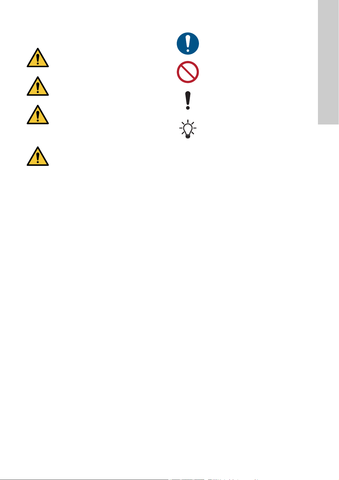
1.3 Other important notes
A blue or grey circle with a white graphical symbol
indicates that an action must be taken.
English (GB)
A red or grey circle with a diagonal bar, possibly with
a black graphical symbol, indicates that an action
must not be taken or must be stopped.
If these instructions are not observed, it may result in
malfunction or damage to the equipment.
Notes or instructions that make the work easier and
ensure safe operation.
2. Receiving the product
2.1 Inspecting the product
Check that the product received is in accordance with the order.
Check that the voltage and frequency of the product match
voltage and frequency of the installation site. See section
6.4.1 Nameplate.
2.2 Scope of delivery
The box contains the following items:
• ALPHAx pump
• ALPHA plug
• insulating shells
• two gaskets
• quick guide.
ALPHA SOLAR is delivered without insulating shells but with a
plug designed for ALPHA SOLAR.
3
Page 4
3. Installing the product
English (GB)
3.1 Mechanical installation
3.1.1 Mounting the product
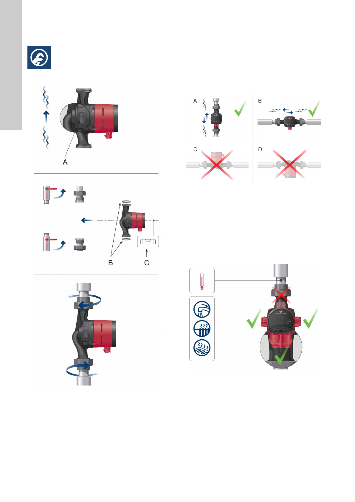
The arrows on the pump housing indicate the flow direction
through the pump. See fig. 1, pos. A.
See section 10.2 Dimensions, ALPHAx XX-40, XX-50, XX-60,
XX-80 or section 10.3 Dimensions, ALPHAx 25-40 A, 25-60 A.
1. Fit the two gaskets when you mount the pump in the pipe. See
fig. 1, pos. B.
2. Install the pump with a horizontal motor shaft. See fig. 1, pos.
C. See also section 3.2 Control box positions.
3. Tighten the fittings.
3.2 Control box positions
TM05 2919 0912TM05 3146 0912
Fig. 2 Control box positions
Always install the pump with a horizontal motor shaft.
• Pump installed correctly in a vertical pipe. See fig. 2, pos. A.
• Pump installed correctly in a horizontal pipe. See fig. 2, pos. B.
• Do not install the pump with a vertical motor shaft. See fig. 2,
pos. C and D.
3.2.1 Positioning of the control box in heating and domestic
hot-water systems
You can position the control box in position 3, 6 and 9 o'clock.
See fig. 4.
Fig. 1 Mounting ALPHAx
4
Fig. 3 Control box positions, heating and domestic hot-water
TM05 3057 0612
systems
Page 5
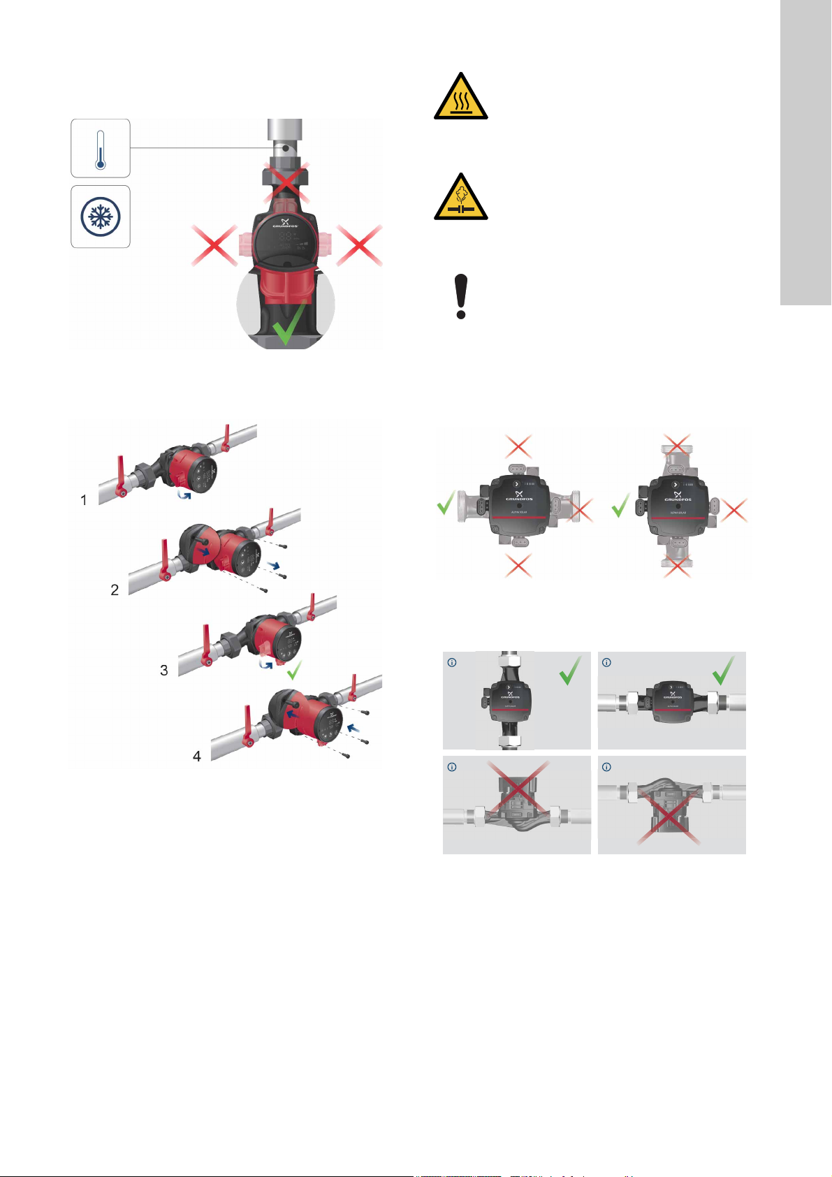
3.2.2 Positioning the control box in air-conditioning and cold-water systems
Position the control box with the plug pointing downwards. See
fig. 4.
CAUTION
Hot surface
Minor or moderate personal injury.
- Position the pump so that persons cannot
accidentally come into contact with hot surfaces.
Fig. 4 Control box position, air-conditioning and cold-water
systems
3.2.3 Changing the control box position
CAUTION
Pressurised system
Minor or moderate personal injury.
- Before dismantling the pump, drain the system or
close the isolating valve on either side of the
pump. The pumped liquid may be scalding hot and
under high pressure.
If you change the position of the control box, fill the
system with the liquid to be pumped or open the
isolating valves.
TM05 3151 1212TM05 3147 1212
1. Remove the four screws.
2. Turn the pump head to the desired position.
3. Insert and cross-tighten the screws.
3.3 Control box positions, ALPHA SOLAR
English (GB)
Fig. 5 Changing the control box position
You can turn the control box in steps of 90 °.
TM06 5636 5115TM06 5831 0616
Fig. 6 Control box positions, ALPHA SOLAR
Always install the pump with horizontal motor shaft. Position the
control box in position 9 o'clock. See fig. 7.
Fig. 7 Position of the ALPHA SOLAR control box
You can turn the control box in steps of 90 °.
5
Page 6

3.4 Insulating the pump housing
English (GB)
4. Electrical installation
Fig. 9 Electrical connection
DANGER
Electric shock
Death or serious personal injury
- Switch off the power supply before starting any
work on the product. Make sure that the power
supply cannot be accidentally switched on.
Fig. 8 Insulating the pump housing
You can reduce the heat loss from the pump and pipe by
insulating the pump housing and the pipe with the insulating
shells supplied with the pump. See fig. 8.
Do not insulate the control box or cover the control
panel.
3.4.1 Air-conditioning and cold-water systems
Use the insulating shells in air-conditioning and cold-water
systems as well.
The insulating shells for air-conditioning and cooling systems are
available as accessories. You can order the insulating shells
separately. See section 12. Accessories.
TM05 3058 0912
Carry out the electrical connection and protection in accordance
with local regulations.
• The motor requires no external motor protection.
• Check that the supply voltage and frequency correspond to
the values stated on the nameplate. See section
6.4.1 Nameplate.
• Connect the pump to the power supply with the plug supplied
with the pump. See steps 1 to 7.
DANGER
Electric shock
Death or serious personal injury
- Connect the pump to earth.
Connect the pump to an external mains switch with
a minimum contact gap of 3 mm in all poles.
6
Page 7
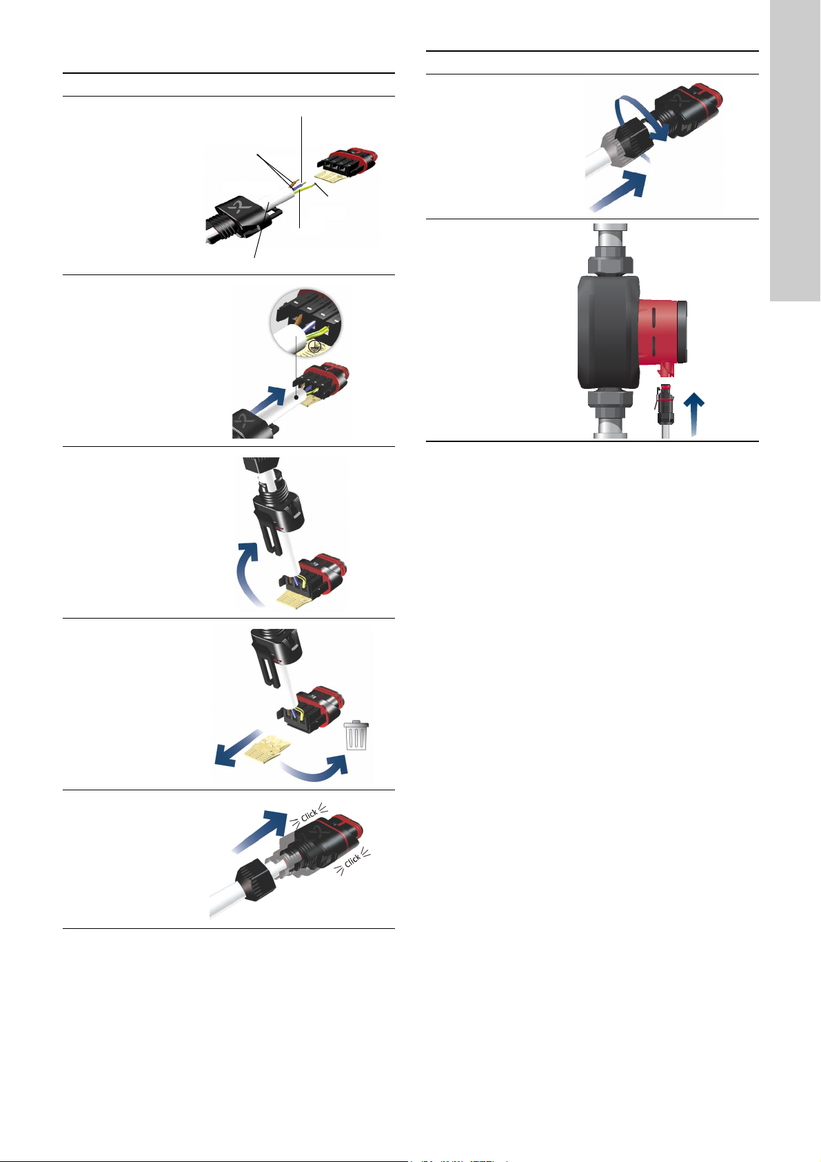
4.1 Assembling the plug
Max. 1.5 mm
2
12 mm
∅5.5 - 10 mm
7 mm
17 mm
Step Action Illustration
Fit the cable gland
and plug cover to
the cable. Strip
1
the cable
conductors as
illustrated.
Connect the cable
conductors to the
2
power supply
plug.
Step Action Illustration
Screw the cable
gland onto the
6
power supply
plug.
TM05 5538 3812
Insert the power
supply plug into
the male plug in
7
the pump control
box.
English (GB)
TM05 5543 3812
Bend the cable
with the cable
3
conductors
pointing upwards.
Pull out the
conductor guide
4
plate and throw it
away.
TM05 5539 3812
TM05 5540 3812
TM05 5541 3812
TM05 3058 0912
5
Click the plug
cover onto the
power supply
plug.
TM05 5542 3812
7
Page 8

4.2 Disassembling the plug
0
1
1 x 230 V ± 10 % ∽ 50/60 Hz
PWM =
Power =
English (GB)
Step Action Illustration
Loosen the cable
1
gland and remove
it from the plug.
Pull off the plug
cover while
2
pressing on both
sides.
Add the conductor
guide plate to
loosen all three
cable conductors
at the same time.
If the guide plate
is missing, then
3
loosen the cable
conductors one by
one by pressing a
screwdriver gently
into the terminal
clip.
4.3 Electrical installation, ALPHA SOLAR
TM05 5545 3812
Fig. 11 Control box connections
4.4 Power supply connection, ALPHA SOLAR
Connect the pump to the power supply with the TE Superseal
power plug.
DANGER
Electric shock
TM05 5546 3812
Death or serious personal injury
- Connect the pump to earth.
Connect the pump to an external mains switch with
a minimum contact gap of 3 mm in all poles.
4.5 Control signal connection, ALPHA SOLAR
If you do not need the signal connection, cover it with a blanking
plug. See fig. 11.
You can control the pump with a low-voltage PWM (pulse-width
modulation) signal.
The PWM signal is a method for generating an analog signal
using a digital source.
The control signal connection has three conductors: signal input,
signal output and signal reference. Connect the cable to the
TM05 5547 3812
control box with a TE Mini Superseal plug. The signal cable can
be supplied with the pump as an accessory.
TM06 5819 0216
The plug has now
been removed
4
from the power
supply plug.
Fig. 10 Starting up the pump
TM05 5548 3812
TM05 3058 0912
8
Page 9
5. Starting up the product
10 Min.
1
2
40 180
A
40440
18
10 Min.
2
1
3
5.1 Before startup
Do not start the pump until the system has been filled with liquid
and vented. Make sure that the required minimum inlet pressure
is available at the pump inlet.
See sections 3. Installing the product and 10. Technical data and
installation dimensions.
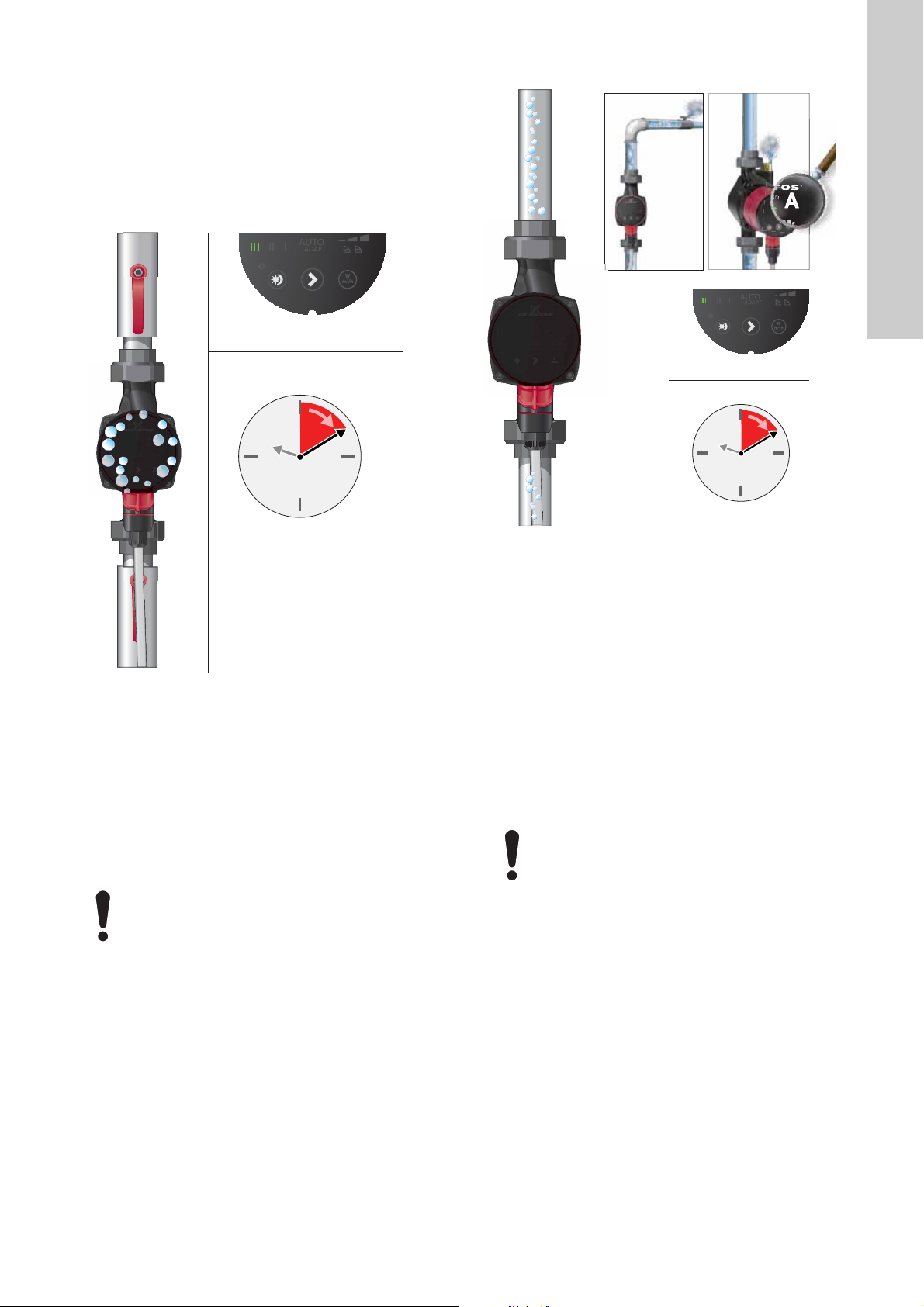
5.2 Venting the pump
5.3 Venting the heating system
English (GB)
Fig. 12 Venting the pump
The pump is self-venting. You do not have to vent the pump
before startup.
Air in the pump may cause noise. This noise ceases when the
pump has run for a few minutes.
You obtain quick venting of the pump by setting the pump to
speed III for a short period. How fast the pump is vented depends
on the system size and design.
When you have vented the pump, i.e. when the noise has
ceased, set the pump according to the recommendations. See
section 7. Control functions.
You cannot vent the system through the pump. See section
5.3 Venting the heating system.
The pump must not run dry.
Fig. 13 Venting of the heating system
Vent the heating system as follows:
• via an air vent valve installed above the pump (1)
• via a pump housing with air separator (2).
In heating systems that often contain much air, we recommend
that you install pumps with pump housing with air separator, i.e.
ALPHAx XX-XX A.
TM05 3075 0912
When the heating system has been filled with liquid, do as
follows:
1. Open the air vent valve.
2. Set the pump to speed III.
3. Let the pump run for a short period
4. Set the pump according to the recommendations. See section
7. Control functions.
Repeat the procedure, if necessary.
The pump must not run dry.
5.4 First startup
• The light in the control panel shows that the power supply has
been switched on. See fig. 10.
• Factory setting: AUTO
ADAPT
.
TM03 8931 2707
9
Page 10
6. Product introduction
1
2
3
Max. 95 %RH
IPX4D
Min./Max.
+2 C / +110
Max. 1.0 MPa
(10 bar)
4
5
6
7
°°
Min./Max.
0 C / +40
< 43 db(A)
°°
English (GB)
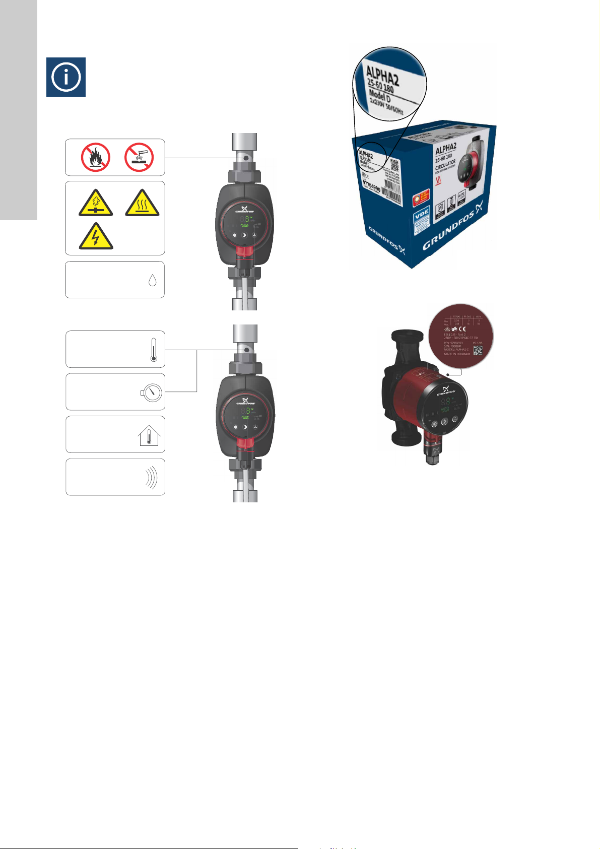
6.1 Product description
TM06 45820 2515TM06 1716 2614
Fig. 15 Model type on the packaging
TM05 3055 0912TM05 3056 0912
ALPHA2/ALPHA3, referred to as ALPHAx in the following, is a
complete range of circulator pumps.
6.1.1 Model type
These installation and operating instructions cover ALPHA2
model B, C and D, and ALPHA3. The model type is stated on the
packaging and nameplate. See figures 15 and 16.
Fig. 14 Pumped liquids, warnings and operating conditions
Fig. 16 Model type on the nameplate
6.2 Applications
The ALPHAx circulator pump is designed for the circulation of
water in heating systems, domestic hot-water systems as well as
air-conditioning and cold-water systems.
Cold-water systems are defined as systems where the ambient
temperature is higher than the temperature of the pumped liquid.
ALPHAx is the best choice for the following systems:
• underfloor heating systems
• one-pipe systems
• two-pipe systems.
ALPHAx is suitable for the following:
• Systems with constant or variable flows where you want to
optimise the setting of the pump duty point.
• Systems with variable flow-pipe temperature.
• Systems where you want automatic night setback.
• Balancing of domestic heating systems.
10
Page 11
6.3 Pumped liquids
1
8
9
7
6
5
4
3
2
10
15
16
14
13
12
11
AUTO
ADAPT
ALPHA 2 25-60 180
For more information about the pumped liquids, warnings and
operating conditions, see fig. 14.
In heating systems, the water must meet the requirements of
accepted standards on water quality in heating systems, for
example the German standard VDI 2035.
The pump is suitable for the following liquids:
• Thin, clean, non-aggressive and non-explosive liquids, not
containing solid particles or fibres.
• Cooling liquids, not containing mineral oil.
• Domestic hot water
Maximum: 14 °dH
Maximum: 65 °C
Maximum peak: 70 °C.
For water with a higher degree of hardness, we recommend
that you use a direct-coupled TPE pump.
• Softened water.
The kinematic viscosity of water is 1 mm
pump is used for a liquid with a higher viscosity, the hydraulic
performance of the pump will be reduced.
Example: 50 % glycol at 20 °C means a viscosity of approx. 10
2
mm
/s (10 cSt) and a reduction of the pump performance by
approx. 15 %.
Do not use additives that can or will disturb the functionality of the
pump.
When selecting a pump, take the viscosity of the pumped liquid
into consideration.
CAUTION
Flammable material
Minor or moderate personal injury.
- Do not use the pump for flammable liquids, such
as diesel oil and petrol.
WARNING
Biological hazard
Death or serious personal injury.
- In domestic hot-water systems, the temperature of
the pumped liquid must always be above 50 °C
due to the risk of legionella.
WARNING
Biological hazard
Death or serious personal injury.
- In domestic hot-water systems, the pump is
permanently connected to the mains water.
Therefore, do not connect the pump by a hose.
CAUTION
Corrosive substance
Minor or moderate personal injury.
- Do not use the pump for aggressive liquids, such
as acids and seawater.
2
/s (1 cSt) at 20 °C. If the
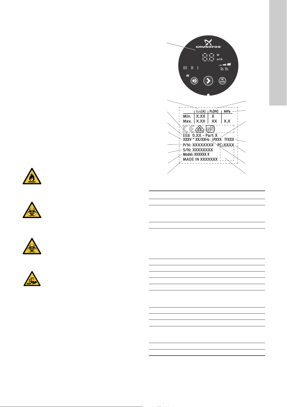
6.4 Identification
6.4.1 Nameplate
Fig. 17 Nameplate
Pos. Description
1 Pump type
Rated current [A]:
2
• Min.: Minimum current [A]
• Max.: Maximum current [A]
3 CE mark and approvals
EEI: Energy Efficiency Index
Part 1: Indicating whether the pump is tested in
accordance with the following:
4
Part 2: Stand-alone product
Part 3: Integrated product according to EN
16297-1:2012 and EN 16297-2:2012.
5 Voltage [V]
6 Product number
7 Serial number
8 Model
9 Country of origin
Input power P1 [W]:
10
• Min.: Minimum input power P1 [W]
• Max.: Maximum input power P1 [W]
11 Maximum system pressure [MPa]
12 Enclosure class
13 Temperature class
Production code:
14
• 1st and 2nd figures: year
• 3rd and 4th figures: week
15 Frequency [Hz]
16 QR code
English (GB)
TM05 3079 0912
11
Page 12

The table below shows the ALPHAx models with built-in functions.
English (GB)
Functions/features
AUTO
ADAPT
Proportional pressure ●●●●
Constant pressure ●●●●
Constant curve ●●●●
Automatic night setback ●●●●
Manual summer mode ●●●
Dry-running protection ●●
ALPHA Reader ●
High-torque start ●●
ALPHAx XX-40 ●●●●
ALPHAx XX-50 ●●●●
ALPHAx XX-60 ●●●●
ALPHAx XX-80 ●●●
6.4.2 Type key
Example ALPHAx 25 -40 N 180
Pump type
Blank: Standard version
L: Limited version
Nominal diameter (DN) of inlet and outlet
ports [mm]
Maximum head [dm]
Blank: Cast-iron pump housing
A: Pump housing with air separator
N: Stainless-steel pump housing
Port-to-port length [mm]
Model B
2012
●●●●
Model C
2015
Model D
2015
ALPHA3 model A
2015
12
Page 13

7. Control functions
1
2
3
4
5
6
7
7.1 Elements on the control panel
Button
presses
0
Active light fields Description
factory setting
AUTO
ADAPT
Fig. 18 Control panel
Pos. Description
Display showing the actual power consumption in
1
watt or the actual flow in m
3
/h.
Nine light fields indicating the pump setting.
2
See section 7.3 Light fields indicating the pump
setting.
Light field indicating the status of automatic night
3
setback.
Button for enabling or disabling of automatic night
4
setback and manual summer mode.
5 Button for selection of pump setting.
Button for selection of parameter to be shown in the
6
display, i.e. actual power consumption in watt or
actual flow in m
3
/h.
7 Connectivity symbol.
7.2 Display
The display (1) is on when you have switched on the power
supply.
The display shows the actual pump power consumption in watt
(integer) or the actual flow in m
3
/h in steps of 0.1 m3/h during
operation.
Faults preventing the pump from operating properly, for example
a blocked rotor, are indicated in the display by fault codes. See
section 9. Fault finding.
If a fault is indicated, correct the fault and reset the pump by
switching the power supply off and on.
If the pump impeller is rotated, for example when filling the pump
with water, sufficient energy can be generated to light up the
display even if the power supply has been switched off.
7.3 Light fields indicating the pump setting
The pump has ten optional performance settings which you can
select with the button (5). See fig. 18.
The pump setting is indicated by nine light fields in the display.
See fig. 19.
1
Lowest
proportional-pressure
curve, PP1
2
Intermediate
proportional-pressure
curve, PP2
3
Highest
proportional-pressure
curve, PP3
4
Lowest
constant-pressure curve,
CP1
TM05 3060 0912
5
Intermediate
constant-pressure curve,
CP2
6
Highest
constant-pressure curve,
CP3
7
8
9
10
Constant curve/constant
speed III
Constant curve/constant
speed II
Constant curve/constant
speed I
AUTO
ADAPT
For information about the function of the settings, see section
9. Fault finding.
7.4 Light field indicating the status of automatic night setback
Light in shows that automatic night setback is active. See fig.
18, pos. 3. See also section 7.5 Button for en ablin g or disa bling
of automatic night setback.
7.5 Button for enabling or disabling of automatic night setback
The button enables and disables automatic night setback. See
fig. 18, pos. 4.
Automatic night setback is only relevant for heating systems
prepared for this function. See section 9. Fault finding.
The light field is on when automatic night setback is
active. See fig. 18, pos. 3.
Factory setting: automatic night setback is not active.
If you have set the pump to speed I, II or III, you cannot select
automatic night setback.
English (GB)
Fig. 19 Nine light fields
TM05 3061 0912
13
Page 14

7.6 Button for selection of pump setting
Q
H
PP3
PP2
PP1
Q
H
H
Q
H
CP3
CP2
CP1
English (GB)
Every time you press the button , the pump setting is changed.
See fig. 18, pos. 5.
A cycle is ten button presses. See section 7.3 Light fields
indicating the pump setting .
7.7 Control modes
7.7.1 Pump setting for two-pipe heating systems
Fig. 20 Selection of pump setting for system type
Factory setting: AUTO
Recommended and alternative pump settings according to fig.
20:
Heating
system
Two-pipe
system
Recommended Alternative
AUTO
* See section 11.1 Guide to performance curves.
ADAPT
function adjusts the pump performance to the
ADAPT
AUTO
The AUTO
actual heat demand in the system. As the performance is
adjusted gradually, we recommend that you leave the pump in the
AUTO
mode at least one week before changing the pump
ADAPT
setting.
If the power supply fails or is disconnected, the pump stores the
AUTO
automatic adjustment when the power supply has been restored.
setting in an internal memory and resumes the
ADAPT
Proportional-pressure curve, PP1, PP2 or PP3
Proportional-pressure control adjusts the pump performance to
the actual heat demand in the system, but the pump performance
follows the selected performance curve, PP1, PP2 or PP3. See
fig. 21 where PP2 has been selected. For further information, see
section 11.1 Guide to performance curves.
ADAPT
ADAPT
.
Pump setting
*
Proportional-pressure
curve, PP1, PP2 or PP3*
Fig. 21 Three proportional-pressure curves/settings
The selection of the proportional-pressure setting depends on the
characteristics of the heating system and the actual heat
demand.
7.7.2 Pump setting for one-pipe heating systems
TM05 3063 0912
Q
Fig. 22 Selection of pump setting for system type
Factory setting: AUTO
ADAPT
.
Recommended and alternative pump settings according to fig.
22:
Heating
system
One-pipe
system
Recommended Alternative
Constant
curve/constant
speed, I, II or III*
Pump setting
Constant-pressure curve
CP1, CP2 or CP3*
* See section 11.1 Guide to performance curves.
AUTO
ADAPT
See section 7.7.1 Pump setting for two-pipe heating systems.
Constant-pressure curve, CP1, CP2 or CP3
Constant-pressure control adjusts the pump performance to the
actual heat demand in the system, but the pump performance
follows the selected performance curve, CP1, CP2 or CP3. See
fig. 23 where CP1 has been selected. For further information, see
section 11.1 Guide to performance curves.
TM05 3064 0912TM05 3065 0912
TM05 3066 0912
Fig. 23 Three constant-pressure curves and settings
The selection of the constant-pressure setting depends on the
characteristics of the heating system and the actual heat
demand.
14
Page 15

7.7.3 Pump setting for underfloor heating systems
Q
H
Q
H
CP3
CP2
CP1
Q
H
Q
H
7.7.4 Pump setting for domestic hot-water systems
English (GB)
Fig. 24 Selection of pump setting for system type
Factory setting: AUTO
ADAPT
.
Recommended and alternative pump settings according to fig.
24:
Pump setting
System type
Recommended Alternative
Underfloor
heating
Constant-pressure
curve, CP1, CP2 or
CP3*
Constant curve/constant
speed, I, II or III
* See section 11.1 Guide to performance curves.
AUTO
ADAPT
See section 7.7.1 Pump setting for two-pipe heating systems.
Constant-pressure curve, CP1, CP2 or CP3
The constant-pressure control adjusts the flow to the actual heat
demand in the system keeping a constant pressure at the same
time. The pump performance follows the selected performance
curve, CP1, CP2 or CP3. See fig. 25 where CP1 has been
selected. For further information, see section 11.1 Guide to
performance curves.
TM05 3067 0912
Fig. 26 Selection of pump setting for system type
Factory setting: AUTO
ADAPT
.
Recommended and alternative pump settings according to fig.
26:
Pump setting
System type
Recommended Alternative
Domestic hot
water
Constant curve/constant
speed, I, II or III
Constant-pressure
curve, CP1, CP2 or
* See section 11.1 Guide to performance curves.
Constant curve/constant speed, I, II or III
At constant-curve/constant-speed operation, the pump runs at a
constant speed, independent of the actual flow demand in the
system. The pump performance follows the selected performance
curve, I, II or III. See fig. 27 where II has been selected. For
further information, see section 11.1 Guide to performance
curves.
TM05 3068 0912
CP3*
TM05 3068 0912
Fig. 27 Three constant curve/constant speed settings
TM05 3066 0912
Fig. 25 Three constant-pressure curves or settings
The selection of the constant-pressure setting depends on the
characteristics of the heating system and the actual heat
demand.
The selection of the constant-curve/constant-speed setting
depends on the characteristics of the heating system and the
number of taps likely to be opened at the same time.
7.7.5 Changing from recommended to alternative pump
setting
Heating systems are relatively slow systems that cannot be set to
the optimum operation within minutes or hours.
If the recommended pump setting does not give the desired
distribution of heat in the rooms of the house, change the pump
setting to the shown alternative.
15
Page 16

7.8 Pump performance
III
II
I
H
PP3
CP3
CP2
PP1
CP1
PP2
English (GB)
Relation between pump setting and pump performance
Figure 28 shows the relation between pump setting and pump
performance by means of curves. See also section
11. Performance curves.
Fig. 28 Pump setting in relation to pump performance
Setting Pump curve Function
AUTO
factory
setting
PP1
PP2
PP3
CP1
CP2
CP3
ADAPT
Highest to lowest
proportional-pressure
curve
Lowest
proportional-pressure
curve
Intermediate
proportional-pressure
curve
Highest
proportional-pressure
curve
Lowest
constant-pressure
curve
Intermediate
constant-pressure
curve
Highest
constant-pressure
curve
The AUTO
within a defined performance range. See fig. 28.
• Adjusting the pump performance to the size of the system.
• Adjusting the pump performance to the variations in load over time.
In AUTO
The duty point of the pump will move up or down on the lowest proportional-pressure curve,
depending on the heat demand. See fig. 28.
The head is reduced at falling heat demand and increased at rising heat demand.
The duty point of the pump will move up or down on the intermediate proportional-pressure
curve, depending on the heat demand. See fig. 28.
The head is reduced at falling heat demand and increased at rising heat demand.
The duty point of the pump will move up or down on the highest proportional-pressure curve,
depending on the heat demand. See fig. 28.
The head is reduced at falling heat demand and increased at rising heat demand.
The duty point of the pump will move out or in on the lowest constant-pressure curve, depending
on the heat demand in the system. See fig. 28.
The head is kept constant, irrespective of the heat demand.
The duty point of the pump will move out or in on the intermediate constant-pressure curve,
depending on the heat demand in the system. See fig. 28.
The head is kept constant, irrespective of the heat demand.
The duty point of the pump will move out or in on the highest constant-pressure curve, depending
on the heat demand in the system. See fig. 28.
The head is kept constant, irrespective of the heat demand.
ADAPT
ADAPT
The pump runs on a constant curve which means that it runs at a constant speed.
In speed III, the pump is set to run on the maximum curve under all operating conditions. See fig.
III Speed III
28.
You obtain quick venting of the pump by setting the pump to speed III for a short period. See
section 5.2 Venting the pump.
The pump runs on a constant curve which means that it runs at a constant speed.
II Speed II
In speed II, the pump is set to run on the intermediate curve under all operating conditions. See
fig. 28.
The pump runs on a constant curve which means that it runs at a constant speed.
I Speed I
In speed I, the pump is set to run on the minimum curve under all operating conditions. See fig.
28.
The pump changes to the curve for automatic night setback, i.e. absolute minimum performance
Automatic night
setback or manual
summer mode
and power consumption, provided that certain conditions are met. In manual summer mode, the
pump is stopped to save energy and only the electronics are running. To avoid liming and
blocking of the pump, the pump is started frequently in a short period. See section 9. Fault
finding.
function enables the pump to control the pump performance automatically
, the pump is set to proportional-pressure control.
TM05 2771 0512
16
Page 17

7.9 Bypass valve
ALP
AUTO
BYPASS
1
2
Q
min.
3
3
A
8. Operating the product
8.1 Using automatic night setback
English (GB)
HA2 L
TM061251 2014
Fig. 30 Automatic night setback activated
Do not use automatic night setback when the pump
is installed in the return pipe of the heating system.
TM05 3076 0912
If you select speed I, II or III, automatic night setback is disabled.
Fig. 29 Systems with bypass valve
The purpose of the bypass valve is to ensure that the heat from
the boiler can be distributed when all valves in the
underfloor-heating circuits and/or thermostatic radiator valves are
closed.
System elements:
• bypass valve
• flowmeter, pos. A.
The minimum flow must be available when all valves are closed.
The pump setting depends on the type of bypass valve used, i.e.
manually operated or thermostatically controlled.
7.9.1 Setting the bypass valve
7.9.2 Manually operated
1. Adjust the bypass valve with the pump in setting I (speed I).
2. Observe the minimum flow of the system. See the
manufacturer's instructions.
3. After setting the bypass valve, set the pump according to
7. Control functions.
7.9.3 Automatically operated, thermostatically controlled
1. Adjust the bypass valve with the pump in setting I (speed I).
2. Observe the minimum flow for the system. Consult the
manufacturer's instructions.
After adjusting the bypass valve, set the pump to the lowest or
highest constant-pressure curve. For further information about
pump settings in relation to performance curves, see section
9. Fault finding.
You do not have to re-enable automatic night setback if the power
supply has been switched off.
If the power supply is switched off when the pump is running on
the curve for automatic night setback, the pump starts in normal
operation. See section 9. Fault finding.
The pump changes back to the curve for automatic night setback
when the condition for automatic night setback is fulfilled again.
See section 8.2 Function of automatic night setback.
If there is insufficient heat in the heating system, check whether
automatic night setback has been enabled. If yes, disable the
function.
To ensure the optimum function of automatic night setback, the
following conditions must be fulfilled:
• The pump must be installed in the flow pipe. See fig. 30, pos.
A.
• The boiler must incorporate automatic control of the liquid
temperature.
Enable automatic night setback by pressing . See section
7.5 Button for enabling or disabling of automatic night setback.
Light in means that automatic night setback is active.
17
Page 18

8.2 Function of automatic night setback
English (GB)
Once you have enabled automatic night setback, the pump
automatically changes between normal duty and automatic night
setback. See section 9. Fault finding.
Changeover between normal duty and automatic night setback
depends on the flow-pipe temperature.
The pump automatically changes over to automatic night setback
when a flow-pipe temperature drop of more than 10 to 15 °C
within approx. two hours is registered. The temperature drop
must be at least 0.1 °C/min.
Changeover to normal duty takes place without a time lag when
the flow-pipe temperature has increased by approx. 10 °C.
8.3 Setting manual summer mode
Manual summer mode is available from model C.
In manual summer mode, the pump is stopped to save energy
and only the electronics are running. To avoid liming and blocking
of the pump, the pump is started frequently in a short period. This
is an alternative to shutting down the pump if there is a risk of
lime deposit.
8.5 ALPHA Reader
You can use this device to balance the radiators in a heating
system in a fast and safe way.
ALPHA Reader provides safe readout of internal data from the
pump. The data are transmitted to a handheld device. See fig. 32.
There is a risk of lime deposit in case of a long
standstill period.
In manual summer mode, the pump starts frequently at low speed
to avoid blocking the rotor. The display is turned off.
If any alarms occur during manual summer mode, no alarms will
be shown. When manual summer mode is deactivated again, only
the actual alarms will be displayed.
If the automatic night setback mode is enabled before setting the
manual summer mode, the pump will return to automatic night
setback mode after manual summer mode.
8.3.1 Activating manual summer mode
Activate the manual summer mode by pressing the automatic
night setback button 3 to 10 seconds. See fig. 30. The green light
field flashes quickly. After a short while the display turns off and
the green light field flashes slowly.
Fig. 31 Automatic night setback button
8.3.2 Deactivating manual summer mode
Deactivate the manual summer mode by pressing any of the
buttons. Then the pump returns to the previous mode and setting.
8.4 Dry-running protection
The dry-running protection protects the pump against dry running
during start and normal operation. See section 9. Fault finding.
During first startup and in case of dry-run, the pump will operate
for 30 minutes before displaying the error code E4.
Fig. 32 ALPHA Reader
Activating and deactivating the ALPHA Reader mode
If you press [W/m
3
/h] and holds it for 3 seconds, ALPHA
Reader is either activated or deactivated, depending on the
previous state.
When ALPHA Reader is active, the AUTONight indicator light
flashes rapidly, indicating activity.
You can activate and deactivate the ALPHA Reader mode in all
pump modes.
For further information, see the ALPHA Reader documentation in
Grundfos Product Center on www.grundfos.com.
8.6 High-torque start
If the shaft is blocked and you cannot start the pump, the display
indicates the alarm "E1 - "- -"", with a delay of 20 minutes.
The pump attempts to restart until the pump is powered off.
During the start attempts, the pump vibrates due to the
high-torque load.
TM05 3149
TM06 4452 2315
18
Page 19

9. Fault finding
DANGER
Electric shock
Death or serious personal injury
- Switch off the power supply before starting any
work on the product. Make sure that the power
supply cannot be accidentally switched on.
CAUTION
Pressurised system
Minor or moderate personal injury
- Before dismantling the pump, drain the system or
close the isolating valves on either side of the
pump. The pumped liquid may be scalding hot
and under high pressure.
Fault Control panel Cause Remedy
1. The pump does not
run.
2. Noise in the system. Shows a number. a) Air in the system. Vent the system.
3. Noise in the pump. Shows a number. a) Air in the pump. Let the pump run. The pump vents itself
4. Insufficient heat. Shows a number. a) The pump performance is too low. Increase the suction head.
Light off. a) One fuse in the installation is blown. Replace the fuse.
Cut in the circuit breaker.
the specified range.
the pipe system. Reset the error by
pressing any button or switch off the
power supply.
See section 5.3 Venting the heating
system.
over time.
See section 5.2 Venting the pump.
air volume in the expansion tank, if
installed.
Changes between "- -"
and "E 1".
Changes between "- -"
and "E 2".
Changes between "- -"
and "E 3".
Changes between "- -"
and "E 4".
b) The current-operated or
voltage-operated circuit breaker has
tripped.
c) The pump is defective. Replace the pump.
a) The rotor is blocked. Remove the impurities.
a) Insufficient supply voltage. Check that the supply voltage falls within
a) Electrical fault. Replace the pump.
a) Dry-running protection. Make sure that there is sufficient liquid in
b) The flow is too high. Reduce the suction head.
b) The inlet pressure is too low. Increase the inlet pressure, or check the
English (GB)
19
Page 20

10. Technical data and installation dimensions
English (GB)
10.1 Technical data
Supply voltage 1 x 230 V ± 10 %, 50/60 Hz, PE
Motor protection The pump requires no external motor protection.
Enclosure class IPX4D
Insulation class F
Relative humidity Maximum 95 % RH
System pressure Maximum 1.0 MPa, 10 bar, 102 m head
Liquid temperature Minimum inlet pressure
Inlet pressure
EMC (electromagnetic
compatibility)
Sound pressure level The sound pressure level of the pump is lower than 43 dB(A).
Ambient temperature 0-40 °C
Temperature class TF110 to CEN 335-2-51
Surface temperature The maximum surface temperature will not exceed 125 °C.
Liquid temperature 2-110 °C
Power consumption in
manual summer mode
Specific EEI values
To avoid condensation in the control box and stator, the liquid
temperature must always be higher than the ambient
temperature.
≤ 75 °C 0.005 MPa, 0.05 bar, 0.5 m head
90 °C 0.028 MPa, 0.28 bar, 2.8 m head
110 °C 0.108 MPa, 1.08 bar, 10.8 m head
EMC Directive: 2004/108/EC.
Standards used: EN 55014-1:2006 and EN 55014-2:1997.
< 0.8 watt
ALPHAx XX-40: EEI ≤ 0.15
ALPHAx XX-50: EEI ≤ 0.16
ALPHAx XX-60: EEI ≤ 0.17
ALPHAx XX-80: EEI ≤ 0.18
ALPHAx XX-40 A: EEI ≤ 0.18
ALPHAx XX-60 A: EEI ≤ 0.20
Ambient
temperature
[°C]
02110
10 10 110
20 20 110
30 30 110
35 35 90
40 40 70
WARNING
Biological hazard
Death or serious personal injury.
- In domestic hot-water systems, we recommend
that you keep the liquid temperature below 65 °C
to eliminate the risk of lime precipitation. The
temperature of the pumped liquid must always be
above 50 °C due to the risk of legionella.
Recommended boiler temperature: 60 °C
If the temperature of the pumped liquid is lower than
the ambient temperature, make sure that the pump is
installed with the pump head and plug in position 6
o'clock.
Liquid temperature
Min.
[°C]
Max.
[°C]
20
Page 21

10.2 Dimensions, ALPHAx XX-40, XX-50, XX-60, XX-80
Dimensional sketches and table of dimensions.
Fig. 33 ALPHAx XX-40, XX-50, XX-60
English (GB)
TM05 2364 5011
Pump type
L1 B1 B2 B3 B4 H1 H2 H3 G
ALPHAx 15-40 130 130 60.5 60.5 44.5 44.5 35.8 103.5 52 1
ALPHAx 15-50 130 130 60.5 60.5 44.5 44.5 35.8 103.5 52 1*
ALPHAx 15-60 130 130 60.5 60.5 44.5 44.5 35.8 103.5 52 1*
ALPHAx 15-80 130 130 60.5 60.5 44.5 44.5 35.8 103.5 52 1*
ALPHAx 25-40 130 130 60.5 60.5 44.5 44.5 35.8 103.5 52 1 1/2
ALPHAx 25-40 N 130 130 60.5 60.5 44.5 44.5 36.8 103.5 52 1 1/2
ALPHAx 25-50 130 130 60.5 60.5 44.5 44.5 35.8 103.5 52 1 1/2
ALPHAx 25-50 N 130 130 60.5 60.5 44.5 44.5 36.8 103.5 52 1 1/2
ALPHAx 25-60 130 130 60.5 60.5 44.5 44.5 35.8 103.5 52 1 1/2
ALPHAx 25-60 N 130 130 60.5 60.5 44.5 44.5 36.8 103.5 52 1 1/2
ALPHAx 25-80 130 130 60.5 60.5 44.5 44.5 36.8 103.5 52 1 1/2
ALPHAx 25-80 N 130 130 60.5 60.5 44.5 44.5 36.8 103.5 52 1 1/2
ALPHAx 25-40 180 180 60.5 60.5 44.5 44.5 35.9 103.5 52 1 1/2
ALPHAx 25-40 N 180 180 60.5 60.5 44.5 44.5 36.9 103.5 52 1 1/2
ALPHAx 25-50 180 180 60.5 60.5 44.5 44.5 35.9 103.5 52 1 1/2
ALPHAx 25-50 N 180 180 60.5 60.5 44.5 44.5 36.9 103.5 52 1 1/2
ALPHAx 25-60 180 180 60.5 60.5 44.5 44.5 35.9 103.5 52 1 1/2
ALPHAx 25-60 N 180 180 60.5 60.5 44.5 44.5 36.9 103.5 52 1 1/2
ALPHAx 25-80 180 180 60.5 60.5 44.5 44.5 36.9 103.5 52 1 1/2
ALPHAx 25-80 N 180 180 60.5 60.5 44.5 44.5 36.9 103.5 52 1 1/2
ALPHAx 32-40 180 180 60.5 60.5 44.5 44.5 35.9 103.5 52 2
ALPHAx 32-40 N 180 180 60.5 60.5 44.5 44.5 36.9 103.5 52 2
ALPHAx 32-50 180 180 60.5 60.5 44.5 44.5 35.9 103.5 52 2
ALPHAx 32-50 N 180 180 60.5 60.5 44.5 44.5 36.9 103.5 52 2
ALPHAx 32-60 180 180 60.5 60.5 44.5 44.5 35.9 103.5 52 2
ALPHAx 32-60 N 180 180 60.5 60.5 44.5 44.5 36.9 103.5 52 2
ALPHAx 32-80 180 180 60.5 60.5 44.5 44.5 36.9 103.5 52 2
ALPHAx 32-80 N 180 180 60.5 60.5 44.5 44.5 36.9 103.5 52 2
* UK version: G 1 1/2.
Dimensions
21
Page 22

10.3 Dimensions, ALPHAx 25-40 A, 25-60 A
English (GB)
Dimensional sketches and table of dimensions.
Fig. 34 ALPHAx 25-40 A, 25-60 A
TM05 2574 0212
Pump type
L1 B1 B2 B3 B4 H1 H2 H3 G
ALPHAx 25-40 A 180 180 63.5 98 32 63 50 124 81 1 1/2
ALPHAx 25-60 A 180 180 63.5 98 32 63 50 124 81 1 1/2
Dimensions
22
Page 23

11. Performance curves
III
II
I
Q
P1
H
III
II
I
PP3
CP3
CP2
PP1
CP1
PP2
11.1 Guide to performance curves
Each pump setting has its own performance curve. However,
AUTO
A power curve, P1, belongs to each performance curve. The
power curve shows the pump power consumption in watt at a
given performance curve.
The P1 value corresponds to the value that you can read from the
pump display. See fig. 35.
covers a performance range.
ADAPT
English (GB)
Fig. 35 Performance curves in relation to pump setting
Setting Pump curve
AUTO
ADAPT
factory setting
PP1 Lowest proportional-pressure curve
PP2 Intermediate proportional-pressure curve
PP3 Highest proportional-pressure curve
CP1 Lowest constant-pressure curve
CP2 Intermediate constant-pressure curve
CP3 Highest constant-pressure curve
Setpoint within the marked area
III Constant curve/constant speed III
II Constant curve/constant speed II
I Constant curve/constant speed I
Curve for automatic night setback/manual
summer mode
For further information about pump settings, see these sections:
7. Control functions
11.2 Curve conditions
The guidelines below apply to the performance curves on the
following pages:
• Test liquid: airless water.
• The curves apply to a density of 83.2 kg/m
temperature of 60 °C.
• All curves show average values and must not be used as
guarantee curves. If a specific minimum performance is
required, individual measurements must be made.
• The curves for speeds I, II and III are marked.
• The curves apply to a kinematic viscosity of 0.474 mm
(0.474 cSt).
• The conversion between head H [m] and pressure p [kPa] has
been made for water with a density of 1000 kg/m
with other densities, for example hot water, the outlet pressure
is proportional to the density.
• Curves obtained according to EN 16297.
3
and a liquid
2
/s
3
. For liquids
TM05 2578 0312
23
Page 24

11.3 Performance curves, ALPHAx XX-40 (N)
0.0 0.2 0.4 0.6 0.8 1.0 1.2 1.4 1.6 1.8 2.0 2.2 2.4
Q [m³/h]
0
1
2
3
4
[m]
H
III
II
I
0.0 0.2 0.4 0.6 0.8 1.0 1.2 1.4 1.6 1.8 2.0 2.2 2.4
Q [m³/h]
0
5
10
15
20
[W]
P1
III
II
I
PP1
CP1
PP2
CP2
PP3
CP3
English (GB)
Fig. 36 ALPHAx XX-40
Setting
AUTO
ADAPT
Min. 30.04
Max. 18 0.18
P1
[W]
3-18 0.04 - 0.18
I
1/1
[A]
TM05 1672 4111
24
Page 25

11.4 Performance curves, ALPHAx XX-50 (N)
0.0 0.2 0.4 0.6 0.8 1.0 1.2 1.4 1.6 1.8 2.0 2.2 2.4 2.6 2.8
Q [m³/h]
0
1
2
3
4
5
[m]
H
III
II
I
0.0 0.2 0.4 0.6 0.8 1.0 1.2 1.4 1.6 1.8 2.0 2.2 2.4 2.6 2.8
Q [m³/h]
0
5
10
15
20
25
[W]
P1
III
II
I
PP1
CP1
PP3
CP3
CP2
PP2
English (GB)
Fig. 37 ALPHAx XX-50
Setting
AUTO
ADAPT
Min. 30.04
Max. 26 0.24
P1
[W]
3-26 0.04 - 0.24
I
1/1
[A]
TM05 1673 4111
25
Page 26

11.5 Performance curves, ALPHAx XX-60 (N)
0.0 0.2 0.4 0.6 0.8 1.0 1.2 1.4 1.6 1.8 2.0 2.2 2.4 2.6 2.8 3.0
Q [m³/h]
0
1
2
3
4
5
6
III
II
I
0.0 0.2 0.4 0.6 0.8 1.0 1.2 1.4 1.6 1.8 2.0 2.2 2.4 2.6 2.8 3.0
Q [m³/h]
0
5
10
15
20
25
30
35
[W]
P1
III
II
I
H
[m]
PP1
CP1
CP3
CP2
PP2
PP3
English (GB)
Fig. 38 ALPHAx XX-60
Setting
AUTO
ADAPT
Min. 30.04
Max. 34 0.32
P1
[W]
3-34 0.04 - 0.32
I
1/1
[A]
TM05 1674 4111
26
Page 27

11.6 Performance curves, ALPHAx 25-40 A
0.0 0.2 0.4 0.6 0.8 1.0 1.2 1.4 1.6 1.8 2.0
Q [m³/h]
0
1
2
3
4
[m]
H
III
II
I
0.0 0.2 0.4 0.6 0.8 1.0 1.2 1.4 1.6 1.8 2.0
Q [m³/h]
0
5
10
15
20
[W]
P1
III
II
I
PP1
CP1
CP3
CP2
PP2
PP3
English (GB)
Fig. 39 ALPHAx 25-40 A
Setting
AUTO
ADAPT
Min. 30.04
Max. 18 0.18
P1
[W]
3-18 0.04 - 0.18
I
1/1
[A]
TM05 2016 4211
27
Page 28

11.7 Performance curves, ALPHAx 25-60 A
1.00.80.60.40.20.0
Q [m³/h]
2.82.62.4
0.0 0.2 0.4 0.6 0.8 1.0 1.2 1.4 1.6 1.8 2.0 2.2 2.4 2.6 2.8
Q [m³/h]
0
1
2
3
4
5
6
[m]
H
III
II
I
1.2 1.4 1.6 1.8 2.0 2.2
0
5
10
15
20
25
30
35
[W]
P1
III
II
I
PP1
CP1
CP3
CP2
PP2
PP3
English (GB)
Fig. 40 ALPHAx 25-60 A
Setting
AUTO
ADAPT
Min. 30.04
Max. 34 0.32
P1
[W]
3-34 0.04 - 0.32
I
1/1
[A]
TM05 2017 4211
28
Page 29

11.8 Performance curves, ALPHAx XX-80 (N)
PP1
CP1
PP2
CP2
PP3
CP3
English (GB)
Fig. 41 ALPHAx 25-60 A
Setting
AUTO
ADAPT
Min. 30.04
Max. 50 0.44
P1
[W]
3-50 0.04 - 0.44
I
1/1
[A]
TM061285 2114
29
Page 30

12. Accessories
Rp
R
Rp
mm
mm
R
Rp
Rc
G
English (GB)
12.1 Unions and valve kits
Product numbers, unions
ALPHAx
15-xx*
15-xx N*
25-xx
25-xx N 529971 529972 519805 519806 505539 519808 519809 529977 529978 529979
G 1 1/2
32-xx
32-xx N 509971 ● 529995
3/4 1 1 1/4 1 1 1/4 3/4 1 1 1/4 ∅22 ∅28 ∅15 ∅18 ∅22 ∅28 ∅42
Connection
G 1
529921 529922 529821 529925 529924
G 2
509921 509922
* When ordering for UK versions, use product numbers for 25-xx (G 1 1/2).
● Available on request.
G-threads have a cylindrical form in accordance with the EN-ISO
228-1 standard. R-threads have a conical form in accordance
with the ISO 7-1 standard. In the case of a thread of size 1 1/2",
the threads are specified as G 1 1/2 or R 1 1/2. You can only
screw male G-threads (cylindrical) into female G-threads. You
can screw male R-threads (conical) into female G- or R-threads.
See fig. 42.
12.2 Insulating shells
The pump is supplied with two insulating shells. Type A pumps
with air-separating chamber are not supplied with insulating
shells. However, you can order insulating shells as an accessory.
See table below.
The insulation thickness of the insulating shells corresponds to
the nominal diameter of the pump.
The insulating shells, which are tailored to the individual pump
type, enclose the entire pump housing. The insulating shells are
easy to fit around the pump. See fig. 43.
Pump type Product number Available
ALPHAx XX-XX 130 98091786 spare part
ALPHAx XX-XX 180 98091787 spare part
ALPHAx XX-XX A 505822 accessory
TM06 5867 0216
Fig. 42 G-threads and R-threads
TM06 5822 0216
Fig. 43 Insulating shells
30
Page 31

12.3 ALPHA plugs
123
Push button LEDs
Fig. 44 ALPHA plugs
Pos. Description
ALPHA straight plug,
1
standard plug connector,
complete
ALPHA angle plug, standard
2
angle plug connection,
complete
ALPHA plug, 90 ° bend to the
3
left, including 4 m cable
ALPHA plug, 90 ° bend to the
left, including 1 m cable and
*
integrated NTC protection
resistor
* This special cable with an active built-in NTC protection
circuit, reduces possible inrush currents. To be used in case of
for instance poor quality of relay components that are
sensitive to inrush current.
Product
number
98284561 spare part
98610291 accessory
96884669 accessory
97844632 accessory
Available
13.2 Application
The new ALPHA SOLAR pump is designed to be integrated in all
kinds of solar systems with either matched-flow or constant-flow
rate.
13.3 Product description
High-efficiency ECM pumps, such as ALPHA SOLAR, must not
be speed-controlled by means of an external speed controller
TM06 5823 0216
which varies or pulses the supply voltage. You can control the
speed with a low-voltage PWM signal from a solar controller to
optimise the solar harvesting and temperature of the system. As a
result, the power consumption of the pump is reduced
considerably.
If no PWM signal is available, you can set the pump to constant
speed, only switched on and off by the controller.
13.4 Operating the product
13.5 Setting by means of the control panel
The user interface is designed with a single push button, one
red/green LED and four yellow LEDs.
.
English (GB)
ALPHA SOLAR cables and plugs can be delivered
on request.
13. ALPHA SOLAR
13.1 Product introduction
TM06 0535 0414
Fig. 46 User interface with one push button and five LEDs
The user interface shows the following:
• operating status
• alarm status
• settings view, after pressing the button.
13.6 Operating status
During operation, the display shows the actual operating status or
the alarm status.
13.7 Alarm status
If the circulator has detected one or more alarms, the red/green
LED switches from green to red. When an alarm is active, the
LEDs indicate the alarm type as defined in the table below. If
multiple alarms are active at the same time, the LEDs only show
the error with the highest priority. The priority is defined by the
sequence of the table.
When there is no active alarm anymore, the user interface
switches back to operating status.
Fig. 45 ALPHA SOLAR pump
TM06 5816 0216
31
Page 32

13.8 Operating status
14.5 m
14.5 m
7.5 m
7.5 m
PWM C PROFILE SOLAR
CONSTANT CURVE 1
CONSTANT CURVE 2
CONSTANT CURVE 3
CONSTANT CURVE 4
PWM C PROFILE SOLAR
8.5 m
6.5 m
5.5 m
4.5 m
10.5 m6.5 m
ON
230 V
No.2
5 mm
<160 V
ON
230 V
ON
English (GB)
The LEDs indicate the actual operating status or alarm status.
This circulator pump is either for internal control with
constant-curve control or external PWM-signal control with profile
C. See fig. 47.
Fig. 47 Operating mode
PWM can only operate if you have set the pump to PWM mode.
Press the button five times until only the green LED is on. When
you connect the PWM cable, the yellow LEDs are on and you can
control the pump via the PWM signal. See fig. 47.
TM06 5817 0216
13.9 Fault finding the product
The alarm status is indicated by the LEDs.
Fault Description
The rotor is blocked. Deblock
the rotor.
The supply voltage is low. Make
sure that there is sufficient
voltage supply to the pump.
Electrical error. Replace the
pump and send the pump to the
nearest Grundfos service
centre.
DANGER
Electric shock
Death or serious personal injury
- Switch off the power supply before starting any
work on the product. Make sure that the power
supply cannot be accidentally switched on.
CAUTION
Pressurised system
Minor or moderate personal injury
- Before dismantling the pump, drain the system or
close the isolating valve on either side of the
pump. The pumped liquid may be scalding hot
and under high pressure.
32
Page 33

14. External PWM control mode and signals
Max.
PWM input signal [%]
Speed
PWM can only operate when the pump is in curve 4 operation.
PWM profile C input signal
At high PWM-signal percentages (duty cycles), a hysteresis
prevents the circulator pump from starting and stopping if the
input signal fluctuates around the shifting point. At low
PWM-signal percentages, the circulator speed is high for safety
reasons. In case of a cable breakage in a solar system, the
circulator pumps will continue to run at maximum speed to
transfer heat from the primary heat exchanger.
Fig. 48 PWM input profile C
15. Digital solar-circuit controller
To replace UPS SOLAR with a new ALPHA SOLAR pump which
fulfils the EuP norm, we offer two solutions:
• Replace the SOLAR controller with a controller suitable for
high-efficiency pumps.
• Keep the old controller and use the pump with phase control.
Use a converter, SIKON HE, which can convert the phase
control to a PWM signal.
When you use SIKON HE, you can replace the conventional
230-V UPS solar pumps by Grundfos ALPHA SOLAR pumps
without having to change the controller to a high-efficiency pump
controller. The function of the performance control of the pump is
maintained.
TM04 9985 0311
English (GB)
PWM input signal
[%]
≤ 10 Maximum speed: max.
> 10 / ≤ 84 Variable speed: min. to max.
> 84 / ≤ 91 Minimum speed: nominal speed
> 91/95 Hysteresis area: on/off
> 95 / ≤ 100 Standby mode: off
Pump status
Fig. 49 Digital solar circuit controller
For further information about the controller, see www.prozeda.de.
16. Technical data
System pressure Maximum 1.0 MPa (10 bar)
Minimum inlet pressure
Maximum liquid
temperature
Enclosure class IPX4D
Motor protection No external protection needed
Approvals and
markings
Water-propylene glycol
mixture
0.05 MPa (0.50 bar) at a liquid
temperature of 95 °C
2-110 °C at an ambient temperature
of 70 °C
2-130 °C at an ambient temperature
of 60 °C
VDE, CE
Maximum water-propylene glycol
mixture is 50 %.
Note: The water-propylene glycol
mixture reduces the performance due
to higher viscosity.
TM065809 0216
33
Page 34

ALPHA SOLAR xx-75 130/180
4>PñK@
>P@
+
>N3D@
S
4>OV@
4>PñK@
>:@
3
EEI ≤ 0.20 Part 3
P
L,avg
≤ 20 W
Setting Max. head
nom
Curve 1 4.5 m
Curve 2 5.5 m
Curve 3 6.5 m
Curve 4 7.5 m
Setting Max. P
1 nom
Curve 1 19 W
Curve 2 28 W
Curve 3 35 W
Curve 4 45 W
B1 B2
H2H1
L3
English (GB)
Fig. 50 Performance curve
Note: PWM speed curves on request.
Electrical data, 1 x 230 V, 50 Hz Settings
Speed P
Min. 2* 0.04 1 - - 4
Max. 45 0.48
* Only in minimum PWM speed operation
[W] I
1
[A] PWM C PP CP CC
1/1
TM06 3658 0815
H3
L1
Pump type
ALPHA SOLAR 15-75 130 130 90 72 45 36 92 128 G 1 1.8
ALPHA SOLAR 25-75 130 130 90 72 45 36 92 128 G 1 1/2 1.9
ALPHA SOLAR 25-75 180 180 90 72 45 36 92 128 G 1 1/2 2.0
34
TM06 6493 1516
Dimensions [mm]
L1 L3 B1 B2 H1 H2 H3
TM06 5636 5115
Connections Weight [kg]
Page 35

ALPHA SOLAR xx-145 130/180
4>PñK@
>P@
+
>N3D@
S
4>OV@
4>PñK@
>:@
3
EEI ≤ 0.20 Part 3
P
L,avg
≤ 25 W
Setting Max. head
nom
Curve 1 6.5 m
Curve 2 8.5 m
Curve 3 10.5 m
Curve 4 14.5 m
Setting Max. P
1 nom
Curve 1 39 W
Curve 2 45 W
Curve 3 52 W
Curve 4 60 W
B1 B2
H2H1
L3
Note: PWM speed curves on request.
Electrical data, 1 x 230 V, 50 Hz Settings
Speed P
[W] I
1
[A] PWM C PP CP CC
1/1
Min. 2* 0.04 1 - - 4
Max. 60 0.58
* Only in minimum PWM speed operation
English (GB)
TM06 3652 0815
H3
L1
Pump type
ALPHA SOLAR 25-145 180 180 90 72 45 25 103 128 G 1 1/2 2.0
17. Disposing of the product
This product has been designed with focus on the disposal and
recycling of materials. The following average disposal values
apply to all variants of ALPHAx pumps:
• 92 % recycling
• 3 % incineration
• 5 % depositing.
Dispose of this product or parts of it in an environmentally sound
way according to local regulations.
For further information, see the end-of-life information at
www.grundfos.com.
TM06 6493 1516
Dimensions [mm]
L1 L3 B1 B2 H1 H2 H3
Subject to alterations.
TM06 5636 5115
Connections Weight [kg]
35
Page 36

Declaration of conformity
Declaration of conformity 1
GB: EC declaration of conformity
We, Grundfos, declare under our sole responsibility that the product
Grundfos ALPHA2/ALPHA3, to which this declaration relates, is in
conformity with these Council directives on the approximation of the laws
of the EC member states:
CZ: ES prohlášení o shodě
My firma Grundfos prohlašujeme na svou plnou odpovědnost, že výrobek
Grundfos ALPHA2/ALPHA3/ALPHA3, na nějž se toto prohlášení
vztahuje, je v souladu s ustanoveními směrnice Rady pro sblížení
právních předpisů členských států Evropského společenství v oblastech:
DK: EF-overensstemmelseserklæring
Vi, Grundfos, erklærer under ansvar at produktet Grundfos
ALPHA2/ALPHA3/ALPHA3 som denne erklæring omhandler, er i
overensstemmelse med disse af Rådets direktiver om indbyrdes
tilnærmelse til EF-medlemsstaternes lovgivning:
ES: Declaración CE de conformidad
Nosotros, Grundfos, declaramos bajo nuestra propia responsabilidad
que el producto Grundfos ALPHA2/ALPHA3, al cual se refiere esta
declaración, está conforme con las Directivas del Consejo en la
aproximación de las leyes de los Estados Miembros del EM:
FR: Déclaration de conformité CE
Nous, Grundfos, déclarons sous notre seule responsabilité, que
le produit Grundfos ALPHA2/ALPHA3, auquel se réfère cette déclaration,
est conforme aux Directives du Conseil concernant le rapprochement
des législations des Etats membres CE relatives aux normes énoncées
ci-dessous :
HR: EZ izjava o usklađenosti
Mi, Grundfos, izjavljujemo pod vlastitom odgovornošću da je proizvod
Grundfos ALPHA2/ALPHA3, na koji se ova izjava odnosi, u skladu s
direktivama ovog Vijeća o usklađivanju zakona država članica EU:
IT: Dichiarazione di conformità CE
Grundfos dichiara sotto la sua esclusiva responsabilità che il prodotto
Grundfos ALPHA2/ALPHA3, al quale si riferisce questa dichiarazione, è
conforme alle seguenti direttive del Consiglio riguardanti il
riavvicinamento delle legislazioni degli Stati membri CE:
LV: EK atbilstības deklarācija
Sabiedrība GRUNDFOS ar pilnu atbildību dara zināmu, ka produkts
Grundfos ALPHA2/ALPHA3, uz kuru attiecas šis paziņojums, atbilst
šādām Padomes direktīvām par tuvināšanos EK dalībvalstu
likumdošanas normām:
PL: Deklaracja zgodności WE
My, Grundfos, oświadczamy z pełną odpowiedzialnością, że nasze
wyroby Grundfos ALPHA2/ALPHA3, których deklaracja niniejsza
dotyczy, są zgodne z następującymi wytycznymi Rady d/s ujednolicenia
przepisów prawnych krajów członkowskich WE:
RO: Declaraţie de conformitate CE
Noi, Grundfos, declarăm pe propria răspundere că produsele Grundfos
ALPHA2/ALPHA3, la care se referă această declaraţie, sunt în
conformitate cu aceste Directive de Consiliu asupra armonizării legilor
Statelor Membre CE:
SE: EG-försäkran om överensstämmelse
Vi, Grundfos, försäkrar under ansvar att produkten Grundfos
ALPHA2/ALPHA3, som omfattas av denna försäkran, är i
överensstämmelse med rådets direktiv om inbördes närmande till
EU-medlemsstaternas lagstiftning, avseende:
SK: Prehlásenie o konformite ES
My firma Grundfos prehlasujeme na svoju plnú zodpovednost',
že výrobok Grundfos ALPHA2/ALPHA3, na ktorý sa toto prehlásenie
vzt'ahuje, je v súlade s ustanovením smernice Rady pre zblíženie
právnych predpisov členských štátov Európskeho spoločenstva v
oblastiach:
KZ: EO сəйкестік туралы мəлімдеме
Біз, Grundfos компаниясы, барлық жауапкершілікпен, осы
мəлімдемеге қатысты болатын Grundfos ALPHA2/ALPHA3 бұйымы
ЕО мүше елдерінің заң шығарушы жарлықтарын үндестіру туралы
мына Еуроодақ кеңесінің жарлықтарына сəйкес келетіндігін
мəлімдейміз:
BG: EC декларация за съответствие
Ние, фирма Grundfos, заявяваме с пълна отговорност, че продукта
Grundfos ALPHA2/ALPHA3/ALPHA3, за който се отнася настоящата
декларация, отговаря на следните указания на Съвета за
уеднаквяване на правните разпоредби на държавите членки на ЕС:
DE: EG-Konformitätserklärung
Wir, Grundfos, erklären in alleiniger Verantwortung, dass das Produkt
Grundfos ALPHA2/ALPHA3/ALPHA3, auf das sich diese Erklärung
bezieht, mit den folgenden Richtlinien des Rates zur Angleichung der
Rechtsvorschriften der EU-Mitgliedsstaaten übereinstimmt:
EE: EL vastavusdeklaratsioon
Meie, Grundfos, deklareerime enda ainuvastutusel, et toode Grundfos
ALPHA2/ALPHA3/ALPHA3, mille kohta käesolev juhend käib, on
vastavuses EÜ Nõukogu direktiividega EMÜ liikmesriikide seaduste
ühitamise kohta, mis käsitlevad:
FI: EY-vaatimustenmukaisuusvakuutus
Me, Grundfos, vakuutamme omalla vastuullamme, että tuote Grundfos
ALPHA2/ALPHA3, jota tämä vakuutus koskee, on EY:n jäsenvaltioiden
lainsäädännön yhdenmukaistamiseen tähtäävien Euroopan neuvoston
direktiivien vaatimusten mukainen seuraavasti:
GR: ∆ήλωση συμμόρφωσης EC
Εμείς, η Grundfos, δηλώνουμε με αποκλειστικά δική μας ευθύνη ότι τα
προϊόντα Grundfos ALPHA2/ALPHA3, στα οποία αναφέρεται η παρούσα
δήλωση, συμμορφώνονται με τις εξής Οδηγίες του Συμβουλίου περί
προσέγγισης των νομοθεσιών των κρατών μελών της ΕΕ:
HU: EK megfelelőségi nyilatkozat
Mi, a Grundfos, egyedüli felelősséggel kijelentjük, hogy a Grundfos
ALPHA2/ALPHA3 termék, amelyre jelen nyilatkozik vonatkozik, megfelel
az Európai Unió tagállamainak jogi irányelveit összehangoló tanács
alábbi előírásainak:
LT: EB atitikties deklaracija
Mes, Grundfos, su visa atsakomybe pareiškiame, kad gaminys Grundfos
ALPHA2/ALPHA3, kuriam skirta ši deklaracija, atitinka šias Tarybos
Direktyvas dėl Europos Ekonominės Bendrijos šalių narių įstatymų
suderinimo:
NL: EC overeenkomstigheidsverklaring
Wij, Grundfos, verklaren geheel onder eigen verantwoordelijkheid dat
het product Grundfos ALPHA2/ALPHA3 waarop deze verklaring
betrekking heeft, in overeenstemming is met de Richtlijnen van de Raad
in zake de onderlinge aanpassing van de wetgeving van de EG lidstaten
betreffende:
PT: Declaração de conformidade CE
A Grundfos declara sob sua única responsabilidade que o produto
Grundfos ALPHA2/ALPHA3, ao qual diz respeito esta declaração, está
em conformidade com as seguintes Directivas do Conselho sobre a
aproximação das legislações dos Estados Membros da CE:
RS: EC deklaracija o usaglašenosti
Mi, Grundfos, izjavljujemo pod vlastitom odgovornošću da je proizvod
Grundfos ALPHA2/ALPHA3, na koji se ova izjava odnosi, u skladu sa
direktivama Saveta za usklađivanje zakona država članica EU:
SI: ES izjava o skladnosti
V Grundfosu s polno odgovornostjo izjavljamo, da so naši izdelki
Grundfos ALPHA2/ALPHA3, na katere se ta izjava nanaša, v skladu z
naslednjimi direktivami Sveta o približevanju zakonodaje za
izenačevanje pravnih predpisov držav članic ES:
UA: Декларація відповідності ЄС
Компанія Grundfos заявляє про свою виключну відповідальність
за те, що продукт Grundfos ALPHA2/ALPHA3, на який поширюється
дана декларація, відповідає таким рекомендаціям Ради з уніфікації
правових норм країн - членів ЄС:
36
Page 37

Low Voltage Directive (2014/35/EU)
Standard used:
• EN 60335-1:2012/AC:2014
• EN 60335-2-51:2003/A1:2008/A2:2012
EMC Directive (2014/30/EU)
Standards used:
• EN 55014-1:2006/A1:2009
• EN 55014-2:1997/A1:2001/A2:2008
Ecodesign Directive (2009/125/EC)
Circulator pumps: Commission Regulation No 641/2009 and
622/2012
Standards used:
• EN 16297-1:2012
• EN 16297-2:2012
• EN 16297-3:2012
Bjerringbro, 20st of April 2016
Svend Aage Kaae
Technical Director
Grundfos Holding A/S
Poul Due Jensens Vej 7
8850 Bjerringbro, Denmark
Person authorised to compile the technical file and
empowered to sign the EC declaration of conformity.
Declaration of conformity
37
Page 38

38
Page 39

Argentina
Bombas GRUNDFOS de Argentina S.A.
Ruta Panamericana km. 37.500 Centro
Industrial Garin
1619 Garín Pcia. de B.A.
Phone: +54-3327 414 444
Telefax: +54-3327 45 3190
Australia
GRUNDFOS Pumps Pty. Ltd.
P.O. Box 2040
Regency Park
South Australia 5942
Phone: +61-8-8461-4611
Telefax: +61-8-8340 0155
Austria
GRUNDFOS Pumpen Vertrieb Ges.m.b.H.
Grundfosstraße 2
A-5082 Grödig/Salzburg
Tel.: +43-6246-883-0
Telefax: +43-6246-883-30
Belgium
N.V. GRUNDFOS Bellux S.A.
Boomsesteenweg 81-83
B-2630 Aartselaar
Tél.: +32-3-870 7300
Télécopie: +32-3-870 7301
Belarus
Представительство ГРУНДФОС в
Минске
220125, Минск
ул. Шафарнянская, 11, оф. 56, БЦ
«Порт»
Тел.: +7 (375 17) 286 39 72/73
Факс: +7 (375 17) 286 39 71
E-mail: minsk@grundfos.com
Bosna and Herzegovina
GRUNDFOS Sarajevo
Zmaja od Bosne 7-7A,
BH-71000 Sarajevo
Phone: +387 33 592 480
Telefax: +387 33 590 465
www.ba.grundfos.com
e-mail: grundfos@bih.net.ba
Brazil
BOMBAS GRUNDFOS DO BRASIL
Av. Humberto de Alencar Castelo Branco,
630
CEP 09850 - 300
São Bernardo do Campo - SP
Phone: +55-11 4393 5533
Telefax: +55-11 4343 5015
Bulgaria
Grundfos Bulgaria EOOD
Slatina District
Iztochna Tangenta street no. 100
BG - 1592 Sofia
Tel. +359 2 49 22 200
Fax. +359 2 49 22 201
email: bulgaria@grundfos.bg
Canada
GRUNDFOS Canada Inc.
2941 Brighton Road
Oakville, Ontario
L6H 6C9
Phone: +1-905 829 9533
Telefax: +1-905 829 9512
China
GRUNDFOS Pumps (Shanghai) Co. Ltd.
10F The Hub, No. 33 Suhong Road
Minhang District
Shanghai 201106
PRC
Phone: +86 21 612 252 22
Telefax: +86 21 612 253 33
Croatia
GRUNDFOS CROATIA d.o.o.
Buzinski prilaz 38, Buzin
HR-10010 Zagreb
Phone: +385 1 6595 400
Telefax: +385 1 6595 499
www.hr.grundfos.com
Czech Republic
GRUNDFOS s.r.o.
Čajkovského 21
779 00 Olomouc
Phone: +420-585-716 111
Telefax: +420-585-716 299
Denmark
GRUNDFOS DK A/S
Martin Bachs Vej 3
DK-8850 Bjerringbro
Tlf.: +45-87 50 50 50
Telefax: +45-87 50 51 51
E-mail: info_GDK@grundfos.com
www.grundfos.com/DK
Estonia
GRUNDFOS Pumps Eesti OÜ
Peterburi tee 92G
11415 Tallinn
Tel: + 372 606 1690
Fax: + 372 606 1691
Finland
OY GRUNDFOS Pumput AB
Trukkikuja 1
FI-01360 Vantaa
Phone: +358-(0) 207 889 500
Telefax: +358-(0) 207 889 550
France
Pompes GRUNDFOS Distribution S.A.
Parc d’Activités de Chesnes
57, rue de Malacombe
F-38290 St. Quentin Fallavier (Lyon)
Tél.: +33-4 74 82 15 15
Télécopie: +33-4 74 94 10 51
Germany
GRUNDFOS GMBH
Schlüterstr. 33
40699 Erkrath
Tel.: +49-(0) 211 929 69-0
Telefax: +49-(0) 211 929 69-3799
e-mail: infoservice@grundfos.de
Service in Deutschland:
e-mail: kundendienst@grundfos.de
Greece
GRUNDFOS Hellas A.E.B.E.
20th km. Athinon-Markopoulou Av.
P.O . B o x 7 1
GR-19002 Peania
Phone: +0030-210-66 83 400
Telefax: +0030-210-66 46 273
Hong Kong
GRUNDFOS Pumps (Hong Kong) Ltd.
Unit 1, Ground floor
Siu Wai Industrial Centre
29-33 Wing Hong Street &
68 King Lam Street, Cheung Sha Wan
Kowloon
Phone: +852-27861706 / 27861741
Telefax: +852-27858664
Hungary
GRUNDFOS Hungária Kft.
Park u. 8
H-2045 Törökbálint,
Phone: +36-23 511 110
Telefax: +36-23 511 111
India
GRUNDFOS Pumps India Private Limited
118 Old Mahabalipuram Road
Thoraipakkam
Chennai 600 096
Phone: +91-44 2496 6800
Indonesia
PT. GRUNDFOS POMPA
Graha Intirub Lt. 2 & 3
Jln. Cililitan Besar No.454. Makasar,
Jakarta Timur
ID-Jakarta 13650
Phone: +62 21-469-51900
Telefax: +62 21-460 6910 / 460 6901
Ireland
GRUNDFOS (Ireland) Ltd.
Unit A, Merrywell Business Park
Ballymount Road Lower
Dublin 12
Phone: +353-1-4089 800
Telefax: +353-1-4089 830
Italy
GRUNDFOS Pompe Italia S.r.l.
Via Gran Sasso 4
I-20060 Truccazzano (Milano)
Tel.: +39-02-95838112
Telefax: +39-02-95309290 / 95838461
Japan
GRUNDFOS Pumps K.K.
1-2-3, Shin-Miyakoda, Kita-ku,
Hamamatsu
431-2103 Japan
Phone: +81 53 428 4760
Telefax: +81 53 428 5005
Korea
GRUNDFOS Pumps Korea Ltd.
6th Floor, Aju Building 679-5
Yeoksam-dong, Kangnam-ku, 135-916
Seoul, Korea
Phone: +82-2-5317 600
Telefax: +82-2-5633 725
Latvia
SIA GRUNDFOS Pumps Latvia
Deglava biznesa centrs
Augusta Deglava ielā 60, LV-1035, Rīga,
Tālr.: + 371 714 9640, 7 149 641
Fakss: + 371 914 9646
Lithuania
GRUNDFOS Pumps UAB
Smolensko g. 6
LT-03201 Vilnius
Tel: + 370 52 395 430
Fax: + 370 52 395 431
Malaysia
GRUNDFOS Pumps Sdn. Bhd.
7 Jalan Peguam U1/25
Glenmarie Industrial Park
40150 Shah Alam
Selangor
Phone: +60-3-5569 2922
Telefax: +60-3-5569 2866
Mexico
Bombas GRUNDFOS de México S.A. de
C.V.
Boulevard TLC No. 15
Parque Industrial Stiva Aeropuerto
Apodaca, N.L. 66600
Phone: +52-81-8144 4000
Telefax: +52-81-8144 4010
Netherlands
GRUNDFOS Netherlands
Velu we zo om 35
1326 AE Almere
Postbus 22015
1302 CA ALMERE
Tel.: +31-88-478 6336
Telefax: +31-88-478 6332
E-mail: info_gnl@grundfos.com
New Zealand
GRUNDFOS Pumps NZ Ltd.
17 Beatrice Tinsley Crescent
North Harbour Industrial Estate
Albany, Auckland
Phone: +64-9-415 3240
Telefax: +64-9-415 3250
Norway
GRUNDFOS Pumper A/S
Strømsveien 344
Postboks 235, Leirdal
N-1011 Oslo
Tlf.: +47-22 90 47 00
Telefax: +47-22 32 21 50
Poland
GRUNDFOS Pompy Sp. z o.o.
ul. Klonowa 23
Baranowo k. Poznania
PL-62-081 Przeźmierowo
Tel: (+48-61) 650 13 00
Fax: (+48-61) 650 13 50
Portugal
Bombas GRUNDFOS Portugal, S.A.
Rua Calvet de Magalhães, 241
Apartado 1079
P-2770-153 Paço de Arcos
Tel.: +351-21-440 76 00
Telefax: +351-21-440 76 90
Romania
GRUNDFOS Pompe România SRL
Bd. Biruintei, nr 103
Pantelimon county Ilfov
Phone: +40 21 200 4100
Telefax: +40 21 200 4101
E-mail: romania@grundfos.ro
Russia
ООО Грундф ос Россия
109544, г. Москва, ул. Школьная, 39-41,
стр. 1
Тел. (+7) 495 564-88-00 (495) 737-30-00
Факс (+7) 495 564 88 11
E-mail grundfos.moscow@grundfos.com
Serbia
Grundfos Srbija d.o.o.
Omladinskih brigada 90b
11070 Novi Beograd
Phone: +381 11 2258 740
Telefax: +381 11 2281 769
www.rs.grundfos.com
Singapore
GRUNDFOS (Singapore) Pte. Ltd.
25 Jalan Tukang
Singapore 619264
Phone: +65-6681 9688
Telefax: +65-6681 9689
Slovakia
GRUNDFOS s.r.o.
Prievozská 4D
821 09 BRATISLAVA
Phona: +421 2 5020 1426
sk.grundfos.com
Slovenia
GRUNDFOS LJUBLJANA, d.o.o.
Leskoškova 9e, 1122 Ljubljana
Phone: +386 (0) 1 568 06 10
Telefax: +386 (0)1 568 06 19
E-mail: tehnika-si@grundfos.com
South Africa
GRUNDFOS (PTY) LTD
Corner Mountjoy and George Allen Roads
Wilbart Ext. 2
Bedfordview 2008
Phone: (+27) 11 579 4800
Fax: (+27) 11 455 6066
E-mail: lsmart@grundfos.com
Spain
Bombas GRUNDFOS España S.A.
Camino de la Fuentecilla, s/n
E-28110 Algete (Madrid)
Tel.: +34-91-848 8800
Telefax: +34-91-628 0465
Sweden
GRUNDFOS AB
Box 333 (Lunnagårdsgatan 6)
431 24 Mölndal
Tel.: +46 31 332 23 000
Telefax: +46 31 331 94 60
Switzerland
GRUNDFOS Pumpen AG
Bruggacherstrasse 10
CH-8117 Fällanden/ZH
Tel.: +41-44-806 8111
Telefax: +41-44-806 8115
Taiwan
GRUNDFOS Pumps (Taiwan) Ltd.
7 Floor, 219 Min-Chuan Road
Taichung, Taiwan, R.O.C.
Phone: +886-4-2305 0868
Telefax: +886-4-2305 0878
Thailand
GRUNDFOS (Thailand) Ltd.
92 Chaloem Phrakiat Rama 9 Road,
Dokmai, Pravej, Bangkok 10250
Phone: +66-2-725 8999
Telefax: +66-2-725 8998
Turkey
GRUNDFOS POMPA San. ve Tic. Ltd. Sti.
Gebze Organize Sanayi Bölgesi
Ihsan dede Caddesi,
2. yol 200. Sokak No. 204
41490 Gebze/ Kocaeli
Phone: +90 - 262-679 7979
Telefax: +90 - 262-679 7905
E-mail: satis@grundfos.com
Ukraine
Бізнес Центр Європа
Столичне шосе, 103
м. Київ, 03131, Україна
Телефон : (+38 044) 237 04 00
Факс.: (+38 044) 237 04 01
E-mail: ukraine@grundfos.com
United Arab Emirates
GRUNDFOS Gulf Distribution
P.O. Box 16768
Jebel Ali Free Zone
Dubai
Phone: +971 4 8815 166
Telefax: +971 4 8815 136
United Kingdom
GRUNDFOS Pumps Ltd.
Grovebury Road
Leighton Buzzard/Beds. LU7 4TL
Phone: +44-1525-850000
Telefax: +44-1525-850011
U.S.A.
GRUNDFOS Pumps Corporation
17100 West 118th Terrace
Olathe, Kansas 66061
Phone: +1-913-227-3400
Telefax: +1-913-227-3500
Uzbekistan
Grundfos Tashkent, Uzbekistan The
Representative Office of Grundfos
Kazakhstan in Uzbekistan
38a, Oybek street, Tashkent
Телефон: (+998) 71 150 3290 / 71 150
3291
Факс: (+998) 71 150 3292
Addresses Revised 01.07.2016
Grundfos companies
Page 40

98092353 0716
ECM: 1188108
www.grundfos.com
The name Grundfos, the Grundfos logo, and be think innovate are registered trademarks owned by Grundfos Holding A/S or Grundfos A/S, Denmark. All rights reserved worldwide. © Copyright Grundfos Holding A/S
 Loading...