

Page 1

ALPHA1
Variable-speed circulators
Installation and operating instructions
GRUNDFOS INSTRUCTIONS
Listed
3191277
Conforms to ANSI/UL Std. 778
Certified to CAN/CSA Std. C22.2 No. 108
Page 2

Table of contents
ALPHA1
English (US)
Installation and operating instructions . . . . . . . . . . . . . . . . . . . . . . . . . . . 3
Français (CA)
Notice d'installation et de fonctionnement . . . . . . . . . . . . . . . . . . . . . . . 17
Español (MX)
Instrucciones de instalación y operación . . . . . . . . . . . . . . . . . . . . . . . . 31
2
Page 3
English (US) Installation and operating instructions
Original installation and operating
instructions
These installation and operating instructions
describe Grundfos ALPHA1.
Sections 1-5 give the information necessary to
be able to unpack, install and start up the
product in a safe way.
Sections 6-11 give important information about
the product, as well as information on service,
fault finding and disposal of the product.
CONTENTS
Page
1. Limited warranty
2. General information
2.1 Symbols used in this document
3. Receiving the product
3.1 Inspecting the product
3.2 Scope of delivery
4. Installing the product
4.1 Quick installation tips
4.2 Mechanical installation
4.3 Changing the power head position
4.4 Electrical connection
5. Starting up the product
5.1 Venting the pump
5.2 First startup
6. Product introduction
6.1 Product description
6.2 Applications
6.3 Pumped liquids
7. Identification
7.1 Nameplate
7.2 Type key
7.3 Approvals
8. Control functions
8.1 Elements on the control panel
8.2 Display
8.3 Setting the pump
8.4 Pump control
8.5 Pump performance and operating
mode selection
9. Fault finding the product
10. Technical data
10.1 Operating conditions
11. Disposing of the product
Prior to installation, read this
document. Installation and operation
must comply with local regulations
and accepted code
s of good practice.
This appliance can be used by
children aged from 8 years and above
and persons with reduced physical,
sensory or mental capabilities or lack
of experience and knowledge if they
have been given supervision or
instruction concerning the use of the
appliance in a safe way and
understand the hazards involved.
Children must not use or play with the
appliance. Cleaning and user
maintenance shall not be made by
children without supervision.
3
4
4
4
4
1. Limited warranty
4
Products manufactured by Grundfos Pumps
5
Corporation (Grundfos) are warranted to the
original user only to be free of defects in
5
material and workmanship for a period of 30
5
months from date of installation, but not more
6
than 36 months from date of manufacture.
7
Grundfos' liability under this warranty shall be
9
limited to repairing or replacing at Grundfos'
option, without charge, F.O.B. Grundfos' factory
9
or authorized service station, any product of
9
Grundfos manufacture. Grundfos will not be
9
liable for any costs of removal, installation,
9
transportation, or any other charges that may
9
arise in connection with a warranty claim.
10
Products which are sold, but not manufactured
by Grundfos, are subject to the warranty
11
provided by the manufacturer of said products
11
and not by Grundfos' warranty.
11
Grundfos will not be liable for damage or wear to
11
products caused by abnormal operating
12
conditions, accident, abuse, misuse,
12
unauthorized alteration or repair, or if the
product was not installed in accordance with
12
Grundfos' printed installation and operating
12
instructions and accepted codes of good
12
practice. The warranty does not cover normal
wear and tear.
13
To obtain service under this warranty, the
14
defective product must be returned to the
distributor or dealer of Grundfos' products from
16
which it was purchased together with proof of
16
purchase and installation date, failure date and
16
supporting installation data. Unless otherwise
provided, the distributor or dealer will contact
Grundfos or an authorized service station for
instructions. Any defective product to be
returned to Grundfos or a service station must
be sent freight prepaid; documentation
supporting the warranty claim and/or a Return
Material Authorization must be included if so
instructed.
Successful operation depends on
careful attention to the procedures
described in this manual. Keep this
manual for future use.
English (US)
3
Page 4

English (US)
Grundfos will not be liable for any incidental or
consequential damages, losses, or expenses
arising from installation, use, or any other
causes. There are no express or implied
warranties, including merchantability or fitness
for a particular purpose, which extend beyond
those warranties described or referred to above.
Some jurisdictions do not allow the exclusion or
limitation of incidental or consequential
damages and some jurisdictions do not allow
limitations on how long implied warranties may
last. Therefore the above limitations or
exclusions may not apply to you. This warranty
gives you specific legal rights and you may also
have other rights which vary from jurisdiction to
jurisdiction.
Products which are repaired or replaced by
Grundfos or authorized service center under the
provisions of these limited warranty terms will
continue to be covered by Grundfos warranty
only through the remainder of the original
warranty period set forth by the original
purchase date.
2. General information
2.1 Symbols used in this document
DANGER
Indicates a hazardous situation which,
if not avoided, will result in death or
serious personal injury.
WARNING
Indicates a hazardous situation which,
if not avoided, could result in death or
serious personal injury.
CAUTION
Indicates a hazardous situation which,
if not avoided, could result in minor or
moderate personal injury.
The text accompanying the three hazard
symbols DANGER, WARNING and CAUTION
will be structured in the following way:
SIGNAL WORD
Description of hazard
Consequence of ignoring the warning.
- Action to avoid the hazard.
Example
DANGER
Electric shock
Death or serious personal injury
- Switch off the power supply before
starting any work on the product.
Make sure that the power supply
cannot be accidentally switched on.
A blue or grey circle with a white
graphical symbol indicates that an
action must be taken.
A red or grey circle with a diagonal
bar, possibly with a black graphical
symbol, indicates that an action must
not be taken or must be stopped.
If these instructions are not observed,
it may result in malfunction or damage
to the equipment.
Tips and advice that make the work
easier.
3. Receiving the product
3.1 Inspecting the product
Check that the product received is in
accordance with the order.
Check that the voltage and frequency of the
product match the voltage and frequency of the
installation site. See section 7. Identification for
information on the nameplate.
3.2 Scope of delivery
The box contains the following items:
• one Grundfos ALPHA1 pump
• one line cord or terminal box
• two gaskets
• installation and operating instructions
• one check valve
• one "Check Valve Installed" sticker.
4
Page 5

4. Installing the product
WARNING
Pressurized system
Death or serious personal injury
- Before dismantling the pump, drain
the system or close the isolating
valve on either side of the pump
before you remove the screws. The
pumped liquid may be scalding hot
and under high pressure.
DANGER
Electric shock
Death or serious personal injury
- Switch off the power supply before
starting any work on the product.
Make sure that the power supply
cannot be accidentally switched on.
DANGER
Electric shock
Death or serious personal injury
- This pump has not been
investigated for use in swimming
pool or marine areas.
4.1 Quick installation tips
1. To ensure proper venting of your system,
place the pump in "Constant Pressure III"
mode until all air has been removed.
Isolating zones during this process will
ensure proper air removal.
2. For balancing manifold zone(s) applications,
utilizing modes "Constant Pressure I" or
"Constant Pressure II" and only one zone at
a time during balancing will ensure proper
flow rate to each zone.
3. Always review your boiler minimum flow rate
requirements if utilizing the pump as a
primary pump. Select one of the constant
pressure modes for boiler primary pump
applications. You may change hydraulic
selection while pumping. No permanent
damage will occur. In fact, Grundfos
encourages testing the various hydraulic
modes with your hydronic system to ensure
maximum energy savings and comfort level.
4. With zone panel control applications, when
there is a call for heat and power has been
sent to the pump, the pump will remember
and restart from the last duty point and
hydraulic mode.
4.2 Mechanical installation
When making pipe connections, follow the
piping manufacturer's recommendations and all
code requirements for the piping material.
• Flush the system of debris before
installation.
• Insert the check valve if required. See fig. 1.
• Refer to the arrows on the pump housing
indicating the direction of the liquid flow
through the pump.
• Install the pump with horizontal motor shaft.
See fig. 2.
• Fit the two gaskets supplied to the pump
ends.
Fig. 1 Check valve installation
Fig. 2 Installation positions
English (US)
TM04 3422 4408
TM06 8959 1417
5
Page 6
English (US)
Power head
orientation A
Power head
orientation B
Power head
orientation C
Power head
orientation D
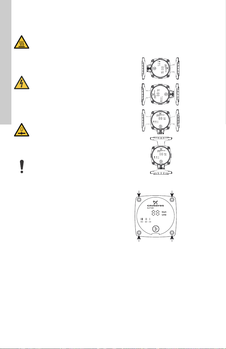
4.3 Changing the power head position
CAUTION
Hot surface
Minor or moderate personal injury
- Position the pump so that persons
cannot accidentally come into
contact with hot surfaces.
DANGER
Electric shock
Death or serious personal injury
- Switch off the power supply before
starting any work on the product.
Make sure that the power supply
cannot be accidentally switched on.
WARNING
Pressurized system
Death or serious personal injury
- Before dismantling the pump, drain
the system or close the isolating
valve on either side of the pump
before you remove the screws. The
pumped liquid may be scalding hot
and under high pressure.
If you change the position of the
power head, fill the system with the
liquid to be pumped or open the
isolating valves.
• Make any change to the power head
orientation before filling the system with
liquid. You can turn the power head in steps
of 90 °.
• See fig. 3 for permissible positions.
• Only use orientations C and D for CSA,
enclosure type 2.
Proceed as follows:
1. If liquid is present, drain the liquid from the
pump or isolate the liquid from the pump.
2. Remove the four socket head cap screws.
3. Turn the pump head to the desired position.
See fig. 3.
4. Cross-tighten the screws to: 7 ft-lbs torque.
Fig. 3 Changing the power head position
TM06 8887 1417
6
Fig. 4 Remove the four socket head cap
screws on the power head to
change the power head position
TM06 8885 1417
Page 7
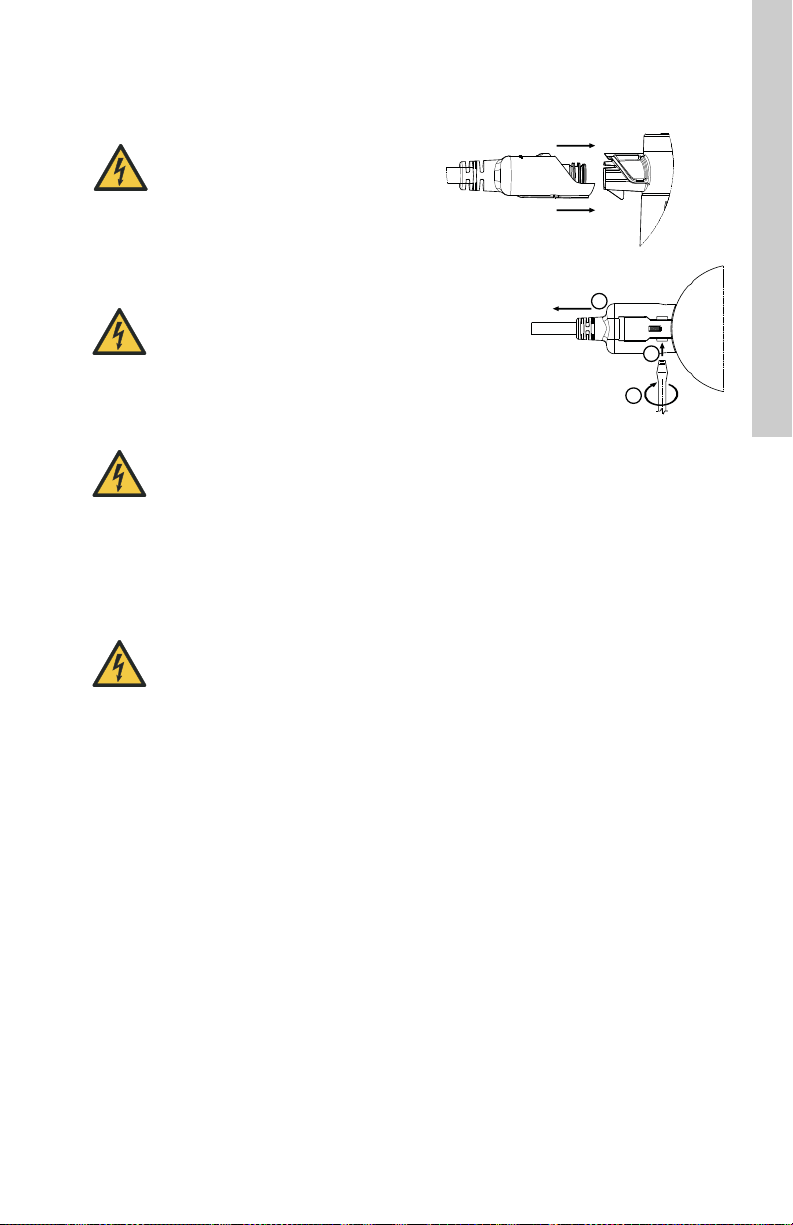
4.4 Electrical connection
1
2
3
How to remove the cord plug from the
pump (bottom view):
How to insert the line cord plug onto the
pump (side view):
1. Insert a 1/8 in. flat blade
screwdriver into the slot.
2. Twist the screwdriver.
3. Pull the cord to remove it.
DANGER
Electric shock
Death or serious personal injury
- All electrical work must be carried
out by a qualified electrician in
accordance with the latest edition
of the National Electric Code and
state, local codes and regulations.
DANGER
Electric shock
Death or serious personal injury
- Switch off the power supply before
starting any work on the product.
Make sure that the power supply
cannot accidentally switched on.
4.4.1 For pump models with line cord
Follow the procedure as shown in fig. 5.
English (US)
DANGER
Electric shock
Death or serious personal injury
- This pump has not been
investigated for use in swimming
pool or marine areas.
DANGER
Electric shock
Death or serious personal injury
- This pump is supplied with a
grounding conductor and
grounding-type attachment plug. T o
reduce the risk of electric shock, be
certain that it is connected only to a
properly grounded, grounding-type
receptacle in accordance with the
National Electric Code and any
state, local governing codes and
regulations.
• The motor is protected by the electronics in
the control box and requires no external
motor protection.
• Check that the supply voltage and frequency
correspond to the values stated on the
pump.
• Only connect the pump to the power supply
with the line cord or through the terminal box
supplied with the pump; see sections
4.4.1 For pump models with line cord and
4.4.2 For pump models with terminal box.
• Do not modify and only use the line cord
supplied.
• The lights on the control panel indicate that
the electrical supply has been switched on.
Fig. 5 Connecting and removing the power
plug for line cord models
TM04 3420 1010
7
Page 8
English (US)
0.4 in.
(10 mm)
Cable conductor
from the pump
Cable conductor
from the power
supply
4.4.2 For pump models with terminal box
1. Loosen the terminal box screw from the
terminal box cover.
2. Utilize either conduit port for the wiring
entrance.
3. Wire the plug connector as illustrated in the
section Wiring procedure below, steps 3a3d. Then complete steps 4-7.
Be sure to connect the ground cable
conductor (green) of the pump to the
ground cable conductor of the power
supply.
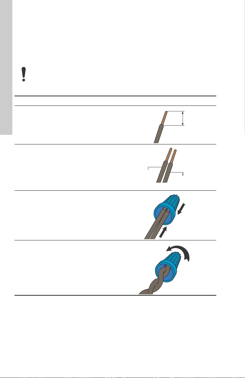
Wiring procedure
Step Action Illustration
Strip the ends of the cable conductors as
3a
illustrated.
Align the end of each of the pump's cable
conductors, including any frayed strands,
with the end of the corresponding cable
conductor from the power supply.
3b
Green conductor: ground
Black conductor: line
White conductor: neutral
TM06 8250 4816
TM06 8253 4816
Insert the ends of the cable conductors
into the connector.
3c
Push the cable conductors fully into the
connector.
Twist the connector until you see two
3d
twists in the cable conductors.
4. Slide the terminal box cover over the
terminal box body.
5. Tighten the cross-head screw on the terminal
box to 5 in-lbs.
6. Switch on the power supply.
7. The lights on the control panel will then
indicate that the power supply has been
switched on.
8
TM06 8251 4816
TM06 8252 4816
Page 9

5. Starting up the product
6.2 Applications
Do not start the pump until the system
has been filled with liquid and vented.
The required minimum inlet pressure must be
available at the pump inlet.
5.1 Venting the pump
The pump is self-venting. It needs not to be
vented before startup.
The pump must not run dry.
Air in the pump may cause noise. This noise
ceases after a few minutes running.
You obtain quick venting of the pump by setting
the pump to "Constant Pressure III" for a short
period. How fast the pump is vented depends on
the system size and design.
When you have vented the pump, that is when
the noise has ceased, set the pump according to
the recommendations. See section 8.3 Setting
the pump.
You cannot vent the system through the pump.
5.2 First startup
• The light in the control panel shows that the
power supply has been switched on. See fig.
7.
• Factory setting: Constant Pressure III.
6. Product introduction
DANGER
Explosion hazard
Death or serious personal injury
- Do not use the pump for transfer of
flammable liquids such as diesel
oil, gasoline, and similar liquids.
DANGER
Electric shock
Death or serious personal injury
- This pump has not been
investigated for use in swimming
pool or marine areas.
The ALPHA1 circulator is designed for the
circulation of water in heating systems, domestic
hot-water systems as well as air-conditioning
and cold-water systems.
Cold-water systems are defined as systems
where the ambient temperature is higher than
the temperature of the pumped liquid.
The pump is the best choice for the following
systems:
• underfloor heating systems
• one-pipe systems
• two-pipe systems.
The pump is suitable for the following:
• systems with constant or variable flows
where you want to optimize the setting of the
pump duty point
• systems with variable flow-pipe temperature
• balancing of domestic heating systems.
English (US)
6.1 Product description
The ALPHA1 circulator incorporates a
permanent-magnet motor and differentialpressure control enabling continuous
adjustment of the pump performance to the
actual system requirements.
The pump has a user-friendly front-mounted
control panel. See sections 7. Identification and
8. Control functions.
When you install an ALPHA1, it means:
• Easy installation and startup.
– The pump is easy to install.
You can start the pump, in most cases,
without making any settings.
• High degree of comfort.
• Mini mum noise from valves, etc.
• Low energy consumption.
– Low energy consumption compared to
conventional circulator pumps.
9
Page 10
English (US)
6.3 Pumped liquids
For information about pressures and
temperatures, see section 10. Technical data.
CAUTION
Flammable material
Minor or moderate personal injury
- Do not use the pump for flammable
liquids, such as diesel oil and
petrol.
WARNING
Biological hazard
Death or serious personal injury
- In domestic hot-water systems, the
temperature of the pumped liquid
must always be above 122 °F (50
°C) due to the risk of legionella.
WARNING
Biological hazard
Death or serious personal injury
- In domestic hot-water systems, the
pump is permanently connected to
the mains water. Therefore, do not
connect the pump by a hose.
CAUTION
Corrosive substance
Minor or moderate personal injury
- Do not use the pump for aggressive
liquids, such as acids and
seawater.
In heating systems, the water must meet the
requirements of accepted standards on water
quality in heating systems.
The pump is suitable for the following liquids:
• Thin, clean, non-aggressive and nonexplosive liquids, not containing solid
particles or fibers.
• Cooling liquids, not containing mineral oil.
• Domestic hot water
Maximum: 14 °dH
Maximum: 149 °F (65 °C)
Maximum peak: 158 °F (70 °C).
For water with a higher degree of hardness,
contact Grundfos.
• Softened water.
2
2
/s (10 cSt)
/s (1
The kinematic viscosity of water is 1 mm
cSt) at 68 °F (20 °C). If the pump is used for a
liquid with a higher viscosity, the hydraulic
performance of the pump will be reduced.
Example: 50 % glycol at 68 °F (20 °C) means a
viscosity of approximately 10 mm
and a reduction of the pump performance by
approximately 15 %.
Do not use additives that can or will disturb the
functionality of the pump.
When selecting a pump, take the viscosity of the
pumped liquid into consideration.
For technical data, see section 10. Technical
data.
6.3.1 Glycol
The pump is designed for pumping clean water,
or up to 50/50 mixtures by weight of glycol and
water.
For glycol usage as well as additional liquid
information, see section 10. Technical data.
To prevent the glycol mixture from degrading,
avoid temperatures exceeding the rated liquid
temperature and minimize the operating time at
high temperatures.
It is important to clean and flush the system
before adding the glycol mixture.
To prevent corrosion or precipitation, check the
glycol mixture and maintain it regularly. If further
dilution of the supplied glycol is required, follow
the glycol supplier's instructions.
10
Page 11

7. Identification
3191277
Listed
7.1 Nameplate
Fig. 6 Nameplate
Pos. Description
1 Product number
2 Voltage [V]
Rated current [A]:
3
• Min.: Minimum current [A]
• Max.: Maximum current [A]
Input power [W]:
4
• Min.: Minimum power [W]
• Max.: Maximum power [W]
5 Maximum fluid temperature [°F]
7.2 Type key
Example ALPHA1 15 -55 F
Pump type
Nominal diameter (DN) of inlet and
outlet ports [mm]
Maximum head [dm]
Pipe connection
F: Flange
7.3 Approvals
TM06 8960 1417
FCC sections
Section 15.19 (a) 3
This device complies with Part 15 of the FCC
Rules. Operation is subject to the following two
conditions: (1) this device may not cause
harmful interference, and (2) this device must
accept any interference received, including
interference that may cause undesired
operation.
Section 15.21
Any changes or modifications to this equipment
not expressly approved by the party responsible
for compliance could void the user's authority to
operate this equipment void.
Section 15.105 (b)
These limits are designed to provide reasonable
protection against harmful interference in a
residential installation. This equipment
generates, uses and can radiate radio frequency
energy and, if not installed and used in
accordance with the instructions, may cause
harmful interference to radio communications.
However, there is no guarantee that interference
will not occur in a particular installation. If this
equipment does cause harmful interference to
radio or television reception, which can be
determined by turning the equipment off and on,
the user is encouraged to try to correct the
interference by one or more of the following
measures:
• Reorient or relocate the receiving antenna.
• Increase the separation between the
• Connect the equipment to an outlet on a
• Consult the dealer or an experienced radio/
Canadian EMC Standard: ICES-003
This class B digital apparatus complies with
Canadian ICES-003.
This equipment has been tested and
found to comply with the limits for a
class B digital device, pursuant to Part
15 of the FCC Rules.
equipment and receiver.
circuit different from that to which the
receiver is connected.
TV technician for help.
English (US)
11
Page 12
English (US)
3
4
2
1
PC XXXX
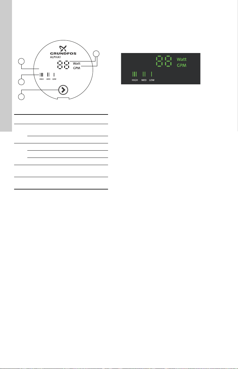
8. Control functions
8.1 Elements on the control panel
Fig. 7 Control panel
Pos. Description
Display showing the power
consumption in watt or the flow
1
Light field indicating high and low flow
Production code:
2
• 1st and 2nd figures: year
• 3rd and 4th figures: week
Light field indicating constant pressure
3
setting
Push-button for selection of pump
4
setting
8.2 Display
The display (1) is on when you have switched on
the power supply.
The display shows the actual pump power
consumption in watt (integer) or the actual flow
during operation.
If a fault is indicated, correct the fault and reset
the pump by switching the power supply off and
on.
If the pump impeller is rotated, for example
when filling the pump with water, sufficient
energy can be generated to light up the display
even if the power supply has been switched off.
Light field indicating high and low flow
• The light field blinks for low flow
– If the flow is lower than 1 gpm, the light
field alternately flashes between "0" and
"1" randomly.
• The light field shows HI for high flow
– If the flow is higher than 12 gpm, the light
field shows "HI" on user interface.
8.2.1 Light fields indicating the pump setting
The pump has optional performance settings
which you can select with the push-button. See
fig. 7.
The pump setting is indicated by light fields in
the display. See fig. 8.
Fig. 8 Light fields
For more information about the function of the
TM06 8878 1417
settings, see section 9. Fault finding the product.
8.3 Setting the pump
You can change the pump setting by pressing
the push-button.
8.3.1 Factory default setting
The pump's factory default setting is the
Constant Pressure III setting.
8.3.2 Changing from recommended to alternative pump setting
Heating systems are "slow" systems that cannot
be set to the optimum operation within minutes
or hours.
However, if the recommended pump setting in
some applications does not give the desired
distribution of heat in the rooms of the house,
you can change to an alternative pump setting.
8.4 Pump control
See section 8.5 Pump performance and
operating mode selection.
Constant-pressure control
In this control mode, a constant differential
pressure across the pump is maintained,
irrespective of the flow.
See also sections 8. Control functions and
8.3 Setting the pump.
TM06 8893 1417
12
Page 13
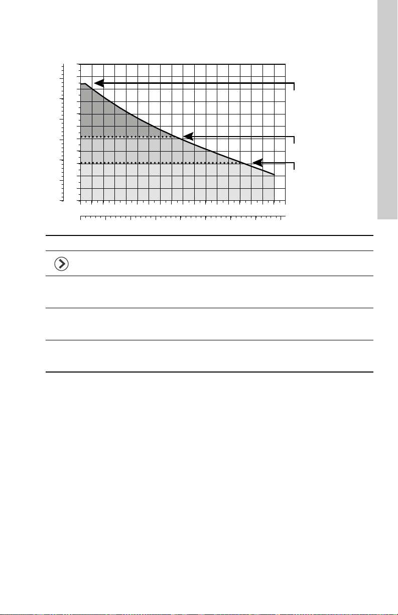
8.5 Pump performance and operating mode selection
0 1 2 3 4 5 6 7 8 9 10 11 12 13 14 15 16
Q [US GPM]
0
2
4
6
8
10
12
14
16
18
20
[ft]
H
0
1
2
3
4
5
6
[m]
H
0.0 0.5 1.0 1.5 2.0 2.5 3.0 3.5 4.0
Q [m³/h]
Constant Pressure III
Constant Pressure II
Constant Pressure I
17 18
The hydraulic performance shown is without check valve.
Pos. Description
• Push-button for selection of pump setting
• Every time you press the push-button, the circulator setting is changed.
Constant pressure III
III
• The duty point of the pump will move left and right along the highest constant-pressure
curve depending on the water demand in the system.
Constant pressure II
II
• The duty point of the pump will move left and right along the middle constant-pressure
curve depending on the water demand in the system.
Constant pressure I
I
• The duty point of the pump will move left and right along the lowest constant-pressure
curve depending on the water demand in the system.
English (US)
TM06 8910 1417
13
Page 14

English (US)
9. Fault finding the product
DANGER
Electric shock
Death or serious personal injury
- Switch off the power supply before
starting any work on the product.
Make sure that the power supply
cannot be accidentally switched on.
Fault Control panel Remedy
1. The pump
does not
run.
2. Noise in
the system
3. Noise in
the pump
The light field is
off.
The light field is
on.
___ ___" a) Supply voltage is too
"
The light field is
on.
The light field is
on.
a) The pump is not
connected to the
power supply.
b) The circuit breaker
has tripped.
c) The pump is
defective.
a) Supply voltage is too
high.
b) The rotor is blocked
by impurities.
low.
a) There is air in the
system.
b) The flow is too high. Reduce the pump speed.
c) Thermal expansion
of system
components.
a) There is air in the
pump.
b) The inlet pressure is
too low.
c) No liquid (dry
running).
d) The pump is
defective.
WARNING
Pressurized system
Death or serious personal injury
- Before dismantling the pump, drain
the system or close the isolating
valve on either side of the pump
before you remove the screws. The
pumped liquid may be scalding hot
and under high pressure.
Connect the pump to the power
supply.
Cut in the circuit breaker.
Replace the pump.
Check that the power supply falls
within the specified range.
Remove the impurities.
Switch the power off and on.
Check for air, locked rotor and/or
voltage.
Correct the power supply.
Install an air eliminator.
Check the mounting brackets for
the pipes.
Secure loose mounting brackets.
Let the pump run, as it will vent
over time.
Install an air eliminator.
Increase the inlet pressure.
Check the air volume in the
expansion tank, if this is installed.
(Pressure leaks in the system can
lead to cavitation.)
Ensure the system has been filled
with liquid and vented.
Open the isolating valves.
Replace the pump.
14
Page 15

Fault Control panel Remedy
4. Insufficient
heat
The light field is
on.
a) The pump
performance is set
too low.
b) The thermostat is set
too low or is not
working.
c) Air or gas in the
system.
d) The valves are
sticking.
e) Wrong direction of
flow.
f) The boiler is not
working properly.
g) The pump
performance is not
adequate for the
application.
h) The pump
performance is not
adequate for the
application.
Increase the pump's constant
pressure setting.
Check to see if the circulator is in
the proper operating mode.
Check the thermostat to ensure
that it is set to the desired
temperature and is working.
Replace the batteries in the
thermostat.
Vent the air or gas from the system
by allowing the pump to run, as it
will vent over time.
Install an air eliminator.
If necessary rework the piping.
Make sure all valves are in good
working order, that is remove lime
deposits.
See the direction of flow arrow
marked on the pump.
Reinstall the pump to correct the
direction of flow.
Check the water temperature from
the boiler and check the boiler
functions.
Repair the boiler if required.
Check for proper sizing of the
circulator and other system
components.
Check the T calculation.
English (US)
15
Page 16

English (US)
10. Technical data
10.1 Operating conditions
Supply voltage
1 x 115 V, + 10 %/- 10 %, 60 Hz.
Motor protection
The pump requires no external motor protection.
Enclosure class
Indoor use only, IP42.
CSA enclosure type 2.
Insulation class
F.
Relative humidity
Maximum 95 %.
Maximum outlet pressure
150 psi (10.34 bar).
Inlet pressure
Liquid
temperature
167 °F (75 °C) 0.75 psi (0.05 bar)
194 °F (90 °C) 4.06 psi (0.28 bar)
230 °F (110 °C) 15.7 psi (1.08 bar)
Sound pressure level
43 dB (A).
Ambient temperature
32 °F (0 °C) to 104 °F (40 °C).
Liquid temperature
36 °F (2 °C) to 230 °F (110 °C).
To avoid condensation in the control box and
stator, the liquid temperature must always be
higher than the ambient temperature.
Ambient
temperature
[°F (°C) ]
32 (0) 36 (2) 230 (110)
50 (10) 50 (10) 230 (110)
68 (20) 68 (20) 230 (110)
86 (30) 86 (30) 230 (110)
95 (35) 95 (35) 194 (90)
104 (40) 104 (40) 158 (70)
Liquid temperature
Minimum
[°F (°C)]
Minimum
inlet pressure
Maximum
[°F (°C) ]
Glycol
Maximum glycol concentrations with clean
water:
50 % glycol @ 36 °F (2 °C).
Hydraulic performance change can be expected.
Watt readings
Accuracy: ± 1 Watt.
Flow indicator
Provides a relative indication of flow - must not
be used in lieu of a flow meter.
Check valve
Use of a check valve may reduce pump
hydraulic performance (up to - 10 %).
Use a check valve in parallel pumping
applications.
Curve conditions
Test liquid: Airless water.
Curves apply to a density of 983.2 kg/m
liquid temperature of 140 °F (60 °C).
All curves show average values and must not be
used as guarantee curves. If a specific minimum
performance is required, individual
measurements must be made.
Curves apply to a kinematic viscosity of 0.474
cSt.
Approximate power usage
Speed
setting
Constant
pressure
Constant
pressure
Constant
pressure
Minimum Maximum
III 39 W 45 W
II 14 W 45 W
I 8 W 45 W
3
and a
11. Disposing of the product
This product or parts of it must be disposed of in
an environmentally sound way:
1. Use the public or private waste collection
service.
2. If this is not possible, contact the nearest
Grundfos company or service workshop.
Subject to alterations.
16
In domestic hot water systems, keep
the liquid temperature below 149 °F
(65 °C) to eliminate the risk of lime
precipitation.
Page 17

Français (CA) Notice d'installation et de fonctionnement
Traduction de la version anglaise originale
La présente notice d'installation et d'utilisation
décrit la pompe Grundfos ALPHA1.
Les paragraphes 1 à 5 fournissent les informations nécessaires pour déballer, installer et
démarrer le produit en toute sécurité.
Les paragraphes 6 à 11 donnent des informations importantes sur le produit, ainsi que sur la
maintenance, le dépannage et la mise au rebut.
SOMMAIRE
Page
1. Garantie limitée
2. Informations générales
2.1 Symboles utilisés dans cette notice
3. Réception du produit
3.1 Inspection du produit
3.2 Livraison
4. Installation du produit
4.1 Conseils d'installation rapide
4.2 Installation mécanique
4.3 Modification de la position de la tête
de pompe
4.4 Connexion électrique
5. Mise en service du produit
5.1 Purge de la pompe
5.2 Première mise en service
6. Introduction au produit
6.1 Description du produit
6.2 Applications
6.3 Liquides pompés
7. Identification
7.1 Plaque signalétique
7.2 Désignation
7.3 Approbations
8. Fonctions de régulation
8.1 Composition du panneau de commande
8.2 Affichage
8.3 Réglage de la pompe
8.4 Régulation de la pompe
8.5 Sélection mode de fonctionnement et
rendement
9. Détection des défauts de fonctionnement
10. Caractéristiques techniques
10.1 Conditions de fonctionnement
11. Mise au rebut du produit
Avant de procéder à l'installation, lire
attentivement cette notice. L'installa-
ion et le fonctionnement doivent être
t
conformes à la réglementation locale
et aux règles de bonne pratique en
vigueur.
Ce produit peut être utilisé par des
enfants âgés d'au moins 8 ans, et par
des personnes ayant des capacités
physiques, sensorielles ou mentales
limitées ou dénuées d'expérience ou
de connaissances, si elles sont correctement supervisées, ou si des instructions relatives à l'utilisation du produit en toute sécurité leur ont été
données, et si les risques encourus
ont été appréhendés. Les enfants ne
sont pas autorisés à utiliser ce produit
ni à jouer avec. Le nettoyage et
17
18
18
18
18
18
19
19
19
1. Garantie limitée
Les produits fabriqués par Grundfos Pumps Cor-
20
poration (Grundfos) sont garantis, uniquement
21
pour l'utilisateur initial, exempts de défauts de
23
matériaux et de fabrication pour une période de
23
30 mois à compter de la date d'installation, mais
au plus 36 mois à compter de la date de fabrica-
23
tion. Dans le cadre de cette garantie, la respon-
23
sabilité de Grundfos se limite à la réparation ou
23
au remplacement, à la convenance de
23
Grundfos, sans frais, FOB de l'usine Grundfos
24
ou d'un atelier de maintenance autorisé, de tout
produit de fabrication Grundfos. Grundfos
25
n'assume aucune responsabilité quant aux frais
25
de dépose, d'installation, de transport ou pour
25
toute autre charge pouvant survenir en relation
25
avec une réclamation au titre de la garantie.
26
Les produits vendus mais non fabriqués par
Grundfos sont couverts par la garantie fournie
26
par le fabricant des dits produits et non par la
garantie de Grundfos.
26
Grundfos n'est responsable ni des dommages ni
26
de l'usure des produits causés par des condi-
26
tions d'exploitation anormales, un accident, un
abus, une mauvaise utilisation, une altération ou
27
une réparation non autorisée, ou par une installation du produit non conforme aux notices d'ins-
28
tallation et de fonctionnement imprimées de
30
Grundfos, ainsi qu'aux codes de bonnes pratiques communément acceptés. La garantie ne
30
couvre pas l'usure normale.
30
Pour bénéficier de la garantie, il faut renvoyer le
produit défectueux au distributeur ou au revendeur de produits Grundfos chez qui il a été
acheté, accompagné de la preuve d'achat, de la
date d'installation, de la date du dysfonctionnement ainsi que des données concernant l'installation. Sauf disposition contraire, le distributeur
ou le revendeur contactera Grundfos ou un atelier de maintenance autorisé pour obtenir des
l'entretien ne doivent pas être effectués par des enfants sans surveillance.
Un bon fonctionnement dépend de
l'attention particulière accordée aux
procédures décrites dans ce manuel.
Conservez ce manuel pour une utilisation future.
Français (CA)
17
Page 18

Français (CA)
instructions. Tout produit défectueux renvoyé à
Grundfos ou à un atelier de maintenance doit
être expédié port payé ; la documentation relative à la déclaration de demande de garantie et
à une autorisation de retour de matériel éventuelle doit être jointe, si elle est demandée.
Grundfos n'assume aucune responsabilité en
cas de dommages indirects ou consécutifs, de
pertes ou de dépenses résultant de l'installation,
de l'utilisation ou de toute autre cause. Il n'existe
aucune garantie, explicite ni implicite, y compris
la qualité marchande ou l'adéquation pour un
usage particulier, en dehors des garanties
décrites ou mentionnées ci-dessus. Certaines
juridictions n'autorisent pas l'exclusion ou la
limitation des dommages indirects ou consécutifs, et certaines juridictions ne permettent pas
de limiter la durée des garanties implicites. Il se
peut donc que les limitations ou exclusions mentionnées ci-dessus ne soient pas applicables
dans votre cas. Cette garantie vous donne des
droits légaux spécifiques. Il se peut que vous
ayez également d'autres droits qui varient d'une
juridiction à l'autre.
Les produits qui sont réparés ou remplacés par
Grundfos ou par atelier de maintenance autorisé, en vertu des dispositions de ces conditions
de garantie limitée, continueront à être couverts
par la garantie Grundfos uniquement pendant le
reste de la période de garantie initialement fixée
à la date d'achat d'origine.
2. Informations générales
2.1 Symboles utilisés dans cette notice
DANGER
Indique une situation dangereuse qui,
si elle n'est pas évitée, entraînera des
blessures graves ou la mort.
AVERTISSEMENT
Indique une situation dangereuse qui,
si elle n'est pas évitée, peut entraîner
des blessures graves ou la mort.
PRÉCAUTIONS
Indique une situation dangereuse qui,
si elle n'est pas évitée, peut entraîner
des blessures légères ou modérées.
Le texte qui accompagne les trois symboles
DANGER, AVERTISSEMENT et PRUDENCE
est structuré de la façon suivante :
Exemple
DANGER
Choc électrique
Blessures graves ou mort
- Avant toute intervention sur le produit, couper l'alimentation électrique. S'assurer que l'alimentation
électrique ne risque pas d'être
branchée accidentellement.
Un cercle bleu ou gris autour d'un pictogramme blanc indique qu'il faut agir.
Un cercle rouge ou gris avec une
barre diagonale, éventuellement avec
un symbole graphique noir, indique
qu'une mesure ne doit pas être prise
ou doit être arrêtée.
Le non-respect de ces consignes peut
entraîner des dysfonctionnements ou
endommager l'équipement.
Conseils et astuces pour faciliter les
opérations.
3. Réception du produit
3.1 Inspection du produit
Vérifier que le produit reçu est conforme à la
commande.
Vérifier que la tension et la fréquence du produit
correspondent à celles du site d'installation.
Pour plus d'informations sur la plaque signalétique, voir paragraphe 7. Identification.
3.2 Livraison
L'emballage contient les éléments suivants :
• une pompe Grundfos ALPHA1 ;
• un cordon d'alimentation ou une boîte de
raccordement ;
• deux joints ;
• des notices d'installation et de fonctionnement ;
• un clapet antiretour ;
• un autocollant "Clapet anti-retour installé".
18
TERME
DESIGNALEMENT
Description du danger
Conséquence de la non-observance
de l'avertissement.
- Mesures pour éviter le danger.
Page 19

4. Installation du produit
AVERTISSEMENT
Système sous pression
Blessures graves ou mort
- Avant de démonter la pompe, purger l'installation ou fermer le robinet
d'arrêt de chaque côté de la pompe
avant de retirer les vis. Le liquide
pompé peut être bouillant et sous
haute pression.
DANGER
Choc électrique
Blessures graves ou mort
- Avant toute intervention sur le produit, couper l'alimentation électrique. S'assurer que l'alimentation
électrique ne risque pas d'être
branchée accidentellement.
DANGER
Choc électrique
Blessures graves ou mort
- Cette pompe n'est pas homologuée
pour une utilisation en piscine ou
dans les zones marines.
4.1 Conseils d'installation rapide
1. Pour assurer une ventilation adéquate de
votre système, placez la pompe en mode
"Constant Pressure III" jusqu'à ce que l'air
soit éliminé. Pendant ce processus, les
zones d'isolation permettront d'assurer une
élimination adéquate de l'air.
2. Pour équilibrer les applications de zones de
manifold, l'utilisation des modes "Constant
Pressure I" ou "Constant Pressure II" et
d'une seule zone à la fois (pendant l'équilibrage) assure que le débit est approprié
pour chaque zone.
3. Pour utiliser la pompe comme pompe primaire, toujours examiner les exigences de
débit minimum de la chaudière. Sélectionner
un des modes de pression constante pour
les applications de pompes primaires de la
chaudière. Vous pouvez modifier la sélection
hydraulique pendant le pompage. Aucun
dommage permanent ne se produira. En fait,
Grundfos encourage à tester les différents
modes hydrauliques avec votre système
hydronique, pour garantir un maximum
d'économie d'énergie et de niveau de
confort.
4. Avec les applications de commande du panneau de zone, lorsqu'un appel pour de la
chaleur et de l'énergie est envoyé à la
pompe, celle-ci mémorise le dernier point de
service et le mode hydraulique en cours, et
elle redémarrera à partir de ceux-ci.
4.2 Installation mécanique
Lors des raccords de tuyauterie, veuillez suivre
les recommandations du fabricant de tuyaux et
toutes les exigences du code pour la tuyauterie.
• Rincer les débris du système avant l'installation.
• Installer un clapet antiretour si cela est
nécessaire. Voir fig. 1.
• Veuillez vous référer aux flèches sur le corps
de pompe indiquant le sens de circulation du
liquide dans la pompe.
• Installer la pompe avec l'arbre du moteur à
l'horizontale. See fig. 2.
• Monter les deux joints fournis aux extrémités
de la pompe.
Fig. 1 Installation du clapet antiretour
Fig. 2 Positions d'installation
Français (CA)
TM04 3422 4408
TM06 8959 1417
19
Page 20

Français (CA)
Tête de
pompe orientation A
Tête de
pompe orientation B
Tête de
pompe orientation C
Tête de pompe
orientation D
4.3 Modification de la position de la tête de pompe
PRÉCAUTIONS
Surface chaude
Blessure mineure ou modérée
- Veiller à ce que la pompe soit positionnée de telle manière que personne ne puisse entrer accidentellement en contact avec les surfaces
chaudes.
DANGER
Choc électrique
Blessures graves ou mort
- Avant toute intervention sur le produit, couper l'alimentation électrique. S'assurer que l'alimentation
électrique ne risque pas d'être
branchée accidentellement.
AVERTISSEMENT
Système sous pression
Blessures graves ou mort
- Avant de démonter la pompe, purger l'installation ou fermer le robinet
d'arrêt de chaque côté de la pompe
avant de retirer les vis. Le liquide
pompé peut être bouillant et sous
haute pression.
Si vous modifiez la position de la tête
de pompe, remplir l'installation avec le
liquide à pomper et ouvrir les robinets
d'arrêt.
• Effectuer toute modification de l'orientation
de la tête de pompe avant de remplir le système de liquide. Vous pouvez tourner la tête
de pompe par rotations de 90 °.
• Voir fig. 3 pour les positions autorisées.
• Pour les boîtiers de protection électrique de
type 2 (CSA), utiliser uniquement les orientations C et D.
Procédure :
1. Si du liquide est présent, purger la pompe ou
isoler le liquide de la pompe.
2. Retirer les quatre vis à tête creuse.
3. Tourner la tête de pompe dans la position
requise. Voir fig. 3.
4. Serrer les vis en croix au couple de 7 lb-pi.
Fig. 3 Modification de la position de la tête
Fig. 4 Retirer les quatre vis à tête creuse
de pompe
sur la tête de pompe pour changer
la position de la tête de pompe
TM06 8887 1417
TM06 8885 1417
20
Page 21

4.4 Connexion électrique
1
2
3
Pour retirer la fiche du cordon de la
pompe (vue de dessous) :
Pour insérer la fiche du cordon d'alimentation dans la pompe (vue latérale) :
1. Insérer un tournevis à
lame plate de 1/8 po dans
la fente.
2. Tourner le tournevis.
3. Tirer sur le cordon pour le
retirer.
DANGER
Choc électrique
Blessures graves ou mort
- Toutes les installations électriques
doivent être effectuées par un électricien qualifié conformément à la
version la plus récente du Code
national de l'électricité, aux codes
nationaux et locaux, ainsi qu'aux
réglementations locales.
DANGER
Choc électrique
Blessures graves ou mort
- Avant toute intervention sur le produit, couper l'alimentation électrique. S'assurer que l'alimentation
électrique ne risque pas d'être
branchée accidentellement.
DANGER
Choc électrique
Blessures graves ou mort
- Cette pompe n'est pas homologuée
pour une utilisation en piscine ou
dans les zones marines.
DANGER
Choc électrique
Blessures graves ou mort
- Cette pompe est fournie avec un
conducteur de mise à la terre et
une fiche de fixation de mise à la
terre. Afin de réduire le risque de
choc électrique, ne relier la pompe
que sur un boîtier électrique correctement relié à la terre, conformément au Code national de l'électricité, aux codes nationaux et locaux,
ainsi qu'aux réglementations
locales.
• Le moteur est protégé par l'électronique du
boîtier de commande et ne nécessite aucune
protection moteur externe.
• Vérifier que la tension d'alimentation et la
fréquence correspondent aux valeurs indiquées sur la plaque signalétique de la
pompe.
• Ne raccorder la pompe à l'alimentation électrique qu'avec le cordon d'alimentation ou
par la boîte de raccordement fournis avec la
pompe ; voir sections 4.4.1 Pour les modèles
de pompes avec cordon d'alimentation et
4.4.2 Pour les modèles de pompes avec
boîte de raccordement.
• Utiliser uniquement le cordon d'alimentation
fourni et n'y apporter aucune modification.
• Les voyants sur le panneau de commande
indiquent que l'alimentation électrique a été
activée.
4.4.1 Pour les modèles de pompes avec
cordon d'alimentation
Suivre la procédure indiquée en fig. 5.
Fig. 5 Raccordement et débranchement
de la fiche d'alimentation pour les
modèles à cordon d'alimentation
Français (CA)
TM04 3420 1010
21
Page 22

Français (CA)
0,4 po
(10 mm)
Conducteur de
câble de la
pompe
Conducteur de
câble de l'alimentation électrique
4.4.2 Pour les modèles de pompes avec boîte de raccordement
1. Desserrer la vis de la boîte de raccordement
du couvercle de cette dernière.
2. Utiliser l'un ou l'autre des ports de conduit
pour l'entrée du câblage.
3. Fixer le connecteur mâle comme illustré au
paragraphe Procédure de câblage ci-dessous, étapes 3a-3d. Effectuer ensuite les
étapes 4 à 7.
S'assurer de brancher le conducteur
de câble de mise à la terre (vert) de la
pompe au conducteur de câble de
mise à la terre de l'alimentation électrique.
Procédure de câblage
Étape Action Illustration
Dénuder les extrémités des conducteurs
3a
de câble comme indiqué dans l'illustration.
Aligner l'extrémité de chacun des conducteurs de câble de la pompe, y compris les
brins effilochés, avec l'extrémité du
conducteur de câble correspondant de
3b
l'alimentation électrique.
Conducteur vert : terre
Conducteur noir : ligne
Conducteur blanc : neutre
TM06 8250 4816
TM06 8253 4816
Insérer les extrémités des conducteurs du
câble dans le connecteur.
3c
Pousser les conducteurs de câble complètement dans le connecteur.
Tourner le connecteur jusqu'à ce que les
3d
deux torsions soient visibles dans les
conducteurs de câble.
4. Glisser le couvercle de la boîte de raccorde-
ment sur celle-ci.
5. Serrer la vis à tête croisée sur la boîte de
raccordement à 5 lb-po.
22
6. Mettre l'alimentation électrique sous tension.
7. Les voyants sur le panneau de commande
indiquent que l'alimentation électrique a été
activée.
TM06 8251 4816
TM06 8252 4816
Page 23

5. Mise en service du produit
6.2 Applications
Ne jamais démarrer la pompe avant
que l'installation n'ait été remplie de
liquide et purgée.
La pression d'aspiration minimale requise doit
être disponible à l'entrée de la pompe.
5.1 Purge de la pompe
La purge de la pompe est automatique. La
pompe n'a pas besoin d'être purgée avant la
mise en service.
La pompe ne doit pas fonctionner à
sec.
L'air se trouvant dans la pompe peut engendrer
du bruit. Ce bruit doit normalement cesser au
bout de quelques minutes de fonctionnement.
Pour obtenir une purge rapide de la pompe, la
régler sur "Constant Pressure III" pendant une
courte période. La rapidité de purge de la
pompe dépend de la taille et de la conception de
l'installation.
Lorsque vous avez purgé la pompe, á savoir
lorsque le bruit a cessé, régler la pompe en
fonction des recommandations. Voir paragraphe 8.3 Réglage de la pompe.
Vous ne pouvez pas purger l'installation par la
pompe.
5.2 Première mise en service
• Le voyant situé sur le panneau de commande
indique la mise sous tension. Voir fig. 7.
• Réglage en usine : "Constant Pressure III".
6. Introduction au produit
6.1 Description du produit
La pompe ALPHA1 est équipée d'un moteur à
aimant permanent et d'une régulation de la pression différentielle permettant l'ajust ement continuel
du rendement de la pompe en fonction des
besoins réels de l'installation.
La pompe dispose d'un panneau de commande
convivial monté sur la face avant. Voir paragraphes 7. Identification et 8. Fonctions de régula-
tion.
L'installation d'une pompe ALPHA1 signifie :
• Une installation et une mise en service faciles.
– La pompe est facile à installer.
Elle peut être démarrée sans effectuer de
réglage, dans la plupart des cas.
• Un confort de haut niveau.
• Moins de bruit dans les vannes, etc.
• Une faible consommation d'énergie.
– Faible consommation d'énergie par rapport
aux pompes de circulation traditionnelles.
DANGER
Risque d'explosion
Blessures graves ou mort
- Ne pas utiliser la pompe pour le
transfert de liquides inflammables
tels que le carburant diesel,
l'essence et les liquides similaires.
DANGER
Choc électrique
Blessures graves ou mort
- Cette pompe n'est pas homologuée
pour une utilisation en piscine ou
dans les zones marines.
La pompe ALPHA1 est conçue pour la circulation de l'eau dans les installations de chauffage,
dans les installations d'eau chaude sanitaire,
ainsi que dans les installations d'eau froide et de
climatisation.
Les installations d'eau froide sont définies
comme des installations dans lesquelles la température ambiante est supérieure à la température du liquide pompé.
La pompe est le choix idéal dans les installations suivantes :
• installations de chauffage par le sol ;
• installations mono-tubes ;
• installations bi-tubes.
La pompe est conçue pour :
• les installations à débits constants ou
variables dans lesquelles vous souhaitez
optimiser le réglage du point de consigne de
la pompe ;
• les systèmes fonctionnant à des températures variables ;
• l'équilibrage des installations d'eau chaude
sanitaire.
Français (CA)
23
Page 24

Français (CA)
6.3 Liquides pompés
Pour des informations sur les pressions et les
températures, voir paragraphe
10. Caractéristiques techniques.
PRÉCAUTIONS
Matériau inflammable
Blessure mineure ou modérée
- Ne pas utiliser la pompe pour les
liquides inflammables, tels que le
carburant diesel et l'essence.
AVERTISSEMENT
Danger biologique
Blessures graves ou mort
- Dans les installations d'eau chaude
sanitaire, la température du liquide
pompé doit toujours être supérieure
à 122 °F (50 °C) pour éviter tout
risque de transmission de la légionelle.
AVERTISSEMENT
Danger biologique
Blessures graves ou mort
- Dans les installations d'eau chaude
sanitaire, la pompe est reliée en
permanence au réseau d'alimentation. Par conséquent, ne pas relier
la pompe par un tuyau flexible.
PRÉCAUTIONS
Substance corrosive
Blessure mineure ou modérée
- Ne pas utiliser la pompe pour les
liquides agressifs tels que l'acide et
l'eau de mer.
Dans les installations de chauffage, la qualité de
l'eau doit être conforme aux normes de qualité
reconnues pour l'eau dans les installations de
chauffage.
La pompe est conçue pour les liquides suivants :
• liquides clairs, non agressifs et non explosifs, ne contenant ni particules solides ni
fibres ;
• liquides de refroidissement ne contenant
aucune huile minérale ;
• eau chaude sanitaire ;
maximum : 14 °dH ;
maximum : 149 °F (65 °C) ;
pointe maximale : 158 °F (70 °C).
Pour l'eau ayant un degré de dureté supérieur, veuillez contacter Grundfos ;
• eau adoucie.
La viscosité cinématique de l'eau est de
2
/s (1 cSt) à 68 °F (20 °C). Si la pompe est
1 mm
utilisée pour un liquide dont la viscosité est plus
élevée, le rendement hydraulique en sera réduit.
Exemple : 50 % de glycol à 68 °F (20 °C) correspond à une viscosité d'environ 10 mm
cSt) et à une réduction du rendement de la
pompe d'environ 15 %.
Ne pas utiliser d'additifs qui peuvent perturber le
fonctionnement de la pompe.
Prendre en compte la viscosité du liquide pompé
lors de la sélection de la pompe.
Pour les spécifications techniques, voir paragraphe 10. Caractéristiques techniques.
6.3.1 Glycol
La pompe est conçue pour pomper de l'eau
claire ou des mélanges allant jusqu'à 50/50 en
poids de glycol et d'eau.
Pour l'utilisation du glycol ainsi que des informations sur les liquides supplémentaires, voir le
paragraphe 10. Caractéristiques techniques.
Pour prévenir la dégradation du mélange de glycol, éviter les températures supérieures à la
température nominale du liquide et minimiser le
temps de fonctionnement à hautes températures.
Bien nettoyer et rincer le système avant d'ajouter le mélange de glycol.
Vérifier régulièrement l'état du mélange glycol
pour prévenir la corrosion et la précipitation. S'il
est nécessaire de diluer davantage le glycol,
suivre les instructions du fournisseur de glycol.
2
/s (10
24
Page 25

7. Identification
3191277
Enregistré
7.1 Plaque signalétique
Fig. 6 Plaque signalétique
Pos. Description
1 Code article
2 Tension [V]
Intensité nominale [A] :
3
• Min. : Intensité minimale [A ]
• Max. : Intensité maximale [A]
Puissance absorbée [W] :
4
• Min. : Puissance minimale [W]
• Max. : Puissance maximale [W]
5 Température maximale du fluide [°F]
7.2 Désignation
Exemple ALPHA1 15 -55 F
Type de pompe
Diamètre nominal (DN) des orifices
d'aspiration et de refoulement [mm]
Hauteur maximale [dm]
Raccordement de la tuyauterie
F : Bride
7.3 Approbations
TM06 8960 1417
Sections FCC
Section 15.19 (a) 3
Cet appareil est conforme à la section 15 de la
réglementation FCC. Son fonctionnement est
soumis aux deux conditions suivantes : 1) cet
appareil ne doit pas provoquer d'interférences
nuisibles, et 2) il doit accepter toute interférence
reçue, y compris les interférences qui peuvent
causer un mauvais fonctionnement.
Section 15.21
Tout changement ou modification apporté à cet
équipement qui n'est pas expressément
approuvé par la partie responsable de la conformité peut annuler l'autorisation d'utiliser cet
équipement.
Section 15.105 (b)
Ces limites sont conçues pour fournir une protection raisonnable contre les interférences nuisibles dans une installation résidentielle. Cet
équipement génère, utilise et peut émettre de
l'énergie de fréquences radio et, s'il n'est pas
installé et utilisé conformément aux instructions,
peut causer des interférences nuisibles aux
communications radio. Cependant, il n'est pas
garanti que des interférences ne se produiront
pas dans une installation particulière. Si cet
équipement provoque des interférences nuisibles à la réception de la radio ou de la télévision, ce qui peut être déterminé en allumant et
en éteignant l'équipement, l'utilisateur est
encouragé à essayer de corriger l'interférence
en prenant une ou plusieurs des mesures suivantes :
• réorienter ou déplacer l'antenne de
• augmenter la séparation entre l'équipement
• brancher l'équipement á une prise sur un cir-
• consulter le revendeur ou un technicien
Norme EMC canadienne : ICES-003
Cet appareil numérique de classe B est
conforme à la norme canadienne ICES-003.
Cet équipement a été testé et déclaré
conforme aux limites d'un appareil
numérique de classe B, conformément à la partie 15 des règles de la
FCC.
réception ;
et le récepteur ;
cuit différent de celui auquel le récepteur est
connecté ;
radio/TV expérimenté pour obtenir de l'aide.
Français (CA)
25
Page 26

Français (CA)
3
4
2
1
PC XXXX
8. Fonctions de régulation
8.1 Composition du panneau de
commande
Fig. 7 Panneau de commande
Pos. Description
Affichage indiquant la consommation
électrique en watt ou le débit
1
Champ lumineux indiquant le niveau du
débit (haut et bas)
Code de production :
2
• 1er et 2e chiffres : année
• 3e et 4e chiffres : semaine
Champ lumineux indiquant le réglage
3
d'une pression constante
Bouton-poussoir pour la sélection du
4
réglage de la pompe
8.2 Affichage
L'affichage (1) est allumé lorsque l'appareil est
sous tension.
L'affichage indique la consommation électrique
en watt (nombres entiers) ou le débit réel pendant le fonctionnement.
Si une erreur est indiquée, corriger celle-ci et
réinitialiser la pompe en coupant et en réactivant
l'alimentation électrique.
En cas de rotation du rotor de la pompe, par
exemple lors du remplissage d'eau, une quantité
d'énergie suffisante peut être générée pour allumer l'affichage, même si l'alimentation électrique a été coupée.
Champ lumineux indiquant le niveau du débit
(haut et bas)
• Le champ lumineux clignote pour un faible
débit.
– Si le débit est inférieur à 1 gpm, le champ
lumineux clignote en alternance entre "0" et
"1", de manière aléatoire.
• Le champ lumineux affiche HI pour un débit
élevé.
– Si le débit est supérieur à 12 gpm, le champ
lumineux affiche "HI" sur l'interface utilisateur.
26
8.2.1 Champs lumineux indiquant le réglage de la pompe
La pompe a des réglages de rendement en
option que vous pouvez sélectionner avec le
bouton-poussoir. Voir fig. 7.
Les réglages de la pompe sont indiqués sur
l'écran par des champs lumineux. Voir fig. 8.
Fig. 8 Champs lumineux
Pour plus d'informations sur la fonction des
TM06 8878 1417
réglages, voir paragraphe 9. Détection des
défauts de fonctionnement.
8.3 Réglage de la pompe
Vous pouvez modifier le réglage de la pompe en
appuyant sur le bouton-poussoir.
8.3.1 Réglage usine par défaut
Le réglage en usine par défaut de la pompe est
le réglage "Constant Pressure III".
8.3.2 Changement du réglage recommandé pour un autre réglage de la pompe
Les installations de chauffage sont des systèmes "lents" qui ne peuvent pas être réglés
rapidement sur un fonctionnement optimal.
Cependant, si, pour certaines applications, le
réglage recommandé de la pompe ne fournit pas
la répartition de chaleur nécessaire dans les
pièces de la maison, vous avez la pos sibilité de
modifier le réglage de la pompe.
8.4 Régulation de la pompe
Voir paragraphe 8.5 Sélection mode de fonction-
nement et rendement.
Régulation en pression constante
Sous ce mode de régulation, une pression différentielle constante est maintenue à travers la
pompe, sans tenir compte du débit.
Voir paragraphes 8. Fonctions de régulation et
8.3 Réglage de la pompe.
TM06 8893 1417
Page 27

8.5 Sélection mode de fonctionnement et rendement
0 1 2 3 4 5 6 7 8 9 10 11 12 13 14 15 16
Q [US GPM]
0
2
4
6
8
10
12
14
16
18
20
[ft]
H
0
1
2
3
4
5
6
[m]
H
0.0 0.5 1.0 1.5 2.0 2.5 3.0 3.5 4.0
Q [m³/h]
Constant Pressure III
Constant Pressure II
Constant Pressure I
17 18
Le rendement hydraulique est affiché sans clapet antiretour.
Pos. Description
• Bouton-poussoir pour la sélection du réglage de la pompe ;
• À chaque pression sur le bouton-poussoir, le réglage de la pompe est modifié.
Constant pressure III
III
• Le point de consigne de la pompe variera à gauche et à droite sur la courbe de pression constante la plus élevée, en fonction de la demande d'eau dans l'installation.
Constant pressure II
II
• Le point de consigne de la pompe variera à gauche et à droite sur la courbe de pression constante intermédiaire, en fonction de la demande d'eau dans l'installation.
Constant pressure I
I
• Le point de consigne de la pompe variera à gauche et à droite sur la courbe de pression constante la plus faible, en fonction de la demande d'eau dans l'installation.
Français (CA)
TM06 8910 1417
27
Page 28

Français (CA)
9. Détection des défauts de fonctionnement
DANGER
Choc électrique
Blessures graves ou mort
- Avant toute intervention sur le produit, couper l'alimentation électrique. S'assurer que l'alimentation
électrique ne risque pas d'être
branchée accidentellement.
Défaut de
fonctionnement
1. La pompe
ne fonctionne pas.
2. Bruit dans
l'installation.
3. Bruit dans
la pompe.
Panneau de
commande
Le champ lumineux est éteint.
Le champ lumineux est allumé.
"___ ___" a) Tension d'alimenta-
Le champ lumineux est allumé.
Le champ lumineux est allumé.
AVERTISSEMENT
Système sous pression
Blessures graves ou mort
- Avant de démonter la pompe, purger l'installation ou fermer le robinet
d'arrêt de chaque côté de la pompe
avant de retirer les vis. Le liquide
pompé peut être bouillant et sous
haute pression.
Solution
a) La pompe n'est pas
correctement branchée à l'alimentation
électrique.
b) Le disjoncteur s'est
déclenché.
c) La pompe est défec-
tueuse.
a) La tension d'alimen-
tation est trop élevée.
b) Le rotor est obstrué
par des impuretés. Enlever les impuretés.
tion trop basse.
a) Il y a de l'air dans
l'installation.
b) Le débit est trop
élevé.
c) Expansion ther-
mique des composants de l'installation.
a) Il y a de l'air dans la
pompe.
b) La pression d'aspira-
tion est trop faible.
c) Pas de liquide
(marche à sec).
d) La pompe est défec-
tueuse.
Raccorder la pompe à l'alimentation électrique.
Couper le disjoncteur.
Remplacer la pompe.
Vérifier que l'alimentation élec-
trique se situe dans la plage spécifiée.
Désactiver et réactiver l'alimentation électrique.
Vérifier l'air, le rotor bloqué et la
tension.
Brancher l'alimentation électrique.
Installer un purgeur d'air.
Réduire la vitesse de la pompe.
Vérifier les supports de montage
de la tuyauterie.
Fixer les supports de fixation desserrés.
Laisser fonctionner la pompe, car
elle se purgera avec le temps.
Installer un purgeur d'air.
Augmenter la pression d'aspiration.
Vérifier le volume d'air présent
dans le réservoir d'expansion (s'il
est installé). (Les fuites de pression dans le système peuvent
entraîner une cavitation.)
S'assurer que l'installation est
pleine de liquide et correctement
purgée.
Ouvrir les robinets d'arrêt.
Remplacer la pompe.
28
Page 29

Défaut de
fonctionnement
4. Chaleur
insuffisante
Panneau de
commande
Le champ lumineux est allumé.
a) Le rendement de la
pompe est trop
faible.
b) Le thermostat est
réglé trop bas ou ne
fonctionne pas.
c) Air ou gaz dans l'ins-
tallation.
d) Les clapets sont col-
lés.
e) Sens d'écoulement
erroné.
f) La chaudière ne
fonctionne pas correctement.
g) Le rendement de la
pompe n'est pas
adapté à l'application.
h) Le rendement de la
pompe n'est pas
adapté à l'application.
Solution
Augmenter le réglage de la pression constante de la pompe.
Vérifier si la pompe est réglée
selon le bon mode de fonctionnement.
S'assurer que le thermostat fonctionne et qu'il est réglé à la température désirée. Remplacer les piles
dans le thermostat.
Purger l'air ou le gaz dans l'installation en laissant la pompe fonctionner, car elle se purgera avec le
temps.
Installer un purgeur d'air.
Si nécessaire, modifier la tuyauterie.
S'assurer que tous les clapets sont
en bon état de fonctionnement, éliminer les dépôts de calcaire si
nécessaire.
Voir la flèche de direction de
l'écoulement marquée sur la
pompe.
Réinstaller la pompe pour corriger
le sens d'écoulement.
Vérifier la température de l'eau de
la chaudière et vérifier les fonctions de celle-ci.
Si nécessaire, réparer la chaudière.
Vérifier le dimensionnement correct de la pompe et des autres
composants de l'installation.
Vérifier le calcul T.
Français (CA)
29
Page 30

Français (CA)
10. Caractéristiques techniques
10.1 Conditions de fonctionnement
Tension d'alimentation
1 x 115 V, + 10 %/- 10 %, 60 Hz.
Protection moteur
La pompe ne nécessite aucune protection
moteur externe.
Indice de protection
Utilisation à l'intérieur uniquement, IP42.
Boîtier CSA de type 2.
Classe d'isolation
F.
Humidité relative
Maximum 95 %.
Pression de refoulement maximale
150 psi (10,34 bar).
Pression d'entrée
Température
du liquide
167 °F (75 °C) 0,75 psi (0,05 bar)
194 °F (90 °C) 4,06 psi (0,28 bar)
230 °F (110 °C) 15,7 psi (1,08 bar)
Niveau de pression sonore
43 dB (A).
Température ambiante
32 °F (0 °C) à 104 °F (40 °C).
Température du liquide
36 °F (2 °C) à 230 °F (110 °C).
Pour éviter la condensation dans le boîter de
commande et le stator, la température du liquide
doit toujours être supérieure à la température
ambiante.
Température
ambiante
[°F (°C) ]
32 (0) 36 (2) 230 (110)
50 (10) 50 (10) 230 (110)
68 (20) 68 (20) 230 (110)
86 (30) 86 (30) 230 (110)
95 (35) 95 (35) 194 (90)
104 (40) 104 (40) 158 (70)
Température du liquide
Minimum
[°F (°C)]
Pression
d'admission
minimale
Maximum
[°F (°C) ]
Glycol
Concentrations maximales de glycol avec de
l'eau claire :
50 % glycol @ 36 °F (2 °C).
Une variation du rendement hydraulique peut
survenir.
Wattmètre
Précision : ± 1 watt.
Indicateur de débit
Fournit une indication relative du débit - ne doit
pas être utilisé à la place d'un débitmètre.
Clapet antiretour
L'utilisation d'un clapet antiretour peut réduire le
rendement hydraulique de la pompe (jusqu'à
- 10 %).
Utiliser un clapet antiretour dans les applications
de pompage parallèle.
Validité des courbes
Liquide testé : eau désaérée.
Les courbes s'appliquent à une densité de 983,2
3
et à une température de liquide de 140 °F
kg/m
(60 °C).
Toutes les courbes sont des valeurs moyennes
et ne doivent être utilisées qu'à titre indicatif. Si
une courbe de rendement minimale spécifique
est requise, des mesures individuelles doivent
être effectuées.
Les courbes sont indiquées pour une viscosité
cinématique de 0,474 cSt.
Consommation approximative de puissance
Réglage de
la vitesse
Pression
constante
Pression
constante
Pression
constante
Minimum Maximum
III 39 W 45 W
II 14 W 45 W
I 8 W 45 W
11. Mise au rebut du produit
Ce produit ou des parties de celui-ci doit être mis
au rebut tout en préservant l'environnement :
1. Utiliser le service local public ou privé de collecte des déchets.
2. Si ce n'est pas possible, envoyer ce produit à
Grundfos ou au réparateur agréé Grundfos le
plus proche.
Nous nous réservons tout droit de modifications.
30
Dans les installations d'eau chaude
sanitaire, il est recommandé de garder
une température de liquide inférieure
à 149 °F (65 °C) afin d'éliminer le
risque de précipitation du calcaire.
Page 31

Español (MX) Instrucciones de instalación y operación
Traducción de la versión original en inglés
Estas instrucciones de instalación y operación
describen la gama ALPHA1 de Grundfos.
Las secciones 1-5 proporcionan la información
necesaria para desempacar, instalar y poner en
marcha el producto de manera segura.
Las secciones 6-11 contienen información
importante acerca del producto, su mantenimiento, la búsqueda de fallas y su eliminación.
CONTENIDO
Página
1. Garantía limitada
2. Información general
2.1 Símbolos utilizados en este documento
3. Recepción del producto
3.1 Inspección del producto
3.2 Contenido del paquete
4. Instalación del producto
4.1 Consejos para una instalación rápida
4.2 Instalación mecánica
4.3 Cambio de la posición del cabezal de
potencia
4.4 Conexión eléctrica
5. Arranque del producto
5.1 Venteo de la bomba
5.2 Arranque inicial
6. Introducción de producto
6.1 Descripción del producto
6.2 Aplicaciones
6.3 Líquidos bombeados
7. Identificación
7.1 Placa de características
7.2 Nomenclatura
7.3 Homologaciones
8. Funciones de control
8.1 Elementos del panel de control
8.2 Pantalla
8.3 Configuración de la bomba
8.4 Control de la bomba
8.5 Desempeño de la bomba y selección
de un modo de operación
9. Búsqueda de fallas del producto
10. Datos técnicos
10.1 Condiciones de funcionamiento
11. Eliminación del producto
Lea este documento antes de llevar a
cabo la instalación. La instalación y la
operación deben tener lugar de
acuerdo con los reglamentos locales
en vigor y los códigos aceptados de
prácticas recomendadas.
Este equipo es apto para el uso por
niños a partir de 8 años y personas
parcialmente incapacitadas física,
sensorial o mentalmente, o bien
carentes de experiencia y conocimientos, siempre que permanezcan
bajo vigilancia o hayan recibido instrucciones acerca del uso seguro del
equipo y comprendan los riesgos asociados. Los niños no deben usar el
equipo ni jugar con él. La limpieza y el
mantenimiento del equipo no deben
ser llevados a cabo por niños sin vigi-
31
32
32
33
33
33
33
1. Garantía limitada
33
GRUNDFOS PUMPS CORPORATION
34
(Grundfos) garantiza exclusivamente al usuario
original que los productos fabricados por dicha
34
empresa se encontrarán libres de defectos de
35
materiales y mano de obra durante un período
38
de 30 meses a partir de la fecha de instalación,
38
sin superar en ningún caso los 36 meses a partir
38
de la fecha de fabricación. La responsabilidad
de Grundfos en el ámbito de esta garantía se
38
limitará a la reparación o sustitución, a decisión
38
de Grundfos, de forma gratuita y debiendo el
38
comprador correr con los gastos de transporte
39
hasta la fábrica o estación de servicio autorizada de Grundfos, de cualquier producto fabri-
40
cado por Grundfos. Grundfos no se hará res-
40
ponsable de ningún costo derivado de la
40
desinstalación, la instalación o el transporte del
40
producto ni de cualquier otro gasto que pudiera
surgir en relación con una reclamación en
41
garantía.
41
Aquellos productos comercializados por
41
Grundfos que no hayan sido fabricados por
41
dicha empresa se encontrarán sujetos a la
41
garantía proporcionada por el fabricante del producto correspondiente y no a la garantía de
42
Grundfos.
43
Grundfos no se responsabilizará de aquellos
daños o deterioros que sufran los productos
45
como consecuencia de condiciones de opera-
45
ción anómalas, accidentes, abusos, usos indebi-
45
dos, alteraciones o reparaciones no autorizadas
o instalaciones no realizadas de acuerdo con las
instrucciones impresas de instalación y operación de Grundfos o las prácticas generalmente
recomendadas. Esta garantía no cubre el desgaste y deterioro normales de los componentes.
lancia.
Para que la operación tenga lugar
correctamente, debe prestarse la
debida atención a los procedimientos
descritos en este manual. Conserve
este manual para poder consultarlo en
el futuro.
Español (MX)
31
Page 32

Español (MX)
Si desea recibir servicio al amparo de esta
garantía, deberá devolver el producto defectuoso al distribuidor o proveedor de productos
Grundfos donde lo haya adquirido, adjuntando
con el mismo una prueba de compra, así como
las fechas de instalación y falla, y los datos relacionados con la instalación. A menos que se
indique de otro modo, el distribuidor o proveedor
se pondrá en contacto con Grundfos o con una
estación de servicio autorizada para solicitar
instrucciones. Cualquier producto defectuoso
que deba ser devuelto a Grundfos o a una estación de servicio deberá enviarse a portes pagados, incluyendo la documentación relacionada
con la reclamación en garantía y/o una autorización de devolución de material, si así se solicita.
Grundfos no se responsabilizará de aquellos
daños, pérdidas o gastos accidentales o resultantes que pudieran derivarse de la instalación o
el uso de sus productos, ni tampoco de cualquiera otra causa que emane de los mismos. No
existen garantías expresas o implícitas, incluidas aquellas de comerciabilidad o idoneidad
para un fin determinado, que amplíen las garantías que se describen o a las que se hace referencia en los párrafos anteriores. Ciertas jurisdicciones no admiten la exclusión o limitación
de los daños accidentales o resultantes; otras
rechazan la imposición de limitaciones en
cuanto a la duración de las garantías implícitas.
Es posible, por tanto, que las limitaciones o
exclusiones anteriores no le sean de aplicación.
Esta garantía le confiere derechos legales específicos. Puede que disponga de otros derechos
en virtud de su jurisdicción.
Los productos reparados o sustituidos por
Grundfos o un centro de servicio autorizado al
amparo de esta garantía limitada continuarán
disfrutando de la garantía de Grundfos hasta la
fecha de extinción de la garantía original, determinada por la fecha de compra original.
El texto que acompaña a los tres tipos de riesgo
anteriores (PELIGRO, ADVERTENCIA Y PRECAUCIÓN) está estructurado del siguiente modo:
PALABRA DE
SEÑALIZACIÓN
Descripción del riesgo
Consecuencias de ignorar la advertencia
- Acciones que deben ponerse en
práctica para evitar el riesgo.
Ejemplo
PELIGRO
Descarga eléctrica
Muerte o lesión personal grave
- Desconecte el suministro eléctrico
antes de comenzar a trabajar con
el producto. Asegúrese también de
que el suministro eléctrico no se
pueda conectar accidentalmente.
Un círculo de color azul o gris con un
signo de admiración en su interior
indica que es preciso poner en práctica una acción.
Un círculo de color rojo o gris con una
barra diagonal y puede que con un
símbolo gráfico de color negro indica
que debe evitarse o interrumpirse una
determinada acción.
No respetar estas instrucciones
puede dar lugar a una operación incorrecta del equipo o daños en el
mismo.
2. Información general
2.1 Símbolos utilizados en este documento
PELIGRO
Indica una situación peligrosa que, de
no remediarse, dará lugar a un riesgo
de muerte o lesión personal grave.
ADVERTENCIA
Indica una situación peligrosa que, de
no remediarse, podría dar lugar a un
riesgo de muerte o lesión personal
grave.
PRECAUCIÓN
Indica una situación peligrosa que, de
no remediarse, podría dar lugar a un
riesgo de lesión personal leve o
moderada.
32
Sugerencias y consejos que facilitan
el trabajo.
Page 33

3. Recepción del producto
3.1 Inspección del producto
Compruebe que el producto recibido se ajuste al
pedido.
Compruebe que la tensión y la frecuencia del
producto coincidan con la tensión y la frecuencia de la red de suministro eléctrico disponible
en el lugar de instalación. Consulte la sección
7. Identificación para familiarizarse con la infor-
mación que proporciona la placa de datos.
3.2 Contenido del paquete
La caja contiene los siguientes artículos:
• una bomba Grundfos ALPHA1;
• un cable de línea o caja de conexiones;
• dos juntas;
• instrucciones de instalación y operación;
• una válvula de retención;
• un adhesivo con el texto "Check Valve Installed".
4. Instalación del producto
ADVERTENCIA
Sistema presurizado
Muerte o lesión personal grave
- Antes de desmontar la bomba y
desenroscar los tornillos, drene el
sistema o cierre la válvula de corte
situada a cualquiera de los lados
de la bomba. Puede que el líquido
bombeado se encuentre a una temperatura suficiente como para provocar quemaduras y sometido a
una presión elevada.
PELIGRO
Descarga eléctrica
Muerte o lesión personal grave
- Desconecte el suministro eléctrico
antes de comenzar a trabajar con
el producto. Asegúrese también de
que el suministro eléctrico no se
pueda conectar accidentalmente.
PELIGRO
Descarga eléctrica
Muerte o lesión personal grave
- Esta bomba no ha sido desarrollada para su uso en albercas o
zonas marítimas.
4.1 Consejos para una instalación rápida
1. Para garantizar el correcto venteo del sis-
tema, configure la bomba en el modo "Presión constante III" hasta que se expulse todo
el aire. Aislar las diferentes zonas durante
este proceso garantiza la adecuada eliminación del aire.
2. Al balancear aplicaciones con zonas colecto-
ras, usar los modos "Presión constante I" o
"Presión constante II" y una sola zona cada
vez durante el balanceo permite garantizar
la entrega del caudal correcto a cada zona.
3. Revise siempre los requerimientos mínimos
de caudal de la caldera si la bomba se usa
como bomba principal. Seleccione uno de
los modos de presión constante en aplicaciones como esta. La selección hidráulica se
puede cambiar durante el bombeo. No se
producirán daños permanentes. De hecho,
Grundfos recomienda probar los diferentes
modos hidráulicos con el sistema para
garantizar la máxima eficiencia energética y
el más alto nivel de confort.
4. En aplicaciones de control de zonas, cuando
tiene lugar una demanda de calor y se envía
potencia a la bomba, esta recuerda el último
punto de trabajo y el modo hidráulico elegidos, y se pone en marcha a partir de los mismos.
Español (MX)
33
Page 34

Español (MX)
4.2 Instalación mecánica
Al conectar las tuberías, respete las recomendaciones del fabricante y todos los requerimientos
establecidos por los códigos correspondientes
al material de las tuberías.
• Lave el sistema para eliminar los residuos
acumulados antes de la instalación.
• Inserte la válvula de retención si es necesario. Consulte la fig. 1.
• Las flechas estampadas en la carcasa de la
bomba indican el sentido en el que debe
atravesarla el líquido.
• Instale la bomba con el eje del motor en
posición horizontal. Consulte la fig. 2.
• Instale las dos juntas suministradas en los
extremos de la bomba.
Fig. 1 Instalación de la válvula de reten-
ción
4.3 Cambio de la posición del cabezal de potencia
PRECAUCIÓN
Superficie caliente
Lesión personal leve o moderada
- Instale la bomba de tal modo que
no sea posible entrar en contacto
accidentalmente con las superficies
calientes.
PELIGRO
Descarga eléctrica
Muerte o lesión personal grave
- Desconecte el suministro eléctrico
antes de comenzar a trabajar con
el producto. Asegúrese también de
que el suministro eléctrico no se
pueda conectar accidentalmente.
ADVERTENCIA
Sistema presurizado
Muerte o lesión personal grave
TM04 3422 4408
- Antes de desmontar la bomba y
desenroscar los tornillos, drene el
sistema o cierre la válvula de corte
situada a cualquiera de los lados
de la bomba. Puede que el líquido
bombeado se encuentre a una temperatura suficiente como para provocar quemaduras y sometido a
una presión elevada.
Fig. 2 Posiciones de instalación
34
Si cambia la posición del cabezal de
potencia, llene el sistema de líquido o
abra las válvulas de corte.
• Si necesita cambiar la orientación del cabezal de potencia, hágalo antes de llenar el
sistema de líquido. El cabezal de potencia
TM06 8959 1417
se puede girar en pasos de 90 °.
• La fig. 3 ilustra las posiciones aceptables.
• Para CSA con enclaustramiento de tipo 2,
use sólo las orientaciones C o D.
Page 35

Cabezal de
potencia,
orientación A
Cabezal de
potencia,
orientación B
Cabezal de
potencia,
orientación C
Cabezal de
potencia, orientación D
Siga los pasos descritos a continuación:
1. Si hay líquido presente, drene el líquido de
la bomba o aíslelo de la misma.
2. Desenrosque los cuatro tornillos de cabeza
hexagonal.
3. Gire el cabezal de la bomba hasta la posición deseada. Consulte la fig. 3.
4. Apriete los tornillos en orden cruzado, aplicando un par de ajuste de: 7 ft-lb.
Fig. 3 Cambio de la posición del cabezal
Fig. 4 Desenrosque los cuatro tornillos de
de potencia
cabeza hexagonal del cabezal de
potencia para cambiar su posición
4.4 Conexión eléctrica
PELIGRO
Descarga eléctrica
Muerte o lesión personal grave
- Todas las conexiones eléctricas
deben ser llevadas a cabo por un
electricista calificado, de acuerdo
con la edición más reciente del
código National Electric Code y los
códigos y normativas en vigor a
nivel estatal y local.
PELIGRO
Descarga eléctrica
Muerte o lesión personal grave
- Desconecte el suministro eléctrico
antes de comenzar a trabajar con
el producto. Asegúrese también de
que el suministro eléctrico no se
pueda conectar accidentalmente.
PELIGRO
Descarga eléctrica
Muerte o lesión personal grave
- Esta bomba no ha sido desarrollada para su uso en albercas o
zonas marítimas.
PELIGRO
TM06 8887 1417
• El motor cuenta con protección mediante la
• Compruebe que la tensión y la frecuencia de
TM06 8885 1417
• Conecte la bomba al suministro eléctrico
• No modifique el cable de línea suministrado
• Los indicadores luminosos del panel de con-
Descarga eléctrica
Muerte o lesión personal grave
- Esta bomba está equipada con un
conductor de aterrizaje y un
enchufe aterrizado. Para reducir el
riesgo de descarga eléctrica, asegúrese de conectarla sólo a un
tomacorriente con toma de tierra
debidamente aterrizado según el
código National Electric Code y
todos los códigos y normativas en
vigor a nivel estatal y local.
electrónica de la caja de control y no
requiere protección externa.
alimentación coincidan con los valores indicados en la bomba.
empleando sólo el cable de línea o mediante
la caja de conexiones suministrada con la
bomba; consulte las secciones 4.4.1 Para
modelos con cable de línea y 4.4.2 Para
modelos con caja de conexiones.
ni use ningún otro cable.
trol indican la conexión del suministro eléctrico.
Español (MX)
35
Page 36

Español (MX)
1
2
3
Cómo desconectar el enchufe de la
bomba (vista inferior):
Cómo insertar el enchufe del cable de línea
en la bomba (vista lateral):
1. Inserte un destornillador de
punta plana de 1/8 in en la
ranura.
2. Gire el destornillador.
3. Tire del cable para desconectarlo.
4.4.1 Para modelos con cable de línea
Siga los pasos descritos en la fig. 5.
Fig. 5 Conexión y desconexión del
enchufe de alimentación para
modelos con cable de línea
TM04 3420 1010
36
Page 37

4.4.2 Para modelos con caja de conexiones
0.4 in
(10 mm)
Conductor del
cable de la
bomba
Conductor del
cable de suministro eléctrico
1. Afloje el tornillo de la cubierta de la caja de
conexiones.
2. Use cualquiera de los orificios para introducir los cables.
3. Conecte los cables según lo descrito en los
pasos 3a-3d de la sección Procedimiento de
cableado (a continuación). Lleve a cabo
entonces los pasos 4-7.
Asegúrese de conectar el conductor
de aterrizaje (verde) del cable de la
bomba al conductor de aterrizaje del
cable de suministro eléctrico.
Procedimiento de cableado
Paso Acción Ilustración
Pele los extremos de los conductores de
3a
los cables como muestra la ilustración.
Alinee el extremo de cada uno de los conductores del cable de la bomba (incluidos
los filamentos sueltos) con el extremo del
conductor correspondiente del cable de
3b
suministro eléctrico.
Conductor verde: tierra
Conductor negro: línea
Conductor blanco: neutro
Español (MX)
TM06 8250 4816
TM06 8253 4816
4. Coloque la cubierta de la caja de conexiones
5. Apriete el tornillo con cabeza de estrella de
Inserte los extremos de los conductores
de ambos cables en el conector.
3c
Introduzca completamente los conductores de ambos cables en el conector.
Gire el conector hasta que los conducto-
3d
res de ambos cables se crucen dos veces.
sobre la caja de conexiones.
la caja de conexiones aplicando un par de
ajuste de 5 in-lb.
6. Conecte el suministro eléctrico.
7. Los indicadores luminosos del panel de control confirmarán entonces la conexión del
suministro eléctrico.
TM06 8251 4816
TM06 8252 4816
37
Page 38

Español (MX)
5. Arranque del producto
6.2 Aplicaciones
No ponga en marcha la bomba hasta
que el sistema se encuentre lleno de
líquido y haya sido venteado.
Asegúrese también de que la presión a la
entrada de la bomba cumpla los requerimientos
de presión de entrada mínima.
5.1 Venteo de la bomba
La bomba cuenta con función de autoventeo. No
es preciso ventearla antes de la puesta en marcha.
La bomba no debe operar en seco.
La existencia de aire en el interior de la bomba
puede dar lugar a ruidos. Normalmente, el ruido
desaparece tras varios minutos de operación.
Es posible ventear la bomba rápidamente operándola brevemente en el modo "Presión constante
III". El tiempo que tomará la bomba en ventearse
dependerá del tamaño y el diseño del sistema.
Una vez venteada la bomba (cuando el ruido ha ya
cesado), ajústela de acuerdo con las recomendaciones. Consulte la sección 8.3 Configuración de
la bomba.
El sistema no se puede ventear mediante la
bomba.
5.2 Arranque inicial
• Los indicadores luminosos del panel de control permiten determinar si el suministro
eléctrico está conectado. Consulte la fig. 7.
• Ajuste de fábrica: "Presión constante III".
6. Introducción de producto
6.1 Descripción del producto
La bomba circuladora ALPHA1 incorpora un motor
de imanes permanentes y un control de presión
diferencial que facilita el ajuste continuo de su
desempeño de acuerdo con los requerimientos
reales del sistema.
Asimismo, posee un panel de control de fácil uso
en la parte delantera. Consulte las secciones
7. Identificación y 8. Funcione s d e co nt r ol.
Instalar una bomba ALPHA1 significa:
• Fácil instalación y puesta en marcha.
– La bomba es fácil de instalar.
En la mayoría de los casos, la puesta en
marcha puede tener lugar sin necesidad de
llevar a cabo ningún ajuste.
• Alto nivel de confort.
• Mínimo nivel de ruido generado por las válvulas, etc.
• Bajo consumo ene r gé tico.
– Bajo consumo de energía en comparación
con las bombas circuladoras convencionales.
PELIGRO
Riesgo de explosión
Muerte o lesión personal grave
- No use la bomba para transferir
líquidos inflamables, como gasóleo, gasolina u otros líquidos similares.
PELIGRO
Descarga eléctrica
Muerte o lesión personal grave
- Esta bomba no ha sido desarrollada para su uso en albercas o
zonas marítimas.
La bomba circuladora ALPHA1 está diseñada
para la circulación de agua en sistemas de calefacción y sistemas de agua caliente sanitaria,
así como sistemas de aire acondicionado y
agua fría.
Los sistemas de agua fría se definen como sistemas donde la temperatura ambiente es superior a la temperatura del líquido bombeado.
La bomba es la mejor opción para los siguientes
sistemas:
• sistemas de calefacción por suelo radiante;
• sistemas monotubo;
• sistemas bitubo.
La bomba es idónea para lo siguiente:
• sistemas con caudales constantes o variables en los que se desea optimizar el ajuste
del punto de trabajo de la bomba;
• sistemas cuya tubería de alimentación presente una temperatura variable;
• balanceo de sistemas domésticos de calefacción.
38
Page 39

6.3 Líquidos bombeados
Para más información sobre presiones y temperaturas, consulte la sección 10. Datos técnicos.
PRECAUCIÓN
Material inflamable
Lesión personal leve o moderada
- No use la bomba para bombear
líquidos inflamables, como gasóleo
o gasolina.
ADVERTENCIA
Riesgo biológico
Muerte o lesión personal grave
- En sistemas de agua caliente sanitaria, la temperatura del líquido
bombeado debe ser siempre superior a 122 °F (50 °C) para evitar el
riesgo de desarrollo de legionela.
ADVERTENCIA
Riesgo biológico
Muerte o lesión personal grave
- En sistemas de agua caliente sanitaria, la bomba permanece conectada a la red de suministro de
agua, por lo que se prohíbe su
conexión empleando una manguera.
PRECAUCIÓN
Sustancia corrosiva
Lesión personal leve o moderada
- No use la bomba para bombear
líquidos agresivos, como ácidos o
agua de mar.
En sistemas de calefacción, el agua debe cumplir los requerimientos establecidos por las normas generalmente aceptadas en materia de
calidad del agua para sistemas de calefacción.
La bomba es apta para los siguientes líquidos:
• Líquidos ligeros, limpios, no agresivos ni
explosivos, sin partículas sólidas ni fibras.
• Líquidos refrigerantes que no contengan
aceites minerales.
• Agua caliente sanitaria:
máximo: 14 °dH;
máximo: 149 °F (65 °C);
pico máximo: 158 °F (70 °C).
Para aguas con un mayor grado de dureza,
póngase en contacto con Grundfos.
• Agua blanda.
La viscosidad cinemática del agua es de
2
/s (1 cSt) a 68 °F (20 °C). Si la bomba se
1 mm
usa para bombear un líquido de mayor viscosidad, su desempeño hidráulico se reducirá.
Ejemplo: A 68 °F (20 °C), una mezcla de glicol
al 50 % presentaría una viscosidad aproximada
de 10 mm
en el desempeño de la bomba de, aproximadamente, un 15 %.
No use aditivos que puedan afectar o afecten
con seguridad a la funcionalidad de la bomba.
Es importante tener en cuenta la viscosidad del
líquido bombeado al elegir una bomba.
Consulte los datos técnicos en la sección
10. Datos técnicos.
6.3.1 Glicol
La bomba está diseñada para bombear agua
limpia o mezclas de agua y glicol en una proporción máxima de 50/50.
Para más información sobre el uso de glicol y
otros líquidos, consulte la sección 10. Datos téc-
nicos.
Para evitar que la mezcla de glicol se degrade,
evite que la temperatura supere la temperatura
nominal del líquido y minimice el tiempo de operación a temperaturas elevadas.
Es importante lavar y enjuagar el sistema antes
de agregar la mezcla de glicol.
Para impedir que se produzca corrosión o precipitación, la mezcla de glicol debe comprobarse
con regularidad y mantenerse en buen estado.
Si es necesario diluir el glicol suministrado, siga
las instrucciones del proveedor de glicol.
2
/s (10 cSt) y causaría una reducción
Español (MX)
39
Page 40

Español (MX)
3191277
Regis-
7. Identificación
7.1 Placa de características
Fig. 6 Placa de datos
Pos. Descripción
1 Referencia
2 Tensión [V]
Corriente nominal [A]:
3
• Min.: corriente mínima [A]
• Max.: corriente máxima [A]
Potencia de entrada [W]:
4
• Min.: potencia mínima [W]
• Max.: potencia máxima [W]
5 Temperatura máxima del fluido [°F]
7.2 Nomenclatura
Ejemplo ALPHA1 15-55 F
Tipo de bomba
Diámetro nominal (DN) de los puertos
de entrada y salida [mm]
Altura máxima [dm]
Conexión de las tuberías
F: Brida
7.3 Homologaciones
TM06 8960 1417
Secciones de la normativa FCC
Sección 15.19 (a) 3
Este dispositivo cumple los requerimientos establecidos en la Parte 15 de la normativa FCC. Su
operación se encuentra sujeta a las siguientes
dos condiciones: (1) este dispositivo no puede
causar interferencias perjudiciales, y (2) este
dispositivo debe aceptar cualquier interferencia
recibida, incluidas aquellas que puedan causar
una operación no deseada del dispositivo.
Sección 15.21
Los cambios o modificaciones aplicados a este
equipo sin autorización expresa por la parte responsable del cumplimiento pueden invalidar la
autoridad del usuario para operar el equipo.
Sección 15.105 (b)
Tales límites han sido establecidos para proporcionar una protección razonable contra interferencias perjudiciales en instalaciones residenciales. Este equipo genera, usa y puede irradiar
energía de radiofrecuencia y, si no se instala y
usa de acuerdo con las instrucciones, puede
generar interferencias perjudiciales para la
recepción de ondas de radio. No es posible, no
obstante, garantizar la ausencia de interferencias en una instalación en particular. Si este
equipo genera interferencias perjudiciales para
la recepción de ondas de radio o televisión, lo
cual puede determinarse apagando y encendiendo el equipo, se recomienda al usuario
intentar corregir las interferencias mediante una
o más de las siguientes medidas:
• Cambiar la orientación o la ubicación de la
• Aumentar la separación entre el equipo y el
• Conectar el equipo a un tomacorriente o un
• Pedir ayuda al distribuidor o a un técnico
Norma canadiense sobre EMC: ICES-003
Este aparato digital de clase B cumple los
requerimientos establecidos por la norma canadiense ICES-003.
Este equipo ha sido probado, determinándose que cumple los límites establecidos para un dispositivo digital de
clase B, conforme con la Parte 15 de
la normativa FCC.
antena receptora.
receptor.
circuito diferente de aquel al que esté conectado el receptor.
experto en radio/TV.
40
Page 41

8. Funciones de control
3
4
2
1
PC XXXX
8.1 Elementos del panel de control
Fig. 7 Panel de control
Pos. Descripción
Pantalla (muestra el consumo energético en W o el caudal)
1
El campo luminoso indica alto o bajo
caudal
Código de fabricación:
2
• C ifras 1 y 2: año
• C ifras 3 y 4: semana
Campo luminoso (nivel de presión
3
constante)
4 Botón de configuración de la bomba
8.2 Pantalla
La pantalla (1) se enciende al conectar el suministro eléctrico.
La pantalla muestra el consumo energético de la
bomba en W (números enteros) o el caudal
durante la operación.
Si se indica una falla, corríjala y restablezca la
bomba desconectando y conectando de nuevo
el suministro eléctrico.
La rotación del impulsor de la bomba (por ejemplo, al llenar la bomba de agua) puede dar lugar
a la generación de energía suficiente como para
iluminar la pantalla, incluso aunque el suministro
eléctrico esté desconectado.
Indicación de alto o bajo caudal mediante el
campo luminoso
• El campo luminoso parpadea cuando el caudal es bajo
– Si el caudal es inferior a 1 gpm, el campo
luminoso parpadeará, mostrando aleatoriamente los valores "0" y "1".
• El campo luminoso muestra "HI" cuando el
caudal es alto
– Si el caudal es superior a 12 gpm, el campo
luminoso mostrará "HI" en la interfaz de
usuario.
8.2.1 Campos luminosos que indican la configuración de la bomba
La bomba posee ajustes de desempeño opcionales que se pueden seleccionar pulsando el
botón. Consulte la fig. 7.
El ajuste de la bomba se indica mediante los
campos luminosos. Consulte la fig. 8.
Fig. 8 Campos luminosos
TM06 8878 1417
Para más información sobre los ajustes, consulte la sección 9. Búsqueda de fallas del pro-
ducto.
8.3 Configuración de la bomba
Es posible cambiar la configuración de la bomba
pulsando el botón.
8.3.1 Ajuste de fábrica
El ajuste de fábrica de la bomba es "Presión
constante III".
8.3.2 Cambio del ajuste recomendado a un ajuste alternativo
Los sistemas de calefacción son sistemas "lentos" que no se pueden ajustar a la operación
óptima en minutos u horas.
No obstante, si el ajuste recomendado de la
bomba no proporciona la distribución deseada
de calor en las diferentes estancias de la
vivienda, es posible cambiarlo por un ajuste
alternativo.
8.4 Control de la bomba
Consulte la sección 8.5 Desempeño de la
bomba y selección de un modo de operación.
Control de presión constante
En este modo de control se mantiene una presión diferencial constante a través de la bomba,
independientemente del caudal.
Consulte también las secciones 8. Funciones de
control y 8.3 Configuración de la bomba.
Español (MX)
TM06 8893 1417
41
Page 42

Español (MX)
0 1 2 3 4 5 6 7 8 9 10 11 12 13 14 15 16
Q [US GPM]
0
2
4
6
8
10
12
14
16
18
20
[ft]
H
0
1
2
3
4
5
6
[m]
H
0.0 0.5 1.0 1.5 2.0 2.5 3.0 3.5 4.0
Q [m³/h]
Constant Pressure III
Constant Pressure II
Constant Pressure I
17 18
8.5 Desempeño de la bomba y selección de un modo de operación
El desempeño hidráulico representado en el gráfico no contempla la válvula de retención.
Pos. Descripción
• Botón de configuración de la bomba.
• La configuración de la bomba circuladora cambia cada vez que se pulsa este botón.
Presión constante III
III
• El punto de trabajo de la bomba se desplaza a izquierda y derecha sobre la curva de
presión constante más alta dependiendo de la demanda de agua del sistema.
Presión constante II
II
• El punto de trabajo de la bomba se desplaza a izquierda y derecha sobre la curva de
presión constante intermedia dependiendo de la demanda de agua del sistema.
Presión constante I
I
• El punto de trabajo de la bomba se desplaza a izquierda y derecha sobre la curva de
presión constante más baja dependiendo de la demanda de agua del sistema.
TM06 8910 1417
42
Page 43

9. Búsqueda de fallas del producto
PELIGRO
Descarga eléctrica
Muerte o lesión personal grave
- Desconecte el suministro eléctrico
antes de comenzar a trabajar con
el producto. Asegúrese también de
que el suministro eléctrico no se
pueda conectar accidentalmente.
Falla
1. La bomba
no opera.
2. El sistema
genera
ruido.
Panel de
control
Campos luminosos apagados.
Campos luminosos encendidos.
"___ ___" a) La tensión de alimen-
Campos luminosos encendidos.
a) La bomba no está
conectada al suministro eléctrico.
b) El interruptor diferen-
cial se ha disparado.
c) La bomba sufre un
defecto.
a) La tensión de alimen-
tación es demasiado
alta.
b) El rotor está obs-
truido debido a la
acumulación de
impurezas.
tación es demasiado
baja.
a) Hay aire en el sis-
tema.
b) El caudal es dema-
siado alto.
c) Expansión térmica
de los componentes
del sistema.
ADVERTENCIA
Sistema presurizado
Muerte o lesión personal grave
- Antes de desmontar la bomba y
desenroscar los tornillos, drene el
sistema o cierre la válvula de corte
situada a cualquiera de los lados de
la bomba. Puede que el líquido
bombeado se encuentre a una temperatura suficiente como para provocar quemaduras y sometido a
una presión elevada.
Solución
Conecte la bomba al suministro
eléctrico.
Conecte el interruptor diferencial.
Reemplace la bomba.
Compruebe que el suministro eléc-
trico cumpla los requerimientos de
la bomba.
Elimine las impurezas.
Desconecte y conecte de nuevo el
suministro eléctrico.
Compruebe si la bomba contiene
aire, si el rotor está obstruido y/o si
la tensión es correcta.
Corrija el suministro eléctrico.
Instale un eliminador de aire.
Reduzca la velocidad de la bomba.
Compruebe los soportes de mon-
taje de las tuberías.
Apriete los soportes de montaje
que estén sueltos.
Español (MX)
43
Page 44

Español (MX)
Falla
3. La bomba
4. El calor no
genera
ruido.
es suficiente.
Panel de
control
Campos luminosos encendidos.
Campos luminosos encendidos.
a) Hay aire en la
bomba.
b) La presión de
entrada es demasiado baja.
c) La bomba no con-
tiene líquido (está
operando en seco).
d) La bomba sufre un
defecto.
a) El desempeño de la
bomba está ajustado
a un nivel demasiado
bajo.
b) El termostato está
ajustado a un nivel
demasiado bajo o no
opera correctamente.
c) El sistema contiene
aire o gas.
d) Las válvulas no ope-
ran correctamente.
e) El sentido de flujo no
es correcto.
f) La caldera no opera
correctamente.
g) El desempeño de la
bomba no es adecuado para la aplicación.
h) El desempeño de la
bomba no es adecuado para la aplicación.
Solución
Permita que la bomba opere para
que se ventee.
Instale un eliminador de aire.
Aumente la presión de entrada.
Compruebe el volumen de aire del
tanque de expansión (si forma
parte del sistema). Las fugas del
sistema pueden dar lugar a cavitación.
Asegúrese de que el sistema esté
lleno de líquido y haya sido venteado.
Abra las válvulas de corte.
Reemplace la bomba.
Aumente el ajuste de presión constante de la bomba.
Compruebe si la bomba circuladora está configurada en el modo
de operación correcto.
Compruebe el termostato y asegúrese de que esté ajustado a la temperatura deseada y opere correctamente. Reemplace las baterías del
termostato.
Ventee el aire o el gas del sistema
operando la bomba, que se venteará sola con el tiempo.
Instale un eliminador de aire.
Si es necesario, compruebe la red
de tuberías.
Asegúrese de que todas las válvulas se encuentren en buen estado
de operación (por ejemplo, elimine
los depósitos de cal).
Consulte la flecha de la bomba,
que indica el sentido de flujo
correcto.
Reinstale la bomba para corregir el
sentido de flujo.
Compruebe la temperatura del
agua suministrada por la caldera y,
a continuación, las funciones de la
misma.
Si es necesario, repare la caldera.
Compruebe que la bomba circuladora y los demás componentes del
sistema posean el tamaño
correcto.
Compruebe el cálculo de T.
44
Page 45

10. Datos técnicos
10.1 Condiciones de funcionamiento
Tensión de alimentación
1 x 115 V, + 10 %/- 10 %, 60 Hz.
Protección del motor
El motor de la bomba no precisa protección
externa.
Clase de protección
Sólo para uso interior, IP42.
Enclaustramiento CSA, tipo 2.
Clase de aislamiento
F.
Humedad relativa
95 %, máximo.
Presión máxima de salida
150 psi (10.34 bar).
Presión de entrada
Temperatura
del líquido
167 °F (75 °C) 0.75 psi (0.05 bar)
194 °F (90 °C) 4.06 psi (0.28 bar)
230 °F (110 °C) 15.7 psi (1.08 bar)
Nivel de presión sonora
43 dB(A).
Temperatura ambiente
32 °F (0 °C) a 104 °F (40 °C).
Temperatura del líquido
36 °F (2 °C) a 230 °F (110 °C).
Para evitar la condensación de líquido en la caja
de control y el estátor, la temperatura del líquido
debe ser siempre superior a la temperatura
ambiente.
Temperatura
ambiente
[°F (°C)]
32 (0) 36 (2) 230 (110)
50 (10) 50 (10) 230 (110)
68 (20) 68 (20) 230 (110)
86 (30) 86 (30) 230 (110)
95 (35) 95 (35) 194 (90)
104 (40) 104 (40) 158 (70)
En sistemas de agua caliente sanitaria, la temperatura del líquido debe
mantenerse por debajo de 149 °F (65
°C) para eliminar el riesgo de precipitación de cal.
Temperatura del líquido
Mínima
[°F (°C)]
Presión de
entrada mínima
Máxima
[°F (°C)]
Glicol
Concentraciones máximas de glicol con agua
limpia:
50 % de glicol @ 36 °F (2 °C).
Deben esperarse alteraciones en el desempeño
hidráulico.
Lecturas de potencia
Precisión: ± 1 W.
Indicador de caudal
Proporciona una indicación relativa de caudal
(no debe emplearse en sustitución de un caudalímetro).
Válvula de retención
El uso de una válvula de retención puede reducir el desempeño hidráulico de la bomba (hasta
en un 10 %).
El uso de una válvula de retención debe tener
lugar en paralelo con la aplicación de bombeo.
Condiciones de las curvas
Líquido de prueba: agua sin aire.
Curvas válidas para una densidad de 983.2 kg/
3
con líquidos a una temperatura de 140 °F
m
(60 °C).
Todas las curvas indican valores medios y no
deben considerarse curvas definitivas. Si es
necesario un desempeño mínimo específico,
deberán realizarse mediciones individuales.
Curvas válidas para una viscosidad cinemática
de 0.474 cSt.
Consumo de potencia aproximado
Ajuste de
presión
Presión
constante
Presión
constante
Presión
constante
Mínimo Máximo
III 39 W 45 W
II 14 W 45 W
I 8 W 45 W
11. Eliminación del producto
La eliminación de este producto o partes de él
debe realizarse de forma respetuosa con el
medio ambiente:
1. Utilice el servicio local, público o privado,
de recogida de residuos.
2. Si esto no es posible, contacte con la compañía o servicio técnico Grundfos más cercano.
Nos reservamos el derecho a modificaciones sin
previo aviso.
Español (MX)
45
Page 46

46
Page 47

GRUNDFOS Kansas City
17100 West 118th Terrace
Olathe, Kansas 66061
Phone: (913) 227-3400
Fax: (913) 227-3500
www.grundfos.us
GRUNDFOS Canada
2941 Brighton Road
Oakville, Ontario L6H 6C9 Canada
Phone: +1-905 829 9533
Telefax: +1-905 829 9512
www.grundfos.ca
GRUNDFOS México
Boulevard TLC No. 15
Parque Industrial Stiva Aeropuerto
C.P. 66600 Apodaca, N.L. México
Phone: 011-52-81-8144 4000
Fax: 011-52-81-8144 4010
www.grundfos.mx
Grundfos companies
Page 48

99258490 0517
ECM: 1206302
www.grundfos.com
© Copyright Grundfos Holding A/S
The name Grundfos, the Grundfos logo, and be think innovate are registered trademarks
owned by Grundfos Holding A/S or Grundfos A/S, Denmark. All rights reserved worldwide.
 Loading...