

Page 1

ALPHA 15-55 HWR-D
Installation and operating instructions
GRUNDFOS INSTRUCTIONS
Page 2

Page 3

ALPHA 15-55 HWR-D
English (US)
Installation and operating instructions ..............................4
3
Table of contents
Page 4

English (US) Installation and operating instructions
Original installation and operating instructions
Table of contents
1. Limited warranty............... 4
2. General information ............. 4
2.1 Hazard statements .............. 4
2.2 Notes ..................... 5
3. Receiving the product............ 5
3.1 Inspecting the product ............ 5
3.2 Scope of delivery ............... 5
4. Installing the product ............ 6
4.1 Location .................... 6
4.2 Tools...................... 6
4.3 Insulating the pump housing ......... 6
4.4 Mechanical installation ............ 6
4.5 Electrical connection ............. 9
5. Starting up the product ...........10
5.1 Venting the system ..............10
5.2 Starting the pump ...............11
6. Product introduction ............11
6.1 Product description ..............11
6.2 Accessories ..................11
6.3 Intended use .................12
6.4 Pumped liquids/media ............12
6.5 Identification..................12
6.6 Approvals for ALPHA 15-55 HWR-D .....13
7. Control functions ..............14
7.1 Pump display .................14
7.2 Temperature sensor LED ...........14
7.3 Push-button LED ...............15
7.4 Repeater LED .................15
7.5 Pump curve ..................16
8. Servicing the product ............17
8.1 Maintaining the product............17
9. Fault finding the product ..........18
9.1 Fault finding table ...............18
10. Technical data ................20
10.1 Operating conditions .............20
11. Disposing of the product ..........20
1. Limited warranty
Products manufactured by Grundfos Pumps
Corporation (Grundfos) are warranted to the
original user only to be free of defects in material
and workmanship for a period of 36 months from
the date code listed on the nameplate of the
pump. Grundfos' liability under this warranty shall
be limited to repairing or replacing at Grundfos'
option, without charge, F.O.B. Grundfos' factory or
authorized service station, any product of
Grundfos manufacture. Grundfos will not be liable
for any costs of removal, installation,
transportation, or any other charges that may
arise in connection with a warranty
claim. Products which are sold, but not
manufactured by Grundfos, are subject to the
warranty provided by the manufacturer of said
products and not by Grundfos' warranty. Grundfos
will not be liable for damage or wear to products
caused by abnormal operating conditions,
accident, abuse, misuse, unauthorized alteration
or repair, or if the product was not installed in
accordance with Grundfos' printed installation and
operating instructions and accepted codes of
good practice. The warranty does not cover
normal wear and tear. To obtain service under this
warranty, the defective product must be returned
to the distributor or dealer of Grundfos' products
from which it was purchased together with proof
of purchase and installation date, failure date and
supporting installation data. Unless otherwise
provided, the distributor or dealer will contact
Grundfos or an authorized service station for
instructions. Any defective product to be returned
to Grundfos or a service station must be sent
freight prepaid; documentation supporting the
warranty claim and/or a Return Material
Authorization must be included if so
instructed. Grundfos will not be liable for any
incidental or consequential damages, losses, or
expenses arising from installation, use, or any
other causes. There are no express or implied
warranties, including merchantability or fitness for
a particular purpose, which extend beyond those
warranties described or referred to above. Some
jurisdictions do not allow the exclusion or
limitation of incidental or consequential damages
and some jurisdictions do not allow limitations on
how long implied warranties may last.
Therefore,the above limitations or exclusions may
not apply to you. This warranty gives you specific
legal rights and you may also have other rights
which vary from jurisdiction to
jurisdiction. Products which are repaired or
replaced by Grundfos or authorized service center
under the provisions of these limited warranty
terms will continue to be covered by Grundfos
warranty only through the remainder of the
original warranty period set forth by the original
purchase date.
2. General information
2.1 Hazard statements
The symbols and hazard statements below may
appear in Grundfos installation and operating
instructions, safety instructions and service
instructions.
4
English (US)
Page 5

DANGER
Indicates a hazardous situation which,
if not avoided, will result in death or
serious personal injury.
WARNING
Indicates a hazardous situation which,
if not avoided, could result in death or
serious personal injury.
CAUTION
Indicates a hazardous situation which,
if not avoided, could result in minor or
moderate personal injury.
The hazard statements are structured in the
following way:
SIGNAL WORD
Description of the hazard
Consequence of ignoring the warning
• Action to avoid the hazard.
2.2 Notes
The symbols and notes below may appear in
Grundfos installation and operating instructions,
safety instructions and service instructions.
FM
Observe these instructions for
explosion-proof products.
A blue or gray circle with a white
graphical symbol indicates that an
action must be taken.
A red or gray circle with a diagonal bar,
possibly with a black graphical symbol,
indicates that an action must not be
taken or must be stopped.
If these instructions are not observed,
it may result in malfunction or damage
to the equipment.
Tips and advice that make the work
easier.
3. Receiving the product
3.1 Inspecting the product
• Check that the product received is in
accordance with the order.
• Check that the voltage and frequency stated
on the product nameplate match the voltage
and frequency of the installation site.
Take care when handling the
product. Do not drop the product.
3.2 Scope of delivery
The box contains the following items:
Quantity Description
1 ALPHA HWR-D pump
1 Line cord
2 Gaskets
1 Push-button HWR-D
1 Temperature sensor HWR-D*
1 Check valve
1 "Check valve installed" sticker
1
Installation and operating
instructions
* If included in this system.
5
English (US)
Page 6

4. Installing the product
4.1 Location
TM073961
Fig. Location of the pump and accessories
The system is intended for indoor use only in
areas protected from droplets and splashes.
Maximum ambient temperature is 104 °F (40 °C).
Push-button HWR-D
Do not install the push-button HWR-D in a shower
or under the tap/faucet where it could be exposed
to water. Mount it at a suitable height out of reach
of small children and pets.
Repeater
This repeater is only for use with the ALPHA
15-55 HWR-D system and is intended for indoor
installation only in areas safe from droplets and
splashes.
For optimum use, place the repeater between the
ALPHA 15-55 HWR-D pump and the push-button
located furthest away from the pump.
4.2 Tools
You will need the following tools to install the
system:
• Hexagon key 4 mm
• Pipe wrench
• Phillips PH1 screwdriver (for temperature
sensor screws).
4.3 Insulating the pump housing
Do not insulate the control box. Do not
cover the control panel.
TM071424
Fig. Insulating the pump housing
4.4 Mechanical installation
4.4.1 Installing the pump
When making pipe connections, follow the piping
manufacturer's recommendations and all code
requirements for the piping material.
WARNING
Pressurized system
Death or serious personal injury
‐ Do not hold the pump in place with
tools while tightening the nuts on
the pump housing.
1. Flush the system of debris before installation.
2. Insert the check valve if required.
6
English (US)
Page 7

3. Refer to the arrows on the pump housing
indicating the direction of the liquid flow
through the pump.
4. Install the pump with horizontal motor shaft.
5. Fit the two gaskets supplied to the pump
ends.
Remember to use the two gaskets
included with the pump.
TM072178
Fig. Check valve installation
TM072176
Fig. Installation positions
4.4.2 Changing the power head position
CAUTION
Hot surface
Minor or moderate personal injury
‐ Position the pump so that persons
cannot accidentally come into
contact with hot surfaces.
WARNING
Electric shock
Death or serious personal injury
‐ Switch off the power supply before
starting any work on the product.
Make sure that the power supply
cannot be accidentally switched on.
WARNING
Pressurized system
Death or serious personal injury
‐ Before dismantling the pump, drain
the system or close the isolating
valve on either side of the pump
before you remove the screws. The
pumped liquid may be scalding hot
and under high pressure.
If you change the position of the power
head, fill the system with the liquid to
be pumped or open the isolating
valves.
• Make any change to the power
head orientation before filling the system with
liquid.
• You can turn the power head in steps of
90°. See figure for permissible positions.
• Only use orientations C and D for CSA,
enclosure type 2.
Proceed as follows:
1. If liquid is present, drain the liquid from the
pump or isolate the liquid from the pump.
2. Remove the four socket head cap screws.
3. Turn the pump head to the desired position.
4. Cross-tighten the screws to: 7 ft-lbs torque.
TM072173
Fig.
Removing the four socket head cap
screws on the power head
7
English (US)
Page 8

A
B
C
D
TM072177
Fig. Power head positions
4.4.3 Installing the temperature sensor
To fulfill the "California water heater regulations
2017 - Title 24", install a temperature sensor
HWR-D in proximity to the pump. If the system is
to be operated without the temperature sensor,
skip this installation step.
Use thermal compound (heatconducting grease) between the
temperature sensor and the pipe
system. Thermal compound is not
included.
Use only one temperature sensor per system.
Follow these steps to install the temperature
sensor:
1. Remove the lid of the temperature sensor
case.
2. Remove the pull-tab from the end of the AA
lithium battery in the sensor case. The
temperature sensor will start up.
3. Mount the temperature sensor on a straight
section of pipe. Position the temperature
sensor to have the best possible contact with
the pipe surface. Apply thermal compound
(heat-conducting grease) to the back of the
sensor case as shown in the figure below.
Loosely position the pipe clamp strip around
the end of the temperature sensor.
4. Tighten the pipe clamp strip. Keep the clamp
on the opposite side of the pipe from the
temperature sensor.
a. To pair the pump and the temperature
sensor: Press and hold the connect button
on the pump for 2 seconds. The blue
connect symbol on the pump will flash.
Then press and hold the connect button on
the temperature sensor for more than 2
seconds. The temperature sensor's
internal blue LED will flash. After
successful pairing of the pump and the
temperature sensor, the blue light will be
on continuously for 5 seconds on both
devices. If the pairing fails, the connect
symbol will flash red for 5 seconds on the
pump. If pairing fails, retry the pairing
procedure.
5. Replace the lid of the temperature sensor
case.
6. Tighten the two end screws on the
temperature sensor case. For best
performance, fully tighten the screws but do
not overtighten.
TM072159
Fig. Removing the screws from the lid
TM072158
Fig. Removing the lid and the pull-tab
TM072157
Fig. Apply a small area of thermal
compound to the back of the sensor
case where shown
Pipe clamp strip
Clamp
TM072161
Fig. Positioning the clamp
8
English (US)
Page 9

TM072160
Fig. Replacing the lid and and the screws
4.4.4 Installing the push-button
Do not install the push-button in a
shower or under the tap/faucet where it
could be exposed to water. Mount it at
a suitable height out of reach of small
children and pets.
To install the push-button:
1. Remove the mounting bracket from the back
of the push-button.
2. Remove the pull-tab from the end of the AAA
batteries. The push-button will start up.
3. Use the included double-sided tape to fasten
the mounting bracket to a surface or wall
away from water droplets or splashes.
4. To pair the push-button with the pump: With
the push-button near the pump, press and
hold the connect button on the pump for 2
seconds. The blue connect symbol will flash.
The connect symbol will stop flashing after 30
seconds if no device has been detected.
5. Press the button on the push-button for 2
seconds. The blue LED on the push-button
will flash.
6. After successful pairing of the push-button
and the pump, the blue light will
be on continuously for 5 seconds on both
devices.
7. If the pairing fails, the light will flash red for 5
seconds on both the pump and the pushbutton. Restart installation of the push-button.
8. To verify operation press button on the pushbutton for less than 2 seconds. Check that
the connect symbol on the pump is on and
green for approx. 2 seconds and the pump
turns on.
9. Replace the push-button on the mounting
bracket.
10. If more than one push-button is used for the
system, repeat the installation procedure.
Pull-tab
Double-sided
tape
TM072154
Fig.
Removing the mounting bracket and
the pull-tab
4.4.5 Installing the repeater
To install the repeater:
1. Connect the included USB cable to the
repeater.
2. Connect the other end of the USB cable to
the included power adapter.
3. Fit the included plug adapter to the power
adapter.
4. Plug the power adapter into a power outlet to
power on the repeater.
5. The LED on the repeater will light green to
indicate the repeater is in operation.
4.5 Electrical connection
DANGER
Electric shock
Death or serious personal injury
‐ All electrical work must be carried
out by a qualified electrician in
accordance with the latest edition
of the National Electric Code and
state, local codes and regulations.
DANGER
Electric shock
Death or serious personal injury
‐ Switch off the power supply before
starting any work on the product.
Make sure that the power
supply cannot be switched on
accidentally.
DANGER
Electric shock
Death or serious personal injury
‐ This pump has not been
investigated for use in swimming
pool or marine areas.
9
English (US)
Page 10

DANGER
Electric shock
Death or serious personal injury
‐ This pump is supplied with a
grounding conductor and
grounding-type attachment plug. To
reduce the risk of electric shock, be
certain that it is connected only to a
properly grounded, grounding-type
receptacle in accordance with the
National Electric Code and any
state, local governing codes and
regulations.
DANGER
Electric shock
Death or serious personal injury
‐ If national, state or local legislation
requires a GFCI (Ground Fault
Circuit Interrupter) or equivalent in
the electrical installation, this shall
be type A or better, due to the
nature of pulsating DC leakage
current.
A Type-A GFCI is identified by this symbol:
TM072832
The motor is protected by the electronics in the
control box and requires no external motor
protection.
• Check that the supply voltage and
frequency of the installation site correspond
to the values stated on the pump.
• Only connect the pump to the power
supply with the line cord supplied with the
pump.
• Do not modify and only use the line
cord supplied.
• The "Power ON" symbol indicates that the
electrical supply has been switched on.
4.5.1 Connecting the line cord
TM072125
Fig.
Inserting the line cord plug into the
pump (side view)
To connect the line cord with the pump:
1. Align the line cord plug with the pump.
2. Insert the line cord plug into the pump as
shown.
3. Push the line cord plug into the pump.
4.5.2 Removing the line cord
1
2
3
TM072126
Fig. Removing the line cord plug from the
pump (bottom view)
To remove the line cord from the pump:
1. Insert a 1/8 inch flat blade screwdriver into
the slot.
2. Twist the screwdriver.
3. Pull the cord to remove it.
5. Starting up the product
5.1 Venting the system
WARNING
Hot water
Death or serious personal injury
‐ If the hot water temperature is too
high, it can cause severe burns or
scalding.
‐ To prevent burns or scalding, be
sure to limit the temperature of the
hot water source before you vent
the system.
To vent the system:
1. Turn on the water supply to the hot water
source.
2. Verify that there are no leaks in any of the
connections.
3. Turn on the tap/faucet furthest from the hot
water source until there is a steady stream of
water with no evidence of air in the system.
10
English (US)
Page 11

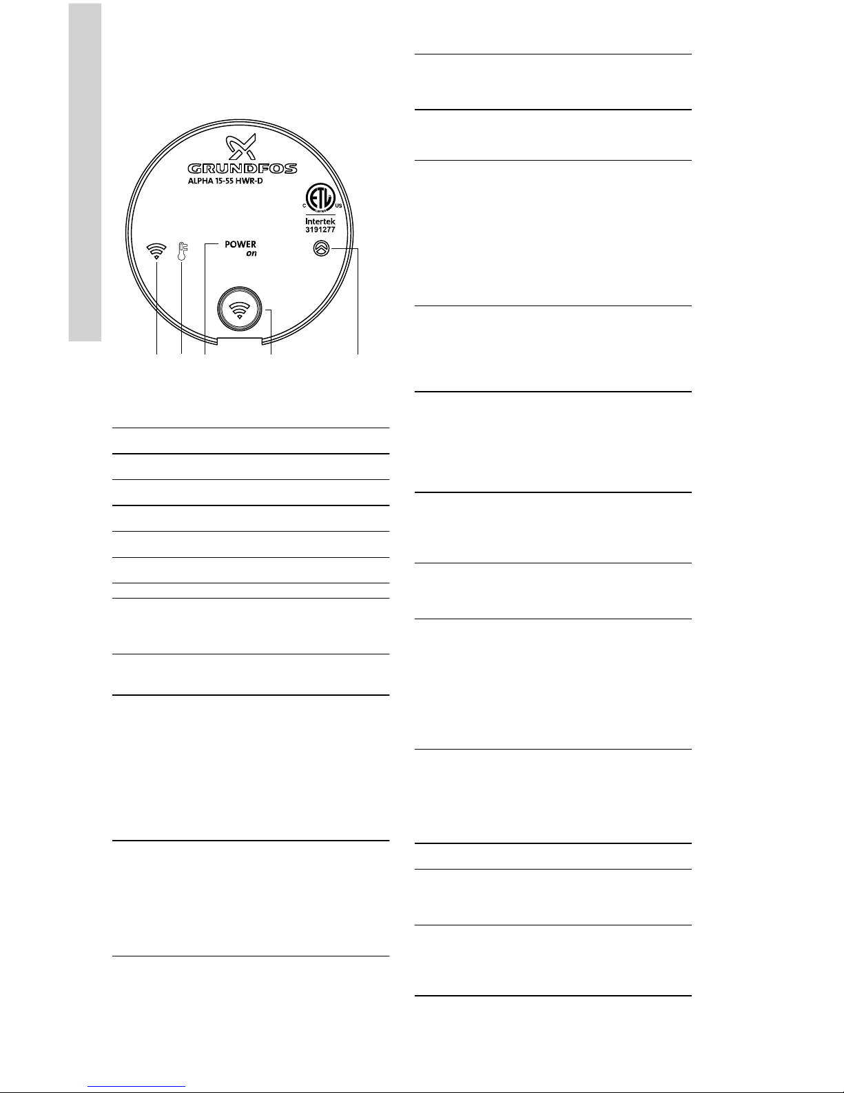
5.2 Starting the pump
3 4 51 2
TM072150
Fig. "Power ON" LED and other indicators
on the pump display
Pos. Description
1 "Connect" LED
2 "Temperature sensor" LED
3 "Power ON" LED
4 Pairing button
5 "Pump operation" LED
• Connect the line cord to the power supply to
start the pump.
• The pump will run for approx. 5 seconds and
then stop.
• The green "Power ON" LED on the pump
display will be lit when the power is on.
6. Product introduction
6.1 Product description
TM072165
Fig.
ALPHA 15-55 HWR-D pump, push-
button, and temperature sensor
The ALPHA HWR-D system is an on-demand hotwater recirculation system for use in domestic hotwater applications. It provides optimal comfort by
providing hot water instantly on demand.
6.2 Accessories
TM072805
Fig. HWR-D accessories
Pos. Description
1
Temperature sensor HWR-D
One temperature sensor is either
included or may be purchased as
an accessory.
2
Push-button HWR-D
One push-button is included in the
delivery. Additional push-buttons
may be purchased as accessories.
3
Repeater HWR-D
A repeater is not included but may
be purchased as an accessory to
increase the range of
communication between the pushbutton and the pump.
11
English (US)
Page 12

6.3 Intended use
The ALPHA 15-55 HWR-D system is intended for
domestic hot-water recirculation. When you
activate the system with the HWR-D push-button,
the pump starts circulating hot water.
To prevent continuous operation, the pump stops
recirculating water again when:
a) the media temperature measured at the
temperature sensor has increased by 10 °F or is
higher than 102 °F.
or
b) the pump has been operating continuously for
more than 5 minutes, or for a total of 15 minutes
during the last hour.
If the system is operated without the temperature
sensor, the pump will stop according to b).
6.4 Pumped liquids/media
CAUTION
Chemical hazard
Minor or moderate personal injury
‐ Do not use the pump for flammable
liquids, such as diesel or gasoline.
WARNING
Biological hazard
Death or serious personal injury
‐ In domestic hot-water systems, the
temperature of the pumped liquid
must always be above 122 °F (50
°C) due to the risk of legionella.
WARNING
Biological hazard
Death or serious personal injury
‐ In domestic hot-water systems, the
pump is permanently connected to
the main water supply. Therefore,
do not connect the pump by a
hose.
WARNING
Hot water
Death or serious personal injury
‐ If the hot water temperature is too
high, it can cause severe burns or
scalding.
‐ Ensure that the temperature of the
hot water source is not high
enough to cause burns or scalding.
CAUTION
Corrosive substance
Minor or moderate personal injury
‐ Do not use the pump for
aggressive liquids such as acids or
seawater.
The pump is suited for domestic hot water.
Maximum: 14 °dH
Maximum: 149 °F (65 °C)
Maximum peak: 158 °F (70 °C).
For water with a higher degree of hardness,
contact Grundfos.
6.5 Identification
6.5.1 Nameplate for ALPHA 15-55 HWR-D
Prod. No. XXXXXXXX
CSA ENC 2
Nonsubmersible Pump
Electronically Protected Class F
Min
Amp
Max water temp 230° F
1
2
3 4
5
6
Max
Watt
1 Ph 115V 60Hz
TM072175
Fig. Nameplate
Pos. Description
1 Product number
2 Voltage [V]
3 Rated current [A]:
Min.: Minimum current [A]
Max.: Maximum current [A]
4 Input power [W]
Min.: Minimum power [W]
Max.: Maximum power [W]
5
Maximum liquid
temperature [°F]
6 FCC and IC ID
12
English (US)
Page 13

6.6 Approvals for ALPHA 15-55 HWR-D
Approval marks
FCC sections
Section 15.19 (a) 3
This device complies with Part 15 of the FCC
Rules. Operation is subject to the following two
conditions: (1) this device may not cause harmful
interference, and (2) this device must accept any
interference received, including interference that
may cause undesired operation.
Section 15.21
Any changes or modifications to this equipment
not expressly approved by the party responsible
for compliance could void the user's authority to
operate this equipment.
Section 15.105 (b)
This equipment has been tested and
found to comply with the limits for a
class B digital device, pursuant to Part
15 of the FCC Rules.
These limits are designed to provide reasonable
protection against harmful interference in a
residential installation. This equipment generates,
uses and can radiate radio frequency energy and,
if not installed and used in accordance with the
instructions, may cause harmful interference to
radio communications. However, there is no
guarantee that interference will not occur in a
particular installation. If this equipment does
cause harmful interference to radio or television
reception, which can be determined by turning the
equipment off and on, the user is encouraged to
try to correct the interference by one or more of
the following measures:
• Reorient or relocate the receiving antenna.
• Increase the separation between
the equipment and receiver.
• Connect the equipment to an outlet on a
circuit different from that to which the receiver
is connected.
• Consult the dealer or an experienced
radio/TV technician for help.
This equipment complies with FCC/IC radiation
exposure limits set forth for an uncontrolled
environment and meets the FCC radio frequency
(RF) Exposure Guidelines and RSS-102 of the IC
radio frequency (RF) Exposure rules. This
equipment should be installed and operated
keeping the radiator at least 8 in (20 cm) or more
away from person's body.
Cet équipement est conforme aux limites
d'exposition aux rayonnement définies par la
norme FCC / IC pour un environnement non
contrôlé et est conforme aux directives
d'exposition de la FCC en matière de
radiofréquences et la norme RSS-102, des règles
d'exposition aux radiofréquences (RF) de l'IC. Cet
équipement doit être installé et utilisé en
maintenant le radiateur à au moins 8 in (20
cm) du corps de la personne.
Canadian ISED information
These devices (ALPHA 15-55 HWR-D, Pushbutton HWR-D, Temperature sensor HWR-D and
Repeater HWR-D) contain license-exempt
transmitter(s)/receiver(s) that comply with
Innovation, Science and Economic Development
Canada’s license-exempt RSS(s). Operation is
subject to the following two conditions: 1.This
device may not cause interference. 2.This device
must accept any interference, including
interference that may cause undesired operation
of the device. Innovation, Science and Economic
Development Canada ICES-003 Compliance
Label: CAN ICES-3(B)/NMB-3(B).
L’émetteur/récepteur exempt de licence contenu
dans le présent appareil est conforme aux CNR
d’Innovation, Sciences etDéveloppement
économique Canada applicables aux appareils
radio exempts de licence. L’exploitation est
autorisée auxdeux conditions suivantes : 1.
L’appareil ne doit pas produire de brouillage; 2.
L’appareil doit accepter tout brouillage
radioélectrique subi, même si le brouillage est
susceptible d’encompromettre le fonctionnement.
Étiquette de conformité à la NMB-003
d’Innovation, Sciences et Développement
économique Canada : CAN ICES-3(B)/-3(B).
These devices (ALPHA 15-55 HWR-D, Pushbutton HWR-D, Temperature sensor HWR-D and
Repeater HWR-D) comply with Industry Canada
RSS-247 and license-exempt RSS standard(s).
Operation is subject to the following two
conditions: (1) this device may not cause
interference, and (2) this device must accept any
interference, including interference that may
cause undesired operation of the device.
Ce dispositif est conforme à lanorme CNR-247
d'Industrie Canada applicable aux appareils radio
exempts de licence. Son fonctionnement est sujet
aux deux conditions suivantes: (1) le dispositif ne
doit pas produire de brouillage préjudiciable, et (2)
ce dispositif doit acceptertout brouillage reçu, y
compris un brouillag e susceptible de provoquer
un fonctionnement indésirable.
13
English (US)
Page 14
7. Control functions
7.1 Pump display
1 2 3 4 5
TM072147
Fig. LED symbols and buttons on the
pump display
Pos. Description
1 "Connect" LED
2 "Temperature sensor" LED
3 "Power ON" LED
4 Pairing button
5 "Pump operation" LED
Pump
display
symbol
Status Explanation
"Power
ON"
Green
Lights green when
pump is powered on.
"Connect"
Flashing
blue
Flashes blue when the
pump is ready for
pairing with the pushbutton or temperature
sensor. The symbol
flashes blue when a
paired temperature
sensor has been
disconnected.
"Connect" Blue
Lights blue for 5
seconds when pairing
is successful between
the pump and
the pushbutton or temperature
sensor.
"Connect"
Flashing
red (5
seconds)
during
installation
Flashes red for 5
seconds, when pairing
has failed with
Pump
display
symbol
Status Explanation
the pushbutton or temperature
sensor.
"Connect"
Flashing
red (2
seconds)
during
normal
operation
Flashes red for 2
seconds when the
battery level in
the push-button is at a
critical level.
Replacement of the
batteries in the pushbutton is
recommended.
"Connect" Green
Lights green for 2
seconds when
the push-button is
activated during
normal operation.
"Pump
operation"
Green
Lights green when the
pump circulates water
during normal
operation and is
connected to the
temperature sensor.
"Pump
operation"
Yellow
Lights yellow when the
pump has timed out.
The pump does not
circulate water.
"Pump
operation"
Red
The pump is in an
alarm state (see fault
finding section).
"Temperat
ure"
Red
Lights red when the
battery level in the
temperature sensor is
at a critically low level
(see fault finding
section). Replace the
battery in the
temperature sensor.
7.2 Temperature sensor LED
The LED is located on the temperature sensor
beneath the lid. You must remove the lid in order
to pair the temperature sensor with the pump.
Status
Explanation
Flashing blue
The LED flashes blue when the
temperature sensor is ready for
pairing with the pump.
Blue
The LED lights blue for 5
seconds when pairing between
the temperature sensor and the
pump has succeeded.
14
English (US)
Page 15

Status Explanation
Flashing red
(5 seconds)
during
installation
The LED flashes red for 5
seconds when pairing between
the temperature sensor and the
pump has failed. Restart of the
installation procedure is
recommended.
7.3 Push-button LED
LED status Explanation
Flashing blue
The LED flashes blue when the
push-button is ready for pairing
with the pump.
Blue
The LED lights blue for 5
seconds when pairing between
the push-button and the pump
has succeeded.
Flashing red
(5 seconds)
during
installation
The LED flashes red for 5
seconds when pairing between
the push-button and the pump
has failed. Restart of the
installation procedure is
recommended.
Flashing red
(2 seconds)
during normal
operation
The LED flashes red for 2
seconds when the battery level
in the push-button is at a
critical level, and the pushbutton is activated.
Replacement of the batteries in
the push-button is
recommended.
Green
The LED lights green for 2
seconds when the push-button
is activated during normal
operation.
7.4 Repeater LED
The LED on the repeater will light green when the
repeater is in operation.
15
English (US)
Page 16
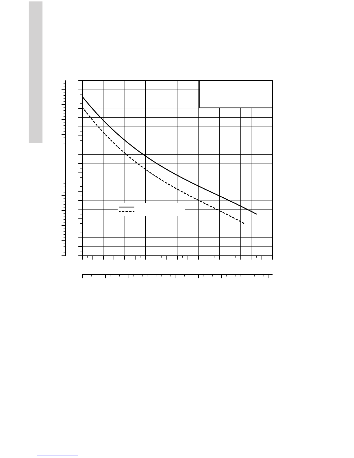
7.5 Pump curve
The pump runs at a constant speed and
consequently on a constant curve. The pump is
set on the maximum curve under all operating
conditions.
0 1 2 3 4 5 6 7 8 9 10 11 12 13 14 15 16 17 18
Q [US GPM]
0
1
2
3
4
5
6
7
8
9
10
11
12
13
14
15
16
17
18
[ft]
H
0.0
0.5
1.0
1.5
2.0
2.5
3.0
3.5
4.0
4.5
5.0
5.5
[m]
H
0.0 0.5 1.0 1.5 2.0 2.5 3.0 3.5 Q [m³/h]
ALPHA 15-55 HWR-D
60 Hz
Without check valve installed
With check valve installed
TM072501
Fig. Performance curve, ALPHA 15-55
HWR-D
16
English (US)
Page 17

8. Servicing the product
8.1 Maintaining the product
The ALPHA HWR-D pump is maintenance-free.
If the pump is damaged, for example with
fractures or dents, replace the pump.
8.1.1 Battery replacement
WARNING
Biological hazard
Death or serious personal injury
‐ Keep batteries out of reach of small
children, the elderly, and pets.
Batteries can cause permanent
injury if ingested or placed in the
nose, mouth, or ears.
‐ Immediate emergency room
treatment is required for anyone
who ingests a battery. In addition,
in the US, consult the 24-hour
National Battery Ingestion Hotline
at 800-498-8666 for assistance.
CAUTION
Corrosive substance
Moderate to minor personal injury and
risk of property damage
‐ The push-button HWR-
D or temperature sensor HWRD must be replaced if battery
leakage occurs.
CAUTION
Flammable material
Minor or moderate personal injury
‐ Do not attempt to recharge non-
rechargeable batteries.
To clean the push-button or
temperature sensor, wipe it with a
clean, damp cloth.
Ensure that disposal of old batteries is in
accordance with local regulations. Recycle old
batteries where possible.
8.1.1.1 Battery replacement for temperature
sensor
The temperature sensor uses AA 3.6 V lithiumthionyl batteries. To change the battery in the
temperature sensor, follow these steps:
1. Remove the lid of the temperature sensor.
2. Remove the old battery.
3. Insert the new battery.
4. Replace the lid of the temperature sensor.
8.1.1.2 Battery replacement for push-button
The push-button uses AAA 1.5 V
alkaline batteries. To change the battery in the
push-button, follow these steps:
1. Remove the push-button from the mounting
bracket on the back of the push-button.
2. Remove the old batteries.
3. Insert the two new batteries.
4. Replace the push-button on the mounting
bracket.
17
English (US)
Page 18

9. Fault finding the product
9.1 Fault finding table
Fault: The pump does not start.
Status Cause Remedy
"Power On" LED on the pump
control panel is not lit.
The pump is not connected to
the power supply.
Make sure the power supply is
switched on.
Check if external protection has
tripped.
Make sure the cables and
connections are free from
defects and connected securely.
The "Power On" LED on the
pump control panel is green. The
"Pump Operation" LED is red.
The pump is in an alarm state.
Contact your local Grundfos
representative.
The "Power On" LED on the
pump control panel is green, but
the pump does not start when
the push-button is activated.
If the "Pump Operation" LED on
the pump control panel is yellow,
the pump has timed out.
Wait until the yellow "Pump
Operation" LED turns off.
The push-button is not paired
with the pump.
Follow the pairing procedure for
the push-button.
The push-button batteries need
replacing.
Replace the batteries in the
push-button.
The push-button is out of range.
Use the Repeater HWR-D
accessory to increase the range
of wireless signals.
After installing the repeater, the
"Power On" LED on the pump
control panel is green, but the
pump does not start when the
push-button is activated.
The push-button is out of range,
and the pump does not receive
the repeater's wireless signal.
Relocate the repeater within the
house for optimum range of
wireless signals.
Fault: The "Connect" LED is flashing blue continuously.
Status
Cause Remedy
The "Connect" LED on the pump
control panel is flashing blue.
The temperature sensor has
been disconnected from the
pump.
The temperature sensor is out of
range.
Ensure the temperature sensor
is in proximity to the pump.
The temperature
sensor batteries need replacing.
Replace the batteries in the
temperature sensor.
The temperature sensor is not
working.
Replace the temperature
sensor. Follow the pairing
procedure for the new
temperature sensor.
Fault: There is noise in the hydraulic system.
Status
Cause Remedy
There are no indicators lit on the
pump or accessories.
Air in the system.
Open a faucet or tap to let
trapped air escape.
18
English (US)
Page 19

Fault: There is noise in the circulator pump.
Status Cause Remedy
There are no indicators lit on the
pump or accessories.
Air is trapped in the pump.
Open a faucet or tap to let
trapped air escape.
No liquid.
Ensure there is liquid in the hot
water supply source.
19
English (US)
Page 20

10. Technical data
10.1 Operating conditions
Supply voltage
- Pump
1 x 115 V, +10 % / -10
%, 60 Hz
- Repeater with USB
plug
5 V DC, +10 % / -10 %
- AC power adapter for
repeater
100-240 V AC, +10 % /
-10 %, 50/60 Hz
Motor protection
The pump requires no
external motor
protection.
Enclosure class
Indoor use only, IP42.
CSA enclosure type 2.
Insulation class F.
Relative humidity Maximum 95 %.
Maximum outlet
pressure
150 psi (10.34 bar).
Sound pressure level 43 dB (A).
Ambient temperature
34 to 104 °F (1 to 40
°C)
Inlet pressure
Liquid temp.
Min. inlet pressure
167 °F (75 °C) 0.75 psi (0.05 bar)
194 °F (90 °C) 4.06 psi (0.28 bar)
230 °F (110 °C) 15.7 psi (1.08 bar)
Liquid temperature
36 °F (2 °C) to 230 °F (110 °C)
In domestic hot water systems, keep
the liquid temperature below
149 °F (65 °C) to eliminate the risk of
lime precipitation.
To avoid condensation in the control box and
stator, the liquid temperature must always be
higher than the ambient temperature.
Ambient
temp.
Min. liquid
temp.
Max. liquid
temp.
[°F (°C)] [°F (°C)] [°F (°C)]
34 (1) 36 (2) 230 (110)
50 (10) 50 (10) 230 (110)
68 (20) 68 (20) 230 (110)
86 (30) 86 (30) 230 (110)
95 (35) 95 (35) 194 (90)
104 (40) 104 (40) 158 (70)
Approximate power usage
Minimum: 2 W
Maximum: 45 W
11. Disposing of the product
CAUTION
Magnetic field
Minor or moderate personal injury
‐ Persons with pacemakers
disassembling this product must
exercise care when handling the
magnetic materials embedded in
the rotor.
This product or parts of it must be disposed of
in an environmentally sound way:
1. Use the public or private waste collection
service.
2. If this is not possible, contact the nearest
Grundfos company or service center.
See also end-of-life information
at www.grundfos.com/product-recycling.
20
English (US)
Page 21

U.S.A.
GRUNDFOS Pumps Corporation
9300 Loiret Boulevard
Lenexa, Kansas 66219 USA
Tel.: +1 913 227 3400
Fax: +1 913 227 3500
GRUNDFOS Water Utility Inc.
3905 Enterprise Court
P.O. Box 6620
Aurora, IL 60598-0620
Phone: +1-630-236-5500
Fax: +1-630-236-5511
GRUNDFOS CBS Inc.
902 Koomey Road
Brookshire, TX 77423 USA
Phone: 281-994-2700
Toll Free: 1-800-955-5847
Fax: 1-800-945-4777
Peerless Pump
2005 Dr. Martin Luther King Jr
US-46202 Indianapolis, Indiana U.S.A.
Phone:317-925-9661
Canada
GRUNDFOS Canada Inc.
2941 Brighton Road
Oakville, Ontario
L6H 6C9
Tel.: +1-905 829 9533
Fax: +1-905 829 9512
Mexico
Bombas GRUNDFOS de México
S.A. de C.V.
Boulevard TLC No. 15
Parque Industrial Stiva Aeropuerto
Apodaca, N.L. 66600
Tel.: +52-81-8144 4000
Fax: +52-81-8144 4010
Revision Info
Last revised on 13-10-2016
Grundfos companies
Page 22

99475026 0119
ECM: 1251559
Trademarks displayed in this material, including but not limited to Grundfos, the Grundfos logo and “be think innovate” are registered trademarks owned by The Grundfos Group. All rights reserved. © 2019 Grundfos Holding A/S,
all rights reserved.
 Loading...