

Page 1

GRUNDFOS INSTRUCTIONS
S pumps, range 72 - 74 - 78
DIN 50/60 Hz
Service instructions
Page 2

English (GB) Service instructions
Caution
Note
English (GB)
Original service instructions.
CONTENTS
1. Symbols used in this document
2. Servicing S pumps with explosion-proof motors
3. Safety
4. Identification
4.1 Nameplate
4.2 Type key
5. Handling the pump
5.1 Lifting the pump
5.2 Lifting points
5.3 Raising pump to upright position
6. Torques, lubricants and special liquids
6.1 Common torques
6.2 Special torques and lubricants
6.3 Quantities of grease in bearings
6.4 Special liquids
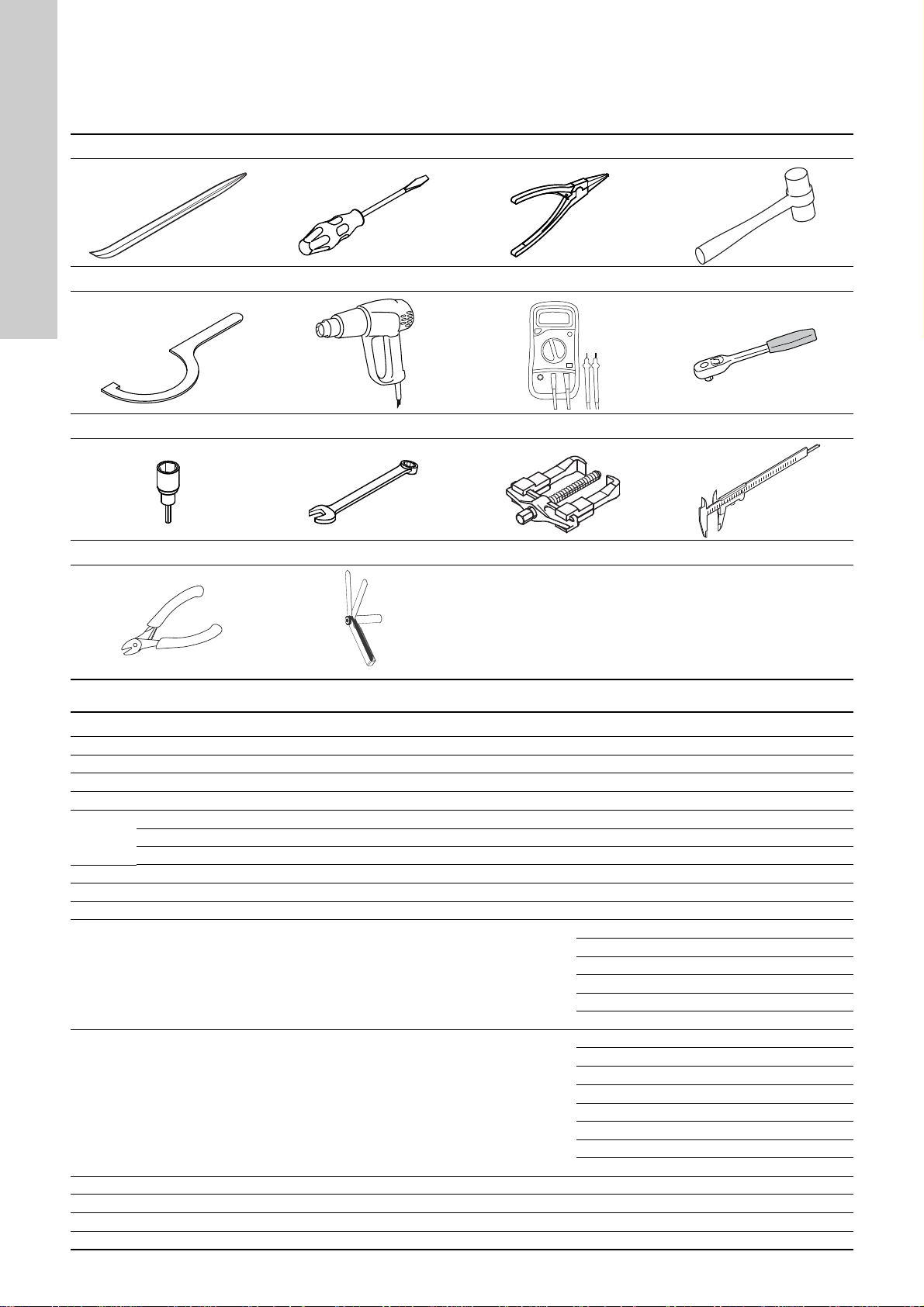
7. Service tools
7.1 Standard tools
7.2 Special tools
7.3 Tightness test tools
7.4 Lifting tools
8. Service
8.1 General information
8.2 Pump cleaning and visual inspection
8.3 Annual maintenance
8.4 Oil check and oil change
8.5 Inspection and adjustment of impeller clearance
9. Dismantling and assembly instructions
9.1 Checking and replacing the cable
9.2 Replacing the terminal board
9.3 Replacing the protection sensors
9.4 Dismantling range 72
9.5 Assembling range 72
9.6 Dismantling range 74
9.7 Assembling range 74
9.8 Dismantling range 78
9.9 Assembling range 78
10. Tightness tests
10.1 Tightness test of stator (submerged)
10.2 Tightness test of terminal box (cable side, submerged)
11. Drawings
11.1 Range 72
11.2 Range 74
11.3 Range 78
11.4 Position numbers and material specification
11.5 Sensor positions
11.6 Electrical connections
Page
10
10
10
10
11
12
13
13
14
17
19
21
23
25
29
30
32
32
32
33
33
42
48
56
58
60
1. Symbols used in this document
Warnin g
If these safety instructions are not observed,
2
3
3
3
3
4
6
6
6
6
7
7
7
7
7
8
8
9
9
9
it may result in personal injury.
Warnin g
These instructions must be observed for
explosion-proof pumps. It is advisable also to
follow these instructions for standard pumps.
Warnin g
If these instructions are not observed, it may lead
to electric shock with consequent risk of serious
personal injury or death.
Warnin g
The surface of the product may be so hot that
it may cause burns or personal injury.
Warnin g
The sound pressure level is so high that hearing
protection must be used.
If these safety instructions are not observed,
it may result in malfunction or damage to the
equipment.
Notes or instructions that make the job easier
and ensure safe operation.
2
Page 3

2. Servicing S pumps with explosion-proof
Note
motors
S pumps, range 72 to 78 have the following explosion protection
classification:
Direct drive, 50 or 60 Hz CE 1180 II2 G Ex bc d IIB T4
72
74, 78
Service work on Ex pumps must be carried out by Grundfos or a
workshop authorised by Grundfos. Violation of this requirement
will invalidate the Ex classification of the pump.
Overhauled and repaired explosion-proof pumps are provided
with a repair plate giving the following information:
• the repair symbol R
• name of registered trade mark of the repairing workshop
• workshop reference number relating to the repair
• date of overhaul or repair.
In case of subsequent repairs, the existing repair plate should be
replaced by a new, updated repair plate and earlier markings
must be recorded.
The repairing workshop must keep records of performed
overhauls and repairs together with records of all previous
overhauls, repairs and possible modifications. Copies of the
repairing workshop’s detailed records should be filed by the
owner or operator together with the original type certificate of the
explosion-proof motor in question.
Frequency converter
drive
Direct drive, 50 or 60 Hz Only on request
Frequency converter
drive
CE 1180 II2 G Ex bc d IIB T3
Only on request
3. Safety
Warning
Pump installation in pits must be carried out by
specially trained persons.
Work in or near pits must be carried out
according to local regulations.
For safety reasons, all work in pits must be supervised by a
person outside the pump pit.
Pits for submersible sewage and wastewater pumps contain
sewage and wastewater with toxic and/or disease-causing
substances. Therefore, all persons involved must wear
appropriate personal protective equipment and clothing, and all
work on and near the pump must be carried out under strict
observance of the hygienic regulations in force.
Warning
Before attempting to lift the pump, make sure the
rated capacity of the lifting equipment (lifting
chain etc.) is adequate for the lifting work.
The rated capacity of the lifting equipment is
stated on the equipment nameplate. The weight
of the pump is stated on the pump nameplate.
4. Identification
4.1 Nameplate
English (GB)
TM05 8220 2113
Fig. 1 Pump nameplate
All pumps can be identified by means of the nameplate on the
motor top cover, see fig. 1.
Pos. Description
1 Type designation
2 Product number
3 Serial number
4 Maximum head (m)
5 Number of phases
6 Voltage, delta connection
7 Voltage, star connection
8 Rated power input (kW)
9 Power factor (Cos φ)
10 Production code (YYWW)
11 Model
12 Maximum liquid temperature
13 Maximum flow rate (l/s)
14 Enclosure class according to IEC 60529
15 Frequency (Hz)
16 Rated speed
17 Current, delta connection
18 Current, star connection
19 Rated power output P2
20 Insulation class
21 Weight
If a pump has been used for a liquid which is
injurious to health or toxic, the pump will be
classified as contaminated.
If Grundfos is requested to service the pump, Grundfos must be
contacted with details about the pumped liquid, etc., before the
pump is returned for service. Otherwise Grundfos can refuse to
accept the pump.
Possible costs of returning the pump are paid by the customer.
However, any application for service (no matter to whom it may
be made) must include details about the pumped liquid if the
pump has been used for liquids which are injurious to health or
toxic.
3
Page 4

4.2 Type key
English (GB)
All S pumps, range 72, 74 and 78, described in this product guide are identified by the type designation stated in the confirmation of order
and other documentation supplied with the pump.
Please note that the pump type described in this type key is not necessarily available in all variants.
Code Example S 2 .90 .250 .2250 .4 .72 S .C .496 .G .N .D .5 13 .Z
Pump type:
Grundfos sewage and wastewater pump
S
Multi-channel impeller pump installed in a column pipe
ST
Impeller type:
Two-channel
2
Three-channel
3
Four-channel
4
Pump passage:
Maximum solids size [mm]
Pump discharge, S type:
250
Nominal diameter of pump discharge port [mm]
Pump discharge, ST-type:
[ ]
Nominal diameter of column pipe [mm]
Output power, P2:
P2 = Code number from type designation/10 [kW]
Number of poles:
4-pole motor
4
6-pole motor
6
8-pole motor
8
10-pole motor
10
12-pole motor
12
14-pole motor
14
Pump range:
72
72
74
74
78
78
Pressure version:
Super-high
S
High
H
Medium
M
Low
L
Extra-low
E
Super low
F
Installation type:
Submerged installation without cooling jacket
S
Submerged installation with cooling jacket
C
Dry installation with cooling jacket
D
Dry horizontal installation with cooling jacket
H
Impeller diameter (average):
[mm]
Material code for impeller, pump housing and stator housing:
Cast iron impeller, pump housing and stator housing
G
Cast iron pump with stainless steel impeller
Q
Pump version:
Non-explosion-proof pump
N
Pump with explosion-proof motor
Ex
Sensor version:
S pump with built-in SM 113 module. PTC sensors are connected directly to IO 113 or other PTC relay.
B
S pump without built-in SM 113 module
D
Frequency:
50 Hz
5
60 Hz
6
Voltage and connection:
50 Hz 60 Hz
3 x 400 / 690 V Y/D 3 x 575 / (996) V Y/D
11
3 x 415 / 719 V Y/D
13
3 x 380-400 / 660-690 V Y/D
18
58
1G
3 x 380 / 660 V Y/D 3 x 380 / 660 V Y/D
1H
3 x 460 / (797) V Y/D
1B
3 x 400-415 / 690-719 V Y/D
1D
3 x 380-415 / 660-719 V Y/D
Z Custom-built products
4
Page 5

Type key used for frame size 74 and 78 until 2010. May still be used for spare pumps manufactured later.
Code Example S 2 X 250 4 H 2 5 11 Z
Pump type:
S
Grundfos (or Sarlin) wastewater pump/sewage pump
Impeller type:
Two-channel
2
Three-channel
3
Four-channel
4
Axial Propeller
A
Multi-channel, small pump passage
N
Pump version:
Standard pump
[ ]
In conformity with the ATEX directive
X
Power:
100
Motor power in kW
Number of poles:
2-pole motor
2
4-pole motor
4
6-pole motor
6
8-pole motor
8
10-pole motor
10
12-pole motor
12
14-pole motor
14
Pump generation:
First generation
[ ]
Second generation
A
Third generation
B
Pressure version:
No classification
[ ]
Super high
S
High
H
Medium
M
Low
L
Super extra low
F
Installation type:
Submerged installation without cooling jacket
1
Submerged installation with cooling jacket
2
Dry installation with cooling jacket
3
Submerged installation, portable. Pump without cooling jacket.
4
Submerged installation, portable. Pump with cooling jacket.
5
Dry horizontal installation with base stand and bracket. Pump with cooling jacket
6
Submerged column installation
7
Interchangeability:
No letter indicates full interchangeability of parts and use of the same spare parts catalogue.
[ ]
The letters (A, B, C...) indicate interchangeability of parts between otherwise identical pumps.
A,B,C
Number of phases:
Single-phase
1
Three-phase
[ ]
Frequency:
50 Hz
5
60 Hz
6
Voltage and starting method:
50 Hz 60 Hz
660-690 V Y
06
288-500 V Y/D
10
400-690 V Y/D 460-(796) V Y/D
11
220-380 V Y/D
12
415-(719) V Y/D
13
500-(865) V Y/D
14
380-660 V Y/D
15
Special equipment:
U
Flanges sized according to ANSI specifications
Non-standard parts:
Special diameter in impeller
D
Special length of cable
C
Combination of C and D or other special part
Z
Material code for impeller, pump and stator housing:
R
Stainless steel impeller, pump housing and stator housing, AISI 316 (DIN W.-Nr. 1.4408)
S
Stainless steel impeller and pump housing, AISI 316 (DIN W.-Nr. 1.4408)
Stainless steel impeller, AISI 316 (DIN W.-Nr. 1.4408)
Q
English (GB)
5
Page 6

5. Handling the pump
English (GB)
S pumps, range 78 weigh up to 7800 kg without accessories. It is
therefore very important to use the right lifting equipment.
The pump weight is stated on the pump nameplate. See section
4.1 Nameplate.
5.1 Lifting the pump
All lifting equipment must be rated for the purpose and checked
for damage before any attempt to lift the pump. The lifting
equipment rating must under no circumstances be exceeded.
See section 7.4 Lifting tools.
5.2 Lifting points
Warning
Never lift the pump by the power supply cables.
It may result in electric short-circuit and risk of
electric shock when the pump is connected to the
mains. The cables and cable entry may be
damaged, leading to loss of watertightness and
consequent severe damage to the motor.
5.3 Raising pump to upright position
Warnin g
Make sure that the lifting brackets are tightened
before attempting to lift the pump. Tighten if
necessary. Carelessness during lifting or
transportation may cause injury to personnel or
damage to the pump.
TM03 3034 0208TM03 3035 0208TM03 3036 0208
Fig. 4 Raising the pump to upright position, step 1
Fig. 2 Lifting points, range 72
Fig. 3 Lifting points, range 74 and 78
TM03 4459 0208TM04 6068 4809
Fig. 5 Raising the pump to upright position, step 2
Fig. 6 Raising the pump to upright position, step 3
6
Page 7

6. Torques, lubricants and special liquids
This section shows the screws and nuts that must be tightened to a certain torque and the lubricants to be used.
6.1 Common torques
Dimension M8 M10 M12 M16 M20 M24 M27 M30
Torque [Nm] 20 40 70 170 330 570 820 1120
6.2 Special torques and lubricants
English (GB)
Range Pos. Description Quantity Dimension
74, 78 61a O-ring (primary shaft seal) 2 - - Oil
74, 78 62 O-ring 1 - - Oil
72, 74 67 Screw (impeller) 1 M24 600 Oil
78
All 72a O-ring 1 - - Oil
All 105
72 105 Screw of primary shaft seal 5 - 8 -
74, 8 105 Screw of primary shaft seal 5 - 15 -
All 105b
72, 74 105b Screw of secondary shaft seal 5 - 8 -
78 105b Screw of secondary shaft seal 5 - 15 -
74, 78 153 Angular contact ball bearings 2 - - Unirex S2 / LGHP 2
All 157 O-ring 1 - - Oil
All 157a O-ring 1 - - Oil
All 162 Roller bearings 1 - - Unirex S2 / LGHP 2
All 154 Ball bearing 1 - - Unirex S2 / LGHP 2
All 193 Oil plug 3 R 3/4 55 ± 5 -
74, 78 756 O-ring 1 - - Oil
67 Screw (impeller) 1 M24 160 Oil
67a Screw (fastening plate of impeller) 3 - 170 Oil
O-ring (inside of stationary part) 1 - - Oil
Primary shaft seal (sliding surfaces) 1 - - Silicone spray
O-ring (inside stationary part) 1 - - Oil
Secondary shaft seal (sliding surfaces) 1 - - Silicone spray
Torque
[Nm]
Lubricant
Oils:
Silicone spray Valvoline: 96249498.
Esso Unirex S2: 96248520/SKF LGHP 2 (-).
Motor oil with viscosity grade SAE 10 W 30 or SAE 10 W 40.
6.3 Quantities of grease in bearings
Range Bearing Amount of grease
72
74 2.3 litres
78 4.2 litres
Range Bearing Amount of grease
72
74 1.0 litres
78 1.7 litres
Lower bearings
Upper bearing
2.2 litres
0.28 litres
6.4 Special liquids
Range Pos. Component Liquid
523 Cable gland for WIO Ergo 4307
All
Würth Ergo 4307 or similar (thread-locking compound)
Henkel Loclite 290 or similar (thread-locking compound)
ACC Silicone Silcoset 151 (glue, FM approved).
520d Moisture switch Loclite 290
177 Terminal board Silcoset 151
7
Page 8
7. Service tools
English (GB)
The following sections shows tools for pump service.
7.1 Standard tools
ABCD
EFGH
IJKL
MN
Standard tools
Pos. Range Designation Description Part number
A All Pinch bar - SV5201
B All Screwdriver Straight slot C All Lock-ring pliers - SV2014
D All Plastic hammer - SV0349
72 Hook spanner (Walter) 120-130 mm -
E
F All Warm-air heater - G All Multimeter - H All Ratchet handle 1/2" - 96777072
I All Hexagon head driver
J All Ring/open-end spanner
K All Puller for bearing - SV0335
L All Sliding gauge 0-150 mm SV0307
M All Cable pliers - N All Feeler gauge - -
74 Hook spanner (SKF) HN22 78 Impact spanner (TMFN) 30-40 -
4 mm SV0414
M6 - 5 mm SV0296
M8 - 6 mm SV0297
M10 - 8 mm SV0298
M12 - 10 mm SV0299
M16 - 12 mm - 1/2" SV0394
8 mm SV0273
10 mm SV0083
12 mm SV0274
16 mm SV0185
20 mm 24 mm SV0122
27 mm SV0084
30 mm SV0073
8
Page 9

7.2 Special tools
OPQR
STUV
Special tools
Pos. Range Designation Description Part number
O All Torque wrench - P 74 Seal assembly tool (PUR127) Roplan 85 mm 96242908
Q 74 Seal assembly tool (PUR128) Roplan 95 mm 96242909
R 78 Seal assembly tool (PUR129) Roplan 110 mm 96242910
S 78 Seal assembly tool (PUR130) Roplan 110 mm 96242911
T 74 Seal assembly tool (PUR131) Roplan 100 mm 96242912
U 78 Seal assembly tool (PUR132) Roplan 120 mm 96242913
V 72 Seal assembly tool (PUR133) Roplan 65 mm 96255372
English (GB)
7.3 Tightness test tools
WXY
BAR
Tightness test tools
Pos. De sig n atio n Description Part number
W Pressure gauge --
X Test plug (KOE045)
Y Test plug (KOE171) Connector R3/4 96061213
Connector M3\8-24 UNF F-ISO
228-G 3\8M
96061209
7.4 Lifting tools
AA BB CC DD
Lifting tools
Pos. De sig n atio n Description Part number
AA Eyebolt with rotating swivel Range 74 and 78 BB Shackle All CC Eye bolt All DD Lifting clamp Range 78 98253177
9
Page 10
8. Service
Note
English (GB)
8.1 General information
Warning
Before starting work on the pump, make sure that
the mains switch has been locked in position 0.
All rotating parts must have stopped moving.
Warning
Except for replacement/dismantling of bearings,
all other service work must be carried out by
Grundfos or an authorised service workshop.
Service must be carried out by specially trained persons.
Before carrying out maintenance and service, it must be ensured
that the pump has been thoroughly flushed with clean water.
Rinse the pump parts with water after dismantling.
Before assembly:
• Clean and check all parts.
• Replace defective parts with new parts.
• Order the necessary service kits.
• Gaskets and O-rings should always be replaced when the
pump is overhauled.
During assembly:
• Lubricate and tighten screws and nuts to correct torque as
stated in section.
8.2 Pump cleaning and visual inspection
A simple maintenance measure is to clean the pumps at regular
intervals. The pumps may be cleaned on site at the pumping
station when lifted up from the wet pit. Hose down the pump
externally using a high-pressure jet cleaner (maximum pressure
100 bar). Caked dirt on the motor must be removed to ensure
good heat conductivity. A mild detergent approved for disposal
into the sewage system may be used. The pumps may be
scrubbed, using a soft brush, if necessary.
Visual inspection of the pump should include search for cracks or
other external damage. Inspect the lifting bracket and lifting chain
for wear and corrosion. Inspect the pump cable for cracks or
lacerations in the sheath, kinks or other damage. Inspect visible
parts of the cable entry for cracks and for being firmly connected
to the motor top cover. Check all visible screws and tighten, if
necessary.
The air vent valve at the top of the cooling jacket may be removed
and cleaned, if necessary. Clean the vent hole before refitting the
valve after cleaning.
8.3 Annual maintenance
Pumps in normal operation should be inspected once a year.
If the pumped liquid is very muddy or sandy, check the pump at
shorter intervals.
The following points should be checked:
• Power consumption
See section 4.1 Nameplate.
• Oil level and oil condition
See section 8.4 Oil check and oil change.
• Cable entry
Make sure that the cables are not sharply bent or pinched.
Replace the cables if necessary.
See section 9.1 Checking and replacing the cable.
• Sensors
Make sure that sensor are working. Replace the sensors if
necessary.
See section 9.3 Replacing the protection sensors
• Impeller clearance
Check the impeller clearance.
See section 8.5 Inspection and adjustment of impeller
clearance.
• Pump parts
Check the pump housing, etc. for possible wear.
Replace defective parts.
• Ball bearings
Check the shaft for noisy or heavy operation (turn the shaft by
hand). Replace defective ball bearings.
A general overhaul of the pump is usually required in case of
defective ball bearings or poor motor function. This work must
be carried out by an authorized service workshop.
Warnin g
On Ex pumps, the ball bearings must only be
replaced by an authorised Ex workshop.
• O-rings and similar parts
During service / replacement, it must be ensured that the
grooves for O-rings and seal faces have been cleaned before
the new parts are fitted.
Used rubber parts must not be reused.
10
Page 11
8.4 Oil check and oil change
Note
Note
Note
Note
B
The oil chamber is filled with oil acting as lubricant and coolant for
both mechanical shaft seals.
Check the oil regularly to avoid damage and
breakdown of the pump.
Low oil level may indicate that the upper mechanical shaft seal is
defective. Contact an authorized service workshop for further
overhaul of the pump and repair, if required.
Warning
Lack of oil may cause overheating and damage of
the mechanical shaft seals. The WIO sensor in
the oil chamber will trip the alarm if the oil quality
is poor or there is not enough oil in the oil
chamber.
Use oil with viscosity grade SAE 10 W 30 or SAE
10 W 40.
Oil quantity
4. If the oil needs to be changed, remove screw C and allow all
the oil to drain from the chamber into the container. Pour an
oil sample into a glass container and observe the condition of
the oil.
Clear oil can be reused.
Emulsified oil must be changed and disposed of.
Used oil must be disposed of in accordance with
local regulations.
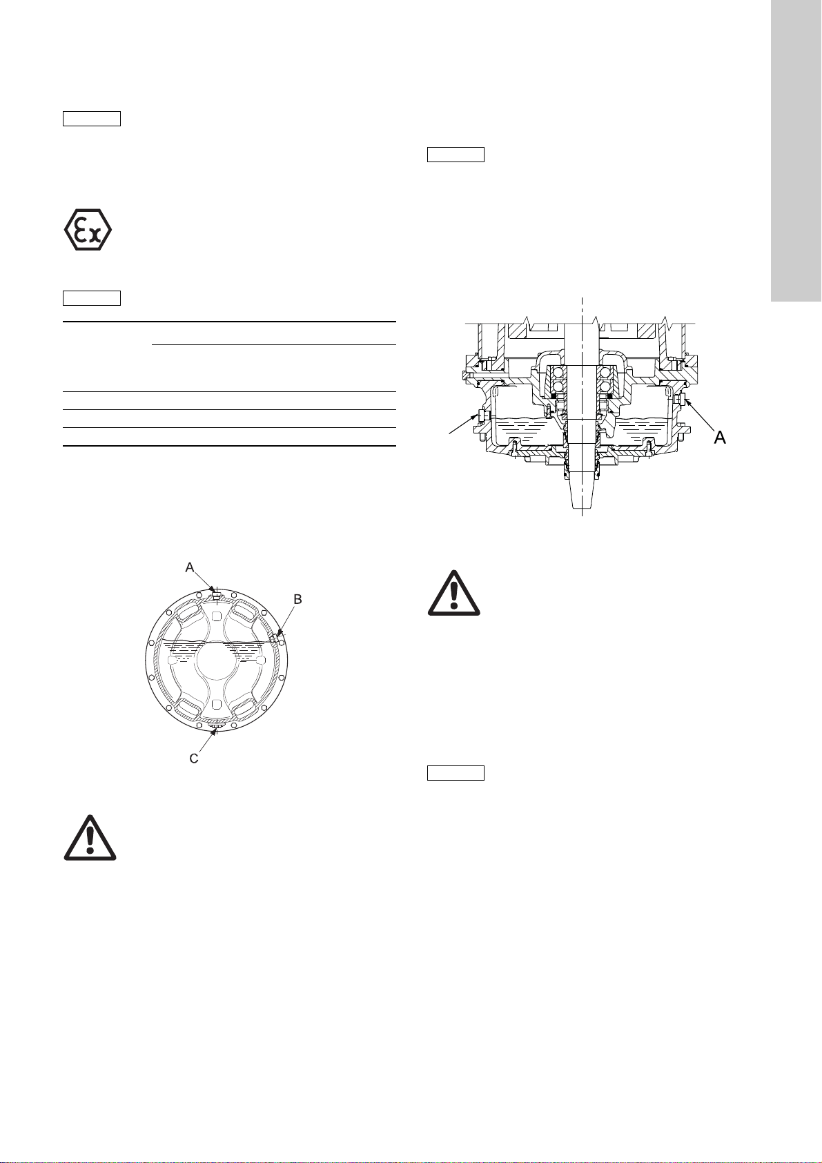
5. Replace the O-rings, refit screw C and tighten securely.
Fill the oil chamber with oil to the correct level. Refit screws A
and B and tighten securely.
Upright position
Proceed as follows:
1. Identify the screws A, B and C and their positions relative to
each other. See fig. 7.
English (GB)
Range
72 25 litres 18.5 litres 25 litres
74 - 20 litres 25 litres
78 - 80 litres 80 litres
The oil in the oil chamber can be changed with the pump in either
horizontal or upright position.
Horizontal position
Proceed as follows:
1. Place the pump in such a position that inspection screw A is
pointing upwards.
Fig. 7 Pump with inspection screw A upwards
Warning
When slackening the screw A of the oil chamber,
note that pressure may have built up in the
chamber. Do not remove the screw until the
pressure has been fully relieved!
2. Place a clean container under the pump to collect all the
drained-off oil. Remove screw B and observe the oil level.
3. Check the oil level and take an oil sample to inspect the
condition of the oil. The oil becomes greyish white like milk if it
contains water. In normal operation a small leakage through
the mechanical shaft seals is expected to happen, but if the
water content in the oil is high, this may be the result of a
defective shaft seal. The oil should be changed if it contains
water.
Installation type
S C and D ST
Fig. 8 Correct oil level of upright pump
Warnin g
When slackening the screw A of the oil chamber,
note that pressure may have built up in the
chamber. Do not remove the screw until the
pressure has been fully relieved!
2. Proceed as above and use screw B again for indication of the
level of oil in the oil chamber. See fig. 8.
3. When the pump is upright, the oil has to be pumped out of the
oil chamber. Use a suction pump with a flexible suction hose
that can be inserted deep into the oil chamber.
4. Pump out the oil using all the screw holes in turns so as to
reach all sections of the interior of the oil chamber. Collect the
drained oil in a clean container.
TM03 1628 2705
5. Replace the O-rings, refit screw C and tighten securely.
Fill the oil chamber with oil to the correct level. Refit screws A
and connecting block B and tighten securely.
Used oil must be disposed of in accordance with
local regulations.
TM04 6924 1210
11
Page 12
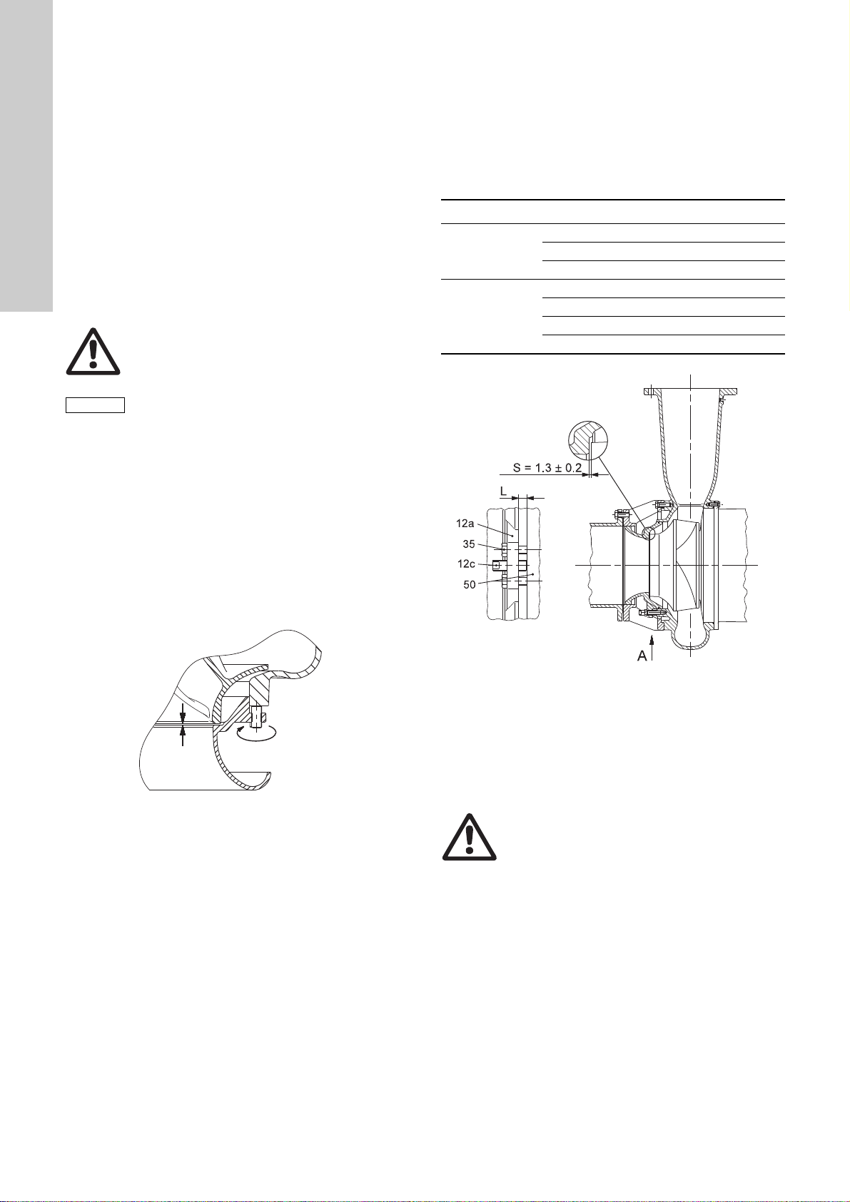
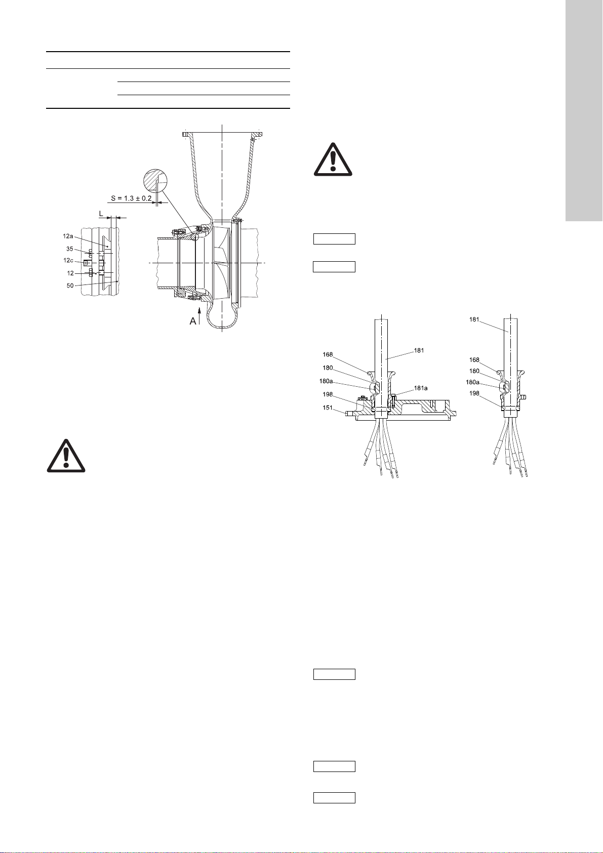
8.5 Inspection and adjustment of impeller clearance
Note
View from direction A
English (GB)
Position numbers of parts (digits) refer to section 11. Drawings
and section 11.4Position numbers and material specification.
The correct impeller clearance is 1.3 mm ± 0.2 mm.
The clearance should be reset if it is 2.0 mm or more.
The method for resetting the clearance is different for dryinstalled pumps, type D, and submersible pumps, types S and C.
For dry-installed pumps there are two methods. All methods are
described here.
8.5.1 Submersible pumps, installation types S, C and ST
Submersible pumps have a separate adjustable pump suction
cover which may be shaped as a suction bell. When the pump is
installed or withdrawn, locate the six fastening screws of the
suction cover and the three set screws.
Use a feeler gauge (N) to check the clearance between the
impeller and the suction cover all around the perimeter of the
suction opening. See fig. 9.
Warning
Never work under a pump when it is hanging
from hoist!
Before adjusting the clearance, clean the gap
between impeller and suction cover.
If the clearance needs adjustment proceed as follows:
1. Slacken all fastening screws (35) and set screws between
suction cover and pump housing.
2. Use a rubber mallet to tap the suction cover to close the
clearance.
3. Open the clearance to specified value by turning the three set
screws (12c).
4. Check that the clearance is uniform around the perimeter of
the suction opening.
5. Tighten the fastening screws (35) and check that the
clearance is stable.
6. Turn the impeller (49) by hand and check at several points.
8.5.2 Dry-installed pumps, installation types D and H
The impeller clearance can be inspected and set with the pump
installed on the pump stand and connected to the pipework.
In these pumps, the suction cover is located between pump
housing and outer connection flange on the suction side of the
pump.
Depending on the construction, there are two ways to set the
impeller clearance.
Method 1
Range Pump types
S2.90.xxx.xxxx.x.xxx.
72 and 74
S2.100.xxx.xxxx.x.xxx.
S3.135.600.xxxx.x.xxx.
S3.115.xxx.xxxx.x.xxx.
78
S3.130.xxx.xxxx.x.xxx.
S3.145.xxx.xxxx.x.xxx.
S4.135.xxx.xxxx.x.xxx.
Fig. 9 Impeller clearance, installation types S, C and ST
Fig. 10 Impeller clearance, installation types D and H,
method 1
These pump types have threaded holes for the fastening screws
(35) of the suction cover (12a) in the pump housing (50) as shown
in fig. 10. Set the impeller (49) clearance as follows:
1. Slacken the three set screws (12c) and close the impeller
TM03 3362 0506
clearance "S" by tightening the six fastening screws (35)
diagonally to move the suction cover evenly.
Warnin g
Do not use too much force when tightening the
fastening screws as this may damage the
bearings. The movement is usual 1 to 3 mm.
2. Measure the distance "L" between suction cover and pump
housing at three points, next to the set screws, using feeler
gauges or callipers and make a note of the distance.
3. Slacken the fastening screws and draw back the suction cover
by 1.3 mm ± 0.2 mm using the three set screws (approx. one
150 ° turn of an M27 set screw) and the distance "L" as
reference.
4. Tighten all fastening screws and check that the distance "L" at
the three reference points is stable on the new value.
TM03 3073 0206
12
Page 13
Method 2
View from direction A
Note
Caution
Note
Note
Note
Range Pump types
S3.110.xxx.xxxx.x.xxx.
72 and 74
S3.120.xxx.xxxx.x.xxx.
S3.135.500.xxxx.x.xxx.
Fig. 11 Impeller clearance, installation type D and H, method 2
9. Dismantling and assembly instructions
Position numbers of parts (digits) refer to section 11. Drawings
and section 11.4 Position numbers and material specification,
and position numbers of tools (letters) refer to section 7. Service
tools.
9.1 Checking and replacing the ca ble
Make sure that the cables are not sharply bent or pinched and
that the cable sheath has no visual defects.
Warnin g
In case of repairs, always use original service
parts from the manufacturer.
Cable change
There are two different methods of changing the cables.
Both methods are described here.
Do not disassemble the cable entry unless you
are going to replace it.
Disconnecting the cables will shorten them
significantly.
9.1.1 Change of cable without adapter flange, method A
TM03 3074 0206
English (GB)
These pump types have threaded holes in the suction cover (12a)
for the fastening screws (35) as shown in fig. 11. Set the impeller
clearance as follows:
1. Slacken the six fastening screws (35) and close the impeller
clearance "S" by tightening the three set screws (12C).
Tighten the screws diagonally to move the suction cover
evenly.
Warning
Do not use too much force when tightening the
fastening screws as this may damage the
bearings. The movement is usual 1 to 3 mm.
2. Measure the distance "L" between suction cover and pump
housing at three points, next to the set screws, using feeler
gauges or callipers and make a note of the distance.
3. Slacken the set screws and draw back the suction cover by
1.3 mm ± 0.2 mm using the six fastening screws (approx. one
270 ° turn of an M12 fastening screw) and the distance "L" as
reference.
4. Tighten all set screws and check that the distance "L" at the
three reference points is stable on the new value.
TM05 6812 5212 - TM05 6813 5212
Fig. 12 Cable entry without adapter flange attached to motor
top cover (left) and cable entry (right)
Disconnecting the old cable
1. Remove the screws (180a). See fig. 12.
2. Remove the cable clamp (180).
3. Remove the screws (181a).
4. Pull the cable out of motor top cover/terminal box (151/164a).
5. Remove the cable entry (168) including the rubber seal (198)
from the cable (181).
6. Remove the rubber seal (198) from the cable entry (168).
Connecting the new cable
1. Slide cable entry (168) on to cable.
2. Slide rubber seal (198) on to cable.
Make sure that the washer is below the rubber
seal and fitted against the cable entry.
Not all rubber seals include the washer
(especially pumps manufactured before 2010).
3. Fit the cable entry to the motor top cover/terminal box (151/
164a) with screws (181a).
4. Fit the cable clamp (180a) to the cable entry (168) with screws
(180a).
To prepare a new cable (length of leads, cable
clips, cable markings, etc.), please use the old
cable as reference.
Connect according to the wiring diagram.
13
Page 14
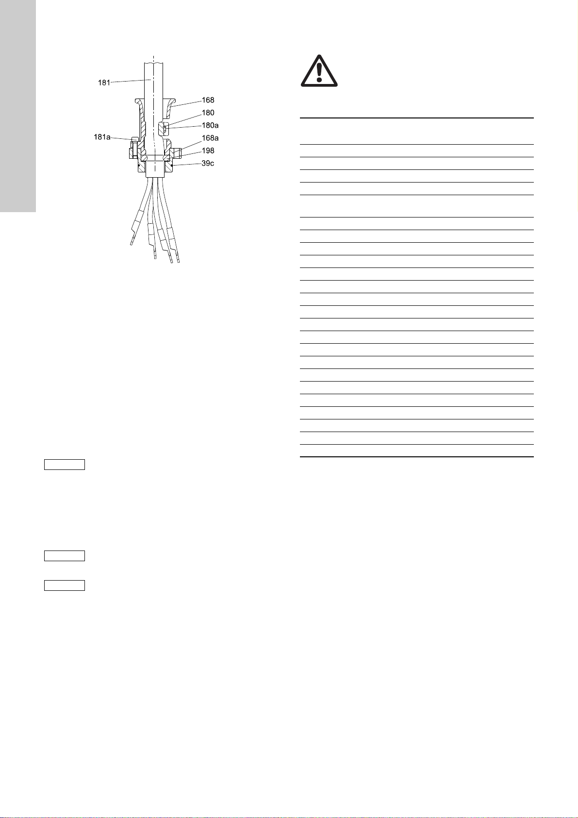
9.1.2 Change of cable with adapter flange, method B
Note
Note
Note
English (GB)
9.2 Replacing the terminal board
Warnin g
Do not change the terminal board unless it is
damaged or it is absolutely necessary.
Please note that the position numbers below refer exclusively to
the replacing of the terminal board.
Fig. 13 Cable entry with adapter flange
Disconnecting the old cable
1. Disconnect the cables from the terminal box (164a).
2. Remove the screws (180a). See fig. 13.
3. Remove the cable clamp (180).
4. Remove the screws (183).
5. Pull out the cable including adapter flange (168a), rubber seal
(198) and cable entry (168).
6. Remove the screws (181a).
7. Pull out the adapter flange (168a).
8. Pull out the cable entry (168) including the rubber seal (198).
9. Remove the rubber seal (198) from the cable entry (168).
Connecting the new cable
1. Slide cable entry (168) on to cable.
2. Slide rubber seal (198) on to cable.
Make sure that the washer is below the rubber
seal and fitted against the cable entry.
3. Slide adapter flange (168a) on to cable.
4. Fit the screws (181a).
5. Fit the cable clamp (180a) on the cable entry (168) with
screws (180a).
6. Fit the cable to motor top cover/terminal box (151/164a).
To prepare a new cable (length of leads, cable
clips, cable markings, etc.), please use the old
cable as reference.
Pos. Description Dimension
1 Copper stud bolt* - 2Sleeve - 3 Washer plate (round) - 4 Plastic bar - -
Washer plate
5
(rectangular)
--
6 Washer plate (square) - 7 Locking plate (round) - 8 Locking plate (square) - -
TM05 6811 5211
9Brass bolt M8 10 Brass screw M12 12
11 Brass nut M8 20
12 Brass nut M12 16
13 Brass nut M16 40
14 Brass nut M20 60
15 Spring washer M8 16 Spring washer M10 17 Spring washer M12 18 Spring washer M16 19 Washer plate M24 20 O-ring 12.0 x 3 21 O-ring 19.2 x 3 22 O-ring 24.0 x 3.53 23 O-ring 34.2 x 3.53 24 Glue (Silcoset 151) - -
* Range 74 pumps manufactured between 1995 and 1997 may
have brass stud bolts.
Torque
[Nm]
Connect according to the wiring diagram.
14
Page 15

9.2.1 Range 72
Tightening torque 16 Nm
Cable side
Stator side
Note
Note
Threaded joint, threads
engaged > 5 mm
Glued joints, shortest path
through joint > 10 mm
Upper bearing
bracket
Creepage distance > 16 mm
Tightening
torque 16 Nm
Cable side
Stator side
Threaded joint, threads
engaged > 5 mm
S pumps, range 72, have two types of terminal board, standard
and Ex. Changing method for both types are described here.
Standard terminal board, method 1
Fig. 14 Standard terminal board, range 72
Dismantling the terminal board
1. Remove the brass nuts (12) and the spring washers (10) from
cable side. See fig. 14.
2. Release the locking of the brass nuts (12) on the stator side
by bending down the tabs of the locking plates (8).
Remove the brass nuts (12) and the plates (8).
3. Remove the washers (3 and 5) including the O-rings (20).
4. Remove the plastic bars (4) including O-rings (22) from both
sides.
5. Remove the copper stud bolts (1) including sleeves (2).
Assembling the terminal board
1. Fit the copper stud bolts (1) into the sleeves (2) and fit them to
the bottom of the upper bearing bracket (61c).
2. Fit the O-rings (22) around the sleeves (2).
3. Fit the plastic bars (4).
4. Fit the washers (3 and 5) including O-rings (20) to the copper
stud bolts (1) on the both sides. Fit the locking plates (8) and
brass nuts (12) on the stator side. Bend one tab of the locking
plates (8) against the nuts (12) to lock the nuts.
5. Connect according to the wiring diagram, use spring washers
(10) and brass nuts (12).
Ex terminal board, method 2
TM05 6798 5212
Fig. 15 Ex terminal board, range 72
Dismantling the terminal board
Warnin g
Ex terminal board parts have been glued
together. You might need to use more force in
removing than normally.
Ex terminal board parts cannot be reused.
1. Remove the brass nuts (12) and the spring washers (17).
Disconnect the cables from both cable and stator sides.
See fig. 15.
2. Release the locking of the brass nuts (12) on the stator side
by bending down the tabs of the locking plates (8).
3. Remove the washers (5) including the O-rings (20).
4. Remove the copper stud bolts (1) including washers (3).
5. Remove the sleeves (2).
Upper bearing bracket (61c) must be cleaned
carefully before assembly.
Assembling the terminal board
1. Fit the copper stud bolts (1) into sleeves (2) and fit them to the
bottom of the upper bearing bracket (61c).
Use glue, such as Silcoset 151.
2. Apply glue to the bottom of the plastic bars (4) and fit to upper
bearing bracket (61c) on the cable side.
3. Apply glue to the bottom of the washers (3) and fit them to the
plastic bars (4).
4. Fit the O-rings (22) around the sleeves (2) on the stator side.
5. Fit the plastic bars (4) on the upper bearing bracket (61c) on
the stator side. Fit the locking plates (8) and brass nuts (12).
Lock the nuts by bending one tab of locking plates (8) towards
the brass nuts (12).
6. Connect according to the wiring diagram, use spring washers
(17) and brass nuts (12).
English (GB)
TM05 6799 5212
15
Page 16

9.2.2 Range 74 and 78
Stator side
Stator side
English (GB)
For S pumps, range 74 and 78, there are two main types of
terminal board depending on pump manufacturing year and
model. Changing methods for all are described here.
Pumps manufactured between 1995 and 1997
Fig. 16 Terminal board for pumps manufactured between 1995
and 1997, range 74 and 78
Dismantling the terminal board
1. See fig. 16.
2. Disconnect the cables from cable side by removing nuts (11),
bolts (9), washer plates (5) and spring washers (15).
3. Disconnect the cables from stator side by removing nuts (13)
and spring washers (18).
4. Remove the nuts (13) and locking plates (7).
5. Remove the plastic bars (4) and washers (3).
6. Remove washers (19).
7. Remove the copper stud bolts (1) and sleeves (2) including Orings (21 and 23).
Assembling the terminal board
1. Fit the O-rings (21 and 23) and lubricate with silicone spray
2. Fit the copper stud bolts (1) in the sleeves (2) fit them to wall.
3. Fit washers (3 and 19).
4. Fit the plastic bars (4).
5. Fit the washers (7) and nuts (13).
6. Connect the cables on the stator side according to the wiring
diagram. Use brass nuts (13) and washers (18).
7. Connect the power cables on the cable side according to the
wiring diagram. Use brass bolts (9), nuts (1) and washers (5
and 15).
Pumps manufactured after 1997
Fig. 17 Terminal board for pumps manufactured 1997 and
later, range 74 and 78
Dismantling the terminal board
1. See fig. 17.
TM05 6817 0113
2. Disconnect the cables from the cable side by removing nuts
(10) and spring washers (17).
3. Disconnect cables from the stator side by removing nuts (13)
and spring washers (18).
4. Release the locking of the nuts (14) by bending down the tabs
of the locking plates (8).
5. Remove the nuts (14).
6. Remove the locking plates (8) and washers (6).
7. Remove the copper stud bolts (1), washer plates (19) and
sleeves (2) including O-rings (21 and 23).
Assembling the terminal board
1. Fit the O-rings (21 and 23) and lubricate with silicone spray.
2. Fit the plastic bars (4) to the wall in the terminal box.
3. Fit the copper stud bolts (1) including sleeves (2) and washers
(19).
4. Fit the washers (6) and the locking plates (8).
5. Fit the nuts (14) and tighten with a torque of 60 Nm.
6. Lock the nuts (14) by bending up one tab of the washers (8).
7. Connect the cables on the stator side according to the wiring
diagram.
8. Connect the cables on the cable side according to the wiring
diagram.
TM05 6818 0113
16
Page 17

9.3 Replacing the protection sensors
Spade connectors
Mounting screw and lock
washer
Screw
Mounting bracket
Caution
Pt100 in stator
Pt100 in upper bearing
9.3.1 Moisture switch
The pumps can have up to three moisture switches, two in the
terminal box (164a) and one on the lower bearing bracket (155).
The changing method is the same, no matter where the switch is
placed.
Warning
Do not touch the head of the moisture switch with
wet or oily hands. Moisture on the sensor head
before installation will cause false measuring
values.
Fig. 18 Moisture switch on lower bearing bracket
Removing the moisture switch
1. Disconnect the spade connectors from the switch.
2. Remove the mounting screw and lock washer from the
mounting bracket. Remove the switch from the base of the
terminal box/upper bearing bracket (164a/61c).
3. Remove the screw.
4. Remove the switch from the mounting bracket.
Fitting new moisture switch
5. Fit the moisture switch to the mounting bracket.
6. Fit the screw to attach the switch to the mounting bracket.
7. Fit the mounting bracket including the switch on the base with
the mounting screw and the lock washer.
8. Connect the spade connectors.
9. Connect the wires according to the wiring diagram.
See section 11.6 Electrical connections.
9.3.2 Pt100 sensor in upper bearing bracket
Fig. 19 Pt100 in upper bearing and in stator
Removing Pt100
1. Cut the wire of the Pt100 sensor right next to sensor.
2. Drill out the sensor from the upper bearing bracket (61c).
Fitting new Pt100
3. Dip the sensor head in glue and insert it into the hole in the
upper bearing bracket (61c).
TM05 6578 4912
4. Connect according to the wiring diagram. See section
11.6 Electrical connections.
9.3.3 Pt100 sensor on the stator
Removing Pt100
1. Cut the wire of the Pt100 sensor right next to sensor and
remove the wire. See fig. 19.
2. Leave the old sensor on the stator (48).
Fitting new Pt100
Warnin g
Make sure that the wire of new sensor is
protected by a protection sleeve.
3. Glue the sensor on to stator windings (48).
4. Connect according to the wiring diagram. See section
11.6 Electrical connections.
English (GB)
TM05 6476 4812
17
Page 18

9.3.4 Pt100 sensor in lower bearing bracket
Quick connector
59a
155
Glue point of Pt100
155
WIO sensor
Connecting
block
155
English (GB)
Pt100 in lower bearing bracket can be fitted in three places
depending on pump manufacturing year. In pumps manufactured
before 2012, sensors are fitted to the locking ring (59a) and lower
bearing bracket (155). See fig. 20. One sensor can be fitted to the
lower bearing bracket (155), but in a different place, see fig. 21.
There are two methods for changing the sensors, and both
methods are described here.
Method A
Removing Pt100
1. See fig. 21. Pull out the sensor using a pair of tongs.
2. Clean the sensor hole carefully.
Fitting new Pt100 sensor in the lower bearing bracket
3. Insert the sensor into the hole in the lower bearing bracket
(155).
4. Spread glue around the sensor end, see fig. 21.
5. Connect according to the wiring diagram. See section
11.6 Electrical connections.
9.3.5 Water-In-Oil sensor (WIO)
Fig. 20 Pt100 sensor positions in the lower bearings
Removing Pt100
1. See fig. 20. Cut the wire of the Pt100 right next to the sensor.
2. Drill out the sensor from the locking ring/bearing bracket (59a/
155).
3. Clean the area with pressurised air.
Fitting new Pt100
4. Dip the whole sensor in the glue and insert it into the hole in
locking ring/bearing bracket (59a/155).
5. Apply a small amount of glue to root of sensor to make sure
that it sticks.
6. Connect according to the wiring diagram. See section
11.6 Electrical connections.
Method B
TM05 6470 4812TM05 6471 4812
TM05 6099 4512
Fig. 22 Water-In-Oil sensor (WIO)
Removing the WIO sensor
1. See section 9.4.10 Removing the rotor.
2. Remove the sensor from the bracket on lower bearing bracket
(155).
3. Open the cable gland.
4. Remove the wires from the connecting block.
5. Pull the sensor cable out through the cable entry in the lower
bearing bracket.
Fitting new WIO sensor
1. Fit the sensor in the bracket.
2. Put the sensor cable up through the cable entry in the lower
bearing bracket.
3. Tighten the cable gland.
4. Cut the cable to a suitable length and connect the wires to the
connecting block. Connect according to the wiring diagram.
See section 11.6 Electrical connections.
Fig. 21 Pt100 in lower bearing bracket on pumps
manufactured after 2010
18
Page 19

9.4 Dismantling range 72
Note
190
164a
173
173b
61c
178
176a
176
164
176c
166
157a
177a
055
759
760
154
177
61c
183
157
For position numbers, see section 11.1 Range 72.
Warning
Maintenance and service work on explosion
proof pumps must be carried out by Grundfos or
a service workshop authorised by Grundfos.
9.4.1 Removing the impeller and pump housing
Before dismantling, support the pump from lifting
bracket with hoist and beneath the discharge
flange with wedges.
1. Remove the outer screws (26).
2. Lift the pump including the impeller (49) and intermediate ring
(1) out of the pump housing (50). Use wedges, if necessary.
3. Remove the O-ring (39a).
4. Place the motor with impeller in horizontal position on for
instance a stable trestle.
5. Remove the O-ring (37b).
6. Support the impeller with a lifting strap, board and hoist to
prevent movement.
7. Bend out the locking tab in the cap (66) and loosen the
impeller screw (67) but do not remove the screw yet.
8. Remove the impeller (49), use wedges, if necessary.
9. Remove the impeller screw (67), the O-ring (67b), the cap
(66) and the O-ring (62a).
10. Remove the impeller (49).
11. Remove the key (9a).
9.4.2 Draining the oil
1. See section 8.4 Oil check and oil change
9.4.3 Removing the primary shaft seal
1. See section 9.4.1 Removing the impeller and pump housing.
2. See section 9.4.2 Draining the oil.
3. Loosen the set screws in the shaft seal (105) and remove the
rotating part.
4. Gently remove the stationary ring of the shaft seal (105).
9.4.4 Removing the terminal box
Fig. 23 Terminal box, range 72
1. See section 9.4.3 Removing the primary shaft seal
2. Place the motor in vertical position on for instance a stable
trestle (shaft downwards).
3. Remove the screws (166). See fig. 23.
4. Remove the terminal box cover (164) including O-ring (165).
5. Remove the screws (173) and locking plate (173b).
6. Disconnect the power cable wires (181) from the terminal
board (177) on upper bearing bracket (61c).
7. Disconnect protection sensor cables from the terminal block
(176a). Do not disconnect the control cable wires from the
terminal block.
8. Straighten the corners of the locking plate (173b) and remove
the screws (173) and the locking plate.
9. Disconnect the control cable (252) earth conductors.
10. Remove the outer screws (178).
11. Lift off the terminal box (164a).
9.4.5 Removing the cooling jacket
1. Remove the screws (150a).
2. Remove the cooling jacket (150c) using a hoist by lifting from
the lifting eyes on both sides of the cooling jacket.
Remove the O-rings (37a and 157b).
9.4.6 Removing the upper bearing bracket
Fig. 24 Upper bearing bracket, range 72
1. See section 9.4.4 Removing the terminal box.
2. See section 9.4.5 Removing the cooling jacket.
3. Remove the screws (183) and fit them in the holes in the
upper bearing bracket (61c).
4. Loosen the bearing bracket by driving the four screws (183)
against the end of the stator housing. Screws will push the
bearing bracket up from the stator housing (55).
5. Pull the upper bearing bracket (61c) approximately 20 cm out
of the stator housing.
6. Disconnect the sensor cables from the terminal board (177)
under upper bearing bracket (61c).
7. Disconnect the cables by removing the screws and locking
plates from the terminal board (177) under the upper bearing
bracket. See fig. 24.
8. Remove the upper bearing bracket (61c) including O-rings
(157a and 157) from the stator housing (55).
9. Remove the moisture absorbing bag (760) from the protection
ring (759).
10. Remove the protection ring (759) including protection sleeve
(177a).
9.4.7 Removing the upper bearing
1. See section 9.4.6 Removing the upper bearing bracket
2. Gently heat up the inner ring of the roller bearing and remove
TM05 6770 5112
the bearing (154) with a bearing puller (K).
English (GB)
TM05 6769 5112
19
Page 20

9.4.8 Removing the shaft seal housing
Note
105b058 272184
055
Note
English (GB)
9.4.11 Removing the lower bearings
1. See section 9.4.10 Removing the rotor.
2. See fig. 26. Disconnect the cable gland (523) in the lower
bearing bracket cover.
3. Disconnect the bearing sensor and remove the cable gland
from the upper bearing bracket cover (60).
4. Remove the screws (182b) and remove upper bearing bracket
cover (60) of the lower bearing bracket. Leave the cover lying
against the stator windings.
5. Loosen and remove the screws (182a).
6. Remove the lower bearing bracket cover (59) of the lower
bearing bracket and remove the O-ring (109).
7. Remove the lock nut (270), lock washer (271) and angle ring
(269).
8. Remove the lower bearing bracket (155) using a hoist.
Fig. 25 Removing the shaft seal housing, range 72
1. See section 9.4.3 Removing the primary shaft seal.
2. Place the motor in horizontal position on for instance a stable
trestle or other support.
3. Remove the vent pipe (272) from the stator housing (55).
4. Secure the shaft seal housing (58) with the lifting strap and
remove screws (184).
5. Remove the shaft seal housing (58) including the vent pipe
(272).
9.4.9 Removing the secondary shaft seal
1. See section 9.4.8 Removing the shaft seal housing.
2. Loosen the set screws in the secondary shaft seal (105b).
Remove the rotating and stationary parts of the shaft seal
(105b).
9.4.10 Removing the rotor
TM05 6768 5112TM05 6802 5212
The outer ring of the roller bearing and the rolls
will be removed together with the bearing
bracket.
9. Collect the springs (153a).
10. Check that the pin (59b) is attached to the lower bearing
bracket.
11. Gently heat up the inner ring of the roller bearing (162) and
remove the ring from the shaft.
12. Gently heat up the outer ring of the roller bearing (162) and
remove the ring from the lower bearing bracket (155).
13. Remove the supporting ring (197) from the shaft.
14. Heat the locking ring (59a) to 200 °C and remove it.
15. Remove the angular contact ball bearings (153) from the
shaft.
16. Remove the upper bearing bracket cover (60) of the lower
bearing bracket from the shaft.
Fig. 26 Rotor, range 72
1. See section 9.4.9 Removing the secondary shaft seal.
2. Remove the screws (184a).
3. Pull the rotor (172) with the lower bearing bracket (155)
approximately 15 cm out of the stator housing to be able to
disconnect the sensors from the connecting block.
Support the rotor by placing boards between the
stator housing and the rotor.
4. Disconnect the sensors from the connecting block.
5. Remove the rotor and place it in vertical position (shaft
upwards) on for instance a stable trestle.
20
Page 21

9.5 Assembling range 72
Note
2
52.2 ± 0.5
56 ± 0.5
68 ± 0.5
Assembly tool PUR133
∅ 80.4
∅ 85
O-rings
9.5.1 Fitting the lower bearings
1. Place the motor in vertical position on for instance a stable
trestle (shaft seal upwards).
2. Fill the upper bearing bracket cover (60) with grease and fit
the cover on the rotor. See section 6.3 Quantities of grease in
bearings.
3. Grease the angular contact ball bearings (153). Fill only 50 %
of the free space of the bearings.
4. Heat up the greased angular contact ball bearings (153) to
120 °C and fit them on the shaft. For the angular contact
bearing to absorb the axial forces, the bearing must be fitted
so that the large surface of the inner ring is resting on the
bearing shoulder of the shaft and the large surface of the
outer ring is resting on the locking ring (59a).
5. Heat the locking ring (59a) to 180 °C and fit it on the bearings
(153).
6. Fit the springs (153a) in the holes of the locking ring.
7. Fit the supporting ring (197) on the rotor.
8. Heat the inner ring of roller bearing (162) to 120 °C and fit it
on the rotor.
9. Fit the outer ring of roller bearing (162) on to the lower bearing
bracket (155).
10. Grease the roller bearings (162). Fill only 50 % of the free
space of the bearings.
11. Check that the pin (59b) and the Pt100 sensor are fitted on
the lower bearing bracket (155).
12. Fit the lower bearing bracket (155) on the rotor.
13. Fit the angle ring (269), lock washer (271) and nut (270) on
the rotor.
Check that the locking ring and the outer ring of
the bearings can be rotated without any
disturbances.
14. Bend one wing of the lock washer (271) into the notch of lock
nut (270).
15. Fit the O-ring (109) in the groove of the lower bearing bracket
(155).
16. Fit the lower bearing bracket cover (59) on the lower bearing
bracket (155) with screws (182a).
17. Fit the upper bearing bracket cover (60) on the lower bearing
with screws (182b).
9.5.2 Fitting the rotor
1. Fit the O-ring (72) on the lower bearing bracket (155).
2. Lower the rotor with shaft into the stator (55), leaving a space
of approximately 20 cm.
3. Connect the sensor connecting block.
4. Complete the fitting of the rotor/shaft.
5. Fit the screws (184a).
9.5.3 Fitting the secondary shaft seal
English (GB)
TM05 6278 4612
Fig. 27 Fitting the secondary shaft seal, range 72
1. Place the motor in horizontal position on for instance a stable
trestle.
2. Clean the shaft.
3. Fit the O-ring on the stationary part of the secondary shaft
seal (105b).
4. Fit the O-ring inside the stationary part of the secondary shaft
seal (105b).
5. Lubricate the moving parts with silicone spray.
6. Fit the stationary part of the secondary shaft seal (105b) on
the shaft and press it home (V). See fig. 27.
7. Tighten the set screws in the secondary shaft seal (105b) with
a torque of 8 Nm.
8. Check the setup length (2 mm) and the assembly length (56 ±
0.5 mm) of the secondary seal (L).
9.5.4 Fitting the shaft seal housing
1. Fit the O-ring (72a) on the lower bearing bracket (155).
2. Fit the O-ring (37c) in the groove of the shaft seal housing
(58).
3. Secure the shaft seal housing (58) including the air went pipe
with the lifting strap and fit it to the stator housing (55).
4. Fit the screws (184).
5. Attach the air went pipe (272) on the stator housing (55).
9.5.5 Fitting the upper bearing
1. Place the motor in vertical position on for instance a stable
trestle (shaft seal downwards).
2. Heat the upper bearing (154) to 120 °C and fit on the shaft.
3. Grease the upper bearing (154). Fill only 50 % of the free
space of the bearing with grease. See section 6.3 Quantities
of grease in bearings.
21
Page 22

9.5.6 Fitting the upper bearing bracket
Note
Note
Note
2
61.2 ± 0.5
65 ± 0.5
77 ± 0.5
Assembly tool PUR133
∅75
∅80
O-rings
English (GB)
1. Check that the protection sleeves are placed against the
protection ring (759).
2. Take the stator cables and protection sensor cables trough the
protection sleeves.
3. Fit the protection ring (759) to the stator housing (55).
4. Fit the upper bearing bracket (61c) into the stator housing
(55), leaving a space of approximately 20 cm.
5. Fit the O-ring (157) to the upper bearing bracket (61c).
6. Connect the stator wires to the terminal board (177) according
to the wiring diagram. Fit the wires, spring washers and
screws. Tighten the screw with a torque of 16 Nm.
7. Connect the protection sensor wires according to the wiring
diagram.
8. Fit the moisture absorbing bag (760) to the protection ring
(759).
Upper bearing bracket must be closed within one
hour after the new moisture absorbing bag has
been exposed to atmospheric humidity.
9. Complete the fitting of the upper bearing bracket and fit
screws (183).
10. See section 10.1 Tightness test of stator (submerged).
9.5.7 Fitting the cooling jacket
This section applies only to pumps with cooling
jacket.
1. Fit the O-ring (37a) on the lower bearing bracket (155).
2. Fit the O-ring (157b) in the groove of the stator housing (55).
3. Fit the cooling jacket (150c) by lifting with a hoist from the
lifting eyes on both sides of the cooling jacket.
4. Fit the screws (150a).
9.5.8 Fitting the terminal box
1. Fit the O-ring (157a).
2. Fit the terminal box (164a) on the stator housing using a hoist.
3. Fit the screws (178).
4. Connect the power cable earth conductors on the upper
bearing bracket (61c) with locking plate (173b) and screws
(173). Bend one corner of the locking plate towards the screw.
5. Connect the protection sensor cables coming from the motor
side to the terminal block (176a).
6. Connect the power cables to the terminal board (177) with
spring washers and screws.
7. Fit the O-ring (165) to the terminal box cover (164).
8. Fit the terminal box cover (164) including the O-ring (165) to
the terminal box (164a).
9. See section 10.2 Tightness test of terminal box (cable side,
submerged).
9.5.9 Fitting the primary shaft seal
TM05 6277 4612
Fig. 28 Fitting the primary shaft seal, range 72
1. Place the motor in horizontal position on for instance a stable
trestle.
2. Make sure that the shaft is clean and smooth.
3. Lubricate the sliding surfaces with silicone spray.
4. Fit the O-ring on the stationary part of the primary shaft seal
(105).
5. Fit the stationary part on the primary seal (105) on the shaft.
6. Check that the O-ring is fitted inside the rotating part of the
primary shaft seal.
7. Fit the rotating part of the primary shaft seal on the shaft and
press it home (V). See fig. 28.
8. Tighten the set screws in the primary shaft seal (105) with a
torque of 8 Nm.
9. Check the setup length (2 mm) and the assembly length (65 ±
0.5 mm) of the primary shaft seal (L).
10. See section 10.1.1 Tightness test of shaft seal housing
(submerged).
Tightness of complete motor must be verified
through a submersion test.
22
Page 23

9.5.10 Oil filling
Note
Note
Note
Note
Cable side
Stator side
1. See section 8.4 Oil check and oil change.
9.5.11 Fitting the impeller and the pump housing
1. Fit the key (9a).
2. Lubricate the cone of the shaft slightly.
3. Fit the O-ring (62a) in the groove of the cap (66). Lubricate the
O-ring.
4. Fit the O-ring (67b) in the groove of screw (67). Lubricate the
thread and the screw head slightly.
5. Support the impeller (49) with a hoist and fit it to the lower
bearing bracket (155).
6. Fit the cap (66) including O-ring (62a) and the screw (67)
including O-ring (67b). Tighten the screw with a torque of 570
Nm.
The new impeller may be higher than the old
impeller, so open the impeller clearance before
fitting the pump housing.
7. Place the motor in vertical position on for instance a stable
trestle (shaft seal downwards).
8. Fit the O-ring (37).
9. Mount the motor on the pump housing.
10. Fit the outer screws (26) and tighten them.
11. Check the impeller clearance. See section 8.5 Inspection and
adjustment of impeller clearance.
9.6 Dismantling range 74
For position numbers, see section 11.2 Range 74.
Warning
Maintenance and service work on explosion
proof pumps must be carried out by Grundfos or
a service workshop authorised by Grundfos.
9.6.1 Removing impeller and pump housing
9.6.3 Removing the primary seal
1. See section 9.6.1 Removing impeller and pump housing.
2. See section 9.6.2 Draining the oil.
3. Loosen the set screws in the shaft seal (105) and remove the
rotating part.
4. Gently remove the stationary ring of the shaft seal (105).
Lever the stationary ring out of the shaft seal by
inserting screwdrivers in positions 0 °, 90 °, 180 °
and 270 °.
9.6.4 Removing the motor top cover
English (GB)
Before dismantling, support the pump unit from
the lifting bracket with hoist and beneath the
discharge flange with wedges.
1. Remove the outer screws (26).
2. Lift the pump including the impeller (49) out of the pump
housing (50) using a hoist. Use wedges, if necessary.
3. Place the motor with impeller in horizontal position on for
instance a stable trestle.
4. Remove the O-ring (37b).
5. Support the impeller with a lifting strap, board and hoist to
prevent movement.
6. Bend out the locking tab in the cap and loosen the impeller
screw (67), but do not remove the screw yet.
7. Remove the impeller (49), use wedges if necessary.
8. Remove the impeller screw (67), the cap (66) and the O-ring
(62a).
9. Remove the impeller (49).
10. Remove the key (9a).
9.6.2 Draining the oil
11. See section 8.4 Oil check and oil change.
TM05 6804 5212
Fig. 29 Terminal box, range 74
1. Remove the screws (166) from the terminal box cover (164)
on the cable side. See fig. 29.
2. Remove the terminal box cover (164) from the terminal box
(164a) including the O-ring (165).
3. Disconnect the control cable wires (252) from the terminal
block. See fig. 30.
4. Remove the screws and the spring washers from the terminal
block bracket.
5. Remove the terminal block including the bracket. Leave the
terminal block and bracket suspended from wires coming
through the partition wall.
The terminal block is connected to the protection
sensor wires coming through the partition wall.
6. Remove the brass nuts and the spring washers from the
terminal board (177) on the cable side. Disconnect the power
cables (181).
23
Page 24

English (GB)
Note
252 181
Terminal block
Terminal block
bracket
Partition wall of
terminal box
177
Earth conductor
Brass nut and
spring washer
Cable side
Screw and
locking plate
Stator side
181
Note
Caution
Note
Fig. 30 Terminal block in terminal box, cable side
7. Bend down the corner of the locking plate, remove the screws
and the plate.
8. Disconnect the earth conductors of the power cable (181).
9. Support the lifting bracket (190) with a hoist, remove screws
(190b) and remove the lifting bracket.
10. Support the cables with a hoist.
11. Remove the screws (183).
12. Remove the motor top cover (151).
13. Remove the O-ring (157a).
In order to change the cables, see section 9.1 Checking and
replacing the cable.
9.6.5 Removing the cooling jacket
This section applies only to pumps with cooling
jacket.
1. See section 9.6.4 Removing the motor top cover.
2. Place the motor in vertical position on for instance a stable
trestle (shaft seal downwards).
3. Remove the screws (150a).
Step 4 applies only to pumps with a locking ring.
4. Remove the locking ring (754) with a hoist.
5. Remove the cooling jacket (150c) by lifting the pump with a
hoist from the lifting eyes on both sides of the cooling jacket.
6. Remove the O-rings (37a and 157b).
9.6.6 Removing the terminal box
1. See section 9.6.4 Removing the motor top cover.
2. See section 9.6.5 Removing the cooling jacket.
3. Remove the screws (166) from the terminal box cover (164)
on the stator side. See fig. 31.
4. Remove the terminal box cover (164) including the O-ring
(165) from the terminal box (164a).
5. Disconnect the protection device cables from the terminal
block.
The terminal block is connected to the protection
sensor wires coming through the partition wall.
6. Disconnect the power cables (181) from the terminal board
(177) by removing the hexagon head screws (10) and
washers (11).
7. Remove the screws (178a or 178 in models without
intermediate ring).
8. Remove the terminal box (164a) including the intermediate
ring (755) using a hoist.
Lift the terminal box carefully to avoid damage to
TM06 0655 0614
the cables.
Step 9 applies only to pumps with intermediate ring.
9. Remove the O-ring (756) from the intermediate ring (755).
9.6.7 Removing the upper bearing
1. Heat up (max. 110 °C) the inner ring of the roller bearing and
pull off the bearing including the bearing housing (61).
2. Remove the circlip (61b).
3. Remove the O-rings (61a) from the outer wall of the bearing
housing (61).
4. Turn the bearing housing (61) so that the roller bearing (154)
is underneath it. Gently heat up (max. 110 °C) the bearing
housing (61) and remove the roller bearing (154).
9.6.8 Removing the shaft seal housing
1. Place the motor in vertical position on for instance a stable
trestle (shaft seal upwards).
2. Remove the screws (184).
3. Remove the shaft seal housing (58) with a hoist. If the
connection is tight, knock gently with a rubber hammer to
ease the separation.
9.6.9 Removing the secondary shaft seal
1. Loosen the set screws in the secondary shaft seal (105b).
2. Carefully remove the rotating part of the shaft seal (105b).
3. Gently remove the stationary ring of the shaft seal (105b).
Lever the stationary ring out of the shaft seal by
inserting screwdrivers in positions 0 °, 90 °, 180 °
and 270 °.
Fig. 31 Terminal box (without motor top cover), range 74
24
TM05 6803 5212
Page 25

9.6.10 Removing the rotor
Note
Note
Note
Note
Note
Note
1. Remove the screws (184a).
2. Loosen the lower bearing bracket (155) from the stator
housing (58) by pushing components apart from each other
with bolts. Lift the rotor (172) at the same time, but no higher
than approximately 10 cm out of the stator housing.
3. Secure lower bearing bracket with boards, and disconnect the
connecting block.
4. Remove the rotor assembly and place it in vertical position
(shaft upwards) on for instance a stable trestle.
9.6.11 Removing the lower bearings
Fig. 32 Rotor, range 74
1. Remove the screws (182b). See fig. 32.
2. Separate the upper bearing bracket cover (60) from the lower
bearing bracket by pushing components apart from each other
with bolts (182b). Leave the cover on to stator wings.
3. Remove the screws (182a).
4. Remove the lower bearing bracket cover (59).
5. Remove the O-ring (109).
6. Bend the tab of the lock washer (271) out of the notch in the
lock nut (270).
7. Remove the lock nut (270), lock washer (271) and angle ring
(269).
8. Remove the lower bearing bracket (155) with a hoist and
remove O-ring (72a).
The outer ring of roller bearing and the rolls will
be removed together with the bearing bracket.
9. Remove the outer ring of roller bearing from lower bearing
bracket by lightly tapping the outer wall of the bearing.
10. Remove the springs (153a).
11. Gently heat up the roller race of the bearing (162) and remove
it.
12. Remove the supporting ring (197).
13. Heat the locking ring (59a) up to 200 °C to loosen it.
Remove the ring.
14. Remove the angular contact ball bearings (153) from the
shaft.
9.7 Assembling range 74
9.7.1 Fitting the lower bearings
1. Place the rotor in vertical position (shaft upwards) on for
instance a stable trestle.
2. Grease the angular contact ball bearings (153) and the roller
bearing (162). Fill only 50 % of the free space of the bearings.
See section 6.3 Quantities of grease in bearings.
3. Fill the bottom of the upper bearing bracket cover (60) with
grease and fit it on the shaft.
Step 4 applies only to pumps that have a labyrinth seal.
4. Heat the labyrinth seal (60a) up to 120 °C and fit it on the
shaft.
5. Heat the greased angular contact ball bearing (153) up to 120
°C and fit it on the shaft.
6. Fit the supporting ring (197) on the shaft.
7. Heat the inner ring of the roller bearing (162) up to 120 °C and
fit it on the shaft.
Let rotor and bearing cool down before
continuing.
8. Heat the locking ring (59a) up to 180 °C and fit it on the shaft.
Let rotor and bearing cool down before
continuing.
9. Fit the six springs (153a) in the locking ring (59a).
10. Fit the roller bearing (162) on the lower bearing bracket (155).
11. Make sure that the pin (59b) is inserted in the hole in the lower
bearing bracket (155). Fit the lower bearing bracket (155) on
the shaft.
12. Fit the angle ring (269) on the rotor.
13. Fit the lock washer (271) on the rotor. Make sure that the tab
TM05 6805 5212
of the inner ring fits into the notch of the shaft.
14. Fit the lock nut (270) on the rotor and tighten it (E).
Check that the bearings rotate smoothly without
any significant play. Adjust if necessary.
15. Bend one tab of the lock washer (271) into the notch of the
lock nut (270).
16. Grease the roller bearing (162). Fill only 50 % of the free
space of the bearing.
17. Fit the O-ring (109) into to the groove of the lower bearing
(155).
18. Fill the bottom of the lower bearing bracket cover (59) with
grease and fit it on the rotor with screws (182a).
19. Lift the upper bearing bracket cover (60) up against the lower
bearing bracket (155) using boards. Fit the screws (182b) and
tighten so that the components are pulled together.
Make an electrical test of sensors attached to
lower bearing bracket.
English (GB)
Angular contact ball bearings might need to be
cut in two to remove them.
15. Remove the upper bearing bracket cover (60).
25
Page 26

9.7.2 Fitting the rotor
Caution
Note
Note
Note
Caution
Note
Stationary part of the secondary shaft seal
Assembly tool PUR131
Assembly tool PUR127
O-ring
English (GB)
1. Lift up the rotor with a hoist and fit O-ring (72).
2. Lower the rotor/shaft into the stator housing (55), leaving
approximately 10 cm open. Secure rotor/stator with boards
between stator housing (55) and lower bearing bracket (155).
3. Connect the sensor connecting block.
4. Remove the boards and complete the fitting of the rotor/shaft.
Pull protection sensor wires tight as the rotor is lowered down.
5. Fit the screws (184a).
Older models only have two bolts between stator
housing and lower bearing bracket. In these
models, secure the assembly of the two
components with four pairs of bolts and nuts.
9.7.3 Fitting the upper bearing
1. Place the motor in vertical position (shaft downwards) on for
instance a stable trestle.
2. Grease the upper bearing (154). Fill only 50 % of the free
space of the bearing. See section 6.3 Quantities of grease in
bearings.
3. Heat the bearing housing (61) up to 120 °C. Fit the upper
bearing (154) in the bearing housing (61).
4. Fit the circlip (61b) in the bearing housing (C).
5. Heat bearing housing and bearing up to 120 °C and fit them
on the shaft.
Let the bearing housing and bearing cool down
before continuing.
6. Fit and lubricate the O-rings (61a).
7. Fill up the bearing with grease.
9.7.4 Fitting the terminal box
1. Fit and lubricate the O-ring (756).
2. Fit the terminal box (164a) including the intermediate ring
(755) on the stator housing (55). Guide the cables out of the
stator side of the terminal box.
3. Fit the screws (178a)
If the intermediate ring is not included on the
pump, fit the terminal box to stator housing with
screws (178).
4. Connect the protection sensor cables to terminal block
according to the wiring diagram. See section 11 .6 Electrical
connections.
5. Fit the stator cables to the terminal board (177) with spring
washers and nuts. Tighten the nuts with a torque of 40 Nm.
Connect according to the wiring diagrams. See section 11.6
Electrical connections.
9.7.5 Fitting the secondary shaft seal
TM05 6175 4512
Fig. 33 Fitting the stationary part of the secondary shaft seal,
range 74
1. Place the motor in horizontal position on for instance a stable
trestle.
2. Make sure that the shaft is clean and smooth.
3. Fit and lubricate the O-ring on the stationary part of the
secondary shaft seal (105b).
4. Fit the stationary part of the secondary shaft seal (105b) and
press it home (P and T). See fig. 33.
Make sure that the pin in lower bearing bracket
cover (59) fits into the notch of the stationary
part.
Test the electrical circuits.
6. Fit the moisture absorbing bag (760) in the terminal box
(164a).
The terminal box must be closed within one hour
after the new moisture absorbing bag has been
exposed to atmospheric humidity.
7. Lubricate and fit the O-ring (165) to the terminal box cover
(164).
8. Fit the terminal box cover (164) on the terminal box (164a)
with screws (166).
26
Page 27

9.7.7 Fitting the primary shaft seal
Note
Note
41 ± 0.5
46.8 ± 0.5
Rotating part of the secondary shaft seal
Assembly tool PUR131
Assembly tool PUR127
Screws, tightening torque 8 Nm
O-ring
Note
Note
Note
Stationary part of primary
shaft seal
Assembly tool PUR128
Assembly tool PUR127
O-ring
Rotating part of primary shaft seal
Assembly tool PUR127
Screws, tightening
torque 15 Nm
63.2 ± 0.5
69 ± 0.5
O-ring
English (GB)
Fig. 34 Fitting the rotating part of secondary shaft seal, range
74
5. Check that an O-ring is fitted inside the rotating part of
secondary shaft seal (105b).
6. Lubricate sliding surfaces with silicone spray.
7. Fit the rotating part of the secondary shaft seal on the shaft
and press it home (P and T). Tighten the set screws in the
secondary shaft seal (105b) with a torque of 8 Nm. See fig.
34.
8. Check the assembly length (46.8 mm ± 0.5 mm) of the
secondary shaft seal (L).
Check the possible leak paths with leak detecting
liquid between stator housing and lower bearing
bracket. See section 10.1 Tightness test of stator
(submerged).
Tightness of complete motor must be verified
through a submersion test.
9.7.6 Fitting the shaft seal housing
1. Lubricate and fit the O-ring (72a).
2. Fit the O-ring (37c) to shaft seal housing (58).
3. Fit the shaft seal housing (58) using a hoist.
4. Fit the screws (184).
TM05 6176 4512
Fig. 35 Fitting the stationary part of primary shaft seal, range
74
1. Make sure that the shaft is clean and smooth.
2. Lubricate and fit the O-ring on the stationary part of the
primary shaft seal (105). Fit the shaft seal on the shaft and
press it home (P and Q). See fig. 35.
Make sure that the pin in shaft seal housing (58)
fits into the notch of the stationary part.
TM05 6177 4512
TM05 6178 4512
Fig. 36 Fitting the rotating part of primary shaft seal, range 74
3. Check that an O-ring is fitted inside the rotating part of primary
shaft seal (105). Lubricate the O-ring.
4. Lubricate the sliding surfaces with silicone spray.
5. Fit the rotating part of the primary shaft seal on the shaft and
press it home (P). See fig. 36. Tighten the set screws in the
shaft seal with a torque of 15 Nm.
6. Check the assembly length (69 mm ± 0.5 mm) of the
secondary shaft seal (L).
Check the possible leak paths with leak detecting
liquid. See section 10.1.1 Tightness test of shaft
seal housing (submerged).
Tightness of complete motor must be verified
through a submersion test.
27
Page 28

9.7.8 Fitting the cooling jacket
Note
Note
Note
Note
Note
English (GB)
This section applies only to pumps with cooling
jacket.
1. Place the motor in vertical position (shaft downwards) on for
instance a stable trestle.
2. Lubricate and fit the O-ring (37a).
3. Fit the cooling jacket (150c) with a hoist.
4. Lubricate and fit the O-ring (157b).
5. Fit the locking ring (754).
6. Fit the screws (150a).
9.7.9 Fitting the motor top cover and connections in the
terminal box
1. Place the motor in horizontal position on for instance a stable
trestle.
Steps 2 to 5 apply only to pumps without adapter flange.
2. Fit the O-ring (157a).
3. Support the motor top cover (151) with a lifting strap and
hoist.
4. Fit the motor top cover (151) on the terminal box (164a).
5. Fit the screws (183).
Steps 6 to 12 apply only to pumps with adapter flange.
6. Secure the motor top cover (151) with hoist.
7. Fit the O-ring (157a).
8. Fit motor top cover (151) to terminal box (164a).
9. Fit screws (183).
10. Lubricate and fit O-ring (39c).
11. Support cable assembly with a lifting strap and fit to motor top
cover.
12. Fit screws (183b).
13. Fit the lifting bracket (190).
14. Fit the screws (190b).
15. Connect the earth conductors of the power cables (181) to the
terminal box (164a). Fit locking plate (11) and hexagon head
screws (10) on the cable shoes. Secure connection by
bending one corner of locking plate (11) up towards the screw
(10).
16. Connect the power cable wires to the terminal board (177)
according to the wiring diagram. Fit the spring washers and
screws. Tighten the screw with a torque of 20 Nm. See section
11.6 Electrical connections.
17. Fit the terminal block including bracket in the terminal box
(164a) with spring washers and screws.
18. Connect the protection sensor cables on the terminal block.
9.7.10 Oil filling
1. See section 8.4 Oil check and oil change.
9.7.11 Fitting the impeller and the pump housing
1. Place the motor in horizontal position on for instance a stable
trestle.
2. Make sure that the O-ring is fitted on the primary shaft seal.
3. Fit the key (9a) in the shaft groove (D).
4. Lubricate the cone of the shaft and the O-ring of the primary
shaft seal.
5. Secure impeller (49) with a lifting strap and hoist.
6. Fit the impeller (49).
7. Fit the O-ring (62a) on the cap (66).
8. Fit the O-ring (67b) on the impeller screw (67).
9. Lightly lubricate the O-rings (62a and 67b) and the thread of
the impeller screw (67).
10. Fit the cap (66) and the impeller screw (67).
11. Support the impeller (49) with a board and tighten the impeller
screw (67) with a torque of 600 Nm. Before final tightening of
the impeller screw, knock the impeller (D) to make sure it is on
correct position.
12. Bend (B and D) the edge of the cap (66) into the notch of the
impeller screw (67).
The new impeller may be higher than the old
impeller, so open the impeller clearance before
assembling the pump housing.
13. Fit and lubricate the O-ring (37b).
14. Support the pump housing (50) beneath the discharge flange
with wedges.
15. Place the motor in vertical position with a hoist and mount the
motor on the pump housing (50).
16. Fit the screws (26).
9.7.12 Adjusting the impeller clearance
17. Check and adjust the impeller clearance. See section
8.5 Inspection and adjustment of impeller clearance.
Test the electrical circuits.
19. Fit the O-ring (165) to the terminal box cover (164).
20. Fit the terminal box cover (164) on the terminal box (164a)
with screws (166).
Check the possible leak paths through tightness
test of terminal box (cable side).
See section 10.2 Tightness test of terminal box
(cable side, submerged).
Tightness of complete motor must be verified
through a submersion test.
The submersion test must be made before oil
filling.
28
Page 29

9.8 Dismantling range 78
Note
Note
Note
For position numbers, see section 11.3 Range 78.
Warning
Maintenance and service work on explosion
proof pumps must be carried out by Grundfos or
a service workshop authorised by Grundfos.
Warning
When lifting range 78 pumps by the shaft, you
must use special lifting tool (DD). See section
7.4 Lifting tools.
9.8.1 Removing the impeller and the pump housing
Before dismantling, support the pump unit from
the lifting bracket with a hoist and beneath the
discharge flange with wedges.
1. Remove the outer screws (26).
2. Lift the pump including the impeller (49) out of the pump
housing (50) with a hoist. Use wedges, if necessary.
3. Place the motor with impeller in horizontal position on for
instance a stable trestle.
4. Remove the O-ring (37b).
5. Support the impeller with the lifting strap, board and hoist to
prevent movement.
6. Remove the impeller screw (67a) including O-ring (67b) and
cap (66) including O-ring (62a).
7. Loosen the three impeller screws (67), but do not remove the
screws yet.
8. Loosen the impeller (49), use wedges if necessary.
9. Remove the impeller screws (67) and locking plate (66a).
10. Remove the impeller (49).
11. Remove the key (9a).
9.8.2 Draining the Oil
1. See section 8.4 Oil check and oil change.
9.8.3 Removing the primary shaft seal
1. See section 9.6.3 Removing the p rimary seal .
9.8.4 Removing the motor top cover
1. See section 9.6.4 Removing the motor top cover.
9.8.5 Removing the cooling jacket
1. See section 9.6.5 Removing the cooling jacket
9.8.6 Removing the terminal box
1. See section 9.6.6 Removing the terminal box.
9.8.7 Removing the upper bearing bracket
1. Remove screws (753).
2. Remove the upper bearing bracket (61c) from the stator
housing (55) by driving the screws against the end of the rotor
shaft. Use screws M20 x 140 DIN933.
3. Lift off the upper bearing bracket (61c).
9.8.8 Removing the upper bearing
1. See section 9.6.7 Removing the upper bearing.
9.8.9 Removing the shaft seal housing
1. See section 9.6.8 Removing the shaft seal housing.
9.8.10 Removing the secondary shaft seal
1. See section 9.6.9 Removing the secondary shaft seal.
9.8.11 Removing the rotor
1. See section 9.6.10 Removing the rotor.
9.8.12 Removing th e low er be arin gs
English (GB)
TM05 6808 5212
Fig. 37 Rotor and lower bearings, range 78
1. Remove the screws (182b). See fig. 37.
2. Remove the upper bearing bracket cover (60) and leave it on
the stator windings.
3. Remove the screws (182a).
4. Remove the lower bearing bracket cover (59).
5. Remove the O-ring (109).
6. Remove the lock nut (270), lock washer (271) and angle ring
(269).
7. Remove the lower bearing bracket (155) with the hoist and
remove O-ring (72a).
The outer ring of the roller bearing and the rolls
will be removed together with the bearing
bracket.
8. Collect the springs (153a).
9. Gently heat up the roller race and pull off the bearing (162)
and supporting ring (197).
10. Heat up the locking ring (59a) to 200 °C and pull it off.
11. Remove the angular contact ball bearings (153) from the
shaft.
Angular contact ball bearings might need to be
cut in two to remove them.
Step 12 applies only to pumps that have a labyrinth seal.
12. Gently heat up the labyrinth seal (60a) and pull it off.
13. Remove the upper bearing bracket cover (60).
29
Page 30

9.9 Assembling range 78
Note
Stationary part of the shaft seal
Assembly tool PUR132
Assembly tool PUR129
Screws M16 x 70 (three)
O-ring
Note
Note
Assembly tool PUR129
Assembly tool PUR132
Set screws (five). Tightening torque: 15 Nm
Rotating part of shaft
seal
52.5 ± 0.5
55.2 ± 0.5
O-ring
English (GB)
9.9.1 Fitting the lower bearings
1. See section 9.7.1 Fitting the lower bearings.
9.9.2 Fitting the rotor
1. See section 9.7.2 Fitting the rotor.
9.9.3 Fitting the upper bearing
1. See section 9.7.3 Fitting the upper bearing.
9.9.4 Fitting the upper bearing bracket
1. Lower the upper bearing bracket (61c) into the stator housing
(55), leaving a space of approximately 20 cm.
2. Pull the cables gently through the holes in the upper bearing
bracket. Complete the fitting of the bracket on the stator.
3. Fit the screws (753).
9.9.5 Fitting the terminal box
1. See section 9.7.4 Fitting the terminal box.
9.9.6 Fitting the secondary shaft seal
TM05 6266 4512
Fig. 39 Fitting the rotating part of the secondary shaft seal,
range 78
5. Check that an O-ring is fitted inside the rotating part of
secondary shaft seal (105b).
6. Lubricate sliding surfaces with silicone spray.
7. Fit the rotating part of the secondary shaft seal on the shaft
and press it home (R and U). Tighten the set screws in the
secondary shaft seal (105b) with a torque of 15 Nm. See fig.
39.
8. Check the assembly length (55.2 ± 0.5 mm) of the secondary
shaft seal (L).
Fig. 38 Fitting the stationary part of the secondary shaft seal,
range 78
1. Place the motor in horizontal position on for instance a stable
trestle.
2. Make sure that the shaft is clean and smooth.
3. Lubricate and fit the O-ring on the stationary part of the
secondary shaft seal (105b).
4. Fit the stationary part of the secondary shaft seal (105b) and
press it home (R and U). See fig. 38.
Make sure that the pin in lower bearing bracket
cover (59) fits into the notch of the stationary
part.
Check the possible leak paths with leak detecting
liquid between stator housing and lower bearing
bracket.
See section 10.1 Tightness test of stator
(submerged).
TM05 6265 4512
Tightness of complete motor must be verified
through a submersion test.
9.9.7 Fitting the shaft seal housing
1. See section 9.7.6 Fitting the shaft seal housing.
30
Page 31

9.9.8 Fitting the primary shaft seal
Note
Note
Assembly tool PUR129
Assembly tool PUR130
Stationary part of the shaft seal
Screws M16 x 70 (three)
O-ring
Set screws (five). Tightening torque: 15 Nm.
Assembly tool PUR129
Rotating part of
shaft seal
70 ± 0.5
74 ± 0.5
O-ring
Note
Fig. 40 Fitting the stationary part of primary shaft seal, range
78
1. Make sure that the shaft is clean and smooth.
2. Lubricate and fit the O-ring on the stationary part of the
primary shaft seal (105). Fit the shaft seal on the shaft and
press it home (R and S). See fig. 40.
9.9.9 Fitting the cooling jacket
1. See section 9.7.8 Fitting the cooling jacket.
2. Fitting the motor top cover and the connections of the terminal
box
1. See section 9.7.9 Fitting the motor top cover and connections
in the terminal box.
9.9.10 Oil filling
1. See section 8.4 Oil check and oil change.
9.9.11 Fitting the impeller and the pump housing
1. Check that the O-ring is fitted on the primary shaft seal (105).
2. Fit the key (9a) in the shaft groove (D).
3. Lightly lubricate the cone of the shaft and O-ring of the
primary shaft seal.
4. Secure the impeller with lifting strap and hoist.
5. Fit the impeller (49) and support it with a board.
TM05 6267 4512TM05 6268 4512
6. Fit the locking plate (66a) and three impeller screws (67).
Tighten the screws with a torque of 170 Nm. Before final
tightening of the impeller screws (67) knock the impeller (D) to
make sure it is in correct position.
7. Fit the O-ring (62a) on the cap (66)
8. Fit O-ring (67b) on the screw (67a). Lightly lubricate the
thread, screw head and the O-ring (67b).
9. Fit the cap (66). Make sure that the pin of the cap fits into the
notch of the locking plate (66a).
10. Fit the screw (67a) and tighten to a torque of 160 Nm.
English (GB)
Fig. 41 Fitting the rotating part of primary shaft seal in range
78 pumps.
3. Check that the O-ring is fitted inside the rotating part of
primary shaft seal (105). Lubricate the O-ring.
4. Fit the rotating part of the primary shaft seal on the shaft and
press it home (R). Tighten the set screws in the shaft seal with
a torque of 15 Nm. See fig. 41.
5. Check the assembly length (74 ± 0.5 mm) of the primary shaft
seal (L).
Check the possible leak paths with leak detecting
liquid.
See section 10.1.1 Tightness test of shaft seal
housing (submerged).
Tightness of complete motor must be verified
through a submersion test.
The new impeller may be higher than the old
impeller, so open the impeller clearance before
assembling the pump housing.
11. Lubricate and fit the O-ring (37b).
12. Support the pump housing (50) beneath the discharge flange
with wedges.
13. Lift the motor into vertical position with a hoist and mount the
motor on the pump housing (50).
14. Fit the screws (26).
9.9.12 Adjusting the impeller clearance
1. Check and adjust the impeller clearance. See section
8.5 Inspection and adjustment of impeller clearance.
31
Page 32

10. Tightness tests
Note
Note
Note
English (GB)
10.1 Tightness test of stator (submerged)
Warning
Maintenance and service work on explosion
proof pumps must be carried out by Grundfos or
a service workshop authorised by Grundfos.
Fig. 42 Test plugs in shaft seal housing and lower bearing
bracket
1. Place the motor in horizontal position with a hoist.
2. Remove the upper oil plug (193) including O-ring (194) from
the shaft seal housing. See fig. 42.
3. Fit the test plug (Connector R3/4) in stead of the oil plug
(193).
4. Fit the hose (approx. 1 m) to the test plug.
Step 5 applies only to Ex pumps.
5. Remove the screw (25a) from the lower bearing bracket.
6. Remove the plug (25) including O-ring (100) from the lower
bearing bracket (155).
7. Fit the test plug (3/8-24 UNF F-ISO 228-G 3/8M) in stead of
the plug (25).
8. Fit the gas hose (N2) to the test plug and pressurise the stator
housing to 0.8 bar.
9. Submerge the motor into the test basin.
10. Place the end of the hose coming from the shaft seal housing
under the surface of the water.
In order to detect possible leaks, let the motor
stay submerged for 15 minutes.
11. Lift the motor out of the test basin.
12. Disconnect the gas hoses and the test plugs.
13. Fit the plug (25) including O-ring (100) on the lower bearing
bracket.
Warning
In explosion proof pumps, the plug (25) on the
shaft seal housing must be locked with a screw
(25a).
14. Fit the upper oil plug (193) including O-ring (194) to the shaft
seal housing.
10.1.1 Tightness test of shaft seal housing (submerged)
1. Place the motor in horizontal position with a hoist.
2. Remove the oil plug (193) including O-ring (194) from the
shaft seal housing.
3. Fit the test plug (R3/4) in stead of the oil plug (193). See fig.
42.
4. Fit the gas hose (N2) to the test plug and pressurise the shaft
seal housing to 0.8 bar.
5. Submerge the motor into the test basin.
In order to detect possible leaks, let the motor
stay submerged for 15 minutes.
6. Lift the motor out of the test basin.
7. Disconnect the gas hose and the test plug.
8. Fit the oil plug (193) including O-ring (194) on the shaft seal
housing.
10.2 Tightness test of terminal box (cable side, submerged)
Warnin g
Maintenance and service work on explosion
proof pumps must be carried out by Grundfos or
a service workshop authorised by Grundfos.
TM05 6810 5212
TM05 6809 5212
Fig. 43 Test plugs in terminal box
Step 1 applies only to Ex pumps.
1. Remove the screw (25a) from the terminal box (164a).
See fig. 43.
2. Remove the plug (25) including O-ring (100) from the terminal
box.
3. Fit the test plug (connector 3/8-24 UNF F-ISO 228-G 3/8M) in
stead of plug (25).
4. Fit the gas hose (N2/dry pressurised air) to the test plug and
pressurise the stator housing to 0.8 bar.
5. Submerge the motor into the test basin.
In order to detect possible leaks, let the motor
stay submerged for 15 minutes.
6. Lift the motor out of the test basin.
7. Disconnect the gas hose and the test plug.
8. Fit the plug (25) including O-ring (100) on the terminal box.
Warnin g
In explosion proof pumps, the plug (25) on the
terminal box must be locked with a screw (25a).
32
Page 33

11. Drawings
Please note that the position numbers in the drawings in sections
11.1 to 11.3 are listed in section 11.4 Position numbers an d
material specification.
11.1 Range 72
Exploded view, installation type S
English (GB)
33
TM03 3055 0508
Page 34

Sectional drawing, installation type S
English (GB)
34
TM03 3615 0508
Page 35

Exploded view, installation type C
English (GB)
35
TM03 3054 0508
Page 36

Sectional drawing, installation type C
English (GB)
36
TM03 3425 0508
Page 37

Exploded view, installation type D
English (GB)
37
TM03 3053 0508
Page 38

Sectional drawing, installation type D
English (GB)
38
TM03 3423 0508
Page 39

Installation type S with cooling jacket
English (GB)
39
TM05 8604 2513
Page 40

Installation type S without cooling jacket
English (GB)
40
TM05 8603 2513
Page 41

Column pipe installation
English (GB)
41
TM05 8605 2513
Page 42

11.2 Range 74
English (GB)
Sectional drawing, installation type C (with intermediate ring)
42
TM05 8595 2513
Page 43

Sectional drawing, column pipe installation 315* (without cooling jacket)
* Based on IEC 315 motor series parts.
English (GB)
43
TM05 8594 2513
Page 44

Submerged installation (old and new guide claw)
Old guide claw
English (GB)
TM05 8620 2513
44
Page 45

Dry, vertical installation
English (GB)
45
TM05 8596 2513
Page 46

Dry, horizontal installation
English (GB)
TM05 8597 2513
46
Page 47

Column pipe installation
English (GB)
47
TM05 8598 2513
Page 48

11.3 Range 78
English (GB)
Installation type C with cooling jacket (manufactured between 1992 and 1996)
48
TM06 0379 0101
Page 49

Installation type C with cooling jacket
English (GB)
49
TM05 8599 2513
Page 50

Column pipe installation
English (GB)
50
TM05 8600 2513
Page 51

Installation type C with (old and new) guide claw
Old guide claw
English (GB)
TM05 8621 2513
51
Page 52

Installation type D (vertical installation with concrete base)
English (GB)
TM05 8619 2513
52
Page 53

Installation type H (horizontal installation)
English (GB)
TM05 8601 2513
53
Page 54

Installation type ST (column pipe installation)
English (GB)
54
TM05 8602 2513
Page 55

Installation type SA (column pipe installation, propeller)
English (GB)
55
TM06 0378 0101
Page 56

11.4 Position numbers and material specification
English (GB)
Motor
Pos. Component Material
7a Rivet Stainless steel
25 Pressure test plug Stainless steel
25a Screw Stainless steel
26a Screw Stainless steel
26b Screw Stainless steel
37a O-ring NBR rubber
37c O-ring NBR rubber
39c O-ring NBR rubber
48 Stator windings
55 Stator housing Cast iron
58 Shaft seal housing Cast iron
59 Lower bearing bracket cover Cast iron
59a Locking ring Aluminium
59b Pin Steel
60 Upper bearing bracket cover Cast iron
60a Labyrinth seal
61 Bearing housing Cast iron
61a O-ring Viton rubber
61b Circlip Steel
61c Upper bearing bracket Cast iron
72 O-ring NBR rubber
72a O-ring NBR rubber
76a Approval plate Stainless steel
76b Warning plate Stainless steel
77 Seal housing cover Cast iron
100 O-ring NBR rubber
101c Locking pin Stainless steel
101d Screw Stainless steel
105 Mechanical shaft seal SiC/SiC, stainless steel
105b Mechanical shaft seal
107 O-ring NBR rubber
109 O-ring Viton rubber
150a Screw Stainless steel
150c Cooling jacket Galvanized steel
151 Motor top cover Cast iron
153 Angular contact ball bearing Steel, brass or steel cage
153a Spring Steel
154 Ball bearing Steel, brass or steel cage
155 Lower bearing bracket Cast iron
157 O-ring NBR rubber
157a O-ring NBR rubber
157b O-ring NBR rubber
162 Roller bearing Steel, brass or steel cage
164 Terminal box cover Cast iron
164a Motor top cover / terminal box Cast iron
165 O-ring NBR rubber
166 Screw Stainless steel
168 Cable entry Cast iron
168a Adapter flange Stainless steel
172 Shaft with rotor Tempered steel
173 Screw Steel
173b Locking plate Steel
173c Washer Steel
173e Screw Stainless steel
173f Spring washer Stainless steel
173g Earth connector Steel
176 Connector set
176a Terminal block
176b Screw Stainless steel
SiC/carbon, stainless
steel
Pos. Com po nent Material
176c Terminal block
176d Screw Steel
177 Terminal board
177a Protection sleeve Rubber or plastic
178 Screw Stainless steel
178a Screw Stainless steel
180 Cable clamp Cast iron
180a Screw Stainless steel
181 Cable Copper, EPR-insulated
181a Screw Stainless steel
182a Screw Stainless steel
182b Screw Stainless steel
183 Screw Stainless steel
184 Screw Stainless steel
184a Screw Stainless steel
190 Lifting bracket Galvanized steel
190a Lifting bracket Galvanized steel
190b Screw Stainless steel
190c Screw Stainless steel
193 Plug Stainless steel
194 O-ring NBR rubber
197 Supporting ring Steel
198 Rubber seal Neoprene rubber
248 Screw Stainless steel
248a Screw Stainless steel
250 Cable clamp Cast iron
250a Cable entry Cast iron
250b Rubber seal Neoprene rubber
252 Cable Copper, EPR-insulated
269 Angle ring Steel
270 Lock nut Steel
271 Lock Washer Steel
272 Vent pipe
519 Conductor bushing
520d Protection sensors
521 Water-in-oil sensor (WIO)
522a Screw Steel
522b Washer Steel
522d Pipe retaining clips Steel
523 Cable gland Steel / rubber
523a O-ring NBR rubber
524a Bracket for SM113 Aluminium
524b Screw Steel
524c Screw Steel
524d Spring washer Steel
529 SM 113
753 Screw Steel
754 Locking ring Cast iron
755 Intermediate ring Cast iron
756 O-ring NBR rubber
759 Protection ring Aluminium
760 Moisture absorbing bag Zeolite absorbent
56
Page 57

Pump
Pos. Component Material
1 Intermediate ring Cast iron
7a Rivet Stainless steel
9a Key (for keyway) Steel
12 Flange Cast iron
12a Suction cover Cast iron
12c Set screw Stainless steel
26 Screw Stainless steel
26c Screw Stainless steel
35 Screw Stainless steel
35a Screw Stainless steel
37 O-ring NBR rubber
37b O-ring NBR rubber
39 O-ring NBR rubber
39a O-ring NBR rubber
*49 Impeller Cast iron
*50 Pump housing Cast iron
62 O-ring NBR rubber
62a O-ring NBR rubber
66 Cap Cast iron or stainless steel
66a Locking plate Steel
67 Impeller screw Stainless steel
67a Screw Stainless steel
67b O-ring NBR rubber
67c Parallel pin Steel
76 Nameplate Stainless steel
301 Motor unit
487a Base plate Steel
487c Screw Stainless steel
487d Washer Steel
488 O-ring NBR rubber
492 Guide claw Cast iron
492a Rubber seal Neoprene rubber
493 Screw Stainless steel
494 Plug Stainless steel
495 O-ring NBR rubber
762a Screw Stainless steel
762b Flange seal
* Available of stainless steel (custom-built option).
English (GB)
57
Page 58

11.5 Sensor positions
English (GB)
Please note that the position numbers in section 11.5 refer
exclusively to the sensors.
Range 74 and 78 manufactured between 1992 to 2012
Pos. Description
1 Pt100 sensor
2 Plug strip (male)
3 Socket strip (female)
4 Cylinder screw
5 Rubber plate
6 Moisture switch
7 Cylinder screw
8 Bracket
9 Cylinder screw
10 Lock washer
11 Insulated conducting wire
12 Silicone rubber sleeve
58
TM05 8682 2613
Page 59

Range 74 and 78, current models
English (GB)
Pos. Description Pos. Description
1 Pt100 (temperature) sensor 12 Bracket
2 Pt100 (temperature) sensor insulated 13 Cylinder screw
3 Plug strip (male) 14 Lock washer
4 Socket strip (female) 15 Insulated conducting wire
5 Cylinder screw 16 Screen
6 WIO sensor 17 Silicone rubber sleeve
7 O-ring 18 Insulation ring
8 Cable gland 19 Sensor bracket (WIO)
9 Moisture switch 20 Hexagon head screw
10 Connector (female) 21 Spring washer
11 Cylinder screw
Option
Pos. Description
22 Vibration sensor
23 Hexagon head screw
24 Lock washer
TM05 8680 2613
59
Page 60

11.6 Electrical connections
T777
77
8
8
6
7
P222
3
4
5
6
2
3
45
6
5
81
4
3
T4
4
6
5
T6
6
T4
5
T5
4
3P3
T44T4
3
P3
1
2
11 P1
2
1
P2 P1P3
P2 P1P3
U2
V2
W2
V1
W2
W1
U2
W2 V2
V2
W2
W1
W1
V1
U2
U1
W1 V1
U1
U1
P3
3
8
7
6
8
7
6
4
5
3
4
5
3
P8
T4 T4
8
7
6
4
5
4
T7
T6
T4
T5
T4
W1
2
1
2
1
W2
V2
U2
3
2
1
C
C
P3
P2
P1
V2
W2
U2
V1
U1
W1
V1
U1
P3
P2
P3
P1
1
2
5
6
7
4
V2
V1
U1
U2
C
C
8P8
8
Terminal box Motor
Free end of
4-conductor
cable
Free end of
9-conductor
cable
Moisture switches
Angular contact bearings
Ball bearing
Roller bearing
U1
U1
U1
U1
U1
U1 U1
U2
U2
U2
U2
U2 U2
V1
V1
V1
V1
V1 V1
V2
V2
V2
V2
V2 V2
W1
W1
W1
W1
W1 W1
W2
W2 W2
W2
W2
W2
U1
U1
U2
U2
V1
V1
V2
V2
W1
W1
W2
W2
U1
V1
V1
W1
W1
U2
V2
W2
U2
V2
W2
1
2
3
4
5
6
7
8
9
1
1
1
2
22 2 2
2
3
33
3
3
3
44
4
44
5
5
5
4
5
5
5
5
55
6
66
6
6
7
77
7
7
8
8
8888
9
99
9
99
P2
P1
T1T2
1
2
2
2
3
4
5
6
7
8
9
1
2
1
2
2
3
3
3
3
4
4
4
5
5
5
5
5
4
5
5
6
7
8
9
6
6
7
7
8
8
9
9
8
9
1
3
4
5
6
7
8
9
C
T2
T1
P1
P2
% H2O
4-20 mA
C
+t
+t
+t
+t
+t
+t
Terminal box
Motor
WIO sensor
Upper bearing
Lower bearing
Stator
Moisture switches
Green/Yellow
Green/Yellow
Grey
Brown
Black
Free end of
10-conductor
cable
English (GB)
Warning
The following wiring diagrams are examples for standard pump models and they are not suitable for all pumps.
Wrong electrical connections may cause injury to personnel or damage to the pump.
To make sure the wiring diagrams are suitable for the pump, contact Grundfos or an authorised service workshop.
Wiring diagram for pumps manufactured before 2009
Wiring diagram for pumps manufactured in 2009 and later
60
TM06 0371 5313
TM06 0353 5113
Page 61

Wiring diagrams for EMC pumps
C
9
15
5
13
14
11
12
4
3
10
17
6
16
1
2
7
8
14
15
16
17
10
10
11
13
12
12
14
13
11
8
9
989
8
777
666
5
5
4
4
5
4
2
2
333
1
2
1
1
2
T2
8
9
9
8
7
7
5
8
9
9
8
4-20 mA
% H O
2
P2
6
5
6
5
5
4
5
4
5
5
4
4
2
3
3
3
P1
T1
2
1
W2W1W2
W1
V2V2
V1U2V1
U2
W1
W2
V1 V2
U1U1
U1 U2
16
17
15
14 14
9
13
12
11
10
7
8
6
5
9
11
10
13
12
7
8
6
5
9
7
8
6
5
9
7
8
6
5
9
5
7
8
6
5
9
8
4
3
1
2
1
4
3
2
2
W2
V2
U2
4
3
1
2
2
5
4
3
3
1
C
W1
V1
U1
W1
2
5
4
3
P2
P1
T1
T2
5
4
W2
W2
V2
V2
U2
U2
W1
V1
V1
U1
U1
U1V1W1
U2V2W2
+t
+t
+t
+t
+t
+t
Motor
Terminal box
Free end of
3-conductor
cable
Free end of
18-conductor
cable
Lower bearing
Stator
Upper bearing
WIO sensor
Moisture switches
T1
T2
55555
11
14
17
16
15
12
13
11
13
12
14
1
8
16
14
15
13
12
11
5
4
6
9
3
2
10
17 7
10
9
8
10
9
9
8
8
7
6
7
6
7
6
5
4
5
4
5
4
3
2
1
3
2
1
3
2
1
4
5
8
9
5
8
8
9
9
5
6
6
7
7
2
3
P2
4
5
5
5
4
P1
1
2
3
3
2
8
9
2
% H O
4-20 mA
5
4
1212
17
16
13
14
15
14
13
9
10
11
9
10
11
7
8
66
8
7
9
6
8
7
9
6
8
7
9
5
6
8
7
W2W2
C
W1W1
V2V2
W1
W2
W2
V1V1
U2U1U2
U1
V1 V2
U1 U2
V2
U2
W1
U1
V1
2
4
3
2
3
4
11
3
2
4
1
2
3
4
5
C
1
3
2
P2
4
5
T1
P1
3
2
T2
W2
W2
V2
V2
U2
U2
W1
V1
W1
U1
U1
V1
V1
U1W1
V2
U2W2
+t
+t
+t
+t
+t
+t
MotorTerminal box
Free end of
18-conductor
cable
Lower bearing
Stator
Upper bearing
WIO sensor
Moisture switches
Free end of 3-conductor cable
English (GB)
TM06 0373 5313
TM06 0374 5313
61
Page 62

Wiring diagram for Ex pumps
5
14
13
16
15
6
17
3
10
12
4
11
8
1
2
7
9
17
16
15
2
3
4
5
6
7
8
9
10
14
13
12
11
10
9
8
7
10
9
10
9
8
7
8
7
6
5
4
3
2
1
6
5
6
5
4
3
4
3
P1
2
1
2
1
1
T6
T5
T4
T3
T2
T1
P2
P1
2
1
U1 U1
W2
W1
W1
U1
V1
W2
U2
V2
W2
U2
V2
W1
U1
V1
W2W2
W1
W1
V1
V1
V2V2
V2
V1
U2
U2
U2
W1
W2
V1 V2
U1
U1 U2
88 T4
17
12
15
16
13
14
10
11
9
10
9
T8
T7
V2
6
7
4
5
3
2
1
W2
W2
V2
7
6
5
4
3
2
1
W1
U2
U2
W1
V1
V1
U1
U1
V2
T3
T2
T1
P2
P1
2
1
W2
W1
U2
V1
U1
3
P1
10
6
8
9
7
4
5
1
2
T7
T8
12
11
12
11
12
11
14
13
11
12
13
14
7
11
13
14
12
9
10
8
5
6
4
3
2
1
T5
T6
11
12
W2
V2
W1
U2
V1
U1
+t
+t
+t
+t
+t
+t
+t
Motor
Terminal box
Free end of 3-conductor cable
Free end of
18-conductor
cable
Ball bearing
Angular contact bearings
Roller bearing
Winding
Moisture switches
English (GB)
Warning
The control circuits are intrinsically safe circuits (see EN 50014 and EN 50020), and in the control panel they must be
connected to an associated apparatus approved for EEx ia IIB circuits (typically safety barriers).
TM06 0372 5313
62
Page 63

Argentina
Bombas GRUNDFOS de Argentina S.A.
Ruta Panamericana km. 37.500 Centro
Industrial Garin
1619 Garín Pcia. de B.A.
Phone: +54-3327 414 444
Telefax: +54-3327 45 3190
Australia
GRUNDFOS Pumps Pty. Ltd.
P.O. Box 2040
Regency Park
South Australia 5942
Phone: +61-8-8461-4611
Telefax: +61-8-8340 0155
Austria
GRUNDFOS Pumpen Vertrieb Ges.m.b.H.
Grundfosstraße 2
A-5082 Grödig/Salzburg
Tel.: +43-6246-883-0
Telefax: +43-6246-883-30
Belgium
N.V. GRUNDFOS Bellux S.A.
Boomsesteenweg 81-83
B-2630 Aartselaar
Tél.: +32-3-870 7300
Télécopie: +32-3-870 7301
Belarus
Представительство ГРУНДФОС в
Минске
220125, Минск
ул. Шафарнянская, 11, оф. 56, БЦ
«Порт»
Тел.: +7 (375 17) 286 39 72/73
Факс: +7 (375 17) 286 39 71
E-mail: minsk@grundfos.com
Bosna and Herzegovina
GRUNDFOS Sarajevo
Zmaja od Bosne 7-7A,
BH-71000 Sarajevo
Phone: +387 33 592 480
Telefax: +387 33 590 465
www.ba.grundfos.com
e-mail: grundfos@bih.net.ba
Brazil
BOMBAS GRUNDFOS DO BRASIL
Av. Humberto de Alencar Castelo Branco,
630
CEP 09850 - 300
São Bernardo do Campo - SP
Phone: +55-11 4393 5533
Telefax: +55-11 4343 5015
Bulgaria
Grundfos Bulgaria EOOD
Slatina District
Iztochna Tangenta street no. 100
BG - 1592 Sofia
Tel. +359 2 49 22 200
Fax. +359 2 49 22 201
email: bulgaria@grundfos.bg
Canada
GRUNDFOS Canada Inc.
2941 Brighton Road
Oakville, Ontario
L6H 6C9
Phone: +1-905 829 9533
Telefax: +1-905 829 9512
China
GRUNDFOS Pumps (Shanghai) Co. Ltd.
50/F Maxdo Center No. 8 XingYi Rd.
Hongqiao development Zone
Shanghai 200336
PRC
Phone: +86 21 612 252 22
Telefax: +86 21 612 253 33
Croatia
GRUNDFOS CROATIA d.o.o.
Buzinski prilaz 38, Buzin
HR-10010 Zagreb
Phone: +385 1 6595 400
Telefax: +385 1 6595 499
www.hr.grundfos.com
Czech Republic
GRUNDFOS s.r.o.
Čajkovského 21
779 00 Olomouc
Phone: +420-585-716 111
Telefax: +420-585-716 299
Denmark
GRUNDFOS DK A/S
Martin Bachs Vej 3
DK-8850 Bjerringbro
Tlf.: +45-87 50 50 50
Telefax: +45-87 50 51 51
E-mail: info_GDK@grundfos.com
www.grundfos.com/DK
Estonia
GRUNDFOS Pumps Eesti OÜ
Peterburi tee 92G
11415 Tallinn
Tel: + 372 606 1690
Fax: + 372 606 1691
Finland
OY GRUNDFOS Pumput AB
Mestarintie 11
FIN-01730 Vantaa
Phone: +358-(0)207 889 900
Telefax: +358-(0)207 889 550
France
Pompes GRUNDFOS Distribution S.A.
Parc d’Activités de Chesnes
57, rue de Malacombe
F-38290 St. Quentin Fallavier (Lyon)
Tél.: +33-4 74 82 15 15
Télécopie: +33-4 74 94 10 51
Germany
GRUNDFOS GMBH
Schlüterstr. 33
40699 Erkrath
Tel.: +49-(0) 211 929 69-0
Telefax: +49-(0) 211 929 69-3799
e-mail: infoservice@grundfos.de
Service in Deutschland:
e-mail: kundendienst@grundfos.de
HILGE GmbH & Co. KG
Hilgestrasse 37-47
55292 Bodenheim/Rhein
Germany
Tel.: +49 6135 75-0
Telefax: +49 6135 1737
e-mail: hilge@hilge.de
Greece
GRUNDFOS Hellas A.E.B.E.
20th km. Athinon-Markopoulou Av.
P.O. Box 71
GR-19002 Peania
Phone: +0030-210-66 83 400
Telefax: +0030-210-66 46 273
Hong Kong
GRUNDFOS Pumps (Hong Kong) Ltd.
Unit 1, Ground floor
Siu Wai Industrial Centre
29-33 Wing Hong Street &
68 King Lam Street, Cheung Sha Wan
Kowloon
Phone: +852-27861706 / 27861741
Telefax: +852-27858664
Hungary
GRUNDFOS Hungária Kft.
Park u. 8
H-2045 Törökbálint,
Phone: +36-23 511 110
Telefax: +36-23 511 111
India
GRUNDFOS Pumps India Private Limited
118 Old Mahabalipuram Road
Thoraipakkam
Chennai 600 096
Phone: +91-44 2496 6800
Indonesia
PT GRUNDFOS Pompa
Jl. Rawa Sumur III, Blok III / CC-1
Kawasan Industri, Pulogadung
Jakarta 13930
Phone: +62-21-460 6909
Telefax: +62-21-460 6910 / 460 6901
Ireland
GRUNDFOS (Ireland) Ltd.
Unit A, Merrywell Business Park
Ballymount Road Lower
Dublin 12
Phone: +353-1-4089 800
Telefax: +353-1-4089 830
Italy
GRUNDFOS Pompe Italia S.r.l.
Via Gran Sasso 4
I-20060 Truccazzano (Milano)
Tel.: +39-02-95838112
Telefax: +39-02-95309290 / 95838461
Japan
GRUNDFOS Pumps K.K.
Gotanda Metalion Bldg., 5F,
5-21-15, Higashi-gotanda
Shiagawa-ku, Tokyo
141-0022 Japan
Phone: +81 35 448 1391
Telefax: +81 35 448 9619
Korea
GRUNDFOS Pumps Korea Ltd.
6th Floor, Aju Building 679-5
Yeoksam-dong, Kangnam-ku, 135-916
Seoul, Korea
Phone: +82-2-5317 600
Telefax: +82-2-5633 725
Latvia
SIA GRUNDFOS Pumps Latvia
Deglava biznesa centrs
Augusta Deglava ielā 60, LV-1035, Rīga,
Tālr.: + 371 714 9640, 7 149 641
Fakss: + 371 914 9646
Lithuania
GRUNDFOS Pumps UAB
Smolensko g. 6
LT-03201 Vilnius
Tel: + 370 52 395 430
Fax: + 370 52 395 431
Malaysia
GRUNDFOS Pumps Sdn. Bhd.
7 Jalan Peguam U1/25
Glenmarie Industrial Park
40150 Shah Alam
Selangor
Phone: +60-3-5569 2922
Telefax: +60-3-5569 2866
Mexico
Bombas GRUNDFOS de México S.A. de
C.V.
Boulevard TLC No. 15
Parque Industrial Stiva Aeropuerto
Apodaca, N.L. 66600
Phone: +52-81-8144 4000
Telefax: +52-81-8144 4010
Netherlands
GRUNDFOS Netherlands
Velu we zoom 3 5
1326 AE Almere
Postbus 22015
1302 CA ALMERE
Tel.: +31-88-478 6336
Telefax: +31-88-478 6332
E-mail: info_gnl@grundfos.com
New Zealand
GRUNDFOS Pumps NZ Ltd.
17 Beatrice Tinsley Crescent
North Harbour Industrial Estate
Albany, Auckland
Phone: +64-9-415 3240
Telefax: +64-9-415 3250
Norway
GRUNDFOS Pumper A/S
Strømsveien 344
Postboks 235, Leirdal
N-1011 Oslo
Tlf.: +47-22 90 47 00
Telefax: +47-22 32 21 50
Poland
GRUNDFOS Pompy Sp. z o.o.
ul. Klonowa 23
Baranowo k. Poznania
PL-62-081 Przeźmierowo
Tel: (+48-61) 650 13 00
Fax: (+48-61) 650 13 50
Portugal
Bombas GRUNDFOS Portugal, S.A.
Rua Calvet de Magalhães, 241
Apartado 1079
P-2770-153 Paço de Arcos
Tel.: +351-21-440 76 00
Telefax: +351-21-440 76 90
Romania
GRUNDFOS Pompe România SRL
Bd. Biruintei, nr 103
Pantelimon county Ilfov
Phone: +40 21 200 4100
Telefax: +40 21 200 4101
E-mail: romania@grundfos.ro
Russia
ООО Грундф ос Россия
109544, г. Москва, ул. Школьная, 39-41,
стр. 1
Тел. (+7) 495 564-88-00 (495) 737-30-00
Факс (+7) 495 564 88 11
E-mail grundfos.moscow@grundfos.com
Serbia
Grundfos Srbija d.o.o.
Omladinskih brigada 90b
11070 Novi Beograd
Phone: +381 11 2258 740
Telefax: +381 11 2281 769
www.rs.grundfos.com
Singapore
GRUNDFOS (Singapore) Pte. Ltd.
25 Jalan Tukang
Singapore 619264
Phone: +65-6681 9688
Telefax: +65-6681 9689
Slovenia
GRUNDFOS d.o.o.
Šlandrova 8b, SI-1231 Ljubljana-Črnuče
Phone: +386 31 718 808
Telefax: +386 (0)1 5680 619
E-mail: slovenia@grundfos.si
South Africa
GRUNDFOS (PTY) LTD
Corner Mountjoy and George Allen Roads
Wilbart Ext. 2
Bedfordview 2008
Phone: (+27) 11 579 4800
Fax: (+27) 11 455 6066
E-mail: lsmart@grundfos.com
Spain
Bombas GRUNDFOS España S.A.
Camino de la Fuentecilla, s/n
E-28110 Algete (Madrid)
Tel.: +34-91-848 8800
Telefax: +34-91-628 0465
Sweden
GRUNDFOS AB
Box 333 (Lunnagårdsgatan 6)
431 24 Mölndal
Tel.: +46 31 332 23 000
Telefax: +46 31 331 94 60
Switzerland
GRUNDFOS Pumpen AG
Bruggacherstrasse 10
CH-8117 Fällanden/ZH
Tel.: +41-44-806 8111
Telefax: +41-44-806 8115
Taiwan
GRUNDFOS Pumps (Taiwan) Ltd.
7 Floor, 219 Min-Chuan Road
Taichung, Taiwan, R.O.C.
Phone: +886-4-2305 0868
Telefax: +886-4-2305 0878
Thailand
GRUNDFOS (Thailand) Ltd.
92 Chaloem Phrakiat Rama 9 Road,
Dokmai, Pravej, Bangkok 10250
Phone: +66-2-725 8999
Telefax: +66-2-725 8998
Turkey
GRUNDFOS POMPA San. ve Tic. Ltd. Sti.
Gebze Organize Sanayi Bölgesi
Ihsan dede Caddesi,
2. yol 200. Sokak No. 204
41490 Gebze/ Kocaeli
Phone: +90 - 262-679 7979
Telefax: +90 - 262-679 7905
E-mail: satis@grundfos.com
Ukraine
Бізнес Центр Європа
Столичне шосе, 103
м. Київ, 03131, Україна
Телефон: (+38 044) 237 04 00
Факс.: (+38 044) 237 04 01
E-mail: ukraine@grundfos.com
United Arab Emirates
GRUNDFOS Gulf Distribution
P.O. Box 16768
Jebel Ali Free Zone
Dubai
Phone: +971 4 8815 166
Telefax: +971 4 8815 136
United Kingdom
GRUNDFOS Pumps Ltd.
Grovebury Road
Leighton Buzzard/Beds. LU7 4TL
Phone: +44-1525-850000
Telefax: +44-1525-850011
U.S.A.
GRUNDFOS Pumps Corporation
17100 West 118th Terrace
Olathe, Kansas 66061
Phone: +1-913-227-3400
Telefax: +1-913-227-3500
Uzbekistan
Grundfos Tashkent, Uzbekistan The Representative Office of Grundfos Kazakhstan in
Uzbekistan
38a, Oybek street, Tashkent
Телефон: (+998) 71 150 3290 / 71 150
3291
Факс: (+998) 71 150 3292
Addresses Revised 11.03.2014
Grundfos companies
Page 64

98464187 0314
ECM: 1112473
www.grundfos.com
The name Grundfos, the Grundfos logo, and be think innovate are registered trademarks owned by Grundfos Holding A/S or Grundfos A/S, Denmark. All rights reserved worldwide. © Copyright Grundfos Holding A/S
 Loading...