

Page 1

DIGITAL SOUND
PROCESSOR
MANUAL
GZDSP 6-8X
Features
• Digital sound processor
• Simple handling via 1-page user interface
• Realtime setup (all functions)
• Cirrus Logic single core 32 Bit, 8-channel, 192 kHz
• 6 channel input / 8 channel output
• High-level and low-level input
• DC Auto-On (using the high-level input)
• TOSLINK input (optical @12 ~ 96 kHz )
• 3.5mm stereo jack AUX – input connector
• 6 x 31 band equalizer ( -18 to + 12 dB / Q: 0.5 - 9 ) 20 - 20000 Hz (on output A - F)
• 2 x 11 band equalizer ( -18 to + 12 dB / Q: 0.5 - 9 ) 20 - 200 Hz (on output G/H)
• Time alignment – adjustable range 0 - 15 ms / 0 - 510 cm
• Adjustable filters (Butterworth) HPF / LPF / BPF with a slope of 6 – 48 dB/Oct.
• selectable phase shift for each channel (0˚ or 180°)
• Memory for up to 10 user presets
• Optional remote control unit with LED display to adjust the main volume and
switch between the presets and input mode
Page 2
- 2 -
Package contents
GZDSP Remote
• 1 x GZDSP 6-8X processor
• 1 x USB cable ( A- to Mini-B connector) 5 m
• 1 x high-level input harness
• 1 x power supply harness
• 1 x PC software und drivers on CD-ROM
• 1 x manual (German/English)
optional:
• remote control unit
with LED display incl. connection wire
Table of contents
Important safety notes and installation instructions 3
Audio connection 4
Power supply connection 5
Remote out connector usage 6
High-level input connection 6
Remote control unit usage 7
PC software installation 7
DSP to PC connection 8
USB port selection 9
Wrong COM port error 10
Software user interface features 11 - 17
>FILE< dropdown menu 18
Preset memory saving 18
Digital sound processor (application examples) 19
Technical specifications 20
Troubleshooting 21
Warranty conditions 22
Page 3

- 3 -
WARNING!
• screwdriver
• electric drill, 3 mm / 0.12“ carbide drill bit
• mounting screws
• power wire min. 1 mm² / 17 AWG
• ground wire min 1 mm² / 17 AWG
Most important
• Disconnect vehicle battery befor e starting the installation! (Note the vehicle’s operating manual)
• Never drill any holes into the fuel tank, brake pipes, wiring or any other sensitive parts of the vehicle!
• Keep the installed wires away from any sharp edges!
High powered audio systems in a vehicle are capable of generating "Live Concert" levels of sound pressure. Continued exposure to
excessively high volume sound levels may cause hearing loss or damage. Also, operation of a motor vehicle while listening to audio
equipment at high volume levels may impair your ability to hear external sounds such as horns, warning signals or emergency vehicles!
This ma y lead to potential traffic hazards. In the interest of safety, consumer electronics recommends listening at lower volume levels
while driving.
Required parts and tools for the installation
Before starting to install the unit, plea se consider the following:
a. If you are planning to expand your system by adding other components in the future, ensure enoug h space is left
and cooling requirements are met.
b. If your head-unit is equipped with pre-amplified outputs (RCA), we recommend to use them.
Mounting the Unit
Planning your system
a) Select a suitable location that is convenient for mounting, is accessible for wiring
and has enough space for air circulation and cooling.
b) You may use the unit as a template to mark the mounting holes, then r emove it and drill the ma rked holes .
Finally mount the unit with the mounting screws.
Caution
Choose a mounting position where all electric wires are protected from damage by sharp edges, heat or other conditions. +12 Volt DC
electrical connections must be fused on the battery side. Make sure your head-unit and all other devices will remain turned off while
connecting parts of the system. If it is necessary to replace any fuse make sure to use only an equivalent one. Using inferior fuses may cause
serious damage to your unit, system or even your cars wiring. Any kind of damage traced back on disregard of these notes will not be
covered b y the warranty!
Page 4
- 4 -
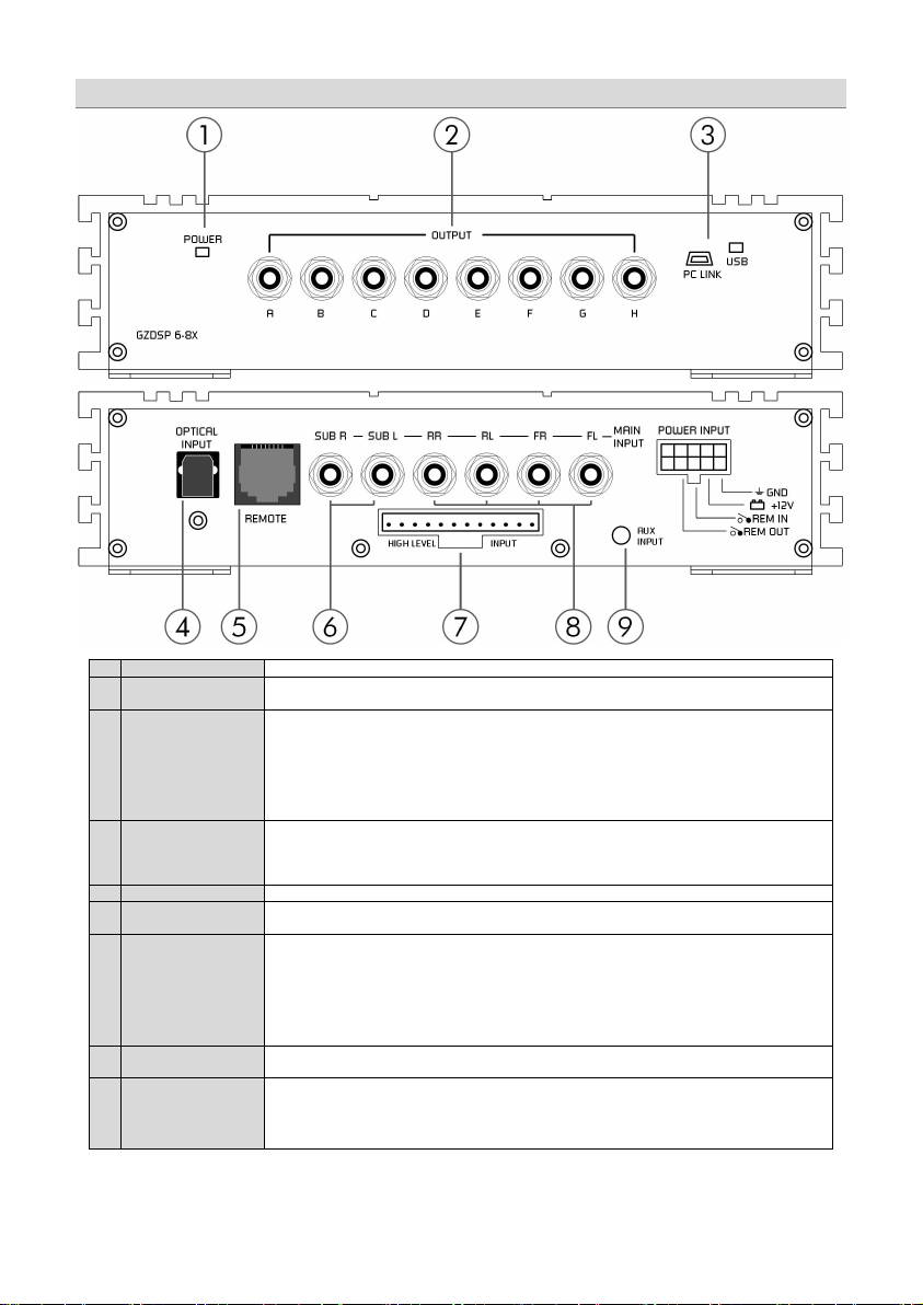
1
Status LED
LED lights up - unit is ready and working
2
RCA output
Every single RCA (LINE OUT) connector provides an audio-signal driving the RCA inputs of the
amplifier and is capable of being configured using the DSP PC software.
3
USB port
Connect th e unit with the supplied cable to your PC to operate the user int erfac e and configure the
4
Optical input
(TOSLINK)
Audio sources offering an optical SP/DIF signal (Stereo PCM) may be connected to this port using a
Please note:
optional remote control unit (GZDSP Remote)
5
RC connector
Connector for the optional remote control unit GZDSP Remote
6
Subwoofer input
If your head-unit has six pre-amplified output channels, the (two) subwoofer channels should be
7
High-level input
The High-Level Input has to be used if the h ead-unit has neither pre-amplified output, nor offering
Caution:
cannot
malfunction and cause serious damage to the DSP unit.
8
RCA input
Connect the pre-amplified head-unit output for front and rear signals using suitable wires to the
RCA (LINE IN) sockets.
9
AUX Input
Please note:
GZDSP Remote)
Audio Connection
setup of the DSP. Ma ke sure to install the PC software previously. The unit may be disconnected
after the setup is done.
We do not recommend to use any extension cord with the supplied USB wire, as the proper
function ca not be ensured. If the enclosed wire is too short, we recommend a suitable USB wire
with an integrated repea ter. The LED next to the USB port will light up blue as soon as the DSP unit
has been connected to the PC.
suitable TOSLINK wire.
connected to these inputs.
a SP/DIF signal. In this case the head-unit speaker output wires have to be connected to the Highlevel Input harness. By using the High-Level Input the DSP unit will turn on automatically
recognizing the DC level, therefore it is not necessary to connect the Remote-In wire to the power
terminal.
External audio sources like smartphone, MP3-player or mobile GPS s ystem may be connected to
the 3.5 mm (1/8”) stereo jack and used with the auxiliary input mode.
optional remote control unit (
If the audio source offers no variable volume level, it is absolutely neces sary to use th e
The high-level input and the RCA input
If the audio source offers no variable volume level, it is absolutely neces sary to use th e
be used a t the same time. This may lead to
Page 5
- 5 -
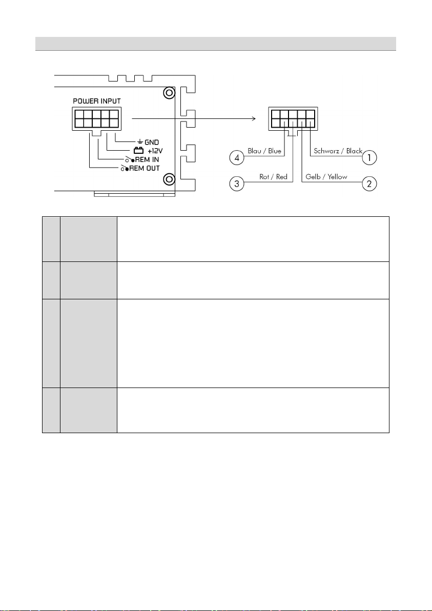
1
Ground
Connect th e unit to a suitable ground terminal on the vehicles body. The ground wire should be as
2
+ 12 Volt
Power
Connect th e unit to the + 12 volt power pole o f the vehicles battery. Use an adequate power wire
3
Remote In
+12 Volt remote turn on signal. Connect the head-units remote out wire (REM) for amplifiers or the
Please note:
4
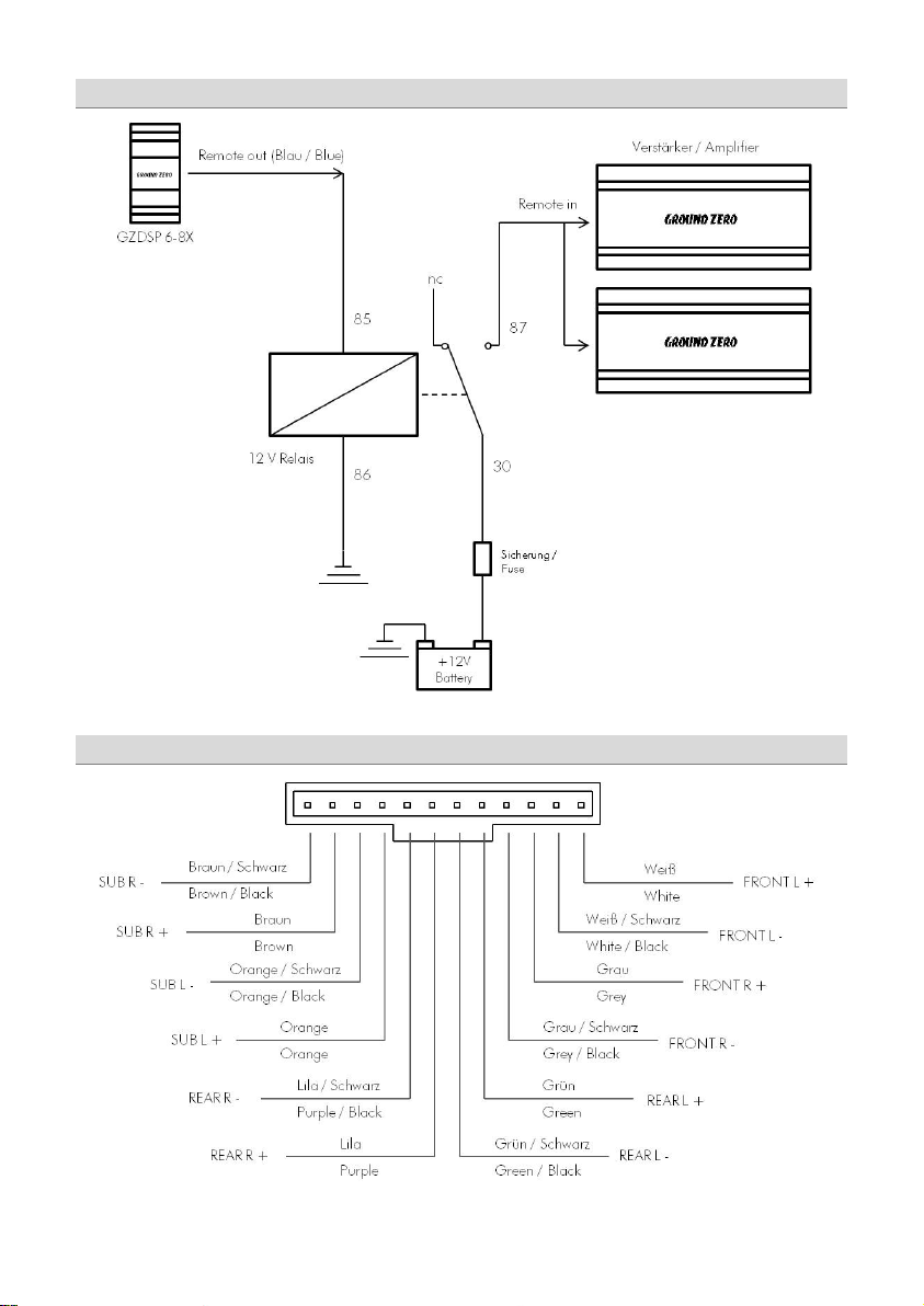
Remote Out
To be used with additional system equipment like amplifiers. If connected to the amplifiers Remote-In
130 mA!
Power Supply Connection
short as possible and be mounted to an unvarnished metal part of the vehi cles body. Ensure that this
part has an unlimited electrical connection to ground pole of the battery. Use an adequate ground
wire gauge (not less than 1,0 mm² / 17 AWG). The ground wire gauge should match the power wire
gauge.
gauge (not less than 1,0 mm² / 17 AWG) and mount an additional fuse holder (with a 2 Ampere
fuse) which will not be further than 30 cm / 12” away from the power p ole of th e vehicles ba ttery.
The fuses should not be plugged into the fuse holder before the installation has been finished.
electric antenna if the RCA signal input or the optical connector is used. A wire gauge of 0.5 mm² /
20 AWG is sufficient.
By using the high-level input the DSP unit will be turned on automatically if a DC-On voltage is
recognized. Therefore it is not necessary to connect a remote wire to the power terminal.
This feature will work fine with most of the modern head-units. However some older head-units may
not be capable to provide the DC-On signal. In this case the Auto Turn/On feature cannot be used.
The Remote-Out function remains in Auto Turn/On mode and may be used for additional system
equipment.
Auto Turn/On (activates the DSP unit)
terminal the amplifier will turn on or off together with the DSP unit when the head-unit is turned on or
off. A wire gauge of 0.5 mm² / 20 AWG is sufficient to connect the amplifier. The current should not
exceed
additional relay (page 6).
If the current of multiple connected units is higher, it is necessary to use an
Page 6
- 6 -
Relay circuit for using multiple amplifiers at the REMOTE OUT teminal
Relais ist nicht im Lieferumfang enthalten / Relay is not included in the package content
High-Level Connector Pin Assignment
Page 7
- 7 -
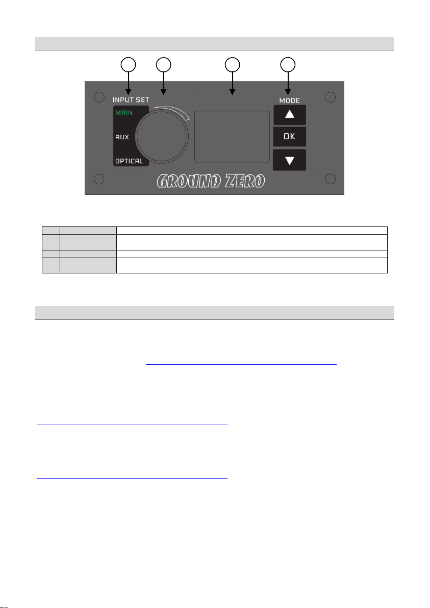
1
Input Set
Selects the Input Mode in shown sequence (MAIN/AUX-IN/OPTICAL)
2
Level Controller
The controller sets the main volume level of the DSP unit. Subwoofer level (SUB OUT G/H) can be
adjusted after pushing and holding the button for approximately 3 seconds.
3
LED Display
The LED display will show the current volume level or the chosen preset
4
Mode (Presets)
Up/Down button switch between previously saved presets. The OK button confirms the selection and
sets the DSP to this preset.
Important note for 64 bit operating systems:
Software update:
1 2 3
4
Installation of PC software
In order to install and use the PC software, a Windows™ XP (SP3) operating system (or later) and a USB port is required.
The installation will need about 25 MB free memory space. We recommend to use a laptop for easier handling.
Insert the enclosed CD-ROM into the CD drive of your PC. If there is no CD drive available, the software can be
downloaded from the following link: http://ground-zero-audio.com/de/downloads/dsp-software.html
Run the setup.exe, the installation wizard will install the software for the DSP the usual way. We recommend to create a
desktop icon. The drivers will be installed automatically during the DSP software installation. Restart the PC after the
installation has been finished.
It may be necessary to install a 64 bit driver manually. The driver can be found on the CD-ROM or at:
http://ground-zero-audio.com/de/downloads/dsp-software.html
Please note that you should always use the latest DSP-Software. Here you can download all software versions:
http://ground-zero-audio.com/de/downloads/dsp-software.html
Remote Control Unit Features (optionally available)
Page 8

- 8 -
Demo Mode (Off-Line Mode):
Important Note:
To configure the DSP unit, it has to be
Connecting the DSP to the PC
connected using the enclosed USB
wire to the PC with the previously
installed DSP software.
The head-unit and the DSP unit has to
be turned on before starting the DSP
software.
The DSP software starts by clicking the
desktop icon.
The start screen will appear and the
GZDSP 6-8x unit has to be selected as
device (Select Device) .
It´s possible to use the PC software without having the DSP unit connected, to become familiar with most of the
software features.
We don´t recommend to use any passive extension cord with the supplied USB wire, as the proper function can´t be ensured. If the
enclosed wire is too short, we r ecommend a suitable USB wire with an integrated repeater.
The LED next to th e USB p ort will light up blue as soon as the DSP unit has been connected to the PC.
Page 9

- 9 -
Select Device
RS232 Setting
Connect
Note:
problem remains, the description on the following page has to be noticed
Now the „Click here to test“ button should be chosen.
All 4 points should be checked.
[OK] Click here to start
After the DSP unit has been selected in the „
the „
selected automatically and varies depending on the computers environment.
By clicking the „
automatically.
The COM port will be assigned automatically by the Windows™ operating
system. Please note that this may be one of the COM1 to COM9 ports. If any
By clicking the „
Selecting the USB COM-port
“ window will appear. Usually the correct COM port will be
“ menu,
“ button the GZDSP 6-8X will be connected to the PC
” button will open the “Channel Matrix”
Page 10

- 10 -
If this message will appear, the operating system
In this case the correct COM port would be number 3
OK
Important note:
Error Message using wrong USB COM-Port
assigned the wrong COM port or it was not possible
to assign one of the COM1 to COM9 ports due to
environmental issues of the PC. The COM port
assignment may be checked with the operating
systems device manager.
Close the pop-up window by clicking „
possible to select the correct COM port at the „Select
COM“ window.
If the assigned COM port is COM10 or higher, one of
the unused COM ports 1 to 9 has to be deleted in order
to change the previously automatically assigned COM
port for the „USB-SERIAL CH340“ device to the one that
has been deleted now.
“, now it is
Page 11

- 11 -
1 2 3
4 5 6 7 8 9 1
Input selection
MAIN
AUX
SPDIF
Gain
speakers.
SOURCE
Features of the User Interface
- RCA or High-Level Audio Input
- 3.5 mm / 1/8“ Stereo Jack
- optical TOSLINK input
Main volume control
- Main volume (-40dB to +12dB).
Caution: The controls have to be used carefully to avoid damaging the
Page 12

- 12 -
2
Channel selection
Clicking the -Icon will invert the left and right inputs.
Warning
CH SETTING
Trying to synchronize (link) two channels, which have already been adjusted separately, will cause
a pop-up warning.
Confirming this with OK will reset all channel wise done previous adjustments. This can not be
revoke. Therefore, either a separate adjustment is recommended or alternatively the copyfunctions
or can be used.
Clicking the
-Icon will link the relevant pair of channels allowing function
adjustments simultaneously (Crossover / Slope / Equalizer) for both channels.
Simultaneous adjustment of channel A and B
Independent adjustment of channel A and B
Clicking
Clicking
will copy the current adjustment of the left channel to the right channel.
will copy the current adjustment of the right channel to the left channel.
Page 13

- 13 -
3
Configuration of in- and outputs
Input
Output
Speaker Type
Input-MIX – Input summing of filtered signals
SUBL+SUBR: Lowpass filtered audio signal
CHANNEL MATRIX
This setup should be chosen if the head-unit has filtered (HPF/LPF/BPF) pre-amplified output channels.
All 6 input channels will be summed to a full-range audio signal.
Outputs A+C+E+G receive a summed audio signal from the input channels FL+RL+SUBL
Outputs B+D+F+H receive a summed audio signal from the input channels FR+RR+SUBR
We recomm end to connect the input channels as follows
FL+FR: Highpass filtered audio signal
RL+RR: Bandpass filtered audio signal
– Assignment of the corresponding input channel to the respective
output A – H.
The following input options are available:
Channel A/B : F-L (
Channel C/D/E/F : F-L (
Channel G/H: F-L (
Front-L) and F-R (Front-R)
Front-L) and F-R (Front-R)
or R-L (
Rear-L) and R-R (Rear-R)
Front-L) and F-R (Front-R)
or R-L (
Rear-L) and R-R (Rear-R)
or SUB-L and SUB-R
or F-L+R (
or R-L+R (
Mono-summation of Front-L and Front-R)
Mono-summation of Rear-L and Rear-R)
or SUB-L+R (Mono-summation of SUB-L and SUB-R)
or F+R-L (
and F+R-R (Summation of Front-R and Rear-R)
Summation of Front-L and Rear-L)
– Clicking the corresponding channel will allow adjustments of
crossover, slope and equalizer functions.
Same as CH Setting (2) function.
– Preselection of the connected speakers.
3 different options can be chosen.
OFF – Channel deactivated
Fullrange – Expertmode. All filters deactivated
Tweeter (A/B) –Highpass filter preset 3000 Hz (12 dB)
Midrange (C/D) –Bandpass filter preset 250 / 3000 Hz (12 dB)
Kickwoofer (E/F) –Bandpass filter preset 80 / 250 Hz (12 dB)
Subwoofer (G/H) –Bandpass filter preset 20 / 80 Hz (12 dB)
Page 14

- 14 -
4
5
Channel configuration
Select
Gain
Delay
Gain –
Delay(ms)
Warning
(5)
Delay(ms)
Phase
Speaker distance entry
Delay(ms)
GAIN & DELAY
SPEAKER DISTANCE
– Marking the Select-box allows to group the respective
channels together for combined adjustments of
and
Adjusting the output level of the respective channel
– Adjusting the time alignment of the respective
channel. Displayed in milliseconds.
It is recommended to fill-in the measured distances of the
speakers to the listening position first
tuning afterwards at
and realize the fine-
– 0 / 180° Phase inversion of the respective channel
– Mute of the respective channel
Before realizing the fine-tuning of each speakers time
alignment in window 4
, the measured distances
of all connected speakers should be added to the graphic.
The distances can be measured with an usual measuring
tape.
The exact distance between listening position (head) and
cone center of each speaker must be measured.
The explanation of a correct implementation on the
following page can be used as an application example.
.
Page 15

- 15 -
Example of use
Warning
3. If that failure notice pops up, one of the two identical distances must be reduced by 1 cm.
point 5
Delay(ms)
Delay(ms)
1. All measured distances (cm) must be added to the
graphic.
2. The speaker with the largest distance will be set as
the reference with the button
The number of channels with the maximum distance must be 1.
In case of 2 channels with maximum distance (for example
mono subwoofer at G/H) a failure notice will pop up.
In this case the instruction from
After editing the numbers correctly the background of the button turns to red ->
4. Clicking the button
data to the
5. In case of 2 channels with largest distance, one of these two identical numbers must be reduced by 1cm.
Subsequently the
will cause the calculation of the respective time alignment and transfer the
list.
button must be clicked. Finally the background turns to red ->
on must be followed.
6. Now the real value can be re-edited
Clicking the button
the data to the
will cause the calculation of the respective time alignment and transferring
list.
.
.
Page 16

- 16 -
6
7
Activating the filters and choosing the slope
Important
Adjusting the cutoff frequency
Note
Hint:
SLOPE
Before choosing the filter, a Speaker type must be defined in window 3.
Highpass (HP) / Bandpass (BP) and Lowpass (LP) can be chosen.
A slope of 6/12/18/24/30/36/42/48 dB/Oct can be selected.
CROSSOVER
The filters can be adjusted continuously from 20 – 20000 Hz.
The controls can only be used if a filter (Slope/6) has been selected
frequency directly with the cursor at the frequency chart (8). Click and
hold the red (HPF) or blue (LPF) dot with the cursor and move it to the
desired point on the frequency chart.
crossover point by typing the required value directly into the box above
and confirm with >ENTER< or by using the up/down cursor buttons.
first.
: If a filter has been selected, it is possible to adjust the crossover
Instead of using the crossover control, it is possible to adjust the
Page 17

- 17 -
8
9
Function of the frequency diagram
Adjusting the parametric 31-band equalizer
FREQUENCY DIAGRAM
The frequency chart displays the adjustments of the 31 band equalizer (9) and the setting of the
crossover (7) for every output channel or a pair of output channels.
Furthermore the curves can be adjusted individually using the mouse (drag&drop).
EQUALIZER
The output channels A to F can be equalized by adjusting 31 frequency bands (20 - 20000 Hz) using
the controls (-18 to +12dB) individually. The subwoofer output channels G/H offer 11 bands (20 - 200
Hz) to adjust the audio signal.
Each frequency can be adjusted individually in 1-Hz steps in the F(Hz) window.
Additionally it is possible to change the filter Q (bandwidth/slope) by typing the required value directly
into the box below each band control (0,5/narrow - 9,0/wide) or by using the up/down cursor buttons.
Furthermore the curves can be adjusted individually in window 8 using the mouse (drag&drop).
The EQ-function can be deactivated with the
Using the
not affected).
button will cause a full reset of the EQ-setup to factory setting. (Other adjustments are
button without resetting the EQ-setup.
Page 18

- 18 -
Features of the „FILE“ Dropdown Menu
*Important
*Important
PC Contrl
Opens the „Select COM“ window (page 9)
Open
Opens a setup file that has been saved previously to the PC memory
Save
Saves the current setup as a file to the PC with unmodified filename. If
no filename has been selected yet, the dialogue will ask for the inp ut.
Save as
Saves a setup file with a certain filename.
Factory setting
Sets the unit to default settings
Class-D AMP Setting
No function
Write to Devic e*
Saves the current setting to the preset memory of the DSP unit.
At the following window the preset number can be selec ted.
Read from Device*
Opens the preset that has been selected with th e optional remote
control GZDSP Remote
Exit
Closes the DSP software
Click „Select Save Place“ and choose one of the presets.
*Note
or an external drive
control unit, it is only possible to use and edit the last preset that has been saved.
: The 10 presets can be used if the optional remote control GZDSP Remote is connected. Without the remote
Saving to the Preset Memory (write to device)
Confirm by clicking „Save to Flash“
control unit, it is only possible to use and edit the last preset that has been saved.
: All presets must be covered in numerical order (Pos
1>Pos 2>Pos 3>…) without skipping a position, otherwise it
will not be possible to access the following presets.
: The 10 presets can be used if the optional remote control GZDSP Remote is connected. Without the remote
Page 19

- 19 -
Digital Sound Processor (application examples)
3-way front system + subwoofer
(full active)
2-way front system (active) +
2-way or coaxial rear system (passive)
+ subwoofer
Channel
A/B
Tweeter
Tweeter
C/D
Midrange
Midwoofer
E /F
Woofer
LP: 150 – 300 Hz
G/H
Subwoofer
LP: 50 – 100 Hz
Subwoofer
LP: 50 – 100 Hz
Note:
GZDSP 6-8X offers countless possible system configations. Here is a description of the two most common applications:
Highpass filter
HP: 2500 – 6000 Hz
Bandpass filter
HP: 150 – 300 Hz
LP: 2500 – 6000 Hz
Bandpass filter
HP: 60 – 80 Hz
Bandpass filter
HP: 10 – 30 Hz
Highpass filter
HP: 2500 – 4500 Hz
Bandpass filter
HP: 60 – 80 Hz
LP: 2500 – 4500 Hz
Rear system
Highpass filter
HP: 60 – 80 Hz
Bandpass filter
HP: 10 – 30 Hz
The final crossover points depend on the speakers capacity that have been installed. The technical specifications
of the speakers will supply more information about possible applications and suggested crossover points.
Above, these are just noncommittal examples. Ground Zero will not be legally responsible for any kind of damage of
speakers or other components caused by wrong settings.
Page 20

- 20 -
Technical Specifications
Model
GZDSP 6-8X
Type
Frequency Response
5 Hz – 20 KHz
(-3 dB)
Signal to noise ratio
Channel separation
Harmonic distortion
Processor
Input sensitivity
High level: 2 – 15 V RMS
Aux inpu: 0.6 – 5 V RM S
Input impedance
Output
Input
Main: 6 x RCA audio socket / 6 x high-level
Digital: TOSLINK optical 12 - 96 kHz stereo
Remote out
Recomended fusing
Dimensions (heatsink)
W x H x L mm / inch
Dimensions (total)
W x H x L mm / inch
Software compatibility
Presets
Gain bandwith
Equalizer
Time alignment
Crossover
Phase switch
Optional remote control
(GZDSP Remote)
8 channel DSP unit
>110 dB
>60 dB
0.05%
Cirrus Logic Sing le Core 32 bit, 8 channel, 192 kHz
Low level: 0.6 – 5 V RM S
>47 kOhm
8 x RCA audio socket
Aux: 3.5 mm / 1/8“ stereo jack
Max 130mA
2 A
96 x 39 x 185 / 3.78“ x 1.5 4“ x 7.28“
132 x 42 x 185 / 5.2“ x 1.65“ x 7.28“
Microsoft Windows™ XP SP3, Vista, 7, 8, 8.1,10
10 Individual presets – storing/calling via optional remote control GZDSP Remote
-40 ~ + 12dB
6 x 31 bands on each channel (A-F) (20-20000Hz) -18 to +12dB, Q 0.5 - 9
2 x 11 bands on subwoofer channels (G/H) (20-200Hz), -18 to +12dB, Q 0.5 - 9
0 - 15ms / 0 - 502cm per channel
6 / 12 / 18 / 24 / 30 / 36 / 42 / 48 dB/Oct. BPF / LPF / HPF Butterworth
20 - 20000Hz
selectab le (0˚ / 18 0°) per channel
Main level, subwoofer level,
input mode, preset selection
Page 21

- 21 -
Error
Control
Help / Solution
-check the fusing
-check the ground connection and wire
signal wire no contact or broken
-check the contact or replace the wire
no audio signal from head-unit
-check the audio output signal of head-unit
-check the r emote out of DSP
-check the amplifiers power supply
non operational source selected
-check the setting
activated >MUTE< function (User Interface)
-check the setting
adjus ted level on optional remote control
unit too low
signal wire no contact or broken
-check the contact or replace the wire
no audio signal from head-unit
-check the audio output signal of head-unit
balance or fader control of head-unit not
in center position
wrong setup of input and output mode
-check the setting
>GAIN< level too low or >Mute< function
(user interface) active
-check the polarity of th e speaker connection
-reduce the volume level
-select the correc t input mode
-pay attention to the input sensitivity of DSP unit
-reduce the volume level of head-unit
-check amplifier input sensitivity
>GAIN< level too high
-reduce the >GAIN< level
-select a superior quality head-unit
-the head-unit, the DSP and each amplifier should be wired up to
a common ground and +12 Volt connection
signal wire no contact or broken
-check the contact or replace the wire
head-unit defective
-let the audio store or manufacturer check the head-unit
amplifier defective
-let the audio store or manufacturer check the amplifier
DSP unit or amplifier mounted close to an
analog output of an OEM MOST head-unit
connected
Detecting Possible Errors
No function PWR LED on?
No sound
(PWR LED on)
Single channels
with no function
Impure sound,
incorrect stereo
reproduction
Distorted sound
quality
Increased
noise level
Car specific
interferen ces
audible through
the audio system
amplifier not switched on
inverted phase of one or more speakers
speaker overload
DSP input override (distortion)
head-unit output override (distortion)
amplifier override (clipping)
head-unit creates noise
diverse power supplies or ground connection
automotive control unit
-check the r emote wire
-check the + 12 Volt connection and wire
-check the setting
-check the setting of th e head-unit
-check the setting
-check the polarity of the high-level input
-check the >PHASE< setting
-check the > TIME ALIGNMENT< adjustment
-check the highpass filter and slope
-set the sound controls of head-unit to center position
-deactivate the >Loudness< function of head -unit
-reduce the level
-use the optical output (if available)
-let the audio store or manufacturer check the head-unit
-choose another mounting position
-connect the digital MOST audio signal directly to the DSP unit*
*Note: Use an optional car specific interface to connect the digital MOST audio signal directly to the GZDSP 6-8X
Page 22

- 22 -
Erlenweg 25, 85658 Egmating, Germany
Tel. +49 (0)8095/873 830 Fax -8310
www.ground-zero-audio.com
Die Gewährleistung entspricht der gesetzlichen Regelung. Eine Rücksendung kann nur nach vorheriger Absprache und in der
Originalverpackung erfolgen. Bitte unbedingt einen maschinell erstellten Kaufbeleg und eine Fehlerbeschreibung beilegen. Von der
Gewährleistung ausgeschlossen sind Defekte, die durch Überlastung, unsachgemäße Behandlung oder bei Teilnahme an Wettbewerben
entstanden sind. Wir behalten uns das Recht vor, zukünftig nötige Änderungen oder Verbesserungen an dem Produkt vorzunehmen ohne
Limited warranty - defective products must be returned in original packaging - please add a copy of the original purchasing invoice showing
the purchasing date and a detailed description of the failure. Failure caused by overload, misuse or by using the product for competition
purpose are not covered by the warranty. We reserve th e right to make needed change or improvement to the product without informing
De Garantie bepa lingen van alle door ground zero g eleverd e prod ucten is volgens wettelijke
verpakking plaatsvinden.SVP een aankoopbon en een duidelijke storingsomschrijving bijvoegen.Van garantie uitgesloten zijn defecten door
overbelasting, onkundig gebruik, of door deelname aan wedstrijden (SPL) ontstaan zijn. Wij behouden ons het recht om de nodige
emballage d'origine sur présentation du reçu ou de la facture indiquant la description du defaut.La présente Garantie n'est pas applicable
lorsque le produit a été endommagé en raison: Mauvaise alimentation, Trop de puissance (HP,Subwoofer) Accident, Installation ou
Utilisation non conforme aux normes Technique (Concours SPL etc). Nous nous réservons le droit d'entreprendre à l'avenir nécessairement
bepalingen geregeld, Een retourzending kan alleen na duidelijke afspraak en in de originele
veranderingen of verbeteringen aan het product door te voeren zonder de kla nt hierover te inform eren.
La garantie est conforme aux droits légaux. Un retour du produit défectueux doit être dans son
den Kunden darüber zu informieren.
customer about this in advance.
des modifications ou des
améliorations au produit sans informer le client.
Ground Zero GmbH
 Loading...