

Page 1

DSP-SERIES
AMPLIFIER
MANUAL
GZDSP 4.80AMP
• 4-channel amplifier with integrated 8-channel signal processor (DSP)
• High efficient 2 Ohm stable class D amplifier
• 6-channel line input (RCA)
• 6-channel high-level input (with auto-on function)
• AUX input (3.5 mm socket)
• TOSLINK input (sampling rate up to 24-bit/96kHz)
• Plug for optional interface (wireless music streaming)
• 4-channel line output (RCA)
• 8-channel signal processor (DSP) - Cirrus Logic single core 32-bit/192 kHz
• Realtime setup of DSP functions (via PC)
• Simple handling, one-page graphical user interface (Windows compatible)
• Channel separated parametric equalizer (6x 31 band / 2x 11band)
• Channel separated time alignment (0-15 ms / 0-510 cm)
• Adjustable crossover (HPF / LPF / BPF - 20 Hz to 20 kHz)
• Selectable crossover slope (6 to 48 dB/Oct)
• Selectable phase shift for each channel (0˚ or 180°)
• Memory for 10 user presets (selectable with optional remote control)
• Two optional remote-control units available (GZDSP Remote or GZDSP Touch-Remote)
to adjust main and subwoofer level, select the presets and input mode
• LED power and status indicator (protection circuit)
• Power on delay
• High temperature / short circuit / overload protection circuit)
Feature list
Page 2
- 2 -
Important safety notes and installation instructions
3
Audio connections (input)
4
Audio connections (output)
5
High-level input harness
5
PC software installation
6
Connecting the unit with a Windows PC
6
USB port selection
7
Wrong COM port error message
8
Software user interface
9
Channel selection
10
Channel matrix
11
Channel configuration (level adjustment and time alignment)
12
Application example (time alignment)
13
Adjustment of the crossover
14
Frequency chart and equalizer
15
File dropdown menu
16
Preset memory saving and loading
16
Technical specifications
18
Error diagnosis
19
Warranty conditions
20
Package contents
• 1 x GZDSP 4.80AMP amplifier
• 1 x USB cable (A- to Mini-B connector) 5 m
• 1 x 4-channel line output harness
• 1 x 6-channel high-level input harness
• 1 x CD-ROM incl. PC software and driver package (for Windows)
• 1 x Owner´s manual (German and English)
• 1 x Fastening Kit
Optionally available:
• Remote-control unit
• Remote-control unit
• Interface
GZDSP BT-Box for wireless music streaming (incl. connecting cable)
GZDSP Remote with LED display incl. connection wire
GZDSP Touch-Remote with color LCD display incl. connection wire
Table of content
Application examples of the GZDSP 4.80AMP 17
Page 3
- 3 -
GZDSP 4.80AMP
Speaker wires
min 1.5 mm² / 15 AWG
Power supply wir es
min 20.0 mm² / 4 AWG
High-level input wires
min 1.00 mm² / 18 AW
Remote Leitung
min 0.50 mm² / 20 AW
WARNING!
• As a precaution, it is recommended to disconnect the vehic les battery before mounting (also note the vehicles manual!)
• The power supply wire (+12 V) has to be protected within max. 20 cm / 8” by a main fuse holder with matching fuse value
(Main fuse value has to be equal to the sum of values of the fuses of each connected device)
• If necessary, replace a defective fuse with the identical value only
• Never drill a hole to the vehicles gas tank or brake lines, to wirings or any other important vehicle part!
• Never pass wires over sharp edges or vehicle parts
• Keep the wiring away from the antenna and electronic devices contr ibuting to radio reception
• Lay the power supply wiring always separated from speaker wiring
• The amplifier contains a temperature protection circuit that turns the device off in case of overheating. After a coo ling time,
it will turn on again automatically. To avoid heat buildup, sufficient air supply for cooling must be provided. Never cover the
surface of the heatsink entirely.
• The amplifier should not be mounted on a heavily vibrating part or surface (e.g. subwoofer enclosure)
• If a pre-amplified output (RCA) is ava ilable (at the head unit), it is recommended to use it for input wiring
• screwdriver
• electric drill - 3 mm / 0.12“ car bide drill b it
• recommende power wiring
Required parts and tools for the installation
Recommended wiring
Mounting instructions
to excessively high-volume sound levels may cause hearing loss or damage. Also, operation of a motor vehicle while
Select a suitable location that is convenient for mounting, is accessible for wiring and has an ample room for air circulation and cooling.
The unit must not be covered or mounted close to heat emitting objects. Because of the high operation temperature (up to 80°C), it is
important to ensure sufficient distance to any heat-sensitive object . Especially the distance between GZDSP 4.80AMP and any plastic part or
electronic component should be at least 3 cm (1.18”).
You may use the unit as a template to mark the mounting holes, then remove it and drill the marked holes. Finally mount the unit with the
mounting screws.
Choose a mounting position where all electric wires are protected from being damaged by sharp edges, heat or other conditions. +12 Volt
DC electrical connections must be fused on the battery side. Make sure your head-unit and all other devices will remain turned off while
connecting parts of the system. If it is necessary to replace the fuse(s), make sure to use only an equivalent one. Using inferior fuses may
cause serious damage to your unit, wiring or even your cars electric. Any kind of damage traced back on disregard of these notes will not
be covered by the warranty!
High powered audio systems in a vehicle can generate "Live Concert" levels of sound pressure. Continued exposure
listening to audio equipment at high volume levels may impair your ability to hear external sounds such as horns,
warning signals or emergency vehicles! This may lead to potential traffic hazards. In the interest of safety, consumer
electronics recommends listening at lower volume levels while driving.
Selecting a mounting position
Mounting the Unit
Caution
Page 4
- 4 -
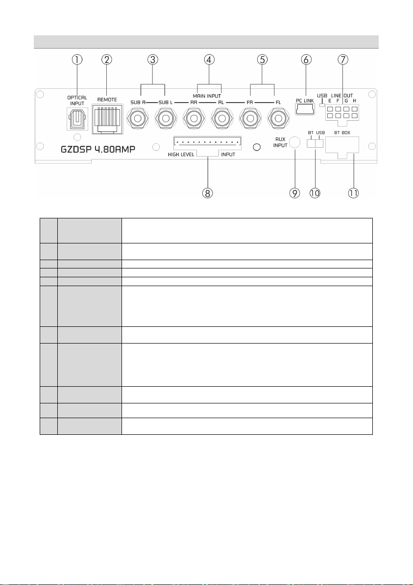
1
OPTICAL INPUT
socket
(TOSLINK)
To connect a digital audio source using the optical signal (SPDIF / stereo PCM)
Attention: If the digital audio source has no level control, we strongly recommend using one of the
available remote-control units. Otherwise the audio reproduction will be applied at max level!
2
REMOTE CONTROL
socket
To connect one of the optionally available remote-control units
GZDSP Remote
GZDSP Touch-Remote
3
Line Input SUB
Connect the subwoofer line out of the head-unit (if available)
4
Line Input REAR
Connect the rear line output of the head-unit (if available)
5
Line Input FRONT
Connect the front line output of the head-unit (if available)
6
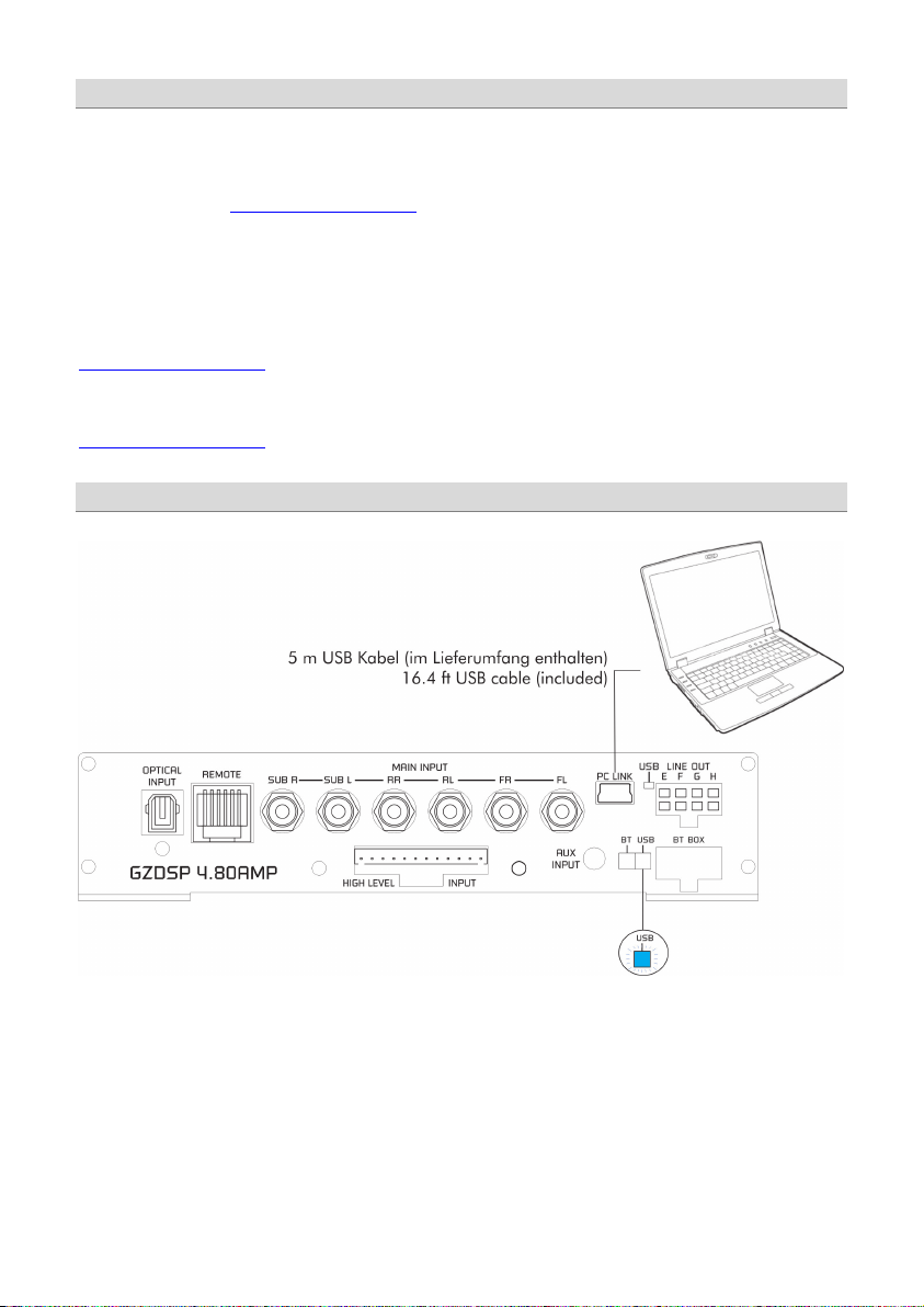
PC CONNECT
(MINI USB socket)
and
status indica tor
To adjust the audio setting the unit must be connected to a PC using the included USB cable
7
LINE OUT
To connect the included 4-channel RCA line out harness delivering the audio signal of channel
8
HIGH LEVEL INPUT
The High-Level Input must be used if there´s no pre-amplified output at the head-unit, nor offering
Caution: The high-level input and the line input(s) cannot be used simultaneously. This may lead
to malfunction and cause serious damage to the DSP unit.
9
AUX INPUT
The 3.5 mm socket can be connected to an additional source unit. AUX can be selected as audio
10
PC Link switch
To establish a wired connection to the PC, the switch must be in „USB” position. The “BT” position
is without function.
11
BT BOX socket
To connect the wireless audio interface GZDSP BT-Box or the remote-control unit
GZDSP Touch-Remote
Audio connections (input)
or
(compatible Windows PC with installed DSP software from the CD). The PC can be disconnected
when the adjustment is done. The USB cable should not be extended to ensure an accurate
communication between the DSP unit and the PC. The indicator next to the MINI USB socket will
turn blue as soon as the connection has been established.
E/F and G/H for further amplifiers. The signal can be set using the PC soft ware.
a SP/DIF signal. In this case the head-unit speaker output wires must be connected to the highlevel input harness. By using the high-level input, the DSP unit will turn on automatically
recognizing the DC level. It´s not necessary to connect the Remote-In wire to the power terminal.
source using the PC software or one of the available remote-control units.
– both are available optionally.
Page 5
- 5 -
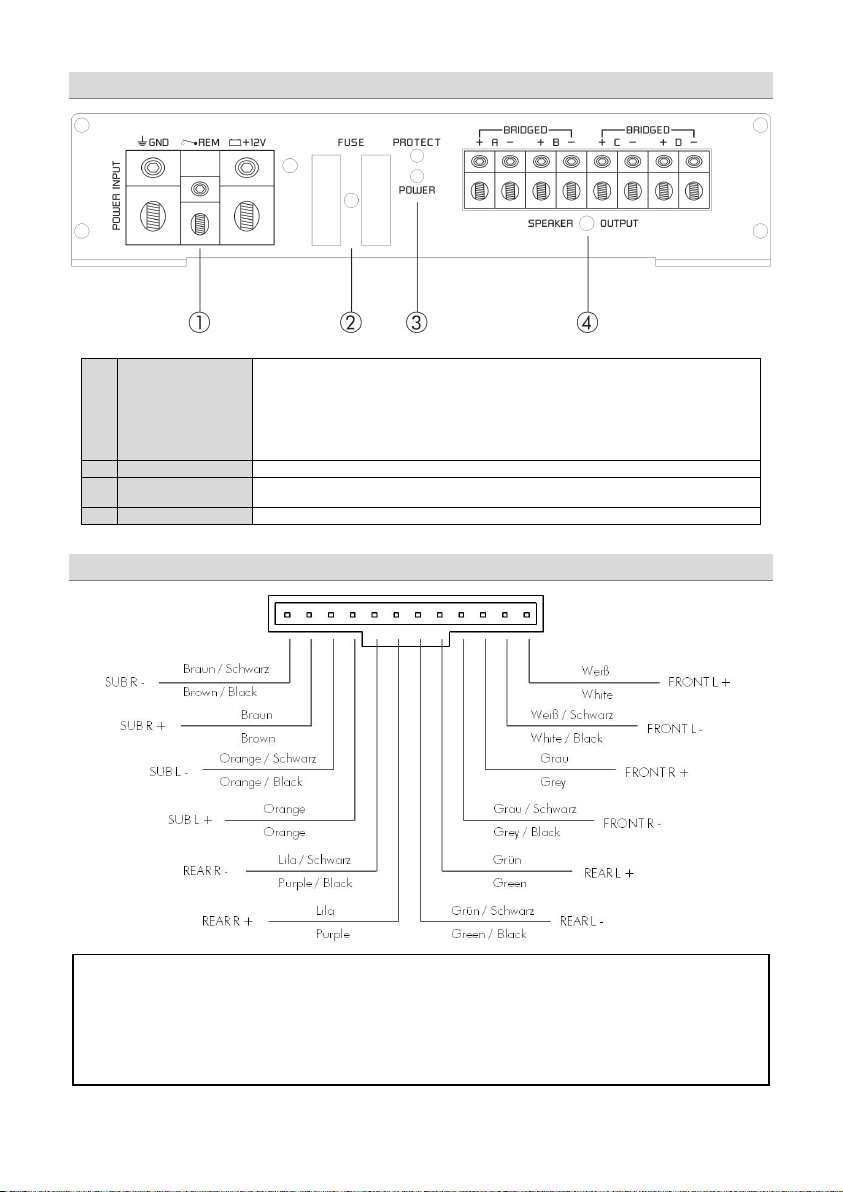
1
POWER INPUT
+12V Positive termin al (battery)
or
Never connect the remote output wire of a source unit in high-level mode to the remote terminal!
130 mA
with a common current exceeding the limitation, an additional relay is required.
2
FUSE
Defective fuses must be replaced by fuses with identical values
3
Status indicator
POWER
green/ok (regular operation mode)
PROTECT red/error (protection mode)
4
SPEAKER OUTPUT
Channel A/B/C/D speaker terminal
ATTENTION!
GND Ground terminal
REM Remote input (in RCA mode)
In high-level mode, the switched voltage at the terminal can be used to turn on additional
amplifiers. The current of the remote terminal is l imited to
High-level input harness
Please note that the GZDSP 4.80AMP cannot be used in vehicles with a factory active system installed. That might lead
to serious defects of the amplifier as well as of the vehicle´s electronic system. In case of uncertainty contact your car
Power input & speaker output connections
audio dealer or the car´s manufacturer.
Remote output (in high-level mode)
. In case of using several units
Page 6
- 6 -
To install and use the PC software, a Windows™ XP (SP3) operating system (or later) with a USB port is required. The
installation will need about 25 MB free memory space. We recommend using a laptop for easier handling. Insert the
enclosed CD-ROM into the CD drive of your PC. If there is no CD drive available, the software can be downloaded
from the following link: www.ground-zero-audio.com
Run the setup.exe file. The installation wizard will install the software for the DSP as usual. We recommend creating a
desktop icon. The drivers will be installed automatically during the DSP software installation. The PC requires a restart
after the installation of the software
Important note for 64-bit operating systems:
It might be necessary to install the 64-bit driver manually. The driver can be found on the CD-ROM or:
www.ground-zero-audio.com
Software update:
It´s strongly recommended running always the latest DSP software. The actual version can be downloaded here:
www.ground-zero-audio.com
Connecting the DSP to the PC
Note about the USB connection:
The included USB cable should not be extended to avoid any kind of malfunction of the communication between the
DSP unit and the PC. The LED next to the USB port on the unit will light up blue as soon as the GZDSP 4.80AMP has
established a connection to the PC.
Installing the PC software
Page 7

- 7 -
In order to configure the DSP,
Select Device
RS232 Setting
Note:
Connect
Click here to test
OK
[OK] Click here to start
the GZDSP 4.80AMP must be connected
to a PC with the DSP software installed
using the included USB wire.
The head unit and the DSP unit must be
turned on before opening the software.
The DSP software starts by double-click
the desktop icon.
The start screen appears and
GZDSP 4.80AMP should be selected as
device (Select Device).
The latest software version can be
downloaded from this page:
www.ground-zero-audio.com
Demo Mode (Offline Mode):
It´s possible to use the software in offline mode without having the GZDSP 4.80AMP connected to the PC to become
familiar with most of the features and to create sample setups.
USB port selection
After having the DSP unit selected at the
the
Usually the correct COM port will be selected automatically. The port number
window will appear.
may vary depending on the computer´s environment. It can be selected
manually using the dropdown menu.
The COM port will be assigned automatically by the Windows operating
system. Please note that this should be one of the ports COM1 to COM9. In
case of any problem, please follow the instructions on the next page.
A click on the
button will start the automatic connection process of
the GZDSP 4.80AMP to the PC.
Next click on
A number of automatic tests will be initiated now and each of them marked as
after successful examination.
Finally, a click on
connects the unit to the PC.
will open the user interface of the
DSP software.
menu,
Page 8

- 8 -
If this message will appear, the operating system
In this case the correct COM port is number 3
OK
Important note:
USB-SERIAL CH340
properties
USB-SERIAL CH340
Wrong COM-Port error message
assigned the wrong COM port or it was not possible
to assign one of the COM1 to COM9 ports due to
environmental issues of the PC. The COM port
assignment may be checked with the operating
system´s device manager.
Close the pop-up window by clicking
possible to select the correct COM port at the Select
COM window.
If the assigned COM port will be COM10 or even
higher one of the unused COM ports 1 to 9 has to be
deleted in order to change the previously automatically
assigned COM port for the
Subsequently, the COM port can be selected in the
of the
on the device at the device manager).
. Now it is
device.
device (right click
Page 9

- 9 -
1 2 3 4 5 6 7 8 9
1
Input selection
MAIN
AUX
SPDIF
Main volume control
Gain
Caution:
SOURCE
Software user interface
- RCA line or high-level input
- 3.5 mm input socket
- Optical input (TOSLINK socket)
- Main volume (-40dB to +12dB)
The controls must be used carefully to avoid damaging the speakers.
Page 10

- 10 -
2
Channel selection
Clicking the -Icon will invert the left and right inputs.
Warning
CH SETTING
Trying to synchronize (link) two channels, which have already been adjusted separately, will cause
a pop-up warning.
Confirming this with OK will reset all channel wise done previous adjustments. This cannot be
revoke. Therefore, either a separate adjustment is recommended or alternatively the copyfunctions
or can be used.
Clicking the
-Icon will link the relevant pair of channels allowing function
adjustments simultaneously (Crossover / Slope / Equalizer) for both channels.
Simultaneous adjustment of channel A and B
Independent adjustment of channel A and B
Clicking
Clicking
will copy the current adjustment of the left channel to the right channel.
will copy the current adjustment of the right channel to the left channel.
Page 11

- 11 -
3
Configuration of in- and outputs
Input
Output
Speaker Type
Input-MIX –
CHANNEL MATRIX
This setup should be chosen if the head unit has filtered (HPF/LPF/BPF) speaker output channels.
All 6 high level input channels will be summed to a full-range audio signal.
Outputs A+C+E+G receive a summed audio signal from the input channels FL+RL
Outputs B+D+F+H receive a summed audio signal from the input channels FR+RR
We recommend connecting the input channels as follows
Front left and Front right: Highpass filtered audio signal
Rear left and Rear right: Bandpass filtered audio signal
Input summing of filtered signals
– Assignment of the corresponding input channel to the respective
output A – H.
The following input options are available:
Channel A/B: F-L (
Channel C/D/E/F: F-L (
Channel G/H: F-L (
or F-L+R (
Front-L) and F-R (Front-R)
Front-L) and F-R (Front-R)
or R-L (
Rear-L) and R-R (Rear-R)
Front-L) and F-R (Front-R)
or R-L (
Rear-L) and R-R (Rear-R)
or R-L+R (
or F+R-L (
or F+R-R (sum of Front-R and Rear-R)
sum of Front-L and Front-R)
sum of Rear-L and Rear-R)
sum of Front-L and Rear-L)
SUB-L and SUB-R
SUB-L+R (
sum of SUB-L and SUB-R)
:
Clicking the corresponding channel will allow adjustments of crossover,
slope and equalizer functions. Same as CH Setting (2) function.
The mentioned information to channel A, B, C and D refer to the speaker
output of the GZDSP 4.80AMP. The signal of channel E, F, G and H will
be available at the RCA line output (via line out harness).
: Pre-selection of the connected speakers.
3 different options can be chosen.
OFF – Channel deactivated
Fullrange – All filters deactivated! (individually selectable)
Tweeter (A/B) – Highpass filter preset 3000 Hz (12 dB/oct)
Midrange
Kickwoofer
Subwoofer
(C/D) – Bandpass filter preset 250 / 3000 Hz (12 dB/oct)
(E/F) – Bandpass filter preset 80 / 250 Hz (12 dB/oct)
(G/H) – Bandpass filter preset 20 / 80 Hz (12 dB/oct)
Page 12

- 12 -
4
5
Channel configuration (level adjustments and time alignment)
Select:
Select
Gain
Delay
Gain:
Delay(ms)
Warning:
(5)
Delay(ms)
Phase
Speaker distance entry
(Gain & Delay)
GAIN & DELAY
Marking the channel as
channels together for combined adjustments of
To adjust the output level of the respective channel
:
To adjust the time alignment of the respective channel.
Will be displayed in milliseconds.
It is recommended to fill in the measured distances of the
speakers to the listening position first
fine-tuning later at the
– 0 / 180° Phase inversion of the respective channel
– Mute of the respective channel
SPEAKER DISTANCE
Before realizing the detailed tuning of each speaker´s time
alignment
connected speakers should be added to this graphic.
The exact distance between listening position (head) and the
cone center of each speaker must be measured.
The explanation of a correct implementation on the
following page can be used as an application example.
ed allows grouping the respective
and
.
and realize detailed
, the measured distances of all
Page 13

- 13 -
Application example (time alignment)
Delay
alignment function. Other DSP settings remain
All measured distances (cm) must be added to the
according fields of the graphic
Clicking the button will cause the calculation of the
respective time alignment in milliseconds and transfer
the data to the
Further detailed adjustments can be edited to either
the time alignment list (ms) or to the speaker distance
window (cm)
The Reset button will delete all settings of the time
list
Page 14

- 14 -
6
7
Adjustment of the crossover
Important:
Speaker Type
Fullrange
Slope
HP
Slope
Note:
Adjusting the cutoff frequency
Note
Hint:
SLOPE
CROSSOVER
Before choosing the filter, a
must be defined in window 3.
When the setup consists of a front system connected to channel A/B and
a rear speaker system connected to channel C/D, the
entry
should be selected. According to the speakers and listeners request a
high pass filter (HP) can be activated at the
window.
High pass (
) / Bandpass (BP) and low pass (LP) can be chosen at the
window for the selected channel(s).
A slope of 6 to 48 dB/oct can be selected at the drop down menu.
The higher the selected value the steeper the slope starting at the
crossover frequency.
The filters can be adjusted continuously from 20 – 20000 Hz.
The controls can only be used if a filter (Slope/6) has been selected
first.
:
If a filter has been selected, it is possible to adjust the crossover
frequency directly with the cursor at the frequency chart (8). Click and
hold the red (HPF) or blue (LPF) dot with the cursor and move it to the
desired point on the frequency chart.
Instead of using the crossover control, it is possible to adjust the
crossover point by typing the required value directly into the box above
and confirm with >ENTER< or by using the up/down cursor buttons.
Page 15

- 15 -
8
9
Function of the frequency diagram
Adjusting the parametric 31-band equalizer
FREQUENCY DIAGRAM
The frequency chart displays the adjustments of the 31-band equalizer (9) and the setting of the
crossover (7) for every output channel or a pair of output channels.
Furthermore, the curves can be adjusted individually using the mouse (drag&drop).
EQUALIZER
The output channels A to F can be equalized by adjusting 31 frequency bands (20 - 20000 Hz) using
the controls (-18 to +12dB) individually. The subwoofer output channels G/H offer 11 bands (20 - 200
Hz) to adjust the audio signal.
Each frequency can be adjusted individually in 1-Hz steps in the F(Hz) window.
Additionally, it is possible to change the filter Q (bandwidth/slope) by typing the required value directly
into the box below each band control (0,5/narrow - 9,0/wide) or by using the up/down cursor buttons.
Furthermore, the curves can be adjusted individually in window 8 using the mouse (drag&drop).
The EQ-function can be deactivated with the
Using the
not affected).
button will cause a full reset of the EQ-setup to factory setting. (Other adjustments are
button without resetting the EQ-setup.
Page 16

- 16 -
PC Contrl
Opens the „Select COM“ window (page 9)
Open
Opens a setup file that has been saved previously to the PC memory
or an external drive
Save
Saves the current setup as a file to the PC with unmodified filename. If
no filename has been selected yet, the dialogue will ask for the input.
Save as
Saves a setup file with a certain filename.
Factory setting
Sets the unit to default settings
Class-D AMP Setting
No function
Write to Device*
Saves the current setting to the preset memory of the GZDSP 4.80AMP
unit. At the following window, the preset number can be selected.
Read from Device*
Opens one of the available presets from the memory of the
window. The blue frame indicates the actually selected preset number.
Exit
Closes the DSP software
Select Save Place
Save
Select Read Place
Read
*Important: The 10 presets can be used if the optional remote control GZDSP Remote or GZDSP Touch-Remote is
connected. Without the remote-control unit, it is only possible to use and edit the last preset that has been saved.
*Note: All presets must be covered in numerical order (Pos 1>Pos 2>Pos 3>…) without skipping a position, otherwise
it will not be possible to access all presets with the remote control.
Preset memory saving and loading
FILE dropdown menu
GZDSP 4.80AMP. The preset can be selected from the following
Open the dropdown menu at
Open the dropdown menu at
preset positions. Confirm by clicking
preset positions. Confirm by clicking
and choose one of the
and choose one of the
Page 17

- 17 -
Application examples
Front and rear speaker system
+ subwoofer (e.g. active sub)
2-way front system (active) +
+ subwoofer (e.g. active sub)
Channel
A/B
Front system at speaker output
HP: 50 – 80 Hz
Tweeter at speaker output
HP: 2500 – 4500 Hz
C/D
Midwoofer at speaker output
LP: 2500 – 4500 Hz
E /F - -
G/H
Subwoofer
LP: 50 – 80 Hz
Subwoofer
LP: 50 – 80 Hz
GZDSP 4.80AMP offers various system configurations. Here is a description of the two most common applications:
High pass filter
Rear system at speaker output
High pass filter
HP: 50 – 120 Hz
Bandpass filter
HP: 10 – 30 Hz
High pass filter
Bandpass filter
HP: 50 – 80 Hz
Bandpass filter
HP: 10 – 30 Hz
Note: The final crossover points depend on the speaker’s capacity that have been installed. The technical specifications
of the speakers will supply more information about possible applications and suggested crossover points.
Above, these are just noncommittal examples. Ground Zero will not be legally responsible for any kind of damage of
speakers or other components caused by wrong settings.
Page 18

- 18 -
Technical Specifications
Model
GZDSP 4.80AMP
Type
Frequency range
20 Hz – 20 KHz
RMS Power @ 4 Ω
CEA Standard CEA-2006-A
RMS Power @ 2 Ω
CEA Standard CEA-2006-A
Processor
Sensitivity
Input resitsance
Output
4-channel line output (RCA)
Input
6-channel high level input
Digital input: TOSLINK optical max. 24bit/96 kHz (PCM stereo)
Remote out
Recommended fuse
Dimensions
Heatsink only
W x H x L
Dimensions
Whole unit
W x H x L
Software compatibility
Preset
Gain range
Equalizer
Tiome alignment
Crossover
Phase shift
Optionally available
Remote control units
GZDSP Remote
GZDSP Touch-Remote
4-channel amplifier with integrated signal processor (DSP)
(-3 dB)
4 x 80 W (1% THD+N)
4 x 130 W (1% THD+N)
Cirrus Logic single core 32 bit, 8-channel, 192 kHz
High level input: 2 – 15 V RMS
AUX input: 0.6 – 5 V RMS
>47 kΩ (low level input)
4-channel speaker output
AUX (3.5 mm socket)
max. 130mA
2 x 30 A
185 x 39 x 181 mm
7.28“ x 1.54“x 7.13“
185 x 42 x 215 mm
7.28“ x 1.77“x 8.46“
Microsoft Windows™ XP SP3, Vista, 7, 8, 8.1,10
10 x individually adjustable / selectable using the optionally ava ilable
remote control unit GZDSP Remote or GZDSP Touch-Remote
-40 to +12dB
6 x 31 bands at output A - F (20 – 20000Hz), -18 bis +12dB, Q 0.5 - 9
2 x 11 bands at output G&H (20 – 200Hz), -18 bis +12dB, Q 0.5 - 9
0 – 15 ms / 0 – 502 cm per channel
6 / 12 / 18 / 24 / 30 / 36 / 42 / 48 dB/oct (BPF / LPF / HPF Butterworth)
(main level, subwoofer level, source selection and preset selection)
20 – 20000 Hz
0° / 180° per channel
or
Page 19

- 19 -
Error
Control
Help / Solution
check the fuse(s)
check the ground connection and wire
no setup selected
select the setup using the DSP software
signal wire no contact or broken
check the contact or replace the wire
no audio signal from the head-unit
check the audio output signal of the head-unit
check the remote wire connection (if used)
check the further amplifier´s po wer supply
non-operational source is selected
check the source unit
MUTE function activated (software)
check the setup using the DSP software
level at optional remote control is too low
check the setting at the remote control
signal wire has no contact or it´s broken
check the contacts or replace the wire
no audio signal from the head-unit
check the audio output signal of the head-unit
balance or fader control of the head-unit is
not in the center position
wrong setup of input and output mode
check the setup using the DSP software
gain (level) is too low, or the MUTE function
is activated in the DSP setup
check the polarity of the speaker connection
check the TIME ALIGNMENT adjustment
reduce the volume leve l
check the high-pass filter and the slope of the filter
select the corr ect input mode
pay attention to the input sensitivity of the unit
reduce the volume level of the head-unit
-deactivate the LOUDNESS function of the head-unit
max output power of the GZDSP 4.80AMP exceeded.
gain (level) is too high
reduce the gain (level) using the DSP software
select a superior quality head-unit
the head-unit, GZDSP 4.80AMP and each further amplifier
+12 Volt terminal
signal wire has no contact or it´s broken
check the contacts or replace the wire
defective head-unit
let the audio store or manufacturer check the head-unit
defective amplifier
let the audio store or manufacturer check the amplifier
this or further ampl ifier(s) mounted near
automotive control units
OEM head-unit´s analog output connected
(although car supports MOST connection)
Error diagnosis
No function PWR LED on?
No sound
(PWR LED on)
Single channels
with no function
Impure sound,
incorrect stereo
reproduction
Distorted sound
quality
Increased
noise level
Car specific
interferences
audible
non-operational further amplifier
inverted phase of one (or more) speakers
speaker overload
DSP input override (distor tion)
head-unit output override (distortion)
amplifier override (clipping)
head-unit creates noise(s)
diverse power supplies or ground connection
check the remote wire (not required in high-level mode)
check the auto-on switch position (in high-level mode)
check the +12 Volt connection and wire
check the setting of the head-unit
check the setup using the DSP software
check the polarity of the high-level input
check the PHASE setting
set the sound controls of the head-unit to center position
reduce the level to avoid damaging the amplifier or the speakers
use the optica l output (if available)
let the audio store or manufacturer check the head-unit
should be wired up to a common ground, as well as a common
choose a mounting position far away from automotive units
use the MOST audio signal of the OEM head-unit*
*Note:
To use the digital MOST audio signal of the OEM head-unit as source, an optional MOST to SP/DIF signal converter is
requested. Connect the SP/DIF signal directly to the digital input of the GZDSP 4.80AMP using TOSLINK connectors.
Page 20

- 20 -
The limited warranty for this product is covered by Ground Zero´s local distribution partners and their
terms and conditions. For further information contact your local retailer or distributor.
Terms of warranty
Ground Zero GmbH
Erlenweg 25, 85658 Egmating, Germany
Tel. +49 (0)8095/873 830 Fax -8310
www.ground-zero-audio.com
 Loading...