

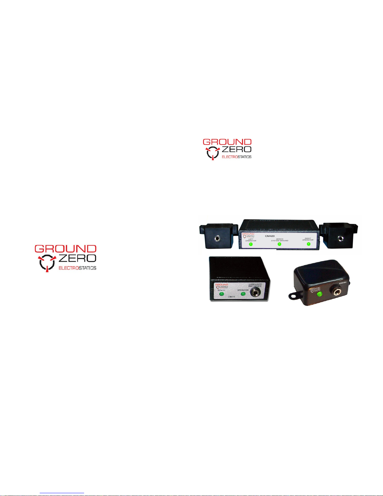
Continuous Workstation Monitors
Model CM400 Series
Instruction Manual
2470-2474 Manatee Avenue East
Bradenton, Florida 34208
Toll Free 877-GND-ZERO (463-1376)
Direct Phone 941-751-7581
Fax 1-941-751-7586
Email sales@gndzero.com
http:/ / www.gndzero.com

Contents
1 Description
CM400 Series 1
2 Installation
Installation Instructions 2
Installation Diagrams 4
Maintenance 6
3 Operation
Wrist Strap Indications 6
Bench System Ground Indications 6
4 Specifications 7
5 Parts Included List 8
6 Service and Warranty 9
Service and Warranty
Ground Zero Electrostatics provides a limited warranty for the
Model CM2015. All new products are guaranteed to be free from
defects in material and workmanship for a period of one (1) year
from the date of shipment. Liability is limited to servicing (after
evaluating, repairing or replacing) any product returned to
Ground Zero Electrostatics. The company does not war-rant
damage due to misuse, neglect, alteration or accident. In no
event shall Ground Zero Electrostatics be liable for collateral or
consequential damages.
To receive service under warranty, please contact Ground Zero
Electrostatics Technical Support.
About Ground Zero Electrostatics
Since 1998, Ground Zero Electrostatics has helped electronic
manufacturing facilities to protect their products and processes
from the many serious problems associated with static electricity.
Ground Zero Electrostatics offers a wide range of unique and
outstanding products to detect, protect, eliminate and monitor
electrostatic charges. Our products are integral components of an
effective static control program.
9

Product Specifications
Dimensions/Weight
CM400 0.88” H x 1.75” W x 1.25” D
(2.24 x 4.45 x 3.18 cm)
7.4 oz.
CM410 1.00” H x 2.40” W x 2.30” D
(2.54 x 6.10 x 5.84 cm)
7.8 oz
CM420 1.00” H x 4.00” W x 2.40” D
(2.54 x 10.16 x 6.10 cm)
12.4 oz
Mounting Mounting materials included
Power Supply
Input 120VAC—60hz
Output 12VDC, 200mA
Audible Alarm 10 beeps (max); 5 seconds
Adjustment No adjustments required
Parts Included List
1. CM400 series workstation monitor
2. CM420 only: Two (2) remote terminals boxes
3. Plug-in Power Supply (12-15 Volts DC, 200 mA, 2.1mm
center positive output)
4. CM410 and CM420 Only: Velcro or Mounting Bracket
5. CM400 only: Two (2) mounting screws
8
Description
Monitors: CM400 Series
Continuously verifying the integrity of the ground system is
critical to an effective ESD protection program. Using specialized
impedance sensing technology, the CM400, CM410 and CM420
single wire monitoring products continuously check the total
ground loop, including the operator, the wrist band and the coil
cord. The systems are compatible with most wrist straps. Units
are tested to NIST traceable standards and require no user
adjustments.
Reliable, Repeatable Results
Accuracy and reliability are improved with the impedance
technology incorporated into our constant monitors. False alarms
disappear and adjustments are not necessary. Powered and
grounded by an AC adapter, the system is fully automatic and
begins sensing when a coil cord is plugged into the unit. A green
light indicates a safe connection and a red light and audible alarm
communicate an unsafe connection.
Continuous Monitors pay for themselves
ESD-S1.1 notes that it is not necessary to test wrist straps daily
when using constant monitoring systems. Higher value-added
products especially benefit from the certainty of continuous
monitoring. The CM400, CM410 and CM420 are perfect solutions
for assuring workstation grounding protection.
1

Installation
1. Remove all items from carton and confirm you have
received all items contained in the “Parts Included List.”
located on Page 8.
2. Choose a location on the work station to mount the
monitor where LED lights are visible and alarm can be
heard by operators. Frequently, monitors are mounted
toward the front edge of workstation or under an eye level
shelf.
NOTE: CM410 and CM420 have an optional requirement
for a Common Point ground
3. Mount monitor securely to workstation using the included
screws, Velcro, or stainless steel bracket included with
monitor model. Refer to installation diagrams located on
Page 4 and 5
NOTE: For CM420 installation move to Step 4 for all other
monitors skip to Step 5.
4. CM420 Only: To install remote wrist strap monitors,
locate a convenient location for operators and mount with
included screws. Frequently remote monitors are mounted
on the underside of work bench near the front edge
5. CM410 and CM420 ONLY: Plug wire from the Common
Point Ground in the banana jack labeled “Bench System
Ground” on back of the monitor.
2
Product Specifications
Performance Specifications
Wrist strap open circuit voltage 0.7 VDC, +0.1VDC @ < 2mA
Mat open circuit voltage 5.0—7.5 VDC
Alarm indicators Visual, audible
(green: safe, red: unsafe)
Alarm set point
Wrist strap 38 to 87pF (human body);
with 1 megohm wrist strap
resistance
Mat 6.5 megohm
Unit monitoring capabilities
CM400 One wrist strap/person
CM410 One wrist strap + mat
CM420 Two wrist straps + mat
CAL400 NIST Calibrated Periodic
verification tool for
CM400
CAL410 NIST Calibrated Periodic
verification tool for
CM410
CAL420 NIST Calibrated Periodic
verification tool for
CM420
7

Operation
Wrist strap monitor operation
Monitoring begins when the coiled cord of the wrist strap is
plugged into the monitor or remote jack. The status of a wrist
strap resistance is indicated by a the tricolor LED and audible
Alarm:
Stand-by indication.
If the wrist strap is removed or not being worn but is still plugged
into monitor, an audible alarm will sound for 7-10 seconds, and
the “OP” (operator) led will be will be blink RED.
Normal indication.
For normal operating resistance “OP” led will be GREEN.
High alarm.
If the operator wrist strap is plugged into the remote and
resistance is higher than maximum, the “OP” led will be RED and
audible alarm will sound.
Bench System Ground (BSG) operation
If unit is equipped with (BSG) monitoring capabilities, monitoring
begins when the coiled cord of the Common Point Ground is
plugged into the (BSG) jack. The status of a (BSG) resistance is
indicated by a the tricolor LED and audible Alarm:
Normal (BSG) indication.
For normal operating resistance led will be GREEN.
High (BSG) alarm.
If GND resistance is higher than maximum limit, led will be RED
and audible alarm will sound.
6
Installation Cont.
6. Insert the power cord into the inlet labeled “POWER” on
the back of unit and connect the AC adapter to a proper
power source.
NOTE: For CM420 installation move to Step 6 for all other
monitors skip to Step 7.
7. CM420 ONLY: Plug the first wrist strap’s coiled cord into
the banana jack labeled “LEFT WRIST STRAP” or “RIGHT
WRIST STRAP” on the back of the monitor. Re-peat
process with second wrist strap using remaining jack. The
“Operator” lights on the front the of unit should turn
GREEN when wrists straps are placed around the wrist.
8. CM400 and CM410 ONLY: Plug the wrist strap’s coiled
cord into the banana jack on the front of the monitor. The
“Operator” lights on the front the of unit should turn
GREEN when wrists straps are placed around the wrist.
NOTE: If wrists strap LED lights do not turn green when wrist
strap is placed on wrist, touch the wrist strap to the Common
Point Ground. If LED light turns green the wrist strap was not
making good contact with the operators wrist.
3
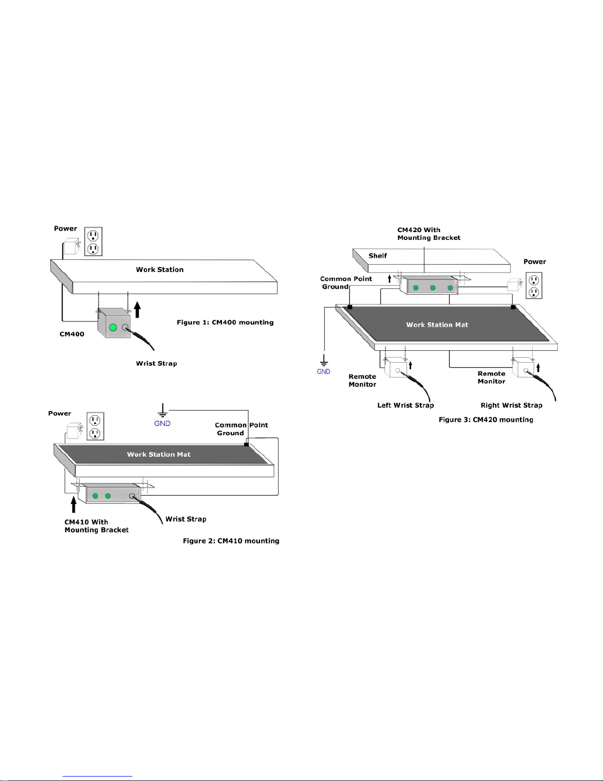
Installation Diagrams
4
Installation Diagrams Cont.
CALIBRATION AND PERIODIC TESTING:
Alarm resistance limits are set by the precision resistors in-side
the tester and never need calibration. You can verify proper
operation of the monitor by periodically testing monitor with an
NIST traceable resistance limit comparator box from Ground Zero
Electrostatics, from the Cal 400 Series.
5
 Loading...