

Page 1
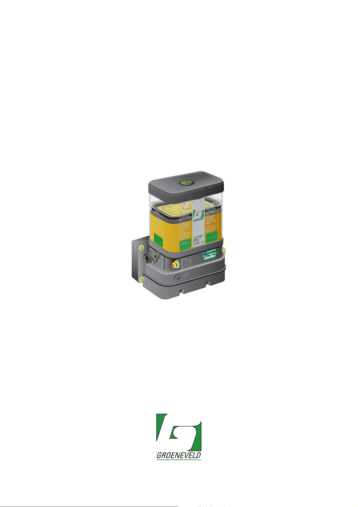
General Manual
OnePlus
Automatic Greasing System
OnePlus
EG1605R01
your efficiency is our challenge
Page 2

General information
Type of manual General Manual
System Automatic Greasing System OnePlus
Document number EG1605R01
Date of issue October 2011
Revisie 01
All rights reserved. No part of this manual may be copied and/or published by means of printing, photocopying,
microfilm or by any other means without prior written permission from Groeneveld. This applies also to the
drawings and diagrams appended.
Groeneveld reserves the right to change parts at any time, without prior or direct notice to the customer. The
contents of this manual may also be changed without prior notice.
This manual applies to the standard version of the product. Groeneveld cannot accept liability for any damage
arising from the use of specifications other than that supplied.
You are requested to contact Groeneveld technical service for information concerning adjustment, maintenance
work or repairs that is not described in this manual.
Whilst this manual has been prepared with the greatest possible care Groeneveld cannot accept responsibility for
any errors of the concequences of such errors.
Page 3

Automatic Greasing System OnePlus
Table of contents
Preface - - - - - - - - - - - - - - - - - - - - - - - - - - - - - - - - - - - - - - - - - - - - 5
1. General information - - - - - - - - - - - - - - - - - - - - - - - - - - - - - - - - - - 6
1.1. Introduction - - - - - - - - - - - - - - - - - - - - - - - - - - - - - - - - - - - - - - - - - - - - 6
1.2. The OnePlus automatic greasing system - - - - - - - - - - - - - - - - - - - - - - - - 6
2. Description components- - - - - - - - - - - - - - - - - - - - - - - - - - - - - - - - 8
2.1. Properties - - - - - - - - - - - - - - - - - - - - - - - - - - - - - - - - - - - - - - - - - - - - - - 8
2.2. Composition of the OnePlus pump - - - - - - - - - - - - - - - - - - - - - - - - - - - - 8
2.3. The integrated control and monitoring unit - - - - - - - - - - - - - - - - - - - - 10
2.4. Selector switches - - - - - - - - - - - - - - - - - - - - - - - - - - - - - - - - - - - - - - - - 11
2.4.1. Setting possibilities selector switches - - - - - - - - - - - - - - - - - - 11
2.5. The plunger pump - - - - - - - - - - - - - - - - - - - - - - - - - - - - - - - - - - - - - - - 12
2.6. Safety and control features - - - - - - - - - - - - - - - - - - - - - - - - - - - - - - - - 12
2.6.1. Maximum grease pressure - - - - - - - - - - - - - - - - - - - - - - - - - - 12
2.6.2. Defective wiring and short-circuits - - - - - - - - - - - - - - - - - - - - 12
2.7. The test push button - - - - - - - - - - - - - - - - - - - - - - - - - - - - - - - - - - - - - 12
2.7.1. Performing a test cycle - - - - - - - - - - - - - - - - - - - - - - - - - - - - - 13
2.7.2. Retrieving fault messages- - - - - - - - - - - - - - - - - - - - - - - - - - - 13
2.8. The optional indicator lamp- - - - - - - - - - - - - - - - - - - - - - - - - - - - - - - - 14
2.9. The distribution blocks - - - - - - - - - - - - - - - - - - - - - - - - - - - - - - - - - - - - 15
2.9.1. Properties - - - - - - - - - - - - - - - - - - - - - - - - - - - - - - - - - - - - - - 15
2.9.2. Composition - - - - - - - - - - - - - - - - - - - - - - - - - - - - - - - - - - - - 15
2.9.3. Principle of operation - - - - - - - - - - - - - - - - - - - - - - - - - - - - - 16
2.9.4. Non-return valves - - - - - - - - - - - - - - - - - - - - - - - - - - - - - - - - 17
2.9.5. Failure of one of the doser segments - - - - - - - - - - - - - - - - - - 17
2.9.6. Closing outputs - - - - - - - - - - - - - - - - - - - - - - - - - - - - - - - - - - 17
2.9.7. Combining outputs - - - - - - - - - - - - - - - - - - - - - - - - - - - - - - - 18
2.10. The optional distribution block monitoring switch - - - - - - - - - - - - - - - 19
3. Designing a system - - - - - - - - - - - - - - - - - - - - - - - - - - - - - - - - - - 20
3.1. Introduction - - - - - - - - - - - - - - - - - - - - - - - - - - - - - - - - - - - - - - - - - - - 20
3.2. Points of departure - - - - - - - - - - - - - - - - - - - - - - - - - - - - - - - - - - - - - 20
3.3. Method - - - - - - - - - - - - - - - - - - - - - - - - - - - - - - - - - - - - - - - - - - - - - - - 22
3.3.1. Determine the operating conditions- - - - - - - - - - - - - - - - - - - 22
3.3.2. Produce a greasing plan- - - - - - - - - - - - - - - - - - - - - - - - - - - - 22
3.3.3. Determine the grease demand of the grease points - - - - - - - 22
3.3.4. Group the grease points- - - - - - - - - - - - - - - - - - - - - - - - - - - - 23
3.3.5. Determine the layout of the system - - - - - - - - - - - - - - - - - - - 23
3.3.6. Check the design - - - - - - - - - - - - - - - - - - - - - - - - - - - - - - - - - 24
Date of issue: October 2011
EG1605R01
Table of contents
3
Page 4

Automatic Greasing System OnePlus
4. Installation- - - - - - - - - - - - - - - - - - - - - - - - - - - - - - - - - - - - - - - - - 25
4.1. Overview - - - - - - - - - - - - - - - - - - - - - - - - - - - - - - - - - - - - - - - - - - - - - - 25
4.2. Safety precautions - - - - - - - - - - - - - - - - - - - - - - - - - - - - - - - - - - - - - - - 25
4.3. General installation directives- - - - - - - - - - - - - - - - - - - - - - - - - - - - - - - 26
4.4. OnePlus pump unit - - - - - - - - - - - - - - - - - - - - - - - - - - - - - - - - - - - - - - - 27
4.4.1. Mounting the pump - - - - - - - - - - - - - - - - - - - - - - - - - - - - - - - 27
4.5. OnePlus distribution blocks- - - - - - - - - - - - - - - - - - - - - - - - - - - - - - - - - 27
4.5.1. General - - - - - - - - - - - - - - - - - - - - - - - - - - - - - - - - - - - - - - - - 27
4.5.2. Assembling distribution blocks - - - - - - - - - - - - - - - - - - - - - - - 27
4.5.3. Mounting the distribution blocks - - - - - - - - - - - - - - - - - - - - - 28
4.6. Primary grease lines and couplings - - - - - - - - - - - - - - - - - - - - - - - - - - - 29
4.6.1. Grease line types - - - - - - - - - - - - - - - - - - - - - - - - - - - - - - - - - 29
4.6.2. Mounting the primary grease lines - - - - - - - - - - - - - - - - - - - - 29
4.7. Secondary grease lines and couplings - - - - - - - - - - - - - - - - - - - - - - - - - 31
4.7.1. Grease line types - - - - - - - - - - - - - - - - - - - - - - - - - - - - - - - - - 31
4.7.2. Mounting the secondary lines - - - - - - - - - - - - - - - - - - - - - - - - 32
4.8. Electrical wiring - - - - - - - - - - - - - - - - - - - - - - - - - - - - - - - - - - - - - - - - - 33
4.8.1. General - - - - - - - - - - - - - - - - - - - - - - - - - - - - - - - - - - - - - - - - 33
4.8.2. Fuse ratings - - - - - - - - - - - - - - - - - - - - - - - - - - - - - - - - - - - - - 33
4.8.3. Pin-layout of the connector on the pump unit- - - - - - - - - - - - 33
4.8.4. Wiring diagram - - - - - - - - - - - - - - - - - - - - - - - - - - - - - - - - - - 34
4.9. De-aerating of the greasing system- - - - - - - - - - - - - - - - - - - - - - - - - - - 35
4.10. Commissioning of the greasing system - - - - - - - - - - - - - - - - - - - - - - - - 35
5. Maintenance - - - - - - - - - - - - - - - - - - - - - - - - - - - - - - - - - - - - - - - 36
5.1. General - - - - - - - - - - - - - - - - - - - - - - - - - - - - - - - - - - - - - - - - - - - - - - - 36
5.2. Regularly checks of the greasing system - - - - - - - - - - - - - - - - - - - - - - - 36
5.3. Filling the grease reservoir - - - - - - - - - - - - - - - - - - - - - - - - - - - - - - - - - 37
5.4. Fault finding- - - - - - - - - - - - - - - - - - - - - - - - - - - - - - - - - - - - - - - - - - - - 38
6. Technical data - - - - - - - - - - - - - - - - - - - - - - - - - - - - - - - - - - - - - - 41
6.1. OnePlus pump unit - - - - - - - - - - - - - - - - - - - - - - - - - - - - - - - - - - - - - - - 41
6.2. Distribution blocks - - - - - - - - - - - - - - - - - - - - - - - - - - - - - - - - - - - - - - - 42
6.3. Regulations - - - - - - - - - - - - - - - - - - - - - - - - - - - - - - - - - - - - - - - - - - - - 42
Date of issue: October 2011
Table of contents4
EG1605R01
Page 5

Automatic Greasing System OnePlus
Preface
This general manual gives a description of the OnePlus automatic greasing system.
It aims at giving insight in the system’s operation and possibilities. Furthermore, in
this manual you will find the technical data on several components of the OnePlus
automatic greasing system.
In this manual the following icons are used to inform or warn the user:
ATTENTION
Draws the user’s attention to important information meant to avoid problems.
WARNING
Warns the user for physical injuries or serious damage to the equipment
caused by improper actions.
Date of issue: October 2011
EG1605R01
Preface
5
Page 6

Automatic Greasing System OnePlus
1 General information
1.1 Introduction
With an automatic greasing system of
machine are lubricated automatically at the correct moment and with the correct
amount of grease. Because greasing takes places while the vehicle or machine is in
operation, the applied grease is spread optimally over the whole surface to be
greased. The greasing system requires no user intervention to operate, apart from
periodically replacing the grease in its reservoir.
Groeneveld’s
tested rigorously. This guarantees an extended operational life and error-free
operation, even under the most extreme operating conditions.
Proper installation, using the correct type of grease, and periodic checks are
prerequisites for the continual hassle-free operation of the system. The periodic
checks, which take little time and effort, can be performed during the normal
maintenance of the vehicle or machine (during oil-replacement, for instance).
Careful selection of construction materials, makes the greasing system itself vitually
maintenance-free.
automatic greasing systems are designed with the utmost care and
Groeneveld
all grease points of a vehicle or
ATTENTION
The automatic greasing system reduces the time and effort spent on
manual greasing significantly. However, do not forget that there may be
grease points that are
not
served by the greasing system and must still be
greased by hand.
1.2 The OnePlus automatic greasing system
A
Groeneveld
vehicle, machine or installation in sequence, i.e. grease is supplied to the connected
grease points one at a time and one after the other (it is a progressive greasing
system).
OnePlus systems are mainly applied on machines with a fixed number of grease
points that require fixed amounts of grease at fixed intervals. This, because the
amount of grease that will be supplied to the individual grease points is governed
by the distribution ratios that results from the choice of doser segment types and
the manner in which those segments are combined in distribution blocks.
OnePlus automatic greasing system serves each grease point of the
Date of issue: October 2011
General information6
EG1605R01
Page 7
Automatic Greasing System OnePlus
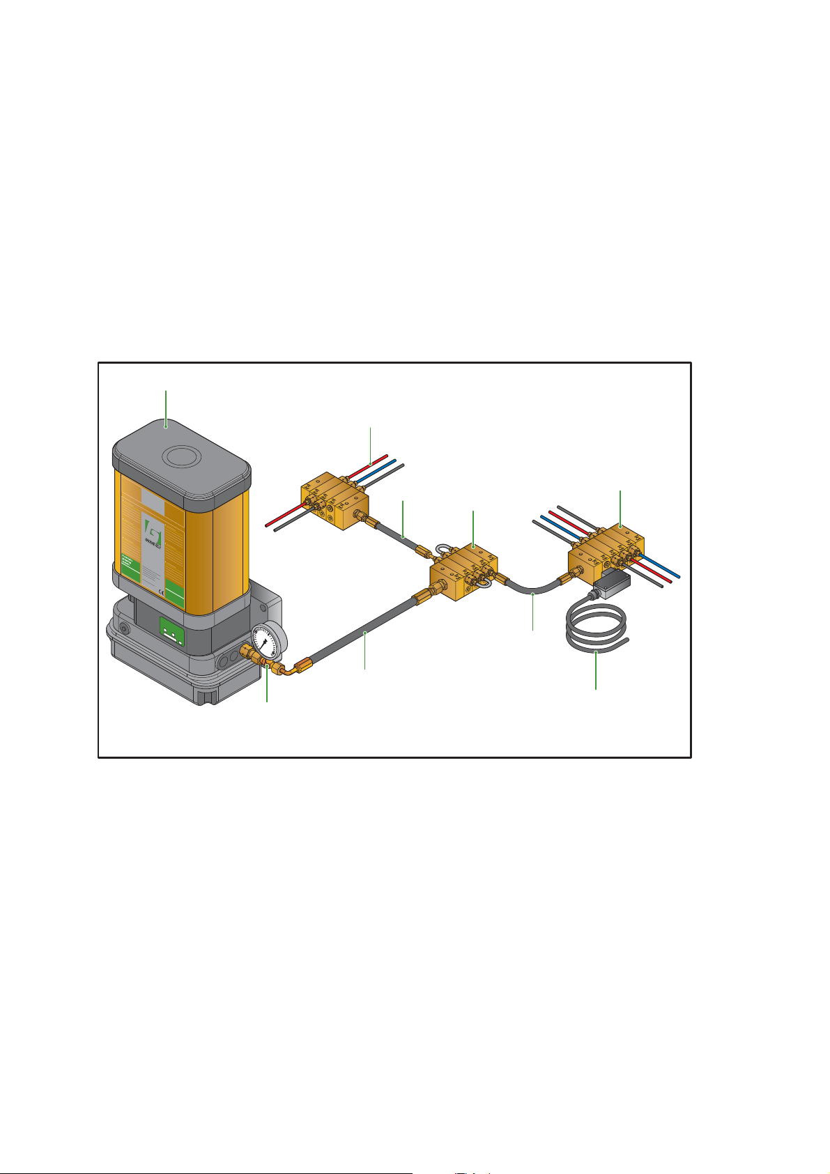
A
Groeneveld
parts (see Figure 1.1):
1. An electric grease pump (plunger pump) with integrated grease reservoir and
a digital control unit with data storage facility.
2. Manometer.
3. Primary grease lines between the pump unit and the distribution blocks and
interconnecting the distribution blocks themselves.
4. Main distribution block.
5. One or more distribution blocks (assembled from multiple doser segments).
6. Secondary grease lines between the distribution blocks (doser segments) and
the individual grease points.
7. Distribution block monitoring switch.
1
OnePlus automatic greasing system could comprise the following
6
O
nePlus
1
0
0
2
5
0
0
3
5
0
4
00
BAR
2
Figure 1.1 System overview
3
4
5
3
3
7
Date of issue: October 2011
EG1605R01
General information
7
Page 8

Automatic Greasing System OnePlus
2Description components
2.1 Properties
The pump unit is the heart of the OnePlus automatic greasing system. The
Groeneveld
industrial machines and trucks that specifically require NLGI-2 grease and do not
have a compressed air system.
The system will automatically lubricate all points connected to the lubrication
system on a timed cycle, with the correct quantity of grease.
The most significant properties of the OnePlus pump unit are:
• Single grease outlet port.
• Interval time and the grease output quantity can be adapted with two rotary
selection switches on the control unit behind the bottom cover of the pump.
• The control unit monitors the electrical wiring and components.
• The system can be extended with an optional block monitoring switch for
guarding the functionality of a distribution block in the system.
• The indicator lamp, supplied with the optional block switch warns the
operator for serious system errors.
OnePlus pump is a Low Cost solution for compact off-road machines,
ATTENTION
The minimum grease level and the opening of the maximum pressure relieve valve are not monitored by the controller in the pump.
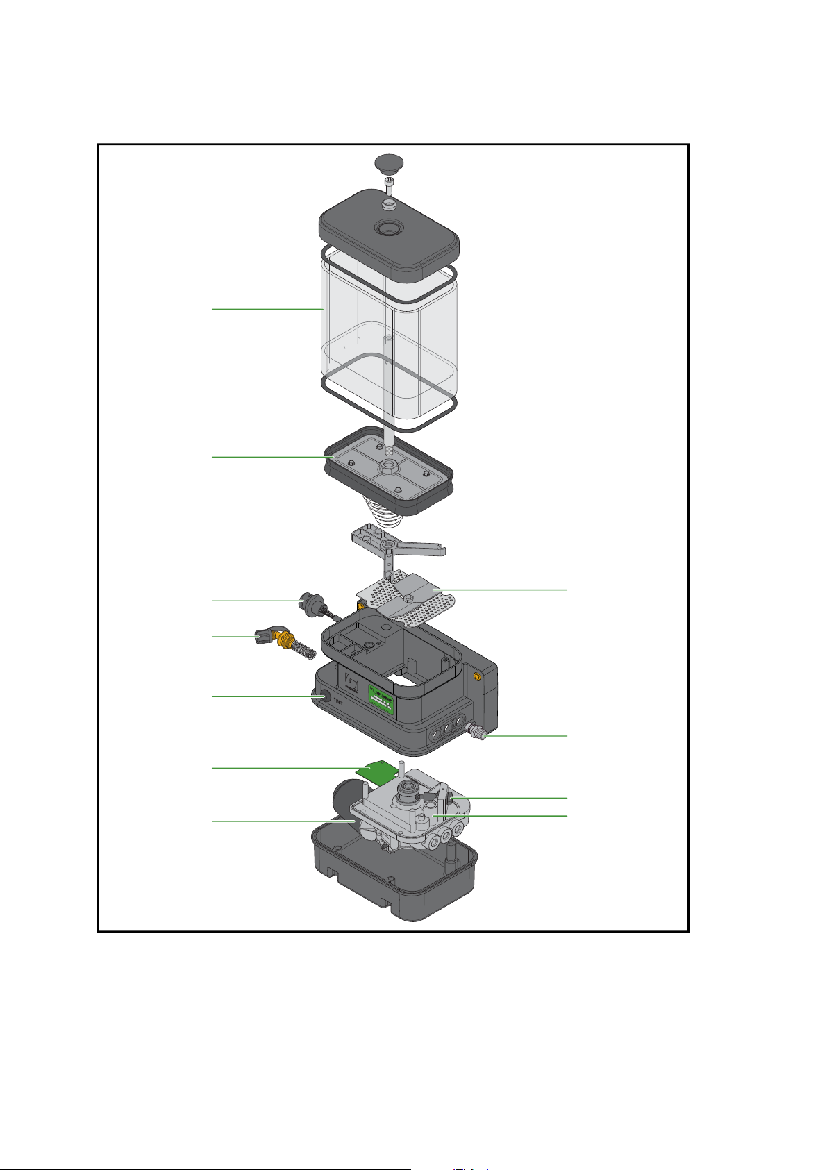
2.2 Composition of the OnePlus pump
The OnePlus pump comprises the following components (see Figure 2.1):
1. Grease reservoir.
2. Follower piston.
3. Electrical connector.
4. Filler coupling with grease filter.
5. Test push button.
6. Electronic control and monitoring unit with a permanent memory.
7. Electric motor with reduction gear and sensor (counts the number of revolutions of the drive shaft of the plunger pump).
8. Relief valve with return line to the grease reservoir and monitoring by the
control unit.
9. Plunger pump.
10. Grease output port.
11. Stirring device.
Date of issue: October 2011
Description components8
EG1605R01
Page 9
Automatic Greasing System OnePlus
1
2
3
4
5
6
7
Figure 2.1 OnePlus pump
11
10
9
8
Date of issue: October 2011
EG1605R01
Description components
9
Page 10
Automatic Greasing System OnePlus
2.3 The integrated control and monitoring unit
The control and monitoring unit initiates and controls the greasing cycles of the
greasing system. All required system and program parameters, such as the time
periods behind the interval selector switch setting possibilities and the grease
output quantities behind the amount selector switch possibilities are laid down in
the control unit. The control unit monitors the performance of various components
of the greasing system, and processes and stores the mal functions it detects.
The basic parameter settings, like interval period and grease amount, can be set by
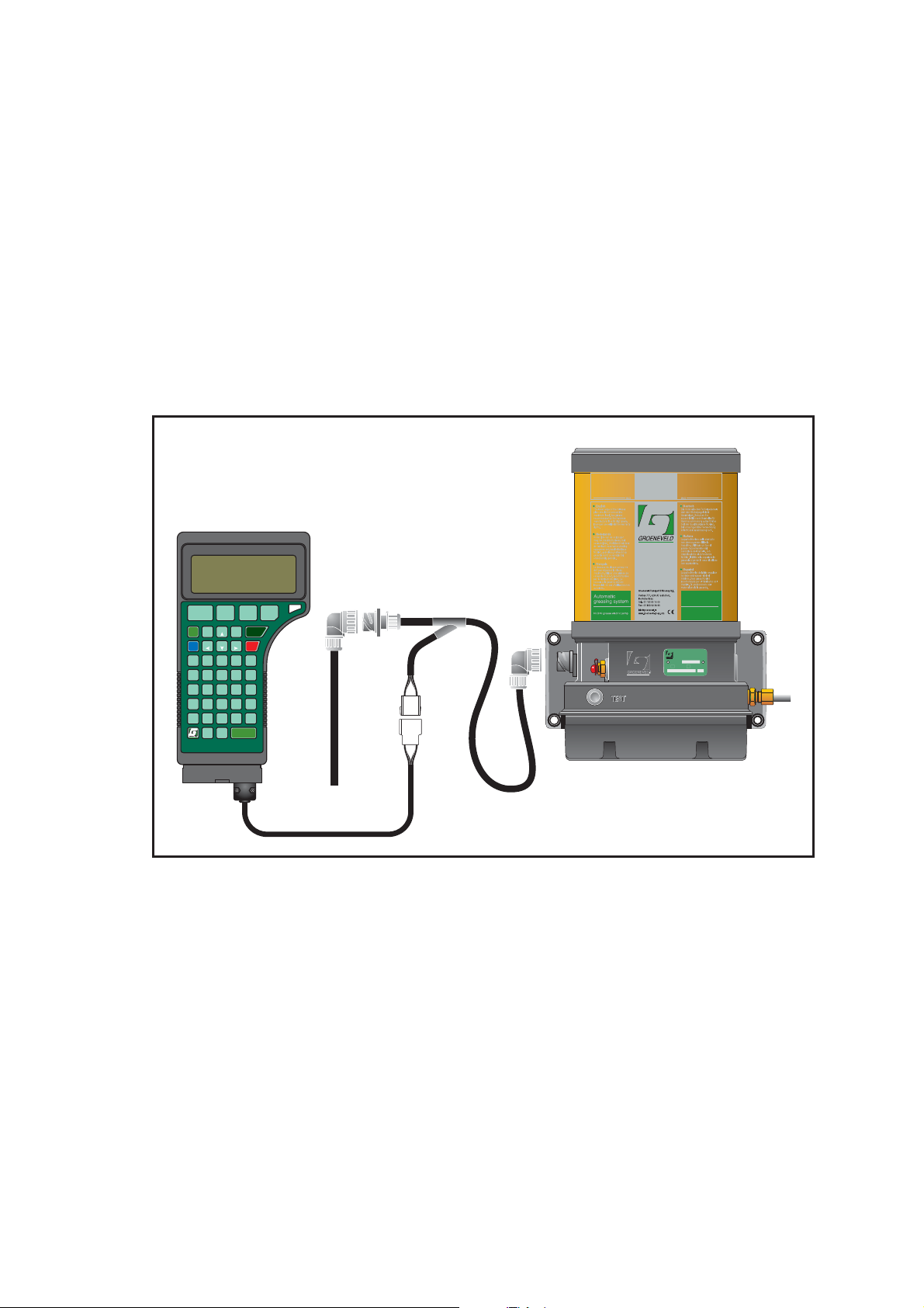
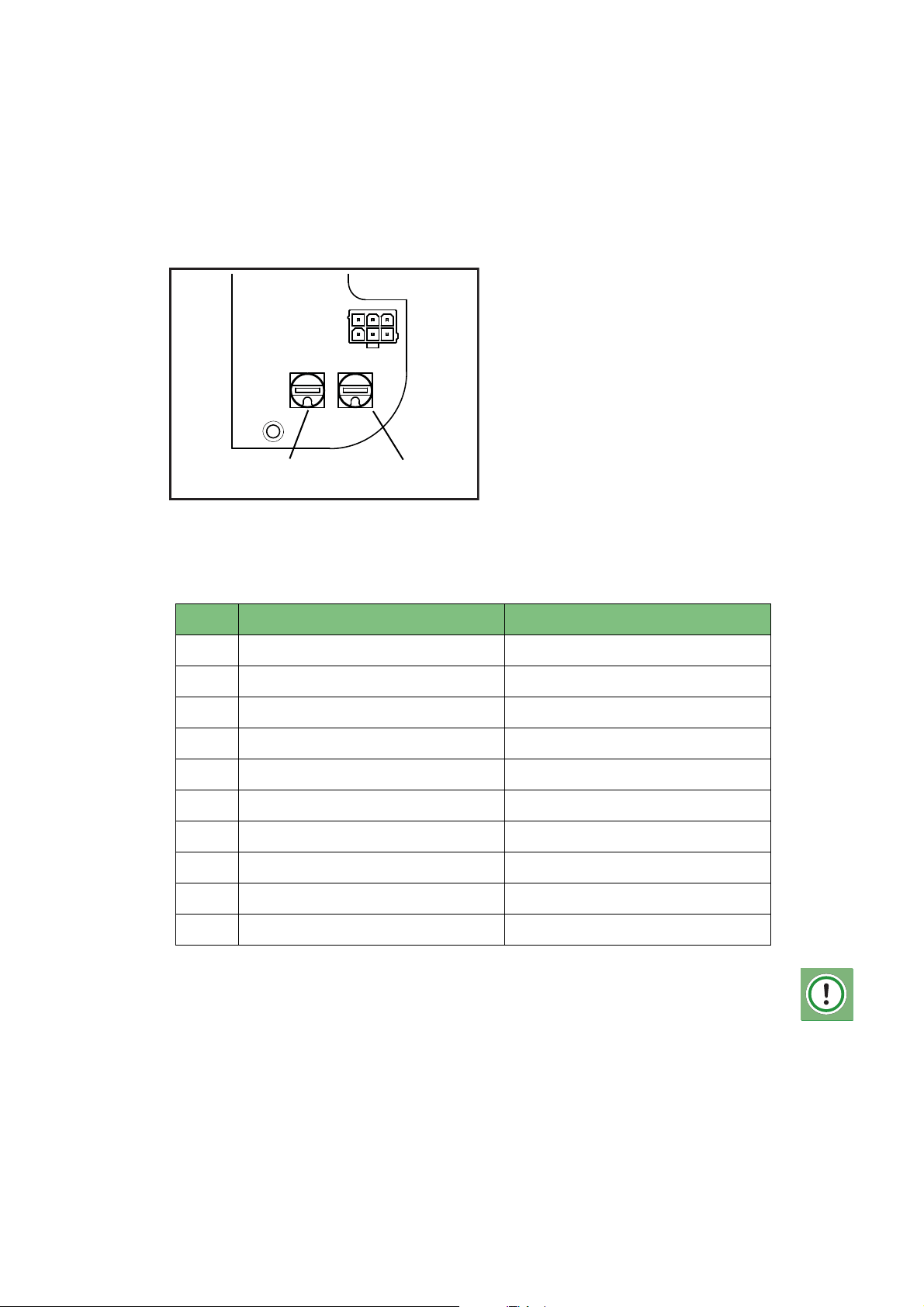
means of two selector switches. You can find these switches on the controllerboard, behind the bottom cover of the pump.
Advanced functionality can be programmed with an UniGINA (
Groeneveld tester for INstallation and Analysis) (see Figure 2.2)
UNIversal
F5F1F6F2F7F3F8
CNTR
PAGEINS
OFF
LGHT
ON
CAPS
BGNPAGE END
LOCK
&A1B2C3
4G5H6
#
F
7L8
%
K
(
)
P
Q
+
-V/W*Y=
U
.Z,
F4
SHIFT
DEL
NUM
LOCK
>
E
D
<
J
I
:
9
O
N
M
?TCUR
0
S
R
Z
ENTER
SPC
Figure 2.2 Connecting the UniGINA to the OnePlus pump.
OnePlus
Date of issue: October 2011
Description components10
EG1605R01
Page 11
Automatic Greasing System OnePlus
55
TIME AMOUNT
selector switch
time interval
selector switch
grease amount
2.4 Selector switches
The integrated control and monitoring unit features two selector switches for
controlling (see Figure 2.3):
• the interval in between the cycle starts and
• the amount of grease per greasing cycle
Figure 2.3 Selector switches
2.4.1 Setting possibilities selector switches
Time interval Grease amount
1 5 minutes 1 cc per cycle
2 10 minutes 2 cc per cycle
3 15 minutes 3 cc per cycle
4 30 minutes 4 cc per cycle
5 45 minutes 5 cc per cycle
6 60 minutes 6 cc per cycle
7 90 minutes 7 cc per cycle
8 120 minutes 8 cc per cycle
9 180 minutes 9 cc per cycle
0 240 minutes 10 cc per cycle
ATTENTION
In indivudal cases the times and amounts behind the selector switches
settings can be customized and differ from the above displayed factory
settings.
Date of issue: October 2011
EG1605R01
Description components
11
Page 12
Automatic Greasing System OnePlus
2.5 The plunger pump
The electric motor drives the plunger pump through a reduction gear. The plunger
pump comprises a drive shaft with excentric, a cylinder with piston, and a nonreturn valve. The excentric moves the piston back and forth, once every revolution
of the drive shaft. During the return stroke of the piston, grease is sucked from the
reservoir into the cylinder (through an opening in the cylinder wall). During the
forward stroke of the piston, the grease is pressed, via the non-return valve,
towards the output port of the pump unit. The amount of grease supplied during
each stroke (revolutions of the drive shaft) depends on the (fixed) diameter of the
cylinder and the stroke length of the piston.
2.6 Safety and control features
2.6.1 Maximum grease pressure
A relief valve is installed in the grease channel between the plunger pump and the
grease output port. This relief valve will start to lead the grease back to the
reservoir if the maximum grease pressure is exceeded during the pump phase of a
greasing cycle. The grease pressure may become too high, for example, when one
of the grease lines to the grease points has become blocked, or when the viscosity
of the grease has become too high (at low temperature).
2.6.2 Defective wiring and short-circuits
Open-loads (interruptions) and short circuits in the pump wiring will be detected
and processed by the control unit.
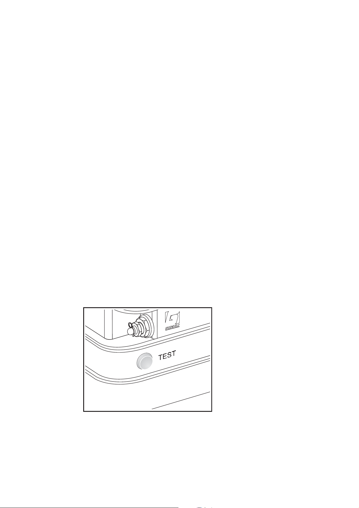
2.7 The test push button
The test push button on the pump unit has two functions:
• Performing a test cycle via the grease output port of the pump unit.
• Retrieving error messages stored in the memory of the control unit.
Date of issue: October 2011
Figure 2.4 The test push button
Description components12
EG1605R01
Page 13
Automatic Greasing System OnePlus
2.7.1 Performing a test cycle
A test cycle can be performed using the test push button, as follow:
1. The supply voltage for the pump unit must be available (ignition on).
2. Depress the test push button for 2 to 5 seconds.
3. The test cycle starts the moment you release the test push button.
During the test cycle the optional indicator lamp will flash (1 second on / 1 second
off).
Any errors that occurs during a test cycle will not be indicated by the indicator lamp
and will not be stored in the memory of the control unit.
2.7.2 Retrieving fault messages
When the system is equipped with the optional indicator lamp, fault messages
stored during the last automatic greasing cycle (pending errors) can be retrieved by
keeping the test push button (see Figure 2.4) depressed for at least five seconds.
Seven seconds after you released the test push button the indicator lamp will start
producing the blink codes to indicate these pending errors.
The indicator lamp indicates the fault codes by blinking:
The decimals of the fault code: long pulses (0,5 seconds)
The units of the fault code: short pulses (0,15 seconds)
There is a two second pause between successive fault codes. For example, if the
fault codes 11 and 22 are displayed, you will see the blink codes:
long, short
two second pause
long, long, short, short
two second pause
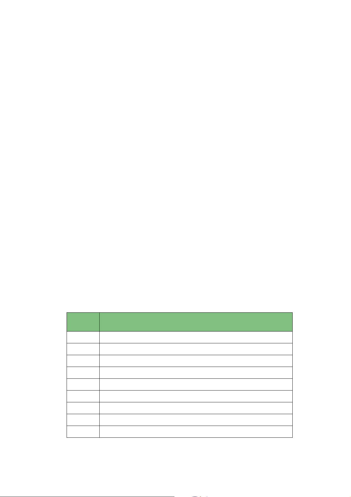
Each fault message has been assigned a two-digit fault code:
Fault
code
10 No errors detected during last executed automatic cycle
11 No state change of the block switch during a number of cycles
21 Drive shaft does not rotate or rotates too slow
Meaning
fault code 11
fault code 22
22 Open load pump motor circuit
23 Over current pump motor circuit
35 Short circuit pump motor
41 Parameter checksum error
Date of issue: October 2011
EG1605R01
42 Power dip during pump start
43 Open load block switch circuit
Description components
13
Page 14
Automatic Greasing System OnePlus
2.8 The optional indicator lamp
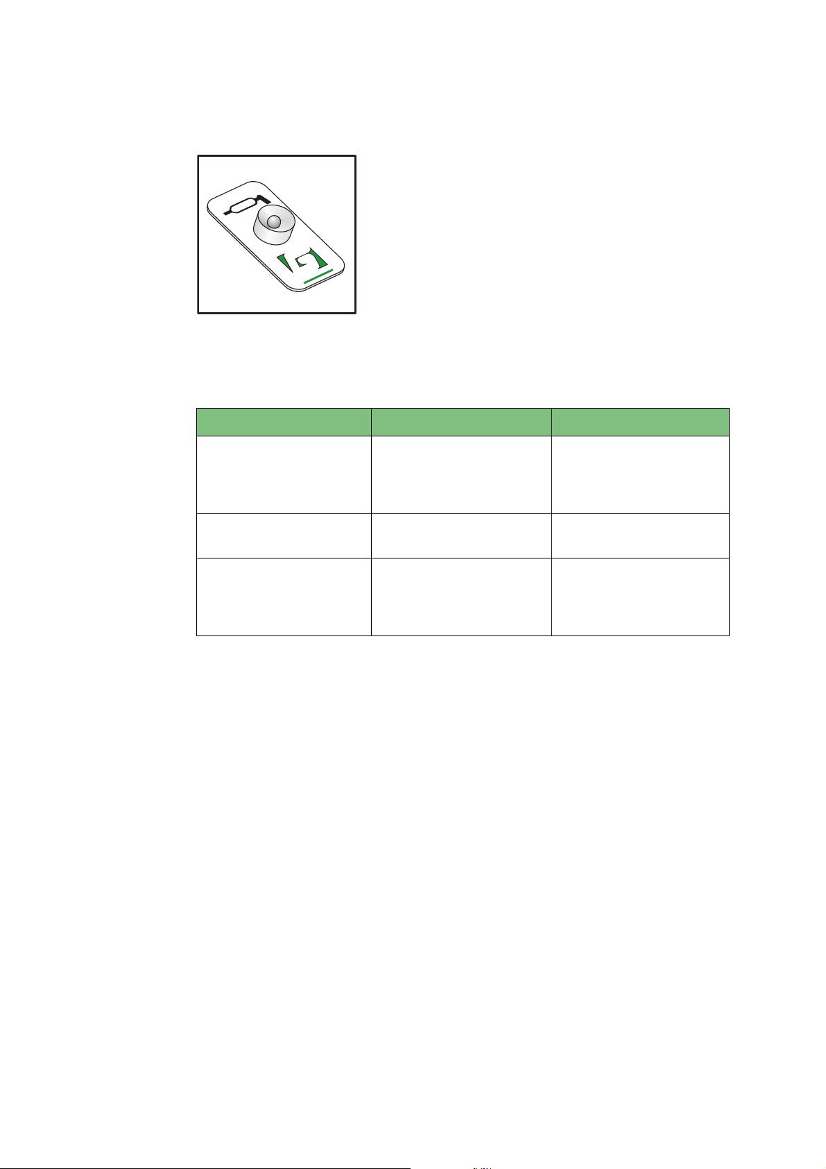
The driver or operator will be informed about the
operation of the greasing system through a indicator
lamp which is installed on the dashboard in the cabin.
The physical form of the indictor lamp may vary, but it is
always installed so that is easily visible.
976.01
GROENEVELD
Figure 2.5 The indicator lamp
The indicator lamp produces the following signals:
Signal Moment Significance
1 x 3 seconds on. 1 second after switching
on ignition.
The supply voltage for
the control unit is available and the indicator
lamp is OK.
Short flashing period
(1 sec. on / 1 sec. off).
Continuously on. A serious error is
During a pump cycle. A test or automatic*
cycle is performed.
System does not func-
detected.
tion properly anymore.
Immediate action is
required!
*) When wanted the flashing during an automatic cycle can be switched off with
an UniGINA device.
Date of issue: October 2011
Description components14
EG1605R01
Page 15
Automatic Greasing System OnePlus
2.9 The distribution blocks
2.9.1 Properties
OnePlus distribution blocks distribute the grease to the various grease points and
meter-out the amount of grease that goes to each individual grease point. They do
so in a progressive, sequential way. The progressive distribution blocks in the
greasing system distribute the grease to the grease points, one grease point at a
time, and one grease point after another. Progressive distribution blocks can be
placed in series, in which case an output of a block is used to feed the next block in
line (through a primary grease line).
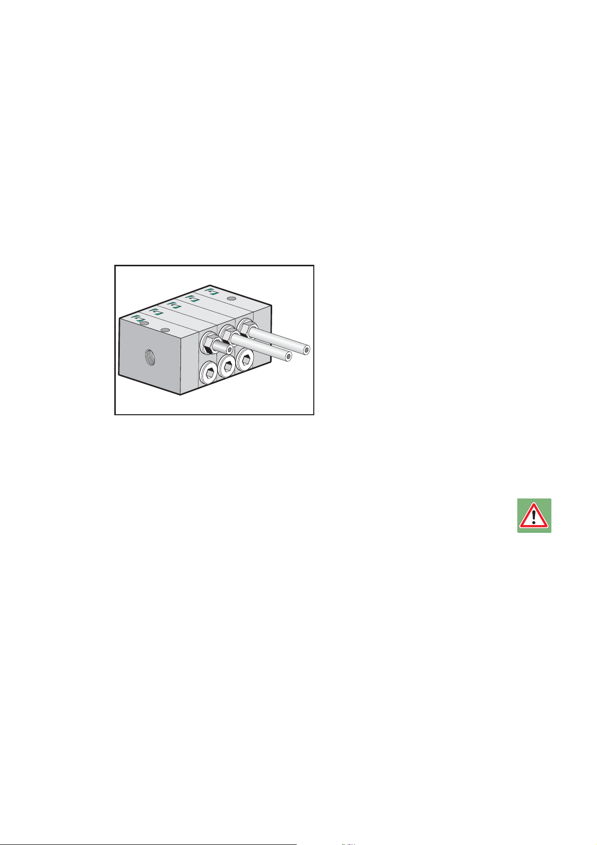
2.9.2 Composition
A progressive distribution block
comprises the following components:
1. a start-segment
2. an end-segment
3. at least three doser segments
The doser segments to be deliverable
in several versions with several
amounts (quantity of grease which by
cycle it is supplied). By several doser
segments in a distribution block
combine can a certain partitioning of
the grease be obtained.
Figure 2.6 Distribution block.
Each doser segment always has two grease output ports, with identical grease
outputs per cycle. The grease channels between the segments are sealed by O-rings
and the segments are pressed together with two compression bolts.
WARNING:
To be able to operate at all, a distribution block needs to have at least three
doser segments.
Date of issue: October 2011
EG1605R01
Description components
15
Page 16
Automatic Greasing System OnePlus
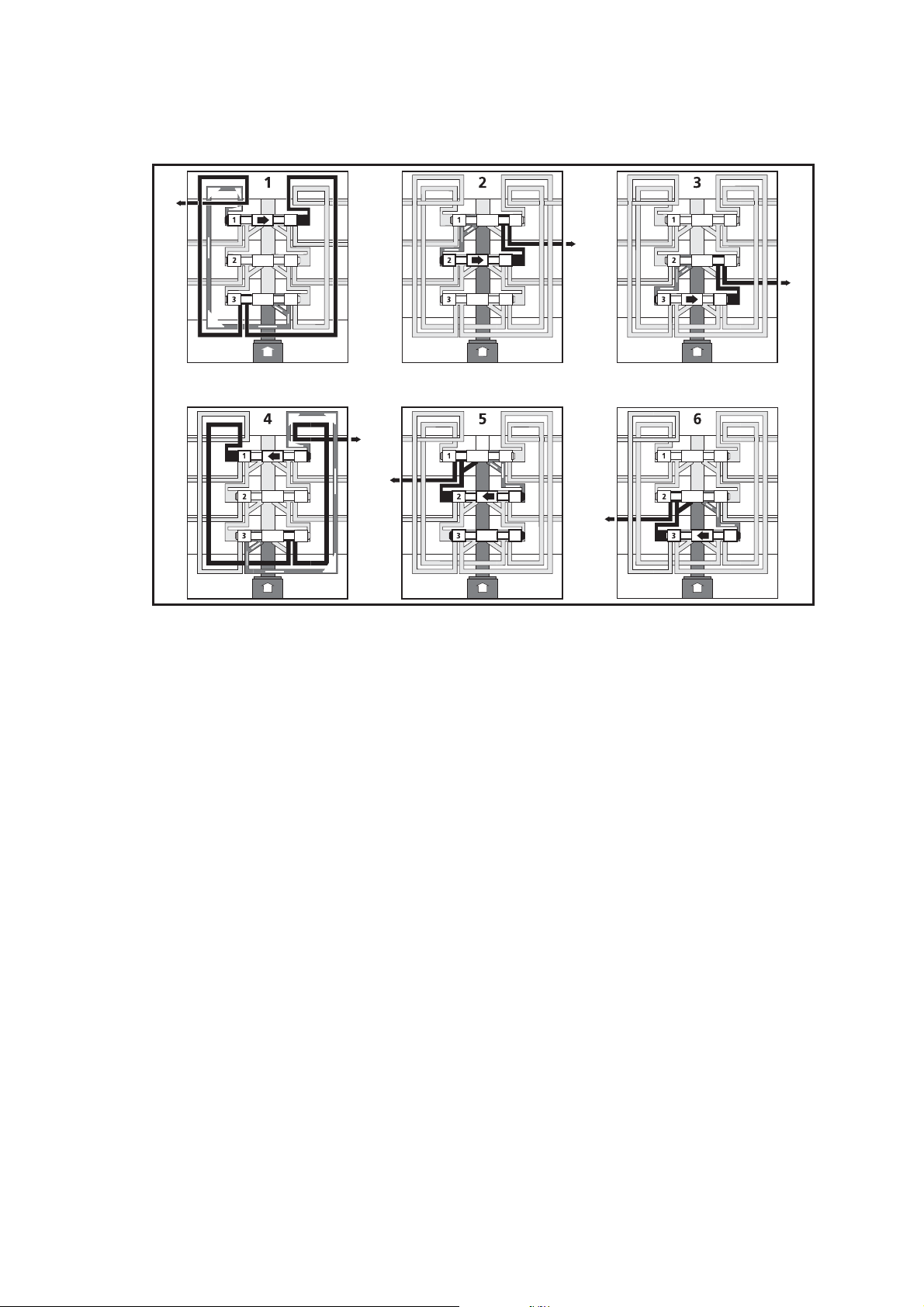
2.9.3 Principle of operation
Figure 2.7 Principle of operation.
To operate, progressive distribution blocks need no other energy source than the
grease pressure supplied by the pump of the greasing system:
1. The lubricant flows from the input port, via piston 3, through all segments to
the left-hand side of piston 1.
2. Piston 1 is pushed to the right by the grease pressure. The grease at the righthand side of piston 1 is pressed to output port 1.
Because piston 1 has now been pushed to the right, the lubricant now flows,
via piston 1, from the central input channel to the left-hand side of piston 2.
3. Piston 2 is then moves and supplies grease to output 2.
Because piston 2 has been pushed to the right, the lubricant now flows, via
piston 2, to the left-hand side of piston 3. Piston 3 is pushed to the right and
supplies lubricant to output port 3.
4. After piston 3 has been pushed to the right, the lubricant is pressed to the
right-hand side of piston 1. Piston 1 will move to the left and supply lubricant
to output port 4.
5. Afterwards piston 2 will also be pressed to the right and will supply lubricant
to output port 5.
6. Afterwards piston 3 will also be pressed to the right and will supply lubricant
to output port 6.
1. The distribution block then arrives back at its starting-off point, and the cycle
will repeat as long as there is pressure in the primary grease line.
Remark:
Date of issue: October 2011
The description and illustration above assume there is a fixed starting-off
point for the doser segments in the distribution block. This is not so. The distribution block always continues from where it left-off during the previous
pump phase of the grease cycle.
Description components16
EG1605R01
Page 17

Automatic Greasing System OnePlus
2.9.4 Non-return valves
Non-return valves are installed in the outputs of the distribution block to prevent
lubricant from flowing back into the distribution block. All output ports to which
primary lines are connected or which are used to interconnect distribution blocks
must be fitted with non-return valves. Output ports which secondary grease lines
are connected, must be fitted with non-return valves if significantly different
return pressures are expected at different output ports.
2.9.5 Failure of one of the doser segments
If a piston in one of the doser segments gets stuck due to contamination, the whole
greasing system will fail to operate properly.
2.9.6 Closing outputs
An output may only be closed-off after removal of the little plug that seperates the
two outputs of a doser segment. Removing the plug allows the grease meant for
the close-off to exit through the output that remains open (it doubles the output
of the one that remains open). The distribution block will become inoperable if the
little plug is not removed.
Date of issue: October 2011
EG1605R01
Description components
17
Page 18
Automatic Greasing System OnePlus
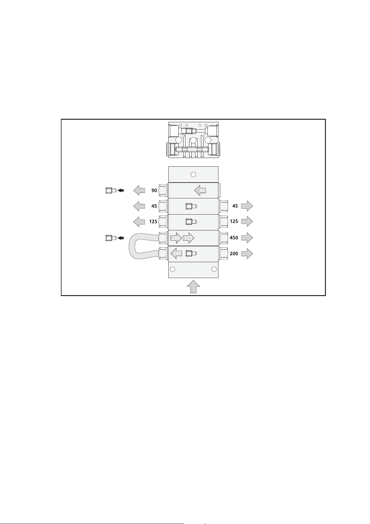
2.9.7 Combining outputs
The outputs of a distribution block can be combined by installing an external
interconnection line. The total grease output in that case is the sum of all outputs
thus interconnected.
The two outputs of a doser segment can be combined by removing the little
internal plug that seperates the two outputs and closing-off one of the ports. This
doubles the output of the port that remains open.
1
1
3
3
4
Figure 2.8 Combining outputs.
The values in the illustration represent the outputs of the ports in mm³ (0,001 cc)
per complete cycle of the distribution block. The amount supplied is determined by
the diameter of the piston.
Date of issue: October 2011
Description components18
EG1605R01
Page 19
Automatic Greasing System OnePlus
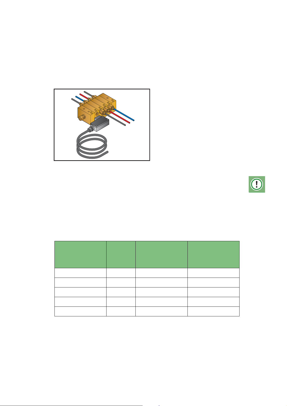
2.10 The optional distribution block monitoring switch
The OnePlus automatic greasing system can be equipped with a switch for
monitoring one of the distribution blocks. When this switch does not change state
during a number of successive greasing cycles, it will warn the operator by
switching on the indicator lamp on the dashboard continuously. This indicator
lamp is delivered in the optional block switch kit.
Figure 2.9 Optional distribution block monitoring switch.
ATTENTION
Please be aware that at low temperatures it will take more successive cycles
to cause a state change of the block switch. We therefore advise to choose
a multiply factor from the table below in order to multiply the number of
cycles in between 2 state changes of the block switch, found in the system
you want to program at ambient temperature (±15 to 20°C).
Minimum
temperature sytem
needs to be
operational
0°C 3 x 3 (3 x 1) 9 (3 x 1)
-5°C 4 x 4 (4 x 1) 12 (3 x 4)
-10°C 5 x 5 (5 x 1) 15 (3 x 5)
-15°C 6 x 6 (6 x 1) 18 (3 x 6)
Advised
multiply
factor*
Advised parameter
setting when state
change each cycle at
+20°C
Advised parameter
setting when state
change every 3
cycles at +20°C
-20°C 8 x 8 (8 x 1) 24 (3 x 8)
* Mentioned factors are based on a system with the block switch mounted to a secondary
distribution block and the use of Greenlube EP-2 grease.
Date of issue: October 2011
EG1605R01
Description components
19
Page 20
Automatic Greasing System OnePlus
3Designing a system
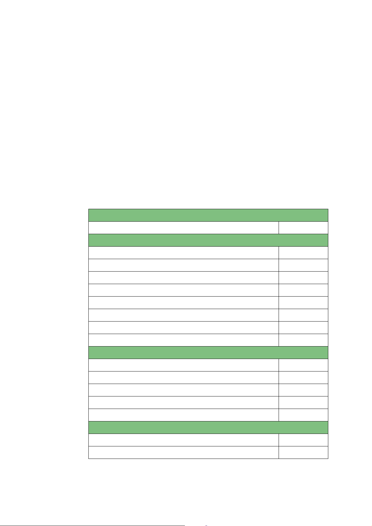
3.1 Introduction
The following aspects influence the design of a OnePlus greasing system:
1. The number of grease points to be connected and:
• The position of the grease points on the vehicle or machine.
• The grease demand of the grease points.
• The greasing interval required by the grease points.
2. The space available on the vehicle or machine for the pump unit and the distribution blocks.
3. The NLGI class of the grease to be used and the lowest ambient temperature
under which the greasing system is expected to function.
3.2 Points of departure
Pump
Maximum working pressure 275 bar
Distribution blocks
Maximum number of distribution blocks in series 2
Available segment types table 1
Minimum number of doser segments in a distribution block 3
Maximum number of doser segments in a distribution block 12
Pressure drops in a distribution block, related to: table 2
• The number of segments in the distribution block
• The NLGI class of the grease used
• The ambient operating temperatures
Primary and secondary grease lines
Pressure drops in the grease lines, connected with: table 3
• The diameter of the lines
• The length of the lines
• The NLGI class of the grease used
Date of issue: October 2011
• The ambient operating temperatures
Resistance at the grease point
Ball or roller bearing 5 bar
Slide bearing 15 bar
Designing a system20
EG1605R01
Page 21
Automatic Greasing System OnePlus
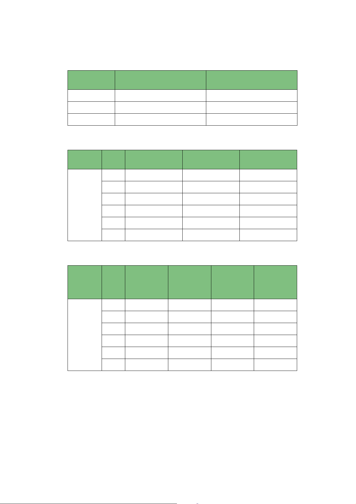
Table 1: Outputs of doser segments
Segment type Output per segment
(2 outputs) [cc]
1 2 x 0,045cc 0,090cc
3 2 x 0,125cc 0,250cc
4 2 x 0,200cc 0,400cc
Output with combined
Table 2: Internal resistance in a distribution block (bar)
Grease
class
NLGI 2
T [°C] 3 doser
segments
+20 14 bar 16 bar 22 bar
+10 28 bar 24 bar 26 bar
0 34 bar 44 bar 55 bar
-10 52 bar 58 bar 72 bar
-15 73 bar 77 bar 100 bar
-20 80 bar 85 bar 170 bar
8 doser
segments
outputs [cc]
12 doser
segments
Table 3: Grease line resistance (bar per metre)
Grease
class
NLGI 2
T [°C] PA ø3/16
ø2,4 mm i.d.
+206 bar6 bar6 bar3 bar
+10 14 bar 8 bar 6 bar 4 bar
0 17 bar 12 bar 10 bar 6 bar
-10 25 bar 18 bar 16 bar 9 bar
-15 34 bar 25 bar 20 bar 14 bar
-20 55 bar 36 bar 30 bar 22 bar
PA ø6
ø3 mm i.d.
High-pres-
sure hose
DN4 ø4mm
i.d.
High-pres-
sure hose
DN6 ø6mm
i.d.
Remark:
The values in these tables were collected during laboratory and field tests
and will be supplemented as new data becomes avialable.
Date of issue: October 2011
EG1605R01
Designing a system
21
Page 22
Automatic Greasing System OnePlus
3.3 Method
1. Determine the conditions under which the system must be able to operate.
2. Make a so-called greasing plan.
3. Indicate, in the greasing plan, the grease demand and greasing interval
required by each grease point.
4. Compile the greasing points in groups.
5. Determine the required layout of the greasing system.
6. Check, by calculation, whether the system will be able to operate under the
conditions determined during step 1.
3.3.1 Determine the operating conditions
Determine with which type and NLGI class of grease the system must be able to
operate at the lowest ambient temperature expected.
3.3.2 Produce a greasing plan
Make a simplified layout drawing of the vehicle and/or the machine. Indicate the
positions of the grease points on that drawing and number them.
3.3.3 Determine the grease demand of the grease points
Note the grease demand (per particular period) of each grease point in a particular
period on the greasing plan. The grease demand can be determined by combining
the recommended amount and the recommended greasing frequency. This information can be extracted from:
• The maintenance instructions concerning the vehicle or machine.
• Existing greasing plans for class 0 or 2 grease systems.
• Information provided by the manufacturer, importer, dealer, owner or
maintenance personnel.
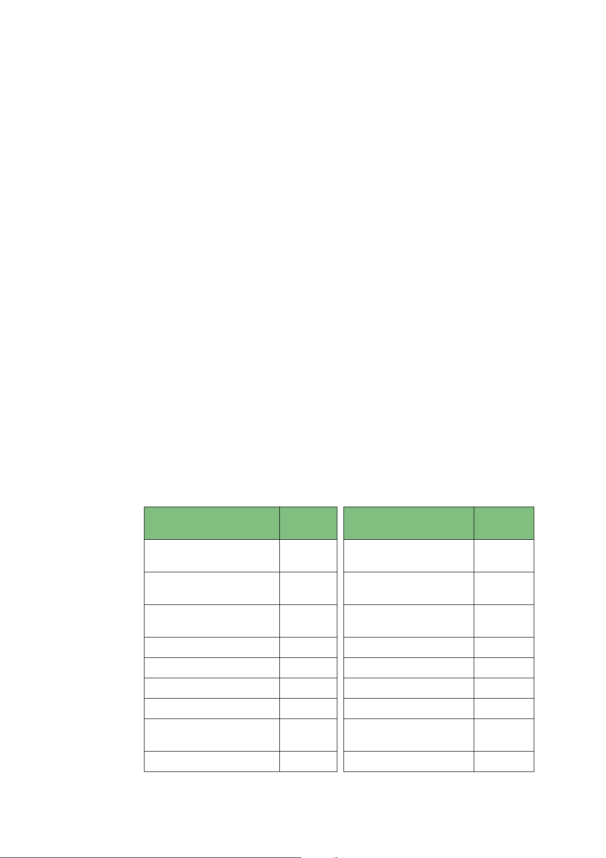
• The information in the table below.
Description Segment
type
Upper stub axle 3
Lower stub axle 3
Suspension bearing,
brake axle (drum side)
Upper stabiliser 1 Lower stabiliser 1
1
Stub axle, single grease
point
Automatic brake
adjuster
Suspension bearing
(brake adjuster side)
Description Segment
type
2 x 3
1
1
Date of issue: October 2011
Spring shackle 3 Rotation point of spring 3
Cabin bearing 1 Coupling disc pin 1
Coupling disc 2 x 4 Tail board hinge 1
Coupling disc, rotation
point
Tail board cyclinder 1
1
Designing a system22
Suspension bearing
drive shaft
1
EG1605R01
Page 23

Automatic Greasing System OnePlus
3.3.4 Group the grease points
Compile groups of grease points, taking account of the following:
• The maximum and minimum number of doser segments that can be
combined in a single distribution block.
• The lengths of the primary and secondary lines in relation with the NLGI class
of grease that must be used and the projected operating temperatures.
• Any special demands that might be placed on the grease output and the
greasing interval.
3.3.5 Determine the layout of the system
Note the positions of the pump unit and the distribution blocks on the greasing
plan. Determine the required composition of the distribution blocks, based on the
group of grease points to be connected with that block. Indicate the routing of the
grease lines on the greasing plan. Take account of:
• The routing of the lines and the type of secondary grease lines that will be
used (single or composite lines with 2 to 3 seperate lines).
• The possibility to combine outputs of doser segments.
• The minimum (3) and maximum (12) number of doser segments that can be
combined in a single distribution block.
Calculate the grease demand of the whole distribution block per whole cycle of the
distribution block (the sum of all rated grease outputs of all doser segments in the
block).
System featuring a main distribution block
Determine the composition of the main distribution block by:
• Determining the ratios of the grease demands of the distribution blocks to be
connected to the main distribution block.
• Selecting segment types for the main distribution block with which those
ratios are most precisely matched.
• Determining the required grease output of the pump unit. This is the sum of
the grease demands of all distribution blocks connected (
main distribution block!
This value can be used in a later stage to determine the grease output of the pump.
).
excluding the
System without a main distribution block
• The determined values may be used to calculate the required grease output
of the pump.
Determine the lengths of the primary grease line between the pump unit and the
distribution block and the lengths of the secondary grease lines between the distribution block and the grease points. Note those lengths on the greasing plan. Determine the number of non-return valves that must be incorporated into the
greasing system.
Date of issue: October 2011
EG1605R01
Designing a system
23
Page 24

Automatic Greasing System OnePlus
3.3.6 Check the design
Before the components of the system are assembled and installed, the projected
system should be checked, by calculation, against the operating conditions it was
designed for. Will it work under the giving operating conditions?
The loss of pressure in the system may not exceed P
mum operating pressure supplied by the pump unit).
p
(Pp equals 90% of the maxi-
1. Calculate the pressure loss P
ating conditions, using table 2.
2. Determine, using the greasing plan, which grease point is furthest from the
pump unit. Calculate, using table 3, the total pressure loss "P
grease line.
3. Determine which type of grease point is connected to this grease line. Determine the resistance "P
of departure).
4. Calculate the largest, total loss of pressure "Pt" for each output port of the
pump unit by adding together the values of the pressure losses in the grease
lines, distribution blocks and at the grease point (P
5. Check: that P
If the loss of pressure in the system exceeds P
1. Is it possible to use a grease of a lower NLGI class?
2. Is it possible to raise the minimum operating temperature requirement?
3. It might be necessary to redesign the system and reconsider whether:
• Its not better to omit the main distribution block by utilising a pump unit
with more grease output ports.
• The layout of the system can be modified to shorten the grease lines or to
reconfigure the distribution blocks.
• Using a grease line of larger diameter to reduce pressure loss will solve the
problem.
t
< Pp.
v
over the distribution blocks, under the set oper-
l
" over that
s
" induced by that type of grease point (see 5.2 Points
t
= Pv + Pl + Ps).
p
investigate the following:
After you have redesigned the system you should always recalculate its suitability.
Date of issue: October 2011
Designing a system24
EG1605R01
Page 25

Automatic Greasing System OnePlus
4Installation
4.1 Overview
To install a
formed:
1. Mounting the pump (including the control unit).
2. Mounting the progressive distribution blocks.
3. Mounting the primary grease line in between the pump and the (main) distribution block and when applied in between the main distribution block and
the secondary distribution blocks.
4. Mounting the secondary grease lines and couplings.
5. Mounting the electrical wiring.
6. Testing the system.
Groeneveld
4.2 Safety precautions
1. Take the necessary precautions to prevent potentially dangerous situations
from occuring during installation, checking and maintenance.
2. Always apply or use adequate safety measures to prevent bodily harm and
damage, before you start working on the vehicle.
3. Ensure the vehicle is immobilised before you start work. Remove the ignition
key and store it in a safe place. Block parts that may move on their own
accord. Engage the parking brake.
4. Pay special attention to tailbords, loading flaps, drop flaps, etc. Take care that
you can work safely unter these parts, without these parts can drop down.
5. Never work underneath a vehicle which is raised by a jack only. Always use a
trestle and check that the ground is firm and flat enough.
6. Keep in mind that a vehicle with air-suspension may drop of its own accord.
7. Only work underneath the cabin if it is fully tilted (and latched). Otherwise a
support must be placed underneath the cabin to ensure the cabin cannot
drop back.
8. Disconnect the earth-clamp from the vehicle’s battery. This prevents electrical
equipment from being inadvertently activated.
9. Avoid working on the cooling system without allowing it to cool down first.
The system is pressurised and may cause burns. Direct contact with the (poisonous ) cooling fluid must be avoided.
10. Adhere to all regulations, specifications and limitations as specified by the
manufacturer of the machine, vehicle or engine.
11. Only use tools that fit and are designed for the specific task you want to perform with them.
12. A vehicle or machine may only be operated by those who are competent to
do so and aware of all possible dangers. If necessary, an expert should be consulted.
13. Keep the environment in which you work clean and tidy. This enhances safety.
OnePlus greasing system the following tasks must be per-
Date of issue: October 2011
EG1605R01
Installation
25
Page 26

Automatic Greasing System OnePlus
4.3 General installation directives
1. Check the contents of the parts kit (using the parts list including in the kit).
2. Check whether the electrical parts in the system meet the vehicle voltage.
3. Before you start installing the greasing system: Check that all grease points
are open and furnished with a sufficient amount of grease. If that is not the
case, grease the grease points by hand. This prevents insufficient greasing of
the grease points during the period following the first few greasing cycles of
the greasing system.
4. Apply Teflon tape, or another type of sealant (e.g. Loctite), to the couplings
and plugs on the distribution blocks and pump unit, if not already fitted with
O-rings, gaskets or sealing rings. While mounting the couplings and plugs,
make sure that the tape does not cause internal contamination of the system.
5. Prevent contamination of the system during the installation. Work with clean
tools and clean the areas on the vehicle or machine where the distribution
blocks and pump unit are to be mounted, before you start installing them.
Even small contaminations can cause the greasing system to
malfunction!
Flush the primary grease lines after installation or maintenance, if contaminations or moisture could not be prevented from entering the system. The deaerating procedure may be used to flush the system.
6. During installation of the grease lines and electrical wiring, ensure that:
• the lines are not mounted onto parts that may become hot, such as the
exhaust, retarder, compressor, turbo charger and air conditioning;
• the lines are routed straight and neatly, and are properly fixed in place
with small or large tie-wraps or clamps;
• the lines that are mounted along moving parts have enough slack and are
mounted in such a manner that , even in the long run, they will not be
damaged, through abrasion or otherwise;
• the lines to moving parts are sufficiently long to follow the movements.
Check this by moving the parts to all positions possible;
• feed-through rubbers are applied at all locations where the lines may
otherwise get damaged.
Date of issue: October 2011
Installation26
EG1605R01
Page 27

Automatic Greasing System OnePlus
4.4 OnePlus pump unit
4.4.1 Mounting the pump
1. If the projected location for the pump unit is not indicated on a vehiclespecific greasing plan, determine, in consultation with the client, the most
suitable location of the pump unit on the vehicle. Take account of:
• The pump unit must be easily accessible (for filling its grease reservoir).
• The grease level in the reservoir must be easy to inspect visually.
• The pump unit must be protected against possible damage.
2. First investigate whether existing mounting holes in the chassis of the vehicle
can be used to mount the mounting plate of the pump unit. Always follow
the directions of the vehicle’s manufacturer when you need to drill new holes.
Do not let the mounting plate rest on the profile flange of the chassis and do
not drill additional mounting holes in the flange in an effort to fix the mounting plate even more securely. Be sure not to damage anything (e.g. lines or
air- tanks) that may be present behind the part in which you drill a hole. After
drilling a hole, always remove the chips (with compressed air or brush).
3. If the mounting plate is to be welded onto the vehicle, the directions of the
vehicle’s manufacturer should be strictly adhered to.
4. Mount the mounting plate with the pump unit onto the chassis.
5. Remove the yellow/red transport plugs from the grease output port and the
de-aerating opening of the pump unit.
6. Mount the nut and sleeve on the output coupling of the pump unit.
4.5 OnePlus distribution blocks
4.5.1 General
The composition of a progressive distribution block is always vehicle/machinespecific.
If the distribution blocks are part of an installation kit, the secondary grease lines
and the couplings for the primary grease lines (to the pump unit or main distribution block) will, usually, have already been mounted onto the distribution blocks.
If the blocks are not part of an installation kit and have not been pre-assembled,
you should mount the grease lines and couplings before you mount the distribution block onto the vehicle or machine.
4.5.2 Assembling distribution blocks
The distribution block must be assembled before it can be installed on the vehicle.
To ensure the reliability of the greasing system, the distribution blocks should be
assembled in a clean, dust-free environment.
The criteria that govern the composition (number and type of doser segments) of
a distribution block are discussed in the Designing a system section of this manual.
1. First study the drawing of the distribution block to be assembled.
2. Check whether all required components are at hand and whether the right
couplings for the right kinds of secondary grease line are available.
3. Begin by placing the start-segment (to which the primary grease line will be
Date of issue: October 2011
connected) onto the work bench with the port for the primary grease line facing downward.
4. Place, in the order as indicated on the drawing, the various doser segments
on top of the start-segment. Place the end-segment on top of the stack.
Ensure that all the openings in the segments are line-up and check that the
required O-rings have been correctly placed between all the segments.
EG1605R01
Installation
27
Page 28

Automatic Greasing System OnePlus
5. Place, using two toothed spring washers, the compression bolts through their
respective holes. Tighten the two bolts alternately and in phases (allen key:
5mm). Tightening moment: 12 Nm.
6. If two output ports of a doser segment need to be combined, remove (allen
key: 2,5mm) the little internal plug that seperates the two output ports. The
grease output of the port that remains open will then be double its normal
output.
7. Mount the couplings, non-return valves and plugs into the output ports of
the distribution blocks, as indicated on the drawing.
8. Mount the secondary grease lines.
9. Connect a grease pump or manual grease gun to the port of the primary
grease line to test the operation of the distribution block and to check for
leakage.
4.5.3 Mounting the distribution blocks
Determine the location of the distribution block on the vehicle or machine. Consult
the specific installation instruction card and/or take account of:
• No stresses may be present in the mounted distribution block. It is best to use
mounting brackets to install the distribution blocks!
• The distribution blocks should not be installed too near moving parts.
• The distribution blocks should not be installed near parts that become hot
(e.g. turbo charger, exhaust).
• Existing mounting holes in the chassis should be utilised, whenever possible.
The distribution blocks can be mounted with the mounting brackets in two ways:
1. First mount the brackets. Then mount the distribution block onto the brackets
(this method is compulsory if the brackets are welded onto the vehicle or
machine).
2. First mount the distribution block onto the bracket. Then mount this assembly
on the vehicle.
Which method is to be preferred depends on the manoevring space you have available.
ATTENTION:
Always apply toothed spring washers to the M5 mounting nuts and bolts of
the distribution blocks. Tighten the bolts alternately and evently. Maximum
tightening moment: 5 Nm.
Date of issue: October 2011
Installation28
EG1605R01
Page 29

Automatic Greasing System OnePlus
4.6 Primary grease lines and couplings
4.6.1 Grease line types
The primary grease lines are those between the pump unit and the main distribution block and between the main distribution block and the secondary distribution
blocks. The primary grease lines are available in a number of different sizes and materials.
• Flexible high-pressure line DN4 (inside diameter 4,0 mm - outside diameter
9,7 mm).
• Flexible high-pressure line DN6 with steel-wire armour (inside diameter 6,0
mm - outside diameter 12,0 mm).
• Metal lines with sizes ø6 x 1 mm or ø8 x 1 mm.
The type of primary grease line most commonly used in the transport industry is the
flexible high-pressure line DN4. This high-quality line combines compactness with
high strength and flexibility.
4.6.2 Mounting the primary grease lines
1. Determine the required length of the grease line to be installed, and cut it to
that length.
2. Mount the couplings onto the line (with high-pressure lines).
Removable couplings:
a. Clamp the sleeve in a bench vice.
b. Turn the line into the sleeve, to end of the sleeve (counter-clockwise!).
c. Turn the line backward 1/4 to 1/2 turn.
d. Apply oil or grease to the pillar, the sleeve and the inside of the line.
e. Turn (clockwise) the grease line pillar in the sleeve, untill it is in position
without tension.
f. Mount the coupling at the other end of the grease line in a similar way.
Press couplings (applied with a simple hand-operated press) for
high-pressure line DN4 (05716):
a. Slide the press sleeve completely over the end of the grease line, so that
the line fills the sleeve completely.
b. Slide, use some oil if necessary, the pillar or the required coupling pin into
the end of the grease line untill the pillar is completely in the grease line.
c. Place the assembly in the press in such a manner that a little piece of the
sleeve remains visible at both sides. Apply pressure until the lever of the
hand-operated press reaches its end-stop.
d. Mount the coupling at the other end of the grease line in a similar way.
ATTENTION:
A simple hand-operated press that can be placed in a bench vice is used with
DN4 high-pressure lines. The thin-walled sleeve of the couplings for this
type of grease line must be pressed exactly in the middle, so that small pieces of unpressed sleeve remain on both sides. This note of attention does not
apply to sleeves meant for use with a hydraulic press. Those types of sleeves
Date of issue: October 2011
EG1605R01
must be pressed over their whole length.
Installation
29
Page 30

Automatic Greasing System OnePlus
Press couplings (applied with a hydraulic press) for high-pressure
grease line DN6 (00817):
a. Check that the press is fitted with the correct type of press blocks, and the
set press diameter. The correct press diameter for this type of grease line is
14,6 mm.
b. Slide the sleeve over the end of the grease line, until it covers the line com-
pletely.
c. Slide, use some oil if necessary, the pillar or the required coupling pin into
the end of the grease line until the pillar is completely in the grease line.
d. Pull the sleeve back slamply until it touches the outside edge of the cou-
pling pin. While doing this, ensure that the pillar remains in place and is
not pressed out of the grease line.
e. Place the assembly into the press and press the sleeve to the required
diameter (14,6 mm).
f. Check the resulting diameter by measuring it (between ridges that may
have formed).
g. Mount the coupling at the other end of the grease line in a similar way.
3. Remove any burrs and other remnants produced by cutting the line, and
clean the grease line by blowing it through. Check that the line is free of
obstructions and check it for internal damage behind the couplings (the inner
lining may have been upset).
4. Fill the line with grease. Either use a pneumatic or hand-operated grease gun.
5. Install the grease line and fix it in place with tie-wraps or clamps. Do not yet
connect the primary grease line(s) to the output port(s) of the pump unit, if
you want to use the pneumatic or hand-operated grease gun to de-aerate the
system.
ATTENTION:
Always use steel cutting rings when using metal grease lines and couplings.
Date of issue: October 2011
Installation30
EG1605R01
Page 31

Automatic Greasing System OnePlus
4.7 Secondary grease lines and couplings
4.7.1 Grease line types
The secondary grease lines are the ones between the distribution blocks and the
grease points. These grease lines are connected to the grease points with the aid of
special couplings. A wide variety of couplings is available.
Which types of couplings should be applied depends, among more things, on:
• The screw thread at the greasing point.
• The position of the greasing point.
• The direction from which the grease line approaches the grease point.
• The type of grease line employed (polyamide lines with brass or steel
couplings; metal lines or high-pressure lines with steel couplings).
• The operation conditions.
The secondary grease lines can be supplied in a number of different sizes and
materials:
• Polyamide lines with outside diameters of 3/16" or 6 mm (standard).
• Stainless steel lines with the outside diameters of 3/16" or 6 mm (standard).
• Kunifer (copper/nickel) lines with outside diameters of 3/16" or 6 mm
(standard).
• Flexible high-pressure lines with inside diameters of 4 mm or 6 mm (1/4").
The type of secondary grease line most commonly used in the transport industry is
the polyamide line with an outside diameter of 3/16” or 6 mm. These grease lines
are supplied as composite lines. In a composite line 2 or 3 polyamide lines are held
together by a single plastic jacket. Each grease line in such a composite line has its
own colour (red, blue or black), so that they can be easily distinguished at the ends
of the composite line (necessary for easy installation and maintenance).
If a composite line is connected to doser segments with different grease outputs,
the individual grease lines should be connected as follows:
• Doser segment with the lowest output Red line
• Doser segment with the highest output Black line
• Doser segment with intermediate output Blue line
Date of issue: October 2011
EG1605R01
Installation
31
Page 32

Automatic Greasing System OnePlus
4.7.2 Mounting the secondary lines
Take attention at the following points during mounting the secondary grease lines
and couplings:
• Always make sure the screw threads of the coupling(s) and the grease point
are identical.
• To identify them, elbow couplings with metric screw thread are marked with
a “M”. Straight couplings with metric screw thread have a groove on their
hexagons.
• Always apply brake booster rubbers when routing grease lines along the
vehicle’s booster lines (this to prevent the booster lines from becoming
pinched-off (over time) by the tie-wraps that are usually used to fix grease
lines).
• Never add extra grease points on your own accord. The integrity of certain
structures may be adversely affected by drilling holes. Always adhere to the
relevant directives issued by the vehicle’s manufacturer.
If a vehicle-specific greasing plan is available, the types (or combination) of couplings to be used at grease point will have been noted on that plan.
First remove the existing grease nipple at the grease point, and replace it by the
required coupling(s).
If the grease point to be connected is a so-called “added” grease point, a hole must
be drilled and the right thread tapped. Do not forget to clean the new hole of any
debris. Mount the required coupling(s) onto the grease point (see the greasing
plan). Make sure that elbow couplings point in the direction of the grease line
(avoid unnecessary (sharp) corners in the grease line).
ATTENTION:
Always check that the newly drilled grease point is open by applying a
hand-operated grease gun to it.
1. Determine the most suitable route for the (composite) grease line to the
grease line(s).
2. Cut the grease line at roughly the required length.
3. Determine approximately, the required length of the individual grease lines
in a composite (polyamide) line. Make absolutely sure that you do not damage the individual grease lines!
4. Strip and remove the outer jacket.
5. Fix the line in place with tie-wraps or clamps up to the coupling at the grease
point.
6. Cut the (individual) grease line to its required length and connect it with the
coupling to the grease point.
Date of issue: October 2011
Installation32
EG1605R01
Page 33
Automatic Greasing System OnePlus
4.8 Electrical wiring
4.8.1 General
Detailed wiring diagrams are available in the installation manual of the specific vehicles or machines.
ATTENTION:
To prevent damage to the electrical system of the vehicle or machine, the
correct fuse(s) must be installed in power supply and control circuit.
On VLG vehicles special demands are placed on:
• the components (e.g. pump, wiring and switches).
• the location of the components on the vehicle.
• the manner in which the greasing system is to be connected to the vehicle’s
electrical system.
Always verify whether the system you are installing and the methods you plan to
use meet those demands.
• Install the wiring only after the main components of the greasing system have
been mounted (e.g. pump unit, indicator lamp, monitoring switches on the
distribution blocks).
• Try, as far as possible, to route the electrical wiring along the grease lines, and
fix the wiring in place together with the grease lines.
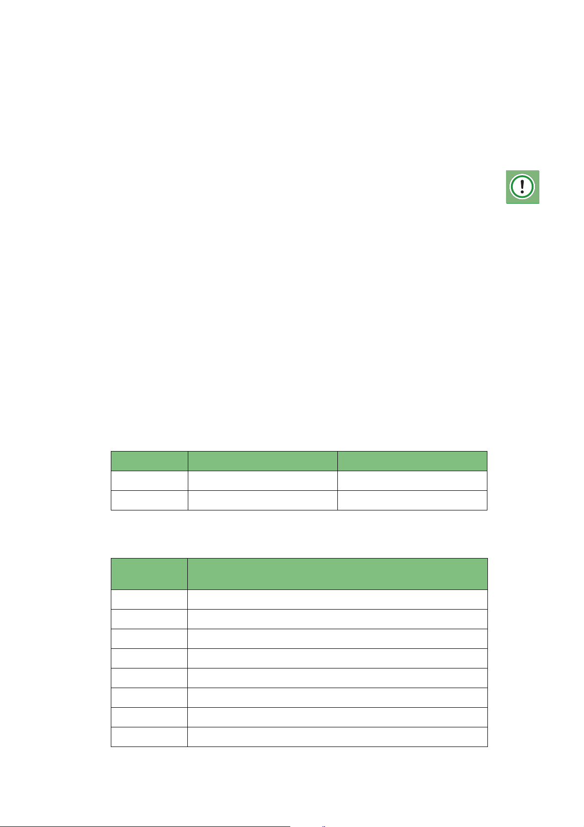
4.8.2 Fuse ratings
Voltage Supply circuit fuse Control circuit fuse
12 Vdc 15 A 3 A
24 Vdc 7,5 A 3 A
4.8.3 Pin-layout of the connector on the pump unit
Pin number
connector
1 Supply voltage (+15)
2 Ground (-31)
Description connection
3 Additional control input (can be a voltage or a ground)
4 Indicator lamp (-)
5 Indicator lamp (+)
Date of issue: October 2011
EG1605R01
6 K-line (communication with the UniGINA)
7 Distribution block monitoring switch
8 Distribution block monitoring switch
Installation
33
Page 34
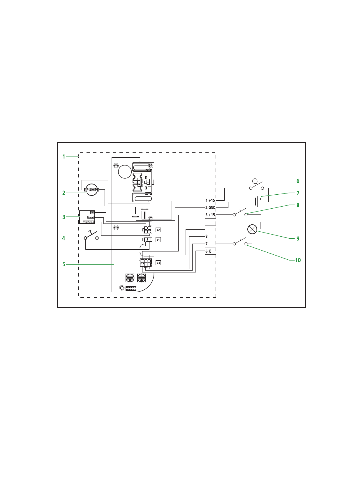
Automatic Greasing System OnePlus
4.8.4 Wiring diagram
1. Pump unit
2. Pump motor
3. Revolution sensor
4. Test push button
5. Control unit
6. Ignition
7. Battery
8. Control input switch
9. Indicator lamp
10. Distribution block monitoring switch
123
4
2 1
1 23
456
Figure 4.1 Wiring diagram
+ or -
4 -
5 +
Date of issue: October 2011
Installation34
EG1605R01
Page 35

Automatic Greasing System OnePlus
4.9 De-aerating of the greasing system
The greasing system can be de-aereted in three different ways:
Method 1
This method can be used when a pneumatic grease pump is available in the workshop. With such a pump the greasing system can be de-aereted quickly by connecting the primary grease line of the OnePlus system (at the pump unit) with that
pneumatic pump. After the system has been de-aereted, the primary line must be
reconnected to the output port of the pump unit.
Method 2
This method may be used when only a hand-operated grease gun is available. The
procedure is the same as described for method 1.
Method 3
This method will have to be used when neither a pneumatic system or a hand-operated grease gun is available. There is no need to disconnect the primary grease
line from the pump unit. The pump unit must then be started and be allowed to
run until all grease points shown a closed collar of fresh grease.
4.10 Commissioning of the greasing system
During commissioning, the system parameters (greasing interval, grease supply per
phase, etc.) must be set or checked using the UniGINA. Detailed information about
the system parameters and the operation of the UniGINA can be found in the User
Manual UniGina OnePlus.
After you have set or checked the system parameters with the UniGINA, you should
also enter the INPUT/OUTPUT menu and check:
• the correct functionally of the control input, when activated.
• the functionality of the pump (manual operation).
• the functionality of the optional indicator lamp, when mounted (manual
operation).
• the functionality of the optional distribution block monitoring switch, when
mounted (activate pump manually and watch the switch changes state within
reasonable time).
Perform a test cycle and check the correct functionality.
Date of issue: October 2011
EG1605R01
Installation
35
Page 36

Automatic Greasing System OnePlus
5 Maintenance
5.1 General
The maintenance of
mal maintenance of the vehicle or machine.
Groeneveld’s
OnePlus systems can be combined with the nor-
WARNING:
If a high-pressure steam/water jet is used to clean the vehicle or machine,
the pump unit of the greasing system should not be directly exposed to the
jet. This to prevent water from entering the pump unit through its de-aerating opening. During normal operation, however, water will never be able
to enter the pump unit.
ATTENTION:
The automatic greasing system reduces the time and effort spent on
manual greasing significantly. However, do not forget that there may be
grease points that are not served by the greasing system and must still be
greased by hand.
5.2 Regularly checks of the greasing system
Check the following points of the OnePlus greasing system:
1. The grease level in the reservoir of the pump unit (refill on time).
2. The pump unit for damage and leakage.
3. The primary and secondary grease lines for damage and leakage.
4. The grease points, collar of fresh grease should be present at all grease
points.
5. Retrieve a possible fault code of a pending error(s), stored the last performed
automatic greasing cycle, by depressing the test push button for at least 5 seconds and watch the indicator lamp 7 seconds after (only possible when the
optional indicator lamp is mounted).
6. Perform a test cycle and check the correct function (hold the test push button
depressed in between 3 and 5 seconds).
Date of issue: October 2011
Maintenance36
EG1605R01
Page 37
Automatic Greasing System OnePlus
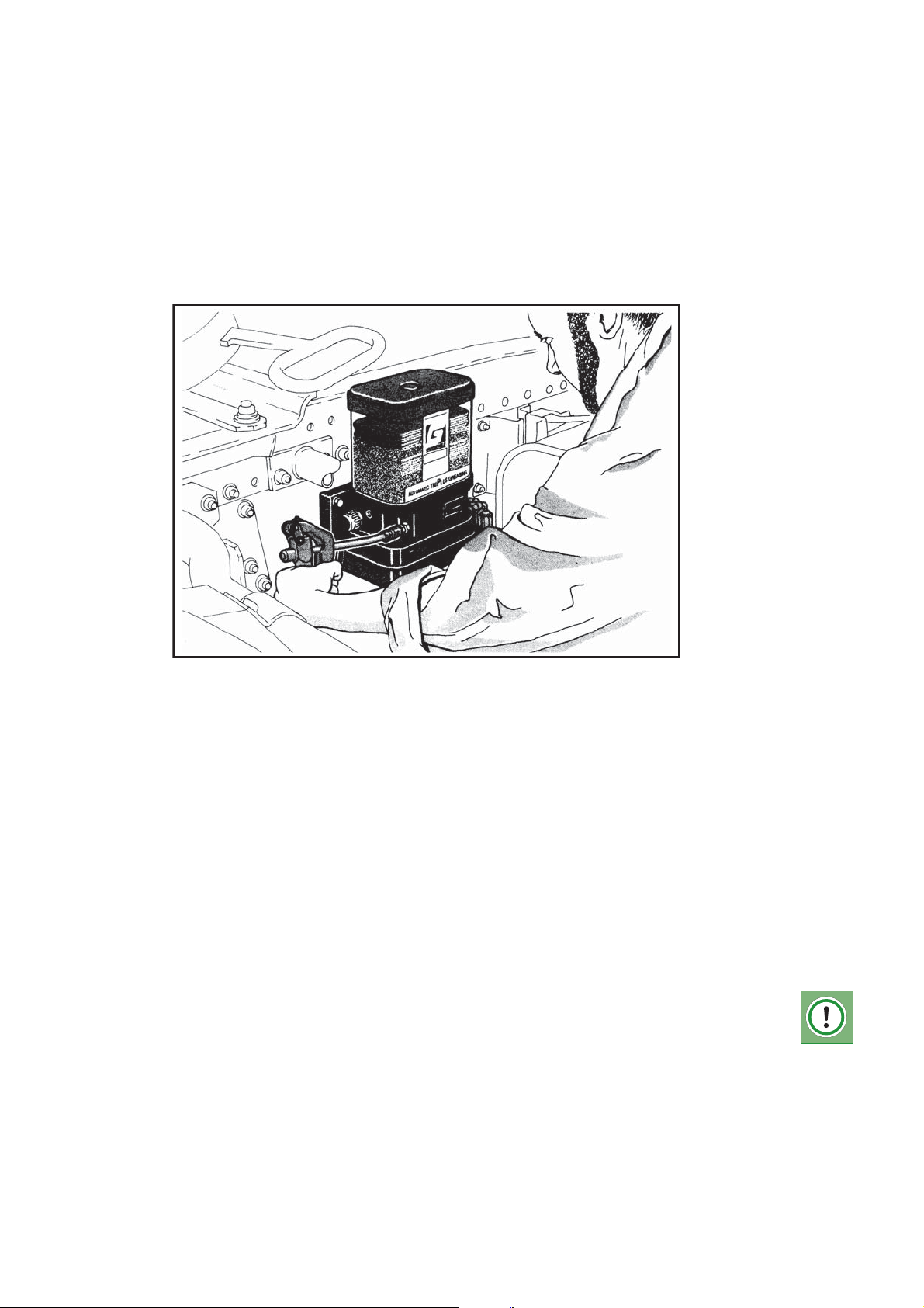
5.3 Filling the grease reservoir
When the grease in the reservoir reaches the minimum level indicated on the reservoir, the reservoir needs to be refilled. To facilitate this, the pump unit is fitted
with a grease nipple onto which a garage grease pump can be placed.
To be able to fill the reservoir using a special filling pump, a special filler coupling
can be installed.
operated or pneumatic filling pumps.
Groeneveld
can supply you with both mobile or stationary, hand-
Figure 5.1 Filling the reservoir with a garage grease pump.
Filling procedure
The grease pump must be suitable for class 2 grease.
First fill the filling hose with grease (if the filling pump or grease barrel is new). This
prevents air being introduced in the grease reservoir.
1. Remove the dust cap of the filler coupling.
2. Clean the filler coupling and the coupling on the hose thoroughly.
3. Lock the hose onto the filler coupling or position the grease gun onto the
filler coupling.
4. Fill the reservoir up to its maximum level, as indicated on the reservoir. Never
fill the reservoir any higher than the maximum level indicated, otherwise the
follower piston may become damaged.
5. Remove the filling hose or grease gun.
6. Clean the dust cap and the grease nipple or filling coupling with a clean rag.
Place the dust cap back onto the filler coupling.
ATTENTION
Check the grease filter behind the filler coupling every 500 hours and clean
or renew the filter.
Air pockets that entered the grease reservoir during filling can escape the
Date of issue: October 2011
reservoir through an opening in the top of the guide rod when the follower
piston is just above maximum level. These air pockets, together with excess
grease, will exit via the de-aerating opening at the left side of the pump
unit.
EG1605R01
Maintenance
37
Page 38

Automatic Greasing System OnePlus
5.4 Fault finding
Problem Cause Solution
Indicator lamp does not
light-up for 3 seconds
after ignition was
switched on.
Indicator lamp is lighted
constantly when the
ignition is powered.
Indicator lamp is flashing for a short period
(1 sec. on / 1 sec. off).
1. No supply voltage
(+15) on pin 1 or at
indicator lamp.
2. No ground potential
on pin 2.
3. Indicator lamp defective.
4. Wiring to pump unit
or to indicator lamp
defective.
System is malfunctioning.
Lamp is flashing to indicate a running pump
cycle, triggered by pushing the test push button
at the pump or the controller program (optional parameter setting
for displaying each automatic cycle to the operator).
Check the fuse and, if
required, replace the
fuse.
Check the ground connection and, if required
repair it.
Replace the indicator
lamp.
Check the wiring and, if
required, repair it.
Retrieve the fault codes
with the test push button or the UniGINA and
repair the system.
When indicator lamp
should not indicate each
automatic triggered
pumping cycle contact
your dealer.
All grease points are too
dry, but no malfunction
is indicated by the
optional indicator lamp.
Too much grease has
been applied to all
grease points.
One or more grease
points are to dry while
others received the correct amount of grease.
The cycle time period or
the set grease amount
per greasing cycle is not
set correctly for the current application.
The cycle time period or
the set grease amount
per greasing cycle is not
set correctly for the current application.
Improper composition of
the distribution blocks.
Shorten the cycle time
period and or increase
the grease amount with
the rotary switches on
the circuit-board behind
the bottom cover of the
pump.
Lenghten the cycle time
period and or decrease
the grease amount with
the rotary switches on
the circuit-board behind
the bottom cover of the
pump.
Change the composition of the distribution
blocks.
Date of issue: October 2011
Maintenance38
EG1605R01
Page 39
Automatic Greasing System OnePlus
Problem Cause Solution
All grease points connected are too dry, and a
malfunction is indicated
by the optional indicator
lamp.
Defective pump unit or
blockage in the system.
Retrieve the fault code.
When the code indicates
that there has been no
state change of the
block monitoring switch,
during a number of successive greasing cycles
this could indicate:
1. System contains
grease that is not suitable for the current
operating conditions.
Solution: Replace the
grease in the pump and
flush the system.
2. Grease reservoir is
empty.
Solution: Fill the reservoir and de-aerate the
pump when necessary.
3. Air pockets in the
grease reservoir.
Solution: Fill the reservoir to maximum level
and let air escape
through the opening in
the top of the guide rod
and de-aerate the
pump. When problem is
consistent try to fill the
reservoir with some oil.
4.The optional block
monitoring switch is not
mounted while the
parameter in the program is activated.
Solution: Connect the
UniGINA to the pump
controller and de-activate this block switch
option.
5. The number of cycles
in which minimal 1 block
switch state change
needs to be detected is
Date of issue: October 2011
EG1605R01
too short.
Solution: Connect the
UniGina to the pump
controller and increase
the number of cycles.
Maintenance
39
Page 40
Automatic Greasing System OnePlus
Problem Cause Solution
6. Distribution block,
grease line or grease
point blocked and pump
pressure is raised to the
maximum.
Solution: Carefully
remove the pressurized
main line from the
pump and mount a Tcoupling with a manometer 0-400 bar. Perform one or more test
cycles to raise the pressure again. When the
maximum pressure is
reached, start removing
the output grease lines
from the distribution
block one by one until
you find the one that
causes the blockage
(pressure will sink when
the blocked line is disassembled). Follow this
blocked line to the
grease point and check
it on damage and repair
and or resolve the blockage. When this line leads
to a secondary distribution block connect the
disassembled line(s) to
the main block again
and repeat the procedure for the lines connected to the secondary
block. If the pressure
does not sink while all
the output lines are disconnected, the blockage resides in the block
itself. Disassemble the
block and clean it internally or mount a new.
Date of issue: October 2011
Remark:
A programming and read-out unit (UniGINA) is used to program and readout the control unit. The UniGINA can also be used to consult a list of faults
that have occurred and were stored in the memory of the control unit. If the
system features a indicator lamp in the cabin the stored fault codes can also
be viewed with the aid of this indicator lamp and the test push button on
the pump unit.
Maintenance40
EG1605R01
Page 41
Automatic Greasing System OnePlus
6 Technical data
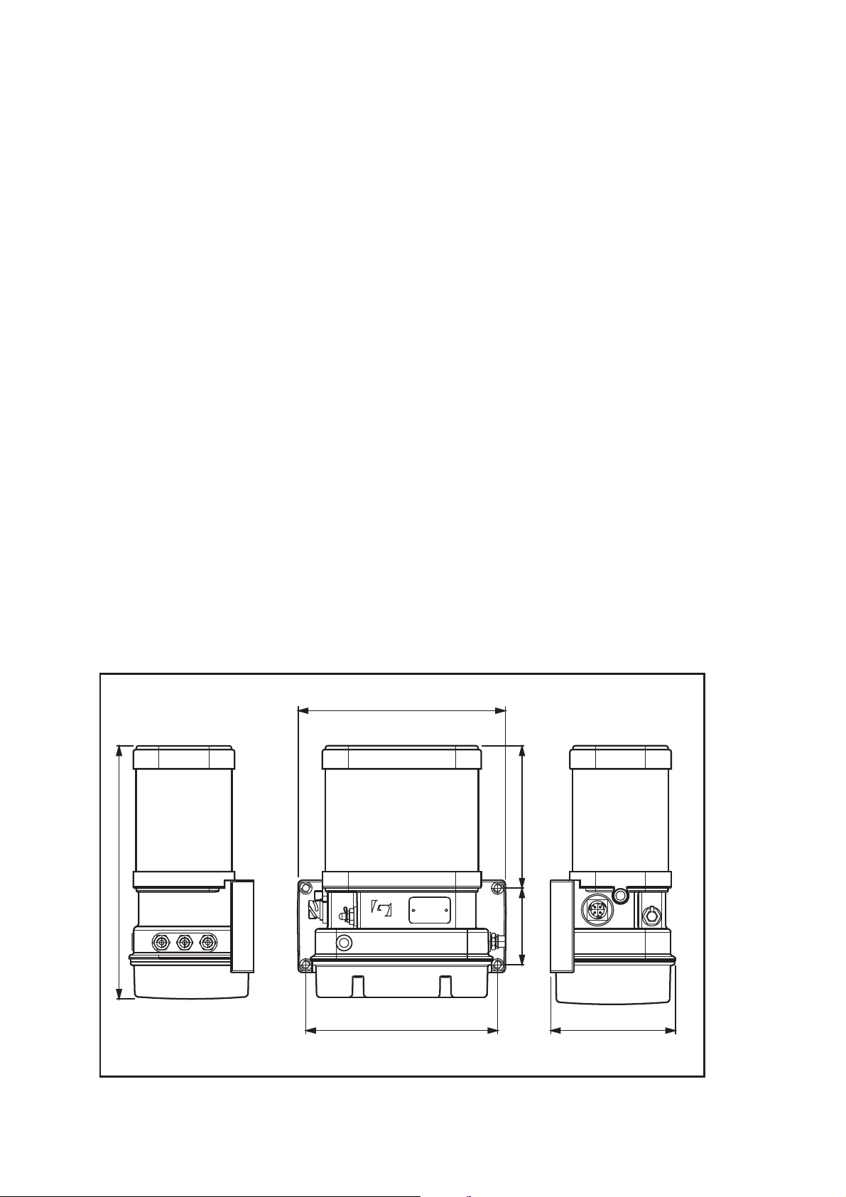
6.1 OnePlus pump unit
Maximum operating pressure : 275bar
Operating temperature : -20 ... +60 °C
Supply voltage : either 12 or 24 Vdc
Rating pump motor (nominal at 20 °C) : 36 W
Rest current : 40 mA
Capacity grease reservoir (standard) : 2 litres *
Minimum-level switch : none
Number of output ports : 1
Pump material
Pump delivery : 0,1 cc per stroke
Protection class : IP67 (for lower part of pump unit)
Grease types : NLGI 2 **
* Other grease reservoirs are available on request.
** Depending on the ambient temperature (consult your grease supplier).
270
338
: hard anodised aluminium - nylon
reinforced
100 187
Date of issue: October 2011
250 162
Figure 6.1 Dimensions of the OnePlus pump unit with a 2 litre reservoir.
EG1605R01
Technical data
41
Page 42
Automatic Greasing System OnePlus
6.2 Distribution blocks
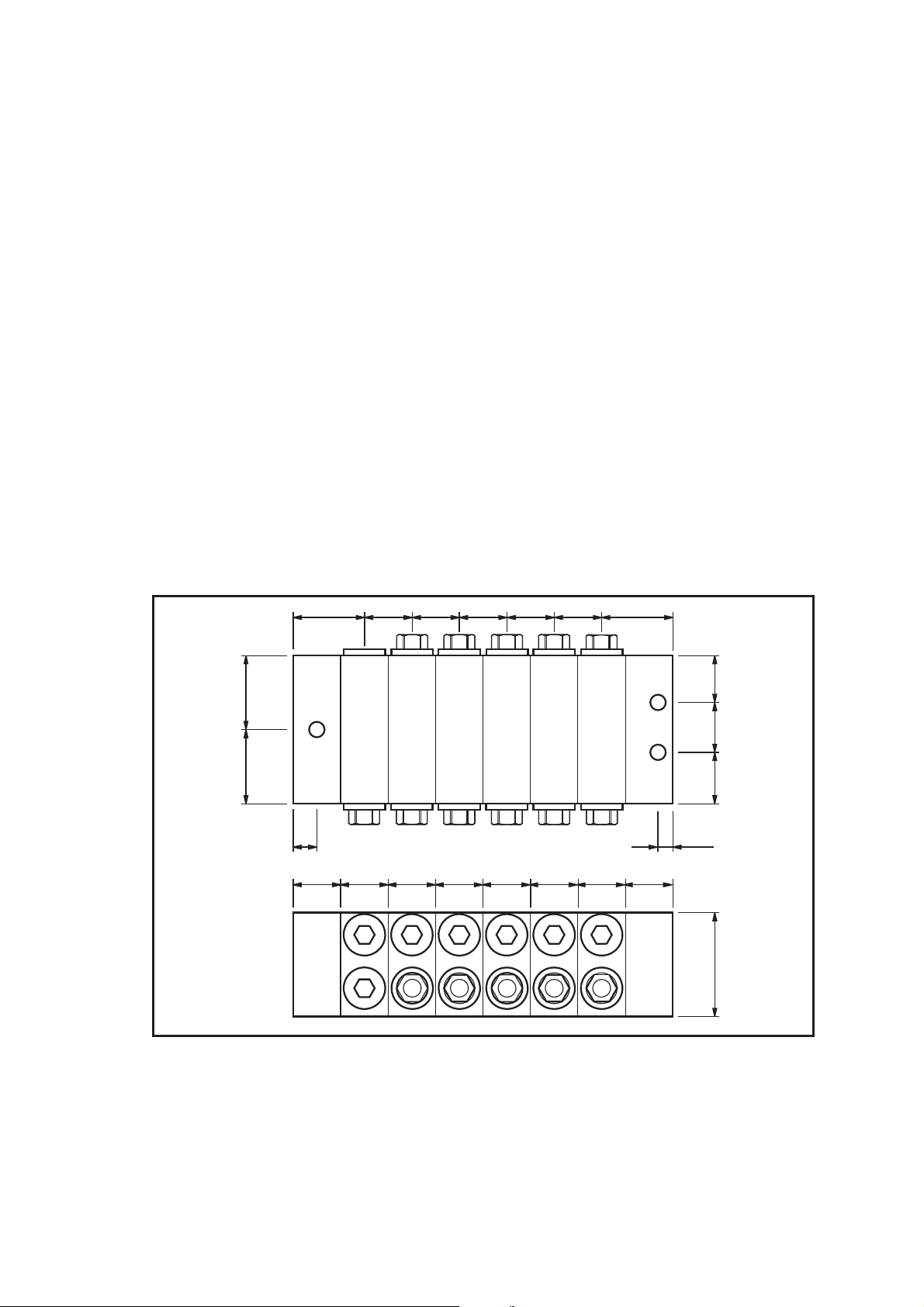
Maximum operating pressure : 275bar
Operating temperature : -20 ... +85 °C
Minimum number of doser segments : 3 (excluding start and end segments)
Maximum number of doser segments : 12 (excl. start and end segments)
Material : galvanised steel
Material O-rings : NBR
Grease inlet port thread : M10 x 1 mm
Delivery per outlet type 1 (two per
segment)
Delivery per outlet type 3 (two per
segment)
Delivery per outlet type 4 (two per
segment)
24 16 16 16 16 16 24
2525
8 4
: 0,045 cc
: 0,125 cc
: 0,200 cc
16,516,53617
1616161616161616
Figure 6.2 Dimensions of the distribution block.
6.3 Regulations
System meets the following EMC standards:
• EC directive 2004/104/EC (automotive).
• UN regulation 10 (automotive).
• ISO 13766 (earth moving machinery).
Technical data42
Date of issue: October 2011
EG1605R01
Page 43

Page 44

www.groeneveld-group.com
Groeneveld Transport Efficiency B.V., Stephensonweg 12, 4207 HB Gorinchem, P.O. Box 777, 4200 AT Gorinchem,
The Netherlands, Ph : +31 183 641 400, F : +31 183 624 474, http://www.groeneveld-group.com
 Loading...