

Page 1
OPERATOR MANUAL
IMPORTANT INFORMATION, KEEP FOR OPERATOR
1055 Mendell Davis Drive, Jackson, MS 39272
888-994-7636, fax 888-864-7636
unifiedbrands.net
THIS MANUAL MUST BE RETAINED FOR FUTURE REFERENCE. READ,
UNDERSTAND AND FOLLOW THE INSTRUCTIONS AND WARNINGS
CONTAINED IN THIS MANUAL.
FOR YOUR SAFETY Instructions to be followed in the event user smells
gas. This information shall be obtained by consulting your local gas
supplier. As a minimum, turn off the gas and call your gas company and
your authorized service agent. Evacuate all personnel from the area.
WARNING Improper installation, adjustment, alteration, service or
maintenance can cause property damage, injury or death. Read the
installation, operating and maintenance instructions thoroughly before
installing or servicing this equipment.
NOTIFY CARRIER OF DAMAGE AT ONCE It is the responsibility of the
consignee to inspect the container upon receipt of same and to determine
the possibility of any damage, including concealed damage. Unified
Brands suggests that if you are suspicious of damage to make a notation
on the delivery receipt. It will be the responsibility of the consignee to file
a claim with the carrier. We recommend that you do so at once.
Manufacture Service/Questions 888-994-7636.
PART NUMBER 174845, REV. E (04/19)
This manual provides information for:
STEAM JACKETED KETTLE
MODELS DH(T)-20/40/60/80
(C,A,C2T™) DOMESTIC
REFERENCES
CSA INTERNATIONAL
8501 East Pleasant Valley Road
Cleveland, Ohio 44131
NSF INTERNATIONAL
798 N. Dixboro Rd.
P.O. Box 130140
Ann Arbor, Michigan 48113-0140
UNDERWRITERS LABORATORIES, INC.
333 Pfingsten Road
Northbrook, Illinois 60062
KLENZADE SALES CENTER ECOLAB, Inc.
370 Wabasha
St. Paul, Minnesota 55102
NATIONAL FIRE PROTECTION ASSOCIATION
60 Battery March Park
Quincy, Massachusetts 02269
NFPA/54 -Installation Gas Appliances &
Piping
NFPA/70 - The National Electric Code
ZEP MANUFACTURING COMPANY
1310-T Seaboard Industrial Boulevard
Atlanta, Georgia 30318
AMERICAN NATIONAL STANDARDS INST., INC.
1430 Broadway
New York, New York 10018
Z223.1-1984 - National Fuel Gas Code
Z21.30 - Installation Gas Appliances & Piping
EQUIPMENT DESCRIPTION
The Groen DH is a floor-mounted, tilting, steam jacketed kettle with a thermostatically or electronically controlled, self-contained, gas-heated steam source and appropriate controls, mounted on a sturdy base. The Model DH is available in 20, 40,
60 or 80 gallon capacities.
The body of the DH Kettle is constructed of stainless steel, welded into one solid
piece. The kettle is furnished with a reinforced rim and a butterfly shaped pouring
lip. It has a steam jacket which is ASME shop inspected and registered with the
national board for working pressures up to 50 PSI. Kettle finish is 180 emery grit
on the inside and bright high buff polish on the outside.
The kettle is tilted with a hand crank to pour out its contents. Stainless steel panels
enclose the controls and the base. Four stainless steel tubular legs support the
unit. Bullet or flanged feet on each of the legs can be adjusted to level the kettle.
Standard DHT units include a two inch tangent draw-off valve.
The self-contained steam source is heated by propane or natural gas. Ignition is
electronic.
The kettle is charged at the factory with chemically pure water which contains rust
inhibitors. The steam source provides kettle temperatures of 150º to approximate-
Information contained in this document is known to be current and accurate at the time of printing/creation. Unified Brands
recommends referencing our product line websites, unifiedbrands.net, for the most updated product information and
specifications. © 2019 Unified Brands. All Rights Reserved. Unified Brands is a wholly-owned subsidiary of Dover Corporation.
ly 295ºF (65 to 150ºC). Unit controls include a thermostat or controller, pressure
gauge, safety valve, pressure limit control, low water cut-off, power switch and
gas regulator valve. The gas supply shuts off automatically when the kettle is tilted.
The unit must be specified for use with natural or propane gas. Service connections for gas and electricity are required. Standard power supply is 115 Volt. Alternate single-phase voltages (208-240V) are available.
Options available include:
1. Two inch tangent drawoff standard on DHT models
2. Strainers, solid disk, 1/4 or 1/8 inch holes
3. No. 31 lift-off cover
4. No. 51 counterbalanced cover w/actuator*
5. Basket Inserts (Tri-BC)
6. Water fill faucets with swing spout
7. Kettle Brush Kit
Page 2

IMPORTANT - READ FIRST - IMPORTANT
CAUTION:
WARNING: THIS UNIT IS INTENDED FOR USE IN THE COMMERCIAL HEATING, COOKING AND
WARNING: KETTLE MUST BE INSTALLED BY PERSONNEL QUALIFIED TO WORK WITH
DANGER: ELECTRICALLY GROUND THE UNIT AT THE TERMINAL PROVIDED. FAILURE TO
WARNING: DO NOT CONNECT ANY PIPING TO THE POP SAFETY VALVE. THE VALVE MUST BE
WARNING: AVOID ALL DIRECT CONTACT WITH HOT EQUIPMENT SURFACES. DIRECT SKIN
WARNING: AVOID ALL DIRECT CONTACT WITH HOT FOOD OR WATER IN THE KETTLE. DIRECT
CAUTION: DO NOT OVER FILL THE KETTLE WHEN COOKING, HOLDING OR CLEANING. KEEP
WARNING: TAKE SPECIAL CARE TO AVOID CONTACT WITH HOT KETTLE BODY OR HOT
WARNING: WHEN TILTING KETTLE FOR PRODUCT TRANSFER:
BE SURE ALL OPERATORS READ, UNDERSTAND AND FOLLOW THE OPERATING
INSTRUCTIONS, CAUTIONS, AND SAFETYINSTRUCTIONS CONTAINED IN THIS MANUAL.
HOLDING OF WATER AND FOOD PRODUCTS, PER THE INSTRUCTIONS CONTAINED
IN THIS MANUAL. ANY OTHER USE COULD RESULT IN SERIOUS PERSONAL
INJURY OR DAMAGE TO THE EQUIPMENT AND WILL VOID WARRANTY.
ELECTRICITY AND PLUMBING. IMPROPER INSTALLATION CAN RESULT IN INJURY
TO PERSONNEL AND/OR DAMAGE TO EQUIPMENT.
GROUND UNIT COULD RESULT IN ELECTROCUTION AND DEATH.
FREE TO VENT STEAM AS NEEDED. THE ELBOW ATTACHED TO THE SAFETY VALVE
SHOULD POINT TO THE FLOOR. IMPROPER INSTALLATION WILL VOID WARRANTY.
CONTACT COULD RESULT IN SEVERE BURNS.
CONTACT COULD RESULT IN SEVERE BURNS.
LIQUIDS A MINIMUM OF 2-3” (5-8 cm) BELOW THE KETTLE BODY RIM TO ALLOW
CLEARANCE FOR STIRRING, BOILING AND SAFE PRODUCT TRANSFER.
PRODUCT WHEN ADDING INGREDIENTS, STIRRING OR TRANSFERRING PRODUCT
TO ANOTHER CONTAINER.
1) USE CONTAINER DEEP ENOUGH TO CONTAIN AND MINIMIZE SPLASHING.
2) PLACE CONTAINER ON STABLE, FLAT SURFACE, AS CLOSE TO KETTLE AS POSSIBLE.
3) DO NOT OVER FILL CONTAINER. AVOID DIRECT SKIN CONTACT WITH HOT
CONTAINER AND ITS CONTENTS.
CAUTION: KEEP FLOORS IN FRONT OF KETTLE WORK AREA CLEAN AND DRY. IF SPILLS OCCUR,
CLEAN IMMEDIATELY, TO AVOID SLIPS OR FALLS.
WARNING: FAILURE TO CHECK SAFETY VALVE OPERATION PERIODICALLY COULD RESULT IN
PERSONAL INJURY AND/OR DAMAGE TO EQUIPMENT.
WARNING: WHEN TESTING SAFETY VALVE, AVOID ANY EXPOSURE TO THE STEAM BLOWING
OUT OF THE SAFETY VALVE. DIRECT CONTACT WITH STEAM COULD RESULT IN
SEVERE BURNS.
WARNING: TO AVOID INJURY, READ AND FOLLOW ALL PRECAUTIONS STATED ON THE LABEL OF
THE WATER TREATMENT COMPOUND.
WARNING: BEFORE REPLACING ANY PARTS, DISCONNECT THE UNIT FROM THE ELECTRIC
POWER SUPPLY AND CLOSE THE MAIN GAS VALVE. ALLOW FIVE MINUTES FOR
UNBURNED GAS TO VENT.
WARNING: KEEP WATER AND SOLUTIONS OUT OF CONTROLS AND ELECTRICAL EQUIPMENT.
NEVER SPRAY OR HOSE THE SUPPORT HOUSING OR ELECTRICAL CONNECTIONS.
CAUTION: MOST CLEANERS ARE HARMFUL TO THE SKIN, EYES, MUCOUS MEMBRANES AND
CLOTHING. PRECAUTIONS SHOULD BE TAKEN. WEAR RUBBER GLOVES, GOGGLES OR
FACE SHIELD AND PROTECTIVE CLOTHING. CAREFULLY READ THE WARNINGS AND
FOLLOW THE DIRECTIONS ON THE LABEL OF THE CLEANER TO BE USED.
CAUTION: USE OF ANY REPLACEMENT PARTS OTHER THAN THOSE SUPPLIED BY GROEN OR
THEIR AUTHORIZED SERVICE AGENTS CAN CAUSE OPERATOR INJURY AND DAMAGE
TO THE EQUIPMENT, AND WILL VOID ALL WARRANTIES.
IMPORTANT: SERVICE PERFORMED BY OTHER THAN FACTORY AUTHORIZED PERSONNEL WILL
VOID WARRANTIES.
WARNING: DO NOT HEAT AN EMPTY KETTLE. EXCESSIVE STEAM PRESSURE COULD DEVELOP.
NOTICE: IT IS RECOMMENDED THAT AN INSTANT-READ THERMOMETER BE USED TO
CHECK THE INTERNAL TEMPERATURE THROUGHOUT THE COOKING PROCESS
AND AFTER THE COOKING PROCESS HAS BEEN COMPLETED TO ENSURE THE
FOOD HAS BEEN COOKED SUFFICIENTLY.
PERFORMANCE DATA
Model
DH/DHT-20
(C,A,C2T)
DH/DHT-40
(C,A,C2T)
DH/DHT-60
(C,A,C2T)
DH/DHT-80
(C,A,C2T)
Kettle
Capacity
20 Gal. 20 inches 35 inches 29 inches
75 liter 508 mm 889 mm 736 mm
40 Gal. 26 inches 47 inches 29 inches
150 liter 660 mm 1194 mm 736 mm
60 Gal. 30 inches 47 inches 29 inches
225 liter 762 mm 1194 mm 736 mm
80 Gal. 34inches 52 inches
302 liter 863 mm 1320 mm 952 mm
Kettle
Body
Diameter
Base
Width
Base
Depth
37-1/2
inches
Firing
Rate Per
Hour
72,000
BTU
100,000
BTU
150,000
BTU
150,000
BTU
Energy
into Prod-
uct Per
Hour
44,140
BTU
65,000
BTU
93,000
BTU
93,000
BTU
INSPECTION & UNPACKING
CAUTION: SHIPPING STRAPS ARE UNDER TENSION AND CAN SNAP BACK WHEN CUT.
TAKE CARE TO AVOID PERSONAL INJURY OR DAMAGE TO THE UNIT BY
STAPLES LEFT IN THE WALLS OF THE CARTON.
CAUTION: THIS UNIT WEIGHS BETWEEN 535 AND 978 POUNDS (245 TO 400 KG)
DEPENDING ON SIZE. INSTALLER SHOULD USE PROPER EQUIPMENT TO
LIFT SAFELY.
The unit arrives completely assembled, except for the tilting handle on hand tilt
models which is shipped inside the kettle. The unit is strapped on a skid and in
a heavy carton. Inspect the carton carefully for damage. Open the container and
check the unit for hidden damage. Report shipping damage or shipment errors to
the delivery agent.
Write down the model number, serial number, and installation date for your unit at
the top of the Service Log at the end of this manual. Keep this manual with the unit.
When installation is to begin, carefully cut any straps which hold the unit on the
skid. Lift the unit straight up off the skid. Examine packing materials to be sure
loose parts are not discarded with the materials.
2 OM-DH(T)-20/40/60/80 (C,A,C2T™) Domestic
Page 3
INSTALLATION
WARNING: THE UNIT MUST BE INSTALLED BY PERSONNEL WHO ARE QUALIFIED TO
DANGER: ELECTRICALLY GROUND THE UNIT AT THE TERMINAL PROVIDED. FAILURE
WARNING: DO NOT CONNECT ANY PIPING TO THE PRESSURE RELIEF VALVE. THE VALVE
The open end of the pressure relief valve
For efficient performance the kettle must be installed in a well-ventilated
area. Items which might restrict or obstruct the flow of air for combustion and
ventilation must be removed. The area directly around the appliance must be free
of combustible materials.
1. Installation can be on a combustible or noncombustible floor. Clearances
2. The kettle should be installed in an adequately ventilated room with provision
3. Set the kettle in place and level it using a spirit level on the bar rim, by turning
4. Complete the piping to the gas service main with ½” line or approved
5. Provide 115 vac, 60 Hz, single phase 5 AMP electrical service. The unit may
6. Core probe storage bracket (C2T models only)
WORK WITH GAS, ELECTRICITY AND PLUMBING. IMPROPER INSTALLATION
CAN CAUSE INJURY TO PERSONNEL AND/OR DAMAGE TO THE EQUIPMENT.
THE UNIT MUST BE INSTALLED IN ACCORDANCE WITH APPLICABLE CODES.
THE UNIT MUST BE INSTALLED BY A LICENSED PLUMBER OR GAS FITTER
WHEN INSTALLED WITHIN THE COMMONWEALTH OF MASSACHUSETTS.
TO GROUND UNIT COULD RESULT IN ELECTROCUTION AND DEATH.
MUST BE FREE TO VENT STEAM AS NEEDED. IMPROPER INSTALLATION
WILL VOID THE WARRANTY! THE ELBOW ATTACHED TO THE PRESSURE
RELIEF VALVE MUST POINT TO THE FLOOR.
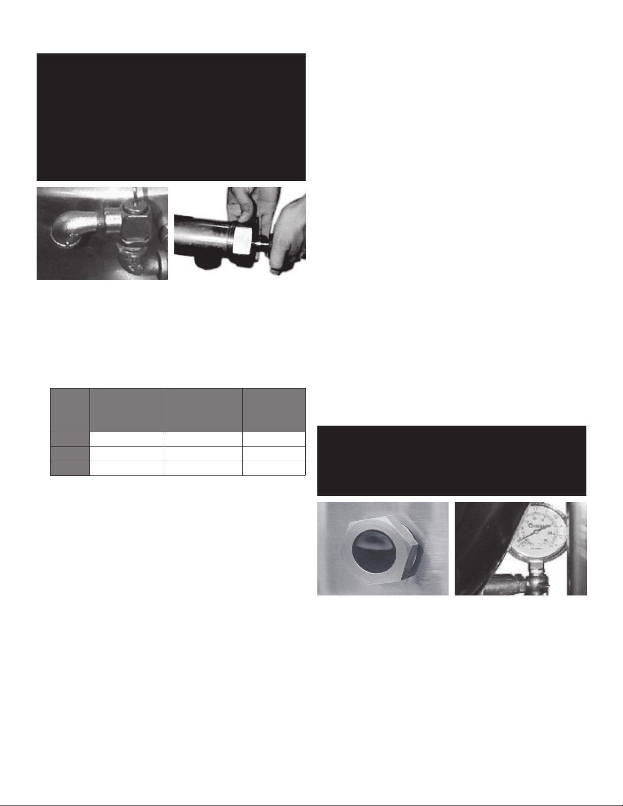
When attaching the draw-off
elbow must face downward.
valve, hand-tighten the nut.
should be per table.
MINIMUM
CLEARANCE FROM
COMBUSTIBLE
WALLS
Left Side 6 in. 0 in. 6 in.
Right Side 6 in. 0 in. 10 in.
Rear 10 in. 10 in. 12 in.
MINIMUM
CLEARANCE FROM
NON-COMBUSTIBLE
WALLS
RECOMMENDED
CLEARANCES
for adequate air supply. The ventilation must employ a vent hood and exhaust
fan with no direct connection between the vent duct and the kettle flue. Do not
obstruct the flue or vent duct after installation.
the bullet or flange feet to adjust leg length. Allow clearance around the unit
for cleaning, maintenance and service.
equivalent.
also be ordered for alternate electric service of 208 VAC - 240 VAC. Observe
local codes and/or The National Electrical Code in accordance with ANSI/
NFPA 70 (current edition), or the Canadian Electrical Code, CSA C22.2 (current
edition), as applicable. Use the wiring diagram inside the service panel and at
the rear of this manual.
a. It is recommend that the core probe storage bracket be installed on the
control console. It is not recommend that the core probe storage bracket
be installed on the kettle body or cover.
b. To obtain proper adhesion, the bonding surface must be unified, clean and
dry. Clean the bonding surface with rubbing alcohol and allow the surface
to dry. Next firmly apply pressure to the storage bracket to help improve
bond strength. After application, the bond strength will increase as the
adhesive flows onto the surface. At room temperature, approximately
50% of the ultimate strength will be achieved after 20 minutes, 90% after
24 hours and 100% after 72 hours.
7. Bring electrical service through the entrance at the rear of the support housing
with a ½ inch conduit connector. Make a watertight connection with the
incoming lines.
8. Electrically ground the unit at the terminal provided.
9. After the kettle has been connected to the gas supply, check all gas joints for
leaks. DO NOT USE FLAME TO CHECK FOR LEAKS. A thick soap solution or
other suitable leak detector should be employed.
10. The gas supply and unit’s installation must conform with local codes or in the
absence of local codes, with the National Fuel Gas Code, ANSI Z223.1/NFPA
54 (current edition), or the Natural Gas and Propane Installation Code CSA
149.1(current edition), as applicable. Additionally following must be complied
with: THE AREA DIRECTLY AROUND THE APPLIANCE MUST BE CLEARED OF
ALL COMBUSTIBLE MATERIAL. FAILURE TO FOLLOW THESE INSTRUCTIONS
CAN CAUSE BODILY INJURY AND /OR PROPERTY DAMAGE. The appliance and
its individual shut-off valve must be disconnected from the gas supply piping
system during any testing at pressures in excess of ½ PSI (3.45 kPa). The
appliance must be isolated from the gas supply piping system by closing its
individual manual shut-off valve during any pressure testing at or less than ½
PSI (3.45 kPa).
11. Confirm that the jacket water level is between the gauge glass markers or
inside the sight glass port. If the level is low, follow instructions under Jacket
Filling and Water Treatment in this manual.
12. The open end of the elbow on the outlet of the safety valve must face
downward. If it does not, turn it to the correct position.
13. For units with optional tangent draw-off: Assemble the tangent draw-off by
placing the large nut over the draw-off valve and inserting it into the draw-off
tube. ONLY HAND-TIGHTEN THE NUT to complete installation.
INITIAL START-UP
WARNING: WATER IS EXTREMELY HOT AND CAN CAUSE SEVERE BURNS. AVOID CONTACT
WARNING: DO NOT STAND ON OR APPLY UNNECESSARY WEIGHT OR PRESSURE ON THE
Correct water level (Model DH-80E and
After the kettle has been installed, the installer should test to ensure that it is
operating correctly.
1. Remove literature and packing materials from the interior and exterior of the
2. If the unit is equipped with a draw-off valve (product outlet), clean out any
3. Confirm that the tilting mechanism is operating properly by tilting the kettle
4. Turn on the electrical service to the unit.
5. Pour 1-2 gallons of water into the kettle.
WITH HOT WATER WHEN EMPTYING UNIT.
KETTLE FRONT OR POURING LIP. THIS COULD RESULT IN THE OVERLOAD AND
FAILURE OF THE TILT MECHANISM, AND POSSIBLE SERIOUS INJURY AND
BURNS TO THE OPERATOR AND OTHERS.
Each day confirm the jacket water
DHT-80 only).
level by checking the water gauge.
unit.
material which might clog or damage the draw-off.
through its full range. Then return the kettle to the upright position.
3 OM-DH(T)-20/40/60/80 (C,A,C2T™) Domestic
Page 4
6.
3.0
Following “To Start Kettle” instructions in the “Operation” section in this manual,
begin heating the water at the highest controller setting. The heat indicator light
should come on, and heating should continue until the water boils.
If the kettle functions as described, it is ready for use. If the unit does not operate
as designed, contact an authorized Service Agent.
OPERATION
WARNING: WHEN TILTING KETTLE:
1) WEAR PROTECTIVE OVEN MITT AND PROTECTIVE APRON.
2) USE DEEP CONTAINER TO CONTAIN AND MINIMIZE PRODUCT SPLASHING.
3) PLACE CONTAINER ON STABLE, FLAT SURFACE, AS CLOSE TO KETTLE AS
4) STAND TO RIGHT OF KETTLE WHILE POURING — NOT DIRECTLY IN POUR PATH
5) POUR SLOWLY, MAINTAINING CONTROL OF KETTLE, AND RETURN KETTLE
6) DO NOT OVERFILL CONTAINER. AVOID SKIN CONTACT WITH HOT CONTAINER
WARNING: AVOID ALL DIRECT CONTACT WITH HOT SURFACES AND HOT FOOD OR WATER IN
CAUTION: DO NOT OVERFILL THE KETTLE WHEN COOKING, HOLDING OR CLEANING.
WARNING: AVOID ALL DIRECT CONTACT WITH HOT FOOD OR WATER IN THE KETTLE.
CAUTION: HEATING AN EMPTY KETTLE MAY CAUSE THE RELEASE OF STEAM FROM THE
CAUTION: DO NOT TILT KETTLE BODY WITH COVER OR BASKET INSERT IN PLACE. COVER
CAUTION: ANY POTENTIAL USER OF THE EQUIPMENT MUST BE TRAINED IN SAFE AND
WARNING: KEEP AREA AROUND KETTLE FREE AND CLEAR OF ALL COMBUSTIBLE
CONTROLS
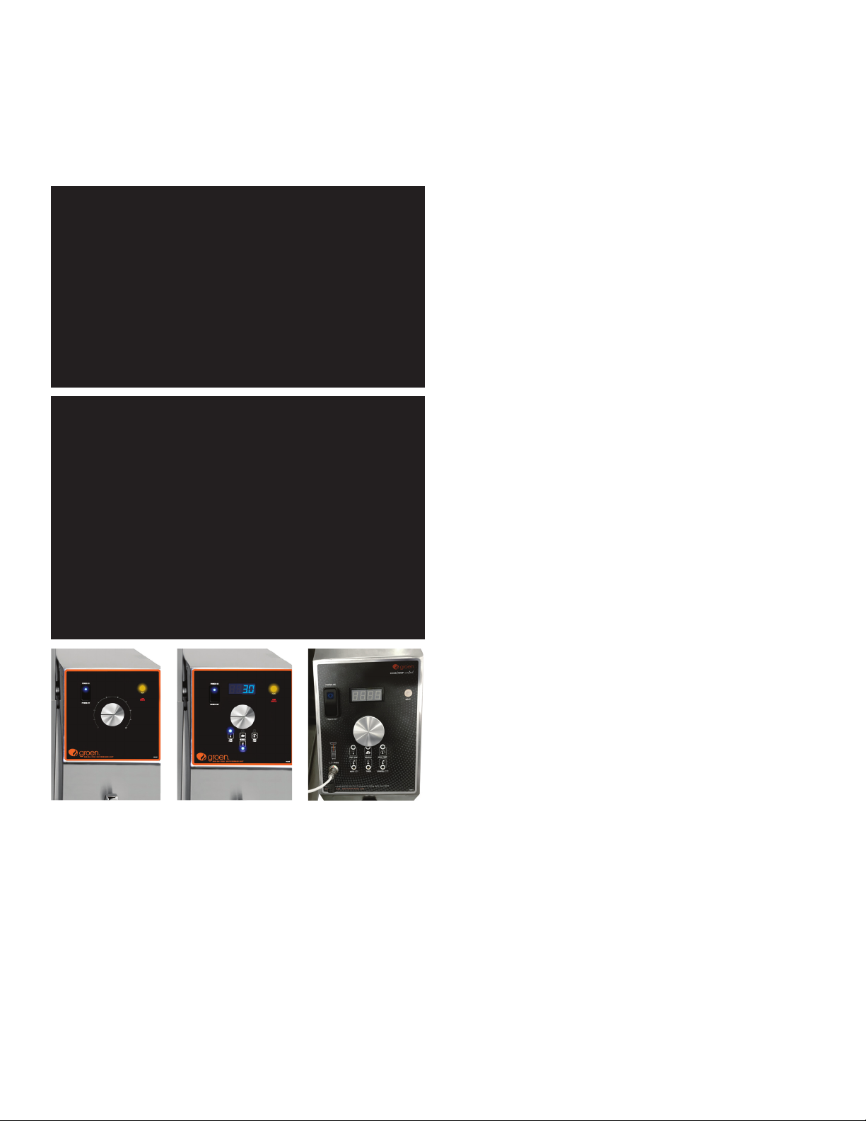
1. Classic Control (-C) Models
POSSIBLE.
OF HOT CONTENTS.
BODY TO UPRIGHT POSITION AFTER CONTAINER IS FILLED OR TRANSFER IS
COMPLETE.
AND ITS CONTENTS.
THE KETTLE. DIRECT CONTACT COULD RESULT IN SEVERE BURNS.
KEEP LIQUIDS AT LEAST 2-3” (5-8 CM) BELOW THE KETTLE RIM TO ALLOW
CLEARANCE FOR STIRRING, BOILING AND SAFE PRODUCT TRANSFER.
DIRECT CONTACT COULD RESULT IN SEVERE BURNS.
PRESSURE RELIEF VALVE.
MAY SLIDE OFF, CAUSING INJURY TO OPERATOR.
CORRECT OPERATING PROCEDURES.
MATERIALS. DO NOT ATTEMPT TO LIGHT ANY BURNER WITH A FLAME.
Classic Control
Advanced Control
Cook2Temp Control
a. The manual gas shut-off valve supplies inlet gas to the unit.
b. Lighted Power ON switch located on the control console. Controls main
power to the unit.
c. The temperature knob, located on the control console, is used to set the
kettle heat values between 1 and 10.
d. Heating indicator light located on the control console, lights when the
controller sends call to open the main gas valve and will cycle on and off
once the unit reaches set temperature. If the unit is tilted, the main gas
valve will be disabled and the light will turn off until the unit is returned to
the cooking position.
e. A LOW WATER indicator light, located on the control console, illuminates
when the jacket water falls below acceptable levels. When lit, the main
gas valve is disabled and will not function until the jacket water is refilled
using the procedure in this manual.
f. Crank tilt – a handle controls the worm and gear mechanism that smoothly
tilts the kettle body and holds it in the desired position.
2. Advanced Control (-A) Models
a. The manual gas shut-off valve supplies inlet gas to the unit.
b. Lighted Power ON switch located on the control console. Controls main
power to the unit.
c. The temperature knob, located on the control console, is used to set
the kettle heat values between 1.0 and 10.0. The current setting will be
reflected on the display.
d. Heating indicator light located on the control console, lights when the
controller sends call to open the main gas valve and will cycle on and off
once the unit reaches set temperature. If the unit is tilted, the main gas
valve will be disabled and the light will turn off until the unit is returned to
the cooking position.
e. A LOW WATER indicator light, located on the control console, illuminates
when the jacket water falls below acceptable levels. When lit, the main
gas valve is disabled and will not function until the jacket water is refilled
using the procedure in this manual.
f. SET TnnP Mode - Allows power to the controller and gas to the pilot without
the kettle heating; the kettle will heat once the LOW TEMP, MANUAL or
HIGH TEMP button is selected.
g. LOW TEMP Button – Used to set operating temperature of the kettle at a
preset low intensity (default = 2.0). Can be pressed at any time during
operation of the unit to change the set temperature to the preset value
except when there is an active TIMER enabled.
h. MANUAL Mode button – Enables the user modify the desired cooking
temperature of the kettle (between 1.0 and 10.0) using the temperature
knob and display (default = 5.0). The operator will press the MANUAL
button and set the desired temperature using the temperature knob and
display. Once the desired intensity is displayed, the user may either press
the MANUAL button again or wait 5 seconds and the set temperature will
be accepted by the controller and locked in. After the set temperature is
accepted, it may be changed at any time by pressing the MANUAL button
and resetting the temperature using the same process above.
i. HIGH TEMP button – Used to set operating temperature of the kettle at a
preset high intensity (default = 7.0). Can be pressed at any time during
operation of the unit to change the set temperature to the preset value
except when there is an active TIMER enabled.
1. TIMER button - once the appropriate set temperature is selected using
the HIGH TEMP, MANUAL or LOW TEMP buttons; a countdown timer
can be set to remind the user when the cooking process is completed.
Range – 1 minute to 10 hours
2. When the timer expires:
a. the set temperature will automatically change to the LOW TEMP
setting and will continue at this setting until the user changes the
temperature via MANUAL or HIGH TEMP buttons
b. An audible alarm will notify the user that attention is required,
the alarm will continue to sound until the user presses the TIMER
button.
3. An active timer can be cancelled by pressing and holding the TIMER
button for 5 secs.
4. Set temp can be changed during an active timer by pressing the
MANUAL button and adjusting the set temp using the Temperature
knob and display.
5. HIGH TEMP and LOW TEMP presets cannot be used to change the
setpoint once a TIMER has started.
4 OM-DH(T)-20/40/60/80 (C,A,C2T™) Domestic
Page 5

j. READY alarm – The control will sound 3 beeps when the unit has reached
within 20 degrees of set point during pre-heat and when a higher set
temperature is selected.
k. Crank tilt – a handle controls the worm and gear mechanism that smoothly
tilts the kettle body and holds it in the desired position.
3. Cook2Temp™ Control (-C2T™) Models
a. Lighted Power ON switch located on the control console. Controls main
power to the unit.
b. Heating indicator light located on the control console, lights when the
controller calls for the main gas valve to open and will cycle on and off
once the unit reaches set temperature. If the unit is tilted, the call for heat
will be interrupted and the light will turn off until the unit is returned to the
cooking position.
c. Low Water indicator light, located on the control console, lights when the
jacket water falls below the acceptable levels. When lit, the main gas valve
is disabled and will not function until the jacket water is refilled using the
procedure in the operator manual.
d. Set Mode – Allows power to the controller and the pilot to light, but
the main burners remain off. The kettle will heat once the LOW TEMP,
MANAUAL or HIGH TEMP button is selected.
e. LOW TEMP Button – Used to set a unit temperature of the kettle at a preset
low temperature (default = 175°F). Can be pressed at any time during
operation of the unit to change the unit temperature to the preset value
except when there is an active TIMER or an active Cook2Temp.
f. MANUAL Button – Enables the user to modify the unit temperature of
the kettle (between 100°F and 287°F) using the temperature knob and
display (default = 183°F). The operator will press the MANUAL button and
then select the desired unit temperature using the temperature knob and
display. Once the desired unit temperature is shown on the display, the
user may either press the MANUAL button again or wait 5 seconds and
the selected temperature will be accepted by the controller and locked in.
After the selected temperature is accepted it may be changed at any time
by pressing the MANUAL button and resetting the temperature using the
same process as above except when there is an active AUTO Cook2Temp.
g. HIGH TEMP Button – Used to set unit temperature of the kettle at a preset
high temperature (default = 287°F). Can be pressed at any time during
operation of the unit to change the unit temperature to the preset value
except when there is an active TIMER or an active Cook2Temp.
h. TIMER Button – Once the appropriate unit temperature is selected using
the LOW TEMP, MANUAL or HIGH TEMP buttons, a countdown timer can be
set to remind the user when the cooking process is completed.
1. Range – 1 minute to 10 hours.
2. When the timer expires:
a. The unit temperature will automatically change to the LOW TEMP
setting and will continue at this setting until the user changes the
temperature via MANUAL or HIGH TEMP buttons.
b. An audible alarm will notify the user that attention is required,
the alarm will continue to sound until the user presses the TIMER
button.
3. An active timer can be cancelled by pressing and holding the TIMER
button for 5 seconds.
4. Unit temperature can be changed during an active timer by pressing
the MANUAL button and adjusting the unit temperature using the
temperature knob and display.
5. LOW TEMP and HIGH TEMP presets cannot be used to change the unit
temperature once a TIMER has been enabled.
6. AUTO C2T and MANUAL C2T cannot be used once a timer has been
enabled. The timer must first be cancelled and then AUTO C2T or
MANUAL C2T can be enabled.
i. Ready alarm – The control will sound 3 beeps when the unit has reached
within 20 degrees of set point during pre-heat and when a higher unit
temperature is selected.
j. AUTO C2T Button – Enables the user to select a set product temperature
(between 100°F and 230°F) using the temperature knob and display.
The operator will press the AUTO C2T button and then select the set
product temperature using the temperature knob and display. Once the
set product temperature is shown on the display, the user may either
press the AUTO C2T button again or wait 5 seconds and the selected
temperature will be accepted by the controller and locked in. The unit
temperature is automatically set 100°F above the set product temperature
and cannot be changed at any time during an active AUTO C2T. After the
set product temperature is accepted it may be changed at any time by first
cancelling AUTO C2T and then using the same process as above to reset
the temperature.
1. After the set product temperature is accepted by the controller and
locked in. The unit will begin to heat and the display will scroll the
actual product temperature followed by the set product temperature.
This display will continue until the cook process has completed.
2. An active AUTO C2T can be cancelled by pressing and holding the
AUTO C2T button for 5 seconds and the unit will then return to Set
Mode.
3. LOW TEMP, MANUAL or HIGH TEMP presets cannot be used to change
the unit temperature once there is an active AUTO C2T. The unit
temperature is automatically set by the controller.
4. Once the set product temperature has been reached and held for 20
seconds consecutively the unit will automatically enable Hold Mode.
k. MANUAL C2T Button – Enables the user to select a set product
temperature (between 100°F and 230°F) using the temperature knob and
display. The operator will press the MANUAL C2T button and then select
the set product temperature using the temperature knob and display.
Once the set product temperature is shown on the display, the user may
either press the MANUAL C2T button again or wait 5 seconds and the
selected temperature will be accepted by the controller and locked in.
Once the set product temperature has been accepted the user will be
prompted to select a unit temperature via the MANUAL button. Once
the set unit temperature is shown on the display, the user may either
press the MANUAL C2T button again or wait 5 seconds and the selected
temperature will be accepted by the controller and locked in. After the set
product temperature and unit temperature are accepted the set product
temperature may be changed at any time by first cancelling MANUAL C2T
and then using the same process as above to reset the temperature.
1. After the set product temperature and unit temperature are accepted
by the controller and locked in. The unit will begin to heat and the
display will scroll the actual product temperature followed by the set
product temperature. This display will continue until the cook process
has completed.
2. An active MANUAL C2T can be cancelled by pressing and holding the
MANUAL C2T button for 5 seconds and the unit will then return to Set
Mode.
3. Unit temperature can be changed during an active MANUAL C2T by
pressing the MANUAL button and adjusting the unit temperature using
the temperature knob and display.
4. Once the set product temperature has been reached and held for 20
seconds consecutively the unit will automatically enable Hold Mode.
l. Hold Mode – Allows the unit to be controlled by the set product temperature
and core probe.
1. Hold Mode is automatically enabled once a set product temperature
has been reached and held for 20 seconds consecutively.
2. The display will scroll the actual product temperature followed by the
hold timer.
5 OM-DH(T)-20/40/60/80 (C,A,C2T™) Domestic
Page 6

3. If the actual product temperature falls below 142°F.
a. An audible alarm along with the display flashing the actual
product temperature will notify the user that attention is required.
b. The alarm can be silenced by pressing any button.
c. The Alarm will resound every 10 minutes until the actual product
temperature returns above 142°F.
4. If the actual product temperature rises 10°F above the set product
temperature.
a. An audible alarm along with the display flashing the actual
product temperature will notify the user that attention is required.
b. The alarm can be silenced pressing any button.
c. The alarm will resound every 10 minutes until the actual product
temperature returns to within 10°F of the set product temperature.
5. At initial hold timer completion (default = 4 hours).
a. An audible alarm will be given for 5 seconds.
b. The alarm can be silenced by pressing any button.
c. The alarm will continue to resound every 15 minutes until Hold
Mode is exited.
m. Display Descriptions
1. SEt nndE – Allows power to the controller without the pan heating, the
pan will heat once the LOW TEMP, MANUAL or HIGH TEMP button is
selected.
2. SEt PrOd tEnP – Indicates the desired finished product temperature.
3. SEt UnIt tEnP – Indicates the desired unit temperature.
4. SEt POInt – Indicates the set point for the desired finished product
temperature.
5. ACt – Indicates the actual product temperature.
6. CPEr – Indicates a core probe error and will continue to display until
the error has been resolved.
7. Prob – Indicates a unit probe error and will continue to display until
the error has been resolved.
8. End – Indicates the cooking process has completed.
9. End HOLd – Indicates the initial hold timer has completed.
4. Cook2Temp™ Control (-C2T™) Core Probe
a. Ensure the core probe has been properly cleaned and sanitized before
each use.
b. It is important that the tip of the core probe be placed correctly into
the product since only the tip of the core probe senses the product
temperature. Do this by inserting the core probe halfway into the product,
positioning the tip at the center of the food mass, avoiding any bones.
If placing into a semi-liquid or liquid product, occasionally stirring the
product will ensure an accurate core probe reading. Do not let the core
probe tip touch the edges, bottom or side of the unit.
c.
If the core probe is not plugged into the receptacle when either the AUTO C2T
or MANUAL C2T button is pressed then an audible alarm along with a core
probe error message will notify the user that attention is required. Simply
plug the core probe into the receptacle and continue with the input process.
d. If the core probe is unplugged from the receptacle during the cooking
process or while in Hold Mode an audible alarm along with a core probe
error message will notify the user that attention is required. Simply plug
the core probe back into the receptacle and the cook process or Hold
Mode will continue.
e. While the core probe is not in use ensure the sealing cap is properly
protecting the panel mount connector. Failure to properly use the sealing
cap could result in damage to the unit.
OPERATING PROCEDURE
1. To Start Kettle Heating:
a. EVERY DAY make sure that the jacket water level in the middle of the sight
glass. If the level is too low, see “Jacket Filling and Water Treatment” in
this manual.
b. Check the pressure/vacuum gauge. If the gauge does not show 20 to
30 inches of mercury (Hg) vacuum (that is a reading of 20 to 30 below 0
atmospheric pressure), see “Jacket Vacuum” in this manual.
c. DO NOT attempt to light any burner with a flame.
d. Open the main supply gas valve (handle in line with the pipe).
e. Turn the switch to ON.
f. Set heat using instructions above.
2. To Stop Kettle Heating:
a. Turn the switch OFF.
b. Turn the manual gas valve OFF (handle a right angle to gas line).
c. Disconnect the units electrical power.
3. To Relight Kettle:
a. Close main gas supply valve.
b. Set on-off switch to OFF.
c. Wait five minutes, then proceed as directed under To Start Kettle Heating.
4. If electric power fails, do not attempt to operate the unit. When power is
restored, proceed as directed in To Start Kettle Heating.
5. To Transfer Product or Empty Kettle:
a. To tilt the body of the kettle forward, turn the hand crank on the front of the
cabinet counter-clockwise. The body will stay in the position it holds when
you stop cranking. To return the kettle body to its upright position, turn the
crank clockwise.
b. Product may also be transferred by means of the optional draw-off valve,
if the kettle is so equipped.
USE OF COMMON ACCESSORIES
1. Lift-Off or Counterbalanced Cover:
a. As with stock pot cooking, an optional cover can speed up the heating of
water and food products. It helps retain heat and reduces the heat and
humidity in the kitchen. A cover can reduce some product cook times
and help maintain the temperature, color and texture of products held or
simmered for longer periods.
b. Be sure the handle is secure on the lift-off cover before using. ALWAYS use
the handle to place or remove cover from the kettle. Wear protective oven
mitts and apron.
c. When putting the cover on the kettle, position it on top of kettle rim, with
its flat edge facing the pouring lip.
d. When removing cover:
1) Firmly grasp plastic handle.
2) Lift rear edge (farthest from operator) 1-2” (3-5 cm) to allow any steam
and water vapor to escape the cooking vessel. Wait 2-3 seconds.
3) Tilt cover to 45-60° angle and allow any hot condensate or product to
roll off cover back into kettle.
4) Remove cover, ensuring that any remaining hot condensate or product
does not drip on operator, floor or work surfaces.
5) Place cover on safe, flat, sanitary, out-of-the-way surface, or return to
kettle rim.
2. Basket Insert:
a. An optional kettle basket insert can assist in cooking water-boiled
6 OM-DH(T)-20/40/60/80 (C,A,C2T™) Domestic
Page 7

products including eggs, potatoes, vegetables, shell fish, pasta and rice.
WEAR EYE
PROTECTION
OM-TD
another container, being sure to avoid
contact with hot product and hot basket
or. . .
f) Place basket with food on stable, at
surface, setting it inside a solid steamer
or bake pan, to catch any remaining hot
water which might drain from product.
c. Prepare a hot solution of the detergent/
cleaning compound as instructed by the
supplier.
OM-TD
OM-TD
another container, being sure to avoid
contact with hot product and hot basket
or. . .
f) Place basket with food on stable, at
surface, setting it inside a solid steamer
or bake pan, to catch any remaining hot
water which might drain from product.
c. Prepare a hot solution of the detergent/
cleaning compound as instructed by the
supplier.
OM-TD
The nylon mesh liner must be used when cooking product smaller than
the mesh size of the basket, which is approximately 1/4” (6 mm). This
includes rice and small pasta shapes.
b. Tips For Use:
1) Allow for the water displacement of the basket and product to be
cooked. This may mean only filling the kettle half full of water. Test the
basket and product displacement with the kettle OFF, and with cold
water in the kettle.
2) Load basket on a level, stable work surface.
3) Lift the loaded basket with both hands. Get help from another person
if the basket is too heavy for safe handling. Then slowly lower product
into kettle.
4) When removing basket with cooked product, lift basket straight up,
ensuring bottom of basket clears the rim and pouring lip of the kettle.
Wear protective oven mitts and protective apron.
5) Allow hot water to fully drain from product, before moving basket
away from the kettle. Do not rest kettle basket on kettle rim or pouring
lip. If basket is too heavy for individual to lift and safely move, get help
from another person. Remove product immediately from basket into
another container, being sure to avoid contact with hot product and
hot basket or place basket with food on stable, flat surface, setting it
inside a solid steamer or bake pan, to catch any remaining hot water
draining from product.
CLEANING
WARNING: KEEP WATER AND SOLUTIONS AWAY FROM CONTROLS AND ELECTRICAL
CAUTION: MOST CLEANERS ARE HARMFUL TO THE SKIN, EYES, MUCOUS
CAUTION: NEVER LEAVE A SANITIZER IN CONTACT WITH STAINLESS STEEL SURFACES
CAUTION: DO NOT MIX PARTS OF DIFFERENT DRAWOFF VALVE ASSEMBLIES. THE
WARNING: AVOID DIRECT CONTACT WITH HOT SURFACES. DIRECT SKIN CONTACT
EQUIPMENT. NEVER SPRAY THE SUPPORT HOUSING OR ELECTRICAL
CONNECTIONS.
MEMBRANES, AND CLOTHING. PRECAUTIONS SHOULD BE TAKEN. WEAR
RUBBER GLOVES, GOGGLES OR FACE SHIELD, AND PROTECTIVE CLOTHING.
READ THE WARNINGS AND FOLLOW THE DIRECTIONS ON THE LABEL OF
THE CLEANER CAREFULLY.
LONGER THAN 30 MINUTES. LONGER CONTACT CAN CAUSE CORROSION.
PARTS ARE NOT INTERCHANGEABLE.
COULD RESULT IN SEVERE BURNS.
Use a brush, sponge, cloth, plastic or
rubber scraper, or plastic wool to clean.
Don’t use metal implements
or steel wool when cleaning.
PRECAUTIONS
Before cleaning, shut off the kettle by turning the main power switch to “OFF,” and
shut off all electric power to the unit at a remote switch, such as the circuit breaker.
PROCEDURE
1. Clean food-contact surfaces as soon as possible after use. If the unit is in
continuous use, thoroughly clean and sanitize the interior and exterior at least
once every 12 hours.
2. Scrape and flush out food residues. Be careful not to scratch the kettle with
metal implements. (For DHT models only: After flushing the kettle, close the
draw-off valve.)
3. Prepare a hot solution of the detergent/ cleaning compound as instructed
by the supplier. Clean the unit thoroughly. A cloth moistened with cleaning
solution can be used to clean controls, housings, and electrical conduits.
4. Model DHT only: Disassemble the tangent draw-off valve. Clean the draw-off
port and each valve part with a brush.
5. Rinse the kettle and draw-off valve parts thoroughly with hot water, then drain
completely.
6. As part of the daily cleaning program, clean soiled external and internal
surfaces. Remember to check the sides of the unit and control housing,
underside of cover, etc.
7. To remove burnt on foods, use a brush, sponge, cloth, plastic or rubber scraper,
or plastic wool with the cleaning solution. To reduce effort required in washing,
let the detergent solution sit in the kettle and soak into the residue. Do NOT use
abrasive materials or metal tools that might scratch the surface. Scratches
make the surface harder to clean and provide places for bacteria to grow.
Do NOT use steel wool, which may leave particles in the surface and cause
eventual corrosion and pitting.
8. The outside of the unit may be cleaned with a warm water (100°F or less)
spray. Do not use a high pressure spray.
9. The outside of the unit may be polished with a stainless steel cleaner such as
“Zepper” from Zep Manufacturing Co.
10. When equipment needs to be sanitized, use a solution equivalent to one that
supplies 200 parts per million available chlorine. Obtain advice on sanitizing
agents from your supplier of sanitizing products.
11. It is recommended that each piece of equipment be sanitized just before use.
12. Clean the kettle thoroughly. If there is difficulty removing mineral deposits or a
film left by hard water or food residues, then use a de-liming agent, following
manufacturer directions.
13. Rinse and drain the unit thoroughly before further use.
14. If cleaning problems persist, contact your cleaning product representative for
assistance. The supplier has a trained technical staff with laboratory facilities
to serve you.
CLEANING CORE PROBE
Remove all food soil from core probe by wiping entire core probe and cable
assembly with warm detergent solution and a clean cloth. Remove detergent
solution by wiping core probe and cable assembly with clean rinse water and a
cloth. Allow core probe and cable assembly to air dry. Do not immerse core probe.
Hand wash only and immediately let air dry.
SUGGESTED CLEANING SUPPLIES
1. Cleaner, such as Klenzade HC-10 or HC-32 from ECOLAB, Inc. or equivalent.
2. Kettle brushes in good condition
3. Sanitizer such as Klenzade XY-12.
4. Film remover such as Klenzade LC-30.
7 OM-DH(T)-20/40/60/80 (C,A,C2T™) Domestic
Page 8
MAINTENANCE
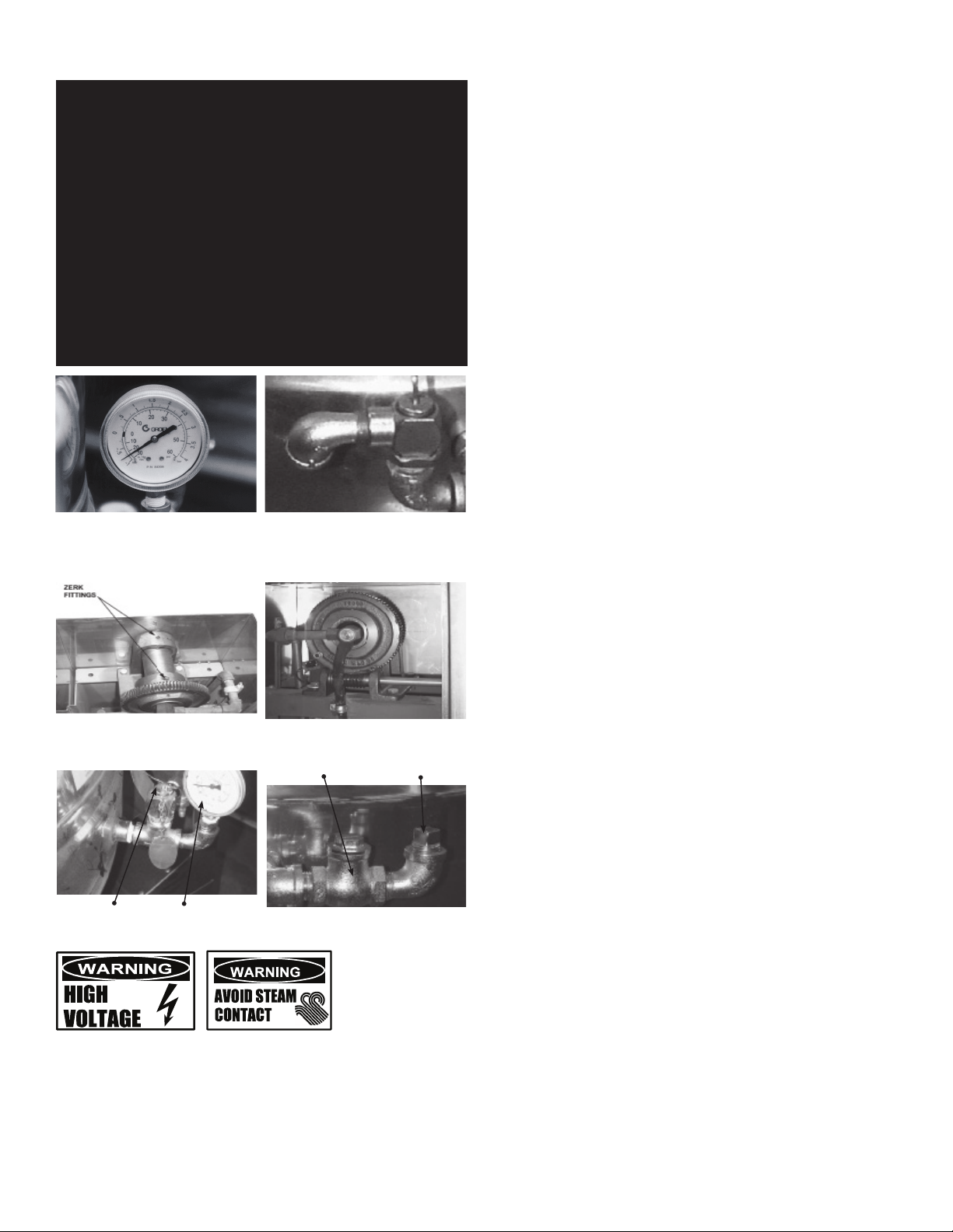
Safety Valve Pressure Gauge
Check Valve Pipe Plug
WARNING: AVOID ANY EXPOSURE TO THE STEAM BLOWING OUT OF THE PRESSURE
CAUTION: KEEP GREASE AWAY FROM ELECTRICAL PARTS LOCATED NEAR THE
WARNING: TO AVOID INJURY, READ AND FOLLOW ALL PRECAUTIONS STATED ON THE
WARNING: USE OF ANY REPLACEMENT PARTS OTHER THAN THOSE SUPPLIED BY
CAUTION: INSURE ELECTRICAL POWER IS REMOVED AND THE GAS IS TURNED OFF AT
WARNING: THIS KETTLE IS DESIGNED TO BE WATER RESISTANT. FAILURE TO FOLLOW
The pressure gauge should show a vacuum of 20 to
PERIODIC MAINTENANCE
NOTICE: Contact an authorized representative when repairs are required.
A Maintenance & Service Log is provided at the back of this manual. Each time
maintenance is performed on your kettle, enter the date on which the work was
done, what was done, and who did it. Keep this manual on file and available
for operators to use. Periodic inspection will minimize equipment down time and
increase the efficiency of operation. The following points should be checked:
RELIEF VALVE. SEVERE BURNS CAN RESULT ON EXPOSED SKIN. FAILURE
TO CHECK PRESSURE RELIEF VALVE OPERATION PERIODICALLY COULD
RESULT IN PERSONAL INJURY AND/OR DAMAGE TO EQUIPMENT.
GEARS.
LABEL OF THE WATER TREATMENT COMPOUND.
THE MANUFACTURER OR THEIR AUTHORIZED DISTRIBUTORS CAN CAUSE
INJURY TO THE OPERATOR AND DAMAGE TO THE EQUIPMENT AND WILL
VOID ALL WARRANTIES.
THE SHUTOFF VALVE PRIOR TO PERFORMING ANY MAINTENANCE ON THIS
KETTLE.
PROPER MAINTENANCE PROCEDURES MAY VOID THE WARRANTY.
30 inches when the kettle is cold.
Add grease through Zerk Fittings.
The open end of the pressure relief valve
elbow must face downward.
Liberally grease the wheel where
it contacts the worm gear.
Test the safety valve at least twice monthly.
1. Check the pressure/vacuum gauge every day. The gauge should show a
vacuum of 20 to 30 inches mercury (Hg), when the kettle is cold. If it does not,
see “Jacket Vacuum” in this manual.
2. Also check the jacket water level every day. It should be in the middle of the
sight glass. If the level is low, see “Jacket Filling and Water Treatment” in this
manual.
3. Carefully test the pressure relief valve at least twice each month. With the
kettle operating at five psi (105 kPa), pull the test lever and let it snap back
to its closed position. If there is little discharge (mostly air), and the pressure
gauge drops back to zero PSI, allow the pressure to build back to five PSI and
repeat the procedure. (Tip: Using a screwdriver or other implement to pull the
ring will help you avoid contact with the steam.)
4. If the valve does not activate, or there is no evidence of discharge, or the
valve leaks, stop using the kettle and contact a qualified Groen service
representative.
5. Keep the primary burner gas jet air inlets free of dust and lint.
6. The pilot flame should be blue. It should envelop about ½ inch (12 mm) of the
flame sensor tip.
7. The gear housing has fittings for lubrication of moving parts. The gears do not
run in oil, so periodic lubrication with grease is necessary.
8. Frequency of lubrication depends on operating conditions, but it should be
done at least once every six months.
9. Use a #2 grade LGI lithium grease to add grease through Zerk fittings on gear
housing until it flows out of the bearings around the trunnion shaft.
10. Place liberal amounts of grease on the gear to cover the arc that is in contact
with the worm gear.
11. Keep electrical wiring and connections in good condition.
12. Keep the inside of the control console clean and dry.
13. Keep burner slots clean.
JACKET VACUUM/REMOVING AIR FROM JACKET
When the kettle is cold, a positive pressure reading on the pressure/vacuum gauge
or a reading near zero indicates that there is air in the jacket. Air in the jacket acts
as an insulator, and slows kettle heating.
To remove air:
1. Start the unit. (Be sure there is water or product in the kettle when heating).
2. When the pressure/vacuum gauge reaches a positive pressure reading of five
PSI, release the trapped air and steam by pulling up the safety valve ring for
about five seconds. Repeat this step three or four times. Then let the pull ring
snap back into the closed position.
3. If there is little discharge (mostly air), and the pressure gauge drops back to
zero PSI, allow the pressure to build back to five PSI and repeat the procedure.
4. Once steam has been vented from the jacket as described in b, above, remove
the hot water from the kettle and replace it with cold. This will condense steam
in the kettle jacket, and the pressure gauge should show a reading of 20 to
30 inches mercury (Hg) below zero. If it does not, or if the vacuum is leaking
down, contact a Groen authorized service agency to correct the problem.
JACKET FILLING AND WATER TREATMENT
The jacket was charged at the factory with the proper amount of treated water.
You may need to restore this water, either because it was lost as venting steam or
by draining. If you are replacing water lost as steam, use distilled water. If you are
replacing treated water that ran out of the jacket, prepare more treated water as
directed in “Water Treatment Procedure,” below.
1. Allow the kettle to cool completely. The procedure will be easier with the kettle
under vacuum (pressure gauge reading below zero).
2. Make sure the fill valve is closed, and remove the square head pipe plug with
open-ended wrench.
3. Position a funnel in the opening and fill it with properly treated water.
8 OM-DH(T)-20/40/60/80 (C,A,C2T™) Domestic
Page 9

4. Slowly open the fill valve to allow water to be sucked into the jacket. Quickly
close the valve to prevent air from entering.
5. Check water level in the jacket to ensure that it is between minimum and
maximum marks on glass or at the top of the sight glass port for models DH/
DHT-80.
6. Close the valve and reinstall the squarehead pipe plug.
7. Reestablish the jacket vacuum as described above, if the pressure gauge does
not show a negative reading of 20 to 30 inches mercury (Hg).
WATER TREATMENT PROCEDURE
1.
Obtain water treatment compound and a pH test kit from your Groen Service Agent.
2. Fill a mixing container with the measured amount of water required. Use only
distilled water.
Model Recommended Jacket Fill
DH-20, DHT-20 (C,A,C2T) 1-3/4 gallons
DH/1-40, DHT/1-40 (C,A,C2T) 1-1/2 gallons
DH-60, DHT-60 (C,A,C2T) 3 gallons
DH-80, DHT-80 (C,A,C2T) 3 gallons
3. Hang a strip of pH test paper on the rim of the container, with about 1 inch of
the strip below the surface of the water.
4. Measure the water treatment compound. One way to do this is to add the
compound from a measuring cup.
5. Stir the water continuously, while you slowly add treatment compound, until
the water has a pH between 10.5 and 11.5. Judge the pH by frequently
comparing the test strip color with the color chart provided in the test kit.
Caution: Do not add excess amount of treatment compound. Excess amount
could cause extensive corrosion.
6. As you add water to the jacket, check water level to ensure that it is between
minimum and maximum marks on glass or at the top of the sight glass port for
models DH/DHT-80 (see photo on page 8). Stop adding water when it reaches
the maximum marker on the gauge.
7. Record the exact amounts of water and treatment compound needed. These
amounts may be used again, if the same water sources and compound are
used. However, it is best to check the pH each time treated water is prepared.
COMPONENT REPLACEMENT
When component replacement involves breaking a gas pipe connection, check the
new connection with soap solution or an appropriate leak detector. DO NOT USE A
FLAME TO TEST FOR LEAKS.
Internal wiring is marked as shown on the circuit schematic drawings (inside
control housing and in this manual). Be sure that new components are wired in the
same manner as old components. An examination of the circuit schematic shows
that the safety components are wired in series. In most cases, a faulty component
may be isolated with a jumper wire to verify that the component is faulty. If this
determination is made, contact a certified Groen Service Agency for assistance.
SEQUENCE OF OPERATION
The following “action-reaction” outline is provided to help understand how the
kettle works.
1. When the power switch is turned on, it starts the spark igniter and opens the
automatic valve for the pilot burner. The spark ignites a pilot flame, which
heats the sensor. The sensor then sends a signal to turn off the spark. The
flame thereafter acts as a standing pilot until the power is turned off.
2. If the pilot flame is not sensed within 90 seconds after spark begins, a timer
shuts down the entire operation. To attempt a second trial for ignition, turn
off the power switch. Check the gas supply valves and wait five minutes
before trying again by switching power on. If you cannot establish a pilot
flame in four tries, close all valves, turn off the power, and contact an
authorized Service Agency.
3. When the operator sets a temperature on the controller, it causes the
automatic valve to admit gas to the main burner, where it is ignited by the
pilot flame. When the kettle reaches the set temperature, the relay switch
opens. This stops the signal to the gas control valve and shuts off gas to the
main burner. The pilot flame remains lit. When the kettle cools below the set
temperature, the relay switch closes and starts another cycle. On and off
cycling continues and maintains the kettle at the desired temperature. This
action is indicated by the Heat indicator light.
The kettle has the following safety features in addition to the 90-second ignition timer:
1. Low water cutoff relay that will shut off gas supplies to all burners until the
jacket water level is corrected.
2. High limit pressure switch, set to open at about 43 PSI and to shut down the
burners until jacket pressure is decreased.
3. Pop safety valve, which will release steam if jacket pressure exceeds 50 PSI.
4. Tilt switch, which shuts off all burners when the kettle is tilted.
5. Gas pressure regulator built into the gas control valve.
REPLACEMENT PARTS
To order parts, contact your Authorized Service Agent. Supply the model
designation, serial number, part description, part number, quantity, and when
applicable, voltage and phase.
CONTACT US
If you have questions pertaining to the content in this manual, contact Unified
Brands at 888-994-7636.
9 OM-DH(T)-20/40/60/80 (C,A,C2T™) Domestic
Page 10

TROUBLESHOOTING
This unit is designed to operate smoothly and efficiently if properly maintained.
However, the following is a list of checks to make in the event of a problem.
Wiring diagrams are found at the end of this manual. When in doubt, turn unit
off and call for service at 888-994-7636. If an item on the check list is marked
with (X), it means that the work should be done by an Authorized Service Agent.
SYMPTOM WHO
Display not lit
(Advanced & C2T only)
PROB in display
(Advanced & C2T only)
HI in display
(Advanced & C2T only)
Kettle is hard to tilt User a.
Kettle continues
heating after it
reaches the
desired temperature
Kettle stops heating
before it reaches the
desired temperature
Safety Valve pops
open
Burners will not light User
System does not
produce a
spark
Safety valve leaks
a small amount of
steam when kettle
is operating
User a. That power supply is on.
Auth Service
Rep Only
Auth Service
Rep Only
Auth Service
Rep Only
Auth Service
Rep Only
User a.
Auth Service
Rep Only
User a.
Auth Service
Rep Only
User
Auth Service
Rep Only
Auth Service
Rep Only
Auth Service
Rep Only
User a. For contamination that prevents seating of the valve. With full
Auth Service
Rep Only
X indicates items which must be performed by authorized technician.
Fuses, accessible by removing caps on the side of the control box.
b.
c. For loose or broken wires. X
d. Temperature controller functioning, by listening for a click
when the switch opens or closes and verifying LEDs on back
of board. X
e. Contactor functioning. X
a. For loose or broken wires or damaged/failed RTD probe. X
b. PCB board malfunction/failure
a. For loose or broken wires or damaged/failed RTD probe. X
b. PCB board malfunction/failure
Gears for foreign materials, and lubrication.
Gears for alignment. X
b.
c. Worm gears or broken gears. X
Temperature Controller dial setting.
Temperature Controller calibration and offset.X
b.
c. Temperature Controller operation. The Temperature Controller
should click when the dial is rotated to settings above and
below the temperature of the kettle.X
Temperature Controller dial setting.
Temperature Controller calibration and offset.X
b.
c. Temperature Controller operation. The Temperature Controller
should click when the dial is rotated to settings above and
below the temperature of the kettle.X
a. For air in the jacket. See “Jacket Vacuum” in the Maintenance
b. Temperature Controller dial setting.
c. For defective Temperature Controller. The relay should click
when the dial is rotated to settings above and below the
temperature of the kettle. If defective, replace.X
d. For defective safety valve. If the valve pops at pressures below
49 PSI, replace.X
a. That the main gas supply valve is open. (handle is in line with
gas pipe).
b. Gas supply to the building.
c. That the kettle body is not tilted.
d. Temperature Controller operation. The relay should click
when the dial is rotated to settings above and below the
temperature of the kettle.X
e. That tilt limit switch is closed when body is not tilted.X
AC voltage between terminals on secondary side of
a.
transformer. If it is not 24 Volt, replace the transformer. X
b. That the high tension cable is firmly attached and in good
condition. If cracked or brittle, replace.X
c. Pilot electric ceramic for crack or break.X
d. Pilot spark gap. Regap.X
pressure in the jacket, pull the leer all the way briefly to blow the
valve clean, then let the lever snap back to seat the valve
b. Safety valve for defects. Replace any defectuve valve with an
identical valve. X
WHAT TO CHECK
Spark is present
but the pilot will
not light
Pilot lights, but
main burner will
not come on and
spark does not
stay on
Pilot lights, but
main burner will
not come on, the
spark stays on
Main burner
comes on but will
not stay on
CPER in display
(C2T only)
Auth Service
Rep Only
Auth Service
Rep Only
Auth Service
Rep Only
Auth Service
Rep Only
User a. That core probe is plugged into the receptacle.
Authorized
Service Rep
Only
a. That the pilot valve is securely connected to terminals. X
b. For 24 VAC at terminals PV and PV/MV. If 24V is not present,
replace the ignition control module. X
b. That gas pressure is at least 3.5” W.C. (8.7818 ub).
c. For gas at the pilot. If it is not flowing:
(1) Check the pilot gas line for kinks and obstructions. X
(2) Clean orifice, if necessary. X
(3) Check magnetic operator for pilot valve on gas valve.
Repair or replace as necessary. X
d. That the pilot spark gap is located in the pilot gas stream. If
not, adjust or replace the pilot burner. X
e. For drafts. Shield the pilot burner, if necessary. X
For 24 V between terminals MV and PV/MV while pilot is burning.
a.
If 24V is not present, replace the ignition control module. X
b. That gas pressure is at least 3.5” W.C.(8.7818 ub). X
c. Electrical connections of the main valve to terminals, to
assure that they are securely attached. Check magnetic
operator for main valve on gas valve. Repair or replace
as necessary. X
Check for bad burner ground. If necessary, repair with
a.
high temperature wire. X
b. Pilot burner ceramic insulator for cracks. X
c. That cable is not grounded out. If it is, correct the
ground-out condition or replace cable. X
d. For proper gas pressure. X
e. Clean pilot assembly, or replace if necessary. X
f. Tighten all mechanical and electrical connections. X
g. If the pilot flame is weak, increase pilot orifice size. X
h. Replace ignition control module. X
Check burner ground for bad wire or connection. Replace
a.
if necessary with high temperature wire. X
b. Check for low gas supply pressure. If necessary, replace
ignition control module. X
b. For loose or broken wires or damaged/failed RTD probe. X
c. PCB board malfunction/failure. X
10 OM-DH(T)-20/40/60/80 (C,A,C2T™) Domestic
Page 11

QUANTITY
Parts List
STAND & HOUSING ASSEMBLY
Ref Description Part #
1 WELDMENT, FRAME, STAND 174805 1 - -
1 WELDMENT, FRAME, STAND 174802 - 1 1
2 WELDMENT, CLADDING, STAND 174806 1 - -
2 WELDMENT, CLADDING, STAND 174812 - 1 1
3 WELDMENT, PEDESTAL 175379 1 - -
3 WELDMENT, PEDESTAL 175330 - 1 1
4 WELDMENT, CLADDING, PEDESTAL 175378 1 - -
4 WELDMENT, CLADDING, PEDESTAL 175337 - 1 1
5 PANEL, SIDE, PEDESTAL 175383 1 - -
5 PANEL, SIDE, PEDESTAL 175336 - 1 1
SCREW, MACHINE, HEX HEAD, 1/2-
6
13 X 1-1/2" LONG
7 NUT, HEX, 1/2"-13 005603 4 4 4
8 WASHER, LOCK, 1/2 005657 4 4 4
9 WASHER, PLAIN, 1/2 005049 8 8 8
10 WASHER, LOCK, #8 012971 2 2 2
SCREW, MACHINE, TRUSS HEAD
11
8-32 X 3/8" LONG
FOOT, ADJUSTABLE, BULLET-FITS
2" TUBE
FOOT, ADJUSTABLE, FLANGED-FITS
2" TUBE
008679 4 4 4
137766 14 14 14
013275 4 4 4
096569 4 4 4
20 Gal
40 Gal
60 Gal
11 OM-DH(T)-20/40/60/80 (C,A,C2T™) Domestic
Page 12

Parts List
GAS VALVE, PIPING & BOTTOM COMPONENTS
12 OM-DH(T)-20/40/60/80 (C,A,C2T™) Domestic
Page 13

Parts List
GAS VALVE, PIPING & BOTTOM COMPONENTS
QUANTITY
Ref Description Part #
1 TUBE, COPPER, 1/2" OD, SOFT 007334
2 ELBOW, 90 DEG, 1/2 NPT, FEMALE 055634 1 1 1 -
3 THERMOSTAT, ELECTRIC 009730 1 1 1 1
4 ELBOW, 90 DEG, 1/2 NPT 008747 4 4 4 5
5 NIPPLE, 1/2 NPT X 2-1/2" LONG 005552 1 1 1 1
6 PROBE, WATER LEVEL, LOW 079811 1 1 1 1
TEE, 1/2 TUBE X 1/2 TUBE X 3/8
7
NPT MALE
FITTING, COMPRESSION, STRAIGHT,
8
1/4 NPT FEMALE
9 SWITCH, PRESSURE, 1/4 NPT 096963 1 1 1 1
FITTING, COMPRESSION, 5/8 TUBE
10
X 1/2 NPT MALE
11 VALVE, GAS, NATURAL 123815 1 1 1 1
11 VALVE, GAS, PROPANE 128412 1 1 1 1
12 BRACKET, SUPPORT, BOTTOM 065382 3 3 3 3
SCREW, TRUSS HEAD, 8-32 X 3/8"
13
LONG
14 NUT, HEX, KEPS, 1/4 NT1101 10 10 10 4
16 BAR, 1/8" X 1 X 4-1/4" LONG 005440 1 1 1 1
17 CLAMP, RIGID CONDUIT 068687 1 1 1 1
NIPPLE, 1/2 NPT X 5-1/2" LONG,
18
CHROME PLATED
NIPPLE, 1/2 NPT X 7" LONG,
18
CHROME PLATED
19 BOOT, PROBE 101143 1 1 1 1
20 COVER, BOTTOM 049801 1 - - -
20 COVER, BOTTOM 090630 - 1 1 -
20 COVER, BOTTOM 149774 - - - 1
21 CAP, BOTTOM, COVER PLATE 049803 1 1 1 1
22 GASKET, BOTTOM PLATE 007937 3 FT 3 FT 3 FT 4 FT
FITTING, COMPRESSION, 90 DEG
24
ELBOW, 1/8 NPT MALE X 1/4 TUBE
25 TUBE, ALUMINUM, 1/4" OD 006796
FITTING, COMPRESSION, 5/8 TUBE
X 1/2 NPT FEMALE
SCREW, TRUSS HEAD, 10-32 X
3/8" LONG
- STRAP, EMT CONDUIT, 3/4" 135252 3 3 3 2
- COUPLING, FULL, 1/2" NPT, 150# 005722 1 1 1 1
- ELBOW, 90 DEG, 3/8 NPT
074593 1 1 1 -
097074 1 1 1 1
049093 3 3 3 3
005764 3 3 3 3
096933 1 1 - -
098519 - - 1 -
004584 1 1 1 1
049094 1 1 1 1
004173 2 2 2 2
055335 - - - 1
20 Gal
40 Gal
60 Gal
18 IN18 IN10 IN10
20 IN20 IN20 IN20
IN
IN
Ref Description Part #
80 Gal
- ELBOW, 90 DEG, UNION, 1/2 NPT 005495 1 1 1 -
- NIPPLE, 1/2 NPT X CLOSE 008877 1 - - 1
- NIPPLE, 1/2 NPT X 3" LONG 005553 1 1 1 2
- NIPPLE, 1/2 NPT X 3-1/2" LONG 008227 2 2 2 -
- NIPPLE, 1/2 NPT X 5" LONG 005555 - - - 1
- NIPPLE, 1/2 NPT X 6" LONG 008638 1 - - -
- NIPPLE, 1/2 NPT X 8" LONG 005557 - 2 1 -
NIPPLE, 1/2 NPT X 9.5" LONG,
BLACK IRON
- NIPPLE, 1/2 NPT X 10" LONG 005558 1 - - -
- NIPPLE, 1/2 NPT X 12" LONG 005600 - 1 1 -
- NIPPLE, 1/2 NPT X 13" LONG 005674 - - - 1
- NIPPLE, 1/2 NPT X 14" LONG 149772 - - - 1
- NIPPLE, 1/2 NPT X 15" LONG 048570 - - - 1
- JOINT, SWIVEL, 1/2 NPT (GAS) 076680 1 1 1 1
- VALVE, GAS, SHUT-OFF, 1/2 NPT 098458 1 1 1 1
SCREW, MACHINE, PAN HEAD, 10-
32 X 1/4" LONG
SCREW, MACHINE, ROUND HEAD,
6-32 X 1/2" LONG
- TUBE, GAS PIPING, SUPPLY SIDE 145038 1 - - -
- TUBE, GAS PIPING, TAKE UP SIDE 145037 1 - - -
- TUBE, GAS PIPING, SUPPLY SIDE 145040 - 1 - -
- TUBE, GAS PIPING, TAKE UP SIDE 145039 - 1 - -
- TUBE, GAS PIPING, SUPPLY SIDE 145042 - - 1 -
- TUBE, GAS PIPING, TAKE UP SIDE 145041 - - 1 -
- TUBE, GAS PIPING, SUPPLY SIDE 149765 - - - 1
- TUBE, GAS PIPING, TAKE UP SIDE 150950 - - - 1
- TUBE, GAS PIPING, TAKE UP SIDE 145041 - - 1 -
- TUBE, GAS PIPING, SUPPLY SIDE 149765 - - - 1
- TUBE, GAS PIPING, TAKE UP SIDE 150950 - - - 1
144360 1 1 1
002962 2 2 2 2
012603 2 2 2 2
20 Gal
QUANTITY
40 Gal
60 Gal
80 Gal
13 OM-DH(T)-20/40/60/80 (C,A,C2T™) Domestic
Page 14

Ref Description Part # Qty
1 NUT, LOCK, 1/2, CONDUIT 005487 1
SCREW, TRUSS HEAD, 8-32 X
2
3/8" LONG
3 MODULE BOX 123775 1
4 GASKET, MODULE BOX 104941 1
5 MODULE, IGNITION 085153 1
6 NUT, HEX, KEPS, 6-32 071289 2
ADAPTER, CONDUIT, PLASTIC,
7
MALE
8 COVER, MODULE BOX 104948 1
005764 6
123733 1
Parts List
MODULE BOX
9 NUT, HEX, KEPS, 8-32 069784 1
ANCHOR, CABLE TIE, SCREW-
10
MOUNTED
11 STRAP, CABLE TIE 011093 1
CABLE. HI VOLTAGE, SPARK
12
IGNITION
SCREW, HEX BINDER HEAD,
10-32 X 3/8" LONG
102231 1
096728 1
084201 2
14 OM-DH(T)-20/40/60/80 (C,A,C2T™) Domestic
Page 15

Parts List
BURNER & PILOT/FLAME SENSOR COMPONENTS
QUANTITY
Ref Description Part #
1 BAFFLE PLATE 123496 1 - - -
1 BAFFLE PLATE 123497 - 1 - -
1 BAFFLE PLATE 123498 - - 1 1
2 NUT, HEX,SERRATED, 1/4-20 NT1101 8 8 8 8
3 PILOT BURNER, NAT GAS 123580 1 1 1 1
3 PILOT BURNER, PROPANE 128415 1 1 1 1
4 BRACKET, BURNER SUPPORT 117008 2 - - -
4 BRACKET, BURNER SUPPORT 117009 - 2 - -
4 BRACKET, BURNER SUPPORT 117010 - - 2 2
5 BRACKET, BURNER 117011 2 - - -
5 BRACKET, BURNER 117012 - 2 - -
5 BRACKET, BURNER 117013 - - 2 2
- WASHER, FENDER, 1/4 132107 - - 3 3
6 BURNER MANIFOLD AND ORIFICES NOTE 1 1 1 1 1
CONTACT FACTORY WITH ELEVATION AND GAS TYPE (NATURAL,
PROPANE, OR SPECIAL MIX) TO OBTAIN CORRECTMANIFOLD AND
NOTE 1
ORIFICES.
20 Gal
40 Gal
60 Gal
80 Gal
15 OM-DH(T)-20/40/60/80 (C,A,C2T™) Domestic
Page 16

QUANTITY
Ref Description Part # 20 Gal 40 Gal 60 Gal 80 Gal
Parts List
FLUE STACK
FLUE, MAIN BODY
1
& FRONT SECTION
FLUE, MAIN BODY
1
& FRONT SECTION
FLUE, MAIN BODY
1
& FRONT SECTION
FLUE, MAIN BODY
1
& FRONT SECTION
FLUE, TOP PLATE,
2
TOP SECTION
FLUE, TOP PLATE,
2
TOP SECTION
FLUE, TOP PLATE,
2
TOP SECTION
FLUE, TOP PLATE,
2
TOP SECTION
FLUE, TOP PLATE,
3
BOTTOM SECTION
117035
117036
117031
117032
137874
137872
149220
150927
117038 1 - - -
117029 - 1 - -
128169 - - 1 -
149222 - - - 1
117037 1 - - -
1 - - -
- 1 - -
- - 1 -
- - - 1
FLUE, TOP PLATE,
3
BOTTOM SECTION
FLUE, TOP PLATE,
3
BOTTOM SECTION
FLUE, TOP PLATE,
3
BOTTOM SECTION
SCREW, TRUSS
4
HEAD, 10-32 X 1/2
LONG
117033 - 1 - -
117028 - - 1 -
149236 - - - 1
072189 6 6 8 8
16 OM-DH(T)-20/40/60/80 (C,A,C2T™) Domestic
Page 17
For Classic & Advanced
Control Models
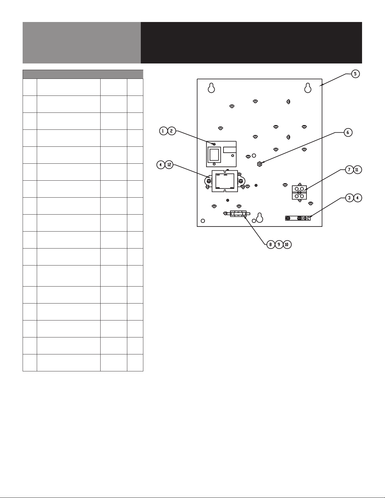
Ref Description Part # Qty
ASSEMBLY, BOARD, WATER
1
LEVEL
3 LUG, GROUND, #14 - #6 AWG 129714 1
SCREW, HEX, SLOTTED HEAD,
4
8-32 X 3/8" LONG
WELDMENT, PANEL,
5
ELECTRICAL
6 NUT, HEX, KEPS, 10-32 071256 1
7 BLOCK, TERMINAL, 2-POLE 003887 1
8 FUSE, 3.0 AMP, TYPE 3 AG 077853 1
9 HOLDER, FUSE, TYPE 3 AG 077854 1
122192 1
069789 4
138123 1
Parts List
ELECTRICAL COMPONENTS
SCREW, ROUND HEAD, MACHINE,
11
8-32 X 1-1/4" LONG
SCREW, ROUND HEAD, SELF-TAP,
12
6-32 X 3/8" LONG
TRANSFORMER, 20VA, 120V
12
PRIMARY, 24V SECONDARY
TRANSFORMER, 40VA,
12
208/240V PRIMARY, 24V
SECONDARY
HARNESS, WIRIN, KETTLE
CONTROL
HARNESS, WIRING, CONTROL
PANEL
LABEL, ELECTRICAL
CONNECTION, 115V
LABEL, ELECTRICAL
CONNECTION, 230V
-
STRAP, CABLE TIE 011093 1
005056 1
012398 1
137487 1
137441 1
123779 1
123582 1
102229 1
008118F 1
17 OM-DH(T)-20/40/60/80 (C,A,C2T™) Domestic
Page 18

For Cook2Temp™ Control Models
Ref Description Part # Qty
WELDMENT, ELECTRICAL
1
MOUNTING DEE & DH-40
2 TERMINAL BLOCK 2P 003887 1
3 P.C. BOARD MOUNTING POST 099901 3
CONTROL BOARD ASSEMBLY,
4
WATER LEVEL
5 FUSE 3.0 AMP TYPE 3 AG 077853 2
6 FUSE HOLDER TYPE 3 AG 077854 2
TRANSFORMER, 20VA, 120
7
PRIMARY
8 LUG GROUND #14-#6 AWG 129714 1
138123 1
122192 1
137487 2
Parts List
ELECTRICAL COMPONENTS
SCREW ROUND HEAD 8-32 1 1/4"
9
SCREW HEX SLOTTED HD W/
10
WASHER #8-32 X 3/8"
SCREW, ROUND HEAD #6-
11
32X.375
WIRE HARNESS, CONTROL,
DH, C2T
HARNESS, HIGH VOLTAGE
WIRING, TDH
WIRE HARNESS, CONTROL,
PANEL, DH, C2T
LABEL, ELECTRICAL
CONNECTION, 115V
-
STRAP, CABLE TIE 011093 1
005056 1
069789 6
012398 2
176929 1
175387 2
176963 1
102229 1
18 OM-DH(T)-20/40/60/80 (C,A,C2T™) Domestic
Page 19

For Classic Control Models
Parts List
FRONT PANEL COMPONENTS
QUANTITY
Ref Description Part #
20 Gal
1 2" ALUMINUM KNOB 175095 1 1 1
2 POWER SWITCH 176921 1 1 1
3 INDICATOR LIGHT, AMBER 116384 1 1 1
4 INDICATOR LIGHT, RED 116383 1 1 1
5 CLASSIC CONTROLS 174843 1 1 1
- HEX NUT 101145 1 1 1
- SPACER, LIGHT MOUNT 175221 1 1 1
- Bracket, Light Mount 175222 1 1 1
- Classic Controls Overlay 175303 1 1 1
For Advanced Control Models
40 Gal
60 Gal
Parts List
FRONT PANEL COMPONENTS
QUANTITY
Ref Description Part #
20 Gal
1 2" ALUMINUM KNOB 174829 1 1 1
2 POWER SWITCH 176921 1 1 1
3 INDICATOR LIGHT, RED 116383 1 1 1
4 ADVANCED CONTROLS 174837 1 1 1
5 HEX NUT 101145 1 1 1
6 INDICATOR LIGHT, AMBER 116384 1 1 1
- SPACER, LIGHT MOUNT 175221 1 1 1
- BRACKET, LIGHT MOUNT 175222 1 1 1
- Overlay, Advanced Controls 175304 1 1 1
40 Gal
60 Gal
19 OM-DH(T)-20/40/60/80 (C,A,C2T™) Domestic
Page 20

For Cook2Temp™ Control Models
Parts List
FRONT PANEL COMPONENTS
QUANTITY
Ref Description Part #
1 2" ALUMINUM KNOB 174829 1 1 1 1
2 POWER SWITCH 176921 1 1 1 1
3 INDICATOR LIGHT, RED 116383 1 1 1 1
4 C2T CONTROLS 176895 1 1 1 1
5 HEX NUT 101145 1 1 1 1
6 INDICATOR LIGHT, AMBER 116384 1 1 1 1
- SPACER, LIGHT MOUNT 175221 1 1 1 1
- BRACKET, LIGHT MOUNT 175222 1 1 1 1
- OVERLAY, C2T CONTROL 176891 1 1 1 1
CAP, SOCKET, PANEL MOUNT, CORE
PROBE, C2T
SOCKET, PANEL MOUNT ASSY,
CORE PROBE, C2T
176927 1 1 1 1
176925 1 1 1 1
20 Gal
40 Gal
60 Gal
80 Gal
20 OM-DH(T)-20/40/60/80 (C,A,C2T™) Domestic
Page 21

QUANTITY
Parts List
TILT MECHANISM COMPONENTS
Ref Description Part #
1 BUSHING, SNAP, 3/4" ID 000453 1 1 1 1
2 KEY, 3/8" SQUARE X 1-3/8" LONG 001474 1 1 1 1
SCREW, CAP, SOCKET HEAD, 3/8-
3
16 X 1-1/2" LONG
4 WASHER, LOCK, SPLIT, 3/8" 005618 1 1 1 1
5 NUT, HEX, 1/2-13 005705 4 4 4 4
6 WASHER, LOCK, 1/2" 005735 4 4 4 4
7 NUT, HEX, 3/8-16 005619 1 1 1 1
SCREW, CAP, HEX HEAD, 1/2-13 X
8
1-1/2" LONG
9 ASSEMBLY, BEARING HOUSING 009762 1 1 1 -
9 ASSEMBLY, BEARING HOUSING 149788 - - - 1
10 BEARING, BALL 009765 2 2 2 2
11 GEAR, WORM, 3/4" BORE 012026 1 1 1 1
12 WASHER, SHIM, 1-3/8" ID 012039 2 2 2 -
13 SCREW, SET, SOCKET 012060 1 1 1 1
14 PIN, ROLL, 1/4" DIA X 1-1/4" LONG 012614 3 3 3 3
15 RING, BASIC, INTERNAL 013483 2 2 2 2
16 GEAR, 3" BORE, 92 TEETH 013609 1 1 1 1
17 HANDLE, CRANK, 3/4" BORE 013617 1 1 1 1
SHAFT, HANDWHEEL, 3/4" OD X
18
13-1/2" LONG
SHAFT, HANDWHEEL, 3/4" OD X
18
20-1/2" LONG
19 SPACER, 3" SCH 40 X 0.75" LONG 013625 1 1 1 -
19 SPACER, 3" SCH 40 X 2.445" LONG 150235 - - - 1
- SHIM, TRUNNION 088246 1 1 1 -
- SHIM, TRUNNION 088247 1 1 1 -
- SPACER, WASHER 004901 1 1 1 1
- WASHER, PLAIN, 1/2" 005049 5 5 5 5
ASSEMBLY, TILT SWITCH &
BRACKET
005097 1 1 1 1
008679 4 4 4 4
013624 1 1 1 -
150937 - - - 1
135331 1 1 1 1
20 Gal
40 Gal
60 Gal
80 Gal
21 OM-DH(T)-20/40/60/80 (C,A,C2T™) Domestic
Page 22

QUANTITY
Parts List
WATER LEVEL & SAFETY VALVE COMPONENTS
Ref Description Part #
1 ASSEMBLY, WATER FILL 097007 1 1 1 -
2 VALVE, SAFETY, 1/2 NPT, 50 PSI 097005 1 1 1 1
ELBOW, 90 DEG, 1/2 NPT, CHROME
3
PLATED
- ASSEMBLY, PLATE & CHAIN 008332 1 1 1 -
COUPLING, FULL, 1/2 NPT, (NICKEL
4
PLATED)
5 ELBOW, 90 DEG, STREET, 1/2 NPT 096905 - - - 1
GAUGE, COMPOUND PRESSURE, W/
6
DUAL SCALE
7 NIPPLE, CLOSE, 1/2" NPT 008877 1 1 1 1
8 ASSEMBLY, PIPING, RELIEF VALVE 141428 - - - 1
9 ASSEMBLY, PIPING, WATER-FILL 139396 - - - 1
- SIGHT GLASS, 1-1/4 NPT 108554 - - - 1
10 FITTINGS, SIGHT GLASS 002845 1 1 1 -
11 GLASS, WATER LEVEL 008742 1 1 - -
11 GLASS, WATER LEVEL 009752 - - 1 -
12 GROMMET, 7/8" ID 007400 2 2 2 -
13 ROD, GUARD, GLASS 002981 2 2 - -
13 ROD, GUARD, GLASS 003127 - - 2 -
- LABEL, MAXIMUM & MINIMUM 000558 1 1 1 -
14 NUT, HEX, CAP, 10-24 005470 2 2 2 -
010108 1 1 1 -
149048 2 2 2 1
084208 1 1 1 1
20 Gal
40 Gal
60 Gal
80 Gal
22 OM-DH(T)-20/40/60/80 (C,A,C2T™) Domestic
Page 23

Parts List
REPLACEMENT KETTLE BODY ASSEMBLIES
QUANTITY
Description Part #
REPLACEMENT KETTLE BODY ASSEMBLIES
KBA & TRUNNION DH-20 50 PSI 175173 1 - - -
KBA & TRUNNION DHT-20 2" TDO 50 PSI 175174 1 - - -
KBA & TRUNNION DH-40 50 PSI 175179 - 1 - -
KBA & TRUNNION DHT-40 2" TDO 50 PSI 175180 - 1 - -
KBA & TRUNNION DH-60 50 PSI 175190 - - 1 -
KBA & TRUNNION DHT-60 2" TDO 50 PSI 175191 - - 1 -
KBA & TRUNNION DH-80 50 PSI 175196 - - - 1
KBA & TRUNNION DHT-80 2" TDO 50 PSI 175197 - - - 1
REPLACEMENT COMBUSTION CHAMBERS
CHAMBER, COMBUSTION 122092 1 - - -
CHAMBER, COMBUSTION 122093 - 1 - -
DIVERTER, FLUE GAS 062105 - 2 - -
DIVERTER, FLUE GAS 062106 - 2 - -
CHAMBER, COMBUSTION 122094 - - 1 -
DIVERTER, CENTER PLATE, FLUE GAS 049716 - - 2 -
DIVERTER, CENTER PLATE, FLUE GAS 049718 - - 2 2
DIVERTER, SIDE PLATE, FLUE GAS 049717 - - 2 2
CHAMBER, COMBUSTION 122094 - - - 1
DIVERTER, TOP PLATE 154028 - - - 1
REPLACEMENT 2" TDO VALVE COMPONENTS
HANDLE, BLACK, 3" DIA 009029 1 1 1 1
NUT, WING, 10-24 009028 1 1 1 1
STEM, VALVE, W/COMPRESSION DISK 009048 1 1 1 1
O-RING, 7/16" ID 009034 1 1 1 1
BONNET, VALVE 009047 1 1 1 1
NUT, HEX 009354 1 1 1 1
REPLACEMENT C2T COMPONENTS
CORE PROBE, DH-20 & 40, C2T 176651 1 1 - -
CORE PROBE, DH-60 & 80, C2T 176652 - - 1 1
BRACKET, CORE PROBE, DH-20, C2T 176654 1 - - -
BRACKET, CORE PROBE, DH-40, C2T 176655 - 1 - -
BRACKET, CORE PROBE, DH-60, C2T 176656 - - 1 -
BRACKET, CORE PROBE, DH-80, C2T 176657 - - - 1
BRACKET ASSEMBLY, CORE PROBE STORAGE 177091 1 1 1 1
WIRE HARNESS, CONTROL, CORE PROBE, C2T 176920 1 1 1 1
20 Gal
40 Gal
60 Gal
80 Gal
23 OM-DH(T)-20/40/60/80 (C,A,C2T™) Domestic
Page 24

For Classic Control Models
DH(T)-20, -40, -60, -80
Wiring Diagram
24 OM-DH(T)-20/40/60/80 (C,A,C2T™) Domestic
Page 25

For Advanced Control Models
DH(T)-20, -40, -60, -80
Wiring Diagram
25 OM-DH(T)-20/40/60/80 (C,A,C2T™) Domestic
Page 26

For Cook2Temp™ Control Models
DH(T)-20, -40, -60, -80
Wiring Diagram
26 OM-DH(T)-20/40/60/80 (C,A,C2T™) Domestic
Page 27

Service Log
Model No: Purchased From:
Serial No: Location:
Date Purchased: Date Installed:
Purchase Order No: For Service Call:
Date Maintenance Performed Performed By
27 OM-DH(T)-20/40/60/80 (C,A,C2T™) Domestic
 Loading...