

Page 1

important information I keep for operator I important information
OPERATOR MANUAL
Part Number 145145 Rev. D DOMESTIC
OM-SSB-3E/5E/10EF
MODELS: SSB-3E/5E/10EF, (2)SSB-3E/5E/10EF
SmartSteam™
Boilerless Steamer
Self-Contained
Electric-Heated
Capacity` 3, 5 or 10 pans Steamer Pans
[per cavity]
(12” x 20” x 2 1/2”)
Use for steamers with
Serial Numbers ending
with “MSD”
THIS MANUAL MUST BE RETAINED FOR FUTURE REFERENCE. READ,
UNDERSTAND AND FOLLOW THE INSTRUCTIONS AND WARNINGS
CONTAINED IN THIS MANUAL
FOR YOUR SAFETY
DO NOT STORE OR USE GASOLINE OR OTHER FLAMMABLE VAPORS
AND LIQUIDS IN THE VICINITY OF THIS OR ANY OTHER APPLIANCE
Information contained in this document is known to be
current and accurate at the time of printing/creation. Unified
Brands recommends referencing our product line websites,
unifiedbrands.net, for the most updated product information and
specifications.
Page 2

OM-SSB-3E/5E/10EF
IMPORTANT –– READ FIRST –– IMPORTANT
WARNING: THE UNIT MUST BE INSTALLED BY PERSONNEL QUALIFIED TO WORK WITH ELECTRICITY
AND PLUMBING. IMPROPER INSTALLATION CAN CAUSE INJURY TO PERSONNEL AND/OR
DAMAGE TO THE EQUIPMENT. THE UNIT MUST BE INSTALLED IN ACCORDANCE WITH
APPLICABLE CODES.
CAUTION: SHIPPING STRAPS ARE UNDER TENSION AND CAN SNAP BACK WHEN CUT.
CAUTION: DO NOT INSTALL THE UNIT IN ANY WAY WHICH WILL BLOCK THE REAR VENTS, OR
WITHIN 2 INCHES OF A HEAT SOURCE SUCH AS A BRAISING PAN, DEEP FRYER, CHAR
BROILER OR KETTLE.
CAUTION: LEVEL THE UNIT FRONT TO BACK, OR PITCH IT SLIGHTLY TO THE REAR, TO AVOID
DRAINAGE PROBLEMS.
WARNING: FOLLOW THE WIRING DIAGRAM EXACTLY WHEN CONNECTING A UNIT TO AVOID
DAMAGE OR INJURY. WIRING DIAGRAM IS LOCATED ON THE INSIDE OF THE RIGHT
PANEL.
CAUTION: DO NOT USE PLASTIC PIPE. DRAIN MUST BE RATED FOR BOILING WATER.
WARNING: DO NOT CONNECT THE DRAIN DIRECTLY TO A BUILDING DRAIN.
WARNING: BLOCKING THE DRAIN IS HAZARDOUS.
IMPORTANT: IMPROPER DRAIN CONNECTION WILL VOID WARRANTY.
IMPORTANT: DO NOT ALLOW ANY WATER TRAPS IN THE LINE. A TRAP CAN CAUSE PRESSURE TO BUILD UP
INSIDE THE CAVITY DURING STEAMING, WHICH WILL MAKE THE DOOR GASKET LEAK.
WARNING: WHEN YOU OPEN THE DOOR, STAY AWAY FROM STEAM COMING OUT OF THE UNIT.
STEAM CAN CAUSE BURNS.
WARNING: BEFORE CLEANING THE OUTSIDE OF THE STEAMER, DISCONNECT THE ELECTRIC
POWER SUPPLY. KEEP WATER AND CLEANING SOLUTIONS OUT OF CONTROLS AND
ELECTRICAL COMPONENTS. NEVER HOSE OR STEAM CLEAN ANY PART OF THE UNIT.
WARNING: ALLOW COOKING CHAMBER TO COOL COMPLETELY BEFORE CLEANING.
WARNING: USE MILD CLEANING AGENTS ONLY. CAREFULLY READ THE WARNINGS AND FOLLOW
THE DIRECTIONS ON THE LABEL OF EACH CLEANING AGENT. USE SAFETY GLASSES
AND RUBBER GLOVES AS RECOMMENDED BY CLEANING AGENT MANUFACTURER.
WARNING: DO NOT PUT HANDS OR TOOLS INTO THE COOKING CHAMBER UNTIL THE FAN HAS
STOPPED TURNING.
WARNING: DO NOT OPERATE THE UNIT UN LESS THE REMOVABLE RIGHT SIDE PANEL HAS BEEN
RETURNED TO ITS PROPER LOCATION.
NOTICE: DO NOT USE A CLEANING AGENT THAT CONTAINS ANY SULFAMIC ACID, OR ANY
CHLORIDE, INCLUDING HYDROCHLORIC ACID. IF THE CHLORIDE CONTENT OF ANY
PRODUCT IS UNCLEAR, CONSULT THE MANUFACTURER. DO NOT USE A CLEANING OR
DELIMING AGENT THAT CONTAINS MORE THAN 30% PHOSPHORIC ACID.
NOTICE: DO NOT USE ANY DEGREASER THAT CONTAINS POTASSIUM HYDROXIDE OR SODIUM
HYDROXIDE OR THAT IS ALKALINE.
WARNING: USE OF ANY REPLACEMENT PARTS OTHER THAN THOSE SUPPLIED BY GROEN OR THEIR
AUTHORIZED DISTRIBUTOR VOIDS ALL WARRANTIES AND CAN RESULT IN BODILY
INJURY TO THE OPERATOR AND DAMAGE THE EQUIPMENT. SERVICE BY OTHER THAN
FACTORY-AUTHORIZED PERSONNEL WILL VOID ALL WARRANTIES.
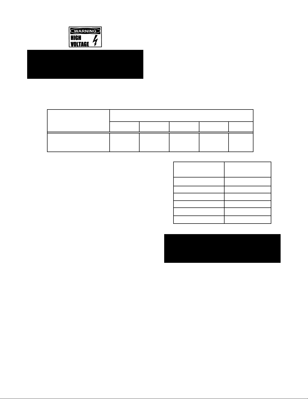
WARNING: HIGH VOLTAGE EXISTS INSIDE CONTROL COMPARTMENTS. DISCONNECT FROM BRANCH
CIRCUIT BEFORE SERVICING. FAILURE TO DO SO CAN RESULT IN INJURY OR DEATH.
2
Page 3

OM-SSB-3E/5E/10EF
Table of Contents
OPERATOR WARNINGS ......................................................................................................................................... 2
REFERENCES ......................................................................................................................................................... 3
EQUIPMENT DESCRIPTION ................................................................................................................................... 4
INSPECTION AND UNPACKING ............................................................................................................................ 4
INSTALLATION AND STARTUP ..........................................................................................................................5-8
OPERATION .........................................................................................................................................................8-9
CLEANING .......................................................................................................................................................... 9-10
MAINTENANCE ................................................................................................................................................ 11-12
TROUBLESHOOTING ......................................................................................................................................13-14
SERVICE LOG ....................................................................................................................................................... 15
WARRANTY PROTECTION .................................................................................................................................. 16
References
UNDERWRITERS LABORATORIES, INC. NATIONAL FIRE PROTECTION ASSOCIATION
333 Pngsten Road 60 Batterymarch Park
Northbrook, Illinois 60062 Quincy, Massachusetts 02269
NFPA/70 The National Electrical Code
NATIONAL SANITATION FOUNDATION
3475 Plymouth Road
Ann Arbor, Michigan 48106
3
Page 4
OM-SSB-3E/5E/10EF
Equipment Description
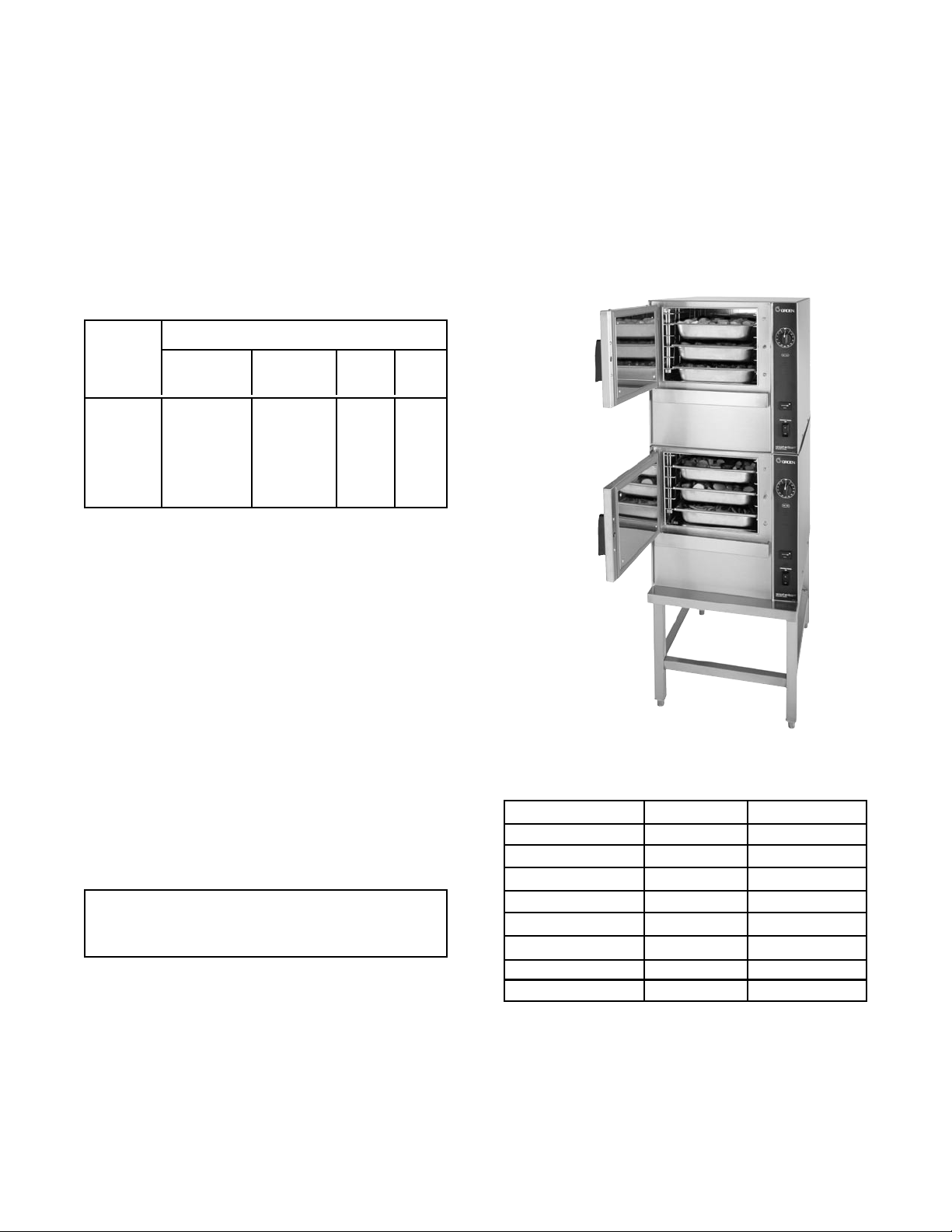
Your Groen SSB-3E/5E/10E or (2)SSB-3E/5E/10E
Smartsteam Boilerless Steamer is designed to
give years of service. It has a stainless steel cavity
(cooking chamber) which is served by an electricheated atmospheric steam generating reservoir. A
powerful blower circulates the steam in the cavity to
increase heating efciency.
Each cavity holds up to three, ve or ten steam table
pans (12” x 20” x 21/2” deep) as shown below.
SSB
Steamer
SSB-3E 3 2 0 0
(2)SSB-3E 6 4 0 0
SSB-5E 5 3 0 0
(2)SSB-5E 10 6 0 0
SSB-10E 10 6 20 10
(2)SSB-10E 20 12 40 20
PANS PER CAPACITY PER TYPE
12 x 20 x 2-1/2
(steamer)
12 x 20 x 4
(steamer)
13 x 18
(half size
18 x 26
(bake)
bake)
An 18-guage stainless steel case encloses the
cavity, the steam generating reservoir and the control
compartment that houses electrical components.
Door hinges are eld-reversible (the door may be set
to open from the left or right). Operating controls are
on the front panel.
Electric SSB-3E/5E/10E units are distinguished from
the rear by the addition of a fuse box, which lets
operators change fuses without removing panels.
The drain system on all models includes a spray
condenser, which cools drain water.
The SSB-3E/5E/10E steamers are equipped with fully
electronic controls. These units are readily identied
by their unique control panels. Steamer function is
controlled by touch pad controls and a rotary timer.
Inspection and Unpacking
Your Groen SSB-3E/5E/10E SmartSteam Boilerless
Steamer will be delivered completely assembled in a
heavy shipping carton strapped to a skid. On receipt,
inspect carton carefully for exterior damage.
CAUTION
SHIPPING STRAPS ARE UNDER TENSION AND
CAN SNAP BACK WHEN CUT.
Carefully cut the straps and detach the sides of the
carton from the skid. Pull the carton up off the unit. Be
careful to avoid personal injury or equipment damage
from staples which might be left in the carton walls.
Write down the model number, serial number and
installation date. Keep this information for reference.
Space for these entries is provided at the top of the
Service Log in the back of this manual.
SSB Steamer
SSB-3E Table Top 220 100
SSB-3E W/Stand 310 141
(2) SSB-3E W/Stand 500 227
SSB-5E Table Top 275 125
SSB-5E W/Stand 350 159
(2)SSB-5E W/Stand 555 252
SSB-10E W/Stand 469 213
(2)SSB-10E W/Stand 764 347
Weight (LBS)
Weight (KGS)
When starting installation, check packing materials to
make sure loose parts such as the condensate drip
tray are not discarded with this material.
4
Page 5
OM-SSB-3E/5E/10EF
Installation and Startup
WARNING
THE UNIT MUST BE INSTALLED BY PERSONNEL WHO ARE QUALIFIED TO WORK WITH ELECTRICITY
AND PLUMBING. IMPROPER INSTALLATION CAN CAUSE INJURY TO PERSONNEL AND/OR DAMAGE TO
THE EQUIPMENT. THE UNIT MUST BE INSTALLED IN ACCORDANCE WITH APPLICABLE CODES.
CAUTION
DO NOT INSTALL THE UNIT WITH THE REAR VENTS BLOCKED OR WITHIN 2 INCHES OF A HEAT SOURCE
SUCH AS A BRAISING PAN, DEEP FAT FRYER, CHARBROILER OR KETTLE.
TO AVOID DRAINAGE PROBLEMS, LEVEL THE UNIT FRONT TO BACK, OR PITCHED SLIGHTLY TO
THE REAR.
1. Installation
Minimum Clearances: SmartSteam Boilerless
Steamer requires the following minimum
clearances to any surface, combustible or noncombustible.
Right Side 2 inches
Left Side 2 inches
Rear 6 inches
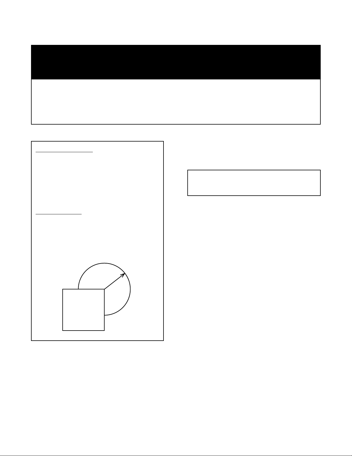
Steam Free Zone: The SmartSteam Boilerless
Steamer can be damaged by steam from
external sources. Do not install the steamer
over a steam venting drain. Ensure that steam is
not present in an area bounded by the footprint
of the steamer and a circle 18 inches in radius
about the right rear corner of the steamer (see
gure below).
18 -inch
radius
457 mm
C. Phase Selection
Refer to steamer wiring diagram and element
wiring on pages 19 and 20 for wiring
information.
CAUTION
EACH UNIT MUST HAVE A SEPARATE GROUND
WIRE FOR SAFE OPERATION.
D. Terminal Block
The terminal block for incoming power is
located at the back of the control compartment.
The ground terminal is located in the wiring
compartment near the terminal block.
E. Supply Wire
The equipment grounding wire must comply
with the National Electrical Code (NEC)
requirements. The wiring diagram on the
inside of the unit’s right side cover gives
directions for proper connection of the
terminal block jumpers. The wire must
be used or the unit will not meet Underwriters
Laboratories and NEC requirements. The
electric hole is sized for a one-inch conduit
tting on the SSB-3E and SSB-5E. The electric
hole is sized for a 11/4” conduit tting
on the SSB-10E.
2. Electrical Supply Connection
A. Panel Removal - Right Side
Open the wiring and control panel by
removing screws from the right side panel.
Slide the panel forward and set it aside.
B. Supply Voltage
The unit must be operated at the rated
name plate voltage. The name plate can be
found on the rear of the unit.
F. Branch Circuit Protection
Each SmartSteam Boilerless Steamer,
including individual units of stacked models,
should have its own branch circuit protection
and ground wire.
5
Page 6
OM-SSB-3E/5E/10EF
WARNING
TO AVOID DAMAGE OR PERSONAL INJURY,
FOLLOW THE WIRING DIAGRAM EXACTLY
Current and power demands for each unit are as
shown below.
ELECTRICAL SUPPLY CONNECTIONS
RATED CURRENT DEMAND PER CAVITY
SSB Steamer
(KW RATING)
SSB-3E (9) 25 44 22 38 11
SSB-5e (12) 34 58 29 50 15
SSb-103 (21) 59 N/A 51 N/A 26
3. Water Connection(s)
208 3P
208 1p
240 1p 240 1- 240 3p
Install a check valve to prevent back ow
in the incoming cold water line, as required
by local plumbing codes. Water pressure
in the line should be between 30 and 60 PSI. If
pressure is above 60 PSI, a pressure regulator
will be needed. These pressures will provide
the 1.5 gallons per minute required for proper
steamer function.
A 3/4 inch female NH connector (garden hose
type) is used to attach the water supply to the
inlet valve. Minimum inside diameter
of the water feed line is 1/2 inch.
Use a washer in the hose connection. Do
not allow the connection to leak, no matter
how slowly. Do not over-tighten hose
connections.
This equipment is to be installed to comply
with the basic plumbing code of the Building
Ofcials and Code Administrators
International, Inc. (BOCA) and the Food
Service Sanitation Manual of the Food and
Drug Administration (FDA).
SSB-Steamer
SSB-3E
(2)SSB-3E
SSB-5E
(2)SSB-5E
SSB-10E
(2)SSB-10E
Drain ID Hose Size
Required (IN)
1.5
2.5
1.5
2.5
2.0
2.0
WARNING:
DO NOT CONNECT THE DRAIN DIRECTLY TO
A BUILDING DRAIN. BLOCKING THE DRAIN IS
HAZARDOUS.
There must be a free air gap between the end of the
hose and the building drain. The free air gap should
be as close as possible to the unit drain. There must
also be no other elbows or other restrictions between
the unit drain and the free air gap.
4. Drain Connection
Level the steamer front to back, or pitch it
slightly to the rear (maximum 1/4 inch) by
adjusting the optional legs or the bullet feet
on the optional stand.
CAUTION
DO NOT USE PLASTIC PIPE. DRAIN MUST BE
RATED FOR BOILING WATER.
6
Page 7

OM-SSB-3E/5E/10EF
Install the drain line with a constant downward pitch.
IMPORTANT: Do not allow water traps in the line.
A trap can cause pressure build-up in the cavity,
which may cause the door gasket to leak.
B. Electrical Supply Connection
Separate electrical connections will be
required for each steamer to be stacked. Each
steamer unit must have it’s own branch
circuit protection.
C. Drain Connection
Steamers must be leveled front to back, or
pitched to the rear (maximum 1/4 inch) by
adjusting the bullet feet on the cabinet or
stand base.
For all factory-stacked SSB steamers,
a 21/2 inch ID hose is attached to the
unit drain. It must be rated for boiling water.
6. Counter-Mounted Units
This section is applicable if the steamer will
be mounted to a counter. All four edges of the
bottom of the steamer must be sealed
with RTV to the counter if the 4 inch
legs are not used. Counter must be made
of a noncombustible material such as
metal or tile.
Proper Drain Line Connection – Drain Line must
have a constant downward pitch of at least 1/4”
per foot. Observe local code regarding air gap
spacing and drain connections.
5. Factory-Stacked Units
This section is applicable only if you are
installing factory-stacked units.
Installing stacked steamers is similar
to installing a single unit. The steamers
are stacked and assembled at the factory
and delivered with the water connections and
drain hoses required for a single point
connection.
A. Water Connection
The same water supply connection
is used for both units. At the water
inlet valve a 3/4 inch female NH connector
(garden hose type) is used for the water supply.
7
Page 8

OM-SSB-3E/5E/10EF
Initial Startup
After the SmartSteam Boilerless Steamer has been
installed, test it to ensure that the unit is operating
correctly.
1. Remove all literature and packing materials
from the interior and exterior of the unit.
2. Make sure the water supply line is open.
3. Turn on electrical service to the unit. The SSB 3E/5E/10E will not operate with out electrical power. Do not attempt to
operate the unit during a power failure.
4. To turn unit on, toggle the lower
rocker switch to the ON position and press
the ON/OFF button on the upper control panel.
NOTE: For normal day-to-day operation, the
rocker switch may be left in the
ON position. Use the upper control
panel ON/OFF button to turn unit ON and OFF.
5. When the steam generating reservoir has
lled with water, the main elements
will begin heating automatically. Within
15 minutes or less the READY light will come
on, indicating that the water has reached
its standby temperature. When the READY
light is displayed, you may take any one of the
following steps:
6. To shut down the unit, press the ON/OFF touch
pad. The steam generating reservoir will then
drain.
7. If the SSB-3E/5E/10E behaves as described
the unit is functioning correctly and ready for
USE.
a. Set the timer to the desired timed
steaming.
b. Turn the timer knob to the manual ON
position for continuous steam.
c. Let the unit stay at ready condition.
WARNING
WHEN YOU OPEN THE DOOR, STAY AWAY
FROM STEAM COMING OUT OF THE UNIT.
STEAM CAN CAUSE BURNS.
8
Page 9

OM-SSB-3E/5E/10EF
P/N 149398 REV B
Operation
WARNING
ANY POTENTIAL USER OF THE EQUIPMENT MUST BE TRAINED IN SAFE AND CORRECT OPERATING
PROCEDURES.
A. Controls
Operator controls are on the front right of the unit.
The SmartSteam Boilerless Steamer control panel
has the following touch pads and indicator lights:
• The ON/OFF touch pad gets the SmartSteam
Boilerless Steamer ready for use and also
shuts it OFF.
• The READY indicator light shows that the
steam generating reservoir is at standby
temperature and the cavity is hot enough to
begin steaming.
• The Upper/Red SERVICE indicator light and
Door/Lid light indicate the water level probes
have stopped working and need to be
cleaned.
• The Door/Lid Indicator light illuminates when
the door is not properly closed.
• The HI TEMP indicator light comes on when
the unit is too hot.
DONE Light
The unit will automatically shut off and
cannot be turned on again until the
steam generator cools and the HI TEMP
indicator light goes out.
• The TIMING indicator light stays on when
the timer is running.
• The Lower/White SERVICE indicator light
shows when the control cooling fan may not
be functioning properly. The light may come
on for several minutes during normal
operation. If it stays on for more than 30
minutes, call for service. It is okay to use
steamer until service arrives, but continued
use for prolonged periods could result in
component damage due to excessive
temperatures.
• The hour meter records the cumulative
hours the steamer has been used. Refer to
warranty statement.
ON Light
TIMED
Cooking Dial
ON/OFF
Touch Pad
READY Light
DOOR OPEN
Light
HOUR Meter
Control
Power
Dial OFF Position
TIMING Light
POWER Light
RED SERVICE Light
HI TEMP
Indicator
COOLING FAN
Indicator Light
9
Page 10

OM-SSB-3E/5E/10EF
The timer is used in three ways:
1. In the OFF position, the steamer stays at a
low boil or ready status.
2. When a cook time is set, the unit steams
until the timer times down to DONE. At that
time, steaming stops, a red DONE light
comes on and a beeper sounds until
the user turns the knob another position.
3. With the timer turned to the ON position, the
unit steams continuously. The green light
stays lit. The steamer will NOT time down.
WARNING
WHEN YOU OPEN THE DOOR, STAY AWAY
FROM THE STEAM COMING OUT OF THE UNIT.
STEAM CAN CAUSE BURNS.
B. Operating Procedure
1. Press the ON/OFF button located on the control
touch pad. The steam generating reservoir will
ll and heat until the READY light comes on
(about 10-14 minutes).
2. Load food into pans in uniform layers. Pans
should be lled to about the same levels and
should be even on top.
3. Open the door and slide the pans onto the
supports. If you will only be steaming one pan,
put it in the middle position.
4. Close the door. With the READY indicator lit,
take one of the following steps:
TIMED STEAMING
! If you want to steam the food for a certain
length of time, set the timer for that period.
The timer will automatically run the steamer
for the set time and then turn it off. A red
DONE light will come on and a beeper will
sound. Steam production stops.
CONTINUOUS STEAMING
! If you want to steam continuously, turn the
timer to the manual ON position. A green ON
light will come on. The unit will continue
steaming until you stop it by turning the
timer to OFF. When steaming continuously,
YOU MUST CONTROL STEAMING TIME.
5. Open the door. Remove the pans from the
steamer, using hot pads or oven mitts to protect
your hands from the hot pans.
6. To shut down the unit, press the ON/OFF rocker
switch to OFF. The steam generating reservoir
will automatically drain.
NOTE: If you use the ON/OFF touch pad to power
down the unit, and then subsequently turn the unit
back on within 4-33 minutes after initial shutdown,
you may briey see the Lower/White Service Light
appear for about a minute while the unit is resetting
itself. To avoid seeing this light during the unit
reset, power down the unit by shutting it off at
the ON/OFF rocker switch. However, if the Lower/
White Service Light appears and does not go away
after 30-35 minutes, you should call your local Groen
Authorized Service Agent to service the control
cooling fan, which is not functioning properly.
NOTE: The steamer was designed to drain
slowly (about 41/2 minutes) to remove residual
heat from the bottom of the cavity. If the unit is
inadvertently turned off, it can be turned on again
after approximately 2 minutes which allows the
water to drain below the bottom probe.
NOTE: If a large amount of shrimp is cooked in
SmartSteam, foaming will occur because the
steam lid actually gets so hot that the shrimp will
cook on its surface and the shrimp proteins in the
dripping will foam on the surface of the steam lid.
* To avoid this, use a catch pan to catch shrimp
drippings and proteins to prevent foaming when
cooking a large amount of shrimp.
10
Page 11

OM-SSB-3E/5E/10EF
Cleaning
To keep your SmartSteam Boilerless Steamer in proper working condition, use the following procedure to clean the
unit. This regular cleaning will reduce the effort required to clean the steam generator and cavity.
A. Suggested Tools
1. Mild detergent
2. Stainless steel exterior cleaner Groen
Spray DeGreaser (Part Number
140830WS)
3. Cloth or sponge
4. Plastic wool or a brush with soft bristles
5. Spray bottle
6. Measuring cup
7. Nylon pad
8. Towels
9. Plastic disposable gloves
10. Funnel
B. Procedure
1. Exterior Cleaning
a. Prepare a warm solution of the mild detergent
as instructed by the supplier. Wet a cloth with
this solution and wring it out. Use the moist
cloth to clean the outside of the unit. Do not
allow freely running liquid to touch the
controls, the control panel, any electrical
part, or any louver on the rear panels.
b. To remove material which may be stuck to
the unit, use plastic wool, a ber brush, or
a plastic or rubber scraper with a detergent
solution.
c. Stainless steel surfaces may be polished with
a recognized stainless steel cleaner.
2. Interior Cleaning
Daily cleaning must be done in order to enhance the
performance and prolong the life of your SmartSteam
Boilerless Steamer.
WARNING
DISCONNECT THE POWER SUPPLY
BEFORE CLEANING THE OUTSIDE OF
THE STEAMER.
KEEP WATER AND CLEANING
SOLUTIONS OUT OF CONTROLS AND
ELECTRICAL COMPONENTS. NEVER
HOSE OR STEAM CLEAN ANY PART OF
THE UNIT.
AVOID CONTACT WITH ANY
CLEANERS, DELIMING AGENT OR
DEGREASER AS RECOMMENDED BY
THE SUPPLIER. MANY ARE HARMFUL.
READ THE WARNINGS AND FOLLOW
THE DIRECTIONS!
EVEN WHEN THE UNIT HAS BEEN SHUT
OFF, DON’T PUT HANDS OR TOOLS
INTO THE COOKING CHAMBER UNTIL
THE FAN HAS STOPPED TURNING.
DON’T OPERATE THE UNIT UNLESS
THE REMOVABLE PARTITION HAS
BEEN PUT BACK IN ITS PROPER
LOCATION.
DON’T USE ANY CLEANING AGENT
THAT CONTAINS ANY SULFAMIC
AGENT OR ANY CHLORIDE, INCLUDING
HYDROCHLORIC ACID (Hcl). TO
CHECK FOR CHLORIDE CONTENT SEE
ANY MATERIAL SAFETY DATA SHEETS
PROVIDED BY THE CLEANING AGENT
MANUFACTURER.
IMPORTANT
DO NOT USE ANY METAL MATERIAL (SUCH AS METAL SPONGES) OR METAL IMPLEMENTS (SUCH
AS A SPOON, SCRAPER OR WIRE BRUSH) THAT MIGHT SCRATCH ANY STAINLESS STEEL SURFACE.
SCRATCHES MAKE THE SURFACE HARD TO CLEAN AND PROVIDE PLACES FOR BACTERIA TO
GROW. DO NOT USE STEEL WOOL, WHICH MAY LEAVE PARTICLES EMBEDDED IN THE SURFACE,
WHICH COULD EVENTUALLY CAUSE CORROSION AND PITTING.
11
Page 12

OM-SSB-3E/5E/10EF
WARNING! ALLOW THE STEAMER TO COOL
COMPLETELY BEFORE CLEANING. HOT
SURFACES CAN CAUSE SEVERE BURNS.
RECOMMENDED TOOLS & CLEANERS:
- Nylon scrub pad, clot or sponge. Scotch-Brite™
Medium duty scrubbing sponges are preferred. Do
NOT use metal scrub pads.
- Mild detergent soap.
CLEANING STEPS:
STEP 1 - Press ON/OFF touch pad to turn steamer
OFF and open steamer door.
STEP 2 - CAUTION: allow the steamer to cool
completely before cleaning
STEP 3 - Remove steam lid by grasping the two tabs
located on the lid front and sliding pan forward.
STEP 4 - Remove left pan rack by lifting rack up and
pulling away from cavity wall.
STEP 5 - Remove right fan shroud and rack assembly
by lifting rack up and pulling away from cavity wall.
DELIMING INSTRUCTIONS:
• When using Groen Boilerless Water Filtration
System use vinegar as a deliming agent.
STEP 6 - Clean steam lid, left pan rack and rack/
shroud assembly to remove food soils. These three
parts may be cleaned in a dishwasher.
STEP 7 - Uses a mild detergent to wipe down the entire
steamer cavity to remove food and scale particles.
Carefully clean oat probes if food residue or loose
scale is present. A thin layer of tightly bound scale
is normal and will not affect steamer performance. If
scale is excessive, then refer to deliming instructions
below.
STEP 8 - Replace pan racks and steam lid. Steamer
is now cleaned and ready to use.
• Groen approved delimer may be used to
remove excessive scale build-up.
STEP 1 - After following all cleaning steps 1 through
7 listed above, turn steamer on and allow water to
enter steamer cavity.
STEP 2 - Pour 1 cup of vinegar or delimer into
steamer cavity and shut door.
STEP 3 - Set steamer timer to 30 minutes and allow
steam cleaning to occur.
STEP 4 - After 30 minute cleaning cycle is complete,
turn steamer OFF and allow to cool completely.
STEP 5 - Open steamer door and wipe down the
entire steamer cavity to remove loosened scale
particles. Carefully clean oat probes if loose scale
is present.
STEP 6 -Replace pan racks and steam lid. Steamer
is now cleaned and ready to use.
FAILURE TO CLEAN THE STEAMER AS
SPECIFIED COULD NEGATIVELY IMPACT
THE PERFORMANCE OF THE STEAMER.
12
Page 13

Maintenance
OM-SSB-3E/5E/10EF
The SmartSteam Boilerless Steamer (electric model
SSB-3E/5E/10E or (2)SSB-3E/5E10E) is designed
for minimum maintenance and no user adjustments
should be necessary. Certain parts may need
replacement after prolonged use. If there is a need
for service, only Groen Authorized Service Agents
should perform the work.
If steam or condensate is seen leaking from around
the door, take the following steps:
1. Check the door gasket. Replace it if it is cracked
or split.
2. Inspect the cooking chamber drain to be sure it
is not blocked.
3. Adjust the door latch pin to allow for changes
that might occur as the gasket ages.
a. Loosen the lock nut at the base of the latch
pin, then turn the latch pin 1/4 turn clockwise,
and tighten the lock nut.
b. After adjustment, run the unit to test for further
steam leakage.
c. If there is still leakage, repeat the adjustment
d. Continue adjusting the pin clockwise until
the door ts tightly enough to prevent
leakage. The hinge may also be adjusted.
Troubleshooting
Your Groen SmartSteam Boilerless Steamer is designed to operate smoothly and efciently if properly maintained.
However, the following is a list of checks to make in the event of a problem. Wiring diagrams are furnished inside
the service panel. If an item on the check list is marked with (x), it means that the work should be done by a Groen
Authorized Service Agent.
SYMPTOM WHO WHAT TO CHECK
1. Blinking Service Light User a. Clean probes in unit / Check oat probe orientation
b. Be sure water supply is adequate to run steamer(s)
during normal operation.
2. No power. User a. Check wall circuit breaker.
b. Disconnect power, then check fuses on back of steamer.
c. Call for service technician.
3. Unit overlls with User a. Clean probes in unit / Check oat probe orientation.
water at start up. b. Call for service technician.
4. Steamer does not ll User a. Is the ON switch depressed?
with water. b. Is the water supply connected?
c. Is the water turned on?
d. Is the water supply hose kinked or obstructed?
e. Check for low water pressure (less than 30 PSI) or low water
ow (less than 1.5 gpm).
f. Is the screen at the water connection clogged?
5. Door/Lid light is on. User a. Is the steamer door securely closed?
6. No steam. User a. Is the ON switch depressed?
b. Is the water supply connected?
c. Is the water turned on?
d. Is steamer door completely closed?
7. Cooling Fan User a. The cooling fan light indicates the component cooling fan
Light is on. may not be operating. The light may come on for several
minutes during normal operation. If it stays on for more than
30 minutes, call for service. Unit may be used for cooking,
while waiting for service.
13
Page 14

OM-SSB-3E/5E/10EF
8. Any unusual User a. Press ON/OFF pad to turn steamer off. Momentarily turn
operation. circuit breaker off and then on or unplug from power. Turn
unit back on.
9. Door pops open. User a. Ensure drain and vent are not plugged. No more than two
units should be attached to a single drain line.
b. Check door pin adjustment per above.
c. Call for service technician.
`10. HI TEMP light is On. User a. Wait 30 minutes for unit to cool down.
b. Call service technician.
11. Upper/Red Service User a. Clean probes / Check oat probe orientation
b. Call service technician.
14
Page 15

OM-SSB-3E/5E/10EF
Service Log
Model No. ___________________________ Purchased From ______________________
Serial No. ___________________________ Location _____________________________
Date Purchased _______________________ Date Installed _________________________
Purchase Order No. ____________________ For Service Call _______________________
Date Maintenance Performed Performed by
15
Page 16

OM-SSB-3E/5E/10EF
GROEN LIMITED WARRANTY TO COMMERCIAL PURCHASE*
(U.S. & Canadian Sales Only)
Groen warrants to original commercial purchaser/users that foodservice equipment manufactured by Groen (“Groen
Equipment”) other than CapKold foodservice equipment, shall be free from defects in material and workmanship for (i)
2000 actual operating hours (provided that such equipment has a device that has recorded actual operating hours since
the installation of such equipment), (ii) twelve (12) months from the date of installation or (iii) fteen (15) months from the
date of shipment from Groen, whichever rs occurs (the “Warranty Period”), in accordance witht he following terms and
conditions:
I. This warranty is limited to replacement parts and related labor for Groen Equipment located at its original place of
installation in the United States and Canada.
II. Damage to Groen Equipment that occurs during shipment must be reported to the carrier and is not covered under
this warranty. The reporting of any damage during shipment is the sole responsibility of the commercial purchaser/user of
such Groen Equipment.
III. For Groen Convection Combo™ Steamer
Steamers, Groen further warrants to the original commercial purchaser/users of such Groen Equipment that the atmospheric
steam generators or boilers contained in such Groen Equipment shall be free from defects in material and workmanship
for (i) 4000 actual operating hours (provided that such equipment has a device that has recorded actual operating hours
since since the installation of such equipment), (ii) twenty-four (24) months from the date of installation or (iii) twenty-seen
(27) months from date of shipment from Groen, whichever rst occurs, provided that: (a) the original purchaser/user shall
have also purchased and installed a Groen PureSteem™ Water Treatment System for use in connection with such Groen
Convection Combo Steamer-Oven, HyPerSteam Convection Steamer or HyPlus Pressureless Steamer on or before teh
date such Groen Equipment was installed, (b) the original purchaser/user has continuously used such Water Treatment
System in connection with such Groen Equipment from the date of installation, and (c) the commercial purchaser/user
shall have maintained such Water Treatment System in accordance with the maintenance and lter cartridge replacement
recommendations of Groen, and otherwise maintained such Oven or Steamer in accordance with all other operational and
maintenance recommendations of Groen.
IV. For Groen SmartSteam™ Boilerless Steamers and Vortex™ Connectionless Steamers, Groen® further warrants to
the original commercial purchaser/users of SmartSteam™ Boilerless Steamers and Vortex™ Connectionless Steamers
shall be free from defects in material and workmanship for (i) 4000 actual operating hours (provided that such equipment
has a device that has recorded actual operating hours since the installation of such equipment), (ii) twenty-four (24)
months from the date of installation or (iii) twenty-seven (27) months from the date of shipment from Groen, whichever rst
occurs. This warrants Groen Vortex Connectionless Steamers that were shipped after March 15, 2004 and SmartSteam
Boilerless Steamers that were shipped after May 1, 2003
-Ovens, HyPerSteam™ Convection Steamers and HyPlus™ Pressureless
.
V. Groen further warrants to the original commercial purchaser/users of Groen Convection Combo Steamer-Ovens
that the electronic relay and control board contained in such Groen Convection Combo Steamer-Oven shall be free from
defects in material and workmanship for (i) 4000 actual operating hours (provided that such equipment has a device that
has recorded actual operating hours since the installation of such equipment), (ii) twenty-four (24) months from the date
of installation or (iii) twenty-seven (27) months from the date of shipment from Groen, whichever rst occurs.
16
Page 17

OM-SSB3E/53/10EF
VI. During the Warranty Period, Groen, directly or through its authorized service representative, will either repair or
replace, at Groen’s sole election, any Groen Equipment determined by Groen to have a defect in material or workmanship.
As to any such warranty service during the Warranty Period, Groen will be responsible for related reasonable labor and
portal to portal transportation expenses (time & mileage) incurred within the United States and Canada.
VII. This warranty does not cover boiler maintenance, calibration, periodic adjustments as specied in operating
instructions or manuals, consumable parts (such as scraper blades, gaskets, packing, etc.), and labor costs incurred
for removal of adjacent equipment or objects to gain access to Groen Equipment. This warranty does not cover defects
caused by improper installation, abuse, careless operation, or improper maintenance of Groen Equipment. This warranty
does not cover damage to Groen Equipment caused by poor water quality or improper boiler maintenance.
THIS WARRANTY IS EXCLUSIVE AND IS IN LIEU OF ALL OTHER WARRANTIES, EXPRESSED OR IMPLIED,
VIII.
INCLUDING ANY IMPLIED WARRANTY OF MERCHANTABILITY OR FITNESS FOR A PARTICULAR PURPOSE, EACH
OF WHICH IS HEREBY EXPRESSLY DISCLAIMED. THE REMEDIES DESCRIBED ABOVE ARE EXCLUSIVE AND IN
NO EVENT SHALL GROEN BE LIABLE FOR SPECIAL, CONSEQUENTIAL, OR INCIDENTAL DAMAGES FOR THE
BREACH OR DELAY IN PERFORMANCE OF THIS WARRANTY.
IX. Groen Equipment is for commercial use only. If sold as a component of another (O.E.M.) manufacturer’s equipment,
or if used as a consumer product, such Equipment is sold AS IS and without any warranty.
*Covers Groen Equipment (other than CapKold foodservice equipment, SmartSteam Boilerless Steamers and
Vortex Connectionless Steamers) ordered after September 11, 2001.
17
Page 18

OM-SSB-3E/5E/10EF
Cost of Extended Coverage.
Limited Extended Warranty Coverage is available on all standard Groen Equipment (other than CapKold
foodservice equipment) covered by the above Groen Limited Warranty. Commercial purchasers/users of Groen Equipment
may elect to extend the standard limited warranty to cover parts, labor and portal to portal transportation costs (time and
mileage) for an additional (i) 2000 actual operating hours, or (ii) twelve (12) month period, or for an additional (i) 4000
actual operating hours, or (ii) twenty four (24) month period, whichever rst occurs, in addition to the time period of
the standard limited warranty described above. Limited Extended Warranty Coverage is not available to extend the
supplemental limited warranty for: (a) atmospheric steam generators or boilers contained in Groen Convection Combo
Steamer-Ovens, HyPerSteam Convection Steamers and HyPlus Pressureless Steamers, or (b) electronic relay and
control boards contained in Groen Convection Combo Steamer-Ovens, or (c) Groen SmartSteam Boilerless Steamers, or
(d) Vortex Connectionless Steamers
Five percent (5.0%) of the LIST PRICE
for each additional twelve (12) months of limited extended warranty coverage. The ve percent (5.0%) of the LIST PRICE
charge will be the net invoice amount for each year of Limited Extended Warranty Coverage purchased.
of the Groen Equipment to be covered by the Limited Extended Warranty
Conditions of Coverage
(1) Limited Extended Warranty Coverage must be purchased at the time the Groen Equipment to be covered is
purchased.
(2) All conditions and limitations on the Standard Limited Warranty Coverage apply to the Limited Extended Warranty
Coverage.
See above for details of conditions and limitations on the Standard Warranty Coverage.
*Covers Groen Equipment (other than CapKold foodservice equipment and Vortex Connectionless Steamers) ordered
after September 11, 2001.
18
Page 19

Page 20

1055 Mendell Davis Drive
Jackson, MS 39272
Telephone 601 372-3903
Fax 601 373-9587
www.groen.com
OM-SSB-3E/5E/10EF
Revised 09/05
Part Number 145145 Rev. D
 Loading...