

Page 1

MODEL T25100
POWDER COATING SYSTEM
OWNER'S MANUAL
(For models manufactured since 8/12)
COPYRIGHT © DECEMBER, 2012 BY GRIZZLY INDUSTRIAL, INC. REVISED SEPTEMBER, 2013 (TR)
WARNING: NO PORTION OF THIS MANUAL MAY BE REPRODUCED IN ANY SHAPE
OR FORM WITHOUT THE WRITTEN APPROVAL OF GRIZZLY INDUSTRIAL, INC.
#TS15269 PRINTED IN CHINA
Page 2

This manual provides critical safety instructions on the proper setup,
operation, maintenance, and service of this machine/tool. Save this
document, refer to it often, and use it to instruct other operators.
Failure to read, understand and follow the instructions in this manual
may result in fire or serious personal injury—including amputation,
electrocution, or death.
The owner of this machine/tool is solely responsible for its safe use.
This responsibility includes but is not limited to proper installation in
a safe environment, personnel training and usage authorization,
proper inspection and maintenance, manual availability and comprehension, application of safety devices, cutting/sanding/grinding tool
integrity, and the usage of personal protective equipment.
The manufacturer will not be held liable for injury or property damage
from negligence, improper training, machine modifications or misuse.
Some dust created by power sanding, sawing, grinding, drilling, and
other construction activities contains chemicals known to the State
of California to cause cancer, birth defects or other reproductive
harm. Some examples of these chemicals are:
• Lead from lead-based paints.
• Crystalline silica from bricks, cement and other masonry products.
• Arsenic and chromium from chemically-treated lumber.
Your risk from these exposures varies, depending on how often you
do this type of work. To reduce your exposure to these chemicals:
Work in a well ventilated area, and work with approved safety equipment, such as those dust masks that are specially designed to filter
out microscopic particles.
Page 3

Table of Contents
INTRODUCTION ............................................................................................................................... 2
Tool Description ......................................................................................................................... 2
Contact Info ................................................................................................................................ 2
Manual Accuracy ........................................................................................................................ 2
Identification ............................................................................................................................... 3
Specifications ............................................................................................................................. 3
SECTION 1: SAFETY ....................................................................................................................... 4
Safety Instructions for Machinery ............................................................................................... 4
Additional Safety for Powder Coating Systems ......................................................................... 6
SECTION 2: POWER SUPPLY ........................................................................................................ 7
Availability............................................................................................................................................7
120V Circuit Requirements .................................................................................................................7
Grounding & Plug Requirements ........................................................................................................8
Extension Cords .................................................................................................................................. 8
SECTION 3: SETUP ......................................................................................................................... 9
Unpacking .................................................................................................................................. 9
Inventory ..................................................................................................................................... 9
Site Considerations .................................................................................................................. 10
Space Allocation ................................................................................................................................ 10
Physical Environment ........................................................................................................................10
Ventilation .......................................................................................................................................... 10
Electrical Installation .......................................................................................................................... 10
Lighting ..............................................................................................................................................10
Moisture Filter Installation ........................................................................................................ 10
SECTION 4: OPERATIONS ........................................................................................................... 11
Operation Overview.................................................................................................................. 11
Basic Controls & Components ................................................................................................. 12
Operational Points .................................................................................................................... 13
Workpiece Preparation ............................................................................................................. 14
Scatter Tips .............................................................................................................................. 14
Powder Cups ............................................................................................................................ 15
Curing ....................................................................................................................................... 15
SECTION 5: ACCESSORIES ......................................................................................................... 16
SECTION 6: MAINTENANCE......................................................................................................... 17
Schedule .................................................................................................................................. 17
Cleaning ................................................................................................................................... 17
SECTION 7: SERVICE ................................................................................................................... 18
Troubleshooting ........................................................................................................................ 18
SECTION 8: PARTS ....................................................................................................................... 20
WARRANTY & RETURNS ............................................................................................................. 21
Page 4
INTRODUCTION
We stand behind our machines. If you have
any questions or need help, use the information
below to contact us. Before contacting, please get
the serial number and manufacture date of your
machine. This will help us help you faster.
We want your feedback on this manual. What did
you like about it? Where could it be improved?
Please take a few minutes to give us feedback.
Tool Description
Powder coating with the Model T25100 is a superior alternative finishing process to wet painting on
metal parts. A few of the advantages of powder
coating are high durability, high-impact and stress
resistance, and uniform control of finish.
The powder coating process uses a dry, finelyground polymer of various types and mixtures that
is electrically charged and applied onto the metal
workpiece through electrical attraction. After completing the powder application, the finish must be
cured (baked) in a dedicated electric oven.
Contact Info
Grizzly Technical Support
1203 Lycoming Mall Circle
Muncy, PA 17756
Phone: (570) 546-9663
Email: techsupport@grizzly.com
Manual Accuracy
We are proud to provide a high-quality owner’s
manual with your new tool!
We made every effort to be exact with the instructions, specifications, drawings, and photographs
contained inside. Sometimes we make mistakes,
but our policy of continuous improvement also
means that sometimes the tool you receive will
be slightly different than what is shown in the
manual.
If you find this to be the case, and the difference
between the manual and tool leaves you confused about a procedure, check our website for
an updated version. We post current manuals and
manual updates for free on our website at www.
grizzly.com.
Alternatively, you can call our Technical Support
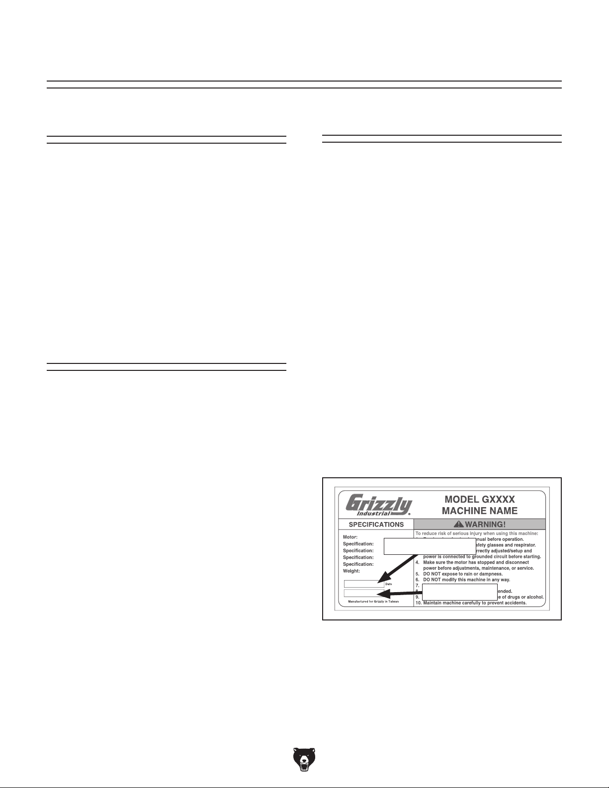
for help. Before calling, please write down the
Manufacture Date and Serial Number stamped
into the machine ID label (see below). This information helps us determine if updated documentation is available for your tool.
-2-
Grizzly Documentation Manager
P.O. Box 2069
Bellingham, WA 98227-2069
Email: manuals@grizzly.com
Manufacture Date
Serial Number
Model T25100 (Mfg. Since 8/12)
Page 5
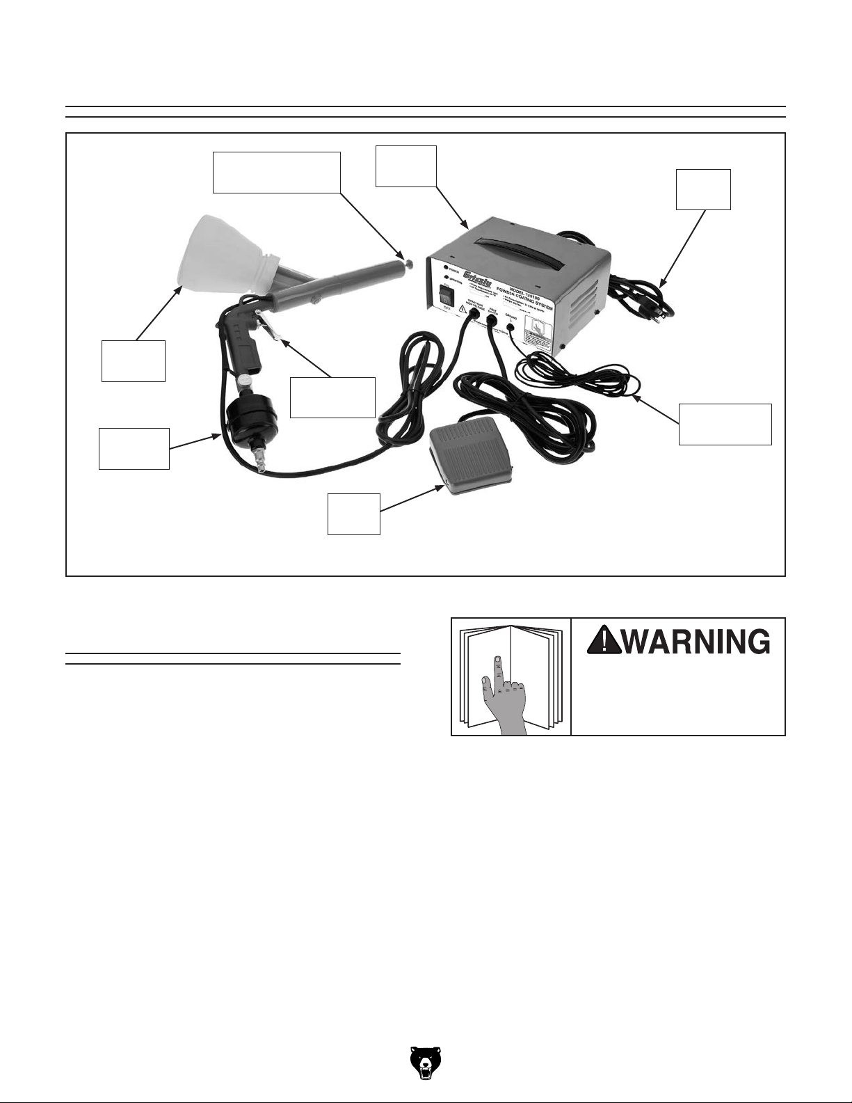
Identification
To reduce your risk of
serious injury, read this
entire manual BEFORE
Powder
Cup
Moisture
Filter
Scatter Tip
& Conductor Pole
Spray Gun
Trigger
Foot
Switch
Control
Box
Power
Cord
Grounding
Cable & Clip
Specifications
Power Requirement ............................. 120V, 15 A
Recommended Air Supply ................. 10 –30 PSI
Maximum Air Supply ................................ 30 PSI
Air Consumption .................... 3.5 CFM at 30 PSI
Output Voltage .................................... 10kv–13kv
Air Quick-Connect Size ...........................
Powder Coating Gun Cord Length ................ 8 ft.
Grounding Cable Length ...............................8 ft.
Foot Pedal Cord Length .............................. 10 f t.
Power Cord Length........................................ 6 ft.
Included Plug .....................................NEMA 5-15
Weight ......................................................6.5 lbs.
Model T25100 (Mfg. Since 8/12)
1
⁄4" NPT
using machine.
-3-
Page 6
SECTION 1: SAFETY
For Your Own Safety, Read Instruction
Manual Before Operating This Machine
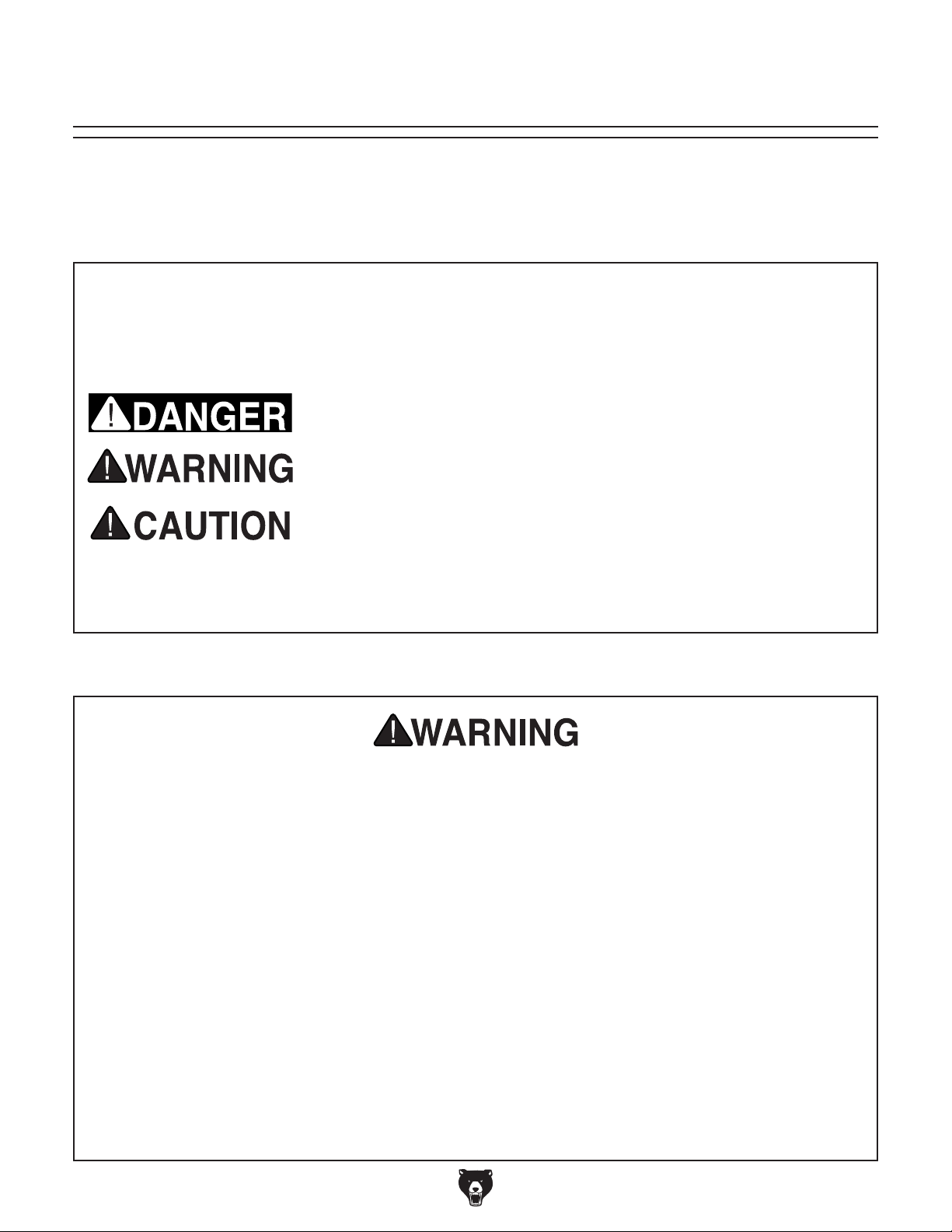
The purpose of safety symbols is to attract your attention to possible hazardous conditions.
This manual uses a series of symbols and signal words intended to convey the level of importance of the safety messages. The progression of symbols is described below. Remember that
safety messages by themselves do not eliminate danger and are not a substitute for proper
accident prevention measures. Always use common sense and good judgment.
Indicates an imminently hazardous situation which, if not avoided,
WILL result in death or serious injury.
Indicates a potentially hazardous situation which, if not avoided,
COULD result in death or serious injury.
Indicates a potentially hazardous situation which, if not avoided,
MAY result in minor or moderate injury. It may also be used to alert
against unsafe practices.
This symbol is used to alert the user to useful information about
NOTICE
proper operation of the machine.
Safety Instructions for Machinery
OWNER’S MANUAL. Read and understand this
owner’s manual BEFORE using machine.
TRAINED OPERATORS ONLY. Untrained operators have a higher risk of being hurt or killed.
Only allow trained/supervised people to use this
machine. When machine is not being used, disconnect power, remove switch keys, or lock-out
machine to prevent unauthorized use—especially
around children. Make workshop kid proof!
DANGEROUS ENVIRONMENTS. Do not use
machinery in areas that are wet, cluttered, or have
poor lighting. Operating machinery in these areas
greatly increases the risk of accidents and injury.
MENTAL ALERTNESS REQUIRED. Full mental
alertness is required for safe operation of machinery. Never operate under the influence of drugs or
alcohol, when tired, or when distracted.
ELECTRICAL EQUIPMENT INJURY RISKS. You
can be shocked, burned, or killed by touching live
electrical components or improperly grounded
machinery. To reduce this risk, only allow qualified
service personnel to do electrical installation or
repair work, and always disconnect power before
accessing or exposing electrical equipment.
DISCONNECT POWER FIRST.
nect machine from power supply BEFORE making
adjustments, changing tooling, or servicing machine.
This prevents an injury risk from unintended startup
or contact with live electrical components.
EYE PROTECTION. Always wear ANSI-approved
safety glasses or a face shield when operating or
observing machinery to reduce the risk of eye
injury or blindness from flying particles. Everyday
eyeglasses are NOT approved safety glasses.
Always discon-
-4-
Model T25100 (Mfg. Since 8/12)
Page 7

WEARING PROPER APPAREL. Do not wear
clothing, apparel or jewelry that can become
entangled in moving parts. Always tie back or
cover long hair. Wear non-slip footwear to avoid
accidental slips, which could cause loss of workpiece control.
HAZARDOUS DUST. Dust created while using
machinery may cause cancer, birth defects, or
long-term respiratory damage. Be aware of dust
hazards associated with each workpiece material,
and always wear a NIOSH-approved respirator to
reduce your risk.
HEARING PROTECTION. Always wear hearing protection when operating or observing loud
machinery. Extended exposure to this noise
without hearing protection can cause permanent
hearing loss.
REMOVE ADJUSTING TOOLS. Tools left on
machinery can become dangerous projectiles
upon startup. Never leave chuck keys, wrenches,
or any other tools on machine. Always verify
removal before starting!
USE CORRECT TOOL FOR THE JOB. Only use
this tool for its intended purpose—do not force
it or an attachment to do a job for which it was
not designed. Never make unapproved modifications—modifying tool or using it differently than
intended may result in malfunction or mechanical
failure that can lead to personal injury or death!
AWKWARD POSITIONS. Keep proper footing
and balance at all times when operating machine.
Do not overreach! Avoid awkward hand positions
that make workpiece control difficult or increase
the risk of accidental injury.
CHILDREN & BYSTANDERS. Keep children and
bystanders at a safe distance from the work area.
Stop using machine if they become a distraction.
FORCING MACHINERY. Do not force machine.
It will do the job safer and better at the rate for
which it was designed.
NEVER STAND ON MACHINE. Serious injury
may occur if machine is tipped or if the cutting
tool is unintentionally contacted.
STABLE MACHINE. Unexpected movement during operation greatly increases risk of injury or
loss of control. Before starting, verify machine is
stable and mobile base (if used) is locked.
USE RECOMMENDED ACCESSORIES. Consult
this owner’s manual or the manufacturer for recommended accessories. Using improper accessories will increase the risk of serious injury.
UNATTENDED OPERATION. To reduce the
risk of accidental injury, turn machine OFF and
ensure all moving parts completely stop before
walking away. Never leave machine running
while unattended.
MAINTAIN WITH CARE. Follow all maintenance
instructions and lubrication schedules to keep
machine in good working condition. A machine
that is improperly maintained could malfunction,
leading to serious personal injury or death.
CHECK DAMAGED PARTS. Regularly inspect
machine for any condition that may affect safe
operation. Immediately repair or replace damaged
or mis-adjusted parts before operating machine.
MAINTAIN POWER CORDS. When disconnecting cord-connected machines from power, grab
and pull the plug—NOT the cord. Pulling the cord
may damage the wires inside. Do not handle
cord/plug with wet hands. Avoid cord damage by
keeping it away from heated surfaces, high traffic
areas, harsh chemicals, and wet/damp locations.
GUARDS & COVERS. Guards and covers reduce
accidental contact with moving parts or flying
debris. Make sure they are properly installed,
undamaged, and working correctly.
Model T25100 (Mfg. Since 8/12)
EXPERIENCING DIFFICULTIES. If at any time
you experience difficulties performing the intended operation, stop using the machine! Contact our
Technical Support at (570) 546-9663.
-5-
Page 8

Additional Safety for Powder Coating
Systems
ELECTROSTATIC GROUNDING. The powder
coating system electrically charges the powder
and gun during application. To prevent electrical
shock or dust explosion from electrostatic sparks,
make sure that the power circuit, control box, and
workpiece are well grounded. Make sure your
body is well grounded to an earth ground, not the
powder coating system—use a grounding strap if
standing on non-grounded or insulated surface.
PERSONAL HEALTH. Powder used in this tool
can cause eye, lung, and skin injuries with sustained exposure. Always wear ANSI-approved
goggles/face mask, NIOSH-approved respirator,
non-insulating gloves, and anti-static clothing that
will protect your skin when handling the powder
and during application.
DUST EXPLOSION. The finely-ground powder
is flammable when floating in the air. Stay at
least 50 feet away from any ignition source (e.g.,
open flame, hot water heater, welder, etc.) when
handling the powder or during operation. Keep a
multi-class fire extinguisher in the immediate work
area.
AIR PRESSURE. Using air pressure with this tool
that exceeds 30 PSI could cause the spray gun
to break apart, which could result in impact injury
or explosion. Never exceed 30 PSI of air pressure
during operation.
ELECTRIC SHOCK. To avoid electrical shock
when tool is connected to power, never touch conductor pole that protrudes from the gun nose—the
conductor pole is electrically charged! After turning the control box OFF, touch the conductor pole
to the grounding clip to discharge current. NEVER
touch the metal workpiece during operation—it
is also electrically charged! Do not use tool if
you have electronic medical devices (e.g., pacemaker).
CURING FUMES. The fumes produced during
curing can cause severe eye, lung, and skin injuries. Always make sure the oven is well-ventilated.
Always wear ANSI approved goggles/face mask,
respirator, and clothing that will protect your skin
when exposed to curing fumes. DO NOT use a
gas oven that could cause the fumes to explode—
only use an electric oven. DO NOT use an oven
that will be used for cooking food. Always keep
the oven at least 50 feet away from any ignition
source during the curing process—the fumes are
volatile!
No list of safety guidelines can be complete. Every shop environment is different.
Always consider safety first, as it applies
to your individual working conditions. Use
this and other equipment with caution and
respect. Failure to do so could result in
serious personal injury, damage to equipment, or poor work results.
-6-
Like all equipment there is potential danger
when operating this tool. Accidents are
frequently caused by lack of familiarity or
failure to pay attention. Use this tool with
respect and caution to decrease the risk
of operator injury. If normal safety precautions are overlooked or ignored, serious
personal injury may occur.
Model T25100 (Mfg. Since 8/12)
Page 9

SECTION 2: POWER SUPPLY
For your own safety and protection of
Availability
Before using the Model T25100, consider the
availability and proximity of the required power
supply circuit. If an existing circuit does not meet
the requirements for this tool, a new circuit must
be installed. To minimize the risk of electrocution, fire, or tool damage, installation work and
electrical wiring must be done by an electrician or
qualified service personnel in accordance with all
applicable codes and standards.
Electrocution, fire, or
system damage may occur
if system is not correctly
grounded and connected
to the power supply.
120V Circuit Requirements
This tool is prewired to operate on a power supply
circuit that has a verified ground and meets the
following requirements:
A power supply circuit includes all electrical systems between the breaker box or fuse panel in the
building and the T25100 control box. The power
supply circuit used for this tool must be sized to
safely handle the current drawn from the tool for
an extended period of time. (If this machine is
connected to a circuit protected by fuses, use a
time delay fuse marked D.)
Note: The circuit requirements listed in this
manual apply to a dedicated circuit—where only
one tool or machine will be running at a time.
If this tool will be connected to a shared circuit
where multiple tools or machines will be running
at the same time, consult a qualified electrician
to ensure that the circuit is properly sized for safe
operation.
property, consult an electrician if you are
unsure about wiring practices or electrical
codes in your area.
Nominal Voltage ........................................120V
Cycle ..........................................................60 Hz
Phase ........................................... Single-Phase
Power Supply Circuit ......................... 15 Amps
Model T25100 (Mfg. Since 8/12)
-7-
Page 10

Improper connection of the equipment-grounding
wire can result in a risk of electric shock. The
wire with green insulation (with or without yellow
stripes) is the equipment-grounding wire. If repair
or replacement of the power cord or plug is necessary, do not connect the equipment-grounding
wire to a live (current carrying) terminal.
Check with a qualified electrician or service personnel if you do not understand these grounding
requirements, or if you are in doubt about whether
the tool is properly grounded. If you ever notice
that a cord or plug is damaged or worn, disconnect it from power, and immediately replace it with
a new one.
Grounding & Plug Requirements
it will not fit the outlet, have a qualified
electrician install the proper outlet with a
This system MUST be grounded. In the event of
certain malfunctions or breakdowns, grounding
reduces the risk of electric shock by providing a
path of least resistance for electric current.
This system is equipped with a power cord that
has an equipment-grounding wire and a grounding plug (similar to the figure below). The plug
must only be inserted into a matching receptacle
(outlet) that is properly installed and grounded in
accordance with all local codes and ordinances.
GROUNDED
5-15 RECEPTACLE
Grounding Prong
5-15 PLUG
Neutral Hot
Figure 1. Typical 5-15 plug and receptacle.
Extension Cords
We do not recommend using an extension cord
with this tool. If you must use an extension cord,
only use it if absolutely necessary and only on a
temporary basis.
Extension cords cause voltage drop, which may
damage electrical components and shorten tool
life. Voltage drop increases as the extension cord
size gets longer and the gauge size gets smaller
(higher gauge numbers indicate smaller sizes).
SHOCK HAZARD!
Two-prong outlets do not meet the grounding
requirements for this machine. Do not modify
or use an adapter on the plug provided—if
verified ground.
-8-
Any extension cord used with this tool must contain a ground wire, match the required plug and
receptacle, and meet the following requirements:
Minimum Gauge Size ...........................16 AWG
Maximum Length (Shorter is Better).......50 ft.
Model T25100 (Mfg. Since 8/12)
Page 11

SECTION 3: SETUP
Your machine was carefully packaged for safe
transportation. Remove the packaging materials
from around your machine and inspect it. If you
discover any damage, please call us immediately
at (570) 546-9663
Save the containers and all packing materials for
possible inspection by the carrier or its agent.
Otherwise, filing a freight claim can be difficult.
When you are completely satisfied with the condition of your shipment, inventory the contents.
Keep children and pets away
from plastic bags or packing
materials shipped with this
The following is a list of items shipped with your
machine. Before beginning setup, lay these items
out and inventory them.
If any non-proprietary parts are missing (e.g. a
nut or a washer), we will gladly replace them; or
for the sake of expediency, replacements can be
obtained at your local hardware store.
Unpacking
for advice.
Box Inventory (Figures 2–3): Qty
A. Powder Coating System ............................. 1
B. Powder Cups w/Gaskets & Lids ................. 2
C. Moisture Filter ............................................. 1
D. Powder Flow Regulator Screw O-Ring ...... 1
E. Fuse 0.5A, Fast-Acting ............................... 1
F. Scatter Tip
G. Scatter Tip
H. Scatter Tip 1" .............................................. 1
1
⁄2 " ............................................ 1
3
⁄4"............................................. 1
A
SUFFOCATION HAZARD!
machine. Discard immediately.
Inventory
If you cannot find an item on this list, carefully check around/inside the machine and
packaging materials. Often, these items get
lost in packaging materials while unpacking or they are pre-installed at the factory.
Model T25100 (Mfg. Since 8/12)
NOTICE
Figure 2. Powder coating system.
B
H
G
F
E
Figure 3. Small item inventory.
D
C
-9-
Page 12

Site Considerations
Space Allocation
Consider the largest size of workpiece that will
be processed with the powder coating system.
Provide enough space for adequate operator
material handling or the installation of auxiliary
equipment.
Physical Environment
The physical environment where this tool is operated is important for safe operation and longevity
of the tool components. For best results, operate
the powder coating system in a clean, dry environment that is free from excessive moisture, hazardous chemicals, airborne abrasives, or extreme
conditions. Make sure that all flammable sources
(e.g., open flame, hot water heater, welder, etc.)
are at least 50 feet away from the work area.
Ventilation
The powder coating and curing processes produce hazardous dust or fumes that can cause
long-term eye, lung, or skin injuries. Make sure the
work area is well ventilated with either mechanical
means or adequate exposure to outside air.
Children and visitors may
be seriously injured if unsupervised around this tool.
Lock entrances to the shop
or disable start switch or
power connection to prevent
unsupervised use.
Moisture Filter
Installation
Thread the moisture filter onto the spray gun
handle, as shown in Figure 4.
Spray Gun
Handle
Moisture
Filter
Electrical Installation
Operate this tool near an existing power source.
Make sure all power cords are protected from
traffic, material handling, moisture, chemicals,
or other hazards. Make sure to leave access to
a means of disconnecting the power source or
engaging a lockout/tagout device, if required.
Lighting
Lighting around the work area must be adequate
enough that operations can be performed safely.
Shadows, glare, or strobe effect that may distract
or impede the operator must be eliminated.
Figure 4. Moisture filter installed.
-10 -
Model T25100 (Mfg. Since 8/12)
Page 13

SECTION 4: OPERATIONS
Operation Overview
To complete a typical operation, the operator
does the following:
The purpose of this overview is to provide the
novice operator with a basic understanding of how
the tool is used during operation, so the tool controls/components discussed later in this manual
are easier to understand.
Due to the generic nature of this overview, it is
not intended to be an instructional guide. To learn
more about specific operations, read this entire
manual and seek additional training from experienced operators, and do additional research
outside of this manual by reading "how to" books,
trade magazines, or websites.
To reduce your risk of
serious injury, read this
entire manual BEFORE
using this tool.
1. Examines the metal workpiece to make sure
it is dry, clean, and suitable for powder coating. Sandblasting the workpiece is one efficient method of cleaning it.
2. Places the workpiece on a stable surface or
securely hangs it in a dry, clean, and wellventilated area. If using a hanger, make sure
that it is made of clean metal and makes good
metal-to-metal contact with the workpiece.
3. Installs the proper scatter tip on the conductor pole.
4. Attaches the grounding clip to the workpiece
or hanger with good metal-to-metal contact.
5. Puts on ANSI-approved goggles/face mask,
respirator, and clothing that protects the
operator's skin.
6. Fills the powder cup with approximately 2" of
the selected powder.
Eye injuries, respiratory problems, or skin
damage can occur while operating this tool.
Wear approved safety goggles, respirator,
non-insulating gloves, and anti-static clothing to protect your skin.
If you are not experienced with this type of
equipment, WE STRONGLY RECOMMEND
that you seek additional training outside of
this manual. Read books/magazines or get
formal training before beginning any projects. Regardless of the content in this section, Grizzly Industrial will not be held liable
for accidents caused by lack of training.
7. Attaches the powder cup to the spray gun.
8. Connects the spray gun to a dry, clean, pres-
surized air source between 10 PSI and 30
PSI.
9. Connects the control box to power and turns
the system ON.
10. Aims the spray gun at the workpiece, then
simultaneously steps on the foot switch and
pulls the gun trigger to direct the powder
cloud onto the workpiece.
11. Maintain an even powder thickness of approximately 2mm.
12. When finished, turns the system OFF, and
immediately grounds the conductor pole to
the grounding clip to discharge the gun's
electrical charge.
Model T25100 (Mfg. Since 8/12)
-11-
Page 14

Basic Controls &
Components
K
I
Use Figures 5–7 and the following descriptions to
gain a better understanding of the Model T25100
controls and components.
A
B
C
A. Power Lamp. Illuminates when power is
enabled to the control box.
B. Spraying Lamp. Illuminates when power is
enabled to the spray gun.
D
E
Figure 5. Control box panel.
F
M
J
H
G
Figure 6. Spray gun controls.
J. Spray Gun Trigger. Enables air to flow
through the powder cup and gun. To begin
spraying, use the spray gun trigger and the
foot switch simultaneously.
K. Powder Cup. Holds the powder coating
material. Air is circulated inside the cup to
provide a fine dust for spraying.
L. Powder Flow Regulating Screw. Fine tunes
the flow of powder from the gun.
M. Conductor Pole. Electrically charges the
powder dust as it leaves the spray gun.
L
N
C. ON/OFF Switch. Enables power to the con-
trol box.
D. Spray Gun Cable. Connects the spray gun
to the control box.
E. Foot Switch Cable. Connects the foot switch
to the control box.
F. Grounding Cable. Provides an electrical
ground for the workpiece.
1
G. Air Quick-Connect. Provides a
nection for incoming air pressure.
H. Moisture Filter. A disposable unit that
removes moisture from the incoming air. We
recommend that you also use an additional
in-line moisture filter on the air compressor.
I. Air Pressure Regulating Valve. Increases/
decreases air flow to the spray gun.
⁄4" NPT con-
N. Scatter Tip. Provides the spray pattern for
the powder dust.
O
P
Figure 7. Foot switch and grounding clip.
O. Foot Switch. Enables power to the spray
gun conductor pole. To begin spraying use
the foot switch and the spray gun trigger
simultaneously.
P. Grounding Clip. Provides an electrical
ground for the workpiece.
-12-
Model T25100 (Mfg. Since 8/12)
Page 15

Operational Points
Adhere to the following points for the best
powder coating results:
• Use a side-to-side overlapping pattern when
spraying. Most powder products require a
coating of approximately 2mm. Check the
powder manufacturer's specifications and
practice attaining the correct thickness on a
scrap workpiece.
• The workpiece MUST be clean of debris,
paint, or other non-metal material. Depending
upon the application, cleaning may be as
simple as using mineral spirits and clean
rags, or it may require a much more complicated "pre-treament" process, such as sandblasting.
• Obtaining good powder coating results
depends on many variables—workpiece pretreatment, powder chemical composition,
method of spraying, curing procedure, etc.
Read books, use online resources, or talk to
professionals to gain an understanding what
is required for your operation.
• Use only high-quality powder coatings.
Investigate the many powder options on the
market and choose the one that best suits
your application.
• Use only pressurized air that is clean, dry,
and free from oil.
• Make sure the system ground clip is firmly
secured to the workpiece or hanger with good
metal-to-metal contact.
• You MUST “cure” the workpiece to complete
the powder coating process. The curing oven
must have good ventilation. Poor air circulation can cause discoloration or hazing.
Fumes from the curing process are poisonous! Make sure the curing oven is well-ventilated. Use a dedicated electric oven that
will NOT be used for cooking food.
• Follow closely the powder manufacturer's
directions for curing. Under-curing can result
in poor physical qualities and over-curing can
change the color.
• Always maintain clean powder cups, spray
gun, and work area. Contamination of powder products by debris or other powder material can produce unexpected results.
• Some orange peel effect may be unavoidable. If this happens, wet-sand the workpiece
with 400 grit sandpaper, thoroughly dry the
workpiece, and repeat the coating process.
• To begin spraying, depress the foot switch
and spray gun trigger simultaneously. The
foot switch enables power to the gun conductor pole, which electrically charges the dust
as it leaves the gun. The spray gun trigger
allows air to flow through the powder cup and
gun to send the powder onto the workpiece.
• Use the air pressure regulating valve and
powder flow regulating screw to control the
flow of powder through the spray gun.
• Experiment with the scatter tips to gain an
understanding of the effects attained with
each tip.
Model T25100 (Mfg. Since 8/12)
• To remove slight imperfections, buff the
workpiece with a loose buffing wheel and
white rouge compound.
Exposure to powder coating materials can cause eye,
lung, or skin injury. Always
wear ANSI-approved goggles, NIOSH-approved respirator, and wear clothing
that will protect your skin.
-13-
Page 16

Workpiece
Preparation
The powder coating system is designed to
ONLY operate on solid, electrically-conductive metal workpieces.
Follow these workpiece preparation guidelines for the best results:
• Thoroughly clean the workpiece of paints or
other finishes, residue left by cleaning solutions, debris, dust, and any other foreign
material. Depending upon the application,
additional pre-treatment steps may be necessary.
• Make sure the workpiece is completely dry.
• Use clean metal material for workpiece hangers. This will ensure that the hanger is
grounded with the workpiece.
Scatter Tips
The Model T25100 ships with three scatter tips
with diameters of
1
⁄2 ", 3⁄4", and 1" (see Figure 9).
• Attach the grounding clip (see Figure 8) to
the workpiece or hanger with a good metalto-metal contact at a point where the powder will not be applied. This will provide a
negative electrical attraction for the charged
power.
Figure 8. System grounding clip.
• Make sure the workpiece is not touching any
other grounding source other than the powder coating system ground.
Figure 9. Included scatter tips.
The scatter tips thread onto the conductor pole
(see Figure 10) and produce different spray patterns. Experiment with a scrap workpiece to gain
an understanding of the effect that each tip produces.
Note: Wipe the tips clean of powder before storing them.
Scatter
Tip
Conductor
Pole
• To reduce the risk of electrical shock from
workpiece contact, position or hang the
workpiece so that it does not need to be
re-positioned during the powder coating process.
-14-
Gun
Nose
Figure 10. Scatter tip installed.
Model T25100 (Mfg. Since 8/12)
Page 17

The spray gun conductor
pole may be electrically
charged. Always disconnect the system from power
and ground the conductor
pole to the system grounding clip before making contact with conductor pole to
reduce the risk of electric
shock or dust explosion
from electrostatic sparks.
Powder Cups
During operation, air circulates inside the powder cup to produce a fine dust, which is then fed
through the spray gun and onto the workpiece.
5. Connect the tool to the air supply (but NOT
to power) and use the spray gun trigger to
send air through the gun to make sure any
residual powder from the last operation is
cleared away.
6. Remove the powder cup from the spray gun
and fill it with up to 2" of powder.
Note: Leaving space in the powder cup
allows the powder to circulate into a fine dust
when the air is applied.
7. Make sure the gasket is in place inside the
mounting cap, then turn the gun upside down
and thread the powder cup onto the mounting
cap (see Figure 12).
To fill and attach the powder cup:
1. DISCONNECT TOOL FROM POWER!
2. Put on eye, lung, and skin protective gear.
3. Make sure the powder cup, gasket, and
mounting cap components (see Figure 11)
are dry and clean of any powder or debris.
Mounting
Cap
Gasket
Powder
Cup
Figure 12. Powder cup installed.
Curing
Curing the powder coating is a process that melts
the powder into an even finish that adheres to the
workpiece. This is done with a dedicated electric
oven that is not used for any other purpose.
Follow the powder coat manufacturer's recommendations for curing temperature and length of
time to produce good results.
Figure 11. Powder cup components.
4. Insert the gasket into the mounting cap, then
thread the empty powder cup onto the mounting cap.
Model T25100 (Mfg. Since 8/12)
The powder coating will NOT adhere to the
workpiece unless it is properly cured in a
dedicated electric oven. Follow all recommendations made by the power coat manufacturer for properly curing their product.
-15-
Page 18

ACCESSORIES
Installing unapproved accessories may
order online at www.grizzly.com or call 1-800-523-4777
SECTION 5: ACCESSORIES
cause machine to malfunction, resulting in
serious personal injury or machine damage.
To reduce this risk, only install accessories
recommended for this machine by Grizzly.
NOTICE
Refer to our website or latest catalog for
additional recommended accessories.
T20501—Face Shield Crown Protector 4"
T20502—Face Shield Crown Protector 7"
T20503—Face Shield Window
T20452—"Kirova" Anti-Reflective S. Glasses
T20451—"Kirova" Clear Safety Glasses
H0736—Shop Fox
H7194—Bifocal Safety Glasses 1.5
H7195—Bifocal Safety Glasses 2.0
H7196—Bifocal Safety Glasses 2.5
®
Safety Glasses
T20502
T20452
H2499—Small Half-Mask Respirator
H3631—Medium Half-Mask Respirator
H3632—Large Half-Mask Respirator
H3635—Cartridge Filter Pair P100
Fine chemical dust has been linked to nasal
cancer and severe respiratory illnesses. If you
work around dust everyday, a half-mask respirator can be a lifesaver. Also compatible with safety
glasses!
Figure 14. Half-mask respirator with disposable
cartridge filters.
H8118—Sandblasting Gun Kit
This spot sandblaster is the quickest, cleanest
way to remove rust spots, peeling pain, or surface blemishes without disturbing the surrounding
area. Supplied with 4 nozzles that allow you to
spot blast inside corners, outside corner, edges,
and flat areas for perfect surface preparation.
T20503
T20451
H7194
Figure 13. Eye protection assortment.
-16 -
H0736
Figure 15. Model H8118 Sandblasting Gun Kit.
Model T25100 (Mfg. Since 8/12)
Page 19

SECTION 6: MAINTENANCE
accidental startup, always
Cleaning
To reduce risk of shock or
disconnect equipment from
power before adjustments,
maintenance, or service.
Schedule
Cleaning the Model T25100 is simple and straightforward.
To clean the Model T25100:
1. DISCONNECT TOOL FROM POWER!
2. DISCONNECT TOOL FROM AIR!
For optimum performance from your tool, follow
this maintenance schedule and refer to any specific instructions given in this section.
Daily Check:
• Damaged spray gun components.
• Worn or damaged wires/cables.
• Any other unsafe condition.
Daily Maintenance:
• Clean the tool.
• Check/replace moisture filter.
3. Ground the spray gun conductor pole to the
grounding clip to remove any residual electrical charge.
4. Put on eye, lung, and skin protection.
5. Put uncontaminated powder back into the
original container and store it in a dry, stable
environment.
6. In a well-ventilated area, use compressed air
to blow away the powder from the spray gun,
powder cups, control box, and foot switch.
Model T25100 (Mfg. Since 8/12)
-17-
Page 20

Review the troubleshooting and procedures in this section if a problem develops with your machine. If you
need replacement parts or additional help with a procedure, call our Technical Support at (570) 546-9663.
Note: Please gather the serial number and manufacture date of your machine before calling.
SECTION 7: SERVICE
Troubleshooting
Symptom Possible Cause Possible Solution
Tool does not turn
on.
Poor adhesion. 1. Workpiece not properly cleaned/pre-treated
Uneven spray
pattern, intermittent
powder flow.
Chipping after
curing.
Cratering after
curing.
Off color after
curing.
Orange peel. 1. Warming up of powder coat is too slow or
1. Control box fuse is blown.
2. Power source turned OFF at breaker.
3. Wall fuse/circuit breaker is blown/tripped;
short in electrical system.
4. ON/OFF switch at fault.
prior to spraying.
2. Coating under/over-cured.
3. Powder coat too thick.
1. Blockage in spray gun body/powder cup.
2. Damp powder.
3. Air pressure low.
4. Powder flow regulating screw too tight.
1. Workpiece not properly cleaned/pretreated.
2. Powder coat too thick.
1. Powder is contaminated.
2. Workpiece not properly cleaned/pre-treated
prior to spraying.
3. Damp powder.
1. Oven not properly ventilated.
2. Incorrect curing time/temperature.
too fast.
2. Powder heat-damaged prior to spraying.
3. Coating too thin.
1. Replace control box fuse (0.5A, Fast-Acting)
2. Make sure circuit breaker is turned ON.
3. Troubleshoot/repair source cause of overload;
replace weak breaker; find/repair electrical short.
4. Replace switch.
1. Thoroughly clean workpiece; research/perform
pretreatment recommendations for workpiece
material and powder.
2. Follow powder manufacturer's curing instructions.
3. Reduce powder coat thickness when spraying.
1. Disconnect tool from power, ground conducting
pole, put on protective gear, and use air pressure to
thoroughly clean spray gun and powder cup.
2. Check powder source; replace powder if
contaminated; replace in-line moisture filter(s).
3. Increase air pressure up to 30 PSI.
4. Loosen screw to increase powder flow.
1. Thoroughly clean workpiece; research/perform
pretreatment recommendations for workpiece
material and powder.
2. Reduce powder coat thickness when spraying.
1. Thoroughly clean spray gun/powder cup; replace
power with new.
2. Thoroughly clean workpiece; research/perform
pretreatment recommendations for workpiece
material and powder.
3. Check powder source; replace powder if
contaminated; replace in-line moisture filter(s).
1. Make sure oven is well ventilated during curing.
2. Follow powder manufacturer's curing instructions.
1. Check curing oven for proper operation; follow
powder manufacturer's curing instructions.
2. Thoroughly clean spray gun/powder cup; replace
powder with new.
3. Increase coating thickness when spraying.
-18-
Model T25100 (Mfg. Since 8/12)
Page 21

Symptom Possible Cause Possible Solution
Poor corrosion
resistance.
Poor impact
resistance or poor
flexibility.
Poor powder
penetration into
recessed areas.
1. Workpiece not properly cleaned/pre-treated
prior to spraying.
2. Powder under-cured.
1. Powder under-cured.
2. Workpiece not properly cleaned/pre-treated
prior to spraying.
3. Coating too thick.
1. Poor workpiece ground.
2. Improper spray pattern.
1. Thoroughly clean workpiece; research/perform
pretreatment recommendations for workpiece
material and powder.
2. Follow powder manufacturer's curing instructions.
1. Follow powder manufacturer's curing instructions.
2. Thoroughly clean workpiece; research/perform
pretreatment recommendations for workpiece
material and powder.
3. Decrease powder coat thickness when spraying.
1. Ensure system grounding clip is making good
metal-to-metal contact with workpiece.
2. Use a scatter tip that will help direct powder into
recessed areas. Position spray gun so powder has
a direct path to recessed areas.
Model T25100 (Mfg. Since 8/12)
-19 -
Page 22

SECTION 8: PARTS
Please Note: We do our best to stock replacement parts whenever possible, but we cannot guarantee that all parts shown here
are available for purchase. Call (800) 523- 4777 or visit our online parts store at www.grizzly.com to check for availability.
3
21
4
31
32
9
10
1
5
6
8
13
28
29
27
7
12
14
11
22
19
26
17
24
25
15
18
16
2
30
REF PART # DESCRIPTION REF PART # DESCRIPTION
1 PT25100001 SPRAY GUN BODY 16 PT25100016 FOOT SWITCH
2 PT25100002 FUSE HOLDER 17 PT25100017 FUSE 0.5A FAST-ACTING
3 PT25100003 CUP AIR TUBE 18 PT25100018 FOOT SWITCH CABLE
4 PT25100004 POWDER CUP 19 PT25100019 POWER CORD 16G 3W 72" 5-15P
5 PT25100005 CUP POWDER TUBE 21 PT25100021 SCATTER TIP 1"
6 PT25100006 SPRAY GUN HANDLE/TRIGGER ASSY 22 PT25100022 SCATTER TIP 3/4"
7 PT25100007 POWDER FLOW REGULATING SCREW 24 PT25100024 SCATTER TIP 1/2"
8 PT25100008 AIR PRESSURE REGULATING VALVE 25 PT25100025 CONDUCTOR POLE
9 PT25100009 MOISTURE FILTER 26 PT25100026 GROUNDING CABLE
10 PT25100010 QUICK-CONNECT AIR ADAPTER 1/4 NPT 27 PT25100027 SPRAY GUN CABLE
11 PT25100011 CONTROL BOX 28 PT25100028 EQUIPMENT ID LABEL
12 PT25100012 POWER LIGHT 29 PT25100029 WARNING LABEL
13 PT25100013 SPRAYING LIGHT 30 PLABEL-14A ELECTRICITY LABEL
14 PT25100014 ON/OFF SWITCH 31 PT25100031 DUST EXPLOSION LABEL
15 PT25100015 GROUNDING CLIP 32 PT25100032 POWDER EXPOSURE LABEL
-20-
Model T25100 (Mfg. Since 8/12)
Page 23

WARRANTY & RETURNS
Grizzly Industrial, Inc. warrants every product it sells for a period of 1 year to the original purchaser from
the date of purchase. This warranty does not apply to defects due directly or indirectly to misuse, abuse,
negligence, accidents, repairs or alterations or lack of maintenance. This is Grizzly’s sole written warranty
and any and all warranties that may be implied by law, including any merchantability or fitness, for any particular purpose, are hereby limited to the duration of this written warranty. We do not warrant or represent
that the merchandise complies with the provisions of any law or acts unless the manufacturer so warrants.
In no event shall Grizzly’s liability under this warranty exceed the purchase price paid for the product and
any legal actions brought against Grizzly shall be tried in the State of Washington, County of Whatcom.
We shall in no event be liable for death, injuries to persons or property or for incidental, contingent, special,
or consequential damages arising from the use of our products.
To take advantage of this warranty, contact us by mail or phone and give us all the details. We will then issue
you a “Return Number,’’ which must be clearly posted on the outside as well as the inside of the carton. We
will not accept any item back without this number. Proof of purchase must accompany the merchandise.
The manufacturers reserve the right to change specifications at any time because they constantly strive to
achieve better quality equipment. We make every effort to ensure that our products meet high quality and
durability standards and we hope you never need to use this warranty.
Please feel free to write or call us if you have any questions about the machine or the manual.
Thank you again for your business and continued support. We hope to serve you again soon.
Page 24

 Loading...